chapter2 2 literature review
TRANSCRIPT

CHAPTER2
2 LITERATURE REVIEW
2.1 Selection of pipe material
Poly Vinyl Chloride (PVC), Steel and Ductile Iron (DI) are the commonly
used material for water pipe lines. However. PVC is not used in pipelines
across waterways and highways unless it is encased for protection from sun
light and external impact and shock loads.
Steel pipes are liable to the actions of acids and alkalis in water and slight
trace of these will produce rust and encrustations. Therefore. pipes must be
protected against it inside and out. and also couplings and bolts. Steel pipes
need frequent painting. Thinner walls of steel pipes and greater susceptibility
to corrosion are likely to cause high maintenance costs and shortened life. In
Sri Lanka 800mm, 900mm. lOOOmm and 1200mm diameters of steel pipes are
used in exposed rising mains and bridge crossings.
The largest practical advantage of Ductile Iron pipe compared with steel pipe
is that Ductile Iron pipe is much easier to install properly. Handling.
assembling, and adapting to field conditions all are other aspects in vvhich
Ductile Iron pipe offers distinct benefits. Therefore, at present DI pipes are
used for most of the waterway and highway crossings.
This study focuses on Ductile Iron pipes. -·-
- 4 -
2.2 Selection of the Type of the pipe joint
Ductile Iron pipe is furnished with several different types of joints: push-on,
mechanical, restrained, flanged, ball and socket, and grooved and shouldered
joints. It is centrifugally cast in 4m, 5.5m, 6m and 9m nominal laying lengths.
Nominal diameters range from 80mm to 1600mm with a variety of pressure
and special thickness classes.
Typically, bridge crossings involve push-on joints, mechanical joints.
restrained joints or combinations thereof.
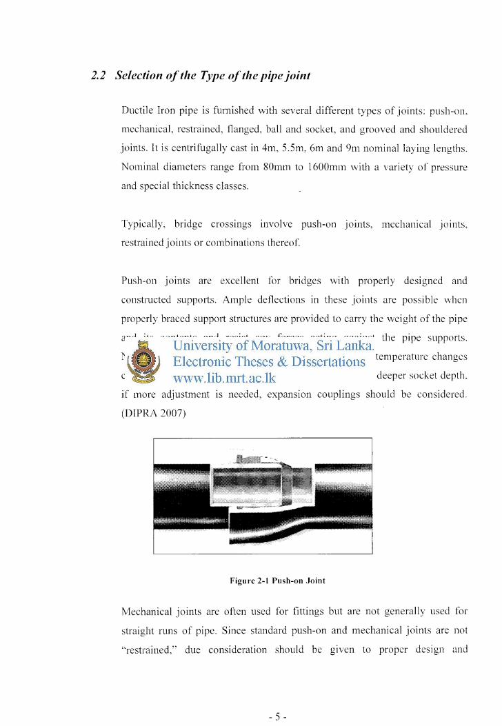
Push-on joints are excellent for bridges with properly designed and
constructed supports. Ample deflections in these joints are possible when
properly braced support structures are provided to carry the weight of the pipe
and its contents and resist any forces acting against the pipe supports.
Normally, expansion and contraction of the pipe due to temperature changes
can be adequately provided for with such joints due to its deeper socket depth.
if more adjustment is needed, expansion couplings should be considered.
(DIPRA 2007)
Figure 2-1 Push-on Joint
Mechanical joints are often used for fittings but are not generally used for
straight runs of pipe. Since standard push-on and mechanical joints are not
·'restrained,'' due consideration should be given to proper design and
- 5 -

construction of supports or anchorages to resist thrust forces, dead loads,
impact and shock load and thermal changes.
~-~1 J CJI 1----------
~-~ l Figure 2-2 Mechanical Joint
The restrained joint complements the push-on and mechanical types by
maintaining flexibility and also by providing both ease of assembly and a
locking feature to resist pull-out. Numerous types are available employing
modifications of the push-on and mechanical joint designs. This depends on
the pipe manufacturer regarding the use of standard push-on joints with
gripping type gasket products on bridges. In a pressurized system, some
flexible restrained joints are subject to significant joint extension. Therefore.
when utilizing restrained joints, proper design and construction techniques
normally should include provisions for extending each joint so as to engage its
restraints. Cumulative joint extension due to thrust pressure over a long
crossing could result in over-deflection, excessive movements. and excessive
beam loadings to fitting connections at the end of a crossing.
- 6-

~~
Figure 2-3 Restrained Joint
According to the present practice, the frequently used types of pipe joints for
crossings are the push-on joint and mechanical joint and these two types are
selected for the further study.
2.3 Methods of crossings
There are two methods of Surface water crossings and highway crossings.
They are:
a) Above ground crossings,
b) Under ground crossings.
Whether the crossing is over or under ground, they present special problems.
• Above ground crossings - In above ground crossing, pipe shall he
adequately supported and anchored, protected from damage or temperature
effects and accessible for repair or replacement.
• Under ground crossings - In under ground crossings, if it is under water,
a minimum cover of 600mm shall be provided over the pipe. When
crossing water courses which are greater than 4.5m in width, the following
shall he provided:
a. the pipe shall be of special construction, having f1exible, restrained
or welded watertight joints,
- 7-

b. valves shall be provided at both ends of water crossings so that the
section can be isolated for testing or repair; the valves shall he easily
accessible, and not subject to flooding,
c. Permanent taps or other provisions to allow insertion of a small
meter to determine leakage and obtain water samples shall he made
on each side of the valve closest to the supply source.
But considering the climatic and the river hed variations in Sri Lankan
conditions, and the common practice in Sri Lanka this study will focus only on
above ground water crossings without disturbing the flow.
Above ground water crossings can be classified in to two groups:
• when the pipe line can be run directly across the bridge and straight in
to the soil- this can often simplify many aspects of the design,
• Crossing by raising the level (by using multiple offsetting bends in the
approach areas of the water way/highway) of the pipe line at the
abutments to avoid the disturbance to the flow of the waterway. - In
the event that bends must be used, external anchorages to be provided
to control the thrust and the thermal movement at these down bend
locations. It may be advantageous to use smaller angle change as
feasible to accommodate the needed elevation offset.
The method of crossing selected for this study is that where the pipe line runs
directly across the bridge and straight in to the soil as it is not feasible to
carryout a detailed study on both types within a limited duration of the study.
2.4 Types of supports for water pipelines
Typical installation of Ductile Iron pipes above ground on supporting system
involves a basic ''pipe-on-support" approach.
- 8 -

It is of the utmost importance that sufficiently sturdy and properly located pipe
lines support structure be provided to prevent lateral and vertical movement of
the pipe or joints and to also prevent any damaging due to axial bending of the
supports in response to axial pipeline movements.
There are several types of supports frequently used in crossings of watervvays
and highways in all parts of the world. Spac~ trusses with angle iron sections
and plane structure with Universal beams and parallel tlanged channels are
used for detailed design.
2.5 Supporting pipes above ground
Pipes frequently have to span over waterways and highways. For short spans
rigid jointed pipes may have sufficient strength to support themselves plus the
fluid. For larger spans. it may be necessary to support the pipe on trusses or
concrete bridges or hang the pipe from an existing traffic bridge.
(Stephenson,1989)
Stephenson ( 1989) describes that, if a truss bridge is to be constructed for the
pipe, the pipe could act as the tension member at the bottom. or the
compression member at the top.
Stephenson ( 1989) proposed an attractive form of bridge as the pipe supported
from suspension cables. He further explained the details of this supporting
arrangement that two cables are preferable to one. as they may be spaced apart
and the hangers attached at an angle to the vertical plane through the pipe. I Ic
says that, this arrangement helps to support the pipe against wind forces and
reduces wind vibrations and pipe could also be designed to act as an arch but
again lateral support would be necessary- either two pipes could be designed
to act together with cross bracings, or cable stays could be erected.
- 9 -

.. Figure 2-4 Pipeline suspension bridges in USA
Stephenson ( 1989) further described that, in all cases except if the p1 pe
supported on an independent bridge, the pipe should be rigid jointed
preferably welded steel. He said that this means there will have to be some
form of expansion joint along the pipe to prevent thermal stresses developing.
But this type of pipe support is not being used in Sri Lanka.
For spans up to 50m, trusses are generally less economic than plate girders
because of higher fabrication cost. They arc therefore adopted only where the
available construction depth is not sufficient. (Buick D. and Graham W.O.
2003)
2.6 Pipes supported on road bridges
There are several pipe cradle support methods for supporting pipes on road
bridges described by Ductile Iron Pipe Research Association (DIPRA-2007).
- 10-

In this publication about cradle support methods, it recommends to have a
support for each and every pipe. It is important that this support should be
sufficiently sturdy and properly located to prevent any detrimental axial
bending of the supports in response to axial pipeline movements. When a
flexibly joined Ductile Iron pipeline is pressurized, some thrust forces
develop- even at slightly deflected joints. If not adequately stabilized, these
forces can cause the joints to deflect to th_eir maximum, creating a ·'snaking"
of the pipeline and possibly even separation of unrestrained joints.
It is recommended in DIPRA (1995) that the saddle angle of the support is
between 90 and 120 degrees. Little or no benefit is gained by increasing 120
degrees but by decreasing the angle less than 90 degrees, stresses tend to
increase rapidly.
a. Types of pipe cradle supports are:
(i) Inside a concrete box utility corridor - normally provided by
the ceiling or the floor. Lateral and axial movement is restricted
by bracing the support structure against the side of the box
corridor. Long rod lengths are not advisable due to the
possibility of twisting or buckling and the lack of proper
support resulting from critical movements ..
(ii) Underneath the deck between girders - Though this has not
been practiced in Sri Lanka, due to the maintenance difficulties
with the available facilities and financial restraints in obtaining
those facilities. In addition to above. another reason is that, the
different organizations are responsible in road bridges and
water supply. But this method is practiced in Japan. This
information is received from Mr. S. Muraoka - structural
Engineer, JICA study team of Outer Circular Higlnvay project.
- 11 -

This is further explained in the section "crossing types use m
other countries".
(iii) On the exterior side of the bridge where the structural material
of the bridge exterior and its design configuration \vill
generally dictate the arrangement for installing the Ductile Iron
Pipe.
b. Pipes Supported on rollers- Pipe supported on rollers normally has
only two point contact locations at each roller support. Due to
smaller contact areas, this point loading results in much higher
localized stress concentrations that are dependent on pipe size, pipe
wall thickness, distance between rollers, location of rollers along the
pipe length, radius of rollers, loading etc. These stress analysis is
difficult and the results arc rendered uncertain by doubtful boundary
conditions,
The types a (ii) and b of above are not practiced in Sri Lanka.
Figure 2-5 Support on exterior side of the bridge ,>''
/,
/
- 12 -

2. 7 Pipes not supported on road bridges I pipe bridges
2. 7.1 Spigot & Socket pipes
2. 7.1.1 Normal spans (Saint Gobain manual-2001)- Support at every p1pe
In Saint Gobain Manual (200 1) for water pipe line products it is
recommended that above ground installations of spigot and socket pipes be
provided with one support per pipe, the support being positioned behind the
socket of each pipe.
This results in a normal maximum distance between supports of 5.5m for
pipes ON 80 to ON800 and 8.0m for pipes ON 900 to ON 1600 shown as
dimension A in Figure 2-6. The lengths of 5.5m and 8.0m are their
manufactured lengths.
The above manual further says that, the pipes should be fixed to the supports
with steel straps, so that the axial movement due to the expansion or
contraction resulting from temperature f1uctuation is taken up at individual
joints in the pipeline. In addition, joints should be assembled with the spigot
end withdrawn 5 to 1 Omm from the bottom of the socket to accommodate
these thermal movements.
Pipes supported in this way arc capable of free def1ection and axial
movement at the joints which accommodate small movements of the pipe
supports.
- 13 -

... ;\ .,.., A = 5.5m Pipe length
Figure 2-6 Supporting Pipes above ground (Socket & Spigot)
Figure 2-7 Each pipe supported (Sammanthurai Sri Lanka)
2. 7.1.2 Unsupported large spans (Saint Gobain manua/-2001)
(Supporting Socket & Spigot Pipes above ground, where support cannot be
provided at every pipe.)
In Saint Gobain Manual (200 1) for water pipe line products says that, where
a support cannot be provided at every pipe, e.g. at stream crossings etc ..
unsupported spans as short as possible up to 11m (where manufacturing
length of pipe is 5.5m) for pipes DN80 to DN 800, 16m (where
manufacturing length of pipe is 8.0m) for pipes DN 900 to DN 1600 can be
installed by positioning supports relative to joints as indicated in Figure 2-8.
- 14 -

When unsupported span exceeds 16m a special pipe support such as Pipe
Bridge using truss or any other method should be provided.
The above manual recommends that the length of dimension B should not
exceed one quarter of total span length.
It further states that, the cut pipes, fittings, valves etc., which are adjacent to - -
the span, must be positioned outside the joints marked X and the length
between the joints X-X must be equal to 3 full length pipes, i.e. 16.5m for
pipes DN 80 to DN 800 and 24m for DN 900 to DN 1600. The inner saddles
carry a double load and in some cases require having increased seating
angles which are specified in the manual.
To prevent excessive stresses in the pipe, the joints at each end of the centre
suspended pipe should not be deflected.
Considering the maintenance point of view, it is better to have some sort of a
structure to allow for maintenance work, rather than support the pipe.
B < % Unsupported Span
Unsupported Span (m) X-X (m) Diameter (mm)
Up to 11 16.5 80- 800
Up to 16 24 900- 1600
Figure 2-8 Un-Supported Large Spans
- ] 5 -

''When designing the construction of a new bridge, there arc many
considerations to be taken into place, but ultimately the span of the area to
be bridged is important to ensure the right materials are chosen for the
construction.''- RETDsteel
2. 7.2 Flanged pipes (Saint Gobain maJJua/-2001)
"'*
The following figures show typical installations where spans greater than
the nominal 1Om or 15m can be obtained
Figure 2-9 Flanged pipes DN80 to DN250 using 5m long pipes
Figure 2-10 Flanged pipes DN300 to DN800 using Sm long pipes
Figure 2-11 Flanged pipes DN900 to DNl600 using 6m long pipes
- 16-

•
2.8 Crossing types use in other countries
In most of the countries pipelines across waterways and highways arc
amalgamated with the road bridges. Sometime they were installed underneath
the interior of the deck in-between girders or support on exterior side of the
bridge.
The sketches obtained from a Japanese Consultant Mr. S. Muraoka. Structural
Engineer JICA study team of the outer circular highway project are shown in
Fig. 2-12 and Fig 2-13.
Figure 2-12 Support on exterior side of the bridge
Figure 2-13 Support under the deck in between bridge beams
- 17 -

Figure 2-14 Pipe bridge across the Umlaas River- permitting safe pedestrian access across the river for the first time
- 18 -