characterisation of materials for use in the molten...
TRANSCRIPT
Characterisation of materials for use in the
Molten Carbonate Fuel Cell
Sara Randström
Licentiate thesis
KTH – Chemical Science and Engineering
Department of Chemical Engineering and Technology
Applied Electrochemistry
SE-100 44 Stockholm, Sweden

© Sara Randström
TRITA-KET R226
ISSN 1104-3466
ISRN KTH/KET/R--226--SE

ABSTRACT
Fuel cells are promising candidates for converting chemical energy into electrical energy. The
Molten Carbonate Fuel Cell (MCFC) is a high temperature fuel cell that produces electrical
energy from a variety of fuels containing hydrogen, hydrocarbons and carbon monoxide. Since
the waste heat has a high temperature it can also be used leading to a high overall efficiency.
Material degradation and the cost of the components are the problems for the commercialisation
of MCFC. Although there are companies around the world starting to commercialise MCFC
some further cost reduction is needed before MCFC can be fully introduced at the market.
In this work, alternative materials for three different components of MCFC have been
investigated. The alternative materials should have a lower cost compared to the state-of-the-art
materials but also meet the life-time goal of MCFC, which is around 5 years.
The nickel dissolution of the cathode is a problem and a cathode with lower solubility is needed.
The dissolution of nickel for three alternative cathode materials was investigated, where one of
the materials had a lower solubility than the state-of-the-art nickel oxide. This material was also
tested in a cell and the electrochemical performance was found to be comparable with nickel
oxide and is an interesting candidate.
An inexpensive anode current collector material is also desired. For the anode current collector,
the contact resistance should be low and it should have good corrosion properties. The two
alternative materials tested had low contact resistance, but some chromium enrichment was seen
at the grain boundaries. This can lead to a decreased mechanical stability of the material.
In the wet-seal area, the stainless steel used as bipolar/separator plate should be coated. An
alternative process to coat the stainless steel, that is less expensive, was evaluated. This process
can be a suitable process, but today, when the coating process is done manually there seems to be
a problem with the adherence.
This work has been a part of the IRMATECH project, which was financed by the European
Commission, where the partners have been universities, research institutes and companies around
Europe.
Keywords: Molten Carbonate Fuel Cell, Anode Current Collector, Cathode, Wet-seal

SAMMANFATTNING
Bränsleceller är med sin höga verkningsgrad lovande kandidater för framtida energi-
omvandlingssystem. Smältkarbonatbränslecellen (MCFC) är en högtemperaturbränslecell som
producerar el från en mängd olika bränslen innehållandes vätgas, kolväten och kolmonoxid.
Eftersom spillvärmet har hög kvalitet kan detta också användas, vilket leder till en hög
totalverkningsgrad.
Materialdegradering och kostnad är det som idag hindrar en fullständig kommersialisering av
MCFC. Flera företag är idag i demonstrationsfasen och många system finns redan runtom i
världen. Ytterligare kostreduktion är dock nödvändig för att kunna nå en fullskalig produktion.
I det här arbetet har alternativa material för tre olika komponenter i MCFC karaktäriserats. De
alternativa materialen ska ha en lägre kostnad än de material som används idag, men samtidigt
klara av livstidsmålet för MCFC som är fem år.
Upplösningen av katoden är ett problem för MCFC. Ett sätt att lösa problemet är att modifiera
nickelkatoden. Tre modifierade katodmaterial har exponerats för smälta för att bestämma
lösligheten av nickel. Ett av materialen hade lägre löslighet än nickeloxid, som vanligtvis används.
Detta material testades i en bränslecell, och resultaten visar att materialet har en jämförbar
prestanda med nickeloxid och är ett intressant material för fortsatt forskning.
Det behövs också billigare anodströmtilledarmaterial. Anodströmtilledarmaterialen bör ha låga
kontaktmotstånd såväl som bra korrosionsegenskaper. De alternativa anodströmtilledarmaterial
som testades visade sig ha låga kontaktmotstånd, dock syntes en viss kromanrikning i
korngränserna. Detta kan leda till att den mekaniska stabiliteten hos materialet minskar.
I ”wet-seal”-området bör det rostfria stål som används ha ett ytskikt. En alternativ metod för att
lägga på ett ytskikt utvärderades. Metoden, som är billigare än den traditionellt använda, kan vara
en bra metod, men vidhäftningen av ytskiktet på stålet är ett problem, alla fall när beläggningen
görs manuellt.
Arbetet har varit en del av IRMATECH, ett projekt finansierat av EU-kommissionen.
Samarbetspartnerna har varit universitet, forskningsinstitut och företag runtom Europa.
Nyckelord: Smältkarbonatbränslecell, Anodströmtilledare, Katod, Wet-seal
LIST OF PAPERS
This thesis is based on the following papers as well as unpublished work. The papers are
appended at the end
I. S. Randström, C. Lagergren, P. Capobianco, Corrosion of anode current collectors in Molten
Carbonate Fuel Cells, accepted for publication in J. Power Sources
II. S. Randström, C. Lagergren, S. Scaccia, Investigation of a Ni(Mg,Fe)O cathode for Molten
Carbonate Fuel Cell applications, submitted to Fuel Cells
Conference contributions
I. S. Randström, C. Lagergren, P. Capobianco, Corrosion of anode current collectors in MCFC,
presented at the 7th Symposium on Molten Salts Chemistry and Technology, Toulouse,
29th August-2nd September 2005
Contribution to the papers by other researchers
In paper II, Dr. Silvera Scaccia at Hydrogen and Fuel Cells Project, ENEA, Italy, performed the
dissolution tests and evaluated the dissolution mechanism.


CONTENTS
1. INTRODUCTION 1
1.1. THE MOLTEN CARBONATE FUEL CELL 2
1.2. AIM OF THE PROJECT 8
2. EXPERIMENTAL 9
2.1. TESTING PROCEDURES 9
2.2. POST-TEST ANALYSIS METHODS 14
3. RESULTS AND DISCUSSION 17
3.1. ANODE CURRENT COLLECTOR 17
3.2. CATHODE 21
3.3. WET-SEAL MATERIAL 27
3.4. CONCLUDING REMARKS 30
4. CONCLUSIONS 32
4.1. ANODE CURRENT COLLECTOR MATERIAL 32
4.2. CATHODE 32
4.3. WET-SEAL MATERIAL 33
5. ACKNOWLEDGEMENTS 34
REFERENCES 35

1
1. INTRODUCTION
The energy consumption in the world is increasing and oil is still the largest source for energy
production. Knowing that the sources of oil are limited, one can directly understand that there is
a demand for alternative energy sources in the future. The question is not if, but rather when we
have to have alternatives ready. Since many applications are based on oil as energy source, the
transition from an oil based society to a society based on other energy sources will be time-
consuming and costly. Therefore it is necessary to have alternatives ready when the oil runs
short. The solution may not be one single source of energy but rather a variety of energy sources,
and use them wisely. Renewable energy sources are of course to prefer, since they are a part of a
sustainable development of the society.
One of the renewable sources are to use the energy left in the waste from humans, industry and
agriculture and this can be a way to handle the larger demand. Landfill gas and sewage gas are
gases that can be used as a source for both electricity and heat production. These gases contain
methane which is considered to be a green house gas, and by releasing these gases to the
atmosphere, it is not only a waste of valuable energy but could also be a contribution to the
climate changes in the world. For other renewable energy sources, such as solar, wind, ocean and
geothermal energy, the consumption rate does not necessarily coincide with the production rate
and there is a need for energy storage. The electric energy then has to be converted to for
example chemical energy and thereafter converted back to electrical energy. For both
conversions a high efficiency is desirable.
Fuel cells are in fact solutions to both the usage of waste gases as well as the energy storage
problem. The electrical energy from some renewable sources can be converted into hydrogen.
Hydrogen as well as hydrocarbons and carbon monoxide can be used as fuels in fuel cells. Of
course, fuel cells are not the only alternative to use the energy in these fuels, but fuel cells have a
high theoretical efficiency, are clean and quiet. They are therefore promising candidates for
energy conversion and the use of waste energy in the future. Today, there are many types of fuel
cells, both for mobile and stationary applications, each fuel cell with its own electrode reactions,
cell design and operation temperature. In this thesis, the work has been focused on the Molten
Carbonate Fuel Cell (MCFC), which is a high temperature fuel cell for power and heat
generation in stationary applications such as industries, hospitals and hotels and to some extent
marine applications.

2
1.1. The Molten Carbonate Fuel Cell
As references for this section, references [1, 2] have been used if not mentioned otherwise.
1.1.1. The principle of the Molten Carbonate Fuel Cell
The Molten Carbonate Fuel Cell is, as already mentioned, a high temperature fuel cell, working at
around 650 °C with a molten salt electrolyte, consisting of a binary or ternary mixture of lithium,
potassium and/or sodium carbonate. The liquid electrolyte is present in the porous electrodes as
well as in the matrix, which is keeping the electrolyte in place. The porous matrix is usually made
of LiAlO2, either α- or γ-LiAlO2 which are two phases of LiAlO2. A schematic view is seen in
Figure 1.
The main anode reaction in MCFC is the oxidation of hydrogen, seen below.
−− ++→+ eCOOHCOH 222232 (1)
Also carbon monoxide can be oxidised,
−− +→+ eCOCOCO 2 2 223 (2)
but this reaction is regarded to be slow. The shift reaction presented on the next page will
therefore be responsible for the main conversion of carbon monoxide present in the fuel.
Anode current collector
Wet-seal area
Anode Electrolyte and matrix Cathode Cathode current collector
Fuel flow Oxidant flow
Figure 1 Schematic view of a Molten Carbonate Fuel Cell

3
COOHCOH +↔+ 222 (3)
By adding enough water in the fuel, the shift reaction also makes it possible to avoid carbon
deposition in the cell caused by the Boudouard reaction.
)( 2 2 sCCOCO +→ (4)
As anode material, porous nickel was earlier used, but it was shown that this anode sintered
during operation which reduced the anode surface available for reactions [3]. Today, the porous
nickel anode is therefore stabilised, most often by chromium or aluminium [3, 4].
The cathode reaction is, as in most fuel cells, the reduction of oxygen.
−− →++ 23222
1 2 COeCOO (5)
The cathode is most often made of lithiated NiO, usually oxidised and lithiated in situ. However,
the degradation of the cathode is one of the main problems for MCFC, and this will be further
discussed in section 1.1.3.
It should be noted, that the carbonate ion is the charge carrier in MCFC and that there is no net
production of carbon dioxide. The overall cell reaction will be
OHOH 2221
2 →+ (6)
and this makes MCFC a very clean power source if using renewable fuels.
The Molten Carbonate Fuel Cell has several benefits; it is reliable, has a high overall efficiency,
especially if coupled to a gas turbine, making use of the high quality waste heat from the cell. The
higher operation temperature also makes it possible to oxidise carbon monoxide, which can
poison the catalyst in the case of low temperature fuel cells. Moreover, the electrodes can be
made of nickel instead of expensive noble metals. The high temperature of the waste heat makes
it also possible to use this energy for the endothermic steam reforming of methane.
224 3 HCOOHCH +↔+ (7)
Methane and other hydrocarbons are found in several types of fuels that are thought to be used
in MCFC such as natural gas, landfill gas, sewage gas, gas from gasification of biomass etc. Even

4
diesel can be used as fuel [5] in MCFC, and this makes MCFC a bridge between an oil based
society and a gas based society.
1.1.2. Commercialisation issues for MCFC
Today when MCFC is taking the last steps towards commercialisation [5], the research on MCFC
is often performed at or in close connection to the companies trying to put MCFC on the
market. Since commercialisation of MCFC is a matter of economy, the research is focused on
reducing the cost of MCFC systems, to enable an improved product to a lower cost.
To be able to take these last steps, it is necessary to investigate every possibility to reduce the
cost and to ensure that the materials used can be produced by simple manufacturing processes in
large scale with satisfactory endurance.
There are several companies and research institutes working with MCFC, among them IHI,
Hitachi and KEPRI in Asia, Fuel Cell Energy in the USA and MTU CFC Solutions and Ansaldo
Fuel Cells in Europe. Many of them are in the demonstration phase with a number of
demonstration plants working around the world [5, 6, 7]. Some of them will go into the
commercialisation phase within the next few years, with system ranging from a few hundred
kilowatts to tens of megawatts.
1.1.3. Material degradation in MCFC
Material degradation is a problem for MCFC. Due to economical reasons, a necessary life-time
has been estimated to be 40 000 h, around 5 years. The materials used must therefore be able to
persist 5 years at 650 ºC in the presence of a molten salt, under reducing or oxidising conditions,
sometimes both at the same time.
Dissolution of the cathode
The dissolution of the cathode material has been one of the main issues for MCFC research. In
the beginning silver was used as cathode material [8]. However, it was shown that this material
was not stable in the cathode environment, but dissolved and formed metallic needles in the
matrix. Besides causing morphological changes of the cathode, this also short circuited the cell
and from the mid 70’s nickel oxide was used instead of silver.
As the operation time and sometimes pressure were increased it was shown that not either nickel
oxide was as stable as desired, but dissolved slowly in the electrolyte. An acidic dissolution
5
mechanism is considered in the fuel cell, since this mechanism is valid when the carbon dioxide
pressure is higher than 10-2 atm [9, 10]. According to this mechanism, nickel oxide and carbon
dioxide form nickel ions and carbonate ions in the following reaction.
−+ +→+ 23
22 CONiCONiO (8)
The dissolved nickel ions are transported from the electrolyte in the pore of the cathode into the
matrix. Near the cathode, the nickel ions react with hydrogen dissolved in the melt, and
precipitate as metallic nickel, forming chains which eventually short circuit the cell [11, 12]. Since
the time to short circuit the cell depends on the equilibrium concentration of nickel dissolved in
the melt, research has aimed at a reduced solubility of the cathode. This can be done in three
ways; changing to another cathode material, stabilising the present nickel oxide or changing the
melt composition.
Alternatives to nickel oxide as cathode material should have equal or higher electrocatalytic
activity, good conductivity, even lower dissolution, mechanical stability, low cost and be easy to
manufacture. During the years many materials have been investigated as cathode material in
MCFC [13-19]. LiCoO2 and LiFeO2 are two materials that have been tested [20-22]. LiCoO2 has
a lower solubility than nickel oxide if the carbon dioxide pressure is lower than 2 atm [23] and a
comparable performance [20], but the higher cost, brittleness and the higher contact resistance
[24] limit the use of LiCoO2. On the other hand, LiFeO2, which has low dissolution and is less
expensive, has too low electrocatalytic activity and too low conductivity to be used as cathode
material [21]. One solution to the problem has been binary or ternary mixtures of the three
oxides LiCoO2, LiFeO2 and NiO [25-30]. Coatings of LiCoO2 or LiFeO2 onto nickel oxide have
also been tested with promising results [31-33], regarding the solubility of nickel. Magnesium,
added to the LiFeO2 coating to increase the conductivity, has also been shown to stabilise the
structure of NiO and increase the basicity of the melt [10], resulting in a low solubility of nickel.
The cathode dissolution is lowered by increasing the basicity of the melt. Basicity is here
described as ability to donate oxide ions. This is similar to the Lowry-Brønsted acid-base theory,
in which the acids are defined as proton donors. Ota et al. [9] showed that the degree of basicity
for the three carbonates was (in decreasing order) Li2CO3 > Na2CO3 > K2CO3, by varying the
melt composition when having an acidic dissolution mechanism. Therefore, lithium / sodium
carbonate has a lower nickel solubility than lithium / potassium carbonate in the acidic
dissolution area and increasing the amount of lithium carbonate will also decrease the solubility

6
of nickel. Increasing the content of lithium in the melt would however lower the solubility and
diffusivity of the gases in the melt. On the other hand, the lithium / sodium mixture has higher
temperature dependence and the temperature variations in large scale cells can therefore cause
uneven performance. Therefore, the cell design and operating parameters will determine the melt
composition used.
The basicity of the melt could be increased by adding oxides of alkaline earth metals or even
lanthanum oxides [10, 21, 34]. As shown by Matsuzawa et al. [35], lanthanum seems to have the
best effect in decreasing the solubility of NiO. Mitsushima et al. [36] also showed, combining the
effect of adding MgO to the melt and having a MgO containing cathode, gives a synergy effect
and results in even lower nickel dissolution. It should be noted though, that the effect of
additives in long-term cell operation are ambiguous.
Corrosion of the anode current collector
At the anode side, the current collector is often made of nickel clad on stainless steel (Ni-clad),
since nickel is thermodynamically stable in MCFC anode environment. Cladding of nickel onto
an inexpensive stainless steel has been a way of combining the good mechanical properties and
better price of the stainless steel with the good chemical properties of nickel. The Ni-clad
material is expected to survive the life-time goal set for MCFC. However, Ni-clad is expensive
and a cheaper material is desired. The new material should have the following properties;
− good conductivity of both metal and oxide layer, if formed;
− cheap, both in manufacturing and treatment;
− good mechanical properties, i.e. not too soft in order to avoid deformation under pressure, but
soft enough to be machined easily;
− corrosion products that do not contaminate the electrolyte or precipitate in the electrodes,
since corrosion on both anode and cathode current collectors can form corrosion products
that dissolve in the melt [37].
The corrosion of the metallic parts in MCFC is often aggravated by hot corrosion, where the
oxide layer formed on the material is attacked by a molten salt, dissolved and precipitated
causing a porous and non protective oxide layer. In the reducing anode atmosphere, the
corrosion agent is considered to be water [1, 38].
7
The contact resistance between the electrode and the current collector is not expected to be high
at the anode side, but it could be a problem when using alloys containing aluminium if the oxide
layer formed consists of an aluminium oxide with low conductivity. Biedenkopf et al. [39]
concluded that small additions of aluminium caused a large increase in the ohmic resistance
when tested in MCFC cathode environment. Lindbergh et al. [38] concluded that the oxide
formed at the anode side is aluminium oxide or lithium aluminate, which are the same types of
aluminium oxides that are formed at the cathode side [39].
Corrosion of the wet-seal area
The corrosion of the wet-seal area (seen in Figure 1) as well as the other metallic parts is a
problem for the life-time of MCFC. A good theoretical analysis regarding the wet-seal area was
done by Donado et al. [40]. They predicted the areas most affected by corrosion, both under
load and at open circuit potential. The corrosion at the anode side of the wet-seal was predicted
to be more severe under load than at open circuit potential, since the atmosphere is less reducing
under load than at open circuit potential. At the cathode side, the corrosion at open circuit
potential was supposed to be more severe than under load. Most of the predicted results were
confirmed by experiments [41].
In the wet-seal area, the material will suffer from different gas compositions and the presence of
galvanic corrosion cells makes it difficult to find a suitable material. However, there is no current
passing through the material and therefore the electrical conductivity of the material and its
oxide layer is not a problem. This opens up the world of aluminium oxide forming materials.
The alloys forming aluminium oxides have good corrosion properties [38-39] and were earlier
suggested as promising current collector materials. Unfortunately, the high resistance of the
formed oxide layer limited this use.
To protect the wet-seal area of the separator plate, a coating is preferred. The alternative, to
incorporate another aluminium containing alloy, is both difficult and expensive. Different
coating processes, among them Ion Vapour Deposition, IVD, have been used to coat the
stainless steel. IVD is an expensive coating process that requires vacuum chambers and post-
treatment of the material. A less expensive process with equal or better performance is desired
and some recent results have been published, using a new technique; Electro Spark Deposition
(ESD) [42]. In the ESD technique, a high frequency pulse is generating a spark which transfers
some material from the electrode to the base material. The results [42] showed that the stainless
8
steel 316L coated by a FeAl coating with the ESD process successfully hindered chromium
diffusion, but the coating also showed signs of aluminium depletion and micro-cracking.
1.2. Aim of the project
This project was a part of the IRMATECH project, financed by the European Commission and
coordinated by Ansaldo Fuel Cells in Italy. Ansaldo Fuel Cells is planning to have a Molten
Carbonate Fuel Cell system available on the market in five years [6]. The goal of the
IRMATECH project was to decrease the cost, minimise the space of the system components,
prolong the life-time of the stack, and minimise the environmental impact and energy demands
for the manufacturing processes. The partners involved were companies, research institutes and
universities around Europe. At KTH, the work was focused on degradation and performance of
alternative materials in three different areas of the cell. The materials were decided by Ansaldo
Fuel Cells as interesting alternatives to the materials currently used.
Two alternative materials were evaluated as possible anode current collector materials. Although,
the often used nickel clad on stainless steel is expected to meet the life-time goal, a less expensive
material is desired. For the metallic current collectors, hot corrosion and possible contact
resistances are the main problems. The alternative materials as well as nickel clad on stainless
steel were therefore tested in single cells. During operation the contact resistance between the
anode and anode current collector was measured and the materials were post-test characterised
to investigate the corrosion behaviour.
As the nickel dissolution of the state-of-the-art NiO is too high for long time operation, a new
better cathode material is needed. The new cathode material should have lower nickel dissolution
but also equal or better performance than NiO as well as good mechanical stability. As
alternative cathode materials, three new materials were investigated in addition to the state-of-
the-art-material, NiO. The dissolution of nickel was investigated for all four materials and one of
the materials was also investigated in a single cell in order to test the electrochemical
performance and mechanical stability.
For the wet-seal material, a less expensive coating process was evaluated which could be used in
a large-scale production. As it is a coating, the adherence, homogeneity and protection given by
the coating are important parameters. These were evaluated in anode and cathode environment.
9
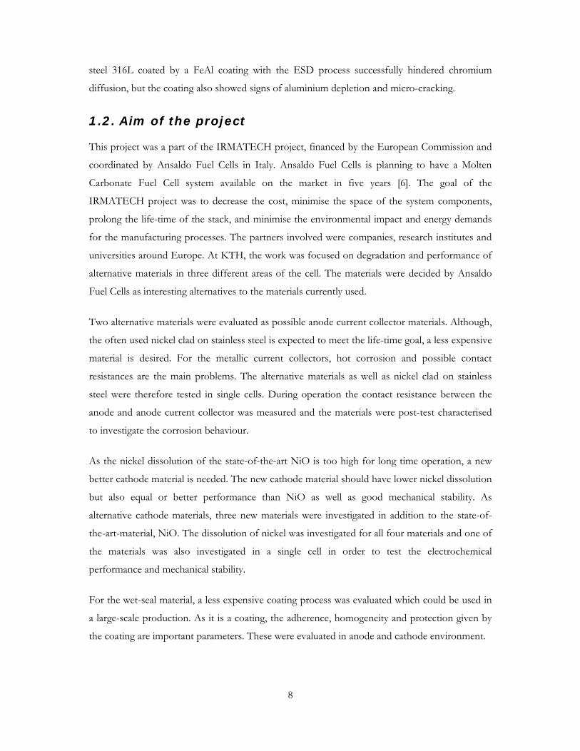
2. EXPERIMENTAL
2.1. Testing Procedures
2.1.1. Single cell tests
A single cell consists of an anode, a cathode and electrolyte in between. It is connected to a load
by current collectors, often in lab-scale size. The advantage is a better control of temperature and
gas composition to a lower cost than operating in a real stack, which consists of several cells
stacked together. The experimental setup of the single cell used is shown in Figure 2.
A circular 3 cm2 lab-scale MCFC was used in the single cell tests performed. The anode was a
nickel anode stabilised by chromium, the electrolyte was (Li0.62K0.38)2CO3 and the matrix
consisted of LiAlO2. After the cell was assembled, it was heated in two steps to 580 °C in
nitrogen atmosphere. Thereafter the gases were changed to anode (16 % CO2, 64 % H2 and
20 % H2O) and cathode gas (14 % O2, 4 % H2O, 29 % CO2 and 53 % N2), with the gas flows
perpendicular to the cell. Two weights with a total weight of 2 kg were put on top of the cell and
the cell was heated to 650 °C. The cell was operated at atmospheric pressure, and the gas flows
were 113 ml min-1 (dry gas) at the cathode side and 109 ml min-1 (dry gas) at the anode side.
During measurements the anode and cathode gas flows were increased to 186 ml min-1 (dry gas)
and 150 ml min-1 (dry gas), respectively, which resulted in a low utilisation, and avoided reactant
Anode
Matrix and electrolyte
Cathode
Anode current collector
Cathode current collector
Reference electrode
Anode current collector probe
Cathode current collector probe
Fuel gas
Oxidant gas
Figure 2 Experimental setup for single cell test

10
depletion. In the cell setup there was also the possibility to use reference electrodes, which could
separate the anode and cathode losses. As reference electrode, a gold wire in contact with the
melt was used, as seen in Figure 2. The environment for the reference electrode was 33 % O2
and 67 % CO2 and the gas flow was 20 ml min-1. The cell setup enabled carbonate additions
during the experiment and small pieces of carbonate (6 - 12 mg) were added on top of the anode
current collector. Since the polarisation of the electrodes varies with the electrolyte fill level [20],
carbonate was added so that the cell polarisation was minimised throughout the experiments. All
cells were operated under load, at a current density of 1600 A m-2, if not mentioned otherwise.
Polarisation curves were collected continuously with a Solartron 1286 or a Solartron 1287
(Solartron Instruments) controlled by MATLAB® Instrument Control Toolbox.
Anode current collector tests
In total, three materials were evaluated as anode current collector materials. One of them was
considered as a reference material, namely nickel clad on stainless steel (Ni-clad). The other two
materials were a high nickel, high chromium alloy, stabilised by yttrium and aluminium, hereafter
called Alloy A, and a commercial high temperature alloy with other additives, called Alloy B. The
anode current collector discs were cut out from a sheet of material and 18 gas holes (Ø 2.2 mm)
were drilled, except in the case of nickel clad on stainless steel, where one of the anode current
collector discs was made by laser. The anode current collector disc was then attached to the tube
by a rivet. Before assembling the cell, the anode current collectors were polished with SiC
abrasive papers (at least #1200), washed with pure water and acetone and thereafter dried. In
order not to destroy the thin layer of nickel clad onto the stainless steel, the anode current
collectors made of Ni-clad were not polished.
To investigate the contact resistance between the anode and the anode current collector, a gold
wire had to be inserted in the anode current collector, as seen in Figure 3. The setup was similar
to that used in the measurements of the contact resistance of the cathode current collector [24]
earlier performed in the group. The gold wire was insulated from the anode current collector
tube by a thin alumina tube. Holes were drilled in the anode current collector tube to ensure that
the gold wire encountered the same gas environment as the anode current collector. The voltage
drop between the anode and the anode current collector was measured while increasing the
current density. The resistance was thereby given by Ohm’s law. The evolution of the voltage
drop and resistance versus time was evaluated. After the cell was shut down, the anode current
collector, anode and matrix were put in Epoxy, cut and polished with ethanol for later post-test
11
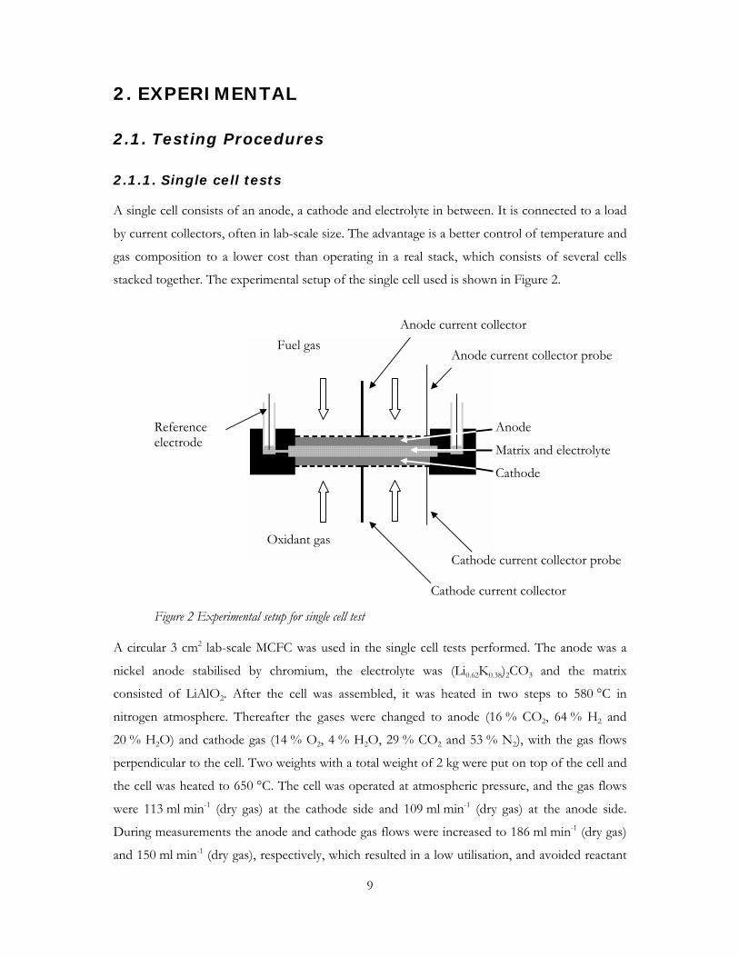
characterisation in Scanning Electron Microscope (SEM) equipped with Energy Dispersive
Spectrometer (EDS).
Cathode tests
To investigate the cathode performance of the new Ni(Mg,Fe)O cathode material, single cells
were operated with NiO and Ni(Mg,Fe)O. One cell was operated with Ni(Mg,Fe)O for 2000 h
and compared with the performance of the state-of-the-art NiO operated for 1500 h and 2064 h.
The cathodes had a diameter of 19 mm and were cut from a sheet of porous cathode. The
thickness of the sheets were 0.54 mm and 0.52 mm for Ni(Mg,Fe)O and NiO, respectively.
The performance of the cathode was investigated both by polarisation curves of the cathode
itself and by cell polarisation curves. The cell polarisation curves were iR corrected with the
current-interrupt method. After shutdown of the cell, the cathode was leached in 50 vol% acetic
acid and thereafter washed in pure water.
2.1.2. Dissolution tests
Three new materials were tested in addition to the state-of-the-art material NiO. The materials
were; the mixed oxide material Ni(Mg,Fe)O, a nickel cathode coated with lithium cobaltite that
was doped with magnesium oxide, hereafter called NiCoMg and a partially oxidised nickel
cathode coated with lithium cobaltite doped with magnesium oxide, hereafter called NiOCoMg.
The cathode pieces of the two latter materials were coated on all sides to avoid any contact with
un-coated cathode material.
The dissolution tests were performed in MCFC cathode environment with increased carbon
dioxide pressure, in order to increase the equilibrium concentration of nickel and cobalt. The
increased carbon dioxide pressure should cause a more acidic melt and thereby increase the
solubility of nickel [9, 10] and cobalt [23]. The solubility of nickel and cobalt also depends on the
Probe (Anode)Probe (Anode Current Collector)
Anode
Figure 3 Probe in contact with the anode for measurements of the resistance of the oxide layer of the anode current collector
12
melt basicity with (Li0.70K0.30)2CO3 having a higher basicity than (Li0.62K0.38)2CO3. The dissolution
tests were therefore performed in both (Li0.62K0.38)2CO3 and (Li0.70K0.30)2CO3, where nickel and
cobalt oxides should have a lower solubility in the latter melt composition [9, 10, 23].
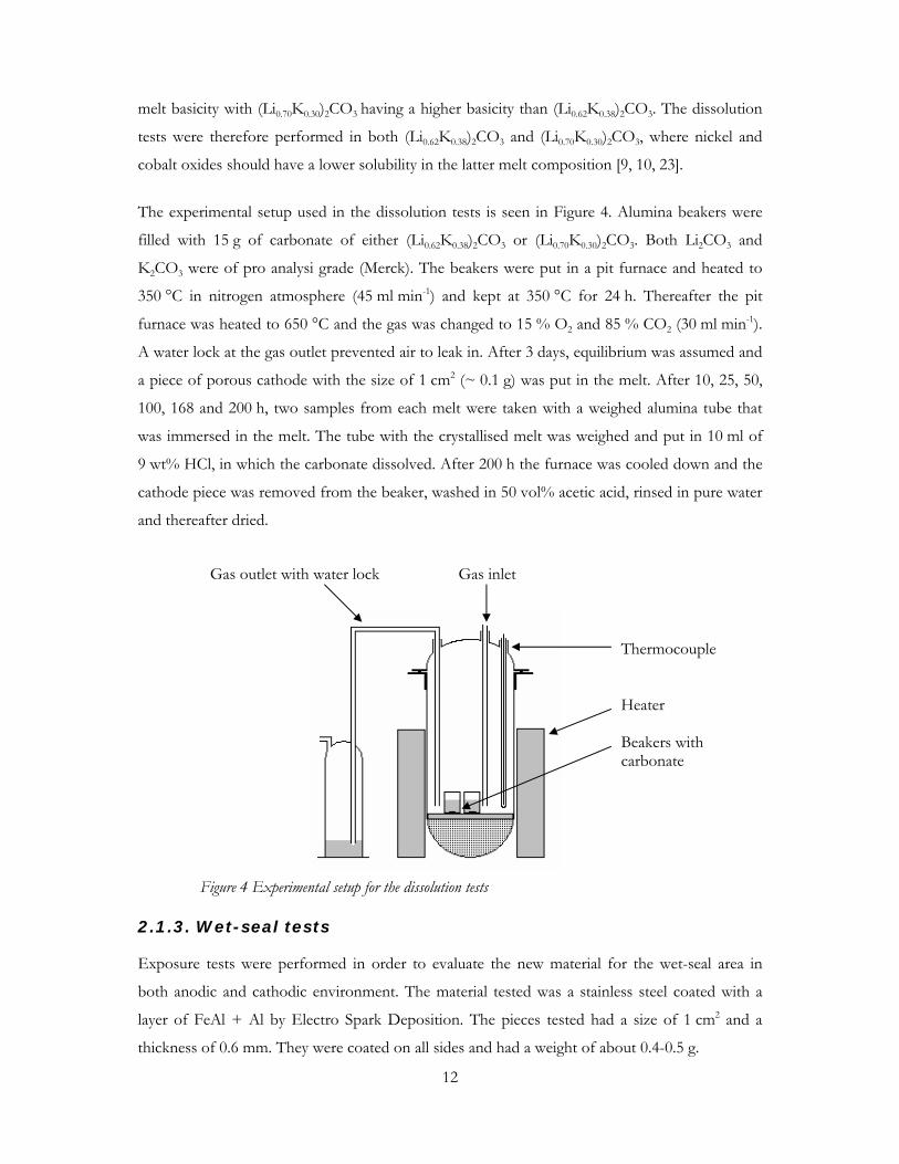
The experimental setup used in the dissolution tests is seen in Figure 4. Alumina beakers were
filled with 15 g of carbonate of either (Li0.62K0.38)2CO3 or (Li0.70K0.30)2CO3. Both Li2CO3 and
K2CO3 were of pro analysi grade (Merck). The beakers were put in a pit furnace and heated to
350 °C in nitrogen atmosphere (45 ml min-1) and kept at 350 °C for 24 h. Thereafter the pit
furnace was heated to 650 °C and the gas was changed to 15 % O2 and 85 % CO2 (30 ml min-1).
A water lock at the gas outlet prevented air to leak in. After 3 days, equilibrium was assumed and
a piece of porous cathode with the size of 1 cm2 (~ 0.1 g) was put in the melt. After 10, 25, 50,
100, 168 and 200 h, two samples from each melt were taken with a weighed alumina tube that
was immersed in the melt. The tube with the crystallised melt was weighed and put in 10 ml of
9 wt% HCl, in which the carbonate dissolved. After 200 h the furnace was cooled down and the
cathode piece was removed from the beaker, washed in 50 vol% acetic acid, rinsed in pure water
and thereafter dried.
2.1.3. Wet-seal tests
Exposure tests were performed in order to evaluate the new material for the wet-seal area in
both anodic and cathodic environment. The material tested was a stainless steel coated with a
layer of FeAl + Al by Electro Spark Deposition. The pieces tested had a size of 1 cm2 and a
thickness of 0.6 mm. They were coated on all sides and had a weight of about 0.4-0.5 g.
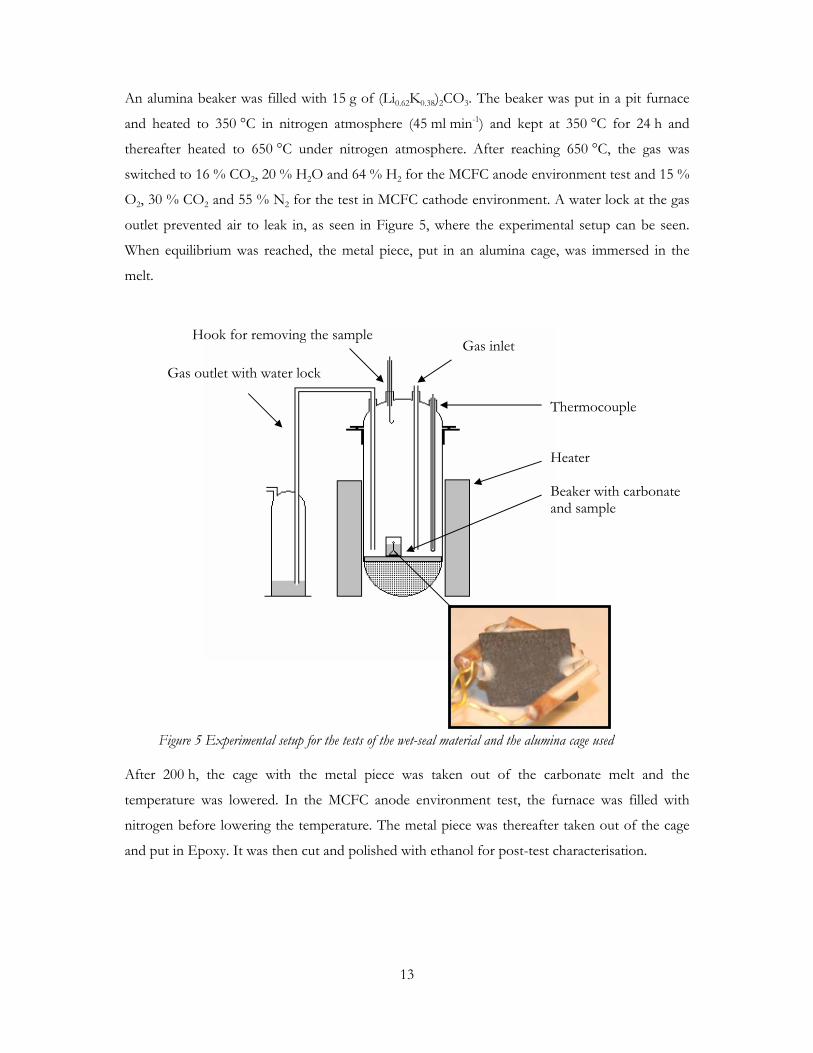
Thermocouple Heater Beakers with carbonate
Gas outlet with water lock Gas inlet
Figure 4 Experimental setup for the dissolution tests
13
An alumina beaker was filled with 15 g of (Li0.62K0.38)2CO3. The beaker was put in a pit furnace
and heated to 350 °C in nitrogen atmosphere (45 ml min-1) and kept at 350 °C for 24 h and
thereafter heated to 650 °C under nitrogen atmosphere. After reaching 650 °C, the gas was
switched to 16 % CO2, 20 % H2O and 64 % H2 for the MCFC anode environment test and 15 %
O2, 30 % CO2 and 55 % N2 for the test in MCFC cathode environment. A water lock at the gas
outlet prevented air to leak in, as seen in Figure 5, where the experimental setup can be seen.
When equilibrium was reached, the metal piece, put in an alumina cage, was immersed in the
melt.
After 200 h, the cage with the metal piece was taken out of the carbonate melt and the
temperature was lowered. In the MCFC anode environment test, the furnace was filled with
nitrogen before lowering the temperature. The metal piece was thereafter taken out of the cage
and put in Epoxy. It was then cut and polished with ethanol for post-test characterisation.
Thermocouple Heater Beaker with carbonate and sample
Gas outlet with water lock
Gas inletHook for removing the sample
Figure 5 Experimental setup for the tests of the wet-seal material and the alumina cage used

14
2.2. Post-test analysis methods
2.2.1. Scanning Electron Microscope (SEM)
SEM is a method for analysing the morphology and composition of an object. The principle
resembles that of the light optical microscope, but instead of light an electron beam is used. The
electron beam is focused by magnetic fields instead of ordinary lenses and interacts with the
atoms of the specimen. There are different types of interactions which enables both
morphological and compositional analyses. Furthermore, the SEM can be connected to an
Energy Dispersive Spectrometer (EDS), which analyses the energy of the produced X-rays from
the interactions to give a chemical composition of the specimen. The EDS used in this study
could detect elements heavier than lithium.
SEM and EDS were frequently used as post-test analysis methods. Table 1 lists the occasions
when SEM and EDS were used. The SEM for the study was a JEOL JSM-840 equipped with
EDS. The SEM and EDS analyses were performed at the Department of Material Science, KTH,
Stockholm.
Table 1 SEM and EDS analyses performed Type of
SEM analysis
After On To study
SEM and EDS Single cell test Anode and anode
current collector
Oxide layer, morphology and
composition
SEM Single cell test Cathode Morphology changes
SEM Dissolution test Cathode Morphology changes
SEM and EDS Single cell test Matrix Nickel precipitation
SEM and EDS Wet seal test Wet seal material Adherence of the coating,
morphology and composition
2.2.2. Inductively Coupled Plasma – Optic Emission Spectroscopy
(ICP-OES)
The ICP-OES analysis is a method for analysing small quantities (often < µg l-1) of elements.
The ICP atomises the sample, and then excites the electrons of the atoms. When the electrons
relax, they emit light in the UV-Vis spectrum, each element having its own combination of
15
wavelengths. The intensity of the wavelength is related to the concentration of the element in the
sample. By detecting the wavelength and intensity, the concentration of the element can
therefore be determined. The detection can be done with a CCD detector, which is able to detect
the intensity of many lines simultaneously, which is done in the case of OES.
Since the instrument detects the intensity of the light emitted, standard solutions have to be
prepared, relating the intensity to a concentration. The standard solutions have consisted of
commercial standard solutions (Ultra Scientific) with original concentrations of 1000 mg l-1 that
were diluted in 9 wt% HCl.
When small quantities of an element are to be detected, there is also an increased risk of noise
from possible contaminations, coming from the chemicals used and from the experiment. The
chemicals used were of pro analysi grade, but some trace contaminations were reported, as seen
in Table 2.
Table 2 Maximum contamination of chemicals used in dissolution tests Chemical Nickel Cobalt Iron Magnesium
Li2CO3 (PA, Merck) - - 0.001 wt% 0.001 wt%
K2CO3 (PA, Merck) - - 0.0005 wt% 0.001 wt%
HCl 37 wt% (PA, Merck) 0.02 ppm 0.01 ppm 0.1 ppm 0.05 ppm
ICP-OES (Varian Vista AX) was used for detection of the dissolved nickel, cobalt, iron and
magnesium in the melt after the dissolution tests. Mean values of the detected lines for each
element was used. In addition, lithium was analysed for a precise detection of the number of
moles of (Li0.62K0.38)2CO3, to calculate the molar fractions of metal ions in the melt. This fraction
was calculated according to Eq. 1.
MeLimass
LiMemass
sampleLimol
sampleMemol
Li
Me
COKLi
MeMe Mc
MycVc
yVcn
ynn
nXyy
⋅⋅⋅⋅
=⋅
⋅⋅⋅=
⋅⋅==
− ,
,
,
,
)(
222
32)1(
Eq. 1
Here, the subscript Me refers to one of the metals nickel, cobalt, magnesium or iron and y is the
fraction of lithium carbonate (0.62 or 0.7). Furthermore cmol is the molar concentration and cmass
the concentration by weight. Vsample is the volume of the sample, n the number of moles and M
the molar weight of the element.
16
ICP-OES analyses were performed at the Department for Geology and Geochemistry,
Stockholm University, Stockholm.
2.2.3. Light optical microscope
The nickel precipitation in the matrix was also investigated in a light optical stereo microscope
(WILD Makroskop M420) connected to a digital camera (Leica DFC280). The magnification of
this equipment was enough to identify where in the matrix nickel precipitation had taken place.
The analyses were performed at the Department of Material Science, KTH, Stockholm.
17
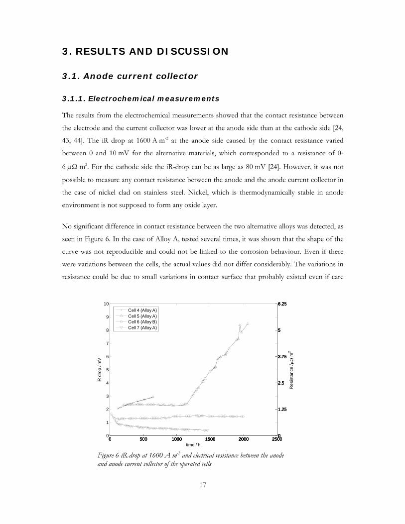
3. RESULTS AND DISCUSSION
3.1. Anode current collector
3.1.1. Electrochemical measurements
The results from the electrochemical measurements showed that the contact resistance between
the electrode and the current collector was lower at the anode side than at the cathode side [24,
43, 44]. The iR drop at 1600 A m-2 at the anode side caused by the contact resistance varied
between 0 and 10 mV for the alternative materials, which corresponded to a resistance of 0-
6 µΩ m2. For the cathode side the iR-drop can be as large as 80 mV [24]. However, it was not
possible to measure any contact resistance between the anode and the anode current collector in
the case of nickel clad on stainless steel. Nickel, which is thermodynamically stable in anode
environment is not supposed to form any oxide layer.
No significant difference in contact resistance between the two alternative alloys was detected, as
seen in Figure 6. In the case of Alloy A, tested several times, it was shown that the shape of the
curve was not reproducible and could not be linked to the corrosion behaviour. Even if there
were variations between the cells, the actual values did not differ considerably. The variations in
resistance could be due to small variations in contact surface that probably existed even if care
0 500 1000 1500 2000 25000
1
2
3
4
5
6
7
8
9
10
iR d
rop
/ mV
time / h0 500 1000 1500 2000 2500
0
1.25
2.5
3.75
5
6.25
Res
ista
nce
/ µΩ
m2
0 500 1000 1500 2000 25000
1.25
2.5
3.75
5
6.25
0 500 1000 1500 2000 25000
1.25
2.5
3.75
5
6.25
0 500 1000 1500 2000 25000
1.25
2.5
3.75
5
6.25Cell 4 (Alloy A)Cell 5 (Alloy A)Cell 6 (Alloy B)Cell 7 (Alloy A)
Figure 6 iR-drop at 1600 A m-2 and electrical resistance between the anode and anode current collector of the operated cells

18
was taken when polishing the anode current collectors and when assembling the cell. Moreover,
the growth of the oxide layer could have affected the contact surface during operation. This
would affect the current distribution in the anode current collector and cause small variations in
the contact resistance.
3.1.2. Post-test analyses
For nickel clad on stainless steel, no oxide scale was present on the nickel layer. Some iron and
chromium had diffused into the nickel layer as seen in Figure 7. This phenomenon was also
observed by Yuh et al. [45].
The manufacturing process of the circular anode current collector was shown to be an important
factor. By drilling the gas holes in the anode current collector, the nickel layer was exposed to a
mechanical stress that during operation caused the nickel layer to detach from the stainless steel.
A crevice was formed that expanded during operation. The post-test analysis showed that the
crevice contained chromium oxide. It was probably LiCrO2, since the ratio between chromium
and oxygen was 1:2 and LiCrO2 is the chromium oxide expected in MCFC anode environment
[46]. In the chromium oxide, small islands enriched in nickel were also found. The crevice is seen
as a darker triangle in Figure 8a. When making the gas holes with laser this crevice was not
found, but instead a small cap of chromium oxides was formed, as seen in Figure 8b.
0
20
40
60
80
100
120
0 0,2 0,4 0,6 0,8 1 1,2 1,4 1,6 1,8
Relative distance
At%
CrFeNi
Figure 7 Diffusion profile of chromium and iron in the nickel layer from the cell operated for 724 h at 650 ºC at a relative distance, where 0 is the surface of the anode current collector and 1 is at the interface nickel – stainless steel

19
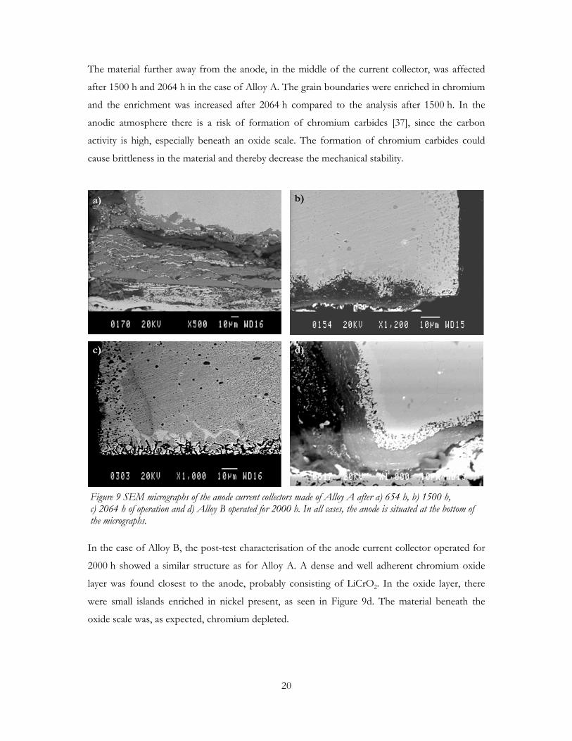
SEM and EDS analysis of the cells operated with Alloy A showed that the material had
corroded. Figure 9 shows SEM micrographs of the current collectors near a gas hole, after 654 h
(Figure 9a), 1500 h (Figure 9b) and 2064 h (Figure 9c) of operation. After 654 h, the formed
chromium oxide layer was shown to be non-adherent. It had fallen off and carbonates were
found between the oxide layers. New chromium oxides were formed at the current collector and
the material beneath the oxide scale was chromium depleted. The chromium oxide found was
probably LiCrO2. As in the case of the corroded crevice of Ni-clad, small islands enriched in
nickel were present in the layers of chromium oxide. Post-test analyses from the anode current
collectors operated for 1500 h and 2064 h (Figure 9b and 9c) showed that the part of the current
collectors closest to the anode, (in Figure 9 seen as the lower part of the micrographs) consisted
of a well adherent chromium oxide layer, best seen in Figure 9b, but also present at some places
after 2064 h. As mentioned in paper 1, this was not detected in the first place, but required re-
cutting and further post-test analysis of the anode current collector. The structure of the
chromium oxide layer was similar to that seen after 654 h, with islands enriched in nickel present,
in Figure 9b seen as brighter stripes. Also in this case, the ratio between chromium and oxygen
was 1:2. Beneath this chromium oxide layer, the composition varied between the points of
analysis.
a) b)
Figure 8 Comparison between current collectors made of nickel clad on stainless steel, with holes made by a) drill and b) laser after 368 h and 724 h, respectively. The nickel layer is seen in the lower part of the figure.
a) b)
20
The material further away from the anode, in the middle of the current collector, was affected
after 1500 h and 2064 h in the case of Alloy A. The grain boundaries were enriched in chromium
and the enrichment was increased after 2064 h compared to the analysis after 1500 h. In the
anodic atmosphere there is a risk of formation of chromium carbides [37], since the carbon
activity is high, especially beneath an oxide scale. The formation of chromium carbides could
cause brittleness in the material and thereby decrease the mechanical stability.
In the case of Alloy B, the post-test characterisation of the anode current collector operated for
2000 h showed a similar structure as for Alloy A. A dense and well adherent chromium oxide
layer was found closest to the anode, probably consisting of LiCrO2. In the oxide layer, there
were small islands enriched in nickel present, as seen in Figure 9d. The material beneath the
oxide scale was, as expected, chromium depleted.
a) b)
c) d)
Figure 9 SEM micrographs of the anode current collectors made of Alloy A after a) 654 h, b) 1500 h, c) 2064 h of operation and d) Alloy B operated for 2000 h. In all cases, the anode is situated at the bottom of the micrographs.

21
Figure 10a shows a magnified picture of the middle of the current collector, further away from
the anode. The grain boundaries were slightly enriched in chromium as seen in Figure 10c, where
element mapping of chromium of the area seen in Figure 10a has been performed. Alloy B
contained additions of an element, known for its ability to prevent chromium carbide formation.
This element was gathered in spots instead of evenly spread in the grain boundaries as seen in
Figure 10b, where element mapping of the additive is shown. This concludes that the small
additions of elements do not prevent chromium enrichment in the grain boundaries completely.
However, a comparison between the chromium content in the grain boundaries of Alloy A and
the chromium content in the grain boundaries of Alloy B, both operated around 2000 h, showed
that chromium was enriched to a larger extent in the case of Alloy A, concluding that the
additive in Alloy B has a positive effect.
It should be noted, that the purpose of this study has been to evaluate these materials in single
cells as real anode current collectors, not to predict the corrosion mechanisms. Prediction of
corrosion mechanisms is preferably done by experiments with a limited amount of parameters,
which are carefully controlled.
3.2. Cathode
3.2.1. Dissolution tests
The dissolution of nickel for the NiO cathode was around 8⋅10-6 mol Ni / mol CO32- in the case
of (Li0.62K0.38)2CO3 and around 5⋅10-6 mol Ni / mol CO32- in the case of (Li0.70K0.30)2CO3 when
operating at 650 ºC with a carbon dioxide pressure of 0.85 atm. The nickel content versus time
can be seen in Figure 11. For the Ni(Mg,Fe)O cathode the nickel dissolution was lower, around
1⋅10-6 mol Ni / mol CO32- for both melt compositions. This is probably due to the stabilising
effect of magnesium and iron on the nickel cathode. However, magnesium was also found in the
a) b) c)
Figure 10 Grain boundary in the anode current collector made of Alloy B operated for 2000 h. a) SEM micrograph b) element mapping of the additive c) element mapping of chromium.

22
melt; with a molar fraction of approximately 800⋅10-6 mol Mg / mol CO32- for (Li0.62K0.38)2CO3
and 500⋅10-6 mol Mg / mol CO32- for (Li0.70K0.30)2CO3. As shown in the work by Mitsushima et al.
[36], additions of MgO both to the melt and the cathode resulted in low dissolution of nickel.
The low dissolution of the Ni(Mg,Fe)O cathode presented here may be a synergy effect of the
magnesium present in the melt and the stabilisation by magnesium of the cathode. The
dissolution of iron in the case of Ni(Mg,Fe)O was lower than the impurity in the pure lithium
and potassium carbonate used.
The two coated cathode materials had a comparable solubility of nickel to that of the state-of-
the-art nickel oxide as seen in Figure 11. The solubility of cobalt of both materials was found to
be between 0.5 and 2⋅10-6 mol Co / mol CO32- for the two melt compositions, as seen in Figure
12. Lada et al. that also tested Ni and NiO coated by LiCoO2 doped with MgO [32] found that
the nickel and cobalt solubilities were below their detection limit for both materials.
For both nickel and cobalt the solubility was lower in the (Li0.70K0.30)2CO3 melt than in the
(Li0.62K0.38)2CO3, which is a result in agreement with literature [3-5]. The higher basicity of lithium
causes a more basic melt in the case of (Li0.70K0.30)2CO3 than in the case of (Li0.62K0.38)2CO3.
Figure 11 Dissolution of nickel for the four types of cathodes tested. The temperature was 650 ºC and the carbon dioxide pressure 0.85 atm.
0,0
2,0
4,0
6,0
8,0
10,0
12,0
14,0
0 50 100 150 200
time / h
X Ni*1
e6 (M
olar
frac
tion) NiOCoMg 70/30
NiOCoMg 62/38
NiCoMg 70/30
NiCoMg 62/38
Ni(Mg,Fe)O 70/30
Ni(Mg,Fe)O 62/38
NiO 70/30
NiO 62/38

23
3.2.2. Single cell tests
From the results of the cathode polarisation curves, it was shown that the performance of the
new Ni(Mg,Fe)O cathode material was comparable to that of NiO. In Figure 13 the total
polarisation of both the cathodes at 1600 A m-2 is shown, including both the cathode
overpotential and the ohmic losses. The total polarisation of Ni(Mg,Fe)O was stable during time,
at a value of 120 mV versus the reference electrode, at 1600 A m-2.
Figure 12 Dissolution of cobalt for the two types of coated cathodes tested. The temperature was 650 ºC and the carbon dioxide pressure 0.85 atm
0,0
0,5
1,0
1,5
2,0
2,5
3,0
3,5
4,0
0 50 100 150 200
time / h
X Co*
1e6
(Mol
ar fr
actio
n)NiOCoMg 70/30NiOCoMg 62/38NiCoMg 70/30NiCoMg 62/38
Figure 13 Total polarisation (both overpotential and ohmic loss) of the cathode versus the reference at 1600 A m-2 of NiO and Ni(Mg,Fe)O
0 500 1000 1500 20000.08
0.1
0.12
0.14
0.16
0.18
0.2
0.22
time / h
E /
V
Ni(Mg, Fe)ONiO

24
By comparing the polarisation of both cells, as shown in Figure 14, it could be concluded that
the difference in overpotential was 25 mV. The cell operated with Ni(Mg,Fe)O had a larger total
overpotential than the cell operated with NiO. The total overpotential was defined as the sum of
the anodic and cathodic overpotential. The difference was therefore not necessarily only due to
the new cathode material, since the overpotential was the sum of both the anode and cathode
overpotential and partially could have depended on a variation between the anodes. One should
also consider that Ni(Mg,Fe)O is a new cathode material and further optimisation of the material
should be done, nevertheless these results showed that the material is an interesting alternative
cathode material.
When post-test characterising the Ni(Mg,Fe)O cathode it appeared that the material had a
tendency to sinter during operation. A comparison between operated and un-operated material is
shown in Figure 15. However, this possible sintering did not affect the performance to a large
extent since the polarisation of the cathode was almost constant during the 2000 h of operation,
as seen in Figure 13. Further investigations are however necessary, since a continuous sintering
would decrease the surface available for reactions in the electrode.
Figure 14 Cell polarisation curves of NiO and Ni(Mg,Fe)O after 843 h and 840 h respectively. T = 650 °C
0 500 1000 1500 2000 2500 3000 3500 4000 45000
0.05
0.1
0.15
0.2
0.25
0.3
0.35
0.4
0.45
0.5
i / Am-2
E /
V
Ni(Mg,Fe)O incl. ohmic lossesNi(Mg,Fe)O excl. ohmic lossesNiO excl. ohmic lossesNiO incl. ohmic losses

25
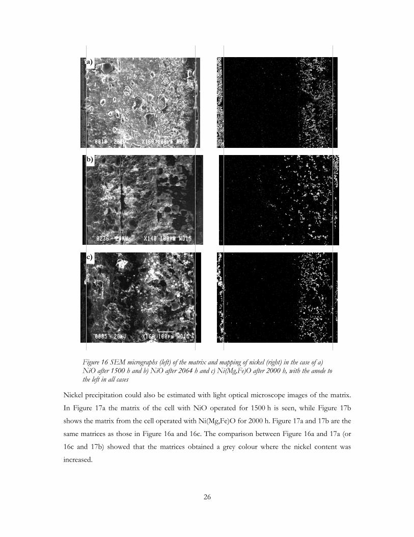
An investigation of the matrices showed that nickel was precipitated in the matrix, both when
operating with a Ni(Mg,Fe)O cathode and when operating with NiO. However, the nickel
precipitation rate seemed to be lower in the case of Ni(Mg,Fe)O. Figure 16 shows SEM
micrographs to the left, and element mapping of nickel in the matrices to the right for
Ni(Mg,Fe)O operated for 2000 h (Figure 16c), compared with NiO operated for 1500 h (Figure
16a) and NiO operated for 2064 h (Figure 16b).
The comparison between the two materials showed that the precipitated nickel had reached
closer to the anode in the case of NiO than in the case of Ni(Mg,Fe)O although they had a
similar operation time. However, the “nickel front” moves very slowly, as seen when comparing
the two matrices from cells operated with NiO for 1500 h and 2064 h, and experiments with
longer operation times should be performed to confirm these indications. As Yoshioka et al.
suggested [11] a decreased solubility of nickel would decrease the nickel precipitation rate and
thereby increase the time to short circuiting.
Figure 15 SEM micrographs of Ni(Mg,Fe)O before (left) and after 2000 h of operation (right)
26
Nickel precipitation could also be estimated with light optical microscope images of the matrix.
In Figure 17a the matrix of the cell with NiO operated for 1500 h is seen, while Figure 17b
shows the matrix from the cell operated with Ni(Mg,Fe)O for 2000 h. Figure 17a and 17b are the
same matrices as those in Figure 16a and 16c. The comparison between Figure 16a and 17a (or
16c and 17b) showed that the matrices obtained a grey colour where the nickel content was
increased.
a)
b)
c)
Figure 16 SEM micrographs (left) of the matrix and mapping of nickel (right) in the case of a) NiO after 1500 h and b) NiO after 2064 h and c) Ni(Mg,Fe)O after 2000 h, with the anode to the left in all cases
27
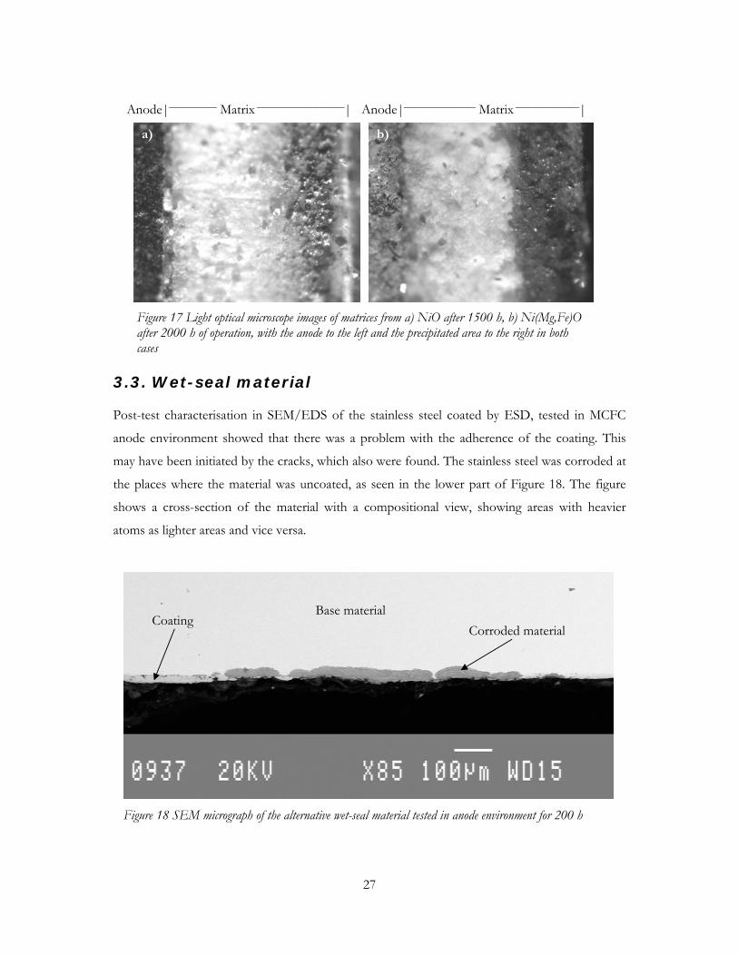
3.3. Wet-seal material
Post-test characterisation in SEM/EDS of the stainless steel coated by ESD, tested in MCFC
anode environment showed that there was a problem with the adherence of the coating. This
may have been initiated by the cracks, which also were found. The stainless steel was corroded at
the places where the material was uncoated, as seen in the lower part of Figure 18. The figure
shows a cross-section of the material with a compositional view, showing areas with heavier
atoms as lighter areas and vice versa.
Base materialCorroded material
Coating
Figure 18 SEM micrograph of the alternative wet-seal material tested in anode environment for 200 h
Figure 17 Light optical microscope images of matrices from a) NiO after 1500 h, b) Ni(Mg,Fe)O after 2000 h of operation, with the anode to the left and the precipitated area to the right in both cases
Anode|____________ Matrix ______________________| Anode|__________________ Matrix ________________|
a) b)
28
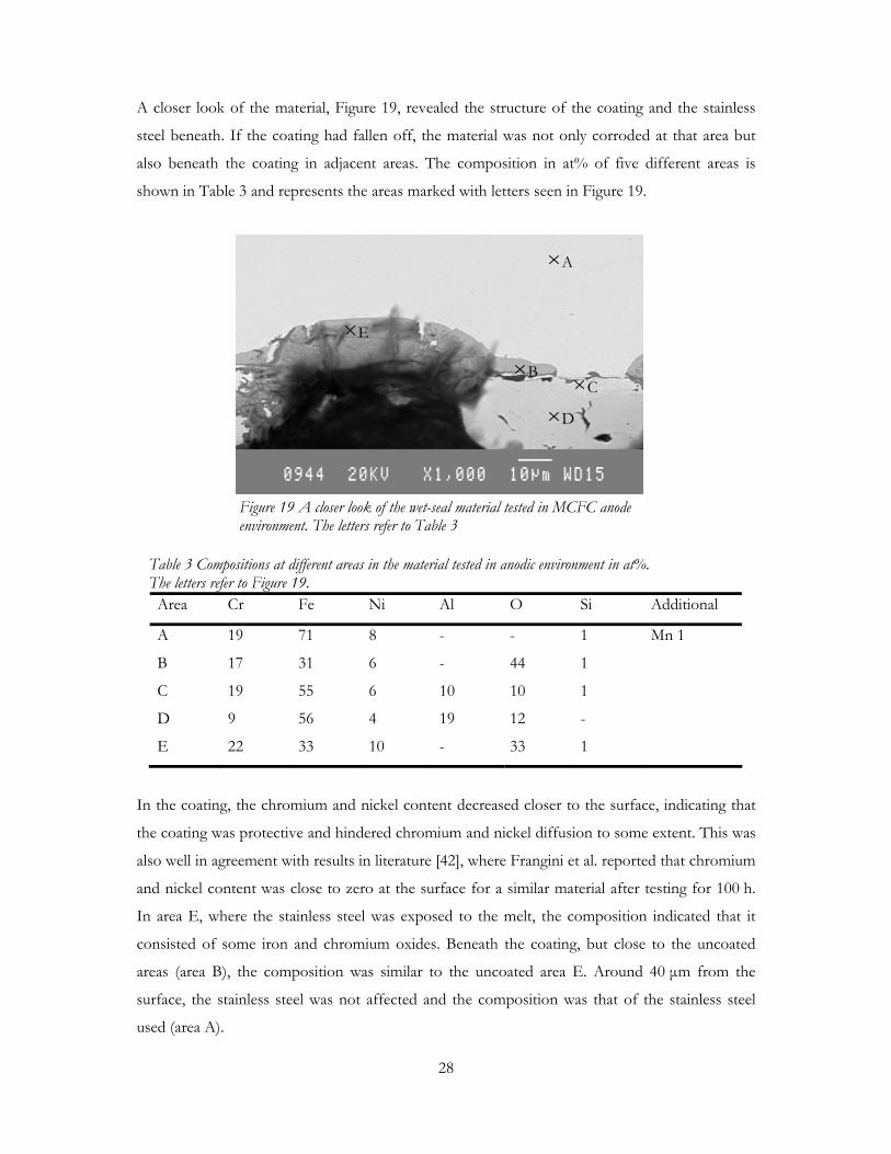
A closer look of the material, Figure 19, revealed the structure of the coating and the stainless
steel beneath. If the coating had fallen off, the material was not only corroded at that area but
also beneath the coating in adjacent areas. The composition in at% of five different areas is
shown in Table 3 and represents the areas marked with letters seen in Figure 19.
Table 3 Compositions at different areas in the material tested in anodic environment in at%. The letters refer to Figure 19.
Area Cr Fe Ni Al O Si Additional
A 19 71 8 - - 1 Mn 1
B 17 31 6 - 44 1
C 19 55 6 10 10 1
D 9 56 4 19 12 -
E 22 33 10 - 33 1
In the coating, the chromium and nickel content decreased closer to the surface, indicating that
the coating was protective and hindered chromium and nickel diffusion to some extent. This was
also well in agreement with results in literature [42], where Frangini et al. reported that chromium
and nickel content was close to zero at the surface for a similar material after testing for 100 h.
In area E, where the stainless steel was exposed to the melt, the composition indicated that it
consisted of some iron and chromium oxides. Beneath the coating, but close to the uncoated
areas (area B), the composition was similar to the uncoated area E. Around 40 µm from the
surface, the stainless steel was not affected and the composition was that of the stainless steel
used (area A).
A
BC
D
E
Figure 19 A closer look of the wet-seal material tested in MCFC anode environment. The letters refer to Table 3
29
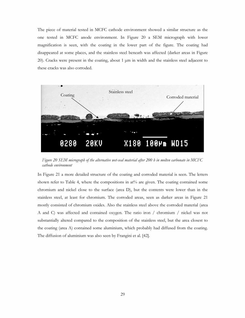
The piece of material tested in MCFC cathode environment showed a similar structure as the
one tested in MCFC anode environment. In Figure 20 a SEM micrograph with lower
magnification is seen, with the coating in the lower part of the figure. The coating had
disappeared at some places, and the stainless steel beneath was affected (darker areas in Figure
20). Cracks were present in the coating, about 1 µm in width and the stainless steel adjacent to
these cracks was also corroded.
In Figure 21 a more detailed structure of the coating and corroded material is seen. The letters
shown refer to Table 4, where the compositions in at% are given. The coating contained some
chromium and nickel close to the surface (area D), but the contents were lower than in the
stainless steel, at least for chromium. The corroded areas, seen as darker areas in Figure 21
mostly consisted of chromium oxides. Also the stainless steel above the corroded material (area
A and C) was affected and contained oxygen. The ratio iron / chromium / nickel was not
substantially altered compared to the composition of the stainless steel, but the area closest to
the coating (area A) contained some aluminium, which probably had diffused from the coating.
The diffusion of aluminium was also seen by Frangini et al. [42].
Stainless steelCoating Corroded material
Figure 20 SEM micrograph of the alternative wet-seal material after 200 h in molten carbonate in MCFC cathode environment
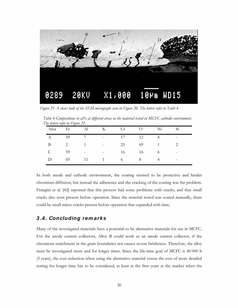
30
Table 4 Compositions in at% at different areas in the material tested in MCFC cathodic environment. The letters refer to Figure 21.
Area Fe Al K Cr O Ni Si
A 59 7 - 17 12 4 -
B 2 1 - 25 69 1 2
C 59 - - 16 16 6 -
D 69 11 1 6 8 4 -
In both anode and cathode environment, the coating seemed to be protective and hinder
chromium diffusion, but instead the adherence and the cracking of the coating was the problem.
Frangini et al. [42] reported that this process had some problems with cracks, and that small
cracks also were present before operation. Since the material tested was coated manually, there
could be small micro cracks present before operation that expanded with time.
3.4. Concluding remarks
Many of the investigated materials have a potential to be alternative materials for use in MCFC.
For the anode current collectors, Alloy B could work as an anode current collector, if the
chromium enrichment in the grain boundaries not causes severe brittleness. Therefore, the alloy
must be investigated more and for longer times. Since the life-time goal of MCFC is 40 000 h
(5 years), the cost reduction when using the alternative material versus the cost of more detailed
testing for longer time has to be considered, at least at the first years at the market when the
A
B D
C
Figure 21 A closer look of the SEM micrograph seen in Figure 20. The letters refer to Table 4

31
production volumes are going to be rather small. Ni-clad is, as already mentioned, predicted to
manage 5 years.
In the case of the cathode material, the situation is different. The nickel dissolution of the
cathode and precipitation of nickel in the matrix is one of the life-time limiting factors for
MCFC. Ni(Mg,Fe)O has shown to have a lower dissolution and an comparable electrochemical
performance compared to NiO. The possible sintering can be a drawback and should be
investigated more in detail. Investigations for longer times, with different gases and large-scale
cathodes should be performed.
For the wet-seal area, the ESD process is a less expensive alternative compared to other coating
processes. However, the adherence and cracking of the coating when the ESD process is done
manually is a problem. The solution could be an automatic coating process, which probably
would make the coating more homogeneous. If this would cause a more adherent coating with
fewer cracks, the diffusion of chromium and oxygen in the coating should be investigated for
both MCFC anode and cathode environment.

32
4. CONCLUSIONS
4.1. Anode current collector material
Alternative materials to the often used Ni-clad were investigated as anode current collector. The
alloys were operated in a lab-scale MCFC and the contact resistance was measured. Afterwards,
the anode current collectors were investigated in SEM/EDS.
No significant difference could be seen in contact resistance between the two new alloys tested.
The contact resistance between the anode and the anode current collector was smaller than
reported for the cathode side for both the materials tested and is not limiting the use of the new
alloys.
The corrosion behaviour for the alloys was not completely satisfactory. In the case of Alloy A, it
was shown that there is a risk that the formed chromium oxide layer can fall off. Alloy B has not
been tested as much as Alloy A, but showed that a chromium oxide layer was present after
2000 h. In both cases chromium was enriched in the grain boundaries, which in a longer time
perspective could cause mechanical damage of the material.
In the case of Alloy A, the chromium enrichment in the grain boundaries had proceeded further
than in the case of Alloy B. Therefore, Alloy B seems to be a better material than Alloy A.
4.2. Cathode
The solubility of the nickel oxide cathode is a problem for MCFC. Therefore, three alternative
materials were investigated by dissolution tests. One of the materials tested was also investigated
in a lab-scale MCFC.
From the results of the dissolution tests it could be seen that the Ni(Mg,Fe)O cathode had a
remarkably lower equilibrium solubility of nickel than the standard nickel oxide cathode.
The electrochemical performance of the Ni(Mg,Fe)O cathode was comparable to that of NiO.
The results from the investigation of the matrices were indicating that Ni(Mg,Fe)O had a lower
precipitation rate than NiO.

33
4.3. Wet-seal material
For the wet-seal area, a new coating process to coat stainless steel with an aluminium containing
coating was evaluated.
The wet-seal material tested, had some problems with the adherence of the coating. Small cracks
were present in the coating and at some places the coating had disappeared in both anodic and
cathodic environment. The manual coating process can be a reason to the inhomogeneous
coating and may be solved by an automatic coating process.

34
5. ACKNOWLEDGEMENTS
The European Commission is gratefully acknowledged for the financial support and the
possibility to be involved in the IRMATECH project, which opened up the possibility to
cooperate over the national boarders. The partners involved in the project are also acknowledged
for good cooperation.
I would also like to thank Dr. Carina Lagergren, who has been my supervisor during these years.
Her support and believe in me has helped me through these years. Prof. Göran Lindbergh is
gratefully acknowledged for his ideas and opinions about the thesis and experimental details.
Following persons are acknowledged for help during experiments and analysis; Tomas Östberg
and Bo Karlsson in the workshop for manufacturing the anode current collectors, Stephan
Andersson at Keranova for having solutions to every ceramic problem, Lena Smuk for helping
me with SEM /EDS analysis and Magnus Mörth for help with ICP-OES analysis. Thank you.
The colleagues at the division of Applied Electrochemistry have been a great support. Thanks
for always bringing the sunshine when days were grey. I will miss you. A special thanks to those
at the fourth floor for interesting and valuable discussions.
Most of all I would like to thank my family. My mother and father for all support and love
through all years and for sparking my interest in science, Johan for always being my little brother
and a good friend in difficult situations, Kalle and Marianne for all adventures, that kept my
mind focused on the important things in life, and last but certainly not least, Jesper for all love,
support and care.
35
REFERENCES
[1] J.R. Selman, in: L.J.M.J. Blomen and M.N. Mugerwa (Eds.), Fuel Cell Systems, Plenum
Press, New York, (1993), 345-463
[2] J. Hoffman, C.-Y. Yuh and A. Godula Jopek, in: W. Vielstich, H.A. Gasteiger, A. Lamm
(Eds.), Handbook of Fuel Cells – Fundamentals, Technology and Applications, Volume 4:
Fuel Cell Technology and Applications, John Wiley & Sons, Chichester, (2003), 921-941
[3] C.D. Iacovangelo, J. Electrochem. Soc., 133, (1986), 2410-2416
[4] J.-H. Wee, D.-J. Song, C.-H. Jun, T.-H. Lim, S.-A. Hong, H.-C. Lim and K.-Y. Lee,
J. Alloys Compd, 390, (2005), 155-160
[5] M. Bischoff, J. Power Sources, 154, (2006), 461-466
[6] Information from Ansaldo Fuel Cells,
http://www.ansaldofuelcells.com/en/development.htm, 2006-03-20
[7] Information from MTU,
http://www.mtu-friedrichshafen.com/cfc/en/proj/pics/projects.pdf, 2006-03-21
[8] G.H.J. Broers and J.A.A. Ketelaar, in: G.J. Young (Editor), Fuel Cells, Reinhold Publishing
Corporation, New York, (1960), 78-93
[9] K. Ota, S. Mitsushima, S. Kato, S. Asano, H. Yoshitake and N. Kamiya, J. Electrochem.
Soc., 139, (1992), 667-671
[10] J.D. Doyon, T. Gilbert, G. Davies and L. Paetsch, J. Electrochem. Soc., 134, (1987), 3035-
3038
[11] S. Yoshioka and H. Urushibata, J. Electrochem. Soc., 144, (1997), 815-822
[12] M. Yoshikawa, Y. Mugikura, T. Watanabe, T. Kahara and T. Mizukami, J. Electrochem.
Soc., 148, (2001), A1230-A1238
[13] C.E. Baumgartner, R.H. Arendt, C.D. Iacovangelo and B.R. Karas, J. Electrochem. Soc.,
131, (1984), 2217-2221
[14] J.L. Smith, G.H. Kucera and A.P. Brown, in: J.R. Selman, D.A. Shores, H.C. Maru and
I. Uchida (Eds.), Molten Carbonate Fuel Cell Technology, PV 90-16, The Electrochem.
Soc., Inc. Pennington, NJ, (1990), pp. 226-247
[15] D.L. Douglas, in: G.J. Young (Editor), Fuel Cells, Reinhold Publishing Corporation, New
York, (1960), 129-149
[16] J. Soler, T. González, M.J., Escudero, T. Rodrigo and L. Daza, J. Power Sources, 106,
(2002), 189-195

36
[17] B. Huang, F. Li, Q. Yu, G. Chen, B. Zhao and K. Hu, J. Power Sources, 128, (2004), 135-
144
[18] P. Ganesan, H. Colon, B. Haran and B.N. Popov, J. Power Sources, 115, (2003), 12-18
[19] L. Giorgi, A. Moreno, A. Pozio and E. Simonetti, in: I. Uchida, K. Hemmes, G. Lindbergh,
D. Shores and J.R. Selman (Eds.), Carbonate Fuel Cell Technology, PV 99-20, The
Electrochem. Soc., Inc. Pennington, NJ, (1999), pp. 158-170
[20] C. Lagergren, A. Lundblad and B. Bergman, J. Electrochem. Soc. 141, (1994), 2959-2966
[21] L. Plomp, J.B.J. Veldhius, E.F. Sitters and S.B. Van der Molen, J. Power Sources, 39,
(1992), 369-373
[22] L. Giorgi, M. Carewska, M. Patriarca, S. Scaccia, E. Simonetti and A. Di Bartolomeo,
J. Power Sources, 49, (1994), 227-243
[23] K. Ota, Y. Takeishi, H. Yoshitake, N. Kamiya and N. Yamazaki, J. Electrochem. Soc., 142,
(1995), 3322-3326
[24] B. Bergman, C. Lagergren, G. Lindbergh, S. Schwartz and B. Zhu, J. Electrochem. Soc.,
148, (2001), A38-A43
[25] A. Wijayasinghe, B. Bergman and C. Lagergren, J. Electrochem. Soc., 150, (2003), A558-
A564
[26] A. Wijayasinghe, C. Lagergren and B. Bergman, Fuel Cells, 2, (2002), 182-188
[27] A. Wijayasinghe, B. Bergman and C. Lagergren, Solid State Ionics, 177, (2006), 165-173
[28] A. Wijayasinghe, B. Bergman and C. Lagergren, Solid State Ionics, 177, (2006), 175-184
[29] A. Wijayasinghe, B. Bergman and C. Lagergren, Electrochim. Acta, 49, (2004), 4709-4717
[30] T. Kudo, K. Kihara, Y. Hisamitsu, Q. Yu, M. Mohamedi and I. Uchida, J. Mater. Chem.,
12, (2002), 2496-2500
[31] H. Okawa, J.-H. Lee, T. Hotta, S. Ohara, S. Takahashi, T. Shibahashi and Y. Yamamasu,
J. Power Sources, 131, (2004), 251-255
[32] W. Lada, A. Deptula, B. Sartowska, T. Olczak, A.G. Chmielewski, M. Carewska, S. Scaccia,
E. Simonetti, L. Giorgi and A. Moreno, J. New Mat. Electrochem. Systems, 6, (2003), 33-
37
[33] T. Fukui, S. Ohara, H. Okawa, T. Hotta and M. Naito, J. Power Sources, 86, (2000), 340-
346
[34] S. Scaccia, J. Molecular Liquids, 116, (2005), 67-71
[35] K. Matsuzawa, T. Mizusaki, S. Mitsushima, N. Kamiya and K.Ota, J. Power Sources, 140,
(2005), 258-263

37
[36] S. Mitsushima, K. Matsuzawa, N. Kamiya and K. Ota, Electrochim. Acta, 47, (2002), 3823-
3830
[37] P. Singh, in: J.R. Selman and T.D. Claar (Eds.), Molten Carbonate Fuel Cell Technology,
PV 84-13, The Electrochem. Soc., Inc. Pennington, NJ, (1984), 124-139
[38] G. Lindbergh and B. Zhu, Electrochim. Acta 46, (2001), 1131-1140
[39] P. Biedenkopf, M.M. Bischoff and T. Wochner, Materials and Corrosion, 51, (2000), 287-
302
[40] R.A. Donado, L.G. Marianowski, H.C. Maru and J.R. Selman, J. Electrochem. Soc., 131,
(1984), 2535-2540
[41] R.A. Donado, L.G. Marianowski, H.C. Maru and J.R. Selman, J. Electrochem. Soc., 131,
(1984), 2541-2544
[42] S. Frangini and A. Masci, Surf. Coat. Technol., 184, (2004), 31-39
[43] A.C. Schoeler, T.D. Kaun and M. Krumpelt, Materials and Corrosion, 51, (2000), 797-807
[44] A.C. Schoeler, T.D. Kaun, I. Bloom, M. Lanagan and M. Krumpelt, J. Electrochem. Soc.,
147, (2000), 916-921
[45] C. Yuh, R. Johnsen, M. Faroque and H. Maru, in: D. Shores, H. Maru, I. Uchida, and J.R.
Selman (Eds.), Carbonate Fuel Cell Technology, PV 93-3, The Electrochem. Soc., Inc.
Pennington, NJ, (1993), 158-170
[46] J.P.T. Vossen, R.C. Makkus and J.H.W. de Wit, J. Electrochem. Soc., 143, (1996), 66-73