characteristics and formation mechanisms of welding
TRANSCRIPT
TECHNICAL ARTICLE
Characteristics and Formation Mechanisms of Welding Defectsin Underwater Friction Stir Welded Aluminum Alloy
Huijie Zhang • Huijie Liu
Received: 7 August 2012 / Revised: 25 September 2012 / Accepted: 3 October 2012 / Published online: 29 November 2012
� Springer Science+Business Media New York and ASM International 2012
Abstract Underwater friction stir welding (FSW) has
been demonstrated to be a promising method for strength
improvement of heat-treatable aluminum alloy joints.
However, when improper welding parameters are utilized,
welding defects, such as voids can be produced in the
joints, leading to dramatically deteriorated mechanical
properties. Thus to obtain high-quality underwater joints, it
is necessary to understand the variables that promote the
formation of these defects. In this study, the characteristics
of welding defects in underwater joints were examined, and
the formation mechanisms of the defects were investigated
by analyzing the material flow patterns during underwater
FSW. The results indicated that welding defects can occur
at both low- and high-rotation speeds (HRS). The defects
formed at HRS can be divided into two types according to
the welding speed. When a HRS and a low welding speed
are chosen, the material beneath the tool shoulder tends to
be extruded into the pin stirred zone (PSZ) after flowing
back to the advancing side. This results in a turbulent flow
condition, creating void defects in the PSZ. When a high
welding speed is coupled with the HRS, a large amount of
material from the thermo-mechanically affected zone is
dragged into the pin hole, which causes the material of the
shoulder stirred zone to fill the pin hole in a downward flow
direction. This leads to turbulent flow in PSZ, and creates
voids or even groove defects in the as-welded joints.
Keywords Aluminum � Welding � Light microscopy
Introduction
Friction stir welding (FSW) is a novel joining technology
presented by The Welding Institute at the beginning of the
1990s [1]. As the process occurs in the solid-state, FSW
largely avoids the problems of solidification and liquation
cracking, which are inherent in fusion welding. This attri-
bute has led FSW to be successfully utilized to weld metals
with low melting points such as aluminum and magnesium
alloys [2–5].
During the FSW of heat-treatable aluminum alloys, the
resulting thermal cycles tend to coarsen or dissolve the
strengthening precipitates in the alloy, creating a softened
region and lowering the mechanical properties of the joints
[6–9]. Therefore, several researchers have applied external
liquid cooling during the FSW process to improve the
mechanical properties of the joints by controlling the
thermal cycling. Benavides et al. [10] performed FSW of
2024 aluminum alloy using liquid nitrogen cooling to
decrease the starting temperature of plates to be welded.
Fratini et al. [11, 12] experimented with in-process heat
treatment with water flowing on the top surface of the
samples during FSW. To take full advantage of the heat
absorption capacity of water, underwater FSW of 2219-T6
aluminum alloy was conducted by the present authors,
during which the whole work piece was kept immersed in
the water environment [13–15]. These investigations all
demonstrated the feasibility of external liquid cooling to
H. Zhang (&) � H. Liu
State Key Laboratory of Advanced Welding and Joining, Harbin
Institute of Technology, Harbin 150001, People’s Republic of
China
e-mail: [email protected]
H. Liu
e-mail: [email protected]
H. Zhang
State Key Laboratory of Robotics, Shenyang Institute of
Automation, Chinese Academy of Sciences, Shenyang 110016,
People’s Republic of China
123
Metallogr. Microstruct. Anal. (2012) 1:269–281
DOI 10.1007/s13632-012-0038-4

improve the performance of heat-treatable aluminum alloy
joints.
During both normal and external-liquid-cooling FSW, if
improper welding parameters are chosen, welding defects
such as void or grooves, can form in the joints, which can
dramatically deteriorate the mechanical properties [15–18].
Thus, understanding the characteristics and formation
mechanisms of welding defects are of critical importance
for obtaining high-quality FSW joints.
For normal FSW of aluminum alloys, a considerable
amount of information is available on welding defects, and
the defects are commonly considered to occur due to
inadequate or excess heat input [19–22]. When less fric-
tional heat is generated at the tool/work piece interface, the
lower plasticity of material does not permit complete filling
of the hole produced by the pin rotation, which conse-
quently leads to defect formation [10, 16, 17, 19–21].
Conversely, when excess heat is generated by using
improper parameters (e.g., higher rotation speeds), the
formation mechanisms of defects are not quite clear. In the
FSW of ADC12 aluminum alloy, it was found that voids
were formed in the joint when the rotation speed was
increased up to a certain value, and the size of the defect
increased with increasing the welding speed [20]. The
authors claimed that the defects formed at higher rotation
speeds resulted from different temperatures between the
upper part near the surface and the lower part, but they did
not provide detailed explanation for this. In the investiga-
tion of Arbegast [21], when relatively high-rotation speeds
(HRS) were utilized, the material directly under the
shoulder was partially extruded into the stir zone (SZ) after
flowing back to the advancing side (AS). The authors
considered this as the reason for the occurrence of defects.
Gaafer et al. [23] pointed out that the excess heat input
induced by HRS could increase the fluidity of the metal and
create turbulent flow at the weld zone, which may con-
tribute to the formation of cavities; however, further
investigation was not conducted to conclusively prove this
point. These results imply that the formation mechanisms
of the defects formed at HRS are still unresolved. Based on
this uncertainty, the present research was conducted with
focus placed on two aspects. One is to analyze the char-
acteristics of defects formed in external-liquid-cooling
FSW, with the intent to provide guidance for process
optimization. The other aspect is clarification of the for-
mation mechanisms of welding defects produced at HRS
by studying material flow patterns of the underwater joints.
Experimental Procedure
The base material used for the experiment was a 7.5-mm-
thick 2219-T6 aluminum alloy with the chemical composition
shown in Table 1. The plate was machined into rectangular
welding samples with dimension of 300 mm long by 100 mm
wide. After cleaning with acetone, the samples were clamped
to the backing plate in a vessel, and then room-temperature
water was poured into the vessel to immerse the top surface of
the samples. Underwater FSW experiments were conducted
along the longitudinal direction (perpendicular to the rolling
direction) of the welding samples.
The welding tool consisted of a 22.5-mm-diameter
shoulder and a conical right-hand threaded pin with a
length of 7.4 mm and median diameter of 7.4 mm.
W6Mo5Cr4V2 high-speed steel was used as the tool
material. The tool tilt angle was 2.5� during the FSW
process. In the investigation of Kim et al. [20], it was dem-
onstrated that the variation of axial load had little effect on
the size of the defects formed at HRS. Therefore, the effect
of axial load on weld formation was not investigated in this
work; axial load was kept at a constant value of 4.6 kN.
The rotation speed and the welding speed were varied
between 600 and 1400 rpm, and 100 and 300 mm/min,
respectively.
After welding, the joints were cross sectioned perpen-
dicular to the welding direction for metallographic analy-
ses. Cross sections were polished using diamond paste,
etched with Keller’s reagent and examined via light
microscopy.
Experimental Results
Characteristics of Underwater FSW Defects
Figure 1 shows the evolutions of weld quality with rotation
speed and welding speed. These results indicate that both
LRS and HRS can yield welding defects in the joints;
furthermore, the rotation speed range for defect-free joints
is gradually narrowed as the welding speed is increased.
Figure 2 shows cross sections of the joints formed under
different welding parameters. It should be noted that the
retreating side (RS) is on the left, while the AS is on the
right for each cross section in the figure; this convention is
used throughout this manuscript.
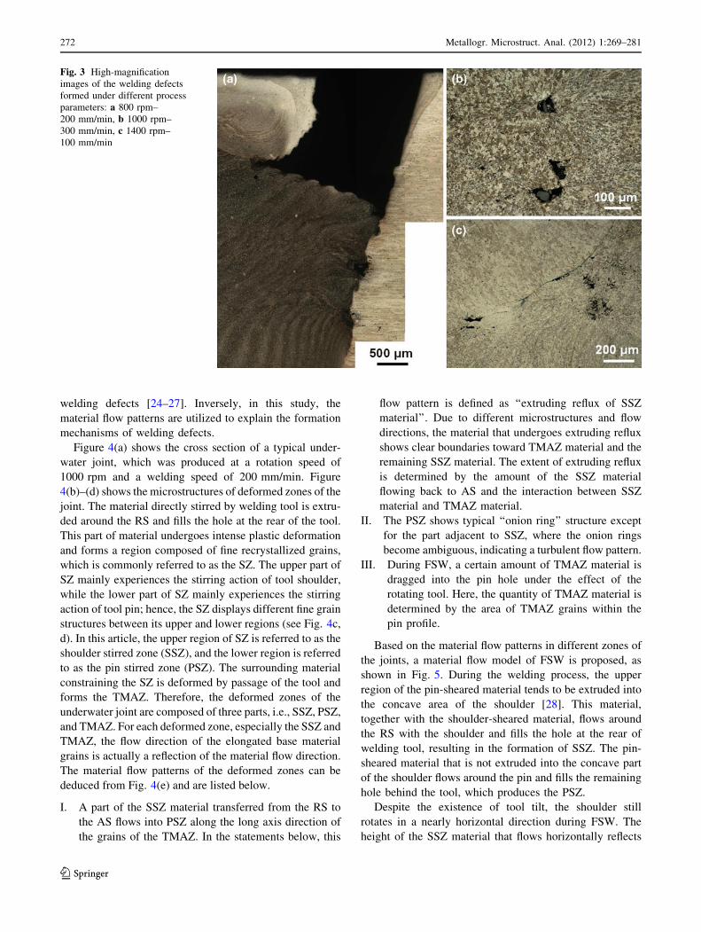
In the low-rotation speed (LRS) range of 600–800 rpm, a
groove defect is formed at the interface between the SZ and
the thermo-mechanically affected zone (TMAZ) on the AS
due to insufficient heat input (see Fig. 3a). For convenience,
the defects formed at relatively LRS are referred to as LRS
Table 1 Chemical compositions of 2219-T6 aluminum alloy (wt.%)
Al Cu Mn Fe Ti V Zn Si Zr
Balance 6.48 0.32 0.23 0.06 0.08 0.04 0.49 0.2
270 Metallogr. Microstruct. Anal. (2012) 1:269–281
123
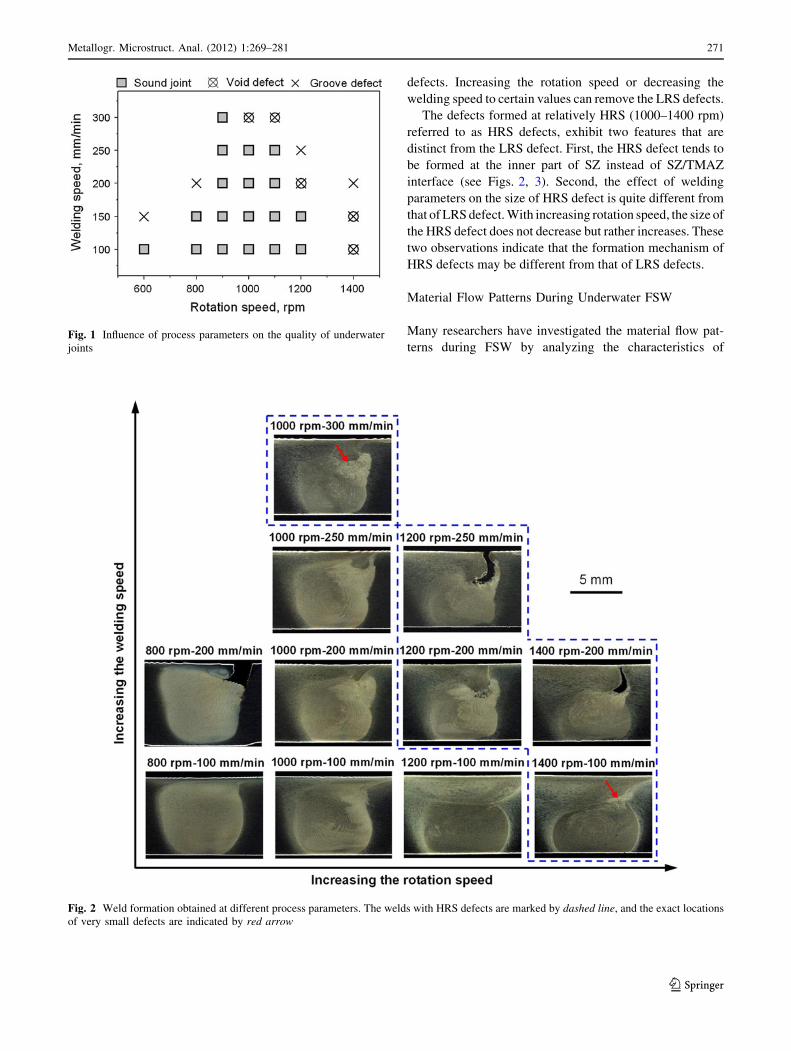
defects. Increasing the rotation speed or decreasing the
welding speed to certain values can remove the LRS defects.
The defects formed at relatively HRS (1000–1400 rpm)
referred to as HRS defects, exhibit two features that are
distinct from the LRS defect. First, the HRS defect tends to
be formed at the inner part of SZ instead of SZ/TMAZ
interface (see Figs. 2, 3). Second, the effect of welding
parameters on the size of HRS defect is quite different from
that of LRS defect. With increasing rotation speed, the size of
the HRS defect does not decrease but rather increases. These
two observations indicate that the formation mechanism of
HRS defects may be different from that of LRS defects.
Material Flow Patterns During Underwater FSW
Many researchers have investigated the material flow pat-
terns during FSW by analyzing the characteristics ofFig. 1 Influence of process parameters on the quality of underwater
joints
Fig. 2 Weld formation obtained at different process parameters. The welds with HRS defects are marked by dashed line, and the exact locations
of very small defects are indicated by red arrow
Metallogr. Microstruct. Anal. (2012) 1:269–281 271
123
welding defects [24–27]. Inversely, in this study, the
material flow patterns are utilized to explain the formation
mechanisms of welding defects.
Figure 4(a) shows the cross section of a typical under-
water joint, which was produced at a rotation speed of
1000 rpm and a welding speed of 200 mm/min. Figure
4(b)–(d) shows the microstructures of deformed zones of the
joint. The material directly stirred by welding tool is extru-
ded around the RS and fills the hole at the rear of the tool.
This part of material undergoes intense plastic deformation
and forms a region composed of fine recrystallized grains,
which is commonly referred to as the SZ. The upper part of
SZ mainly experiences the stirring action of tool shoulder,
while the lower part of SZ mainly experiences the stirring
action of tool pin; hence, the SZ displays different fine grain
structures between its upper and lower regions (see Fig. 4c,
d). In this article, the upper region of SZ is referred to as the
shoulder stirred zone (SSZ), and the lower region is referred
to as the pin stirred zone (PSZ). The surrounding material
constraining the SZ is deformed by passage of the tool and
forms the TMAZ. Therefore, the deformed zones of the
underwater joint are composed of three parts, i.e., SSZ, PSZ,
and TMAZ. For each deformed zone, especially the SSZ and
TMAZ, the flow direction of the elongated base material
grains is actually a reflection of the material flow direction.
The material flow patterns of the deformed zones can be
deduced from Fig. 4(e) and are listed below.
I. A part of the SSZ material transferred from the RS to
the AS flows into PSZ along the long axis direction of
the grains of the TMAZ. In the statements below, this
flow pattern is defined as ‘‘extruding reflux of SSZ
material’’. Due to different microstructures and flow
directions, the material that undergoes extruding reflux
shows clear boundaries toward TMAZ material and the
remaining SSZ material. The extent of extruding reflux
is determined by the amount of the SSZ material
flowing back to AS and the interaction between SSZ
material and TMAZ material.
II. The PSZ shows typical ‘‘onion ring’’ structure except
for the part adjacent to SSZ, where the onion rings
become ambiguous, indicating a turbulent flow pattern.
III. During FSW, a certain amount of TMAZ material is
dragged into the pin hole under the effect of the
rotating tool. Here, the quantity of TMAZ material is
determined by the area of TMAZ grains within the
pin profile.
Based on the material flow patterns in different zones of
the joints, a material flow model of FSW is proposed, as
shown in Fig. 5. During the welding process, the upper
region of the pin-sheared material tends to be extruded into
the concave area of the shoulder [28]. This material,
together with the shoulder-sheared material, flows around
the RS with the shoulder and fills the hole at the rear of
welding tool, resulting in the formation of SSZ. The pin-
sheared material that is not extruded into the concave part
of the shoulder flows around the pin and fills the remaining
hole behind the tool, which produces the PSZ.
Despite the existence of tool tilt, the shoulder still
rotates in a nearly horizontal direction during FSW. The
height of the SSZ material that flows horizontally reflects
Fig. 3 High-magnification
images of the welding defects
formed under different process
parameters: a 800 rpm–
200 mm/min, b 1000 rpm–
300 mm/min, c 1400 rpm–
100 mm/min
272 Metallogr. Microstruct. Anal. (2012) 1:269–281
123

the stirring effect of shoulder on the work piece in the
thickness direction (i.e., the level of shoulder-driven flow).
This height is defined as h1 in this manuscript.
In the PSZ, the material experiences two flow patterns.
One is the circle flow around tool pin, and the other is the
upward flow due to the shearing of pin threads. The mini-
mum height of the PSZ adjacent to SSZ, defined as h2,
reflects the effect of pin-driven flow on the filling of pin hole.
Influence of Process Parameters on Material Flow
Patterns
Influence of Rotation Speed
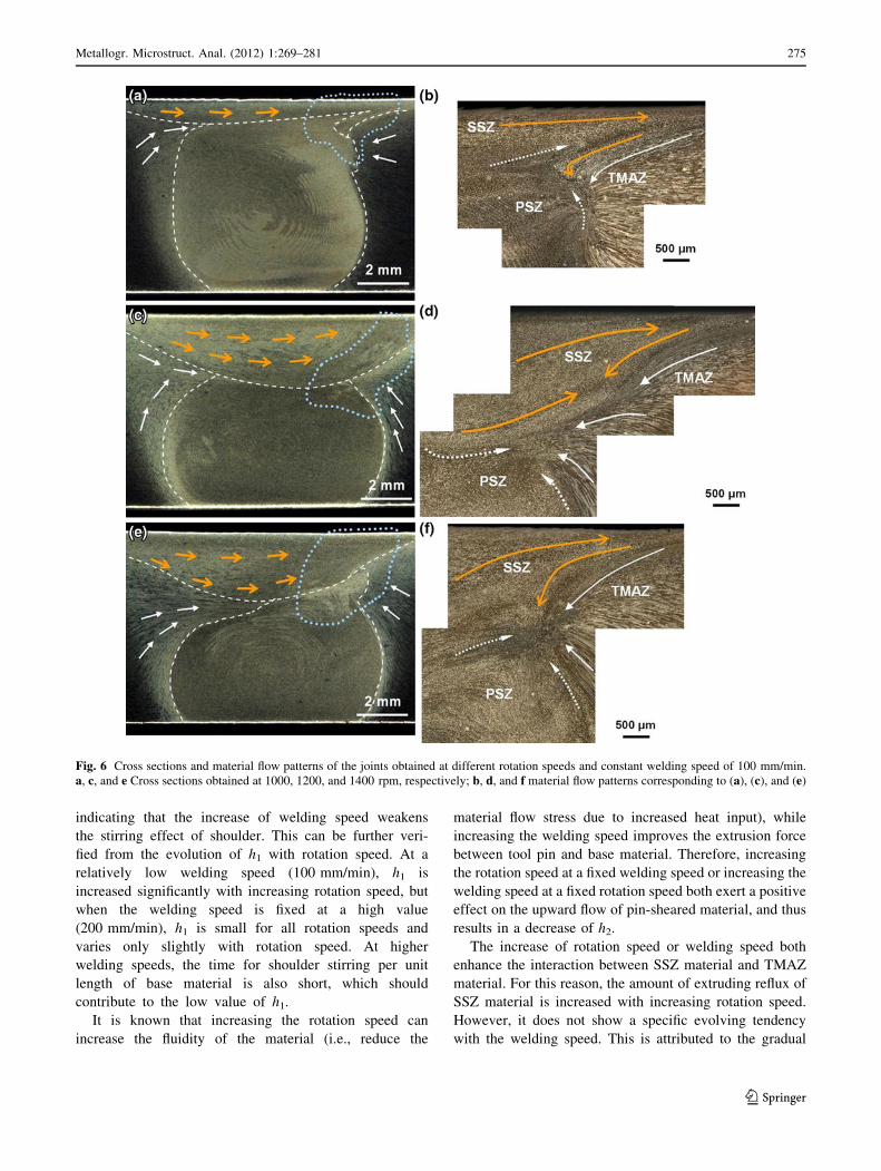
Figure 6 shows cross-sectional micrographs and corre-
sponding flow patterns for welds with a constant welding
speed of 100 mm/min and different rotation speeds. As the
rotation speed increases, h1 is significantly increased but h2
is gradually decreased (Fig. 6a, c, e). This suggests an
improvement in the stirring effect of shoulder and an
enhancement of the upward flow of pin-sheared material.
Additionally, the extruding reflux of SSZ material is
increased on the AS with an increase in the rotation speed
(Fig. 6b, d, f). When the rotation speed is increased up to
1400 rpm, turbulent material flow occurs in the PSZ
adjacent to SSZ, and a void defect is observed at this
location (Fig. 3c).
Weld cross sections and corresponding material flow
patterns for the conditions of a relatively high constant
weld speed of 200 mm/min and varying rotation speeds are
shown in Fig. 7. With increasing the rotation speed, h2
gradually decreases, but in contrast, slight variations occur
in h1 (Fig. 7a, c, e). Furthermore, the amount of TMAZ
material dragged into the pin hole increases with increasing
rotation speed. At 1200 and 1400 rpm, the SSZ material
flows into the pin hole in a downward direction, and
welding defects such as voids and grooves are present in
the joints. Prior to the occurrence of groove defect, the
Fig. 4 Cross section and microstructures of the deformed zones of a typical underwater joint. a Cross section b TMAZ, c SSZ, d PSZ, e enlarged
view of the microstructures in the dash square of Fig. 4(a)
Metallogr. Microstruct. Anal. (2012) 1:269–281 273
123

extruding reflux of SSZ material increases with increasing
rotation speed (Fig. 7b, d).
Influence of Welding Speed
Figure 8 shows the cross sections and material flow patterns
of welds produced at different welding speeds and a constant
rotation speed of 1000 rpm. With increasing weld speed, h1
and h2 exhibit little variation from 100 to 200 mm/min but
decrease at 300 mm/min (Fig. 8a, c, e). This implies that
increasing the welding speed not only weakens the stirring
effect of the shoulder but also enhances the upward flow of
pin-sheared material. Extruding reflux of SSZ material
occurs at 100 mm/min. At 200 mm/min, this phenomenon
becomes more severe, leading to the turbulent flow in the
PSZ; simultaneously, a certain quantity of TMAZ material is
dragged into the pin hole (Fig. 8c, d). At the higher rotation
speed of 300 mm/min, more TMAZ material is involved in
the filling process of pin hole. When this part of TMAZ
material stops flowing, SSZ material then flows into the pin
hole in a downward direction, and in this case, a void defect is
observed in the joint (Fig. 8e, f).
Figure 9 shows cross sections and material flow patterns
of the welds produced at different welding speeds and a
constant rotation speed of 1200 rpm. h1 is greatly decreased
when the rotation speed increases from 100 mm/min to the
range of 200–250 mm/min; additionally, h2 also decreases
progressively with increasing welding speed (Fig. 9a, c, e).
At 200 mm/min, a large amount of TMAZ material is
involved in filling the pin hole (Fig. 9c). Similar to the
observations for Fig. 8(f), the SSZ material flows into the
pin hole in a downward direction, and a void defect is
formed at the PSZ adjacent to SSZ (Fig. 9d). At a higher
welding speed of 250 mm/min, more TMAZ material is
dragged into the pin hole, and the SSZ material exhibits
greater tendency for downward flow (see Fig. 9e, f). A
groove defect is formed in the joint under these conditions.
Formation Mechanisms of Underwater FSW Defects
The previously discussed observations indicate that the
influence of process parameters on material flow patterns is
mainly dependent on four aspects:
I. The stirring effect of shoulder on work piece, which is
characterized by h1.
II. The height of pin hole filled by PSZ material, which is
characterized by h2.
III. The amount of the extruding reflux of SSZ material.
IV. The amount of the TMAZ material that is dragged
into pin hole.
At any constant rotation speed between 1000 and
1400 rpm, h1 decreases with increasing welding speed,
Fig. 5 Material plastic flow
model for the underwater FSW.
a Movement of plastic material
during FSW, b material flow
patterns in the deformed zones
of the joint
274 Metallogr. Microstruct. Anal. (2012) 1:269–281
123
indicating that the increase of welding speed weakens
the stirring effect of shoulder. This can be further veri-
fied from the evolution of h1 with rotation speed. At a
relatively low welding speed (100 mm/min), h1 is
increased significantly with increasing rotation speed, but
when the welding speed is fixed at a high value
(200 mm/min), h1 is small for all rotation speeds and
varies only slightly with rotation speed. At higher
welding speeds, the time for shoulder stirring per unit
length of base material is also short, which should
contribute to the low value of h1.
It is known that increasing the rotation speed can
increase the fluidity of the material (i.e., reduce the
material flow stress due to increased heat input), while
increasing the welding speed improves the extrusion force
between tool pin and base material. Therefore, increasing
the rotation speed at a fixed welding speed or increasing the
welding speed at a fixed rotation speed both exert a positive
effect on the upward flow of pin-sheared material, and thus
results in a decrease of h2.
The increase of rotation speed or welding speed both
enhance the interaction between SSZ material and TMAZ
material. For this reason, the amount of extruding reflux of
SSZ material is increased with increasing rotation speed.
However, it does not show a specific evolving tendency
with the welding speed. This is attributed to the gradual
Fig. 6 Cross sections and material flow patterns of the joints obtained at different rotation speeds and constant welding speed of 100 mm/min.
a, c, and e Cross sections obtained at 1000, 1200, and 1400 rpm, respectively; b, d, and f material flow patterns corresponding to (a), (c), and (e)
Metallogr. Microstruct. Anal. (2012) 1:269–281 275
123

reduction of the SSZ material that flows back to AS when
the welding speed is increased.
The amount of the TMAZ material involved in the
filling process of pin hole is dependent on the sum of h1
and h2. If the height of the pin hole filled by PSZ material is
small, and the shoulder has a weak stirring effect on the
work piece, a large amount of TMAZ material is then
dragged into the pin hole by the viscous force of SZ
material.
Figure 10 presents a quantitative analysis of h1, h2 and
the extruding reflux of SSZ material obtained at relatively
HRS. The welds with HRS defects are classified into two
types according to their formation characteristics: a large
sum of h1 and h2, or a small sum of h1 and h2. Further
analysis finds that welds with a large h1 and h2 sum are a
result of a low welding speed (100 mm/min), while the low
sum type is a result of a relatively high welding speed
(200–300 mm/min). Both the types of welds are charac-
terized by different material flow patterns, as described in
section 3. Therefore, it can be concluded that the formation
mechanism of HRS defects is dependent on the welding
speed. In other words, HRS defects can be divided into two
Fig. 7 Cross sections and material flow patterns of the joints obtained at different rotation speeds and constant welding speed of 200 mm/min.
a, c, and e Cross sections obtained at 1000, 1200, and 1400 rpm, respectively; b, d, and f material flow patterns corresponding to (a), (c), and (e)
276 Metallogr. Microstruct. Anal. (2012) 1:269–281
123

types, i.e., defects formed at low welding speeds and
defects formed at high welding speeds. In the low speed
case, h1 is large and the sum of h1 and h2 is comparable to
the weld thickness, h. For the high speed case, h1 is rather
small and the sum of h1 and h2 is significantly lower than
the weld thickness. Based on the evolution of material flow
patterns with process parameters, the formation mecha-
nisms of these two types of defects are separately
discussed.
At a HRS of 1400 rpm and a relatively low welding
speed of 100 mm/min, the shoulder exerts severe stirring
effect on the work piece, making the sum of h1 and h2
comparable to weld thickness h. Under this condition, the
shoulder- and pin-driven flows are consistent in direction
near the SSZ/PSZ interface. However, a large amount of
SSZ material is transferred back to the AS from the RS
during FSW. This increases the extrusion force between
SSZ and TMAZ materials, leading to more extruding reflux
of SSZ material and thus the turbulent flow in the PSZ.
Consequently, a void defect is formed in the PSZ adjacent
to SSZ (Fig. 3c). That is to say, the larger amount of
extruding reflux of SSZ material is responsible for the
formation of HRS defect, and this viewpoint is in agree-
ment with Arbegast’s results [21].
When relatively high welding speeds (200–300 mm/min)
are combined with HRS, the shoulder stirring effect is dra-
matically weakened and the height of the pin hole filled by
PSZ material is also small. Under this condition, a large
Fig. 8 Cross sections and material flow patterns of the joints obtained at different welding speeds and constant rotation speed of 1000 rpm. a, c,
and e Cross sections obtained at 100, 200, and 300 mm/min, respectively; b, d, and f material flow patterns corresponding to (a), (c), and (e)
Metallogr. Microstruct. Anal. (2012) 1:269–281 277
123
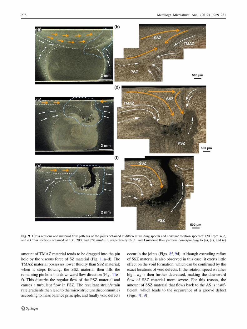
amount of TMAZ material tends to be dragged into the pin
hole by the viscous force of SZ material (Fig. 11a–d). The
TMAZ material possesses lower fluidity than SSZ material;
when it stops flowing, the SSZ material then fills the
remaining pin hole in a downward flow direction (Fig. 11e–
f). This disturbs the regular flow of the PSZ material and
causes a turbulent flow in PSZ. The resultant strain/strain
rate gradients then lead to the microstructure discontinuities
according to mass balance principle, and finally void defects
occur in the joints (Figs. 8f, 9d). Although extruding reflux
of SSZ material is also observed in this case, it exerts little
effect on the void formation, which can be confirmed by the
exact locations of void defects. If the rotation speed is rather
high, h2 is then further decreased, making the downward
flow of SSZ material more severe. For this reason, the
amount of SSZ material that flows back to the AS is insuf-
ficient, which leads to the occurrence of a groove defect
(Figs. 7f, 9f).
Fig. 9 Cross sections and material flow patterns of the joints obtained at different welding speeds and constant rotation speed of 1200 rpm. a, c,
and e Cross sections obtained at 100, 200, and 250 mm/min, respectively; b, d, and f material flow patterns corresponding to (a), (c), and (e)
278 Metallogr. Microstruct. Anal. (2012) 1:269–281
123

During the formation process of this type of defect, the
HRS serves two functions. First, it provides the material
sufficient plasticity and fluidity even at relatively high
welding speeds; second, it promotes the upward flow of pin-
sheared material. The high welding speed also plays two
roles. Besides the promotion of upward flow of pin-sheared
Fig. 10 h1, h2, and extruding
reflux obtained at different
process parameters
Fig. 11 Schematic view of the
formation mechanism of HRS
defect. a, c, e Horizontal plane
of the weld; b, d, f cross
sections of the weld (made
along the red lines in a, c, and e)
Metallogr. Microstruct. Anal. (2012) 1:269–281 279
123

material, it dramatically weakens the stirring effect of
shoulder on the work piece. Therefore, if a higher welding
speed is chosen, the rotation speed should be low to retard
the upward flow of pin-sheared material. On the contrary, if
a higher rotation speed is utilized, the welding speed should
be low to improve the stirring effect of shoulder on the work
piece. These are the reasons why HRS coupled with low
welding speed, or LRS coupled with high welding speed,
generally produce defect-free underwater joints.
Previous investigations also observed the occurrence of
HRS defects during FSW of aluminum alloys, and some
researchers have attempted to elucidate the formation
mechanisms of HRS defects [20, 21, 23]. However, these
previously published studies mainly focused on the effect
of HRS, and the effect of welding speed was rarely men-
tioned. Although Kim et al. [20] found that increasing the
welding speed increased the size of HRS defects, the rea-
son for this was not deeply investigated in their research.
By analyzing the defect characteristics and material flow
patterns in underwater FSW, this work for the first time
proposes a relationship between the formation mechanism
of HRS defects and welding speed. When the welding
speed is low, the formation mechanism of HRS defect is
found to be the same as that reported by previous
researchers [21], as described above. However, at relatively
high welding speed, the formation mechanism of HRS
defect is quite different. In this case, a large amount of
TMAZ material tends to be dragged into the pin hole,
which causes the significant downward flow of SSZ
material and finally the occurrence of HRS defects.
Conclusions
1. LRS and HRS can both yield welding defects during
underwater FSW. The LRS defect is generally found at
the SZ/TMAZ interface on the AS, while the HRS
defect tends to be present in the SZ. When the rotation
speed is increased, the LRS defect becomes small and
may even be eliminated, but the size of HRS defect
gradually increases.
2. The insufficient heat input and lower fluidity of
material are reasons for the formation of LRS defect.
The HRS defect can be divided into two types
according to the welding speed.
3. The HRS defect formed at low welding speed is
induced by the larger extent of extruding reflux of SSZ
material on the AS.
4. At HRS and high welding speed, a large amount of
TMAZ material is dragged into the pin hole, which
causes the SSZ material to flow into the pin hole in a
downward direction. This not only leads to turbulent
flow in PSZ, but also reduces the amount of SSZ
material that flows back to AS. Finally, void and even
groove defects are formed in the joints.
Acknowledgments The authors are grateful to be supported by the
National Basic Research Program of China (973 Program,
2010CB731704), National Natural Science Foundation of China
(51175117) and the National Science and Technology Major Project
of China (2010ZX04007).
References
1. W.M. Thomas, E.D. Nicholas, J.C. Needham, M.G. Murch, P.
Temple-Smith, C.J. Dawes, Friction Stir Butt Welding, Interna-
tional Patent Application No. PCT/GB92/02203 and GB Patent
Application No. 9125978.8; 1991
2. M.R. Johnsen, Friction stir welding takes off at boeing. Weld. J.
78, 35–39 (1999)
3. D. Joelj, The friction stir welding advantage. Weld. J. 80, 30–34
(2001)
4. R.S. Mishra, Z.Y. Ma, Friction stir welding and processing.
Mater. Sci. Eng. Rep. 50, 1–78 (2005)
5. P.L. Threadgill, A.J. Leonard, H.R. Shercliff, P.J. Withers, Friction
stir welding of aluminum alloys. Int. Mater. Rev. 54, 49–93 (2009)
6. M.W. Mahoney, C.G. Rhodes, J.G. Flintoff, R.A. Spurling, W.H.
Bingel, Properties of friction-stir-welded 7075 T651 aluminum.
Metall. Mater. Trans. A 29, 1955–1964 (1998)
7. Y.S. Sato, H. Kokawa, M. Enomoto, S. Jogan, Microstructural
evolution of 6063 aluminum during friction-stir welding. Metall.
Mater. Trans. A 30, 2429–2437 (1999)
8. R.W. Fonda, J.F. Bingert, Microstructural evolution in the heat-
affected zone of a friction stir weld. Metall. Mater. Trans. A 35,
1487–1499 (2004)
9. F.C. Liu, Z.Y. Ma, Influence of tool dimension and welding
parameters on microstructure and mechanical properties of fric-
tion-stir-welded 6061-T651 aluminum alloy. Metall. Mater.
Trans. A 39, 2378–2388 (2008)
10. S. Benavides, Y. Li, L.E. Murr, D. Brown, J.C. McClure, Low-
temperature friction-stir welding of 2024 aluminum. Scripta
Mater. 41, 809–815 (1999)
11. L. Fratini, G. Buffa, R. Shivpuri, In-process heat treatments to
improve FS-welded butt joints. Int. J. Adv. Manuf. Technol. 43,
664–670 (2009)
12. L. Fratini, G. Buffa, R. Shivpuri, Mechanical and metallurgical
effects of in process cooling during friction stir welding of
AA7075-T6 butt joints. Acta Mater. 58, 2056–2067 (2010)
13. H.J. Liu, H.J. Zhang, Y.X. Huang, L. Yu, Mechanical properties
of underwater friction stir welded 2219 aluminum alloy. Trans.
Nonferrous Met. Soc. China 20, 1387–1391 (2010)
14. H.J. Liu, H.J. Zhang, L. Yu, Homogeneity of mechanical prop-
erties of underwater friction stir welded 2219-T6 aluminum alloy.
JMEPEG 20, 1419–1422 (2011)
15. H.J. Zhang, H.J. Liu, L. Yu, Microstructure and mechanical
properties as a function of rotation speed in underwater friction stir
welded aluminum alloy joints. Mater. Des. 32, 4402–4407 (2011)
16. H.J. Liu, H. Fujii, M. Maeda, K. Nogi, Tensile properties and
fracture locations of friction-stir-welded joints of 2017-T351
aluminum alloy. J. Mater. Process. Technol. 142, 692–696 (2003)
17. Y.C. Chen, H.J. Liu, J.C. Feng, Friction stir welding character-
istics of different heat-treated-state 2219 aluminum alloy plates.
Mater. Sci. Eng., A 420, 21–25 (2006)
18. L. Cui, X.Q. Yang, G. Zhou, X.D. Xu, Z.K. Shen, Characteristics
of defects and tensile behaviors on friction stir welded AA6061-
T4 T-joints. Mater. Sci. Eng., A 543, 58–68 (2012)
280 Metallogr. Microstruct. Anal. (2012) 1:269–281
123

19. A.J. Leonard, S.A. Lockyer, Flaws in friction stir welds, Pro-ceedings of the 4th International Symposium on Friction StirWelding, Paper No. S2-P1, Utah, USA. TWI Ltd., May, 2003
20. Y.G. Kim, H. Fujii, T. Tsumura, T. Komazaki, K. Nakata, Three
defect types in friction stir welding of aluminum die casting
alloy. Mater. Sci. Eng., A 415, 250–254 (2006)
21. W.J. Arbegast, A flow-partitioned deformation zone model for
defect formation during friction stir welding. Scripta Mater. 58,
372–376 (2008)
22. B. Li, Y.F. Shen, W.Y. Hu, The study on defects in aluminum
2219-T6 thick butt friction stir welds with the application of
multiple non-destructive testing methods. Mater. Des. 32,
2073–2084 (2011)
23. A.M. Gaafer, T.S. Mahmoud, E.H. Mansour, Microstructural and
mechanical characteristics of AA7020-O Al plates joined by
friction stir welding. Mater. Sci. Eng., A 527, 7424–7429 (2010)
24. P.B. Prangnell, C.P. Heason, Grain structure formation during
friction stir welding observed by the ‘‘Stop Action Technique’’.
Acta Mater. 53, 3179–3192 (2005)
25. R.M. Leal, C. Leitao, A. Loureiro, D.M. Rodrigues, P. Vilaca,
Material flow in heterogeneous friction stir welding of thin alu-
minium sheets: effect of shoulder geometry. Mater. Sci. Eng., A
498, 384–391 (2008)
26. Z.W. Chen, T. Pasang, Y. Qi, Shear flow and formation of nugget
zone during friction stir welding of aluminium alloy 5083-O.
Mater. Sci. Eng., A 474, 312–316 (2008)
27. S.M. Chowdhury, D.L. Chen, S.D. Bhole, X. Cao, Tensile properties
of a friction stir welded magnesium alloy: effect of pin tool thread
orientation and weld pitch. Mater. Sci. Eng., A 527, 6064–6075 (2010)
28. K. Kumar, S.V. Kailas, The role of friction stir welding tool on
material flow and weld formation. Mater. Sci. Eng., A 485,
367–374 (2008)
Metallogr. Microstruct. Anal. (2012) 1:269–281 281
123