characterization and performance analysis of a chiral
TRANSCRIPT
HAL Id: hal-01379904https://hal.inria.fr/hal-01379904
Submitted on 14 Oct 2016
HAL is a multi-disciplinary open accessarchive for the deposit and dissemination of sci-entific research documents, whether they are pub-lished or not. The documents may come fromteaching and research institutions in France orabroad, or from public or private research centers.
L’archive ouverte pluridisciplinaire HAL, estdestinée au dépôt et à la diffusion de documentsscientifiques de niveau recherche, publiés ou non,émanant des établissements d’enseignement et derecherche français ou étrangers, des laboratoirespublics ou privés.
Characterization and Performance Analysis of aChiral-Metamaterial Channel with Giant Optical
Activity for Terahertz CommunicationsAnna Maria Vegni, Valeria Loscrì
To cite this version:Anna Maria Vegni, Valeria Loscrì. Characterization and Performance Analysis of a Chiral-Metamaterial Channel with Giant Optical Activity for Terahertz Communications. Nano Commu-nication Networks, Elsevier 2016, 9, pp.28-35. 10.1016/j.nancom.2016.07.004. hal-01379904

Characterization and Performance Analysis of aChiral-Metamaterial Channel with Giant Optical
Activity for Terahertz Communications
Anna Maria Vegnia,∗, Valeria Loscrıb
aDepartment of Engineering, Roma Tre University, Rome, ItalybINRIA Lille-Nord Europe, FUN Research Lab, Lille Nord-Europe, France.
Abstract
Technology in the THz frequency band has progressed rapidly in the last few1
years. The THz frequency band offers greater communication bandwidth than2
microwaves frequencies, and is becoming a standard for nanoscale communica-3
tions. Traditional channel models for lower frequencies do not take into consid-4
eration specific properties as the very high molecular absorption or the very high5
reflection loss. In addition, in a propagation medium exhibiting a Giant Optical6
Activity, it is also important to derive the characteristics of the channel affected by7
chirality effects. This phenomenon occurs in particular material known as chiral-8
metamaterials in the (4–10) THz band.9
The main contribution of this paper consist in the analysis of specific parame-10
ters of a chiral-metamaterial, such as the relative electrical permittivity, magnetic11
permeability and chirality coefficients. These parameters are considered for the12
channel model derivation both in Line-of-Sight and No Line-of-Sight propagation.13
The chiral effect affects the channel through the presence of spectral win-14
dows, due to peaks of resonance of chiral parameter. Performance analysis of the15
chirality-affected channel is assessed in terms of (i) channel capacity, (ii) propaga-16
∗Corresponding authorEmail addresses: [email protected] (Anna Maria Vegni ),
[email protected] (Valeria Loscrı )Preprint submitted to Nano Communication Networks October 14, 2016

tion delay, (iii) coherence bandwidth, and (iv) symbol rates, for different distances17
and propagation modes.18
Keywords: THz band, chirality effects, Giant Optical Activity,
nano-communications
1. Introduction1
Over the last few years we have witnessed an increasing demand for much2
higher speed and ubiquitous wireless communication systems. Technological de-3
velopment pave the advent of new communication paradigms, such as the Internet4
of NanoThings [1]. Following this trend, the THz frequency band is rising as a5
very promising solution to enable ultra-high-speed communications with the aim6
to overcome the spectrum scarcity and capacity limitations of current wireless sys-7
tems. Advanced physical layer solutions are required, able to capture the specific8
and inherent features of the THz frequency bands. Indeed, traditional channel9
models for lower frequency bands cannot be adopted for THz communication.10
Some new channel models have been presented for THz frequency bands [2,11
3, 4, 5, 6], where some of the specific characteristics of this frequency band, such12
as the high molecular absorption and the spreading loss, are taken into consider-13
ation and analyzed. Also, the analysis of signal propagation has been addressed14
in [7] through a multi-ray approach by assuming reflected, scattered and diffracted15
paths. As a result, the authors derived the main THz-band channel features, such16
as the distance-varying spectral windows, and the temporal broadening effects.17
As it can be noticed from previous works, channel modeling in THz band18
is typically addressed through the study of its transfer functions that consider19
specific features, like molecular absorption loss or spreading loss, among oth-20
2

ers. However, the previous models take into consideration some specific features1
of the channel at THz frequencies, but neglect other important effects that could2
play a very important role in the channel modeling. One of these properties is3
the electro-magnetic chirality effect and the specific features of the propagation4
medium. Chirality effect is the characteristic of some natural materials to ren-5
der an electric/magnetic response (displacement) under a magnetic/electric exci-6
tation (field), respectively. This effect can be recognized in the so-called natu-7
ral/artificial chiral materials. Examples of natural chiral materials are the sugar8
molecules (sucrose) or the cholesteric liquid crystals. Artificial chiral materials,9
e.g., sculptured thin films [8], can be obtained by doping a natural dielectric with10
an amount of metallic/dielectric impurities each working as a couple of interacting11
electro-magnetic dipoles. These impurities generate the handedness experimen-12
tal evidence that prevents the superimposition of the molecular structure over a13
reverse copy of itself.14
The relative chirality parameter is an intrinsic characteristic of a chiral homo-15
geneous isotropic medium. Standard values are in the range [0, 1]. We observe16
that in a specific range of the THz band, i.e., (4-10) THz, the chiral parameter can17
reach very high values that vary with the frequency, and show a resonant behav-18
ior. Materials with this specific feature are said to exhibit a Giant Optical Activity19
(GOA). In particular media such as the chiral complex materials where a GOA20
takes place, the relative chirality parameter is complex and frequency-dependent,21
showing multiple peaks at specific resonance frequencies [9].22
GOA material affected by chirality effects is generally called as chiral-metamaterial [10],23
due to the effect that the real part of relative electric permittivity and magnetic24
permeability of the material shows negative values, and are frequency-dependent.25
3

This interesting property is of great interest to many areas of science, like analyt-1
ical chemistry and molecular biology. Finally, chiral-metamaterials are suitable2
media for the realization of nanosystem applications. Specifically, they represent3
the ideal candidates for operations in the THz band. In fact, in comparison to nat-4
ural materials, chiral-metamaterials show a strong response to the THz radiation5
that represents a great technological potential in several sectors such as imaging,6
sensing, and also communications.7
In this paper, we focus on GOA chiral-metamaterials, derive the channel trans-8
fer function and analyze its specific behavior in case of direct and multi-path prop-9
agation, in the (4–10) THz frequency range [9]. Due to the resonant behavior of10
chiral parameter, the channel model shows specific frequency-dependent spectral11
windows, guaranteeing high bandwidth values.12
This paper is organized as follows. In Section 2 we introduce the frequency-13
dependent behavior of specific parameters of a chiral-metamaterial. Starting from14
the concept of electro-magnetic chirality [11, 12, 13], we consider the chiral ef-15
fects following the change in the propagation velocity and in the refractive index,16
due to the chiral impurities inside the propagation medium. These effects are eval-17
uated also in the case when the considered medium exhibits a GOA [9, 14]. Then,18
in Section 3 we derive the corresponding chirality-affected channel model for THz19
band, and present the related frequency-dependent spectral windows. Section 4 is20
then devoted to the performances of the chiral channel, assessed in terms of ca-21
pacity, propagation delay, coherence bandwidth, and symbol rates, in case of LoS22
and NLoS propagation modes. Finally, conclusions are drawn at the end of the23
paper.24
4
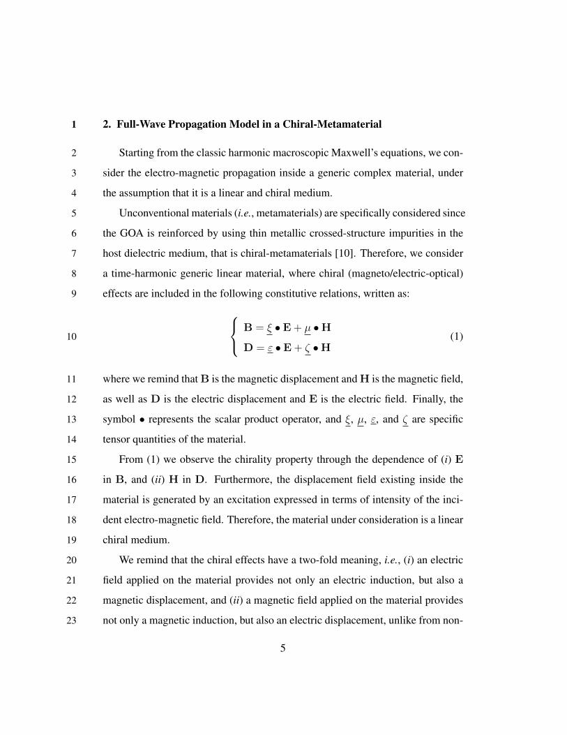
2. Full-Wave Propagation Model in a Chiral-Metamaterial1
Starting from the classic harmonic macroscopic Maxwell’s equations, we con-2
sider the electro-magnetic propagation inside a generic complex material, under3
the assumption that it is a linear and chiral medium.4
Unconventional materials (i.e., metamaterials) are specifically considered since5
the GOA is reinforced by using thin metallic crossed-structure impurities in the6
host dielectric medium, that is chiral-metamaterials [10]. Therefore, we consider7
a time-harmonic generic linear material, where chiral (magneto/electric-optical)8
effects are included in the following constitutive relations, written as:9 B = ξ • E + µ •H
D = ε • E + ζ •H(1)10
where we remind that B is the magnetic displacement and H is the magnetic field,11
as well as D is the electric displacement and E is the electric field. Finally, the12
symbol • represents the scalar product operator, and ξ, µ, ε, and ζ are specific13
tensor quantities of the material.14
From (1) we observe the chirality property through the dependence of (i) E15
in B, and (ii) H in D. Furthermore, the displacement field existing inside the16
material is generated by an excitation expressed in terms of intensity of the inci-17
dent electro-magnetic field. Therefore, the material under consideration is a linear18
chiral medium.19
We remind that the chiral effects have a two-fold meaning, i.e., (i) an electric20
field applied on the material provides not only an electric induction, but also a21
magnetic displacement, and (ii) a magnetic field applied on the material provides22
not only a magnetic induction, but also an electric displacement, unlike from non-23
5

chiral materials.1
As previously said, in this paper our attention is devoted to GOA chiral-2
metamaterials [15], where the authors show that for a GOA reciprocal material3
the specific constitutive relations are as follows:4 B
D
=
−j ξ0ξrc µ0µr
ε0εr j ξ0ξrc
• E
H
, (2)5
where it is clear that the natural dielectric (where εb and µb are the permittivity and6
permeability, respectively) becomes a metamaterial. Moreover, according to [15],7
at the frequency around 5 THz and 8 THz, there are four resonance frequencies of8
the ξr relative chirality parameter, i.e., [4.8, 5.6, 7.9, 8.2] THz.9
The same consideration is applied to the relative permittivity and permeability10
parameters, still in the (4–10) THz band. As reported in [9, 16], εr and µr are11
complex parameters, and the real part has a frequency-dependent behavior with12
resonant peaks.13
Equation (2) becomes14 B
D
=
=
−j Ωξω0ω
ω20−ω2−jωγ µ0
(µb + Ωµω2
ω20−ω2−jωγ
)ε0
(εb +
Ωεω20
ω20−ω2−jωγ
)j
Ωξω0ω
ω20−ω2−jωγ
• E
H
, (3)15
where ω = 2πf , ε0, and µ0 are the absolute permittivity and permeability, respec-16
6
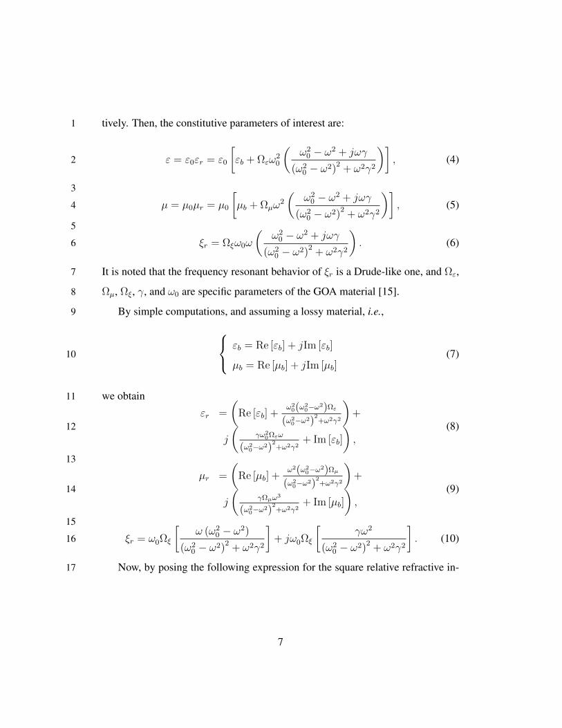
tively. Then, the constitutive parameters of interest are:1
ε = ε0εr = ε0
[εb + Ωεω
20
(ω2
0 − ω2 + jωγ
(ω20 − ω2)
2+ ω2γ2
)], (4)2
3
µ = µ0µr = µ0
[µb + Ωµω
2
(ω2
0 − ω2 + jωγ
(ω20 − ω2)
2+ ω2γ2
)], (5)4
5
ξr = Ωξω0ω
(ω2
0 − ω2 + jωγ
(ω20 − ω2)
2+ ω2γ2
). (6)6
It is noted that the frequency resonant behavior of ξr is a Drude-like one, and Ωε,7
Ωµ, Ωξ, γ, and ω0 are specific parameters of the GOA material [15].8
By simple computations, and assuming a lossy material, i.e.,9 εb = Re [εb] + jIm [εb]
µb = Re [µb] + jIm [µb](7)10
we obtain11
εr =
(Re [εb] +
ω20(ω2
0−ω2)Ωε
(ω20−ω2)
2+ω2γ2
)+
j
(γω2
0Ωεω
(ω20−ω2)
2+ω2γ2
+ Im [εb]
),
(8)12
13
µr =
(Re [µb] +
ω2(ω20−ω2)Ωµ
(ω20−ω2)
2+ω2γ2
)+
j
(γΩµω3
(ω20−ω2)
2+ω2γ2
+ Im [µb]
),
(9)14
15
ξr = ω0Ωξ
[ω (ω2
0 − ω2)
(ω20 − ω2)
2+ ω2γ2
]+ jω0Ωξ
[γω2
(ω20 − ω2)
2+ ω2γ2
]. (10)16
Now, by posing the following expression for the square relative refractive in-17
7

dex:1εrµr + ξ2
r = (Re [εr] + jIm [εr]) (Re [µr] + jIm [µr]) +
+(Re [ξr] + jIm [ξr])2 > 0,
(11)2
we observe that the following conditions hold for a GOA material:3
Ωε =
(1 +
γ2
ω2 − ω20
)Re [εb] , (12)4
5
Ωµ =
(1 +
γ2
ω2 − ω20
)Re [µb] , (13)6
Ωξ =
(1 +
γ2
ω2 − ω20
)√Re [εb] Re [µb]. (14)
It is observed that relations (12), (13), and (14) state the connection between the7
host material parameters, i.e., εb, and µb, and the specific GOA ones in order to8
obtain a positive refractive index in (11).9
Finally, the computation of the electro-magnetic field in the channel is carried10
out through the solutions of linear differential equations, arising from the follow-11
ing source-less Maxwell’s equations:12 (∇+ jωξ
)• E = −jωµ •H(
∇− jωζ)•H = jωε • E
(15)13
and the solving differential equations for E and H are given, respectively:14 [(∇− jωζ
)• µ−1 •
(∇+ jωξ
)− ω2ε
]• E = 0[(
∇+ jωξ)• ε−1 •
(∇− jωζ
)− ω2µ
]•H = 0
(16)15
where∇ is Kong’s operator.16
8

As a noteworthy point, we can examine how the constitutive relations influ-1
ence the channel polarization properties. Typically, the antenna at the transmitter2
side is a radiating element that can be linearly or circularly polarized. In these3
two cases we obtain interesting features of the channel directly connected with4
the constitutive relations of the medium. Namely, by assuming the linear polar-5
ization of the electric field generated by an appropriate antenna (i.e., E = Exx),6
we obtain the final second order partial differential equation for Ex, i.e.,7
α1Ex + α2∂Ex∂x
+ α3∂Ex∂y
+ α4∂Ex∂z
+ α5∂2Ex∂y2
+ α6∂2Ex∂z2
= 0, (17)8
where αi with i = (1, 2, . . . , 6) are coefficients depending on the elements of ε, µ,9
ξ, and ζ tensors.10
On the other side, for a circularly polarized antenna, i.e., E = Exx + Eyy =11
Exx + j (±)Exy, the final second order partial differential equation for Ex is12
obtained:13
γ1Ex+γ2∂2Ex∂x2
+γ3∂2Ex∂x∂y
+γ4∂2Ex∂x∂z
+γ5∂2Ex∂y2
+γ6∂2Ex∂y∂z
+γ7∂2Ex∂z2
= 0, (18)14
where γj with j = (1, 2, . . . , 7) are coefficients depending on the elements of ε,15
µ, ξ, and ζ tensors. Equations (17) and (18) allow to classify the transmission16
properties of the channel according to the choice of the transmitting medium.17
Therefore, such formulas are useful as design tools for materials working in THz18
band, including GOA materials and optical metamaterials.19
Notice that αi and γj parameters can be described through 36 degrees of free-20
dom as a consequence of their dependance on ε, µ, ξ, and ζ tensors. This means21
that we have a lot of partial differential linear equations similar to (17) and (18)22
9

that should be examined in order to determine the corresponding propagation char-1
acteristics of the channel. However, as future work, we can investigate this point2
by starting from a topology of channel material (e.g., bianisotropic, biaxial, etc.)3
and then determine the specific transmission/ reflection related properties.4
3. Chiral-affected Channel Model5
In this section, we present how the relative chiralilty parameter affects the6
channel performance in the (4–10) THz band, in the case of ray tracing propaga-7
tion (i.e., LoS, and NLoS), and under the linear polarization hypothesis. Specifi-8
cally, in NLoS case, we focus on reflected paths due at generic reflection centers9
located at z-plane. The reflection characteristics of the transmissive channel can10
be evaluated through the specific knowledge of the local planar geometry associ-11
ated to the reflection centers.12
The use of ray tracing techniques for channel modeling in THz band has been13
largely adopted, like in [5], where Han et al. consider a multi-ray approach with14
one direct path, and other reflected, scattered, and diffracted paths. According to15
this approach, the channel model is the combination of several individual narrow16
sub-bands, each of them with a flat-band response. Assuming Ni narrow sub-17
bands, and in the case of stationary environment, the channel response in the i-th18
sub-band is given as19
hi (τ) =
Ni∑n=1
αi,nδ (τ − τn), (19)20
where αi,n is the frequency-dependent attenuation, and τn is the propagation delay21
of the n-th ray in the multi-ray approach.22
From (19), and according to the computations in [5], we can derive the LoS23
10
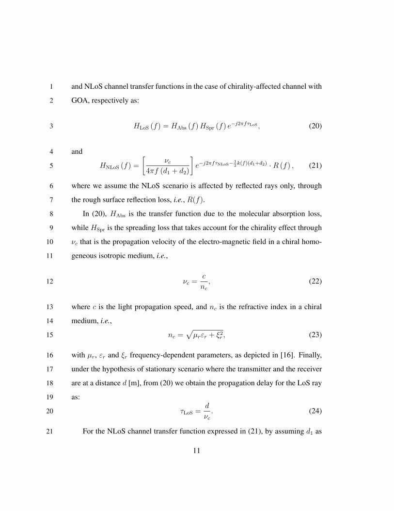
and NLoS channel transfer functions in the case of chirality-affected channel with1
GOA, respectively as:2
HLoS (f) = HAbs (f)HSpr (f) e−j2πfτLoS , (20)3
and4
HNLoS (f) =
[νc
4πf (d1 + d2)
]e−j2πfτNLoS− 1
2k(f)(d1+d2) ·R (f) , (21)5
where we assume the NLoS scenario is affected by reflected rays only, through6
the rough surface reflection loss, i.e., R(f).7
In (20), HAbs is the transfer function due to the molecular absorption loss,8
while HSpr is the spreading loss that takes account for the chirality effect through9
νc that is the propagation velocity of the electro-magnetic field in a chiral homo-10
geneous isotropic medium, i.e.,11
νc =c
nc, (22)12
where c is the light propagation speed, and nc is the refractive index in a chiral13
medium, i.e.,14
nc =√µrεr + ξ2
r , (23)15
with µr, εr and ξr frequency-dependent parameters, as depicted in [16]. Finally,16
under the hypothesis of stationary scenario where the transmitter and the receiver17
are at a distance d [m], from (20) we obtain the propagation delay for the LoS ray18
as:19
τLoS =d
νc. (24)20
For the NLoS channel transfer function expressed in (21), by assuming d1 as21
11

4 5 6 7 8 9 10 f [THz]
40
60
80
100
120
140
160
180
200
220
Path
Los
s [dB
]
LoS, 1mLoS, 5mLoS, 10mNLoS, 1mNLoS, 5mNLoS, 10m
PL = 160 dB
PL = 80 dB
0 5 10 15 20 25Distance [m]
0
1
2
3
4
5
6
Tota
l usa
ble
band
wid
th [
THz]
120
LoSNLoS
0 5 10 15 20 25Distance [m]
0
1
2
3
4
5
6
Tota
l usa
ble
band
wid
th [
Hz]
160
LoSNLoS
(a) (b) (c)
Figure 1: Spectral windows in a chiral-affected channel with GOA. (a) Path loss, and (b) totalusage bandwidth for LoS and NLoS propagation in case of a path loss threshold of 120 dB, and(c) 160 dB.
the distance between the transmitter and a generic reflecting point, and d2 as the1
distance between this point and the receiver, we obtain the propagation delay of2
the j-th NLoS ray along the distance (d1 + d2), as3
τNLoS =d1 + d2
νc. (25)4
From the expressions of channel transfer functions in (20) and (21), it is easy5
to compute the total path loss, as depicted in Figure 1 (a) in case of LoS and NLoS6
propagations, for different distances from transmitter to receiver, and assuming a7
specific reflecting angle for multi-path. The expressions of path loss in LoS and8
NLoS are respectively:9
ALoS = As + Aa = 20log10
(4πd
λChir
)+ 10γdlog10e, (26)10
12

and1ANLoS = 10log10
(νc
4πf(d1+d2)
)+
+10log10
(e−
12α(d1+d2)e
− 2 cos(βi)√n2c−1 e
− 8π2f2σ2cos2(βi)ν2c
).
(27)2
where λc = νc/f is the wavelength in the considered medium affected by the3
homogeneous chirality, and γ is the absorption coefficient measuring the amount4
of absorption loss of the EM field in the medium.5
From Figure 1, by increasing the distance, the path loss has a higher trend.6
Moreover, similarly to the results in [7], the LoS propagation (black lines) pro-7
vides higher values with respect to the NLoS scenario (blue lines). In both LoS8
and NLoS, the behavior is frequency-dependent, but in LoS propagation the path9
loss has a smoother trend, with some peaks at 5.8, 8.09 and 8.93 THz. On the other10
hand, for NLoS propagation, the peaks are well noticeable at 5.8 and 8.93 THz,11
while on the other frequencies, the trend is on average flat around 70, 100 and12
120 dB for LoS at d = 1, 5, and 10 m, respectively.13
Similarly to the analysis conducted in [7], we aim to characterize the spectral14
windows of chiral channel transfer functions in case of LoS and NLoS propaga-15
tion. A spectral window is given by the portion of spectrum below a given path16
loss threshold. We expect to observe that the path loss peaks caused by the chiral17
effect create several spectral windows, with different bandwidths in each of them.18
In the case of a path loss threshold set to 80 dB, the communication distance is19
limited for NLoS propagation at lower distance of 1 m, except the two peaks that20
are above this threshold, and correspond to 5.84 THz and 8.98 THz. According21
to the values assumed in [7], the threshold of 80 dB corresponds to no gains of22
transmission and reception antennas, and so to a multi-path propagation model.23
13

In order to identify the spectral windows for LoS propagation, we have to in-1
crease the path loss threshold around 120 dB, so that a few windows appear for2
a distance of 1 m (see curve LoS for d = 1 m in Figure 1 (a)). However, in3
this case most of the path loss for LoS propagation is above the threshold, thus4
providing a reduced usable bandwidth. Figure 1 (b) depicts the usable bandwidth5
versus the distance for the path loss threshold of 120 dB. We notice that the avail-6
able spectrum in LoS propagation is limited up to 4 m, reaching a maximum at7
1.32 THz corresponding to a distance of 1 m. In contrast, the NLoS propagation8
reaches higher bandwidths, and then it decreases at 17 m where the bandwidth is9
0.01 THz. The bandwidth rate in LoS is 75.5 GHz/m, while it reaches 3.90 THz/m10
in NLoS scenario.11
It follows that an increase of the path loss threshold to 160 dB is expected12
to provide higher values of usable bandwidth in LoS propagation, as depicted in13
Figure 1 (c). Higher path loss thresholds rise from higher antenna gains, and the14
transmission becomes directional through the LoS path. In this case, the usable15
bandwidth in LoS propagation reaches higher values than those for the threshold16
of 120 dB. The lowest value is 0.01 THz for a distance of 15 m, and the average17
bandwidth rate for LoS propagation is 2.39 THz/m.18
On the other side, for NLoS propagation, the usable bandwidth reaches ap-19
proximately the maximum value of 6 THz for different distances, and then the20
average rate of the total usable bandwidth is 5.99 THz/m. As a result, we can21
conclude that within the range (4–10) THz the available bandwidth is almost the22
entire band, especially for NLoS propagation.23
Notice that in this paper, we focus only on the transfer functions in LoS and24
NLoS scenarios in a chirality-affected channel, assuming a flat behavior for the25
14

molecular absorption loss (frequency independent behavior). Then, in all the1
simulation results we omit the frequency-dependent molecular absorption effect.2
Specifically, in NLoS we assume the presence of reflected rays only, since we are3
interested in the behavior of highly frequency-dependent reflections that depend4
on the shape, material, and roughness of the reflecting surface affects the THz5
wave propagation.6
4. Chiral Channel Characterization7
Following the chirality-affected channel model presented in Section 3, in this8
section we investigate its main features in the (4–10) THz band. Specifically, we9
aim to characterize (i) the channel capacity, (ii) the propagation delay, (iii) the10
coherence bandwidth, and (iv) the symbol rate.11
4.1. Channel capacity and propagation delay12
To evaluate the capacity limits in a chiral medium, we refer to the approach13
adopted in [5], where the received signal has been decomposed as a sum of the14
sub-bands, each one with a narrow behavior and a flat-band response. The follow-15
ing constraint is adopted:16NB∑i=1
Pi ≤ PTOT , (28)17
where NB is the total number of sub-bands, Pi is the transmission power in the i-18
th sub-band, and PTOT is the total transmit power in the (4–10) THz band. Notice19
that, since the chiral parameter has a frequency-dependent behavior in (4–10) THz20
band, we consider only this frequency range.21
For NB sub-bands, the capacity can be defined as the sum of the single capac-1
15
4 5 6 7 8 9 10f [THz]
107
108
109
Capa
city
[bit/
s]
LoS, 1mLoS, 5mLoS, 10mNLoS, 1mNLoS, 5mNLoS, 10m
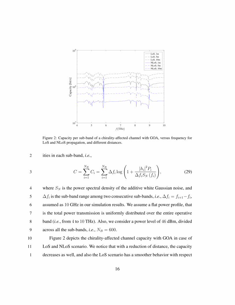
Figure 2: Capacity per sub-band of a chirality-affected channel with GOA, versus frequency forLoS and NLoS propagation, and different distances.
ities in each sub-band, i.e.,2
C =
NB∑i=1
Ci =
NB∑i=1
∆fi log
(1 +
|hi|2Pi∆fiSN (fi)
), (29)3
where SN is the power spectral density of the additive white Gaussian noise, and4
∆fi is the sub-band range among two consecutive sub-bands, i.e., ∆fi = fi+1−fi,5
assumed as 10 GHz in our simulation results. We assume a flat power profile, that6
is the total power transmission is uniformly distributed over the entire operative7
band (i.e., from 4 to 10 THz). Also, we consider a power level of 46 dBm, divided8
across all the sub-bands, i.e., NB = 600.9
Figure 2 depicts the chirality-affected channel capacity with GOA in case of10
LoS and NLoS scenario. We notice that with a reduction of distance, the capacity11
decreases as well, and also the LoS scenario has a smoother behavior with respect1
16

4 5 6 7 8 9 10f [THz]
0
0.2
0.4
0.6
0.8
1
1.2
1.4
Prop
agat
ion
dela
y [
s]
LoS, 1mLoS, 5mLoS, 10mNLoS, 1mNLoS, 5mNLoS, 10m
Figure 3: Propagation delay versus frequency in a chirality-affected channel with GOA, for LoSand NLoS propagation, and different distances.
to the frequency, while the NLoS shows an accentuate frequency-dependent trend,2
with distinguishable peaks at resonance frequencies. Specifically, in LoS, the3
capacity has an almost flat behavior, with a mean value of 0.22 Gbit/s for d =4
10 m. Performances get worst in the case of NLoS propagation for d = 1 m,5
where we observe a degradation of capacity at 5.81 and 8.92 THz, corresponding6
to 25.65 Mbit/s and 24.47 Mbit/s, respectively.7
From the expressions in (24) and (25), the propagation delay in LoS and NLoS8
scenarios is depicted in Figure 3. We observe the frequency-dependent behavior9
due to the chiral effect, and as expected, performance gets worst when the distance10
increases. An almost-flat behavior is shown for LoS at short distances (i.e., d =11
1 m), while a resonant trend appears when increasing the distance, as well as in12
NLoS scenario due to the longer distances covered. Finally, we observe that the13
propagation delay both in LoS and NLoS case shows lower values corresponding1
17

to 5.81 and 8.92 THz.2
4.2. Coherence bandwidth and symbol rate3
The root mean square (rms) delay spread is a measure of how dispersive the4
channel is. It is expressed as [7]:5
σi =
√τ 2i − τ 2
i , (30)6
where τi and τ 2i are the first and second moments of the instantaneous power-delay7
profile, respectively. From (30) we can derive information about the coherence8
bandwidth, defined as the range of frequencies over which the channel correlation9
exceeds 50%.10
In our simulations, we consider two scenarios with a variable number of NLoS11
reflected rays, i.e., (i) one, and (ii) five, and one direct ray. In both cases, we12
observe the frequency-dependent behavior as typical of chiral materials exhibiting13
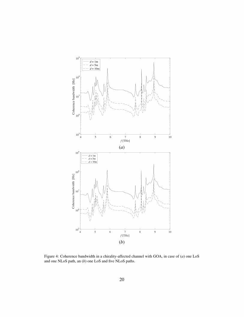
GOA. In Figure 4 (a) we show the coherence bandwidth in the case of one LoS14
and one NLoS path for different distances. As experienced in [5], higher values15
are reached for shorter distances. However, we cannot compare our results to16
others obtained with pre-existing approaches, since the frequency range is not the17
same.18
In our simulations, several peaks appear due to the chirality effects. This can19
allow tuning the frequency to resonant peaks in order to obtain higher perfor-20
mances. For example, for d = 1 m, the minimum value of rms delay is 0.33 ns,21
corresponding to 8.92 THz. This value corresponds to a symbol rate limited to22
0.1/σi = 0.29 Gbit/s to avoid inter-symbol interference. Also, in this case, the23
coherence bandwidth is limited to 0.59 GHz at the frequency peak of 8.92 THz.1
18

On the other side, when the distance increases (i.e., d = 10 m), the minimum2
rms delay is 3.6 ns at 8.92 THz. This value provides a symbol rate limited to3
27.71 Mbit/s, and the coherence bandwidth equals to 55.43 MHz, still at the same4
frequency.5
Performances get worst in case of multiple reflected paths, as shown in Fig-6
ure 4 (b). For d = 1 m the minumum rms is 0.78 ns, which corresponds to a7
coherence bandwidth of 0.25 GHz. For higher distances (i.e., d = 10 m) the8
minimum rms is 7.31 ns, corresponding to a coherence bandwidth is 27.3 MHz.9
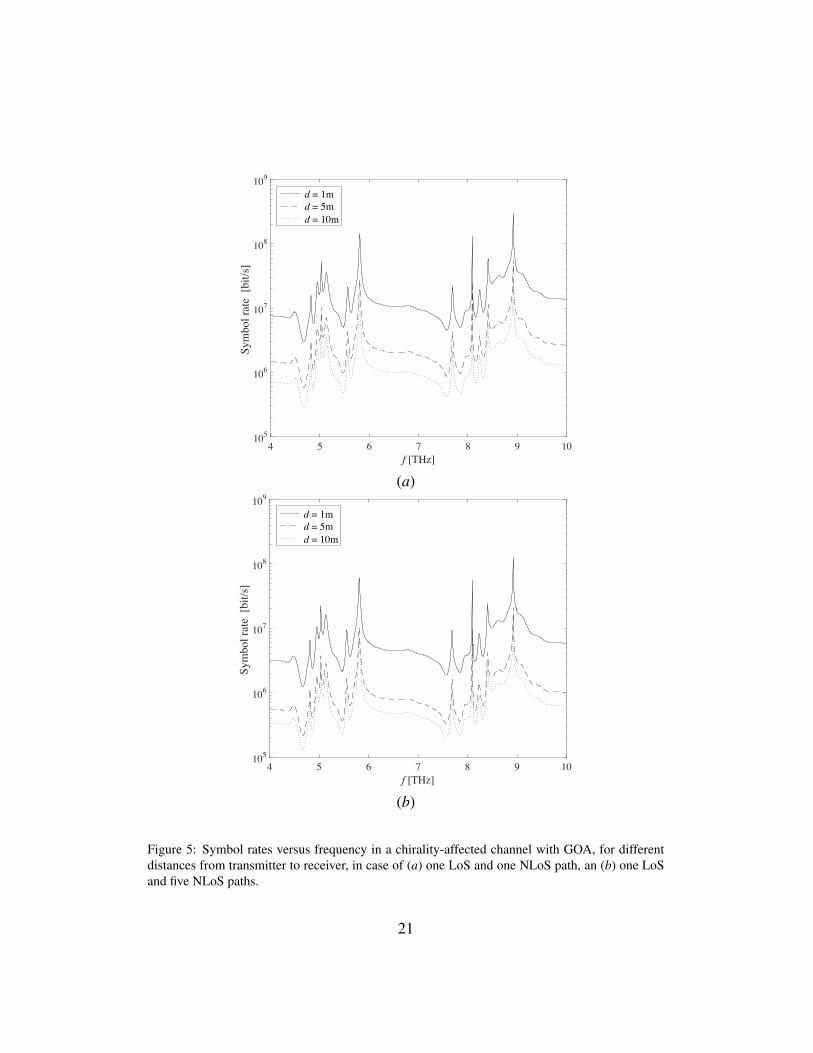
Finally, following the analysis of coherence bandwidths, we can derive the10
symbol rates in different scenarios, as depicted in Figure 5 (a) and (b) in case of11
(a) one LoS and one NLoS path, and (b) one LoS and five reflected NLoS paths,12
respectively. We notice the symbol rate is limited to a maximum of 0.29 Gbit/s13
corresponding to 8.92 THz, in order to avoid InterSymbol Interference (ISI) for14
linearly-modulated signals. Again, the chiral frequency behavior is observed, and15
a decrease of symbol rate is experienced for increasing distances (e.g., for d =16
10 m the symbol rate reaches 0.27 Mbit/s at 4.67 THz). Finally, as depicted in17
Figure 5 (b) an increase of reflected NLoS paths affects the symbol rate, then18
causing a decrease of performances until 0.13 Mbit/s for d = 10 m at 4.67 THz,19
while the maximum value is 0.12 Gbit/s obtained for d = 1 m at the frequency of20
8.92 THz.21
5. Conclusions22
In this paper we have derived the channel transfer function of a GOA chirality23
affected channel, both in the case of LoS and NLoS propagation in the (4–10) THz24
band.1
19
4 5 6 7 8 9 10f [THz]
105
106
107
108
109
Cohe
renc
e ba
ndw
idth
[H
z]
d = 1m d = 5m d = 10m
(a)
4 5 6 7 8 9 10f [THz]
105
106
107
108
109
Cohe
renc
e ba
ndw
idth
[H
z]
d = 1m d = 5m d = 10m
(b)
Figure 4: Coherence bandwidth in a chirality-affected channel with GOA, in case of (a) one LoSand one NLoS path, an (b) one LoS and five NLoS paths.
20
4 5 6 7 8 9 10f [THz]
105
106
107
108
109
Sym
bol r
ate
[bit/
s]
d = 1m d = 5m d = 10m
(a)
4 5 6 7 8 9 10f [THz]
105
106
107
108
109
Sym
bol r
ate
[bit/
s]
d = 1m d = 5m d = 10m
(b)
Figure 5: Symbol rates versus frequency in a chirality-affected channel with GOA, for differentdistances from transmitter to receiver, in case of (a) one LoS and one NLoS path, an (b) one LoSand five NLoS paths.
21
We considered the effects of the relative chiral parameter, assuming a frequency-2
dependent behavior with resonant peaks at specific frequencies. As a result, this3
affects the channel transfer function, as well as other performances. In particular,4
we identified the spectral windows that rise from the chiral effect, and the asso-5
ciated usable bandwidths. The spectral windows vary with the distance and the6
frequency, with corresponding bandwidths up to 6 THz, both in LoS and NLoS7
propagation. Another contribution of the paper has been in the identification of8
specific frequencies that allow high performance to be achieved. Thanks to the9
frequency-dependent behavior of a chiral-metamaterial, we can tune the working10
frequency in order to maximize the performance. Just as an example, the rms11
delay is dependent on the distance and carrier frequency, and reaches minimum12
values at 8.92 THz, corresponding to higher coherence bandwidths.13
As conclusion of this paper, we can claim that GOA metamaterial present-14
ing chirality effects, are really promising in terms of performance that can be15
achieved, above all in the case of lower distances. Also, distance-adaptive and16
multi-carrier transmissions represent the more appropriate communication tech-17
niques that can benefit from the relationship between distance and bandwidth in18
the range (4–10) THz.19
References
[1] I. F. Akyildiz, J. M. Jornet, The Internet of Nano-Things, IEEE Wireless
Communication Magazine 17 (6) (2010) 58–63.
[2] J. Jornet, I. Akyildiz, Channel modeling and capacity analysis for
electromagnetic wireless nanonetworks in the terahertz band, Wireless
22

Communications, IEEE Transactions on 10 (10) (2011) 3211–3221.
doi:10.1109/TWC.2011.081011.100545.
[3] I. Llatser, A. Mestres, S. Abadal, E. Alarcon, H. Lee, A. Cabellos-Aparicio,
Time- and frequency-domain analysis of molecular absorption in short-
range terahertz communications, Antennas and Wireless Propagation Let-
ters, IEEE 14 (2015) 350–353. doi:10.1109/LAWP.2014.2362194.
[4] G. Piro, K. Yang, G. Boggia, N. Chopra, L. Grieco, A. Alomainy, Tera-
hertz communications in human tissues at the nanoscale for healthcare ap-
plications, Nanotechnology, IEEE Transactions on 14 (3) (2015) 404–406.
doi:10.1109/TNANO.2015.2415557.
[5] C. Han, A. Bicen, I. Akyildiz, Multi-ray channel modeling and wideband
characterization for wireless communications in the terahertz band, Wire-
less Communications, IEEE Transactions on 14 (5) (2015) 2402–2412.
doi:10.1109/TWC.2014.2386335.
[6] C. Zhang, C. Han, I. F. Akyildiz, Three dimensional end-to-end modeling
and directivity analysis for graphene-based antennas in the terahertz band,
in: 2015 IEEE Global Communications Conference (GLOBECOM), 2015,
pp. 1–6. doi:10.1109/GLOCOM.2015.7417131.
[7] C. Han, A. Bicen, I. Akyildiz, Multi-wideband waveform design for distance
adaptive wireless communications in the terahertz band, Signal Processing,
IEEE Transactions on 64 (4) (2016) 910–922.
[8] A. Lakhtakia, R. Messier, Sculptured thin films: nanoengineerred morphol-
ogy and optics, SPIE Press monograph, 2015.
23

[9] F. Fang, Y. Cheng, Dual-band terahertz chiral metamaterial with giant optical
activity and negative refractive index based on cross-wire structure, Progress
In Electromagnetics Research M 31 (2013) 59–69.
[10] B. Wang, T. Koschny, M. Kafesaki, C. M. Soukoulis, Chiral metamaterials:
Simulations and experiments, J. Opt. A: Pure Appl. Opt. 11.
[11] N. Engheta, Chiral Materials and Chiral Electrodynamics: Background &
Basic Physical Principles, in: Special Workshop on Chiral and Complex
Materials Progress in Electromagnetics Research Symposium, 1991.
[12] A. Lakhtakia, Recent contributions to classical electromagnetic theory of
chiral media: what next?, Speculations in Science and Technology 14 (1)
(1991) 2–17.
[13] I. Lindell, A. Sihvola, S. Tretyakov, A. Viitanen, Electromagnetic waves in
chiral and bi-isotropic media, Artech House, 1994.
[14] J. Zhou, D. R. Chowdhury, R. Zhao, A. Azad, H.-T. Chen, C. M. Soukoulis,
A. J. Taylor, Terahertz chiral metamaterials with giant and dynamically tun-
able optical activity, Phys. Rev. B 86. doi:10.1103/PhysRevB.86.035448.
URL http://link.aps.org/doi/10.1103/PhysRevB.86.
035448
[15] R. Zhao, T. Koschny, C. M. Soukoulis, Chiral metamaterials: retrieval of the
effective parameters with and without substrate, Optics express 18 (4).
[16] A. M. Vegni, V. Loscrı, Performance of a Chirality-affected Channel ex-
hibiting Giant Optical Activity for Terahertz Communications, in: accepted
to ACM NanoCom 2016, 2016, pp. 1–6.
24