characterization of material structure by the x-ray
TRANSCRIPT
Characterization of material
structure by the X-ray diffraction
II
X-ray diffraction phenomenon.
Part I

geometrical
Diffraction theories of X-ray on condensed matter
describes only directions, in which the diffracted rays are observed (no intensity predictions)
Various extent of generality
kinematical
dynamicalDescribes diffraction on materials withenough large areas of coherent scatteringwith L dimmension ( mL > 0.01)
describes (among others) intensity ofradiation and is correct in the case of defectedand relatively fine-grained materials to fulfilrelation: I(scattered) << I(diffracted). No extinctionis regarded

Christian HUYGENS(1629-1695), 1678: outline of light theory
HUYGENS explained mechanizm of waves propagation
FRESNEL1818: perturbation in any point is a result of interference of elementary waves regarding its amplitude and phase

Thomas YOUNG (1773-1829),
1802 carried out and explained the interference phenomenaEstimated wavelength.Other interests: elasticity of solid bodies (E modulus)- for steel E = 2.0 x 100 000 MPa (obecnie ≈ 210 Gpa)- for bronze E = 1.0 x 100 000 MPa- for glass E = 0.6 x 100 000 MPa

Interference


Objec of scattering (size) Radiation (typical wavelength)
Print-paint dot in newspaper (0.1 mm) Thermal radiation (0.1 nm, typical)
Rain drops (10 mm) Visible light (520 nm, green) (prism effect!)
Row of the parked autos (3 m) Audible sound wave (1.26 m at 20°C)
Lattice-plane distance (0.5 nm) X-ray (0.154 nm, CuKa)
Singular atoms in crystal (0.1 nm) Electron beam (3.7 pm for 100 keV)
Obstacle size scatterind diffraction

Scattered coherent waves:
Interference constructive Interference destructive
Diffraction = scattering + interference
Mathematical formulae: von Laue* (1912)
Max von LAUE (1879–1960), physiker,
prof. univ. Zurich and Berlin,
Discoverer of X-ray diffraction, Nobel
Prize, 1914

A basic diffraction equation of X-rays: Bragg equation
• in Anglo-Sakson literature → Bragg (Braggs) equation• in Russian literature → Bragg-Wulf or Wulf-Bragg equation
What was the truth?William Henry BRAGG (1862–1942), physicist and crystallographist, prof.Univ. of London, member and chairman of the Royal Society, Nobel Prize1915 (along with son W.L. Bragg) for study of crystals structure.
William Lawrance BRAGG (1890–1971), physicist and crystallographist, prof.Univ. of Cambridge, member of the Royal Society, Nobel Prize 1915 (alongwith son W.H. Bragg) for study of crystals structure.
Gieorgij W. Wulf (1863–1925), crystallographist, prof. Univ. of Kazań,Warsaw (1899–1906) and Moscow (since 1918), member of the ScienceAcademy of USSR. Study in Warsaw, Munich and Paris. In 1913 returned toMoscow and begun dissemination of Laue’s discovery.

…by Bragg:
m
2
Adnotation at the end of the work of G.W. Wulf (sent from Russia) from 1913: „Eingegangen 3
Februar 1913”
where = dhkl, = cosy (y – angle between incident beam and normal to
diffracting lattice plane), m – order of reflection)
Bhkldn sin2
Gieorgij W. Wulf – two his works from beginning 1913 in Russian [Fizika, 1913,
zesz. 1, s. 10 and Priroda, 1913, s. 27] concerned to interference of X-rays and its
behaviour in passing through the crystals. He known the earlier works of W.L.
Bragg from 1912r.
[Proceedings of the Royal Society, 1913, 88, 428]
„Ueber die Kristallroentgenogramme”[Physikalishe Zeitschtrift, 1913, z. 6, s. 217]….by Wulf:
Adnotation at the end of the work of H.W & W.L. Braggs from 1913: „Received April 7, 1913”
y cos2 hkldm

m
2
Bhkldn sin2
Base law (equation) of diffraction theory:
y cos2 hkldm
Bragg law (equation)
Braggs – Wulf law (equation)
Wulf – Braggs law (equation)
Wulf law (equation)
Braggs law (equation)

„SURFACE ENGINEERING FOR CORROSION AND WEAR RESISTANCE” Editet by J.R. Davis, Davis & Associates, 2001.
„INŻYNIERIA WARSTWY WIERZCHNIEJ” Piotr Kula, Wydawnictwo Politechniki Łódzkiej, 2000.
Analysis of crystal structure by diffraction techniques
The crystal structure can be analyzed by X-ray diffraction (XRD from x-ray
diffraction) and electron diffraction.
Max von Laue (1879-1960),
Wiliam Henry Bragg (1862 - 1942) and Wiliam Lawrence Bragg (1890 - 1971) Max
von Laue (1879 – 1960),
Diffraction - when an X-ray beam with a wavelength comparable to that between atoms
falls on a material, the X-ray beams are scattered in all directions. Most of the radiation
scattered by one atom is extinguished by radiation scattered by other atoms. However,
when radiation falls on certain crystallographic planes at specific angles, it is amplified
and not weakened.

Donald R. Askeland, Pradeep P. Phulé „The
science and engineering of materials”,
Thomson 2006.
Weakening (a) and strengthening (b) of
the interaction between X-rays and
crystalline material.
The amplification shall be provided at a
raading angle θ corresponding to
Bragg's equation → sin θ=λ/2dhkl
Analysis of crystal structure
by diffraction techniques

Donald R. Askeland, Pradeep P. Phulé „The science and engineering of materials”, Thomson 2006.
The amplification shall be provided at an angle of incidence θ corresponding to
Bragg's equation → sin θ=nλ/2dhkl
Analysis of crystal structure by diffraction techniques

Donald R. Askeland, Pradeep P. Phulé „The science and engineering of materials”, Thomson 2006.
Analysis of crystal structure by diffraction techniques
In the practical description of the interaction of radiation with the crystal, its
structure is treated as a periodic system of atomic planes behaving as
mirrors. Reinforcement shall be provided at an incidence angle θ
corresponding to Bragg's equation → sin θ=nλ/2dhkl
where: n is the total number (designating the row of scattering), λ - the
wavelength of the radiation (for particle streams, the wavelength shall be
determined from de Broglie: λ=h/p where: h - Planck constant and p -
particle momentum), d - distance between atomic planes in the crystal, θ -
angle between the beam of incident radiation and the plane of reflection of
the beam (angle of deflection at which the maximum intensity of deflected
radiation is observed).

Powder sample
Analysis of crystal structure by diffraction techniques
In the powder sample always some
part of the powder particles
(microcrystals) have so oriented
certain planes (hkl), they meet the
Bragg condition.

Donald R. Askeland, Pradeep P. Phulé „The science and engineering of materials”, Thomson 2006.
Analysis of crystal structure by diffraction techniques
a) Scheme of diffractometer,
b) Diffractogram obtained from a
gold powder sample.
If we know the wavelength of X-rays
(λ), we can determine the distances
between the planes (and identify the
reflective crystallographic planes).

„SURFACE ENGINEERING FOR CORROSION AND WEAR RESISTANCE” Editet by J.R. Davis, Davis & Associates, 2001.
„INŻYNIERIA WARSTWY WIERZCHNIEJ” Piotr Kula, Wydawnictwo Politechniki Łódzkiej, 2000.
Listing of diffractograms recorded after removal of subsequent surface zones of the
4H13 steel nitrate sulphate layer → structural layer analysis.

Distance between crystallographic planes {hkl}:
Cubic primitive cell : h2+k2+l2= 1, 2, 3, 4, 5, 6, 8, ….
Cubic body centred cell : h2+k2+l2= 2, 4, 6, 8, 10, 12, 14, 16, ….
Cubic face centred cell : h2+k2+l2= 3, 4, 8, 11, 12, 16, ….
222
0
lkh
adhkl
)(4
sin 222
2
0
22 lkh
a


J-P. Morniroli: Large-angle convergent -beam diffraction (LACBED), 2002 Société Française des Microscopies, Paris.
a) A diffracted beam is produced if a hkl node of the reciprocal lattice is located exactly
on the Ewald sphere. This situation occurs for the node Phkl.
b) Relationship between a set of (hkl) lattice planes and its corresponding reciprocal
lattice vector ghkl. This vector is perpendicular to the (hkl) lattice planes and its
modulus ghkl is equal to 1/dhkl.
c) Vector description of Bragg’s law. Bragg’s law is satisfied when the scattering vector
S is equal to the reciprocal lattice vector ghkl.
Ewald sphere construction. General Case.

The principle of Laue Equation
Reciprocal space
All the reciprocal lattice points can be described by a linear combination of multiples of
three basis vectors: . Its definition is equivalent to the following relations:
An interesting property of the reciprocal lattice vector is that the relations are still valid if
we replace lattice vectors by reciprocal lattice vectors and inversely reciprocal lattice
vectors by lattice vectors. If V* is the volume of the reciprocal unit cell, the reader can
show that the expression VV* = 1 is also valid.

Now a reciprocal lattice vector h⃗ can be define by a linear combination of integer
multiples of the three reciprocal lattice vectors:
The reciprocal vectors play an important role in diffraction.
Miller indices
By construction, every reciprocal lattice vector is normal to a series of lattice planes.
We know also that the faces of a crystal are parallel to lattice planes and therefore
normal to the reciprocal vectors. We can therefore uniquely characterise each face
of a crystal by the integer components of a reciprocal vector with one important
subtlety. A face normal to vector h⃗ cannot be distinguished from a normal to
vector nh⃗. Therefore, we shall characterise each face of a crystal by three integer
components but without any common denominator. The triplet (h,k,l) satisfying this
condition is called the Miller indices of the face. With this specification, we realise
that Miller indices are only a subset of the possible reciprocal lattice vectors.

Miller indicators
The plane intersects the axes of the crystal at certain points, cutting off segments of a
certain length. The ratio of the net constant to the length of these sections, multiplied
by the constant, gives Miller indicators of this plane. The constant must be chosen so
that the indicators are as low as possible in absolute terms. Where the plane is
parallel to either axis, the intersection is infinite, giving a Miller Index of 0.

An abstraction of a crystalline structure where only the nodes of the lattice are given.
We have also reported a series of lattice planes with distances di and the
corresponding normal hi→ to the series of planes.
An important relation
between the distances d and
the reciprocal lattice
vector h⃗ normal to the
series of equidistant planes :

x
y
z
o
b
c
[001](100)
(010)
(001)
(110)
(1,-1,0)
(111)
{111}
(-1,1,0)
a

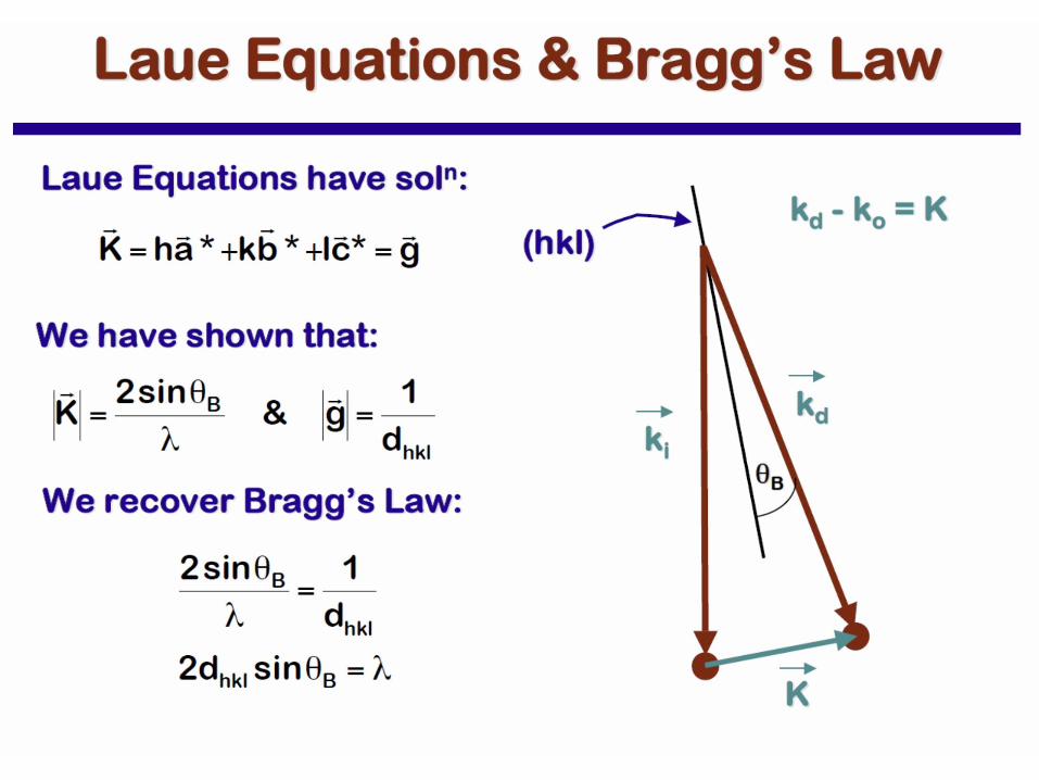
Laue Equations

Laue Equations
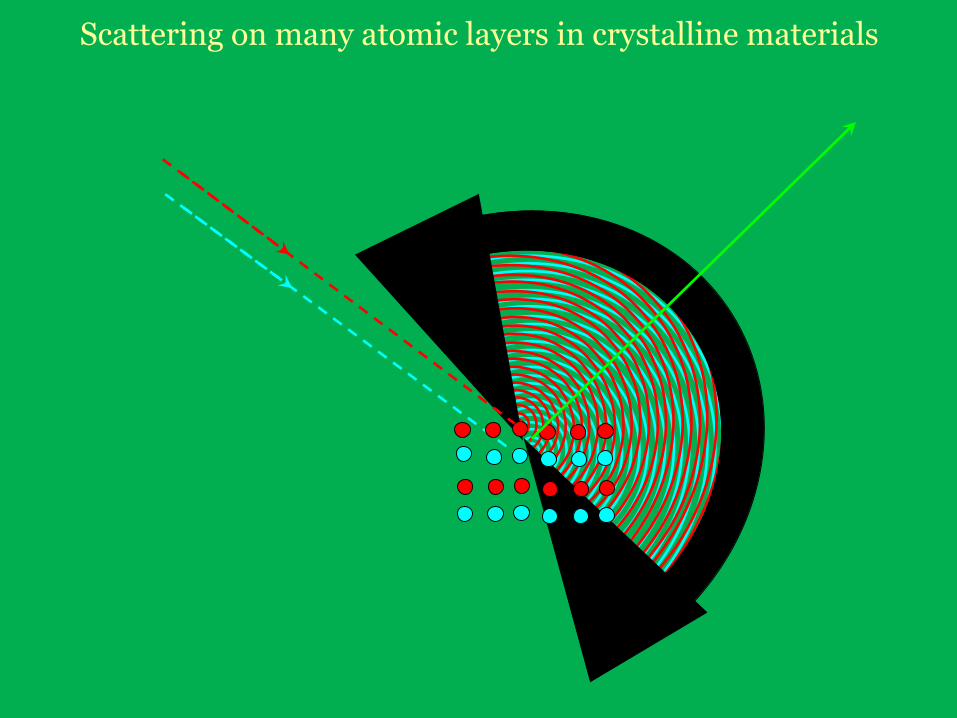
Scattering on many atomic layers in crystalline materials


Scattering on many atom layers in crystalline materials
a(cosa – cosa0) = H
Condition of X-ray diffraction on a lattice axis:
a0
a
front
of in
cid
ent
wave
a
b(cosb – cosb0) = Kc(cosg – cosg0) = L
LAUE’s equations
(condition of X-ray diffraction on a
space lattice of crystal)
DS = a(cosa – cosa0) = H
Thank you