characterization of regenerated silk material for
TRANSCRIPT
CHARACTERIZATION OF REGENERATED SILK MATERIAL FOR BIOMIMETIC
SPINNING AND FILM CASTING
A Thesis
Submitted to the Graduate Faculty
of the
North Dakota State University
of Agriculture and Applied Science
By
Bradley Thomas Hoffmann
In Partial Fulfillment of the Requirements
for the Degree of
MASTER OF SCIENCE
Major Department:
Mechanical Engineering
March 2018
Fargo, North Dakota
North Dakota State University
Graduate School
Title
Characterization of Regenerated Silk Materials by Biomimetic Spinning
and Film Casting
By
Bradley Hoffmann
The Supervisory Committee certifies that this disquisition complies with North Dakota State
University’s regulations and meets the accepted standards for the degree of
MASTER OF SCIENCE
SUPERVISORY COMMITTEE:
Dr. Long Jiang
Chair
Dr. Amanda Brooks
Dr. Bashir Khoda
Dr. Daniel Ewert
Dr. Yechun Wang
Approved:
4/5/2018 Dr. Alan R. Kallmeyer
Date Department Chair
iii
ABSTRACT
Natural silks produced by spiders and silkworms exhibit tailorable mechanical
performance yet to be achieved synthetically. This phenomenon is derived from a biological
system that has been evolutionarily optimized. In efforts to harness this elusive promise of
tailorable bio-material fabrication, a study was conducted to investigate 1) silk solution processing
2) silk spinning via a biomimetic spinning system 3) dispersions of carbon nanotubes into
regenerated silk by spinning and casting.
A formic acid calcium chloride solvent system was chosen by rheological characterization
for further processing. Fibers were spun through the biomimetic system using hydrodynamic fluid
focusing (HF) yielding predictable diameters, with improved mechanical performance correlated
to smaller diameter fibers resulted from HF. Alternatively, carbon nanotubes functionalized with
carboxylic-acid (CNTC) and non-functionalized (CNTNF) were integrated into spinning and
casting processes. Decreases in performance was observed in CNTNF constructs, however an
increase was present in CNTC suggesting structural integration of silk proteins.
iv
ACKNOWLEDGEMENTS
I would like to thank my advisors, Dr. Long Jiang and Dr. Amanda Brooks for their joint
enthusiasm and support throughout my studies. It was with their foundation and passionate
teaching style that I was able to build upon my educational mindset and pursue well rounded
research. I would also like to thank my advisory committee Dr. Bashir Khoda, Dr. Yechun Wang
and Dr. Dan Ewert for their guidance and providing a multidisciplinary atmosphere for
collaboration. Appreciation for the mechanical engineering department is warranted. My education
has been a pursuit of interdisciplinary integration of electrical and mechanical engineering. The
faculty and staff sustain an environment conducive to learning and exploring research.
Funding was supported by the North Dakota Department of Commerse Phase I Venture
Grant, National Science Foundation (grant # 1746111) and ND NASA EPSCoR. I would also like
to thank the ND Space Grant Consortium for their support in fellowship funding in pursuit of my
studies.
v
TABLE OF CONTENTS
ABSTRACT ................................................................................................................................... iii
ACKNOWLEDGEMENTS ........................................................................................................... iv
LIST OF TABLES ......................................................................................................................... ix
LIST OF FIGURES ........................................................................................................................ x
LIST OF ABBREVIATIONS ....................................................................................................... xv
LIST OF APPENDIX TABLES .................................................................................................. xvi
CHAPTER 1: INTRODUCTION ................................................................................................... 1
Research Objectives .................................................................................................................... 2
CHAPTER 2: A COMPARISON OF THE SILKS OF BOMBYX MORI AND
NEPHILA CLAVIPES ................................................................................................................... 5
The Ecological Purpose of Silks ................................................................................................. 5
Types of Spider Silk ................................................................................................................ 5
Types of Silkworm Silk ........................................................................................................... 6
Natural Silk Protein Spinning ..................................................................................................... 7
Material Structure of Silkworm and Spider Silks ....................................................................... 9
Mechanical Characteristics of Silkworm and Spider Silks ....................................................... 12
Acquiring and Processing Silk Proteins .................................................................................... 15
Cloning and Reproducing Recombinant Silk Proteins .......................................................... 15
Solubility of Silk Proteins ..................................................................................................... 16
Applications of Manufacturing Silk Fibers and Constructs ...................................................... 17
Artificial Spinning Techniques.............................................................................................. 17
Biomedical Applications of Silk ........................................................................................... 19
Silk Nanocomposites and Films ............................................................................................ 20
Concluding Observations .......................................................................................................... 22
References ................................................................................................................................. 22
vi
CHAPTER 3: SYNTHESIS AND CHARACTERIZATION OF SILK SOLVENT
SYSTEMS THROUGH A RHEOLOGICAL INVESTIGATION ............................................... 36
Silk Spin Dope Preparation ....................................................................................................... 39
Silkworm Silk Degumming ................................................................................................... 39
Lithium Bromide Silk Solution ............................................................................................. 39
Calcium Chloride, Ethanol and Water Ternary Silk Solution ............................................... 40
Formic Acid and Calcium Chloride Silk Solution ................................................................ 40
Hexaflouroisopropanol Silk Solution .................................................................................... 41
Characterization of Silk Solutions ............................................................................................. 42
Rheology................................................................................................................................ 42
Solvent System Selection .......................................................................................................... 46
References ................................................................................................................................. 47
CHAPTER 4: USING ENGINEERING TO UNRAVEL THE MYSTERY OF SPIDER
SILK FIBER FORMATION......................................................................................................... 52
Abstract ..................................................................................................................................... 52
Introduction ............................................................................................................................... 53
Methods ..................................................................................................................................... 57
Results ....................................................................................................................................... 59
Discussion ................................................................................................................................. 62
Conclusion ................................................................................................................................. 64
References ................................................................................................................................. 65
CHAPTER 5: DEVELOPMENT OF A COMPLEX CONTROL SYSTEM FOR
MULTIPLE FLUID FLOW GRADIENTS .................................................................................. 67
Abstract ..................................................................................................................................... 67
Introduction ............................................................................................................................... 68
Methods ..................................................................................................................................... 71
vii
Device .................................................................................................................................... 71
Control System for Fluid Rate Control ................................................................................. 72
Hydrodynamic Focusing Simulation Implementation........................................................... 73
Spin Dope Solution and Fiber Spinning ................................................................................ 74
Results ....................................................................................................................................... 75
Discussion ................................................................................................................................. 78
Conclusion ................................................................................................................................. 79
References ................................................................................................................................. 79
CHAPTER 6: USING HYDRODYNAMIC FOCUSING TO PREDICTABLY ALTER
THE DIAMTER OF SYNTHETIC FIBERS ................................................................................ 82
Abstract ..................................................................................................................................... 82
Introduction ............................................................................................................................... 82
Materials and Methods .............................................................................................................. 87
Solution Preparation .............................................................................................................. 87
Steady State Rheology ........................................................................................................... 87
Fluid Simulations................................................................................................................... 87
Hydrodynamic Spinning ........................................................................................................ 88
Mechanical Testing ............................................................................................................... 89
Statistics ................................................................................................................................. 89
Results and Discussion .............................................................................................................. 89
Conclusion ................................................................................................................................. 96
References ................................................................................................................................. 97
CHAPTER 7: SILK BASED COMPOSITE MATERIAL PROCESSING ............................... 103
Synthesizing Formic Acid Calcium Chloride Silk Solvent System ........................................ 105
Thin Silk Film Casting ............................................................................................................ 105
Dispersion of Carbon Nanotubes via Sonication .................................................................... 107
viii
Dispersion of Carbon Nanotubes via Homogenizer ................................................................ 108
Silk Nanocomposite Fiber Spun Through Biomimetic Device ............................................... 109
Mechanical Tensile Testing of Silk Films and Fibers ............................................................. 110
Mechanical Performance of Sonicated Silk Films .............................................................. 112
Mechanical Performance of Homogenized Silk Films ........................................................ 116
Mechanical Performance of Homogenized Silk Fibers ....................................................... 118
Viscoelastic Characteristics of Silk Films Observed via Frequency Sweep Rheology .......... 120
Mechanical Performance of Other Silk Nanocomposite Films ............................................... 123
References ............................................................................................................................... 126
CHAPTER 8: CONCLUDING REMARKS .............................................................................. 131
Future Works ........................................................................................................................... 133
Pathway One - Biomimetic Device ..................................................................................... 134
Pathway Two - Film Casting ............................................................................................... 135
APPENDIX. SUPPLEMENTARY TABLES ............................................................................ 137
ix
LIST OF TABLES
Table Page
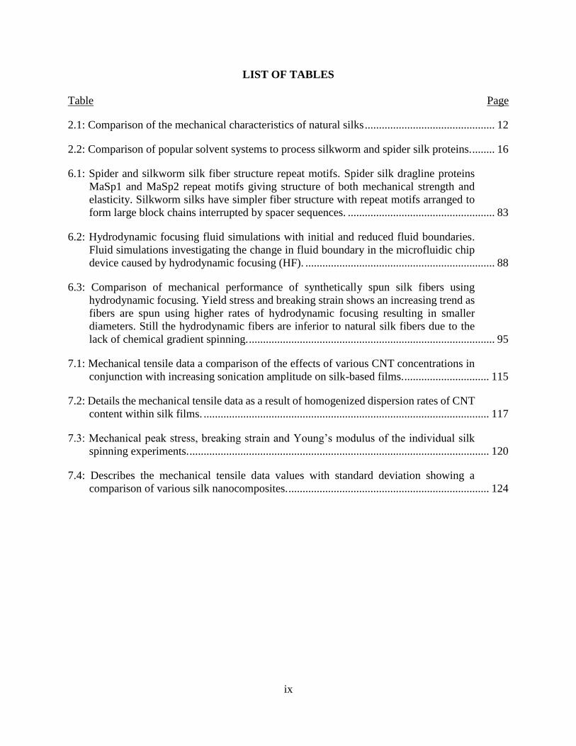
2.1: Comparison of the mechanical characteristics of natural silks .............................................. 12
2.2: Comparison of popular solvent systems to process silkworm and spider silk proteins. ........ 16
6.1: Spider and silkworm silk fiber structure repeat motifs. Spider silk dragline proteins
MaSp1 and MaSp2 repeat motifs giving structure of both mechanical strength and
elasticity. Silkworm silks have simpler fiber structure with repeat motifs arranged to
form large block chains interrupted by spacer sequences. .................................................... 83
6.2: Hydrodynamic focusing fluid simulations with initial and reduced fluid boundaries.
Fluid simulations investigating the change in fluid boundary in the microfluidic chip
device caused by hydrodynamic focusing (HF). ................................................................... 88
6.3: Comparison of mechanical performance of synthetically spun silk fibers using
hydrodynamic focusing. Yield stress and breaking strain shows an increasing trend as
fibers are spun using higher rates of hydrodynamic focusing resulting in smaller
diameters. Still the hydrodynamic fibers are inferior to natural silk fibers due to the
lack of chemical gradient spinning. ....................................................................................... 95
7.1: Mechanical tensile data a comparison of the effects of various CNT concentrations in
conjunction with increasing sonication amplitude on silk-based films. .............................. 115
7.2: Details the mechanical tensile data as a result of homogenized dispersion rates of CNT
content within silk films. ..................................................................................................... 117
7.3: Mechanical peak stress, breaking strain and Young’s modulus of the individual silk
spinning experiments. .......................................................................................................... 120
7.4: Describes the mechanical tensile data values with standard deviation showing a
comparison of various silk nanocomposites. ....................................................................... 124
x
LIST OF FIGURES
Figure Page
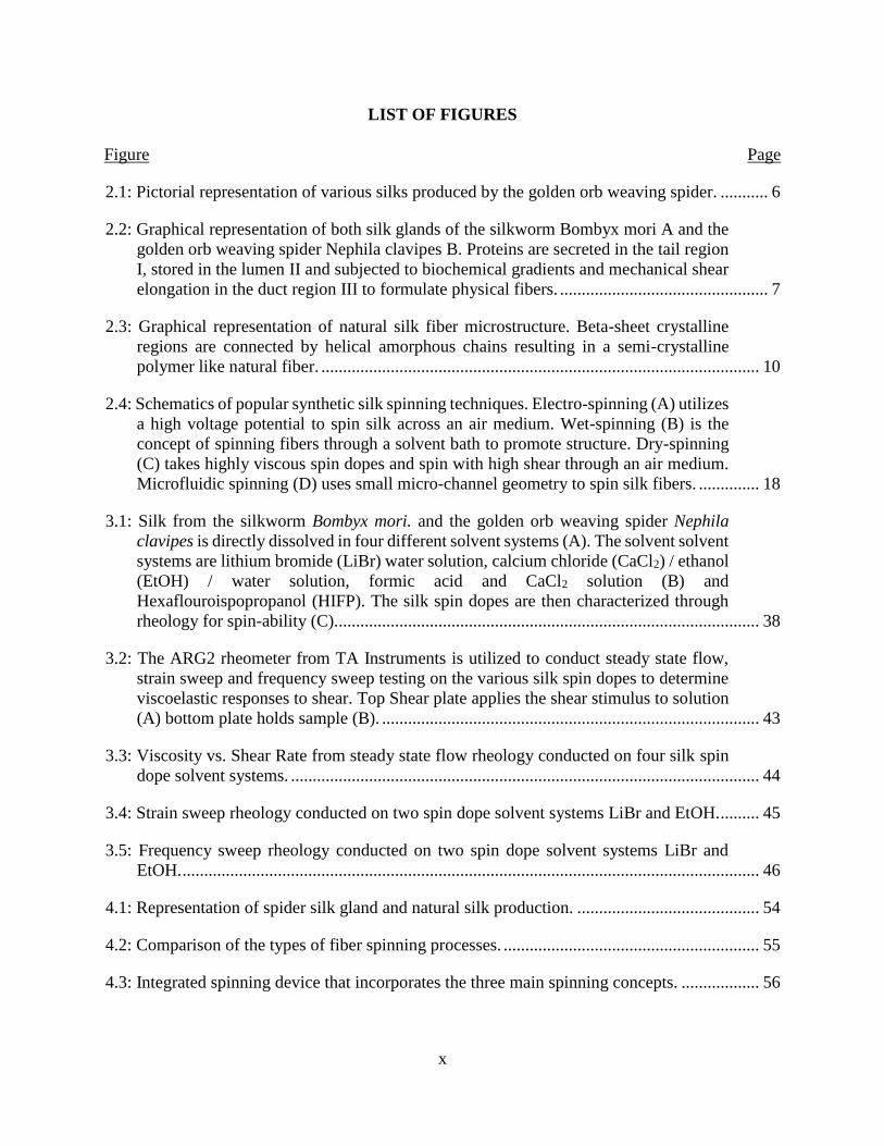
2.1: Pictorial representation of various silks produced by the golden orb weaving spider. ........... 6
2.2: Graphical representation of both silk glands of the silkworm Bombyx mori A and the
golden orb weaving spider Nephila clavipes B. Proteins are secreted in the tail region
I, stored in the lumen II and subjected to biochemical gradients and mechanical shear
elongation in the duct region III to formulate physical fibers. ................................................ 7
2.3: Graphical representation of natural silk fiber microstructure. Beta-sheet crystalline
regions are connected by helical amorphous chains resulting in a semi-crystalline
polymer like natural fiber. ..................................................................................................... 10
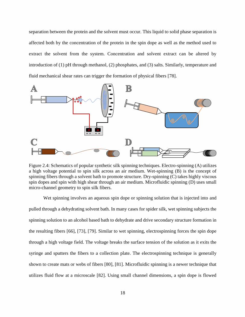
2.4: Schematics of popular synthetic silk spinning techniques. Electro-spinning (A) utilizes
a high voltage potential to spin silk across an air medium. Wet-spinning (B) is the
concept of spinning fibers through a solvent bath to promote structure. Dry-spinning
(C) takes highly viscous spin dopes and spin with high shear through an air medium.
Microfluidic spinning (D) uses small micro-channel geometry to spin silk fibers. .............. 18
3.1: Silk from the silkworm Bombyx mori. and the golden orb weaving spider Nephila
clavipes is directly dissolved in four different solvent systems (A). The solvent solvent
systems are lithium bromide (LiBr) water solution, calcium chloride (CaCl2) / ethanol
(EtOH) / water solution, formic acid and CaCl2 solution (B) and
Hexaflouroispopropanol (HIFP). The silk spin dopes are then characterized through
rheology for spin-ability (C). ................................................................................................. 38
3.2: The ARG2 rheometer from TA Instruments is utilized to conduct steady state flow,
strain sweep and frequency sweep testing on the various silk spin dopes to determine
viscoelastic responses to shear. Top Shear plate applies the shear stimulus to solution
(A) bottom plate holds sample (B). ....................................................................................... 43
3.3: Viscosity vs. Shear Rate from steady state flow rheology conducted on four silk spin
dope solvent systems. ............................................................................................................ 44
3.4: Strain sweep rheology conducted on two spin dope solvent systems LiBr and EtOH. ......... 45
3.5: Frequency sweep rheology conducted on two spin dope solvent systems LiBr and
EtOH. ..................................................................................................................................... 46
4.1: Representation of spider silk gland and natural silk production. .......................................... 54
4.2: Comparison of the types of fiber spinning processes. ........................................................... 55
4.3: Integrated spinning device that incorporates the three main spinning concepts. .................. 56
xi
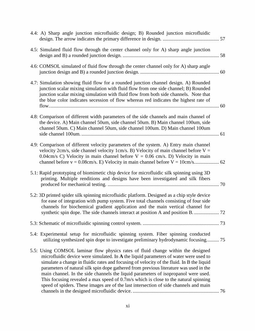
4.4: A) Sharp angle junction microfluidic design; B) Rounded junction microfluidic
design. The arrow indicates the primary difference in design. ............................................. 57
4.5: Simulated fluid flow through the center channel only for A) sharp angle junction
design and B) a rounded junction design. ............................................................................. 58
4.6: COMSOL simulated of fluid flow through the center channel only for A) sharp angle
junction design and B) a rounded junction design. ............................................................... 60
4.7: Simulation showing fluid flow for a rounded junction channel design. A) Rounded
junction scalar mixing simulation with fluid flow from one side channel; B) Rounded
junction scalar mixing simulation with fluid flow from both side channels. Note that
the blue color indicates secession of flow whereas red indicates the highest rate of
flow. ....................................................................................................................................... 60
4.8: Comparison of different width parameters of the side channels and main channel of
the device. A) Main channel 50um, side channel 50um. B) Main channel 100um, side
channel 50um. C) Main channel 50um, side channel 100um. D) Main channel 100um
side channel 100um. .............................................................................................................. 61
4.9: Comparison of different velocity parameters of the system. A) Entry main channel
velocity 2cm/s, side channel velocity 1cm/s. B) Velocity of main channel before V =
0.04cm/s C) Velocity in main channel before V = 0.06 cm/s. D) Velocity in main
channel before v = 0.08cm/s. E) Velocity in main channel before V = 10cm/s.................... 62
5.1: Rapid prototyping of biomimetic chip device for microfluidic silk spinning using 3D
printing. Multiple renditions and designs have been investigated and silk fibers
produced for mechanical testing. ......................................................................................... 70
5.2: 3D printed spider silk spinning microfluidic platform. Designed as a chip style device
for ease of integration with pump system. Five total channels consisting of four side
channels for biochemical gradient application and the main vertical channel for
synthetic spin dope. The side channels interact at position A and position B. .................... 72
5.3: Schematic of microfluidic spinning control system. ............................................................. 73
5.4: Experimental setup for microfluidic spinning system. Fiber spinning conducted
utilizing synthesized spin dope to investigate preliminary hydrodynamic focusing. ......... 75
5.5: Using COMSOL laminar flow physics rates of fluid change within the designed
microfluidic device were simulated. In A the liquid parameters of water were used to
simulate a change in fluidic rates and focusing of velocity of the fluid. In B the liquid
parameters of natural silk spin dope gathered from previous literature was used in the
main channel. In the side channels the liquid parameters of isopropanol were used.
This focusing revealed a max speed of 0.7m/s which is close to the natural spinning
speed of spiders. These images are of the last intersection of side channels and main
channels in the designed microfluidic device. ..................................................................... 76
xii
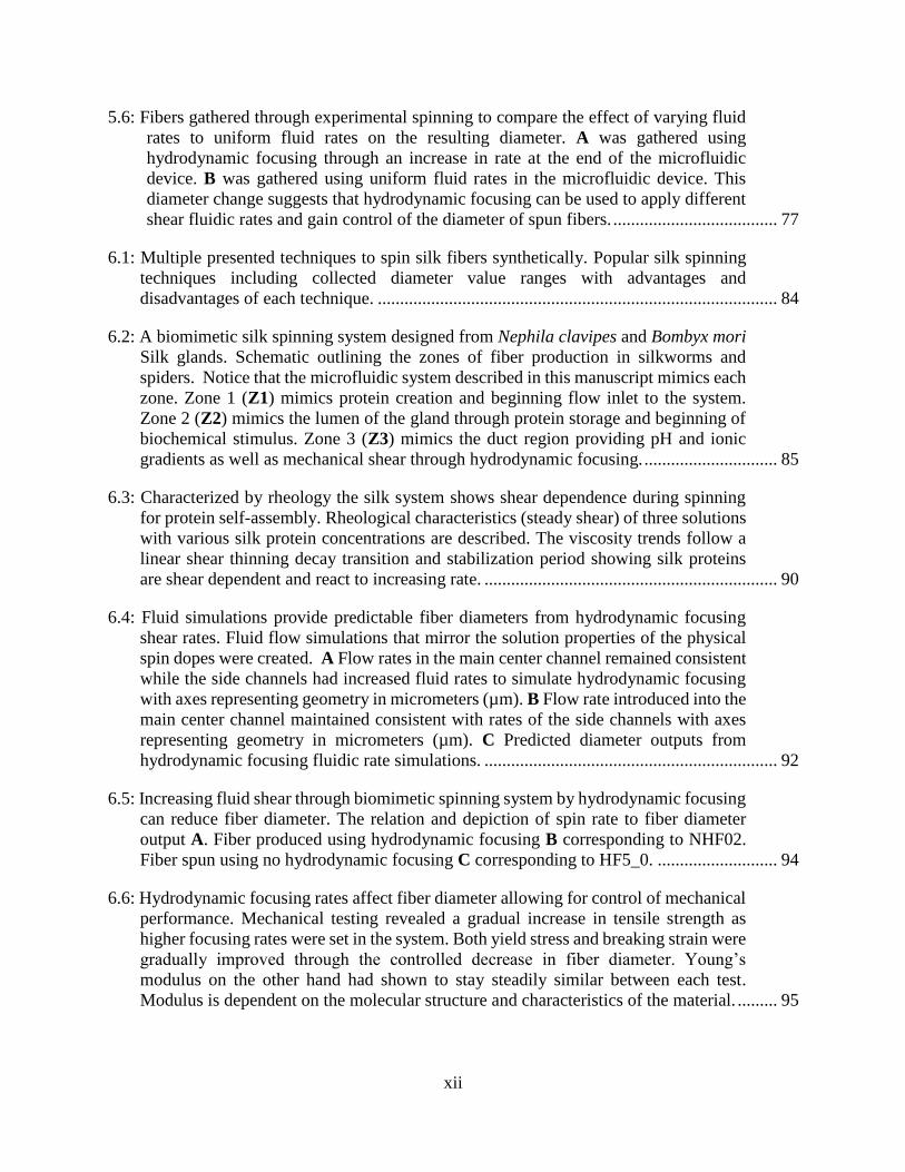
5.6: Fibers gathered through experimental spinning to compare the effect of varying fluid
rates to uniform fluid rates on the resulting diameter. A was gathered using
hydrodynamic focusing through an increase in rate at the end of the microfluidic
device. B was gathered using uniform fluid rates in the microfluidic device. This
diameter change suggests that hydrodynamic focusing can be used to apply different
shear fluidic rates and gain control of the diameter of spun fibers. ..................................... 77
6.1: Multiple presented techniques to spin silk fibers synthetically. Popular silk spinning
techniques including collected diameter value ranges with advantages and
disadvantages of each technique. .......................................................................................... 84
6.2: A biomimetic silk spinning system designed from Nephila clavipes and Bombyx mori
Silk glands. Schematic outlining the zones of fiber production in silkworms and
spiders. Notice that the microfluidic system described in this manuscript mimics each
zone. Zone 1 (Z1) mimics protein creation and beginning flow inlet to the system.
Zone 2 (Z2) mimics the lumen of the gland through protein storage and beginning of
biochemical stimulus. Zone 3 (Z3) mimics the duct region providing pH and ionic
gradients as well as mechanical shear through hydrodynamic focusing. .............................. 85
6.3: Characterized by rheology the silk system shows shear dependence during spinning
for protein self-assembly. Rheological characteristics (steady shear) of three solutions
with various silk protein concentrations are described. The viscosity trends follow a
linear shear thinning decay transition and stabilization period showing silk proteins
are shear dependent and react to increasing rate. .................................................................. 90
6.4: Fluid simulations provide predictable fiber diameters from hydrodynamic focusing
shear rates. Fluid flow simulations that mirror the solution properties of the physical
spin dopes were created. A Flow rates in the main center channel remained consistent
while the side channels had increased fluid rates to simulate hydrodynamic focusing
with axes representing geometry in micrometers (µm). B Flow rate introduced into the
main center channel maintained consistent with rates of the side channels with axes
representing geometry in micrometers (µm). C Predicted diameter outputs from
hydrodynamic focusing fluidic rate simulations. .................................................................. 92
6.5: Increasing fluid shear through biomimetic spinning system by hydrodynamic focusing
can reduce fiber diameter. The relation and depiction of spin rate to fiber diameter
output A. Fiber produced using hydrodynamic focusing B corresponding to NHF02.
Fiber spun using no hydrodynamic focusing C corresponding to HF5_0. ........................... 94
6.6: Hydrodynamic focusing rates affect fiber diameter allowing for control of mechanical
performance. Mechanical testing revealed a gradual increase in tensile strength as
higher focusing rates were set in the system. Both yield stress and breaking strain were
gradually improved through the controlled decrease in fiber diameter. Young’s
modulus on the other hand had shown to stay steadily similar between each test.
Modulus is dependent on the molecular structure and characteristics of the material. ......... 95
xiii
7.1: Silk based thin films synthesized by air drying casting process. Natural silk is
dissolved in a solvent system of formic acid/calcium chloride until a viscous solution
is reached (A). The solution is directly pour casted, dried and immersed in water to
promote protein structure (B). ............................................................................................. 106
7.2: Scanning electron microscopy of neat film cross sections A and B compared to a film
CNT nanocomposite film cross section C. A and B images show white fibrils that are
comprised of silk proteins that self-assemble during the casting process. The
interaction in image C shows the CNT bundle coinciding around the silk nano-fibrils.
............................................................................................................................................. 109
7.3: Experimental setup of silk spinning system. ....................................................................... 109
7.4: Silk films casted with CNTs. A was cast with a silk solution CNT mixture dispersed
via sonication. B was cast from a dispersed silk – CNT solution using a homogenizer
at high RPM. Note the larger agglomerate of CNTs are noticeable by visual inspection
in the sonicated sample. ....................................................................................................... 110
7.5: MTS Insight tensile testing setup A. Silk film specimen for mechanical testing B. ........... 111
7.6: Instron Microtensile testing setup A. Silk fiber specimen for mechanical testing B. ......... 112
7.7: Stress vs. Strain curves compare mechanical performance as a result of sonication
amplitudes of Neat (A), 0.2% CNTNF (B), 0.4% CNTNF (C), 0.6% CNTNF (D) and
0.1% CNTC (E) Films. ........................................................................................................ 113
7.8: Stress vs. Strain curves compare mechanical performance as a result of change of CNT
concentration at various sonication amplitudes 20% (A), 40% (B), 60% (C) and 80%
(D). ...................................................................................................................................... 114
7.9: Stress vs. Strain curves an investigation into the change in mechanical performance
due to increasing homogenized dispersion rates. ................................................................ 117
7.10: Stress vs. Strain curve of silk fibers spun through the biomimetic device. The
comparison is shown of Neat Fibers, CNTNF dispersed Fibers and CNTC dispersed
Fibers.................................................................................................................................. 119
7.11: Comparison of silk fibers spun through the biomimetic device conducted by
microscopy. The silk fibers show an increase in a darker appearance from Neat Fiber
to CNTNF with the CNTC fibers showing the darkest distribution. ................................ 120
7.12: Storage (G’) and Loss (G”) Modulus vs. angular frequency shows silk films and the
response to drying time. ..................................................................................................... 121
7.13: G’ and G” vs. Angular Frequency plots comparing neat films to CNTC films at
homogenized dispersion rates of 10000 RPM. This shows a slight increase in
mechanical performance of viscoelastic responses to oscillatory shear. .......................... 122
xiv
7.14: Stress vs. Strain plot comparison of mechanical tensile performance between various
silk nanocomposites. The integration of CNTs, GO and CNF has shown to vary
mechanical properties of peak stress, breaking strain and Young’s modulus. .................. 124
7.15: X-Ray diffraction plot of intensity vs. 2θ. The x-ray diffraction testing shows a
comparison of neat silk crystal structure with CNTNF and CNF nanocomposite films.
............................................................................................................................................ 125
xv
LIST OF ABBREVIATIONS
CaCl2 ..............................................................Calcium Choride
CNC ...............................................................Cellulose Nano-Crystals
CNF ................................................................Cellulose Nano-Fibers
CNTs ..............................................................Carbon Nanotubes
CNTC .............................................................Carbon Nanotubes COOH
CNTNF ..........................................................Carbon Nanotubes Non-Functionalized
CRPs ..............................................................Cysteine-Rich Proteins
EtOH ..............................................................Ethanol
FA ..................................................................Formic Acid
GO ..................................................................Graphene Oxide
HF ..................................................................Hydrodynamic Focusing
HFIP ...............................................................Hexifloro-2-Propanol
LiBr ................................................................Lithium Bromide
MA .................................................................Major Ampullate
MaSp1 ............................................................Major Ampullate Spidroin 1
MaSp2 ............................................................Major Ampullate Spidroin 2
NHF................................................................No Hydrodynamic Focusing
Na2CO3 ...........................................................Sodium Carbonate
SCF ................................................................Silk – Calcium Chloride – Formic Acid
xvi
LIST OF APPENDIX TABLES
Table Page
A1: Experimental Data for Sonicated Neat Film Tensile Specimens. ....................................... 137
A2: Experimental Data for Sonicated 0.2% wt/vol CNTNF Film Tensile Specimens. ............. 138
A3: Experimental Data for Sonicated 0.4% wt/vol CNTNF Film Tensile Specimens. ............. 139
A4: Experimental Data for Sonicated 0.6% wt/vol CNTNF Film Tensile Specimens. ............. 140
A5: Experimental Data for Sonicated 0.1% wt/vol CNTC Film Tensile Specimens. ............... 141
A6: Experimental Data for Homogenized Neat Film Tensile Specimens. ................................ 142
A7: Experimental Data for Homogenized 0.1% wt/vol CNTNF Film Tensile Specimens. ...... 142
A8: Experimental Data for Homogenized 0.1% wt/vol CNTC Film Tensile Specimens. ........ 143
A9: Experimental Data for Homogenized 0.1% wt/vol GO Film Tensile Specimens. ............. 143
A10: Experimental Data for Homogenized 0.2% wt/vol GO Film Tensile Specimens. ........... 143
A11: Experimental Data for Homogenized 0.1% wt/vol CNF Film Tensile Specimens. ......... 144
A12: Experimental Data for Homogenized 0.2% wt/vol CNF Film Tensile Specimens. ......... 144
A13: Experimental Data for Homogenized Neat Fiber Tensile Specimens. ............................. 144
A14: Experimental Data for Homogenized 0.1% CNTNF Fiber Tensile Specimens. .............. 145
A15: Experimental Data for Homogenized 0.1% CNTC Fiber Tensile Specimens .................. 145
A16: Peak Stress ANOVA Statistical Test of Variation due to Sonication Amplitude............. 145
A17: Peak Stress ANOVA Statistical Test of Variation due to CNT Concentration ................ 145
A18: Mechanical Tensile Data ANOVA Statistical Test of Variation due to
Homogenization Dispersion Rate 5000 to 10000 RPM .................................................. 146
A19: Mechanical Tensile Data ANOVA Statistical Test of Homogenized Films Variance
Due to CNT Functionalization .......................................................................................... 146
1
CHAPTER 1: INTRODUCTION
Biomimicry, in which a material or process imitates a natural occurrence, is rapidly gaining
popularity as a source of new solutions to global grand challenges. Observations have revealed
that evolution can drive and shape innovation and the development of technology. From achieved
flight by the Wright Brothers in the early 1900s to the invention of Velcro inspired by wild brush,
survival driven processes have been evolutionarily optimized to succeed. Building upon nature’s
bounty, the use of bio-based materials or biomaterials have been of interest to both scientists and
popular culture. Naturally occurring bio-based materials are of intrigue due not only to their
recyclable byproducts and bio-degradability but also to their ecologically friendly, green
manufacturing.
Bio-materials, such as, natural silks produced by a variety of insects and arthropods have
a long history of use for basic survival ranging from fishing to wound care [1], due to their balance
of mechanical properties that exhibit ranges of high tensile strength, extensibility, energy
absorbance and toughness [2]. Although some of the earliest documented research and use of silk
occurred in the textile industry, structural materials and sutures for wound care were reported as
early as the 1700’s, with reports continuing through the 1800s and 1900s [1], [3], [4]. Much of the
intrigue surrounding this natural fiber that is stronger than steel and can rival the mechanical
performance of man-made polymers is centered not only on the composition of the fiber itself but
also on the natural glandular process that produces such a material. In the case of spiders, which
produce silk throughout their lifetime, unique amino acid sequences have allowed the spider to
tailor its silk for specific ecological purposes. Studying not only the evolution of such optimization
but more importantly, the natural material processing that has produced this variation, has opened
2
the door for continued biomimetic materials research to capture that tailorability during
biomaterial manufacturing.
In this study, silkworm and spider silk spinning processes were investigated to provide a
biomimetic approach to synthesizing high performance, tailorable, biomaterials through either
fiber spinning or protein casting methods of manufacturing. While this first chapter sets the stage
for the work presented in this thesis and outlines the hypotheses and objectives guiding the
research, the second chapter is meant to provide a comprehensive review of the literature to provide
insight into the material and mechanical properties of silkworm and spider silk fibers, the natural
silk spinning processes, current synthetic spinning techniques, as well as, efforts to create silk-
based constructs and nanocomposites. The third chapter discusses characterization of dissolution
processes of silk spin dope solutions via rheology. The fourth chapter delineates experiments to
capture the natural spinning process of spiders and silkworms in an experimental, microfluidic,
biomimetic device. In the fifth chapter processing of fibers with controlled diameters spun through
the biomimetic device with hydrodynamic focusing is discussed. Building upon the spinning and
expressing a casting methodology, the sixth chapter describes integration of carbon nanotubes into
the spinning and casting processes to develop a silk-based nanocomposite. The seventh chapter
provides a concise summary of the encompassed work and offers a perspective future works in
this field.
Research Objectives
Natural silk fibers are one of the world’s most versatile materials and have been optimized
for specific ecological functions through millions of years of evolution. Silk from species such as
spiders and silkworms are of particular interest due to their strength and elasticity that rival that of
man-made materials. Despite some significant differences, both spiders and silkworms have an
3
intricate silk spinning process (i.e., ionic, pH and shear gradients) that is enveloped in a gland; this
complexity allows the mechanical characteristics of the silks to be varied with precision [2], [5].
This elusive balance of strength and elasticity in a single material has been investigated in synthetic
fiber production; however, due to synthetic processing, it has never been attainable or recapitulated
to resemble its natural counterpart. The mechanical ability of natural silks in conjunction with their
in vivo biocompatibility makes spider and silkworm silks contenders for biomedical implants and
drug delivery carriers [6], [7]. The promise of natural silks may be realized by using biomimetic
engineering guided by material composite theory [8]–[10]. Adopting the characteristics of a
spinning system that has been optimized through evolution is the approach used in this study of
silk processing. By recapitulating the natural silk processing system, spider and silkworm silk can
be harnessed to create not only a versatile material to improve biomedical implants but also a
material appropriate for high strength, smart, aerospace applications. The objectives in this thesis
are to (1) fabricate silk-based materials that can perform at the same magnitude as their natural
counterparts through the use of a biomimetic approach and (2) develop a homogenous silk
nanocomposite. These global objectives circulate around the hypothesis that natural silk proteins
can be processed using the controlled application of mechanical shear and chemical gradients to
yield fibers and films with both strength and elasticity. As a corollary, nanoparticles dispersed into
silk films and fibers will exhibit altered strength and extensibility.
Objective 1: Re-spin natural silk protein solutions into fibers of controlled and predictable
diameter using a fabricated 3D printed biomimetic microfluidic device with application of
controlled mechanical shear and chemical gradients.
• Sub-aim 1.1: Using fluid flow simulations, evaluate the impact of hydrodynamic
focusing on a predicted fiber diameter.
4
• Sub-aim 1.2: Confirm in silico fluid flow simulations on the bench using a prototype
3D printed microfluidic device with side infusion channels.
Objective 2: Cast natural, silk-based, protein solutions into films to characterize large scale
silk processing.
• Sub-aim 2.1: Conduct and optimize the casting process of silk solutions to create
uniform thin films.
• Sub-aim 2.2: Mechanically test cast silk films to determine their strength and
viscoelastic characteristics.
Objective 3: Create a homogenous silk protein solution with integrated carbon nanotubes
to alter the mechanical properties of both synthetically spun silk fibers and films.
• Sub-aim 3.1: Disperse both functionalized and neat carbon nanoparticles into silk
protein spin dope to make homogenous nanocomposite biomimetic fibers.
• Sub-aim 3.2: Disperse both functionalized and neat carbon nanoparticles into silk
protein solutions to make homogenous nanocomposite films with altered mechanical
and/or electrical properties.
5
CHAPTER 2: A COMPARISON OF THE SILKS OF BOMBYX MORI AND NEPHILA
CLAVIPES
The Ecological Purpose of Silks
Spider and silkworm silks remain one of the world’s highest quality bio-based materials
with mechanical characteristics that rival and in some cases exceed man-made synthetic materials
[11], [12]. These two species of arthropods have evolutionarily optimized a silk fiber spinning
system through millions of years. This natural process has been made possible through the
coexistence of biochemical stimuli and mechanical fluid shear within a single silk gland structure,
allowing tailorable control of mechanical and material characteristics. Developing a system to
replicate the mechanical and material characteristics of both silkworm and spider dragline silk
(Major Ampullate silk) can be inspired by identifying common elements of the biological spinning
systems of both spiders and silkworms.
Types of Spider Silk
Specifically, two species, the golden orb weaving spider (Nephila clavipes) and the
silkworm (Bombyx mori) are of interest to multiple groups of researchers due to defined structure
function relationships that govern the mechanical performance their silks. Unlike silkworms that
produce a single type of silk at a specific phase of their life cycle, orb-weaving spiders produce
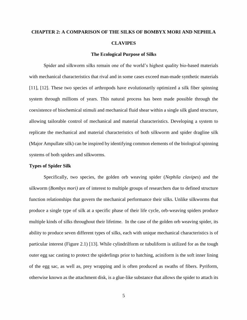
multiple kinds of silks throughout their lifetime. In the case of the golden orb weaving spider, its
ability to produce seven different types of silks, each with unique mechanical characteristics is of
particular interest (Figure 2.1) [13]. While cylindrilform or tubuliform is utilized for as the tough
outer egg sac casting to protect the spiderlings prior to hatching, aciniform is the soft inner lining
of the egg sac, as well as, prey wrapping and is often produced as swaths of fibers. Pyriform,
otherwise known as the attachment disk, is a glue-like substance that allows the spider to attach its
6
silk to surfaces. As the primary prey catching silk of the web, flagelliform is extremely extensible,
stretching over 200% elongation [13]. Aggregate silk is the only non-solid silk and is found as an
aqueous glue silk used to coat other silks and provides an adhesive quality to the web. Minor
ampullate silk is used for web structure. The major ampullate silk or the dragline silk is used as
the spider’s lifeline to maneuver and drop. The dragline silk is of most interest to material science
as it is not only the strongest silk but it also has moderate extensibility, leading some to characterize
it as having the highest mechanical performance. Amazingly, each of these silks is segregated into
a specific set of paired glands in the abdomen of the spider.
Figure 2.1: Pictorial representation of various silks produced by the golden orb weaving spider.
Types of Silkworm Silk
Silkworms on the other hand only produce one type of silk fiber during the transition
between larva to moth. Two glands produce twin silk fibroin and are positioned along either side
of the silkworm’s body. The controlling biological valve of the silkworm’s gland allows silk to be
spun out through the oral orifice of the insect. Silk fibroin is spun to create the cocoon in a bottom
7
up fashion as the silkworm begins the silk process it will begin at the bottom of its body working
towards the top.
Natural Silk Protein Spinning
Through separate evolutionary pathways silkworms and spiders have coalesced in the
development of complex silk spinning systems. The flow characteristics of silk spin dope within
the glands during spinning suggests a natural extrusion process not unlike man-made polymer
extruders [14], [15]. The gland structures have been shaped by evolutionary selection to allow for
1) sufficient surface area to facilitate dehydration and protein alignment, 2) control of shear forces
and flow characteristics as the liquid crystalline feedstock flows through the silk gland [15] and 3)
tight packing within the limited space of the spider’s abdomen and along the full body length of
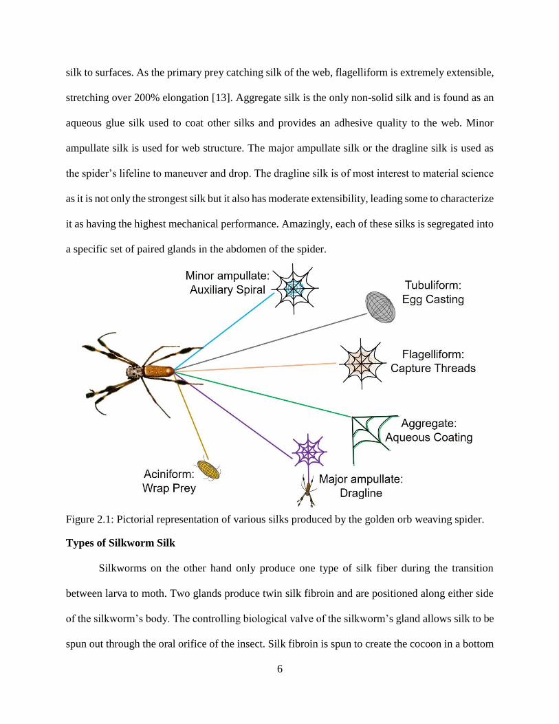
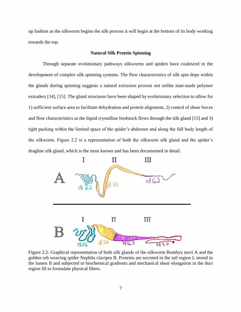
the silkworm. Figure 2.2 is a representation of both the silkworm silk gland and the spider’s
dragline silk gland, which is the most known and has been documented in detail.
Figure 2.2: Graphical representation of both silk glands of the silkworm Bombyx mori A and the
golden orb weaving spider Nephila clavipes B. Proteins are secreted in the tail region I, stored in
the lumen II and subjected to biochemical gradients and mechanical shear elongation in the duct
region III to formulate physical fibers.
8
Natural major ampullate silk produced by the spider and the fibroin produced by the
silkworm is subjected not only to dehydration, pH and ionic gradients produced via carbonic
anhydrase, but also to fluidic shear within the silk glands, which yields high strength and toughness
[16]. This complex sequence of events can best be understood by breaking the gland structure into
several parts, giving the ability for control of mechanical characteristics when being extruded or
spun leading to tailored fibers [12].
The long silk gland structures consist of a tail region, lumen or large storage for proteins,
a tapering duct region, and a biological spinneret valve. The tail region is lined with modified
epithelial cells, which secrete proteins. These proteins accumulate to a very high concentration as
they pass through the tail region and into the lumen of the gland for protein storage. This region at
times has concentrations of almost 50% (w/v) proteins stored with chloride and sodium ions [12].
In the lumen of the gland the proteins form a micelles with hydrophobic-hydrophilic block
structures [17]. From the lumen, the proteins pass through an s-shaped tapering duct that allows
for increasing dehydration and protein alignment to form a fiber through biochemical interactions
and mechanical shear elongation. In this region, the sodium and chloride ions are replaced with
potassium and phosphate ions that will change the pH and ionic values introduced to the proteins
allowing a change in electronegativity [18], [19]. These chemical stimuli change the pH and ionic
composition to further help with protein alignment. The protein alignment and structural re-
arrangement of crystalline regions is correlated to pH and cations present and their interaction with
the specific amino acids of the protein [19]. The pH at the beginning of the gland is more basic
with a pH of 7-8. At the end of the process, the spin solution is more acidic with a pH close to 5
[16], [20], [21].
9
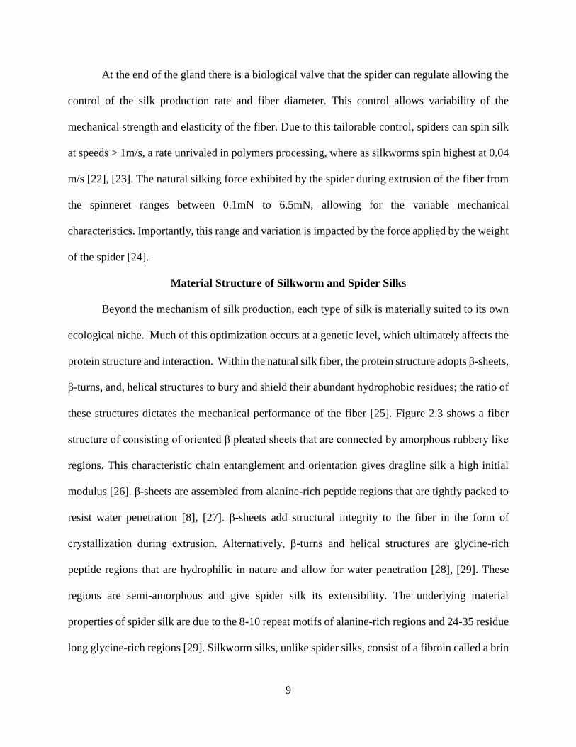
At the end of the gland there is a biological valve that the spider can regulate allowing the
control of the silk production rate and fiber diameter. This control allows variability of the
mechanical strength and elasticity of the fiber. Due to this tailorable control, spiders can spin silk
at speeds > 1m/s, a rate unrivaled in polymers processing, where as silkworms spin highest at 0.04
m/s [22], [23]. The natural silking force exhibited by the spider during extrusion of the fiber from
the spinneret ranges between 0.1mN to 6.5mN, allowing for the variable mechanical
characteristics. Importantly, this range and variation is impacted by the force applied by the weight
of the spider [24].
Material Structure of Silkworm and Spider Silks
Beyond the mechanism of silk production, each type of silk is materially suited to its own
ecological niche. Much of this optimization occurs at a genetic level, which ultimately affects the
protein structure and interaction. Within the natural silk fiber, the protein structure adopts β-sheets,
β-turns, and, helical structures to bury and shield their abundant hydrophobic residues; the ratio of
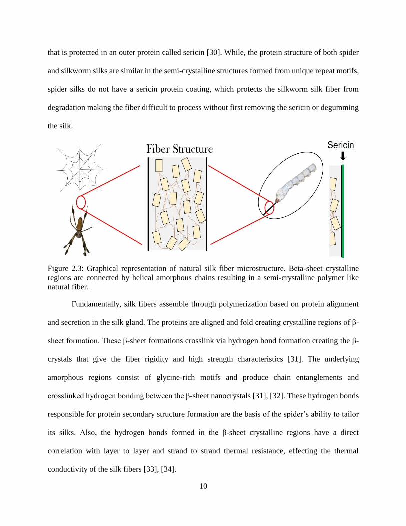
these structures dictates the mechanical performance of the fiber [25]. Figure 2.3 shows a fiber
structure of consisting of oriented β pleated sheets that are connected by amorphous rubbery like
regions. This characteristic chain entanglement and orientation gives dragline silk a high initial
modulus [26]. β-sheets are assembled from alanine-rich peptide regions that are tightly packed to
resist water penetration [8], [27]. β-sheets add structural integrity to the fiber in the form of
crystallization during extrusion. Alternatively, β-turns and helical structures are glycine-rich
peptide regions that are hydrophilic in nature and allow for water penetration [28], [29]. These
regions are semi-amorphous and give spider silk its extensibility. The underlying material
properties of spider silk are due to the 8-10 repeat motifs of alanine-rich regions and 24-35 residue
long glycine-rich regions [29]. Silkworm silks, unlike spider silks, consist of a fibroin called a brin
10
that is protected in an outer protein called sericin [30]. While, the protein structure of both spider
and silkworm silks are similar in the semi-crystalline structures formed from unique repeat motifs,
spider silks do not have a sericin protein coating, which protects the silkworm silk fiber from
degradation making the fiber difficult to process without first removing the sericin or degumming
the silk.
Figure 2.3: Graphical representation of natural silk fiber microstructure. Beta-sheet crystalline
regions are connected by helical amorphous chains resulting in a semi-crystalline polymer like
natural fiber.
Fundamentally, silk fibers assemble through polymerization based on protein alignment
and secretion in the silk gland. The proteins are aligned and fold creating crystalline regions of β-
sheet formation. These β-sheet formations crosslink via hydrogen bond formation creating the β-
crystals that give the fiber rigidity and high strength characteristics [31]. The underlying
amorphous regions consist of glycine-rich motifs and produce chain entanglements and
crosslinked hydrogen bonding between the β-sheet nanocrystals [31], [32]. These hydrogen bonds
responsible for protein secondary structure formation are the basis of the spider’s ability to tailor
its silks. Also, the hydrogen bonds formed in the β-sheet crystalline regions have a direct
correlation with layer to layer and strand to strand thermal resistance, effecting the thermal
conductivity of the silk fibers [33], [34].
11
Beyond specific secondary structures with a single protein is the multi-protein structure.
Specifically, spider’s dragline silk is a composite of two major proteins, major ampullate spidroin
1 (MaSp1) and major ampullate spidroin 2 (MaSp2) [35]. Cysteine-rich proteins (CRPs) are
present in higher quantities within the silk glands. These CRPs are extruded with MaSp1 and
MaSp2 to formulate higher molecular weight complexes that give the silk some of its mechanical
characteristics [36]. Cysteine proteins belong to a slipknot family. When CRPs are expressed with
the major ampullate silk proteins, they allow the formation of disulfide bonds, resulting in a
slipknot action or configuration during polymerization of the proteins and polypeptide chains [36].
Hence inclusion of CRPs may lead to increased toughness and resistance to chemical degradation,
which are characteristics of spider silk. While the semi-crystalline fiber structure is similar in the
fact that the proteins that make up the repeat motif regions form β-sheet and helical structures, the
protein sequencing between the terminal regions is the largest difference between Nephila clavipes
and Bombyx mori.
Spider silk has four main motifs that make up the major ampullate protein sequence.
Polyalanine-rich regions, glycine-rich regions, spacers and C-terminal regions each give specific
mechanical characteristics and structure as the fiber is formed [37], [38]. Spacers are believed to
give the fiber a characteristic of surface charge or charged regions for interaction as the fiber chain
is being polymerized in the gland [38]. Silkworms have large block structures repeat motifs of
(GA)nGX that coincide two major sequences of GAGAGS and GAGAGY. These large block
chains will form elastic β-spiral and β-sheet structures based on the silkworm spinning these
sequences as needed for its cocoon [39].
12
Mechanical Characteristics of Silkworm and Spider Silks
Golden orb weaving spiders can produce multiple types of natural silks with varying
mechanical properties. This ability to produce a fiber tailored for a specific ecological purpose
allows the spider to create and control the characteristics of its silk at will. Dragline silk (major
ampullate) is utilized by the spider to move around its terrain and provide structural integrity to its
web. Major ampullate spider silk fibers along as well as silkworm silk have mechanical properties
comparable to the strength, strain, extensibility, toughness and energy absorption of man-made
polymeric materials, such as Kevlar and Nylon (Table 2.1) [11], [12], [40], [41].
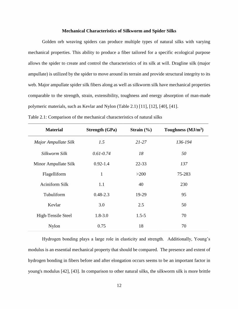
Table 2.1: Comparison of the mechanical characteristics of natural silks
Hydrogen bonding plays a large role in elasticity and strength. Additionally, Young’s
modulus is an essential mechanical property that should be compared. The presence and extent of
hydrogen bonding in fibers before and after elongation occurs seems to be an important factor in
young's modulus [42], [43]. In comparison to other natural silks, the silkworm silk is more brittle
Material Strength (GPa) Strain (%) Toughness (MJ/m3)
Major Ampullate Silk 1.5 21-27 136-194
Silkworm Silk 0.61-0.74 18 50
Minor Ampullate Silk 0.92-1.4 22-33 137
Flagelliform 1 >200 75-283
Aciniform Silk 1.1 40 230
Tubuliform 0.48-2.3 19-29 95
Kevlar 3.0 2.5 50
High-Tensile Steel 1.8-3.0 1.5-5 70
Nylon 0.75 18 70

13
due to a decrease in hydrogen bonding during elongation and after fracture [43]. Nevertheless,
both spider and silkworm (Bombyx mori) silks have β-sheet crystalline regions of poly-alanine and
helical glycine-rich amorphous regions [13], [28], [44].
The extent of β-sheet is manifest mechanically not only in a resistance to compression but
also in a viscoelasticity. Rheology reveals that natural spider silk spin dope collected from the
major ampullate gland has shown viscoelastic behavior similar to shear thickening polymer melts
at higher concentrations [45]. The shear thickening property is driven by elements of
concentration, change in pH and ionic elements. This suggests that the spider can control the fluid
strain, as well as, viscosity of the solution within its silk gland to stop premature fiber formation.
Also, elements of this control may be provided by certain genetic elements such as the C-terminus
of the proteins. Hence synthetically controlling fiber formation could be done through pH and
ionic components introduced at different areas of the spinning process. The spin dope of the spider
is said to undergo a liquid to solid strain-induced phase separation. This has been analyzed using
oscillatory shear and shear flow rheological testing experiments. This reveals shear thinning
characteristics at higher strain rates suggesting molecular elongation and alignment of proteins
through the silk gland [46].
Beyond shear dependency of these silk fibers, one characteristic unique to spider silks is a
mechanical contraction response to moisture [47]. The silk fibers are susceptible to humidity and
temperature and this characteristic is theorized to be present to give the spider's web structural
integrity by allowing it to self-repair and become taught during increased humidity [47].
Furthermore, hydrogen bonding aids in characteristics of self-annealing stress relaxation in the
amorphous regions of the silk. This unique characteristic of spider silks is called supercontraction
(i.e., contraction up to 50% if their original length when exposed to water) [48]. Spider silk
14
contracts in the presence of water exhibiting a rubbery like state. Water absorption from
supercontraction tends to occur in the amorphous regions of the silk.
The spider’s dragline silk shows a glass transition from temperature and humidity. This
transitioning period allows for a change from glassy characteristics found in semi-crystalline
polymers to a rubber like state. Specifically, during the physical extension after supercontraction
the amorphous chains become more oriented creating a polymeric glass phase. Hydrogen
secondary bonds that can be affected by water can act like a plasticizer. Additionally, one study
suggests that supercontraction may be an annealing mechanism of the fiber or ground-state
allowing recoverable mechanical behavior to be harnessed in high humidity [48]. The ability to
supercontract adds an additional layer of control to the tailorability of these high tensile silk fibers.
Supercontraction may allow the spider to manipulate the mechanical characteristics of the silk
fiber through pre-stressing the fiber assembly before it leaves the silk gland, based on the presence
of free water molecules and as a result of the protein/protein interaction. Importantly, the presence
of water could initiate disruption of hydrogen bonding found in the elastomeric silk fiber allowing
an equilibrium state to occur and reducing initial stress [49].
The amorphous regions of the fiber are thought to be responsible for self-annealing and
realignment of the protein chains through supercontraction to remove hydrophobic stress. There is
however, another component that oppositely aids in strain hardening when the fiber is subjected
to stress. The β-sheet crystalline regions form sheets of proteins that give rigidity to the fiber. Upon
tensile loading and stress elongation these crystalline regions stretch and pull apart forming smaller
β-sheet crystals. These characteristics aid in reformation of crystalline regions, giving the fibers
high strength and toughness. Essentially, the motif, hierarchal structure of major ampullate spider
15
silk in conjunction with the protein alignment that occurs during spinning leads to a self-strain
hardening behavior [32].
Acquiring and Processing Silk Proteins
Silks produced by silkworms and spiders can be gathered through (1) forcible silking or
(2) recombinant protein expression. Although forcible silking provides a complete picture of the
mechanics of silk, the territorial nature of spiders makes scale-up difficult if not impossible
necessitating an alternative approach. Recombinant protein production from insect and
mammalian cells has shown to be promising alternatives to raising and farming spiders.
Cloning and Reproducing Recombinant Silk Proteins
During efforts to increase the scalability of silk protein production towards a reliable
industrial scale, advances in biotechnology and molecular biology (e.g., new cloning systems and
scale up processes) have been a driving force in current and previous studies [50], [51]. Since the
discovery of the genetic sequence of MaSp1 and MaSp2 [52] and with all subsequent silk genetic
sequences, investigation into recombinant production has kept pace, allowing the use of different
hosts such as goats [53], plants [54], yeast [55] and bacteria [56] to try to recapitulate the protein
properties of silk. A variety of cloning techniques have been looked at to try and reconstitute
genetically altered or cloned spider silk proteins. Unfortunately, several logistical limitations (e.g.,
highly repetitive genetics sequence and very large proteins exceed the capability of traditional
recombinant expression systems (e.g., bacteria, yeast, etc)), necessitate the production of only a
smaller, truncated, version of the protein in a variety of other higher capacity systems such as goats
[57].
To scale protein production for industrial manufacturing, the proteins of spider silk have
been synthesized using genetic alteration of goats to produce the proteins in their milk upon
16
maturing [58], [59]. Similar to the transgenic manipulation of goats, there has been research to
produce spider silk proteins in transgenic tobacco and potato plants [54]. By utilizing plants,
MaSp1 could be produced as a byproduct of the plant, providing an ecofriendly approach to
manufacturing spider silk.
Solubility of Silk Proteins
While the production of silk proteins can be made green, the solubilization of those proteins
often requires organic solvents. Studies into the solubility and continued processing of both
recombinantly produced and naturally obtained silk proteins have been extensive [60]. Natural
silks are highly resistant to various solvents making them difficult to solubilize; however, popular
solvent systems allow for the breakdown of silk proteins to create a spin dope able to be used
during synthetic spinning (Table 2.2).
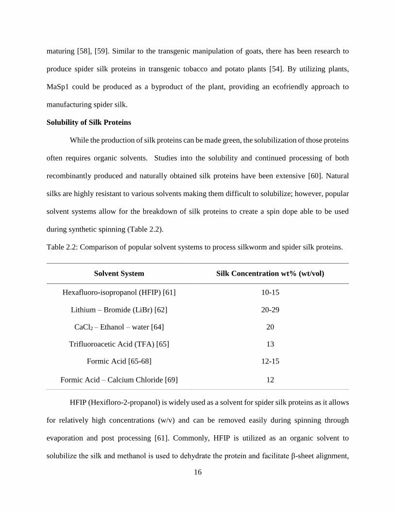
Table 2.2: Comparison of popular solvent systems to process silkworm and spider silk proteins.
HFIP (Hexifloro-2-propanol) is widely used as a solvent for spider silk proteins as it allows
for relatively high concentrations (w/v) and can be removed easily during spinning through
evaporation and post processing [61]. Commonly, HFIP is utilized as an organic solvent to
solubilize the silk and methanol is used to dehydrate the protein and facilitate β-sheet alignment,
Solvent System Silk Concentration wt% (wt/vol)
Hexafluoro-isopropanol (HFIP) [61] 10-15
Lithium – Bromide (LiBr) [62] 20-29
CaCl2 – Ethanol – water [64] 20
Trifluoroacetic Acid (TFA) [65] 13
Formic Acid [65-68] 12-15
Formic Acid – Calcium Chloride [69] 12
17
ultimately, promoting fiber formation. Lithium bromide (LiBr) is a salt based solvent system that
is heavily used for processing both silkworm silk and spider silk, as it is able to completely
disassemble the fiber into its amino acid components. After solubilization the salt can be removed
through dialysis leaving an aqueous silk solution [62]. CaCl2 is utilized in the solvent system with
ethanol and water to disrupt secondary protein structure of the protein [63]. In the solvent system
of CaCl2, ethanol and water the ethanol plays a key role in supporting protein interactions and β-
sheet formation during spinning [64]. Formic acid and trifluoroacetic acid, organic solvents, have
gained traction for their ability to break some of the macrostructures of silkworm silk without
damaging or degrading silk proteins [65]–[68]. Building on formic acid studies, adding calcium
chloride (CaCl2) salt to the formic acid solvent system allows for silk fibers to be broken into
solubilized nano-fibril structures instead of individual molecular components [69].
Applications of Manufacturing Silk Fibers and Constructs
In order to scale up silk production for a variety of applications, silk proteins must be
recombinantly produced and synthetically spun to produce fibers that rival natural spider silk.
Unfortunately, the natural process is complex and elements of the spinning environment have not
been completely replicated, potentially compromising our ability to synthetically replicate the
mechanical properties of silk. Research into the production of tailorable silk fibers using a
biomimetic approaches has been significantly overlooked.
Artificial Spinning Techniques
For artificial spinning, concentrations of spider silk of around (10-20% w/v) are necessary
to get reliable fibers. Historically techniques such as electro-spinning [70], [71], wet-spinning
[72]–[74], dry-spinning [75], and microfluidic spinning [76], [77] have been used to spin synthetic
silkworm and spider silk as seen in Figure 2.4. For biomimetic silk fiber formation, a phase
18
separation between the protein and the solvent must occur. This liquid to solid phase separation is
affected both by the concentration of the protein in the spin dope as well as the method used to
extract the solvent from the system. Concentration and solvent extract can be altered by
introduction of (1) pH through methanol, (2) phosphates, and (3) salts. Similarly, temperature and
fluid mechanical shear rates can trigger the formation of physical fibers [78].
Figure 2.4: Schematics of popular synthetic silk spinning techniques. Electro-spinning (A) utilizes
a high voltage potential to spin silk across an air medium. Wet-spinning (B) is the concept of
spinning fibers through a solvent bath to promote structure. Dry-spinning (C) takes highly viscous
spin dopes and spin with high shear through an air medium. Microfluidic spinning (D) uses small
micro-channel geometry to spin silk fibers.
Wet spinning involves an aqueous spin dope or spinning solution that is injected into and
pulled through a dehydrating solvent bath. In many cases for spider silk, wet spinning subjects the
spinning solution to an alcohol based bath to dehydrate and drive secondary structure formation in
the resulting fibers [66], [73], [79]. Similar to wet spinning, electrospinning forces the spin dope
through a high voltage field. The voltage breaks the surface tension of the solution as it exits the
syringe and sputters the fibers to a collection plate. The electrospinning technique is generally
shown to create mats or webs of fibers [80], [81]. Microfluidic spinning is a newer technique that
utilizes fluid flow at a microscale [82]. Using small channel dimensions, a spin dope is flowed
19
through a microfluidic channel. The small dimensions and fluid dynamics help align the proteins
and with specific designs other stimulus, such as, biochemical stimulus can be introduced to
change pH or electronegativity and help aid in protein alignment and polymerization [83], [84].
Unfortunately, none of the spinning techniques described above fully exploit the natural silk
creation process found in the spider’s silk gland.
Post processing or post-spin drawing of synthetic silk fibers through an additional solvent
bath or air after spinning has been investigated in an effort to increase mechanical performance.
During the post-spin draw process, it is thought that the additional mechanical stimulus and
elongation could align protein chains and improve mechanical characteristics [85]. Importantly,
the spider’s natural spinning system is thought to couple fiber formation and elongation (coupled
spin and draw). These effects were observed as fibers were spun through an aqueous solution to
stretch the fibers and assist in increased mechanical properties. Techniques have looked at
isopropanol as a post spin draw solution to dehydrate and provide alignment of fibers as they are
spun [86]. Methanol has also been used as a solvent bath for the processing of fibers as it has
shown to alter the mechanical properties of wet spun spider silk [87].
Biomedical Applications of Silk
In addition to silk’s natural mechanical properties and versatility in processing, natural silk
does not invoke an immune response, an imperative quality for biomedical engineering materials
such as those used for tissue engineering and implant research [88]. Recently, an aqueous silk
solution (6 to 8% wt/wt) was exposed to airflow and water to reach a 25 to 50% concentration, a
technique that was utilized to make silk-based machined orthopedic implants [89]. Along with the
ability to not invoke an immune response natural silk fibers are shown to maintain their structural
integrity in vivo [90], allowing for the continued development of new materials for use as scaffolds
20
for tissue growth and repair. Continually, silk proteins have grown in popularity for tissue repair
as a variety of new solvent systems have yielded aqueous and harmless solutions. These solutions
can then be utilized for bio-inks to be 3-D printed and hydrogels for cell growth or drug delivery
[91]–[93].
Silk Nanocomposites and Films
Natural silks have been utilized to create different types of bio-based nanocomposites and
constructs. For example, a nanocomposite has been synthesized using spider silk and cellulose
nanocrystals (CNC) and cellulose nanofibers (CNF) [94], [95]. This mixture has been seen to
increase the glass transition temperature in comparison to all-natural spider silk. This may be due
to chain/chain interaction and the crystallinity of the cellulose nanocrystals [95]. These spider silk
cellulose nanocrystal composites have been utilized to make films, including thin transparent
films, and sponges. Additional studies of natural biopolymers have also produced composite
nanowires using polymerization of aniline and spider silk to produce a surface conductive material
[96].
Natural silk nanocomposites with graphene and carbon-based materials have been explored
for their conductance, energy storage (uses for supercapacitors), and developmental electronics
applications. Many of these nanocomposites are made with silkworm silk due to the limited
availability of spider silk. Specifically, the silk produced by silkworms was utilized as a
nanocomposite with graphene oxide for supercapacitance. The nanocomposite was synthesized
using graphene oxide and an lithium bromide (LiBr) silkworm silk solution (4% wt) [97].
Graphene oxide sheets and natural cocoon silk produced by silkworms have also been used to
formulate nanocomposite membranes. These membranes were synthesized using a layer by layer
21
heterogeneous approach through surface interaction of the graphene oxide sheets and silk layers
[98]. The layer-by-layer nanocompositing increased the tensile modulus of the silk-based material.
Similarly, functionalized carbon nanotubes have been used to coat spider silk making a
scaffold to increase conductivity of the fiber, which is a natural insulator [99]. This technique
utilized aqueous natural spider silk and amine functionalize multiwall carbon nanotubes bonded
through physical shearing until carbon nanotubes were fully coating the spider silk bundle [100].
Additionally, a study investigating the effects of multiwalled carbon nanotubes and the electrical
coating of re-spun silk fibers had been investigated. This study observed the dispersion of carbon
nanotubes in a solvent system of formic acid and CaCl2 to coat on the outer surface of the re-spun
fibers to improve electrical characteristics of conductivity [101]. Recently, a study involving
transmuting spider silk into carbon fiber has been conducted to serve as an alternative to oxygen
reduction reaction found as a normal catalyst for carbon fiber formation. This study consisted of
harvesting spider silk, dispersing it in zinc dichloride and evaporating the solution over heat.
Carbonization occurred through increased excessive heat on the solid samples for an extended
period of time. This resulted in a carbon based residue, allowing continued material
characterization [102]. Additionally, several studies have laid the ground work for casting of film
and scaffold structures [103]–[105]. Utilizing a solvent system of formic acid and CaCl2 the self-
assembly process of silk proteins is captured in preliminary silk based casting [106]. Alternatively,
silk-based nanocomposite film and scaffold material orientations, created using a LiBr solvent
system, have been investigated for uses in humidity sensing and tissue engineering [107]–[109].
Continually, these scaffolds and films can drive innovation towards biomedical applications.
22
Concluding Observations
While natural silks have been used for centuries in primitive medical applications and
textiles popularity in current science has driven investigations into how to harness this biomaterial.
With silks as strong as steel, the popularity and intrigue into how silk spinning insects create their
natural fibers has recently become a race to procure the secrets of high performance bio-based
material fabrication. These previous studies have spun investigations into the mechanisms that
yield these mechanical characteristics, but synthetic processes have yet to capture the mechanical
performance of the natural counterpart. The essence of the silk fiber structures is assembled
through an intricate dependence on three stimuli. To better characterize the silk spinning process,
it is critical to include all basic building blocks of the natural system into the manufacturing process
of these fibers. Biomimetic engineering will bring observations of the individual elements into a
complete design of a silk spinning system that incorporates 1) metal ion gradients, 2) biochemical
pH gradients and 3) mechanical shear flow gradients that are analogous to the natural spinning
system. Integration of these three elements into a biomimetic system will not only initiative the
control of tailorable fiber production but will give insight into the self-assembly process of the
natural proteins for silk based 3-D constructs. Ultimately the biomimetic processing of silk will
enable future studies to harness the power of high performance natural materials for a plethora of
engineering and medical applications.
References
[1] R. Lewis, “Unraveling the Weave of Spider Silk,” BioScience, vol. 46, no. 9, pp. 636–638,
Oct. 1996.
23
[2] O. Tokareva, M. Jacobsen, M. Buehler, J. Wong, and D. L. Kaplan, “Structure–function–
property–design interplay in biopolymers: Spider silk,” Acta Biomater., vol. 10, no. 4, pp.
1612–1626, Apr. 2014.
[3] O. G. Kiliani, “II. On Traumatic Keloid of the Median Nerve, with Observations upon the
Absorption of Silk Sutures,” Ann. Surg., vol. 33, no. 1, pp. 13–22, Jan. 1901.
[4] M. Bon, “A Discourse upon the Usefulness of the Silk of Spiders. By Monsieur Bon,
President of the Court of Accounts, Aydes and Finances, and President of the Royal Society
of Sciences at Montpellier. Communicated by the Author,” Philos. Trans., vol. 27, no. 325–
336, pp. 2–16, Jan. 1710.
[5] G. Fang et al., “Insights into Silk Formation Process: Correlation of Mechanical Properties
and Structural Evolution during Artificial Spinning of Silk Fibers,” ACS Biomater. Sci. Eng.,
vol. 2, no. 11, pp. 1992–2000, Nov. 2016.
[6] J. G. Hardy, A. Leal-Egaña, and T. R. Scheibel, “Engineered Spider Silk Protein-Based
Composites for Drug Delivery: Engineered Spider Silk Protein-Based Composites …,”
Macromol. Biosci., vol. 13, no. 10, pp. 1431–1437, Oct. 2013.
[7] B. Kundu et al., “Silk proteins for biomedical applications: Bioengineering perspectives,”
Prog. Polym. Sci., vol. 39, no. 2, pp. 251–267, Feb. 2014.
[8] P. Alam, “Biomimetic Insights: Structure-Toughness Relations in Spider Silk Nanocrystals,”
Adv. Mater. Res., vol. 622–623, pp. 1799–1802, Dec. 2012.
[9] R. Karnani, M. Krishnan, and R. Narayan, “Biofiber-reinforced polypropylene composites,”
Polym. Eng. Sci., vol. 37, no. 2, pp. 476–483, Feb. 1997.
[10] J. G. Hardy and T. R. Scheibel, “Composite materials based on silk proteins,” Prog. Polym.
Sci., vol. 35, no. 9, pp. 1093–1115, Sep. 2010.
24
[11] F. K. Ko, S. Kawabata, M. Inoue, M. Niwa, S. Fossey, and J. W. Song, “Engineering
Properties of Spider Silk,” MRS Proc., vol. 702, Jan. 2001.
[12] A. Rising and J. Johansson, “Toward spinning artificial spider silk,” Nat. Chem. Biol., vol.
11, no. 5, pp. 309–315, Apr. 2015.
[13] L. Eisoldt, A. Smith, and T. Scheibel, “Decoding the secrets of spider silk,” Mater. Today,
vol. 14, no. 3, pp. 80–86, Mar. 2011.
[14] D. N. Breslauer, L. P. Lee, and S. J. Muller, “Simulation of Flow in the Silk Gland,”
Biomacromolecules, vol. 10, no. 1, pp. 49–57, Jan. 2009.
[15] D. P. Knight and F. Vollrath, “Liquid crystals and flow elongation in a spider’s silk
production line,” Proc. R. Soc. Lond. B Biol. Sci., vol. 266, no. 1418, pp. 519–523, Mar.
1999.
[16] M. Andersson, J. Johansson, and A. Rising, “Silk Spinning in Silkworms and Spiders,” Int.
J. Mol. Sci., vol. 17, no. 8, p. 1290, Aug. 2016.
[17] H.-J. Jin and D. L. Kaplan, “Mechanism of silk processing in insects and spiders,” Nature,
vol. 424, no. 6952, pp. 1057–1061, Aug. 2003.
[18] E. Doblhofer, A. Heidebrecht, and T. Scheibel, “To spin or not to spin: spider silk fibers and
more,” Appl. Microbiol. Biotechnol., vol. 99, no. 22, pp. 9361–9380, Nov. 2015.
[19] C. Dicko, D. Knight, J. M. Kenney, and F. Vollrath, “Conformational polymorphism,
stability and aggregation in spider dragline silks proteins,” Int. J. Biol. Macromol., vol. 36,
no. 4, pp. 215–224, Sep. 2005.
[20] G. Askarieh et al., “Self-assembly of spider silk proteins is controlled by a pH-sensitive
relay,” Nature, vol. 465, no. 7295, p. 236, May 2010.
25
[21] C. W. P. Foo, E. Bini, J. Hensman, D. P. Knight, R. V. Lewis, and D. L. Kaplan, “Role of
pH and charge on silk protein assembly in insects and spiders,” Appl. Phys. A, vol. 82, no. 2,
pp. 223–233, Feb. 2006.
[22] K. B. Guess and C. Viney, “Thermal analysis of major ampullate (drag line) spider silk: the
effect of spinning rate on tensile modulus1,” Thermochim. Acta, vol. 315, no. 1, pp. 61–66,
May 1998.
[23] M. M. R. Khan et al., “Structural characteristics and properties of Bombyx mori silk fiber
obtained by different artificial forcibly silking speeds,” Int. J. Biol. Macromol., vol. 42, no.
3, pp. 264–270, Apr. 2008.
[24] J. Pérez-Rigueiro, M. Elices, G. Plaza, J. I. Real, and G. V. Guinea, “The effect of spinning
forces on spider silk properties,” J. Exp. Biol., vol. 208, no. 14, pp. 2633–2639, Jul. 2005.
[25] X. Liu and K.-Q. Zhang, “Silk Fiber — Molecular Formation Mechanism, Structure-
Property Relationship and Advanced Applications,” in Oligomerization of Chemical and
Biological Compounds, C. Lesieur, Ed. InTech, 2014.
[26] Y. Termonia, “Molecular Modeling of Spider Silk Elasticity,” Macromolecules, vol. 27, no.
25, pp. 7378–7381, Dec. 1994.
[27] L. Zhang, Z. Bai, H. Ban, and L. Liu, “Effects of the amino acid sequence on thermal
conduction through β-sheet crystals of natural silk protein,” Phys Chem Chem Phys, vol. 17,
no. 43, pp. 29007–29013, 2015.
[28] M. Lee, J. Kwon, and S. Na, “Mechanical behavior comparison of spider and silkworm silks
using molecular dynamics at atomic scale,” Phys Chem Chem Phys, vol. 18, no. 6, pp. 4814–
4821, 2016.
26
[29] I. Su and M. J. Buehler, “Nanomechanics of silk: the fundamentals of a strong, tough and
versatile material,” Nanotechnology, vol. 27, no. 30, p. 302001, Jul. 2016.
[30] M. Mondal, “The silk proteins, sericin and fibroin in silkworm, Bombyx mori Linn., - a
review,” Casp. J. Environ. Sci., vol. 5, no. 2, pp. 63–76, Apr. 2007.
[31] L. Zhang, T. Chen, H. Ban, and L. Liu, “Hydrogen bonding-assisted thermal conduction in
β-sheet crystals of spider silk protein,” Nanoscale, vol. 6, no. 14, p. 7786, 2014.
[32] P. Alam, “Protein unfolding versus β -sheet separation in spider silk nanocrystals,” Adv. Nat.
Sci. Nanosci. Nanotechnol., vol. 5, no. 1, p. 015015, 2014.
[33] X. Huang, G. Liu, and X. Wang, “New Secrets of Spider Silk: Exceptionally High Thermal
Conductivity and Its Abnormal Change under Stretching,” Adv. Mater., vol. 24, no. 11, pp.
1482–1486, Mar. 2012.
[34] W. Huang, S. Krishnaji, D. Kaplan, and P. Cebe, “Thermal analysis of spider silk inspired
di-block copolymers in the glass transition region by TMDSC,” J. Therm. Anal. Calorim.,
vol. 109, no. 3, pp. 1193–1201, Sep. 2012.
[35] M. S. Creager et al., “Solid-state NMR comparison of various spiders’ dragline silk fiber,”
Biomacromolecules, vol. 11, no. 8, pp. 2039–2043, Aug. 2010.
[36] T. Pham et al., “Dragline Silk: A Fiber Assembled with Low-Molecular-Weight Cysteine-
Rich Proteins,” Biomacromolecules, vol. 15, no. 11, pp. 4073–4081, Nov. 2014.
[37] C. Y. Hayashi, N. H. Shipley, and R. V. Lewis, “Hypotheses that correlate the sequence,
structure, and mechanical properties of spider silk proteins,” Int. J. Biol. Macromol., vol. 24,
no. 2–3, pp. 271–275, Apr. 1999.
27
[38] A. E. Brooks, H. B. Steinkraus, S. R. Nelson, and R. V. Lewis, “An investigation of the
divergence of major ampullate silk fibers from Nephila clavipes and Argiope aurantia,”
Biomacromolecules, vol. 6, no. 6, pp. 3095–3099, Dec. 2005.
[39] A. D. Malay et al., “Relationships between physical properties and sequence in silkworm
silks,” Sci. Rep., vol. 6, p. 27573, Jun. 2016.
[40] J. M. Gosline, P. A. Guerette, C. S. Ortlepp, and K. N. Savage, “spi,” J. Exp. Biol., vol. 202,
no. 23, pp. 3295–3303, Dec. 1999.
[41] R. V. Lewis, “Spider silk: the unraveling of a mystery,” Acc. Chem. Res., vol. 25, no. 9, pp.
392–398, Sep. 1992.
[42] T. Vehoff, A. Glišović, H. Schollmeyer, A. Zippelius, and T. Salditt, “Mechanical Properties
of Spider Dragline Silk: Humidity, Hysteresis, and Relaxation,” Biophys. J., vol. 93, no. 12,
pp. 4425–4432, Dec. 2007.
[43] O. Hakimi, D. P. Knight, F. Vollrath, and P. Vadgama, “Spider and mulberry silkworm silks
as compatible biomaterials,” Compos. Part B Eng., vol. 38, no. 3, pp. 324–337, Apr. 2007.
[44] C.-Z. Zhou, F. Confalonieri, M. Jacquet, R. Perasso, Z.-G. Li, and J. Janin, “Silk fibroin:
Structural implications of a remarkable amino acid sequence,” Proteins Struct. Funct.
Bioinforma., vol. 44, no. 2, pp. 119–122, Aug. 2001.
[45] X. Chen, D. P. Knight, and F. Vollrath, “Rheological Characterization of Nephila Spidroin
Solution,” Biomacromolecules, vol. 3, no. 4, pp. 644–648, Jul. 2002.
[46] C. Holland, A. E. Terry, D. Porter, and F. Vollrath, “Comparing the rheology of native spider
and silkworm spinning dope,” Nat. Mater., vol. 5, no. 11, pp. 870–874, Nov. 2006.
28
[47] R. W. Work, “Dimensions, Birefringences, and Force-Elongation Behavior of Major and
Minor Ampullate Silk Fibers from Orb-Web-Spinning Spiders—The Effects of Wetting on
these Properties,” Text. Res. J., vol. 47, no. 10, pp. 650–662, Oct. 1977.
[48] M. Elices, G. R. Plaza, J. Pérez-Rigueiro, and G. V. Guinea, “The hidden link between
supercontraction and mechanical behavior of spider silks,” J. Mech. Behav. Biomed. Mater.,
vol. 4, no. 5, pp. 658–669, Jul. 2011.
[49] M. Elices, G. V. Guinea, J. Pérez-Rigueiro, and G. R. Plaza, “Polymeric fibers with tunable
properties: Lessons from spider silk,” Mater. Sci. Eng. C, vol. 31, no. 6, pp. 1184–1188, Aug.
2011.
[50] N. Dinjaski and D. L. Kaplan, “Recombinant protein blends: silk beyond natural design,”
Curr. Opin. Biotechnol., vol. 39, pp. 1–7, Jun. 2016.
[51] T. I. Harris et al., “Sticky Situation: An Investigation of Robust Aqueous-Based Recombinant
Spider Silk Protein Coatings and Adhesives,” Biomacromolecules, vol. 17, no. 11, pp. 3761–
3772, Nov. 2016.
[52] M. Xu and R. V. Lewis, “Structure of a protein superfiber: spider dragline silk.,” Proc. Natl.
Acad. Sci., vol. 87, no. 18, pp. 7120–7124, Sep. 1990.
[53] B. Zhu, W. Li, R. V. Lewis, C. U. Segre, and R. Wang, “E-spun composite fibers of collagen
and dragline silk protein: fiber mechanics, biocompatibility, and application in stem cell
differentiation,” Biomacromolecules, vol. 16, no. 1, pp. 202–213, Jan. 2015.
[54] J. Scheller, K.-H. Guhrs, F. Grosse, and U. Conrad, “Production of spider silk proteins in
tobacco and potato,” Nat. Biotechnol., vol. 19, no. 6, pp. 573–577, 2001.
29
[55] S. R. Fahnestock and L. A. Bedzyk, “Production of synthetic spider dragline silk protein in
<Emphasis Type="Italic">Pichia pastoris</Emphasis>,” Appl. Microbiol. Biotechnol., vol.
47, no. 1, pp. 33–39, Jan. 1997.
[56] X.-X. Xia, Z.-G. Qian, C. S. Ki, Y. H. Park, D. L. Kaplan, and S. Y. Lee, “Native-sized
recombinant spider silk protein produced in metabolically engineered Escherichia coli results
in a strong fiber,” Proc. Natl. Acad. Sci., vol. 107, no. 32, pp. 14059–14063, Aug. 2010.
[57] M. B. Hinman, J. A. Jones, and R. V. Lewis, “Synthetic spider silk: a modular fiber,” Trends
Biotechnol., vol. 18, no. 9, pp. 374–379, Sep. 2000.
[58] B. An et al., “Physical and biological regulation of neuron regenerative growth and network
formation on recombinant dragline silks,” Biomaterials, vol. 48, pp. 137–146, Apr. 2015.
[59] C. L. Tucker et al., “Mechanical and Physical Properties of Recombinant Spider Silk Films
Using Organic and Aqueous Solvents,” Biomacromolecules, vol. 15, no. 8, pp. 3158–3170,
Aug. 2014.
[60] A. Koeppel and C. Holland, “Progress and trends in artificial silk spinning: a systematic
review,” ACS Biomater. Sci. Eng., Jan. 2017.
[61] C. Zhao, J. Yao, H. Masuda, R. Kishore, and T. Asakura, “Structural characterization and
artificial fiber formation of Bombyx mori silk fibroin in hexafluoro-iso-propanol solvent
system,” Biopolymers, vol. 69, no. 2, pp. 253–259, Jun. 2003.
[62] S. Sohn and S. P. Gido, “Wet-Spinning of Osmotically Stressed Silk Fibroin,”
Biomacromolecules, vol. 10, no. 8, pp. 2086–2091, Aug. 2009.
[63] X. Chen, D. P. Knight, Z. Shao, and F. Vollrath, “Regenerated Bombyx silk solutions studied
with rheometry and FTIR,” Polymer, vol. 42, no. 25, pp. 09969–09974, Dec. 2001.
30
[64] M. Li, W. Tao, S. Kuga, and Y. Nishiyama, “Controlling molecular conformation of
regenerated wild silk fibroin by aqueous ethanol treatment,” Polym. Adv. Technol., vol. 14,
no. 10, pp. 694–698, Oct. 2003.
[65] S.-W. Ha, A. E. Tonelli, and S. M. Hudson, “Structural Studies of Bombyx mori Silk Fibroin
during Regeneration from Solutions and Wet Fiber Spinning,” Biomacromolecules, vol. 6,
no. 3, pp. 1722–1731, May 2005.
[66] I. C. Um, C. S. Ki, H. Kweon, K. G. Lee, D. W. Ihm, and Y. H. Park, “Wet spinning of silk
polymer: II. Effect of drawing on the structural characteristics and properties of filament,”
Int. J. Biol. Macromol., vol. 34, no. 1–2, pp. 107–119, Apr. 2004.
[67] C. S. Ki et al., “Dissolution and wet spinning of silk fibroin using phosphoric acid/formic
acid mixture solvent system,” J. Appl. Polym. Sci., vol. 105, no. 3, pp. 1605–1610, Aug. 2007.
[68] K. H. Lee, D. H. Baek, C. S. Ki, and Y. H. Park, “Preparation and characterization of wet
spun silk fibroin/poly(vinyl alcohol) blend filaments,” Int. J. Biol. Macromol., vol. 41, no. 2,
pp. 168–172, Jul. 2007.
[69] F. Zhang et al., “Regeneration of high-quality silk fibroin fiber by wet spinning from CaCl2–
formic acid solvent,” Acta Biomater., vol. 12, pp. 139–145, Jan. 2015.
[70] T. Hodgkinson, Y. Chen, A. Bayat, and X.-F. Yuan, “Rheology and Electrospinning of
Regenerated Bombyx mori Silk Fibroin Aqueous Solutions,” Biomacromolecules, vol. 15,
no. 4, pp. 1288–1298, Apr. 2014.
[71] J. Zhu, Y. Zhang, H. Shao, and X. Hu, “Electrospinning and rheology of regenerated Bombyx
mori silk fibroin aqueous solutions: The effects of pH and concentration,” Polymer, vol. 49,
no. 12, pp. 2880–2885, Jun. 2008.
31
[72] J. Yan, G. Zhou, D. P. Knight, Z. Shao, and X. Chen, “Wet-Spinning of Regenerated Silk
Fiber from Aqueous Silk Fibroin Solution: Discussion of Spinning Parameters,”
Biomacromolecules, vol. 11, no. 1, pp. 1–5, Jan. 2010.
[73] I. C. Um, H. Kweon, K. G. Lee, D. W. Ihm, J.-H. Lee, and Y. H. Park, “Wet spinning of silk
polymer. I. Effect of coagulation conditions on the morphological feature of filament,” Int.
J. Biol. Macromol., vol. 34, no. 1–2, pp. 89–105, Apr. 2004.
[74] R. Madurga, A. M. Gañán-Calvo, G. R. Plaza, G. V. Guinea, M. Elices, and J. Pérez-Rigueiro,
“Production of High Performance Bioinspired Silk Fibers by Straining Flow Spinning,”
Biomacromolecules, vol. 18, no. 4, pp. 1127–1133, Apr. 2017.
[75] W. Wei, Y. Zhang, H. Shao, and X. Hu, “Posttreatment of the dry-spun fibers obtained from
regenerated silk fibroin aqueous solution in ethanol aqueous solution,” J. Mater. Res., vol.
26, no. 9, pp. 1100–1106, May 2011.
[76] E. Kang, G. S. Jeong, Y. Y. Choi, K. H. Lee, A. Khademhosseini, and S.-H. Lee, “Digitally
tunable physicochemical coding of material composition and topography in continuous
microfibres,” Nat. Mater., vol. 10, no. 11, pp. 877–883, Sep. 2011.
[77] J. Luo et al., “Tough silk fibers prepared in air using a biomimetic microfluidic chip,” Int. J.
Biol. Macromol., vol. 66, pp. 319–324, May 2014.
[78] K. Spiess, A. Lammel, and T. Scheibel, “Recombinant Spider Silk Proteins for Applications
in Biomaterials,” Macromol. Biosci., vol. 10, no. 9, pp. 998–1007, Sep. 2010.
[79] B. Hoffmann, A. Nodland, C. Gruat-Henry, and A. Brooks, “Using Engineering To Unravel
The Mystery of Spider Silk Fiber Formation,” Biomed. Sci. Instrum., vol. 52, 2016.
[80] J. S. Stephens, S. R. Fahnestock, R. S. Farmer, K. L. Kiick, D. B. Chase, and J. F. Rabolt,
“Effects of Electrospinning and Solution Casting Protocols on the Secondary Structure of a
32
Genetically Engineered Dragline Spider Silk Analogue Investigated via Fourier Transform
Raman Spectroscopy,” Biomacromolecules, vol. 6, no. 3, pp. 1405–1413, May 2005.
[81] B.-M. Min, G. Lee, S. H. Kim, Y. S. Nam, T. S. Lee, and W. H. Park, “Electrospinning of
silk fibroin nanofibers and its effect on the adhesion and spreading of normal human
keratinocytes and fibroblasts in vitro,” Biomaterials, vol. 25, no. 7–8, pp. 1289–1297, Mar.
2004.
[82] R. Konwarh, P. Gupta, and B. B. Mandal, “Silk-microfluidics for advanced biotechnological
applications: A progressive review,” Biotechnol. Adv., vol. 34, no. 5, pp. 845–858, Sep. 2016.
[83] J. Luo et al., “Tough silk fibers prepared in air using a biomimetic microfluidic chip,” Int. J.
Biol. Macromol., vol. 66, pp. 319–324, May 2014.
[84] M. E. Kinahan et al., “Tunable silk: using microfluidics to fabricate silk fibers with
controllable properties,” Biomacromolecules, vol. 12, no. 5, pp. 1504–1511, May 2011.
[85] S. Carmichael, J. Y. Barghout, and C. Viney, “The effect of post-spin drawing on spider silk
microstructure: a birefringence model,” Int. J. Biol. Macromol., vol. 24, no. 2–3, pp. 219–
226, Apr. 1999.
[86] A. E. Albertson, F. Teulé, W. Weber, J. L. Yarger, and R. V. Lewis, “Effects of different
post-spin stretching conditions on the mechanical properties of synthetic spider silk fibers,”
J. Mech. Behav. Biomed. Mater., vol. 29, pp. 225–234, Jan. 2014.
[87] A. E. Brooks, M. S. Creager, and R. V. Lewis, “Altering the mechanics of spider silk through
methanol post-spin drawing,” Biomed. Sci. Instrum., vol. 41, pp. 1–6, 2005.
[88] J. Melke, S. Midha, S. Ghosh, K. Ito, and S. Hofmann, “Silk fibroin as biomaterial for bone
tissue engineering,” Acta Biomater., vol. 31, pp. 1–16, Feb. 2016.
33
[89] C. Li et al., “Regenerated silk materials for functionalized silk orthopedic devices by
mimicking natural processing,” Biomaterials, vol. 110, pp. 24–33, Dec. 2016.
[90] G. H. Altman et al., “Silk-based biomaterials,” Biomaterials, vol. 24, no. 3, pp. 401–416,
Feb. 2003.
[91] B. Kundu, R. Rajkhowa, S. C. Kundu, and X. Wang, “Silk fibroin biomaterials for tissue
regenerations,” Adv. Drug Deliv. Rev., vol. 65, no. 4, pp. 457–470, Apr. 2013.
[92] S. Kapoor and S. C. Kundu, “Silk protein-based hydrogels: Promising advanced materials for
biomedical applications,” Acta Biomater., vol. 31, pp. 17–32, Feb. 2016.
[93] I. Donderwinkel, J. C. M. van Hest, and N. R. Cameron, “Bio-inks for 3D bioprinting: recent
advances and future prospects,” Polym. Chem., vol. 8, no. 31, pp. 4451–4471, Aug. 2017.
[94] Y. Feng et al., “Facile Preparation of Biocompatible Silk Fibroin/Cellulose Nanocomposite
Films with High Mechanical Performance,” ACS Sustain. Chem. Eng., vol. 5, no. 7, pp. 6227–
6236, Jul. 2017.
[95] S. Meirovitch et al., “Spider Silk-CBD-Cellulose Nanocrystal Composites: Mechanism of
Assembly,” Int. J. Mol. Sci., vol. 17, no. 9, p. 1573, Sep. 2016.
[96] H. Goto, R. Kikuchi, and A. Wang, “Spider Silk/Polyaniline Composite Wire,” Fibers, vol.
4, no. 2, p. 12, Mar. 2016.
[97] Y. Wang, Y. Song, Y. Wang, X. Chen, Y. Xia, and Z. Shao, “Graphene/silk fibroin based
carbon nanocomposites for high performance supercapacitors,” J Mater Chem A, vol. 3, no.
2, pp. 773–781, 2015.
[98] K. Hu, M. K. Gupta, D. D. Kulkarni, and V. V. Tsukruk, “Ultra-Robust Graphene Oxide-Silk
Fibroin Nanocomposite Membranes,” Adv. Mater., vol. 25, no. 16, pp. 2301–2307, Apr.
2013.
34
[99] E. Steven et al., “Physical characterization of functionalized spider silk: electronic and
sensing properties,” Sci. Technol. Adv. Mater., vol. 12, no. 5, p. 055002, Oct. 2011.
[100] E. Steven et al., “Carbon nanotubes on a spider silk scaffold,” Nat. Commun., vol. 4, Sep.
2013.
[101] S. Ling, Z. Qin, C. Li, W. Huang, D. L. Kaplan, and M. J. Buehler, “Polymorphic
regenerated silk fibers assembled through bioinspired spinning,” Nat. Commun., vol. 8, no.
1, p. 1387, Nov. 2017.
[102] L. Zhou, P. Fu, X. Cai, S. Zhou, and Y. Yuan, “Naturally derived carbon nanofibers as
sustainable electrocatalysts for microbial energy harvesting: A new application of spider
silk,” Appl. Catal. B Environ., vol. 188, pp. 31–38, Jul. 2016.
[103] C. B. Borkner, M. B. Elsner, and T. Scheibel, “Coatings and Films Made of Silk Proteins,”
ACS Appl. Mater. Interfaces, vol. 6, no. 18, pp. 15611–15625, Sep. 2014.
[104] Y. Yang, H. W. Kwak, and K. H. Lee, “Effect of Residual Lithium Ions on the Structure
and Cytotoxicity of Silk Fibroin Film,” Int. J. Ind. Entomol., vol. 27, no. 2, pp. 265–270,
2013.
[105] A. Baecker et al., “Silk scaffolds connected with different naturally occurring biomaterials
for prostate cancer cell cultivation in 3D,” Biopolymers, vol. 107, no. 2, pp. 70–79, Feb. 2017.
[106] F. Zhang, X. You, H. Dou, Z. Liu, B. Zuo, and X. Zhang, “Facile fabrication of robust silk
nanofibril films via direct dissolution of silk in CaCl2-formic acid solution,” ACS Appl.
Mater. Interfaces, vol. 7, no. 5, pp. 3352–3361, Feb. 2015.
[107] E. Colusso, G. Perotto, Y. Wang, M. Sturaro, F. Omenetto, and A. Martucci, “Bioinspired
stimuli-responsive multilayer film made of silk–titanate nanocomposites,” J. Mater. Chem.
C, vol. 5, no. 16, pp. 3924–3931, Apr. 2017.
35
[108] Y. Zhou et al., “Photopolymerized maleilated chitosan/methacrylated silk fibroin
micro/nanocomposite hydrogels as potential scaffolds for cartilage tissue engineering,” Int.
J. Biol. Macromol., vol. 108, pp. 383–390, Mar. 2018.
[109] Q. Lu et al., “Water-insoluble silk films with silk I structure,” Acta Biomater., vol. 6, no.
4, pp. 1380–1387, Apr. 2010.
36
CHAPTER 3: SYNTHESIS AND CHARACTERIZATION OF SILK SOLVENT
SYSTEMS THROUGH A RHEOLOGICAL INVESTIGATION
Natural fibers are bio-based materials produced by a variety of animals and insects [1]. Of
the numerous natural fibers produced, natural silks spun by many arthropods exhibit material
characteristics of interest to multi-disciplinary studies of material science, biomedical engineering
and microbiology [2], [3]. Specifically, spiders and silkworms produce highly versatile natural silk
fibers of interest to numerous research studies [4]–[7]. These natural silk fibers exhibit material
properties that rival or exceed the mechanical performance of man-made materials such as steel,
Kevlar and Nylon [8], [9]. Underlying the high strength, elasticity and toughness of physical silk
fibers the protein feedstock, or spin dope, synthesized by these species have polymer-like
characteristics [10], [11].
Extrusion of this spin dope is accomplished through natural silk spinning systems that,
depending on the species have been derived from entirely different evolutionary path. Despite their
evolutionary differences, there are commonalities in the processing of the proteins during silk
spinning. The basic elements of spinning start with an aqueous highly viscous, silk feedstock that
is stored in glands within the body of the specimen [12], [13]. Utilizing the silk feedstock on
demand, the evolution of silk production in spiders and silkworms has coalesced to create intricate,
glandular silk spinning systems, containing balanced metal ions, mechanical shear and
biochemical pH gradients, hence promoting silk fiber structure [14]–[16].
The silk spin dope is comprised of a viscous liquid crystalline protein that exhibits shear
thinning characteristics during the spinning process [17]–[19]. During processing the silk spin
dopes display self-assembly, a characteristic of natural manufacturing that is a derivative of the
ionic, pH and shear gradients present in the silk gland [20]. This self-assembly processing can be
37
attributed to the gland geometry and phase transition characteristics of the spin dope. Through
fluid flow and reduced geometry in the duct region of the silk gland there is an accumulation of
shear that drives a liquid to solid phase transition [21], [22]. The resulting phase transition occurs
as there is an attenuation of viscosity as protein chains begin to align and assemble [23].
In this processing qualities of naturally occurring silk spinning systems have highlighted
the need for biomimetic spinning; however, beyond ionic and pH gradients, there is added control
of structure through the presence of water during spinning [24]. The structures that give strength
and elasticity are further controlled through an annealing process induced by humidity and
moisture within the gland. This moisture is present during the key bonding stages of amino acid
accumulation. This characteristic bonding is similar to condensation polymerization [25], [26].
The silk polymer chains grow as the repeat motifs are placed by the spider or silkworm and water
is then a byproduct in the duct region of the gland [26]. The presence and removal of water
molecules allow for the formation of secondary structure between hydrogen side groups along the
protein chains, plasticizing the silk fiber [27]. This secondary structure allows the polymer chains
to fold creating crystalline regions and resulting in a semi-crystalline silk fiber [28]. The presence
of water alongside the balance of ionic and pH gradients allows for the control of crystallinity
percentage in the fiber providing the control of strength and elasticity as the spider or silkworm
needs.
The interaction between the spinning gland and the silk protein spin dope is a feat of
evolutionary manufacturing. Attempts have been made to create synthetic silk spin dopes through
solubilizing silk proteins in a plethora of solvent systems [29]. Each study exemplifies the material
reliance on the spinning process (i.e., pH, ionic and shear gradients). The solubility of silk into
various spin dopes has been investigated to drive the synthetic protein’s “spin-ability” and fiber
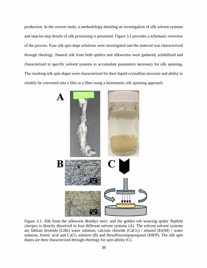
38
production. In the current study, a methodology detailing an investigation of silk solvent systems
and step-by-step details of silk processing is presented. Figure 3.1 provides a schematic overview
of the process. Four silk spin dope solutions were investigated and the material was characterized
through rheology. Natural silk from both spiders and silkworms were gathered, solubilized and
characterized in specific solvent systems to accumulate parameters necessary for silk spinning.
The resulting silk spin dopes were characterized for their liquid-crystalline structure and ability to
reliably be converted into a film or a fiber using a biomimetic silk spinning approach.
Figure 3.1: Silk from the silkworm Bombyx mori. and the golden orb weaving spider Nephila
clavipes is directly dissolved in four different solvent systems (A). The solvent solvent systems
are lithium bromide (LiBr) water solution, calcium chloride (CaCl2) / ethanol (EtOH) / water
solution, formic acid and CaCl2 solution (B) and Hexaflouroispopropanol (HIFP). The silk spin
dopes are then characterized through rheology for spin-ability (C).
39
Silk Spin Dope Preparation
Silkworm Silk Degumming
Silkworm silk from (Bombyx mori.) was collected from Jiangsu Fu’an Cacoon and Silk Co.
in spools of silk. The silk was further processed by degumming to remove sericin protein. Sericin
protein is an adhesive protein that coats the silkworm silk fibroin allowing the cocoons to hold
structure but does not contribute to the mechanical performance of the fiber [30]. Sericin is often
removed from silkworm silk as it is adhesive making processing difficult and it has low
biocompatibility when silk is used for biomedical applications [31], [32]. To remove the sericin
silk is degummed through a thermal-chemical reaction using a water and sodium carbonate
(Na2CO3) salt solution. Sodium carbonate weakens the secondary bonding of the silk proteins
allowing for further solubility [33].
The water salt solution is of low concentration but high volume allowing for more silk to
be degummed at one time. One liter of water was placed on a hot plate and set to 100℃. Sodium
carbonate was added to the water to create a 0.5% wt/vol (5 g/L) solution. Silk was removed from
the spool and placed in the water salt solution and boiled at 100℃ for 1 hour. After 1 hour in the
solution bath the silk was removed and rinsed thoroughly with distilled or deionized water to
removed residual sericin protein. The rinsed silk bundle was left to dry in chemical fume hood for
24 hours.
Lithium Bromide Silk Solution
Degummed silkworm silk is directly dissolved in a 9.0 to 9.3 M Lithium Bromide (LiBr)
aqueous salt solution yielding 3 to 5 % wt/vol silk spin dope. LiBr is used in this solvent system
to disrupt the secondary hydrogen bonding of the molecular protein chains allowing easier
dissolution of the silk fibers [34]. The salt solution was placed on a hot plate at 40℃ and silk was
40
added to the solution at small quantities and allowed to dissolve. Note that this process took 1 to 5
hours based on the concentration of silk added to the solution. Once the silk has dissolved, the
solution was dialyzed against distilled water (3.5 kDa to 7 kDa dialysis tubing) for two days to
remove the LiBr salt from the solution. Once the solution was dialyzed an aqueous silk spin dope
was created for silk spinning. Spider dragline silk collected through forcibly silking of the golden
orb weaving spider (Nephila clavipes) can also be dissolved in a 9.0 M solution of LiBr. The
resulting solution is smaller quantity with high viscosity (100 µl). Notably, it was difficult to attain
large amounts of spider silk through forcibly silking in comparison to spools of silkworm silk.
Calcium Chloride, Ethanol and Water Ternary Silk Solution
Degummed silk from the silkworm (Bombyx mori) was directly dissolved in a ternary
solvent of Calcium Chloride (CaCl2), Ethanol (CH3CH2OH) and water (H2O). Specifically, the
ternary solution was comprised of a 1:2:8 mole ratio of CaCl2, CH3CH2OH and H2O respectively.
Silk was added to yield 3% wt/vol spin dope. The silk spin dope is placed on a hotplate at 78 ℃
for 4 to 5 hours until completely dissolved. Once the silk was completely dissolved in the solvent
system, the spin dope was dialyzed using molecular weight cut off (MWCO) 3.5 to 7 kDa in
distilled water for two days to remove CaCl2 from the system. The resulting aqueous silk solution
was used for spinning. CaCl2 was used to disrupt the electronegativity of the secondary hydrogen
bonds within the protein chains [35]; this is similar to the natural silk spinning process.
Alternatively, ethanol promoted silk protein interactions that yield higher β-sheet formation
through the silk spinning process [36].
Formic Acid and Calcium Chloride Silk Solution
Similar to other ionic solutions, formic acid with CaCl2 salt is a relatively new yet popular
solvent system. Silk can be difficult to dissolve in formic acid; however the addition of CaCl2
41
provides the chemical disruptive mechanism to weaken secondary bonding allowing for silk to
dissolve [37]. This solvent system provides silk dissolution while maintaining silk nanofibril
structure in suspension. The interaction with the CaCl2 salt and formic acid breaks the silk proteins
down leaving fibril structures and allowing the spinning process to harness the self-assembly
mechanisms more efficiently [33]. Various salt concentrations yielded nanofibril structure.
Generally, 8% wt/vol of CaCl2 in formic acid is used. In this study utilizing the 8% wt/vol CaCl2
– formic acid solution allowed degummed silkworm silk to be directly dissolved.
Spin dope concentrations best for spinning generally fell in the range of 8 to 12% wt/vol
of silk. The silk was allowed to dissolve in the solvent system for 3+ hours until no silk was visually
apparent. Importantly, the formic acid CaCl2 solvent system does not require external heat to be
applied and offers a relatively quick processing time in comparison to LiBr or
CaCl2/CH3CH2OH/H2O solutions. The CaCl2 salt in this solvent system not only plays a role in
silk dissolving but also provides ionic assistance for silk formation during spinning. The Ca+ ion
present from the salt allows for silk protein bonding and promotes secondary structure during
spinning and silk film casting [38].
Hexaflouroisopropanol Silk Solution
Hexaflouroispopropanol (HIFP) is one of the most popular solvent systems to create a silk
spin dope for both silkworm silk and spider silk [39]–[42]. HFIP is widely used as it (1) is able to
dissolve silk at high concentration, (2) does not affect the silk protein structure, and (3) can be
removed quickly through spinning into a coagulant bath such as methanol or ethanol. Spider silk
collected from the golden orb weaving spider through forcibly silking was directly dissolved in
HFIP and placed into a thermal shaker at 900 RPM and 50 ℃. The silk was allowed to dissolve
for 1 to 2 hours to create a spin dope. The resulting silk spin dope is a viscous liquid that can be
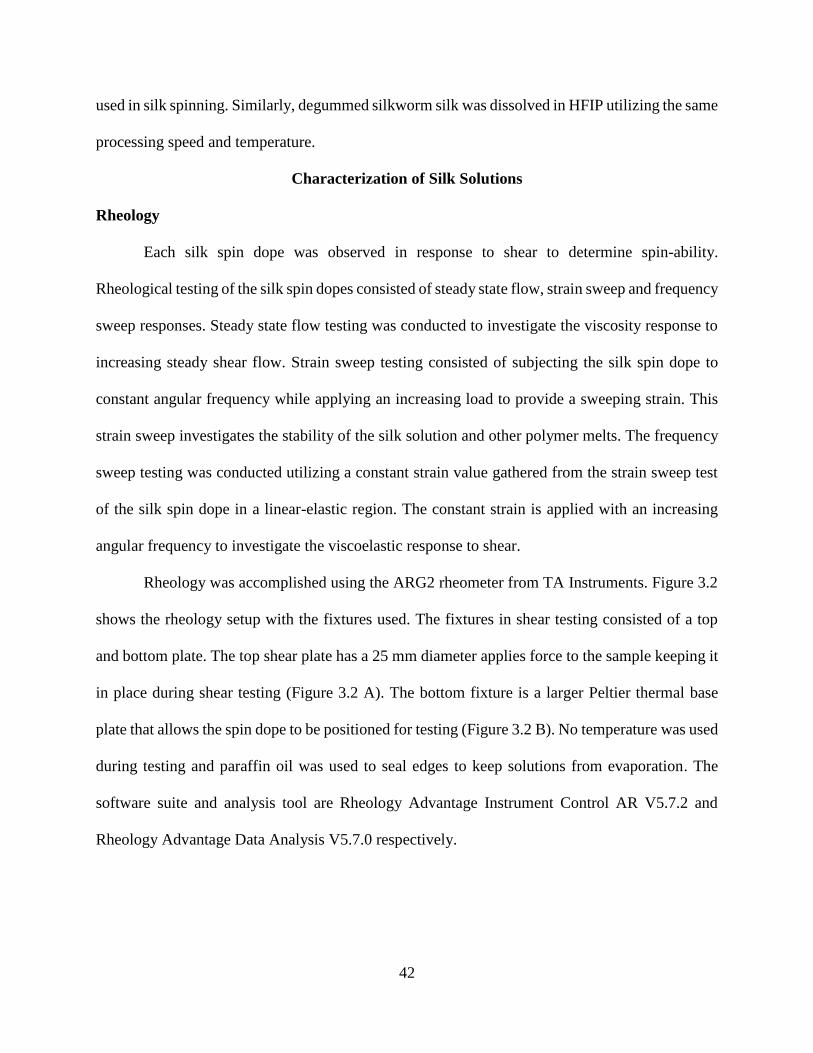
42
used in silk spinning. Similarly, degummed silkworm silk was dissolved in HFIP utilizing the same
processing speed and temperature.
Characterization of Silk Solutions
Rheology
Each silk spin dope was observed in response to shear to determine spin-ability.
Rheological testing of the silk spin dopes consisted of steady state flow, strain sweep and frequency
sweep responses. Steady state flow testing was conducted to investigate the viscosity response to
increasing steady shear flow. Strain sweep testing consisted of subjecting the silk spin dope to
constant angular frequency while applying an increasing load to provide a sweeping strain. This
strain sweep investigates the stability of the silk solution and other polymer melts. The frequency
sweep testing was conducted utilizing a constant strain value gathered from the strain sweep test
of the silk spin dope in a linear-elastic region. The constant strain is applied with an increasing
angular frequency to investigate the viscoelastic response to shear.
Rheology was accomplished using the ARG2 rheometer from TA Instruments. Figure 3.2
shows the rheology setup with the fixtures used. The fixtures in shear testing consisted of a top
and bottom plate. The top shear plate has a 25 mm diameter applies force to the sample keeping it
in place during shear testing (Figure 3.2 A). The bottom fixture is a larger Peltier thermal base
plate that allows the spin dope to be positioned for testing (Figure 3.2 B). No temperature was used
during testing and paraffin oil was used to seal edges to keep solutions from evaporation. The
software suite and analysis tool are Rheology Advantage Instrument Control AR V5.7.2 and
Rheology Advantage Data Analysis V5.7.0 respectively.
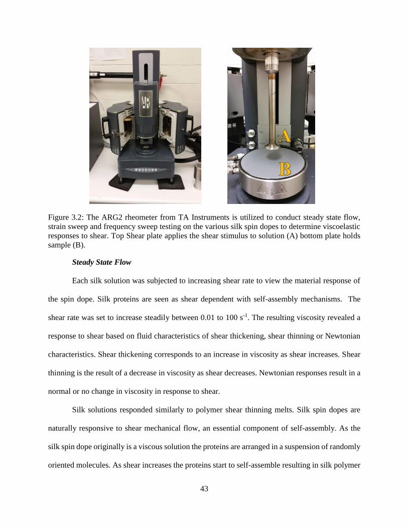
43
Figure 3.2: The ARG2 rheometer from TA Instruments is utilized to conduct steady state flow,
strain sweep and frequency sweep testing on the various silk spin dopes to determine viscoelastic
responses to shear. Top Shear plate applies the shear stimulus to solution (A) bottom plate holds
sample (B).
Steady State Flow
Each silk solution was subjected to increasing shear rate to view the material response of
the spin dope. Silk proteins are seen as shear dependent with self-assembly mechanisms. The
shear rate was set to increase steadily between 0.01 to 100 s-1. The resulting viscosity revealed a
response to shear based on fluid characteristics of shear thickening, shear thinning or Newtonian
characteristics. Shear thickening corresponds to an increase in viscosity as shear increases. Shear
thinning is the result of a decrease in viscosity as shear decreases. Newtonian responses result in a
normal or no change in viscosity in response to shear.
Silk solutions responded similarly to polymer shear thinning melts. Silk spin dopes are
naturally responsive to shear mechanical flow, an essential component of self-assembly. As the
silk spin dope originally is a viscous solution the proteins are arranged in a suspension of randomly
oriented molecules. As shear increases the proteins start to self-assemble resulting in silk polymer
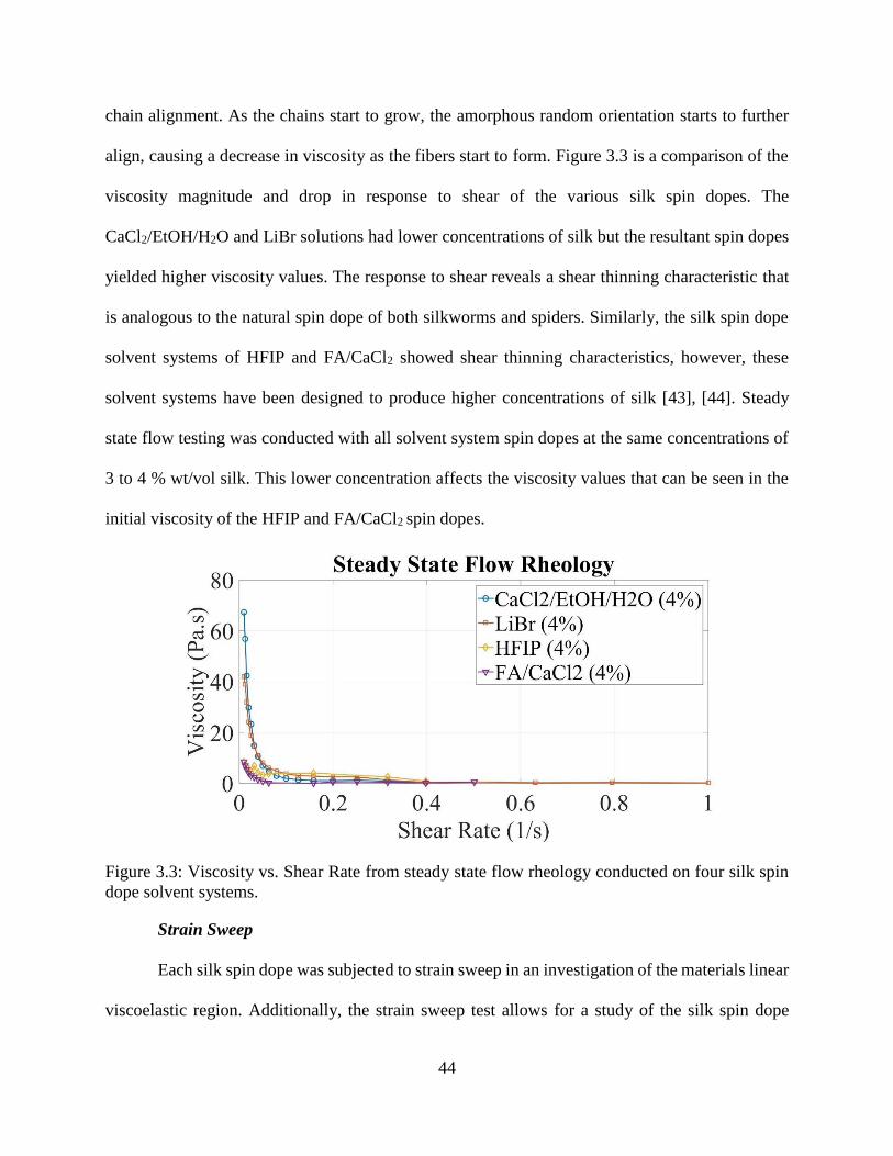
44
chain alignment. As the chains start to grow, the amorphous random orientation starts to further
align, causing a decrease in viscosity as the fibers start to form. Figure 3.3 is a comparison of the
viscosity magnitude and drop in response to shear of the various silk spin dopes. The
CaCl2/EtOH/H2O and LiBr solutions had lower concentrations of silk but the resultant spin dopes
yielded higher viscosity values. The response to shear reveals a shear thinning characteristic that
is analogous to the natural spin dope of both silkworms and spiders. Similarly, the silk spin dope
solvent systems of HFIP and FA/CaCl2 showed shear thinning characteristics, however, these
solvent systems have been designed to produce higher concentrations of silk [43], [44]. Steady
state flow testing was conducted with all solvent system spin dopes at the same concentrations of
3 to 4 % wt/vol silk. This lower concentration affects the viscosity values that can be seen in the
initial viscosity of the HFIP and FA/CaCl2 spin dopes.
Figure 3.3: Viscosity vs. Shear Rate from steady state flow rheology conducted on four silk spin
dope solvent systems.
Strain Sweep
Each silk spin dope was subjected to strain sweep in an investigation of the materials linear
viscoelastic region. Additionally, the strain sweep test allows for a study of the silk spin dope
45
materials stability giving insight to how strain breaks the material down. Generally, all testing was
done in the linear viscoelastic region as that is the stable region of the material [25]. Strain sweep
was accomplished by holding the angular frequency constant at 6.283 rad/s. The strain was set to
sweep between low strain values to determine the linear elastic region. The range of strain was
between 0.001 and 100%. Only two of the four spin dope solvent systems were tested using strain
shear rheology. The HFIP and FA/CaCl2 solvent systems were not tested as these solvent systems
evaporated to quickly to finish testing. Of the LiBr and EtOH samples, 1ml of each spin dope was
tested through strain sweep rheology. The test was manually stopped upon determination of the
linear viscoelastic plateau region. The resulting values are viscoelastic characteristics of storage
(G’) and loss modulus (G”) versus increasing strain. Figure 3.4 is a comparison of the viscoelastic
response to strain sweep testing. The initial plateau of G’ is determined by the stable linear
viscoelastic region of the silk spin dope, which allows the material to respond to shear in a
viscoelastic manner without breaking or degrading the material. Strain percentages within this
region were utilized for further testing of frequency sweep.
Figure 3.4: Strain sweep rheology conducted on two spin dope solvent systems LiBr and EtOH.
Frequency Sweep
The various silk spin dopes were subjected to a frequency sweep test to investigate how
increasing angular frequency has a time effect on the viscoelastic response. Figure 3.5 is a
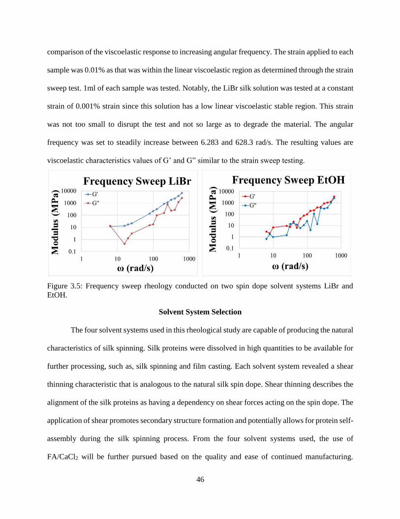
46
comparison of the viscoelastic response to increasing angular frequency. The strain applied to each
sample was 0.01% as that was within the linear viscoelastic region as determined through the strain
sweep test. 1ml of each sample was tested. Notably, the LiBr silk solution was tested at a constant
strain of 0.001% strain since this solution has a low linear viscoelastic stable region. This strain
was not too small to disrupt the test and not so large as to degrade the material. The angular
frequency was set to steadily increase between 6.283 and 628.3 rad/s. The resulting values are
viscoelastic characteristics values of G’ and G” similar to the strain sweep testing.
Figure 3.5: Frequency sweep rheology conducted on two spin dope solvent systems LiBr and
EtOH.
Solvent System Selection
The four solvent systems used in this rheological study are capable of producing the natural
characteristics of silk spinning. Silk proteins were dissolved in high quantities to be available for
further processing, such as, silk spinning and film casting. Each solvent system revealed a shear
thinning characteristic that is analogous to the natural silk spin dope. Shear thinning describes the
alignment of the silk proteins as having a dependency on shear forces acting on the spin dope. The
application of shear promotes secondary structure formation and potentially allows for protein self-
assembly during the silk spinning process. From the four solvent systems used, the use of
FA/CaCl2 will be further pursued based on the quality and ease of continued manufacturing.
47
FA/CaCl2 was selected due to: (1) quickly dissolving silk, (2) produce higher silk concentrations,
(3) facilitate ionic exchange during spinning, and (4) preserve nanofibril structure. These
conditions will provide the necessary qualities to allow silk proteins to self-assemble, thus a more
biomimetic approach to silk spinning and casting.
References
[1] G. Bhat, Ed., “Woodhead Publishing Series in Textiles,” in Structure and Properties of High-
Performance Fibers, Oxford: Woodhead Publishing, 2017, pp. xi–xix.
[2] B. Kundu et al., “Silk proteins for biomedical applications: Bioengineering perspectives,”
Prog. Polym. Sci., vol. 39, no. 2, pp. 251–267, Feb. 2014.
[3] E. Doblhofer, A. Heidebrecht, and T. Scheibel, “To spin or not to spin: spider silk fibers and
more,” Appl. Microbiol. Biotechnol., vol. 99, no. 22, pp. 9361–9380, Nov. 2015.
[4] C. Holland, A. E. Terry, D. Porter, and F. Vollrath, “Natural and unnatural silks,” Polymer,
vol. 48, no. 12, pp. 3388–3392, Jun. 2007.
[5] F. Vollrath, D. Porter, and C. Holland, “The science of silks,” MRS Bull., vol. 38, no. 01, pp.
73–80, Jan. 2013.
[6] M. E. Kinahan et al., “Tunable silk: using microfluidics to fabricate silk fibers with
controllable properties,” Biomacromolecules, vol. 12, no. 5, pp. 1504–1511, May 2011.
[7] R. V. Lewis, “Spider silk: the unraveling of a mystery,” Acc. Chem. Res., vol. 25, no. 9, pp.
392–398, Sep. 1992.
[8] L.-D. Koh et al., “Structures, mechanical properties and applications of silk fibroin
materials,” Prog. Polym. Sci., vol. 46, pp. 86–110, Jul. 2015.
[9] J. Pérez-Rigueiro, C. Viney, J. Llorca, and M. Elices, “Silkworm silk as an engineering
material,” J. Appl. Polym. Sci., vol. 70, no. 12, pp. 2439–2447, Dec. 1998.
48
[10] M. Elices, G. V. Guinea, J. Pérez-Rigueiro, and G. R. Plaza, “Polymeric fibers with tunable
properties: Lessons from spider silk,” Mater. Sci. Eng. C, vol. 31, no. 6, pp. 1184–1188, Aug.
2011.
[11] D. Kaplan, Ed., Silk polymers: materials science and biotechnology. Washington, DC:
American Chemical Society, 1994.
[12] P. R. Laity and C. Holland, “Native Silk Feedstock as a Model Biopolymer: A Rheological
Perspective,” Biomacromolecules, vol. 17, no. 8, pp. 2662–2671, Aug. 2016.
[13] P. R. Laity and C. Holland, “The Rheology behind Stress-Induced Solidification in Native
Silk Feedstocks,” Int. J. Mol. Sci., vol. 17, no. 11, p. 1812, Oct. 2016.
[14] G. Askarieh et al., “Self-assembly of spider silk proteins is controlled by a pH-sensitive
relay,” Nature, vol. 465, no. 7295, p. 236, May 2010.
[15] C. W. P. Foo, E. Bini, J. Hensman, D. P. Knight, R. V. Lewis, and D. L. Kaplan, “Role of
pH and charge on silk protein assembly in insects and spiders,” Appl. Phys. A, vol. 82, no. 2,
pp. 223–233, Feb. 2006.
[16] X. Wang, Y. Li, Q. Liu, Q. Chen, Q. Xia, and P. Zhao, “In vivo effects of metal ions on
conformation and mechanical performance of silkworm silks,” Biochim. Biophys. Acta BBA
- Gen. Subj., vol. 1861, no. 3, pp. 567–576, Mar. 2017.
[17] D. P. Knight and F. Vollrath, “Liquid crystals and flow elongation in a spider’s silk
production line,” Proc. R. Soc. Lond. B Biol. Sci., vol. 266, no. 1418, pp. 519–523, Mar.
1999.
[18] F. Vollrath and D. P. Knight, “Liquid crystalline spinning of spider silk,” Nat. Lond., vol.
410, no. 6828, pp. 541–8, Mar. 2001.
49
[19] P. R. Laity, S. E. Gilks, and C. Holland, “Rheological behaviour of native silk feedstocks,”
Polymer, vol. 67, pp. 28–39, Jun. 2015.
[20] P. Dubey, S. Murab, S. Karmakar, P. K. Chowdhury, and S. Ghosh, “Modulation of Self-
Assembly Process of Fibroin: An Insight for Regulating the Conformation of Silk
Biomaterials,” Biomacromolecules, vol. 16, no. 12, pp. 3936–3944, Dec. 2015.
[21] D. N. Breslauer, L. P. Lee, and S. J. Muller, “Simulation of Flow in the Silk Gland,”
Biomacromolecules, vol. 10, no. 1, pp. 49–57, Jan. 2009.
[22] C. Holland, A. E. Terry, D. Porter, and F. Vollrath, “Comparing the rheology of native spider
and silkworm spinning dope,” Nat. Mater., vol. 5, no. 11, pp. 870–874, Nov. 2006.
[23] X. Liu and K.-Q. Zhang, “Silk Fiber — Molecular Formation Mechanism, Structure-
Property Relationship and Advanced Applications,” in Oligomerization of Chemical and
Biological Compounds, C. Lesieur, Ed. InTech, 2014.
[24] Q. Peng, H. Shao, X. Hu, and Y. Zhang, “Role of humidity on the structures and properties
of regenerated silk fibers,” Prog. Nat. Sci. Mater. Int., vol. 25, no. 5, pp. 430–436, Oct. 2015.
[25] A. B. Strong, Plastics: Materials and Processing. Pearson.
[26] C.-C. Chen, S. Riou, S. L. Hsu, and H. D. Stidham, “Characterization of Silk Crystallization
Behavior on Highly Oriented Substrates,” Langmuir, vol. 12, no. 4, pp. 1035–1039, Jan.
1996.
[27] M. Heim, D. Keerl, and T. Scheibel, “Spider Silk: From Soluble Protein to Extraordinary
Fiber,” Angew. Chem. Int. Ed., vol. 48, no. 20, pp. 3584–3596, May 2009.
[28] X. Hu, D. Kaplan, and P. Cebe, “Dynamic Protein−Water Relationships during β-Sheet
Formation,” Macromolecules, vol. 41, no. 11, pp. 3939–3948, Jun. 2008.
50
[29] A. Koeppel and C. Holland, “Progress and trends in artificial silk spinning: a systematic
review,” ACS Biomater. Sci. Eng., Jan. 2017.
[30] J. Pérez-Rigueiro, C. Viney, J. Llorca, and M. Elices, “Mechanical properties of single-brin
silkworm silk,” J. Appl. Polym. Sci., vol. 75, no. 10, pp. 1270–1277, Mar. 2000.
[31] G. H. Altman et al., “Silk-based biomaterials,” Biomaterials, vol. 24, no. 3, pp. 401–416,
Feb. 2003.
[32] J. Pérez-Rigueiro, M. Elices, J. Llorca, and C. Viney, “Effect of degumming on the tensile
properties of silkworm (Bombyx mori) silk fiber,” J. Appl. Polym. Sci., vol. 84, no. 7, pp.
1431–1437, May 2002.
[33] F. Zhang et al., “Silk dissolution and regeneration at the nanofibril scale,” J. Mater. Chem.
B, vol. 2, no. 24, pp. 3879–3885, 2014.
[34] E. S. Sashina, A. M. Bochek, N. P. Novoselov, and D. A. Kirichenko, “Structure and
solubility of natural silk fibroin,” Russ. J. Appl. Chem., vol. 79, no. 6, pp. 869–876, Jun. 2006.
[35] X. Chen, D. P. Knight, Z. Shao, and F. Vollrath, “Regenerated Bombyx silk solutions studied
with rheometry and FTIR,” Polymer, vol. 42, no. 25, pp. 09969–09974, Dec. 2001.
[36] M. Li, W. Tao, S. Kuga, and Y. Nishiyama, “Controlling molecular conformation of
regenerated wild silk fibroin by aqueous ethanol treatment,” Polym. Adv. Technol., vol. 14,
no. 10, pp. 694–698, Oct. 2003.
[37] I. C. Um, H. Kweon, Y. H. Park, and S. Hudson, “Structural characteristics and properties of
the regenerated silk fibroin prepared from formic acid,” Int. J. Biol. Macromol., vol. 29, no.
2, pp. 91–97, Aug. 2001.
51
[38] L. Zhou, X. Chen, Z. Shao, Y. Huang, and D. P. Knight, “Effect of Metallic Ions on Silk
Formation in the Mulberry Silkworm, Bombyx mori,” J. Phys. Chem. B, vol. 109, no. 35, pp.
16937–16945, Sep. 2005.
[39] C. L. Tucker et al., “Mechanical and Physical Properties of Recombinant Spider Silk Films
Using Organic and Aqueous Solvents,” Biomacromolecules, vol. 15, no. 8, pp. 3158–3170,
Aug. 2014.
[40] C. Zhao, J. Yao, H. Masuda, R. Kishore, and T. Asakura, “Structural characterization and
artificial fiber formation of Bombyx mori silk fibroin in hexafluoro-iso-propanol solvent
system,” Biopolymers, vol. 69, no. 2, pp. 253–259, Jun. 2003.
[41] B. Zuo, L. Liu, and Z. Wu, “Effect on properties of regenerated silk fibroin fiber coagulated
with aqueous methanol/ethanol,” J. Appl. Polym. Sci., vol. 106, no. 1, pp. 53–59, Oct. 2007.
[42] Zhenghua Zhu et al., “Mechanical Properties of Regenerated Bombyx mori Silk Fibers and
Recombinant Silk Fibers Produced by Transgenic Silkworms,” J. Biomater. Sci. -- Polym.
Ed., vol. 21, no. 3, pp. 395–411, Mar. 2010.
[43] C. Zhao, J. Yao, H. Masuda, R. Kishore, and T. Asakura, “Structural characterization and
artificial fiber formation of Bombyx mori silk fibroin in hexafluoro-iso-propanol solvent
system,” Biopolymers, vol. 69, no. 2, pp. 253–259, Jun. 2003.
[44] F. Zhang et al., “Regeneration of high-quality silk fibroin fiber by wet spinning from CaCl2–
formic acid solvent,” Acta Biomater., vol. 12, pp. 139–145, Jan. 2015.
52
CHAPTER 4: USING ENGINEERING TO UNRAVEL THE MYSTERY OF SPIDER
SILK FIBER FORMATION1
The design of a biomimetic spinning system consists of a multi-channel microfluidic
device to mimic the natural spinning elements found in spiders and silkworms. To characterize
this mimicry and provide an optimized device channel geometry, fluid simulations through out
this study had been conducted. Assumptions for each simulation had been taken into effect. These
assumptions consisted of fluid flow parameters within software of COMSOL and Autodesk CFD.
The fluid velocities input into the system was a correlated constant velocity. Further analysis can
be done in subjecting a parabolic shape flow, however for preliminary flow characterization a
constant flow was used. Mesh size was kept constant throughout the channels and can be improved
through increased mesh analysis at each intersection. Mesh was kept constant again for preliminary
flow analysis. The assumptions of shear thinning flow was the inspiration as it is analogous of the
natural spin dope. This attribute was collected from experimental spin dope parameters.
Abstract
Major ampullate spider silk, produced by the golden orb weaver (Nephila clavipes), has
been sought after for its characteristic strength and toughness. Although the genetic sequence of
major ampullate silk has been known since the 1990s, little was known about the natural
production of major ampullate spider silk until recently. Thus, synthetic silk fibers have been
produced in a significantly different way, resulting in a synthetic silk fiber with inferior mechanical
1 The material in this chapter was co-authored by Bradley Hoffmann, Austin Nodland, Catherine
Gruat-Henry, Ben Brooks and Amanda E Brooks. Bradley Hoffmann had primary responsibility
for preparing silk samples, conducting bench top spinning experiments and device design. Austin
Nodland provided contributions to device design and fluid simulations. Catherine Gruat-Henry
contributed device design and CAD drawing responsibility. Bradley Hoffmann also drafted and
revised all versions of this chapter. Amanda E. Brooks and Ben Brooks served as proofreader and
checked works by Bradley Hoffmann.
53
properties. Synthetic fabrication devices do not mimic the shear forces (i.e., synthetic pushing vs
natural pulling via gravity), nor the pH or ionic gradients of the spider’s biological silk spinning
system. In an attempt to mimic the process, a device was designed to incorporate both pH and ion
gradients and promote shearing forces, which act to align the silk proteins, and trigger
polymerization. Subsequently, computational fluid dynamics software was used to simulate the
design and ensure consistent laminar flow. Future efforts will produce a prototype device based
on the presented simulations.
Introduction
The golden orb weaver’s silks have been sought after for its characteristics of strength and
toughness [1,2]. Discovery of major ampullate silk’s genetic sequence paved the way for molecular
biologists, material scientists, and engineers to recapitulate and manipulate the mechanical
properties of this high-performance fiber. With a combination of strength similar to the that of
nylon and Kevlar fibers and extensibility on the same order of magnitude as rubber, major
ampullate silk is an extreme high performance natural fiber that we are currently unable to
recapitulate [3].
Furthermore, Major amullate silk’s amino acid block structure is adaptable and amenable
to green processing and genetically programmed biodegradability, which also makes it highly
sought after. Synthetic production of a major ampullate silk mimetic may serve as a source of new
structural biomaterials and a potential “smart” polymer for drug delivery. Unfortunately,
recapitulating or modifying the genetic sequence of the protein represents only one variable of the
equation to produce a tailored high-performance fiber, spinning, or fiber processing, can no longer
be ignored for its important contribution to the properties.
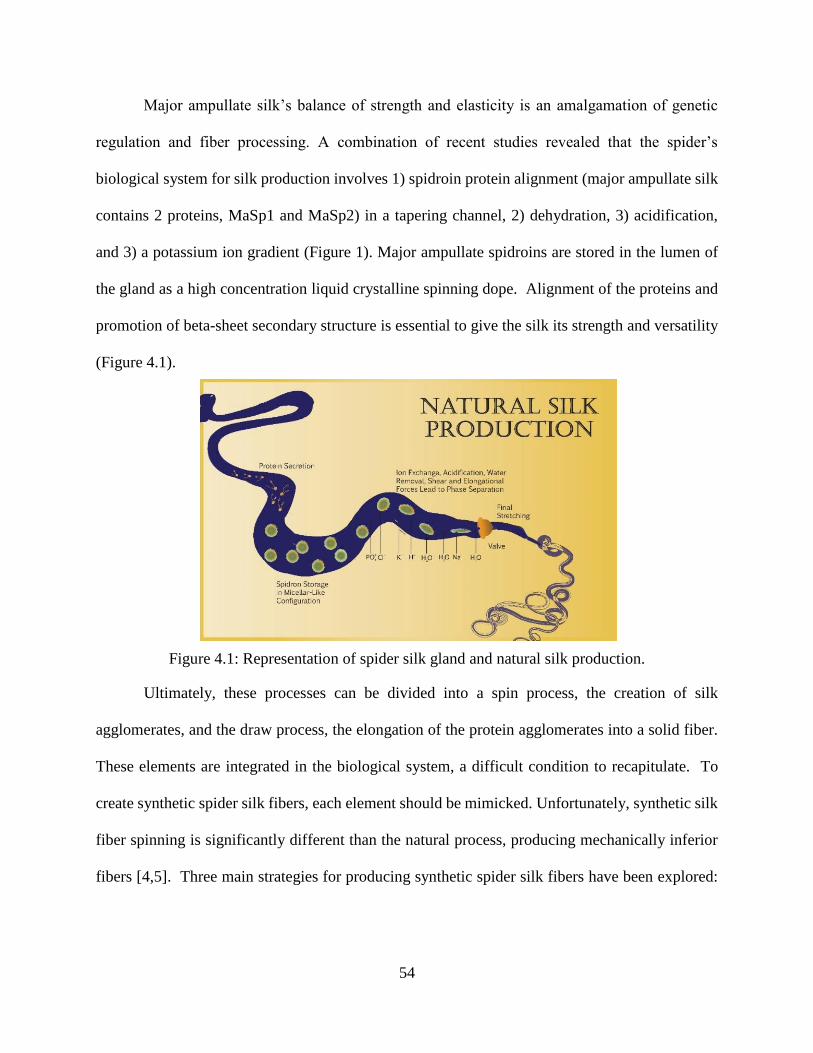
54
Major ampullate silk’s balance of strength and elasticity is an amalgamation of genetic
regulation and fiber processing. A combination of recent studies revealed that the spider’s
biological system for silk production involves 1) spidroin protein alignment (major ampullate silk
contains 2 proteins, MaSp1 and MaSp2) in a tapering channel, 2) dehydration, 3) acidification,
and 3) a potassium ion gradient (Figure 1). Major ampullate spidroins are stored in the lumen of
the gland as a high concentration liquid crystalline spinning dope. Alignment of the proteins and
promotion of beta-sheet secondary structure is essential to give the silk its strength and versatility
(Figure 4.1).
Figure 4.1: Representation of spider silk gland and natural silk production.
Ultimately, these processes can be divided into a spin process, the creation of silk
agglomerates, and the draw process, the elongation of the protein agglomerates into a solid fiber.
These elements are integrated in the biological system, a difficult condition to recapitulate. To
create synthetic spider silk fibers, each element should be mimicked. Unfortunately, synthetic silk
fiber spinning is significantly different than the natural process, producing mechanically inferior
fibers [4,5]. Three main strategies for producing synthetic spider silk fibers have been explored:
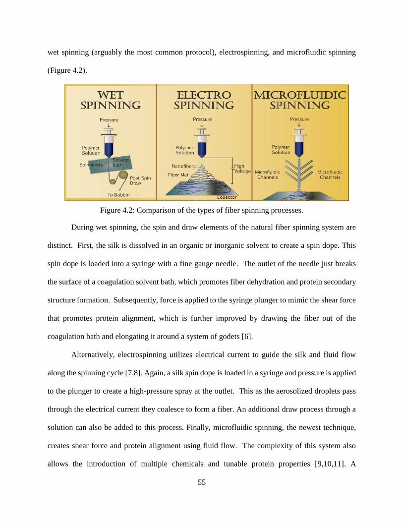
55
wet spinning (arguably the most common protocol), electrospinning, and microfluidic spinning
(Figure 4.2).
Figure 4.2: Comparison of the types of fiber spinning processes.
During wet spinning, the spin and draw elements of the natural fiber spinning system are
distinct. First, the silk is dissolved in an organic or inorganic solvent to create a spin dope. This
spin dope is loaded into a syringe with a fine gauge needle. The outlet of the needle just breaks
the surface of a coagulation solvent bath, which promotes fiber dehydration and protein secondary
structure formation. Subsequently, force is applied to the syringe plunger to mimic the shear force
that promotes protein alignment, which is further improved by drawing the fiber out of the
coagulation bath and elongating it around a system of godets [6].
Alternatively, electrospinning utilizes electrical current to guide the silk and fluid flow
along the spinning cycle [7,8]. Again, a silk spin dope is loaded in a syringe and pressure is applied
to the plunger to create a high-pressure spray at the outlet. This as the aerosolized droplets pass
through the electrical current they coalesce to form a fiber. An additional draw process through a
solution can also be added to this process. Finally, microfluidic spinning, the newest technique,
creates shear force and protein alignment using fluid flow. The complexity of this system also
allows the introduction of multiple chemicals and tunable protein properties [9,10,11]. A
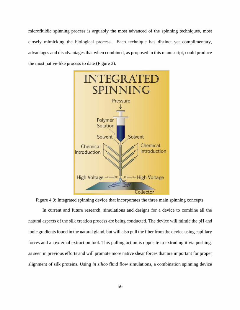
56
microfluidic spinning process is arguably the most advanced of the spinning techniques, most
closely mimicking the biological process. Each technique has distinct yet complimentary,
advantages and disadvantages that when combined, as proposed in this manuscript, could produce
the most native-like process to date (Figure 3).
Figure 4.3: Integrated spinning device that incorporates the three main spinning concepts.
In current and future research, simulations and designs for a device to combine all the
natural aspects of the silk creation process are being conducted. The device will mimic the pH and
ionic gradients found in the natural gland, but will also pull the fiber from the device using capillary
forces and an external extraction tool. This pulling action is opposite to extruding it via pushing,
as seen in previous efforts and will promote more native shear forces that are important for proper
alignment of silk proteins. Using in silico fluid flow simulations, a combination spinning device
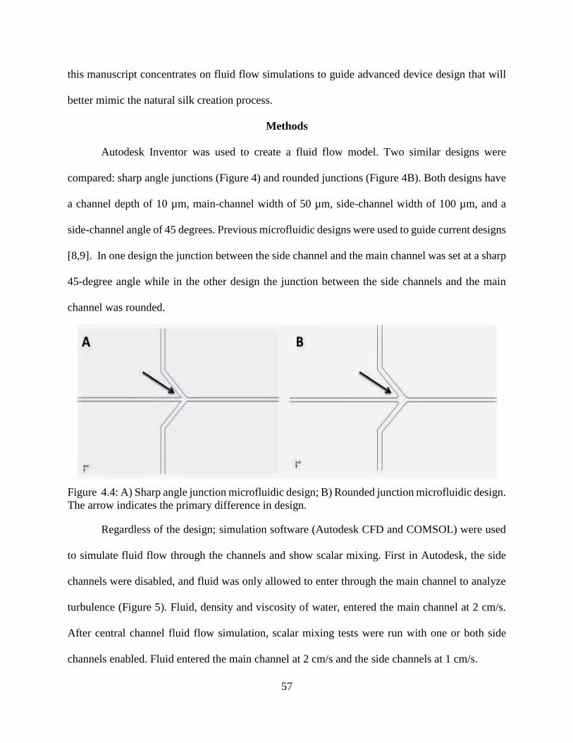
57
this manuscript concentrates on fluid flow simulations to guide advanced device design that will
better mimic the natural silk creation process.
Methods
Autodesk Inventor was used to create a fluid flow model. Two similar designs were
compared: sharp angle junctions (Figure 4) and rounded junctions (Figure 4B). Both designs have
a channel depth of 10 µm, main-channel width of 50 µm, side-channel width of 100 µm, and a
side-channel angle of 45 degrees. Previous microfluidic designs were used to guide current designs
[8,9]. In one design the junction between the side channel and the main channel was set at a sharp
45-degree angle while in the other design the junction between the side channels and the main
channel was rounded.
Figure 4.4: A) Sharp angle junction microfluidic design; B) Rounded junction microfluidic design.
The arrow indicates the primary difference in design.
Regardless of the design; simulation software (Autodesk CFD and COMSOL) were used
to simulate fluid flow through the channels and show scalar mixing. First in Autodesk, the side
channels were disabled, and fluid was only allowed to enter through the main channel to analyze
turbulence (Figure 5). Fluid, density and viscosity of water, entered the main channel at 2 cm/s.
After central channel fluid flow simulation, scalar mixing tests were run with one or both side
channels enabled. Fluid entered the main channel at 2 cm/s and the side channels at 1 cm/s.
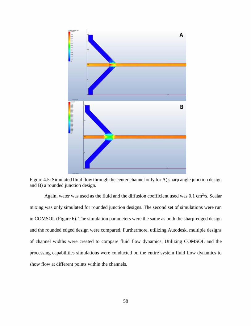
58
Figure 4.5: Simulated fluid flow through the center channel only for A) sharp angle junction design
and B) a rounded junction design.
Again, water was used as the fluid and the diffusion coefficient used was 0.1 cm2/s. Scalar
mixing was only simulated for rounded junction designs. The second set of simulations were run
in COMSOL (Figure 6). The simulation parameters were the same as both the sharp-edged design
and the rounded edged design were compared. Furthermore, utilizing Autodesk, multiple designs
of channel widths were created to compare fluid flow dynamics. Utilizing COMSOL and the
processing capabilities simulations were conducted on the entire system fluid flow dynamics to
show flow at different points within the channels.
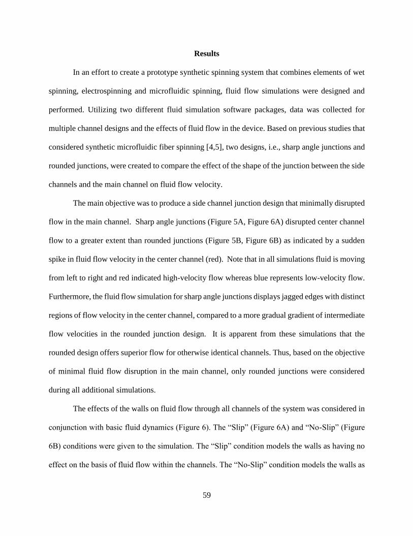
59
Results
In an effort to create a prototype synthetic spinning system that combines elements of wet
spinning, electrospinning and microfluidic spinning, fluid flow simulations were designed and
performed. Utilizing two different fluid simulation software packages, data was collected for
multiple channel designs and the effects of fluid flow in the device. Based on previous studies that
considered synthetic microfluidic fiber spinning [4,5], two designs, i.e., sharp angle junctions and
rounded junctions, were created to compare the effect of the shape of the junction between the side
channels and the main channel on fluid flow velocity.
The main objective was to produce a side channel junction design that minimally disrupted
flow in the main channel. Sharp angle junctions (Figure 5A, Figure 6A) disrupted center channel
flow to a greater extent than rounded junctions (Figure 5B, Figure 6B) as indicated by a sudden
spike in fluid flow velocity in the center channel (red). Note that in all simulations fluid is moving
from left to right and red indicated high-velocity flow whereas blue represents low-velocity flow.
Furthermore, the fluid flow simulation for sharp angle junctions displays jagged edges with distinct
regions of flow velocity in the center channel, compared to a more gradual gradient of intermediate
flow velocities in the rounded junction design. It is apparent from these simulations that the
rounded design offers superior flow for otherwise identical channels. Thus, based on the objective
of minimal fluid flow disruption in the main channel, only rounded junctions were considered
during all additional simulations.
The effects of the walls on fluid flow through all channels of the system was considered in
conjunction with basic fluid dynamics (Figure 6). The “Slip” (Figure 6A) and “No-Slip” (Figure
6B) conditions were given to the simulation. The “Slip” condition models the walls as having no
effect on the basis of fluid flow within the channels. The “No-Slip” condition models the walls as
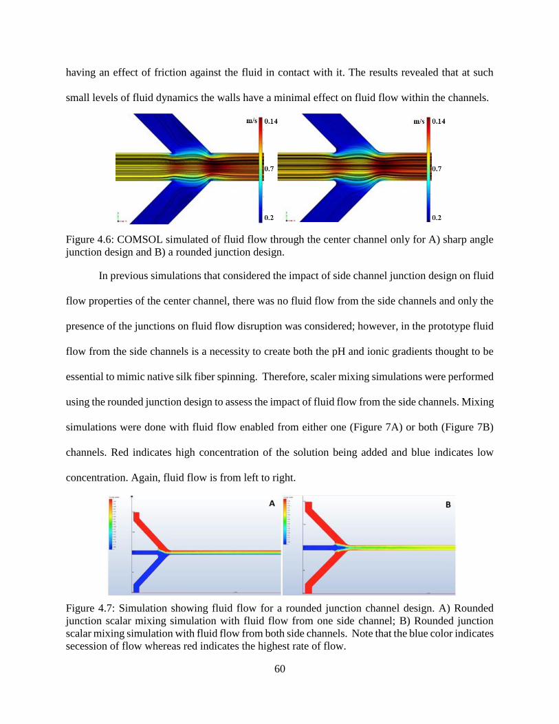
60
having an effect of friction against the fluid in contact with it. The results revealed that at such
small levels of fluid dynamics the walls have a minimal effect on fluid flow within the channels.
Figure 4.6: COMSOL simulated of fluid flow through the center channel only for A) sharp angle
junction design and B) a rounded junction design.
In previous simulations that considered the impact of side channel junction design on fluid
flow properties of the center channel, there was no fluid flow from the side channels and only the
presence of the junctions on fluid flow disruption was considered; however, in the prototype fluid
flow from the side channels is a necessity to create both the pH and ionic gradients thought to be
essential to mimic native silk fiber spinning. Therefore, scaler mixing simulations were performed
using the rounded junction design to assess the impact of fluid flow from the side channels. Mixing
simulations were done with fluid flow enabled from either one (Figure 7A) or both (Figure 7B)
channels. Red indicates high concentration of the solution being added and blue indicates low
concentration. Again, fluid flow is from left to right.
Figure 4.7: Simulation showing fluid flow for a rounded junction channel design. A) Rounded
junction scalar mixing simulation with fluid flow from one side channel; B) Rounded junction
scalar mixing simulation with fluid flow from both side channels. Note that the blue color indicates
secession of flow whereas red indicates the highest rate of flow.
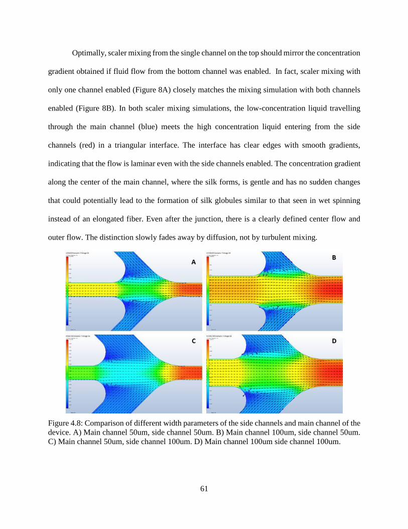
61
Optimally, scaler mixing from the single channel on the top should mirror the concentration
gradient obtained if fluid flow from the bottom channel was enabled. In fact, scaler mixing with
only one channel enabled (Figure 8A) closely matches the mixing simulation with both channels
enabled (Figure 8B). In both scaler mixing simulations, the low-concentration liquid travelling
through the main channel (blue) meets the high concentration liquid entering from the side
channels (red) in a triangular interface. The interface has clear edges with smooth gradients,
indicating that the flow is laminar even with the side channels enabled. The concentration gradient
along the center of the main channel, where the silk forms, is gentle and has no sudden changes
that could potentially lead to the formation of silk globules similar to that seen in wet spinning
instead of an elongated fiber. Even after the junction, there is a clearly defined center flow and
outer flow. The distinction slowly fades away by diffusion, not by turbulent mixing.
Figure 4.8: Comparison of different width parameters of the side channels and main channel of the
device. A) Main channel 50um, side channel 50um. B) Main channel 100um, side channel 50um.
C) Main channel 50um, side channel 100um. D) Main channel 100um side channel 100um.
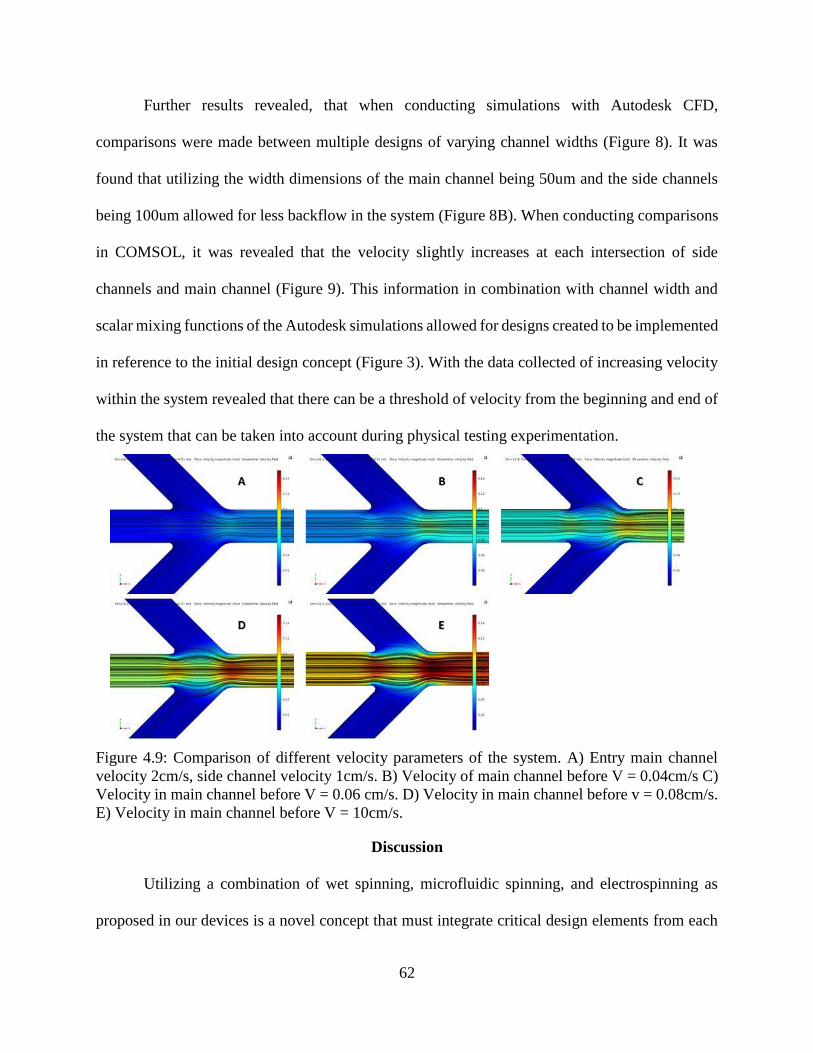
62
Further results revealed, that when conducting simulations with Autodesk CFD,
comparisons were made between multiple designs of varying channel widths (Figure 8). It was
found that utilizing the width dimensions of the main channel being 50um and the side channels
being 100um allowed for less backflow in the system (Figure 8B). When conducting comparisons
in COMSOL, it was revealed that the velocity slightly increases at each intersection of side
channels and main channel (Figure 9). This information in combination with channel width and
scalar mixing functions of the Autodesk simulations allowed for designs created to be implemented
in reference to the initial design concept (Figure 3). With the data collected of increasing velocity
within the system revealed that there can be a threshold of velocity from the beginning and end of
the system that can be taken into account during physical testing experimentation.
Figure 4.9: Comparison of different velocity parameters of the system. A) Entry main channel
velocity 2cm/s, side channel velocity 1cm/s. B) Velocity of main channel before V = 0.04cm/s C)
Velocity in main channel before V = 0.06 cm/s. D) Velocity in main channel before v = 0.08cm/s.
E) Velocity in main channel before V = 10cm/s.
Discussion
Utilizing a combination of wet spinning, microfluidic spinning, and electrospinning as
proposed in our devices is a novel concept that must integrate critical design elements from each
63
process. In this manuscript, we have designed two permutations of the microfluidic component.
Microfluidic fluid dynamics concepts will allow for the development of a device that will better
mimic the natural silk creation process. Fluid flow was simulated in each design and the results
were assessed according to two design criteria: 1) laminar fluid flow must be maintained in the
center channel and 2) a concentration gradient must be created in the center channel via fluid flow
from the side channels. The use of laminar flow is evolutionarily conserved in biological systems
and is therefore assumed to be critical. Thus, maintenance of laminar fluid flow is assumed to be
necessary for the creation of a solid silk fiber as turbulent fluid flow would cause premature protein
aggregation, acting like a blood clot to block fluid flow through the channels.
It was found in comparison between the two simulation packages that COMSOL showed
higher promising results in higher quality data analysis. COMSOL also has the processing power
and versatility to conduct multiple simulations with a higher quantity of parameters. In unison
Autodesk CFD allowed for quick efficient simulation parameters to be conducted. As COMSOL
has a high learning curve, Autodesk CFD is user friendly and allows for easy analysis
implementation. Both simulation software techniques provided data that was used to progress the
research forward into the prototyping stage.
While the design with sharp angle junctions produced a sudden increase in velocity at the
center of the channel, which could disrupt silk fiber formation causing premature protein
aggregation and self-assembly [1,9], the design with rounded junctions exhibited no sudden
changes in velocity at the center of the channel to disrupt silk fiber formation, and the gradients
are smooth with no apparent jagged edges, indicating consistent laminar flow. Importantly,
sporadic flow or turbulent flow could increase fluid flow pressure in the channel or backflow
through side channels. Through the concentration of interconnected channel fluid flow a
64
concentration gradient, an essential component for silk fiber formation can be promoted. Scalar
mixing fluid flow simulations from the rounded junction design clearly show that flow is laminar
and that a gentle gradient is introduced along the center of the channel, promoting the formation
of beta-sheet structures and creates a more mechanically robust silk fiber. Simulations also
revealed that the introduction of fluid from connected side channels to the main channel does not
substantially disrupt fluid flow velocity. A prototype device will be fabricated based on our
simulated fluid dynamics using a rounded junction design.
Conclusion
Native major ampullate spider silk production can be recapitulated more accurately using
microfluidic fluid flow to mimic the chemical gradients and protein alignment now recognized to
be essential to robust high-performance fiber formation. Creation and maintenance of laminar
flow is critical to this process and its importance cannot be overstated. A stable laminar fluid flow
and chemical gradients (pH and ionic) will be established prior to injecting a viscous silk spin dope
into the fluid flow (analogous to wet spinning). Flow and capillary forces will then act in concert
to simultaneously draw out the silk fiber from self-assembling protein aggregates as they align.
Subsequent addition of inline electro-spinning will allow us to even more closely mimic the natural
mechanical forces utilized to spin a major ampullate silk fiber as drawing a nascent fiber through
electric fields may promote sheer forces to further strength the fiber at the end of the process.
Ultimately, the processes necessary to recapitulate major ampullate spider silk production
artificially may provide insight into different creative solutions with broad societal impacts (e.g.,
muscle fiber and tissue repair, controlled drug release, high performance biomaterials, etc.).
65
References
[1] S. Keten, Z. Xu, B. Ihle, and M. J. Buehler, “Nanoconfinement controls stiffness, strength
and mechanical toughness of β-sheet crystals in silk,” Nat. Mater., vol. 9, no. 4, pp. 359–367,
Apr. 2010.
[2] A. Heidebrecht, L. Eisoldt, J. Diehl, A. Schmidt, M. Geffers, G. Lang, and T. Scheibel,
“Biomimetic fibers made of recombinant spidroins with the same toughness as natural spider
silk,” Adv. Mater. Deerfield Beach Fla, vol. 27, no. 13, pp. 2189–2194, Apr. 2015.
[3] C. Y. Hayashi, N. H. Shipley, and R. V. Lewis, “Hypotheses that correlate the sequence,
structure, and mechanical properties of spider silk proteins,” Int. J. Biol. Macromol., vol. 24,
no. 2–3, pp. 271–275, Apr. 1999.
[4] A. E. Brooks, S. M. Stricker, S. B. Joshi, T. J. Kamerzell, C. R. Middaugh, and R. V. Lewis,
“Properties of synthetic spider silk fibers based on Argiope aurantia MaSp2,”
Biomacromolecules, vol. 9, no. 6, pp. 1506–1510, Jun. 2008.
[5] Slotta, Ute, N. Mougin, L. Romer, and A. Leimer, “Synthetic Spider Silk Proteins and
Threads,” Chem. Eng. Prog., pp. 43–49, May 2012.
[6] J. Leclerc, T. Lefèvre, M. Gauthier, S. M. Gagné, and M. Auger, “Hydrodynamical properties
of recombinant spider silk proteins: Effects of pH, salts and shear, and implications for the
spinning process,” Biopolymers, vol. 99, no. 9, pp. 582–593, Sep. 2013.
[7] K. Yoon, H. N. Lee, C. S. Ki, D. Fang, B. S. Hsiao, B. Chu, and I. C. Um, “Effects of
degumming conditions on electro-spinning rate of regenerated silk,” Int. J. Biol. Macromol.,
vol. 61, pp. 50–57, Oct. 2013.
[8] A. Rising and J. Johansson, “Toward spinning artificial spider silk,” Nat. Chem. Biol., vol.
11, no. 5, pp. 309–315, Apr. 2015.
66
[9] M. E. Kinahan, E. Filippidi, S. Köster, X. Hu, H. M. Evans, T. Pfohl, D. L. Kaplan, and J.
Wong, “Tunable silk: using microfluidics to fabricate silk fibers with controllable
properties,” Biomacromolecules, vol. 12, no. 5, pp. 1504–1511, May 2011.
[10] S. Rammensee, “Assembly of Engineered Spider Silk in Microfluidic Devices and Free
Surface Flow,” Technische Universitat Munchen, 2009.
[11] J. N. Lee, C. Park, and G. M. Whitesides, “Solvent Compatibility of Poly(dimethylsiloxane)-
Based Microfluidic Devices,” Anal. Chem., vol. 75, no. 23, pp. 6544–6554, Dec. 2003.
67
CHAPTER 5: DEVELOPMENT OF A COMPLEX CONTROL SYSTEM FOR
MULTIPLE FLUID FLOW GRADIENTS2
Abstract
Biomimetic engineering inspires innovation from biology, advancing technology to benefit
society and improving green manufacturing and environmental biomaterial stability. Major
ampullate spider silk has provided material science innovation for decades. The broad potential of
spider silk has long had multidisciplinary interest from a broad variety of STEM disciplines.
Specifically, understanding and ultimately manipulating natural fiber characteristics relies on the
integration of chemical and biological gradients with shear thinning forces, necessitating a
multidisciplinary team approach to make significant progress. Inspiration for biomimetic fibers
comes not only from biology but also from synthetic chemistry, having mechanical characteristics
that closely resembles other fibrous man-made polymers, such as, Kevlar or Nylon. Unfortunately,
although the genetic sequence of the major ampullate spider silk proteins is known, artificial
production of silk fibers is inferior and results in mechanically inferior fibers when compared to
the natural silk. By engineering a device that mimics the natural process (i.e., pH gradients, ionic
gradients, and mechanical fluid dynamics) found in the spider’s gland, it is possible to spin
tailorable mechanically superior biological fibers. Initial research focused on multiple fluid flow
simulations and complex microfluidic prototype development to reconstitute a single major
ampullate fiber from dissolved natural silk obtained via forcible silking. Preliminary fibers have
2 The material in this chapter was co-authored by Bradley Hoffmann, Catherine Gruat-Henry,
Pranothi Mulinti, Long Jiang, Ben D Brooks and Amanda E Brooks. Bradley Hoffmann had
primary responsibilities including preparing silk samples, conducting bench top spinning
experiments, developing spinning control system and device design. Catherine Gruat-Henry
provided contributions fluid simulations. Pranothi provided insight into protein structure. Bradley
Hoffmann also drafted and revised all versions of this chapter. Amanda E. Brooks, Long Jiang and
Ben D Brooks served as proofreader and checked works by Bradley Hoffmann.
68
been successfully spun using an aqueous spider silk spin dope and mechanically tested. However,
to ensure customizable biological fiber production, an artificial spinning device with multiple
pumps and a focus on the complex control system to control fluid rates and biochemical gradients
is necessary.
Introduction
Natural silks produced by spiders and silkworms have baffled researchers for decades. This
biological phenomenon has paved an evolutionary path for these organisms to develop a complex
spinning process to make unique biopolymers. These silks have allowed for their survival for
millions of years giving way to species that can produce multiple types of silks with varying
mechanical properties at will [1], [2]. Older civilizations utilized silks for different applications of
hunting, fishing and wound care [3]. Continued popularity in modern material science has shined
a light of science fiction upon synthesizing spider silk artificially. However, recently in the past
few decades, a new light has illuminated this biomaterial. With research, diving deep into the
various biochemical interactions and mechanical flow rates found in the silk glands of spiders.
Dragline silk or major ampullate silk produced by spiders has been the most of interest due to its
high strength and elastic characteristics [4]. This natural fiber is continually proving to be a
promising material for continued synthetic bio-based polymers and composites.
Previously, observations of the natural spinning process of major ampullate silk produced
by the golden orb-weaving spider (Nephila clavipes) reveals a complex relationship of biochemical
interactions (i.e., various pH and ionic gradients) and shear thinning fluid dynamics that aid in
protein alignment [5], [6]. Even with these observations unfortunately, researchers have not come
close to recreating the mechanical characteristics of the natural fiber necessitating further
understanding of the polymerization process of the natural silk. A better understanding of the
69
natural spinning process can allow continued biomimetic engineering in spinning synthetic spider
silks. This understanding includes fluid flow dynamics, rheological description, protein
sequencing and mechanical characterization of the silks and natural spin dope. In material science,
it is a necessity to understand how resin or molten state of a polymer will react during the synthesis
processing. Molecular chains can interact forming bonding, crosslinking and chain entanglement
that changes various mechanical characteristics. In this same understanding, the spin dope or
fluidic proteins found in the silk gland of the golden orb-weaving spider could be represented in
these same polymeric interactions.
The major ampullate gland has been shaped by evolutionary processing and allows the
spider to control the shear forces and flow characteristics as the liquid crystalline feedstock flows
through the silk gland [7]. We can divide this gland into three major portions a tail region, lumen
or protein storage, and a tapering duct [8]. The first portion is the tail region, which produces the
proteins through epithelial cells that line the gland. As these proteins continue down the gland,
they are conglomerated into the lumen portion of the gland. This lumen is a large sac like region
that allows for collection and storage of the spidroin proteins for quick silk spinning. The proteins
in this region form micellar like configurations of hydrophilic centers and hydrophobic outer shells
that possibly aid in protein alignment and configuration. In this portion, the concentration of the
proteins can be as high as 50% w/v [8]. As the proteins are needed, they continue down the third
portion of the gland, the tapering duct. This portion introduces pH and ionic gradients that allow
for dehydration and a change in electronegativity. These factors allow for peptide bonding and
chain alignment. Along with this biochemical interaction, the tapering duct provides a shear
thinning forces that also aids in the protein alignment. The spider silk spin dope is highly shear
dependent, which has been shown in various studies of rheological characterizations of natural
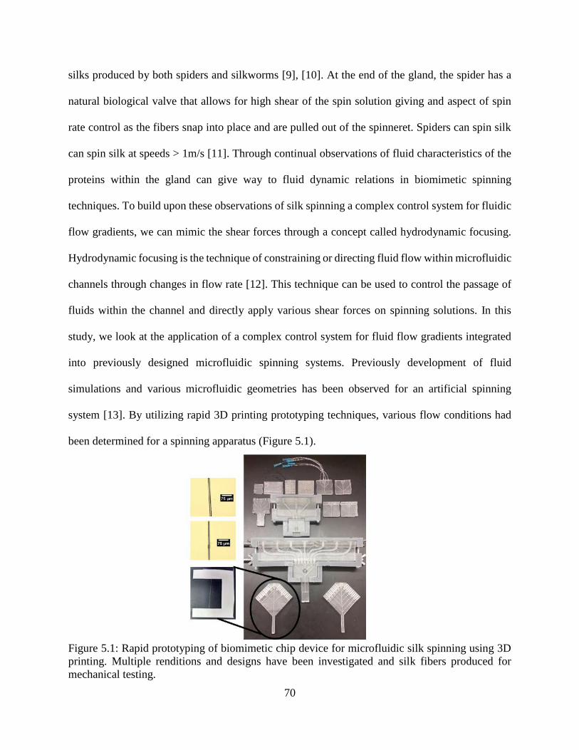
70
silks produced by both spiders and silkworms [9], [10]. At the end of the gland, the spider has a
natural biological valve that allows for high shear of the spin solution giving and aspect of spin
rate control as the fibers snap into place and are pulled out of the spinneret. Spiders can spin silk
can spin silk at speeds > 1m/s [11]. Through continual observations of fluid characteristics of the
proteins within the gland can give way to fluid dynamic relations in biomimetic spinning
techniques. To build upon these observations of silk spinning a complex control system for fluidic
flow gradients, we can mimic the shear forces through a concept called hydrodynamic focusing.
Hydrodynamic focusing is the technique of constraining or directing fluid flow within microfluidic
channels through changes in flow rate [12]. This technique can be used to control the passage of
fluids within the channel and directly apply various shear forces on spinning solutions. In this
study, we look at the application of a complex control system for fluid flow gradients integrated
into previously designed microfluidic spinning systems. Previously development of fluid
simulations and various microfluidic geometries has been observed for an artificial spinning
system [13]. By utilizing rapid 3D printing prototyping techniques, various flow conditions had
been determined for a spinning apparatus (Figure 5.1).
Figure 5.1: Rapid prototyping of biomimetic chip device for microfluidic silk spinning using 3D
printing. Multiple renditions and designs have been investigated and silk fibers produced for
mechanical testing.
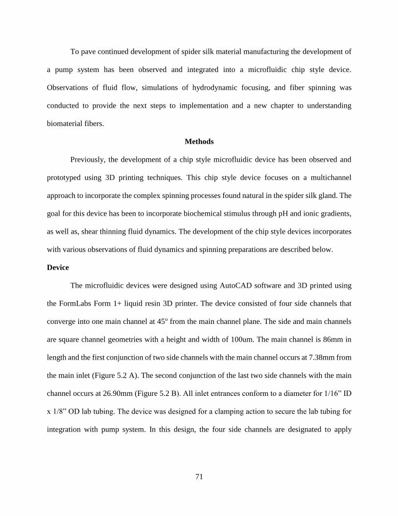
71
To pave continued development of spider silk material manufacturing the development of
a pump system has been observed and integrated into a microfluidic chip style device.
Observations of fluid flow, simulations of hydrodynamic focusing, and fiber spinning was
conducted to provide the next steps to implementation and a new chapter to understanding
biomaterial fibers.
Methods
Previously, the development of a chip style microfluidic device has been observed and
prototyped using 3D printing techniques. This chip style device focuses on a multichannel
approach to incorporate the complex spinning processes found natural in the spider silk gland. The
goal for this device has been to incorporate biochemical stimulus through pH and ionic gradients,
as well as, shear thinning fluid dynamics. The development of the chip style devices incorporates
with various observations of fluid dynamics and spinning preparations are described below.
Device
The microfluidic devices were designed using AutoCAD software and 3D printed using
the FormLabs Form 1+ liquid resin 3D printer. The device consisted of four side channels that
converge into one main channel at 45o from the main channel plane. The side and main channels
are square channel geometries with a height and width of 100um. The main channel is 86mm in
length and the first conjunction of two side channels with the main channel occurs at 7.38mm from
the main inlet (Figure 5.2 A). The second conjunction of the last two side channels with the main
channel occurs at 26.90mm (Figure 5.2 B). All inlet entrances conform to a diameter for 1/16” ID
x 1/8” OD lab tubing. The device was designed for a clamping action to secure the lab tubing for
integration with pump system. In this design, the four side channels are designated to apply
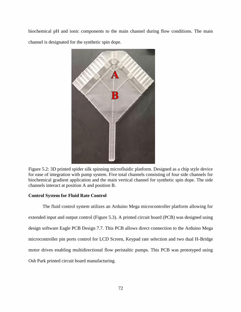
72
biochemical pH and ionic components to the main channel during flow conditions. The main
channel is designated for the synthetic spin dope.
Figure 5.2: 3D printed spider silk spinning microfluidic platform. Designed as a chip style device
for ease of integration with pump system. Five total channels consisting of four side channels for
biochemical gradient application and the main vertical channel for synthetic spin dope. The side
channels interact at position A and position B.
Control System for Fluid Rate Control
The fluid control system utilizes an Arduino Mega microcontroller platform allowing for
extended input and output control (Figure 5.3). A printed circuit board (PCB) was designed using
design software Eagle PCB Design 7.7. This PCB allows direct connection to the Arduino Mega
microcontroller pin ports control for LCD Screen, Keypad rate selection and two dual H-Bridge
motor drives enabling multidirectional flow peristaltic pumps. This PCB was prototyped using
Osh Park printed circuit board manufacturing.
73
Using pulse width modulation (PWM) rates of these two peristaltic pumps were
experimentally collected using three designated analog values directly set using the keypad. Once
the analog values were corresponded to specific rates, a linear trend line equation was calculated
using Excel with an R2 value of 0.9904. This equation was utilized in software implementation
created using the Arduino integrated development environment (IDE) allowing for a higher degree
of accuracy of direct user input for specified fluidic rates.
Figure 5.3: Schematic of microfluidic spinning control system.
Hydrodynamic Focusing Simulation Implementation
Simulations of hydrodynamic focusing of the device designs were computed using
COMSOL laminar flow physics. The designs for the microfluidic device were imported into the
COMSOL software directly. Two simulations had been run using different liquid parameters. The
first liquid characteristics were used from water. With 0.0412m/s from the inlet of the first three
inlets and 0.1923m/s in the last two inlets to provide the hydrodynamic focusing effect. The second
set of simulations consisted of two different liquids.
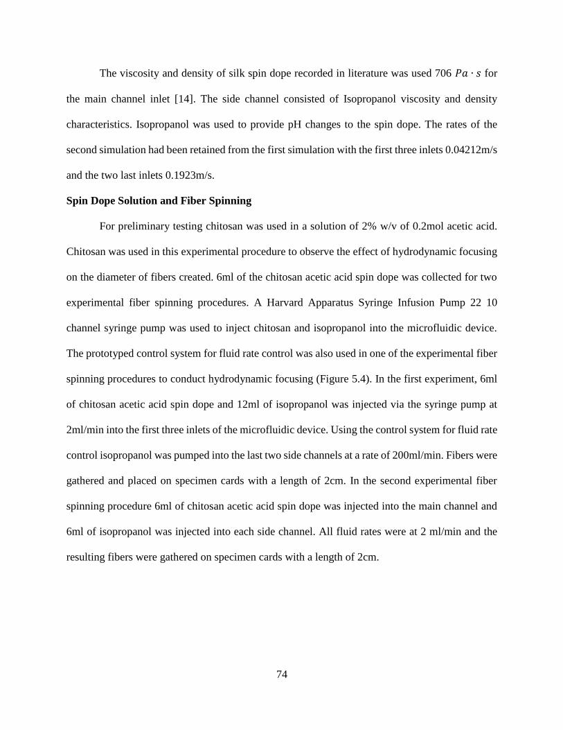
74
The viscosity and density of silk spin dope recorded in literature was used 706 𝑃𝑎 ∙ 𝑠 for
the main channel inlet [14]. The side channel consisted of Isopropanol viscosity and density
characteristics. Isopropanol was used to provide pH changes to the spin dope. The rates of the
second simulation had been retained from the first simulation with the first three inlets 0.04212m/s
and the two last inlets 0.1923m/s.
Spin Dope Solution and Fiber Spinning
For preliminary testing chitosan was used in a solution of 2% w/v of 0.2mol acetic acid.
Chitosan was used in this experimental procedure to observe the effect of hydrodynamic focusing
on the diameter of fibers created. 6ml of the chitosan acetic acid spin dope was collected for two
experimental fiber spinning procedures. A Harvard Apparatus Syringe Infusion Pump 22 10
channel syringe pump was used to inject chitosan and isopropanol into the microfluidic device.
The prototyped control system for fluid rate control was also used in one of the experimental fiber
spinning procedures to conduct hydrodynamic focusing (Figure 5.4). In the first experiment, 6ml
of chitosan acetic acid spin dope and 12ml of isopropanol was injected via the syringe pump at
2ml/min into the first three inlets of the microfluidic device. Using the control system for fluid rate
control isopropanol was pumped into the last two side channels at a rate of 200ml/min. Fibers were
gathered and placed on specimen cards with a length of 2cm. In the second experimental fiber
spinning procedure 6ml of chitosan acetic acid spin dope was injected into the main channel and
6ml of isopropanol was injected into each side channel. All fluid rates were at 2 ml/min and the
resulting fibers were gathered on specimen cards with a length of 2cm.
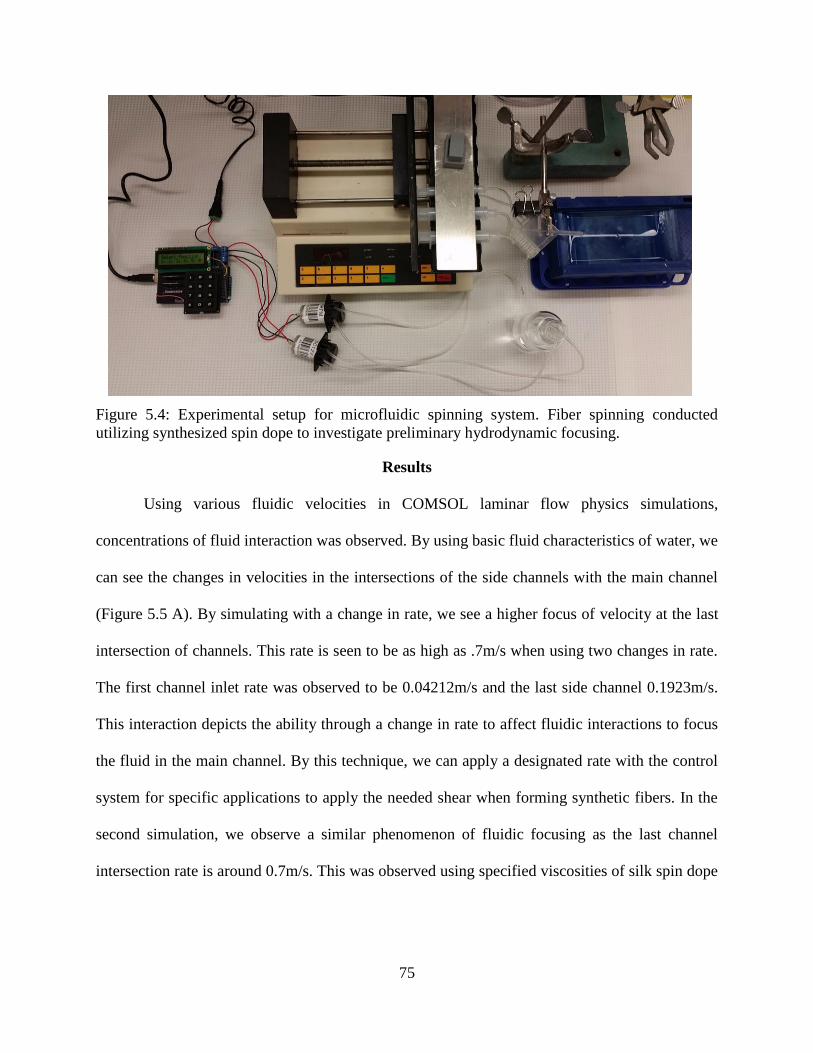
75
Figure 5.4: Experimental setup for microfluidic spinning system. Fiber spinning conducted
utilizing synthesized spin dope to investigate preliminary hydrodynamic focusing.
Results
Using various fluidic velocities in COMSOL laminar flow physics simulations,
concentrations of fluid interaction was observed. By using basic fluid characteristics of water, we
can see the changes in velocities in the intersections of the side channels with the main channel
(Figure 5.5 A). By simulating with a change in rate, we see a higher focus of velocity at the last
intersection of channels. This rate is seen to be as high as .7m/s when using two changes in rate.
The first channel inlet rate was observed to be 0.04212m/s and the last side channel 0.1923m/s.
This interaction depicts the ability through a change in rate to affect fluidic interactions to focus
the fluid in the main channel. By this technique, we can apply a designated rate with the control
system for specific applications to apply the needed shear when forming synthetic fibers. In the
second simulation, we observe a similar phenomenon of fluidic focusing as the last channel
intersection rate is around 0.7m/s. This was observed using specified viscosities of silk spin dope
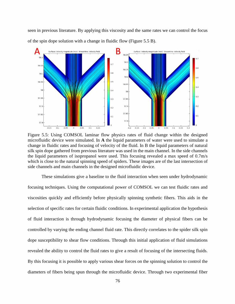
76
seen in previous literature. By applying this viscosity and the same rates we can control the focus
of the spin dope solution with a change in fluidic flow (Figure 5.5 B).
Figure 5.5: Using COMSOL laminar flow physics rates of fluid change within the designed
microfluidic device were simulated. In A the liquid parameters of water were used to simulate a
change in fluidic rates and focusing of velocity of the fluid. In B the liquid parameters of natural
silk spin dope gathered from previous literature was used in the main channel. In the side channels
the liquid parameters of isopropanol were used. This focusing revealed a max speed of 0.7m/s
which is close to the natural spinning speed of spiders. These images are of the last intersection of
side channels and main channels in the designed microfluidic device.
These simulations give a baseline to the fluid interaction when seen under hydrodynamic
focusing techniques. Using the computational power of COMSOL we can test fluidic rates and
viscosities quickly and efficiently before physically spinning synthetic fibers. This aids in the
selection of specific rates for certain fluidic conditions. In experimental application the hypothesis
of fluid interaction is through hydrodynamic focusing the diameter of physical fibers can be
controlled by varying the ending channel fluid rate. This directly correlates to the spider silk spin
dope susceptibility to shear flow conditions. Through this initial application of fluid simulations
revealed the ability to control the fluid rates to give a result of focusing of the intersecting fluids.
By this focusing it is possible to apply various shear forces on the spinning solution to control the
diameters of fibers being spun through the microfluidic device. Through two experimental fiber
77
spinning, procedures to compare the use of various rates during fluid flow and similar rates fibers
of various diameters were gathered. The first experimentation was to deliver a chitosan acetic acid
spin dope through the microfluidic device and have it subjected to two varying fluid rates.
The chitosan spin dope was injected using a rate of 2ml/min into the device main channel
at the first fluid intersection isopropanol was injected into the side channels at a rate of 2ml/min.
As the isopropanol and chitosan continued through the device a higher rate of fluid change was
injected into the device last side channels. This rate of 200ml/min is to drive the focusing capability
and lower the total diameter of the fiber at the outlet of the device. The average diameter of fibers
collected through this technique was captured at 13.58um (Figure 5.6 A). The second set of
experiments was done using previous spinning techniques of a uniform rate of fluid flow in the
device. Chitosan acetic acid spin dope was injected into the main channel at 2ml/min and subjected
to continuous rates at each intersection of 2ml/min isopropanol. The resulting fibers from the
uniform rate of flow was revealed to be of average diameter 46.74um (Figure 5.6 B). Suggesting
that hydrodynamic focusing of the first experimental fiber spinning procedure has a correlation
with the resulting diameters of fibers being produced.
Figure 5.6: Fibers gathered through experimental spinning to compare the effect of varying fluid
rates to uniform fluid rates on the resulting diameter. A was gathered using hydrodynamic focusing
through an increase in rate at the end of the microfluidic device. B was gathered using uniform
fluid rates in the microfluidic device. This diameter change suggests that hydrodynamic focusing
can be used to apply different shear fluidic rates and gain control of the diameter of spun fibers.
78
Discussion
The designed microfluidic device follows a concept of integration between multiple
spinning techniques. By incorporating these fluidic spinning procedures, we gain a chip style
device that can be integrated into a complex fluid control system. The control aspect of fluid
dynamics allows for a more accurate representation or mimic of the spinning environment found
in the gland of the spider. COMSOL fluid dynamic physics simulations can give preliminary data
to the interactions of fluid velocities, pressures and concentrations. Utilizing hydrodynamic
focusing, it was hypothesized that this fluid interaction will focus the velocities of the main channel
of the designed device allowing for a narrowing of the spinning window resulting in smaller
diameter fibers. In simulation, the hydrodynamic focusing revealed that the interactions between
the side channels and the main channel gave a focusing phenomenon that increased the velocities
and narrowed fluid flow. The rates used in simulation could then be captured in experimental
examination of the hydrodynamic focusing procedure. In the comparison between both
hydrodynamic focusing and uniform flow rates fibers had been collected and observed. The fibers
expressed changes in diameter based on fluid rate. This is directly correlated to the phenomenon
found in the natural process of spinning fibers. The natural spin dope found in spider glands is
highly susceptible to shear forces suggesting that controlling this shear rate the fiber mechanical
characteristics can also be controlled.
Further examination must be conducted on various flow rates in conjunction with other
spinning parameters such as, pH and ionic gradients. Leading to further characterization of these
fibers and correlation to rheological flow conditions of the spin dopes before they enter the device.
This rheological characterization can aid in the material processing of and correlation between
fluid characteristics and fiber mechanical properties. The natural spinning process of spider silk is
79
complex and by integrating a control system to control fluidic flow into a microfluidic device the
shear thinning forces of the spin dope can be aid in mechanically versatile fibers.
Conclusion
Biomimetic engineering is a driving course of action in the continued spider silk material
research. If the natural process that is found in the gland of major ampullate spider silk (i.e., pH,
Ionic gradients and shear thinning fluidic forces) could be manipulated and controlled in a device,
then the control of mechanically versatile fibers can be accomplished. In this study, we look at the
simulations of varying fluidic rates to accomplish the shear thinning forces found in the gland of
the spider. Using COMSOL insight was gained into the hydrodynamic focusing of fluids at
different velocity rates. This focusing can be used to control the mechanical characteristics of the
fibers as they are spun.
In using this information gained from fluidic simulations. Experimental fiber spinning
allowed for a comparison of uniform rates of fluid velocities and varying hydrodynamic forces
had been accomplished. The results revealed that the collected fiber diameters could be varied as
they are spun using a fluidic gradient through the device. In using chitosan as a preliminary
material, we show that by changing the fluid rates we can cause hydrodynamic focusing of the
spin dope to narrow the spinning window and get smaller fiber diameters. This serves as a baseline
for continued spider silk spinning solutions to be conducted in similar spinning fabrications.
Opening a door to the future of spider silk manufacturing products.
References
[1] R. V. Lewis, “Spider Silk: Ancient Ideas for New Biomaterials,” Chem. Rev., vol. 106, no.
9, pp. 3762–3774, Sep. 2006.
80
[2] A. E. Brooks, H. B. Steinkraus, S. R. Nelson, and R. V. Lewis, “An investigation of the
divergence of major ampullate silk fibers from Nephila clavipes and Argiope aurantia,”
Biomacromolecules, vol. 6, no. 6, pp. 3095–3099, Dec. 2005.
[3] R. Lewis, “Unraveling the Weave of Spider Silk,” BioScience, vol. 46, no. 9, pp. 636–638,
Oct. 1996.
[4] O. Tokareva, M. Jacobsen, M. Buehler, J. Wong, and D. L. Kaplan, “Structure–function–
property–design interplay in biopolymers: Spider silk,” Acta Biomater., vol. 10, no. 4, pp.
1612–1626, Apr. 2014.
[5] A. Rising and J. Johansson, “Toward spinning artificial spider silk,” Nat. Chem. Biol., vol.
11, no. 5, pp. 309–315, Apr. 2015.
[6] L. Eisoldt, A. Smith, and T. Scheibel, “Decoding the secrets of spider silk,” Mater. Today,
vol. 14, no. 3, pp. 80–86, Mar. 2011.
[7] D. P. Knight and F. Vollrath, “Liquid crystals and flow elongation in a spider’s silk
production line,” Proc. R. Soc. Lond. B Biol. Sci., vol. 266, no. 1418, pp. 519–523, Mar.
1999.
[8] E. Doblhofer, A. Heidebrecht, and T. Scheibel, “To spin or not to spin: spider silk fibers and
more,” Appl. Microbiol. Biotechnol., vol. 99, no. 22, pp. 9361–9380, Nov. 2015.
[9] P. R. Laity, S. E. Gilks, and C. Holland, “Rheological behaviour of native silk feedstocks,”
Polymer, vol. 67, pp. 28–39, Jun. 2015.
[10] C. Holland, A. E. Terry, D. Porter, and F. Vollrath, “Natural and unnatural silks,” Polymer,
vol. 48, no. 12, pp. 3388–3392, Jun. 2007.
81
[11] K. B. Guess and C. Viney, “Thermal analysis of major ampullate (drag line) spider silk: the
effect of spinning rate on tensile modulus1,” Thermochim. Acta, vol. 315, no. 1, pp. 61–66,
May 1998.
[12] G.-B. Lee, C.-C. Chang, S.-B. Huang, and R.-J. Yang, “The hydrodynamic focusing effect
inside rectangular microchannels,” J. Micromechanics Microengineering, vol. 16, no. 5, pp.
1024–1032, May 2006.
[13] B. Hoffmann, A. Nodland, C. Gruat-Henry, and A. Brooks, “Using Engineering To Unravel
The Mystery of Spider Silk Fiber Formation,” Biomed. Sci. Instrum., vol. 52, 2016.
[14] P. R. Laity and C. Holland, “Native Silk Feedstock as a Model Biopolymer: A Rheological
Perspective,” Biomacromolecules, vol. 17, no. 8, pp. 2662–2671, Aug. 2016.
82
CHAPTER 6: USING HYDRODYNAMIC FOCUSING TO PREDICTABLY ALTER
THE DIAMTER OF SYNTHETIC FIBERS3
Abstract
Spiders and silkworms provide a model of superior processing for multifunctional and
highly versatile high-performance fibers. Mimicking the spider’s complex control system for
chemical and mechanical gradients has remained an ongoing obstacle for synthetic silk production.
In this study, the use of hydrodynamic fluid focusing within a 3D printed biomimetic spinning
system to recapitulate the biological spinneret is explored and shown to produce predictable, small
diameter fibers. Mirroring in silico fluid flow simulations using a hydrodynamic microfluidic
spinning technique, we have developed a model correlating spinning rates, solution viscosity and
fiber diameter outputs that will significantly advance the field of synthetic silk fiber production.
The use of hydrodynamic focusing to produce controlled output fiber diameter simulates the
natural silk spinning process and continues to build upon a 3D printed biomimetic spinning
platform.
Introduction
Orb-weaving spiders, such as the golden orb-weaver, Nephila clavipes, produce up to 6
solid silk fibers, each with a specified ecological purpose. Major ampullate (MA) silk fibers, the
most studied of the group, possess both high strength and elasticity [1], [2]. Despite our ability to
reproduce and manipulate the key genetic elements of major ampullate silk proteins, the unique
3 The material in this chapter was co-authored by Bradley Hoffmann, Catherine Gruat-Henry,
Pranothi Mulinti, Long Jiang, Ben D Brooks and Amanda E Brooks. Bradley Hoffmann had
primary responsibility for preparing all silk samples, conducting all bench top spinning
experiments, developing and fluid simulations. Catherine Gruat-Henry provided contributions to
fluid simulations. Pranothi provided insight into protein structure. Bradley Hoffmann also drafted
and revised all versions of this chapter. Amanda E. Brooks, Long Jiang and Ben D Brooks served
as proofreader and checked works by Bradley Hoffmann.
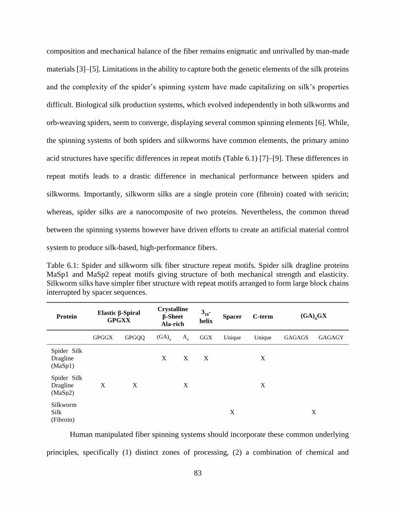
83
composition and mechanical balance of the fiber remains enigmatic and unrivalled by man-made
materials [3]–[5]. Limitations in the ability to capture both the genetic elements of the silk proteins
and the complexity of the spider’s spinning system have made capitalizing on silk’s properties
difficult. Biological silk production systems, which evolved independently in both silkworms and
orb-weaving spiders, seem to converge, displaying several common spinning elements [6]. While,
the spinning systems of both spiders and silkworms have common elements, the primary amino
acid structures have specific differences in repeat motifs (Table 6.1) [7]–[9]. These differences in
repeat motifs leads to a drastic difference in mechanical performance between spiders and
silkworms. Importantly, silkworm silks are a single protein core (fibroin) coated with sericin;
whereas, spider silks are a nanocomposite of two proteins. Nevertheless, the common thread
between the spinning systems however have driven efforts to create an artificial material control
system to produce silk-based, high-performance fibers.
Table 6.1: Spider and silkworm silk fiber structure repeat motifs. Spider silk dragline proteins
MaSp1 and MaSp2 repeat motifs giving structure of both mechanical strength and elasticity.
Silkworm silks have simpler fiber structure with repeat motifs arranged to form large block chains
interrupted by spacer sequences.
Human manipulated fiber spinning systems should incorporate these common underlying
principles, specifically (1) distinct zones of processing, (2) a combination of chemical and
Protein Elastic β-Spiral GPGXX
Crystalline
β-Sheet
Ala-rich 3
10-
helix Spacer C-term (GA)nGX
GPGGX GPGQQ (GA)n A
n GGX Unique Unique GAGAGS GAGAGY
Spider Silk
Dragline
(MaSp1) X X X X
Spider Silk
Dragline
(MaSp2) X X X X
Silkworm
Silk
(Fibroin) X X
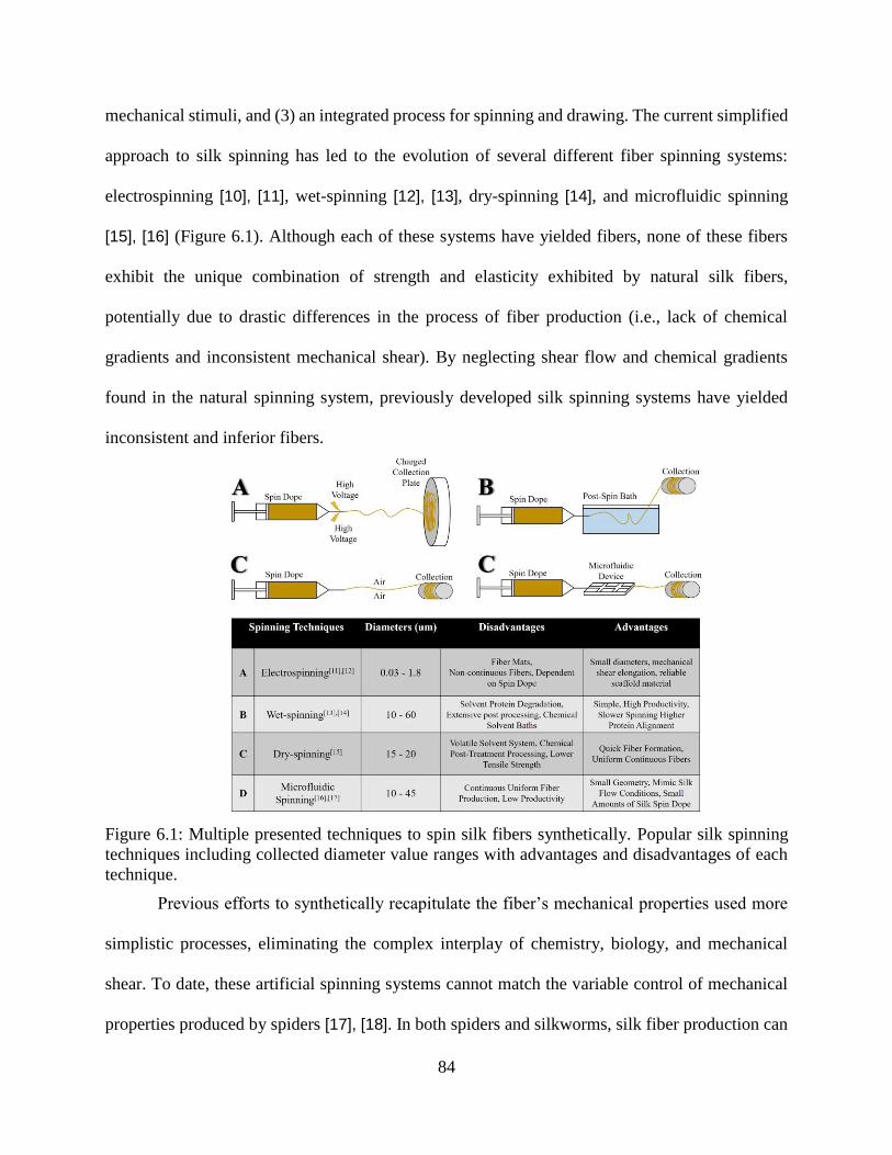
84
mechanical stimuli, and (3) an integrated process for spinning and drawing. The current simplified
approach to silk spinning has led to the evolution of several different fiber spinning systems:
electrospinning [10], [11], wet-spinning [12], [13], dry-spinning [14], and microfluidic spinning
[15], [16] (Figure 6.1). Although each of these systems have yielded fibers, none of these fibers
exhibit the unique combination of strength and elasticity exhibited by natural silk fibers,
potentially due to drastic differences in the process of fiber production (i.e., lack of chemical
gradients and inconsistent mechanical shear). By neglecting shear flow and chemical gradients
found in the natural spinning system, previously developed silk spinning systems have yielded
inconsistent and inferior fibers.
Figure 6.1: Multiple presented techniques to spin silk fibers synthetically. Popular silk spinning
techniques including collected diameter value ranges with advantages and disadvantages of each
technique.
Previous efforts to synthetically recapitulate the fiber’s mechanical properties used more
simplistic processes, eliminating the complex interplay of chemistry, biology, and mechanical
shear. To date, these artificial spinning systems cannot match the variable control of mechanical
properties produced by spiders [17], [18]. In both spiders and silkworms, silk fiber production can
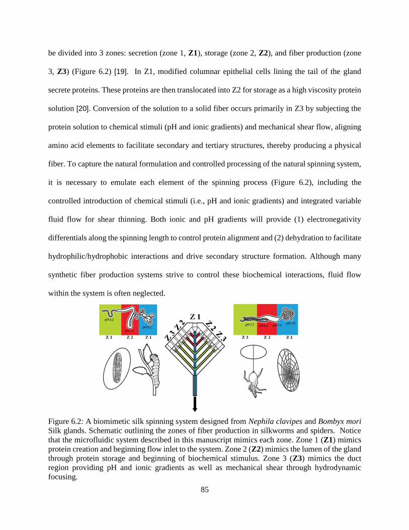
85
be divided into 3 zones: secretion (zone 1, Z1), storage (zone 2, Z2), and fiber production (zone
3, Z3) (Figure 6.2) [19]. In Z1, modified columnar epithelial cells lining the tail of the gland
secrete proteins. These proteins are then translocated into Z2 for storage as a high viscosity protein
solution [20]. Conversion of the solution to a solid fiber occurs primarily in Z3 by subjecting the
protein solution to chemical stimuli (pH and ionic gradients) and mechanical shear flow, aligning
amino acid elements to facilitate secondary and tertiary structures, thereby producing a physical
fiber. To capture the natural formulation and controlled processing of the natural spinning system,
it is necessary to emulate each element of the spinning process (Figure 6.2), including the
controlled introduction of chemical stimuli (i.e., pH and ionic gradients) and integrated variable
fluid flow for shear thinning. Both ionic and pH gradients will provide (1) electronegativity
differentials along the spinning length to control protein alignment and (2) dehydration to facilitate
hydrophilic/hydrophobic interactions and drive secondary structure formation. Although many
synthetic fiber production systems strive to control these biochemical interactions, fluid flow
within the system is often neglected.
Figure 6.2: A biomimetic silk spinning system designed from Nephila clavipes and Bombyx mori
Silk glands. Schematic outlining the zones of fiber production in silkworms and spiders. Notice
that the microfluidic system described in this manuscript mimics each zone. Zone 1 (Z1) mimics
protein creation and beginning flow inlet to the system. Zone 2 (Z2) mimics the lumen of the gland
through protein storage and beginning of biochemical stimulus. Zone 3 (Z3) mimics the duct
region providing pH and ionic gradients as well as mechanical shear through hydrodynamic
focusing.
86
Not only do current spinning systems disregard the three distinct zones but virtually all,
except electrospinning, systems separate the spin and draw processes, requiring post-spin
processing to improve mechanical properties and thin the fiber diameter [21]–[23]. Separating
these two processes into spin, or coalescence of proteins, and draw, or shear thinning of the fiber,
represents a fundamental departure from the natural spinning process resulting in inconsistent and
mechanically inferior fibers. Furthermore, the extrusion, pushing action found in many artificial
spinning systems subjects the protein solution to unnatural forces. To attain controlled diameters
while combining the spin and draw process, fluid focusing or hydrodynamic focusing can be
exploited. Hydrodynamic focusing uses fluid flow dynamics to narrow the central fluid stream
within the microfluidic channel [24]. The use of fluid focusing provides the opportunity for
controlled flow to be correlated with diameter [25]. Previous studies have coincided with the need
for continued investigations of the dependence of the spinning process on fluidic flow spinning
[26], [27]. These studies investigate the strain dependence of the spinning process, which is a step
towards the biomimetic processing.
In these studies the use of a dual sheath fluidic flow focuses on a restricted geometry and
prevents the ability to integrate chemical gradients. The current study presents (1) a preliminary
correlation between silk spin dope fluid characteristics and the mechanical properties of the
resulting fibers; (2) a microfluidic spinning system design that provides the ability to introduce a
gradient of both chemical and mechanical stimuli [28], [29]; and (3) integrated hydrodynamic
focusing to eliminate the necessary post-spin processing found with other synthetic spinning
systems. Ultimately, this combination of controlled fluid dynamics and mechanical shear allows
predictable control of the output diameter of silk fibers.
87
Materials and Methods
Solution Preparation
Natural silks produced by the silkworm Bombyx mori supplied from Jiangsu Fu’an Cacoon
and Silk Co. were degummed by boiling at 100°C in 0.05%wt Na2CO3 aqueous solution.
Degummed silk was allowed to dry overnight. Dry degummed silk was directly dissolved as an
8% w/w concentration in a CaCl2 – formic acid solution for 3 hours at room temperature. This
process was repeated to give 8, 10 and 12 % w/w silk solutions. Alternatively, natural major
ampullate silk produced by the spider Nephila clavipes (wild caught in Florida) was collected
through forcibly silking in Brooks’ Lab at 20-30 rpm. The silk was dissolved in HFIP to produce
an 8% w/v solution.
Steady State Rheology
Silk samples of concentration 8, 10 and 12 %w/w were prepared for rheological analysis.
Silk solutions were loaded into a TA ARG2 rheometer with a test plate size of 25mm. Each
concentration was subjected to steady state shear at strain of 0.01%. The steady state shear
continued to increase through a step range of 6.283-628.3 rad/s angular frequency.
Fluid Simulations
COMSOL Multiphysics simulation software was utilized to visualize and correlate fluid
flow dynamics using custom microfluidic device channel dimensions generated using AutoCAD.
Device geometry consisted of 5 channel inlets and 1 outlet channel. The length of main channel
was 100 mm and the width ranged from 1 to 1.5 mm. Fluid shear changes were simulated using
the COMSOL Laminar Flow Module by varying the fluidic rates and assessing stream line output.
The main channel rate was held constant at 0.2ml/min while flow rates through the side channels
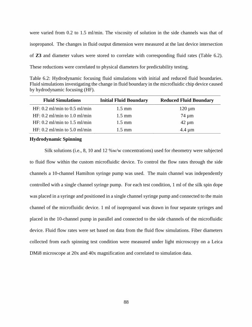
88
were varied from 0.2 to 1.5 ml/min. The viscosity of solution in the side channels was that of
isopropanol. The changes in fluid output dimension were measured at the last device intersection
of Z3 and diameter values were stored to correlate with corresponding fluid rates (Table 6.2).
These reductions were correlated to physical diameters for predictability testing.
Table 6.2: Hydrodynamic focusing fluid simulations with initial and reduced fluid boundaries.
Fluid simulations investigating the change in fluid boundary in the microfluidic chip device caused
by hydrodynamic focusing (HF).
Hydrodynamic Spinning
Silk solutions (i.e., 8, 10 and 12 %w/w concentrations) used for rheometry were subjected
to fluid flow within the custom microfluidic device. To control the flow rates through the side
channels a 10-channel Hamilton syringe pump was used. The main channel was independently
controlled with a single channel syringe pump. For each test condition, 1 ml of the silk spin dope
was placed in a syringe and positioned in a single channel syringe pump and connected to the main
channel of the microfluidic device. 1 ml of isopropanol was drawn in four separate syringes and
placed in the 10-channel pump in parallel and connected to the side channels of the microfluidic
device. Fluid flow rates were set based on data from the fluid flow simulations. Fiber diameters
collected from each spinning test condition were measured under light microscopy on a Leica
DMi8 microscope at 20x and 40x magnification and correlated to simulation data.
Fluid Simulations Initial Fluid Boundary Reduced Fluid Boundary
HF: 0.2 ml/min to 0.5 ml/min 1.5 mm 120 µm
HF: 0.2 ml/min to 1.0 ml/min 1.5 mm 74 µm
HF: 0.2 ml/min to 1.5 ml/min 1.5 mm 42 µm
HF: 0.2 ml/min to 5.0 ml/min 1.5 mm 4.4 µm
89
Mechanical Testing
Each 3cm length of fiber collected during spinning was secured to a specimen card for
tensile testing using an Instron 5942 Micro-tensile testing apparatus on a 50-gram load cell. Each
specimen was loaded at a rate of 2mm/min and tested until failure.
Statistics
Fiber diameters are reported as an average (Excel 2016) of multiple independent replicates
at each rate using hydrodynamic focusing (HF) and without hydrodynamic focusing (NHF).
NHF0_2 spun at 0.2 ml/min (n = 3), NHF0_5 spun at 0.5 ml/min (n = 4), HF0_5 spun at 0.2
ml/min in the main channel Z1 and Z2 with 0.5 ml/min at Z3 (n = 9), HF1_0 spun at 0.2 ml/min
in the main channel Z1 and Z2 with 1.0 ml/min at Z3 (n = 7), HF1_5 spun at 0.2 ml/min in the
main channel Z1 and Z2 with 1.5 ml/min at Z3 (n = 4), HF5_0 spun at 0.2 ml/min in the main
channel Z1 and Z2 with 5.0 ml/min at Z3 (n = 13). Mechanical testing of re-spun silk gathered
from independent spinning at each rate NHF (n = 4), HF0_5 (n = 3), HF1_0 (n = 6), and HF1_5
(n = 3) are expressed as an average using a custom MATLAb code (v. R2016A) expressed with
standard deviation of the mean of each individual sample size. Rheology of three different silk
solutions (i.e., 8, 10 and 12 %w/w concentrations) is expressed as an average (Excel 2016) (n = 3)
for each solution.
Results and Discussion
Using a previously developed 3D printed, multichannel, microfluidic device (Figure 6.2),
both chemical stimuli and gradient fluid flow can be integrated to directly mimic the natural gland
system. Since silk protein alignment is naturally dependent on mechanical shear, laminar flow
within Z2 and part of Z3 of the device maintains stable environmental conditions to resist
premature fiber formation. Inhibition of premature fiber formation in the gland is thought to
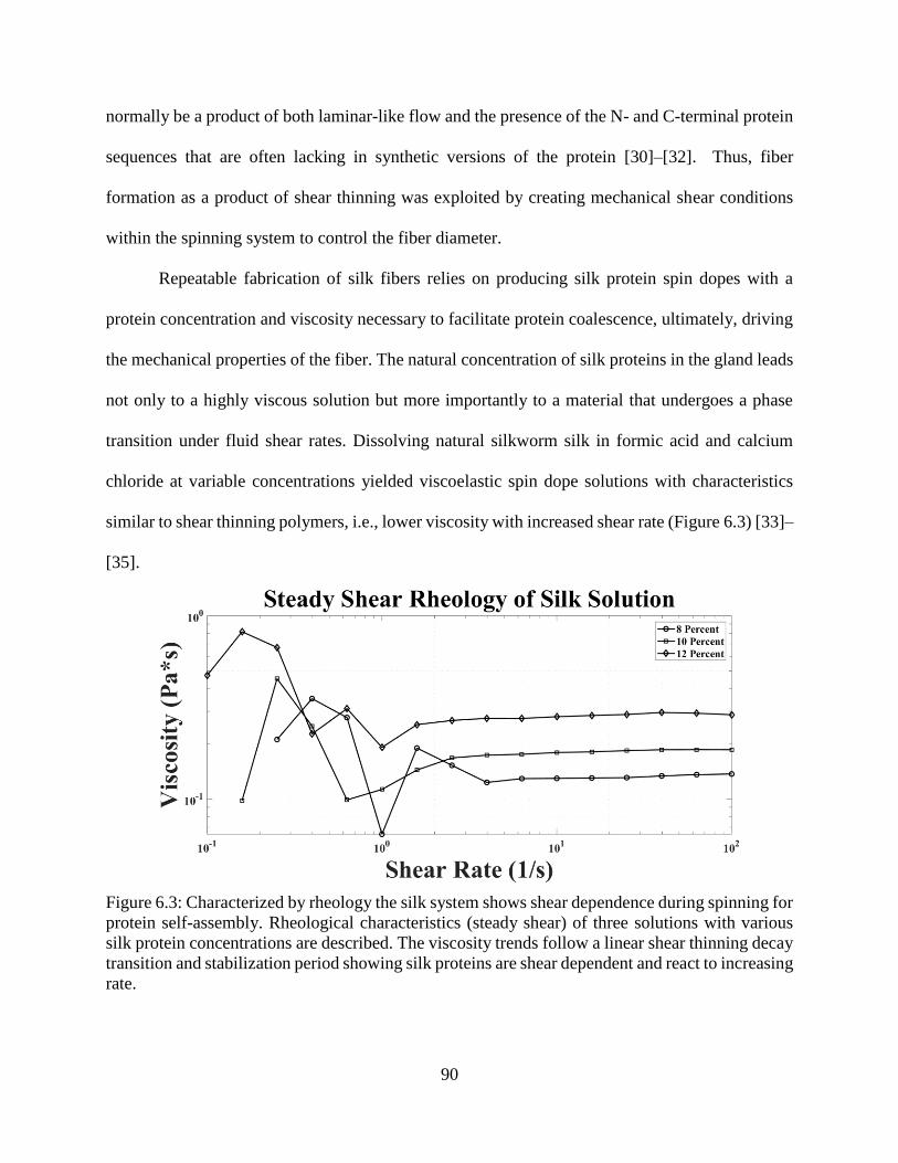
90
normally be a product of both laminar-like flow and the presence of the N- and C-terminal protein
sequences that are often lacking in synthetic versions of the protein [30]–[32]. Thus, fiber
formation as a product of shear thinning was exploited by creating mechanical shear conditions
within the spinning system to control the fiber diameter.
Repeatable fabrication of silk fibers relies on producing silk protein spin dopes with a
protein concentration and viscosity necessary to facilitate protein coalescence, ultimately, driving
the mechanical properties of the fiber. The natural concentration of silk proteins in the gland leads
not only to a highly viscous solution but more importantly to a material that undergoes a phase
transition under fluid shear rates. Dissolving natural silkworm silk in formic acid and calcium
chloride at variable concentrations yielded viscoelastic spin dope solutions with characteristics
similar to shear thinning polymers, i.e., lower viscosity with increased shear rate (Figure 6.3) [33]–
[35].
Figure 6.3: Characterized by rheology the silk system shows shear dependence during spinning for
protein self-assembly. Rheological characteristics (steady shear) of three solutions with various
silk protein concentrations are described. The viscosity trends follow a linear shear thinning decay
transition and stabilization period showing silk proteins are shear dependent and react to increasing
rate.
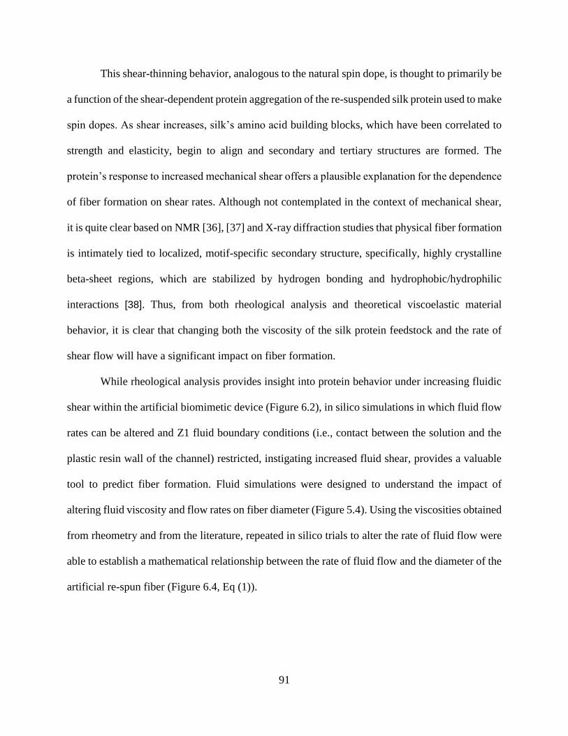
91
This shear-thinning behavior, analogous to the natural spin dope, is thought to primarily be
a function of the shear-dependent protein aggregation of the re-suspended silk protein used to make
spin dopes. As shear increases, silk’s amino acid building blocks, which have been correlated to
strength and elasticity, begin to align and secondary and tertiary structures are formed. The
protein’s response to increased mechanical shear offers a plausible explanation for the dependence
of fiber formation on shear rates. Although not contemplated in the context of mechanical shear,
it is quite clear based on NMR [36], [37] and X-ray diffraction studies that physical fiber formation
is intimately tied to localized, motif-specific secondary structure, specifically, highly crystalline
beta-sheet regions, which are stabilized by hydrogen bonding and hydrophobic/hydrophilic
interactions [38]. Thus, from both rheological analysis and theoretical viscoelastic material
behavior, it is clear that changing both the viscosity of the silk protein feedstock and the rate of
shear flow will have a significant impact on fiber formation.
While rheological analysis provides insight into protein behavior under increasing fluidic
shear within the artificial biomimetic device (Figure 6.2), in silico simulations in which fluid flow
rates can be altered and Z1 fluid boundary conditions (i.e., contact between the solution and the
plastic resin wall of the channel) restricted, instigating increased fluid shear, provides a valuable
tool to predict fiber formation. Fluid simulations were designed to understand the impact of
altering fluid viscosity and flow rates on fiber diameter (Figure 5.4). Using the viscosities obtained
from rheometry and from the literature, repeated in silico trials to alter the rate of fluid flow were
able to establish a mathematical relationship between the rate of fluid flow and the diameter of the
artificial re-spun fiber (Figure 6.4, Eq (1)).
92
Figure 6.4: Fluid simulations provide predictable fiber diameters from hydrodynamic focusing
shear rates. Fluid flow simulations that mirror the solution properties of the physical spin dopes
were created. A Flow rates in the main center channel remained consistent while the side channels
had increased fluid rates to simulate hydrodynamic focusing with axes representing geometry in
micrometers (µm). B Flow rate introduced into the main center channel maintained consistent with
rates of the side channels with axes representing geometry in micrometers (µm). C Predicted
diameter outputs from hydrodynamic focusing fluidic rate simulations.
𝐷 = 0.0001𝑒
−0.014(w∗𝜏𝜂
) (1)
The relationship of fiber diameters (D) collected from both simulations and benchtop
hydrodynamic focused spinning show an exponential decrease corresponding with the width of
the microfluidic channel w, fluid shear stress 𝝉 and solution viscosity 𝜼. Importantly, while native
Nephila clavipes fibers have an average diameter of 3-7 μm, previous studies have established that
high strength fibers have smaller diameters and more elastic fibers having larger diameters [39]–
[41]. Thus, synthetic production of high-performance fibers with tailored mechanical properties
requires the ability to predictably and consistently modify the fiber diameter. Fluid flow
simulations, which established this relationship, were subsequently replicated on the bench and
used to spin physical fibers in an analogous process.
Attaining consistent, small diameter fibers based strictly on the physical dimensions of the
system is challenging at best and often insurmountable. Thus, previous efforts to create smaller
93
diameter fibers have been focused on the need to 1) limit the boundary conditions of the spinning
environment and 2) alter the post spin draw ratio. Post spin processing, in addition to introducing
inconsistency, has yet to yield a fiber that can rival the mechanical strength of its natural
counterpart.
To investigate the impact of smaller boundary conditions due to fluid focusing within the
microfluidic-spinning device and isolate the impact of spinning on the mechanical properties of
the fiber, both silkworm silk and spider silk were dissolved and re-spun. Using a ratio of fluid
flow rates and solution viscosity, the diameter of the center channel fluid (i.e. silk) could be
narrowed or focused to yield small diameter fibers (Figure 6.5). Spinning with a variable fluid rate
provides shear gradients that restrict the boundary condition of the silk spin dope, effectively
narrowing the spin dope fluid stream. This focusing leads to a fluidic draw that occurs naturally as
the spin dope flows through the intersection of the side channels that output a lower viscosity fluid
(i.e. isopropanol) at a higher rate. Traditionally, in synthetic silk spinning systems, post spin draw
solvent baths that facilitate dehydration are used to promote secondary structure as the fibers are
being spun (i.e., methanol, isopropanol (IPA)) [42]. Nevertheless, it is possible that the use of IPA
compromises the mechanical properties of the fiber due to rapid dehydration. PEG infused IPA
may facilitate a better protein alignment and may be tried in the future. Localized shear stress
acting on the spin dope at the channel junction facilitates protein alignment and likely promotes
beta-sheet alignment and fiber formation. Using flow to physically move or draw the fiber through
the device, subjects the fiber to more natural mechanical forces, leading to more uniform,
consistent fibers, a distinct advantage of the current system.
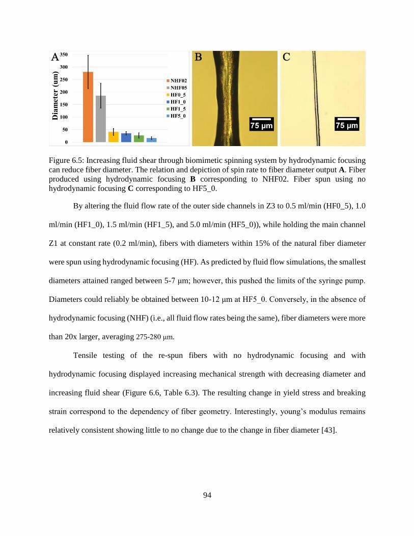
94
Figure 6.5: Increasing fluid shear through biomimetic spinning system by hydrodynamic focusing
can reduce fiber diameter. The relation and depiction of spin rate to fiber diameter output A. Fiber
produced using hydrodynamic focusing B corresponding to NHF02. Fiber spun using no
hydrodynamic focusing C corresponding to HF5_0.
By altering the fluid flow rate of the outer side channels in Z3 to 0.5 ml/min (HF0_5), 1.0
ml/min (HF1_0), 1.5 ml/min (HF1_5), and 5.0 ml/min (HF5_0)), while holding the main channel
Z1 at constant rate (0.2 ml/min), fibers with diameters within 15% of the natural fiber diameter
were spun using hydrodynamic focusing (HF). As predicted by fluid flow simulations, the smallest
diameters attained ranged between 5-7 μm; however, this pushed the limits of the syringe pump.
Diameters could reliably be obtained between 10-12 μm at HF5_0. Conversely, in the absence of
hydrodynamic focusing (NHF) (i.e., all fluid flow rates being the same), fiber diameters were more
than 20x larger, averaging 275-280 μm.
Tensile testing of the re-spun fibers with no hydrodynamic focusing and with
hydrodynamic focusing displayed increasing mechanical strength with decreasing diameter and
increasing fluid shear (Figure 6.6, Table 6.3). The resulting change in yield stress and breaking
strain correspond to the dependency of fiber geometry. Interestingly, young’s modulus remains
relatively consistent showing little to no change due to the change in fiber diameter [43].
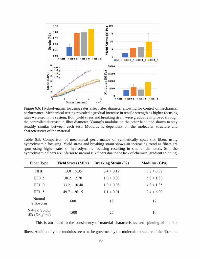
95
Figure 6.6: Hydrodynamic focusing rates affect fiber diameter allowing for control of mechanical
performance. Mechanical testing revealed a gradual increase in tensile strength as higher focusing
rates were set in the system. Both yield stress and breaking strain were gradually improved through
the controlled decrease in fiber diameter. Young’s modulus on the other hand had shown to stay
steadily similar between each test. Modulus is dependent on the molecular structure and
characteristics of the material.
Table 6.3: Comparison of mechanical performance of synthetically spun silk fibers using
hydrodynamic focusing. Yield stress and breaking strain shows an increasing trend as fibers are
spun using higher rates of hydrodynamic focusing resulting in smaller diameters. Still the
hydrodynamic fibers are inferior to natural silk fibers due to the lack of chemical gradient spinning.
This is attributed to the consistency of material characteristics and spinning of the silk
fibers. Additionally, the modulus seems to be governed by the molecular structure of the fiber and
Fiber Type Yield Stress (MPa) Breaking Strain (%) Modulus (GPa)
NHF 13.0 ± 5.35 0.4 ± 0.12 3.8 ± 0.32
HF0_5 30.2 ± 2.70 1.0 ± 0.03 5.8 ± 1.80
HF1_0 33.2 ± 10.48 1.0 ± 0.08 4.3 ± 1.35
HF1_5 49.7 ± 26.15 1.1 ± 0.01 9.4 ± 6.00
Natural
Silkworm 600 18 17
Natural Spider
silk (Dragline) 1500 27 10
96
is relatively independent on the characteristics of the material [43]. Nevertheless, despite the
controlled fluidic shear spinning, the resulting fibers are still mechanically inferior to the natural
silk fibers, suggesting the needed integration of chemical gradients in the spinning system [20],
[44]–[47].
Conclusion
Despite decreased diameters, the strength and elasticity of the re-spun fibers are still no match
for their natural counterpart. However, this study demonstrates the ability of hydrodynamic
focusing in the absence of gravimetric pull to narrow the diameter of the fiber in a predictable way
and increase the mechanical performance. Additionally, this study reveals more precisely the
relationship between fluid viscosity and shear rate leading to the derivation of a predictive equation
for the diameter. Spinning at specific rates yields fibers with diameters that matched the in-silico
predictions, leading to a complete spinning system that can provide fibers to rival the diameters of
the natural silk produced by both silkworms and spiders. Although closely approximating the
diameter of the natural fiber did not fully recapitulate its mechanics, future efforts to integrate
chemical stimuli (e.g., pH and ionic gradients) are predicted to increase protein alignment and
improve the fiber’s mechanical performance.
Nevertheless, the importance of producing fibers with a predictable diameter via
hydrodynamic focusing cannot be understated. By focusing the fluid stream within the device, the
concept of hydrodynamic focusing can constrict the boundary conditions of silk spin dope fluid
flow and yield fibers with smaller diameters. Future efforts to integrate elements of pH and ionic
gradients in unison with fiber focusing to control the assembly of beta-sheet and helical amorphous
regions are expected to further improve the mechanical performance of synthetic fibers.
97
References
[1] E. Doblhofer, A. Heidebrecht, and T. Scheibel, “To spin or not to spin: spider silk fibers and
more,” Applied Microbiology and Biotechnology, vol. 99, no. 22, pp. 9361–9380, Nov. 2015.
[2] L. Eisoldt, A. Smith, and T. Scheibel, “Decoding the secrets of spider silk,” Materials Today,
vol. 14, no. 3, pp. 80–86, Mar. 2011.
[3] R. V. Lewis, “Spider Silk: Ancient Ideas for New Biomaterials,” Chemical Reviews, vol.
106, no. 9, pp. 3762–3774, Sep. 2006.
[4] F. Vollrath, “Strength and structure of spiders’ silks,” Reviews in Molecular Biotechnology,
vol. 74, no. 2, pp. 67–83, Aug. 2000.
[5] G. H. Altman et al., “Silk-based biomaterials,” Biomaterials, vol. 24, no. 3, pp. 401–416,
Feb. 2003.
[6] A. E. Brooks, H. B. Steinkraus, S. R. Nelson, and R. V. Lewis, “An investigation of the
divergence of major ampullate silk fibers from Nephila clavipes and Argiope aurantia,”
Biomacromolecules, vol. 6, no. 6, pp. 3095–3099, Dec. 2005.
[7] C. Y. Hayashi, N. H. Shipley, and R. V. Lewis, “Hypotheses that correlate the sequence,
structure, and mechanical properties of spider silk proteins,” Int. J. Biol. Macromol., vol. 24,
no. 2–3, pp. 271–275, Apr. 1999.
[8] A. E. Brooks, S. M. Stricker, S. B. Joshi, T. J. Kamerzell, C. R. Middaugh, and R. V. Lewis,
“Properties of synthetic spider silk fibers based on Argiope aurantia MaSp2,”
Biomacromolecules, vol. 9, no. 6, pp. 1506–1510, Jun. 2008.
[9] A. D. Malay et al., “Relationships between physical properties and sequence in silkworm
silks,” Scientific Reports, vol. 6, p. 27573, Jun. 2016.
98
[10] B.-M. Min, G. Lee, S. H. Kim, Y. S. Nam, T. S. Lee, and W. H. Park, “Electrospinning and
rheology of regenerated Bombyx mori silk fibroin aqueous solutions: The effects of pH and
concentration,” Biomaterials, vol. 25, no. 7–8, pp. 1289–1297, Mar. 2004.
[11] J. Zhu, Y. Zhang, H. Shao, and X. Hu, “Electrospinning and rheology of regenerated Bombyx
mori silk fibroin aqueous solutions: The effects of pH and concentration,” Polymer, vol. 49,
no. 12, pp. 2880–2885, Jun. 2008.
[12] J. Yan, G. Zhou, D. P. Knight, Z. Shao, and X. Chen, “Wet-Spinning of Regenerated Silk
Fiber from Aqueous Silk Fibroin Solution: Discussion of Spinning Parameters,”
Biomacromolecules, vol. 11, no. 1, pp. 1–5, Jan. 2010.
[13] G. Zhou, Z. Shao, D. P. Knight, J. Yan, and X. Chen, “Silk Fibers Extruded Artificially from
Aqueous Solutions of Regenerated Bombyx mori Silk Fibroin are Tougher than their Natural
Counterparts,” Adv. Mater., vol. 21, no. 3, pp. 366–370, Jan. 2009.
[14] W. Wei, Y. Zhang, H. Shao, and X. Hu, “Posttreatment of the dry-spun fibers obtained from
regenerated silk fibroin aqueous solution in ethanol aqueous solution,” Journal of Materials
Research, vol. 26, no. 9, pp. 1100–1106, May 2011.
[15] E. Kang, G. S. Jeong, Y. Y. Choi, K. H. Lee, A. Khademhosseini, and S.-H. Lee, “Digitally
tunable physicochemical coding of material composition and topography in continuous
microfibres,” Nature Materials, vol. 10, no. 11, pp. 877–883, Sep. 2011.
[16] J. Luo et al., “Tough silk fibers prepared in air using a biomimetic microfluidic chip,”
International Journal of Biological Macromolecules, vol. 66, pp. 319–324, May 2014.
[17] O. Tokareva, M. Jacobsen, M. Buehler, J. Wong, and D. L. Kaplan, “Structure–function–
property–design interplay in biopolymers: Spider silk,” Acta Biomaterialia, vol. 10, no. 4,
pp. 1612–1626, Apr. 2014.
99
[18] A. Rising and J. Johansson, “Toward spinning artificial spider silk,” Nature Chemical
Biology, vol. 11, no. 5, pp. 309–315, Apr. 2015.
[19] M. Andersson, J. Johansson, and A. Rising, “Silk Spinning in Silkworms and Spiders,”
International Journal of Molecular Sciences, vol. 17, no. 8, p. 1290, Aug. 2016.
[20] A. Rising and J. Johansson, “Toward spinning artificial spider silk,” Nat Chem Biol, vol. 11,
no. 5, pp. 309–315, May 2015.
[21] D. Ebrahimi, O. Tokareva, N. G. Rim, J. Y. Wong, D. L. Kaplan, and M. J. Buehler, “Silk–
Its Mysteries, How It Is Made, and How It Is Used,” ACS Biomaterials Science &
Engineering, vol. 1, no. 10, pp. 864–876, Oct. 2015.
[22] A. E. Brooks, M. S. Creager, and R. V. Lewis, “Altering the mechanics of spider silk through
methanol post-spin drawing,” Biomed Sci Instrum, vol. 41, pp. 1–6, 2005.
[23] M. E. Kinahan et al., “Tunable Silk: Using Microfluidics to Fabricate Silk Fibers with
Controllable Properties,” Biomacromolecules, vol. 12, no. 5, pp. 1504–1511, May 2011.
[24] G.-B. Lee, C.-C. Chang, S.-B. Huang, and R.-J. Yang, “The hydrodynamic focusing effect
inside rectangular microchannels,” Journal of Micromechanics and Microengineering, vol.
16, no. 5, pp. 1024–1032, May 2006.
[25] T. Cubaud and T. G. Mason, “Capillary threads and viscous droplets in square
microchannels,” Physics of Fluids, vol. 20, no. 5, p. 053302, May 2008.
[26] R. Madurga, A. M. Gañán-Calvo, G. R. Plaza, G. V. Guinea, M. Elices, and J. Pérez-
Rigueiro, “Straining flow spinning: production of regenerated silk fibers under a wide range
of mild coagulating chemistries,” Green Chem., vol. 19, no. 14, pp. 3380–3389, Jul. 2017.
100
[27] R. Madurga, G. V. Guinea, M. Elices, J. Pérez-Rigueiro, and A. M. Gañán-Calvo, “Straining
flow spinning: Simplified model of a bioinspired process to mass produce regenerated silk
fibers controllably,” European Polymer Journal, vol. 97, pp. 26–39, Dec. 2017.
[28] B. Hoffmann, A. Nodland, C. Gruat-Henry, and A. Brooks, “Using Engineering To Unravel
The Mystery of Spider Silk Fiber Formation,” Biomedical Sciences Instrumentation, vol. 52,
2016.
[29] B. Hoffmann, C. Gruat-Henry, P. Mulinti, L. Jiang, B. Brooks, and A. Brooks, “Development
of a Complex Control System for Multiple Fluid Flow Gradients,” Biomedical Sciences
Instrumentation, vol. 53, Apr. 2017.
[30] S. Ittah, S. Cohen, S. Garty, D. Cohn, and U. Gat, “An essential role for the C-terminal
domain of a dragline spider silk protein in directing fiber formation,” Biomacromolecules,
vol. 7, no. 6, pp. 1790–1795, Jun. 2006.
[31] L. Eisoldt, C. Thamm, and T. Scheibel, “Review the role of terminal domains during storage
and assembly of spider silk proteins,” Biopolymers, vol. 97, no. 6, pp. 355–361, Jun. 2012.
[32] W. A. Gaines, M. G. Sehorn, and W. R. Marcotte, “Spidroin N-terminal domain promotes a
pH-dependent association of silk proteins during self-assembly,” J. Biol. Chem., vol. 285,
no. 52, pp. 40745–40753, Dec. 2010.
[33] J. D. Ferry, Viscoelastic Properties of Polymers. John Wiley & Sons, 1980.
[34] A. E. Brooks, T. J. Brothers, M. S. Creager, and R. V. Lewis, “A novel methodology to
explore the viscoelasticity of spider major ampullate silk,” J Appl Biomater Biomech, vol. 5,
no. 3, pp. 158–165, Dec. 2007.
[35] C. Holland, A. E. Terry, D. Porter, and F. Vollrath, “Comparing the rheology of native spider
and silkworm spinning dope,” Nat Mater, vol. 5, no. 11, pp. 870–874, Nov. 2006.
101
[36] M. S. Creager et al., “Solid-state NMR comparison of various spiders’ dragline silk fiber,”
Biomacromolecules, vol. 11, no. 8, pp. 2039–2043, Aug. 2010.
[37] S. Sampath and J. L. Yarger, “Structural hysteresis in dragline spider silks induced by
supercontraction: an X-ray fiber micro-diffraction study,” RSC Adv., vol. 5, no. 2, pp. 1462–
1473, Dec. 2014.
[38] A. D. Parkhe, S. K. Seeley, K. Gardner, L. Thompson, and R. V. Lewis, “Structural studies
of spider silk proteins in the fiber,” J. Mol. Recognit., vol. 10, no. 1, pp. 1–6, Jan. 1997.
[39] K. H. Tow, D. M. Chow, F. Vollrath, I. Dicaire, T. Gheysens, and L. Thévenaz, “The Silky
Way: Biomimetic sensing through changes in structural proteins,” ESA, EPFL, Oxford,
Final Report Ariadna ID 14-6401, Apr. 2015.
[40] U. Slotta, N. Mougin, L. Römer, and A. H. Leimer, “Synthetic Spider Silk Proteins and
Threads,” Chemical Engineering Progress, vol. 108, no. 5, pp. 43-49,35, May 2012.
[41] F. Vollrath, “Biology of spider silk,” International Journal of Biological Macromolecules,
vol. 24, no. 2, pp. 81–88, Mar. 1999.
[42] A. E. Brooks, M. S. Creager, and R. V. Lewis, “Altering the mechanics of spider silk through
methanol post-spin drawing,” Biomed Sci Instrum, vol. 41, pp. 1–6, 2005.
[43] Y. Termonia, “Molecular Modeling of Spider Silk Elasticity,” Macromolecules, vol. 27, no.
25, pp. 7378–7381, Dec. 1994.
[44] J. M. Gosline, P. A. Guerette, C. S. Ortlepp, and K. N. Savage, “The mechanical design of
spider silks: from fibroin sequence to mechanical function,” Journal of Experimental
Biology, vol. 202, no. 23, pp. 3295–3303, Dec. 1999.
[45] F. Vollrath and D. P. Knight, “Liquid crystalline spinning of spider silk,” Nature; London,
vol. 410, no. 6828, pp. 541–8, Mar. 2001.
102
[46] J. Pérez-Rigueiro, C. Viney, J. Llorca, and M. Elices, “Mechanical properties of single-brin
silkworm silk,” J. Appl. Polym. Sci., vol. 75, no. 10, pp. 1270–1277, Mar. 2000.
[47] J. Pérez-Rigueiro, C. Viney, J. Llorca, and M. Elices, “Silkworm silk as an engineering
material,” J. Appl. Polym. Sci., vol. 70, no. 12, pp. 2439–2447, Dec. 1998.
103
CHAPTER 7: SILK BASED COMPOSITE MATERIAL PROCESSING
Spiders and silkworms both spin high strength and versatile silk fibers [1], [2]. These silk
fibers have been investigated in an effort to harness the material characteristics of the fiber and the
spinning processes [3]. Beyond the silk fiber, silk proteins have been assembled, into a variety of
constructs including scaffolds, hydrogels, films, biomedical implants, textile weaves and semi-
conductive materials [4]–[8]. Processing silk proteins for each of these forms relies, at least in part,
on their ability to self-assemble during synthetic manufacturing [9], [10]. The mechanism of chain
growth and interaction between the silk proteins is an intricate process that entails a wide
dependence on mechanical shear, pH, metal ions and humidity [11]–[13].
Each of the specific constructs harnesses some of these processing parameters. Scaffolds
and hydrogels provide the necessary structure to seed cells for reparative healing of tissues [14]–
[16]. Silks scaffolds and hydrogels have been used as a biocompatible natural material for tissue
repair. The biocompatibility, degradation, mechanical performance and formability makes both
spider and silkworm silk popular scaffolding materials [17]. However, for silkworm silk, initial
processing must be done to remove sericin before manufacturing the silk scaffold or hydrogel.
Sericin is not biocompatible and is reported to cause an immune response within the body [18].
The manufacturing process to create both silk scaffolds and hydrogels relies upon the dependence
on mechanical shear and protein self-assembly. Generally, hydrogels and scaffold materials are
synthesized through vortexing, sonication, shearing and solvent treatment [19].
Building upon the self-assembling nature of silk proteins, silkworm silk (and to a limited
extent spider silk) has formulated and cast into thin films [20], [21]. While the film structures
experience slight shear flow during processing, the ionic dehydration effects are capitalized on to
drive the self-assembly. The solvent systems used in film casting allow for the break down of
104
silkworm silk fibroin while also incorporating ionic salts. These ion salts play key roles in the
assembling of the protein polymer chains by promoting secondary structure and providing metal
ionic stimulus [22]. Specifically, in this study the use of CaCl2 not only allows for the breakdown
of silk in the formic acid but also promotes structure by providing Ca+ ions when casting [22].
Beyond scaffolds, hydrogels and films, silk proteins have been utilized as a material for
various biomedical implantable constructs (e.g., Bio-inks for tissue growth, orthopedic screws and
bolts, microneedles for vaccination) [23]–[25]. These investigations study the aspects of cross-
linking silk proteins for faster more accurate manufacturing processes, again focusing on the shear
dependence of the protein self-assembly. Particularly, in bio-inks and 3D printing of these silk
proteins, cross-linking in the form of hydrogeling aids in the silk structures [26]. This, in unison
with the shear thinning characteristics of silk spin dopes, allows for the proteins to be constructed
into usable solid objects [27]. Various applications of silk constructs utilize the shear-thinning
characteristics of silk proteins in tandem with metal ion dependence of protein interactions. This
in combination with composite theory yields bio-based composite materials with the mechanical
performance of natural silk [28], [29]. Of more interest are composite silk materials endowed with
electrical characteristics for electronics and sensory applications [30]–[32]. Silk composites
incorporating conductive materials specifically focus efforts on coating spun or re-spun fibroin
with carbon based nanoparticle dispersions [33]–[35]. In the current study the application of
silkworm silk films and fibers are being investigated with the integration of nanoparticles to
change the strength and elastic characteristics of the silk constructs. Focusing on a solvent system
that allows for the self-assembly of silk proteins, allows for phase-transitions within the spinning
and casting processes. Sonication and high-speed homogenizing will be used and compared as
dispersion techniques.
105
Synthesizing Formic Acid Calcium Chloride Silk Solvent System
Silk from the silkworm Bombyx mori was purchased in bulk spools from Jiangsu Fu’an
Cacoon and Silk Co. The silk was then boiled at 100℃ for one hour in a salt solution of 0.5%
wt/vol sodium carbonate (Na2CO3) distilled water mixture to remove sericin proteins. Sericin
provides adhesive characteristics to the silkworm’s silk for structure and protection of its cocoon.
Sericin is difficult to dissolve and process in the silk solution [36]. After allowing the silk to degum
for one hour, the silk bundle was removed from the water bath and rinsed with distilled water
thoroughly three times to remove excess sericin protein and Na2CO3 salt. Subsequently, the silk
was allowed to air dry for 24 hours in chemical fume hood.
Degummed silk was added directly to an 8% wt/vol calcium chloride (CaCl2) formic acid
solution to reach the desired concentration of silk. Importantly, the impact of various
concentrations of CaCl2 salt in the dissolution solvent on silk structure has been investigated by
Zhang et al. [37]. In this study an 8% wt/vol CaCl2 formic acid (FA) solution is the appropriate
salt concentration to allow the silk to dissolve within the solvent system while maintaining
nanofibril structure. The resulting solution is a viscous clear yellow substance that can be cast or
spun. The silk was allowed to completely dissolve for 3+ hours. Generally, a silk concentration
between 8 to 12%wt/vol provided a stable solution to process.
Thin Silk Film Casting
During this study a film casting procedure was conducted to yield pliable films with smooth
surfaces. The Silk – CaCl2 – FA (SCF) solution was directly poured into a 90 mm petri dish, and
the FA was allowed to evaporate from the silk film over 48 hours. The 48 hour curing time ensured
that the FA was fully evaporated and that the silk proteins have time to self-assemble. If film
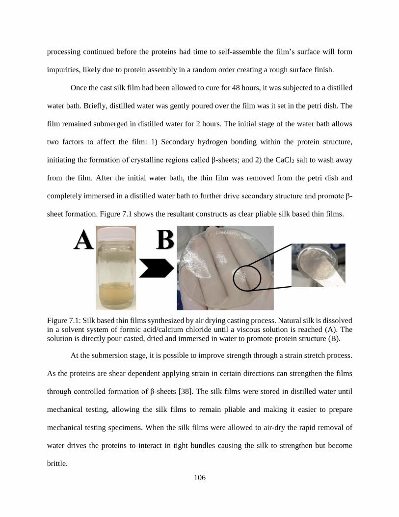
106
processing continued before the proteins had time to self-assemble the film’s surface will form
impurities, likely due to protein assembly in a random order creating a rough surface finish.
Once the cast silk film had been allowed to cure for 48 hours, it was subjected to a distilled
water bath. Briefly, distilled water was gently poured over the film was it set in the petri dish. The
film remained submerged in distilled water for 2 hours. The initial stage of the water bath allows
two factors to affect the film: 1) Secondary hydrogen bonding within the protein structure,
initiating the formation of crystalline regions called β-sheets; and 2) the CaCl2 salt to wash away
from the film. After the initial water bath, the thin film was removed from the petri dish and
completely immersed in a distilled water bath to further drive secondary structure and promote β-
sheet formation. Figure 7.1 shows the resultant constructs as clear pliable silk based thin films.
Figure 7.1: Silk based thin films synthesized by air drying casting process. Natural silk is dissolved
in a solvent system of formic acid/calcium chloride until a viscous solution is reached (A). The
solution is directly pour casted, dried and immersed in water to promote protein structure (B).
At the submersion stage, it is possible to improve strength through a strain stretch process.
As the proteins are shear dependent applying strain in certain directions can strengthen the films
through controlled formation of β-sheets [38]. The silk films were stored in distilled water until
mechanical testing, allowing the silk films to remain pliable and making it easier to prepare
mechanical testing specimens. When the silk films were allowed to air-dry the rapid removal of
water drives the proteins to interact in tight bundles causing the silk to strengthen but become
brittle.
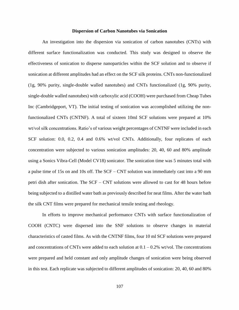
107
Dispersion of Carbon Nanotubes via Sonication
An investigation into the dispersion via sonication of carbon nanotubes (CNTs) with
different surface functionalization was conducted. This study was designed to observe the
effectiveness of sonication to disperse nanoparticles within the SCF solution and to observe if
sonication at different amplitudes had an effect on the SCF silk proteins. CNTs non-functionalized
(1g, 90% purity, single-double walled nanotubes) and CNTs functionalized (1g, 90% purity,
single-double walled nanotubes) with carboxylic acid (COOH) were purchased from Cheap Tubes
Inc (Cambridgeport, VT). The initial testing of sonication was accomplished utilizing the non-
functionalized CNTs (CNTNF). A total of sixteen 10ml SCF solutions were prepared at 10%
wt/vol silk concentrations. Ratio’s of various weight percentages of CNTNF were included in each
SCF solution: 0.0, 0.2, 0.4 and 0.6% wt/vol CNTs. Additionally, four replicates of each
concentration were subjected to various sonication amplitudes: 20, 40, 60 and 80% amplitude
using a Sonics Vibra-Cell (Model CV18) sonicator. The sonication time was 5 minutes total with
a pulse time of 15s on and 10s off. The SCF – CNT solution was immediately cast into a 90 mm
petri dish after sonication. The SCF – CNT solutions were allowed to cast for 48 hours before
being subjected to a distilled water bath as previously described for neat films. After the water bath
the silk CNT films were prepared for mechanical tensile testing and rheology.
In efforts to improve mechanical performance CNTs with surface functionalization of
COOH (CNTC) were dispersed into the SNF solutions to observe changes in material
characteristics of casted films. As with the CNTNF films, four 10 ml SCF solutions were prepared
and concentrations of CNTs were added to each solution at 0.1 – 0.2% wt/vol. The concentrations
were prepared and held constant and only amplitude changes of sonication were being observed
in this test. Each replicate was subjected to different amplitudes of sonication: 20, 40, 60 and 80%
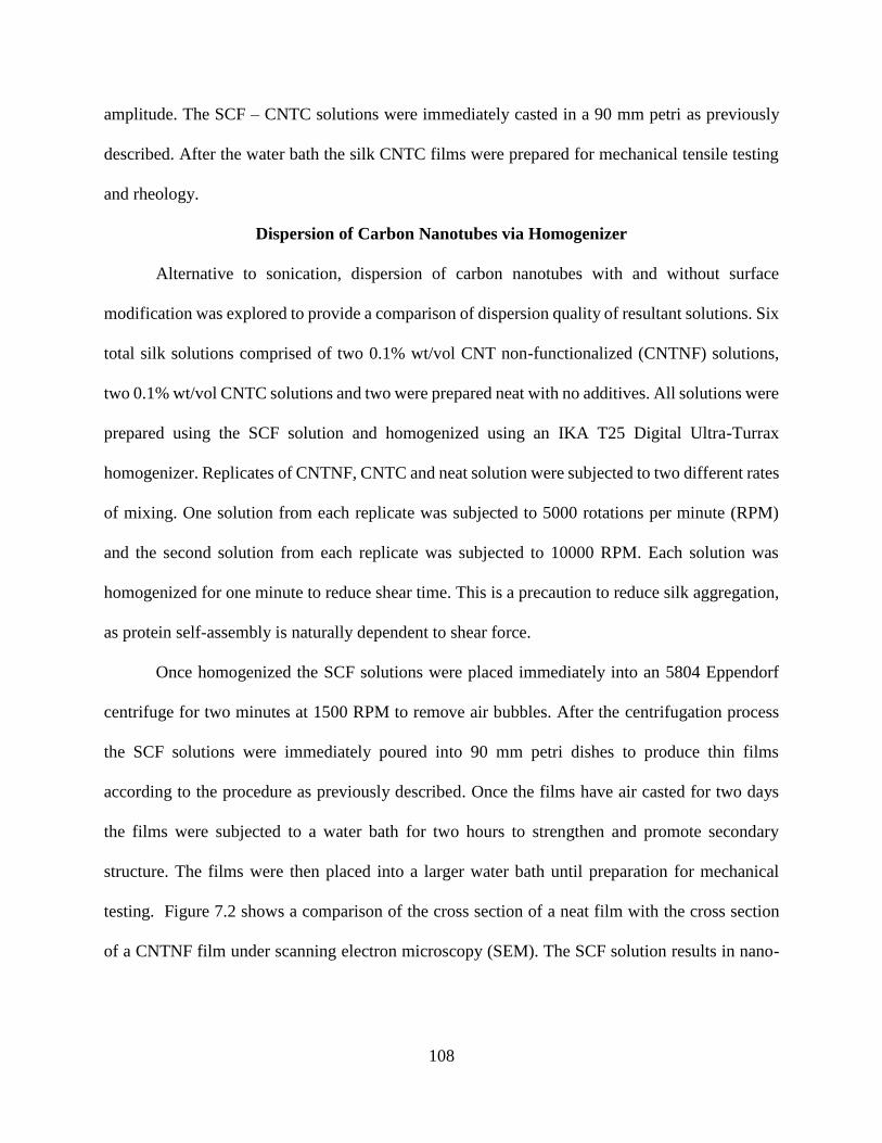
108
amplitude. The SCF – CNTC solutions were immediately casted in a 90 mm petri as previously
described. After the water bath the silk CNTC films were prepared for mechanical tensile testing
and rheology.
Dispersion of Carbon Nanotubes via Homogenizer
Alternative to sonication, dispersion of carbon nanotubes with and without surface
modification was explored to provide a comparison of dispersion quality of resultant solutions. Six
total silk solutions comprised of two 0.1% wt/vol CNT non-functionalized (CNTNF) solutions,
two 0.1% wt/vol CNTC solutions and two were prepared neat with no additives. All solutions were
prepared using the SCF solution and homogenized using an IKA T25 Digital Ultra-Turrax
homogenizer. Replicates of CNTNF, CNTC and neat solution were subjected to two different rates
of mixing. One solution from each replicate was subjected to 5000 rotations per minute (RPM)
and the second solution from each replicate was subjected to 10000 RPM. Each solution was
homogenized for one minute to reduce shear time. This is a precaution to reduce silk aggregation,
as protein self-assembly is naturally dependent to shear force.
Once homogenized the SCF solutions were placed immediately into an 5804 Eppendorf
centrifuge for two minutes at 1500 RPM to remove air bubbles. After the centrifugation process
the SCF solutions were immediately poured into 90 mm petri dishes to produce thin films
according to the procedure as previously described. Once the films have air casted for two days
the films were subjected to a water bath for two hours to strengthen and promote secondary
structure. The films were then placed into a larger water bath until preparation for mechanical
testing. Figure 7.2 shows a comparison of the cross section of a neat film with the cross section
of a CNTNF film under scanning electron microscopy (SEM). The SCF solution results in nano-
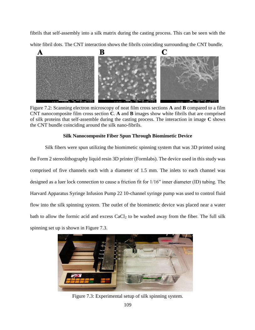
109
fibrils that self-assembly into a silk matrix during the casting process. This can be seen with the
white fibril dots. The CNT interaction shows the fibrils coinciding surrounding the CNT bundle.
Figure 7.2: Scanning electron microscopy of neat film cross sections A and B compared to a film
CNT nanocomposite film cross section C. A and B images show white fibrils that are comprised
of silk proteins that self-assemble during the casting process. The interaction in image C shows
the CNT bundle coinciding around the silk nano-fibrils.
Silk Nanocomposite Fiber Spun Through Biomimetic Device
Silk fibers were spun utilizing the biomimetic spinning system that was 3D printed using
the Form 2 stereolithography liquid resin 3D printer (Formlabs). The device used in this study was
comprised of five channels each with a diameter of 1.5 mm. The inlets to each channel was
designed as a luer lock connection to cause a friction fit for 1/16” inner diameter (ID) tubing. The
Harvard Apparatus Syringe Infusion Pump 22 10-channel syringe pump was used to control fluid
flow into the silk spinning system. The outlet of the biomimetic device was placed near a water
bath to allow the formic acid and excess CaCl2 to be washed away from the fiber. The full silk
spinning set up is shown in Figure 7.3.
Figure 7.3: Experimental setup of silk spinning system.
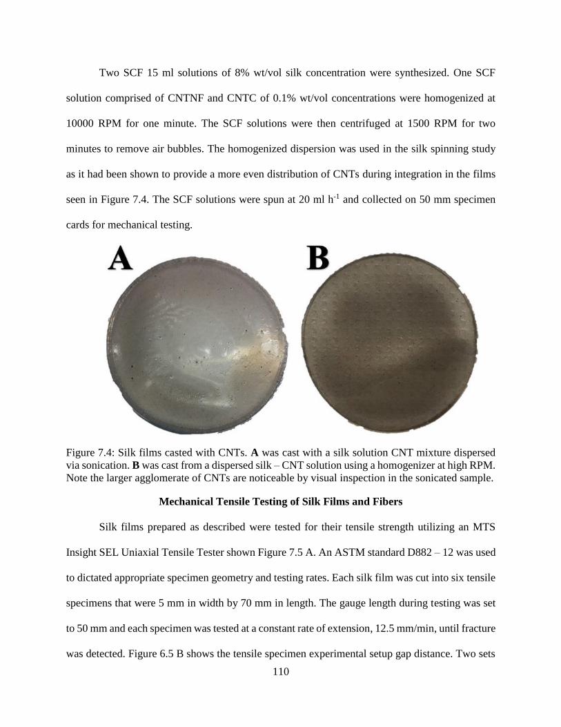
110
Two SCF 15 ml solutions of 8% wt/vol silk concentration were synthesized. One SCF
solution comprised of CNTNF and CNTC of 0.1% wt/vol concentrations were homogenized at
10000 RPM for one minute. The SCF solutions were then centrifuged at 1500 RPM for two
minutes to remove air bubbles. The homogenized dispersion was used in the silk spinning study
as it had been shown to provide a more even distribution of CNTs during integration in the films
seen in Figure 7.4. The SCF solutions were spun at 20 ml h-1 and collected on 50 mm specimen
cards for mechanical testing.
Figure 7.4: Silk films casted with CNTs. A was cast with a silk solution CNT mixture dispersed
via sonication. B was cast from a dispersed silk – CNT solution using a homogenizer at high RPM.
Note the larger agglomerate of CNTs are noticeable by visual inspection in the sonicated sample.
Mechanical Tensile Testing of Silk Films and Fibers
Silk films prepared as described were tested for their tensile strength utilizing an MTS
Insight SEL Uniaxial Tensile Tester shown Figure 7.5 A. An ASTM standard D882 – 12 was used
to dictated appropriate specimen geometry and testing rates. Each silk film was cut into six tensile
specimens that were 5 mm in width by 70 mm in length. The gauge length during testing was set
to 50 mm and each specimen was tested at a constant rate of extension, 12.5 mm/min, until fracture
was detected. Figure 6.5 B shows the tensile specimen experimental setup gap distance. Two sets
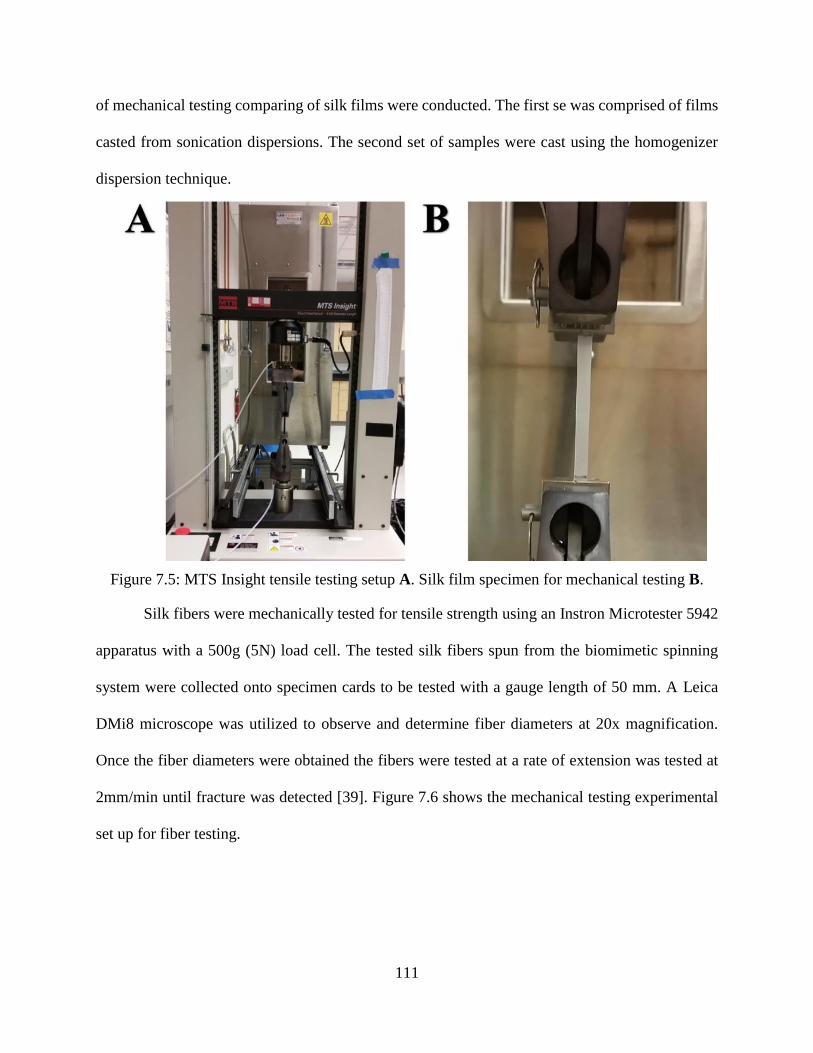
111
of mechanical testing comparing of silk films were conducted. The first se was comprised of films
casted from sonication dispersions. The second set of samples were cast using the homogenizer
dispersion technique.
Figure 7.5: MTS Insight tensile testing setup A. Silk film specimen for mechanical testing B.
Silk fibers were mechanically tested for tensile strength using an Instron Microtester 5942
apparatus with a 500g (5N) load cell. The tested silk fibers spun from the biomimetic spinning
system were collected onto specimen cards to be tested with a gauge length of 50 mm. A Leica
DMi8 microscope was utilized to observe and determine fiber diameters at 20x magnification.
Once the fiber diameters were obtained the fibers were tested at a rate of extension was tested at
2mm/min until fracture was detected [39]. Figure 7.6 shows the mechanical testing experimental
set up for fiber testing.
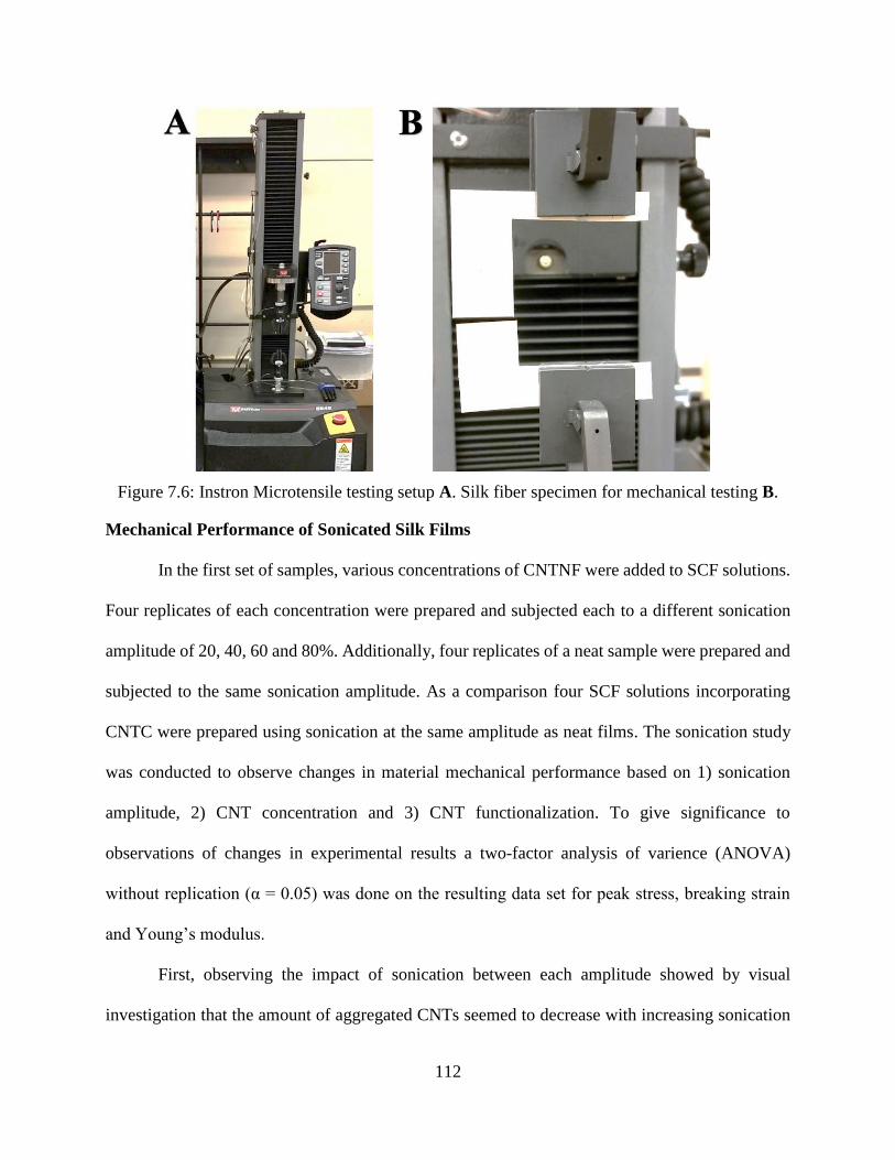
112
Figure 7.6: Instron Microtensile testing setup A. Silk fiber specimen for mechanical testing B.
Mechanical Performance of Sonicated Silk Films
In the first set of samples, various concentrations of CNTNF were added to SCF solutions.
Four replicates of each concentration were prepared and subjected each to a different sonication
amplitude of 20, 40, 60 and 80%. Additionally, four replicates of a neat sample were prepared and
subjected to the same sonication amplitude. As a comparison four SCF solutions incorporating
CNTC were prepared using sonication at the same amplitude as neat films. The sonication study
was conducted to observe changes in material mechanical performance based on 1) sonication
amplitude, 2) CNT concentration and 3) CNT functionalization. To give significance to
observations of changes in experimental results a two-factor analysis of varience (ANOVA)
without replication (α = 0.05) was done on the resulting data set for peak stress, breaking strain
and Young’s modulus.
First, observing the impact of sonication between each amplitude showed by visual
investigation that the amount of aggregated CNTs seemed to decrease with increasing sonication
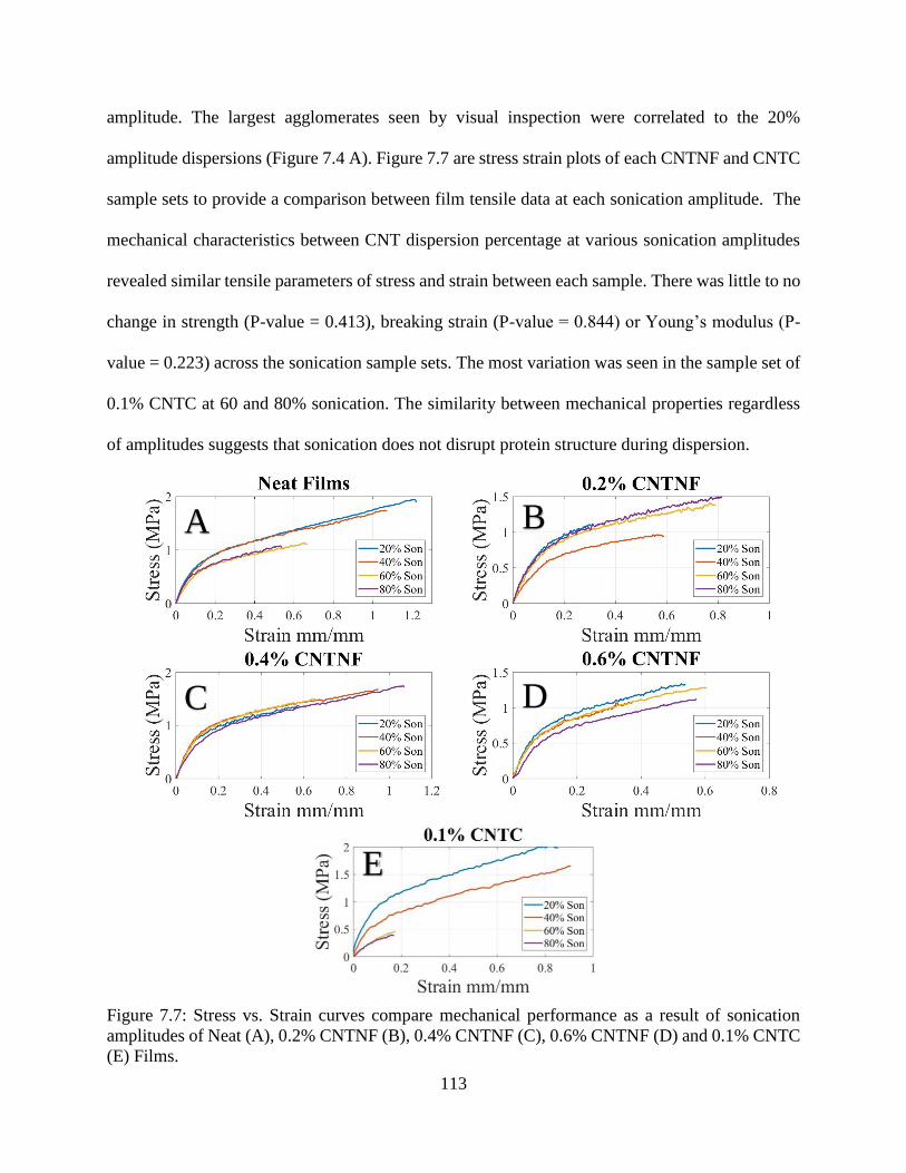
113
amplitude. The largest agglomerates seen by visual inspection were correlated to the 20%
amplitude dispersions (Figure 7.4 A). Figure 7.7 are stress strain plots of each CNTNF and CNTC
sample sets to provide a comparison between film tensile data at each sonication amplitude. The
mechanical characteristics between CNT dispersion percentage at various sonication amplitudes
revealed similar tensile parameters of stress and strain between each sample. There was little to no
change in strength (P-value = 0.413), breaking strain (P-value = 0.844) or Young’s modulus (P-
value = 0.223) across the sonication sample sets. The most variation was seen in the sample set of
0.1% CNTC at 60 and 80% sonication. The similarity between mechanical properties regardless
of amplitudes suggests that sonication does not disrupt protein structure during dispersion.
Figure 7.7: Stress vs. Strain curves compare mechanical performance as a result of sonication
amplitudes of Neat (A), 0.2% CNTNF (B), 0.4% CNTNF (C), 0.6% CNTNF (D) and 0.1% CNTC
(E) Films.
A B
C D
E
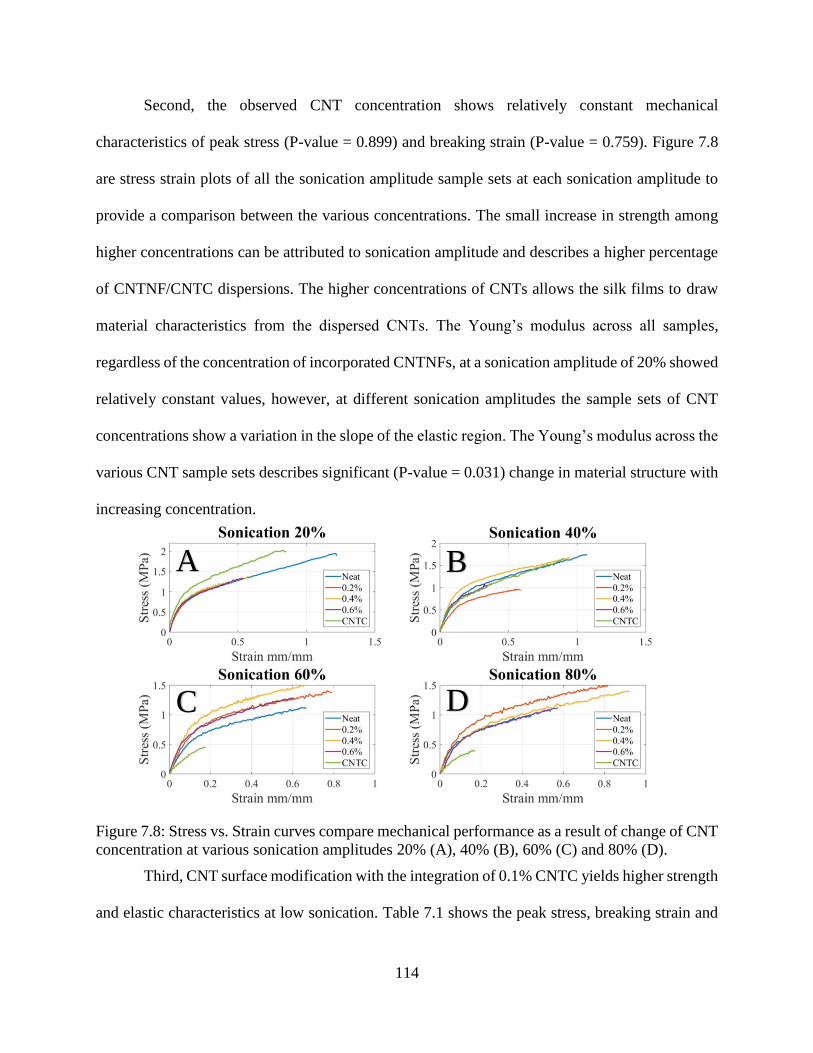
114
Second, the observed CNT concentration shows relatively constant mechanical
characteristics of peak stress (P-value = 0.899) and breaking strain (P-value = 0.759). Figure 7.8
are stress strain plots of all the sonication amplitude sample sets at each sonication amplitude to
provide a comparison between the various concentrations. The small increase in strength among
higher concentrations can be attributed to sonication amplitude and describes a higher percentage
of CNTNF/CNTC dispersions. The higher concentrations of CNTs allows the silk films to draw
material characteristics from the dispersed CNTs. The Young’s modulus across all samples,
regardless of the concentration of incorporated CNTNFs, at a sonication amplitude of 20% showed
relatively constant values, however, at different sonication amplitudes the sample sets of CNT
concentrations show a variation in the slope of the elastic region. The Young’s modulus across the
various CNT sample sets describes significant (P-value = 0.031) change in material structure with
increasing concentration.
Figure 7.8: Stress vs. Strain curves compare mechanical performance as a result of change of CNT
concentration at various sonication amplitudes 20% (A), 40% (B), 60% (C) and 80% (D).
Third, CNT surface modification with the integration of 0.1% CNTC yields higher strength
and elastic characteristics at low sonication. Table 7.1 shows the peak stress, breaking strain and
A B
C D
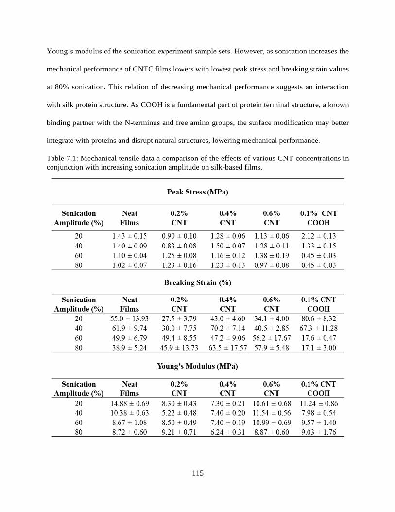
115
Young’s modulus of the sonication experiment sample sets. However, as sonication increases the
mechanical performance of CNTC films lowers with lowest peak stress and breaking strain values
at 80% sonication. This relation of decreasing mechanical performance suggests an interaction
with silk protein structure. As COOH is a fundamental part of protein terminal structure, a known
binding partner with the N-terminus and free amino groups, the surface modification may better
integrate with proteins and disrupt natural structures, lowering mechanical performance.
Table 7.1: Mechanical tensile data a comparison of the effects of various CNT concentrations in
conjunction with increasing sonication amplitude on silk-based films.
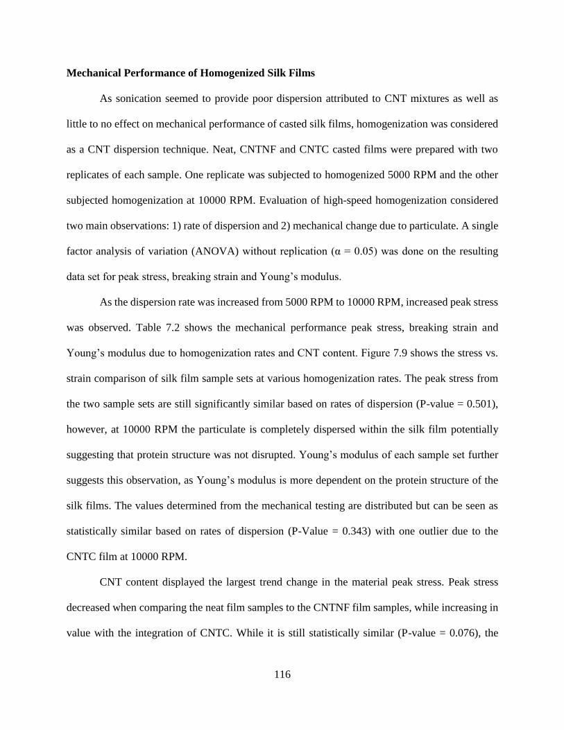
116
Mechanical Performance of Homogenized Silk Films
As sonication seemed to provide poor dispersion attributed to CNT mixtures as well as
little to no effect on mechanical performance of casted silk films, homogenization was considered
as a CNT dispersion technique. Neat, CNTNF and CNTC casted films were prepared with two
replicates of each sample. One replicate was subjected to homogenized 5000 RPM and the other
subjected homogenization at 10000 RPM. Evaluation of high-speed homogenization considered
two main observations: 1) rate of dispersion and 2) mechanical change due to particulate. A single
factor analysis of variation (ANOVA) without replication (α = 0.05) was done on the resulting
data set for peak stress, breaking strain and Young’s modulus.
As the dispersion rate was increased from 5000 RPM to 10000 RPM, increased peak stress
was observed. Table 7.2 shows the mechanical performance peak stress, breaking strain and
Young’s modulus due to homogenization rates and CNT content. Figure 7.9 shows the stress vs.
strain comparison of silk film sample sets at various homogenization rates. The peak stress from
the two sample sets are still significantly similar based on rates of dispersion (P-value = 0.501),
however, at 10000 RPM the particulate is completely dispersed within the silk film potentially
suggesting that protein structure was not disrupted. Young’s modulus of each sample set further
suggests this observation, as Young’s modulus is more dependent on the protein structure of the
silk films. The values determined from the mechanical testing are distributed but can be seen as
statistically similar based on rates of dispersion (P-Value = 0.343) with one outlier due to the
CNTC film at 10000 RPM.
CNT content displayed the largest trend change in the material peak stress. Peak stress
decreased when comparing the neat film samples to the CNTNF film samples, while increasing in
value with the integration of CNTC. While it is still statistically similar (P-value = 0.076), the
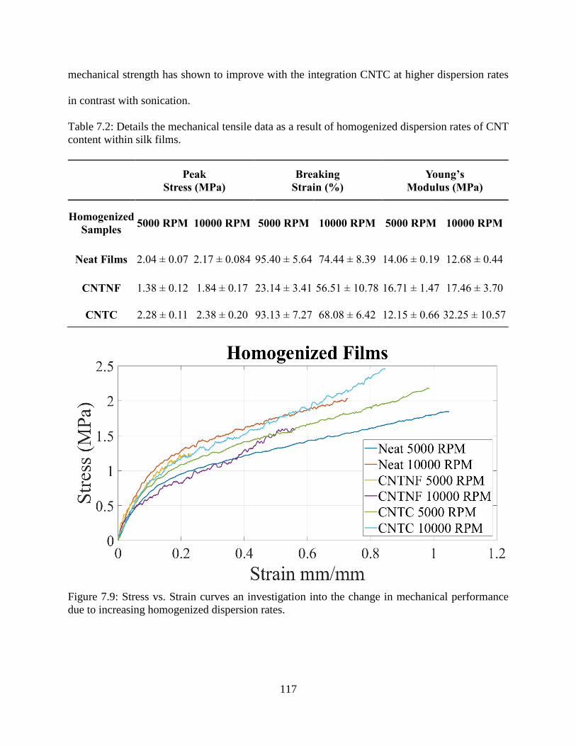
117
mechanical strength has shown to improve with the integration CNTC at higher dispersion rates
in contrast with sonication.
Table 7.2: Details the mechanical tensile data as a result of homogenized dispersion rates of CNT
content within silk films.
Figure 7.9: Stress vs. Strain curves an investigation into the change in mechanical performance
due to increasing homogenized dispersion rates.
Peak
Stress (MPa)
Breaking
Strain (%)
Young’s
Modulus (MPa)
Homogenized
Samples 5000 RPM 10000 RPM 5000 RPM 10000 RPM 5000 RPM 10000 RPM
Neat Films 2.04 ± 0.07 2.17 ± 0.084 95.40 ± 5.64 74.44 ± 8.39 14.06 ± 0.19 12.68 ± 0.44
CNTNF 1.38 ± 0.12 1.84 ± 0.17 23.14 ± 3.41 56.51 ± 10.78 16.71 ± 1.47 17.46 ± 3.70
CNTC 2.28 ± 0.11 2.38 ± 0.20 93.13 ± 7.27 68.08 ± 6.42 12.15 ± 0.66 32.25 ± 10.57
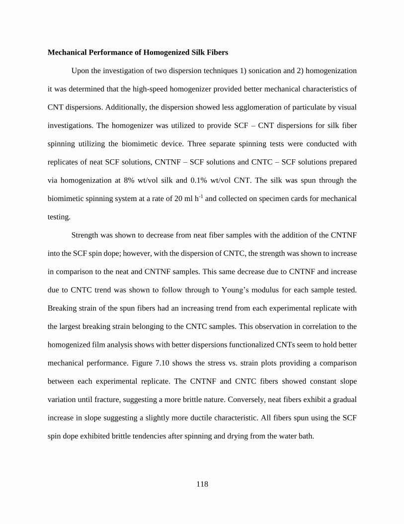
118
Mechanical Performance of Homogenized Silk Fibers
Upon the investigation of two dispersion techniques 1) sonication and 2) homogenization
it was determined that the high-speed homogenizer provided better mechanical characteristics of
CNT dispersions. Additionally, the dispersion showed less agglomeration of particulate by visual
investigations. The homogenizer was utilized to provide SCF – CNT dispersions for silk fiber
spinning utilizing the biomimetic device. Three separate spinning tests were conducted with
replicates of neat SCF solutions, CNTNF – SCF solutions and CNTC – SCF solutions prepared
via homogenization at 8% wt/vol silk and 0.1% wt/vol CNT. The silk was spun through the
biomimetic spinning system at a rate of 20 ml h-1 and collected on specimen cards for mechanical
testing.
Strength was shown to decrease from neat fiber samples with the addition of the CNTNF
into the SCF spin dope; however, with the dispersion of CNTC, the strength was shown to increase
in comparison to the neat and CNTNF samples. This same decrease due to CNTNF and increase
due to CNTC trend was shown to follow through to Young’s modulus for each sample tested.
Breaking strain of the spun fibers had an increasing trend from each experimental replicate with
the largest breaking strain belonging to the CNTC samples. This observation in correlation to the
homogenized film analysis shows with better dispersions functionalized CNTs seem to hold better
mechanical performance. Figure 7.10 shows the stress vs. strain plots providing a comparison
between each experimental replicate. The CNTNF and CNTC fibers showed constant slope
variation until fracture, suggesting a more brittle nature. Conversely, neat fibers exhibit a gradual
increase in slope suggesting a slightly more ductile characteristic. All fibers spun using the SCF
spin dope exhibited brittle tendencies after spinning and drying from the water bath.
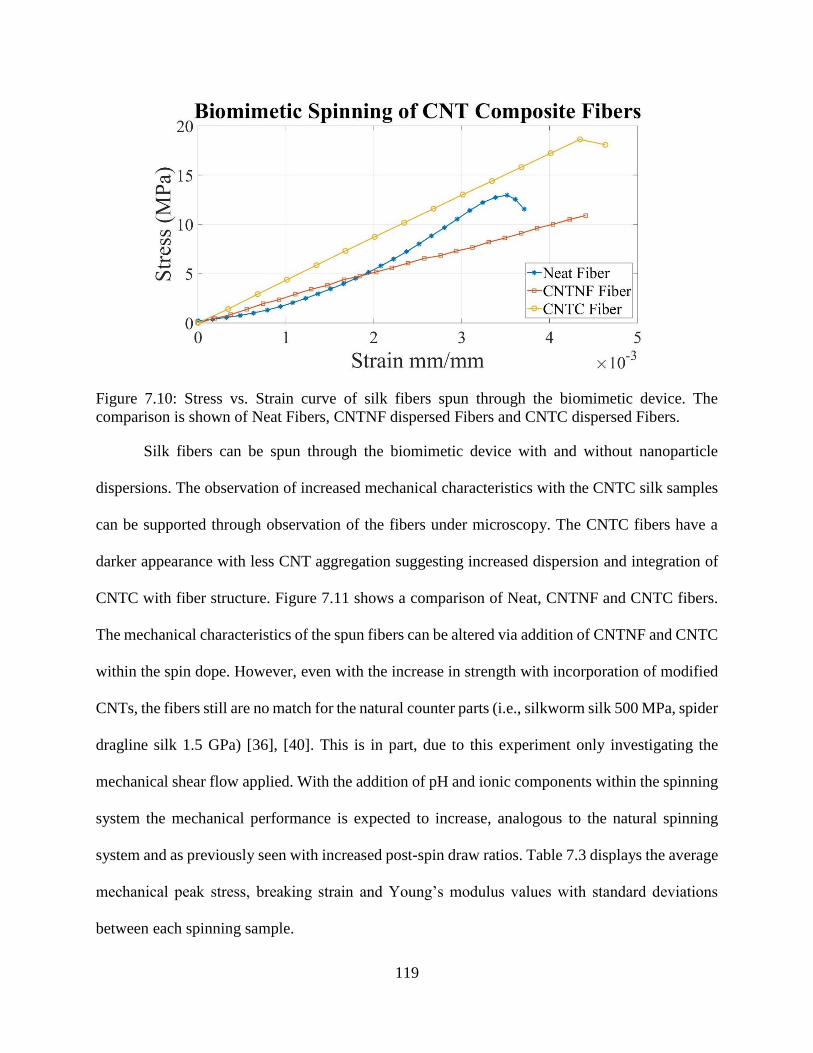
119
Figure 7.10: Stress vs. Strain curve of silk fibers spun through the biomimetic device. The
comparison is shown of Neat Fibers, CNTNF dispersed Fibers and CNTC dispersed Fibers.
Silk fibers can be spun through the biomimetic device with and without nanoparticle
dispersions. The observation of increased mechanical characteristics with the CNTC silk samples
can be supported through observation of the fibers under microscopy. The CNTC fibers have a
darker appearance with less CNT aggregation suggesting increased dispersion and integration of
CNTC with fiber structure. Figure 7.11 shows a comparison of Neat, CNTNF and CNTC fibers.
The mechanical characteristics of the spun fibers can be altered via addition of CNTNF and CNTC
within the spin dope. However, even with the increase in strength with incorporation of modified
CNTs, the fibers still are no match for the natural counter parts (i.e., silkworm silk 500 MPa, spider
dragline silk 1.5 GPa) [36], [40]. This is in part, due to this experiment only investigating the
mechanical shear flow applied. With the addition of pH and ionic components within the spinning
system the mechanical performance is expected to increase, analogous to the natural spinning
system and as previously seen with increased post-spin draw ratios. Table 7.3 displays the average
mechanical peak stress, breaking strain and Young’s modulus values with standard deviations
between each spinning sample.
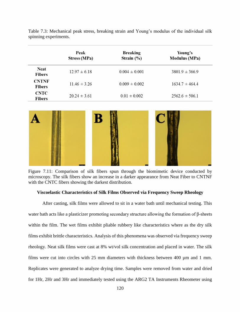
120
Table 7.3: Mechanical peak stress, breaking strain and Young’s modulus of the individual silk
spinning experiments.
Figure 7.11: Comparison of silk fibers spun through the biomimetic device conducted by
microscopy. The silk fibers show an increase in a darker appearance from Neat Fiber to CNTNF
with the CNTC fibers showing the darkest distribution.
Viscoelastic Characteristics of Silk Films Observed via Frequency Sweep Rheology
After casting, silk films were allowed to sit in a water bath until mechanical testing. This
water bath acts like a plasticizer promoting secondary structure allowing the formation of β-sheets
within the film. The wet films exhibit pliable rubbery like characteristics where as the dry silk
films exhibit brittle characteristics. Analysis of this phenomena was observed via frequency sweep
rheology. Neat silk films were cast at 8% wt/vol silk concentration and placed in water. The silk
films were cut into circles with 25 mm diameters with thickness between 400 µm and 1 mm.
Replicates were generated to analyze drying time. Samples were removed from water and dried
for 1Hr, 2Hr and 3Hr and immediately tested using the ARG2 TA Instruments Rheometer using
121
frequency sweep testing with an angular frequency range of 6.283 to 628.3 rad/s and constant
strain of 0.1%. A neat sample was tested at 0Hr as a control. Figure 7.12 is the frequency sweep
plot data comparing G’ and G” to various drying times. The resultant viscoelastic characteristics
showed an increase in both storage modulus (G’) and loss modulus (G”) as the drying time
increased. The increase in G’ was observed to be a larger significant variation (P-value = 4.1E-13)
due to drying time. G’ measures stored energy in the material due to shear which describes the
materials elastic characteristics. G” measures the energy dissipated as a response to shear and
describes the viscous characteristics. During controlled timed drying the G” also changed
significantly (P-value = 3.8E-8), driving more energy dissipation as the film losses its ability to
respond viscously.
Figure 7.12: Storage (G’) and Loss (G”) Modulus vs. angular frequency shows silk films and the
response to drying time.
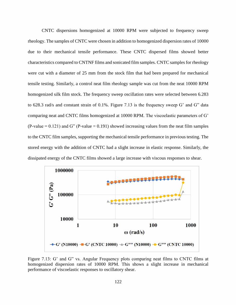
122
CNTC dispersions homogenized at 10000 RPM were subjected to frequency sweep
rheology. The samples of CNTC were chosen in addition to homogenized dispersion rates of 10000
due to their mechanical tensile performance. These CNTC dispersed films showed better
characteristics compared to CNTNF films and sonicated film samples. CNTC samples for rheology
were cut with a diameter of 25 mm from the stock film that had been prepared for mechanical
tensile testing. Similarly, a control neat film rheology sample was cut from the neat 10000 RPM
homogenized silk film stock. The frequency sweep oscillation rates were selected between 6.283
to 628.3 rad/s and constant strain of 0.1%. Figure 7.13 is the frequency sweep G’ and G” data
comparing neat and CNTC films homogenized at 10000 RPM. The viscoelastic parameters of G’
(P-value = 0.121) and G” (P-value = 0.191) showed increasing values from the neat film samples
to the CNTC film samples, supporting the mechanical tensile performance in previous testing. The
stored energy with the addition of CNTC had a slight increase in elastic response. Similarly, the
dissipated energy of the CNTC films showed a large increase with viscous responses to shear.
Figure 7.13: G’ and G” vs. Angular Frequency plots comparing neat films to CNTC films at
homogenized dispersion rates of 10000 RPM. This shows a slight increase in mechanical
performance of viscoelastic responses to oscillatory shear.

123
Mechanical Performance of Other Silk Nanocomposite Films
Beyond the integration of CNTs into silk fibers and the observation of various dispersion
techniques a preliminary study of two additional silk nanocomposite films was conducted.
Graphene oxide (GO) and cellulose nanofibers (CNFs) were dispersed into SCF solutions using
homogenized dispersion rates of 10000 RPM. This homogenized rate had shown the better quality
in dispersion seen by visual investigation of the CNTs in previous studies. Four SCF solutions
were prepared at 8% wt/vol concentration of silk.
Two of the solutions were prepared integrating GO and two were prepared with CNF. Both
sample sets had one replicate of 0.1% wt/vol and 0.2% wt/vol of particulate. The CNF and GO
films were prepared using similar techniques of homogenization, 48-hour casting, two-hour water
bath and then final water bath until mechanical testing. Similar ASTM standard D882 – 12 was
used for mechanical testing to provide: geometry of tensile specimen strips (5mm x 70 mm), testing
rate (12.5 mm/min) and gauge length (50mm).
The resultant mechanical performance of the GO silks showed a decrease peak stress,
breaking strain and Young’s modulus due to change of 0.1% to 0.2% wt/vol concentrations. These
values however are larger than the neat film characteristics showing an improvement of properties.
The CNF films show an increasing trend of peak stress and breaking strain with increasing
concentration. The Young’s modulus of the CNF samples shows a decreasing trend but relatively
similar. The CNF films showed a large significant shift in mechanical performance. Suggesting
that future films with higher concentrations could continue to improve mechanical performance.
Figure 7.14 shows the stress vs. strain plot comparing the various silk nanocomposite tensile
performances. Table 7.4 describes the mechanical values of peak stress, breaking strain and
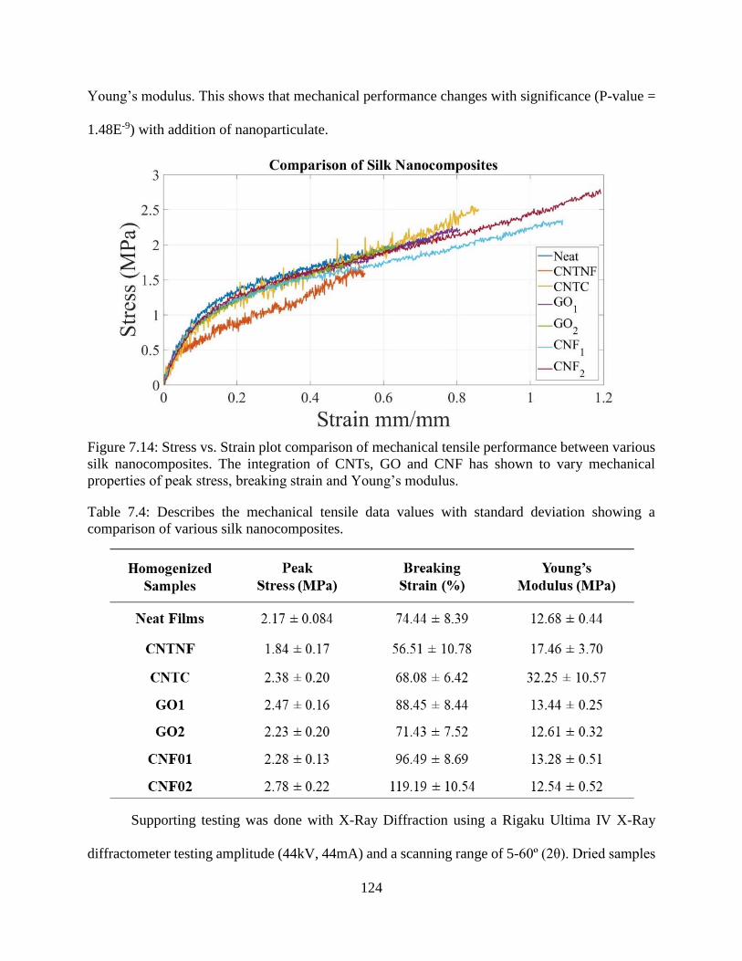
124
Young’s modulus. This shows that mechanical performance changes with significance (P-value =
1.48E-9) with addition of nanoparticulate.
Figure 7.14: Stress vs. Strain plot comparison of mechanical tensile performance between various
silk nanocomposites. The integration of CNTs, GO and CNF has shown to vary mechanical
properties of peak stress, breaking strain and Young’s modulus.
Table 7.4: Describes the mechanical tensile data values with standard deviation showing a
comparison of various silk nanocomposites.
Supporting testing was done with X-Ray Diffraction using a Rigaku Ultima IV X-Ray
diffractometer testing amplitude (44kV, 44mA) and a scanning range of 5-60º (2θ). Dried samples
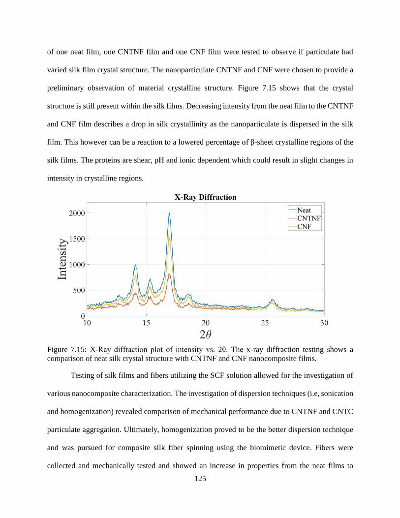
125
of one neat film, one CNTNF film and one CNF film were tested to observe if particulate had
varied silk film crystal structure. The nanoparticulate CNTNF and CNF were chosen to provide a
preliminary observation of material crystalline structure. Figure 7.15 shows that the crystal
structure is still present within the silk films. Decreasing intensity from the neat film to the CNTNF
and CNF film describes a drop in silk crystallinity as the nanoparticulate is dispersed in the silk
film. This however can be a reaction to a lowered percentage of β-sheet crystalline regions of the
silk films. The proteins are shear, pH and ionic dependent which could result in slight changes in
intensity in crystalline regions.
Figure 7.15: X-Ray diffraction plot of intensity vs. 2θ. The x-ray diffraction testing shows a
comparison of neat silk crystal structure with CNTNF and CNF nanocomposite films.
Testing of silk films and fibers utilizing the SCF solution allowed for the investigation of
various nanocomposite characterization. The investigation of dispersion techniques (i.e, sonication
and homogenization) revealed comparison of mechanical performance due to CNTNF and CNTC
particulate aggregation. Ultimately, homogenization proved to be the better dispersion technique
and was pursued for composite silk fiber spinning using the biomimetic device. Fibers were
collected and mechanically tested and showed an increase in properties from the neat films to
126
CNTNF with the best performance being CNTC dispersions. However, the spun fibers were no
match for the natural silks of spiders and silkworms. This leads to future works with the
incorporation of pH and ionic components in the spinning process in addition to nanoparticles to
improve either mechanical strength or elasticity beyond this study. Additionally, the use of silk
films can be investigated to improve performance with increasing and optimizing the
nanoparticulate concentrations. Incorporating these additional parameters will allow for optimized
strength, elasticity and potentially electrical characteristics to be obtained in a silk-based material.
References
[1] F. Vollrath, “Strength and structure of spiders’ silks,” Rev. Mol. Biotechnol., vol. 74, no. 2,
pp. 67–83, Aug. 2000.
[2] J. Pérez-Rigueiro, C. Viney, J. Llorca, and M. Elices, “Mechanical properties of single-brin
silkworm silk,” J. Appl. Polym. Sci., vol. 75, no. 10, pp. 1270–1277, Mar. 2000.
[3] M. Andersson, J. Johansson, and A. Rising, “Silk Spinning in Silkworms and Spiders,” Int.
J. Mol. Sci., vol. 17, no. 8, Aug. 2016.
[4] A. Baecker et al., “Silk scaffolds connected with different naturally occurring biomaterials
for prostate cancer cell cultivation in 3D,” Biopolymers, vol. 107, no. 2, pp. 70–79, Feb. 2017.
[5] C. Li et al., “Regenerated silk materials for functionalized silk orthopedic devices by
mimicking natural processing,” Biomaterials, vol. 110, pp. 24–33, Dec. 2016.
[6] H. Tao et al., “Silk-based resorbable electronic devices for remotely controlled therapy and
in vivo infection abatement,” Proc. Natl. Acad. Sci., vol. 111, no. 49, pp. 17385–17389, Dec.
2014.
127
[7] Y. Wang, Y. Song, Y. Wang, X. Chen, Y. Xia, and Z. Shao, “Graphene/silk fibroin based
carbon nanocomposites for high performance supercapacitors,” J Mater Chem A, vol. 3, no.
2, pp. 773–781, 2015.
[8] C. B. Borkner, M. B. Elsner, and T. Scheibel, “Coatings and Films Made of Silk Proteins,”
ACS Appl. Mater. Interfaces, vol. 6, no. 18, pp. 15611–15625, Sep. 2014.
[9] P. Dubey, S. Murab, S. Karmakar, P. K. Chowdhury, and S. Ghosh, “Modulation of Self-
Assembly Process of Fibroin: An Insight for Regulating the Conformation of Silk
Biomaterials,” Biomacromolecules, vol. 16, no. 12, pp. 3936–3944, Dec. 2015.
[10] G. Askarieh et al., “Self-assembly of spider silk proteins is controlled by a pH-sensitive
relay,” Nature, vol. 465, no. 7295, p. 236, May 2010.
[11] Q. Peng, H. Shao, X. Hu, and Y. Zhang, “Role of humidity on the structures and properties
of regenerated silk fibers,” Prog. Nat. Sci. Mater. Int., vol. 25, no. 5, pp. 430–436, Oct. 2015.
[12] A. E. Brooks, M. S. Creager, and R. V. Lewis, “Altering the mechanics of spider silk through
methanol post-spin drawing,” Biomed. Sci. Instrum., vol. 41, pp. 1–6, 2005.
[13] D. P. Knight and F. Vollrath, “Liquid crystals and flow elongation in a spider’s silk
production line,” Proc. R. Soc. Lond. B Biol. Sci., vol. 266, no. 1418, pp. 519–523, Mar.
1999.
[14] J. Hardy et al., “Biomineralization of Engineered Spider Silk Protein-Based Composite
Materials for Bone Tissue Engineering,” Materials, vol. 9, no. 7, p. 560, Jul. 2016.
[15] J. Melke, S. Midha, S. Ghosh, K. Ito, and S. Hofmann, “Silk fibroin as biomaterial for bone
tissue engineering,” Acta Biomater., vol. 31, pp. 1–16, Feb. 2016.
[16] S. Nagarkar, T. Nicolai, C. Chassenieux, and A. Lele, “Structure and gelation mechanism of
silk hydrogels,” Phys. Chem. Chem. Phys., vol. 12, no. 15, pp. 3834–3844, 2010.
128
[17] P. Bhattacharjee et al., “Silk scaffolds in bone tissue engineering: An overview,” Acta
Biomater., vol. 63, pp. 1–17, Nov. 2017.
[18] L. Meinel et al., “The inflammatory responses to silk films in vitro and in vivo,” Biomaterials,
vol. 26, no. 2, pp. 147–155, Jan. 2005.
[19] S. Kapoor and S. C. Kundu, “Silk protein-based hydrogels: Promising advanced materials for
biomedical applications,” Acta Biomater., vol. 31, pp. 17–32, Feb. 2016.
[20] Q. Lu et al., “Water-insoluble silk films with silk I structure,” Acta Biomater., vol. 6, no. 4,
pp. 1380–1387, Apr. 2010.
[21] I. C. Um, H. Kweon, Y. H. Park, and S. Hudson, “Structural characteristics and properties of
the regenerated silk fibroin prepared from formic acid,” Int. J. Biol. Macromol., vol. 29, no.
2, pp. 91–97, Aug. 2001.
[22] F. Zhang et al., “Regeneration of high-quality silk fibroin fiber by wet spinning from CaCl2–
formic acid solvent,” Acta Biomater., vol. 12, pp. 139–145, Jan. 2015.
[23] B. Marelli et al., “Programming function into mechanical forms by directed assembly of silk
bulk materials,” Proc. Natl. Acad. Sci., p. 201612063, Dec. 2016.
[24] J. A. Stinson et al., “Silk Fibroin Microneedles for Transdermal Vaccine Delivery,” ACS
Biomater. Sci. Eng., vol. 3, no. 3, pp. 360–369, Mar. 2017.
[25] M. J. Rodriguez, J. Brown, J. Giordano, S. J. Lin, F. G. Omenetto, and D. L. Kaplan, “Silk
based bioinks for soft tissue reconstruction using 3-dimensional (3D) printing with in vitro
and in vivo assessments,” Biomaterials, vol. 117, pp. 105–115, Feb. 2017.
[26] I. Donderwinkel, J. C. M. van Hest, and N. R. Cameron, “Bio-inks for 3D bioprinting: recent
advances and future prospects,” Polym. Chem., vol. 8, no. 31, pp. 4451–4471, Aug. 2017.
129
[27] C. Holland, A. E. Terry, D. Porter, and F. Vollrath, “Comparing the rheology of native spider
and silkworm spinning dope,” Nat. Mater., vol. 5, no. 11, pp. 870–874, Nov. 2006.
[28] D. U. Shah, D. Porter, and F. Vollrath, “Opportunities for silk textiles in reinforced
biocomposites: Studying through-thickness compaction behaviour,” Compos. Part Appl. Sci.
Manuf., vol. 62, pp. 1–10, Jul. 2014.
[29] D. U. Shah, D. Porter, and F. Vollrath, “Can silk become an effective reinforcing fibre? A
property comparison with flax and glass reinforced composites,” Compos. Sci. Technol., vol.
101, pp. 173–183, Sep. 2014.
[30] M. H. Park et al., “Critical role of silk fibroin secondary structure on the dielectric
performances of organic thin-film transistors,” RSC Adv, vol. 6, no. 7, pp. 5907–5914, 2016.
[31] C.-H. Wang, C.-Y. Hsieh, and J.-C. Hwang, “Flexible Organic Thin-Film Transistors with
Silk Fibroin as the Gate Dielectric,” Adv. Mater., vol. 23, no. 14, pp. 1630–1634, Apr. 2011.
[32] H.-S. Kim, S. H. Yoon, S.-M. Kwon, and H.-J. Jin, “pH-Sensitive Multiwalled Carbon
Nanotube Dispersion with Silk Fibroins,” Biomacromolecules, vol. 10, no. 1, pp. 82–86, Jan.
2009.
[33] M. Shayannia, H. Sajjadi, V. Motaghitalab, and A. K. Haghi, “Effect of multi wall carbon
nanotubes on characteristics and morphology of nanofiber scaffolds composited of
MWNTs/silk fibroin,” Adv. Powder Technol., vol. 28, no. 3, pp. 775–784, Mar. 2017.
[34] K. Hu, M. K. Gupta, D. D. Kulkarni, and V. V. Tsukruk, “Ultra-Robust Graphene Oxide-Silk
Fibroin Nanocomposite Membranes,” Adv. Mater., vol. 25, no. 16, pp. 2301–2307, Apr.
2013.
130
[35] C. Zhang, Y. Zhang, H. Shao, and X. Hu, “Hybrid Silk Fibers Dry-Spun from Regenerated
Silk Fibroin/Graphene Oxide Aqueous Solutions,” ACS Appl. Mater. Interfaces, vol. 8, no.
5, pp. 3349–3358, Feb. 2016.
[36] G. H. Altman et al., “Silk-based biomaterials,” Biomaterials, vol. 24, no. 3, pp. 401–416,
Feb. 2003.
[37] F. Zhang et al., “Silk dissolution and regeneration at the nanofibril scale,” J. Mater. Chem.
B, vol. 2, no. 24, pp. 3879–3885, 2014.
[38] F. Zhang, X. You, H. Dou, Z. Liu, B. Zuo, and X. Zhang, “Facile fabrication of robust silk
nanofibril films via direct dissolution of silk in CaCl2-formic acid solution,” ACS Appl.
Mater. Interfaces, vol. 7, no. 5, pp. 3352–3361, Feb. 2015.
[39] A. E. Brooks et al., “Distinct contributions of model MaSp1 and MaSp2 like peptides to the
mechanical properties of synthetic major ampullate silk fibers as revealed in silico,”
Nanotechnol. Sci. Appl., vol. 1, pp. 9–16, Aug. 2008.
[40] A. Rising and J. Johansson, “Toward spinning artificial spider silk,” Nat. Chem. Biol., vol.
11, no. 5, pp. 309–315, Apr. 2015.
131
CHAPTER 8: CONCLUDING REMARKS
Often the largest challenges in engineering can be solved through observations of the world
around us. Creating and designing with the mindset of biomimicry can provide advantageous and
crucial elements to engineering development without having to re-invent the wheel. In this
instance, inspiration was drawn from the intricate silk fiber spinning system of spiders and
silkworms in an effort to produce a synthetic processing of system(s) for high performance bio-
materials. Silks produced by spiders and silkworms have remarkable characteristics that have yet
to be harnessed in synthetic processing. It has been observed previously that natural proteins
undergo various biochemical and mechanical stimuli (i.e., pH, ionic and fluid flow gradients)
within a gland structure in the abdomen of these arthropods. The result of this optimized system is
a semi-crystalline bio-polymer fiber driven by self-assembly mechanisms. This element of self-
assembly is by far the most valuable characteristic that has the potential of being harnessed. The
self-assembling proteins drive primary, secondary and tertiary structures that yield controllable
mechanical attributes. The dependency of pH, metallic-ion and shear gradients allow, specifically
spiders, the ability to control mechanical performance based on the need for survival.
The development of a biomimetic spinning system in this master’s thesis allows a start to
investigate self-assembly driven by mechanical fluid shear. Designed with inspiration from the
gland structure of the spider and silk worm the device in this study utilized a five-channel inlet
system to allow for integration of chemical stimuli and fluidic shear forces. The mutli-channel
device is 3D printed, which allows for quick rapid prototyping and direct feedback from spinning
tests. Utilizing a concept of fluid focusing called hydrodynamic focusing fibers have been spun
from the device with predictable fiber diameter, collected and tested. The correlation of fiber
diameter is directly driven by the magnitude of increased fluid flow difference in the last
132
intersection of the device, resulting in improved mechanical performance from smaller diameter
fibers derived from higher ratios of fluid focusing. Additionally, this predictable outcome builds
upon the platform allowing for quality control in manufacturing of these silk fibers.
Gathering more insight from the self-assembly mechanism construction and optimization
of a thin film casting process was investigated in tandem with silk spinning. This parallel path
provided a way to develop 3D-silk constructs for continued study. The silk films were optimized
based on the structural characteristic promoted by solvent system used to dissolve silk proteins. A
formic acid calcium chloride system provided the necessary stimuli to break tertiary and some
secondary structure and dissolve silk proteins. However, in the dissolution process the silk
structure is left semi-intact with nanofibrils homogenously dispersed in the silk solution. During
the casting process, the silk nanofibrils were allowed to self-assemble during a dehydration stage
that evaporates the formic acid. With the formic acid leaving the system the calcium chloride salt
provides a Ca+ ion potential that begins to drive self-assembly. In the end stages of film processing
water was added to escalate the protein assembly process by acting as a plasticizer further driving
secondary structure and potentially increasing the content of crystallinity (β-sheets) within the
film. This process of ionic exchange and hydration are the starting point for preliminary studies to
identify the dependence of silk on these parameters for continued construct processing.
Building upon the biomimetic spinning system and the optimized processing of silk films
a final investigation of a silk-based nanocomposite was undertaken. This investigation had two
significant objectives for silk processing: 1) do carbon nanotubes disrupt protein self-assembly
mechanisms and 2) does integration of carbon nanotubes improve or inhibit mechanical
performance. Two dispersion techniques were investigated to compare the best viable option to
integrate carbon nanotubes with and without modification. Carbon nanotubes modified with
133
carboxylic acid (COOH) were utilized to observe if the CNTs would disperse and bond better with
the silk proteins as COOH is a terminal region in the fiber protein chain.
From the dispersion techniques considered, it was determined that high-speed
homogenization had a greater affect to yield a more homogenous dispersion. The resulting
mechanical performance showed that the integration of CNTNF in both fibers and films had
slightly decreased in material strength. Alternatively, with the integration of CNTC, the material
performance showed a slight increase in mechanical properties. The preliminarily assessment of
the impact of nanocomposites on the silk’s crystalline structure was observed using x-ray
diffraction (XRD). XRD confirmed that the crystalline structure due to silk β-sheets was still
present despite the integration of CNTs.
Preliminary studies into other nanoparticulate reinforcements were investigated through
mechanical tensile testing. Graphene oxide and cellulose nanofibers were cast into silk films. The
graphene oxide had increased mechanical strength and elasticity at lower concentrations. Cellulose
nanofibrils on the other hand provided higher strength and exceptional breaking strain with higher
concentrations suggesting an interaction that does not disrupt the silk protein structure. These
parallel tests provide a platform for continued analysis of the self-assembly process building upon
the knowledge gained from mechanical shear characterization.
Future Works
Descriptions of future works can be broken into two separate pathways for multiple
investigations. Pathway one concentrates on the silk spinning system and pathway two focuses on
the film casting processing. Although these pathways are separated in the specific processing for
the silk, they have underlying elements that can build off of one another.
134
Pathway One - Biomimetic Device
The biomimetic device is a standalone platform that is predominately a microfluidic chip.
This provides a vast opportunity for developmental scale up of a complex control system.
Currently there are three main subsystems that can be integrated together to develop this larger
control system. The stage of fiber spinning has been accomplished and this is considered the
middle stage of this system. Through the investigations of hydrodynamic focusing the control of
flow in each individual channel was revealed to be crucial in providing tailored in fiber diameter.
The first stage then is the development of a fluid control system that can be easily integrated into
the microfluidic chip design. This system is currently in adolescence, but its development can lead
into the fiber collection of final stage. Observations gained through spinning also have driven
towards the need for a fiber collection system. Providing controllable fiber collection with the
ability to match fiber output rates with spin dope input rates will aid in hydrodynamic focusing
and controllable diameter outputs. Additionally, a fiber collection output that can in real-time
gather fiber diameter and adjust spinning rates and by providing a feedback loop to the inlet fluidic
flow subsystem would critically improve the manufacturability and scale up of this biomimetic
system. Currently, this final system is in preliminary stages of investigation.
Beyond the mechanical and electrical subsystems, spinning tests will need to be
investigated with incorporated pH and ionic chemical gradients. This study primarily investigated
mechanical shear. By applying mechanical shear in tandem with pH and ionic components an
increase in protein structure is an expected outcome, which could tend toward the natural silk fiber
performance. The integration of pH and ionic gradients could also aid in the self-assembly
processing of other silk 3-D constructs and aid in silk film processing.
135
Pathway Two - Film Casting
Observations of various qualities of the resulting thin films have driven the need for further
investigation to improve the quality of the developed constructs. The thin films are highly
dependent on humidity and moisture content. During the wet stages the films are pliable, however,
in dry stages the films become brittle. Investigation into slow drying processes with controlled
humidity will need to be further pursued. A possibility to negate this drying affect would be to
increase the content of Cellulose Nanofibrils or Nanocrystals in the thin films nanocomposites.
From the preliminary nanocomposite cellulose nanofiber data, silk films have a reduced time
dependency related to drying in ambient air conditions. This nanocomposite with larger
concentrations of cellulose could also improve mechanical performance. Additionally, the
optimization of graphene content within the silk film could provide larger opportunities for the
development of conductive pathways within the film. As these films are humidity dependent, the
addition of graphene could provide an application for a silk-based humidity sensor with an increase
in conductivity.
With the observations of the self-assembly processing the use of silk film casting has
provided an opportunity to investigate the curing process of a silk-based material. These tendencies
can be applied to additive manufacturing as these proteins are shear thinning in nature, it may
prove possible to 3D print constructs such as films into various shapes. The investigation into a
curing agent will be pursued to provide initiation of the self-assembly process. Currently, the use
of an ionic solution, in tandem with water, could provide the possibility to drive this secondary
structure. Providing a solvent system that is less harmful to the environment and is biocompatible
is a key priority in continued investigation of silk-based constructs. It is recommended to use an
aqueous solution as this could provide initial structure during processing. By providing a highly
136
viscous aqueous based solution with an extrusion process, such as printing, the proteins would
begin to respond to shear and self-assemble. With a rapid succession of ionic solution, dehydration
and water bath could provide the necessary curing progression for 3D printing.
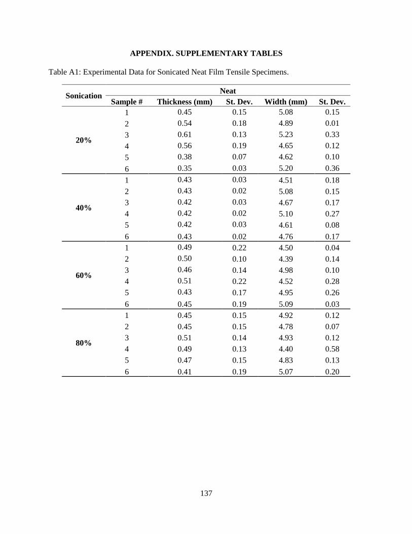
137
APPENDIX. SUPPLEMENTARY TABLES
Table A1: Experimental Data for Sonicated Neat Film Tensile Specimens.
Sonication Neat
Sample # Thickness (mm) St. Dev. Width (mm) St. Dev.
20%
1 0.45 0.15 5.08 0.15
2 0.54 0.18 4.89 0.01
3 0.61 0.13 5.23 0.33
4 0.56 0.19 4.65 0.12
5 0.38 0.07 4.62 0.10
6 0.35 0.03 5.20 0.36
40%
1 0.43 0.03 4.51 0.18
2 0.43 0.02 5.08 0.15
3 0.42 0.03 4.67 0.17
4 0.42 0.02 5.10 0.27
5 0.42 0.03 4.61 0.08
6 0.43 0.02 4.76 0.17
60%
1 0.49 0.22 4.50 0.04
2 0.50 0.10 4.39 0.14
3 0.46 0.14 4.98 0.10
4 0.51 0.22 4.52 0.28
5 0.43 0.17 4.95 0.26
6 0.45 0.19 5.09 0.03
80%
1 0.45 0.15 4.92 0.12
2 0.45 0.15 4.78 0.07
3 0.51 0.14 4.93 0.12
4 0.49 0.13 4.40 0.58
5 0.47 0.15 4.83 0.13
6 0.41 0.19 5.07 0.20
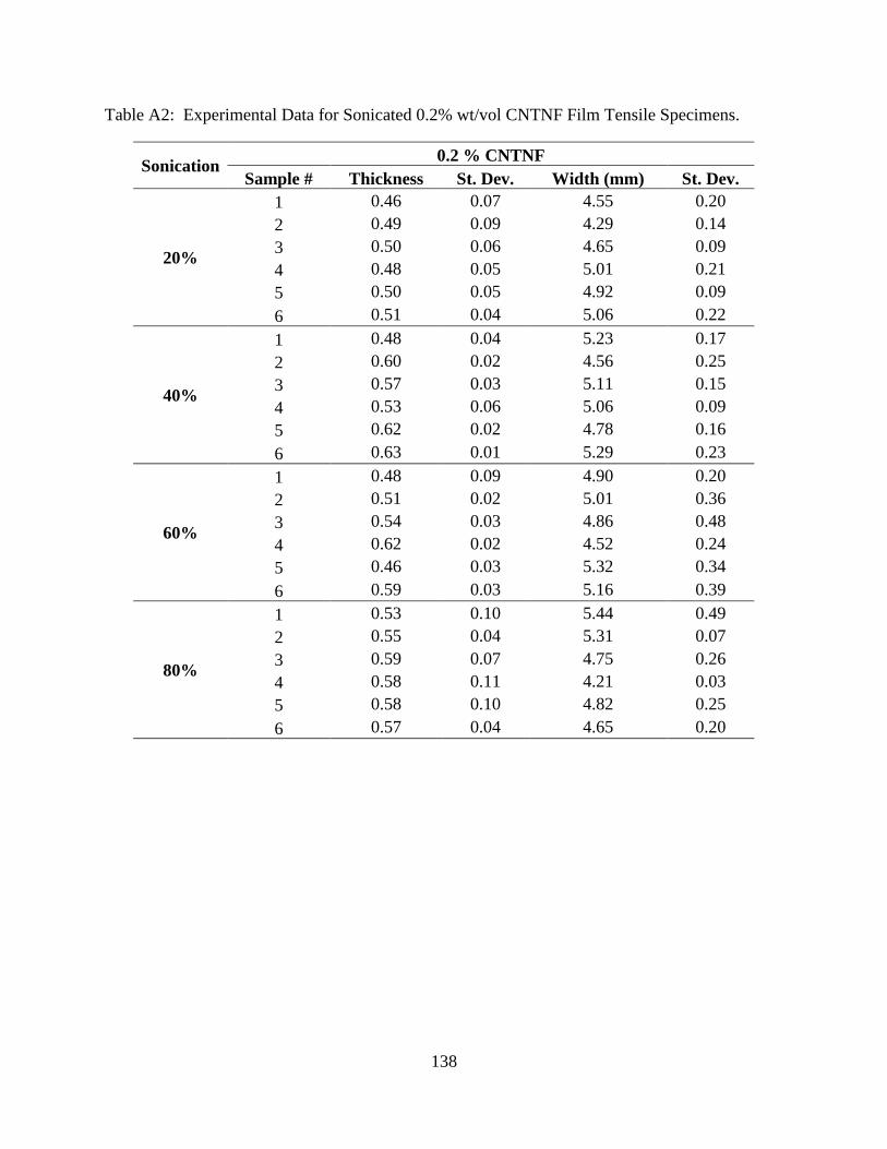
138
Table A2: Experimental Data for Sonicated 0.2% wt/vol CNTNF Film Tensile Specimens.
Sonication 0.2 % CNTNF
Sample # Thickness St. Dev. Width (mm) St. Dev.
20%
1 0.46 0.07 4.55 0.20
2 0.49 0.09 4.29 0.14
3 0.50 0.06 4.65 0.09
4 0.48 0.05 5.01 0.21
5 0.50 0.05 4.92 0.09
6 0.51 0.04 5.06 0.22
40%
1 0.48 0.04 5.23 0.17
2 0.60 0.02 4.56 0.25
3 0.57 0.03 5.11 0.15
4 0.53 0.06 5.06 0.09
5 0.62 0.02 4.78 0.16
6 0.63 0.01 5.29 0.23
60%
1 0.48 0.09 4.90 0.20
2 0.51 0.02 5.01 0.36
3 0.54 0.03 4.86 0.48
4 0.62 0.02 4.52 0.24
5 0.46 0.03 5.32 0.34
6 0.59 0.03 5.16 0.39
80%
1 0.53 0.10 5.44 0.49
2 0.55 0.04 5.31 0.07
3 0.59 0.07 4.75 0.26
4 0.58 0.11 4.21 0.03
5 0.58 0.10 4.82 0.25
6 0.57 0.04 4.65 0.20
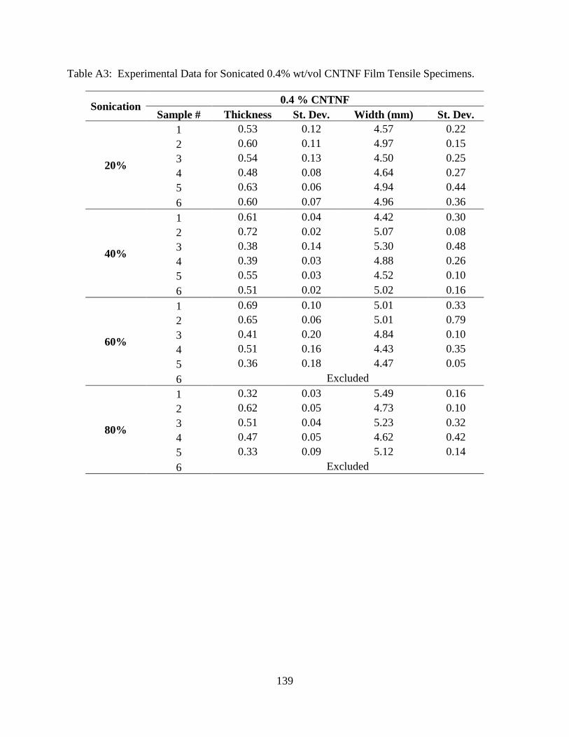
139
Table A3: Experimental Data for Sonicated 0.4% wt/vol CNTNF Film Tensile Specimens.
Sonication 0.4 % CNTNF
Sample # Thickness St. Dev. Width (mm) St. Dev.
20%
1 0.53 0.12 4.57 0.22
2 0.60 0.11 4.97 0.15
3 0.54 0.13 4.50 0.25
4 0.48 0.08 4.64 0.27
5 0.63 0.06 4.94 0.44
6 0.60 0.07 4.96 0.36
40%
1 0.61 0.04 4.42 0.30
2 0.72 0.02 5.07 0.08
3 0.38 0.14 5.30 0.48
4 0.39 0.03 4.88 0.26
5 0.55 0.03 4.52 0.10
6 0.51 0.02 5.02 0.16
60%
1 0.69 0.10 5.01 0.33
2 0.65 0.06 5.01 0.79
3 0.41 0.20 4.84 0.10
4 0.51 0.16 4.43 0.35
5 0.36 0.18 4.47 0.05
6 Excluded
80%
1 0.32 0.03 5.49 0.16
2 0.62 0.05 4.73 0.10
3 0.51 0.04 5.23 0.32
4 0.47 0.05 4.62 0.42
5 0.33 0.09 5.12 0.14
6 Excluded
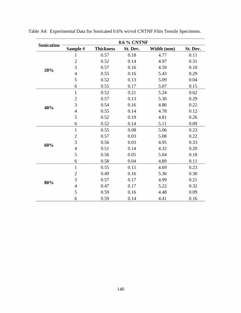
140
Table A4: Experimental Data for Sonicated 0.6% wt/vol CNTNF Film Tensile Specimens.
Sonication 0.6 % CNTNF
Sample # Thickness St. Dev. Width (mm) St. Dev.
20%
1 0.57 0.18 4.77 0.11
2 0.52 0.14 4.97 0.31
3 0.57 0.16 4.59 0.10
4 0.55 0.16 5.43 0.29
5 0.52 0.13 5.09 0.04
6 0.55 0.17 5.07 0.15
40%
1 0.52 0.21 5.24 0.62
2 0.57 0.13 5.30 0.29
3 0.54 0.16 4.86 0.22
4 0.55 0.14 4.78 0.12
5 0.52 0.19 4.81 0.26
6 0.52 0.14 5.11 0.09
60%
1 0.55 0.08 5.06 0.23
2 0.57 0.03 5.08 0.22
3 0.56 0.03 4.95 0.33
4 0.51 0.14 4.32 0.20
5 0.56 0.05 5.04 0.18
6 0.58 0.04 4.89 0.11
80%
1 0.55 0.15 4.69 0.23
2 0.49 0.16 5.36 0.30
3 0.57 0.17 4.99 0.21
4 0.47 0.17 5.22 0.32
5 0.59 0.16 4.48 0.09
6 0.59 0.14 4.41 0.16
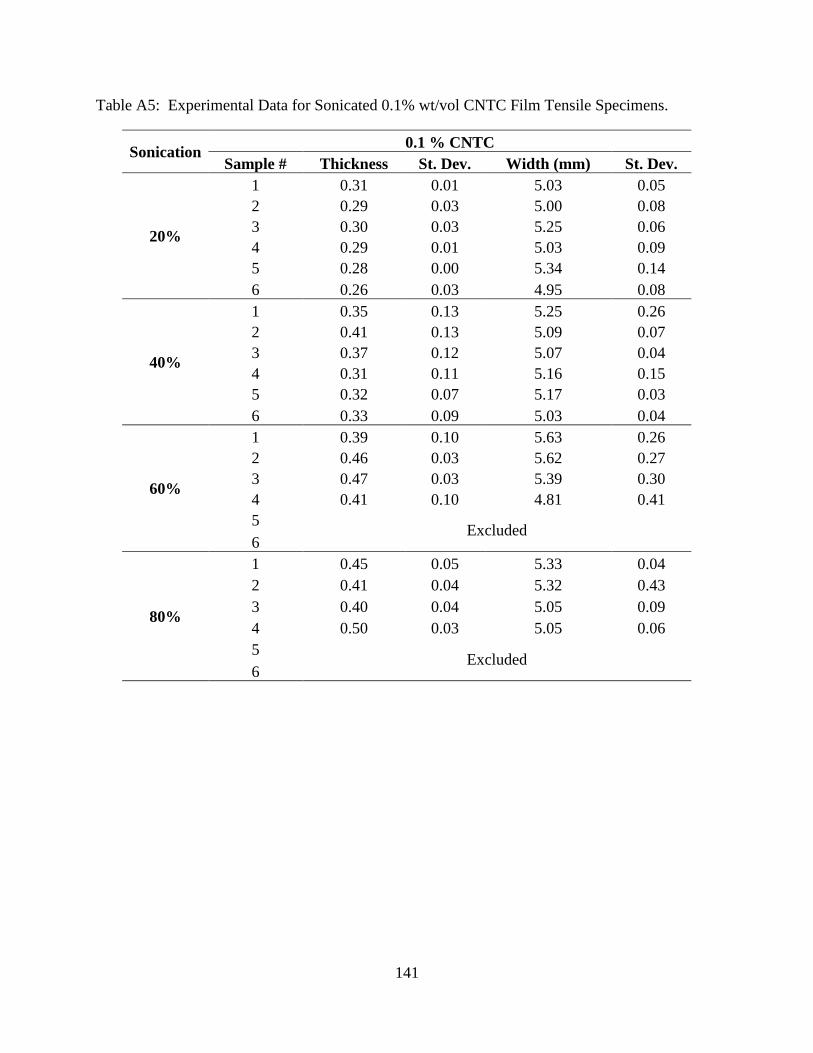
141
Table A5: Experimental Data for Sonicated 0.1% wt/vol CNTC Film Tensile Specimens.
Sonication 0.1 % CNTC
Sample # Thickness St. Dev. Width (mm) St. Dev.
20%
1 0.31 0.01 5.03 0.05
2 0.29 0.03 5.00 0.08
3 0.30 0.03 5.25 0.06
4 0.29 0.01 5.03 0.09
5 0.28 0.00 5.34 0.14
6 0.26 0.03 4.95 0.08
40%
1 0.35 0.13 5.25 0.26
2 0.41 0.13 5.09 0.07
3 0.37 0.12 5.07 0.04
4 0.31 0.11 5.16 0.15
5 0.32 0.07 5.17 0.03
6 0.33 0.09 5.03 0.04
60%
1 0.39 0.10 5.63 0.26
2 0.46 0.03 5.62 0.27
3 0.47 0.03 5.39 0.30
4 0.41 0.10 4.81 0.41
5 Excluded
6
80%
1 0.45 0.05 5.33 0.04
2 0.41 0.04 5.32 0.43
3 0.40 0.04 5.05 0.09
4 0.50 0.03 5.05 0.06
5 Excluded
6
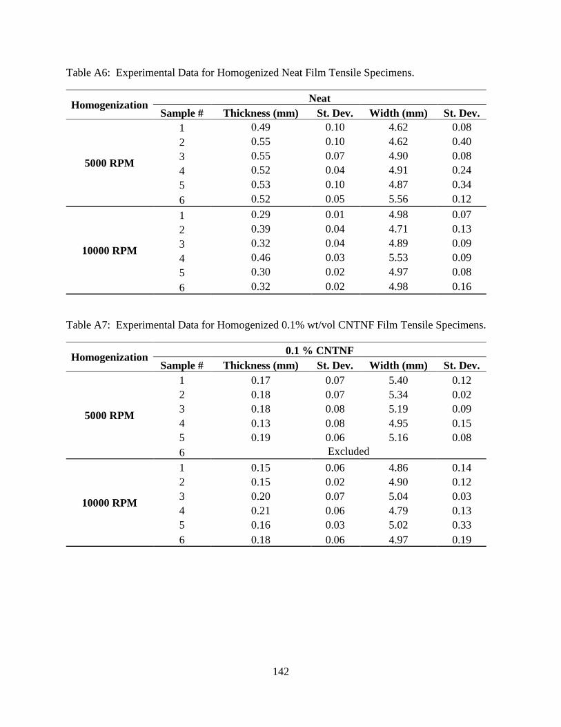
142
Table A6: Experimental Data for Homogenized Neat Film Tensile Specimens.
Homogenization Neat
Sample # Thickness (mm) St. Dev. Width (mm) St. Dev.
5000 RPM
1 0.49 0.10 4.62 0.08
2 0.55 0.10 4.62 0.40
3 0.55 0.07 4.90 0.08
4 0.52 0.04 4.91 0.24
5 0.53 0.10 4.87 0.34
6 0.52 0.05 5.56 0.12
10000 RPM
1 0.29 0.01 4.98 0.07
2 0.39 0.04 4.71 0.13
3 0.32 0.04 4.89 0.09
4 0.46 0.03 5.53 0.09
5 0.30 0.02 4.97 0.08
6 0.32 0.02 4.98 0.16
Table A7: Experimental Data for Homogenized 0.1% wt/vol CNTNF Film Tensile Specimens.
Homogenization 0.1 % CNTNF
Sample # Thickness (mm) St. Dev. Width (mm) St. Dev.
5000 RPM
1 0.17 0.07 5.40 0.12
2 0.18 0.07 5.34 0.02
3 0.18 0.08 5.19 0.09
4 0.13 0.08 4.95 0.15
5 0.19 0.06 5.16 0.08
6 Excluded
10000 RPM
1 0.15 0.06 4.86 0.14
2 0.15 0.02 4.90 0.12
3 0.20 0.07 5.04 0.03
4 0.21 0.06 4.79 0.13
5 0.16 0.03 5.02 0.33
6 0.18 0.06 4.97 0.19
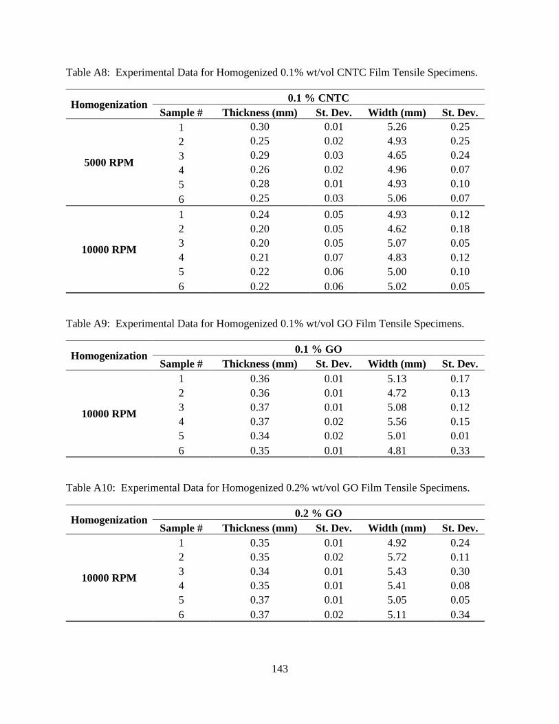
143
Table A8: Experimental Data for Homogenized 0.1% wt/vol CNTC Film Tensile Specimens.
Homogenization 0.1 % CNTC
Sample # Thickness (mm) St. Dev. Width (mm) St. Dev.
5000 RPM
1 0.30 0.01 5.26 0.25
2 0.25 0.02 4.93 0.25
3 0.29 0.03 4.65 0.24
4 0.26 0.02 4.96 0.07
5 0.28 0.01 4.93 0.10
6 0.25 0.03 5.06 0.07
10000 RPM
1 0.24 0.05 4.93 0.12
2 0.20 0.05 4.62 0.18
3 0.20 0.05 5.07 0.05
4 0.21 0.07 4.83 0.12
5 0.22 0.06 5.00 0.10
6 0.22 0.06 5.02 0.05
Table A9: Experimental Data for Homogenized 0.1% wt/vol GO Film Tensile Specimens.
Homogenization 0.1 % GO
Sample # Thickness (mm) St. Dev. Width (mm) St. Dev.
10000 RPM
1 0.36 0.01 5.13 0.17
2 0.36 0.01 4.72 0.13
3 0.37 0.01 5.08 0.12
4 0.37 0.02 5.56 0.15
5 0.34 0.02 5.01 0.01
6 0.35 0.01 4.81 0.33
Table A10: Experimental Data for Homogenized 0.2% wt/vol GO Film Tensile Specimens.
Homogenization 0.2 % GO
Sample # Thickness (mm) St. Dev. Width (mm) St. Dev.
10000 RPM
1 0.35 0.01 4.92 0.24
2 0.35 0.02 5.72 0.11
3 0.34 0.01 5.43 0.30
4 0.35 0.01 5.41 0.08
5 0.37 0.01 5.05 0.05
6 0.37 0.02 5.11 0.34
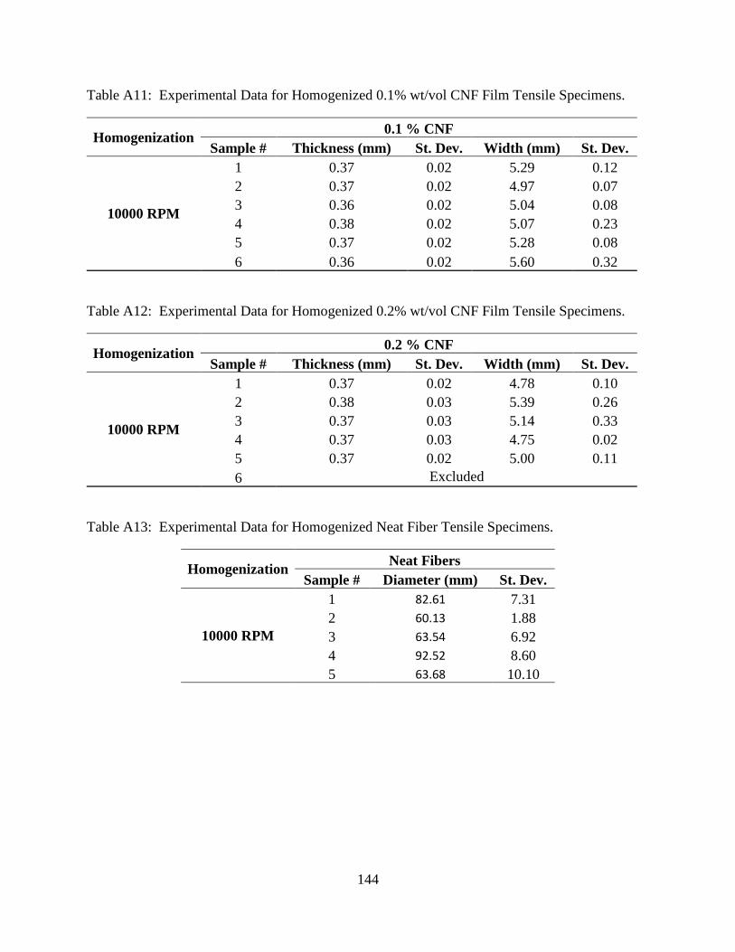
144
Table A11: Experimental Data for Homogenized 0.1% wt/vol CNF Film Tensile Specimens.
Homogenization 0.1 % CNF
Sample # Thickness (mm) St. Dev. Width (mm) St. Dev.
10000 RPM
1 0.37 0.02 5.29 0.12
2 0.37 0.02 4.97 0.07
3 0.36 0.02 5.04 0.08
4 0.38 0.02 5.07 0.23
5 0.37 0.02 5.28 0.08
6 0.36 0.02 5.60 0.32
Table A12: Experimental Data for Homogenized 0.2% wt/vol CNF Film Tensile Specimens.
Homogenization 0.2 % CNF
Sample # Thickness (mm) St. Dev. Width (mm) St. Dev.
10000 RPM
1 0.37 0.02 4.78 0.10
2 0.38 0.03 5.39 0.26
3 0.37 0.03 5.14 0.33
4 0.37 0.03 4.75 0.02
5 0.37 0.02 5.00 0.11
6 Excluded
Table A13: Experimental Data for Homogenized Neat Fiber Tensile Specimens.
Homogenization Neat Fibers
Sample # Diameter (mm) St. Dev.
10000 RPM
1 82.61 7.31
2 60.13 1.88
3 63.54 6.92
4 92.52 8.60
5 63.68 10.10
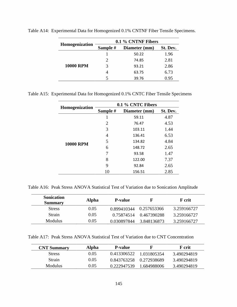
145
Table A14: Experimental Data for Homogenized 0.1% CNTNF Fiber Tensile Specimens.
Homogenization 0.1 % CNTNF Fibers
Sample # Diameter (mm) St. Dev.
10000 RPM
1 50.22 1.96
2 74.85 2.81
3 93.21 2.86
4 63.75 6.73
5 39.76 0.95
Table A15: Experimental Data for Homogenized 0.1% CNTC Fiber Tensile Specimens
Homogenization 0.1 % CNTC Fibers
Sample # Diameter (mm) St. Dev.
10000 RPM
1 59.11 4.87
2 76.47 4.53
3 103.11 1.44
4 136.41 6.53
5 134.82 4.84
6 148.72 2.65
7 93.58 1.47
8 122.00 7.37
9 92.84 2.65
10 156.51 2.85
Table A16: Peak Stress ANOVA Statistical Test of Variation due to Sonication Amplitude
Sonication
Summary Alpha P-value F F crit
Stress 0.05 0.899410344 0.257653366 3.259166727
Strain 0.05 0.75874514 0.467390288 3.259166727
Modulus 0.05 0.030897844 3.848136873 3.259166727
Table A17: Peak Stress ANOVA Statistical Test of Variation due to CNT Concentration
CNT Summary Alpha P-value F F crit
Stress 0.05 0.413306522 1.031805354 3.490294819
Strain 0.05 0.843763258 0.272938689 3.490294819
Modulus 0.05 0.222947539 1.684988006 3.490294819
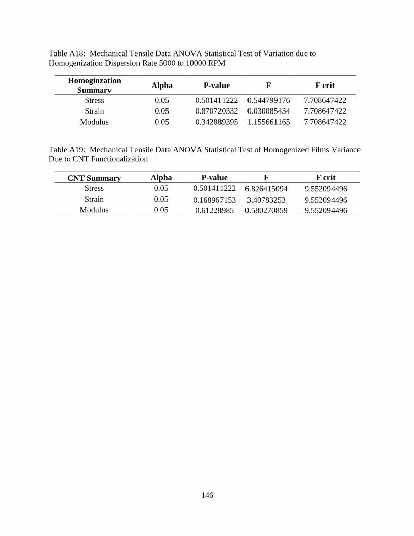
146
Table A18: Mechanical Tensile Data ANOVA Statistical Test of Variation due to
Homogenization Dispersion Rate 5000 to 10000 RPM
Homoginzation
Summary Alpha P-value F F crit
Stress 0.05 0.501411222 0.544799176 7.708647422
Strain 0.05 0.870720332 0.030085434 7.708647422
Modulus 0.05 0.342889395 1.155661165 7.708647422
Table A19: Mechanical Tensile Data ANOVA Statistical Test of Homogenized Films Variance
Due to CNT Functionalization
CNT Summary Alpha P-value F F crit
Stress 0.05 0.501411222 6.826415094 9.552094496
Strain 0.05 0.168967153 3.40783253 9.552094496
Modulus 0.05 0.61228985 0.580270859 9.552094496