characterization of the reacting two-phase flow … · characterization of the reacting two-phase...
TRANSCRIPT

Characterization of the Reacting Two-phase Flow inside aResearch Ramjet Combustor
Ristori A., Heid G., Brossard C., Bresson A.
Office National d’Etudes et de Recherches Aérospatiales (ONERA),29 Avenue de la Division Leclerc, F-92322 Châtillon Cedex, France .email: [email protected]
A research ramjet program has been initiated at ONERA with the support ofDGA/SPNuc with the aim of improving methodology for ramjet combustion chamberdesign and tuning by using validated CFD codes. The approach used was to design andmanufacture a specific ramjet model in order to setup an experimental database for non-reacting and reacting flows; the final aim is to validate models and CFD codes in orderto have an accurate numerical tool able to predict steady performances of ramjetcombustors (combustion efficiency, pressure recovery, stability limits,...). Two three-dimensional ramjet research combustors have been defined and are presented in thispaper. These motors have been specifically designed to experimentally simulate flowsinside real solid-propellant Ducted Rockets (SDR) or Liquid Fueled Ramjet (LFRJ); thefirst one is dedicated to cold flow experiments at atmospheric pressure (transparentmodel in Plexiglass®) and the second one to hot flow experiments under more realisticconditions (combustion model equipped with glass windows). Visualization and LDVresults obtained for these models in non-reacting flow cases are presented in comparisonwith numerical results. Visualizations, PLIF, LDV and PIV results obtained for realisticand reacting two-phase flow cases are also presented here.
1. Introduction
Until recently, the methodology used to develop ramjet engine and study ramjet combustorperformances was mainly based on an experimental approach consisting of combustion testsin connected pipe mode.
Thanks to the availability of more powerful computers and new 3D CFD codes, it is nowpossible to compute turbulent and reacting flow fields inside a ramjet combustor.Improvements of the development methodology can be considered and reduction ofcombustion testing now becomes possible for designing and tuning a ramcombustor.Nevertheless, an efficient use of this tool requires the availability of models and codes in thecase of ramjet application.
This is the reason why, in 1995, with the support of French Official Services (DGA/SPNuc),ONERA initiated a research ramjet program with the aim of improving the methodology forramjet combustion chamber design and tuning by using validated CFD codes.
This paper describes the ramjet research model designed and tested in order to set-up anexperimental database for non-reacting and reacting flow cases. Experimental results such ashydraulic visualization, Laser Doppler Velocimetry (LDV) measurements, Particle ImageVelocimetry (PIV) and Planar Laser-Induced Fluorescence (PLIF) visualizations obtained on

the ramjet research combustor models are presented and discussed. The first calculatedresults for non-reacting flow cases are compared with LDV data.
2. Description of the Research Ramjet Project
The research ramjet program that has been initiated at ONERA [1] with the aim of validatingmodels and CFD codes for ramjet applications is based on the design, manufacturing andtesting of a specific ramjet model in order to set-up an experimental database for non-reactingand reacting flows and to perform, at the same time, numerical simulations using differentmodels (turbulence, combustion,…) and CFD codes.
Comparisons between experimental and numerical data should allow the development,ultimately, of a validated numerical tool able to predict steady state performances of ramjetcombustors (combustion efficiency, pressure recovery, stability limits,...).
Ducted Rockets (SDR) and Liquid Fueled Ramjets (LFRJ) are in the scope of this study. Inthe case of SDR, one-phase flow characterization is concerned whereas, in the case of LFRJ,the investigation of the flow structure is more complicated. A two-phase flowcharacterization and the validation of two-phase flow models in CFD codes are required.
The program is composed of two parts, each part involving a specific combustor model:
• the first part is focused on cold flow studies (transparent model) on hydraulic andaerodynamic test rigs for internal aerodynamics characterization,
• the second part is focused on hot flow studies (combustion model) for non-reacting (hotair flow without combustion) and reacting cases.
In these two parts, numerical simulations are associated and mainly conducted using a 3Dcode named MSD [2], which has been developed by ONERA.
3. Ramjet Combustor Models for Cold and Hot Flow Experiments
With the objective to conduct specific combustion studies, a three-dimensional ramjet enginegeometry has been defined in order to have operating conditions of the combustor (pressure,velocity, temperature) comparable to real motors. The engine configuration considered hereconsists of a main combustor with two lateral air inlets on opposite sides; downstream is anaxisymmetric nozzle. In order to facilitate optical access (models equipped with specific glasswindows for optical measurements) inside the combustor, the geometry was designed with asquare section for the air inlets and the duct.
In the case of ducted rocket simulation, fuel injection occurs at the head end of the combustorand the use of a gaseous fuel (propane) is planned to simulate burnt gases coming from thegas generator. For liquid fueled ramjet simulation, fuel injection can be located either at thehead end of the combustor (same location as for ducted rocket simulation) or in the air inletnear the elbow. Kerosene is used as a fuel. The ramcombustor design and the maincharacteristics are given in Figure 1. Further details about the design were publishedpreviously [1].

Fig. 1 3-D view of the combustion model. Fig. 2 Transparent SDR model (hydraulic tests).
In the case of LFRJ investigations for three different simulated flight cases, numerical valuesfor inlet air temperature, air mass flow rate, fuel mass flow rate, theoretical combustionchamber pressure and temperature are given in Table I for an equivalence ratio equal to 0.5and 1. A specific transparent model at scale 1.6 with respect to the combustion model hasbeen built to perform cold flow experiments (Figure 2). This model is only available foratmospheric tests with water or air flow. For this reason, there is no nozzle at the outlet andthe length of the model has been limited compared to the combustion model. In the case ofthe simulation of a SDR combustor, two fuel holes are located at the head end of thecombustor. Their dimensions are determined to keep constant the ratio of momentumquantity between simulated air and fuel with respect to the combustion model [1].
LFRJ Simulationm°C10H20 (g/s) Pi4 th ( bar ) Ti4 th ( K )
FLIGHT CONDITION Ti2 (K) m°2 (kg/s) φ=0.5 φ=1 φ=0.5 φ=1 φ=0.5 φ=1
Low Altitude 520 2.9 98 196 5.7 7.1 1668 2355
Middle Altitude 600 1.9 64 128 3.8 4.7 1722 2380
High Altitude 750 0.9 30.5 61 1.8 2.2 1836 2436
Table I. Test conditions for experimental studies on SDR and LFRJ cases.
4. Non-reacting flow studies
In the non-reacting flow experiments presented below, mainly SDR and LFRJ simulationswere investigated. The experimental data obtained are helpful in understanding mixingprocesses and flow structures inside such a combustor, and also for partial validation of CFDcodes. Three test campaigns have been carried out:• the first one on a hydraulic test rig to perform SDR flow visualizations of the mixing
process between air and gas generator products inside the transparent model (the 3Dflowfields were studied experimentally), colorimetric techniques and image processingwere combined to allow flow visualization of the mixing process;
• the second one on an aerodynamic test rig to perform LFRJ flow visualizations and PDAmeasurements in the fuel injection spray either at the head end of the combustor or insidethe air inlet in the elbow.
• the third one on aerodynamic test rigs where 2D LDV measurements have beenperformed inside test combustors (transparent and combustion models).
PROBE
WINDOWS
IGNITER

4.1. Mixing visualizations in water tunnel test facility
For these tests, water flows simulated air and fuel flows. Figure 2 shows a picture of thetransparent SDR model installed on the hydraulic test rig . A tracer dye (fluorescein) wasmixed with water in order to simulate the fuel. Different fuel-to-air mixture ratios weresimulated by varying the water flow rate. To visualize fuel and air mixing processes, laserlight sheet oriented perpendicular and parallel to the flow were moved in order to investigatedifferent sections of the combustor. The intensity delivered by each pixel of the CCD camerais directly proportional to the local fuel concentration. Visualizations of the mixing process,for the lengthwise section ZE = 40 mm (CFD-mesh, Figure 3), show (Figure 4) that theincrease of the equivalence ratio is associated with an increase of the fuel jet penetration intothe ram-air stream. However, if the fuel jet momentum becomes too high (simulated E.R =1.7 and .2.3.), a large fraction of the fuel passes through the ram-air stream without mixingwith the air; the consequence would be a decrease of the combustion efficiency or the blow-out of the flame. Further results were published on fuel and air mixing [4] and comparisonsbetween local E.R. measured and calculated in water have been done recently [5].
Fig. 3 Mesh of transparent SDR model (scale 1.6). Fig. 4 E.R.(φ) influence on jet-penetration.
4.2. Fuel spray injectors characterization
For the reacting case, the combustor was operated as a liquid fueled ramjet (LFRJ) using twohollow-cone kerosene injectors located either at the head end of the combustor or inside theair inlet in the elbow region (Figure 5).
Fig. 5 Visualization of the hollow cone spray
Measurements of axial and radial velocities as well as Sauter Mean Diameter (SMD or D32)were performed, 40 mm downstream from the location of the commercial DELAVAN® BJ3®
injector used for combustion experiments (Figure 6). PDA measurements results wereobtained at atmospheric pressure, for two different fuel injection pressures, without or withtwo different surrounding air flow rates.
φ = 0.5
φ = 1.1
φ = 1.7
φ = 2.3
MIN MAX

Fig. 6 Atomizer hollow cone spray characterization without/with surrounding air flow
4.3. LDV measurements and comparison with CFD computations in non-reacting flow cases
In order to measure detailed gas-phase velocity, a four-beam, two-color (blue and green)Laser Doppler Velocimeter was used. A fiberoptic probe was used to transmit laser beamsand create a probe volume; the forward scattering light intensity was collected by amultimode fiberoptic probe and amplified by two photomultipliers. The LDV measurementswere conducted on many different lengthwise and cross-sections inside the transparent andcombustion models.A recirculation zone at the dome region is caused by the jet impingement of the two ram airstreams and the existence of free volume at the head end of the combustor. In the cold flowcase (transparent model), mean velocities are around 60 m/s at the ram-air outlets and 30.m/s(Mach=0.08) inside the duct. In the hot flow non reacting case (combustion model in middlealtitude flight simulated test condition), the flow is preheated to 600 K (test setup in non-vitiated air) and mean ram-air velocity is 340 m/s and axial duct velocity is 170 m/s(Mach=0.35). However, compressibility effects are not taken into account in the cold flowcase since the Mach number is equal only to 0.08 inside the duct [1][4] versus 0.35 for the hotflow real case [6]. A general conclusion is that measured and calculated velocity are inagreement (Figure 7). Results obtained partially validate the theoretical and numericalmodels developed in the MSD code.
Fig. 7 Axial velocity U measured (LDV) and compared with computational results
Z (mm) - Traversée Verticale
D3
2(µ
m)
-8 -6 -4 -2 0 2 4 6 840
60
80
100
120
140
160
180
200
P = 2 Bars - Vdébit = 88 m/sP = 2 Bars - Vdébit = 176 m/sP = 8 Bars - Vdébit = 88 m/sP = 8 Bars - Vdébit = 176 m/s
Gicleur BJM3 Avec Air
Z (mm) - Traversée Verticale
D3
2(µ
m)
-45 -30 -15 0 15 30 4520
40
60
80
100
120
140
160
P = 2 BarsP = 4 BarsP = 6 BarsP = 8 Bars
Gicleur BJM3 Sans AirAtomizer without surrounding air Atomizer with surrounding air
LDV Meas. – Mach=0.08
CFD Comput. – Mach=0.08
Plane 2 (X=171 mm)
Plane 3 (X=217 mm) Plane 5 (X=347 mm)
LDV Comput. Meas. Results LDV Comput.
Meas. Results
LDV Comput. Meas. Results
LDV Comput. Meas. Results
Mach=0.35Air
Air
1 2 3 4 5X =0
X80 mm
Y
Z
Plane 1 (X=147 mm)
X=250mm X=347 mm( Mach =0.35 )
Y
Z

5. Reacting flow studies
The second part of the program is focused on combustion studies. This is an important phasebecause global and local measurements are performed exactly at the operating conditions of areal motor. For this purpose the combustion model is used: visualizations, LDV, PIV, PLIFand gas analysis measurements have been done for this model in LFRJ combustorsimulations under realistic thermodynamical test conditions (Table I).Experimental studies in connecting pipe test setup with non-vitiated air have been carried outin reacting flows at test conditions corresponding to the high altitude case for an equivalenceratio equal to 0.5. Pressures and temperatures are measured on the combustion model tocharacterize the global operation of the combustor. The combustor was operated as a liquidfueled ramjet (LFRJ) with two kerosene injectors located at the head end of the combustor.Visualizations, LDV and PIV measurements as well as the OH* emission and OH-PLIFmethods are used to describe the flow pattern.
5.1. High-speed Visualizations
Figure 8 shows an instantaneous image of the turbulent flame inside the duct section,obtained from a high speed movie (1,000 frames/sec) recorded using a high speed digitalvideo camera. Movies at a higher speed (4,000 frames/sec) have also been recorded and arecurrently being analyzed to deduce some information about the unsteady characteristics of theflame, such as instability frequencies.
Fig. 8 Instantaneous Image of the Flame. Fig. 9 Combustor equipped with quartz windows and the LDV system.
5.2. Laser Doppler Velocimetry and Particle Image Velocimetry measurements
The LDV system used for those experiments has been presented elsewhere [6]. A photographof the combustor, showing in particular the two ram air inlets, the duct section equipped withquartz windows, and the LDV receiving head, is provided in Figure 9.Compared to the non-reacting flow case, the analysis of the flow [6] shows that no significantchanges in the flow structure between X=250 mm and X=350 mm were observed in thereacting flow case (Figure 10). Therefore, the impingement of the two ram air streams didnot result in a deviation of the flow towards the side-walls as in the non-reacting flow case(plane 5 – Figure 7). This difference can be attributed to a much lower ram air velocity in thereacting flow case than in the non-reacting flow case due to the pressure increase caused bythe combustion; the mean velocity in the ram air inlet ducts was 345 m/s in the non-reactingflow case versus only around 180 m/s in the reacting flow case. The axial profile in Figure
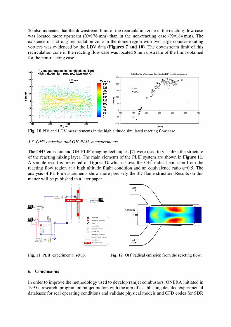
10 also indicates that the downstream limit of the recirculation zone in the reacting flow casewas located more upstream (X=176 mm) than in the non-reacting case (X=184 mm). Theexistence of a strong recirculation zone in the dome region with two large counter-rotatingvortices was evidenced by the LDV data (Figures 7 and 10). The downstream limit of thisrecirculation zone in the reacting flow case was located 8 mm upstream of the limit obtainedfor the non-reacting case.
Fig. 10 PIV and LDV measurements in the high altitude simulated reacting flow case
5.3. OH* emission and OH-PLIF measurements
The OH* emission and OH-PLIF imaging techniques [7] were used to visualize the structureof the reacting mixing layer. The main elements of the PLIF system are shown in Figure 11.A sample result is presented in Figure 12 which shows the OH* radical emission from thereacting flow region at a high altitude flight condition and an equivalence ratio φ=0.5. Theanalysis of PLIF measurements show more precisely the 3D flame structure. Results on thismatter will be published in a later paper.
Fig. 11 PLIF experimental setup. Fig. 12 OH* radical emission from the reacting flow.
6. Conclusions
In order to improve the methodology used to develop ramjet combustors, ONERA initiated in1995 a research program on ramjet motors with the aim of establishing detailed experimentaldatabases for real operating conditions and validate physical models and CFD codes for SDR
ÿ dt
Nd:Yag500 mJ= 532 nmλ
DyeLaser
do
ublin
g
PM Sig
PM Ré
f
dt
Controller/
Pulser
TranslationController
ICCD
periscope
reference : flat flame
mirror
silica glass window
colored filter
optical fiber
electric al connection
electric al synchronization
laser beam
Translation stage
Air
Air
Kérosène
Axial Profile of the mean Longitudinal (U) velocity component
-100
-50
0
50
100
150
200
250
100 150 200 250 300 350 400
X (mm)
U (
m/s
)
PIVLDV

or LFRJ applications. A specific 3D ramjet geometry design with a square section well-adapted to optical measurements has been defined. Values of dimensions and area ratios arecomparable to real motors ones. The program has an important experimental phase associatedwith numerical simulations mainly conducted using the MSD code developed by ONERA.Up until now, experiments were done either for cold flow, or hot flow with or withoutcombustion. Based on the 3D ramjet geometry design previously defined, one model foreach kind of experiment has been built. The model for cold flow studies is entirelytransparent and used at atmospheric pressure on hydraulic or aerodynamic test rigs. Thecombustion model is equipped with quartz windows to allow local optical measurements.In the case of cold flow studies, SDR simulation was studied; mixing characteristics betweenfuel and air have also been examined on a hydraulic test rig whereas aerodynamic flowfieldshave been measured on a aerodynamic test rig. Cold flow studies were performed in theframe of this work to ascertain whether this semi-empirical approach, previously used in thedevelopment methodology, is justified although the compressibility effects are not taken intoaccount in this kind of simulation.The main part of the experimental program is based on hot flow experiments. Up until now,LDV and PIV measurements were carried out for the non-reacting case (no fuel injection)and the reacting case (LFRJ case with fuel injection at the head end of the combustor).Velocity profiles and turbulence characteristics were obtained in the horizontal and verticalmid-sections of the combustor duct section. PLIF measurements were also performed forLFRJ cases at middle and high altitude simulated flight cases.The experimental results obtained in this study already represent a significant data base,which will be used for comparisons with flow field computations. This data base will becompleted in the near future with additional measurements obtained for high speed flowscorresponding to high and middle altitude flight conditions by using other techniques.
Acknowledgments
The authors would like to thank the French Délégation Générale de l’Armement, Service desProgrammes Nucléaires (DGA/SPNuc), for its financial support in this research program.
References
[1] Ristori A, Heid G, Cochet A, Lavergne G, "Experimental and numerical study of turbulent flowinside a research SDR combustor ", 35th Joint Propulsion Conference & Exhibit, June 20-24, LosAngeles, USA, AIAA Paper-99-2814, 1999.
[2] Ristori A, Dufour E, "Numerical simulation of ducted rocket motor ", 37th Joint PropulsionConference & Exhibit, July 8-11, Salt Lake City, Utah, AIAA Paper-2001-3193, 2001
[3] AGARD Advisory Report 323 - Working Group 22 on "Experimental and Analytic Methods forthe Determination of Connected-Pipe Ramjet and Ducted Rocket Internal Performance", AR-323, 1994.
[4] Ristori A, Heid G, Cochet A, Lavergne G, "Experimental and numerical study of turbulent flowinside a dual inlet research ducted rocket combustor ", XIVth Symposium ISOABE, September5-10, 1999, Florence, Italy.
[5] Heid G and Ristori A, "An optical method for local equivalence ratios measurements applied tohydraulic simulation of a ramjet combustion chamber", Proceedings of PSFVIP-4, June 3-5,2003, Chamonix, France.
[6] Gicquel P, Brossard C, Barat M, Ristori A, 2002, “Experimental study of a high speed flow insidea dual research ducted rocket combustor using laser doppler velocimetry“, Proceedings of 2002joint US ASME-European Fluid Engineering Summer Conference : Forum on High Speed JetFlows, July 14-18, Montreal.
[7] Bresson A , « Techniques d’imagerie quantitatives : fluorescence induite par laser appliquée auxécoulements et aux combustions », Ph. DThesis , Rouen University, (2000).