characterizing the chemical stability of high · pdf fileabstract the chemical ... the...
TRANSCRIPT
CHARACTERIZING THE CHEMICAL STABILITY OF HIGH TEMPERATURE MATERIALS FOR APPLICATION IN EXTREME ENVIRONMENTS Elizabeth Opila NASA Glenn Research Center 21000 Brookpark Rd. Cleveland, OH 44135 ABSTRACT
The chemical stability of high temperature materials must be known for use in the extreme environments of combustion applications. The characterization techniques available at NASA Glenn Research Center vary from fundamental thermodynamic property determination to material durability testing in actual engine environments. In this paper some of the unique techniques and facilities available at NASA Glenn will be reviewed. Multiple cell Knudsen effusion mass spectrometry is used to determine thermodynamic data by sampling gas species formed by reaction or equilibration in a Knudsen cell held in a vacuum. The transpiration technique can also be used to determine thermodynamic data of volatile species but at atmospheric pressures. Thermodynamic data in the Si-O-H(g) system were determined with this technique. Free Jet Sampling Mass Spectrometry can be used to study gas-solid interactions at a pressure of one atmosphere. Volatile Si(OH)4(g) was identified by this mass spectrometry technique. A High Pressure Burner Rig is used to expose high temperature materials in hydrocarbon-fueled combustion environments. Silicon carbide (SiC) volatility rates were measured in the burner rig as a function of total pressure, gas velocity and temperature. Finally, the Research Combustion Lab Rocket Test Cell is used to expose high temperature materials in hydrogen/oxygen rocket engine environments to assess material durability. SiC recession due to rocket engine exposures was measured as a function of oxidant/fuel ratio, temperature, and total pressure. The emphasis of the discussion for all techniques will be placed on experimental factors that must be controlled for accurate acquisition of results and reliable prediction of high temperature material chemical stability. INTRODUCTION
The aim of this paper is to describe capabilities for determining materials chemical stability at high temperatures. In general, experimental equipment which is unique to NASA Glenn Research Center is described1. These facilities include equipment for fundamental thermodynamic property determination as well as those which allow testing in complex combustion environments. Midway between fundamental property determination and actual combustion environments, a varied array of test rigs are also used to determine degradation mechanisms for materials at high temperatures. These include vacuum furnaces, box furnaces, controlled atmosphere furnaces, thermogravimetric analysis furnaces, furnaces for cyclic oxidation in air and controlled atmospheres, ultra high temperature furnaces for use in air environments (2300K capability) and Mach 0.3 burner rigs which operate at one atmosphere. While these capabilities are not discussed within this report, they are an important bridge between the fundamental and application-oriented equipment discussed here.
This is a preprint or reprint of a paper presented at a conference. Since revisions may be made prior to formal publication, this version is made available with the understanding that it will not be cited or reproduced without the permission of the author.
https://ntrs.nasa.gov/search.jsp?R=20050196724 2018-05-15T01:43:31+00:00Z

Experimental techniques rather than the results are featured in this paper. The information that can be obtained by each method, and the range of achievable temperatures, pressures, gas velocities, and reactive environments are described. Limitations and lessons learned for each technique are also discussed. Examples of results are presented. Many examples describe the Si-O-H system, since a large body of work has been conducted in this area at the NASA Glenn Research Center in the effort to develop silicon-based ceramics for propulsion applications and water vapor-containing combustion environments.
KNUDSEN EFFUSION MASS SPECTROMETRY
Knudsen Effusion Mass Spectromety (KEMS) is a powerful technique used to identify vapor species and their relative pressures2,3. A condensed sample is placed in a Knudsen cell (inner dimensions ~10 mm dia., 7 mm height) and uniformly heated until equilibrium between the vapor and the condensed phase is achieved. The vapor is continuously sampled by effusion through a small orifice (~1.5 mm dia., 4 mm height) in the cell which is held in a vacuum. A molecular beam is formed from the effusion vapor, ionized and directed into a magnetic sector mass spectrometer for identification and pressure measurement. A schematic diagram of this process is shown in Figure 1. The vapor species is identified by the mass-to- charge ratio (m/e). The species pressure is directly proportional to the intensity of the signal obtained. Measurements of the vapor species pressure as a function of temperature allow a number of thermodynamic quantities to be determined. The enthalpy of sublimation of the condensed phase or the enthalpy of vapor species reaction can be determined from the slope of a plot of log measured pressure versus inverse temperature. Component activities can be determined by comparing the relative vapor pressure of a characteristic species in equilibrium with a solution phase to that of a pure component. The temperature dependence of measured activities enables the partial enthalpies and entropies of mixing to be determined. In addition, plateaus in vapor pressure as a function of temperature allow the accurate determination of phase transformation temperatures. The temperature range of measurements is about 1000 to >2000K. The lower limit is determined by the ability to make pyrometer measurements as well as thermal gradients in the furnace. The upper limit is determined by the temperature limit of the furnace components. The range of pressures that can be measured by this technique is between 10-12 and 10-4 atm. The lower limit is established by the sensitivity of the mass spectrometer while the upper limit is determined by the transition from molecular to hydrodynamic flow. Molecular flow is desired for accurate measurements and occurs when molecule – molecule collisions are negligible compared to molecule – cell wall collisions.
The primary concern for accurate thermodynamic measurements is the accurate measurement of temperature. This problem is overcome in a multiple cell KEMS in which the melting point of gold, or another primary temperature standard, is measured in one cell as part of the same experiment in which the vapor species of interest are studied in another cell. Container compatibility is a second important issue. In practice, the cell material becomes part of the system under study. A non-reactive cell material that can reach equilibrium with the sample quickly is desired. Typically metallic alloys are studied in refractory ceramic cells (Al2O3, ZrO2, Y2O3) and ceramics are studied in refractory metal cells (W, Mo, Ir). Another issue is the repeatable formation of a well-defined molecular beam. Molecular beam formation is controlled by the effusion orifice, apertures between the effusion cell and the ion-source, as well as system

alignment. Variation in instrument calibration, an issue for single cell instruments, is mostly overcome by the use of multiple cells.
As an example, the multiple cell KEMS was used to determine the effect of dissolved oxygen on the activities of aluminum and titanium in Ti3Al(O). These results show that dissolved oxygen acts to increase the activity of aluminum (see Figure 2) and decrease the titanium activity. These effects are important to the understanding of how dissolved oxygen affects protective aluminum oxide formation on Ti3Al at high temperatures.
Figure 1. Schematic drawing of ion beam formation for analysis in the KEMS.
Figure 2. Aluminum activity variation in Ti3Al as a function of dissolved oxygen and temperature.
THE TRANSPIRATION TECHNIQUE The transpiration technique has been reviewed by Merten and Bell4. This is a relatively
simple technique for determining thermodynamic data for gas phase species as well as indirectly identifying the gas species. In this method, shown schematically in Figure 3, a carrier and/or reactive gas mixture flows over a heated condensed phase sample at rates low enough for equilibrium to be maintained. Any product gases formed from the reaction between condensed phase and reactant gas are carried downstream to a cooler portion of the gas train where they condense. The condensate is collected and the amount of condensate is determined quantitatively by chemical analysis techniques, such as atomic emission spectroscopy. This technique is a direct measurement of condensable gas species pressure. Thermodynamic data for the reaction can be determined from the temperature dependence of the reaction. The species identity can be determined indirectly from the dependence of the product on the reactant gas pressure. This technique is a useful analogue to KEMS since it allows the determination of thermodynamic data of gas species, but at relatively high pressures: 0.1 to 1 atm. The temperature range is limited at low temperatures by the formation of measurable product for the
0.001
0.010
0.100
1.000
0.00056 0.00061 0.00066 0.00071 0.00076 0.000811/T
a(Al)
A20 Ti-35Al-20OA8 Ti-28Al-7.9OA5 Ti-28Al-4OA2 Ti-30Al-0.25O
incr
easi
ng [
O]
α2(O) + γ + Al2O3
α2(O)
β-Ti(Al,O)

reaction of interest (about 20 µg) and at high temperatures by either the temperature capability of the furnace or by reactions between the condensed phase and the container. In our laboratory, transpiration experiments have been conducted at temperatures as high as 1725K for the SiO2(c)-H2O(g) system. Gas flow rates must be low enough so that equilibrium in the transpiration cell is maintained. About 50 to 500 ccm are typical flow rates.
Experimental concerns include the following. First, equilibrium between the solid and gas must be maintained. This is attained by placing a constriction in both the gas inlet and outlet of the reaction cell. At very low flow rates, diffusion of the products out of the reaction cell can contribute significantly to transport through the cell. At very high flow rates, the gas stream may not reach the equilibrium product saturation. In the course of any transpiration study, it should be demonstrated that experiments were conducted in a flow regime where the pressure of the product species was independent of flow rate, and the product flux increases linearly with flow rate.
Another area of concern is the complete collection and accurate analysis of condensate. Complete collection of condensates can be difficult for oxides such as Al2O3 which are insoluble in acids. In such cases, techniques such as pyrosulfate fusion are needed to recover the condensate5,6. Collection of liquid condensates can also be difficult, especially in the case where water vapor, a reactant gas, is condensing also. Finally, care must be taken that standards for spectroscopic analysis are accurate.
Accurate temperature measurement is of utmost importance when measuring thermodynamic data. In this case, a thermocouple is typically immersed in the middle of the condensed phase sample. Reactions of the thermocouple with the sample are a concern. This concern is typically addressed by replacing the thermocouple at regular intervals.
Undesired reactions between the sample and the transpiration cell may also be a problem for obtaining accurate thermodynamic data. Careful choice of the transpiration cell material is required, as previously discussed for Knudsen cells. In our laboratory, we have studied the Si-O-H system extensively7. It is now accepted that the following reaction occurs in water vapor at pressures near one atmosphere7,8:
SiO2(c) + 2H2O(g) = Si(OH)4(g) (1) Examination of this reaction shows that the formation of Si(OH)4 should have a square dependence on the water vapor partial pressure. The pressure dependence of volatile species in the Si-O-H system is shown in Figure 4. At temperatures of 1473K and below, Reaction (1) is found to be occur. At higher temperatures, the power law exponent for the water vapor pressure dependence is lower than two, suggesting that other Si-O-H species such as SiO(OH)(g) may be important. Temperature dependent results for Si-O-H volatility have also been determined. The slope of a plot of log(PSi(OH)4) versus inverse temperature can be used to calculate the second law heat of reaction. Third law heats of reaction can be determined from each pressure-temperature data point when the Gibbs free energy function for the vapor molecule is known or can be estimated based on its structure. The transpiration method is a conceptually simple technique for determining thermodynamic data and vapor species identity at higher gas pressures and with oxidizing gases where KEMS is not possible.

Figure 3. Schematic drawing of the transpiration furnace.
log [P(H2O)/Pa]
3.8 4.0 4.2 4.4 4.6 4.8 5.0
log
[P(S
i-OH
)/Pa]
-2.8
-2.4
-2.0
-1.6
-1.2
-0.8
-0.4
T = 1473 KT = 1173 KT = 1673 K
Figure 4. Water vapor partial pressure dependence of volatile Si-O-H species formation: Slopes equal (1.95 ± 0.01), (1.99 ± 0.06), and (1.71 ± 0.02) at 1173, 1473, and 1673K respectively. The theoretical slope for Si(OH)4 formation is 2.
FREE JET SAMPLING MASS SPECTROMETRY Volatile species formed at one atmosphere can be directly identified using the specialized
Free Jet Sampling Mass Spectrometer (FJSMS) at NASA Glenn Research Center. The mass spectrometer has been described in detail9 and is shown schematically in Figure 5. This instrument is a nice complement to the transpiration method, since it can sample the gas phase at the same conditions under which the transpiration experiments are conducted. Both simple vaporization reactions and reactions which form gaseous products can be studied. This system is composed of a high temperature furnace containing a porous solid or powder sample and a flowing reactant/carrier gas mixture at one atmosphere total pressure that is positioned directly beneath a platinum-rhodium sampling cone. The volatile species of interest, entrained in the gas mixture at one atmosphere pressure, enters an 0.2 mm diameter hole in the sampling cone. A free jet expansion of the gas stream occurs as it flows through a series of differentially pumped chambers. The expansion leads to a well defined molecular beam with essentially collisionless flow. This sampling system preserves the chemical and dynamic integrity of the volatile species even if they are condensable or reactive. The molecular beam is then ionized and directed into a quadrupole mass spectrometer for identification by mass-to-charge (m/e) ratio. Because of the nature of the quadrupole mass spectrometer, quantitative data can not be obtained, precluding thermodynamic data determination. However, important qualitative trends in vapor pressures can be observed. The temperature range of measurement is limited at low temperatures by the formation of measurable amounts of product for the reaction of interest and the quadrupole sensitivity. By vaporizing NaCl and comparing to known thermodynamic data10, the lower detection limit for
cell

vapor pressure of a condensable species in this instrument has been estimated to be about 1x10⁻⁶ atm. The measurements are limited at high temperatures by the temperature capability of the furnace which is about 1400°C. Carrier gas flow rates must be high enough so that the condensable species is carried to the sampling cone, but not so high as to cause the cone to plug with condensate. A typical flow rate is about 200 ccm. Experimental concerns include the following. Typically, sample temperature is measured by immersing a thermocouple in the sample, or by placing a thermocouple in direct contact with the sample container. Sample temperature is not easily controlled in experiments with the FJSMS because variations in gas flow rate and carrier/reactive gas composition cause significant changes in both sample temperature and the baseline in the mass spectra. Because condensable vapor species are often of interest, alignment of the cone, collimators, and mass spectrometer are critical. Permanent gases are relatively easily detected with small amounts of misalignment, but condensable species are not. The optimization of the quadrupole sensitivity varies with m/e. For a given tuning of the instrument, mass discrimination of the larger masses occurs relative to the smaller masses. The instrument should therefore be tuned at the approximate m/e of the unknown volatile species using a known vapor species. The inert gases helium, neon, argon, krypton, and xenon are useful standards which cover a range of m/e.
For example11, Figure 6 shows results for mass spectra of SiO2 in dry oxygen compared to results obtained in water vapor plus oxygen as per Reaction 1. In the presence of water vapor, the peak at m/e=79 is attributed to Si(OH)3
+(g), a fragment of Si(OH)4(g). The peak at m/e=96 is attributed to Si(OH)4
+(g). The loss of an OH group during the ionization process is typical. Note that krypton found naturally in small amounts in the oxygen carrier gas serves as a good standard for m/e in this mass region. The distinctive isotopic distribution of krypton provides a fingerprint for accurate identification of m/e.
70 75 80 85 90 95 100m/e
Inte
nsity
SiO2 + O2
Si(OH)3+
82-86Kr+
1325°C
SiO2 + H2O/O2
Si(OH)4+
14243
1260°C
Figure 5. Schematic drawing of the FJSMS.
Figure 6. Mass spectra for vapor species observed from SiO2 plus dry oxygen compared to SiO2 plus wet oxygen.
HIGH PRESSURE BURNER RIG The High Pressure Burner Rig (HPBR) at the NASA Glenn Research Center was
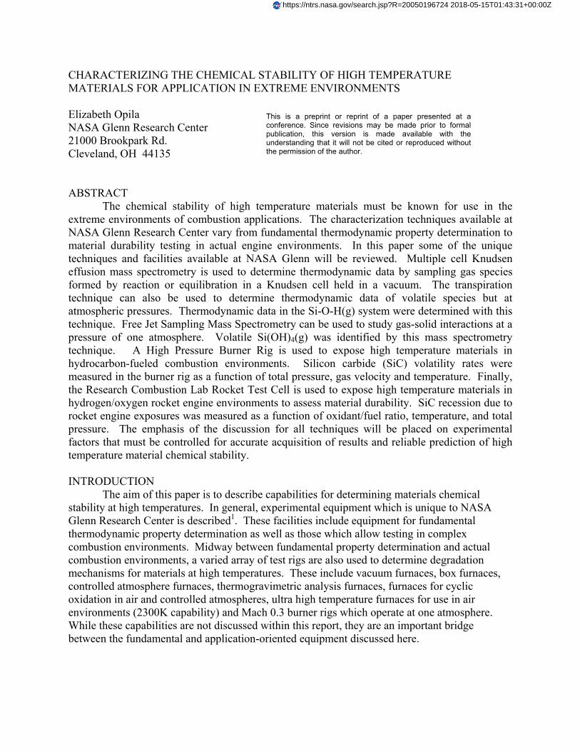
designed specifically to test materials in combustion environments that simulate a gas turbine engine12. Water vapor makes up about 10% of the combustion products when a hydrocarbon fuel is burned13. Formation of volatile hydroxides, such as Si(OH)4, is a great concern in combustion environments, especially at high pressures. The HPBR allows testing of materials at high pressures and moderately high gas velocities where volatility is more easily observed. A schematic diagram of the rig is shown in Figure 7. Preheated air is mixed with a hydrocarbon fuel. Combustion is initiated by an igniter. The combustion products flow downstream to a test section, over the material samples to be tested, and then are exhausted. Material durability is monitored by periodic weight change and material recession measurements.
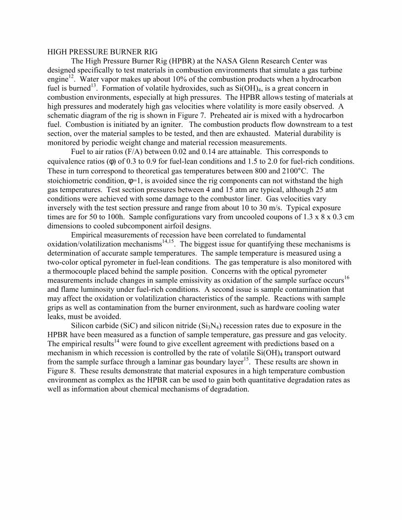
Fuel to air ratios (F/A) between 0.02 and 0.14 are attainable. This corresponds to equivalence ratios (φ) of 0.3 to 0.9 for fuel-lean conditions and 1.5 to 2.0 for fuel-rich conditions. These in turn correspond to theoretical gas temperatures between 800 and 2100°C. The stoichiometric condition, φ=1, is avoided since the rig components can not withstand the high gas temperatures. Test section pressures between 4 and 15 atm are typical, although 25 atm conditions were achieved with some damage to the combustor liner. Gas velocities vary inversely with the test section pressure and range from about 10 to 30 m/s. Typical exposure times are for 50 to 100h. Sample configurations vary from uncooled coupons of 1.3 x 8 x 0.3 cm dimensions to cooled subcomponent airfoil designs. Empirical measurements of recession have been correlated to fundamental oxidation/volatilization mechanisms14,15. The biggest issue for quantifying these mechanisms is determination of accurate sample temperatures. The sample temperature is measured using a two-color optical pyrometer in fuel-lean conditions. The gas temperature is also monitored with a thermocouple placed behind the sample position. Concerns with the optical pyrometer measurements include changes in sample emissivity as oxidation of the sample surface occurs16 and flame luminosity under fuel-rich conditions. A second issue is sample contamination that may affect the oxidation or volatilization characteristics of the sample. Reactions with sample grips as well as contamination from the burner environment, such as hardware cooling water leaks, must be avoided. Silicon carbide (SiC) and silicon nitride (Si3N4) recession rates due to exposure in the HPBR have been measured as a function of sample temperature, gas pressure and gas velocity. The empirical results14 were found to give excellent agreement with predictions based on a mechanism in which recession is controlled by the rate of volatile Si(OH)4 transport outward from the sample surface through a laminar gas boundary layer15. These results are shown in Figure 8. These results demonstrate that material exposures in a high temperature combustion environment as complex as the HPBR can be used to gain both quantitative degradation rates as well as information about chemical mechanisms of degradation.
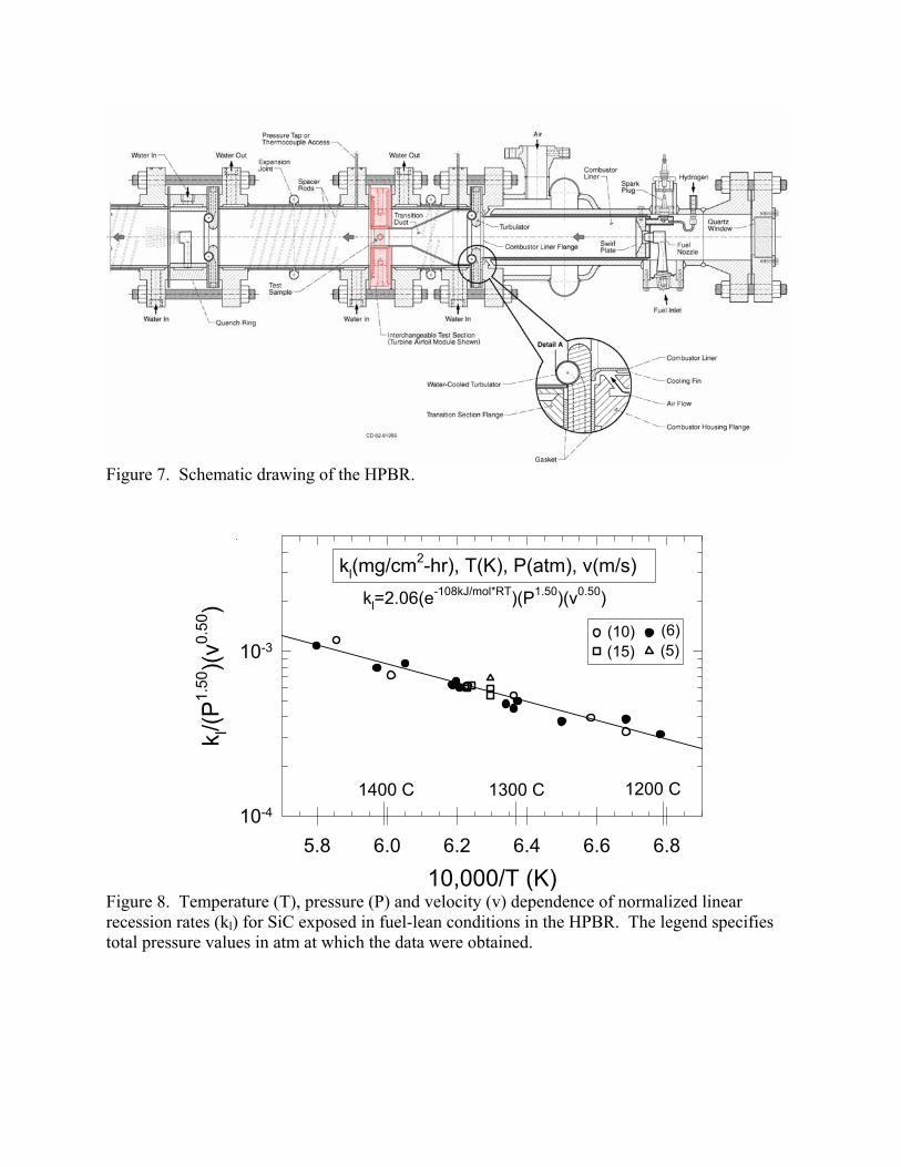
Figure 7. Schematic drawing of the HPBR. Figure 8. Temperature (T), pressure (P) and velocity (v) dependence of normalized linear recession rates (kl) for SiC exposed in fuel-lean conditions in the HPBR. The legend specifies total pressure values in atm at which the data were obtained.
10,000/T (K)5.8 6.0 6.2 6.4 6.6 6.8
k l/(P
1.50
)(v0.
50)
10-4
10-3(6)
(15) (5)(10)
1400 C 1200 C1300 C
kl(mg/cm2-hr), T(K), P(atm), v(m/s)kl=2.06(e-108kJ/mol*RT)(P1.50)(v0.50)

ROCKET COMBUSTION LAB, HYDROGEN/OXYGEN ROCKET ENGINE (CELL 22) A hydrogen/oxygen rocket engine test cell (Cell 22) was developed at NASA Glenn
Research Center in the 1980’s to test the durability of thermal barrier coatings in a high heat flux environment17,18. Since that time, Cell 22 has been used in various programs to screen materials for a number of properties and applications including thermal shock resistance, ablative material performance, nonablative nozzle throat performance, and design viability for cooled ceramic matrix composite components19,20. Durability is generally assessed based on visual observations of sample integrity after test. High temperature materials can be tested in two different configurations, shown schematically in Figure 9. Many features are common to both configurations. Gaseous hydrogen and oxygen are supplied to a water cooled injector. The oxygen to fuel ratio (O/F) is controlled by the relative amounts of each gas supplied to the injector. Combustion is initiated with an igniter. The combustion products flow downstream through water cooled hardware. In the first test configuration, the sample to be tested, typically in coupon form, is placed in the pressure chamber upstream of the nozzle. Here pressures can vary from about 6 atm to 60 atm. The gas velocities are relatively low, on the order of 200 m/sec. Gas temperatures depend on the O/F. The stoichiometric condition for the hydrogen/oxygen system is O/F=8 corresponding to a gas temperatures in excess of 3000°C. Fuel-rich conditions with an O/F of about 2.0, corresponding to a gas temperature of 1800°C, are more typically used. In general, fuel rich conditions are used, although some testing has been conducted in the oxygen-rich regime. In the second configuration for material testing, the sample to be exposed is placed downstream of the nozzle. The sample configuration can be of subcomponent complexity since it is outside of the engine. Here the pressure is 1 atm, but gas velocities up to mach 2 (660 m/s) have been achieved. Gas temperature is again dependent on O/F. O/Fs between 1.3 and 7.0 have been used, corresponding to gas temperatures between about 1300 and 3000°C.
The increased complexity of the test engine makes accurate determination of the material exposure parameters difficult. Pressure in the test chamber is measured by strain gauge transducers at a pressure port in the combustion chamber. Gas flow rates are controlled by choosing the appropriately sized sonic venturi that should be operated with the appropriate pressure drop across the venturi. Temperature, again, is very difficult to measure. Thin film thermocouples have been applied to coupons tested within the pressure chamber. Unfortunately, these thin films are not robust enough to withstand the high gas velocities and temperatures typically found in test. Only limited success at the most benign conditions has been attained measuring material temperature by this method. Sheathed thermocouples can also be inserted into the combustion flow allowing temperature profiling of the flowing gas across the pressure chamber. Typically the temperature across the chamber is found to be very nonuniform and depends strongly on the choice of injector. Single element injectors have been found to result in the smallest temperature gradients, about 25°C in 1 cm as measured at the midline of the chamber. Average gas temperatures can also be estimated by monitoring the heat loss to the water cooled chamber walls. There is no view port in the water-cooled pressure chamber precluding any optical pyrometry. Temperature measurements of components downstream of the nozzle have been attempted with optical equipment, such as pyrometers or IR cameras. Difficulties with flame luminosity are severe, so the accuracy of these measurements is uncertain. Generally, the most reliable measurements have been obtained using thermocouples in contact with the cool side of the test article or in a hole just below the hot side surface.
Surface temperatures can then be calculated for materials of well-defined and well-known thermal conductivity.
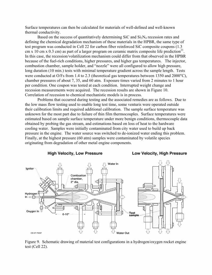
Based on the success of quantitatively determining SiC and Si3N4 recession rates and defining the chemical degradation mechanism of these materials in the HPBR, the same type of test program was conducted in Cell 22 for carbon fiber reinforced SiC composite coupons (1.3 cm x 10 cm x 0.3 cm) as part of a larger program on ceramic matrix composite life prediction21. In this case, the recession/volatilization mechanism could differ from that observed in the HPBR because of the fuel-rich conditions, higher pressures, and higher gas temperatures. The injector, combustion chamber, sample holder, and “nozzle” were all configured to allow high pressure, long duration (10 min.) tests with minimal temperature gradient across the sample length. Tests were conducted at O/Fs from 1.4 to 2.3 (theoretical gas temperatures between 1350 and 2000°C), chamber pressures of about 7, 35, and 60 atm. Exposure times varied from 2 minutes to 1 hour per condition. One coupon was tested at each condition. Interrupted weight change and recession measurements were acquired. The recession results are shown in Figure 10. Correlation of recession to chemical mechanistic models is in process.
Problems that occurred during testing and the associated remedies are as follows. Due to the low mass flow testing used to enable long test time, some venturis were operated outside their calibration limits and required additional calibration. The sample surface temperature was unknown for the most part due to failure of thin film thermocouples. Surface temperatures were estimated based on sample surface temperature under more benign conditions, thermocouple data obtained by probing the gas stream, and estimations based on loss of heat to the hardware cooling water. Samples were initially contaminated from city water used to build up back pressure in the engine. The water source was switched to de-ionized water ending this problem. Finally, at the highest pressure (60 atm) samples were contaminated by volatile species originating from degradation of other metal engine components.
Figure 9. Schematic drawing of material test configurations in a hydrogen/oxygen rocket engine test (Cell 22).

0 10 20 30 40 50 60
time (minutes)
-0.20
-0.15
-0.10
-0.05
0.00
chan
ge in
sam
ple
thic
knes
s (m
m)
100 psi, OF=1.7100 psi, OF=2.0100 psi, OF=2.3500 psi, OF=1.5500 psi, OF=1.75500 psi, OF=1.9
Figure 10. SiC recession measurements as a function of chamber pressure and OF exposures in a hydrogen/oxygen rocket engine test (Cell 22). CONCLUDING REMARKS In summary, several statements can be made about the determination of material chemical stability in severe environments. First, accurate temperature measurements are challenging, but critical, for accurate prediction of material stability. Second, experimental determination of thermodynamic data is critical to prediction of material stability in extreme environments. More work needs to be done in this area. Finally, identification of chemical degradation mechanisms and quantitative rate determination can be made, even in complex test environments, if experimental parameters are well controlled and accurately measured. ACKNOWLEDGMENTS
The author would like to acknowledge Evan Copland (Case Western Reserve University, Cleveland, OH), Nathan Jacobson (NASA-GRC), Dennis Fox (NASA-GRC), Dwight Myers (East Central University, Ada, OK), Craig Robinson (QSS, Inc., Brookpark, OH), Martha Jaskowiak (NASA-GRC) and Andy Eckel (NASA-GRC) for their contributions to this work.
REFERENCES 1http://www.grc.nasa.gov/WWW/EDB/index.htm 2R.T. Grimley, “Mass Spectrometry” pp. 195-243 in The Characterization of High Temperature Vapors, ed. J.L. Margrave, John Wiley & Sons, NY, 1967. 3E.H. Copland and N.S. Jacboson, “Thermodynamic Activity Measurements with Knudsen Cell Mass Spectrometry,” Interface 10 [2] 28-31 (2001). 4U. Merten and W.E. Bell, “The Transpiration Method,” pp. 91-114 in The Characterization of High Temperature Vapors, ed. J.L. Margrave, John Wiley & Sons, NY, 1967.
5Z. Sulcek and P. Povondra, Decomposition by Fusion, pp. 167-242 in Methods of Decomposition in Inorganic Analysis, CRC Press, Boca Raton, FL , 1989.

6L. Brewer and A.W. Searcy, “The Gaseous Species of the Al-Al2O3 System,” J. Am. Chem. Soc. 73, 5308 (1951). 7N.S. Jacobson, E.J. Opila, D. Myers, and E. Copland, Thermodynamics of Gas Phase Species in the Si-O-H System,” accepted for publication in Journal of Chemical Thermodynamics.
8A. Hashimoto, “The Effect of H2O Gas on Volatilities of Planet-Forming Major Elements: 1. Experimental Determination of Thermodynamic Properties of Ca-, Al-, and Si-Hydroxide Gas Molecules and its Application to the Solar Nebula,” Geochim. Cosmochim. Acta 56, 511-32 (1992).
9C.A. Stearns, F.J. Kohl, G.C. Fryburg, and R.A. Miller, “A High Pressure Modulated Molecular Beam Mass Spectrometric Sampling System,” NASA TM 73720, (1977).
10 M.W. Chase, Jr., C.A. Davies, J.R. Downey, Jr., D.J. Frurip, R.A. McDonald, and A.N. Syverud, Editors, JANAF Thermochemical Tables, 3rd ed., American Chemical Society and American Physical Society, New York, 1985. 11 E.J. Opila, D.S. Fox, N.S. Jacobson, “Mass Spectrometric Identification of Si-O-H(g) Species from the Reaction of Silica with Water Vapor at Atmospheric Pressure,” J. Am. Ceram. Soc., 80 [4] 1009-12 (1997). 12R.C. Robinson, “SiC Recession due to SiO2 Scale Volatility Under Combustor Conditions,” NASA CR 202331, 1997. 13N.S. Jacobson, “Corrosion of Silicon-Based Ceramics in Combustion Environments,” J. Am. Ceram. Soc., 76 [1] 3-28 (1993). 14R.C. Robinson and J.L. Smialek, “SiC Recession due to SiO2 Scale Volatility under Combustion Conditions. Part I: Experimental Results and Empirical Model,” J. Am. Ceram. Soc. 82 [7] 1817-25 (1999). 15 E.J. Opila, J.L. Smialek, R.C. Robinson, D.S. Fox, and N.S. Jacobson, “SiC Recession due to SiO2 Scale Volatility under Combustion Conditions. Part II: Thermodynamics and Gaseous Diffusion Model,” J. Am. Ceram. Soc. 82 [7] 1826-34 (1999). 16 E.J. Opila, R.C. Robinson, “The Oxidation Rate of SiC in High Pressure Water Vapor Environments,” pp. 398-406 in High Temperature Corrosion and Materials Chemistry, eds. M. McNallan, E. Opila, T. Maruyama, T. Narita, The Electrochemical Society, Pennington, NJ, 2000. 17J.A. Nesbitt and W.J. Brindley, “Heat Transfer to Throat Tubes in a Square-Chambered Rocket Engine at the NASA Lewis Research Center,” NASA TM 102336 – Oct. 1989. 18J.A. Nesbitt, “Thermal Modelling of Various Thermal Barrier Coatings in a High Heat Flux Rocket Engine,” NASA TM 102418 – Dec. 1989. 19M.J. Bur, “A Combustion Research Facility for Testing Advanced Materials for Space Applications,” 41st Aerospace Sciences Meeting and Exhibit, Reno, Nevada, Jan. 6-9, 2003, AIAA-2003-282. 20K.W. Dickens, D.L. Linne, and N.J. Georgiadis, “Experiment and Modeling of a Rocket Engine Heat Flux Environment for Materials Testing,” 41st Aerospace Sciences Meeting and Exhibit, Reno, Nevada, Jan. 6-9, 2003, AIAA-2003-0283. 21S.R. Levine, A.M. Calomino, J.R. Ellis, M.C. Halbig, S.K. Mital, P.L. Murthy, E.J. Opila, D.J. Thomas, L.U.J.T. Ogbuji, and M.J. Verrilli, “Ceramic Matrix Composites (CMC) Life Prediction Method Development,” NASA TM−2000-210052, 2000.