charisma manual ver 3 rev 4 102016 - dreamline · charisma manual ver 3 rev 4 10/2016 2 this model...
TRANSCRIPT

Model#: SHDR-1360760-## Model#: SHDR-1348760-##
CHARISMASHOWER/TUB DOOR INSTALLATION INSTRUCTIONS
IMPORTANTDreamLine® reserves the right to alter, modify or redesign products at any time without prior notice. For the latest up-to-date technical drawings, manuals, warranty information or additional details please refer to your model’s web page on DreamLine.com
For more information about DreamLine® Shower Doors, Tub Doors & Enclosures, please visit DreamLine.com
Model#: SHDR-1360580-## ##=finish01- Chrome04- Brushed Nickel
CHARISMA manual Ver 3 Rev 4 10/2016
CHARISMA manual Ver 3 Rev 4 10/2016 2
This model is treated with DreamLine’s exclusive ClearMaxTM Glass technology. This is a specially formulated coating that prevents the build up of soap and water spots. Install the surface with the ClearMaxTM label towards the inside of the shower.Please note that depending on the model, the glass may be coated on either one or both surfaces.
For best results, squeegee the glass after each use and dry with a soft cloth.

Preparation
NOTE: THIS MANUAL WILL DESCRIBE THE SHOWER DOOR INSTALLATION. PLEASE FOLLOW THE SAME SEQUENCE OF INSTALLATION STEPS FOR THE TUB DOOR INSTALLATION.
1. PRIOR TO INSTALLATION, EXAMINE ALL BOXES AND PACKAGES FOR SHIPPING DAMAGE AND COMPARE THE PIECE COUNT WITH YOUR PACKING SLIP. AFTER OPENING ALL BOXES AND PACKAGES READ THIS INTRODUCTION CAREFULLY. CHECK THAT ALL OF THE NEEDED PARTS ARE INCLUDED IN THE PACKAGE BY CHECKING OFF THE COMPONENTS ON THE “DETAILED DIAGRAM OF SHOWER DOOR COMPONENTS”. IF THE UNIT HAS BEEN DAMAGED, HAS A FINISHING DEFECT, OR HAS MISSING PARTS, PLEASE CONTACT OUR CUSTOMER SUPPORT DEPARTMENT WITHIN 3 BUSINESS DAYS OF THE DELIVERY DATE. PLEASE NOTE THAT DREAMLINE® WILL NOT REPLACE ANY DAMAGED PRODUCTS OR MISSING PARTS FREE OF CHARGE AFTER 3 BUSINESS DAYS OR IF THE PRODUCT HAS BEEN INSTALLED. FEEL FREE TO CONTACT DREAMLINE® IF YOU HAVE ANY QUESTIONS, AND PLEASE PROVIDE AN ORDER NUMBER, JOB NAME OR OTHER PROOF OF PURCHASE TO HELP US IDENTIFY YOUR ORIGINAL ORDER.
2. PLEASE NOTE THAT YOU SHOULD CONSULT YOUR LOCAL BUILDING CODES WITH QUESTIONS ABOUT INSTALLATION COMPLIANCE STANDARDS. BUILDING AND PLUMBING CODES MAY VARY BY LOCATION, AND DREAMLINE® IS NOT RESPONSIBLE FOR CODE COMPLIANCE STANDARDS FOR YOUR PROJECT AND WILL NOT ACCEPT ANY RETURNS.
3. IF THIS UNIT IS GOING TO BE INSTALLED IN A NEW CONSTRUCTION, PLEASE INSTALL ALL OF THE REQUIRED PLUMBING AND DRAINAGE BEFORE INSTALLING THE SHOWER. USE A COMPETENT AND LICENSED (IF REQUIRED BY LOCAL CODE) PLUMBER FOR ALL PLUMBING INSTALLATION.
4. PLEASE MAKE SURE THAT PRIOR TO BEGINNING THE INSTALLATION, THE SURFACES ARE LEVELED AND SOLID AND WILL BE ABLE TO SUPPORT THE TOTAL WEIGHT OF THE UNIT. ALSO MAKE SURE THE WALLS ARE AT RIGHT ANGLES. IRREGULAR INSTALLATION SURFACE LEVEL, RADIUS CORNERS OR IMPROPER ANGLE OF SIDE WALLS WILL RESULT IN SERIOUS PROBLEMS FOR YOUR INSTALLA-
TION. PLEASE NOTE THAT SOME ADJUSTMENTS AND DRILLING MAY BE NECESSARY DURING THE INSTALLATION PROCESS.
5. PLEASE PROTECT ALL PRIMARY SURFACES OF THE PRODUCT DURING INSTALLATION. NEVER SET YOUR GLASS DOWN DIRECTLY ONTO A TILE FLOOR. LEAVE CORNER PROTECTORS IN PLACE UNTIL IT IS NECESSARY TO REMOVE THEM. ALWAYS USE A PIECE OF WOOD OR CARDBOARD TO PROTECT THE BOTTOM EDGE AND CORNERS OF THE GLASS PRIOR TO AND DURING INSTALLATION.
6. THIS UNIT MUST BE INSTALLED UPON A FINISHED THRESHOLD AND AGAINST FINISHED WALLS.
7. PLEASE NOTE! THIS DOOR DOES NOT HAVE OUT-OF-PLUMB ADJUSTMENT. MAKE SURE YOUR WALLS ARE PLUMB, YOUR SILL IS LEVEL, AND THAT YOUR FINISHED OPENING WIDTH IS BETWEEN 56” TO 60” FOR THE 60” MODELS; OR BETWEEN 44” TO 48” FOR THE 48” MODEL.
8. THIS MODEL REQUIRES A MINIMUM OF 2” OF FLAT THRESHOLD SPACE FOR INSTALLATION.
9. INSTALLATION INTO A STUD OR OTHER WOOD REINFORCEMENT BEHIND THE WALL IS RECOMMENDED.
10. PROFESSIONAL INSTALLATION RECOMMENDED.
NOTE: DO NOT INSTALL THE TOWEL BARS ON THE GLASS UNTIL INSTRUCTED TO DO SO. DO NOT LIFT THE GLASS USING THE TOWEL BARS. THIS COULD RESULT IN DAMAGE TO THE GLASS AND/OR SERIOUS PERSONAL INJURY. ALWAYS USE AN ASSISTANT OR A PROFESSIONAL GRADE GLASS SUCTION CUP WHEN HANDLING HEAVY GLASS.
3CHARISMA manual Ver 3 Rev 4 10/2016

Tools
NOTE: Unpack your unit carefully and inspect it. Lay it out and identify all parts using the detailed diagram and packing list in this manual as a reference. Before discarding the carton, check for small hardware bags that may have fallen to the bottom of the box. If any parts are damaged or missing, please contact DreamLine® for replacement. The shipping boxes may contain extra parts not used in your model configuration.
NOTE: Retain these installation instructions for future reference.
4CHARISMA manual Ver 3 Rev 4 10/2016
W
Top
Middle
Bottom
TapeMeasure Pencil Screwdriver
Phillips5/16”(8mm)
Drill bitLevel
Silicone Hammer
9/64"(3.5mm)
Drill bit
Miter saw or Hacksaw
3/16"(5mm)
Drill bit
DrillPower
Metal File
Painter’s Tape
Tip: Measure the finished opening before proceeding with the installation to be sure that the correct model size has been ordered.
Tip: Prior to installation, cover the shower/tub drain with tape to prevent losing screws or small parts.

Detailed Diagram of shower door components
5CHARISMA manual Ver 3 Rev 4 10/2016
The glass surface with the ClearMax™
label must be installed facing the inside of the shower
# Item Qty1 Guide rail 1PC
Parts List
2 Bottom Rail 1PC3 Door Glass 4 Towel Bar5 Wall anchor 4PCS6 6PCS
8
91011
4PCS
6PCS# Item Qty
12 Guide Block (left / right / middle)13 Bumper strips15 3mm hex wrench
1set
161PC
4PCS
4PCSRound head screwST4.2×16
Round head screwST4.2×40
Decorative cover for Guide blockRoller assemblyGuide rail bracket
Round head screw ST4.2×10
2PCS2PCS
4PCS2PCS
1
3
2
4
5
6
8
9
10
11
12
1315
16

Installation steps
6CHARISMA manual Ver 3 Rev 4 10/2016
Fig 1
Fig 2
W
W
W
GUIDE RAIL (#01)W = FINISHED OPENING -1/16”
Metal File
1. Measure the finished opening width at the top, middle and bottom. This distance is marked as “W”.
See Fig 1 for details
2. The Guide Rail (#01) and the Bottom Rail (#02) have been precut for your model size width of 48” or 60”.If your finished opening width is less than 48” or 60”, you will need to cut the Guide Rail (01) and the Bottom Rail (02) to “W” (W = finished opening -1/16”).
>The Guide Rail (#01) can be cut from either end. (Fig 2) >The Bottom Rail (#02) must be cut equally from both ends. (Fig 3) so that the center guide holes stay centered.
You can use a miter saw or a hack saw. Use a metal file to file down any burrs that occur to prevent scratches to the wall. See Fig 2 for details
NOTE: This unit does not allow for out-of-plumb wall conditions.
7CHARISMA manual Ver 3 Rev 4 10/2016
Fig 4
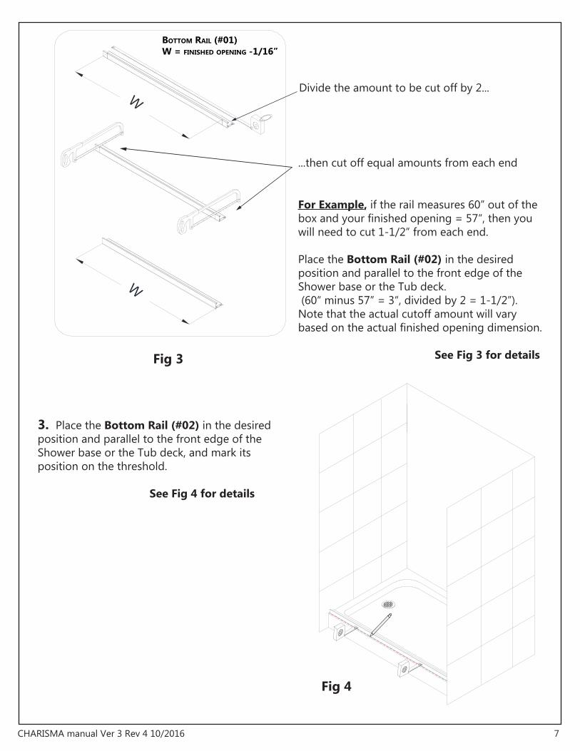
Fig 3
W
W
BOTTOM RAIL (#01)W = FINISHED OPENING -1/16”
Divide the amount to be cut off by 2...
...then cut off equal amounts from each end
For Example, if the rail measures 60” out of the box and your finished opening = 57“, then you will need to cut 1-1/2” from each end.
Place the Bottom Rail (#02) in the desired position and parallel to the front edge of the Shower base or the Tub deck. (60“ minus 57” = 3“, divided by 2 = 1-1/2”). Note that the actual cutoff amount will vary based on the actual finished opening dimension.
See Fig 3 for details
3. Place the Bottom Rail (#02) in the desired position and parallel to the front edge of the Shower base or the Tub deck, and mark its position on the threshold.
See Fig 4 for details
8CHARISMA manual Ver 3 Rev 4 10/2016
Fig 5
Fig 6
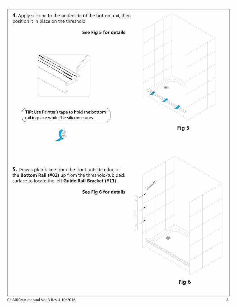
TIP: Use Painter’s tape to hold the bottom rail in place while the silicone cures.
5. Draw a plumb line from the front outside edge of the Bottom Rail (#02) up from the threshold/tub deck surface to locate the left Guide Rail Bracket (#11). See Fig 6 for details
4. Apply silicone to the underside of the bottom rail, then position it in place on the threshold. See Fig 5 for details

9CHARISMA manual Ver 3 Rev 4 10/2016
Fig 7
Fig 8
74”
56”
74”
56”
HEIGHT OF THE GUIDE RAIL BRACKET FOR 76” SHOWER DOOR: MODEL # SHDR-1348760 & SHDR-1360760
HEIGHT OF THE GUIDE RAIL BRACKET FOR 58” TUB DOOR:MODEL # SHDR-1360580
6. Place the Guide Rail Bracket (#11) at a height of 74” from the base.
Align the front bottom corner of the Guide Rail Bracket (#11) with the outside of the Bottom Rail (#02) to mark the wall for drilling. Be sure to keep the Guide Rail Bracket (#11) level. See Fig 7 for details
7. Place the front edge of the Guide Rail Bracket (#11) on the plumb line at a height of 56” from the base. Align the front bottom corner of the Guide Rail Bracket (#11) with the outside of the Bottom Rail (#02) to mark the wall for drilling. See Fig 8 for details
Note: Be sure to keep the Guide Rail Brackets level.
10CHARISMA manual Ver 3 Rev 4 10/2016
Fig 9
Fig 10
1 2 3 4 5
6
Ø 5/16"
7
1 2 3 4 5Ø 5/16"
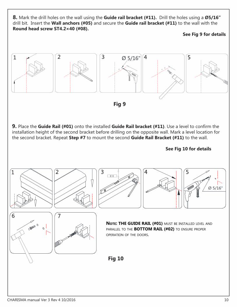
NOTE: THE GUIDE RAIL (#01) MUST BE INSTALLED LEVEL AND PARALLEL TO THE BOTTOM RAIL (#02) TO ENSURE PROPER OPERATION OF THE DOORS.
8. Mark the drill holes on the wall using the Guide rail bracket (#11). Drill the holes using a Ø5/16” drill bit. Insert the Wall anchors (#05) and secure the Guide rail bracket (#11) to the wall with the Round head screw ST4.2×40 (#08). See Fig 9 for details
9. Place the Guide Rail (#01) onto the installed Guide Rail bracket (#11). Use a level to confirm the installation height of the second bracket before drilling on the opposite wall. Mark a level location for the second bracket. Repeat Step #7 to mount the second Guide Rail Bracket (#11) to the wall. See Fig 10 for details
11CHARISMA manual Ver 3 Rev 4 10/2016
Ø 1/8"
Ø 1/8" Ø 1/8"
Fig 11
1 2
3 4
Fig 12
5 6
1 2 3
4
7
outside
outside
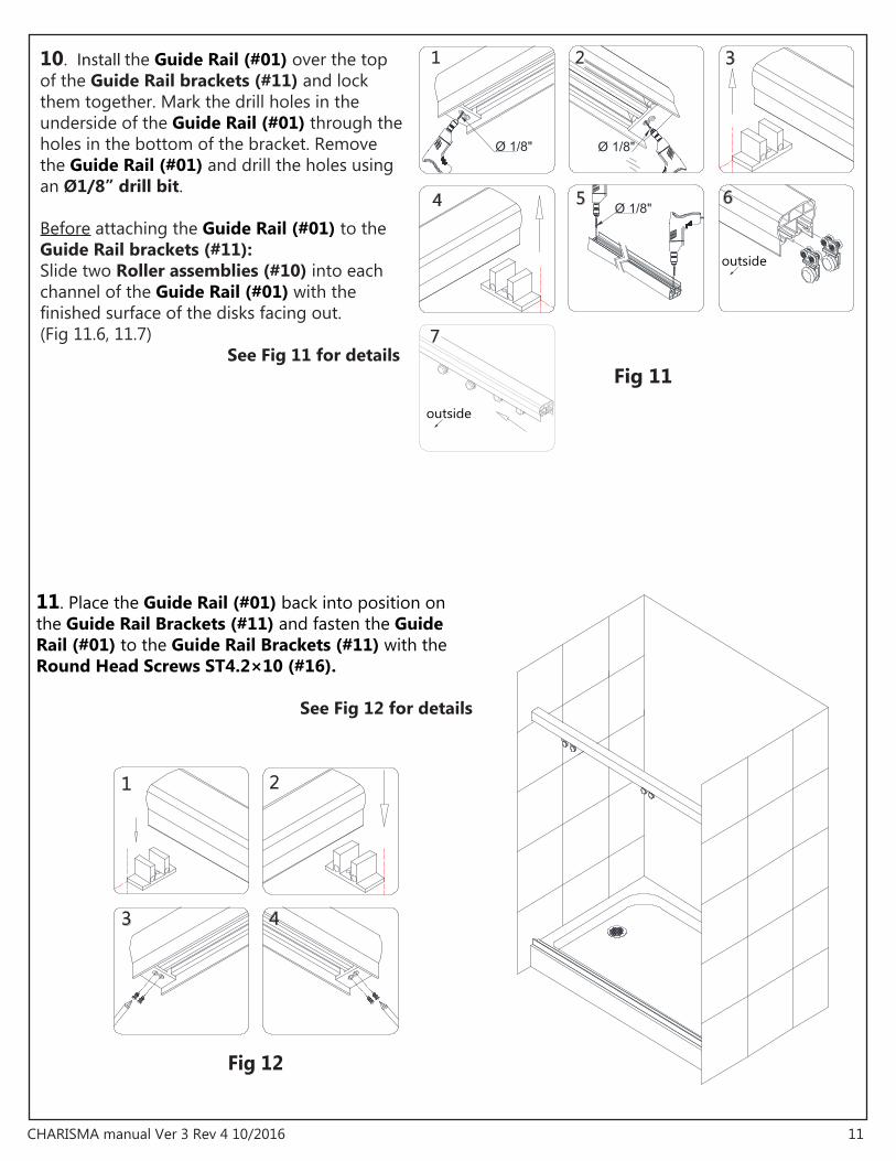
10. Install the Guide Rail (#01) over the top of the Guide Rail brackets (#11) and lock them together. Mark the drill holes in the underside of the Guide Rail (#01) through the holes in the bottom of the bracket. Remove the Guide Rail (#01) and drill the holes using an Ø1/8” drill bit. Before attaching the Guide Rail (#01) to the Guide Rail brackets (#11):Slide two Roller assemblies (#10) into each channel of the Guide Rail (#01) with the finished surface of the disks facing out.(Fig 11.6, 11.7) See Fig 11 for details
11. Place the Guide Rail (#01) back into position on the Guide Rail Brackets (#11) and fasten the Guide Rail (#01) to the Guide Rail Brackets (#11) with the Round Head Screws ST4.2×10 (#16).
See Fig 12 for details

12CHARISMA manual Ver 3 Rev 4 10/2016
Fig 13
Fig 14
outside
12. Secure the Door Glass (#03) onto the Roller assemblies (#10) and fasten them with the provided bolts.
See Fig 13 for details
NOTE: ROTATING THE GLASS HOLDER OUTER DISKS: THE DISK BOLT IS POSITIONED OFF-CENTER BY 1/8” TO PROVIDE FOR SOME MINOR ADJUSTMENTS TO THE DOOR GLASS TO ACHIEVE A BETTER SEAL WITH THE WALL. YOU WILL NEED AN ASSISTANT TO SUPPORT THE WEIGHT OF THE GLASS WHILE YOU LOOSEN THE BOLT, ROTATE THE DISK AND RE-TIGHTEN THE BOLT.
NOTE:ON THE OUTSIDE DOOR GLASS, THE TOWEL BAR IS INSTALLED FACING OUTWARD.ON THE INSIDE DOOR GLASS, THE TOWEL BAR IS INSTALLED FACING INWARD.
NOTE:DO NOT USE THE TOWEL BARS TO LIFT THE GLASS!THIS MAY RESULT IN DAMAGE TO THE GLASS AND/OR SERIOUS PERSONAL INJURY.
13. Install the towel bars onto the door glass. See Fig 14 for details
TIP: BE SURE TO COVER THE DRAIN TO PREVENT LOOSING ANY SCREWS.
view from outside view from inside
Roller Adjustment Disk

13CHARISMA manual Ver 3 Rev 4 10/2016
Fig 16
Fig 15
1
4
7 8 9
5 6
2Ø 1/8"
3
Ø 1/8"
center
outside
outside
left
right
14. As viewed from the outside: Slide the Door Glass (#03) tothe right side and secure the Left Guide block (#12) to the left end of the Bottom Rail (#02). Drill Ø1/8" holes into the Bottom Rail (#02) through holes in the Guide block (#12) and fasten the Guide Block (#12) with the Round head screw ST4.2×16 (#06).
Install the Middle Guide block (#12) into the pre-drilled holes in the Bottom Rail (#02) using the Round head screws ST4.2×16 (#06).
Now slide the doors to the left side and install the Right Guide block (#12) to the right end of the Bottom Rail (#02).Cover the screws with the Decorative covers for Guide block (#09).
See Fig 15 for details
15. Press the Bumper strips (#13) onto the vertical edges of the Door Glass (#03).Trim the bottom of the bumper strips so that they do not bind in the guide blocks.
See Fig 16 for details

14CHARISMA manual Ver 3 Rev 4 10/2016
Fig 17
24Hours
16. Apply a good quality mildew-resistant silicone along the connection of the Guide Rail (#01) and the shower base or tub deck. Allow 24 hours for the silicone to fully cure before using the shower. See Fig 17 for details
NOTE: To maximize the life of your door, it is important to regularly inspect the glass and other hardware for misalignment, proper attachment, and/or damage. Contact DreamLine with any questions or concerns.
Product Maintenance
BASES and BACKWALLS: To ensure long lasting life for your acrylic back walls: wipe them off after each use with a soft cloth. To clean the acrylic back walls use non-abrasive sprays or cream based cleaners. Avoid the use of aerosol spray cleaners. Never use abrasive cleansers, metal brushes or scrapers that could scratch or dull the surface.
GLASS: To ensure long lasting life for your glass shower products: wipe them off after each use with a soft cloth. Rinse and wipe off the glass using either a soft cloth or a squeegee to prevent soap buildup and water spots (Hard water can etch the surface of the glass over time if left to dry). To prevent scratching the surface: never use abrasive cleaners or cleaning products that contain scouring agents. Never use bristle brushes or abrasive sponges that may scratch the surface.
HARDWARE: To ensure a long lasting finish: wipe off the metal parts after each use with a soft cloth. Do not use abrasive cleaners or cleaning products containing ammonia, bleach or acid. If accidentally used, rinse the surface as soon as possible to prevent damage to the finish (peeling or corrosion). After cleaning the polished finishes, rinse thoroughly and wipe dry with soft cloth. Clean stainless steel surfaces at least once a week. When applying stainless steel cleaner or polish to stainless steel hardware, work with (not across) the grain. Never use an abrasive sponge or cloth, steel wool or wired brush as these may permanently scratch the surfaces.
15CHARISMA manual Ver 3 Rev 4 10/2016

TEL: 866-731-2244FAX: 866-857-3638DREAMLINE.COM
For more information on DreamLine® Shower Doors and Enclosure please visit DreamLine.com