charlottesville, virginia electronics division...
TRANSCRIPT

NATIONAL RADIO ASTRONOMY OBSERVATORY Charlottesville, Virginia
ELECTRONICS DIVISION TECHNICAL NOTE NO. 154
Title: 140-ft MODCOMF CONTROL COMPUTER DATA OUTPUT
Author(s) Ronald B. Weimer
Date: April 25, 1989
DISTRIBUTION:
GB CV TU VLA GB Library ER Library Library Downtown VLA Library R. Lacasse IR Library Library Mountain P. Napier R. Weimer M. Balister J. Payne J. Campbell D. Schiebel C. Burgess R. Freund W. Brundage E. Childers S-K Pan J. Lamb C. Brockway A. R. Kerr D. Emerson J. Coe N. Bailey P. Jewell R. Norrod S. Srikanth J. Cochran S. White L. D'Addario A. Perfetto G. Behrens N. Horner R. Fisher F. Crews


140-FT MODCOMP CONTROL COMPUTER DATA OUTPUT
Ronald B. Weimer
Introduction
The control computer at the 140-ft telescope collects observing data, stores it on the disk and does some preliminary data reduction. The data comes from the autocorrelator, digital standard receiver, or A/D converter. Log information is also included along with the data. At the present time a copy of the stored data is sent over a 16-bit wide data channel to the analysis Modcomp. In order to improve the data analysis at the telescope we needed to make the data available in real time to a more modem computer system. No ethemet interface to the Modcomp computers is available. Changing the programs to handle a new interface would be difficult. What we tried to do is develop an interface that would be transparent to the current program and hardware. It turned out that Bob Vance, Ron Maddalena, and Allen Farris modified the data transmission program slightly to make synchronization easier. The original intent was to pipe the data to a Sun model 3/60 workstation. It would accept the data, convert Modcomp floating point numbers to standard numbers, store the data on disk, and make it available for reduction either on itself or over the ethemet loop to a remote terminal. We got the data link running but had trouble with missing data when the Sun got busy doing data reduction. As a consequence, the system was modified so that the data is first piped to an Apple Mac II which modifies the numbers and sends it over ethemet to the Sun. This report describes the electronics in the Modcomp that captures the control computer to analysis computer data stream and transmits it to the Mac II.
Description of Electronics
The Modcomp link was built on a General Purpose Controller by Dwayne Schiebel. The signals of interest are: 16 bits of data (0UT1N to 0UT16N), an output data strobe (OUDCM), a transfer initiate signal (XFERN), and Master Clear (ICBFB) . A 5 MHz clock (CLKFBN) was brought in but was not used. The input data word is broken up into two 8-bit bytes, stored in a first in/first out (FIFO) memory and then sent to the Mac II over an RS-232 serial-data link.
The maximum buffer size was around 5000 16-bit words. The FIFO will handle 12 K bytes--3 each 4 K x 9 bits.
Figure 1 schematic. The FIFO's are cleared by Master Clear or by the start of a new Modcomp transfer (6G). Data input is bussed thru the 74LS240 (9C, 9D) into the input of the FIFO's (11A, 11B, 11C). A 4.90 MHz crystal oscillator (8D) is used for local clocks and the baud rates for the serial data links. A data sheet is included on the IDT 7204 used as a FIFO.
Figure 2 schematic. An OUDCMN pulse starts a sequence of loading 2 bytes intojthe FIFO input (7F, 7E) . OEMS and OELS selects which byte is to be loaded, and W signal strobes the data into the FIFO. The FIFO output buss Q0 thru Q7 is used on page 3. EF signal (6F, 6A) is high if all 3 chips are empty.

Figure 3 schematic. Chip 6D divides the crystal oscillator clock down to provide baud rate clocks. Note: A switch is shown for baud rate select but only 9600 should be used. EF is gated with either DTR or the XON/XOFF signal (sheet 5) to initiate the serial data out. DTR is not used in the Mac II link. Chips 7B, 7C, 7D, and 8B generate the signals to read a byte out of the FIFO, load it in a shift register, and shift the data out. Chips 7A and 8A form the data shift register. The chip in IB shifts the TTL level to RS-232 signal levels. A data sheet for this chip is also included. One TTL to RS-232 circuits is not used. The same chip shifts RS-232 levels back to TTL. One circuit is used for the DTR signal and one for the receive data on page 5.
Figure 4 schematics. These circuits are for test only. To use, the ribbon cables from the GPC are removed and test jumpers from 4F and 4G to 8E and 8F are plugged in. A dip carrier holding two switches is then plugged into slot 4A. The jumpers and switches are in the brown folder for the circuits. Pressing the reset switch simulates a transfer initiate; then pressing the start switch loads 5 K words into FIFO, which starts the serial data output sequence.
Figure 5 schematics. This is the XON/XOFF circuit added. Receive data is level shifted by the 232 chip and fed to a UART (ID). XON/XOFF is decoded (3F, 3C) and sets or resets a flip flop (3D). A data sheet for the CDP 1854 is included. (UART is the courtesy of Ed Childers.)
Physical Layout
The circuit was constructed on a Shalloway card, mounted in an empty slot in the same page as the Modcomp to Modcomp link transmitter. Two 16-pin ribbon cables connect from the GPC to the Shalloway card. Data link connections are via the edge connector as well as +5 V power supply. A male DB 25 connector is mounted on the back of the PCI. The Mac II cable ended up with three conductor, ground and two data. A copy of the card layout is included (Figures 6 and 7). Also, a wire list from the GPC is included (Figure 8). Wirewrap lists are not included. They are in the brown folder.

ours A; s^^
^ _^ P<
Ik /y
0<TUN ZFXr
^O/ cLck ->6C5

ouDewW v
XT/
XS/ fl£S£-T
i. t O . rt O

oAi -?,5"^ 3^3 6D SM,Fr
s
■CD 1^3
T77
/x
^
-L 6 8
c^5 VoNj^opp
6^)
•fv
//) /j /jbvf 3) tt\s\ 61 >0
o
w CO
/ >
/y p?i
sw«Fr
/ / ^ <-• o

STA^T j^j
4G3 -» 0^Dcm
iJ 3^^
7i[ wt 3c?3 La t\ ^3
HD Y VE n /o ^T 5 1
vfj,/•* 'y y3 ^ // JO ^ 7 t VG
^^S£T TO ■^ VSV y^^^ STbf
C_>3
NJO ra V
f ■^ V^ S rcGFg
na 8
II 10 «}
J/ OAV
4 3 2
^o^fC
H O
lA

Xeff =0^3 ^ooo/OO// - / 3,,
r \l nc 13?^
H Pt IS oE.
^^1 ^5 SDO
^^^ ^3-^ TBUSO
Te\AS7 31 £?* Xoti
%£ c
1 Re^/
yoMXoef ^3
*oFf
YON
FIGURE 5

n it h <s Ul Ui Irt
■> 11/
o < <r
fr\t>DCon\p -ToLtJ £(+fF£<%
v. y'Tr
M
•<
X
pt^j?.?. A Jk A o* O* Ul jw f\» o a» o» A
\je -A» v
10
cr.« Si D* ^VO * C ^wo
M ' cAfive
E a |«J3 iC.Yiisl 8
SOSSD ">V 0-?V ^7V
^^ <^__^Dp c-* *** <% g^
fi ?5f, ^-3^ 7 :t
?a ^6o
2_2l__i»
ov
m
g^-< S-F-g g-6"? S-o-3 g-c-^ g-a-^ o-^<
a. i0 a» XL « s
FIGURE 6

WIRE WHAP BOARD COMPONENT LOCATION -2 -81
BY fieui c/tfi^ ^ • ? p f0 'yes LOCATION
DATF V/Vsr/gy
G F E D C B A
i! ^< xC X - X ^ a. 3
XPT7AOH
i i /V^l M /y^ M ^7^? ^?
10 X -XL X - XT ^>< X i i ~rx: I X
9 ^f ^
I'it-SWQ 7^S^o
1 1 I 1! 11 /oao l^d /o ^0 ^.0 I
8 x . C/}6kE_l i.? /r^ nr. 77^SJ9 3
IS to El l/c ^ ^ 7 ^ /^ ^ /G /C Sl/C |/C
7 7V^ 7V «3" ^J^ 3 i*,K 00 '113
77^.? 7/
2^ /v 7l<¥! /Y 7/7 !/</ 7^ /V ia SI JLW 11 7 /7l /V
6 11LS /LJ ~)<tL5--.-l ^ TiLSOQ 77^3 ?3 Die n^Lsoo 7V4SQV
'L
7n la 7 )VI 1/7 7 ^ ivl 71"' /y '7 ~) 11 Zl 7 /V l/w
5 , 1 ! f 1
4 i ^W^^^ ^^^3^2 -1 V-soo 7 ^ 2L s 7y
3 /^/i
SUJITCH
/I* it 7 /Vl /^ 1 11 ^ 7 A/ A/ 7 /? /y y i 8
3 17^7 7V^-7y
s!/u| |/c 7 /v! A 7l/7 /7 [T/v /v
2 ! 1 nr
1 >< - \ CD/3' f57
D3<. C Xo /^AX a.35.
! ! J / VC fife - /c •'5 U C /C C /t
II
10
9
8
7
6
5
4
3
2
*S
4.0
1*1
l<o
[IOZ 74 —100 PIN CONNECTOR
SO
OTES: TYPE OF IC
LSAMPLE BOX S|CNAUSJ DE:scRJpT|0N
IC GROUND CONNECTION-
IC POWER CONNECTION
N88704 GI7 GI8
14 |C||4
13
LOCATION OF PIN NUMBER I
■ SPARE OUTPUT PIN NUMBER (SJ
^V^ 14 OR 16
.OI9uF ERI
6 PIN IC
IE RED CAP CAPACITOR PLUGGED INTO VCC. Q GND. ASSOCIATED WITH IC. 2. VIEW, COMPONENT SIDE OF BOARD
3. THIS COLUMN NOT AVAILABLE
* VCC CONNECTOR PINS: P2,4, 98,100 - GND. CONNECTOR PINS : P I, 3, 27, 49, 73,97, 99 FIGURE 7

/TJoQConAp - /TVO^co AA 0 XM'.T G {PC
- 'S B /^
u / s a i s a t s
to
/S
7 U I
IX I
u / LA) T U/T
/a-
a. s
O/TTHR I W
U i IA 7 U / w /0
U i R )/ U 3 D <o
G /sJ D GMD
GN-J) GA3 D
G AJ^
G M r>
-'O *>? —
£»« r/j owrr 8*/ ^>-
DTt-l 77 >>-
25*5
17 —*>— 7
-*> —
mhLZ
£>BXS fe rrvi^L £
v 6. r i v c T" a^ V o>T 3 \/ GT V
V GT 4. VGT 7 1/ or 7 V/G r /o VGT// VGT /Z. VGT /3 V 6T/V
1/6 S" / \/(i S 2. V C 5 3 V G S ^ ^ Co ss VC S 4 VG S "J vcs g Mt S «J VC S ) o VGS y; VGS ;i VCS VI
VGS y^
Oc\T / -/V/
Ou 7" / C A/
OU.D C Vn YFERA/ ICBFB
rs;c
^C
F~^rAA«.R
tf — .3NJ(
AA^ •^i /ec|
3 u,, -1
—~»
—>'i
-■?>
^/^C^r FIGURE 8

f^TELEDYNE SEMICONDUCTOR The Analog Signal Processing Company
TSC232 Dual RS-232 Transmitter/Receiver General Description
The TSC232 from Teledyne Semiconductor is a dual RS-232 transmitter/receiver that complies with EIA RS-232C guidelines and is ideal for all RS-232C communication links. This device has a 5 V power supply and two charge pump voltage converters that produce +10 V/-10 V power supplies.
The TSC232 has four level translators. Two are RS-232 transmitters that convert TTL/CMOS input levels to 9 V RS-232 outputs. The other two translators are RS-232 receivers that convert RS-232 inputs to 5 V TTL/CMOS output levels. The receivers have a nominal threshold of 1.3 V, a typical hysteresis of 0.5 V, and can operate with up to ±30 V inputs.
Features • Meets all RS-232C Specifications • Operates from Single 5 V Power Supply • 2 Drivers and 2 Receivers • Onboard Voltage Quadrupler • ±30 V Input Levels • ±9 V Output Swing with +5 V Supply • Low Power CMOS: 5 mA
o 3
"O C o u 'E o
CO © C >»
"O o
Functional Diagram
SMF^CI
22«f^=;C2 5
TTL CMOS INPUTS
TTL CMOS OUTPUTS
TSC232
W
DSRS
• CTS \nS-232 INPUT
CALL 1-800-888-9966
3278 When contacting suppliers, say you saw it in IC MASTER © IC MASTER 1989

CMOS PARALLEL, FIRST-IN/FIRST-OUT FIFO 2048 x,9-BIT:&.4096 x g-BIT
PRELIMINARY IDT7203S/L IDT7204S/L
FEATURES: • Firet-ln. First-Out dual port memory • 2048 x 9 organization (IDT7203) • 4096 x 9 organization (IDT7204) • Low power consumption
—Active: 660mW (max.) —Power down: 66mW (max.)
• Asynchronous and simultaneous read and write • Fully expandable by both word depth and/or bit width • Pin and functionally compatible with IDT7201/02
• IDT7204 allows 4096 word structure without expansion • Half-full flag capability in single device mode • Master/slave multiprocessing applications
• Bidirectional and rate buffer applications • Empty and full warning flags • Auto retransmit capability
• High-performance CEMOS*" II technology • Available in DIP and LCC • Military product available 100% screened to MIL-STD-883,
Class B
DESCRIPTION: The IDT7203/7204 is a dual port memory that utilizes a special
First-ln. First-Out algorithm that loads and empties data on a first-in. first-out basis. The device uses full and empty flags to prevent data overflow and underflow and expansion logic to allow for unlimited expansion capability in both word size and depth.
The reads and writes are internally sequential through the use of ring pointers, with no address information required to load and unload data. Data is toggled in and out of the device through the use of the WRITE (W) and READ (R) pins. The device has a read/write cycle time of 65ns (15MHz).
The device utilizes a 9-bit wide data array to allow for control and parity bits at the user's option. This feature is especially useful in data communications applications where it is necessary to use a parity bit for transmission/reception error checking. It also features a RETRANSMIT (RT) capability that allows for reset of the read pointer to its initial position when RT is pulsed low to allow for retransmission from the beginning of data. A half-full flag is available in the single device mode and width expansion modes.
The IDT7203/7204 is fabricated using the high-speed CEMOS™ II, 1.5 micron technology and is available in DIP and LCC screened to MIL-STD-883, Method 5004. It is designed for those applications requiring asynchronous and simultaneous read/writes in multiprocessing and rate buffer applications. The 4096 x 9 organization for the IDT7204 allows a 4096 deep word structure without the need for expansion.
PIN CONFIGURATIONS FUNCTIONAL BLOCK DIAGRAM
w C '
- 01
-D» ""DO ^B
— oo — Ot * 02
""* OJ 0*
GNO
TJ-
c *
c» c»
» ID vcc 27 ^ 04- 2« 3 os» 2S D Of' 24 3 07 U a D PLmfu
22 DM*'
"^^^^ 20 D xonw r
i* D o» . w I] M w IT D os *- « D o«-
O O X* Z it 5
& IT 2L »
"J0J 3» 3 31 2»CI :3« i 23 C3 3» 27 E3 :3« 2«c: :3» 2SC]
'.Z* 24 CI
:3ti 23 c; :3« 22 C2
I31* IS M 17 W 1« 21 C3
OSP7M1-00I
TOP view
2 s 2 y l«
tec TOP view
WRITE CONTROL
OAmMPUTS (00-03)
Trhrn
READ CONTROL
WRITE POINTER ^
RAM ARRAV 2043 it 40Mi» c READ
POINTER
IT
THREE- STATE
BUFFERS
11,11111111
TnTT ^] DATA OUTPUTS IO0-O3)
FLAO LOGIC
EXPANSION LOGIC
RESET LOGIC
H-Bl RJKt
-»■ ft
-+■ nww
CCMOS i« a trademark of Integrated Oevtca Technology, Inc.
MILITARY AND COMMERCIAL TEMPERATURE RANGES FEBRUARY 1986 ei«M inMgrated Oewca TecimoMgy. '"e Pnnled m U S A
4-21

IOT7203/IOT7204 CMOS PARALLEL FIRST-IN/FIRST-OUT FIFO 20M x 9-BIT ft 4096 I 9-BIT MIUTARV AND COMMERCIAL TEMPERATURE RANGES
SIGNAL DESCRIPTIONS: INPUTS:
DATA IN (DO - D8) Data inputs for 9-bit wide data.
CONTROLS: RESET (RS) _
Reset is accomplished whenever the RESET (RS) input is taken to a low state. During reset, both internal read and write pointers are set to the first location. A reset is required after power up before a write operation can take place. Both the READ ENABLE (R) and WRITE ENABLE (W) mputsmust be in the high state during reset. HALFFULL FLAG (HF) will be reset to high after master RESET (RS).
WRITE ENABLE (W) A write cycle is initiated on the falling edge of this input if
the FULL FLAG (FF) is not set. Data setup and hold times must be adhered to with respect to the rising edge of the WRITE ENABLE (W). Data is stored in the RAM array sequentially and independently of any ongoing read operation.
After half of the memory is filled, and at the falling edge of the next write operation, the HALF FULL FLAG (HF) will be set to low and will remain set until the difference between the write pointer and read pointer is less than or equal to one half of the total memory of the device. The HALF FULL FLAG (HF) is then reset by the rising edge of the read opdVation.
To prevent data overflow, the FULL FLAG (FF) will go low. inhibiting further write operations. Upon the completion of a valid read operation, the FULL FLAG (FF) will go high after tpFF. allowing a valid write to begin.
READ ENABLE (R) A read cycle is initiated on the falling edge of the READ
ENABLE (R) provided the EMPTY FLAG (EF) is not set. The data is accessed on a First-ln, First-Out basis independent of any ongoing write operations. After READ ENABLE (R) goes high, the Data Outputs (Q0 through Q8) will return to a high impedance condition until the next READ operation. When all the data has been read from the FIFO, the EMPTY FLAG (EF) will go low. inhibiting further read operations with the data outputs remaining in a high impedance state. Once a valid write operation has been accomplished, the EMPTY FLAG (EF) will go high after tWEF. and a valid READ can then begin.
FIRST LOAD/RETRANSMIT (FL/RT) This is a dual purpose output. In the Multiple Device Mode,
this pin is grounded to indicate that it is the first device
loaded. (See Operating Modes.) In the Single Device Mode, this pin acts as the retransmit input. The Single Device Mode is initiated by grounding the EXPANSION IN (XT).
The IDT7203/4 can be made to retransmit data when the RETRANSMIT ENABLE CONTROL (RT) input is pulsed low. A retransmit operation will set the internal read pointer to the first location and will not affect the write pointer. READ ENABLE (R) and WRITE ENABLE (W) must be in the high state during retransmit. This feature is useful when less than 2048/4096 writes are performed between resets. The retransmit feature is not compatible with Depth Expansion Mode and will affect HALF FULL FLAG (HF) depending on the relative locations of the read and write pointers.
EXPANSION IN (Xl) This input is a dual purpose pin. EXPANSION IN (XI) is
grounded to indicate an operation in the single device mode. EXPANSION IN (XI) is connected to EXPANSION OUT (XO) of the previous device in the Depth Expansion or Daisy Cham Mode.
OUTPUTS: _ FULL FLAG (FF) _
The FULL FLAG (FF) will go low. inhibiting further write operation, when the write pointer is one location from the read pointer, indicating that the device is full. If the read pointer is not moved after RESET (RS). the FULL FLAG (FF) will go low after 2048 writes for the IDT7203 and 4096 writes for the IDT7204.
EXPANSION OUT/HALF FULL FLAG (XO/HF) This is a dual purpose output. In the single device^node,
when EXPANSION IN (Xl) is grounded, this output acts as an indication of a half full memory.
After half of the memory is filled, and at the falling edge of the next write operation, the HALF FULL FLAG (HF) will be set to low and will remain set until the difference between the write pointer and read pointer is less than or equal to one half of the total memory of the device. The HALF FULL FLAG (HF) is then reset by the rising edge of the read operation.
In the Multiple Device Mode^XPANSION IN (Xl) is connected to EXPANSION OUT (XO) of the previous device. This output acts as a signal to the next device in the Daisy Chain by providing a pulse to the next device when the previous device reaches the last location of memory.
DATA OUTPUTS (Q0 - Q8) Data outputs for 9-bit wide data. This output is in a high
impedance condition whenever READ (R) is in a high state.
*■ •RSC * 'ns * 'RSR 2 W and R ' V,H during RESET.
Figure 2. Reset
4-24

1017203/1017204 CMOS PARALLEL FIRST-IN/FtRST-OUT FIFO 204S x 9-BIT ft 409« x 9-BIT MILITARY AND COMMERCIAL TEMPERATURE RANGES
>14Q «iw—
\ < ;ia
Sx
lea
>-o
;^\
% U0
<^0
>s > <5i-
DATA OUT VAUO )<X£G™XX> -H»c-
1^0
^m
^o
/ ^s r \Q =1 / DATA IN VALID J / DATA IN VALID V
Figure 3. Asynchronous Write and Read Operation
Figure 4. Full Flag From Last Write to First Read OSPTJOI-OOT
\ ^
^SpEE)®-
FIRST WRITE AOOITtONAL FIRST WRITES READ
/ llo
v_/
Figure S. Empty Flag From Last Read to First Write
4-25
IOT7203/IOT7204 CMOS PARALLEL FIRST-IN/FIRST-OUT FIFO 2048 x 9-BIT & 4096 x 9-BIT MILITARY AND COMMERCIAL TEMPERATURE RANGES
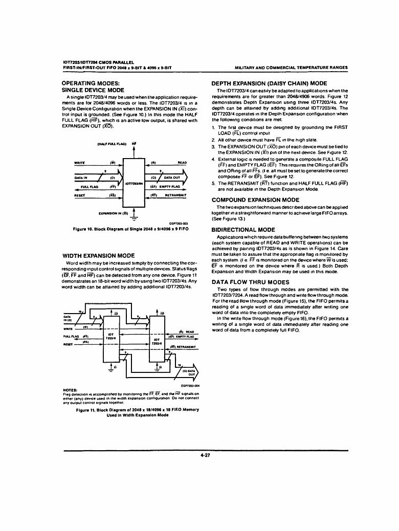
OPERATING MODES: SINGLE DEVICE MODE
A single IDT7203/4 may be used when the application require¬ ments are for 2048/4096 words or less. The IDT7203/4js in a Single Device Configuration when the EXPANSION IN (XT) con¬ trol input is grounded. (See Figure 10.) In this mode the HALF FULL FLAG (HF), which is an active low output, is shared with EXPANSION OUT (XO).
(HALF FULL FLAG) H?
T^/ -¥ \ / DATA OUT )
(EF) EMPTY FLAG
(RT) RETRANSMIT
EXPANSION IN (XI) 1 OSPT203-003
Figure 10. Block Diagram of Single 2048 x 9/4096 % 9 FIFO
WIDTH EXPANSION MODE Word width may be increased simply by connecting the cor¬
responding input control signals of multiple devices. Status flags
(EF, FF and HF) can be detected from any one device. Figure 11 demonstrates an 18-bit word width by using two IDT7203/4s. Any word width can be attained by adding additional IDT7203/4s.
"/ ♦ -. ♦ .-= / . k 1 w
.HtO, / ^T*^
IOT 7201/4
v-^ IOT
7203/4
Wn,TC ' ««" r ' f n (») RCAO
FUU. FLAG lO) (EF) EMPTY FLAG __
IMS) * * _ (St) RETRANSMIT
T t\ ♦ st i. n \ _JL" i- 1 / (O) OATA\ / our/
OSP7203-004 NOTES: _ Flag detection is accomplished by monitoring the FF. EF. and the HF signals on either (any) device used m the width expansion configuration Oo not connect any output control signals together.
Figure 11. Block Diagram of 2048 x 18/4096 x 18 FIFO Memory Used In Width Expansion Mode
DEPTH EXPANSION (DAISY CHAIN) MODE The IDT7203/4 can easily be adapted to applications when the
requirements are for greater than 2048/4906 words. Figure 12 demonstrates Depth Expansion using three IDT7203/4s. Any depth can be attained by adding additional IDT7203/4s. The IDT7203/4 operates in the Depth Expansion configuration when the following conditions are met
1. The first device must be designed by grounding the FIRST LOAD (FL) control input
2. All other device must have FL in the high state.
3. The EXPANSION OUT (XO) pm of each device must be tied to the EXPANSION IN (XI) pin of the next device. See Figure 12.
4. External logic is needed to generate a composite FULL FLAG (FF)andEMPTYFLAG (EF) This requires the ORing of all EFs andORmgof allFFs. (I e. all must be set to generate the correct composite FF or EF). See Figure 12.
5. The RETRANSMIT (RT) function and HALF FULL FLAG (HF) are not available in the Depth Expansion Mode.
COMPOUND EXPANSION MODE The two expansion techniques described above can be applied
together in a straightforward manner to achieve large FIFO arrays. (See Figure 13.)
BIDIRECTIONAL MODE Applications which require data buffering between two systems
(each system capable of READ and WRITE operations) can be achieved by pairing IDT7203/4s as is shown in Figure 14. Care must be taken to assure that the appropriate flag is monitored by each system. (I e. FF is monitored on the device where W is used: EF is monitored on the device where R is used.) Both Depth Expansion and Width Expansion may be used in this mode.
DATA FLOW THRU MODES Two types of flow through modes are permitted with the
IDT7203/7204. A read flow through and write flow through mode. For the read flow through mode (Figure 15). the FIFO permits a reading of a single word of data immediately after writing one word ol data into the completely empty FIFO.
In the write flow through mode (Figure 16). the FIFO permits a writing of a single word of data immediately after reading one word of data from a completely full FIFO.
4-27

IDT7203/IDT7204 CMOS PARALLEL FIRST-IN/FIRST-OUT FIFO 2048 x 9-BIT & 4096 ■ 9-BIT MILITARY AND COMMERCIAL TEMPERATURE RANGES
TRUTH TABLES TABLE I — RESET AND RETRANSMIT — SINGLE DEVICE CONFIGURATION/WIDTH EXPANSION MODE
MODE INPUTS INTERNAL STATUS OUTPUTS
RS RT XI Read Pointer Write Pointer EF FF HF
Reset 0 X 0 Location Zero Location Zero 0 1 1
Retransmit 1 0 0 Location Zero Unchanged X X X
NOTE 1 Pointer will increment if flag is high.
TABLE II — RESET AND FIRST LOAD TRUTH TABLE — DEPTH EXPANSION/COMPOUND EXPANSION MODE
MODE INPUTS INTERNAL STATUS OUTPUTS
RS FL xT Read Pointer Write Pointer EF FF
Reset-First Device 0 0 (D Location Zero Location Zero 0 1
Reset all Other Devices 0 1 (D Location Zero Location Zero 0 1
NOTES: _ 1 Xl_is connected toJJOol previous device See Figure 12 _
RS - Reset Input. FL.HT = First Load/Retransmit. EF = Empty Flag Output FF = Full Flag Output XI - Expansion Input. HF = Half Full Flag Output
w [—
15
\. R
s. FF
IOT 7203/4
EF
V *! ». k
/ / \ / o> ' ' v
EF
EF
Y L_
X,
XO „
T" S* u FF IOT
7203/4 "TT^' vj^
- "
:±2 r+LJ
i
H
i _ XI
io
FF IDT
7203/4
^ RS 1' I TL
Figure 12. Block Diagram ot 6,144 x 9/12.288 x 9 FIFO Memory (Depth Expansion) DSP7701-aOS
4-28

CMOS Peripherals .315
CDP1854A, CDP1854AC
^r'^^^Sli ►
COP1854AD COP1854ACD H-1891
^ mz* P ^ «W^T '■
CDP1S54AE
Programmable Universal Asynchronous Receiver/Transmitter (UART) Features: ■ Two operating modes:
Mode Q-functionaUy compatible with industry types such as the TR1602A Mode 1-interlaces directly with CDPIBOO-series microprocessors without additional components
■ Full- or half-duplex operation m Parity, framing, and overrun error
detection
■ Baud rate-DC to 200 K bits/sec @ VDD=SV DC to 400 K bits/sec @ VOD=10 V
■ Fully programmable with externally se¬ lectable word length (5-8 bits), parity inhibit, even/odd parity, and 1, IVi. or 2 stop bits
■ False start bit detection
"he RCA CDP1854A and CDP1854AC are silicon-gate CMOS Universal Asynchronous Receiver/Transmitter ' UART) circuits. They are designed to provide the necessary 'ormattmg and control for interfacing between serial and parallel data. For example, these UARTs can be used to ^erface between a peripheral or terminal with serial I/O sorts and the 8-bit CDP1800-senes microprocessor parallel :ata bus system. The CDP1854A is capable of full duplex ^Deration, i.e.. simultaneous conversion of serial input data 'o parallel output data and parallel input data to serial Output data.
~^e COP1854A UART can be programmed to operate in one of two modes by using the mode control input. When the mode input is high (MODE=1). the CDP1854A is
\ voo 1 "i—^—45 1 T CLOCK
MO0E(V0ol_ 2 39 — rrs ' vss — 3 38 — Is
CTC — 4 37 — PSt R eus 7 — S 36 NC R eus a — 6 33 CS3 R BUS S •— 7 34 RQ/WR Reus 4 — 8 33 TBUS7 R BUS 3 9 32 — reuse R BUS 2 IO-. ,31 TBUSS R BUS 1 — II \ /30 TBUS4 R BUS 0 12 V 29 TBUS3
TJTf — .3 /\28 T8US2 FE 14 / • 27 — TBUSI
PE/OC IS 2fi T BUSO RSEL 16 2S T— SOO
R CLOCK 17 24 ~RTS TPB 18 23 ^'•CSI 0» — 19 22 — THR*
SOI 20 21 |— CLtAR , TOP VIEW
NC-NO CONNECTION / MCS-2M9MI
/ /
Mode 1
directly compatible with the CDP1800-series micro¬ processor system without additional interface circuitry. When the mode input is low (MOpE=0). the device is functionally compatible with industry standard UARTs such as the TR1602A. It is also pin compatible with these types, except that pin 2 is used for the mode control input instead of a VGG=~12 V supply connection.
The COP1854A and the CDP1854AC are functionally identical. The CDP1854A has a recommended operating- voltage range of 4-10.5 volts, and the COP1854AC has a recommended operating-voltage range of 4-6.5 volts.
The CDP1854A and CDP1854AC are supplied in hermetic 40-lead dual-in-line ceramic packages (D suffix) and in 40-lead dual-in-line plastic packages (E suffix). The CDP1854AC is also available in chip form (H suffix).
vOO —I —j—v-r- -401 TCLOCX MOOCIVSSI 2 39 — EPE
vss — 38 — WLSI RRO 37 WLS2
R BUS 7 36 — SBS R BUS 6 35 — PI R BUS 3 34 CRL R BUS 4 8 v 33 — T BUS 7 R BUS 3 32 T BUS « R BUS 2 31 — T BUS 5 R BUS 1 — 30 TBUS 4 R BUS 0 29h—TBUS 3
PC — TBUS 2 FE T BUS 1 OE — TBUSO
SFO SOO RCLOCK TSRE
csa — — YnftC OA THRC
SOI 1 20 31 MR TOP VIEW
PIN 2 NO CONNECTION 0NCCPS4O2 »!CS- <•'*•«■
ModeO
File Number 1193

326 CMOS Microprocessors, Memories and Peripherals
CDP1854A, CDP1854AC Functional Definitions for CO PI 854 A Terminals Standard Mode 0
SIGNAL: FUNCTION
VOO: Positive supply voltage.
MODE SELECT (MODE): A low-level voltage at this input selects Standard Mode 0 Operation.
VSS: Ground.
RECEIVER REGISTER DISCONNECT (RRD): A high-level voltage applied to this input disconnects the Receiver Holding Register from the Receiver Bus.
RECEIVER BUS (R BUS 7 - R BUS 0): Receiver parallel data outputs.
PARITY ERROR (PE): A high-level voltage at this output indicates that the received parity does not compare to that programmed by the EVEN PARITY ENABLE (EPE) control. This output is updated each time a character is transferred to the Receiver Holding Register. PE lines from a number of arrays can be bused together since an output disconnect capability is provided by the STATUS FLAG DISCONNECT (SFD) line.
FRAMING ERROR (FE): A high-level voltage at this output indicates that the received character has no valid stop bit. i.e.. the bit following the parity bit (if programmed) is not a high-level voltage. This output is updated each time a character is transferred to the Receiver Holding Register. FE lines from a number of arrays can be bused together since an output disconnect capability is provided by the STATUS FLAG DISCONNECT (SFD) line.
OVERRUN ERROR (OE): A high-level voltage at this output indicates that the DATA AVAILABLE (DA) flag was not reset before the next character was transferred to the Receiver Holding Register. OE lines from a number of arrays can be bused together since an output disconnect capability is provided by the STATUS FLAG DISCONNECT (SFD) line.
STATUS FLAG DISCONNECT (SFO): A high-level voltage applied to this input disables the 3- state output drivers for PE. FE. OE. DA. and THRE. allowing these status outputs to be bus connected.
RECEIVER CLOCK (RCLOCK): Clock input with a frequency 16 times the desired receiver shift rate.
DATA AVAILABLE RESET (DAR): A low-level voltage applied to this input resets the DA flip-Hop.
DATA AVAILABLE (DA): A high-level voltage at this output indicates that an entire character nas been received and transferred to the Receiver Holding Register.
SERIAL DATA IN (SDI): Serial data received at this input enters the receiver shift register at a point determined by the character length. A high-level voltage must be present when data is not being received.
MASTER RESET (MR): A high-level voltage at this input resets the Receiver Holding Register. Control Register, and Status Register, and sets the serial data output high.
TRANSMITTER HOLDING REGISTER EMPTY (THRE): A high-level voltage at this output indicates that the Transmitter Holding Register has transferred its contents to the Transmitter Shift Register and may be reloaded with a new character.
TRANSMITTER HOLDING REGISTER LOAD (THRL): A low-level voltage applied to this input enters the character on the bus into the Transmitter Holding Register. Data is latched on the trailing edge of this signal.
TRANSMITTER SHIFT REGISTER EMPTY (TSRE): A high-level voltage at this output indicates that the Transmitter Shift Register has completed serial transmission of a full character including stop bit(s). It remains at this level until the start ot transmission of the next character.
SERIAL DATA OUTPUT (SDO): The contents of the Transmitter Shift Register (start bit. data bits, parity bit, and stop (bit(s)) are serially shifted out on this output. When no character is being transmitted, a high-level is maintained. Start of transmission is defined as the transition of the start bit from a high-level to a low-level output voltage.
TRANSMITTER BUS (T BUS 0 - T BUS 7): Transmitter parallel data inputs.
CONTROL REGISTER LOAD (CRL): A high-level voltage at this input loads the Control Register with the control bits (PI. EPE. SBS, WLSI. WLS2). This line may be strobed or hardwired to a high-level input voltage.
PARITY INHIBIT (PI): A high-level voltage at this input inhibits the parity genera¬ tion and verification circuits and will clamp the PE output low. If parity is inhibited the stop bit(s) will immediately follow the last data bit on transmission.
STOP BIT SELECT (SBS): This input selects the number of stop bits to be transmitted after the parity bit. A high-level selects two stop bits, a low-level selects one stop bit. Selection of two stop bits with five data bits programmed selects 1.5 stop bits.
TPA
SCI
NO
OMAI
BUS o
J L T CLOCK R CLOCK
PI
OAft
RRO
THRL
SBS
WLSI
WLS2
EPE
UART C0PI8S4A
TSRE
DA
T BUS
R BUS
MR
SOI
SDO
■o- vss »2CS-J«»0*
Fig. 8 • Mode 0 connection diagram.

CMOS Peripherals, .327
CDP1854A, CDP1854AC
DYNAMIC ELECTRICAL CHARACTERISTICS at TA = -40 to +85° C, CL=100 pF, see Fig. 9.
VDD ±5% , tr.tf=20 us, VIH=O.7 VDD. VIL=O.3 VDD
CHARACTERISTIC VOD (V)
LIMITS
UNITS CDP1854A i CDP1854AC
Typ.T Max.* Typ.- Max.* 1 Interface Timing — Mode 0 I
Minimum Pulse Width: CRL tcRL
5
10
100
50
150
75
100 150 ns
Minimum Pulse Width:
MR tMR
5
10
200
100
400
200
200 400 ns
j Minimum Setup Time:
Control Word to CRL tcwC
5
10
40
20
80
50
40 80 ns
1 Minimum Hold Time:
• Control Word after CRL tcCW 5
10
100
50
150
75
100 150 ns
i Propagation Delay Time:
1 SFD High to SOD tSFDH
5
10
200
100
300
150
200 300 ns
SFD Low to SOD tSFDL 5
10
75
40
120
60
75 120 ns
RRO High to Receiver Register
High Impedance IRRDH
5
10
200
100
300
150
200 300 ns
"~.cical values are for TA=25*C and nominal voltages. ".'aximum limits of minimum characteristics are the values above which all devices function.
CONTROL INPUT WORD TIMING
CONTROL WORO INPUT X X 1 .
'ccw—■« ; CRL /
STATUS OUTPUT TIMING
-'CRL- v
"1
OUTPUTS ^r- X -'SFDH
, 1 —I'SFDLH*-
1 • i
SFO 1
ICCCIVE* RCGISTCR DISCONNECT TIMING
~i (
R BUS 7 X D X
—JIRRDMU— r» IRROL-"*
RRO i »
i
Fig. 9 - Mode 0 interlace timing aiagram.

328 CMOS Microprocessors, Memories and Peripherals
CDP1854A, CDP1854AC
WORD LENGTH SELECT 2 (WLS2): WORD LENGTH SELECT 1 (WLSI): These two inputs select the character length (exclusive of parity) as follows:
WLS2 WLSI Word Length
Low Low 5 Bits
Low High 6 Bits
High Low 7 Bits
EVEN PARITY ENABLE (EPE): A high-level voltage at this input selects even parity to be generated by the transmitter and checked by the receiver. A low-level input selects odd parity.
TRANSMITTER CLOCK (TCLOCK): Clock input with a frequency 16 times the desired transmitter shift rate.
Description of Standard Mode 0 Operation (Mode lnput=Vss) 1. Initialization and Controls
The MASTER RESET (MR) input is pulsed, resetting the Control. Status, and Receiver Holding Registers and setting the SERIAL DATA OUTPUT (SDO) signal high. Timing is generated from the clock inputs. Transmitter Clock (TCLOCK) and Receiver Clock (RCLOCK). at a frequency equal to 16 times the serial data bit rate. When the receiver data input rate and the transmitter data output rate are the same, the TCLOCK and RCLOCK inputs may be connected togetner. The CONTROL REGISTER LOAD (CRL) input is pulsed to store the control inputs PARITY INHIBIT (PI). EVEN PARITY ENABLE (EPE). STOP BIT SELECT (SBS). and WORD LENGTH SELECTS (WLSI and WLS2). These inputs may be hardwired to the proper voltage levels (Vss or VQD) instead of being dynamically set and CRL may be hardwired to VQD The CDP1854A is then ready for transmitter and/or receiver operation.
2. Transmitter Operation
For the transmitter timing diagram refer to Fig. 10. At the beginning of a typical transmitting sequence the Transmitter Holding Register is empty (THRE is HIGH). A character is transferred from the transmitter bus to the Transmitter
holding Register by applying a low pulse to the TRANS- MITTER HOLDING REGISTER LOAD (THRL) input causing THRE to go low. If the Transmitter Shift Register is empty (TSRE is HIGH) and the clock is low, on the next high-to- low transition of the clock the character is loaded into the Transmitter Shift Register preceded by a start bit. Serial data transmission begins 1/2 clock period later with a start bit and 5-8 data bits followed by the parity bit (if pro¬ grammed) and stop bit(s). The THRE output signal goes high 1/2 clock period later on the high-to-low transition of the clock. When THRE goes high, another character can be loaded into the Transmitter Holding Register for trans¬ mission beginning with a start bit immediately following the last stop bit of the previous character. This process is repeated until all characters have been transmitted. When transmission is complete. THRE and Transmitter Shift Register Empty (TSRE) will both be high. The format of serial data is shown in Fig. 12. Duration of each serial output data bit is determined by the transmitter clock frequency (fCLOCK) and will be 16/f CLOCK.
3. Receiver Operation
The receive operation begins when a start bit is detected at the SERIAL DATA IN (SOI) input. After the detection of a high-to-low transition on the SDI line, a divide-by-16 counter is enabled and a valid start bit is verified by checking for a low-level input 7-1/2 receiver clock periods later. When a valid start bit has been verified, the following data bits, parity bit (if programmed), and stop bit(s) are shifted into the Receiver Shift Register at clock pulse 7-1/2 in each bit time. If programmed, the parity bit is checked, and receipt of a valid stop bit is verified. On count 7-1/2 of the first stop bit. the received data is loaded into the Receiver Holding Register. If the word length is less than 8 bits, zeros (low output voltage level) are loaded into the unused most significant bits. If DATA AVAILABLE (DA) has not been reset by the time the Receiver Holding Register is loaded, the OVERRUN ERROR (OE) signal is raised. One-half clock period later, the PARITV ERROR (PE) and FRAMING ERROR (FE) signals become valid for the character in the Receiver Holding Register. The DA signal is also raised at this time. The 3-state output drivers for DA. OE. PE and FE are enabled when STATUS FLAG DISCONNECT (SFD) is low. When RECEIVER REGISTER DISCONNECT (RRD) goes low. the receiver bus 3-state output drivers are enabled and data is available at the RECEIVER BUS (R BUS 0 - R BUS 7) outputs. Applyinq a negative pulse to the DATA AVAILABLE RESET (oXfl) resets DA. The preceding sequence of operation is repeated for each serial character received. A receiver timing diagram is shown in Fig. 11.

CMOS Peripherals 329
CDP1854A, CDP1854AC DYNAMIC ELECTRICAL CHARACTERISTICS at TA = -40 to +85°C, VDD ±5%, tr,tf=20 ns, V|H=0.? VDD. VIL=0.3 Vnn. CL=100 pF, see Fig. 10.
CHARACTERISTIC VDD (V)
LIMITS 1
UNITS CDP1854A ! CDP1854AC ' Typ.t Max.* Typ.* Max.*
[ Transmitter Timing — Mode 0
Minimum Clock Period tec 5
10
250
125
310
155
250 310 ns
Minimum Pulse Width:
Clock Low Level. tCL
5
10
100
75
125
100
100 125 ns
Clock High Level <CH 5
10
100
75
125
100
100 125 ns
THRL tTHTH 5
10
100
50
150
75 100 150
ns
Minimum Setup Time:
THRL to Clock tTHC
5
10
175
90
275
150
175 275 ns
tDT 5
10
20
0
50
40
20 50 ns Data to THRL
Minimum Hold Time:
Data after THRL tTO
5
10
80
40
120
60
80 120 ns
Propagation Delay Time:
Clock to Data Start Bit ♦CD
5
10
300
150
450
225
300 450 ns
Clock to THRE tCT 5
10
200
100
300
150
200 300 ns
THRL to THRE tTTHR 5
10
200
100
300
150
200 300 ns
Typical values are for ^=25*0 and nominal voltages. •Maximum limits of minimum characteristics are the values above which all devices function.
TRANSMITTER HOLDING REGISTER LOADED
kc
,J^_R_R_(T_R_m
* THE HOLDING REGISTER IS LOADED ON THE TRAILING EDGE OF THRL «* THE TRANSMITTER SHIFT REGISTER. IF EMPTY. IS LCA0E0 ON THE FIRST HIGH-TO-LOW TRANSITION OF THE
CLOCK WHICH OCCURS AT LEAST 1/2 CLOCK PERlO0»«THC*f TER THE TRAILING EDGE OF TMRL, AND TRANS¬ MISSION OF A START BIT OCCURS 1/2 CLOCK PERIOD ♦ lC9 LATER
MCK- Jif rim Fig 10 - Mode 0 transmitter timing diagram
330 CMOS Microprocessors, Memories and Peripherals
CDP1854A, CDP1854AC
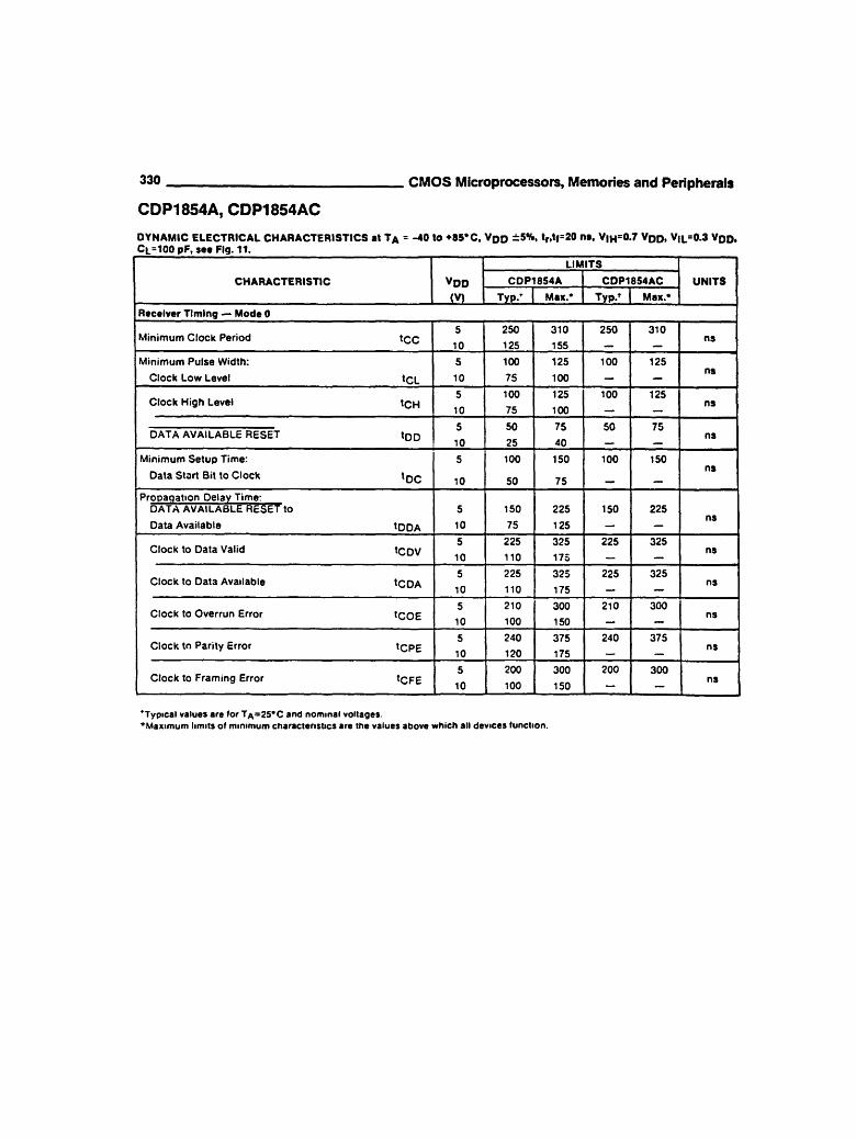
DYNAMIC ELECTRICAL CHARACTERISTICS at TA = -40 to ♦85,C, VDD ±5%, tr.tf=20 na, V|HS0.7 VDD. V|L=0.3 VQD, Ct.=100 pF, see Fig. 11.
CHARACTERISTIC VDD (V)
LIMITS |
UNITS CDP1854A CDP1854AC
Typ/ Max.* Typ.' Max.*
Receiver Timing — Mode 0
Minimum Clock Period tec 5
10
250
125
310
155
250 310 ns
Minimum Pulse Width:
Clock Low Level tCL
5
10
100
75
125
100
100 125 ns
Clock High Level tcH 5
10
100
75
125
100
100 125 ns
5
10
50
25
75
40
50 75 ns DATA AVAILABLE RESET tDD
Minimum Setup Time:
Data Start Bit to Clock IQQ
5
10
100
50
150
75
100 150 ns
Prooaqation Delay Time: DATA AVAILABLE RESET to
Data Available tDDA
5
10
150
75
225
125
150 225 ns
Clock to Data Valid tCDV 5
10
225
110
325
175
225 325 ns
Clock to Data Available tCDA 5
10
225
110
325
175
225 325 ns
Clock to Overrun Error tCOE 5
10
210
100
300
150
210 300 ns
Clock to Parity Error tCPE 5
10
240
120
375
175
240 375 ns
'Typical values are for TA=25*C and nominal voltages. 'Maximum limits of minimum characteristics are the values above which all devices function.

CMOS Peripherals .331
CDP1854A, CDP1854AC
R BUS 0- R BUS 7 . X
i-^COA
* IF A START BIT OCCURS AT A TIME LESS THAN toe BEFORE A HIGH-TO-lOW TRANSITION OF THE CLOCK. THE START BIT MAY NOT BE RECOGNIZED UNTIL THE NEXT HIGH-TO-LOW TRANSITION OF THE CLOCK. THE START BIT MAY BE COMPLETELY ASYNCHRONOUS WITH THE CLOCK
» » IF A PENDING OA HAS NOT BEEN CLEARED BY A READ OF THE RECEIVER HOLDING REGISTER BY THE TIME A NEW WORD IS LOADED INTO THE RECEIVER HOLDING REGISTER. THE OE SIGNAL WILL COME TRUE.
92CM-3I4T7
Fig. 11 - Mode 0 receiver timing diagram.
M ■• is /1,
rmnmnm—\ /^r -\ 3-8 DATA BITS « -STOP BITS
I.I 1/2 OR 2 PARITY BIT
».'C» -«*»»
Fig. 12 - Serial data word format.
