check point ddos protector · check point ddos protector getting started guide | 6 chapter 2 safety...
TRANSCRIPT

9 July 2012
Getting Started Guide
Check Point DDoS Protector
6.05

© 2012 Check Point Software Technologies Ltd.
All rights reserved. This product and related documentation are protected by copyright and distributed under licensing restricting their use, copying, distribution, and decompilation. No part of this product or related documentation may be reproduced in any form or by any means without prior written authorization of Check Point. While every precaution has been taken in the preparation of this book, Check Point assumes no responsibility for errors or omissions. This publication and features described herein are subject to change without notice.
RESTRICTED RIGHTS LEGEND:
Use, duplication, or disclosure by the government is subject to restrictions as set forth in subparagraph (c)(1)(ii) of the Rights in Technical Data and Computer Software clause at DFARS 252.227-7013 and FAR 52.227-19.
TRADEMARKS:
Refer to the Copyright page (http://www.checkpoint.com/copyright.html) for a list of our trademarks.
Refer to the Third Party copyright notices (http://www.checkpoint.com/3rd_party_copyright.html) for a list of relevant copyrights and third-party licenses.

Important Information
Latest Software
We recommend that you install the most recent software release to stay up-to-date with the latest functional improvements, stability fixes, security enhancements and protection against new and evolving attacks.
For additional technical information, visit the Check Point Support Center (http://supportcenter.checkpoint.com).
Revision History
Date Description
7 June 2012 First release of this document

Contents
Important Information ..................................................................................................3 Check Point DDoS Protector Overview ......................................................................5
Supported Appliances ...............................................................................................5 Safety Instructions .......................................................................................................6 Pre-Installation ........................................................................................................... 17
Checking the Contents ............................................................................................ 17 Connections and Grounding .................................................................................... 17 Port Cables ............................................................................................................. 17 Mounting the Platform ............................................................................................. 18 Verifying Accessibility of Management Communication Ports ................................... 18 Connecting Cables to Platforms .............................................................................. 18
Connecting Cables to the DP x06 Series Platform ............................................... 18 Connecting Cables to DP x412 Series Platforms ................................................. 19
Installing Check Point DDoS Protector .................................................................... 20 DP x06 Series ......................................................................................................... 20 DP x412 Series ........................................................................................................ 21
LCD Module for DP x412 Series ......................................................................... 23 Check Point DDoS Protector Boot Commands ................................................... 26
Connecting and Installing Check Point DDoS Protector ............................................ 26 Connecting the Management Port and Inspection Port Cables ............................. 26 Considerations When Connecting Inspection Ports with Internal Bypass ............. 26
Configuring Management Ports ................................................................................ 27 Configuring the Management Port for the First Time ........................................... 27 Modifying the Route to the Management Port ..................................................... 28 Enabling HTTP/HTTPS and Web Management Access via the Serial Interface .. 28
Configuring Routes ................................................................................................... 29 Configuring HTTP, HTTPS, and SSH Access ........................................................... 30 Configuring a Network Protection Policy and Network Protection Profiles .......... 32
Configuring a Network Protection Policy .................................................................. 32 Configuring Behavioral DoS Profiles ........................................................................ 33 Configuring a DNS Protection Profile ....................................................................... 34 Configuring DoS Shield Protection .......................................................................... 36 Configuring Packet Anomalies Protection ................................................................ 36 Configuring a Connection Limit Profile ..................................................................... 37 Configuring a SYN Protection Profile ....................................................................... 39 Configuring an Out-of-State Protection Profile ......................................................... 42 Configuring an HTTP Mitigator Profile ..................................................................... 43
Viewing and Configuring Network Classes .............................................................. 45 Viewing and Configuring Application-Port-Group Classes .................................... 46 Configuring Services ................................................................................................. 47
Configuring Syslog Reporting .................................................................................. 47 Configuring Black Lists ............................................................................................. 47 Configuring White Lists............................................................................................. 50

Check Point DDoS Protector Getting Started Guide | 5
Chapter 1
Check Point DDoS Protector Overview
Check Point DDoS Protector is a real-time DoS protection device, which maintains business continuity by protecting the application infrastructure against existing and emerging network-based threats. Unlike market alternatives that rely on static signatures, Check Point DDoS Protector provides unique behavioral-based, automatically generated, real-time signatures, mitigating attacks that are not vulnerability based and zero-minute attacks such as: network and application floods, HTTP page floods, malware propagation, Web application brute force attacks aiming to defeat authentication schemes, and more - all without blocking legitimate users’ traffic and with no need for human intervention.
Supported Appliances These appliances support Check Point DDoS Protector:
x06 Series:
DP 506
DP 1006
DP 2006
DP 3006
X412 series:
DP 4412
DP 8412
DP 12412

Check Point DDoS Protector Getting Started Guide | 6
Chapter 2
Safety Instructions The following safety instructions are presented in English, French, and German.
Safety Instructions
CAUTION
A readily accessible disconnect device shall be incorporated in the building installation wiring.
Due to the risks of electrical shock, and energy, mechanical, and fire hazards, any procedures that involve opening panels or changing components must be performed by qualified service personnel only.
To reduce the risk of fire and electrical shock, disconnect the device from the power line before removing cover or panels.
The following figure shows the caution label that is attached to Check Point DDoS Protector platforms with dual power supplies.
Electrical Shock Hazard Label
DUAL-POWER-SUPPLY-SYSTEM SAFETY WARNING IN CHINESE
The following figure is the warning for Check Point DDoS Protector platforms with dual power supplies.
Dual-Power-Supply-System Safety Warning in Chinese
Translation of Dual-Power-Supply-System Safety Warning in Chinese:
This unit has more than one power supply. Disconnect all power supplies before maintenance to avoid electric shock.
SERVICING
Do not perform any servicing other than that contained in the operating instructions unless you are qualified to do so. There are no serviceable parts inside the unit.
HIGH VOLTAGE
Any adjustment, maintenance, and repair of the opened instrument under voltage must be avoided as much as possible and, when inevitable, must be carried out only by a skilled person who is aware of the hazard involved.
Capacitors inside the instrument may still be charged even if the instrument has been disconnected from its source of supply.

Safety Instructions
Check Point DDoS Protector Getting Started Guide | 7
GROUNDING
Before connecting this device to the power line, the protective earth terminal screws of this device must be connected to the protective earth in the building installation.
LASER
This equipment is a Class 1 Laser Product in accordance with IEC60825 - 1: 1993 + A1:1997 + A2:2001 Standard.
FUSES
Make sure that only fuses with the required rated current and of the specified type are used for replacement. The use of repaired fuses and the short-circuiting of fuse holders must be avoided. Whenever it is likely that the protection offered by fuses has been impaired, the instrument must be made inoperative and be secured against any unintended operation.
LINE VOLTAGE
Before connecting this instrument to the power line, make sure the voltage of the power source matches the requirements of the instrument. Refer to the Specifications for information about the correct power rating for the device.
48V DC-powered platforms have an input tolerance of 36-72V DC. SPECIFICATION CHANGES
Specifications are subject to change without notice.
Note - This equipment has been tested and found to comply with the limits for a Class A digital device pursuant to Part 15B of the FCC Rules and EN55022 Class A, EN 55024; EN 61000-3-2; EN 61000-3-3; IEC 61000 4-2 to 4-6, IEC 61000 4-8 and IEC 61000-4-11 For CE MARK Compliance. These limits are designed to provide reasonable protection against harmful interference when the equipment is operated in a commercial environment. This equipment generates, uses, and can radiate radio frequency energy and, if not installed and used in accordance with the instruction manual, may cause harmful interference to radio communications. Operation of this equipment in a residential area is likely to cause harmful interference in which case the user is required to correct the interference at his own expense.
VCCI ELECTROMAGNETIC-INTERFERENCE STATEMENTS
Statement for Class A VCCI-certified Equipment
Translation of Statement for Class A VCCI-certified Equipment:
This is a Class A product based on the standard of the Voluntary Control Council for Interference by Information Technology Equipment (VCCI). If this equipment is used in a domestic environment, radio disturbance may occur, in which case, the user may be required to take corrective action.
Statement for Class B VCCI-certified Equipment
Translation of Statement for Class B VCCI-certified Equipment:
This is a Class B product based on the standard of the Voluntary Control Council for Interference by Information Technology Equipment (VCCI). If this is used near a radio or television receiver in a domestic environment, it may cause radio interference.

Safety Instructions
Check Point DDoS Protector Getting Started Guide | 8
Install and use the equipment according to the instruction manual.
KCC KOREA
KCC — Korea Communications Commission Certificate of Broadcasting and Communication Equipment
Statement for Class A KCC-certified Equipment in Korean
Translation of Statement For Class A KCC-certified Equipment in Korean:
This equipment is Industrial (Class A) electromagnetic wave suitability equipment and seller or user should take notice of it, and this equipment is to be used in the places except for home.
SPECIAL NOTICE FOR NORTH AMERICAN USERS
For North American power connection, select a power supply cord that is UL Listed and CSA Certified 3 - conductor, [18 AWG], terminated in a molded on plug cap rated 125 V, [5 A], with a minimum length of 1.5m [six feet] but no longer than 4.5m...For European connection, select a power supply cord that is internationally harmonized and marked “<HAR>”, 3 - conductor, 0,75 mm2 minimum mm2 wire, rated 300 V, with a PVC insulated jacket. The cord must have a molded on plug cap rated 250 V, 3 A.
RESTRICT AREA ACCESS
The DC powered equipment should only be installed in a Restricted Access Area. INSTALLATION CODES
This device must be installed according to country national electrical codes. For North America, equipment must be installed in accordance with the US National Electrical Code, Articles 110 - 16,
110 -17, and 110 -18 and the Canadian Electrical Code, Section 12.
INTERCONNECTION OF UNITS
Cables for connecting to the unit RS232 and Ethernet Interfaces must be UL certified type DP-1 or DP-2. (Note- when residing in non LPS circuit) OVERCURRENT PROTECTION A readily accessible listed branch-circuit over current protective device rated 15 A must be incorporated in the building wiring for each power input.
REPLACEABLE BATTERIES
If equipment is provided with a replaceable battery, and is replaced by an incorrect battery type, then an explosion may occur. This is the case for some Lithium batteries and the following is applicable:
If the battery is placed in an Operator Access Area, there is a marking close to the battery or a statement in both the operating and service instructions.
If the battery is placed elsewhere in the equipment, there is a marking close to the battery or a statement in the service instructions.
This marking or statement includes the following text warning: CAUTION
RISK OF EXPLOSION IF BATTERY IS REPLACED BY AN INCORRECT BATTERY TYPE. DISPOSE OF USED BATTERIES ACCORDING TO THE INSTRUCTIONS.
Caution - To Reduce the Risk of Electrical Shock and Fire
1. This equipment is designed to permit connection between the earthed conductor of the DC supply circuit and the earthing conductor equipment. See Installation Instructions.
2. All servicing must be undertaken only by qualified service personnel. There are not user serviceable parts inside the unit.
3. DO NOT plug in, turn on or attempt to operate an obviously damaged unit.

Safety Instructions
Check Point DDoS Protector Getting Started Guide | 9
4. Ensure that the chassis ventilation openings in the unit are NOT BLOCKED.
5. Replace a blown fuse ONLY with the same type and rating as is marked on the safety label adjacent to the power inlet, housing the fuse.
6. Do not operate the device in a location where the maximum ambient temperature exceeds 40°C/104°F.
7. Be sure to unplug the power supply cord from the wall socket BEFORE attempting to remove and/or check the main power fuse.
CLASS 1 LASER PRODUCT AND REFERENCE TO THE MOST RECENT LASER STANDARDS IEC 60
825-1:1993 + A1:1997 + A2:2001 AND EN 60825-1:1994+A1:1996+ A2:2001
AC units for Denmark, Finland, Norway, Sweden (marked on product):
Denmark - “Unit is class I - unit to be used with an AC cord set suitable with Denmark deviations. The cord includes an earthing conductor. The Unit is to be plugged into a wall socket outlet which is connected to a protective earth. Socket outlets which are not connected to earth are not to be used!”
Finland - (Marking label and in manual) - “Laite on liitettävä suojamaadoituskoskettimilla varustettuun pistorasiaan”
Norway (Marking label and in manual) - “Apparatet må tilkoples jordet stikkontakt”
Unit is intended for connection to IT power systems for Norway only.
Sweden (Marking label and in manual) - “Apparaten skall anslutas till jordat uttag.”
To connect the power connection:
1. Connect the power cable to the main socket, located on the rear panel of the device.
2. Connect the power cable to the grounded AC outlet.
CAUTION
Risk of electric shock and energy hazard. Disconnecting one power supply disconnects only one power supply module. To isolate the unit completely, disconnect all power supplies.
Instructions de sécurité
AVERTISSEMENT
Un dispositif de déconnexion facilement accessible sera incorporé au câblage du bâtiment.
En raison des risques de chocs électriques et des dangers énergétiques, mécaniques et d’incendie, chaque procédure impliquant l’ouverture des panneaux ou le remplacement de composants sera exécutée par du personnel qualifié.
Pour réduire les risques d’incendie et de chocs électriques, déconnectez le dispositif du bloc d’alimentation avant de retirer le couvercle ou les panneaux.
La figure suivante montre l’étiquette d’avertissement apposée sur les plateformes Check Point DDoS Protector dotées de plus d’une source d’alimentation électrique.
Étiquette d’avertissement de danger de chocs électriques
AVERTISSEMENT DE SÉCURITÉ POUR LES SYSTÈMES DOTÉS DE DEUX SOURCES D’ALIMENTATION ÉLECTRIQUE (EN CHINOIS)
La figure suivante représente l’étiquette d’avertissement pour les plateformes Check Point DDoS Protector dotées de deux sources d’alimentation électrique.

Safety Instructions
Check Point DDoS Protector Getting Started Guide | 10
Avertissement de sécurité pour les systèmes dotes de deux sources d’alimentation électrique (en chinois)
Traduction de la Avertissement de sécurité pour les systèmes dotes de deux sources d’alimentation électrique (en chinois):
Cette unité est dotée de plus d’une source d’alimentation électrique. Déconnectez toutes les sources d’alimentation électrique avant d’entretenir l’appareil ceci pour éviter tout choc électrique.
ENTRETIEN
N’effectuez aucun entretien autre que ceux répertoriés dans le manuel d’instructions, à moins d’être qualifié en la matière. Aucune pièce à l’intérieur de l’unité ne peut être remplacée ou réparée.
HAUTE TENSION
Tout réglage, opération d’entretien et réparation de l’instrument ouvert sous tension doit être évité. Si cela s’avère indispensable, confiez cette opération à une personne qualifiée et consciente des dangers impliqués.
Les condensateurs au sein de l’unité risquent d’être chargés même si l’unité a été déconnectée de la source d’alimentation électrique.
MISE A LA TERRE
Avant de connecter ce dispositif à la ligne électrique, les vis de protection de la borne de terre de cette unité doivent être reliées au système de mise à la terre du bâtiment.
LASER
Cet équipement est un produit laser de classe 1, conforme à la norme IEC60825 - 1: 1993 + A1: 1997 + A2: 2001.
FUSIBLES
Assurez-vous que, seuls les fusibles à courant nominal requis et de type spécifié sont utilisés en remplacement. L’usage de fusibles réparés et le court-circuitage des porte-fusibles doivent être évités. Lorsqu’il est pratiquement certain que la protection offerte par les fusibles a été détériorée, l’instrument doit être désactivé et sécurisé contre toute opération involontaire.
TENSION DE LIGNE
Avant de connecter cet instrument à la ligne électrique, vérifiez que la tension de la source d’alimentation correspond aux exigences de l’instrument. Consultez les spécifications propres à l’alimentation nominale correcte du dispositif.
Les plateformes alimentées en 48 CC ont une tolérance d’entrée comprise entre 36 et 72 V CC. MODIFICATIONS DES SPÉCIFICATIONS
Les spécifications sont sujettes à changement sans notice préalable.
Remarque: Cet équipement a été testé et déclaré conforme aux limites définies pour un appareil numérique de classe A, conformément au paragraphe 15B de la réglementation FCC et EN55022 Classe A, EN 55024, EN 61000-3-2; EN 61000-3-3; IEC 61000 4-2 to 4-6, IEC 61000 4-8, et IEC 61000-4-11, pour la marque de conformité de la CE. Ces limites sont fixées pour fournir une protection raisonnable contre les interférences nuisibles, lorsque l’équipement est utilisé dans un environnement commercial. Cet équipement génère, utilise et peut émettre des fréquences radio et, s’il n’est pas installé et utilisé conformément au manuel d’instructions, peut entraîner des interférences nuisibles aux communications radio. Le fonctionnement de cet équipement dans une zone résidentielle est susceptible de provoquer des interférences nuisibles, auquel cas l’utilisateur devra corriger le problème à ses propres frais.

Safety Instructions
Check Point DDoS Protector Getting Started Guide | 11
DÉCLARATIONS SUR LES INTERFÉRENCES ÉLECTROMAGNÉTIQUES VCCI
Déclaration pour l’équipement de classe A certifié VCCI
Traduction de la Déclaration pour l’équipement de classe A certifié VCCI:
Il s’agit d’un produit de classe A, basé sur la norme du Voluntary Control Council for Interference by Information Technology Equipment (VCCI). Si cet équipement est utilisé dans un environnement domestique, des perturbations radioélectriques sont susceptibles d’apparaître. Si tel est le cas, l’utilisateur sera tenu de prendre des mesures correctives.
Déclaration pour l’équipement de classe B certifié VCCI
Traduction de la Déclaration pour l’équipement de classe B certifié VCCI:
Il s’agit d’un produit de classe B, basé sur la norme du Voluntary Control Council for Interference by Information Technology Equipment (VCCI). S’il est utilisé à proximité d’un poste de radio ou d’une télévision dans un environnement domestique, il peut entraîner des interférences radio.
Installez et utilisez l’équipement selon le manuel d’instructions. KCC Corée
KCC — Certificat de la commission des communications de Corée pour les equipements de radiodiffusion et communication.
Déclaration pour l’équipement de classe A certifié KCC en langue coréenne
Translation de la Déclaration pour l’équipement de classe A certifié KCC en langue coréenne: Cet équipement est un matériel (classe A) en adéquation aux ondes électromagnétiques et levendeur ou l’utilisateur doit prendre cela en compte. Ce matériel est donc fait pour être utilisé ailleurs qu’ á la maison.
NOTICE SPÉCIALE POUR LES UTILISATEURS NORD-AMÉRICAINS
Pour un raccordement électrique en Amérique du Nord, sélectionnez un cordon d’alimentation homologué UL et certifié CSA 3 - conducteur, [18 AWG], muni d’une prise moulée à son extrémité, de 125 V, [5 A], d’une longueur minimale de 1,5 m [six pieds] et maximale de 4,5m...Pour la connexion européenne, choisissez un cordon d’alimentation mondialement homologué et marqué “<HAR>”, 3 - conducteur, câble de 0,75 mm2 minimum, de 300 V, avec une gaine en PVC isolée. La prise à l’extrémité du cordon, sera dotée d’un sceau moulé indiquant: 250 V, 3 A.
ZONE A ACCÈS RESTREINT
L’équipement alimenté en CC ne pourra être installé que dans une zone à accès restreint.

Safety Instructions
Check Point DDoS Protector Getting Started Guide | 12
CODES D’INSTALLATION
Ce dispositif doit être installé en conformité avec les codes électriques nationaux. En Amérique du Nord, l’équipement sera installé en conformité avec le code électrique national américain, articles 110-16, 110 -17, et 110 -18 et le code électrique canadien, Section 12. INTERCONNEXION DES UNÎTES.
Les câbles de connexion à l’unité RS232 et aux interfaces Ethernet seront certifiés UL, type DP-1 ou DP-2. (Remarque- s’ils ne résident pas dans un circuit LPS) PROTECTION CONTRE LES SURCHARGES.
Un circuit de dérivation, facilement accessible, sur le dispositif de protection du courant de 15 A doit être intégré au câblage du bâtiment pour chaque puissance consommée.
BATTERIES REMPLAÇABLES
Si l’équipement est fourni avec une batterie, et qu’elle est remplacée par un type de batterie incorrect, elle est susceptible d’exploser. C’est le cas pour certaines batteries au lithium, les éléments suivants sont donc applicables:
Si la batterie est placée dans une zone d’accès opérateur, une marque est indiquée sur la batterie ou une remarque est insérée, aussi bien dans les instructions d’exploitation que d’entretien.
Si la batterie est placée ailleurs dans l’équipement, une marque est indiquée sur la batterie ou une remarque est insérée dans les instructions d’entretien.
Cette marque ou remarque inclut l’avertissement textuel suivant: AVERTISSEMENT
RISQUE D’EXPLOSION SI LA BATTERIE EST REMPLACÉE PAR UN MODÈLE INCORRECT. METTRE AU REBUT LES BATTERIES CONFORMÉMENT AUX INSTRUCTIONS.
Attention - Pour réduire les risques de chocs électriques et d’incendie
1. Cet équipement est conçu pour permettre la connexion entre le conducteur de mise à la terre du circuit électrique CC et l’équipement de mise à la terre. Voir les instructions d’installation.
2. Tout entretien sera entrepris par du personnel qualifié. Aucune pièce à l’intérieur de l’unité ne peut être remplacée ou réparée.
3. NE branchez pas, n’allumez pas ou n’essayez pas d’utiliser une unité manifestement endommagée.
4. Vérifiez que l’orifice de ventilation du châssis dans l’unité n’est PAS OBSTRUE.
5. Remplacez le fusible endommagé par un modèle similaire de même puissance, tel qu’indiqué sur l’étiquette de sécurité adjacente à l’arrivée électrique hébergeant le fusible.
6. Ne faites pas fonctionner l’appareil dans un endroit, où la température ambiante dépasse la valeur maximale autorisée. 40°C/104°F.
7. Débranchez le cordon électrique de la prise murale AVANT d’essayer de retirer et/ou de vérifier le fusible d’alimentation principal.
PRODUIT LASER DE CLASSE 1 ET RÉFÉRENCE AUX NORMES LASER LES PLUS RÉCENTES: IEC 60 825-1: 1993 + A1: 1997 + A2: 2001 ET EN 60825-1: 1994+A1: 1996+ A2: 2001
Unités à CA pour le Danemark, la Finlande, la Norvège, la Suède (indiqué sur le produit):
Danemark - Unité de classe 1 - qui doit être utilisée avec un cordon CA compatible avec les déviations du Danemark. Le cordon inclut un conducteur de mise à la terre. L’unité sera branchée à une prise murale, mise à la terre. Les prises non-mises à la terre ne seront pas utilisées!
Finlande (Étiquette et inscription dans le manuel) - Laite on liitettävä suojamaadoituskoskettimilla varustettuun pistorasiaan
Norvège (Étiquette et inscription dans le manuel) - Apparatet må tilkoples jordet stikkontakt
L’unité peut être connectée à un système électrique IT (en Norvège uniquement).
Suède (Étiquette et inscription dans le manuel) - Apparaten skall anslutas till jordat uttag.
Pour brancher à l’alimentation électrique:
1. Branchez le câble d’alimentation à la prise principale, située sur le panneau arrière de l’unité.
2. Connectez le câble d’alimentation à la prise CA mise à la terre.

Safety Instructions
Check Point DDoS Protector Getting Started Guide | 13
AVERTISSEMENT
Risque de choc électrique et danger énergétique. La déconnexion d’une source d’alimentation électrique ne débranche qu’un seul module électrique. Pour isoler complètement l’unité, débranchez toutes les sources d’alimentation électrique.
ATTENTION
Risque de choc et de danger électriques. Le débranchement d’une seule alimentation stabilisée ne débranche qu’un module “Alimentation Stabilisée”. Pour Isoler complètement le module en cause, il faut débrancher toutes les alimentations stabilisées.
Attention: Pour Réduire Les Risques d’Électrocution et d’Incendie
1. Toutes les opérations d’entretien seront effectuées UNIQUEMENT par du personnel d’entretien qualifié. Aucun composant ne peut être entretenu ou remplacée par l’utilisateur.
2. NE PAS connecter, mettre sous tension ou essayer d’utiliser une unité visiblement défectueuse.
3. Assurez-vous que les ouvertures de ventilation du châssis NE SONT PAS OBSTRUÉES.
4. Remplacez un fusible qui a sauté SEULEMENT par un fusible du même type et de même capacité, comme indiqué sur l’étiquette de sécurité proche de l’entrée de l’alimentation qui contient le fusible.
5. NE PAS UTILISER l’équipement dans des locaux dont la température maximale dépasse 40 degrés Centigrades.
6. Assurez vous que le cordon d’alimentation a été déconnecté AVANT d’essayer de l’enlever et/ou vérifier le fusible de l’alimentation générale.
Sicherheitsanweisungen
VORSICHT
Die Elektroinstallation des Gebäudes muss ein unverzüglich zugängliches Stromunterbrechungsgerät integrieren.
Aufgrund des Stromschlagrisikos und der Energie-, mechanische und Feuergefahr dürfen Vorgänge, in deren Verlauf Abdeckungen entfernt oder Elemente ausgetauscht werden, ausschließlich von qualifiziertem Servicepersonal durchgeführt werden.
Zur Reduzierung der Feuer- und Stromschlaggefahr muss das Gerät vor der Entfernung der Abdeckung oder der Paneele von der Stromversorgung getrennt werden.
Folgende Abbildung zeigt das VORSICHT-Etikett, das auf die Check Point DDoS Protector-Plattformen mit Doppelspeisung angebracht ist.
Warnetikett Stromschlaggefahr
SICHERHEITSHINWEIS IN CHINESISCHER SPRACHE FÜR SYSTEME MIT DOPPELSPEISUNG Die folgende Abbildung ist die Warnung für Check Point DDoS Protector -Plattformen mit Doppelspeisung.
Sicherheitshinweis in chinesischer Sprache für Systeme mit Doppelspeisung
Safety Instructions
Check Point DDoS Protector Getting Started Guide | 14
Übersetzung von Sicherheitshinweis in chinesischer Sprache für Systeme mit Doppelspeisung:
Die Einheit verfügt über mehr als eine Stromversorgungsquelle. Ziehen Sie zur Verhinderung von Stromschlag vor Wartungsarbeiten sämtliche Stromversorgungsleitungen ab. WARTUNG Führen Sie keinerlei Wartungsarbeiten aus, die nicht in der Betriebsanleitung angeführt sind, es sei denn, Sie sind dafür qualifiziert. Es gibt innerhalb des Gerätes keine wartungsfähigen Teile.
HOCHSPANNUNG
Jegliche Einstellungs-, Instandhaltungs- und Reparaturarbeiten am geöffneten Gerät unter Spannung müssen so weit wie möglich vermieden werden. Sind sie nicht vermeidbar, dürfen sie ausschließlich von qualifizierten Personen ausgeführt werden, die sich der Gefahr bewusst sind.
Innerhalb des Gerätes befindliche Kondensatoren können auch dann noch Ladung enthalten, wenn das Gerät von der Stromversorgung abgeschnitten wurde.
ERDUNG
Bevor das Gerät an die Stromversorgung angeschlossen wird, müssen die Schrauben der Erdungsleitung des Gerätes an die Erdung der Gebäudeverkabelung angeschlossen werden.
LASER
Dieses Gerät ist ein Laser-Produkt der Klasse 1 in Übereinstimmung mit IEC60825 - 1: 1993 + A1:1997 + A2:2001 Standard.
SICHERUNGEN
Vergewissern Sie sich, dass nur Sicherungen mit der erforderlichen Stromstärke und der angeführten Art verwendet werden. Die Verwendung reparierter Sicherungen sowie die Kurzschließung von Sicherungsfassungen muss vermieden werden. In Fällen, in denen wahrscheinlich ist, dass der von den Sicherungen gebotene Schutz beeinträchtigt ist, muss das Gerät abgeschaltet und gegen unbeabsichtigten Betrieb gesichert werden.
LEITUNGSSPANNUNG
Vor Anschluss dieses Gerätes an die Stromversorgung ist zu gewährleisten, dass die Spannung der Stromquelle den Anforderungen des Gerätes entspricht. Beachten Sie die technischen Angaben bezüglich der korrekten elektrischen Werte des Gerätes.
Plattformen mit 48 V DC verfügen über eine Eingangstoleranz von 36-72 V DC.
ÄNDERUNGEN DER TECHNISCHEN ANGABEN
Änderungen der technischen Spezifikationen bleiben vorbehalten.
Hinweis: Dieses Gerät wurde geprüft und entspricht den Beschränkungen von digitalen Geräten der Klasse 1 gemäß Teil 15B FCC-Vorschriften und EN55022 Klasse A, EN55024; EN 61000-3-2; EN; IEC 61000 4-2 to 4-6, IEC 61000 4-8 und IEC 61000-4- 11 für Konformität mit der CE-Bezeichnung. Diese Beschränkungen dienen dem angemessenen Schutz vor schädlichen Interferenzen bei Betrieb des Gerätes in kommerziellem Umfeld. Dieses Gerät erzeugt, verwendet und strahlt elektromagnetische Hochfrequenzstrahlung aus. Wird es nicht entsprechend den Anweisungen im Handbuch montiert und benutzt, könnte es mit dem Funkverkehr interferieren und ihn beeinträchtigen. Der Betrieb dieses Gerätes in Wohnbereichen wird höchstwahrscheinlich zu schädlichen Interferenzen führen. In einem solchen Fall wäre der Benutzer verpflichtet, diese Interferenzen auf eigene Kosten zu korrigieren.
ERKLÄRUNG DER VCCI ZU ELEKTROMAGNETISCHER INTERFERENZ
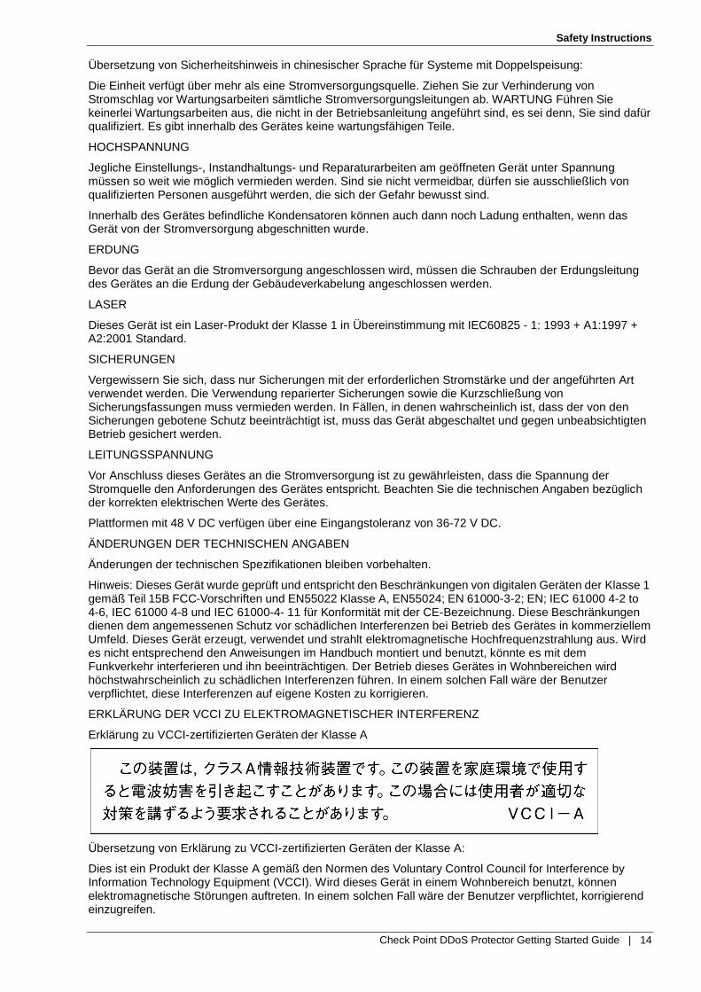
Erklärung zu VCCI-zertifizierten Geräten der Klasse A
Übersetzung von Erklärung zu VCCI-zertifizierten Geräten der Klasse A:
Dies ist ein Produkt der Klasse A gemäß den Normen des Voluntary Control Council for Interference by Information Technology Equipment (VCCI). Wird dieses Gerät in einem Wohnbereich benutzt, können elektromagnetische Störungen auftreten. In einem solchen Fall wäre der Benutzer verpflichtet, korrigierend einzugreifen.

Safety Instructions
Check Point DDoS Protector Getting Started Guide | 15
Erklärung zu VCCI-zertifizierten Geräten der Klasse B
Übersetzung von Erklärung zu VCCI-zertifizierten Geräten der Klasse B:
Dies ist ein Produkt der Klasse B gemäß den Normen des Voluntary Control Council for Interference by Information Technology Equipment (VCCI). Wird dieses Gerät in einem Wohnbereich benutzt, können elektromagnetische Störungen auftreten.
Montieren und benutzen Sie das Gerät laut Anweisungen im Benutzerhandbuch.
KCC KOREA
KCC — Korea Communications Commission Zertifikat für Rundfunk-und Nachrichtentechnik
Erklärung zu KCC-zertifizierten Geräten der Klasse A
Übersetzung von Erklärung zu KCC-zertifizierten Geräten der Klasse A:
Verkäufer oder Nutzer sollten davon Kenntnis nehmen, daß dieses Gerät der Klasse A für industriell elektromagnetische Wellen geeignete Geräten angehört und dass diese Geräte nicht für den heimischen Gebrauch bestimmt sind.
BESONDERER HINWEIS FÜR BENUTZER IN NORDAMERIKA
Wählen Sie für den Netzstromanschluss in Nordamerika ein Stromkabel, das in der UL aufgeführt und CSA-zertifiziert ist 3 Leiter, [18 AWG], endend in einem gegossenen Stecker, für 125 V, [5 A], mit einer Mindestlänge von 1,5 m [sechs Fuß], doch nicht länger als 4,5 m. Für europäische Anschlüsse verwenden Sie ein international harmonisiertes, mit “<HAR>” markiertes Stromkabel, mit 3 Leitern von mindestens 0,75 mm2, für 300 V, mit PVC-Umkleidung. Das Kabel muss in einem gegossenen Stecker für 250 V, 3 A enden.
BEREICH MIT EINGESCHRÄNKTEM ZUGANG
Das mit Gleichstrom betriebene Gerät darf nur in einem Bereich mit eingeschränktem Zugang montiert werden.
INSTALLATIONSCODES
Dieses Gerät muss gemäß der landesspezifischen elektrischen Codes montiert werden. In Nordamerika müssen Geräte entsprechend dem US National Electrical Code, Artikel 110 - 16, 110 - 17 und 110 - 18, sowie dem Canadian Electrical Code, Abschnitt 12, montiert werden. VERKOPPLUNG VON GERÄTEN Kabel für die Verbindung des Gerätes mit RS232- und Ethernet- müssen UL-zertifiziert und vom Typ DP-1 oder DP-2 sein. (Anmerkung: bei Aufenthalt in einem nicht-LPS-Stromkreis)
ÜBERSTROMSCHUTZ
Ein gut zugänglicher aufgeführter Überstromschutz mit Abzweigstromkreis und 15 A Stärke muss für jede Stromeingabe in der Gebäudeverkabelung integriert sein.

Safety Instructions
Check Point DDoS Protector Getting Started Guide | 16
AUSTAUSCHBARE BATTERIEN
Wird ein Gerät mit einer austauschbaren Batterie geliefert und für diese Batterie durch einen falschen Batterietyp ersetzt, könnte dies zu einer Explosion führen. Dies trifft zu für manche Arten von Lithiumsbatterien zu, und das folgende gilt es zu beachten:
Wird die Batterie in einem Bereich für Bediener eingesetzt, findet sich in der Nähe der Batterie eine Markierung oder Erklärung sowohl im Betriebshandbuch als auch in der Wartungsanleitung.
Ist die Batterie an einer anderen Stelle im Gerät eingesetzt, findet sich in der Nähe der Batterie eine Markierung oder einer Erklärung in der Wartungsanleitung.
Diese Markierung oder Erklärung enthält den folgenden Warntext: VORSICHT EXPLOSIONSGEFAHR, FALLS BATTERIE DURCH EINEN FALSCHEN BATTERIETYP ERSETZT WIRD.
GEBRAUCHTE BATTERIEN DEN ANWEISUNGEN ENTSPRECHEND ENTSORGEN.
Denmark - “Unit is class I - mit Wechselstromkabel benutzen, dass für die Abweichungen in Dänemark eingestellt ist. Das Kabel ist mit einem Erdungsdraht versehen. Das Kabel wird in eine geerdete Wandsteckdose angeschlossen. Keine Steckdosen ohne Erdungsleitung verwenden!”
Finland - (Markierungsetikett und im Handbuch) - Laite on liitettävä suojamaadoituskoskettimilla varustettuun pistorasiaan
Norway - (Markierungsetikett und im Handbuch) - Apparatet må tilkoples jordet stikkontakt Ausschließlich für Anschluss an IT-Netzstromsysteme in Norwegen vorgesehen
Sweden - (Markierungsetikett und im Handbuch) - Apparaten skall anslutas till jordat uttag.
Anschluss des Stromkabels:
1. Schließen Sie das Stromkabel an den Hauptanschluss auf der Rückseite des Gerätes an.
2. Schließen Sie das Stromkabel an den geerdeten Wechselstromanschluss an. VORSICHT
Stromschlag- und Energiegefahr Die Trennung einer Stromquelle trennt nur ein
Stromversorgungsmodul von der Stromversorgung. Um das Gerät komplett zu isolieren, muss es von der gesamten Stromversorgung getrennt werden.
Vorsicht - Zur Reduzierung der Stromschlag- und Feuergefahr
1. Dieses Gerät ist dazu ausgelegt, die Verbindung zwischen der geerdeten Leitung des Gleichstromkreises und dem Erdungsleiter des Gerätes zu ermöglichen. Siehe Montageanleitung.
2. Wartungsarbeiten jeglicher Art dürfen nur von qualifiziertem Servicepersonal ausgeführt werden. Es gibt innerhalb des Gerätes keine vom Benutzer zu wartenden Teile.
3. Versuchen Sie nicht, ein offensichtlich beschädigtes Gerät an den Stromkreis anzuschließen, einzuschalten oder zu betreiben.
4. Vergewissern Sie sich, dass sie Lüftungsöffnungen im Gehäuse des Gerätes NICHT BLOCKIERT SIND.
5. Ersetzen Sie eine durchgebrannte Sicherung ausschließlich mit dem selben Typ und von der selben Stärke, die auf dem Sicherheitsetikett angeführt sind, das sich neben dem Stromkabelanschluss, am Sicherungsgehäuse.
6. Betreiben Sie das Gerät nicht an einem Standort, an dem die Höchsttemperatur der Umgebung 40°C überschreitet.
7. Vergewissern Sie sich, das Stromkabel aus dem Wandstecker zu ziehen, BEVOR Sie die Hauptsicherung entfernen und/oder prüfen.

Check Point DDoS Protector Getting Started Guide | 17
Chapter 3
Pre-Installation
Checking the Contents Before beginning the installation, verify that all components are included as listed in the packing list document attached to the device box. If you are missing any of the components, contact Check Point Technical Support.
Connections and Grounding
Caution - The intra-building port(s) of the equipment or subassembly is suitable for connection to intra-building or unexposed wiring or cabling only. The intra-building port(s) of the equipment or subassembly MUST NOT be metallically connected to interfaces that connect to the OSP or its wiring. These interfaces are designed for use as intra- building interfaces only (Type 2 or Type 4 ports as described in GR-1089-CORE, Issue 4) and require isolation from the exposed OSP cabling. The addition of Primary Protectors is not sufficient protection in order to connect these interfaces metallically to OSP wiring.
Only copper cables, 18 AWG or larger, must be used for grounding purposes.
When mounting a Check Point DDoS Protector platform with a DC power supply, battery return terminals must be in the configuration of an Isolated DC Return (DC-I) or Common DC Return (DC-C).
The following diagram shows the proper grounding connection to a Check Point DDoS Protector platform.
Proper Grounding
The Check Point DDoS Protector platform must be connected to the grounding wire by means of the grounding screw using the listed lug.
Bare conductors must be coated with antioxidant before making crimp connections.
A star washer (tooth washer) must be used next to opposite sides of the grounding lug or terminal. This provides the proper locking mechanism. The internal tooth washer removes paint from the chassis to establish a metal-to-metal contact to the un-plated surface.
Port Cables Ethernet port cables should be shielded and grounded at both ends.
Lug or
terminal
Screw
Toothed washer
Chasis

Pre-Installation
Check Point DDoS Protector Getting Started Guide | 18
Mounting the Platform The platform can be either rack-mounted or mounted on a tabletop. The package includes brackets to enable rack-mounting of the device. Rubber feet are attached to the bottom of the device to enable tabletop mounting.
Caution - After you mount the platform, ensure that there is adequate airflow surrounding it.
To rack-mount the platform:
1. Attach one bracket to each side of the device, using the screws provided.
2. Attach the platform to the rack with the mounting screws.
3. Connect at least one ground wire from the platform chassis to the rack. Typically, the platform has one or two, special, ground screws on the back panel near the screws that secure the power supply.
Caution - Reliable grounding of rack-mounted equipment should be maintained. Particular attention should be given to supply connections other than direct connections to the branch circuit (for example, use of power strips). The rack must be properly grounded.
Caution - Installation of the equipment in a rack should be such that the amount of airflow required for safe operation of the equipment is not compromised.
Caution - Mounting of the equipment in the rack should be such that a hazardous condition is not achieved due to uneven mechanical loading.
Caution - Consideration should be given to the connection of the equipment to the supply circuit and the effect that overloading of the circuits might have on overcurrent protection and supply wiring. Appropriate consideration of equipment nameplate ratings should be used when addressing this concern.
Caution - If installed in a closed or multi-unit rack assembly, the operating ambient temperature of the rack environment may be greater than room ambient. Therefore, consideration should be given to installing the equipment in an environment compatible with the maximum ambient temperature (Tma).
Caution - If the platform is equipped with an AC power supply, connecting a ground wire is not required, but is recommended.
Verifying Accessibility of Management Communication Ports Check Point DDoS Protector management interfaces communicate with various UDP/TCP ports using HTTPS, HTTP, Telnet, and SSH. If you intend to use these interfaces, ensure they are accessible and not blocked by your firewall.
Connecting Cables to Platforms
Connecting Cables to the DP x06 Series Platform
The information in this section is correct for the basic, platform model and the sub-models.
Note - Check Point supplies a RJ-45–to–DE-9 adapter cable to connect the console port of the platform to a console PC.

Pre-Installation
Check Point DDoS Protector Getting Started Guide | 19
Connect the cables to a DP x06 series platform in the following order:
1. Insert the 8P8C connector of the RJ-45–to–DE-9 adapter cable to the port labeled CONSOLE.
2. Insert the DE-9 connector of the RJ-45–to–DE-9 adapter cable to the console PC.
3. If you are going to use port MNG 1 for out-of-band management, connect a cable to the port labeled MNG 1.
4. Connect the traffic-port cables to the platform.
5. Connect the power cable to the power socket located on the rear panel of the platform.
6. Connect the power cable to the power outlet.
Connecting Cables to DP x412 Series Platforms
The information in this section applies to the basic platform models and the sub-models.
Connect the cables to a DP x412 Series platform in the following order:
1. Insert the 8P8C connector of the RJ-45–to–DE-9 adapter cable to the port labeled CONSOLE.
2. Insert the 8P8C connector of the RJ-45–to–DE-9 adapter cable to the port labeled CONSOLE.
3. Connect the cables in the following order:
a) Power cable
b) Serial (RS-232) cable
c) Management port cable (Ethernet 10/100/1000) to the relevant port, MNG 1 or MNG 2.
d) Traffic-port cables
4. Connect the power cable/s to the power socket/s located on the rear panel of the device.
5. Connect the power cable/s to the power outlet/s.
6. Connect the serial cable to the platform.
7. Connect the serial cable to your console.
Check Point DDoS Protector Getting Started Guide | 20
Chapter 4
Installing Check Point DDoS Protector This chapter explains how to install a Check Point DDoS Protector device.
The term device refers to the physical platform and the Check Point DDoS Protector product software.
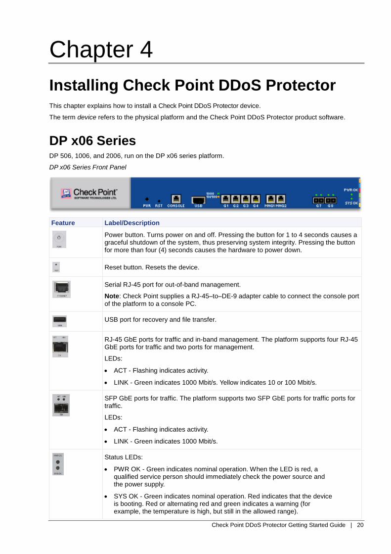
DP x06 Series DP 506, 1006, and 2006, run on the DP x06 series platform.
DP x06 Series Front Panel
Feature Label/Description
Power button. Turns power on and off. Pressing the button for 1 to 4 seconds causes a graceful shutdown of the system, thus preserving system integrity. Pressing the button for more than four (4) seconds causes the hardware to power down.
Reset button. Resets the device.
Serial RJ-45 port for out-of-band management.
Note: Check Point supplies a RJ-45–to–DE-9 adapter cable to connect the console port of the platform to a console PC.
USB port for recovery and file transfer.
RJ-45 GbE ports for traffic and in-band management. The platform supports four RJ-45 GbE ports for traffic and two ports for management.
LEDs:
ACT - Flashing indicates activity.
LINK - Green indicates 1000 Mbit/s. Yellow indicates 10 or 100 Mbit/s.
SFP GbE ports for traffic. The platform supports two SFP GbE ports for traffic ports for traffic.
LEDs:
ACT - Flashing indicates activity.
LINK - Green indicates 1000 Mbit/s.
Status LEDs:
PWR OK - Green indicates nominal operation. When the LED is red, a qualified service person should immediately check the power source and the power supply.
SYS OK - Green indicates nominal operation. Red indicates that the device is booting. Red or alternating red and green indicates a warning (for example, the temperature is high, but still in the allowed range).

Installing Check Point DDoS Protector
Check Point DDoS Protector Getting Started Guide | 21
DP x06 Series Back Panel
Feature Label/Description
Ground screws Screws to ground the platform chassis to the rack. 1U units have one ground screw. Typically, 2U units have two ground screws.
Power supply socket(s) The socket to which the power cable is connected.
Note - If the power is disconnected and reconnected (for example, after the power cord is removed and replaced, or after a power failure), the platform returns to its previous state. For example, if the platform was running, and then you disconnect the power cord, when you reconnect the power cord, the platform automatically switches on. Likewise, if the platform is not running, if you disconnect the power cord and reconnect it, the platform stays powered off until you press the power button.
DP x412 Series DP 4412, 8412, and 12412 run on DP x412 Series.
DP x412 Series Front Panel
Feature Label/Description
10 Gigabit Ethernet (10GbE) ports for traffic or management. The platform supports four XFP ports.
LEDs:
ACT - Flashing indicates activity.
LINK - Green indicates 10GbE.
SFP GbE ports for traffic or management. The platform supports four SFP ports.
LEDs:
ACT - Flashing indicates activity.
LINK - Green indicates 1000 Mbit/s.
RJ-45 GbE ports for traffic or management. The platform supports eight GbE ports.
LEDs:
ACT - Flashing indicates activity.
LINK - Green indicates 1000 Mbit/s. Yellow indicates 10 or 100 Mbit/s.
Installing Check Point DDoS Protector
Check Point DDoS Protector Getting Started Guide | 22
Feature Label/Description
Power button. Turns power on and off. Pressing the button for 1 to 4 seconds causes a graceful shutdown of the system, thus preserving system integrity. Pressing the button for more than four (4) seconds causes the hardware to power down.
Reset button. Resets the device.
USB port for recovery and file transfer.
Management ports. The platform supports two RJ-45 10/100/1000 Ethernet ports, which are for management only.
LEDs:
ACT - Flashing indicates activity.
LINK - Green indicates 1000 Mbit/s. Yellow indicates 10 or 100 Mbit/s.
RS-232 DE-9 port for out-of-band management.
Status LEDs:
PWR - Green indicates nominal operation. When the platform carries a dual power supply, red indicates that one of the two power cables is not supplying power or that one of the power supplies is malfunctioning. When the LED is red, a qualified service person should immediately check the power source and the power supply.
FAN - Green indicates nominal operation. Red indicates that one or more fans is not operating.
SYS OK - Green indicates nominal operation. Red indicates that the device is booting. Red or alternating red and green indicates a warning (for example, the temperature is high, but still in the allowed range).
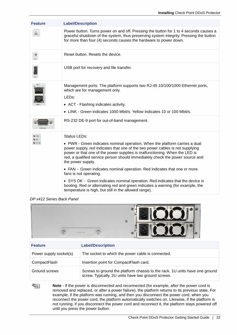
DP x412 Series Back Panel
Feature Label/Description
Power supply socket(s) The socket to which the power cable is connected.
CompactFlash Insertion point for CompactFlash card.
Ground screws Screws to ground the platform chassis to the rack. 1U units have one ground screw. Typically, 2U units have two ground screws.
Note - If the power is disconnected and reconnected (for example, after the power cord is removed and replaced, or after a power failure), the platform returns to its previous state. For example, if the platform was running, and then you disconnect the power cord, when you reconnect the power cord, the platform automatically switches on. Likewise, if the platform is not running, if you disconnect the power cord and reconnect it, the platform stays powered off until you press the power button.

Installing Check Point DDoS Protector
Check Point DDoS Protector Getting Started Guide | 23
LCD Module for DP x412 Series
DP x412 series platforms support an LCD module, which consists of the LCD itself and LCD menu buttons.
DP x412 Series LCD
You can use the LCD module for detailed device monitoring and for the initial configuration of the management port.
LCD Menu Buttons
There are six functional LCD menu buttons: up arrow, down arrow, left arrow, right arrow, Enter (), and Escape (×). Press the up or down buttons to select different menus within the menu hierarchies. Press the right button to choose the selected menu. Press the left button to return to the previous level in the hierarchy.
If you are configuring the DP x412 series platform for the first time, the buttons have additional functionality (see “Initial Configuration of the Management Port Using the LCD Module”).
Nominal Display
When you turn on an OnDemand Switch, the LCD displays:
ODS<Version>
Loading
During the boot process, the third line, Loading…, changes to Loaded Boot <Boot version>.
After the initial configuration, when the device completes booting—or after 30 minutes without any activity, the LCD displays:
<Product>
<Product version>
Time: <HH:MM:SS>
Initial Configuration of the Management Port Using the LCD Module
When you turn on the DP x412 series platform for the first time, there is no defined IP address, subnet mask, or physical port for the management port of the device. You can define these parameters using the
LCD module after the platform boots and displays Setup Config.
Caution - When the LCD displays Setup Config, you have 30 seconds to enter the
setup configuration. After these 30 seconds elapse, the platform uses the defaults, 192.168.1.1, 255.255.255.0, and G-1 respectively. However, later, using the CLI, you can change the values as required.
When you configure the management IP address and IP subnet mask using the LCD module, the buttons have the following additional functionality:
The up and down arrow buttons increase or decrease numbers.
The left and right arrow buttons move the cursor to the next digit or returns the cursor to the previous number.
At the end of the management IP address or subnet mask, the right arrow button moves the cursor to the next field in this menu. To return to the previous field, press the left arrow button.
Enter () to set the values.
Escape (×) leaves the value unchanged.

Installing Check Point DDoS Protector
Check Point DDoS Protector Getting Started Guide | 24
To configure the management port using the LCD module:
1. Turn on the DP x412 series platform.
The boot process starts.
2. Within 30 seconds after the LCD displays Setup Config, press the right arrow.
The LCD displays IP address with the value 000.000.000.000, and the cursor on the first number.
3. Enter the IP address of the management port for the Check Point DDoS Protector.
4. Press the right arrow button.
The LCD displays IP subnet mask with the value 255.000.000.000.
5. Enter the IP subnet mask of the management port for the Check Point DDoS Protector.
6. Press the right arrow button.
The LCD displays the selected management port.
7. Scroll down to the physical port that you want to use as the management port (for example, MNG-1).
8. Press the right arrow button.
The LCD displays Enable web and its value, Yes or No.
9. Press the up arrow for Yes. Press the down arrow for No.
10. Press the right arrow button.
The LCD displays Enable telnet and its value, Yes or No.
11. Press the up arrow for Yes. Press the down arrow for No.
12. Press the right arrow button.
The LCD displays Enable SSH and its value, Yes or No.
13. Press the up arrow for Yes. Press the down arrow for No.
14. Press to save and exit the startup configuration.
The Check Point DDoS Protector reboots with your configuration.

Installing Check Point DDoS Protector
Check Point DDoS Protector Getting Started Guide | 25
LCD Menus
After the Check Point DDoS Protector boots, press any of the LCD buttons to access the LCD menus.
Menu Submenu Subsubmenu Remark
Device Information
Platform Platform type and version.
Product Product.
Version Version of product.
MAC MAC address of the platform.
Serial The serial number of the device.
Power supply Single power supply or dual power supply.
Number of CPUs Number of CPUs.
Number of cores Number of CPU cores.
CPU util CPU utilization in percent.
CPU temp CPU temperature in Centigrade.
Memory RAM in megabytes.
Statistics
(see the Note below)
Port statistics Port Port identifier, for example G-1.
Port status Either up or down.
Pkt: in<Number>/ out<Number>K
Number of input and output packets in thousands per second.
Displayed only when Port status is up.
Byt: in<Number>/ Out<Number>MB
Amount of input and output megabytes per second.
Displayed only when Port status is up.
Settings LCD Contrast Contrast Increase or decrease LCD contrast using the right and left arrow buttons.
LCD Backlight Backlight Increase or decrease LCD backlight intensity using the right and left arrow buttons.
Serial Baud Rate Serial baud rate The selected rate is enclosed in asterisks, for
example *19200*. Press the down and up
arrow buttons to scroll between the values.
Shutdown Shutdown Shutdown Enter = Yes
Escape = No
Reboot Reboot Enter = Yes
Escape = No
Note - The LCD displays statistics per port and refreshes them every second. Thus,
the packets-in, packets-out, megabytes-in, and megabytes-out values are per second.

Installing Check Point DDoS Protector
Check Point DDoS Protector Getting Started Guide | 26
Check Point DDoS Protector Boot Commands
The following table lists the boot commands that the Check Point DDoS Protector platforms support and which you may use.
Feature Label/Description
? Print this list.
@ Boot (load and go).
a Print installed applications list.
e Print fatal exception.
Caution - Some boot commands are intended only for use by Check Point Technical Support.
Connecting and Installing Check Point DDoS Protector To connect and install Check Point DDoS Protector:
1. Connect the cables in the following order:
a) Power cable/s
b) Serial (RS-232) cable
c) Management port cable (Ethernet 10/100/1000)
d) Inspection ports cables (two cables per segment, copper - 10/100/1000, or fiber)
2. Connect the power cable to the power socket located on the rear panel of the device.
3. Connect the power cable to the power outlet.
4. Connect the serial cable to the platform.
5. Connect the serial cable to your console.
Connecting the Management Port and Inspection Port Cables
Check Point DDoS Protector platforms have ports for exclusively for traffic inspection and separate ports for out-of band management.
Considerations When Connecting Inspection Ports with Internal Bypass
Check Point DDoS Protector is installed between two end points - for example, between a switch and a router, between two switches, or between a switch and a server.
The RJ-45 traffic ports on Check Point DDoS Protector devices include a configurable internal bypass mechanism. When set to Fail Open, the internal bypass is activated when the application does not control the device, such as power off or reboot.
Consider the following when connecting to copper (RJ-45) ports for traffic inspection:
When turned off, the device ports are set as switch ports (MDIX).
Connect the device with the power off as you would connect a switch.
Use a straight-through cable to connect a server or a router.
Use a crossover cable to connect a switch.

Installing Check Point DDoS Protector
Check Point DDoS Protector Getting Started Guide | 27
Make sure your link is active (internal bypass is working).
Turn on the device and make sure your link is active.
Note - Cables may be purchased from third-party suppliers.
Configuring Management Ports To manage Check Point DDoS Protector, you need to configure a management port using an IP address. You can then manage the device with an SSH Client, Web Based Management (WBM), or Telnet.
Configuring the Management Port for the First Time
To configure the management port for the first time:
1. Ensure that an ASCII console is connected to the device through the serial cable and that console computer is turned on.
The following procedure uses HyperTerminal as the console application.
2. From the HyperTerminal open window, select File > Properties, or click the Properties icon in the toolbar. The New Connection Properties dialog box is displayed.
3. In the New Connection Properties dialog box, select Configure. The Properties window is displayed with the Port Settings pane.
4. In the Port Settings pane, set the following parameters:
Bits per second: 19200
Data bits: 8
Parity: None
Stop bits: 1
Flow control: None
5. Power on the device. The PWR and SYS or SYS OK LED indicators on the front panel light up.
The device starts up. After approximately a minute, the Startup Configuration window is displayed.
6. In the Startup Configuration window, provide the requested information for the IP address, IP subnet mask, port number, for the management port, and default router IP address parameters; and press Enter for each of the remaining settings. The device reboots after the last parameter is defined. Press Enter to accept default values.
If no configuration is entered within 30 seconds, the device applies the following default configuration:
IP Address: 192.168.1.1
IP subnet mask: 255.255.255.0
Port number for management. The default is MNG-1.
User name and password: admin
7. If the start-up configuration screen does not appear, do the following:
a. Wait for the prompt DefensePro#.
b. Type login and press Enter.
c. Enter the username and password:
User: admin
Password: admin
d. To view the current IP interface setting of the device, enter:
net ip-interface get
e. To add/modify/delete the existing IP Interface, enter:
net ip-interface help

Installing Check Point DDoS Protector
Check Point DDoS Protector Getting Started Guide | 28
Modifying the Route to the Management Port
To modify the route to the management port:
1. Connect to the Check Point DDoS Protector device via the serial port. (For instructions, see steps 1 through 5 in the previous procedure, “To configure the management port for the first time.”)
2. At the Check Point DDoS Protector prompt (DefensePro#), do one of the following:
For DP x06 Series devices, selecting the MNG-1 management port, enter the following command: net route table create 0.0.0.0 <NetworkMask> <DefaultGateway> -i 5
For DP x06 Series devices, selecting the MNG-2 management port, enter the following command: net route table create 0.0.0.0 <NetworkMask> <DefaultGateway> -i 6
For DP x412 Series devices, selecting the MNG-1 management port, enter the following command: net route table create 0.0.0.0 <NetworkMask> <DefaultGateway> -i 17
For DP x412 Series devices, selecting the MNG-2 management port, enter the following command: net route table create 0.0.0.0 <NetworkMask> <DefaultGateway> -i 18
Example: net route table create 0.0.0.0 0.0.0.0 10.202.142.42 -i 17
Enabling HTTP/HTTPS and Web Management Access via the Serial Interface
The procedures in the following chapters use the Check Point DDoS Protector Web interface. Perform the following procedure to enable HTTP/HTTPS and Web access.
To enable HTTP/HTTPS access for Web Based Management:
1. Connect to the Check Point DDoS Protector device via the serial port. (For instructions, see steps 1 through 5 in the previous section “Configuring Management Ports” on page 27.)
2. At the Check Point DDoS Protector prompt (DefensePro#), to enable access to the Check Point DDoS Protector Web interface, enter the following command: manage management-port -w
3. To enable HTTP access, enter the following command: manage web status set 1
4. To enable HTTPS access, enter the following command: manage secure-web status set 1
Installing Check Point DDoS Protector
Check Point DDoS Protector Getting Started Guide | 29
Chapter 5
Configuring Routes Check Point DDoS Protector supports IP routing compliant with RFC1812 router requirements. Dynamic addition and deletion of IP interfaces is supported. This ensures that extremely low latency is maintained. IP router supports RIP I, RIP II and OSPF routing protocols. OSPF is an intra-domain IP routing protocol, intended to replace RIP in bigger or more complex networks. OSPF and its MIB are supported as specified in RFC 1583 and RFC 1850, with some limitations.
Note - The procedure in this chapter uses the Check Point DDoS Protector Web interface.
The Check Point DDoS Protector Web interface is supported by the following Internet browsers:
Microsoft Internet Explorer version 6 when using Windows operating systems
Microsoft Internet Explorer version 7 and 8
Mozilla when using Linux operating systems
Firefox
To open the Check Point DDoS Protector Web interface:
Enter the IP address of the Check Point DDoS Protector device in the address bar of your browser.
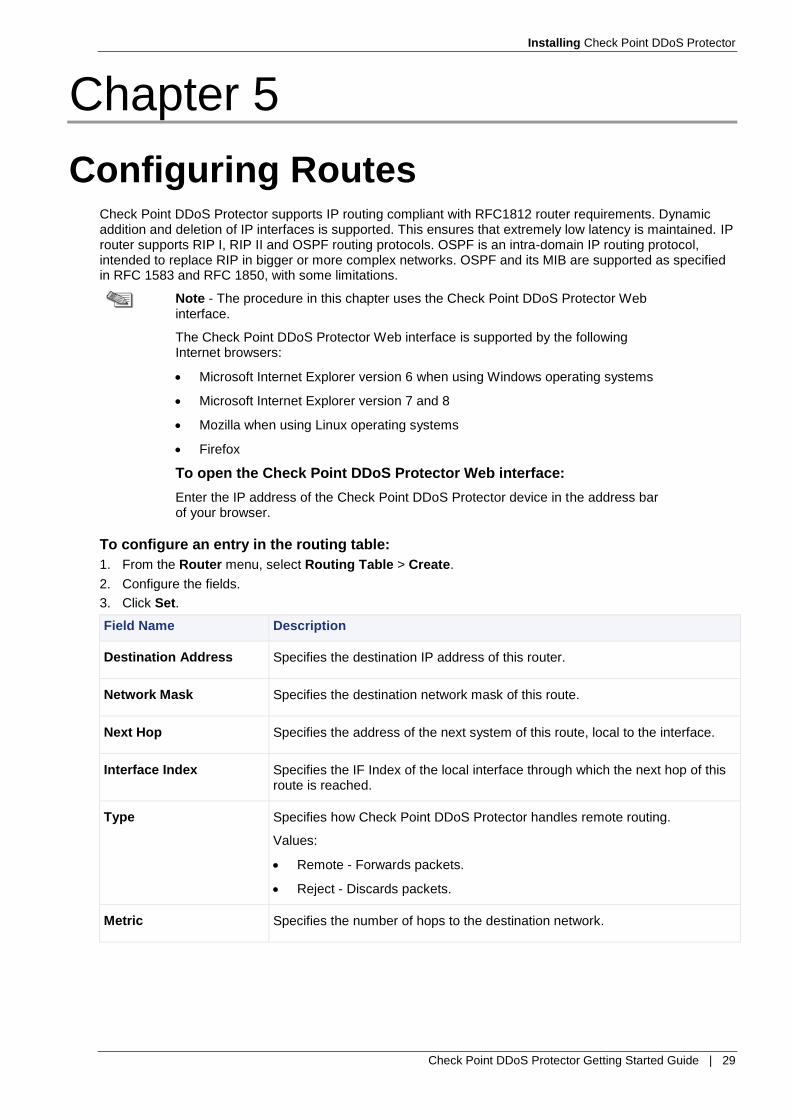
To configure an entry in the routing table:
1. From the Router menu, select Routing Table > Create.
2. Configure the fields.
3. Click Set.
Field Name Description
Destination Address Specifies the destination IP address of this router.
Network Mask Specifies the destination network mask of this route.
Next Hop Specifies the address of the next system of this route, local to the interface.
Interface Index Specifies the IF Index of the local interface through which the next hop of this route is reached.
Type Specifies how Check Point DDoS Protector handles remote routing.
Values:
Remote - Forwards packets.
Reject - Discards packets.
Metric Specifies the number of hops to the destination network.

Check Point DDoS Protector Getting Started Guide | 30
Chapter 6
Configuring HTTP, HTTPS, and SSH Access
Note - The procedure in this chapter uses the Check Point DDoS Protector Web interface.
The Check Point DDoS Protector Web interface is supported by the following Internet browsers:
Microsoft Internet Explorer version 6 when using Windows operating systems
Microsoft Internet Explorer version 7 and 8
Mozilla when using Linux operating systems
Firefox
To open the Check Point DDoS Protector Web interface:
Enter the IP address of the Check Point DDoS Protector device in the address bar of your browser.
To configure which protocols the management port allows:
1. From the Security menu, select Management Ports.
2. Configure the fields.
3. Click Set.
Field Name Description
SNMP Specifies whether the management port allows SNMP access.
TELNET Specifies whether the management port allows Telnet access.
SSH Specifies whether the management port allows SSH access.
WEB Specifies whether the management port allows Web access.
SSL Specifies whether the management port allows SSL access.
To configure HTTP (Web) access:
1. From the Services menu, select Management Interfaces > Web Server > Web.
2. Configure the fields.
3. Click Set.
Field Name Description
Web Server Port Specifies the port to which the Web Based Management is assigned.
Web Server Status Enables or disables the status of the Web server.
Web Help Location Specifies the location (path) of the Web help files.

Installing Check Point DDoS Protector
Check Point DDoS Protector Getting Started Guide | 31
Field Name Description
Web Access Level Values: readWrite, readOnly
To configure HTTPS (Secure Web) access:
1. From the Services menu, select Management Interfaces > Web Server > Secure Web.
2. Configure the fields.
3. Click Set.
Field Name Description
Secured Web Port Specifies the port through which HTTPS gets requests.
Secured Web Status Enables or disables the status of the Web server.
Secured Web Certificate File Specifies the certificate file that is used by secure Web for encryption.
To configure SSH access:
1. From the Services menu, select Management Interfaces > SSH > Server.
2. Configure the fields.
3. Click Set.
Field Name Description
SSH Port Specifies the source port for the SSH server connection.
SSH Status Enables or disables the SSH feature. When disabled, SSH connection is not possible.
SSH Session Timeout Specifies the timeout, in minutes, for the device to maintain connection during periods of inactivity for Telnet and SSH.
Values:
0 - Specifies unlimited.
1 - 120
SSH Authentication Timeout
Specifies the timeout, in seconds, for the device to continue trying to authorize the connection for Telnet and SSH.
Values:
0 - Specifies unlimited.
1 - 120
Check Point DDoS Protector Getting Started Guide | 32
Chapter 7
Configuring a Network Protection Policy and Network Protection Profiles
Configure a Network Protection policy after you have configured all the protection profiles that you want to include in the policy.
Note - The procedures in this chapter use the Check Point DDoS Protector Web interface.
The Check Point DDoS Protector Web interface is supported by the following Internet browsers:
Microsoft Internet Explorer version 6 when using Windows operating systems
Microsoft Internet Explorer version 7 and 8
Mozilla when using Linux operating systems
Firefox
To open the Check Point DDoS Protector Web interface:
Enter the IP address of the Check Point DDoS Protector device in the address bar of your browser.
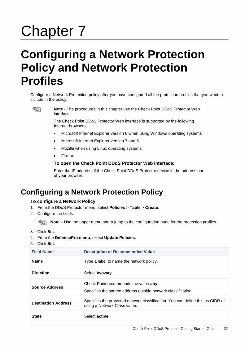
Configuring a Network Protection Policy To configure a Network Policy:
1. From the DDoS Protector menu, select Policies > Table > Create.
2. Configure the fields.
Note – Use the upper menu bar to jump to the configuration pane for the protection profiles.
3. Click Set.
4. From the DefensePro menu, select Update Policies.
5. Click Set.
Field Name Description or Recommended Value
Name Type a label to name the network policy.
Direction Select twoway.
Source Address Check Point recommends the value any.
Specifies the source address outside network classification.
Destination Address Specifies the protected network classification. You can define this as CIDR or using a Network Class value.
State Select active.

Installing Check Point DDoS Protector
Check Point DDoS Protector Getting Started Guide | 33
Field Name Description or Recommended Value
Action Select Block and Report or Report Only.
Behavioral Dos Profile Select the required profile.
Signatures Profile
Select DoS-All.
Note: The DoS Shield feature must be enabled. For more information, see “Configuring DoS Shield.”
Connection Limit Select the required profile.
DNS protection Profile Select the required profile.
SYN Protection Profile Select the required profile.
Configuring Behavioral DoS Profiles Each Behavioral DoS profile must be configured for a particular Network Protection policy. The traffic that the profile describes needs to reflect the actual traffic measurements of the Network Protection policy.
Before you can configure a Behavioral DoS profile, you need to enable the Behavioral DoS feature.
To enable the Behavioral DoS feature:
1. From the DDoS Protector menu, select Denial of Service > Behavioral DoS > Global Parameters.
2. From the Behavioral DoS Status drop-down list, select enable.
3. Click Set.
To configure a Behavioral DoS profile:
1. From the DefensePro menu, select Denial of Service > Behavioral DoS > Behavioral DoS Profiles > Create.
2. Configure the fields.
3. Click Set.
Field Name Description or Recommended Value
Profile Name The user-defined name for the profile.
SYN Flood status Specifies whether this profile protects against SYN Flood attacks.
Default: Inactive
TCP Reset Flood status Specifies whether this profile protects against TCP Reset Flood attacks.
Default: Inactive
TCP FIN+ACK Flood status
Specifies whether this profile protects against TCP FIN+ACK Flood attacks.
Default: Inactive
TCP SYN+ACK Flood status
Specifies whether this profile protects against TCP SYN+ACK Flood attacks.
Default: Inactive
TCP Fragmented Flood status
Specifies whether this profile protects against TCP Fragmented Flood attacks.
Default: Inactive
UDP Flood status Specifies whether this profile protects against UDP Flood attacks.
Default: Inactive

Installing Check Point DDoS Protector
Check Point DDoS Protector Getting Started Guide | 34
Field Name Description or Recommended Value
IGMP Flood status Specifies whether this profile protects against IGMP Flood attacks.
Default: Inactive
ICMP Flood status Specifies whether this profile protects against ICMP Flood attacks.
Default: Inactive
Configuration of the inbound traffic in [Kbit/Sec]
Specifies the highest expected volume, in Kbit/s, of inbound traffic in Kbit/s, on the relevant network segment.
Configuration of the outbound traffic in [Kbit/Sec]
Specifies the highest expected volume, in Kbit/s, of outbound traffic, on the relevant network segment.
Packet Report Status Select disable.
Packet Trace Status Select disable.
Configuring a DNS Protection Profile Each DNS Protection profile must be configured for a particular Network Protection policy. The traffic that the profile describes needs to reflect the actual traffic measurements of the Network Protection policy.
Before you can configure a DNS Protection profile, you need to enable the DNS Protection feature.
To enable the DNS Protection feature:
1. From the DefensePro menu, select Denial of Service > DNS Protection > Global Parameters.
2. From the DNS Protection Status drop-down list, select enable.
3. Click Set.
To configure a DNS Protection profile:
1. From the DefensePro menu, select Denial of Service > DNS Protection > DNS Protection Profiles > Create.
2. Configure the fields.
3. Click Set.
Field Name Description or Recommended Value
Profile Name Specifies the user-defined name for the profile.
Expected QPS Specifies the expected QPS.
DNS A Flood status Specifies whether this profile protects against these attacks.
Default: Inactive
DNS A Quota[%] Set a value or use the default. The device displays the value 0 until you click Set and reset the device. Then, the actual default value is displayed.
DNS MX Flood status Specifies whether this profile protects against these attacks.
Default: Inactive
DNS MX Quota[%] Set a value or use the default. The device displays the value 0 until you click Set and reset the device. Then, the actual default value is displayed.

Installing Check Point DDoS Protector
Check Point DDoS Protector Getting Started Guide | 35
Field Name Description or Recommended Value
DNS PTR Flood status Specifies whether this profile protects against these attacks.
Default: Inactive
DNS PTR Quota[%] Set a value or use the default. The device displays the value 0 until you click Set and reset the device. Then, the actual default value is displayed.
DNS AAAA Flood status Specifies whether this profile protects against these attacks.
Default: Inactive
DNS AAAA Quota[%] Set a value or use the default. The device displays the value 0 until you click Set and reset the device. Then, the actual default value is displayed.
DNS TEXT Flood status Specifies whether this profile protects against these attacks.
Default: Inactive
DNS TEXT Quota[%] Set a value or use the default. The device displays the value 0 until you click Set and reset the device. Then, the actual default value is displayed.
DNS SOA Flood status Specifies whether this profile protects against these attacks.
Default: Inactive
DNS SOA Quota[%] Set a value or use the default. The device displays the value 0 until you click Set and reset the device. Then, the actual default value is displayed.
DNS NAPTR Flood status Specifies whether this profile protects against these attacks.
Default: Inactive
DNS NAPTR Quota[%] Set a value or use the default. The device displays the value 0 until you click Set and reset the device. Then, the actual default value is displayed.
DNS SRV Flood status Specifies whether this profile protects against these attacks.
Default: Inactive
DNS SRV Quota[%] Set a value or use the default. The device displays the value 0 until you click Set and reset the device. Then, the actual default value is displayed.
DNS OTHER Flood status Specifies whether this profile protects against these attacks.
Default: Inactive
DNS OTHER Quota[%] Set a value or use the default. The device displays the value 0 until you click Set and reset the device. Then, the actual default value is displayed.
Max Allowed QPS Specifies the maximum allowed QPS.
Signature Rate Limit Target Set the required value.
Packet Report Status Select disable.

Installing Check Point DDoS Protector
Check Point DDoS Protector Getting Started Guide | 36
Field Name Description or Recommended Value
Packet Trace Status Select disable.
Action Select Block and Report.
Configuring DoS Shield Protection The DoS Shield mechanism implements a sampling algorithm, and detects traffic flooding.
The DoS Shield protection is exposed as the DoS-All option for the Signatures Profile parameter in a Network Protection policy.
To configure DoS Shield global parameters:
1. From the DefensePro menu, select Intrusion Protection > Signature Protection > DoS Shield > Global Parameters.
2. Configure the fields.
3. Click Set.
Field Name Description or Recommended Value
Protection Status Select enable.
Sampling Rate
The rate at which the DoS Shield mechanism samples a packet to check for an attack. For example, if the specified value is 5001, the DoS Shield mechanism checks 1 out of 5001 packets.
Default: 5001
Sampling Frequency
How often, in seconds, the DoS Shield mechanism compares the predefined thresholds for each dormant attack to the current value of packet counters matching the attack.
Default: 5
Note: If the sampling time is very short, there are frequent comparisons of counters to thresholds, so regular traffic bursts might be considered attacks. If the sampling time is too long, the DoS Shield mechanism cannot detect real attacks quickly enough.
Configuring Packet Anomalies Protection Packet Anomalies is a global protection, which is not related to a Network Protection policy or Server Protection policy.
Generally, whenever a packet matching one of the predefined checks arrives, it is automatically blocked, discarded, and reported. However, if you require, you can allow certain anomalous traffic to flow through the device without inspection.
To configure the Packet Anomalies parameters:
1. From the DefensePro menu, select Packet Anomalies > Table.
2. From the Packet Trace Status drop-down list, select disable.
3. To modify the configuration of a packet anomaly:
a. Select the relevant ID from the table.
b. Configure the fields.
c. Click Set.
4. Click Set.

Installing Check Point DDoS Protector
Check Point DDoS Protector Getting Started Guide | 37
Field Name Description or Recommended Value
ID (Read-only) The ID number of the anomaly.
Name (Read-only) The name of the anomaly.
Risk Specifies the risk value for reporting. Values:
Info
Low
Medium
High
Action Values:
no-report
report
block
ReportAction (Read-only) The action that the device does when the Action is report or no-report.
Values:
Bypass - The anomalous packet is forwarded to the destination with no further inspection.
Process - The anomalous packet continues to be inspected by the protection modules.
Configuring a Connection Limit Profile To configure a Connection Limit profile, first configure the Attack definitions for the profile. Multiple Connection Limit profiles can use the same Attack definitions. Changes to an Attack definition apply to all the Connection Limit profiles that use it.
To configure the definition of an Attack for a Connection Limit profile:
1. From the DefensePro menu, select Denial of Service > Connection Limit > Attacks > Create.
2. Configure the fields.
3. Click Set.
Field Name Description or Recommended Value
ID Enter 0. The system generates an identifier, beginning with 450000, when you click Set. Afterwards, the ID is read-only.
Attack Name A user-defined name for easy identification of the attack.
Destination App. Port Specifies the application port or ports of the destination.
Values:
A Layer 4 port that represents the application you want to protect.
An Application-Port-Group class, string object, for example h.
A blank field specifies any port.
Note: You can modify and configure Application Port Group classes. For more information, see “Viewing and Configuring Application-Port-Group Classes.”
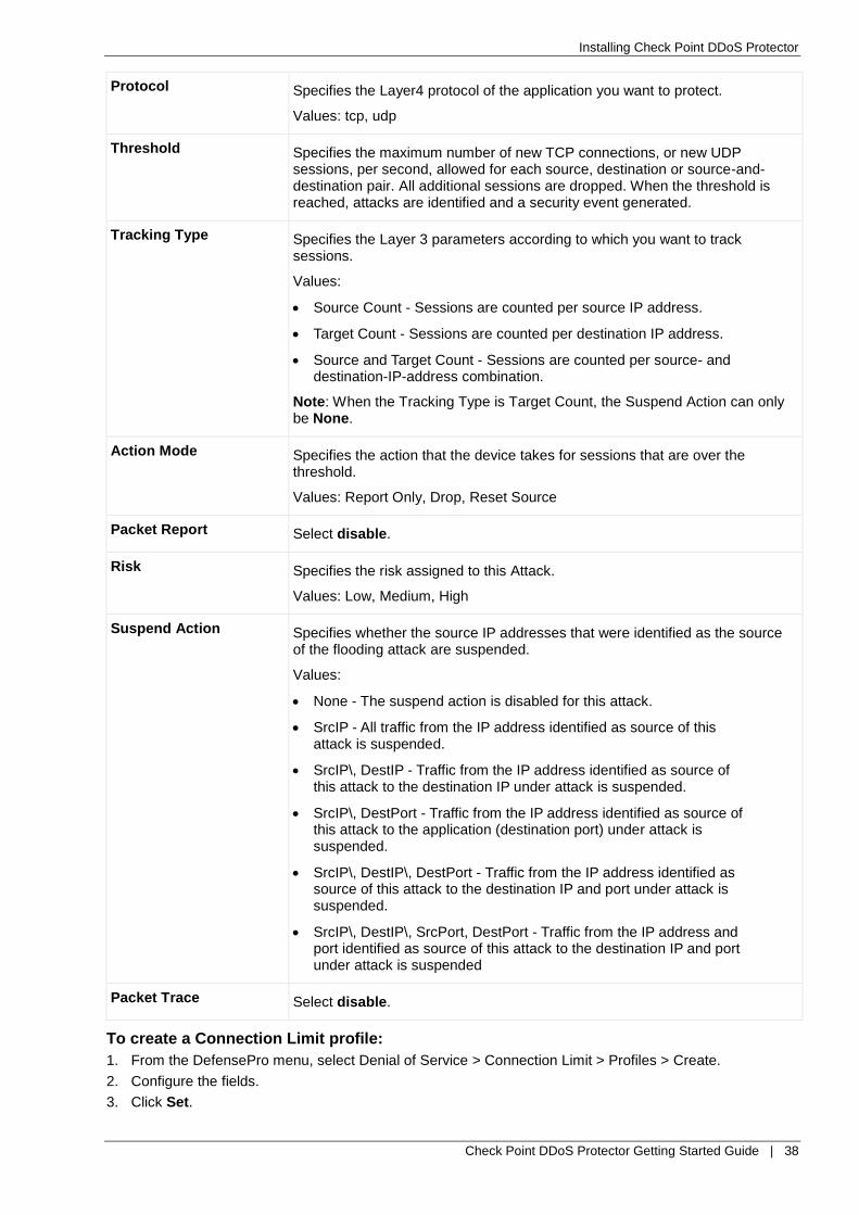
Installing Check Point DDoS Protector
Check Point DDoS Protector Getting Started Guide | 38
Protocol Specifies the Layer4 protocol of the application you want to protect.
Values: tcp, udp
Threshold Specifies the maximum number of new TCP connections, or new UDP sessions, per second, allowed for each source, destination or source-and-destination pair. All additional sessions are dropped. When the threshold is reached, attacks are identified and a security event generated.
Tracking Type Specifies the Layer 3 parameters according to which you want to track sessions.
Values:
Source Count - Sessions are counted per source IP address.
Target Count - Sessions are counted per destination IP address.
Source and Target Count - Sessions are counted per source- and destination-IP-address combination.
Note: When the Tracking Type is Target Count, the Suspend Action can only be None.
Action Mode Specifies the action that the device takes for sessions that are over the threshold.
Values: Report Only, Drop, Reset Source
Packet Report Select disable.
Risk Specifies the risk assigned to this Attack.
Values: Low, Medium, High
Suspend Action Specifies whether the source IP addresses that were identified as the source of the flooding attack are suspended.
Values:
None - The suspend action is disabled for this attack.
SrcIP - All traffic from the IP address identified as source of this attack is suspended.
SrcIP\, DestIP - Traffic from the IP address identified as source of this attack to the destination IP under attack is suspended.
SrcIP\, DestPort - Traffic from the IP address identified as source of this attack to the application (destination port) under attack is suspended.
SrcIP\, DestIP\, DestPort - Traffic from the IP address identified as source of this attack to the destination IP and port under attack is suspended.
SrcIP\, DestIP\, SrcPort, DestPort - Traffic from the IP address and port identified as source of this attack to the destination IP and port under attack is suspended
Packet Trace Select disable.
To create a Connection Limit profile:
1. From the DefensePro menu, select Denial of Service > Connection Limit > Profiles > Create.
2. Configure the fields.
3. Click Set.

Installing Check Point DDoS Protector
Check Point DDoS Protector Getting Started Guide | 39
Field Name Description or Recommended Value
Connection Limiting Profile Specifies a name for the profile. The name belongs to the list in the configuration of the Network Protection policy.
Connection Limiting Attack Specifies the name of an Attack from the Connection Limiting Attacks that you configured.
To add an Attack definition to an existing Connection Limit profile:
1. From the DefensePro menu, select Denial of Service > Connection Limit > Profiles.
2. For the Profiles Table, click the Connection Limit profile.
3. Click Create.
4. From the Connection Limiting Attack drop-down list, select the Attack definition to add to the profile.
5. Click Set.
To delete an Attack definition from an existing Connection Limit profile:
1. From the DefensePro menu, select Denial of Service > Connection Limit > Profiles.
2. For the Profiles Table, click the Connection Limit profile.
3. Select the checkbox in the row with the Attack you want to delete.
4. Click Delete.
Configuring a SYN Protection Profile To configure a SYN Protection profile, first configure the Attack definitions for the profile. Multiple SYN Protection profiles can use the same Attack definitions. Changes to an Attack definition apply to all the SYN Protection profiles that use it.
Check Point DDoS Protector provides a set of predefined definitions of SYN attacks. A predefined definition of a SYN attack is labeled Static in the GUI. You can modify some of the parameters in Static Attacks. In addition, you can create your own definitions of SYN attacks, which are labeled User.
Before you can configure a SYN Protection profile, you need to enable the SYN Protection feature.
To enable the SYN Protection feature:
1. From the DefensePro menu, select Denial of Service > SYN Protection > Global Parameters.
2. From the SYN Protection Status drop-down list, select enable.
3. Click Set.
To configure the definition of a predefined Attack:
1. From the DefensePro menu, select Denial of Service > SYN Protection > Attacks > Static.
2. Select the ID of the predefined Attack.
3. Configure the fields.
4. Click Set.
Field Name Description or Recommended Value
Attack Name A name for easy identification of the Attack.
Activation Threshold If the average rate of SYN packets received at a certain Destination is higher than this threshold, the protection is activated.
Values: 1 - 150,000
Default: 2500
Termination Threshold If the average rate of SYN packets received at a certain Destination for the duration of the tracking period drops below this threshold, the protection is stopped.
Values: 1 – 150,000
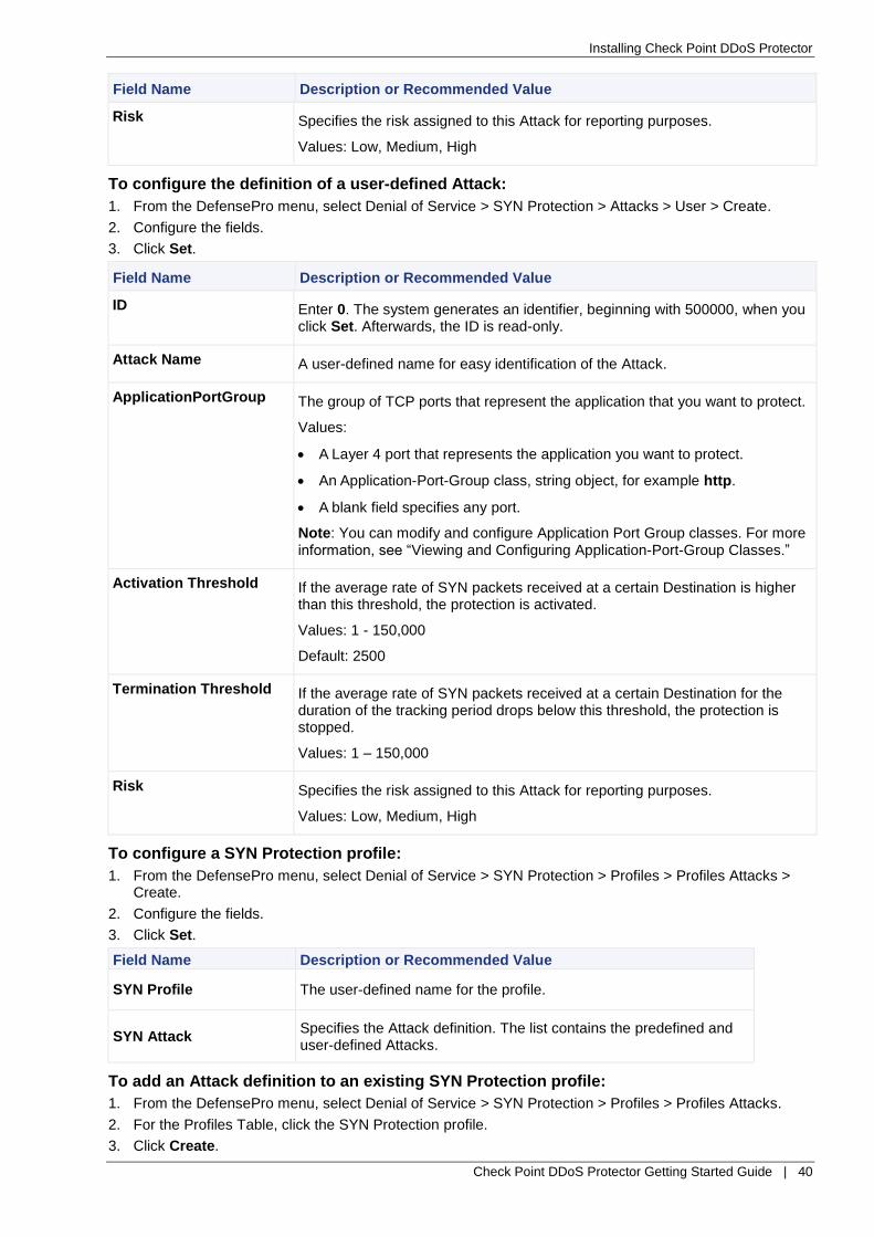
Installing Check Point DDoS Protector
Check Point DDoS Protector Getting Started Guide | 40
Field Name Description or Recommended Value
Risk Specifies the risk assigned to this Attack for reporting purposes.
Values: Low, Medium, High
To configure the definition of a user-defined Attack:
1. From the DefensePro menu, select Denial of Service > SYN Protection > Attacks > User > Create.
2. Configure the fields.
3. Click Set.
Field Name Description or Recommended Value
ID Enter 0. The system generates an identifier, beginning with 500000, when you click Set. Afterwards, the ID is read-only.
Attack Name A user-defined name for easy identification of the Attack.
ApplicationPortGroup The group of TCP ports that represent the application that you want to protect.
Values:
A Layer 4 port that represents the application you want to protect.
An Application-Port-Group class, string object, for example http.
A blank field specifies any port.
Note: You can modify and configure Application Port Group classes. For more information, see “Viewing and Configuring Application-Port-Group Classes.”
Activation Threshold If the average rate of SYN packets received at a certain Destination is higher than this threshold, the protection is activated.
Values: 1 - 150,000
Default: 2500
Termination Threshold If the average rate of SYN packets received at a certain Destination for the duration of the tracking period drops below this threshold, the protection is stopped.
Values: 1 – 150,000
Risk Specifies the risk assigned to this Attack for reporting purposes.
Values: Low, Medium, High
To configure a SYN Protection profile:
1. From the DefensePro menu, select Denial of Service > SYN Protection > Profiles > Profiles Attacks > Create.
2. Configure the fields.
3. Click Set.
Field Name Description or Recommended Value
SYN Profile The user-defined name for the profile.
SYN Attack Specifies the Attack definition. The list contains the predefined and user-defined Attacks.
To add an Attack definition to an existing SYN Protection profile:
1. From the DefensePro menu, select Denial of Service > SYN Protection > Profiles > Profiles Attacks.
2. For the Profiles Table, click the SYN Protection profile.
3. Click Create.

Installing Check Point DDoS Protector
Check Point DDoS Protector Getting Started Guide | 41
4. From the SYN Attack drop-down list, select the Attack definition to add to the profile.
5. Click Set.
To delete an Attack definition from an existing SYN Protection profile:
1. From the DefensePro menu, select Denial of Service > SYN Protection > Profiles Attacks.
2. For the Profiles Table, click the SYN Protection profile.
3. Select the checkbox in the row with the Attack you want to delete.
4. Click Delete.
To view and modify parameters of existing SYN Protection profiles:
1. From the DefensePro menu, select Denial of Service > SYN Protection > Profiles > Profiles Parameters.
2. Click the profile.
3. Configure the fields.
4. Click Set.
Field Name Description or Recommended Value
Profile Name (Read-only) The user-defined name for the profile.
Authentication Method Specifies the Authentication Method that the device uses at the transport layer.
When the device is installed in and ingress-only topology, select the safe-reset method.
Values:
transparent-proxy - When the device receives a SYN packet, the device replies with a SYN ACK packet with a cookie in the Sequence Number field. If the response is an ACK that contains the cookie, the device considers the session to be legitimate. Then, the device opens a connection with the destination and acts as transparent proxy between the source and the destination.
safe-reset - When the device receives a SYN packet, the device responds with an ACK packet with an invalid Sequence Number field as a cookie. If the client responds with RST and the cookie, the device discards the packet, adds the source IP address to the TCP Authentication Table. The next SYN packet from the same source passes through the device, and the session is approved for the server. The device saves the source IP address for a specified time. Typically, you specify this method when the network policy rule handles only ingress traffic.
Default: transparent-proxy
HTTP Authentication Select enable.
Specifies whether the device authenticates the transport layer of HTTP traffic using SYN cookies and then authenticates the HTTP application layer using the specified HTTP Authentication Method.
Values:
Enabled - The device authenticates the Transport Layer of HTTP traffic using SYN cookies and then authenticates the HTTP Application Layer using the specified HTTP Authentication Method.
Disabled - The device handles HTTP traffic using the specified TCP Authentication Method.
Default: Disabled

Installing Check Point DDoS Protector
Check Point DDoS Protector Getting Started Guide | 42
Field Name Description or Recommended Value
HTTP Authentication method
Specifies the method that the profile uses to authenticates HTTP traffic at the application layer.
Values:
Redirect - The device authenticates HTTP traffic using a 302-Redirect response code.
JavaScript - The device authenticates HTTP traffic using a JavaScript object generated by the device.
Default: Redirect
Configuring an Out-of-State Protection Profile You can create an Out-of-State Protection profile and use it in Network Protection policies.
Before you can configure an Out-of-State Protection profile, you need to enable the Out-of-State Protection feature.
To enable the Out-of-State Protection feature:
1. From the DefensePro menu, select Intrusion Prevention > Out-of-State > Global Parameters.
2. From the Protection Status drop-down list, select enable.
3. From the Operational State drop-down list, select enable.
4. Click Set.
To configure an Out-of-State Protection profile:
1. From the DefensePro menu, select Intrusion Prevention > Out-of-State > Profiles > Create.
2. Configure the fields.
3. Click Set.
Field Name Description or Recommended Value
Profile Name The user-defined name for the profile.
Activation Threshold The rate, in PPS, of out-of-state packets above which the profile considers the packets to be part of a flood attack. When the device detects an attack, it issues an appropriate alert and drops the out-of-state packets that exceed the threshold. Packets that do not exceed the threshold bypass the Check Point DDoS Protector device.
Values: 1 – 250,000 Default: 5000
Termination Threshold The rate, in PPS, of out-of-state packets below which the profile considers the flood attack to have stopped; and the device resumes normal operation.
Values: 1 – 250,000 Default: 4000
SYN-ACK Allow status Specifies whether a SYN-ACK packet bypasses the Check Point DDoS Protector device even when the device has not inspected SYN packet for the session. Default: enable
Packet Trace status Select disable.
Packet Report status Select disable.

Installing Check Point DDoS Protector
Check Point DDoS Protector Getting Started Guide | 43
Profile Risk The risk - for reporting purposes - assigned to the attack that the profile detects. Values: info, low, medium, high Default: low
Profile Action The action that the profile takes when it encounters out-of-state packets. Values: Block and Report, Report Only Default: Block and Report
Configuring an HTTP Mitigator Profile The HTTP Mitigator detects and mitigates HTTP request flood attacks to protect Web servers. The HTTP Mitigator collects and builds a statistical model of the protected server traffic, and then, using fuzzy logic inference systems and statistical thresholds, detects traffic anomalies and identifies the malicious sources.
You specify an HTTP Mitigator profile in a Server Protection policy.
Before you can configure an HTTP Mitigator profile, you need to enable the HTTP Mitigator feature.
To enable the HTTP Mitigator feature:
1. From the DefensePro menu, select Denial of Service > HTTP Mitigator > Global Parameters.
2. From the Protection Status drop-down list, select enable.
3. Click Set.
To configure an HTTP Mitigator profile:
1. From the DefensePro menu, select Denial of Service > HTTP Mitigator > Profiles > Create.
2. Configure the fields.
3. Click Set.
Field Name Description or Recommended Value
Profile Name The user-defined name for the profile.
Sensitivity Level Check Point recommends the default value medium.
Specifies how sensitive the profile is to deviations from the baseline. High specifies that Check Point DDoS Protector identifies an attack when the device detects only a small deviation from the baselines. Values:
minor
low
medium
high
Default: medium
Action Check Point recommends the default value Block and Report.
The action that the device takes when the profile detects suspicious traffic. Values:
Block and Report - Blocks and reports on the suspicious traffic.
Report Only - Reports the suspicious traffic.
Default: Block and Report
Packet Report Select disable.

Installing Check Point DDoS Protector
Check Point DDoS Protector Getting Started Guide | 44
Field Name Description or Recommended Value
Packet Trace Select disable.
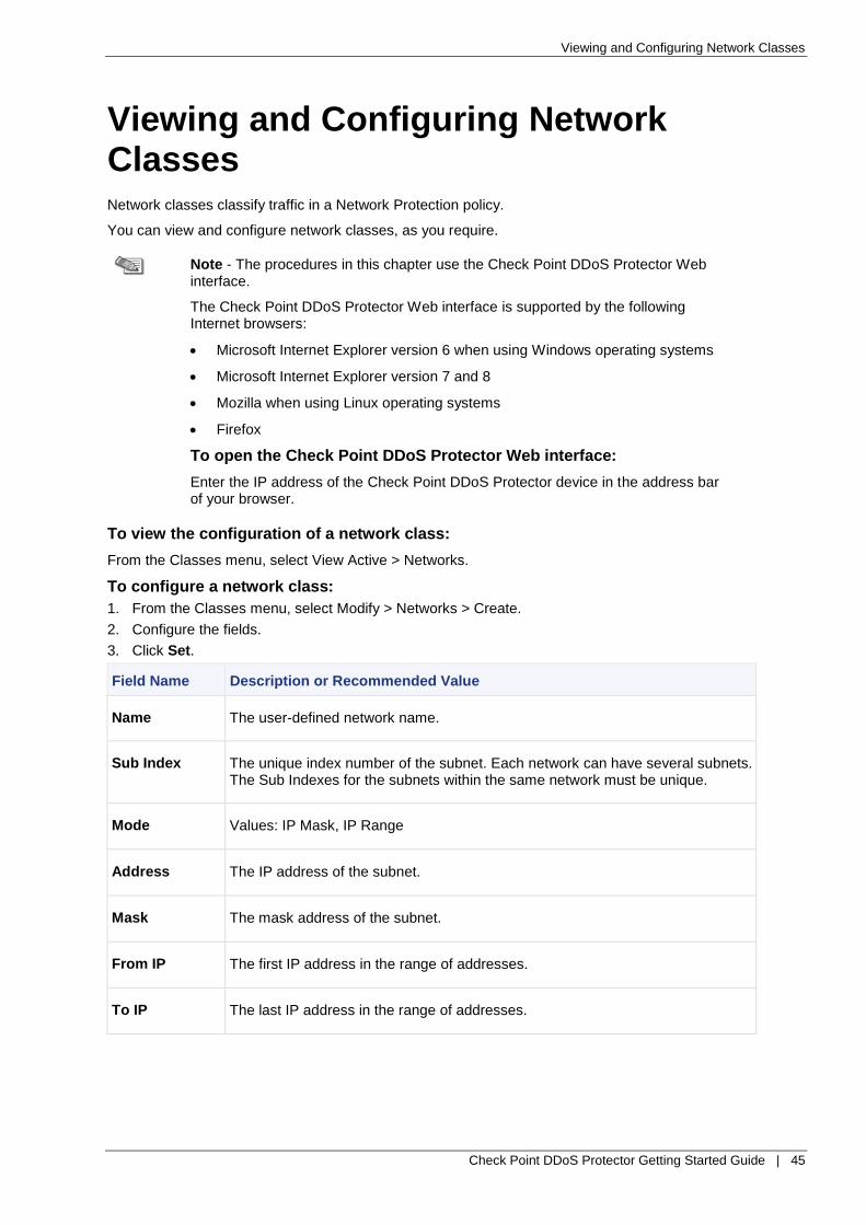
Viewing and Configuring Network Classes
Check Point DDoS Protector Getting Started Guide | 45
Viewing and Configuring Network Classes Network classes classify traffic in a Network Protection policy.
You can view and configure network classes, as you require.
Note - The procedures in this chapter use the Check Point DDoS Protector Web interface.
The Check Point DDoS Protector Web interface is supported by the following Internet browsers:
Microsoft Internet Explorer version 6 when using Windows operating systems
Microsoft Internet Explorer version 7 and 8
Mozilla when using Linux operating systems
Firefox
To open the Check Point DDoS Protector Web interface:
Enter the IP address of the Check Point DDoS Protector device in the address bar of your browser.
To view the configuration of a network class:
From the Classes menu, select View Active > Networks.
To configure a network class:
1. From the Classes menu, select Modify > Networks > Create.
2. Configure the fields.
3. Click Set.
Field Name Description or Recommended Value
Name The user-defined network name.
Sub Index The unique index number of the subnet. Each network can have several subnets. The Sub Indexes for the subnets within the same network must be unique.
Mode Values: IP Mask, IP Range
Address The IP address of the subnet.
Mask The mask address of the subnet.
From IP The first IP address in the range of addresses.
To IP The last IP address in the range of addresses.

Viewing and Configuring Application-Port-Group Classes
Check Point DDoS Protector Getting Started Guide | 46
Viewing and Configuring Application-Port-Group Classes Application-port-group classes define applications based on Layer 4 destination ports.
You can view the configuration of Static Application-Port-Group classes. You can view and configure your own Application-Port-Group classes, as you require.
Note - The procedures in this chapter use the Check Point DDoS Protector Web interface.
The Check Point DDoS Protector Web interface is supported by the following Internet browsers:
Microsoft Internet Explorer version 6 when using Windows operating systems
Microsoft Internet Explorer version 7 and 8
Mozilla when using Linux operating systems
Firefox
To open the Check Point DDoS Protector Web interface:
Enter the IP address of the Check Point DDoS Protector device in the address bar of your browser.
To view the configuration of an application-port-group class:
From the Classes menu, select View Active > Appl. Port Groups.
To configure an application-port-group class:
1. From the Classes menu, select Modify > Appl. Port Groups > Create.
2. Configure the fields.
3. Click Set.
Field Name Description or Recommended Value
Name The name of the group.
From Port The first port in the range.
To define a group with a single port, set the same value for the From Port and To Port parameters.
To associate a number of ranges with the same port group, use the same group name for all the ranges that you want to include in one group.
To Port The last port in the range.

Configuring Services
Check Point DDoS Protector Getting Started Guide | 47
Configuring Services
Note - The procedures in this chapter use the Check Point DDoS Protector Web interface.
The Check Point DDoS Protector Web interface is supported by the following Internet browsers:
Microsoft Internet Explorer version 6 when using Windows operating systems
Microsoft Internet Explorer version 7 and 8
Mozilla when using Linux operating systems
Firefox
To open the Check Point DDoS Protector Web interface:
Enter the IP address of the Check Point DDoS Protector device in the address bar of your browser.
Configuring Syslog Reporting You can get report of the system performance in the Syslog Reporting window. The device issues syslog messages during the system operation.
To enable syslog messages:
1. From the Services menu, select Syslog Reporting.
2. Configure the fields.
3. Click Set.
Field Name Description or Recommended Value
Profile Name The user-defined name for the profile.
Syslog Operation Enables or disables Syslog reporting.
Syslog Station Address The IP address of the device running the syslog service (syslogd).
Syslog Station Facility The type of the device of the sender. This is sent with Syslog messages.
Default: Local Use 6
Syslog Destination Port Specifies the address for the Syslog Destination port.
Syslog Source Port Sets the UDP port that is used by Syslog messages.
Values: 1025 - 65535
Default: 514
Configuring Black Lists Check Point DDoS Protector drops packets that match an active Black List policy. The device blacklists packets if all the criteria for the policy evaluate to true. You can use Black List policies to block traffic that you know to be malicious.

Configuring Black Lists
Check Point DDoS Protector Getting Started Guide | 48
Note - The procedures in this chapter use the Check Point DDoS Protector Web interface.
The Check Point DDoS Protector Web interface is supported by the following Internet browsers:
Microsoft Internet Explorer version 6 when using Windows operating systems
Microsoft Internet Explorer version 7 and 8
Mozilla when using Linux operating systems
Firefox
To open the Check Point DDoS Protector Web interface:
Enter the IP address of the Check Point DDoS Protector device in the address bar of your browser.
To configure a Black List policy:
1. From the DefensePro menu, select Black List > Create.
2. Configure the fields.
3. Click Set.
4. From the DefensePro menu, select Update Policies.
5. Click Set.
Field Name Description or Recommended Value
Name The user-defined name for the policy.
State Specifies whether the policy is active. You can select inactive to deactivate the policy without removing it from the list.
Values: active, inactive
Default: active
SrcNetwork The source network or IP address for the policy. The network must be configured on the device.
Default: any - That is, traffic from any source.
DstNetwork The destination network or IP address for the policy. The network must be configured on the device.
Default: any - any - That is, traffic to any destination network.
SrcPortGroup The source, port group for the policy. The port group must be configured on the device in the Application Port Group table.
This parameter is relevant only for UDP, TCP, and SCTP traffic. You cannot use a port group for ICMP, IGMP, or GRE.
DstPortGroup The destination, port group for the policy. The port group must be configured on the device in the Application Port Group table.
This parameter is relevant only for UDP, TCP, and SCTP traffic. You cannot use a port group for ICMP, IGMP, or GRE.
PhysicalPortGroup The physical port group for the policy.
VLANTag The VLAN tag group that you want for the policy.

Configuring Black Lists
Check Point DDoS Protector Getting Started Guide | 49
Field Name Description or Recommended Value
Protocol The protocol for the policy.
Values:
Any
GRE
ICMP
ICMPv6
IGMP
SCTP
TCP
UDP
L2TP
GTP
IPinIP
Default: Any
Direction The direction of packets for the policy. This parameter relates to L4 sessions only.
Values:
One-direct - The protection applies to sessions originating from sources to destinations that match the network definitions of the policy.
Bi-direct - The protection applies to sessions that match the network definitions of the policy regardless of their direction.
Default: one-direct
ReportAction The report action that the device takes when it encounters a packet that matches the policy.
Value:
report - The device issues a trap when it encounters a black-listed
packet.
no-report - The device issues no trap when it encounters a black-
listed packet.
Default: report
Description The user-defined description for the policy up to 19 characters.
Entry Expiration Timer (Hours)
The Expiration Timer can be used only with dynamic Black List rules. The Expiration Timer for a static Black List rule must be set to 0 (zero hours and zero minutes).
When the rule expires (that is, when the Entry Expiration Timer elapses), the rule disappears from the Black List Policy table when the table refreshes.
The maximum Expiration Timer is two hours.
Entry Expiration Timer (Minutes)
Specifies the hours remaining for the rule.
The Expiration Timer can be used only with dynamic Black List rules. The Expiration Timer for a static Black List rule must be set to 0 (zero hours and

Configuring White Lists
Check Point DDoS Protector Getting Started Guide | 50
Field Name Description or Recommended Value
zero minutes).
When the rule expires (that is, when the Entry Expiration Timer elapses), the rule disappears from the Black List Policy table when the table refreshes.
Detector An IP address that can identify the root cause of the black list rule identify. This parameter has no affect on Check Point DDoS Protector operation.
Detector Security Module A DDoS Protector security module that can identify the root cause of the black list rule. This parameter has no affect on Check Point DDoS Protector operation.
Dynamic Specifies whether the rule implements the Expiration Timer.
Values: Yes, No
Default: No
Note: Changing the configuration of this option takes effect only after you update policies.
Black List Packet Report Select disable.
Configuring White Lists Check Point DDoS Protector exempts packets that match an active White List policy from specified inspection processes. The device white-lists packets if all the criteria for the policy evaluate to true.
For each protection, you can set the direction of the bypass. For instance, sessions initiated from the white list IP address are bypassed, while sessions initiated toward the IP address are inspected as usual.
Caution - Check Point DDoS Protector continues to block packets from a source or destination that is part of an active attack even after you add the source or destination to the White List per protection.
Note - Since IP addresses belonging to the White List are not inspected, certain protections are not applied for the opposite direction. For example, with SYN Protection, this can cause servers not to be added to known destinations due to ACK packets not being inspected.
Note - The procedures in this chapter use the Check Point DDoS Protector Web interface.
The Check Point DDoS Protector Web interface is supported by the following Internet browsers:
Microsoft Internet Explorer version 6 when using Windows operating systems
Microsoft Internet Explorer version 7 and 8
Mozilla when using Linux operating systems
Firefox
To open the Check Point DDoS Protector Web interface:
Enter the IP address of the Check Point DDoS Protector device in the address bar of your browser.
To configure a White List policy:
1. From the DefensePro menu, select White List.
2. Configure the fields.

Configuring White Lists
Check Point DDoS Protector Getting Started Guide | 51
3. Click Set.
4. From the DefensePro menu, select Update Policies.
5. Click Set.
Field Name Description or Recommended Value
Name The user-defined name for the policy.
State Specifies whether the policy is active. You can select inactive to deactivate the policy without removing it from the list.
Values: active, inactive
Default: active
SrcNetwork The source network or IP address for the policy. The network must be configured on the device.
Default: any - That is, traffic from any source.
DstNetwork The destination network or IP address for the policy. The network must be configured on the device.
Default: any - That is, traffic to any destination network
SrcPortGroup The source, port group for the policy. The port group must be configured on the device in the Application Port Group table.
This parameter is relevant only for UDP, TCP, and SCTP traffic. You cannot use a port group for ICMP, IGMP, or GRE.
DstPortGroup The destination, port group for the policy. The port group must be configured on the device in the Application Port Group table.
This parameter is relevant only for UDP, TCP, and SCTP traffic. You cannot use a port group for ICMP, IGMP, or GRE.
PhysicalPortGroup The physical port group for the policy.
VLANTag The VLAN tag group that you want for the policy.
Protocol The protocol for the policy.
Values:
Any
GRE
ICMP
ICMPv6
IGMP
SCTP
TCP
UDP
L2TP
GTP
IPinIP
Default: Any
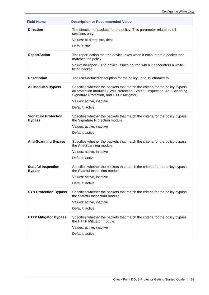
Configuring White Lists
Check Point DDoS Protector Getting Started Guide | 52
Field Name Description or Recommended Value
Direction The direction of packets for the policy. This parameter relates to L4 sessions only.
Values: bi-direct, src, dest
Default: src
ReportAction The report action that the device takes when it encounters a packet that matches the policy.
Value: no-report - The device issues no trap when it encounters a white-listed packet.
Description The user-defined description for the policy up to 19 characters.
All Modules Bypass Specifies whether the packets that match the criteria for the policy bypass all protection modules (SYN Protection, Stateful Inspection, Anti-Scanning, Signature Protection, and HTTP Mitigator).
Values: active, inactive
Default: active
Signature Protection Bypass
Specifies whether the packets that match the criteria for the policy bypass the Signature Protection module.
Values: active, inactive
Default: active
Anti-Scanning Bypass Specifies whether the packets that match the criteria for the policy bypass the Anti-Scanning module.
Values: active, inactive
Default: active
Stateful Inspection Bypass
Specifies whether the packets that match the criteria for the policy bypass the Stateful Inspection module.
Values: active, inactive
Default: active
SYN Protection Bypass Specifies whether the packets that match the criteria for the policy bypass the Stateful Inspection module.
Values: active, inactive
Default: active
HTTP Mitigator Bypass Specifies whether the packets that match the criteria for the policy bypass the HTTP Mitigator module.
Values: active, inactive
Default: active