chemical design factor – effect of liquid … pipeline...chemical design factor – effect of...
TRANSCRIPT

AGA PMC Meeting September 12, 2016 Dr. Gene Palermo Palermo Plastics Pipe (P3) Consulting www.plasticspipe.com
Chemical Design Factor – Effect of Liquid Hydrocarbons on PE Pipe Design Pressure

PPI TR-9

GPTC Guide Material – Part 192.123 “Design Limitations for Plastic Pipe”
4 EFFECTS OF LIQUID HYDROCARBONS
4.1 General.
Liquid hydrocarbons such as gasoline, diesel fuel, and condensates, either inside the pipe or in the surrounding soil, are known to have a detrimental effect on PE and PVC plastic piping materials. PA piping is not affected by liquid hydrocarbons. Contact the piping manufacturer for specific recommendations.

GPTC Recommendation TABLE 192.123i
Pipe Material Chemical Design
Factor (DFC)
PA (polyamide) 1.00
PE (polyethylene) 0.50
PVC (polyvinyl chloride) 0.50


How does the gas distribution industry use
the information in this GTI Report that was funded by PHMSA and is currently on
the PHMSA website?
New PPI Technical Report
Based on GTI Report, PPI initiated a new Project to develop a new Technical Report – TC 2016-01
“Chemical Design Factor for PE Pipe in the Presence of Liquid Hydrocarbons”
First ballot has been issued and task group will review results of the ballot at the PPI meeting in Dallas in two weeks.

Outline for new PPI TR Background Information
Shipment of Pipe Samples for Testing
PE Pipe Test Protocol
Chemical Design Factor Calculation

Shipping Your Pipe To determine the appropriate chemical
design factor for your pipeline, you first need to contact the lab and ship them a sample
Pipe samples need to be cut and immediately packaged to prevent the liquid hydrocarbon from evaporating from the pipe sample.

Shipping Protocol - 1 1) Mark or document on the sample pipe the
orientation where the hydrocarbon saturation is suspected.
2) Immediately wrap the pipe with a non-absorptive material such as Tedlar. If Tedlar is not available, wrapping the sample in aluminum foil followed by an overwrap using a household plastic wrap will achieve the same protective purpose

Shipping Protocol - 2 3) Place the wrapped pipe in a cooler. Use
frozen ice packs or gel packs to keep the sample cold. It is imperative to keep the sample cold to prevent desorption.
4) Ship the cooler overnight to the testing lab.
5) Include chain of custody (COC) documentation with the sample. The area of exposure should also be noted on the COC.

Test Specimens To determine the long-term chemical design factor
for PE pipe that has absorbed some heavy hydrocarbons (HHC) in the field, the test laboratory must determine the true stress at true strain for both the “wet” as-received PE pipe sample and for the corresponding “dry” PE pipe sample.
Tensile test specimens are obtained by die-punching ASTM D638 Type-V specimens out of both the “wet” as-received pipe sample and unsaturated “dry” pipe samples.

Sample Testing All tests are performed on a universal tensile
testing machine with a video extensometer in order to obtain the complete true stress-strain curves of the PE materials.
A pull rate of 10% engineering strain per second (0.7625 mm/s) is used for all tests.
Specimens are acclimated to the test temperature for at least 1 hour.

Test Protocol - 1 1) Remove all wrapping from the cooled “as-
received” pipe sample from the field.
2) Cut the pipe sample in half. One half is the “wet” sample and the other half will be “dried” later.
3) Punch out ASTM D638 Type-V specimens from the “wet” sample.
4) Obtain the true stress-strain curve at the desired test temperature using the tensile test machine at 10% strain per second.

Test Protocol - 2 5) Determine the true stress at 40% strain for
the “wet” sample.
6) Dry the other half of the pipe sample in an oven to remove all liquid hydrocarbons
7) Repeat steps 3, 4 and 5 for the “dry” sample.
8) Calculate the stress reduction factor (SRF), which is:
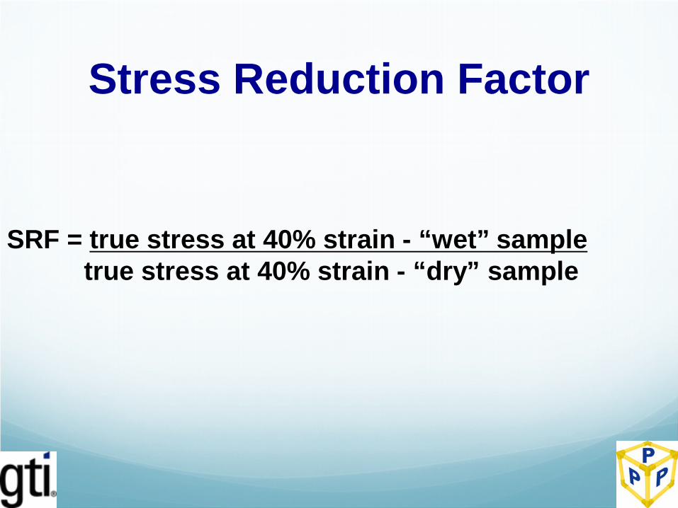
Stress Reduction Factor
SRF = true stress at 40% strain - “wet” sample true stress at 40% strain - “dry” sample

Chemical Design Factor For PE pipe used in gas applications, the chemical
design factor (DFC) is calculated from the stress reduction factor (SRF) that was obtained in the previous section on the “wet” and “dry” PE pipe samples.
If the SRF is 0.90, this means there is a 10% reduction in the true stress of the “wet” as-received pipe as compared to the control “dry” pipe. Thus, the DFC is 0.90.

Design Pressure Calculation per DOT Part 192.121
P = 2 (S) (DFS) (DFC) (DR – 1)
P = design pressure, psig
S = hydrostatic design basis, psi
DFS = design factor for the application – gas
DFC = chemical design factor
DR = dimension ratio of the pipe
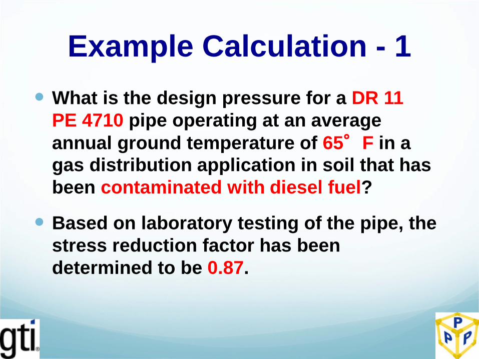
Example Calculation - 1 What is the design pressure for a DR 11
PE 4710 pipe operating at an average annual ground temperature of 65°F in a gas distribution application in soil that has been contaminated with diesel fuel?
Based on laboratory testing of the pipe, the stress reduction factor has been determined to be 0.87.

Example Calculation
P = 2 (S) (DF) (DFC) (DR – 1)
P = 2 (1600) (0.32) (0.87) (11 – 1)
P = 89 psig for a gas application

Effect of Liquid Hydrocarbon on PE Design Pressure
The design pressure for this pipe without a liquid hydrocarbon is 102 psig
In the presence of liquid hydrocarbons in the soil the chemical design factor was calculated to be 0.87, or a 13% reduction in the HDB
This results in a 13% reduction in the design pressure, or 89 psig
This is considerable better than a 50% reduction in design pressure, which would be 51 psig

Example Calculation - 2 What is the design pressure for a DR 11
PE 2708 pipe operating at an average annual ground temperature of 65°F in a gas distribution application in which liquid hydrocarbon in the natural gas inside the pipe has penetrated into the pipe wall – i.e. bubbles are present during heating?
Based on laboratory testing of the pipe, the stress reduction factor has been determined to be 0.93.

Example Calculation
P = 2 (S) (DF) (DFC) (DR – 1)
P = 2 (1250) (0.32) (0.93) (11 – 1)
P = 74 psig for a gas application

Effect of Liquid Hydrocarbon on PE Design Pressure
The design pressure for this pipe without a liquid hydrocarbon is 80 psig
In the presence of liquid hydrocarbons inside the pipe the chemical design factor was calculated to be 0.93, or a 7% reduction in the HDB
This results in a 7% reduction in the design pressure, or 74 psig
This is considerable better than a 50% reduction in design pressure, which would be 40 psig

Need Testing? For additional information on how GTI can test
your pipeline to determine the chemical design factor in the presence of liquid hydrocarbons (from inside or outside the pipe) contact:
Dr. Gene Palermo [email protected] (865) 995-1156 Dennis Jarnecke- GTI [email protected] (847) 544-3415

THE END
Prepared by Palermo Plastics
Pipe (P3) Consulting