chemical engineering - an overview - idc · 1 chemical engineering – an overview 1.1 basics of...
TRANSCRIPT

Chemical engineering
- an overview :
Stoichiometry
Chemical kinetics
Fluid mechanics

Chemical Engineering - an overview: Stoichiometry, Chemical Kinetics, Fluid Mechanics

WHO ARE WE? IDC Technologies is internationally acknowledged as the premier provider of practical, technical training for engineers and technicians. We specialize in the fields of electrical systems, industrial data communications, telecommunications, automation and control, mechanical engineering, chemical and civil engineering, and are continually adding to our portfolio of over 60 different workshops. Our instructors are highly respected in their fields of expertise and in the last ten years have trained over 200,000 engineers, scientists and technicians. With offices conveniently located worldwide, IDC Technologies has an enthusiastic team of professional engineers, technicians and support staff who are committed to providing the highest level of training and consultancy. TECHNICAL WORKSHOPS TRAINING THAT WORKS We deliver engineering and technology training that will maximize your business goals. In today’s competitive environment, you require training that will help you and your organization to achieve its goals and produce a large return on investment. With our ‘training that works’ objective you and your organization will:
Get job-related skills that you need to achieve your business goals Improve the operation and design of your equipment and plant Improve your troubleshooting abilities Sharpen your competitive edge Boost morale and retain valuable staff Save time and money
EXPERT INSTRUCTORS We search the world for good quality instructors who have three outstanding attributes:
1. Expert knowledge and experience – of the course topic 2. Superb training abilities – to ensure the know-how is transferred effectively and quickly to you in
a practical, hands-on way 3. Listening skills – they listen carefully to the needs of the participants and want to ensure that you
benefit from the experience. Each and every instructor is evaluated by the delegates and we assess the presentation after every class to ensure that the instructor stays on track in presenting outstanding courses. HANDS-ON APPROACH TO TRAINING All IDC Technologies workshops include practical, hands-on sessions where the delegates are given the opportunity to apply in practice the theory they have learnt. REFERENCE MATERIALS A fully illustrated workshop book with hundreds of pages of tables, charts, figures and handy hints, plus considerable reference material is provided FREE of charge to each delegate. ACCREDITATION AND CONTINUING EDUCATION Satisfactory completion of all IDC workshops satisfies the requirements of the International Association for Continuing Education and Training for the award of 1.4 Continuing Education Units. IDC workshops also satisfy criteria for Continuing Professional Development according to the requirements of the Institution of Electrical Engineers and Institution of Measurement and Control in the UK, Institution of Engineers in Australia, Institution of Engineers New Zealand, and others.
THIS BOOK WAS DEVELOPED BY IDC TECHNOLOGIES

CERTIFICATE OF ATTENDANCE Each delegate receives a Certificate of Attendance documenting their experience. 100% MONEY BACK GUARANTEE IDC Technologies’ engineers have put considerable time and experience into ensuring that you gain maximum value from each workshop. If by lunchtime on the first day you decide that the workshop is not appropriate for your requirements, please let us know so that we can arrange a 100% refund of your fee. ONSITE WORKSHOPS All IDC Technologies Training Workshops are available on an on-site basis, presented at the venue of your choice, saving delegates travel time and expenses, thus providing your company with even greater savings. OFFICE LOCATIONS
AUSTRALIA • CANADA • INDIA • IRELAND • MALAYSIA • NEW ZEALAND • POLAND • SINGAPORE • SOUTH AFRICA • UNITED KINGDOM • UNITED STATES
On-Site Training
All IDC Technologies Training Workshops are available on an on-site basis, presented at the venue of your choice, saving delegates travel time and expenses, thus providing your company with even
greater savings. For more information or a FREE detailed proposal contact Kevin Baker by e-mailing:
[email protected] www.idc-online.com
Visit our website for FREE Pocket Guides IDC Technologies produce a set of 6 Pocket Guides used by
thousands of engineers and technicians worldwide. Vol. 1 – ELECTRONICS Vol. 4 – INSTRUMENTATION Vol. 2 – ELECTRICAL Vol. 5 – FORMULAE & CONVERSIONS Vol. 3 – COMMUNICATIONS Vol. 6 – INDUSTRIAL AUTOMATION
To download a FREE copy of these internationally best selling pocket guides go to:
www.idc-online.com/downloads/
SAVE MORE THAN 50% OFF the per person
cost
CUSTOMISE the training to YOUR WORKPLACE!
Have the training delivered WHEN
AND WHERE you need it!

IDC TECHNOLOGIES
Worldwide Offices
AUSTRALIA Telephone: 1300 138 522 • Facsimile: 1300 138 533
West Coast Office
1031 Wellington Street, West Perth, WA 6005 PO Box 1093, West Perth, WA 6872
East Coast Office
PO Box 1750, North Sydney, NSW 2059
CANADA Toll Free Telephone: 1800 324 4244 • Toll Free Facsimile: 1800 434 4045
Suite 402, 814 Richards Street, Vancouver, NC V6B 3A7
INDIA Telephone : +91 444 208 9353
35 4th Street, Kumaran Colony, Vadapalani, Chennai 600026
IRELAND Telephone : +353 1 473 3190 • Facsimile: +353 1 473 3191
PO Box 8069, Shankill Co Dublin
MALAYSIA Telephone: +60 3 5192 3800 • Facsimile: +60 3 5192 3801
26 Jalan Kota Raja E27/E, Hicom Town Center Seksyen 27, 40400 Shah Alam, Selangor
NEW ZEALAND
Telephone: +64 9 263 4759 • Facsimile: +64 9 262 2304 Parkview Towers, 28 Davies Avenue, Manukau City
PO Box 76-142, Manukau City
POLAND Telephone: +48 12 6304 746 • Facsimile: +48 12 6304 750
ul. Krakowska 50, 30-083 Balice, Krakow
SINGAPORE Telephone: +65 6224 6298 • Facsimile: + 65 6224 7922
100 Eu Tong Sen Street, #04-11 Pearl’s Centre, Singapore 059812
SOUTH AFRICA Telephone: +27 87 751 4294 or +27 79 629 5706 • Facsimile: +27 11 312 2150
68 Pretorius Street, President Park, Midrand PO Box 389, Halfway House 1685
UNITED KINGDOM
Telephone: +44 20 8335 4014 • Facsimile: +44 20 8335 4120 Suite 18, Fitzroy House, Lynwood Drive, Worcester Park, Surrey KT4 7AT
UNITED STATES
Toll Free Telephone: 1800 324 4244 • Toll Free Facsimile: 1800 434 4045 7101 Highway 71 West #200, Austin TX 78735
Website: www.idc-online.com
Email: [email protected]

Presents
Chemical Engineering - an overview: Stoichiometry, Chemical Kinetics, Fluid Mechanics
Revision 1
Website: www.idc-online.com E-mail: [email protected]

IDC Technologies Pty Ltd PO Box 1093, West Perth, Western Australia 6872 Offices in Australia, New Zealand, Singapore, United Kingdom, Ireland, Malaysia, Poland, United States of America, Canada, South Africa and India Copyright © IDC Technologies 2013. All rights reserved. All rights to this publication, associated software and workshop are reserved. No part of this publication may be reproduced, stored in a retrieval system or transmitted in any form or by any means electronic, mechanical, photocopying, recording or otherwise without the prior written permission of the publisher. All enquiries should be made to the publisher at the address above. Disclaimer
Whilst all reasonable care has been taken to ensure that the descriptions, opinions, programs, listings, software and diagrams are accurate and workable, IDC Technologies do not accept any legal responsibility or liability to any person, organization or other entity for any direct loss, consequential loss or damage, however caused, that may be suffered as a result of the use of this publication or the associated workshop and software.
In case of any uncertainty, we recommend that you contact IDC Technologies for clarification or assistance.
Trademarks All logos and trademarks belong to, and are copyrighted to, their companies respectively. Acknowledgements
IDC Technologies expresses its sincere thanks to all those engineers and technicians on our training workshops who freely made available their expertise in preparing this manual.

Table of Contents
1 Chemical engineering- an overview 1 1.1 Basics of chemical engineering 1 1.2 Unit operations 2 1.3 Thermodynamics 8 1.4 Chemical Kinetics 9 1.5 Chemical engineer – scope & responsibilities 9 1.6 “Ten greatest achievements” of chemical engineering 15 1.7 Chemical engineering “Today & Tomorrow” 17
2 Stoichiometry 19 2.1 Introduction 19 2.2 Understanding chemical formulas and equations 19 2.3 Balancing chemical equations 25 2.4 Chemical periodicity 27 2.5 Molecular weight 28 2.6 The mole and molar mass 29 2.7 Percent composition 29 2.8 Introduction to solutions 32 2.9 Units and dimensions 33 2.10 Process variables 36
3 Chemical kinetics 41 3.1 Chemical reactions – Basic concepts 41 3.2 Classification of chemical reactions 42 3.3 Chemical reaction profile 43 3.4 Classification of reactors 44 3.5 Catalysts 49 3.6 Promoters 53 3.7 Efficiency criteria of a chemical process 55

4 Fluid mechanics 57 4.1 Introduction 57 4.2 Volumetric properties of liquids 57 4.3 Liquid-column manometers 58 4.4 Mechanical pressure gauges 61 4.5 Measurement of fluid flow 65 4.6 Valves 82 4.7 Fluid moving machinery 90 4.8 Centrifugal pumps 91 4.9 Positive-displacement pumps 92 4.10 Agitation equipments 96

1
Chemical engineering – an overview
1.1 Basics of chemical engineering Chemical engineering is associated with:
• Efficient and economic control of chemical processes • Design of chemical reactors and process plants • Development of sustainable products • Pollution control and treatment of industrial wastes
Man has utilized chemicals for a long time but chemical engineering was recognized
as a separate field only a century ago. Egyptians developed certain types of papers as early as 2000 BC and glass is presumed to have been invented close to 5000 BC. Perhaps the single most important pursuit in chemistry was the ‘manufacture’ of gold. As soon as

2 Practical fundamentals of chemical engineering
man discovered this metal he became obsessed with it. No civilization could resist the shine of this precious metal. In the middle ages a set of ‘mad-hatters’ decided to live their dream of converting base metals to gold. The conversion became the ‘Holy Grail’ of those pursuing it. Some of the greatest discoveries in physical chemistry were made by these people even though the ‘Grail’ still remains elusive. Today their work is recognized as a pioneering effort and the first standardization of manufacturing techniques which ultimately gave us the field of Chemical Engineering. These scientists are collectively referred to as the Alchemists.
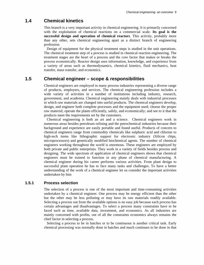
But like all other engineering disciplines, chemical engineering ultimately got recognized as a major field of engineering in the 19th century. During this period of industrial revolution the requirement for engineers who could design chemical reactors and plants was greatly enhanced because of the increase in the use of chemicals in every day life. This was a time when the chemical industry grew rapidly and it needed experts to handle chemical plants and their design. Up till 1910, the chemical industry had to rely mainly on mechanical engineers and chemists.
Figure 1.1 Typical chemical process plant
However, due to emerging methods and techniques, chemical processing was becoming too complex, and it called for the training of engineers in the field of chemical processing. The design of chemical reactors and other equipment involved in a chemical process plant was beyond the scope for chemists and mechanical engineers. Keeping all these factors in view, the start of a new engineering discipline for chemicals was seriously considered.
As a result, chemical engineering emerged as a separate discipline in 1910 when professors at Massachusetts Institute of Technology (MIT) realized that neither mechanical engineering nor chemistry offered sound approaches to a chemical plant’s design. So a new branch of engineering was started to prepare engineers specializing in the design, operation, and construction of chemical processing plants. Subsequently, this field got universal recognition and many institutions throughout the globe started teaching this subject. Today, thousands of chemical engineers are working around the globe and scores of young men and women are being trained.
1.2 Unit operations Processing and manufacturing of chemicals in industries is based on many operations such as heat transfer, mass transfer, fluid flow, distillation, evaporation, absorption, drying, leaching, mixing, crystallization, adsorption, and humidification.
The idea of treating these processes of the chemical industry as unit operations was also put forward by the professors of the MIT. They characterized the physical operations necessary for manufacturing chemicals as unit operations. Although originally largely

Chemical engineering- an overview 3
descriptive, these unit operations have been the object of vigorous study and now can be used with sound mathematical procedures for plant design predictions.
During 1930, P. H. Groggins proposed a similar approach to classifying chemical operations as unit processes. Such processes include nitration, oxidation, hydrogenation, sulphonation, chlorination, and esterification. Development of a lab-scale process, designed by a chemist, into a large-scale industrial process is a difficult task and requires the knowledge of the chemicals as well as the mechanical aspects of the equipment required.
The physical operations necessary for manufacturing chemicals are called unit operations. It is a method of organizing much of the subject matter of chemical engineering. Unit operations can be, no doubt, called the heart of chemical engineering. The unit operations concept is based on the fact that by systematically studying the operations (such as heat transfer, mass transfer, fluid flow, drying, distillation, evaporation, absorption, extraction, and mixing) involved in the chemical industry, the treatment of all processes is unified and simplified. The unit operations are largely used to conduct the primary physical steps of preparing the reactants, separating and purifying the products, recycling unconverted reactants, and controlling the energy transfer into or out of the chemical reactors. The design of the equipment involved for these operations is also studied in unit operations. Because of the complexity and variety of the modern chemical manufacturing processes the need for arranging the different processes systematically has become undeniable. The chemical steps themselves are conducted by controlling the flow of material and energy to and from the reaction zone.
1.2.1 Fluid mechanics The branch of engineering that investigates the behavior of fluids is called fluid mechanics. It is a part of a larger branch of engineering called continuum mechanics, which deals with the behavior of fluids as well as stressed solids. A fluid is a substance that does not permanently resist distortion. An attempt to alter the shape of a mass of fluid results in layers of fluids sliding over one another until a new shape is attained. During the change in shape, shear stresses exist depending upon the viscosity of the fluid and the rate of sliding, but when the final shape is achieved all the shear stresses disappear. A fluid in equilibrium is free from shear stresses.
Fluids may be compressible or incompressible. If the density of a fluid changes slightly with the changes in temperature and pressure then such a fluid is called incompressible and if the density changes significantly then such a fluid is said to be compressible. Gases are generally considered to be compressible while liquids are considered incompressible.
The behavior of fluids is very important in chemical engineering. It is a major part of unit operations principle. Understanding of fluids is essential not only for accurately treating problems in the movement of fluids through pipes, compressors, pumps, and all kinds of process equipment but also for the study of heat flow and many separation principles that depend on diffusion and mass transfer. Design and study of measuring devices (such as flow meters, area meters, pressure gauges), transportation equipment (such as compressors and pumps), and mixing and agitation equipment (such as mixers and agitators) are considered in fluid mechanics.
Fluid mechanics can be divided into two branches: • Fluid statics • Fluid dynamics

4 Practical fundamentals of chemical engineering
Fluid statics deals with the fluids at rest or in equilibrium state with no shear stress. It is concerned with the properties and behavior of fluids. In the case of liquids this subject is called hydrostatics and in the case of gases it is called pneumatics.
Fluid dynamics, also called fluid flow, deals with the flowing fluids or with fluids when section of the fluid is in motion relative to the other parts. The flow of a fluid is of two types:
• Laminar flow: The flow in which the layers of the fluid are flowing parallel to the axis of the pipe or conduit
• Turbulent flow: The flow in which the layers of the moving fluids are not parallel to the axis of the pipe and the fluid is disturbed from point to point
Chemical engineers are continuously involved with the flow of fluids. In industrial applications, they have to transport fluids from one point to another through pipes or open ducts which require the determination of pressure drops in the system, selection of a proper type of pump or compressor, power required for pumping or compression, and measurement of flow rates. All these aspects are studied in fluid flow. A major portion of fluid flow deals with the transportation, metering, and mixing & agitation of fluids.
1.2.2 Heat transfer Heat transfer is the branch of engineering that deals with the rates of heat exchange between hot and cold bodies. The driving force for heat transfer is the temperature difference per unit area or temperature gradient. In a majority of chemical processes heat is either given out or absorbed. Most of the times the fluids must be heated or cooled in a variety of equipment such as boilers, heaters, condensers, furnaces, dryers, evaporators, and reactors. In all of these cases the fundamental problem encountered is the transferring of heat at the desired rate. Some times it is necessary to prevent the loss of heat from vessels or pipes.
The control of flow of heat at the desired rate is one of the most important areas of chemical engineering. The principles and laws governing the rates of heat flow are studied under the heading of heat transfer. Even though the transfer of heat is involved in every unit operation, in evaporation, drying, and combustion the primary concern is the transfer of heat rather than the transfer of mass and these operations are governed by the rate of heat transfer. Laws and equations of heat transfer are used for the designing of the equipment required for these processes.
Evaporation is the process used to concentrate a solution consisting of a non-volatile solute and volatile solvent. In a majority of evaporations the solvent is water.
Drying is the removal of relatively small amounts of water or other liquid from the solid material to reduce the content of residual liquid to a low value.
Heat transfer can take place through the following three modes of (heat) transfer: • Conduction • Convection • Radiation
However, most of the processes are a combination of two or more modes of heat transfer.
Conduction Conduction is the transfer of heat through fixed material such as stationary walls. In a solid, the flow of heat is the result of the transfer of vibrational energy from one molecule to another, and in fluids it occurs in addition as a result of the transfer of kinetic energy. Heat transfer through conduction may also arise from the movement of free electrons.

Chemical engineering- an overview 5
Convection Convection is the heat transfer occurring due to the mixing of relatively hot and cold portions of a fluid. If this mixing takes place due to density differences, then such a process is called natural or free convection, e.g. a pool of liquid heated from below. However, if the mixing takes place due to eddies produced by mechanical agitation then such a process is called forced convection. It is important to note that convection requires mixing of fluid elements and is not governed by just the temperature difference as in conduction and radiation.
Radiation Radiation is the transfer of radiant energy from one body to another. All materials radiate thermal energy in the form of electromagnetic waves. When radiation falls on a second body it may be partially reflected, transmitted, or absorbed. It is only the fraction that is absorbed that appears as heat in the body. While heat transfer deals with the transfer of heat between hot and cold bodies independently, Process heat transfer deals with the rates of heat exchange as they occur in the heat-transfer equipment of the engineering and chemical processes.
1.2.3 Mass transfer Mass transfer is involved with the transfer of a component in a mixture from a region in which it has a high concentration to a region in which its concentration is lower. This process can occur in a gas, liquid, or vapor. It can result from the random velocities of the molecules (molecular diffusion) or from the circulating or eddy currents present in a turbulent fluid (eddy diffusion). Like temperature gradient is the driving force for heat transfer, the driving force for mass transfer is the concentration gradient. Many unit operations such as distillation, absorption, extraction, leaching, membrane separation, dehumidification, crystallization, ion exchange, and adsorption are considered as mass transfer operations. Even though transfer of heat is also involved in these operations but the rate of mass transfer governs the rate phenomena in these processes. Unlike purely mechanical separation processes, which utilize density difference and particle size, these methods make use of differences in vapor pressure, solubility, or diffusivity.
Distillation The function is to separate, by vaporization, a liquid mixture of miscible and volatile substances into individual components or, in some cases into groups of components.
Absorption In absorption a soluble vapor is absorbed by means of a liquid in which the solute gas is more or less soluble, from its mixture with an inert gas. The solute is subsequently recovered from the liquid by distillation, and the absorbing liquid can either be discarded or reused.
Desorption When a solute is transferred from the solvent liquid to the gas phase, the operation is known as stripping or desorption.

6 Practical fundamentals of chemical engineering
Dehumidification A pure liquid is partially removed from an inert or carrier gas by condensation. Usually the carrier gas is virtually insoluble in the liquid.
Membrane separations In membrane separations, including gas separations, reverse osmosis, and ultra filtration, one component of a liquid or gaseous mixture passes through a selective membrane more readily than the other components.
Adsorption In adsorption a solute is removed from either a liquid or a gas through contact with a solid adsorbent, the surface of which has a special affinity for the solute.
Liquid extraction Also called solvent extraction, a mixture of two components is treated by a solvent that preferentially dissolves one or more of the components in the mixture. The mixture so treated is called the raffinate and the solvent-rich phase is called extract. In extraction of solids, or leaching, soluble material is dissolved from its mixture from an inert solid by means of a liquid solvent.
Crystallization This process is used to obtain materials in attractive and uniform crystals of good purity, separating a solute from a melt or a solution and leaving impurities behind.
1.2.4 Solid particulate operations Also termed as particle technology, this branch of unit operations deals with solid handling and is mainly concerned with the mixing, size reduction, and mechanical separation of solids. Solids in general are more difficult to handle than fluids. In processing solids appear in a variety of forms such as angular pieces, continuous sheets, finely divided powders. They may be hard and abrasive, tough and rubbery, soft or fragile, dusty, cohesive, free flowing, or sticky. Whatever their form, means must be found to handle these solids.
Mixing of solids resembles to some extent with the mixing of low-viscosity liquids, however, mixing of solids requires much more power. In mixing two or more separate components are intermingled to obtain a uniform product. Some of the mixers and blenders used for liquids are also used for solids. Solid mixers mainly used are kneaders, dispersers, masticators, mixer-extruders, mixing rolls, pug mills, ribbon blenders, screw mixers, tumbling mixers, and impact wheel.
Size reduction Size reduction, referred to as communition, is a term applied to the methods and ways used to cut or breakdown solid particles in smaller pieces.
Reduction of particle size is usually carried in four ways: • Compression • Impact • Attrition or rubbing • Cutting

Chemical engineering- an overview 7
Separations Separations can be classified into two classes:
• Diffusional operations
Involves the transfer of material between phases e.g. absorption, distillation, adsorption etc
• Mechanical separations
It is used for heterogeneous mixtures. This class of separation processes consists of techniques based on physical differences between the particles such as size, shape, or density. They are applicable to separating solids from gases, liquid drops from gases, solids from solids, and solids from liquids
Two general methods are:
• The use of a sieve, or membrane such as a screen or a filter, which retains one component and allows the other to pass
• The utilization of differences in the rate of sedimentation of particles or drops as they move through a liquid or a gas. The operations included in mechanical separations are screening, filtration, and gravity and centrifugal settling
Screening Screening is a method of separating particles according to size alone. In industrial screening the solids are dropped or thrown against a screening surface. The undersize (also called fines) pass through the screen openings leaving behind oversize (also called tails) particles. Industrial screens are made from woven wire, silk, plastic cloth, metal, and perforated or slotted metal plates. Stationary screens, grizzlies, gyrating screens, vibrating screens, and centrifugal sifters are used for this purpose.
Filtration Filtration is the separation of solid particles from a fluid by passing the fluid through a filtering medium through which the solids are deposited. Industrial filtrations range from simple straining to highly complex separations. The fluid may be a liquid or a gas; the valuable stream from the filter may be fluid, solid, or both.
Filters are divided into three main groups: • Cake filters separate relatively large amounts of solids as a cake of crystals
or sludge. Filter press, shell and leaf filter, belt filter, rotary drum filter, batch centrifuge filters are used for this purpose
• Clarifying filters remove small amounts of solids to produce a clean gas or a sparkling clear liquid by trapping the solid particles inside the filter medium. Gravity bed filters, cartridge filters, edge filters, tank filters, pad filters, bag filters, and granular bed filters are used for this purpose
• Cross-flow filters are used for very fine particles or for micro-filtration. In a cross-flow filter the feed suspension flows under pressure at a fairly high velocity across the filter medium. Some of the liquid passes through the medium as a clear filtrate, leaving behind a more concentrated suspension. For these filters different types of membranes are used

8 Practical fundamentals of chemical engineering
Settling processes Settling processes are used for mechanical separations, utilizing the movement of solid particles or liquid drops through a fluid.
Gravity settling processes are based on the fact that particles heavier than the suspended fluid can be removed from a gas or liquid in a large settling tank in which the fluid velocity is low and the particles are allowed a sufficient time to settle out.
Gravity settling process is of two types: • Clarifier: A settler that removes virtually all the particles from a liquid • Classifier: A device that separates the solid into two fractions
Centrifugal settling processes are efficient than gravity settling processes. A given
particle in a given fluid settles under gravitational force at a fixed maximum rate. To increase the settling rate the force of gravity acting on the particle may be replaced by a much stronger centrifugal force. Centrifugal separators, to certain extent, have replaced the gravity separators because of their greater effectiveness with fine drops and particles and their much smaller size for a given capacity. The most widely used type of centrifugal separators is the cyclone separator. Other types mostly used are centrifugal decanters, tubular centrifuges, disk centrifuge, nozzle discharge centrifuge, and centrifugal classifiers.
1.3 Thermodynamics The transformation of heat energy into some other form of energy or the transformation of some other form of energy into heat energy is called thermodynamics. Thermodynamics is a very useful branch of engineering science and is very helpful in the treatment of such processes as refrigeration, flashing, and the development of boilers and steam and gas turbines. Thermodynamics is governed by two rules called the first and second law of thermodynamics.
First law of thermodynamics First law of thermodynamics states that Energy can neither be created nor destroyed, however it can be transferred from one form to another. This law is also known as law of conservation of energy. In thermodynamic sense, heat and work refer to energy in transit across the boundary between the system and surroundings. These forms of energy can never be stored. Energy is stored in its potential, kinetic, and internal forms. These forms reside with material objects and exist because of position, configuration, and motion of matter.
Second law of thermodynamics The second law of thermodynamics states that it is impossible to transfer heat from a cold body to a hot body unless external work is done on the system. Or, no heat engine operating continuously in a cycle can extract heat from a hot reservoir and convert it into useful work without having a sink. The universal applicability of this science is shown by the fact that physicists, chemists, and engineers employ it. In each case the basic principles are the same but the applications differ.
Thermodynamics enables a chemical engineer to cope with a wide variety of problems. Among the most important of these are the determinations of heat and work requirements for many physical and chemical processes, and the determination of equilibrium conditions for chemical reactions and for the transfer of chemical species between phases.
Chemical engineering- an overview 9
1.4 Chemical kinetics This branch is a very important activity in chemical engineering. It is primarily concerned with the exploitation of chemical reactions on a commercial scale. Its goal is the successful design and operation of chemical reactors. This activity, probably more than any other, sets chemical engineering apart as a distinct branch of engineering profession.
Design of equipment for the physical treatment steps is studied in the unit operations. The chemical treatment step of a process is studied in chemical reaction engineering. The treatment stages are the heart of a process and the core factor that makes or breaks the process economically. Reactor design uses information, knowledge, and experience from a variety of areas such as thermodynamics, chemical kinetics, fluid mechanics, heat transfer, mass transfer, and economics.
1.5 Chemical engineer – scope & responsibilities Chemical engineers are employed in many process industries representing a diverse range of products, employers, and services. The chemical engineering profession includes a wide variety of activities in a number of institutions including industry, research, government, and academia. Chemical engineering mainly deals with industrial processes in which raw materials are changed into useful products. The chemical engineers develop, design, and engineer both complete processes and the equipment used; choose the proper raw material; operate the plants efficiently, safely, and economically; and see to it that the products meet the requirements set by the customers.
Chemical engineering is both an art and a science. Chemical engineers work in numerous areas besides petroleum refining and the petrochemical industries because their background and experience are easily portable and found useful. Products of concern to chemical engineers range from commodity chemicals like sulphuric acid and chlorine to high-tech items like lithographic support for electronic industry (Silicon chips, microprocessors) and genetically modified biochemical agents. The number of chemical engineers working throughout the world is enormous. These engineers are employed by both private and public enterprises. They work in a variety of fields besides process and designing. The wide spectrum of application of chemical engineers shows that chemical engineers must be trained to function in any phase of chemical manufacturing. A chemical engineer during his career performs various activities. From plant design to successful plant operation he has to face many tasks and challenges. To have a better understanding of the work of a chemical engineer let us consider the important activities undertaken by him
1.5.1 Process selection The selection of a process is one of the most important and time-consuming activities undertaken by a chemical engineer. One process may be energy efficient than the other but the other may be less polluting or may have its raw materials readily available. Selecting a process out from the available options is no easy job because each process has certain advantages and disadvantages. To select a process many constraints have to be faced such as time, available data, investment, and economics. As all industries are mainly concerned with profits, out of all the constraints economics always remains the chief factor in selecting a process.
Selecting a process to be in batches or to be continuous is another critical task. Early chemical processing was normally done in batches and much continues to be done in that

10 Practical fundamentals of chemical engineering
way. Batches can be measured correctly and are much suitable for small-scale production. However, the temperature and pressure control can be troublesome.
Furthermore time and resources lost in attaining the required conditions such as temperature and pressure, limits the use of batch processes. On the other hand, continuous processes require far smaller and less expensive equipment, have much less material in process, have less chance to ruin large quantities, have more uniform operating conditions, and give more uniform products than batch processes.
Continuous processes are very suitable for large-scale productions. However, these require concise control of flow-rates and conditions, which is impossible without high quality instrumentation. The reduction in plant cost per unit of production is often the major force in selecting a process to continuous or in batches.
1.5.2 Operation Operation of a process plant is another important activity carried out by a chemical engineer. Chemical processing of a raw material into the desired product can only be achieved by operating the chemical plant. The quality and quantity of the product is directly dependent on the efficient operation of a plant. The smooth operation of a plant is a very difficult task and requires close attention of the engineer at all times. Many problems like temperature and pressure control, maintenance, and safety continue to arise during the plant operation. Experience and application of engineering principles is always needed to shoot out these problems. Negligence of a small problem can often lead to bigger, more complex problems and can cause unnecessary halts in production.
In order to be able to handle plant operation smoothly, a chemical engineer should start early to become familiar with the industrial equipment such as pumps, compressors, distillation columns, filter presses, and heat exchangers, etc. Almost every industry wants its engineers to be intimately familiar with every pipe & gauge of that industry. That is why every industry makes its new engineers spend their earlier time in tracing pipelines, an activity known as line tracing. The reason behind this practice is to intimately familiarize the engineers with all the pipelines, gauges, valves, and equipment of that industry so that whenever there is any fault in any section he should be able to identify the location and to work out its solution immediately.
In fact, troubleshooting is the core of plant operation. Successful plant operation of a chemical plant does not only depend upon the original strength of the materials of construction but also upon the affects of corrosion. Constant check-ups and inspection must be maintained to avoid corrosion. Mechanical failures are seldom experienced unless there has been previous corrosion or weakening by chemical attack.
Chemical manufacturing process can be divided into the following steps: • Raw material • Physical treatment steps • Chemical treatment steps • Recycle • Product
1.5.3 Instrumentation and control In commercial scale continuous operations the function of the workers and the supervising chemical engineer is to maintain the plant in proper running conditions. Maintaining required temperature, pressure, flow-rates, and other conditions is a very difficult task. Quality instrumentation is a must for maintaining these conditions.

Chemical engineering- an overview 11
Instruments are the essential tools for modern processing. A chemical engineer must have the proper knowledge of the instruments involved for controlling and measuring process variables. Adequate ability to design control systems for processes and workout problems faced in controlling process operations is also essential.
Batch operation requires few instruments and hence more supervision on the part of the workers and the chemical engineer because the conditions and procedures differ from the start to the finish. Programmed instruments can solve even these problems if the expense can be justified. Instrument costs, once a trivial part of the total plant investment, have risen up to 25% of the total investment.
The use of computers has reduced this cost to some extent. Earlier plants used mechanical control instruments. These were replaced by pneumatic control systems, which were replaced by electronic control systems. Currently, plant-control is being done by DCS (Distributed Control System) using computers. DCS incorporates the use of electronic control devices but it utilizes computers to monitor and control process conditions. Even though many industries continue to use pneumatic and electronic control systems, however, the global trend is towards DCS because of its ability to handle plant operation more smoothly. Instrumentation has been forced into this position of eminence by the increase in continuous processes, increase in labour and supervision costs, the relative unreliability of human actions, and by the availability of many types of instruments at decreasing price and increasing reliability.
Instrument types include indicating instruments, recording instruments, and controlling instruments. Two types of instruments are generally used: analog and digital. Analog instruments such as pressure spring thermometer and Bourdon pressure gauges show results by mechanical movement of some type of device (e.g. spring or Bourdon tube), which is proportional to the quantity being measured. Digital devices generally utilize a transducer, a device that converts the measured signal into some other type of signal usually electronic or pneumatic. These devices also use electronic circuits, which convert the signal to readable numerical figures (digits), which are then displayed and may be recorded.
1.5.4 Chemical process economics Economics is a vital part of an engineers work. Engineers are distinguished from scientists by their consciousness of costs and profits. Economics plays a vital role in the operation, design, and maintenance of every chemical plant. A good chemical engineer always gives economics top priority in his every effort. Every engineering decision involves cost considerations. Engineers must continue to keep up with the economic changes that may affect their products.
The primary objective of an engineer's efforts must be to deliver safely the best product or the most efficient services at the lowest cost to the employer and the consumer. Since change is an outstanding characteristic of the chemical procedures, hence potential alteration of a process is of importance not only when the plant is being designed but continuously.
Decisions based on comparative facts must be exerted in most of the important discussions of a chemical engineer. Careful calculations using local parameters generally lead to clear and just decisions. Yield and conversions of the chemical process form the basis for the material and energy balances, which in turn are the foundation for the cost determination. Primary stress must be laid on these balances to keep the plant operation economical and profitable. Economic conditions and limitations are one of the most important factors of any plant design activity. The engineer must consider costs and

12 Practical fundamentals of chemical engineering
profits constantly throughout his work. Cost per unit product always turns out to be the key issue for any business enterprise and an engineer should always work to keep it as economical as possible. It’s almost always better to sell many units of product at a low profit per unit than a few units at a high cost. An engineer must take into account the volume for production when determining costs and total profits for various types of designs, keeping in view customer needs and demands.
1.5.5 Marketing Whenever a new product is under assessment, market evaluation for that product becomes essential. The job of a chemical engineer then leads to the market estimation of that product. The factors generally considered in the market evaluation are the present and future supply and demand, present and future uses, new uses, present buying habits, price range for products and by-products, character, location, and number of possible customers.
The marketing of a product does not only depend upon its advertisement but also on the quality of the product, its physical conditions, and it’s packing. Good firms rarely compromise on quality. Proper instrumentation, uniform plant conditions, good operators, and careful supervision lead to quality production. The physical conditions of the products have a very strong impact on the marketability. The physical conditions involve crystal structure, particle size and shape, colours, and moisture content.
Packaging of the product also plays an important role in the marketing of a product, especially the consumer products. However, packaging is often expensive. The most economical containers are refillable bulk ones such as tanks, tank-ships, and tank-cars. But these cannot be used for the consumer products since the container appearance is very important to the customers. For consumer products quality packing with attractive colours, designs, and materials has to be used.
Price of a product is the real concern for a customer. Prices should be maintained within the affordable range of a large number of people, since bigger markets lead to larger profits. To enhance the marketing of a product, an engineer should listen to the suggestions and the information brought to him by the salesperson, since he is the link between the company and the customer.
1.5.6 Safety Chemical engineer also has role to perform in plant safety. Nothing is more dangerous to a plant than fire. Precautions to prevent and extinguish fire must be taken. Employees must be protected against toxic chemicals. Safety measures not only keep the employees out of danger but also save money and time by reducing accidents and any unnecessary halts in the production. Even though every human being is bound to err sometime, but at times he gets careless too. Sometimes too much familiarity with chemicals breeds’ carelessness, hence well-run plants have safety devices and continuing programmes for alerting those working with a given process to its hazards. Adequate safety and fire protection measures require expert guidance. There is considerable difference of opinion in rating certain chemicals as hazardous and their degree of toxicity. There are different standards for many toxic and harmful substances, however nowadays the governments decide these standards and are very severe on their implementation.

Chemical engineering- an overview 13
1.5.7 Construction of a plant The construction (erection) of a plant is another activity carried out by a chemical engineer. The presence of the chemical engineer is essential during the erection of the plant in order to implement the design standards and interpret technical and design data whenever needed. The chemical engineer should always work closely with the construction team during the final stages of construction and purchasing designs. Construction of the plant may be started before the final design is completed.
During plant erection, the chemical engineer should visit the plant site to assist in the interpretation of plans and learn methods for improving future designs. The engineer should also be available during the initial start-up of the plant and early phases of operation. During the erection of a plant the engineer becomes intimately connected with the plant and hence learns the internal structure of the plant. The chemical engineer becomes involved with the installation of every pipe and gauge of the plant and this helps greatly while running the plant and eliminating problems faced during operation.
1.5.8 Research and development Adequate and skilled research with patent protection is required for future profits. The chemical process industry has certain salient characteristics such as rapidly changing procedures, new processes, new raw materials and new markets. Research creates or utilizes these changes. Without forward-looking investigation or research a company would lag behind in the competitive progress of its industry. Development is the adaptation of research ideas to the realities of production and industry. The progress of industry opens up new markets for even the most fundamental, established products.
1.5.9 Management Due to the dramatic rise in productivity and the recent technological advances in the chemical process industries, this sector has become very complex. The complexity of this industry has made it very difficult for business graduates, who do not have any knowledge of chemicals and equipments, to handle it. Now the chemical companies like to have chemical engineers as their mangers.
Management is a very important aspect of plant operation. Handling the personnel, most importantly the workers is one of the most difficult jobs but a chemical engineer is always in contact with his workers and most of the time has to rely on them. Dealing the personnel is often called Human engineering. The job of a chemical engineer is to control and run machines effectively and efficiently, and there is no machine better or more complex than the human being. Controlling this machine is perhaps the most difficult task a man has to perform. But as an engineer is in constant interaction with his workers and personnel so he has to perform it effectively. Hence, a good engineer must be a good manager as well and has to listen to their opinions and understand their attitude. Keeping the personnel in high spirits and motivate them is very important.
1.5.10 Process system engineering Many engineers are realizing that they can no longer think of a process plant as a collection of individually designed operations and processes. It is becoming increasingly evident that each separate unit of a plant influences all others in subtle ways. It is also true that the plant is a part of an ecological system extending well beyond its boundaries. The general availability of the computers has made it possible to study the dynamic behaviour of plants as well as their static or steady state behaviour. Such intense studies

14 Practical fundamentals of chemical engineering
have shown new possibilities for plant operation not previously conceived. The next generation of engineers will be studying, analyzing, and optimizing such interacting and complex systems. This is a major improvement over envisioning design as involving simple, non-interacting, static systems that use only operations and unit processes.
1.5.11 Environment The role of a chemical engineer in controlling pollution and waste generation can hardly be over emphasized. Chemical engineers are concentrating in the area of environmental engineering to develop new methods and techniques to treat wastes generated by the process industries, minimize waste generation and develop renewable sources of material and energy.
These engineers are working towards developing sustainable and renewable technologies. Their role in the earlier design phases of process industries has now led to new practically fume-less chemical plants.
1.5.12 Design Design of a chemical process plant is the one activity unique to chemical engineering and is the strongest reason justifying the existence of chemical engineering as a distinct branch of engineering. Design is a creative activity and is perhaps the most satisfying and rewarding activities undertaken by a chemical engineer. It is the synthesis, the putting together of ideas to achieve a desired purpose. It is perhaps the most important task undertaken by a chemical engineer. The design does not exist at the commencement of a project. The designer starts with a specific objective in mind, a need, and by developing and evaluating possible designs, arrives at what he considers best way of achieving that objective.
A principle responsibility of the chemical engineer is the design, construction, and operation of chemical plants. In this modern world age of industrial competition, a successful chemical engineer needs more than a knowledge and understanding of the fundamentals sciences and related engineering subjects such as thermodynamics, reaction kinetics, and computer technology. The engineer must also have the ability to apply this knowledge to practical situations for the purpose of accomplishing something that will be beneficial to society. However, in making these applications, the chemical engineer must recognize the economic implications, which are involved and proceed accordingly.
Plant design includes all engineering aspects involved in the development of either a new, modified, or expanded industrial plant. In this development the chemical engineer makes economic evaluations of new processes, designs individual pieces of equipment for the proposed new venture, or develops a plant layout for coordination of the overall operation. Because of these design duties, the chemical engineer is many times referred to as design engineer. On the other hand, a chemical engineer specializing in the economic aspects of the design is often referred to as cost engineer. Chemical engineering design of new chemical plants and the expansion or revision of the existing ones require the use of engineering principles and theories combined with a practical realization of the limits imposed by individual conditions.

Chemical engineering- an overview 15
1.6 “Ten greatest achievements” of chemical engineering
1.6.1 The atom Biology, medicine, metallurgy, and power generation have all been transformed by the capability to split the atom and isolate isotopes. Chemical engineers played a significant role in achieving both of these results. Early on chemical facilities were used in warfare, which ultimately resulted in the production of the atomic bomb. Today, these technologies have found uses in more peaceful applications. Medical doctors now use isotopes to monitor bodily functions; quickly identifying clogged arteries and veins. Similarly, biologists gain invaluable insight into the basic mechanisms of life and archaeologists can accurately date their historical findings.
1.6.2 The plastic age The start of 19th Century witnessed tremendous achievements in polymer chemistry. However, it required the vision of chemical engineers during the 20th century to make bulk produced polymers a viable economic reality. When a plastic called Bakelite was introduced in 1908 it heralded the dawn of the "Plastic Age" and quickly found uses in electric insulation, plugs & sockets, clock bases, iron cooking handles and fashionable jewelry. Now, plastic has become so ubiquitous that we hardly notice it exists. Yet, nearly all aspects of modern life are positively and deeply impacted by plastic.
1.6.3 The human reactor Chemical engineers have been engaged in detailed study of complex chemical processes by breaking them up into smaller called-"unit operations." Such operations might comprise of heat exchangers, filters, chemical reactors and the like. Subsequently, this concept has also been applied to the human body. The implications of such analysis have aided to improve clinical care, suggest improvements in diagnostic and therapeutic devices and led to mechanical wonders such as artificial organs. Medical doctors and chemical engineers continue to work in tandem to help us live longer fuller lives.
1.6.4 Wonder drugs for the masses Chemical engineers have been adept to take small quantities of antibiotics developed by distinguished researchers such as Sir Arthur Fleming (who discovered penicillin in 1929) and increase their yields several thousand times through mutation and special brewing techniques. Today's low price, high volume, drugs owe their existence to the work of chemical engineers. This ability to bring once scarce materials to all members of society through industrial creativity is a defining characteristic of chemical engineering.

16 Practical fundamentals of chemical engineering
1.6.5 Synthetic fibers Right from blankets and clothes to beds and pillows, synthetic fibers keep us warm, cozy and provide a good night's rest. Synthetic fibers also help reduce the strain on natural sources of cotton and wool, and can be tailored to specific applications.
1.6.6 Liquefied air When ambient air is cooled to very low temperatures (about 320 deg F below zero) it condenses into a liquid. Chemical engineers are then capable to separate out the different components of air. The purified nitrogen can be used to recover petroleum, freeze food, produce semiconductors, or prevent unwanted reactions while oxygen is used to make steel, smelt copper, weld metals together and support the lives of patients in hospitals.
1.6.7 The environment Chemical engineers furnish economical solutions to clean up yesterday's waste and prevent tomorrow's pollution. Catalytic converters, reformulated gasoline and smoke stack scrubbers all help keep the world clean. Additionally, chemical engineers help reduce the strain on natural materials through synthetic replacements, more efficient processing and new recycling technologies.
1.6.8 Food Plants require large quantities of nitrogen, potassium and phosphorus to grow in abundance. Chemical fertilizers can help provide these nutrients to crops, which in turn provide us with a bountiful and balanced diet. Fertilizers are especially important in certain regions of our earth where food can sometimes be scarce. Advances in biotechnology also offer the potential to further increase worldwide food production. Finally, chemical engineers are at the forefront of food processing where they help create better tasting and most nutritious foods.
1.6.9 Petrochemicals Chemical engineers have assisted to develop processes like catalytic cracking to break down the complex organic molecules found in crude oil into much simpler components. These building blocks are then separated and recombined to form many useful products including: gasoline, lubricating oils, plastics, synthetic rubber and synthetic fibers. Petroleum processing is therefore recognized as an enabling technology, without which, much of modern life would cease to function.
1.6.10 Synthetic rubber Chemical engineers play a prominent role in developing today’s synthetic rubber industry. During World War II, synthetic rubber capacity suddenly became of great importance. This was because modern society runs on rubber. Tires, gaskets, hoses, and conveyor belts (not to mention running shoes) are all made of rubber. Whether you drive, bike, roller-blade, or run; odds are all are running on rubber.

Chemical engineering- an overview 17
1.7 Chemical engineering “today & tomorrow” The ‘Big Four’ engineering fields comprises of civil, mechanical, electrical, and chemical engineers. Of these, chemical engineers are numerically the smallest group. However, this relatively small group holds a very important position in many industries and chemical engineers are, on average, the highest paid of the ‘Big Four’. Also, numerous chemical engineers have found their way into upper management.
Chemical Engineering offers a career, which enables professionals to contribute in a
meaningful way to society. Many young engineers are assigned projects, which involve environmental, health, and safety issues associated with chemical processing. The chemical processing industry is committed to producing high value products which are a benefit to society, and which have minimal environmental, health and safety consequences.

18 Practical fundamentals of chemical engineering

2 Stoichiometry
2.1 Introduction Stoichiometry is the calculation of quantities in chemical equations. In a given chemical reaction, stoichiometry tells us what quantity of each reactant we need in order to get enough of our desired product. Because of its real-life applications in chemical engineering as well as research, stoichiometry is one of the most important and fundamental topics in chemistry. The most simple stoichiometric problem will present you with a certain amount of a reactant and then ask how much of a product can be formed. Here is a generic chemical equation:
2 X + 2Y ---> 3Z Here is a typically-worded problem: Given 20.0 grams of X and sufficient Y, how many grams of Z can be produced? It is required to get familiar with the use molar ratios, molar masses, balancing and interpreting equations along with conversions between grams and moles.
The meaning of a chemical equation Chemical equations give information in three major areas:
• They tell us what substances are reacting (those being used up) and what substances are products (those being made)
• The coefficients of a balanced equation tell us in what ratio the substances react or are produced
• The relative amounts of all substances involved in the reaction
2.2 Understanding chemical formulas and equations One of the most ‘mysterious’ parts of chemical engineering is the knowledge of writing chemical formulas and equations. It is almost magical that a chemical engineer hears the
20 Practical fundamentals of chemical engineering
name of a substance or chemical reaction and can instantly translate this into a chemical formula or equation. The depth of knowledge possessed by a chemical engineer is beyond the scope of this course and manual. But we shall definitely make a beginning at unraveling the mystery of this section of chemical engineering. A chemical reaction takes place between two or more chemicals. But it is not so in every case. For example if zinc and iron are placed together nothing happens. Even when heated to high temperatures the two metals merely fuse and don’t react chemically. It is therefore important to understand how and why chemical reactions take place. In their quest to make gold out of lead yester-year alchemists discovered that a certain type of compound (or element) reacted with only another specific type of compound (or element). Gold was considered pure because it has virtually no reaction with any compound under standard conditions. On the other hand even if a tiny bit of sodium comes into contact with water there is a vigorous and often explosive reaction. One conclusion that was arrived at was that the reaction took place even when extremely minute quantities of two reactive substances came into contact with each other. In other words the reaction was independent of the quantity of reactants. The term used today to describe the smallest part of an element (pure substance) is the ‘Atom’. The first reference to this particle is found in the Vedic Period in India (around 1500 BC) where the learned sage Maharshi Kanad propounded the idea of ‘Anu’ or the smallest particle of matter that can exist independently. The term atom was first used by the Greek philosopher Democritus and in Greek it means ‘indivisible’. Later the works of John Dalton (1808), William Crookes (1878), JJ Thomson (1879) further defined the structure of the atom. But it was the work of Rutherford and Neils Bohr that gave rise to the structure of the atom that is in use even today. Although science has since discovered ‘sub-atomic’ particles the principles of the Rutherford-Bohr model have remained unchanged. In chemistry it is believed that a chemical reaction takes place at the atomic level. To understand a chemical reaction and to classify elements based on their reactivity a basic understanding of the structure of the atom is necessary.
2.2.1 The structure of the atom Rutherford conducted exhaustive experiments to determine the structure of the atom and was the first person to actually propose a model of an atom. He based his research on William Crookes’ discovery of charged particles that were called electrons and on JJ Thomson’s model of an atom. Since he found that both theories proposed by his predecessors were flawed he proposed his own model of an atom based on the experiments he conducted. The salient feature of his model was the theory that an atom consisted of a nucleus of positively charged protons with negatively charged electrons revolving around it. Hence an atom was thought of having charged particles but remained electrically neutral. In 1913 Neils Bohr, a Danish physicist discovered that the laws of mechanics and electrodynamics could not be used to substantiate Rutherford’s theory and hence was

Stoichiometry 21
flawed. He then suggested that electrons revolving around the nucleus were doing so in fixed orbits (also known as shells or energy levels). It is this basic information that revolutionized the way a chemical reaction was viewed. The model of an atom proposed by Bohr details many aspects which are beyond the scope of our study and the relevant ones are used to describe a chemical reaction. The basic structure of an atom was thought to be that of a central nucleus consisting of positively charged particles called protons surrounded by negatively charged particles that revolved at very high speed around the nucleus and were known as electrons. It was calculated that the mass of an electron was negligible when compared to the mass of an atom. It was further believed that to sustain stability and remain stationery a proton had to have higher mass. Since an atom was always electrically neutral the number of protons always equaled the number of electrons in an atom. But this theory was soon dismissed because when the system of a.m.u. (atomic mass unit) was used to calculate the mass of an atom the results didn’t add up. It was experimentally determined that the mass of the protons was far less than the total weight of the atom. The difference in mass was explained by proposing that within the nucleus there had to be present particles that had the same mass as that of protons but had no electric charge. These particles were called Neutrons. To begin understanding a chemical reaction we need to know the three most important parts of the atom that have just been referred to along with their properties, symbols and electric charge. The table below illustrates all of these.
Sub-atomic
particle Definition Symbol
Electron A particle that revolves around a central nucleus; has negligible mass; has a negative charge of 1.
e
Proton A particle making up a nucleus; has a mass of one hydrogen atom; has a positive charge of 1.
p
Neutron A particle making up a nucleus; has a mass almost equal to one hydrogen atom; has no charge
n
The arrangement of these three sub-atomic particles gives rise to unique elements. It can therefore be said that all elements consist of these particles but acquire their uniqueness from the arrangements of these particles in their respective atoms. The number of protons in the nucleus of an atom is called the Atomic Number and is denoted by the letter ‘Z’. Based on the fact that an atom is electrically neutral it follows that the number of protons is equal to the number of electrons present in the atom. The number of protons and neutrons present in the nucleus of an atom are called the Mass Number and is denoted by the letter ‘A’.
Based on the above information it follows that
• Z = p = e • A = n + p

22 Practical fundamentals of chemical engineering
The arrangement of electrons revolving around a nucleus is of prime importance and is based on the theory put forward by Bohr and Bury. The salient features of this theory are detailed below.
• The maximum number of electrons that can be present in any shell of an atom is given by the formula 2n2 where n = the number of the shell (counted from its proximity to the nucleus. E.g. the shell closest to the nucleus is numbered 1, the next one is 2 and so on).
• The outermost shell of an atom cannot have more than 8 electrons and the last but one shell cannot have more than 18 electrons
• Each shell or orbit of an electron need not wait to complete the maximum number of electrons permissible by the formula 2n2 before another shell is formed. It is observed that a new shell is formed as soon as the outermost shell attains 8 electrons.
• An atom stops reacting chemically once the outermost shell acquires 8 electrons or it has only one shell containing 2 electrons (as in the case of Helium).
Figure 2.1 Structure of an atom

Stoichiometry 23
Based on the information we can now tabulate the number of electrons in each shell or orbit for a given element. The table below lists some of the elements commonly used.
Element No. of neutrons n = A – Z
No. of protons Z = p
No. of electrons Z = e
Electronic configuration
Hydrogen 1H1 1 – 1 = 0 1 1 1, Helium 2He4 4 – 2 =2 2 2 2, Carbon 6C12 12 – 6 = 6 6 6 2,4 Nitrogen 7N14 14 – 7 = 7 7 7 2,5 Oxygen 8O16 16 – 8 = 8 8 8 2,6 Neon 10Ne20 20 – 10 = 10 10 10 2,8 Sodium 11Na23 23 – 11 = 12 11 11 2,8,1 Aluminum 13Al27 27 – 13 = 14 13 13 2,8,3 Sulphur 16S32 32 – 16 = 16 16 16 2,8,6 Chlorine 17Cl35 35 – 17 = 18 17 17 2,8,7 Calcium 20Ca40 40 – 20 = 20 20 20 2,8,8,2
From the above information an important term in Chemistry is coined: Valency. This is a number denoting the number of electrons present in the last shell of a neutral atom. It is believed that when two atoms of different elements undergo any chemical change, the valency electrons are transferred from one to another. A chemical bond is described as the force that actually holds the atoms together within a molecule of substances that have undergone a chemical reaction. So why do elements combine or undergo a chemical reaction? It has long been known that ‘noble’ gases like Neon do not react chemically. A common feature among all noble gases is that they have either 2 or 8 electrons in their last shell or orbit. Similarly all other elements have between 1 and 7 electrons in their last shell. In 1918 Kossel and Lewis used these assumptions and independently came to the conclusion that a duplet (two electrons in the last shell) or an octet (eight electrons in the last shell), were the most stable configuration for atoms. They further stated in this configuration an atom will be in a minimum state of energy. Based on this assumption it follows that each atom tries to attain a configuration of duplet or octet in its last shell. Those with one electron in the last shell find it easier to get rid of that electron and those with seven in their last shell find it easier to acquire a single electron. This giving and taking of electrons is what determines whether two elements combine chemically or not. It can further be concluded that all atoms aspire to be ‘noble’ or attain chemical stability by trying to acquire an electronic configuration similar to that of a noble gas. To understand this further the Figure 2.2 shows the electronic configuration of the first 20 elements appearing in the Periodic Table.

24 Practical fundamentals of chemical engineering
Figure 2.2 Electronic configuration of atoms

Stoichiometry 25
When an atom gives up an electron it acquires a positive charge (+) and when it acquires an electron it becomes negatively charged (–). This can be illustrated with a simple example.
Na – 1e– = Na+ Cl + 1e– = Cl–
In both the examples a stable configuration of 8 electrons (in the last orbit) is obtained. This is the reason why Sodium (Na) and Chlorine (Cl) react vigorously to produce Sodium Chloride (NaCl). The transfer of electrons from one atom to another gives rise to another important term often used in chemistry: Chemical Bond. In the periodic table the elements are listed in a prescribed format. Besides the obvious grouping of atomic weights the other major criterion used is the number of electrons in the last shell. This is why Lithium, Sodium, and Potassium, appear in the same column (each has one electron in its last orbit). It is now evident why elements react and why Sodium and Potassium will not react chemically as both of them want to get rid of an electron to obtain stability. It can therefore be concluded that a chemical reaction will most likely take place between an element that wants to get rid of an electron and one that wants to receive an electron. In the example stated above Sodium wants to give up an electron and Chlorine wants to receive an electron. This is the reason that when these two elements come into contact with each other they react vigorously.
2.3 Balancing chemical equations The first step to balancing equations is to write the chemical components in the form that they exist in nature symbolically. A balanced chemical equation follows the Law of Conservation of Mass and hence to deem an equation balanced the amount of each element reacting must give rise to an equal amount of the same element in the new formed compound. This must be done before the equation can be used in a chemically meaningful way. A balanced equation has equal numbers of each type of atom on each side of the equation. The Law of Conservation of Mass is the rationale for balancing a chemical equation. Here is the example equation for this lesson:
H2 + O2 ---> H2O
It is an unbalanced equation (sometimes also called a skeleton equation). This means that there are unequal numbers on at least one atom on each side of the arrow. In the example equation, there are two atoms of hydrogen on each side, but there are two atoms of oxygen on the left side and only one on the right side. A balanced equation must have equal numbers of each type of atom on both sides of the arrow.

26 Practical fundamentals of chemical engineering
An equation is balanced by changing coefficients in a somewhat trial-and-error fashion. It is important to note that only the coefficients can be changed, never, a subscript. The coefficient times the subscript gives the total number of atoms.
Sample problem As a sample exercise, consider the equation given below. To determine whether this reaction is balanced you must first determine how many atoms of each type are on the reactant side (left-hand side) of the equation and how many atoms of each type are on the product side (right-hand side).
In this example, you have two nitrogen atoms and two hydrogen atoms on the reactant side but only one nitrogen atom and three hydrogen atoms on the product side. For balancing the equation, we are not concerned what molecules these atoms are in, just the number of atoms of each type. To balance this reaction, it is best to choose one kind of atom to balance initially. Let's choose nitrogen in this case. To obtain the same number of nitrogen atoms on the product side as on the reactant side requires multiplying the number of product NH3 molecules by two to give:
As you can see above, once we know what the molecules are (N2, H2, and NH3 in this case) we cannot change them (only how many of them there are). The nitrogen atoms are now balanced, but there are six atoms of hydrogen on the product side and only two of them on the reactant side. The next step requires multiplying the number of hydrogen molecules by three to give:

Stoichiometry 27
As a final step, make sure to go back and check whether you indeed have the same number of each type of atom on the reactant side as on the product side. In this example, we have two nitrogen atoms and six hydrogen atoms on both sides of the equation. We now have a balanced chemical equation for this reaction
2.4 Chemical periodicity Lothar Meyer and Dimitri Mendeleev both discovered meaningful patterns of properties among the approximately 63 elements known in 1865.Both listed the elements in order of increasing atomic weight and saw that the properties repeat, a phenomenon called periodicity. Mendeleev offered some bold, but correct, proposals about places in the scheme that seemed inconsistent and so is generally given credit for the development of the periodic table. Mendeleev's periodic table left holes where a known element would not properly fit. The classic example is germanium, which was unknown. There was no element in the group that fits the properties of the element below silicon and to the left of arsenic. Mendeleev left that position empty and proposed that the element that belonged there, which he called eka-silicon, was simply yet to be discovered. Within a few years, it was found and its properties matched Mendeleev's predictions almost perfectly. At the time of Mendeleev, scientists did not know about the structure of the atom and about subatomic particles and so they did know about atomic numbers. It is a universal fact that the atomic number is the number of protons in the nucleus and therefore it is the charge of the nucleus. The periodic table is actually arranged in order of increasing atomic number, not increasing atomic weight.
A periodic table is included in Appendix -A for reference.
2.4.1 Ionization energy The ionization energy, IE, is the energy required to remove the outermost electron from a gaseous atom or ion. The first ionization energy, IE1, is the energy for the removal of an electron from a neutral, gaseous atom: M (g) M(g)
+ + e. Metallic atoms tend to lose enough electrons to gain the electron configuration of the proceeding noble gas. There are periodic trends in the ionization energies, also tied to the effective nuclear charge. As the effective nuclear charge increases, it requires more energy to remove the outermost electron from an atom. Consequently, ionization energy is also related to the atomic radius, with ionization energy increasing as atomic radius decreases. Therefore, the first ionization energy increases from left to right in a period and from bottom to top in a group.
2.4.2 Electron affinities Electron affinity, E, is the energy change of the reaction of adding an electron to a gaseous atom or ion.: M(g) + e M(g)
-. These reactions tend to be exothermic and so the values of E are generally negative.

28 Practical fundamentals of chemical engineering
In general, electron affinity tends to decrease (become more negative) from left to right in a period. Going down a group, there is little change in the electron affinities. Negative electron affinity means that the atom gains electrons easily.
2.4.3 Sizes of ions Recall that atoms increase in size going from right-to left on a period and top-to-bottom in a group. Cations are smaller than their parent atom because the effective nuclear charge on the outermost electrons is greater in the cation. The number of protons remains the same but the number of screening electrons decreases. Anions are larger than their parent atoms because the effective nuclear charge on the outermost electrons in smaller in the anion. The number of protons remains the same but the number of screening electrons increases. Isoelectronic series are groups of atoms and ions which have the same electronic configuration. Within isoelectronic series, the more positive the charge, the smaller the species and the more negative the charge, the larger the species. Having understood the fundamental way in which atoms react we will now look at how a chemical engineer uses this information to determine reactions, quantities and product values in the field.
2.5 Molecular weight The molecular weight of a substance is the weight in atomic mass units of all the atoms in a given formula. An atomic mass unit is defined as 1/12 the weight of the carbon-12 isotope. The old symbol was amu, while the most correct symbol is u (a lower case letter u). Carbon-12 is defined as weighing exactly 12 amu. This is the starting point for how much an atom weighs. The molecular weight of a substance is needed tell us how many grams are in one mole of that substance. The mole is the standard method in chemistry for communicating how much of a substance is present.
The four steps used to calculate a substance’s molecular weight are mentioned below:
Step One: Determine how many atoms of each different element are in the formula. Step Two: Look up the atomic weight of each element in a periodic table. Step Three: Multiply step one times step two for each element. Step Four: Add the results of step three together and round off as necessary.

Stoichiometry 29
2.6 The mole and molar mass The mole is the standard method in chemistry for communicating how much of a substance is present. Here is how the International Union of Pure and Applied Chemistry (IUPAC) defines "mole:" The mole is the amount of substance of a system which contains as many elementary entities as there are atoms in 0.012 kilogram of carbon-12. When the mole is used, the elementary entities must be specified and may be atoms, molecules, ions, electrons, other particles, or specified groups of such particles. One mole contains as many entities as there are in 12 grams of carbon-12 (or 0.012 kilogram). There are 6.022 x 10²³ atoms in 12 grams of carbon-12. This number has been very carefully measured in a number of ways over many decades.
Avogadro's number 6.022 x 10²³ is so important that it has a name. It is called Avogadro's number and has the symbol N. It is so named in honor of Amedeo Avogadro, an Italian chemist, who, in 1811, made a critical contribution (recognized only in 1860 after his death) which helped greatly with the measurement of atomic weights.
2.7 Percent composition Percent composition is the percent by mass of each element present in a compound.
Consider Water (H2O) for an example. One mole of water is 18.0152 grams. In that compound, there are two moles of H atoms and 2 x 1.008 = 2.016 grams. That's how many grams of hydrogen are present in one mole of water.
There is also one mole of oxygen atoms weighing 16.00 grams in the mole of water. To get the percentage of hydrogen, divide the 2.016 by 18.015 and multiply by 100, giving 11.19%.
For oxygen it is 16.00 ÷ 18.015 = 88.81%.
2.7.1 Molar ratios The molar ratio will assume a place of central importance in solving stoichiometric problems. The sources for these ratios are the coefficients of a balanced equation.

30 Practical fundamentals of chemical engineering
Consider a sample equation: 2 H2 + O2 ---> 2 H2O
What is the molar ratio between H2 and O2?
Answer: two to one. So this ratio in fractional form is: 2 / 1
What is the molar ratio between O2 and H2O?
Answer: one to two. As a fraction, it is: 1/ 2
2.7.2 Mole-mole problems The procedure used below involves making two ratios and setting them equal to each other. This is called a proportion. One ratio will come from the coefficients of the balanced equation and the other will be constructed from the problem. The ratio set up from data in the problem will almost always be the one with an unknown in it.
It is then possible to cross-multiply and divide to get the answer. Consider the equation:
N2 + 3 H2 ---> 2 NH3
Problem: If we have 2.00 mol of N2 reacting with sufficient H2, how many moles of NH3 will be produced?
Solution The ratio from the problem will have N2 and NH3 in it. How is it possible to know which number goes on top or bottom in the ratios? Answer: it does not matter, except that you observe the next point all the time. When making the two ratios, be 100% certain that numbers are in the same relative positions. For example, if the value associated with NH3 is in the numerator, then MAKE SURE it is in both numerators.
Use the coefficients of the two substances to make the ratio from the equation. Why isn't H2 involved in the problem? Answer: The word "sufficient" removes it from consideration.
Let's use this ratio to set up the proportion: NH3/ N2 That means the ratio from the equation is: 2 / 1 The ratio from the data in the problem will be: x / 2 The proportion (setting the two ratios equal) is: x / 2 = 2 / 1 Solving by cross-multiplying gives x = 4.00 mol of NH3 produced.

Stoichiometry 31
2.7.3 Mole-mass problems The solution procedure used below involves making two ratios and setting them equal to each other. This is called a proportion. One ratio will come from the coefficients of the balanced equation and the other will be constructed from the problem. The ratio set up from data in the problem will almost always be the one with an unknown in it.
It is now possible to cross-multiply and divide to get the answer. However, there is one addition to the above technique. One of the values will need to be expressed in moles. This could be either a reactant or a product. In either case, moles will have to convert to grams or the reverse. Suppose a specific mass is indicated in a problem. It is required to convert this to moles.
Example - If 80.0 grams of O2 was produced, how many moles of KClO3 decomposed? The ratio from the above statement is: 3/ 2 The ratio from the data in the problem will be: 2.5 / x The 2.50 mole came from 80.0 g ÷ 32.0 g/mol. The 32.0 g/mol is the molar mass of O2. Be careful to keep in mind that oxygen is O2, not just O. Solving by cross-multiplying and dividing gives x = 1.67 mol of KClO3 decomposed.
2.7.4 Mass-mass problems This is the most common type of stoichiometric problem. There are four steps involved in solving these problems:
• Make sure calculations are based on a properly balanced equation. • Convert grams of the substance given in the problem to moles. • Construct two ratios - one from the problem and one from the equation and
set them equal. Solve for "x," which is usually found in the ratio from the problem.
• Convert moles of the substance just solved for into grams.
Remarks
• Double check the equation. Lots of students go right ahead and solve using the unbalanced equation supplied in the problem (or test question for that matter).
• DON'T use the same molar mass in steps two and four. • Don't multiply the molar mass of a substance by the coefficient in the
problem BEFORE using it in one of the steps above. For example, if the formula says 2 H2O, DON'T use 36.0 g/mol, use 18.0 g/mol.
• Don't round off until the very last answer. A graphical representation is given below.

32 Practical fundamentals of chemical engineering
Figure 2.3 Mass-Mass Conversion Chart
2.8 Introduction to solutions A solution is a particular type of mixture. Mixtures in chemistry are combinations of different substances where each substance retains its chemical properties. Generally, mixtures can be separated by non-chemical means such as filtration, heating, or centrifugation. A solution is a homogeneous mixture where all particles exist as individual molecules or ions. There are homogeneous mixtures where the particle size is much larger than individual molecules. However, the particle size is so small that the mixture never settles out. Terms such as colloid, sol, and gel are used to identify these mixtures. A solution has two components: the solute and the solvent. The solvent is the substance in greater amount. It is usually a liquid, although it does not have to be. It is usually water, but it does not have to be. We will focus on water only and will leave non-aqueous solvents alone. The solute is the substance in lesser amount.
Molarity The molarity of a solution is calculated by taking the moles of solute and dividing by the liters of solution.
Dilution: Definition and Calculations To dilute a solution means to add more solvent without the addition of more solute. Of course, the resulting solution is thoroughly mixed so as to ensure that all parts of the

Stoichiometry 33
solution are identical. The fact that the solvent amount stays constant allows us to develop calculation techniques.
Moles before dilution = moles after dilution From the definition of molarity, the moles of solute equals the molarity times the volume. Hence it is now possible to substitute MV (molarity times volume) into the above equation, like this:
M1V1 = M2V2
In the following sections we will review the other measurements that a chemical engineer uses in a process plant.
2.9 Units and dimensions A measured or numbered quantity has a numerical value and a unit associated with it. It is useful and essential in most engineering calculations to specify both the parameters appearing in an equation. A dimension is a property that can be measured, such as length, time, mass or temperature. Alternatively, it is obtained by multiplying or dividing other dimensions; such as length/time (velocity), length3 (volume), or mass/length3 (density). Measurable units are specific values of dimensions that are outlined by conventions, custom or law, such as mass (grams), time (seconds), or feet (centimeters) etc. Units are similar to algebraic variables when quantities are added, subtracted, multiplied or divided. The numerical values of two quantities may be added or subtracted only if the units are the same. Numerical values and their corresponding units can be combined by multiplication or division.
2.9.1 Systems of units A system of units comprises the following components:
Base units or units These units indicate the dimensions of mass, length, temperature, time, electrical current and light intensity.
Multiple units They are defined as multiples or fractions of base units such as minutes, hours and milliseconds, all of which are defined in terms of the base unit of a second. Multiple units are defined for convenience rather than necessity.
Derived units They are obtained in one of two ways:
• By multiplying and dividing base or multiple units (cm2, ft/min, kg m/s2, etc). Derived units of this type are commonly referred to as compound units
• As defined equivalents of compound units (e.g. 1 erg = 1g cm/s2) During the 1960’s, an international conference proposed a system of metric units that is widely accepted in the scientific and engineering field. It is known as the “Systeme

34 Practical fundamentals of chemical engineering
Internationale d’Unites,” or the SI system for short. Unit prefixes are used in the SI system to indicate powers of ten. The CGS (Centimeter, Gram, Second) system is almost identical to the SI system; the main difference being that grams (g) and centimeters (cm) are used instead of kilograms and meters as the base units of mass and length. The base units of the American engineering system are the foot (ft) for length, the pound mass (lbm) for mass and the second (s) for time.
2.9.2 Conversion of units A measured quantity can be defined in terms of any units having the suitable dimensions. The equivalence between two expressions of a given quantity may be expressed in terms of a ratio. For example, velocity can be expressed in terms of ft/sec, miles/hr, or any other ratio of a length unit to a time unit. The numerical value of the velocity then is based on the unit chosen.
1 ft (one foot per 12 inches)
12 in. (12 in.)2 = 144in.2
(1 ft)2 1 ft2
Ratios as described above are known as conversion factors. To convert a quantity expressed in terms of one unit to its equivalent in terms of another unit, multiply the given quantity by the conversion factor (new unit /old unit). Quantity Conversion Length
1 m = 100 cm = 3.28084 ft = 39.3701 in
Mass 1 kg = 103 g = 2.20462 lbm
Force 1 N = 1 kg×m/s2 = 105 dyn = 0.22480923 lb
Pressure 1 bar = 105 kg/ms2 = 105 N/m2 = 106 dyn/cm2 = 0.986923 (atm) = 14.5038 psia = 750.06 mm HG
Volume 1 m3 = 106 cm2 = 103 liter = 35.3147 ft3 = 264.172 US gallons
Density 1 g/cm3 = 103 kg/liter = 103 g/liter = 62.4278 lbm/gal
Energy
1 J = 1 kg.m2/ s2 = 1 Nm

Stoichiometry 35
Energy (cont) = 1 W.s = 107 dyn cm = 107 erg = 10 cm3 bar = 10–2 l bar = 10–5 m3 bar = 0.29006 cal = 9.86923 cm3 atm = 5.12197 × 10⁻³ ft3 psia = 0.737562 ft lb =9.47831 × 10⁻⁴ Btu
Power 1 kW = 103 kg.m2/s3 = 102 W = 103 J/s = 103 VA = 239.006 cal/s = 737.562 ft lb/s = 56.8699 Btu/min = 1.34102 HP
Note: atm = standard atmosphere; cal = thermochemical calorie; Btu = International Steam Table Btu.
2.9.3 Force and weight Newton’s second law of motion states that force is proportional to the product of mass and acceleration (length/time2). Natural unit of force is therefore, kg m/s2 (SI), g cm/s2
(CGS) and lbm. ft/s2 (American engineering).
gc = 1 kg.m/s2 = 1 g.cm/s2 = 32.174 lbm .ft
N dyne lbf s2
The equation which connects force in defined units to mass and acceleration is
F = ma / gc
The weight of an object is the force exerted on the object by the gravitational attraction of the earth. Consider an object of mass m, is subjected to a gravitational force W (W is by definition the weight of the object). If this object were falling freely its acceleration would be g. The weight, mass and free fall acceleration of the object are related by the following equation:
W = mg / gc
The value of g at sea level and 450 latitude and corresponding value of g/gc are given below in each system of units:
g = 9.8066 m/s2 => g/gc = 9.8066 N/kg
g = 980.66 cm/s2 => g/gc = 980.66 dyne/g
g = 32.174 ft / s2 => g/gc = 1 lbf / lbm

36 Practical fundamentals of chemical engineering
2.9.4 Dimensional homogeneity and dimensionless quantities Every valid equation must be dimensionally homogeneous which means, all additive terms on both sides of the equation must have the same units. A dimensionless quantity can be a pure number (e.g. 2, 3.5) or a multiplicative combination of variables with no net units:
M (g) / M0 (g)
Quantity like (M/M0 ) is called a dimensionless group.
Certain important dimensionless numbers are mentioned below. • Archimedes Number • Arrhenius Number • Bingham Number • Capillary Number • Cavitation Number • Darcy friction factor • Drag Coefficient • Elasticity Number • Fourier Number • Heat Transfer Factor • Mass Transfer Factor • Reynolds Number
2.9.5 Arithmetic calculations • A rule of thumb is that when two or more quantities are combined by
multiplication and/or division, the number of significant figures in the result should equal the lowest number of significant figures of any of the multiplicants or divisors
• The rule is that when two or more numbers are added or subtracted, the positions of the last significant figures of each number should be compared. Of these positions, the one farthest to the left is the position of the last permissible significant figure of the sum
• The logic behind rounding off numbers in which the digit to be dropped is a 5, is always to make the last digit of the rounded-off number even
e.g. 2.68 => 2.7, 5.34 =>5.3
2.10 Process variables A process is any operation or series of operations that results in a physical or chemical change in a material or a mixture of materials. The material that enters a process is referred to as the input or feed to the process and that which leaves is called the output or product. A process unit is a device in which one of the operations that constitutes a process is carried out. Each process unit has associated with it a set of input and output process streams, which consists of the materials that enter and leave the unit.

Stoichiometry 37
The process variable is a set of quantities that defines the operating conditions of a reactor or a system of reactors.
2.10.1 Mass and volume The density of a substance is the mass per unit volume of the substance. The specific volume of a substance is the volume per unit mass of the substance and is therefore the inverse of the density. Densities of pure solids and liquids are relatively independent of temperature and pressure and may be found in standard references (such as the Chemical Engineers’ Handbook). The specific gravity (SG) of a substance is the ratio of the density ρ of the substance to the density ρref of a reference substance at a specific condition.
SG = ρ / ρref
2.10.2 Flow rate
Mass and volumetric flow rate Continuous processes involve the movement of material from various process units. The rate, at which material is transported through a process line, is the flow rate of that material. The flow rate of a process stream may be expressed as a mass flow rate (mass/time) or as a volumetric flow rate (volume/time). Consider a fluid (gas or liquid) which flows in a cylindrical pipe as shown in Figure 2.5, where the shaded area represents a section perpendicular to the direction of flow. If the mass flow rate of the fluid is m (kg/sec), then every second m kilograms of the fluid pass through the cross section. If the volumetric flow rate of the fluid at the given cross-section is V (m3/sec), then every second V cubic meters of the fluid pass through the cross section. However, the mass m and the volume V of a fluid (in this case, the fluid that passes through the cross section each second) are not independent quantities but are related through the fluid density ρ :
ρ = m / V
m (kg fluid / s )
v (m fluid / s )3
Figure 2.4 Mass and Volumetric Flow rate

38 Practical fundamentals of chemical engineering
2.10.3 Pressure
Fluid pressure and hydrostatic head A pressure is the ratio of a force to the area on which it acts. Accordingly, pressure units are force units divided by area units (e.g. N/m2, dynes/cm2....). The SI pressure unit (N/m2) is called a Pascal (Pa). Consider a fluid (gas or liquid) contained in a closed vessel or flowing through a pipe and suppose that a hole of area A is made in the wall of the containing vessel, as in Figure 2.6. The fluid pressure may be defined as the ratio (F/A), where F is the minimum force that would have to be exerted on a plug in the hole to keep the fluid from emerging.
Figure 2.5 Fluid Pressure in Tank and a pipe
Consider a vertical column of fluid is h meters high and has a uniform cross sectional area A(m2) Fig 3.3. Further, assume that the fluid has a density of ρ(kg / m3) and that a pressure po (N/m2 ) is exerted on the upper surface of the column. The pressure P of the fluid at the base of the column is called the hydrostatic pressure of the fluid (F/A). F thus equals the force on the top surface plus the weight of the fluid in the column.
P = P0 + ρ(g/gc) h

Stoichiometry 39
h(m)
P0( N/m )2
P( N/m )2
A(m )2
Fluid density (kg / m ) ρ 3
Figure 2.6 Pressure at the Base of a Fluid Column
2.10.4 Temperature The temperature of a substance in a particular state (solid, liquid or gas) is a measure of the average kinetic energy held by the molecules. The two most common temperature scales are defined using the freezing point (Tf ) and boiling point (Tb) of water at a pressure of 1 atmosphere. Celsius (or centigrade) scale: Tf is assigned a value of 0ºC and Tb is assigned a value of 1000C. Absolute zero (theoretically the lowest temperature that can be reached in nature) on this scale falls at -273.15ºC. Fahrenheit scale: Tf is assigned a value of 32ºF and Tb is assigned a value of 212ºF. Absolute zero falls at –459.67ºF. The Kelvin and Rankine scales are defined such that absolute zero has a value of 0 and the size of a degree is the same as a Celsius degree (Kelvin scale) or a Fahrenheit degree (Rankine scale). The following relationships may be used to convert a temperature expressed in one defined scale unit to its equivalent in another.
T(K) = T(ºC) + 273.15 T(ºR) = T(ºF) + 459.67 T(ºR) = 1.8T(K) T(ºF) = 1.8T(ºC) + 32
A degree is to denote both a temperature and its interval.

40 Practical fundamentals of chemical engineering
Consider the temperature interval from 0ºC to 5ºC. There are nine Fahrenheit and Rankine degrees in this interval and only five Celsius and Kelvin degrees. An interval of 1 Celsius or Kelvin degree therefore contains 1.8 Fahrenheit or Rankine degrees, leading to these conversion factors:
1.8ºF / 1ºC 1.8ºR / 1K 1ºF / 1ºR 1ºC/ 1K

3
Chemical kinetics
3.1 Chemical reactions – Basic concepts A chemical reaction is a process in which material changes from a beginning mass to a resulting substance. The significance of a chemical reaction is that new material or materials are produces along with the disappearance of the mass that changed to make the new. This does not mean that new elements have been made. In order to make new elements, the nuclear contents must change. There are magnitudes of difference in the amounts of energy in ordinary chemical reactions compared to nuclear reactions; the rearrangement of the nuclei of atoms to change to new elements is enormous compared to the smaller energies of chemical changes. A chemical equation is a best method to describe what goes on in a chemical reaction.
3.1.1 Examples of chemical changes Chemical reactions, also called chemical changes, are not limited to happening in a chemistry lab. Here are some examples of chemical reactions with the corresponding chemical equations: An iron bar rusts The iron reacts with oxygen in the air to make rust.
4 Fe + 3 O2 2 Fe2O3
Methane burns Methane combines with oxygen in the air to make carbon dioxide and water vapor.
CH4 + 2 O2 CO2 + 2 H2O As a general rule, biochemical process makes poor examples of basic chemical reactions because the actual reaction is carried on within living things and under enzyme control.

42 Practical fundamentals of chemical engineering
3.1.2 Examples of physical changes Here are some examples of changes that are not chemical reactions. In each case, physical processes may reclaim the original material or materials.
• Water boils out of a kettle or condenses on a cold glass • An aluminum pot is put on a burner and gets hot • Dry ice goes from a solid to a gaseous form of carbon dioxide (sublimation) • Gold melts or solidifies • Sand is mixed in with salt • A piece of chalk is ground to dust • Glass breaks • An iron rod gets magnetized • A lump of sugar dissolves in water •
3.2 Classification of chemical reactions Chemists have identified millions of different compounds and an equal number of chemical reactions to form them. When scientists are confronted with an overwhelming number of things, they tend to classify them into groups, in order to make them easier to study and understand. One popular classification scheme for chemical reactions breaks them up into five major categories or types.
3.2.1 Synthesis (Also called direct combination) A synthesis reaction involves two or more substances combining to make a more complex substance. The reactants may be elements or compounds, and the product will always be a compound. The general formula for this type of reaction can be shown as:
A + B ---> AB or Element or compound + element or compound --> compound
Some examples of synthesis reactions are shown below; 2H2(g) + O2(g) ----> 2H2O(g) C(s) + O2(g) ----> CO2(g) CaO(s) + H2O(l) ----> Ca(OH)2(s)
3.2.2 Decomposition In a decomposition reaction, one substance is broken down into two or more, simpler substances. This type of reaction is the opposite of a synthesis reaction, as shown by the general formula below;
AB ----> A + B or Compound ---> element or compound + element or compound
Some examples of decomposition reactions are shown below; C12H22O11(s) ----> 12C(s) + 11H2O(g) Pb(OH)2(cr) ----> PbO(cr) + H2O(g) 2Ag2O(cr) ----> 4Ag(cr) + O2(g)
3.2.3 Single displacement (Also called single replacement)
In this type of reaction, a neutral element becomes an ion as it replaces another ion in a compound. The general form of this equation can be written as;

Chemical kinetics 43
In the case of a positive ion being replaced: A + BC ----> B + AC
or In the case of a negative ion being replaced:
A + BC ----> C + BA
In either case we have; element + compound ----> element + compound
Some examples of single displacement reactions are shown below:
Zn(s) + H2SO4(aq) ----> ZnSO4(aq) + H2(g) 2Al(s) + 3CuCl2(aq) ---> 2AlCl3(aq) + 3Cu(s) Cl2(g) + KBr(aq) ----> KCl(aq) + Br2(l)
3.2.4 Double displacement (Also called double replacement) Like dancing couples, the compounds in this type of reaction exchange partners. The basic form for this type of reaction is shown below;
AB + CD ----> CB + AD
or Compound + Compound ----> Compound + Compound
Some examples of double displacement reactions are shown below; AgNO3(aq) + NaCl(aq) ----> AgCl(s) + NaNO3(aq) ZnBr2(aq) + 2AgNO3(aq) ----> Zn(NO3)2(aq) + 2AgBr(cr) H2SO4(aq) + 2NaOH(aq) ----> Na2SO4(aq) + 2H2O(l)
3.2.5 Combustion When organic compounds like propane are burned, they react with the oxygen in the air to form carbon dioxide and water. The reason why these combustion reactions will stop when all available oxygen is used up is because oxygen is one of the reactants. The basic form of the combustion reaction is shown below:
hydrocarbon + oxygen ----> carbon dioxide and water
Some examples of combustion reactions are: CH4(g) + 2O2(g) ----> 2H2O(g) + CO2(g) 2C2H6(g) + 7O2(g) ----> 6H20(g) + 4CO2(g) C3H8(g) + 5O2(g) ----> 4H2O(g) + 3CO2(g)
3.3 Chemical reaction profile
When the reaction proceeds the reactants decrease in concentration while the products increase in concentration. Consider the following two reactions:
A + B --> C A + C --> D
Where C is the desired product. Let's assume that this reaction takes place over a solid catalyst.

44 Practical fundamentals of chemical engineering
Figure 3.1 Schematic representation of a reaction process
The reaction concentration profile may resemble:
Figure 3.2 A typical reaction profile
3.4 Classification of reactors
In general, chemical reactors have been broadly classified in two ways: • According to the type of operation • According to design features
The former classification is mainly for homogeneous reactions and divides the reactors into batch, continuous, or semi-continuous types. Brief descriptions of these types are as follows.
3.4.1 Batch reactor
This type takes in all the reactants at the beginning and processes them according to predetermined course of reaction during which no material is fed into or removed from the reactor. Usually it is in a form of tank with or without agitation and is used primarily

Chemical kinetics 45
in a small-scale production. Most of the basic kinetic data for reactor design are obtained from the type.
Figure 3.3
Batch reactor The Sequencing Batch Reactor (SBR) is a batch process for treating wastewater. This process is capable of achieving biological P removal, nitrification, de-nitrification and BOD5 removal in one reactor. Sequencing batch reactors are suitable for plants that need flexibility and control or that have limited space available. One bioreactor serves as a multipurpose reactor. Cycles that occur in the SBR process are anaerobic, anoxic, react, settling, decant and idle cycles. The reactor is also used for settling the mixed liquor and decanting the treated wastewater, thus eliminating the need for a secondary clarifier. The liquid level in the reactor and the cycle time can be varied, allowing for the flexibility required to achieve the various processes. A typical operation consists of three or four cycles per day.
Figure 3.4 Sequencing Batch Reactor (SBR)
3.4.2 Continuous stirred tank reactor
This reactor consists of a well -stirred tank containing the enzyme, which is normally immobilised. The substrate stream is continuously pumped into the reactor at the same time as the product stream is removed. If the reactor is behaving in an ideal manner, there is total back mixing and the product stream is identical with the liquid phase within the reactor and invariant with respect to time. Some molecules of substrate may be removed

46 Practical fundamentals of chemical engineering
rapidly from the reactor, whereas others may remain for substantial periods. The distribution of residence times for molecules in the substrate stream is shown in figure 3.5. The CSTR is an easily constructed, versatile and cheap reactor, which allows simple catalyst charging and replacement. Its well -mixed nature permits straightforward control over the temperature and pH of the reaction and the supply or removal of gases. CSTRs tend to be rather large as the: need to be efficiently mixed. Their volumes are usually about five to ten time the volume of the contained immobilised enzyme. This, however, has the advantage that there is very little resistance to the flow of the substrate stream, which may contain colloidal or insoluble substrates, so long as the insoluble particles are not able to sweep the immobilised enzyme from the reactor. The mechanical nature of the stirring limits the supports for the immobilised enzymes to materials, which do not easily disintegrate to give 'fines' which may enter the product stream. However, fairly small particle (down to about 10 μm diameter) may be used, if they are sufficiently dense to stay within the reactor. This minimises problems due to diffusion resistance.
Figure 3.5 CSTR
Continuous Stirred Tank Reactors (CSTR) for gases (e.g. ozone, carbon dioxide) under defined climate conditions. Advantages A continuous process operates at a steady state in which all the variables go to stable value. How fast this steady state is reached depends on the residence time distribution behaviour of the process and this varies from a single mean residence time for a process with ideal plug flow and multiple mean residence times for a fully back mixed reactor like for instance a CSTR. After the steady state is reached, the heat production becomes constant making accurate temperature control much better. Because of the time independent conversion-space relationship it is possible to fine-tune the exact location and flow rates of additional feeds. In a traditional semi-batch process these additions are generally made on a time based profile because there are not sufficient robust on-line sensors to allow feedback control. For the continuous process, the slower

Chemical kinetics 47
off-line measurements can be used to adjust for instance temperature or feed flow rates. This way, the product properties can be kept constant. This contrasts sharply with a semi-batch process where minor disturbances in the early stages of the reaction (caused by for instance poor temperature control) result in a different conversion-time history and in different product properties because the additions are made at the "wrong" time. Disadvantages Emulsion polymerisation can be very sensitive to residence time distribution, especially if particle nucleation is involved. It has been shown that a reactor system with too much back mixing (the ultimate case being a single CSTR) can result in non-steady behaviour. In that case the particle number and the conversion can start to oscillate resulting in a variation in product properties. Even if these oscillations do not occur, the resulting number of particles (and because of this also the volumetric production rate) will be considerably lower. Another negative effect of residence time distribution is that if a grade change is required also some "twilight" product will be produced which has some intermediate properties and, depending on what change is imposed, has to be considered as waste or low quality product. This limits the flexibility of reactor systems with considerable back-mixing to applications where large amounts of a single grade are required and where the different grades differ only slightly. In all other cases, only a continuous reactor system with near plug flow behaviour will be suitable.
3.4.3 Plug flow reactors (PFR) The most important characteristic of a PBR is that material flows through the reactor as a plug; they are also called plug flow reactors (PFR). Ideally, the entire substrate stream flows at the same velocity, parallel to the reactor axis with no back -mixing. All material present at any given reactor cross -section has had an identical residence time. The longitudinal position within the PBR is, therefore, proportional to the time spent within the reactor; all products emerging with the same residence time and all substrate molecules having an equal opportunity for reaction
Figure 3.6
Plug Flow Reactors (PFR)

48 Practical fundamentals of chemical engineering
Figure 3.7 Cross-section of plug flow reactor
3.4.4 Fluidised bed reactors (FBR)
These reactors generally behave in a manner intermediate between CSTRs and PBRs. They consist of a bed of immobilised enzyme which is fluidised by the rapid upwards flow of the substrate stream alone or in combination with a gas or secondary liquid stream, either of which may be inert or contain material relevant to the reaction. A gas stream is usually preferred, as it does not dilute the product stream. There is a minimum fluidisation velocity needed to achieve bed expansion, which depends upon the size, shape, porosity and density of the particles and the density and viscosity of the liquid. This minimum fluidisation velocity is generally fairly low (about 0.2 - 1.0 cm s-1) as most immobilised-enzyme particles have densities close to that of the bulk liquid. In this case the relative bed expansion is proportional to the superficial gas velocity and inversely proportional to the square root of the reactor diameter. Fluidising the bed requires a large power input but, once fluidised, there is little further energetic input needed to increase the flow rate of the substrate stream through the reactor figure 3.8. At high flow rates and low reactor diameters almost ideal plug-flow characteristics may be achieved. However, the kinetic performance of the FBR normally lies between that of the PBR and the CSTR, as the small fluid linear velocities allowed by most biocatalyst particles causes a degree of back mixing that is often substantial, although never total.

Chemical kinetics 49
Figure 3.8
Fluidized bed reactor
FBRs are chosen where a high conversion is needed but the substrate stream is colloidal or the reaction produces a substantial pH change or heat output. They are particularly useful if the reaction involves the utilisation or release of gaseous material.
Here are some other applications of FBR technology:
• Fertilizers from coal • Oil Decontamination of sand • Industrial and municipal waste treatment • Radioactive waste solidification •
3.5 Catalysts A catalyst is a substance, which changes the rate of a chemical reaction (usually speeding it up), but when the reaction is finished, the catalyst is chemically the same as it was at the beginning. This means that none of it is used up in the reaction Catalysts are quite substrate-specific, which means that they are only good at changing the rate of one type of chemical reaction and not much good with any others. Catalysts are very important in industry, where it would be uneconomic (or even impossible) to carry out certain chemical reactions.
Examples of industrial processes, which use catalysts that contain transition metals, are:
• Making margarine from vegetable oils (Nickel catalyst) • Making sulphuric acid (Vanadium catalyst) • Making ammonia (Iron catalyst) • Making nitric acid (Platinum catalyst) • Making sulphur dioxide (Platinum catalyst) • Making polymers (plastics) (Titanium catalyst)

50 Practical fundamentals of chemical engineering
3.5.1 Classification of catalyst
Homogeneous catalyst A catalyst in the same phase (usually liquid or gas solution) as the reactants and products is called homogeneous catalyst. These precious metal compounds and salts are typically used as homogeneous catalysts. The active metal component includes Palladium
• Good Selectivity • Suitable Micro porous Structure • High Strength • Long Life (over Two Years) •
Figure 3.9 Palladium
Platinum Platinum is used as a catalytic agent in processing of nitric acid, fertilizers, synthetic fibers, and a variety of other materials. In catalytic processes, the catalyst material is not consumed and can be recycled for future use. This makes chemical demand for platinum quite volatile. Platinum is essential in many of these processes and there are few satisfactory substitutes.
Figure 3.10 Platinum

Chemical kinetics 51
Rhodium Rhodium catalyst gives extremely high activity in hydrogenation of an aromatic compound. It hydrogenates many compounds at room temperature and atmospheric pressure. Normally, a palladium metal catalyst is used for hydrogenation of olefins, but rhodium catalyst gives even higher activity than palladium metal catalyst in this reaction. Iridium The iridium catalyst proved to be more stable under a wide range of conditions, and more soluble so that it has no tendency to precipitate out of solution. This means that the catalyst can be continuously recycled within the plant. New catalyst does not need to be added. As well as this iridium is considerably cheaper. The rarest of the PGMs, iridium is second only to osmium as the densest element and is the most corrosive resistant known. It is white with a yellowish hue. Although brittle, it is extremely hard (over 4 times that of platinum itself) and with its high melting point, temperature stability and corrosion resistance is used in high-temperature equipment such as the crucibles used to grow crystals for laser technology. Its biological compatibility is what we owe most to iridium as this enables it to be used in a range of medical and surgical applications. Iridium can be found in health technology combating cancer, Parkinson's disease, heart conditions and even deafness and blindness. Its durability prolongs the life of electronic components and products, which exploit iridium's conductivity and stability. A shiny, oxidation-resistant metal, iridium also adds to the brilliance and durability of jewels. It also has industrial applications such as the production of chlorine and caustic soda. Osmium Osmium is the densest substance known and the hardest of all Platinum Group Metals (PGMs.). It is 10 times harder than platinum itself. It is these extraordinary qualities that see osmium used in a range of applications in which frictional wear must be avoided, including fountain pen nibs, styluses, and instrument pivots. Especially when alloyed to other PGMs. Its conductivity means it can be used as a more effective and durable alternative to gold as plating in electronic products. Like the other PGMs it is an extremely efficient oxidation catalyst and contributes to the environment through use in fuel cells. This quality is also uniquely applied in forensic science for staining fingerprints and DNA (as osmium tetroxide). Ruthenium Ruthenium's catalytic qualities make it a key element in catalysts for fuel cells. Due to its hardness and corrosion resistance, ruthenium is used to coat electrodes in the chloralkali process, which produces chlorine and caustic soda for a wide range of industrial and domestic applications.

52 Practical fundamentals of chemical engineering
In the future, the use of ruthenium in alloys for aircraft turbine blades will help reduce the CO2 impact of air travel on the environment. If current prototypes are successful, their high melting points and high temperature stability will allow for higher temperatures and, therefore, a more efficient burning of aircraft fuel. Heterogeneous catalysts Heterogeneous catalysts are sometimes called surface catalysts because they position the reactant molecules on their very surface. Many metals serve as heterogeneous catalysts in which the reactant molecules have an interface between themselves and the catalyst surface. In the reaction known as Hydrogenation, double bonds between carbons accept two hydrogen atoms and use the Pi electrons between the two carbons in order to attach these hydrogen atoms to the carbon atom. The di-atomic Hydrogen molecule attaches itself to the surface of a metal catalyst such as Platinum, Nickel, or Paladium. The double bonded organic molecule does the same. The single bond between the Hydrogen atoms is broken, and so is the Pi bond between the two carbons within the organic molecule broken. The Hydrogen atoms then form a single bond with its single electron and one of the two Pi electrons that previously constituted the Pi bond between the two carbon atoms. Once the Hydrogen has been attached the product molecule disengages from the surface only to have fresh reactant molecules take its place upon the surface of the metal. Heterogeneous catalysts are, as a rule, not as efficient as homogeneous catalysts.
Figure 3.11 Heterogeneous catalyst
Elemental maps showing the distribution of chromium (red), nickel (blue), and copper (green) in heterogeneous catalyst pellet. Auto catalyst An auto catalyst is a cylinder of circular or elliptical cross section made from ceramic or metal formed into a fine honeycomb and coated with a solution of chemicals and platinum group metals. It is mounted inside a stainless steel canister (the whole assembly is called a catalytic converter) and is installed in the exhaust line of the vehicle between the engine and the silencer (muffler). Vehicle exhaust contains a number of harmful elements, which can be controlled by the platinum group metals in auto catalysts.

Chemical kinetics 53
The major exhaust pollutants are: • Carbon monoxide, which is a poisonous gas • Oxides of nitrogen, which contribute to acid rain, low level ozone and smog
formation and which exacerbate breathing problems • Hydrocarbons, which are involved in the formation of smog and have an
unpleasant smell • Particulate, which contains known cancer-causing compounds
Auto catalysts convert over 90 per cent of hydrocarbons, carbon monoxide and oxides of nitrogen from gasoline engines into less harmful carbon dioxide, nitrogen and water vapour. Auto catalysts also reduce the pollutants in diesel exhaust by converting 90 per cent of hydrocarbons and carbon monoxide and 30 to 40 per cent of particulate into carbon dioxide and water vapor.
3.6 Promoters Promoters are not catalysts by themselves but increase the effectiveness of a catalyst. For example, alumina Al2O3, is added to finely divided iron to increase the ability of the iron to catalyze the formation of ammonia from a mixture of nitrogen and hydrogen. A poison reduces the effectiveness of a catalyst. For example, lead compounds poison the ability of platinum as a catalyst. Thus, leaded gasoline shall not be used for automobiles equipped with catalytic converters.
3.6.1 Enzymes – the biological catalysts When a catalyst is doing its job in a living thing, this kind of catalyst is called an Enzyme. Many of the reactions in catabolism are favorable. This means that these reactions will occur spontaneously even outside of a living organism. The problem is, they are way too slow to be of any use in a biological system. If cells did not have ways of speeding up catabolism, life would be nearly impossible. Enzymes accelerate almost all biological reactions.
Enzymes (biological catalysts) are used in the baking, brewing and dairy industries. Beverages Beer and lager are alcoholic drinks made in the following way:
• A source of sugar (barley) is added to water and allowed to grow (barley is a plant!). Enzymes in the mixture start to make sugars
• The mixture is then flavoured with hops • After a bit of a technical process, this mixture has yeast (a living fungus and
there are lots of them) added to it • The yeast 'eats' the sugar and gives out alcohol as a waste product
Baking Bread is a food made in the following way: Flour, water, salt, yeast and other ingredients (to give flavour) are mixed together to give 'dough'. The dough is left to 'rise'. Both of the reactions described above start to happen. The carbon dioxide gas bubbles get trapped in the dough and it starts to get a bit bigger (a bit like a balloon). Alcohol is also made in the dough. Then the dough is 'kneaded' to get rid of any big gaps. It may be allowed to rise again, followed by kneading again. The

54 Practical fundamentals of chemical engineering
dough is shaped and 'baked' at over 100°C. During the baking, the yeast is killed (remember, it starts as a living fungus), the alcohol evaporates away (no getting drunk on bread then!) and sugars remain, giving extra flavour to the bread once it has cooled. Fermentation takes place from when the flour and yeast meet, right up to the temperature at which the yeast dies (about 46°C). When milk 'goes off', this means certain bacteria from around the milk start to multiply, using the milk as a food. The waste materials given out by the bacteria are often nasty and, what's more, if we drink the milk, the bacteria may multiply in us! Even some harmless bacteria will 'sour' milk. Yoghurt Milk contains sugar. The bacterium Lactobacillus bulgaricus is added to the milk and its enzymes ferment the sugar (at about 43°C for 4 to 5 hours) into lactic acid. It is this acid the gives yoghurt its pleasant acidic taste. It is also this acid, which stops harmful bacteria from multiplying. The yoghurt is now more like a watery paste.
Fruit and their juices can be added to give a range of flavoured yoghurts. Most yoghurt has been pasteurized (heated to the kill the bacteria), but this is not done to 'live' yoghurts, which still have the bacteria doing their job. Another microbe called Streptococcus thermophilus is also present in live yoghurt giving it its creamy flavour. Some yeast may also be present. Cheese Traditionally, an enzyme called rennin was taken form the stomach juices of calves. When this enzyme is added to milk, it starts to 'clot' (form a paste). If the watery part of the mixture (the 'whey') is removed, the part, which is left behind, is the 'curd', the raw material of cheese. Salt is then added.
Some specially designed Lactobacillus bacteria are also used instead to make the curd. There are many cheeses. The curd can be allowed to age slightly to give cream cheeses or it can be squeezed and left much longer to slightly decompose giving Cheddar and Cheshire cheeses. If the curd is left long enough, decomposition goes so far that the cheese starts to turn back into a liquid.
3.6.2 Transition metals as catalysts The first period of transition metals are represented by these metals:
Sc Ti V Cr Mn Fe Co Ni Cu and Zn
Typical common features among them are the presences of d electrons, and in many of them, and their unfilled d orbital. As a result, transition metals form compounds of variable oxidation states. Thus, these metals are electron banks that lend out electrons at appropriate time, and store them for chemical species at other times.

Chemical kinetics 55
3.7 Efficiency criteria of a chemical process In addition to the general economic criteria, there are factors to reflect the efficiency of a chemical process. Fractional Conversion It is the fraction of a reactant that has undergone a chemical change at a particular stage of the reaction process. Yield The yield of a product is the ratio of the quantity of the product actually obtained to its maximum obtainable quantity. Selectivity Total or integral selectivity, is the ratio between the amount of reactant used up in a desired reaction and the total amount of the same reactant used up during the overall reaction. Throughput and Production Rates Throughput is the quantity of the product obtained per unit time. The maximum throughput of a chemical plant is normally referred to as its design capacity. Production rate is defined as the throughput per unit of some quantity characterizing the standard geometry of the equipment, such as its volume, cross-sectional area, etc.

56 Practical fundamentals of chemical engineering

4 Fluid mechanics
4.1 Introduction Fluid Mechanics is that section of applied mechanics, concerned with the static and dynamics of liquids and gases. Knowledge of fluid mechanics is essential for the chemical engineer, because the majority of chemical processing operations are conducted either partially or totally in the fluid phase. The handling of liquids is much simpler, much cheaper, and much less troublesome than the handling of solids. Even in many operations, a solid is handled in a finely divided state so that it stays in suspension in a fluid.
Fluid statics: treats fluids in the equilibrium state of no shear stress Fluid mechanics: deals with portions of fluid in motion relative to other parts.
4.2 Volumetric properties of fluids 4.2.1 Ideal gas law
The ideal gas law is based on the kinetic theory of gases by assuming that gas molecules have a negligible volume, exert no forces on one another and collide elastically with the walls of their container.
PV= nRT P = absolute pressure of a gas V = volume or volumetric flow rate of the gas n = number of moles or molar flow rate of the gas R = the gas constant, whose value depends on the units of P, V, n, and T T = absolute temperature of the gas The equation may also be written as PV=nRT Where = (V/n) is the molar volume of the gas.
A gas, whose P-V-T behavior is well represented by the above equation, is said to behave as an ideal gas or perfect gas.

58 Practical fundamentals of chemical engineering
4.2.2 Standard conditions To perform P-V-T calculations utilizing the ideal gas law requires values of R with different units and it can be made easy by the following method:
PV = nRT and for a set of arbitrarily chosen reference conditions
PsVs = nsRTs and then to divide the first equation by the second:
PV / PsVs = nT / nsTs
4.2.3 Ideal gas mixtures Suppose nA moles of substance A, nB moles of B, nc moles of C, etc are contained in a volume V at a temperature T and total pressure P. The partial pressure pA and partial volume vA of A in the mixture are defined as follows: pA = The pressure that would be exerted by nA moles of A alone in the same total Volume V at the same temperature T. vA = The volume that would be occupied by nA moles of A alone at the total pressure P and temperature T of the mixture. Consider each of the individual mixture components and that the mixture as a whole behaves in an ideal manner (this is the definition of an ideal gas mixture). If there are n moles of all species in the volume V at a pressure P and temperature T, then
PV = nRT In addition, from the definition of partial pressure,
pAV = nART Dividing the second equation by the first yields
pA / P = nA / n = yA (The Mole Fraction of A In The Gas) Or
pA = yA P and vA = yA V
4.3 Liquid-column manometers A Manometer is a pressure measuring device .The height, or head, to which a fluid rises in an open vertical tube fixed to an apparatus containing a liquid, is a direct measure of the pressure at the point of attachment. This principle is applied to liquid column manometers:
• For high vacuums or for high pressures and large pressure differences, the gauge liquid is a high-density liquid, e.g. mercury
• For low pressures and small pressure differences, a low-density liquid is used, e.g. Alcohol, water, or carbon tetrachloride

Fluid mechanics 59
4.3.1 Types of liquid-column manometers
Open manometer In the "open" type, air exerts pressure on the liquid in one arm of the U-tube. The difference in liquid level in the two arms is a measure of the gas pressure relative to air pressure.
Figure 4.1
Open U tube manometer
Closed U tube manometer The "closed" type of manometer has a vacuum above the liquid in one arm. The pressure measured with an instrument of this type does not depend on the pressure of the air and is called the absolute pressure. This manometer can be used to measure the pressure of the air itself. Such a manometer (one used to measure atmospheric pressure) is called a barometer. Differential U tube In some cases, however, the difference between pressures at ends of the manometer tube is desired rather than the actual pressure at the either end. A manometer to determine this differential pressure is known as differential pressure manometer. Mercury manometer The mercury manometer employs two mercury reservoirs. The mercury in one reservoir is displaced by gas pressure changes resulting from water-level fluctuations over the orifice. This displacement activates a motor that moves the other reservoir to balance the pressure change. This movement is converted to a shaft rotation for recording.
Figure 4.2
Mercury manometer

60 Practical fundamentals of chemical engineering
Well type manometer Well manometers are direct reading device used for process monitoring, general-purpose production testing or laboratory measurement. These instruments may also be used for tank level, flow measurement and leak detection. Well manometers are constructed of aluminum channel, stainless steel end blocks and stainless steel manometer well. The glass tubing is a yoke packed with viton gaskets at each end block and is supported at spaced intervals to prevent distortion. In most cases, the uncertainty of a manometer reading is + 1/2 of the smallest scale graduation. This is due to the human eye's ability to interpolate between graduations
Figure 4.3 Well type manometer
Inclined type manometer Inclined manometers offer greater readability by stretching a vertical differential along an inclined indicating column, giving more graduations per unit of vertical height. This effectively increases the instrument’s sensitivity and accuracy. Scales are typically graduated to the hundredth of an inch.
Figure 4.4
Inclined type manometer

Fluid mechanics 61
Mercury barometer Most barometers are manufactured with a scale calibrated to read the height of a column of mercury in millimeters. The average pressure of the air will support a column of mercury 760 mm high.
4.3.3 Limitations of manometer • While it can be adapted to measure very small pressure differences, it cannot
be used conveniently for large pressure differences - although it is possible to connect a number of manometers in series and to use mercury as the manometric fluid to improve the range
• Some liquids are unsuitable for use because they do not form well-defined menisci. Surface tension can also cause errors due to capillary rise; this can be avoided if the diameters of the tubes are sufficiently large - preferably not less than 15 mm diameter
• A major disadvantage of the manometer is its slow response, which makes it unsuitable for measuring fluctuating pressures
• It is essential that the pipes connecting the manometer to the pipe or vessel containing the liquid under pressure should be filled with this liquid and there should be no air bubbles in the liquid
4.4 Mechanical pressure gauges
Gauges with an elastic measuring element are used extensively to measure pressures in technical applications because they are both robust and easy to handle. These gauges incorporate measuring elements, which deform elastically under the influence of pressure. Mechanical pressure gauges are manufactured with bourdon tube, diaphragm, and bellow and spring elements and are accordingly different. The measuring elements are made of copper alloys, alloyed steels or produced with special materials for specific measuring applications. Pressures are only measurable in conjunction with a reference pressure. The atmospheric pressure alone serves as reference pressure and the pressure gauge shows how much higher or lower the measured pressure is in relation to the given atmospheric pressure (i.e. an overpressure measuring instrument). The pressure is shown in standard measuring ranges on over 270 degrees on the dial. Liquid filled pressure gauges offer optimal protection against destruction by high dynamic pressure loads or vibrations as a result of their cushioning. Switching operations can be carried out when combined with alarm contacts. Electrical output signals (for example, 4...20mA) can be used for industrial process automation in combination with transmitters.
4.4.1 Types of mechanical pressure gauges Bourdon and Diaphragm Gauges that show both pressure and vacuum indications on the same dial are called compound gauges. Bourdon-tube gauge Bourdon tubes are circular-shaped tubes with an oval cross-sectional appearance. The pressure of the media acts on the inside of this tube, which results in the oval cross section becoming almost round. Because of the curvature of the tube ring, the bourdon tube bends when tension occurs. The end of the tube, which is free, moves, thus being a

62 Practical fundamentals of chemical engineering
measurement for the pressure. A pointer indicates this movement. Bourdon tubes bent at an angle of approx. 250° are used for measuring pressures up to approximately 60 bar.
For higher pressure, Bourdon tubes are utilized which has a number of superimposed coils of the same diameter (i.e. helical coils) or helical-shaped coils (i.e. helical springs) at one level. Bourdon tubes can only be protected against overload to a limited extent. For specific measuring operations, the pressure gauge can be provided with a chemical seal as a separation or protection system. The pressure ranges are between 0...0.6 and 0...4000 bar with a reading accuracy (or accuracy class) from 0.1 to 4.0%.
Figure 4.5 Bourdon gauge
Diaphragm gauge Diaphragm elements are circular-shaped, convoluted membranes. They are either clamped around the rim between two flanges or welded and exposed t to the pressure of the media acting on one side. The deflection caused in this way is used as a measurement for the pressure and is indicated by a pointer. When compared with bourdon tubes, these diaphragm elements have a relatively high activating force and because of the circular clamping of the element, they are insensitive to vibration. The diaphragm element can be subjected to higher overload through load take-up points (by bringing the diaphragm element against the upper flange).

Fluid mechanics 63
Figure 4.6 Diaphragm gauge
The measuring instrument can also be protected against extremely corrosive media by coating with special material or covering with foil. Pressure ranges are between 0...16 mbar and 0...40 bar in accuracy class 0.6 to 2.5.
4.4.2 Pressure gauges with capsule element The capsule element comprises of two circular-shaped, convoluted membranes sealed tight around their circumference. The pressure acts on the inside of this capsule. A pointer indicates the stroke movement as a measurement of pressure. Pressure gauges with capsule elements are more suitable for gaseous media and relatively low pressures. Overload protection is possible within certain limits. The activating force is increased if a number of capsule elements are connected mechanically in series (a so-called capsule element "package"). Pressure ranges are between 0...2.5 mbar and 0...0.6 bar in the accuracy class 0.1 to 2.5.
Figure 4.7 Gauge with capsule element
Absolute pressure gauges These instruments are employed where pressures are to be measured independently of the natural fluctuations in atmospheric pressure. As a rule, all the known types of element and measuring principles can be applied.

64 Practical fundamentals of chemical engineering
Figure 4.8 Absolute gauge
The pressure of the media to be measured is compared against a reference pressure, which at the same time is absolute zero. For this purpose, an absolute vacuum is given as reference pressure in a reference chamber on the side of the measuring element not subject to pressure. Sealing off the appropriate measuring chamber or surrounding case accomplishes this function. Measuring element movement transmission and pressure indication follow in the same way as with the already described overpressure gauges. Differential pressure gauges The difference between two pressures is evaluated directly and shown on the differential pressure gauge. Two sealed medium chambers are separated by the measuring element or measurement elements, respectively. If both operating pressures are the same, the measuring element cannot make any movement and no pressure will be indicated. A differential pressure reading is only given when one of the pressures is either higher or lower. Low differential pressures can be measured directly in the case of high static pressures.
Figure 4.9 Gauge differential pressure gauge
Very high overload capability is reached with diaphragm elements. The permissible static pressure and the overload capability on the + und - side must be observed. Transmission of the measuring element movement and pressure indication is the same as with the

Fluid mechanics 65
already described overpressure gauges in the majority of cases. Pressure ranges are between 0...16 mbar and 0...25 bar in the accuracy class 0.6 to 2.5. The typical areas of application are:
• Filter technology (monitoring filter pollution) • Filling level measurement (in enclosed containers) • Flow measurement (pressure drop) •
4.5 Measurement of fluid flow Measuring fluid flow is one of the most important factors of process control. In fact, it may well be the most frequently measured process variable.
Different types of meters are used industrially, including:
• Meters based on direct weighing or measurement of volume • Variable-head meters • Area meters • Current meters • Positive-displacement meters • Magnetic meters • Ultrasonic meters
Most widely used for flow measurement are the several types of variable-head meter and area meters.
4.5.1 Variable head meters Head meters are the most common types of meter utilized to measure fluid flow rates. They measure fluid flow indirectly by creating and measuring a differential pressure by means of an obstruction to the fluid flow. Using well-established conversion coefficients, which depend on the type of head meter used and diameter of the pipe, a measurement of the differential pressure may be translated into a volume rate. Head meters are simple, reliable, and offer more flexibility than other flow measurement methods. The head-type flow meter usually consists of two components:
• Primary device The primary devices are placed in the pipe to restrict the flow and develop a differential pressure. The primary device can be selected for compatibility with the specific fluid or application
• Secondary devices The secondary device measures the differential pressure and provides readout or signal for transmission to a control-measuring device is not required in the field. The secondary device can be selected for the type or readout of signal transmission desired
Venturi meter In this meter, the fluid is accelerated by its passage through a converging cone of angle 15-20o. The pressure difference between the upstream end if the cone and the throat are measured which provide the signal for the rate of flow. The fluid is then retarded in a cone of smaller angle (5-7o) in which large proportion of kinetic energy is converted back to pressure energy. Because of the gradual reduction in the area, there is no vena

66 Practical fundamentals of chemical engineering
contracta and the flow area is a minimum at the throat so that the coefficient of contraction is unity. The attraction of this meter lies in its high-energy recovery so that it may be used where only a small pressure head is available, though its construction is expensive. To make the pressure recovery large, the angle of downstream cone is small, so boundary layer separation is prevented and friction minimized. Since separation does not occur in a contracting cross section, the upstream cone can be made shorter than the downstream cone with but little friction, and space and material are thereby conserved. Although venturi meters can be applied to the measurement of gas, they are most commonly used for liquids. Venturi tube applications are generally restricted to those requiring a low-pressure drop and a high accuracy reading. They are widely used in large diameter pipes such as those found in waste treatment plants because their gradually sloping shape will allow solids to flow through it. Orifice meter The orifice meter consists of a flat orifice plate with a circular hole drilled in it. There is a pressure tap upstream from the orifice plate and another just downstream. There are three recognized methods of placing the taps. And the coefficient of the meter will depend upon the position of taps.
Figure 4.10 Orifice meter
The principle of the orifice meter is identical with that of the venturi meter. The reduction of the cross section of the flowing stream in passing through the orifice increases the velocity head at the expense of the pressure head, and the reduction in pressure between the taps is measured by a manometer. Bernoulli's equation provides a basis for correlating the increase in velocity head with the decrease in pressure head. A practical advantage of this device is that cost does not increase significantly with pipe size.

Fluid mechanics 67
Flow nozzle Flow nozzles may be assumed a variation on the venturi tube. The nozzle opening is an elliptical restriction in the flow but with no outlet area for pressure recovery. Pressure taps are located approximately 1/2 pipe diameter downstream and 1 pipe diameter upstream.
Figure 4.11 Flow nozzle assembly
The flow nozzle is a high velocity flow meter used where turbulence is quite high (Reynolds numbers above 50,000) such as in steam flow at high temperatures. The pressure drop of a flow nozzle falls between that of the venturi tube and the orifice plate (30 to 95 percent). Pitot tube The pitot tube is a device to measure the local velocity along a streamline. The pitot tube has two tubes: one is static tube (b), and another is impact tube (a). The opening of the impact tube is perpendicular to the flow direction. The opening of the static tube is parallel to the direction of flow. The two legs are connected to the legs of a manometer or equivalent device for measuring small pressure differences. The static tube measures the static pressure, since there is no velocity component perpendicular to its opening. The impact tube measures both the static pressure and impact pressure (due to kinetic energy). In terms of heads, the impact tube measures the static pressure head plus the velocity head.
Figure 4.12 Pitot tube
The pitot tube measures the velocity of only a filament of liquid, and hence it can be used for exploring the velocity distribution across the pipe cross-section. If, however, it is

68 Practical fundamentals of chemical engineering
desired to measure the total flow of fluid through the pipe, the velocity must be measured at various distances from the walls and the results integrated. The total flow rate can be calculated from a single reading only of the velocity distribution across the cross-section is already known.
4.5.2 Area meters These meters consist of devices in which the pressure drop is nearly constant. The area through which the fluid flows varies with the flow rate. The area is related through proper calibration to the flow rate. Rotameters Rotameters (also known as variable-area flowmeters) are typically made from a tapered glass tube that is positioned vertically in the fluid flow. A float that is the same size as the base of the glass tube rides upward in relation to the amount of flow. Because the tube is larger in diameter at the top of the glass than at the bottom, the float resides at the point where the differential pressure between the upper and lower surfaces balance the weigh if the float. In most rotameter applications, the flow rate is read directly from a scale inscribed on the glass; in certain cases, an automatic sensing device is used to sense the level of the float and transmit a flow signal. These "transmitting rotameters" are often made from stainless steel or other materials for various fluid applications and higher pressures.
Figure 4.13
Rotameter principle It comprises of a gradually tapered glass tube mounted vertically in a frame with the large end up. The fluid flows upward through the tapered tube and freely suspends a float. The float is the indicating element. The entire fluid stream must flow through the annular space between the float and the tube wall. The tube is marked in divisions and the reading of the meter is obtained from the scale reading of the float. A calibration curve must be available to convert the observed scale reading to flow rate. Rotameters can be used for either liquid or gas flow measurements.

Fluid mechanics 69
Rotameters may range in size from 1/4 inch to greater then 6 inches. They measure a wider band of flow (10 to 1) than an orifice plate with an accuracy of ±2 percent, and a maximum operating pressure of 300 psig when constructed of glass. Rotameters are commonly used for purge flows and levels. Target meters In a target meter a sharp-edged disk is fixed at right angles to the direction of flow and the drag force exerted by the fluid is measured. The flow rate is proportional to the square root of this force and to the fluid density. Target meters are rugged and inexpensive and can be used with a variety of fluids, even viscous liquids and slurries. The bar mechanism, however, tends to clog if the solids content of the slurry is high.
Figure 4.14 Target flow mechanism
Target flowmeters may be used where rough accuracy is required or where the fluid is extremely dirty. A disk or body is immersed into the fluid stream perpendicular to the flow. The differential pressure forces acting on the target are sensed by a strain either gage or force balance method. The magnitude of the strain gage signal or energy required to maintain balance is proportional to the fluid flow. Target flow meters may be used in applications where the flowing fluid has sufficient momentum to cause the required pressure differential.
Figure 4.15
Target flow meter The target flowmeter is located where turbulence, pulsation, or vibrations are minimized. If mass flow rate outputs are required, then the target flowmeter requires other readings to infer mass flow. Manual or computer calculations incorporating physical process measurements such as absolute pressure, differential pressure, temperature and viscosity

70 Practical fundamentals of chemical engineering
readings must be applied to the output signal to obtain the actual flow rate. These meters typically have a turn down ratio of 10:1. Vortex-shedding meters As the fluid flows over a bluff body, vortices are alternately formed downstream on either side of the bluff body. The frequency of the vortices is proportional to the fluid velocity.
Figure 4.16 Vortex shedding mechanism
Various sensing methods can be applied to measure the frequency of the vortices. If mass flow rate outputs are required, then the vortex shedder flowmeter requires other readings to infer mass flow. Manual or computer calculations incorporating physical process measurements such as absolute pressure, differential pressure, temperature and viscosity readings must be applied to the output signal to obtain the actual flow rate.
Figure 4.17
Vortex shedding assembly In a vortex-shedding meter, the “target” is a bluff body, often trapezoidal in cross section. The body is designed to create, when flow is turbulent, a “vortex street” in its wake. Sensors close to the bluff body measure the pressure fluctuations and hence the frequency of the vortex shedding from which the volumetric flow rates may be inferred.

Fluid mechanics 71
These meters are suitable for many types of fluids, including high-temperature gas and steam. The minimum Reynolds number required for a linear response is fairly high, so the flow rate of high viscous liquids cannot be measured by this type of instrument.
Figure 4.18 Vortex flow meter
Turbine meters Turbine flowmeters consist of inlet flow conditioners, rotor, rotor supports, rotor bearings, housing, and signal pick-off coil. A turbine rotor has multiple blades, and the velocity of rotation sensed by the pick-off coil is proportional to flow.
Figure 4.19 Turbine meter
Turbine flowmeters are sensitive to density and viscosity fluctuations. If mass flow rate outputs are required, then the turbine flowmeter requires other readings to infer mass flow. Manual or computer calculations incorporating physical process measurements such

72 Practical fundamentals of chemical engineering
as absolute pressure, differential pressure, temperature and viscosity readings must be applied to the output signal to obtain the actual flow rate. Clean fluids are required to prevent contamination of the bearings unless sealed bearings are used. Turbine meters typically have a turn down ratio of 10:1, but with special care, it is possible to achieve 20:1. Other rotational meters are the propeller, paddle wheel, impeller, rotor and rotating cup flowmeters. They are exceptionally accurate when used under proper conditions but tend to be fragile and their maintenance costs may be high.
4.5.3 Positive displacement meters Positive Displacement (PD) flow meters measure the volumetric flow rate of a liquid or gas by separating the flow stream into known volumes and counting them over time. Vanes, gears, pistons, or diaphragms are used to separate the fluid. PD flow meters provide good to excellent accuracy and are one of only a few technologies that can be used to measure viscous liquids. Positive displacement flow meters may incorporate oval gears, helical gear, pistons, lobed impeller, sliding vanes, or nutating disks. This type of flow meter entraps a known quantity of fluid per pulse and by totaling up the pulses over time the fluid flow rate is known. If mass flow rate outputs are required, then the positive displacement flow meter requires other readings to infer mass flow. Manual or computer calculations incorporating physical process measurements such as absolute pressure, differential pressure, temperature and viscosity readings must be applied to the output signal to obtain the actual flow rate. They are very accurate and suitable for clean gases and liquids, even viscous ones. They perform well under high viscosities and can handle dirty liquids or slurries. They are relatively expensive and may be costly to operate. Reciprocating piston meters Reciprocating piston meters are of the single and multiple-piston types. The specific choice depends on the range of flow rates required in the particular application. Piston meters can be used to handle a wide variety of liquids. Liquid never encounters with gears or other parts that might clog or corrode.
Figure 4.20 Reciprocating piston meter
Oval-gear meters Oval-gear meters have two rotating, oval-shaped gears with synchronized, close fitting teeth. A fixed quantity of liquid passes through the meter for each revolution. Shaft rotation can be monitored to obtain specific flow rates.

Fluid mechanics 73
Figure 4.21 Oval gear meter
Rotary-vane meters Rotary-vane meters are available in several designs, but they all operate on the same principle. The basic unit comprises of an equally divided, rotating impeller (containing two or more compartments) mounted inside the meter's housing. The impeller is in continuous contact with the casing. A fixed volume of liquid is swept to the meter's outlet from each compartment as the impeller rotates. The revolutions of the impeller are counted and registered in volumetric units The Rotary positive displacement gas meters are designed to measure gas volumes with a high degree of accuracy. The measuring chamber is machined out of solid metal so the displaced volume is fixed by the dimensions of the impellers and measuring body. Since the displaced volume is fixed, the accuracy of the meter remains constant over time. The flow of the gas causes the rotation of the impellers. Nutating-disk meters Nutating-disk meters have a moveable disk mounted on a concentric sphere located in a spherical side-walled chamber. The pressure of the liquid passing through the measuring chamber causes the disk to rock in a circulating path without rotating about its own axis. It is the only moving part in the measuring chamber. A pin extending perpendicularly from the disk is connected to a mechanical counter that monitors the disk's rocking motions. Each cycle is proportional to a specific quantity of flow. As is true with all positive-displacement meters, viscosity variations below a given threshold will affect measuring accuracies. Many sizes and capacities are available. The units can be made from a wide selection of construction materials. The most common type of displacement flow meter is the nutating disk, or wobble plate meter. This type of flow meter is normally used for water service, such as raw water supply and evaporator feed. The movable element is a circular disk, which is attached to a central ball. A shaft is fastened to the ball and held in an inclined position by a cam or roller. The

74 Practical fundamentals of chemical engineering
disk is mounted in a chamber, which has spherical sidewalls and conical top and bottom surfaces. The fluid enters an opening in the spherical wall on one side of the partition and leaves through the other side. As the fluid flows through the chamber, the disk wobbles, or executes a nutating motion. Since the volume of fluid required making the disc complete one revolution is known, the total flow through a nutating disc can be calculated by multiplying the number of disc rotations by the known volume of fluid. To measure this flow, the motion of the shaft generates a cone with the point, or apex, down. The top of the shaft operates a revolution counter, through a crank and set of gears, which is calibrated to indicate total system flow. A variety of accessories, such as automatic count resetting devices, can be added to the fundamental mechanism, which performs functions in addition to measuring the flow.
Figure 4.22 Nutating disc meter
4.5.4 Magnetic meters
Magnetic flow meters follow Faraday's law of Electromagnetic induction. In a magnetic flowmeter, an electromotive force (flux) is generated perpendicular to the conductive fluid as it passes through a magnetic field in a nonmagnetic conduit. An electromagnet is excited by a pulsed DC either current or sinusoidal AC current. Through ion exchange an electro-motive-force (emf) is produced across an electrode pair, thereby providing the magnetic flowmeter with an emf output signal proportional to the fluid velocity. Magnetic flowmeters are used in conductive liquid applications exclusively. Normally, when installed they provide an unobstructed flow. Typically the minimum conductivity of the fluid is in the order of 0.1 microsiemns/cm so magnetic flowmeters won't work for most gases and petroleum products. These meters typically have a turn down ratio of 10:1. Electromagnetic meters Electromagnetic meters can handle most liquids and slurries, providing that the material being metered is electrically conductive. The flow tube mounts directly in the pipe. Pressure drop across the meter is the same as it is through an equivalent length of pipe because there are no moving parts or obstructions to the flow. The voltmeter can be attached directly to the flow tube or can be mounted remotely and connected to it by a shielded cable

Fluid mechanics 75
Figure 4.23 Electro magnetic meter
Electromagnetic meters are used widely in urban and wastewater systems and in industrial applications where a high degree of accuracy is required. They could be used in similar configurations to ultrasonic meters. Electromagnetic flowmeters have major advantages:
• High degree of accuracy (<0.5%±) and consistent over full flow range when calibrated correctly
• No obstructions to flow • Robust with only minimal routine maintenance • They can measure difficult and corrosive liquids and slurries • They can measure forward as well as reverse flow with equal accuracy
Disadvantages:
• Relatively high cost • Power supply required • Electronic components liable to lightning damage • Repairs require skilled technician and specialized equipment
These meters are non-intrusive. They create no pressure drop in the fluid. The rate of flow is measured from outside the tube. Commercial magnetic meters can measure the velocity of almost all liquids except hydrocarbons, whose electrical conductivity is too small.
4.5.5 Ultrasonic meters The ultrasonic meter can measure water, wastewater, hydrocarbon liquids, organic or inorganic chemicals, milk, beer, lube oils and the list goes on. The basic requirement is that the fluid is ultrasonically conductive and has a reasonably well formed flow. Clamp-on ultrasonic flowmeters measure flow through the pipe without any contact with the process media, ensuring that corrosion and other effects from the fluid will not affect the workings of the sensors or electronics.

76 Practical fundamentals of chemical engineering
Doppler and transit-time flowmeters are two types of ultrasonic flow meters that have been extensively used in liquid applications. Both transit time and Doppler ultrasonic flowmeters may use clamp-on sensors with their associated assemblies and detect flow rate from the outside of the pipe without stopping the process or cutting through the pipe. The ultrasonic transducers can be mounted in one of two modes. The upstream and downstream ultrasonic transducers can be installed on opposite sides of the pipe (diagonal mode) or on the same side (reflect mode)
Figure 4.24
Transducer mounting The electronics unit will measure internally, the time it takes signals to transmit from one transducer to another. At zero flow, we see no difference in time, but when flow is introduced, time for the transmission of signal from the downstream transducer to the upstream transducer will take longer than the upstream to downstream. Hence, we will see a time differential, which has a relationship with the velocity of the fluid being measured. Knowing the internal diameter of the pipe, we can now calculate a volumetric flow for the liquid. Obviously there are factors such as solid and liquid refractive angles, error transmissions and poor sonic conductivity at times, but the inbuilt software will normally deal with these by telling us how we should space the transducers and by rejecting erroneous data it receives. It is important when installing an ultrasonic transit time flow meter to select a location where we would find the most fully formed flow profile, this means that we should avoid bends and try to install our meters on straight runs of pipe. A rule of thumb in the industry is to give at least 10 diameter lengths upstream and 5 lengths downstream. If we are measuring liquids such as water with known properties and sonic velocities, we can further check our measurements by several diagnostic methods. Using the keypad we can see what the actual sonic velocity of water is being measured on our installation. This is one of the simplest and quickest methods.
4.5.6 Coriolis meters Coriolis meters measure the mass rate of flow directly as opposed to volumetric flow. Because mass does not change, the meter is linear without having to be adjusted for variations in liquid properties. It also eliminates the need to compensate for changing temperature and pressure conditions. The meter is especially useful for measuring liquids whose viscosity varies with velocity at given temperatures and pressures. Coriolis meters are also available in various designs. A popular unit consists of a U-shaped flow tube enclosed in a sensor housing connected to an electronics unit. The

Fluid mechanics 77
sensing unit can be installed directly into any process. The electronics unit can be located up to 500 feet from the sensor.
Figure 4.25 Coriolis meters
Inside the sensor housing, the U-shaped flow tube is vibrated at its natural frequency by a magnetic device located at the bend of the tube. The vibration is similar to that of a tuning fork, covering less than 0.1 in. and completing a full cycle about 80 times/sec. As the liquid flows through the tube, it is forced to take on the vertical movement of the tube. When the tube is moving upward during half of its cycle, the liquid flowing into the meter resist being forced up by pushing down on the tube.
Figure 4.26
U shaped flow tube Having been forced upward, the liquid flowing out of the meter resists having its vertical motion decreased by pushing up on the tube. This action causes the tube to twist. When the tube is moving downward during the second half of its vibration cycle, it twists in the opposite direction. The amount of twist is directly proportional to the mass flow rate of the liquid flowing through the tube. Magnetic sensors located on each side of the flow tube measure the tube velocities, which change as the tube twists. The sensors feed this

78 Practical fundamentals of chemical engineering
information to the electronics unit, where it is processed and converted to a voltage proportional to mass flow rate. The meter has a wide range of applications from adhesives and coatings to liquid nitrogen.
4.5.7 Calorimetric meter
Calorimetric or energy balance thermal mass flowmeters require one heating element and two temperature sensors. Although many design variations exist, they all have a similar operating method. Typically, the heater is attached to the middle of a flow tube with a constant heat input. Two matched RTDs or thermocouples are attached equidistant upstream and downstream of the heater. The temperature differential at flowing conditions is sensed, producing an output signal. Because both temperature sensors see the same temperature and pressure effects, the design is inherently unaffected by density changes and the result will be a true mass flow output. Limitations of this flowmeter design would commonly be a maximum flow rate of 200 liters per minute, non-industrial packaging, and a tendency to clog in dirty fluids. These meters typically have a turn down ratio of 10:1.
Figure 4.27
Calorimetric meter
Constant power thermal mass flow meters Constant power thermal mass flowmeters are thermal (heat loss) mass flowmeters and require three active elements. A constant current heating element is coupled to an RTD. This heated RTD acts a heat loss flow sensor while a second RTD operates as an environmental temperature sensor. When the fluid is at rest the heat loss is at a minimum. Heat loss increases with increasing fluid velocity. In this method of operation the mass of the sensor must change, it's temperature, making it slow to respond to fluid velocity changes. In addition, this method of operation has a limited useful temperature range due to the constant current applied.

Fluid mechanics 79
Figure 4.28
Constant power thermal mass flowmeter
The dynamic temperature range may be widened by applying more power (current) to the heater, but this can result in excessive heat applied to the heater when the fluid is at rest. The effects of variations in density are virtually eliminated by molecular heat transfer and sensor temperature corrections. These meters typically have a turn down ratio of 100:1. Constant temperature thermal mass flow meters Constant temperature thermal mass flowmeters are thermal mass flowmeters (heat loss). There are three basic operating methods, which are commonly used to excite the sensor. Constant temperature thermal mass flowmeters require two active sensors (typically platinum RTDs) that are operated in a balanced state. One acts as a temperature sensor reference; the other is the active heated sensor. Heat loss produced by the flowing fluid tends to unbalance the heated flow sensor and it is forced back into balance by the electronics. With this method of operating the constant temperature sensor, only the skin temperature is affected by the fluid flow heat loss. This allows the sensor core temperature to be maintained and produces a very fast response to fluid velocity and temperature changes. Additionally, because the power is applied as needed, the system has a wide operating range of flow and temperature.
Figure 4.29 Constant temperature thermal mass flowmeter
The heated sensor maintains an index of overheat above the environmental temperature sensed by the unheated element. The effects of variations in density are virtually

80 Practical fundamentals of chemical engineering
eliminated by molecular heat transfer and sensor temperature corrections. These meters typically have a turn down ratio of 1000:1 when properly sized.
4.5.8 Open channel meters The common method of measuring flow through an open channel is to measure the height or HEAD of the liquid as it passes over an obstruction (a flume or weir) in the channel. Using ultrasonic level technology, open channel flow meters include a non-contacting sensor mounted above the flume or weir. By measuring the transit time or time of flight from transmission of an ultrasonic pulse to receipt of an echo, the water level or "Head" is accurately measured. Flumes and weirs are specially designed channel shapes that characterize the flow of water. The choice of flume or weir type depends on the application: flow rate, channel shape and solids content of the water. The traditional method to measure flow in man made channels is to introduce a restriction into the section. The liquid flowing in that channel must rise as the flowing volume is constant upstream and downstream of that section. By measuring that rise, the flow rate can be deduced. Such devises are known as flumes and weirs. Weirs Weirs operate on the principle that an obstruction in a channel will cause water to back up, creating a high level (head) behind the barrier. The head is a function of flow velocity, and, therefore, the flow rate through the device. Weirs consist of vertical plates with sharp crests. The top of the plate can be straight or notched. Weirs are classified in accordance with the shape of the notch. The basic types are V-notch, rectangular, and trapezoidal A notch is an opening in the side of a measuring tank or reservoir extending above the free surface. A weir is a notch on a large scale, used, for example, to measure the flow of a river, and may be sharp edged or has a substantial breadth in the direction of flow.
Figure 4.30 Weirs
Flumes Flumes are generally used when head loss must be kept to a minimum, or if the flowing liquid contains large amounts of suspended solids. Flumes are to open channels what venturi tubes are to closed pipes. Popular flumes are the Parshall and Palmer-Bowlus designs.

Fluid mechanics 81
Figure 4.31 Classification of flumes
The Parshall flume consists of a converging upstream section, a throat, and a diverging downstream section. Flume walls are vertical and the floor of the throat is inclined downward. Head loss through Parshall flumes is lower than for other types of open-channel flow measuring devices. High flows velocities help make the flume self-cleaning. Flow can be measured accurately under a wide range of conditions. Palmer-Bowlus flumes have a trapezoidal throat of uniform cross section and a length about equal to the diameter of the pipe in which it is installed. It is comparable to a Parshall flume in accuracy and in ability to pass debris without cleaning. A principal advantage is the comparative ease with which it can be installed in existing circular conduits, because a rectangular approach section is not required. Rectangular and trapezoidal flumes function by having a constriction at the throat and/or a raised invert (bottom) at the throat. Either feature can cause critical flow at the throat in a properly operating flume. These flumes are simpler to construct, can be more easily fit into an existing channel, and can trap less sediment than a Parshall flume. However, the methodology relating discharge to measured head is more complex. U-flumes, similar to Palmer-Bowles flumes but with a semi-circular throat, are ideal for use in culverts or pipes. Critical flow is achieved by narrowing the throat or by raising the bottom of the flume at the throat. Analysis of U flumes is similar to that of the trapezoidal flume. Discharge through weirs and flumes is a function of level, so level measurement techniques must be used with the equipment to determine flow rates. Staff gages and float-operated units are the simplest devices used for this purpose. Various electronic sensing, totalizing, and recording systems are also available.

82 Practical fundamentals of chemical engineering
4.5.9 Insertion meters A few insertion meters measure the average flow velocity but the majority measures the local velocity at one point only.
Figure 4.32 Insertion meter
4.6 Valves It is all but impossible to design a practical fluid power system without some means of controlling the volume and pressure of the fluid and directing the flow of fluid to the operating units. This is accomplished by the incorporation of different types of valves. A valve is defined as any device by which the flow of fluid may be started, stopped, or regulated by a movable part that opens or obstructs passage. As applied in fluid power systems, valves are used for controlling the flow, the pressure, and the direction of the fluid flow. Valves must be accurate in the control of fluid flow and pressure and the sequence of operation. Leakage between the valve element and the valve seat is reduced to a negligible quantity by precision-machined surfaces, resulting in carefully controlled clearances. This is one of the very important reasons for minimizing contamination in fluid power systems. Contamination causes valves to stick, plugs small orifices, and causes abrasions of the valve seating surfaces, which results in leakage between the valve element and valve seat when the valve is in the closed position. Any of these can result in inefficient operation or complete stoppage of the equipment. Valves may be controlled manually, electrically, pneumatically, mechanically, hydraulically, or by combinations of two or more of these methods. Factors that determine the method of control include the purpose of the valve, the design and purpose of the system, the location of the valve within the system, and the availability of the source of power. Classification of valves There are three principal types of control valves used in pneumatic/hydraulic systems:
• Flow control • Pressure control • Directional control
Some valves have multiple functions that fall into more than one classification.
4.6.1 Flow control valves Flow control valves are used to regulate the flow of fluids in fluid-power systems. Control of flow in fluid-power systems is important because the rate of movement of

Fluid mechanics 83
fluid-powered machines depends on the rate of flow of the pressurized fluid. These valves may be operated manually, hydraulically, electrically, or pneumatically. Ball valves Ball valves, as the name implies, are stop valves that use a ball to stop or start a flow of fluid. As the valve handle is turned to open the valve, the ball rotates to a point where part or all of the hole through the ball is in line with the valve body inlet and outlet, allowing fluid to flow through the valve. When the ball is rotated, the hole is perpendicular to the flow openings of the valve body, the flow of fluid stops. Most ball valves are the quick-acting type. They require only a 90-degree turn to either completely open or close the valve. However, many are operated by planetary gears. This type of gearing allows the use of a relatively small hand wheel and operating force to operate a large valve. The gearing does, however, increase the operating time for the valve. Some ball valves also contain a swing check located within the ball to give the valve a check valve feature. There are also three-way ball valves that are used to supply fluid from a single source to one component or the other in a two-component system. Gate valves Gate valves are used when a straight-line flow of fluid and minimum flow restriction are needed. Gate valves are so-named because the part that either stops or allows flow through the valve acts somewhat like a gate. The gate is usually wedge-shaped. When the valve is wide open, the gate is fully drawn up into the valve bonnet. This leaves an opening for flow through the valve the same size as the pipe in which the valve is installed. Therefore, there is little pressure drop or flow restriction through the valve. Gate valves are not suitable for throttling purposes. The control of flow is difficult because of the valve’s design, and the flow of fluid slapping against a partially open gate can cause extensive damage to the valve. Except as specifically authorized, gate valves should not be used for throttling.
Figure 4.33 Operation of a gate valve

84 Practical fundamentals of chemical engineering
Gate valves are classified as either rising-stem or non rising-stem valves. The stem is threaded into the gate. As the hand wheel on the stem is rotated, the gate travels up or down the stem on the threads while the stem remains vertically stationary. This type of valve will usually have a pointer indicator threaded onto the upper end of the stem to indicate the position of the gate. Valves with rising stems are used when it is important to know by immediate inspection whether the valve is open or closed and when the threads (stem and gate) exposed to the fluid could become damaged by fluid contaminants. In this valve, the stem rises out of the valve when the valve is opened. Globe valves Globe valves are probably the most common valves in existence. The inlet and outlet openings for globe valves are arranged in a way to satisfy the flow requirements. Figure 4.34 shows straight-, angle-, and cross-flow valves.
Figure 4.34
Types of globe valve bodies The moving parts of a globe valve consist of the disk, the valve stem, and the hand wheel. The stem connects the hand wheel and the disk. It is threaded and fits into the threads in the valve bonnet. The part of the globe valve that controls flow is the disk, which is attached to the valve stem. (Disks are available in various designs.) The valve is closed by turning the valve stem in until the disk is seated into the valve seat. This prevents fluid from flowing through the valve (Figure 4.35 view A).
Figure 4.35
Operation of a globe valve The edge of the disk and the seat are very accurately machined so that they form a tight seal when the valve is closed. When the valve is open (Figure 4.35 view B), the fluid flows through the space between the edge of the disk and the seat. Since the fluid flows equally on all sides of the center of support when the valve is open, there is no unbalanced pressure on the disk to cause uneven wear. The rate at which fluid flows through the valve is regulated by the position of the disk in relation to the seat. The valve

Fluid mechanics 85
is commonly used as a fully open or fully closed valve, but it may be used as a throttle valve. However, since the seating surface is a relatively large area, it is not suitable as a throttle valve, where fine adjustments are required in controlling the rate of flow. The globe valve should never be jammed in the open position. After a valve is fully opened, the hand wheel should be turned toward the closed position approximately one-half turn. Unless this is done, the valve is likely to seize in the open position, making it difficult, if not impossible, to close the valve. Many valves are damaged in this manner. Another reason for not leaving globe valves in the fully open position is that it is sometimes difficult to determine if the valve is open or closed. If the valve is jammed in the open position, the stem may be damaged or broken by someone who thinks the valve is closed, and attempts to open it. It is important that globe valves be installed with the pressure against the face of the disk to keep the system pressure away from the stem packing when the valve is shut. Needle valves Needle valves are similar in design and operation to the globe valve. Instead of a disk, a needle valve has a long tapered point at the end of the valve stem. A cross-sectional view of a needle valve is illustrated in figure 4.36. The long taper of the valve element permits a much smaller seating surface area than that of the globe valve; therefore, the needle valve is more suitable as a throttle valve. Needle valves are used to control flow into delicate gauges, which might be damaged by sudden surges of fluid under pressure. Needle valves are also used to control the end of a work cycle, where it is desirable for motion to be brought slowly to a halt, and at other points where precise adjustments of flow are necessary and where a small rate of flow is desired.
igure 4.36 Cross-sectional view of a needle valve
Hydraulic and pneumatic globe valves The valve consists of a valve body and a stem cartridge assembly. The stem cartridge assembly includes the bonnet, gland nut, packing, packing retainer, handle, stem, and

86 Practical fundamentals of chemical engineering
seat. On small valves (1/8 and 1/4 inch) the stem is made in one piece, but on larger sizes it is made of a stem, guide, and stem retainer. The valve disk is made of nylon and is swaged into the stem, either for 1/8- and 1/4-inch valves, or the guide, for larger valves. The bonnet screws into the valve body with left-hand threads and is sealed by an O-ring (including a back-up ring). The valve is available with either a rising stem or a non-rising stem. The rising stem valve uses the same port body design, as does the non-rising stem valve. The stem is threaded into the gland nut and screws outward as the valve is opened. This valve does not incorporate provisions for tightening the stem packing nor replacing the packing while the valve is in service; therefore, complete valve disassembly is required for maintenance. Figure 4.37 illustrates a rising stem hydraulic and pneumatic globe valve.
Figure 4.37 Pneumatic globe valve
4.6.2 Pressure control valves
The safe and efficient operation of fluid power systems, system components, and related equipment requires a means of controlling pressure. There are many types of automatic pressure control valves. Some of them merely provide an escape for pressure that exceeds a set pressure; some only reduce the pressure to a lower pressure system or subsystem; and some keep the pressure in a system within a required range. Relief valves Some fluid power systems, even when operating normally, may temporarily develop excessive pressure; for example, when an unusually strong work resistance is encountered. Relief valves are used to control this excess pressure. Relief valves are automatic valves used on system lines and equipment to prevent over-pressurization. Most relief valves simply lift (open) at a preset pressure and reset (shut) when the pressure drops slightly below the lifting pressure. They do not maintain flow or pressure

Fluid mechanics 87
at a given amount, but prevent pressure from rising above a specific level when the system is temporarily overloaded. Main system relief valves are generally installed between the pump or pressure source and the first system isolation valve. The valve must be large enough to allow the full output of the hydraulic pump to be delivered back to the reservoir. In a pneumatic system, the relief valve controls excess pressure by discharging the excess gas to the atmosphere. Smaller relief valves, similar in design and operation to the main system relief valve, are used in isolated parts of the system where a check valve or directional control valve prevents pressure from being relieved through the main system relief valve and where pressures must be relieved at a set point lower than that provided by the main system relief. Figure 4.38 shows a typical relief valve. System pressure simply acts under the valve disk at the inlet to the valve. When the system pressure exceeds the force exerted by the valve spring, the valve disk lifts off its seat, allowing some of the system fluid to escape through the valve outlet until the system pressure is reduced to just below the relief set point of the valve.
Figure 4.38 Relief valve
All relief valves have an adjustment for increasing or decreasing the set relief pressure. Some relief valves are equipped with an adjusting screw for this purpose. This adjusting screw is usually covered with a cap, which must be removed before an adjustment can be made. Some type of locking device, such as a lock nut, is usually provided to prevent the

88 Practical fundamentals of chemical engineering
adjustment from changing through vibration. Other types of relief valves are equipped with a hand wheel for adjusting the valve. Either the adjusting screw or the hand wheel is turned clockwise to increase the pressure at which the valve will open. In addition, most relief valves are also provided with an operating lever or some type of device to allow manual cycling or gagging the valve open for certain tasks In some hydraulic systems, there is a pressure in the return line. This backpressure is caused by restrictions in the return line and will vary in relation to the amount of fluid flowing in the return line. This pressure creates a force on the back of the valve element and will increase the force necessary to open the valve and relieve system pressure.
4.6.3 Directional control valves Directional control valves are designed to direct the flow of fluid, at a desired time, to the point in a fluid power system where it will do work. The driving of a ram back and forth in its cylinder is an example of a directional control valve application. Various other terms are used to identify directional control valves, such as selector valve, transfer valve, and control valve. They are ideal for machine tools, production and material handling equipment, marine auxiliary power controls, off-highway and heavy construction equipment, oilfield, and farm equipment. Directional control valves for hydraulic and pneumatic applications are similar in design and application, with one major difference: the return port of a hydraulic valve is ported through the return line to the reservoir, while the return port of a pneumatic valve is exhausted to the atmosphere. There are a number of valve porting options available, depending upon the needs of a given application. However, they vary considerably in physical characteristics and operation. The valves may be a:
• Poppet type, in which a piston or ball moves on and off a seat • Rotary-spool type, in which a spool rotates about its axis • Sliding-spool type, in which a spool slides axially in a bore
Directional-control valves may also be classified according to the method used to actuate the valve element:
• Hydraulically operated • Manually (lever or plunger action) operated • Mechanically (cam or trip action) operated • Electrically (solenoid action) operated
Directional-control valves may also be classified according to the number of positions of the valve elements or the total number of flow paths provided in the extreme position. For example, a three-position, four-way valve has two extreme positions and a center or neutral position. In each of the two extreme positions, there are two flow paths, making a total of four flow paths. Poppet valve It consists primarily of a movable poppet that closes against a valve seat. Pressure from the inlet tends to hold the valve tightly closed. A slight force applied to the poppet stem opens the poppet. The action is similar to the valves of an automobile engine. The poppet

Fluid mechanics 89
stem usually has an O-ring seal to prevent leakage. In some valves, the poppets are held in the seated position by springs. The number of poppets in a valve depends on the purpose of the valve.
Figure 4.39 Poppet valve
Spool valve The valve element slides back and forth to block and uncover ports in the housing. Sometimes called a piston type, the sliding-spool valve has a piston of which the inner areas are equal. Pressure from the inlet ports acts equally on both inner piston areas regardless of the position of the spool. Sealing is done by a machine fit between the spool and valve body and sleeve.
Figure 4.40 Sliding-spool valve
Check valves Check valves are used to “check” (prevent) flow in one direction while allowing flow in the opposite direction. Check valves are available in a variety of different configurations.

90 Practical fundamentals of chemical engineering
They may be installed independently in a line, or they may be incorporated as an integral part of a sequence, counterbalance, or pressure-reducing valve. The valve element may be a sleeve, cone, ball, poppet, piston, spool, or disc. Force of the moving fluid opens a check valve; backflow, a spring, or gravity closes the valve.
Figure 4.41
Standard check valve
4.7 Fluid moving machinery Fluids are transported by means of pumps, compressors, fans etc. The methods used to move fluid can be based on two principles:
• Machinery applying direct pressure to the fluid • Machinery utilizing torque to generate rotation
Many different methods are used to classify pumps:
• Non-positive displacement pumps that discharge liquid in a continuous flow
• Positive displacement pumps that discharge volumes separated by a period of no discharge
• Fixed displacement pump delivers the same amount of fluid on each cycle • Fixed delivery • Variable delivery • Constant volume
• Variable displacement pump is constructed so that the displacement per cycle can be varied
Pumps may also be classified according to the specific design used to create the flow of fluid. Practically all-hydraulic pumps fall within three design classifications:
• Centrifugal • Rotary • Reciprocating

Fluid mechanics 91
4.8 Centrifugal pumps 4.8.1 Working mechanism of a centrifugal pump
A centrifugal pump is one of the simplest pieces of equipment in any process plant. Its purpose is to convert energy of a prime mover (a electric motor or turbine) first into velocity or kinetic energy and then into pressure energy of a fluid that is being pumped. The energy changes occur by virtue of two main parts of the pump, the impeller and the volute or diffuser. The impeller is the rotating part that converts driver energy into the kinetic energy. The volute or diffuser is the stationary part that converts the kinetic energy into pressure energy. Note: All of the forms of energy involved in a liquid flow system are expressed in terms of feet of liquid i.e. head.
4.8.2 Components of centrifugal pumps A centrifugal pump has two main components:
• A rotating component comprised of an impeller and a shaft • A stationary component comprised of a casing, casing cover, and bearings. •
Figure 4.42 Centrifugal pump cross section
4.8.3 Generation of centrifugal force
The process liquid enters the suction nozzle and then into eye (center) of a revolving device known as an impeller. When the impeller rotates, it spins the liquid sitting in the cavities between the vanes outward and provides centrifugal acceleration. As liquid leaves the eye of the impeller a low-pressure area is created causing more liquid to flow toward the inlet. Because the impeller blades are curved, the fluid is pushed in a tangential and radial direction by the centrifugal force. This force acting inside the pump is the same one that keeps water inside a bucket that is rotating at the end of a string. Figure 4.42 depicts a side cross-section of a centrifugal pump indicating the movement of the liquid.
4.8.4 Conversion of kinetic energy to pressure energy The key idea is that the energy created by the centrifugal force is kinetic energy. The amount of energy given to the liquid is proportional to the velocity at the edge or vane tip

92 Practical fundamentals of chemical engineering
of the impeller. The faster the impeller revolves or the bigger the impeller is, then the higher will be the velocity of the liquid at the vane tip and the greater the energy imparted to the liquid. This kinetic energy of a liquid coming out of an impeller is harnessed by creating a resistance to the flow. The first resistance is created by the pump volute (casing) that catches the liquid and slows it down. In the discharge nozzle, the liquid further decelerates and its velocity is converted to pressure according to Bernoulli’s principle. Pump curves relate flow rate and pressure (head) developed by the pump at different impeller sizes and rotational speeds. The centrifugal pump operation should conform to the pump curves supplied by the manufacturer. In order to read and understand the pump curves, it is very important to develop a clear understanding of the terms used in the curves.
4.8.5 Cavitation In designing any installation in which a centrifugal pump is used, careful attention must be paid to check the minimum pressure, which will arise at any point. If this pressure is less than the vapor pressure at the pumping temperature, vaporization will occur and the pump may not be capable of developing the required suction head. Moreover, if the liquid contains gases, these may come out of solution giving rise to packets of gas. This phenomenon is known as cavitation and may result in mechanical damage to the pump as the bubbles collapse. The onset of cavitation is accompanied by a marked increase in noise and vibration as the bubbles collapse, and a loss of head.
4.9 Positive-displacement pumps Positive-displacement pumps are another category of pumps. Types of positive-displacement pumps are reciprocating, metering, and rotary pumps. Positive-displacement pumps operate by forcing a fixed volume of fluid from the inlet pressure section of the pump into the discharge zone of the pump. These pumps generally tend to be larger than equal-capacity dynamic pumps. Positive-displacement pumps frequently are used in hydraulic systems at pressures ranging up to 5000 psi. A principal advantage of hydraulic power is the high power density (power per unit weight) that can be achieved. They also provide a fixed displacement per revolution and, within mechanical limitations, infinite pressure to move fluids.
4.9.1 Rotary pumps All rotary pumps have rotating parts, which trap the fluid at the inlet (suction) port and force it through the discharge port into the system. Gears, screws, lobes, and vanes are commonly used to move the fluid. Rotary pumps are positive displacement of the fixed displacement type. Rotary pumps are designed with very small clearances between rotating parts and stationary parts to minimize slippage from the discharge side back to the suction side. They are designed to operate at relatively moderate speeds. Operating at high speeds causes erosion and excessive wear, which results in, increased clearances. There are numerous types of rotary pumps and various methods of classification. They may be classified by the shaft position—either vertically or horizontally mounted; the type of drive—electric motor, gasoline engine, and so forth; their manufacturer’s name; or their service application. However, classification of rotary pumps is generally made

Fluid mechanics 93
according to the type of rotating element. A few of the most common types of rotary pumps are discussed in the following paragraphs. Gear pumps Gear pumps are classified as either external or internal gear pumps. In external gear, pumps the teeth of both gears project outward from their centers. External pumps may use spur gears, herringbone gears, or helical gears to move the fluid. In an internal gear pump, the teeth of one gear project outward, but the teeth of the other gear project inward toward the center of the pump. Internal gear pumps may be either centered or off-centered.
Figure 4.43 Gear pump
External-gear pumps are used for flow rates up to about 400 m3/hr working against pressures as high as 170 atm. The volumetric efficiency of gear pumps is in the order of 96 percent at pressures of about 40 atm but decreases as the pressure rises.
Figure 4.44 Internal gear pump
In the internal-gear pump a spur gear, or pinion, meshes with a ring gear with internal teeth. Both gears are inside the casing. The ring gear is coaxial with the inside of the casing, but the pinion, which is externally driven, is mounted eccentrically with respect to the center of the casing. A stationary metal crescent fills the space between the two gears. Liquid is carried from inlet to discharge by both gears, in the spaces between the gear teeth and the crescent.

94 Practical fundamentals of chemical engineering
Lobe pumps In principle the lobe pump is similar to the external gear pump; liquid flows into the region created as the counter-rotating lobes unmesh. Displacement volumes are formed between the surfaces of each lobe and the casing, and the liquid is displaced by meshing of the lobes. Relatively large displacement volumes enable large solids (nonabrasive) to be handled. They also tend to keep liquid velocities and shear low, making the pump type suitable for high viscosity, shear-sensitive liquids. The choice of two or three lobe rotors depends upon solids size, liquid viscosity, and tolerance of flow pulsation. Two lobes handle larger solids and high viscosity but pulsates more. Larger lobe pumps cost 4-5 times a centrifugal pump of equal flow and head.
Figure 4.45 Lobe pump
Screw pumps A most important class of pump for dealing with highly viscous material is the screw pump. Designs employing one, two and three screws are in use.
Multiple screw pumps operate as follows:
• The displacement volume is opened at the suction as the counter-rotating screws unmesh
• Subsequent meshing of the screws produces a displacement volume bounded by the thread roots, the thread flanks, and the pump casing
• Continued rotation of the screws translate the displacement volume to the pump discharge
• At the pump discharge the volume is displaced by the meshing of the screw ends
In single screw pumps, the fluid is sheared in the channel between the screw and the wall. Flow is produced because of viscous forces. Pressures achieved with low viscosity materials are negligible.
Figure 4.46 Screw pump

Fluid mechanics 95
4.9.2 Reciprocating pumps Reciprocating pumps operate by displacing a fixed volume through the reciprocating motion of either a piston, a diaphragm, or a bellows. In the simplest example, a piston is drawn back in a closed chamber, creating a vacuum which draws in a fixed volume of fluid. The piston then moves forward and expels the fluid. In this way, by either controlling the stroke length of the piston or the piston stroking speed, accurate flow control can be achieved. The reciprocating motion can be supplied by a motor driven eccentric or a liner magnetic drive (solenoid). Piston pumps typically require seals or close clearances around the piston to operate accurately. This introduces the problems of seal and piston wear, contamination of the pumped fluid by wear particles, and limitations on the material selections for optimum chemical resistance. The simplest form of the piston pump is the syringe pump, which is designed to accurately meter up to the volume of one full stroke of the syringe. By accurately stepping the piston on a syringe pump, very accurate flow rates in microliters can be obtained. The major disadvantage of this type of pump is that once the syringe is empty, the refill period allows no flow from the pump. Thus, a syringe pump is not suitable in continuous metering applications. Diaphragm metering pumps eliminate some of the disadvantages of piston style pumps by replacing the piston with a flexible diaphragm. Because the diaphragm is sealed by clamping around the edge, the pump uses no dynamic seals, which can wear, eliminating leakage or contamination of the pumped fluid.
They may be single-cylinder or multi-cylinder design and of the following three types:
• Piston pumps • Plunger pumps • Diaphragm pumps
Figure 4.47
Operation of a liquid diaphragm pump

96 Practical fundamentals of chemical engineering
Diaphragm pump The diaphragm pump has been developed for handling corrosive liquids and those containing suspensions of abrasive solids. It is in two sections separated by a diaphragm of rubber, leather, or plastics material. In one section, a piston or plunger operates in a cylinder in which a non-corrosive fluid is displaced. The movement of the fluid is transmitted by means of flexible diaphragm to the liquid to be pumped. The only moving parts of the pump that are in contact with the liquid are the valves, and these can be specially designed to handle the material. In some cases, the movement of the diaphragm is produced by direct mechanical action, or the diaphragm may be air actuated.
Figure 4.48 Diaphragm pump
4.10 Agitation equipment Liquids are agitated for a number of purposes, depending on the objectives of the process. These include:
• Suspending solid particles • Blending miscible liquids • Dispersing a gas through the liquid in the form of small bubbles • Dispersing a second liquid, immiscible with the first, to form an emulsion or
suspension of fine drops • Promoting heat transfer between the liquid and a coil or jacket •
4.10.1 Static or inline mixers Static mixers consist of a series of mixing elements arranged axially in a pipe or duct and are widely used in the process industry for a large variety of mixing applications. The energy for mixing is derived from the kinetic energy of the fluid stream. Hence, there is an increase in the pressure drop relative to that of empty pipes.

Fluid mechanics 97
There are several advantages to static mixers: • No moving parts • Simple construction • Lower capital and operating costs • Lower energy requirements • Narrow residence time distributions
The main disadvantages of static mixers are increased pressure drop and fouling problems. Though there are numerous static mixer designs, only two of the more common designs are shown below. Helical mixers Helical mixers are comprised of a series of mixing elements with the leading edge of one element being perpendicular to the trailing edge of the previous. Each mixing element is a metal or polymeric ribbon with a 180 degree helical twist that measures approximately one and a half pipe diameters in length. These mixers can be used for laminar, transitional, and turbulent flow applications and are suitable for most blending and dispersion processes involving liquids and gases. The mixing elements can be permanently mounted inside a tube or removable to allow for frequent cleaning and inspection.
Figure 4.49
Helical mixer
High Efficiency Vortex (HEV) mixers High Efficiency Vortex (HEV) mixers consist of a series of baffles or tabs inclined relative to one another and at an angle relative to the pipe axis. The mixer elements are rotated by 90 degrees and arranged successively in the pipe. This design can be used in all turbulent-flow mixing applications regardless of line shape or size, and has pressure losses 75% less than conventional static mixers. Mixing is achieved by controlled vortex structures generated by the baffle geometry that requires a mixer length less than 2 pipe diameters. Typical applications include low-viscosity liquid-liquid blending processes, as well as gas-gas mixing.
Figure 4.50 HEV mixer

98 Practical fundamentals of chemical engineering
4.10.2 Dynamic mixers A dynamic mixer consists of an impeller, mixer shaft, support structure, gear or bearing housing, and a motor. Though side-entry and bottom-entry mixers are occasionally used, most mixers are top-mounted (shown to the left) with the motor and support housing located above the fluid level. The motor power required for proper mixing can range from less than 1 hp for small vessels containing low viscosity fluids to more than 5000 hp when mixing viscous fluids in large vessels. The extent to which fluid mixing occurs is controlled by the design, size, location, and speed of rotation of the impeller. Some of the more common metal fabricated impeller designs are shown below, but other highly efficient designs that incorporate advanced composites are also widely used in industry.
Figure 4.51 Dynamic mixer
Marine and pitched blade impellers The marine impeller (left) is the classical design used for axial mixing. This design, often pitched for downward pumping action, provides a uniform discharge and is most often used with low viscosity fluids (less than 1,000 centipoises). In most cases, vessel baffling is required for the optimal performance of this impeller design. A similar design is the pitched blade impeller (right). This design produces axial flow and is well suited for applications requiring high speeds to disperse liquid/solid mixtures in non-baffled vessels.
Figure 4.52 Marine impeller

Fluid mechanics 99
Curved and straight blade impeller The curved blade or backswept turbine (left) is used with highly viscous mixtures where power consumption is a concern or with liquid/brittle solid mixtures. The straight blade turbine (right) is designed for gas/liquid applications requiring high shear at high speeds. Frequently, these two designs produce radial fluid flow and require vessel baffling to achieve optimum performance.
Figure 4.53 Curved blade impeller
Helical impellers Helical impellars are used in applications involving highly viscous fluids, such as polymer melts and carmalized sugars. These designs incorporate outer (left and right) helical bands with minimal vessel wall clearance to achieve axial flow at low agitator speeds. In order to further enhance the axial flow patterns of non-Newtonian fluids, an additional inner helical flight with opposite handedness is attached to the impeller shaft (left). The inner flight produces downward pumping action, while the outer flight pumps in the upward direction.
Figure 4.54 Helical blade impeller
Anchor impeller The anchor impeller design (left) is best suited for mixing of high viscosity fluids. The design produces radial flow at low speeds. These types of impellars often incorporate wipers that remove material from the vessel walls during agitation, which enhances heat transfer.

100 Practical fundamentals of chemical engineering
Figure 4.55 Anchor blade impeller

Practical Fundamentals of CHEMICAL ENGINEERING
YOU MAY ALSO BE INTERESTED IN THE FOLLOWING TITLE:
This book is available for purchase in printed form or as an ebook
For more details about this title please visit the link below:
http://www.idc-online.com/content/practical-fundamentals-chemical-engineering-27
If you would like a quote or any further information please do not hesitate to contact us: