chemical engineering research and design - … menne.pdf · — fluid process engineering, rwth...
TRANSCRIPT
chemical engineering research and design 1 2 7 ( 2 0 1 7 ) 170–179
Contents lists available at ScienceDirect
Chemical Engineering Research and Design
journa l h om epage: www.elsev ier .com/ locate /cherd
Liquid–liquid centrifugal separation — Newequipment for optical (photographic) evaluation atlaboratory scale
Armin Eggert, Stephan Sibirtsev, David Menne, Andreas Jupke ∗
AVT — Fluid Process Engineering, RWTH Aachen University, Aachen, Germany
a r t i c l e i n f o
Article history:
Received 26 June 2017
Accepted 5 September 2017
Available online 12 September 2017
Keywords:
Centrifugal liquid–liquid separation
Batch settling cell
Sedimentation
Enhanced force field
Coalescence
Dispersion number
a b s t r a c t
Since liquid–liquid separation techniques are applied in chemical process industry, research
and development received a strong level of attention. Thus, liquid–liquid separation behav-
ior in gravity equipment – e.g., in settling tanks – especially sedimentation and coalescence
are investigated in detail. However, for liquid–liquid separation in centrifugal equipment –
e.g., tube centrifuges – only superficial knowledge and less detailed investigations are given
in open literature. This work focuses on the development of a new laboratory equipment
for optical (photographic) evaluation of the centrifugal liquid–liquid separation processes.
A new stirred centrifugal batch settling cell (SCBSC) utilizing a rotor–rotor/stator concept,
experimental setup and method as well as analytical procedures are presented and dis-
cussed. Furthermore, results of mixing and separation process within the SCBSC are shown.
The centrifugal force field thereby affects the required differential rotation speed for the
dispersion process. The evaluation of the separation process is presented and discussed
considering sedimentation and coalescence curves exemplary for two liquid–liquid sys-
tems. In the course of this, a comparison between gravitational and centrifugal separation
was successful. Finally, the separation behavior is described by a dimensionless dispersion
number.© 2017 Institution of Chemical Engineers. Published by Elsevier B.V. All rights reserved.
Schaflinger, 1990). Gebauer et al. gives a schematic classification for
1. Introduction
The separation of a mixture consisting of two immiscible liquids into
two coherent phases is an important task in (petro-) chemical, biotech-
nological, pharmaceutical as well as in food industry. For example,
industrial applications, such as in extraction processes, multi-phase
reaction systems, (offshore) oil exploration or hetero azeotrope distilla-
tion, frequently require liquid–liquid separation techniques. Separation
behavior and consequently equipment performance depends on
chemo-physical parameters, such as density difference between the
two phases, viscosity of the continuous phase, dispersed phase frac-
tion and surface tension. Since liquid–liquid separation is challenging,
various separation techniques were developed to counter different sep-
aration challenges. Thus, a broad range of techniques and equipment is
available for custom-made liquid–liquid separation process engineer-
∗ Corresponding author at: Forckenbeckstraße 51, 52074 Aachen, GermaE-mail addresses: [email protected] (A. Eg
[email protected] (D. Menne), [email protected]://dx.doi.org/10.1016/j.cherd.2017.09.0050263-8762/© 2017 Institution of Chemical Engineers. Published by Elsev
ing. Reliable methods for selection of a suitable separation technique
as well as calculation and design of equipment and performance are
of particular interest. Therefore, separation phenomena have received
a strong attention in research and development in the last decades. In
order to obtain better separation efficiency, an increase of the force field
by centrifugal rotation is an attractive technique. Thus, the centrifugal
acceleration and the resulting mass force can be increased up to 106
times higher compare to the gravity force field. Literature surveys of dif-
ferent types of centrifugal equipment, separators and extractors, can be
found in (Beveridge, 2000; Gebauer et al., 1982; Schaflinger, 1990; Simon,
1982; van Kemenade et al., 2014). Schaflinger and Beveridge summa-
rizes various types of centrifugal separators (centrifuges, decanters and
cyclones) for different types of multi-phase mixtures (Beveridge, 2000;
ny.gert), [email protected] (S. Sibirtsev),chen.de (A. Jupke).
centrifugal separation and extraction equipment (Gebauer et al., 1982).
ier B.V. All rights reserved.
chemical engineering research and design 1 2 7 ( 2 0 1 7 ) 170–179 171
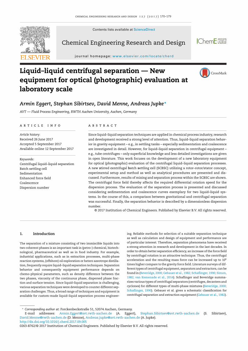
Fig. 1 – Analogies of mixer settler units for extraction processes in the gravitational field (left) and in the centrifugal field(right). Blue (heavy phase) and yellow (light phase) arrows visualizes the entrance and outlet of the coherent liquids, greenthe homogenous mixed liquid–liquid dispersion. The separation process in the settling tank and in the rotor zone isindicated by the wedge-shaped dispersion band. (For interpretation of the references to color in this figure legend, ther
F
d
e
t
n
s
s
s
g
acg
t
t
s
t
a
r
e
D
L
M
1
a
f
e
r
c
n
c
m
t
O
1
l
t
(
s
w
i
s
p
t
f
eader is referred to the web version of this article.)
urther Gebauer et al. distinguishes between continuous mixer-settler
evices and differential contactors for extraction processes (Gebauer
t al., 1982). The first group enables mixing and complete separation of
wo liquids in each equilibrium stage, the second group operates with
on-discrete counter current flow which enables more equilibrium
tages in one device. The comparison of classic continuous mixer-
ettler (MS) in the gravitational field (left) and the centrifugal field is
hown in Fig. 1. One of the most commonly used continuous centrifu-
al extractors with liquid–liquid separation in the rotor zone is the
nnular centrifugal contactor (ACC), or synonymously used annular
entrifugal extractor (ACE) (Vedantam and Joshi, 2006). In the annular
ab between the housing and the rotor of the ACC, which represents
he mixing part of the extractor, the mixing process takes place. In
he rotor zone, which represents the settling part of the extractor, the
eparation occurs. Thus, two coherent liquid phases enter and leave
he centrifugal device. The ACC was developed by Bernstein in 1973
nd experimentally investigated in detail by Leonard et al. and further
esearches in several experimental works (Arafat et al., 2001; Bernstein
t al., 1973, 1987; Birdwell et al., 2006; Cao et al., 2013; Duan et al., 2005;
uan and Cao, 2015; Kadam et al., 2008, 2009; Klasson et al., 2005;
eonard, 1988; Leonard et al., 1997, 2001, 2006; Mandal et al., 2015;
eikrantz et al., 2001, 2005; Svn Ayyappa et al., 2014; Webster et al.,
967). In all these works no investigations considering detached mixing
nd separation was performed. However, there are experimental based
urther developments of the classic ACC (Duan et al., 2009; Meikrantz
t al., 2002; Rivalier et al., 2004). The most comprehensive and detailed
esearch of centrifugal extraction equipment was carried out in the
ollaborative research center 153 “reaction and mass transfer tech-
ique for dispersed two-phase systems”. In this collaborative research
enter, several researches focused on the drop formation and drop
otion process within the Podbielniak differential centrifugal extrac-
or (ReinholdSchilp 1982 Fluiddynamik in Zentrifugal-Extraktoren I;
tillinger, 1988; Schilp, 1983; Schilp and Blaß, 1982, 1983; Stölting et al.,
979; Stölting, 1979; Stölting and Blaß, 1978). However, for centrifugal
iquid–liquid separation only few detailed investigations for sedimen-
ation and even less for coalescence phenomena are given in literature
Jammoal and Lee, 2015; Otillinger, 1988). Other researchers quantified
eparation kinetics and efficiency for centrifugal oil–water separator
ith plate pack internals (Plat, 1994) or for stable oil–water emulsions
n tube centrifuges (Cambiella et al., 2006; Krebs et al., 2012). From the
tate of the art it is evident that there are no established studies, which
resent a clear understanding of the flow dynamics, such as sedimen-
ation and coalescence of dispersed droplet swarms within centrifugal
orce field. Despite these facts, few authors deal with modeling and
CFD simulation of the rotor zone, neglecting that a validation and
quantification of the simulation is challenging (Li et al., 2012; Padial-
Collins et al., 2006; Patra et al., 2013; Vedantam et al., 2012; Wardle
et al., 2009). Thus, the simulation is only being discussed qualitatively
with basic physical knowledge and experience from gravitational sep-
arator. However, from the state of the art the simulated results seem
unsuitable for reliable equipment design and performance prediction.
Rather a clear request for investigation of the rotor zone was formu-
lated in (Vedantam and Joshi, 2006). Thus, a gab in understanding
certain hydrodynamic effects and their influence on the liquid–liquid
separation kinetic within centrifugal equipment of various scales and
operational modes is identified. Therefore, a detailed study on the flow
dynamics in the rotor regions becomes imperative. Thus, phase separa-
tion should be investigated within the centrifugal field. To understand
the influence of higher acceleration on phase separation phenom-
ena optical measurements of the rotor zone is implemented in batch
experiments. A new cylindrical equipment applied for experimental
investigations and graphical analyses of the experiments will be pre-
sented.
The gravitational settler as illustrates in Fig. 1 is one of the fre-
quently used devices in liquid–liquid separation techniques, which
gives a good example of how the liquid–liquid separation behav-
ior can be determined. The separation of two immiscible liquids
is characterized by droplet sedimentation, droplet–droplet coales-
cence, droplet–interface coalescence and the overall separation time.
Henschke developed a nowadays well-established laboratory scale
experimental method for the liquid–liquid separation using a standard-
ized stirred batch settling cell. Combined with a model-based approach
the settler can be designed based on laboratory scale data (Henschke,
1995). Schematic sedimentation and coalescence curves are shown in
Fig. 2 and are described in detail in literature. Both, sedimentation
and coalescence, can be described mathematically by detailed single
drop and droplet swarm models (Henschke, 1995). For model parameter
determination, droplet Sauter mean diameter and coalescence time as
well as experimental data from laboratory scale batch separation exper-
iments are necessary. For a better comparability of the gravitational
and centrifugal separation progress the experiments will be presented
in a normalized way. Normalization of the separation progress is deter-
mined by the percentage of the separation progress with regard to the
overall separation, Eqs. (1) and (2).
h% = h = f(t)h0
(1)
172 chemical engineering research and design 1 2 7 ( 2 0 1 7 ) 170–179
Fig. 2 – Schematic illustration of the liquid–liquid separation process of batch experimental investigations within thegravitational field as proposed by Henschke (1995). Separation progress (sedimentation and coalescence) of the lighterdispersed phase is characterized by the sedimentation curve, coalescence curve and overall separations time tE.
Table 1 – Physical properties of saturated liquid–liquid systems (Henschke, 1995).
System � (kg/m3) � (mPa s) � (mN/m) Phase state
1 Water 987 1.463 1.75 Continuousn-Butanol 846 3.32 Dispersed
2 Water 999 1.323 3.8 Continuous
Cyclohexanone 953t% = t = f(x)tE
(2)
For centrifugal separators design and performance calculation is
still based on simplified models and expert knowledge or expensive
and time-consuming pilot-plat experiments (Brunner, 1985; Hemfort,
1983; Rousselet Robatel). Furthermore, these kinds of studies are barely
reported in the available literature. However, one empirical correlation
to predict the separation efficiency depending on the centrifugal force
field, is given in its most general form by Leonard, Eq. (3), (Leonard et al.,
1981; Leonard, 1995).
NDi = 1t
·√
�Za
= 1t
·√
ro − ri
a(3)
a = r · ω2 = r · (2 � n)2 (4)
r = 2 · (r3o − r3
i )
3 · (r2o − r2
i )(5)
In this context NDi is called the “Dispersion Number” and is pri-
marily proposed for dispersion characterization. Furthermore, a is the
acceleration of the dispersed system as defined in Eq. (4), t is the charac-
teristic average residence time of the dispersion band as defined in Eq.
(5) and �Z is the thickness of the dispersion band in direction of accel-
eration, given bei the difference of the outer radius ro and the inner
radius ri. This correlation was established and experimentally investi-
gated by an integral, black-box investigation of the liquid–liquid flow
pattern in the rotor zone of an ACC (Leonard, 1995). For a batch system,
as given in standardized settling tests, ti is the overall separation time
and for a continuous settler operation ti is defined as the quotient of
2.31 Dispersed
dispersion volume V in the settling zone and the volumetric flow rate
q, Eq. (6).
tr = Vq
(6)
2. Material and methods
2.1. Chemical system
For experiments with the SCBSC, n-butanol/water and cyclo-hexanone/water as liquid–liquid systems were chosen. Thephysical properties are summarized in Table 1. The organicphase n-butanol was provided by Merck, Darmstadt, Germany,with a purity of 99%, cyclohexanone from CarlRoth, München,Germany, with a purity of 98%. The aqueous phase was deion-ized and distillated in a MonoDest3000 distillery from LenzGlas Instrumente, Wertheim, Germany. Furthermore for waterconditioning sodium chloride (NaCl), with purity of 99%, wasprovided by Merck, Darmstadt, Germany.
2.2. Experimental set-up
To observe the separation of disperse liquid–liquid systemsin centrifugal force field a new laboratory equipment isrequired. Thus, and for a high level of reproducibility a (stan-dardized) stirred centrifugal batch settling cell (SCBSC) atlaboratory scale was developed and applied for patent (Eggert
et al., 2016a). Furthermore, the setup was improved and canbe utilized now as a centrifugal reactor concept for fast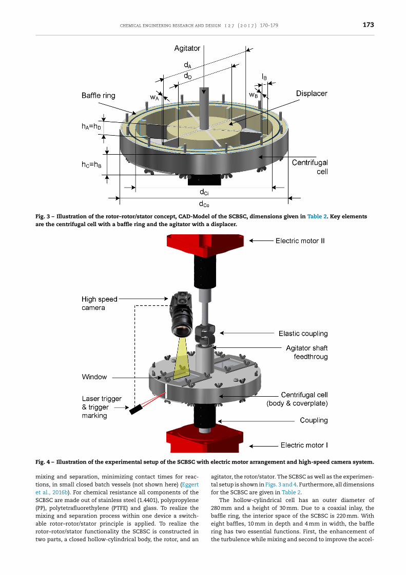
chemical engineering research and design 1 2 7 ( 2 0 1 7 ) 170–179 173
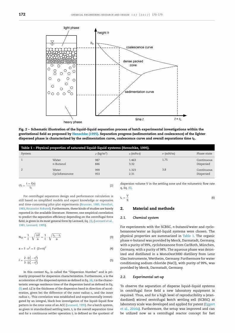
Fig. 3 – Illustration of the rotor–rotor/stator concept, CAD-Model of the SCBSC, dimensions given in Table 2. Key elementsare the centrifugal cell with a baffle ring and the agitator with a displacer.
F ith e
mteS(mart
ig. 4 – Illustration of the experimental setup of the SCBSC w
ixing and separation, minimizing contact times for reac-ions, in small closed batch vessels (not shown here) (Eggertt al., 2016b). For chemical resistance all components of theCBSC are made out of stainless steel (1.4401), polypropylene
PP), polytetrafluorethylene (PTFE) and glass. To realize theixing and separation process within one device a switch-
ble rotor–rotor/stator principle is applied. To realize the
otor–rotor/stator functionality the SCBSC is constructed inwo parts, a closed hollow-cylindrical body, the rotor, and anlectric motor arrangement and high-speed camera system.
agitator, the rotor/stator. The SCBSC as well as the experimen-tal setup is shown in Figs. 3 and 4. Furthermore, all dimensionsfor the SCBSC are given in Table 2.
The hollow-cylindrical cell has an outer diameter of280 mm and a height of 30 mm. Due to a coaxial inlay, thebaffle ring, the interior space of the SCBSC is 220 mm. Witheight baffles, 10 mm in depth and 4 mm in width, the baffle
ring has two essential functions. First, the enhancement ofthe turbulence while mixing and second to improve the accel-
174 chemical engineering research and design 1 2 7 ( 2 0 1 7 ) 170–179
Table 2 – Dimensions of SCBSC CAD-Model, Fig. 3.
Component Dimension Symbol Value (mm)
Stirrer Diameter dA 200Height hA 28Width wA 4
Displacer Diameter dD 80/120Height hD = hA 28
Centrifugalcell
Diameter dCo 280Height hC 30
Bafflering
Diameter dBi 220Height hB 30Width wB 5Length lB 10
eration of the liquid–liquid system in the separation process.To observe the separation process two glass windows with asize of 70 × 50 mm are mounted on the axial front surfaces ofthe SCBSC. On the cover plate, a sealed feedthrough for theagitator shaft is placed centrically. The agitator consists of asix-blade paddle stirrer with a size of 22 mm in height and190 mm in diameter, fixed on a shaft and a displacer, whichhas two major functions. First, to relocate the separation pro-cess to higher centrifugal forces and second to limit the totalfree liquid volume of the centrifugal cell from 950 ml to 700 mlwithout applying of a gas pocket. Thereby, no gas is mixed inthe liquid–liquid disperse system during the mixing. The dis-placer can be varied from 80 mm to 120 mm in diameter. Both,the hollow-cylindrical body as well as the agitator are coupledand powered by separate servo electric motors (type: CMPZ80 M, 11 kW, 400 V, 50 Hz, up to 6000 rpm, supplied by SEW-EURODRIVE GmbH & CoKG, Bruchsal, Germany) as shown inFig. 4. These motors enable rotations in both directions. To reg-ulate the direction and rotation speed, manually or via controlsoftware, the motors are connected to frequency convert-ers (type: MOVIDRIVE
®MDX60B, supplied by SEW-EURODRIVE
GmbH & CoKG, Bruchsal, Germany). For the optical obser-vation a high speed video camera (type: Os4S1-C-O4, 8 GBDDR working storage, 512 GB SSD intern storage, 1024 × 1024pixels, 6.000 frames per second (fps), supplied by ImagingSolutions GmbH, Eningen, Germany) with a camera objec-tive (type: LM16HC, 1′′ 16 mm/F1.4, supplied by Kowa OptimedDeutschland GmbH, Duesseldorf, Germany) is used. The cam-era is installed perpendicular to the centrifugal cell rotationaxis. Thus, the camera is focusing on the centrifugal cell frontsurface and glass windows. The camera is triggered by a laserlight barrier and a trigger marker on the cylinder wall. Cam-era and recording settings are controlled via Ethernet linkageand the Motion Studio PC software (v. 2.12.05). For a suffi-cient lighting performance, required for short exposure times,a 500 W light emitting diode (LED) is used. The 500 W LEDis powered by a direct current (DC) laboratory power supply(type: PS 8360-10 T, 0. . .360 V, 0. . .10 A, up to 1000 W, suppliedby Elektro-Automatik GmbH & Co. KG, Viersen, Germany). Fortemperature control the experimental equipment is located ina housing, which is vented by a fan heater. The fan heater iscontrolled by a PID controller.
2.3. Experimental preparation
Prior to the experimental investigations the liquid phase sys-
tems were mutually saturated. According to experimentalconditions, the temperature was set to 25 ◦C. The volumetricratio for saturation was 1:1 (Vorg:Vaq). The water was condi-tioned with ions by addition of 5.0 g/l NaCl. The experimentalequipment was disassembled completely and all componentswere first rinsed with deionized, distilled water, followed byacetone and finally with deionized, distilled water again. Allcomponents were dried at 40 ◦C for 12 h before the cell wasassembled. After assembling, the settling cell was filled andinstalled in the test stand.
2.4. Experimental method
The experimental method is characterized by consecutivelyalternating process steps of mixing and separation withinthe centrifugal force field. For better illustration an animatedvideo of the SCBSC is given in Video 1.
In order to generate the centrifugal force field, the cen-trifugal cell and the agitator are powered synchronously indirection and at the same basic rotational speed. Thereby, anorientation of the liquid phases in direction of the centrifugalacceleration takes place: The light phase is located at the dis-placer and the heavy phase is located at the baffle ring. Theannular liquid layers and the phase boundary are observedvertically through the glass window. To generate the disper-sion inside the SCBSC a differential rotation speed betweenthe centrifugal cell and the agitator is applied. For this pur-pose, the rotational speed of the agitator is changed while thecentrifugal cell is kept on basic rotational speed. Thus, the dif-ferential rotational speed �n as given in Eq. (7) is defined asthe difference of rotational speed of the centrifugal cell nc andthe agitator ns.
�n = nc − ns (7)
The differential rotational speed introduces a power inputinto the liquid–liquid system. This power input causesturbulences which result in droplet formation. After theliquid–liquid dispersion is formed, the agitator is switchedback to basic rotation speed in 20 ms, thus the separationprocess is initiated as shown in Fig. 5. The relative motionbetween the baffle ring and the stirrer is interrupted whilethe synchronized rotation. Opposite to the mixing the turbu-lence field within the centrifugal cell collapses as no furtherpower input is initiated. Consequently, the liquid phases arenow accelerated only in radial direction to the axis of the rota-tion. The heavy phase flows outward and accumulates at theinner wall of the baffle ring. The light phase flows inward andaccumulates at the outer wall of the displacer. At the sametime as the phase separation process starts the high speedcamera system starts recording the process.
2.5. Analytical method
The analytical method is based on the optical observation ofthe liquid–liquid separation during the centrifugation processas shown in Fig. 6. Due to a trigger signal one picture per rev-olution is recorded. All images are stored on an internal SSDcard of the camera. The images are analyzed offline by pic-ture evaluation considering the region of interest to followa radial trajectory to the axis of rotation. The evaluation issimplified by a millimeter raster in cylindrical coordinates asshown in Fig. 5, which was placed on the window. The sep-
aration progress is quantified by path-time coordinates. Eachpath coordinate includes a value for the sedimentation and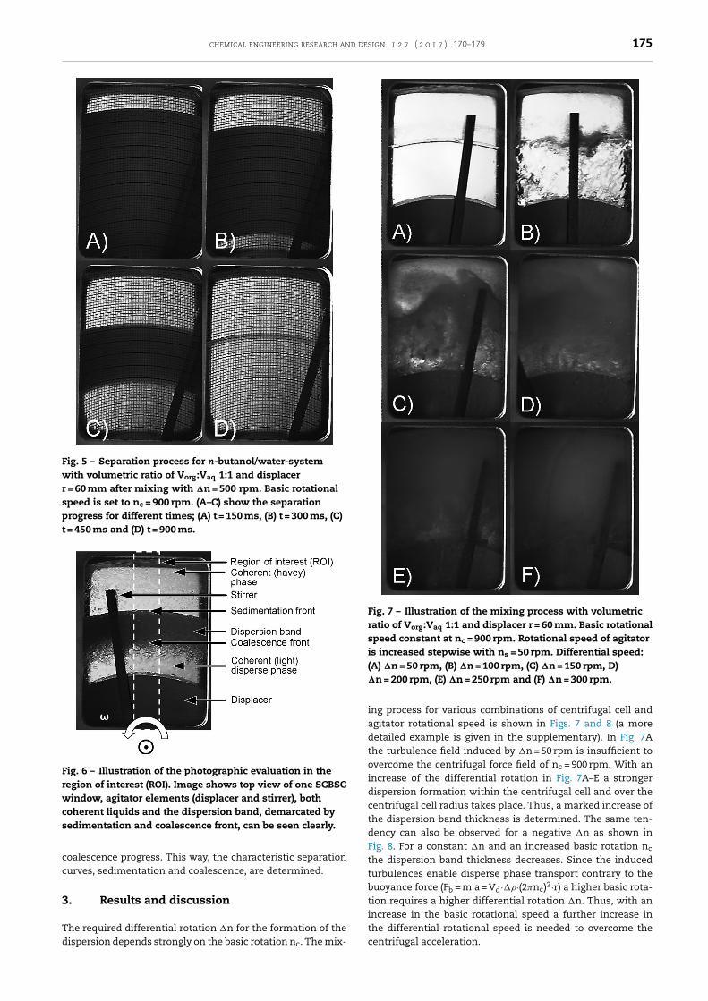
chemical engineering research and design 1 2 7 ( 2 0 1 7 ) 170–179 175
Fig. 5 – Separation process for n-butanol/water-systemwith volumetric ratio of Vorg:Vaq 1:1 and displacerr = 60 mm after mixing with �n = 500 rpm. Basic rotationalspeed is set to nc = 900 rpm. (A–C) show the separationprogress for different times; (A) t = 150 ms, (B) t = 300 ms, (C)t = 450 ms and (D) t = 900 ms.
Fig. 6 – Illustration of the photographic evaluation in theregion of interest (ROI). Image shows top view of one SCBSCwindow, agitator elements (displacer and stirrer), bothcoherent liquids and the dispersion band, demarcated bysedimentation and coalescence front, can be seen clearly.
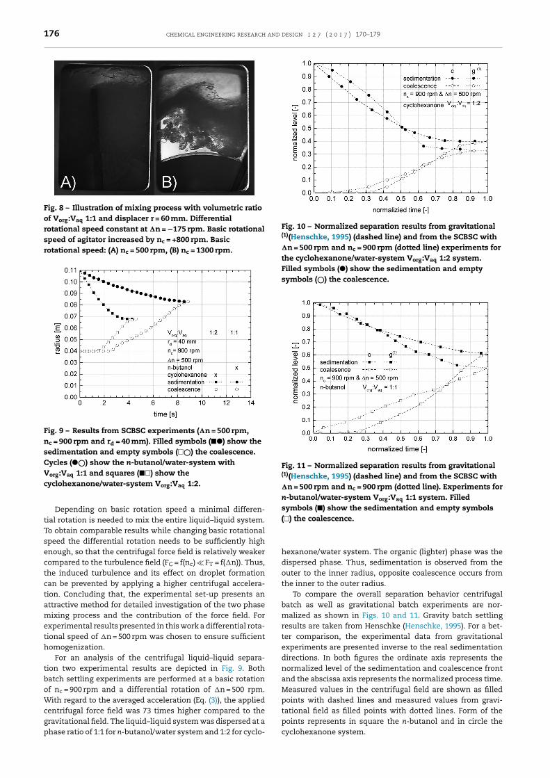
cc
3
Td
Fig. 7 – Illustration of the mixing process with volumetricratio of Vorg:Vaq 1:1 and displacer r = 60 mm. Basic rotationalspeed constant at nc = 900 rpm. Rotational speed of agitatoris increased stepwise with ns = 50 rpm. Differential speed:(A) �n = 50 rpm, (B) �n = 100 rpm, (C) �n = 150 rpm, D)�n = 200 rpm, (E) �n = 250 rpm and (F) �n = 300 rpm.
the differential rotational speed is needed to overcome the
oalescence progress. This way, the characteristic separationurves, sedimentation and coalescence, are determined.
. Results and discussion
he required differential rotation �n for the formation of the
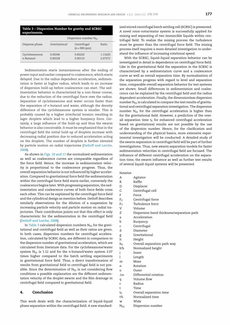
ispersion depends strongly on the basic rotation nc. The mix-ing process for various combinations of centrifugal cell andagitator rotational speed is shown in Figs. 7 and 8 (a moredetailed example is given in the supplementary). In Fig. 7Athe turbulence field induced by �n = 50 rpm is insufficient toovercome the centrifugal force field of nc = 900 rpm. With anincrease of the differential rotation in Fig. 7A–E a strongerdispersion formation within the centrifugal cell and over thecentrifugal cell radius takes place. Thus, a marked increase ofthe dispersion band thickness is determined. The same ten-dency can also be observed for a negative �n as shown inFig. 8. For a constant �n and an increased basic rotation nc
the dispersion band thickness decreases. Since the inducedturbulences enable disperse phase transport contrary to thebuoyance force (Fb = m·a = Vd·��·(2�nc)2·r) a higher basic rota-tion requires a higher differential rotation �n. Thus, with anincrease in the basic rotational speed a further increase in
centrifugal acceleration.
176 chemical engineering research and design 1 2 7 ( 2 0 1 7 ) 170–179
Fig. 8 – Illustration of mixing process with volumetric ratioof Vorg:Vaq 1:1 and displacer r = 60 mm. Differentialrotational speed constant at �n = −175 rpm. Basic rotationalspeed of agitator increased by nc = +800 rpm. Basicrotational speed: (A) nc = 500 rpm, (B) nc = 1300 rpm.
Fig. 9 – Results from SCBSC experiments (�n = 500 rpm,nc = 900 rpm and rd = 40 mm). Filled symbols (��) show thesedimentation and empty symbols (�©) the coalescence.Cycles (�©) show the n-butanol/water-system withVorg:Vaq 1:1 and squares (��) show thecyclohexanone/water-system Vorg:Vaq 1:2.
Fig. 10 – Normalized separation results from gravitational(1)(Henschke, 1995) (dashed line) and from the SCBSC with�n = 500 rpm and nc = 900 rpm (dotted line) experiments forthe cyclohexanone/water-system Vorg:Vaq 1:2 system.Filled symbols (�) show the sedimentation and emptysymbols (©) the coalescence.
Fig. 11 – Normalized separation results from gravitational(1)(Henschke, 1995) (dashed line) and from the SCBSC with�n = 500 rpm and nc = 900 rpm (dotted line). Experiments forn-butanol/water-system Vorg:Vaq 1:1 system. Filledsymbols (�) show the sedimentation and empty symbols(�) the coalescence.
Depending on basic rotation speed a minimal differen-tial rotation is needed to mix the entire liquid–liquid system.To obtain comparable results while changing basic rotationalspeed the differential rotation needs to be sufficiently highenough, so that the centrifugal force field is relatively weakercompared to the turbulence field (FC = f(nc) � FT = f(�n)). Thus,the induced turbulence and its effect on droplet formationcan be prevented by applying a higher centrifugal accelera-tion. Concluding that, the experimental set-up presents anattractive method for detailed investigation of the two phasemixing process and the contribution of the force field. Forexperimental results presented in this work a differential rota-tional speed of �n = 500 rpm was chosen to ensure sufficienthomogenization.
For an analysis of the centrifugal liquid–liquid separa-tion two experimental results are depicted in Fig. 9. Bothbatch settling experiments are performed at a basic rotationof nc = 900 rpm and a differential rotation of �n = 500 rpm.With regard to the averaged acceleration (Eq. (3)), the appliedcentrifugal force field was 73 times higher compared to thegravitational field. The liquid–liquid system was dispersed at a
phase ratio of 1:1 for n-butanol/water system and 1:2 for cyclo-hexanone/water system. The organic (lighter) phase was thedispersed phase. Thus, sedimentation is observed from theouter to the inner radius, opposite coalescence occurs fromthe inner to the outer radius.
To compare the overall separation behavior centrifugalbatch as well as gravitational batch experiments are nor-malized as shown in Figs. 10 and 11. Gravity batch settlingresults are taken from Henschke (Henschke, 1995). For a bet-ter comparison, the experimental data from gravitationalexperiments are presented inverse to the real sedimentationdirections. In both figures the ordinate axis represents thenormalized level of the sedimentation and coalescence frontand the abscissa axis represents the normalized process time.Measured values in the centrifugal field are shown as filledpoints with dashed lines and measured values from gravi-tational field as filled points with dotted lines. Form of thepoints represents in square the n-butanol and in circle thecyclohexanone system.
chemical engineering research and design 1 2 7 ( 2 0 1 7 ) 170–179 177
Table 3 – Dispersion Number for gravity and SCBSCexperiments.
Dispersion number NDi
Disperse phase Gravitational Centrifugal(n = 900 rpm)
Ratio
Cyclohexanone 0.00246 0.00220 1.11620n-Butanol 0.00228 0.00110 2.07372
pdtoidStdpltbcdob2
atioawcieasijc(
tIttcstirsctc
4
Tp
Sedimentation starts instantaneous after the ending ofower input and earlier compared to coalescence, which startselayed. Due to the radius dependent acceleration, sedimen-ation is faster at higher radius, which leads to an increasef dispersion hold-up before coalescence can start. The sed-
mentation behavior is characterized by a non-linear course,ue to the reduction of the centrifugal force over the radius.eparation of cyclohexanone and water occurs faster thanhe separation of n-butanol and water, although the densityifference of the cyclohexanone system is smaller. This isrobably caused by a higher interfacial tension resulting in
ager droplets which lead to a higher buoyancy force. Cer-ainly, a large influence of the hold-up and thus the swarmehavior is also conceivable. It must be emphasized that in theentrifugal field the initial hold-up of droplets increase withecreasing radial position due to reduced acceleration actingn the droplets. The number of droplets is further elevatedy particle motion on radial trajectories (Detloff and Lerche,008).
As shown in Figs. 10 and 11 the normalized sedimentations well as coalescence curves are comparable regardless ofhe force field. Hence, the increase in sedimentation veloc-ty is proportional to the coalescence progress. Thus, theverall separation behavior is not influenced by higher acceler-tion. Compared to gravitational force field the sedimentationithin the centrifugal force field starts earlier, conversely the
oalescence begins later. With progressing separation, the sed-mentation and coalescence curves of both force fields crossach other. This can be explained by the centrifugal force fieldnd the cylindrical design as mention before. Detloff describesimilarly observations for the dilution of a suspension byncreasing particle velocity and particle motion on radial tra-ectories. Their contribution points out that this effect is onlyharacteristic for the sedimentation in the centrifugal fieldDetloff and Lerche, 2008).
In Table 3 calculated dispersion numbers NDi for the gravi-ational and centrifugal field as well as their ratios are given.n both cases, dispersion numbers for centrifugal accelera-ion, calculated by SCBSC data, are different in comparison tohe dispersion number of gravitational acceleration, which arealculated from literature data. For the cyclohexanone/waterystem NDi is 1.12 and for the n-butanol/water system 2.07imes higher compared to the batch settling experimentsn gravitational force field. Thus, a direct transformation ofesults from gravitational field to centrifugal field is not pos-ible. Since the determination of NDi is not considering flowonditions a possible explanation are the different sedimen-ation velocity of the droplet swarm and the film drainage inentrifugal field compared to gravitational field.
. Conclusion
his work deals with the characterization of liquid–liquidhase separation within the centrifugal field. A new standard-
ized stirred centrifugal batch settling cell (SCBSC) is presented.A novel rotor–rotor/stator system is successfully applied formixing and separating of two immiscible liquids within cen-trifugal field. To realize the mixing process the turbulencemust be greater than the centrifugal force field. The mixingprocess itself requires a more detailed investigation to under-stand the influence of increasing rotational speed.
With the SCBSC, liquid–liquid separation behavior can beinvestigated in detail in dependence on centrifugal force field.Like in the gravitational field the separation in the SCBSC ischaracterized by a sedimentation curve and a coalescencecurve as well as overall separation time. By normalization ofthe separation progress with regard to level and separationtime, comparable overall separation behavior for test systemsare shown. Small differences in sedimentation and coales-cence can be explained by the centrifugal field and the radiusdependent acceleration. Finally, the dimensionless dispersionnumber NDi is calculated to compare the test results of gravita-tional and centrifugal separation investigation. The dispersionnumber NDi for the centrifugal acceleration is higher thanfor the gravitational field. However, a prediction of the over-all separation time tE for enhanced centrifugal accelerationbased on gravitational results are not possible by the useof the dispersion number. Hence, for the clarification andunderstanding of the physical basics, more extensive exper-imental investigation will be conducted. A detailed study ofthe swarm separation in centrifugal field will be part of furtherinvestigations. Thus, new swarm separation models for fastersedimentation velocities in centrifugal field are focused. Theinfluence of different centrifugal acceleration on the separa-tion time, the swarm influence as well as further test resultsof several liquid–liquid systems will be presented.
NotationA AgitatorB BaffleD DisplacerC Centrifugal cellF ForceFC Centrifugal forceFT Turbulence forceV VolumeZ Dispersion band thickness/separation patha Accelerationb Buoyancyc Centrifugald Diameterg Gravitationalh Heighth0 Overall separation path wayh% Normalized heighti Innerl Lengthm Massn Rotationo Outer�n Differential rotationq Volume flowr Radiust TimetE Overall separation timet% Normalized time
w WideNDi Dispersion number
178 chemical engineering research and design 1 2 7 ( 2 0 1 7 ) 170–179
ω Angular frequency� Density� Viscosity� Interfacial tension
AbbreviationsSCBSC Stirred centrifugal batch settling cellACC/ACE Annular centrifugal contactor/extractorrpm Rounds per minuteorg Organicaq Aqueous
Acknowledgments
This work was performed as part of the Cluster of Excel-lence “Tailor-Made Fuels from Biomass”, which is funded bythe Excellence Initiative by the German federal and stategovernments to promote science and research at German uni-versities. Further, the authors thank RWTH Aachen University— department 4.1 Technology Transfer for the assumption ofthe patent application.
Appendix A. Supplementary data
Supplementary data associated with this arti-cle can be found, in the online version, athttp://dx.doi.org/10.1016/j.cherd.2017.09.005.
References
Arafat, H.A., Hash, M.C., Hebden, A.S., Leonard, R.A., 2001.Characterization and Recovery of Solvent Entrained Duringthe Use of Centrifugal Contactors. Argonne, 30 pp.
Bernstein, G.J., Grosvenor, D.E., Lenc, J.F., Levitz, N.M., 1973.Development and Performance of a High-speed AnnularCentrifugal Contactor. Chemical Enineering Division.
Bernstein, G.J., Leonard, R.A., Ziegler, A.A., Steindler, M.J., 1987.An improved annular centrifugal contactor for solventextraction reprocessing of nuclear reactor fuel. In: 84thNational Meeting, American Institute of Chemical Engineers.
Beveridge, T., 2000. Large-scale centrifugation. Handbook ofMethods and Instrumentation in Separation Science, vol. 1.Academic Press Minister of Public Works and GovernmentServices, Canada, pp. 320–329.
Birdwell, J.F., McFarlane, J., Hunt, R.D., Luo, H., DePaoli, D.W.,Schuh, D.L., Dai, S., 2006. Separation of ionic liquiddispersions in centrifugal solvent extraction contactors. Sep.Sci. Technol. 41 (10), 2205–2223,http://dx.doi.org/10.1080/01496390600745719.
Brunner, A., 1985. Schwerölreinigung—Zentrifugalabscheider.Tech. Rundsch. Sulzer 4, 47–58.
Cambiella, A., Benito, J.M., Pazos, C., Coca, J., 2006. Centrifugalseparation efficiency in the treatment of waste emulsifiedoils. Chem. Eng. Res. Des. 84 (1), 69–76,http://dx.doi.org/10.1205/cherd.05130.
Cao, S., Duan, W., Chengqian, W., 2013. Effects of structureparameters on the hydraulic performance of the �20 annularcentrifugal contactor. Energy Procedia 39, 461–466,http://dx.doi.org/10.1016/j.egypro.2013.07.237.
Detloff, T., Lerche, D., 2008. Centrifugal separation in tube anddisc geometries: experiments and theoretical models. ActaMech. 201 (1–4), 83–94,http://dx.doi.org/10.1007/s00707-008-0074-y.
Duan, W., Cao, S., 2015. Determination of the liquid hold-upvolume and the interface radius of an annular centrifugalcontactor using the liquid-fast-separation method. Chem.
Eng. Commun. 203 (4), 548–556,http://dx.doi.org/10.1080/00986445.2015.1048802.Duan, W., Cheng, Q., Zhou, X., Zhou, J., 2009. Development of a�20 mm annular centrifugal contactor for the hot test of thetotal TRPO process. Prog. Nucl. Energy 51 (2), 313–318,http://dx.doi.org/10.1016/j.pnucene.2008.08.002.
Duan, W., Song, C., Wu, Q., Zhou, X., Zhou, J., 2005. Developmentand performance of a new annular centrifugal contactor forsemi-industrial scale. Sep. Sci. Technol. 40 (9), 1871–1883,http://dx.doi.org/10.1081/SS-200064531.
Eggert, A., Bednarz, A., Sirbirtsev, S., Jupke, A., 2016. Vorrichtungund Verfahren zur Untersuchung des Phasentrennverhaltensvon wenigstens zwei Phasen im Zentrifugalfeld (DE102016002949.8).
Eggert, A., Sirbirtsev, S., Jupke, A., 2016. Vorrichtung undVerfahren zur Untersuchung und/oder Durchführung einerReaktion von wenigsten zwei Phasen im Zentrifugalfeld (DE102016012649.3).
Gebauer, K., Steiner, L., Hartland, S., 1982.Zentrifugalextraktion—Eine Literaturübersicht. Chem. Ing.Tech. 54 (5), 476–496, http://dx.doi.org/10.1002/cite.330540511.
Hemfort, H., 1983. Separatoren—Zentrifugen für Klärung,Trennung, Extraktion. GEA Westfalia Separator AG.
Henschke, M., 1995. Dimensionierung liegenderFlüssig-flüssig-Abscheider anhand diskontinuierlicherAbsetzversuche. Dissertation. Aachen, TechnischeHochschule, VDI-Verlag, Düsseldorf, 161 pp.
Jammoal, Y., Lee, J., 2015. Drop velocity in a rotating liquid–liquidsystem. Chem. Eng. Res. Des. 104, 638–646,http://dx.doi.org/10.1016/j.cherd.2015.10.003.
Kadam, B.D., Joshi, J.B., Koganti, S.B., Patil, R.N., 2008.Hydrodynamic and mass transfer characteristics of annularcentrifugal extractors. Chem. Eng. Res. Des. 86 (3), 233–244,http://dx.doi.org/10.1016/j.cherd.2007.10.020.
Kadam, B.D., Joshi, J.B., Koganti, S.B., Patil, R.N., 2009. Dispersedphase hold-up, effective interfacial area and Sauter meandrop diameter in annular centrifugal extractors. Chem. Eng.Res. Des. 87 (10), 1379–1389,http://dx.doi.org/10.1016/j.cherd.2009.03.005.
Klasson, K.T., Taylor, P.A., Walker, J.F., Jones, S.A., Cummins, R.L.,Richardson, S.A., 2005. Modification of a centrifugal separatorfor in-well oil–water separation. Sep. Sci. Technol. 40 (1–3),453–462, http://dx.doi.org/10.1081/SS-200042503.
Krebs, T., Schroën, C., Boom, R.M., 2012. Separation kinetics of anoil-in-water emulsion under enhanced gravity. Chem. Eng.Sci. 71, 118–125, http://dx.doi.org/10.1016/j.ces.2011.10.057.
Leonard, R.A., 1988. Recent advances in centrifugal contactordesign. Sep. Sci. Technol. 23 (12–13), 1473–1487,http://dx.doi.org/10.1080/01496398808075643.
Leonard, R.A., 1995. Solvent characterization using the dispersionnumber. Sep. Sci. Technol. 30 (7–9), 1103–1122,http://dx.doi.org/10.1080/01496399508010335.
Leonard, R.A., Bernstein, G.J., Pelto, R.H., Ziegler, A.A., 1981.Liquid–liquid dispersion in turbulent couette flow. AIChE J. 27(3), 495–503, http://dx.doi.org/10.1002/aic.690270320.
Leonard, R.A., Bernstein, G.J., Ziegler, A.A., Pelto, R.H., 2006.Annular centrifugal contactors for solvent extraction. Sep. Sci.Technol. 15 (4), 925–943,http://dx.doi.org/10.1080/01496398008076278.
Leonard, R.A., Chamberlain, D.B., Conner, C., 1997. Centrifugalcontactors for laboratory-scale solvent extraction test. Sep.Sci. Technol. 32 (1–4), 193–210,http://dx.doi.org/10.1080/01496399708003194.
Leonard, R.A., Regalbuto, M.C., Aase, S.B., Arafat, H.A.,Falkenberg, J.R., 2001. Hydraulic performance of a 5 cmcontactor four caustic-side solvent extraction, ChemicalTechnology Division, Argonne National Laboratory, Argonne,Illinois, United States Department of Energy under ContractW-31-109-Eng-38 – ANL-02/18.
Li, S., Duan, W., Chen, J., Wang, J., 2012. CFD simulation ofgas–liquid–liquid three-phase flow in an annular centrifugalcontactor. Ind. Eng. Chem. Res. 51 (34), 11245–11253,http://dx.doi.org/10.1021/ie300821t.
Mandal, K., Kumar, S., Vijayakumar, V., Mudali, U.K., Ravisankar,A., Natarajan, R., 2015. Hydrodynamic and mass transfer
chemical engineering research and design 1 2 7 ( 2 0 1 7 ) 170–179 179
M
M
M
O
P
P
P
RR
R
S
S
S
in Reprocessing of Irradiated Fuel American Institute ofChemical Engineers Meeting New York, New York 20 pp.
studies of 125 mm centrifugal extractor with 30% TBP/nitricacid system. Prog. Nucl. Energy 85, 1–10,http://dx.doi.org/10.1016/j.pnucene.2015.05.005.
eikrantz, D.H., Laq, J.D., Todd, T.A., 2005. Design attributes andscale up testing of annular centrifugal contactors. ChemicalEngineering Division of the AIChE National Meeting(INL/CON-05-00088).
eikrantz, D.H., Macaluso, L.L., Flim, W.D., Heald, C.J., Mendoza,G., Meikrantz, S.B., 2002. A new annular centrifugal contactorfor pharmaceutical processes. Chem. Eng. Commun. 189,1629–1639, http://dx.doi.org/10.1080/00986440290123633.
eikrantz, D.H., Meikrantz, S.B., Macaluso, L.L., 2001. Annularcentrifugal contactors for multiple stage extraction processes.Chem. Eng. Commun. 188 (1), 115–127,http://dx.doi.org/10.1080/00986440108912900.
tillinger, F., 1988. Fluiddynamik und Stoffübergang inZentrifugalextraktoren, Technische Universität München,Germany, 46 pp.
adial-Collins, N.T., Zhang, D.Z., Zou, Q., Ma, X., VanderHeyden,W.B., 2006. Centrifugal contactors: separation of an aqueousand an organic stream in the rotor zone (LA-UR-05-7800). Sep.Sci. Technol. 41 (6), 1001–1023,http://dx.doi.org/10.1080/01496390600641611.
atra, J., Pandey, N.K., Muduli, U.K., Natarajan, R., Joshi, J.B., 2013.Hydrodynamic study of flow in the rotor region of annularcentrifugal contactors using CFD simulation. Chem. Eng.Commun. 200 (4), 471–493,http://dx.doi.org/10.1080/00986445.2012.706838.
lat, R., 1994. Gravitational and Centrifugal Oil–water Separators,Thesis Technical University Delft, Netherlands, 168 pp.
einholdSchilp 1982 Fluiddynamik in Zentrifugal-Extraktoren I.ivalier, P., Gandi, F., Duhamet, J., 2004. Development of new
annular centrifugal solvent extractioncontactor, Poster P1-48,at ATLANTE 2004, Nimes, France online: IAEA InternationalAtomic Enery Agency https://www.iaea.org/.
ousselet Robatel. Scale-up of Liquid/Liquid Centrifuges,Manufacturing centrifuges and centrifugal extractionequipment, whitepaper, brochures from Robatel onlinewww.rousselet-robatel.com.
chaflinger, U., 1990. Centrifugal separation of a mixture. FluidDyn. Res. 6 (6), 213–249,http://dx.doi.org/10.1016/0169-5983(90)90014-P.
chilp, R., 1983. Fluiddynamik in Zentrifugalextraktoren.IDEA-Verlag GmbH Puchheim, 318 pp.
chilp, R., Blaß, E., 1982. Fluiddynamik in Zentrifugalextraktoren.Chem. Ing. Tech. 54 (4), MS 990/1982.
Schilp, R., Blaß, E., 1983. Bewegung und Stabilität von Tropfen innichtmischbaren Flässigkeiten bei hohenZentrifugalfeldstßrken. Chem. Ing. Tech. 55 (8), MS 1133/83.
Simon, E., 1982. Die diskontinuierliche Zentrifuge alsBetriebssystem in der Chemischen Industrie. Chem. Ing. Tech.54 (4), 333–350, http://dx.doi.org/10.1002/cite.330540408.
Stölting, M., 1979. Bildung und Bewegung von Einzeltopfen ineiner rotierenden Flüssigkeit, Theses Technical UniversityMunich, Germany, 83 pp.
Stölting, M., Blaß, E., 1978. Tropfenbildung und Tropfenbewegungin einem rotierenden Extraktor. Chem. Ing. Tech. 50 (6), MS595/78.
Stölting, M., Hengstler, N., Blaß, E., 1979. Auslegung vonZentrifugalextraktoren—Eine Verbsindung vonverfahrenstechnischen und physikochemischenProblemstellungen. Ber. Bundesgesellschaft Phys. Chem. 83(11), 1116–1120, http://dx.doi.org/10.1002/bbpc.19790831115.
Svn Ayyappa, Balamurugan, M., Kumar, S., Mudali, U.K.,Natarajan, R., 2014. Hydrodynamic and Mass Transfer Studiesin 50 mm Centrifugal Extractor, Seminar on Recent Advancesin Fuel Cycle Technologies, Kalpakkam, India, 4 pp.
van Kemenade, E., Brouwers, B., van Benthum, R., 2014.Centrifugal separation with emphasis on the rotationalparticle separator. ChemBioEng Rev. 1 (6), 262–272,http://dx.doi.org/10.1002/cben.201400027.
Vedantam, S., Joshi, J.B., 2006. Annular centrifugal contactors—areview. Chem. Eng. Res. Des. 84 (7), 522–542,http://dx.doi.org/10.1205/cherd.05219.
Vedantam, S., Wardle, K.E., Tamhane, T.V., Ranade, V.V., Joshi, J.B.,2012. CFD simulation of annular centrifugal extractors. Int. J.Chem. Eng. 2012 (94), 1–31,http://dx.doi.org/10.1155/2012/759397.
Wardle, K.E., Allen, T.R., Swaney, R., 2009. CFD simulation of theseparation zone of an annular centrifugal contactor. Sep. Sci.Technol. 44 (3), 517–542,http://dx.doi.org/10.1080/01496390802634398.
Webster, D.S., Jennings, A.S., Kishbaugh, A.A., Bethmann, H.K.,1967. Performance of Centrifugal Mixer-Settler in theRepricessing of Nuclear Fuel, Symposium on Recent Advances