chemical reaction engineering - aalborg universitethomes.nano.aau.dk/lg/chemreact2008_files/chemical...
TRANSCRIPT

Chemical Reaction Engineering
• Lecture plan (Lectures 5-10)– Lecture 5: Mole balance and design equations for
batch and continuous mode reactors. – Lecture 6: Rate laws in the reactor design– Lecture 7: Isothermal reactor design– Lecture 8: Bioreactors. Comsol modelling of
reactions and reactors. H-cell with chemical reaction.
– Lecture 9. Comsol modelling: flow through porous bed and stirred batch reactor.
– Lecture 10. Comsol modelling of biochips: reaction on the surface.

Chemical Reaction Engineering
Lecture 5

Rates of chemical reactions2 3A B C D+ ⎯⎯→ +
Instantaneous rate of consumption of a reactant:
[ ] /d R dt−Instantaneous rate of formation of a product:
[ ] /d P dtFrom stoichiometry
[ ] 1 [ ] [ ] 1 [ ]3 2
d D d C d A d Bdt dt dt dt
= = − = −
Rate of the reaction:1 i
i
dn dvdt dt
ξν
= =
! In the case of heterogeneous reaction the rate will be defined per unit area of catalyst as mol/m2s! In the case of continuous flow reactor change of concentration is not equal to the reaction rate

Rates of chemical reactions
• Rate of chemical reaction is an algebraic function involving concentration
• e.g. 1st order reaction
A Ar kC− =
A product→
• 2nd order reaction2
A Ar kC− =

The general mole balance equation
• Mass balance:Rate of flow IN – Rate of flow OUT + Generation=Accumulation
0j
j j i
dNF F G
dt− + =
i iG r V= ⋅
moles/time moles/(time·volume) volume

The general mole balance equation
V
i iG rdV= ∫
0
Vj
j j i
dNF F rdV
dt− + =∫
• The general mole balance equation:
• From here, design equation for different types of the reactors can be developed
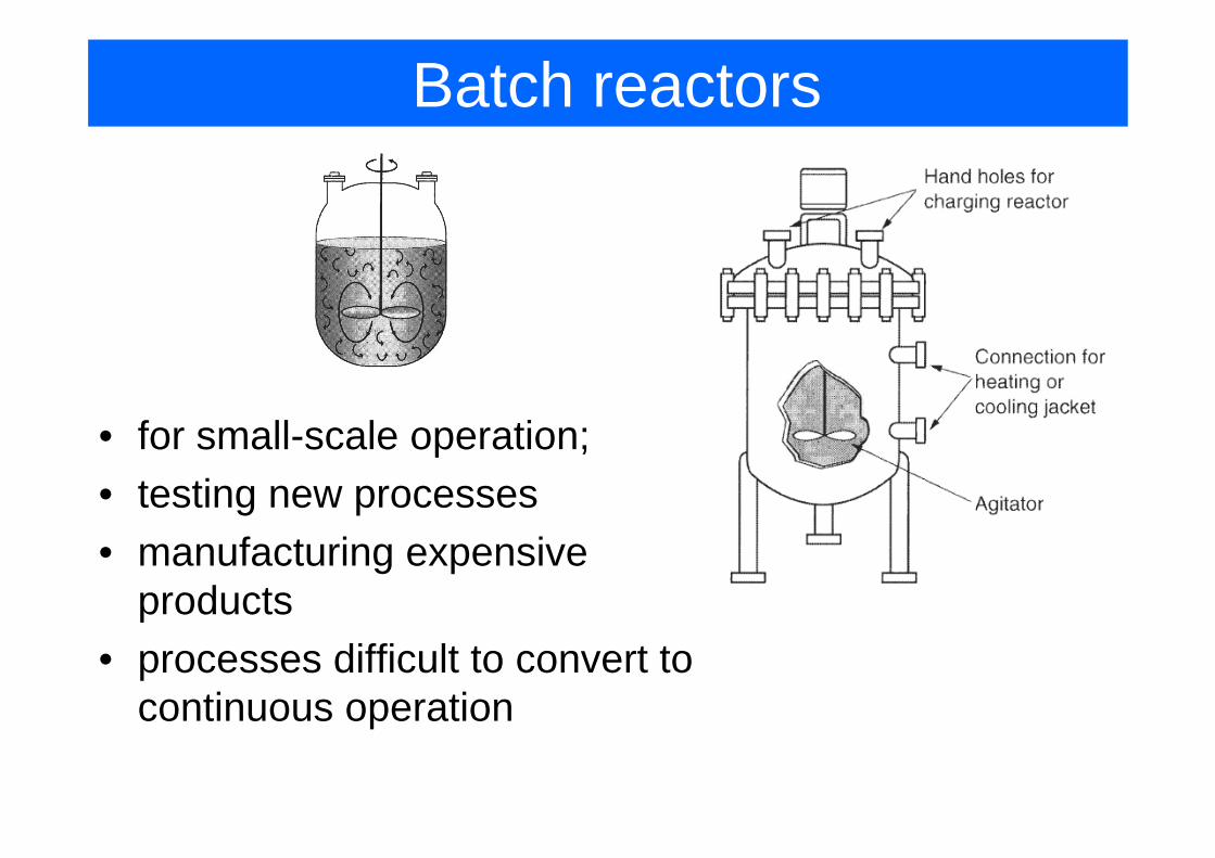
Batch reactors
• for small-scale operation;• testing new processes• manufacturing expensive
products• processes difficult to convert to
continuous operation

Batch reactors
• assuming perfect mixing, reaction rate the same through the volume
0
Vj
j j i
dNF F rdV
dt− + =∫
0
Vj
i
dNrdV
dt=∫
jj
dNr V
dt=
• integrating the equation we can get Nj vs t –“mole-time trajectory”

Batch reactors
Pfaudler’s Batch reactor
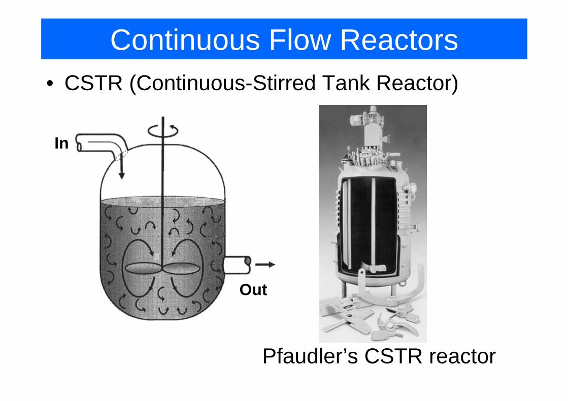
Continuous Flow Reactors• CSTR (Continuous-Stirred Tank Reactor)
Pfaudler’s CSTR reactor
In
Out

Continuous Flow Reactors• CSTR (Continuous-Stirred Tank Reactor)
0
Vj
j j i
dNF F rdV
dt− + =∫
=0, operation in a steady mode
• assuming perfect mixing:
0j jF F rV− = − 0j jF FV
r−
=−
Design equation of CSTR
0 0A A
A
v C vCVr−
=−
or

Continuous Flow Reactors
• Tubular reactor
• usually operates in steady state• easy to maintain, produce highest yield

Continuous Flow Reactors
• PFR (plug flow reactor) – useful approximation of a tubular reactor
• For every slice of volume:
0 0j j iF F r V− + ∆ = | |j V j V Vi
F Fr
V+∆−
=∆
ji
dFr
dV=
• From here, a volume required to produce given molar flow rate of product can be determined

Continuous Flow Reactors
• Packed-Bed reactor – here the reaction takes place on the surface of catalyst
• reaction rate defined per unit area (or mass) of catalyst
mol A reacted/s g catalystAr− = ⋅

Continuous Flow Reactors
• as in the PFR case, we can calculate design equation now in terms of catalyst weight coordinate
W – catalyst weight coordinate
| | 0AW AW W iF F r W+∆− + ∆ = | |AW AW Wi
F Fr
W+∆−
=∆
AA
dFrdW
′ =

Reactors Mole Balance: Summary

Sizing of reactors
Here we’ll find how to find the size of a reactor is relation between the reaction
rate and conversion factor is known

Conversion in the reactors
• if we are interested in species A we can define A as the basis of calculation
aA bB cC dD+ ⎯⎯→ +
b c dA B C Da a a
+ ⎯⎯→ +
• conversion: Moles of A reactedMoles of A fedAX =
• maximum conversion for reversible reactions is the equilibrium conversion Xe.

Batch reactor design equations
• the equation can be integrated to find the time necessary to achieve required conversion
• the longer reactants spend in the chamber the higher is the degree of conversion
[ ] [ ]0Moles of A reacted A AN X= ⋅
[ ] [ ] [ ]0 0Moles of A in reactor, A A A AN N N X= − ⋅
0
( )AA
AA
dN r Vdt
dN dXNdt dt
− = −
= −0 ( )A A
dXN r Vdt
= −

Design equations for flow reactors
• molar flow rate is concentration * volume rate
[ ][ ] [ ][ ]
[ ][ ]0
Moles of A fed Moles of A reactedtime Moles of A fedAF X =
[ ] [ ] [ ]0 0A A AF F X F− ⋅ =
[ ] [ ]0 0 0(1 )A A AF F X C v= − =

Design equations for flow reactors• CSTR:
[ ] [ ]0 (1 )A AF F X= −
0 0A A A
A A
F F F XVr r− ⋅
= =− −
• Because the reactor is perfectly mixed, the exit composition is identical to the composition inside the reactor

Design equations for flow reactors• Tubular Flow Reactor (PFR):
[ ] [ ]0 (1 )A AF F X= −
00
X
AA
dXV Fr
=−∫
• to integrate we need to know rA depends on the concentration (and therefore on conversion)
AA
dFrdV−
− =0A
AF dXr
dV− =

Design equations for flow reactors• Packed-Bed Reactor: similar derivation, but W instead of V
[ ] [ ]0 (1 )A AF F X= −
00
X
A
A
dXW Fr
=′−
∫
• from this equation we can find weight of catalyst W required to achieve the conversion X
AA
dFrdW−′− =
0AA
F dXrdW
′− =

Levenspiel plot• reactor volume required is always reciprocal in
rA and proportional to X.
00
X
AA
dXV Fr
=−∫
0A
A
F XVr⋅
=−
PFR: CSTR:
• Levenspiel plot:

Reactors in series• CSTR in series
– 1st reactor
0 1 1 1
1 0 0 1
0A A A
A A A
F F r VF F F X
− + =
= − 1 0 11
1A
A
V F Xr
=−
– 2nd reactor
1 2 2 2
2 0 0 2
0A A A
A A A
F F r VF F F X
− + == −
( )2 0 1 22
1A
A
V F X Xr
= −−

Mean residence time (Space Time)• mean residence time defined as:
0
Vv
τ =

Reactor design equations: Summary

Chemical synthesis with microreactors
• Advantages:– scale-out instead of
scale-up– flexible– easy to change the
production volume
Univ. of Texas microreactor for biodiesel production: cost reduction 40c/gallon
G. Jovanovic, Univ. of Oregon, microreactor for biodiesel production:

Chemical synthesis with microreactors
• not every reaction benefits from microreactor• however:
– exothermic reactions are usually easier to control in microreactors due to better temperature control(reactions involving explosives, regionselectivereactions)
– photochemical reactions can be easier arranged to absorb more light
– multistep reactions (e.g. peptide synthesis)– biphasic reactions (gas-liquid)– synthesis of analytically pure components