chief dispatcher modulating lead/lag controllers … · chief dispatcher modulating lead/lag...
TRANSCRIPT
203.743.6741 • 203.798.7313www.preferred-mfg.com
Instruments & Controls
Catalog 25
Instruments &
Controls
125
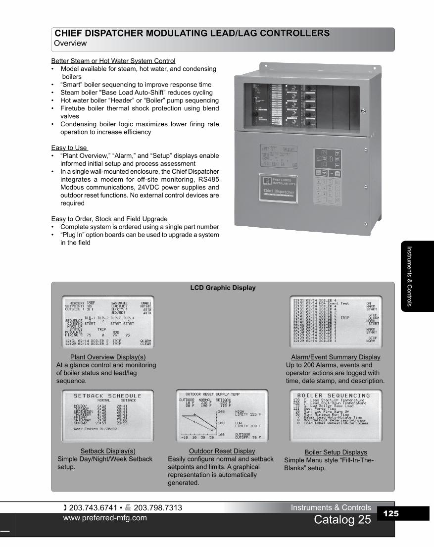
CHIEF DISPATCHER MODULATING LEAD/LAG CONTROLLERSOverview
BetterSteamorHotWaterSystemControl• Modelavailableforsteam,hotwater,andcondensing
boilers• “Smart”boilersequencingtoimproveresponsetime• Steamboiler"BaseLoadAuto-Shift”reducescycling• Hotwaterboiler“Header”or“Boiler”pumpsequencing• Firetube boiler thermal shock protection using blend
valves• Condensing boiler logicmaximizes lower firing rate
operationtoincreaseefficiency
EasytoUse• “PlantOverview,”“Alarm,”and“Setup”displaysenable
informedinitialsetupandprocessassessment• Inasinglewall-mountedenclosure,theChiefDispatcher
integrates amodem for off-sitemonitoring, RS485Modbuscommunications,24VDCpowersuppliesandoutdoorresetfunctions.Noexternalcontroldevicesarerequired
EasytoOrder,StockandFieldUpgrade• Completesystemisorderedusingasinglepartnumber• “PlugIn”optionboardscanbeusedtoupgradeasystem
inthefield
LCD Graphic Display
PlantOverviewDisplay(s)Ataglancecontrolandmonitoringofboilerstatusandlead/lagsequence.
Alarm/EventSummaryDisplayUpto200Alarms,eventsandoperatoractionsareloggedwithtime,datestamp,anddescription.
SetbackDisplay(s)SimpleDay/Night/WeekSetbacksetup.
OutdoorResetDisplayEasilyconfigurenormalandsetbacksetpointsandlimits.Agraphicalrepresentationisautomaticallygenerated.
BoilerSetupDisplaysSimpleMenustyle“Fill-In-The-Blanks”setup.
203.743.6741 • 203.798.7313www.preferred-mfg.com
Instruments & Controls
Catalog 25
Inst
rum
ents
& C
ontro
ls
126
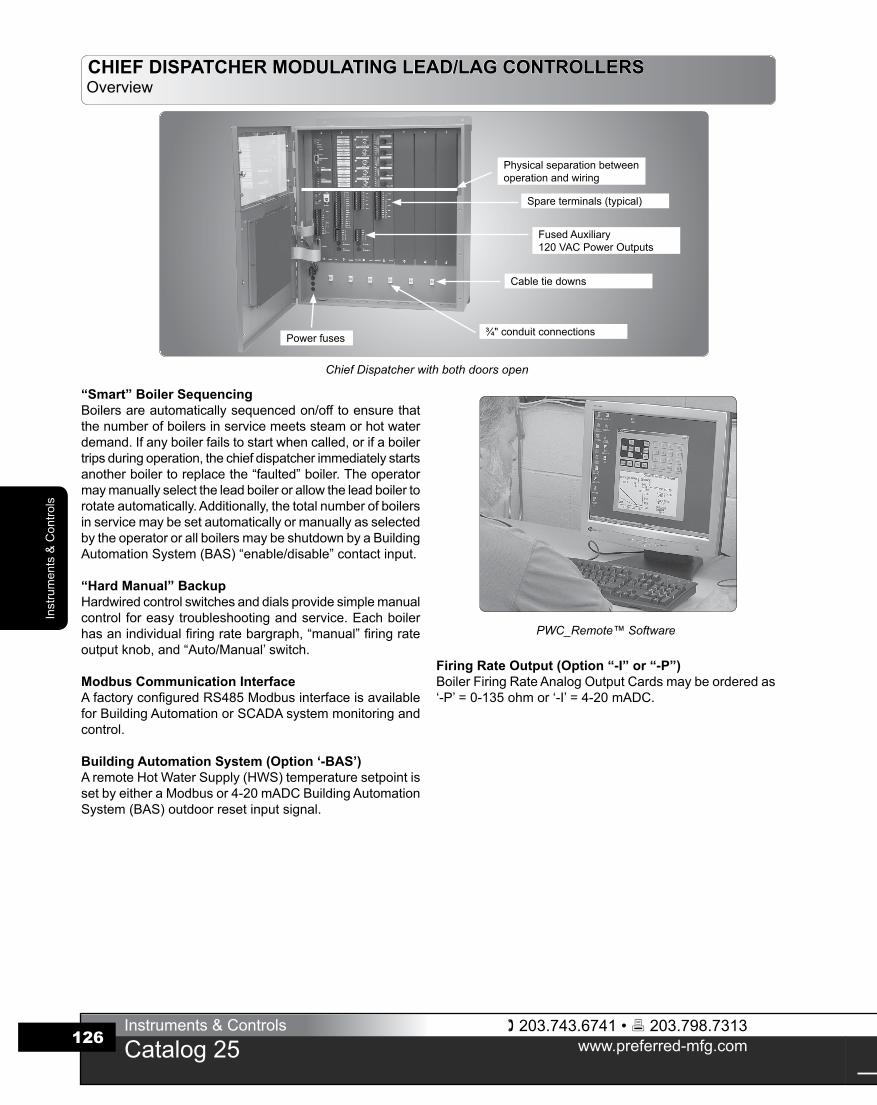
“Smart” Boiler SequencingBoilersareautomaticallysequencedon/offtoensurethatthenumberofboilersinservicemeetssteamorhotwaterdemand.Ifanyboilerfailstostartwhencalled,orifaboilertripsduringoperation,thechiefdispatcherimmediatelystartsanotherboilertoreplacethe“faulted”boiler.Theoperatormaymanuallyselecttheleadboilerorallowtheleadboilertorotateautomatically.Additionally,thetotalnumberofboilersinservicemaybesetautomaticallyormanuallyasselectedbytheoperatororallboilersmaybeshutdownbyaBuildingAutomationSystem(BAS)“enable/disable”contactinput.
“Hard Manual” BackupHardwiredcontrolswitchesanddialsprovidesimplemanualcontrolforeasytroubleshootingandservice.Eachboilerhasanindividualfiringratebargraph,“manual”firingrateoutputknob,and“Auto/Manual’switch.
Modbus Communication InterfaceAfactoryconfiguredRS485ModbusinterfaceisavailableforBuildingAutomationorSCADAsystemmonitoringandcontrol.
Building Automation System (Option ‘-BAS’)AremoteHotWaterSupply(HWS)temperaturesetpointissetbyeitheraModbusor4-20mADCBuildingAutomationSystem(BAS)outdoorresetinputsignal.
Firing Rate Output (Option “-I” or “-P”)BoilerFiringRateAnalogOutputCardsmaybeorderedas‘-P’=0-135ohmor‘-I’=4-20mADC.
Spareterminals(typical)
Cabletiedowns
¾"conduitconnectionsPowerfuses
Physicalseparationbetweenoperationandwiring
FusedAuxiliary120VACPowerOutputs
CHIEF DISPATCHER MODULATING LEAD/LAG CONTROLLERSOverview
Chief Dispatcher with both doors open
PWC_Remote™ Software
203.743.6741 • 203.798.7313www.preferred-mfg.com
Instruments & Controls
Catalog 25
Instruments &
Controls
127
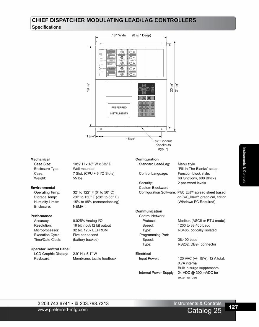
CHIEF DISPATCHER MODULATING LEAD/LAG CONTROLLERSSpecifications
MechanicalCaseSize: 10½"Hx18"Wx8½"DEnclosureType: WallmountedCase: 7Slot,(CPU+6I/OSlots)Weight: 55lbs.
EnvironmentalOperatingTemp: 32°to122°F(0°to50°C)StorageTemp: -20°to150°F(-28°to65°C)HumidityLimits: 15%to95%(noncondensing)Enclosure: NEMA1
PerformanceAccuracy: 0.025%AnalogI/OResolution: 16bitinput/12bitoutputMicroprocessor: 32bit,128kEEPROMExecutionCycle: FivepersecondTime/DateClock: (batterybacked)
Operator Control PanelLCDGraphicDisplay: 2.9"Hx5.1"WKeyboard: Membrane,tactilefeedback
ConfigurationStandardLead/Lag: Menustyle
“Fill-In-The-Blanks”setup.ControlLanguage: Functionblockstyle,
60functions,600BlocksSecurity: 2passwordlevelsCustomBlockwareConfigurationSoftware: PWC_Edit™ spreadsheetbased
or PWC_Draw™ graphical,editor.(WindowsPCRequired)
CommunicationControlNetwork:Protocol: Modbus(ASCIIorRTUmode)Speed: 1200to38,400baudType: RS485,opticallyisolated
ProgrammingPort:Speed: 38,400baudType: RS232,DB9Fconnector
ElectricalInputPower: 120VAC(+/-15%),12Atotal,
0.7AinternalBuiltinsurgesuppressors
InternalPowerSupply: 24VDC@300mADCforexternal use
G
G
G
G
G
15 5/8"1 3/16"
18 " Wide (8 1/2 " Deep)
19 1
/4"
20 1
/8"
21 1
/8"
3/4" ConduitKnockouts
(typ. 7)
FAN
FUEL VALVE
LOCKOUT
BOILER 1
FAN
FUEL VALVE
LOCKOUT
BOILER 2
FANFUEL VALVELOCKOUT
BOILER 3
LOW FEEDWTR PSILOW FEED TANK LEV
MAN AUTO
BOILER 1
MAN AUTO
BOILER 2
MAN AUTO
BOILER 3
MAN AUTO
MAN AUTO
RUNCPU OK
FORCED
CPU Module
ALARM
BATTERY
COM 1
PROGRAMMINGPORT
Tx MODEM 1
Rx
CD
AA
Tx COM 2
Rx
LCD CONTRAST
BOILER 2
ON - OFF - AUTO
BOILER 1
BOILER 3
ON - OFF - AUTO
FEED PUMP 1
ON - OFF - AUTO
FEED PUMP 2
ON - OFF - AUTO
ON - OFF - AUTO
PREFERRED
INSTRUMENTS
ABC
1DEF
2GHI
3JKL
4MNO
5STU
7VWX
8YZ "
9% # ,
0: < >
./ + -
SPACE
PQR
6
PAGEDOWN
PAGEUP
MENU
HOMEPAGE
ESC ENTERALARMLIST
ALARMSILENCE
203.743.6741 • 203.798.7313www.preferred-mfg.com
Instruments & Controls
Catalog 25
Inst
rum
ents
& C
ontro
ls
128
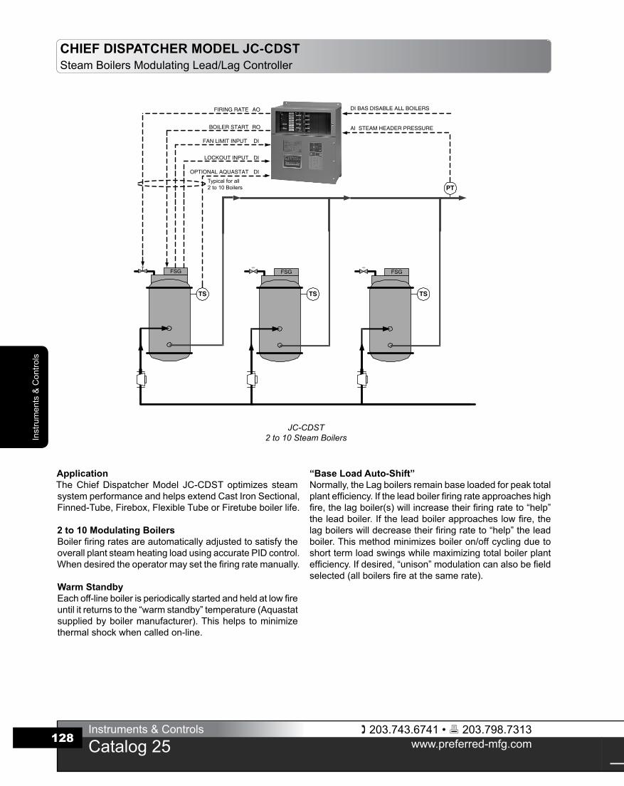
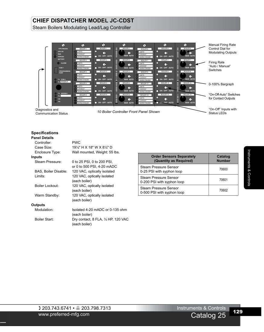
CHIEF DISPATCHER MODEL JC-CDSTSteamBoilersModulatingLead/LagController
ApplicationTheChiefDispatcherModel JC-CDSToptimizes steamsystemperformanceandhelpsextendCastIronSectional,Finned-Tube,Firebox,FlexibleTubeorFiretubeboilerlife.
2 to 10 Modulating BoilersBoilerfiringratesareautomaticallyadjustedtosatisfytheoverallplantsteamheatingloadusingaccuratePIDcontrol.Whendesiredtheoperatormaysetthefiringratemanually.
Warm StandbyEachoff-lineboilerisperiodicallystartedandheldatlowfireuntilitreturnstothe“warmstandby”temperature(Aquastatsuppliedbyboilermanufacturer).Thishelps tominimizethermalshockwhencalledon-line.
Typical for all2 to 10 Boilers
JC-CDST2 to 10 Steam Boilers
“Base Load Auto-Shift”Normally,theLagboilersremainbaseloadedforpeaktotalplantefficiency.Iftheleadboilerfiringrateapproacheshighfire,thelagboiler(s)willincreasetheirfiringrateto“help”theleadboiler.Iftheleadboilerapproacheslowfire,thelagboilerswilldecreasetheirfiringrateto“help”theleadboiler.Thismethodminimizesboileron/offcyclingduetoshorttermloadswingswhilemaximizingtotalboilerplantefficiency.Ifdesired,“unison”modulationcanalsobefieldselected(allboilersfireatthesamerate).
203.743.6741 • 203.798.7313www.preferred-mfg.com
Instruments & Controls
Catalog 25
Instruments &
Controls
129
SpecificationsPanel DetailsController: PWCCaseSize: 19¼"HX18"WX8½"DEnclosureType: Wallmounted,Weight:55lbs.
InputsSteamPressure: 0to25PSI,0to200PSI,
or0to500PSI,4-20mADCBAS,BoilerDisable: 120VAC,opticallyisolatedLimits: 120VAC,opticallyisolated
(eachboiler)BoilerLockout: 120VAC,opticallyisolated
(eachboiler)WarmStandby: 120VAC,opticallyisolated
(eachboiler)OutputsModulation: Isolated4-20mADCor0-135ohm
(eachboiler)BoilerStart: Drycontact,8FLA,½HP,120VAC
(eachboiler)
CHIEF DISPATCHER MODEL JC-CDSTSteamBoilersModulatingLead/LagController
ManualFiringRateControlDialfor ModulatingOutputs
FiringRate“Auto/Manual”Switches
0-100%Bargraph
“On-Off-Auto”Switchesfor Contact Outputs
“On-Off”InputswithStatusLEDs10 Boiler Controller Front Panel ShownDiagnosticsand
CommunicationStatus
Order Sensors Separately(Quantity as Required)
CatalogNumber
SteamPressureSensor0-25PSIwithsyphonloop 70600
SteamPressureSensor0-200PSIwithsyphonloop 70601
SteamPressureSensor0-500PSIwithsyphonloop 70602
203.743.6741 • 203.798.7313www.preferred-mfg.com
Instruments & Controls
Catalog 25
Inst
rum
ents
& C
ontro
ls
130
CHIEF DISPATCHER MODEL JC-CDSTSuggestedSpecifications
1. ApplicationSupplyafullyintegratedboilercontrolsystemtocoordinatetheoperationoftwo(selectuptoten)fullymodulatingsteamboilersin order tomaintainSteamHeaderPressure at setpoint.Thecontrolsystemshallbemicroprocessor-basedandsuitable forwallmounting.2. Boiler ModulationThecontrol systemshallprovideaPIDbasedcontrol scheme.Modulation shall be field selectable as either “Unison” (all atthe same firing rate) or as “Series”. Seriesmodulation shallinclude“BaseLoadAuto-Shift”logicinordertominimizeboileron/offcycling.Normallythelagboilersshallbebaseloadedatanoperatoradjustablefiringrateforpeakefficiency.Whentheleadboiler’sfiringrateapproacheshighfire,thelagboiler(s)willautomaticallymodulateupfromthebaseloadfiringrateto“help”theleadboilerwithoutstartinganotherlagboiler.Iftheleadboilerapproacheslowfire,thelagboilerswillmodulatetowardlowfireto“help”theleadboilerandpreventashortcycleofalagboiler.Whentheleadboilerleavesthehighorlowfirepositionthelagboiler(s)resumefiringatthenormalbaseloadforpeakefficiency.Iftheloadincreaseordecreaseislongterm,alagboilershallbecycledonoroffasrequired.Modulationsignalsshallbe4-20mADCor 0-135 ohm (as required by the boiler) and shall beelectricallyisolatedchannel-channelandchannel-ground.3. Steam Header Pressure SetpointTheoperatormaysettheSteamHeaderPressureSetpointviaafrontpaneldisplay.4. Boiler SequenceThecontrolsystemshallusebothSteamHeaderPressureandBoilerFiringRatepercenttostartandstoptheboilersandminimizethetotalnumberofboilersinoperation.ThecontrollershallstartandstopboilerswhentheSteamHeaderPressureisoutsideanadjustablepressurelimitbandforlongerthananadjustableshorttimedelay.Toanticipateandminimizeheaderpressuredeviations,thecontrolsystemshallstartorstopthenextboilerifthe“lead”boilerhasbeennearhighorlowfireforlongerthantheadjustabletimedelay.Thecontrolsystemshallmonitoreachboiler’slockoutand limit circuits and shall rapidly andautomatically skip overthoseboilersthatarepowereddownformaintenance,trippedorotherwisewillnotstart.Theleadboilershalleitherautomaticallyrotateonatimeofday/dayofweek(ormonth)schedule,orshallbemanuallyselectedbytheoperator.Provideawarmstandbyboilershellaquastatinputforeachboiler.Ifrecommendedbytheboilermanufacturer,eachoff-lineboilershallbestartedandheldatlowfirewhenthetemperaturedrops.Whencalledtorun,theboilershallholdatlowfireuntilthetemperaturerisesabovethewarmstandbysetting.Provideanaquastatreleasetomodulateover-ridetimertopreventaprotractedlowfirehold.TheControlSystemshallreducethefiringratetoaminimumbeforestoppingaboilertopreventaccumulationoffuelinthefurnace.
5. Operator Controls, Trends, Indications and AlarmsThe control system shall include a 16 line x 40 character (orgreater)LCDdisplayforboilersequencecontrolandstatus,alarmandeventsummaries,andsetupmenusforeasyoperation,tuningandtroubleshooting.Alarms,eventsandoperatoractionsshallbeloggedwithtime/datestampandEnglishlanguagedescription.6. ReliabilityIncludehardwiredbackupstations topermitmanual operationoftheplantshouldthecontrolsystemrequireservice.Manualoperationmust be possiblewhen themicroprocessor is notfunctioning. Hardwired “hand-off-auto” control switchesmustbewireddirectlyintoeveryboilerstart/stopcircuit.Each4-20mADCor0-135ohmmodulatingcontroloutputmust includeahardwiredmanualbackupstationwithauto/manualswitch,outputcontrolknobandoutputlevelindicator(bargraph,analogmeterordigitaldisplay).7. CommunicationTheControl System shall have the ability of simultaneouslycommunicating to aDataAcquisitionSystem (DAS),BuildingAutomation System (BAS) or BuildingManagement System(BMS)viaRS485Modbusprotocol,andtoaPersonalComputer.Theindividualboilerlimits,lockout,start/stop,warmstandby,andfiringratestatusshallbereadable.Headersetpoint,plantfiringrate,boilerquantitycalledtostart,boilerselectedasleadandallsetupparametersshallbeeasilyreadandwritten.8. Quality AssuranceThe control system shall bemanufactured and labeled inaccordancewithUL508requirements(CSAC22.2#14foruseinCanada).InspectionandlabelingshallbesupervisedbyULorotherOSHAapprovedNationallyRecognizedTestLab(NRTL).ThecontrolsystemshallbeaPreferredInstruments,Danbury,CT,Model JC-CDST-x-P (‘x’=boilerquantityfrom2to10;“-P”for0-135ohm;“-I”for4-20mA).
203.743.6741 • 203.798.7313www.preferred-mfg.com
Instruments & Controls
Catalog 25
Instruments &
Controls
131
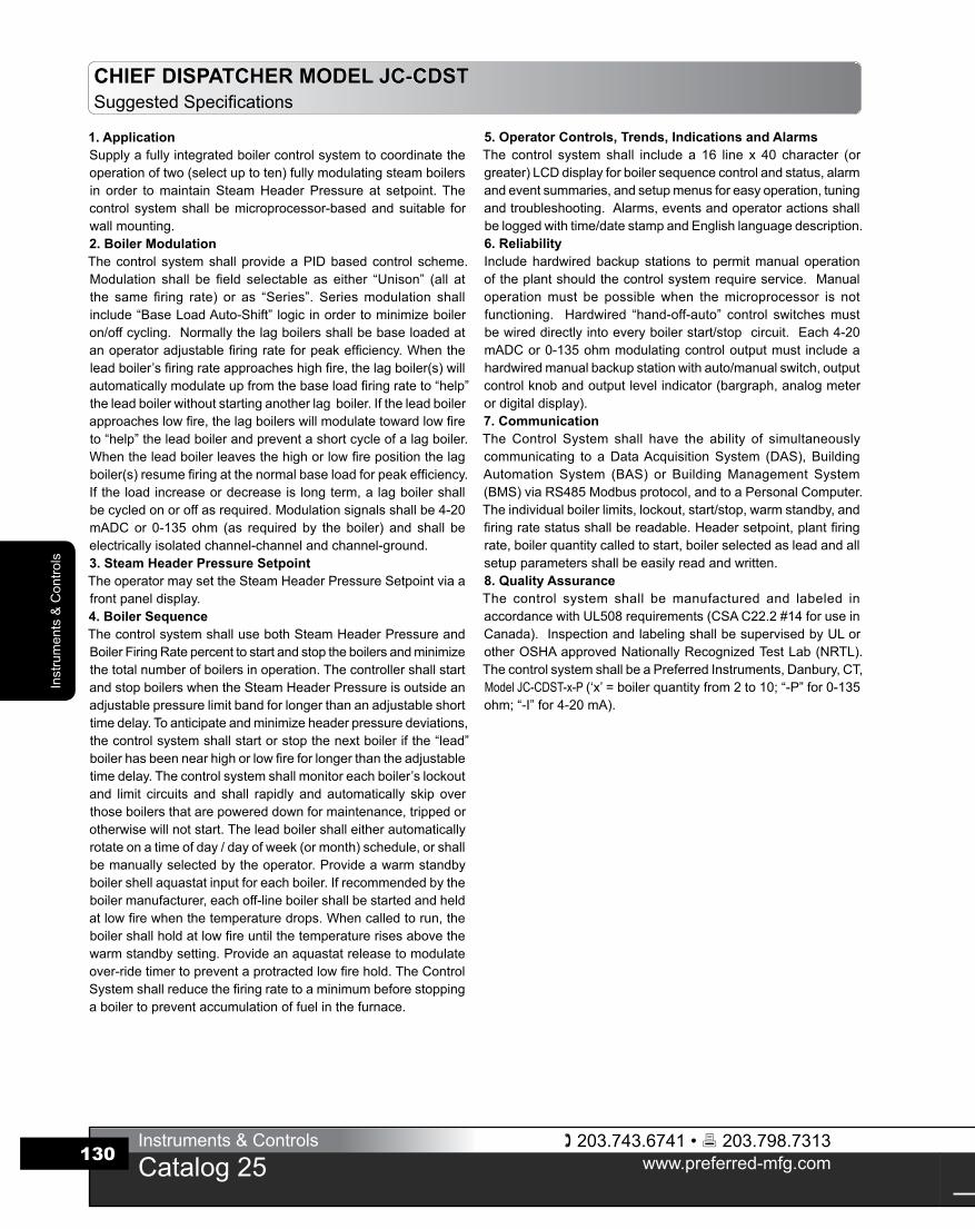
CHIEF DISPATCHER MODEL JC-CDHWHotWaterBoilersModulatingLead/LagController
ApplicationTheChiefDispatcherModelJC-CDHWoptimizeshotwatersystemperformanceandhelpsextendCastIronSectional,Finned-Tube,FireboxorFlexibleTubeboilerlife.
2 to 10 Fully Modulating BoilersHotWaterSupply(HWS)headertemperatureismaintainedusingaccuratePIDcontrol.Multipleboilersaremodulatedin“Unison”(allatthesamefiringrate)toensureevenheatdelivery.Lagboilersarebroughtuptothe“Unison”firingrateusingapredeterminedRampRatetomeettheheatingloadwithminimumovershoot.Whendesired,theoperatormaysetthe“unison”firingratemanually.
Outdoor ResetEnergyissavedbyloweringtheHotWaterSupply(HWS)temperature setpoint as the outside air temperatureincreases.Operatingcostisreducedduringwarmerdays.Whendesired, the operatormay set theHWSsetpointmanually.
Time of Day / Week SetbackThisfeatureisusedinheatingapplicationstosaveenergyby lowering theHotWaterSupply (HWS) temperaturesetpoint during timeswhen the heating requirement isreduced,suchasatnightoronweekendsandholidays.
JC-CDHW2 to 10 Hot Water Boilers
Domestic Hot Water Priority (2 to 9 boiler systems) A temperature switch (thermostat) contact closure inputwill override the “outdoor reset and “setback” portion oftheprogramandforcetheHWStemperaturesetpointtoadomestichotwatersetpoint.Arelayoutputisavailabletostartadomestichotwaterpumpifrequired.
Condensing Boiler Logic (option “-C”)Condensing boiler logic takes full advantage of thecondensing boiler design bymaximizing the number ofboilersrunningnearlowfiretomaximizeefficiency.
AI HOT WATER SUPPLY HEADER TEMPERATURE
Typical forEach Boiler
203.743.6741 • 203.798.7313www.preferred-mfg.com
Instruments & Controls
Catalog 25
Inst
rum
ents
& C
ontro
ls
132
CHIEF DISPATCHER MODEL JC-CDHWHotWaterBoilersModulatingLead/LagController
Order Sensors Separately(Quantity as Required)
CatalogNumber
HotWaterThermistorTemperatureSensor0ºto300ºF,4½"depth 70610
Thermowell,SS,4½"x½"NPT 70610WOutsideAirThermistorTemperatureSensorwithweather-proofcover 70612
Optional Features CatalogNumber
BuildingAutomationSystem(BAS)4-20mADCSetpoint JC-CDHWxxx-BAS
CondensingBoilerLogic JC-CDHWxxx-C
SpecificationsPanel DetailsController: PWCCaseSize: 19¼"HX18"WX8½"DEnclosureType: Wallmounted,Weight:55lbs.
InputsHotWaterTemperature: 0°to300°F,ThermistorOutdoorAirTemperature: Thermistor(non“BAS”version)BASResetSetpoint: 4-20mADC(“-BAS”version)BASBoilerDisable: 120VAC,opticallyisolated
(eachboiler)Limits: 120VAC,opticallyisolated
(eachboiler)BoilerLockout: 120VAC,opticallyisolated
(eachboiler) DomesticHWPriority: 120VAC,opticallyisolatedOutputsModulation: Isolated4-20mADCor0-135ohm
(eachboiler)BoilerStart: Drycontact,8FLA,½HP,
120VAC(eachboiler)DomesticHWCirculationPump: Drycontact,8FLA,½HP,
120VAC
Ordering InformationSpecifyChiefDispatcherCatalogNumber:
JC-CDHW-2-PBoilerQuantity 2to10Analog Output Type 4-20mADC-I
0-135ohm-P
DOM. HW PRIORITY
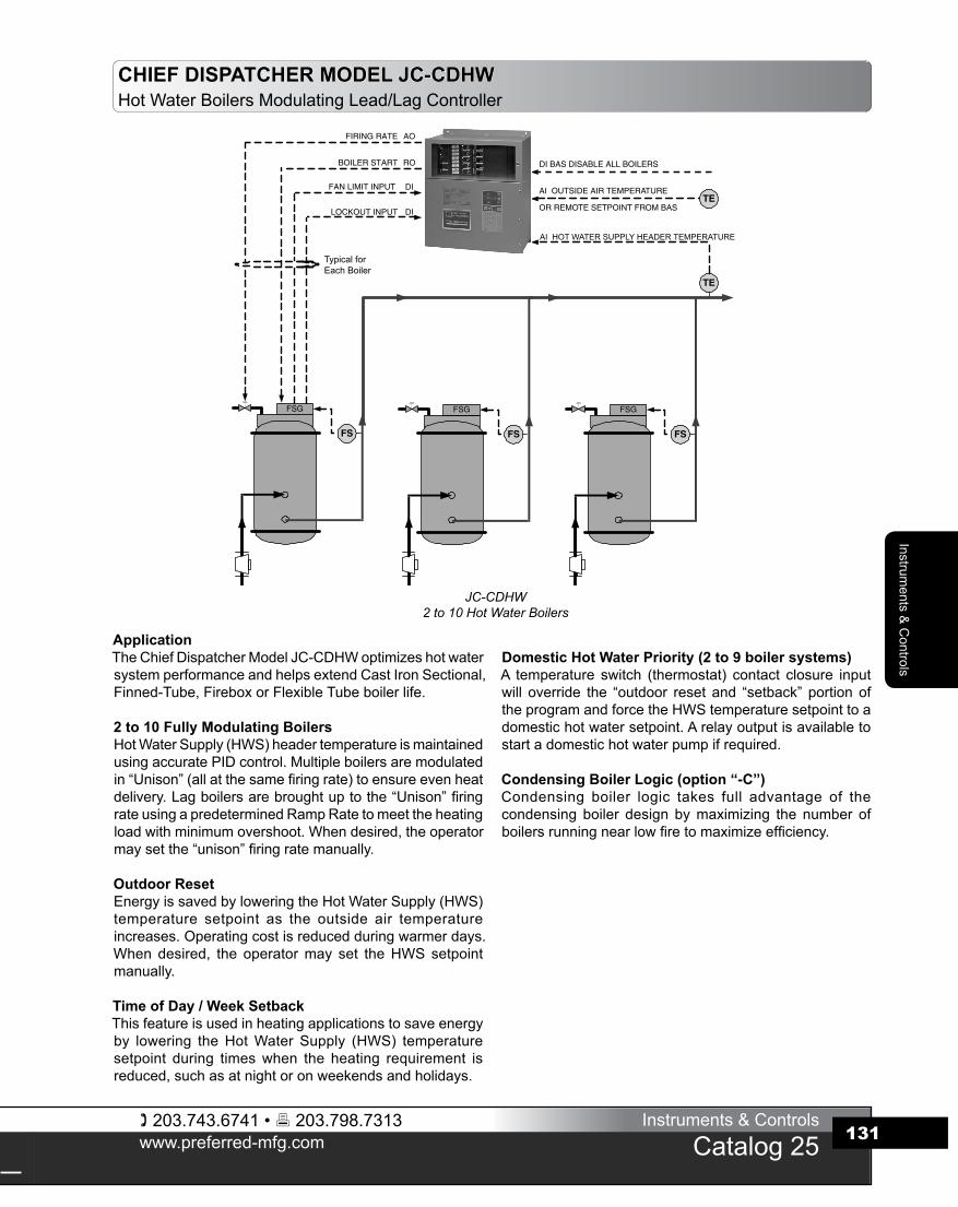
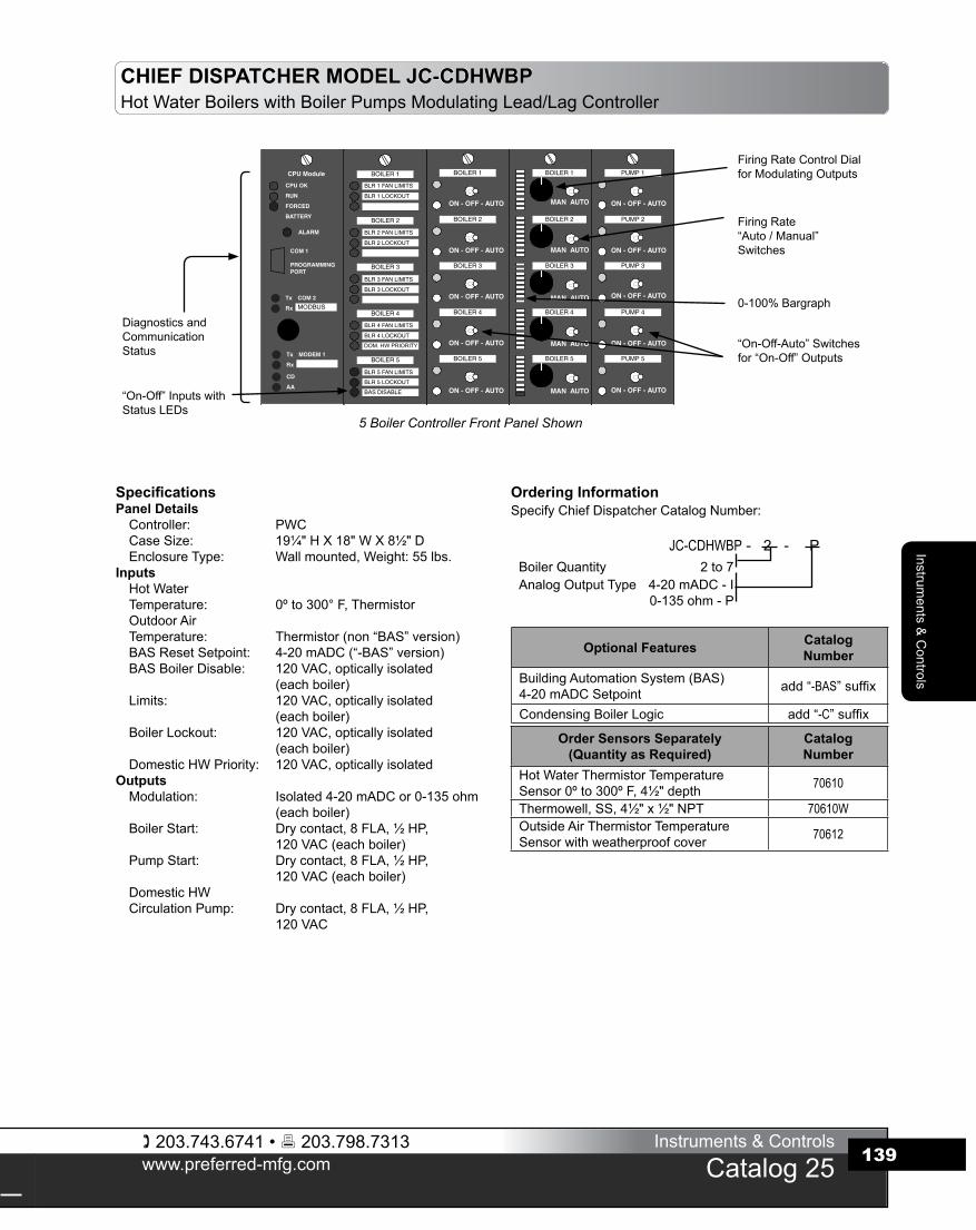
FiringRateControlDialforModulatingOutputs
FiringRate“Auto/Manual”Switches
0-100%Bargraph
“On-Off-Auto”Switchesfor“On-Off”Outputs
“On-Off”InputswithStatusLEDs
DiagnosticsandCommunicationStatus
5 Boiler Controller Front Panel Shown
203.743.6741 • 203.798.7313www.preferred-mfg.com
Instruments & Controls
Catalog 25
Instruments &
Controls
133
1. ApplicationSupplyafullyintegratedboilercontrolsystemtocoordinatetheoperationoftwo(selectuptoten)fullymodulatinghotwaterboilersinordertomaintaintheHotWaterSupply(HWS)temperatureatsetpoint.Thecontrolsystemshallbemicroprocessor-basedandsuitableforwallmounting.2. Boiler ModulationThecontrolsystemshallincorporateaHWSheadertemperaturePIDcontrolscheme.Boilersshallbemodulatedin“Unison”(allatthesamefiringrate).Modulationsignalsshallbe4-20mADCor0-135ohm(asrequiredbytheboiler)andshallbeelectricallyisolatedchannel-channelandchannel-ground.3. Hot Water Supply (HWS) Temperature SetpointWhen theHWSTemperature control loop is in the “automatic”mode,thecontrolsystemshallestablishtheHWStemperaturesetpointbasedonthetimeofday,dayoftheweekandtheoutsideairtemperature.Whenin“manual”modetheoperatormaysettheHWStemperatureviaafrontpaneldisplay.Alltemperaturesandtime/datedatamustbefieldadjustablethrough“fill-in-the-blanks”styledisplays.Alternately,thecontrolsystemshallaccepta4-20mADCoutdoor air temperature reset setpoint signal fromanexternalBuildingAutomationSystem(BAS).4. Boiler SequenceThe control system shall utilize bothHWS temperature andboilerfiringratepercent tostartandstoptheboilersandshallminimizethetotalnumberofboilersinoperation.ThecontrollershallstartandstopboilerswhentheHWStemperatureisoutsidetheadjustable temperature limit for longer than theadjustabletimedelay.Inordertominimizeheadertemperaturedeviations,thecontrolsystemshallstartandstopthenextboilerwhenthe“lead”boilerisatanadjustablefiringratelimitforlongerthantheadjustabletimedelay.Thecontrolsystemshallmonitorbothboilerlockoutandlimitcircuitstoautomaticallyskipoverthoseboilersthat are powereddown formaintenance, trippedor otherwisewill not start.The lead boiler shall either automatically rotateonatimeofday,dayofweek(ormonth)schedule,orshallbemanuallyselectedbytheoperator.Theboilershallberunatlowfireforwarm-upforapresetlowfireholdtime.Thebaseloadramprateshallbefieldadjustable.TheControlSystemshallreducethefiringratetoaminimumbeforestoppingaboilertopreventaccumulationoffuelinthefurnace.
5. Operator Controls, Trends, Indications and AlarmsThe control system shall include a 16 line x 40 character (orgreater)LCDdisplayforboilersequencecontrolandstatus,alarmandeventsummaries,andsetupmenusforeasyoperation,tuningandtroubleshooting.Alarms,eventsandoperatoractionsshallbeloggedwithTime/DatestampandEnglishlanguagedescription..6. ReliabilityIncludehardwiredbackupstations topermitmanual operationoftheplantshouldthecontrolsystemrequireservice.Manualoperationmust be possiblewhen themicroprocessor is notfunctioning.Hardwired “Hand-Off-Auto” control switchesmustbewireddirectly intoeveryboilerandpumpStart/Stopcircuit.Each4-20mADCor0-135ohmmodulatingcontroloutputmustinclude a hardwiredmanual backup stationwithAuto/Manualswitch,outputcontrolknobandoutputlevelindicator(bargraph,analogmeterordigitaldisplay).7. CommunicationTheControl System shall have the ability of simultaneouslycommunicating to aDataAcquisitionSystem (DAS),BuildingAutomation System (BAS) or BuildingManagement System(BMS)viaRS485ModbusprotocolandtoaPersonalComputer.Theindividualboilerlimits,lockout,start/stop,warmstandby,andfiringratestatusshallbereadable.Headersetpoint,plantfiringrate,boilerquantitycalledtostart,boilerselectedasleadandallsetupparametersshallbeeasilyreadandwritten.8. Quality AssuranceThe control system shall bemanufactured and labeled inaccordancewithUL508requirements(CSAC22.2#14foruseinCanada).InspectionandlabelingshallbesupervisedbyULorotherOSHAapprovedNationallyRecognizedTestLab(NRTL).ThecontrolsystemshallbeaPreferredInstruments,Danbury,CT,Model JC-CDHW-x-P (‘x’=boilerquantityfrom2to10;“-P”for0-135ohm;“-I”for4-20mA).
CHIEF DISPATCHER MODEL JC-CDHWSuggestedSpecifications
203.743.6741 • 203.798.7313www.preferred-mfg.com
Instruments & Controls
Catalog 25
Inst
rum
ents
& C
ontro
ls
134
SystemReturn
SystemSupply
Boiler Start DO
DI BAS Disable All Boilers
Fuel Input DI
Typical for allBoiler
Typical for allPump
Headered PumpControl Option
AI Outside Air Temp
DI DHW Priority Command
AI Hot Water Supply Header Temp
DI Pump Flow Proven
RO Pump Start
TE
TE
FS FS
Alphanumeric Pager
PWC_Remote
Firing Rate AO
or Remote SP from BAS
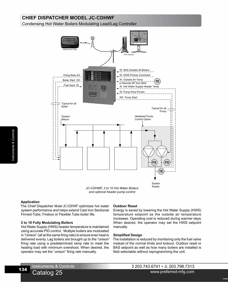
CHIEF DISPATCHER MODEL JC-CDHWFCondensingHotWaterBoilersModulatingLead/LagController
ApplicationTheChiefDispatcherModel JC-CDHWF optimizeshotwatersystemperformanceandhelpsextendCastIronSectional,Finned-Tube,FireboxorFlexibleTubeboilerlife.
2 to 10 Fully Modulating BoilersHotWaterSupply(HWS)headertemperatureismaintainedusingaccuratePIDcontrol.Multipleboilersaremodulatedin“Unison”(allatthesamefiringrate)toensureevenheatisdeliveredevenly.Lagboilersarebroughtuptothe“unison”firing rateusingapredetermined ramp rate tomeet theheatingloadwithminimumovershoot.Whendesired,theoperatormaysetthe“unison”firingratemanually.
Outdoor ResetEnergyissavedbyloweringtheHotWaterSupply(HWS)temperature setpoint as the outside air temperatureincreases.Operatingcostisreducedduringwarmerdays.Whendesired, the operatormay set theHWSsetpointmanually.
Simplified DesignTheinstallationisreducedbymonitoringonlythefuelvalveinsteadofthenormallimitsandlockout.OutdoorresetorBASsetpointaswellashowmanyboilersareinstalledisfieldselectablewithoutreprogrammingtheunit.
JC-CDHWF, 2 to 10 Hot Water Boilers and optional header pump control
203.743.6741 • 203.798.7313www.preferred-mfg.com
Instruments & Controls
Catalog 25
Instruments &
Controls
135
CHIEF DISPATCHER MODEL JC-CDHWFCondensingHotWaterBoilersModulatingLead/LagController
Time of Day / Week SetbackThisfeatureisusedinheatingapplicationstosaveenergyby lowering theHotWaterSupply (HWS) temperaturesetpoint during timeswhen the heating requirement isreduced,suchasatnightoronweekendsandholidays.
Domestic Hot Water Priority (2 to 9 boiler systems) A temperature switch (thermostat) contact closure inputwilloverride the“outdoor reset”and“setbackportion”oftheprogramandforcetheHWStemperaturesetpointtoadomestichotwatersetpoint.Arelayoutputisavailabletostartadomestichotwaterpumpifrequired.
Condensing Boiler LogicCondensing boiler logic takes full advantage of thecondensing boiler design bymaximizing the number ofboilersrunningnearlowfiretoincreaseefficiency.
Header Pump ControlHeader circulating pumps are controlled to ensure acontinuous flow of water through the heating system.Pumpsarecontrolledforhandlingtheplant,andatrippedpumpisautomaticallyreplacedwithastandbyunit.Theleadpumpcanberotatedmanuallyorautomatically.

203.743.6741 • 203.798.7313www.preferred-mfg.com
Instruments & Controls
Catalog 25
Inst
rum
ents
& C
ontro
ls
136
Ordering InformationSpecifyChiefDispatcherCatalogNumber:
JC-CDHWF-2-PCHBoilerQuantity 2to10Analog Output Type 4-20mADC-I
0-135ohm-P
CHIEF DISPATCHER MODEL JC-CDHWFCondensingHotWaterBoilersModulatingLead/LagController
Order Sensors Separately(Quantity as Required)
CatalogNumber
HotWaterThermistorTemperatureSensor0ºto300ºF,4½"depth 70610
Thermowell,SS,4½"x½"NPT 70610WOutsideAirThermistorTemperatureSensorwithweatherproofcover 70612
Optional Features CatalogNumber
HeaderPumpControl JC-CDHWFxxx-H
SpecificationsPanel DetailsController: PWCCaseSize: 19¼"HX18"WX8½"DEnclosureType: Wallmounted,Weight:55lbs.
InputsHotWaterTemperature: 0°to300°F,ThermistorOutdoorAirTemperature: ThermistorBASResetSetpoint: 4-20mADCBASBoilerDisable: 120VAC,opticallyisolated
(eachboiler)Fuel: 120VAC,opticallyisolated
(eachboiler) DomesticHWPriority: 120VAC,opticallyisolatedOutputsModulation: Isolated4-20mADCor0-135ohm
(eachboiler)BoilerStart: Drycontact,8FLA,½HP,
120VAC(eachboiler)DomesticHWCirculationPump: Drycontact,8FLA,½HP,
120VAC
DOM. HW PRIORITY
FiringRateControlDialforModulatingOutputs
FiringRate“Auto/Manual”Switches
0-100%Bargraph
“On-Off-Auto”Switchesfor“On-Off”Outputs
“On-Off”InputswithStatusLEDs
DiagnosticsandCommunicationStatus
5 Boiler Controller Front Panel Shown
CondensingHeaderPump

203.743.6741 • 203.798.7313www.preferred-mfg.com
Instruments & Controls
Catalog 25
Instruments &
Controls
137
CHIEF DISPATCHER MODEL JC-CDHWFSuggestedSpecifications
1. ApplicationSupplyafullyintegratedboilercontrolsystemtocoordinatetheoperationoftwo(selectuptoten)fullymodulating,condensinghotwaterboilersandheadersecondarywatercirculatingpumpsinordertomaintaintheHotWaterSupply(HWS)temperatureatsetpoint.Thecontrolsystemshallbemicroprocessor-basedandsuitableforwallmounting.2. Boiler ModulationThecontrolsystemshallincorporateaHWSheadertemperaturePIDcontrolscheme.Boilersshallbemodulatedin“Unison”(allatthesamefiringrate).Modulationsignalsshallbe4-20mADCor0-135ohm(asrequiredbytheboiler)andshallbeelectricallyisolatedchannel-channelandchannel-ground.3. Hot Water Supply (HWS) Temperature SetpointWhen theHWSTemperature control loop is in the “automatic”mode,thecontrolsystemshallestablishtheHWStemperaturesetpointbasedonthetimeofday,dayoftheweekandtheoutsideairtemperature.Whenin“manual”modetheoperatormaysettheHWStemperatureviaafrontpaneldisplay.Alltemperaturesandtime/datedatamustbefieldadjustablethrough“fill-in-the-blanks”styledisplays.Alternately,thecontrolsystemshallaccepta4-20mADCoutdoor air temperature reset setpoint signal fromanexternalBuildingAutomationSystem(BAS).4. Boiler SequenceThecontrolsystemshallusebothHWStemperatureandboilerfiring ratepercent tostartandstop theboilers,minimizing thetotalnumberofboilersinoperation.ThecontrollershallstartandstopboilerswhentheHWStemperatureisoutsidetheadjustabletemperature limit for longer than theadjustable timedelay.Tominimize header temperature deviations, the control systemshallstartandstop thenextboilerwhen the“lead”boiler isatanadjustablefiringratelimitforlongerthantheadjustabletimedelay.Thecontrolsystemshallmonitorboilerfuelvalvecircuitstoautomaticallyskipoverthoseboilersthatarepowereddownformaintenance,trippedorotherwisewillnotstart.Theleadboilershalleitherautomaticallyrotateonatimeofday,dayofweek(ormonth)schedule,orshallbemanuallyselectedbytheoperator.Theboilershallberunatlowfireforwarm-upforapresetlowfireholdtime.Thebaseloadramprateshallbefieldadjustable.Thecontrolsystemshallreducethefiringratetoaminimumbeforestoppingaboilertopreventaccumulationoffuelinthefurnace.
5. Operator Controls, Trends, Indications and AlarmsThe control system shall include a 16 line x 40 character (orgreater)LCDdisplayforboilersequencecontrolandstatus,alarmandeventsummaries,andsetupmenusforeasyoperation,tuningandtroubleshooting.Alarms,events,andoperatoractionsshallbeloggedwithTime/DatestampandEnglishlanguagedescription..6. ReliabilityIncludehardwiredbackupstationstopermitmanualoperationoftheplantifthecontrolsystemrequireservice.Manualoperationmust be possiblewhen themicroprocessor is not functioning.Hardwired“Hand-Off-Auto”controlswitchesmustbewireddirectlyintoeveryboilerandpumpStart/Stopcircuit.Each4-20mADCor0-135ohmmodulatingcontroloutputmustincludeahardwiredmanualbackupstationwithAuto/Manualswitch,outputcontrolknobandoutputlevelindicator(bargraph,analogmeterordigitaldisplay).7. CommunicationTheControl System shall have the ability of simultaneouslycommunicating to aDataAcquisitionSystem (DAS),BuildingAutomation System (BAS) or BuildingManagement System(BMS)viaRS485ModbusprotocolandtoaPersonalComputer.Theindividualboilerlimits,lockout,start/stop,warmstandby,andfiringratestatusshallberead.Headersetpoint,plantfiringrate,boilerquantitycalledtostart,boilerselectedasleadandallsetupparametersshallbereadableandwritable.8. Quality AssuranceThe control system shall bemanufactured and labeled inaccordancewithUL508requirements (CSAC22.2#14 foruseinCanada).InspectionandlabelingshallbesupervisedbyULorotherOSHAapprovedNationallyRecognizedTestLab(NRTL).ThecontrolsystemshallbeaPreferredInstruments,Danbury,CT,Model JC-CDHWF-C-H-x-P (‘x’=boilerquantityfrom2to10;“-P”for0-135ohm;“-I”for4-20mA).
203.743.6741 • 203.798.7313www.preferred-mfg.com
Instruments & Controls
Catalog 25
Inst
rum
ents
& C
ontro
ls
138
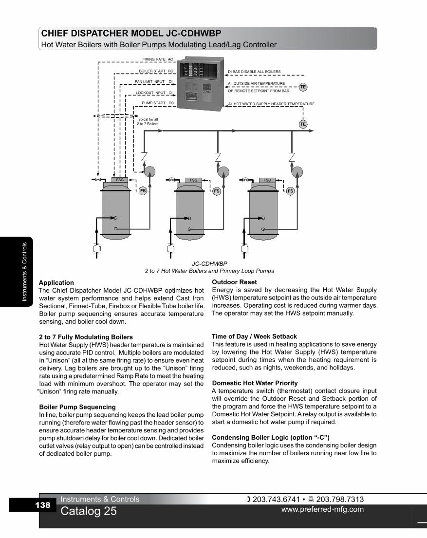
CHIEF DISPATCHER MODEL JC-CDHWBPHotWaterBoilerswithBoilerPumpsModulatingLead/LagController
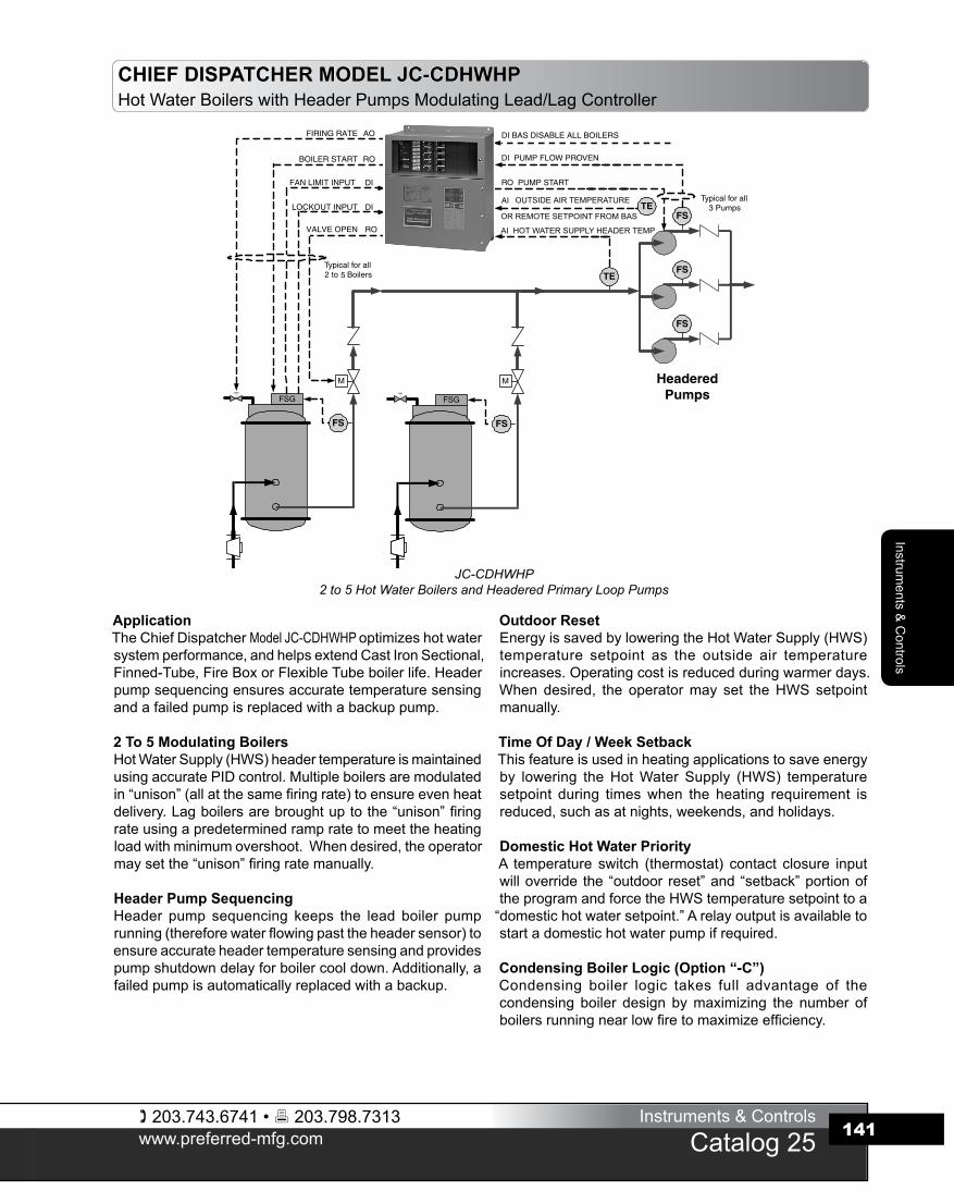
ApplicationTheChiefDispatcherModelJC-CDHWBPoptimizeshotwater systemperformanceand helps extendCast IronSectional,Finned-Tube,FireboxorFlexibleTubeboilerlife.Boiler pump sequencing ensures accurate temperaturesensing,andboilercooldown.
2 to 7 Fully Modulating BoilersHotWaterSupply(HWS)headertemperatureismaintainedusingaccuratePIDcontrol.Multipleboilersaremodulatedin“Unison”(allatthesamefiringrate)toensureevenheatdelivery.Lagboilersarebroughtuptothe“Unison”firingrateusingapredeterminedRampRatetomeettheheatingloadwithminimumovershoot.Theoperatormayset the“Unison”firingratemanually.
Boiler Pump Sequencing Inline,boilerpumpsequencingkeepstheleadboilerpumprunning(thereforewaterflowingpasttheheadersensor)toensureaccurateheadertemperaturesensingandprovidespumpshutdowndelayforboilercooldown.Dedicatedboileroutletvalves(relayoutputtoopen)canbecontrolledinsteadofdedicatedboilerpump.
AI HOT WATER SUPPLY HEADER TEMPERATURE
JC-CDHWBP2 to 7 Hot Water Boilers and Primary Loop Pumps
Outdoor ResetEnergy is saved by decreasing theHotWater Supply(HWS)temperaturesetpointastheoutsideairtemperatureincreases.Operatingcostisreducedduringwarmerdays.TheoperatormaysettheHWSsetpointmanually.
Time of Day / Week SetbackThisfeatureisusedinheatingapplicationstosaveenergyby lowering theHotWaterSupply (HWS) temperaturesetpoint during timeswhen the heating requirement isreduced,suchasnights,weekends,andholidays.
Domestic Hot Water Priority A temperature switch (thermostat) contact closure inputwill override theOutdoorReset andSetback portion oftheprogramandforcetheHWStemperaturesetpointtoaDomesticHotWaterSetpoint.Arelayoutputisavailabletostartadomestichotwaterpumpifrequired.
Condensing Boiler Logic (option “-C”)Condensingboilerlogicusesthecondensingboilerdesigntomaximizethenumberofboilersrunningnearlowfiretomaximizeefficiency.
203.743.6741 • 203.798.7313www.preferred-mfg.com
Instruments & Controls
Catalog 25
Instruments &
Controls
139
DOM. HW PRIORITY
FiringRateControlDialforModulatingOutputs
FiringRate“Auto/Manual”Switches
0-100%Bargraph
“On-Off-Auto”Switchesfor“On-Off”Outputs
“On-Off”InputswithStatusLEDs
DiagnosticsandCommunicationStatus
5 Boiler Controller Front Panel Shown
Order Sensors Separately(Quantity as Required)
CatalogNumber
HotWaterThermistorTemperatureSensor0ºto300ºF,4½"depth 70610
Thermowell,SS,4½"x½"NPT 70610WOutsideAirThermistorTemperatureSensorwithweatherproofcover 70612
Optional Features CatalogNumber
BuildingAutomationSystem(BAS)4-20mADCSetpoint add“-BAS”suffix
CondensingBoilerLogic add“-C”suffix
CHIEF DISPATCHER MODEL JC-CDHWBPHotWaterBoilerswithBoilerPumpsModulatingLead/LagController
SpecificationsPanel DetailsController: PWCCaseSize: 19¼"HX18"WX8½"DEnclosureType: Wallmounted,Weight:55lbs.
InputsHotWaterTemperature: 0ºto300°F,ThermistorOutdoorAirTemperature: Thermistor(non“BAS”version)BASResetSetpoint: 4-20mADC(“-BAS”version)BASBoilerDisable: 120VAC,opticallyisolated
(eachboiler)Limits: 120VAC,opticallyisolated
(eachboiler)BoilerLockout: 120VAC,opticallyisolated
(eachboiler) DomesticHWPriority: 120VAC,opticallyisolatedOutputsModulation: Isolated4-20mADCor0-135ohm
(eachboiler)BoilerStart: Drycontact,8FLA,½HP,
120VAC(eachboiler)PumpStart: Drycontact,8FLA,½HP,
120VAC(eachboiler)DomesticHWCirculationPump: Drycontact,8FLA,½HP,
120VAC
Ordering InformationSpecifyChiefDispatcherCatalogNumber:
JC-CDHWBP-2-PBoilerQuantity 2to7Analog Output Type 4-20mADC-I
0-135ohm-P
203.743.6741 • 203.798.7313www.preferred-mfg.com
Instruments & Controls
Catalog 25
Inst
rum
ents
& C
ontro
ls
140
1. ApplicationSupplyafullyintegratedboilercontrolsystemtocoordinatetheoperationoftwo(selectuptoseven)fullymodulatinghotwaterboilers andboiler primarywater circulatingpumps in order tomaintain theHotWaterSupply(HWS)temperatureatsetpoint.Thecontrolsystemshallbemicroprocessor-basedandsuitableforwallmounting.2. Boiler ModulationThecontrolsystemshallincorporateaHWSheadertemperaturePIDcontrolscheme.Boilersshallbemodulatedin“Unison”(allatthesamefiringrate).Modulationsignalsshallbe4-20mADCor0-135ohm(asrequiredbytheboiler)andshallbeelectricallyisolatedchannel-channelandchannel-ground.3. Hot Water Supply (HWS) Temperature SetpointWhen theHWSTemperature control loop is in the “automatic”mode,thecontrolsystemshallestablishtheHWStemperaturesetpointbasedonthetimeofday,dayoftheweekandtheoutsideairtemperature.Whenin“manual”modetheoperatormaysettheHWStemperatureviaafrontpaneldisplay.Alltemperaturesandtime/datedatamustbefieldadjustablethrough“fill-in-the-blanks”styledisplays.Alternately,thecontrolsystemshallaccepta4-20mADCoutdoor air temperature reset setpoint signal fromanexternalBuildingAutomationSystem(BAS).4. Boiler SequenceThe control system shall utilize bothHWS temperature andboilerfiringratepercent tostartandstoptheboilersandshallminimizethetotalnumberofboilersinoperation.ThecontrollershallstartandstopboilerswhentheHWStemperatureisoutsidetheadjustable temperature limit for longer than theadjustabletimedelay.Inordertominimizeheadertemperaturedeviations,thecontrolsystemshallstartandstopthenextboilerwhenthe“lead”boilerisatanadjustablefiringratelimitforlongerthantheadjustabletimedelay.Thecontrolsystemshallmonitorbothboilerlockoutandlimitcircuitstoautomaticallyskipoverthoseboilersthatarepowereddownformaintenance,trippedorotherwisewillnotstart.Theleadboilershalleitherautomaticallyrotateonatimeofday,dayofweek(ormonth)schedule,orshallbemanuallyselectedbytheoperator.Theboilershallberunat lowfireforwarm-upforapresetlowfireholdtime.Thebaseloadramprateshallbefieldadjustable.Thecontrolsystemshallreducethefiringratetoaminimumbeforestoppingaboilertopreventaccumulationoffuelinthefurnace.5. Boiler Pump SequenceInclude independentlyoperatedprimarywaterpumpcontrol toallowboilerwarm-uptothereturnwatertemperaturebeforetheboilers start, continuewater flow for an adjustable cool downperiodaftertheboilerhasstopped,andensurewaterisalwaysmovingpasttheheadertemperaturesensorevenafterthelastboilerhasbeenstopped.Thepumpshallimmediatelystopifanytripsoccurduringpre-purge,pilot,ormainflametrialforignition.
6. Operator Controls, Trends, Indications and AlarmsThe control system shall include a 16 line x 40 character (orgreater)LCDdisplayforboilersequencecontrolandstatus,alarmandeventsummaries,andsetupmenusforeasyoperation,tuningandtroubleshooting.Alarms,eventsandoperatoractionsshallbeloggedwithtime/datestampandEnglishlanguagedescription..7. ReliabilityIncludehardwiredbackupstations topermitmanual operationof theplantshould thecontrolsystemrequireservice.Manualoperationmust be possiblewhen themicroprocessor is notfunctioning.Hardwired“hand-off-auto”controlswitchesmustbewireddirectlyintoeveryboilerandpumpstart/stopcircuit.Each4-20mADCor0-135ohmmodulatingcontroloutputmustincludeahardwiredmanualbackupstationwithauto/manualswitch,outputcontrolknobandoutputlevelindicator(bargraph,analogmeterordigitaldisplay).8. CommunicationThe control system shall have the ability of simultaneouslycommunicating to aDataAcquisitionSystem (DAS),BuildingAutomation System (BAS) or BuildingManagement System(BMS)viaRS485ModbusprotocolandtoaPersonalComputer.Theindividualboilerlimits,lockout,start/stop,warmstandby,andfiringratestatusshallbereadable.Headersetpoint,plantfiringrate,boilerquantitycalledtostart,boilerselectedasleadandallsetupparametersshallbereadableandwritable.9. Quality AssuranceThe control system shall bemanufactured and labeled inaccordancewithUL508requirements (CSAC22.2#14 foruseinCanada).InspectionandlabelingshallbesupervisedbyULorotherOSHAapprovedNationallyRecognizedTestLab(NRTL).Thecontrol systemshall beaPreferred Instruments,Danbury,CT,Model JC-CDHWBP-x-P (‘x’=boilerquantityfrom2to7;“-P”for0-135ohm;“-I”for4-20mA).
CHIEF DISPATCHER MODEL JC-CDHWBPSuggestedSpecifications
203.743.6741 • 203.798.7313www.preferred-mfg.com
Instruments & Controls
Catalog 25
Instruments &
Controls
141
ApplicationTheChiefDispatcherModel JC-CDHWHP optimizeshotwatersystemperformance,andhelpsextendCastIronSectional,Finned-Tube,FireBoxorFlexibleTubeboilerlife.Headerpumpsequencingensuresaccuratetemperaturesensingandafailedpumpisreplacedwithabackuppump.
2 To 5 Modulating BoilersHotWaterSupply(HWS)headertemperatureismaintainedusingaccuratePIDcontrol.Multipleboilersaremodulatedin“unison”(allatthesamefiringrate)toensureevenheatdelivery.Lagboilersarebroughtuptothe“unison”firingrateusingapredeterminedrampratetomeettheheatingloadwithminimumovershoot.Whendesired,theoperatormaysetthe“unison”firingratemanually.
Header Pump Sequencing Header pump sequencing keeps the lead boiler pumprunning(thereforewaterflowingpasttheheadersensor)toensureaccurateheadertemperaturesensingandprovidespumpshutdowndelayforboilercooldown.Additionally,afailedpumpisautomaticallyreplacedwithabackup.
AI HOT WATER SUPPLY HEADER TEMP
OUTSIDE AIR TEMPERATURE
OR REMOTE SETPOINT FROM BAS
JC-CDHWHP2 to 5 Hot Water Boilers and Headered Primary Loop Pumps
Outdoor Reset EnergyissavedbyloweringtheHotWaterSupply(HWS)temperature setpoint as the outside air temperatureincreases.Operatingcostisreducedduringwarmerdays.Whendesired, the operatormay set theHWSsetpointmanually.
Time Of Day / Week Setback Thisfeatureisusedinheatingapplicationstosaveenergyby lowering theHotWaterSupply (HWS) temperaturesetpoint during timeswhen the heating requirement isreduced,suchasatnights,weekends,andholidays.
Domestic Hot Water PriorityA temperature switch (thermostat) contact closure inputwilloverride the“outdoor reset”and“setback”portionoftheprogramandforcetheHWStemperaturesetpointtoa“domestichotwatersetpoint.”Arelayoutputisavailabletostartadomestichotwaterpumpifrequired.
Condensing Boiler Logic (Option “-C”)Condensing boiler logic takes full advantage of thecondensing boiler design bymaximizing the number ofboilersrunningnearlowfiretomaximizeefficiency.
CHIEF DISPATCHER MODEL JC-CDHWHPHotWaterBoilerswithHeaderPumpsModulatingLead/LagController
203.743.6741 • 203.798.7313www.preferred-mfg.com
Instruments & Controls
Catalog 25
Inst
rum
ents
& C
ontro
ls
142
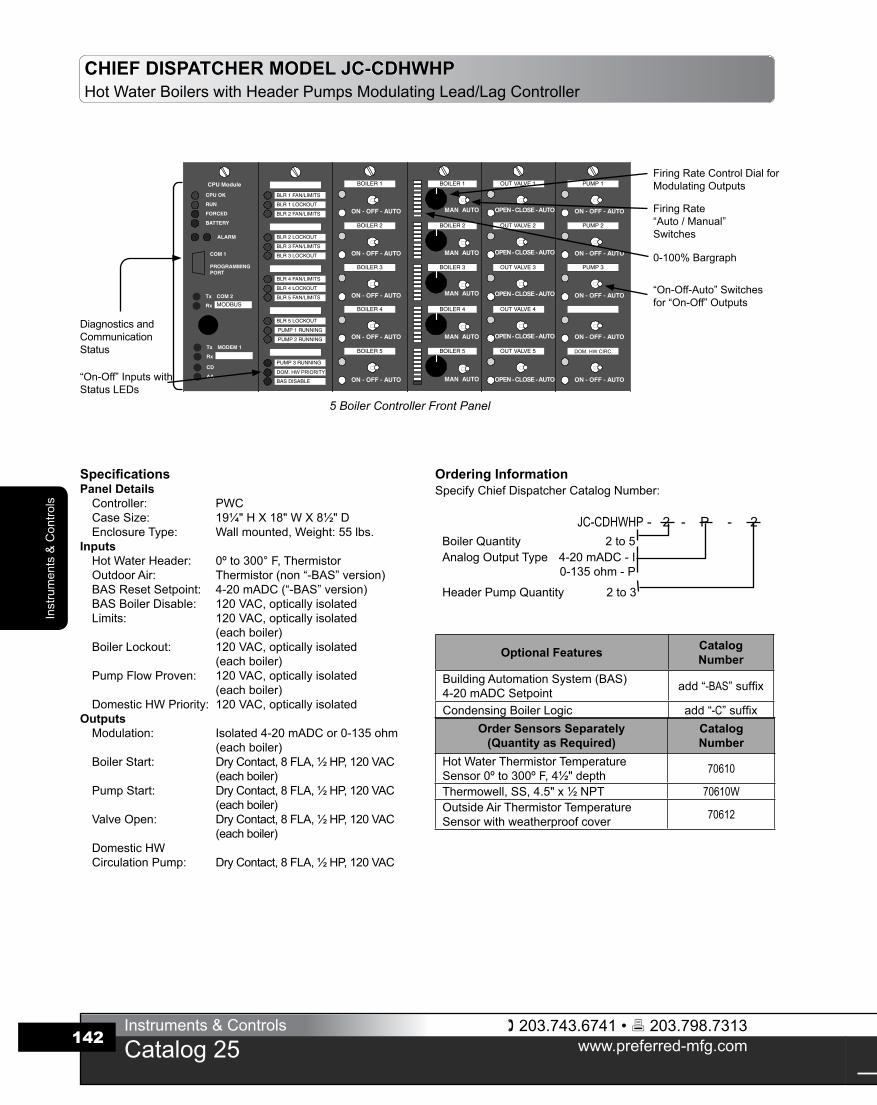
SpecificationsPanel DetailsController: PWCCaseSize: 19¼"HX18"WX8½"DEnclosureType: Wallmounted,Weight:55lbs.
InputsHotWaterHeader: 0ºto300°F,ThermistorOutdoorAir: Thermistor(non“-BAS”version)BASResetSetpoint: 4-20mADC(“-BAS”version)BASBoilerDisable: 120VAC,opticallyisolatedLimits: 120VAC,opticallyisolated
(eachboiler)BoilerLockout: 120VAC,opticallyisolated
(eachboiler)PumpFlowProven: 120VAC,opticallyisolated
(eachboiler) DomesticHWPriority: 120VAC,opticallyisolatedOutputsModulation: Isolated4-20mADCor0-135ohm
(eachboiler)BoilerStart: DryContact,8FLA,½HP,120VAC
(eachboiler)PumpStart: DryContact,8FLA,½HP,120VAC
(eachboiler)ValveOpen: DryContact,8FLA,½HP,120VAC
(eachboiler)DomesticHWCirculationPump: DryContact,8FLA,½HP,120VAC
CHIEF DISPATCHER MODEL JC-CDHWHPHotWaterBoilerswithHeaderPumpsModulatingLead/LagController
OPEN - CLOSE - AUTO
OPEN - CLOSE - AUTO
OPEN - CLOSE - AUTO
OPEN - CLOSE - AUTO
OPEN - CLOSE - AUTODOM. HW PRIORITY
DOM. HW CIRC.
FiringRateControlDialforModulatingOutputs
FiringRate“Auto/Manual”Switches
0-100%Bargraph
“On-Off-Auto”Switchesfor“On-Off”Outputs
“On-Off”Inputswith StatusLEDs
5 Boiler Controller Front Panel
Diagnosticsand CommunicationStatus
Order Sensors Separately(Quantity as Required)
CatalogNumber
HotWaterThermistorTemperatureSensor0ºto300ºF,4½"depth 70610
Thermowell,SS,4.5"x½NPT 70610WOutsideAirThermistorTemperatureSensorwithweatherproofcover 70612
Optional Features CatalogNumber
BuildingAutomationSystem(BAS)4-20mADCSetpoint add“-BAS”suffix
CondensingBoilerLogic add“-C”suffix
Ordering InformationSpecifyChiefDispatcherCatalogNumber:
JC-CDHWHP-2-P-2BoilerQuantity 2to5Analog Output Type 4-20mADC-I
0-135ohm-P
HeaderPumpQuantity 2to3
203.743.6741 • 203.798.7313www.preferred-mfg.com
Instruments & Controls
Catalog 25
Instruments &
Controls
143
1. ApplicationSupplyafullyintegratedboilercontrolsystemtocoordinatetheoperationof two (select up to five) fullymodulatinghotwaterboilers,two(selectuptothree)headerprimarywatercirculatingpumpsandboilerwaterflowcontrolvalvesinordertomaintaintheHotWaterSupply(HWS)temperatureatsetpoint.Thecontrolsystem shall bemicroprocessor-based and suitable forwallmounting.2. Boiler ModulationThecontrolsystemshallincorporateaHWSheadertemperaturePIDcontrolscheme.Boilersshallbemodulatedin“unison”(allatthesamefiringrate).Modulationsignalsshallbe4-20mADCor0-135ohm(asrequiredbytheboiler)andshallbeelectricallyisolatedchannel-channelandchannel-ground.3. Hot Water Supply (HWS) Temperature SetpointWhen theHWSTemperature control loop is in the “automatic”mode,thecontrolsystemshallestablishtheHWStemperaturesetpointbasedonthetimeofday,dayoftheweekandtheoutsideairtemperature.Whenin“manual”modetheoperatormaysettheHWStemperatureviaafrontpaneldisplay.Alltemperaturesandtime/datedatamustbefieldadjustablethrough“fill-in-the-blanks”styledisplays.Alternately,thecontrolsystemshallaccepta4-20mADCoutdoor air temperature reset setpoint signal fromanexternalBuildingAutomationSystem(BAS).4. Boiler SequenceThe control system shall utilize bothHWS temperature andboilerfiringratepercent tostartandstoptheboilersandshallminimizethetotalnumberofboilersinoperation.ThecontrollershallstartandstopboilerswhentheHWStemperatureisoutsidetheadjustable temperature limit for longer than theadjustabletimedelay.Inordertominimizeheadertemperaturedeviationsthecontrolsystemshallstartandstopthenextboilerwhenthe“lead”boilerisatanadjustablefiringratelimitforlongerthantheadjustabletimedelay.Thecontrolsystemshallmonitorbothboilerlockoutandlimitcircuitstoautomaticallyskipoverthoseboilersthatarepowereddownformaintenance,trippedorotherwisewillnotstart.Theleadboilershalleitherautomaticallyrotateonatimeofday,dayofweek(ormonth)schedule,orshallbemanuallyselectedbytheoperator.Theboilershallberunat lowfireforwarm-upforapresetlowfireholdtime.Thebaseloadramprateshallbefieldadjustable.Thecontrolsystemshallreducethefiringratetoaminimumbeforestoppingaboilertopreventaccumulationoffuelinthefurnace.5. Header Pump SequenceProvidemainheaderprimarywaterpumpcontroltoimprovefiredequipment availability. Start the quantity of header pumps asrequiredforthenumberofboilersinoperation.Thecontrolsystemshallmonitorpumpoutletflowswitchstatustoautomaticallystartastandbypumpwhenacommandtostartthepumpfailstoproduceflow.Systemmustkeepatleastonepumprunningtoensurewaterisalwaysmovingpasttheheadertemperaturesensorevenafterthelastboilerhasbeenstopped.
6. Boiler Water Flow Control Valve SequenceProvideboilerwaterflowvalvecontroltopreventwaterfromflowingthrough off-line boilers (and lowering theHWS temperature);continuewaterflowforanadjustablecooldownperiodaftertheboilerhasstopped,andensurewaterisalwaysmovingpasttheheadertemperaturesensorevenafterthelastboilerhasbeenstopped.Thevalveshallbeimmediatelyclosedifanytripsoccurduringpre-purge,pilot,ormainflametrialforignition.7. Operator Controls, Trends, Indications and AlarmsThe control system shall include a 16 line x 40 character (orgreater)LCDdisplayforboilersequencecontrolandstatus,alarmandeventsummaries,andsetupmenusforeasyoperation,tuningandtroubleshooting.Alarms,eventsandoperatoractionsshallbeloggedwithtime/datestampandEnglishlanguagedescription.8. ReliabilityIncludehardwiredbackupstations topermitmanual operationof theplantshould thecontrolsystemrequireservice.Manualoperationmust be possiblewhen themicroprocessor is notfunctioning.Hardwired“Hand-Off-Auto”controlswitchesmustbewireddirectlyintoeveryboiler,pump,andvalvestart/stopcircuit.Each4-20mADCor0-135ohmmodulatingcontroloutputmustinclude a hardwiredmanual backup stationwith auto/manualswitch,outputcontrolknobandoutputlevelindicator(bargraph,analogmeterordigitaldisplay).9. CommunicationThe control system shall have the ability of simultaneouslycommunicating to aDataAcquisitionSystem (DAS),BuildingAutomation System (BAS) or BuildingManagement System(BMS)viaRS485Modbusprotocolandtoapersonalcomputer.Theindividualboilerlimits,lockout,start/stop,warmstandby,andfiringratestatusshallbereadable.Headersetpoint,plantfiringrate,boilerquantitycalledtostart,boilerselectedasleadandallsetupparametersshallbeeasilyreadandwritten.10. Quality AssuranceThe control system shall bemanufactured and labeled inaccordancewithUL508requirements (CSAC22.2#14 foruseinCanada).InspectionandlabelingshallbesupervisedbyULorotherOSHAapprovedNationallyRecognizedTestLab(NRTL).Thecontrol systemshall beaPreferred Instruments,Danbury,CT,Model JC-CDHWHP-x-P-y (“x”=boilerquantityfrom2to5;“-P”for0-135ohm;“-I”for4-20mA;“y”=pumpquantityfrom2to3).
CHIEF DISPATCHER MODEL JC-CDHWHPSuggestedSpecifications
203.743.6741 • 203.798.7313www.preferred-mfg.com
Instruments & Controls
Catalog 25
Inst
rum
ents
& C
ontro
ls
144
CHIEF DISPATCHER MODEL JC-CDHWTSPHotWaterBoilerswithThermalShockProtectionModulatingLead/LagController
ApplicationTheChiefDispatcherModel JC-CDHWTSP willoptimizehotwater system performance and help extend boiler life.Blendvalvesareusedtoallowoff-lineboilerwarm-upandpreventthermalshock.2 To 4 Modulating BoilersHotWaterSupply(HWS)headertemperatureismaintainedusingaccuratePIDcontrol.Multipleboilersaremodulatedin“unison”(allatthesamefiringrate)toensureevenheatdelivery.Lagboilersarebroughtuptothe“unison”firingrateusingapredeterminedrampratetomeettheheatingloadwithminimumovershoot.Theoperatormaysetthe“unison”firingratemanually.Eachboilerhasanindividualboileroutlettemperaturesensor.Ifanyboilerapproachesitshightemperatureshutdownlimit, itwillcutbackfiringrateindividuallytopreventaboilertrip.Boiler Pump Sequencing Inlineboilerpumpsequencingkeepstheleadboilerpumprunning (water flowspast theheader sensor) to ensureaccurateheadertemperaturesensingandprovidespumpshutdowndelayforboilercooldown.Thermal Shock ProtectionIndividual boiler outlet 3-way recirculating valves areautomaticallypositionedbasedontheboilerstartsequence,boiler outlet and returnwater temperatures. If theboilerreturnwater temperaturedropsbelowa lowtemperaturesetpoint,thevalveopenstoallowhotboileroutletwaterto
AI HOT WATER SUPPLY HEADER TEMPERATURE
OUTSIDE AIR TEMPERATURE
OR REMOTE SETPOINT FROM BAS
JC-CDHWTSP2 to 4 Hot Water Boilers, Primary Loop Pumps and Blend Valves
blendwithcoldreturnwatertemperature.Thevalveslowlyrepositionstoward0%recirculationafterreturnwaterrisesabovesetpoint.Whenaboileriscalledtooperate,the3-wayvalveissetto95%recirculation.Aftertheboilerstartsandtheoutlettemperatureisclosetosupplytemperaturesetpoint,thevalveslowlyrepositionstoward0%recirculation.Outdoor Reset EnergyissavedbyloweringtheHotWaterSupply(HWS)temperature setpoint as the outside air temperatureincreases.Operatingcostisreducedduringwarmerdays.TheoperatormaysettheHWSsetpointmanually.Time Of Day/ Week Setback Thisfeatureisusedinheatingapplicationstosaveenergyby lowering theHotWaterSupply (HWS) temperaturesetpoint during timeswhen the heating requirement isreduced,suchasatnightoronweekendsandholidays.Domestic Hot Water PriorityA temperature switch (thermostat) contact closure inputwilloverride the“outdoor reset”and“setback”portionoftheprogramandforcetheHWStemperaturesetpointtoadomestichotwatersetpoint.Arelayoutputisavailabletostartadomestichotwaterpumpifrequired.Condensing Boiler Logic (Option “-C”)Condensing boiler logic takes full advantage of thecondensing boiler design bymaximizing the number ofboilersrunningnearlowfiretomaximizeefficiency.
203.743.6741 • 203.798.7313www.preferred-mfg.com
Instruments & Controls
Catalog 25
Instruments &
Controls
145
DOM. HW PRIORITY
DOM. HW PRIORITY
FiringRateControlDialforModulatingOutputs
FiringRate“Auto/Manual”Switches
0-100%Bargraph
“On-Off-Auto”Switchesfor“On-Off”Outputs
“On-Off”InputswithStatusLEDs
4 Boiler Controller Front Panel
Order Sensors Separately(Quantity as Required)
CatalogNumber
HotWaterThermistorTemp.Sensor0ºto300ºF,4½"depth 70610
Thermowell,SS,4½"x½NPT 70610WOutsideAirThermistorTemp.Sensorwithweatherproofcover 70612
DiagnosticsandCommunicationStatus
AnalogInputswithStatusIndicator
CHIEF DISPATCHER MODEL JC-CDHWTSPHotWaterBoilerswithThermalShockProtectionModulatingLead/LagController
Optional Features CatalogNumber
BuildingAutomationSystem(BAS)4-20mADCSetpoint add“-BAS”suffix
CondensingBoilerLogic add“-C”suffix
SpecificationsPanel DetailsController: PWCCaseSize: 19¼"HX18"WX8½"D
EnclosureType: Wallmounted,Weight:55lbs.InputsHotWaterTemperature: 0ºto300°F,ThermistorOutletWater: Thermistor(eachboiler)ReturnWater: Thermistor(eachboiler)OutdoorAir: Thermistor(non“-BAS”version)BASResetSetpoint: 4-20mADC(“-BAS”version)BAS,BoilerDisable: 120VAC,opticallyisolatedLimits: 120VAC,opticallyisolated(eachboiler)BoilerLockout: 120VAC,opticallyisolated(eachboiler)
DomesticHWPriority: 120VAC,opticallyisolatedOutputsBoilerModulation: Isolated:4-20mADCor0-135ohm
(eachboiler)BalancingValve: Isolated:4-20mADC
(eachboiler)BoilerStart: Drycontact,8FLA,½HP,120VAC
(eachboiler)PumpStart: Drycontact,8FLA,½HP,120VAC
(eachboiler)DomesticHWCirculationPump: Drycontact,8FLA,½HP,120VAC
Ordering InformationSpecifyChiefDispatcherCatalogNumber:
JC-CDHWTSP-2-PBoilerQuantity 2to4Analog Output Type 4-20mADC-I
0-135ohm-P
203.743.6741 • 203.798.7313www.preferred-mfg.com
Instruments & Controls
Catalog 25
Inst
rum
ents
& C
ontro
ls
146
1. Application Supplyafullyintegratedboilerhotwatercontrolsystemtocoordinatetheoperationoftwo(selectuptofour)fullymodulatinghotwaterboilers,boilerwatercirculatingpumpsandboilerwaterflowcontrolvalvestomaintainHotWaterSupply(HWS)temperatureatsetpointandprovidethermalshockprotection.Thecontrolsystemshallbemicroprocessor-basedandsuitableforwallmounting.2. Boiler ModulationThecontrolsystemshallincorporatea“cascadewithcutback”HWStemperaturePIDcontrolscheme.TheHWStemperatureshallbecomparedwithasetpoint toestablisha targetboilerfiring rate. Ifanindividualboileroutlettemperatureexceedsapre-setmaximumsetpoint,thatboiler’sfiringrateshallbeautomaticallycutbackbyaPIDlooptopreventahightemperaturetrip.Boilersshallbemodulatedin“unison”(allatthesamefiringrate).Modulationsignalsshallbe4-20mADCor0-135ohm(asrequiredbytheboiler)andshallbeelectricallyisolatedchannel-channelandchannel-ground.3. Hot Water Supply (HWS) Temperature SetpointWhentheHWSTemperaturecontrolloopisinthe“automatic”mode,thecontrolsystemshallestablishtheHWStemperaturesetpointbasedonthetimeofday,dayoftheweekandtheoutsideairtemperature.Whenin“manual”modetheoperatormaysettheHWStemperatureviaafrontpaneldisplay.Alltemperaturesandtime/datedatamustbefieldadjustablethrough“fill-in-the-blanks”styledisplays.Alternately,thecontrolsystemshallaccepta4-20mADCoutdoorairtemperatureresetsetpointsignalfromanexternalBuildingAutomationSystem(BAS).4. Boiler SequenceThecontrolsystemshallusebothHWStemperatureandboilerfiringratepercenttostartandstoptheboilers,minimizingthetotalnumberofboilersinoperation.ThecontrollershallstartandstopboilerswhentheHWStemperatureisoutsidetheadjustabletemperaturelimitforlongerthantheadjustabletimedelay.Inordertominimizeheadertemperaturedeviations,thecontrolsystemshallstartandstopthenextboilerwhenthe“lead”boilerisatanadjustablefiringratelimitfor longerthantheadjustabletimedelay.Thecontrolsystemshallmonitorbothboilerlockoutandlimitcircuitstoautomaticallyskipoverboilersthatarepowereddownformaintenance,trippedorotherwisewillnotstart.Theleadboilershalleitherautomaticallyrotateonatimeofday,dayofweek(ormonth)schedule,orshallbemanuallyselectedbytheoperator.Theboilershallberunatlowfireforwarm-upforapresetlowfireholdtime.Thecontrolsystemshallreducethefiringratetoaminimumbeforestoppingaboilertopreventaccumulationoffuelinthefurnace.5. Boiler Pump SequenceIncludeindependentlyoperatedprimarywaterpumpcontrol.Systemmustkeepatleastonepumprunningtoensurewaterisalwaysmovingpasttheheadertemperaturesensor.6. Boiler Water Flow Control Valve SequenceProvidecontrolforanelectricactuator,wtihslowopening(2minute),flowbalancing,twovalveassemblyforeachboiler.Thevalveassemblyshalllinkaboileroutletvalveandboilerwaterrecirculationvalvesothattheyoperateasasingleunit.Thevalvesshallbearrangedsothatasonevalvecloses,theothervalveopens,ensuringacontinuous
flowofwaterthroughtheboiler.Theassemblyshallacceptasingle4-20mADCsignaltopositionbothvalves.Thisvalveshallpreventwater fromflowing throughoff-lineboilers (and lowering theHWStemperature), allowboilerwarm-up to returnwater temperaturebefore theboilerstarts,continuewaterflowforanadjustablecooldownperiodaftertheboilerhasstopped,andensurewaterisalwaysmovingpasttheheadertemperaturesensorevenafterthelastboilerhasbeenstopped.Slowlyjogopenthevalveovera10-minuteperiod(adjustable) topreventboiler thermalshocking. If theboiler returnwatertemperatureis50°F(adjustable)belowtheboileroutletwatertemperature,thevalveshallslowlyjogclosed,causingboileroutletwatertoblendwiththeexcessivelycoldreturnwater.Whenthereturnwatertemperaturereturnstoanacceptablerange,theboileroutletvalveshallslowlyjogopen.7. Operator Controls, Trends, Indications and AlarmsThecontrolsystemshallincludean16linex40character(orgreater)LCDdisplay forboiler sequencecontrol andstatus,alarmandeventsummaries,andsetupmenusforeasyoperation,tuningandtroubleshooting.Alarms,eventsandoperatoractionsshallbeloggedwithtime/datestampandEnglishlanguagedescription.8. ReliabilityIncludehardwiredbackupstationstopermitmanualoperationoftheplantshouldthecontrolsystemrequireservice.Manualoperationmustbepossiblewhenthemicroprocessorisnotfunctioning.Hardwired“hand-off-auto”control switchesmustbewireddirectly intoeveryboilerandpumpstart/stopcircuit.Each4-20mADCor0-135ohmmodulatingcontroloutputmustincludeahardwiredmanualbackupstationwithauto/manualswitch,outputcontrolknobandoutputlevelindicator(bargraph,analogmeterordigitaldisplay).9. CommunicationThe control system shall have the ability of simultaneouslycommunicating to aDataAcquisitionSystem (DAS),BuildingAutomation System (BAS) or BuildingManagement System(BMS)viaRS485Modbusprotocolandtoapersonalcomputer.Theindividualboilerlimits,lockout,start/stop,warmstandby,andfiringratestatusshallbereadable.Headersetpoint,plantfiringrate,boilerquantitycalledtostart,boilerselectedasleadandallsetupparametersshallbereadableandwritable.10. Quality AssuranceThe control system shall bemanufactured and labeled inaccordancewithUL508requirements (CSAC22.2#14 foruseinCanada).InspectionandlabelingshallbesupervisedbyULorotherOSHAapprovedNationallyRecognizedTestLab(NRTL).Thecontrol systemshall beaPreferred Instruments,Danbury,CT,Model JC-CDHWTSP-x-P (‘x’=boilerquantityfrom2to4;“-P”for0-135ohm;“-I”for4-20mADC).
CHIEF DISPATCHER MODEL JC-CDHWTSPSuggestedSpecifications