chief universal measuring system · the chief universal measuring system (ums) is a precision tool...
TRANSCRIPT
OWNERS MANUAL
Chief UniversalMeasuring System
R
1999 © Chief Automotive Systems, Inc.

Chief’s Limited One-YearWarranty & Liability
CHIEF'S LIMITED ONE-YEAR
WARRANTY & LIABILITY
Chief Automotive Technologies, Inc. warrants for one year from date of installation
and/or purchase any of its products which do not perform satisfactorily due to defect
caused by faulty material or workmanship. Chief’s obligation under this warranty is
limited to the repair or replacement of products which are defective and which have not
been misused, carelessly handled, or defaced by repair or repairs made or attempted by
others.
CHIEF AUTOMOTIVE TECHNOLOGIES, INC. DOES NOT ASSUME
RESPONSIBILITY FOR ANY DEATH, INJURY OR PROPERTY DAMAGE
RESULTING FROM THE OPERATOR’S NEGLIGENCE OR MISUSE OF THIS
PRODUCT OR ITS ATTACHMENTS. CHIEF MAKES NO WRITTEN,
EXPRESS OR IMPLIED WARRANTY WHATSOEVER OF MERCHANTABIL-
ITY OR FITNESS FOR A PARTICULAR PURPOSE OR OTHERWISE
REGARDING THE EQUIPMENT OR ANY PART OF THE PRODUCT OTHER
THAN THE LIMITED ONE-YEAR WARRANTY STATED ABOVE.
RUNIVERSAL MEASURING SYSTEM
OWNERS MANUAL
The Chief Universal Measuring System (UMS) is aprecision tool that offers unlimited measuringcapabilities. It provides a simple yet highly practicaltechnology to auto body repair, one that can beapplied to any type of vehicle whether it be of‘unitized body construction’ (with or without struts)or ‘perimeter frame construction’. It works equallywell on pickup trucks, vans and all other utilityvehicles.
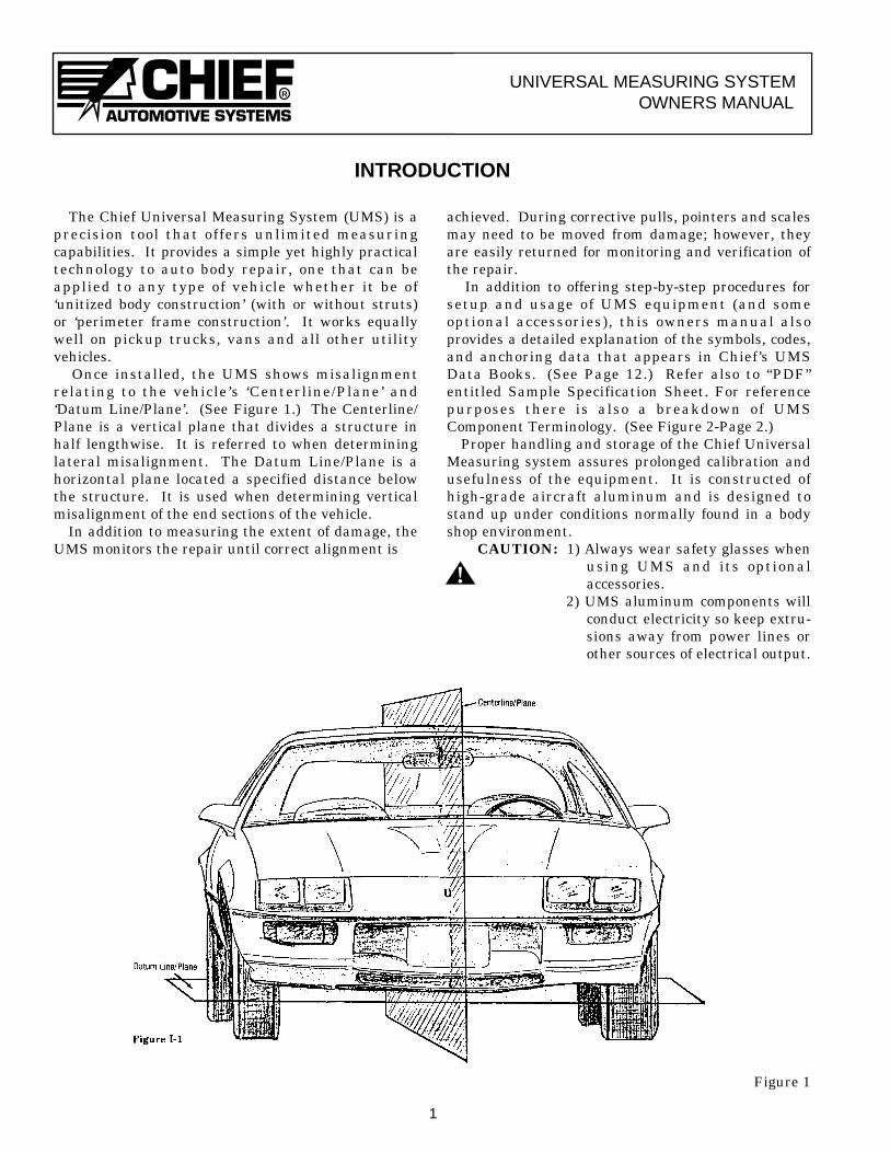
Once installed, the UMS shows misalignmentrelating to the vehicle ’s ‘Centerline/Plane ’ and‘Datum Line/Plane’. (See Figure 1.) The Centerline/Plane is a vertical plane that divides a structure inhalf lengthwise. It is referred to when determininglateral misalignment. The Datum Line/Plane is ahorizontal plane located a specified distance belowthe structure. It is used when determining verticalmisalignment of the end sections of the vehicle.
In addition to measuring the extent of damage, theUMS monitors the repair until correct alignment is
achieved. During corrective pulls, pointers and scalesmay need to be moved from damage; however, theyare easily returned for monitoring and verification ofthe repair.
In addition to offering step-by-step procedures forsetup and usage of UMS equipment (and someoptional accessories), this owners manual alsoprovides a detailed explanation of the symbols, codes,and anchoring data that appears in Chief’s UMSData Books. (See Page 12.) Refer also to “PDF”entitled Sample Specification Sheet. For referencepurposes there is also a breakdown of UMSComponent Terminology. (See Figure 2-Page 2.)
Proper handling and storage of the Chief UniversalMeasuring system assures prolonged calibration andusefulness of the equipment. It is constructed ofhigh-grade aircraft aluminum and is designed tostand up under conditions normally found in a bodyshop environment.
CAUTION: 1) Always wear safety glasses whenusing UMS and its optionalaccessories.
2) UMS aluminum components willconduct electricity so keep extru-sions away from power lines orother sources of electrical output.
1
INTRODUCTION
Figure 1
!
R
UNIVERSAL MEASURING SYSTEMOWNERS MANUAL
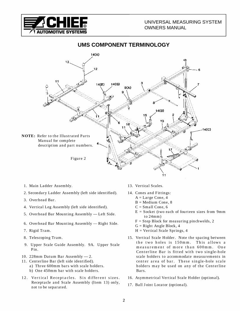
1. Main Ladder Assembly.
2. Secondary Ladder Assembly (left side identified).
3. Overhead Bar.
4. Vertical Leg Assembly (left side identified).
5. Overhead Bar Mounting Assembly — Left Side.
6. Overhead Bar Mounting Assembly — Right Side.
7. Rigid Tram.
8. Telescoping Tram.
9. Upper Scale Guide Assembly. 9A. Upper ScalePin.
10. 228mm Datum Bar Assembly — 2.11. Centerline Bar (left side identified).
a) Three 600mm bars with scale holders.b) One 450mm bar with scale holders.
12. Vertical Receptacles. Six different sizes.Receptacle and Scale Assembly (Item 13) only,not to be separated.
13. Vertical Scales.
14. Cones and Fittings:A = Large Cone, 4B = Medium Cone, 8C = Small Cone, 6E = Socket (two each of fourteen sizes from 9mm
to 24mm)F = Step Block for measuring pinchwelds, 2G = Right Angle Block, 4H = Vertical Scale Springs, 4
15. Vertical Scale Holder. Note the spacing betweenthe two holes is 150mm. This allows ameasurement of more than 600mm. OneCenterline Bar is fitted with two single-holescale holders to accommodate measurements incenter area of bar. These single-hole scaleholders may be used on any of the CenterlineBars.
16. Asymmetrical Vertical Scale Holder (optional).
17. Ball Joint Locator (optional).
2
UMS COMPONENT TERMINOLOGY
NOTE: Refer to the Illustrated PartsManual for completedescription and part numbers.
Figure 2
RUNIVERSAL MEASURING SYSTEM
OWNERS MANUAL
SETTING UP THE MEASURING SYSTEM
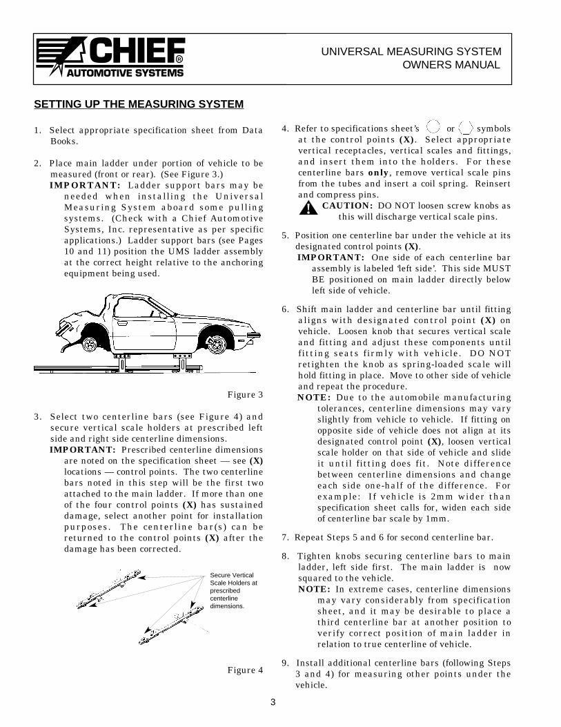
1. Select appropriate specification sheet from DataBooks.
2. Place main ladder under portion of vehicle to bemeasured (front or rear). (See Figure 3.)IMPORTANT: Ladder support bars may be
needed when installing the UniversalMeasuring System aboard some pullingsystems. (Check with a Chief AutomotiveSystems, Inc. representative as per specificapplications.) Ladder support bars (see Pages10 and 11) position the UMS ladder assemblyat the correct height relative to the anchoringequipment being used.
Figure 3
3. Select two centerline bars (see Figure 4) andsecure vertical scale holders at prescribed leftside and right side centerline dimensions.IMPORTANT: Prescribed centerline dimensions
are noted on the specification sheet — see (X)locations — control points. The two centerlinebars noted in this step will be the first twoattached to the main ladder. If more than oneof the four control points (X) has sustaineddamage, select another point for installationpurposes. The centerline bar(s) can bereturned to the control points (X) after thedamage has been corrected.
Figure 4
4. Refer to specifications sheet’s or symbolsat the control points (X). Select appropriatevertical receptacles, vertical scales and fittings,and insert them into the holders. For thesecenterline bars only, remove vertical scale pinsfrom the tubes and insert a coil spring. Reinsertand compress pins.
CAUTION: DO NOT loosen screw knobs asthis will discharge vertical scale pins.
5. Position one centerline bar under the vehicle at itsdesignated control points (X).IMPORTANT: One side of each centerline bar
assembly is labeled ‘left side’. This side MUSTBE positioned on main ladder directly belowleft side of vehicle.
6. Shift main ladder and centerline bar until fittingaligns with designated control point (X) onvehicle. Loosen knob that secures vertical scaleand fitting and adjust these components untilfitting seats firmly with vehicle. DO NOTretighten the knob as spring-loaded scale willhold fitting in place. Move to other side of vehicleand repeat the procedure.NOTE: Due to the automobile manufacturing
tolerances, centerline dimensions may varyslightly from vehicle to vehicle. If fitting onopposite side of vehicle does not align at itsdesignated control point (X), loosen verticalscale holder on that side of vehicle and slideit until fitting does fit. Note differencebetween centerline dimensions and changeeach side one-half of the difference. Forexample: If vehicle is 2mm wider thanspecification sheet calls for, widen each sideof centerline bar scale by 1mm.
7. Repeat Steps 5 and 6 for second centerline bar.
8. Tighten knobs securing centerline bars to mainladder, left side first. The main ladder is nowsquared to the vehicle.NOTE: In extreme cases, centerline dimensions
may vary considerably from specificationsheet, and it may be desirable to place athird centerline bar at another position toverify correct position of main ladder inrelation to true centerline of vehicle.
9. Install additional centerline bars (following Steps3 and 4) for measuring other points under thevehicle.
3
Secure VerticalScale Holders atprescribedcenterlinedimensions.
!
RUNIVERSAL MEASURING SYSTEM
OWNERS MANUAL
10. Length measurements are accomplished withsliding tapes located on both sides of mainladder. When taking a length measurement atrear of vehicle, set zero point of left side tape atscribe line of front centerline bar and read lengthat scribe lines of centerline bars at rear ofvehicle. When taking a length measurement atfront of vehicle, set zero point of left side tape atscribe line of rear centerline bar and read lengthat scribe lines of centerline bars at front ofvehicle. NOTE: 1) When reading length on right side of
vehicle, follow same procedures;however, refer to rear edge ofcenterline bar guides instead ofscribe lines.
2) Due to automobile manufacturingtolerances, length between controlpoints may vary slightly from vehicleto vehicle. Generally, any deviationof length found in this area shouldbe carried out through rest ofvehicle. For example: If vehicle is4mm longer than data sheet calls forbetween control points, add 4mm toremainder of length dimensions.
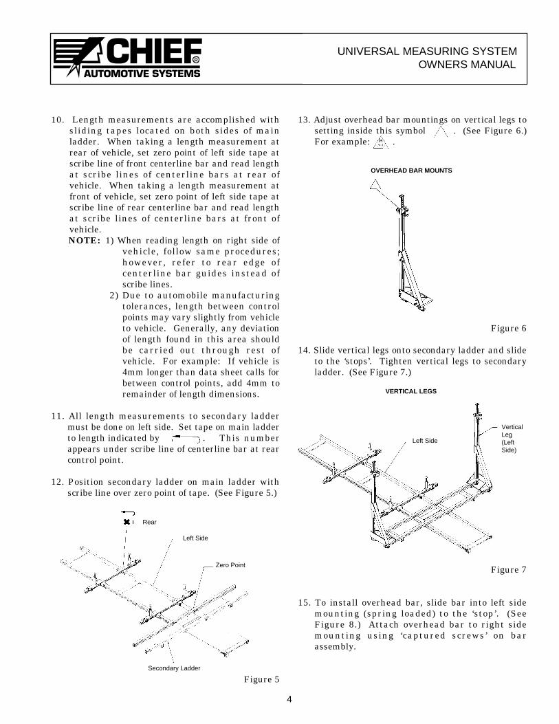
11. All length measurements to secondary laddermust be done on left side. Set tape on main ladderto length indicated by . This numberappears under scribe line of centerline bar at rearcontrol point.
12. Position secondary ladder on main ladder withscribe line over zero point of tape. (See Figure 5.)
Figure 5
13. Adjust overhead bar mountings on vertical legs tosetting inside this symbol . (See Figure 6.)For example: .
Figure 6
14. Slide vertical legs onto secondary ladder and slideto the ‘stops’. Tighten vertical legs to secondaryladder. (See Figure 7.)
Figure 7
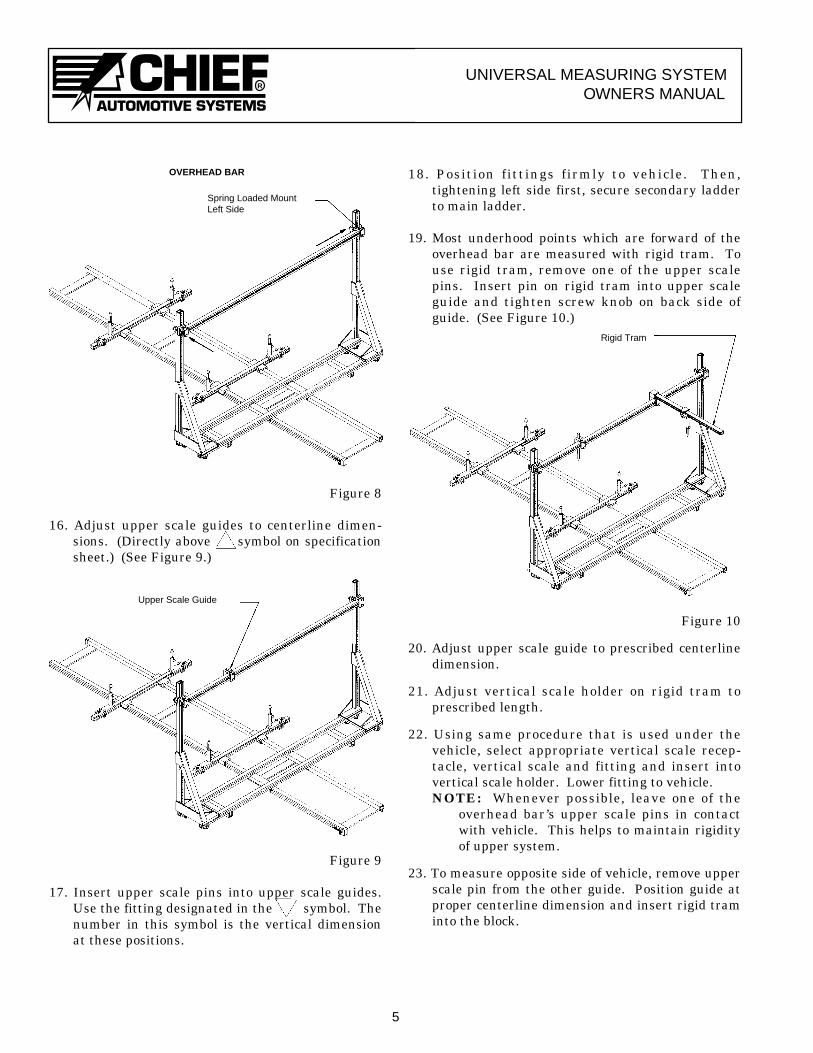
15. To install overhead bar, slide bar into left sidemounting (spring loaded) to the ‘stop’. (SeeFigure 8.) Attach overhead bar to right sidemounting using ‘captured screws ’ on barassembly.
4
Rear
Left Side
Zero Point
Secondary Ladder
OVERHEAD BAR MOUNTS
VERTICAL LEGS
Left Side
VerticalLeg(LeftSide)
RUNIVERSAL MEASURING SYSTEM
OWNERS MANUAL
Figure 8
16. Adjust upper scale guides to centerline dimen-sions. (Directly above symbol on specificationsheet.) (See Figure 9.)
Figure 9
17. Insert upper scale pins into upper scale guides.Use the fitting designated in the symbol. Thenumber in this symbol is the vertical dimensionat these positions.
18. Position fittings firmly to vehicle. Then,tightening left side first, secure secondary ladderto main ladder.
19. Most underhood points which are forward of theoverhead bar are measured with rigid tram. Touse rigid tram, remove one of the upper scalepins. Insert pin on rigid tram into upper scaleguide and tighten screw knob on back side ofguide. (See Figure 10.)
Figure 10
20. Adjust upper scale guide to prescribed centerlinedimension.
21. Adjust vertical scale holder on rigid tram toprescribed length.
22. Using same procedure that is used under thevehicle, select appropriate vertical scale recep-tacle, vertical scale and fitting and insert intovertical scale holder. Lower fitting to vehicle. NOTE: Whenever possible, leave one of the
overhead bar’s upper scale pins in contactwith vehicle. This helps to maintain rigidityof upper system.
23. To measure opposite side of vehicle, remove upperscale pin from the other guide. Position guide atproper centerline dimension and insert rigid traminto the block.
5
OVERHEAD BAR
Spring Loaded MountLeft Side
Upper Scale Guide
Rigid Tram
RUNIVERSAL MEASURING SYSTEM
OWNERS MANUAL
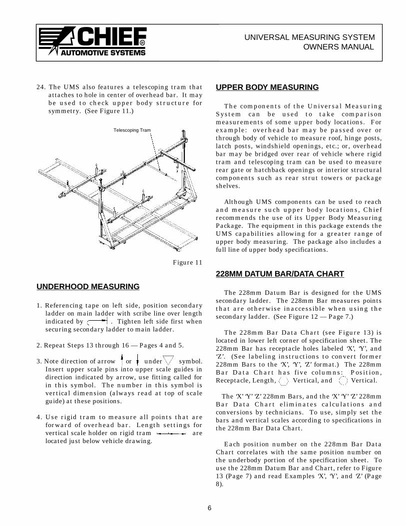
24. The UMS also features a telescoping tram thatattaches to hole in center of overhead bar. It maybe used to check upper body structure forsymmetry. (See Figure 11.)
Figure 11
UNDERHOOD MEASURING
1. Referencing tape on left side, position secondaryladder on main ladder with scribe line over lengthindicated by . Tighten left side first whensecuring secondary ladder to main ladder.
2. Repeat Steps 13 through 16 — Pages 4 and 5.
3. Note direction of arrow or under symbol.Insert upper scale pins into upper scale guides indirection indicated by arrow, use fitting called forin this symbol. The number in this symbol isvertical dimension (always read at top of scaleguide) at these positions.
4. Use rigid tram to measure all points that areforward of overhead bar. Length settings forvertical scale holder on rigid tram arelocated just below vehicle drawing.
UPPER BODY MEASURING
The components of the Universal MeasuringSystem can be used to take comparisonmeasurements of some upper body locations. Forexample: overhead bar may be passed over orthrough body of vehicle to measure roof, hinge posts,latch posts, windshield openings, etc.; or, overheadbar may be bridged over rear of vehicle where rigidtram and telescoping tram can be used to measurerear gate or hatchback openings or interior structuralcomponents such as rear strut towers or packageshelves.
Although UMS components can be used to reachand measure such upper body locations, Chiefrecommends the use of its Upper Body MeasuringPackage. The equipment in this package extends theUMS capabilities allowing for a greater range ofupper body measuring. The package also includes afull line of upper body specifications.
228MM DATUM BAR/DATA CHART
The 228mm Datum Bar is designed for the UMSsecondary ladder. The 228mm Bar measures pointsthat are otherwise inaccessible when using thesecondary ladder. (See Figure 12 — Page 7.)
The 228mm Bar Data Chart (see Figure 13) islocated in lower left corner of specification sheet. The228mm Bar has receptacle holes labeled ‘X’, ‘Y’, and‘Z’. (See labeling instructions to convert former228mm Bars to the ‘X’, ‘Y’, ‘Z’ format.) The 228mmBar Data Chart has five columns: Position,Receptacle, Length, Vertical, and Vertical.
The ‘X’ ‘Y’ ‘Z’ 228mm Bars, and the ‘X’ ‘Y’ ‘Z’ 228mmBar Data Chart eliminates calculations andconversions by technicians. To use, simply set thebars and vertical scales according to specifications inthe 228mm Bar Data Chart.
Each position number on the 228mm Bar DataChart correlates with the same position number onthe underbody portion of the specification sheet. Touse the 228mm Datum Bar and Chart, refer to Figure13 (Page 7) and read Examples ‘X’, ‘Y’, and ‘Z’ (Page8).
6
Telescoping Tram

RUNIVERSAL MEASURING SYSTEM
OWNERS MANUAL
Figure 12
7
228mm Datum Bars
Figure 13
SAMPLE SPECIFICATION SHEET
RUNIVERSAL MEASURING SYSTEM
OWNERS MANUAL
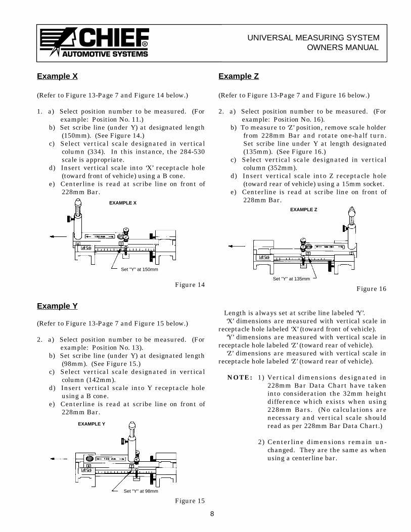
Example X
(Refer to Figure 13-Page 7 and Figure 14 below.)
1. a) Select position number to be measured. (Forexample: Position No. 11.)
b) Set scribe line (under Y) at designated length(150mm). (See Figure 14.)
c) Select vertical scale designated in verticalcolumn (334). In this instance, the 284-530scale is appropriate.
d) Insert vertical scale into ‘X’ receptacle hole(toward front of vehicle) using a B cone.
e) Centerline is read at scribe line on front of228mm Bar.
Figure 14
Example Y
(Refer to Figure 13-Page 7 and Figure 15 below.)
2. a) Select position number to be measured. (Forexample: Position No. 13).
b) Set scribe line (under Y) at designated length(98mm). (See Figure 15.)
c) Select vertical scale designated in verticalcolumn (142mm).
d) Insert vertical scale into Y receptacle holeusing a B cone.
e) Centerline is read at scribe line on front of228mm Bar.
Figure 15
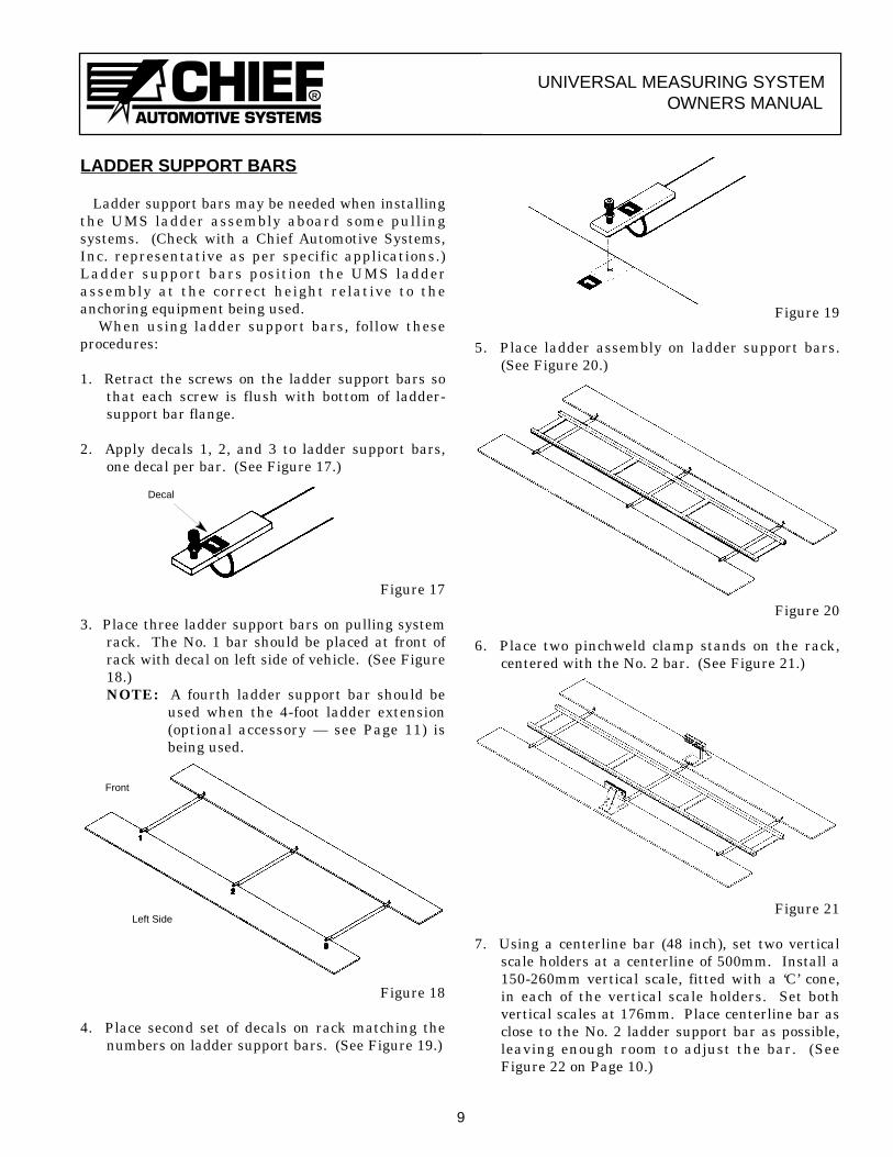
Example Z
(Refer to Figure 13-Page 7 and Figure 16 below.)
2. a) Select position number to be measured. (Forexample: Position No. 16).
b) To measure to ‘Z’ position, remove scale holderfrom 228mm Bar and rotate one-half turn.Set scribe line under Y at length designated(135mm). (See Figure 16.)
c) Select vertical scale designated in verticalcolumn (352mm).
d) Insert vertical scale into Z receptacle hole(toward rear of vehicle) using a 15mm socket.
e) Centerline is read at scribe line on front of228mm Bar.
Figure 16
Length is always set at scribe line labeled ‘Y’.‘X’ dimensions are measured with vertical scale in
receptacle hole labeled ‘X’ (toward front of vehicle).‘Y’ dimensions are measured with vertical scale in
receptacle hole labeled ‘Z’ (toward rear of vehicle).‘Z’ dimensions are measured with vertical scale in
receptacle hole labeled ‘Z’ (toward rear of vehicle).
NOTE: 1) Vertical dimensions designated in228mm Bar Data Chart have takeninto consideration the 32mm heightdifference which exists when using228mm Bars. (No calculations arenecessary and vertical scale shouldread as per 228mm Bar Data Chart.)
2) Centerline dimensions remain un-changed. They are the same as whenusing a centerline bar.
8
Set "Y" at 150mm
EXAMPLE XEXAMPLE Z
Set "Y" at 135mm
EXAMPLE Y
Set "Y" at 98mm
Left Side
Left Side
Left Side
RUNIVERSAL MEASURING SYSTEM
OWNERS MANUAL
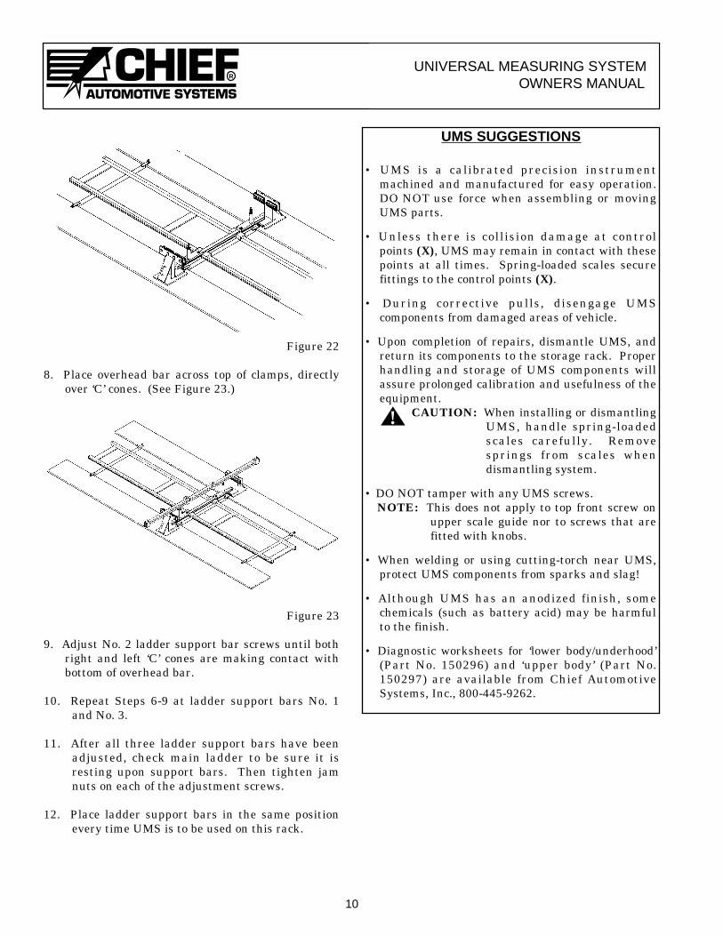
LADDER SUPPORT BARS
Ladder support bars may be needed when installingthe UMS ladder assembly aboard some pullingsystems. (Check with a Chief Automotive Systems,Inc. representative as per specific applications.)Ladder support bars position the UMS ladderassembly at the correct height relative to theanchoring equipment being used.
When using ladder support bars, follow theseprocedures:
1. Retract the screws on the ladder support bars sothat each screw is flush with bottom of ladder-support bar flange.
2. Apply decals 1, 2, and 3 to ladder support bars,one decal per bar. (See Figure 17.)
Figure 17
3. Place three ladder support bars on pulling systemrack. The No. 1 bar should be placed at front ofrack with decal on left side of vehicle. (See Figure18.)NOTE: A fourth ladder support bar should be
used when the 4-foot ladder extension(optional accessory — see Page 11) isbeing used.
Figure 18
4. Place second set of decals on rack matching thenumbers on ladder support bars. (See Figure 19.)
Figure 19
5. Place ladder assembly on ladder support bars.(See Figure 20.)
Figure 20
6. Place two pinchweld clamp stands on the rack,centered with the No. 2 bar. (See Figure 21.)
Figure 21
7. Using a centerline bar (48 inch), set two verticalscale holders at a centerline of 500mm. Install a150-260mm vertical scale, fitted with a ‘C’ cone,in each of the vertical scale holders. Set bothvertical scales at 176mm. Place centerline bar asclose to the No. 2 ladder support bar as possible,leaving enough room to adjust the bar. (SeeFigure 22 on Page 10.)
9
Front
Left Side
Decal
RUNIVERSAL MEASURING SYSTEM
OWNERS MANUAL
Figure 22
8. Place overhead bar across top of clamps, directlyover ‘C’ cones. (See Figure 23.)
Figure 23
9. Adjust No. 2 ladder support bar screws until bothright and left ‘C’ cones are making contact withbottom of overhead bar.
10. Repeat Steps 6-9 at ladder support bars No. 1and No. 3.
11. After all three ladder support bars have beenadjusted, check main ladder to be sure it isresting upon support bars. Then tighten jamnuts on each of the adjustment screws.
12. Place ladder support bars in the same positionevery time UMS is to be used on this rack.
UMS SUGGESTIONS
• UMS is a calibrated precision instrumentmachined and manufactured for easy operation.DO NOT use force when assembling or movingUMS parts.
• Unless there is collision damage at controlpoints (X), UMS may remain in contact with thesepoints at all times. Spring-loaded scales securefittings to the control points (X).
• During corrective pulls, disengage UMScomponents from damaged areas of vehicle.
• Upon completion of repairs, dismantle UMS, andreturn its components to the storage rack. Properhandling and storage of UMS components willassure prolonged calibration and usefulness of theequipment.
CAUTION: When installing or dismantlingUMS, handle spring-loadedscales carefully. Removesprings from scales whendismantling system.
• DO NOT tamper with any UMS screws.NOTE: This does not apply to top front screw on
upper scale guide nor to screws that arefitted with knobs.
• When welding or using cutting-torch near UMS,protect UMS components from sparks and slag!
• Although UMS has an anodized finish, somechemicals (such as battery acid) may be harmfulto the finish.
• Diagnostic worksheets for ‘lower body/underhood’(Part No. 150296) and ‘upper body’ (Part No.150297) are available from Chief AutomotiveSystems, Inc., 800-445-9262.
10
!
RUNIVERSAL MEASURING SYSTEM
OWNERS MANUAL
ASYMMETRICAL VERTICAL SCALEHOLDER (OPTIONAL ACCESSORY)
Asymmetrical vertical scale holder is used whencorresponding right and left dimensions areasymmetrical at a given position (within 100mm).(See Figure 24.)
Figure 24
1. Position centerline bar on main ladder at lengthspecified for left side.
2. Place asymmetrical holder on right side ofcenterline bar as shown in Figure 24.
3. Position asymmetrical holder at specifiedcenterline dimension and clamp in place.
4. Slide scale forward or rearward a distance equalto the difference between right and left lengthdimensions. (To measure opposite direction,remove scale and rotate 180°.)
5. Tighten knob to hold scale at desired dimension.
BALL JOINT LOCATOR (OPTIONAL ACCESSORY)
Figure 25
1. Work on side of vehicle with least damage first.2. Position centerline bar at length indicated on data
sheet. The symbol indicates length fromrear zero point to center of ball joint.
3. Place ball joint locator on centerline bar. (SeeFigure 25.)
4. Slide locator and raise pointer as needed to locatecenter of ball joint.
5. Tighten knob to hold pointer in place while movinglocator to opposite side of vehicle.
6. Compare location of ball joints.
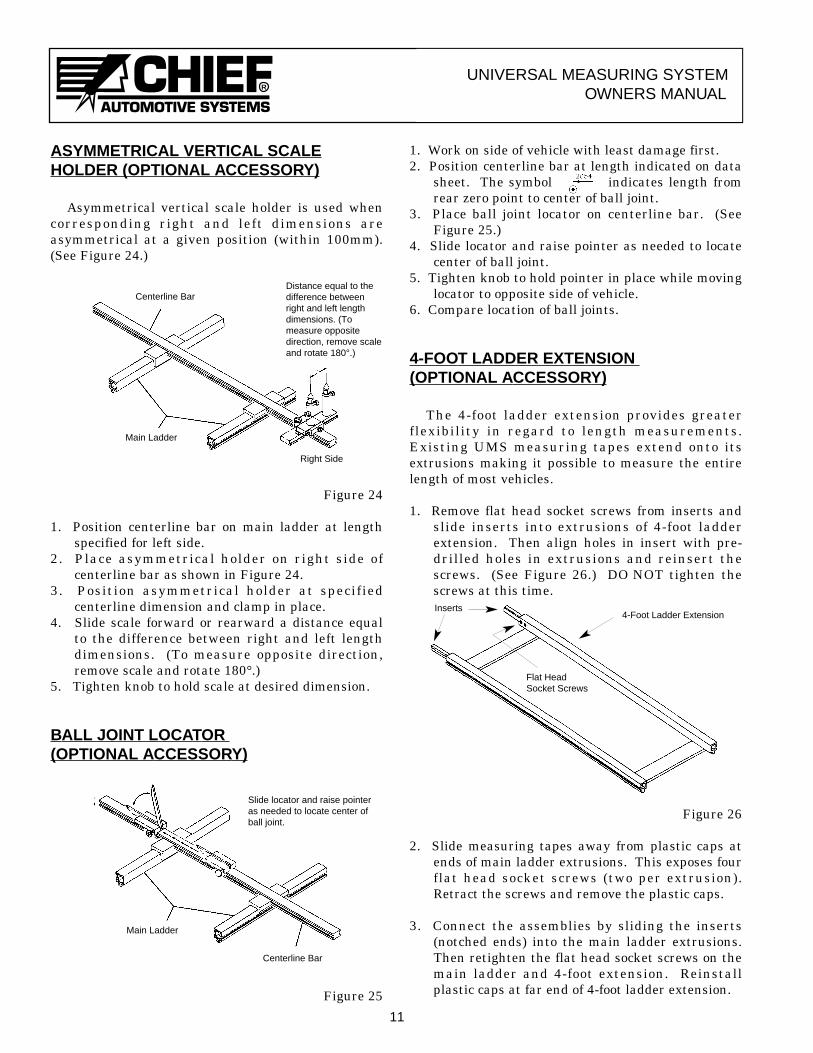
4-FOOT LADDER EXTENSION (OPTIONAL ACCESSORY)
The 4-foot ladder extension provides greaterflexibility in regard to length measurements.Existing UMS measuring tapes extend onto itsextrusions making it possible to measure the entirelength of most vehicles.
1. Remove flat head socket screws from inserts andslide inserts into extrusions of 4-foot ladderextension. Then align holes in insert with pre-drilled holes in extrusions and reinsert thescrews. (See Figure 26.) DO NOT tighten thescrews at this time.
Figure 26
2. Slide measuring tapes away from plastic caps atends of main ladder extrusions. This exposes fourflat head socket screws (two per extrusion).Retract the screws and remove the plastic caps.
3. Connect the assemblies by sliding the inserts(notched ends) into the main ladder extrusions.Then retighten the flat head socket screws on themain ladder and 4-foot extension. Reinstallplastic caps at far end of 4-foot ladder extension.
11
Centerline BarDistance equal to thedifference betweenright and left lengthdimensions. (Tomeasure oppositedirection, remove scaleand rotate 180°.)
Main Ladder
Right Side
Slide locator and raise pointeras needed to locate center ofball joint.
Main Ladder
Centerline Bar
4-Foot Ladder Extension
Flat HeadSocket Screws
Inserts
R
UNIVERSAL MEASURING SYSTEMOWNERS MANUAL
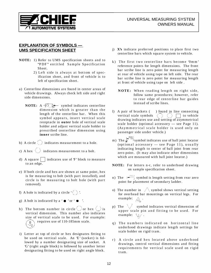
EXPLANATION OF SYMBOLS — UMS SPECIFICATION SHEET
NOTE: 1) Refer to UMS specification sheets and to“PDF” entitled Sample SpecificationSheet.
2) Left side is always at bottom of spec-ification sheet, and front of vehicle is toleft of specification sheet.
a) Centerline dimensions are found in center areas ofvehicle drawings. Always check left side and rightside dimensions.
NOTE: A symbol indicates centerlinedimension which is greater than thelength of the centerline bar. When thissymbol appears, insert vertical scalereceptacle in outer hole of vertical scaleholder and adjust vertical scale holder toprescribed centerline dimension usinginner scribe line.
b) A circle indicates measurement to a hole.
c) A hex indicates measurement to a bolt.
d) A square indicates use of ‘F’ block to measureto an edge.
e) If both circle and hex are shown at same point, hexis for measuring to bolt (with part installed), andcircle is for measuring to bolt hole (with partremoved).
f) A hole is indicated by a circle ‘ ’.
g) A bolt is indicated by a ‘ ’ or ‘ ’.
h) The bottom number in circle or hex isvertical dimension. This number also indicatessize of vertical scale to be used. For example:
requires use of 110-185mm scale.
i) Letter at top of circle or hex designates fitting tobe used on vertical scale. An ‘E’ (socket) is fol-lowed by a number designating size of socket. A‘G’ (right angle block) is followed by another letterdesignating fitting to be used on right angle block.
j) X’s indicate preferred positions to place first twocenterline bars which square system to vehicle.
k) The first two centerline bars become ‘0mm ’reference points for length dimensions. The frontbar scribe line is zero point for measuring lengthat rear of vehicle using tape on left side. The rearbar scribe line is zero point for measuring lengthat front of vehicle using tape on left side .
NOTE: When reading length on right side,follow same procedures; however, referto rear edge of centerline bar guidesinstead of scribe lines.
l) A pair of brackets ( ) found in line connectingvertical scale symbols to vehicledrawing indicates use and setting of asymmetricalscale holder (optional accessory — see Page 11).(Asymmetrical scale holder is used only onpassenger side under vehicle.)
m) The symbol indicates use of ball joint locator(optional accessory — see Page 11), usuallyindicating length to center of ball joint from rearzero point. (It may also indicate other dimensionswhich are measured with ball joint locator.)
NOTE: For letters n-r, refer to underhood drawingon sample specification sheet.
n) The symbol is length setting from rear zeropoint for placement of secondary ladder.
o) The number in symbol shows vertical settingfor overhead bar mountings on vertical legs. Forexample: .
p) The symbol indicates vertical dimension ofupper scale pin and fitting to be used. Forexample: .
q) The numbers indicated on horizontal lineunderhood drawings indicate length settings forscale holder on rigid tram.
r) A circle and hex located above underhooddrawings, control vertical dimensions and fittingrequirements for vertical scale used on rigidtram.
12
RUNIVERSAL MEASURING SYSTEM
OWNERS MANUAL
EXPLANATION OF CODE BOX
NOTE: Refer to “PDF” entitled Sample SpecificationSheet.
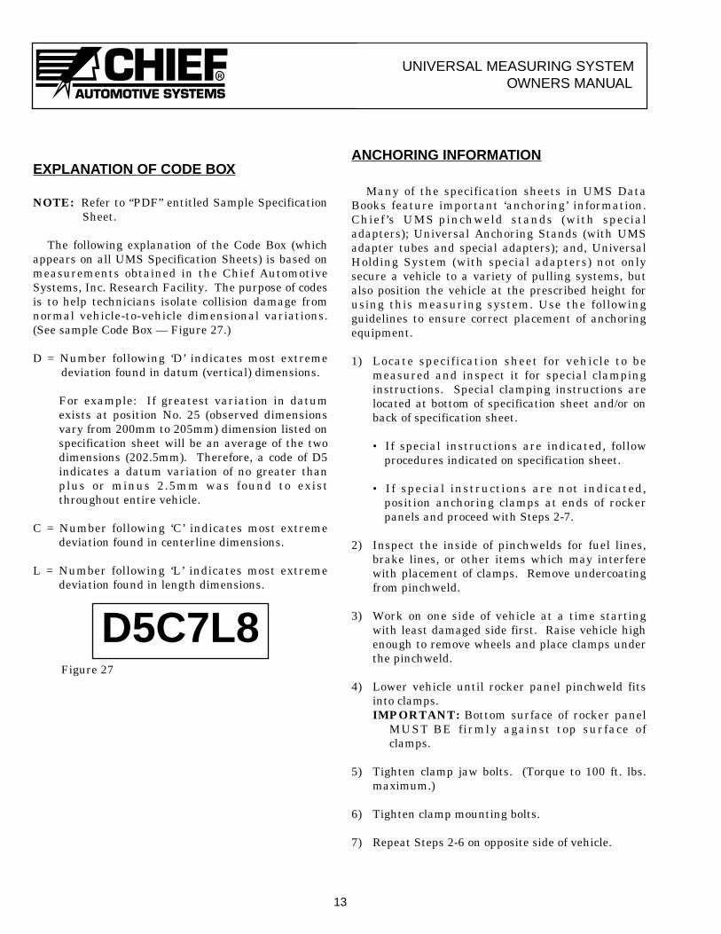
The following explanation of the Code Box (whichappears on all UMS Specification Sheets) is based onmeasurements obtained in the Chief AutomotiveSystems, Inc. Research Facility. The purpose of codesis to help technicians isolate collision damage fromnormal vehicle-to-vehicle dimensional variations.(See sample Code Box — Figure 27.)
D = Number following ‘D’ indicates most extremedeviation found in datum (vertical) dimensions.
For example: If greatest variation in datumexists at position No. 25 (observed dimensionsvary from 200mm to 205mm) dimension listed onspecification sheet will be an average of the twodimensions (202.5mm). Therefore, a code of D5indicates a datum variation of no greater thanplus or minus 2.5mm was found to existthroughout entire vehicle.
C = Number following ‘C’ indicates most extremedeviation found in centerline dimensions.
L = Number following ‘L’ indicates most extremedeviation found in length dimensions.
Figure 27
ANCHORING INFORMATION
Many of the specification sheets in UMS DataBooks feature important ‘anchoring’ information.Chief ’s UMS pinchweld stands (with specialadapters); Universal Anchoring Stands (with UMSadapter tubes and special adapters); and, UniversalHolding System (with special adapters) not onlysecure a vehicle to a variety of pulling systems, butalso position the vehicle at the prescribed height forusing this measuring system. Use the followingguidelines to ensure correct placement of anchoringequipment.
1) Locate specification sheet for vehicle to bemeasured and inspect it for special clampinginstructions. Special clamping instructions arelocated at bottom of specification sheet and/or onback of specification sheet.
• If special instructions are indicated, followprocedures indicated on specification sheet.
• If special instructions are not indicated,position anchoring clamps at ends of rockerpanels and proceed with Steps 2-7.
2) Inspect the inside of pinchwelds for fuel lines,brake lines, or other items which may interferewith placement of clamps. Remove undercoatingfrom pinchweld.
3) Work on one side of vehicle at a time startingwith least damaged side first. Raise vehicle highenough to remove wheels and place clamps underthe pinchweld.
4) Lower vehicle until rocker panel pinchweld fitsinto clamps.IMPORTANT: Bottom surface of rocker panel
MUST BE firmly against top surface ofclamps.
5) Tighten clamp jaw bolts. (Torque to 100 ft. lbs.maximum.)
6) Tighten clamp mounting bolts.
7) Repeat Steps 2-6 on opposite side of vehicle.
13
D5C7L8
RUNIVERSAL MEASURING SYSTEM
OWNERS MANUAL
14
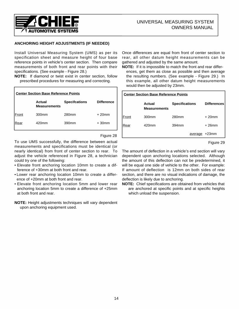
ANCHORING HEIGHT ADJUSTMENTS (IF NEEDED)
Install Universal Measuring System (UMS) as per itsspecification sheet and measure height of four basereference points in vehicle’s center section. Then comparemeasurements of both front and rear points with theirspecifications. (See example - Figure 28.)NOTE: If diamond or twist exist in center section, follow
prescribed procedures for measuring and correcting.
To use UMS successfully, the difference between actualmeasurements and specifications must be identical (ornearly identical) from front of center section to rear. Toadjust the vehicle referenced in Figure 28, a techniciancould try one of the following:• Elevate front anchoring location 10mm to create a dif-
ference of +30mm at both front and rear.• Lower rear anchoring location 10mm to create a differ-
ence of +20mm at both front and rear.• Elevate front anchoring location 5mm and lower rear
anchoring location 5mm to create a difference of +25mmat both front and rear.
NOTE: Height adjustments techniques will vary dependent upon anchoring equipment used.
Once differences are equal from front of center section torear, all other datum height measurements can begathered and adjusted by the same amount.NOTE: If it is impossible to match the front and rear differ-
ences, get them as close as possible and then averagethe resulting numbers. (See example - Figure 29.) Inthis example, all other datum height measurementswould then be adjusted by 23mm.
The amount of deflection in a vehicle’s end section will varydependent upon anchoring locations selected. Althoughthe amount of this deflection can not be predetermined, itwill be equal one side of vehicle to the other. For example:If amount of deflection is 12mm on both sides of rearsection, and there are no visual indications of damage, thedeflection is likely due to anchoring.NOTE: Chief specifications are obtained from vehicles that
are anchored at specific points and at specific heights which unload the suspension.
Center Section Base Reference Points
Actual Specifcations DifferenceMeasurements
Front 300mm 280mm + 20mm
Rear 420mm 390mm + 30mm
Center Section Base Reference Points
Actual Specifications DifferencesMeasurements
Front 300mm 280mm + 20mm
Rear 420mm 394mm + 26mm
average +23mmFigure 28
Figure 29


R
P.O. Box 1368Grand Island, Nebraska 68802-1368308-384-9747
Chief reserves the right to alter product specifications and/or package components without notice.
Form UMS Rev. 4/07Part No. 150022