choosing an oscilloscope for coherent optical modulation...
TRANSCRIPT
As demand for data increases, network operators continue to search for methods to increase data throughput of existing optical networks. As data rates increase to 40Gb/s, 100Gb/s, and beyond, complex modulation formats become prevalent. These modulation formats present new challenges for the designer when it comes to choices of test equipment.
This Technical Brief will outline the basic technologies used to convert complex modulated optical signals to electrical signals capable of being acquired by an oscilloscope. Further explanation of coherent detection techniques will be discussed and why real-time or equivalent-time scopes may be chosen. Finally, a number of equipment configurations will be shown that support coherent demodulation and analysis.
Choosing an Oscilloscope forCoherent Optical Modulation AnalysisTechnical Brief
Coherent Receiver BasicsComplex modulation formats such as BPSK, QPSK, QAM, and DP-QPSK typically utilize C-band or L-band lasers as the optical carrier. These lasers operate at frequencies between 186THz and 196THz. Obviously no oscilloscope is capable of directly measuring these frequencies. Additionally, these complex modulation formats carry information in both the phase and polarization of the optical carrier.
Coherent receivers fulfill two necessary functions. First, they downconvert the optical carrier to an intermediate frequency capable of being acquired by a modern oscilloscope. Second, they use coherent detection techniques to recover not only the amplitude of the optical carrier, but also the phase and state of polarization.
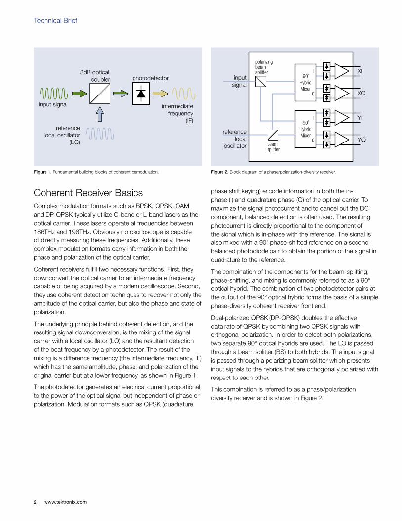
The underlying principle behind coherent detection, and the resulting signal downconversion, is the mixing of the signal carrier with a local oscillator (LO) and the resultant detection of the beat frequency by a photodetector. The result of the mixing is a difference frequency (the intermediate frequency, IF) which has the same amplitude, phase, and polarization of the original carrier but at a lower frequency, as shown in Figure 1.
The photodetector generates an electrical current proportional to the power of the optical signal but independent of phase or polarization. Modulation formats such as QPSK (quadrature
phase shift keying) encode information in both the in-phase (I) and quadrature phase (Q) of the optical carrier. To maximize the signal photocurrent and to cancel out the DC component, balanced detection is often used. The resulting photocurrent is directly proportional to the component of the signal which is in-phase with the reference. The signal is also mixed with a 90° phase-shifted reference on a second balanced photodiode pair to obtain the portion of the signal in quadrature to the reference.
The combination of the components for the beam-splitting, phase-shifting, and mixing is commonly referred to as a 90° optical hybrid. The combination of two photodetector pairs at the output of the 90° optical hybrid forms the basis of a simple phase-diversity coherent receiver front end.
Dual-polarized QPSK (DP-QPSK) doubles the effective data rate of QPSK by combining two QPSK signals with orthogonal polarization. In order to detect both polarizations, two separate 90° optical hybrids are used. The LO is passed through a beam splitter (BS) to both hybrids. The input signal is passed through a polarizing beam splitter which presents input signals to the hybrids that are orthogonally polarized with respect to each other.
This combination is referred to as a phase/polarization diversity receiver and is shown in Figure 2.
Figure 2. Block diagram of a phase/polarization-diversity receiver.Figure 1. Fundamental building blocks of coherent demodulation.
XI
XQ
90˚HybridMixer
I
Q
YI
YQ
90˚HybridMixer
I
Q
polarizingbeamsplitter
beamsplitter
inputsignal
referencelocal
oscillator
input signal
3dB opticalcoupler photodetector
intermediatefrequency
(IF)reference
local oscillator(LO)
Technical Brief
www.tektronix.com2
Coherent Demodulation TechniquesOften dependent upon system configuration or the type of oscilloscope available, coherent receivers may employ different demodulation techniques as described below.
Homodyne detection
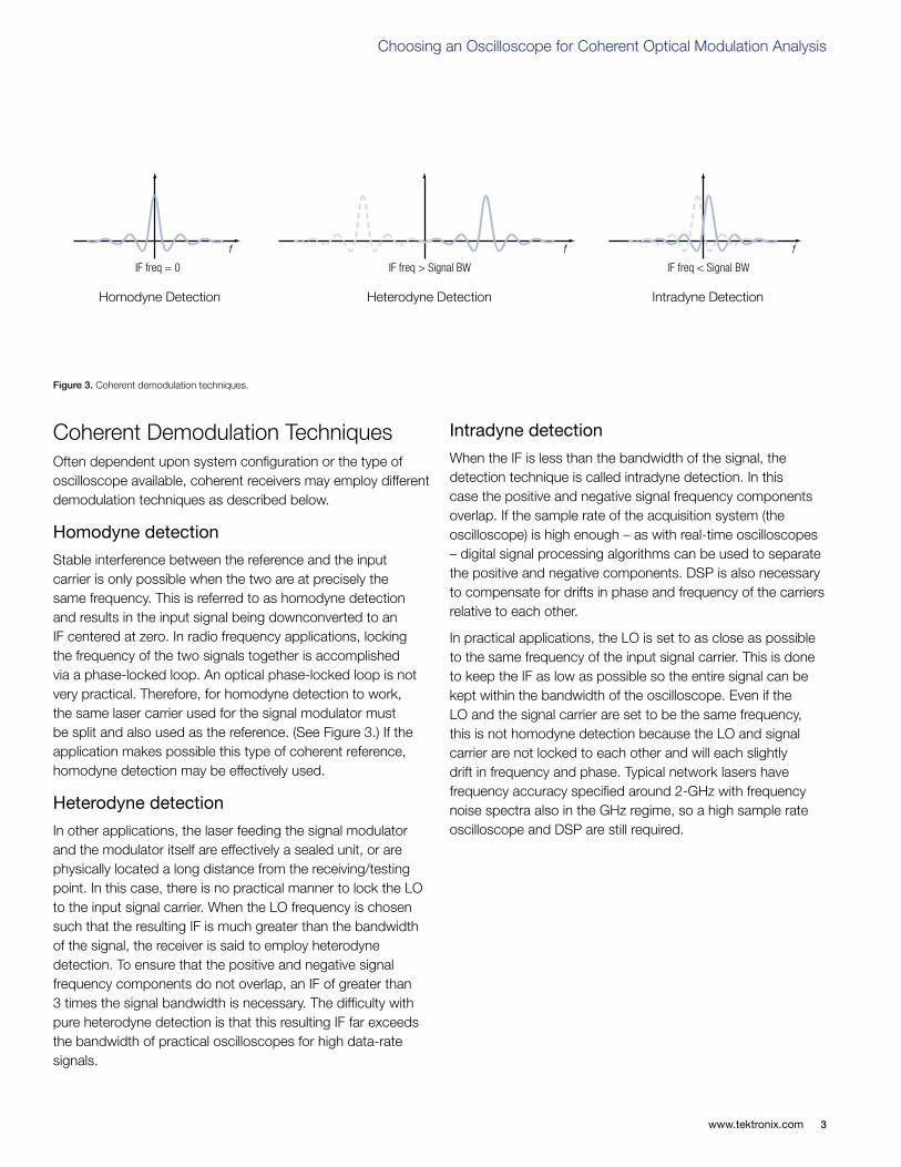
Stable interference between the reference and the input carrier is only possible when the two are at precisely the same frequency. This is referred to as homodyne detection and results in the input signal being downconverted to an IF centered at zero. In radio frequency applications, locking the frequency of the two signals together is accomplished via a phase-locked loop. An optical phase-locked loop is not very practical. Therefore, for homodyne detection to work, the same laser carrier used for the signal modulator must be split and also used as the reference. (See Figure 3.) If the application makes possible this type of coherent reference, homodyne detection may be effectively used.
Heterodyne detection
In other applications, the laser feeding the signal modulator and the modulator itself are effectively a sealed unit, or are physically located a long distance from the receiving/testing point. In this case, there is no practical manner to lock the LO to the input signal carrier. When the LO frequency is chosen such that the resulting IF is much greater than the bandwidth of the signal, the receiver is said to employ heterodyne detection. To ensure that the positive and negative signal frequency components do not overlap, an IF of greater than 3 times the signal bandwidth is necessary. The difficulty with pure heterodyne detection is that this resulting IF far exceeds the bandwidth of practical oscilloscopes for high data-rate signals.
Intradyne detection
When the IF is less than the bandwidth of the signal, the detection technique is called intradyne detection. In this case the positive and negative signal frequency components overlap. If the sample rate of the acquisition system (the oscilloscope) is high enough – as with real-time oscilloscopes – digital signal processing algorithms can be used to separate the positive and negative components. DSP is also necessary to compensate for drifts in phase and frequency of the carriers relative to each other.
In practical applications, the LO is set to as close as possible to the same frequency of the input signal carrier. This is done to keep the IF as low as possible so the entire signal can be kept within the bandwidth of the oscilloscope. Even if the LO and the signal carrier are set to be the same frequency, this is not homodyne detection because the LO and signal carrier are not locked to each other and will each slightly drift in frequency and phase. Typical network lasers have frequency accuracy specified around 2-GHz with frequency noise spectra also in the GHz regime, so a high sample rate oscilloscope and DSP are still required.
Figure 3. Coherent demodulation techniques.
f
IF freq = 0 IF freq > Signal BW
f
IF freq < Signal BW
f
Homodyne Detection Heterodyne Detection Intradyne Detection
www.tektronix.com 3
Choosing an Oscilloscope for Coherent Optical Modulation Analysis
Instrument Choices for Coherent Modulation Signal Analysis
Equivalent-time Oscilloscopes
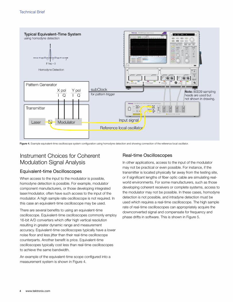
When access to the input to the modulator is possible, homodyne detection is possible. For example, modulator component manufacturers, or those developing integrated laser/modulator, often have such access to the input of the modulator. A high sample rate oscilloscope is not required. In this case an equivalent-time oscilloscope may be used.
There are several benefits to using an equivalent-time oscilloscope. Equivalent-time oscilloscopes commonly employ 16-bit A/D converters which offer high vertical resolution resulting in greater dynamic range and measurement accuracy. Equivalent-time oscilloscopes typically have a lower noise floor and less jitter than their real-time oscilloscope counterparts. Another benefit is price. Equivalent-time oscilloscopes typically cost less than real-time oscilloscopes to achieve the same bandwidth.
An example of the equivalent-time scope configured into a measurement system is shown in Figure 4.
Real-time Oscilloscopes
In other applications, access to the input of the modulator may not be practical or even possible. For instance, if the transmitter is located physically far away from the testing site, or if significant lengths of fiber optic cable are simulating real-world environments. For some manufacturers, such as those developing coherent receivers or complete systems, access to the modulator may not be possible. In these cases, homodyne detection is not possible, and intradyne detection must be used which requires a real-time oscilloscope. The high sample rate of real-time oscilloscopes can appropriately acquire the downconverted signal and compensate for frequency and phase drifts in software. This is shown in Figure 5.
Figure 4. Example equivalent-time oscilloscope system configuration using homodyne detection and showing connection of the reference local oscillator.
Technical Brief
www.tektronix.com4
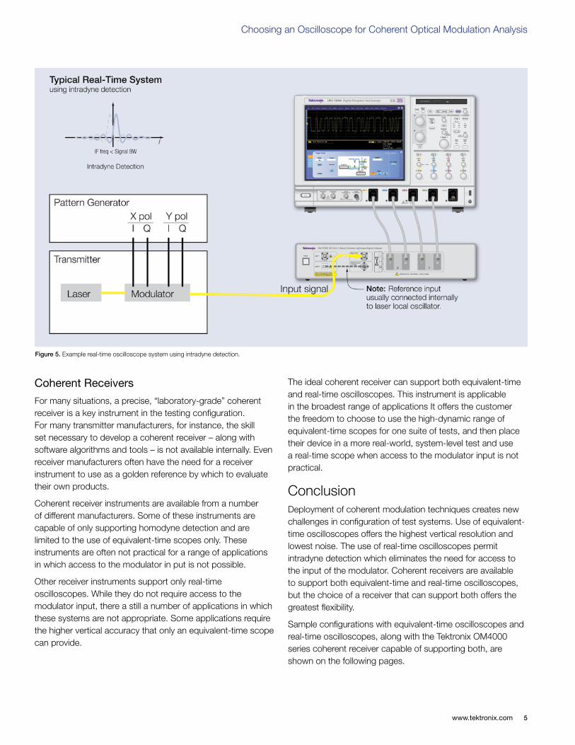
Figure 5. Example real-time oscilloscope system using intradyne detection.
Coherent Receivers
For many situations, a precise, “laboratory-grade” coherent receiver is a key instrument in the testing configuration. For many transmitter manufacturers, for instance, the skill set necessary to develop a coherent receiver – along with software algorithms and tools – is not available internally. Even receiver manufacturers often have the need for a receiver instrument to use as a golden reference by which to evaluate their own products.
Coherent receiver instruments are available from a number of different manufacturers. Some of these instruments are capable of only supporting homodyne detection and are limited to the use of equivalent-time scopes only. These instruments are often not practical for a range of applications in which access to the modulator in put is not possible.
Other receiver instruments support only real-time oscilloscopes. While they do not require access to the modulator input, there a still a number of applications in which these systems are not appropriate. Some applications require the higher vertical accuracy that only an equivalent-time scope can provide.
The ideal coherent receiver can support both equivalent-time and real-time oscilloscopes. This instrument is applicable in the broadest range of applications It offers the customer the freedom to choose to use the high-dynamic range of equivalent-time scopes for one suite of tests, and then place their device in a more real-world, system-level test and use a real-time scope when access to the modulator input is not practical.
ConclusionDeployment of coherent modulation techniques creates new challenges in configuration of test systems. Use of equivalent-time oscilloscopes offers the highest vertical resolution and lowest noise. The use of real-time oscilloscopes permit intradyne detection which eliminates the need for access to the input of the modulator. Coherent receivers are available to support both equivalent-time and real-time oscilloscopes, but the choice of a receiver that can support both offers the greatest flexibility.
Sample configurations with equivalent-time oscilloscopes and real-time oscilloscopes, along with the Tektronix OM4000 series coherent receiver capable of supporting both, are shown on the following pages.
www.tektronix.com 5
Choosing an Oscilloscope for Coherent Optical Modulation Analysis
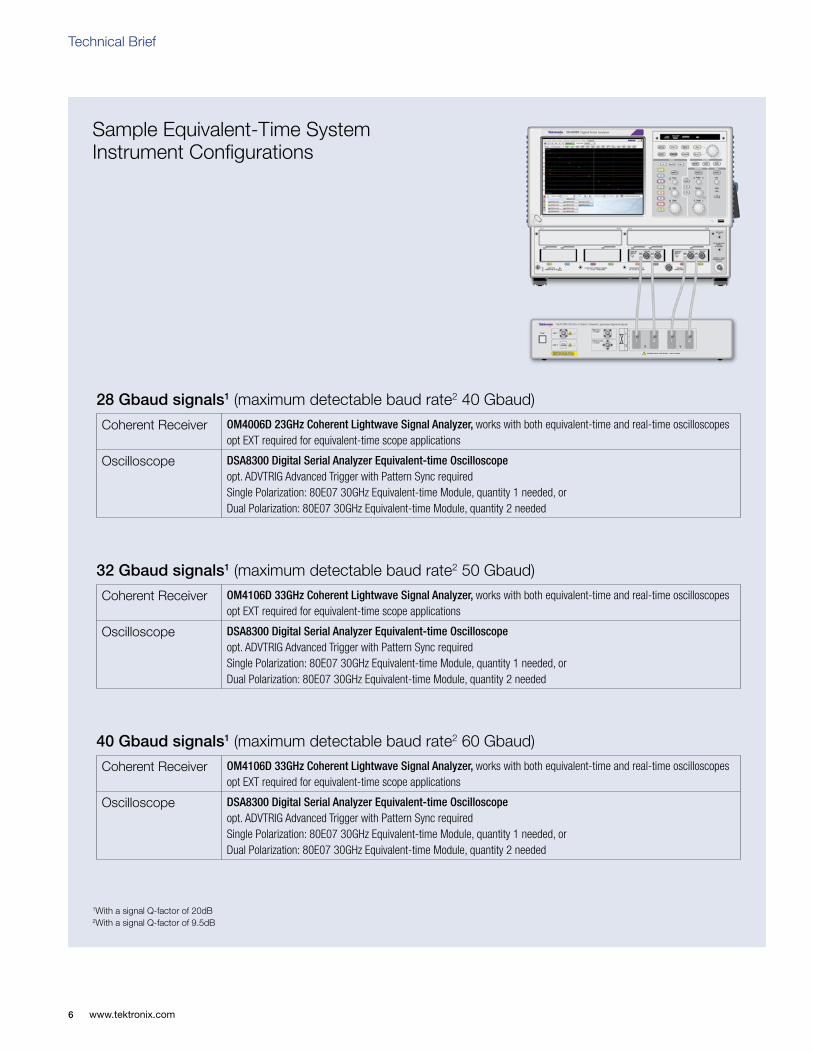
Sample Equivalent-Time System Instrument Configurations
1With a signal Q-factor of 20dB2With a signal Q-factor of 9.5dB
28 Gbaud signals1 (maximum detectable baud rate2 40 Gbaud)
Coherent Receiver OM4006D 23GHz Coherent Lightwave Signal Analyzer, works with both equivalent-time and real-time oscilloscopesopt EXT required for equivalent-time scope applications
Oscilloscope DSA8300 Digital Serial Analyzer Equivalent-time Oscilloscopeopt. ADVTRIG Advanced Trigger with Pattern Sync required Single Polarization: 80E07 30GHz Equivalent-time Module, quantity 1 needed, or Dual Polarization: 80E07 30GHz Equivalent-time Module, quantity 2 needed
32 Gbaud signals1 (maximum detectable baud rate2 50 Gbaud)
Coherent Receiver OM4106D 33GHz Coherent Lightwave Signal Analyzer, works with both equivalent-time and real-time oscilloscopesopt EXT required for equivalent-time scope applications
Oscilloscope DSA8300 Digital Serial Analyzer Equivalent-time Oscilloscopeopt. ADVTRIG Advanced Trigger with Pattern Sync required Single Polarization: 80E07 30GHz Equivalent-time Module, quantity 1 needed, or Dual Polarization: 80E07 30GHz Equivalent-time Module, quantity 2 needed
40 Gbaud signals1 (maximum detectable baud rate2 60 Gbaud)
Coherent Receiver OM4106D 33GHz Coherent Lightwave Signal Analyzer, works with both equivalent-time and real-time oscilloscopesopt EXT required for equivalent-time scope applications
Oscilloscope DSA8300 Digital Serial Analyzer Equivalent-time Oscilloscopeopt. ADVTRIG Advanced Trigger with Pattern Sync required Single Polarization: 80E07 30GHz Equivalent-time Module, quantity 1 needed, or Dual Polarization: 80E07 30GHz Equivalent-time Module, quantity 2 needed
Technical Brief
www.tektronix.com6

Sample Equivalent-Time System Instrument Configurations
1With a signal Q-factor of 20dB2With a signal Q-factor of 9.5dB
28 Gbaud signals1 (maximum detectable baud rate2 40 Gbaud)
Coherent Receiver OM4006D 23GHz Coherent Lightwave Signal Analyzer, works with both equivalent-time and real-time oscilloscopesopt EXT required for equivalent-time scope applications
Oscilloscope DPO72004C 20GHz Digital Phosphor Oscilloscopesupports single and dual polarization systems
32 Gbaud signals1 (maximum detectable baud rate2 50 Gbaud)
Coherent Receiver OM4106D 33GHz Coherent Lightwave Signal Analyzer, works with both equivalent-time and real-time oscilloscopesopt EXT required for equivalent-time scope applications
Oscilloscope DPO72504D 25GHz Digital Phosphor Oscilloscopesupports single and dual polarization systems
40 Gbaud signals1 (maximum detectable baud rate2 60 Gbaud)
Coherent Receiver OM4106D 33GHz Coherent Lightwave Signal Analyzer, works with both equivalent-time and real-time oscilloscopesopt EXT required for equivalent-time scope applications
Oscilloscope Single Polarization: DPO73304D 33GHz Digital Phospor OscilloscopeDual Polarization: DPO73304D 33GHz Digital Phospor Oscilloscope, requires quantity 2
www.tektronix.com 7
Choosing an Oscilloscope for Coherent Optical Modulation Analysis

Contact Tektronix:ASEAN / Australasia (65) 6356 3900
Austria* 00800 2255 4835
Balkans, Israel, South Africa and other ISE Countries +41 52 675 3777
Belgium* 00800 2255 4835
Brazil +55 (11) 3759 7627
Canada 1 (800) 833-9200
Central East Europe and the Baltics +41 52 675 3777
Central Europe & Greece +41 52 675 3777
Denmark +45 80 88 1401
Finland +41 52 675 3777
France* 00800 2255 4835
Germany* 00800 2255 4835
Hong Kong 400-820-5835
India 000-800-650-1835
Italy* 00800 2255 4835
Japan 81 (3) 6714-3010
Luxembourg +41 52 675 3777
Mexico, Central/South America & Caribbean 52 (55) 56 04 50 90
Middle East, Asia and North Africa +41 52 675 3777
The Netherlands* 00800 2255 4835
Norway 800 16098
People’s Republic of China 400-820-5835
Poland +41 52 675 3777
Portugal 80 08 12370
Republic of Korea 001-800-8255-2835
Russia & CIS +7 (495) 7484900
South Africa +27 11 206 8360
Spain* 00800 2255 4835
Sweden* 00800 2255 4835
Switzerland* 00800 2255 4835
Taiwan 886 (2) 2722-9622
United Kingdom & Ireland* 00800 2255 4835
USA 1 (800) 833-9200
* If the European phone number above is not accessible, please call +41 52 675 3777
Contact List Updated 10 February 2011
For Further InformationTektronix maintains a comprehensive, constantly expanding collection of application notes, technical briefs and other resources to help engineers working on the cutting edge of technology. Please visit www.tektronix.com
Copyright © 2012, Tektronix. All rights reserved. Tektronix products are covered by U.S. and foreign patents, issued and pending. Information in this publication supersedes that in all previously published material. Specification and price change privileges reserved. TEKTRONIX and TEK are registered trademarks of Tektronix, Inc. All other trade names referenced are the service marks, trademarks or registered trademarks of their respective companies.
07/12 EA/WWW 85W-28243-0