chris antle engineering design spring 2015
DESCRIPTION
Engineering project portfolio, spring 2015.TRANSCRIPT
B.S. Electrical Engineering, Mechatronics Minor Montana State University Expected Comple7on: Spring 2016
CHRIS ANTLE ENGINEERING DESIGN

About
Creation and design have been an integral part of my life, from
snapping together Legos to restoring vintage motorcycles. My
continuous curiosity prompted my pursuit of a degree in Electrical
Engineering, with a minor in Mechatronics.
The result is a thorough understanding of electrical and mechanical
systems, their interactions, and the necessary means to bring a
design to life. This portfolio provides a summary of my projects,
academic and personal, highlighting their purpose and the design
process used. More information is available upon request.
Chris Antle
406.599.6472
3

Circuit Design
Spring/Fall 2014
Strain gage and audio system project circuits allowed for a rigorous study of analog circuit design. Each design was broken into discrete stages, such as an instrumentation amplifier,
comparator, and tone control. CAD and analysis software were used in conjunction with test equipment throughout the design
process.
< Complete Strain Gage Circuit
4
BJT audio amplifier circuit >
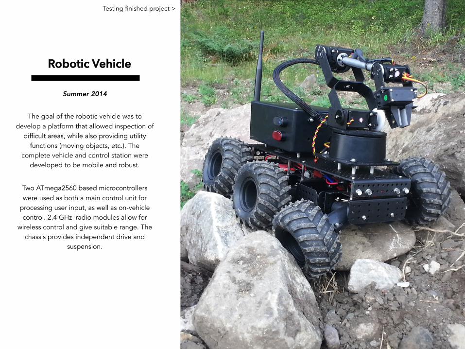
Robotic Vehicle
Summer 2014
The goal of the robotic vehicle was to develop a platform that allowed inspection of
difficult areas, while also providing utility functions (moving objects, etc.). The
complete vehicle and control station were developed to be mobile and robust.
Two ATmega2560 based microcontrollers were used as both a main control unit for
processing user input, as well as on-vehicle control. 2.4 GHz radio modules allow for
wireless control and give suitable range. The chassis provides independent drive and
suspension.
Testing finished project >
5
6
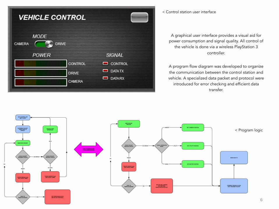
A graphical user interface provides a visual aid for power consumption and signal quality. All control of
the vehicle is done via a wireless PlayStation 3 controller.
A program flow diagram was developed to organize the communication between the control station and vehicle. A specialized data packet and protocol were
introduced for error checking and efficient data transfer.
< Control station user interface
< Program logic

Residential Hydroelectric System
Fall 2012
As part of a multidisciplinary undergraduate design course, the feasibility of a small-scale hydroelectric system was analyzed. As team leader, I coordinated the interface between systems. Conceptual sketches of possible
designs led to a decision matrix, which allowed for a quantitative approach to the
design choice.
Decision matrix > 7
!
!
Conceptual sketch >

8
Once a design was chosen, the system architecture was developed. The design was broken down into
three discrete subsystems, which could be addressed by the team.
A prop design was developed, and computational fluid dynamics used for an approximation of torque. This figure, in conjunction with a specified generator, allowed for an expected output power figure to be
computed. An overall report addressing the feasibility of the design, test procedure, and cost analysis was
produced.
< System architecture diagram
< CFD of turbine for torque approximation

Mining Equipment Grapple
Summer 2013
Developed for a mining company, the grapple was designed to lift large boulders
from the pit. As a summer internship project, I worked on a cross-discipline team to design, manufacture, and test the product. Robust
design and wear resistance were emphasized in design, due to extreme demands on the
product.
< Finished product 9
< Basic structure model
Component manufacturing drawing >
4.5005.156
6.211
14.313
3.500
13.313
3.745-12 X 0.930"
3.618-12 X 0.656"
0.063 X 45_
0.250 X 45_n 0.500 x THRU TO PERP. DRILLED HOLE(SEE NOTE)(SEE NOTE)(SEE NOTE)(SEE NOTE)
n 3.750
n 4.250
2.250
2 x 3/8-16 UNC x 1.500n 2.25 BOLT CIRCLE
2X 3/8-16 UNC x 1.250n 2.25 BOLT CIRCLE
n1.375SLOT x 0.300
n 1.375 x 1.250
4X 1/2-14 NPT x 1.150n 2.25 BOLT CIRCLE
n.500x 13.500 (1)
n.500 x 12.625 (2)
n.500 x 11.750 (3)
n.500 x 10.938 (4)
(1)
(3)
(4)
(2)
7.23.2013
DRAWN BY:
TITLE:PROPRIETARY AND CONFIDENTIALPROPRIETARY AND CONFIDENTIALPROPRIETARY AND CONFIDENTIALPROPRIETARY AND CONFIDENTIALTHE INFORMATION CONTAINED IN THIS DOCUMENT IS THE PROPERTYOF MMC INC. ANY REPRODUCTION OR USE WITHOUT WRITTEN PERMISSIONOF MMC INC IS PROHIBITED
MILD STEEL
ANTLE MMC INCMMC INCMMC INCMMC INC
3.001
MATERIAL:
SHAFTDATE:
UNLESS OTHERWISE SPECIFIED:UNLESS OTHERWISE SPECIFIED:UNLESS OTHERWISE SPECIFIED:UNLESS OTHERWISE SPECIFIED:DIMENSIONS ARE IN INCHESTOLERANCES: X.X = 0.1X.XX = 0.025X.XXX = 0.005
ZONE DATE
SHEET
DESCRIPTION
SCALE
REV
FSCM NO. REV
A
REVISIONS
DWG NO.SIZE
APPROVED
HOLES ALONG RIGHT END OF SHAFT ARE DRILLED 90 DEGREE FROM EACH ANOTHER IN FOLLOWING INCREMENTS FROM RIGHT END:(1) 0.925"(2) 1.7850"(3) 2.675"(4) 3.5325"
DISTANCE TO FLANGE ON WELDMENT (SEE ASSEMBLY)IS 11 7/8". MACHINE FLANGE TO 2 3/8" AFTER WEDLING

Vise Design and Build
Fall 2011
The vise design and build project was an exercise in design for manufacturing. From a conceptual sketch, a CAD model was created
as well as manufacturing prints. Special emphasis was put on GD&T. Once the model was checked, the design was fabricated in the
machine shop using traditional mills and lathes. Once the project was built, it was tested and graded against the specified
tolerances.
10
CAD model >
Manufacturing print >
Finished design >

65’ Triumph TR6
Winter 2011
Over the 2011 winter, this 1965 Triumph TR6 was brought back to life. A complete engine overhaul/ restoration was performed, as well as many upgrades to the electrical system.
Chassis modifications were made for simplicity and weight savings. All fabrication, wiring, and paint was done in house (literally, I rebuilt the engine on my dining room table).
The bike won “best in class” at the Salt Flat Social motorcycle show the following year.
Completed bike >
11
!