chrome plating controls enhancement to the 120-mm plating ...fractory metals to protect ordnance...
TRANSCRIPT
Approved for public release; distribution is unlimited.
ERD
C/C
ERL
TR-0
2-19
Chrome Plating Controls Enhancement to the 120-mm Plating Facility at Watervliet Arsenal, NY Fiscal Year 2000
Con
stru
ctio
n E
ngin
eeri
ng
Res
earc
h La
bora
tory
Joyce C. Baird, Dave Franklin, and Phil Darcy
August 2002
1.
2 ERDC/CERL TR-02-19
Foreword This study was conducted for 622720960, “Congressional – Watervliet Arsenal Pol-lution Projects.” The project was co-developed under the Value Engineering Pro-gram of the U.S. Army Corps of Engineers. The project described in this report was conducted at Watervliet Arsenal (WVA) during Fiscal Year (FY) 2000. The WVA technical monitor was Phil Darcy, Benet Laboratories.
The work was performed by the Environmental Processes Branch (CN-E) of the In-stallations Division (CN), Construction Engineering Research Laboratory (CERL). The CERL Principal Investigator was Joyce Baird. Part of this work was done by MSE Technology Applications (MSE-TA), Butte, Montana, under Department of Energy (DOE) contract No. 02138408. The technical editor was Linda L. Wheatley, Information Technology Laboratory — Champaign. Michelle J. Hansen is Acting Chief, CN-E, and Dr. John T. Bandy is Chief, CN. The Technical Director of the In-stallation Operations business area is Gary W. Schanche, and the Director of CERL is Dr. Alan W. Moore.
CERL is an element of the Engineer Research and Development Center (ERDC), U.S. Army Corps of Engineers. The Commander and Executive Director of ERDC is COL John W. Morris III, EN, and the Director is Dr. James R. Houston.
DISCLAIMER: The contents of this report are not to be used for advertising, publication, or promotional purposes. Citation of trade names does not constitute an official endorsement or approval of the use of such commercial products. All product names and trademarks cited are the property of their respective owners. The findings of this report are not to be construed as an official Department of the Army position unless so designated by other authorized documents. DESTROY THIS REPORT WHEN IT IS NO LONGER NEEDED. DO NOT RETURN IT TO THE ORIGINATOR.

ERDC/CERL TR-02-19 3
Contents Foreword ............................................................................................................................................2
List of Figures....................................................................................................................................4
1 Introduction.................................................................................................................................5 Background .........................................................................................................................5
Watervliet Arsenal ..........................................................................................................................5 Benet Laboratories.........................................................................................................................7 Manufacturing Practices at Watervliet Arsenal...............................................................................7 Plating Operations at Watervliet Arsenal........................................................................................9 Chromium Plating ........................................................................................................................10 Problems in the Plating Operations at WVA.................................................................................11 National Emission Standards for Hazardous Air Pollutants..........................................................13
Objective ...........................................................................................................................14 Approach...........................................................................................................................14 Mode of Technology Transfer............................................................................................14 Units of Weight and Measure............................................................................................15
2 Chrome Plating Controls Enhancement...............................................................................16 Site Investigation...............................................................................................................16 System Hardware Design .................................................................................................16
Replacement of Analog Indicators With Digital Equipment ..........................................................16 Calibration of Scrubber Instrumentation.......................................................................................18 Simplification of the Rectifier Current Loops ................................................................................19 Reduction of Reagent Glycol Contamination ...............................................................................20 Series 871 Probe Functional Specifications.................................................................................22 Series 875 Analyzer/Transmitter Functional Specifications..........................................................23 Reagent Pump Protection............................................................................................................23 Additional Hardware Upgrades ....................................................................................................27
Automated Control and Monitoring System ......................................................................27 Software Modifications ......................................................................................................28 Operating and Maintenance (O&M) Manuals and Training ..............................................28
3 Summary ...................................................................................................................................29
References .......................................................................................................................................30
Report Documentation Page .........................................................................................................32

4 ERDC/CERL TR-02-19
List of Figures 1 Main gates at Watervliet Arsenal (WVA), Watervliet, NY.............................................6 2 Aerial view of WVA ......................................................................................................6 3 WVA grounds...............................................................................................................7 4 A recoilless rifle............................................................................................................8 5 From left to right, 8-inch, 12-inch, and 16-inch guns displayed in front of the
Arsenal Museum .........................................................................................................8 6 Building 35 at WVA......................................................................................................9 7 Part of the chrome plating process (Building 35) ......................................................10 8 Chrome plating scrubber air monitoring NESHAP compliance computer ................. 11 9 Dwyer Magnehelic® differential pressure gauge.......................................................12 10 Industrial Wastewater Treatment Plant at WVA.........................................................13 11 Johnson-Yokogawa 30-Channel Digital Indicator and Recorder (DX200) ................17 12 DX200 in service, control panel CP-201, 120-mm plating area, Bldg. 35, WVA.......17 13 DX200 Back Panel Wiring .........................................................................................18 14 Johnson-Yokogawa EJA series DPharp differential pressure transmitter .................19 15 Foxboro Series 871 pH probe ...................................................................................20 16 The Foxboro Series 875 pH analyzer/transmitter......................................................20 17 pH probe and cable in heat exchanger cooling line, Foxboro 871 series .................21 18 pH analyzer with high/low alarm outputs, Foxboro Model 875PH.............................21 19 New magnetic drive sealless chromic acid pumps....................................................24 20 Power monitor, WenTech's Unipower Models HPL110 and HPL420 ........................24 21 MCC starter bucket for chromic acid pump, with power monitor installed ................26 22 Power monitor, MCC starter bucket for electropolish pump......................................26

ERDC/CERL TR-02-19 5
1 Introduction
Background
Watervliet Arsenal
Watervliet Arsenal (WVA) is in Watervliet, NY, on the banks of the Hudson River, 7 miles north of the state capital of Albany and in the heart of the Northeast Corri-dor. WVA is under the U.S. Army Industrial Operations Command (IOC) and is the nation’s only cannon manufacturing facility. Founded in 1813, WVA is the oldest continuously active arsenal in the United States. The U.S. Congress approved the establishment of a National Cannon Factory in 1897, and Watervliet was chosen as the site. Figures 1, 2, and 3 show the main entrance, an aerial view of the arsenal, and a section of WVA grounds. WVA is listed among the National Historic Land-marks, National Register Number 66000503. The Statement of Significance (as of designation – November 13, 1966) reads: “Founded in 1813, the Arsenal's busiest years were during the Mexican and Civil Wars. It became the Government's cannon factory in 1889, producing seacoast defense guns.”
http://www.nr.nps.gov/iwisapi/explorer.dll?IWS_SCHEMA=NRIS1&IWS_LOGIN=1&IWS_REPORT=100000044 *
* Web addresses included in this report are provided as sources for the figures and as resources for further investi-
gation of the subjects.

6 ERDC/CERL TR-02-19
Figure 1. Main gates at Watervliet Arsenal (WVA), Watervliet, NY.
http://www.cyhaus.com/arsenal/default.htm
Figure 2. Aerial view of WVA.
http://www.mse-ta.com/main_business_wastemin2.htm

ERDC/CERL TR-02-19 7
Figure 3. WVA grounds.
http://www.vintageviews.org/vv-ny/UZ/cards/w004.html
Benet Laboratories
WVA is also home to the Army's Benet Laboratories, part of the Army Research, Development, and Engineering Center (ARDEC) at Picatinny, NJ. Benet Laborato-ries’ primary mission is the development of advanced cannons. Benet also performs scientific and engineering activities, and is responsible for research, design, devel-opment, and engineering support of tank cannon, tank mounts, tank autoloaders, artillery cannon, mortars, recoilless rifles, and tank turret items. Benet's colloca-tion with the production facilities at WVA provides an excellent opportunity for con-current engineering and rapid prototyping.
http://www.globalsecurity.org/military/facility/watervliet.htm
Manufacturing Practices at Watervliet Arsenal
WVA produces the finest large caliber cannon in the world. Its recoilless rifles (Fig-ure 4), mortars, howitzers, tank guns, and the massive 16-inch battleship guns (Figure 5) are unmatched.

8 ERDC/CERL TR-02-19
Figure 4. A recoilless rifle.
http://www.cyhaus.com/arsenal/default.htm
WVA brings together the past and the present. Although the entire arsenal is listed as a National Historic Landmark, it is one of the most modern manufacturing facili-ties to be found in either the public or private sectors.
http://www.hqda.army.mil/acsimweb/gcd/watrvlet.htm.
The group of guns shown in Figure 5 includes a 16-inch battleship gun.
Figure 5. From left to right, 8-inch, 12-inch, and 16-inch guns displayed in front of the Arsenal Museum.
http://www.cyhaus.com/arsenal/default.htm

ERDC/CERL TR-02-19 9
Employees at WVA produce whole cannon systems today. The cannon begins as a large ingot of steel that successively goes through a number of procedures before reaching the chrome-plating operation. When the ingot has been heated to 1,950 ºF, fed into a rotary forge where it attains the gun-barrel shape, and moved through a series of water jets that cool it before undergoing various machining operations, it finally reaches the chrome plating facility. After caustic cleansing, rinsing, and pol-ishing, the gun barrel is lowered 40 to 70 feet into a chromic acid bath. Chrome plating the inside of the barrel extends the life of the tube about 25 percent.
http://www.dtic.mil/soldiers/nov1998/features/ioc2.html
Plating Operations at Watervliet Arsenal
The major plating area at WVA is in Building 35 (Figures 6 and 7). Machining, electroplating, grinding, drilling, and cutting have been performed in Building 35 since the early 1900s. Most of these operations involve chemicals such as plating solutions, acids, caustics, cutting oils, hydraulic fluids, and coolants. Plating opera-tions are performed in the eastern and southern portions of the building. The proc-essing pits are approximately 40 feet in depth and extend below the ground-water table.
Figure 6. Building 35 at WVA.
http://www.globalsecurity.org/military/library/report/enviro/WVA_IAP.pdf

10 ERDC/CERL TR-02-19
Figure 7. Part of the chrome plating process (Building 35).
http://www.globalsecurity.org/military/library/report/enviro/WVA_IAP.pdf
WVA plating facilities handle small parts as well as long cylindrical parts up to 30 inches in diameter by 33 feet long. Corrosion and wear-resistant coatings can be applied to metals, as well as fiberglass epoxy laminate for composite materials, plastic, and rubber applications. Available technologies for plating and surface coating include glow-discharge process and application of a super-hard skin to select surfaces of work pieces through programmable equipment. Coatings of many types can be applied chemically or electrically as customer needs dictate. http://www.wva.army.mil/MFGSERV.HTM
Chromium Plating
Chromium is a good refractory metal coating because it is extremely hard with a high melting temperature (1,875 °C) and provides excellent resistance to wear, ero-sion, and corrosion. The use of electro-deposits such as chromium plating and re-fractory metals to protect ordnance materials is an established industrial practice. Refractory metals are used to protect gun barrels from the erosive and corrosive en-vironment inside a gun tube after firing. When the projectile is fired, extreme tem-peratures, pressures, and gases are produced near the breech end of the gun. These conditions, coupled with stresses, expose the gun barrel to extreme friction, wear, erosion, and corrosion. http://www.bmpcoe.org/bestpractices/internal/watva/watva_2.html

ERDC/CERL TR-02-19 11
Problems in the Plating Operations at WVA
1. Rectifer current inaccuracies. The U.S. Environmental Protection Agency’s (EPA’s) National Emission Standards for Hazardous Air Pollutants (NESHAP) re-quires tonnage per year of chrome particles discharged to the atmosphere to be cal-culated by multiplying total plating time by the magnitude of rectifier current. In the plating operations at WVA, a discrepancy existed between the data supplied to the air monitoring computer (Figure 8) and the panel meters, which are used by op-erators to set plating current levels. This discrepancy was also true for the 120-mm plating facility. Rectifier current loops had been incorrectly calibrated, causing inac-curacies in the database for scrubber air emission tracking. The data were therefore invalid and could not be used for compliance verification or regulatory monitoring.
Figure 8. Chrome plating scrubber air monitoring NESHAP compliance computer.
2. Scrubber pressure reading inaccuracies. In addition, the Dwyer gauges (Dwyer Instruments, Inc., Michigan City, IN) used for measuring overall scrubber differen-tial pressure and inlet velocity pressure in the 120-mm major plating facility have discrepancies between the analog meter movements on the face of the instruments and the transmitted signals displayed in the air monitoring computer. Stack tests, held with the assistance of state officials, were performed at the time of the commis-sioning of the scrubbers. These stack tests measured scrubber air pressure and ve-locity, and provided data, which demonstrated optimal meter ranges for maximum scrubbing action. But because the electronic signal differs from the meter reading, the compliance test in the computer’s software is invalid. Figure 9 shows a Dwyer Magnehelic® differential pressure gauge.

12 ERDC/CERL TR-02-19
Figure 9. Dwyer Magnehelic® differential pressure gauge.
http://www.johnsherman.com/gauges/magnehelic.htm
The Dwyer frictionless Magnehelic® movement indicates low air or noncorrosive gas pressures — either positive, negative (vacuum), or differential. The instrument is designed to resist shock, vibration, and over-pressures. Its uses include the meas-urement of fan and blower pressures, filter resistance, air velocity, furnace draft, pressure drop across orifice plates, liquid levels with bubbler systems, and pres-sures in fluid amplifier or fluidic systems. It also checks gas-air ratio controls and automatic valves. The transmitter mounted on the back of the gauge is designed so that the electronic output correlates to within 2 percent of the pointer reading. However, if the pointer is pegged violently to top or bottom scale due to high or low pressure occurrences, the pointer can be permanently damaged, and can therefore be inaccurate. The 120-mm scrubber velocity pressure gauge (0-2 inches water col-umn [w.c.] range) was observed to have an error of 10 percent at midrange (i.e., with an applied pressure of 1 inch w.c., the electronic output was 1 inch w.c. while the pointer indicated 1.1 inch w.c.).
3. Reagent glycol contamination. Contamination of the chrome, electropolish, or caustic tanks occasionally occurs due to corrosion in the heat exchanger lines. For efficiency reasons, the same lines are used in all three-reagent loops. If a line springs a leak due to caustic corrosion, the heating and cooling lines, which contain glycol, become contaminated with caustic solution, which in turn causes the cross-over valves to build up deposits of the additive in the caustic. The ultimate result is contaminated reagent tanks and the dumping of glycol to the Industrial Wastewater Treatment Plant (IWTP; Figure 10). This contamination is very costly because the IWTP is not set up to treat glycol. It is believed that pH probes inserted into the heating and cooling lines, downstream of the filtering system, will alert the plant operator to the caustic contamination of the heat exchangers.

ERDC/CERL TR-02-19 13
Figure 10. Industrial Wastewater Treatment Plant at WVA.
http://www.globalsecurity.org/military/library/report/enviro/WVA_IAP.pdf
4. Outdated panel indicators. Many of the electrical safety interlocks (such as flow verification, bath temperature, and tank level) control the operation of the chrome plating facility. These interlocks help provide an efficient manufacturing process, prevent spills, avoid maintenance problems like pump burnout, and reduce waste. In many cases, the interlocks rely on relay outputs from analog indicators that are extremely old and no longer serviceable. The width of the dial pointer makes it dif-ficult to ascertain the exact reading on the dial, which obviously can present opera-tional problems. And if a relay fails, parts are not available for replacement be-cause of the age of the instrument.
5. Lack of adequate reagent pump protection. Current transformers were in use to protect the reagent pumps from over- or under-current conditions due to dead-heading or dry-running. The transformers provided input signals to panel indica-tors (previous paragraph), which in turn provided relay interlocks to shut down pump motor circuits under abnormal operating conditions. At least three of the current transformers were found to be oversized so that they were ineffectual in preventing pump damage (Northrup et al. 2001).
National Emission Standards for Hazardous Air Pollutants
For immersion-type chrome plating facilities, the EPA’s NESHAP requires that tonnage per year of chrome particles discharged to the atmosphere be calculated by multiplying total plating time by the magnitude of rectifier current. http://aec.army.mil/usaec/compliance/regulation.pdf

14 ERDC/CERL TR-02-19
NESHAP was established under the Clean Air Act (CAA), Section 112 (http://aec.army.mil/usaec/compliance/caa00.html), implemented under EPA juris-diction, and places standards on all hazardous air pollutants. NESHAP governs such materials as organic liquids, asbestos, polyurethane foam, and wastewater. NESHAP compliance is mandatory for businesses and individuals alike.
Objective
The objective of this project was to improve the overall operation of the WVA plating facility by addressing the problems outlined in the previous section. The work was performed in conjunction with two other fiscal year (FY) 2000 projects reported in Northrup et al. (2001): The Mag-Drive Pump Upgrade and the Line 3 Hoist Con-trols Upgrade for Minor Plating.
Approach
The approach to the project was to upgrade the 120-mm plating facilities by execut-ing a number of tasks as detailed in Chapter 2. The upgrade was achieved by (1) simplifying the rectifier current circuits, (2) calibrating the scrubber pressure read-ings and upgrading the compliance computer, (3) installing a pH monitoring and alarm system, (4) replacing the old analog panel indicators, and (5) installing accu-rate pump power monitors and connecting to the main panel alarm system.
Mode of Technology Transfer
This report will be made accessible through the World Wide Web at: http://www.cecer.army.mil
The WVA web site address is: http://www.wva.army.mil

ERDC/CERL TR-02-19 15
Units of Weight and Measure
U.S. standard units of measure are used throughout this report. A table of conver-sion factors for Standard International (SI) units is provided below.
SI conversion factors
1 in. = 2.54 cm 1 ft = 0.305 m °F = (°C x 1.8) + 32

16 ERDC/CERL TR-02-19
2 Chrome Plating Controls Enhancement
Site Investigation
A site visit and preliminary investigation were conducted at WVA before beginning the project. Meetings were held with the principles at WVA to confirm scope and prioritize work tasks. Additional work performed during site investigation was to inspect the as-built condition of existing scrubber air, rectifier current, pump motor protection, and tank temperature loops, to discuss possible design scenarios for the modified loops, and to determine locations for new equipment. These meetings were held in January 2001 in Building 20 at WVA.
System Hardware Design
The system hardware design modification included replacing the existing analog indicators and upgrading the alarm system with digital equipment, calibrating the scrubber instrumentation and connecting to the compliance computer, installing pH monitoring equipment and connecting to the panel alarm system, simplifying the rectifier current loops, and performing related computer upgrades.
Replacement of Analog Indicators With Digital Equipment
MSE Technology Applications, Inc. (MSE) developed new designs for the existing plating tank temperature loops. Existing temperature elements were reused, and all unused, redundant, or unnecessary equipment was removed. Simplification of the control panel instrumentation included, for example, the replacement of 24 in-dividual analog indicators with a single 30-channel digital indicator and recorder (Figures 11 and 12). Figure 13 shows the simplification of wiring in the back of the panel. This was done in both 120-mm control panels, CP-201 and CP-301. Any re-quired instrumentation was procured, installed, and calibrated by MSE. Of particu-lar concern were the existing temperature indicators, the Honeywell Vutroniks. Be-cause of the age of these instruments, repair parts are no longer available. They were replaced with individual channels on the new digital recorders for the most critical temperature loops, to ensure accurate measurement and display of plating temperatures.

ERDC/CERL TR-02-19 17
Figure 11. Johnson-Yokogawa 30-Channel Digital Indicator and Recorder (DX200).
http://www.yokogawa.com/tm/Bu/DX/
Figure 12. DX200 in service, control panel CP-201, 120-mm plating area, Bldg. 35, WVA.

18 ERDC/CERL TR-02-19
Figure 13. DX200 Back Panel Wiring.
Calibration of Scrubber Instrumentation
WVA replaced the 120-mm scrubber in early 2001. Stack testing was performed by WVA in May 2001, after MSE left the site. WVA had specified Johnson-Yokogawa pressure transmitters (Yokogawa Industrial Automation America, Inc., Newnan, GA; Figure 14) as pressure meters for the new scrubber. The new pressure meters were installed, and MSE performed loop calibrations, initiated the instruments calibration records, and marked instruments with calibration stickers. These cali-brations of the 120-mm scrubber air pressure ensured that all instruments in the loop matched a National Institute of Standards and Technology (NIST)-traceable calibrated standard. The digital readout on the face of the transmitter now matches the indicated and recorded temperature in the compliance computer. Any pressure readings outside of the ranges determined as optimum during stack testing are flagged and silent-alarmed on the computer screen. The range of allowable pres-sures (obtained from stack tests) may be entered into the Wonderware computer by authorized personnel.
The high performance differential pressure transmitter model EJA-110A can be used to measure liquid, gas, or steam flow as well as liquid level, density, and pres-sure. It outputs a 4 to 20 mA DC signal corresponding to the measured differential pressure. This makes the instrument extremely compatible with the Allen-Bradley Programmable Logic Controller (PLC) in the scrubber air monitoring data collection system. Model EJA110A also features remote setup and monitoring through communications with the BRAIN terminal.

ERDC/CERL TR-02-19 19
The DPharp Digital™ (Yokogawa Corp., Newnan, GA) family offers reduced inven-tory with up to 100:1 turndown, ±0.075 percent accuracy and ±0.1 percent stability for 24 months of operation. Yokogawa's unique transmitter construction produces the first hysteresis-free capsule design offering superior overpressure protection. Standard software advancements include low-flow customizing, bi-directional flow, and electronic reverse piping for flow measurement. Standard materials for flow, differential, and gauge pressure transmitters include Hastelloy C-276 process isola-tion diaphragms, stainless steel process flanges, bolting, and hardware. DPharp's “multivariate-based” construction incorporates event memory for improved trans-mitter health monitoring and advanced diagnostic capabilities. At WVA, DPharp models were installed with the BRAIN™ communication protocol.
Figure 14. Johnson-Yokogawa EJA series DPharp differential pressure transmitter.
http://www.yca.com/products/transmitters/pressure_tm.htm
Simplification of the Rectifier Current Loops
After investigation of existing 120-mm rectifier current loops, the new system hardware designs ensured minimization of the number of instruments in each loop. With WVA’s permission, all existing instrumentation that was unused (because it was part of the Automated Control and Manufacturing System [ACMS]) or unneces-sary was removed to decrease the clutter of the loops and increase the ease of cali-bration for WVA maintenance. (A description of the ACMS is included in the next main section of this chapter.) The new designs reflect greater accuracy, agreement of all instruments in a given loop, and ease of calibration. The calibrated current loops are now displayed on the compliance computer, with a silent warning (flashing
20 ERDC/CERL TR-02-19
computer screen) given whenever the total current of the major plating rectifiers is greater than 21,000 amps. At this level of current, the scrubber is approaching its limit for removing fumes from the room. The system adheres to CAA requirements and enhances personnel safety.
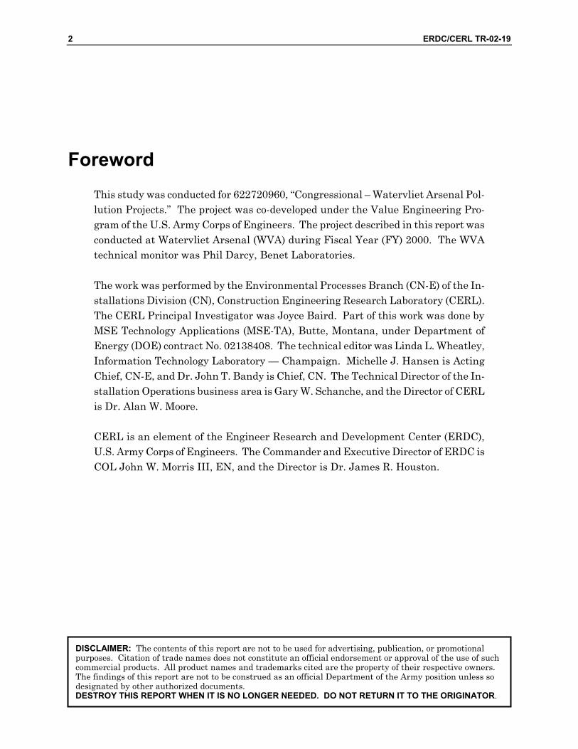
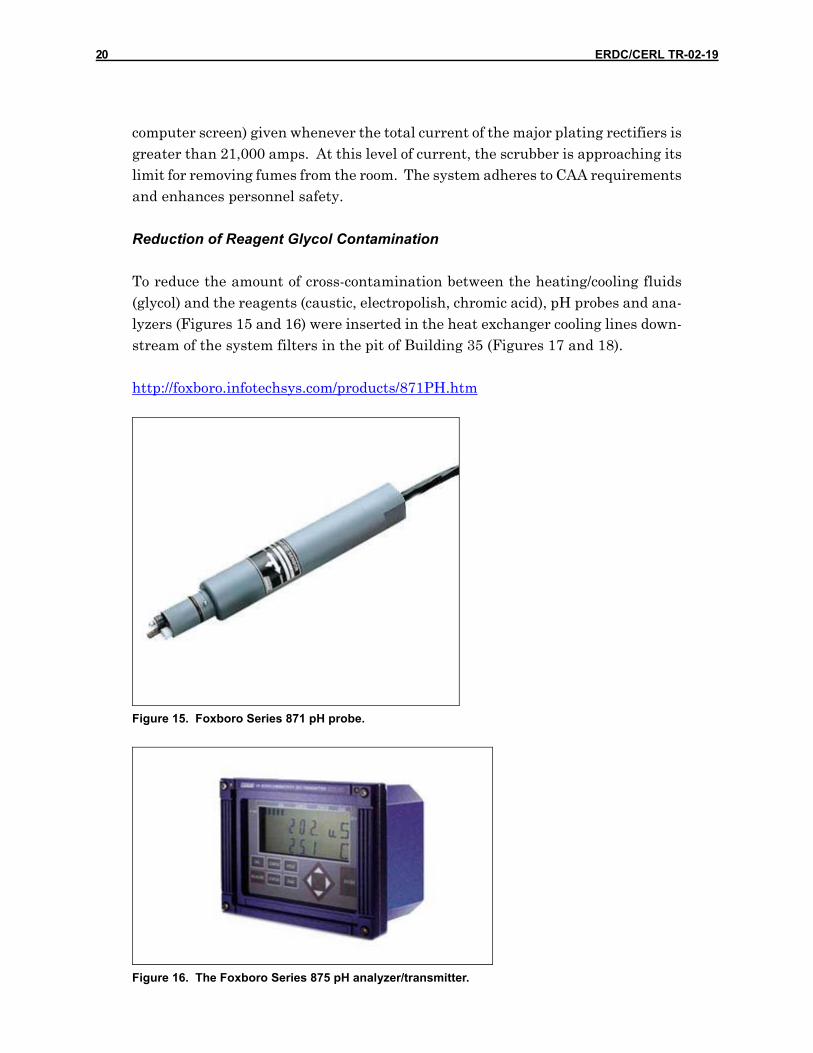
Reduction of Reagent Glycol Contamination
To reduce the amount of cross-contamination between the heating/cooling fluids (glycol) and the reagents (caustic, electropolish, chromic acid), pH probes and ana-lyzers (Figures 15 and 16) were inserted in the heat exchanger cooling lines down-stream of the system filters in the pit of Building 35 (Figures 17 and 18).
http://foxboro.infotechsys.com/products/871PH.htm
Figure 15. Foxboro Series 871 pH probe.
Figure 16. The Foxboro Series 875 pH analyzer/transmitter.

ERDC/CERL TR-02-19 21
Figure 17. pH probe and cable in heat exchanger cooling line, Foxboro 871 series.
The calibration of the units was centered around the pH of the glycol in use at the time of the installation of the equipment. The analyzers have wired relay outputs that initiate audible alarms in the annunciator system in the main control panel. A pH deviation of ± 2 from the center set point will trigger an alarm. Also, analog outputs are connected to the digital recorders (which still have several spare chan-nels) in the main panel so that operators may observe the cooling lines’ pH without having to enter the pit during plating runs.
Figure 18. pH analyzer with high/low alarm outputs, Foxboro Model 875PH.

22 ERDC/CERL TR-02-19
Series 871 Probe Functional Specifications
Table 1 lists the pressure/temperature ratings for the Series 871 probe functional specifications.
Table 1. Pressure/temperature ratings for Series 871 probe.
Pressure Rating (1) Temperature Rating (1) Application Probe Body
MPa psi °C °F 1 150 -5 20
Ryton 1 150 80 175 0.9 125 -5 20 0.6 90 50 120
Submersible or Ball Valve CPVC
0.3 50 80 175 1 150 -5 20
Ryton 1 150 125 255 0.9 125 -5 20 0.3 50 80 175
In-line CPVC
0.1 15 100 212
(1) Actual application rating may be reduced by electrode choice, as shown in Table 2. Table 2. Actual application ratings.
Pressure Rating Temperature Rating Electrode MPa psi °C °F 0.7 100 -5 20 Glass pH 0.7 100 105 220 1 150 -5 20
Antimony pH or ORP 1 150 125 255
Temperature Compensation: Sensor includes encapsulated automatic temperature compensator, which covers range -5 to + 125 °C (20 to 255 °F).
Analyzer/Transmitter Compatibility: 875PH: 871PH-3, -4, -5, -6 (Note: 871PH-1,2 are compatible, but some diagnostics are not available.)
Measuring Electrodes: Plug-in interchangeable electrodes; glass pH electrodes use high stability silver, silver chloride (Ag, AgCl) internals. Ryton, ptfe, ctfe, or epoxy body, as specified.
Reference Electrode: Nonflowing, with Ag, AgCl internals and potassium chloride (KCl) saturated with AgCl electrolyte. Process junction is ceramic. Ryton, ptfe, or epoxy body, as specified.

ERDC/CERL TR-02-19 23
Series 875 Analyzer/Transmitter Functional Specifications
Table 3 includes the Series 875 analyzer/transmitter functional specifications. Table 3. Series 875 analyzer/transmitter functional specifications.
875IT Series Intelligent Electrochemical Two-Wire Transmitters for pH/ORP, Contacting Conductivity/Resistivity and Electrodeless Conductivity Measurement Sensor and Transmitter Diagnostics Self-prompting Calibration Routines 4 to 20 mA and/or Digital Communications NEMA 4X, IEC IP65 Enclosure Intrinsically Safe Construction Remote Configuration Via Personal Computer and Foxboro PC10/PC20 Software pH/ORP Version Compatible with Preamplified or Unamplified pH/ORP Sensors Compatible with most Ion Selective Electrodes (ISE) EC Version Conductivity or Concentration Measurement Up to Three Distinct Applications May be Programmed and Autoswitched CR Version Conductivity or Resistivity Measurement
These 2-wire intelligent transmitters, when coupled with 871 Series sensors, pro-vide measurement indication and a choice of analog or digital outputs for recording or control of pH/ORP, contacting conductivity/resistivity, or electrodeless conductiv-ity. Their human interfaces and online diagnostics provide local configuration, cali-bration, status, and troubleshooting.
Reagent Pump Protection
Six new low-maintenance magnetic drive sealless pumps were installed (Figure 19). The motor control center (MCC) for these pumps is on the main floor of Building 35, at the south end of the 120-mm plating area. One phase of the motor leads was routed through current transformers that provided analog signals to the panel indi-cators. The intention was to inform the operator of motor-running status or failure. The problem was that, in some cases, the current transformer was incorrectly sized so that calibration was impossible; therefore, motor and pump protection was sus-pect.

24 ERDC/CERL TR-02-19
Figure 19. New magnetic drive sealless chromic acid pumps.
The solution was to install power monitors (Figure 20) in the MCC buckets for each of the six new reagent pumps: three chromic acid pumps and three electropolish pumps.
The HPL family of power monitor modules (WEN Technology, Inc., Raleigh, NC) protect equipment driven by 3-phase motors pumps, fans, conveyors, mixers, me-chanical drives from damage that can occur if a motor continues to drive against a mechanical fault.
Figure 20. Power monitor, WenTech's Unipower Models HPL110 and HPL420.
http://www.wentec.com/unipower/overview/

ERDC/CERL TR-02-19 25
Typical applications
• Pumps − blockage, run-dry, cavitation protection • Conveyors and feeders − blockage protection, auto-reverse unblock feature • Grinding mills − feeder control and blockage protection • Mechanical drives − immediate recognition of overload • PLC/PC controllers − accurate power transducer input
Benefits
• Family of modules − specific solutions for specific applications • Simple setup − front panel programming and display, no pots or trimmers • True power display − bright light-emitting diodes (LED) display true power (%) • Up to three alarm limits • Peak hold − capture and store both maximum and minimum power values • 4-20mA current loop output • Bright LED display − easy readability at any angle • Hysteresis and dP/dt functions – control of secondary systems • Ts and Tr delay timers − adjustable sensitivity to eliminate false trips
True power
The HPL family measures true motor power using the function P = x V x I x cos ø. This power is directly proportional to the load applied to the motor by the machine and is superior to measuring motor current, particularly at partial load.
HPL family
The HPL approach offers a family of intelligent modules for measuring and monitor-ing motor power. Each module has a particular program and function allowing ap-propriate modules to be matched with specific applications. In this manner, HPL units can typically replace a number of components with a single, self-contained module.
Programming
All modules are programmed from the front panel using four keys: Up, Down, Mode, and Reset. A bright LED display shows selected values. Historical trend data peak/min power is always stored. These values are available from the front panel display and are used for setting the alarm limits. Programming is as easy as calling up the historical max/min values during normal running and setting the

26 ERDC/CERL TR-02-19
alarm trip points with respect to these values. All programming is done at the front panel easily and accurately using the Mode, Up, and Down keys.
Figures 21 and 22 depict typical installations for chromic acid pump and electro-polish pump MCC power buckets. The relay outputs of the power monitors are wired into the start circuit for each pump; therefore, any abnormality will shut down the motor and protect the pump. In addition, analog outputs are wired to the new digital indicator/recorders for operator usage.
Figure 21. MCC starter bucket for chromic acid pump, with power monitor installed.
Figure 22. Power monitor, MCC starter bucket for electropolish pump.

ERDC/CERL TR-02-19 27
Additional Hardware Upgrades
MSE provided an upgraded 120-mm Wonderware compliance computer. This com-puter has a Zip™ drive, replacing the Jaz® drive computer, which is effectively obso-lete and presented difficulties in transferring new programs into the computer, or data out of it. The new computer also had the following features: Compact Disc Read-Only Memory (CD-ROM) drive, 866-Megahertz (MHz) speed or greater, a 10-Gigabyte (GB) hard drive, and 256 Megabytes (MB) of memory. This computer greatly enhances the installation of software upgrades, provides ample space for data storage and increases the operating speed.
Automated Control and Monitoring System
The problem of chrome loss during proof firing of the 120-mm gun tubes prompted implementation of the Watervliet Improvement Program. The 120-mm gun tube is one application of chrome plating technology at WVA. Chrome plating of 0.004 to 0.005 inch on the inside bore provides corrosion and erosion protection for the can-non tube. Data collection began in the related process areas to determine the rela-tionship and effect on the chrome plating process. The pre-plating processes such as heat-treating and honing, as well as the actual characteristics (geometry, chemistry, and mechanical properties) of each tube were documented in an attempt to measure each one’s effect. The result of the Improvement Program was a significant de-crease in the instance of chrome loss during proof firing and the development of a very robust chrome plating process.
As an additional improvement to the chrome plating process, the ACMS system was simplified. All unnecessary equipment and wiring was removed, and drawings modified and combined so that a technician can refer to one document at a time dur-ing maintenance and troubleshooting. The system capabilities now include auto-mated recording of temperature, bath level, conductivity, time, date, and tank num-ber. The process rectifiers are also controlled to allow for recipe downloading for each product line. The data will be transferred to the NT server where the informa-tion is stored in a data warehouse and is available for analyses, traceability, and future retrieval using web-based technologies.
http://www.bmpcoe.org/bestpractices/internal/watva/watva_27.html

28 ERDC/CERL TR-02-19
Software Modifications
MSE made changes to the 120-mm System Logic Controller (SLC)-5/04 ladder logic programming, which were necessary to accommodate the loop hardware changes. These modifications included changes to the rectifier current loops and the plating tank temperature loops for the 120-mm scrubber air monitoring system.
Additionally, the 120-mm Wonderware computer screens were upgraded to show the addition of the plating tank temperatures. The plating record sheets were added to the computer. These sheets are available to the operator to be printed af-ter all data have been inserted.
The 120-mm Wonderware computer has screens depicting air monitoring and recti-fier current data for minor plating scrubbers 104 and 105. These screens were up-dated to include new portable and stationary rectifiers and were removed and placed on the Wonderware computer recently installed in the minor plating area.
Programmers upgraded the Environmental Management Information System (EMIS) for the 120-mm scrubber web page, and also the WVA loop drawings to show all modifications to the rectifier current and tank temperature loops.
Operating and Maintenance (O&M) Manuals and Training
The scrubber air monitoring and air emissions tracking O&M manuals were up-dated so that all instrumentation data sheets are included, and all new Wonder-ware screens are shown and described. Sections on vendor information, Wonder-ware screens/descriptions and operation, loop description, and calibration of tank temperature rectifier current controls and monitoring equipment were upgraded as necessary. Drawings of each loop were referenced in the binder, and electronic cop-ies of all software were presented to WVA Computer Support. These copies in-cluded backups and system recovery disks for Windows® NT, the Yokogawa digital indicator, the PLC ladder logic, and updated Wonderware files. Also, licenses for Wonderware, Windows® NT, and the digital indicator were delivered, in addition to the latest development software for the Allen-Bradley SLC-5/04 ladder logic.
Training sessions for maintenance personnel were conducted in the 120-mm plating facility area. The training included an overview of the O&M manual, descriptions of each of the operator interface panels, and hardware equipment troubleshooting. A separate training session was provided for operations and maintenance personnel on the temperature control and monitoring equipment and the rectifier current loop equipment.

ERDC/CERL TR-02-19 29
3 Summary
The chrome plating controls enhancement to the 120-mm plating facility reduced the annual operating costs and improved the efficiency of the 120-mm major plating facility at WVA. Areas of improvement included reduced downtime for the inability to find replacement indicator parts, and reduced downtime due to early awareness of heat exchanger leaks. Accurate temperature displays and recordings are benefi-cial for quality assurance purposes. A large database of daily plating records helps to avoid air emission compliance violations. Costs were significantly reduced for IWTP hazardous waste disposals due to reduced glycol discharges. Savings in maintenance labor due to reduced calibration time (48 analog indicators replaced with 2 digital indicators/recorders) were noticeable.

30 ERDC/CERL TR-02-19
References
Northrup, Jearldine I., Joyce C. Baird, Dave Franklin, and Phil Darcy, Chrome Plating Projects at Watervliet Arsenal: Fiscal Year 2000, ERDC/CERL SR-01-23/ADA396131 (U.S. Army Corps of Engineers, Engineer Research and Development Center [ERDC], Construction Engineering Research Laboratory [CERL], September 2001).
Northrup, Jearldine I., Joyce C. Baird, Phil Darcy, and Donald J. Schiller, Environmental Management Information System (EMIS) at Watervliet Arsenal, NY, ERDC/CERL TR-00-28/ADA383234 (U.S. Army Corps of Engineers, ERDC/CERL, October 2000).
ERDC/CERL TR-02-19 31
CERL DISTRIBUTION
Chief of Engineers ATTN: CEHEC-IM-LH (2) Engineer Research and Development Center (Libraries) ATTN: ERDC, Vicksburg, MS ATTN: Cold Regions Research, Hanover, NH ATTN: Topographic Engineering Center, Alexandria, VA Defense Tech Info Center 22304 ATTN: DTIC-O 5 6/02

REPORT DOCUMENTATION PAGE Form Approved
OMB No. 0704-0188 Public reporting burden for this collection of information is estimated to average 1 hour per response, including the time for reviewing instructions, searching existing data sources, gathering and maintaining the data needed, and completing and reviewing this collection of information. Send comments regarding this burden estimate or any other aspect of this collection of information, including suggestions for reducing this burden to Department of Defense, Washington Headquarters Services, Directorate for Information Operations and Reports (0704-0188), 1215 Jefferson Davis Highway, Suite 1204, Arlington, VA 22202-4302. Respondents should be aware that notwithstanding any other provision of law, no person shall be subject to any penalty for failing to comply with a collection of information if it does not display a currently valid OMB control number. PLEASE DO NOT RETURN YOUR FORM TO THE ABOVE ADDRESS. 1. REPORT DATE (DD-MM-YYYY)
08-2002 2. REPORT TYPE
Final 3. DATES COVERED (From - To)
5a. CONTRACT NUMBER 5b. GRANT NUMBER
4. TITLE AND SUBTITLE Chrome Plating Controls Enhancement to the 120-mm Plating Facility at Watervliet Arsenal, NY: Fiscal Year 2000
5c. PROGRAM ELEMENT NUMBER 5d. PROJECT NUMBER Congressional 5e. TASK NUMBER
6. AUTHOR(S) Joyce C. Baird, Dave Franklin, and Phil Darcy
5f. WORK UNIT NUMBER 622720960 8. PERFORMING ORGANIZATION REPORT
NUMBER 7. PERFORMING ORGANIZATION NAME(S) AND ADDRESS(ES) U.S. Army Engineer Research and Development Center (ERDC) Construction Engineering Research Laboratory (CERL) PO Box 9005 Champaign, IL 61826-9005
ERDC/CERL TR-02-19
9. SPONSORING / MONITORING AGENCY NAME(S) AND ADDRESS(ES) 10. SPONSOR/MONITOR’S ACRONYM(S) SOSWV-IMI-E Commander, Watervliet Arsenal
Watervliet, NY 12189
11. SPONSOR/MONITOR’S REPORT NUMBER(S)
12. DISTRIBUTION / AVAILABILITY STATEMENT Approved for public release; distribution is unlimited.
13. SUPPLEMENTARY NOTES Copies are available from the National Technical Information Service, 5285 Port Royal Road, Springfield, VA 22161.
14. ABSTRACT
Watervliet Arsenal’s (WVA’s) chrome plating controls in its 120-mm plating facility required enhancements and upgrades to improve efficiency and reduce operating costs. A site visit and preliminary investigation determined that system hardware needed modification. New designs were developed for the existing plating tank temperature loops and analog indicators were replaced with digital equip-ment. Scrubber instrumentation was calibrated, rectifier current loops were simplified, additional hardware was provided, and software was modified. Operating and maintenance manuals were updated and maintenance personnel were provided training.
The chrome plating controls enhancement to the 120-mm plating facility reduced the annual operating costs and improved the effi-ciency of the 120-mm major plating facility at WVA.
15. SUBJECT TERMS Watervliet Arsenal, NY industrial facilities energy conservation air pollution controls chromium plating 16. SECURITY CLASSIFICATION OF: 17. LIMITATION
OF ABSTRACT 18. NUMBER
OF PAGES 19a. NAME OF RESPONSIBLE PERSON
Joyce C. Baird a. REPORT
Unclassified b. ABSTRACT
Unclassified c. THIS PAGE
Unclassified
SAR
32 19b. TELEPHONE NUMBER (in-
clude area code) (217)373-4469
Standard Form 298 (Rev. 8-98) Prescribed by ANSI Std. 239.18