chunky graphite in ductile iron castings - iftabira.org chunky graphite.pdf · chunky graphite in...
TRANSCRIPT
184/1
Chunky graphite in ductile iron castings
R Källbom *, K Hamberg ** and L-E Björkegren *.
* Swedish Foundry Association, Sweden, ** Chalmers University ofTechnology, Sweden.
AbstractNon-spherical graphite morphology is detrimental on the mechanicalproperties of ductile iron castings. This includes the branched andinterconnected chunky graphite that occasionally occurs in the thermalcenter of castings. In this work the graphite morphology in ferritic ductileiron that contained chunky graphite was studied. Chunky graphite wasshown to be a progressively degenerated morphology of sphericalgraphite. Attempts to investigate the presence and segregation patterns ofelements that might play a role in the still concealed formation and growthmechanism of chunky graphite were made. No macro segregation wasdetected. The possible role of micro segregation of trace elements wasdiscussed but could not be determined. The graphite nucleation potentialseemed to be low in the chunky graphite areas due to the lack of availableoxygen and/or sulphur.
Key words ductile iron, graphite morphology, chunky graphite,segregation, nucleation

184/2
IntroductionSpherical graphite morphology is an important factor to attain high qualityductile iron castings. Every other type of morphology is detrimental on themechanical properties. This includes the branched and interconnectedchunky graphite that occasionally occurs in the thermal center of ductileiron castings. The presence of chunky graphite decreases the ultimatetensile strength (Rm) and especially the fracture elongation (A5). Thepossible decrease in a ferritic ductile iron has been shown to reach 25%and 50% respectively depending on the amount of chunky graphite [1].However, the hardness (HBW) and the yield strength (Rp02) are hardlyaffected at all by chunky graphite. Regarding the dynamic properties ofalmost 100% chunky graphite containing material the crack propagationrate is not significantly affected but the fracture toughness of the materialwill be lower [2].
The risk of chunky graphite formation is increasing with long solidificationtime. Consequently, the amount of chunky graphite tends to increase withincreased wall thicknesses [1]. The call for further research work todetermine the cause and growth mechanism of chunky graphite isescalating with increased used of heavy section ductile iron castings indemanding applications within the heavy automotive and the windmillindustries among others.
According to Gagné and Argo chunky graphite shows a spiral crystalgrowth pattern caused by carbon supersaturation and constitutionalsupercooling as the driving forces [3]. Fast diffusion rate due to the lack of,or partially disrupted, austenite shell around the graphite nodule has alsobeen discussed as one possible cause for chunky graphite formation [3].According to Itofuji et al the chunky graphite forms as a result of the lack ofmagnesium gas bubbles in the melt and, further on, the growing graphiteis in contact with residual liquid iron through thin liquid channels in theaustenite [4]. The liquid channels are formed when segregated elementslower the solidus temperature. Liu et al regards the chunky graphite to bea deteriorated form of nodular graphite [5]. It has in fact been observedthat the transition between the graphite structures type A flake, type Bflake, type D undercooled flake, coral, compacted, chunky and sphericalgraphite is continuous and not intermittent [6]. The different morphologieswere stated, by Liu et al to occur as a result of change in solidification rateand as a function of alloy addition or segregation [6].
In this work the graphite morphology in ferritic ductile iron that containschunky graphite has been studied and attempts have been made toinvestigate the presence and segregation patterns of elements that mightplay a role of the concealed formation mechanism of chunky graphite.
ExperimentalHigh silicon alloyed ductile iron were prepared in a 250 kg inductionfurnace. The charge material consisted of pig iron 41 %, returns 17 % and
184/3
steel scrap 42 %. Furan bonded moulds were used to cast a patternconsisting of five 200 mm x 200 mm blocks with thicknesses ranging from10 to 200 mm. The temperature change of the melts was logged duringsolidification using thermocouples placed in the center of each block. Thesolidification time ranged from 90 seconds to 90 minutes for each blockrespectively. Besides the blocks a component cast in the same siliconalloyed ductile iron has been investigated. The component is a front axlehousing aimed for a dumper. Specimens were cut out from an area with ahot spot with fairly long solidification time (approx. 30 min).
Tensile test bars were machined, perpendicular to gravitational direction,from the center of the blocks and from the components. The graphitemorphology was studied in the fracture surfaces of the bars using SEM.The microstructure was studied in different positions within the test barsusing conventional optical microscope. The deep etched technique usedconsisted of 40 minutes etching in a mixture of HCl and HNO3 (3:1)followed by a cleaning step in Vogel´s etchant and thereafter well rinsed inethanol. Some specimens were color etched in boiling sodium hydroxide(10g) + picric acid (10g) + potassium pyrosulfite (10g).
Using GD-OES (Glow Discharge Optical Emission Spectroscopy)investigation of macro segregation was made, comparing nodular andchunky graphite areas within the same 200 mm cubic block.Measurements were made in up to six positions located 10, 20, 30, 45, 60and 90 mm from the cast surface. The analyzed positions are indicated inFigure 1.
SEM with EDS as well as EPMA were used as analyzing tools in orders toinvestigate micro segregation tendencies.
ResultsGraphite morphologyChunky graphite is mainly located in the thermal center. Nevertheless, thechunky graphite zone can represent a reasonably large volume of thecasting. This is exemplified by Figure 1 where the presence of chunkygraphite appears as a shaded area in a sawed cross section. Some areaswithin the dark zone consist of nodules but the main graphite morphologyis chunky, Figure 2. From Figure 1 it appears as the transition fromnodular to chunky graphite growth happens very sudden in an interruptedmanner. However, optical microscopy and SEM studies of the graphitemorphology put forward a gradual change.
The graphite morphology in the vicinity of chunky graphite areas in this200 mm cubic casting is classified to be a mixture of form IV to VIaccording to the standard EN ISO 945:1994. Large irregular graphitelumps, which cannot be classified by the standard, as well as very smallislands of chunky graphite, are also found in those areas, Figure 3.
184/4
The examined fracture surfaces of the tensile test bars are located withinthe chunky graphite zone shown in Figure 1. SEM investigations ofgraphite in the fracture surfaces indicate gradual degeneration fromspherical to chunky morphology. Figure 4 shows well-shaped nodules.Approaching chunky graphite areas different graphite morphologies as inFigure 5 and 6 can be observed. These observations, that chunky graphiteis a progressively degenerated morphology of nodules, are in line with thetheory of Liu et al [5]. The degenerated graphite shape in Figure 7 and thepyramidal growth of chunky graphite branches in Figure 8 confirm theobservations of Liu et al [5].
All specimens from the front axle housing showed somewhat differentgraphite morphology compared to the 200 mm thick block. In mostlocations normal spherical graphite morphology emerged. Roughly 15%degenerated chunky graphite appeared at the most in the hot spots.Figure 9 shows a typical area, here the cell boarders appear in a brown towhite color. The blue etching parts in the microstructure containdegenerated graphite and do appear before the brownish cell boarders.Here two variants of degenerated graphite can be seen. One type ofgraphite that appears as normal chunky graphite (see Figure 10 in deepetched condition) and one more like a stringer of graphite (Figure 11).These graphite stringers lie between the secondary dendrite arms. Theclassical chunky graphite seems to be placed in the center of the dendritearms. In all cases the degenerated graphite can co-exist with sphericalgraphite.
Segregation of elementsBulk analyzes did not show any significant difference in chemicalcomposition between the different positions indicated in Figure 1. Somevariations could be seen in Si content, for example, between differentpositions but no coupling to chunky graphite could be confirmed. Macrosegregation between the nodular areas outside the chunky graphite zoneas well as inside the zone was hence not detected, Table 1.
Attempts to investigate micro segregation tendencies of low contentelements such as Ce, Ca and S in the blocks by using EPMA turned out tobe unsuccessful since the concentrations were below the detection limit ofthe instrument. This was a fact close to spherical graphite as well asnearby chunky graphite. The average Si content was somewhat highernear the chunky graphite compared to that near a nodule. Nevertheless,the difference was not greater than the Si fluctuation between twonodules.
Closer investigations of the graphite in the front axle housing show somedifferences. The stringer like graphite had in most cases been nucleatedon oxides. Spot analysis of the oxide particles revealed normal oxidescontaining Si and or Mg. The melts that produced the components had a

184/5
rather high amount of residual magnesium content, 0.060-0.065 (%), thismight explain the amount of particles with high magnesium content. Thestringer graphite is not considered to be a chunky graphite variant.
In order to find evidence of micro segregation further investigations weremade with SEM – EDS. Mapping, spot and line analysis were tried withoutmuch success. The only evidence of segregation was found in the Si andMn content between graphite particles. No evidence of tramp elementslike the elements mentioned in the literature [1], were found. A possiblereason is a relatively small concentration of the mentioned elements andan insensitive analyzing method. The method gave the response from atoo great material volume that disturbed the analysis.
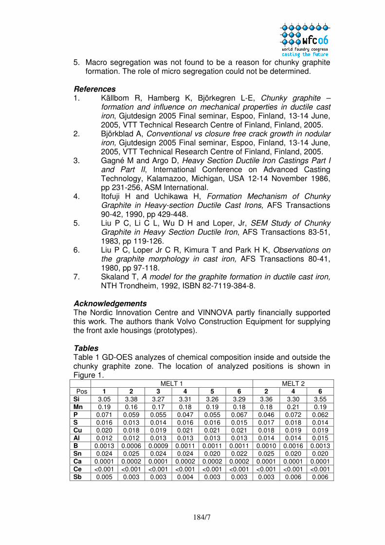
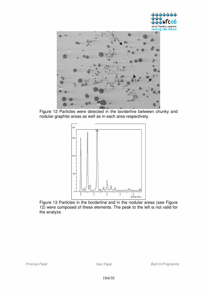
Further, spot analyses in two types of areas, chunky and nodular, asdepicted in Figure 12 were carried out. The focus was on systematicanalysis of particles found during the EDS-mapping. A majority of thesmall particles (<10 µm) were found in the eutectic cell borders betweennodular and chunky graphite areas, typical location is shown in Figure 12.However, particles were also found in the nodular area as well as in thechunky area close to the borderline. The amount of particles was greaterin the cell border areas than in the chunky graphite areas. The chemicalcomposition of the particles was not the same in all areas. In the cellborders and in areas with nodular graphite, the particles contained Mg, Oand Si (see Figure 13). Some particles contained Ti and C. Frequently theparticles in those areas also contained P and S. On the other hand, in thechunky graphite areas the number of particles was small. Most of theparticles in those areas contained Mg and S but no oxygen. Trace of Aland Ca were found as well.
DiscussionDuring solidification the condition in the melt is gradually, but rapidly,changing to be more favorable for the chunky graphite growth manner.Different authors have debated the change in melt condition that promotesthe chunky graphite growth. Several theories indicate, as mentioned in theintroduction, that the cause of chunky graphite is related to the chemicalcomposition of the melt. Heavy section castings with long solidificationtimes are more prone to develop chunky graphite. The graphiteprecipitation and growth start out to be nodular and then changes towardschunky. Consequently, it can be assumed that variations in concentrationdue to segregation of certain elements might be a possible reason for thetransition of graphite morphology growth. The elements Ca, Si, Al, Ni, Ceand other RE are said to promote chunky graphite, especially in absenceof the elements Sn, As, Bi, B, Sb and Pb [1].
However, in this work no macro segregation of elements was found.Further, the role of micro segregation could not be determined since thechemical concentrations were too low to be detected by conventionalanalyzing methods.
184/6
Nevertheless, the evaluation of the results of this work renders ahypothesis that the collaboration between Mg, S and O is important for thechunky graphite formation. Skaland has depicted the nucleation sites forspherical graphite [7]. The substrate contains a MgS core circumscribedby a shell of magnesium silicate, normally MgO·SiO2. Skaland denote thissubstrate type A. Active elements introduced to the melt by inoculation,such as Ca, Ba, Sr and Al, will react with the magnesium silicate and forma hexagonal substrate that is a favorable site for graphite precipitation. Ifoxygen (or sulphur) is not present the needed hexagonal nucleus will notform.
The irregular graphite often found in microstructures of castings thatcontain chunky graphite (as Figure 3) indicates in fact low oxygen contentin the melt. The Mg-treatment was experimentally well performed and theMg content is high enough to produce nodular graphite. No vermiculargraphite can be found at all. Therefore the irregular graphite consequentlyindicates insufficient inoculation. However, since the inoculation procedurewas good it can be assumed that the inoculation has not worked properlydue to low oxygen content.
In this work, an excess of Mg/O/Si containing particles was found in theareas containing graphite nodules as well as in the borderline betweennodular and chunky areas. Therefore, one can assume that the nucleationrequirements for spheroidal graphite can be fulfilled in those areas. Aconsequence, however, is that the areas containing nodules consumemost of the oxygen. A strong indication for this is that only MgS particlesare found in the chunky graphite areas demonstrating that the oxygenlevel has been too low to form the hexagonal structure that are needed tofavor spherical graphite growth. The graphite nucleation is disturbed andchunky graphite will form between the nodular areas.
Besides Mg, elements as Ca, Al, Si, Ce consume oxygen by formingstable oxides. This further strengthens the hypothesis, that low availableoxygen content might be a reason for chunky graphite formation, sincethese elements also are said to promote chunky graphite.
Conclusions1. The branched chunky graphite is a progressively degenerated
morphology of spherical graphite.2. Unstable or changing melt condition during the solidification leads to
chunky graphite formation, a change that is still not fully defined.3. In chunky graphite areas MgS particles were found while the amount of
magnesium oxides was limited compared to the areas that containedspherical graphite.
4. The lack of available oxygen (or possibly sulphur) to form nuclei forspherical graphite precipitation might be a reason for chunky graphiteformation.
184/7
5. Macro segregation was not found to be a reason for chunky graphiteformation. The role of micro segregation could not be determined.
References1. Källbom R, Hamberg K, Björkegren L-E, Chunky graphite –
formation and influence on mechanical properties in ductile castiron, Gjutdesign 2005 Final seminar, Espoo, Finland, 13-14 June,2005, VTT Technical Research Centre of Finland, Finland, 2005.
2. Björkblad A, Conventional vs closure free crack growth in nodulariron, Gjutdesign 2005 Final seminar, Espoo, Finland, 13-14 June,2005, VTT Technical Research Centre of Finland, Finland, 2005.
3. Gagné M and Argo D, Heavy Section Ductile Iron Castings Part Iand Part II, International Conference on Advanced CastingTechnology, Kalamazoo, Michigan, USA 12-14 November 1986,pp 231-256, ASM International.
4. Itofuji H and Uchikawa H, Formation Mechanism of ChunkyGraphite in Heavy-section Ductile Cast Irons, AFS Transactions90-42, 1990, pp 429-448.
5. Liu P C, Li C L, Wu D H and Loper, Jr, SEM Study of ChunkyGraphite in Heavy Section Ductile Iron, AFS Transactions 83-51,1983, pp 119-126.
6. Liu P C, Loper Jr C R, Kimura T and Park H K, Observations onthe graphite morphology in cast iron, AFS Transactions 80-41,1980, pp 97-118.
7. Skaland T, A model for the graphite formation in ductile cast iron,NTH Trondheim, 1992, ISBN 82-7119-384-8.
AcknowledgementsThe Nordic Innovation Centre and VINNOVA partly financially supportedthis work. The authors thank Volvo Construction Equipment for supplyingthe front axle housings (prototypes).
TablesTable 1 GD-OES analyzes of chemical composition inside and outside thechunky graphite zone. The location of analyzed positions is shown inFigure 1.
MELT 1 MELT 2Pos 1 2 3 4 5 6 2 4 6
Si 3.05 3.38 3.27 3.31 3.26 3.29 3.36 3.30 3.55Mn 0.19 0.16 0.17 0.18 0.19 0.18 0.18 0.21 0.19P 0.071 0.059 0.055 0.047 0.055 0.067 0.046 0.072 0.062S 0.016 0.013 0.014 0.016 0.016 0.015 0.017 0.018 0.014Cu 0.020 0.018 0.019 0.021 0.021 0.021 0.018 0.019 0.019Al 0.012 0.012 0.013 0.013 0.013 0.013 0.014 0.014 0.015B 0.0013 0.0006 0.0009 0.0011 0.0011 0.0011 0.0010 0.0016 0.0013Sn 0.024 0.025 0.024 0.024 0.020 0.022 0.025 0.020 0.020Ca 0.0001 0.0002 0.0001 0.0002 0.0002 0.0002 0.0001 0.0001 0.0001Ce <0.001 <0.001 <0.001 <0.001 <0.001 <0.001 <0.001 <0.001 <0.001Sb 0.005 0.003 0.003 0.004 0.003 0.003 0.003 0.006 0.006

184/8
Figures
Figure 1 Chunky graphite Figure 2 Graphite morphology inzone located in the thermal the thermal center of a 200 mmcenter (200 mm cube). cube (105 X)Numbers denote positions ofanalyzes, see Table 1.
Figure 3 Mixture of graphite shapes Figure 4 Well-shaped nodulesjust outside the chunky zone (45 X) (750 X)
Figure 5 Approaching chunky Figure 6 Transition state in thegraphite areas the graphite gradually border of a chunky graphite cellchanges its morphology (350 X) (1000 X)
1 2 3 4 5 6

184/9
Figure 7 Degenerated graphite Figure 8 Pyramidal growth of(2000 X) chunky graphite branches
(deep etched 1500 X)
Figure 9 Color etched microstructure Figure 10 Deep etched graphitecontaining chunky graphite. that looks like classical chunky
graphite.
Figure 11 Stringer graphite that is notconsidered to be chunky graphite.
184/10
Figure 12 Particles were detected in the borderline between chunky andnodular graphite areas as well as in each area respectively.
Figure 13 Particles in the borderline and in the nodular areas (see Figure12) were composed of these elements. The peak to the left is not valid forthe analyze.