cid 3002-1101 2e operators manual · lds 3000 operators manual – eu ... message window ......
TRANSCRIPT
Youreyeinhell
LDS 3000Operators Manual

© Siemens Laser Analytics AB June 2003LDS 3000 Operators manual – EU (metric) unitsDocument number: CID 3002-1101 Rev. 2E (Compatible with software LDS3k ver. 5.4)
LDS 3000 Operators manual Content
1 Introduction 1
2 Overview 32.1 Central unit CU 3000 32.2 Hybrid Cable FC 3000 42.3 Sensor CD 3002 5
3 Measurement principle 7
4 Basic functions 94.1 Software environment 94.2 The built-in keyboard 114.3 The screen 114.4 Start LDS 3000 134.5 User level 164.6 Turn off LDS 3000 174.7 Display modes 174.8 Main window 224.9 Settings window 234.10 Alarm table 25
5 Calibration 275.1 Calibration procedure 27
6 Alarm 296.1 Alarm indications in LDS 3000 296.2 Set the alarm limits for the relay modules 326.3 Calibrate transmission level 336.4 View connected I/O-modules 336.5 View I/O configurations 356.6 Status line and alarm table 366.7 Viewing temperature from input modules 38
7 External connections 41
8 Communication 438.1 The communication window in LDS 3000 438.2 Status messages on LDS 3000 478.3 System reboot by a connected user 47
9 Service and Maintenance 49
I

Content LDS 3000 Operators manual
II

LDS 3000 Operators manual Introduction
1 IntroductionThe LDS 3000 is a system for on-line gas analysis providing continu-ous presentation of accurate measurements.
The gas concentration is measured using line absorption spectrosco-py. Cross sensitivities to other gases are eliminated in the measure-ments due to the spatial purity of the laser enabling selective detection of individual absorption lines.
The LDS 3000 consists of a sensor pair (measuring head) and a central unit connected using optical fibre cables. The central unit and the sen-sor can be installed several hundred meters apart.
The light source is a diode laser whose wavelength can be tuned with-in a narrow spectral range. An optical fibre guides the light from the central unit to the sensor, where it is directed into the measuring sec-tion. The laser beam passes through the gas in the measuring section and is partially absorbed there. The light attenuated in this way is de-tected by the receiver and is returned to the central unit. The variation in the intensity of the laser light in the vicinity of the absorption line is measured, and the concentration of the gas being measured is cal-culated using the second harmonic of the detected signal.
The LDS 3000 can measure at up to three measurement locations si-multaneously. To extend the number of measurement points an extra receiver board in the central unit, extra I/O modules and an extra sen-sor with cabling is added per channel.
The LDS 3000 operates as an independent unit. An 85-264 VAC main power supply is all that is required. The gas concentration and instru-ment status are indicated on the graphical display. The gas concentra-tion is also continuously given as an analog 4-20 mA output. As options, several other parameters such as transmission level and dif-ferent alarms can be obtained.
With a PC running Windows 95/98/ME or Windows NT/2000/XP. LDS 3000 can also be operated remotely via the serial port, either directly (local mode) or via modem. This requires the optional software LDS-Comm (LDS Communication Client) installed on the remote compu-ter. All aspects of LDS 3000 can be controlled in this way.
1

Introduction LDS 3000 Operators manual
2
LDS 3000 Operators manual Overview
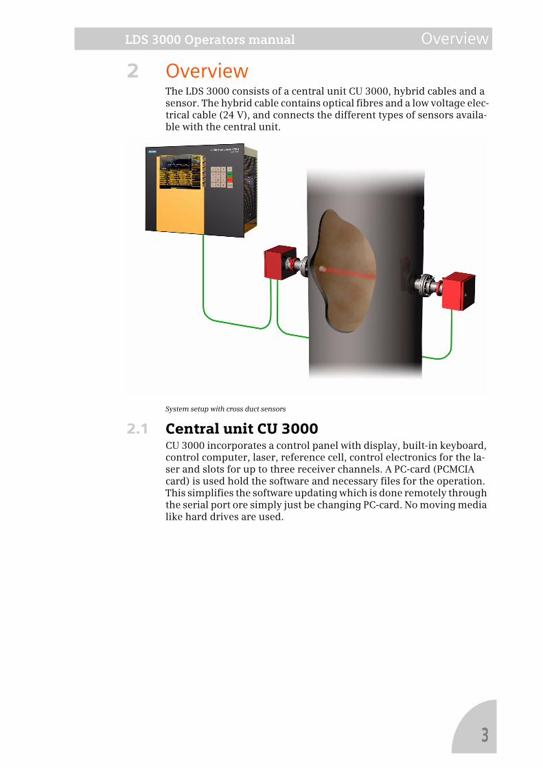
2 OverviewThe LDS 3000 consists of a central unit CU 3000, hybrid cables and a sensor. The hybrid cable contains optical fibres and a low voltage elec-trical cable (24 V), and connects the different types of sensors availa-ble with the central unit.
System setup with cross duct sensors
2.1 Central unit CU 3000CU 3000 incorporates a control panel with display, built-in keyboard, control computer, laser, reference cell, control electronics for the la-ser and slots for up to three receiver channels. A PC-card (PCMCIA card) is used hold the software and necessary files for the operation. This simplifies the software updating which is done remotely through the serial port ore simply just be changing PC-card. No moving media like hard drives are used.
3
Overview LDS 3000 Operators manual
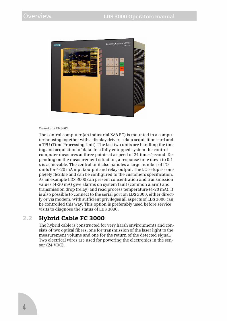
Central unit CU 3000
The control computer (an industrial X86 PC) is mounted in a compu-ter housing together with a display driver, a data acquisition card and a TPU (Time Processing Unit). The last two units are handling the tim-ing and acquisition of data. In a fully equipped system the control computer measures at three points at a speed of 24 times/second. De-pending on the measurement situation, a response time down to 0.1 s is achievable. The central unit also handles a large number of I/O-units for 4-20 mA input/output and relay output. The I/O setup is com-pletely flexible and can be configured to the customers specification. As an example LDS 3000 can present concentration and transmission values (4-20 mA) give alarms on system fault (common alarm) and transmission drop (relay) and read process temperature (4-20 mA). It is also possible to connect to the serial port on LDS 3000, either direct-ly or via modem. With sufficient privileges all aspects of LDS 3000 can be controlled this way. This option is preferably used before service visits to diagnose the status of LDS 3000.
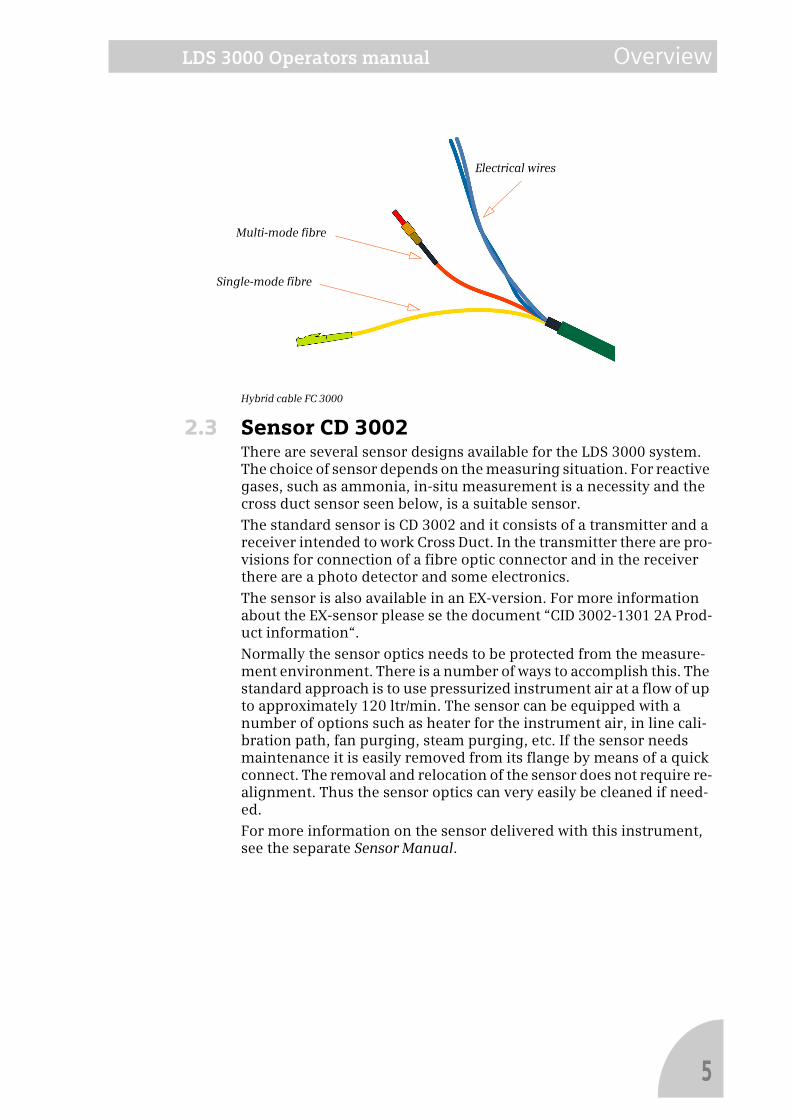
2.2 Hybrid Cable FC 3000The hybrid cable is constructed for very harsh environments and con-sists of two optical fibres, one for transmission of the laser light to the measurement volume and one for the return of the detected signal. Two electrical wires are used for powering the electronics in the sen-sor (24 VDC).
4
LDS 3000 Operators manual Overview
Hybrid cable FC 3000
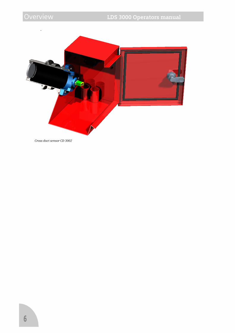
2.3 Sensor CD 3002There are several sensor designs available for the LDS 3000 system. The choice of sensor depends on the measuring situation. For reactive gases, such as ammonia, in-situ measurement is a necessity and the cross duct sensor seen below, is a suitable sensor.
The standard sensor is CD 3002 and it consists of a transmitter and a receiver intended to work Cross Duct. In the transmitter there are pro-visions for connection of a fibre optic connector and in the receiver there are a photo detector and some electronics.
The sensor is also available in an EX-version. For more information about the EX-sensor please se the document “CID 3002-1301 2A Prod-uct information“.
Normally the sensor optics needs to be protected from the measure-ment environment. There is a number of ways to accomplish this. The standard approach is to use pressurized instrument air at a flow of up to approximately 120 ltr/min. The sensor can be equipped with a number of options such as heater for the instrument air, in line cali-bration path, fan purging, steam purging, etc. If the sensor needs maintenance it is easily removed from its flange by means of a quick connect. The removal and relocation of the sensor does not require re-alignment. Thus the sensor optics can very easily be cleaned if need-ed.
For more information on the sensor delivered with this instrument, see the separate Sensor Manual.
Single-mode fibre
Multi-mode fibre
Electrical wires
5
Overview LDS 3000 Operators manual
.
Cross duct sensor CD 3002
6
LDS 3000 Operators manual Measurement principle
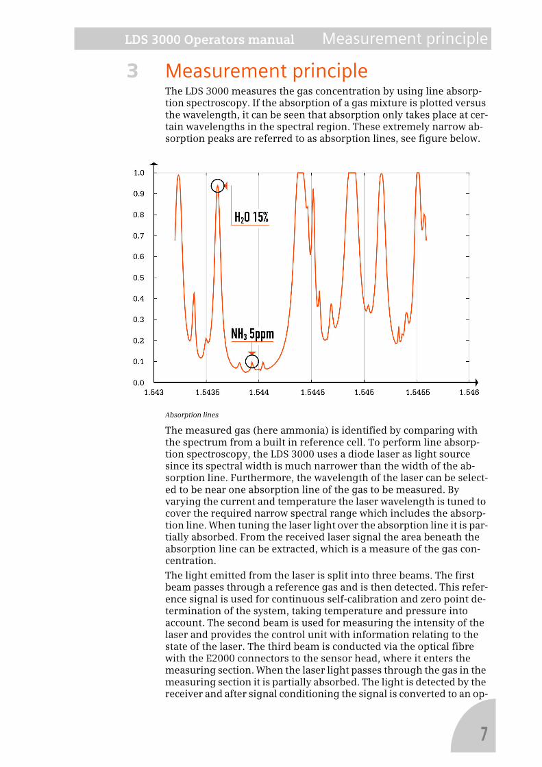
3 Measurement principleThe LDS 3000 measures the gas concentration by using line absorp-tion spectroscopy. If the absorption of a gas mixture is plotted versus the wavelength, it can be seen that absorption only takes place at cer-tain wavelengths in the spectral region. These extremely narrow ab-sorption peaks are referred to as absorption lines, see figure below.
Absorption lines
The measured gas (here ammonia) is identified by comparing with the spectrum from a built in reference cell. To perform line absorp-tion spectroscopy, the LDS 3000 uses a diode laser as light source since its spectral width is much narrower than the width of the ab-sorption line. Furthermore, the wavelength of the laser can be select-ed to be near one absorption line of the gas to be measured. By varying the current and temperature the laser wavelength is tuned to cover the required narrow spectral range which includes the absorp-tion line. When tuning the laser light over the absorption line it is par-tially absorbed. From the received laser signal the area beneath the absorption line can be extracted, which is a measure of the gas con-centration.
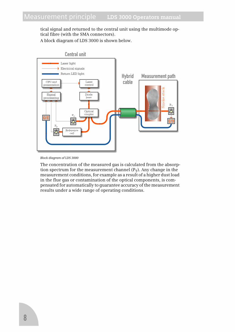
The light emitted from the laser is split into three beams. The first beam passes through a reference gas and is then detected. This refer-ence signal is used for continuous self-calibration and zero point de-termination of the system, taking temperature and pressure into account. The second beam is used for measuring the intensity of the laser and provides the control unit with information relating to the state of the laser. The third beam is conducted via the optical fibre with the E2000 connectors to the sensor head, where it enters the measuring section. When the laser light passes through the gas in the measuring section it is partially absorbed. The light is detected by the receiver and after signal conditioning the signal is converted to an op-
7
Measurement principle LDS 3000 Operators manual
tical signal and returned to the central unit using the multimode op-tical fibre (with the SMA connectors).
A block diagram of LDS 3000 is shown below.
Block diagram of LDS 3000
The concentration of the measured gas is calculated from the absorp-tion spectrum for the measurement channel (PT). Any change in the measurement conditions, for example as a result of a higher dust load in the flue gas or contamination of the optical components, is com-pensated for automatically to guarantee accuracy of the measurement results under a wide range of operating conditions.
PT
Lasercontrol
Laser light
Return LED light
Electrical signals
Central unit
Hybridcable
Measurement pathCPU and
presentation
PR
PO
Referencecell
Diodelaser
Opticalcoupler
Signalprocessing
Smok
e st
ack
8
LDS 3000 Operators manual Basic functions
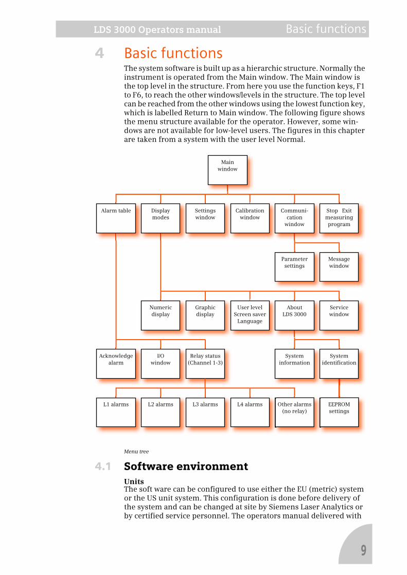
4 Basic functionsThe system software is built up as a hierarchic structure. Normally the instrument is operated from the Main window. The Main window is the top level in the structure. From here you use the function keys, F1 to F6, to reach the other windows/levels in the structure. The top level can be reached from the other windows using the lowest function key, which is labelled Return to Main window. The following figure shows the menu structure available for the operator. However, some win-dows are not available for low-level users. The figures in this chapter are taken from a system with the user level Normal.
Menu tree
4.1 Software environmentUnitsThe soft ware can be configured to use either the EU (metric) system or the US unit system. This configuration is done before delivery of the system and can be changed at site by Siemens Laser Analytics or by certified service personnel. The operators manual delivered with
Main
window
Alarm table Display
modes
Settings
window
Calibration
window
Communi-
cation
window
Stop Exit
measuring
program
Parameter
settings
Message
window
Numeric
display
Graphic
display
User level
Screen saver
Language
About
LDS 3000
Service
window
Acknowledge
alarm
Relay status
(Channel 1-3)
I/O
window
System
information
EEPROM
settings
System
identification
L1 alarms L2 alarms L3 alarms L4 alarms Other alarms
(no relay)
9
Basic functions LDS 3000 Operators manual
the system reflects either of the two settings.
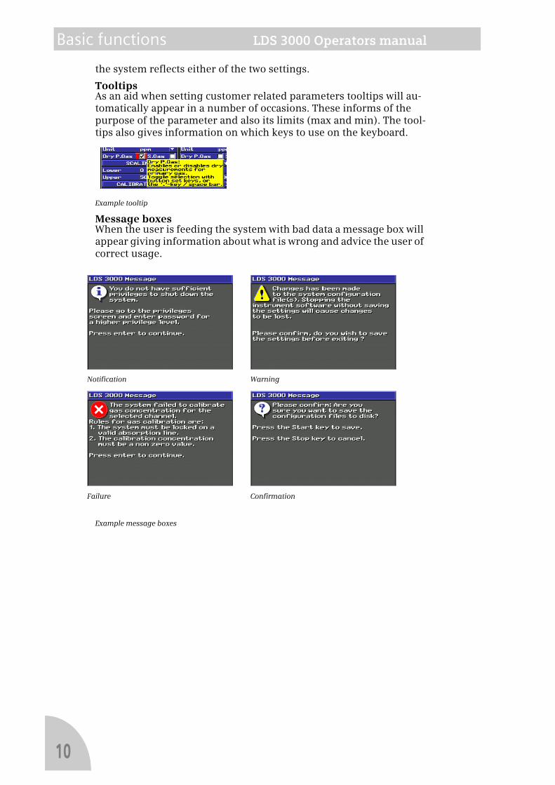
TooltipsAs an aid when setting customer related parameters tooltips will au-tomatically appear in a number of occasions. These informs of the purpose of the parameter and also its limits (max and min). The tool-tips also gives information on which keys to use on the keyboard.
Example tooltip
Message boxesWhen the user is feeding the system with bad data a message box will appear giving information about what is wrong and advice the user of correct usage.
Example message boxes
Notification Warning
Failure Confirmation
10
LDS 3000 Operators manual Basic functions
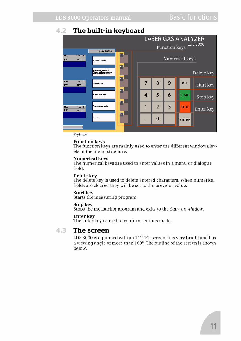
4.2 The built-in keyboard
Keyboard
Function keysThe function keys are mainly used to enter the different windows/lev-els in the menu structure.
Numerical keysThe numerical keys are used to enter values in a menu or dialogue field.
Delete keyThe delete key is used to delete entered characters. When numerical fields are cleared they will be set to the previous value.
Start keyStarts the measuring program.
Stop keyStops the measuring program and exits to the Start-up window.
Enter keyThe enter key is used to confirm settings made.
4.3 The screenLDS 3000 is equipped with an 11" TFT-screen. It is very bright and has a viewing angle of more than 160°. The outline of the screen is shown below.
Function keys
Numerical keys
Delete key
Enter key
Start key
Stop key
11

Basic functions LDS 3000 Operators manual
Ad
apti
ve k
ey la
bel
s
Screen outline
Main screenHere is where text input and measurement values are presented. There are several different appearances on this part of the screen.
System timeCurrent time is displayed. This is the time that will be stored in the system log every time an event is stored.
Window nameThe name of the actual window. Use this when you consult the manu-al.
User on-lineThis text line continuously shows the name of any externally logged on user.
Status lineHere the systems reports the status of the measurements. Here you can see errors, alarms, etc. For more information on status codes see Status messages on LDS 3000 on page 47.
Message lineIn this line you see a number of different messages from LDS 3000. You see for instance system responses on illegal key sequences, activ-ity on the serial port, etc. The table below shows the different messag-es.
System time Window name
Mai
n s
cree
n
12

LDS 3000 Operators manual Basic functions
Adaptive key labels There are six function keys immediately to the right of the screen. These keys change function depending on what the operator is work-ing with at the moment. This function is labelled on the adapting key labels.
4.4 Start LDS 3000After installation, the power to LDS 3000 is turned on with the main power switch at the rear. After power up, which takes about 30 sec-onds, the Start-up window is displayed.
Message Meaning
No Session! User of LDS 3000 is trying to communicate with a remote user when no one is connected
No Modem Response!
LDS 3000 fails to initialize the modem
User On Line Indicates that an external user logged on
User Log Off! Indicates that an external user logged off
SMS Success-fully Sent!
LDS 3000 informs that a SMS message was successfully transmit-ted
Not Allowed! User of LDS 3000 is trying to send a text message when the serial line is busy. Try again later!
Packet Csum Error!
LDS 3000 received a packet with a check-sum error. This can indi-cate a bad phone line.
Message Sent! LDS 3000 informs that a text message was successfully transmit-ted
Receiving File... LDS 3000 informs that a file presently is being received
Sending File... LDS 3000 informs that a file presently is being transmitted
Transfer Stopped The transfer was stopped by the external user.
“Incoming text message“
Incoming text messages can be shown here if this option is cho-sen by the external user
Message Received!
A text message has been received from an external user and is available in the communication window
Got Unknown Packet!
LDS 3000 received a packet that was unknown. This could be a compatibility problem
13

Basic functions LDS 3000 Operators manual
.
Start-up window
In the start-up window you have two alternatives.
Start LDS 3000 instrumentPress [F1], Start LDS 3000 instrument. A new window is now dis-played.
Enter the first character in your password within five seconds other-wise the system automatically starts up at the lowest level. You have a total of 10 seconds to enter the password. Information about user lev-els can be found in User level on page 16.
Press [F1], Quick start. The system will start at the lowest user level.
At this level you do not have the possibility to change any setting.
Press [F2] to cancel the start-up.
14
LDS 3000 Operators manual Basic functions
Note!
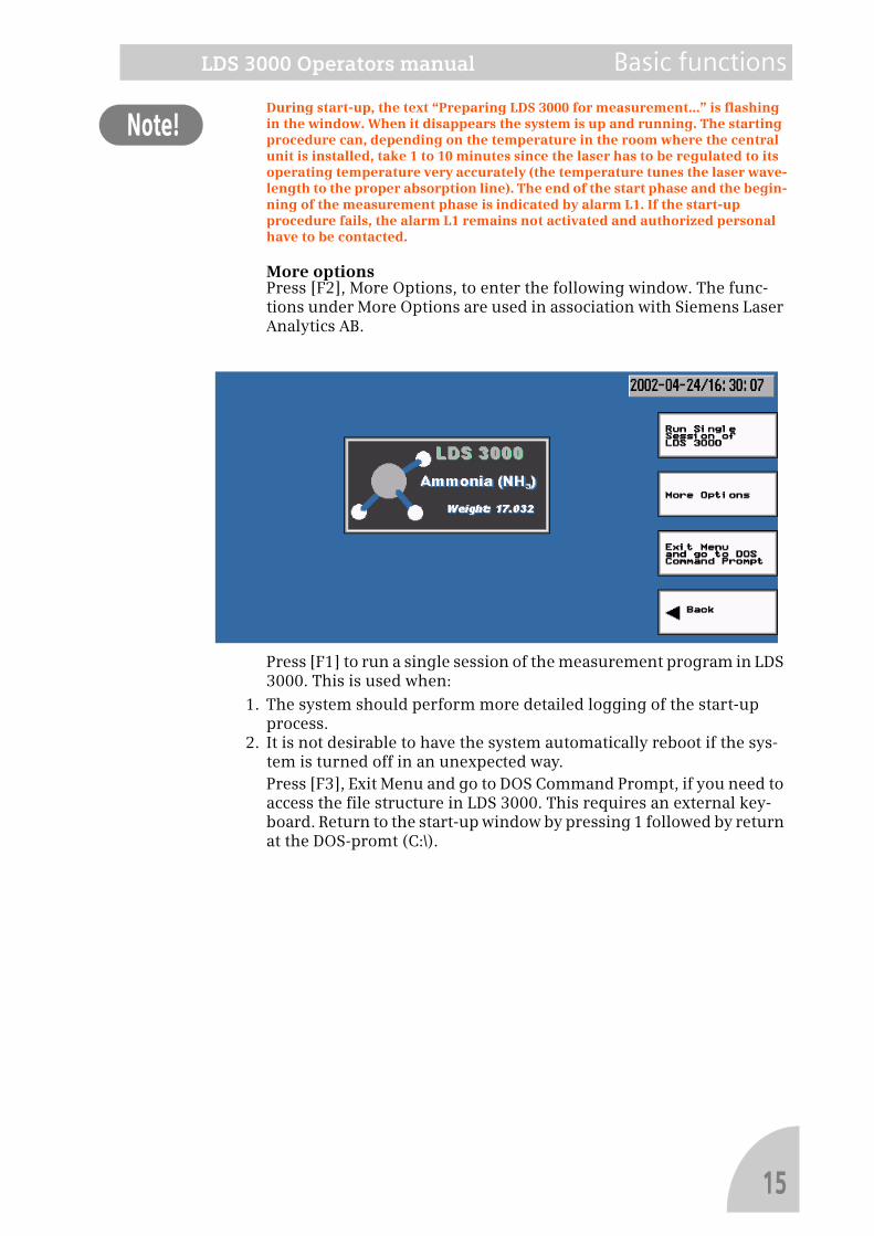
During start-up, the text “Preparing LDS 3000 for measurement...” is flashing in the window. When it disappears the system is up and running. The starting procedure can, depending on the temperature in the room where the central unit is installed, take 1 to 10 minutes since the laser has to be regulated to its operating temperature very accurately (the temperature tunes the laser wave-length to the proper absorption line). The end of the start phase and the begin-ning of the measurement phase is indicated by alarm L1. If the start-up procedure fails, the alarm L1 remains not activated and authorized personal have to be contacted.More optionsPress [F2], More Options, to enter the following window. The func-tions under More Options are used in association with Siemens Laser Analytics AB.
Press [F1] to run a single session of the measurement program in LDS 3000. This is used when:
1. The system should perform more detailed logging of the start-up process.
2. It is not desirable to have the system automatically reboot if the sys-tem is turned off in an unexpected way.Press [F3], Exit Menu and go to DOS Command Prompt, if you need to access the file structure in LDS 3000. This requires an external key-board. Return to the start-up window by pressing 1 followed by return at the DOS-promt (C:\).
15
Basic functions LDS 3000 Operators manual
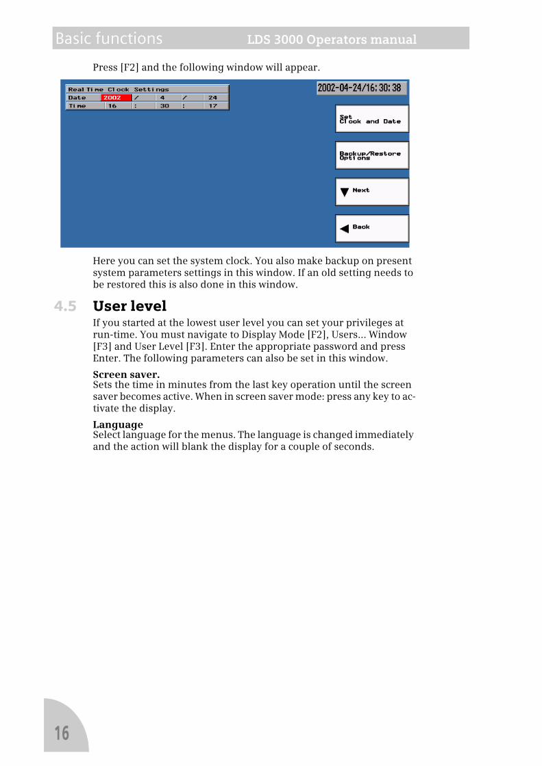
Press [F2] and the following window will appear.
Here you can set the system clock. You also make backup on present system parameters settings in this window. If an old setting needs to be restored this is also done in this window.
4.5 User levelIf you started at the lowest user level you can set your privileges at run-time. You must navigate to Display Mode [F2], Users... Window [F3] and User Level [F3]. Enter the appropriate password and press Enter. The following parameters can also be set in this window.
Screen saver.Sets the time in minutes from the last key operation until the screen saver becomes active. When in screen saver mode: press any key to ac-tivate the display.
LanguageSelect language for the menus. The language is changed immediately and the action will blank the display for a couple of seconds.
16
LDS 3000 Operators manual Basic functions
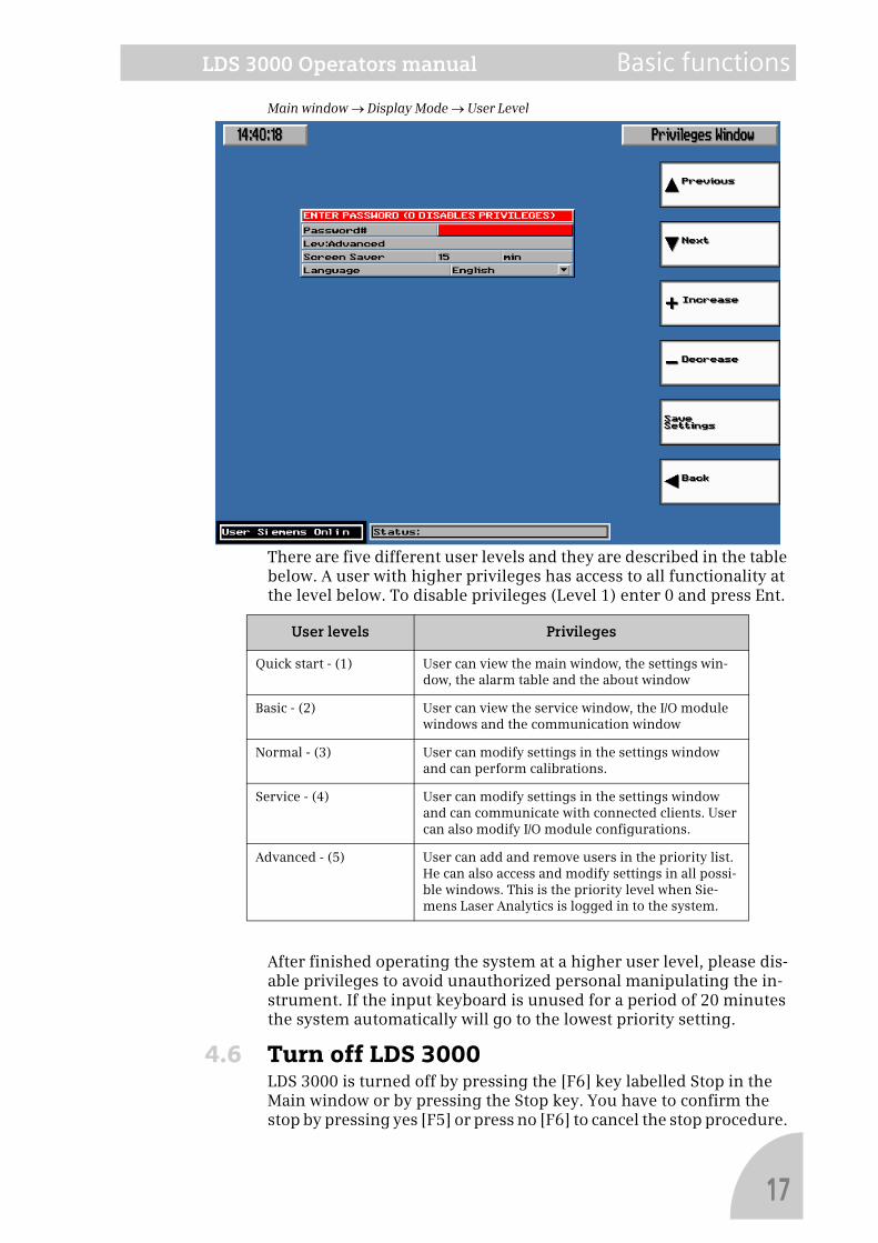
Main window → Display Mode → User Level
There are five different user levels and they are described in the table below. A user with higher privileges has access to all functionality at the level below. To disable privileges (Level 1) enter 0 and press Ent.
After finished operating the system at a higher user level, please dis-able privileges to avoid unauthorized personal manipulating the in-strument. If the input keyboard is unused for a period of 20 minutes the system automatically will go to the lowest priority setting.
4.6 Turn off LDS 3000LDS 3000 is turned off by pressing the [F6] key labelled Stop in the Main window or by pressing the Stop key. You have to confirm the stop by pressing yes [F5] or press no [F6] to cancel the stop procedure.
User levels Privileges
Quick start - (1) User can view the main window, the settings win-dow, the alarm table and the about window
Basic - (2) User can view the service window, the I/O module windows and the communication window
Normal - (3) User can modify settings in the settings window and can perform calibrations.
Service - (4) User can modify settings in the settings window and can communicate with connected clients. User can also modify I/O module configurations.
Advanced - (5) User can add and remove users in the priority list. He can also access and modify settings in all possi-ble windows. This is the priority level when Sie-mens Laser Analytics is logged in to the system.
17

Basic functions LDS 3000 Operators manual
Note!
This requires sufficient privileges, at least user level “basic”. Now it is safe to turn off the power with the power switch at the rear.If the measuring program in LDS 3000 is terminated in any other way (like in a temporarily power failure) it will automatically restart if the power is turned back on after it has been off, unless the system was started in “single session”.
4.7 Display modesThe Main window is the normal overview window. Here the measured values are displayed in a horizontal bar graph and with large numer-als, including unit. The scaling is the same as the 4-20 mA output. Also on display here is the Rms-level which is a measure of the optical transmission level in the measurement path. It is always calibrated to 100% during installation and further measurements are thus refer-enced to this time. The measured gas will also be displayed here.
Status lineAt the bottom of the screen a status line is always visible which shows the status of the LDS 3000. For more information se Status messages on LDS 3000 on page 47.
Main window
If you press the key Display Mode, Users,... [F2] a new button-set will appear. From this you can select three display modes, overview win-dows, Numeric Display and Graphic Display.
18
LDS 3000 Operators manual Basic functions
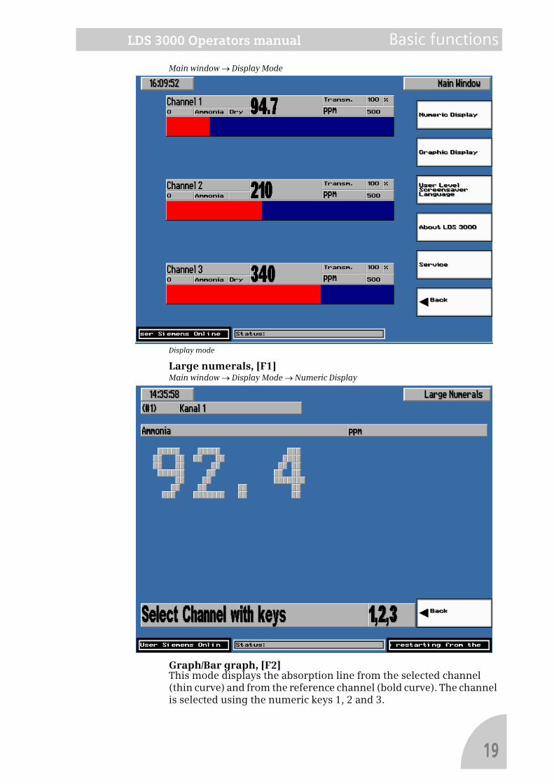
Main window → Display Mode
Display mode
Large numerals, [F1]Main window → Display Mode → Numeric Display
Graph/Bar graph, [F2]This mode displays the absorption line from the selected channel (thin curve) and from the reference channel (bold curve). The channel is selected using the numeric keys 1, 2 and 3.
19
Basic functions LDS 3000 Operators manual
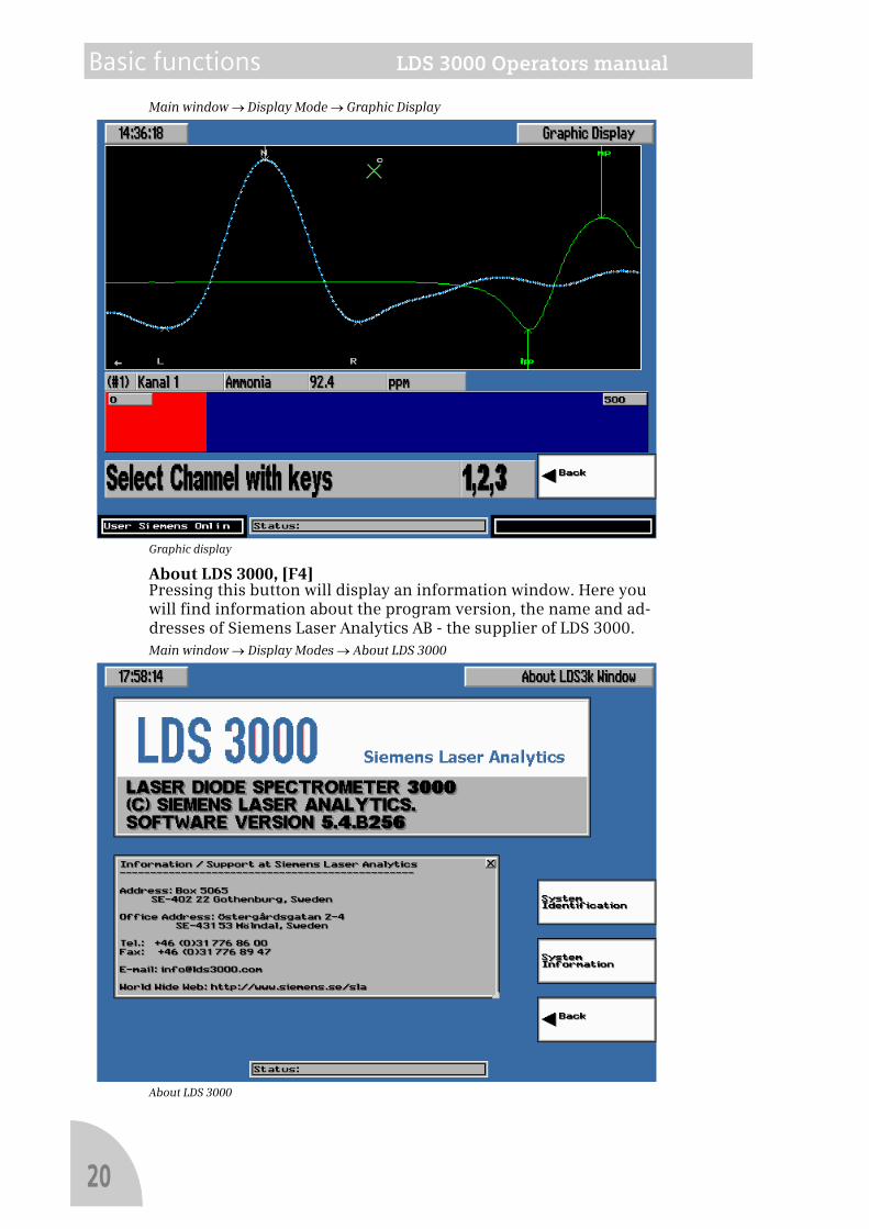
Main window → Display Mode → Graphic Display
Graphic display
About LDS 3000, [F4]Pressing this button will display an information window. Here you will find information about the program version, the name and ad-dresses of Siemens Laser Analytics AB - the supplier of LDS 3000.Main window → Display Modes → About LDS 3000
About LDS 3000
20
LDS 3000 Operators manual Basic functions
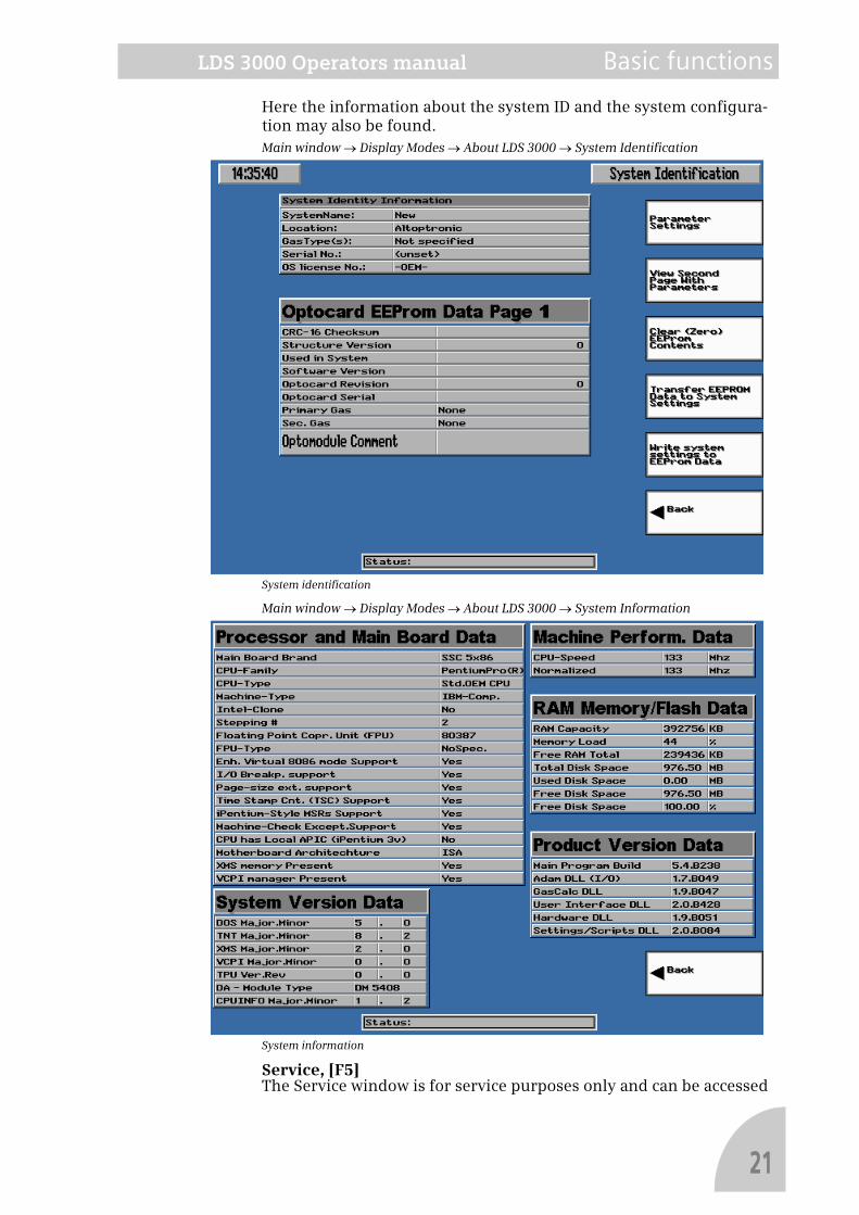
Here the information about the system ID and the system configura-tion may also be found.Main window → Display Modes → About LDS 3000 → System Identification
System identification
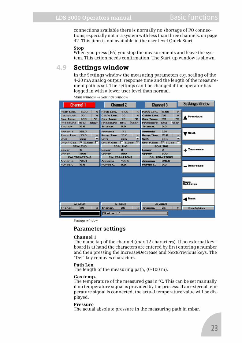
Main window → Display Modes → About LDS 3000 → System Information
System information
Service, [F5]The Service window is for service purposes only and can be accessed
21

Basic functions LDS 3000 Operators manual
by authorized personell only.
Back, [F6]Return to the Main window.
4.8 Main windowThe Main window is the normal overview window and shows the measured values numerically and as a horizontal bar graph. The bar graph has the same range scaling as the 4-20 mA current output.
Main window
Function keysAlarm tableWhen you press [F1] the alarm table is accessed. In the alarm table you find information on alarms that have occurred. You can also reset the table.
Display modes, Users, Language, About, ServiceWhen you press [F2] you can select one of two possible alternative dis-play modes, Numeric Display and Graphic Display. Furthermore, you can select your user level.
SettingsWhen you press [F3] you enter the window for changing the measure-ment parameters. See the section Settings.
CalibrateWith the function key [F4] labelled Calibration you display the Set-tings window with a button-set for calibration. See the chapter Cali-bration. Not available in the user levels Quick Start and Basic.
CommunicationPressing [F5] shows the Communication window. See There is a limit-ed number of I/O connections and LDS 3000 can only be equipped with as many I/O's as there are connections available. However, with 30
22
LDS 3000 Operators manual Basic functions
connections available there is normally no shortage of I/O connec-tions, especially not in a system with less than three channels. on page 42. This item is not available in the user level Quick Start.
StopWhen you press [F6] you stop the measurements and leave the sys-tem. This action needs confirmation. The Start-up window is shown.
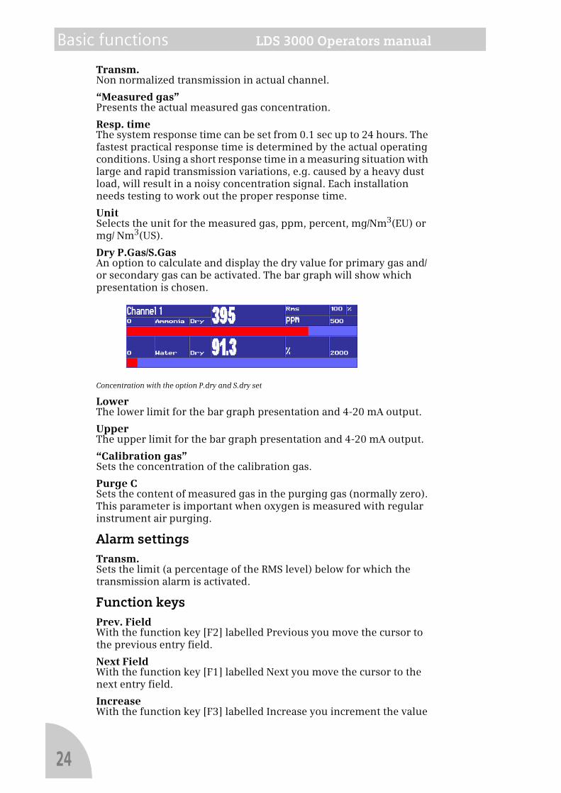
4.9 Settings windowIn the Settings window the measuring parameters e.g. scaling of the 4-20 mA analog output, response time and the length of the measure-ment path is set. The settings can’t be changed if the operator has logged in with a lower user level than normal.Main window → Settings window
Settings window
Parameter settingsChannel 1The name tag of the channel (max 12 characters). If no external key-board is at hand the characters are entered by first entering a number and then pressing the Increase/Decrease and Next/Previous keys. The “Del” key removes characters.
Path LenThe length of the measuring path, (0-100 m).
Gas temp.The temperature of the measured gas in °C. This can be set manually if no temperature signal is provided by the process. If an external tem-perature signal is connected, the actual temperature value will be dis-played.
PressureThe actual absolute pressure in the measuring path in mbar.
23
Basic functions LDS 3000 Operators manual
Transm.Non normalized transmission in actual channel.
“Measured gas”Presents the actual measured gas concentration.
Resp. timeThe system response time can be set from 0.1 sec up to 24 hours. The fastest practical response time is determined by the actual operating conditions. Using a short response time in a measuring situation with large and rapid transmission variations, e.g. caused by a heavy dust load, will result in a noisy concentration signal. Each installation needs testing to work out the proper response time.
UnitSelects the unit for the measured gas, ppm, percent, mg/Nm3(EU) or mg/ Nm3(US).
Dry P.Gas/S.GasAn option to calculate and display the dry value for primary gas and/or secondary gas can be activated. The bar graph will show which presentation is chosen.
Concentration with the option P.dry and S.dry set
LowerThe lower limit for the bar graph presentation and 4-20 mA output.
UpperThe upper limit for the bar graph presentation and 4-20 mA output.
“Calibration gas”Sets the concentration of the calibration gas.
Purge CSets the content of measured gas in the purging gas (normally zero). This parameter is important when oxygen is measured with regular instrument air purging.
Alarm settingsTransm.Sets the limit (a percentage of the RMS level) below for which the transmission alarm is activated.
Function keysPrev. FieldWith the function key [F2] labelled Previous you move the cursor to the previous entry field.
Next FieldWith the function key [F1] labelled Next you move the cursor to the next entry field.
IncreaseWith the function key [F3] labelled Increase you increment the value
24
LDS 3000 Operators manual Basic functions
in the current entry field with 1 in the least significant figure.
DecreaseWith the function key [F4] labelled Decrease you decrement the value in the current entry field with 1 in the least significant figure.
Save settingsWith the function key [F5] labelled Save settings the parameters changes made are saved to disk.
BackWith the function key [F6] labelled Return you return to the Main win-dow.
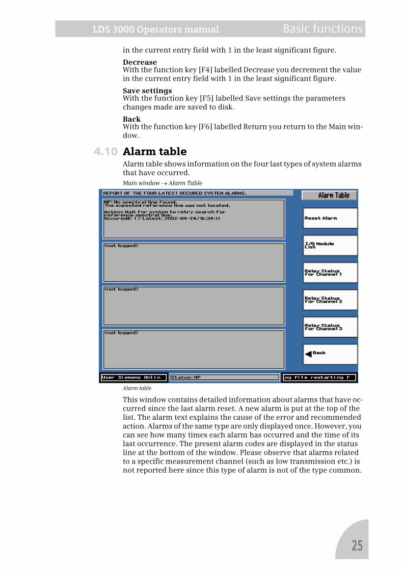
4.10 Alarm tableAlarm table shows information on the four last types of system alarms that have occurred.Main window → Alarm Table
Alarm table
This window contains detailed information about alarms that have oc-curred since the last alarm reset. A new alarm is put at the top of the list. The alarm text explains the cause of the error and recommended action. Alarms of the same type are only displayed once. However, you can see how many times each alarm has occurred and the time of its last occurrence. The present alarm codes are displayed in the status line at the bottom of the window. Please observe that alarms related to a specific measurement channel (such as low transmission etc.) is not reported here since this type of alarm is not of the type common.
25
Basic functions LDS 3000 Operators manual
Function keysReset alarmPressing [F1] resets the alarm.
I/O module listPressing [F2] brings up a window that shows the currently connected I/O-modules.
Relay status for ch. 1Pressing [F3] shows information on the status of the relay.
Relay status for ch. 2Pressing [F4] shows information on the status of the relay.
Relay status for ch. 3Pressing [F5] shows information on the status of the relay.
BackPressing [F6] you return to the Main window.
26
LDS 3000 Operators manual Calibration
Note!
5 CalibrationLDS 3000 is calibrated before delivery. Due to the measurement prin-ciple and the continuous on-line calibration control, no further cali-bration is normally necessary. However, if for some reason the instrument needs to be recalibrated, it can easily be done on site, i.e. with a calibration cell located in the receiver of the sensor head.
Compensation parameters for pressure and temperature are stored in LDS 3000 before installation and after discussions with the customer. If temperature vary significantly it can be measured and fed into LDS 3000 using an optional analog input. This option is not available for pressure.The calibration procedure is critical and should only be performed by person-nel from Siemens Laser Analytics AB or by certified personnel at site.
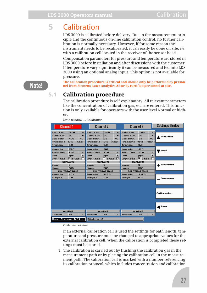
5.1 Calibration procedureThe calibration procedure is self-explanatory. All relevant parameters like the concentration of calibration gas, etc. are entered. This func-tion is only available for operators with the user level Normal or high-er.Main window → Calibration
Calibration window
If an external calibration cell is used the settings for path length, tem-perature and pressure must be changed to appropriate values for the external calibration cell. When the calibration is completed these set-tings must be stored.
1. The calibration is carried out by flushing the calibration gas in the measurement path or by placing the calibration cell in the measure-ment path. The calibration cell is marked with a number referencing its calibration protocol, which includes concentration and calibration
27

Calibration LDS 3000 Operators manual
date.
28

LDS 3000 Operators manual Alarm
Note!
6 AlarmThis chapter describes all available alarms and diagnostics methods of the LDS 3000 system. This includes all settings and configuration possibilities.
6.1 Alarm indications in LDS 3000
Common alarm 'L1'.The common alarm is controlled by a number of conditions. When all conditions are fulfilled the relay will be closed and the I/O ports acti-vated. No measurement values is valid when L1 is active. Users with the lowest user level can only use the function Reset Alarm.Main window → Alarm Table
Alarm table
The 'L1' relay output will always have the same state for all channels since it re-flects the operating condition of the central unit and not the sensors.
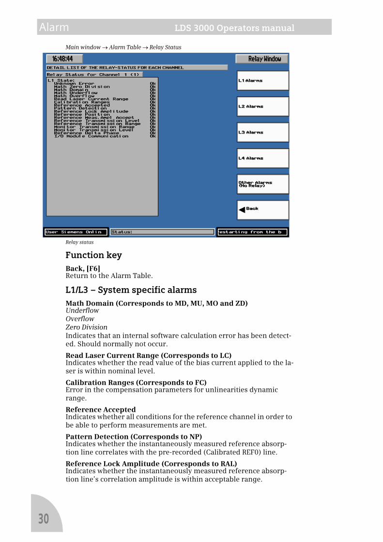
The conditions for L1 are displayed in the Relay window. This window displays the status of the relay modules, and a diagram showing the gas absorption lines for all active channels.
29
Alarm LDS 3000 Operators manual
Main window → Alarm Table → Relay Status
Relay status
Function keyBack, [F6]Return to the Alarm Table.
L1/L3 – System specific alarmsMath Domain (Corresponds to MD, MU, MO and ZD)UnderflowOverflowZero DivisionIndicates that an internal software calculation error has been detect-ed. Should normally not occur.
Read Laser Current Range (Corresponds to LC)Indicates whether the read value of the bias current applied to the la-ser is within nominal level.
Calibration Ranges (Corresponds to FC)Error in the compensation parameters for unlinearities dynamic range.
Reference AcceptedIndicates whether all conditions for the reference channel in order to be able to perform measurements are met.
Pattern Detection (Corresponds to NP)Indicates whether the instantaneously measured reference absorp-tion line correlates with the pre-recorded (Calibrated REF0) line.
Reference Lock Amplitude (Corresponds to RAL)Indicates whether the instantaneously measured reference absorp-tion line’s correlation amplitude is within acceptable range.
30
LDS 3000 Operators manual Alarm
Reference Position (Corresponds to RP)Indicates whether the instantaneously measured reference absorp-tion line is regulated within expected lock-interval.
Reference Meas. Amplitude Accept (Corresponds to RAM)States whether the reference line used for the measurement is within acceptable range.
Reference Transmission Level (Corresponds to TRH)States whether the absolute transmission level for the reference chan-nel has exceeded the maximum allowed limit.
Reference Transmission Range (Corresponds to TR)States whether the relative transmission level for the reference chan-nel has gone outside the valid range (30% from the nominally cali-brated level).
Monitor Transmission Range (Corresponds to TM)States whether the relative monitor transmission level has gone out-side the valid range (±30% from the nominally calibrated level).
Monitor Transmission Level (Corresponds to TMH)States whether the absolute monitor transmission level has exceeded the allowed limit (3950 AD-units).
Reference Delta Phase (Corresponds to DPR)States whether the absolute read Delta Phase level for the reference channel has exceeded the allowed limit (490 AD-units).
I/O Module Communication (Corresponds to Mxx)Indicates whether one or more I/O modules is not responding, either during system start-up or during measurement. The number and type of I/O modules varies depending on the specific system configuration. If one of the missing modules is a relay module, it will not be able to reflect this or any other designated type of alarm on its relays.
L2/L4 – Channel specific alarmsConcentration Range (Corresponds to CON 1-3)States whether the concentration level for compensation against oth-er gas (either internal, external or manual) is outside the valid range. This range can be specified individually for each channel in the I/O window.
Temperature Range (Corresponds to TEM 1-3)States whether the process temperature level used for compensation (either internal, external or manual) is outside the valid range. This range can be specified individually for each channel in the I/O win-dow.
Pressure Range (Corresponds to PRS 1-3)States whether the process pressure level used for compensation (ei-ther internal, external or manual) is outside the valid range. This range can be specified individually for each channel in the I/O win-dow.
Transmission Low Limit (Corresponds to T 1-3 L)States whether the relative transmission level for the specific meas-urement channel is below the alarm level. This alarm also goes active if the absolute transmission level goes below 10 AD-units.
Transmission High Limit (Corresponds to T 1-3 H)States whether the relative transmission level for the specific meas-
31

Alarm LDS 3000 Operators manual
urement channel is above the highest alarm level (3950 AD-units).
AD Data Dynamic Range (Corresponds to AH 1-3)States whether the raw absorption line data is over sampled. The data must be within 95% of the dynamic sampling range.
Amplitude Too Low (Corresponds to AL 1-3)States whether the primary or the secondary gas absorption line is too low for valid temperature or concentration calculation. This alarm can only go active for systems measuring Oxygen/Temperature or Water/Temperature.
Deltaphase Within Nominal (Corresponds to DP 1-3)States whether the absolute read deltaphase level for the specific measurement channel has exceeded the highest allowed limit (490 AD-units).
Other alarms (No Relay)Laser Modulation Range (Corresponds to MOD)States whether the laser modulation level should be modified due to long term performance changes of the laser. The condition for this er-ror is verified once each day at 03:00.
Measured Absorption Data (Corresponds to AD)States whether the measured absorption data is valid. If this error oc-curs it signals a serious system error.
6.2 Set the alarm limits for the relay modulesThe alarm limits for the relay modules are set in the Settings window. Here we only describe the alarm parameters. For information about the other parameters and function keys, see the section The concen-tration of the measured gas is calculated from the absorption spec-trum for the measurement channel (PT). Any change in the measurement conditions, for example as a result of a higher dust load in the flue gas or contamination of the optical components, is com-pensated for automatically to guarantee accuracy of the measurement results under a wide range of operating conditions. on page 8.
32
LDS 3000 Operators manual Alarm
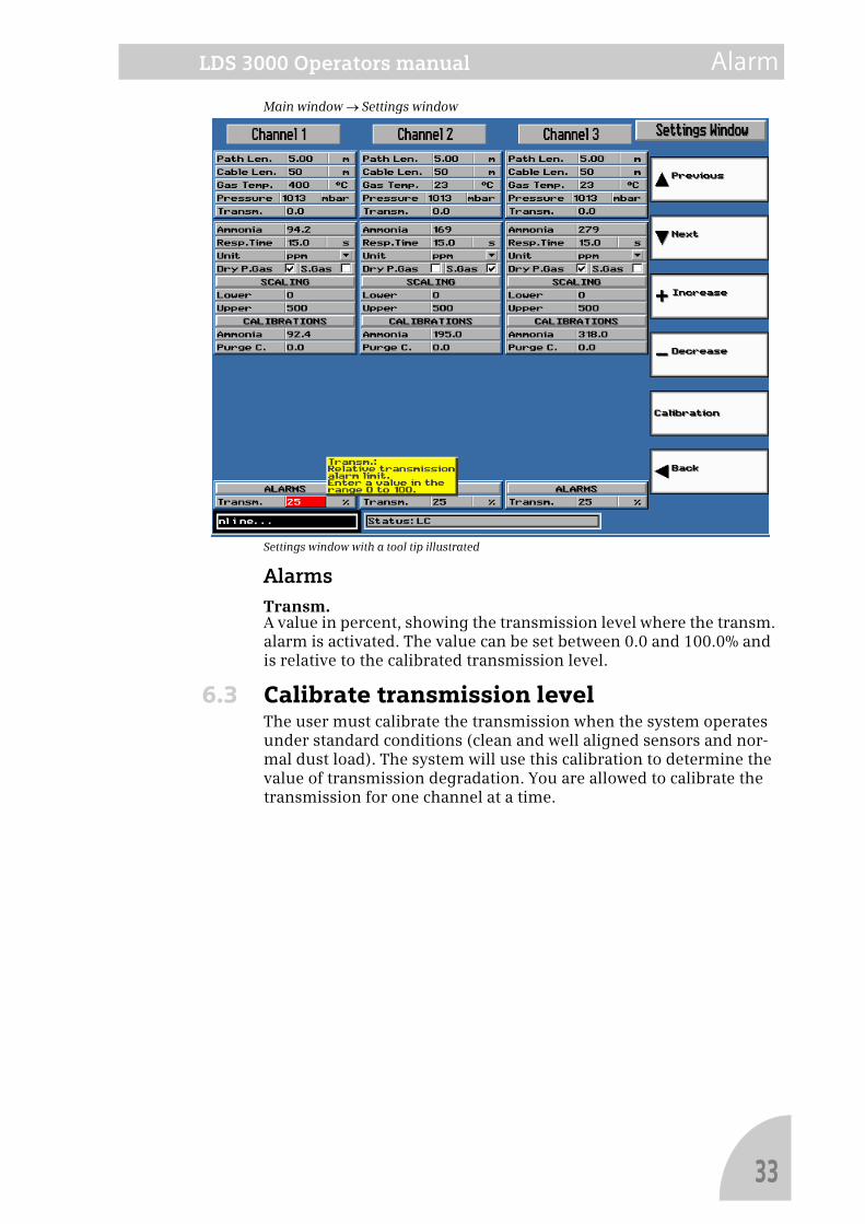
Main window → Settings window
Settings window with a tool tip illustrated
AlarmsTransm.A value in percent, showing the transmission level where the transm. alarm is activated. The value can be set between 0.0 and 100.0% and is relative to the calibrated transmission level.
6.3 Calibrate transmission levelThe user must calibrate the transmission when the system operates under standard conditions (clean and well aligned sensors and nor-mal dust load). The system will use this calibration to determine the value of transmission degradation. You are allowed to calibrate the transmission for one channel at a time.
33
Alarm LDS 3000 Operators manual
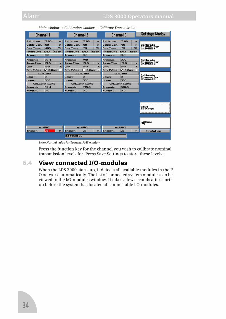
Main window → Calibration window → Calibrate Transmission
Store Normal value for Transm. RMS window
Press the function key for the channel you wish to calibrate nominal transmission levels for. Press Save Settings to store these levels.
6.4 View connected I/O-modulesWhen the LDS 3000 starts up, it detects all available modules in the I/O network automatically. The list of connected system modules can be viewed in the I/O-modules window. It takes a few seconds after start-up before the system has located all connectable I/O-modules.
34
LDS 3000 Operators manual Alarm
Note!
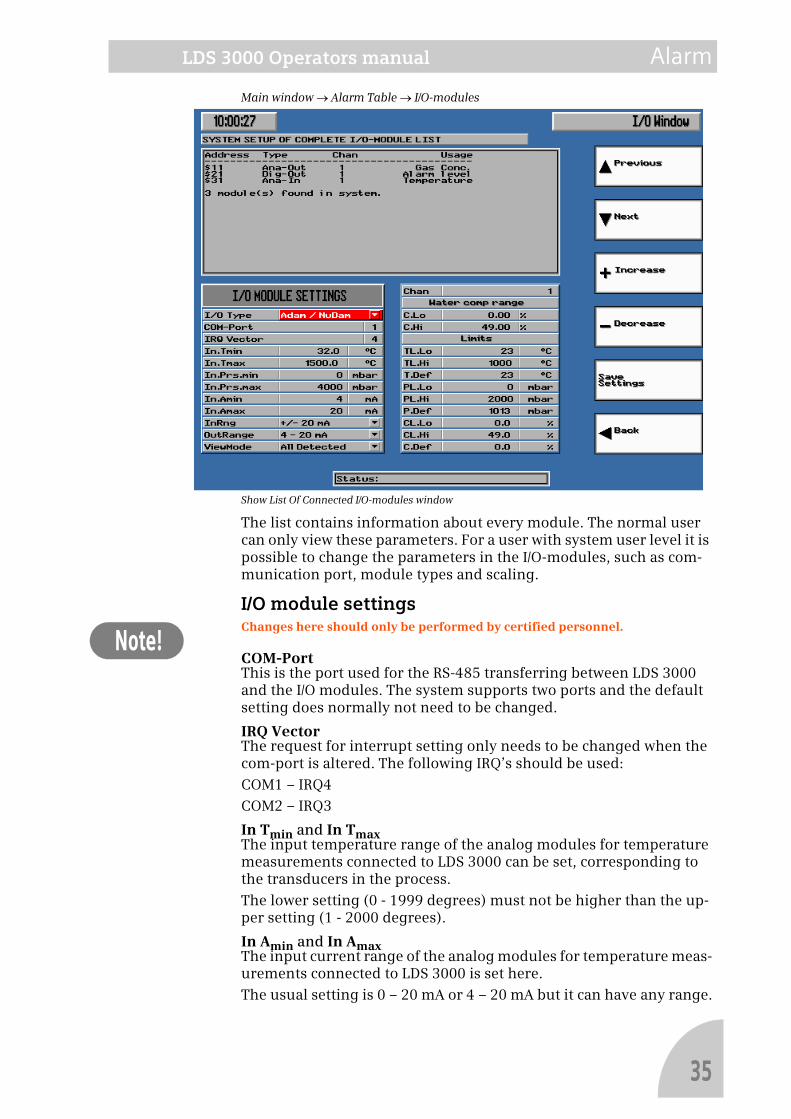
Main window → Alarm Table → I/O-modules
Show List Of Connected I/O-modules window
The list contains information about every module. The normal user can only view these parameters. For a user with system user level it is possible to change the parameters in the I/O-modules, such as com-munication port, module types and scaling.
I/O module settingsChanges here should only be performed by certified personnel.
COM-PortThis is the port used for the RS-485 transferring between LDS 3000 and the I/O modules. The system supports two ports and the default setting does normally not need to be changed.
IRQ VectorThe request for interrupt setting only needs to be changed when the com-port is altered. The following IRQ’s should be used:
COM1 – IRQ4
COM2 – IRQ3
In Tmin and In TmaxThe input temperature range of the analog modules for temperature measurements connected to LDS 3000 can be set, corresponding to the transducers in the process.
The lower setting (0 - 1999 degrees) must not be higher than the up-per setting (1 - 2000 degrees).
In Amin and In AmaxThe input current range of the analog modules for temperature meas-urements connected to LDS 3000 is set here.
The usual setting is 0 – 20 mA or 4 – 20 mA but it can have any range.
35
Alarm LDS 3000 Operators manual
InRangeThe type of the input modules connected to LDS 3000 must be config-ured at start-up. This pull-down menu contains the types supported by LDS 3000 and the proper choice must be made here.
OutRangeThe type of the output modules connected to LDS 3000 must be con-figured at start-up. This pull-down menu contains the types support-ed by LDS 3000 and the proper choice must be made here.
View I/O configurationsThis feature is available for users who configure the system´s I/O-modules. The following list shows the different I/O modules that can be attached to the system, and how the modules should be config-ured.
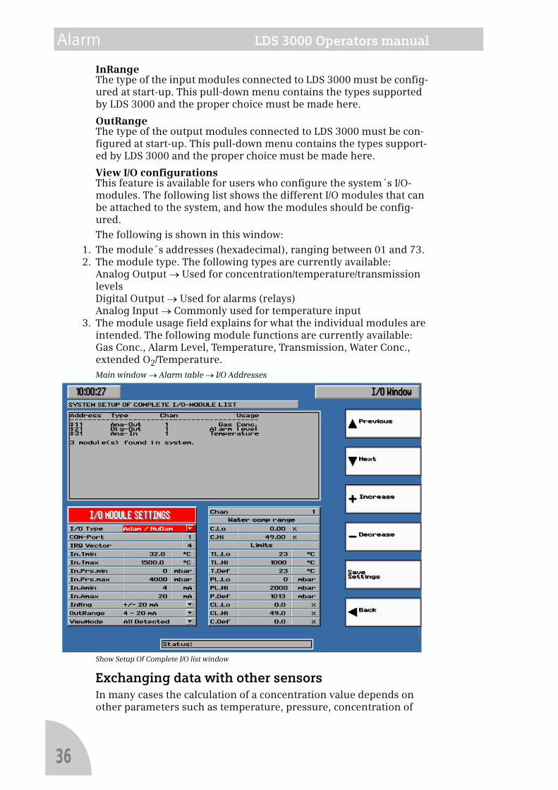
The following is shown in this window:
1. The module´s addresses (hexadecimal), ranging between 01 and 73.2. The module type. The following types are currently available:
Analog Output → Used for concentration/temperature/transmission levelsDigital Output → Used for alarms (relays)Analog Input → Commonly used for temperature input
3. The module usage field explains for what the individual modules are intended. The following module functions are currently available:Gas Conc., Alarm Level, Temperature, Transmission, Water Conc., extended O2/Temperature.Main window → Alarm table → I/O Addresses
Show Setup Of Complete I/O list window
Exchanging data with other sensorsIn many cases the calculation of a concentration value depends on other parameters such as temperature, pressure, concentration of
36
LDS 3000 Operators manual Alarm
other gases like water, etc. These parameters can be transferred to LDS 3000 via 4 – 20 mA modules. The other sensor can be another LDS 3000 measuring for instance water or it can be a thermocouple deliv-ering a temperature value. The ranges and limits for these parameters are set here.
ChanThe settings under Ranges and Limits are channel specific and the appropriate channel is selected here – 1 through 3.
RangesC. Lo and C.HiThis is the lower and upper range limits for the incoming or outgoing concentration values. When two LDS 3000 are interconnected these settings must coincide. LDS 3000 can not act as a receiver and trans-mitter at the same time.
Valid interval is 0 to 100 000 ppm.
LimitsThese settings are used as a quality check of the incoming parameters. If for instance a thermocouple fails the signal will fall outside these limits and the measured value will be replaced with a default value representing an educated guess of the actual value.
TL.Lo and TL.HiThis is the lower and upper range limits for the incoming temperature values.
CL.Lo and CL.HiThis is the lower and upper range limits for the incoming concentra-tion values.
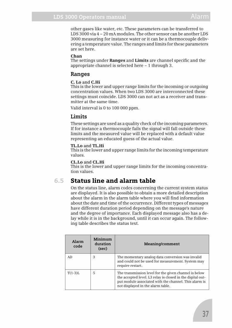
6.5 Status line and alarm tableOn the status line, alarm codes concerning the current system status are displayed. It is also possible to obtain a more detailed description about the alarm in the alarm table where you will find information about the date and time of the occurrence. Different types of messages have different duration period depending on the message's nature and the degree of importance. Each displayed message also has a de-lay while it is in the background, until it can occur again. The follow-ing table describes the status text.
Alarm code
Minimum duration
(sec)Meaning/comment
AD 3 The momentary analog data conversion was invalid and could not be used for measurement. System may require restart.
T(1-3)L 5 The transmission level for the given channel is below the accepted level. L3 relay is closed in the digital out-put module associated with the channel. This alarm is not displayed in the alarm table.
37
Alarm LDS 3000 Operators manual
Alarm TableThe alarm table contains a table presenting a history of the last four alarms that have occurred (of different types). The user resets the alarms in this window. Any status message presented keeps informa-
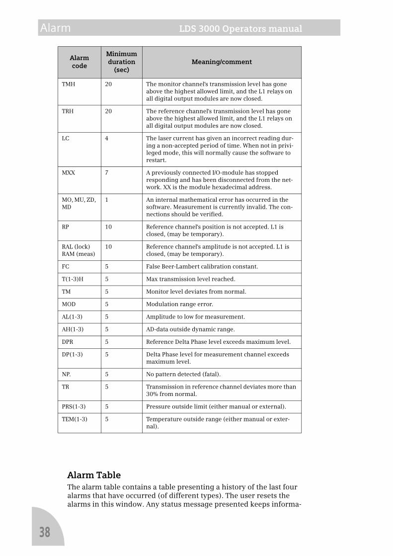
TMH 20 The monitor channel's transmission level has gone above the highest allowed limit, and the L1 relays on all digital output modules are now closed.
TRH 20 The reference channel's transmission level has gone above the highest allowed limit, and the L1 relays on all digital output modules are now closed.
LC 4 The laser current has given an incorrect reading dur-ing a non-accepted period of time. When not in privi-leged mode, this will normally cause the software to restart.
MXX 7 A previously connected I/O-module has stopped responding and has been disconnected from the net-work. XX is the module hexadecimal address.
MO, MU, ZD, MD
1 An internal mathematical error has occurred in the software. Measurement is currently invalid. The con-nections should be verified.
RP 10 Reference channel's position is not accepted. L1 is closed, (may be temporary).
RAL (lock)RAM (meas)
10 Reference channel's amplitude is not accepted. L1 is closed, (may be temporary).
FC 5 False Beer-Lambert calibration constant.
T(1-3)H 5 Max transmission level reached.
TM 5 Monitor level deviates from normal.
MOD 5 Modulation range error.
AL(1-3) 5 Amplitude to low for measurement.
AH(1-3) 5 AD-data outside dynamic range.
DPR 5 Reference Delta Phase level exceeds maximum level.
DP(1-3) 5 Delta Phase level for measurement channel exceeds maximum level.
NP. 5 No pattern detected (fatal).
TR 5 Transmission in reference channel deviates more than 30% from normal.
PRS(1-3) 5 Pressure outside limit (either manual or external).
TEM(1-3) 5 Temperature outside range (either manual or exter-nal).
Alarm code
Minimum duration
(sec)Meaning/comment
38
LDS 3000 Operators manual Alarm
Note!
Note!
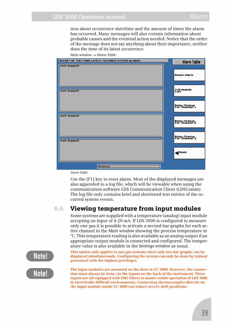
tion about occurrence date/time and the amount of times the alarm has occurred. Many messages will also contain information about probable causes and the eventual action needed. Notice that the order of the message does not say anything about their importance, neither does the time of its latest occurrence.Main window → Alarm Table
Alarm Table
Use the [F1] key to reset alarm. Most of the displayed messages are also appended to a log file, which will be viewable when using the communication software LDS Communication Client (LDSComm). The log file only contains brief and shortened text entries of the oc-curred system events.
6.6 Viewing temperature from input modulesSome systems are supplied with a temperature (analog) input module accepting an input of 4-20 mA. If LDS 3000 is configured to measure only one gas it is possible to activate a second bar graphs for each ac-tive channel in the Main window showing the process temperature in °C. This temperature reading is also available as an analog output if an appropriate output module is connected and configured. The temper-ature value is also available in the Settings window as usual.This option only applies to one gas systems since only two bar graphs can be displayed simultaneously. Configuring the system can only be done by trained personnel with the highest privileges.
The input modules are mounted on the door in CU 3000. However, the connec-tion must always be done via the inputs on the back of the instrument. These inputs are all equipped with EMC filters to assure stable operation of LDS 3000 in electrically difficult environments. Connecting thermocouples directly on the input module inside CU 3000 can induce severe drift problems.
39

Alarm LDS 3000 Operators manual
40
LDS 3000 Operators manual External connections
Note!
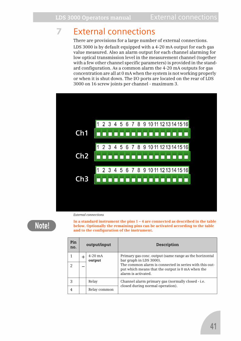
7 External connectionsThere are provisions for a large number of external connections.
LDS 3000 is by default equipped with a 4-20 mA output for each gas value measured. Also an alarm output for each channel alarming for low optical transmission level in the measurement channel (together with a few other channel specific parameters) is provided in the stand-ard configuration. As a common alarm the 4-20 mA outputs for gas concentration are all at 0 mA when the system is not working properly or when it is shut down. The I/O ports are located on the rear of LDS 3000 on 16 screw joints per channel - maximum 3.
External connections
In a standard instrument the pins 1 – 4 are connected as described in the table below. Optionally the remaining pins can be activated according to the table and to the configuration of the instrument.
Pin no.
output/input Description
1 + 4-20 mAoutput
Primary gas conc. output (same range as the horizontal bar graph in LDS 3000).The common alarm is connected in series with this out-put which means that the output is 0 mA when the alarm is activated.
2 –
3 Relay Channel alarm primary gas (normally closed - i.e. closed during normal operation).
4 Relay common
41
External connections LDS 3000 Operators manual
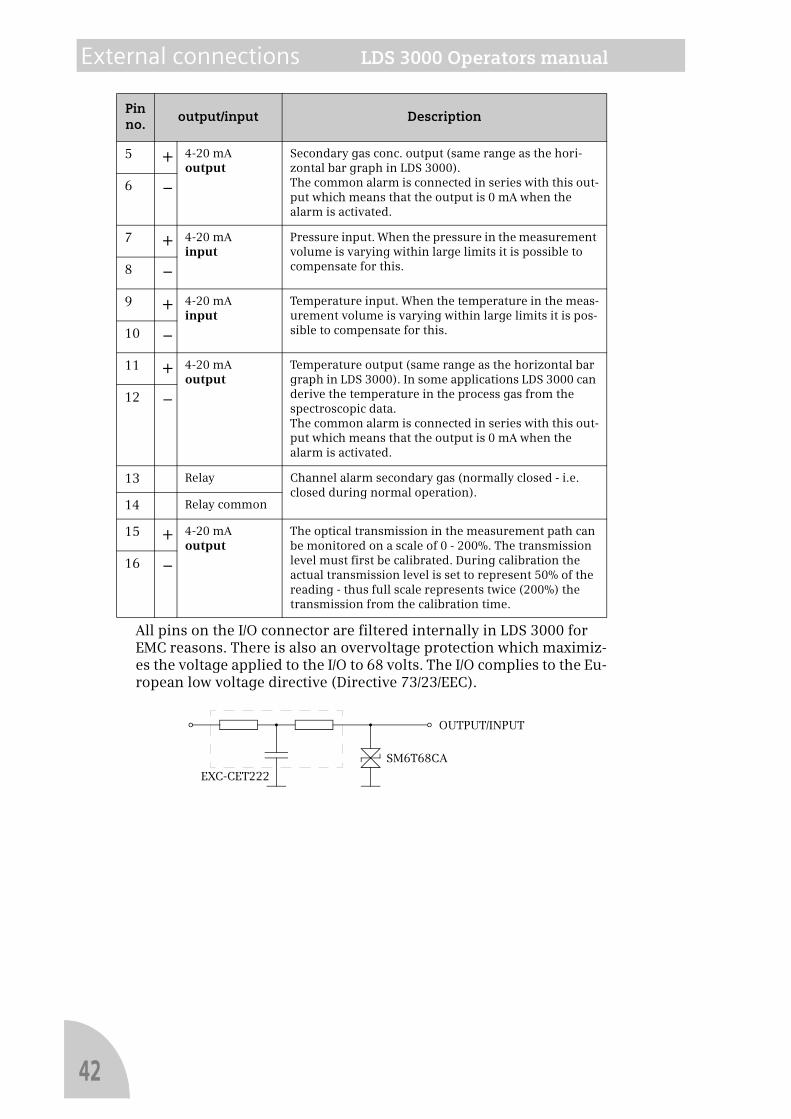
All pins on the I/O connector are filtered internally in LDS 3000 for EMC reasons. There is also an overvoltage protection which maximiz-es the voltage applied to the I/O to 68 volts. The I/O complies to the Eu-ropean low voltage directive (Directive 73/23/EEC).
5 + 4-20 mAoutput
Secondary gas conc. output (same range as the hori-zontal bar graph in LDS 3000).The common alarm is connected in series with this out-put which means that the output is 0 mA when the alarm is activated.
6 –
7 + 4-20 mAinput
Pressure input. When the pressure in the measurement volume is varying within large limits it is possible to compensate for this.8 –
9 + 4-20 mAinput
Temperature input. When the temperature in the meas-urement volume is varying within large limits it is pos-sible to compensate for this.10 –
11 + 4-20 mAoutput
Temperature output (same range as the horizontal bar graph in LDS 3000). In some applications LDS 3000 can derive the temperature in the process gas from the spectroscopic data.The common alarm is connected in series with this out-put which means that the output is 0 mA when the alarm is activated.
12 –
13 Relay Channel alarm secondary gas (normally closed - i.e. closed during normal operation).
14 Relay common
15 + 4-20 mAoutput
The optical transmission in the measurement path can be monitored on a scale of 0 - 200%. The transmission level must first be calibrated. During calibration the actual transmission level is set to represent 50% of the reading - thus full scale represents twice (200%) the transmission from the calibration time.
16 –
Pin no.
output/input Description
EXC-CET222
SM6T68CA
OUTPUT/INPUT
42
LDS 3000 Operators manual Communication
8 CommunicationThis chapter describes the remote communication with LDS 3000. The remote system calling LDS 3000 can be a standard PC running the ap-plication “LDS Communication Client” (LDSComm) under Windows 95/98 or Windows NT/2000/XP with a modem installed and configured. One important feature of LDSComm is its possibility of logging meas-urement data onto the client hard drive. LDSComm is optional soft-ware and is described in detail in a separate Manual. LDS 3000 creates a record of all communication activities on the PC-card. The related settings are described below. This menu is not available for user level Quick Start.
The actions in the communication window normally requires a stand-ard PC keyboard connected to LDS 3000 (by opening the back door and connecting it in the appropriate connector.
The following describes the functions available when using LDS-Comm.
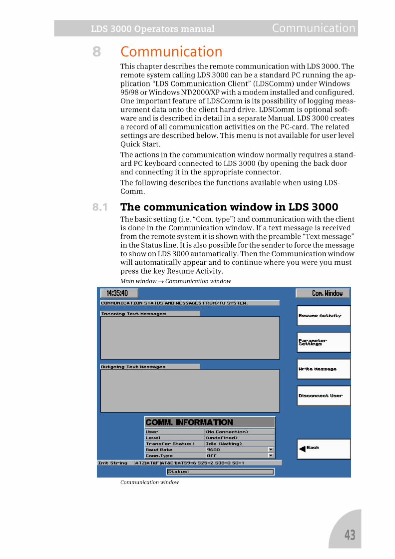
8.1 The communication window in LDS 3000The basic setting (i.e. “Com. type”) and communication with the client is done in the Communication window. If a text message is received from the remote system it is shown with the preamble “Text message” in the Status line. It is also possible for the sender to force the message to show on LDS 3000 automatically. Then the Communication window will automatically appear and to continue where you were you must press the key Resume Activity.Main window → Communication window
Communication window
43
Communication LDS 3000 Operators manual
Function keyResume Activity, [F1]Return to the window displayed when the message was received.
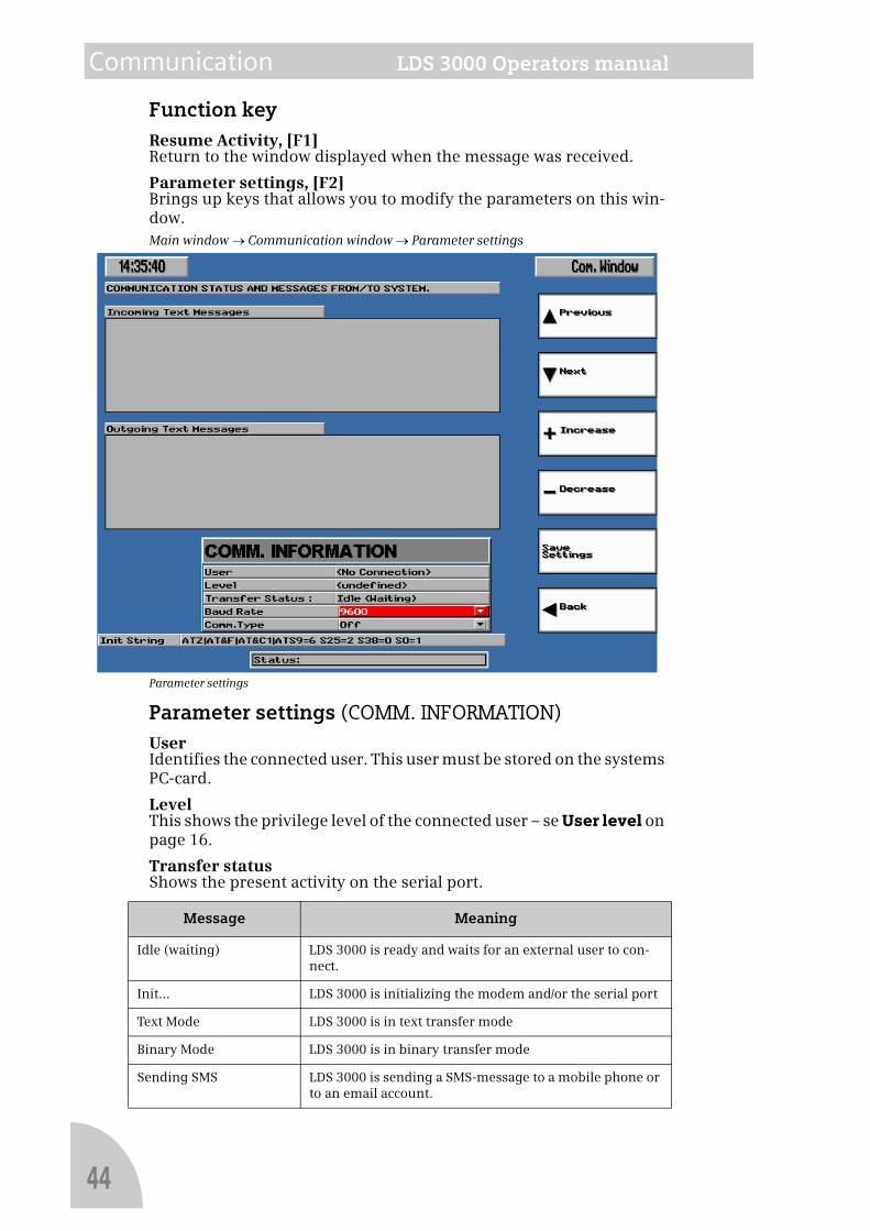
Parameter settings, [F2]Brings up keys that allows you to modify the parameters on this win-dow.Main window → Communication window → Parameter settings
Parameter settings
Parameter settings (COMM. INFORMATION)UserIdentifies the connected user. This user must be stored on the systems PC-card.
LevelThis shows the privilege level of the connected user – se User level on page 16.
Transfer statusShows the present activity on the serial port.
Message Meaning
Idle (waiting) LDS 3000 is ready and waits for an external user to con-nect.
Init... LDS 3000 is initializing the modem and/or the serial port
Text Mode LDS 3000 is in text transfer mode
Binary Mode LDS 3000 is in binary transfer mode
Sending SMS LDS 3000 is sending a SMS-message to a mobile phone or to an email account.
44
LDS 3000 Operators manual Communication
Baud rateSets the baud rate for the external connection. In local mode this can be set to 115 200. The connected user and the system must be set to the same baud rate. The accepted baud rate depends on the quality of the telephone line used. The program suggests an optimal speed de-pending on the chosen communication type.
Com. typeOff
In this position you cannot logg on. Incoming calls are ignored. This is the preferred setting when no modem line or phone line is connect-ed.
Local
In this mode it is possible to access LDS 3000 via a “null modem cable” if the client system is located close to LDS 3000. The only signals that need to be connected in the cable are RX ↔ TX. CTS/RTS shall not be connected in this cable.
• Baud rates up to 115 200 bps.
External modem
The system is connected to an external modem on one of the dedicat-ed communication ports.The modem/modem settings must comply with the following:
• Baud rates up to 38 400 bps.
• Compatibility with Hayes AT industry standard.
• Handle hardware controlled flow control and error correction.
External GSM-modem
The system is connected to an external modem on one of the dedicat-ed communication ports.The modem/modem settings must comply with the following:
• Baud rates up to 38 400 bps.
• Compatibility with Hayes AT industry standard.
• Handle hardware controlled flow control and error correction.
Init StringAt start-up any modem connected to LDS 3000 is initiated with one or more “init strings” that are passed to the modem. These can be edited in the program (LDS3k) if an external key board is available. The com-mands in the default init strings complies to the Hayes standard. The
Hanging up (Comm Err.) Connection error, LDS 3000 is trying to disconnect
LabView Bin. LDS 3000 is connected to LDSComm in LabView mode and transfer is progressing.
Executing... LDS 3000 is executing a DOS command on request from the external user.
Preparing... LDS 3000 is preparing to send or receive a file.
Done XX% File transfer is ready to XX%
Hanging up... The external user has requested LogOff which now is in action
Message Meaning
45
Communication LDS 3000 Operators manual
Note!
modem is also re-initiated after shout-down and also every 10 sec-onds if the modem is in the idle state (se table above). The default init string is optimized for the modem type selected under “Com. type” above. Some modems, for instance if it does not comply to the Hayes standard, may require a modified init string. The modification is done by moving the cursor to the field with the init string and modifying it. This operation requires a standard PC keyboard connected to the in-strument. If the change is permanent the setting must be saved.
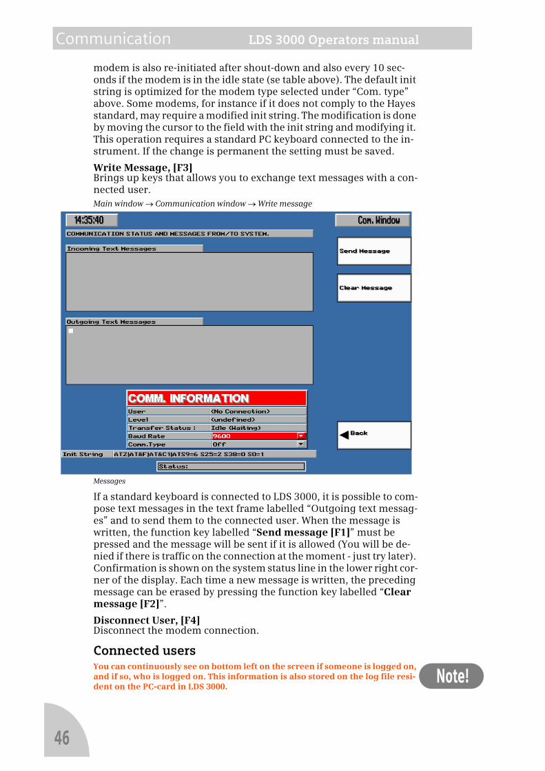
Write Message, [F3]Brings up keys that allows you to exchange text messages with a con-nected user.Main window → Communication window → Write message
Messages
If a standard keyboard is connected to LDS 3000, it is possible to com-pose text messages in the text frame labelled “Outgoing text messag-es” and to send them to the connected user. When the message is written, the function key labelled “Send message [F1]” must be pressed and the message will be sent if it is allowed (You will be de-nied if there is traffic on the connection at the moment - just try later). Confirmation is shown on the system status line in the lower right cor-ner of the display. Each time a new message is written, the preceding message can be erased by pressing the function key labelled “Clear message [F2]”.
Disconnect User, [F4]Disconnect the modem connection.
Connected usersYou can continuously see on bottom left on the screen if someone is logged on, and if so, who is logged on. This information is also stored on the log file resi-dent on the PC-card in LDS 3000.
46
LDS 3000 Operators manual Communication
8.2 Status messages on LDS 3000During communication with a user, certain messages can be shown for approximately three seconds in the status line in the lower right corner of the display. All of these messages are stored in the system log file. The abbreviations shown in the status line are listed below.
User logged onThis indicates that a user has logged-on with the correct password. The name of the logged on user is displayed.
User logged offThe user has logged off in a correct way.
Lost contactContact with the connected user was prematurely terminated. A rea-son for this could be a bad telephone connection. If this occurs fre-quently the modem connection, phone plug, etc. should be checked.
Hanging up (Com. error)When this happens, LDS 3000 has broken the connection because no handshaking has occurred for more than one minute.
Unknown packetA corrupt data package has been detected. A low priority message with a very low occurrence rate.
Checksum errorNot very serious if it happens on rare occasions. It means that some of the information during transfer from the host to LDS 3000 was lost. A reason might be a noisy line causing bit errors.
Text messageA text message was sent from the client. If the client did not automat-ically change the window to the Communication window, you must do so manually to read the message.
Message sentConfirmation that a message was successfully sent from LDS 3000 to the external client.
Message not sentYour message was not sent at this time because of ongoing communi-cation. Try later.
Executing...The host is running an executable batch file on LDS 3000. This mes-sage flashes until the task is completed.
Receiving file...The host is sending a file to LDS 3000. This message flashes until the task is completed.
Sending file...LDS 3000 is sending a file to the host. This message flashes until the task is completed.
Transfer stoppedTransfer of the file was stopped. The reason can either be that the host cancelled the operation or that a file storage error occurred.
8.3 System reboot by a connected userReboot messageIt is possible for users in the remote system with sufficient privileges
47

Communication LDS 3000 Operators manual
Note!
to perform a reboot of the system, for instance when an upgrade of the software has been done. The operator of LDS 3000 will be in-formed about the reboot.A user connected to LDS 3000 has selected to reboot the system in order to be able to update the software. Please select “Override” if you wish to cancel this operation.
This enables you to delay the reboot to a more convenient time.
48
LDS 3000 Operators manual Service and Maintenance
Note!
9 Service and MaintenanceDuring normal use of LDS 3000 the central unit needs no service. The sensors and their optical surfaces will need regular maintenance. De-pending on application and purging method the interval may be be-tween 1 and 12 months.
Cross duct sensorIf the transmission in a channel drops below the level set by the user, the sensor in this channel needs to be serviced (cleaning of the optical surfaces or realigning of the optical path). The procedure for this is described in the sensor manual.
Semi extractive in situ sensorIf the flow rate of the gas drops below the level set by the user, the sin-tered steel filter needs to be cleaned or replaced.
All other types of service must be carried out by authorized personnel only. For more detailed information about the different sensors, refer to the manual for the respective sensors.
Calibration checkUsing the optional calibration cell CC 3000, the calibration can be checked at any time. Normally the LDS 3000 does not have to be cali-brated but due to local regulations the calibration has to be checked with regular intervals.The calibration procedure is critical and should only be performed by person-nel from Siemens Laser Analytics AB or by certified personnel at site.
49

Service and Maintenance LDS 3000 Operators manual
50