cinema eos on˜set hdr/wcg ecosystem -...
TRANSCRIPT

© 2016 Canon USA, Inc. All rights reserved.
WHITE PAPER
CINEMA EOS ON-SET HDR/WCG ECOSYSTEM
Written by Larry ThorpeCustomer Experience Innovation Division, Canon U.S.A., Inc.
For more info:
cinemaeos.usa.canon.com
CINEMA EOS

2
Cinema EOS On-set HDR / WCG Ecosystem
Abstract. High Dynamic Range (HDR) and Wide Color Gamut (WCG) are now widely accepted as constituting important attributes to overall enhancement of the viewer experience – for home and for theatrical viewing. While closely associated with the emerging UHD / 4K they both can equally apply to contemporary HD / 2K systems. Today’s digital productions that entail HDR augmented by WCG require significant changes to practices on-set. The Lenses used in these productions require the highest contrast ratio and tight management of highlight related optical artifacts. Cameras must be capable of originating imagery having credibly high exposure latitude. Reference Displays capable of portraying both HDR and WCG become essential to on-set acquisition workflow for the filmmakers to have complete confidence in the process.
This paper will outline the numerous design strategies in a unique second generation digital cinematography production system intended to originate imagery in 2K / HD / 4K / UHD formats that have both High Dynamic Range (HDR) and Wide Color Gamut (WCG). The system includes the cine lens, a new digital camcorder, and an on-set reference display that share a coordinated system design conforming to the ACES 1.0 system developed by the Technical Council of the Academy of Motion Picture Arts and Sciences [1]
1.0 It will be shown that the optical dynamic range of the lens plays a critical role in originating high quality HDR and that its spectral transmittance is central to originating WCG imagery.
2.0 Canon’s EOS C300 Mark II digital cinema camera has a 15-stop exposure latitude that allows it to originate impressive HDR imagery. The camera offers a choice of wide color gamuts including the new ITU-R BT.2020 wide color gamut, and a Cinema Gamut that is even wider.
3.0 Canon’s new portable 24-inch on-set reference display DP V2410 was designed in concert with the EOS C300 Mark II camera. The display includes HDR functionality. It directly accepts the 4K / UHD RAW signal output of the camera and internally deBayers this for realtime monitoring. The display applies the ACES-based IDT processing that takes the camera’s 4K/UHD RAW signal output into an ACES 1.0 space. The common standard ASC CDL color correction system within the reference display allows control of Slope, Offset, Power and Saturation according to this standard. The display supports both Canon Log 2 and Log 3 signal inputs and signals encoded according to the PQ based EOTF (SMPTE ST-2084) and the Hybrid Log Gamma (HLG) EOTF. It separately accepts the ACESProxy 10-bit serial digital output of the C300 Mark II camera to support on-set grading of program material being recorded on board via the XF-AVC codec.
INTRODUCTION HDR and WCG began as separate technological movements but over the past year have been steadily
converging as a consequence of:
1. Better understanding of their respective implications
2. Broadening tests worldwide [2],
3. Publications of important reports [3],
4. International standardization bodies undertaking both studies and actual standardization processes [4].

3
Wide Color Gamut (WCG) came to a successful fruition with the publication of the ITU-R BT.2020 production standard for UHDTV [5]. High Dynamic Range is presently garnering more attention around the world as numerous entities in both the television and the theatrical motion picture communities
grapple with the challenges of rationalizing an end-to-end HDR ecosystem.
The ACES system development was tailor made to support HDR / WCG program production. It is fortuitous that Canon’s debut of the new EOS C300 Mark II HDR camera and the DP V2410 reference display approximately coincided with the formal publication of the ACES 1.0 system. Both of these product developments were significantly guided by ACES 1.0.
THE HDR / WCG ECOSYSTEM The on-set ecosystem for HDR and WCG on-set origination is reproduced in Figure 1. HDR for digital motion imaging starts with a lens having a high contrast ratio that can deliver the finely nuanced tonal gradations for the nominally exposed signal, while accurately reproducing specular highlights in the scene, and protecting against optical artifacts stimulated by severe off-axis highlights. This combines with an associated camera image sensor having the requisite exposure latitude, a high bit-depth A/D conversion system, and a camera OETF that protects the integrity of that latitude within the associated digital recording system [6].
The on-set ecosystem is completed by an on-set HDR reference display that empowers the production team to creatively adjust lighting and effectively assess what is being captured in different scenes.
Figure 1 Summarizes the core elements of the on-set digital acquisition system that bear upon HDR and WCG origination – the Cinema EOS lens, C300 Mark II camera, and reference display DP V2410
Wide color gamut also starts with the spectral response of the lens, followed by that of the Color Filter Array (CFA) and the image sensor, the optical IR filter, and followed in turn by the necessary linear matricing of the RGB primaries.
When shooting on set, it is typically not convenient to use floating-point values for monitoring. The ACES system resolves this by including an integer encoding that can be transported from the camera over an HD-SDI link for on-set monitoring. This is a lower-quality ACES encoding called ACESproxy not intended for recording. On significant productions it has become customary for the Director and Director of Photography to do a basic color grade that establishes the specific “look” they jointly seek for each scene. This becomes the all-important initial reference for the postproduction team tasked with the final grading. The ACES system includes a standard for applying the look on-set in ACESproxy space, and then applying it again in DI such that the original look is preserved. This is the intended workflow for creating “look” metadata using ASC CDL values.

4
1.0 THE HDR LENS
The current industry discussions on HDR and WCG center largely on the associated camera, recorders, workflow, and infrastructure. It is sometimes overlooked that the origination of HDR imagery starts with the lens that is coupled to the HDR camera [6]. It is the task of the lens to translate the enormous range of luminance possibilities emanating from real world scenes to an optical representation on the camera image sensor that is as faithful as possible to that scene. The light path through the lens is fraught with multiple optical challenges and the new high interest in HDR has elevated related complexities.
Figure 2 The HDR system relies upon the effective dynamic range of the lens as well as that of the
camera image sensor
To do justice to the HDR camera the lens must have:
Requisite contrast ratio over the nominally exposed image – that is, from black to the diffuse reference white level – to ensure the excellent tonal reproduction expected from an HDR system and, most especially, clarity of detail in dark shadowed areas of the scene.
Clarity of reproduction of specular highlights within the scene – be it indoor or outdoor – with minimization of any associated ghosting and flaring artifacts
Tight management of any reflections within the lens barrel that might contaminate the image with flare and ghosting
Control of off-axis highlights that can cause veiling glare and flares
1.1 Sophisticated Design Simulation is Critical to Achieving HDR Optical Performance High zoom ratio lenses dramatically alter the angle of view of the lens which is attended by a huge

5
diversity of light ray angles entering the lens system. Over many years Canon has developed increasingly powerful computer simulation systems that facilitate detailed examination of the passage of such light rays through the entire optical system and their behavior at all conceivable lens settings. The simulation can predict the individual paths of the lights rays and their relative strengths under all forms of lighting conditions. Identifying undesirable internal reflections and introducing the requisite multiple counter strategies is central to ensuring the highest optical HDR capability.
1.2 Lens Contrast Ratio:
Today’s digital cameras readily achieve a Luma signal to noise specification of 60dB or better which equates with a 1000:1 dynamic range for the nominally exposed signal (capped black to reference white). Thus the associated lens must have a contrast ratio in excess of this to do full justice to the camera capability. If a lens has a transmissivity in the neighborhood of 80 % then the black reproduction capability must be lower than 0.1% to exhibit that level of contrast ratio.
Central to achieving a high contrast ratio is minimization of inner reflections in all glass elements. This is achieved by sophisticated multilayer (to manage all visible wavelengths) optical coatings on each and every element surface. The coating technologies elevate the light transmission through the lens system while simultaneously suppressing contamination of scene blacks – thus raising the overall lens contrast ratio. Figure 3 suggests two scenarios that indicate how critically important it is to lower the black contamination to achieve a high contrast ratio.
Figure 3 Illustrating the dual role of optical coatings in elevating lens light transmission while
lowering black contamination – with two scenarios for the black level
Canon’s professional lenses utilize multi-layer coatings that are effective across the entire range of wavelength of visible light, and they are all uniquely developed by Canon. In a multi-element zoom lens these coatings are enormously effective in elevating the transmission of the light through the entire optical system as well as playing a major role in shaping the spectral characteristic of the lens system. They are also central to curtailing the light scatter caused by unwanted reflections that elevate what should be deep blacks in a scene while also causing flare around high intensity elements within a scene.
Internal light reflections can also be caused by light scattering from the edges of the glass elements and in order to prevent this, the edges of each glass is designed and processed with special anti-reflection paint made of high refractive index medium and minimal black particles.

6
Multiple reflections can also cause the creation of ghost artifacts. Figure 4 shows how a carefully designed HDR lens can overcome some of these optical artifacts.
Figure 4 Examples of glare and ghosts within a lens caused by unwanted reflections and their
effective elimination with high quality optical coatings
1.3 Specular Highlights within the Framed Scene: A critical expectation from the HDR imaging system is the faithful reproduction of small specular highlights within the scene and here a variety of additional optical considerations arise. Small intense specular highlights that are in focus should be reproduced as small circular spots with crisp outlines and smooth delineation. It is the faithful reproduction of such highlights that properly exploit the subjective benefits of HDR. Out of focus speculars should be reproduced as enlarged circles with smooth bokeh. Glass materials, optical coatings and a multi-frame aperture all contribute to this precision clean reproduction of specular highlights.
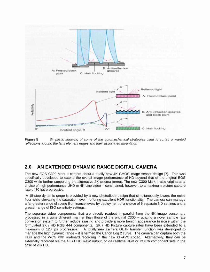
1.4 Intense Highlights Lenses can exhibit vulnerabilities to intense external off-axis highlights (such as the sun or a studio light) that can stimulate a variety of unexpected optical interferences. Strong unwanted reflections that might be stimulated by off-axis intense highlights can separately create another mechanism of internal reflections that spill across the entire image plane – and is termed veiling glare. As well as the measures described for the glass elements themselves there are additional optomechanical techniques that are mobilized to eliminate or attenuate the strong reflections that can take place within the lens barrel.
Angled surfaces and junctures of surfaces can all create reflections and accordingly special anti-reflection paints having ultra-fine black pigment grains have been developed that are made of high refractive index medium. Light blocking grooves, knife edges, and other mechanical strategies are mobilized. An electrostatic flocking process directly applies an extremely fine pile to mounting surfaces that also require an anti-reflection finish. This technique is extremely effective because the pile stands perpendicular to the wall surfaces. This is especially effective in the long barrel sections of zoom lenses.
Figure 5 summarizes some of these optomechanical counter strategies.
7
Figure 5 Simplistic showing of some of the optomechanical strategies used to curtail unwanted reflections around the lens element edges and their associated mountings
2.0 AN EXTENDED DYNAMIC RANGE DIGITAL CAMERA
The new EOS C300 Mark II centers about a totally new 4K CMOS image sensor design [7]. This was specifically developed to extend the overall image performance of HD beyond that of the original EOS C300 while further supporting the alternative 2K cinema format. The new C300 Mark II also originates a choice of high performance UHD or 4K cine video – constrained, however, to a maximum picture capture rate of 30 fps progressive.
A 15-stop dynamic range is provided by a new photodiode design that simultaneously lowers the noise floor while elevating the saturation level – offering excellent HDR functionality. The camera can manage a far greater range of scene Illuminance levels by deployment of a choice of 5 separate ND settings and a greater range of ISO sensitivity settings.
The separate video components that are directly readout in parallel from the 4K image sensor are processed in a quite different manner than those of the original C300 – utilizing a novel sample rate conversion system to further reduce aliasing and provide a more benign appearance to noise within the formulated 2K / HD RGB 444 components. 2K / HD Picture capture rates have been extended to a maximum of 120 fps progressive. A totally new camera OETF transfer function was developed to manage the high dynamic range – it is termed the Canon Log 2 curve. The camera can capture both the HDR and the WCG with on-board recording in the new XF-AVC codec. Alternatively, they can be externally recorded via the 4K / UHD RAW output, or via realtime RGB or YCrCb component sets in the case of 2K/ HD.

8
IMPLEMENTATION OF THE ON-SET HDR / WCG ECOSYSTEM
Canon undertook a coordinated design to produce an on-set digital motion imaging system having HDR functionality. The lens-camera system that originates HDR has been described. What now becomes important is how to effectively use that camera to originate imagery where creative HDR is desired for certain scenes. Anticipating the ultimate portrayal of HDR imagery on new HDR displays (having high luminance levels and high contrast) places a special burden on those originating that imagery. The images need to be accurately displayed on-set on an appropriate reference display. This starts with the ability to accurately portray deep black levels on set. The ability to capture very dark objects and very bright objects within a single scene requires structuring video that preserves all of that information until it finally reaches a display capable of approximating the luminance levels of the original scene.
The heart of the on-set HDR ecosystem is a unique 4K reference display developed by Canon – the DP-V2410. This is a portable (weighing only 26 lbs.) display having a 24-inch display diagonal. It can be AC or battery powered.
Figure 6 The Canon on-set HDR / WCG ecosystem consists of the tight system integration of
these two key products – the EOS C300 Mark II camera and the DP V2410 reference display
The DP-V2410 reference display is unique in accepting the 4K RAW output of the EOS C300 Mark II camera and internally debayering this 10-bit Log 2 encoded signal [8].
Figure 7 The camera (on the right) sends it 4K RAW output via the 3G SDI serial interface to the
reference display (center) where it can be looped through to any of a wide selection of external recorders

9
THE GUIDANCE OF ACES Canon has actively participated in the development work of the Technical Council of the Academy of Motion Picture Arts and Sciences that led to last year’s release of the ACES 1.0 system. This collaboration profoundly influenced the coordinated system approach that Canon took to the new C300 Mark II camcorder and the DP-V2410 on-set reference display. Canon has also actively participated in the supporting work of the Technical Committee of the ASC—see Figure 8.
Figure 8 Conveying a sense of Canon’s active collaboration with the Technology Council of AMPAS and the Technical Committee of the ASC
The basic intent of ACES is to support high dynamic range, wide color gamut, and high bit depth workflows and to enable seamless interchange of high quality motion picture images – regardless of the image source. It creates a common digital image format that facilitates postproduction processing of diverse original image formats.
Figure 9 Outlining the overall process of the Academy Color Encoding System (ACES)

10
The workflow strategy begins with the design of an Input Device Transform (IDT) for each specific Camera – Figure 9. The IDT transforms the unique tonal and color reproduction of the camera to a common linear light representation according to the Academy Color Encoding Specification (ACES) – SMPTE Standard ST 2065-1. The ACES system is a large container that preserves all of the camera information through use of 16-bit half-floating point values that cover 33 stops of dynamic range, and a color space having wide virtual RGB primaries that encompass the entire visible color gamut. This representation can then be manipulated by the grading process without any losses. All of the manipulation (color correction, VFX) is supported by metadata. The original source material is not touched.
The DP-V2410 is intended for on-set grading and does not require the precision and huge dynamic range and color space of the full ACES system. Accordingly, the 18-bit processing engine of the DP-V2410 deploys the basics of the ACESproxy (described below) processing to implement the requisite grading.
3.0 THE ON-SET HDR / WCG REFERENCE DISPLAY
The DP-V2410 deploys a powerful 18-bit processing engine that includes the core of the ACES system. The “scene referred” input 4K RAW Log encoded signals are debayered and converted to ACES RGB relative exposure values and passed through the IDT transformation for the C300 Mark II camera before entering the ACES color space for grading.
Figure 10 The 4K reference display deploys a powerful 18-bit engine to internally implement an on-
set ACES system that works directly with the EOS C300 Mark II camera
The DP-V2410 incorporates a color grading capability conforming to the ASC Color Decision List (ASC CDL) format. The images are then mapped back to a linear light representation at a high bit depth. To view these image manipulations the output must be rendered to a scene viewing state – which is the role of the Reference Rendering Transform (RRT). The RRT transforms the linear light scene referred system to a display referred (output) color space. Its specifications were designed to produce an image that would be subjectively pleasing on any display (this is analogous to the film printing process). The final transformation is via the ODT -- that makes the final mapping of dynamic range, electro-optical transfer characteristic, color gamut, and bit depth to precisely match those of the Canon 10-bit DCI-P3 reference display panel.
If the EOS C300 Mark II is alternatively originating 2K / HD the related Canon Log 2 encoded video component sets (either RGB 444 or YCrCb 422) are sent via the same 3G/HD-SDI serial interface to the reference display where they are graded, then linearized, and finally passed through the color space and gamma transforms for the display panel.

11
Figure 11 Showing the processing of the 4K RAW signal from the C300 Mark II camera
The input 4K RAW signal from the EOS C300 Mark II camera is first debayered and the IDT transform for that camera is applied following which the 4K RGB frames are operated upon within the ACES color space. They are then linearized (removal of the Canon Log 2 or Log 3 coding to restore the original linear light representation). The reference display can alternatively accept an input 4K signal that has been encoded with the PQ OETF function (that is specified in the SMPTE standard ST 2084) or encoded with the alternative Hybrid Log Gamma (HLG) OETF. Following grading they are linearized to a high bit depth and precisely transformed to the color space and gamma characteristics of the 10-bit display panel.
Figure 12 A variety of inputs are accepted by the DP-V2410 reference display

12
The CDL is a list of the primary color corrections to be applied to an image. Four parameters constitute the CDL: Offset (lift), Slope (gain), Power (gamma) slope, and Saturation. While saturation has only one value, each of the other parameters comprises a red, green and blue value, making for 10 CDL numbers in total for each image segment. The grading adjustments can be made directly from the panel built into the display – shown in Figure 13, or they can be made from an external controller such as the Element Tangent controller shown in Figure 12.
Figure 13 Showing the ACES based grading controls provided by the DP-V2410 display
4.0 MONITORING THE CAMERA HDR OUTPUT IMAGE DATA
The DP-V2410 has HDR functionality. The standard brightness level of the display panel (diffuse reference white) is 100 candelas per square meter (nits). The peak brightness level of the display is 400 percent above that reference white. The 15-stop HDR capability of the EOS C300 Mark II camera means that it can deliver a maximum HDR level of 1600% above reference white level. Accordingly, such high input HDR possibilities must be pre-processed – via a special range-setting function – to match the more modest HDR capability of this reference display. The range setting takes place on the high bit-depth linear light representation that follows the grading processor. There are two modes of HDR processing built into the display:
4.1 CLIP MODE: If a given scene contains a range of escalating highlight levels a decision can
be made to eliminate the highest of these and to display highlights up to approximately 400% of reference white. In such a case, the display is set to the Clip Mode – which will pass all highlights up to 400% level and clip all signals that are above this level.
4.2 COMPRESSION MODE: If various input highlight levels above 400% up to the 1600%
maximum are to be faithfully displayed then the Compress Mode is selected. This linearly compresses the input signal to ensure that its maximum highlight level matches the 400% level of the display.

13
Figure 14 Showing the pre-processing within the DP-V2410 reference display to control the
different levels of the input HDR signal from the EOS C300 Mark II camera to ensure that the selected peak white level always matches the maximum capability of the display
Figure 15 Illustrating the CLIP mode (on the left) and the COMPRESSION mode (on the right) for
managing portrayal of HDR input signals in the reference display

14
ACESPROXY (ACES 1.0) SYSTEM
The basic ACES system deploys a digital encoding method using IEEE half-precision floating-point encoding. ACESproxy10 is a separate system that was developed [9] specifically to be a working-space encoding for on-set preview and grading (to support look creation by the director and DoP). This encoding was designed to support on-set grading using the ASC Color Decision List (ASC CDL) to create metadata that details the basic RGB color correction information describing the particular look. The encoding is designed for systems that transport the images via the 10-bit HD SDI interface. Because 10-bit cannot support the full range of ACES data with the same precision, the ACESproxy encoding uses a prescribed log transfer function that captures a middle portion of the possible range of ACES values.
As outlined earlier the DP-V2410 reference display utilizes the basic ACESproxy video processing system for on-set grading of the 4K RAW signal from the C300 Mark II. If the camera is not being used in RAW mode – but rather internally recording the 4K video using the XF-AVC codec – then grading can still be fully implemented using the ACESproxy interface between the C300 Mark II and the DP-V2410.
Figure 16 shows the on-set HDR / WCG ecosystem where 10-bit log-encoded ACESproxy 10 output from the MON Output terminal on the EOS C300 Mark II is directly connected to the DP-V2410. The camera has already applied the DIT transformation to this signal that allows it to enter the ACES color space within the display. That proxy signal can now be graded via the same built-in ASC controls in the display or from an external controller. The signal is then linearized to a high bit-depth linear light representation which allows the final color space transform and display EOTF to be very accurately applied.
Figure 16 The ACESproxy is a 10-bit log encoded representation of the HDR video originated in the
EOS C300 Mark II that directly interfaces with the DP-V2410 reference display via 10-bit HD SDI
15
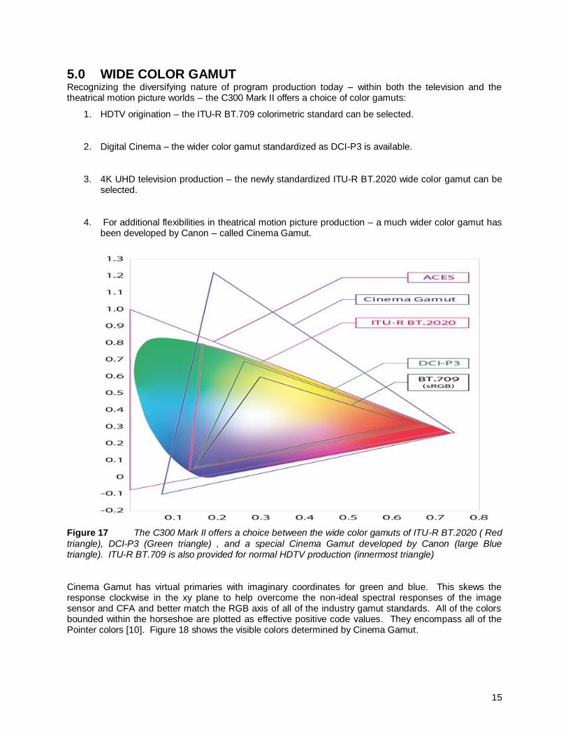
5.0 WIDE COLOR GAMUT Recognizing the diversifying nature of program production today – within both the television and the theatrical motion picture worlds – the C300 Mark II offers a choice of color gamuts:
1. HDTV origination – the ITU-R BT.709 colorimetric standard can be selected.
2. Digital Cinema – the wider color gamut standardized as DCI-P3 is available.
3. 4K UHD television production – the newly standardized ITU-R BT.2020 wide color gamut can be selected.
4. For additional flexibilities in theatrical motion picture production – a much wider color gamut has been developed by Canon – called Cinema Gamut.
Figure 17 The C300 Mark II offers a choice between the wide color gamuts of ITU-R BT.2020 ( Red
triangle), DCI-P3 (Green triangle) , and a special Cinema Gamut developed by Canon (large Blue triangle). ITU-R BT.709 is also provided for normal HDTV production (innermost triangle)
Cinema Gamut has virtual primaries with imaginary coordinates for green and blue. This skews the response clockwise in the xy plane to help overcome the non-ideal spectral responses of the image sensor and CFA and better match the RGB axis of all of the industry gamut standards. All of the colors bounded within the horseshoe are plotted as effective positive code values. They encompass all of the Pointer colors [10]. Figure 18 shows the visible colors determined by Cinema Gamut.
16
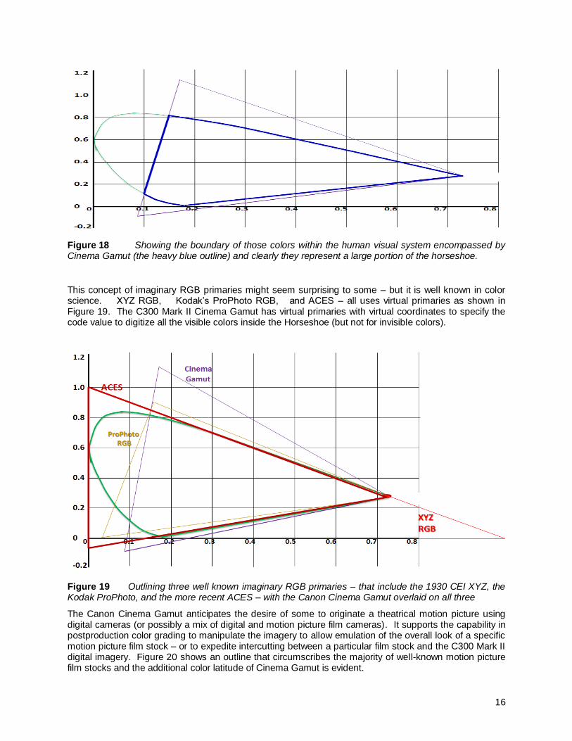
Figure 18 Showing the boundary of those colors within the human visual system encompassed by Cinema Gamut (the heavy blue outline) and clearly they represent a large portion of the horseshoe.
This concept of imaginary RGB primaries might seem surprising to some – but it is well known in color science. XYZ RGB, Kodak’s ProPhoto RGB, and ACES – all uses virtual primaries as shown in Figure 19. The C300 Mark II Cinema Gamut has virtual primaries with virtual coordinates to specify the code value to digitize all the visible colors inside the Horseshoe (but not for invisible colors).
Figure 19 Outlining three well known imaginary RGB primaries – that include the 1930 CEI XYZ, the Kodak ProPhoto, and the more recent ACES – with the Canon Cinema Gamut overlaid on all three
The Canon Cinema Gamut anticipates the desire of some to originate a theatrical motion picture using digital cameras (or possibly a mix of digital and motion picture film cameras). It supports the capability in postproduction color grading to manipulate the imagery to allow emulation of the overall look of a specific motion picture film stock – or to expedite intercutting between a particular film stock and the C300 Mark II digital imagery. Figure 20 shows an outline that circumscribes the majority of well-known motion picture film stocks and the additional color latitude of Cinema Gamut is evident.

17
Figure 20 The large dotted triangle is the Canon Cinema Gamut which effectively reproduces all of
the colors within the human visual system that are bounded by the dark blue outline. It can be seen that this totally encompasses the brown outline, which represents motion picture film
Canon provides 3x3 color matrices to convert the code value of Cinema Gamut to the major color gamuts of Rec 709, Rec 2020, and DCI-P3. These matrices support simple clipping of the color information that allows correct display of each of the standardized color spaces.
ITU-R BT.2020 Color Matrix (Constant Luminance)
The television world (both SDTV and HDTV) has long operated based upon the Non-Constant Luminance (NCL) system – where gamma corrected RGB components produce a somewhat inaccurate matriced Luma representation, which in turn, compounds inaccuracies in the creation of the Cr and Cb color difference components. When no chroma subsampling is used (RGB 4:4:4) the inaccuracies virtually disappear. In the new era of wide color gamut origination interest is growing in the use of Constant Luminance (CL) systems. This was recognized in the standardization of ITU-R BT.2020 wide color gamut system by including both NCL and CL nonlinear transfer functions in that standard.
Wide Color Gamut Mapping to Reference Display Panel The DP-V2410 reference display panel has a native color gamut capability that conforms to the DCI-P3 specification. Although the ITU-R BT.2020 color gamut is much wider than that of this display panel, gamut-mapping technology is used to optimize the display of color data outside the native capability of the display panel. This mapping technology is based on the fact that the human visual system is more sensitive to shifts in hue rather than chroma. Using this as a basis, an algorithm that maps color data outside that of the native display gamut was developed and implemented in the DP-V2410, allowing optimized display of images having broad color gamuts. The principle of this gamut mapping is shown in Figures 21 and 22.

18
Figure 21 Illustrating the gamut mapping algorithm for the Non Constant Luminance (NCL) – that
takes the green of the wide BT.2020 gamut to the nearest color on the native gamut of the display
In addition to the Non-Constant Luminance color matrix conversion standardized by ITU-R BT.2020 the DP-V2410 also supports Constant Luminance. The method of color matrix conversion differs between constant and non-constant luminance. As opposed to the conversion from YUV to RGB signals while maintaining 0.45 gamma with non-constant conversion, constant luminance converts YUV signal to linear signals followed by conversion to RGB signals. This supports the monitoring of images recorded with constant luminance.
Figure 22 Showing the simpler gamut mapping when Constant Luminance signals are entailed

19
THE SUBJECTIVE LINKAGE OF HDR AND WCG
To a certain degree HDR and WCG started as two separate developments within the television industry. However, as each became better understood it was soon apparent that it is the combination of extended dynamic range and extended color gamut that can add dramatic subjective enhancements to portrayed imagery – both in the home and in the cinema. This is true for 2K / HD and for 4K / UHD.
By itself, HDR holds promise of video portrayal with considerably higher brightness while retaining rich deep blacks and fine details within both dark shadowed and highlight regions of a scene. Overall, HDR is an enhancement to scene contrast that simultaneously benefits both ends of the luminance scale. Those who study colorimetry have long known that the colorfulness of a given color can be increased when its luminance is increased. This is known as the “Hunt Effect” [10].
The subjective appearance of colors on a display is the collective of its hue, its saturation, and its brightness (or lightness, as it is more generally termed). This three-dimensionality of color suggests a volume – and indeed, the term “color volume” is increasingly referred to in contemporary discussions of HDR portrayal. An important benefit of HDR is the potential to increase the colorfulness of imagery by virtue of this enhancement to color volume.
Figure 23 Two views offering a simplistic depiction of color volume showing that the subjective
saturation of colors increases as the associated luminance (some term this “Luminosity”) rises
WCG system allows cameras to capture a far wider range of real world colors while HDR enhances the portrayal of these colors. The combination of HDR and WCG is offering visual enhancements that had not been anticipated by many.
Color volume of an HDR display is specified by its color primaries, white point, and luminance range.

20
6.0 SUMMARY
The intent of this paper is to report on the development of an on-set digital acquisition system that was guided by the ACES 1.0 system developed by the Technical Council of the Academy of Motion Picture Arts and Sciences. The ACES system is a superb system for supporting image manipulation and all color grading manipulations of high dynamic range images and wide color gamut images.
The Canon Cinema EOS HDR / WCG ecosystem described includes the following:
1. The Cinema EOS Super 35m cinematography lenses that were developed in concert with the Cinema EOS cameras to ensure full HDR and WCG capability
2. The EOS C300 Mark II camera that originates either 2K / HD or 4K / UHD having a 15-stop HDR capability and a choice of wide color gamuts that include DCI-P3, ITU Rec BT.2020, or Canon Cinema Gamut. A separate white paper discusses the EOS C300 Mark II camera [6]
3. The EOS C300 Mark II transfers its 4K RAW signal output via an industry-standardized 3G SDI serial link (SMPTE ST 425M)
4. The DP-V2410 reference display directly accepts this serial 4K RAW
5. That RAW signal can be looped through that display and fed on to an external RAW recorder (of which there are a number of industry choices)
6. The reference display internally deBayers the 4K RAW signal and allows realtime monitoring of the same.
7. The reference display can alternatively accept the 2K / HD realtime RGB or YCrCb video component sets from the EOS C300 Mark II – which is also transferred via the same ST 425M serial 3G SDI interface
8. The 18-bit processing engine within the DP-V2410 incorporates an ACES workflow functionality – that works for 2K / HD and for 4K /UHD
9. As part of that ACES system the display incorporates the IDT for the EOS C300 Mark II camera – which is directly applied to the 2K / HD or to the debayered 4K / UHD video components
10. On-set color grading can be performed on the various signal inputs to the display via the built-in CDL controls in the monitor or by an external controller like the Element Tangent
11. If on-board XF-AVC recording of these various formats is used as an alternative to external RAW recording – then on-set color grading can still be performed by using the ACESproxy10 system built into both the EOS C300 Mark II camera and the DP V2410 reference display
12. A single 10-bit interface from the MON out terminal of the camera transports the prescribed log encoded ACESproxy video via HD SDI to the reference display. The same choice of CDL controllers is used to implement the on-set grading.

21
REFERENCES
[1] http:/www.oscars.org/science-technology/sci-tech-projects/aces
[2] Philippe Hanhart, Pavel Korshunov, Touradj Ebrahimi, Yvonne Thomas, and Hans Hoffmann “Subjective Quality Evaluation of High Dynamic Range Video and Display for Future TV”
JSMPTE, May/June 2015 [3] Mike Nilsson, “Ultra High Definition Video Formats and Standardization”
BT Media and Broadcast Research Paper, Version 1.0 April 2015
[4] [Proposed] “Draft New Recommendation ITU-R BT.[HDR] - Transfer characteristics and related
specifications for high dynamic range television systems” ITU-R WP6C Contribution 349 Oct 31
st 2014
[5] Recommendation ITU-R BT.2020, “Parameter values for ultra-high definition television systems
for production and international programme exchange” October 2012
[6] Fumiaki Usui, Ryuhei Kamata, and Laurence J. Thorpe, “Lens Considerations for Digital
Cinematography” SMPTE Motion Imaging Journal, January/February 2015 Page 28
[7] http://www.usa.canon.com/CUSA/assets/app/pdf/camera/brochures/WhitePaper-
imageperformanceenhancements-eosc300markii.pdf [8] http://www.usa.canon.com/CUSA/assets/app/pdf/camera/brochures/whitepaper-extended-
recording-eosc300markii.pdf [9] Specification S-2013-001 ACESproxy, an Integer Log Encoding of ACES Image Data
Technology Council of the Academy of Motion Picture Arts and Sciences
[10] Hunt RWG (1952) Light and dark adaptation and perception of color. J Opt Soc. Am. 42: 190–199