circuits chapter 23. circuit elements and design circuit diagram – a logical picture of what is...
TRANSCRIPT
Circuits
Chapter 23
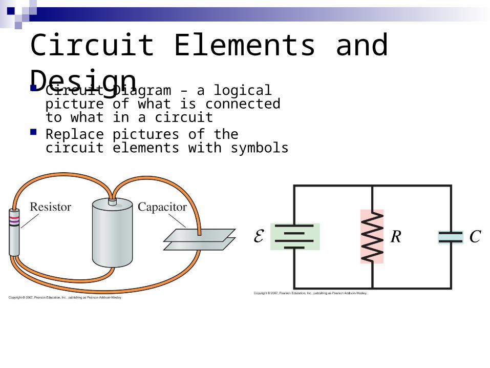
Circuit Elements and Design Circuit Diagram – a logical picture
of what is connected to what in a circuit
Replace pictures of the circuit elements with symbols
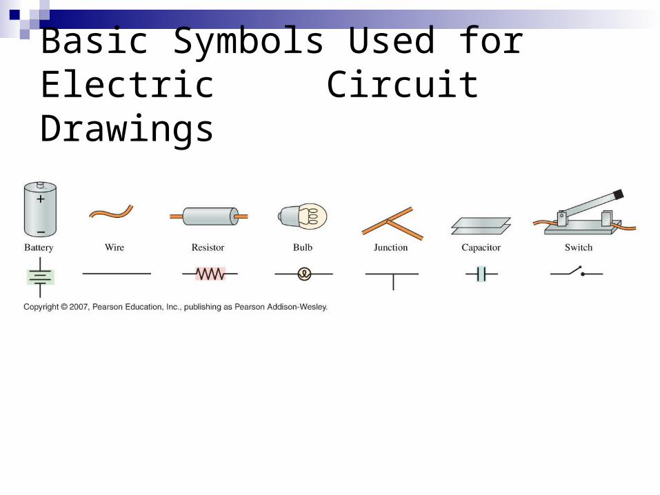
Basic Symbols Used for Electric Circuit Drawings
Circuit Diagrams
The longer line at one end of the battery symbol represents the positive terminal
The emf is shown beside the battery Capacitance and resistance are shown beside
the symbols Wires are shown as straight line connections
between circuit elements Higher potentials are put toward the top of the
diagram
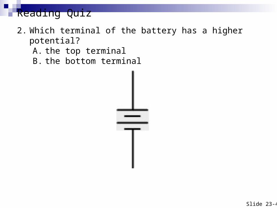
Reading Quiz 2. Which terminal of the battery has a higher potential?
A. the top terminalB. the bottom terminal
Slide 23-4
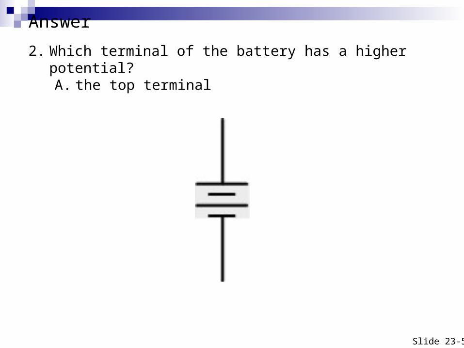
2. Which terminal of the battery has a higher potential?A. the top terminal
Slide 23-5
Answer
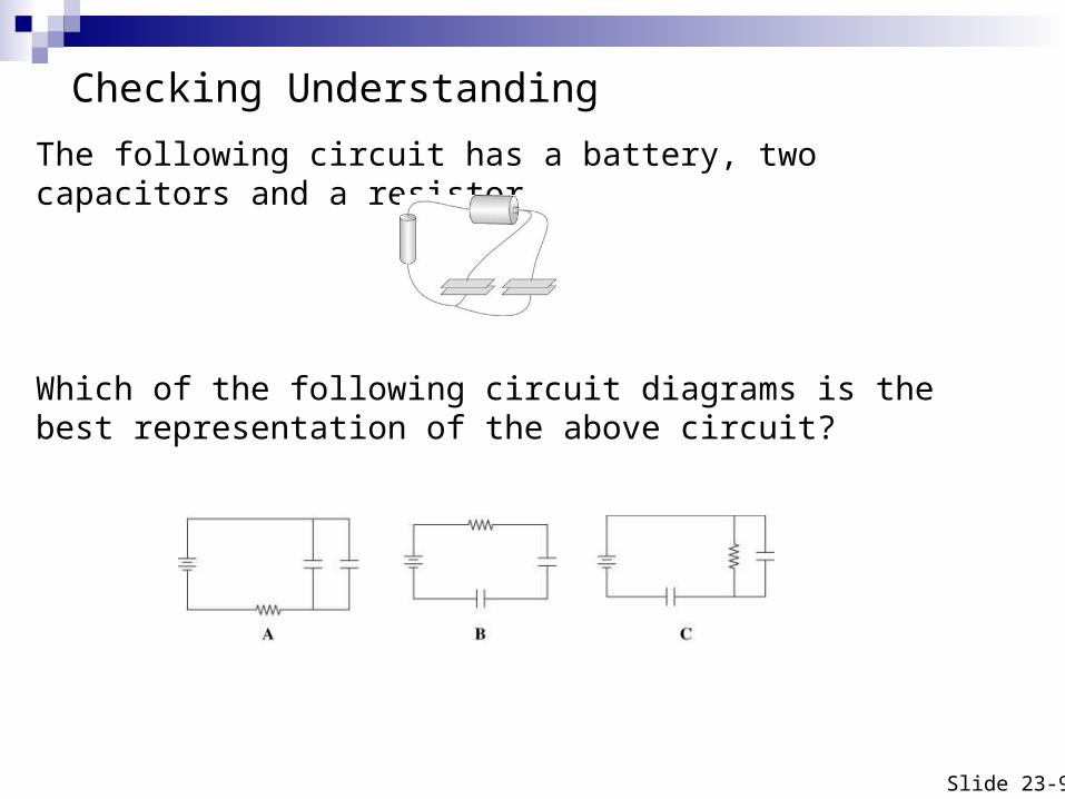
Checking Understanding
The following circuit has a battery, two capacitors and a resistor.
Which of the following circuit diagrams is the best representation of the above circuit?
Slide 23-9
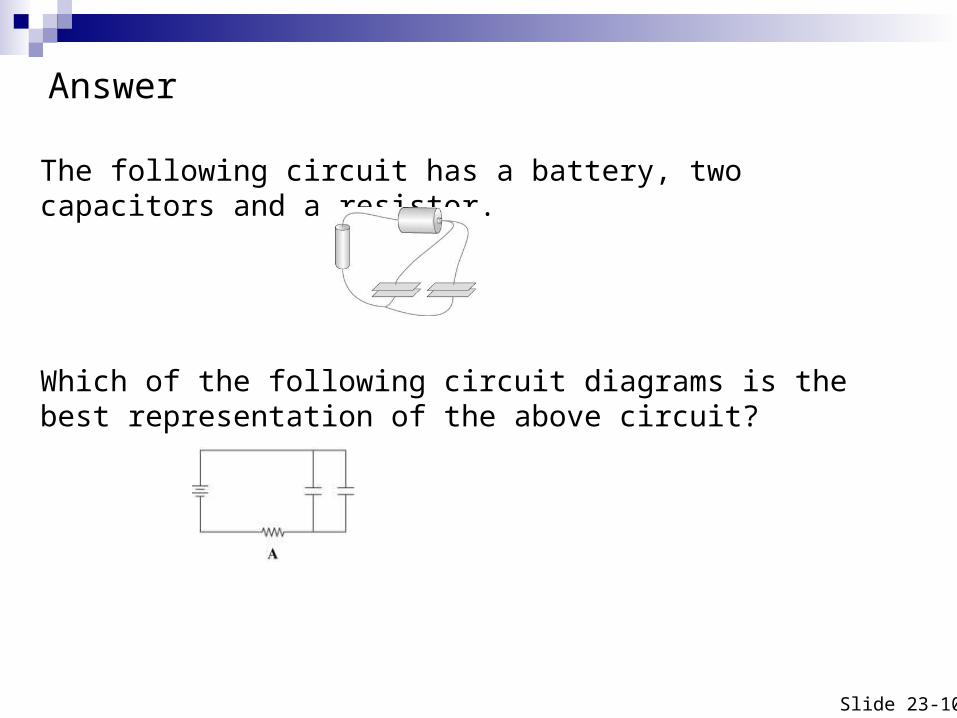
The following circuit has a battery, two capacitors and a resistor.
Which of the following circuit diagrams is the best representation of the above circuit?
Slide 23-10
Answer
Kirchhoff’s Laws
Analyzing a circuit Find:
The potential difference across each circuit component
The current through each circuit component

Kirchhoff’s Junction Law
Kichhoff’s Loop Law
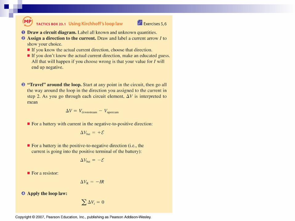
To apply the loop we must identify which potential differences are negative and which are positive.
Kirchhoff’s Loop law can only be true if at least one of the potential differences ΔVi is negative
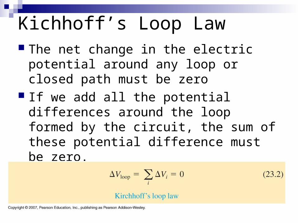
Kichhoff’s Loop Law The net change in the electric potential
around any loop or closed path must be zero
If we add all the potential differences around the loop formed by the circuit, the sum of these potential difference must be zero.
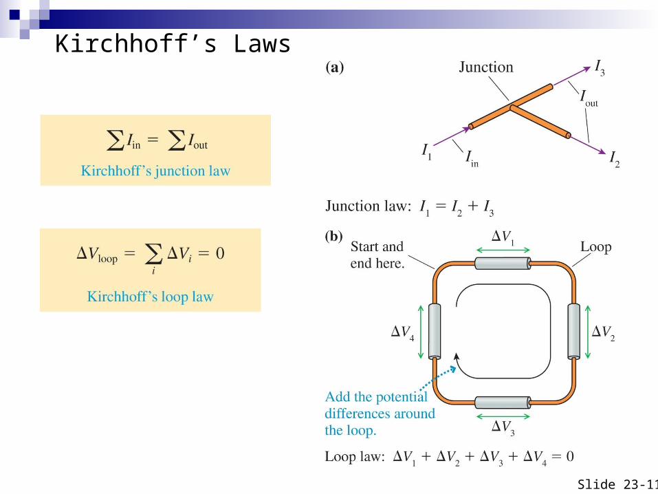
Kirchhoff’s Laws
Slide 23-11
ΔVbat can be – or +
ΔVR is always – because potential across a resistor always decreases along the direction of the current
Voltage “drop” across the resistor Ohm’s law only considered magnitude of
current
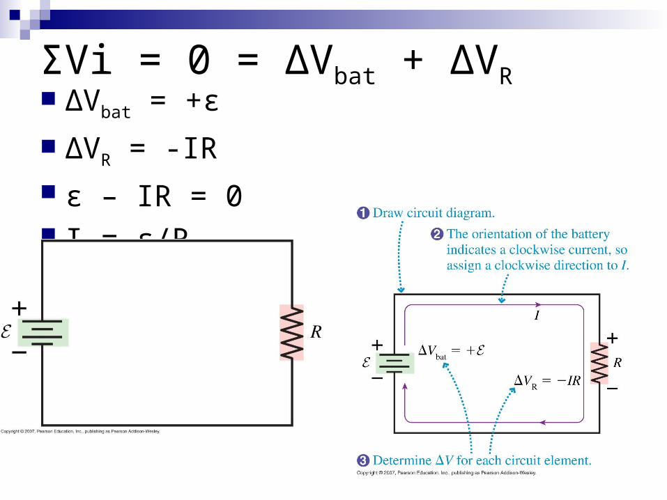
ΣVi = 0 = ΔVbat + ΔVR ΔVbat = +ε
ΔVR = -IR ε – IR = 0 I = ε/R
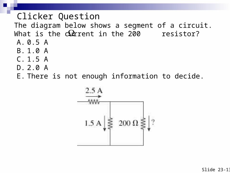
The diagram below shows a segment of a circuit. What is the current in the 200 resistor?A. 0.5 AB. 1.0 AC. 1.5 AD. 2.0 AE. There is not enough information to decide.
Slide 23-13
Clicker Question
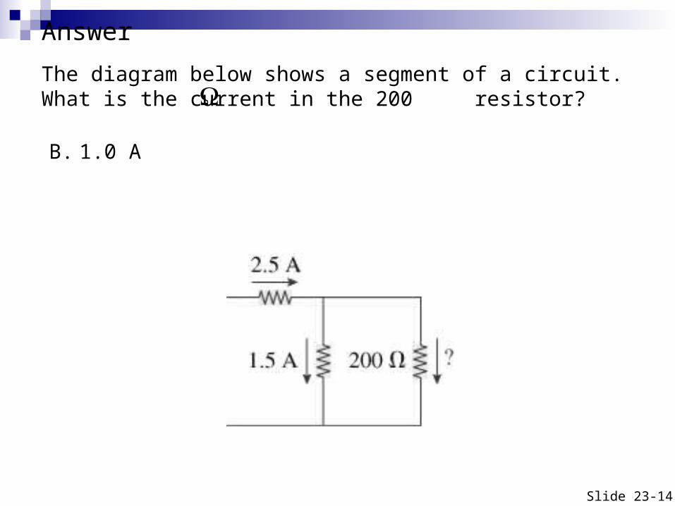
The diagram below shows a segment of a circuit. What is the current in the 200 resistor?
B. 1.0 A
Slide 23-14
Answer
The diagram below shows a circuit with two batteries and three resistors. What is the potential difference across the 200 resistor?
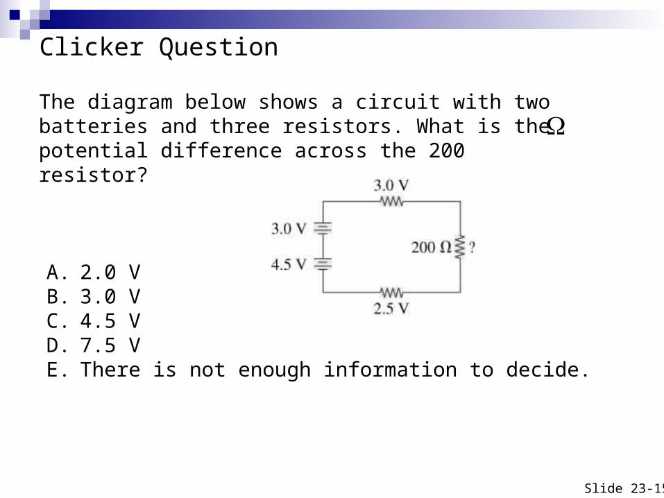
A. 2.0 VB. 3.0 VC. 4.5 VD. 7.5 VE. There is not enough information to decide.
Slide 23-15
Clicker Question
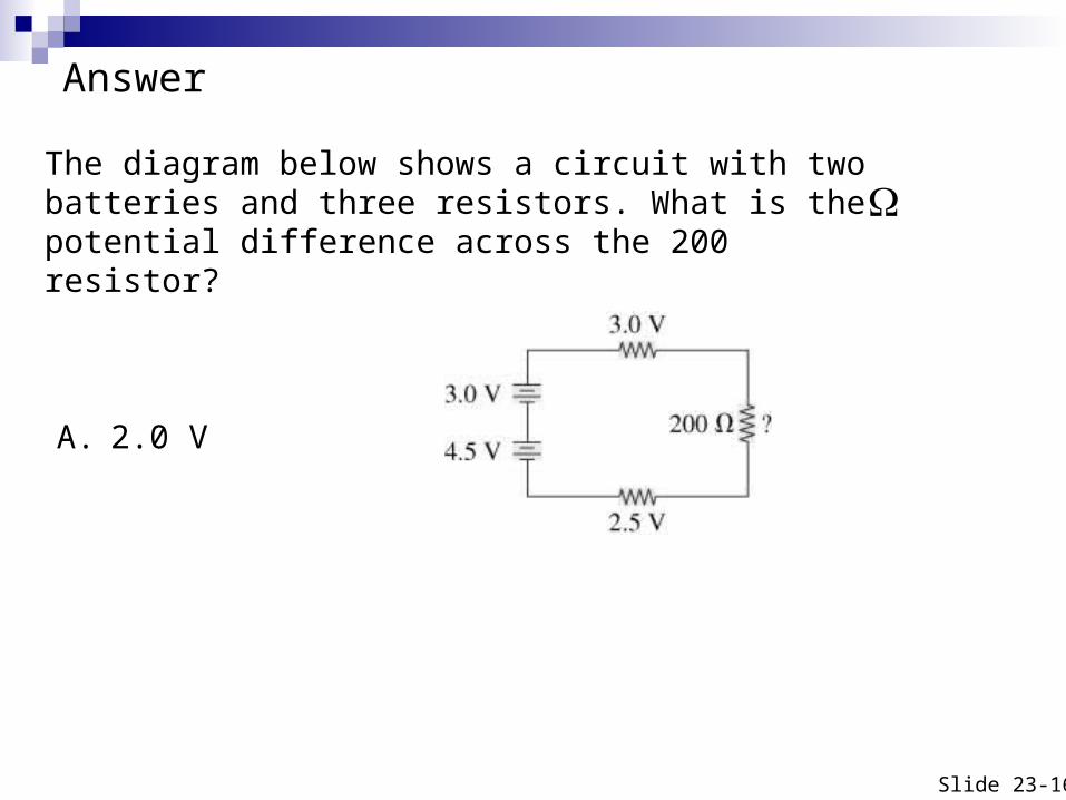
The diagram below shows a circuit with two batteries and three resistors. What is the potential difference across the 200 resistor?
A. 2.0 V
Slide 23-16
Answer
Series and Parallel Resistors
Two bulbs are connected in series if they are connected directly to each other with no junctions in between.
If two bulbs are connected at both ends in a circuit they are in parallel
We use equivalent resistance (the resistance of a single resistor which would replace more than one series or parallel resistors in a circuit) to solve circuit problems
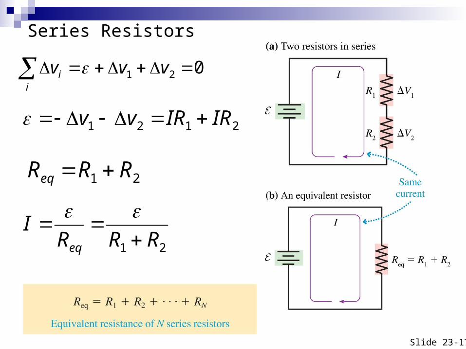
Series Resistors
Slide 23-17
021 vvvi
i
2121 IRIRvv
21 RRReq
21 RRRI
eq
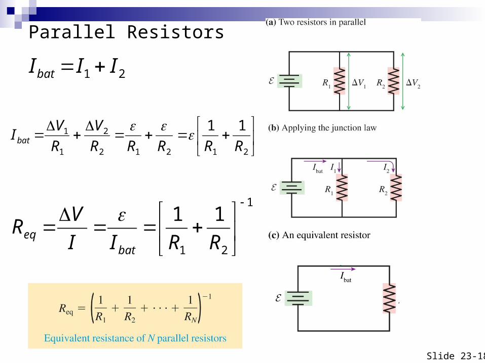
Parallel Resistors
Slide 23-18
21 IIIbat
21212
2
1
1 11
RRRRR
V
R
VIbat
1
21
11
RRII
VR
bateq
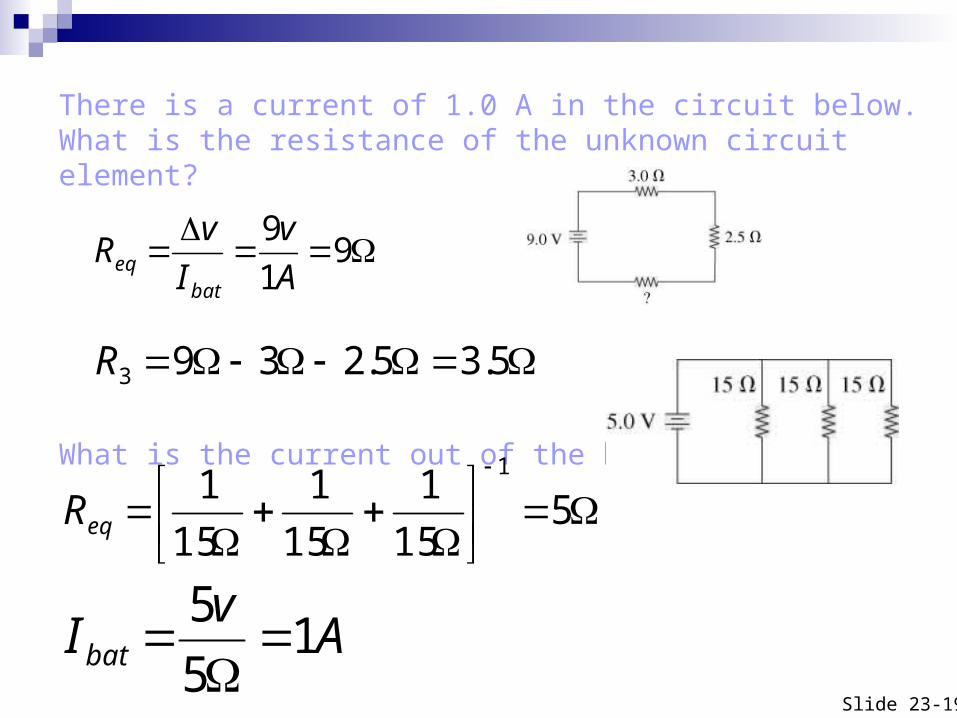
There is a current of 1.0 A in the circuit below. What is the resistance of the unknown circuit element?
What is the current out of the battery?
Slide 23-19
515
1
15
1
15
11
eqR
Av
Ibat 15
5
91
9
A
v
I
vR
bateq
5.35.2393R