cisco 7600 series ethernet services 20g line card hardware...
TRANSCRIPT
Cisco 7600 Series Ethernet Services 20G Line Card Hardware Installation GuideJuly, 2009
Americas HeadquartersCisco Systems, Inc.170 West Tasman DriveSan Jose, CA 95134-1706 USAhttp://www.cisco.comTel: 408 526-4000
800 553-NETS (6387)Fax: 408 527-0883
Text Part Number: OL-11908-05

THE SOFTWARE LICENSE AND LIMITED WARRANTY FOR THE ACCOMPANYING PRODUCT ARE SET FORTH IN THE INFORMATION PACKET THAT SHIPPED WITH THE PRODUCT AND ARE INCORPORATED HEREIN BY THIS REFERENCE. IF YOU ARE UNABLE TO LOCATE THE SOFTWARE LICENSE OR LIMITED WARRANTY, CONTACT YOUR CISCO REPRESENTATIVE FOR A COPY.
The following information is for FCC compliance of Class A devices: This equipment has been tested and found to comply with the limits for a Class A digital device, pursuant to part 15 of the FCC rules. These limits are designed to provide reasonable protection against harmful interference when the equipment is operated in a commercial environment. This equipment generates, uses, and can radiate radio-frequency energy and, if not installed and used in accordance with the instruction manual, may cause harmful interference to radio communications. Operation of this equipment in a residential area is likely to cause harmful interference, in which case users will be required to correct the interference at their own expense.
The following information is for FCC compliance of Class B devices: The equipment described in this manual generates and may radiate radio-frequency energy. If it is not installed in accordance with Cisco’s installation instructions, it may cause interference with radio and television reception. This equipment has been tested and found to comply with the limits for a Class B digital device in accordance with the specifications in part 15 of the FCC rules. These specifications are designed to provide reasonable protection against such interference in a residential installation. However, there is no guarantee that interference will not occur in a particular installation.
Modifying the equipment without Cisco’s written authorization may result in the equipment no longer complying with FCC requirements for Class A or Class B digital devices. In that event, your right to use the equipment may be limited by FCC regulations, and you may be required to correct any interference to radio or television communications at your own expense.
You can determine whether your equipment is causing interference by turning it off. If the interference stops, it was probably caused by the Cisco equipment or one of its peripheral devices. If the equipment causes interference to radio or television reception, try to correct the interference by using one or more of the following measures:
• Turn the television or radio antenna until the interference stops.
• Move the equipment to one side or the other of the television or radio.
• Move the equipment farther away from the television or radio.
• Plug the equipment into an outlet that is on a different circuit from the television or radio. (That is, make certain the equipment and the television or radio are on circuits controlled by different circuit breakers or fuses.)
Modifications to this product not authorized by Cisco Systems, Inc. could void the FCC approval and negate your authority to operate the product.
The Cisco implementation of TCP header compression is an adaptation of a program developed by the University of California, Berkeley (UCB) as part of UCB’s public domain version of the UNIX operating system. All rights reserved. Copyright © 1981, Regents of the University of California.
NOTWITHSTANDING ANY OTHER WARRANTY HEREIN, ALL DOCUMENT FILES AND SOFTWARE OF THESE SUPPLIERS ARE PROVIDED “AS IS” WITH ALL FAULTS. CISCO AND THE ABOVE-NAMED SUPPLIERS DISCLAIM ALL WARRANTIES, EXPRESSED OR IMPLIED, INCLUDING, WITHOUT LIMITATION, THOSE OF MERCHANTABILITY, FITNESS FOR A PARTICULAR PURPOSE AND NONINFRINGEMENT OR ARISING FROM A COURSE OF DEALING, USAGE, OR TRADE PRACTICE.
IN NO EVENT SHALL CISCO OR ITS SUPPLIERS BE LIABLE FOR ANY INDIRECT, SPECIAL, CONSEQUENTIAL, OR INCIDENTAL DAMAGES, INCLUDING, WITHOUT LIMITATION, LOST PROFITS OR LOSS OR DAMAGE TO DATA ARISING OUT OF THE USE OR INABILITY TO USE THIS MANUAL, EVEN IF CISCO OR ITS SUPPLIERS HAVE BEEN ADVISED OF THE POSSIBILITY OF SUCH DAMAGES
TCCDE, CCSI, CCENT, Cisco Eos, Cisco HealthPresence, the Cisco logo, Cisco Lumin, Cisco Nexus, Cisco Nurse Connect, Cisco Stackpower, Cisco StadiumVision, Cisco TelePresence, Cisco WebEx, DCE, and Welcome to the Human Network are trademarks; Changing the Way We Work, Live, Play, and Learn and Cisco Store are service marks; and Access Registrar, Aironet, AsyncOS, Bringing the Meeting To You, Catalyst, CCDA, CCDP, CCIE, CCIP, CCNA, CCNP, CCSP, CCVP, Cisco, the Cisco Certified Internetwork Expert logo, Cisco IOS, Cisco Press, Cisco Systems, Cisco Systems Capital, the Cisco Systems logo, Cisco Unity, Collaboration Without Limitation, EtherFast, EtherSwitch, Event Center, Fast Step, Follow Me Browsing, FormShare, GigaDrive, HomeLink, Internet Quotient, IOS, iPhone, iQuick Study, IronPort, the IronPort logo, LightStream, Linksys, MediaTone, MeetingPlace, MeetingPlace Chime Sound, MGX, Networkers, Networking Academy, Network Registrar, PCNow, PIX, PowerPanels, ProConnect, ScriptShare, SenderBase, SMARTnet, Spectrum Expert, StackWise, The Fastest Way to Increase Your Internet Quotient, TransPath, WebEx, and the WebEx logo are registered trademarks of Cisco Systems, Inc. and/or its affiliates in the United States and certain other countries.
All other trademarks mentioned in this document or website are the property of their respective owners. The use of the word partner does not imply a partnership relationship between Cisco and any other company. (0903R)
Cisco 7600 Series Ethernet Services 20G Line Card Hardware Installation Guide Copyright © 2008, Cisco Systems, Inc. All rights reserved.
OL-11908-05
C O N T E N T S
Preface vii
Organization ii-viii
Cisco 7600 Series Router Documentation ii-ix
Other Cisco IOS Software Publications ii-x
C H A P T E R 1 Cisco 7600 Series Ethernet Services 20G Line Card Product Overview 1-1
Introduction to the Cisco 7600 Series Ethernet Services 20G Line Card 1-1
Product Overview 1-2
Cisco 7600 Series Ethernet Services 20G Line Card Product Numbers 1-2
Supported Platforms 1-3
Cisco IOS Software Release and Hardware Revision Requirements 1-3
Modular Optics Compatibility 1-4
Supported CWDM-SFP Modules 1-4
Supported DWDM-XFP and DWDM-SFP Modules 1-4
Supported BX-SFP Modules 1-8
Power Management 1-8
C H A P T E R 2 Overview: Cisco 7600 Series Ethernet Services 20G Line Cards 2-1
Cisco 7600 Series Ethernet Services 20G Line Card Summary 2-1
Checking Hardware and Software Compatibility 2-1
Identifying Slots and Subslots for the Cisco 7600 Series Ethernet Services 20G Line Cards 2-2
Specifying the Slot Location for a Cisco 7600 Series Ethernet Services 20G Line Cards 2-2
Cisco 7600-ES20-10G Line Card Overview 2-3
Cisco 7600-ES20-10G Line Card Processor 2-3
Cisco 7600-ES20-10G Line Card LEDs 2-4
Cisco 7600 SIP-200 Physical Specifications 2-4
Cisco 7600 SIP-200 Line Card Memory Options 2-5
Cisco 7600-ES20-10G Cables and Connectors 2-5
Cisco 7600-ES20-GE Line Card Overview 2-6
Cisco 7600-ES20-GE Line Card Processor 2-6
Cisco 7600-ES20-GE Line Card LEDs 2-6
20-Port 10GE ES20 Physical Specifications 2-7
Cisco 7600-ES20-GE Line Card Memory Options 2-7
Cisco 7600-ES20-GE Line Card Cables and Connectors 2-8
IIICisco 7600 Series Ethernet Services 20G Line Card Hardware Installation Guide
Contents
C H A P T E R 3 Installing and Removing a Cisco 7600 Series Ethernet Services 20G Line Card 3-1
Handling Cisco 7600 Series Ethernet Services 20G Line Cards 3-1
Online Insertion and Removal 3-2
Preparing for Online Removal of a Cisco 7600 Series Ethernet Services 20G Line Card 3-2
Verifying Deactivation and Activation of a Cisco 7600 Series Ethernet Services 20G Line Card 3-4
Preparing for Online Removal of a SFP or XFP Modules 3-5
C H A P T E R 4 Preparing to Install a Cisco 7600 Series Ethernet Services 20G Line Card 4-1
Required Tools and Equipment 4-1
Safety Guidelines 4-1
Safety Warnings 4-2
Electrical Equipment Guidelines 4-6
Telephone Wiring Guidelines 4-7
Preventing Electrostatic Discharge Damage 4-7
Laser/LED Safety 4-8
C H A P T E R 5 Installing and Removing SFP and XFP Modules 5-1
Removing and Installing SFP Modules 5-1
Bale Clasp SFP Module 5-2
Mylar Tab SFP Module 5-4
Actuator Button SFP Module 5-6
Slide Tab SFP Module 5-8
Removing and Installing XFP Modules 5-11
Installing the 10-Gigabit XFP Transceiver Module 5-13
Removing the 10-Gigabit XFP Transceiver Module 5-16
C H A P T E R 6 Troubleshooting the Installation 6-1
Troubleshooting 6-1
Using debug Commands 6-2
Packing a Cisco 7600 ES20 Line Card for Shipment 6-2
I N D E X
IVCisco 7600 Series Ethernet Services 20G Line Card Hardware Installation Guide
OL-11908-05

Preface
This preface describes the objectives and organization of this document and explains how to find additional information on related products and services. This preface contains the following sections:
• Objectives, page vii
• Document Revision History, page vii
• Organization, page viii
• Related Documentation, page viii
• Related Documentation, page ix
• Cisco 7600 Series Router Documentation, page ix
• Document Conventions, page x
• Obtaining Documentation and Submitting a Service Request, page xi
ObjectivesThis document describes the Cisco 7600 Series Ethernet Services 20G line cards, hereinafter referred to as the Cisco 7600 ES20 line cards, that are supported on the Cisco 7600 series routers. This document also describes how to install the Cisco 7600 ES20 line cards and how to troubleshoot the installation.
Document Revision HistoryTable 1 records technical changes to this document. The table shows the Cisco IOS software release number and document revision number for the change, the date of the change, and a brief summary of the change.
Table 1 Document Revision History
Release No. Revision Date Change Summary
12.2(33) SRD OL-11908-05 June 2009 • Added a new section on General precautions within the section “Safety Guidelines”.
viiCisco 7600 Series Ethernet Services 20G Line Card Hardware Installation Guide
OL-11908-05

Preface Organization
OrganizationThis document contains the following chapters:
Related DocumentationThe documentation listed below is available online and on the Documentation DVD.
Your router, switch, or gateway and the Cisco IOS software running on it contain extensive features, which are documented in the following resources:
• Cisco 7600-ES20 Ethernet Line Cards Configuration Guide
• Cisco IOS software:
12.2(33) SRD OL-11908-05 October 2008 • Added CWDM SFP.
• Added ER Version2 XFP support.
• Added DWDM SFP and BX SFP support.
12.2(33) SRC 1 OL-11907-04 May 2008 Added DWDM-XFP support.
12.2(33) SRC OL-11908-3 January 2008 Added SFP-GE-T support.
12.2(33) SRB1 OL-11908-2 June 2007 Added XFP-10GZR-OC192LR.
12.2 SRB OL-11908-1 February 2007 Initial version.
Table 1 Document Revision History
Section Title Description
Chapter 1 Cisco 7600 Series Ethernet Services 20G Line Card Product Overview
Provides an introduction to the Cisco 7600 Series Ethernet Services 20G line cards.
Chapter 2 Overview: Cisco 7600 Series Ethernet Services 20G Line Cards
Provides a compatibility summary for the Cisco 7600 Series Ethernet Services 20G line cards. For each supported ES20 line card, provides a summary of characteristics and an overview.
Chapter 3 Preparing to Install a Cisco 7600 Series Ethernet Services 20G Line Card
Describes the required tools, equipment, and safety guidelines for installing Cisco 7600 Series Ethernet Services 20G line cards.
Chapter 4 Installing and Removing a Cisco 7600 Series Ethernet Services 20G Line Card
Describes the procedures for installing and removing Cisco 7600 Series Ethernet Services 20G line cards on a Cisco 7600 series router.
Chapter 5 Installing and Removing SFP and XFP Modules
Describes the procedures for installing and removing SFP and XFP modules on Cisco 7600 Series Ethernet Services 20G line cards.
Chapter 6 Troubleshooting the Installation Provides information for troubleshooting the installation of Cisco 7600 Series Ethernet Services 20G line cards. It also describes helpful debug commands and provides packing instructions.
viiiCisco 7600 Series Ethernet Services 20G Line Card Hardware Installation Guide
OL-11908-05
Preface Organization
– For Cisco IOS configuration information and support, refer to the configuration guide or command reference for a Cisco IOS mainline release. You can also refer to the specific Cisco IOS software document for a particular feature.
– To see if a feature is supported by a Cisco IOS release, to locate the software document for that feature, or to check the minimum software requirements of Cisco IOS software with the hardware installed on your router, Cisco maintains the Software Advisor tool on Cisco.com. You must be a registered user on Cisco.com to access this tool. To access Software Advisor, click Login at Cisco.com, type “Software Advisor” in the SEARCH box, and click GO. Click the link for the Software Advisor tool.
Note You can access Cisco IOS software configuration and hardware installation and maintenance documentation on the World Wide Web at http://www.cisco.com. Translated documentation is available at the following URL: http://www.cisco.com/public/countries_languages.shtml.
• For international agency compliance, safety, and statutory information for WAN interfaces:
– Regulatory Compliance and Safety Information for the Cisco 7600 Series Routers
– Site Preparation and Safety Guide
Related DocumentationThis section refers you to other documentation that also might be useful as you configure your Cisco 7600 series router. The documentation listed below is available online.
Cisco 7600 Series Router DocumentationAs you configure your Cisco 7600 series router, you should also refer to the following companion publication for important hardware installation information:
• Cisco 7600 Series Ethernet Services 20G Line Card Hardware Installation Guide
An overview of the Cisco 7600 series router features, benefits, and applications can be found in the Cisco 7600 Series Internet Router Essentials document located at the following URL:
http://www.cisco.com/en/US/products/hw/routers/ps368/products_quick_start09186a0080092248.html
Some of the following other Cisco 7600 series router publications might be useful to you as you configure your Cisco 7600 series router.
• Cisco 7600 Series Cisco IOS Software Configuration Guide
http://www.cisco.com/en/US/products/hw/routers/ps368/products_installation_and_configuration_guides_list.html
• Cisco 7600 Series Cisco IOS Command Reference
http://www.cisco.com/en/US/products/hw/routers/ps368/prod_command_reference_list.html
• Cisco 7600 Series Cisco IOS System Message Guide
http://www.cisco.com/en/US/products/hw/routers/ps368/products_system_message_guides_list.html
• Cisco 7600 Series Internet Router MIB Specifications Guide
http://www.cisco.com/en/US/products/hw/routers/ps368/prod_technical_reference_list.html.
ixCisco 7600 Series Ethernet Services 20G Line Card Hardware Installation Guide
OL-11908-05

Preface Organization
Several other publications are also related to the Cisco 7600 series router. For a complete reference of related documentation, refer to the Cisco 7600 Series Routers Documentation Roadmap located at the following URL:
http://www.cisco.com/en/US/products/hw/routers/ps368/products_documentation_roadmaps_list.html.
Other Cisco IOS Software PublicationsYour router and the Cisco IOS software running on it contain extensive features. You can find documentation for Cisco IOS software features at the following URL:
http://www.cisco.com/en/US/products/sw/iosswrel/tsd_products_support_category_home.html.
Cisco IOS Release 12.2SR Software Publications
Documentation for Cisco IOS Release 12.2SR, including command reference and system error messages, can be found at the following URL:
http://www.cisco.com/en/US/products/ps6922/tsd_products_support_series_home.html.
Document ConventionsWithin the SIP and SPA software configuration guides, the term router is generally used to refer to a variety of Cisco products (for example, routers, access servers, and switches). Routers, access servers, and other networking devices that support Cisco IOS software are shown interchangeably within examples. These products are used only for illustrative purposes; that is, an example that shows one product does not necessarily indicate that other products are not supported.
This documentation uses the following conventions:
Command syntax descriptions use the following conventions:
Convention Description
^ or Ctrl The ^ and Ctrl symbols represent the Control key. For example, the key combination ^D or Ctrl-D means hold down the Control key while you press the D key. Keys are indicated in capital letters but are not case sensitive.
string A string is a nonquoted set of characters shown in italics. For example, when setting an SNMP community string to public, do not use quotation marks around the string or the string will include the quotation marks.
Convention Description
bold Bold text indicates commands and keywords that you enter exactly as shown.
italics Italic text indicates arguments for which you supply values.
[x] Square brackets enclose an optional element (keyword or argument).
| A vertical line indicates a choice within an optional or required set of keywords or arguments.
xCisco 7600 Series Ethernet Services 20G Line Card Hardware Installation Guide
OL-11908-05
Preface Organization
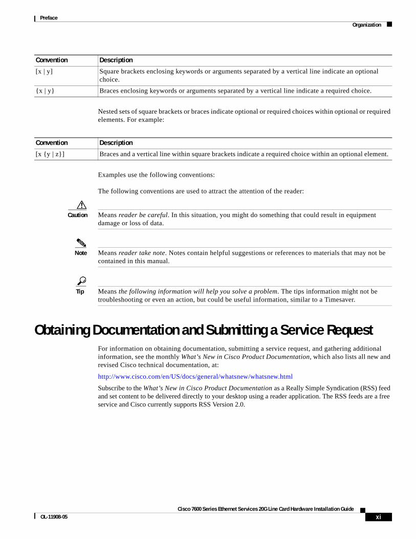
Nested sets of square brackets or braces indicate optional or required choices within optional or required elements. For example:
Examples use the following conventions:
The following conventions are used to attract the attention of the reader:
Caution Means reader be careful. In this situation, you might do something that could result in equipment damage or loss of data.
Note Means reader take note. Notes contain helpful suggestions or references to materials that may not be contained in this manual.
Tip Means the following information will help you solve a problem. The tips information might not be troubleshooting or even an action, but could be useful information, similar to a Timesaver.
Obtaining Documentation and Submitting a Service RequestFor information on obtaining documentation, submitting a service request, and gathering additional information, see the monthly What’s New in Cisco Product Documentation, which also lists all new and revised Cisco technical documentation, at:
http://www.cisco.com/en/US/docs/general/whatsnew/whatsnew.html
Subscribe to the What’s New in Cisco Product Documentation as a Really Simple Syndication (RSS) feed and set content to be delivered directly to your desktop using a reader application. The RSS feeds are a free service and Cisco currently supports RSS Version 2.0.
[x | y] Square brackets enclosing keywords or arguments separated by a vertical line indicate an optional choice.
{x | y} Braces enclosing keywords or arguments separated by a vertical line indicate a required choice.
Convention Description
Convention Description
[x {y | z}] Braces and a vertical line within square brackets indicate a required choice within an optional element.
xiCisco 7600 Series Ethernet Services 20G Line Card Hardware Installation Guide
OL-11908-05

Preface Organization
xiiCisco 7600 Series Ethernet Services 20G Line Card Hardware Installation Guide
OL-11908-05

Cisco 7600 Series Ethernet SOL-11908-05
C H A P T E R 1
Cisco 7600 Series Ethernet Services 20G Line Card Product OverviewThis chapter provides an introduction to the Cisco 7600 Series Ethernet Services 20G (ES20) line card. It includes the following sections:
• Introduction to the Cisco 7600 Series Ethernet Services 20G Line Card, page 1-1
• Cisco IOS Software Release and Hardware Revision Requirements, page 1-3
• Modular Optics Compatibility, page 1-4
• Power Management, page 1-8
Introduction to the Cisco 7600 Series Ethernet Services 20G Line Card
The Cisco 7600 Series Ethernet Services 20G (ES20) line cards are a multiple-fabric, fixed-port Ethernet line card for the Cisco 7600 series routers that are capable of 20 Gbps of traffic forwarding using a fixed port interface design. The two versions of the Cisco 7600 Series Ethernet Services 20G line card are:
• 2-port version: 7600-ES20-10G.
• 20-port version: 7600-ES20-GE.
The difference between the two versions are the link interface daughter cards that accept small form-factor pluggable (SFP or XFP) optical transceivers. Additionally, each of the two versions has a packet engine daughter card and a control processor daughter card.
Note SFP modules are optics modules with speeds lower than 10 Gbps; XFP modules are optics modules with speeds equal to or greater than 10 Gbps.
The SFP and XFP modules allow the line cards to be configured for different media types (copper or fiber) and different optical requirements (single mode fiber or multimode fiber) as available.
The 7600-ES20-10G uses a 2-port 10GE fixed interface daughter card that accepts pluggable XFP modules.
The 7600-ES20-GE uses a 20-port GE fixed interface daughter card that accepts pluggable SFP modules.
1-1ervices 20G Line Card Hardware Installation Guide
Chapter 1 Cisco 7600 Series Ethernet Services 20G Line Card Product Overview Introduction to the Cisco 7600 Series Ethernet Services 20G Line Card
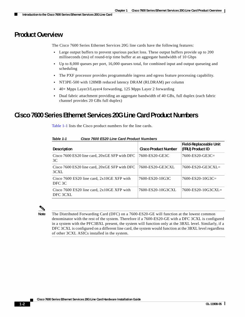
Product OverviewThe Cisco 7600 Series Ethernet Services 20G line cards have the following features:
• Large output buffers to prevent spurious packet loss. These output buffers provide up to 200 milliseconds (ms) of round-trip time buffer at an aggregate bandwidth of 10 Gbps
• Up to 8,000 queues per port, 16,000 queues total, for combined input and output queueing and scheduling
• The PXF processor provides programmable ingress and egress feature processing capability.
• NT3PE-500 with 128MB reduced latency DRAM (RLDRAM) per column
• 40+ Mpps Layer3/Layer4 forwarding, 125 Mpps Layer 2 forwarding
• Dual fabric attachment providing an aggregate bandwidth of 40 GBs, full duplex (each fabric channel provides 20 GBs full duplex)
Cisco 7600 Series Ethernet Services 20G Line Card Product NumbersTable 1-1 lists the Cisco product numbers for the line cards.
Note The Distributed Forwarding Card (DFC) on a 7600-ES20-GE will function at the lowest common denominator with the rest of the system. Therefore if a 7600-ES20-GE with a DFC 3CXL is configured in a system with the PFC3BXL present, the system will function only at the 3BXL level. Similarly, if a DFC 3CXL is configured on a different line card, the system would function at the 3BXL level regardless of other 3CXL ASICs installed in the system.
Table 1-1 Cisco 7600 ES20 Line Card Product Numbers
Description Cisco Product NumberField-Replaceable Unit (FRU) Product ID
Cisco 7600 ES20 line card, 20xGE SFP with DFC 3C
7600-ES20-GE3C 7600-ES20-GE3C=
Cisco 7600 ES20 line card, 20xGE SFP with DFC 3CXL
7600-ES20-GE3CXL 7600-ES20-GE3CXL=
Cisco 7600 ES20 line card, 2x10GE XFP with DFC 3C
7600-ES20-10G3C 7600-ES20-10G3C=
Cisco 7600 ES20 line card, 2x10GE XFP with DFC 3CXL
7600-ES20-10G3CXL 7600-ES20-10G3CXL=
1-2Cisco 7600 Series Ethernet Services 20G Line Card Hardware Installation Guide
OL-11908-05

Chapter 1 Cisco 7600 Series Ethernet Services 20G Line Card Product Overview Cisco IOS Software Release and Hardware Revision Requirements
Supported PlatformsTable 1-2 lists the supported router platforms for Cisco 7600 ES20 line cards.
Cisco IOS Software Release and Hardware Revision Requirements
The Cisco 7600 ES20 line cards have certain Cisco IOS software requirements. Also, to ensure compatibility with the software, your Cisco 7600 ES20 line card should have a specific hardware revision number. The number is printed on a label affixed to the component side of the card and is displayed by the show diag command.
Table 1-3 lists the hardware and software requirements for Cisco 7600 ES20 line cards.
The show diag slot_number, show version, and show hardware commands display the current hardware configuration of the router, including the system software version that is currently loaded and running, and the hardware revision number. For complete descriptions of show commands, refer to the Cisco IOS Configuration Fundamentals Configuration Guide and the Cisco IOS Configuration Fundamentals Command Reference for the installed Cisco IOS release.
If the command displays indicate that the Cisco IOS software is a version earlier than you need, check the contents of flash memory to determine if the required images are available on your system. The dir devicename command displays a list of all files stored in flash memory. If you do not have the correct software version, contact Cisco customer service.
For software configuration information, refer to the Cisco IOS software configuration and command reference publications for the installed Cisco IOS release. Also refer to the Cisco IOS software release notes for additional information.
Table 1-2 Cisco 7600 ES20 Line Card Supported Router Platforms
Cisco 7600 ES20 Line Card Supported Platform
7600-ES20-10G All Cisco 7600 series routers except for the Cisco 7603 router
7600-ES20-GE All Cisco 7600 series routers except for the Cisco 7603 router
Table 1-3 Cisco 7600 ES20 Line Card and Cisco IOS Release and Hardware Version Compatibility
Cisco 7600 ES20 Line Card Cisco Product NumberRequiredHardware Version
Minimum Cisco IOS Software Release
Cisco 7600 ES20 line card, 20xGE SFP with DFC 3C
7600-ES20-GE3C 68-2919-01 Cisco IOS Release 12.2SRB
Cisco 7600 ES20 line card, 2x10GE XFP with DFC 3C
7600-ES20-10G3C 68-2917-01 Cisco IOS Release 12.2SRB
Cisco 7600 ES20line card, 20xGE SFP with DFC 3CXL
7600-ES20-GE3CXL 68-2918-01 Cisco IOS Release 12.2SRB
Cisco 7600 ES20 line card, 2x10GE XFP with DFC 3CXL
7600-ES20-10G3CXL 68-2916-01 Cisco IOS Release 12.2SRB
1-3Cisco 7600 Series Ethernet Services 20G Line Card Hardware Installation Guide
OL-11908-05

Chapter 1 Cisco 7600 Series Ethernet Services 20G Line Card Product Overview Modular Optics Compatibility
Modular Optics CompatibilityThe Cisco 7600 ES20 line cards use small form-factor pluggable (SFP or XFP) optical transceivers to provide network connectivity. Table 1-4 lists the supported modules.
Table 1-4 Supported Modules
Supported CWDM-SFP Modules Table 1-5 lists the pluggable SFP modules supported on Cisco 7600-ES20-1GE. For details on removing or installing the SFP modules, see “Removing and Installing SFP Modules, page 5-1”.
Table 1-5 Supported SFP Modules
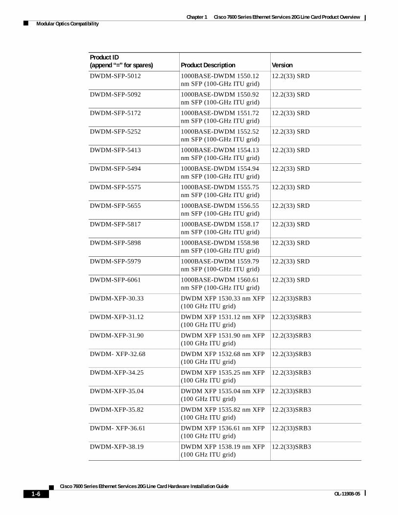
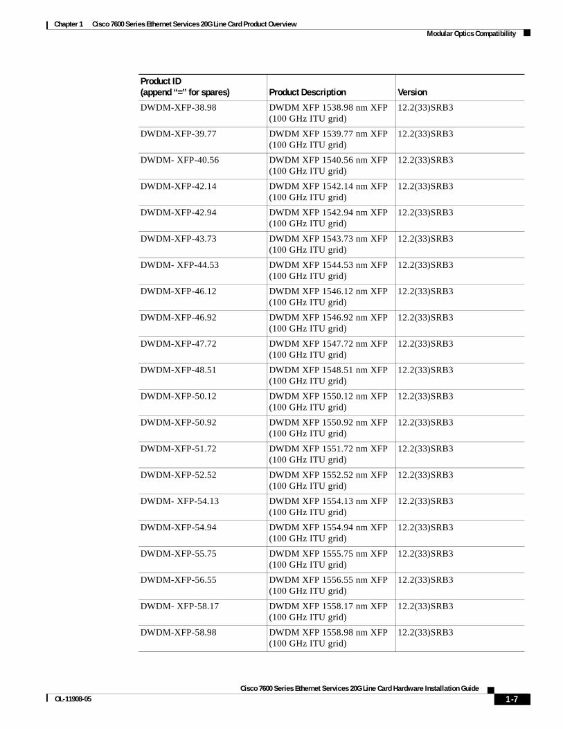
Supported DWDM-XFP and DWDM-SFP Modules Table 1-6 lists the pluggable XFP modules supported on Cisco 7600-ES20-10GE. For details on removing or installing the XFP modules, see ““Removing and Installing XFP Modules” section on page 5-11”
Line Cards Supported Modules (Cisco Part Numbers)
7600-ES20-10G XFP-10GLR-OC192SR, XFP-10GER-OC192IR XFP-10GZR-OC192LR
7600-ES20-GE SFP-GE-S, SFP-GE-L, SFP-GE-Z, SFP-GE-T
Product ID(append “=” for spare) Product Description Version
CWDM-SFP-1470= CWDM SFP 1470 nm; Gigabit Ethernet and 1G/2G FC
12.2(33) SRD
CWDM-SFP-1490= CWDM SFP 1490 nm; Gigabit Ethernet and 1G/2G FC
12.2(33) SRD
CWDM-SFP-1510= CWDM SFP 1510 nm; Gigabit Ethernet and 1G/2G FC
12.2(33) SRD
CWDM-SFP-1530= CWDM SFP 1530 nm; Gigabit Ethernet and 1G/2G FC
12.2(33) SRD
CWDM-SFP-1550= CWDM SFP 1550 nm; Gigabit Ethernet and 1G/2G FC
12.2(33) SRD
CWDM-SFP-1570= CWDM SFP 1570 nm; Gigabit Ethernet and 1G/2G FC
12.2(33) SRD
CWDM-SFP-1590= CWDM SFP 1590 nm; Gigabit Ethernet and 1G/2G FC
12.2(33) SRD
CWDM-SFP-1610= CWDM SFP 1610 nm; Gigabit Ethernet and 1G/2G FC
12.2(33) SRD
1-4Cisco 7600 Series Ethernet Services 20G Line Card Hardware Installation Guide
OL-11908-05

Chapter 1 Cisco 7600 Series Ethernet Services 20G Line Card Product Overview Modular Optics Compatibility
Table 1-6 Supported XFP Modules
Product ID(append “=” for spares) Product Description Version
DWDM-SFP-3033 1000BASE-DWDM 1530.33 nm SFP (100-GHz ITU grid)
12.2(33) SRD
DWDM-SFP-3112 1000BASE-DWDM 1531.12 nm SFP (100-GHz ITU grid)
12.2(33) SRD
DWDM-SFP-3190 1000BASE-DWDM 1531.90 nm SFP (100-GHz ITU grid)
12.2(33) SRD
DWDM-SFP-3268 1000BASE-DWDM 1532.68 nm SFP (100-GHz ITU grid)
12.2(33) SRD
DWDM-SFP-3425 1000BASE-DWDM 1534.25 nm SFP (100-GHz ITU grid)
12.2(33) SRD
DWDM-SFP-3504 1000BASE-DWDM 1535.04 nm SFP (100-GHz ITU grid)
12.2(33) SRD
DWDM-SFP-3582 1000BASE-DWDM 1535.82 nm SFP (100-GHz ITU grid)
12.2(33) SRD
DWDM-SFP-3661 1000BASE-DWDM 1536.61 nm SFP (100-GHz ITU grid)
12.2(33) SRD
DWDM-SFP-3819 1000BASE-DWDM 1538.19 nm SFP (100-GHz ITU grid)
12.2(33) SRD
DWDM-SFP-3898 1000BASE-DWDM 1538.98 nm SFP (100-GHz ITU grid)
12.2(33) SRD
DWDM-SFP-3977 1000BASE-DWDM 1539.77 nm SFP (100-GHz ITU grid)
12.2(33) SRD
DWDM-SFP-4056 1000BASE-DWDM 1540.56 nm SFP (100-GHz ITU grid)
12.2(33) SRD
DWDM-SFP-4214 1000BASE-DWDM 1542.14 nm SFP (100-GHz ITU grid)
12.2(33) SRD
DWDM-SFP-4294 1000BASE-DWDM 1542.94 nm SFP (100-GHz ITU grid)
12.2(33) SRD
DWDM-SFP-4373 1000BASE-DWDM 1543.73 nm SFP (100-GHz ITU grid)
12.2(33) SRD
DWDM-SFP-4453 1000BASE-DWDM 1544.53 nm SFP (100-GHz ITU grid)
12.2(33) SRD
DWDM-SFP-4612 1000BASE-DWDM 1546.12 nm SFP (100-GHz ITU grid)
12.2(33) SRD
DWDM-SFP-4692 1000BASE-DWDM 1546.92 nm SFP (100-GHz ITU grid)
12.2(33) SRD
DWDM-SFP-4772 1000BASE-DWDM 1547.72 nm SFP (100-GHz ITU grid)
12.2(33) SRD
DWDM-SFP-4851 1000BASE-DWDM 1548.51 nm SFP (100-GHz ITU grid)
12.2(33) SRD
1-5Cisco 7600 Series Ethernet Services 20G Line Card Hardware Installation Guide
OL-11908-05
Chapter 1 Cisco 7600 Series Ethernet Services 20G Line Card Product Overview Modular Optics Compatibility
DWDM-SFP-5012 1000BASE-DWDM 1550.12 nm SFP (100-GHz ITU grid)
12.2(33) SRD
DWDM-SFP-5092 1000BASE-DWDM 1550.92 nm SFP (100-GHz ITU grid)
12.2(33) SRD
DWDM-SFP-5172 1000BASE-DWDM 1551.72 nm SFP (100-GHz ITU grid)
12.2(33) SRD
DWDM-SFP-5252 1000BASE-DWDM 1552.52 nm SFP (100-GHz ITU grid)
12.2(33) SRD
DWDM-SFP-5413 1000BASE-DWDM 1554.13 nm SFP (100-GHz ITU grid)
12.2(33) SRD
DWDM-SFP-5494 1000BASE-DWDM 1554.94 nm SFP (100-GHz ITU grid)
12.2(33) SRD
DWDM-SFP-5575 1000BASE-DWDM 1555.75 nm SFP (100-GHz ITU grid)
12.2(33) SRD
DWDM-SFP-5655 1000BASE-DWDM 1556.55 nm SFP (100-GHz ITU grid)
12.2(33) SRD
DWDM-SFP-5817 1000BASE-DWDM 1558.17 nm SFP (100-GHz ITU grid)
12.2(33) SRD
DWDM-SFP-5898 1000BASE-DWDM 1558.98 nm SFP (100-GHz ITU grid)
12.2(33) SRD
DWDM-SFP-5979 1000BASE-DWDM 1559.79 nm SFP (100-GHz ITU grid)
12.2(33) SRD
DWDM-SFP-6061 1000BASE-DWDM 1560.61 nm SFP (100-GHz ITU grid)
12.2(33) SRD
DWDM-XFP-30.33 DWDM XFP 1530.33 nm XFP (100 GHz ITU grid)
12.2(33)SRB3
DWDM-XFP-31.12 DWDM XFP 1531.12 nm XFP (100 GHz ITU grid)
12.2(33)SRB3
DWDM-XFP-31.90 DWDM XFP 1531.90 nm XFP (100 GHz ITU grid)
12.2(33)SRB3
DWDM- XFP-32.68 DWDM XFP 1532.68 nm XFP (100 GHz ITU grid)
12.2(33)SRB3
DWDM-XFP-34.25 DWDM XFP 1535.25 nm XFP (100 GHz ITU grid)
12.2(33)SRB3
DWDM-XFP-35.04 DWDM XFP 1535.04 nm XFP (100 GHz ITU grid)
12.2(33)SRB3
DWDM-XFP-35.82 DWDM XFP 1535.82 nm XFP (100 GHz ITU grid)
12.2(33)SRB3
DWDM- XFP-36.61 DWDM XFP 1536.61 nm XFP (100 GHz ITU grid)
12.2(33)SRB3
DWDM-XFP-38.19 DWDM XFP 1538.19 nm XFP (100 GHz ITU grid)
12.2(33)SRB3
Product ID(append “=” for spares) Product Description Version
1-6Cisco 7600 Series Ethernet Services 20G Line Card Hardware Installation Guide
OL-11908-05
Chapter 1 Cisco 7600 Series Ethernet Services 20G Line Card Product Overview Modular Optics Compatibility
DWDM-XFP-38.98 DWDM XFP 1538.98 nm XFP (100 GHz ITU grid)
12.2(33)SRB3
DWDM-XFP-39.77 DWDM XFP 1539.77 nm XFP (100 GHz ITU grid)
12.2(33)SRB3
DWDM- XFP-40.56 DWDM XFP 1540.56 nm XFP (100 GHz ITU grid)
12.2(33)SRB3
DWDM-XFP-42.14 DWDM XFP 1542.14 nm XFP (100 GHz ITU grid)
12.2(33)SRB3
DWDM-XFP-42.94 DWDM XFP 1542.94 nm XFP (100 GHz ITU grid)
12.2(33)SRB3
DWDM-XFP-43.73 DWDM XFP 1543.73 nm XFP (100 GHz ITU grid)
12.2(33)SRB3
DWDM- XFP-44.53 DWDM XFP 1544.53 nm XFP (100 GHz ITU grid)
12.2(33)SRB3
DWDM-XFP-46.12 DWDM XFP 1546.12 nm XFP (100 GHz ITU grid)
12.2(33)SRB3
DWDM-XFP-46.92 DWDM XFP 1546.92 nm XFP (100 GHz ITU grid)
12.2(33)SRB3
DWDM-XFP-47.72 DWDM XFP 1547.72 nm XFP (100 GHz ITU grid)
12.2(33)SRB3
DWDM-XFP-48.51 DWDM XFP 1548.51 nm XFP (100 GHz ITU grid)
12.2(33)SRB3
DWDM-XFP-50.12 DWDM XFP 1550.12 nm XFP (100 GHz ITU grid)
12.2(33)SRB3
DWDM-XFP-50.92 DWDM XFP 1550.92 nm XFP (100 GHz ITU grid)
12.2(33)SRB3
DWDM-XFP-51.72 DWDM XFP 1551.72 nm XFP (100 GHz ITU grid)
12.2(33)SRB3
DWDM-XFP-52.52 DWDM XFP 1552.52 nm XFP (100 GHz ITU grid)
12.2(33)SRB3
DWDM- XFP-54.13 DWDM XFP 1554.13 nm XFP (100 GHz ITU grid)
12.2(33)SRB3
DWDM-XFP-54.94 DWDM XFP 1554.94 nm XFP (100 GHz ITU grid)
12.2(33)SRB3
DWDM-XFP-55.75 DWDM XFP 1555.75 nm XFP (100 GHz ITU grid)
12.2(33)SRB3
DWDM-XFP-56.55 DWDM XFP 1556.55 nm XFP (100 GHz ITU grid)
12.2(33)SRB3
DWDM- XFP-58.17 DWDM XFP 1558.17 nm XFP (100 GHz ITU grid)
12.2(33)SRB3
DWDM-XFP-58.98 DWDM XFP 1558.98 nm XFP (100 GHz ITU grid)
12.2(33)SRB3
Product ID(append “=” for spares) Product Description Version
1-7Cisco 7600 Series Ethernet Services 20G Line Card Hardware Installation Guide
OL-11908-05
Chapter 1 Cisco 7600 Series Ethernet Services 20G Line Card Product Overview Supported BX-SFP Modules
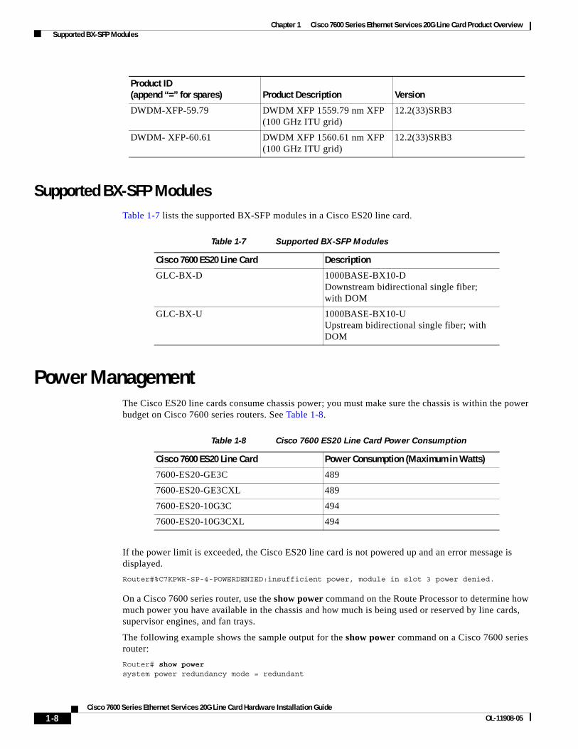
Supported BX-SFP ModulesTable 1-7 lists the supported BX-SFP modules in a Cisco ES20 line card.
Table 1-7 Supported BX-SFP Modules
Power ManagementThe Cisco ES20 line cards consume chassis power; you must make sure the chassis is within the power budget on Cisco 7600 series routers. See Table 1-8.
Table 1-8 Cisco 7600 ES20 Line Card Power Consumption
If the power limit is exceeded, the Cisco ES20 line card is not powered up and an error message is displayed.
Router#%C7KPWR-SP-4-POWERDENIED:insufficient power, module in slot 3 power denied.
On a Cisco 7600 series router, use the show power command on the Route Processor to determine how much power you have available in the chassis and how much is being used or reserved by line cards, supervisor engines, and fan trays.
The following example shows the sample output for the show power command on a Cisco 7600 series router:
Router# show power system power redundancy mode = redundant
DWDM-XFP-59.79 DWDM XFP 1559.79 nm XFP (100 GHz ITU grid)
12.2(33)SRB3
DWDM- XFP-60.61 DWDM XFP 1560.61 nm XFP (100 GHz ITU grid)
12.2(33)SRB3
Product ID(append “=” for spares) Product Description Version
Cisco 7600 ES20 Line Card Description
GLC-BX-D 1000BASE-BX10-D Downstream bidirectional single fiber; with DOM
GLC-BX-U 1000BASE-BX10-U Upstream bidirectional single fiber; with DOM
Cisco 7600 ES20 Line Card Power Consumption (Maximum in Watts)
7600-ES20-GE3C 489
7600-ES20-GE3CXL 489
7600-ES20-10G3C 494
7600-ES20-10G3CXL 494
1-8Cisco 7600 Series Ethernet Services 20G Line Card Hardware Installation Guide
OL-11908-05

Chapter 1 Cisco 7600 Series Ethernet Services 20G Line Card Product Overview Power Management
system power redundancy operationally = non-redundantsystem power total = 2669.10 Watts (63.55 Amps @ 42V)system power used = 1530.90 Watts (36.45 Amps @ 42V)system power available = 1138.20 Watts (27.10 Amps @ 42V) Power-Capacity PS-Fan Output OperPS Type Watts A @42V Status Status State---- ------------------ ------- ------ ------ ------ -----1 PWR-2700-AC 1319.22 31.41 - - off2 PWR-2700-AC 2669.10 63.55 OK OK on Pwr-Allocated OperFan Type Watts A @42V State---- ------------------ ------- ------ -----1 FAN-MOD-6HS 180.18 4.29 OK Pwr-Requested Pwr-Allocated Admin OperSlot Card-Type Watts A @42V Watts A @42V State State---- ------------------ ------- ------ ------- ------ ----- -----2 7600-ES20-BASE 340.20 8.10 340.20 8.10 on on4 7600-ES20-BASE 340.20 8.10 340.20 8.10 on on5 7600-SIP-600 341.88 8.14 341.88 8.14 on on6 WS-SUP720-3BXL 328.44 7.82 328.44 7.82 on onRouter#
1-9Cisco 7600 Series Ethernet Services 20G Line Card Hardware Installation Guide
OL-11908-05

Chapter 1 Cisco 7600 Series Ethernet Services 20G Line Card Product Overview Power Management
1-10Cisco 7600 Series Ethernet Services 20G Line Card Hardware Installation Guide
OL-11908-05

Cisco 7600 Series Ethernet SOL-11908-05
C H A P T E R 2
Overview: Cisco 7600 Series Ethernet Services 20G Line CardsThis chapter describes the Cisco 7600 Series Ethernet Services 20G (ES20) line cards that are supported on the Cisco 7600 series routers and contains the following sections:
• Cisco 7600 Series Ethernet Services 20G Line Card Summary, page 2-1
• Identifying Slots and Subslots for the Cisco 7600 Series Ethernet Services 20G Line Cards, page 2-2
• Cisco 7600-ES20-10G Line Card Overview, page 2-3
• Cisco 7600-ES20-GE Line Card Overview, page 2-6
Cisco 7600 Series Ethernet Services 20G Line Card SummarySummary descriptions of the Cisco 7600 Series Ethernet Services 20G line cards that are supported on the Cisco 7600 series routers are shown in Table 2-1.
Checking Hardware and Software CompatibilityTo check the minimum software requirements of Cisco IOS software with the hardware installed on your router, Cisco maintains the Software Advisor tool on Cisco.com. This tool does not verify whether the Cisco 7600 ES20 line cards within a system are compatible, but it does provide the minimum Cisco IOS requirements for individual hardware modules or components.
Cisco ES20 Line Card Product Numbers Description
Maximum Number of SFPs or XFPs
Minimum Cisco IOS Release
7600-ES20-10G 7600-ES20-10G3C, 7600-ES20-10G3CXL
2-port 10 Gigabit Ethernet line card providing core-facing redundant 10 Gigabit Ethernet uplinks with H-VPLS support.
2 Cisco IOS Release 12.2SRB
7600-ES20-GE 7600-ES20-GE3C, 7600-ES20-GE3CXL
20-port 1 Gigabit Ethernet line card providing core-facing redundant Ethernet uplinks with H-VPLS support.
20 Cisco IOS Release 12.2SRB
2-1ervices 20G Line Card Hardware Installation Guide

Chapter 2 Overview: Cisco 7600 Series Ethernet Services 20G Line Cards Identifying Slots and Subslots for the Cisco 7600 Series Ethernet Services 20G Line Cards
Note Access to this tool is limited to users with Cisco.com login accounts.
To access Software Advisor, click Login at Cisco.com, type “Software Advisor” in the SEARCH box, and click GO. Click the link for the Software Advisor tool.
Choose a product family or enter a specific product number to search for the minimum supported software release needed for your hardware.
Identifying Slots and Subslots for the Cisco 7600 Series Ethernet Services 20G Line Cards
This section describes how to specify the physical location of a Cisco 7600 Series Ethernet Services 20G line cards on the Cisco 7600 series routers within the command-line interface (CLI) to configure or monitor those devices.
Specifying the Slot Location for a Cisco 7600 Series Ethernet Services 20G Line Cards
The Cisco 7600 series routers support different chassis models, each of which supports a certain number of chassis slots.
Note The Cisco 7600 ES20 line cards are not supported with a Supervisor Engine 1, Supervisor Engine 1A, Supervisor Engine 2, or Supervisor Engine 720-3A.
For information about the chassis slots available in different Cisco 7600 series router models, see http://www.cisco.com/univercd/cc/td/doc/product/core/cis7600/hardware/cis_76xx/osr_over.htm.
Some commands allow you to display information about the Cisco 7600 ES20 line card itself, such as show module, show idprom module, show hw-module slot, and show diagbus. These commands require you to specify the chassis slot location where the Cisco 7600 ES20 line card that you want information about is installed.
For example, to display status and information about the Cisco 7600 ES20 line card installed in slot 6 of a Cisco 7609 router, enter the following command:
Router# show module 6
For more information about Cisco 7600 ES20 line card commands, see the “Command Summary for the Cisco 7600 Series Ethernet Services 20G Line Card ” and the “Cisco 7600 Series Ethernet Services 20G Line Card Commands” chapters in the Cisco 7600 Series Router SIP, SSC, and SPA Software Configuration Guide .
Note The Cisco 7600 ES20 line card must be in a slot that provides two primary serial channels. Dual serial channels are not available in all slots of a 13-slot chassis. Dual fabric connectivity is supported in slots 9 to 13.
2-2Cisco 7600 Series Ethernet Services 20G Line Card Hardware Installation Guide
OL-11908-05

Chapter 2 Overview: Cisco 7600 Series Ethernet Services 20G Line Cards Cisco 7600-ES20-10G Line Card Overview
Cisco 7600-ES20-10G Line Card Slot, Bay, and Port Locations
The Cisco 7600-ES20-10G line card uses a slot/bay/port numbering scheme. The slot refers to whichever slot the line card occupies in the router. The bay number is always 0. The port number is either 0 or 1.
Executing the show interface command for a Cisco 7600-ES20-10G line card located in slot 4 of a Cisco 7600 series router chassis produces the following:
show interface TenGigabitEthernet4/0/0 (first interface)show interface TenGigabitEthernet4/0/1 (second interface)
Cisco 7600-ES20-GE Line Card Slot, Bay, and Port Locations
The Cisco 7600-ES20-GE line card uses a <slot, bay, port> numbering scheme. The slot refers to whichever slot the line card occupies in the router. The bay number is always zero. The port number is zero through 19.
Executing the show interface command for a Cisco 7600-ES20-GE line card located in slot 6 of a Cisco 7600 series router chassis produces the following (only first six interfaces are shown):
show interface TenGigabitEthernet6/0/0 (first interface)show interface TenGigabitEthernet6/0/1 (second interface)show interface TenGigabitEthernet6/0/2 (third interface)show interface TenGigabitEthernet6/0/3 (fourth interface)show interface TenGigabitEthernet6/0/4 (fift interface)show interface TenGigabitEthernet6/0/5 (sixth interface)
For more information about Cisco 7600 ES20 line card commands, see the “Command Summary for the Cisco 7600 ES20 Line Cards ” and the “Cisco 7600 ES20 Line Card Commands” chapters in the Cisco 7600 Series Router SIP, SSC, and SPA Software Configuration Guide .
Cisco 7600-ES20-10G Line Card OverviewThe following sections describe the Cisco 7600-ES20-10G line card:
• Cisco 7600-ES20-10G Line Card Processor, page 2-3
• Cisco 7600-ES20-10G Line Card LEDs, page 2-4
• Cisco 7600 SIP-200 Physical Specifications, page 2-4
• Cisco 7600 SIP-200 Line Card Memory Options, page 2-5
• Cisco 7600-ES20-10G Cables and Connectors, page 2-5
Cisco 7600-ES20-10G Line Card ProcessorThe processor on a Cisco 7600-ES20-GE line card is described in Table 2-1.
Table 2-1 Cisco 7600-ES20-10G Line Card Processor
Type Speed Description
CPU 400 megahertz (MHz) internal operating frequency
Broadcom 1125 MIPS-based design
2-3Cisco 7600 Series Ethernet Services 20G Line Card Hardware Installation Guide
OL-11908-05
Chapter 2 Overview: Cisco 7600 Series Ethernet Services 20G Line Cards Cisco 7600-ES20-10G Line Card Overview
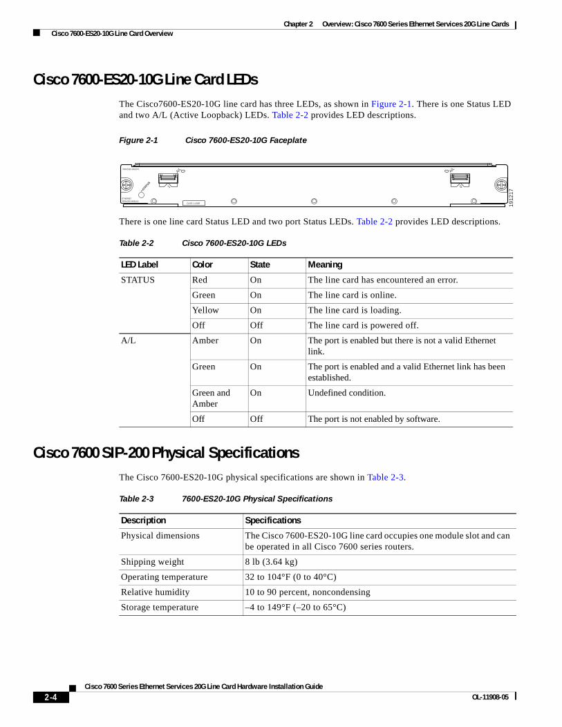
Cisco 7600-ES20-10G Line Card LEDsThe Cisco7600-ES20-10G line card has three LEDs, as shown in Figure 2-1. There is one Status LED and two A/L (Active Loopback) LEDs. Table 2-2 provides LED descriptions.
Figure 2-1 Cisco 7600-ES20-10G Faceplate
There is one line card Status LED and two port Status LEDs. Table 2-2 provides LED descriptions.
Cisco 7600 SIP-200 Physical SpecificationsThe Cisco 7600-ES20-10G physical specifications are shown in Table 2-3.
A/L
STATU
S
ETHERNETSERVICES MODULE
7600-ES20-10G3CXL
CLASS 1 LASER
A/L
1 0
1912
17
Table 2-2 Cisco 7600-ES20-10G LEDs
LED Label Color State Meaning
STATUS Red On The line card has encountered an error.
Green On The line card is online.
Yellow On The line card is loading.
Off Off The line card is powered off.
A/L Amber On The port is enabled but there is not a valid Ethernet link.
Green On The port is enabled and a valid Ethernet link has been established.
Green and Amber
On Undefined condition.
Off Off The port is not enabled by software.
Table 2-3 7600-ES20-10G Physical Specifications
Description Specifications
Physical dimensions The Cisco 7600-ES20-10G line card occupies one module slot and can be operated in all Cisco 7600 series routers.
Shipping weight 8 lb (3.64 kg)
Operating temperature 32 to 104°F (0 to 40°C)
Relative humidity 10 to 90 percent, noncondensing
Storage temperature –4 to 149°F (–20 to 65°C)
2-4Cisco 7600 Series Ethernet Services 20G Line Card Hardware Installation Guide
OL-11908-05

Chapter 2 Overview: Cisco 7600 Series Ethernet Services 20G Line Cards Cisco 7600-ES20-10G Line Card Overview
Cisco 7600 SIP-200 Line Card Memory OptionsTable 2-4 lists the memory options available for the Cisco 7600-ES20-10G line card:
Cisco 7600-ES20-10G Cables and ConnectorsThe Cisco 7600-ES20-10G line card supports the XFP-10GLR-OC192SR and XFP-10GER-OC192IR XFP modules.
The XFP-10GLR-OC192SR and XFP-10GER-OC192IR XFPs modules include an optical transmitter and receiver pair integrated with Clock and Data Recovery (CDR) integrated circuits.
The XFP modules provide high-speed serial links at the following rates: 9.95 Gbps (OC-192) and 10.3125 Gbps (10 Gigabit Ethernet) on single-mode fiber (SMF). The transmit side recovers and retimes the 10-Gbps serial data and passes it to a laser driver. The laser driver biases and modulates a 1310-nm or 1550-nm laser, enabling data transmission over SMF through an LC connector. The receive side recovers and retimes the 10-Gbps optical data stream from a photo-detector transimpedance amplifier and passes it to an output driver.
See the label on the XFP module for technology type and model.
• XFP module dimensions are:
• Height: 12.5 mm
• Width: 18.35 mm
• Length: 71.1mm
The XFP module temperature range is 0°C to 70°C.
Figure 2-2 XFP Module
Table 2-5 lists XFP module port cabling specifications.
Table 2-4 Cisco 7600-ES20-10G Line Card Memory Options
Line Card Memory Options
Cisco 7600-ES20-10G 1 GB
1294
99
2-5Cisco 7600 Series Ethernet Services 20G Line Card Hardware Installation Guide
OL-11908-05

Chapter 2 Overview: Cisco 7600 Series Ethernet Services 20G Line Cards Cisco 7600-ES20-GE Line Card Overview
Table 2-5 Port Cabling Specifications
Figure 2-3 shows the cable type for use with the XFP optical transceiver module on the Cisco 7600-ES20-10G line card.
Figure 2-3 LC-Type Cable for the XFP Optical Transceiver Modules
Cisco 7600-ES20-GE Line Card OverviewThe following sections describe the Cisco 7600-ES20-GE line card:
• Cisco 7600-ES20-GE Line Card Processor, page 2-6
• Cisco 7600-ES20-GE Line Card LEDs, page 2-6
• 20-Port 10GE ES20 Physical Specifications, page 2-7
Cisco 7600-ES20-GE Line Card ProcessorThe processor on a Cisco 7600-ES20-GE line card is described in Table 2-6.
Cisco 7600-ES20-GE Line Card LEDsThe Cisco 7600-ES20-GE line card has 21 LEDs, as shown in Figure 2-4.
XFP Wavelength Fiber Type
XFP-10GLR-OC192SR 1310 nm SMF
XFP-10GER-OC192IR 1550 nm SMF
XFP-10GZR-OC192LR 1550 nm SMF
/ / / // /
TXRX 8492
9
Table 2-6 Cisco 7600-ES20-GE Line Card Processor
Type Speed Description
CPU 400 megahertz (MHz) internal operating frequency
Broadcom 1125 MIPS-based design
2-6Cisco 7600 Series Ethernet Services 20G Line Card Hardware Installation Guide
OL-11908-05

Chapter 2 Overview: Cisco 7600 Series Ethernet Services 20G Line Cards Cisco 7600-ES20-GE Line Card Overview
Figure 2-4 Cisco 7600-ES20-GE Line Card Faceplate
There is one line card STATUS LED and twenty A/L (Active Loopback) LEDs. Table 2-7 provides LED descriptions.
20-Port 10GE ES20 Physical SpecificationsThe Cisco 7600-ES20-GE line card physical specifications are shown in Table 2-8.
Cisco 7600-ES20-GE Line Card Memory OptionsTable 2-4 lists the memory options available for the Cisco 7600-ES20-GE line card:
STATU
S
ETHERNETSERVICES MODULE
7600-ES20-GE3CXL
CLASS 1 LASER
0
A/L
1912
18
1
A/L
2
A/L
3
A/L
4
A/L
5
A/L
6
A/L
7
A/L
8
A/L
9
A/L
10
A/L
11
A/L
12
A/L
13
A/L
14
A/L
15
A/L
16
A/L
17
A/L
18
A/L
19
A/L
Table 2-7 Cisco 7600-ES20-GE Line Card LEDs
LED Label Color State Meaning
STATUS Red On The line card has encountered an error.
Green On The line card is online.
Yellow On The line card is loading.
Off Off The line card is powered off.
A/L Amber On The port is enabled but there is not a valid Ethernet link.
Green On The port is enabled and a valid Ethernet link has been established.
Green and Amber
On Undefined condition.
Off Off The port is not enabled by software.
Table 2-8 Cisco 7600-ES20-GE Line Card Physical Specifications
Description Specifications
Physical dimensions The Cisco 7600-ES20-GE line card occupies one module slot and can be operated in all Cisco 7600 series routers.
Shipping weight 8 lb (3.64 kg)
Operating temperature 32 to 104°F (0 to 40°C)
Relative humidity 10 to 90 percent, noncondensing
Storage temperature –4 to 149°F (–20 to 65°C)
2-7Cisco 7600 Series Ethernet Services 20G Line Card Hardware Installation Guide
OL-11908-05
Chapter 2 Overview: Cisco 7600 Series Ethernet Services 20G Line Cards Cisco 7600-ES20-GE Line Card Overview
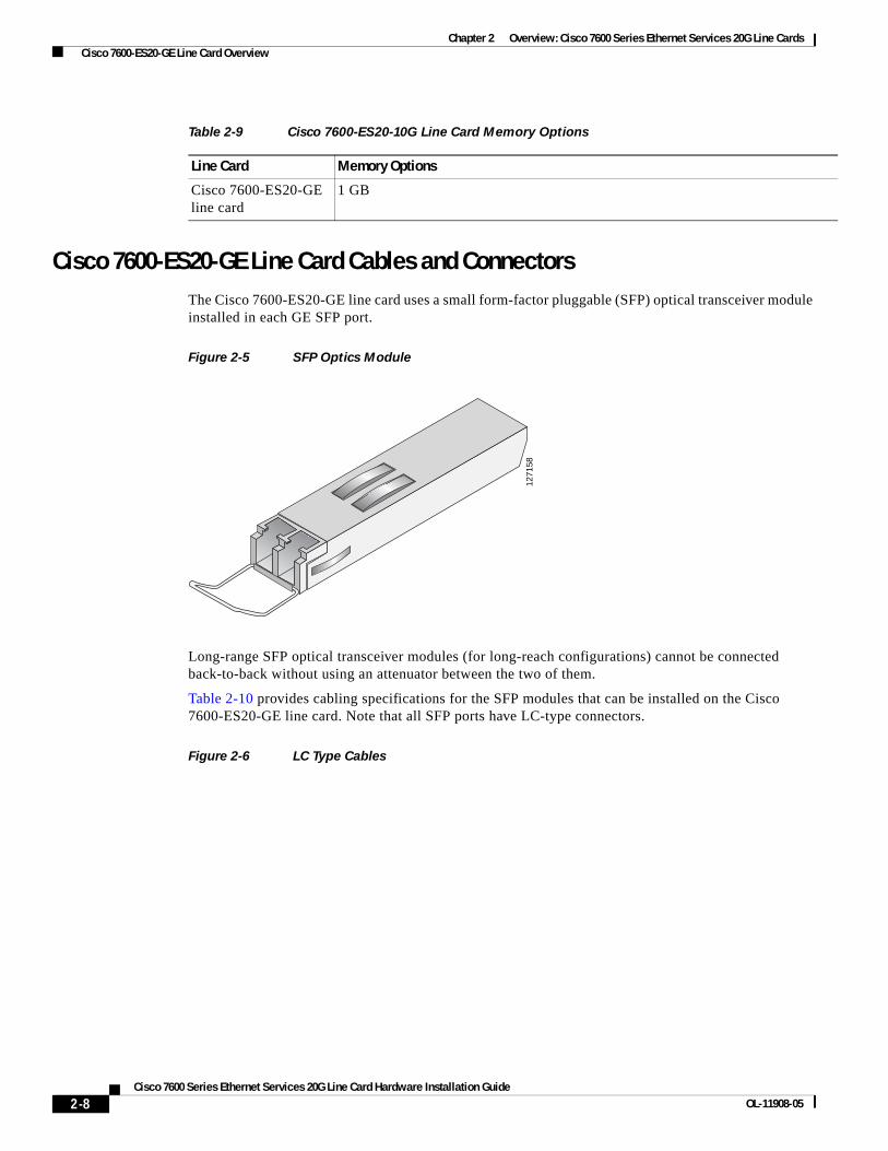
Cisco 7600-ES20-GE Line Card Cables and ConnectorsThe Cisco 7600-ES20-GE line card uses a small form-factor pluggable (SFP) optical transceiver module installed in each GE SFP port.
Figure 2-5 SFP Optics Module
Long-range SFP optical transceiver modules (for long-reach configurations) cannot be connected back-to-back without using an attenuator between the two of them.
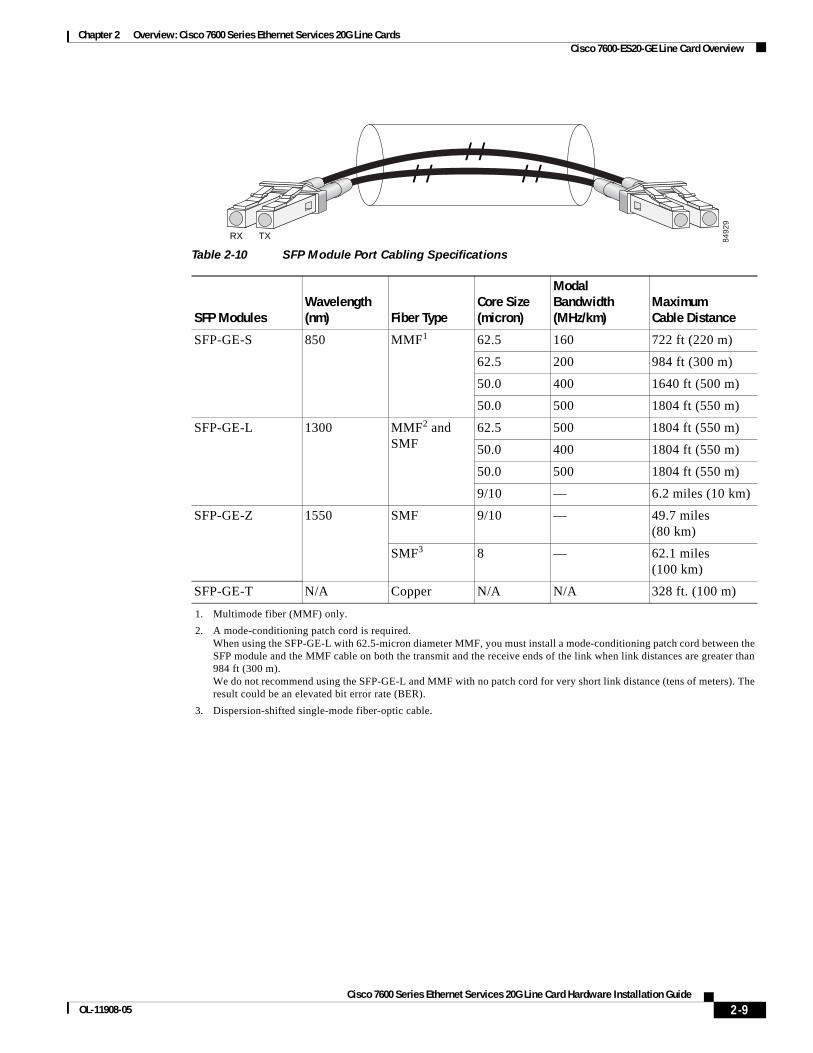
Table 2-10 provides cabling specifications for the SFP modules that can be installed on the Cisco 7600-ES20-GE line card. Note that all SFP ports have LC-type connectors.
Figure 2-6 LC Type Cables
Table 2-9 Cisco 7600-ES20-10G Line Card Memory Options
Line Card Memory Options
Cisco 7600-ES20-GE line card
1 GB
1271
58
2-8Cisco 7600 Series Ethernet Services 20G Line Card Hardware Installation Guide
OL-11908-05
Chapter 2 Overview: Cisco 7600 Series Ethernet Services 20G Line Cards Cisco 7600-ES20-GE Line Card Overview
/ / / // /
TXRX 8492
9
Table 2-10 SFP Module Port Cabling Specifications
SFP ModulesWavelength (nm) Fiber Type
Core Size (micron)
Modal Bandwidth (MHz/km)
Maximum Cable Distance
SFP-GE-S 850 MMF1 62.5 160 722 ft (220 m)
62.5 200 984 ft (300 m)
50.0 400 1640 ft (500 m)
50.0 500 1804 ft (550 m)
SFP-GE-L 1300 MMF2 and SMF
62.5 500 1804 ft (550 m)
50.0 400 1804 ft (550 m)
50.0 500 1804 ft (550 m)
9/10 — 6.2 miles (10 km)
SFP-GE-Z 1550 SMF 9/10 — 49.7 miles (80 km)
SMF3 8 — 62.1 miles (100 km)
SFP-GE-T N/A Copper N/A N/A 328 ft. (100 m)
1. Multimode fiber (MMF) only.
2. A mode-conditioning patch cord is required. When using the SFP-GE-L with 62.5-micron diameter MMF, you must install a mode-conditioning patch cord between the SFP module and the MMF cable on both the transmit and the receive ends of the link when link distances are greater than 984 ft (300 m). We do not recommend using the SFP-GE-L and MMF with no patch cord for very short link distance (tens of meters). The result could be an elevated bit error rate (BER).
3. Dispersion-shifted single-mode fiber-optic cable.
2-9Cisco 7600 Series Ethernet Services 20G Line Card Hardware Installation Guide
OL-11908-05

Chapter 2 Overview: Cisco 7600 Series Ethernet Services 20G Line Cards Cisco 7600-ES20-GE Line Card Overview
2-10Cisco 7600 Series Ethernet Services 20G Line Card Hardware Installation Guide
OL-11908-05

Cisco 7600 Series Ethernet SOL-11908-05
C H A P T E R 4
Installing and Removing a Cisco 7600 Series Ethernet Services 20G Line CardThis chapter describes how to install or remove Cisco 7600 Series Ethernet Services 20G (ES20) line cards on the Cisco 7600 series routers. This chapter contains the following sections:
• Handling Cisco 7600 Series Ethernet Services 20G Line Cards, page 4-1.
• Online Insertion and Removal, page 4-2.
Handling Cisco 7600 Series Ethernet Services 20G Line CardsEach Cisco 7600 ES20 line card circuit board is mounted to a metal carrier and is sensitive to electrostatic discharge (ESD) damage. Before you begin installation, read Chapter 4, “Preparing to Install a Cisco 7600 Series Ethernet Services 20G Line Card,” for a list of parts and tools required for installation.
Caution Always handle the Cisco 7600 ES20 line card by the carrier edges and handle; never touch the line card components or connector pins. (See Figure 3-1.)
When a slot is not in use, a blank filler plate must be installed in the empty slot to allow the router or switch to conform to electromagnetic interference (EMI) emissions requirements and to allow proper airflow across the installed modules. If you plan to install a Cisco 7600 ES20 line card in a slot that is not in use, you must first remove the blank filler plate.
Figure 3-1 Handling a Cisco 7600 ES20 Line Card
4-1ervices 20G Line Card Hardware Installation Guide

Chapter 4 Installing and Removing a Cisco 7600 Series Ethernet Services 20G Line Card Online Insertion and Removal
Online Insertion and RemovalThe Cisco 7600 series routers support online insertion and removal (OIR) of the Cisco 7600 ES20 line card, as well as OIR for the SFP or XFP modules. Therefore, you can remove a Cisco 7600 ES20 line card with its SFP or XFP modules still intact, or you can remove SFP or XFP modules independently from the Cisco 7600 ES20 line card, leaving the line card installed in the router.
This section includes the following topics on OIR support:
• Preparing for Online Removal of a Cisco 7600 Series Ethernet Services 20G Line Card, page 4-2
• Verifying Deactivation and Activation of a Cisco 7600 Series Ethernet Services 20G Line Card, page 4-4
• Preparing for Online Removal of a SFP or XFP Modules, page 4-5
Preparing for Online Removal of a Cisco 7600 Series Ethernet Services 20G Line Card
The Cisco 7600 series routers support OIR of the Cisco 7600 ES20 line card. To do this, you can power down a Cisco 7600 ES20 line card (which automatically deactivates any installed SFP or XFP modules) and remove the Cisco 7600 ES20 line card with the SFP or XFP modules still intact.
Although graceful deactivation of a ES20 line card is preferred using the no power enable module command, the Cisco 7600 series routers do support removal of the ES20 line card without deactivating it first.
If you plan to remove a Cisco 7600 ES20 line card, you can deactivate the Cisco 7600 ES20 line card first, using the no power enable module global configuration command.
7000
6
Metal carrier
GND
Printed circuit board
4-2Cisco 7600 Series Ethernet Services 20G Line Card Hardware Installation Guide
OL-11908-05

Chapter 4 Installing and Removing a Cisco 7600 Series Ethernet Services 20G Line Card Online Insertion and Removal
When you deactivate a Cisco 7600 ES20 line card using this command, it automatically deactivates each of the SFP or XFP modules that are installed in that Cisco 7600 ES20 line card. Therefore, it is not necessary to deactivate each of the SFP or XFP modules prior to deactivating the Cisco 7600 ES20 line card.
Deactivating a Cisco 7600 Series Ethernet Services 20G Line Card
To deactivate a ES20 Ethernet line card and its installed SFPs or XFPs prior to removal of the ES20 line card, use the following command in global configuration mode:
For more information about chassis slot numbering, refer to the Chapter 2, “Identifying Slots and Subslots for the Cisco 7600 Series Ethernet Services 20G Line Cards,” section in this guide.
Reactivating a Cisco 7600 Series Ethernet Services 20G Line Card
Once you deactivate a Cisco 7600 ES20 line card, whether or not you have performed an OIR, you must use the power enable module global configuration command to reactivate the Cisco 7600 ES20 line card.
If you did not issue a command to deactivate the SFP or XFP modules installed in a Cisco 7600 ES20 line card, but you did deactivate the Cisco 7600 ES20 line card using the no power enable module command, then you do not need to reactivate the SFP or XFP modules after an OIR of the Cisco 7600 ES20 line card. The installed SFP or XFP modules automatically reactivate upon reactivation of the Cisco 7600 ES20 line card in the router.
For example, consider the case where you remove a Cisco 7600 ES20 line card from the router to replace it with another Cisco 7600 ES20 line card. You reinstall the same SFP or XFP modules into the new Cisco 7600 ES20 line card. When you enter the power enable module command on the router, the SFP or XFP modules will automatically reactivate with the new Cisco 7600 ES20 line card.
To activate a Cisco 7600 ES20 line card and its installed SFP or XFP modules after the Cisco 7600 ES20 line card has been deactivated, use the following command in global configuration mode:
For more information about chassis slot numbering, refer to the Identifying Slots and Subslots for the Cisco 7600 Series Ethernet Services 20G Line Cards, page 2-2 section in this guide.
Command Purpose
Router(config)# no power enable module slot
Shuts down any installed interfaces, and deactivates the ES20 line card in the specified slot, where:
• slot—Specifies the chassis slot number where the ES20 line card is installed.
Command Purpose
Router(config)# power enable module slot Activates the ES20 line card in the specified slot and its installed SFPs or XFPs, where:
• slot—Specifies the chassis slot number where the ES20 line card is installed.
4-3Cisco 7600 Series Ethernet Services 20G Line Card Hardware Installation Guide
OL-11908-05
Chapter 4 Installing and Removing a Cisco 7600 Series Ethernet Services 20G Line Card Online Insertion and Removal
Verifying Deactivation and Activation of a Cisco 7600 Series Ethernet Services 20G Line Card
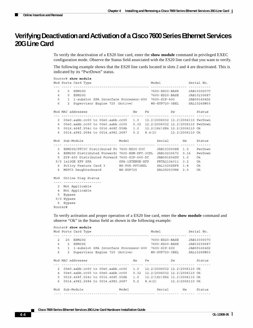
To verify the deactivation of a ES20 line card, enter the show module command in privileged EXEC configuration mode. Observe the Status field associated with the ES20 line card that you want to verify.
The following example shows that the ES20 line cards located in slots 2 and 4 are deactivated. This is indicated by its “PwrDown” status.
Router# show moduleMod Ports Card Type Model Serial No.--- ----- -------------------------------------- ------------------ ----------- 2 0 ESM20G 7600-ES20-BASE JAB1030007C 4 0 ESM20G 7600-ES20-BASE JAB10230687 5 1 1-subslot SPA Interface Processor-600 7600-SIP-600 JAB091604D2 6 2 Supervisor Engine 720 (Active) WS-SUP720-3BXL SAL1026SW03
Mod MAC addresses Hw Fw Sw Status--- ---------------------------------- ------ ------------ ------------ ------- 2 00e0.aabb.cc00 to 00e0.aabb.cc00 1.0 12.2(2006032 12.2(2006110 PwrDown 4 00e0.aabb.cc00 to 00e0.aabb.cc00 0.32 12.2(2006032 12.2(2006110 PwrDown 5 0016.468f.554c to 0016.468f.558b 1.0 12.2(18r)SX4 12.2(2006110 Ok 6 0014.a982.2684 to 0014.a982.2687 5.2 8.4(2) 12.2(2006110 Ok
Mod Sub-Module Model Serial Hw Status ---- --------------------------- ------------------ ----------- ------- ------- 2 ESM20G/PFC3C Distributed Fo 7600-ES20-D3C JAB1030008H 1.0 PwrDown 4 ESM20G Distributed Forwardi 7600-ESM-DFC-3CXL JAB10230672 0.16 PwrDown 5 SIP-600 Distributed Forward 7600-SIP-600-DC JAB091604DU 1.0 Ok 5/0 1x10GE XFP SPA SPA-1XTENGE-XFP PRTA2104311 3.2 Ok 6 Policy Feature Card 3 WS-F6K-PFC3BXL SAL1025SEF8 1.8 Ok 6 MSFC3 Daughterboard WS-SUP720 SAL09253VH8 2.5 Ok
Mod Online Diag Status ---- ------------------- 2 Not Applicable 4 Not Applicable 5 Bypass 5/0 Bypass 6 BypassRouter#
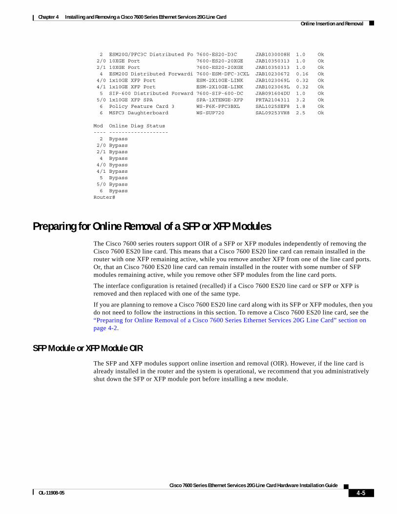
To verify activation and proper operation of a ES20 line card, enter the show module command and observe “Ok” in the Status field as shown in the following example:
Router# show moduleMod Ports Card Type Model Serial No.--- ----- -------------------------------------- ------------------ ----------- 2 20 ESM20G 7600-ES20-BASE JAB1030007C 4 2 ESM20G 7600-ES20-BASE JAB10230687 5 1 1-subslot SPA Interface Processor-600 7600-SIP-600 JAB091604D2 6 2 Supervisor Engine 720 (Active) WS-SUP720-3BXL SAL1026SW03
Mod MAC addresses Hw Fw Sw Status--- ---------------------------------- ------ ------------ ------------ ------- 2 00e0.aabb.cc00 to 00e0.aabb.cc00 1.0 12.2(2006032 12.2(2006110 Ok 4 00e0.aabb.cc00 to 00e0.aabb.cc00 0.32 12.2(2006032 12.2(2006110 Ok 5 0016.468f.554c to 0016.468f.558b 1.0 12.2(18r)SX4 12.2(2006110 Ok 6 0014.a982.2684 to 0014.a982.2687 5.2 8.4(2) 12.2(2006110 Ok
Mod Sub-Module Model Serial Hw Status ---- --------------------------- ------------------ ----------- ------- -------
4-4Cisco 7600 Series Ethernet Services 20G Line Card Hardware Installation Guide
OL-11908-05
Chapter 4 Installing and Removing a Cisco 7600 Series Ethernet Services 20G Line Card Online Insertion and Removal
2 ESM20G/PFC3C Distributed Fo 7600-ES20-D3C JAB1030008H 1.0 Ok 2/0 10XGE Port 7600-ES20-20XGE JAB10350313 1.0 Ok 2/1 10XGE Port 7600-ES20-20XGE JAB10350313 1.0 Ok 4 ESM20G Distributed Forwardi 7600-ESM-DFC-3CXL JAB10230672 0.16 Ok 4/0 1x10GE XFP Port ESM-2X10GE-LINK JAB1023069L 0.32 Ok 4/1 1x10GE XFP Port ESM-2X10GE-LINK JAB1023069L 0.32 Ok 5 SIP-600 Distributed Forward 7600-SIP-600-DC JAB091604DU 1.0 Ok 5/0 1x10GE XFP SPA SPA-1XTENGE-XFP PRTA2104311 3.2 Ok 6 Policy Feature Card 3 WS-F6K-PFC3BXL SAL1025SEF8 1.8 Ok 6 MSFC3 Daughterboard WS-SUP720 SAL09253VH8 2.5 Ok
Mod Online Diag Status ---- ------------------- 2 Bypass 2/0 Bypass 2/1 Bypass 4 Bypass 4/0 Bypass 4/1 Bypass 5 Bypass 5/0 Bypass 6 BypassRouter#
Preparing for Online Removal of a SFP or XFP ModulesThe Cisco 7600 series routers support OIR of a SFP or XFP modules independently of removing the Cisco 7600 ES20 line card. This means that a Cisco 7600 ES20 line card can remain installed in the router with one XFP remaining active, while you remove another XFP from one of the line card ports. Or, that an Cisco 7600 ES20 line card can remain installed in the router with some number of SFP modules remaining active, while you remove other SFP modules from the line card ports.
The interface configuration is retained (recalled) if a Cisco 7600 ES20 line card or SFP or XFP is removed and then replaced with one of the same type.
If you are planning to remove a Cisco 7600 ES20 line card along with its SFP or XFP modules, then you do not need to follow the instructions in this section. To remove a Cisco 7600 ES20 line card, see the “Preparing for Online Removal of a Cisco 7600 Series Ethernet Services 20G Line Card” section on page 4-2.
SFP Module or XFP Module OIR
The SFP and XFP modules support online insertion and removal (OIR). However, if the line card is already installed in the router and the system is operational, we recommend that you administratively shut down the SFP or XFP module port before installing a new module.
4-5Cisco 7600 Series Ethernet Services 20G Line Card Hardware Installation Guide
OL-11908-05

Chapter 4 Installing and Removing a Cisco 7600 Series Ethernet Services 20G Line Card Online Insertion and Removal
4-6Cisco 7600 Series Ethernet Services 20G Line Card Hardware Installation Guide
OL-11908-05

Cisco 7600 Series Ethernet SOL-11908-05
C H A P T E R 3
Preparing to Install a Cisco 7600 Series Ethernet Services 20G Line CardThis chapter describes the general equipment, safety, and site preparation requirements for installing a Cisco 7600 Series Ethernet Services 20G (ES20) line card. This chapter contains the following sections:
• Required Tools and Equipment, page 3-1
• Safety Guidelines, page 3-1
• Laser/LED Safety, page 3-8
Required Tools and EquipmentYou need the following tools and parts to remove and install Cisco 7600 ES20 line cards. If you need additional equipment, contact a service representative.
• Cisco 7600 ES20 line card
• Interface cables to connect the Cisco 7600 ES20 line card with another router or switch
• Any SFP or XFP modules, or memory you need to install (and are not already installed)
• Number 1 Phillips and a 3/16-inch flat-blade screwdriver
• Number 2 Phillips screwdriver
• Your own electrostatic discharge (ESD)-prevention equipment or the ESD-preventive wrist or ankle strap and instructions supplied with your line card
• Antistatic mat
• Antistatic container
• Fiber-optic end-face cleaning tools and inspection equipment. For complete information on inspecting and cleaning fiber-optic connections, refer to the white-paper document at this URL:
http://www.cisco.com/en/US/tech/tk482/tk876/technologies_white_paper09186a0080254eba.shtml
Safety GuidelinesThis section provides safety guidelines that you should follow when working with any equipment that connects to electrical power or telephone wiring.
3-1ervices 20G Line Card Hardware Installation Guide

Chapter 3 Preparing to Install a Cisco 7600 Series Ethernet Services 20G Line Card Safety Guidelines
General PrecautionsFollow these general precautions while handling the line card hardware:
• The module needs to be properly aligned and that the module MUST be gently pushed into the chassis.
• Customers must take care while inserting a linecard, to insert the linecard through appropriate guides provided along the sides of the chassis. Failure to do so can result in connector damage and non functional chassis.
• As a general caution before installing any linecard or supervisor engine, you must inspect both the chassis and linecard connectors and verify for existing damage. If damage is present, do not insert the linecard(s) into the chassis. A case should be opened with Cisco TAC to further troubleshoot the problem.
Safety WarningsSafety warnings appear throughout this publication in procedures that, if performed incorrectly, might harm you. A warning symbol precedes each warning statement.
Warning Definition
Warning IMPORTANT SAFETY INSTRUCTIONS
This warning symbol means danger. You are in a situation that could cause bodily injury. Before you work on any equipment, be aware of the hazards involved with electrical circuitry and be familiar with standard practices for preventing accidents. Use the statement number provided at the end of each warning to locate its translation in the translated safety warnings that accompanied this device. Statement 1071
SAVE THESE INSTRUCTIONS
Waarschuwing BELANGRIJKE VEILIGHEIDSINSTRUCTIES
Dit waarschuwingssymbool betekent gevaar. U verkeert in een situatie die lichamelijk letsel kan veroorzaken. Voordat u aan enige apparatuur gaat werken, dient u zich bewust te zijn van de bij elektrische schakelingen betrokken risico's en dient u op de hoogte te zijn van de standaard praktijken om ongelukken te voorkomen. Gebruik het nummer van de verklaring onderaan de waarschuwing als u een vertaling van de waarschuwing die bij het apparaat wordt geleverd, wilt raadplegen.
BEWAAR DEZE INSTRUCTIES
3-2Cisco 7600 Series Ethernet Services 20G Line Card Hardware Installation Guide
OL-11908-05
Chapter 3 Preparing to Install a Cisco 7600 Series Ethernet Services 20G Line Card Safety Guidelines
Varoitus TÄRKEITÄ TURVALLISUUSOHJEITA
Tämä varoitusmerkki merkitsee vaaraa. Tilanne voi aiheuttaa ruumiillisia vammoja. Ennen kuin käsittelet laitteistoa, huomioi sähköpiirien käsittelemiseen liittyvät riskit ja tutustu onnettomuuksien yleisiin ehkäisytapoihin. Turvallisuusvaroitusten käännökset löytyvät laitteen mukana toimitettujen käännettyjen turvallisuusvaroitusten joukosta varoitusten lopussa näkyvien lausuntonumeroiden avulla.
SÄILYTÄ NÄMÄ OHJEET
Attention IMPORTANTES INFORMATIONS DE SÉCURITÉ
Ce symbole d'avertissement indique un danger. Vous vous trouvez dans une situation pouvant entraîner des blessures ou des dommages corporels. Avant de travailler sur un équipement, soyez conscient des dangers liés aux circuits électriques et familiarisez-vous avec les procédures couramment utilisées pour éviter les accidents. Pour prendre connaissance des traductions des avertissements figurant dans les consignes de sécurité traduites qui accompagnent cet appareil, référez-vous au numéro de l'instruction situé à la fin de chaque avertissement.
CONSERVEZ CES INFORMATIONS
Warnung WICHTIGE SICHERHEITSHINWEISE
Dieses Warnsymbol bedeutet Gefahr. Sie befinden sich in einer Situation, die zu Verletzungen führen kann. Machen Sie sich vor der Arbeit mit Geräten mit den Gefahren elektrischer Schaltungen und den üblichen Verfahren zur Vorbeugung vor Unfällen vertraut. Suchen Sie mit der am Ende jeder Warnung angegebenen Anweisungsnummer nach der jeweiligen Übersetzung in den übersetzten Sicherheitshinweisen, die zusammen mit diesem Gerät ausgeliefert wurden.
BEWAHREN SIE DIESE HINWEISE GUT AUF.
Avvertenza IMPORTANTI ISTRUZIONI SULLA SICUREZZA
Questo simbolo di avvertenza indica un pericolo. La situazione potrebbe causare infortuni alle persone. Prima di intervenire su qualsiasi apparecchiatura, occorre essere al corrente dei pericoli relativi ai circuiti elettrici e conoscere le procedure standard per la prevenzione di incidenti. Utilizzare il numero di istruzione presente alla fine di ciascuna avvertenza per individuare le traduzioni delle avvertenze riportate in questo documento.
CONSERVARE QUESTE ISTRUZIONI
Advarsel VIKTIGE SIKKERHETSINSTRUKSJONER
Dette advarselssymbolet betyr fare. Du er i en situasjon som kan føre til skade på person. Før du begynner å arbeide med noe av utstyret, må du være oppmerksom på farene forbundet med elektriske kretser, og kjenne til standardprosedyrer for å forhindre ulykker. Bruk nummeret i slutten av hver advarsel for å finne oversettelsen i de oversatte sikkerhetsadvarslene som fulgte med denne enheten.
TA VARE PÅ DISSE INSTRUKSJONENE
3-3Cisco 7600 Series Ethernet Services 20G Line Card Hardware Installation Guide
OL-11908-05
Chapter 3 Preparing to Install a Cisco 7600 Series Ethernet Services 20G Line Card Safety Guidelines
Aviso INSTRUÇÕES IMPORTANTES DE SEGURANÇA
Este símbolo de aviso significa perigo. Você está em uma situação que poderá ser causadora de lesões corporais. Antes de iniciar a utilização de qualquer equipamento, tenha conhecimento dos perigos envolvidos no manuseio de circuitos elétricos e familiarize-se com as práticas habituais de prevenção de acidentes. Utilize o número da instrução fornecido ao final de cada aviso para localizar sua tradução nos avisos de segurança traduzidos que acompanham este dispositivo.
GUARDE ESTAS INSTRUÇÕES
¡Advertencia! INSTRUCCIONES IMPORTANTES DE SEGURIDAD
Este símbolo de aviso indica peligro. Existe riesgo para su integridad física. Antes de manipular cualquier equipo, considere los riesgos de la corriente eléctrica y familiarícese con los procedimientos estándar de prevención de accidentes. Al final de cada advertencia encontrará el número que le ayudará a encontrar el texto traducido en el apartado de traducciones que acompaña a este dispositivo.
GUARDE ESTAS INSTRUCCIONES
Varning! VIKTIGA SÄKERHETSANVISNINGAR
Denna varningssignal signalerar fara. Du befinner dig i en situation som kan leda till personskada. Innan du utför arbete på någon utrustning måste du vara medveten om farorna med elkretsar och känna till vanliga förfaranden för att förebygga olyckor. Använd det nummer som finns i slutet av varje varning för att hitta dess översättning i de översatta säkerhetsvarningar som medföljer denna anordning.
SPARA DESSA ANVISNINGAR
3-4Cisco 7600 Series Ethernet Services 20G Line Card Hardware Installation Guide
OL-11908-05

Chapter 3 Preparing to Install a Cisco 7600 Series Ethernet Services 20G Line Card Safety Guidelines
3-5Cisco 7600 Series Ethernet Services 20G Line Card Hardware Installation Guide
OL-11908-05

Chapter 3 Preparing to Install a Cisco 7600 Series Ethernet Services 20G Line Card Safety Guidelines
3-6Cisco 7600 Series Ethernet Services 20G Line Card Hardware Installation Guide
OL-11908-05

Chapter 3 Preparing to Install a Cisco 7600 Series Ethernet Services 20G Line Card Safety Guidelines
Electrical Equipment GuidelinesFollow these basic guidelines when working with any electrical equipment:
• Before beginning any procedures requiring access to the chassis interior, locate the emergency power-off switch for the room in which you are working.
• Disconnect all power and external cables before moving a chassis.
• Do not work alone when potentially hazardous conditions exist.
• Never assume that power has been disconnected from a circuit; always check.
• Do not perform any action that creates a potential hazard to people or makes the equipment unsafe; carefully examine your work area for possible hazards such as moist floors, ungrounded power extension cables, and missing safety grounds.
Telephone Wiring GuidelinesUse the following guidelines when working with any equipment that is connected to telephone wiring or to other network cabling:
• Never install telephone wiring during a lightning storm.
• Never install telephone jacks in wet locations unless the jack is specifically designed for wet locations.
• Never touch uninsulated telephone wires or terminals unless the telephone line has been disconnected at the network interface.
3-7Cisco 7600 Series Ethernet Services 20G Line Card Hardware Installation Guide
OL-11908-05
Chapter 3 Preparing to Install a Cisco 7600 Series Ethernet Services 20G Line Card Laser/LED Safety
• Use caution when installing or modifying telephone lines.
Preventing Electrostatic Discharge DamageElectrostatic discharge (ESD) damage, which can occur when electronic cards or components are improperly handled, results in complete or intermittent failures. An Cisco 7600 ES20 line card comprises printed circuit boards that are fixed ina metal carrier. Electromagnetic interference (EMI) shielding and connectors are integral components of the carrier. Although the metal carrier helps to protect the board from ESD, use a preventive antistatic strap during handling.
Following are guidelines for preventing ESD damage:
• Always use an ESD wrist or ankle strap and ensure that it makes good skin contact.
• Connect the equipment end of the strap to an unfinished chassis surface.
• When installing a component, use any available ejector levers or captive installation screws to properly seat the bus connectors in the backplane or midplane. These devices prevent accidental removal, provide proper grounding for the system, and help to ensure that bus connectors are properly seated.
• When removing a component, use any available ejector levers or captive installation screws to release the bus connectors from the backplane or midplane.
• Handle carriers by available handles or edges only; avoid touching the printed circuit boards or connectors.
• Place a removed board component-side-up on an antistatic surface or in a static shielding container. If you plan to return the component to the factory, immediately place it in a static shielding container.
• Avoid contact between the printed circuit boards and clothing. The wrist strap only protects components from ESD voltages on the body; ESD voltages on clothing can still cause damage.
• Never attempt to remove the printed circuit board from the metal carrier.
Caution For safety, periodically check the resistance value of the antistatic strap. The measurement should be between 1 and 10 megohms (Mohms).
Laser/LED SafetyAn optical single-mode transmitter uses a small laser to transmit the light signal to the network ring. Keep the transmit port covered whenever a cable is not connected to it. Although multimode transceivers typically use LEDs for transmission, it is good practice to keep open ports covered and avoid staring into open ports or apertures. The single-mode aperture port contains a laser warning label, as shown in Figure 4-1. The multimode aperture contains a Class 1 LED warning label, as shown in Figure 4-1. These warnings apply to SFP and XFP modules that transmit signals via an optical carrier signal.
3-8Cisco 7600 Series Ethernet Services 20G Line Card Hardware Installation Guide
OL-11908-05

Chapter 3 Preparing to Install a Cisco 7600 Series Ethernet Services 20G Line Card Laser/LED Safety
Figure 4-1 Class 1 Laser Warning Labels for Single-Mode Port
Warning Class 1 laser product. Statement 1008
Warning Invisible laser radiation may be emitted from disconnected fibers or connectors. Do not stare into beams or view directly with optical instruments. Statement 1051
Waarschuwing Losgekoppelde of losgeraakte glasvezels of aansluitingen kunnen onzichtbare laserstraling produceren. Kijk niet rechtstreeks in de straling en gebruik geen optische instrumenten rond deze glasvezels of aansluitingen.
Varoitus Irrotetuista kuiduista tai liittimistä voi tulla näkymätöntä lasersäteilyä. Älä tuijota säteitä tai katso niitä suoraan optisilla välineillä.
Attention Les fibres ou connecteurs débranchés risquent d'émettre des rayonnements laser invisibles à l'œil. Ne regardez jamais directement les faisceaux laser à l'œil nu, ni d'ailleurs avec des instruments optiques.
Warnung Unterbrochene Fasern oder Steckerverbindungenkönnen unsichtbare Laserstrahlung abgeben. Blicken Sie weder mit bloßem Auge noch mit optischen Instrumenten direkt in Laserstrahlen.
Avvertenza Le fibre ottiche ed i relativi connettori possono emettere radiazioni laser. I fasci di luce non devono mai essere osservati direttamente o attraverso strumenti ottici.
Advarsel Det kan forekomme usynlig laserstråling fra fiber eller kontakter som er frakoblet. Stirr ikke direkte inn i strålene eller se på dem direkte gjennom et optisk instrument.
Aviso Radiação laser invisível pode ser emitida de conectores ou fibras desconectadas. Não olhe diretamente para os feixes ou com instrumentos ópticos.
¡Advertencia! Es posible que las fibras desconectadas emitan radiación láser invisible. No fije la vista en los rayos ni examine éstos con instrumentos ópticos.
Varning! Osynlig laserstrålning kan avges från frånkopplade fibrer eller kontaktdon. Rikta inte blicken in i strålar och titta aldrig direkt på dem med hjälp av optiska instrument.
PRODUIT LASER DE CLASSE 1
CLASS 1 LASER PRODUCT LASERPRODUKT DER KLASSE 1
PRODUCTO LASER CLASE 11
H66
55
3-9Cisco 7600 Series Ethernet Services 20G Line Card Hardware Installation Guide
OL-11908-05

Chapter 3 Preparing to Install a Cisco 7600 Series Ethernet Services 20G Line Card Laser/LED Safety
Aviso Radiação laser invisível pode ser emitida a partir de fibras ou conectores desconectados. Não fixe o olhar nos feixes e nem olhe diretamente com instrumentos ópticos.
Advarsel Usynlig laserstråling kan forekomme fra brugte fibre eller stik. Stir ikke ind i stråler eller direkte med optiske instrumenter.
3-10Cisco 7600 Series Ethernet Services 20G Line Card Hardware Installation Guide
OL-11908-05
Chapter 3 Preparing to Install a Cisco 7600 Series Ethernet Services 20G Line Card Laser/LED Safety
Warning Invisible laser radiation may be emitted from disconnected fibers or connectors. Do not stare into beams or view directly with optical instruments. Statement 1051
Warning Class 1 LED product. Statement 1027
3-11Cisco 7600 Series Ethernet Services 20G Line Card Hardware Installation Guide
OL-11908-05

Chapter 3 Preparing to Install a Cisco 7600 Series Ethernet Services 20G Line Card Laser/LED Safety
3-12Cisco 7600 Series Ethernet Services 20G Line Card Hardware Installation Guide
OL-11908-05

Cisco 7600 Series Ethernet SOL-11908-05
C H A P T E R 5
Installing and Removing SFP and XFP ModulesThis chapter describes how to install or remove small form-factor pluggables (SFP modules or XFP modules) on the Cisco 7600 Series Ethernet Services 20G (ES20) line card. This chapter contains the following sections:
• Removing and Installing SFP Modules, page 5-1.
• Removing and Installing XFP Modules, page 5-11.
Removing and Installing SFP Modules
Note The Cisco 7600-ES20-GE will only support the SFP modules listed in this document. An SFP check is run every time an SFP module is inserted into a Cisco 7600-ES20-GE and only SFP modules that pass this check are usable.
Before you remove or install an SFP module, read the installation information in this section and the “Laser/LED Safety” section on page 3-8.
Caution Protect the SFP modules by inserting clean dust covers into them after the cables are removed. Be sure to clean the optic surfaces of the fiber cables before you plug them back into the optical ports of another SFP module. Avoid getting dust and other contaminants into the optical ports of your SFP modules, because the optics will not work correctly when obstructed with dust.
Caution It is strongly recommended that you do not install or remove the SFP module with fiber-optic cables attached to it because of the potential of damaging the cable, the cable connector, or the optical interfaces in the SFP module. Disconnect all cables before removing or installing an SFP module. Removing and inserting an SFP module can shorten its useful life, so you should not remove and insert SFP modules any more often than is absolutely necessary.
5-1ervices 20G Line Card Hardware Installation Guide
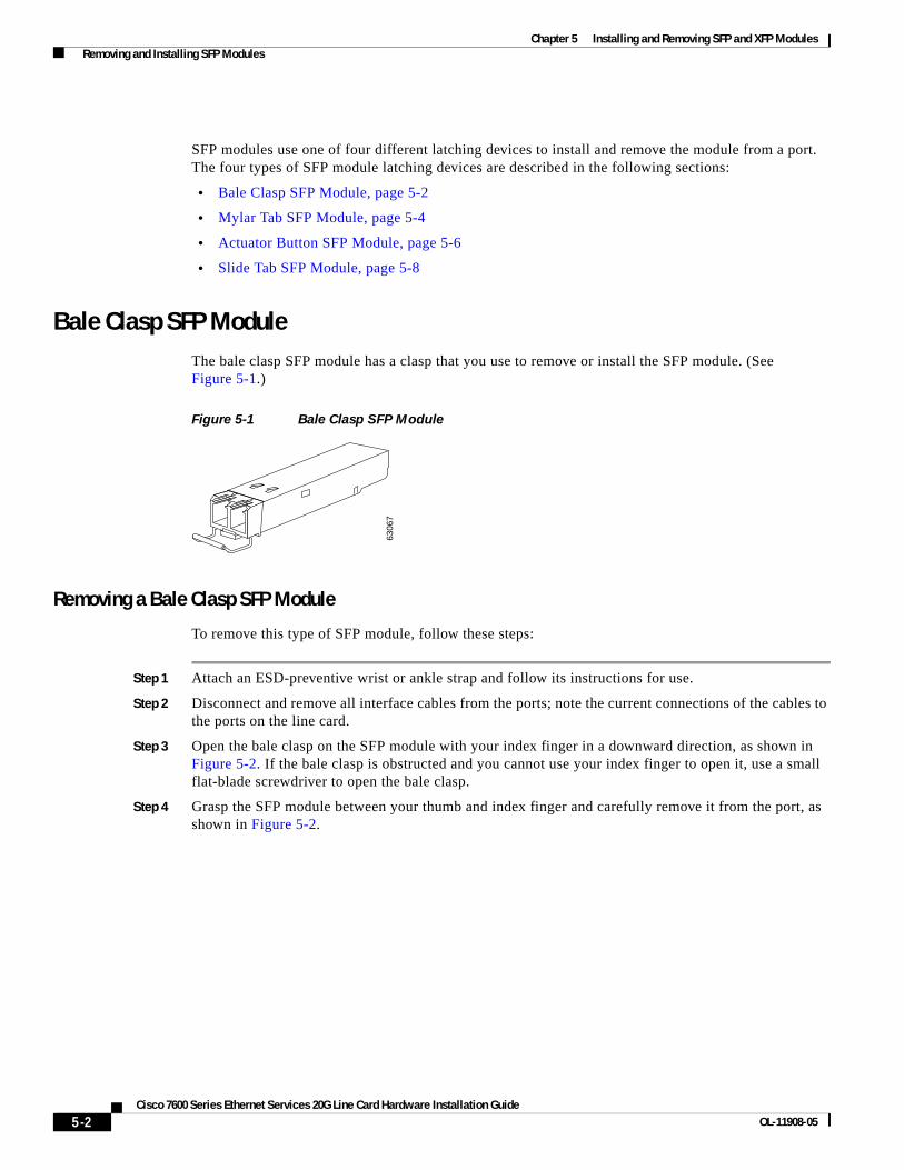
Chapter 5 Installing and Removing SFP and XFP Modules Removing and Installing SFP Modules
SFP modules use one of four different latching devices to install and remove the module from a port. The four types of SFP module latching devices are described in the following sections:
• Bale Clasp SFP Module, page 5-2
• Mylar Tab SFP Module, page 5-4
• Actuator Button SFP Module, page 5-6
• Slide Tab SFP Module, page 5-8
Bale Clasp SFP ModuleThe bale clasp SFP module has a clasp that you use to remove or install the SFP module. (See Figure 5-1.)
Figure 5-1 Bale Clasp SFP Module
Removing a Bale Clasp SFP Module
To remove this type of SFP module, follow these steps:
Step 1 Attach an ESD-preventive wrist or ankle strap and follow its instructions for use.
Step 2 Disconnect and remove all interface cables from the ports; note the current connections of the cables to the ports on the line card.
Step 3 Open the bale clasp on the SFP module with your index finger in a downward direction, as shown in Figure 5-2. If the bale clasp is obstructed and you cannot use your index finger to open it, use a small flat-blade screwdriver to open the bale clasp.
Step 4 Grasp the SFP module between your thumb and index finger and carefully remove it from the port, as shown in Figure 5-2.
6306
7
5-2Cisco 7600 Series Ethernet Services 20G Line Card Hardware Installation Guide
OL-11908-05

Chapter 5 Installing and Removing SFP and XFP Modules Removing and Installing SFP Modules
Figure 5-2 Removing a Bale Clasp SFP Module
Step 5 Place the removed SFP module on an antistatic mat, or immediately place it in a static shielding bag if you plan to return it to the factory.
Step 6 Protect your line card by inserting clean SFP module cage covers into the optical module cage when there is no SFP module installed.
Installing a Bale Clasp SFP Module
To install this type of SFP module, follow these steps:
Step 1 Attach an ESD-preventive wrist or ankle strap and follow its instructions for use.
STATUS
ETHERNETSERVICES MODULE
7600-ES20-GE3CXL
CLASS 1 LASER
0
A/L
1912
24
1
A/L
2
A/L
3
A/L
4
A/L
STATUS
ETHERNETSERVICES MODULE
7600-ES20-GE3CXL
CLASS 1 LASER
0
A/L
1
A/L
2
A/L
3
A/L
4
A/L
5-3Cisco 7600 Series Ethernet Services 20G Line Card Hardware Installation Guide
OL-11908-05

Chapter 5 Installing and Removing SFP and XFP Modules Removing and Installing SFP Modules
Step 2 Close the bale clasp before inserting the SFP module.
Step 3 Line up the SFP module with the port and slide it into the port. (See Figure 5-3.)
Figure 5-3 Installing a Bale Clasp SFP Module into a Port
Note Verify that the SFP modules are completely seated and secured in their assigned receptacles on the line card by firmly pushing on each SFP module. If the SFP module is not completely seated and secured in the receptacle, you will hear a click as the triangular pin on the bottom of the SFP module snaps into the hole in the receptacle.
Mylar Tab SFP ModuleThe mylar tab SFP module has a tab that you pull to remove the module from a port. (See Figure 5-4.)
Figure 5-4 Mylar Tab SFP Module
Removing a Mylar Tab SFP Module
To remove this type of SFP module, follow these steps:
Step 1 Attach an ESD-preventive wrist or ankle strap and follow its instructions for use.
STATUS
ETHERNETSERVICES MODULE
7600-ES20-GE3CXL
CLASS 1 LASER
0
A/L
1912
23
1
A/L
2
A/L
3
A/L
4
A/L
6306
5
5-4Cisco 7600 Series Ethernet Services 20G Line Card Hardware Installation Guide
OL-11908-05

Chapter 5 Installing and Removing SFP and XFP Modules Removing and Installing SFP Modules
Step 2 Disconnect and remove all interface cables from the ports; note the current connections of the cables to the ports on the line card.
Step 3 Pull the tab gently in a slightly downward direction until it disengages from the port, then pull the SFP module out. (See Figure 5-5.)
Figure 5-5 Removing a Mylar Tab SFP Module
Step 4 Place the removed SFP module on an antistatic mat, or immediately place it in a static shielding bag if you plan to return it to the factory.
Step 5 Protect your line card by inserting clean SFP module cage covers into the optical module cage when there is no SFP module installed.
Caution When pulling the tab to remove the SFP module, be sure to pull in a straight outward motion so you remove the SFP module from the port in a parallel direction. Do not twist or pull the tab, because you might disconnect it from the SFP module.
Installing a Mylar Tab SFP Module
To install this type of SFP module, follow these steps:
Step 1 Attach an ESD-preventive wrist or ankle strap and follow its instructions for use.
Step 2 Line up the SFP module with the port, and slide it into place. (See Figure 5-6.)
STATUS
ETHERNETSERVICES MODULE
7600-ES20-GE3CXL
CLASS 1 LASER
0
A/L
1912
20
1
A/L
2
A/L
3
A/L
4
A/L
5-5Cisco 7600 Series Ethernet Services 20G Line Card Hardware Installation Guide
OL-11908-05
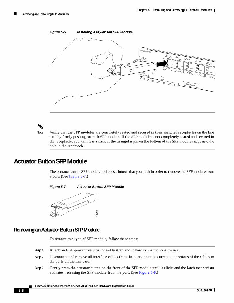
Chapter 5 Installing and Removing SFP and XFP Modules Removing and Installing SFP Modules
Figure 5-6 Installing a Mylar Tab SFP Module
Note Verify that the SFP modules are completely seated and secured in their assigned receptacles on the line card by firmly pushing on each SFP module. If the SFP module is not completely seated and secured in the receptacle, you will hear a click as the triangular pin on the bottom of the SFP module snaps into the hole in the receptacle.
Actuator Button SFP ModuleThe actuator button SFP module includes a button that you push in order to remove the SFP module from a port. (See Figure 5-7.)
Figure 5-7 Actuator Button SFP Module
Removing an Actuator Button SFP Module
To remove this type of SFP module, follow these steps:
Step 1 Attach an ESD-preventive wrist or ankle strap and follow its instructions for use.
Step 2 Disconnect and remove all interface cables from the ports; note the current connections of the cables to the ports on the line card.
Step 3 Gently press the actuator button on the front of the SFP module until it clicks and the latch mechanism activates, releasing the SFP module from the port. (See Figure 5-8.)
STATUS
ETHERNETSERVICES MODULE
7600-ES20-GE3CXL
CLASS 1 LASER
0
A/L
1
A/L
2
A/L
3
A/L
4
A/L
6306
6
5-6Cisco 7600 Series Ethernet Services 20G Line Card Hardware Installation Guide
OL-11908-05

Chapter 5 Installing and Removing SFP and XFP Modules Removing and Installing SFP Modules
Figure 5-8 Removing an Actuator Button SFP Module from a Port
Step 4 Grasp the actuator button between your thumb and index finger and carefully pull the SFP module from the port.
Step 5 Place the removed SFP module on an antistatic mat, or immediately place it in a static shielding bag if you plan to return it to the factory.
Step 6 Protect your line card by inserting clean SFP module cage covers into the optical module cage when there is no SFP module installed.
STATUS
ETHERNETSERVICES MODULE
7600-ES20-GE3CXL
CLASS 1 LASER
0
A/L
1912
22
1
A/L
2
A/L
3
A/L
4
A/L
STATUS
ETHERNETSERVICES MODULE
7600-ES20-GE3CXL
CLASS 1 LASER
0
A/L
1
A/L
2
A/L
3
A/L
4
A/L
5-7Cisco 7600 Series Ethernet Services 20G Line Card Hardware Installation Guide
OL-11908-05

Chapter 5 Installing and Removing SFP and XFP Modules Removing and Installing SFP Modules
Installing an Actuator Button SFP Module
To install this type of SFP module, follow these steps:
Step 1 Attach an ESD-preventive wrist or ankle strap and follow its instructions for use.
Step 2 Line up the SFP module with the port and slide it in until the actuator button clicks into place. (See Figure 5-9.) Be sure not to press the actuator button as you insert the SFP module because you might inadvertently disengage the SFP module from the port.
Figure 5-9 Installing an Actuator Button SFP Module
Note Verify that the SFP modules are completely seated and secured in their assigned receptacles on the line card by firmly pushing on each SFP module. If the SFP module is not completely seated and secured in the receptacle, you will hear a click as the triangular pin on the bottom of the SFP module snaps into the hole in the receptacle.
Slide Tab SFP ModuleThe slide tab SFP module has a tab underneath the front of the SFP module that you use to disengage the module from a port. (See Figure 5-10.)
Figure 5-10 Slide Tab SFP Module
STATUS
ETHERNETSERVICES MODULE
7600-ES20-GE3CXL
CLASS 1 LASER
0
A/L
1912
21
1
A/L
2
A/L
3
A/L
4
A/L
8465
1
5-8Cisco 7600 Series Ethernet Services 20G Line Card Hardware Installation Guide
OL-11908-05

Chapter 5 Installing and Removing SFP and XFP Modules Removing and Installing SFP Modules
Removing a Slide Tab SFP Module
To remove this type of SFP module, follow these steps:
Step 1 Attach an ESD-preventive wrist or ankle strap and follow its instructions for use.
Step 2 Disconnect and remove all interface cables from the ports; note the current connections of the cables to the ports on the line card.
Step 3 Grasp the SFP module between your thumb and index finger.
Step 4 With your thumb, push the slide tab on the bottom front of the SFP module in the direction of the line card to disengage the module from the line card port. (See Figure 5-11.)
Figure 5-11 Disengaging the Slide Tab
Step 5 With the tab still pushed, carefully pull the SFP module from the port as shown in Figure 5-12.
Caution You must disengage the SFP module by pushing on the slide tab before you can pull out the SFP module. If you pull on the SFP module without disengaging the tab, you can damage the SFP module.
8465
2
5-9Cisco 7600 Series Ethernet Services 20G Line Card Hardware Installation Guide
OL-11908-05

Chapter 5 Installing and Removing SFP and XFP Modules Removing and Installing SFP Modules
Figure 5-12 Removing a Slide Tab SFP Module
Step 6 Place the removed SFP module on an antistatic mat, or immediately place it in a static shielding bag if you plan to return it to the factory.
Step 7 Protect your line card by inserting clean SFP module cage covers into the optical module cage when there is no SFP module installed.
Installing a Slide Tab SFP Module
To install this type of SFP module, follow these steps:
Step 1 Attach an ESD-preventive wrist or ankle strap and follow its instructions for use.
Step 2 Hold the SFP module with the hardware label facing up.
Caution The SFP module must be inserted with the hardware label facing up to avoiding damaging the module or the line card.
Step 3 Insert the SFP module into the appropriate slot and gently push on it until it snaps into the slot tightly. (See Figure 5-13.)
STAT
US
ETHERNETSERVICES MODULE
7600-ES20-GE3CXL
0
A/L
1
A/L
2
A/L
3
A/L
4
A/L
5-10Cisco 7600 Series Ethernet Services 20G Line Card Hardware Installation Guide
OL-11908-05

Chapter 5 Installing and Removing SFP and XFP Modules Removing and Installing XFP Modules
Figure 5-13 Installing a Slide Tab SFP Module
Note Verify that the SFP modules are completely seated and secured in their assigned receptacles on the line card by firmly pushing on each SFP module. If the SFP module is not completely seated and secured in the receptacle, you will hear a click as the triangular pin on the bottom of the SFP module snaps into the hole in the receptacle.
Removing and Installing XFP Modules
Note The dual LC connector on the XFP transceiver modules support network interface cables with either Physical Contact (PC) or Ultra-Physical Contact (UPC) polished face types. The dual LC connector on the XFP transceiver modules do not support network interface cables with an Angle Polished Connector (APC) polished face type.
The 10-Gigabit XFP transceiver module is a hot-swappable I/O device that plugs into 10-Gigabit ports. (See Figure 5-14.) The XFP transceiver module connects the electrical circuitry of the system with the optical network.
STATUS
ETHERNETSERVICES MODULE
7600-ES20-GE3CXL
CLASS 1 LASER
0
A/L
1
A/L
2
A/L
3
A/L
4
A/L
1912
25
5-11Cisco 7600 Series Ethernet Services 20G Line Card Hardware Installation Guide
OL-11908-05
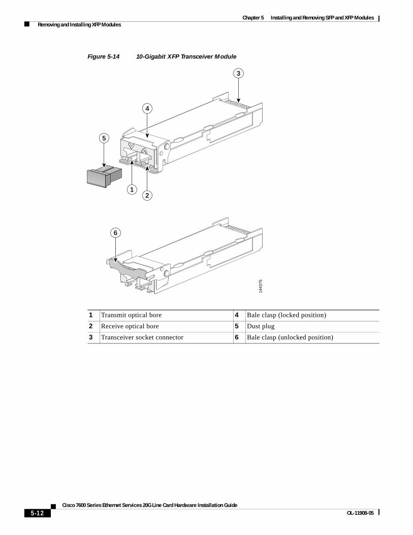
Chapter 5 Installing and Removing SFP and XFP Modules Removing and Installing XFP Modules
Figure 5-14 10-Gigabit XFP Transceiver Module
1 Transmit optical bore 4 Bale clasp (locked position)
2 Receive optical bore 5 Dust plug
3 Transceiver socket connector 6 Bale clasp (unlocked position)
3
4
1443
75
12
5
6
5-12Cisco 7600 Series Ethernet Services 20G Line Card Hardware Installation Guide
OL-11908-05

Chapter 5 Installing and Removing SFP and XFP Modules Removing and Installing XFP Modules
Table 5-1 lists the port cabling specifications for the 10-Gigabit XFP transceiver modules. Table 5-2 lists the XFP transceiver optical transmit and receive specifications.
Installing the 10-Gigabit XFP Transceiver Module
Caution The XFP transceiver is a static-sensitive device. Always use an ESD wrist strap or similar individual grounding device when handling XFP transceivers or coming into contact with system modules.
Table 5-1 XFP Transceiver Port Cabling Specifications
XFP Product Number
Nominal Wavelength (nm) Cable Type
Core Size (microns)
Modal Bandwidth (MHz/km) Maximum Cabling Distance
XFP-10GLR-OC192SR= 1310 SMF G.652 — 10 km (6.2 miles) 10-Gigabit Ethernet
2 km (1.24 miles) OC-192/STM-64 SR1
XFP-10GER-OC192IR= 1550 SMF G.652 — 40 km (24.86 miles)
XFP-10GZR-OC192IR 1550 SMF G.652 — 80 km (10 miles)
Table 5-2 XFP Transceiver Optical Transmit and Receive Specifications
XFP Product NumberTransceiver Operating Mode
Transmit Power (dBm)
Receive Power (dBm)
Transmit and Receive Wavelength (nm)
XFP-10GLR-OC192SR= 10GBASE-LR, 1310-nm SMF
(10.3125-Gbps line rate)
+0.5 Max
–8.2 Min
+0.5 (Max)
–14.4 (Min)
1260 to 1355 (TX)
1260 to 1565 (RX)
OC-192/STM-64 SR1, 1310-nm SMF
(9.95328-Gbps line rate)
–1.0 Max
–6.0 Min
–1.0 (Max)
–11.0 (Min)
1290 to 1330 (TX)
1260 to 1565 (RX)
XFP-10GER-OC192IR= 10GBASE-ER, 1550-nm SMF
(10.3125-Gbps line rate)
+4.0 Max
–4.7 Min
–1.0 (Max)
–15.8 (Min)
1530 to 1565 (TX)
1260 to 1565 (RX)
OC-192/STM-64 IR2, 1550-nm SMF
(9.95328-Gbps line rate)
+2.0 Max
–1.0 Min
+2.0 (Max)
–14.0 (Min
1530 to 1565 (TX)
1260 to 1565 (RX)
XFP-10GEZR-OC192IR= 10GBASE-ZR, 1550-nm SMF
(10.3125-Gbps line rate)
OC-192/STM-64 LR2, 1550-nm SMF
(9.95328-Gbps line rate)
+4.0 Max
0 Min
-24 (Max)
-7 (Min)
1260 to 1565
5-13Cisco 7600 Series Ethernet Services 20G Line Card Hardware Installation Guide
OL-11908-05

Chapter 5 Installing and Removing SFP and XFP Modules Removing and Installing XFP Modules
To install an XFP transceiver, follow these steps:
Step 1 Remove the XFP transceiver from its protective packaging.
Note Do not remove the optical bore dust plugs until directed to do so later in the procedure.
Step 2 Check the label on the XFP transceiver body to verify that you have the correct model for your network.
Step 3 Position the XFP transceiver in front of the XFP socket opening on the module. Slide the XFP transceiver part of the way into the transceiver socket on the system module front panel.
Step 4 Remove the optical bore dust plug from the XFP transceiver.
Step 5 Pivot the bale clasp up so that it is parallel with the transceiver body. (See Figure 5-15.)
Step 6 Continue sliding the XFP transceiver into the socket until the XFP transceiver is mated with the transceiver socket connector.
Step 7 Latch the XFP transceiver in the transceiver socket by pivoting the bale clasp down so that the bale clasp is perpendicular to the transceiver body. (See Figure 5-15.)
Caution If the latch is not fully engaged, you may accidently disconnect the XFP transceiver.
Step 8 Immediately reinstall the dust plug in the XFP transceiver optical bores. Do not remove the dust plug until you are ready to attach the network interface cable.
5-14Cisco 7600 Series Ethernet Services 20G Line Card Hardware Installation Guide
OL-11908-05

Chapter 5 Installing and Removing SFP and XFP Modules Removing and Installing XFP Modules
Figure 5-15 Installing the 10-Gigabit XFP Transceiver Module
Note 10-Gigabit XFP transceivers are keyed to prevent incorrect insertion.
Note Before removing the dust plugs and making any optical connections, follow these guidelines:
• Always keep the protective dust plugs on the unplugged fiber-optic cable connectors and the transceiver optical bores until you are ready to make a connection.
• Always inspect and clean the LC connector end faces just before making any connections. Refer to the Tip on this page for a pointer to a fiber-optic inspection and cleaning white paper.
• Always grasp the LC connector housing to plug or unplug a fiber-optic cable.
a. Remove the dust plugs from the optical network interface cable LC connectors. Save the dust plugs for future use.
b. Inspect and clean the LC connector’s fiber-optic end faces.
STATUS
ETHERNETSERVICES MODULE
7600-ES20-10G3CXL
CLASS 1 LASER
1912
27
STATUS
ETHERNETSERVICES MODULE
7600-ES20-10G3CXL
CLASS 1 LASER
1
A/L
1
A/L
5-15Cisco 7600 Series Ethernet Services 20G Line Card Hardware Installation Guide
OL-11908-05

Chapter 5 Installing and Removing SFP and XFP Modules Removing and Installing XFP Modules
Tip For complete information on inspecting and cleaning fiber-optic connections, refer to this URL:
http://www.cisco.com/en/US/tech/tk482/tk607/technologies_white_paper09186a0080254eba.shtml
c. Remove the dust plugs from the XFP transceiver module optical bores.
d. Immediately attach the network interface cable LC connectors to the XFP transceiver module. (See Figure 5-16 for cabling the XFP transceiver module.)
Figure 5-16 Cabling a10-Gigabit XFP Transceiver Module
Removing the 10-Gigabit XFP Transceiver Module
Caution The XFP transceiver is a static-sensitive device. Always use an ESD wrist strap or similar individual grounding device when handling XFP transceivers or coming into contact with modules.
If you are removing an XFP transceiver, follow these steps:
Step 1 Disconnect the network interface cable from the XFP transceiver connectors. Immediately reinstall the dust plug in the fiber-optic cable LC connector.
Step 2 Pivot the XFP transceiver bale clasp up to release the XFP transceiver from the socket. (See Figure 5-17.)
Step 3 Slide the XFP transceiver out of the socket. Pivot the bale clasp down and immediately install the dust plug in the XFP transceiver optical bores. (See Figure 5-17.)
Step 4 Immediately place the XFP transceiver in an antistatic bag.
1912
28
STATUS
ETHERNETSERVICES MODULE
7600-ES20-10G3CXL
CLASS 1 LASER
1
A/L
5-16Cisco 7600 Series Ethernet Services 20G Line Card Hardware Installation Guide
OL-11908-05

Chapter 5 Installing and Removing SFP and XFP Modules Removing and Installing XFP Modules
Figure 5-17 Removing the 10-Gigabit XFP Transceiver
1912
29
STATUS
ETHERNETSERVICES MODULE
7600-ES20-10G3CXL
CLASS 1 LASER
1
A/L
STATUS
ETHERNETSERVICES MODULE
7600-ES20-10G3CXL
CLASS 1 LASER
1
A/L
5-17Cisco 7600 Series Ethernet Services 20G Line Card Hardware Installation Guide
OL-11908-05

Chapter 5 Installing and Removing SFP and XFP Modules Removing and Installing XFP Modules
5-18Cisco 7600 Series Ethernet Services 20G Line Card Hardware Installation Guide
OL-11908-05
Cisco 7600 Series Ethernet SOL-11908-05
C H A P T E R 6
Troubleshooting the InstallationThis chapter describes how to troubleshoot the installation of the Cisco 7600 Series Ethernet Services 20G (ES20) line card on the Cisco 7600 series routers. This chapter contains the following sections:
• Troubleshooting, page 6-1.
• Using debug Commands, page 6-2.
• Packing a Cisco 7600 ES20 Line Card for Shipment, page 6-2
TroubleshootingThis section describes troubleshooting the installation of the Cisco 7600 ES20 line card. Possible problems, observations and comments, and solutions are indicated for the following troubleshooting symptoms:
• Cisco 7600 ES20 line card transitions repeatedly from on to off.
• Cisco 7600 ES20 line card is deactivated.
Cisco 7600 ES20 Line Card Transitions Repeatedly From On to Off
Possible Problem Observations and Comments Solutions
Cisco 7600 ES20 line card is booting up; this is normal operation
Cisco 7600 ES20 line card STATUS LED alternates green, amber, or off
Wait 30 seconds until the boot process completes and the STATUS LED stays on.
Cisco 7600 ES20 line card does not go beyond the bootup stage
Cisco 7600 ES20 line card STATUS LED transitions continue and alternates green, amber, or off
Follow the recommended action for the displayed error message.
Cisco 7600 ES20 line card is not up to date
During Cisco 7600 ES20 line card initalization, the need to update the FPGA is automatically detected
Follow the system prompts to update the FPGA image.
If the Cisco 7600 ES20 line card is cycling because of an FPD problem, the most likely cause is a FPD failure or that the FPD package file is not present.
For more information about performing FPD upgrades, refer to the “Upgrading Field-Programmable Devices” chapter in the Cisco 7600 Series Router SIP, SSC, and SPA Software Configuration Guide .
6-1ervices 20G Line Card Hardware Installation Guide

Chapter 6 Troubleshooting the Installation Using debug Commands
Using debug CommandsThe debug hw-module subslot command is intended for use by Cisco Systems technical support personnel. For more information about the debug hw-module subslot command, see the Cisco 7600 Series Router SIP, SSC, and SPA Software Configuration Guide .
Caution Because debugging output is assigned high priority in the CPU process, it can render the system unusable. For this reason, use debug commands only to troubleshoot specific problems or during troubleshooting sessions with Cisco technical support staff. Moreover, it is best to use debug commands during periods of lower network traffic and fewer users. Debugging during these periods decreases the likelihood that increased debug command processing overhead will affect system use.
For information about other debug commands supported on the Cisco 7600 ES20 line card and to view the explanations and recommended actions for the Cisco 7600 series router error messages, including messages related to the Cisco 7600 ES20 line card, refer to the following documents:
• Cisco IOS Release 12.2 SR Command References
• Cisco 7600 Series Cisco IOS System Message Guide, 12.2SR
Packing a Cisco 7600 ES20 Line Card for ShipmentThis section provides step-by-step instructions for packing a Cisco 7600 ES20 line card for shipment. Before beginning this procedure, you should have the following original Cisco Systems packaging materials:
Cisco 7600 ES20 Line Card Is Deactivated
Possible Problem Observations and Comments Solutions
Cisco 7600 ES20 line card is not fully seated in the chassis slot
Output of the show diag slot command
STATUS LED is off
Follow this procedure:
• Remove the Cisco 7600 ES20 line card from the slot.
• Inspect the Cisco 7600 ES20 line card. Verify there are no bent pins or parts and that there is nothing that could prevent a good connection.
• Insert the Cisco 7600 ES20 line card into the chassis slot.
Cisco 7600 ES20 line card is not at the minimum hardware revision level
Error message indicating the Cisco 7600 ES20 line card is not at the minimum FPGA revision level
Output of the show hw-module subslot fpd command
Output of the show diag slot command
STATUS LED is off
Follow the FPD upgrade process to update the FPGA.
For more information about performing FPD upgrades, refer to the “Upgrading Field-Programmable Devices” chapter in the Cisco 7600 Series Router SIP, SSC, and SPA Software Configuration Guide .
6-2Cisco 7600 Series Ethernet Services 20G Line Card Hardware Installation Guide
OL-11908-05

Chapter 6 Troubleshooting the Installation Packing a Cisco 7600 ES20 Line Card for Shipment
• Static shielding bag
• Smaller inner carton
• Larger exterior carton
• Two foam packing cushions
Caution The Cisco Systems original packaging is to be used for the shipment of all Cisco 7600 ES20 line cards. Failure to properly use Cisco Systems packaging can result in damage or loss of product.
Warning During this procedure, wear grounding wrist straps to avoid ESD damage to the card. Do not directly touch the backplane with your hand or any metal tool, or you could shock yourself.
Note These instructions assume that the Cisco 7600 ES20 line card has been removed from the router according to the recommended procedures specified in this guide.
To pack a Cisco 7600 ES20 line card for shipment, perform the following steps:
Step 1 Insert the Cisco 7600 ES20 line card into the static shielding bag.
Step 2 Insert the bagged Cisco 7600 ES20 line card into the smaller inner carton. Be careful to position the Cisco 7600 ES20 line card so that the bottom motherboard lip is held by the packaging cutout.
Step 3 Close the smaller inner carton and tape the sides closed.
Step 4 Place the sealed smaller inner carton containing the Cisco 7600 ES20 line card into the two foam packing cushions (they only fit one way).
Step 5 Place the sealed smaller inner carton and packing cushions into the larger exterior carton, and seal the larger exterior carton with tape for shipment.
6-3Cisco 7600 Series Ethernet Services 20G Line Card Hardware Installation Guide
OL-11908-05

Chapter 6 Troubleshooting the Installation Packing a Cisco 7600 ES20 Line Card for Shipment
6-4Cisco 7600 Series Ethernet Services 20G Line Card Hardware Installation Guide
OL-11908-05

Cisco 7600 Series Ethernet SOL-11908-05
I N D E X
Numerics
7600-ES20-10G
Memory Installation and Removal 2-5
Memory Options 2-5
port locations 2-3
7600-ES20-10G3C
description 2-1
7600-ES20-10G3CXL
description 2-1
7600-ES20-10G line card
LEDs 2-4
7600-ES20-GE
port locations 2-3
7600-ES20-GE3C
description 2-1
7600-ES20-GE3CXL
description 2-1
A
activation
verifying for ES20 line card 3-4
C
cables
LC-type
(figure) 2-6
cautions, usage in text ii-xi
command syntax
conventions ii-x
D
deactivation
verifying for ES20 line card 3-4
debug Commands 6-2
E
ES20 line card
debugging 6-2
hardware versions 1-3
online removal 3-2
part numbers 1-3
power consumption 1-8
product numbers 1-2
reactivating 3-3
safety guidelines 4-1
slot locations 2-2
troubleshooting 6-1
Ethernet Services 20G line card
see ES20 line card 2-1
L
LC-type cable
(figure) 2-6
LEDs 2-4
N
no power enable module command 3-2, 3-3
notes, usage in text ii-xi
IN-1ervices 20G Line Card Hardware Installation Guide

Index
O
OIR (online insertion and removal)
for ES20 line card 3-2
for SFPs and XFPs 3-5
P
Packing
A ES20 line card for shipment 6-2
packing instructions 6-2
power enable module command 3-3
Power Management
ES20 line card power consumption 1-8
R
required tools 4-1
S
safety warnings 4-2
SFP module
actuator button 5-6
bale clasp 5-2
mylar tab 5-4
slide type 5-8
SFP modules
removing and installing 5-1
Shipment
Packing a ES20 line card for 6-2
show diagbus command 2-2
show hw-module slot command 2-2
show idprom module command 2-2
show module command 2-2, 3-4
supervisor engines
supported by ES20 line card 2-2
supported platforms 1-3
IN-2Cisco 7600 Series Ethernet Services 20G Line Card Hardware Insta
T
tips, usage in text ii-xi
Troubleshooting the installation 6-1
U
Using debug commands 6-2
X
XFP modules
removing and installing 5-11
supported 1-4
llation GuideOL-11908-05