cisco asr 1002-hx router hardware installation … asr 1002-hx router hardware installation guide...
TRANSCRIPT
Cisco ASR 1002-HX Router Hardware Installation GuideFirst Published: May 23, 2016
Americas HeadquartersCisco Systems, Inc.170 West Tasman DriveSan Jose, CA 95134-1706USAhttp://www.cisco.comTel: 408 526-4000 800 553-NETS (6387)Fax: 408 527-0883
THE SPECIFICATIONS AND INFORMATION REGARDING THE PRODUCTS IN THIS MANUAL ARE SUBJECT TO CHANGE WITHOUT NOTICE. ALL STATEMENTS,INFORMATION, AND RECOMMENDATIONS IN THIS MANUAL ARE BELIEVED TO BE ACCURATE BUT ARE PRESENTED WITHOUT WARRANTY OF ANY KIND,EXPRESS OR IMPLIED. USERS MUST TAKE FULL RESPONSIBILITY FOR THEIR APPLICATION OF ANY PRODUCTS.
THE SOFTWARE LICENSE AND LIMITEDWARRANTY FOR THE ACCOMPANYING PRODUCT ARE SET FORTH IN THE INFORMATION PACKET THAT SHIPPED WITHTHE PRODUCT AND ARE INCORPORATED HEREIN BY THIS REFERENCE. IF YOU ARE UNABLE TO LOCATE THE SOFTWARE LICENSE OR LIMITED WARRANTY,CONTACT YOUR CISCO REPRESENTATIVE FOR A COPY.
The following information is for FCC compliance of Class A devices: This equipment has been tested and found to comply with the limits for a Class A digital device, pursuant to part 15of the FCC rules. These limits are designed to provide reasonable protection against harmful interference when the equipment is operated in a commercial environment. This equipmentgenerates, uses, and can radiate radio-frequency energy and, if not installed and used in accordance with the instruction manual, may cause harmful interference to radio communications.Operation of this equipment in a residential area is likely to cause harmful interference, in which case users will be required to correct the interference at their own expense.
The following information is for FCC compliance of Class B devices: This equipment has been tested and found to comply with the limits for a Class B digital device, pursuant to part 15of the FCC rules. These limits are designed to provide reasonable protection against harmful interference in a residential installation. This equipment generates, uses and can radiate radiofrequency energy and, if not installed and used in accordance with the instructions, may cause harmful interference to radio communications. However, there is no guarantee that interferencewill not occur in a particular installation. If the equipment causes interference to radio or television reception, which can be determined by turning the equipment off and on, users areencouraged to try to correct the interference by using one or more of the following measures:
• Reorient or relocate the receiving antenna.
• Increase the separation between the equipment and receiver.
• Connect the equipment into an outlet on a circuit different from that to which the receiver is connected.
• Consult the dealer or an experienced radio/TV technician for help.
Modifications to this product not authorized by Cisco could void the FCC approval and negate your authority to operate the product
The Cisco implementation of TCP header compression is an adaptation of a program developed by the University of California, Berkeley (UCB) as part of UCB’s public domain versionof the UNIX operating system. All rights reserved. Copyright © 1981, Regents of the University of California.
NOTWITHSTANDINGANYOTHERWARRANTYHEREIN, ALL DOCUMENT FILES AND SOFTWAREOF THESE SUPPLIERS ARE PROVIDED "AS IS"WITHALL FAULTS.CISCO AND THE ABOVE-NAMED SUPPLIERS DISCLAIM ALL WARRANTIES, EXPRESSED OR IMPLIED, INCLUDING, WITHOUT LIMITATION, THOSE OFMERCHANTABILITY, FITNESS FORA PARTICULAR PURPOSEANDNONINFRINGEMENTORARISING FROMACOURSEOFDEALING, USAGE, OR TRADE PRACTICE.
IN NO EVENT SHALL CISCO OR ITS SUPPLIERS BE LIABLE FOR ANY INDIRECT, SPECIAL, CONSEQUENTIAL, OR INCIDENTAL DAMAGES, INCLUDING, WITHOUTLIMITATION, LOST PROFITS OR LOSS OR DAMAGE TO DATA ARISING OUT OF THE USE OR INABILITY TO USE THIS MANUAL, EVEN IF CISCO OR ITS SUPPLIERSHAVE BEEN ADVISED OF THE POSSIBILITY OF SUCH DAMAGES.
Any Internet Protocol (IP) addresses and phone numbers used in this document are not intended to be actual addresses and phone numbers. Any examples, command display output, networktopology diagrams, and other figures included in the document are shown for illustrative purposes only. Any use of actual IP addresses or phone numbers in illustrative content is unintentionaland coincidental.
Cisco and the Cisco logo are trademarks or registered trademarks of Cisco and/or its affiliates in the U.S. and other countries. To view a list of Cisco trademarks, go to this URL: http://www.cisco.com/go/trademarks. Third-party trademarks mentioned are the property of their respective owners. The use of the word partner does not imply a partnershiprelationship between Cisco and any other company. (1110R)
© 2016 Cisco Systems, Inc. All rights reserved.
C O N T E N T S
P r e f a c e Preface ix
Document Revision History ix
Document Objectives ix
Audience ix
Document Organization x
Conventions x
Related Documentation xii
Obtaining Documentation and Submitting a Service Request xii
C H A P T E R 1 Overview 1
Hardware Features 1
Front View 2
Built-In SFP and SFP+ Ports 3
Slot Numbering 4
Management and Storage Connections 5
LEDs 5
Rear View 7
Cisco Product Identification Standard 7
Unique Device Identifier 7
Serial Number and PID/VID Label Location 10
C H A P T E R 2 Supported Hardware Components 11
Supported EPAs 11
Supported Transceivers 12
Supported Crypto Module 14
Supported DIMM Upgrade 14
Power Supplies 14
Cisco ASR 1002-HX Router Hardware Installation Guide iii
Power Supply LEDs 15
Power Supply Fans 16
Power Cords 16
C H A P T E R 3 Preparing Your Site for Installation 19
Prerequisites and Preparation 19
Site Planning Checklist 20
Safety Guidelines 20
Safety Warnings 21
Safety Recommendations 21
Cautions and Regulatory Compliance Statements for NEBS 21
Standard Warning Statements 22
General Safety Warnings 23
Site Planning 26
General Precautions 26
Site Selection Guidelines 27
Site Environmental Requirements 27
Physical Characteristics 28
Site Power Guidelines 28
Electrical Circuit Requirements 29
Site Cabling Guidelines 30
Console Port Connections 30
USB Serial Console 31
Interference Considerations 31
Electromagnetic Interference 31
Radio Frequency Interference 32
Lightning and AC Power Fault Interference 32
Rack-Mounting Guidelines 32
Precautions for Rack-Mounting 32
General Rack-Selection Guidelines 33
Guidelines for 23-in. (Telco) Racks 34
Equipment Rack Guidelines 34
Locating for Safety 34
Locating for Easy Maintenance 34
Locating for Proper Airflow 35
Cisco ASR 1002-HX Router Hardware Installation Guideiv
Contents
Preventing Electrostatic Discharge Damage 35
Electrical Safety 36
Chassis-Lifting Guidelines 36
Tools and Equipment 37
Unpacking and Verifying Shipping Contents 37
Checking the Shipping Container Contents 37
Installation Checklist 38
C H A P T E R 4 Installing the Router 41
Installation Methods 41
Guidelines for a Standalone Equipment Shelf or Tabletop Installation 42
Installing the Router on a Standalone Equipment Shelf or Tabletop 43
Guidelines for Rack Installation 43
Verifying Rack Dimensions 44
Attaching the Front Rack-Mount Brackets 45
Attaching the Rear Rack-Mount Brackets 46
Mounting the Router in the Rack 47
Two-Post Rack Installation 48
Four-Post Rack Installation 49
Attaching the Cable Management Bracket 51
Chassis Ground Connection 52
Recommended Tools and Supplies 53
Attaching a Chassis Ground Connection 54
Connecting Cables 55
Connecting the Console and Auxiliary Port Cables 56
Connecting to the Mini USB Console Port 56
Management Ethernet Port Cable Connection 57
C H A P T E R 5 Power Up and Initial Configuration 59
Checking Conditions Prior to System Startup 59
Powering Up the Router 60
Performing the Initial Configuration on the Router 62
Using the Cisco setup Command Facility 62
Completing the Configuration 65
Using the Cisco IOS-XE CLI—Manual Configuration 66
Cisco ASR 1002-HX Router Hardware Installation Guide v
Contents
Configuring the Router Hostname 67
Configuring the Enable and Enable Secret Passwords 68
Configuring the Console Idle Privileged EXEC Timeout 69
Gigabit Ethernet Management Interface Overview 70
Default Gigabit Ethernet Configuration 70
Configuring Gigabit Ethernet Interfaces 70
Saving Your Router Configuration 72
Verifying the Initial Configuration 72
Powering Off the Router Safely 73
Environmental Monitoring and Reporting Functions 73
Alarm Monitoring 74
Environmental Monitoring 75
Fan Failures 75
Reporting Functions 76
C H A P T E R 6 License Verification 83
Viewing the Cisco IOS License Level 83
Viewing License Information 84
Port Licensing 87
Evaluation License Features 88
Configuring the Crypto Throughput Level 89
C H A P T E R 7 Removing and Replacing FRUs 91
Removing and Replacing the Power Supplies 91
Removing AC Power Supplies 92
Installing AC Power Supplies 92
Removing DC Input Power Supplies 93
Installing DC Input Power Supplies 93
Wiring the DC Input Power Source 94
Removing and Replacing USB Flash Memory Stick 97
Removing and Replacing a DIMM 97
Removing a DIMM 98
Replacing a DIMM 101
Removing and Replacing an EPA 103
Electrostatic Discharge Prevention 103
Cisco ASR 1002-HX Router Hardware Installation Guidevi
Contents
Removing an EPA 104
Replacing an EPA 105
Installing the Crypto Module 105
Repacking the Router 107
A P P E N D I X A Technical Specifications 109
Cisco ASR 1002-HX Router Specifications 109
A P P E N D I X B Port Signals and Pinouts 111
Management Ethernet Port Signals and Pinouts 111
Console Port Signals and Pinouts 111
Auxiliary Port Signals and Pinouts 112
Cisco ASR 1002-HX Router Hardware Installation Guide vii
Contents
Cisco ASR 1002-HX Router Hardware Installation Guideviii
Contents
Preface
• Document Revision History, page ix
• Document Objectives, page ix
• Audience, page ix
• Document Organization, page x
• Conventions, page x
• Related Documentation, page xii
• Obtaining Documentation and Submitting a Service Request, page xii
Document Revision HistoryThe following table records the changes made to this document.
Change SummaryDate
First version of the document.May 2016
Document ObjectivesThis publication describes the installation of the Cisco ASR 1002-HX Router and replacement or upgrade offield-replaceable units (FRUs).
AudienceThis publication is primarily designed for persons responsible for installing, maintaining, and troubleshootingthe Cisco ASR 1002-HX Router. The users of this guide should:
• Be familiar with electronic circuitry and wiring practices.
• Have experience working as electronic or electromechanical technicians.
Cisco ASR 1002-HX Router Hardware Installation Guide ix
• Have experience in installing high-end networking equipment.
Certain procedures described in this guide require a certified electrician.Note
Document OrganizationThe following table describes the chapters and appendixes in this installation guide:
DescriptionChapter and Appendix
Provides an overview of the Cisco ASR 1002-HX RouterOverview1
Provides an overview of the hardware components for theCisco ASR 1002-HX Router
Supported Hardware Components2
Provides site preparation guidelines for installing the CiscoASR 1002-HX Router
Preparing Your Site for Installation3
Provides information about the installation methods andsteps to install the Cisco ASR 1002-HX Router
Installing the Router4
Provides basic system startup and initial configurationinformation
Power Up and Initial Configuration5
Provides information about the Cisco ASR 1002-HXRouter licenses
License Verification6
Provides instructions for removing and replacing thevarious FRUs in the Cisco ASR 1002-HX Router
Removing and Replacing FRUs7
Provides router specifications for the Cisco ASR 1002-HXRouter
Technical SpecificationsA
Lists pinout specifications for the Cisco ASR 1002-HXRouter
Port Signals and PinoutsB
ConventionsIndicationText Type
Text the user should enter exactly as shown or keys a user should press appearin this font.
User input
Document titles appear in this font.Document titles
Cisco ASR 1002-HX Router Hardware Installation Guidex
PrefaceDocument Organization
IndicationText Type
Terminal sessions and information that the system displays appear in thisfont.
System output
CLI command keywords appear in this font.
Variables in a CLI command appear in this font.
CLI commands
Elements in square brackets are optional.[ ]
Required alternative keywords are grouped in braces and separated by verticalbars.
{x | y | z}
Optional alternative keywords are grouped in brackets and separated by verticalbars.
[x | y | z]
A nonquoted set of characters. Do not use quotation marks around the string orthe string will include the quotation marks.
string
Nonprinting characters such as passwords are in angle brackets.< >
Default responses to system prompts are in square brackets.[ ]
An exclamation point (!) or a pound sign (#) at the beginning of a line of codeindicates a comment line.
!
#
Means reader take note. Notes contain helpful suggestions or references to material not covered in thedocument.
Note
Means the following information will help you solve a problem. The tips information might not betroubleshooting or even an action, but could be useful information, similar to a Timesaver.
Tip
Means reader be careful. In this situation, you might perform an action that could result in equipmentdamage or loss of data.
Caution
Means the described action saves time. You can save time by performing the action described in theparagraph.
Timesaver
Cisco ASR 1002-HX Router Hardware Installation Guide xi
PrefaceConventions
IMPORTANT SAFETY INSTRUCTIONS
This warning symbol means danger. You are in a situation that could cause bodily injury. Before youwork on any equipment, be aware of the hazards involved with electrical circuitry and be familiar withstandard practices for preventing accidents. Use the statement number provided at the end of each warningto locate its translation in the translated safety warnings that accompanied this device.
SAVE THESE INSTRUCTIONS
Warning
Related DocumentationSee the following documentation for more information:
• Release Notes for Cisco ASR 1000 Series, Cisco IOS XE Denali 16.2
• Open Source Used In Cisco ASR 1002-HX Router
• Cisco IOS XE Denali 16.2 Migration Guide for Access and Edge Routers
The Documentation Roadmap for Cisco ASR 1000 Series, Cisco IOS XE Denali 16.x provides links to allCisco ASR 1000 Series product documentation.
Obtaining Documentation and Submitting a Service RequestFor information on obtaining documentation, submitting a service request, and gathering additional information,see the monthly What's New in Cisco Product Documentation, which also lists all new and revised Ciscotechnical documentation.
Subscribe to theWhat's New in Cisco Product Documentation as a Really Simple Syndication (RSS) feedand set content to be delivered directly to your desktop using a reader application. The RSS feeds are a freeservice and Cisco currently supports RSS version 2.0.
Cisco ASR 1002-HX Router Hardware Installation Guidexii
PrefaceRelated Documentation
C H A P T E R 1Overview
The Cisco ASR 1000 Series Aggregation Services Routers are mid-range edge routers that establish a newprice-to-performance class offering benefits to both enterprise and service providers alike. The Cisco ASR1000 Series Aggregation Services Routers portfolio is based on an innovative custom-built ASIC calledQuantum Flow Processor that aggregates services at scale.
The Cisco ASR 1002-HX Router is a part of the Cisco ASR 1000 Series and offers a compact form factorthat consumes less rack space and power while offering 100 Gbps forwarding throughput. The Cisco ASR1002-HXRouter supports all the general-purpose routing and security features of the Cisco ASR 1000 SeriesAggregation Services Routers.
• Hardware Features, page 1
• Cisco Product Identification Standard, page 7
• Serial Number and PID/VID Label Location, page 10
Hardware FeaturesThe Cisco ASR 1002-HX Router supports:
• Up to 32 GB (16 GB in the base configuration) of DDR3 error-correcting code-protected field-replaceablememory, with single-bit error correction and multi-bit error detection.
• A fixed forwarding processor with up to 100 Gbps sustained forwarding data traffic through the chassis.
• Up to 25 Gbps security and crypto processing through a dedicated security processor.
• RJ-45 console ports and auxiliary ports, and a mini USB console port.
• One copper Ethernet 10/100/1000 Mbps network management port.
• An embedded USB (eUSB) flash module that supports 32 GB of nonvolatile Flash storage.
• Two USB 2.0 ports for USB flash sticks.
• Eight built-in 1 GE SFP-only interfaces, and eight built-in 10 GE SFP+ interfaces that support SyncE.
• One Ethernet Port Adapter (EPA) bay.
• Stratum 3E network clocking per GR-1244-CORE, using 1 GE, 10 GE, or EPA interfaces as timingsources.
Cisco ASR 1002-HX Router Hardware Installation Guide 1
• Software redundancy using Dual IOS, similar to all the other non-hardware redundant routers from theCisco ASR 1000 Series Aggregation Services Router family.
• LED indicators for Ethernet and console status, as well as visual system state indications.
• Command-line interface (CLI), alarm, networkmanagement, logging, statistics aggregation, and on-boardfailure logging (OBFL).
• Environmental chassis management.
• 80 Mb ternary content-addressable memory (TCAM).
• Field-replaceable units (FRU) with online insertion and removal (OIR).See Chapter 2, Supported Hardware Components for information on supported FRUs.
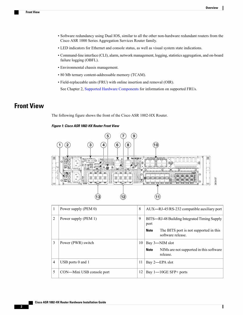
Front ViewThe following figure shows the front of the Cisco ASR 1002-HX Router.
Figure 1: Cisco ASR 1002-HX Router Front View
AUX—RJ-45/RS-232 compatible auxiliary port8Power supply (PEM 0)1
BITS—RJ-48Building Integrated Timing Supplyport
The BITS port is not supported in thissoftware release.
Note
9Power supply (PEM 1)2
Bay 3—NIM slot
NIMs are not supported in this softwarerelease.
Note
10Power (PWR) switch3
Bay 2—EPA slot11USB ports 0 and 14
Bay 1—10GE SFP+ ports12CON—Mini USB console port5
Cisco ASR 1002-HX Router Hardware Installation Guide2
OverviewFront View
Bay 0—1GE SFP ports13CON—RJ-45/RS-232 compatible console port6
MGMT—RJ-45 10/100/1000 managementEthernet port
7
Two power supplies (AC or DC) are accessed from the front of the router and are hot-swappable.
The Cisco ASR 1002-HX Router can support two AC or two DC power supplies. Do not install mixedAC and DC power supply units in the same chassis.
Caution
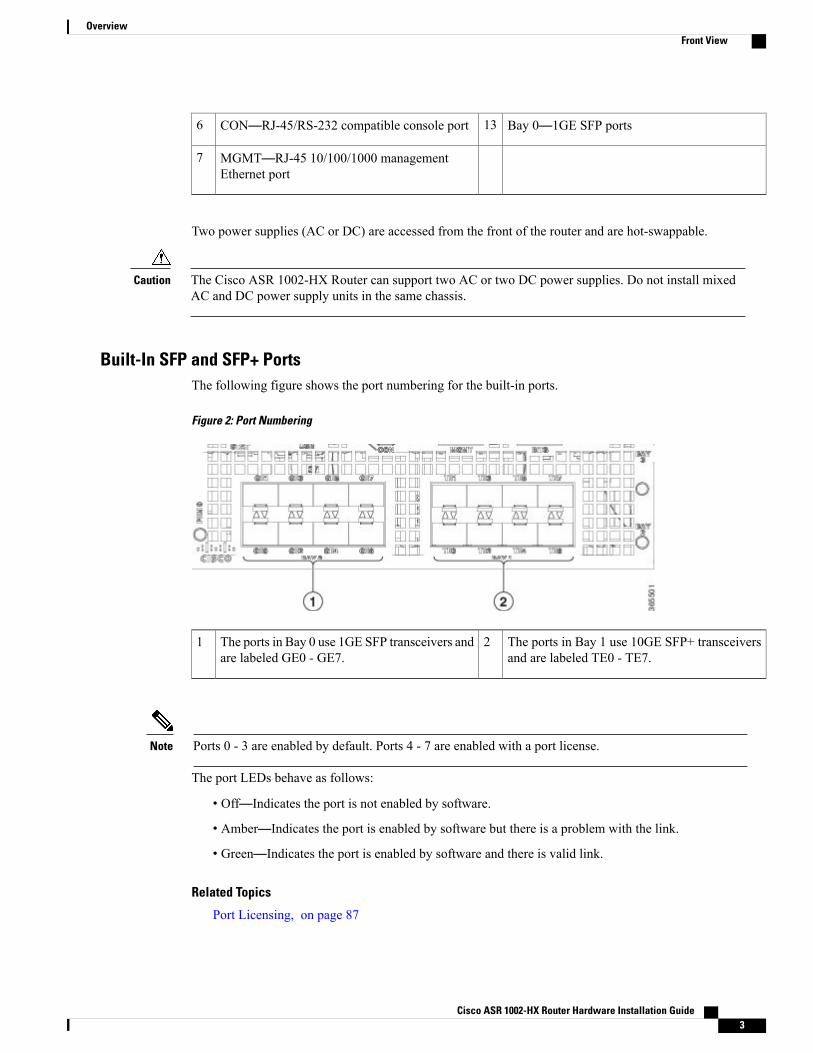
Built-In SFP and SFP+ PortsThe following figure shows the port numbering for the built-in ports.
Figure 2: Port Numbering
The ports in Bay 1 use 10GE SFP+ transceiversand are labeled TE0 - TE7.
2The ports in Bay 0 use 1GE SFP transceivers andare labeled GE0 - GE7.
1
Ports 0 - 3 are enabled by default. Ports 4 - 7 are enabled with a port license.Note
The port LEDs behave as follows:
• Off—Indicates the port is not enabled by software.
• Amber—Indicates the port is enabled by software but there is a problem with the link.
• Green—Indicates the port is enabled by software and there is valid link.
Related Topics
Port Licensing, on page 87
Cisco ASR 1002-HX Router Hardware Installation Guide 3
OverviewFront View
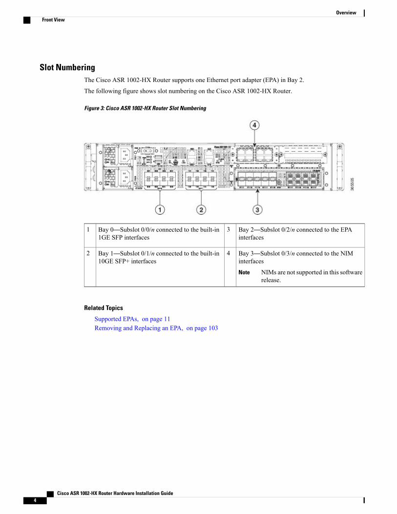
Slot NumberingThe Cisco ASR 1002-HX Router supports one Ethernet port adapter (EPA) in Bay 2.
The following figure shows slot numbering on the Cisco ASR 1002-HX Router.
Figure 3: Cisco ASR 1002-HX Router Slot Numbering
Bay 2—Subslot 0/2/n connected to the EPAinterfaces
3Bay 0—Subslot 0/0/n connected to the built-in1GE SFP interfaces
1
Bay 3—Subslot 0/3/n connected to the NIMinterfaces
NIMs are not supported in this softwarerelease.
Note
4Bay 1—Subslot 0/1/n connected to the built-in10GE SFP+ interfaces
2
Related Topics
Supported EPAs, on page 11Removing and Replacing an EPA, on page 103
Cisco ASR 1002-HX Router Hardware Installation Guide4
OverviewFront View
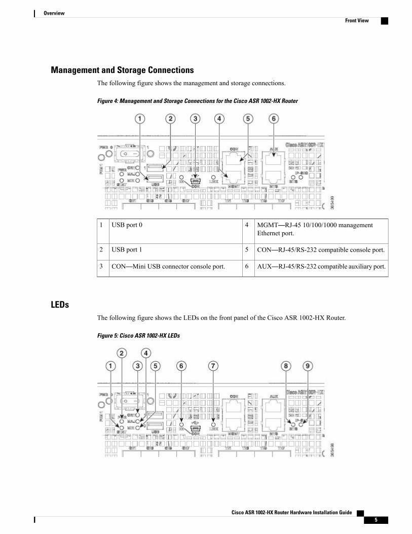
Management and Storage ConnectionsThe following figure shows the management and storage connections.
Figure 4: Management and Storage Connections for the Cisco ASR 1002-HX Router
MGMT—RJ-45 10/100/1000 managementEthernet port.
4USB port 01
CON—RJ-45/RS-232 compatible console port.5USB port 12
AUX—RJ-45/RS-232 compatible auxiliary port.6CON—Mini USB connector console port.3
LEDsThe following figure shows the LEDs on the front panel of the Cisco ASR 1002-HX Router.
Figure 5: Cisco ASR 1002-HX LEDs
Cisco ASR 1002-HX Router Hardware Installation Guide 5
OverviewFront View
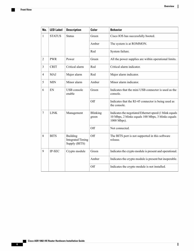
BehaviorColorDescriptionLED LabelNo.
Cisco IOS has successfully booted.GreenStatusSTATUS1
The system is at ROMMON.Amber
System failure.Red
All the power supplies are within operational limits.GreenPowerPWR2
Critical alarm indicator.RedCritical alarmCRIT3
Major alarm indicator.RedMajor alarmMAJ4
Minor alarm indicator.AmberMinor alarmMIN5
Indicates that the mini USB connector is used as theconsole.
GreenUSB consoleenable
EN6
Indicates that the RJ-45 connector is being used asthe console.
Off
Indicates the negotiated Ethernet speed (1 blink equals10 Mbps, 2 blinks equals 100 Mbps, 3 blinks equals1000 Mbps).
Blinkinggreen
ManagementLINK7
Not connected.Off
The BITS port is not supported in this softwarerelease.
OffBuildingIntegrated TimingSupply (BITS)
BITS8
Indicates the cryptomodule is present and operational.GreenCrypto moduleIP-SEC9
Indicates the crypto module is present but inoperable.Amber
Indicates the crypto module is not installed.Off
Cisco ASR 1002-HX Router Hardware Installation Guide6
OverviewFront View
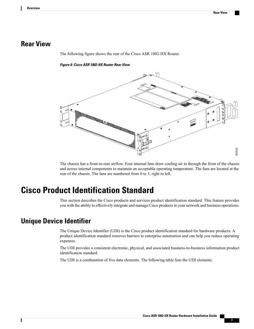
Rear ViewThe following figure shows the rear of the Cisco ASR 1002-HX Router.
Figure 6: Cisco ASR 1002-HX Router Rear View
The chassis has a front-to-rear airflow. Four internal fans draw cooling air in through the front of the chassisand across internal components to maintain an acceptable operating temperature. The fans are located at therear of the chassis. The fans are numbered from 0 to 3, right to left.
Cisco Product Identification StandardThis section describes the Cisco products and services product identification standard. This feature providesyou with the ability to effectively integrate andmanage Cisco products in your network and business operations.
Unique Device IdentifierThe Unique Device Identifier (UDI) is the Cisco product identification standard for hardware products. Aproduct identification standard removes barriers to enterprise automation and can help you reduce operatingexpenses.
The UDI provides a consistent electronic, physical, and associated business-to-business information productidentification standard.
The UDI is a combination of five data elements. The following table lists the UDI elements.
Cisco ASR 1002-HX Router Hardware Installation Guide 7
OverviewRear View
Table 1: UDI Elements
DescriptionPhysicalVisibility
ElectronicVisibility
UDI Data Element
Product ID, also known as product name, modelname, product number
YesYesPID
Version IDYesYesVID
Serial number, the unique instance of the PIDYesYesSN
Type, such as chassis, slot, or power supply—YesEntity Name
Additional product information—YesProduct Description
The combination of serial number and product ID (PID) is unique and consistent across all Cisco products.The PID that is coded on hardware is called a base product identifier.
Additional orderable PIDs can be associated to a base PID. For instance, an orderable PID may describe apackaging configuration for a product or a bundled group of products sold, tested, and shipped together.Specific unique device identifier (UDI) benefits include the following:
• Identifies:
◦Individual Cisco products in your networks
◦PIDs and serial numbers for service and replaceable products
◦Version IDs (VIDs) for product version visibility
• Facilitates discovery of products subject to recall or upgrade
• Enhances inventory automation of Cisco products
The Cisco product identification standard provides the following features:
• Version visibility—Cisco continuously improves products through feature additions. Product changesare indicated by incrementing the VID, which provides version visibility to help you understand andmanage product changes. VID management ensures consistency of changes from product to product.
• Operating expense reduction—Cisco UDIs provide accurate and detailed network inventory information;identifying each Cisco product in a network element through a standard interface. Cisco operatingsystems can view and use this data, allowing you to automate your electronic inventory.
• Consistency across product layers—The UDIs are embedded in the hardware products and cannot beoverwritten. Operating and management systems discover UDIs through standard interfaces and displayUDIs in standard outputs. Standard interfaces include the IETF standard ENTITY-MIB.
show diag chassis eeprom detail Command
The show diag chassis eeprom command displays the PID, VID, PCB serial number, hardware revision, andother such information.
Cisco ASR 1002-HX Router Hardware Installation Guide8
OverviewUnique Device Identifier
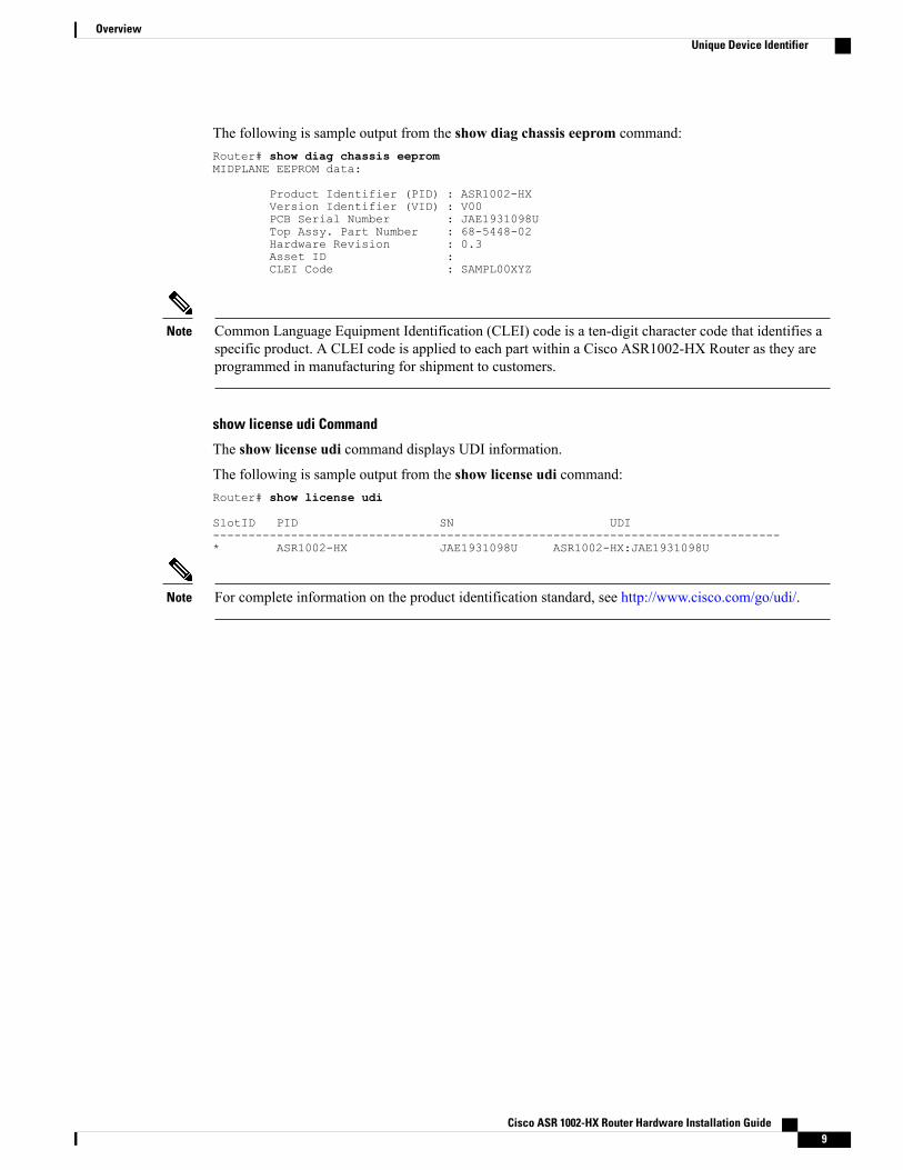
The following is sample output from the show diag chassis eeprom command:Router# show diag chassis eepromMIDPLANE EEPROM data:
Product Identifier (PID) : ASR1002-HXVersion Identifier (VID) : V00PCB Serial Number : JAE1931098UTop Assy. Part Number : 68-5448-02Hardware Revision : 0.3Asset ID :CLEI Code : SAMPL00XYZ
Common Language Equipment Identification (CLEI) code is a ten-digit character code that identifies aspecific product. A CLEI code is applied to each part within a Cisco ASR1002-HX Router as they areprogrammed in manufacturing for shipment to customers.
Note
show license udi Command
The show license udi command displays UDI information.
The following is sample output from the show license udi command:Router# show license udi
SlotID PID SN UDI--------------------------------------------------------------------------------* ASR1002-HX JAE1931098U ASR1002-HX:JAE1931098U
For complete information on the product identification standard, see http://www.cisco.com/go/udi/.Note
Cisco ASR 1002-HX Router Hardware Installation Guide 9
OverviewUnique Device Identifier
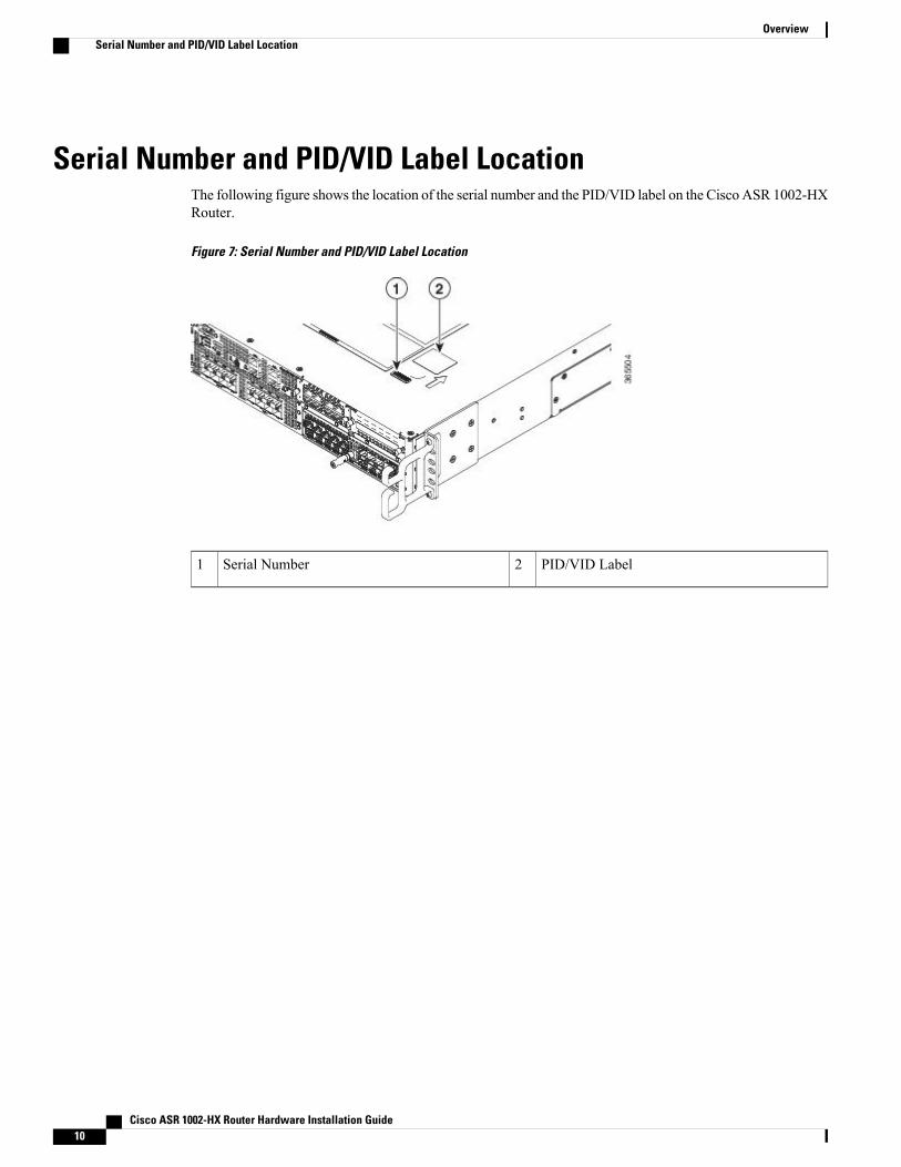
Serial Number and PID/VID Label LocationThe following figure shows the location of the serial number and the PID/VID label on the Cisco ASR 1002-HXRouter.
Figure 7: Serial Number and PID/VID Label Location
PID/VID Label2Serial Number1
Cisco ASR 1002-HX Router Hardware Installation Guide10
OverviewSerial Number and PID/VID Label Location
C H A P T E R 2Supported Hardware Components
This chapter contains information about the supported hardware components on the Cisco ASR 1002-HXRouter, and contains the following sections:
• Supported EPAs, page 11
• Supported Transceivers, page 12
• Supported Crypto Module, page 14
• Supported DIMM Upgrade , page 14
• Power Supplies, page 14
Supported EPAsThe following table lists the supported EPAs on the Cisco ASR 1002-HX Router.
DescriptionPID
Eighteen 1GE-ports that support small form-factor pluggable (SFP)optical transceivers to provide network connectivity. Ports are numbered0 – 17.See Table 3: Supported SFP Transceivers, on page 13 for supportedtransceivers.
EPA-18X1GE
Cisco ASR 1002-HX Router Hardware Installation Guide 11
An EPA has two types of LEDs: an A/L (Active/Link) LED for each port on the EPA, and a STATUS LED,as shown in the following figure.
Figure 8: EPA-18X1GE LEDs
STATUS2A/L1
Table 2: EPA LEDs
DescriptionColor or StateFunction
Port is enabled and the link is up.GreenA/L (Active/Link)
Port is enabled and the link isdown.
Amber
Port is not enabled.Off
EPA is ready and operational.GreenStatus
EPA power is on and good, and theEPA is being configured.
Amber
EPA power is off.Off
Related Topics
Removing and Replacing an EPA, on page 103
Supported TransceiversThe Cisco ASR 1002-HXRouter supports the following small form-factor pluggable (SFP) optical transceivertypes:
Cisco ASR 1002-HX RouterPortsBay
SFPPorts GE0 – GE7Bay 0
Cisco ASR 1002-HX Router Hardware Installation Guide12
Supported Hardware ComponentsSupported Transceivers
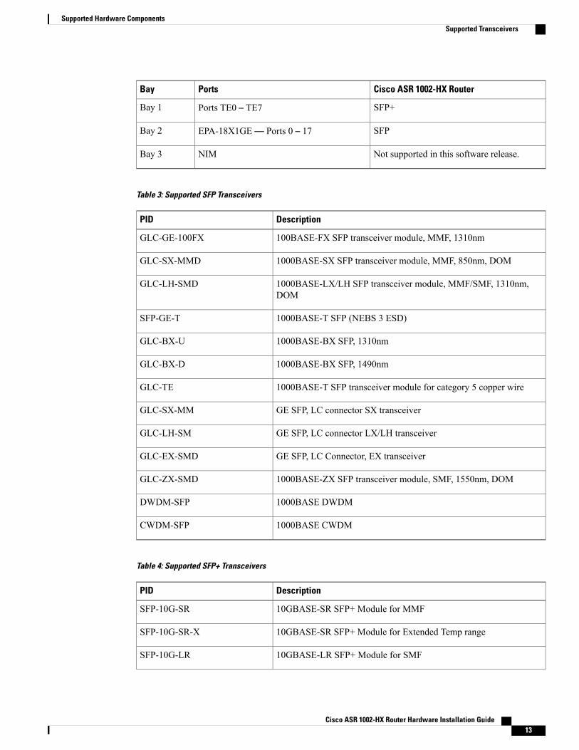
Cisco ASR 1002-HX RouterPortsBay
SFP+Ports TE0 – TE7Bay 1
SFPEPA-18X1GE— Ports 0 – 17Bay 2
Not supported in this software release.NIMBay 3
Table 3: Supported SFP Transceivers
DescriptionPID
100BASE-FX SFP transceiver module, MMF, 1310nmGLC-GE-100FX
1000BASE-SX SFP transceiver module, MMF, 850nm, DOMGLC-SX-MMD
1000BASE-LX/LH SFP transceiver module, MMF/SMF, 1310nm,DOM
GLC-LH-SMD
1000BASE-T SFP (NEBS 3 ESD)SFP-GE-T
1000BASE-BX SFP, 1310nmGLC-BX-U
1000BASE-BX SFP, 1490nmGLC-BX-D
1000BASE-T SFP transceiver module for category 5 copper wireGLC-TE
GE SFP, LC connector SX transceiverGLC-SX-MM
GE SFP, LC connector LX/LH transceiverGLC-LH-SM
GE SFP, LC Connector, EX transceiverGLC-EX-SMD
1000BASE-ZX SFP transceiver module, SMF, 1550nm, DOMGLC-ZX-SMD
1000BASE DWDMDWDM-SFP
1000BASE CWDMCWDM-SFP
Table 4: Supported SFP+ Transceivers
DescriptionPID
10GBASE-SR SFP+ Module for MMFSFP-10G-SR
10GBASE-SR SFP+ Module for Extended Temp rangeSFP-10G-SR-X
10GBASE-LR SFP+ Module for SMFSFP-10G-LR
Cisco ASR 1002-HX Router Hardware Installation Guide 13
Supported Hardware ComponentsSupported Transceivers
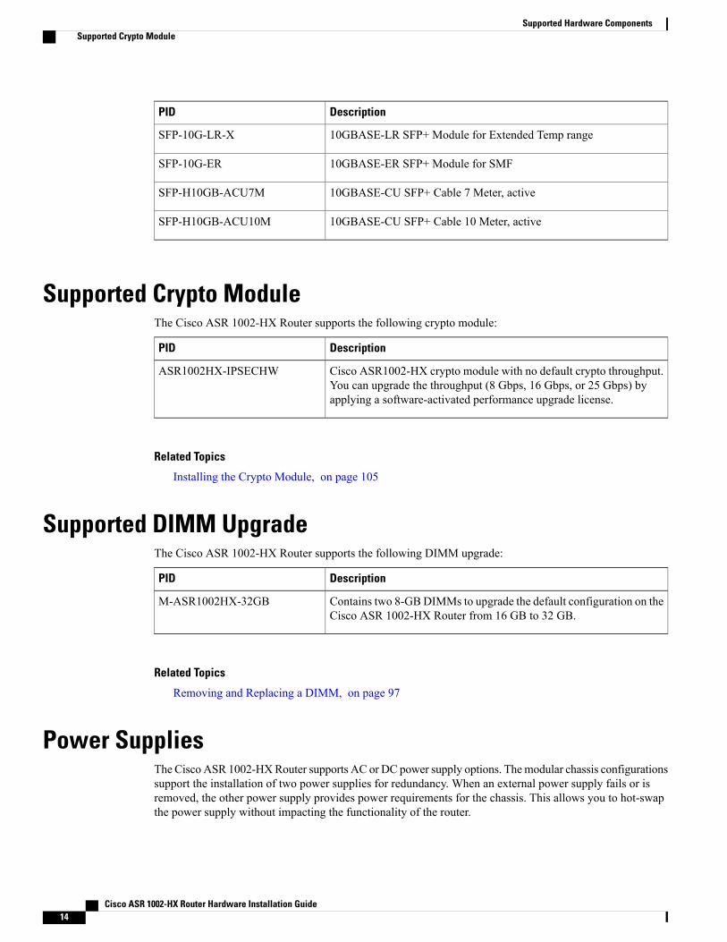
DescriptionPID
10GBASE-LR SFP+ Module for Extended Temp rangeSFP-10G-LR-X
10GBASE-ER SFP+ Module for SMFSFP-10G-ER
10GBASE-CU SFP+ Cable 7 Meter, activeSFP-H10GB-ACU7M
10GBASE-CU SFP+ Cable 10 Meter, activeSFP-H10GB-ACU10M
Supported Crypto ModuleThe Cisco ASR 1002-HX Router supports the following crypto module:
DescriptionPID
Cisco ASR1002-HX crypto module with no default crypto throughput.You can upgrade the throughput (8 Gbps, 16 Gbps, or 25 Gbps) byapplying a software-activated performance upgrade license.
ASR1002HX-IPSECHW
Related Topics
Installing the Crypto Module, on page 105
Supported DIMM UpgradeThe Cisco ASR 1002-HX Router supports the following DIMM upgrade:
DescriptionPID
Contains two 8-GBDIMMs to upgrade the default configuration on theCisco ASR 1002-HX Router from 16 GB to 32 GB.
M-ASR1002HX-32GB
Related Topics
Removing and Replacing a DIMM, on page 97
Power SuppliesThe CiscoASR 1002-HXRouter supports AC or DC power supply options. Themodular chassis configurationssupport the installation of two power supplies for redundancy. When an external power supply fails or isremoved, the other power supply provides power requirements for the chassis. This allows you to hot-swapthe power supply without impacting the functionality of the router.
Cisco ASR 1002-HX Router Hardware Installation Guide14
Supported Hardware ComponentsSupported Crypto Module
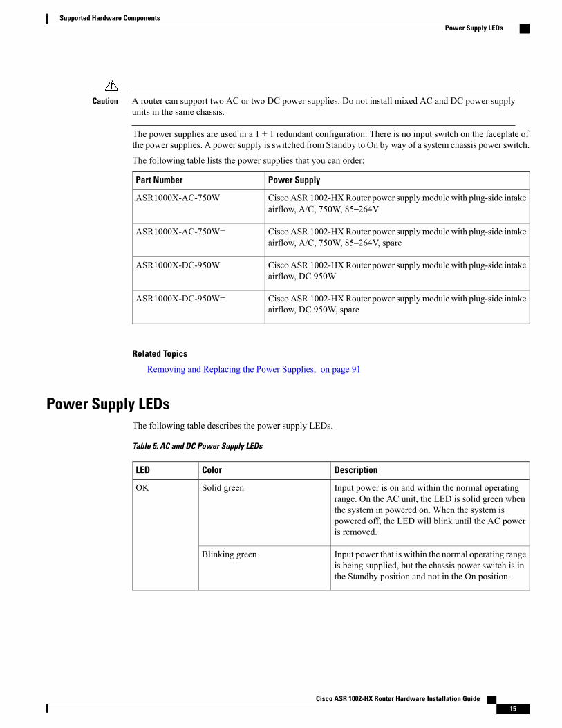
A router can support two AC or two DC power supplies. Do not install mixed AC and DC power supplyunits in the same chassis.
Caution
The power supplies are used in a 1 + 1 redundant configuration. There is no input switch on the faceplate ofthe power supplies. A power supply is switched from Standby to On by way of a system chassis power switch.
The following table lists the power supplies that you can order:
Power SupplyPart Number
CiscoASR 1002-HXRouter power supplymodule with plug-side intakeairflow, A/C, 750W, 85–264V
ASR1000X-AC-750W
CiscoASR 1002-HXRouter power supplymodule with plug-side intakeairflow, A/C, 750W, 85–264V, spare
ASR1000X-AC-750W=
CiscoASR 1002-HXRouter power supplymodule with plug-side intakeairflow, DC 950W
ASR1000X-DC-950W
CiscoASR 1002-HXRouter power supplymodule with plug-side intakeairflow, DC 950W, spare
ASR1000X-DC-950W=
Related Topics
Removing and Replacing the Power Supplies, on page 91
Power Supply LEDsThe following table describes the power supply LEDs.
Table 5: AC and DC Power Supply LEDs
DescriptionColorLED
Input power is on and within the normal operatingrange. On the AC unit, the LED is solid green whenthe system in powered on. When the system ispowered off, the LED will blink until the AC poweris removed.
Solid greenOK
Input power that is within the normal operating rangeis being supplied, but the chassis power switch is inthe Standby position and not in the On position.
Blinking green
Cisco ASR 1002-HX Router Hardware Installation Guide 15
Supported Hardware ComponentsPower Supply LEDs
DescriptionColorLED
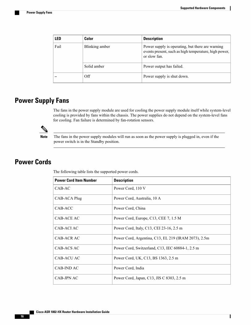
Power supply is operating, but there are warningevents present, such as high temperature, high power,or slow fan.
Blinking amberFail
Power output has failed.Solid amber
Power supply is shut down.Off–
Power Supply FansThe fans in the power supply module are used for cooling the power supply module itself while system-levelcooling is provided by fans within the chassis. The power supplies do not depend on the system-level fansfor cooling. Fan failure is determined by fan-rotation sensors.
The fans in the power supply modules will run as soon as the power supply is plugged in, even if thepower switch is in the Standby position.
Note
Power CordsThe following table lists the supported power cords.
DescriptionPower Cord Item Number
Power Cord, 110 VCAB-AC
Power Cord, Australia, 10 ACAB-ACA Plug
Power Cord, ChinaCAB-ACC
Power Cord, Europe, C13, CEE 7, 1.5 MCAB-ACE AC
Power Cord, Italy, C13, CEI 23-16, 2.5 mCAB-ACI AC
Power Cord, Argentina, C13, EL 219 (IRAM 2073), 2.5mCAB-ACR AC
Power Cord, Switzerland, C13, IEC 60884-1, 2.5 mCAB-ACS AC
Power Cord, UK, C13, BS 1363, 2.5 mCAB-ACU AC
Power Cord, IndiaCAB-IND AC
Power Cord, Japan, C13, JIS C 8303, 2.5 mCAB-JPN AC
Cisco ASR 1002-HX Router Hardware Installation Guide16
Supported Hardware ComponentsPower Supply Fans
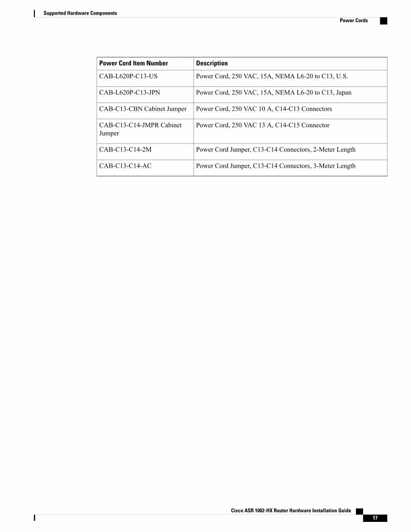
DescriptionPower Cord Item Number
Power Cord, 250 VAC, 15A, NEMA L6-20 to C13, U.S.CAB-L620P-C13-US
Power Cord, 250 VAC, 15A, NEMA L6-20 to C13, JapanCAB-L620P-C13-JPN
Power Cord, 250 VAC 10 A, C14-C13 ConnectorsCAB-C13-CBN Cabinet Jumper
Power Cord, 250 VAC 13 A, C14-C15 ConnectorCAB-C13-C14-JMPR CabinetJumper
Power Cord Jumper, C13-C14 Connectors, 2-Meter LengthCAB-C13-C14-2M
Power Cord Jumper, C13-C14 Connectors, 3-Meter LengthCAB-C13-C14-AC
Cisco ASR 1002-HX Router Hardware Installation Guide 17
Supported Hardware ComponentsPower Cords

Cisco ASR 1002-HX Router Hardware Installation Guide18
Supported Hardware ComponentsPower Cords
C H A P T E R 3Preparing Your Site for Installation
This chapter contains important safety information you should know before working with the Cisco ASR1002-HX Router, and guides you through the process of preparing your site for router installation.
• Prerequisites and Preparation, page 19
• Safety Guidelines, page 20
• Cautions and Regulatory Compliance Statements for NEBS, page 21
• Standard Warning Statements, page 22
• Site Planning, page 26
• Preventing Electrostatic Discharge Damage, page 35
• Electrical Safety, page 36
• Chassis-Lifting Guidelines, page 36
• Tools and Equipment, page 37
• Unpacking and Verifying Shipping Contents, page 37
• Installation Checklist, page 38
Prerequisites and PreparationBefore you perform the procedures in this guide, we recommend that you:
• Read the safety guidelines in the next section and review the electrical safety and ESD-preventionguidelines in this guide.
• Ensure that you have all of the necessary tools and equipment (see the "Tools and Equipment" section).
• Ensure that you have access to the Cisco ASR 1000 Series Aggregation Services Routers SoftwareConfiguration Guide (an online document that is available for viewing or download at Cisco.com) duringthe installation.
• Ensure that the power and cabling requirements are in place at your installation site.
• Ensure that the equipment required to install the router is available.
Cisco ASR 1002-HX Router Hardware Installation Guide 19
• Ensure that your installation site meets the environmental conditions to maintain normal operation.
Before installing the router, you must consider power and cabling requirements that must be in place at yourinstallation site, special equipment for installing the router, and the environmental conditions your installationsite must meet to maintain normal operation.
The shipping package for the router is engineered to reduce the chances of product damage associated withroutine material handling experienced during shipment:
• Router should always be transported or stored in its shipping package in the upright position.
• Keep the router in the shipping container until you have determined the installation site.
Inspect all items for shipping damage. If an item appears damaged, contact a Cisco customer servicerepresentative immediately.
Note
Site Planning ChecklistUse the following checklist to perform and account for all the site-planning tasks described in this chapter:
• The site air conditioning system can compensate for the heat dissipation of the router.
• Electrical service to the site complies with the requirements.
• The electrical circuit servicing the router complies with the requirements.
• Consideration has been given to console port wiring and limitations of the cabling involved, accordingto TIA/EIA-232F.
• The Ethernet cabling distances are within limitations.
• The equipment rack in which you plan to install the router chassis complies with requirements. Carefulconsideration has be given to safety, ease of maintenance, and proper airflow in selecting the locationof the rack.
Safety GuidelinesBefore you begin the installation or replacement procedure, review the safety guidelines in this section toavoid injuring yourself or damaging the equipment.
This section contains guidelines, and do not include every potentially hazardous situation. When youinstall a router, always use common sense and caution.
Note
Cisco ASR 1002-HX Router Hardware Installation Guide20
Preparing Your Site for InstallationSite Planning Checklist
Safety WarningsSafety warnings appear throughout this publication in procedures that, if performed incorrectly, might harmyou. A warning symbol precedes each warning statement.
Before you install, configure, or performmaintenance on the router, review the documentation for the procedureyou are about to perform, paying special attention to the safety warnings.
Do not unpack the system until you are ready to install it. Keep the chassis in the shipping container toprevent accidental damage until you determine an installation site. Use the appropriate unpackingdocumentation included with the system.
Note
Read the installation instructions in this document before you connect the system to its power source. Failureto read and follow these guidelines could lead to an unsuccessful installation and possibly damage the systemand components.
Safety RecommendationsThe following guidelines will help to ensure your own safety and protect your Cisco equipment. This list doesnot cover all potentially hazardous situations, so be alert.
• Cisco safety policy mandates that all its routers must conform to the requirements of IEC 60950, withappropriate national deviations, as a minimum. In addition, Cisco routers must also meet the requirementsof any other normative documents, for example, standards, technical specifications, laws or regulations.
• Review the safety warnings listed in Regulatory Compliance and Safety Information for the Cisco ASR1000 Series Aggregation Services Routers (available online at Cisco.com) before installing, configuring,or maintaining the router.
• Never attempt to lift an object that might be too heavy for you to lift by yourself.
• Always turn all power supplies off and unplug all power cables before opening the chassis.
• Always unplug the power cable before installing or removing a chassis.
• Keep the chassis area clear and dust free during and after installation.
• Keep tools and chassis components away from walk areas.
• Do not wear loose clothing, jewelry (including rings and chains), or other items that could get caughtin the chassis. Fasten your tie or scarf and sleeves.
• The router operates safely when it is used in accordance with its marked electrical ratings andproduct-usage instructions.
Cautions and Regulatory Compliance Statements for NEBSThe following table lists cautions, regulatory compliance statements, and requirements for the NetworkEquipment Building System (NEBS) certification from the Telcordia Electromagnetic Compatibility andElectrical Safety – Generic Criteria for Network Telecommunications Equipment (A Module of LSSGR,
Cisco ASR 1002-HX Router Hardware Installation Guide 21
Preparing Your Site for InstallationSafety Warnings
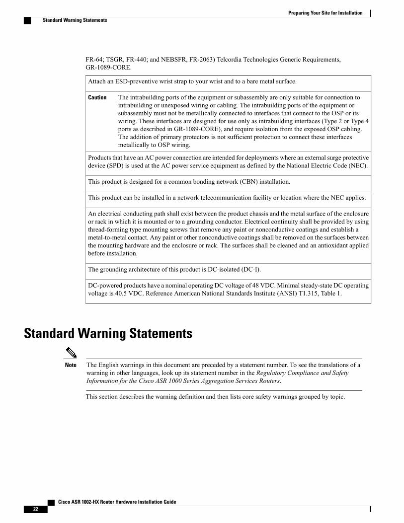
FR-64; TSGR, FR-440; and NEBSFR, FR-2063) Telcordia Technologies Generic Requirements,GR-1089-CORE.
Attach an ESD-preventive wrist strap to your wrist and to a bare metal surface.
The intrabuilding ports of the equipment or subassembly are only suitable for connection tointrabuilding or unexposed wiring or cabling. The intrabuilding ports of the equipment orsubassembly must not be metallically connected to interfaces that connect to the OSP or itswiring. These interfaces are designed for use only as intrabuilding interfaces (Type 2 or Type 4ports as described in GR-1089-CORE), and require isolation from the exposed OSP cabling.The addition of primary protectors is not sufficient protection to connect these interfacesmetallically to OSP wiring.
Caution
Products that have an AC power connection are intended for deployments where an external surge protectivedevice (SPD) is used at the AC power service equipment as defined by the National Electric Code (NEC).
This product is designed for a common bonding network (CBN) installation.
This product can be installed in a network telecommunication facility or location where the NEC applies.
An electrical conducting path shall exist between the product chassis and the metal surface of the enclosureor rack in which it is mounted or to a grounding conductor. Electrical continuity shall be provided by usingthread-forming type mounting screws that remove any paint or nonconductive coatings and establish ametal-to-metal contact. Any paint or other nonconductive coatings shall be removed on the surfaces betweenthe mounting hardware and the enclosure or rack. The surfaces shall be cleaned and an antioxidant appliedbefore installation.
The grounding architecture of this product is DC-isolated (DC-I).
DC-powered products have a nominal operating DC voltage of 48 VDC.Minimal steady-state DC operatingvoltage is 40.5 VDC. Reference American National Standards Institute (ANSI) T1.315, Table 1.
Standard Warning Statements
The English warnings in this document are preceded by a statement number. To see the translations of awarning in other languages, look up its statement number in the Regulatory Compliance and SafetyInformation for the Cisco ASR 1000 Series Aggregation Services Routers.
Note
This section describes the warning definition and then lists core safety warnings grouped by topic.
Cisco ASR 1002-HX Router Hardware Installation Guide22
Preparing Your Site for InstallationStandard Warning Statements
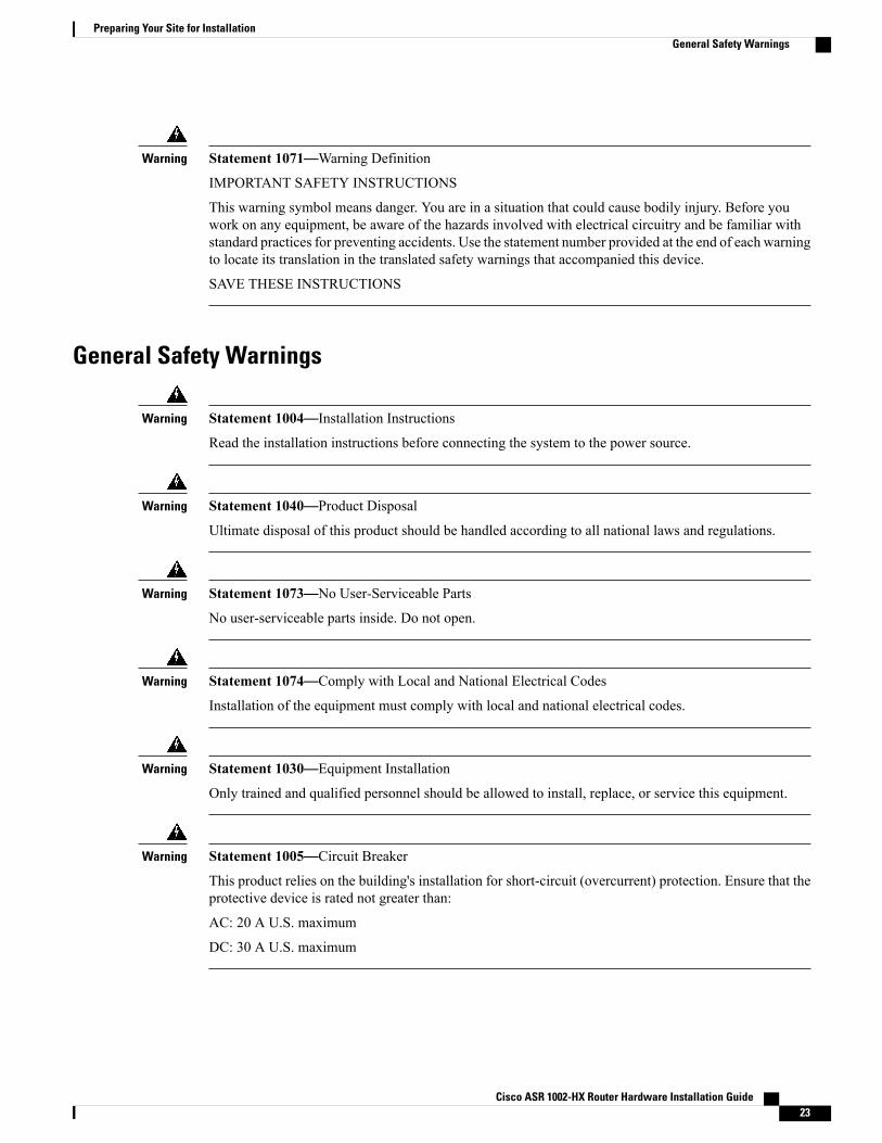
Statement 1071—Warning Definition
IMPORTANT SAFETY INSTRUCTIONS
This warning symbol means danger. You are in a situation that could cause bodily injury. Before youwork on any equipment, be aware of the hazards involved with electrical circuitry and be familiar withstandard practices for preventing accidents. Use the statement number provided at the end of each warningto locate its translation in the translated safety warnings that accompanied this device.
SAVE THESE INSTRUCTIONS
Warning
General Safety Warnings
Statement 1004—Installation Instructions
Read the installation instructions before connecting the system to the power source.
Warning
Statement 1040—Product Disposal
Ultimate disposal of this product should be handled according to all national laws and regulations.
Warning
Statement 1073—No User-Serviceable Parts
No user-serviceable parts inside. Do not open.
Warning
Statement 1074—Comply with Local and National Electrical Codes
Installation of the equipment must comply with local and national electrical codes.
Warning
Statement 1030—Equipment Installation
Only trained and qualified personnel should be allowed to install, replace, or service this equipment.
Warning
Statement 1005—Circuit Breaker
This product relies on the building's installation for short-circuit (overcurrent) protection. Ensure that theprotective device is rated not greater than:
AC: 20 A U.S. maximum
DC: 30 A U.S. maximum
Warning
Cisco ASR 1002-HX Router Hardware Installation Guide 23
Preparing Your Site for InstallationGeneral Safety Warnings
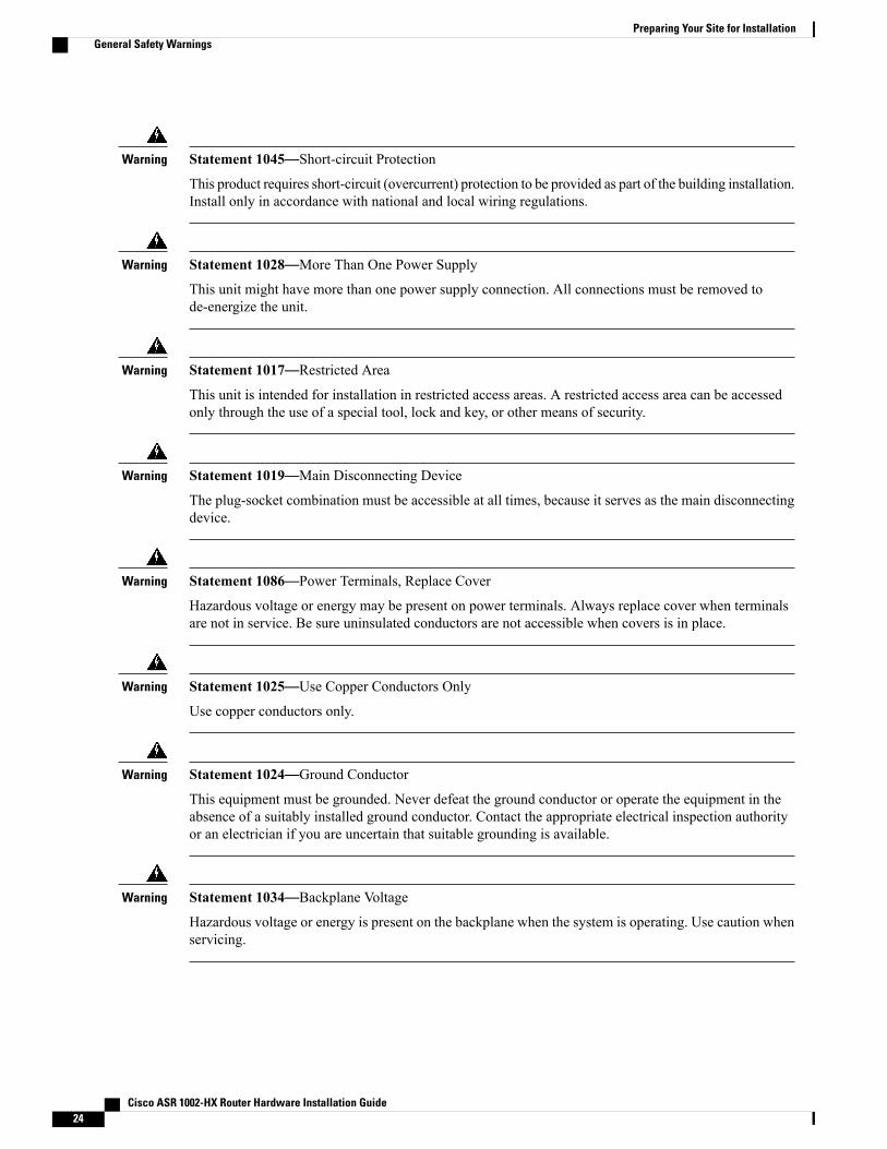
Statement 1045—Short-circuit Protection
This product requires short-circuit (overcurrent) protection to be provided as part of the building installation.Install only in accordance with national and local wiring regulations.
Warning
Statement 1028—More Than One Power Supply
This unit might have more than one power supply connection. All connections must be removed tode-energize the unit.
Warning
Statement 1017—Restricted Area
This unit is intended for installation in restricted access areas. A restricted access area can be accessedonly through the use of a special tool, lock and key, or other means of security.
Warning
Statement 1019—Main Disconnecting Device
The plug-socket combination must be accessible at all times, because it serves as the main disconnectingdevice.
Warning
Statement 1086—Power Terminals, Replace Cover
Hazardous voltage or energy may be present on power terminals. Always replace cover when terminalsare not in service. Be sure uninsulated conductors are not accessible when covers is in place.
Warning
Statement 1025—Use Copper Conductors Only
Use copper conductors only.
Warning
Statement 1024—Ground Conductor
This equipment must be grounded. Never defeat the ground conductor or operate the equipment in theabsence of a suitably installed ground conductor. Contact the appropriate electrical inspection authorityor an electrician if you are uncertain that suitable grounding is available.
Warning
Statement 1034—Backplane Voltage
Hazardous voltage or energy is present on the backplane when the system is operating. Use caution whenservicing.
Warning
Cisco ASR 1002-HX Router Hardware Installation Guide24
Preparing Your Site for InstallationGeneral Safety Warnings
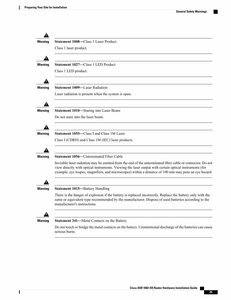
Statement 1008—Class 1 Laser Product
Class 1 laser product.
Warning
Statement 1027—Class 1 LED Product
Class 1 LED product.
Warning
Statement 1009—Laser Radiation
Laser radiation is present when the system is open.
Warning
Statement 1010—Staring into Laser Beam
Do not stare into the laser beam.
Warning
Statement 1055—Class I and Class 1M Laser
Class I (CDRH) and Class 1M (IEC) laser products.
Warning
Statement 1056—Unterminated Fiber Cable
Invisible laser radiation may be emitted from the end of the unterminated fiber cable or connector. Do notview directly with optical instruments. Viewing the laser output with certain optical instruments (forexample, eye loupes, magnifiers, and microscopes) within a distance of 100 mmmay pose an eye hazard.
Warning
Statement 1015—Battery Handling
There is the danger of explosion if the battery is replaced incorrectly. Replace the battery only with thesame or equivalent type recommended by the manufacturer. Dispose of used batteries according to themanufacturer's instructions.
Warning
Statement 341—Metal Contacts on the Battery
Do not touch or bridge the metal contacts on the battery. Unintentional discharge of the batteries can causeserious burns.
Warning
Cisco ASR 1002-HX Router Hardware Installation Guide 25
Preparing Your Site for InstallationGeneral Safety Warnings
Statement 1032—Lifting the Chassis
To prevent personal injury or damage to the chassis, never attempt to lift or tilt the chassis using thehandles on modules (such as power supplies, fans, or cards); these types of handles are not designed tosupport the weight of the unit.
Warning
Statement 1047—Overheating Prevention
To prevent the system from overheating, do not operate it in an area that exceeds the maximumrecommended ambient temperature of:
104° F (40° C)
Warning
Statement 1029—Blank Faceplates and Cover Panels
Blank faceplates and cover panels serve three important functions: they prevent exposure to hazardousvoltages and currents inside the chassis; they contain electromagnetic interference (EMI) that might disruptother equipment; and they direct the flow of cooling air through the chassis. Do not operate the systemunless all cards, faceplates, front covers, and rear covers are in place.
Warning
Site PlanningThis section contains site-planning information, and will help you plan for the installation of the Cisco ASR1002-HX Router.
General PrecautionsObserve the following general precautions when using and working with the Cisco ASR 1002-HX Router:
• Keep your system components away from radiators and heat sources and do not block cooling vents.
• Do not spill food or liquids on your system components and never operate the product in a wetenvironment.
• Do not push any objects into the openings of your system components. Doing so can cause fire or electricshock by shorting out interior components.
• Position system cables and power supply cable carefully. Route system cables and power supply cableand plug such that they cannot be stepped on or tripped over. Be sure that nothing else rests on yoursystem component cables or power cable.
• Do not modify power cables or plugs. Consult a licensed electrician or your power company for sitemodifications. Always follow your local and national wiring rules.
• If you turn off your system, wait at least 30 seconds before turning it on again to avoid system componentdamage.
Cisco ASR 1002-HX Router Hardware Installation Guide26
Preparing Your Site for InstallationSite Planning
Site Selection GuidelinesThe Cisco ASR 1002-HXRouter requires specific environmental operating conditions. Temperature, humidity,altitude, and vibration can affect the performance and reliability of the router. The following sections providespecific information to help you plan for a proper operating environment.
The Cisco ASR 1002-HX Router is designed to meet the industry EMC, safety, and environmental standardsdescribed in the Regulatory, Safety, and Compliance Information for Cisco ASR 1000 Series AggregationServices Routers document.
Site Environmental RequirementsEnvironmental monitoring protects the system and components from damage caused by excessive voltageand temperature conditions. To ensure normal operation and avoid unnecessary maintenance, plan and prepareyour site configuration before installation. After installation, make sure the site maintains the environmentalcharacteristics, as shown in the following table.
Table 6: Cisco ASR 1002-HX Router Environmental Tolerance
MaximumMinimumEnvironmental Characteristic
104° F (40° C)
(40° C up to 10,000 feet)
32° F (0° C)Operating temperature (nominal)
122° F (50° C)32° F (0° C)Operating temperature (short term)
158° F (70° C)–4° F (–20° C)Storage temperature
90%10%Operative humidity (nominal)(relative humidity)
90%5%Operative humidity (short term)
95%5%Storage humidity (relativehumidity)
6,000 feet (1829 meters)–500 feet (–152.4 meters)Altitude, operating: over allowabletemperature range (0 to 50 degreesC)
50,000 feet (15240 meters)–1000 feet (–304.8 meters)Altitude, nonoperating: overallowable temperature range
158° F (70° C)–13° F (–25° C)Thermal shock nonoperating withchange over time of 3 minutes
122° F (50° C)32° F (0° C)Thermal Shock - Operating at 2.5degree C per minute
Cisco ASR 1002-HX Router Hardware Installation Guide 27
Preparing Your Site for InstallationSite Selection Guidelines
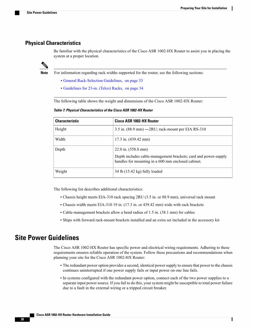
Physical CharacteristicsBe familiar with the physical characteristics of the Cisco ASR 1002-HX Router to assist you in placing thesystem at a proper location.
For information regarding rack widths supported for the router, see the following sections:Note
• General Rack-Selection Guidelines, on page 33
• Guidelines for 23-in. (Telco) Racks, on page 34
The following table shows the weight and dimensions of the Cisco ASR 1002-HX Router:
Table 7: Physical Characteristics of the Cisco ASR 1002-HX Router
Cisco ASR 1002-HX RouterCharacteristic
3.5 in. (88.9 mm)—2RU; rack-mount per EIA RS-310Height
17.3 in. (439.42 mm)Width
22.0 in. (558.8 mm)
Depth includes cable-management brackets; card and power-supplyhandles for mounting in a 600 mm enclosed cabinet.
Depth
34 lb (15.42 kg) fully loadedWeight
The following list describes additional characteristics:
• Chassis height meets EIA-310 rack spacing 2RU (3.5 in. or 88.9 mm), universal rack mount
• Chassis width meets EIA-310 19 in. (17.3 in. or 439.42 mm) wide with rack brackets
• Cable-management brackets allow a bend radius of 1.5 in. (38.1 mm) for cables
• Ships with forward rack-mount brackets installed and an extra set included in the accessory kit
Site Power GuidelinesThe Cisco ASR 1002-HX Router has specific power and electrical wiring requirements. Adhering to theserequirements ensures reliable operation of the system. Follow these precautions and recommendations whenplanning your site for the Cisco ASR 1002-HX Router:
• The redundant power option provides a second, identical power supply to ensure that power to the chassiscontinues uninterrupted if one power supply fails or input power on one line fails.
• In systems configured with the redundant power option, connect each of the two power supplies to aseparate input power source. If you fail to do this, your systemmight be susceptible to total power failuredue to a fault in the external wiring or a tripped circuit breaker.
Cisco ASR 1002-HX Router Hardware Installation Guide28
Preparing Your Site for InstallationSite Power Guidelines
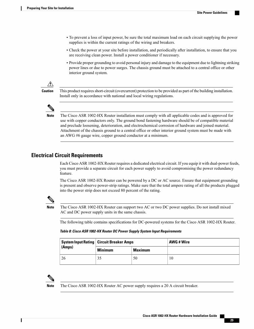
• To prevent a loss of input power, be sure the total maximum load on each circuit supplying the powersupplies is within the current ratings of the wiring and breakers.
• Check the power at your site before installation, and periodically after installation, to ensure that youare receiving clean power. Install a power conditioner if necessary.
• Provide proper grounding to avoid personal injury and damage to the equipment due to lightning strikingpower lines or due to power surges. The chassis ground must be attached to a central office or otherinterior ground system.
This product requires short-circuit (overcurrent) protection to be provided as part of the building installation.Install only in accordance with national and local wiring regulations.
Caution
The Cisco ASR 1002-HX Router installation must comply with all applicable codes and is approved foruse with copper conductors only. The ground bond fastening hardware should be of compatible materialand preclude loosening, deterioration, and electrochemical corrosion of hardware and joined material.Attachment of the chassis ground to a central office or other interior ground system must be made withan AWG #6 gauge wire, copper ground conductor at a minimum.
Note
Electrical Circuit RequirementsEach Cisco ASR 1002-HXRouter requires a dedicated electrical circuit. If you equip it with dual-power feeds,you must provide a separate circuit for each power supply to avoid compromising the power redundancyfeature.
The Cisco ASR 1002-HX Router can be powered by a DC or AC source. Ensure that equipment groundingis present and observe power-strip ratings. Make sure that the total ampere rating of all the products pluggedinto the power strip does not exceed 80 percent of the rating.
The Cisco ASR 1002-HX Router can support two AC or two DC power supplies. Do not install mixedAC and DC power supply units in the same chassis.
Note
The following table contains specifications for DC-powered systems for the Cisco ASR 1002-HX Router.
Table 8: Cisco ASR 1002-HX Router DC Power Supply System Input Requirements
AWG # WireCircuit Breaker AmpsSystem Input Rating(Amps)
MaximumMinimum
10503526
The Cisco ASR 1002-HX Router AC power supply requires a 20 A circuit breaker.Note
Cisco ASR 1002-HX Router Hardware Installation Guide 29
Preparing Your Site for InstallationSite Power Guidelines
The following table lists AC and DC power supply system rating requirements for the Cisco ASR 1002-HXRouter.
Table 9: AC and DC Power Supply System Rating Specifications for the Cisco ASR 1002-HX Router
SpecificationDescription
AC = 85–264 VACDC = –40–72 VDC
Power supply declared ratings
50/60 Hz for AC power suppliesLine frequency rating
Site Cabling GuidelinesThis section contains guidelines for wiring and cabling at your site. When preparing your site for networkconnections to the Cisco ASR 1002-HX Router, consider the type of cable required for each component, andthe cable limitations. Consider the distance limitations for signaling, EMI, and connector compatibility.Possible cable types are fiber, thick or thin coaxial, foil twisted-pair cabling, or unshielded twisted-pair cabling.
Also consider any additional interface equipment you need, such as transceivers, hubs, switches, modems,channel service units (CSUs), or data service units (DSUs).
Before you install the Cisco ASR 1002-HX Router, have all the additional external equipment and cables athand. For ordering information, contact a Cisco customer service representative.
The extent of your network and the distances between network interface connections depend in part on thefollowing factors:
• Signal type
• Signal speed
• Transmission medium
The distance and rate limits referenced in the following sections are the IEEE-recommendedmaximum speedsand distances for signaling purposes. Use this information as guidelines when planning your networkconnections prior to installing the Cisco ASR 1002-HX Router.
If wires exceed recommended distances, or if wires pass between buildings, give special consideration to theeffect of a lightning strike in your vicinity. The electromagnetic pulse caused by lightning or other high-energyphenomena can easily couple enough energy into unshielded conductors to destroy electronic devices. If youhave had problems of this sort in the past, you may want to consult experts in electrical surge suppression andshielding.
Console Port ConnectionsThe Cisco ASR 1002-HX Router provides console and auxiliary ports to connect a terminal or computer forlocal console access.
Both ports have RJ-45 connectors, support RS-232 asynchronous data, and have distance recommendationsspecified in the IEEE RS-232 standard.
Cisco ASR 1002-HX Router Hardware Installation Guide30
Preparing Your Site for InstallationSite Cabling Guidelines
USB Serial Console
The USB serial console port connects directly to the USB connector of a PC using a USB Type A to 5-pinmini USB Type-B cable. The USB Console supports full speed (12Mbps) operation. The console port doesnot support hardware flow control.
Note • Always use shielded USB cables with a properly terminated shield. The USB serial console interfacecable must not exceed 3 meters in length.
• Only one console port can be active at a time. When a cable is plugged into the USB console port,the RJ-45 port becomes inactive. Conversely, when the USB cable is removed from the USB port,the RJ-45 port becomes active.
• 4-pin mini USB Type-B connectors are easily confused with 5-pin mini USB Type-B connectors.Only 5-pin mini USB Type-B is supported.
Interference ConsiderationsWhen wires are run for a significant distance, there is a risk that stray signals will be induced on the wires asinterference. If interference signals are strong, they can cause data errors or damage to the equipment.
The following sections describe sources of interference and how to minimize its effects on the Cisco ASR1002-HX Router.
Electromagnetic Interference
All the equipment powered by AC current can propagate electrical energy that can cause electromagneticinterference (EMI) and possibly affect the operation of other equipment. The typical sources of EMI areequipment power cords and power service cables from electric utility companies.
Strong EMI can destroy the signal drivers and receivers in the Cisco ASR 1002-HX Routerr and even createan electrical hazard by causing power surges through power lines into installed equipment. These problemsare rare, but could be catastrophic.
To resolve these problems, you need specialized knowledge and equipment, which could consume substantialtime and money. However, you should ensure that you have a properly grounded and shielded electricalenvironment, paying special attention to the need for electrical surge suppression.
The following table lists electrode magnetic compliance standards for the Cisco ASR 1002-HX Router.
Cisco ASR 1002-HX Router Hardware Installation Guide 31
Preparing Your Site for InstallationSite Cabling Guidelines
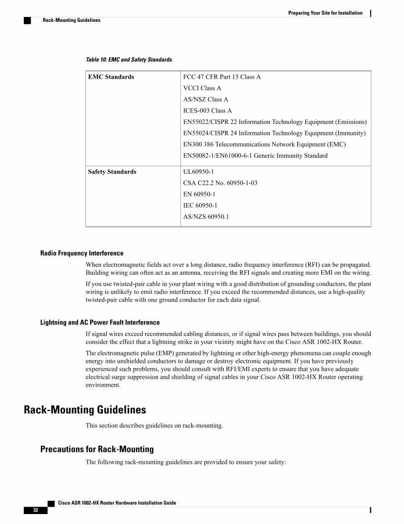
Table 10: EMC and Safety Standards
FCC 47 CFR Part 15 Class A
VCCI Class A
AS/NSZ Class A
ICES-003 Class A
EN55022/CISPR 22 Information Technology Equipment (Emissions)
EN55024/CISPR 24 Information Technology Equipment (Immunity)
EN300 386 Telecommunications Network Equipment (EMC)
EN50082-1/EN61000-6-1 Generic Immunity Standard
EMC Standards
UL60950-1
CSA C22.2 No. 60950-1-03
EN 60950-1
IEC 60950-1
AS/NZS 60950.1
Safety Standards
Radio Frequency Interference
When electromagnetic fields act over a long distance, radio frequency interference (RFI) can be propagated.Building wiring can often act as an antenna, receiving the RFI signals and creating more EMI on the wiring.
If you use twisted-pair cable in your plant wiring with a good distribution of grounding conductors, the plantwiring is unlikely to emit radio interference. If you exceed the recommended distances, use a high-qualitytwisted-pair cable with one ground conductor for each data signal.
Lightning and AC Power Fault Interference
If signal wires exceed recommended cabling distances, or if signal wires pass between buildings, you shouldconsider the effect that a lightning strike in your vicinity might have on the Cisco ASR 1002-HX Router.
The electromagnetic pulse (EMP) generated by lightning or other high-energy phenomena can couple enoughenergy into unshielded conductors to damage or destroy electronic equipment. If you have previouslyexperienced such problems, you should consult with RFI/EMI experts to ensure that you have adequateelectrical surge suppression and shielding of signal cables in your Cisco ASR 1002-HX Router operatingenvironment.
Rack-Mounting GuidelinesThis section describes guidelines on rack-mounting.
Precautions for Rack-MountingThe following rack-mounting guidelines are provided to ensure your safety:
Cisco ASR 1002-HX Router Hardware Installation Guide32
Preparing Your Site for InstallationRack-Mounting Guidelines
• Do not move large racks by yourself. Due to the height and weight of a rack, a minimum of two peopleare required to accomplish this task.
• Ensure that the rack is level and stable before extending a component from the rack.
• Ensure that proper airflow is provided to the components in the rack.
• Do not step or stand on any component or systemwhen servicing other systems or components in a rack.
•When mounting the Cisco ASR 1002-HX Router in a partially filled rack, load the rack from the bottomto the top with the heaviest component at the bottom of the rack.
• If the rack is provided with stabilizing devices, install the stabilizers before mounting or servicing theunit in the rack.
General Rack-Selection GuidelinesThe Cisco ASR 1002-HX Router can be mounted in most two-post or four-post, 19-in. equipment racks thatcomply with the Electronics Industries Association (EIA) standard for equipment racks (EIA-310-D 19-in.).The rack must have at least two posts with mounting flanges to mount the chassis.
When mounting a chassis in any type of rack equipment, ensure that the inlet air to the chassis does notexceed 131°F (55°C).
Caution
The distance between the center lines of the mounting holes on the two mounting posts must be 18.31 in. ±0.06 in. (46.50 cm ± 0.15 cm). The rack-mounting hardware included with the chassis is suitable for most19-in. (48.3-cm) equipment racks.
Consider installing the Cisco ASR 1002-HX Router in a rack with the following features:
• NEBS-compliant, 19-in. (48.3-cm) wide rack.
• EIA or ETSI hole patterns in the mounting rails. Required mounting hardware is shipped with the CiscoASR 1002-HX Router. If the rack that you plan to install the system in has metric-threaded rails, youmust provide your own metric-mounting hardware.
• Perforated top and open bottom for ventilation to prevent overheating.
• Leveling feet for stability.
The Cisco ASR 1002-HX Router should not be installed in an enclosed rack because the chassis requiresan unobstructed flow of cooling air to maintain acceptable operating temperatures for its internalcomponents. Installing the router in any type of enclosed rack—even with the front and back doorsremoved—could disrupt the air flow, trap heat next to the chassis, and cause an overtemperature conditioninside the router. If you use an enclosed rack, make certain that there are air vents on all sides of the rackand there is proper ventilation.
Note
Cisco ASR 1002-HX Router Hardware Installation Guide 33
Preparing Your Site for InstallationRack-Mounting Guidelines
Guidelines for 23-in. (Telco) RacksIf needed, you can also install the Cisco ASR 1002-HX Router in 23-in. (Telco) racks. For information onthe adapters needed for 23 in. racks, contact the Newton Instrument Company:
http://www.enewton.com
111 East A Street, Butner NC, USA, 27509
919 575-6426
Equipment Rack GuidelinesThe placement of racks can affect personnel safety, system maintenance, and the system’s ability to operatewithin the environmental characteristics described in Table 6: Cisco ASR 1002-HX Router EnvironmentalTolerance , on page 27. Choose a proper location for the Cisco ASR 1002-HX Router by following theguidelines below.
Locating for Safety
If the Cisco ASR 1002-HXRouter is the heaviest or the only piece of equipment in the rack, consider installingit at or near the bottom to ensure that the rack’s center of gravity is as low as possible.
For additional information about the proper placement of electronic equipment, see the documentGR-63-CORE,Network Equipment Building System (NEBS) Requirements: Physical Protection.
Locating for Easy Maintenance
Keep at least 3 feet of clear space in front of and behind the rack. This space ensures that you can remove theCisco ASR 1002-HX Router components and perform routine maintenance and upgrades easily.
Avoid installing the Cisco ASR 1002-HX Router in a congested rack and consider how the routing of cablesfrom other pieces of equipment in the same rack might affect access to the routers cards.
The front and top of the chassis must remain unobstructed to ensure adequate airflow and prevent overheatinginside the chassis.
Allow the following clearances for normal system maintenance:
• At the top of the chassis—At least 3 in. (7.6 cm)
• In front of the chassis—3 to 4 ft (91.44 cm to 121.92 cm)
To avoid problems during installation and ongoing operation, follow these general precautions when you planthe equipment locations and connections:
• Use the show environment all and the show facility-alarm status commands regularly to check theinternal system status. The environmental monitor continually checks the interior chassis environment;it provides warnings for high temperature and creates reports on any occurrences. If warning messagesare displayed, take immediate action to identify the cause and correct the problem. For more informationon these commands, see the "Environmental Monitoring and Reporting Functions" section.
• Keep the Cisco ASR 1002-HX Router off the floor and out of the areas that collect dust.
• Follow ESD-prevention procedures to avoid damage to equipment. Damage from static discharge cancause immediate or intermittent equipment failure.
Cisco ASR 1002-HX Router Hardware Installation Guide34
Preparing Your Site for InstallationRack-Mounting Guidelines
Locating for Proper Airflow
Ensure that the location of the Cisco ASR 1002-HX Router has enough airflow to keep the system operatingwithin the environmental characteristics, and the air temperature is sufficient to compensate for the heatdissipated by the system.
Avoid locating the Cisco ASR 1002-HX Router in a location in which the chassis air intake vents could drawin the exhaust air from adjacent equipment. Consider how the air flows through the router. The airflow directionis front to back with ambient air drawn in from the venting located on the chassis’ front sides.
Preventing Electrostatic Discharge DamageElectrostatic discharge (ESD) damage occurs when electronic cards or components are improperly handledresulting in complete or intermittent failures. Static electricity can harm delicate components inside yoursystem. To prevent static damage, discharge static electricity from your body before you touch any of yoursystem components, such as a microprocessor. As you continue to work on your system, periodically touchan unpainted metal surface on the computer chassis.
The following are guidelines for preventing ESD damage:
• Always use an ESD-preventive wrist or ankle strap and ensure that it makes good skin contact. Beforeremoving a card from the chassis, connect the equipment end of the strap to the ESD plug at the bottomof the chassis below the power entry modules.
• Handle line cards by faceplates and carrier edges only; avoid touching the card components or connectorpins.
•When removing a module, place the removed module component-side-up on an antistatic surface or ina static-shielding bag. If the module is to be returned to the factory, immediately place it in astatic-shielding bag.
• Avoid contact between the modules and clothing. The wrist strap protects the card from ESD voltagesonly on the body; ESD voltages on clothing can still cause damage.
•When transporting a sensitive component, place it in an antistatic container or packaging.
• Handle all sensitive components in a static-safe area. If possible, use antistatic floor pads and workbenchpads.
For safety, periodically check the resistance value of the antistatic strap. The measurement should bebetween 1 and 10 ohms.
Caution
Always tighten the captive installation screws on all the system components when you are installing them.These screws prevent accidental removal of the module, provide proper grounding for the system, andhelp ensure that the bus connectors are properly seated in the backplane.
Caution
Cisco ASR 1002-HX Router Hardware Installation Guide 35
Preparing Your Site for InstallationPreventing Electrostatic Discharge Damage
Electrical SafetyAll the system components are hot-swappable. They are designed to be removed and replaced while the systemis operating, without presenting an electrical hazard or damage to the system.
Follow these basic guidelines when you are working with any electrical equipment:
• Before beginning any procedures requiring access to the chassis interior, locate the emergency power-offswitch for the room in which you are working.
• Disconnect all power and external cables before installing or removing a chassis.
• Do not work alone when potentially hazardous conditions exist.
• Never assume that power has been disconnected from a circuit; always check.
• Do not perform any action that creates a potential hazard to people or makes the equipment unsafe.Never install equipment that appears damaged.
• Carefully examine your work area for possible hazards such as moist floors, ungrounded power extensioncables, and missing safety grounds.
In addition, use the following guidelines when working with any equipment that is disconnected from a powersource, but is still connected to telephone wiring or other network cabling:
• Never install telephone wiring during a lightning storm.
• Never install telephone jacks in wet locations unless the jack is specifically designed for wet locations.
• Never touch uninsulated telephone wires or terminals unless the telephone line has been disconnectedat the network interface.
• Use caution when installing or modifying telephone lines.
Statement 1001—Work During Lightning Activity
Do not work on the system or connect or disconnect cables during periods of lightning activity.
Warning
Chassis-Lifting GuidelinesThe chassis is not intended to be moved frequently. Before you install the system, ensure that your site isproperly prepared so that you can avoid having to move the chassis later to accommodate power sources andnetwork connections.
Each time you lift the chassis or any heavy object, follow these guidelines:
• Ensure that your footing is solid, and balance the weight of the chassis between your feet.
• Lift the chassis slowly; never move suddenly or twist your body as you lift.
• Keep your back straight and lift with your legs, not your back. If you must bend down to lift the chassis,bend at the knees, not at the waist, to reduce the strain on your back muscles.
• Do not remove installed components from the chassis.
Cisco ASR 1002-HX Router Hardware Installation Guide36
Preparing Your Site for InstallationElectrical Safety
• Always disconnect all external cables before lifting or moving the chassis.
Tools and EquipmentThe following tools and equipment are recommended as the minimum necessary equipment to install theCisco ASR 1002-HX Router. You may need additional tools and equipment to install associated equipmentand cables. You may also require test equipment to check electronic and optical signal levels, power levels,and communications links.
• Phillips hand screwdriver
• 3.5-mm flat-blade screwdriver
• Tape measure (optional)
• Level (optional)
• Power drill
• 8-gauge wire
• Rack-mount brackets
• Cable-management brackets
Unpacking and Verifying Shipping ContentsWhen you receive your chassis, perform the following steps and use the shipping contents checklist in thefollowing section.
Procedure
Step 1 Inspect the box for any shipping damage. (If there is damage, contact your Cisco service representative).Step 2 Unpack the Cisco ASR 1002-HX Router.Step 3 Perform a visual inspection of the chassis.Step 4 After you have unpacked the system, verify that you have received all of the required components, including
all the accessory items. Using the packing list as a guide, verify that you have received all the equipment listedin your order, and ensure that the configuration matches the packing list.
Checking the Shipping Container ContentsUse the components list shown in the following table to check the contents of the Cisco ASR 1002-HXRoutershipping container. Do not discard the shipping container. You need the container if you move or have to shipthe Cisco ASR 1002-HX Router in the future.
Cisco ASR 1002-HX Router Hardware Installation Guide 37
Preparing Your Site for InstallationTools and Equipment
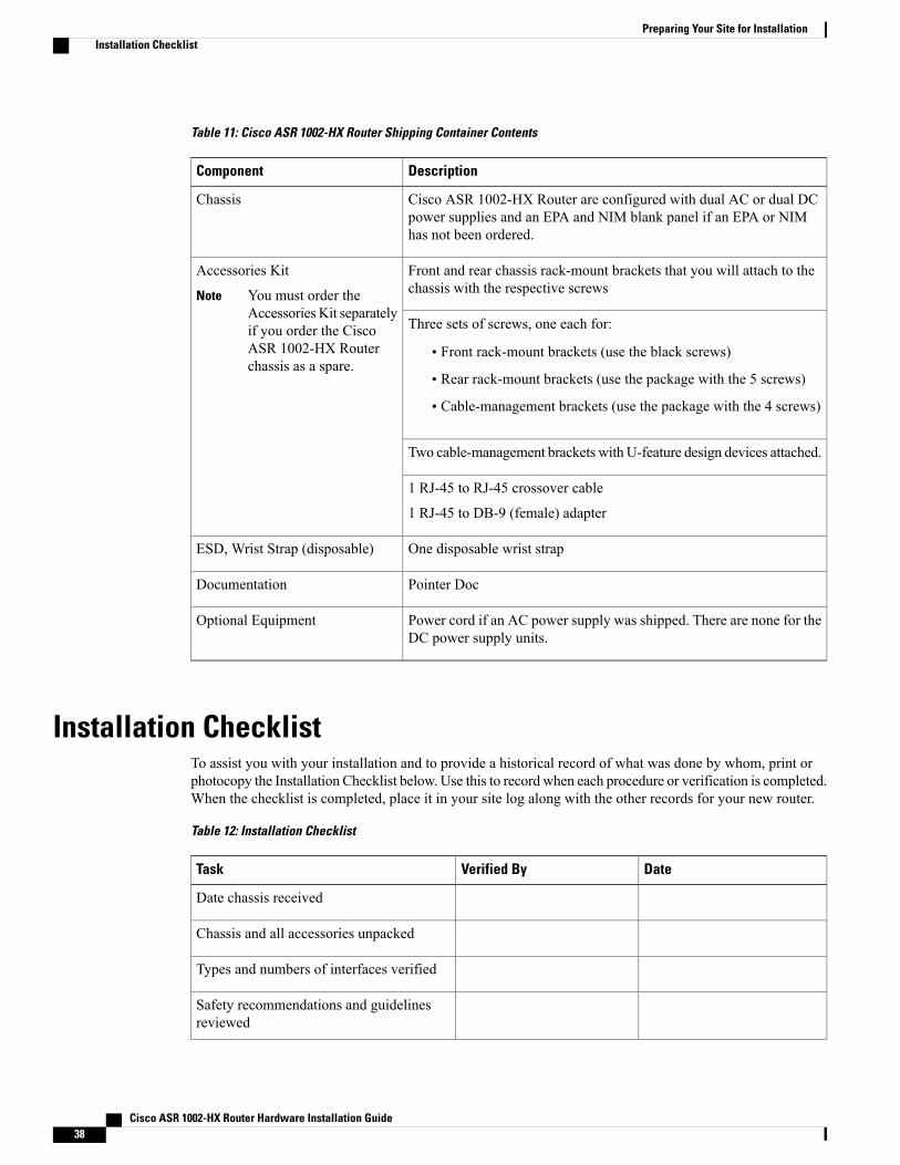
Table 11: Cisco ASR 1002-HX Router Shipping Container Contents
DescriptionComponent
Cisco ASR 1002-HX Router are configured with dual AC or dual DCpower supplies and an EPA and NIM blank panel if an EPA or NIMhas not been ordered.
Chassis
Front and rear chassis rack-mount brackets that you will attach to thechassis with the respective screws
Accessories Kit
You must order theAccessories Kit separatelyif you order the CiscoASR 1002-HX Routerchassis as a spare.
Note
Three sets of screws, one each for:
• Front rack-mount brackets (use the black screws)
• Rear rack-mount brackets (use the package with the 5 screws)
• Cable-management brackets (use the package with the 4 screws)
Two cable-management brackets with U-feature design devices attached.
1 RJ-45 to RJ-45 crossover cable
1 RJ-45 to DB-9 (female) adapter
One disposable wrist strapESD, Wrist Strap (disposable)
Pointer DocDocumentation
Power cord if an AC power supply was shipped. There are none for theDC power supply units.
Optional Equipment
Installation ChecklistTo assist you with your installation and to provide a historical record of what was done by whom, print orphotocopy the Installation Checklist below. Use this to record when each procedure or verification is completed.When the checklist is completed, place it in your site log along with the other records for your new router.
Table 12: Installation Checklist
DateVerified ByTask
Date chassis received
Chassis and all accessories unpacked
Types and numbers of interfaces verified
Safety recommendations and guidelinesreviewed
Cisco ASR 1002-HX Router Hardware Installation Guide38
Preparing Your Site for InstallationInstallation Checklist
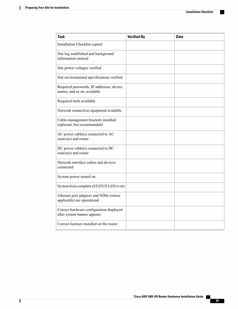
DateVerified ByTask
Installation Checklist copied
Site log established and backgroundinformation entered
Site power voltages verified
Site environmental specifications verified
Required passwords, IP addresses, devicenames, and so on, available
Required tools available
Network connection equipment available
Cable-management brackets installed(optional, but recommended)
AC power cable(s) connected to ACsource(s) and router
DC power cable(s) connected to DCsource(s) and router
Network interface cables and devicesconnected
System power turned on
System boot complete (STATUS LED is on)
Ethernet port adapters and NIMs (whereapplicable) are operational
Correct hardware configuration displayedafter system banner appears
Correct licenses installed on the router
Cisco ASR 1002-HX Router Hardware Installation Guide 39
Preparing Your Site for InstallationInstallation Checklist

Cisco ASR 1002-HX Router Hardware Installation Guide40
Preparing Your Site for InstallationInstallation Checklist
C H A P T E R 4Installing the Router
This chapter provides procedures for installing the Cisco ASR 1002-HX Router on an equipment shelf,tabletop, or in an equipment rack.
• Installation Methods, page 41
• Guidelines for a Standalone Equipment Shelf or Tabletop Installation, page 42
• Installing the Router on a Standalone Equipment Shelf or Tabletop, page 43
• Guidelines for Rack Installation, page 43
• Attaching the Front Rack-Mount Brackets, page 45
• Attaching the Rear Rack-Mount Brackets, page 46
• Mounting the Router in the Rack, page 47
• Attaching the Cable Management Bracket, page 51
• Chassis Ground Connection, page 52
• Connecting Cables, page 55
Installation MethodsThe Cisco ASR 1002-HX Router is designed for standalone, 2-rail 19-inch rack-mount (front rail only), and4-rail 19-inch rack-mount (front and rear rail) installations.
Although rack-mounting is the preferred method of installation, you can mount the chassis on an equipmentshelf or tabletop.
Cisco ASR 1002-HX Router Hardware Installation Guide 41
Statement 1071—Warning Definition
IMPORTANT SAFETY INSTRUCTIONS
This warning symbol means danger. You are in a situation that could cause bodily injury. Before youwork on any equipment, be aware of the hazards involved with electrical circuitry and be familiar withstandard practices for preventing accidents. Use the statement number provided at the end of each warningto locate its translation in the translated safety warnings that accompanied this device.
SAVE THESE INSTRUCTIONS
Warning
Statement 1004—Installation Instructions
Read the installation instructions before connecting the system to the power source.
Warning
Proceed with the installation if you have already unpacked your chassis and read all the site requirementsfor your new equipment.
Note
Guidelines for a Standalone Equipment Shelf or TabletopInstallation
The chassis should already be in the area where you want to install it. If you have not determined where toinstall your chassis, see Preparing Your Site for Installation for information about site considerations.
When installing the Cisco ASR 1002-HX Router on a sturdy equipment shelf or tabletop, ensure that thesurface is clean and that you have considered the following:
• The Cisco ASR 1002-HXRouter requires at least 3 inches (7.62 cm) of clearance at the inlet and exhaustvents (the front and rear sides of the chassis).
• The chassis should be installed off the floor. Dust that accumulates on the floor is drawn into the interiorof the router by the cooling fans. Excessive dust inside the router can cause overtemperature conditionsand component failures.
• There must be approximately 19 inches (48.3 cm) of clearance at the front and rear of the chassis toinstall and replace FRUs, or to access network cables and equipment.
• The chassis needs adequate ventilation. Do not install it in an enclosed cabinet where ventilation isinadequate.
• Keep the cable-management bracket ready if you plan to install it on the front of the chassis.
• Ensure that an adequate chassis ground (earth) connection exists for your router chassis (see the "Attachinga Chassis Ground Connection" section).
Cisco ASR 1002-HX Router Hardware Installation Guide42
Installing the RouterGuidelines for a Standalone Equipment Shelf or Tabletop Installation
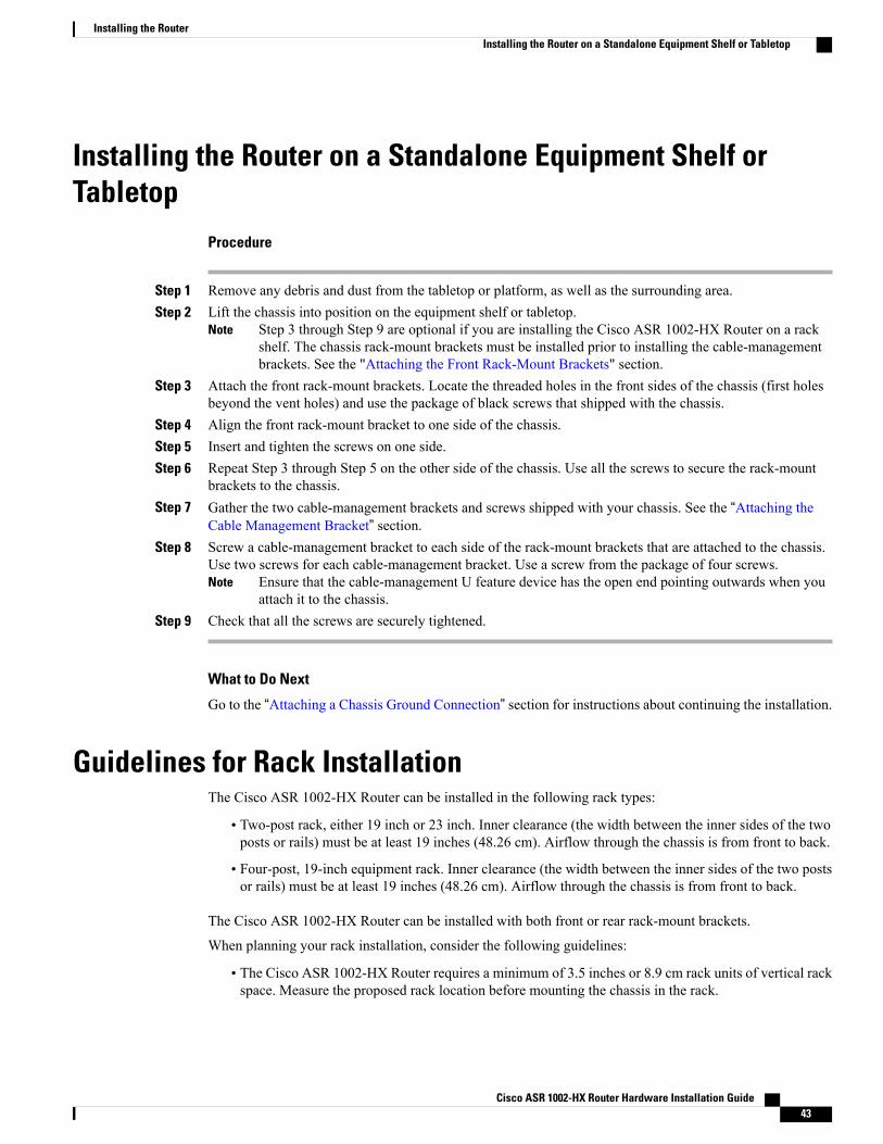
Installing the Router on a Standalone Equipment Shelf orTabletop
Procedure
Step 1 Remove any debris and dust from the tabletop or platform, as well as the surrounding area.Step 2 Lift the chassis into position on the equipment shelf or tabletop.
Step 3 through Step 9 are optional if you are installing the Cisco ASR 1002-HX Router on a rackshelf. The chassis rack-mount brackets must be installed prior to installing the cable-managementbrackets. See the "Attaching the Front Rack-Mount Brackets" section.
Note
Step 3 Attach the front rack-mount brackets. Locate the threaded holes in the front sides of the chassis (first holesbeyond the vent holes) and use the package of black screws that shipped with the chassis.
Step 4 Align the front rack-mount bracket to one side of the chassis.Step 5 Insert and tighten the screws on one side.Step 6 Repeat Step 3 through Step 5 on the other side of the chassis. Use all the screws to secure the rack-mount
brackets to the chassis.Step 7 Gather the two cable-management brackets and screws shipped with your chassis. See the “Attaching the
Cable Management Bracket” section.Step 8 Screw a cable-management bracket to each side of the rack-mount brackets that are attached to the chassis.
Use two screws for each cable-management bracket. Use a screw from the package of four screws.Ensure that the cable-management U feature device has the open end pointing outwards when youattach it to the chassis.
Note
Step 9 Check that all the screws are securely tightened.
What to Do Next
Go to the “Attaching a Chassis Ground Connection” section for instructions about continuing the installation.
Guidelines for Rack InstallationThe Cisco ASR 1002-HX Router can be installed in the following rack types:
• Two-post rack, either 19 inch or 23 inch. Inner clearance (the width between the inner sides of the twoposts or rails) must be at least 19 inches (48.26 cm). Airflow through the chassis is from front to back.
• Four-post, 19-inch equipment rack. Inner clearance (the width between the inner sides of the two postsor rails) must be at least 19 inches (48.26 cm). Airflow through the chassis is from front to back.
The Cisco ASR 1002-HX Router can be installed with both front or rear rack-mount brackets.
When planning your rack installation, consider the following guidelines:
• The Cisco ASR 1002-HX Router requires a minimum of 3.5 inches or 8.9 cm rack units of vertical rackspace. Measure the proposed rack location before mounting the chassis in the rack.
Cisco ASR 1002-HX Router Hardware Installation Guide 43
Installing the RouterInstalling the Router on a Standalone Equipment Shelf or Tabletop
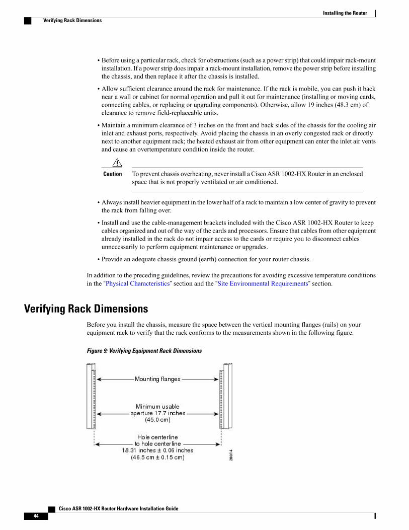
• Before using a particular rack, check for obstructions (such as a power strip) that could impair rack-mountinstallation. If a power strip does impair a rack-mount installation, remove the power strip before installingthe chassis, and then replace it after the chassis is installed.
• Allow sufficient clearance around the rack for maintenance. If the rack is mobile, you can push it backnear a wall or cabinet for normal operation and pull it out for maintenance (installing or moving cards,connecting cables, or replacing or upgrading components). Otherwise, allow 19 inches (48.3 cm) ofclearance to remove field-replaceable units.
• Maintain a minimum clearance of 3 inches on the front and back sides of the chassis for the cooling airinlet and exhaust ports, respectively. Avoid placing the chassis in an overly congested rack or directlynext to another equipment rack; the heated exhaust air from other equipment can enter the inlet air ventsand cause an overtemperature condition inside the router.
To prevent chassis overheating, never install a CiscoASR 1002-HXRouter in an enclosedspace that is not properly ventilated or air conditioned.
Caution
• Always install heavier equipment in the lower half of a rack to maintain a low center of gravity to preventthe rack from falling over.
• Install and use the cable-management brackets included with the Cisco ASR 1002-HX Router to keepcables organized and out of the way of the cards and processors. Ensure that cables from other equipmentalready installed in the rack do not impair access to the cards or require you to disconnect cablesunnecessarily to perform equipment maintenance or upgrades.
• Provide an adequate chassis ground (earth) connection for your router chassis.
In addition to the preceding guidelines, review the precautions for avoiding excessive temperature conditionsin the “Physical Characteristics” section and the “Site Environmental Requirements” section.
Verifying Rack DimensionsBefore you install the chassis, measure the space between the vertical mounting flanges (rails) on yourequipment rack to verify that the rack conforms to the measurements shown in the following figure.
Figure 9: Verifying Equipment Rack Dimensions
Cisco ASR 1002-HX Router Hardware Installation Guide44
Installing the RouterVerifying Rack Dimensions
Procedure
Step 1 Mark and measure the distance between two holes on the left and right mounting rails.The distance should measure 18.31 inches ± 0.06 inches (46.5 cm ± 0.15 cm).
Measure for pairs of holes near the bottom, middle, and top of the equipment rack to ensure that therack posts are parallel.
Note
Step 2 Measure the space between the inner edges of the left front and right front mounting flanges on the equipmentrack.The space must be at least 17.7 inches (45 cm) to accommodate the chassis that is 17.25 inches (43.8 cm)wide and fits between the mounting posts on the rack.
Attaching the Front Rack-Mount BracketsBefore You Begin
Before installing the chassis in the rack, you must install the rack-mount brackets on each side of the chassis.
Determine where in the rack you want the chassis to be mounted. If you are mounting more than one chassisin the rack, then start from the bottom up or the center of the rack. The following figure shows the bracketsattached to the chassis. Depending on the bracket holes you use, the chassis may protrude in the rack.
The cable-management brackets are attached to the chassis after you install the chassis rack-mount bracketson the chassis and mount the chassis in the rack.
Note
Procedure
Step 1 Locate the threaded holes on the side of the chassis. Ensure that you hold the front rack-mount bracket withthe ear and holes facing outward and towards the front of the chassis.
Cisco ASR 1002-HX Router Hardware Installation Guide 45
Installing the RouterAttaching the Front Rack-Mount Brackets
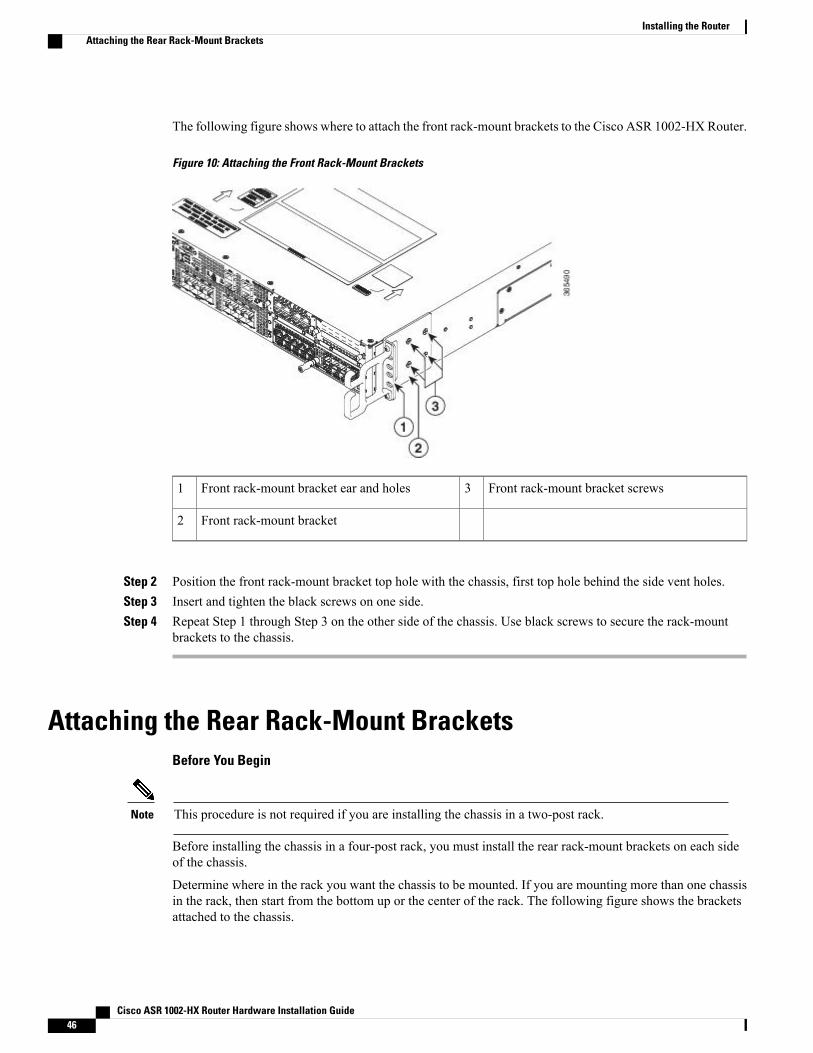
The following figure shows where to attach the front rack-mount brackets to the Cisco ASR 1002-HX Router.
Figure 10: Attaching the Front Rack-Mount Brackets
Front rack-mount bracket screws3Front rack-mount bracket ear and holes1
Front rack-mount bracket2
Step 2 Position the front rack-mount bracket top hole with the chassis, first top hole behind the side vent holes.Step 3 Insert and tighten the black screws on one side.Step 4 Repeat Step 1 through Step 3 on the other side of the chassis. Use black screws to secure the rack-mount
brackets to the chassis.
Attaching the Rear Rack-Mount BracketsBefore You Begin
This procedure is not required if you are installing the chassis in a two-post rack.Note
Before installing the chassis in a four-post rack, you must install the rear rack-mount brackets on each sideof the chassis.
Determine where in the rack you want the chassis to be mounted. If you are mounting more than one chassisin the rack, then start from the bottom up or the center of the rack. The following figure shows the bracketsattached to the chassis.
Cisco ASR 1002-HX Router Hardware Installation Guide46
Installing the RouterAttaching the Rear Rack-Mount Brackets
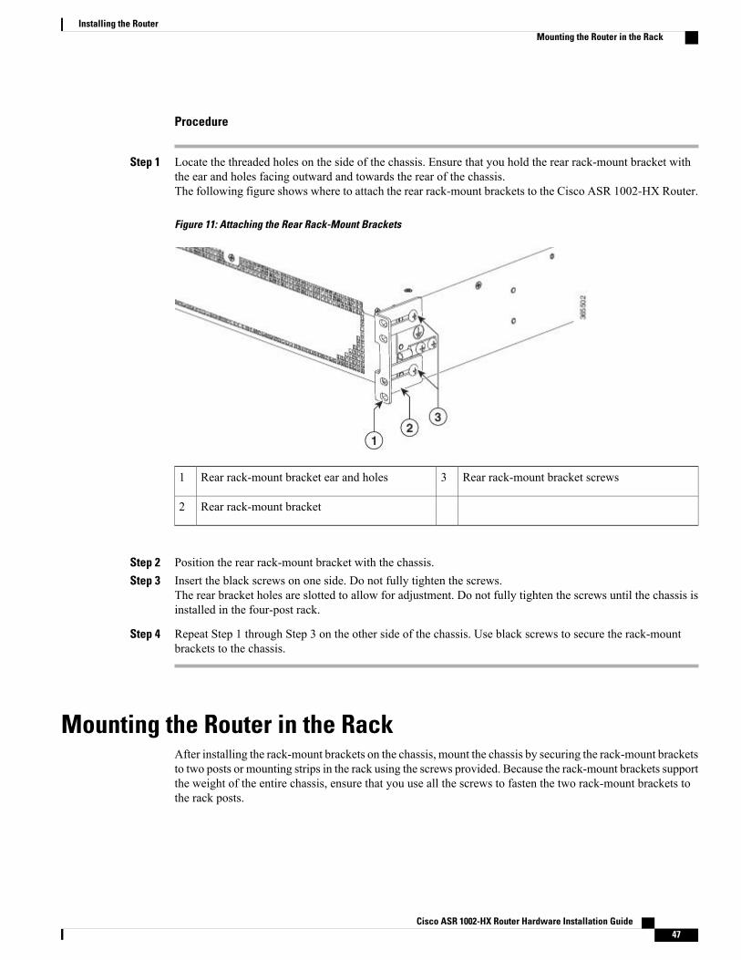
Procedure
Step 1 Locate the threaded holes on the side of the chassis. Ensure that you hold the rear rack-mount bracket withthe ear and holes facing outward and towards the rear of the chassis.The following figure shows where to attach the rear rack-mount brackets to the Cisco ASR 1002-HX Router.
Figure 11: Attaching the Rear Rack-Mount Brackets
Rear rack-mount bracket screws3Rear rack-mount bracket ear and holes1
Rear rack-mount bracket2
Step 2 Position the rear rack-mount bracket with the chassis.Step 3 Insert the black screws on one side. Do not fully tighten the screws.
The rear bracket holes are slotted to allow for adjustment. Do not fully tighten the screws until the chassis isinstalled in the four-post rack.
Step 4 Repeat Step 1 through Step 3 on the other side of the chassis. Use black screws to secure the rack-mountbrackets to the chassis.
Mounting the Router in the RackAfter installing the rack-mount brackets on the chassis, mount the chassis by securing the rack-mount bracketsto two posts or mounting strips in the rack using the screws provided. Because the rack-mount brackets supportthe weight of the entire chassis, ensure that you use all the screws to fasten the two rack-mount brackets tothe rack posts.
Cisco ASR 1002-HX Router Hardware Installation Guide 47
Installing the RouterMounting the Router in the Rack

Two-Post Rack Installation
Statement 1006—Chassis Warning for Rack-Mounting and Servicing
To prevent bodily injury when mounting or servicing this unit in a rack, you must take special precautionsto ensure that the system remains stable. The following guidelines are provided to ensure your safety:
Warning
• This unit should be mounted at the bottom of the rack if it is the only unit in the rack.
• When mounting this unit in a partially filled rack, load the rack from the bottom to the top withthe heaviest component at the bottom of the rack.
• If the rack is provided with stabilizing devices, install the stabilizers before mounting or servicingthe unit in the rack.
The Cisco ASR 1002-HXRouter can be installed on a two-post rack, either 19 inch or 23 inch.We recommendthat you allow at least 1 or 2 inches (2.54 or 5.08 cm) of vertical clearance between the router and any equipmentdirectly above and below it.
Procedure
Step 1 On the chassis, ensure that all the screw fasteners on the installed components are securely tightened.
Step 2 Make sure that your path to the rack is unobstructed. If the rack is on wheels, ensure that the brakes are engagedor that the rack is otherwise stabilized.
Step 3 (Optional) Install a shelf in the rack to support the Cisco ASR 1002-HX Router. If you use a shelf, it helpssupport the chassis while you secure it to the rack.
If you are using a shelf, place the chassis on the shelf and slightly raise the front of the chassis toalign the mounting bracket holes with the rack post holes while allowing the bottom of the chassisto rest on the shelf.
Note
Step 4 With two people, lift the chassis into position between the rack posts.Step 5 Align the mounting bracket holes with the rack post holes and attach the chassis to the rack.Step 6 Position the chassis until the rack-mounting flanges are flush against the mounting rails on the rack.
To allow space to attach the cable-management brackets to the chassis in the rack easily, use therack-mount bracket ear holes mentioned in Steps 7 and 8.
Tip
Step 7 Hold the chassis in position against the mounting rails in the equipment rack and follow these steps:a) Insert the bottom screw into the second hole up from the bottom of the rack-mount ear and use a hand-held
screwdriver to tighten the screw to the rack rail.To make installation easier, insert one screw at the bottom of the chassis and the next screw at thetop of the chassis diagonally from the first screw.
Tip
b) Insert the top screw into the second hole from the top of the rack-mount ear diagonally from the bottomscrew and tighten the screw to the rack rail.
c) Insert the rest of the screws to secure the chassis to the rack equipment.
Step 8 Tighten all the screws on each side to secure the chassis to the equipment rack.
Cisco ASR 1002-HX Router Hardware Installation Guide48
Installing the RouterTwo-Post Rack Installation
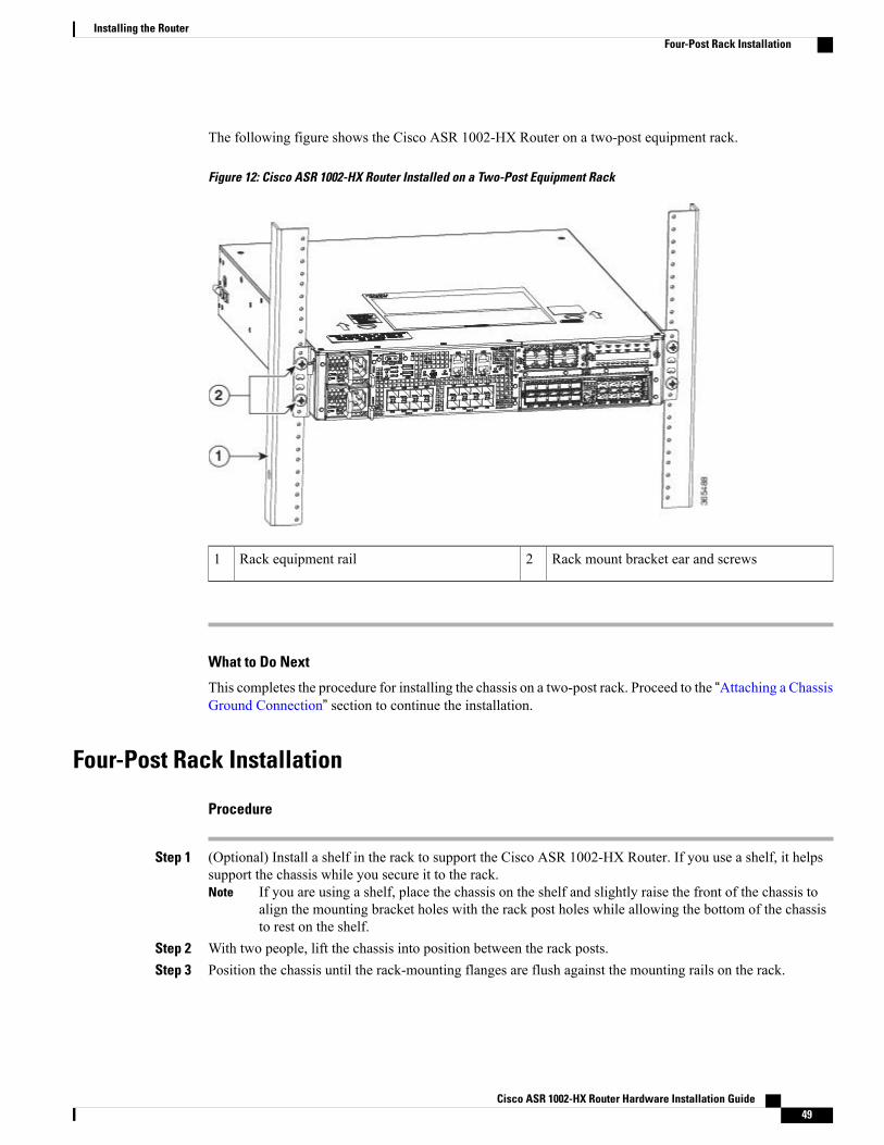
The following figure shows the Cisco ASR 1002-HX Router on a two-post equipment rack.
Figure 12: Cisco ASR 1002-HX Router Installed on a Two-Post Equipment Rack
Rack mount bracket ear and screws2Rack equipment rail1
What to Do Next
This completes the procedure for installing the chassis on a two-post rack. Proceed to the “Attaching a ChassisGround Connection” section to continue the installation.
Four-Post Rack Installation
Procedure
Step 1 (Optional) Install a shelf in the rack to support the Cisco ASR 1002-HX Router. If you use a shelf, it helpssupport the chassis while you secure it to the rack.
If you are using a shelf, place the chassis on the shelf and slightly raise the front of the chassis toalign the mounting bracket holes with the rack post holes while allowing the bottom of the chassisto rest on the shelf.
Note
Step 2 With two people, lift the chassis into position between the rack posts.Step 3 Position the chassis until the rack-mounting flanges are flush against the mounting rails on the rack.
Cisco ASR 1002-HX Router Hardware Installation Guide 49
Installing the RouterFour-Post Rack Installation
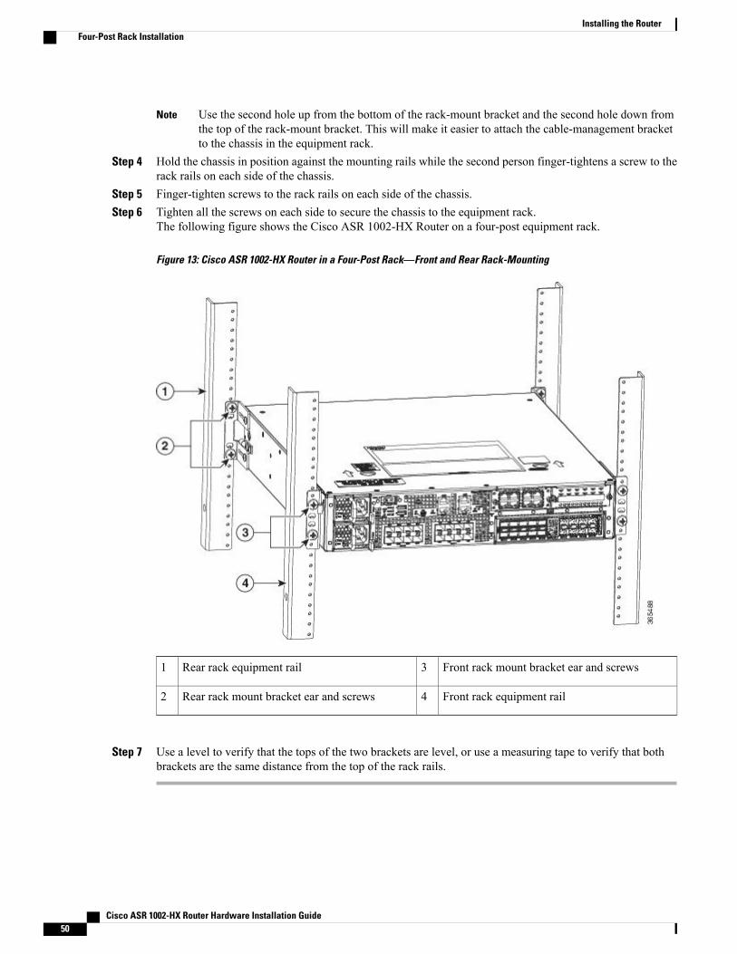
Use the second hole up from the bottom of the rack-mount bracket and the second hole down fromthe top of the rack-mount bracket. This will make it easier to attach the cable-management bracketto the chassis in the equipment rack.
Note
Step 4 Hold the chassis in position against the mounting rails while the second person finger-tightens a screw to therack rails on each side of the chassis.
Step 5 Finger-tighten screws to the rack rails on each side of the chassis.Step 6 Tighten all the screws on each side to secure the chassis to the equipment rack.
The following figure shows the Cisco ASR 1002-HX Router on a four-post equipment rack.
Figure 13: Cisco ASR 1002-HX Router in a Four-Post Rack—Front and Rear Rack-Mounting
Front rack mount bracket ear and screws3Rear rack equipment rail1
Front rack equipment rail4Rear rack mount bracket ear and screws2
Step 7 Use a level to verify that the tops of the two brackets are level, or use a measuring tape to verify that bothbrackets are the same distance from the top of the rack rails.
Cisco ASR 1002-HX Router Hardware Installation Guide50
Installing the RouterFour-Post Rack Installation
What to Do Next
This completes the procedure for installing the chassis in the rack. Proceed to the “Attaching a Chassis GroundConnection" section to continue the installation.
Attaching the Cable Management BracketThe cable management brackets should be mounted to each rack-mount bracket on the chassis to providecablemanagement to both sides of the chassis (parallel with card orientation). These brackets are screw-mountedto the rack-mount brackets to allow easy installation and removal of cables.
The cable-management brackets for the CiscoASR1002-HXRouter contain one independent cable-managementU-type feature with two screws for each bracket.
Make certain that the cable-management bracket "U" feature is facing upwards when you attach it to thechassis.
Note
Procedure
Step 1 Align the cable-management bracket to the rack-mount bracket on one side of the Cisco ASR 1002-HXRouter.The cable-management bracket aligns to the top hole of the chassis rack-mount bracket.
Step 2 Using a Phillips screwdriver, insert one screw through the top screw hole of the cable-management bracketand into the chassis rack-mount bracket and tighten the screw.
Use the package of screws that camewith your chassis containing four screws.Note
Cisco ASR 1002-HX Router Hardware Installation Guide 51
Installing the RouterAttaching the Cable Management Bracket
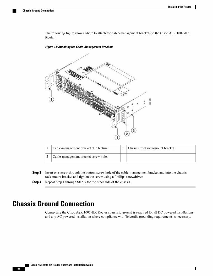
The following figure shows where to attach the cable-management brackets to the Cisco ASR 1002-HXRouter.
Figure 14: Attaching the Cable-Management Brackets
Chassis front rack-mount bracket3Cable-management bracket "U" feature1
Cable-management bracket screw holes2
Step 3 Insert one screw through the bottom screw hole of the cable-management bracket and into the chassisrack-mount bracket and tighten the screw using a Phillips screwdriver.
Step 4 Repeat Step 1 through Step 3 for the other side of the chassis.
Chassis Ground ConnectionConnecting the Cisco ASR 1002-HX Router chassis to ground is required for all DC powered installationsand any AC powered installation where compliance with Telcordia grounding requirements is necessary.
Cisco ASR 1002-HX Router Hardware Installation Guide52
Installing the RouterChassis Ground Connection
Statement 1024—Ground Conductor
This equipment must be grounded. Never defeat the ground conductor or operate the equipment in theabsence of a suitably installed ground conductor. Contact the appropriate electrical inspection authorityor an electrician if you are uncertain that suitable grounding is available.
Warning
Before you connect power or turn on power to your chassis, you must provide an adequate chassis ground(earth) connection for the chassis. A chassis ground connector is provided on each Cisco ASR 1002-HXRouter. There is a stud on the rear left side of the chassis.
The grounding wire should always be the first to be installed or connected and the last to be removed ordisconnected.
Caution
Have the recommended tools and supplies available before you begin this procedure.
Recommended Tools and SuppliesThe following tools, equipment, and supplies are necessary to connect the system ground to the chassis:
• Phillips screwdriver
• 3.5-mm flat blade screwdriver (Phoenix # 1205053 or equivalent 3.5-mm flat blade)
• Dual-lug chassis ground component
• Grounding wire
Cisco ASR 1002-HX Router Hardware Installation Guide 53
Installing the RouterRecommended Tools and Supplies
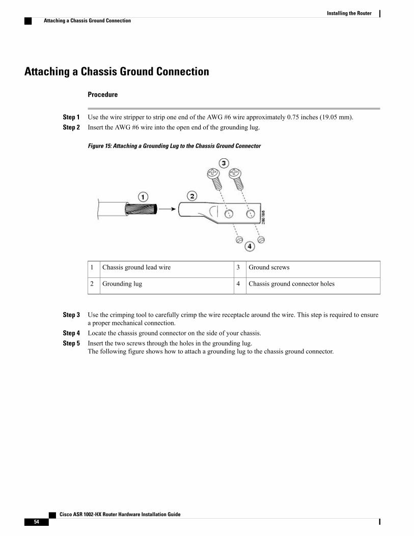
Attaching a Chassis Ground Connection
Procedure
Step 1 Use the wire stripper to strip one end of the AWG #6 wire approximately 0.75 inches (19.05 mm).Step 2 Insert the AWG #6 wire into the open end of the grounding lug.
Figure 15: Attaching a Grounding Lug to the Chassis Ground Connector
Ground screws3Chassis ground lead wire1
Chassis ground connector holes4Grounding lug2
Step 3 Use the crimping tool to carefully crimp the wire receptacle around the wire. This step is required to ensurea proper mechanical connection.
Step 4 Locate the chassis ground connector on the side of your chassis.Step 5 Insert the two screws through the holes in the grounding lug.
The following figure shows how to attach a grounding lug to the chassis ground connector.
Cisco ASR 1002-HX Router Hardware Installation Guide54
Installing the RouterAttaching a Chassis Ground Connection
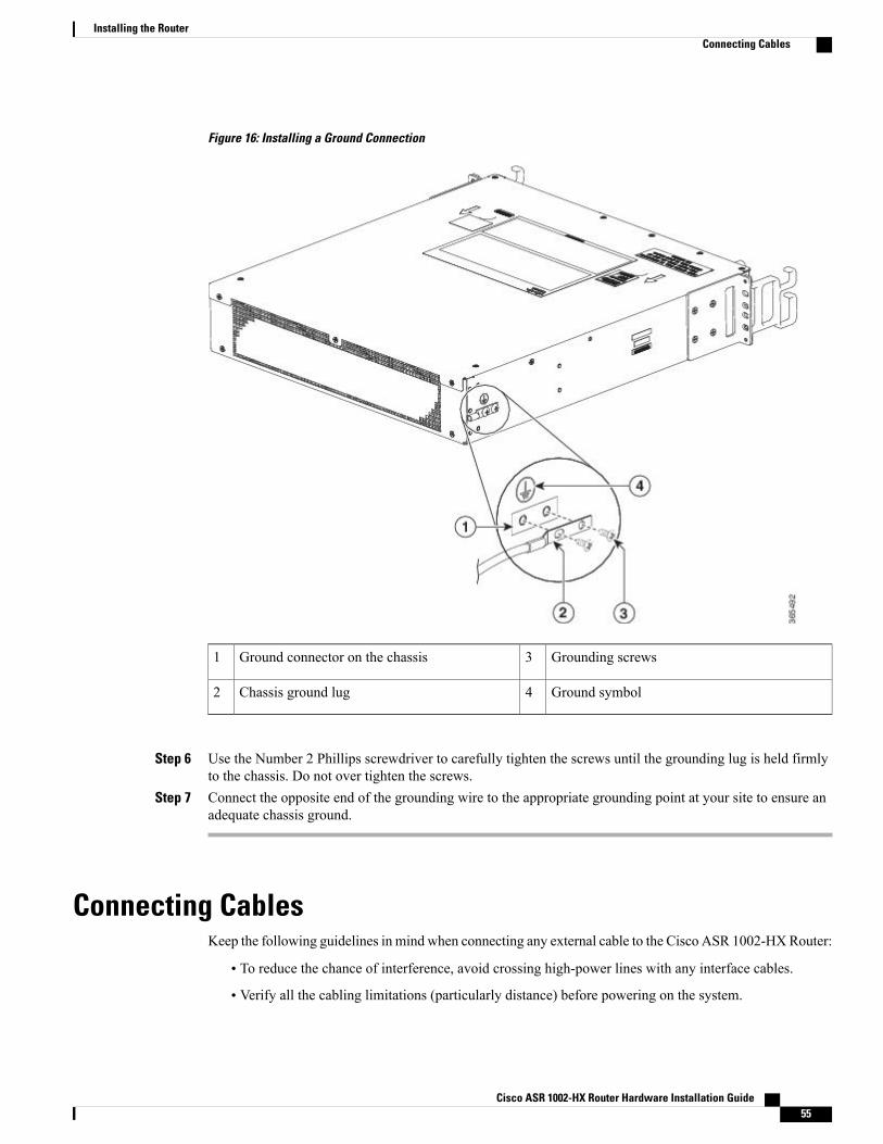
Figure 16: Installing a Ground Connection
Grounding screws3Ground connector on the chassis1
Ground symbol4Chassis ground lug2
Step 6 Use the Number 2 Phillips screwdriver to carefully tighten the screws until the grounding lug is held firmlyto the chassis. Do not over tighten the screws.
Step 7 Connect the opposite end of the grounding wire to the appropriate grounding point at your site to ensure anadequate chassis ground.
Connecting CablesKeep the following guidelines in mind when connecting any external cable to the Cisco ASR 1002-HXRouter:
• To reduce the chance of interference, avoid crossing high-power lines with any interface cables.
• Verify all the cabling limitations (particularly distance) before powering on the system.
Cisco ASR 1002-HX Router Hardware Installation Guide 55
Installing the RouterConnecting Cables
Connecting the Console and Auxiliary Port CablesThe router uses RJ-45 ports for both auxiliary ports and console ports to attach a console terminal. The routerhas an asynchronous serial (EIA/TIA-232) RJ-45 console port labeled CON on its front panel. You can connectthis port to most types of video terminals with a console cable kit that is included with your router. The consolecable kit contains:
• One RJ-45-to-RJ-45 crossover cable
• One RJ-45-to-DB-9 (female) adapter
A crossover cable reverses pin connections from one end to the other. In other words, it connects pin 1 (atone end) to pin 8 (at the other end), pin 2 to pin 7, pin 3 to pin 6, and so on. You can identify a crossover cableby comparing the two modular ends of the cable. Hold the cable ends in your hand, side-by-side, with thetabs at the back. Ensure that the wire connected to the outside (left) pin of the left plug (pin 1) is the samecolor as the wire connected to the outside (right) pin of the right plug (pin 8).
Both the console and auxiliary ports are asynchronous serial ports; devices connected to these ports must becapable of asynchronous transmission.
Before connecting to the console interface on the router using a terminal or PC, perform the following steps:
Procedure
Step 1 Before connecting a terminal to the console port, configure the terminal to match the chassis console port asfollows: 9600 baud, 8 data bits, no parity, 1 stop bits (9600 8N1).
Step 2 Connect one end of the RJ-45 cable to the serial RJ-45 console port (CON) on the Cisco ASR 1002-HXRouterusing the RJ-45 to DB-9 cable. Connect the DB-9 end to your terminal equipment.
For information about how to change the default settings to meet the requirements of your terminalor host, see the Cisco IOS Terminal Services Configuration Guide.
Note
Step 3 After you establish normal router operation, you can disconnect the terminal.Use the following procedure to connect a video terminal to the console port.
What to Do Next
Go to the "Connecting to the Mini USB Console Port" section to continue the installation.
Connecting to the Mini USB Console PortThe USB serial console port connects directly to the USB connector of a PC using a USB Type A to 5-pinmini USB Type-B cable. The USB Console supports full speed (12Mbps) operation. The console port doesnot support hardware flow control.
Cisco ASR 1002-HX Router Hardware Installation Guide56
Installing the RouterConnecting the Console and Auxiliary Port Cables
Note • Always use shielded USB cables with a properly terminated shield. The USB serial console interfacecable must not exceed 3 meters in length.
• Only one console port can be active at a time. When a cable is plugged into the USB console port,the RJ-45 port becomes inactive. Conversely, when the USB cable is removed from the USB port,the RJ-45 port becomes active.
• 4-pin mini USB Type-B connectors are easily confused with 5-pin mini USB Type-B connectors.Note that only the 5-pin mini USB Type-B is supported.
The default parameters for the console port are 9600 baud, 8 data bits, no parity, and 1 stop bit.
For operation with aMicrosoftWindows OS version older thanWindows 7, the CiscoWindows USBConsoleDriver must be installed on any PC connected to the console port. If the driver is not installed, prompts guideyou through a simple installation process.
The Cisco Windows USB Console Driver allows plugging and unplugging the USB cable from the consoleport without affecting Windows HyperTerminal operations. No special drivers are needed for Mac OS X orLinux.
Baud rates for the USB console port are 1200, 2400, 4800, 9600, 19200, 38400, 57600, and 115200 bps.
Management Ethernet Port Cable Connection
To comply with Class A emission requirements, a shielded Ethernet cable must be used for the connection.Caution
Procedure
Step 1 Insert an Ethernet RJ-45 cable into the MGMT port.Step 2 Insert the other end of the RJ-45 cable to your management device or network.
Cisco ASR 1002-HX Router Hardware Installation Guide 57
Installing the RouterManagement Ethernet Port Cable Connection
Cisco ASR 1002-HX Router Hardware Installation Guide58
Installing the RouterManagement Ethernet Port Cable Connection
C H A P T E R 5Power Up and Initial Configuration
This chapter guides you through a basic router configuration, which is sufficient for you to access yournetwork. Complex configuration procedures are beyond the scope of this publication and can be found inthe modular configuration and modular command reference publications in the Cisco IOS softwareconfiguration documentation set that corresponds to the software release installed on your Cisco hardware.
• Checking Conditions Prior to System Startup, page 59
• Powering Up the Router, page 60
• Performing the Initial Configuration on the Router, page 62
• Saving Your Router Configuration, page 72
• Verifying the Initial Configuration, page 72
• Powering Off the Router Safely, page 73
• Environmental Monitoring and Reporting Functions, page 73
Checking Conditions Prior to System StartupEnsure that all the card slots and compartments are closed. Install blank faceplates on empty slots. Alwayshave power supply slots filled. If you leave a power supply slot uncovered, then you risk exposure to hazardousvoltages on the power pins on the midplane.
Statement 1029—Blank Faceplates and Cover Panels
Blank faceplates and cover panels serve three important functions: they prevent exposure to hazardousvoltages and currents inside the chassis; they contain electromagnetic interference (EMI) that might disruptother equipment; and they direct the flow of cooling air through the chassis. Do not operate the systemunless all cards, faceplates, front covers, and rear covers are in place.
Warning
To view the boot sequence, you must have a console connection to the Cisco ASR 1002-HXRouter beforeit powers up.
Note
Cisco ASR 1002-HX Router Hardware Installation Guide 59
Ensure that the following conditions are addressed before starting up the router:
• The network interface cable or the optional Management port cable is connected.
• The chassis is securely mounted and grounded.
• The power and interface cables are connected.
• Your PC with terminal emulation program (hyperTerminal or equivalent) is connected to the consoleport, powered up, and is configured for 9600 baud, 8 data bits, 1 stop bit, no parity, with flow controlset to none.
• You have selected passwords for access control.
• Captive installation screws are tight on all removable components.
• The console terminal is turned on.
• You have determined the IP addresses for the network interfaces.
• The EPA and the NIM are inserted in their slots, if applicable.
• Empty card slots are filled with card blanks. This ensures proper air flow through the chassis andelectromagnetic compatibility (EMC).
Powering Up the RouterYou are now ready to power on the system for the first time. Follow these steps.
Before You Begin
Before you power on, make sure that:
• The power supply cord is plugged into the power supply inlet.
• All cables are connected.
• Your computer is powered up and connected.
Procedure
Step 1 Move the chassis power switch to the ON position. Listen for the fans; you should immediately hear themoperating. Ensure that the power supply LED OK is green and the FAIL LED is not illuminated.The front-panel indicator LEDs provide power, activity, and status information useful during bootup. Formore detailed information about the LEDs, see the "LEDs" section.
Step 2 Observe the initialization process. When the system boot is complete (the process takes a few seconds), therouter begins to initialize.
Cisco ASR 1002-HX Router Hardware Installation Guide60
Power Up and Initial ConfigurationPowering Up the Router
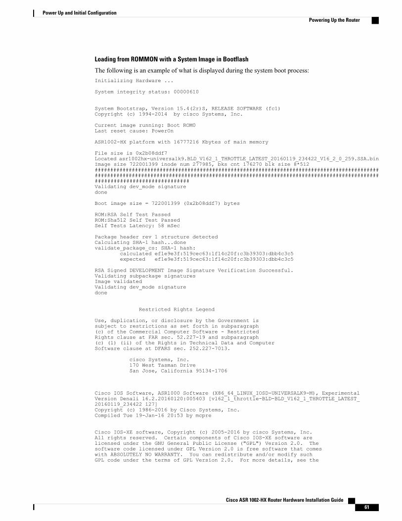
Loading from ROMMON with a System Image in Bootflash
The following is an example of what is displayed during the system boot process:Initializing Hardware ...
System integrity status: 00000610
System Bootstrap, Version 15.4(2r)S, RELEASE SOFTWARE (fc1)Copyright (c) 1994-2014 by cisco Systems, Inc.
Current image running: Boot ROM0Last reset cause: PowerOn
ASR1002-HX platform with 16777216 Kbytes of main memory
File size is 0x2b08ddf7Located asr1002hx-universalk9.BLD_V162_1_THROTTLE_LATEST_20160119_234422_V16_2_0_259.SSA.binImage size 722001399 inode num 277985, bks cnt 176270 blk size 8*512######################################################################################################################################################################################################################Validating dev_mode signaturedone
Boot image size = 722001399 (0x2b08ddf7) bytes
ROM:RSA Self Test PassedROM:Sha512 Self Test PassedSelf Tests Latency: 58 mSec
Package header rev 1 structure detectedCalculating SHA-1 hash...donevalidate_package_cs: SHA-1 hash:
calculated ef1e9e3f:519cec63:1f14c20f:c3b39303:dbb4c3c5expected ef1e9e3f:519cec63:1f14c20f:c3b39303:dbb4c3c5
RSA Signed DEVELOPMENT Image Signature Verification Successful.Validating subpackage signaturesImage validatedValidating dev_mode signaturedone
Restricted Rights Legend
Use, duplication, or disclosure by the Government issubject to restrictions as set forth in subparagraph(c) of the Commercial Computer Software - RestrictedRights clause at FAR sec. 52.227-19 and subparagraph(c) (1) (ii) of the Rights in Technical Data and ComputerSoftware clause at DFARS sec. 252.227-7013.
cisco Systems, Inc.170 West Tasman DriveSan Jose, California 95134-1706
Cisco IOS Software, ASR1000 Software (X86_64_LINUX_IOSD-UNIVERSALK9-M), ExperimentalVersion Denali 16.2.20160120:005403 [v162_1_throttle-BLD-BLD_V162_1_THROTTLE_LATEST_20160119_234422 127]Copyright (c) 1986-2016 by Cisco Systems, Inc.Compiled Tue 19-Jan-16 20:53 by mcpre
Cisco IOS-XE software, Copyright (c) 2005-2016 by cisco Systems, Inc.All rights reserved. Certain components of Cisco IOS-XE software arelicensed under the GNU General Public License ("GPL") Version 2.0. Thesoftware code licensed under GPL Version 2.0 is free software that comeswith ABSOLUTELY NO WARRANTY. You can redistribute and/or modify suchGPL code under the terms of GPL Version 2.0. For more details, see the
Cisco ASR 1002-HX Router Hardware Installation Guide 61
Power Up and Initial ConfigurationPowering Up the Router
documentation or "License Notice" file accompanying the IOS-XE software,or the applicable URL provided on the flyer accompanying the IOS-XEsoftware.
This product contains cryptographic features and is subject to UnitedStates and local country laws governing import, export, transfer anduse. Delivery of Cisco cryptographic products does not implythird-party authority to import, export, distribute or use encryption.Importers, exporters, distributors and users are responsible forcompliance with U.S. and local country laws. By using this product youagree to comply with applicable laws and regulations. If you are unableto comply with U.S. and local laws, return this product immediately.
A summary of U.S. laws governing Cisco cryptographic products may be found at:http://www.cisco.com/wwl/export/crypto/tool/stqrg.html
If you require further assistance please contact us by sending email [email protected].
cisco ASR1002-HX (2KH) processor (revision 2KH) with 3724092K/6147K bytes of memory.Processor board ID FXS1922Q0LLCrypto Hardware Module present26 Gigabit Ethernet interfaces8 Ten Gigabit Ethernet interfaces32768K bytes of non-volatile configuration memory.16777216K bytes of physical memory.30056447K bytes of eUSB flash at bootflash:.0K bytes of at webui:.
Press RETURN to get started!
*Jan 21 17:57:38.704: %SMART_LIC-6-AGENT_READY: Smart Agent for Licensing is initialized*Jan 21 17:57:39.462: %LICENSE-6-EULA_ACCEPT_ALL: The Right to Use End User License Agreementis accepted*Jan 21 17:57:39.482: %IOS_LICENSE_IMAGE_APPLICATION-6-LICENSE_LEVEL: Module name = asr1002hx
Next reboot level = adventerprise and License = adventerprise*Jan 21 17:57:54.438: %SPANTREE-5-EXTENDED_SYSID: Extended SysId enabled for type vlan*Jan 21 17:57:54.493: ***** plat:0 0 flag:1 *****Jan 21 17:57:58.264: %VOICE_HA-7-STATUS: CUBE HA-supported platform detected.*Jan 21 17:58:04.623: %LINK-3-UPDOWN: Interface Lsmpi0, changed state to up*Jan 21 17:58:04.624: %LINK-3-UPDOWN: Interface EOBC0, changed state to up*Jan 21 17:58:04.624: %LINEPROTO-5-UPDOWN: Line protocol on Interface VoIP-Null0, changedstate to up*Jan 21 17:58:04.624: %LINEPROTO-5-UPDOWN: Line protocol on Interface LI-Null0, changedstate to up*Jan 21 17:58:04.624: %LINK-3-UPDOWN: Interface GigabitEthernet0, changed state to down
.
.
.
Performing the Initial Configuration on the Router
Using the Cisco setup Command FacilityThe setup command facility prompts you to enter the information that is needed to configure a router quickly.The facility takes you through an initial configuration, including LAN and WAN interfaces.
Cisco ASR 1002-HX Router Hardware Installation Guide62
Power Up and Initial ConfigurationPerforming the Initial Configuration on the Router
The setup command facility is entered automatically if there is no configuration on the router when it isbooted into Cisco IOS-XE.
Note
For information on modifying the configuration after you create it, see theCisco IOS XE Configuration Guideand the Cisco IOS XE Command References.
This section explains how to configure a host name for the router, set passwords, and configure an interfaceto communicate with the management network.
If you make a mistake while using the setup command facility, you can exit and run the setup commandfacility again. Press Ctrl-C, and enter the setup command in privileged EXEC mode (Router#).
Note
Procedure
Step 1 From the Cisco IOS-XE CLI, enter the setup command in privileged EXEC mode:Router> enablePassword: <password>Router# setup
--- System Configuration Dialog ---Continue with configuration dialog? [yes/no]:
The prompts in the setup command facility vary depending on your router model, on the installed interfacemodules, and on the software image. The following steps and the user entries (in bold) are shown as examplesonly.
Step 2 To proceed using the setup command facility, enter yes.Continue with configuration dialog? [yes/no]: yes
At any point you may enter a question mark '?' for help.
Use ctrl-c to abort configuration dialog at any prompt.Default settings are in square brackets '[]'.
Step 3 Basic management setup configures only enough connectivity.Would you like to enter basic management setup? [yes/no]: yes
Step 4 Enter a hostname for the router (this example uses myrouter):Configuring global parameters:Enter host name [Router]: myrouter
Step 5 Enter an enable secret password. This password is encrypted (for more security) and cannot be seen whenviewing the configuration.The enable secret is a password used to protect access toprivileged EXEC and configuration modes. This password, afterentered, becomes encrypted in the configuration.Enter enable secret: cisco
Cisco ASR 1002-HX Router Hardware Installation Guide 63
Power Up and Initial ConfigurationUsing the Cisco setup Command Facility
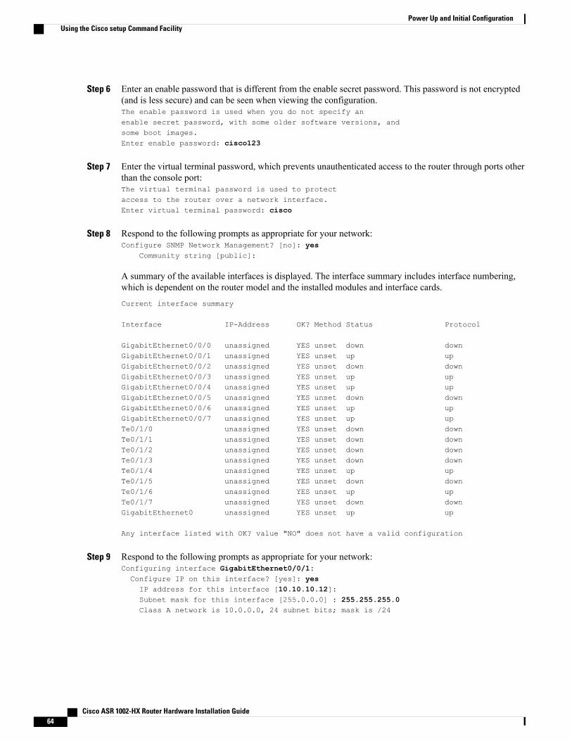
Step 6 Enter an enable password that is different from the enable secret password. This password is not encrypted(and is less secure) and can be seen when viewing the configuration.The enable password is used when you do not specify anenable secret password, with some older software versions, andsome boot images.Enter enable password: cisco123
Step 7 Enter the virtual terminal password, which prevents unauthenticated access to the router through ports otherthan the console port:The virtual terminal password is used to protectaccess to the router over a network interface.Enter virtual terminal password: cisco
Step 8 Respond to the following prompts as appropriate for your network:Configure SNMP Network Management? [no]: yes
Community string [public]:
A summary of the available interfaces is displayed. The interface summary includes interface numbering,which is dependent on the router model and the installed modules and interface cards.
Current interface summary
Interface IP-Address OK? Method Status Protocol
GigabitEthernet0/0/0 unassigned YES unset down downGigabitEthernet0/0/1 unassigned YES unset up upGigabitEthernet0/0/2 unassigned YES unset down downGigabitEthernet0/0/3 unassigned YES unset up upGigabitEthernet0/0/4 unassigned YES unset up upGigabitEthernet0/0/5 unassigned YES unset down downGigabitEthernet0/0/6 unassigned YES unset up upGigabitEthernet0/0/7 unassigned YES unset up upTe0/1/0 unassigned YES unset down downTe0/1/1 unassigned YES unset down downTe0/1/2 unassigned YES unset down downTe0/1/3 unassigned YES unset down downTe0/1/4 unassigned YES unset up upTe0/1/5 unassigned YES unset down downTe0/1/6 unassigned YES unset up upTe0/1/7 unassigned YES unset down downGigabitEthernet0 unassigned YES unset up up
Any interface listed with OK? value "NO" does not have a valid configuration
Step 9 Respond to the following prompts as appropriate for your network:Configuring interface GigabitEthernet0/0/1:Configure IP on this interface? [yes]: yesIP address for this interface [10.10.10.12]:Subnet mask for this interface [255.0.0.0] : 255.255.255.0Class A network is 10.0.0.0, 24 subnet bits; mask is /24
Cisco ASR 1002-HX Router Hardware Installation Guide64
Power Up and Initial ConfigurationUsing the Cisco setup Command Facility
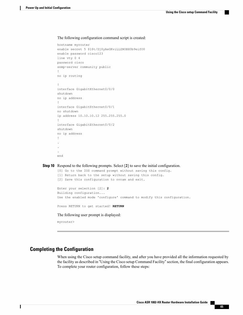
The following configuration command script is created:
hostname myrouterenable secret 5 $1$t/Dj$yAeGKviLLZNOBX0b9eifO0enable password cisco123line vty 0 4password ciscosnmp-server community public!no ip routing
!interface GigabitEthernet0/0/0shutdownno ip address!interface GigabitEthernet0/0/1no shutdownip address 10.10.10.12 255.255.255.0!interface GigabitEthernet0/0/2shutdownno ip address!...end
Step 10 Respond to the following prompts. Select [2] to save the initial configuration.[0] Go to the IOS command prompt without saving this config.[1] Return back to the setup without saving this config.[2] Save this configuration to nvram and exit.
Enter your selection [2]: 2Building configuration...Use the enabled mode 'configure' command to modify this configuration.
Press RETURN to get started! RETURN
The following user prompt is displayed:
myrouter>
Completing the ConfigurationWhen using the Cisco setup command facility, and after you have provided all the information requested bythe facility as described in “Using the Cisco setup Command Facility” section, the final configuration appears.To complete your router configuration, follow these steps:
Cisco ASR 1002-HX Router Hardware Installation Guide 65
Power Up and Initial ConfigurationUsing the Cisco setup Command Facility
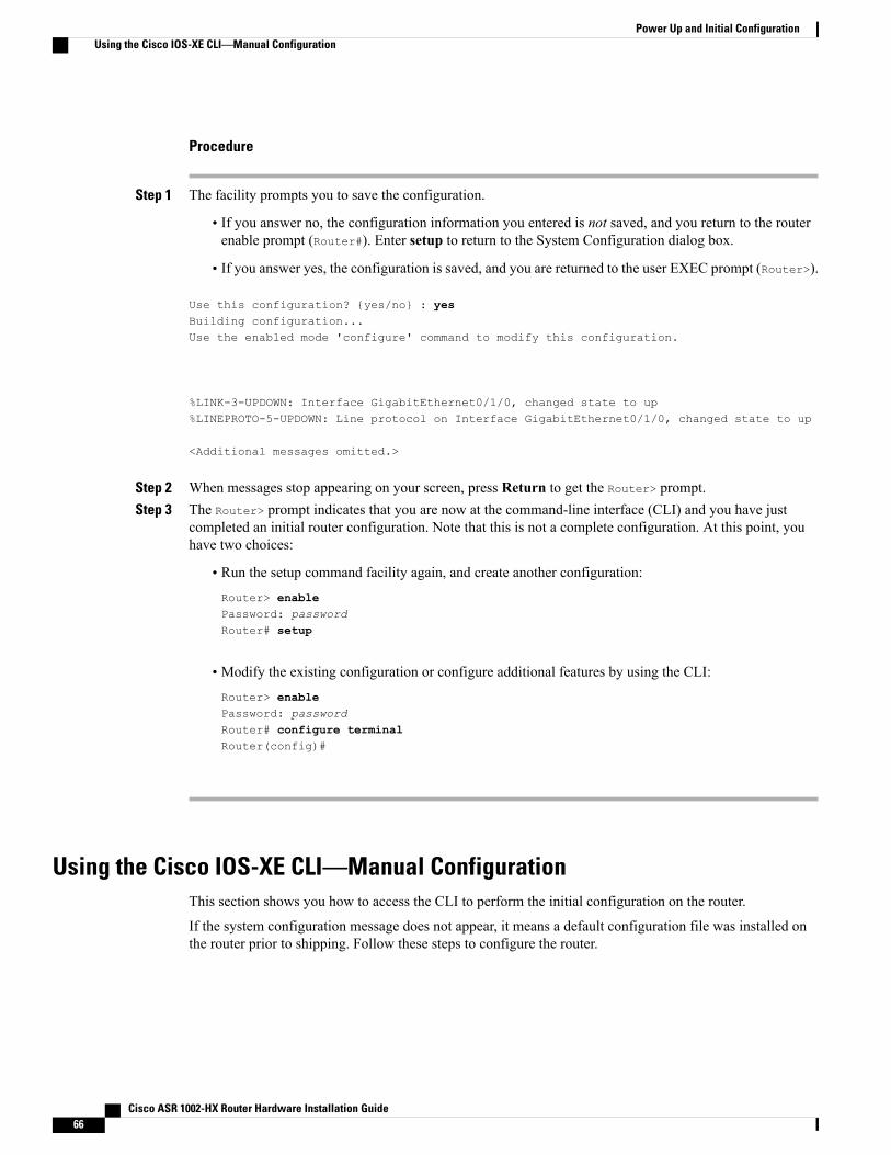
Procedure
Step 1 The facility prompts you to save the configuration.
• If you answer no, the configuration information you entered is not saved, and you return to the routerenable prompt (Router#). Enter setup to return to the System Configuration dialog box.
• If you answer yes, the configuration is saved, and you are returned to the user EXEC prompt (Router>).
Use this configuration? {yes/no} : yesBuilding configuration...Use the enabled mode 'configure' command to modify this configuration.
%LINK-3-UPDOWN: Interface GigabitEthernet0/1/0, changed state to up%LINEPROTO-5-UPDOWN: Line protocol on Interface GigabitEthernet0/1/0, changed state to up
<Additional messages omitted.>
Step 2 When messages stop appearing on your screen, press Return to get the Router> prompt.Step 3 The Router> prompt indicates that you are now at the command-line interface (CLI) and you have just
completed an initial router configuration. Note that this is not a complete configuration. At this point, youhave two choices:
• Run the setup command facility again, and create another configuration:Router> enablePassword: passwordRouter# setup
• Modify the existing configuration or configure additional features by using the CLI:
Router> enablePassword: passwordRouter# configure terminalRouter(config)#
Using the Cisco IOS-XE CLI—Manual ConfigurationThis section shows you how to access the CLI to perform the initial configuration on the router.
If the system configuration message does not appear, it means a default configuration file was installed onthe router prior to shipping. Follow these steps to configure the router.
Cisco ASR 1002-HX Router Hardware Installation Guide66
Power Up and Initial ConfigurationUsing the Cisco IOS-XE CLI—Manual Configuration
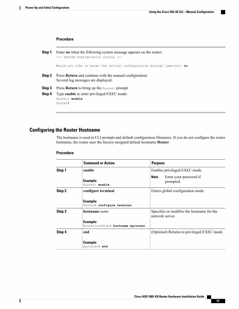
Procedure
Step 1 Enter no when the following system message appears on the router:--- System Configuration Dialog ---
Would you like to enter the initial configuration dialog? [yes/no]: no
Step 2 Press Return and continue with the manual configuration:Several log messages are displayed.
Step 3 Press Return to bring up the Router> prompt.Step 4 Type enable to enter privileged EXEC mode:
Router> enableRouter#
Configuring the Router HostnameThe hostname is used in CLI prompts and default configuration filenames. If you do not configure the routerhostname, the router uses the factory-assigned default hostname Router.
Procedure
PurposeCommand or Action
Enables privileged EXEC mode.enableStep 1
Example:Router> enable
Enter your password ifprompted.
Note
Enters global configuration mode.configure terminal
Example:Router# configure terminal
Step 2
Specifies or modifies the hostname for thenetwork server.
hostname name
Example:Router(config)# hostname myrouter
Step 3
(Optional) Returns to privileged EXEC mode.end
Example:myrouter# end
Step 4
Cisco ASR 1002-HX Router Hardware Installation Guide 67
Power Up and Initial ConfigurationUsing the Cisco IOS-XE CLI—Manual Configuration
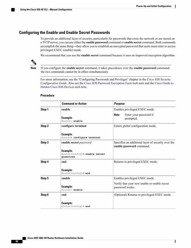
Configuring the Enable and Enable Secret PasswordsTo provide an additional layer of security, particularly for passwords that cross the network or are stored ona TFTP server, you can use either the enable password command or enable secret command. Both commandsaccomplish the same thing—they allow you to establish an encrypted password that users must enter to accessprivileged EXEC (enable) mode.
We recommend that you use the enable secret command because it uses an improved encryption algorithm.
If you configure the enable secret command, it takes precedence over the enable password command;the two commands cannot be in effect simultaneously.
Note
For more information, see the “Configuring Passwords and Privileges” chapter in the Cisco IOS SecurityConfiguration Guide. Also see the Cisco IOS Password Encryption Facts tech note and the Cisco Guide toHarden Cisco IOS Devices tech note.
Procedure
PurposeCommand or Action
Enables privileged EXEC mode.enableStep 1
Example:Router> enable
Enter your password ifprompted.
Note
Enters global configuration mode.configure terminal
Example:Router# configure terminal
Step 2
Specifies an additional layer of security over theenable password command.
enable secret password
Example:Router(config)# enable secretgreentree
Step 3
Returns to privileged EXEC mode.end
Example:Router(config)# end
Step 4
Enables privileged EXEC mode.enableStep 5
Example:Router> enable
Verify that your new enable or enable secretpassword works.
(Optional) Returns to privileged EXEC mode.end
Example:Router(config)# end
Step 6
Cisco ASR 1002-HX Router Hardware Installation Guide68
Power Up and Initial ConfigurationUsing the Cisco IOS-XE CLI—Manual Configuration
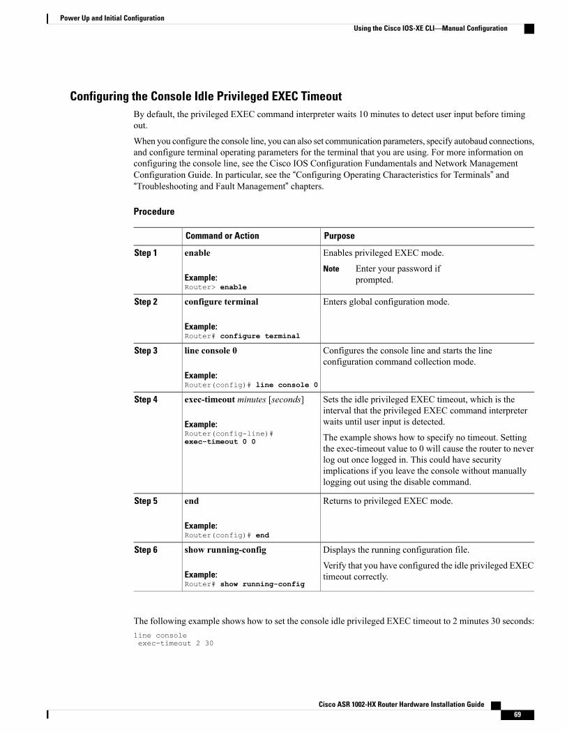
Configuring the Console Idle Privileged EXEC TimeoutBy default, the privileged EXEC command interpreter waits 10 minutes to detect user input before timingout.
When you configure the console line, you can also set communication parameters, specify autobaud connections,and configure terminal operating parameters for the terminal that you are using. For more information onconfiguring the console line, see the Cisco IOS Configuration Fundamentals and Network ManagementConfiguration Guide. In particular, see the “Configuring Operating Characteristics for Terminals” and“Troubleshooting and Fault Management” chapters.
Procedure
PurposeCommand or Action
Enables privileged EXEC mode.enableStep 1
Example:Router> enable
Enter your password ifprompted.
Note
Enters global configuration mode.configure terminal
Example:Router# configure terminal
Step 2
Configures the console line and starts the lineconfiguration command collection mode.
line console 0
Example:Router(config)# line console 0
Step 3
Sets the idle privileged EXEC timeout, which is theinterval that the privileged EXEC command interpreterwaits until user input is detected.
exec-timeout minutes [seconds]
Example:Router(config-line)#exec-timeout 0 0
Step 4
The example shows how to specify no timeout. Settingthe exec-timeout value to 0 will cause the router to neverlog out once logged in. This could have securityimplications if you leave the console without manuallylogging out using the disable command.
Returns to privileged EXEC mode.end
Example:Router(config)# end
Step 5
Displays the running configuration file.show running-configStep 6
Example:Router# show running-config
Verify that you have configured the idle privileged EXECtimeout correctly.
The following example shows how to set the console idle privileged EXEC timeout to 2 minutes 30 seconds:line consoleexec-timeout 2 30
Cisco ASR 1002-HX Router Hardware Installation Guide 69
Power Up and Initial ConfigurationUsing the Cisco IOS-XE CLI—Manual Configuration
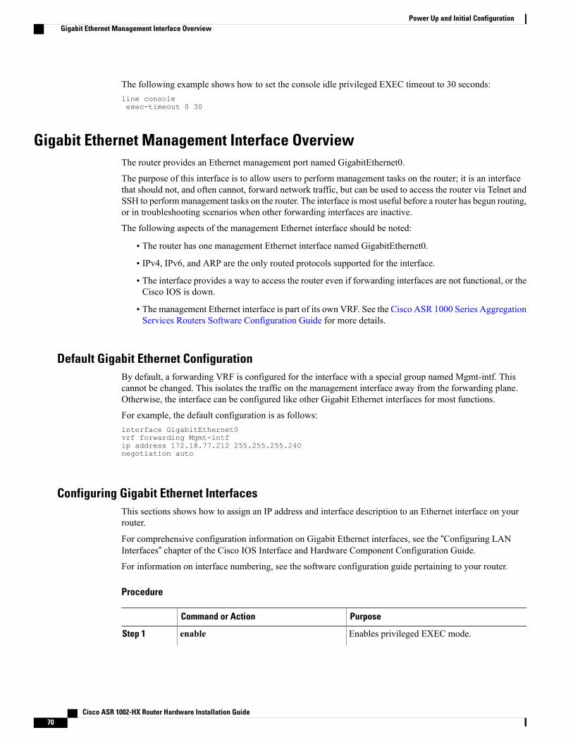
The following example shows how to set the console idle privileged EXEC timeout to 30 seconds:line consoleexec-timeout 0 30
Gigabit Ethernet Management Interface OverviewThe router provides an Ethernet management port named GigabitEthernet0.
The purpose of this interface is to allow users to perform management tasks on the router; it is an interfacethat should not, and often cannot, forward network traffic, but can be used to access the router via Telnet andSSH to performmanagement tasks on the router. The interface is most useful before a router has begun routing,or in troubleshooting scenarios when other forwarding interfaces are inactive.
The following aspects of the management Ethernet interface should be noted:
• The router has one management Ethernet interface named GigabitEthernet0.
• IPv4, IPv6, and ARP are the only routed protocols supported for the interface.
• The interface provides a way to access the router even if forwarding interfaces are not functional, or theCisco IOS is down.
• The management Ethernet interface is part of its own VRF. See the Cisco ASR 1000 Series AggregationServices Routers Software Configuration Guide for more details.
Default Gigabit Ethernet ConfigurationBy default, a forwarding VRF is configured for the interface with a special group named Mgmt-intf. Thiscannot be changed. This isolates the traffic on the management interface away from the forwarding plane.Otherwise, the interface can be configured like other Gigabit Ethernet interfaces for most functions.
For example, the default configuration is as follows:interface GigabitEthernet0vrf forwarding Mgmt-intfip address 172.18.77.212 255.255.255.240negotiation auto
Configuring Gigabit Ethernet InterfacesThis sections shows how to assign an IP address and interface description to an Ethernet interface on yourrouter.
For comprehensive configuration information on Gigabit Ethernet interfaces, see the “Configuring LANInterfaces” chapter of the Cisco IOS Interface and Hardware Component Configuration Guide.For information on interface numbering, see the software configuration guide pertaining to your router.
Procedure
PurposeCommand or Action
Enables privileged EXEC mode.enableStep 1
Cisco ASR 1002-HX Router Hardware Installation Guide70
Power Up and Initial ConfigurationGigabit Ethernet Management Interface Overview
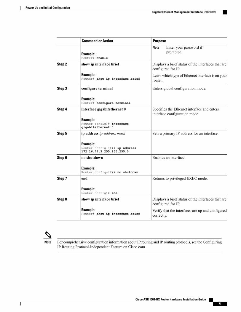
PurposeCommand or Action
Example:Router> enable
Enter your password ifprompted.
Note
Displays a brief status of the interfaces that areconfigured for IP.
show ip interface brief
Example:Router# show ip interface brief
Step 2
Learn which type of Ethernet interface is on yourrouter.
Enters global configuration mode.configure terminal
Example:Router# configure terminal
Step 3
Specifies the Ethernet interface and entersinterface configuration mode.
interface gigabitethernet 0
Example:Router(config)# interfacegigabitethernet 0
Step 4
Sets a primary IP address for an interface.ip address ip-address mask
Example:Router(config-if)# ip address172.16.74.3 255.255.255.0
Step 5
Enables an interface.no shutdown
Example:Router(config-if)# no shutdown
Step 6
Returns to privileged EXEC mode.end
Example:Router(config)# end
Step 7
Displays a brief status of the interfaces that areconfigured for IP.
show ip interface brief
Example:Router# show ip interface brief
Step 8
Verify that the interfaces are up and configuredcorrectly.
For comprehensive configuration information about IP routing and IP routing protocols, see the ConfiguringIP Routing Protocol-Independent Feature on Cisco.com.
Note
Cisco ASR 1002-HX Router Hardware Installation Guide 71
Power Up and Initial ConfigurationGigabit Ethernet Management Interface Overview
Saving Your Router ConfigurationThis section describes how to avoid losing your configuration at the next system reload or power cycle bysaving the running configuration to the startup configuration in NVRAM. The NVRAM provides 32 MB ofstorage on the router.
To aid file recovery and minimize downtime in case of file corruption, we recommend that you savebackup copies of the startup configuration file and the Cisco IOS-XE software system image file on aserver.
Note
To avoid losing work you have completed, be sure to save your configuration occasionally as you proceed.Use the copy running-config startup-config command to save the configuration to NVRAM.
Note
Procedure
PurposeCommand or Action
Enables privileged EXEC mode.enableStep 1
Example:Router> enable
Enter your password if prompted.
Saves the running configuration to the startupconfiguration.
copy running-config startup-config
Example:Router# copy running-configstartup-config
Step 2
Verifying the Initial ConfigurationEnter the following commands in Cisco IOS-XE to verify the initial configuration on the router:
• show version—Displays the system hardware version, the installed software version, the names andsources of configuration files, the boot images, and the amount of installed DRAM, NVRAM, and flashmemory.
• show diag—Lists and displays diagnostic information about the installed controllers, interface processors,and port adapters.
• show interfaces— Shows if interfaces are operating correctly and if interfaces and line protocols are inthe correct state, either up or down
• show ip interface brief—Displays a summary of the interfaces configured for IP protocol.
Cisco ASR 1002-HX Router Hardware Installation Guide72
Power Up and Initial ConfigurationSaving Your Router Configuration
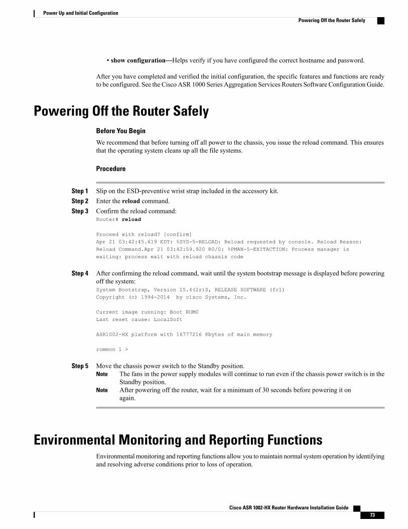
• show configuration—Helps verify if you have configured the correct hostname and password.
After you have completed and verified the initial configuration, the specific features and functions are readyto be configured. See the Cisco ASR 1000 Series Aggregation Services Routers Software Configuration Guide.
Powering Off the Router SafelyBefore You Begin
We recommend that before turning off all power to the chassis, you issue the reload command. This ensuresthat the operating system cleans up all the file systems.
Procedure
Step 1 Slip on the ESD-preventive wrist strap included in the accessory kit.Step 2 Enter the reload command.Step 3 Confirm the reload command:
Router# reload
Proceed with reload? [confirm]Apr 21 03:42:45.619 EDT: %SYS-5-RELOAD: Reload requested by console. Reload Reason:Reload Command.Apr 21 03:42:59.920 R0/0: %PMAN-5-EXITACTION: Process manager isexiting: process exit with reload chassis code
Step 4 After confirming the reload command, wait until the system bootstrap message is displayed before poweringoff the system:System Bootstrap, Version 15.4(2r)S, RELEASE SOFTWARE (fc1)Copyright (c) 1994-2014 by cisco Systems, Inc.
Current image running: Boot ROM0Last reset cause: LocalSoft
ASR1002-HX platform with 16777216 Kbytes of main memory
rommon 1 >
Step 5 Move the chassis power switch to the Standby position.The fans in the power supply modules will continue to run even if the chassis power switch is in theStandby position.
Note
After powering off the router, wait for a minimum of 30 seconds before powering it onagain.
Note
Environmental Monitoring and Reporting FunctionsEnvironmental monitoring and reporting functions allow you tomaintain normal system operation by identifyingand resolving adverse conditions prior to loss of operation.
Cisco ASR 1002-HX Router Hardware Installation Guide 73
Power Up and Initial ConfigurationPowering Off the Router Safely
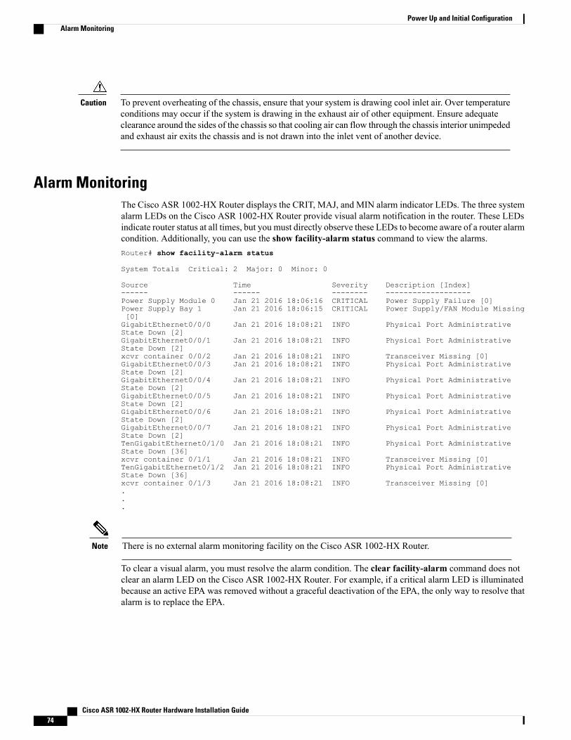
To prevent overheating of the chassis, ensure that your system is drawing cool inlet air. Over temperatureconditions may occur if the system is drawing in the exhaust air of other equipment. Ensure adequateclearance around the sides of the chassis so that cooling air can flow through the chassis interior unimpededand exhaust air exits the chassis and is not drawn into the inlet vent of another device.
Caution
Alarm MonitoringThe Cisco ASR 1002-HX Router displays the CRIT, MAJ, and MIN alarm indicator LEDs. The three systemalarm LEDs on the Cisco ASR 1002-HX Router provide visual alarm notification in the router. These LEDsindicate router status at all times, but you must directly observe these LEDs to become aware of a router alarmcondition. Additionally, you can use the show facility-alarm status command to view the alarms.Router# show facility-alarm status
System Totals Critical: 2 Major: 0 Minor: 0
Source Time Severity Description [Index]------ ------ -------- -------------------Power Supply Module 0 Jan 21 2016 18:06:16 CRITICAL Power Supply Failure [0]Power Supply Bay 1 Jan 21 2016 18:06:15 CRITICAL Power Supply/FAN Module Missing[0]GigabitEthernet0/0/0 Jan 21 2016 18:08:21 INFO Physical Port AdministrativeState Down [2]GigabitEthernet0/0/1 Jan 21 2016 18:08:21 INFO Physical Port AdministrativeState Down [2]xcvr container 0/0/2 Jan 21 2016 18:08:21 INFO Transceiver Missing [0]GigabitEthernet0/0/3 Jan 21 2016 18:08:21 INFO Physical Port AdministrativeState Down [2]GigabitEthernet0/0/4 Jan 21 2016 18:08:21 INFO Physical Port AdministrativeState Down [2]GigabitEthernet0/0/5 Jan 21 2016 18:08:21 INFO Physical Port AdministrativeState Down [2]GigabitEthernet0/0/6 Jan 21 2016 18:08:21 INFO Physical Port AdministrativeState Down [2]GigabitEthernet0/0/7 Jan 21 2016 18:08:21 INFO Physical Port AdministrativeState Down [2]TenGigabitEthernet0/1/0 Jan 21 2016 18:08:21 INFO Physical Port AdministrativeState Down [36]xcvr container 0/1/1 Jan 21 2016 18:08:21 INFO Transceiver Missing [0]TenGigabitEthernet0/1/2 Jan 21 2016 18:08:21 INFO Physical Port AdministrativeState Down [36]xcvr container 0/1/3 Jan 21 2016 18:08:21 INFO Transceiver Missing [0]...
There is no external alarm monitoring facility on the Cisco ASR 1002-HX Router.Note
To clear a visual alarm, you must resolve the alarm condition. The clear facility-alarm command does notclear an alarm LED on the Cisco ASR 1002-HX Router. For example, if a critical alarm LED is illuminatedbecause an active EPA was removed without a graceful deactivation of the EPA, the only way to resolve thatalarm is to replace the EPA.
Cisco ASR 1002-HX Router Hardware Installation Guide74
Power Up and Initial ConfigurationAlarm Monitoring
Environmental MonitoringThe environmental monitoring functions use sensors to monitor the temperature of the cooling air as it movesthrough the chassis.
The local power supplies provide the ability to monitor:
• Input and output voltage
• Output current
• Outlet temperature
The Cisco ASR 1002-HX Router is expected to meet the following environmental operating conditions:
• Operating Temperature Nominal: 32° to 104° (0° to 40°C)
• Operating Temperature Short Term: 32° to 131° (0° to +55°C)
• Operating Humidity Nominal (relative humidity): 10 to 90% relative
• Operating Humidity Short Term: 5 to 90% relative
• Operating Altitude: –500 to 10,000 feet (–152.4 to 3048 meters)
• DC Input Range: –40 to –72 VDC
• AC Input Range: 85 to 264 VAC
In addition, the power supplies monitor internal power supply temperatures and voltages. A power supply iseither within tolerance (normal) or out of tolerance (critical). If an internal power supply temperature or voltagereaches a critical level, the power supply shuts down without any interaction with the system processor.
The environmental monitoring functions use the following levels of status conditions to monitor the system:
• Normal—All monitored parameters are within normal tolerances.
•Warning—The system has exceeded a specified threshold. The system continues to operate, but operatoraction is recommended to bring the system back to a normal state.
• Critical—An out-of-tolerance temperature or voltage condition exists. The system continues to operate,but the system is approaching shutdown. Immediate operator action is required.
• Shutdown—Before any shutdown, the system logs the status of monitored parameters in NVRAM sothat you can retrieve it later to help determine the cause of the problem.
• Power supply shutdown—The power supply detected an internal out-of-tolerance overvoltage, overcurrent,or temperature condition and shut itself down. All DC power remains disabled until you toggle thechassis power switch.
Fan FailuresFour internal fans draw cooling air in through the front of the chassis and across internal components tomaintain an acceptable operating temperature. The fans are located at the rear of the chassis. The fans in theCisco ASR 1002-HX Routerare numbered from 0 to 3, right to left. When the system power is on, all fansshould be operational. However, the system continues to operate even if a fan fails.
Cisco ASR 1002-HX Router Hardware Installation Guide 75
Power Up and Initial ConfigurationEnvironmental Monitoring
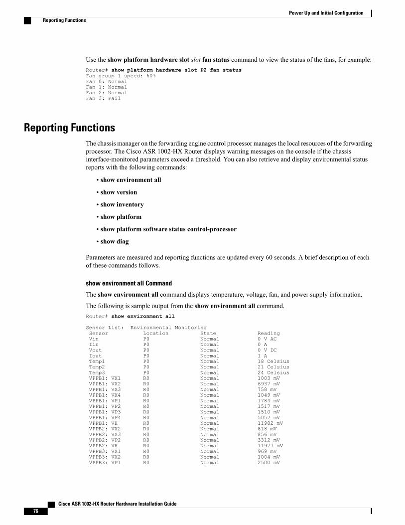
Use the show platform hardware slot slot fan status command to view the status of the fans, for example:Router# show platform hardware slot P2 fan statusFan group 1 speed: 60%Fan 0: NormalFan 1: NormalFan 2: NormalFan 3: Fail
Reporting FunctionsThe chassis manager on the forwarding engine control processor manages the local resources of the forwardingprocessor. The Cisco ASR 1002-HX Router displays warning messages on the console if the chassisinterface-monitored parameters exceed a threshold. You can also retrieve and display environmental statusreports with the following commands:
• show environment all
• show version
• show inventory
• show platform
• show platform software status control-processor
• show diag
Parameters are measured and reporting functions are updated every 60 seconds. A brief description of eachof these commands follows.
show environment all Command
The show environment all command displays temperature, voltage, fan, and power supply information.
The following is sample output from the show environment all command.Router# show environment all
Sensor List: Environmental MonitoringSensor Location State ReadingVin P0 Normal 0 V ACIin P0 Normal 0 AVout P0 Normal 0 V DCIout P0 Normal 1 ATemp1 P0 Normal 18 CelsiusTemp2 P0 Normal 21 CelsiusTemp3 P0 Normal 24 CelsiusVPPB1: VX1 R0 Normal 1003 mVVPPB1: VX2 R0 Normal 6937 mVVPPB1: VX3 R0 Normal 758 mVVPPB1: VX4 R0 Normal 1049 mVVPPB1: VP1 R0 Normal 1784 mVVPPB1: VP2 R0 Normal 1517 mVVPPB1: VP3 R0 Normal 1510 mVVPPB1: VP4 R0 Normal 5057 mVVPPB1: VH R0 Normal 11982 mVVPPB2: VX2 R0 Normal 818 mVVPPB2: VX3 R0 Normal 856 mVVPPB2: VP2 R0 Normal 3312 mVVPPB2: VH R0 Normal 11977 mVVPPB3: VX1 R0 Normal 969 mVVPPB3: VX2 R0 Normal 1004 mVVPPB3: VP1 R0 Normal 2500 mV
Cisco ASR 1002-HX Router Hardware Installation Guide76
Power Up and Initial ConfigurationReporting Functions
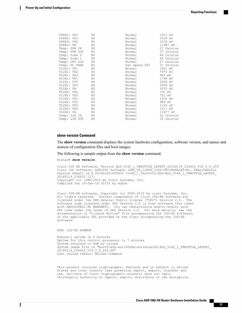
VPPB3: VP2 R0 Normal 1207 mVVPPB3: VP3 R0 Normal 1518 mVVPPB3: VP4 R0 Normal 1518 mVVPPB3: VH R0 Normal 11987 mVTemp: PPB IN R0 Normal 21 CelsiusTemp: PPB OUT R0 Normal 37 CelsiusTemp: Yoda 0 R0 Normal 48 CelsiusTemp: Yoda 1 R0 Normal 49 CelsiusTemp: CPU Die R0 Normal 27 CelsiusTemp: FC FANS R0 Fan Speed 60% 21 CelsiusVLIB1: VX1 R0 Normal 1001 mVVLIB1: VX2 R0 Normal 7070 mVVLIB1: VX3 R0 Normal 949 mVVLIB1: VP1 R0 Normal 1796 mVVLIB1: VP2 R0 Normal 2508 mVVLIB1: VP3 R0 Normal 3309 mVVLIB1: VH R0 Normal 5033 mVVLIB2: VX2 R0 Normal 752 mVVLIB2: VX3 R0 Normal 751 mVVLIB2: VP1 R0 Normal 1010 mVVLIB2: VP2 R0 Normal 986 mVVLIB2: VP3 R0 Normal 1195 mVVLIB2: VP4 R0 Normal 1517 mVVLIB2: VH R0 Normal 11977 mVTemp: LIB IN R0 Normal 22 CelsiusTemp: LIB OUT R0 Normal 32 Celsius
show version Command
The show version command displays the system hardware configuration, software version, and names andsources of configuration files and boot images.
The following is sample output from the show version command:Router# show version
Cisco IOS XE Software, Version BLD_V162_1_THROTTLE_LATEST_20160119_234422_V16_2_0_259Cisco IOS Software, ASR1000 Software (X86_64_LINUX_IOSD-UNIVERSALK9-M), ExperimentalVersion Denali 16.2.20160120:005403 [v162_1_throttle-BLD-BLD_V162_1_THROTTLE_LATEST_20160119_234422 127]Copyright (c) 1986-2016 by Cisco Systems, Inc.Compiled Tue 19-Jan-16 20:53 by mcpre
Cisco IOS-XE software, Copyright (c) 2005-2016 by cisco Systems, Inc.All rights reserved. Certain components of Cisco IOS-XE software arelicensed under the GNU General Public License ("GPL") Version 2.0. Thesoftware code licensed under GPL Version 2.0 is free software that comeswith ABSOLUTELY NO WARRANTY. You can redistribute and/or modify suchGPL code under the terms of GPL Version 2.0. For more details, see thedocumentation or "License Notice" file accompanying the IOS-XE software,or the applicable URL provided on the flyer accompanying the IOS-XEsoftware.
ROM: IOS-XE ROMMON
Kahuna-1 uptime is 6 minutesUptime for this control processor is 7 minutesSystem returned to ROM by reloadSystem image file is "bootflash:asr1002hx-universalk9.BLD_V162_1_THROTTLE_LATEST_20160119_234422_V16_2_0_259.SS"Last reload reason: Reload Command
This product contains cryptographic features and is subject to UnitedStates and local country laws governing import, export, transfer anduse. Delivery of Cisco cryptographic products does not implythird-party authority to import, export, distribute or use encryption.
Cisco ASR 1002-HX Router Hardware Installation Guide 77
Power Up and Initial ConfigurationReporting Functions
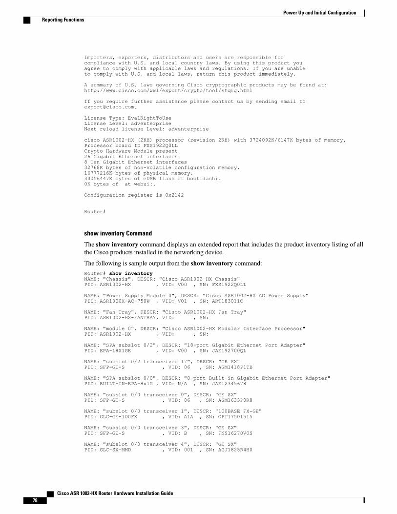
Importers, exporters, distributors and users are responsible forcompliance with U.S. and local country laws. By using this product youagree to comply with applicable laws and regulations. If you are unableto comply with U.S. and local laws, return this product immediately.
A summary of U.S. laws governing Cisco cryptographic products may be found at:http://www.cisco.com/wwl/export/crypto/tool/stqrg.html
If you require further assistance please contact us by sending email [email protected].
License Type: EvalRightToUseLicense Level: adventerpriseNext reload license Level: adventerprise
cisco ASR1002-HX (2KH) processor (revision 2KH) with 3724092K/6147K bytes of memory.Processor board ID FXS1922Q0LLCrypto Hardware Module present26 Gigabit Ethernet interfaces8 Ten Gigabit Ethernet interfaces32768K bytes of non-volatile configuration memory.16777216K bytes of physical memory.30056447K bytes of eUSB flash at bootflash:.0K bytes of at webui:.
Configuration register is 0x2142
Router#
show inventory Command
The show inventory command displays an extended report that includes the product inventory listing of allthe Cisco products installed in the networking device.
The following is sample output from the show inventory command:Router# show inventoryNAME: "Chassis", DESCR: "Cisco ASR1002-HX Chassis"PID: ASR1002-HX , VID: V00 , SN: FXS1922Q0LL
NAME: "Power Supply Module 0", DESCR: "Cisco ASR1002-HX AC Power Supply"PID: ASR1000X-AC-750W , VID: V01 , SN: ART183011C
NAME: "Fan Tray", DESCR: "Cisco ASR1002-HX Fan Tray"PID: ASR1002-HX-FANTRAY, VID: , SN:
NAME: "module 0", DESCR: "Cisco ASR1002-HX Modular Interface Processor"PID: ASR1002-HX , VID: , SN:
NAME: "SPA subslot 0/2", DESCR: "18-port Gigabit Ethernet Port Adapter"PID: EPA-18X1GE , VID: V00 , SN: JAE192700QL
NAME: "subslot 0/2 transceiver 17", DESCR: "GE SX"PID: SFP-GE-S , VID: 06 , SN: AGM1418P1TB
NAME: "SPA subslot 0/0", DESCR: "8-port Built-in Gigabit Ethernet Port Adapter"PID: BUILT-IN-EPA-8x1G , VID: N/A , SN: JAE12345678
NAME: "subslot 0/0 transceiver 0", DESCR: "GE SX"PID: SFP-GE-S , VID: 06 , SN: AGM1633P0R8
NAME: "subslot 0/0 transceiver 1", DESCR: "100BASE FX-GE"PID: GLC-GE-100FX , VID: A1A , SN: OPT17501515
NAME: "subslot 0/0 transceiver 3", DESCR: "GE SX"PID: SFP-GE-S , VID: B , SN: FNS16270V0S
NAME: "subslot 0/0 transceiver 4", DESCR: "GE SX"PID: GLC-SX-MMD , VID: 001 , SN: AGJ1825R4H0
Cisco ASR 1002-HX Router Hardware Installation Guide78
Power Up and Initial ConfigurationReporting Functions
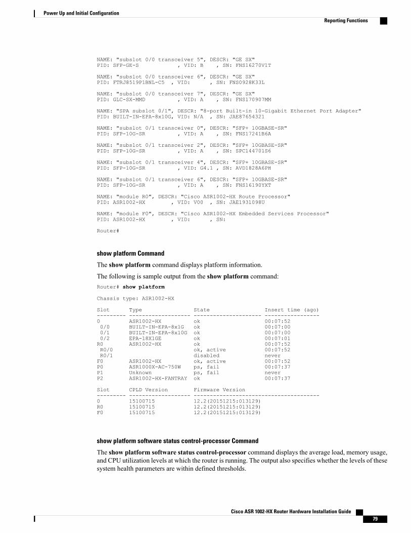
NAME: "subslot 0/0 transceiver 5", DESCR: "GE SX"PID: SFP-GE-S , VID: B , SN: FNS16270V1T
NAME: "subslot 0/0 transceiver 6", DESCR: "GE SX"PID: FTRJ8519P1BNL-C5 , VID: , SN: FNS0928K33L
NAME: "subslot 0/0 transceiver 7", DESCR: "GE SX"PID: GLC-SX-MMD , VID: A , SN: FNS170907MM
NAME: "SPA subslot 0/1", DESCR: "8-port Built-in 10-Gigabit Ethernet Port Adapter"PID: BUILT-IN-EPA-8x10G, VID: N/A , SN: JAE87654321
NAME: "subslot 0/1 transceiver 0", DESCR: "SFP+ 10GBASE-SR"PID: SFP-10G-SR , VID: A , SN: FNS17241B6A
NAME: "subslot 0/1 transceiver 2", DESCR: "SFP+ 10GBASE-SR"PID: SFP-10G-SR , VID: A , SN: SPC144701S6
NAME: "subslot 0/1 transceiver 4", DESCR: "SFP+ 10GBASE-SR"PID: SFP-10G-SR , VID: G4.1 , SN: AVD1828A6PH
NAME: "subslot 0/1 transceiver 6", DESCR: "SFP+ 10GBASE-SR"PID: SFP-10G-SR , VID: A , SN: FNS16190YXT
NAME: "module R0", DESCR: "Cisco ASR1002-HX Route Processor"PID: ASR1002-HX , VID: V00 , SN: JAE1931098U
NAME: "module F0", DESCR: "Cisco ASR1002-HX Embedded Services Processor"PID: ASR1002-HX , VID: , SN:
Router#
show platform Command
The show platform command displays platform information.
The following is sample output from the show platform command:Router# show platform
Chassis type: ASR1002-HX
Slot Type State Insert time (ago)--------- ------------------- --------------------- -----------------0 ASR1002-HX ok 00:07:520/0 BUILT-IN-EPA-8x1G ok 00:07:000/1 BUILT-IN-EPA-8x10G ok 00:07:000/2 EPA-18X1GE ok 00:07:01R0 ASR1002-HX ok 00:07:52R0/0 ok, active 00:07:52R0/1 disabled neverF0 ASR1002-HX ok, active 00:07:52P0 ASR1000X-AC-750W ps, fail 00:07:37P1 Unknown ps, fail neverP2 ASR1002-HX-FANTRAY ok 00:07:37
Slot CPLD Version Firmware Version--------- ------------------- ---------------------------------------0 15100715 12.2(20151215:013129)R0 15100715 12.2(20151215:013129)F0 15100715 12.2(20151215:013129)
show platform software status control-processor Command
The show platform software status control-processor command displays the average load, memory usage,and CPU utilization levels at which the router is running. The output also specifies whether the levels of thesesystem health parameters are within defined thresholds.
Cisco ASR 1002-HX Router Hardware Installation Guide 79
Power Up and Initial ConfigurationReporting Functions
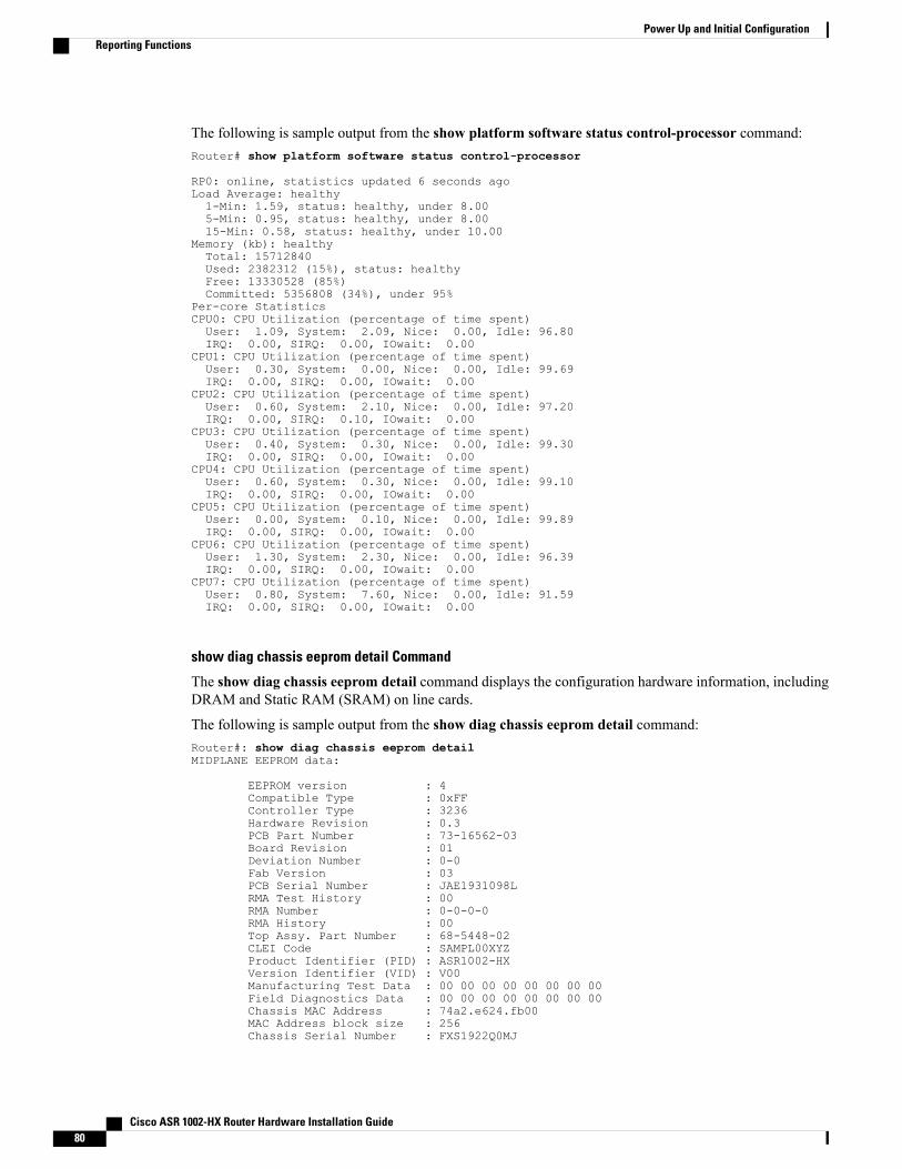
The following is sample output from the show platform software status control-processor command:Router# show platform software status control-processor
RP0: online, statistics updated 6 seconds agoLoad Average: healthy1-Min: 1.59, status: healthy, under 8.005-Min: 0.95, status: healthy, under 8.0015-Min: 0.58, status: healthy, under 10.00
Memory (kb): healthyTotal: 15712840Used: 2382312 (15%), status: healthyFree: 13330528 (85%)Committed: 5356808 (34%), under 95%
Per-core StatisticsCPU0: CPU Utilization (percentage of time spent)User: 1.09, System: 2.09, Nice: 0.00, Idle: 96.80IRQ: 0.00, SIRQ: 0.00, IOwait: 0.00
CPU1: CPU Utilization (percentage of time spent)User: 0.30, System: 0.00, Nice: 0.00, Idle: 99.69IRQ: 0.00, SIRQ: 0.00, IOwait: 0.00
CPU2: CPU Utilization (percentage of time spent)User: 0.60, System: 2.10, Nice: 0.00, Idle: 97.20IRQ: 0.00, SIRQ: 0.10, IOwait: 0.00
CPU3: CPU Utilization (percentage of time spent)User: 0.40, System: 0.30, Nice: 0.00, Idle: 99.30IRQ: 0.00, SIRQ: 0.00, IOwait: 0.00
CPU4: CPU Utilization (percentage of time spent)User: 0.60, System: 0.30, Nice: 0.00, Idle: 99.10IRQ: 0.00, SIRQ: 0.00, IOwait: 0.00
CPU5: CPU Utilization (percentage of time spent)User: 0.00, System: 0.10, Nice: 0.00, Idle: 99.89IRQ: 0.00, SIRQ: 0.00, IOwait: 0.00
CPU6: CPU Utilization (percentage of time spent)User: 1.30, System: 2.30, Nice: 0.00, Idle: 96.39IRQ: 0.00, SIRQ: 0.00, IOwait: 0.00
CPU7: CPU Utilization (percentage of time spent)User: 0.80, System: 7.60, Nice: 0.00, Idle: 91.59IRQ: 0.00, SIRQ: 0.00, IOwait: 0.00
show diag chassis eeprom detail Command
The show diag chassis eeprom detail command displays the configuration hardware information, includingDRAM and Static RAM (SRAM) on line cards.
The following is sample output from the show diag chassis eeprom detail command:Router#: show diag chassis eeprom detailMIDPLANE EEPROM data:
EEPROM version : 4Compatible Type : 0xFFController Type : 3236Hardware Revision : 0.3PCB Part Number : 73-16562-03Board Revision : 01Deviation Number : 0-0Fab Version : 03PCB Serial Number : JAE1931098LRMA Test History : 00RMA Number : 0-0-0-0RMA History : 00Top Assy. Part Number : 68-5448-02CLEI Code : SAMPL00XYZProduct Identifier (PID) : ASR1002-HXVersion Identifier (VID) : V00Manufacturing Test Data : 00 00 00 00 00 00 00 00Field Diagnostics Data : 00 00 00 00 00 00 00 00Chassis MAC Address : 74a2.e624.fb00MAC Address block size : 256Chassis Serial Number : FXS1922Q0MJ
Cisco ASR 1002-HX Router Hardware Installation Guide80
Power Up and Initial ConfigurationReporting Functions
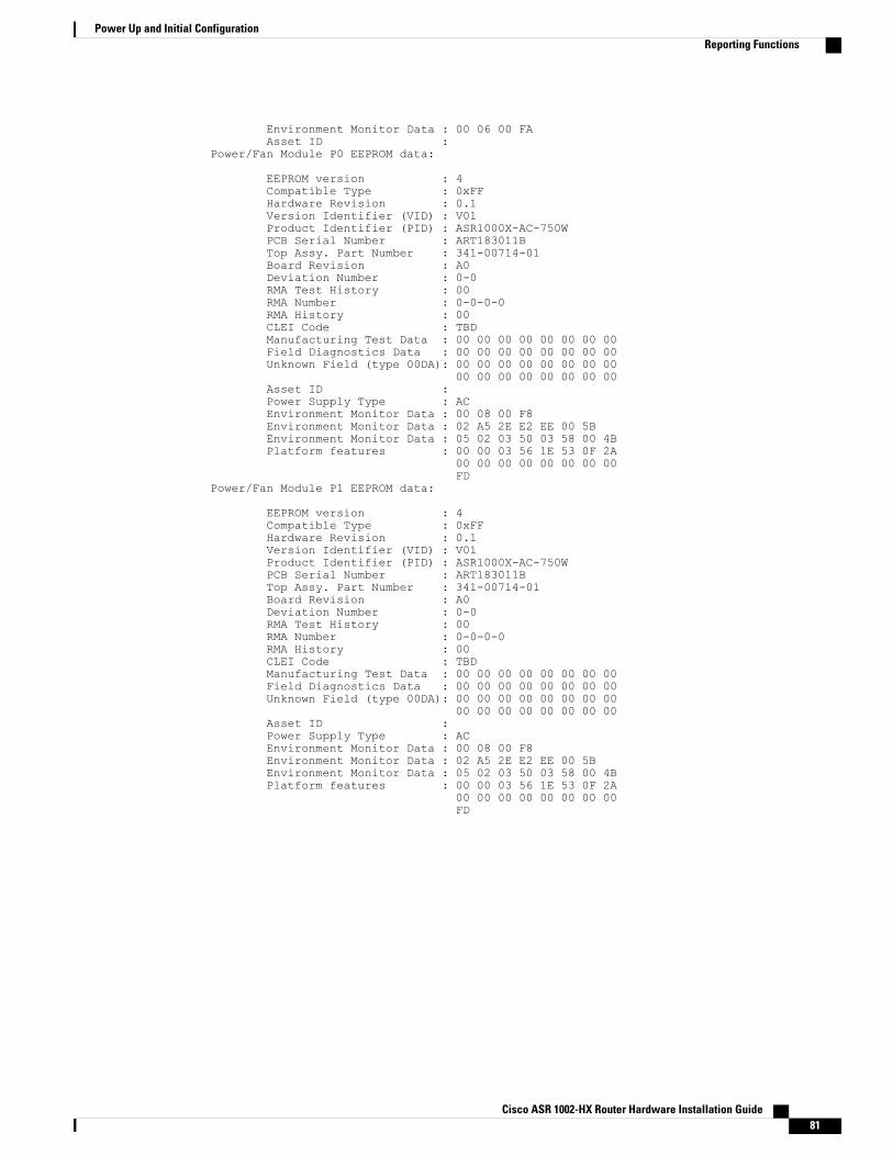
Environment Monitor Data : 00 06 00 FAAsset ID :
Power/Fan Module P0 EEPROM data:
EEPROM version : 4Compatible Type : 0xFFHardware Revision : 0.1Version Identifier (VID) : V01Product Identifier (PID) : ASR1000X-AC-750WPCB Serial Number : ART183011BTop Assy. Part Number : 341-00714-01Board Revision : A0Deviation Number : 0-0RMA Test History : 00RMA Number : 0-0-0-0RMA History : 00CLEI Code : TBDManufacturing Test Data : 00 00 00 00 00 00 00 00Field Diagnostics Data : 00 00 00 00 00 00 00 00Unknown Field (type 00DA): 00 00 00 00 00 00 00 00
00 00 00 00 00 00 00 00Asset ID :Power Supply Type : ACEnvironment Monitor Data : 00 08 00 F8Environment Monitor Data : 02 A5 2E E2 EE 00 5BEnvironment Monitor Data : 05 02 03 50 03 58 00 4BPlatform features : 00 00 03 56 1E 53 0F 2A
00 00 00 00 00 00 00 00FD
Power/Fan Module P1 EEPROM data:
EEPROM version : 4Compatible Type : 0xFFHardware Revision : 0.1Version Identifier (VID) : V01Product Identifier (PID) : ASR1000X-AC-750WPCB Serial Number : ART183011BTop Assy. Part Number : 341-00714-01Board Revision : A0Deviation Number : 0-0RMA Test History : 00RMA Number : 0-0-0-0RMA History : 00CLEI Code : TBDManufacturing Test Data : 00 00 00 00 00 00 00 00Field Diagnostics Data : 00 00 00 00 00 00 00 00Unknown Field (type 00DA): 00 00 00 00 00 00 00 00
00 00 00 00 00 00 00 00Asset ID :Power Supply Type : ACEnvironment Monitor Data : 00 08 00 F8Environment Monitor Data : 02 A5 2E E2 EE 00 5BEnvironment Monitor Data : 05 02 03 50 03 58 00 4BPlatform features : 00 00 03 56 1E 53 0F 2A
00 00 00 00 00 00 00 00FD
Cisco ASR 1002-HX Router Hardware Installation Guide 81
Power Up and Initial ConfigurationReporting Functions
Cisco ASR 1002-HX Router Hardware Installation Guide82
Power Up and Initial ConfigurationReporting Functions
C H A P T E R 6License Verification
This chapter provides information about verifying the Cisco IOS license level, viewing the Cisco ASR1002-HX Router license, and configuring the port license and crypto throughput level.
• Viewing the Cisco IOS License Level, page 83
• Viewing License Information, page 84
• Port Licensing, page 87
• Configuring the Crypto Throughput Level, page 89
Viewing the Cisco IOS License LevelUse the show version command to determine the Cisco IOS license level in the router. For example:Router# show version...License Level: adventerpriseLicense Type: RightToUseNext reload license Level: adventerprise...
Table 13: show version Command Output Description
DescriptionField Name
Indicates the current Cisco IOS license code level.License Level: adventerprise
Indicates whether you are utilizing a permanent(purchased) license, an evaluation 60-day license, ora Right-to-Use license that would indicate that thepurchase of a license is required.
License Type: RightToUse
Indicates the startup configuration definition that willbe used for the next reload instance.
Next reload license Level: adventerprise
Cisco ASR 1002-HX Router Hardware Installation Guide 83
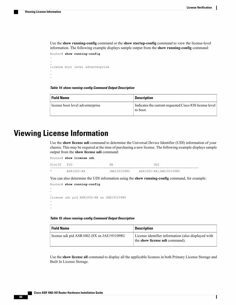
Use the show running-config command or the show startup-config command to view the license-levelinformation. The following example displays sample output from the show running-config command:Router# show running-config...license boot level adventerprise...
Table 14: show running-config Command Output Description
DescriptionField Name
Indicates the current requested Cisco lOS license levelto boot.
license boot level adventerprise
Viewing License InformationUse the show license udi command to determine the Universal Device Identifier (UDI) information of yourchassis. This may be required at the time of purchasing a new license. The following example displays sampleoutput from the show license udi command:Router# show license udi
SlotID PID SN UDI--------------------------------------------------------------------------------* ASR1002-HX JAE1931098U ASR1002-HX:JAE1931098U
You can also determine the UDI information using the show running-config command, for example:Router# show running-config...license udi pid ASR1002-HX sn JAE1931098U...
Table 15: show running-config Command Output Description
DescriptionField Name
License identifier information (also displayed withthe show license udi command).
license udi pid ASR1002-HX sn JAE1931098U
Use the show license all command to display all the applicable licenses in both Primary License Storage andBuilt In License Storage.
Cisco ASR 1002-HX Router Hardware Installation Guide84
License VerificationViewing License Information
Primary License Storage stores the currently purchased and installed licenses.Note
The following example displays sample output from the show license all command:Router# show license allLicense Store: Primary License StorageLicense Store: Built-In License StorageStoreIndex: 0 Feature: adventerprise Version: 1.0
License Type: EvalRightToUseLicense State: Active, In Use
Evaluation total period: 8 weeks 4 daysEvaluation period left: 3 days 13 hoursPeriod used: 8 weeks 0 dayTransition date: Jan 25 2016 07:31:44
License Count: Non-CountedLicense Priority: Low
StoreIndex: 1 Feature: advipservices Version: 1.0License Type: EvalRightToUseLicense State: Active, Not in Use, EULA not accepted
Evaluation total period: 8 weeks 4 daysEvaluation period left: 8 weeks 4 daysPeriod used: 0 minute 0 second
License Count: Non-CountedLicense Priority: None
StoreIndex: 2 Feature: avc Version: 1.0License Type: EvalRightToUseLicense State: Active, Not in Use, EULA not accepted
Evaluation total period: 8 weeks 4 daysEvaluation period left: 8 weeks 4 daysPeriod used: 0 minute 0 second
License Count: Non-CountedLicense Priority: None
StoreIndex: 3 Feature: fwnat_red Version: 1.0License Type: EvalRightToUseLicense State: Active, Not in Use, EULA not accepted
Evaluation total period: 8 weeks 4 daysEvaluation period left: 8 weeks 4 daysPeriod used: 0 minute 0 second
License Count: Non-CountedLicense Priority: None
StoreIndex: 4 Feature: ipsec Version: 1.0License Type: EvalRightToUseLicense State: Active, Not in Use, EULA not accepted
Evaluation total period: 8 weeks 4 daysEvaluation period left: 8 weeks 4 daysPeriod used: 0 minute 0 second
License Count: Non-CountedLicense Priority: None
StoreIndex: 5 Feature: lawful_intr Version: 1.0License Type: EvalRightToUseLicense State: Active, Not in Use, EULA not accepted
Evaluation total period: 8 weeks 4 daysEvaluation period left: 8 weeks 4 daysPeriod used: 0 minute 0 second
License Count: Non-CountedLicense Priority: None
StoreIndex: 6 Feature: lisp Version: 1.0License Type: EvalRightToUseLicense State: Active, Not in Use, EULA not accepted
Evaluation total period: 8 weeks 4 daysEvaluation period left: 8 weeks 4 daysPeriod used: 0 minute 0 second
License Count: Non-CountedLicense Priority: None
StoreIndex: 7 Feature: otv Version: 1.0License Type: EvalRightToUseLicense State: Active, Not in Use, EULA not accepted
Evaluation total period: 8 weeks 4 daysEvaluation period left: 8 weeks 4 days
Cisco ASR 1002-HX Router Hardware Installation Guide 85
License VerificationViewing License Information
Period used: 0 minute 0 secondLicense Count: Non-CountedLicense Priority: None
StoreIndex: 8 Feature: sw_redundancy Version: 1.0License Type: EvalRightToUseLicense State: Active, Not in Use, EULA accepted
Evaluation total period: 8 weeks 4 daysEvaluation period left: 7 weeks 0 dayPeriod used: 1 week 3 days
License Count: Non-CountedLicense Priority: Low
StoreIndex: 9 Feature: vpls Version: 1.0License Type: EvalRightToUseLicense State: Active, Not in Use, EULA not accepted
Evaluation total period: 8 weeks 4 daysEvaluation period left: 8 weeks 4 daysPeriod used: 0 minute 0 second
License Count: Non-CountedLicense Priority: None
StoreIndex: 10 Feature: FoundationSuiteK9 Version: 1.0License Type: EvalRightToUseLicense State: Active, Not in Use, EULA not accepted
Evaluation total period: 8 weeks 4 daysEvaluation period left: 8 weeks 4 daysPeriod used: 0 minute 0 second
License Count: Non-CountedLicense Priority: None
StoreIndex: 11 Feature: AdvUCSuiteK9 Version: 1.0License Type: EvalRightToUseLicense State: Active, Not in Use, EULA not accepted
Evaluation total period: 8 weeks 4 daysEvaluation period left: 8 weeks 4 daysPeriod used: 0 minute 0 second
License Count: Non-CountedLicense Priority: None
StoreIndex: 12 Feature: 2HXIPS8G Version: 1.0License Type: EvalRightToUseLicense State: Active, In Use
Evaluation total period: 8 weeks 4 daysEvaluation period left: 6 weeks 5 daysPeriod used: 1 week 5 daysTransition date: Mar 09 2016 16:10:35
License Count: Non-CountedLicense Priority: Low
StoreIndex: 13 Feature: 2HX8G16G Version: 1.0License Type: EvalRightToUseLicense State: Active, Not in Use, EULA not accepted
Evaluation total period: 8 weeks 4 daysEvaluation period left: 8 weeks 4 daysPeriod used: 0 minute 0 second
License Count: Non-CountedLicense Priority: None
StoreIndex: 14 Feature: 2HX8G25G Version: 1.0License Type: EvalRightToUseLicense State: Active, In Use
Evaluation total period: 8 weeks 4 daysEvaluation period left: 6 weeks 5 daysPeriod used: 1 week 5 daysTransition date: Mar 09 2016 16:10:35
License Count: Non-CountedLicense Priority: Low
StoreIndex: 15 Feature: 2HX16G25G Version: 1.0License Type: EvalRightToUseLicense State: Active, Not in Use, EULA not accepted
Evaluation total period: 8 weeks 4 daysEvaluation period left: 8 weeks 4 daysPeriod used: 0 minute 0 second
License Count: Non-CountedLicense Priority: None
StoreIndex: 16 Feature: interface_10g Version: 1.0License Type: EvalRightToUseLicense State: Active, Not in Use, EULA accepted
Evaluation total period: 8 weeks 4 days
Cisco ASR 1002-HX Router Hardware Installation Guide86
License VerificationViewing License Information
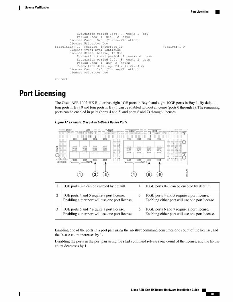
Evaluation period left: 7 weeks 1 dayPeriod used: 1 week 2 days
License Count: 0/0 (In-use/Violation)License Priority: Low
StoreIndex: 17 Feature: interface_1g Version: 1.0License Type: EvalRightToUseLicense State: Active, In Use
Evaluation total period: 8 weeks 4 daysEvaluation period left: 8 weeks 2 daysPeriod used: 1 day 2 hoursTransition date: Apr 23 2016 22:33:22
License Count: 1/0 (In-use/Violation)License Priority: Low
router#
Port LicensingThe Cisco ASR 1002-HX Router has eight 1GE ports in Bay 0 and eight 10GE ports in Bay 1. By default,four ports in Bay 0 and four ports in Bay 1 can be enabled without a license (ports 0 through 3). The remainingports can be enabled in pairs (ports 4 and 5, and ports 6 and 7) through licenses.
Figure 17: Example: Cisco ASR 1002-HX Router Ports
10GE ports 0–3 can be enabled by default.41GE ports 0–3 can be enabled by default.1
10GE ports 4 and 5 require a port license.Enabling either port will use one port license.
51GE ports 4 and 5 require a port license.Enabling either port will use one port license.
2
10GE ports 6 and 7 require a port license.Enabling either port will use one port license.
61GE ports 6 and 7 require a port license.Enabling either port will use one port license.
3
Enabling one of the ports in a port pair using the no shut command consumes one count of the license, andthe In-use count increases by 1.
Disabling the ports in the port pair using the shut command releases one count of the license, and the In-usecount decreases by 1.
Cisco ASR 1002-HX Router Hardware Installation Guide 87
License VerificationPort Licensing
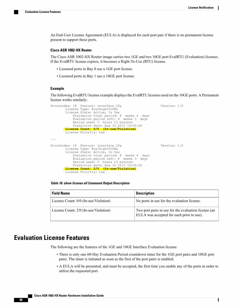
An End-User License Agreement (EULA) is displayed for each port pair if there is no permanent licensepresent to support these ports.
Cisco ASR 1002-HX Router
The Cisco ASR 1002-HX Router image carries two 1GE and two 10GE port EvalRTU (Evaluation) licenses.If the EvalRTU license expires, it becomes a Right-To-Use (RTU) license.
• Licensed ports in Bay 0 use a 1GE port license.
• Licensed ports in Bay 1 use a 10GE port license.
Example
The following EvalRTU license example displays the EvalRTU licenses used on the 10GE ports. A Permanentlicense works similarly:StoreIndex: 16 Feature: interface_10g Version: 1.0
License Type: EvalRightToUseLicense State: Active, In Use
Evaluation total period: 8 weeks 4 daysEvaluation period left: 8 weeks 3 daysPeriod used: 3 hours 13 minutesTransition date: Aug 16 2013 19:05:26
License Count: 0/0 (In-use/Violation)License Priority: Low
...
StoreIndex: 16 Feature: interface_10g Version: 1.0License Type: EvalRightToUseLicense State: Active, In Use
Evaluation total period: 8 weeks 4 daysEvaluation period left: 8 weeks 3 daysPeriod used: 3 hours 13 minutesTransition date: Aug 16 2013 19:05:26
License Count: 2/0 (In-use/Violation)License Priority: Low
Table 16: show license all Command Output Description
DescriptionField Name
No ports in use for the evaluation license.License Count: 0/0 (In-use/Violation)
Two port pairs in use for the evaluation license (anEULA was accepted for each prior to use).
License Count: 2/0 (In-use/Violation)
Evaluation License FeaturesThe following are the features of the 1GE and 10GE Interface Evaluation license:
• There is only one 60-Day Evaluation Period countdown timer for the 1GE port pairs and 10GE portpairs. The timer is initiated as soon as the first of the port pairs is enabled.
• A EULA will be presented, and must be accepted, the first time you enable any of the ports in order toutilize the requested port.
Cisco ASR 1002-HX Router Hardware Installation Guide88
License VerificationEvaluation License Features
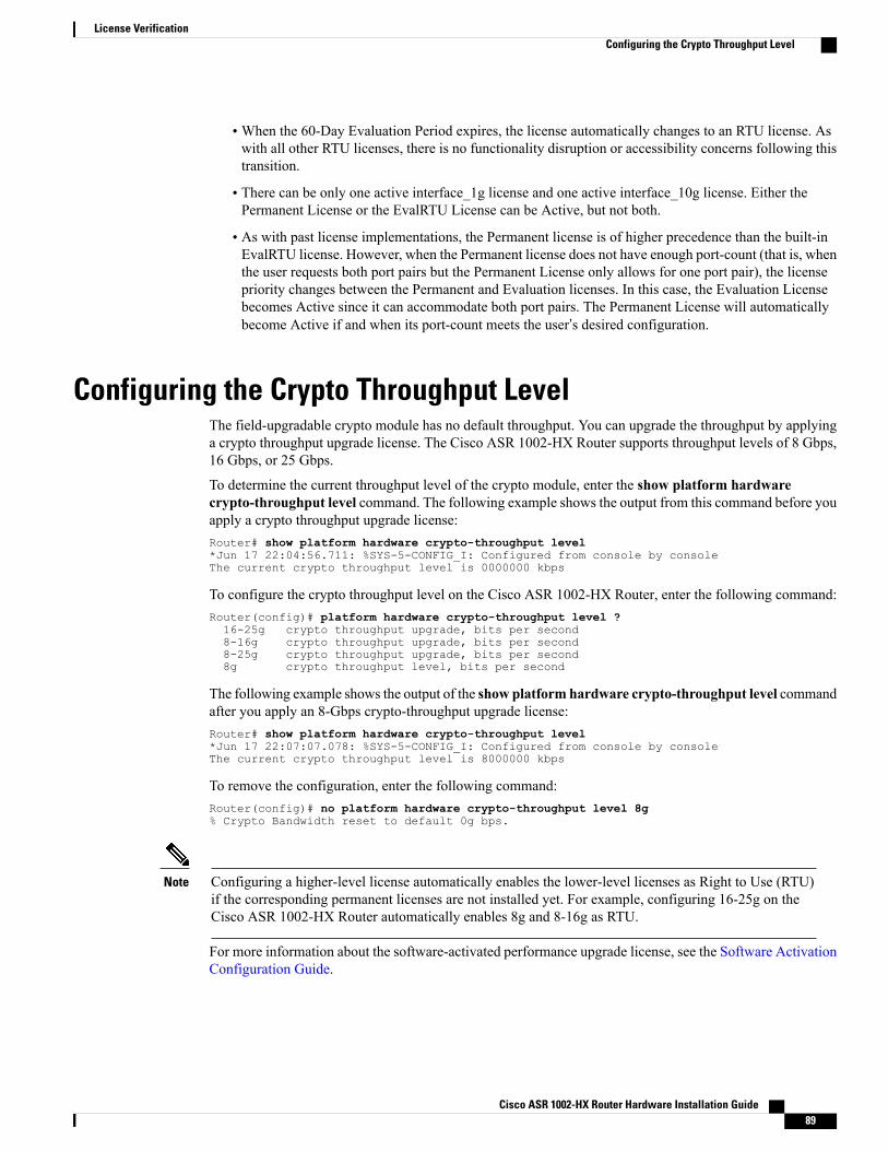
•When the 60-Day Evaluation Period expires, the license automatically changes to an RTU license. Aswith all other RTU licenses, there is no functionality disruption or accessibility concerns following thistransition.
• There can be only one active interface_1g license and one active interface_10g license. Either thePermanent License or the EvalRTU License can be Active, but not both.
• As with past license implementations, the Permanent license is of higher precedence than the built-inEvalRTU license. However, when the Permanent license does not have enough port-count (that is, whenthe user requests both port pairs but the Permanent License only allows for one port pair), the licensepriority changes between the Permanent and Evaluation licenses. In this case, the Evaluation Licensebecomes Active since it can accommodate both port pairs. The Permanent License will automaticallybecome Active if and when its port-count meets the user’s desired configuration.
Configuring the Crypto Throughput LevelThe field-upgradable crypto module has no default throughput. You can upgrade the throughput by applyinga crypto throughput upgrade license. The Cisco ASR 1002-HX Router supports throughput levels of 8 Gbps,16 Gbps, or 25 Gbps.
To determine the current throughput level of the crypto module, enter the show platform hardwarecrypto-throughput level command. The following example shows the output from this command before youapply a crypto throughput upgrade license:Router# show platform hardware crypto-throughput level*Jun 17 22:04:56.711: %SYS-5-CONFIG_I: Configured from console by consoleThe current crypto throughput level is 0000000 kbps
To configure the crypto throughput level on the Cisco ASR 1002-HX Router, enter the following command:Router(config)# platform hardware crypto-throughput level ?16-25g crypto throughput upgrade, bits per second8-16g crypto throughput upgrade, bits per second8-25g crypto throughput upgrade, bits per second8g crypto throughput level, bits per second
The following example shows the output of the show platform hardware crypto-throughput level commandafter you apply an 8-Gbps crypto-throughput upgrade license:Router# show platform hardware crypto-throughput level*Jun 17 22:07:07.078: %SYS-5-CONFIG_I: Configured from console by consoleThe current crypto throughput level is 8000000 kbps
To remove the configuration, enter the following command:Router(config)# no platform hardware crypto-throughput level 8g% Crypto Bandwidth reset to default 0g bps.
Configuring a higher-level license automatically enables the lower-level licenses as Right to Use (RTU)if the corresponding permanent licenses are not installed yet. For example, configuring 16-25g on theCisco ASR 1002-HX Router automatically enables 8g and 8-16g as RTU.
Note
For more information about the software-activated performance upgrade license, see the Software ActivationConfiguration Guide.
Cisco ASR 1002-HX Router Hardware Installation Guide 89
License VerificationConfiguring the Crypto Throughput Level

Cisco ASR 1002-HX Router Hardware Installation Guide90
License VerificationConfiguring the Crypto Throughput Level
C H A P T E R 7Removing and Replacing FRUs
This chapter describes procedures for removing and replacing field-replaceable units (FRUs) from Cisco1002-HX Routers.
• Removing and Replacing the Power Supplies, page 91
• Removing and Replacing USB Flash Memory Stick, page 97
• Removing and Replacing a DIMM, page 97
• Removing and Replacing an EPA, page 103
• Installing the Crypto Module, page 105
• Repacking the Router, page 107
Removing and Replacing the Power SuppliesThe following sections describes the procedures for removing and replacing the Cisco ASR 1002-HX Routerpower supplies.
The Cisco ASR 1002-HX Router has redundant power supplies that can be hot-swapped.Note
The has two power supply slots that are accessed from the front of the chassis: power supply slot 0 (PS0)is on the bottom and power supply slot 1 (PS1) is on the top (next to the chassis power switch).
Note
Statement 1077—Do Not Operate Unit Without Covers
The covers are an integral part of the safety design of the product. Do not operate the unit without thecovers installed.
Warning
Cisco ASR 1002-HX Router Hardware Installation Guide 91
Statement 1046—Installing or Replacing the Unit
When installing or replacing the unit, the ground connection must always be made first and disconnectedlast.
Warning
Statement 1003—DC Power Disconnection
Before performing any of the following procedures, ensure that power is removed from the DC circuit.
Warning
Statement 1030—Equipment Installation
Only trained and qualified personnel should be allowed to install, replace, or service this equipment.
Warning
Removing AC Power SuppliesThis section describes how to remove an AC power supply from the Cisco ASR 1002-HX Router.
Procedure
Step 1 Ensure that the chassis power switch is in the Standby position.It is not required to place the chassis power switch in the Standby position if you want to hot-swapa single power supply.
Note
Step 2 Unplug the power cable from the power supply.Step 3 Press the retaining latch towards the pull handle, grasp the handle with one hand, and pull the power supply
out of the slot while supporting the weight of the power supply with the other hand.Step 4 Repeat these steps if it is required to remove the other AC power supply.
Installing AC Power Supplies
Do not install the power supplies with the chassis cover off.Note
Procedure
Step 1 Ensure that the chassis power switch on the chassis is in the Standby position.It is not required to place the chassis power switch in the Standby position if you want to hot-swapa single power supply.
Note
Cisco ASR 1002-HX Router Hardware Installation Guide92
Removing and Replacing FRUsRemoving AC Power Supplies
Step 2 Insert the power supply module into the appropriate slot(s), making sure that the retention latch is firmlyplaced. You can verify that the power supply module is firmly latched by gently pulling the power supplyhandle.
Step 3 Insert the power supply cables firmly into the power supplies.Ensure that both power supplies are inserted firmly and the power cords are inplace.
Note
Step 4 If you have changed the chassis power switch to the Standby position in Step 1, press the power switch to theOn position.The power supply LEDs are illuminated (green).
Removing DC Input Power SuppliesThe DC power supply has a terminal block that is installed into the power supply terminal block header.
Procedure
Step 1 Turn off the circuit breaker from the power source.
Step 2 Ensure that the chassis power switch is in the Standby position.It is not required to place the chassis power switch in the Standby position if you want to hot-swapa single power supply.
Note
Step 3 Remove the plastic cover from the terminal block.Step 4 Unscrew the two terminal block screws on the unit and remove the wires from the power supply.Step 5 Press the power supply retaining latch towards the pull handle, grasp the handle with one hand, and pull the
power supply out of the slot while supporting the weight of the power supply with the other hand.
Installing DC Input Power Supplies
Statement 1003—DC Power Disconnection
Before performing any of the following procedures, ensure that power is removed from the DC circuit.
Warning
Statement 1030—Equipment Installation
Only trained and qualified personnel should be allowed to install, replace, or service this equipment.
Warning
Do not install the power supplies with the chassis cover off.Note
Cisco ASR 1002-HX Router Hardware Installation Guide 93
Removing and Replacing FRUsRemoving DC Input Power Supplies
This section describes how to install the DC power supply input power leads to the DC input power supply.Before you begin, read these important notices:
• The color coding of the DC input power supply leads depends on the color coding of the DC powersource at your site. Ensure that the lead color coding you choose for the DC input power supply matchesthe lead color coding used at the DC power source and verify that the power source is connected to thenegative (–) terminal and to the positive (+) terminal on the power supply.
• Ensure that the chassis ground is connected on the chassis before you begin installing the DC powersupply. Follow the steps provided in the "Chassis Ground Connection" section.
• For DC input power cables, the wire gauge is based on the National Electrical Code (NEC) and localcodes for 26 amp service at nominal DC input voltage (–40/–72 VDC). One pair of cable leads, sourceDC (–) and source DC return (+), are required for each power distribution unit (PDU). These cables areavailable from any commercial cable vendor. All DC input power cables for the chassis should be 10gauge wire and cable lengths should match within 10 percent of deviation.
Each DC input power cable is terminated at the PDU by a cable lug, as shown in the following figure.
DC input power cables must be connected to the PDU terminal studs in the proper positive (+) and negative(–) polarity. In some cases, the DC cable leads are labeled, which is a relatively safe indication of thepolarity. However, you must verify the polarity by measuring the voltage between the DC cable leads.When making the measurement, the positive (+) lead and the negative (–) lead must always match the (+)and (–) labels on the power distribution unit.
Note
Figure 18: DC Input Power Cable Lug
To avoid hazardous conditions, all components in the area where DC input power is accessible must beproperly insulated. Therefore, before installing the DC cable lugs, be sure to insulate the lugs accordingto the manufacturer's instructions.
Note
Wiring the DC Input Power Source
Statement 1046—Installing or Replacing the Unit
When installing or replacing the unit, the ground connection must always be made first and disconnectedlast.
Warning
Cisco ASR 1002-HX Router Hardware Installation Guide94
Removing and Replacing FRUsInstalling DC Input Power Supplies
Procedure
Step 1 Turn off the circuit breaker from the power source.
Step 2 Ensure that the chassis power switch is in the Standby position.It is not required to place the power switch in the Standby position if you want to hot-swap a singlepower supply.
Note
Step 3 Remove the plastic cover from the terminal block.Before you continue to install the terminal block ground wires, stop and perform Step4.
Caution
Cisco ASR 1002-HX Router Hardware Installation Guide 95
Removing and Replacing FRUsInstalling DC Input Power Supplies
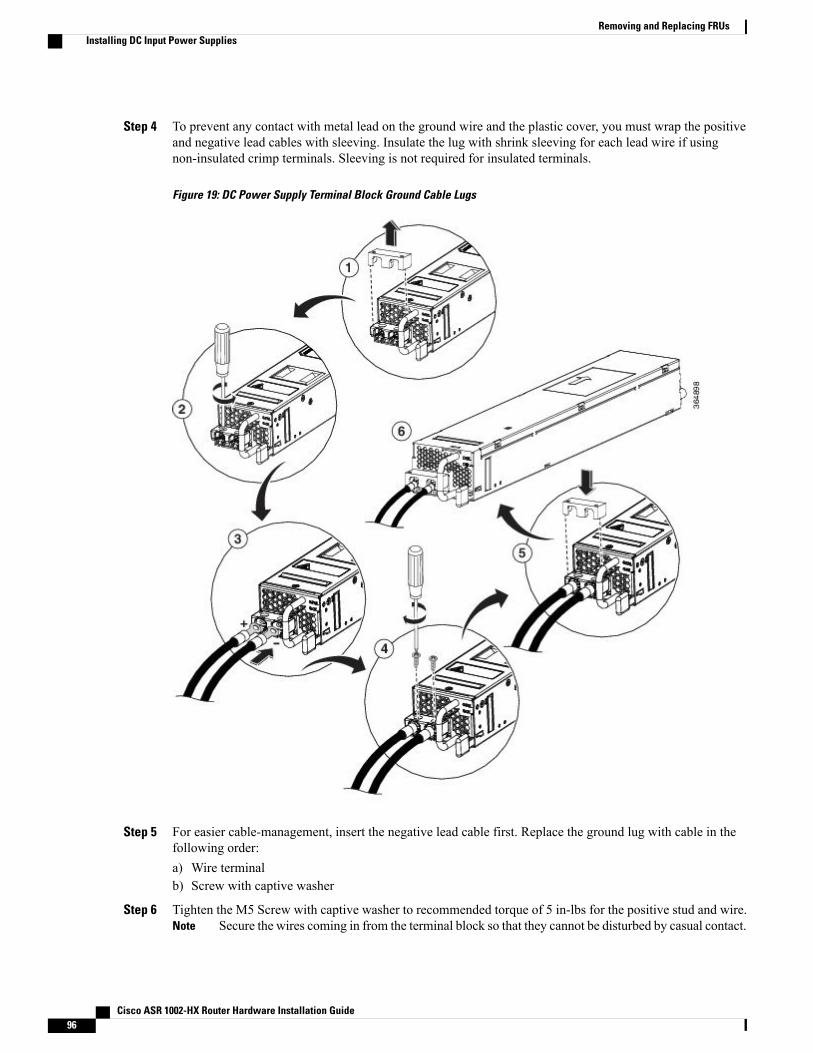
Step 4 To prevent any contact with metal lead on the ground wire and the plastic cover, you must wrap the positiveand negative lead cables with sleeving. Insulate the lug with shrink sleeving for each lead wire if usingnon-insulated crimp terminals. Sleeving is not required for insulated terminals.
Figure 19: DC Power Supply Terminal Block Ground Cable Lugs
Step 5 For easier cable-management, insert the negative lead cable first. Replace the ground lug with cable in thefollowing order:a) Wire terminalb) Screw with captive washer
Step 6 Tighten the M5 Screw with captive washer to recommended torque of 5 in-lbs for the positive stud and wire.Secure the wires coming in from the terminal block so that they cannot be disturbed by casual contact.Note
Cisco ASR 1002-HX Router Hardware Installation Guide96
Removing and Replacing FRUsInstalling DC Input Power Supplies

Step 7 Replace the terminal block plastic cover. The plastic cover is slotted and keyed to fit correctly over the terminalblock.
Step 8 Turn on the circuit breaker at the power source.Step 9 If you have changed the chassis power switch to the Standby position in step 2, turn the power switch to the
On position.The power supply LEDs illuminate green.
Removing and Replacing USB Flash Memory StickThe Cisco ASR 1002-HXRouter contains USB ports for a flash memory stick to store configurations or CiscoIOS XE consolidated packages.
Do not remove a USB Flash memory stick when issuing a file access command or a read/write operationto the Flash memory stick when it is processing. The router might reload or the USB Flash memory stickmay get damaged. Prior to the removal of the USB device, check to see if the USB activity LED on thefront panel is flashing.
Caution
To remove and then replace a USB flash memory stick, follow these steps:
Procedure
Step 1 Pull the flash memory stick from the USB port.Step 2 To replace a Cisco USB Flash memory stick, insert the module into USB port 0 or 1. The Flash memory stick
can be inserted only in one way, and can be inserted or removed regardless of whether the router is poweredup or not.
Removing and Replacing a DIMMThis section describes how to replace the DIMMs on the Cisco ASR 1002-HX Router.
You might have to upgrade a DIMM for the following reasons:
• You have upgraded to a new Cisco IOS feature set or release that requires more memory.
• You are using very large routing tables or many protocols.
The DIMM component is keyed and slotted for easier connection.
Cisco ASR 1002-HX Router
The Cisco ASR 1002-HX Router has four DIMM slots and supports 16-GB configuration by default (two8-GB DIMMS), and can be upgraded to 32-GB (four 8-GB DIMMS) configuration.
Cisco ASR 1002-HX Router Hardware Installation Guide 97
Removing and Replacing FRUsRemoving and Replacing USB Flash Memory Stick
To ensure that each memory channel uses DIMMs from the same vendor, you must move the 8 GBDIMMfrom Channel A, Slot 1, to Channel B, Slot 2. You can then install the upgrade DIMMs in Channel A,Slots 0 and 1.
Caution
The following table shows the slots that are supported for inserting the memory DIMMs in the Cisco ASR1002-HX Router.
Table 17: Cisco ASR 1002-HX Router: Supported Slots for Inserting the DIMMs
Memory Channel BMemory Channel AMemory PID Option
Slot 3 (U1DB1)Slot 2 (U1DB0)Slot 1 (U1DA1)Slot 0 (U1DA0)
8 GB–8 GB–M-ASR1002HX-16GB(default)
8 GB8 GB8 GB8 GBM-ASR1002HX-32GB(upgrade)
Removing a DIMM
Before You Begin
Perform the following steps before you begin the process of removing and replacing a DIMM:
• Use an ESD-preventive wrist strap.
• Back up the data that you want to save.
• Remove the power supplies before you remove the chassis top cover.
The top cover cannot be removed until the power supplies are removed from the chassis.The chassis has a safety mechanism built in to prevent the removal of the top cover untilthe power supplies are removed.
Caution
Procedure
Step 1 With an ESD wrist strap on, remove the power supplies from the chassis.The chassis cover cannot be removed until the power supplies are removed from the chassis.Note
For instructions about how to remove the AC and DC power supplies from the Cisco ASR 1002-HX Router,see:
• Removing AC Power Supplies
• Removing DC Input Power Supplies
Cisco ASR 1002-HX Router Hardware Installation Guide98
Removing and Replacing FRUsRemoving a DIMM
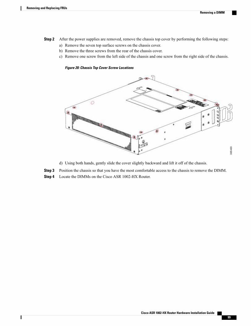
Step 2 After the power supplies are removed, remove the chassis top cover by performing the following steps:a) Remove the seven top surface screws on the chassis cover.b) Remove the three screws from the rear of the chassis cover.c) Remove one screw from the left side of the chassis and one screw from the right side of the chassis.
Figure 20: Chassis Top Cover Screw Locations
d) Using both hands, gently slide the cover slightly backward and lift it off of the chassis.
Step 3 Position the chassis so that you have the most comfortable access to the chassis to remove the DIMM.Step 4 Locate the DIMMs on the Cisco ASR 1002-HX Router.
Cisco ASR 1002-HX Router Hardware Installation Guide 99
Removing and Replacing FRUsRemoving a DIMM
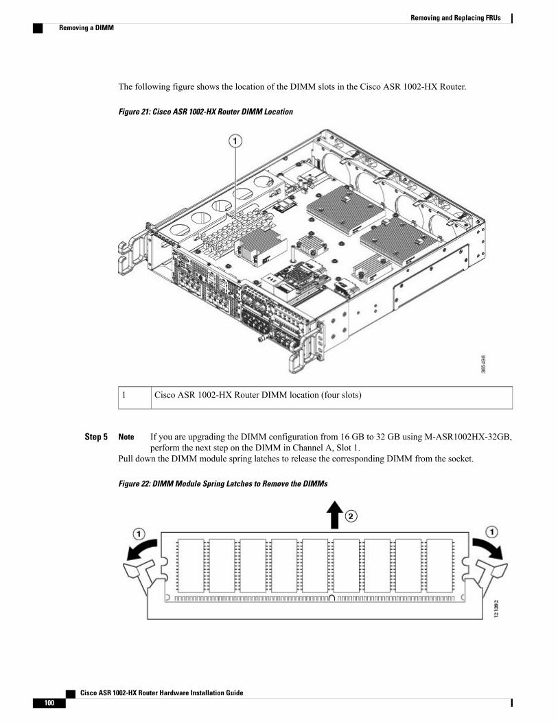
The following figure shows the location of the DIMM slots in the Cisco ASR 1002-HX Router.
Figure 21: Cisco ASR 1002-HX Router DIMM Location
Cisco ASR 1002-HX Router DIMM location (four slots)1
Step 5 If you are upgrading the DIMM configuration from 16 GB to 32 GB using M-ASR1002HX-32GB,perform the next step on the DIMM in Channel A, Slot 1.
Note
Pull down the DIMM module spring latches to release the corresponding DIMM from the socket.
Figure 22: DIMM Module Spring Latches to Remove the DIMMs
Cisco ASR 1002-HX Router Hardware Installation Guide100
Removing and Replacing FRUsRemoving a DIMM
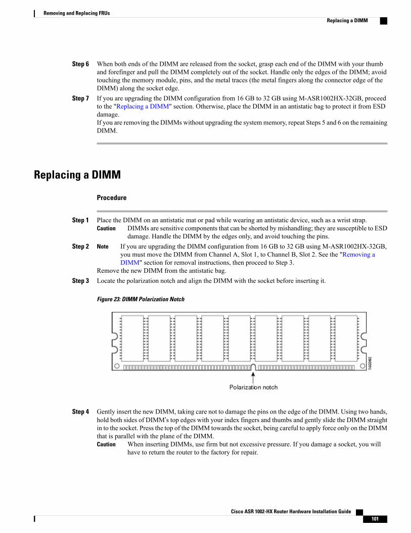
Step 6 When both ends of the DIMM are released from the socket, grasp each end of the DIMM with your thumband forefinger and pull the DIMM completely out of the socket. Handle only the edges of the DIMM; avoidtouching the memory module, pins, and the metal traces (the metal fingers along the connector edge of theDIMM) along the socket edge.
Step 7 If you are upgrading the DIMM configuration from 16 GB to 32 GB using M-ASR1002HX-32GB, proceedto the "Replacing a DIMM" section. Otherwise, place the DIMM in an antistatic bag to protect it from ESDdamage.If you are removing the DIMMs without upgrading the systemmemory, repeat Steps 5 and 6 on the remainingDIMM.
Replacing a DIMM
Procedure
Step 1 Place the DIMM on an antistatic mat or pad while wearing an antistatic device, such as a wrist strap.DIMMs are sensitive components that can be shorted by mishandling; they are susceptible to ESDdamage. Handle the DIMM by the edges only, and avoid touching the pins.
Caution
Step 2 If you are upgrading the DIMM configuration from 16 GB to 32 GB using M-ASR1002HX-32GB,you must move the DIMM from Channel A, Slot 1, to Channel B, Slot 2. See the "Removing aDIMM" section for removal instructions, then proceed to Step 3.
Note
Remove the new DIMM from the antistatic bag.Step 3 Locate the polarization notch and align the DIMM with the socket before inserting it.
Figure 23: DIMM Polarization Notch
Step 4 Gently insert the new DIMM, taking care not to damage the pins on the edge of the DIMM. Using two hands,hold both sides of DIMM’s top edges with your index fingers and thumbs and gently slide the DIMM straightin to the socket. Press the top of the DIMM towards the socket, being careful to apply force only on the DIMMthat is parallel with the plane of the DIMM.
When inserting DIMMs, use firm but not excessive pressure. If you damage a socket, you willhave to return the router to the factory for repair.
Caution
Cisco ASR 1002-HX Router Hardware Installation Guide 101
Removing and Replacing FRUsReplacing a DIMM
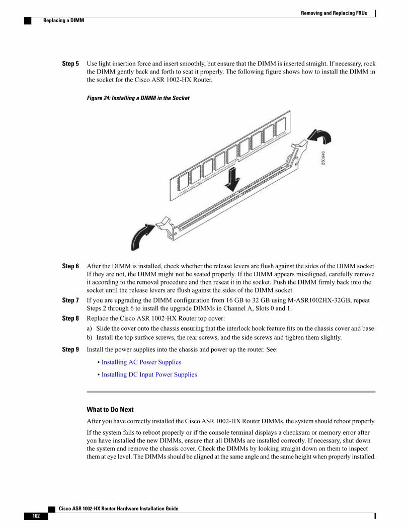
Step 5 Use light insertion force and insert smoothly, but ensure that the DIMM is inserted straight. If necessary, rockthe DIMM gently back and forth to seat it properly. The following figure shows how to install the DIMM inthe socket for the Cisco ASR 1002-HX Router.
Figure 24: Installing a DIMM in the Socket
Step 6 After the DIMM is installed, check whether the release levers are flush against the sides of the DIMM socket.If they are not, the DIMM might not be seated properly. If the DIMM appears misaligned, carefully removeit according to the removal procedure and then reseat it in the socket. Push the DIMM firmly back into thesocket until the release levers are flush against the sides of the DIMM socket.
Step 7 If you are upgrading the DIMM configuration from 16 GB to 32 GB using M-ASR1002HX-32GB, repeatSteps 2 through 6 to install the upgrade DIMMs in Channel A, Slots 0 and 1.
Step 8 Replace the Cisco ASR 1002-HX Router top cover:a) Slide the cover onto the chassis ensuring that the interlock hook feature fits on the chassis cover and base.b) Install the top surface screws, the rear screws, and the side screws and tighten them slightly.
Step 9 Install the power supplies into the chassis and power up the router. See:
• Installing AC Power Supplies
• Installing DC Input Power Supplies
What to Do Next
After you have correctly installed the Cisco ASR 1002-HXRouter DIMMs, the system should reboot properly.
If the system fails to reboot properly or if the console terminal displays a checksum or memory error afteryou have installed the new DIMMs, ensure that all DIMMs are installed correctly. If necessary, shut downthe system and remove the chassis cover. Check the DIMMs by looking straight down on them to inspectthem at eye level. The DIMMs should be aligned at the same angle and the same height when properly installed.
Cisco ASR 1002-HX Router Hardware Installation Guide102
Removing and Replacing FRUsReplacing a DIMM
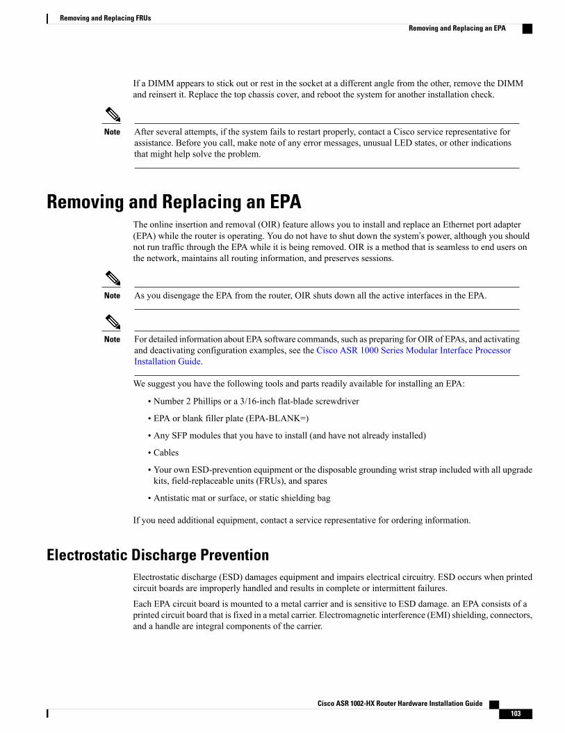
If a DIMM appears to stick out or rest in the socket at a different angle from the other, remove the DIMMand reinsert it. Replace the top chassis cover, and reboot the system for another installation check.
After several attempts, if the system fails to restart properly, contact a Cisco service representative forassistance. Before you call, make note of any error messages, unusual LED states, or other indicationsthat might help solve the problem.
Note
Removing and Replacing an EPAThe online insertion and removal (OIR) feature allows you to install and replace an Ethernet port adapter(EPA) while the router is operating. You do not have to shut down the system’s power, although you shouldnot run traffic through the EPA while it is being removed. OIR is a method that is seamless to end users onthe network, maintains all routing information, and preserves sessions.
As you disengage the EPA from the router, OIR shuts down all the active interfaces in the EPA.Note
For detailed information about EPA software commands, such as preparing for OIR of EPAs, and activatingand deactivating configuration examples, see the Cisco ASR 1000 Series Modular Interface ProcessorInstallation Guide.
Note
We suggest you have the following tools and parts readily available for installing an EPA:
• Number 2 Phillips or a 3/16-inch flat-blade screwdriver
• EPA or blank filler plate (EPA-BLANK=)
• Any SFP modules that you have to install (and have not already installed)
• Cables
• Your own ESD-prevention equipment or the disposable grounding wrist strap included with all upgradekits, field-replaceable units (FRUs), and spares
• Antistatic mat or surface, or static shielding bag
If you need additional equipment, contact a service representative for ordering information.
Electrostatic Discharge PreventionElectrostatic discharge (ESD) damages equipment and impairs electrical circuitry. ESD occurs when printedcircuit boards are improperly handled and results in complete or intermittent failures.
Each EPA circuit board is mounted to a metal carrier and is sensitive to ESD damage. an EPA consists of aprinted circuit board that is fixed in a metal carrier. Electromagnetic interference (EMI) shielding, connectors,and a handle are integral components of the carrier.
Cisco ASR 1002-HX Router Hardware Installation Guide 103
Removing and Replacing FRUsRemoving and Replacing an EPA
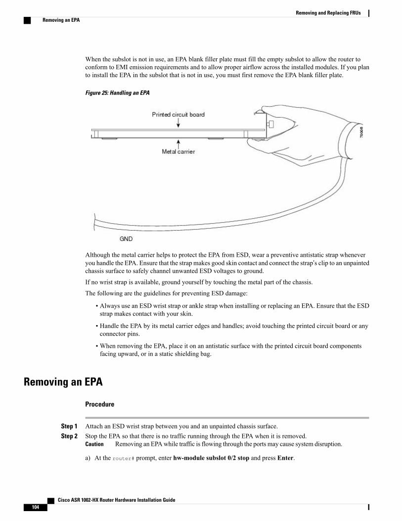
When the subslot is not in use, an EPA blank filler plate must fill the empty subslot to allow the router toconform to EMI emission requirements and to allow proper airflow across the installed modules. If you planto install the EPA in the subslot that is not in use, you must first remove the EPA blank filler plate.
Figure 25: Handling an EPA
Although the metal carrier helps to protect the EPA from ESD, wear a preventive antistatic strap wheneveryou handle the EPA. Ensure that the strap makes good skin contact and connect the strap’s clip to an unpaintedchassis surface to safely channel unwanted ESD voltages to ground.
If no wrist strap is available, ground yourself by touching the metal part of the chassis.
The following are the guidelines for preventing ESD damage:
• Always use an ESD wrist strap or ankle strap when installing or replacing an EPA. Ensure that the ESDstrap makes contact with your skin.
• Handle the EPA by its metal carrier edges and handles; avoid touching the printed circuit board or anyconnector pins.
•When removing the EPA, place it on an antistatic surface with the printed circuit board componentsfacing upward, or in a static shielding bag.
Removing an EPA
Procedure
Step 1 Attach an ESD wrist strap between you and an unpainted chassis surface.Step 2 Stop the EPA so that there is no traffic running through the EPA when it is removed.
Removing an EPAwhile traffic is flowing through the ports may cause system disruption.Caution
a) At the router# prompt, enter hw-module subslot 0/2 stop and press Enter.
Cisco ASR 1002-HX Router Hardware Installation Guide104
Removing and Replacing FRUsRemoving an EPA
b) At the router# prompt, enter end and press Enter.
Step 3 Disconnect all the cables from the EPA.Step 4 Loosen the captive screw in the center of the EPA by turning it counterclockwise.Step 5 Slide the EPA out of the EPA slot.
Replacing an EPA
Procedure
Step 1 Locate the guide rails that hold the EPA in place.
Step 2 Align the EPA with the guide rails and carefully slide the EPA all the way all the way into the slot until theEPA stops.
Step 3 Use a number 2 Phillips screwdriver to fully seat the EPA by turning the captive screw clockwise.When fully seated, the EPA should be flush with the router faceplate.
Avoid overtorquing the EPA captive screw when installing the EPA. Tighten the captive screw onthe EPA to a torque of 11 +/-1 inch-pounds.
Note
Step 4 Restart the EPA using the following steps:a) At the router# prompt, enter hw-module subslot 0/2 start and press Enter.b) At the router# prompt, enter end and press Enter.
Step 5 Use the show platform command to verify whether the status of subslot 0/2 is OK.Router# show platform
Chassis type: ASR1002-HX
Slot Type State Insert time (ago)--------- ------------------- --------------------- -----------------0 ASR1002-HX ok 00:07:520/0 BUILT-IN-EPA-8x1G ok 00:07:000/1 BUILT-IN-EPA-8x10G ok 00:07:000/2 EPA-18X1GE ok 00:07:01...
Installing the Crypto ModuleBefore You Begin
To install the crypto module, you must shut down the router and remove it from the rack. Enter the copyrunning-config startup-config command to save the configuration to NVRAM.
Cisco ASR 1002-HX Router Hardware Installation Guide 105
Removing and Replacing FRUsReplacing an EPA
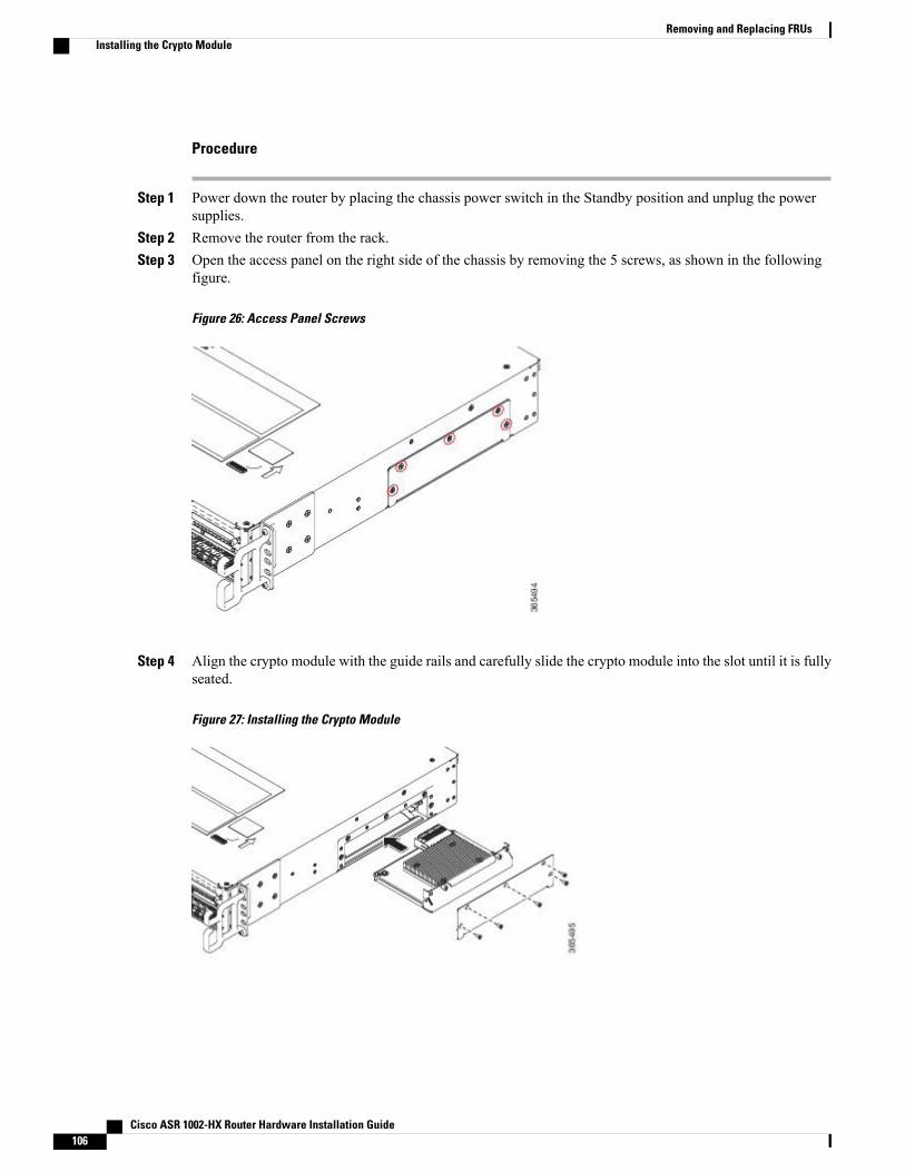
Procedure
Step 1 Power down the router by placing the chassis power switch in the Standby position and unplug the powersupplies.
Step 2 Remove the router from the rack.Step 3 Open the access panel on the right side of the chassis by removing the 5 screws, as shown in the following
figure.
Figure 26: Access Panel Screws
Step 4 Align the crypto module with the guide rails and carefully slide the crypto module into the slot until it is fullyseated.
Figure 27: Installing the Crypto Module
Cisco ASR 1002-HX Router Hardware Installation Guide106
Removing and Replacing FRUsInstalling the Crypto Module
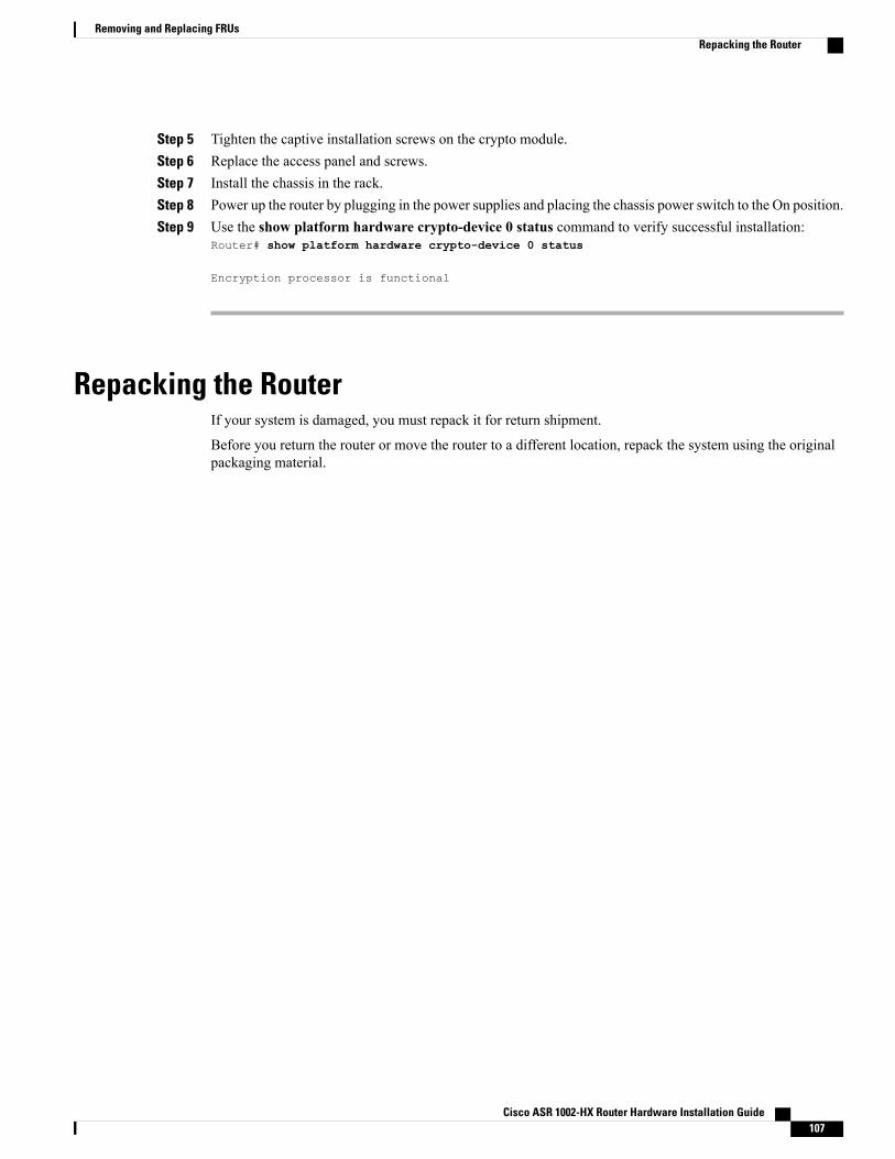
Step 5 Tighten the captive installation screws on the crypto module.Step 6 Replace the access panel and screws.Step 7 Install the chassis in the rack.Step 8 Power up the router by plugging in the power supplies and placing the chassis power switch to the On position.Step 9 Use the show platform hardware crypto-device 0 status command to verify successful installation:
Router# show platform hardware crypto-device 0 status
Encryption processor is functional
Repacking the RouterIf your system is damaged, you must repack it for return shipment.
Before you return the router or move the router to a different location, repack the system using the originalpackaging material.
Cisco ASR 1002-HX Router Hardware Installation Guide 107
Removing and Replacing FRUsRepacking the Router

Cisco ASR 1002-HX Router Hardware Installation Guide108
Removing and Replacing FRUsRepacking the Router
A P P E N D I X ATechnical Specifications
This appendix provides technical specifications for the Cisco ASR 1002-HX Router.
• Cisco ASR 1002-HX Router Specifications, page 109
Cisco ASR 1002-HX Router SpecificationsSpecificationDescription
Height—3.5 in. (88.9 mm)
Width—17.3 in. (439.42 mm)
Depth—22.0 in. (558.8 mm) including card handles, cable-managementbrackets, and power supply handles)
Dimensions (H x W x D)
34 lb (15.42 kg) fully loadedWeight
32° to 104° F (0° to 40° C)Nominal operating temperature
32° to 122° F (0° to 50° C)Short-term operating temperature
10 to 90% relative humidityNominal operating humidity
5 to 90%Short-term operating humidity
–4° to 158° F (–20° to +70° C)Storage temperature
• Maximum (DC): 750 W
• Maximum (AC): 750 W
• Maximum (Out): 450 W
Power consumption
Cisco ASR 1002-HX Router Hardware Installation Guide 109
Cisco ASR 1002-HX Router Hardware Installation Guide110
Technical SpecificationsCisco ASR 1002-HX Router Specifications
A P P E N D I X BPort Signals and Pinouts
This appendix provides the port signals and pinout specifications.
• Management Ethernet Port Signals and Pinouts, page 111
• Console Port Signals and Pinouts, page 111
• Auxiliary Port Signals and Pinouts, page 112
Management Ethernet Port Signals and PinoutsThe following table lists the Management Ethernet 10/100 RJ-45 port pinouts.
DescriptionDirectionSignalPin
T/R data +I/OTX/RX AData +1
T/R data -I/OTX/RX AData -2
T/R Data +I/OTX/RX BData +3
T/R Data + (Unused for 10/100)I/OTX/RX CData +4
T/R Data - (Unused for 10/100)I/OTX/RX CData -5
T/R Data -I/OTX/RX BData -6
T/R Data + (Unused for 10/100)I/OTX/RX DData +7
T/R Data - (Unused for 10/100)I/OTX/RX DData -8
Console Port Signals and PinoutsThe following table lists the pinouts of the RJ-45 console port.
Cisco ASR 1002-HX Router Hardware Installation Guide 111
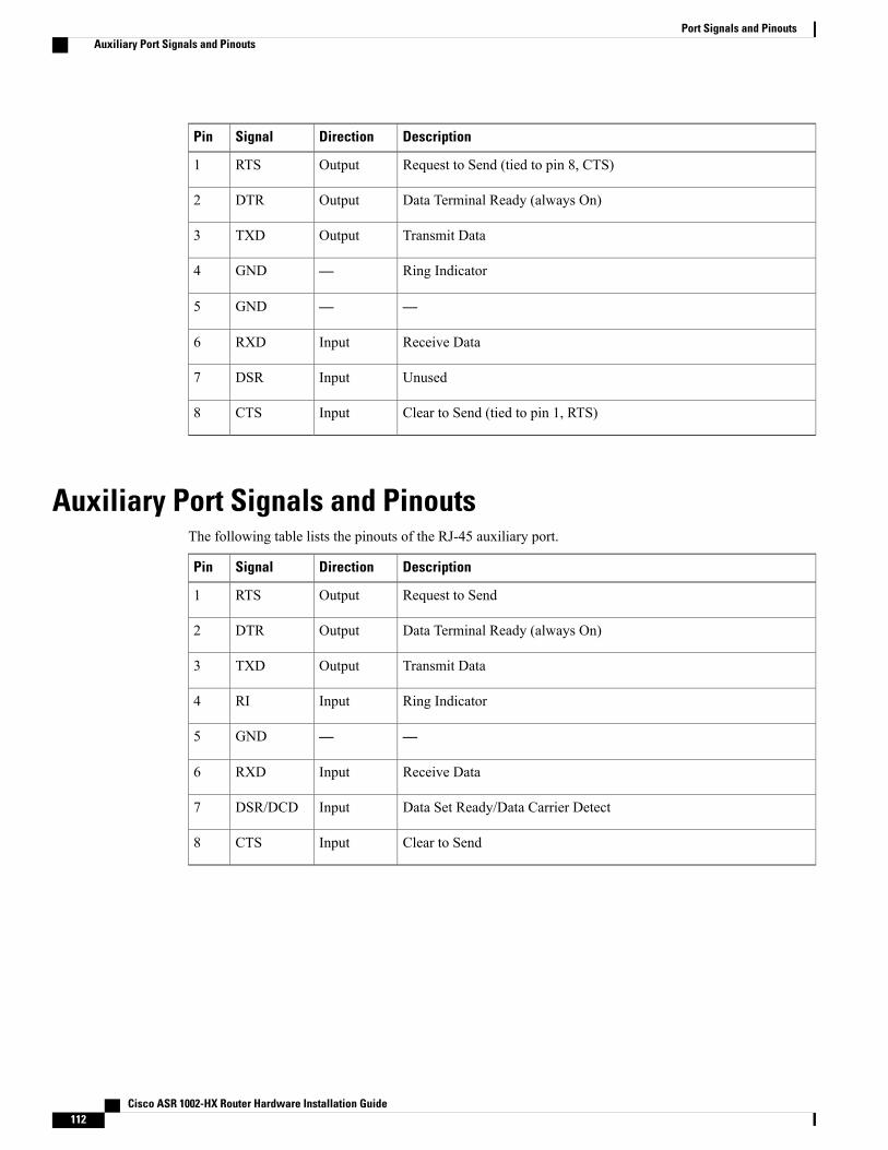
DescriptionDirectionSignalPin
Request to Send (tied to pin 8, CTS)OutputRTS1
Data Terminal Ready (always On)OutputDTR2
Transmit DataOutputTXD3
Ring Indicator—GND4
——GND5
Receive DataInputRXD6
UnusedInputDSR7
Clear to Send (tied to pin 1, RTS)InputCTS8
Auxiliary Port Signals and PinoutsThe following table lists the pinouts of the RJ-45 auxiliary port.
DescriptionDirectionSignalPin
Request to SendOutputRTS1
Data Terminal Ready (always On)OutputDTR2
Transmit DataOutputTXD3
Ring IndicatorInputRI4
——GND5
Receive DataInputRXD6
Data Set Ready/Data Carrier DetectInputDSR/DCD7
Clear to SendInputCTS8
Cisco ASR 1002-HX Router Hardware Installation Guide112
Port Signals and PinoutsAuxiliary Port Signals and Pinouts