cisco asr sgsn guide
DESCRIPTION
ciscoTRANSCRIPT
Cisco ASR 5000 Serving GPRS Support Node
Administration Guide
Version 14.0
Last Updated July 31, 2013
Americas Headquarters Cisco Systems, Inc. 170 West Tasman Drive San Jose, CA 95134-1706 USA http://www.cisco.com Tel: 408 526-4000 800 553-NETS (6387) Fax: 408 527-0883
Text Part Number: OL-27223-06

THE SPECIFICATIONS AND INFORMATION REGARDING THE PRODUCTS IN THIS MANUAL ARE SUBJECT TO CHANGE WITHOUT NOTICE. ALL STATEMENTS, INFORMATION, AND RECOMMENDATIONS IN THIS MANUAL ARE BELIEVED TO BE ACCURATE BUT ARE PRESENTED WITHOUT WARRANTY OF ANY KIND, EXPRESS OR IMPLIED. USERS MUST TAKE FULL RESPONSIBILITY FOR THEIR APPLICATION OF ANY PRODUCTS.
THE SOFTWARE LICENSE AND LIMITED WARRANTY FOR THE ACCOMPANYING PRODUCT ARE SET FORTH IN THE INFORMATION PACKET THAT SHIPPED WITH THE PRODUCT AND ARE INCORPORATED HEREIN BY THIS REFERENCE. IF YOU ARE UNABLE TO LOCATE THE SOFTWARE LICENSE OR LIMITED
WARRANTY, CONTACT YOUR CISCO REPRESENTATIVE FOR A COPY.
The Cisco implementation of TCP header compression is an adaptation of a program developed by the University of California, Berkeley (UCB) as part of UCB’s public domain version of the UNIX operating system. All rights reserved. Copyright © 1981, Regents of the University of California.
NOTWITHSTANDING ANY OTHER WARRANTY HEREIN, ALL DOCUMENT FILES AND SOFTWARE OF THESE SUPPLIERS ARE PROVIDED “AS IS” WITH ALL FAULTS. CISCO AND THE ABOVE-NAMED SUPPLIERS DISCLAIM ALL WARRANTIES, EXPRESSED OR IMPLIED, INCLUDING, WITHOUT LIMITATION, THOSE OF MERCHANTABILITY, FITNESS FOR A PARTICULAR PURPOSE AND NONINFRINGEMENT OR ARISING FROM A COURSE OF DEALING, USAGE, OR TRADE PRACTICE.
IN NO EVENT SHALL CISCO OR ITS SUPPLIERS BE LIABLE FOR ANY INDIRECT, SPECIAL, CONSEQUENTIAL, OR INCIDENTAL DAMAGES, INCLUDING, WITHOUT LIMITATION, LOST PROFITS OR LOSS OR DAMAGE TO DATA ARISING OUT OF THE USE OR INABILITY TO USE THIS MANUAL, EVEN IF CISCO OR ITS SUPPLIERS HAVE BEEN ADVISED OF THE POSSIBILITY OF SUCH DAMAGES.
Cisco and the Cisco Logo are trademarks of Cisco Systems, Inc. and/or its affiliates in the U.S. and other countries. A listing of Cisco's trademarks can be found at www.cisco.com/go/trademarks. Third party trademarks mentioned are the property of their respective owners. The use of the word partner does not imply a partnership relationship between Cisco and any other company.
Any Internet Protocol (IP) addresses and phone numbers used in this document are not intended to be actual addresses and phon e numbers. Any examples, command display
output, network topology diagrams, and other figures included in the document are shown for illustrative purposes only. Any use of actual IP addresses or phone numbers in
illustrative content is unintentional and coincidental.
Cisco ASR 5000 Serving GPRS Support Node Administration Guide
© 2013 Cisco Systems, Inc. All rights reserved.
Cisco ASR 5000 Serving GPRS Support Node Administration Guide ▄ OL-27223-06 iii
CONTENTS
About this Guide ................................................................................................ xi Conventions Used ................................................................................................................................... xii Supported Documents and Resources .................................................................................................. xiii
Related Common Documentation ...................................................................................................... xiii Related Product Documentation .................................................................................................... xiii Obtaining Documentation .............................................................................................................. xiii
Contacting Customer Support ................................................................................................................ xiv
Serving GPRS Support Node (SGSN) Overview ............................................ 15 Product Description ................................................................................................................................ 16
Platform Requirements....................................................................................................................... 17 Licenses ............................................................................................................................................. 17
Network Deployments and Interfaces .................................................................................................... 18 SGSN and Dual Access SGSN Deployments .................................................................................... 18 SGSN/GGSN Deployments ............................................................................................................... 19 S4-SGSN Deployments...................................................................................................................... 20 SGSN Logical Network Interfaces ...................................................................................................... 21
SGSN Core Functionality ....................................................................................................................... 25 All-IP Network (AIPN) ......................................................................................................................... 25 SS7 Support ....................................................................................................................................... 25 PDP Context Support ......................................................................................................................... 26 Mobility Management ......................................................................................................................... 26
GPRS Attach .................................................................................................................................. 26 GPRS Detach ................................................................................................................................ 27 Paging ............................................................................................................................................ 27 Service Request ............................................................................................................................. 27 Authentication ................................................................................................................................ 28 P-TMSI Reallocation ...................................................................................................................... 28 P-TMSI Signature Reallocation ..................................................................................................... 28 Identity Request ............................................................................................................................. 28
Location Management ........................................................................................................................ 28 Session Management......................................................................................................................... 29
PDP Context Activation .................................................................................................................. 29 PDP Context Modification .............................................................................................................. 30 PDP Context Deactivation ............................................................................................................. 30 PDP Context Preservation ............................................................................................................. 30
Charging ............................................................................................................................................. 30 SGSN in GPRS/UMTS Network .................................................................................................... 30 SGSN in LTE/SAE Network ........................................................................................................... 31
Features and Functionality ..................................................................................................................... 33 3G-2G Location Change Reporting .................................................................................................... 34 Accounting Path Framework, New for 14.0........................................................................................ 35 APN Aliasing ...................................................................................................................................... 35
Default APN ................................................................................................................................... 35 APN Redirection per APN with Lowest Context-ID ............................................................................ 35 APN Resolution with SCHAR or RNC-ID ........................................................................................... 36
▀ Contents
▄ Cisco ASR 5000 Serving GPRS Support Node Administration Guide
iv OL-27223-06
Automatic Protection Switching (APS) ............................................................................................... 36 Authentications and Reallocations -- Selective .................................................................................. 37 Avoiding PDP Context Deactivations ................................................................................................. 37 Bulk Statistics Support........................................................................................................................ 38 CAMEL Service Phase 3, Ge Interface .............................................................................................. 39
CAMEL Service .............................................................................................................................. 39 CAMEL Support ............................................................................................................................. 39 Ge Interface ................................................................................................................................... 39 CAMEL Configuration .................................................................................................................... 40
Commandguard .................................................................................................................................. 40 Configurable RAB Asymmetry Indicator in RAB Assignment Request .............................................. 40 Direct Tunnel ...................................................................................................................................... 40 Downlink Data Lockout Timer ............................................................................................................ 41 DSCP Templates for Control and Data Packets - Iu or Gb over IP ................................................... 41 Dual PDP Addresses for Gn/Gp ......................................................................................................... 41 ECMP over ATM ................................................................................................................................. 41 Equivalent PLMN ................................................................................................................................ 42 First Vector Configurable Start for MS Authentication ....................................................................... 42 Gb Manager ........................................................................................................................................ 42 GMM-SM Event Logging .................................................................................................................... 42 Gn/Gp Delay Monitoring ..................................................................................................................... 43 GTP-C Path Failure Detection and Management .............................................................................. 43 Handling Multiple MS Attaches All with the Same Random TLLI ...................................................... 43 HSPA Fallback ................................................................................................................................... 44 Ignore Context-ID During 4G/3G Handovers ..................................................................................... 44 Intra- or Inter-SGSN Serving Radio Network Subsystem (SRNS) Relocation (3G only) ................... 44 Lawful Intercept .................................................................................................................................. 45 Link Aggregation - Horizontal ............................................................................................................. 45 Local DNS .......................................................................................................................................... 45 Local Mapping of MBR ....................................................................................................................... 45 Local QoS Capping ............................................................................................................................ 46 Location Services ............................................................................................................................... 46 Lock/Shutdown the BSC from the SGSN ........................................................................................... 46 Management System Overview ......................................................................................................... 46 Multiple PLMN Support....................................................................................................................... 48 Network Sharing ................................................................................................................................. 49
Benefits of Network Sharing........................................................................................................... 49 GWCN Configuration ..................................................................................................................... 49 MOCN Configuration ...................................................................................................................... 50 Implementation ............................................................................................................................... 50
NPU FastPath ..................................................................................................................................... 51 NRPCA - 3G ....................................................................................................................................... 52 Operator Policy ................................................................................................................................... 52
Some Features Managed by Operator Policies ............................................................................. 52 Overcharging Protection ..................................................................................................................... 52 QoS Traffic Policing per Subscriber ................................................................................................... 53
QoS Classes .................................................................................................................................. 53 QoS Negotiation ............................................................................................................................. 53 DSCP Marking ............................................................................................................................... 53 Traffic Policing ................................................................................................................................ 53
Reordering of SNDCP N-PDU Segments .......................................................................................... 54 S4 Support on the SGSN ................................................................................................................... 54
S3 and S4 Interface Support .......................................................................................................... 56 S6d and Gr Interface Support ........................................................................................................ 56
Contents ▀
Cisco ASR 5000 Serving GPRS Support Node Administration Guide ▄ OL-27223-06 v
DNS SNAPTR Support .................................................................................................................. 56 S4-SGSN Statistics Support .......................................................................................................... 57 S13’ Interface Support ................................................................................................................... 57 Idle Mode Signaling Reduction ...................................................................................................... 57 ISD / DSD Message Handling and HSS Initiated Bearer Modification .......................................... 58 UMTS-GSM AKA Support on the S4-SGSN.................................................................................. 59 3G and 2G SGSN Routing Area Update ....................................................................................... 59 IPv4 and IPv6 PDP Type Override ................................................................................................ 60 P-GW Initiated PDP Bearer Deactivation ...................................................................................... 60 S-GW and P-GW Tunnel and EPS Subscription Recovery ........................................................... 61 Local Configuration of S-GW and S4-SGSN per RAI .................................................................... 61 Configurable GUTI to RAI Conversion Mapping ............................................................................ 61 S4-SGSN Support for Mobility Management Procedures ............................................................. 61 QoS Mapping Support ................................................................................................................... 62 MS Initiated Primary and Secondary Activation............................................................................. 62 Deactivation Procedure Support .................................................................................................... 63 MS, PGW and HSS Initiated PDP Modification Procedure Support .............................................. 63 Fallback from the S4 Interface to the Gn Interface ........................................................................ 64 Operator Policy Selection of S4 or Gn Interface ............................................................................ 64 IDFT Support During Connected Mode Handovers ....................................................................... 65 Disassociated DSR Support .......................................................................................................... 65 SGSN Serving Radio Network Subsystem (SRNS) Relocation Support ....................................... 65 E-UTRAN Service Handover Support ............................................................................................ 66 Support for Gn Handoff from S4-SGSN to 2G/3G Gn SGSN ........................................................ 67 Summary of Functional Differences between an S4-SGSN and an SGSN (Gn/Gp)..................... 67
Session Recovery .............................................................................................................................. 71 SGSN Pooling and Iu-Flex / Gb-Flex ................................................................................................. 72
Gb/Iu Flex Offloading ..................................................................................................................... 72 Short Message Service (SMS over Gd) ............................................................................................. 73 SMS Authentication Repetition Rate .................................................................................................. 73 SMSC Address Denial........................................................................................................................ 73 Threshold Crossing Alerts (TCA) Support.......................................................................................... 73 Tracking Usage of GEA Encryption Algorithms ................................................................................. 74 VLR Pooling via the Gs Interface ....................................................................................................... 74
How the SGSN Works ............................................................................................................................ 76 First-Time GPRS Attach ..................................................................................................................... 76 PDP Context Activation Procedures .................................................................................................. 77 Network-Initiated PDP Context Activation Process ............................................................................ 79 MS-Initiated Detach Procedure .......................................................................................................... 80
Supported Standards .............................................................................................................................. 81 IETF Requests for Comments (RFCs) ............................................................................................... 81 3GPP Standards ................................................................................................................................ 81 ITU Standards .................................................................................................................................... 84 Object Management Group (OMG) Standards .................................................................................. 85
SGSN in a 2.5G GPRS Network ....................................................................... 87 2.5G SGSN Configuration Components ................................................................................................. 88
The SGSN_Ctx ................................................................................................................................... 88 The Accounting_Ctx ........................................................................................................................... 89
How the 2.5G SGSN Works ................................................................................................................... 91 For GPRS and/or IMSI Attach ............................................................................................................ 91 For PDP Activation ............................................................................................................................. 92
Information Required for the 2.5G SGSN ............................................................................................... 94 Global Configuration........................................................................................................................... 94 SGSN Context Configuration ............................................................................................................. 96
▀ Contents
▄ Cisco ASR 5000 Serving GPRS Support Node Administration Guide
vi OL-27223-06
Accounting Context Configuration ...................................................................................................... 97
SGSN 3G UMTS Configuration ........................................................................ 99 3G SGSN Configuration Components .................................................................................................. 100
For GPRS and/or IMSI Attach .......................................................................................................... 101 Information Required for 3G Configuration ........................................................................................... 102
Global Configuration ......................................................................................................................... 102 SGSN Context Configuration ........................................................................................................... 104 Accounting Context Configuration .................................................................................................... 106
SGSN Service Configuration Procedures .................................................... 109 2.5G SGSN Service Configuration ....................................................................................................... 111 3G SGSN Service Configuration .......................................................................................................... 113 Dual Access SGSN Service Configuration ........................................................................................... 115 Configuring the S4-SGSN ..................................................................................................................... 117 Configuring an SS7 Routing Domain .................................................................................................... 119
Configuring an SS7 Routing Domain to Support Broadband SS7 Signaling ................................... 119 Example Configuration ................................................................................................................. 119
Configuring an SS7 Routing Domain to Support IP Signaling for SIGTRAN ................................... 120 Example Configuration ................................................................................................................. 121
Configuring GTT ................................................................................................................................... 122 Example Configuration ..................................................................................................................... 122
Configuring an SCCP Network ............................................................................................................. 124 Example Configuration ..................................................................................................................... 124
Configuring a MAP Service................................................................................................................... 125 Example Configuration ..................................................................................................................... 125
Configuring an IuPS Service (3G only) ................................................................................................. 127 Example Configuration ..................................................................................................................... 127
Configuring an SGTP Service............................................................................................................... 128 Example Configuration ..................................................................................................................... 128
Configuring a Gs Service ...................................................................................................................... 129 Example Configuration ..................................................................................................................... 129
Configuring an SGSN Service (3G only) .............................................................................................. 130 Example Configuration ..................................................................................................................... 130
Configuring a GPRS Service (2.5G only) ............................................................................................. 132 Example Configuration ..................................................................................................................... 132
Configuring a Network Service Entity ................................................................................................... 134 Configure a Network Service Entity for IP ........................................................................................ 134
Example Configuration for a Network Service Entity for IP ......................................................... 134 Configure a Network Service Entity for Frame Relay ....................................................................... 134
Example Configuration for a Network Service Entity for IP ......................................................... 135 Configuring DNS Client ......................................................................................................................... 136
Example Configuration ..................................................................................................................... 136 Configuring GTPP Accounting Support ................................................................................................ 137
Creating GTPP Group ...................................................................................................................... 137 Configuring GTPP Group ................................................................................................................. 138 Verifying GTPP Group Configuration ............................................................................................... 139
Configuring and Associating the EGTP Service (S4 Only) ................................................................... 140 Example Configuration ..................................................................................................................... 140
Configuring and Associating the GTPU Service (S4 Only) .................................................................. 142 Example Configuration ..................................................................................................................... 142
Configuring the DNS Client Context for APN and SGW Resolution (Optional) .................................... 143 Example Configuration ..................................................................................................................... 143
Configuring the S6d Diameter Interface (S4 Only) ............................................................................... 145 Configuring the Diameter Endpoint for the S6d Interface ................................................................ 145
Contents ▀
Cisco ASR 5000 Serving GPRS Support Node Administration Guide ▄ OL-27223-06 vii
Example Configuration ................................................................................................................. 146 Configuring the HSS Peer Service and Interface Association for the S6d Interface ....................... 146
Example Configuration ................................................................................................................. 147 Associating the HSS Peer Service with the SGSN and GPRS Services for the S6d Interface ....... 147
Example Configuration ................................................................................................................. 147 Configuring Operator Policy-Based S6d Interface Selection (Optional) .......................................... 148
Example Configuration ................................................................................................................. 148 Configuring the Subscription Interface Preference for the S6d Interface (Optional) ....................... 148
Example Configuration ................................................................................................................. 148 Configuring the S13’ Interface (S4 Only, Optional) .............................................................................. 149
Configuring a Diameter Endpoint for the S13’ Interface .................................................................. 149 Example Configuration ................................................................................................................. 150
Configuring the HSS Peer Service and Interface Association for the S13’ Interface ...................... 150 Example Configuration ................................................................................................................. 151
Associating the HSS Peer Service with the SGSN and GPRS Services for the S13’ Interface ...... 152 Example Configuration ................................................................................................................. 152
Configuring S13’ Interface Selection Based on an Operator Policy ................................................ 152 Example Configuration ................................................................................................................. 153
Configuring QoS Mapping for EPC-Capable UEs using the S4 Interface (S4 Only, Optional) ............ 154 Example Configuration ..................................................................................................................... 154
Configuring the Peer SGSN Interface Type (S4 Only, Optional) ......................................................... 156 Example Configuration ..................................................................................................................... 156
Configuring Gn Interface Selection Based on an Operator Policy (S4 Only, Optional) ....................... 157 Example Configuration ..................................................................................................................... 157
Configuring a Custom MME Group ID (S4 Only, Optional) .................................................................. 158 Example Configuration ..................................................................................................................... 158
Configuring and Associating the Selection of an SGW for RAI (S4 Only, Optional) ............................ 160 Example Configuration ..................................................................................................................... 160
Configuring a Local PGW Address (S4 Only, Optional) ....................................................................... 162 Example Configuration ..................................................................................................................... 162
Configuring the Peer MME Address (S4 Only, Optional) ..................................................................... 163 Example Configuration ..................................................................................................................... 163
Configuring the ISR Feature (S4 Only, Optional) ................................................................................. 164 Example Configuration ..................................................................................................................... 164
Configuring IDFT for Connected Mode Handover (S4 Only, Optional) ................................................ 165 Example Configuration ..................................................................................................................... 165
Creating and Configuring ATM Interfaces and Ports (3G only)............................................................ 167 Creating and Configuring Frame Relay Ports (2.5G only) ................................................................... 168 Configuring APS/MSP Redundancy ..................................................................................................... 169
Example Configuration ..................................................................................................................... 169
3G-2G Location Change Reporting ............................................................... 171 Feature Description .............................................................................................................................. 172
Relationships .................................................................................................................................... 172 License ............................................................................................................................................. 172 Standards Compliance ..................................................................................................................... 172
How it Works ........................................................................................................................................ 173 Call Flows ......................................................................................................................................... 173
Configuring Location Change Reporting .............................................................................................. 175 Verifying the Location Change Reporting Configuration .................................................................. 175
Direct Tunnel ................................................................................................... 177 Direct Tunnel Feature Overview ........................................................................................................... 178 Direct Tunnel Configuration .................................................................................................................. 182
Configuring Direct Tunnel Support on the SGSN ............................................................................ 182
▀ Contents
▄ Cisco ASR 5000 Serving GPRS Support Node Administration Guide
viii OL-27223-06
Enabling Setup of GTP-U Direct Tunnels .................................................................................... 183 Enabling Direct Tunnel per APN .................................................................................................. 183 Enabling Direct Tunnel per IMEI .................................................................................................. 184 Enabling Direct Tunnel to Specific RNCs .................................................................................... 184 Verifying the SGSN Direct Tunnel Configuration ......................................................................... 185
Configuring S12 Direct Tunnel Support on the S-GW ...................................................................... 187
GMM-SM Event Logging ................................................................................. 189 Feature Description .............................................................................................................................. 190
Feature Overview ............................................................................................................................. 190 Events to be Logged......................................................................................................................... 190 Event Record Fields ......................................................................................................................... 190 EDR Storage .................................................................................................................................... 194 Architecture ...................................................................................................................................... 194 Limitations ........................................................................................................................................ 194
Configuration ........................................................................................................................................ 195
Location Services ........................................................................................... 197 Location Services - Feature Description ............................................................................................... 198 How Location Services Works .............................................................................................................. 199 Relationship to Other SGSN Functions ................................................................................................ 200 Architecture ........................................................................................................................................... 201 Limitations ............................................................................................................................................. 202 Flows ..................................................................................................................................................... 203
Flows ................................................................................................................................................ 203 Standards Compliance ......................................................................................................................... 205 Configuring Location Services (LCS) on the SGSN ............................................................................. 206
Enabling LCS .................................................................................................................................... 206 Identifying the GMLC ........................................................................................................................ 207 Creating the Location Service Configuration .................................................................................... 207 Fine-tuning the Location Service Configuration ............................................................................... 208 Associating the Location Service Config with the SGSN ................................................................. 208 Associating the Location Service Config with an Operator Policy ................................................... 208 Verifying the LCS Configuration for the SGSN ................................................................................ 209
Monitoring and Troubleshooting the LCS on the SGSN ....................................................................... 210
Operator Policy ............................................................................................... 211 What Operator Policy Can Do .............................................................................................................. 212
A Look at Operator Policy on an SGSN ........................................................................................... 212 A Look at Operator Policy on an S-GW ............................................................................................ 212
The Operator Policy Feature in Detail .................................................................................................. 213 Call Control Profile ............................................................................................................................ 213 APN Profile ....................................................................................................................................... 214 IMEI-Profile (SGSN only).................................................................................................................. 215 APN Remap Table ............................................................................................................................ 215 Operator Policies .............................................................................................................................. 216 IMSI Ranges ..................................................................................................................................... 216
How It Works......................................................................................................................................... 218 Operator Policy Configuration .............................................................................................................. 219
Call Control Profile Configuration ..................................................................................................... 220 Configuring the Call Control Profile for an SGSN ........................................................................ 220 Configuring the Call Control Profile for an MME or S-GW ........................................................... 220
APN Profile Configuration ................................................................................................................ 221 IMEI Profile Configuration - SGSN only ........................................................................................... 221 APN Remap Table Configuration ..................................................................................................... 222
Contents ▀
Cisco ASR 5000 Serving GPRS Support Node Administration Guide ▄ OL-27223-06 ix
Operator Policy Configuration .......................................................................................................... 222 IMSI Range Configuration ................................................................................................................ 223
Configuring IMSI Ranges on the MME or S-GW ......................................................................... 223 Configuring IMSI Ranges on the SGSN ...................................................................................... 223
Operator Policy Component Associations - MME ............................................................................ 224 Associating Operator Policy Components on the MME ............................................................... 224 Configuring Accounting Mode for- S-GW .................................................................................... 225
Verifying the Feature Configuration ...................................................................................................... 226
SGSN Serving Radio Network Subsystem Relocation ............................... 227 Feature Description .............................................................................................................................. 228
Relationships to Other Features ...................................................................................................... 228 How it Works ........................................................................................................................................ 229
SRNS Relocation on the SGSN (Gn/Gp) ......................................................................................... 229 SGSN (Gn/Gp) SRNS Relocation Call Flow Diagrams ............................................................... 230
SRNS Relocation on the S4-SGSN ................................................................................................. 234 IDFT Support During Connected Mode Handovers ..................................................................... 238 S4-SGSN SRNS Relocation Call Flow Diagrams ........................................................................ 240
Standards Compliance ..................................................................................................................... 258 Configuring SRNS Relocation on the SGSN ........................................................................................ 259
Configuring the SRNS Relocation Feature ...................................................................................... 259 Enabling IDFT (Optional, S4-SGSN Only) ................................................................................... 259
Verifying the SRNS Feature Configuration ...................................................................................... 260 Monitoring and Troubleshooting SRNS Relocation .............................................................................. 261
SRNS Bulk Statistics ........................................................................................................................ 261 Show Command Output Supporting the SRNS Relocation Feature ................................................ 262
Subscriber Overcharging Protection ............................................................ 265 Feature Overview ................................................................................................................................. 266 Overcharging Protection - GGSN Configuration .................................................................................. 268
GTP-C Private Extension Configuration........................................................................................... 268 Verifying Your GGSN Configuration ................................................................................................. 269
Overcharging Protection - SGSN Configuration ................................................................................... 270 Private Extension IE Configuration .................................................................................................. 270 RANAP Cause Trigger Configuration ............................................................................................... 271 Verifying the Feature Configuration ................................................................................................. 271
Monitoring and Troubleshooting .................................................................. 273 Monitoring ............................................................................................................................................. 274
Daily - Standard Health Check ......................................................................................................... 274 Monthly System Maintenance .......................................................................................................... 276 Every 6 Months ................................................................................................................................ 277
Troubleshooting .................................................................................................................................... 278 Problems and Issues ........................................................................................................................ 278 Troubleshooting More Serious Problems ......................................................................................... 278
Causes for Attach Reject ............................................................................................................. 278 Single Attach and Single Activate Failures .................................................................................. 278 Mass Attach and Activate Problems ............................................................................................ 279 Single PDP Context Activation without Data ............................................................................... 280 Mass PDP Context Activation but No Data.................................................................................. 281
Engineering Rules........................................................................................... 283 Service Rules ....................................................................................................................................... 284 SGSN Connection Rules ...................................................................................................................... 285 Operator Policy Rules ........................................................................................................................... 286 SS7 Rules ............................................................................................................................................. 288
▀ Contents
▄ Cisco ASR 5000 Serving GPRS Support Node Administration Guide
x OL-27223-06
SS7 Routing ..................................................................................................................................... 288 SIGTRAN .......................................................................................................................................... 288 Broadband SS7 ................................................................................................................................ 289 SCCP ................................................................................................................................................ 289 GTT................................................................................................................................................... 289
SGSN Interface Rules .......................................................................................................................... 290 System-Level .................................................................................................................................... 290 3G Interface Limits ........................................................................................................................... 290 2G Interface Limits ........................................................................................................................... 290
Cisco ASR 5000 Serving GPRS Support Node Administration Guide ▄ OL-27223-06 xi
About this Guide
This preface describes the information contained within this Cisco ASR 5000 Series Serving GPRS Support Node
Administration Guide. As well, it lists document conventions, related documents, and contact information for Cisco
customer service.
This guide provides deployment and feature information for the Serving GPRS Support Node (SGSN) on the ASR 5000
platform. It includes instructions and engineering rules for using its command line interface (CLI) to configure and
manage the
2.5G GPRS SGSN services
3G UMTS SGSN services
Dual Access services
LTE/SAE interface services
As the range of SGSN services are highly flexible and scalable, it is impossible to document every possible
configuration so typically only basic service setup configuration is provided.
In addition, functional and configuration information is provided for some of the more complex features in feature-
specific chapters.
About this Guide
▀ Conventions Used
▄ Cisco ASR 5000 Serving GPRS Support Node Administration Guide
xii OL-27223-06
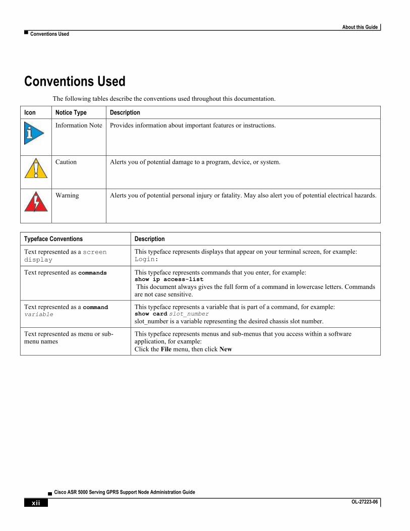
Conventions Used The following tables describe the conventions used throughout this documentation.
Icon Notice Type Description
Information Note Provides information about important features or instructions.
Caution Alerts you of potential damage to a program, device, or system.
Warning Alerts you of potential personal injury or fatality. May also alert you of potential electrical hazards.
Typeface Conventions Description
Text represented as a screen
display
This typeface represents displays that appear on your terminal screen, for example: Login:
Text represented as commands This typeface represents commands that you enter, for example: show ip access-list
This document always gives the full form of a command in lowercase letters. Commands are not case sensitive.
Text represented as a command variable
This typeface represents a variable that is part of a command, for example: show card slot_number
slot_number is a variable representing the desired chassis slot number.
Text represented as menu or sub-menu names
This typeface represents menus and sub-menus that you access within a software application, for example:
Click the File menu, then click New
About this Guide
Supported Documents and Resources ▀
Cisco ASR 5000 Serving GPRS Support Node Administration Guide ▄ OL-27223-06 xiii
Supported Documents and Resources
Related Common Documentation
The most up-to-date information for this product is available in the SGSN Release Notes provided with each product
release.
The following Cisco ASR 5000 Series common documents are available and work in conjunction with the SGSN:
Release Change Reference
Hardware Installation Guide
System Administration Guide
Command Line Interface Reference
For StarOS 12.3 and earlier releases: AAA and GTPP Interface Administration Reference
For StarOS 14.0 and later releases: AAA Interface Administration and Reference
For StarOS 14.0 and later releases: GTPP Interface Administration and Reference
Statistics and Counters Reference
SNMP MIB Reference
Thresholding Configuration Guide
Product Overview
Related Product Documentation
The following product-specific documents are also available and work in conjunction with the SGSN:
Cisco ASR 5000 Series Gateway GPRS Support Node Administration Guide
Web Element Manager Installation and Administration Guide
Obtaining Documentation
The most current Cisco documentation is available on the following website:
http://www.cisco.com/cisco/web/psa/default.html
About this Guide
▀ Contacting Customer Support
▄ Cisco ASR 5000 Serving GPRS Support Node Administration Guide
xiv OL-27223-06
Contacting Customer Support Use the information in this section to contact customer support.
Refer to the support area of http://www.cisco.com for up-to-date product documentation or to submit a service request.
A valid username and password are required to access this site. Please contact your Cisco sales or service representative
for additional information.
Cisco ASR 5000 Serving GPRS Support Node Administration Guide ▄ OL-27223-06 15
Chapter 1 Serving GPRS Support Node (SGSN) Overview
This section contains general overview information about the Serving GPRS Support Node (SGSN), including sections
for:
Product Description
Network Deployments and Interfaces
SGSN Core Functionality
Features and Functionality
How the SGSN Works
Supported Standards
Serving GPRS Support Node (SGSN) Overview
▀ Product Description
▄ Cisco ASR 5000 Serving GPRS Support Node Administration Guide
16 OL-27223-06
Product Description The ASR 5000 provides a highly flexible and efficient Serving GPRS Support Node (SGSN) service to the wireless
carriers. Functioning as an SGSN, the system readily handles wireless data services within 2.5G General Packet Radio
Service (GPRS) and 3G Universal Mobile Telecommunications System (UMTS) data networks. The SGSN also can
serve as an interface between GPRS and/or UMTS networks and the EPC (4G) network.
Important: Throughout this section the designation for the subscriber equipment is referred to in various ways:
UE for user equipment (common to 3G/4G scenarios), MS or mobile station (common to 2G/2.5G scenarios), and MN or mobile node (common to 2G/2.5G scenarios involving IP-level functions). Unless noted, these terms are equivalent and the term used usually complies with usage in the relevant standards.
In a GPRS/UMTS network, the SGSN works in conjunction with radio access networks (RANs) and Gateway GPRS
Support Nodes (GGSNs) to:
Communicate with home location registers (HLR) via a Gr interface and mobile visitor location registers (VLRs) via a Gs interface to register a subscriber’s user equipment (UE), or to authenticate, retrieve or update subscriber profile information.
Support Gd interface to provide short message service (SMS) and other text-based network services for attached subscribers.
Activate and manage IPv4, IPv6, or point-to-point protocol (PPP) -type packet data protocol (PDP) contexts for a subscriber session.
Setup and manage the data plane between the RAN and the GGSN providing high-speed data transfer with configurable GEA0-3 ciphering.
Provide mobility management, location management, and session management for the duration of a call to ensure smooth handover.
Provide various types of charging data records (CDRs) to attached accounting/billing storage mechanisms such as our SMC-based hard drive or a GTPP Storage Server (GSS) or a charging gateway function (CGF).
Provide CALEA support for lawful intercepts.
The S4-SGSN is an SGSN configured with 2G and/or 3G services and then configured to interface with the 4G EPC
network via the S4 interface. This enables the S4-SGSN to support handovers from UMTS/GPRS networks to the EPC
network. The S4-SGSN works in conjunction with EPC network elements and gateways to:
Interface with the EPC network S-GW (via the S4 interface) and MME (via the S3 interface) to enable handovers between 2G/3G networks and the EPC (4G) network.
Interface with the Equipment Identity Registry via the S13’ interface to perform the ME identity check.
Interface with the HSS via the S6d interface to obtain subscription-related information.
Communicate with S4-SGSNs via the S16 interface.
Provide Idle Mode Signaling support for EPC-capable UEs.
This section catalogs many of the SGSN key components and features for data services within the GPRS/UMTS
environment. Also, a range of SGSN operational and compliance information is summarized with pointers to other
information sources.
Serving GPRS Support Node (SGSN) Overview
Product Description ▀
Cisco ASR 5000 Serving GPRS Support Node Administration Guide ▄ OL-27223-06 17
Platform Requirements
The SGSN service runs on a Cisco® ASR 5000 Series chassis running StarOS. The chassis can be configured with a
variety of components to meet specific network deployment requirements. For additional information, refer to the
Installation Guide for the chassis and/or contact your Cisco account representative.
Licenses
The SGSN is a licensed Cisco product and requires the purchase and installation of the SGSN Software License.
Separate feature licenses may be required. Contact your Cisco account representative for detailed information on
specific licensing requirements.
For information on installing and verifying licenses, refer to the Managing License Keys section of the Software
Management Operations section in the System Administration Guide.
Serving GPRS Support Node (SGSN) Overview
▀ Network Deployments and Interfaces
▄ Cisco ASR 5000 Serving GPRS Support Node Administration Guide
18 OL-27223-06
Network Deployments and Interfaces The following logical connection maps illustrate the SGSN’s ability to connect to various radio access network types,
core network types, and network components:
GSM edge radio access network (GERAN) provides access to the 2.5G general packet radio service (GPRS) network
UMTS terrestrial radio access network (UTRAN) provides access to the 3G universal mobile telecommunications system (UMTS) network
evolved UTRAN (E-UTRAN) provides access to the 4G mobile evolved packet core (EPC) of the long term evolution/system architecture evolution (LTE/SAE) network
another SGSN
standalone gateway GPRS support node (GGSN)
co-located P-GW/GGSN
mobile service center (MSC)
visitor location register (VLR)
home location register (HLR)
charging gateway (CF - sometimes referred to as a charging gateway function (CGF))
GTPP storage server (GSS)
equipment identity registry (EIR)
home subscriber server (HSS)
mobility management entity (MME)
serving gateway (S-GW)
CAMEL service’s GSM service control function (gsmSCF)
short message service server center (SMS-C)
network devices in another PLMN
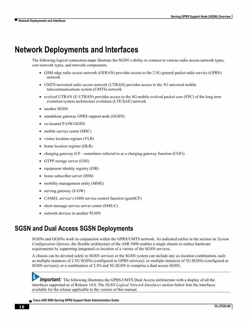
SGSN and Dual Access SGSN Deployments
SGSNs and GGSNs work in conjunction within the GPRS/UMTS network. As indicated earlier in the section on System
Configuration Options, the flexible architecture of the ASR 5000 enables a single chassis to reduce hardware
requirements by supporting integrated co-location of a variety of the SGSN services.
A chassis can be devoted solely to SGSN services or the SGSN system can include any co-location combination, such
as multiple instances of 2.5G SGSNs (configured as GPRS services); or multiple instances of 3G SGSNs (configured as
SGSN services); or a combination of 2.5G and 3G SGSN to comprise a dual access SGSN.
Important: The following illustrates the GPRS/UMTS Dual Access architecture with a display of all the
interfaces supported as of Release 14.0. The SGSN Logical Network Interfaces section below lists the interfaces available for the release applicable to the version of this manual.
Serving GPRS Support Node (SGSN) Overview
Network Deployments and Interfaces ▀
Cisco ASR 5000 Serving GPRS Support Node Administration Guide ▄ OL-27223-06 19
Figure 1. 2.5G & 3G Dual Access Architecture
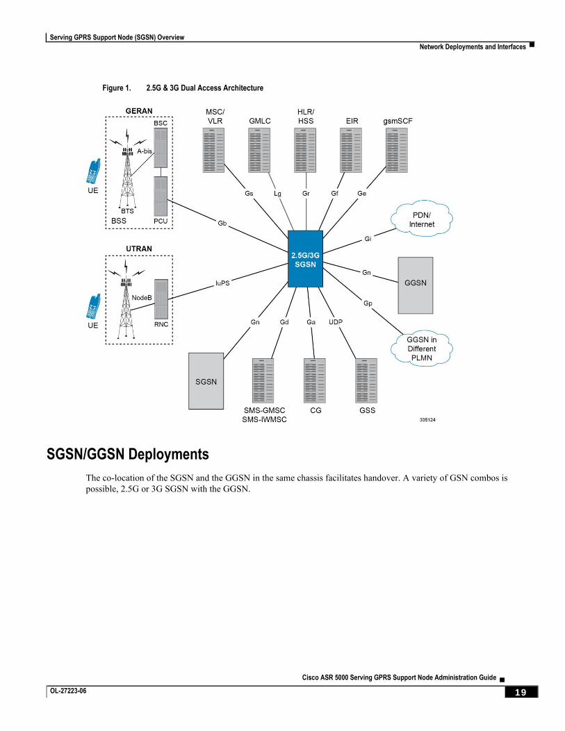
SGSN/GGSN Deployments
The co-location of the SGSN and the GGSN in the same chassis facilitates handover. A variety of GSN combos is
possible, 2.5G or 3G SGSN with the GGSN.
Serving GPRS Support Node (SGSN) Overview
▀ Network Deployments and Interfaces
▄ Cisco ASR 5000 Serving GPRS Support Node Administration Guide
20 OL-27223-06
Figure 2. GSN Combo Architecture
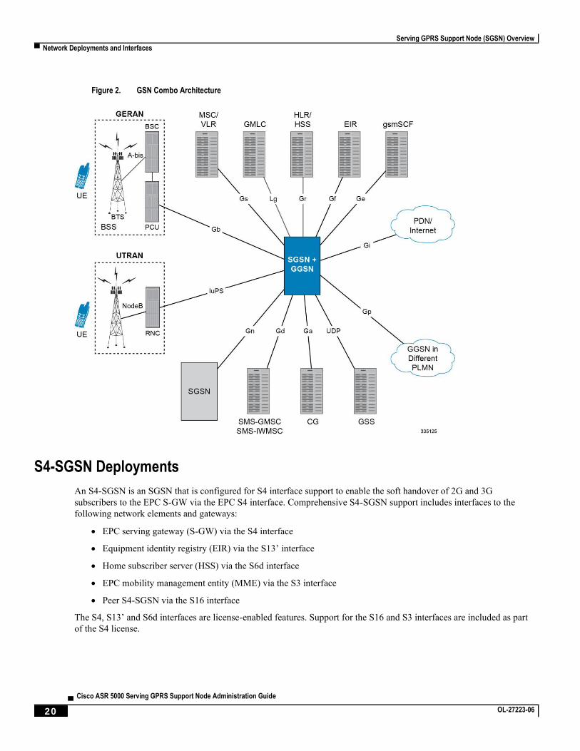
S4-SGSN Deployments
An S4-SGSN is an SGSN that is configured for S4 interface support to enable the soft handover of 2G and 3G
subscribers to the EPC S-GW via the EPC S4 interface. Comprehensive S4-SGSN support includes interfaces to the
following network elements and gateways:
EPC serving gateway (S-GW) via the S4 interface
Equipment identity registry (EIR) via the S13’ interface
Home subscriber server (HSS) via the S6d interface
EPC mobility management entity (MME) via the S3 interface
Peer S4-SGSN via the S16 interface
The S4, S13’ and S6d interfaces are license-enabled features. Support for the S16 and S3 interfaces are included as part
of the S4 license.
Serving GPRS Support Node (SGSN) Overview
Network Deployments and Interfaces ▀
Cisco ASR 5000 Serving GPRS Support Node Administration Guide ▄ OL-27223-06 21
Figure 3. S4-SGSN Network Architecture
SGSN Logical Network Interfaces
The SGSN provides IP-based transport on all RAN and core network interfaces, in addition to the standard IP-based
interfaces (Ga, Gn, Gp, Iu-PS). This means enhanced performance, future-proof scaling and reduction of inter-
connectivity complexity. The all-IP functionality is key to facilitating evolution to the next generation technology
requirements.
The SGSN provides the following functions over the logical network interfaces illustrated above:
Serving GPRS Support Node (SGSN) Overview
▀ Network Deployments and Interfaces
▄ Cisco ASR 5000 Serving GPRS Support Node Administration Guide
22 OL-27223-06
Ga: The SGSN uses the Ga interface with GPRS Transport Protocol Prime (GTPP) to communicate with the charging gateway (CG, also known as CGF) and/or the GTPP storage server (GSS). The interface transport layer is typically UDP over IP but can be configured as TCP over IP for:
One or more Ga interfaces per system context, and
An interface over Ethernet 10/100 or Ethernet 1000 interfaces
The charging gateway handles buffering and pre-processing of billing records and the GSS provides storage for
Charging Data Records (CDRs). For additional information regarding SGSN charging, refer to the Charging
section.
IuPS: The SGSN provides an IP over ATM (IP over AAL5 over ATM) interface between the SGSN and the RNCs in the 3G UMTS radio access network (UTRAN). RANAP is the control protocol that sets up the data plane (GTP-U) between these nodes. SIGTRAN (M3UA/SCTP) or QSAAL (MTP3B/QSAAL) handle IuPS-C (control) for the RNCs.
Some of the procedures supported across this interface are:
Control plane based on M3UA/SCTP
Up to 128 Peer RNCs per virtual SGSN. Up to 256 peers per physical chassis
SCTP Multi-Homing supported to facilitate network resiliency
M3UA operates in and IPSP client/server and single/double-ended modes
Multiple load shared M3UA instances for high-performance and redundancy
Works over Ethernet and ATM (IPoA) interfaces
Facilitates SGSN Pooling
RAB (Radio Access Bearer) Assignment Request
RAB Release Request
Iu Release Procedure
SGSN-initiated Paging
Common ID
Security Mode Procedures
Initial MN Message
Direct Transfer
Reset Procedure
Error Indication
SRNS relocation
Gb: This is the SGSN’s interface to the base station system (BSS) in a 2G radio access network (RAN). It
connects the SGSN via UDP/IP (via an Ethernet interface) or Frame Relay (via a Channelized SDH or SONET
interface). Gb-IP is the preferred interface as it improves control plane scaling as well as facilitates the
deployment of SGSN Pools.
Some of the procedures supported across this interface are:
BSS GSM at 900/1800/1900 MHz
BSS Edge
Serving GPRS Support Node (SGSN) Overview
Network Deployments and Interfaces ▀
Cisco ASR 5000 Serving GPRS Support Node Administration Guide ▄ OL-27223-06 23
Frame Relay congestion handling
Traffic management per Frame Relay VC
NS load sharing
NS control procedures
BVC management procedures
Paging for circuit-switched services
Suspend/Resume
Flow control
Unacknowledged mode
Acknowledged mode
Gn/Gp: The Gn/Gp interfaces, comprised of GTP/UDP/IP-based protocol stacks, connect the SGSNs and GGSNs to other SGSNs and GGSNs within the same public land mobile network (PLMN) - the Gn - or to GGSNs in other PLMNs - the Gp.
This implementation supports:
GTPv0 and GTPv1, with the capability to auto-negotiate the version to be used with any particular peer
GTP-C (control plane) and GTP-U (user plane)
Transport over ATM/STM-1Optical, Fast Ethernet, and Ethernet 1000 line cards/QGLCs)
One or more Gn/Gp interfaces configured per system context
As well, the SGSN can support the following IEs from later version standards:
IMEI-SV
RAT TYPE
User Location Information
Extended PDP Type (Release 9)
Extended RNC ID (Release 9)
Ge: This is the interface between the SGSN and the SCP that supports the CAMEL service. It supports both SS7 and SIGTRAN and uses the CAP protocol.
Gr: This is the interface to the HLR. It supports SIGTRAN (M3UA/SCTP/IP) over Ethernet.
Some of the procedures supported by the SGSN on this interface are:
Send Authentication Info
Update Location
Insert Subscriber Data
Delete Subscriber Data
Cancel Location
Purge
Reset
Ready for SM Notification
Serving GPRS Support Node (SGSN) Overview
▀ Network Deployments and Interfaces
▄ Cisco ASR 5000 Serving GPRS Support Node Administration Guide
24 OL-27223-06
SIGTRAN based interfaces M3UA/SCTP
Peer connectivity can be through an intermediate SGP or directly depending on whether the peer (HLR, EIR, SMSC, GMLC) is SIGTRAN enabled or not
SCTP Multi-Homing supported to facilitate network resiliency
M3UA operates in IPSP client/server and single/double-ended modes
Multiple load shared M3UA instances for high-performance and redundancy
Works over Ethernet (IPoA) interface
Gs: This is the interface used by the SGSN to communicate with the visitor location register (VLR) or mobile switching center (MSC) to support circuit switching (CS) paging initiated by the MSC. This interface uses Signaling Connection Control Part (SCCP) connectionless service and BSSAP+ application protocols.
Gd: This is the interface between the SGSN and the SMS Gateway (SMS-GMSC / SMS-IWMSC) for both 2G and 3G technologies through multiple interface mediums. Implementation of the Gd interface requires purchase of an additional license.
Gf: Interface is used by the SGSN to communicate with the equipment identity register (EIR) which keeps a listing of UE (specifically mobile phones) being monitored. The SGSN’s Gf interface implementation supports functions such as:
International Mobile Equipment Identifier-Software Version (IMEI-SV) retrieval
IMEI-SV status confirmation
Lg: This interface, between the SGSN and the gateway mobile location center (GMLC), supports 3GPP standards-compliant LoCation Services (LCS) for both 2G and 3G technologies. Implementation of the Lg interface requires purchase of an additional license.
S3: On the S4-SGSN, this interface provides a GTPv2-C signaling path connection between the EPC mobility management entity (MME) and the SGSN. This functionality is part of the S4 interface feature license.
S4: On the S4-SGSN, this interface provides a data and signaling interface between the EPC S-GW and the S4-SGSN for bearer plane transport (GTPv1-U). The S4-SGSN communicates with the P-GW via the S-GW. A separate feature license is required for S4 interface support.
S6d: On the SGSN, this is the S6d interface between the SGSN and the HSS. This enables the SGSN to get subscription details of a user from the HSS when a user tries to register with the SGSN. A separate feature license is required for S6d Diameter interface support.
S13‘: The SGSN supports the S13‘ interface between the SGSN and the EIR. This enables the SGSN to communicate with an Equipment Identity Registry (EIR) via the Diameter protocol to perform the Mobile Equipment (ME) identity check procedure between the SGSN and EIR. Performing this procedure enables the SGSN to verify the equipment status of the Mobile Equipment. A separate feature license is required for S13’ interface support.
S16: On the S4-SGSN, this interface provides a GTPv2 path to a peer S4-SGSN. Support for this interface is provided as part of the S4 interface license.
Serving GPRS Support Node (SGSN) Overview
SGSN Core Functionality ▀
Cisco ASR 5000 Serving GPRS Support Node Administration Guide ▄ OL-27223-06 25
SGSN Core Functionality The SGSN core functionality is comprised of:
All-IP Network (AIPN)
SS7 Support
PDP Context Support
Mobility Management
Location Management
Session Management
Charging
All-IP Network (AIPN)
AIPN provides enhanced performance, future-proof scaling and reduction of inter-connectivity complexity.
In accordance with 3GPP, the SGSN provides IP-based transport on all RAN and core network interfaces, in addition to
the standard IP-based interfaces (Ga, Gn, Gp, Iu-Data). The all-IP functionality is key to facilitating Iu and Gb Flex
(SGSN pooling) functionality as well as evolution to the next generation technology requirements.
The following IP-based protocols are supported on the SGSN:
SCTP
M3UA over SCTP
GTPv0 over UDP
GTPv1 over UDP
GTPv2 over UDP (S4-SGSN only)
GTP-U over UDP
Diameter over TCP and SCTP (S4-SGSN only)
SS7 Support
The ASR 5000 SGSN implements SS7 functionality to communicate with the various SS7 network elements, such as
HLRs and VLRs.
The SGSN employs standard SS7 addressing (point codes) and global title translation. SS7 feature support includes:
Transport layer support includes:
Broadband SS7 (MTP3B/SSCF/SSCOP/AAL5)
Narrowband SS7 (high speed and low speed)
SIGTRAN (M3UA/SCTP/IP)
SS7 variants supported:
Serving GPRS Support Node (SGSN) Overview
▀ SGSN Core Functionality
▄ Cisco ASR 5000 Serving GPRS Support Node Administration Guide
26 OL-27223-06
ITU-T (International Telecommunication Union - Telecommunications - Europe)
ANSI (American National Standards Institute - U.S.)
B-ICI (B-ISDN Inter-Carrier Interface)
China
TTC (Telecommunication Technology Committee - Japan)
NTT (Japan)
SS7 protocol stack components supported:
MTP2
MTP3
SCCP with BSSAP+ and RANAP
ISUP
TCAP and MAP
PDP Context Support
Support for subscriber primary and secondary Packet Data Protocol (PDP) contexts in compliance with 3GPP standards
ensure complete end-to-end GPRS connectivity.
The SGSN supports a total of 11 PDP contexts per subscriber. Of the 11 PDP context, all can be primaries, or 1 primary
and 10 secondaries or any combination of primary and secondary. Note that there must be at least one primary PDP
context in order for secondaries to establish.
PDP context processing supports the following types and functions:
Types: IPv4, IPv6, IPv4v6 (dual stack) and/or PPP
GTPP accounting support
PDP context timers
Quality of Service (QoS)
Mobility Management
The SGSN supports mobility management (MM) in compliance with applicable 3GPP standards and procedures to
deliver the full range of services to the mobile device. Some of the procedures are highlighted below:
GPRS Attach
The SGSN is designed to accommodate a very high rate of simultaneous attaches. The actual attach rate depends on the
latencies introduced by the network and scaling of peers. In order to optimize the entire signaling chain, the SGSN
eliminates or minimizes bottlenecks caused by large scale control signaling. For this purpose, the SGSN implements
features such as an in-memory data-VLR and SuperCharger. Both IMSI and P-TMSI based attaches are supported.
The SGSN provides the following mechanisms to control MN attaches:
Serving GPRS Support Node (SGSN) Overview
SGSN Core Functionality ▀
Cisco ASR 5000 Serving GPRS Support Node Administration Guide ▄ OL-27223-06 27
Attached Idle Timeout - When enabled, if an MN has not attempted to setup a PDP context since attaching, this timer forces the MN to detach with a cause indicating that the MN need not re-attach. This timer is particularly useful for reducing the number of attached subscribers, especially those that automatically attach at power-on.
Detach Prohibit - When enabled, this mechanism disables the Attached Idle Timeout functionality for selected MNs which aggressively re-attach when detached by the network.
Prohibit Reattach Timer - When enabled, this timer mechanism prevents MNs, that were detached due to inactivity, from re-attaching for a configured period of time. Such MNs are remembered by the in-memory data-VLR until the record needs to be purged.
Attach Rate Throttle - It is unlikely that the SGSN would become a bottleneck because of the SGSN’s high signaling rates. However, other nodes in the network may not scale commensurately. To provide network overload protection, the SGSN provides a mechanism to control the number of attaches occurring through it on a per second basis.
Beside configuring the rate, it is possible to configure the action to be taken when the overload limit is reached. Note,
this is a soft control and the actual attach rate may not match exactly the configured value depending on the load
conditions.
GPRS Detach
The SGSN is designed to accommodate a very high rate of simultaneous detaches. However, the actual detach rate is
dependent on the latencies introduced by the network and scaling of peers. A GPRS detach results in the deactivation of
all established PDP contexts.
There are a variety of detaches defined in the standards and the SGSN supports the following detaches:
MN Initiated Detach - The MN requests to be detached.
SGSN Initiated Detach - The SGSN requests the MN to detach due to expiry of a timer or due to administrative action.
HLR Initiated Detach - The detach initiated by the receipt of a cancel location from the HLR.
Mass detaches triggered by administrative commands are paced in order to avoid flooding the network and peer nodes
with control traffic.
Paging
CS-Paging is initiated by a peer node - such as the MSC - when there is data to be sent to an idle or unavailable UE. CS-
paging requires the Gs interface. This type of paging is intended to trigger a service request from the UE. If necessary,
the SGSN can use PS-Paging to notify the UE to switch channels. Once the UE reaches the connected state, the data is
forwarded to it.
Paging frequency can be controlled by configuring a paging-timer.
Service Request
The Service Request procedure is used by the MN in the PMM Idle state to establish a secure connection to the SGSN
as well as request resource reservation for active contexts.
The SGSN allows configuration of the following restrictions:
Prohibition of services
Enforce identity check

Serving GPRS Support Node (SGSN) Overview
▀ SGSN Core Functionality
▄ Cisco ASR 5000 Serving GPRS Support Node Administration Guide
28 OL-27223-06
PLMN restriction
Roaming restrictions
Authentication
The SGSN authenticates the subscriber via the authentication procedure. This procedure is invoked on attaches, PDP
activations, inter-SGSN routing Area Updates (RAUs), and optionally on configurable periodic RAUs. The procedure
requires the SGSN to retrieve authentication quintets/triplets from the HLR (AuC) and issuing an authentication and
ciphering request to the MN. The SGSN implements an in-memory data-VLR functionality to pre-fetch and store
authentication vectors from the HLR. This decreases latency of the control procedures.
Additional configuration at the SGSN allows for the following:
Enforcing ciphering
Retrieval of the IMEI-SV
P-TMSI Reallocation
The SGSN supports standard Packet-Temporary Mobile Identity (P-TMSI) Reallocation procedures to provide identity
confidentiality for the subscriber.
The SGSN can be configured to allow or prohibit P-TMSI reallocation on the following events:
Routing Area Updates
Attaches
Detaches
Service Requests
The SGSN reallocates P-TMSI only when necessary.
P-TMSI Signature Reallocation
The SGSN supports operator definition of frequency and interval for Packet Temporary Mobile Subscriber Identity (P-
TMSI) signature reallocation for all types of routing area update (RAU) events.
Identity Request
This procedure is used to retrieve IMSI and IMEI-SV from the MN. The SGSN executes this procedure only when the
MN does not provide the IMSI and the MM context for the subscriber is not present in the SGSN’s data-VLR.
Location Management
The SGSN’s 3GPP compliance for location management ensures efficient call handling for mobile users.
The SGSN supports routing area updates (RAU) for location management. The SGSN implements standards based
support for:
Periodic RAUs
Intra-SGSN RAUs
Serving GPRS Support Node (SGSN) Overview
SGSN Core Functionality ▀
Cisco ASR 5000 Serving GPRS Support Node Administration Guide ▄ OL-27223-06 29
Inter-SGSN RAUs.
The design of the SGSN allows for very high scalability of RAUs. In addition, the high capacity of the SGSN and Flex
functionality provides a great opportunity to convert high impact Inter-SGSN RAUs to lower impact Intra-SGSN RAUs.
The SGSN provides functionality to enforce the following RAU restrictions:
Prohibition of GPRS services
Enforce identity request
Enforce IMEI check
PLMN restriction
Roaming restrictions
The SGSN also provides functionality to optionally supply the following information to the MN:
P-TMSI Signature and Allocated P-TMSI
List of received N-PDU numbers for loss less relocation
Negotiated READY timer value
Equivalent PLMNs
PDP context status
Network features supported
Session Management
Session management ensures proper PDP context setup and handling.
For session management, the SGSN supports four 3GPP-compliant procedures for processing PDP contexts:
Activation
Modification
Deactivation
Preservation
PDP Context Activation
The PDP context activation procedure establishes a PDP context with the required QoS from the MN to the GGSN.
These can be either primary or secondary contexts. The SGSN supports a minimum of 1 PDP primary context per
attached subscriber, and up to a maximum of 11 PDP contexts per attached subscriber.
The PDP context types supported are:
PDP type IPv4
PDP type IPv6
PDP type IPv4v6
PDP type PPP
Both dynamic and static addresses for the PDP contexts are supported.
The SGSN provides configuration to control the duration of active and inactive PDP contexts.
Serving GPRS Support Node (SGSN) Overview
▀ SGSN Core Functionality
▄ Cisco ASR 5000 Serving GPRS Support Node Administration Guide
30 OL-27223-06
When activating a PDP context the SGSN can establish the GTP-U data plane from the RNC through the SGSN to the
GGSN or directly between the RNC and the GGSN (one tunnel).
The SGSN is capable of interrogating the DNS infrastructure to resolve the specified APN to the appropriate GGSN.
The SGSN also provides default and override configuration of QoS and APN.
PDP Context Modification
This procedure is used to update the MN and the GGSN. The SGSN is capable of initiating the context modification or
negotiating a PDP context modification initiated by either the MN or the GGSN.
PDP Context Deactivation
This procedure is used to deactivate PDP contexts. The procedure can be initiated by the MN or the SGSN. The SGSN
provides configurable timers to initiate PDP deactivation of idle contexts as well as active contexts.
PDP Context Preservation
The SGSN provides this functionality to facilitate efficient radio resource utilization. This functionality comes into play
on the following triggers:
RAB (Radio Access Bearer) Release Request
This is issued by the RAN to request the release of RABs associated with specific PDP contexts. The SGSN
responds with a RAB assignment request, waits for the RAB assignment response and marks the RAB as
having been released. The retention of the PDP contexts is controlled by configuration at the SGSN. If the PDP
contexts are retained the SGSN is capable of receiving downlink packets on them.
Iu Release Request
The RAN issues an Iu release request to release all RABs of an MN and the Iu connection. The retention of the
PDP contexts is controlled by configuration at the SGSN. When PDP contexts are retained the SGSN is
capable of receiving downlink packets on them.
When PDP contexts are preserved, the RABs can be restored on a service request from the MN without having
to go through the PDP context establishment process again. The service request is issued by the MN either
when it has some data to send or in response to a paging request, on downlink data, from the SGSN.
Charging
Charging functionality for the SGSN varies depending upon the type of network in which it is deployed.
SGSN in GPRS/UMTS Network
The SGSN provides an efficient and accurate billing system for all calls and SMSs passing through the SGSN. The
charging-specific interfaces and 3GPP standards supported by the SGSN deployments are listed below:
Allows the configuration of multiple CGFs and a single GSS in a single GTPP group along with their relative priorities.
Implements the standardized Ga interface.
Fully supports the GPRS Tunneling Protocol Prime (GTPP) over UDP/TCP.
Serving GPRS Support Node (SGSN) Overview
SGSN Core Functionality ▀
Cisco ASR 5000 Serving GPRS Support Node Administration Guide ▄ OL-27223-06 31
Supports the relevant charging information as defined in:
3GPP TS 29.060 v7.9.0 (2008-09): Technical Specification; 3rd Generation Partnership Project; Technical Specification Group Core Network; General Packet Radio Service (GPRS); GPRS Tunnelling Protocol (GTP) across the Gn and Gp interface (Release 6)
3GPP TS 32.215 v5.9.0 (2005-06): 3rd Generation Partnership Project; Technical Specification Group Services and System Aspects; Telecommunication management; Charging management; Charging data description for the Packet Switched (PS) domain (Release 4)
3GPP TS.32.251 V8.8.0 (2009-12): 3rd Generation Partnership Project; Technical Specification Group Services and System Aspects; Telecommunication management; Charging management; Packet Switched (PS) domain charging (Release 8).
3GPP TS 32.298 V8.7.0 (2009-12): 3rd Generation Partnership Project; Technical Specification Group Service and System Aspects; Telecommunication management; Charging management; Charging Data Record (CDR) parameter description (Release 8)
Charging Data Records (CDRs)
The SGSN generates CDRs with the charging information. The following sections outline the types of CDRs generated
by the SGSN.
SGSN Call Detail Records (S-CDRs)
These charging records are generated for PDP contexts established by the SGSN. They contain attributes as defined in
TS 32.251 v7.2.0.
Mobility Call Detail Records (M-CDRs)
These charging records are generated by the SGSN’s mobility management (MM) component and correspond to the
mobility states. They contain attributes as defined in 3GPP TS 32.251 v7.2.0.
Short Message Service CDRs
SGSN supports following CDRs for SMS related charging:
SMS-Mobile Originated CDRs (SMS-MO-CDRs)
SMS Mobile Terminated CDRs (SMS-MT-CDRs)
These charging records are generated by the SGSN’s Short Message Service component. They contain attributes as
defined in 3GPP TS 32.215 v5.9.0.
SGSN in LTE/SAE Network
Beginning in release 14.0, an SGSN can function in an LTE/SAE network using enhancements to support various other
interfaces including an S4 interface. In these cases, the SGSN is referred to as an S4-SGSN.
The S4-SGSN does not support S-CDRs. When the S4 interface is used, per PDP (or EPS bearer) charging records are generated by the S-GW using the S-GW-CDR.
SMS service is currently not supported by S4-SGSN, therefore SMS CDRs are not supported by the S4-SGSN.
Serving Gateway Call Detail Records (S-GW-CDRs)

Serving GPRS Support Node (SGSN) Overview
▀ SGSN Core Functionality
▄ Cisco ASR 5000 Serving GPRS Support Node Administration Guide
32 OL-27223-06
The S-GW-CDRs are generated by the S-GW. The S-GW collects the charging information per user per IP-CAN bearer.
The collected information is called as S-GW-CDR and sent to the Charging Gateway over the Gz interface.
Serving GPRS Support Node (SGSN) Overview
Features and Functionality ▀
Cisco ASR 5000 Serving GPRS Support Node Administration Guide ▄ OL-27223-06 33
Features and Functionality It is impossible to list all of the features supported by the ASR 5000 2.5G and/or 3G SGSN.
Those features listed below are only a few of the features that enable the operator to control the SGSN and their
network. All of these features are either proprietary or comply with relevant 3GPP specifications.
Some of the proprietary features may require a separate license. Contact your Cisco account representative for detailed
information on specific licensing requirements. For information on installing and verifying licenses, refer to the
Managing License Keys section of the Software Management Operations section in the System Administration Guide.
The following is an alphabetical list of the features described in this overview:
3G-2G Location Change Reporting
Accounting Path Framework, New for 14.0
APN Aliasing
APN Redirection per APN with Lowest Context-ID
APN Resolution with SCHAR or RNC-ID
Automatic Protection Switching (APS)
Authentications and Reallocations -- Selective
Avoiding PDP Context Deactivations
Bulk Statistics Support
CAMEL Service Phase 3, Ge Interface
Commandguard
Configurable RAB Asymmetry Indicator in RAB Assignment Request
Direct Tunnel
Downlink Data Lockout Timer
DSCP Templates for Control and Data Packets - Iu or Gb over IP
Dual PDP Addresses for Gn/Gp
ECMP over ATM
Equivalent PLMN
First Vector Configurable Start for MS Authentication
Gb Manager
GMM-SM Event Logging
Gn/Gp Delay Monitoring
GTP-C Path Failure Detection and Management
Handling Multiple MS Attaches All with the Same Random TLLI
Ignore Context-ID During 4G3G Handovers
Intra- or Inter-SGSN Serving Radio Network Subsystem (SRNS) Relocation (3G only)
Serving GPRS Support Node (SGSN) Overview
▀ Features and Functionality
▄ Cisco ASR 5000 Serving GPRS Support Node Administration Guide
34 OL-27223-06
Lawful Intercept
Link Aggregation - Horizontal
Local DNS
Local Mapping of MBR
Local QoS Capping
Location Services
LockShutdown the BSC from the SGSN
Management System Overview
Multiple PLMN Support
Network Sharing
NPU FastPath
NRPCA - 3G
Operator Policy
Overcharging Protection
QoS Traffic Policing per Subscriber
Reordering of SNDCP N-PDU Segments
S4 Support on the SGSN
Session Recovery
SGSN Pooling and Iu-Flex Gb-Flex
Short Message Service (SMS over Gd)
SMS Authentication Repetition Rate
SMSC Address Denial
Threshold Crossing Alerts (TCA) Support
Tracking Usage of GEA Encryption Algorithms
VLR Pooling via the Gs Interface
3G-2G Location Change Reporting
With Location Change Reporting enabled, the SGSN facilitates location-based charging on the GGSN by providing the
UE’s geographical location information when the UE is in connected mode.
Location-based charging is a values-added function that ensures subscribers pay a premium for location-based services,
such as service in a congested areas. With the required feature license installed, the operator uses the CLI to enable the
reporting independently for each network access type: GPRS (2G) or UMTS (3G).
For more information about how the feature works and how to configure it, refer to the 3G-2G Location Change
Reporting feature section.
Serving GPRS Support Node (SGSN) Overview
Features and Functionality ▀
Cisco ASR 5000 Serving GPRS Support Node Administration Guide ▄ OL-27223-06 35
Accounting Path Framework, New for 14.0
As of Release 14.0, the SGSN uses a new accounting path framework to support PSC3 numbers of 8 million attached
subs and 16 million PDP contexts. In the old accounting path framework, there was one AAA session per sub-session in
the Session manager and one archive session per sub-session in AAA manager. As part of the new accounting path
framework there is only one AAA session per call in the Session manager and one archive session per call in the AAA
manager. Also, there is an additional accounting session in the Session manager and the AAA manager per sub-session.
The new accounting path framework improves memory and CPU utilization and prevents tariff or time limit delay.
There are no changes in the CLI syntax to support the new accounting path and the existing accounting behavior of
SGSN is not modified.
APN Aliasing
In many situations, the APN provided in the Activation Request is unacceptable – perhaps it does not match with any of
the subscribed APNs or it is misspelled – and would result in the SGSN rejecting the Activation Request. The APN
Aliasing feature enables the operator to override an incoming APN – specified by a subscriber or provided during the
APN selection procedure (TS 23.060) – or replace a missing APN with an operator-preferred APN.
The APN Aliasing feature provides a set of override functions: Default APN, Blank APN, APN Remapping, and
Wildcard APN to facilitate such actions as:
overriding a mismatched APN with a default APN.
overriding a missing APN (blank APN) with a default or preferred APN.
overriding an APN on the basis of charging characteristics.
overriding an APN by replacing part or all of the network or operator identifier with information defined by the operator, for example, MNC123.MCC456.GPRS could be replaced by MNC222.MCC333.GPRS.
overriding an APN for specific subscribers (based on IMSI) or for specific devices (based on IMEI).
Default APN
Operators can configure a “default APN” for subscribers not provisioned in the HLR. The default APN feature will be
used in error situations when the SGSN cannot select a valid APN via the normal APN selection process. Within an
APN remap table, a default APN can be configured for the SGSN to:
override a requested APN when the HLR does not have the requested APN in the subscription profile.
provide a viable APN if APN selection fails because there was no “requested APN” and wildcard subscription was not an option.
In either of these instances, the SGSN can provide the default APN as an alternate behavior to ensure that PDP context
activation is successful.
Recently, the SGSN’s default APN functionality was enhanced so that if a required subscription APN is not present in
the subscriber profile, then the SGSN will now continue the activation with another configured 'dummy' APN. The call
will be redirected, via the GGSN, to a webpage informing the user of the error and prompting to subscribe for services.
APN Redirection per APN with Lowest Context-ID
The APN Redirection per APN with Lowest Context-ID feature adds the flexibility to select the subscription APN with
the least context ID when the APN is not found in the subscription. SGSN already provides sophisticated APN
Serving GPRS Support Node (SGSN) Overview
▀ Features and Functionality
▄ Cisco ASR 5000 Serving GPRS Support Node Administration Guide
36 OL-27223-06
replacement with support for first-in-subscription, default APN, blank APN, and wildcard APN. This latest feature
works along similar lines providing further flexibility to the operator in allowing activations when the MS requested
APN is incorrect, misspelled, or not present in the subscription.
The SGSN's APN selection procedure is based on 3GPP 23.060 Annex A, which this feature extends based on CLI
controls under the APN Remap Table configuration mode.
APN Resolution with SCHAR or RNC-ID
It is now possible to append charging characteristic information to the DNS string. The SGSN includes the profile index
value portion of the CC as binary/decimal/hexadecimal digits (type based on the configuration) after the APN network
identification. The charging characteristic value is taken from the subscription record selected for the subscriber during
APN selection. This enables the SGSN to select a GGSN based on the charging characteristics information.
After appending the charging characteristic the DNS string will take the following form:
<apn_network_id>.<profile_index>.<apn_operator_id >. The profile index in the following example has a
value 10: quicknet.com.uk.1010.mnc234.mcc027.gprs.
If the RNC_ID information is configured to be a part of the APN name, and if inclusion of the profile index of the
charging characteristics information is enabled before the DNS query is sent, then the profile index is included after the
included RNC_ID and the DNS APN name will appear in the following form:
<apn_network_id>.<rnc_id>.<profile_index>.<apn_operator_id>. In the following example, the DNS
query for a subscriber using RNC 0321 with the profile index of value 8 would appear as:
quicknet.com.uk.0321.1000.mnc234.mcc027.gprs.
Automatic Protection Switching (APS)
Automatic protection switching (APS is now available on an inter-card basis for SONET configured CLC2 (Frame
Relay) and OLC2 (ATM) optical line cards. Multiple switching protection (MSP) version of is also available for SDH
configured for the CLC2 and OLC2 (ATM) line cards.
APS/MSP offers superior redundancy for SONET/SDH equipment and supports recovery from card failures and fiber
cuts. APS allows an operator to configure a pair of SONET/SDH lines for line redundancy. In the event of a line
problem, the active line switches automatically to the standby line within 60 milliseconds (10 millisecond initiation and
50 millisecond switchover).
At this time, the ASR 5000 APS/MSP supports the following parameters:
1+1 - Each redundant line pair consists of a working line and a protection line.
uni-directional - Protection on one end of the connection.
non-revertive - Upon restoration of service, this parameter prevents the network from automatically reverting to the original working line.
The protection mechanism used for the APS/MSP uses a linear 1+1 architecture, as described in the ITU-T G.841
standard and the Bellcore publication GR-253-CORE, SONET Transport Systems; Common Generic Criteria, Section
5.3. The connection is unidirectional.
With APS/MSP 1+1, each redundant line pair consists of a working line and a protection line. Once a signal fail
condition or a signal degrade condition is detected, the hardware switches from the working line to the protection line.
With the non-revertive option, if a signal fail condition is detected, the hardware switches to the protection line and does
not automatically revert back to the working line.
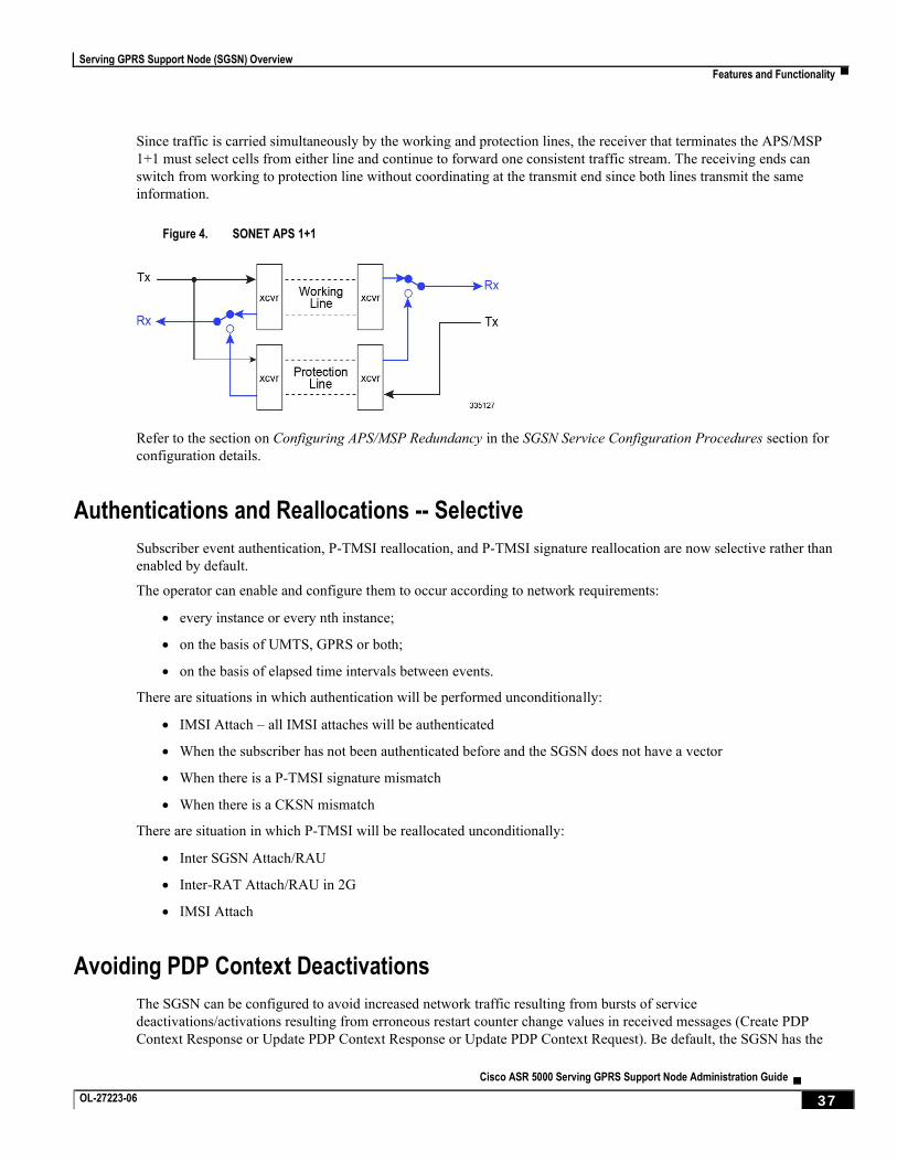
Serving GPRS Support Node (SGSN) Overview
Features and Functionality ▀
Cisco ASR 5000 Serving GPRS Support Node Administration Guide ▄ OL-27223-06 37
Since traffic is carried simultaneously by the working and protection lines, the receiver that terminates the APS/MSP
1+1 must select cells from either line and continue to forward one consistent traffic stream. The receiving ends can
switch from working to protection line without coordinating at the transmit end since both lines transmit the same
information.
Figure 4. SONET APS 1+1
Refer to the section on Configuring APS/MSP Redundancy in the SGSN Service Configuration Procedures section for
configuration details.
Authentications and Reallocations -- Selective
Subscriber event authentication, P-TMSI reallocation, and P-TMSI signature reallocation are now selective rather than
enabled by default.
The operator can enable and configure them to occur according to network requirements:
every instance or every nth instance;
on the basis of UMTS, GPRS or both;
on the basis of elapsed time intervals between events.
There are situations in which authentication will be performed unconditionally:
IMSI Attach – all IMSI attaches will be authenticated
When the subscriber has not been authenticated before and the SGSN does not have a vector
When there is a P-TMSI signature mismatch
When there is a CKSN mismatch
There are situation in which P-TMSI will be reallocated unconditionally:
Inter SGSN Attach/RAU
Inter-RAT Attach/RAU in 2G
IMSI Attach
Avoiding PDP Context Deactivations
The SGSN can be configured to avoid increased network traffic resulting from bursts of service
deactivations/activations resulting from erroneous restart counter change values in received messages (Create PDP
Context Response or Update PDP Context Response or Update PDP Context Request). Be default, the SGSN has the
Serving GPRS Support Node (SGSN) Overview
▀ Features and Functionality
▄ Cisco ASR 5000 Serving GPRS Support Node Administration Guide
38 OL-27223-06
responsibility to verify possible GTP-C path failure by issuing an Echo Request/Echo Response to the GGSN. Path
failure will only be confirmed if the Echo Response contains a new restart counter value. Only after this confirmation of
the path failure does the SGSN begin deactivation of PDP contexts.
Bulk Statistics Support
System support for bulk statistics allows operators to choose which statistics to view and to configure the format in
which the statistics are presented. This simplifies the post-processing of statistical data since it can be formatted to be
parsed by external, back-end processors.
When used in conjunction with the Web Element Manager, the data can be parsed, archived, and graphed.
The system can be configured to collect bulk statistics (performance data) and send them to a collection server (called a
receiver). Bulk statistics are statistics that are collected in a group. The individual statistics are grouped by schema. The
following is the list of schemas supported for use by the SGSN:
System: Provides system-level statistics
Card: Provides card-level statistics
Port: Provides port-level statistics
DLCI-Util: Provides statistics specific to DLCIs utilization for CLC-type line cards
EGTPC: Provides statistics specific to the configured ETPC service on the S4-SGSN
GPRS: Provides statistics for LLC, BSSGP, SNDCP, and NS layers
SCCP: Provides SCCP network layer statistics
SGTP: Provides SGSN-specific GPRS Tunneling Protocol (GTP) statistics
SGSN: Provides statistics for: mobility management (MM) and session management (SM) procedures; as well, MAP, TCAP, and SMS counters are captured in this schema. SGSN Schema statistic availability is per service (one of: SGSN, GPRS, MAP) and per routing area (RA)
SS7Link: Provides SS7 link and linkset statistics
SS7RD: Provides statistics specific to the proprietary SS7 routing domains
The system supports the configuration of up to 4 sets (primary/secondary) of receivers. Each set can be configured with
to collect specific sets of statistics from the various schemas. Statistics can be pulled manually from the chassis or sent
at configured intervals. The bulk statistics are stored on the receiver(s) in files.
The format of the bulk statistic data files can be configured by the user. Users can specify the format of the file name,
file headers, and/or footers to include information such as the date, chassis host name, chassis uptime, the IP address of
the system generating the statistics (available for only for headers and footers), and/or the time that the file was
generated.
When the Web Element Manager is used as the receiver, it is capable of further processing the statistics data through
XML parsing, archiving, and graphing.
The Bulk Statistics Server component of the Web Element Manager parses collected statistics and stores the information
in the PostgreSQL database. If XML file generation and transfer is required, this element generates the XML output and
can send it to a Northbound NMS or an alternate bulk statistics server for further processing.
Additionally, if archiving of the collected statistics is desired, the Bulk Statistics server writes the files to an alternative
directory on the server. A specific directory can be configured by the administrative user or the default directory can be
used. Regardless, the directory can be on a local file system or on an NFS-mounted file system on the Web Element
Manager server.
Serving GPRS Support Node (SGSN) Overview
Features and Functionality ▀
Cisco ASR 5000 Serving GPRS Support Node Administration Guide ▄ OL-27223-06 39
CAMEL Service Phase 3, Ge Interface
The ASR 5000 SGSN provides PDP session support as defined by Customized Applications for Mobile network
Enhanced Logic (CAMEL) phase 3.
CAMEL Service
CAMEL service enables operators of 2.5G/3G networks to provide operator-specific services (such as prepaid GPRS
service and prepaid SMS service) to subscribers, even when the subscribers are roaming outside their HPLMN.
CAMEL Support
ASR 5000 SGSN support for CAMEL phase 3 services expands with each SGSN application release. Current support
enables operators of 2.5G/3G networks to provide operator-specific services (such as prepaid GPRS service and prepaid
SMS service) to subscribers, even when the subscribers are roaming outside their HPLMN.
For this release the SGSN has expanded its support for CAMEL Scenario 1 adding:
Implementation of Scenario1 triggers (TDP-Attach, TDP-Attach-ChangeofPosition)
Implementation of Scenario1 Dynamic triggers (DP-Detach, DP-ChangeofPosition)
Expanded conformance to 3GPP spec 23.078 (Release 4)
The ASR 5000 SGSN supports the following GPRS-related functionality in CAMEL phase 3:
Control of GPRS PDP contexts
Functional support for CAMEL interaction includes:
PDP Context procedures per 3GPP TS 29.002
GPRS TDP (trigger detection point) functions
Default handling codes, if no response received from SCP
GPRS EDP (event detection points) associated with SCP
Charging Procedures: Handle Apply Charging GPRS & Handle Apply Charging Report GPRS
“GPRS Dialogue scenario 2" for CAMEL control with SCP
CAMEL-related data items in an S-CDR:
SCF Address
Service Key
Default Transaction Handling
Level of CAMEL service (phase 3)
Session Recovery for all calls have an ESTABLISHED CAMEL association.
Ge Interface
The ASR 5000 implementation of CAMEL uses standard CAP protocol over a Ge interface between the SGSN and the
SCP. This interface can be deployed over SS7 or SIGTAN.
Serving GPRS Support Node (SGSN) Overview
▀ Features and Functionality
▄ Cisco ASR 5000 Serving GPRS Support Node Administration Guide
40 OL-27223-06
The SGSN's Ge support includes use of the gprsSSF CAMEL component with the SGSN and the gsmSCF component
with the SCP.
CAMEL Configuration
To provide the CAMEL interface on the SGSN, a new service configuration mode, called “CAMEL Service”, has been
introduced on the SGSN.
1. An SCCP Network configuration must be created or exist already.
2. A CAMEL Service instance must be created.
3. The CAMEL Service instance must be associated with either the SGSN Service configuration or the GPRS Service configuration in order to enable use of the CAMEL interface.
4. The CAMEL Service must be associated with the SCCP Network configuration.
Until a CAMEL Service is properly configured, the SGSN will not process any TDP for pdp-context or mo-sms.
Commandguard
Operators can accidentally enter configuration mode via CLI or file replay. To protect against this, SGSN supports
commandguard CLI command. Commandguard, which is disabled by default, can only be enabled or disabled from the
Global Configuration mode. When Commandguard is enabled it affects the configure and autoconfirm CLI
commands by causing them to prompt (Y/N) for confirmation. When autoconfirm is enabled Commandguard has no
affect. The commandguard state is preserved in the SCT and, when enabled, is output by the various variants of the
show config CLI.
Configurable RAB Asymmetry Indicator in RAB Assignment Request
The SGSN sets the value for the RAB Asymmetry Indicator that is included in the RAB Assignment Request.
In releases prior to R12.0, the SGSN set the RAB asymmetry indicator to "Symmetric-Bidirectional" when downlink
and uplink bit rates were equal. Now, the SGSN selects the value based on the symmetry of negotiated maximum bit
rates as follows:
If the uplink and downlink bit rates are equal then it is set to “Symmetric-Bidirectional”,
If uplink bit rate is set to 0 kbps, then it is set to “Asymmetric-Unidirectional-Downlink”,
If downlink bit rate is set to 0 kbps, then it is set to “Asymmetric-Unidirectional-Uplink”,
If the uplink and downlink bit rates are non-zero and different, then it is set to “Asymmetric-Bidirectional”.
A change in CLI configuration allows the SGSN to override the above functionality and set the RAB Asymmetry
Indicator to “Asymmetric-Bidirectional” when uplink and downlink bit rates are equal. As a result, two sets of bit rates -
one for downlink and one for uplink - will be included in the RAB Assignment Requests as mandated in 3GPP TS
25.413.
Direct Tunnel
In accordance with standards, one tunnel functionality enables the SGSN to establish a direct tunnel at the user plane
level - a GTP-U tunnel, directly between the RAN and the GGSN. Feature details and configuration procedures are
provided in the Direct Tunnel feature section in this guide.
Serving GPRS Support Node (SGSN) Overview
Features and Functionality ▀
Cisco ASR 5000 Serving GPRS Support Node Administration Guide ▄ OL-27223-06 41
Downlink Data Lockout Timer
Currently, if paging fails after maximum number of retries, the page proceed flag (PPF) is cleared and further downlink
data is dropped. The PPF is set to ‘true’ if there is any uplink activity from the UE.
The Downlink Data Lockout Timer is a new, configurable timer added for both GPRS and SGSN services to reduce the
frequency of mobile-initiated keep alive messages. If enabled, this timer starts whenever the paging procedure fails after
the maximum number of retransmissions and the Page Proceed Flag (PPF) is cleared. If there is any downlink activity
when the lockout timer is running, the packets are dropped and the drop cause is set as Page Failed. When the lockout
timer expires, the PPF is set to true and further downlink packets are queued and paging is re-initiated. In order to avoid
endless paging activity when there is no page response or uplink activity from the UE, an optional configurable repeat
count value is used. If the repeat value is configured as 'y' then the lockout timer is started 'y' number of times after page
failure. The implementation of the lockout timer is different for 2G/3G subscribers, but the behavior is the same.
DSCP Templates for Control and Data Packets - Iu or Gb over IP
The SGSN supports a mechanism for differentiated services code point (DSCP) marking of control packets and
signaling messages for the SGSN’s M3UA level on the Iu interface and for LLC messages for the Gb interface.
This DSCP marking feature enables the SGSN to perform classifying and managing of network traffic and to determine
quality of service (QoS) for the interfaces to an IP network.
Implementation of this feature requires the use of several CLIs commands to create one or more reusable templates.
These templates set DSCP parameter configuration for downlink control packets and data packets that can be associated
with one or more configurations for at the GPRS service level, the peer-NSEI level, the IuPS service level, and the PSP
instance level.
Dual PDP Addresses for Gn/Gp
In accordance with 3GPP Release 9.0 specifications, it is now possible to configure SGSN support for dual stack PDP
type addressing (IPv4v6) for PDP context association with one IPv4 address and one IPv6 address/prefix when
requested by the MS/UE.
ECMP over ATM
Iu Redundancy is the ASR 5000's implementation of equal-cost multi-path routing (ECMP) over ATM.
Iu Redundancy is based on the standard ECMP multi-path principle of providing multiple next-hop-routes of equal cost
to a single destination for packet transmission. ECMP works with most routing protocols and can provide increased
bandwidth when traffic load-balancing is implemented over multiple paths.
ECMP over ATM will create an ATM ECMP group when multiple routes with different destination ATM interfaces are
defined for the same destination IP address. When transmitting a packet with ECMP, the NPU performs a hash on the
packet header being transmitted and uses the result of the hash to index into a table of next hops. The NPU looks up the
ARP index in the ARP table (the ARP table contains the next-hop and egress interfaces) to determine the next-hop and
interface for sending packets.
Serving GPRS Support Node (SGSN) Overview
▀ Features and Functionality
▄ Cisco ASR 5000 Serving GPRS Support Node Administration Guide
42 OL-27223-06
Equivalent PLMN
This feature is useful when an operator deploys both GPRS and UMTS access in the same radio area and each radio
system broadcasts different PLMN codes. It is also useful when operators have different PLMN codes in different
geographical areas, and the operators’ networks in the various geographical areas need to be treated as a single HPLMN.
This feature allows the operator to consider multiple PLMN codes for a single subscriber belonging to a single home
PLMN (HPLMN). This feature also allows operators to share infrastructure and it enables a UE with a subscription with
one operator to access the network of another operator.
First Vector Configurable Start for MS Authentication
Previously, the SGSN would begin authentication towards the MS only after the SGSN received all requested vectors.
This could result in a radio network traffic problem when the end devices timed out and needed to re-send attach
requests.
Now, the SGSN can be configured to start MS authentication as soon as it receives the first vector from the AuC/HLR
while the SAI continues in parallel. After an initial attach request, some end devices restart themselves after waiting for
the PDP to be established. In such cases, the SGSN restarts and a large number of end devices repeat their attempts to
attach. The attach requests flood the radio network, and if the devices timeout before the PDP is established then they
continue to retry, thus even more traffic is generated. This feature reduces the time needed to retrieve vectors over the
GR interface to avoid the high traffic levels during PDP establishment and to facilitate increased attach rates.
Gb Manager
A new SGSN proclet has been developed. Now, all the link level procedures related to Gb -
protocol (GPRS-NS and BSSGP) hosting, handling, administration, message distribution,
keeping the other managers informed about the link/remote-node status,
handling functionality of the Gb interface (all 2G signaling)
are removed from the Link Manager and moved to the SGSN's new Gb Manager proclet. The new Gb Manager provides increased flexibility in handling link level procedures for each access type independently
and ensures scalability. The consequence of relieving the Link Manager, of a large amount of message handling, is to
decrease delays in sending sscop STAT messages resulting in the detection of link failure at the remote end. Use of this
separate new proclet to handle 2G signaling messages means there will not be any MTP link fluctuation towards the
RNS, which is seen during the BSC restart or extension activity in the network. As well, this improves the fluctuation
towards the 3G connectivity.
GMM-SM Event Logging
To facilitate troubleshooting, the SGSN will capture procedure-level information per 2G or 3G subscriber (IMSI-based)
in CSV formatted event data records (EDRs) that are stored on an external server.
This feature logs the following events:
Attaches
Activation of PDP Context
RAU
Serving GPRS Support Node (SGSN) Overview
Features and Functionality ▀
Cisco ASR 5000 Serving GPRS Support Node Administration Guide ▄ OL-27223-06 43
ISRAU
Deactivation of PDP Context
Detaches
Authentications
PDP Modifications
The new SGSN event logging feature is enabled/disabled per service via CLI commands. For more information on this
feature, refer to the section GMM/SM Event Logging in this guide.
Gn/Gp Delay Monitoring
The SGSN measures the control plane packet delay for GTP-C signaling messages on the SGSN’s Gn/Gp interface
towards the GGSN.
If the delay crosses a configurable threshold, an alarm will be generated to prompt the operator.
A delay trap is generated when the GGSN response to an ECHO message request is delayed more than a configured
amount of time and for a configured number of consecutive responses. When this occurs, the GGSN will be flagged as
experiencing delay.
A clear delay trap is generated when successive ECHO Response (number of successive responses to detect a delay
clearance is configurable), are received from a GGSN previously flagged as experiencing delay.
This functionality can assist with network maintenance, troubleshooting, and early fault discovery.
GTP-C Path Failure Detection and Management
The SGSN now provides the ability to manage GTP-C path failures detected as a result of spurious restart counter
change messages received from the GGSN.
Previous Behavior: The old default behavior was to have the Session Manager (SessMgr) detect GTP-C path failure
based upon receiving restart counter changes in messages (Create PDP Context Response or Update PDP Context
Response or Update PDP Context Request) from the GGSN and immediately inform the SGTPC Manager (SGTPCMgr)
to pass the path failure detection to all other SessMgrs so that PDP deactivation would begin.
New Behavior: The new default behavior has the SessMgr inform the SGTPCMgr of the changed restart counter value.
The SGTPCMgr now has the responsibility to verify a possible GTP-C path failure by issuing an Echo Request/Echo
Response to the GGSN. Path failure will only be confirmed if the Echo Response contains a new restart counter value.
Only after this confirmation of the path failure does the SGTPCMgr inform all SessMgrs so that deactivation of PDP
contexts begins.
Handling Multiple MS Attaches All with the Same Random TLLI
Some machine-to-machine (M2M) devices from the same manufacturer will all attempt PS Attaches using the same
fixed random Temporary Logical Link Identifier (TLLI).
The SGSN cannot distinguish between multiple M2M devices trying to attach simultaneously using the same random
TLLI and routing area ID (RAI). As a result, during the attach process of an M2M device, if a second device tries to
attach with the same random TLLI, the SGSN interprets that as an indication that the original subscriber moved during
the Attach process and the SGSN starts communicating with the second device and drops the first device.
Serving GPRS Support Node (SGSN) Overview
▀ Features and Functionality
▄ Cisco ASR 5000 Serving GPRS Support Node Administration Guide
44 OL-27223-06
The SGSN can be configured to allow only one subscriber at a time to attach using a fixed random TLLI. While an
Attach procedure with a fixed random TLLI is ongoing (that is, until a new P-TMSI is accepted by the MS), all other
attaches sent to the SGSN with the same random TLLI using a different IMSI will be dropped by the SGSN’s Linkmgr.
To limit the wait-time functionality to only the fixed random TLLI subscribers, the TLLI list can be configured to
control which subscribers will be provided this functionality.
HSPA Fallback
Besides enabling configurable support for either 3GPP Release 6 (HSPA) and 3GPP Release 7 (HSPA+) to match
whatever the RNCs support, this feature enables configurable control of data rates on a per RNC basis. This means that
operators can allow subscribers to roam in and out of coverages areas with different QoS levels.
The SGSN can now limit data rates (via QoS) on a per-RNC basis. Some RNCs support HSPA rates (up to 16 Mbps in
the downlink and 8 Mbps in the uplink) and cannot support higher data rates - such as those enabled by HSPA+
(theoretically, up to 256 Mbps both downlink and uplink). Being able to specify the QoS individually for each RNC
makes it possible for operators to allow their subscribers to move in-and-out of coverage areas with different QoS
levels, such as those based on 3GPP Release 6 (HSPA) and 3GPP Release 7 (HSPA+).
For example, when a PDP context established from an RNC with 21 Mbps is handed off to an RNC supporting only 16
Mbps, the end-to-end QoS will be re-negotiated to 16 Mbps. Note that an MS/UE may choose to drop the PDP context
during the QoS renegotiation to a lower value.
This data rate management per RNC functionality is enabled, in the radio network controller (RNC) configuration
mode, by specifying the type of 3GPP release specific compliance, either release 7 for HSPA+ rates or pre-release 7 for
HSPA rates.
Ignore Context-ID During 4G/3G Handovers
HSS and HLR, when operating as separate network nodes, are required to use the same context-ID for a given APN-
configuration of a subscriber. During inter-RAT cell reselections and handovers between 2G/3G and 4G, if the SGSN
does not find a matching APN-configuration for the given context-ID learnt from the peer node, then the PDP does not
get established. This could result in SRNS relocation failures when none of the PDP's learnt from the SGSN has a
matching context-ID in the HLR.
New commands have been added to enable the operator to configure the SGSN to ignore the context-ID provided by the
peer and to use the PDP- type and address information to search through HLR subscription and to update the context-ID
information within the PDP. For details, refer to the description for the rau-inter command under the Call-Control
Profile Configuration Mode Commands section of the Cisco ASR 5x00 GPRS / UMTS Command Line Interface
Reference.
Intra- or Inter-SGSN Serving Radio Network Subsystem (SRNS) Relocation (3G only)
Implemented according to 3GPP standard, the SGSN supports both inter- and intra-SGSN RNS relocation (SRNS) to
enable handover of an MS from one RNC to another RNC.
The relocation feature is triggered by subscribers (MS/UE) moving from one RNS to another. If the originating RNS
and destination RNS are connected to the same SGSN but are in different routing areas, the behavior triggers an intra-
SGSN Routing Area Update (RAU). If the RNS are connected to different SGSNs, the relocation is followed by an
Serving GPRS Support Node (SGSN) Overview
Features and Functionality ▀
Cisco ASR 5000 Serving GPRS Support Node Administration Guide ▄ OL-27223-06 45
inter-SGSN RAU. This feature is configured through the Call-Control Profile Configuration Mode which is part of the
feature set.
Lawful Intercept
The Cisco Lawful Intercept feature is supported on the SGSN. Lawful Intercept is a license-enabled, standards-based
feature that provides telecommunications service providers with a mechanism to assist law enforcement agencies in
monitoring suspicious individuals for potential illegal activity. For additional information and documentation on the
Lawful Intercept feature, contact your Cisco account representative.
Link Aggregation - Horizontal
The SGSN supports enhanced link aggregation (LAG) within ports on different XGLCs. Ports can be from multiple
XGLCs. LAG works by exchanging control packets (Link Aggregation Control Marker Protocol) over configured
physical ports with peers to reach agreement on an aggregation of links. LAG sends and receives the control packets
directly on physical ports attached to different XGLCs. The link aggregation feature provides higher aggregated
bandwidth, auto-negotiation, and recovery when a member port link goes down.
Local DNS
Previously, the SGSN supported GGSN selection for an APN only through operator policy, and supported a single pool
of up to 16 GGSN addresses which were selected in round robin fashion.
The SGSN now supports configuration of multiple pools of GGSNs; a primary pool and a secondary. As part of DNS
resolution, the operator can use operator policies to prioritize local GGSNs versus remote ones. This function is built
upon existing load balancing algorithms in which weight and priority are configured per GGSN, with the primary
GGSN pool used first and the secondary used if no primary GGSNs are available.
The SGSN first selects a primary pool and then GGSNs within that primary pool; employing a round robin mechanism
for selection. If none of the GGSNs in a pool are available for activation, then the SGSN proceeds with activation
selecting a GGSN from a secondary pool on the basis of assigned weight. A GGSN is considered unavailable when it
does not respond to GTP Requests after a configurable number of retries over a configurable time period. Path failure is
detected via GTP-echo.
Local Mapping of MBR
The SGSN provides the ability to map a maximum bit rate (MBR) value (provided by the HLR) to an HSPA MBR
value.
The mapped value is selected based on the matching MBR value obtained from the HLR subscription. QoS negotiation
then occurs based on the converted value.
This feature is available within the operator policy framework. MBR mapping is configured via new keywords added to
the qos class command in the APN Profile configuration mode. A maximum of four values can be mapped per QoS
per APN.
Important: To enable this feature the qos prefer-as-cap, also a command in the APN Profile configuration
mode, must be set to either both-hlr-and-local or to hlr subscription.
Serving GPRS Support Node (SGSN) Overview
▀ Features and Functionality
▄ Cisco ASR 5000 Serving GPRS Support Node Administration Guide
46 OL-27223-06
Local QoS Capping
The operator can configure a cap or limit for the QoS bit rate.
The SGSN can now be configured to cap the QoS bit rate parameter when the subscribed QoS provided by the HLR is
lower than the locally configured value.
Depending upon the keywords included in the command, the SGSN can:
take the QoS parameter configuration from the HLR configuration.
take the QoS parameter configuration from the local settings for use in the APN profile.
during session establishment, apply the lower of either the HLR subscription or the locally configured values.
Location Services
LoCation Services (LCS) on the SGSN is a 3GPP standards-compliant feature that enables the SGSN to collect and use
or share location (geographical position) information for connected UEs in support of a variety of location services,
such as location-based charging and positioning services. The SGSN uses the Lg interface to the gateway mobile
location center (GMLC), which provides the mechanisms to support specialized mobile location services for operators,
subscribers, and third party service providers. Use of this feature and the Lg interface is license controlled.
For details about this feature and its configuration, refer to the Location Services section of the SGSN Administration
Guide.
Lock/Shutdown the BSC from the SGSN
When the SGSN returns to Active state, after scenarios such as rebooting or reloading, all the BSCs that had been
connected to the SGSN would attempt to re-establish connections. This could result in two serious problems for
operators:
1. high CPU usage in the SGSN where too many BSC/RNCs were connected.
2. network overload when other network nodes cannot match the SGSN's capacity.
The SGSN now supports a Lock/Shutdown feature that provides a two prong solution. CPU Usage Solution: Staggering
the BSC auto-learning procedures when the SGSN re-loads will help to reduce the high CPU usage. This can be
achieved by the operator locking the NSE/BSCs from the SGSN before reboot/reload and then unlocking them one-by-
one to avoid high CPU usage.
Network Overload Solution: A new timer, SNS-GUARD, has been added to clean-up resources if the SNS procedure
does not complete properly, whether or not the BSC is administratively locked. Now the SGSN starts this timer after
sending SNS-SIZE-ACK and the BSC information will be removed, if the auto-learning clean-up procedure does not
complete before the timer expires.
A series of new commands and keywords has been added to enable the operator to configure this new administrative
Lock/Shutdown the BSC functionality as part of 'interface management' configuration. For details, refer to the SGSN
Global Interface Management section of the Cisco ASR 5x00 GPRS / UMTS Command Line Interface Reference.
Management System Overview
The system's management capabilities are designed around the Telecommunications Management Network (TMN)
model for management - focusing on providing superior quality network element (NE) and element management system
(Web Element Manager) functions. The system provides element management applications that can easily be integrated,
Serving GPRS Support Node (SGSN) Overview
Features and Functionality ▀
Cisco ASR 5000 Serving GPRS Support Node Administration Guide ▄ OL-27223-06 47
using standards-based protocols (CORBA and SNMPv1, v2), into higher-level management systems - giving wireless
operators the ability to integrate the system into their overall network, service, and business management systems. In
addition, all management is performed out-of-band for security and to maintain system performance.
The Operation and Maintenance module of the system offers comprehensive management capabilities to the operators
and enables them to operate the system more efficiently. There are multiple ways to manage the system either locally or
remotely using its out-of-band management interfaces.
These include:
Using the command line interface (CLI)
Remote login using Telnet, and Secure Shell (SSH) access to CLI through SPIO card's Ethernet management interfaces
Local login through the Console port on SPIO card using an RS-232 serial connection
Using the Web Element Manager (WEM) application (requires a separate license)
Supports communications through 10 Base-T, 100 Base-TX, 1000 Base-TX, or 1000
Base-SX (optical gigabit Ethernet) Ethernet management interfaces on the SPIO
Client-Server model supports any browser (i.e. Microsoft Internet Explorer v5.0 and above or Netscape v4.7 or above, and others)
Supports Common Object Request Broker Architecture (CORBA) protocol and Simple Network Management Protocol version 1 (SNMPv1) for fault management
Provides complete Fault, Configuration, Accounting, Performance, and Security (FCAPS) capabilities
Can be easily integrated with higher-level network, service, and business layer applications using the Object Management Group's (OMG’s) Interface Definition Language (IDL)
The following figure demonstrates these various element management options and how they can be utilized within the
wireless carrier network.
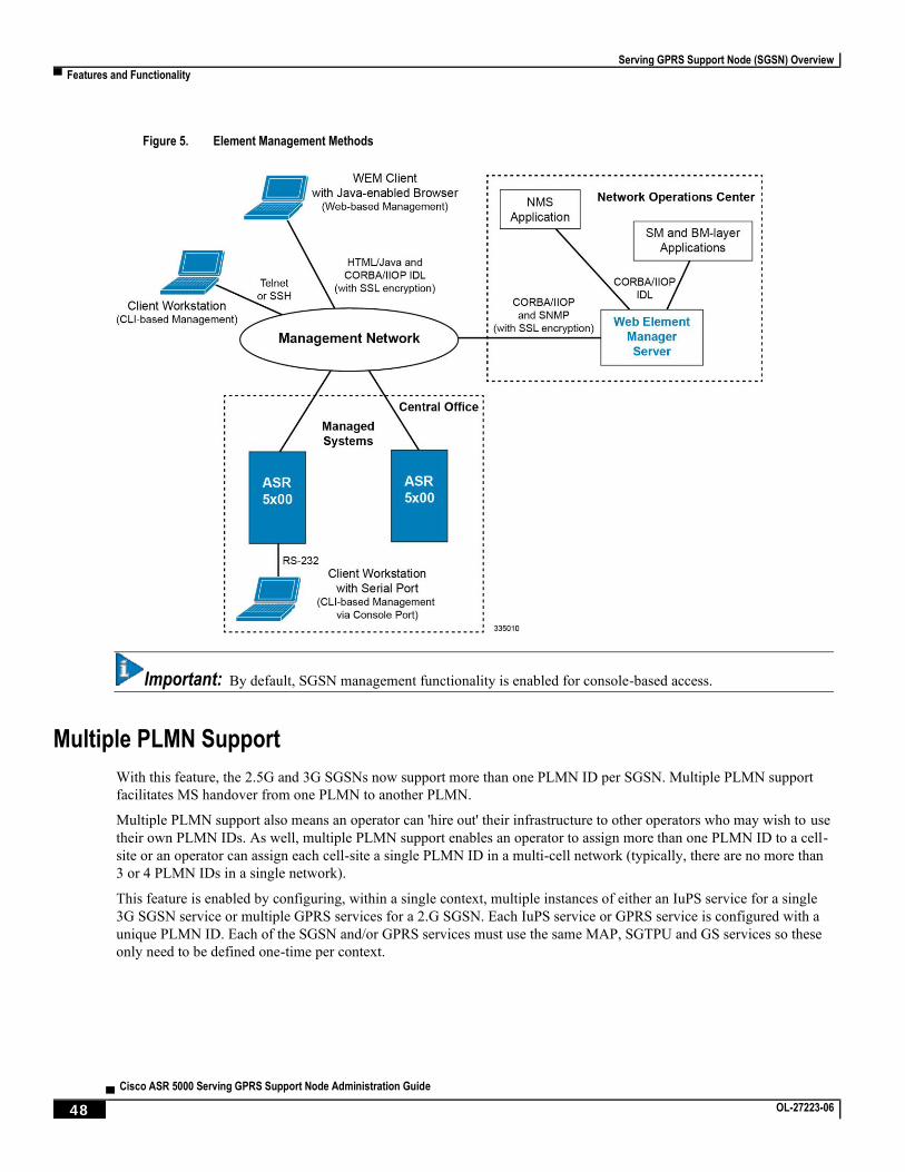
Serving GPRS Support Node (SGSN) Overview
▀ Features and Functionality
▄ Cisco ASR 5000 Serving GPRS Support Node Administration Guide
48 OL-27223-06
Figure 5. Element Management Methods
Important: By default, SGSN management functionality is enabled for console-based access.
Multiple PLMN Support
With this feature, the 2.5G and 3G SGSNs now support more than one PLMN ID per SGSN. Multiple PLMN support
facilitates MS handover from one PLMN to another PLMN.
Multiple PLMN support also means an operator can 'hire out' their infrastructure to other operators who may wish to use
their own PLMN IDs. As well, multiple PLMN support enables an operator to assign more than one PLMN ID to a cell-
site or an operator can assign each cell-site a single PLMN ID in a multi-cell network (typically, there are no more than
3 or 4 PLMN IDs in a single network).
This feature is enabled by configuring, within a single context, multiple instances of either an IuPS service for a single
3G SGSN service or multiple GPRS services for a 2.G SGSN. Each IuPS service or GPRS service is configured with a
unique PLMN ID. Each of the SGSN and/or GPRS services must use the same MAP, SGTPU and GS services so these
only need to be defined one-time per context.
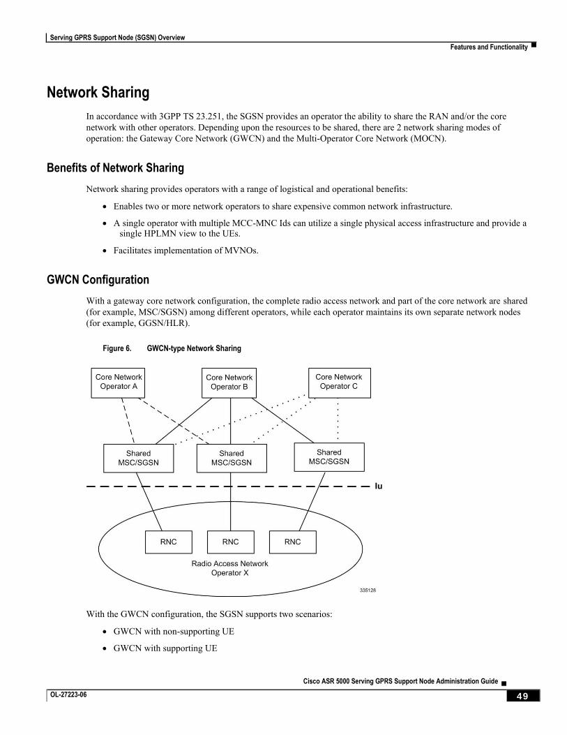
Serving GPRS Support Node (SGSN) Overview
Features and Functionality ▀
Cisco ASR 5000 Serving GPRS Support Node Administration Guide ▄ OL-27223-06 49
Network Sharing
In accordance with 3GPP TS 23.251, the SGSN provides an operator the ability to share the RAN and/or the core
network with other operators. Depending upon the resources to be shared, there are 2 network sharing modes of
operation: the Gateway Core Network (GWCN) and the Multi-Operator Core Network (MOCN).
Benefits of Network Sharing
Network sharing provides operators with a range of logistical and operational benefits:
Enables two or more network operators to share expensive common network infrastructure.
A single operator with multiple MCC-MNC Ids can utilize a single physical access infrastructure and provide a single HPLMN view to the UEs.
Facilitates implementation of MVNOs.
GWCN Configuration
With a gateway core network configuration, the complete radio access network and part of the core network are shared
(for example, MSC/SGSN) among different operators, while each operator maintains its own separate network nodes
(for example, GGSN/HLR).
Figure 6. GWCN-type Network Sharing
With the GWCN configuration, the SGSN supports two scenarios:
GWCN with non-supporting UE
GWCN with supporting UE
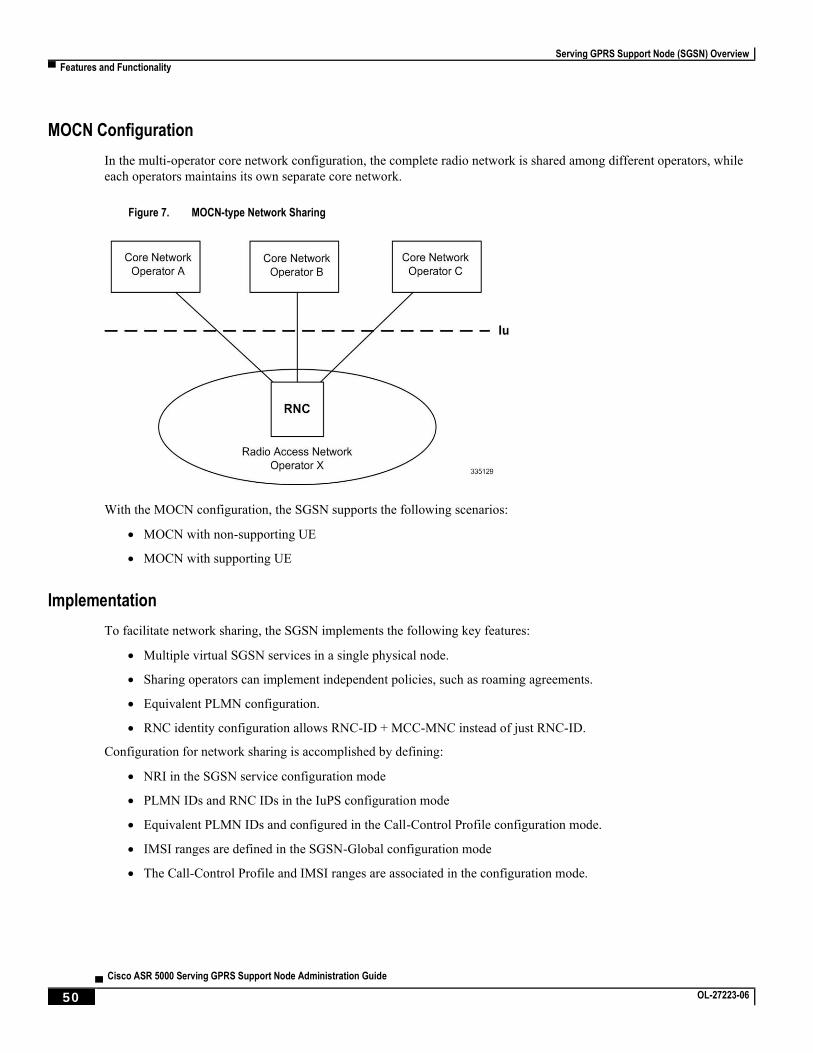
Serving GPRS Support Node (SGSN) Overview
▀ Features and Functionality
▄ Cisco ASR 5000 Serving GPRS Support Node Administration Guide
50 OL-27223-06
MOCN Configuration
In the multi-operator core network configuration, the complete radio network is shared among different operators, while
each operators maintains its own separate core network.
Figure 7. MOCN-type Network Sharing
With the MOCN configuration, the SGSN supports the following scenarios:
MOCN with non-supporting UE
MOCN with supporting UE
Implementation
To facilitate network sharing, the SGSN implements the following key features:
Multiple virtual SGSN services in a single physical node.
Sharing operators can implement independent policies, such as roaming agreements.
Equivalent PLMN configuration.
RNC identity configuration allows RNC-ID + MCC-MNC instead of just RNC-ID.
Configuration for network sharing is accomplished by defining:
NRI in the SGSN service configuration mode
PLMN IDs and RNC IDs in the IuPS configuration mode
Equivalent PLMN IDs and configured in the Call-Control Profile configuration mode.
IMSI ranges are defined in the SGSN-Global configuration mode
The Call-Control Profile and IMSI ranges are associated in the configuration mode.
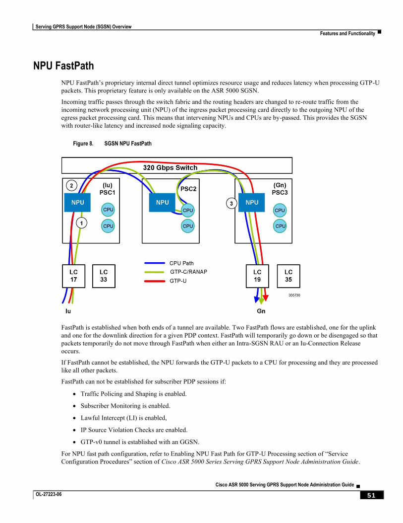
Serving GPRS Support Node (SGSN) Overview
Features and Functionality ▀
Cisco ASR 5000 Serving GPRS Support Node Administration Guide ▄ OL-27223-06 51
NPU FastPath
NPU FastPath’s proprietary internal direct tunnel optimizes resource usage and reduces latency when processing GTP-U
packets. This proprietary feature is only available on the ASR 5000 SGSN.
Incoming traffic passes through the switch fabric and the routing headers are changed to re-route traffic from the
incoming network processing unit (NPU) of the ingress packet processing card directly to the outgoing NPU of the
egress packet processing card. This means that intervening NPUs and CPUs are by-passed. This provides the SGSN
with router-like latency and increased node signaling capacity.
Figure 8. SGSN NPU FastPath
FastPath is established when both ends of a tunnel are available. Two FastPath flows are established, one for the uplink
and one for the downlink direction for a given PDP context. FastPath will temporarily go down or be disengaged so that
packets temporarily do not move through FastPath when either an Intra-SGSN RAU or an Iu-Connection Release
occurs.
If FastPath cannot be established, the NPU forwards the GTP-U packets to a CPU for processing and they are processed
like all other packets.
FastPath can not be established for subscriber PDP sessions if:
Traffic Policing and Shaping is enabled.
Subscriber Monitoring is enabled.
Lawful Intercept (LI) is enabled,
IP Source Violation Checks are enabled.
GTP-v0 tunnel is established with an GGSN.
For NPU fast path configuration, refer to Enabling NPU Fast Path for GTP-U Processing section of “Service
Configuration Procedures” section of Cisco ASR 5000 Series Serving GPRS Support Node Administration Guide.
Serving GPRS Support Node (SGSN) Overview
▀ Features and Functionality
▄ Cisco ASR 5000 Serving GPRS Support Node Administration Guide
52 OL-27223-06
NRPCA - 3G
The SGSN supports the Network Requested Primary PDP Context Activation (NRPCA) procedure for 3G attachments.
There are no interface changes to support this feature. Support is configured with existing CLI commands (network-
initiated-pdp-activation, location-area-list) in the call control profile configuration mode and timers (T3385-timeout
and max-actv-retransmission) are set in the SGSN service configuration mode.
Operator Policy
The non-standard feature is unique to the ASR 5000 SGSN. This feature empowers the carrier with unusual and flexible
control to manage functions that aren’t typically used in all applications and to determine the granularity of the
implementation of any: to groups of incoming calls or to simply one single incoming call. For details about the feature,
its components, and how to configure it, refer to the Operator Policy section in this guide.
Important: SGSN configurations created prior to Release 11.0 are not forward compatible. All
configurations for SGSNs, with -related configurations that were generated with software releases prior to Release 11.0, must be converted to enable them to operate with an SGSN running Release 11.0 or higher. Your Cisco Representative can accomplish this conversion for you.
Some Features Managed by Operator Policies
The following is a list of some of the features and functions that can be controlled via configuration of Operator
Policies:
APN Aliasing
Authentication
Direct Tunnel - for feature description and configuration details, refer to the Direct Tunnel section in this guide
Equivalent PLMN
IMEI Override
Intra- or Inter-SGSN Serving Radio Network Subsystem (SRNS) Relocation (3G only)
Network Sharing
QoS Traffic Policing per Subscriber
SGSN Pooling - Gb/Iu Flex
SuperCharger
Subscriber Overcharging Protection - for feature description and configuration details, refer to the Subscriber Overcharging Protection section in this guide.
Overcharging Protection
Overcharging Protection enables the SGSN to avoid overcharging the subscriber if/when a loss of radio coverage
(LORC) occurs in a UMTS network. For details and configuration information, refer to the Subscriber Overcharging
Protection section in this book.
Serving GPRS Support Node (SGSN) Overview
Features and Functionality ▀
Cisco ASR 5000 Serving GPRS Support Node Administration Guide ▄ OL-27223-06 53
QoS Traffic Policing per Subscriber
Traffic policing enables the operator to configure and enforce bandwidth limitations on individual PDP contexts for a
particular traffic class.
Traffic policing typically deals with eliminating bursts of traffic and managing traffic flows in order to comply with a
traffic contract.
The SGSN conforms to the DiffServ model for QoS by handling the 3GPP defined classes of traffic, QoS negotiation,
DSCP marking, traffic policing, and support for HSDPA/HSUPA.
QoS Classes
The 3GPP QoS classes supported by the SGSN are:
Conversational
Streaming
Interactive
Background
The SGSN is capable of translating between R99 and R97/98 QoS attributes.
QoS Negotiation
On PDP context activation, the SGSN calculates the QoS allowed, based upon:
Subscribed QoS - This is a per-APN configuration, obtained from the HLR on an Attach. It specifies the highest QoS allowed to the subscriber for that APN.
Configured QoS - The SGSN can be configured with default and highest QoS profiles in the configuration.
MS requested QoS - The QoS requested by the UE on pdp-context activation.
DSCP Marking
The SGSN performs diffserv code point (DSCP) marking of the GTP-U packets according to allowed-QoS to PHB
mapping. The default mapping matches that of the UMTS to IP QoS mapping defined in 3GPP TS 29.208.
The SGSN also supports DSCP marking of the GTP control plane messages on the Gn/Gp interface. This allows QoS to
be set on GTP-C messages, and is useful if Gn/Gp is on a less than ideal link. DSCP marking is configurable via the
CLI, with default = Best Effort Forwarding.
Traffic Policing
The SGSN can police uplink and downlink traffic according to predefined QoS negotiated limits fixed on the basis of
individual contexts - either primary or secondary. The SGSN employs the Two Rate Three Color Marker (RFC2698)
algorithm for traffic policing. The algorithm meters an IP packet stream and marks its packets either green, yellow, or
red depending upon the following variables:
PIR - Peak Information Rate (measured in bytes/second)
CIR - Committed Information Rate (measured in bytes/second)
PBS - Peak Burst Size (measured in bytes)
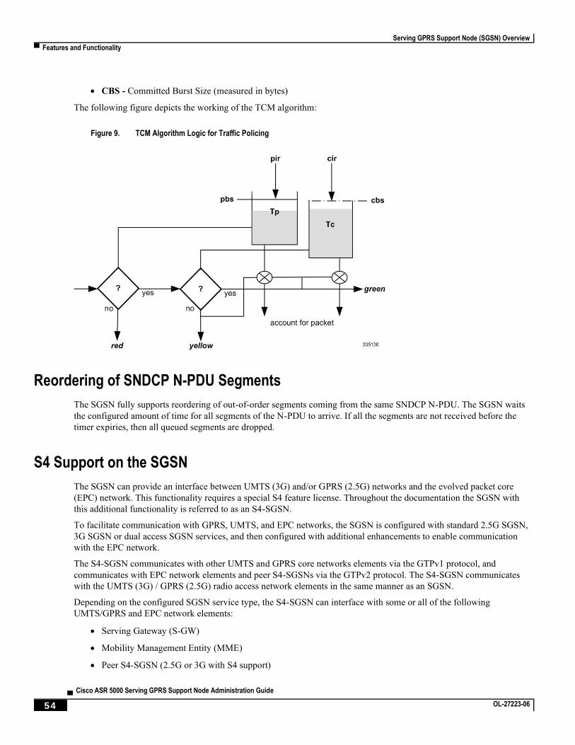
Serving GPRS Support Node (SGSN) Overview
▀ Features and Functionality
▄ Cisco ASR 5000 Serving GPRS Support Node Administration Guide
54 OL-27223-06
CBS - Committed Burst Size (measured in bytes)
The following figure depicts the working of the TCM algorithm:
Figure 9. TCM Algorithm Logic for Traffic Policing
Reordering of SNDCP N-PDU Segments
The SGSN fully supports reordering of out-of-order segments coming from the same SNDCP N-PDU. The SGSN waits
the configured amount of time for all segments of the N-PDU to arrive. If all the segments are not received before the
timer expiries, then all queued segments are dropped.
S4 Support on the SGSN
The SGSN can provide an interface between UMTS (3G) and/or GPRS (2.5G) networks and the evolved packet core
(EPC) network. This functionality requires a special S4 feature license. Throughout the documentation the SGSN with
this additional functionality is referred to as an S4-SGSN.
To facilitate communication with GPRS, UMTS, and EPC networks, the SGSN is configured with standard 2.5G SGSN,
3G SGSN or dual access SGSN services, and then configured with additional enhancements to enable communication
with the EPC network.
The S4-SGSN communicates with other UMTS and GPRS core networks elements via the GTPv1 protocol, and
communicates with EPC network elements and peer S4-SGSNs via the GTPv2 protocol. The S4-SGSN communicates
with the UMTS (3G) / GPRS (2.5G) radio access network elements in the same manner as an SGSN.
Depending on the configured SGSN service type, the S4-SGSN can interface with some or all of the following
UMTS/GPRS and EPC network elements:
Serving Gateway (S-GW)
Mobility Management Entity (MME)
Peer S4-SGSN (2.5G or 3G with S4 support)
Serving GPRS Support Node (SGSN) Overview
Features and Functionality ▀
Cisco ASR 5000 Serving GPRS Support Node Administration Guide ▄ OL-27223-06 55
Peer dual access S4-SGSN
Peer SGSN (2.5G or 3G)
Peer dual access SGSN
GGSN
The S4-SGSN includes the following S4-SGSN specific functionality and features:
S3 and S4 Interface Support
S6d / Gr Interface Support
DNS SNAPTR Support
S4-SGSN Specific Bulk Statistics Support
S13’ Interface Support
Idle Mode Signaling Reduction
ISD DSD Message Handling and HSS Initiated Bearer Modification
UMTS-GSM AKA Support on the S4-SGSN
3G and 2G SGSN Routing Area Update
IPv4 and IPv6 PDP Type Override
P-GW Initiated PDP Bearer Deactivation
S-GW and P-GW Tunnel and EPS Subscription Recovery
Local Configuration of S-GW and S4-SGSN per RAI
Configurable GUTI to RAI Conversion Mapping
S4-SGSN Support for Mobility Management Procedures
QoS Mapping Support
MS Initiated Primary and Secondary Activation
Deactivation Procedure Support
MS, PGW and HSS Initiated PDP Modification Procedure Support
Fallback from the S4 Interface to the Gn Interface
Operator Policy Selection of S4 or Gn Interface
IDFT Support During Connected Mode Handovers
Disassociated DSR Support
SGSN Serving Radio Network Subsystem (SRNS) Relocation Support
Support for Gn Handoff from S4-SGSN to 2G3G Gn SGSN
Summary of Functional Differences between an SGSN and an S4-SGSN (Gn/Gp)
Serving GPRS Support Node (SGSN) Overview
▀ Features and Functionality
▄ Cisco ASR 5000 Serving GPRS Support Node Administration Guide
56 OL-27223-06
S3 and S4 Interface Support
S3 and S4 interface support is a license-enabled feature that enables 2G and 3G networks to interface with the 4G
evolved packet core (EPC) network. The S3/S4 functionality ensures session continuity on handovers between 2G/3G
subscribers and 4G LTE subscribers. S3/S4 functionality simplifies core network operations the following ways:
Replaces the GGSN in the network with the P-GW
Replaces the need for an HLR by providing connectivity to the HSS
Optimized idle mode signaling during 3G/2G to 4G handovers (when the ISR feature is enabled)
The S3 and S4 interfaces provide control and bearer separation, and offload the backward compatibility requirement
from the mobility management entity (MME) and serving gateway (S-GW) EPC elements to the UMTS core.
S3 Interface: Provides a GTPv2-C signaling path connection between the MME and the SGSN (MPC). The S4-SGSN to MME RAU/TAU context handovers are supported via the S3 interface.
S4 Interface: Provides a data and signaling interface between the S-GW and the S4-SGSN (MPC) for bearer plane transport (GTPv2-U). The S4-SGSN communicates with the P-GW via the S-GW.
With support for S3/S4 interface, soft-handoffs between 2G/3G and the EPC networks are possible for multi-mode UEs.
Without this functionality, the Gn/Gp SGSN can still inter-work with the EPC core using GTPv1, but soft-handoffs
cannot be achieved. Note that GTPv2 to GTPv1 conversions (for QoS and Context IDs) are lossy data conversions, so a
subscriber doesn’t encounter a similar type of network behavior while in 2G/3G and 4G networks.
S6d and Gr Interface Support
The S4-SGSN supports the Diameter based S6d interface to the HSS, in addition to the legacy Gr interface to the HLR
(used by an SGSN configured to use the Gn/Gp interfaces). This is a license-enabled feature.
The S6d / Gr interface enhancements allow operators to consolidate the HLR/HSS functions into a single node, which
improves operational efficiency and other overhead. With the deployment of the EPC core, many operators may
consolidate the HLR/HSS functions into a single node. Until then, the S4-SGSN still supports the MAP-based Gr and
the Diameter based S6d interfaces.
The SGSN selects the Gr interface / S6d interface based on the MAP or HSS service associated with the configured
SGSN and/or GPRS services. If both the services are associated, then SGSN will use the following order of selection:
1. Select the appropriate interface based on any operator policy preference for S6d / Gr.
2. If no operator policy is present, then by use the Gr interface by default.
The S4-SGSN sets the following initiate UGL messages on a change of HSS service:
Initial attach indicator bit in Update GPRS Location message, ISR information IE, if the UGL is sent for an initial attach or for a inbound routing area update without ISR activation and the selected interface is Gr.
Initial attach indicator bit in Update Location Request message, ULR flags, if the ULR is sent for an initial attach or for a inbound routing area update without ISR activation and the selected interface is S6d.
DNS SNAPTR Support
By default, the S4-SGSN supports the initiation of a DNS query after APN selection using a S-NAPTR query. The
SGSN resolves a P-GW by sending an APN-FQDN query to the DNS client. Similarly, the SGSN resolves the S-GW by
sending a RAI-FQDN query to the DNS client. The DNS Client then sends a query to the DNS server to retrieve
NAPTR/SRV/A records and return the S-GW or P-GW IP address to the SGSN.
Serving GPRS Support Node (SGSN) Overview
Features and Functionality ▀
Cisco ASR 5000 Serving GPRS Support Node Administration Guide ▄ OL-27223-06 57
On the S4-SGSN, an additional configurable is available that identifies the context where DNS lookup for EPC-capable
UEs must occur. This is accomplished by creating a call control profile that directs the system’s DNS client to perform
the lookup in the context where the SGSN’s DNS client is configured.
If the CLI configurable is not used, or removed, the S4-SGSN chooses the DNS client from the context where the EGTP
service is configured for performing P-GW DNS resolution, if the EGTP service is associated for a EPC capable UE.
If the EGTP service is not present and the UE is EPC-capable, and if apn-resolve-dns-query snaptr is
configured in an APN profile, then the S4-SGSN uses the DNS client in the context where the SGTP service is present
for resolving a co-located P-GW/GGSN and selects the Gn interface.
S4-SGSN Statistics Support
Statistics have been added to provide information on S4-SGSN functionality.
The statistics added track information related to:
SGW Relocations
ISR Deactivations
Number of active PDPs using the S4 interface in 3G
S3 Interface Selection Statistics
Procedure Abort Statistics
GTPU Statistics
IDFT Statistics
In addition, support for EGTPC schema bulk statistics is implemented to provide information on communication
between the S4-SGSN and the EPC S-GW over the S4 interface.
S13’ Interface Support
In addition to the MAP-based Gf interface, the S4-SGSN supports the Diameter-based S13’ (S13 prime) interface
towards the equipment identify registry. The S13’ interface support enables operators to consolidate the EIR functions
into a single node, which increases operational efficiency. S13’ interface support is a license-enabled feature.
The S13’ interface enables the S4-SGSN to perform the ME Identity Check procedure to validate the IMEI with the
EIR. The S4-SGSN selects Gf or S13’ interface based on which interface is configured and the type of service (MAP or
HSS) is associated with the SGSN and/or the GPRS service. If both services are associated, then the S4-SGSN will
select the appropriate interface based on the following sequence:
1. An operator policy preference is configured for Gf or S13’
2. If no operator policy preference is set, then by default the S4-SGSN uses the Gf interface
By default, the IMSI is sent to the EIR as part of the IMEI Check procedure over the S13’ interface.
Idle Mode Signaling Reduction
The Idle Mode Signaling Reduction (ISR) feature enables a UE to be registered in both UMTS and GPRS networks at
the same time it is registered in the E-UTRAN network. To activate the ISR feature, for a UE, ISR functionality must be
supported in both the UE and the SGSN, MME, S-GW and HSS. In this release, ISR support is restricted to 3G network
access only. ISR is a license-enabled feature.
Serving GPRS Support Node (SGSN) Overview
▀ Features and Functionality
▄ Cisco ASR 5000 Serving GPRS Support Node Administration Guide
58 OL-27223-06
The ISR feature allows the UE to roam between LTE and 3G networks while reducing the frequency of TAU and RAU
procedures due to a UE selecting E-UTRAN or UMTS networks. It reduces the signaling between the UE and network,
and also reduces the signaling between the E-UTRAN and UMTS networks.
When ISR is activated on the S4-SGSN, the UE is registered with both the MME and SGSN. Both the SGSN and the
MME have a control connection with the S-GW. The MME and SGSN are both registered at the HSS.
The UE stores MM parameters from the SGSN (e.g., P-TMSI and RA) and from the MME (e.g. GUTI and TA(s)) and
the UE stores session management (bearer) contexts that are common for access to the E-UTRAN and GPRS/UMTS
networks. In an idle state, the UE can re-select between E-UTRAN and GPRS/UMTS networks (within the registered
RA and TAs) without being required to perform TAU or RAU procedures with the network.
The network can activate ISR on a per UE basis.
The SGSN and MME store each other's address when ISR is activated.
ISR Deactivation Procedure
If the S4-SGSN has activated ISR for an MS and the MS is in ECM-CONNECTED state through the MME, and if in
both the MME and the MS, ISR was deactivated due to any of the following conditions, the S4-SGSN will become
aware that ISR is deactivated when the next RAU from the MS is received with P-TMSI mapped from GUTI.
MS has a control connection with the MME and creates a new EPS bearer after ISR is activated. In this case, the UE will deactivate ISR when it initiates RAU to SGSN and sees that there is difference between current bearers, and beaters at the time of ISR activation.
A periodic TAU is missed
There is an HSS initiated EPS bearer deactivation at the MME
If the S4-SGSN receives a RAU request with P-TMSI mapped from GUTI, it will locally clear the MM and PDP
contexts of the MS and shall send a Context Request to the MME. The S4-SGSN will then build the MM and PDP
contexts based on the Context Response received from MME.
ISD / DSD Message Handling and HSS Initiated Bearer Modification
The Home Subscriber Server (HSS) / Home Location Register (HLR) maintains the subscriber database. Insert
Subscriber Data (ISD) and Delete Subscriber Data (DSD) messages are generated by the HSS/HLR. These messages are
used to communicate the subscribers current subscription data to the S4-SGSN. The subscription data for a subscriber
can include one of the following:
GPRS subscription data.
EPS subscription data.
Both GPRS and EPS subscription data.
The PDP is either modified or deleted based on the subscription data received by the S4-SGSN.
The S4-SGSN deletes the PDP context if any form of barring is detected or if the APN-name or PDP-type of the PDP
address is changed. The S4-SGSN modifies the PDP if QoS is changed or APN-AMBR is changed (in case of EPS
subscription).
If a PDP modification is required based on the subscription data received but the associated UE is disconnected or in an
inactive state, such PDP contexts are deleted by the S4-SGSN.
If the UE is connected or in a ready state, the S4-SGSN sends an updated bearer command (with subscribed QoS) to the
S-SGW or P-GW and the P-GW initiates a PDP modify procedure.
Serving GPRS Support Node (SGSN) Overview
Features and Functionality ▀
Cisco ASR 5000 Serving GPRS Support Node Administration Guide ▄ OL-27223-06 59
HSS initiated bearer modification
The Modify bearer command is a notification sent to the S-GW/P-GW which notifies a change in the subscribed QoS.
The message is sent to S-GW/P-GW if the UE is in ready or connected state. Modify Bearer command is not sent when
the PDP is in preserved state and when ISR is active, in such cases the S4-SGSN initiated modify request using Modify
Bearer Request updates the QoS to the S-GW/P-GW after the PDP is active or UE activity is detected on S4-SGSN
respectively.
UMTS-GSM AKA Support on the S4-SGSN
The S4-SGSN provides support for the following UMTS/GSM Authentication and Key Agreement (AKA) procedures:
SRNS relocation
Attach
PTMSI attach (foreign/local)
Service Request
Inter SGSN RAU
Timers Handling
Re-use of Vectors
Using the Peer SGSN/MME vectors (ISRAU/PTMSI attach) in the same or different PLMN
3G and 2G SGSN Routing Area Update
The S4-SGSN supports outbound Routing Area Update (RAU) procedures for a subscriber already attached on that
SGSN (that have PDP contexts anchored through S4 interface) and inbound RAU procedures for an EPC capable UE.
The RAU procedures are required to enable mobility across the UMTS and EPC core network coverage areas using the
S3 interface for context transfers.
The S4-SGSN determines if the old peer node is an MME or SGSN based on the most significant bit of the LAC. If the
most significant bit of the LAC is set then the old peer node is an MME (and the RAI is mapped from GUTI). If the bit
is not set then the old RAI represents an SGSN.
However, some operators have already used LAC values greater than 32768 (most significant bit set) for their existing
UMTS / GPRS networks. For such operators identification of a peer node through MSB bit of LAC will not work. In
these cases, operators can use the Configurable GUTI to RAI Conversion Mapping feature.
The following RAU procedures are supported for both 2G and 3G services:
2G and 3G Intra-SGSN RAU with and without S-GW relocation
2G and 3G Inter-SGSN/SGSN-MME RAU with and without S-GW relocation across S16 and S3 interfaces
Intra-SGSN Inter-RAT RAU with and without S-GW relocation
2G and 3G Intra RAU with and without S-GW Relocation
The S4-SGSN supports the intra-SGSN routing area update (ISRAU), which can occur in the following scenarios:
The MS changes its routing area
The periodic RAU timer expires for the MS
Serving GPRS Support Node (SGSN) Overview
▀ Features and Functionality
▄ Cisco ASR 5000 Serving GPRS Support Node Administration Guide
60 OL-27223-06
The MS changes its network capability
The S4-SGSN also supports intra SGSN, inter PLMN RAU requests. However, if the new PLMN’s operator policy is
configured to use the Gn interface, the PDP contexts are not transferred from the S4 interface to the Gn interface.
Important: The S4-SGSN currently does not support the association of a different EGTP service for each
PLMN.
2G and 3G Inter-SGSN and Inter SGSN-MME RAU with and without S-GW Relocation Across S16 and S3 Interfaces
The S4-SGSN supports both Inter-SGSN RAU and SGSN-MME RAU, which will be triggered when a UE sends
Routing Area Update (RAU) request to a new SGSN in the following scenarios:
The serving RAI changes from one SGSN coverage area to another SGSN coverage area
During a handover from a E-UTRAN coverage area to a UMTS coverage area
Intra-SGSN Inter-RAT RAU with and without S-GW Relocation
The S4-SGSN supports intra-SGSN 3G to 2G routing area updates (RAU) and supports the handover of MM and PDP
contexts from the SGSN service to the GPRS service. Similarly, it supports intra-SGSN 2G to 3G RAUs and supports
the handover of MM and PDP contexts from the GPRS service to the SGSN service.
Important: Currently, the S4-SGSN expects that both the SGSN and GPRS services will be associated with the
same EGTP service for successful intra-SGSN inter-RAT handovers.
IPv4 and IPv6 PDP Type Override
The S4-SGSN supports the override of the IPv4/IPv6 PDP type by either IPv4 or IPv6 when the dual PDP feature is
enabled. This is controlled via a call control profile, and is configured independently for 2G GPRS and 3G UMTS
access.
Statistics are maintained to track successes and failures for IPv4 and IPv6 PDP activations with override.
P-GW Initiated PDP Bearer Deactivation
The S4-SGSN supports the P-GW initiated PDP deactivation procedure in addition to the legacy MS initiated
deactivation procedure.
The S4-SGSN processes Delete Bearer Requests received from the S-GW (sent by the P-GW) and deactivates the
requested bearers (PDP contexts) by sending a Deactivate PDP Context Request to the UE and then deactivates the PDP
context. If the S4-SGSN receives a Delete Bearer Request from the S-GW and the subscriber is in the PMM-IDLE /
GPRS-STANDBY state, it pages the UE before deactivating the PDP context request.
In the case of 3G, the S4-SGSN will initiate RAB release procedures for the deactivated bearers. For 2G there is no
RAB release procedure.
Serving GPRS Support Node (SGSN) Overview
Features and Functionality ▀
Cisco ASR 5000 Serving GPRS Support Node Administration Guide ▄ OL-27223-06 61
S-GW and P-GW Tunnel and EPS Subscription Recovery
The S4-SGSN supports session recovery procedures and recovers the S4 tunnel created for each subscriber assigned
PDP contexts through S4 interface. This functionality is part of session recovery procedures and allows sessions to be
reconstructed when the system recovers from a card-level software fault.
The SGSN side TEID and the S-GW side TEID for the S4 tunnel are check-pointed and recovered during session
recovery. The S4-SGSN also recovers every PDN connection and their corresponding P-GW-side TEID.
The S4-SGSN session recovery procedures have been enhanced to support recovery of EPS subscription data received
from the HLR / HSS. The EPS subscription information may contain a maximum of 50 APN profiles and each APN
profile contains an APN name string and a PDN GW FQDN string, which is check-pointed and recovered as part of the
enhanced session recovery procedures.
Local Configuration of S-GW and S4-SGSN per RAI
The SGSN already supports selection of the S-GW using DNS SNAPTR queries for the RAI FQDN. The S4-SGSN now
provides the option to configure a local S-GW address for a RAI (LAC, RAC MCC and MNC). This functionality
enhances the S-GW selection logic to allow the call to continue even if DNS lookup fails for any reason.
The S4-SGSN will select this local S-GW address based on the configured local policy. The local policy also can be
configured to allow the selection of the locally configured S-GW address when the DNS lookup fails.
Local selection of the S-GW address applies in the following scenarios:
First PDP context activation for a subscriber
Intra SGSN routing area update
New SGSN routing area update
Intra SGSN inter RAT handover
Currently local selection of the S-GW address is not supported in the following scenarios:
Intra SGSN SRNS relocation
New SGSN SRNS relocation
Configurable GUTI to RAI Conversion Mapping
The S4-SGSN allows operators to configure mapping to an EPC MME for networks that already use LAC ranges
between 32768 and 65535.
LAC ranges between 32768 to 65535 are currently being used in some UMTS/GPRS deployments although 3GPP TS
23.003 indicates that a UMTS / GPRS network should not use LACs in that range. This range is reserved for the MME
group code.
In an LTE network, the MME group code is mapped to the LAC and therefore the LAC and MME group code should be
separate. The S4-SGSN provides a customized solution for this problem by identifying the valid MME group codes,
which it uses to identify whether the received LAC is a native LAC or a LAC mapped from GUTI (i.e., an MME group
code part of GUTI).
S4-SGSN Support for Mobility Management Procedures
To support the S6d/Gr interface, the S4-SGSN supports the following mobility management procedures over the those
(HSS/HLR) interfaces:
Serving GPRS Support Node (SGSN) Overview
▀ Features and Functionality
▄ Cisco ASR 5000 Serving GPRS Support Node Administration Guide
62 OL-27223-06
Attach
Service request
Detach
Iu-Release procedures
Operator policy override for the Gn/S4 interface for EPC subscribers
Zone code
ARD
ADD
Operator policy-based Mobility Management context handling
QoS Mapping Support
The S4-SGSN supports the configuration of QoS parameters to ensure proper QoS parameter mapping between the S4-
SGSN and EPC S-GWs, P-GWs, and UEs.
The S4-SGSN communicates QoS parameters towards the S-GW and P-GW in EPC QoS. However, it sends QoS
towards the UE in the QoS format defined in the GMM/SM specification (TS 24.008). 3GPP defines a mapping for EPS
QoS to pre-release 8 QoS in TS 23.401, Annex E. On the S4-SGSN, operators can configure the quality of service
(QoS) parameters as call-control-profiles that will ensure proper QoS mapping between the S4-SGSN and the EPC
gateways (P-GW and S-GW) and UEs.
The configured call-control-profiles will be used if the S4 interface is chosen for PDP activation, but the subscription
does not have an EPS subscription. Therefore, GPRS subscription data (which uses QoS in pre-release 8 format), will be
mapped to EPS QoS behavior. The Allocation and Retention policy will be mapped to EPS ARP using the configured
call control profiles.
If the QoS mapping configuration is not used, the following default mappings are used:
Default ARP high-priority value = 5
Default ARP medium-priority value = 10
Default pre-emption capability = shall-not-trigger-pre-emption
Default pre-emption vulnerability = not pre-emptable
MS Initiated Primary and Secondary Activation
The S4-SGSN supports default and dedicated bearer activation for:
Default and dedicated activation - secondary PDP procedure trigger from MS).
Lawful Intercept for activation rejects and failures
Dual stack PDP handling
APN-selection as per annex A.2/Spec 23.060 rel-9
Serving GPRS Support Node (SGSN) Overview
Features and Functionality ▀
Cisco ASR 5000 Serving GPRS Support Node Administration Guide ▄ OL-27223-06 63
Deactivation Procedure Support
The S4-SGSN supports the following deactivation procedures:
3G / 2G MS initiated bundle deactivation
3G / 2G MS initiated dedicated bearer deactivation
3G / 2G P-GW initiated dedicated bearer deactivation
3G / 2G P-GW initiated PDN deactivation
MS, PGW and HSS Initiated PDP Modification Procedure Support
The S4-SGSN supports the following packet data protocol (PDP) modification procedures:
2G and 3G MS initiated PDP modification procedures
2G and 3G P-GW Initiated PDP modification procedures
2G and 3G HSS initiated PDP modification procedures
The PDP context modification procedures are invoked by the network or by the MS to modify the parameters that were
negotiated under the following conditions:
During the PDP context activation procedure
During the secondary PDP context activation procedure
At a previously performed PDP context modification procedure
Depending on the selected Bearer Control Mode, the MS or the network may also create and delete a traffic flow
template (TFT) in an active PDP context. The procedure can be initiated by the network or the MS at any time when a
PDP context is active. Only the network may modify or delete a TFT packet filter that the network has created.
Conversely, only the MS may modify or delete a TFT packet filter that the MS has created.
MS-Initiated PDP Context Modification
The Mobile Station (MS) initiated PDP context modification procedure MS allows for a change in negotiated QoS, the
radio priority level, or the TFT negotiated during the PDP context activation procedure.
E-UTRAN capable MSs will not modify the QoS of the first PDP context that was established within the PDN
connection.
The MS initiates the Modification procedure by sending a MODIFY PDP CONTEXT REQUEST message to the SGSN.
The SGSN validates the received message and sends out a BEARER RESOURCE COMMAND message to the S-GW
with a valid PTI value which is then sent to the PGW. On accepting the modification, the P-GW sends out an Update
Bearer Request with the PTI copied from the received BEARER RESOURCE COMMAND message. Upon successful
completion of the modification, the SGSN replies with the MODIFY PDP CONTEXT ACCEPT message.
P-GW-Initiated PDP Context Modification
The Packet Data Node Gateway (P-GW) initiated PDP context modification procedure is used in cases when:
One or several of the EPS Bearer QoS parameters are to be modified
To add/modify/delete the TFT related to the PDP Context or BCM-Mode change
The P-GW can request the modification procedure by sending an UPDATE BEARER REQUEST message without a
PTI field to the S-GW, and the S-GW will forward the request to SGSN. The SGSN validates the request and initiates a
Serving GPRS Support Node (SGSN) Overview
▀ Features and Functionality
▄ Cisco ASR 5000 Serving GPRS Support Node Administration Guide
64 OL-27223-06
MODIFY PDP CONTEXT REQUEST message to the MS. On successful completion of the procedure, the SGSN will
send an UPDATE BEARER RESPONSE with an appropriate cause value.
HSS Initiated PDP Context Modification
The Home Subscriber Server (HSS) initiated PDP context modification procedure is used when the HSS decides to
modify the subscribed QoS, where typically QoS related parameters are changed. The parameters that may be modified
are UE-AMBR, APN-AMBR QCI and Allocation/Retention Policy.
The HSS initiates the modification by sending an Insert Subscriber Data (IMSI, Subscription Data) message to the
SGSN. The Subscription Data includes EPS subscribed QoS (QCI, ARP) and the subscribed UE-AMBR and APN
AMBR.
The S4-SGSN then updates the stored Subscription Data and acknowledges the Insert Subscriber Data message by
returning an Insert Subscriber Data Ack (IMSI) message to the HSS and sends the Modify Bearer Command (EPS
Bearer Identity, EPS Bearer QoS, APN AMBR) message to the S-GW. The S-GW forwards the Modify Bearer
Command (EPS Bearer Identity, EPS Bearer QoS, APN AMBR) message to the P-GW. Note that the EPS Bearer QoS
sent in the Modify Bearer Command does not modify the per bearer bit-rate. It is sent to carry only a change in the ARP
/ QCI received from subscription. Also, the Modify Bearer Command can be sent only for the default bearer (primary
PDP) in a PDN connection.
The P-GW modifies the default bearer of each PDN connection corresponding to the APN for which subscribed QoS
has been modified. If the subscribed ARP parameter has been changed, the P-GW shall also modify all dedicated EPS
bearers having the previously subscribed ARP value unless superseded by PCRF decision. The P-GW then sends the
Update Bearer Request (EPS Bearer Identity, EPS Bearer QoS [if QoS is changed], TFT, APN AMBR) message to the
S-GW.
The S-GW sends the Update Bearer Request (EPS Bearer Identity, EPS Bearer QoS [if QoS is changed] APN-AMBR,
TFT) message to the SGSN. On completion of modification S4-SGSN acknowledges the bearer modification by sending
the "Update Bearer Response (EPS Bearer Identity)" message to P-GW via S-GW. If the bearer modification fails, the
P-GW deletes the concerned EPS Bearer.
Fallback from the S4 Interface to the Gn Interface
The S4-SGSN supports fallback the S4 interface and selects the Gn interface for the 1st PDP context activation if the
APN DNS-SNAPTR resolution returns only a Gn address. This functionality allows the PDP context request to be
completed when DNS resolution returns a GGSN address instead of a P-GW address.
This mechanism is applicable in the following cases:
The UE is EPC-capable
The UE’s subscription has a GPRS subscription only (and not an EPS subscription)
If the subscription has an EPS subscription for an APN, then it is assumed that the P-GW addresses are configured in
the DNS for that APN.
Operator Policy Selection of S4 or Gn Interface
The S4-SGSN supports Operator Policy selection of either the S4 or the Gn interface for PDP context operations. This
feature allows flexible operator control over interface selection for operational or administrative reasons.
This functionality overrides any other criteria for selection of the P-GW or the GGSN for PDP contexts. This feature is
applicable only for EPC-capable UEs.

Serving GPRS Support Node (SGSN) Overview
Features and Functionality ▀
Cisco ASR 5000 Serving GPRS Support Node Administration Guide ▄ OL-27223-06 65
IDFT Support During Connected Mode Handovers
The S4-SGSN supports the setup of indirect data forwarding tunnels (IDFT) between the eNodeB and the RNC via the
SGW during connected mode handovers. This allows the S4-SGSN to support connected mode handovers between the
UTRAN and E-UTRAN networks across the S3 interface.
Once enabled, IDFT is employed under the following conditions:
If the SGSN is the old node participating in the connected mode handover, then indirect data forwarding
tunnels is used if:
The target node to which the connected mode handover is initiated should be an eNodeB (i.e., the SGSN performs the handover to the MME).
The enb-direct-data-forward CLI setting is not configured as the source RNC configuration (in
RNC Configuration Mode).
If the SGSN is the new node participating in the connected mode handover, then indirect data forwarding
tunnels is employed if:
The source node from which connected mode handover is initiated is an eNodeB (i.e., the MME is performing a handover to the SGSN).
The enb-direct-data-forward setting is not configured in the source RNC configuration (in RNC
Configuration Mode).
The source MME indicated that it does not support direct forwarding via a Forward Relocation Request.
Important: If the target SGSN did not relocate to a new SGW, IDFT does not apply. The target SGSN sets up an
indirect data forwarding tunnel with SGW only if the SGW is relocated. If the SGW is not relocated, then it is the source MME that sets up the indirect data forwarding tunnel between source the eNodeB and target RNC through the SGW.
Disassociated DSR Support
The S4-SGSN supports the disassociation of the SGSN and EGTP applications for a Delete Session Request in a certain
scenario. In this scenario, the SGSN application instructs the EGTP facility to send the Delete Session Request to the
SGW and not respond back to the SGSN application to confirm the action. In effect, the SGSN application disassociates
itself from the EGTP facility. Since the SGSN application is no longer waiting for a response from the EGTP facility,
there will be reduced internal communication between the SGSN and EGTP. The the EGTP facility will handle
retransmissions of the DSR request, thereby eliminating the possibility of hanging sessions at the SGSN.
The behavior of the disassociated DSR feature for each of the applicable scenarios follows:
1. The SGSN / MME wants to send a DSR with OI=0 and SI=1 to an old SGW during SGW relocation.
2. The SGSN application instructs the EGTP facility to inform the old SGW of the DSR and the SGSN doesn't expect any response from EGTP.
3. The EGTP facility handles retransmissions of this DSR request.
SGSN Serving Radio Network Subsystem (SRNS) Relocation Support
SRNS relocation is the method defined in 3GPP TS 23.401 for connected mode inter-RAT handovers from E-UTRAN
to UTRAN or UTRAN to E-UTRAN networks. The SGSN already supports SRNS relocation across the Gn interface.
The SGSN now also supports SRNS relocation with the following cases across the S3 (S4-SGSN to MME) and S16
(S4-SGSN to S4-SGSN) interfaces:

Serving GPRS Support Node (SGSN) Overview
▀ Features and Functionality
▄ Cisco ASR 5000 Serving GPRS Support Node Administration Guide
66 OL-27223-06
Intra-SGSN SRNS relocation
Inter-SGSN SRNS relocation over the S16 interface
UTRAN-to-E-UTRAN connected mode Inter-RAT handover over the S3 interface
UTRAN-to-E-UTRAN connected mode Inter-RAT handover over the S3 interface
The relocation feature is triggered by subscribers (MS/UE) moving between an eNodeB and an RNC. If the originating
and destination nodes are connected to the same S4-SGSN but are in different routing areas, the behavior triggers an
intra-SGSN Routing Area Update (RAU). If the nodes are connected to different S4-SGSNs, the relocation is followed
by an inter-SGSN RAU.
As part of the SRNS relocation feature implementation on the S4-SGSN, the SGSN application also supports the gtpv2
(egtp) protocol for:
Inter-SGSN SRNS relocations over the S16 interface
MME - SGSN SRNS relocations over the S3 interface
Configuration and Maintenance
The existing srns-inter and srns-intra commands in Call Control Profile Configuration Mode are used to enable
this feature.
In addition, the enb-direct-data forward command in RNC Configuration Mode can be used to enable the S4-
SGSN to apply direct forwarding tunnels or indirect data forwarding tunnels (IDFT) between a particular eNodeB and
RNC.
Statistics are also available with the show s4-sgsn statistics all command that enable operators to track SGW
relocations and SRNS procedure aborts.
E-UTRAN Service Handover Support
The SGSN supports configuration-based enabling of the E-UTRAN Service Handover Information Element, which is
optional in the following RANAP messages used during SRNS relocation:
RAB Assignment Request
Relocation Request
This feature is useful in the following scenarios:
1. A UE is E-UTRAN capable, the PLMN is E-UTRAN capable, but the UE has not subscribed to EPS services (no 4G subscription available).
2. The VPLMN is E-UTRAN-capable, and the UE of an inbound roamer is E-UTRAN capable, but the UE has only a UTRAN/GERAN roaming agreement in place.
The feature ensures that an SRNS relocation handover to E-UTRAN is not allowed for E-UTRAN capable UEs that
have only a UTRAN/GERAN roaming agreement. This results in an elimination of potential service denial or disruption
issues, and unnecessary signaling.
To implement this feature, CLI commands have been implemented so that the SGSN can be configured to:
Override the "eutran-not-allowed" flag received from the HLR/HSS in the ISD/ULA request for the Access Restriction Data (ARD) parameter (for scenario #2 above).
Enable the inclusion of the E-UTRAN Service Handover IE in RAB Assignment Request and Relocation Request RANAP messages for scenarios #1 and #2 above).
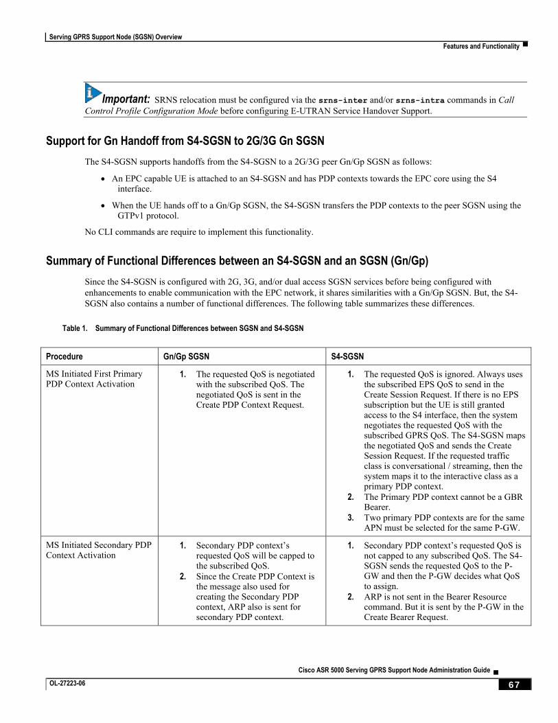
Serving GPRS Support Node (SGSN) Overview
Features and Functionality ▀
Cisco ASR 5000 Serving GPRS Support Node Administration Guide ▄ OL-27223-06 67
Important: SRNS relocation must be configured via the srns-inter and/or srns-intra commands in Call
Control Profile Configuration Mode before configuring E-UTRAN Service Handover Support.
Support for Gn Handoff from S4-SGSN to 2G/3G Gn SGSN
The S4-SGSN supports handoffs from the S4-SGSN to a 2G/3G peer Gn/Gp SGSN as follows:
An EPC capable UE is attached to an S4-SGSN and has PDP contexts towards the EPC core using the S4 interface.
When the UE hands off to a Gn/Gp SGSN, the S4-SGSN transfers the PDP contexts to the peer SGSN using the GTPv1 protocol.
No CLI commands are require to implement this functionality.
Summary of Functional Differences between an S4-SGSN and an SGSN (Gn/Gp)
Since the S4-SGSN is configured with 2G, 3G, and/or dual access SGSN services before being configured with
enhancements to enable communication with the EPC network, it shares similarities with a Gn/Gp SGSN. But, the S4-
SGSN also contains a number of functional differences. The following table summarizes these differences.
Table 1. Summary of Functional Differences between SGSN and S4-SGSN
Procedure Gn/Gp SGSN S4-SGSN
MS Initiated First Primary PDP Context Activation
1. The requested QoS is negotiated with the subscribed QoS. The negotiated QoS is sent in the Create PDP Context Request.
1. The requested QoS is ignored. Always uses the subscribed EPS QoS to send in the Create Session Request. If there is no EPS subscription but the UE is still granted access to the S4 interface, then the system negotiates the requested QoS with the subscribed GPRS QoS. The S4-SGSN maps the negotiated QoS and sends the Create Session Request. If the requested traffic class is conversational / streaming, then the system maps it to the interactive class as a primary PDP context.
2. The Primary PDP context cannot be a GBR Bearer.
3. Two primary PDP contexts are for the same APN must be selected for the same P-GW.
MS Initiated Secondary PDP Context Activation
1. Secondary PDP context’s requested QoS will be capped to the subscribed QoS.
2. Since the Create PDP Context is the message also used for creating the Secondary PDP context, ARP also is sent for secondary PDP context.
1. Secondary PDP context’s requested QoS is not capped to any subscribed QoS. The S4-SGSN sends the requested QoS to the P-GW and then the P-GW decides what QoS to assign.
2. ARP is not sent in the Bearer Resource command. But it is sent by the P-GW in the Create Bearer Request.
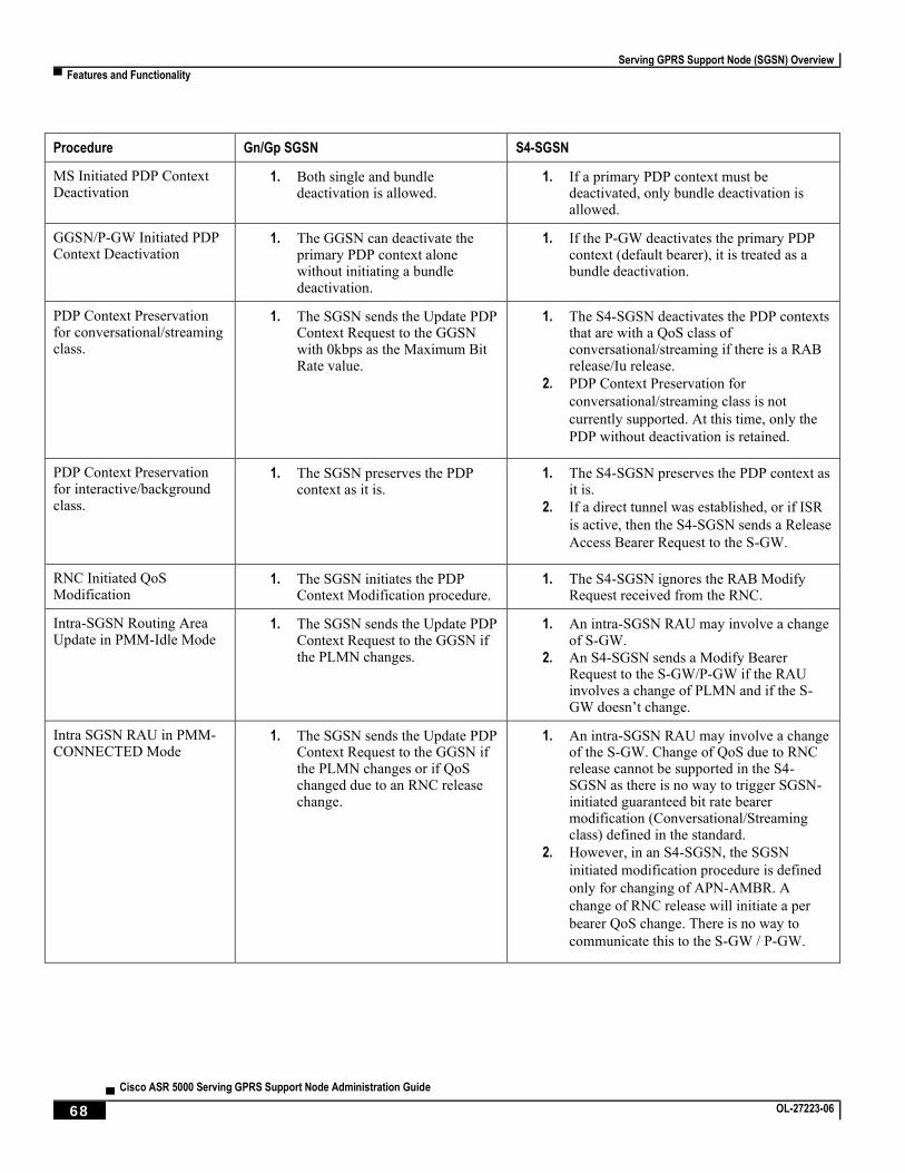
Serving GPRS Support Node (SGSN) Overview
▀ Features and Functionality
▄ Cisco ASR 5000 Serving GPRS Support Node Administration Guide
68 OL-27223-06
Procedure Gn/Gp SGSN S4-SGSN
MS Initiated PDP Context Deactivation
1. Both single and bundle deactivation is allowed.
1. If a primary PDP context must be deactivated, only bundle deactivation is allowed.
GGSN/P-GW Initiated PDP Context Deactivation
1. The GGSN can deactivate the primary PDP context alone without initiating a bundle deactivation.
1. If the P-GW deactivates the primary PDP context (default bearer), it is treated as a bundle deactivation.
PDP Context Preservation for conversational/streaming class.
1. The SGSN sends the Update PDP Context Request to the GGSN with 0kbps as the Maximum Bit Rate value.
1. The S4-SGSN deactivates the PDP contexts that are with a QoS class of conversational/streaming if there is a RAB release/Iu release.
2. PDP Context Preservation for
conversational/streaming class is not
currently supported. At this time, only the
PDP without deactivation is retained.
PDP Context Preservation for interactive/background class.
1. The SGSN preserves the PDP context as it is.
1. The S4-SGSN preserves the PDP context as it is.
2. If a direct tunnel was established, or if ISR
is active, then the S4-SGSN sends a Release
Access Bearer Request to the S-GW.
RNC Initiated QoS Modification
1. The SGSN initiates the PDP Context Modification procedure.
1. The S4-SGSN ignores the RAB Modify Request received from the RNC.
Intra-SGSN Routing Area Update in PMM-Idle Mode
1. The SGSN sends the Update PDP Context Request to the GGSN if the PLMN changes.
1. An intra-SGSN RAU may involve a change of S-GW.
2. An S4-SGSN sends a Modify Bearer Request to the S-GW/P-GW if the RAU involves a change of PLMN and if the S-GW doesn’t change.
Intra SGSN RAU in PMM-CONNECTED Mode
1. The SGSN sends the Update PDP Context Request to the GGSN if the PLMN changes or if QoS changed due to an RNC release change.
1. An intra-SGSN RAU may involve a change of the S-GW. Change of QoS due to RNC release cannot be supported in the S4-SGSN as there is no way to trigger SGSN-initiated guaranteed bit rate bearer modification (Conversational/Streaming class) defined in the standard.
2. However, in an S4-SGSN, the SGSN
initiated modification procedure is defined
only for changing of APN-AMBR. A
change of RNC release will initiate a per
bearer QoS change. There is no way to
communicate this to the S-GW / P-GW.
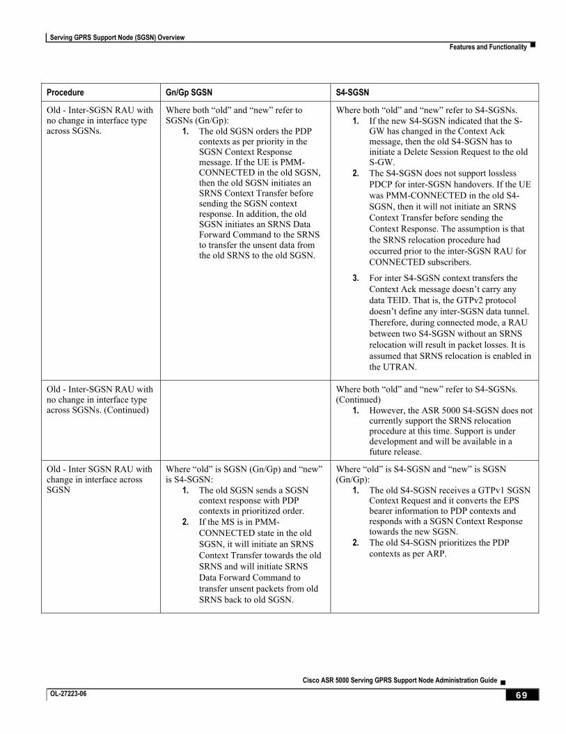
Serving GPRS Support Node (SGSN) Overview
Features and Functionality ▀
Cisco ASR 5000 Serving GPRS Support Node Administration Guide ▄ OL-27223-06 69
Procedure Gn/Gp SGSN S4-SGSN
Old - Inter-SGSN RAU with no change in interface type across SGSNs.
Where both “old” and “new” refer to SGSNs (Gn/Gp):
1. The old SGSN orders the PDP contexts as per priority in the SGSN Context Response message. If the UE is PMM-CONNECTED in the old SGSN, then the old SGSN initiates an SRNS Context Transfer before sending the SGSN context response. In addition, the old SGSN initiates an SRNS Data Forward Command to the SRNS to transfer the unsent data from the old SRNS to the old SGSN.
Where both “old” and “new” refer to S4-SGSNs.
1. If the new S4-SGSN indicated that the S-GW has changed in the Context Ack message, then the old S4-SGSN has to initiate a Delete Session Request to the old S-GW.
2. The S4-SGSN does not support lossless
PDCP for inter-SGSN handovers. If the UE
was PMM-CONNECTED in the old S4-
SGSN, then it will not initiate an SRNS
Context Transfer before sending the
Context Response. The assumption is that
the SRNS relocation procedure had
occurred prior to the inter-SGSN RAU for
CONNECTED subscribers.
3. For inter S4-SGSN context transfers the
Context Ack message doesn’t carry any
data TEID. That is, the GTPv2 protocol
doesn’t define any inter-SGSN data tunnel.
Therefore, during connected mode, a RAU
between two S4-SGSN without an SRNS
relocation will result in packet losses. It is
assumed that SRNS relocation is enabled in
the UTRAN.
Old - Inter-SGSN RAU with no change in interface type across SGSNs. (Continued)
Where both “old” and “new” refer to S4-SGSNs. (Continued)
1. However, the ASR 5000 S4-SGSN does not currently support the SRNS relocation procedure at this time. Support is under development and will be available in a future release.
Old - Inter SGSN RAU with change in interface across SGSN
Where “old” is SGSN (Gn/Gp) and “new” is S4-SGSN:
1. The old SGSN sends a SGSN context response with PDP contexts in prioritized order.
2. If the MS is in PMM-
CONNECTED state in the old
SGSN, it will initiate an SRNS
Context Transfer towards the old
SRNS and will initiate SRNS
Data Forward Command to
transfer unsent packets from old
SRNS back to old SGSN.
Where “old” is S4-SGSN and “new” is SGSN (Gn/Gp):
1. The old S4-SGSN receives a GTPv1 SGSN Context Request and it converts the EPS bearer information to PDP contexts and responds with a SGSN Context Response towards the new SGSN.
2. The old S4-SGSN prioritizes the PDP
contexts as per ARP.
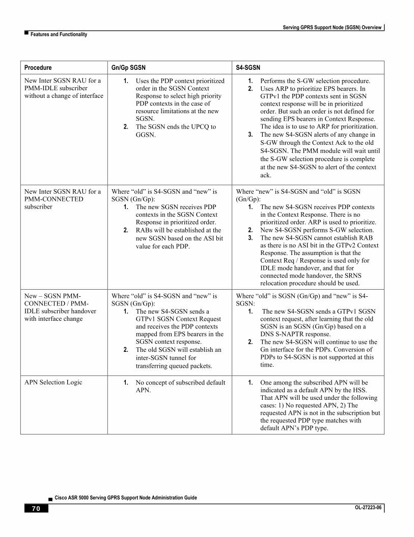
Serving GPRS Support Node (SGSN) Overview
▀ Features and Functionality
▄ Cisco ASR 5000 Serving GPRS Support Node Administration Guide
70 OL-27223-06
Procedure Gn/Gp SGSN S4-SGSN
New Inter SGSN RAU for a PMM-IDLE subscriber without a change of interface
1. Uses the PDP context prioritized order in the SGSN Context Response to select high priority PDP contexts in the case of resource limitations at the new SGSN.
2. The SGSN ends the UPCQ to
GGSN.
1. Performs the S-GW selection procedure.
2. Uses ARP to prioritize EPS bearers. In GTPv1 the PDP contexts sent in SGSN context response will be in prioritized order. But such an order is not defined for sending EPS bearers in Context Response. The idea is to use to ARP for prioritization.
3. The new S4-SGSN alerts of any change in
S-GW through the Context Ack to the old
S4-SGSN. The PMM module will wait until
the S-GW selection procedure is complete
at the new S4-SGSN to alert of the context
ack.
New Inter SGSN RAU for a PMM-CONNECTED subscriber
Where “old” is S4-SGSN and “new” is SGSN (Gn/Gp):
1. The new SGSN receives PDP contexts in the SGSN Context Response in prioritized order.
2. RABs will be established at the
new SGSN based on the ASI bit
value for each PDP.
Where “new” is S4-SGSN and “old” is SGSN (Gn/Gp):
1. The new S4-SGSN receives PDP contexts in the Context Response. There is no prioritized order. ARP is used to prioritize.
2. New S4-SGSN performs S-GW selection.
3. The new S4-SGSN cannot establish RAB as there is no ASI bit in the GTPv2 Context Response. The assumption is that the Context Req / Response is used only for IDLE mode handover, and that for connected mode handover, the SRNS relocation procedure should be used.
New – SGSN PMM-CONNECTED / PMM-IDLE subscriber handover with interface change
Where “old” is S4-SGSN and “new” is SGSN (Gn/Gp):
1. The new S4-SGSN sends a GTPv1 SGSN Context Request and receives the PDP contexts mapped from EPS bearers in the SGSN context response.
2. The old SGSN will establish an
inter-SGSN tunnel for
transferring queued packets.
Where “old” is SGSN (Gn/Gp) and “new” is S4-SGSN:
1. The new S4-SGSN sends a GTPv1 SGSN context request, after learning that the old SGSN is an SGSN (Gn/Gp) based on a DNS S-NAPTR response.
2. The new S4-SGSN will continue to use the Gn interface for the PDPs. Conversion of PDPs to S4-SGSN is not supported at this time.
APN Selection Logic 1. No concept of subscribed default APN.
1. One among the subscribed APN will be indicated as a default APN by the HSS. That APN will be used under the following cases: 1) No requested APN, 2) The requested APN is not in the subscription but the requested PDP type matches with default APN’s PDP type.
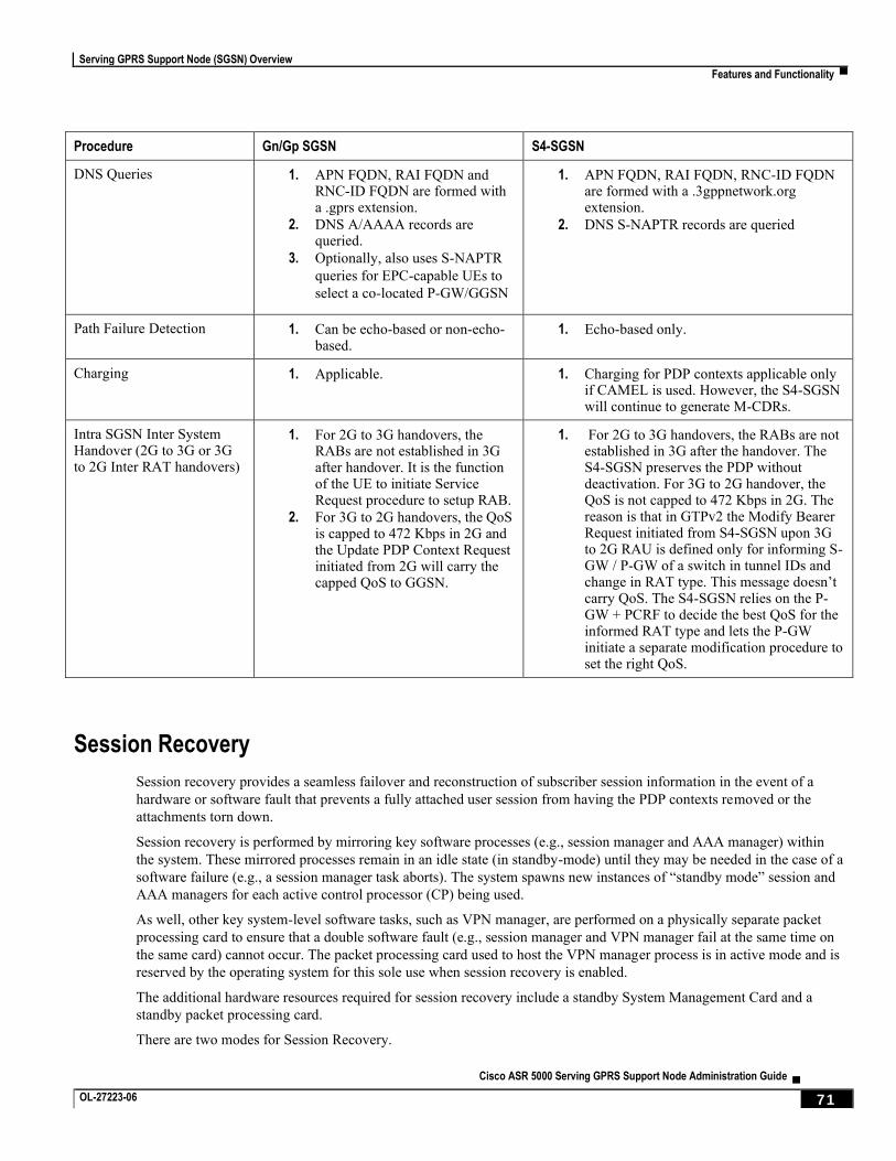
Serving GPRS Support Node (SGSN) Overview
Features and Functionality ▀
Cisco ASR 5000 Serving GPRS Support Node Administration Guide ▄ OL-27223-06 71
Procedure Gn/Gp SGSN S4-SGSN
DNS Queries 1. APN FQDN, RAI FQDN and RNC-ID FQDN are formed with a .gprs extension.
2. DNS A/AAAA records are queried.
3. Optionally, also uses S-NAPTR
queries for EPC-capable UEs to
select a co-located P-GW/GGSN
1. APN FQDN, RAI FQDN, RNC-ID FQDN are formed with a .3gppnetwork.org extension.
2. DNS S-NAPTR records are queried
Path Failure Detection 1. Can be echo-based or non-echo-based.
1. Echo-based only.
Charging 1. Applicable. 1. Charging for PDP contexts applicable only if CAMEL is used. However, the S4-SGSN will continue to generate M-CDRs.
Intra SGSN Inter System Handover (2G to 3G or 3G to 2G Inter RAT handovers)
1. For 2G to 3G handovers, the RABs are not established in 3G after handover. It is the function of the UE to initiate Service Request procedure to setup RAB.
2. For 3G to 2G handovers, the QoS is capped to 472 Kbps in 2G and the Update PDP Context Request initiated from 2G will carry the capped QoS to GGSN.
1. For 2G to 3G handovers, the RABs are not established in 3G after the handover. The S4-SGSN preserves the PDP without deactivation. For 3G to 2G handover, the QoS is not capped to 472 Kbps in 2G. The reason is that in GTPv2 the Modify Bearer Request initiated from S4-SGSN upon 3G to 2G RAU is defined only for informing S-GW / P-GW of a switch in tunnel IDs and change in RAT type. This message doesn’t carry QoS. The S4-SGSN relies on the P-GW + PCRF to decide the best QoS for the informed RAT type and lets the P-GW initiate a separate modification procedure to set the right QoS.
Session Recovery
Session recovery provides a seamless failover and reconstruction of subscriber session information in the event of a
hardware or software fault that prevents a fully attached user session from having the PDP contexts removed or the
attachments torn down.
Session recovery is performed by mirroring key software processes (e.g., session manager and AAA manager) within
the system. These mirrored processes remain in an idle state (in standby-mode) until they may be needed in the case of a
software failure (e.g., a session manager task aborts). The system spawns new instances of “standby mode” session and
AAA managers for each active control processor (CP) being used.
As well, other key system-level software tasks, such as VPN manager, are performed on a physically separate packet
processing card to ensure that a double software fault (e.g., session manager and VPN manager fail at the same time on
the same card) cannot occur. The packet processing card used to host the VPN manager process is in active mode and is
reserved by the operating system for this sole use when session recovery is enabled.
The additional hardware resources required for session recovery include a standby System Management Card and a
standby packet processing card.
There are two modes for Session Recovery.
Serving GPRS Support Node (SGSN) Overview
▀ Features and Functionality
▄ Cisco ASR 5000 Serving GPRS Support Node Administration Guide
72 OL-27223-06
Task recovery mode: One or more session manager failures occur and are recovered without the need to use resources on a standby packet processor card. In this mode, recovery is performed by using the mirrored “standby-mode” session manager task(s) running on active packet processor cards. The “standby-mode” task is renamed, made active, and is then populated using information from other tasks such as AAA manager.
Full packet processing card recovery mode: Used when a packet processing card hardware failure occurs, or when a packet processor card migration failure happens. In this mode, the standby packet processor card is made active and the “standby-mode” session manager and AAA manager tasks on the newly activated packet processor card perform session recovery.
Session/Call state information is saved in the peer AAA manager task because each AAA manager and session manager
task is paired together. These pairs are started on physically different packet processor cards to ensure task recovery.
When session recovery occurs, the system reconstructs the following subscriber information:
Data and control state information required to maintain correct call behavior
Subscriber data statistics that are required to ensure that accounting information is maintained
A best-effort attempt to recover various timer values such as call duration, absolute time, and others
For more information on session recovery use and session recovery configuration, refer to the Session Recovery section
in the Cisco ASR 5000 Series System Administration Guide.
SGSN Pooling and Iu-Flex / Gb-Flex
This implementation allows carriers to load balance sessions among pooled SGSNs, to improve reliability and
efficiency of call handling, and to use Iu-Flex / Gb-Flex to provide carriers with deterministic failure recovery.
The SGSN, with its high capacity, signaling performance, and peering capabilities, combined with its level of fault
tolerance, delivers many of the benefits of Flex functionality even without deploying SGSN pooling.
As defined by 3GPP TS 23.236, the SGSN implements Iu-Flex and Gb-Flex functionality to facilitate network sharing
and to ensure SGSN pooling for 2.5G and 3G accesses as both separate pools and as dual-access pools.
SGSN pooling enables the following:
Eliminates the single point of failure between an RNC and an SGSN or between a BSS and an SGSN.
Ensures geographical redundancy, as a pool can be distributed across sites.
Minimizes subscriber impact during service, maintenance, or node additions or replacements.
Increases overall capacity via load sharing across the SGSNs in a pool.
Reduces the need/frequency for inter-SGSN RAUs. This substantially reduces signaling load and data transfer delays.
Supports load redistribution with the SGSN offloading procedure.
Gb/Iu Flex Offloading
The SGSN supports Gb/Iu Flex subscriber offloading from one SGSN to another specific SGSN in a 2G/3G pool.
In addition, the operator can configure the offloading Target NRI in P-TMSI, and the quantity to offload to the Target.
This can be used to provide load balancing, or to offload a single node in pool, take it out of service for whatever reason
(e.g., maintenance).
Serving GPRS Support Node (SGSN) Overview
Features and Functionality ▀
Cisco ASR 5000 Serving GPRS Support Node Administration Guide ▄ OL-27223-06 73
Short Message Service (SMS over Gd)
The SGSN implements a configurable Short Message Service (SMS) to support sending and receiving text messages up
to 140 octets in length. The SGSN handles multiple, simultaneous messages of both types: those sent from the MS/UE
(SMS-MO: mobile originating) and those sent to the MS/UE (SMS-MT: mobile terminating). Short Message Service is
disabled by default.
After verifying a subscription for the PLMN’s SMS service, the SGSN connects with the SMSC (short message service
center), via a Gd interface, to relay received messages (from a mobile) using MAP-MO-FORWARD-REQUESTs for
store-and-forward.
In the reverse, the SGSN awaits messages from the SMSC via MAP-MT-FORWARD-REQUESTs and checks the
subscriber state before relaying them to the target MS/UE.
The SGSN will employ both the Page procedure and MNRG (mobile not reachable for GPRS) flags in an attempt to
deliver messages to subscribers that are absent.
The SGSN supports
charging for SMS messages, and
lawful intercept of SMS messages
SMS Authentication Repetition Rate
The SGSN provides an authentication procedures for standard GMM events like Attach, Detach, RAU, and Service-
Request, and SMS events such as Activate, all with support for 1-in-N Authenticate functionality. The SGSN did not
provide the capability to authenticate MO/MT SMS events.
Now, the authentication functionality has been expanded to the Gs interface where the SGSN now supports
configuration of the authentication repetition rate for SMS-MO and SMS-MT, for every nth event. This functionality is
built on existing SMS CLI, with configurable MO and/or MT. The default is not to authenticate.
SMSC Address Denial
Previously, the SGSN supported restricting MO-SMS and MT-SMS only through SGSN operator policy configuration.
Now, the SGSN can restrict forwarding of SMS messages to specific SMSC addresses, in order to allow operators to
block SMS traffic that cannot be charged for. This functionality supports multiple SMSCs and is configurable per
SMSC address with a maximum of 10 addresses. It is also configurable for MO-SMS and/or MT-SMS messages.
Threshold Crossing Alerts (TCA) Support
Thresholding on the system is used to monitor the system for conditions that could potentially cause errors or outage.
Typically, these conditions are temporary (i.e high CPU utilization, or packet collisions on a network) and are quickly
resolved. However, continuous or large numbers of these error conditions within a specific time interval may be
indicative of larger, more severe issues. The purpose of thresholding is to help identify potentially severe conditions so
that immediate action can be taken to minimize and/or avoid system downtime.
The system supports Threshold Crossing Alerts for certain key resources such as CPU, memory, number of sessions etc.
With this capability, the operator can configure threshold on these resources whereby, should the resource depletion
cross the configured threshold, a SNMP Trap would be sent.
Serving GPRS Support Node (SGSN) Overview
▀ Features and Functionality
▄ Cisco ASR 5000 Serving GPRS Support Node Administration Guide
74 OL-27223-06
The following thresholding models are supported by the system:
Alert: A value is monitored and an alert condition occurs when the value reaches or exceeds the configured high threshold within the specified polling interval. The alert is generated then generated and/or sent at the end of the polling interval.
Alarm: Both high and low threshold are defined for a value. An alarm condition occurs when the value reaches or exceeds the configured high threshold within the specified polling interval. The alert is generated then generated and/or sent at the end of the polling interval.
Thresholding reports conditions using one of the following mechanisms:
SNMP traps: SNMP traps have been created that indicate the condition (high threshold crossing and/or clear) of each of the monitored values.
Generation of specific traps can be enabled or disabled on the chassis. Ensuring that only important faults get displayed.
SNMP traps are supported in both Alert and Alarm modes.
Logs: The system provides a facility called threshold for which active and event logs can be generated. As with other system facilities, logs are generated Log messages pertaining to the condition of a monitored value are generated with a severity level of WARNING.
Logs are supported in both the Alert and the Alarm models.
Alarm System: High threshold alarms generated within the specified polling interval are considered “outstanding” until a the condition no longer exists or a condition clear alarm is generated. “Outstanding” alarms are reported to the system's alarm subsystem and are viewable through the Alarm Management menu in the Web Element Manager.
The Alarm System is used only in conjunction with the Alarm model.
Important: For more information on threshold crossing alert configuration, refer to the Thresholding
Configuration Guide.
Tracking Usage of GEA Encryption Algorithms
GPRS encryption algorithm (GEA) significantly affects the SGSN processing capacity based on the GEAx level used -
GEA1, GEA2, or GEA3.
Operators would like to be able to identify the percentages of their customer base that are using the various GEA
encryption algorithms. The same tool can also track the migration trend from GEA2 to GEA3 and allow an operator to
forecast the need for additional SGSN capacity.
New fields and counters have been added to the output generated by the show subscribers gprs-only|sgsn-
only summary command. This new information enables the operator to track the number of subscribers capable of
GEA0-GEO3 and to easily see the number of subscribers with negotiated GEAx levels.
VLR Pooling via the Gs Interface
VLR Pooling, also known as Gs Pooling, helps to reduce call delays and call dropping, when the MS/UE is in motion,
by routing a service request to a core network (CN) node with available resources.
VLR pools are configured in the Gs Service, which supports the Gs interface configuration for communication with
VLRs and MSCs.

Serving GPRS Support Node (SGSN) Overview
Features and Functionality ▀
Cisco ASR 5000 Serving GPRS Support Node Administration Guide ▄ OL-27223-06 75
A pool area is a geographical area within which an MS/UE can roam without the need to change the serving CN node.
A pool area is served by one or more CN nodes in parallel. All the cells, controlled by an RNC or a BSC belong to the
same one (or more) pool area(s).
VLR hash is used when a pool of VLRs is serving a particular LAC (or list of LACs). The selection of VLR from this
pool is based on the IMSI digits. From the IMSI, the SGSN derives a hash value (V) using the algorithm: [(IMSI div 10)
modulo 1000]. Every hash value (V) from the range 0 to 999 corresponds to a single MSC/VLR node. Typically many
values of (V) may point to the same MSC/VLR node.
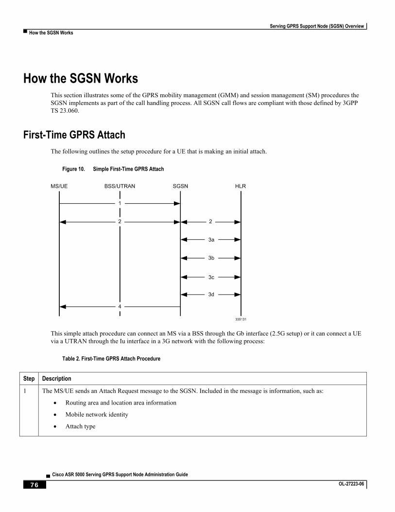
Serving GPRS Support Node (SGSN) Overview
▀ How the SGSN Works
▄ Cisco ASR 5000 Serving GPRS Support Node Administration Guide
76 OL-27223-06
How the SGSN Works This section illustrates some of the GPRS mobility management (GMM) and session management (SM) procedures the
SGSN implements as part of the call handling process. All SGSN call flows are compliant with those defined by 3GPP
TS 23.060.
First-Time GPRS Attach
The following outlines the setup procedure for a UE that is making an initial attach.
Figure 10. Simple First-Time GPRS Attach
This simple attach procedure can connect an MS via a BSS through the Gb interface (2.5G setup) or it can connect a UE
via a UTRAN through the Iu interface in a 3G network with the following process:
Table 2. First-Time GPRS Attach Procedure
Step Description
1 The MS/UE sends an Attach Request message to the SGSN. Included in the message is information, such as:
Routing area and location area information
Mobile network identity
Attach type
Serving GPRS Support Node (SGSN) Overview
How the SGSN Works ▀
Cisco ASR 5000 Serving GPRS Support Node Administration Guide ▄ OL-27223-06 77
Step Description
2 Authentication is mandatory if no MM context exists for the MS/UE:
The SGSN gets a random value (RAND) from the HLR to use as a challenge to the MS/UE.
The SGSN sends a Authentication Request message to the UE containing the random RAND.
The MS/UE contains a SIM that contains a secret key (Ki) shared between it and the HLR called a Individual Subscriber Key. The UE uses an algorithm to process the RAND and Ki to get the session key (Kc) and the signed response (SRES).
The MS/UE sends a Authentication Response to the SGSN containing the SRES.
3 The SGSN updates location information for the MS/UE: a) The SGSN sends an Update Location message, to the HLR, containing the SGSN number, SGSN address, and IMSI. b) The HLR sends an Insert Subscriber Data message to the “new” SGSN. It contains subscriber information such as IMSI and GPRS subscription data. c) The “New” SGSN validates the MS/UE in new routing area: If invalid: The SGSN rejects the Attach Request with the appropriate cause code. If valid: The SGSN creates a new MM context for the MS/UE and sends a Insert Subscriber Data Ack back to the HLR. d) The HLR sends a Update Location Ack to the SGSN after it successfully clears the old MM context and creates new one
4 The SGSN sends an Attach Accept message to the MS/UE containing the P-TMSI (included if it is new), VLR TMSI, P-TMSI Signature, and Radio Priority SMS. At this point the GPRS Attach is complete and the SGSN begins generating M-CDRs.
If the MS/UE initiates a second call, the procedure is more complex and involves information exchanges and validations
between “old” and “new” SGSNs and “old” and “new” MSC/VLRs. The details of this combined GPRS/IMSI attach
procedure can be found in 3GPP TS23.060.
PDP Context Activation Procedures
The following figure provides a high-level view of the PDP Context Activation procedure performed by the SGSN to
establish PDP contexts for the MS with a BSS-Gb interface connection or a UE with a UTRAN-Iu interface connection.
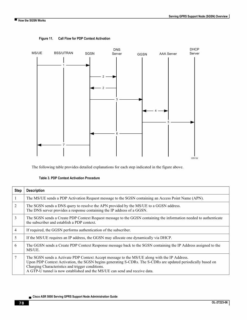
Serving GPRS Support Node (SGSN) Overview
▀ How the SGSN Works
▄ Cisco ASR 5000 Serving GPRS Support Node Administration Guide
78 OL-27223-06
Figure 11. Call Flow for PDP Context Activation
The following table provides detailed explanations for each step indicated in the figure above.
Table 3. PDP Context Activation Procedure
Step Description
1 The MS/UE sends a PDP Activation Request message to the SGSN containing an Access Point Name (APN).
2 The SGSN sends a DNS query to resolve the APN provided by the MS/UE to a GGSN address. The DNS server provides a response containing the IP address of a GGSN.
3 The SGSN sends a Create PDP Context Request message to the GGSN containing the information needed to authenticate the subscriber and establish a PDP context.
4 If required, the GGSN performs authentication of the subscriber.
5 If the MS/UE requires an IP address, the GGSN may allocate one dynamically via DHCP.
6 The GGSN sends a Create PDP Context Response message back to the SGSN containing the IP Address assigned to the MS/UE.
7 The SGSN sends a Activate PDP Context Accept message to the MS/UE along with the IP Address. Upon PDP Context Activation, the SGSN begins generating S-CDRs. The S-CDRs are updated periodically based on Charging Characteristics and trigger conditions. A GTP-U tunnel is now established and the MS/UE can send and receive data.
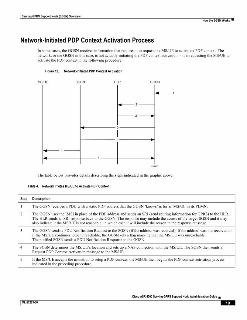
Serving GPRS Support Node (SGSN) Overview
How the SGSN Works ▀
Cisco ASR 5000 Serving GPRS Support Node Administration Guide ▄ OL-27223-06 79
Network-Initiated PDP Context Activation Process
In some cases, the GGSN receives information that requires it to request the MS/UE to activate a PDP context. The
network, or the GGSN in this case, is not actually initiating the PDP context activation -- it is requesting the MS/UE to
activate the PDP context in the following procedure:
Figure 12. Network-Initiated PDP Context Activation
The table below provides details describing the steps indicated in the graphic above.
Table 4. Network Invites MS/UE to Activate PDP Context
Step Description
1 The GGSN receives a PDU with a static PDP address that the GGSN ‘knows’ is for an MS/UE in its PLMN.
2 The GGSN uses the IMSI in place of the PDP address and sends an SRI (send routing information for GPRS) to the HLR. The HLR sends an SRI response back to the GGSN. The response may include the access of the target SGSN and it may also indicate it the MS/UE is not reachable, in which case it will include the reason in the response message.
3 The GGSN sends a PDU Notification Request to the SGSN (if the address was received). If the address was not received or if the MS/UE continues to be unreachable, the GGSN sets a flag marking that the MS/UE was unreachable. The notified SGSN sends a PDU Notification Response to the GGSN.
4 The SGSN determines the MS/UE’s location and sets up a NAS connection with the MS/UE. The SGSN then sends a Request PDP Context Activation message to the MS/UE.
5 If the MS/UE accepts the invitation to setup a PDP context, the MS/UE then begins the PDP context activation process indicated in the preceding procedure.
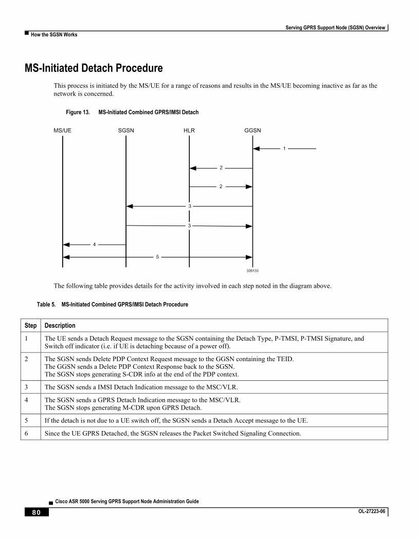
Serving GPRS Support Node (SGSN) Overview
▀ How the SGSN Works
▄ Cisco ASR 5000 Serving GPRS Support Node Administration Guide
80 OL-27223-06
MS-Initiated Detach Procedure
This process is initiated by the MS/UE for a range of reasons and results in the MS/UE becoming inactive as far as the
network is concerned.
Figure 13. MS-Initiated Combined GPRS/IMSI Detach
The following table provides details for the activity involved in each step noted in the diagram above.
Table 5. MS-Initiated Combined GPRS/IMSI Detach Procedure
Step Description
1 The UE sends a Detach Request message to the SGSN containing the Detach Type, P-TMSI, P-TMSI Signature, and Switch off indicator (i.e. if UE is detaching because of a power off).
2 The SGSN sends Delete PDP Context Request message to the GGSN containing the TEID. The GGSN sends a Delete PDP Context Response back to the SGSN. The SGSN stops generating S-CDR info at the end of the PDP context.
3 The SGSN sends a IMSI Detach Indication message to the MSC/VLR.
4 The SGSN sends a GPRS Detach Indication message to the MSC/VLR. The SGSN stops generating M-CDR upon GPRS Detach.
5 If the detach is not due to a UE switch off, the SGSN sends a Detach Accept message to the UE.
6 Since the UE GPRS Detached, the SGSN releases the Packet Switched Signaling Connection.
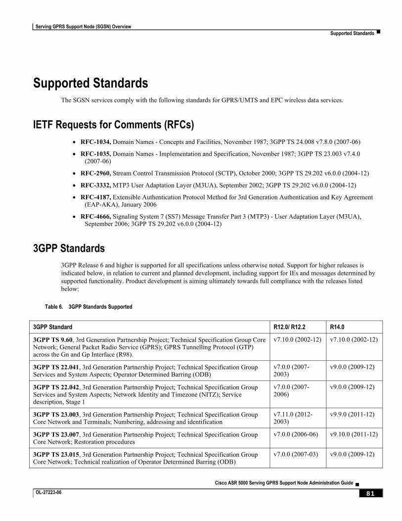
Serving GPRS Support Node (SGSN) Overview
Supported Standards ▀
Cisco ASR 5000 Serving GPRS Support Node Administration Guide ▄ OL-27223-06 81
Supported Standards The SGSN services comply with the following standards for GPRS/UMTS and EPC wireless data services.
IETF Requests for Comments (RFCs)
RFC-1034, Domain Names - Concepts and Facilities, November 1987; 3GPP TS 24.008 v7.8.0 (2007-06)
RFC-1035, Domain Names - Implementation and Specification, November 1987; 3GPP TS 23.003 v7.4.0 (2007-06)
RFC-2960, Stream Control Transmission Protocol (SCTP), October 2000; 3GPP TS 29.202 v6.0.0 (2004-12)
RFC-3332, MTP3 User Adaptation Layer (M3UA), September 2002; 3GPP TS 29.202 v6.0.0 (2004-12)
RFC-4187, Extensible Authentication Protocol Method for 3rd Generation Authentication and Key Agreement (EAP-AKA), January 2006
RFC-4666, Signaling System 7 (SS7) Message Transfer Part 3 (MTP3) - User Adaptation Layer (M3UA), September 2006; 3GPP TS 29.202 v6.0.0 (2004-12)
3GPP Standards
3GPP Release 6 and higher is supported for all specifications unless otherwise noted. Support for higher releases is
indicated below, in relation to current and planned development, including support for IEs and messages determined by
supported functionality. Product development is aiming ultimately towards full compliance with the releases listed
below:
Table 6. 3GPP Standards Supported
3GPP Standard R12.0/ R12.2 R14.0
3GPP TS 9.60, 3rd Generation Partnership Project; Technical Specification Group Core Network; General Packet Radio Service (GPRS); GPRS Tunnelling Protocol (GTP) across the Gn and Gp Interface (R98).
v7.10.0 (2002-12) v7.10.0 (2002-12)
3GPP TS 22.041, 3rd Generation Partnership Project; Technical Specification Group Services and System Aspects; Operator Determined Barring (ODB)
v7.0.0 (2007-2003)
v9.0.0 (2009-12)
3GPP TS 22.042, 3rd Generation Partnership Project; Technical Specification Group Services and System Aspects; Network Identity and Timezone (NITZ); Service description, Stage 1
v7.0.0 (2007-2006)
v9.0.0 (2009-12)
3GPP TS 23.003, 3rd Generation Partnership Project; Technical Specification Group Core Network and Terminals; Numbering, addressing and identification
v7.11.0 (2012-2003)
v9.9.0 (2011-12)
3GPP TS 23.007, 3rd Generation Partnership Project; Technical Specification Group Core Network; Restoration procedures
v7.0.0 (2006-06) v9.10.0 (2011-12)
3GPP TS 23.015, 3rd Generation Partnership Project; Technical Specification Group Core Network; Technical realization of Operator Determined Barring (ODB)
v7.0.0 (2007-03) v9.0.0 (2009-12)
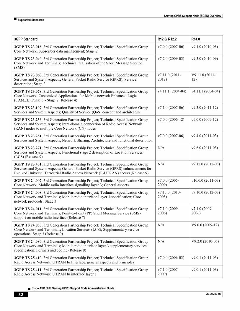
Serving GPRS Support Node (SGSN) Overview
▀ Supported Standards
▄ Cisco ASR 5000 Serving GPRS Support Node Administration Guide
82 OL-27223-06
3GPP Standard R12.0/ R12.2 R14.0
3GPP TS 23.016, 3rd Generation Partnership Project; Technical Specification Group Core Network; Subscriber data management; Stage 2
v7.0.0 (2007-06) v9.1.0 (2010-03)
3GPP TS 23.040, 3rd Generation Partnership Project; Technical Specification Group Core Network and Terminals; Technical realization of the Short Message Service (SMS)
v7.2.0 (2009-03) v9.3.0 (2010-09)
3GPP TS 23.060, 3rd Generation Partnership Project; Technical Specification Group Services and System Aspects; General Packet Radio Service (GPRS); Service description; Stage 2
v7.11.0 (2011-2012)
V9.11.0 (2011-12)
3GPP TS 23.078, 3rd Generation Partnership Project; Technical Specification Group Core Network; Customized Applications for Mobile network Enhanced Logic (CAMEL) Phase 3 - Stage 2 (Release 4)
v4.11.1 (2004-04) v4.11.1 (2004-04)
3GPP TS 23.107, 3rd Generation Partnership Project; Technical Specification Group Services and System Aspects; Quality of Service (QoS) concept and architecture
v7.1.0 (2007-06) v9.3.0 (2011-12)
3GPP TS 23.236, 3rd Generation Partnership Project; Technical Specification Group Services and System Aspects; Intra-domain connection of Radio Access Network (RAN) nodes to multiple Core Network (CN) nodes
v7.0.0 (2006-12) v9.0.0 (2009-12)
3GPP TS 23.251, 3rd Generation Partnership Project; Technical Specification Group Services and System Aspects; Network Sharing; Architecture and functional description
v7.0.0 (2007-06) v9.4.0 (2011-03)
3GPP TS 23.271, 3rd Generation Partnership Project; Technical Specification Group Services and System Aspects; Functional stage 2 description of Location Services (LCS) (Release 9)
N/A v9.6.0 (2011-03)
3GPP TS 23.401, 3rd Generation Partnership Project; Technical Specification Group Services and System Aspects; General Packet Radio Service (GPRS) enhancements for Evolved Universal Terrestrial Radio Access Network (E-UTRAN) access (Release 9)
N/A v9.12.0 (2012-03)
3GPP TS 24.007, 3rd Generation Partnership Project; Technical Specification Group Core Network; Mobile radio interface signalling layer 3; General aspects
v7.0.0 (2005-2009)
v10.0.0 (2011-03)
3GPP TS 24.008, 3rd Generation Partnership Project; Technical Specification Group Core Network and Terminals; Mobile radio interface Layer 3 specification; Core network protocols; Stage 3
v7.15.0 (2010-2003)
v9.10.0 (2012-03)
3GPP TS 24.011, 3rd Generation Partnership Project; Technical Specification Group Core Network and Terminals; Point-to-Point (PP) Short Message Service (SMS) support on mobile radio interface (Release 7)
v7.1.0 (2009-2006)
v7.1.0 (2009-2006)
3GPP TS 24.030, 3rd Generation Partnership Project; Technical Specification Group Core Network and Terminals; Location Services (LCS); Supplementary service operations; Stage 3 (Release 9)
N/A V9.0.0 (2009-12)
3GPP TS 24.080, 3rd Generation Partnership Project; Technical Specification Group Core Network and Terminals; Mobile radio interface layer 3 supplementary services specification; Formats and coding (Release 9)
N/A V9.2.0 (2010-06)
3GPP TS 25.410, 3rd Generation Partnership Project; Technical Specification Group Radio Access Network; UTRAN Iu Interface: general aspects and principles
v7.0.0 (2006-03) v9.0.1 (2011-03)
3GPP TS 25.411, 3rd Generation Partnership Project; Technical Specification Group Radio Access Network; UTRAN Iu interface layer 1
v7.1.0 (2007-2009)
v9.0.1 (2011-03)
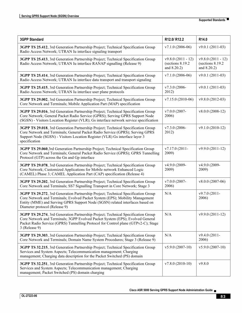
Serving GPRS Support Node (SGSN) Overview
Supported Standards ▀
Cisco ASR 5000 Serving GPRS Support Node Administration Guide ▄ OL-27223-06 83
3GPP Standard R12.0/ R12.2 R14.0
3GPP TS 25.412, 3rd Generation Partnership Project; Technical Specification Group Radio Access Network; UTRAN Iu interface signaling transport
v7.1.0 (2006-06) v9.0.1 (2011-03)
3GPP TS 25.413, 3rd Generation Partnership Project; Technical Specification Group Radio Access Network; UTRAN Iu interface RANAP signalling (Release 9)
v9.8.0 (2011 - 12) (sections 8.19.2 and 8.20.2)
v9.8.0 (2011 - 12) (sections 8.19.2 and 8.20.2)
3GPP TS 25.414, 3rd Generation Partnership Project; Technical Specification Group Radio Access Network; UTRAN Iu interface data transport and transport signaling
v7.1.0 (2006-06) v9.0.1 (2011-03)
3GPP TS 25.415, 3rd Generation Partnership Project; Technical Specification Group Radio Access Network; UTRAN Iu interface user plane protocols
v7.3.0 (2006-2012)
v9.0.1 (2011-03)
3GPP TS 29.002, 3rd Generation Partnership Project; Technical Specification Group Core Network and Terminals; Mobile Application Part (MAP) specification
v7.15.0 (2010-06) v9.8.0 (2012-03)
3GPP TS 29.016, 3rd Generation Partnership Project; Technical Specification Group Core Network; General Packet Radio Service (GPRS); Serving GPRS Support Node (SGSN) - Visitors Location Register (VLR); Gs interface network service specification
v7.0.0 (2007-2006)
v8.0.0 (2008-12)
3GPP TS 29.018, 3rd Generation Partnership Project; Technical Specification Group Core Network and Terminals; General Packet Radio Service (GPRS); Serving GPRS Support Node (SGSN) - Visitors Location Register (VLR) Gs interface layer 3 specification
v7.3.0 (2006-2012)
v9.1.0 (2010-12)
3GPP TS 29.060,3rd Generation Partnership Project; Technical Specification Group Core Network and Terminals; General Packet Radio Service (GPRS); GPRS Tunnelling Protocol (GTP) across the Gn and Gp interface
v7.17.0 (2011-2009)
v9.9.0 (2011-12)
3GPP TS 29.078, 3rd Generation Partnership Project; Technical Specification Group Core Network; Customized Applications for Mobile network Enhanced Logic (CAMEL) Phase 3; CAMEL Application Part (CAP) specification (Release 4)
v4.9.0 (2009-2009)
v4.9.0 (2009-2009)
3GPP TS 29.202, 3rd Generation Partnership Project; Technical Specification Group Core Network and Terminals; SS7 Signalling Transport in Core Network; Stage 3
v7.0.0 (2007-2006)
v8.0.0 (2007-06)
3GPP TS 29.272, 3rd Generation Partnership Project; Technical Specification Group Core Network and Terminals; Evolved Packet System (EPS); Mobility Management Entity (MME) and Serving GPRS Support Node (SGSN) related interfaces based on Diameter protocol (Release 9)
N/A v9.7.0 (2011-2006)
3GPP TS 29.274, 3rd Generation Partnership Project; Technical Specification Group Core Network and Terminals; 3GPP Evolved Packet System (EPS); Evolved General Packet Radio Service (GPRS) Tunnelling Protocol for Control plane (GTPv2-C); Stage 3 (Release 9)
N/A v9.9.0 (2011-12)
3GPP TS 29.303, 3rd Generation Partnership Project; Technical Specification Group Core Network and Terminals; Domain Name System Procedures; Stage 3 (Release 9)
N/A v9.4.0 (2011-2006)
3GPP TS 32.215, 3rd Generation Partnership Project; Technical Specification Group Services and System Aspects; Telecommunication management; Charging management; Charging data description for the Packet Switched (PS) domain
v5.9.0 (2007-10) v5.9.0 (2007-10)
3GPP TS 32.251, 3rd Generation Partnership Project; Technical Specification Group Services and System Aspects; Telecommunication management; Charging management; Packet Switched (PS) domain charging
v7.8.0 (2010-10) v9.8.0
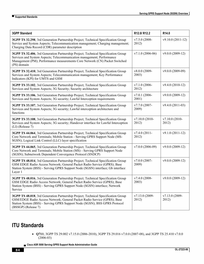
Serving GPRS Support Node (SGSN) Overview
▀ Supported Standards
▄ Cisco ASR 5000 Serving GPRS Support Node Administration Guide
84 OL-27223-06
3GPP Standard R12.0/ R12.2 R14.0
3GPP TS 32.298, 3rd Generation Partnership Project; Technical Specification Group Service and System Aspects; Telecommunication management; Charging management; Charging Data Record (CDR) parameter description
v7.5.0 (2008-2012)
v9.10.0 (2011-12)
3GPP TS 32.406, 3rd Generation Partnership Project; Technical Specification Group Services and System Aspects; Telecommunication management; Performance Management (PM); Performance measurements Core Network (CN) Packet Switched (PS) domain
v7.1.0 (2006-06) v9.0.0 (2009-12)
3GPP TS 32.410, 3rd Generation Partnership Project; Technical Specification Group Services and System Aspects; Telecommunication management; Key Performance Indicators (KPI) for UMTS and GSM
v8.0.0 (2009-2003)
v9.0.0 (2009-09)
3GPP TS 33.102, 3rd Generation Partnership Project; Technical Specification Group Services and System Aspects; 3G Security; Security architecture
v7.1.0 (2006-2012)
v9.4.0 (2010-12)
3GPP TS 33.106, 3rd Generation Partnership Project; Technical Specification Group Services and System Aspects; 3G security; Lawful Interception requirements
v7.0.1 (2006-2001)
v9.0.0 (2009-12)
3GPP TS 33.107, 3rd Generation Partnership Project; Technical Specification Group Services and System Aspects; 3G security; Lawful interception architecture and functions
v7.7.0 (2007-2009)
v9.4.0 (2011-03)
3GPP TS 33.108, 3rd Generation Partnership Project; Technical Specification Group Services and System Aspects; 3G security; Handover interface for Lawful Interception (LI) (Release 7)
v7.10.0 (2010-2012)
v7.10.0 (2010-2012)
3GPP TS 44.064, 3rd Generation Partnership Project; Technical Specification Group Core Network and Terminals; Mobile Station - Serving GPRS Support Node (MS-SGSN); Logical Link Control (LLC) layer specification
v7.4.0 (2011-2012)
v9.1.0 (2011-12)
3GPP TS 44.065, 3rd Generation Partnership Project; Technical Specification Group Core Network and Terminals; Mobile Station (MS) - Serving GPRS Support Node (SGSN); Subnetwork Dependent Convergence Protocol (SNDCP)
v7.0.0 (2006-09) v9.0.0 (2009-12)
3GPP TS 48.014, 3rd Generation Partnership Project; Technical Specification Group GSM EDGE Radio Access Network; General Packet Radio Service (GPRS); Base Station System (BSS) - Serving GPRS Support Node (SGSN) interface; Gb interface Layer 1
v7.0.0 (2007-2009)
v9.0.0 (2009-12)
3GPP TS 48.016, 3rd Generation Partnership Project; Technical Specification Group GSM EDGE Radio Access Network; General Packet Radio Service (GPRS); Base Station System (BSS) - Serving GPRS Support Node (SGSN) interface; Network Service
v7.4.0 (2008-2003)
v9.0.0 (2009-12)
3GPP TS 48.018, 3rd Generation Partnership Project; Technical Specification Group GSM/EDGE Radio Access Network; General Packet Radio Service (GPRS); Base Station System (BSS) - Serving GPRS Support Node (SGSN); BSS GPRS Protocol (BSSGP) (Release 7)
v7.13.0 (2009-2012)
v7.13.0 (2009-2012)
ITU Standards
Q711; 3GPP TS 29.002 v7.15.0 (2006-2010), 3GPP TS 29.016 v7.0.0 (2007-08), and 3GPP TS 25.410 v7.0.0 (2006-03)
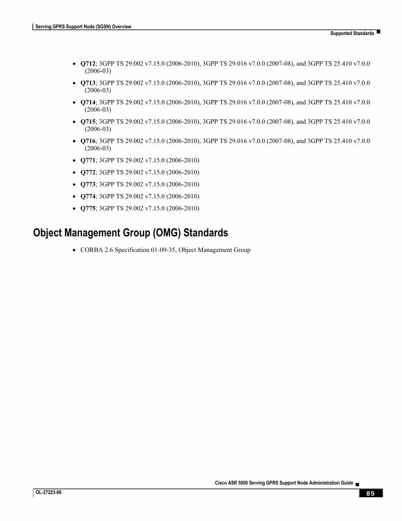
Serving GPRS Support Node (SGSN) Overview
Supported Standards ▀
Cisco ASR 5000 Serving GPRS Support Node Administration Guide ▄ OL-27223-06 85
Q712; 3GPP TS 29.002 v7.15.0 (2006-2010), 3GPP TS 29.016 v7.0.0 (2007-08), and 3GPP TS 25.410 v7.0.0 (2006-03)
Q713; 3GPP TS 29.002 v7.15.0 (2006-2010), 3GPP TS 29.016 v7.0.0 (2007-08), and 3GPP TS 25.410 v7.0.0 (2006-03)
Q714; 3GPP TS 29.002 v7.15.0 (2006-2010), 3GPP TS 29.016 v7.0.0 (2007-08), and 3GPP TS 25.410 v7.0.0 (2006-03)
Q715; 3GPP TS 29.002 v7.15.0 (2006-2010), 3GPP TS 29.016 v7.0.0 (2007-08), and 3GPP TS 25.410 v7.0.0 (2006-03)
Q716; 3GPP TS 29.002 v7.15.0 (2006-2010), 3GPP TS 29.016 v7.0.0 (2007-08), and 3GPP TS 25.410 v7.0.0 (2006-03)
Q771; 3GPP TS 29.002 v7.15.0 (2006-2010)
Q772; 3GPP TS 29.002 v7.15.0 (2006-2010)
Q773; 3GPP TS 29.002 v7.15.0 (2006-2010)
Q774; 3GPP TS 29.002 v7.15.0 (2006-2010)
Q775; 3GPP TS 29.002 v7.15.0 (2006-2010)
Object Management Group (OMG) Standards
CORBA 2.6 Specification 01-09-35, Object Management Group

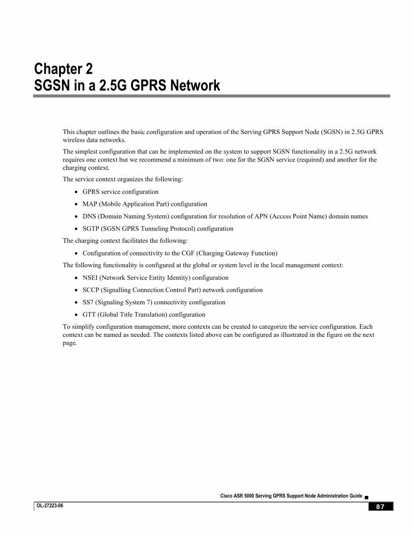
Cisco ASR 5000 Serving GPRS Support Node Administration Guide ▄ OL-27223-06 87
Chapter 2 SGSN in a 2.5G GPRS Network
This chapter outlines the basic configuration and operation of the Serving GPRS Support Node (SGSN) in 2.5G GPRS
wireless data networks.
The simplest configuration that can be implemented on the system to support SGSN functionality in a 2.5G network
requires one context but we recommend a minimum of two: one for the SGSN service (required) and another for the
charging context.
The service context organizes the following:
GPRS service configuration
MAP (Mobile Application Part) configuration
DNS (Domain Naming System) configuration for resolution of APN (Access Point Name) domain names
SGTP (SGSN GPRS Tunneling Protocol) configuration
The charging context facilitates the following:
Configuration of connectivity to the CGF (Charging Gateway Function)
The following functionality is configured at the global or system level in the local management context:
NSEI (Network Service Entity Identity) configuration
SCCP (Signalling Connection Control Part) network configuration
SS7 (Signaling System 7) connectivity configuration
GTT (Global Title Translation) configuration
To simplify configuration management, more contexts can be created to categorize the service configuration. Each
context can be named as needed. The contexts listed above can be configured as illustrated in the figure on the next
page.
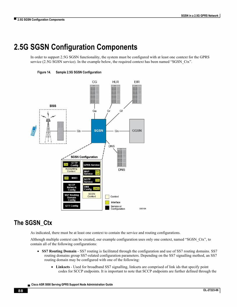
SGSN in a 2.5G GPRS Network
▀ 2.5G SGSN Configuration Components
▄ Cisco ASR 5000 Serving GPRS Support Node Administration Guide
88 OL-27223-06
2.5G SGSN Configuration Components In order to support 2.5G SGSN functionality, the system must be configured with at least one context for the GPRS
service (2.5G SGSN service). In the example below, the required context has been named “SGSN_Ctx”.
Figure 14. Sample 2.5G SGSN Configuration
The SGSN_Ctx
As indicated, there must be at least one context to contain the service and routing configurations.
Although multiple context can be created, our example configuration uses only one context, named “SGSN_Ctx”, to
contain all of the following configurations:
SS7 Routing Domain - SS7 routing is facilitated through the configuration and use of SS7 routing domains. SS7 routing domains group SS7-related configuration parameters. Depending on the SS7 signalling method, an SS7 routing domain may be configured with one of the following:
Linksets - Used for broadband SS7 signalling, linksets are comprised of link ids that specify point codes for SCCP endpoints. It is important to note that SCCP endpoints are further defined through the
SGSN in a 2.5G GPRS Network
2.5G SGSN Configuration Components ▀
Cisco ASR 5000 Serving GPRS Support Node Administration Guide ▄ OL-27223-06 89
configuration of SCCP Networks which are associated with the SS7 routing domain in which the linkset is configured.
Application Server Processes (ASPs) / Peer Server Processes (PSPs) - Used for IP (SIGTRAN), M3UA ASPs and PSPs dictate the IP address and port information used to facilitate communication between network endpoints. ASPs refer to the local endpoints.
GTT - Global Title Translation (GTT) configuration consists of defining GTT associations, defining GTT address maps, and referring to these in an SCCP network configuration.The GTT Associations define GTT rules. The GTT Address Maps define a GTT database. These are configured in the Global Configuration mode and are available to all SCCP networks configured in the system.
SCCP Network - SCCP (Signalling Connection Control Part) networks are a concept specific to this platform. SCCP networks apply only to SS7 applications using SCCP. The purpose of an SCCP network is to isolate the higher protocol layers above SCCP and the application itself from SS7 connectivity issues, as well as, to provide a place for global SCCP configuration specific to SGSN services. Use the following example configuration to specify a global SCCP configuration specific to SGSN services.
MAP Service - The Mobile Application Part (MAP) is an SS7 protocol which provides an application layer for the various nodes in GSM and UMTS mobile core networks and GPRS core networks to communicate with each other in order to provide services to mobile phone users. MAP is the application-layer protocol used to access the Home Location Register (HLR), Visitor Location Register (VLR), Mobile Switching Center (MSC), Equipment Identity Register (EIR), Authentication Center (AUC), Short Message Service Center (SMSC) and Serving GPRS Support Node (SGSN).
The primary facilities provided by MAP are:
Mobility Services: location management (when subscribers move within or between networks), authentication, managing service subscription information, fault recovery.
Operation and Maintenance: subscriber tracing, retrieving a subscriber's IMSI.
Call Handling: routing, managing calls while roaming, checking that a subscriber is available to receive calls.
Supplementary Services.
SMS
Packet Data Protocol (PDP) services for GPRS: providing routing information for GPRS connections.
Location Service Management Services: obtaining the location of subscribers.
SGTP Service- The SGSN GPRS Tunneling Protocol (GTP) service specifies the GTP settings for the SGSN. At a bare minimum, an address to use for GTP-C (Control signaling) and an address for GTP-U (User data) must be configured.
GPRS Service- All of the parameters needed for the system to perform as a an SGSN in a GPRS network are configured in the GPRS service. The GPRS service uses other configurations such as SGTP and MAP to communicate with other network entities and setup communications between the BSS and the GGSN.
NSEI (Network Service Entity Instance)- This identifies the NSEI to use and associates it with a Network Service Virtual Connection Identifier.
DNS- DNS Client configurations provide DNS configuration in a context to resolve APN domain names.
The Accounting_Ctx
If no context is defined for GTPP configuration, the SGSN automatically generates an accounting context with default
GTPP configurations. The context, from our example, contains the following configuration:

SGSN in a 2.5G GPRS Network
▀ 2.5G SGSN Configuration Components
▄ Cisco ASR 5000 Serving GPRS Support Node Administration Guide
90 OL-27223-06
GTPP Configuration - This configuration specifies how to connect to the GTPP charging servers.
Ga Interface - This is an IP interface.
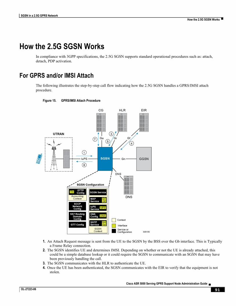
SGSN in a 2.5G GPRS Network
How the 2.5G SGSN Works ▀
Cisco ASR 5000 Serving GPRS Support Node Administration Guide ▄ OL-27223-06 91
How the 2.5G SGSN Works In compliance with 3GPP specifications, the 2.5G SGSN supports standard operational procedures such as: attach,
detach, PDP activation.
For GPRS and/or IMSI Attach
The following illustrates the step-by-step call flow indicating how the 2.5G SGSN handles a GPRS/IMSI attach
procedure.
Figure 15. GPRS/IMSI Attach Procedure
1. An Attach Request message is sent from the UE to the SGSN by the BSS over the Gb interface. This is Typically a Frame Relay connection.
2. The SGSN identifies UE and determines IMSI. Depending on whether or not the UE is already attached, this could be a simple database lookup or it could require the SGSN to communicate with an SGSN that may have been previously handling the call.
3. The SGSN communicates with the HLR to authenticate the UE.
4. Once the UE has been authenticated, the SGSN communicates with the EIR to verify that the equipment is not stolen.
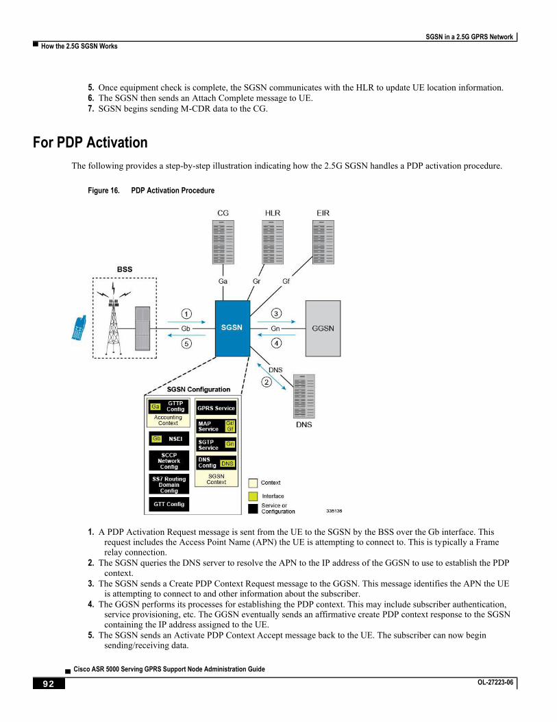
SGSN in a 2.5G GPRS Network
▀ How the 2.5G SGSN Works
▄ Cisco ASR 5000 Serving GPRS Support Node Administration Guide
92 OL-27223-06
5. Once equipment check is complete, the SGSN communicates with the HLR to update UE location information.
6. The SGSN then sends an Attach Complete message to UE.
7. SGSN begins sending M-CDR data to the CG.
For PDP Activation
The following provides a step-by-step illustration indicating how the 2.5G SGSN handles a PDP activation procedure.
Figure 16. PDP Activation Procedure
1. A PDP Activation Request message is sent from the UE to the SGSN by the BSS over the Gb interface. This request includes the Access Point Name (APN) the UE is attempting to connect to. This is typically a Frame relay connection.
2. The SGSN queries the DNS server to resolve the APN to the IP address of the GGSN to use to establish the PDP context.
3. The SGSN sends a Create PDP Context Request message to the GGSN. This message identifies the APN the UE is attempting to connect to and other information about the subscriber.
4. The GGSN performs its processes for establishing the PDP context. This may include subscriber authentication, service provisioning, etc. The GGSN eventually sends an affirmative create PDP context response to the SGSN containing the IP address assigned to the UE.
5. The SGSN sends an Activate PDP Context Accept message back to the UE. The subscriber can now begin sending/receiving data.

SGSN in a 2.5G GPRS Network
How the 2.5G SGSN Works ▀
Cisco ASR 5000 Serving GPRS Support Node Administration Guide ▄ OL-27223-06 93
6. The SGSN begins generating S-CDR data that will be sent to the CG.
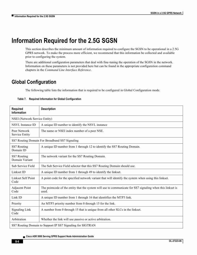
SGSN in a 2.5G GPRS Network
▀ Information Required for the 2.5G SGSN
▄ Cisco ASR 5000 Serving GPRS Support Node Administration Guide
94 OL-27223-06
Information Required for the 2.5G SGSN This section describes the minimum amount of information required to configure the SGSN to be operational in a 2.5G
GPRS network. To make the process more efficient, we recommend that this information be collected and available
prior to configuring the system.
There are additional configuration parameters that deal with fine-tuning the operation of the SGSN in the network.
Information on these parameters is not provided here but can be found in the appropriate configuration command
chapters in the Command Line Interface Reference.
Global Configuration
The following table lists the information that is required to be configured in Global Configuration mode.
Table 7. Required Information for Global Configuration
Required Information
Description
NSEI (Network Service Entity)
NSVL Instance ID A unique ID number to identify the NSVL instance
Peer Network Service Entity
The name or NSEI index number of a peer NSE.
SS7 Routing Domain For Broadband SS7 Signaling
SS7 Routing Domain ID
A unique ID number from 1 through 12 to identify the SS7 Routing Domain.
SS7 Routing Domain Variant
The network variant for the SS7 Routing Domain.
Sub Service Field The Sub Service Field selector that this SS7 Routing Domain should use.
Linkset ID A unique ID number from 1 through 49 to identify the linkset.
Linkset Self Point Code
A point code for the specified network variant that will identify the system when using this linkset.
Adjacent Point Code
The pointcode of the entity that the system will use to communicate for SS7 signaling when this linkset is used.
Link ID A unique ID number from 1 through 16 that identitfies the MTP3 link.
Priority An MTP3 priority number from 0 through 15 for the link.
Signaling Link Code
A number from 0 through 15 that is unique from all other SLCs in the linkset.
Arbitration Whether the link will use passive or active arbitration.
SS7 Routing Domain to Support IP SS7 Signaling for SIGTRAN
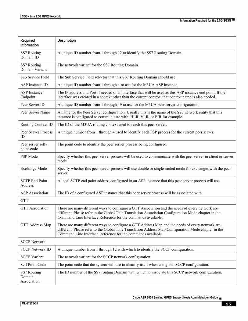
SGSN in a 2.5G GPRS Network
Information Required for the 2.5G SGSN ▀
Cisco ASR 5000 Serving GPRS Support Node Administration Guide ▄ OL-27223-06 95
Required Information
Description
SS7 Routing Domain ID
A unique ID number from 1 through 12 to identify the SS7 Routing Domain.
SS7 Routing Domain Variant
The network variant for the SS7 Routing Domain.
Sub Service Field The Sub Service Field selector that this SS7 Routing Domain should use.
ASP Instance ID A unique ID number from 1 through 4 to use for the M3UA ASP instance.
ASP Instance Endpoint
The IP address and Port if needed of an interface that will be used as this ASP instance end point. If the interface was created in a context other than the current context, that context name is also needed.
Peer Server ID A unique ID number from 1 through 49 to use for the M3UA peer server configuration.
Peer Server Name A name for the Peer Server configuration. Usually this is the name of the SS7 network entity that this instance is configured to communicate with. HLR, VLR, or EIR for example.
Routing Context ID The ID of the M3UA routing context used to reach this peer server.
Peer Server Process ID
A unique number from 1 through 4 used to identify each PSP process for the current peer server.
Peer server self-point-code
The point code to identify the peer server process being configured.
PSP Mode Specify whether this peer server process will be used to communicate with the peer server in client or server mode.
Exchange Mode Specify whether this peer server process will use double or single-ended mode for exchanges with the peer server.
SCTP End Point Address
A local SCTP end point address configured in an ASP instance that this peer server process will use.
ASP Association The ID of a configured ASP instance that this peer server process will be associated with.
GTT
GTT Association There are many different ways to configure a GTT Association and the needs of every network are different. Please refer to the Global Title Translation Association Configuration Mode chapter in the Command Line Interface Reference for the commands available.
GTT Address Map There are many different ways to configure a GTT Address Map and the needs of every network are different. Please refer to the Global Title Translation Address Map Configuration Mode chapter in the Command Line Interface Reference for the commands available.
SCCP Network
SCCP Network ID A unique number from 1 through 12 with which to identify the SCCP configuration.
SCCP Variant The network variant for the SCCP network configuration.
Self Point Code The point code that the system will use to identify itself when using this SCCP configuration.
SS7 Routing Domain Association
The ID number of the SS7 routing Domain with which to associate this SCCP network configuration.
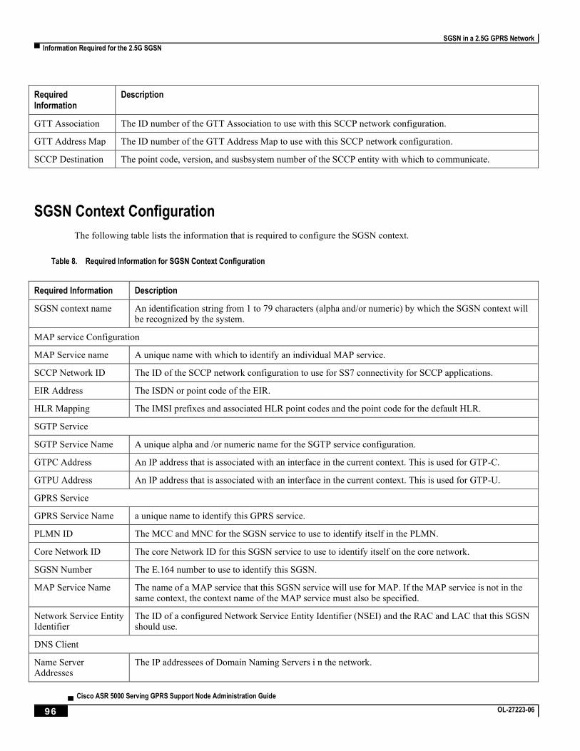
SGSN in a 2.5G GPRS Network
▀ Information Required for the 2.5G SGSN
▄ Cisco ASR 5000 Serving GPRS Support Node Administration Guide
96 OL-27223-06
Required Information
Description
GTT Association The ID number of the GTT Association to use with this SCCP network configuration.
GTT Address Map The ID number of the GTT Address Map to use with this SCCP network configuration.
SCCP Destination The point code, version, and susbsystem number of the SCCP entity with which to communicate.
SGSN Context Configuration
The following table lists the information that is required to configure the SGSN context.
Table 8. Required Information for SGSN Context Configuration
Required Information Description
SGSN context name An identification string from 1 to 79 characters (alpha and/or numeric) by which the SGSN context will be recognized by the system.
MAP service Configuration
MAP Service name A unique name with which to identify an individual MAP service.
SCCP Network ID The ID of the SCCP network configuration to use for SS7 connectivity for SCCP applications.
EIR Address The ISDN or point code of the EIR.
HLR Mapping The IMSI prefixes and associated HLR point codes and the point code for the default HLR.
SGTP Service
SGTP Service Name A unique alpha and /or numeric name for the SGTP service configuration.
GTPC Address An IP address that is associated with an interface in the current context. This is used for GTP-C.
GTPU Address An IP address that is associated with an interface in the current context. This is used for GTP-U.
GPRS Service
GPRS Service Name a unique name to identify this GPRS service.
PLMN ID The MCC and MNC for the SGSN service to use to identify itself in the PLMN.
Core Network ID The core Network ID for this SGSN service to use to identify itself on the core network.
SGSN Number The E.164 number to use to identify this SGSN.
MAP Service Name The name of a MAP service that this SGSN service will use for MAP. If the MAP service is not in the same context, the context name of the MAP service must also be specified.
Network Service Entity Identifier
The ID of a configured Network Service Entity Identifier (NSEI) and the RAC and LAC that this SGSN should use.
DNS Client
Name Server Addresses
The IP addressees of Domain Naming Servers i n the network.
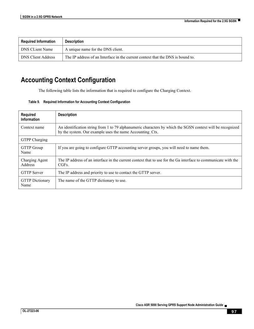
SGSN in a 2.5G GPRS Network
Information Required for the 2.5G SGSN ▀
Cisco ASR 5000 Serving GPRS Support Node Administration Guide ▄ OL-27223-06 97
Required Information Description
DNS CLient Name A unique name for the DNS client.
DNS Client Address The IP address of an Interface in the current context that the DNS is bound to.
Accounting Context Configuration
The following table lists the information that is required to configure the Charging Context.
Table 9. Required Information for Accounting Context Configuration
Required Information
Description
Context name An identification string from 1 to 79 alphanumeric characters by which the SGSN context will be recognized by the system. Our example uses the name Accounting_Ctx.
GTPP Charging
GTTP Group Name
If you are going to configure GTTP accounting server groups, you will need to name them.
Charging Agent Address
The IP address of an interface in the current context that to use for the Ga interface to communicate with the CGFs.
GTTP Server The IP address and priority to use to contact the GTTP server.
GTTP Dictionary Name
The name of the GTTP dictionary to use.

Cisco ASR 5000 Serving GPRS Support Node Administration Guide ▄ OL-27223-06 99
Chapter 3 SGSN 3G UMTS Configuration
This chapter outlines the basic deployment, configuration, and operation of the system to function as a Serving GPRS
Support Node (SGSN) in 3G UMTS wireless data networks.
The simplest configuration that can be implemented on the system to support SGSN functionality in a 3G network
requires one context but we recommend a minimum of two: one for the SGSN service (required) and another for the
charging context.
The SGSN context facilitates the following:
SGSN service configuration
Mobile Application Part (MAP) configuration
IuPS (Iu Packet Switched) interface configuration for communication with the RAN (Radio Access Network)
DNS (Domain Naming System) Client configuration for resolution of APN domain names
SGTP (SGSN GPRS Tunneling Protocol) configuration
The charging context facilitates the following:
Configuration of connectivity to the CGF (Charging Gateway Function)
The following functionality is configured at the global system level:
SCCP (Signalling Connection Control Part) network configuration
SS7 (Signaling System 7) connectivity configuration
GTT (Global Title Translation) configuration
To simply configuration management, more contexts can be created and used and all context can be named as needed.
The contexts listed above can be configured as illustrated in the figure on the next page.
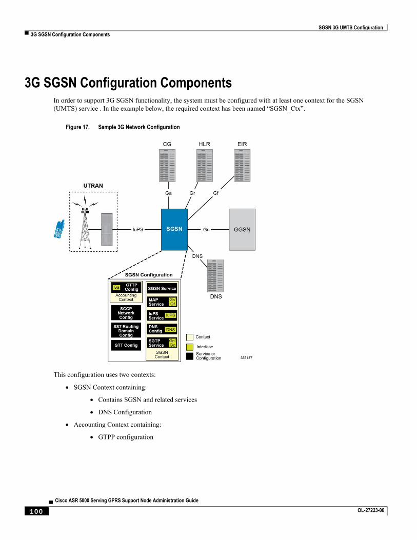
SGSN 3G UMTS Configuration
▀ 3G SGSN Configuration Components
▄ Cisco ASR 5000 Serving GPRS Support Node Administration Guide
100 OL-27223-06
3G SGSN Configuration Components In order to support 3G SGSN functionality, the system must be configured with at least one context for the SGSN
(UMTS) service . In the example below, the required context has been named “SGSN_Ctx”.
Figure 17. Sample 3G Network Configuration
This configuration uses two contexts:
SGSN Context containing:
Contains SGSN and related services
DNS Configuration
Accounting Context containing:
GTPP configuration
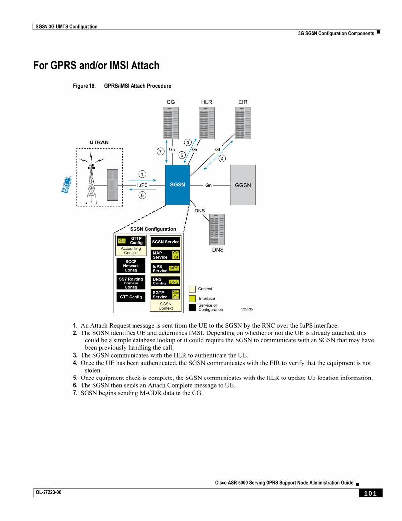
SGSN 3G UMTS Configuration
3G SGSN Configuration Components ▀
Cisco ASR 5000 Serving GPRS Support Node Administration Guide ▄ OL-27223-06 101
For GPRS and/or IMSI Attach
Figure 18. GPRS/IMSI Attach Procedure
1. An Attach Request message is sent from the UE to the SGSN by the RNC over the IuPS interface.
2. The SGSN identifies UE and determines IMSI. Depending on whether or not the UE is already attached, this could be a simple database lookup or it could require the SGSN to communicate with an SGSN that may have been previously handling the call.
3. The SGSN communicates with the HLR to authenticate the UE.
4. Once the UE has been authenticated, the SGSN communicates with the EIR to verify that the equipment is not stolen.
5. Once equipment check is complete, the SGSN communicates with the HLR to update UE location information.
6. The SGSN then sends an Attach Complete message to UE.
7. SGSN begins sending M-CDR data to the CG.
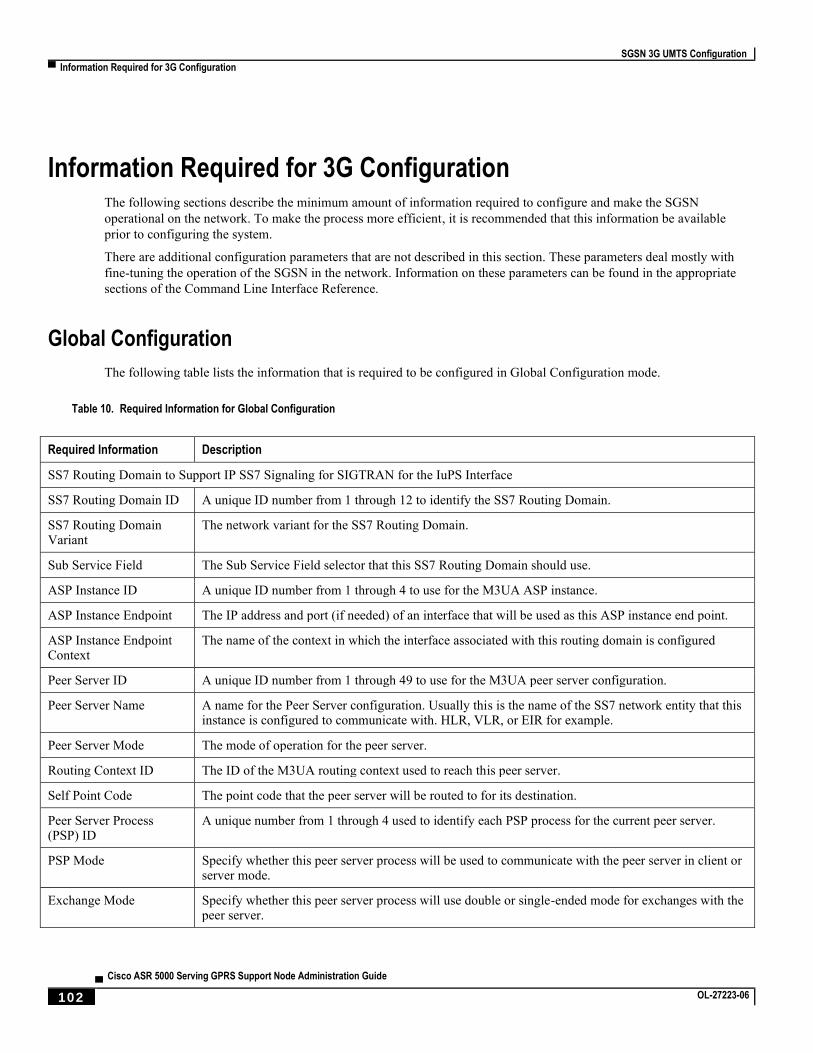
SGSN 3G UMTS Configuration
▀ Information Required for 3G Configuration
▄ Cisco ASR 5000 Serving GPRS Support Node Administration Guide
102 OL-27223-06
Information Required for 3G Configuration The following sections describe the minimum amount of information required to configure and make the SGSN
operational on the network. To make the process more efficient, it is recommended that this information be available
prior to configuring the system.
There are additional configuration parameters that are not described in this section. These parameters deal mostly with
fine-tuning the operation of the SGSN in the network. Information on these parameters can be found in the appropriate
sections of the Command Line Interface Reference.
Global Configuration
The following table lists the information that is required to be configured in Global Configuration mode.
Table 10. Required Information for Global Configuration
Required Information Description
SS7 Routing Domain to Support IP SS7 Signaling for SIGTRAN for the IuPS Interface
SS7 Routing Domain ID A unique ID number from 1 through 12 to identify the SS7 Routing Domain.
SS7 Routing Domain Variant
The network variant for the SS7 Routing Domain.
Sub Service Field The Sub Service Field selector that this SS7 Routing Domain should use.
ASP Instance ID A unique ID number from 1 through 4 to use for the M3UA ASP instance.
ASP Instance Endpoint The IP address and port (if needed) of an interface that will be used as this ASP instance end point.
ASP Instance Endpoint Context
The name of the context in which the interface associated with this routing domain is configured
Peer Server ID A unique ID number from 1 through 49 to use for the M3UA peer server configuration.
Peer Server Name A name for the Peer Server configuration. Usually this is the name of the SS7 network entity that this instance is configured to communicate with. HLR, VLR, or EIR for example.
Peer Server Mode The mode of operation for the peer server.
Routing Context ID The ID of the M3UA routing context used to reach this peer server.
Self Point Code The point code that the peer server will be routed to for its destination.
Peer Server Process (PSP) ID
A unique number from 1 through 4 used to identify each PSP process for the current peer server.
PSP Mode Specify whether this peer server process will be used to communicate with the peer server in client or server mode.
Exchange Mode Specify whether this peer server process will use double or single-ended mode for exchanges with the peer server.
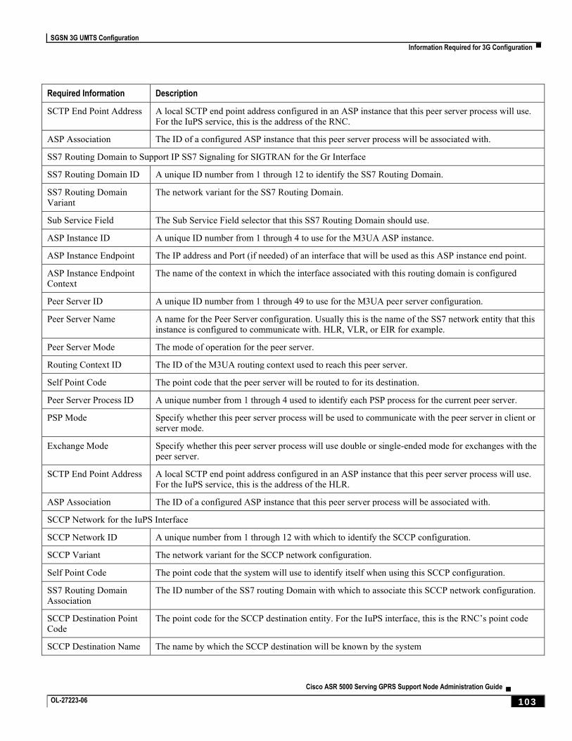
SGSN 3G UMTS Configuration
Information Required for 3G Configuration ▀
Cisco ASR 5000 Serving GPRS Support Node Administration Guide ▄ OL-27223-06 103
Required Information Description
SCTP End Point Address A local SCTP end point address configured in an ASP instance that this peer server process will use. For the IuPS service, this is the address of the RNC.
ASP Association The ID of a configured ASP instance that this peer server process will be associated with.
SS7 Routing Domain to Support IP SS7 Signaling for SIGTRAN for the Gr Interface
SS7 Routing Domain ID A unique ID number from 1 through 12 to identify the SS7 Routing Domain.
SS7 Routing Domain Variant
The network variant for the SS7 Routing Domain.
Sub Service Field The Sub Service Field selector that this SS7 Routing Domain should use.
ASP Instance ID A unique ID number from 1 through 4 to use for the M3UA ASP instance.
ASP Instance Endpoint The IP address and Port (if needed) of an interface that will be used as this ASP instance end point.
ASP Instance Endpoint Context
The name of the context in which the interface associated with this routing domain is configured
Peer Server ID A unique ID number from 1 through 49 to use for the M3UA peer server configuration.
Peer Server Name A name for the Peer Server configuration. Usually this is the name of the SS7 network entity that this instance is configured to communicate with. HLR, VLR, or EIR for example.
Peer Server Mode The mode of operation for the peer server.
Routing Context ID The ID of the M3UA routing context used to reach this peer server.
Self Point Code The point code that the peer server will be routed to for its destination.
Peer Server Process ID A unique number from 1 through 4 used to identify each PSP process for the current peer server.
PSP Mode Specify whether this peer server process will be used to communicate with the peer server in client or server mode.
Exchange Mode Specify whether this peer server process will use double or single-ended mode for exchanges with the peer server.
SCTP End Point Address A local SCTP end point address configured in an ASP instance that this peer server process will use. For the IuPS service, this is the address of the HLR.
ASP Association The ID of a configured ASP instance that this peer server process will be associated with.
SCCP Network for the IuPS Interface
SCCP Network ID A unique number from 1 through 12 with which to identify the SCCP configuration.
SCCP Variant The network variant for the SCCP network configuration.
Self Point Code The point code that the system will use to identify itself when using this SCCP configuration.
SS7 Routing Domain Association
The ID number of the SS7 routing Domain with which to associate this SCCP network configuration.
SCCP Destination Point Code
The point code for the SCCP destination entity. For the IuPS interface, this is the RNC’s point code
SCCP Destination Name The name by which the SCCP destination will be known by the system
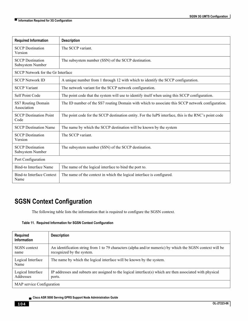
SGSN 3G UMTS Configuration
▀ Information Required for 3G Configuration
▄ Cisco ASR 5000 Serving GPRS Support Node Administration Guide
104 OL-27223-06
Required Information Description
SCCP Destination Version
The SCCP variant.
SCCP Destination Subsystem Number
The subsystem number (SSN) of the SCCP destination.
SCCP Network for the Gr Interface
SCCP Network ID A unique number from 1 through 12 with which to identify the SCCP configuration.
SCCP Variant The network variant for the SCCP network configuration.
Self Point Code The point code that the system will use to identify itself when using this SCCP configuration.
SS7 Routing Domain Association
The ID number of the SS7 routing Domain with which to associate this SCCP network configuration.
SCCP Destination Point Code
The point code for the SCCP destination entity. For the IuPS interface, this is the RNC’s point code
SCCP Destination Name The name by which the SCCP destination will be known by the system
SCCP Destination Version
The SCCP variant.
SCCP Destination Subsystem Number
The subsystem number (SSN) of the SCCP destination.
Port Configuration
Bind-to Interface Name The name of the logical interface to bind the port to.
Bind-to Interface Context Name
The name of the context in which the logical interface is configured.
SGSN Context Configuration
The following table lists the information that is required to configure the SGSN context.
Table 11. Required Information for SGSN Context Configuration
Required Information
Description
SGSN context name
An identification string from 1 to 79 characters (alpha and/or numeric) by which the SGSN context will be recognized by the system.
Logical Interface Name
The name by which the logical interface will be known by the system.
Logical Interface Addresses
IP addresses and subnets are assigned to the logical interface(s) which are then associated with physical ports.
MAP service Configuration
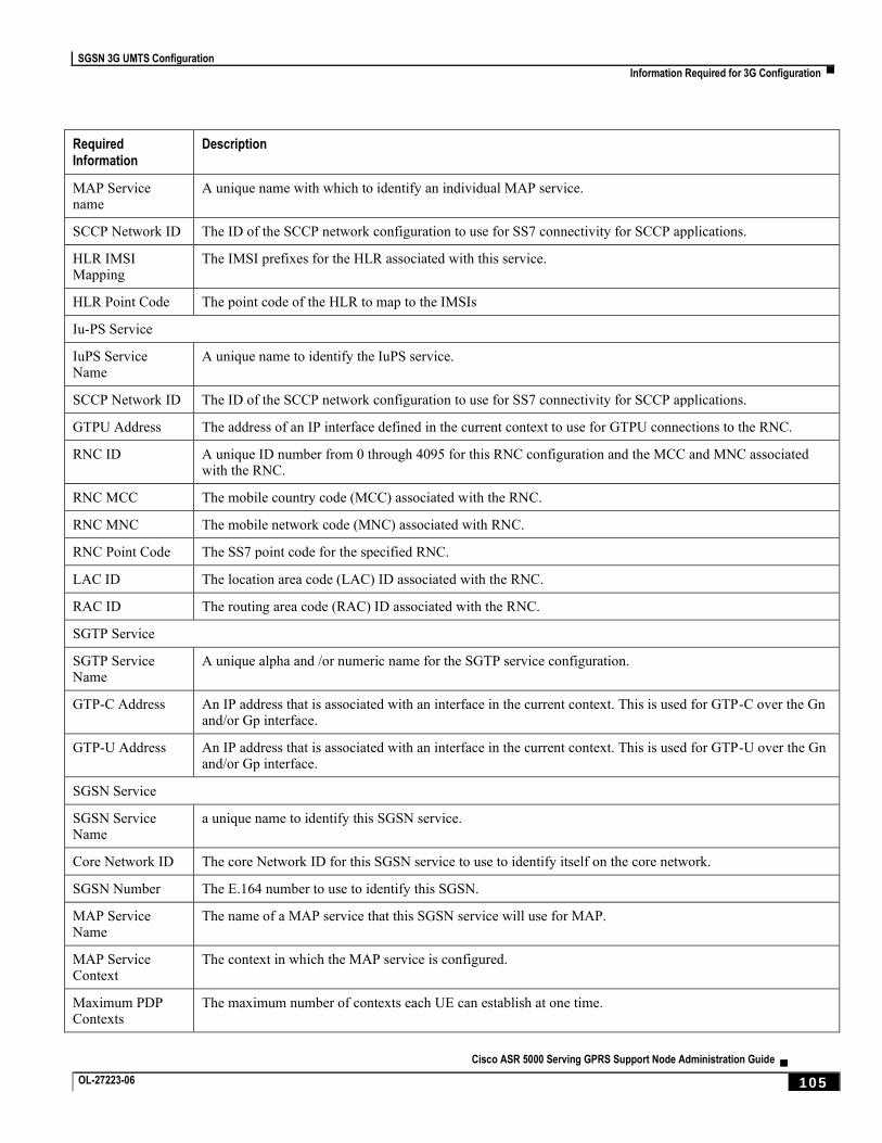
SGSN 3G UMTS Configuration
Information Required for 3G Configuration ▀
Cisco ASR 5000 Serving GPRS Support Node Administration Guide ▄ OL-27223-06 105
Required Information
Description
MAP Service name
A unique name with which to identify an individual MAP service.
SCCP Network ID The ID of the SCCP network configuration to use for SS7 connectivity for SCCP applications.
HLR IMSI Mapping
The IMSI prefixes for the HLR associated with this service.
HLR Point Code The point code of the HLR to map to the IMSIs
Iu-PS Service
IuPS Service Name
A unique name to identify the IuPS service.
SCCP Network ID The ID of the SCCP network configuration to use for SS7 connectivity for SCCP applications.
GTPU Address The address of an IP interface defined in the current context to use for GTPU connections to the RNC.
RNC ID A unique ID number from 0 through 4095 for this RNC configuration and the MCC and MNC associated with the RNC.
RNC MCC The mobile country code (MCC) associated with the RNC.
RNC MNC The mobile network code (MNC) associated with RNC.
RNC Point Code The SS7 point code for the specified RNC.
LAC ID The location area code (LAC) ID associated with the RNC.
RAC ID The routing area code (RAC) ID associated with the RNC.
SGTP Service
SGTP Service Name
A unique alpha and /or numeric name for the SGTP service configuration.
GTP-C Address An IP address that is associated with an interface in the current context. This is used for GTP-C over the Gn and/or Gp interface.
GTP-U Address An IP address that is associated with an interface in the current context. This is used for GTP-U over the Gn and/or Gp interface.
SGSN Service
SGSN Service Name
a unique name to identify this SGSN service.
Core Network ID The core Network ID for this SGSN service to use to identify itself on the core network.
SGSN Number The E.164 number to use to identify this SGSN.
MAP Service Name
The name of a MAP service that this SGSN service will use for MAP.
MAP Service Context
The context in which the MAP service is configured.
Maximum PDP Contexts
The maximum number of contexts each UE can establish at one time.
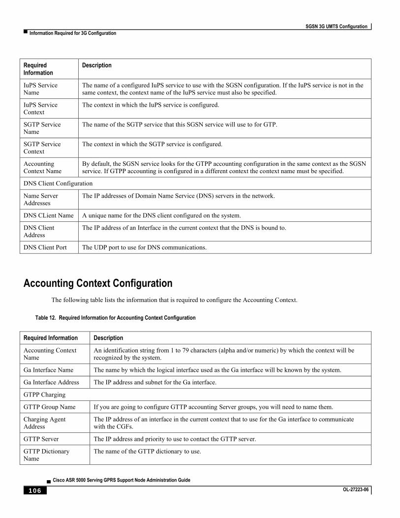
SGSN 3G UMTS Configuration
▀ Information Required for 3G Configuration
▄ Cisco ASR 5000 Serving GPRS Support Node Administration Guide
106 OL-27223-06
Required Information
Description
IuPS Service Name
The name of a configured IuPS service to use with the SGSN configuration. If the IuPS service is not in the same context, the context name of the IuPS service must also be specified.
IuPS Service Context
The context in which the IuPS service is configured.
SGTP Service Name
The name of the SGTP service that this SGSN service will use to for GTP.
SGTP Service Context
The context in which the SGTP service is configured.
Accounting Context Name
By default, the SGSN service looks for the GTPP accounting configuration in the same context as the SGSN service. If GTPP accounting is configured in a different context the context name must be specified.
DNS Client Configuration
Name Server Addresses
The IP addresses of Domain Name Service (DNS) servers in the network.
DNS CLient Name A unique name for the DNS client configured on the system.
DNS Client Address
The IP address of an Interface in the current context that the DNS is bound to.
DNS Client Port The UDP port to use for DNS communications.
Accounting Context Configuration
The following table lists the information that is required to configure the Accounting Context.
Table 12. Required Information for Accounting Context Configuration
Required Information Description
Accounting Context Name
An identification string from 1 to 79 characters (alpha and/or numeric) by which the context will be recognized by the system.
Ga Interface Name The name by which the logical interface used as the Ga interface will be known by the system.
Ga Interface Address The IP address and subnet for the Ga interface.
GTPP Charging
GTTP Group Name If you are going to configure GTTP accounting Server groups, you will need to name them.
Charging Agent Address
The IP address of an interface in the current context that to use for the Ga interface to communicate with the CGFs.
GTTP Server The IP address and priority to use to contact the GTTP server.
GTTP Dictionary Name
The name of the GTTP dictionary to use.

SGSN 3G UMTS Configuration
Information Required for 3G Configuration ▀
Cisco ASR 5000 Serving GPRS Support Node Administration Guide ▄ OL-27223-06 107

Cisco ASR 5000 Serving GPRS Support Node Administration Guide ▄ OL-27223-06 109
Chapter 4 SGSN Service Configuration Procedures
This chapter provides configuration instructions to enable the SGSN to function in GPRS (2.5G), UMTS (3G), or LTE
(4G) networks. The System Administration Guide provides interface and system-level configuration details and the
Command Line Interface Reference provides additional command information.
Important: Please note that LTE (4G) support is only available in releases 14.0 an higher.
High level step-by-step service configuration procedures are provided for the following:
2.5G SGSN Service Configuration
3G SGSN Service Configuration
Dual Access SGSN Service Configuration
Configuring the S4-SGSN
Important: At least one packet processing card must be activated prior to configuring the first service.
Procedures for configuring the packet processing card can be found in the System Administration Guide.
Detailed procedures are provided for the following:
Configuring an SS7 Routing Domain
Configuring an SS7 Routing Domain to Support Broadband SS7 Signaling
Configuring an SS7 Routing Domain to Support IP Signaling for SIGTRAN
Configuring GTT
Configuring an SCCP Network
Configuring a MAP Service
Configuring an IuPS Service (3G only)
Configuring an SGTP Service
Configuring a Gs Service
Configuring a GPRS Service (2.5G only)
Configuring an SGSN Service (3G only)
Configuring a Network Service Entity
Configure a Network Service Entity for IP
Configure a Network Service Entity for Frame Relay
Configuring DNS Client
Configuring GTPP Accounting Support
SGSN Service Configuration Procedures
▀ Information Required for 3G Configuration
▄ Cisco ASR 5000 Serving GPRS Support Node Administration Guide
110 OL-27223-06
Configuring and Associating the EGTP Service (S4 Only)
Configuring DNS for APN Resolution (S4 Only)
Configuring the S6d Diameter Interface (S4 Only)
Configuring the Diameter Endpoint for the S6d Interface
Configuring the HSS Peer Service and Interface Association for the S6d Interface
Associating the HSS Peer Service with the SGSN and GPRS Services for the S6d Interface
Configuring Operator Policy-Based S6d Interface Selection (Optional)
Configuring the Subscription Interface Preference for the S6d Interface (Optional)
Configuring the S13’ Interface (S4 Only)
Configure a Diameter Endpoint for the S13’ Interface
Configuring the HSS Peer Service and Interface Association for the S13’ Interface
Associate the HSS Peer Service with the SGSN Service for the S13’ Interface
Configuring Operator Policy-Based S13’ Interface Selection
Configuring QoS Mapping for EPC-Capable UEs using the S4 Interface (S4 Only)
Configuring the Peer SGSN Interface Type (S4 Only, Optional)
Configuring Operator Policy-Based Gn Interface Selection (S4 Only, Optional)
Configuring a Custom MME Group ID (S4 Only, Optional)
Configuring the Selection of an SGW for RAI (S4 Only, Optional)
Configuring a Local PGW Address (S4 Only, Optional)
Configuring the Peer MME Address (S4 Only, Optional)
Configuring the ISR Feature (S4 Only, Optional)
Creating and Configuring ATM Interfaces and Ports (3G only)
Creating and Configuring Frame Relay Ports (2.5G only)
Configuring APS/MSP Redundancy
SGSN Service Configuration Procedures
2.5G SGSN Service Configuration ▀
Cisco ASR 5000 Serving GPRS Support Node Administration Guide ▄ OL-27223-06 111
2.5G SGSN Service Configuration The following configuration steps must be completed to allow the system to operate in a 2.5G GPRS network.
The service handling the GPRS or 2.5G functions in the SGSN is called the “gprs-service”.
Step 1 Create all the contexts you will use in your configuration. Refer to the “System Element Configuration Procedures”
chapter in the System Administration Guide.
Step 2 Create and configure the Frame Relay interface(s) and Ethernet interface(s). Refer to the “System Element
Configuration Procedures” chapter in the System Administration Guide.
Step 3 Configure SS7 routing domains. Use the procedure in Configuring an SS7 Routing Domain . The concept of an SS7
routing domain is not a standard SS7 concept. It is a concept specific to this platform which groups a set of SS7 feature
configuration together to facilitate the management of the SS7 connectivity resources for an SGSN service.
Step 4 Configure GTT. The GTT configuration is used to set rules for GTT and define the GTT databases. Follow the
procedure in Configuring GTT.
Step 5 Configure SCCP-Networks. The purpose of an SCCP network is to isolate the higher protocol layers above SCCP and
the application itself from SS7 connectivity issues, as well as, to provide a place for global SCCP configuration specific
to SGSN services. Use the procedure in Configuring an SCCP Network.
Step 6 Configure MAP services. The MAP service configuration is used by the SGSN service to communicate with many of
the nodes on the narrow band-SS7 network part of the network such as HLR, EIR, GSM-SCF, GMLC and SMS-
GMSC/SMS-IWMSC. The purpose of having an isolated map configuration is to enable different application services to
use the map service to communicate with other map entities in the network. Use the procedure in Configuring a MAP
Service.
Step 7 Configure SGTP. The SGTP service configures the parameters used for GTP Tunneling. At the minimum, interfaces for
GTP-C and GTP-U must be configured. Use the procedure in Configuring an SGTP Service.
Step 8 Configure the SGSN service. All the parameters specific to the operation of an SGSN are configured in the SGSN
service configuration mode. SGSN services use other configurations like MAP and IuPS to communicate with other
elements in the network. The system can support multiple SGSN services. Use the procedure in Configuring an SGSN
Service (3G only).
Step 9 Configure the GPRS service. All of the parameters needed for the system to perform as a an SGSN in a GPRS network
are configured in the GPRS service. The GPRS service uses other configurations such as SGTP and MAP to
communicate with other network entities and setup communications between the BSS and the GGSN. Use the
procedure in Configuring a GPRS Service (2.5G only).
Step 10 Configure the Network Service Entity Instance. This identifies the NSEI to use and associates it with a Network Service
Virtual Connection Identifier. Use the procedure in Configuring a Network Service Entity.
Step 11 Configure DNS. This configuration enables domain name resolution and specifies the DNSs to use for lookup. Use the
procedure in Configuring DNS Client.
Step 12 Configure GTPP Accounting. This configures GTPP-based accounting for subscriber PDP contexts. Use the procedure
in Configuring GTPP Accounting Support.
Step 13 Configure Frame Relay DLCI paths and bind them to NSEI links as needed. Refer to Creating and Configuring Frame
Relay Interfaces and Ports in the System Administration Guide.

SGSN Service Configuration Procedures
▀ 2.5G SGSN Service Configuration
▄ Cisco ASR 5000 Serving GPRS Support Node Administration Guide
112 OL-27223-06
Step 14 Save your configuration to flash memory, an external memory device, and/or a network location using the Exec mode
command save configuration. For additional information on how to verify and save configuration files, refer to the
System Administration Guide and the Command Line Interface Reference.
SGSN Service Configuration Procedures
3G SGSN Service Configuration ▀
Cisco ASR 5000 Serving GPRS Support Node Administration Guide ▄ OL-27223-06 113
3G SGSN Service Configuration The following configuration steps must be completed to allow the system to operate in a 3G network.
Step 1 Create the contexts needed. Refer to the System Element Configuration Procedures chapter in the System
Administration Guide.
Step 2 Create any interfaces needed in the appropriate context. Refer to the System Element Configuration Procedures chapter
in the System Administration Guide for IP (broadcast Ethernet) interfaces and for ATM interfaces.
Step 3 Configure SS7 routing domains. The SS7 routing domain is proprietary concept to provide a combined configuration
for the SS7 links, linksets, and related parameters. SS7 routing domain configurations are common to both SIGTRAN
and MTP3-B networks. Use the procedure in Configuring an SS7 Routing Domain.
Step 4 Configure global title translations (GTT). The GTT configuration is used to set rules for GTT and to define the GTT
databases. Follow the procedure in Configuring GTT.
Step 5 Configure SCCP networks. The SCCP network (layer) provides services to protocol layers higher in the SS7 protocol
stack, for example RANAP and TCAP. The SCCP layer is also responsible for GTT. As well, all the SS7 routing
domains (created in step 3) will be associated with an SCCP network. Use the procedure in Configuring an SCCP
Network.
Step 6 Configure MAP services. The MAP service configuration is used by the SGSN service to communicate with many of
the nodes in the SS7 network, such as the HLR, EIR, GSM-SCF, GMLC and SMS-GMSC/SMS-IWMSC. Having an
isolated MAP configuration enables different application services to use the MAP service to communicate with other
MAP entities in the network. Use the procedure in Configuring a MAP Service.
Step 7 Configure IuPS services. A set of parameters define the communication path between the SGSN service and radio
network controllers (RNCs) in a UMTS IuPS service. Use the procedure in Configuring an IuPS Service (3G only).
Step 8 Configure SGTP services. The SGTP service configures the parameters used for GTP Tunneling. At a minimum,
interfaces for GTP-C and GTP-U must be configured. Use the procedure in Configuring an SGTP Service.
Step 9 Configure the SGSN service. All the parameters specific to the operation of an SGSN are configured in the SGSN
service configuration mode. SGSN services use other configurations like MAP and IuPS to communicate with other
elements in the network. The system can support multiple SGSN services. Use the procedure in Configuring an SGSN
Service (3G only).
Step 10 Configure DNS clients. This configuration enables domain name resolution and specifies the DNSs to use for lookup.
Use the procedure in Configuring DNS Client.
Step 11 Optional: Configure operator policies. Operator policies are not required for SGSN operation, however, they provide
the operator with a powerful method for determining call handling. SGSN operator policies specify rules governing the
services, facilities and privileges available to a single subscriber or groups of subscribers. Use the procedure in
Configuring SGSN Operator Policies.
Step 12 Configure GTPP Accounting. This configures GTPP-based accounting for subscriber PDP contexts. Use the procedure
in Configuring GTPP Accounting Support.
Step 13 Configure ATM PVCs and bind them to interfaces or SS7 links as needed. Refer to Creating and Configuring ATM
Interfaces and Ports in the System Administration Guide.

SGSN Service Configuration Procedures
▀ 3G SGSN Service Configuration
▄ Cisco ASR 5000 Serving GPRS Support Node Administration Guide
114 OL-27223-06
Step 14 Save your configuration to flash memory, an external memory device, and/or a network location using the Exec mode
command save configuration. For additional information on how to verify and save configuration files, refer to the
System Administration Guide and the Command Line Interface Reference.
SGSN Service Configuration Procedures
Dual Access SGSN Service Configuration ▀
Cisco ASR 5000 Serving GPRS Support Node Administration Guide ▄ OL-27223-06 115
Dual Access SGSN Service Configuration The following configuration steps must be completed to allow the SGSN to operate in both GPRS (2.5G) and UMTS
(3G) networks. This type of co-location is referred to as dual access.
To configure dual access requires a combination of steps from both the 2.5G and 3G configuration procedures:
Step 1 Create the contexts needed. Refer to the System Element Configuration Procedures chapter in the System
Administration Guide.
Step 2 Create any interfaces needed in the appropriate context refer to the System Element Configuration Procedures chapter in
the System Administration Guide.
Step a For IP (broadcast Ethernet) interfaces, refer to Creating and Configuring Ethernet Interfaces and
Ports in the System Administration Guide.
Step b For ATM interfaces (3G) refer to Creating and Configuring ATM Interfaces and Ports in the
System Administration Guide.
Step c For Frame Relay interfaces (2.5G) refer to Creating and Configuring Frame Relay Interfaces and
Ports in the System Administration Guide.
Step 3 Configure SS7 routing domains. The SS7 routing domain is a non-standard, proprietary SS7 concept specific to this
platform. SS7 routing domains provide a combined configuration for the SS7 links, linksets, and related parameters for
SS7 connectivity resources for an SGSN service. SS7 routing domain configurations are common to both SIGTRAN
and MTP3-B networks. Use the procedure in Configuring an SS7 Routing Domain.
Step 4 Configure global title translations (GTT). The GTT configuration is used to set rules for GTT and to define the GTT
databases. Follow the procedure in Configuring GTT.
Step 5 Configure SCCP networks. The SCCP network (layer) provides services to protocol layers higher in the SS7 protocol
stack, for example RANAP and TCAP. The SCCP layer is also responsible for GTT (step 4) and every SS7 routing
domain (step 3) will be associated with an SCCP network. Use the procedure in Configuring an SCCP Network.
Step 6 Configure MAP services. The MAP service configuration is used by the SGSN service to communicate with many of
the nodes in the SS7 network, such as the HLR, EIR, GSM-SCF, GMLC and SMS-GMSC/SMS-IWMSC. Having an
isolated MAP configuration enables different application services to use the MAP service to communicate with other
MAP entities in the network. Use the procedure in Configuring a MAP Service.
Step 7 Configure IuPS services. A set of parameters define the communication path between the SGSN service and radio
network controllers (RNCs) in a UMTS IuPS service. Use the procedure in Configuring an IuPS Service (3G only).
Step 8 Configure SGTP services. The SGTP service configures the parameters used for GTP Tunneling. At a minimum,
interfaces for GTP-C and GTP-U must be configured. Use the procedure in Configuring an SGTP Service.
Step 9 Configure the GPRS service. All of the parameters needed for the system to perform as a an SGSN in a GPRS network
are configured in the GPRS service. The GPRS service uses other configurations such as SGTP and MAP to
communicate with other network entities and setup communications between the BSS and the GGSN. Use the
procedure in Configuring a GPRS Service (2.5G only).
Step 10 Configure the Network Service Entity Instance. This identifies the NSEI to use and associates it with a Network Service
Virtual Connection Identifier. Use the procedure in Configuring a Network Service Entity.
SGSN Service Configuration Procedures
▀ Dual Access SGSN Service Configuration
▄ Cisco ASR 5000 Serving GPRS Support Node Administration Guide
116 OL-27223-06
Step 11 Configure DNS. This configuration enables domain name resolution and specifies the DNSs to use for lookup. Use the
procedure in Configuring DNS Client.
Step 12 Configure GTPP Accounting. This configures GTPP-based accounting for subscriber PDP contexts. Use the procedure
in Configuring GTPP Accounting Support.
Step 13 Configure ATM PVCs and bind them to interfaces or SS7 links as needed. Refer to Creating and Configuring ATM
Interfaces and Ports in the System Administration Guide.
Step 14 Configure Frame Relay DLCI paths and bind them to NSEI links as needed. Refer to Creating and Configuring Frame
Relay Interfaces and Ports in the System Administration Guide.
Step 15 Save your configuration to flash memory, an external memory device, and/or a network location using the Exec mode
command save configuration. For additional information on how to verify and save configuration files, refer to the
System Administration Guide and the Command Line Interface Reference.
SGSN Service Configuration Procedures
Configuring the S4-SGSN ▀
Cisco ASR 5000 Serving GPRS Support Node Administration Guide ▄ OL-27223-06 117
Configuring the S4-SGSN The following configuration steps comprise the required and optional tasks for configuring the S4-SGSN to provide an
interface between GPRS (2.5G) / UMTS (3G) networks and EPC (4G) networks via the EPC S4 interface. This is
referred to as an S4-SGSN.
Caution: The S4-SGSN cannot operate until after 2G, 3G or dual access SGSN service is configured. Do not
begin S4-SGSN configuration until one of those services is configured and operational. Refer to the 2.5G SGSN Service Configuration , 3G SGSN Service Configuration , or Dual Access SGSN Service Configuration sections in this chapter for details on configuring those services.
Before you begin the configuration procedure, note the following:
Configuration steps 1 through 5 are mandatory for the S4-SGSN to operate properly.
Configuration steps 6 through 15 are optional. They can be used to configure or enable various optional functionality and features, including:
Bypass DNS resolution for various network elements
Configure GUTI-to-RAI mapping
Configure operator-specific QoS mapping values
Configure the S13’ interface for the Mobile Equipment Identity (MEI) check
Configure the license-enabled Idle Mode Signaling Reduction feature
Configure the Indirect Data Forwarding Tunnel feature
Step 1 Configure, 2G, 3G or Dual Access SGSN service support. Refer to the 2.5G SGSN Service Configuration , 3G SGSN
Service Configuration , or Dual Access SGSN Service Configuration sections in this chapter for the configuration
Step 2 Configure and associate the EGTP service. The EGTP service is required to support communication between the SGSN
and the EPC SGW over the S4 interface using the GTPv2 protocol. Refer to the Configuring and Associating the EGTP
Service (S4 Only) procedure.
Step 3 Configure and associate the GTPU service. The GTPU service supports the configured EGTP service by enabling the
sending and receiving of GTP bearer packets from the EPC SGW over the S4 intereface. Refer to the Configuring and
Associating the GTPU Service (S4 Only) procedure.
Step 4 Configure DNS for APN resolution. Configurables must be set to enable the default DNS client on the SGSN to resolve
EPC PGW and SGW addresses. Refer to the Configuring the DNS Client Context for APN and SGW Resolution
procedure.
Step 5 Configure the S6d Diameter Interface. The S6d interface is used by the SGSN to communicate with the HSS. The HSS
is a master user database that contains all subscription related information, Refer to the Configuring the S6d Diameter
Interface (S4 Only) procedure.
Step 6 Optional. Configure the S13’ (S13 prime) interface. This interface is used to perform Mobile Equipment (ME) identity
check procedure between the SGSN and Equipment Identity Registry. Refer to the Configuring the S13 Interface (S4
Only, Optional) procedure.
SGSN Service Configuration Procedures
▀ Configuring the S4-SGSN
▄ Cisco ASR 5000 Serving GPRS Support Node Administration Guide
118 OL-27223-06
Step 7 Optional. Configure operator-specific QoS mapping between EPC elements and the SGSN. The S4-SGSN
communicates QoS parameters towards the SGW/ PGW and EPC UEs in different formats. Operators must configure
the SGSN quality of service (QoS) parameters as a call-control-profile that will ensure proper QoS mapping between
the S4-SGSN, SGW/PGW and UEs. Refer to the Configuring QoS Mapping for EPC-Capable UEs using the S4
Interface (S4 Only, Optional) procedure.
Step 8 Optional. Configure the interface type used by the S4-SGSN to communicate with the peer SGSN. Refer to the
Configuring the Peer SGSN Interface Type (S4 Only, Optional) procedure.
Step 9 Optional. Configure Gn interface selection for EPC-capable UEs based on an operator policy. When the EGTP service
is configured, the SGSN, by default, selects the S4 interface for 1) EPC capable UEs and 2) non-EPC capable UEs that
have an EPS subscription only. However, operators have the option to forcefully select the Gn interface for both types
of UEs. Refer to the Configuring Gn Interface Selection Based on an Operator Policy (S4 Only, Optional) procedure.
Step 10 Optional. Configure a custom MME group ID. For operators who are using LAC ranges between 32768 and 65535 in
UMTS/GPRS deployments, rather than for MMEs in LTE deployments, the SGSN provides a workaround to ensure
backward compatibility. Refer to the Configuring a Custom MME Group ID (S4 Only, Optional) procedure.
Step 11 Optional. Configure the S-GW for a RAI. If operators wish to bypass DNS resolution for obtaining the EPC S-GW
address, the S4-SGSN can select a locally configured S-GW by performing a local look-up for the current RAI. Refer to
the Configuring the Selection of an SGW for RAI (S4 Only, Optional) procedure.
Step 12 Optional. Configure a Local PGW Address. For operators who wish to bypass DNS resolving an EPC P-GW address,
the SGSN can be configured with a local P-GW address as part of an APN profile. Refer to the Configuring a Local
PGW Address (S4 Only, Optional) procedure.
Step 13 Optional. Configure the peer MME address. If operators wish to bypass DNS to resolve the peer MME address, the
SGSN supports the local configuration of a peer MME address for a given MME group (LAC) and MME code (RAC).
Refer to Configuring the Peer MME Address (S4 Only, Optional) procedure.
Step 14 Optional. Configure the Idle Mode Signaling Reduction (ISR) feature. The ISR is a license-enabled feature allows the
UE to roam between LTE and 3G networks while reducing the frequency of TAU and RAU procedures due to the UE
selecting E-UTRAN or UTRAN networks. Refer to the Configuring the ISR Feature (S4 Only, Optional) procedure.
Step 15 Optional. Enable the setup of indirect data forwarding tunnels (IDFT) between the eNodeB and the RNC via the SGW
during connected mode handovers. This allows for connected mode handovers between the UTRAN and E-UTRAN
networks across the S3 (S4-SGSN-to-MME) interface. Refer to Configuring IDFT for Connected Mode Handover (S4
Only, Optional) .
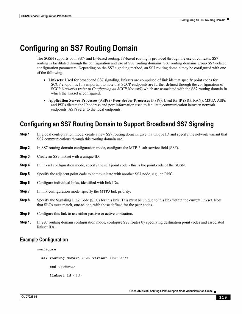
SGSN Service Configuration Procedures
Configuring an SS7 Routing Domain ▀
Cisco ASR 5000 Serving GPRS Support Node Administration Guide ▄ OL-27223-06 119
Configuring an SS7 Routing Domain The SGSN supports both SS7- and IP-based routing. IP-based routing is provided through the use of contexts. SS7
routing is facilitated through the configuration and use of SS7 routing domains. SS7 routing domains group SS7-related
configuration parameters. Depending on the SS7 signaling method, an SS7 routing domain may be configured with one
of the following:
Linksets: Used for broadband SS7 signaling, linksets are comprised of link ids that specify point codes for SCCP endpoints. It is important to note that SCCP endpoints are further defined through the configuration of SCCP Networks (refer to Configuring an SCCP Network) which are associated with the SS7 routing domain in which the linkset is configured.
Application Server Processes (ASPs) / Peer Server Processes (PSPs): Used for IP (SIGTRAN), M3UA ASPs and PSPs dictate the IP address and port information used to facilitate communication between network endpoints. ASPs refer to the local endpoints.
Configuring an SS7 Routing Domain to Support Broadband SS7 Signaling
Step 1 In global configuration mode, create a new SS7 routing domain, give it a unique ID and specify the network variant that
SS7 communications through this routing domain use.
Step 2 In SS7 routing domain configuration mode, configure the MTP-3 sub-service field (SSF).
Step 3 Create an SS7 linkset with a unique ID.
Step 4 In linkset configuration mode, specify the self point code - this is the point code of the SGSN.
Step 5 Specify the adjacent point code to communicate with another SS7 node, e.g., an RNC.
Step 6 Configure individual links, identified with link IDs.
Step 7 In link configuration mode, specify the MTP3 link priority.
Step 8 Specify the Signaling Link Code (SLC) for this link. This must be unique to this link within the current linkset. Note
that SLCs must match, one-to-one, with those defined for the peer nodes.
Step 9 Configure this link to use either passive or active arbitration.
Step 10 In SS7 routing domain configuration mode, configure SS7 routes by specifying destination point codes and associated
linkset IDs.
Example Configuration
configure
ss7-routing-domain <id> variant <variant>
ssf <subsvc>
linkset id <id>
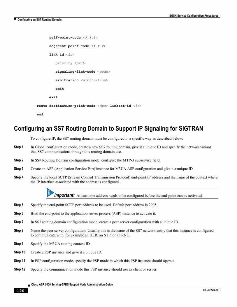
SGSN Service Configuration Procedures
▀ Configuring an SS7 Routing Domain
▄ Cisco ASR 5000 Serving GPRS Support Node Administration Guide
120 OL-27223-06
self-point-code <#.#.#>
adjacent-point-code <#.#.#>
link id <id>
priority <pri>
signaling-link-code <code>
arbitration <arbitration>
exit
exit
route destination-point-code <dpc> linkset-id <id>
end
Configuring an SS7 Routing Domain to Support IP Signaling for SIGTRAN
To configure IP, the SS7 routing domain must be configured in a specific way as described below:
Step 1 In Global configuration mode, create a new SS7 routing domain, give it a unique ID and specify the network variant
that SS7 communications through this routing domain use.
Step 2 In SS7 Routing Domain configuration mode, configure the MTP-3 subservice field.
Step 3 Create an ASP (Application Service Part) instance for M3UA ASP configuration and give it a unique ID.
Step 4 Specify the local SCTP (Stream Control Transmission Protocol) end-point IP address and the name of the context where
the IP interface associated with the address is configured.
Important: At least one address needs to be configured before the end-point can be activated.
Step 5 Specify the end-point SCTP port address to be used. Default port address is 2905.
Step 6 Bind the end-point to the application server process (ASP) instance to activate it.
Step 7 In SS7 routing domain configuration mode, create a peer server configuration with a unique ID.
Step 8 Name the peer server configuration. Usually this is the name of the SS7 network entity that this instance is configured
to communicate with, for example an HLR, an STP, or an RNC.
Step 9 Specify the M3UA routing context ID.
Step 10 Create a PSP instance and give it a unique ID.
Step 11 In PSP configuration mode, specify the PSP mode in which this PSP instance should operate.
Step 12 Specify the communication mode this PSP instance should use as client or server.
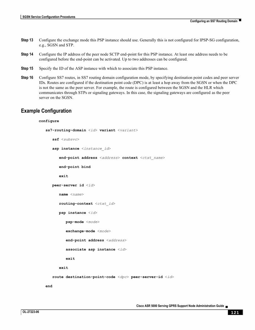
SGSN Service Configuration Procedures
Configuring an SS7 Routing Domain ▀
Cisco ASR 5000 Serving GPRS Support Node Administration Guide ▄ OL-27223-06 121
Step 13 Configure the exchange mode this PSP instance should use. Generally this is not configured for IPSP-SG configuration,
e.g., SGSN and STP.
Step 14 Configure the IP address of the peer node SCTP end-point for this PSP instance. At least one address needs to be
configured before the end-point can be activated. Up to two addresses can be configured.
Step 15 Specify the ID of the ASP instance with which to associate this PSP instance.
Step 16 Configure SS7 routes, in SS7 routing domain configuration mode, by specifying destination point codes and peer server
IDs. Routes are configured if the destination point code (DPC) is at least a hop away from the SGSN or when the DPC
is not the same as the peer server. For example, the route is configured between the SGSN and the HLR which
communicates through STPs or signaling gateways. In this case, the signaling gateways are configured as the peer
server on the SGSN.
Example Configuration
configure
ss7-routing-domain <id> variant <variant>
ssf <subsvc>
asp instance <instance_id>
end-point address <address> context <ctxt_name>
end-point bind
exit
peer-server id <id>
name <name>
routing-context <ctxt_id>
psp instance <id>
psp-mode <mode>
exchange-mode <mode>
end-point address <address>
associate asp instance <id>
exit
exit
route destination-point-code <dpc> peer-server-id <id>
end
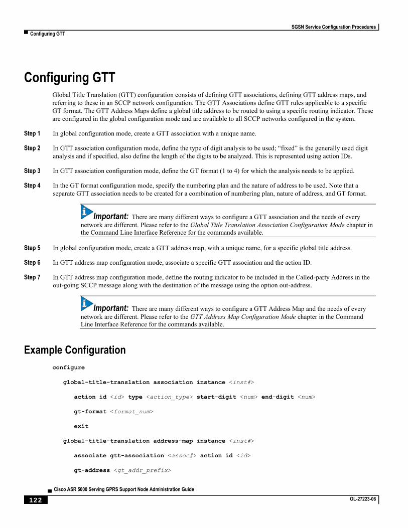
SGSN Service Configuration Procedures
▀ Configuring GTT
▄ Cisco ASR 5000 Serving GPRS Support Node Administration Guide
122 OL-27223-06
Configuring GTT Global Title Translation (GTT) configuration consists of defining GTT associations, defining GTT address maps, and
referring to these in an SCCP network configuration. The GTT Associations define GTT rules applicable to a specific
GT format. The GTT Address Maps define a global title address to be routed to using a specific routing indicator. These
are configured in the global configuration mode and are available to all SCCP networks configured in the system.
Step 1 In global configuration mode, create a GTT association with a unique name.
Step 2 In GTT association configuration mode, define the type of digit analysis to be used; “fixed” is the generally used digit
analysis and if specified, also define the length of the digits to be analyzed. This is represented using action IDs.
Step 3 In GTT association configuration mode, define the GT format (1 to 4) for which the analysis needs to be applied.
Step 4 In the GT format configuration mode, specify the numbering plan and the nature of address to be used. Note that a
separate GTT association needs to be created for a combination of numbering plan, nature of address, and GT format.
Important: There are many different ways to configure a GTT association and the needs of every
network are different. Please refer to the Global Title Translation Association Configuration Mode chapter in the Command Line Interface Reference for the commands available.
Step 5 In global configuration mode, create a GTT address map, with a unique name, for a specific global title address.
Step 6 In GTT address map configuration mode, associate a specific GTT association and the action ID.
Step 7 In GTT address map configuration mode, define the routing indicator to be included in the Called-party Address in the
out-going SCCP message along with the destination of the message using the option out-address.
Important: There are many different ways to configure a GTT Address Map and the needs of every
network are different. Please refer to the GTT Address Map Configuration Mode chapter in the Command Line Interface Reference for the commands available.
Example Configuration
configure
global-title-translation association instance <inst#>
action id <id> type <action_type> start-digit <num> end-digit <num>
gt-format <format_num>
exit
global-title-translation address-map instance <inst#>
associate gtt-association <assoc#> action id <id>
gt-address <gt_addr_prefix>

SGSN Service Configuration Procedures
Configuring GTT ▀
Cisco ASR 5000 Serving GPRS Support Node Administration Guide ▄ OL-27223-06 123
out-address <name>
ssf <sub_svc_fld>
routing-indicator <route_ind>
ni-indicator <addr_ind>
ssn <sub_sys_num>
point-code <pt_code>
end
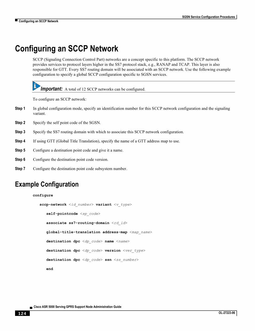
SGSN Service Configuration Procedures
▀ Configuring an SCCP Network
▄ Cisco ASR 5000 Serving GPRS Support Node Administration Guide
124 OL-27223-06
Configuring an SCCP Network SCCP (Signaling Connection Control Part) networks are a concept specific to this platform. The SCCP network
provides services to protocol layers higher in the SS7 protocol stack, e.g., RANAP and TCAP. This layer is also
responsible for GTT. Every SS7 routing domain will be associated with an SCCP network. Use the following example
configuration to specify a global SCCP configuration specific to SGSN services.
Important: A total of 12 SCCP networks can be configured.
To configure an SCCP network:
Step 1 In global configuration mode, specify an identification number for this SCCP network configuration and the signaling
variant.
Step 2 Specify the self point code of the SGSN.
Step 3 Specify the SS7 routing domain with which to associate this SCCP network configuration.
Step 4 If using GTT (Global Title Translation), specify the name of a GTT address map to use.
Step 5 Configure a destination point code and give it a name.
Step 6 Configure the destination point code version.
Step 7 Configure the destination point code subsystem number.
Example Configuration
configure
sccp-network <id_number> variant <v_type>
self-pointcode <sp_code>
associate ss7-routing-domain <rd_id>
global-title-translation address-map <map_name>
destination dpc <dp_code> name <name>
destination dpc <dp_code> version <ver_type>
destination dpc <dp_code> ssn <ss_number>
end
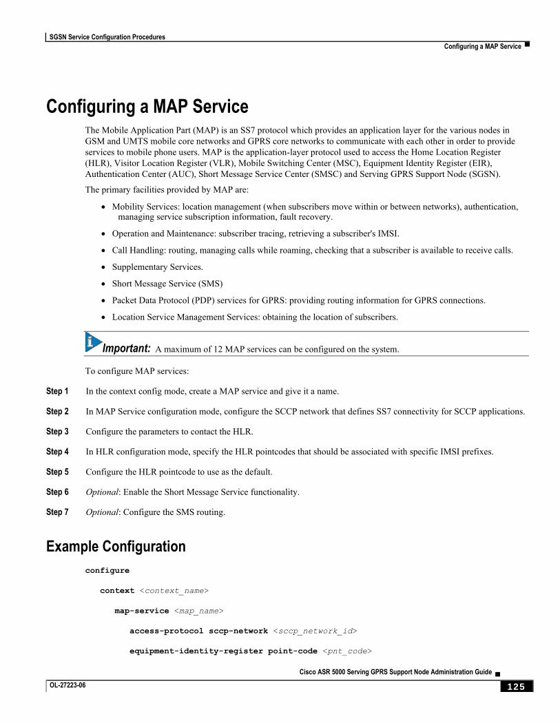
SGSN Service Configuration Procedures
Configuring a MAP Service ▀
Cisco ASR 5000 Serving GPRS Support Node Administration Guide ▄ OL-27223-06 125
Configuring a MAP Service The Mobile Application Part (MAP) is an SS7 protocol which provides an application layer for the various nodes in
GSM and UMTS mobile core networks and GPRS core networks to communicate with each other in order to provide
services to mobile phone users. MAP is the application-layer protocol used to access the Home Location Register
(HLR), Visitor Location Register (VLR), Mobile Switching Center (MSC), Equipment Identity Register (EIR),
Authentication Center (AUC), Short Message Service Center (SMSC) and Serving GPRS Support Node (SGSN).
The primary facilities provided by MAP are:
Mobility Services: location management (when subscribers move within or between networks), authentication, managing service subscription information, fault recovery.
Operation and Maintenance: subscriber tracing, retrieving a subscriber's IMSI.
Call Handling: routing, managing calls while roaming, checking that a subscriber is available to receive calls.
Supplementary Services.
Short Message Service (SMS)
Packet Data Protocol (PDP) services for GPRS: providing routing information for GPRS connections.
Location Service Management Services: obtaining the location of subscribers.
Important: A maximum of 12 MAP services can be configured on the system.
To configure MAP services:
Step 1 In the context config mode, create a MAP service and give it a name.
Step 2 In MAP Service configuration mode, configure the SCCP network that defines SS7 connectivity for SCCP applications.
Step 3 Configure the parameters to contact the HLR.
Step 4 In HLR configuration mode, specify the HLR pointcodes that should be associated with specific IMSI prefixes.
Step 5 Configure the HLR pointcode to use as the default.
Step 6 Optional: Enable the Short Message Service functionality.
Step 7 Optional: Configure the SMS routing.
Example Configuration
configure
context <context_name>
map-service <map_name>
access-protocol sccp-network <sccp_network_id>
equipment-identity-register point-code <pnt_code>
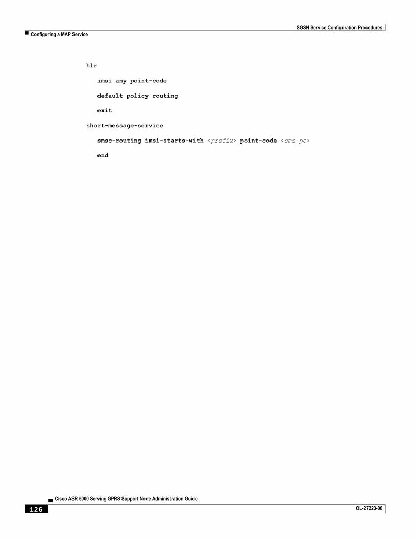
SGSN Service Configuration Procedures
▀ Configuring a MAP Service
▄ Cisco ASR 5000 Serving GPRS Support Node Administration Guide
126 OL-27223-06
hlr
imsi any point-code
default policy routing
exit
short-message-service
smsc-routing imsi-starts-with <prefix> point-code <sms_pc>
end
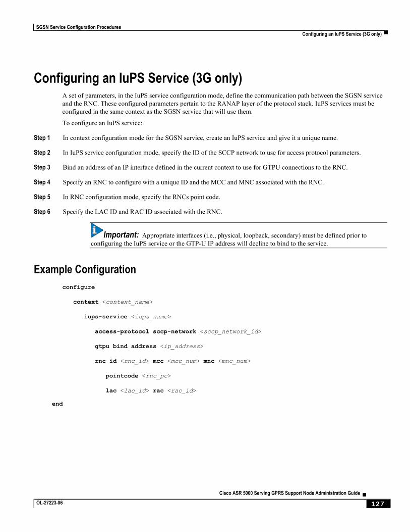
SGSN Service Configuration Procedures
Configuring an IuPS Service (3G only) ▀
Cisco ASR 5000 Serving GPRS Support Node Administration Guide ▄ OL-27223-06 127
Configuring an IuPS Service (3G only) A set of parameters, in the IuPS service configuration mode, define the communication path between the SGSN service
and the RNC. These configured parameters pertain to the RANAP layer of the protocol stack. IuPS services must be
configured in the same context as the SGSN service that will use them.
To configure an IuPS service:
Step 1 In context configuration mode for the SGSN service, create an IuPS service and give it a unique name.
Step 2 In IuPS service configuration mode, specify the ID of the SCCP network to use for access protocol parameters.
Step 3 Bind an address of an IP interface defined in the current context to use for GTPU connections to the RNC.
Step 4 Specify an RNC to configure with a unique ID and the MCC and MNC associated with the RNC.
Step 5 In RNC configuration mode, specify the RNCs point code.
Step 6 Specify the LAC ID and RAC ID associated with the RNC.
Important: Appropriate interfaces (i.e., physical, loopback, secondary) must be defined prior to
configuring the IuPS service or the GTP-U IP address will decline to bind to the service.
Example Configuration
configure
context <context_name>
iups-service <iups_name>
access-protocol sccp-network <sccp_network_id>
gtpu bind address <ip_address>
rnc id <rnc_id> mcc <mcc_num> mnc <mnc_num>
pointcode <rnc_pc>
lac <lac_id> rac <rac_id>
end
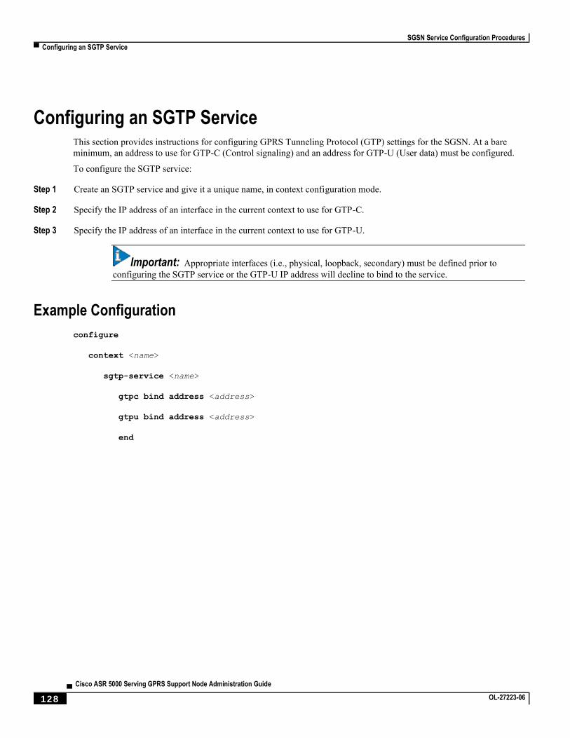
SGSN Service Configuration Procedures
▀ Configuring an SGTP Service
▄ Cisco ASR 5000 Serving GPRS Support Node Administration Guide
128 OL-27223-06
Configuring an SGTP Service This section provides instructions for configuring GPRS Tunneling Protocol (GTP) settings for the SGSN. At a bare
minimum, an address to use for GTP-C (Control signaling) and an address for GTP-U (User data) must be configured.
To configure the SGTP service:
Step 1 Create an SGTP service and give it a unique name, in context configuration mode.
Step 2 Specify the IP address of an interface in the current context to use for GTP-C.
Step 3 Specify the IP address of an interface in the current context to use for GTP-U.
Important: Appropriate interfaces (i.e., physical, loopback, secondary) must be defined prior to
configuring the SGTP service or the GTP-U IP address will decline to bind to the service.
Example Configuration
configure
context <name>
sgtp-service <name>
gtpc bind address <address>
gtpu bind address <address>
end
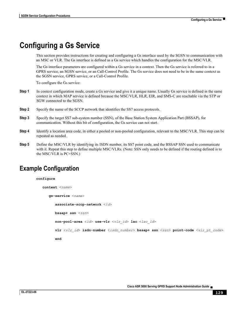
SGSN Service Configuration Procedures
Configuring a Gs Service ▀
Cisco ASR 5000 Serving GPRS Support Node Administration Guide ▄ OL-27223-06 129
Configuring a Gs Service This section provides instructions for creating and configuring a Gs interface used by the SGSN to communication with
an MSC or VLR. The Gs interface is defined as a Gs service which handles the configuration for the MSC/VLR.
The Gs interface parameters are configured within a Gs service in a context. Then the Gs service is referred to in a
GPRS service, an SGSN service, or an Call-Control Profile. The Gs service does not need to be in the same context as
the SGSN service, GPRS service, or a Call-Control Profile.
To configure the Gs service:
Step 1 In context configuration mode, create a Gs service and give it a unique name. Usually Gs service is defined in the same
context in which MAP service is defined because the MSC/VLR, HLR, EIR, and SMS-C are reachable via the STP or
SGW connected to the SGSN.
Step 2 Specify the name of the SCCP network that identifies the SS7 access protocols.
Step 3 Specify the target SS7 sub-system number (SSN), of the Base Station System Application Part (BSSAP), for
communication. Without this bit of configuration, the Gs service can not start.
Step 4 Identify a location area code, in either a pooled or non-pooled configuration, relevant to the MSC/VLR. This step can be
repeated as needed.
Step 5 Define the MSC/VLR by identifying its ISDN number, its SS7 point code, and the BSSAP SSN used to communicate
with it. Repeat this step to define multiple MSC/VLRs. (Note: SSN only needs to be defined if the routing defined is to
the MSC/VLR is PC+SSN.)
Example Configuration
configure
context <name>
gs-service <name>
associate-sccp-network <id>
bssap+ ssn <ssn>
non-pool-area <id> use-vlr <vlr_id> lac <lac_id>
vlr <vlr_id> isdn-number <isdn_number> bssap+ ssn <ssn> point-code <vlr_pt_code>
end
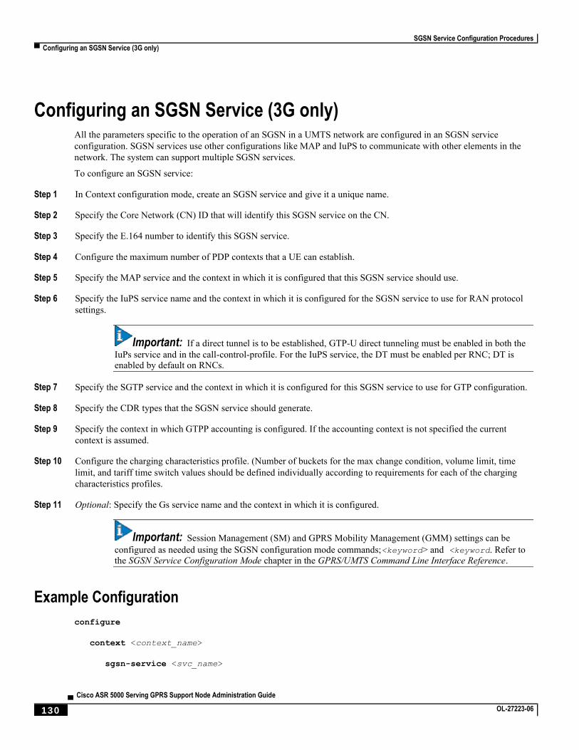
SGSN Service Configuration Procedures
▀ Configuring an SGSN Service (3G only)
▄ Cisco ASR 5000 Serving GPRS Support Node Administration Guide
130 OL-27223-06
Configuring an SGSN Service (3G only) All the parameters specific to the operation of an SGSN in a UMTS network are configured in an SGSN service
configuration. SGSN services use other configurations like MAP and IuPS to communicate with other elements in the
network. The system can support multiple SGSN services.
To configure an SGSN service:
Step 1 In Context configuration mode, create an SGSN service and give it a unique name.
Step 2 Specify the Core Network (CN) ID that will identify this SGSN service on the CN.
Step 3 Specify the E.164 number to identify this SGSN service.
Step 4 Configure the maximum number of PDP contexts that a UE can establish.
Step 5 Specify the MAP service and the context in which it is configured that this SGSN service should use.
Step 6 Specify the IuPS service name and the context in which it is configured for the SGSN service to use for RAN protocol
settings.
Important: If a direct tunnel is to be established, GTP-U direct tunneling must be enabled in both the
IuPs service and in the call-control-profile. For the IuPS service, the DT must be enabled per RNC; DT is enabled by default on RNCs.
Step 7 Specify the SGTP service and the context in which it is configured for this SGSN service to use for GTP configuration.
Step 8 Specify the CDR types that the SGSN service should generate.
Step 9 Specify the context in which GTPP accounting is configured. If the accounting context is not specified the current
context is assumed.
Step 10 Configure the charging characteristics profile. (Number of buckets for the max change condition, volume limit, time
limit, and tariff time switch values should be defined individually according to requirements for each of the charging
characteristics profiles.
Step 11 Optional: Specify the Gs service name and the context in which it is configured.
Important: Session Management (SM) and GPRS Mobility Management (GMM) settings can be
configured as needed using the SGSN configuration mode commands;<keyword> and <keyword. Refer to
the SGSN Service Configuration Mode chapter in the GPRS/UMTS Command Line Interface Reference.
Example Configuration
configure
context <context_name>
sgsn-service <svc_name>
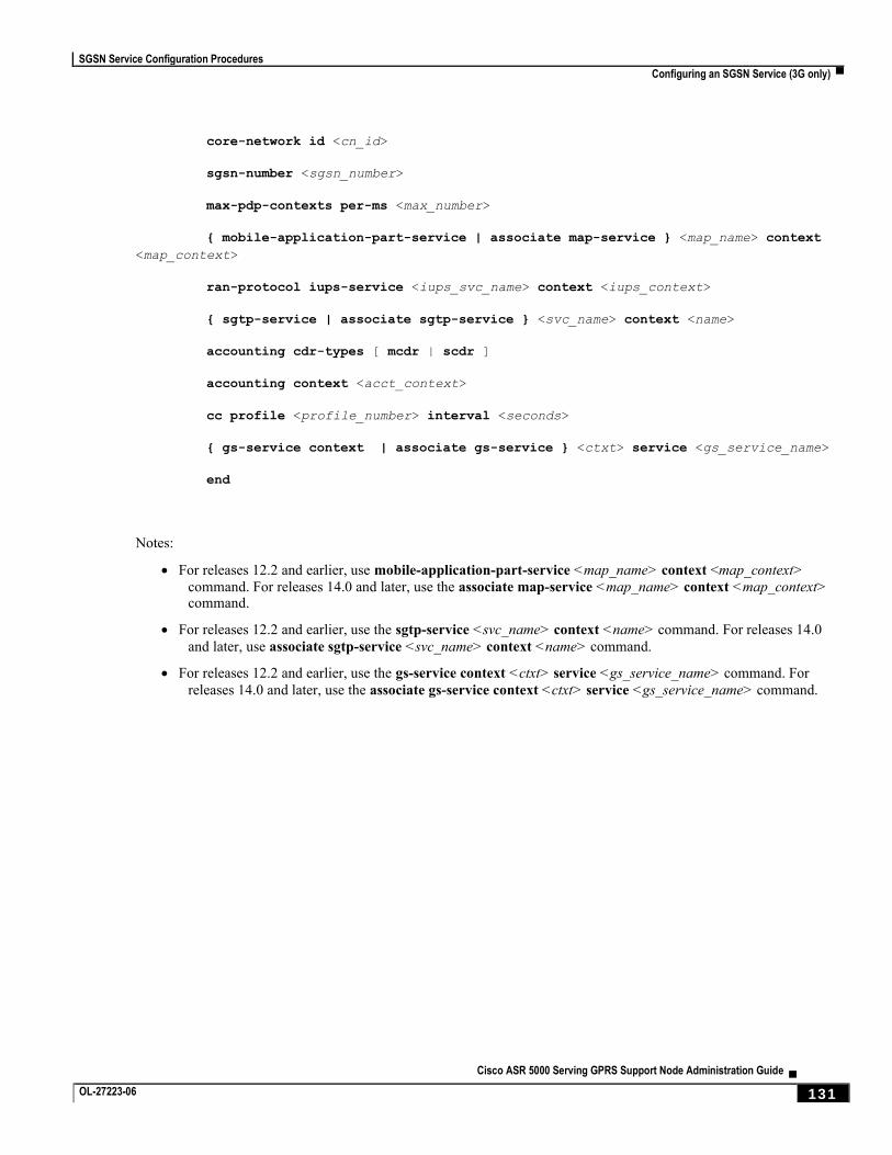
SGSN Service Configuration Procedures
Configuring an SGSN Service (3G only) ▀
Cisco ASR 5000 Serving GPRS Support Node Administration Guide ▄ OL-27223-06 131
core-network id <cn_id>
sgsn-number <sgsn_number>
max-pdp-contexts per-ms <max_number>
{ mobile-application-part-service | associate map-service } <map_name> context
<map_context>
ran-protocol iups-service <iups_svc_name> context <iups_context>
{ sgtp-service | associate sgtp-service } <svc_name> context <name>
accounting cdr-types [ mcdr | scdr ]
accounting context <acct_context>
cc profile <profile_number> interval <seconds>
{ gs-service context | associate gs-service } <ctxt> service <gs_service_name>
end
Notes:
For releases 12.2 and earlier, use mobile-application-part-service <map_name> context <map_context>
command. For releases 14.0 and later, use the associate map-service <map_name> context <map_context> command.
For releases 12.2 and earlier, use the sgtp-service <svc_name> context <name> command. For releases 14.0
and later, use associate sgtp-service <svc_name> context <name> command.
For releases 12.2 and earlier, use the gs-service context <ctxt> service <gs_service_name> command. For
releases 14.0 and later, use the associate gs-service context <ctxt> service <gs_service_name> command.
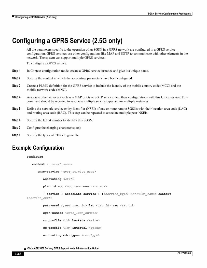
SGSN Service Configuration Procedures
▀ Configuring a GPRS Service (2.5G only)
▄ Cisco ASR 5000 Serving GPRS Support Node Administration Guide
132 OL-27223-06
Configuring a GPRS Service (2.5G only) All the parameters specific to the operation of an SGSN in a GPRS network are configured in a GPRS service
configuration. GPRS services use other configurations like MAP and SGTP to communicate with other elements in the
network. The system can support multiple GPRS services.
To configure a GPRS service:
Step 1 In Context configuration mode, create a GPRS service instance and give it a unique name.
Step 2 Specify the context in which the accounting parameters have been configured.
Step 3 Create a PLMN definition for the GPRS service to include the identity of the mobile country code (MCC) and the
mobile network code (MNC).
Step 4 Associate other services (such as a MAP or Gs or SGTP service) and their configurations with this GPRS service. This
command should be repeated to associate multiple service types and/or multiple instances.
Step 5 Define the network service entity identifier (NSEI) of one or more remote SGSNs with their location area code (LAC)
and routing area code (RAC). This step can be repeated to associate multiple peer-NSEIs.
Step 6 Specify the E.164 number to identify this SGSN.
Step 7 Configure the charging characteristic(s).
Step 8 Specify the types of CDRs to generate.
Example Configuration
configure
context <context_name>
gprs-service <gprs_service_name>
accounting <ctxt>
plmn id mcc <mcc_num> mnc <mnc_num>
{ service | associate service | }<service_type> <service_name> context
<service_ctxt>
peer-nsei <peer_nsei_id> lac <lac_id> rac <rac_id>
sgsn-number <sgsn_isdn_number>
cc profile <id> buckets <value>
cc profile <id> interval <value>
accounting cdr-types <cdr_type>

SGSN Service Configuration Procedures
Configuring a GPRS Service (2.5G only) ▀
Cisco ASR 5000 Serving GPRS Support Node Administration Guide ▄ OL-27223-06 133
end
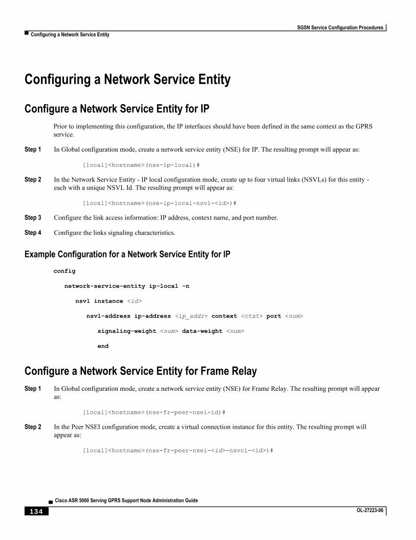
SGSN Service Configuration Procedures
▀ Configuring a Network Service Entity
▄ Cisco ASR 5000 Serving GPRS Support Node Administration Guide
134 OL-27223-06
Configuring a Network Service Entity
Configure a Network Service Entity for IP
Prior to implementing this configuration, the IP interfaces should have been defined in the same context as the GPRS
service.
Step 1 In Global configuration mode, create a network service entity (NSE) for IP. The resulting prompt will appear as:
[local]<hostname>(nse-ip-local)#
Step 2 In the Network Service Entity - IP local configuration mode, create up to four virtual links (NSVLs) for this entity -
each with a unique NSVL Id. The resulting prompt will appear as:
[local]<hostname>(nse-ip-local-nsvl-<id>)#
Step 3 Configure the link access information: IP address, context name, and port number.
Step 4 Configure the links signaling characteristics.
Example Configuration for a Network Service Entity for IP
config
network-service-entity ip-local -n
nsvl instance <id>
nsvl-address ip-address <ip_addr> context <ctxt> port <num>
signaling-weight <num> data-weight <num>
end
Configure a Network Service Entity for Frame Relay
Step 1 In Global configuration mode, create a network service entity (NSE) for Frame Relay. The resulting prompt will appear
as:
[local]<hostname>(nse-fr-peer-nsei-id)#
Step 2 In the Peer NSEI configuration mode, create a virtual connection instance for this entity. The resulting prompt will
appear as:
[local]<hostname>(nse-fr-peer-nsei-<id>-nsvci-<id>)#
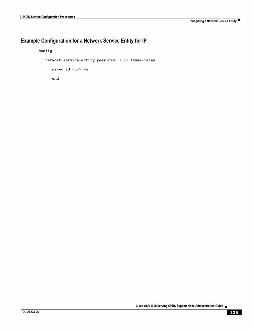
SGSN Service Configuration Procedures
Configuring a Network Service Entity ▀
Cisco ASR 5000 Serving GPRS Support Node Administration Guide ▄ OL-27223-06 135
Example Configuration for a Network Service Entity for IP
config
network-service-entity peer-nsei <id> frame-relay
ns-vc id <id> -n
end
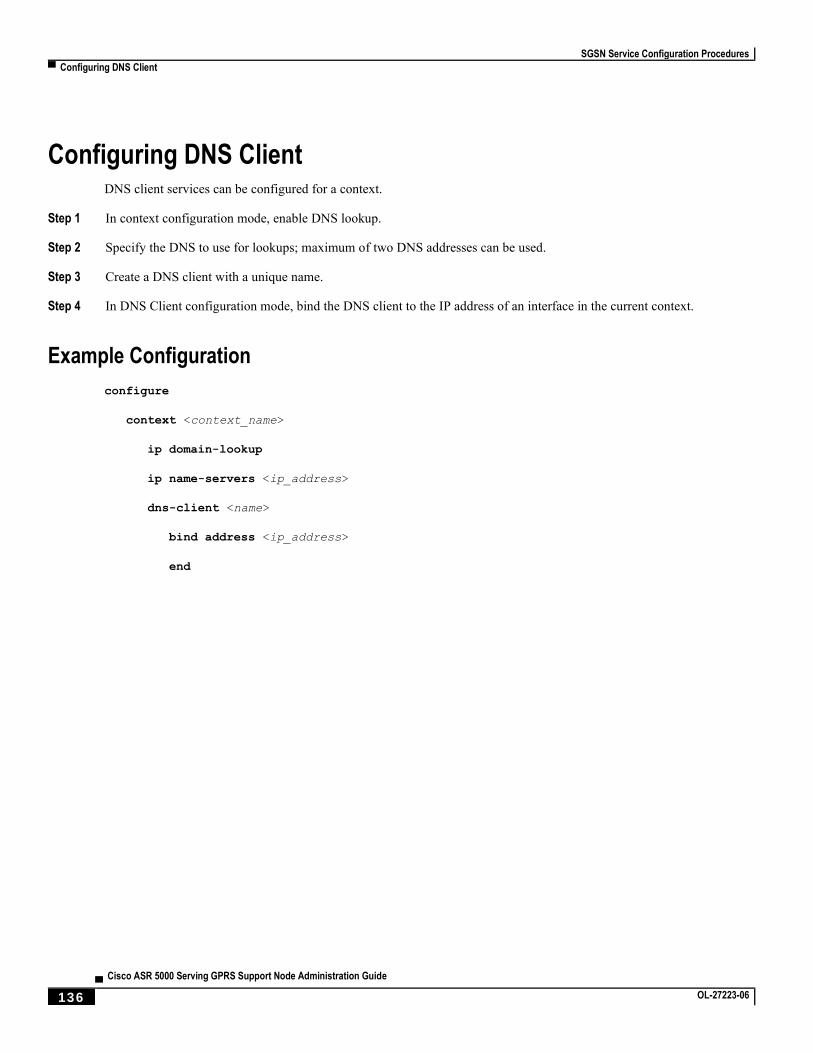
SGSN Service Configuration Procedures
▀ Configuring DNS Client
▄ Cisco ASR 5000 Serving GPRS Support Node Administration Guide
136 OL-27223-06
Configuring DNS Client DNS client services can be configured for a context.
Step 1 In context configuration mode, enable DNS lookup.
Step 2 Specify the DNS to use for lookups; maximum of two DNS addresses can be used.
Step 3 Create a DNS client with a unique name.
Step 4 In DNS Client configuration mode, bind the DNS client to the IP address of an interface in the current context.
Example Configuration
configure
context <context_name>
ip domain-lookup
ip name-servers <ip_address>
dns-client <name>
bind address <ip_address>
end
SGSN Service Configuration Procedures
Configuring GTPP Accounting Support ▀
Cisco ASR 5000 Serving GPRS Support Node Administration Guide ▄ OL-27223-06 137
Configuring GTPP Accounting Support This section provides instructions for configuring GTPP-based accounting which allows the SGSN to send M-CDR
and/or S-CDR accounting data to the Charging Gateways (CGs) over the Ga interface.
The Ga interface and GTPP functionality are typically configured within a separate charging context.
The SGSN begins to generate M-CDR data upon GPRS/IMSI attach. S-CDR data generation begins upon PDP context
activation.
Accounting servers can be configured individually or as GTPP accounting server groups. GTPP accounting server
groups can each have completely different GTPP settings configured. Although a GTTP server can be included in
multiple GTPP groups.
Any GTPP accounting servers configured at the context level that are not specifically configured as part of a GTPP
group, are automatically assigned to be part of the GTPP server group called default that is part of every context.
A maximum of 8 GTPP named server groups can be configured across all contexts. A maximum of 4 CGFs can be
configured in each GTPP server group. A total of total 32 CGFs can be configured across all server groups, including
the server group called default, in one context. Each GTPP group must have unique GTPP charging agents (CGFs)
configured.
Important: The system supports the specification of the UDP port number for the charging agent function on the
system and for the CG. The default charging agent port is 49999. The default CG Server port is (3386). If an SGSN service and a GGSN service are both configured on this system be sure that the UDP ports are unique for each type of service. Refer to the Command Line Interface Reference for information on changing the ports used.
To configure the GTPP accounting support for a SGSN service:
Step 1 Create the GTPP group in accounting context by applying the example configuration in the Creating GTPP Group
section.
Step 2 Configure the charging agent and GTPP server (CGF) related parameters for the GTPP accounting support by applying
the example configuration in the Configuring GTPP Group section.
Step 3 Verify your GTPP group and accounting configuration by following the steps in the Verifying GTPP Group
Configuration section.
Step 4 Save your configuration to flash memory, an external memory device, and/or a network location using the Exec mode
command save configuration. For additional information on how to verify and save configuration files, refer to the
System Administration Guide and the Command Line Interface Reference.
Creating GTPP Group
Use the following example to create the GTPP group to support GTPP accounting:
configure
context <vpn_ctxt_name>
gtpp group <gtpp_group_name> -noconfirm
SGSN Service Configuration Procedures
▀ Configuring GTPP Accounting Support
▄ Cisco ASR 5000 Serving GPRS Support Node Administration Guide
138 OL-27223-06
end
Notes:
In addition to one default GTPP group “default” a maximum of 8 GTPP groups can be configured with this command in a context.
In case no GTPP group is configured in this context, system creates a default GTPP group named “default” and all the CGF servers and their parameters configured in this context are applicable to this “default” GTPP group.
Configuring GTPP Group
Use the following example to configure the GTPP server parameters, GTPP dictionary, and optionally CGF to support
GTPP accounting:
configure
context <vpn_ctxt_name>
gtpp group <gtpp_group_name>
gtpp charging-agent address <ip_address> [ port <port> ]
gtpp server <ip_address> [ max <msgs >] [ priority <priority>]
gtpp dictionary <dictionaries>
gtpp max-cdrs <number_cdrs> [ wait-time <dur_sec> ]
gtpp transport-layer { tcp | udp }
end
Notes:
In addition to one default GTPP group “default” a maximum of 8 GTPP groups can be configured with this command in a context.
In case no GTPP group is configured in this context, system creates a default GTPP group named “default” and all the CGF servers and their parameters configured in this context are applicable to this “default” GTPP group.
Command for CGF gtpp charging-agent is optional and configuring gtpp charging-agent on port 3386 may
interfere with ggsn-service configured with the same ip address. Multiple interfaces can be configured within a single context if needed.
For more information on GTPP dictionary encoding, if you are using StarOS 12.3 or an earlier release, refer to the AAA and GTPP Interface Administration and Reference. If you are using StarOS 14.0 or a later release, refer to the GTPP Interface Administration and Reference.
For better performance, it is recommended to configure maximum number of CDRs as 255 with gtpp max-
cdrs command.
You can select transport layer protocol as TCP or UDP for Ga interface with gtpp transport-layer
command. By default it is UDP.
Multiple GTPP server can be configured using multiple instances of this command subject to following limits:
Total 4 GTPP server in one GTPP group
SGSN Service Configuration Procedures
Configuring GTPP Accounting Support ▀
Cisco ASR 5000 Serving GPRS Support Node Administration Guide ▄ OL-27223-06 139
Total 32 GTPP server in one context
Total 9 GTPP groups (1 default and 8 user defined GTPP groups) can be configured in one context. Number of CGFs in 1 GTPP group is limited to 4 and a total of 32 CGF servers across all GTPP groups in one context are configurable.
Verifying GTPP Group Configuration
Step 1 Verify that your CGFs were configured properly by entering the following command in Exec Mode:
show gtpp accounting servers
This command produces an output similar to that displayed below:
context: source
Preference IP Port Priority State Group
---------- --------------- ---- -------- ------- ------
Primary 192.168.32.135 3386 1 Active default
Primary 192.168.89.9 3386 100 Active default
SGSN Service Configuration Procedures
▀ Configuring and Associating the EGTP Service (S4 Only)
▄ Cisco ASR 5000 Serving GPRS Support Node Administration Guide
140 OL-27223-06
Configuring and Associating the EGTP Service (S4 Only) This section describes how to configure and associate the EGTP service to support S4-SGSN functionality.
The SGSN communicates with the EPC network SGW via the GTPv2 protocol over the S4 interface. GTPv2 is
configured on the chassis as part of an EGTP service. Once configured, the EGTP service then must be associated with
the configured UMTS (3G) and/or GPRS (2G) service configured on the system to provide access to the EPC network.
Once the EGTP service is associated with the UTRAN and/or GERAN service, then the S4-SGSN will be chosen for
PDP context activation in the following cases:
If the last known capability of the UE indicates that it is EPC-capable.
If the last known capability of the UE indicates it is non-EPC capable but has an EPS subscription only.
If a PDP context is already activated for the UE, and the S4 interface is already selected for the UE.
Important: The S4 feature license must be enabled on the S4-SGSN to configure the EGTP service.
Important: S4 support for the SGSN requires the presence of an SGTP service, even though S4 support is being
configured for the SGSN to use the S4 interface. The SGTP service is required to interface with non-EPC capable roaming partners via the Gn interface. SGTP is also required for subscribers using mobile phones that are not EPC-capable in an EPC network.
Important: Currently, the S4-SGSN does not support the transfer of PDP contexts from the S4 interface to the
Gn interface within the same S4-SGSN.
Use the following procedure to configure and associate the EGTP service to for S4 functionality on the SGSN:
Step 1 Access Context Configuration Mode.
Step 2 Create and configure the EGTP service in the desired context.
Step 3 Configure the interface type for the EGTP service.
Step 4 Configure the validation mode for the EGTP service. The default and recommened setting is standard.
Step 5 Associate the EGTP service with the configured 2.5G service (if configured).
Step 6 Associate the EGTP service with the configured 3G service (if configured).
Example Configuration
config
context <context_name>
egtp-service <service_name>
gtpc bind ipv4-address <ipv4_address>
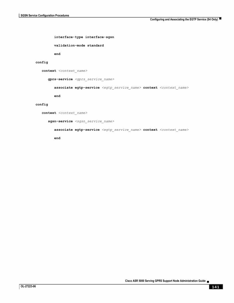
SGSN Service Configuration Procedures
Configuring and Associating the EGTP Service (S4 Only) ▀
Cisco ASR 5000 Serving GPRS Support Node Administration Guide ▄ OL-27223-06 141
interface-type interface-sgsn
validation-mode standard
end
config
context <context_name>
gprs-service <gprs_service_name>
associate egtp-service <egtp_service_name> context <context_name>
end
config
context <context_name>
sgsn-service <sgsn_service_name>
associate egtp-service <egtp_service_name> context <context_name>
end
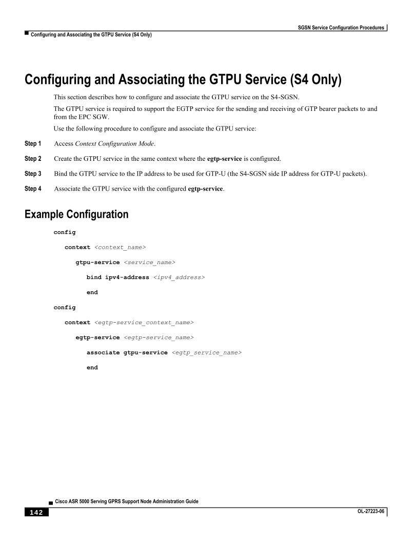
SGSN Service Configuration Procedures
▀ Configuring and Associating the GTPU Service (S4 Only)
▄ Cisco ASR 5000 Serving GPRS Support Node Administration Guide
142 OL-27223-06
Configuring and Associating the GTPU Service (S4 Only) This section describes how to configure and associate the GTPU service on the S4-SGSN.
The GTPU service is required to support the EGTP service for the sending and receiving of GTP bearer packets to and
from the EPC SGW.
Use the following procedure to configure and associate the GTPU service:
Step 1 Access Context Configuration Mode.
Step 2 Create the GTPU service in the same context where the egtp-service is configured.
Step 3 Bind the GTPU service to the IP address to be used for GTP-U (the S4-SGSN side IP address for GTP-U packets).
Step 4 Associate the GTPU service with the configured egtp-service.
Example Configuration
config
context <context_name>
gtpu-service <service_name>
bind ipv4-address <ipv4_address>
end
config
context <egtp-service_context_name>
egtp-service <egtp-service_name>
associate gtpu-service <egtp_service_name>
end
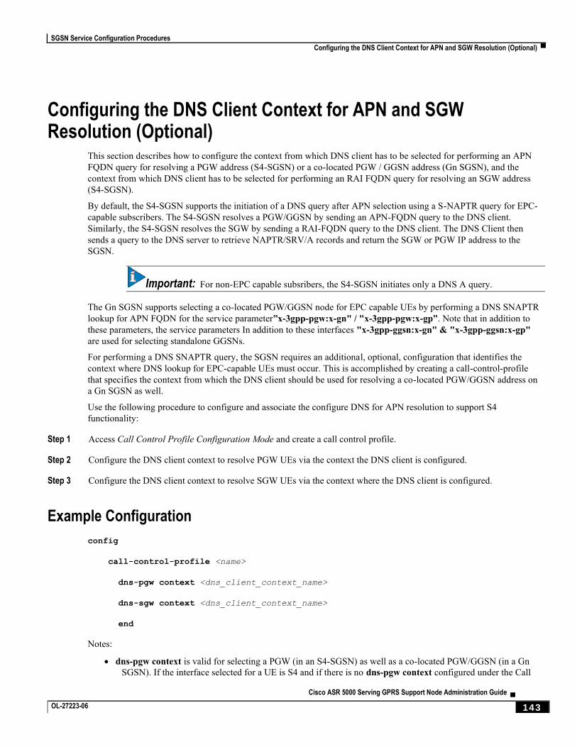
SGSN Service Configuration Procedures
Configuring the DNS Client Context for APN and SGW Resolution (Optional) ▀
Cisco ASR 5000 Serving GPRS Support Node Administration Guide ▄ OL-27223-06 143
Configuring the DNS Client Context for APN and SGW Resolution (Optional)
This section describes how to configure the context from which DNS client has to be selected for performing an APN
FQDN query for resolving a PGW address (S4-SGSN) or a co-located PGW / GGSN address (Gn SGSN), and the
context from which DNS client has to be selected for performing an RAI FQDN query for resolving an SGW address
(S4-SGSN).
By default, the S4-SGSN supports the initiation of a DNS query after APN selection using a S-NAPTR query for EPC-
capable subscribers. The S4-SGSN resolves a PGW/GGSN by sending an APN-FQDN query to the DNS client.
Similarly, the S4-SGSN resolves the SGW by sending a RAI-FQDN query to the DNS client. The DNS Client then
sends a query to the DNS server to retrieve NAPTR/SRV/A records and return the SGW or PGW IP address to the
SGSN.
Important: For non-EPC capable subsribers, the S4-SGSN initiates only a DNS A query.
The Gn SGSN supports selecting a co-located PGW/GGSN node for EPC capable UEs by performing a DNS SNAPTR
lookup for APN FQDN for the service parameter”x-3gpp-pgw:x-gn" / "x-3gpp-pgw:x-gp”. Note that in addition to
these parameters, the service parameters In addition to these interfaces "x-3gpp-ggsn:x-gn" & "x-3gpp-ggsn:x-gp"
are used for selecting standalone GGSNs.
For performing a DNS SNAPTR query, the SGSN requires an additional, optional, configuration that identifies the
context where DNS lookup for EPC-capable UEs must occur. This is accomplished by creating a call-control-profile
that specifies the context from which the DNS client should be used for resolving a co-located PGW/GGSN address on
a Gn SGSN as well.
Use the following procedure to configure and associate the configure DNS for APN resolution to support S4
functionality:
Step 1 Access Call Control Profile Configuration Mode and create a call control profile.
Step 2 Configure the DNS client context to resolve PGW UEs via the context the DNS client is configured.
Step 3 Configure the DNS client context to resolve SGW UEs via the context where the DNS client is configured.
Example Configuration
config
call-control-profile <name>
dns-pgw context <dns_client_context_name>
dns-sgw context <dns_client_context_name>
end
Notes:
dns-pgw context is valid for selecting a PGW (in an S4-SGSN) as well as a co-located PGW/GGSN (in a Gn
SGSN). If the interface selected for a UE is S4 and if there is no dns-pgw context configured under the Call
SGSN Service Configuration Procedures
▀ Configuring the DNS Client Context for APN and SGW Resolution (Optional)
▄ Cisco ASR 5000 Serving GPRS Support Node Administration Guide
144 OL-27223-06
Control Profile, then by default it will look for the DNS client in the context where the EGTP service is
defined. If the interface selected for a UE is gn-gp, and if there is no dns-pgw context configured under the Call Control Profile, then by default the system will look for the DNS client in the context where the SGTP service is configured for selecting co-located PGW/GGSNs if:
The UE is EPC capable and,
apn-resolve-dns-query snaptr is configured under an APN Profile.
dns-sgw context specifies the name of the context where the DNS client is configured and that will be used for
DNS resolution of SGWs. If dns-sgw is not configured, the S4-SGSN uses the DNS client configured in the context where EGTP service is configured to query the SGW DNS address.
SGSN Service Configuration Procedures
Configuring the S6d Diameter Interface (S4 Only) ▀
Cisco ASR 5000 Serving GPRS Support Node Administration Guide ▄ OL-27223-06 145
Configuring the S6d Diameter Interface (S4 Only) This section describes how to configure the S6d Diameter interface to support S4 functionality.
The S6d interface is a Diameter-based interface used to support S4 functionality by enabling the S4-SGSN to
communicate with the HSS. The HSS is a master user database that contains all subscription related information, and
performs the following functions:
Authentication and authorization of the user
Provides the subscribers location information
Provides the subscribers IP information
To support the S6d interface, an HSS Peer Service must be configured and associated with a Diameter endpoint. This
HSS Peer Service is then associated with the configured SGSN and/or GPRS services to enable communication with the
HSS via the S6d interface. Optionally, operators can configure an operator policy-based interface selection.
Configuring the S6d interface consists of the following procedures:
1. Configuring a Diameter Endpoint for the S6d interface
2. Configuring the HSS Peer Service and Interface Association for the S6d interface
3. Associating the HSS Peer Service with the SGSN and GPRS Services for the S6d interface.
4. Optional. Configuring operator policy-based interface selection for the S6d interface.
Configuring the Diameter Endpoint for the S6d Interface
Use the following procedure to configure the Diameter endpoint for the S6d interface:
Step 1 Configure a port that will be bound to an interface (at step 3) to be used as the S6d interface.
Step 2 Configure an Ethernet interface to be used as a diameter endpoint.
Step 3 Configure a Diameter endpoint to be used as the S6d interface.
Step 4 Specify the origin host address and the IP address of the Ethernet interface to be used as the S6d interface.
Step 5 Specify the origin realm. The realm is the Diameter identity. The originator’s realm is present in all Diameter messages
and is typically the company or service provider’s name.
Step 6 Specify the peer name, peer realm name, peer IP address and port number. The peer IP address and port number are the
IP address and port number of the HSS.
Step 7 Specify the route entry peer. This parameter is optional. The route entry peer parameter is required if multiple HSS
peers are configured under a Diameter point and operators want to associate a routing weight to each HSS peer so that
the S4-SGSN contacts each HSS based on the weight distribution.
Step 8 Optional. Enable or disable the watchdog-timeout parameter.
Step 9 The use-proxy keyword can be specified in the diameter-endpoint command to enable the proxy mode. The usage
of proxy mode depends on the operator’s HSS capabilities.
SGSN Service Configuration Procedures
▀ Configuring the S6d Diameter Interface (S4 Only)
▄ Cisco ASR 5000 Serving GPRS Support Node Administration Guide
146 OL-27223-06
Example Configuration
config
port ethernet <slot number/port number>
no shutdown
bind interface <s6d_interface_name> <context_name>
end
config
context <context_name>
interface <s6d_interface_name>
ip address <s6d_interface_ip_address> <subnet_mask>
exit
diameter endpoint <endpoint_name>
origin host <host_name> address <s6d_interface_ip_address>
origin realm <realm_name>
peer <peer_name> realm <realm_name> address <hss_ip_address>
route-entry peer <route_entry_name>
use-proxy
no watchdog-timeout
end
Configuring the HSS Peer Service and Interface Association for the S6d Interface
Use the following procedure to configure the HSS Peer Service and interface association for the S6d interface:
Step 1 Configure a Diameter endpoint. If not already configured, refer to the Configuring the Diameter Endpoint for the S6d
Interface procedure. Then specify the IP address of the Ethernet interface configured in Step 1 as the Diameter endpoint
address.
Step 2 Associate the Diameter endpoint with an HSS peer service.
Step 3 Specify the Diameter dictionary to be used for the HSS Peer Service. The standard-r9 dictionary must be used for
the S6d interface.
SGSN Service Configuration Procedures
Configuring the S6d Diameter Interface (S4 Only) ▀
Cisco ASR 5000 Serving GPRS Support Node Administration Guide ▄ OL-27223-06 147
Example Configuration
config
context <sgsn_context_name>
hss-peer-service <hss_peer_service_name>
diameter hss-endpoint <hss_endpoint_name>
diameter hss-dictionary standard_r9
end
Associating the HSS Peer Service with the SGSN and GPRS Services for the S6d Interface
Use this procedure to association the HSS Peer Service with the SGSN and GPRS Services:
Step 1 Access Context Configuration Mode and create an SGSN service.
Step 2 Associate the HSS peer service name with the SGSN service.
Step 3 Access Context Configuration Mode and create a GPRS service.
Step 4 Associate the HSS peer service name with the GPRS service.
Example Configuration
config
context <context name>
sgsn-service <sgsn-service-name>
associate hss-peer-service <hss-peer-service-name>
end
config
context <context name>
gprs-service <gprs-service-name>
associate hss-peer-service <hss-peer-service-name>
end
SGSN Service Configuration Procedures
▀ Configuring the S6d Diameter Interface (S4 Only)
▄ Cisco ASR 5000 Serving GPRS Support Node Administration Guide
148 OL-27223-06
Configuring Operator Policy-Based S6d Interface Selection (Optional)
It is mandatory for the SGSN and GPRS services to have either a MAP service association or an HSS-Peer-Service
association.
If no MAP service is associated with the SGSN or GPRS services, and only the HSS service is associated with the SGSN or GPRS services, then the S6d interface is selected.
If both the MAP service and the HSS-Peer-Service are associated with the SGSN or GPRS service, by default the Gr interface is selected. To override the default use of the Gr interface, configure the operator policy to select the s6d-interface.
Once the interface selection is configured, the call-control-profile is first checked to determine whether to select the MAP-interface or HSS-interface. If neither the MAP nor HSS is configured under the call control profile, then the system checks the configured SGSN or GPRS-services.
Step 1 Access Call Control Profile Configuration Mode and create a call-control-profile.
Step 2 Associate the configured HSS peer service with the S6d interface. The s6d-interface option must be selected.
Example Configuration
config
call-control-profile <name>
associate hss-peer-service <name> s6d-interface
end
Configuring the Subscription Interface Preference for the S6d Interface (Optional)
The S4-SGSN provides a mechanism to associate a MAP service with call-control-profile. In some situations, it is
possible that both the MAP service and the HSS peer service are associated with the Call Control Profile. In these cases,
operators can configure the preferred subscription interface.
Step 1 Access Call Control Profile Configuration Mode and create a call-control-profile.
Step 2 Specify the preference of the subscription-interface. Selecting the hlr option will cause the MAP protocol to be used to
exchange messages with the HLR. The hss option causes the Diameter-protocol to be used to exchange messages with
the HSS.
Example Configuration
config
call-control-profile <name>
prefer subscription-interface { hlr | hss }
end
SGSN Service Configuration Procedures
Configuring the S13’ Interface (S4 Only, Optional) ▀
Cisco ASR 5000 Serving GPRS Support Node Administration Guide ▄ OL-27223-06 149
Configuring the S13’ Interface (S4 Only, Optional) The S13' (S13 prime) interface is a Diameter-based interface that is used to perform the Mobile Equipment (ME)
identity check procedure between the SGSN and EIR. Configuring the S13’ interface is optional.
The SGSN performs ME identity check to verify the Mobile Equipment’s identity status.
The S13‘interface uses the Diameter protocol. An HSS Peer Service must be configured and associated with a Diameter
endpoint. It is not mandatory to configure the HSS Peer Service under the SGSN or the GPRS service. By configuring
the HSS Peer Service in Call Control Profile Configuration Mode, the S13‘interface can be used.
In the absence of an operator policy, the HSS Peer Service must be associated with the configured SGSN or GPRS
service to be able to utilize the S13‘interface. In the presence of an operator policy, the operator policy configured
overrides the service configured in the SGSN or GPRS service.
Important: The S13’ interface can only be configured after the S6d interface has been configured. Refer to
Configuring the S6d Diameter Interface (S4 Only) procedure for information on configuring the S6d interface.
Configuring the S13’ interface consists of the following procedures;
Step 1 Configure a Diameter Endpoint for the S13’ interface.
Step 2 Configure the HSS Peer Service and Interface association for the S13’ interface.
Step 3 Associate the HSS Peer Service with the SGSN and GPRS services for the S13’ interface.
Step 4 Optional. Configure an operator policy S13-based interface selection call control profile for the S13’ interface.
Configuring a Diameter Endpoint for the S13’ Interface
Use this procedure to configure a Diameter endpoint for the S13’ interface:
Step 1 Access Context Configuration Mode and create a Diameter endpoint.
Step 2 Specify the origin host address and the IP address of the S13‘interface.
Step 3 Specify the origin realm. The realm is the Diameter identity. The originator’s realm is present in all Diameter messages
and is typically the company or service name.
Step 4 Specify the peer name, peer realm name, peer IP address and port number. The peer IP address and port number are the
IP address and port number of the HSS.
Step 5 Specify the route entry peer (optional). The route entry peer parameter is required if multiple HSS or EIR peers are
configured under a Diameter point and operators wish to associate a routing weight to each HSS or EIR peer so that
SGSN contacts each HSS or EIR based on the weight distribution.
Step 6 The user can optionally enable or disable the parameter watchdog-timeout.
Step 7 The use-proxy keyword can be specified in the diameter-endpoint command to enable the proxy mode. The usage of
proxy mode depends on the operator’s EIR capabilities.
SGSN Service Configuration Procedures
▀ Configuring the S13’ Interface (S4 Only, Optional)
▄ Cisco ASR 5000 Serving GPRS Support Node Administration Guide
150 OL-27223-06
Example Configuration
config
port ethernet <s13’_interface_name>
no shutdown
bind interface s13’_interface_name> <sgsn_context_name>
end
config
context <context_name>
interface s13’_interface_ip> <subnet_mask>
exit
diameter endpoint <s13’_endpoint_name>
origin host <host_name> address <host_address>
origin realm <realm_address>
peer <peer_name> realm <realm_name > address <hss_ip_address>
route-entry peer <route_entry_name>
use-proxy
no watchdog-timeout
exit
hss-peer-service <hss_peer_service_name>
diameter hss-endpoint <s6d_endpoint_name> eir-endpoint <s13’_endpoint_name>
end
Configuring the HSS Peer Service and Interface Association for the S13’ Interface
Use the following procedure to configure the HSS Peer Service and Interface association:
Step 1 Configure an Ethernet interface to be used as a Diameter endpoint.
Step 2 Configure a Diameter endpoint and specify the IP address of the Ethernet interface configured in Step 1 as the Diameter
endpoint address.
Step 3 Configure an HSS peer service and associate it with the Diameter endpoint configured for the S6d and S13’ interfaces.

SGSN Service Configuration Procedures
Configuring the S13’ Interface (S4 Only, Optional) ▀
Cisco ASR 5000 Serving GPRS Support Node Administration Guide ▄ OL-27223-06 151
Step 4 Specify the Diameter dictionary to be used for the HSS-Peer-Service. The standard-r9 option must be selected for
the SGSN.
Example Configuration
config
port ethernet <slot_number/port_number>
no shutdown
bind interface <s6d_interface_name> <sgsn_context_name>
end
config
context <sgsn_context_name>
interface <s6d_interface_name>
ip address <s6d_interface_ip_address> <subnetmask>
exit
diameter endpoint <s6d-endpoint_name>
origin realm <realm_name>
origin host <name> address <s6d_interface_address>
peer <peer_name> realm <realm_name> address <hss_ip_address>
exit
diameter endpoint <s13’_endpoint_name>
origin realm <realm_name>
origin host <name> address <s13’_interface_address>
peer <peer_name> realm <realm_name> address <eir_ip_address>
exit
hss-peer-service <hss_peer_service_name>
diameter hss-endpoint <hss_endpoint_name> eir-endpoint <eir_endpoint_name>
diameter hss-dictionary standard-r9
end

SGSN Service Configuration Procedures
▀ Configuring the S13’ Interface (S4 Only, Optional)
▄ Cisco ASR 5000 Serving GPRS Support Node Administration Guide
152 OL-27223-06
Associating the HSS Peer Service with the SGSN and GPRS Services for the S13’ Interface
Use this procedure to associate the HSS Peer Service with the SGSN and GPRS services.
Step 1 In Context Configuration Mode create a SGSN service.
Step 2 Associate the HSS peer service with SGSN service, if configured, and provide the HSS peer service name and context
name.
Step 3 Associate the HSS peer service with GPRS service, if configured, and provide the HSS peer service name and context
name.
Example Configuration
config
context <context_name>
sgsn-service <sgsn_service_name>
associate hss-peer-service <hss-peer-service-name>
end
config
context <context_name>
gprs-service <gprs_service_name>
associate hss-peer-service <hss-peer-service-name>
end
Configuring S13’ Interface Selection Based on an Operator Policy
It is mandatory for the SGSN and GPRS service to have either a MAP service association or an HSS Peer Service
association.
In the absence of a MAP service association with SGSN or GPRS service, and if the HSS service is associated with the SGSN or GPRS service then the S13‘ interface is selected.
If both the MAP service and the HSS-Peer-Service are associated with the SGSN or GPRS service, by default the Gf interface is selected. To override this default, operators can configure an operator policy to configure behavior for the S13’ interface selection.
Once configured, the behavior is as follows:
First, the call control profile is checked to determine on whether a MAP or HSS interface is configured.
If neither A MAP or HSS is configured under the call control profile, then the system uses the configuration in the SGSN or GPRS service.
SGSN Service Configuration Procedures
Configuring the S13’ Interface (S4 Only, Optional) ▀
Cisco ASR 5000 Serving GPRS Support Node Administration Guide ▄ OL-27223-06 153
Use this procedure to configure an operator policy used for S13’ interface selection.
Step 1 Access Call Control Configuration Mode and configure a call-control-profile.
Step 2 Associate the HSS Peer Service with the s13-prime-interface.
Example Configuration
config
call-control-profile <name>
associate hss-peer-service <name> s13-prime-interface
end
SGSN Service Configuration Procedures
▀ Configuring QoS Mapping for EPC-Capable UEs using the S4 Interface (S4 Only, Optional)
▄ Cisco ASR 5000 Serving GPRS Support Node Administration Guide
154 OL-27223-06
Configuring QoS Mapping for EPC-Capable UEs using the S4 Interface (S4 Only, Optional)
An S4-SGSN communicates QoS parameters towards the SGW and PGW in EPC QoS. However, it sends QoS towards
the UE in the QoS format defined in the GMM/SM specification (TS 24.008). 3GPP defines a mapping for EPS QoS to
pre-release 8 QoS in TS 23.401, Annex E. On the S4-SGSN, operators can configure the quality of service (QoS)
parameters as Call Control Profiles that will ensure proper QoS mapping between the S4-SGSN and the EPC gateways
(PGW and SGW) and UEs. However, such configurations are optional. If no mapping is configured, then the S4-SGSN
uses the default mapping.
The configured Call Control Profiles also will be used if the S4 interface is chosen for PDP activation, but the
subscription does not have an EPS subscription. Therefore, GPRS subscription data (which uses QoS in pre-release 8
format), will be mapped to EPS QoS behavior. The allocation and retention policy will be mapped to EPS ARP using
the configured Call Control Profiles. Specifically, the configuration provided in this section enables the S4-SGSN to:
Map EPC ARP (allocation and retention priority) parameters to pre-release 8 ARP (Gn/Gp ARP) parameters during S4-SGSN to Gn SGSN call handovers.
Map ARP parameters received in a GPRS subscription from the HLR to EPC ARP parameters if the S4 interface is selected for an EPC capable UE that has only a GPRS subscription (but no EPS subscription) in the HLR / HSS.
If the QoS mapping configuration is not used, the following default mappings are used:
Default ARP high-priority value = 5
Default ARP medium-priority value = 10
Default pre-emption capability = shall-not-trigger-pre-emption
Default pre-emption vulnerability = pre-emptable
Use this procedure to configure QoS mapping for EPC Gateways and UEs:
Step 1 Access Call Control Profile Configuration Mode and create a call-control-profile.
Step 2 Configure the QoS ARP settings.
Step 3 Exit back to the Local prompt.
Step 4 Access the call-control profile you just configured.
Step 5 Configure the QoS pre-emption or vulnerability capabilities.
Example Configuration
config
call-control-profile <cc_profile_name>
qos gn-gp arp high-priority <hi_prior_value> medium-priority <med_prior_value>
end

SGSN Service Configuration Procedures
Configuring QoS Mapping for EPC-Capable UEs using the S4 Interface (S4 Only, Optional) ▀
Cisco ASR 5000 Serving GPRS Support Node Administration Guide ▄ OL-27223-06 155
config
call-control-profile <cc-profile-name>
qos gn-gp pre-emption { capability { may-trigger-pre-emption | shall-not-trigger-
pre-emption } | vulnerability { not-pre-emptable | pre-emptable } }
end
SGSN Service Configuration Procedures
▀ Configuring the Peer SGSN Interface Type (S4 Only, Optional)
▄ Cisco ASR 5000 Serving GPRS Support Node Administration Guide
156 OL-27223-06
Configuring the Peer SGSN Interface Type (S4 Only, Optional) Operators can specify the type of interface the S4-SGSN will use to communicate with the peer SGSN in a call control
profile.
Use the following procedure to configure the peer SGSN interface type:
Step 1 Access the Call Control Profile configuration for the peer SGSN.
Step 2 Configure the interface type to be used for communication between the S4-SGSN and the peer SGSN. s16 must be
specified if the peer SGSN is an S4-SGSN.
Example Configuration
config
call-control-profile <cc_profile_name>
sgsn-address { rac <rac value> lac <lac value> | rnc_id rnc_id } prefer { local |
fallback-for-dns } address ipv4 <ipv4 address> interface { gn | s16 }
end
Note:
The rnc_id parameter can be used instead of the rac and lac values if operators wish to configure the target
RNC ID that maps to the address of the peer SGSN via the S16 interface. The RNC ID is used by the S4-SGSN for inter-SGSN SRNS relocation. Configuration of the rnc_id is optional, and valid only if SRNS relocation
first has been configured in Call Control Profile Configuration Mode using the srns-inter and/or srns-
intra commands.
The fallback-for-dns option is under development for future use, and is not currently supported on the S4-SGSN.
NRI-based validation is not supported on the S4-SGSN.
SGSN Service Configuration Procedures
Configuring Gn Interface Selection Based on an Operator Policy (S4 Only, Optional) ▀
Cisco ASR 5000 Serving GPRS Support Node Administration Guide ▄ OL-27223-06 157
Configuring Gn Interface Selection Based on an Operator Policy (S4 Only, Optional)
The S4-SGSN uses the S4 interface to communicate with EPC-capable UEs. However, operators have the to option to
create a call-control-profile that enables the S4-SGSN to forcefully select the Gn interface for EPC-capable UEs.
Use this procedure to forcefully select the Gn interface for EPC-capable UEs:
Step 1 Access Call Control Profile Configuration Mode.
Step 2 Create a call-control-profile.
Step 3 Configure the SGSN to forcefully select the Gn interface.
Example Configuration
config
call-control-profile <cc_profile_name>
sgsn-core-nw-interface { gn | s4 }
end
Note:
sgsn-core-nw-interface specifies the interface that EPC-capable UEs will use to communicate with the packet
core gateways (GGSN/SGW). The default setting for EPC-capable UEs is s4.
SGSN Service Configuration Procedures
▀ Configuring a Custom MME Group ID (S4 Only, Optional)
▄ Cisco ASR 5000 Serving GPRS Support Node Administration Guide
158 OL-27223-06
Configuring a Custom MME Group ID (S4 Only, Optional) 3GPP specifications define how a GUTI allocated by an MME is translated into an old P-TMSI and old RAI when a UE
hands over to an SGSN. 3GPP specifications state that when a GUTI is mapped to an old RAI, the MME group ID
portion of the GUTI will be mapped to a Location Area Code (LAC). MME group IDs are 16-bit numbers which always
have their most significant bit set. As a result, their range is 32768 - 65535.
However, some operators may have already configured their networks with LACs for UTRAN and GERAN coverage in
the 32768 - 65535 range. To provide backward compatibility for such deployments, a custom list of MME group IDs
must be configured for use by both the S4-SGSN and MME products for UTRAN/GERAN and E-UTRAN handovers.
Once the custom MME Group IDs have been configured, operators then can configure the S4-SGSN to use the available
custom MME Group IDs configured for both GPRS (2G) and UTRAN (3G) network services.
Use the following procedure to configure the SGSN to use the custom MME Group IDs:
Step 1 Access LTE Network Global MME ID Management Database Configuration Mode.
Step 2 Specify the PLMN MCC and MNC values.
Step 3 Configure the low and high end values of the LAC range to be used.
Step 4 Access the context in which the SGSN (3G) service is configured.
Step 5 Associate the 3G service (if configured), with the MME’s Network Global MME ID Management Database that
contains the custom list of MME Group IDs.
Step 6 Access the context in which the 2G GPRS service is configured.
Step 7 Associate the 2G service, if configured, with the MME’s Network Global MME ID Management Database that contains
the custom list of MME Group IDs.
Example Configuration
config
lte-policy
network-global-mme-id-mgmt-db
plmn mcc <mcc_value> mnc <mnc_value> mme-group-id-range first
<low_end_of_range> last <high_end_of_range>
exit
exit
context <context_name>
sgsn-service <sgsn_service_name>
associate network-global-mme-id-mgmt-db
SGSN Service Configuration Procedures
Configuring a Custom MME Group ID (S4 Only, Optional) ▀
Cisco ASR 5000 Serving GPRS Support Node Administration Guide ▄ OL-27223-06 159
end
config
context <context_name>
gprs-service <gprs_service_name>
associate network-global-mme-id-mgmt-db
end
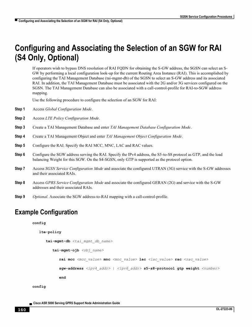
SGSN Service Configuration Procedures
▀ Configuring and Associating the Selection of an SGW for RAI (S4 Only, Optional)
▄ Cisco ASR 5000 Serving GPRS Support Node Administration Guide
160 OL-27223-06
Configuring and Associating the Selection of an SGW for RAI (S4 Only, Optional)
If operators wish to bypass DNS resolution of RAI FQDN for obtaining the S-GW address, the SGSN can select an S-
GW by performing a local configuration look-up for the current Routing Area Instance (RAI). This is accomplished by
configuring the TAI Management Database (tai-mgmt-db) of the SGSN to select an S-GW address and its associated
RAI. In addition, the TAI Management Database must be associated with the 2G and/or 3G services configured on the
SGSN. The TAI Management Database can also be associated with a call-control-profile for RAI-to-SGW address
mapping.
Use the following procedure to configure the selection of an SGW for RAI:
Step 1 Access Global Configuration Mode.
Step 2 Access LTE Policy Configuration Mode.
Step 3 Create a TAI Management Database and enter TAI Management Database Configuration Mode.
Step 4 Create a TAI Management Object and enter TAI Management Object Configuration Mode.
Step 5 Configure the RAI. Specify the RAI MCC, MNC, LAC and RAC values.
Step 6 Configure the SGW address serving the RAI. Specify the IPv4 address, the S5-to-S8 protocol as GTP, and the load
balancing Weight for this SGW. On the S4-SGSN, only GTP is supported as the protocol option.
Step 7 Access SGSN Service Configuration Mode and associate the configured UTRAN (3G) service with the S-GW addresses
and their associated RAIs.
Step 8 Access GPRS Service Configuration Mode and associate the configured GERAN (2G) and service with the S-GW
addresses and their associated RAIs.
Step 9 Optional. Associate the SGW address-to-RAI mapping with a call-control-profile.
Example Configuration
config
lte-policy
tai-mgmt-db <tai_mgmt_db_name>
tai-mgmt-ojb <obj_name>
rai mcc <mcc_value> mnc <mnc_value> lac <lac_value> rac <rac_value>
sgw-address <ipv4_addr> | <ipv6_addr> s5-s8-protocol gtp weight <number>
end
config

SGSN Service Configuration Procedures
Configuring and Associating the Selection of an SGW for RAI (S4 Only, Optional) ▀
Cisco ASR 5000 Serving GPRS Support Node Administration Guide ▄ OL-27223-06 161
context <context_name>
sgsn-service <sgsn_service_name>
associate tai-mgmt-db <tai_mgmt_db_name>
end
config
context <context_name>
gprs-service <gprs_service_name>
associate tai-mgmt-db <tai_mgmt_db_name>
end
config
call-control-profile <cc_profile_name>
associate tai-mgmt-db <tai_mgmt_db_name>
end
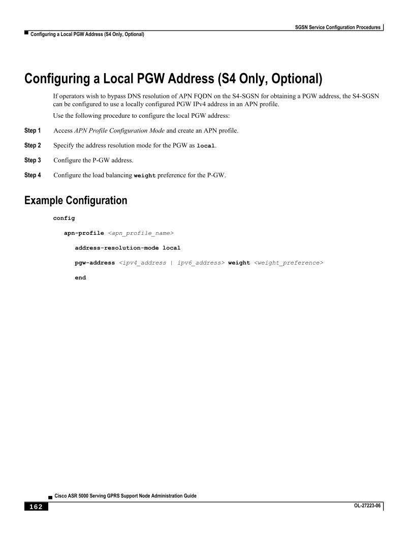
SGSN Service Configuration Procedures
▀ Configuring a Local PGW Address (S4 Only, Optional)
▄ Cisco ASR 5000 Serving GPRS Support Node Administration Guide
162 OL-27223-06
Configuring a Local PGW Address (S4 Only, Optional) If operators wish to bypass DNS resolution of APN FQDN on the S4-SGSN for obtaining a PGW address, the S4-SGSN
can be configured to use a locally configured PGW IPv4 address in an APN profile.
Use the following procedure to configure the local PGW address:
Step 1 Access APN Profile Configuration Mode and create an APN profile.
Step 2 Specify the address resolution mode for the PGW as local.
Step 3 Configure the P-GW address.
Step 4 Configure the load balancing weight preference for the P-GW.
Example Configuration
config
apn-profile <apn_profile_name>
address-resolution-mode local
pgw-address <ipv4_address | ipv6_address> weight <weight_preference>
end
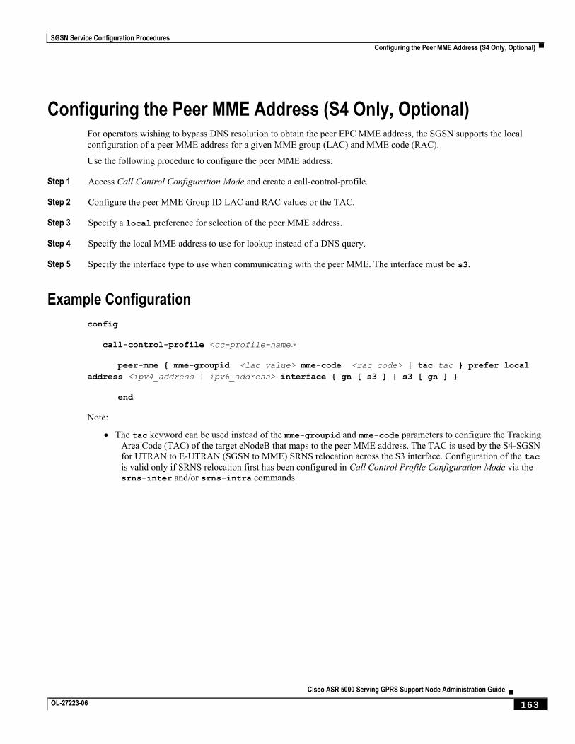
SGSN Service Configuration Procedures
Configuring the Peer MME Address (S4 Only, Optional) ▀
Cisco ASR 5000 Serving GPRS Support Node Administration Guide ▄ OL-27223-06 163
Configuring the Peer MME Address (S4 Only, Optional) For operators wishing to bypass DNS resolution to obtain the peer EPC MME address, the SGSN supports the local
configuration of a peer MME address for a given MME group (LAC) and MME code (RAC).
Use the following procedure to configure the peer MME address:
Step 1 Access Call Control Configuration Mode and create a call-control-profile.
Step 2 Configure the peer MME Group ID LAC and RAC values or the TAC.
Step 3 Specify a local preference for selection of the peer MME address.
Step 4 Specify the local MME address to use for lookup instead of a DNS query.
Step 5 Specify the interface type to use when communicating with the peer MME. The interface must be s3.
Example Configuration
config
call-control-profile <cc-profile-name>
peer-mme { mme-groupid <lac_value> mme-code <rac_code> | tac tac } prefer local
address <ipv4_address | ipv6_address> interface { gn [ s3 ] | s3 [ gn ] }
end
Note:
The tac keyword can be used instead of the mme-groupid and mme-code parameters to configure the Tracking
Area Code (TAC) of the target eNodeB that maps to the peer MME address. The TAC is used by the S4-SGSN for UTRAN to E-UTRAN (SGSN to MME) SRNS relocation across the S3 interface. Configuration of the tac
is valid only if SRNS relocation first has been configured in Call Control Profile Configuration Mode via the srns-inter and/or srns-intra commands.
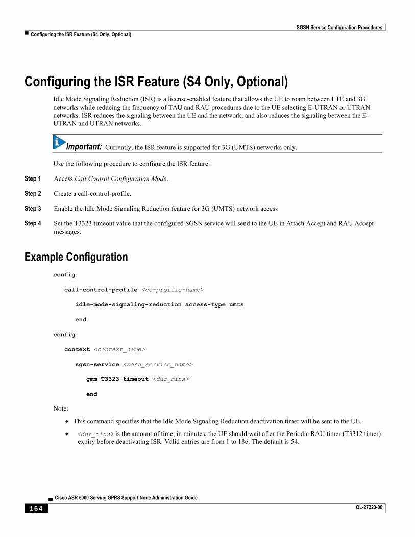
SGSN Service Configuration Procedures
▀ Configuring the ISR Feature (S4 Only, Optional)
▄ Cisco ASR 5000 Serving GPRS Support Node Administration Guide
164 OL-27223-06
Configuring the ISR Feature (S4 Only, Optional) Idle Mode Signaling Reduction (ISR) is a license-enabled feature that allows the UE to roam between LTE and 3G
networks while reducing the frequency of TAU and RAU procedures due to the UE selecting E-UTRAN or UTRAN
networks. ISR reduces the signaling between the UE and the network, and also reduces the signaling between the E-
UTRAN and UTRAN networks.
Important: Currently, the ISR feature is supported for 3G (UMTS) networks only.
Use the following procedure to configure the ISR feature:
Step 1 Access Call Control Configuration Mode.
Step 2 Create a call-control-profile.
Step 3 Enable the Idle Mode Signaling Reduction feature for 3G (UMTS) network access
Step 4 Set the T3323 timeout value that the configured SGSN service will send to the UE in Attach Accept and RAU Accept
messages.
Example Configuration
config
call-control-profile <cc-profile-name>
idle-mode-signaling-reduction access-type umts
end
config
context <context_name>
sgsn-service <sgsn_service_name>
gmm T3323-timeout <dur_mins>
end
Note:
This command specifies that the Idle Mode Signaling Reduction deactivation timer will be sent to the UE.
<dur_mins> is the amount of time, in minutes, the UE should wait after the Periodic RAU timer (T3312 timer) expiry before deactivating ISR. Valid entries are from 1 to 186. The default is 54.

SGSN Service Configuration Procedures
Configuring IDFT for Connected Mode Handover (S4 Only, Optional) ▀
Cisco ASR 5000 Serving GPRS Support Node Administration Guide ▄ OL-27223-06 165
Configuring IDFT for Connected Mode Handover (S4 Only, Optional)
The S4-SGSN supports the setup of indirect data forwarding tunnels (IDFT) between the eNodeB and the RNC via the
SGW during connected mode handovers. This allows the S4-SGSN to support connected mode handovers between the
UTRAN and E-UTRAN networks across the S3 interface.
Once enabled, IDFT is employed under the following conditions:
If the SGSN is the old node participating in the connected mode handover:
The target node to which the connected mode handover is initiated should be an eNodeB (i.e., the SGSN performs the handover to the MME.
The enb-direct-data-forward CLI setting is not configured in the target RNC configuration (in
RNC Configuration Mode).
If the SGSN is the new node participating in the connected mode handover:
The source node from which connected mode handover is initiated is an eNodeB (i.e., the MME is performing a handover to the SGSN).
The enb-direct-data-forward CLI setting is not configured in the target RNC configuration (in RNC Configuration Mode).
The source MME indicated that it does not support direct forwarding via a Forward Relocation Request.
Important: If the target SGSN did not relocate to a new SGW, then IDFT does not apply. The target SGSN sets
up an indirect data forwarding tunnel with the SGW only if the SGW is relocated. If the SGW is not relocated, then the source MME sets up the indirect data forwarding tunnel between the source eNodeB and the target RNC through the SGW.
Important: By default, indirect data forwarding is enabled, and direct forwarding is disabled.
To configure IDFT for connected mode inter RAT handovers:
Step 1 Enter the context where the IuPS service is configured.
Step 2 Enter IuPS Service Configuration Mode and enter the configured IuPS service.
Step 3 Enter the RNC ID of the IuPS service for which you want to enable IDFT.
Step 4 Disable direct data forwarding for connected mode inter RAT handovers.
Example Configuration
config
context <context_name>
iups-service <iups_service_name>
SGSN Service Configuration Procedures
▀ Configuring IDFT for Connected Mode Handover (S4 Only, Optional)
▄ Cisco ASR 5000 Serving GPRS Support Node Administration Guide
166 OL-27223-06
rnc id <rnc_id>
no enb-direct-data-forward
end
Where:
no enb-direct-data-forward enables the setup of IDFT between the eNodeB and the RNC via the SGW
for connected mode inter RAT handovers. If IDFT is enabled, the SGSN/MME will send the IDFT request towards the SGW. Once enabled, the SGSN/MME will send IDFT requests towards the SGW.
To disable IDFT, enter the enb-direct-data-forward command.
SGSN Service Configuration Procedures
Creating and Configuring ATM Interfaces and Ports (3G only) ▀
Cisco ASR 5000 Serving GPRS Support Node Administration Guide ▄ OL-27223-06 167
Creating and Configuring ATM Interfaces and Ports (3G only) ATM ports and their associated PVCs can be configured for use with point-to-point interfaces and defined in a context
or they can be bound to link IDs defined in SS7 routing domains.
Refer to the chapter titled System Element Configuration Procedures in the System Administration Guide for
information on configuring ATM interfaces.
SGSN Service Configuration Procedures
▀ Creating and Configuring Frame Relay Ports (2.5G only)
▄ Cisco ASR 5000 Serving GPRS Support Node Administration Guide
168 OL-27223-06
Creating and Configuring Frame Relay Ports (2.5G only) Frame Relay ports and their associated DLCIs can be configured for communication with 2G Base Station subsystem
(BSS) for an SGSN implementation.
Refer to the chapter titled System Element Configuration Procedures in the System Administration Guide for
information on configuring Frame Relay ports.
SGSN Service Configuration Procedures
Configuring APS/MSP Redundancy ▀
Cisco ASR 5000 Serving GPRS Support Node Administration Guide ▄ OL-27223-06 169
Configuring APS/MSP Redundancy ASP/MSP redundancy is only available for the OLC2 and CLC2 line cards. It is setup per linecard -- all ports share the
same setup.
APS is enabled with the redundancy command in the Card configuration mode.
Important: At this time the aps command in the Card Configuration Mode chapter is still in development and
should not be used. The parameters are all set by default and cannot be changed or disabled.
Related configuration for signal degrade and signal failure bit error rate thresholds for high path, low path, and transport
overhead - use the commands in the Port Channelized configuration mode.
For command details, refer to the Card Configuration Mode Commands chapter and the Port Configuration Mode
Commands chapter in the Cisco UMTS Command Line Interface Reference.
Step 1 Configure a line card for either SONET or SDH.
Step 2 Configure APS for a SONET line card or MPS for an SDH line card.
Use the configuration example below:
Example Configuration
Use the following example (replacing specific values) to setup a CLC2 (Frame Relay) line card:
config
card 27
framing sdh e1
header-type 4-byte
initial-e1-framing standard
redundancy aps-mode
service-type frame-relay
no shutdown
end

Cisco ASR 5000 Serving GPRS Support Node Administration Guide ▄ OL-27223-06 171
Chapter 5 3G-2G Location Change Reporting
3G/2G Location Change Reporting on the SGSN facilitates location-based charging on the GGSN by providing the
UE’s location information when it is in connected mode.
The SGSN notifies the GGSN whenever one of the following changes:
the serving cell global identity (CGI), or
the service area identity (SAI), or
the routing area identity (RAI).
Contents
This document contains the following sections:
Feature Description
How it Works
Configuring Location Change Reporting
3G-2G Location Change Reporting
▀ Feature Description
▄ Cisco ASR 5000 Serving GPRS Support Node Administration Guide
172 OL-27223-06
Feature Description The 3G/2G Location Change Reporting feature enables the operator to charge the user for location-based services.
Location-based charging is a values-added function that ensures subscribers pay a premium for operator-determined
location-based services, such as service in a congested area.
This optional feature functions in accordance with 3GPP TS 23.060, Release 9, sections 12.7.5 and 15.1.3 and requires
an additional license - the Location Reporting License. With the license, the operator uses the CLI to enable the feature
independently for each access type: GPRS (2G) or UMTS (3G).
Relationships
The SGSN works with the GGSN for this feature. The GGSN must send subscription information to the SGSN for the
3G/2G Location Change Reporting feature to work.
This feature is independent of user location information (ULI) configuration, which allows GTP-C messages to be used
for carrying user location information to the GGSN.
License
A feature-specific license is required. Please consult your Cisco Account Representative for information about the
specific license. For information on installing and verifying licenses, refer to the “Managing License Keys” section of
the Software Management Operations chapter in the System Administration Guide.
Standards Compliance
The SGSN 3G/2G Location Change Reporting feature complies with the following standards:
3GPP TS 23.060 Release 9
3GPP TS 29.060 Release 9.7.0
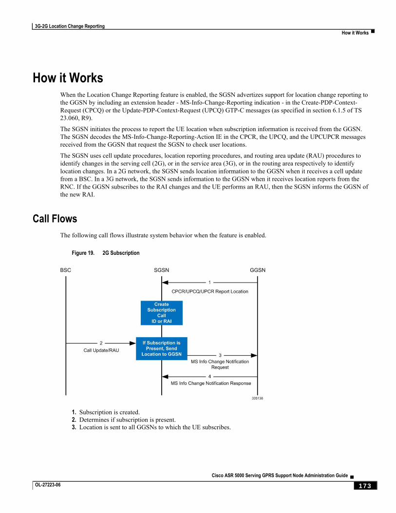
3G-2G Location Change Reporting
How it Works ▀
Cisco ASR 5000 Serving GPRS Support Node Administration Guide ▄ OL-27223-06 173
How it Works When the Location Change Reporting feature is enabled, the SGSN advertizes support for location change reporting to
the GGSN by including an extension header - MS-Info-Change-Reporting indication - in the Create-PDP-Context-
Request (CPCQ) or the Update-PDP-Context-Request (UPCQ) GTP-C messages (as specified in section 6.1.5 of TS
23.060, R9).
The SGSN initiates the process to report the UE location when subscription information is received from the GGSN.
The SGSN decodes the MS-Info-Change-Reporting-Action IE in the CPCR, the UPCQ, and the UPCUPCR messages
received from the GGSN that request the SGSN to check user locations.
The SGSN uses cell update procedures, location reporting procedures, and routing area update (RAU) procedures to
identify changes in the serving cell (2G), or in the service area (3G), or in the routing area respectively to identify
location changes. In a 2G network, the SGSN sends location information to the GGSN when it receives a cell update
from a BSC. In a 3G network, the SGSN sends information to the GGSN when it receives location reports from the
RNC. If the GGSN subscribes to the RAI changes and the UE performs an RAU, then the SGSN informs the GGSN of
the new RAI.
Call Flows
The following call flows illustrate system behavior when the feature is enabled.
Figure 19. 2G Subscription
1. Subscription is created.
2. Determines if subscription is present.
3. Location is sent to all GGSNs to which the UE subscribes.
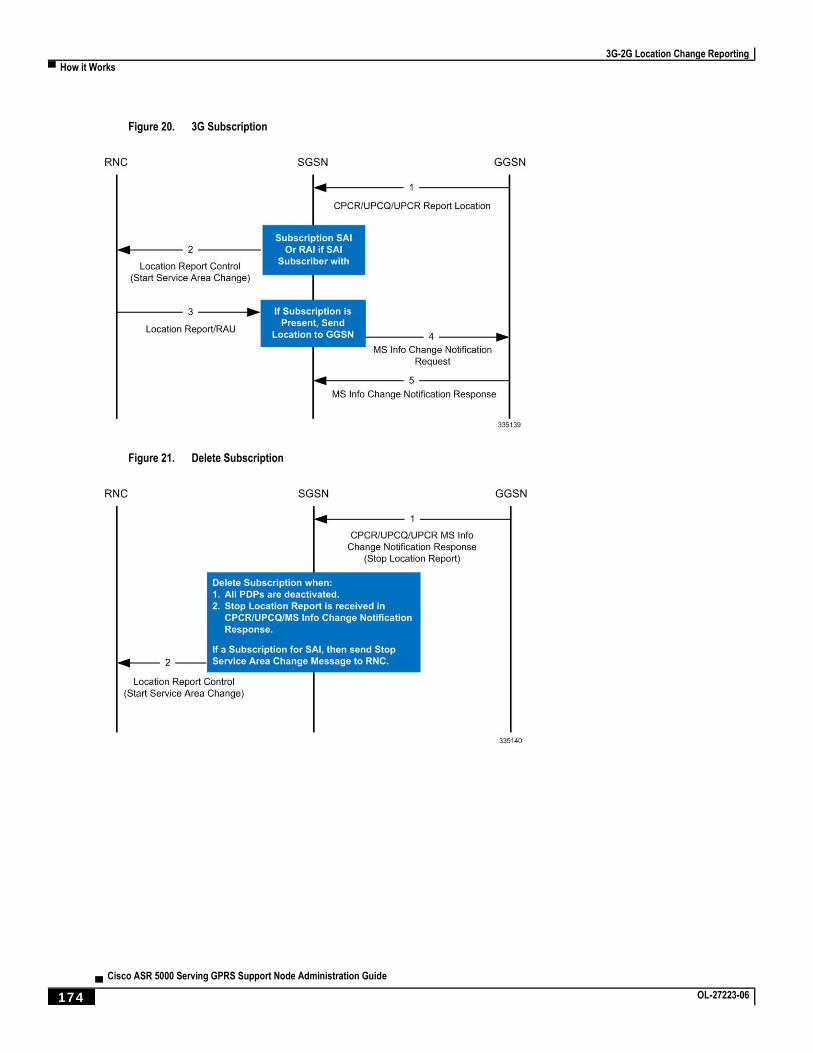
3G-2G Location Change Reporting
▀ How it Works
▄ Cisco ASR 5000 Serving GPRS Support Node Administration Guide
174 OL-27223-06
Figure 20. 3G Subscription
Figure 21. Delete Subscription
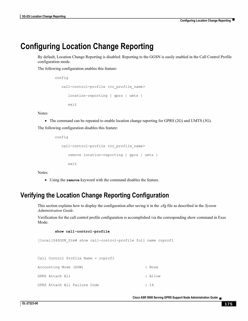
3G-2G Location Change Reporting
Configuring Location Change Reporting ▀
Cisco ASR 5000 Serving GPRS Support Node Administration Guide ▄ OL-27223-06 175
Configuring Location Change Reporting By default, Location Change Reporting is disabled. Reporting to the GGSN is easily enabled in the Call Control Profile
configuration mode.
The following configuration enables this feature:
config
call-control-profile <cc_profile_name>
location-reporting { gprs | umts }
exit
Notes:
The command can be repeated to enable location change reporting for GPRS (2G) and UMTS (3G).
The following configuration disables this feature:
config
call-control-profile <cc_profile_name>
remove location-reporting { gprs | umts }
exit
Notes:
Using the remove keyword with the command disables the feature.
Verifying the Location Change Reporting Configuration
This section explains how to display the configuration after saving it in the .cfg file as described in the System
Administration Guide.
Verification for the call control profile configuration is accomplished via the corresponding show command in Exec
Mode:
show call-control-profile
[local]S4SGSN_Sim# show call-control-profile full name ccprof1
Call Control Profile Name = ccprof1
Accounting Mode (SGW) : None
GPRS Attach All : Allow
GPRS Attach All Failure Code : 14
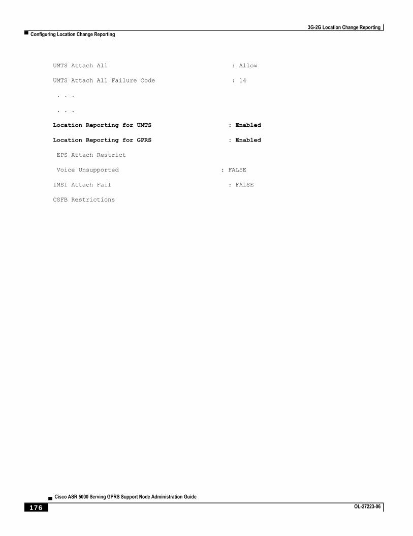
3G-2G Location Change Reporting
▀ Configuring Location Change Reporting
▄ Cisco ASR 5000 Serving GPRS Support Node Administration Guide
176 OL-27223-06
UMTS Attach All : Allow
UMTS Attach All Failure Code : 14
. . .
. . .
Location Reporting for UMTS : Enabled
Location Reporting for GPRS : Enabled
EPS Attach Restrict
Voice Unsupported : FALSE
IMSI Attach Fail : FALSE
CSFB Restrictions
Cisco ASR 5000 Serving GPRS Support Node Administration Guide ▄ OL-27223-06 177
Chapter 6 Direct Tunnel
This chapter briefly describes the 3G/4G UMTS direct tunnel (DT) feature, indicates how it is implemented on various
systems on a per call basis, and provides feature configuration procedures.
Products supporting direct tunnel include:
3G devices (per 3GPP TS 23.919 v8.0.0):
the Serving GPRS Support Node (SGSN)
the Gateway GPRS Support Node (GGSN)
LTE devices (per 3GPP TS 23.401 v8.3.0):
Serving Gateway (S-GW)
PDN Gateway (P-GW)
Important: Direct tunnel is a licensed Cisco feature. A separate feature license is required for configuration.
Contact your Cisco account representative for detailed information on specific licensing requirements. For information on installing and verifying licenses, refer to the Managing License Keys section of the Software Management Operations chapter in the System Administration Guide.
The SGSN determines if setup of a direct tunnel is allowed or disallowed. Currently, the SGSN and S-GW are the only
products that provide configuration commands for this feature. All other products that support direct tunnel do so by
default.
This chapter provides the following information:
Direct Tunnel Feature Overview
Direct Tunnel Configuration

Direct Tunnel
▀ Direct Tunnel Feature Overview
▄ Cisco ASR 5000 Serving GPRS Support Node Administration Guide
178 OL-27223-06
Direct Tunnel Feature Overview The direct tunnel architecture allows the establishment of a direct user plane (GTP-U) tunnel between the radio access
network equipment (RNC) and the GGSN/P-GW.
Once a direct tunnel is established, the SGSN/S-GW continues to handle the control plane (RANAP/GTP-C) signaling
and retains the responsibility of making the decision to establish direct tunnel at PDN context activation.
Figure 22. GTP-U Direct Tunneling
A direct tunnel improves the user experience (for example, expedites web page delivery, reduces round trip delay for
conversational services) by eliminating switching latency from the user plane. An additional advantage, direct tunnel
functionality implements optimization to improve the usage of user plane resources (and hardware) by removing the
requirement from the SGSN/S-GW to handle the user plane processing.
A direct tunnel is achieved upon PDN context activation in the following ways:
3G network: The SGSN establishes a user plane (GTP-U) tunnel directly between the RNC and the GGSN,
using an Updated PDN Context Request toward the GGSN.
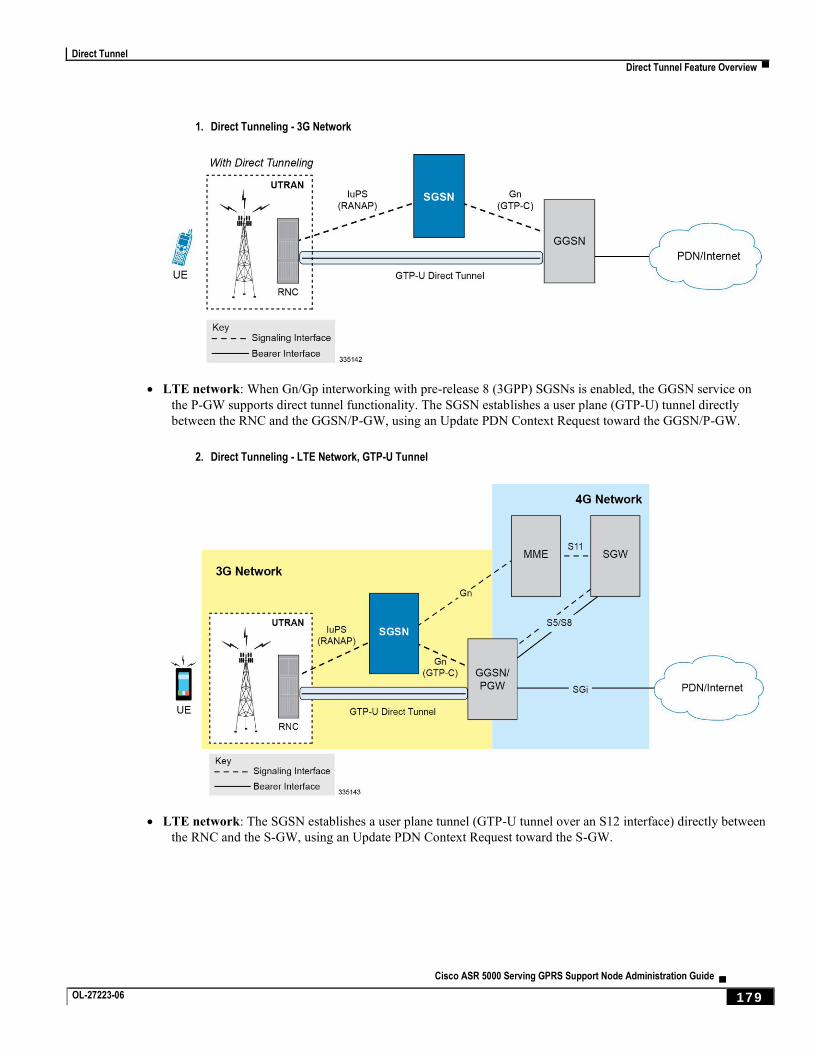
Direct Tunnel
Direct Tunnel Feature Overview ▀
Cisco ASR 5000 Serving GPRS Support Node Administration Guide ▄ OL-27223-06 179
1. Direct Tunneling - 3G Network
LTE network: When Gn/Gp interworking with pre-release 8 (3GPP) SGSNs is enabled, the GGSN service on
the P-GW supports direct tunnel functionality. The SGSN establishes a user plane (GTP-U) tunnel directly
between the RNC and the GGSN/P-GW, using an Update PDN Context Request toward the GGSN/P-GW.
2. Direct Tunneling - LTE Network, GTP-U Tunnel
LTE network: The SGSN establishes a user plane tunnel (GTP-U tunnel over an S12 interface) directly between
the RNC and the S-GW, using an Update PDN Context Request toward the S-GW.
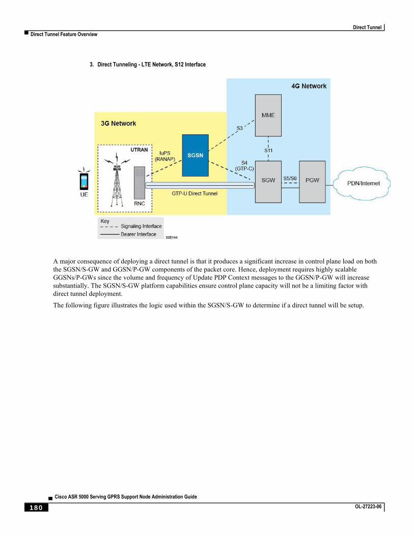
Direct Tunnel
▀ Direct Tunnel Feature Overview
▄ Cisco ASR 5000 Serving GPRS Support Node Administration Guide
180 OL-27223-06
3. Direct Tunneling - LTE Network, S12 Interface
A major consequence of deploying a direct tunnel is that it produces a significant increase in control plane load on both
the SGSN/S-GW and GGSN/P-GW components of the packet core. Hence, deployment requires highly scalable
GGSNs/P-GWs since the volume and frequency of Update PDP Context messages to the GGSN/P-GW will increase
substantially. The SGSN/S-GW platform capabilities ensure control plane capacity will not be a limiting factor with
direct tunnel deployment.
The following figure illustrates the logic used within the SGSN/S-GW to determine if a direct tunnel will be setup.
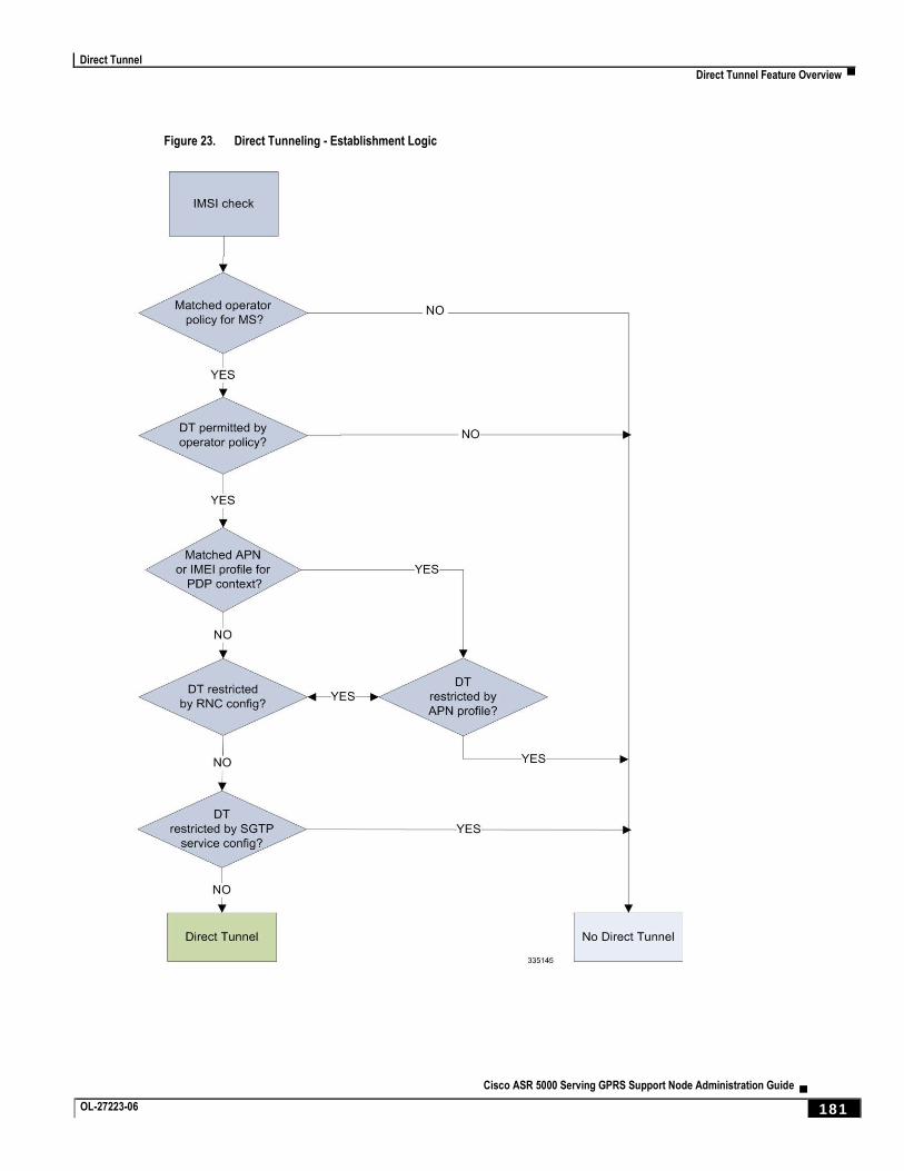
Direct Tunnel
Direct Tunnel Feature Overview ▀
Cisco ASR 5000 Serving GPRS Support Node Administration Guide ▄ OL-27223-06 181
Figure 23. Direct Tunneling - Establishment Logic
Direct Tunnel
▀ Direct Tunnel Configuration
▄ Cisco ASR 5000 Serving GPRS Support Node Administration Guide
182 OL-27223-06
Direct Tunnel Configuration The following configurations are provided in this section:
Configuring Direct Tunnel Support on the SGSN
Configuring S12 Direct Tunnel Support on the S-GW
The SGSN/S-GW direct tunnel functionality is enabled within an operator policy configuration. One aspect of an
operator policy is to allow or disallow the setup of direct GTP-U tunnels. If no operator policies are configured, the
system looks at the settings in the system operator policy named default.
By default, direct tunnel support is
disallowed on the SGSN/S-GW
allowed on the GGSN/P-GW.
Important: If direct tunnel is allowed in the default operator policy, then any incoming call that does not have
an applicable operator policy configured will have direct tunnel allowed.
For more information about operator policies and configuration details, refer to Operator Policy.
Configuring Direct Tunnel Support on the SGSN
The following is a high-level view of the steps, and the associated configuration examples, to configure the SGSN to
setup a direct tunnel.
Before beginning any of the following procedures, you must have completed (1) the basic service configuration for the
SGSN, as described in the Cisco ASR Serving GPRS Support Node Administration Guide, and (2) the creation and
configuration of a valid operator policy, as described in the Operator Policy chapter in this guide.
Step 1 Configure the SGSN to setup GTP-U direct tunnel between an RNC and an access gateway by applying the example
configuration presented in the Enabling Setup of GTP-U Direct Tunnels section below.
Step 2 Configure the SGSN to allow GTP-U direct tunnels to an access gateway, for a call filtered on the basis of the APN, by
applying the example configuration presented in the Enabling Direct Tunnel per APN section below.
Important: It is only necessary to complete either step 2 or step 3 as a direct tunnel can not be setup
on the basis of call filtering matched with both an APN profile and an IIMEI profile.
Step 3 Configure the SGSN to allow GTP-U direct tunnels to a GGSN, for a call filtered on the basis of the IMEI, by applying
the example configuration presented in the Enabling Direct Tunnel per IMEI section below.
Step 4 Configure the SGSN to allow GTP-U direct tunnel setup from a specific RNC by applying the example configuration
presented in the Enabling Direct Tunnel to Specific RNCs section below.
Step 5 (Optional) Configure the SGSN to disallow direct tunnel setup to a single GGSN that has been configured to allow it in
the APN profile. This command allows the operator to restrict use of a GGSN for any reason, such as load balancing.
Refer to the direct-tunnel-disabled-ggsn command in the SGTP Service Configuration Mode chapter of the
Command Line Interface Reference.
Direct Tunnel
Direct Tunnel Configuration ▀
Cisco ASR 5000 Serving GPRS Support Node Administration Guide ▄ OL-27223-06 183
Step 6 Save your configuration to flash memory, an external memory device, and/or a network location using the Exec mode
command save configuration. For additional information on how to verify and save configuration files, refer to the
System Administration Guide and the Command Line Interface Reference.
Step 7 Check that your configuration changes have been saved by using the sample configuration found in the Verifying the
SGSN Direct Tunnel Configuration section in this chapter.
Enabling Setup of GTP-U Direct Tunnels
The SGSN determines whether a direct tunnel can be setup and by default the SGSN doesn’t support direct tunnel.
Example Configuration
Enabling direct tunnel setup on an SGSN is done by configuring direct tunnel support in a call-control profile.
config
call-control-profile <policy_name>
direct-tunnel attempt-when-permitted
end
Notes:
A call-control profile must have been previously created, configured, and associated with a previously created,
configured, and valid operator policy. For information about operator policy creation/configuration, refer to the
Operator Policy chapter in this guide.
Direct tunnel is now allowed on the SGSN but will only setup if allowed on both the destination node and the
RNC.
Enabling Direct Tunnel per APN
In each operator policy, APN profiles are configured to connect to one or more GGSNs and to control the direct tunnel
access to that GGSN based on call filtering by APN. Multiple APN profiles can be configured per operator policy.
By default, APN-based direct tunnel functionality is allowed so any existing direct tunnel configuration must be
removed to return to default and to ensure that the setup has not been restricted.
Example Configuration
The following is an example of the commands used to ensure that direct tunneling, to a GGSN(s) identified in the APN
profile, is enabled:
config
apn-profile <profile_name>
remove direct tunnel
end
Notes:
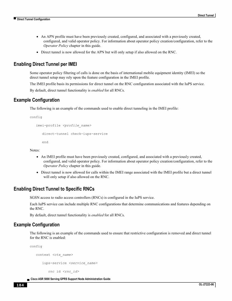
Direct Tunnel
▀ Direct Tunnel Configuration
▄ Cisco ASR 5000 Serving GPRS Support Node Administration Guide
184 OL-27223-06
An APN profile must have been previously created, configured, and associated with a previously created,
configured, and valid operator policy. For information about operator policy creation/configuration, refer to the
Operator Policy chapter in this guide.
Direct tunnel is now allowed for the APN but will only setup if also allowed on the RNC.
Enabling Direct Tunnel per IMEI
Some operator policy filtering of calls is done on the basis of international mobile equipment identity (IMEI) so the
direct tunnel setup may rely upon the feature configuration in the IMEI profile.
The IMEI profile basis its permissions for direct tunnel on the RNC configuration associated with the IuPS service.
By default, direct tunnel functionality is enabled for all RNCs.
Example Configuration
The following is an example of the commands used to enable direct tunneling in the IMEI profile:
config
imei-profile <profile_name>
direct-tunnel check-iups-service
end
Notes:
An IMEI profile must have been previously created, configured, and associated with a previously created,
configured, and valid operator policy. For information about operator policy creation/configuration, refer to the
Operator Policy chapter in this guide.
Direct tunnel is now allowed for calls within the IMEI range associated with the IMEI profile but a direct tunnel
will only setup if also allowed on the RNC.
Enabling Direct Tunnel to Specific RNCs
SGSN access to radio access controllers (RNCs) is configured in the IuPS service.
Each IuPS service can include multiple RNC configurations that determine communications and features depending on
the RNC.
By default, direct tunnel functionality is enabled for all RNCs.
Example Configuration
The following is an example of the commands used to ensure that restrictive configuration is removed and direct tunnel
for the RNC is enabled:
config
context <ctx_name>
iups-service <service_name>
rnc id <rnc_id>
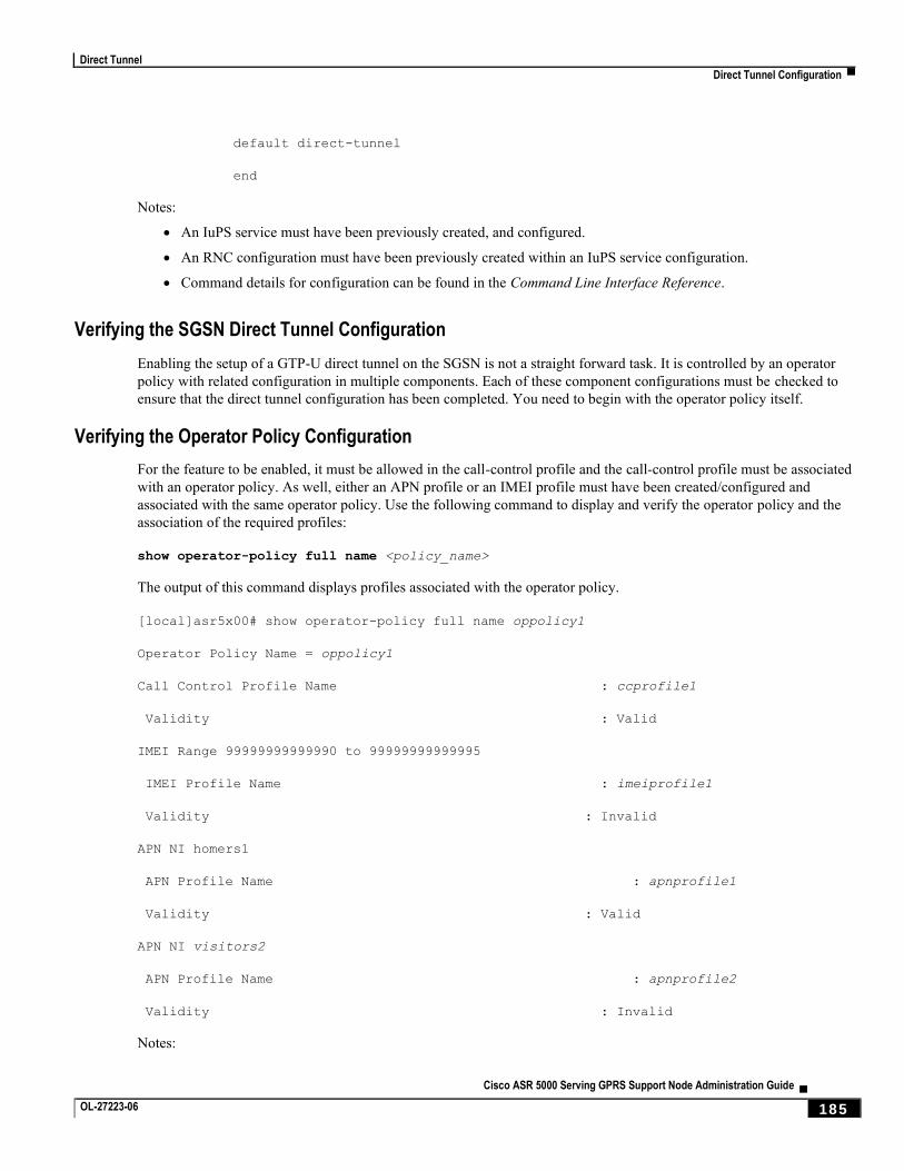
Direct Tunnel
Direct Tunnel Configuration ▀
Cisco ASR 5000 Serving GPRS Support Node Administration Guide ▄ OL-27223-06 185
default direct-tunnel
end
Notes:
An IuPS service must have been previously created, and configured.
An RNC configuration must have been previously created within an IuPS service configuration.
Command details for configuration can be found in the Command Line Interface Reference.
Verifying the SGSN Direct Tunnel Configuration
Enabling the setup of a GTP-U direct tunnel on the SGSN is not a straight forward task. It is controlled by an operator
policy with related configuration in multiple components. Each of these component configurations must be checked to
ensure that the direct tunnel configuration has been completed. You need to begin with the operator policy itself.
Verifying the Operator Policy Configuration
For the feature to be enabled, it must be allowed in the call-control profile and the call-control profile must be associated
with an operator policy. As well, either an APN profile or an IMEI profile must have been created/configured and
associated with the same operator policy. Use the following command to display and verify the operator policy and the
association of the required profiles:
show operator-policy full name <policy_name>
The output of this command displays profiles associated with the operator policy.
[local]asr5x00# show operator-policy full name oppolicy1
Operator Policy Name = oppolicy1
Call Control Profile Name : ccprofile1
Validity : Valid
IMEI Range 99999999999990 to 99999999999995
IMEI Profile Name : imeiprofile1
Validity : Invalid
APN NI homers1
APN Profile Name : apnprofile1
Validity : Valid
APN NI visitors2
APN Profile Name : apnprofile2
Validity : Invalid
Notes:
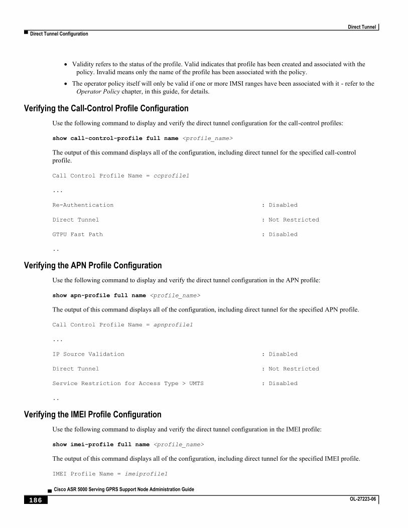
Direct Tunnel
▀ Direct Tunnel Configuration
▄ Cisco ASR 5000 Serving GPRS Support Node Administration Guide
186 OL-27223-06
Validity refers to the status of the profile. Valid indicates that profile has been created and associated with the
policy. Invalid means only the name of the profile has been associated with the policy.
The operator policy itself will only be valid if one or more IMSI ranges have been associated with it - refer to the
Operator Policy chapter, in this guide, for details.
Verifying the Call-Control Profile Configuration
Use the following command to display and verify the direct tunnel configuration for the call-control profiles:
show call-control-profile full name <profile_name>
The output of this command displays all of the configuration, including direct tunnel for the specified call-control
profile.
Call Control Profile Name = ccprofile1
...
Re-Authentication : Disabled
Direct Tunnel : Not Restricted
GTPU Fast Path : Disabled
..
Verifying the APN Profile Configuration
Use the following command to display and verify the direct tunnel configuration in the APN profile:
show apn-profile full name <profile_name>
The output of this command displays all of the configuration, including direct tunnel for the specified APN profile.
Call Control Profile Name = apnprofile1
...
IP Source Validation : Disabled
Direct Tunnel : Not Restricted
Service Restriction for Access Type > UMTS : Disabled
..
Verifying the IMEI Profile Configuration
Use the following command to display and verify the direct tunnel configuration in the IMEI profile:
show imei-profile full name <profile_name>
The output of this command displays all of the configuration, including direct tunnel for the specified IMEI profile.
IMEI Profile Name = imeiprofile1
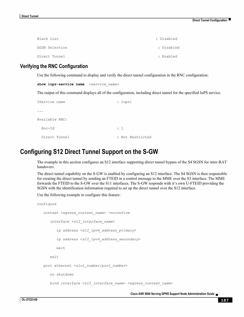
Direct Tunnel
Direct Tunnel Configuration ▀
Cisco ASR 5000 Serving GPRS Support Node Administration Guide ▄ OL-27223-06 187
Black List : Disabled
GGSN Selection : Disabled
Direct Tunnel : Enabled
Verifying the RNC Configuration
Use the following command to display and verify the direct tunnel configuration in the RNC configuration:
show iups-service name <service_name>
The output of this command displays all of the configuration, including direct tunnel for the specified IuPS service.
IService name : iups1
...
Available RNC:
Rnc-Id : 1
Direct Tunnel : Not Restricted
Configuring S12 Direct Tunnel Support on the S-GW
The example in this section configures an S12 interface supporting direct tunnel bypass of the S4 SGSN for inter-RAT
handovers.
The direct tunnel capability on the S-GW is enabled by configuring an S12 interface. The S4 SGSN is then responsible
for creating the direct tunnel by sending an FTEID in a control message to the MME over the S3 interface. The MME
forwards the FTEID to the S-GW over the S11 interfaces. The S-GW responds with it’s own U-FTEID providing the
SGSN with the identification information required to set up the direct tunnel over the S12 interface.
Use the following example to configure this feature:
configure
context <egress_context_name> -noconfirm
interface <s12_interface_name>
ip address <s12_ipv4_address_primary>
ip address <s12_ipv4_address_secondary>
exit
exit
port ethernet <slot_number/port_number>
no shutdown
bind interface <s12_interface_name> <egress_context_name>
Direct Tunnel
▀ Direct Tunnel Configuration
▄ Cisco ASR 5000 Serving GPRS Support Node Administration Guide
188 OL-27223-06
exit
context <egress_context_name> -noconfirm
gtpu-service <s12_gtpu_egress_service_name>
bind ipv4-address <s12_interface_ip_address>
exit
egtp-service <s12_egtp_egress_service_name>
interface-type interface-sgw-egress
validation-mode default
associate gtpu-service <s12_gtpu_egress_service_name>
gtpc bind address <s12_interface_ip_address>
exit
sgw-service <sgw_service_name> -noconfirm
associate egress-proto gtp egress-context <egress_context_name> egtp-service
<s12_egtp_egress_service_name>
end
Notes:
The S12 interface IP address(es) can also be specified as IPv6 addresses using the ipv6 address command.
Cisco ASR 5000 Serving GPRS Support Node Administration Guide ▄ OL-27223-06 189
Chapter 7 GMM-SM Event Logging
With the introduction of this feature, the SGSN now supports limited use of event data records (EDRs). This chapters
details the SGSN’s event logging feature, with the use of EDRs, which is intended to facilitate subscriber-level
troubleshooting. This feature is relevant for StarOS™ Release 12.0 (and higher) software supporting SGSN services
within GPRS and UMTS networks.
This chapter provides the following information:
Feature Description
Feature Overview
Events to be Logged
Event Record Fields
EDR Storage
Architecture
Limitations
Configuration
GMM-SM Event Logging
▀ Feature Description
▄ Cisco ASR 5000 Serving GPRS Support Node Administration Guide
190 OL-27223-06
Feature Description
Feature Overview
At any one time, the SGSN handles a large number of mobile stations (MS). In order to efficiently troubleshoot any
issue for a single subscriber, it is necessary to know the events that have happened for that subscriber. Prior to this event
logging feature, the SGSN did not support a debugging method that was event-based per subscriber.
The debugging framework will allow operators to troubleshoot problems related to a particular IMSI. The event logging
feature will capture procedure-level information per subscriber. Upon completing a procedure, either successfully or
unsuccessfully, the SGSN generates a procedure-summary or event report logging the event.
The SGSN uses the event reports to generate event data record (EDR) files comprised of logged information in comma-
separated ASCII values - CSV format. The SGSN sends one ASCII formatted CSV record per line. The CSV records
are stored in a file and are optionally compressed before sending to an external server. The storage space in the ASR5K
is limited so the CSV records need to be SFTed to an external server periodically. The transfer of the CSV record file
from the SGSN and to the external server can be based on configurable PULL or PUSH models. In case of PUSH, the
time-interval can be configured at the SGSN.
Events to be Logged
The following subscriber events will be logged:
Attaches
Activation of PDP Context
Routing Area Update (RAU)
Inter-SGSN RAU (ISRAU)
Deactivation of PDP Context
Detaches
Authentications
PDP Modifications
Event Record Fields
The EDRs include the following information in CSV format.
Important: If particular information is not relevant or is unavailable for the procedure being logged, then the
field is left blank.
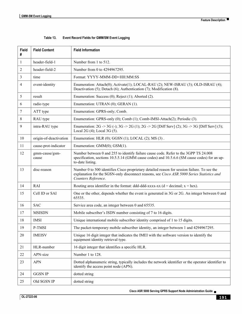
GMM-SM Event Logging
Feature Description ▀
Cisco ASR 5000 Serving GPRS Support Node Administration Guide ▄ OL-27223-06 191
Table 13. Event Record Fields for GMM/SM Event Logging
Field #
Field Content Field Information
1 header-field-1 Number from 1 to 512.
2 header-field-2 Number from 0 to 4294967295.
3 time Format: YYYY-MMM-DD+HH:MM:SS
4 event-identity Enumeration: Attach(0); Activate(1); LOCAL-RAU (2); NEW-ISRAU (3); OLD-ISRAU (4); Deactivation (5); Detach (6); Authentication (7); Modification (8).
5 result Enumeration: Success (0); Reject (1); Aborted (2).
6 radio type Enumeration: UTRAN (0); GERAN (1).
7 ATT type Enumeration: GPRS-only; Comb.
8 RAU type Enumeration: GPRS-only (0); Comb (1); Comb-IMSI-Attach(2); Periodic (3).
9 intra-RAU type Enumeration: 2G -> 3G (-); 3G -> 2G (1); 2G -> 2G [Diff Serv] (2); 3G -> 3G [Diff Serv] (3); Local 2G (4); Local 3G (5).
10 origin-of-deactivation Enumeration: HLR (0); GGSN (1); LOCAL (2); MS (3) .
11 cause-prot-indicator Enumeration: GMM(0); GSM(1).
12 gmm-cause/gsm-cause
Number between 0 and 255 to identify failure cause code. Refer to the 3GPP TS 24.008 specification, sections 10.5.5.14 (GMM cause codes) and 10.5.6.6 (SM cause codes) for an up-to-date listing.
13 disc-reason Number 0 to 500 identifies Cisco proprietary detailed reason for session failure. To see the explanation for the SGSN-only disconnect reasons, see Cisco ASR 5000 Series Statistics and Counters Reference.
14 RAI Routing area identifier in the format: ddd-ddd-xxxx-xx (d = decimal; x = hex).
15 Cell ID or SAI One or the other, depends whether the event is generated in 3G or 2G. An integer between 0 and 65535.
16 SAC Service area code, an integer between 0 and 65535.
17 MSISDN Mobile subscriber’s ISDN number consisting of 7 to 16 digits.
18 IMSI Unique international mobile subscriber identity comprised of 1 to 15 digits.
19 P-TMSI The packet-temporary mobile subscriber identity, an integer between 1 and 4294967295.
20 IMEISV Unique 16 digit integer that indicates the IMEI with the software version to identify the equipment identity retrieval type.
21 HLR-number 16 digit integer that identifies a specific HLR.
22 APN-size Number 1 to 128.
23 APN Dotted alphanumeric string, typically includes the network identifier or the operator identifier to identify the access point node (APN).
24 GGSN IP dotted string
25 Old SGSN IP dotted string
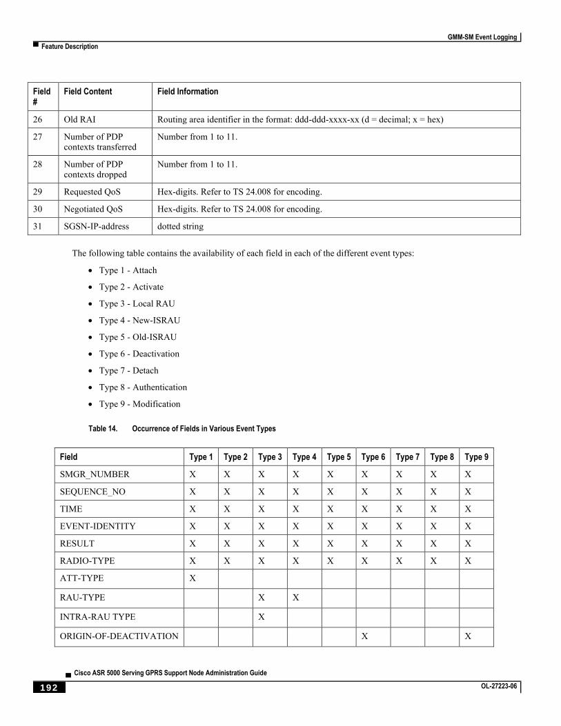
GMM-SM Event Logging
▀ Feature Description
▄ Cisco ASR 5000 Serving GPRS Support Node Administration Guide
192 OL-27223-06
Field #
Field Content Field Information
26 Old RAI Routing area identifier in the format: ddd-ddd-xxxx-xx (d = decimal; x = hex)
27 Number of PDP contexts transferred
Number from 1 to 11.
28 Number of PDP contexts dropped
Number from 1 to 11.
29 Requested QoS Hex-digits. Refer to TS 24.008 for encoding.
30 Negotiated QoS Hex-digits. Refer to TS 24.008 for encoding.
31 SGSN-IP-address dotted string
The following table contains the availability of each field in each of the different event types:
Type 1 - Attach
Type 2 - Activate
Type 3 - Local RAU
Type 4 - New-ISRAU
Type 5 - Old-ISRAU
Type 6 - Deactivation
Type 7 - Detach
Type 8 - Authentication
Type 9 - Modification
Table 14. Occurrence of Fields in Various Event Types
Field Type 1 Type 2 Type 3 Type 4 Type 5 Type 6 Type 7 Type 8 Type 9
SMGR_NUMBER X X X X X X X X X
SEQUENCE_NO X X X X X X X X X
TIME X X X X X X X X X
EVENT-IDENTITY X X X X X X X X X
RESULT X X X X X X X X X
RADIO-TYPE X X X X X X X X X
ATT-TYPE X
RAU-TYPE X X
INTRA-RAU TYPE X
ORIGIN-OF-DEACTIVATION X X
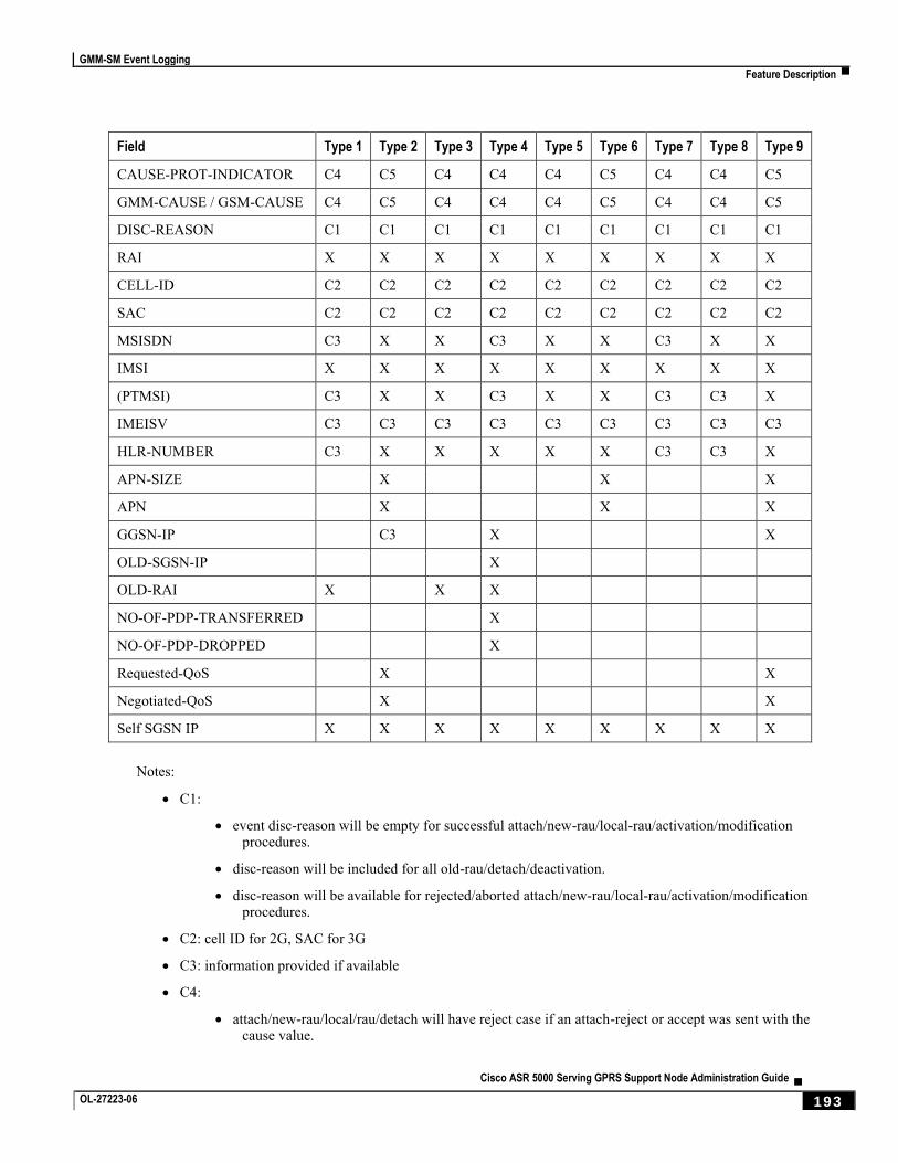
GMM-SM Event Logging
Feature Description ▀
Cisco ASR 5000 Serving GPRS Support Node Administration Guide ▄ OL-27223-06 193
Field Type 1 Type 2 Type 3 Type 4 Type 5 Type 6 Type 7 Type 8 Type 9
CAUSE-PROT-INDICATOR C4 C5 C4 C4 C4 C5 C4 C4 C5
GMM-CAUSE / GSM-CAUSE C4 C5 C4 C4 C4 C5 C4 C4 C5
DISC-REASON C1 C1 C1 C1 C1 C1 C1 C1 C1
RAI X X X X X X X X X
CELL-ID C2 C2 C2 C2 C2 C2 C2 C2 C2
SAC C2 C2 C2 C2 C2 C2 C2 C2 C2
MSISDN C3 X X C3 X X C3 X X
IMSI X X X X X X X X X
(PTMSI) C3 X X C3 X X C3 C3 X
IMEISV C3 C3 C3 C3 C3 C3 C3 C3 C3
HLR-NUMBER C3 X X X X X C3 C3 X
APN-SIZE X X X
APN X X X
GGSN-IP C3 X X
OLD-SGSN-IP X
OLD-RAI X X X
NO-OF-PDP-TRANSFERRED X
NO-OF-PDP-DROPPED X
Requested-QoS X X
Negotiated-QoS X X
Self SGSN IP X X X X X X X X X
Notes:
C1:
event disc-reason will be empty for successful attach/new-rau/local-rau/activation/modification procedures.
disc-reason will be included for all old-rau/detach/deactivation.
disc-reason will be available for rejected/aborted attach/new-rau/local-rau/activation/modification procedures.
C2: cell ID for 2G, SAC for 3G
C3: information provided if available
C4:
attach/new-rau/local/rau/detach will have reject case if an attach-reject or accept was sent with the cause value.
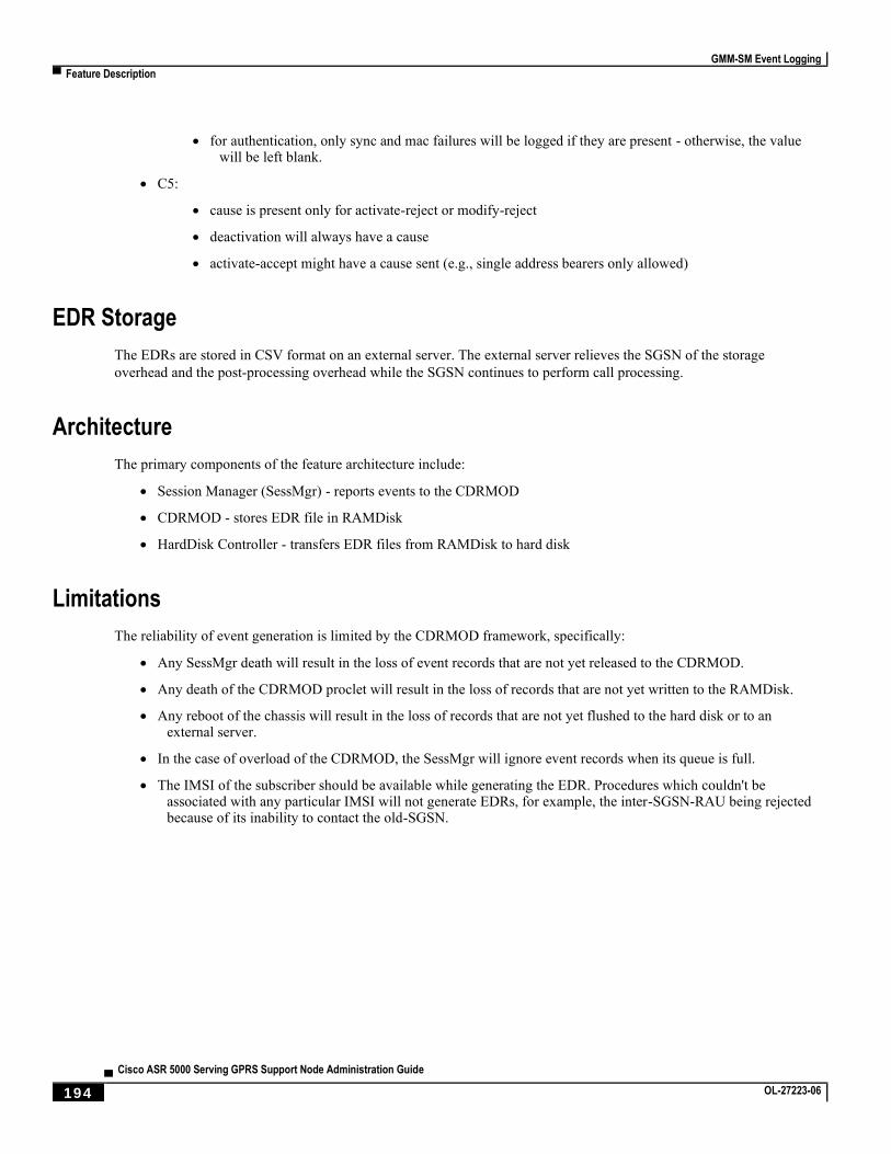
GMM-SM Event Logging
▀ Feature Description
▄ Cisco ASR 5000 Serving GPRS Support Node Administration Guide
194 OL-27223-06
for authentication, only sync and mac failures will be logged if they are present - otherwise, the value will be left blank.
C5:
cause is present only for activate-reject or modify-reject
deactivation will always have a cause
activate-accept might have a cause sent (e.g., single address bearers only allowed)
EDR Storage
The EDRs are stored in CSV format on an external server. The external server relieves the SGSN of the storage
overhead and the post-processing overhead while the SGSN continues to perform call processing.
Architecture
The primary components of the feature architecture include:
Session Manager (SessMgr) - reports events to the CDRMOD
CDRMOD - stores EDR file in RAMDisk
HardDisk Controller - transfers EDR files from RAMDisk to hard disk
Limitations
The reliability of event generation is limited by the CDRMOD framework, specifically:
Any SessMgr death will result in the loss of event records that are not yet released to the CDRMOD.
Any death of the CDRMOD proclet will result in the loss of records that are not yet written to the RAMDisk.
Any reboot of the chassis will result in the loss of records that are not yet flushed to the hard disk or to an external server.
In the case of overload of the CDRMOD, the SessMgr will ignore event records when its queue is full.
The IMSI of the subscriber should be available while generating the EDR. Procedures which couldn't be associated with any particular IMSI will not generate EDRs, for example, the inter-SGSN-RAU being rejected because of its inability to contact the old-SGSN.
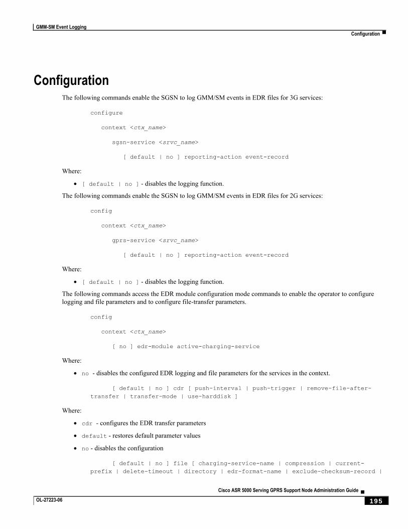
GMM-SM Event Logging
Configuration ▀
Cisco ASR 5000 Serving GPRS Support Node Administration Guide ▄ OL-27223-06 195
Configuration The following commands enable the SGSN to log GMM/SM events in EDR files for 3G services:
configure
context <ctx_name>
sgsn-service <srvc_name>
[ default | no ] reporting-action event-record
Where:
[ default | no ] - disables the logging function.
The following commands enable the SGSN to log GMM/SM events in EDR files for 2G services:
config
context <ctx_name>
gprs-service <srvc_name>
[ default | no ] reporting-action event-record
Where:
[ default | no ] - disables the logging function.
The following commands access the EDR module configuration mode commands to enable the operator to configure
logging and file parameters and to configure file-transfer parameters.
config
context <ctx_name>
[ no ] edr-module active-charging-service
Where:
no - disables the configured EDR logging and file parameters for the services in the context.
[ default | no ] cdr [ push-interval | push-trigger | remove-file-after-
transfer | transfer-mode | use-harddisk ]
Where:
cdr - configures the EDR transfer parameters
default - restores default parameter values
no - disables the configuration
[ default | no ] file [ charging-service-name | compression | current-
prefix | delete-timeout | directory | edr-format-name | exclude-checksum-record |
GMM-SM Event Logging
▀ Configuration
▄ Cisco ASR 5000 Serving GPRS Support Node Administration Guide
196 OL-27223-06
field-separator | file-sequence-number | headers | name | reset-indicator |
rotation | sequence-number | storage-limit | time-stamp | trailing-text | trap-
on-file-delete | xor-final-record
Where:
file - configures file creation properties for the records
default - restores the default file creation properties
no - disables the configuration
Cisco ASR 5000 Serving GPRS Support Node Administration Guide ▄ OL-27223-06 197
Chapter 8 Location Services
LoCation Services (LCS) on the MME and SGSN is a 3GPP standards-compliant feature that enables the system (MME
or SGSN) to collect and use or share location (geographical position) information for connected UEs in support of a
variety of location services.
Location Services
▀ Location Services - Feature Description
▄ Cisco ASR 5000 Serving GPRS Support Node Administration Guide
198 OL-27223-06
Location Services - Feature Description The Location Services (LCS) feature enables the EPC MME and the GPRS/UMTS SGSN to use the SLg (MME) or Lg
(SGSN) interface which provides the mechanisms to support specialized mobile location services for operators,
subscribers, and third party service providers. Use of this feature and the SLg/Lg interface is license controlled.
The location information is reported in standard geographical co-ordinates (longitude and latitude) together with the
time-of-day and the estimated errors (uncertainty) of the location of the UE. For external use, the location information
may be requested by and reported to a client application associated with the UE, or a client within or attached to the core
network. For internal use, the location information can be utilized by the SGSN for functions such as location assisted
handover or to support other features.
Location information is intended to be used for
location-based charging (e.g., home-location billing, roaming-location billing),
location-based services (e.g., lawful interception, emergency calls),
positioning services offered to the subscribers (e.g., mobile yellow pages, navigation applications on mobiles), and
by the operator for service provider services such as network planning and enhanced call routing.
Location Services
How Location Services Works ▀
Cisco ASR 5000 Serving GPRS Support Node Administration Guide ▄ OL-27223-06 199
How Location Services Works The SGSN LCS responsibilities center around UE subscription authorization and managing LCS positioning requests.
The LCS functions of the SGSN are related to charging and billing, LCS co-ordination, location request, authorization
and operation of the LCS services.
When using the Iu interface, before the SGSN can request location information of a target UE from the radio access
network (RAN), an Iu signaling connection must have been established between the SGSN and the RAN. The SGSN
sends a Location Request message to the RAN. The RAN determines the location of the target UE related to this Iu
signaling connection and sends a Location Report to the SGSN over the same Iu signaling connection. On the Iu
interface, only one location request for a geographic location estimate can be ongoing at any time.
The pre-requisite for LCS procedures on the Gb interface is that the UE is in “ready state”. On the Gb interface, only
one location request can be ongoing at any time.
The operation begins with a LCS Client requesting location information for a UE from the LCS server. The LCS server
will pass the request to the LCS functional entity (SGSN) in the core network. The LCS functional entitiy (SGSN) in the
core network then:
1. verifies that the LCS Client is authorized to request the location of the UE or subscriber;
2. verifies that location services are supported by the UE;
3. establishes whether it (the MME/SGSN) is allowed to locate the UE or subscriber, for privacy or other reasons;
4. establishes which network element in the radio access network ( GERAN or UTRAN or E-UTRAN ) should receive the Location Request;
5. requests the access network (via the A, Gb, Iu or S1 interface) to provide location information for an identified UE, with indicated QoS;
6. receives information about the location of the UE from the Access Network and forward it to the Client;
7. sends appropriate accounting information to an accounting function.
Location Services
▀ Relationship to Other SGSN Functions
▄ Cisco ASR 5000 Serving GPRS Support Node Administration Guide
200 OL-27223-06
Relationship to Other SGSN Functions The Location Services feature utilizes several of the existing SGSN functionalities:
Mobility Management module
MAP Service module
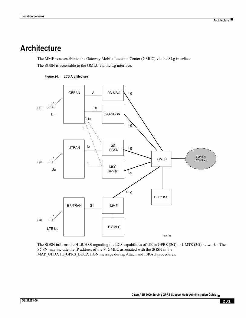
Location Services
Architecture ▀
Cisco ASR 5000 Serving GPRS Support Node Administration Guide ▄ OL-27223-06 201
Architecture The MME is accessible to the Gateway Mobile Location Center (GMLC) via the SLg interface.
The SGSN is accessible to the GMLC via the Lg interface.
Figure 24. LCS Architecture
The SGSN informs the HLR/HSS regarding the LCS capabilities of UE in GPRS (2G) or UMTS (3G) networks. The
SGSN may include the IP address of the V-GMLC associated with the SGSN in the
MAP_UPDATE_GPRS_LOCATION message during Attach and ISRAU procedures.
Location Services
▀ Limitations
▄ Cisco ASR 5000 Serving GPRS Support Node Administration Guide
202 OL-27223-06
Limitations Currently, SGSN support is limited to:
1. Immediate Mobile-Terminating Location Requests [TS 3GPP 23.271]
For GPRS (2G), Location reporting granularity is at the Cell Global Identifier (CGI) level only.
2. A single location request at a time for the target UE. Concurrent location requests are not supported.
3. Only Provide Subscriber Location messages with the id as IMSI are supported.
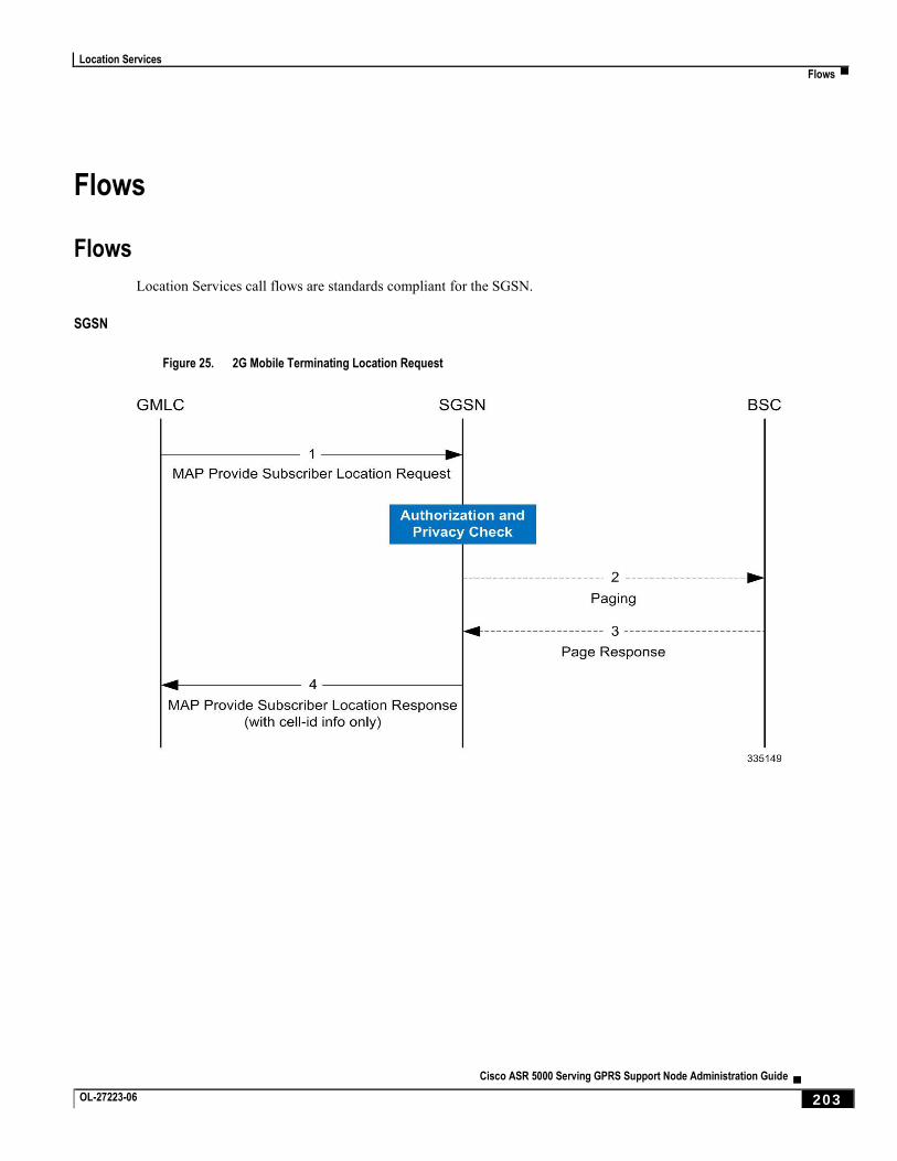
Location Services
Flows ▀
Cisco ASR 5000 Serving GPRS Support Node Administration Guide ▄ OL-27223-06 203
Flows
Flows
Location Services call flows are standards compliant for the SGSN.
SGSN
Figure 25. 2G Mobile Terminating Location Request
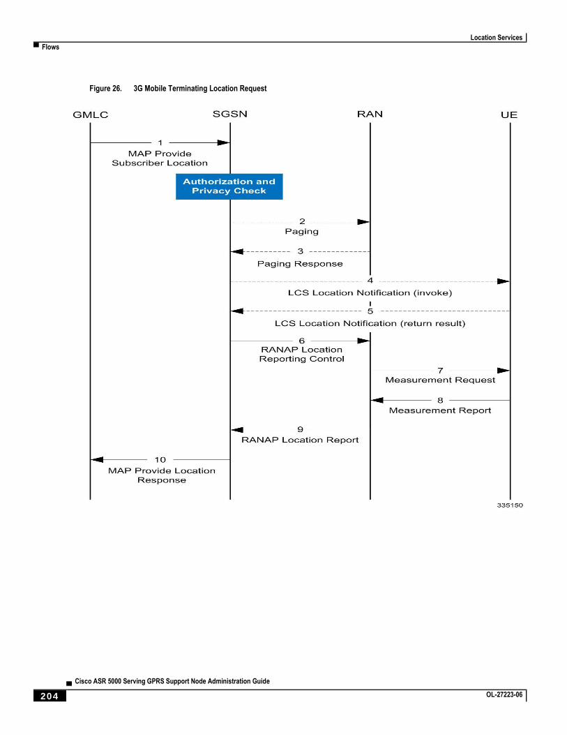
Location Services
▀ Flows
▄ Cisco ASR 5000 Serving GPRS Support Node Administration Guide
204 OL-27223-06
Figure 26. 3G Mobile Terminating Location Request
Location Services
Standards Compliance ▀
Cisco ASR 5000 Serving GPRS Support Node Administration Guide ▄ OL-27223-06 205
Standards Compliance The SGSN’s Location Services feature complies with the following standards:
TS 3GPP 23.271, v9.6.0
TS 3GPP 24.030, v9.0.0
TS 3GPP 24.080, v9.2.0
TS 3GPP 25.413, v9.8.0 (sections 8.19.2 and 8.20.2)
TS 3GPP 29.002, v9.7.0
Location Services
▀ Configuring Location Services (LCS) on the SGSN
▄ Cisco ASR 5000 Serving GPRS Support Node Administration Guide
206 OL-27223-06
Configuring Location Services (LCS) on the SGSN This section provides a high-level series of steps and the associated configuration examples to configure Location
Services on the 2G or 3G SGSN -- or for both.
The commands could be issued in a different order, but we recommend that you follow the outlined order for an initial
LCS configuration. All listed configuration steps are mandatory unless otherwise indicated.
Important: For all the required configuration commands to be available and to implement the configuration, the
SGSN must have loaded the license for the Lg interface.
Step 1 Enable Location Services on the SGSN.
Step 2 Identify the GMLC (in the MAP service) to which the SGSN connects for LCS access to the external LCS client.
Step 3 Configure the MAP service’s M1 timer.
Important: Step 3 is not mandatory but it is recommended.
Step 4 Create a location services configuration and associate the MAP service.
Step 5 Fine-tune LCS configuration per UE by defining LCS-related restrictions.
Step 6 Associate the location services configuration with the appropriate SGSN - GPRS (2G) service and/or UMTS (3G)
service.
Step 7 Associate the location services configuration with an operator policy.
Step 8 Save your configuration to flash memory, an external memory device, and/or a network location using the Exec mode
command save configuration. For additional information on how to verify and save configuration files, refer to the
System Administration Guide.
Step 9 Verify the configuration for each component by following the instructions provided in the Verifying the Feature
Configuration section.
Enabling LCS
Location Services functionality is enabled globally for the SGSN.
config
sgsn-global
location-services
end
Notes:
This command enables and ‘starts’ LCS on the SGSN.
Location Services
Configuring Location Services (LCS) on the SGSN ▀
Cisco ASR 5000 Serving GPRS Support Node Administration Guide ▄ OL-27223-06 207
This command also enables support for the Lg interface on the SGSN.
Using the ‘no’ keyword stops LCS.
Identifying the GMLC
Use the MAP service configuration to identify the GMLC to which the SGSN connects for LCS access to the external
LCS client. We recommend that you also configure the MAP service’s M1 timer, however, this is option.
config
context <context_name>
map-service <map_service_name>
gmlc { isdn E.164# | point-code <point_code> } gsn-address <ipv4_address> [
source-ssn <ssn> ]
timeout m1 seconds
end
Notes:
Only one GMLC can be configured per MAP service.
isdn is the 1-15 digit E.164 number that identifies the GMLC.
point-code is the address for the GMLC in dotted-decimal ###.###.### or decimal ######## SS7 point-code
format
gsn-address is the IPv4 address for the GMLC
source-ssn optionally identifies the source SSN value to be used.
Creating the Location Service Configuration
This set of configuration commands creates a location service configuration and associates the MAP service with the
location service. Up to 16 separate location services can be created.
config
context context_name
location-service loc_serv_name
associate map-service map_serv_name
end
Notes:
The SGSN supports a maximum of 16 location service configuration. It should be noted that this number, 16, is not part of the SGSN’s service configuration limit of 256.
Location Services
▀ Configuring Location Services (LCS) on the SGSN
▄ Cisco ASR 5000 Serving GPRS Support Node Administration Guide
208 OL-27223-06
Associate the MAP Service configuration in which the GMLC is defined.
Fine-tuning the Location Service Configuration
Fine-tune the location service configuration per UE by defining LCS-related restrictions. The following commands will
be used to configure the LCSN timer (location notification invoke procedures timer). Configuring the timer value is
optional.
config
context context_name
location-service loc_serv_name
timeout lcsn seconds
Notes:
LCSN timer range is 10 - 20 with a default of 15. seconds.
Associating the Location Service Config with the SGSN
Location service functionality can be associated with either the 3G SGSN via commands in the SGSN Service
configuration mode or with the 2G SGSN via commands in the GPRS Service configuration mode.
The following associates the location service configuration with a 3G SGSN:
config
context context_name
sgsn-service service-name
associate location-service loc_serv_name
Notes:
To associate with a 2G SGSN, enter the GPRS service configuration mode in place of the SGSN service configuration mode.
Associating the Location Service Config with an Operator Policy
Location service functionality can be associated with an operator policy to provide granular control.
The following associates the location service configuration with a call-control profile by IMSI and these CLIs will
disable/enable Mobile Terminating, Mobile Originating and/or Network Induced location requests by access-type.
config
call-control-profile ccprofile_name
location-service service-name
Location Services
Configuring Location Services (LCS) on the SGSN ▀
Cisco ASR 5000 Serving GPRS Support Node Administration Guide ▄ OL-27223-06 209
lcs-mt { allow | restrict } access-type { gprs | umts }
Notes:
lcs-mt enables mobile-terminating location requests.
replace lcs-mo with lcs-mt to enable the mobile-terminating Location Requests or with lcs-ni to enable
network-induced Location Requests.
Default for the 3 lcs commands is allow
Verifying the LCS Configuration for the SGSN
View the location service configuration to verify the configurations created for the Location Service functionality, by
using the following commands:
show location-service service { all | name loc_serv_name
View the MAP configuration to verify the MAP configurations created for the Location Service functionality, by using
the following commands:
show map-service { all | name map_serv_name
View the call-control profile configuration to verify the configurations created for the Location Service functionality, by
using the following commands:
show call-control-profile full name ccprof_name
Location Services
▀ Monitoring and Troubleshooting the LCS on the SGSN
▄ Cisco ASR 5000 Serving GPRS Support Node Administration Guide
210 OL-27223-06
Monitoring and Troubleshooting the LCS on the SGSN Use the commands listed below to monitor and/or troubleshoot the operation of the Location Services on the SGSN.
show map statistics name map-service-name
clear map statistics name map-service-name
show gmm-sm statistics
show subscribers sgsn-only summary
show subscribers gprs-only summary
Cisco ASR 5000 Serving GPRS Support Node Administration Guide ▄ OL-27223-06 211
Chapter 9 Operator Policy
The proprietary concept of an operator policy, originally architected for the exclusive use of an SGSN, is non-standard
and currently unique to the ASR 5x00. This optional feature empowers the carrier with flexible control to manage
functions that are not typically used in all applications and to determine the granularity of the implementation of any
operator policy: to groups of incoming calls or to simply one single incoming call.
The following products support the use of the operator policy feature:
MME (Mobility Management Entity - LTE)
SGSN (Serving GPRS Support Node - 2G/3G/LTE)
S-GW (Serving Gateway - LTE)
This document includes the following information:
What Operator Policy Can Do
The Operator Policy Feature in Detail
Call Control Profile
APN Profile
IMEI-Profile (SGSN only)
APN Remap Table
Operator Policies
IMSI Ranges
How It Works
Operator Policy Configuration
Operator Policy Component Associations - MME
Verifying the Feature Configuration
Operator Policy
▀ What Operator Policy Can Do
▄ Cisco ASR 5000 Serving GPRS Support Node Administration Guide
212 OL-27223-06
What Operator Policy Can Do Operator policy enables the operator to specify a policy with rules governing the services, facilities and privileges
available to subscribers.
A Look at Operator Policy on an SGSN
The following is only a sampling of what working operator policies can control on an SGSN:
APN information included in call activation messages are sometimes damaged, misspelled, missing. In such cases, the calls are rejected. The operator can ensure calls aren't rejected and configure a range of methods for handling APNs, including converting incoming APNs to preferred APNs and this control can be used in a focused fashion or defined to cover ranges of subscribers.
In another example, it is not unusual for a blanket configuration to be implemented for all subscriber profiles stored in the HLR. This results in a waste of resources, such as the allocation of the default highest QoS setting for all subscribers. An operator policy provides the opportunity to address such issues by allowing fine-tuning of certain aspects of profiles fetched from HLRs and, if desired, overwrite QoS settings received from HLR.
A Look at Operator Policy on an S-GW
The S-GW operator policy provides mechanisms to fine tune the behavior for subsets of subscribers. It also can be used
to control the behavior of visiting subscribers in roaming scenarios by enforcing roaming agreements and providing a
measure of local protection against foreign subscribers.
The S-GW uses operator policy in the SGW service configuration to control the accounting mode. The default
accounting mode is GTTP, but RADIUS/Diameter and none are options. The accounting mode value from the call
control profile overrides the value configured in SGW service. If the accounting context is not configured in the call
control profile, it is taken from SGW service. If the SGW service does not have the relevant configuration, the current
context or default GTPP group is assumed.
Operator Policy
The Operator Policy Feature in Detail ▀
Cisco ASR 5000 Serving GPRS Support Node Administration Guide ▄ OL-27223-06 213
The Operator Policy Feature in Detail This flexible feature provides the operator with a range of control to manage the services, facilities and privileges
available to subscribers.
Operator policy definitions can depend on factors such as (but not limited to):
roaming agreements between operators,
subscription restrictions for visiting or roaming subscribers,
provisioning of defaults to override standard behavior.
These policies can override standard behaviors and provide mechanisms for an operator to circumvent the limitations of
other infrastructure elements such as DNS servers and HLRs in 2G/3G networks.
By configuring the various components of an operator policy, the operator fine-tunes any desired restrictions or
limitations needed to control call handling and this can be done for a group of callers within a defined IMSI range or per
subscriber.
Re-Usable Components - Besides enhancing operator control via configuration, the operator policy feature minimizes
configuration by drastically reducing the number of configuration lines needed. Operator policy maximizes
configurations by breaking them into the following reusable components that can be shared across IMSI ranges or
subscribers:
call control profiles
IMEI profiles (SGSN only)
APN profiles
APN remap tables
operator policies
IMSI ranges
Each of these components is configured via a separate configuration mode accessed through the Global Configuration
mode.
Call Control Profile
A call control profile can be used by the operator to fine-tune desired functions, restrictions, requirements, and/or
limitations needed for call management on a per-subscriber basis or for groups of callers across IMSI ranges. For
example:
setting access restriction cause codes for rejection messages
enabling/disabling authentication for various functions such as attach and service requests
enabling/disabling ciphering, encryption, and/or integrity algorithms
enabling/disabling of packet temporary mobile subscriber identity (P-TMSI) signature allocation (SGSN only)
enabling/disabling of zone code checking
allocation/retention priority override behavior (SGSN only)
Operator Policy
▀ The Operator Policy Feature in Detail
▄ Cisco ASR 5000 Serving GPRS Support Node Administration Guide
214 OL-27223-06
enabling/disabling inter-RAT, 3G location area, and 4G tracking area handover restriction lists (MME and S-GW only)
setting maximum bearers and PDNs per subscriber (MME and S-GW only)
Call control profiles are configured with commands in the Call Control Profile configuration mode. A single call control
profile can be associated with multiple operator policies
For planning purposes, based on the system configuration, type of packet services cards, type of network (2G, 3G, 4G,
LTE), and/or application configuration (single, combo, dual access), the following call control profile configuration
rules should be considered:
1 (only one) - call control profile can be associated with an operator policy
1000 - maximum number of call control profiles per system (e.g., an SGSN).
15 - maximum number of equivalent PLMNs for 2G and 3G per call control profile
15 - maximum number of equivalent PLMNs for 2G per ccprofile.
15 - maximum number of supported equivalent PLMNs for 3G per ccprofile.
256 - maximum number of static SGSN addresses supported per PLMN
5 - maximum number of location area code lists supported per call control profile.
100 - maximum number of LACs per location area code list supported per call control profile.
unlimited number of zone code lists can be configured per call control profile.
100 - maximum number of LACs allowed per zone code list per call control profile.
2 - maximum number of integrity algorithms for 3G per call control profile.
3 - maximum number of encryption algorithms for 3G per call control profile.
APN Profile
An APN profile groups a set of access point name (APN)-specific parameters that may be applicable to one or more
APNs. When a subscriber requests an APN that has been identified in a selected operator policy, the parameter values
configured in the associated APN profile will be applied.
For example:
enable/disable a direct tunnel (DT) per APN. (SGSN)
define charging characters for calls associated with a specific APN.
identify a specific GGSN to be used for calls associated with a specific APN (SGSN).
define various quality of service (QoS) parameters to be applied to calls associated with a specific APN.
restrict or allow PDP context activation on the basis of access type for calls associated with a specific APN.
APN profiles are configured with commands in the APN Profile configuration mode. A single APN profile can be
associated with multiple operator policies.
For planning purposes, based on the system configuration, type of packet processing cards and 2G, 3G, 4G, and/or dual
access, the following APN profile configuration rules should be considered:
50 - maximum number of APN profiles that can be associated with an operator policy.
1000 - maximum number of APN profiles per system (e.g., an SGSN).
Operator Policy
The Operator Policy Feature in Detail ▀
Cisco ASR 5000 Serving GPRS Support Node Administration Guide ▄ OL-27223-06 215
116 - maximum gateway addresses (GGSN addresses) that can be defined in a single APN profile.
IMEI-Profile (SGSN only)
The IMEI is a unique international mobile equipment identity number assigned by the manufacturer that is used by the
network to identify valid devices. The IMEI has no relationship to the subscriber.
An IMEI profile group is a set of device-specific parameters that control SGSN behavior when one of various types of
Requests is received from a UE within a specified IMEI range. These parameters control:
Blacklisting devices
Identifying a particular GGSN to be used for connections for specified devices
Enabling/disabling direct tunnels to be used by devices
IMEI profiles are configured with commands in the IMEI Profile configuration mode. A single IMEI profile can be
associated with multiple operator policies.
For planning purposes, based on the system configuration, type of packet processing cards, type of network (2G, 3G,
4G, LTE), and/or application configuration (single, combo, dual access), the following IMEI profile configuration rules
should be considered:
10 - maximum number of IMEI ranges that can be associated with an operator policy.
1000 - maximum number of IMEI profiles per system (such as an SGSN).
APN Remap Table
APN remap tables allow an operator to override an APN specified by a user, or the APN selected during the normal
APN selection procedure, as specified by 3GPP TS 23.060. This atypical level of control enables operators to deal with
situations such as:
An APN is provided in the Activation Request that does not match with any of the subscribed APNs; either a different APN was entered or the APN could have been misspelled. In such situations, the SGSN would reject the Activation Request. It is possible to correct the APN, creating a valid name so that the Activation Request is not rejected.
In some cases, an operator might want to force certain devices/users to use a specific APN. For example, all iPhone4 users may need to be directed to a specific APN. In such situations, the operator needs to be able to override the selected APN.
An APN remap table group is a set of APN-handling configurations that may be applicable to one or more subscribers.
When a subscriber requests an APN that has been identified in a selected operator policy, the parameter values
configured in the associated APN remap table will be applied. For example, an APN remap table allows configuration
of the following:
APN aliasing - maps incoming APN to a different APN based on partial string match (MME and SGSN) or matching charging characteristic (MME and SGSN).
Wildcard APN - allows APN to be provided by the SGSN when wildcard subscription is present and the user has not requested an APN.
Default APN - allows a configured default APN to be used when the requested APN cannot be used – for example, the APN is not part of the HLR subscription.
Operator Policy
▀ The Operator Policy Feature in Detail
▄ Cisco ASR 5000 Serving GPRS Support Node Administration Guide
216 OL-27223-06
APN remap tables are configured with commands in the APN Remap Table configuration mode. A single APN remap
table can be associated with multiple operator policies, but an operator policy can only be associated with a single APN
remap table.
For planning purposes, based on the system configuration, type of packet processing cards, type of network (2G, 3G,
4G, LTE), and/or application configuration (single, combo, dual access), the following APN remap table configuration
rules should be considered:
1 – maximum number of APN remap tables that can be associated with an operator policy.
1000 – maximum number of APN remap tables per system (such as an SGSN).
100 – maximum remap entries per APN remap table.
Operator Policies
The profiles and tables are created and defined within their own configuration modes to generate sets of rules and
instructions that can be reused and assigned to multiple policies. An operator policy binds the various configuration
components together. It associates APNs, with APN profiles, with an APN remap table, with a call control profile,
and/or an IMEI profile (SGSN only) and associates all the components with filtering ranges of IMSIs.
In this manner, an operator policy manages the application of rules governing the services, facilities, and privileges
available to subscribers.
Operator policies are configured and the associations are defined via the commands in the Operator Policy configuration
mode.
The IMSI ranges are configured with the command in the SGSN-Global configuration mode.
For planning purposes, based on the system configuration, type of packet processing cards, type of network (2G, 3G,
4G, LTE), and/or application configuration (single, combo, dual access), the following operator policy configuration
rules should be considered:
1 – maximum number of call control profiles associated with a single operator policy.
1 – maximum number of APN remap tables associated with a single operator policy.
10 – maximum number of IMEI profiles associated with a single operator policy (SGSN only)
50 – maximum number of APN profiles associated with a single operator policy.
1000 – maximum number of operator policies per system (e.g., an SGSN); this number includes the single default operator policy.
1000 – maximum number of IMSI ranges defined per system (e.g., an SGSN).
Important: SGSN operator policy configurations created with software releases prior to Release 11.0 are not
forward compatible. Such configurations can be converted to enable them to work with an SGSN running Release 11.0 or higher. Your Cisco Account Representative can accomplish this conversion for you.
IMSI Ranges
Ranges of international mobile subscriber identity (IMSI) numbers, the unique number identifying a subscriber, are
associated with the operator policies and used as the initial filter to determine whether or not any operator policy would
be applied to a call. The range configurations are defined by the MNC, MCC, a range of MSINs, and optionally the
PLMN ID. The IMSI ranges must be associated with a specific operator policy.

Operator Policy
The Operator Policy Feature in Detail ▀
Cisco ASR 5000 Serving GPRS Support Node Administration Guide ▄ OL-27223-06 217
IMSI ranges are defined differently for each product supporting the operator policy feature.
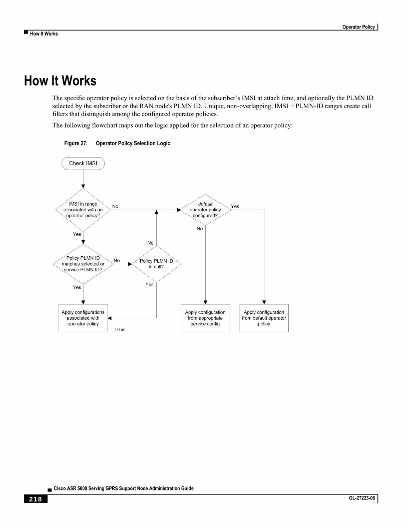
Operator Policy
▀ How It Works
▄ Cisco ASR 5000 Serving GPRS Support Node Administration Guide
218 OL-27223-06
How It Works The specific operator policy is selected on the basis of the subscriber’s IMSI at attach time, and optionally the PLMN ID
selected by the subscriber or the RAN node's PLMN ID. Unique, non-overlapping, IMSI + PLMN-ID ranges create call
filters that distinguish among the configured operator policies.
The following flowchart maps out the logic applied for the selection of an operator policy:
Figure 27. Operator Policy Selection Logic
Operator Policy
Operator Policy Configuration ▀
Cisco ASR 5000 Serving GPRS Support Node Administration Guide ▄ OL-27223-06 219
Operator Policy Configuration This section provides a high-level series of steps and the associated configuration examples to configure an operator
policy. By configuring an operator policy, the operator fine-tunes any desired restrictions or limitations needed to
control call handling per subscriber or for a group of callers within a defined IMSI range.
Most of the operator policy configuration components are common across the range of products supporting operator
policy. Differences will be noted as they are encountered below.
Important: This section provides a minimum instruction set to implement operator policy. For this feature to be
operational, you must first have completed the system-level configuration as described in the System Administration Guide and the service configuration described in your product’s administration guide.
The components can be configured in any order. This example begins with the call control profile:
Step 1 Create and configure a call control profile, by applying the example configuration presented in the Call Control Profile
Configuration section.
Step 2 Create and configure an APN profile, by applying the example configuration presented in the APN Profile
Configuration section.
Important: It is not necessary to configure both an APN profile and an IMEI profile. You can
associate either type of profile with a policy. It is also possible to associate one or more APN profiles with an IMEI profile for an operator policy (SGSN only).
Step 3 Create and configure an IMEI profile by applying the example configuration presented in the IMEI Profile
Configuration section (SGSN only).
Step 4 Create and configure an APN remap table by applying the example configuration presented in the APN Remap Table
Configuration section.
Step 5 Create and configure an operator policy by applying the example configuration presented in the Operator Policy
Configuration section.
Step 6 Configure an IMSI range by selecting and applying the appropriate product-specific example configuration presented in
the IMSI Range Configuration sections below.
Step 7 Associate the configured operator policy components with each other and a network service by applying the example
configuration in the Operator Policy Component Associations section.
Step 8 Save your configuration to flash memory, an external memory device, and/or a network location using the Exec mode
command save configuration. For additional information on how to verify and save configuration files, refer to the
System Administration Guide .
Step 9 Verify the configuration for each component separately by following the instructions provided in the Verifying the
Feature Configuration section of this chapter.
Operator Policy
▀ Operator Policy Configuration
▄ Cisco ASR 5000 Serving GPRS Support Node Administration Guide
220 OL-27223-06
Call Control Profile Configuration
This section provides the configuration example to create a call control profile and enter the configuration mode.
Use the call control profile commands to define call handling rules that will be applied via an operator policy. Only one
call control profile can be associated with an operator policy, so it is necessary to use (and repeat as necessary) the range
of commands in this mode to ensure call-handling is sufficiently managed.
Configuring the Call Control Profile for an SGSN
The example below includes some of the more commonly configured call control profile parameters with sample
variables that you will replace with your own values.
configure
call-control-profile <profile_name>>
attach allow access-type umts location-area-list instance <list_id>
authenticate attach
location-area-list instance <instance> area-code <area_code>
sgsn-number <E164_number>
end
Note:
Refer to the Call Control Profile Configuration Mode chapter in the Command Line Interface Reference for command details and variable options.
This profile will only become valid when it is associated with an operator policy.
Configuring the Call Control Profile for an MME or S-GW
The example below includes some of the more commonly configured call control profile parameters with sample
variables that you will replace with your own values.
configure
call-control-profile <profile_name>>
associate hss-peer-service <service_name> s6a-interface
attach imei-query-type imei verify-equipment-identity
authenticate attach
dns-pgw context <mme_context_name>
dns-sgw context <mme_context_name>
end
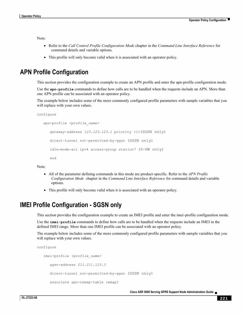
Operator Policy
Operator Policy Configuration ▀
Cisco ASR 5000 Serving GPRS Support Node Administration Guide ▄ OL-27223-06 221
Note:
Refer to the Call Control Profile Configuration Mode chapter in the Command Line Interface Reference for command details and variable options.
This profile will only become valid when it is associated with an operator policy.
APN Profile Configuration
This section provides the configuration example to create an APN profile and enter the apn-profile configuration mode.
Use the apn-profile commands to define how calls are to be handled when the requests include an APN. More than
one APN profile can be associated with an operator policy.
The example below includes some of the more commonly configured profile parameters with sample variables that you
will replace with your own values.
configure
apn-profile <profile_name>
gateway-address 123.123.123.1 priority <1>(SGSN only)
direct-tunnel not-permitted-by-ggsn (SGSN only)
idle-mode-acl ipv4 access-group station7 (S-GW only)
end
Note:
All of the parameter defining commands in this mode are product-specific. Refer to the APN Profile Configuration Mode chapter in the Command Line Interface Reference for command details and variable options.
This profile will only become valid when it is associated with an operator policy.
IMEI Profile Configuration - SGSN only
This section provides the configuration example to create an IMEI profile and enter the imei-profile configuration mode.
Use the imei-profile commands to define how calls are to be handled when the requests include an IMEI in the
defined IMEI range. More than one IMEI profile can be associated with an operator policy.
The example below includes some of the more commonly configured profile parameters with sample variables that you
will replace with your own values.
configure
imei-profile <profile_name>
ggsn-address 211.211.123.3
direct-tunnel not-permitted-by-ggsn (SGSN only)
associate apn-remap-table remap1
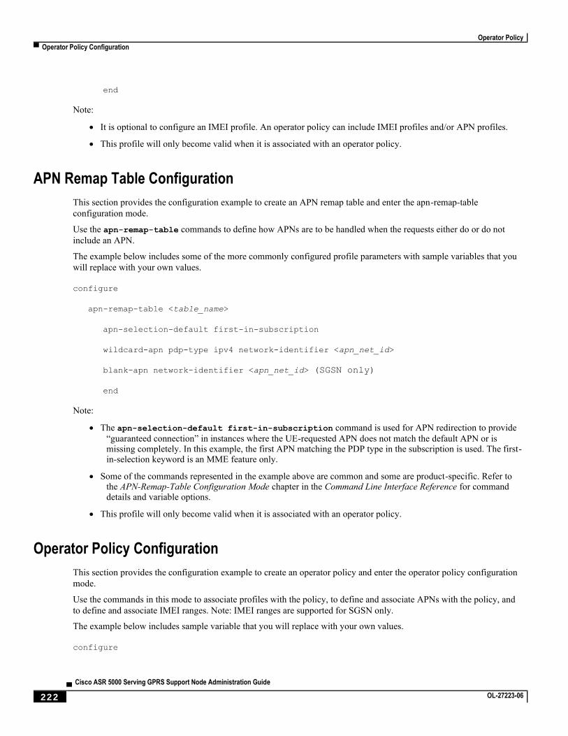
Operator Policy
▀ Operator Policy Configuration
▄ Cisco ASR 5000 Serving GPRS Support Node Administration Guide
222 OL-27223-06
end
Note:
It is optional to configure an IMEI profile. An operator policy can include IMEI profiles and/or APN profiles.
This profile will only become valid when it is associated with an operator policy.
APN Remap Table Configuration
This section provides the configuration example to create an APN remap table and enter the apn-remap-table
configuration mode.
Use the apn-remap-table commands to define how APNs are to be handled when the requests either do or do not
include an APN.
The example below includes some of the more commonly configured profile parameters with sample variables that you
will replace with your own values.
configure
apn-remap-table <table_name>
apn-selection-default first-in-subscription
wildcard-apn pdp-type ipv4 network-identifier <apn_net_id>
blank-apn network-identifier <apn_net_id> (SGSN only)
end
Note:
The apn-selection-default first-in-subscription command is used for APN redirection to provide
“guaranteed connection” in instances where the UE-requested APN does not match the default APN or is missing completely. In this example, the first APN matching the PDP type in the subscription is used. The first-in-selection keyword is an MME feature only.
Some of the commands represented in the example above are common and some are product-specific. Refer to the APN-Remap-Table Configuration Mode chapter in the Command Line Interface Reference for command details and variable options.
This profile will only become valid when it is associated with an operator policy.
Operator Policy Configuration
This section provides the configuration example to create an operator policy and enter the operator policy configuration
mode.
Use the commands in this mode to associate profiles with the policy, to define and associate APNs with the policy, and
to define and associate IMEI ranges. Note: IMEI ranges are supported for SGSN only.
The example below includes sample variable that you will replace with your own values.
configure
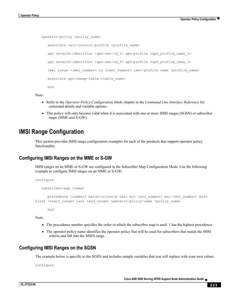
Operator Policy
Operator Policy Configuration ▀
Cisco ASR 5000 Serving GPRS Support Node Administration Guide ▄ OL-27223-06 223
operator-policy <policy_name>
associate call-control-profile <profile_name>
apn network-identifier <apn-net-id_1> apn-profile <apn_profile_name_1>
apn network-identifier <apn-net-id_2> apn-profile <apn_profile_name_1>
imei range <imei_number> to <imei_number> imei-profile name <profile_name>
associate apn-remap-table <table_name>
end
Note:
Refer to the Operator-Policy Configuration Mode chapter in the Command Line Interface Reference for command details and variable options.
This policy will only become valid when it is associated with one or more IMSI ranges (SGSN) or subscriber maps (MME and S-GW).
IMSI Range Configuration
This section provides IMSI range configuration examples for each of the products that support operator policy
functionality.
Configuring IMSI Ranges on the MME or S-GW
IMSI ranges on an MME or S-GW are configured in the Subscriber Map Configuration Mode. Use the following
example to configure IMSI ranges on an MME or S-GW:
configure
subscriber-map <name>
precedence <number> match-criteria imsi mcc <mcc_number> mnc <mnc_number> msin
first <start_range> last <end_range> operator-policy-name <policy_name>
end
Note:
The precedence number specifies the order in which the subscriber map is used. 1 has the highest precedence.
The operator policy name identifies the operator policy that will be used for subscribers that match the IMSI criteria and fall into the MSIN range.
Configuring IMSI Ranges on the SGSN
The example below is specific to the SGSN and includes sample variables that you will replace with your own values.
configure
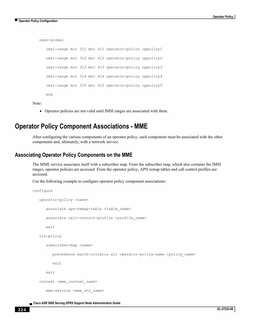
Operator Policy
▀ Operator Policy Configuration
▄ Cisco ASR 5000 Serving GPRS Support Node Administration Guide
224 OL-27223-06
sgsn-global
imsi-range mcc 311 mnc 411 operator-policy oppolicy1
imsi-range mcc 312 mnc 412 operator-policy oppolicy2
imsi-range mcc 313 mnc 413 operator-policy oppolicy3
imsi-range mcc 314 mnc 414 operator-policy oppolicy4
imsi-range mcc 315 mnc 415 operator-policy oppolicy5
end
Note:
Operator policies are not valid until IMSI ranges are associated with them.
Operator Policy Component Associations - MME
After configuring the various components of an operator policy, each component must be associated with the other
components and, ultimately, with a network service.
Associating Operator Policy Components on the MME
The MME service associates itself with a subscriber map. From the subscriber map, which also contains the IMSI
ranges, operator policies are accessed. From the operator policy, APN remap tables and call control profiles are
accessed.
Use the following example to configure operator policy component associations:
configure
operator-policy <name>
associate apn-remap-table <table_name>
associate call-control-profile <profile_name>
exit
lte-policy
subscriber-map <name>
precedence match-criteria all operator-policy-name <policy_name>
exit
exit
context <mme_context_name>
mme-service <mme_svc_name>
Operator Policy
Operator Policy Configuration ▀
Cisco ASR 5000 Serving GPRS Support Node Administration Guide ▄ OL-27223-06 225
associate subscriber-map <name>
end
Notes:
The precedence command in the subscriber map mode has other match-criteria types. The all type is
used in this example.
Configuring Accounting Mode for- S-GW
The accounting mode command configures the mode to be used for accounting – GTPP (default), RADIUS/Diameter
or None for S-GW service. This command is run from the S-GW Service Configuration Mode.
Use the following example to change the S-GW accounting mode from GTPP (the default) to RADIUS/Diameter:
configure
context <sgw_context_name>
sgw-service <sgw_srv_name>
accounting mode radius-diameter
end
Notes:
An accounting mode configured for the call control profile will override this setting.
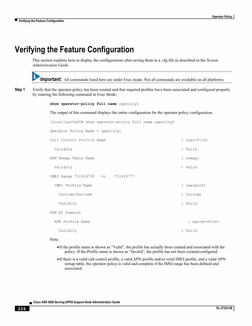
Operator Policy
▀ Verifying the Feature Configuration
▄ Cisco ASR 5000 Serving GPRS Support Node Administration Guide
226 OL-27223-06
Verifying the Feature Configuration This section explains how to display the configurations after saving them in a .cfg file as described in the System
Administration Guide .
Important: All commands listed here are under Exec mode. Not all commands are available on all platforms.
Step 1 Verify that the operator policy has been created and that required profiles have been associated and configured properly
by entering the following command in Exec Mode:
show operator-policy full name oppolicy1
The output of this command displays the entire configuration for the operator policy configuration.
[local]asr5x00# show operator-policy full name oppolicy1
Operator Policy Name = oppolicy1
Call Control Profile Name : ccprofile1
Validity : Valid
APN Remap Table Name : remap1
Validity : Valid
IMEI Range 711919739 to 711919777
IMEI Profile Name : imeiprof1
Include/Exclude : Include
Validity : Valid
APN NI homers1
APN Profile Name : apn-profile1
Validity : Valid
Note:
If the profile name is shown as “Valid”, the profile has actually been created and associated with the policy. If the Profile name is shown as “Invalid”, the profile has not been created/configured.
If there is a valid call control profile, a valid APN profile and/or valid IMEI profile, and a valid APN remap table, the operator policy is valid and complete if the IMSI range has been defined and associated.
Cisco ASR 5000 Serving GPRS Support Node Administration Guide ▄ OL-27223-06 227
Chapter 10 SGSN Serving Radio Network Subsystem Relocation
This chapter describes the SGSN Serving Radio Network Subsystem Relocation (SRNS) feature, and provides detailed
information on the following:
Feature Description
How it Works
Configuring SRNS Relocation on the SGSN
Monitoring and Troubleshooting SRNS Relocation
SGSN Serving Radio Network Subsystem Relocation
▀ Feature Description
▄ Cisco ASR 5000 Serving GPRS Support Node Administration Guide
228 OL-27223-06
Feature Description The SRNS relocation feature facilitates connected mode inter-RAT handovers between UTRAN (3G) networks or
between UTRAN and EUTRAN (LTE) networks. The advantage of this feature is that the radio bearer establishment
occurs before the actual handover at the target.
The Gn/Gp SGSN and S4-SGSN support inter- and intra-SGSN SRNS relocation to enable:
Handovers of an MS from one RNC to another RNC
Handovers of an MS from one RNC to an eNodeb
The S4-SGSN supports the optional setup of indirect data forwarding tunnels (IDFT) between the eNodeB and the RNC
via the SGW during connected mode handovers. This allows the S4-SGSN to support connected mode handovers
between the UTRAN and E-UTRAN networks across the S3 interface. IDFT is not supported on the SGSN across the
Gn interface.
The SRNS Relocation feature is included with the base SGSN license. It does not require an additional feature license.
Relationships to Other Features
This section describes how the SRNS Relocation feature relates to other SGSN features.
For an SGSN operating via the Gn/Gp interfaces, a 3G service (sgsn-service) must be configured and enabled before SRNS Relocation can be configured.
For an S4-SGSN, both a 3G service (sgsn-service) and S4-SGSN support (egtp-service) must be configured before SRNS Relocation can be configured.
If operators are using non-standard LAC ranges, then a network-global-mme-id-mgmt-db must be configured and associated with the sgsn-service.
For detailed instructions on configuring the above, refer to the Cisco ASR 5000 Serving GPRS Support Node
Administration Guide.
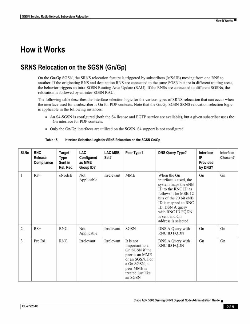
SGSN Serving Radio Network Subsystem Relocation
How it Works ▀
Cisco ASR 5000 Serving GPRS Support Node Administration Guide ▄ OL-27223-06 229
How it Works
SRNS Relocation on the SGSN (Gn/Gp)
On the Gn/Gp SGSN, the SRNS relocation feature is triggered by subscribers (MS/UE) moving from one RNS to
another. If the originating RNS and destination RNS are connected to the same SGSN but are in different routing areas,
the behavior triggers an intra-SGSN Routing Area Update (RAU). If the RNSs are connected to different SGSNs, the
relocation is followed by an inter-SGSN RAU.
The following table describes the interface selection logic for the various types of SRNS relocation that can occur when
the interface used for a subscriber is Gn for PDP contexts. Note that the Gn/Gp SGSN SRNS relocation selection logic
is applicable in the following instances:
An S4-SGSN is configured (both the S4 license and EGTP service are available), but a given subscriber uses the Gn interface for PDP contexts.
Only the Gn/Gp interfaces are utilized on the SGSN. S4 support is not configured.
Table 15. Interface Selection Logic for SRNS Relocation on the SGSN Gn/Gp
SI.No RNC
Release
Compliance
Target
Type
Sent in
Rel. Req.
LAC
Configured
as MME
Group ID?
LAC MSB
Set?
Peer Type? DNS Query Type? Interface
IP
Provided
by DNS?
Interface
Chosen?
1 R8+ eNodeB Not Applicable
Irrelevant MME When the Gn interface is used, the system maps the eNB ID to the RNC ID as follows: The MSB 12 bits of the 20 bit eNB ID is mapped to RNC ID. DSN A query with RNC ID FQDN is sent and Gn address is selected.
Gn Gn
2 R8+ RNC Not Applicable
Irrelevant SGSN DNS A Query with RNC ID FQDN
Gn Gn
3 Pre R8 RNC Irrelevant Irrelevant It is not important to a Gn SGSN if the peer is an MME or an SGSN. For a Gn SGSN, a peer MME is treated just like an SGSN
DNS A Query with RNC ID FQDN
Gn Gn
SGSN Serving Radio Network Subsystem Relocation
▀ How it Works
▄ Cisco ASR 5000 Serving GPRS Support Node Administration Guide
230 OL-27223-06
SGSN (Gn/Gp) SRNS Relocation Call Flow Diagrams
This section provides call flow diagrams and process descriptions for the following SGSN Gn/Gp SRNS Relocation
scenarios:
Inter-SGSN (Gn/Gp) SRNS Relocation Call Flow
Intra-SGSN (Gn/Gp) SRNS Relocation Call Flow
The Inter-SGSN (Gn/Gp) SRNS Relocation procedure is illustrated in the following diagram.
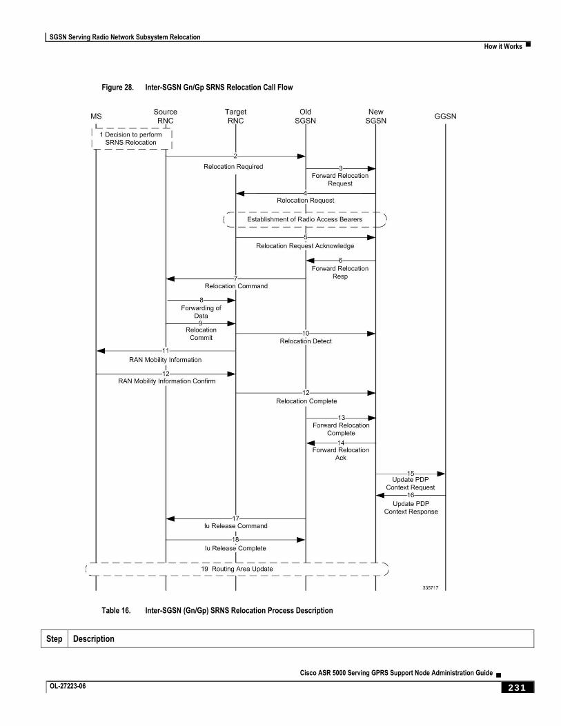
SGSN Serving Radio Network Subsystem Relocation
How it Works ▀
Cisco ASR 5000 Serving GPRS Support Node Administration Guide ▄ OL-27223-06 231
Figure 28. Inter-SGSN Gn/Gp SRNS Relocation Call Flow
Table 16. Inter-SGSN (Gn/Gp) SRNS Relocation Process Description
Step Description
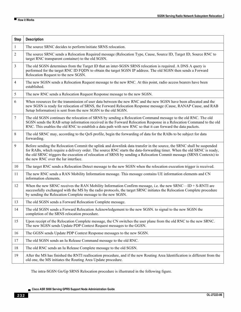
SGSN Serving Radio Network Subsystem Relocation
▀ How it Works
▄ Cisco ASR 5000 Serving GPRS Support Node Administration Guide
232 OL-27223-06
Step Description
1 The source SRNC decides to perform/initiate SRNS relocation.
2 The source SRNC sends a Relocation Required message (Relocation Type, Cause, Source ID, Target ID, Source RNC to target RNC transparent container) to the old SGSN.
3 The old SGSN determines from the Target ID that an inter-SGSN SRNS relocation is required. A DNS A query is performed for the target RNC ID FQDN to obtain the target SGSN IP address. The old SGSN then sends a Forward Relocation Request to the new SGSN.
4 The new SGSN sends a Relocation Request message to the new RNC. At this point, radio access bearers have been established.
5 The new RNC sends a Relocation Request Response message to the new SGSN.
6 When resources for the transmission of user data between the new RNC and the new SGSN have been allocated and the new SGSN is ready for relocation of SRNS, the Forward Relocation Response message (Cause, RANAP Cause, and RAB Setup Information) is sent from the new SGSN to the old SGSN.
7 The old SGSN continues the relocation of SRNS by sending a Relocation Command message to the old RNC. The old SGSN sends the RAB setup information received in the Forward Relocation Response in a Relocation Command to the old RNC. This enables the old RNC to establish a data path with new RNC so that it can forward the data packets.
8 The old SRNC may, according to the QoS profile, begin the forwarding of data for the RABs to be subject for data forwarding.
9 Before sending the Relocation Commit the uplink and downlink data transfer in the source, the SRNC shall be suspended for RABs, which require a delivery order. The source RNC starts the data-forwarding timer. When the old SRNC is ready, the old SRNC triggers the execution of relocation of SRNS by sending a Relocation Commit message (SRNS Contexts) to the new RNC over the Iur interface.
10 The target RNC sends a Relocation Detect message to the new SGSN when the relocation execution trigger is received.
11 The new RNC sends a RAN Mobility Information message. This message contains UE information elements and CN information elements.
12 When the new SRNC receives the RAN Mobility Information Confirm message, i.e. the new SRNC—ID + S-RNTI are successfully exchanged with the MS by the radio protocols, the target SRNC initiates the Relocation Complete procedure by sending the Relocation Complete message to the new SGSN.
13 The old SGSN sends a Forward Relocation Complete message.
14 The old SGSN sends a Forward Relocation Acknowledgement to the new SGSN. to signal to the new SGSN the completion of the SRNS relocation procedure.
15 Upon receipt of the Relocation Complete message, the CN switches the user plane from the old RNC to the new SRNC. The new SGSN sends Update PDP Context Request messages to the GGSN.
16 The GGSN sends Update PDP Context Response messages to the new SGSN.
17 The old SGSN sends an Iu Release Command message to the old RNC.
18 The old RNC sends an Iu Release Complete message to the old SGSN.
19 After the MS has finished the RNTI reallocation procedure, and if the new Routing Area Identification is different from the old one, the MS initiates the Routing Area Update procedure.
The intra-SGSN Gn/Gp SRNS Relocation procedure is illustrated in the following figure.
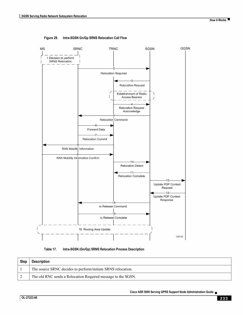
SGSN Serving Radio Network Subsystem Relocation
How it Works ▀
Cisco ASR 5000 Serving GPRS Support Node Administration Guide ▄ OL-27223-06 233
Figure 29. Intra-SGSN Gn/Gp SRNS Relocation Call Flow
Table 17. Intra-SGSN (Gn/Gp) SRNS Relocation Process Description
Step Description
1 The source SRNC decides to perform/initiate SRNS relocation.
2 The old RNC sends a Relocation Required message to the SGSN.
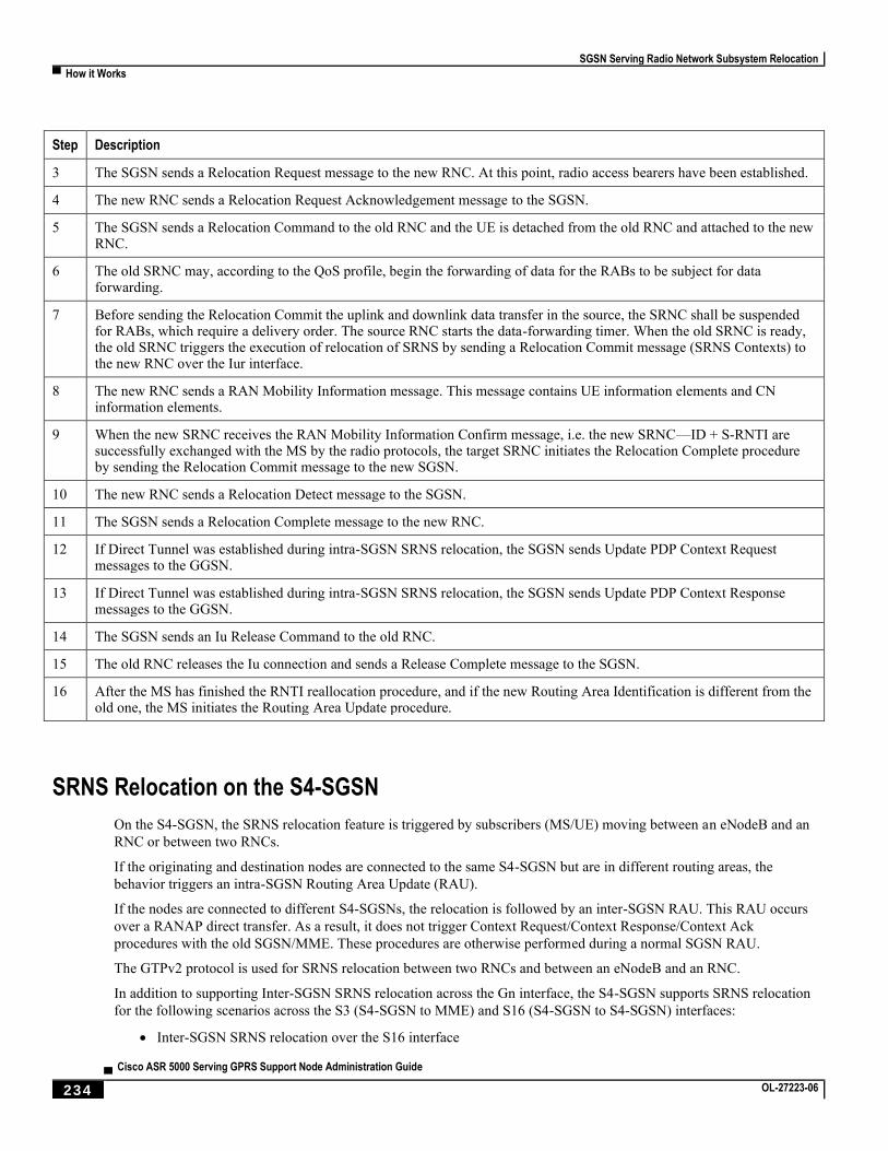
SGSN Serving Radio Network Subsystem Relocation
▀ How it Works
▄ Cisco ASR 5000 Serving GPRS Support Node Administration Guide
234 OL-27223-06
Step Description
3 The SGSN sends a Relocation Request message to the new RNC. At this point, radio access bearers have been established.
4 The new RNC sends a Relocation Request Acknowledgement message to the SGSN.
5 The SGSN sends a Relocation Command to the old RNC and the UE is detached from the old RNC and attached to the new RNC.
6 The old SRNC may, according to the QoS profile, begin the forwarding of data for the RABs to be subject for data forwarding.
7 Before sending the Relocation Commit the uplink and downlink data transfer in the source, the SRNC shall be suspended for RABs, which require a delivery order. The source RNC starts the data-forwarding timer. When the old SRNC is ready, the old SRNC triggers the execution of relocation of SRNS by sending a Relocation Commit message (SRNS Contexts) to the new RNC over the Iur interface.
8 The new RNC sends a RAN Mobility Information message. This message contains UE information elements and CN information elements.
9 When the new SRNC receives the RAN Mobility Information Confirm message, i.e. the new SRNC—ID + S-RNTI are successfully exchanged with the MS by the radio protocols, the target SRNC initiates the Relocation Complete procedure by sending the Relocation Commit message to the new SGSN.
10 The new RNC sends a Relocation Detect message to the SGSN.
11 The SGSN sends a Relocation Complete message to the new RNC.
12 If Direct Tunnel was established during intra-SGSN SRNS relocation, the SGSN sends Update PDP Context Request messages to the GGSN.
13 If Direct Tunnel was established during intra-SGSN SRNS relocation, the SGSN sends Update PDP Context Response messages to the GGSN.
14 The SGSN sends an Iu Release Command to the old RNC.
15 The old RNC releases the Iu connection and sends a Release Complete message to the SGSN.
16 After the MS has finished the RNTI reallocation procedure, and if the new Routing Area Identification is different from the old one, the MS initiates the Routing Area Update procedure.
SRNS Relocation on the S4-SGSN
On the S4-SGSN, the SRNS relocation feature is triggered by subscribers (MS/UE) moving between an eNodeB and an
RNC or between two RNCs.
If the originating and destination nodes are connected to the same S4-SGSN but are in different routing areas, the
behavior triggers an intra-SGSN Routing Area Update (RAU).
If the nodes are connected to different S4-SGSNs, the relocation is followed by an inter-SGSN RAU. This RAU occurs
over a RANAP direct transfer. As a result, it does not trigger Context Request/Context Response/Context Ack
procedures with the old SGSN/MME. These procedures are otherwise performed during a normal SGSN RAU.
The GTPv2 protocol is used for SRNS relocation between two RNCs and between an eNodeB and an RNC.
In addition to supporting Inter-SGSN SRNS relocation across the Gn interface, the S4-SGSN supports SRNS relocation
for the following scenarios across the S3 (S4-SGSN to MME) and S16 (S4-SGSN to S4-SGSN) interfaces:
Inter-SGSN SRNS relocation over the S16 interface
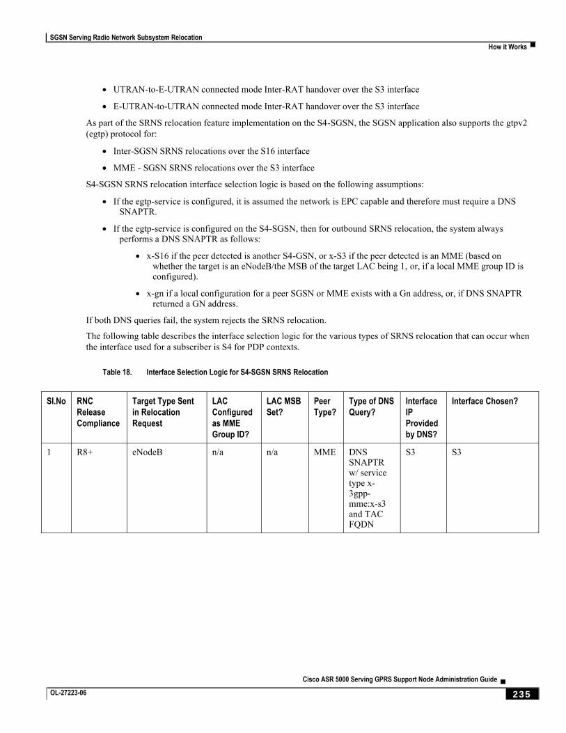
SGSN Serving Radio Network Subsystem Relocation
How it Works ▀
Cisco ASR 5000 Serving GPRS Support Node Administration Guide ▄ OL-27223-06 235
UTRAN-to-E-UTRAN connected mode Inter-RAT handover over the S3 interface
E-UTRAN-to-UTRAN connected mode Inter-RAT handover over the S3 interface
As part of the SRNS relocation feature implementation on the S4-SGSN, the SGSN application also supports the gtpv2
(egtp) protocol for:
Inter-SGSN SRNS relocations over the S16 interface
MME - SGSN SRNS relocations over the S3 interface
S4-SGSN SRNS relocation interface selection logic is based on the following assumptions:
If the egtp-service is configured, it is assumed the network is EPC capable and therefore must require a DNS SNAPTR.
If the egtp-service is configured on the S4-SGSN, then for outbound SRNS relocation, the system always performs a DNS SNAPTR as follows:
x-S16 if the peer detected is another S4-GSN, or x-S3 if the peer detected is an MME (based on whether the target is an eNodeB/the MSB of the target LAC being 1, or, if a local MME group ID is configured).
x-gn if a local configuration for a peer SGSN or MME exists with a Gn address, or, if DNS SNAPTR returned a GN address.
If both DNS queries fail, the system rejects the SRNS relocation.
The following table describes the interface selection logic for the various types of SRNS relocation that can occur when
the interface used for a subscriber is S4 for PDP contexts.
Table 18. Interface Selection Logic for S4-SGSN SRNS Relocation
SI.No RNC
Release
Compliance
Target Type Sent
in Relocation
Request
LAC
Configured
as MME
Group ID?
LAC MSB
Set?
Peer
Type?
Type of DNS
Query?
Interface
IP
Provided
by DNS?
Interface Chosen?
1 R8+ eNodeB n/a n/a MME DNS SNAPTR w/ service type x-3gpp-mme:x-s3 and TAC FQDN
S3 S3
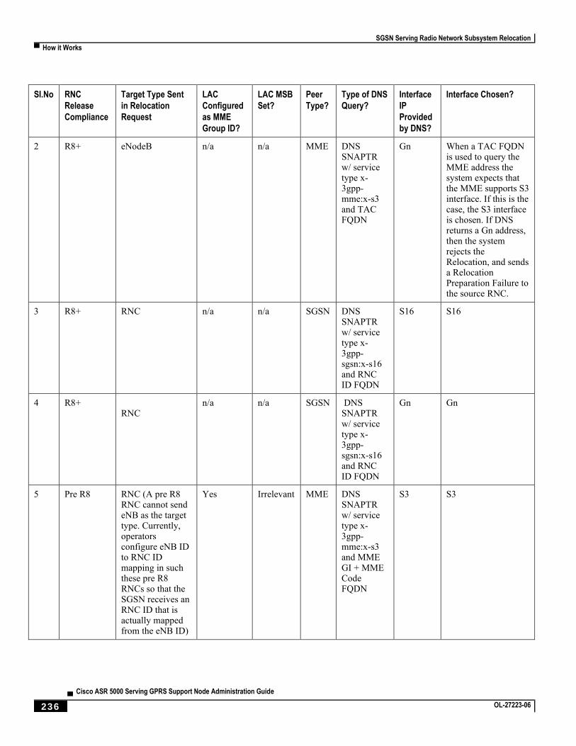
SGSN Serving Radio Network Subsystem Relocation
▀ How it Works
▄ Cisco ASR 5000 Serving GPRS Support Node Administration Guide
236 OL-27223-06
SI.No RNC
Release
Compliance
Target Type Sent
in Relocation
Request
LAC
Configured
as MME
Group ID?
LAC MSB
Set?
Peer
Type?
Type of DNS
Query?
Interface
IP
Provided
by DNS?
Interface Chosen?
2 R8+ eNodeB n/a n/a MME DNS SNAPTR w/ service type x-3gpp-mme:x-s3 and TAC FQDN
Gn When a TAC FQDN is used to query the MME address the system expects that the MME supports S3 interface. If this is the case, the S3 interface is chosen. If DNS returns a Gn address, then the system rejects the Relocation, and sends a Relocation Preparation Failure to the source RNC.
3 R8+ RNC n/a n/a SGSN DNS SNAPTR w/ service type x-3gpp-sgsn:x-s16 and RNC ID FQDN
S16 S16
4 R8+ RNC
n/a n/a SGSN DNS SNAPTR w/ service type x-3gpp-sgsn:x-s16 and RNC ID FQDN
Gn Gn
5 Pre R8 RNC (A pre R8 RNC cannot send eNB as the target type. Currently, operators configure eNB ID to RNC ID mapping in such these pre R8 RNCs so that the SGSN receives an RNC ID that is actually mapped from the eNB ID)
Yes Irrelevant MME DNS SNAPTR w/ service type x-3gpp-mme:x-s3 and MME GI + MME Code FQDN
S3 S3
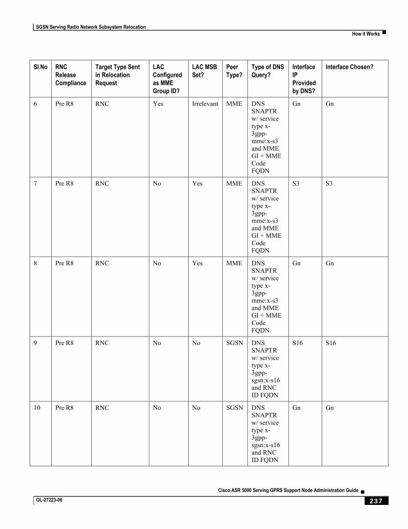
SGSN Serving Radio Network Subsystem Relocation
How it Works ▀
Cisco ASR 5000 Serving GPRS Support Node Administration Guide ▄ OL-27223-06 237
SI.No RNC
Release
Compliance
Target Type Sent
in Relocation
Request
LAC
Configured
as MME
Group ID?
LAC MSB
Set?
Peer
Type?
Type of DNS
Query?
Interface
IP
Provided
by DNS?
Interface Chosen?
6 Pre R8 RNC Yes Irrelevant MME DNS SNAPTR w/ service type x-3gpp-mme:x-s3 and MME GI + MME Code FQDN
Gn Gn
7 Pre R8 RNC No Yes MME DNS SNAPTR w/ service type x-3gpp-mme:x-s3 and MME GI + MME Code FQDN
S3 S3
8 Pre R8 RNC No Yes MME DNS SNAPTR w/ service type x-3gpp-mme:x-s3 and MME GI + MME Code FQDN
Gn Gn
9 Pre R8 RNC No No SGSN DNS SNAPTR w/ service type x-3gpp-sgsn:x-s16 and RNC ID FQDN
S16 S16
10 Pre R8 RNC No No SGSN DNS SNAPTR w/ service type x-3gpp-sgsn:x-s16 and RNC ID FQDN
Gn Gn
SGSN Serving Radio Network Subsystem Relocation
▀ How it Works
▄ Cisco ASR 5000 Serving GPRS Support Node Administration Guide
238 OL-27223-06
IDFT Support During Connected Mode Handovers
The S4-SGSN supports the setup of indirect data forwarding tunnels (IDFT) between the eNodeB and the RNC via the
SGW during connected mode handovers.
Once enabled, IDFT is employed under the following conditions:
If the SGSN is the old node:
The target node to which the connected mode handover is initiated should be an eNodeB (i.e., the SGSN performs the handover to the MME).
The enb-direct-data-forward CLI setting is not configured as the source RNC configuration (in
RNC Configuration Mode).
If the SGSN is the new node:
The source node from which connected mode handover is initiated is an eNodeB (i.e., the MME is performing a handover to the SGSN).
The enb-direct-data-forward setting is not configured in the source RNC configuration (in RNC
Configuration Mode).
The source MME indicated that it does not support direct forwarding via a Forward Relocation Request.
Important: If the target SGSN did not relocate to a new SGW, IDFT setup does not apply at the SGSN. The
target SGSN sets up an indirect data forwarding tunnel with the SGW only if the SGW is relocated. If the SGW is not relocated, then it is the source MME that sets up the indirect data forwarding tunnel between source the eNodeB and target RNC through the SGW.
The following diagram illustrates the interface selection logic for S4-SGSN connected mode handovers.
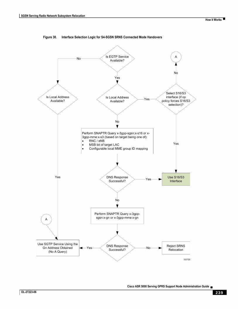
SGSN Serving Radio Network Subsystem Relocation
How it Works ▀
Cisco ASR 5000 Serving GPRS Support Node Administration Guide ▄ OL-27223-06 239
Figure 30. Interface Selection Logic for S4-SGSN SRNS Connected Mode Handovers
SGSN Serving Radio Network Subsystem Relocation
▀ How it Works
▄ Cisco ASR 5000 Serving GPRS Support Node Administration Guide
240 OL-27223-06
S4-SGSN SRNS Relocation Call Flow Diagrams
This section provides call flow diagrams for the following S4-SGSN SRNS relocation scenarios:
Inter-S4-SGSN SRNS Relocation without SGW Relocation
Inter-S4-SGSN Relocation with SGW Relocation
Intra-S4-SGSN SRNS Relocation without SGW Relocation
Inter-S4-SGSN Relocation with SGW Relocation
S4-SGSN E-UTRAN to UTRAN Connected Mode Handover without SGW Relocation
S4-SGSN UTRAN to E-UTRAN Connected Mode Handover with SGW Relocation Call Flow
S4-SGSN Inter-SGSN SRNS Relocation with Hard Handover and SGW Relocation
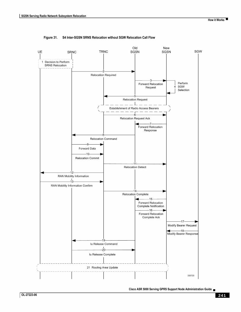
SGSN Serving Radio Network Subsystem Relocation
How it Works ▀
Cisco ASR 5000 Serving GPRS Support Node Administration Guide ▄ OL-27223-06 241
Figure 31. S4 Inter-SGSN SRNS Relocation without SGW Relocation Call Flow
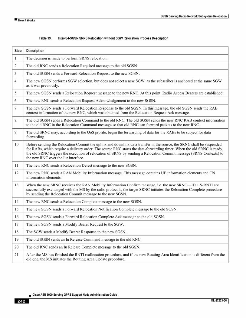
SGSN Serving Radio Network Subsystem Relocation
▀ How it Works
▄ Cisco ASR 5000 Serving GPRS Support Node Administration Guide
242 OL-27223-06
Table 19. Inter-S4-SGSN SRNS Relocation without SGW Relocation Process Description
Step Description
1 The decision is made to perform SRNS relocation.
2 The old RNC sends a Relocation Required message to the old SGSN.
3 The old SGSN sends a Forward Relocation Request to the new SGSN.
4 The new SGSN performs SGW selection, but does not select a new SGW, as the subscriber is anchored at the same SGW as it was previously.
5 The new SGSN sends a Relocation Request message to the new RNC. At this point, Radio Access Bearers are established.
6 The new RNC sends a Relocation Request Acknowledgement to the new SGSN.
7 The new SGSN sends a Forward Relocation Response to the old SGSN. In this message, the old SGSN sends the RAB context information of the new RNC, which was obtained from the Relocation Request Ack message.
8 The old SGSN sends a Relocation Command to the old RNC. The old SGSN sends the new RNC RAB context information to the old RNC in the Relocation Command message so that old RNC can forward packets to the new RNC.
9 The old SRNC may, according to the QoS profile, begin the forwarding of data for the RABs to be subject for data forwarding.
10 Before sending the Relocation Commit the uplink and downlink data transfer in the source, the SRNC shall be suspended for RABs, which require a delivery order. The source RNC starts the data-forwarding timer. When the old SRNC is ready, the old SRNC triggers the execution of relocation of SRNS by sending a Relocation Commit message (SRNS Contexts) to the new RNC over the Iur interface.
11 The new RNC sends a Relocation Detect message to the new SGSN.
12 The new RNC sends a RAN Mobility Information message. This message contains UE information elements and CN information elements.
13 When the new SRNC receives the RAN Mobility Information Confirm message, i.e. the new SRNC—ID + S-RNTI are successfully exchanged with the MS by the radio protocols, the target SRNC initiates the Relocation Complete procedure by sending the Relocation Commit message to the new SGSN.
14 The new RNC sends a Relocation Complete message to the new SGSN.
15 The new SGSN sends a Forward Relocation Notification Complete message to the old SGSN.
16 The new SGSN sends a Forward Relocation Complete Ack message to the old SGSN.
17 The new SGSN sends a Modify Bearer Request to the SGW.
18 The SGW sends a Modify Bearer Response to the new SGSN.
19 The old SGSN sends an Iu Release Command message to the old RNC.
20 The old RNC sends an Iu Release Complete message to the old SGSN.
21 After the MS has finished the RNTI reallocation procedure, and if the new Routing Area Identification is different from the old one, the MS initiates the Routing Area Update procedure.

SGSN Serving Radio Network Subsystem Relocation
How it Works ▀
Cisco ASR 5000 Serving GPRS Support Node Administration Guide ▄ OL-27223-06 243
Figure 32. Inter-S4-SGSN Relocation with SGW Relocation
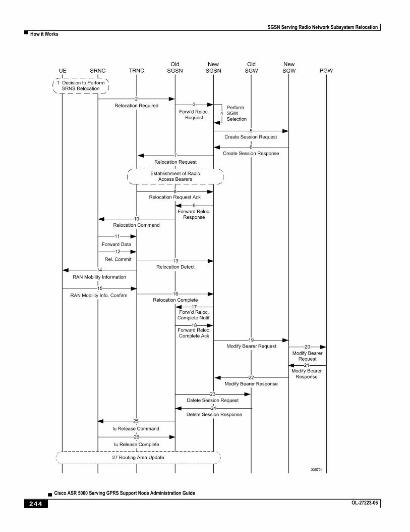
SGSN Serving Radio Network Subsystem Relocation
▀ How it Works
▄ Cisco ASR 5000 Serving GPRS Support Node Administration Guide
244 OL-27223-06
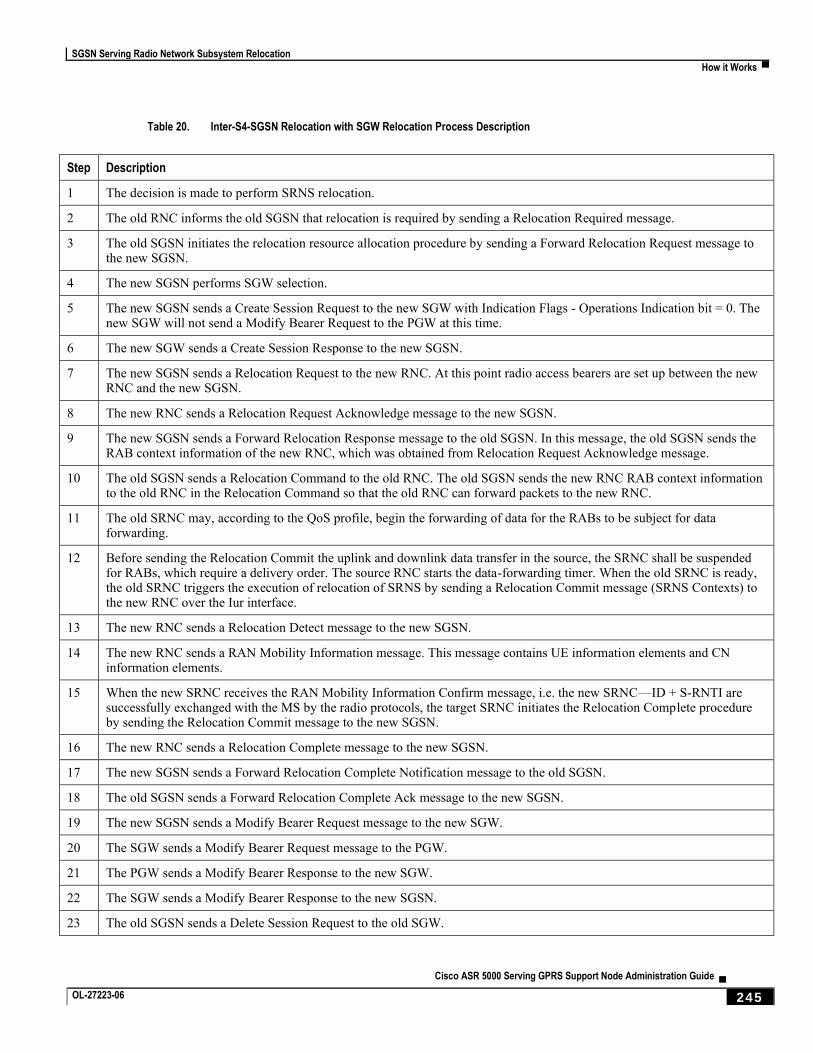
SGSN Serving Radio Network Subsystem Relocation
How it Works ▀
Cisco ASR 5000 Serving GPRS Support Node Administration Guide ▄ OL-27223-06 245
Table 20. Inter-S4-SGSN Relocation with SGW Relocation Process Description
Step Description
1 The decision is made to perform SRNS relocation.
2 The old RNC informs the old SGSN that relocation is required by sending a Relocation Required message.
3 The old SGSN initiates the relocation resource allocation procedure by sending a Forward Relocation Request message to the new SGSN.
4 The new SGSN performs SGW selection.
5 The new SGSN sends a Create Session Request to the new SGW with Indication Flags - Operations Indication bit = 0. The new SGW will not send a Modify Bearer Request to the PGW at this time.
6 The new SGW sends a Create Session Response to the new SGSN.
7 The new SGSN sends a Relocation Request to the new RNC. At this point radio access bearers are set up between the new RNC and the new SGSN.
8 The new RNC sends a Relocation Request Acknowledge message to the new SGSN.
9 The new SGSN sends a Forward Relocation Response message to the old SGSN. In this message, the old SGSN sends the RAB context information of the new RNC, which was obtained from Relocation Request Acknowledge message.
10 The old SGSN sends a Relocation Command to the old RNC. The old SGSN sends the new RNC RAB context information to the old RNC in the Relocation Command so that the old RNC can forward packets to the new RNC.
11 The old SRNC may, according to the QoS profile, begin the forwarding of data for the RABs to be subject for data forwarding.
12 Before sending the Relocation Commit the uplink and downlink data transfer in the source, the SRNC shall be suspended for RABs, which require a delivery order. The source RNC starts the data-forwarding timer. When the old SRNC is ready, the old SRNC triggers the execution of relocation of SRNS by sending a Relocation Commit message (SRNS Contexts) to the new RNC over the Iur interface.
13 The new RNC sends a Relocation Detect message to the new SGSN.
14 The new RNC sends a RAN Mobility Information message. This message contains UE information elements and CN information elements.
15 When the new SRNC receives the RAN Mobility Information Confirm message, i.e. the new SRNC—ID + S-RNTI are successfully exchanged with the MS by the radio protocols, the target SRNC initiates the Relocation Complete procedure by sending the Relocation Commit message to the new SGSN.
16 The new RNC sends a Relocation Complete message to the new SGSN.
17 The new SGSN sends a Forward Relocation Complete Notification message to the old SGSN.
18 The old SGSN sends a Forward Relocation Complete Ack message to the new SGSN.
19 The new SGSN sends a Modify Bearer Request message to the new SGW.
20 The SGW sends a Modify Bearer Request message to the PGW.
21 The PGW sends a Modify Bearer Response to the new SGW.
22 The SGW sends a Modify Bearer Response to the new SGSN.
23 The old SGSN sends a Delete Session Request to the old SGW.
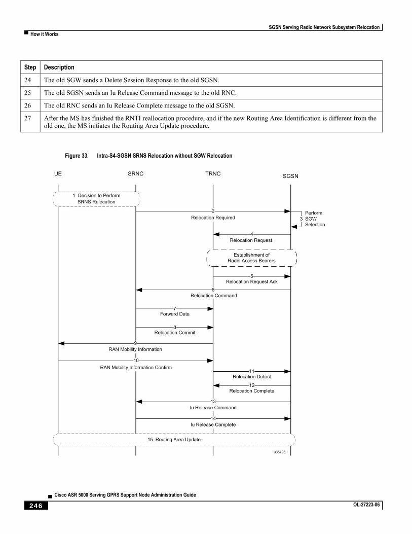
SGSN Serving Radio Network Subsystem Relocation
▀ How it Works
▄ Cisco ASR 5000 Serving GPRS Support Node Administration Guide
246 OL-27223-06
Step Description
24 The old SGW sends a Delete Session Response to the old SGSN.
25 The old SGSN sends an Iu Release Command message to the old RNC.
26 The old RNC sends an Iu Release Complete message to the old SGSN.
27 After the MS has finished the RNTI reallocation procedure, and if the new Routing Area Identification is different from the old one, the MS initiates the Routing Area Update procedure.
Figure 33. Intra-S4-SGSN SRNS Relocation without SGW Relocation
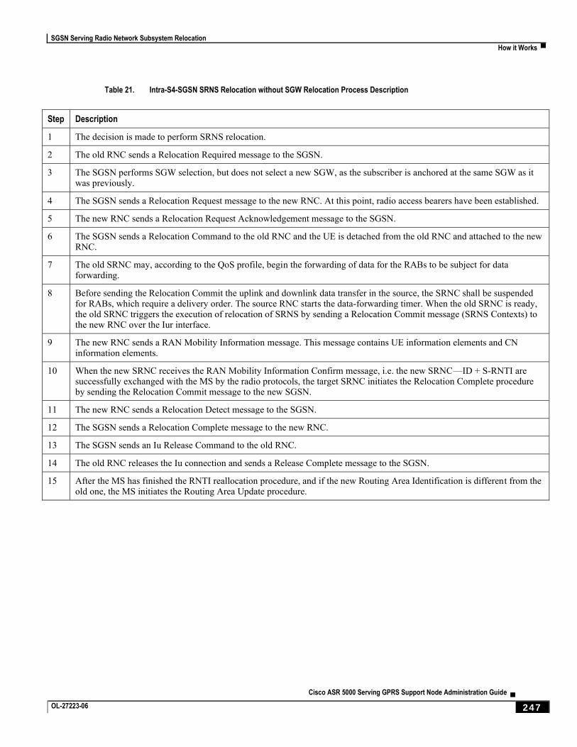
SGSN Serving Radio Network Subsystem Relocation
How it Works ▀
Cisco ASR 5000 Serving GPRS Support Node Administration Guide ▄ OL-27223-06 247
Table 21. Intra-S4-SGSN SRNS Relocation without SGW Relocation Process Description
Step Description
1 The decision is made to perform SRNS relocation.
2 The old RNC sends a Relocation Required message to the SGSN.
3 The SGSN performs SGW selection, but does not select a new SGW, as the subscriber is anchored at the same SGW as it was previously.
4 The SGSN sends a Relocation Request message to the new RNC. At this point, radio access bearers have been established.
5 The new RNC sends a Relocation Request Acknowledgement message to the SGSN.
6 The SGSN sends a Relocation Command to the old RNC and the UE is detached from the old RNC and attached to the new RNC.
7 The old SRNC may, according to the QoS profile, begin the forwarding of data for the RABs to be subject for data forwarding.
8 Before sending the Relocation Commit the uplink and downlink data transfer in the source, the SRNC shall be suspended for RABs, which require a delivery order. The source RNC starts the data-forwarding timer. When the old SRNC is ready, the old SRNC triggers the execution of relocation of SRNS by sending a Relocation Commit message (SRNS Contexts) to the new RNC over the Iur interface.
9 The new RNC sends a RAN Mobility Information message. This message contains UE information elements and CN information elements.
10 When the new SRNC receives the RAN Mobility Information Confirm message, i.e. the new SRNC—ID + S-RNTI are successfully exchanged with the MS by the radio protocols, the target SRNC initiates the Relocation Complete procedure by sending the Relocation Commit message to the new SGSN.
11 The new RNC sends a Relocation Detect message to the SGSN.
12 The SGSN sends a Relocation Complete message to the new RNC.
13 The SGSN sends an Iu Release Command to the old RNC.
14 The old RNC releases the Iu connection and sends a Release Complete message to the SGSN.
15 After the MS has finished the RNTI reallocation procedure, and if the new Routing Area Identification is different from the old one, the MS initiates the Routing Area Update procedure.
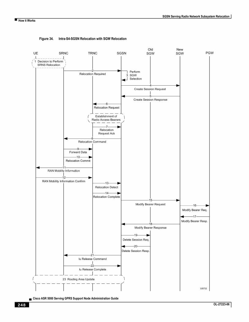
SGSN Serving Radio Network Subsystem Relocation
▀ How it Works
▄ Cisco ASR 5000 Serving GPRS Support Node Administration Guide
248 OL-27223-06
Figure 34. Intra-S4-SGSN Relocation with SGW Relocation
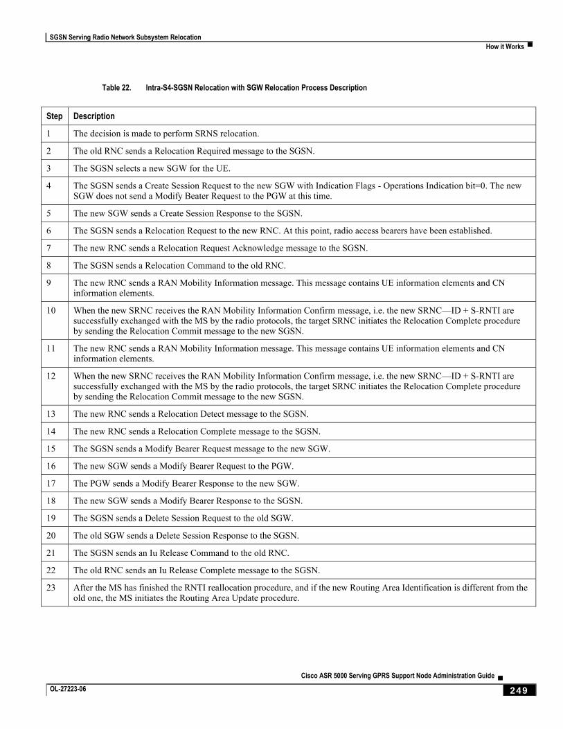
SGSN Serving Radio Network Subsystem Relocation
How it Works ▀
Cisco ASR 5000 Serving GPRS Support Node Administration Guide ▄ OL-27223-06 249
Table 22. Intra-S4-SGSN Relocation with SGW Relocation Process Description
Step Description
1 The decision is made to perform SRNS relocation.
2 The old RNC sends a Relocation Required message to the SGSN.
3 The SGSN selects a new SGW for the UE.
4 The SGSN sends a Create Session Request to the new SGW with Indication Flags - Operations Indication bit=0. The new SGW does not send a Modify Beater Request to the PGW at this time.
5 The new SGW sends a Create Session Response to the SGSN.
6 The SGSN sends a Relocation Request to the new RNC. At this point, radio access bearers have been established.
7 The new RNC sends a Relocation Request Acknowledge message to the SGSN.
8 The SGSN sends a Relocation Command to the old RNC.
9 The new RNC sends a RAN Mobility Information message. This message contains UE information elements and CN information elements.
10 When the new SRNC receives the RAN Mobility Information Confirm message, i.e. the new SRNC—ID + S-RNTI are successfully exchanged with the MS by the radio protocols, the target SRNC initiates the Relocation Complete procedure by sending the Relocation Commit message to the new SGSN.
11 The new RNC sends a RAN Mobility Information message. This message contains UE information elements and CN information elements.
12 When the new SRNC receives the RAN Mobility Information Confirm message, i.e. the new SRNC—ID + S-RNTI are successfully exchanged with the MS by the radio protocols, the target SRNC initiates the Relocation Complete procedure by sending the Relocation Commit message to the new SGSN.
13 The new RNC sends a Relocation Detect message to the SGSN.
14 The new RNC sends a Relocation Complete message to the SGSN.
15 The SGSN sends a Modify Bearer Request message to the new SGW.
16 The new SGW sends a Modify Bearer Request to the PGW.
17 The PGW sends a Modify Bearer Response to the new SGW.
18 The new SGW sends a Modify Bearer Response to the SGSN.
19 The SGSN sends a Delete Session Request to the old SGW.
20 The old SGW sends a Delete Session Response to the SGSN.
21 The SGSN sends an Iu Release Command to the old RNC.
22 The old RNC sends an Iu Release Complete message to the SGSN.
23 After the MS has finished the RNTI reallocation procedure, and if the new Routing Area Identification is different from the old one, the MS initiates the Routing Area Update procedure.
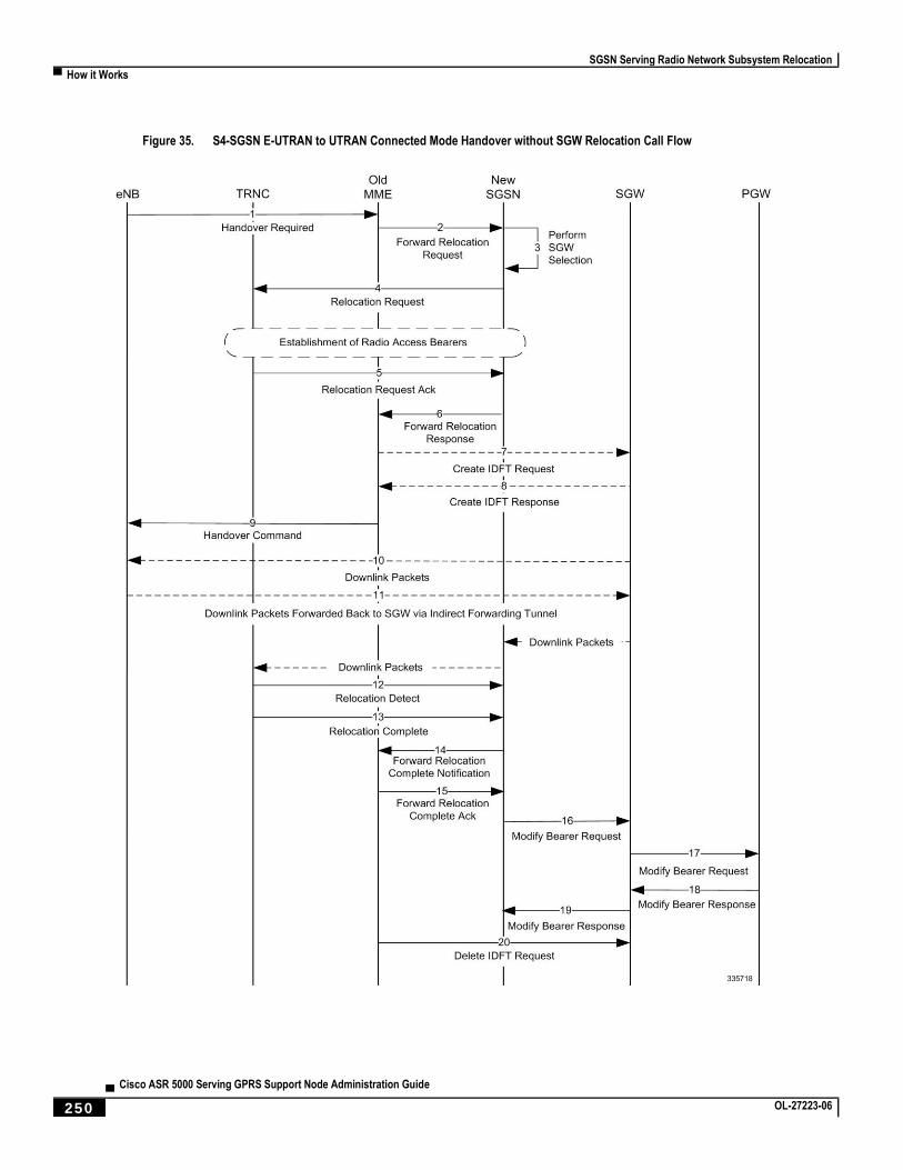
SGSN Serving Radio Network Subsystem Relocation
▀ How it Works
▄ Cisco ASR 5000 Serving GPRS Support Node Administration Guide
250 OL-27223-06
Figure 35. S4-SGSN E-UTRAN to UTRAN Connected Mode Handover without SGW Relocation Call Flow
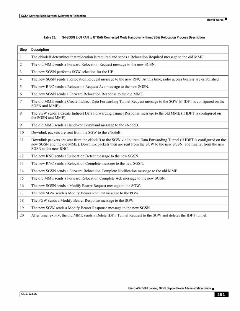
SGSN Serving Radio Network Subsystem Relocation
How it Works ▀
Cisco ASR 5000 Serving GPRS Support Node Administration Guide ▄ OL-27223-06 251
Table 23. S4-SGSN E-UTRAN to UTRAN Connected Mode Handover without SGW Relocation Process Description
Step Description
1 The eNodeB determines that relocation is required and sends a Relocation Required message to the old MME.
2 The old MME sends a Forward Relocation Request message to the new SGSN.
3 The new SGSN performs SGW selection for the UE.
4 The new SGSN sends a Relocation Request message to the new RNC. At this time, radio access bearers are established.
5 The new RNC sends a Relocation Request Ack message to the new SGSN.
6 The new SGSN sends a Forward Relocation Response to the old MME.
7 The old MME sends a Create Indirect Data Forwarding Tunnel Request message to the SGW (if IDFT is configured on the SGSN and MME).
8 The SGW sends a Create Indirect Data Forwarding Tunnel Response message to the old MME (if IDFT is configured on the SGSN and MME).
9 The old MME sends a Handover Command message to the eNodeB.
10 Downlink packets are sent from the SGW to the eNodeB.
11 Downlink packets are sent from the eNodeB to the SGW via Indirect Data Forwarding Tunnel (if IDFT is configured on the new SGSN and the old MME). Downlink packets then are sent from the SGW to the new SGSN, and finally, from the new SGSN to the new RNC.
12 The new RNC sends a Relocation Detect message to the new SGSN.
13 The new RNC sends a Relocation Complete message to the new SGSN.
14 The new SGSN sends a Forward Relocation Complete Notification message to the old MME.
15 The old MME sends a Forward Relocation Complete Ack message to the new SGSN.
16 The new SGSN sends a Modify Bearer Request message to the SGW.
17 The new SGW sends a Modify Bearer Request message to the PGW.
18 The PGW sends a Modify Bearer Response message to the SGW.
19 The new SGW sends a Modify Bearer Response message to the new SGSN.
20 After timer expiry, the old MME sends a Delete IDFT Tunnel Request to the SGW and deletes the IDFT tunnel.
SGSN Serving Radio Network Subsystem Relocation
▀ How it Works
▄ Cisco ASR 5000 Serving GPRS Support Node Administration Guide
252 OL-27223-06
Figure 36. S4-SGSN UTRAN to E-UTRAN Connected Mode Handover with SGW Relocation Call Flow
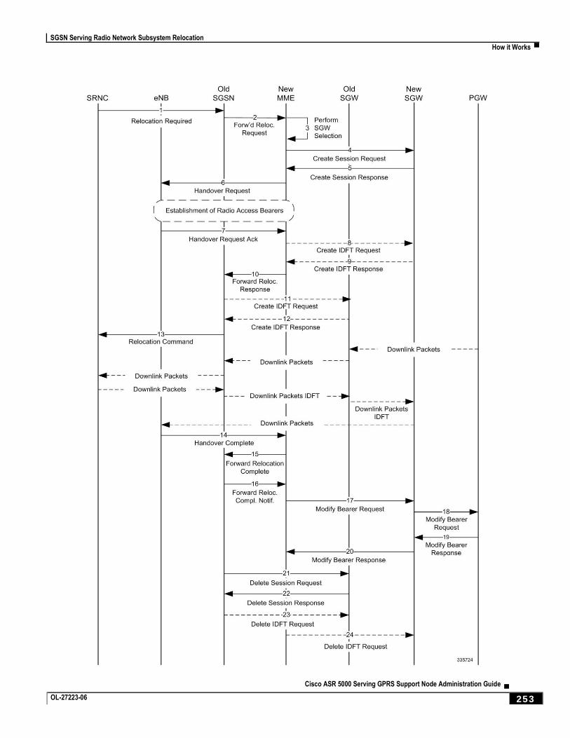
SGSN Serving Radio Network Subsystem Relocation
How it Works ▀
Cisco ASR 5000 Serving GPRS Support Node Administration Guide ▄ OL-27223-06 253
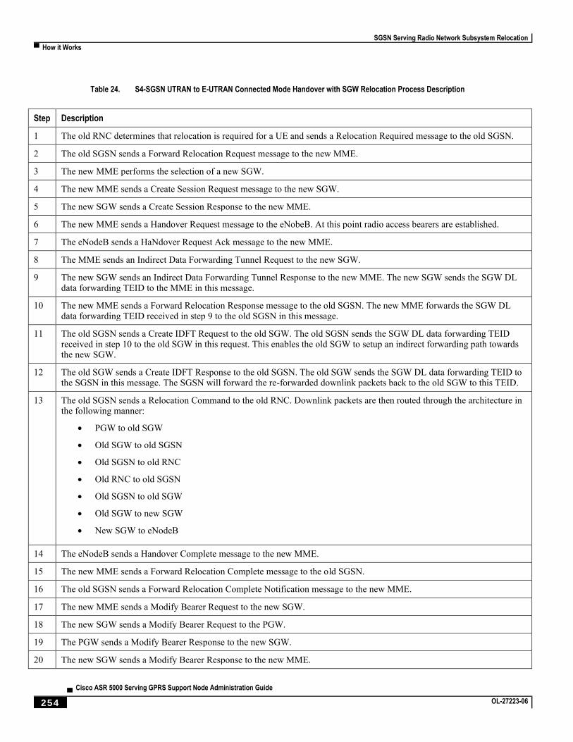
SGSN Serving Radio Network Subsystem Relocation
▀ How it Works
▄ Cisco ASR 5000 Serving GPRS Support Node Administration Guide
254 OL-27223-06
Table 24. S4-SGSN UTRAN to E-UTRAN Connected Mode Handover with SGW Relocation Process Description
Step Description
1 The old RNC determines that relocation is required for a UE and sends a Relocation Required message to the old SGSN.
2 The old SGSN sends a Forward Relocation Request message to the new MME.
3 The new MME performs the selection of a new SGW.
4 The new MME sends a Create Session Request message to the new SGW.
5 The new SGW sends a Create Session Response to the new MME.
6 The new MME sends a Handover Request message to the eNobeB. At this point radio access bearers are established.
7 The eNodeB sends a HaNdover Request Ack message to the new MME.
8 The MME sends an Indirect Data Forwarding Tunnel Request to the new SGW.
9 The new SGW sends an Indirect Data Forwarding Tunnel Response to the new MME. The new SGW sends the SGW DL data forwarding TEID to the MME in this message.
10 The new MME sends a Forward Relocation Response message to the old SGSN. The new MME forwards the SGW DL data forwarding TEID received in step 9 to the old SGSN in this message.
11 The old SGSN sends a Create IDFT Request to the old SGW. The old SGSN sends the SGW DL data forwarding TEID received in step 10 to the old SGW in this request. This enables the old SGW to setup an indirect forwarding path towards the new SGW.
12 The old SGW sends a Create IDFT Response to the old SGSN. The old SGW sends the SGW DL data forwarding TEID to the SGSN in this message. The SGSN will forward the re-forwarded downlink packets back to the old SGW to this TEID.
13 The old SGSN sends a Relocation Command to the old RNC. Downlink packets are then routed through the architecture in the following manner:
PGW to old SGW
Old SGW to old SGSN
Old SGSN to old RNC
Old RNC to old SGSN
Old SGSN to old SGW
Old SGW to new SGW
New SGW to eNodeB
14 The eNodeB sends a Handover Complete message to the new MME.
15 The new MME sends a Forward Relocation Complete message to the old SGSN.
16 The old SGSN sends a Forward Relocation Complete Notification message to the new MME.
17 The new MME sends a Modify Bearer Request to the new SGW.
18 The new SGW sends a Modify Bearer Request to the PGW.
19 The PGW sends a Modify Bearer Response to the new SGW.
20 The new SGW sends a Modify Bearer Response to the new MME.
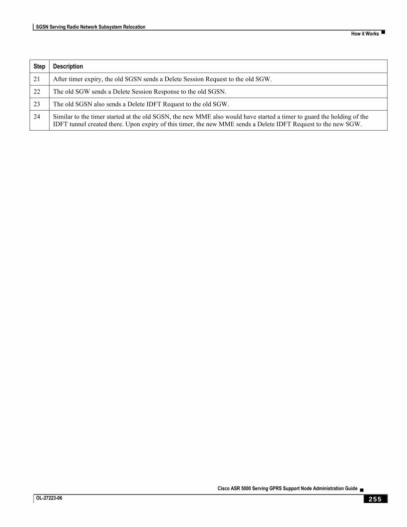
SGSN Serving Radio Network Subsystem Relocation
How it Works ▀
Cisco ASR 5000 Serving GPRS Support Node Administration Guide ▄ OL-27223-06 255
Step Description
21 After timer expiry, the old SGSN sends a Delete Session Request to the old SGW.
22 The old SGW sends a Delete Session Response to the old SGSN.
23 The old SGSN also sends a Delete IDFT Request to the old SGW.
24 Similar to the timer started at the old SGSN, the new MME also would have started a timer to guard the holding of the IDFT tunnel created there. Upon expiry of this timer, the new MME sends a Delete IDFT Request to the new SGW.
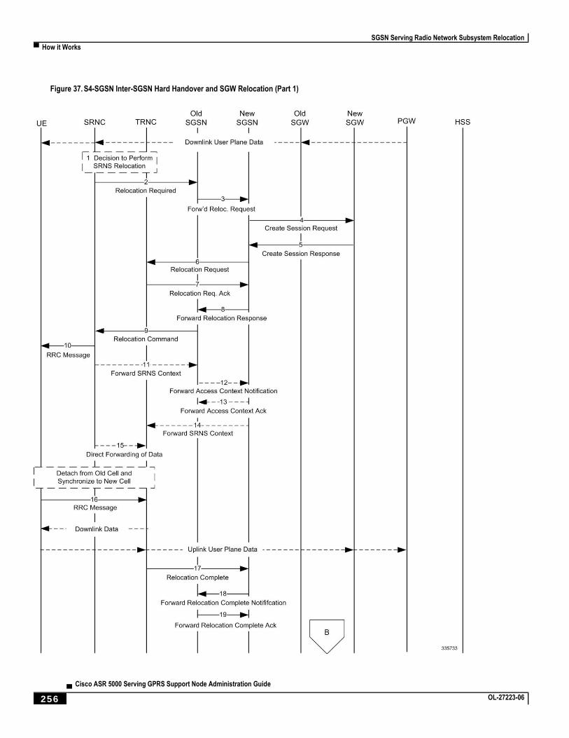
SGSN Serving Radio Network Subsystem Relocation
▀ How it Works
▄ Cisco ASR 5000 Serving GPRS Support Node Administration Guide
256 OL-27223-06
Figure 37. S4-SGSN Inter-SGSN Hard Handover and SGW Relocation (Part 1)
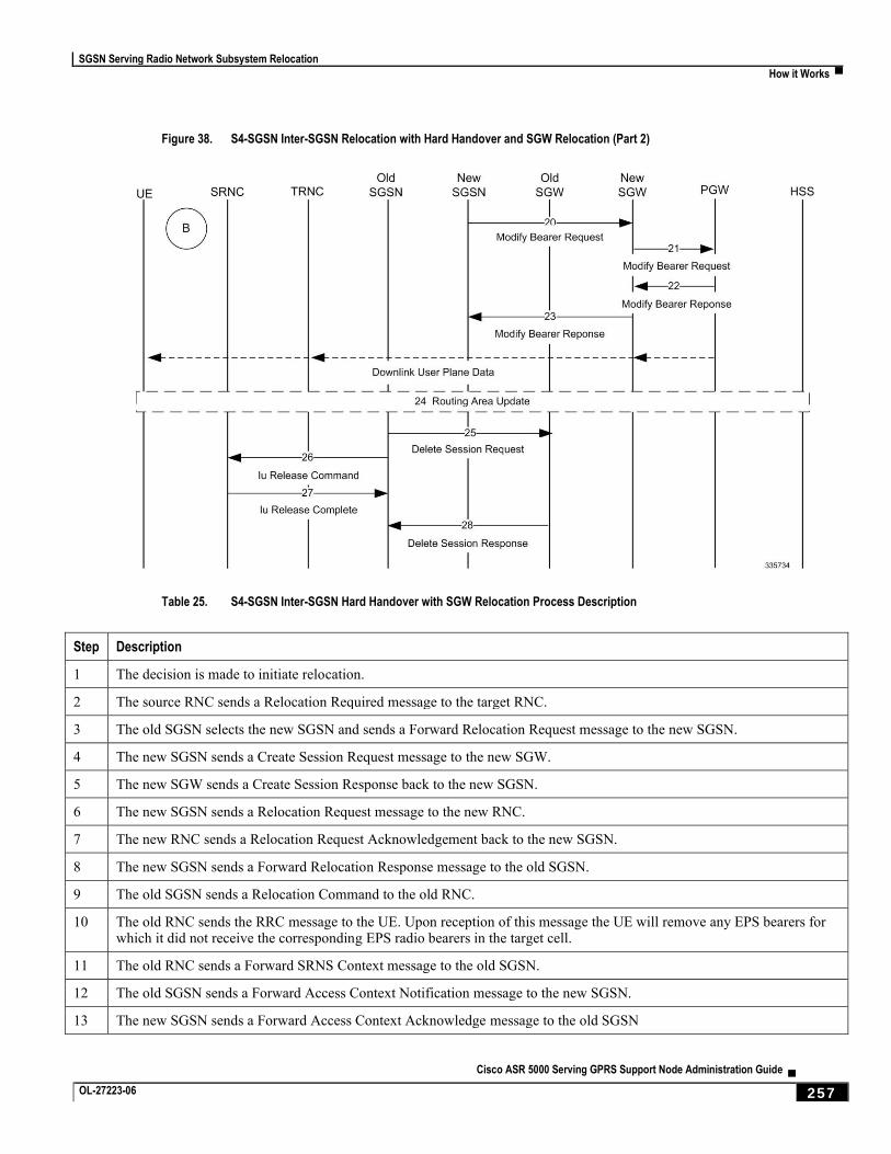
SGSN Serving Radio Network Subsystem Relocation
How it Works ▀
Cisco ASR 5000 Serving GPRS Support Node Administration Guide ▄ OL-27223-06 257
Figure 38. S4-SGSN Inter-SGSN Relocation with Hard Handover and SGW Relocation (Part 2)
Table 25. S4-SGSN Inter-SGSN Hard Handover with SGW Relocation Process Description
Step Description
1 The decision is made to initiate relocation.
2 The source RNC sends a Relocation Required message to the target RNC.
3 The old SGSN selects the new SGSN and sends a Forward Relocation Request message to the new SGSN.
4 The new SGSN sends a Create Session Request message to the new SGW.
5 The new SGW sends a Create Session Response back to the new SGSN.
6 The new SGSN sends a Relocation Request message to the new RNC.
7 The new RNC sends a Relocation Request Acknowledgement back to the new SGSN.
8 The new SGSN sends a Forward Relocation Response message to the old SGSN.
9 The old SGSN sends a Relocation Command to the old RNC.
10 The old RNC sends the RRC message to the UE. Upon reception of this message the UE will remove any EPS bearers for which it did not receive the corresponding EPS radio bearers in the target cell.
11 The old RNC sends a Forward SRNS Context message to the old SGSN.
12 The old SGSN sends a Forward Access Context Notification message to the new SGSN.
13 The new SGSN sends a Forward Access Context Acknowledge message to the old SGSN
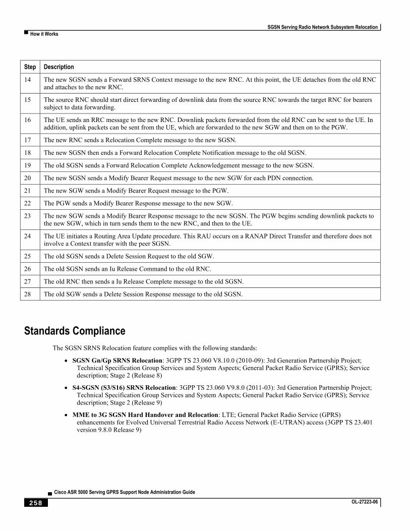
SGSN Serving Radio Network Subsystem Relocation
▀ How it Works
▄ Cisco ASR 5000 Serving GPRS Support Node Administration Guide
258 OL-27223-06
Step Description
14 The new SGSN sends a Forward SRNS Context message to the new RNC. At this point, the UE detaches from the old RNC and attaches to the new RNC.
15 The source RNC should start direct forwarding of downlink data from the source RNC towards the target RNC for bearers subject to data forwarding.
16 The UE sends an RRC message to the new RNC. Downlink packets forwarded from the old RNC can be sent to the UE. In addition, uplink packets can be sent from the UE, which are forwarded to the new SGW and then on to the PGW.
17 The new RNC sends a Relocation Complete message to the new SGSN.
18 The new SGSN then ends a Forward Relocation Complete Notification message to the old SGSN.
19 The old SGSN sends a Forward Relocation Complete Acknowledgement message to the new SGSN.
20 The new SGSN sends a Modify Bearer Request message to the new SGW for each PDN connection.
21 The new SGW sends a Modify Bearer Request message to the PGW.
22 The PGW sends a Modify Bearer Response message to the new SGW.
23 The new SGW sends a Modify Bearer Response message to the new SGSN. The PGW begins sending downlink packets to the new SGW, which in turn sends them to the new RNC, and then to the UE.
24 The UE initiates a Routing Area Update procedure. This RAU occurs on a RANAP Direct Transfer and therefore does not involve a Context transfer with the peer SGSN.
25 The old SGSN sends a Delete Session Request to the old SGW.
26 The old SGSN sends an Iu Release Command to the old RNC.
27 The old RNC then sends a Iu Release Complete message to the old SGSN.
28 The old SGW sends a Delete Session Response message to the old SGSN.
Standards Compliance
The SGSN SRNS Relocation feature complies with the following standards:
SGSN Gn/Gp SRNS Relocation: 3GPP TS 23.060 V8.10.0 (2010-09): 3rd Generation Partnership Project; Technical Specification Group Services and System Aspects; General Packet Radio Service (GPRS); Service description; Stage 2 (Release 8)
S4-SGSN (S3/S16) SRNS Relocation: 3GPP TS 23.060 V9.8.0 (2011-03): 3rd Generation Partnership Project; Technical Specification Group Services and System Aspects; General Packet Radio Service (GPRS); Service description; Stage 2 (Release 9)
MME to 3G SGSN Hard Handover and Relocation: LTE; General Packet Radio Service (GPRS) enhancements for Evolved Universal Terrestrial Radio Access Network (E-UTRAN) access (3GPP TS 23.401 version 9.8.0 Release 9)
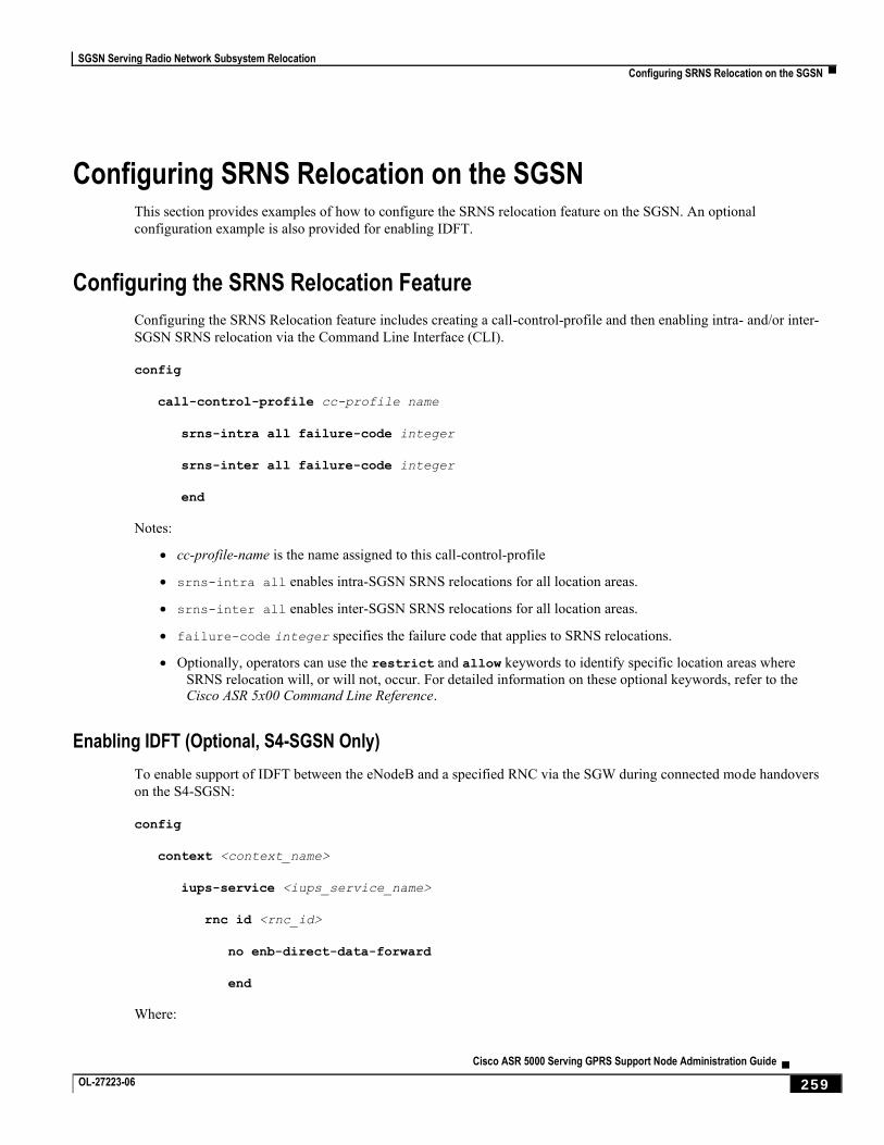
SGSN Serving Radio Network Subsystem Relocation
Configuring SRNS Relocation on the SGSN ▀
Cisco ASR 5000 Serving GPRS Support Node Administration Guide ▄ OL-27223-06 259
Configuring SRNS Relocation on the SGSN This section provides examples of how to configure the SRNS relocation feature on the SGSN. An optional
configuration example is also provided for enabling IDFT.
Configuring the SRNS Relocation Feature
Configuring the SRNS Relocation feature includes creating a call-control-profile and then enabling intra- and/or inter-
SGSN SRNS relocation via the Command Line Interface (CLI).
config
call-control-profile cc-profile name
srns-intra all failure-code integer
srns-inter all failure-code integer
end
Notes:
cc-profile-name is the name assigned to this call-control-profile
srns-intra all enables intra-SGSN SRNS relocations for all location areas.
srns-inter all enables inter-SGSN SRNS relocations for all location areas.
failure-code integer specifies the failure code that applies to SRNS relocations.
Optionally, operators can use the restrict and allow keywords to identify specific location areas where
SRNS relocation will, or will not, occur. For detailed information on these optional keywords, refer to the Cisco ASR 5x00 Command Line Reference.
Enabling IDFT (Optional, S4-SGSN Only)
To enable support of IDFT between the eNodeB and a specified RNC via the SGW during connected mode handovers
on the S4-SGSN:
config
context <context_name>
iups-service <iups_service_name>
rnc id <rnc_id>
no enb-direct-data-forward
end
Where:
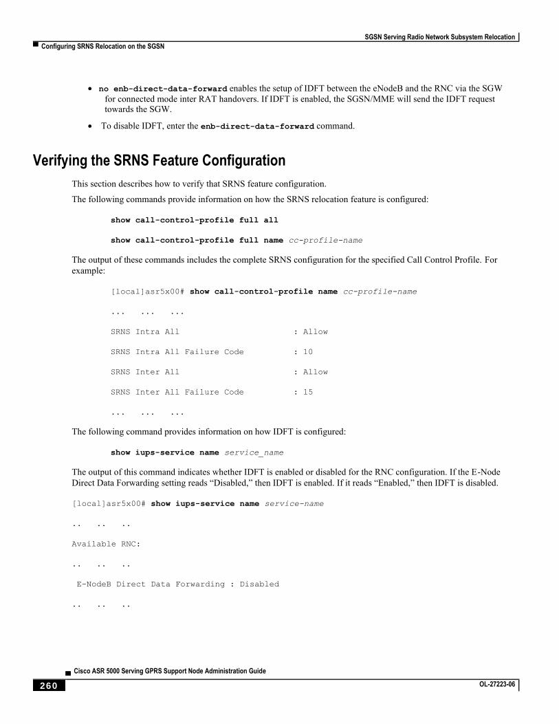
SGSN Serving Radio Network Subsystem Relocation
▀ Configuring SRNS Relocation on the SGSN
▄ Cisco ASR 5000 Serving GPRS Support Node Administration Guide
260 OL-27223-06
no enb-direct-data-forward enables the setup of IDFT between the eNodeB and the RNC via the SGW
for connected mode inter RAT handovers. If IDFT is enabled, the SGSN/MME will send the IDFT request towards the SGW.
To disable IDFT, enter the enb-direct-data-forward command.
Verifying the SRNS Feature Configuration
This section describes how to verify that SRNS feature configuration.
The following commands provide information on how the SRNS relocation feature is configured:
show call-control-profile full all
show call-control-profile full name cc-profile-name
The output of these commands includes the complete SRNS configuration for the specified Call Control Profile. For
example:
[local]asr5x00# show call-control-profile name cc-profile-name
... ... ...
SRNS Intra All : Allow
SRNS Intra All Failure Code : 10
SRNS Inter All : Allow
SRNS Inter All Failure Code : 15
... ... ...
The following command provides information on how IDFT is configured:
show iups-service name service_name
The output of this command indicates whether IDFT is enabled or disabled for the RNC configuration. If the E-Node
Direct Data Forwarding setting reads “Disabled,” then IDFT is enabled. If it reads “Enabled,” then IDFT is disabled.
[local]asr5x00# show iups-service name service-name
.. .. ..
Available RNC:
.. .. ..
E-NodeB Direct Data Forwarding : Disabled
.. .. ..
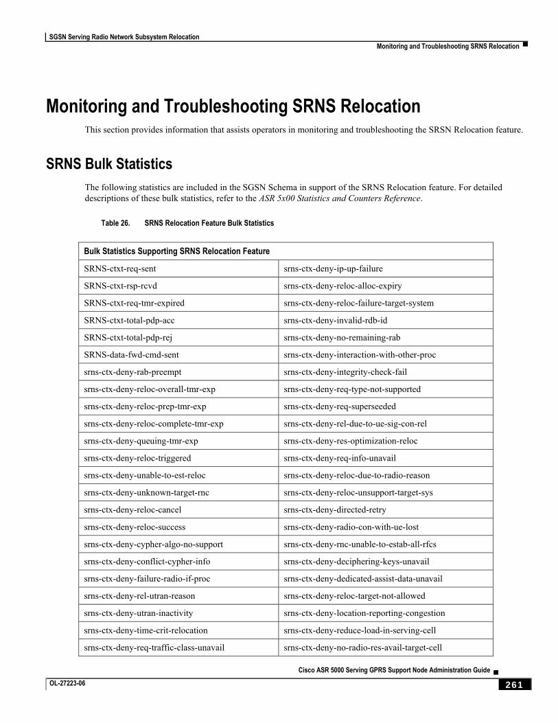
SGSN Serving Radio Network Subsystem Relocation
Monitoring and Troubleshooting SRNS Relocation ▀
Cisco ASR 5000 Serving GPRS Support Node Administration Guide ▄ OL-27223-06 261
Monitoring and Troubleshooting SRNS Relocation This section provides information that assists operators in monitoring and troubleshooting the SRSN Relocation feature.
SRNS Bulk Statistics
The following statistics are included in the SGSN Schema in support of the SRNS Relocation feature. For detailed
descriptions of these bulk statistics, refer to the ASR 5x00 Statistics and Counters Reference.
Table 26. SRNS Relocation Feature Bulk Statistics
Bulk Statistics Supporting SRNS Relocation Feature
SRNS-ctxt-req-sent srns-ctx-deny-ip-up-failure
SRNS-ctxt-rsp-rcvd srns-ctx-deny-reloc-alloc-expiry
SRNS-ctxt-req-tmr-expired srns-ctx-deny-reloc-failure-target-system
SRNS-ctxt-total-pdp-acc srns-ctx-deny-invalid-rdb-id
SRNS-ctxt-total-pdp-rej srns-ctx-deny-no-remaining-rab
SRNS-data-fwd-cmd-sent srns-ctx-deny-interaction-with-other-proc
srns-ctx-deny-rab-preempt srns-ctx-deny-integrity-check-fail
srns-ctx-deny-reloc-overall-tmr-exp srns-ctx-deny-req-type-not-supported
srns-ctx-deny-reloc-prep-tmr-exp srns-ctx-deny-req-superseeded
srns-ctx-deny-reloc-complete-tmr-exp srns-ctx-deny-rel-due-to-ue-sig-con-rel
srns-ctx-deny-queuing-tmr-exp srns-ctx-deny-res-optimization-reloc
srns-ctx-deny-reloc-triggered srns-ctx-deny-req-info-unavail
srns-ctx-deny-unable-to-est-reloc srns-ctx-deny-reloc-due-to-radio-reason
srns-ctx-deny-unknown-target-rnc srns-ctx-deny-reloc-unsupport-target-sys
srns-ctx-deny-reloc-cancel srns-ctx-deny-directed-retry
srns-ctx-deny-reloc-success srns-ctx-deny-radio-con-with-ue-lost
srns-ctx-deny-cypher-algo-no-support srns-ctx-deny-rnc-unable-to-estab-all-rfcs
srns-ctx-deny-conflict-cypher-info srns-ctx-deny-deciphering-keys-unavail
srns-ctx-deny-failure-radio-if-proc srns-ctx-deny-dedicated-assist-data-unavail
srns-ctx-deny-rel-utran-reason srns-ctx-deny-reloc-target-not-allowed
srns-ctx-deny-utran-inactivity srns-ctx-deny-location-reporting-congestion
srns-ctx-deny-time-crit-relocation srns-ctx-deny-reduce-load-in-serving-cell
srns-ctx-deny-req-traffic-class-unavail srns-ctx-deny-no-radio-res-avail-target-cell

SGSN Serving Radio Network Subsystem Relocation
▀ Monitoring and Troubleshooting SRNS Relocation
▄ Cisco ASR 5000 Serving GPRS Support Node Administration Guide
262 OL-27223-06
Bulk Statistics Supporting SRNS Relocation Feature
srns-ctx-deny-invalid-rab-param-val srns-ctx-deny-geran-iu-mode-failure
srns-ctx-deny-req-max-bit-rate-unavail srns-ctx-deny-access-restrict-shared-nwtk
srns-ctx-deny-req-max-bit-rate-dl-unavail srns-ctx-deny-in-reloc-nwt-support-puesbine
srns-ctx-deny-req-max-bit-rate-ul-unavail srns-ctx-deny-traffic-target-more-src-cell
srns-ctx-deny-req-gbr-unavail srns-ctx-deny-mbms-no-multicat-svc-for-ue
srns-ctx-deny-req-gbr-dl-unavail srns-ctx-deny-mbms-unknown-ue-id
srns-ctx-deny-req-gbr-ul-unavail srns-ctx-deny-mbms-sess-start-no-data-bearer
srns-ctx-deny-req-trans-delay-not-achieve srns-ctx-deny-mbms-superseed-nnsf
srns-ctx-deny-inval-rab-param-combo srns-ctx-deny-mbms-ue-linking-already-done
srns-ctx-deny-violation-for-sdu-param srns-ctx-deny-mbms-ue-delinking-failure
srns-ctx-deny-violation-traffic-hanlde-prio srns-ctx-deny-tmgi-unknown
srns-ctx-deny-violation-for-gbr srns-ctx-deny-ms-unspecified-failure
srns-ctx-deny-usr-plane-ver-unsupported srns-ctx-deny-no-response-from-rnc
Show Command Output Supporting the SRNS Relocation Feature
This section provides information regarding CLI show commands that provide output to support of the SRSN
Relocation feature.
The following show commands are available in support of the SRNS Relocation feature on the SGSN and the S4-
SGSN:
show s4-sgsn statistics all
show gmm-sm statistics
The following counters are included in the show gmm-sm statistics command output to support the SRNS Relocation
feature. These statistics provide information on RAN application messages and the total number of attempted and
successful SGSN Gn/Gp and S4-SGSN SRNS relocations. These totals are further subdivided by SRNS relocation type.
Note that these statistics apply to the SGSN (Gn/Gp) and the S4-SGSN on the SGSN-RNC-UE interface side. For
detailed descriptions of these statistics, refer to the ASR 5x00 Statistics and Counters Reference.
Table 27. GMM SM Statistics Supporting SRNS Relocation
GMM SM Statistics Supporting SRNS Relocation
RANAP Procedures
Relocation Required Relocation Request Relocation Failure Relocation Cancel Relocation Detect
Relocation Complete Relocation Command Relocation Request Ack Relocation Prep Failure Relocation Cancel Ack
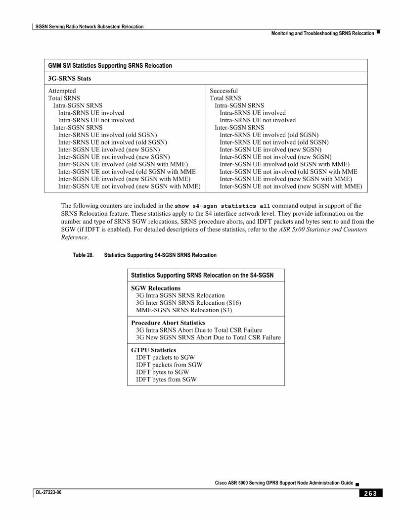
SGSN Serving Radio Network Subsystem Relocation
Monitoring and Troubleshooting SRNS Relocation ▀
Cisco ASR 5000 Serving GPRS Support Node Administration Guide ▄ OL-27223-06 263
GMM SM Statistics Supporting SRNS Relocation
3G-SRNS Stats
Attempted Total SRNS Intra-SGSN SRNS Intra-SRNS UE involved Intra-SRNS UE not involved Inter-SGSN SRNS Inter-SRNS UE involved (old SGSN) Inter-SRNS UE not involved (old SGSN) Inter-SGSN UE involved (new SGSN) Inter-SGSN UE not involved (new SGSN) Inter-SGSN UE involved (old SGSN with MME) Inter-SGSN UE not involved (old SGSN with MME Inter-SGSN UE involved (new SGSN with MME) Inter-SGSN UE not involved (new SGSN with MME)
Successful Total SRNS Intra-SGSN SRNS Intra-SRNS UE involved Intra-SRNS UE not involved Inter-SGSN SRNS Inter-SRNS UE involved (old SGSN) Inter-SRNS UE not involved (old SGSN) Inter-SGSN UE involved (new SGSN) Inter-SGSN UE not involved (new SGSN) Inter-SGSN UE involved (old SGSN with MME) Inter-SGSN UE not involved (old SGSN with MME Inter-SGSN UE involved (new SGSN with MME) Inter-SGSN UE not involved (new SGSN with MME)
The following counters are included in the show s4-sgsn statistics all command output in support of the
SRNS Relocation feature. These statistics apply to the S4 interface network level. They provide information on the
number and type of SRNS SGW relocations, SRNS procedure aborts, and IDFT packets and bytes sent to and from the
SGW (if IDFT is enabled). For detailed descriptions of these statistics, refer to the ASR 5x00 Statistics and Counters
Reference.
Table 28. Statistics Supporting S4-SGSN SRNS Relocation
Statistics Supporting SRNS Relocation on the S4-SGSN
SGW Relocations 3G Intra SGSN SRNS Relocation 3G Inter SGSN SRNS Relocation (S16) MME-SGSN SRNS Relocation (S3)
Procedure Abort Statistics 3G Intra SRNS Abort Due to Total CSR Failure 3G New SGSN SRNS Abort Due to Total CSR Failure
GTPU Statistics IDFT packets to SGW IDFT packets from SGW IDFT bytes to SGW IDFT bytes from SGW

Cisco ASR 5000 Serving GPRS Support Node Administration Guide ▄ OL-27223-06 265
Chapter 11 Subscriber Overcharging Protection
Subscriber Overcharging Protection is a proprietary, enhanced feature that prevents subscribers in UMTS networks from
being overcharged when a loss of radio coverage (LORC) occurs. This chapter indicates how the feature is implemented
on various systems and provides feature configuration procedures. Products supporting subscriber overcharging
protection include Cisco’s Gateway GPRS Support Node (GGSN) and Serving GPRS Support Node (SGSN).
The individual product administration guides provide examples and procedures for configuration of basic services.
Before using the procedures in this chapter, we recommend that you select the configuration example that best meets
your service model, and configure the required elements for that model, as described in the respective guide.
Important: Subscriber Overcharging Protection is a licensed Cisco feature. A separate feature license may be
required. Contact your Cisco account representative for detailed information on specific licensing requirements. For information on installing and verifying licenses, refer to the Managing License Keys section of the Software Management Operations chapter in the System Administration Guide.
This chapter covers the following topics in support of the Subscriber Overcharging Protection feature:
Feature Overview
Overcharging Protection - GGSN Configuration
Overcharging Protection - SGSN Configuration
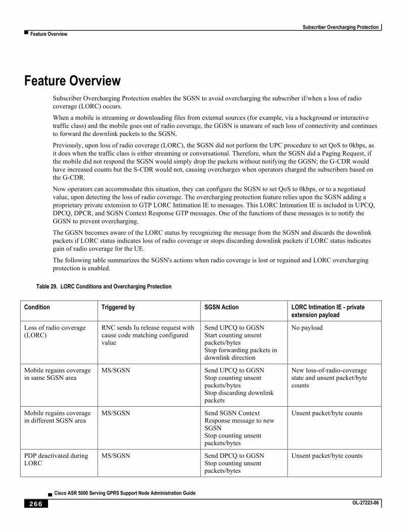
Subscriber Overcharging Protection
▀ Feature Overview
▄ Cisco ASR 5000 Serving GPRS Support Node Administration Guide
266 OL-27223-06
Feature Overview Subscriber Overcharging Protection enables the SGSN to avoid overcharging the subscriber if/when a loss of radio
coverage (LORC) occurs.
When a mobile is streaming or downloading files from external sources (for example, via a background or interactive
traffic class) and the mobile goes out of radio coverage, the GGSN is unaware of such loss of connectivity and continues
to forward the downlink packets to the SGSN.
Previously, upon loss of radio coverage (LORC), the SGSN did not perform the UPC procedure to set QoS to 0kbps, as
it does when the traffic class is either streaming or conversational. Therefore, when the SGSN did a Paging Request, if
the mobile did not respond the SGSN would simply drop the packets without notifying the GGSN; the G-CDR would
have increased counts but the S-CDR would not, causing overcharges when operators charged the subscribers based on
the G-CDR.
Now operators can accommodate this situation, they can configure the SGSN to set QoS to 0kbps, or to a negotiated
value, upon detecting the loss of radio coverage. The overcharging protection feature relies upon the SGSN adding a
proprietary private extension to GTP LORC Intimation IE to messages. This LORC Intimation IE is included in UPCQ,
DPCQ, DPCR, and SGSN Context Response GTP messages. One of the functions of these messages is to notify the
GGSN to prevent overcharging.
The GGSN becomes aware of the LORC status by recognizing the message from the SGSN and discards the downlink
packets if LORC status indicates loss of radio coverage or stops discarding downlink packets if LORC status indicates
gain of radio coverage for the UE.
The following table summarizes the SGSN's actions when radio coverage is lost or regained and LORC overcharging
protection is enabled.
Table 29. LORC Conditions and Overcharging Protection
Condition Triggered by SGSN Action LORC Intimation IE - private extension payload
Loss of radio coverage (LORC)
RNC sends Iu release request with cause code matching configured value
Send UPCQ to GGSN Start counting unsent packets/bytes Stop forwarding packets in downlink direction
No payload
Mobile regains coverage in same SGSN area
MS/SGSN Send UPCQ to GGSN Stop counting unsent packets/bytes Stop discarding downlink packets
New loss-of-radio-coverage state and unsent packet/byte counts
Mobile regains coverage in different SGSN area
MS/SGSN Send SGSN Context Response message to new SGSN Stop counting unsent packets/bytes
Unsent packet/byte counts
PDP deactivated during LORC
MS/SGSN Send DPCQ to GGSN Stop counting unsent packets/bytes
Unsent packet/byte counts
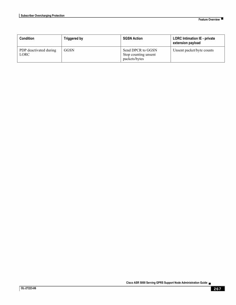
Subscriber Overcharging Protection
Feature Overview ▀
Cisco ASR 5000 Serving GPRS Support Node Administration Guide ▄ OL-27223-06 267
Condition Triggered by SGSN Action LORC Intimation IE - private extension payload
PDP deactivated during LORC
GGSN Send DPCR to GGSN Stop counting unsent packets/bytes
Unsent packet/byte counts
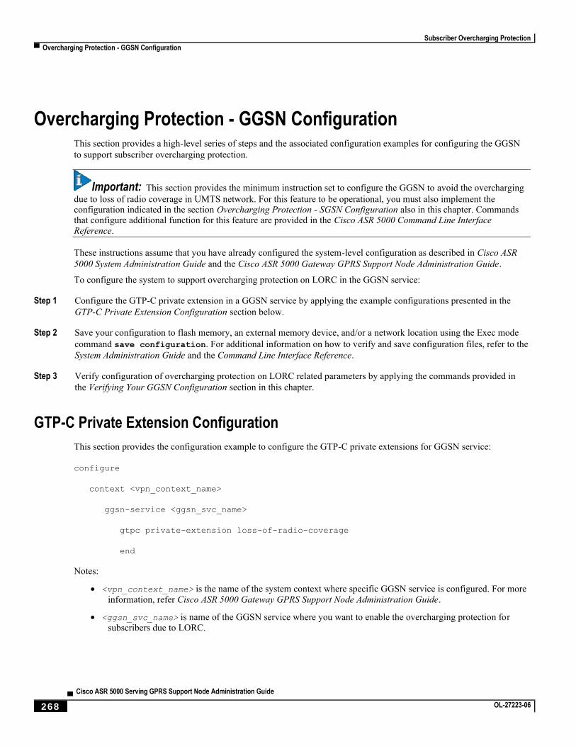
Subscriber Overcharging Protection
▀ Overcharging Protection - GGSN Configuration
▄ Cisco ASR 5000 Serving GPRS Support Node Administration Guide
268 OL-27223-06
Overcharging Protection - GGSN Configuration This section provides a high-level series of steps and the associated configuration examples for configuring the GGSN
to support subscriber overcharging protection.
Important: This section provides the minimum instruction set to configure the GGSN to avoid the overcharging
due to loss of radio coverage in UMTS network. For this feature to be operational, you must also implement the configuration indicated in the section Overcharging Protection - SGSN Configuration also in this chapter. Commands that configure additional function for this feature are provided in the Cisco ASR 5000 Command Line Interface Reference.
These instructions assume that you have already configured the system-level configuration as described in Cisco ASR
5000 System Administration Guide and the Cisco ASR 5000 Gateway GPRS Support Node Administration Guide.
To configure the system to support overcharging protection on LORC in the GGSN service:
Step 1 Configure the GTP-C private extension in a GGSN service by applying the example configurations presented in the
GTP-C Private Extension Configuration section below.
Step 2 Save your configuration to flash memory, an external memory device, and/or a network location using the Exec mode
command save configuration. For additional information on how to verify and save configuration files, refer to the
System Administration Guide and the Command Line Interface Reference.
Step 3 Verify configuration of overcharging protection on LORC related parameters by applying the commands provided in
the Verifying Your GGSN Configuration section in this chapter.
GTP-C Private Extension Configuration
This section provides the configuration example to configure the GTP-C private extensions for GGSN service:
configure
context <vpn_context_name>
ggsn-service <ggsn_svc_name>
gtpc private-extension loss-of-radio-coverage
end
Notes:
<vpn_context_name> is the name of the system context where specific GGSN service is configured. For more
information, refer Cisco ASR 5000 Gateway GPRS Support Node Administration Guide.
<ggsn_svc_name> is name of the GGSN service where you want to enable the overcharging protection for subscribers due to LORC.
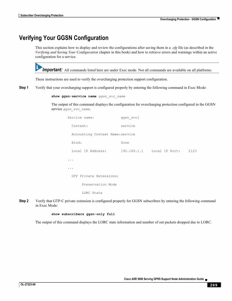
Subscriber Overcharging Protection
Overcharging Protection - GGSN Configuration ▀
Cisco ASR 5000 Serving GPRS Support Node Administration Guide ▄ OL-27223-06 269
Verifying Your GGSN Configuration
This section explains how to display and review the configurations after saving them in a .cfg file (as described in the
Verifying and Saving Your Configuration chapter in this book) and how to retrieve errors and warnings within an active
configuration for a service.
Important: All commands listed here are under Exec mode. Not all commands are available on all platforms.
These instructions are used to verify the overcharging protection support configuration.
Step 1 Verify that your overcharging support is configured properly by entering the following command in Exec Mode:
show ggsn-service name ggsn_svc_name
The output of this command displays the configuration for overcharging protection configured in the GGSN
service ggsn_svc_name.
Service name: ggsn_svc1
Context: service
Accounting Context Name:service
Bind: Done
Local IP Address: 192.169.1.1 Local IP Port: 2123
...
...
GTP Private Extensions:
Preservation Mode
LORC State
Step 2 Verify that GTP-C private extension is configured properly for GGSN subscribers by entering the following command
in Exec Mode:
show subscribers ggsn-only full
The output of this command displays the LORC state information and number of out packets dropped due to LORC.
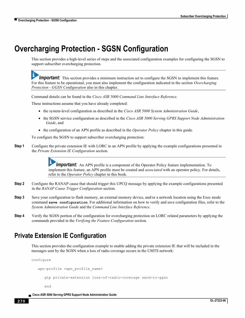
Subscriber Overcharging Protection
▀ Overcharging Protection - SGSN Configuration
▄ Cisco ASR 5000 Serving GPRS Support Node Administration Guide
270 OL-27223-06
Overcharging Protection - SGSN Configuration This section provides a high-level series of steps and the associated configuration examples for configuring the SGSN to
support subscriber overcharging protection.
Important: This section provides a minimum instruction set to configure the SGSN to implement this feature.
For this feature to be operational, you must also implement the configuration indicated in the section Overcharging Protection - GGSN Configuration also in this chapter.
Command details can be found in the Cisco ASR 5000 Command Line Interface Reference.
These instructions assume that you have already completed:
the system-level configuration as described in the Cisco ASR 5000 System Administration Guide,
the SGSN service configuration as described in the Cisco ASR 5000 Serving GPRS Support Node Administration Guide, and
the configuration of an APN profile as described in the Operator Policy chapter in this guide.
To configure the SGSN to support subscriber overcharging protection:
Step 1 Configure the private extension IE with LORC in an APN profile by applying the example configurations presented in
the Private Extension IE Configuration section.
Important: An APN profile is a component of the Operator Policy feature implementation. To
implement this feature, an APN profile must be created and associated with an operator policy. For details, refer to the Operator Policy chapter in this book.
Step 2 Configure the RANAP cause that should trigger this UPCQ message by applying the example configurations presented
in the RANAP Cause Trigger Configuration section.
Step 3 Save your configuration to flash memory, an external memory device, and/or a network location using the Exec mode
command save configuration. For additional information on how to verify and save configuration files, refer to the
System Administration Guide and the Command Line Interface Reference.
Step 4 Verify the SGSN portion of the configuration for overcharging protection on LORC related parameters by applying the
commands provided in the Verifying the Feature Configuration section.
Private Extension IE Configuration
This section provides the configuration example to enable adding the private extension IE that will be included in the
messages sent by the SGSN when a loss of radio coverage occurs in the UMTS network:
configure
apn-profile <apn_profile_name>
gtp private-extension loss-of-radio-coverage send-to-ggsn
end

Subscriber Overcharging Protection
Overcharging Protection - SGSN Configuration ▀
Cisco ASR 5000 Serving GPRS Support Node Administration Guide ▄ OL-27223-06 271
Note:
<apn_profile_name> is the name of a previously configured APN profile. For more information, refer to the Operator Policy chapter, also in this book.
RANAP Cause Trigger Configuration
This section provides the configuration example to enable the RANAP cause trigger and define the trigger message
value:
configure
context <context_name>
iups-service <iups_service_name>
loss-of-radio-coverage ranap-cause <cause> end
Note:
<context_name> is the name of the previously configured context in which the IuPS service has been configured.
<cause> is an integer from 1 to 512 (the range of reasons is a part of the set defined by 3GPP TS 25.413) that
allows configuration of the RANAP Iu release cause code to be included in messages. Default is 46 (MS/UE radio connection lost).
Verifying the Feature Configuration
This section explains how to display the configurations after saving them in a .cfg file as described in the Verifying and
Saving Your Configuration chapter elsewhere in this guide.
Important: All commands listed here are under Exec mode. Not all commands are available on all platforms.
These instructions are used to verify the overcharging protection support configuration.
Step 1 Verify that your overcharging support is configured properly by entering the following command in Exec Mode:
show apn-profile full name apn_profile_name
The output of this command displays the entire configuration for the APN profile configuration. Only the
portion related to overcharging protection configuration in the SGSN is displayed below. Note that the profile
name is an example:
APN Profile name: : apnprofile1
Resolution Priority: : dns-fallback
...
...
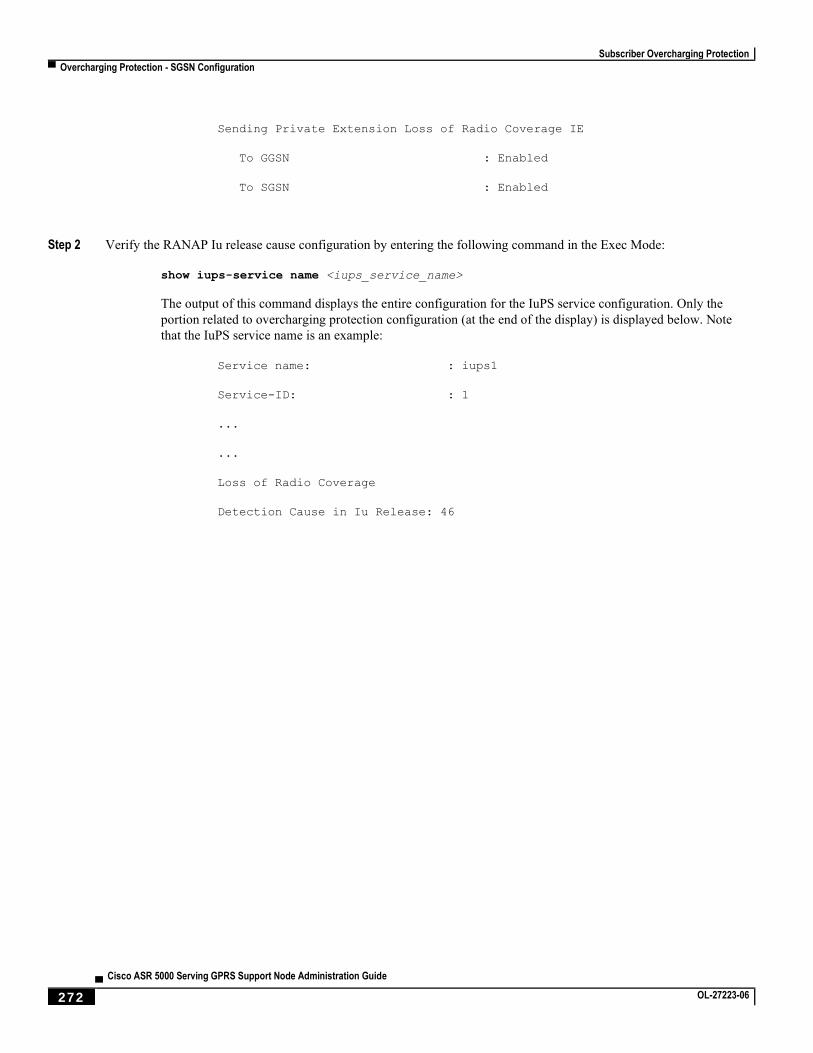
Subscriber Overcharging Protection
▀ Overcharging Protection - SGSN Configuration
▄ Cisco ASR 5000 Serving GPRS Support Node Administration Guide
272 OL-27223-06
Sending Private Extension Loss of Radio Coverage IE
To GGSN : Enabled
To SGSN : Enabled
Step 2 Verify the RANAP Iu release cause configuration by entering the following command in the Exec Mode:
show iups-service name <iups_service_name>
The output of this command displays the entire configuration for the IuPS service configuration. Only the
portion related to overcharging protection configuration (at the end of the display) is displayed below. Note
that the IuPS service name is an example:
Service name: : iups1
Service-ID: : 1
...
...
Loss of Radio Coverage
Detection Cause in Iu Release: 46
Cisco ASR 5000 Serving GPRS Support Node Administration Guide ▄ OL-27223-06 273
Chapter 12 Monitoring and Troubleshooting
Monitoring and troubleshooting the SGSN are not unrelated tasks that use many of the same procedures. This chapter
provides information and instructions for using the system command line interface (CLI), primarily the show command,
to monitor service status and performance and to troubleshoot operations.
The show commands used for monitoring and troubleshooting include keywords (parameters) that can fine-tune the
output to produce information on all aspects of the system, ranging from current software configuration through call
activity and status. The keywords, used in the procedures documented in this chapter, are intended to provide the most
useful and in-depth information for monitoring the system. To learn about all of the keywords possible, refer to the
Command Line Interface Reference. To learn about the details for the information in the show command outputs, refer
to the Statistics and Counters Reference.
In addition to the CLI documented in this chapter, the system supports other monitoring and troubleshooting tools:
SNMP (Simple Network Management Protocol) traps that indicate status and alarm conditions. Refer to the SNMP MIB Reference for a detailed listing of these traps.
bulk statistics (performance data) which can be accessed in various manners. For a complete list of SGSN supported statistics, refer to the Statistics and Counters Reference. For information about configuring the formats for static collection, refer to the Command Line Interface Reference.
threshold crossing alerts for conditions that are typically temporary, such as high CPU or port utilization, but can indicate potentially severe conditions. For information on threshold crossing alert configuration, refer to the Thresholding Configuration Guide.
The monitoring and troubleshooting procedures are organized on a task-basis with details for:
Monitoring (information required regularly)
Daily – Standard Health Check
Monthly System Maintenance
Semi-Annual Check
Troubleshooting (information required intermittently)
Overview of Possible Fault Types
Single and Mass Problem Scenarios
Reference Materials (information required infrequently)

Monitoring and Troubleshooting
▀ Monitoring
▄ Cisco ASR 5000 Serving GPRS Support Node Administration Guide
274 OL-27223-06
Monitoring This section contains commands used to monitor system performance and the status of tasks, managers, applications,
and various other software components. Most of the procedure commands are useful for both maintenance and
diagnotics.
There is no limit to the frequency that any of the individual commands or procedures can be implemented, however, the
organization of tasks into three unique sets of procedures suggests a recommendation for minimal implementation:
Daily – Standard Health Check
Monthly System Maintenance
Semi-Annual Check
Daily - Standard Health Check
The standard health check is divided into three independent procedures:
Health Check - Hardware & Physical Layer
Health Check - System & Performance
Health Check - SGSN-Specific Status & Performance
Health Check - Hardware & Physical Layer
The first set of commands are useful for monitoring the hardware status for the entire system. The second set of
commands check the status of hardware elements within the chassis and provide some verification of the physical layer
status. The operational parameters for the hardware are included in the Hardware Installation and Administration
Guide. Note that all hardware elements generate alarms in the case of failure.
Table 30. Hardware Status Checks
To Do This: Enter This Command:
All hardware problems generate alarms, the following checks can be replaced by reviewing the trap history.
show snmp trap
history
Check the status of the PFUs. Output indicates the power level for the cards in the chassis. All active cards should be in an "ON" state.
show power chassis
Check the power status of an individual chassis. show power all
View the status of the fan trays. In case of a fan problem, refer to your support contract to contact the appropriate service or sales representative.
show fans
View the LED status for all installed cards. All LEDs for active cards should be green. show leds all
Checking the temperatures confirms that all cards and fan trays are operating within safe ranges to ensure hardware efficiency.
show temperature
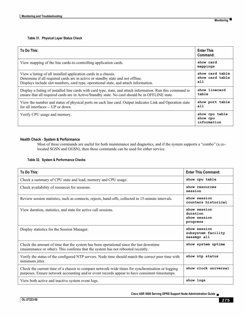
Monitoring and Troubleshooting
Monitoring ▀
Cisco ASR 5000 Serving GPRS Support Node Administration Guide ▄ OL-27223-06 275
Table 31. Physical Layer Status Check
To Do This: Enter This Command:
View mapping of the line cards-to-controlling application cards. show card
mappings
View a listing of all installed application cards in a chassis. Determine if all required cards are in active or standby state and not offline. Displays include slot numbers, card type, operational state, and attach information.
show card table show card table
all
Display a listing of installed line cards with card type, state, and attach information. Run this command to ensure that all required cards are in Active/Standby state. No card should be in OFFLINE state.
show linecard
table
View the number and status of physical ports on each line card. Output indicates Link and Operation state for all interfaces -- UP or down.
show port table
all
Verify CPU usage and memory. show cpu table show cpu
information
Health Check - System & Performance
Most of these commands are useful for both maintenance and diagnotics, and if the system supports a “combo” (a co-
located SGSN and GGSN), then these commands can be used for either service.
Table 32. System & Performance Checks
To Do This: Enter This Command:
Check a summary of CPU state and load, memory and CPU usage. show cpu table
Check availability of resources for sessions. show resources
session
Review session statistics, such as connects, rejects, hand-offs, collected in 15-minute intervals. show session
counters historical
View duration, statistics, and state for active call sessions. show session
duration show session
progress
Display statistics for the Session Manager. show session
subsystem facility
sessmgr all
Check the amount of time that the system has been operational since the last downtime (maintenance or other). This confirms that the system has not rebooted recently.
show system uptime
Verify the status of the configured NTP servers. Node time should match the correct peer time with minimum jitter.
show ntp status
Check the current time of a chassis to compare network-wide times for synchronisation or logging purposes. Ensure network accounting and/or event records appear to have consistent timestamps.
show clock universal
View both active and inactive system event logs. show logs
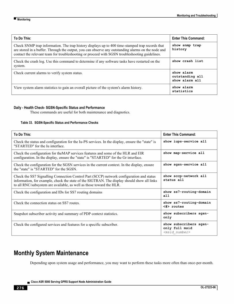
Monitoring and Troubleshooting
▀ Monitoring
▄ Cisco ASR 5000 Serving GPRS Support Node Administration Guide
276 OL-27223-06
To Do This: Enter This Command:
Check SNMP trap information. The trap history displays up to 400 time-stamped trap records that are stored in a buffer. Through the output, you can observe any outstanding alarms on the node and contact the relevant team for troubleshooting or proceed with SGSN troubleshooting guidelines.
show snmp trap
history
Check the crash log. Use this command to determine if any software tasks have restarted on the system.
show crash list
Check current alarms to verify system status. show alarm
outstanding all show alarm all
View system alarm statistics to gain an overall picture of the system's alarm history. show alarm
statistics
Daily - Health Check- SGSN-Specific Status and Performance
These commands are useful for both maintenance and diagnotics.
Table 33. SGSN-Specific Status and Performance Checks
To Do This: Enter This Command:
Check the status and configuration for the Iu-PS services. In the display, ensure the "state" is "STARTED" for the Iu interface.
show iups-service all
Check the configuration for theMAP services features and some of the HLR and EIR configuration. In the display, ensure the "state" is "STARTED" for the Gr interface.
show map-service all
Check the configuration for the SGSN services in the current context. In the display, ensure the "state" is "STARTED" for the SGSN.
show sgsn-service all
Check the SS7 Signalling Connection Control Part (SCCP) network configuration and status information, for example, check the state of the SIGTRAN. The display should show all links to all RNC/subsystem are available, as well as those toward the HLR.
show sccp-network all
status all
Check the configuration and IDs for SS7 routing domains show ss7-routing-domain
all
Check the connection status on SS7 routes. show ss7-routing-domain
<#> routes
Snapshot subscriber activity and summary of PDP context statistics. show subscribers sgsn-
only
Check the configured services and features for a specific subscriber. show subscribers sgsn-
only full msid
<msid_number>
Monthly System Maintenance
Depending upon system usage and performance, you may want to perform these tasks more often than once-per-month.
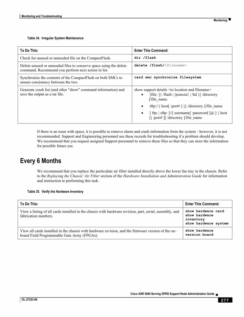
Monitoring and Troubleshooting
Monitoring ▀
Cisco ASR 5000 Serving GPRS Support Node Administration Guide ▄ OL-27223-06 277
Table 34. Irregular System Maintenance
To Do This: Enter This Command:
Check for unused or unneeded file on the CompactFlash. dir /flash
Delete unused or unneeded files to conserve space using the delete command. Recommend you perform next action in list
delete /flash/<filename>
Synchronise the contents of the CompactFlash on both SMCs to ensure consistency between the two.
card smc synchronize filesystem
Generate crash list (and other "show" command information) and save the output as a tar file.
show support details <to location and filename>
[file: ]{ /flash | /pcmcia1 | /hd }[ /directory
]/file_name
tftp://{ host[ :port# ] }[ /directory ]/file_name
[ ftp: | sftp: ]//[ username[ :password ]@ ] { host
}[ :port# ][ /directory ]/file_name
If there is an issue with space, it is possible to remove alarm and crash information from the system - however, it is not
recommended. Support and Engineering personnel use these records for troubleshooting if a problem should develop.
We recommend that you request assigned Support personnel to remove these files so that they can store the information
for possible future use.
Every 6 Months
We recommend that you replace the particulate air filter installed directly above the lower fan tray in the chassis. Refer
to the Replacing the Chassis' Air Filter section of the Hardware Installation and Administration Guide for information
and instruction to performing this task.
Table 35. Verify the Hardware Inventory
To Do This: Enter This Command:
View a listing of all cards installed in the chassis with hardware revision, part, serial, assembly, and fabrication numbers.
show hardware card show hardware
inventory show hardware system
View all cards installed in the chassis with hardware revision, and the firmware version of the on-board Field Programmable Gate Array (FPGAs).
show hardware
version board
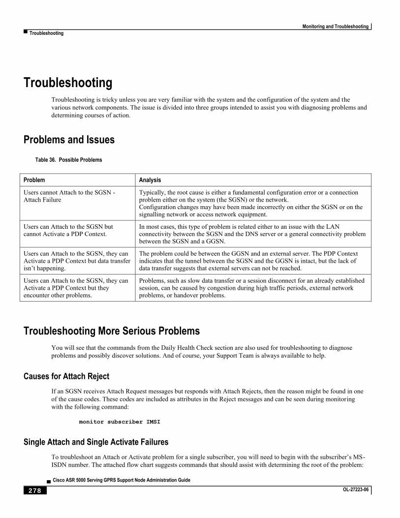
Monitoring and Troubleshooting
▀ Troubleshooting
▄ Cisco ASR 5000 Serving GPRS Support Node Administration Guide
278 OL-27223-06
Troubleshooting Troubleshooting is tricky unless you are very familiar with the system and the configuration of the system and the
various network components. The issue is divided into three groups intended to assist you with diagnosing problems and
determining courses of action.
Problems and Issues
Table 36. Possible Problems
Problem Analysis
Users cannot Attach to the SGSN - Attach Failure
Typically, the root cause is either a fundamental configuration error or a connection problem either on the system (the SGSN) or the network. Configuration changes may have been made incorrectly on either the SGSN or on the signalling network or access network equipment.
Users can Attach to the SGSN but cannot Activate a PDP Context.
In most cases, this type of problem is related either to an issue with the LAN connectivity between the SGSN and the DNS server or a general connectivity problem between the SGSN and a GGSN.
Users can Attach to the SGSN, they can Activate a PDP Context but data transfer isn’t happening.
The problem could be between the GGSN and an external server. The PDP Context indicates that the tunnel between the SGSN and the GGSN is intact, but the lack of data transfer suggests that external servers can not be reached.
Users can Attach to the SGSN, they can Activate a PDP Context but they encounter other problems.
Problems, such as slow data transfer or a session disconnect for an already established session, can be caused by congestion during high traffic periods, external network problems, or handover problems.
Troubleshooting More Serious Problems
You will see that the commands from the Daily Health Check section are also used for troubleshooting to diagnose
problems and possibly discover solutions. And of course, your Support Team is always available to help.
Causes for Attach Reject
If an SGSN receives Attach Request messages but responds with Attach Rejects, then the reason might be found in one
of the cause codes. These codes are included as attributes in the Reject messages and can be seen during monitoring
with the following command:
monitor subscriber IMSI
Single Attach and Single Activate Failures
To troubleshoot an Attach or Activate problem for a single subscriber, you will need to begin with the subscriber’s MS-
ISDN number. The attached flow chart suggests commands that should assist with determining the root of the problem:
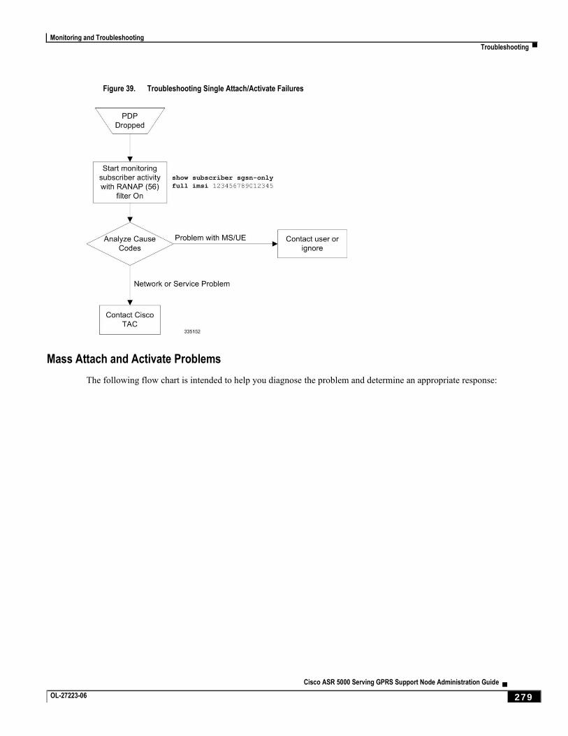
Monitoring and Troubleshooting
Troubleshooting ▀
Cisco ASR 5000 Serving GPRS Support Node Administration Guide ▄ OL-27223-06 279
Figure 39. Troubleshooting Single Attach/Activate Failures
Mass Attach and Activate Problems
The following flow chart is intended to help you diagnose the problem and determine an appropriate response:
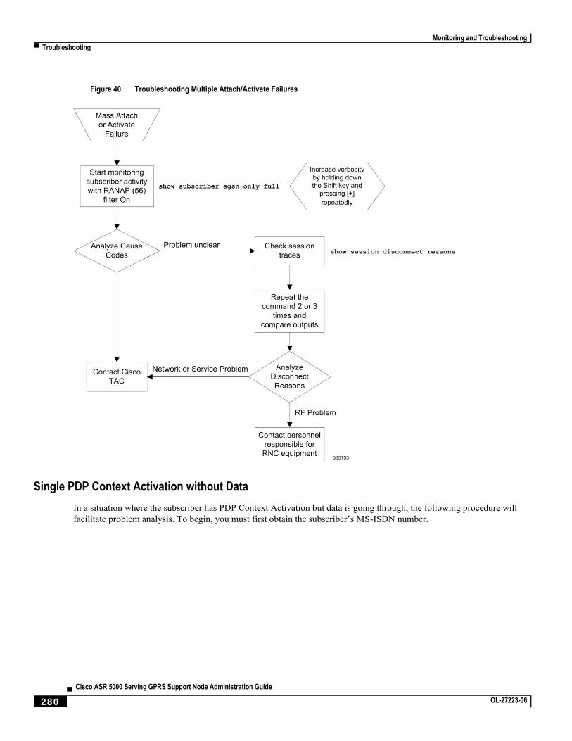
Monitoring and Troubleshooting
▀ Troubleshooting
▄ Cisco ASR 5000 Serving GPRS Support Node Administration Guide
280 OL-27223-06
Figure 40. Troubleshooting Multiple Attach/Activate Failures
Single PDP Context Activation without Data
In a situation where the subscriber has PDP Context Activation but data is going through, the following procedure will
facilitate problem analysis. To begin, you must first obtain the subscriber’s MS-ISDN number.
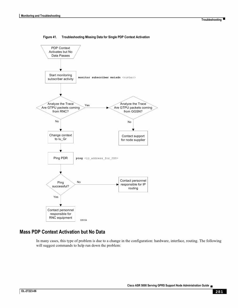
Monitoring and Troubleshooting
Troubleshooting ▀
Cisco ASR 5000 Serving GPRS Support Node Administration Guide ▄ OL-27223-06 281
Figure 41. Troubleshooting Missing Data for Single PDP Context Activation
Mass PDP Context Activation but No Data
In many cases, this type of problem is due to a change in the configuration: hardware, interface, routing. The following
will suggest commands to help run down the problem:
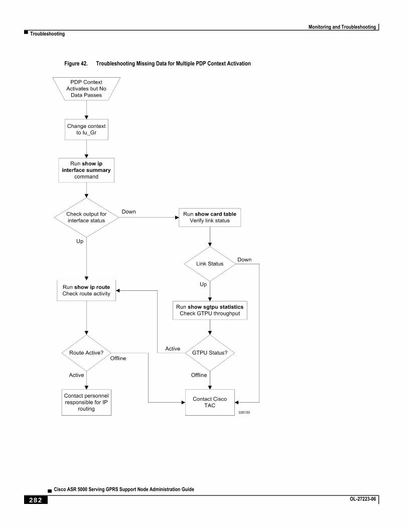
Monitoring and Troubleshooting
▀ Troubleshooting
▄ Cisco ASR 5000 Serving GPRS Support Node Administration Guide
282 OL-27223-06
Figure 42. Troubleshooting Missing Data for Multiple PDP Context Activation

Cisco ASR 5000 Serving GPRS Support Node Administration Guide ▄ OL-27223-06 283
Appendix A Engineering Rules
This section provides SGSN-specific 2.5G, 3G , and common engineering rules or limit guidelines for the current
release. These limits are hardcoded into the SGSN system and are not configurable. The limits are documented here
because they should be considered prior to configuring an SGSN for network deployment.
Generic platform and system rules or limits can be found in the “Engineering Rules” appendix in the System
Administration Guide.
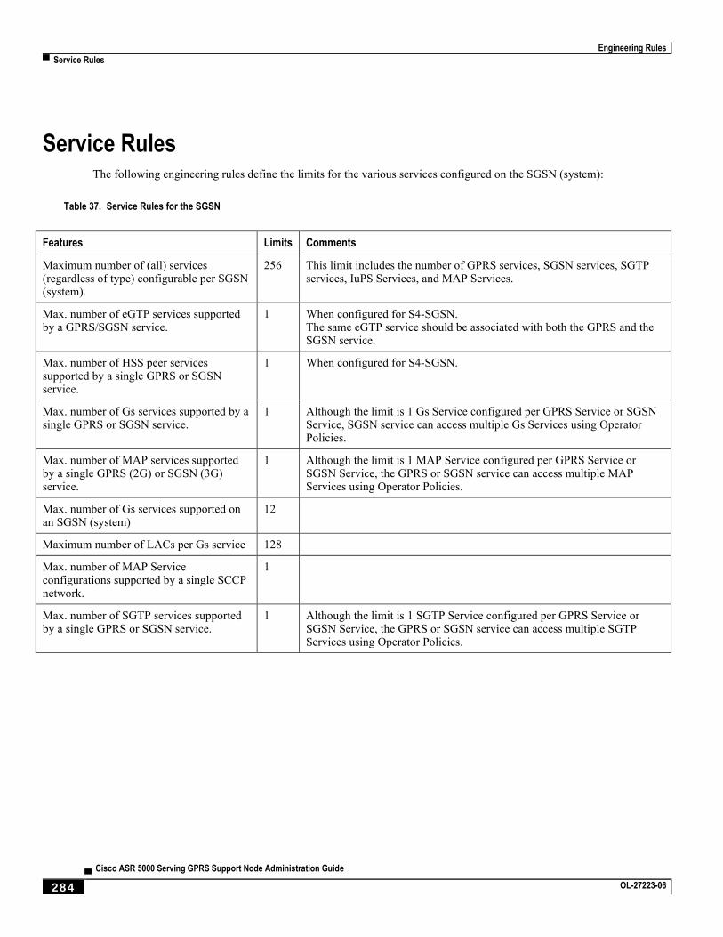
Engineering Rules
▀ Service Rules
▄ Cisco ASR 5000 Serving GPRS Support Node Administration Guide
284 OL-27223-06
Service Rules The following engineering rules define the limits for the various services configured on the SGSN (system):
Table 37. Service Rules for the SGSN
Features Limits Comments
Maximum number of (all) services (regardless of type) configurable per SGSN (system).
256 This limit includes the number of GPRS services, SGSN services, SGTP services, IuPS Services, and MAP Services.
Max. number of eGTP services supported by a GPRS/SGSN service.
1 When configured for S4-SGSN. The same eGTP service should be associated with both the GPRS and the SGSN service.
Max. number of HSS peer services supported by a single GPRS or SGSN service.
1 When configured for S4-SGSN.
Max. number of Gs services supported by a single GPRS or SGSN service.
1 Although the limit is 1 Gs Service configured per GPRS Service or SGSN Service, SGSN service can access multiple Gs Services using Operator Policies.
Max. number of MAP services supported by a single GPRS (2G) or SGSN (3G) service.
1 Although the limit is 1 MAP Service configured per GPRS Service or SGSN Service, the GPRS or SGSN service can access multiple MAP Services using Operator Policies.
Max. number of Gs services supported on an SGSN (system)
12
Maximum number of LACs per Gs service 128
Max. number of MAP Service configurations supported by a single SCCP network.
1
Max. number of SGTP services supported by a single GPRS or SGSN service.
1 Although the limit is 1 SGTP Service configured per GPRS Service or SGSN Service, the GPRS or SGSN service can access multiple SGTP Services using Operator Policies.
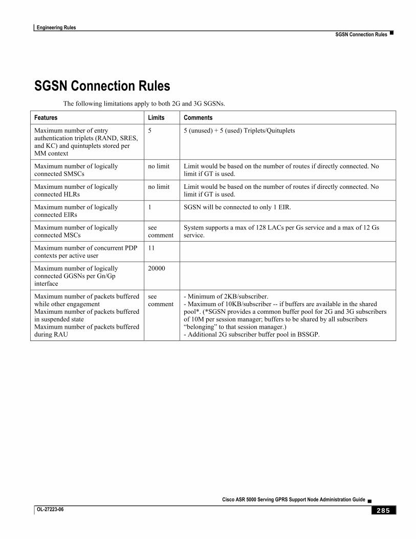
Engineering Rules
SGSN Connection Rules ▀
Cisco ASR 5000 Serving GPRS Support Node Administration Guide ▄ OL-27223-06 285
SGSN Connection Rules The following limitations apply to both 2G and 3G SGSNs.
Features Limits Comments
Maximum number of entry authentication triplets (RAND, SRES, and KC) and quintuplets stored per MM context
5 5 (unused) + 5 (used) Triplets/Quituplets
Maximum number of logically connected SMSCs
no limit Limit would be based on the number of routes if directly connected. No limit if GT is used.
Maximum number of logically connected HLRs
no limit Limit would be based on the number of routes if directly connected. No limit if GT is used.
Maximum number of logically connected EIRs
1 SGSN will be connected to only 1 EIR.
Maximum number of logically connected MSCs
see comment
System supports a max of 128 LACs per Gs service and a max of 12 Gs service.
Maximum number of concurrent PDP contexts per active user
11
Maximum number of logically connected GGSNs per Gn/Gp interface
20000
Maximum number of packets buffered while other engagement Maximum number of packets buffered in suspended state Maximum number of packets buffered during RAU
see comment
- Minimum of 2KB/subscriber. - Maximum of 10KB/subscriber -- if buffers are available in the shared pool*. (*SGSN provides a common buffer pool for 2G and 3G subscribers of 10M per session manager; buffers to be shared by all subscribers “belonging” to that session manager.) - Additional 2G subscriber buffer pool in BSSGP.
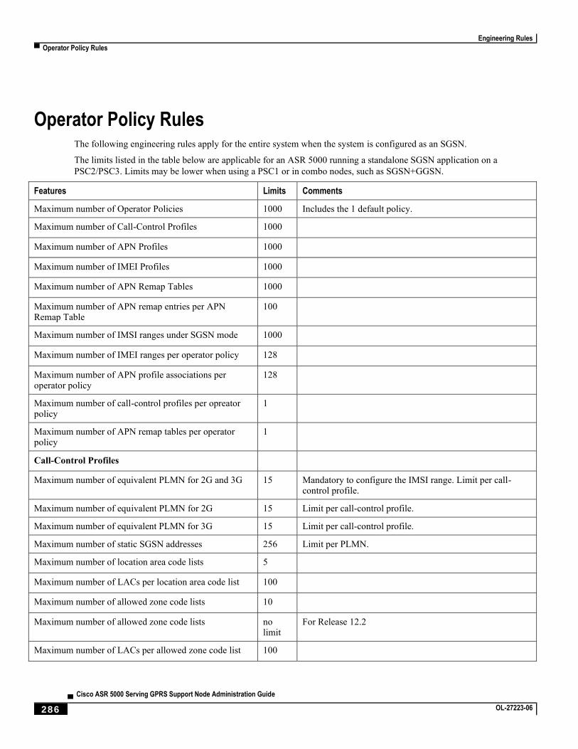
Engineering Rules
▀ Operator Policy Rules
▄ Cisco ASR 5000 Serving GPRS Support Node Administration Guide
286 OL-27223-06
Operator Policy Rules The following engineering rules apply for the entire system when the system is configured as an SGSN.
The limits listed in the table below are applicable for an ASR 5000 running a standalone SGSN application on a
PSC2/PSC3. Limits may be lower when using a PSC1 or in combo nodes, such as SGSN+GGSN.
Features Limits Comments
Maximum number of Operator Policies 1000 Includes the 1 default policy.
Maximum number of Call-Control Profiles 1000
Maximum number of APN Profiles 1000
Maximum number of IMEI Profiles 1000
Maximum number of APN Remap Tables 1000
Maximum number of APN remap entries per APN Remap Table
100
Maximum number of IMSI ranges under SGSN mode 1000
Maximum number of IMEI ranges per operator policy 128
Maximum number of APN profile associations per operator policy
128
Maximum number of call-control profiles per opreator policy
1
Maximum number of APN remap tables per operator policy
1
Call-Control Profiles
Maximum number of equivalent PLMN for 2G and 3G 15 Mandatory to configure the IMSI range. Limit per call-control profile.
Maximum number of equivalent PLMN for 2G 15 Limit per call-control profile.
Maximum number of equivalent PLMN for 3G 15 Limit per call-control profile.
Maximum number of static SGSN addresses 256 Limit per PLMN.
Maximum number of location area code lists 5
Maximum number of LACs per location area code list 100
Maximum number of allowed zone code lists 10
Maximum number of allowed zone code lists no limit
For Release 12.2
Maximum number of LACs per allowed zone code list 100
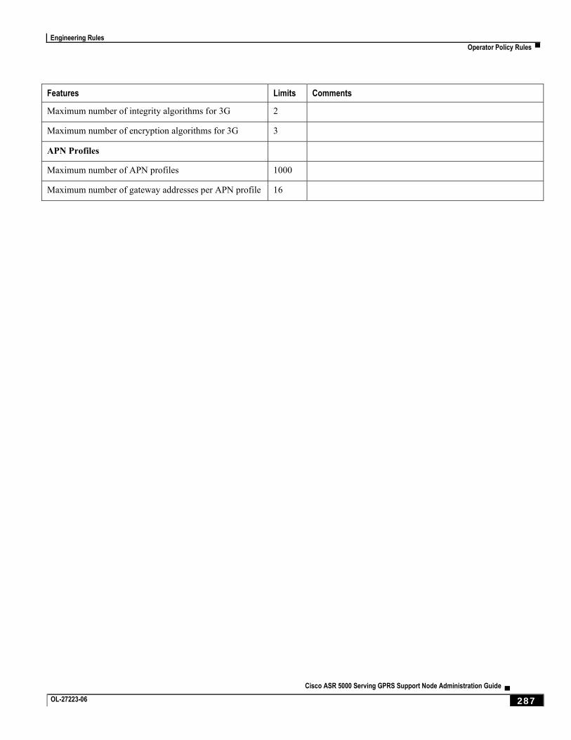
Engineering Rules
Operator Policy Rules ▀
Cisco ASR 5000 Serving GPRS Support Node Administration Guide ▄ OL-27223-06 287
Features Limits Comments
Maximum number of integrity algorithms for 3G 2
Maximum number of encryption algorithms for 3G 3
APN Profiles
Maximum number of APN profiles 1000
Maximum number of gateway addresses per APN profile 16
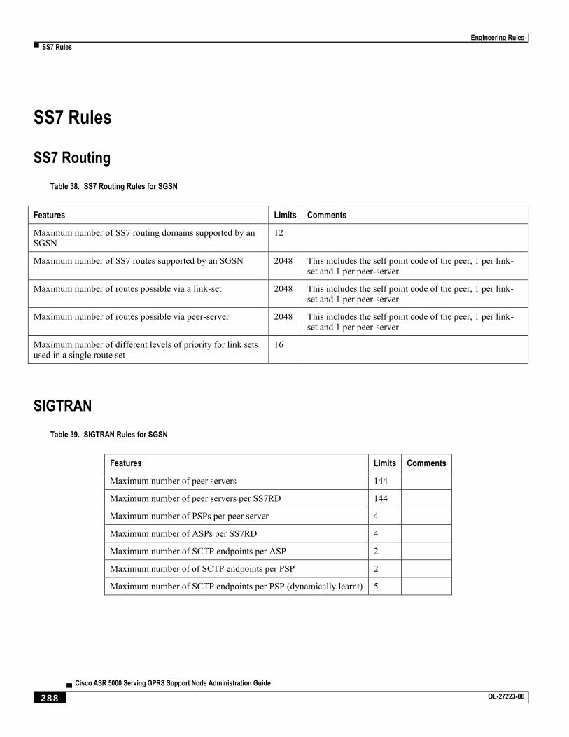
Engineering Rules
▀ SS7 Rules
▄ Cisco ASR 5000 Serving GPRS Support Node Administration Guide
288 OL-27223-06
SS7 Rules
SS7 Routing
Table 38. SS7 Routing Rules for SGSN
Features Limits Comments
Maximum number of SS7 routing domains supported by an SGSN
12
Maximum number of SS7 routes supported by an SGSN 2048 This includes the self point code of the peer, 1 per link-set and 1 per peer-server
Maximum number of routes possible via a link-set 2048 This includes the self point code of the peer, 1 per link-set and 1 per peer-server
Maximum number of routes possible via peer-server 2048 This includes the self point code of the peer, 1 per link-set and 1 per peer-server
Maximum number of different levels of priority for link sets used in a single route set
16
SIGTRAN
Table 39. SIGTRAN Rules for SGSN
Features Limits Comments
Maximum number of peer servers 144
Maximum number of peer servers per SS7RD 144
Maximum number of PSPs per peer server 4
Maximum number of ASPs per SS7RD 4
Maximum number of SCTP endpoints per ASP 2
Maximum number of of SCTP endpoints per PSP 2
Maximum number of SCTP endpoints per PSP (dynamically learnt) 5
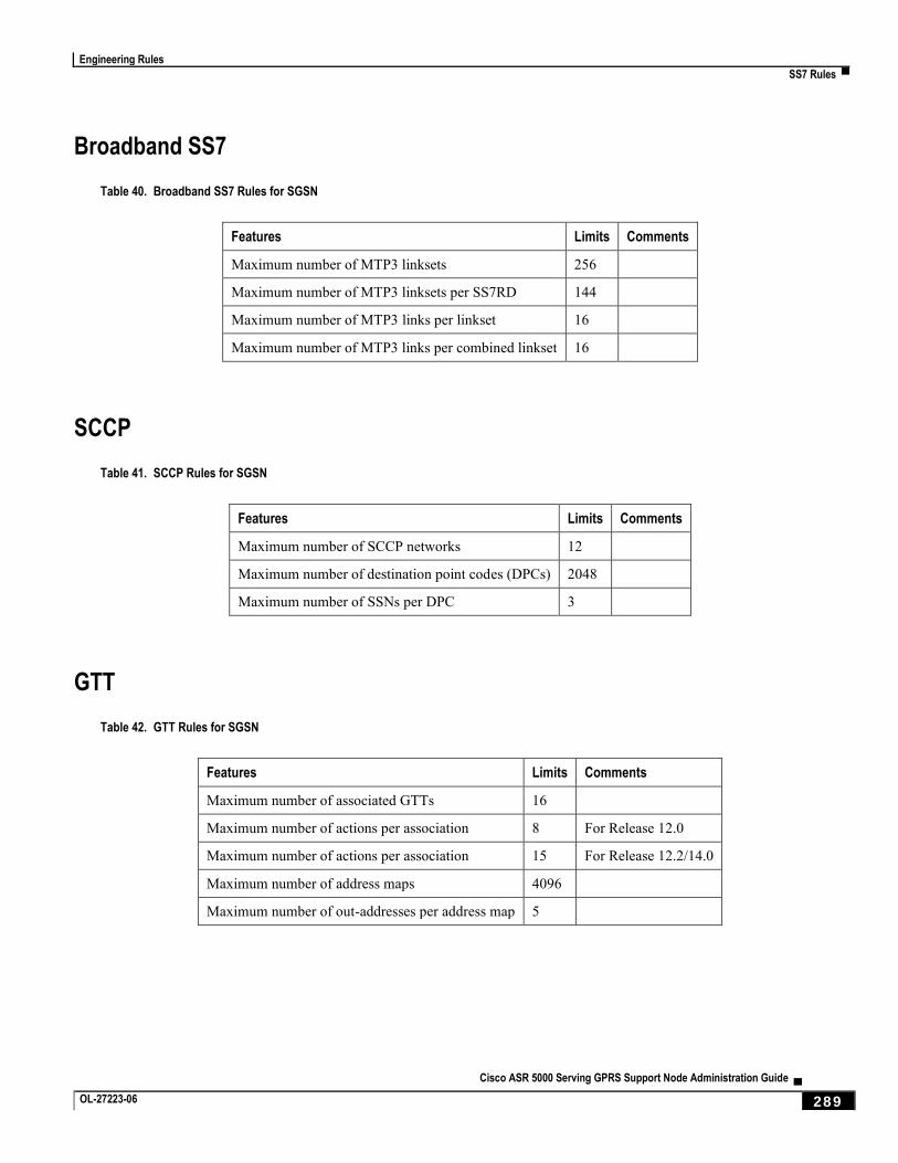
Engineering Rules
SS7 Rules ▀
Cisco ASR 5000 Serving GPRS Support Node Administration Guide ▄ OL-27223-06 289
Broadband SS7
Table 40. Broadband SS7 Rules for SGSN
Features Limits Comments
Maximum number of MTP3 linksets 256
Maximum number of MTP3 linksets per SS7RD 144
Maximum number of MTP3 links per linkset 16
Maximum number of MTP3 links per combined linkset 16
SCCP
Table 41. SCCP Rules for SGSN
Features Limits Comments
Maximum number of SCCP networks 12
Maximum number of destination point codes (DPCs) 2048
Maximum number of SSNs per DPC 3
GTT
Table 42. GTT Rules for SGSN
Features Limits Comments
Maximum number of associated GTTs 16
Maximum number of actions per association 8 For Release 12.0
Maximum number of actions per association 15 For Release 12.2/14.0
Maximum number of address maps 4096
Maximum number of out-addresses per address map 5
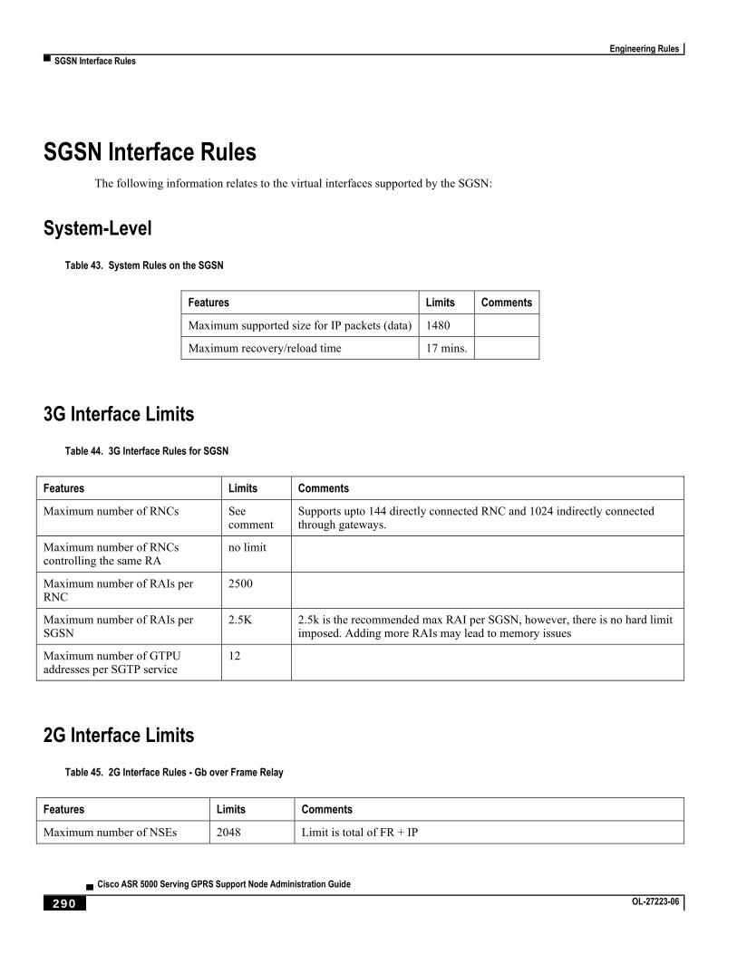
Engineering Rules
▀ SGSN Interface Rules
▄ Cisco ASR 5000 Serving GPRS Support Node Administration Guide
290 OL-27223-06
SGSN Interface Rules The following information relates to the virtual interfaces supported by the SGSN:
System-Level
Table 43. System Rules on the SGSN
Features Limits Comments
Maximum supported size for IP packets (data) 1480
Maximum recovery/reload time 17 mins.
3G Interface Limits
Table 44. 3G Interface Rules for SGSN
Features Limits Comments
Maximum number of RNCs See comment
Supports upto 144 directly connected RNC and 1024 indirectly connected through gateways.
Maximum number of RNCs controlling the same RA
no limit
Maximum number of RAIs per RNC
2500
Maximum number of RAIs per SGSN
2.5K 2.5k is the recommended max RAI per SGSN, however, there is no hard limit imposed. Adding more RAIs may lead to memory issues
Maximum number of GTPU addresses per SGTP service
12
2G Interface Limits
Table 45. 2G Interface Rules - Gb over Frame Relay
Features Limits Comments
Maximum number of NSEs 2048 Limit is total of FR + IP
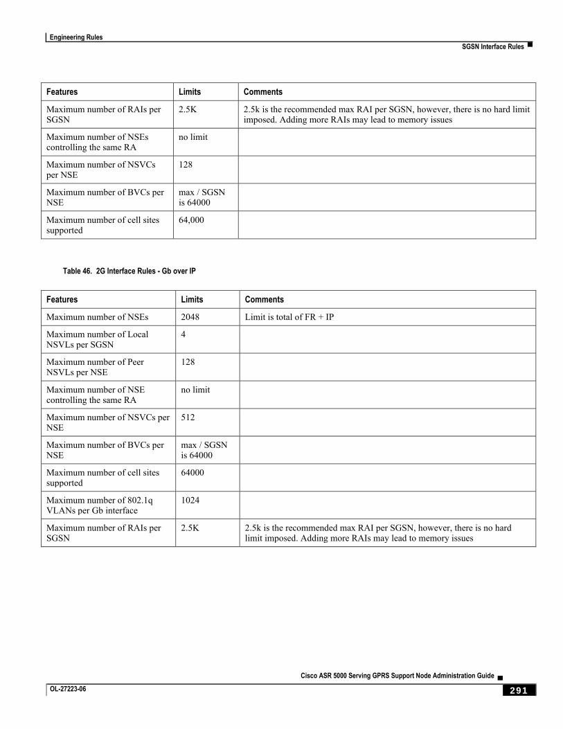
Engineering Rules
SGSN Interface Rules ▀
Cisco ASR 5000 Serving GPRS Support Node Administration Guide ▄ OL-27223-06 291
Features Limits Comments
Maximum number of RAIs per SGSN
2.5K 2.5k is the recommended max RAI per SGSN, however, there is no hard limit imposed. Adding more RAIs may lead to memory issues
Maximum number of NSEs controlling the same RA
no limit
Maximum number of NSVCs per NSE
128
Maximum number of BVCs per NSE
max / SGSN is 64000
Maximum number of cell sites supported
64,000
Table 46. 2G Interface Rules - Gb over IP
Features Limits Comments
Maximum number of NSEs 2048 Limit is total of FR + IP
Maximum number of Local NSVLs per SGSN
4
Maximum number of Peer NSVLs per NSE
128
Maximum number of NSE controlling the same RA
no limit
Maximum number of NSVCs per NSE
512
Maximum number of BVCs per NSE
max / SGSN is 64000
Maximum number of cell sites supported
64000
Maximum number of 802.1q VLANs per Gb interface
1024
Maximum number of RAIs per SGSN
2.5K 2.5k is the recommended max RAI per SGSN, however, there is no hard limit imposed. Adding more RAIs may lead to memory issues