cisco ecds software command reference · contents 2 ol-31961-01 authsvr 2-37 bandwidth (global...
TRANSCRIPT

Cisco ECDS Command ReferenceFebruary 3, 2016
Cisco Systems, Inc.www.cisco.com
Cisco has more than 200 offices worldwide. Addresses, phone numbers, and fax numbers are listed on the Cisco website at www.cisco.com/go/offices.

THE SPECIFICATIONS AND INFORMATION REGARDING THE PRODUCTS IN THIS MANUAL ARE SUBJECT TO CHANGE WITHOUT NOTICE. ALL STATEMENTS, INFORMATION, AND RECOMMENDATIONS IN THIS MANUAL ARE BELIEVED TO BE ACCURATE BUT ARE PRESENTED WITHOUT WARRANTY OF ANY KIND, EXPRESS OR IMPLIED. USERS MUST TAKE FULL RESPONSIBILITY FOR THEIR APPLICATION OF ANY PRODUCTS.
THE SOFTWARE LICENSE AND LIMITED WARRANTY FOR THE ACCOMPANYING PRODUCT ARE SET FORTH IN THE INFORMATION PACKET THAT SHIPPED WITH THE PRODUCT AND ARE INCORPORATED HEREIN BY THIS REFERENCE. IF YOU ARE UNABLE TO LOCATE THE SOFTWARE LICENSE OR LIMITED WARRANTY, CONTACT YOUR CISCO REPRESENTATIVE FOR A COPY.
The Cisco implementation of TCP header compression is an adaptation of a program developed by the University of California, Berkeley (UCB) as part of UCB’s public domain version of the UNIX operating system. All rights reserved. Copyright © 1981, Regents of the University of California.
NOTWITHSTANDING ANY OTHER WARRANTY HEREIN, ALL DOCUMENT FILES AND SOFTWARE OF THESE SUPPLIERS ARE PROVIDED “AS IS” WITH ALL FAULTS. CISCO AND THE ABOVE-NAMED SUPPLIERS DISCLAIM ALL WARRANTIES, EXPRESSED OR IMPLIED, INCLUDING, WITHOUT LIMITATION, THOSE OF MERCHANTABILITY, FITNESS FOR A PARTICULAR PURPOSE AND NONINFRINGEMENT OR ARISING FROM A COURSE OF DEALING, USAGE, OR TRADE PRACTICE.
IN NO EVENT SHALL CISCO OR ITS SUPPLIERS BE LIABLE FOR ANY INDIRECT, SPECIAL, CONSEQUENTIAL, OR INCIDENTAL DAMAGES, INCLUDING, WITHOUT LIMITATION, LOST PROFITS OR LOSS OR DAMAGE TO DATA ARISING OUT OF THE USE OR INABILITY TO USE THIS MANUAL, EVEN IF CISCO OR ITS SUPPLIERS HAVE BEEN ADVISED OF THE POSSIBILITY OF SUCH DAMAGES.
OR ITS SUPPLIERS HAVE BEEN ADVISED OF THE POSSIBILITY OF SUCH DAMAGES.
Cisco and the Cisco logo are trademarks or registered trademarks of Cisco and/or its affiliates in the U.S. and other countries. To view a list of Cisco trademarks, go to this URL: www.cisco.com/go/trademarks. Third-party trademarks mentioned are the property of their respective owners. The use of the word partner does not imply a partnership relationship between Cisco and any other company. (1110R)
Any Internet Protocol (IP) addresses used in this document are not intended to be actual addresses. Any examples, command display output, and figures included in the document are shown for illustrative purposes only. Any use of actual IP addresses in illustrative content is unintentional and coincidental.
© 2014-2016 Cisco Systems, Inc. All rights reserved.
OL-31961-01
C O N T E N T S
Preface 11
What’s in This Guide 11
Audience 11
Document Revision History 11
Document Organization 12
Document Conventions 12
Related Documentation 13
Obtaining Documentation and Submitting a Service Request 13
C H A P T E R 1 Command-Line Interface Command Summary 1-1
Using CDS Device Modes 1-1
Using Command-Line Processing 1-1
Using Command Modes 1-2
Using EXEC Mode 1-2
Using Global Configuration Mode 1-3
Using Interface Configuration Mode 1-3
Using Other Configuration Modes 1-4
Checking the Command Syntax 1-4
System Help 1-6
Saving Configuration Changes 1-6
C H A P T E R 2 Cisco ECDS Software Commands 2-1
Cisco ECDS Commands List 2-1
access-lists 2-18
acquirer (EXEC) 2-21
acquirer (global configuration) 2-23
acquisition-distribution 2-25
alarm nic-shutdown-alarm 2-27
alarm overload-detect 2-29
asset 2-31
authentication 2-32
1

Contents
authsvr 2-37
bandwidth (global configuration) 2-38
bandwidth (interface configuration) 2-41
banner 2-43
bitrate 2-46
bypass 2-49
cache 2-53
cache-router 2-54
capability 2-55
cd 2-56
cdn-select 2-57
cdnfs 2-58
cdsm 2-60
CIMC url 2-63
clear cache 2-64
clear content 2-65
clear ip 2-67
clear logging 2-70
clear service-router 2-71
clear statistics 2-72
clear transaction-logs 2-76
clear users 2-77
clear wmt 2-78
clock (EXEC) 2-79
clock (global configuration) 2-81
cms (EXEC) 2-84
cms (global configuration) 2-88
configure 2-91
copy 2-92
cpfile 2-96
debug 2-97
delfile 2-105
deltree 2-106
device 2-107
dir 2-109
2
OL-31961-01

Contents
direct-server-return 2-110
disable 2-111
disk (EXEC) 2-112
disk (global configuration) 2-117
distribution 2-119
dnslookup 2-122
enable 2-123
end 2-124
exec-timeout 2-125
exit 2-126
expert-mode password 2-127
external-ip 2-128
find-pattern 2-130
flash-media-streaming 2-132
help 2-135
hostname 2-136
http 2-137
https (EXEC) 2-142
https server 2-146
https server (mine) 2-150
icap 2-154
install 2-155
interface 2-156
ip (global configuration) 2-159
ip (interface configuration) 2-168
ip access-list 2-170
ipv6 2-178
kernel kdb 2-179
key 2-180
key-string 2-181
key chain 2-182
line 2-184
lls 3-185
logging 3-186
ls 3-190
3
OL-31961-01

Contents
mkdir 3-191
mkfile 3-192
movie-streamer 3-193
mtu 3-197
nat 3-198
no (global configuration) 3-199
no (interface configuration) 3-201
ntp 3-202
ntpdate 3-204
ping 3-205
ping6 3-206
port-channel 3-207
primary-interface 3-209
proximity algorithm bgp 3-211
proximity engine enable 3-212
pwd 3-213
qos 3-214
radius-server 3-216
rcp 3-220
rea 3-221
reload 3-222
rename 3-223
restore 3-224
rmdir 3-227
rtsp 3-228
rule 3-231
script 3-240
service-monitor 3-241
service-router 3-245
service snmp restart 3-251
setup 3-251
show access-lists 300 3-253
show acquirer 3-254
show alarms 3-256
show arp 3-259
4
OL-31961-01

Contents
show authentication 3-260
show authsvr 3-261
show bandwidth 3-262
show banner 3-264
show bitrate 3-265
show bypass 3-266
show cache 3-269
show capability 3-270
show cdn-select 3-271
show cdnfs 3-272
show clock 3-273
show cms 3-276
show content 3-278
show debugging 3-279
show device-mode 3-282
show direct-server-return 3-284
show disks 3-285
show distribution 3-289
show flash 3-298
show flash-media-streaming 3-299
show ftp 3-301
show hardware 3-302
show hosts 3-305
show http 3-306
show https 3-310
show interface 3-312
show inventory 3-315
show ip access-list 3-317
show ip interface 3-319
show ip routes 3-320
show key chain 3-322
show logging 3-323
show movie-streamer 3-325
show ntp 3-326
show processes 3-328
5
OL-31961-01

Contents
show programs 3-330
show qos 3-337
show radius-server 3-338
show rcp 3-340
show rea 3-341
show rtsp 3-342
show rule 3-343
show running-config 3-345
show service-monitor 3-348
show service-router 3-351
show services 3-355
show snmp 3-357
show ssh 3-361
show standby 3-362
show startup-config 3-363
show statistics access-lists 300 3-366
show statistics acquirer 3-367
show statistics authentication 3-369
show statistics authsvr 3-370
show statistics cdnfs 3-371
show statistics distribution 4-374
show statistics flash-media-streaming 4-377
show statistics http 4-384
show statistics icap 4-388
show statistics icmp 4-389
show statistics ip 4-395
show statistics movie-streamer 4-399
show statistics netstat 4-402
show statistics qos 4-403
show statistics radius 4-404
show statistics replication 4-405
show statistics service-router 4-407
show statistics services 4-411
show statistics snmp 4-412
show statistics tacacs 4-414
6
OL-31961-01

Contents
show statistics tcp 4-415
show statistics transaction-logs 4-424
show statistics udp 4-426
show statistics wccp 4-427
show statistics wmt 4-431
show tacacs 4-437
show tech-support 4-439
show telnet 4-445
show transaction-logging 4-446
show url-signature 4-450
show user 4-451
show users 4-452
show version 4-453
show wccp 4-454
show wmt 4-459
shutdown (interface configuration) 4-465
shutdown (EXEC) 4-466
snmp-server community 4-470
snmp-server contact 4-471
snmp-server enable traps 4-472
snmp-server group 4-474
snmp-server host 4-476
snmp-server location 4-478
snmp-server notify inform 4-479
snmp-server trap-source 4-481
snmp-server user 4-482
snmp-server view 4-484
sshd 4-486
streaming-interface 4-488
sysreport 4-489
tacacs 4-490
tcpdump 4-494
tcp timestamp 4-499
telnet 4-500
telnet enable 4-501
7
OL-31961-01

Contents
terminal 4-502
test-url 4-503
traceroute 4-507
traceroute srp 4-510
traceroute6 4-511
transaction-log force 4-512
transaction-logs 4-514
type 4-531
type-tail 4-533
undebug 4-536
url-signature 4-537
username 4-540
wccp custom-web-cache 4-543
wccp flow-redirect 4-548
wccp https-cache 4-549
wccp port-list 4-553
wccp router-list 4-554
wccp rtmp 4-556
wccp rtsp 4-558
wccp service-number 4-560
wccp shutdown 4-566
wccp slow-start 4-568
wccp version 4-570
wccp web-cache 4-571
wccp wmt 4-575
wccp wmt-rtspu 4-578
whoami 4-581
wmt 4-582
write 4-599
A P P E N D I X A Acronyms A-1
A P P E N D I X B Standard Time Zones B-1
A P P E N D I X C Unsupported Features C-1
Unsupported in Cisco ECDS C-1
8
OL-31961-01

Contents
Unsupported in Cisco ECDS with WCCP C-1
Where to Go Next C-2
I N D E X
9
OL-31961-01

Contents
10
OL-31961-01

Preface
This chapter contains the following sections:
• What’s in This Guide, page 11
• Audience, page 11
• Document Revision History, page 11
• Document Organization, page 12
• Document Conventions, page 12
• Related Documentation, page 13
• Obtaining Documentation and Submitting a Service Request, page 13
What’s in This GuideThis guide describes how to configure and maintain the Cisco Enterprise Content Delivery System (ECDS) software using command-line interface (CLI) commands.
AudienceThis guide is for the networking professional using Cisco ECDS Release 2.6; you should have experience working with the Cisco ECDS and be familiar with the concepts and terminology of Ethernet and local area networking.
Document Revision HistoryTable 1 describes document update history.
Table 1 Document Revision History
Date Change Summary
February 2011 Initial release.
August 2012 Support for ECDS Releases up to 2.5.5.
November 2013 Support for ECDS Releases up to 2.6
11Cisco ECDS Software Command Reference

Document OrganizationTable 2 lists the chapters in this guide.
Document ConventionsTable 3 lists conventions used to convey instructions and information.
May 2014 Support for ECDS Releases up to 2.6
June 2015 Support for ECDS Releases up to 2.6
Table 1 Document Revision History
Date Change Summary
Table 2 Document Organization
Chapter Description
Chapter 1, “Command-Line Interface Command Summary”
How to use the Cisco ECDS CLI to configure software features.
Chapter 2, “Cisco ECDS Software Commands” Provides a complete list of Cisco ECDS commands listed alphabetically.
Appendix A, “Acronyms” Lists the abbreviations and acronyms used in this guide.
Appendix B, “Standard Time Zones” Lists supported standard time zones that you can configure on the Cisco Media Delivery Engine (MDE) and the offset from coordinated universal time (UTC) for each standard time zone.
Table 3 Document Conventions
Convention Description
boldface font Commands, keywords, and button names are in boldface.
italic font Variables for which you supply values are in italics. Directory names and filenames are also in italics.
screen font Terminal sessions and information the system displays are in screen font.
boldface screen font Information you must enter is in boldface screen font.
italic screen font Variables you enter are in italic screen font.
^ The symbol ^ represents the key labeled Control. For example, the key combination ^D in a screen display means hold down the Control key while you press the D key.
string Defined as a nonquoted set of characters.
For example, when setting a community string for SNMP to “public,” do not use quotation marks around the string, or the string will include the quotation marks.
12Cisco ECDS Software Command Reference

Notes, cautions, and warnings use these conventions and symbols:
Note Means reader take note. Notes contain helpful suggestions or references to materials not contained in this manual.
Caution Means reader be careful. In this situation, you might do something that could result in equipment damage or loss of data.
Related DocumentationFor complete document support for the Cisco Media Delivery Engine appliances and the Cisco Enterprise Content Delivery System, see the Documentation for the Enterprise Content Delivery System (ECDS) document roadmap at the following link:
http://www.cisco.com/en/US/docs/video/ecds/documentation.html
Obtaining Documentation and Submitting a Service RequestFor information on obtaining documentation, submitting a service request, and gathering additional information, see the monthly What’s New in Cisco Product Documentation, which also lists all new and revised Cisco technical documentation, at:
http://www.cisco.com/en/US/docs/general/whatsnew/whatsnew.html
Subscribe to the What’s New in Cisco Product Documentation as a Really Simple Syndication (RSS) feed and set content to be delivered directly to your desktop using a reader application. The RSS feeds are a free service and Cisco currently supports RSS version 2.0.
vertical bars ( | ) Vertical bars separate alternative, mutually exclusive, elements.
{ } Elements in braces are required elements.
[ ] Elements in square brackets are optional.
{x | y | z} Required keywords are grouped in braces and separated by vertical bars.
[x | y | z] Optional keywords are grouped in brackets and separated by vertical bars.
[{ }] Braces within square brackets indicate a required choice within an optional element.
< > Nonprinting characters, such as passwords or tabs, are in angle brackets.
Table 3 Document Conventions
Convention Description
13Cisco ECDS Software Command Reference

14Cisco ECDS Software Command Reference

C H A P T E R 1
Command-Line Interface Command SummaryThe following sections provide an overview of the Cisco Enterprise Content Delivery System (ECDS) software command-line interface (CLI):
• Using CDS Device Modes, page 1-1
• Using Command-Line Processing, page 1-1
• Using Command Modes, page 1-2
• Checking the Command Syntax, page 1-4
• System Help, page 1-6
• Saving Configuration Changes, page 1-6
Note The CLI can be accessed through the console port or Telnet.
Using CDS Device ModesIn Cisco ECDS software, the device mode determines whether the CDS device is functioning as a Service Engine (SE), CDS Manager (CDSM), or Service Router (SR). The commands available from a specific CLI mode are determined by the CDS device mode in effect. Use the device mode global configuration command to change the current device mode to another configuration. Use the show device-mode command to display the current device configuration.
To determine if a specific command is available for a specific device type, see Table 2-1 in Chapter 2, “Cisco ECDS Software Commands.”
Using Command-Line ProcessingCisco ECDS software commands are not case sensitive. You can abbreviate commands and parameters as long as they contain enough letters to be different from any other currently available commands or parameters.
You can scroll through the last 20 commands stored in the history buffer and enter or edit the command at the prompt. Table 1-1 describes CLI navigation tips.
1-1Cisco ECDS Software Command Reference

Chapter 1 Command-Line Interface Command Summary Using Command Modes
Using Command ModesThis section describes available command modes:
• Using EXEC Mode, page 1-2
• Using Global Configuration Mode, page 1-3
• Using Interface Configuration Mode, page 1-3
• Using Other Configuration Modes, page 1-4
Using EXEC ModeUse EXEC mode for setting, viewing, and testing system operations. EXEC mode is divided into two access levels, user and privileged. Use the enable and disable commands to switch between the two levels.
Table 1-1 Command-Line Processing Keystroke Combinations
Keystroke Combinations Function
Ctrl-A Jumps to the first character of the command line.
Ctrl-B or the Left Arrow key Moves the cursor back one character.
Ctrl-C Escapes and terminates prompts and tasks.
Ctrl-D Deletes the character at the cursor.
Ctrl-E Jumps to the end of the current command line.
Ctrl-F or the Right Arrow key Moves the cursor forward one character.
Ctrl-K Deletes from the cursor to the end of the command line.
Ctrl-L Repeats the current command line on a new line.
Ctrl-N or the Down Arrow key Enters the next command line in the history buffer.
Ctrl-P or the Up Arrow key Enters the previous command line in the history buffer.
Ctrl-T Transposes the character at the cursor with the character to the left of the cursor.
Ctrl-U; Ctrl-X Deletes from the cursor to the beginning of the command line.
Ctrl-W Deletes the last word entered.
Esc-B Moves the cursor back one word.
Esc-D Deletes from the cursor to the end of the word.
Esc-F Moves the cursor forward one word.
Delete key or Backspace key Erases a mistake when entering a command; reenter the command after using this key.
1-2Cisco ECDS Software Command Reference

Chapter 1 Command-Line Interface Command Summary Using Command Modes
Access to the user-level EXEC command line requires a valid password. The user-level EXEC commands are a subset of the privileged-level EXEC commands. The user-level EXEC prompt is the host name followed by a right angle bracket (>). The prompt for the privileged-level EXEC command line is the pound sign (# ). To execute an EXEC command, enter the command at the EXEC system prompt and press the Return key. In the following example, a user accesses the privileged-level EXEC command line from the user level.
ServiceEngine> enableServiceEngine#
Use the Delete or Backspace key sequences to edit commands when you enter commands at the EXEC prompt.
As a shortcut, you can abbreviate commands to the fewest letters that make them unique. For example, the letters sho can be entered for the show command.
Certain EXEC commands display multiple screens with the following prompt at the bottom of the screen:
--More--
Press the Spacebar to continue the output, or press Return to display the next line. Press any other key to return to the prompt. Also, at the --More-- prompt, you can enter a question mark (?) to display the help message.
To leave EXEC mode, use the exit command at the system prompt:
ServiceEngine# exit
The EXEC commands are entered in EXEC mode.
Using Global Configuration ModeUse global configuration mode for setting, viewing, and testing ECDS software feature configuration. To access this mode, enter the configure command from privileged EXEC mode. You must be in global configuration mode to enter global configuration commands.
ServiceEngine# configureServiceEngine(config)#
To exit global configuration mode, use the end global configuration command:
ServiceEngine(config)# end
You can also exit global configuration mode by entering the exit command or by pressing Ctrl-Z.
Global configuration commands are entered in global configuration mode.
Using Interface Configuration ModeUse interface configuration mode for setting, viewing, and testing ECDS software feature configuration on a specific interface. To access this mode, enter the interface command from global configuration mode. The following example demonstrates how to enter interface configuration mode:
ServiceEngine# configureServiceEngine(config)# interface ?GigabitEthernet Select a gigabit ethernet interface to configurePortChannel Ethernet Channel of interfacesStandby Standby groups
1-3Cisco ECDS Software Command Reference

Chapter 1 Command-Line Interface Command Summary Checking the Command Syntax
To exit interface configuration mode, enter exit to return to global configuration mode:
ServiceEngine(config-if)# exitServiceEngine(config)#
Interface configuration commands are entered in interface configuration mode.
Using Other Configuration ModesThe CLI provides several other configuration modes that make it easier to configure specific features, including the configuration modes described in Table 1-2.
To work with these configuration modes, enter the appropriate command from the global configuration mode prompt. The CLI enters a new configuration mode where all subsequent commands apply to the current entry. To return to global configuration mode, enter the exit command.
For further information about these configuration modes and the commands permitted in each one, see Chapter 2, “Cisco ECDS Software Commands.”
Checking the Command SyntaxThe user interface provides error isolation in the form of an error indicator, a caret symbol (^). The ̂ symbol appears at the point in the command string where you have entered an incorrect command, keyword, or argument.
In the following example, suppose you want to set the clock. Use context-sensitive help to check the syntax for setting the clock.
An example of a mistake is as follows:
ServiceEngine# clock ?read-calendar Read the calendar and update system clockset Set the time and dateupdate-calendar Update the calendar with system clock
The help output shows that the set keyword is required. Check the syntax for entering the time.
ServiceEngine# clock set ?<0-23>: Current Time (hh:mm:ss)
Enter the current time in a 24-hour format with hours, minutes, and seconds separated by colons.
ServiceEngine# clock set 13:32:00% Incomplete command.
Table 1-2 Commands Used to Access Configuration Modes for Specific Features
Configuration Mode Command to Enter from Global Configuration Mode
Standard access control list (ACL) configuration mode
ip access-list standard
Extended ACL configuration mode ip access-list extended
1-4Cisco ECDS Software Command Reference

Chapter 1 Command-Line Interface Command Summary Checking the Command Syntax
The system indicates that you need to provide additional arguments to complete the command. Press the Up Arrow to automatically repeat the previous command entry. Then add a space and question mark (?) to display the additional arguments.
ServiceEngine# clock set 13:32:00 ?<1-31> Day of the monthJanuary Month of the yearFebruaryMarch. . .
Enter the day and month as prompted and use the question mark for additional instructions.
ServiceEngine# clock set 13:32:00 12 April ? <1993-2035> Year
Now you can complete the command entry by entering the year.
ServiceEngine# clock set 13:32:00 12 April 00 ^%Invalid input detected at '^' marker.ServiceEngine#
The caret symbol (^) and help response indicate an error with the 00 entry. To display the correct syntax, press Ctrl-P or the Up Arrow. You can also reenter the command string, and then enter a space character, a question mark, and press Enter.
ServiceEngine# clock set 13:32:00 12 April ?<1993-2035> YearServiceEngine# clock set 13:32:00 12 April
Enter the year using the correct syntax and press Return to execute the command.
ServiceEngine# clock set 13:32:00 12 April 2012Sun Aor 12 13:32:00 UTC 2012Restarting acquisition and distributionServiceEngine#
Note We strongly recommend that you configure all ECDS devices to use the Network Time Protocol (NTP) to keep their time synchronized. See the “ntp” section on page -202 for more details.
1-5Cisco ECDS Software Command Reference

Chapter 1 Command-Line Interface Command Summary System Help
System Help Obtain help when you enter commands by using the following methods:
• For a brief description of the context-sensitive help system, enter help.
• To list all commands for a command mode, enter a question mark (?) at the system prompt.
• To obtain a list of commands that start with a particular character set, enter an abbreviated command immediately followed by a question mark (?).
ServiceEngine# cl?clear clock
• To list the command keywords or arguments, enter a space and a question mark (?) after the command.
ServiceEngine# clock ?read-calendarRead the calendar and update system clocksetSet the time and dateupdate-calendarUpdate the calendar with system clock
Saving Configuration ChangesTo avoid losing new configurations, save them to NVRAM using the copy or write commands, as shown in the following examples:
ServiceEngine# copy running-config startup-config
or
ServiceEngine# write
See the command description for the copy running-config startup-config command for more information on “running” and “saved” configuration modes.
1-6Cisco ECDS Software Command Reference

C H A P T E R 2
Cisco ECDS Software CommandsThis chapter contains an alphabetical listing of all the commands in Cisco ECDS software and command mode information.
Table 2-1 summarizes all ECDS commands and indicates the command mode and device mode for each command. The commands used to access configuration modes are marked with a Tip to indicate that the same command may have different effects when entered in a different command mode, and for this reason, they are listed and documented separately. When the first occurrence is entered in EXEC mode, the second occurrence is entered in global configuration mode. When the first occurrence is entered in global configuration mode, the second occurrence is entered in interface configuration mode.
The ECDS software device mode determines whether the ECDS device is functioning as a Service Engine (SE), CDS Manager (CDSM), or Service Router (SR). The commands available from a specific CLI mode are determined by the ECDS device mode in effect. All indicates that the command is available for every device mode.
Note When viewing this guide online, click the name of the command in the left column of the table to jump to the command page, which provides the command syntax, examples, and usage guidelines.
Note See Appendix A, “Acronyms” for an expansion of all acronyms used in this publication.
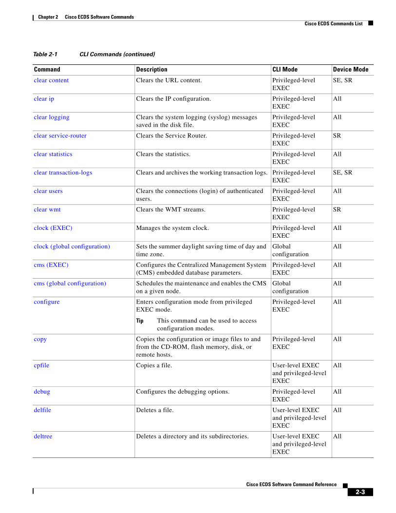
Cisco ECDS Commands ListTable 2-1 CLI Commands
Command Description CLI Mode Device Mode
access-lists Configures the access control list entries. Global configuration
SE
acquirer (EXEC) Configures the content acquirer. Privileged-level EXEC
SE
acquirer (global configuration) Enables authentication when the acquirer obtains content through a proxy server.
Global configuration
SE
acquisition-distribution Starts and stops the acquisition and distribution database cleanup process and the content acquisition and distribution process.
Privileged-level EXEC
SE
2-1Cisco ECDS Software Command Reference

Chapter 2 Cisco ECDS Software CommandsCisco ECDS Commands List
alarm nic-shutdown-alarm Generates an alarm when the NIC interface is shut down.
Global configuration
SE
alarm overload-detect Configures the detection of alarm overload. Global configuration
All
asset Configures the CISCO-ENTITY-ASSET-MIB.
Global configuration
All
authentication Configures the authentication parameters. Global configuration
All
authsvr Enables and configures the Authorization server. Global configuration
SE
bandwidth (global configuration) Sets the allowable bandwidth usage and its duration for the Movie Streamer and WMT streaming media.
Global configuration
SE
bandwidth (interface configuration) Sets the specified interface bandwidth to 10, 100, or 1000 Mbps.
Interface configuration
All
banner Configures the EXEC, login, and message-of-the-day (MOTD) banners.
Global configuration
All
bitrate Configures the maximum pacing bit rate for the Movie Streamer and configures WMT bit-rate settings.
Global configuration
SE
bypass Configures the bypass functions. Global configuration
SE
cache Specifies the cache commands. Global configuration
SE
cache-router Configures the cache-router commands. Global configuration
SE
capability Modifies the capability configuration. Global configuration
SE
cd Changes the directory. User-level EXEC and privileged-level EXEC
All
cdn-select Not supported in this release. Global Configuration
SR
cdnfs Manages the Media Streamer CDS network file system (CDNFS).
Privileged-level EXEC
SE
cdsm Configures the CDSM IP address and primary or standby role settings.
Global configuration
All
CIMC url Exposes the CIMC URL of a device to the ECDSM.
Global configuration
All
clear cache Clears the HTTP object cache. Privileged-level EXEC
SE, SR
Table 2-1 CLI Commands (continued)
Command Description CLI Mode Device Mode
2-2Cisco ECDS Software Command Reference
Chapter 2 Cisco ECDS Software CommandsCisco ECDS Commands List
clear content Clears the URL content. Privileged-level EXEC
SE, SR
clear ip Clears the IP configuration. Privileged-level EXEC
All
clear logging Clears the system logging (syslog) messages saved in the disk file.
Privileged-level EXEC
All
clear service-router Clears the Service Router. Privileged-level EXEC
SR
clear statistics Clears the statistics. Privileged-level EXEC
All
clear transaction-logs Clears and archives the working transaction logs. Privileged-level EXEC
SE, SR
clear users Clears the connections (login) of authenticated users.
Privileged-level EXEC
All
clear wmt Clears the WMT streams. Privileged-level EXEC
SR
clock (EXEC) Manages the system clock. Privileged-level EXEC
All
clock (global configuration) Sets the summer daylight saving time of day and time zone.
Global configuration
All
cms (EXEC) Configures the Centralized Management System (CMS) embedded database parameters.
Privileged-level EXEC
All
cms (global configuration) Schedules the maintenance and enables the CMS on a given node.
Global configuration
All
configure Enters configuration mode from privileged EXEC mode.
Tip This command can be used to access configuration modes.
Privileged-level EXEC
All
copy Copies the configuration or image files to and from the CD-ROM, flash memory, disk, or remote hosts.
Privileged-level EXEC
All
cpfile Copies a file. User-level EXEC and privileged-level EXEC
All
debug Configures the debugging options. Privileged-level EXEC
All
delfile Deletes a file. User-level EXEC and privileged-level EXEC
All
deltree Deletes a directory and its subdirectories. User-level EXEC and privileged-level EXEC
All
Table 2-1 CLI Commands (continued)
Command Description CLI Mode Device Mode
2-3Cisco ECDS Software Command Reference

Chapter 2 Cisco ECDS Software CommandsCisco ECDS Commands List
device Configures the mode of operation on a device. Global configuration
All
dir Displays the list of files in a directory. User-level EXEC and privileged-level EXEC
All
direct-server-return Enable a VIP for direct server return. Global configuration
SE, SR
disable Turns off the privileged EXEC commands. Privileged-level EXEC
All
disk (EXEC) Allocates the disks among the cdnfs and sysfs file systems.
Privileged-level EXEC
All
disk (global configuration) Configures how the disk errors should be handled.
Global configuration
All
distribution Reschedules and refreshes the content redistribution through multicast for all delivery services or a specified delivery service ID or name.
Privileged-level EXEC
SE
dnslookup Resolves a host or domain name to an IP address. User-level EXEC and privileged-level EXEC
All
enable Accesses the privileged EXEC commands.
Tip This command can be used to access configuration modes.
User-level EXEC and privileged-level EXEC
All
end Exits configuration and privileged EXEC modes. Global configuration
All
exec-timeout Configures the length of time that an inactive Telnet or secure shell session (SSH) remains open.
Global configuration
All
exit Exits from interface, global configuration, or privileged EXEC modes.
All All
expert-mode password Sets the expert-mode password. Global configuration
All
external-ip Configures up to a maximum of eight external IP addresses.
Global configuration
All
find-pattern Searches for a particular pattern in a file. Privileged-level EXEC
All
flash-media-streaming Enables and configures Flash Media Streaming. Global configuration
SE, SR
help Obtains online help for the command-line interface.
Global configuration and user-level EXEC
All
hostname Configures the device network name. Global configuration
All
Table 2-1 CLI Commands (continued)
Command Description CLI Mode Device Mode
2-4Cisco ECDS Software Command Reference

Chapter 2 Cisco ECDS Software CommandsCisco ECDS Commands List
http Configures HTTP-related parameters. Global configurative SE, SR
https (EXEC) Creates, removes, and imports certificates and private keys when using the Service Engine as an HTTPS server.
Privileged-level EXEC
SE
https server Configures the Service Engine to act as an origin HTTPS server.
Global configuration
SE
https server (mine) Creates, removes, and imports certificates and private keys when using the Service Engine as an HTTPS server.
Global configuration
SE
icap Enables the Internet Content Adaptation Protocol for supporting third-party software applications and plug-ins.
Global configuration
SE
install Installs a new version of the caching application. Privileged-level EXEC
All
interface Configures a Gigabit Ethernet or port-channel interface. Provides access to interface configuration mode.
Tip This command can be used to access configuration modes.
Global configuration
All
ip (global configuration) Configures the Internet Protocol. Global configuration
All
ip (interface configuration) Configures the interface Internet Protocol. Interface configuration
All
ip access-list Creates and modifies the access lists for controlling access to interfaces or applications. Provides access to ACL configuration mode.
Tip This command can be used to access configuration modes.
Global configuration
All
ipv6 Specifies the default gateway’s IPv6 address. Global configuration
SE
kernel kdb Enables the kernel debugger configuration mode. Global configuration
All
key Creates a key ID and enters into key ID configuration submode.
Key chain submode SR
key-string Creates a key string to be used for authentication. Key ID configuration submode
SR
key chain Creates a key chain and enters into key chain configuration submode.
Global configuration
SR
line Specifies the terminal line settings. Global configuration
All
Table 2-1 CLI Commands (continued)
Command Description CLI Mode Device Mode
2-5Cisco ECDS Software Command Reference

Chapter 2 Cisco ECDS Software CommandsCisco ECDS Commands List
lls Displays the files in a long list format. User-level EXEC and privileged-level EXEC
All
logging Configures system logging messages (syslog). Global configuration
All
ls Lists the files and subdirectories in a directory. User-level EXEC and privileged-level EXEC
All
mkdir Makes a directory. User-level EXEC and privileged-level EXEC
All
mkfile Makes a file (for testing). User-level EXEC and privileged-level EXEC
All
movie-streamer Enables and configures the Movie Streamer server.
Global configuration
SE
mtu Sets the interface maximum transmission unit packet size.
Interface configuration
All
nat Specifies the external NAT IP address of the device.
Global configuration
SE
no (global configuration) Negates a global configuration command or sets its defaults.
Global configuration
All
no (interface configuration) Negates an interface command or sets its defaults.
Interface configuration
All
ntp Configures the Network Time Protocol server. Global configuration
All
ntpdate Sets the NTP software clock. Privileged-level EXEC
All
ping Sends the echo packets. User-level EXEC and privileged-level EXEC
All
ping6 Pings the IPv6 address. User-level EXEC and privileged-level EXEC
SE
port-channel Configures the port-channel load-balancing options.
Global configuration
All
primary-interface Configures a primary interface for the ECDS network to be a Gigabit Ethernet or port-channel interface.
Global configuration
All
proximity algorithm bgp Enables a BGP proximity algorithm option for the Proximity Engine.
Global configuration
SR
proximity engine enable Enables the Proximity Engine. Global Configuration
SR
Table 2-1 CLI Commands (continued)
Command Description CLI Mode Device Mode
2-6Cisco ECDS Software Command Reference

Chapter 2 Cisco ECDS Software CommandsCisco ECDS Commands List
pwd Displays the present working directory. User-level EXEC and privileged-level EXEC
All
qos Globally enables QoS functionality on the device.
Global configuration
SE
radius-server Configures the RADIUS authentication. Global configuration
All
rcp Enables RCP. Global configuration
All
rea Starts the remote execution agent. User-level EXEC and privileged-level EXEC
SE
reload Halts a device and performs a cold restart. Privileged-level EXEC
All
rename Renames a file. User-level EXEC and privileged-level EXEC
All
restore Restores a device to its manufactured default status.
Privileged-level EXEC
All
rmdir Removes a directory. User-level EXEC and privileged-level EXEC
All
rtsp Configures the Real-Time Streaming Protocol-related parameters.
Global configuration
SE
rule Sets the rules by which the SE filters HTTP, HTTPS, and Real-Time Streaming Protocol (RTSP) traffic.
Global configuration
SE
script Checks the errors in a script or executes a script. Privileged-level EXEC
All
service-monitor Configures service monitor information. Global configuration
SE
service-router Configures service routing. Global configuration
All
service snmp restart Restarts the snmp process. Privileged-level EXEC
SE
setup Configures the basic configuration settings and a set of commonly used caching services.
Privileged-level EXEC
All
show access-lists 300 Displays the access control list configuration. User-level EXEC and privileged-level EXEC
SE
show acquirer Displays the acquirer delivery service information and progress for a specified delivery service number or name.
User-level EXEC and privileged-level EXEC
SE
Table 2-1 CLI Commands (continued)
Command Description CLI Mode Device Mode
2-7Cisco ECDS Software Command Reference

Chapter 2 Cisco ECDS Software CommandsCisco ECDS Commands List
show alarms Displays information on various types of alarms, their status, and history.
User-level EXEC and privileged-level EXEC
All
show arp Displays the Address Resolution Protocol entries.
User-level EXEC and privileged-level EXEC
All
show authentication Displays the authentication configuration. User-level EXEC and privileged-level EXEC
All
show authsvr Displays the Authorization Server status. User-level EXEC and privileged-level EXEC
SE
show bandwidth Displays the bandwidth allocated to a particular device.
User-level EXEC and privileged-level EXEC
SE, SR
show banner Displays information on various types of banners.
User-level EXEC and privileged-level EXEC
All
show bitrate Displays the SE bit-rate configuration. User-level EXEC and privileged-level EXEC
SE, SR
show bypass Displays bypass configuration information User-level EXEC and privileged-level EXEC
SE, SR
show cache Displays a list of cached contents. User-level EXEC and privileged-level EXEC
SE
show capability Displays information for the Cap-X profile ID. User-level EXEC and privileged-level EXEC
SE
show cdn-select Not supported in this release. User-level EXEC and privileged-level EXEC
SR
show cdnfs Displays the ECDS network file system information.
User-level EXEC and privileged-level EXEC
CDSM, SE
show clock Displays the system clock. User-level EXEC and privileged-level EXEC
All
show cms Displays the Centralized Management System protocol, embedded database content, maintenance status, and other information.
User-level EXEC and privileged-level EXEC
All
Table 2-1 CLI Commands (continued)
Command Description CLI Mode Device Mode
2-8Cisco ECDS Software Command Reference

Chapter 2 Cisco ECDS Software CommandsCisco ECDS Commands List
show content Displays all content entries in the CDS. User-level EXEC and privileged-level EXEC
SE
show debugging Displays the state of each debugging option. User-level EXEC and privileged-level EXEC
All
show device-mode Displays the configured or current mode of a CDSM, SE, or SR device.
User-level EXEC and privileged-level EXEC
All
show direct-server-return Displays the Direct Server return information. User-level EXEC and privileged-level EXEC
SE, SR
show disks Displays the disk configurations. User-level EXEC and privileged-level EXEC
All
show distribution Displays the distribution information for a specified delivery service.
User-level EXEC and privileged-level EXEC
SE
show flash Displays the flash memory information. User-level EXEC and privileged-level EXEC
All
show flash-media-streaming Displays the Flash Media Streaming information.
User-level EXEC and privileged-level EXEC
SE, SR
show ftp Displays the caching configuration of the file transfer protocol (FTP).
User-level EXEC and privileged-level EXEC
All
show hardware Displays the system hardware information. User-level EXEC and privileged-level EXEC
All
show hosts Displays the IP domain name, name servers, IP addresses, and host table.
User-level EXEC and privileged-level EXEC
All
show http Displays the HTTP-related caching configuration.
User-level EXEC and privileged-level EXEC
SE
show https Displays HTTPS proxy status and port policies. User-level EXEC and privileged-level EXEC
SE
show interface Displays the hardware interface information. User-level EXEC and privileged-level EXEC
All
Table 2-1 CLI Commands (continued)
Command Description CLI Mode Device Mode
2-9Cisco ECDS Software Command Reference
Chapter 2 Cisco ECDS Software CommandsCisco ECDS Commands List
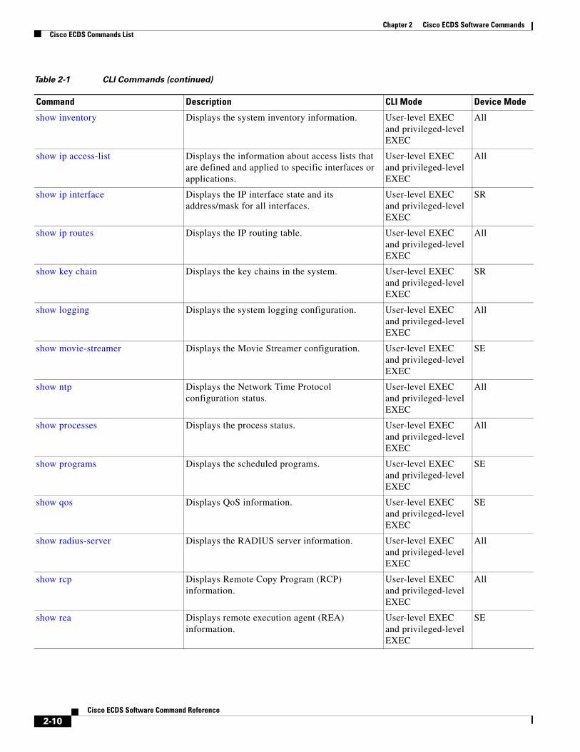
show inventory Displays the system inventory information. User-level EXEC and privileged-level EXEC
All
show ip access-list Displays the information about access lists that are defined and applied to specific interfaces or applications.
User-level EXEC and privileged-level EXEC
All
show ip interface Displays the IP interface state and its address/mask for all interfaces.
User-level EXEC and privileged-level EXEC
SR
show ip routes Displays the IP routing table. User-level EXEC and privileged-level EXEC
All
show key chain Displays the key chains in the system. User-level EXEC and privileged-level EXEC
SR
show logging Displays the system logging configuration. User-level EXEC and privileged-level EXEC
All
show movie-streamer Displays the Movie Streamer configuration. User-level EXEC and privileged-level EXEC
SE
show ntp Displays the Network Time Protocol configuration status.
User-level EXEC and privileged-level EXEC
All
show processes Displays the process status. User-level EXEC and privileged-level EXEC
All
show programs Displays the scheduled programs. User-level EXEC and privileged-level EXEC
SE
show qos Displays QoS information. User-level EXEC and privileged-level EXEC
SE
show radius-server Displays the RADIUS server information. User-level EXEC and privileged-level EXEC
All
show rcp Displays Remote Copy Program (RCP) information.
User-level EXEC and privileged-level EXEC
All
show rea Displays remote execution agent (REA) information.
User-level EXEC and privileged-level EXEC
SE
Table 2-1 CLI Commands (continued)
Command Description CLI Mode Device Mode
2-10Cisco ECDS Software Command Reference
Chapter 2 Cisco ECDS Software CommandsCisco ECDS Commands List
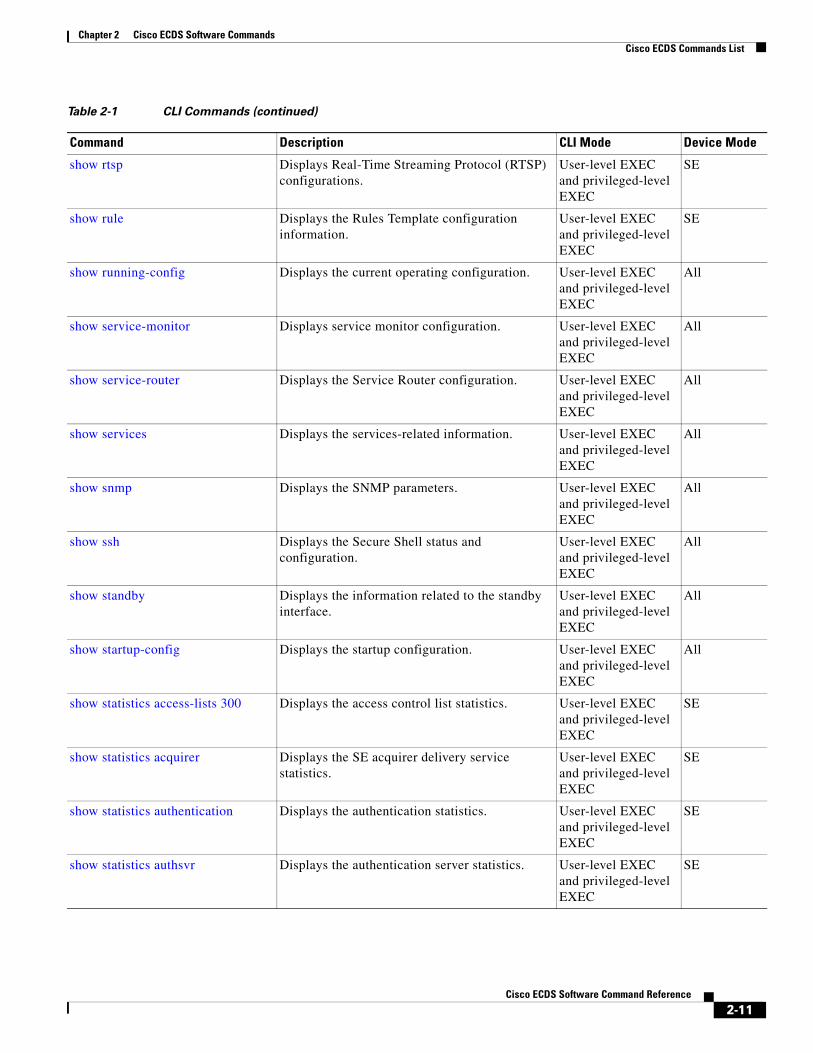
show rtsp Displays Real-Time Streaming Protocol (RTSP) configurations.
User-level EXEC and privileged-level EXEC
SE
show rule Displays the Rules Template configuration information.
User-level EXEC and privileged-level EXEC
SE
show running-config Displays the current operating configuration. User-level EXEC and privileged-level EXEC
All
show service-monitor Displays service monitor configuration. User-level EXEC and privileged-level EXEC
All
show service-router Displays the Service Router configuration. User-level EXEC and privileged-level EXEC
All
show services Displays the services-related information. User-level EXEC and privileged-level EXEC
All
show snmp Displays the SNMP parameters. User-level EXEC and privileged-level EXEC
All
show ssh Displays the Secure Shell status and configuration.
User-level EXEC and privileged-level EXEC
All
show standby Displays the information related to the standby interface.
User-level EXEC and privileged-level EXEC
All
show startup-config Displays the startup configuration. User-level EXEC and privileged-level EXEC
All
show statistics access-lists 300 Displays the access control list statistics. User-level EXEC and privileged-level EXEC
SE
show statistics acquirer Displays the SE acquirer delivery service statistics.
User-level EXEC and privileged-level EXEC
SE
show statistics authentication Displays the authentication statistics. User-level EXEC and privileged-level EXEC
SE
show statistics authsvr Displays the authentication server statistics. User-level EXEC and privileged-level EXEC
SE
Table 2-1 CLI Commands (continued)
Command Description CLI Mode Device Mode
2-11Cisco ECDS Software Command Reference

Chapter 2 Cisco ECDS Software CommandsCisco ECDS Commands List
show statistics cdnfs Displays the SE ECDS network file system statistics.
User-level EXEC and privileged-level EXEC
CDSM, SE
show statistics distribution Displays the simplified statistics for content distribution components.
User-level EXEC and privileged-level EXEC
SE
show statistics flash-media-streaming
Displays the statistics for Flash Media Streaming.
User-level EXEC and privileged-level EXEC
SE
show statistics http Displays the Hypertext Transfer Protocol statistics.
User-level EXEC and privileged-level EXEC
SE, SR
show statistics icap Not supported on the ECDS. — —
show statistics icmp Displays the Internet Control Message Protocol statistics.
User-level EXEC and privileged-level EXEC
All
show statistics ip Displays the Internet Protocol statistics. User-level EXEC and privileged-level EXEC
All
show statistics movie-streamer Displays statistics for the Movie Streamer. User-level EXEC and privileged-level EXEC
SE
show statistics netstat Displays the Internet socket connection statistics.
User-level EXEC and privileged-level EXEC
All
show statistics qos Displays statistics for the QoS policy service. User-level EXEC and privileged-level EXEC
SE
show statistics radius Displays the RADIUS authentication statistics. User-level EXEC and privileged-level EXEC
All
show statistics replication Displays the delivery service replication status and related statistical data.
User-level EXEC and privileged-level EXEC
CDSM, SR
show statistics service-router Displays the Service Router statistics. User-level EXEC and privileged-level EXEC
SR
show statistics services Displays the services statistics. User-level EXEC and privileged-level EXEC
All
show statistics snmp Displays the SNMP statistics. User-level EXEC and privileged-level EXEC
All
Table 2-1 CLI Commands (continued)
Command Description CLI Mode Device Mode
2-12Cisco ECDS Software Command Reference

Chapter 2 Cisco ECDS Software CommandsCisco ECDS Commands List
show statistics tacacs Displays the Service Engine TACACS+ authentication and authorization statistics.
User-level EXEC and privileged-level EXEC
All
show statistics tcp Displays the Transmission Control Protocol statistics.
User-level EXEC and privileged-level EXEC
All
show statistics transaction-logs Displays the transaction log export statistics. User-level EXEC and privileged-level EXEC
SE
show statistics udp Displays the User Datagram Protocol statistics. User-level EXEC and privileged-level EXEC
All
show statistics wccp Displays the WCCP statistics for the Service Engine.
user-level EXEC and privileged-level EXEC
SE
show statistics wmt Displays the Web Engine statistics. User-level EXEC and privileged-level EXEC
SE
show statistics wmt Displays the Windows Media Technologies statistics.
User-level EXEC and privileged-level EXEC
SE
show tacacs Displays TACACS+ authentication protocol configuration information.
User-level EXEC and privileged-level EXEC
All
show tech-support Displays the system information for Cisco technical support.
User-level EXEC and privileged-level EXEC
All
show telnet Displays the Telnet services configuration. User-level EXEC and privileged-level EXEC
All
show transaction-logging Displays the transaction logging information. User-level EXEC and privileged-level EXEC
SE
show url-signature Displays the URL signature information. User-level EXEC and privileged-level EXEC
SE
show user Displays the user identification number and username information.
User-level EXEC and privileged-level EXEC
All
show users Displays the specified users. User-level EXEC and privileged-level EXEC
All
Table 2-1 CLI Commands (continued)
Command Description CLI Mode Device Mode
2-13Cisco ECDS Software Command Reference

Chapter 2 Cisco ECDS Software CommandsCisco ECDS Commands List
show version Displays the software version. User-level EXEC and privileged-level EXEC
All
show wccp Displays Web Cache Communication Protocol (WCCP) information.
User-level EXEC and privileged-level EXEC
SE
show wmt Displays the WMT configuration. User-level EXEC and privileged-level EXEC
SE
shutdown (interface configuration) Shuts down the specified interface. Interface configuration
All
shutdown (EXEC) Shuts down the device (stops all applications and operating system).
Privileged-level EXEC
All
snmp-server community Configures the community access string to permit access to the SNMP.
Global configuration
All
snmp-server contact Specifies the text for the MIB object sysContact. Global configuration
All
snmp-server enable traps Enables the SNMP traps. Global configuration
All
snmp-server group Defines a user security model group. Global configuration
All
snmp-server host Specifies the hosts to receive SNMP traps. Global configuration
All
snmp-server location Specifies the path for the MIB object sysLocation.
Global configuration
All
snmp-server notify inform Configures the SNMP inform request. Global configuration
All
snmp-server trap-source Specifies the interface from where the traps should be send.
Global configuration
All
snmp-server user Defines a user who can access the SNMP engine. Global configuration
All
snmp-server view Defines a version 2 SNMP (SNMPv2) MIB view. Global configuration
All
sshd Configures the SSH service parameters. Global configuration
All
streaming-interface Configures the streaming interface. Global configuration
SE
sysreport Saves the sysreport onto a user-specified file. Privileged-level EXEC
SE
tacacs Configures TACACS+ server parameters. Global configuration
All
Table 2-1 CLI Commands (continued)
Command Description CLI Mode Device Mode
2-14Cisco ECDS Software Command Reference

Chapter 2 Cisco ECDS Software CommandsCisco ECDS Commands List
tcpdump Dumps the TCP traffic on the network. Privileged-level EXEC
All
tcp timestamp Enables and disables TCP timestamp. Global configuration
All
telnet Starts the Telnet client. User-level EXEC and privileged-level EXEC
All
telnet enable Enables the Telnet services. Global configuration
All
terminal Sets the terminal output commands. User-level EXEC and privileged-level EXEC
All
test-url Tests the accessibility of a URL using FTP, HTTP, or HTTPS.
User-level EXEC and privileged-level EXEC
SE, SR
traceroute Traces the route to a remote host. User-level EXEC and privileged-level EXEC
All
traceroute srp Not supported on the ECDS. — —
traceroute6 Traces the route to a remote IPv6-enabled host. User-level EXEC and privileged-level EXEC
SE, SR
transaction-log force Forces archiving of the working log file to make a transaction log file.
Privileged-level EXEC
All
transaction-logs Configures and enables the transaction logging parameters.
Global configuration
SE
type Displays a file. User-level EXEC and privileged-level EXEC
All
type-tail Displays the last several lines of a file. User-level EXEC and privileged-level EXEC
All
undebug Disables the debugging functions (see also debug).
Privileged-level EXEC
All
url-signature Configures the url signature. Global configuration
SE
username Establishes the username authentication. Global configuration
All
wccp custom-web-cache Enables the Service Engine to accept redirected HTTP traffic on a port other than 80.
Global configuration
SE
wccp flow-redirect Enables Web Cache Communication Protocol (WCCP) flow redirection
Global configuration
SE
Table 2-1 CLI Commands (continued)
Command Description CLI Mode Device Mode
2-15Cisco ECDS Software Command Reference

Chapter 2 Cisco ECDS Software CommandsCisco ECDS Commands List
wccp https-cache Enables Web Cache Communication Protocol (WCCP) flow redirection to a Service Engine configured as an HTTPS server
Global configuration
SE
wccp port-list Associates ports with specific Web Cache Communication Protocol (WCCP) Version 2 dynamic services.
Global configuration
SE
wccp router-list Configures a router list for Web Cache Communication Protocol (WCCP) Version 2.
Global configuration
SE
wccp rtmp Configures Web Cache Communication Protocol (WCCP) Version 2 Real-Time Messaging Protocol (RTMP) media stream transparent interception.
Global configuration
SE
wccp rtsp Configures Web Cache Communication Protocol (WCCP) Version 2 Real-Time Streaming Protocol (RTSP) protocol transparent interception.
Global configuration
SE
wccp service-number Enables up to eight dynamic Web Cache Communication Protocol (WCCP) redirection services on the Service Engine
Global configuration
SE
wccp shutdown Sets the maximum time interval after which the Service Engine will perform a clean shutdown of Web Cache Communication Protocol (WCCP)
Global configuration
SE
wccp slow-start Enables the slow-start capability of the caching service on the Service Engine with Web Cache Communication Protocol (WCCP).
Global configuration
SE
wccp version Specifies the version of Web Cache Communication Protocol (WCCP) that the Service Engine should use. The ECDS uses only Version 2.
Global configuration
SE
wccp web-cache Configures the router to run the web cache service with Web Cache Communication Protocol (WCCP) Version 2.
Global configuration
SE
wccp wmt Configures the router to run the web cache service with Web Cache Communication Protocol (WCCP) and Windows Media Technologies (WMT).
Global configuration
SE
wccp wmt-rtspu Configures Web Cache Communication Protocol (WCCP) Version 2 WMT Real-Time Streaming Protocol (RTSP) transparent interception.
Global configuration
SE
whoami Displays the current user’s name. User-level EXEC and privileged-level EXEC
All
wmt Starts and stops the named WMT multicast stations.
privileged-level EXEC
All
Table 2-1 CLI Commands (continued)
Command Description CLI Mode Device Mode
2-16Cisco ECDS Software Command Reference

Chapter 2 Cisco ECDS Software CommandsCisco ECDS Commands List
wmt Configures the WMT. Global configuration
SE
write Writes or erases the startup configurations to NVRAM or to a terminal session, or writes the MIB persistence configuration to disk.
Privileged-level EXEC
All
Table 2-1 CLI Commands (continued)
Command Description CLI Mode Device Mode
2-17Cisco ECDS Software Command Reference

Chapter 2 Cisco ECDS Software Commandsaccess-lists
access-listsTo configure access control list entries, use the access-lists command in global configuration mode. To remove access control list entries, use the no form of this command.
access-lists {300 {deny groupname {any [position number] | groupname [position number]}} | {permit groupname {any [position number] | groupname [position number]}} | enable}
no access-lists {300 {deny groupname {any [position number] | groupname [position number}} | {permit groupname {any [position number] | groupname [position number]}} | enable}
Syntax Description
Defaults No default behavior or values
Command Modes Global configuration
Usage Guidelines In the ECDS software, you can configure group authorization using an access control list (ACL) only after a user has been authenticated against an LDAP HTTP-request authentication server. The use of this list configures a group privilege when members of the group are accessing content provided by the SE. You can use the ACL to allow the users who belong to certain groups or to prevent them from viewing specific content. This authorization feature offers more granular access control by specifying that access is only allowed to specific groups.
Use the access-lists enable global configuration command to enable the use of the ACL.
Use the access-lists 300 command to permit or deny a group from accessing the Internet using the SE. For instance, use the access-lists 300 deny groupname marketing command to prevent any user from the marketing group from accessing content through the SE.
At least one login authentication method, such as local, TACACS+, or RADIUS, must be enabled.
Note We recommend that you configure the local login authentication method as the primary method.
300 Specifies the group name-based access control list (ACL).
deny Specifies the rejection action.
groupname Defines which groups are granted or denied access to content that is served by this SE.
any Specifies any group name.
position (Optional) Specifies the position of the access control list record within the access list.
number (Optional) Position number within the access control list. The range is from 1 to 4294967294.
groupname Name of the group that is permitted or denied from accessing the Internet using an SE.
permit Specifies the permission action.
enable Enables the access control list.
2-18Cisco ECDS Software Command Reference

Chapter 2 Cisco ECDS Software Commandsaccess-lists
In Cisco ECDS software, the access control list contains the following feature enhancements and limitations:
• User can belong to several groups.
• User can belong to an unlimited number of groups within group name strings.
• A group name string is a case-sensitive string with mixed-case alphanumeric characteristics.
• Each unique group name string cannot exceed 128 characters.
Note If the unique group name string is longer than 128 characters, the group is ignored.
• Group names in a group name string are separated by a comma.
• Total string of individual group names cannot exceed 750 characters.
For Windows-based user groups, you must append the domain name in front of the group name in the form domain or group as follows:
For Windows NT-based user groups, use the domain NetBIOS name.
Examples The following example shows how to display the configuration of the access control list by using the show access-lists 300 command:
ServiceEngine# show access-lists 300 Access Control List Configuration --------------------------------- Access Control List is enabled
Groupname-based List (300) 1. permit groupname techpubs 2. permit groupname acme1 3. permit groupname engineering 4. permit groupname sales 5. permit groupname marketing
6. deny groupname any
The following example shows how to display statistical information for the access control list by using the show statistics access-lists 300 command:
ServiceEngine# show statistics access-lists 300 Access Control Lists Statistics ----------------------------------------- Groupname and username-based List (300) Number of requests: 1 Number of deny responses: 0 Number of permit responses: 1
The following example shows how to reset the statistical information for the access control list by using the clear statistics access-lists 300 command:
ServiceEngine# clear statistics access-lists 300ServiceEngine(config)# access-lists 300 permit groupname acme1 position 2
Related Commands Command Description
2-19Cisco ECDS Software Command Reference

Chapter 2 Cisco ECDS Software Commandsaccess-lists
show access-lists 300 Displays the access control list configuration.
show statistics access-list 300 Displays the access control list statistics.
2-20Cisco ECDS Software Command Reference

Chapter 2 Cisco ECDS Software Commandsacquirer (EXEC)
acquirer (EXEC)To start or stop content acquisition on a specified acquirer delivery service, use the acquirer command in EXEC configuration mode. You can also use this command to verify and correct the Last-Modified-Time attribute in content acquired using the Cisco ECDS software.
acquirer {check-time-for-old-content [delivery-service-id delivery-service-num | delivery-service-name delivery-service-name] | [correct [delivery-service-id delivery-service-num | delivery-service-name delivery-service-name]] | start-delivery-service {delivery-service-id delivery-service-num | delivery-service-name delivery-service-name} | stop-delivery-service {delivery-service-id delivery-service-num | delivery-service-name delivery-service-name} | test-url url [use-http-proxy url | use-smb-options smb-options]}
Syntax Description
Defaults If you do not specify the delivery service, this command applies to all delivery services assigned to the Content Acquirer.
check-time-for-old-content Checks the content for Last-Modified-Time attributes in the local time format.
delivery-service-id (Optional) Sets the delivery service number identifier.
delivery-service-num (Optional) Delivery service number. The range is from 0 to 4294967295.
delivery-service-name (Optional) Sets the delivery service name descriptor.
delivery-service-name (Optional) Delivery service name.
correct (Optional) Changes the Last-Modified-Time attributes in the local time format to the Greenwich mean time (GMT) format.
start-delivery-service Starts the content acquisition.
stop-delivery-service Stops the content acquisition.
test-url Tests the accessibility of a URL, using HTTP, HTTPS, FTP, or SMB.
url URL to be tested.
Note For the Server Message Block (SMB) protocol, use the uniform naming convention (UNC) path, for example, //host/share/file.
use-http-proxy (Optional) Specifies the HTTP proxy. The connectivity of the URL (content request over HTTP) through the HTTP proxy server (the SE) is tested. Use this option only when the HTTP protocol is used.
url (Optional) HTTP proxy URL. Use one of the following formats to specify the HTTP proxy URL:
http://proxyIpAddress:proxyPort
http://proxyUser:proxypasswd@proxyIpAddress:proxyPort
use-smb-options (Optional) Specifies the username, password, port, and domain for the SMB URL.
smb-options (Optional) Parameters to be specified when an SMB URL is used. Use the following format to specify these parameters:
username=xxx,password=xxx,port=xxx,workgroup=xxx
Note All the comma-separated key=value pairs are optional and need to be specified only if the SMB host requires them.
2-21Cisco ECDS Software Command Reference

Chapter 2 Cisco ECDS Software Commandsacquirer (EXEC)
Command Modes EXEC
Usage Guidelines The acquirer is a software agent that gathers delivery service content before it is distributed to the receiver SEs in an ECDS network. The acquirer maintains a task list, which it updates after receiving a notification of changes in its delivery service configuration.
The acquirer stores the Last-Modified-Time attribute in the local time format.
SEs running Cisco ECDS software identify changes in the Last-Modified-Time attribute and download content only when changes have occurred.
Use the acquirer start-delivery-service command to immediately start acquisition tasks for the selected delivery-service. Use the acquirer stop-delivery-service command to immediately stop all acquisition tasks for the selected delivery service.
Use the acquirer test-url url command in EXEC configuration mode to test whether a URL is accessible or not. The actual content is dumped into the path /dev/null.
Examples The following example shows how the acquirer starts acquiring content on delivery service 86:
ServiceEngine# acquirer start-delivery-service delivery-service-id 86
ServiceEngine# acquirer start-delivery-service delivery-service-name corporate
The following example shows how the acquirer stops acquiring content on delivery service 86:
ServiceEngine# acquirer stop-delivery-service delivery-service-id 86
ServiceEngine# acquirer stop-delivery-service delivery-service-name corporate
The following example shows how the acquirer test-url command is used to test a URL:
ServiceEngine# acquirer test-url http://172.16.150.26--05:16:41-- http://10.107.150.26 => `/dev/null' Connecting to 10.107.150.26:80... connected. HTTP request sent, awaiting response... 200 OK Length: 1,722 [ text/html ]
100% [ ====================================> ] 1,722 1.64M/s ETA 00:00
02:45:40 (1.64 MB/s) - `/dev/null' saved [ 1722/1722 ]
Related Commands Command Description
show acquirer Displays the acquirer delivery service information and progress for a specified delivery service number or name.
show statistics acquirer Displays the SE acquirer delivery service statistics.
2-22Cisco ECDS Software Command Reference

Chapter 2 Cisco ECDS Software Commandsacquirer (global configuration)
acquirer (global configuration)To provide authentication when the acquirer obtains content through a proxy server, use the acquirer command in global configuration mode. To disable acquirer proxy authentication, use the no form of this command.
acquirer proxy authentication {outgoing {hostname | ip-address} port-num} username | password password}
no acquirer proxy authentication {outgoing {hostname | ip-address} port-num} username | password password}
Syntax Description
Defaults No default behavior or values
Command Modes Global configuration
Usage Guidelines Use the acquirer proxy authentication outgoing global configuration command to configure authentication when you enable content acquisition through a proxy server. You must first configure the proxy host and the port using the http proxy outgoing host global configuration command. The maximum number of outgoing proxies allowed is eight. When you remove an outgoing proxy using the no http outgoing proxy command, the authentication information associated with that proxy is automatically removed.
Use the acquirer proxy authentication transparent command for transparent caches in the ECDS network that require authentication.
The acquirer supports a proxy with basic authentication. Content acquisition through a proxy server is supported only for HTTP and not for HTTPS or FTP. Also, authentication is only supported for a single proxy server in a chain, so if multiple proxy servers in a chain require authentication, the request fails.
proxy Configures parameters for outgoing proxy-mode requests for content acquisition.
authentication Enables authentication so the acquirer can obtain content through a proxy server.
outgoing Enables authentication for a nontransparent proxy server.
hostname Hostname of a nontransparent proxy server.
ip-address IP address of a nontransparent proxy server.
port-num Port number of a nontransparent proxy server. The range is from 1 to 65535.
username Username for authentication using a maximum of 256 characters.
password Allows the use of a password for authentication.
password Password for authentication using a maximum of 256 characters.
2-23Cisco ECDS Software Command Reference

Chapter 2 Cisco ECDS Software Commandsacquirer (global configuration)
Acquisition through a proxy server can be configured when the Content Acquirer cannot directly access the origin server because the origin server is set up to allow access only by a specified proxy server. When a proxy server is configured for Content Acquirer content acquisition, the acquirer contacts the proxy server instead of the origin server, and all requests to that origin server go through the proxy server.
Note Content acquisition through a proxy server is only supported for HTTP requests. It is not supported for HTTPS, FTP, MMS, or MMS-over-HTTP requests.
There are three ways to configure the proxy server: through the CDSM GUI, through the SE CLI, or through the manifest file. If you need to configure the SE to use the proxy for both caching and pre-positioned content, use the CLI to configure the proxy. The CLI command is a global configuration command that configures the entire SE to use the proxy. If only the acquirer portion of the SE needs to use the proxy for acquiring the pre-positioned content, use the manifest file or specify the outgoing proxy. When you configure the proxy server in the manifest file, you are configuring the acquirer to use the proxy to fetch the content for a particular delivery service.
Note Proxy configurations in the manifest file take precedence over proxy configurations in the CLI. A noProxy attribute configuration in the manifest file takes precedence over the other proxy server configurations in the manifest file.
You can also configure a proxy for fetching the manifest file by using the CDSM GUI (the Creating New Delivery Service or Modifying Delivery Service window). When you configure a proxy server in the CDSM GUI, the proxy configuration is valid only for acquiring the manifest file itself and not for acquiring the delivery service content. Requests for the manifest file go through the proxy server, and requests for the content go directly to the origin server.
Tip Before configuring a proxy server, verify that the Content Acquirer is able to ping the proxy server. To check whether the proxy server is accepting incoming HTTP traffic at the configured port, use the acquirer test-url http://proxyIP:proxyport command in global configuration mode in the Content Acquirer CLI, where the URL in the command is the URL of the proxy server being tested. If the proxy is not servicing the configured port, this message displays “failed: Connection refused.”
Examples The following example shows the authentication configuration for a transparent proxy server with basic authentication:
ServiceEngine(config)# acquirer proxy authentication transparent 192.168.1.1 8080 myname
Related Commands Command Description
http proxy outgoing Configures the SE to direct all HTTP miss traffic to a parent cache.
show acquirer Displays the acquirer delivery service information and progress for a specified delivery service number or name.
2-24Cisco ECDS Software Command Reference

Chapter 2 Cisco ECDS Software Commandsacquisition-distribution
acquisition-distributionTo start or stop the content acquisition and distribution process, use the acquisition-distribution command in EXEC configuration mode.
acquisition-distribution {database-cleanup {start | stop} | start | stop}
Syntax Description
Defaults No default behavior or values
Command Modes EXEC
Usage Guidelines When you use the acquisition-distribution database-cleanup command, the acquisition and distribution database is checked to ensure that all pre-positioned content is available in cdnfs. If any pre-positioned content is found to be missing from cdnfs, the content is replicated to all SEs in the ECDS network. Content Acquirers assigned to a delivery service acquire the content directly from the origin server and replicate the content through the delivery service either by unicast or multicast transmission to other SEs in the delivery service. Receiver SEs obtain the content from forwarder SEs either by unicast or multicast. In the case of a disk00 failure when the database is stored on disk00 in an internal file system (/state), the recovery of the acquisition and distribution database is done automatically. You should run the acquisition and distribution database cleanup if a failure occurs or if you have to replace a disk drive other than disk00.
Examples The following example starts the acquisition and distribution database cleanup process:
ServiceEngine# acquisition-distribution database-cleanup start
The following example starts the acquisition and distribution process:
ServiceEngine# acquisition-distribution start
The following example stops the acquisition and distribution process:
ServiceEngine# acquisition-distribution stop
Related Commands
database-cleanup Cleans up the acquisition and distribution database to maintain consistency with the file system.
start Starts the cleanup of the acquisition and distribution database.
stop Stops the cleanup of the acquisition and distribution database.
start Starts the acquisition and distribution process.
stop Stops the acquisition and distribution process.
Command Description
cdnfs cleanup Cleans up the content of deleted channels from the acquisition and distribution database.
2-25Cisco ECDS Software Command Reference

Chapter 2 Cisco ECDS Software Commandsacquisition-distribution
show acquirer Displays the acquirer delivery service information and progress for a specified delivery service number or name.
show distribution Displays the distribution information for a specified delivery service.
2-26Cisco ECDS Software Command Reference

Chapter 2 Cisco ECDS Software Commandsalarm nic-shutdown-alarm
alarm nic-shutdown-alarmTo generate a system alarm when the NIC interface is shut down, use the alarm-nic-shutdown-alarm command in global configuration mode. To disable, use the no form of this command.
alarm nic-shutdown-alarm {enable}
no alarm overload-detect {enable}
Syntax Description
Defaults Alarm is disabled.
Command Modes Global configuration
Command History
Usage Guidelines When multiple applications running on an SE experience problems at the same time, numerous alarms are set off simultaneously, and the SE may stop responding. You can use the alarm overload-detect command to set an overload limit for the incoming alarms from the node health manager. If the number of alarms exceeds the maximum number of alarms allowed, the SE enters an alarm overload state until the number of alarms drops down to the number defined in the clear.
When the SE is in the alarm overload state, the following events occur:
• Alarm overload notification is sent to SNMP and the CMS. The clear and raise values are also communicated to SNMP and the CMS.
• SNMP traps and CMS notifications for subsequent alarm raise and clear operations are suspended.
• Alarm overload clear notification is sent.
• SE remains in the alarm overload state until the rate of incoming alarms decreases to the clear value.
Note In the alarm overload state, applications continue to raise alarms and the alarms are recorded within the SE. The show alarms and show alarms history command in EXEC configuration modes displays all the alarms even in the alarm overload state.
Examples The following example enables the detection of alarm overload:
ServiceEngine(config)# alarm overload-detect enable
The following example sets the threshold for triggering the alarm overload at 100 alarms per second:
ServiceEngine(config)# alarm overload-detect raise 100
enable Enable alarm entry when interface is shut down.
Release Description
2.5.5 This command was introduced.
2-27Cisco ECDS Software Command Reference

Chapter 2 Cisco ECDS Software Commandsalarm nic-shutdown-alarm
The following example sets the level for clearing the alarm overload at 10 alarms per second:
ServiceEngine(config)# alarm overload-detect clear 10
Related Commands Command Description
show alarms Displays information on various types of alarms, their status, and history.
show alarm status Displays the status of various alarms and alarm overload settings.
2-28Cisco ECDS Software Command Reference

Chapter 2 Cisco ECDS Software Commandsalarm overload-detect
alarm overload-detectTo detect alarm overload situations, use the alarm overload-detect command in global configuration mode. To disable alarm overload detection, use the no form of this command.
alarm overload-detect {clear 1-999 [raise 10-1000] | enable | raise 10-1000 [clear 1-999]}
no alarm overload-detect {clear 1-999 [raise 10-1000] | enable | raise 10-1000 [clear 1-999]}
Syntax Description
Defaults raise: 10 alarms per second
clear: 1 alarm per second
Command Modes Global configuration
Usage Guidelines When multiple applications running on an SE experience problems at the same time, numerous alarms are set off simultaneously, and the SE may stop responding. You can use the alarm overload-detect command to set an overload limit for the incoming alarms from the node health manager. If the number of alarms exceeds the maximum number of alarms allowed, the SE enters an alarm overload state until the number of alarms drops down to the number defined in the clear.
When the SE is in the alarm overload state, the following events occur:
• Alarm overload notification is sent to SNMP and the CMS. The clear and raise values are also communicated to SNMP and the CMS.
• SNMP traps and CMS notifications for subsequent alarm raise and clear operations are suspended.
• Alarm overload clear notification is sent.
• SE remains in the alarm overload state until the rate of incoming alarms decreases to the clear value.
Note In the alarm overload state, applications continue to raise alarms and the alarms are recorded within the SE. The show alarms and show alarms history command in EXEC configuration modes displays all the alarms even in the alarm overload state.
clear Specifies the threshold below which the alarm overload state on the SE is cleared and the Simple Network Management Protocol (SNMP) traps and alarm notifications to the Centralized Management System (CMS) resume.
Note The alarm overload-detect clear command value must be less than the alarm overload-detect raise value.
1-999 Number of alarms per second that ends an alarm overload condition.
raise (Optional) Specifies the threshold at which the MDE enters an alarm overload state and SNMP traps and alarm notifications to CMS are suspended.
10-1000 Number of alarms per second that triggers an alarm overload.
enable Enables the detection of alarm overload situations.
2-29Cisco ECDS Software Command Reference

Chapter 2 Cisco ECDS Software Commandsalarm overload-detect
Examples The following example enables the detection of alarm overload:
ServiceEngine(config)# alarm overload-detect enable
The following example sets the threshold for triggering the alarm overload at 100 alarms per second:
ServiceEngine(config)# alarm overload-detect raise 100
The following example sets the level for clearing the alarm overload at 10 alarms per second:
ServiceEngine(config)# alarm overload-detect clear 10
Related Commands Command Description
show alarms Displays information on various types of alarms, their status, and history.
show alarm status Displays the status of various alarms and alarm overload settings.
2-30Cisco ECDS Software Command Reference

Chapter 2 Cisco ECDS Software Commandsasset
assetTo configure the CISCO-ENTITY-ASSET-MIB, use the asset command in global configuration mode. To remove the asset tag name, use the no form of this command.
asset tag name
no asset tag name
Syntax Description
Defaults No default behavior or values
Command Modes Global configuration
Examples The following example shows how to configure a tag name for the asset tag string:
ServiceEngine(config)# asset tag entitymib
tag Sets the asset tag.
name Asset tag name string.
2-31Cisco ECDS Software Command Reference

Chapter 2 Cisco ECDS Software Commandsauthentication
authenticationTo specify authentication and authorization methods, use the authentication command in global configuration mode. To selectively disable options, use the no form of this command.
authentication {configuration {local | radius | tacacs} enable [primary | secondary] | fail-over server-unreachable | login {local | radius | tacacs} enable [primary | secondary]}
no authentication {configuration {local | radius | tacacs} enable [primary | secondary] | fail-over server-unreachable | login {local | radius | tacacs} enable [primary | secondary]}
Syntax Description
Defaults The local authentication method is enabled by default.
Command Modes Global configuration
Usage Guidelines Authentication, also referred to as login, is the act of verifying usernames and passwords. Authorization is the action of determining what a user is allowed to do. It permits or denies privileges for authenticated users in the network. For example, if you log in to an SE with a superuser administrator account (for example, the predefined admin account), you have the highest level of access privileges and can perform any administrative task such as the following:
• Configure the standalone SE.
• Obtain statistical information that the standalone SE has collected.
• Reload the device.
Generally, authentication precedes authorization in a network.
The authentication command configures both the authentication and authorization methods that govern login and configuration access to the SE. Login and configuration privileges can be maintained in two different databases in the ECDS 2.6 software: the local database and RADIUS database. If all databases are enabled, then all three databases are queried. If the user data cannot be found in the first database queried, then the second and third databases are queried.
configuration Sets configuration authentication (authorization).
local Selects the local database for authentication or authorization.
radius Selects a RADIUS server for authentication or authorization.
tacacs Selects TACACS+ server authentication.
enable Enables the source of authorization information.
primary (Optional) Sets the first authentication method used.
secondary (Optional) Sets the second authentication method used.
fail-over Sets the condition to use the next authentication scheme, when primary authentication fails.
server-unreachable Specifies that a failover to the secondary authentication scheme should occur only if the primary authentication server is unreachable.
login Selects the local method for authentication.
2-32Cisco ECDS Software Command Reference

Chapter 2 Cisco ECDS Software Commandsauthentication
When an administrator can log in to the SE through the console or the SE GUI, the SE checks the specified authentication database to verify the user’s username and password to process these administrative login requests and to determine the access rights that this particular administrator should be granted during this login session. When the SE receives an administrative login request, the SE can check its local database or a remote third-party database to verify the username with the password and to determine the access privileges of the administrator.
When defining or modifying the authentication configuration method for an SE, follow these guide-lines:
• You can use the authentication command to choose between using an external access server or the internal (local) SE-based AAA system for user access management.
• You can configure any combination of these authentication and authorization methods to control access and set privileges on an SE:
– Local authentication and authorization
– RADIUS authentication and authorization
• Authentication configuration applies to the following:
– Console and Telnet connection attempts
– Secure FTP (SFTP), SSH (SSH Version 1 and Version 2), and Websense server access
• If you configure a RADIUS key on the SE (the RADIUS client), make sure that you configure an identical key on the RADIUS server.
• If you configure multiple RADIUS servers, the first server configured is the primary server, and authentication requests are sent to this server first. You can also specify secondary servers for authentication and authorization purposes.
• By default, the SE uses the local database to authenticate and authorize administrative login requests. The SE verifies whether all authentication databases are disabled and if so, sets the system to the default state. For information on this default state, see the “Default Administrative Login Authentication and Authorization Configuration” section on page 2-33.
The authentication login command determines whether the user has any level of permission to access the SE. The authentication configuration command authorizes the user with privileged access (configuration access) to the SE.
The authentication login local and the authentication configuration local commands use a local database for authentication and authorization.
The authentication login radius and authentication configuration radius commands use a remote RADIUS server to determine the level of user access.
By default, the local method is enabled, RADIUS both disabled for login and configuration. Whenever RADIUS is disabled, local is automatically enabled. RADIUS and local methods can be enabled at the same time. The primary option specifies the first method to attempt for both login and configuration; the secondary option specifies the method to use if the primary method fails. If all methods of an authentication login or authentication configuration commands are configured as primary or secondary, local is attempted first, then RADIUS.
Default Administrative Login Authentication and Authorization Configuration
By default, the SE uses the local database to obtain login authentication and authorization privileges for administrative users.
2-33Cisco ECDS Software Command Reference
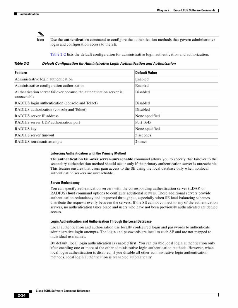
Chapter 2 Cisco ECDS Software Commandsauthentication
Note Use the authentication command to configure the authentication methods that govern administrative login and configuration access to the SE.
Table 2-2 lists the default configuration for administrative login authentication and authorization.
Enforcing Authentication with the Primary Method
The authentication fail-over server-unreachable command allows you to specify that failover to the secondary authentication method should occur only if the primary authentication server is unreachable. This feature ensures that users gain access to the SE using the local database only when nonlocal authentication servers are unreachable.
Server Redundancy
You can specify authentication servers with the corresponding authentication server (LDAP, or RADIUS) host command options to configure additional servers. These additional servers provide authentication redundancy and improved throughput, especially when SE load-balancing schemes distribute the requests evenly between the servers. If the SE cannot connect to any of the authentication servers, no authentication takes place and users who have not been previously authenticated are denied access.
Login Authentication and Authorization Through the Local Database
Local authentication and authorization use locally configured login and passwords to authenticate administrative login attempts. The login and passwords are local to each SE and are not mapped to individual usernames.
By default, local login authentication is enabled first. You can disable local login authentication only after enabling one or more of the other administrative login authentication methods. However, when local login authentication is disabled, if you disable all other administrative login authentication methods, local login authentication is reenabled automatically.
Table 2-2 Default Configuration for Administrative Login Authentication and Authorization
Feature Default Value
Administrative login authentication Enabled
Administrative configuration authorization Enabled
Authentication server failover because the authentication server is unreachable
Disabled
RADIUS login authentication (console and Telnet) Disabled
RADIUS authorization (console and Telnet) Disabled
RADIUS server IP address None specified
RADIUS server UDP authorization port Port 1645
RADIUS key None specified
RADIUS server timeout 5 seconds
RADIUS retransmit attempts 2 times
2-34Cisco ECDS Software Command Reference

Chapter 2 Cisco ECDS Software Commandsauthentication
Specifying RADIUS Authentication and Authorization Settings
RADIUS authentication clients reside on the SE running Cisco ECDS software. When enabled, these clients send authentication requests to a central (remote) RADIUS server, which contains login authentication and network service access information.
To configure RADIUS authentication on an SE, you must configure a set of RADIUS authentication server settings on the SE. You can use the SE GUI or the CLI to configure this set of RADIUS authentication server settings for an SE.
Table 2-3 describes the RADIUS authentication settings.
After configuring these RADIUS authentication settings on the SE, you can enable RADIUS login authentication and authorization on the SE.
Examples The following example shows the output of the show authentication user command:
ServiceEngine# show authentication userLogin Authentication: Console/Telnet/Ftp/SSH Session----------------------------- ------------------------------local disabledRadius disabledTacacs+ disabled
Configuration Authentication: Console/Telnet/Ftp/SSH Session----------------------------- ------------------------------local disabledRadius disabledTacacs+ disabled
Table 2-3 RADIUS Authentication Settings
Setting Description
RADIUS server RADIUS servers that the SE is to use for RADIUS authentication. To enable the SE to use a specific RADIUS server, enter the IP address or hostname of the RADIUS server and port information. Up to five different hosts are allowed. Early deployment of RADIUS was done using port number 1645, although the official port number for RADIUS is now 1812. Up to five different ports are allowed.
RADIUS key Key used to encrypt and authenticate all communication between the RADIUS client (the SE) and the RADIUS server. The maximum number of characters in the key is 15. There is no default.
Tip Make sure that the same RADIUS key is enabled on the RADIUS server.
RADIUS timeoutinterval
Number of seconds that the SE waits for a response from the specified RADIUS authentication server before declaring a timeout. The range is 1 to 20 seconds. The default value is 5 seconds.
RADIUS retransmitcount
Number of times that the SE is to retransmit its connection to the RADIUS if the RADIUS timeout interval is exceeded. The range is one to three tries. The default value is two tries.
2-35Cisco ECDS Software Command Reference

Chapter 2 Cisco ECDS Software Commandsauthentication
The following example shows the output of the show statistics authentication command:
ServiceEngine# show statistics authentication Authentication Statistics --------------------------------------Number of access requests: 37Number of access deny responses: 14Number of access allow responses: 23
Related Commands Command Description
radius-server Configures the RADIUS authentication.
show authentication Displays the authentication configuration.
show statistics authentication Displays the authentication statistics.
username Establishes the username authentication.
2-36Cisco ECDS Software Command Reference
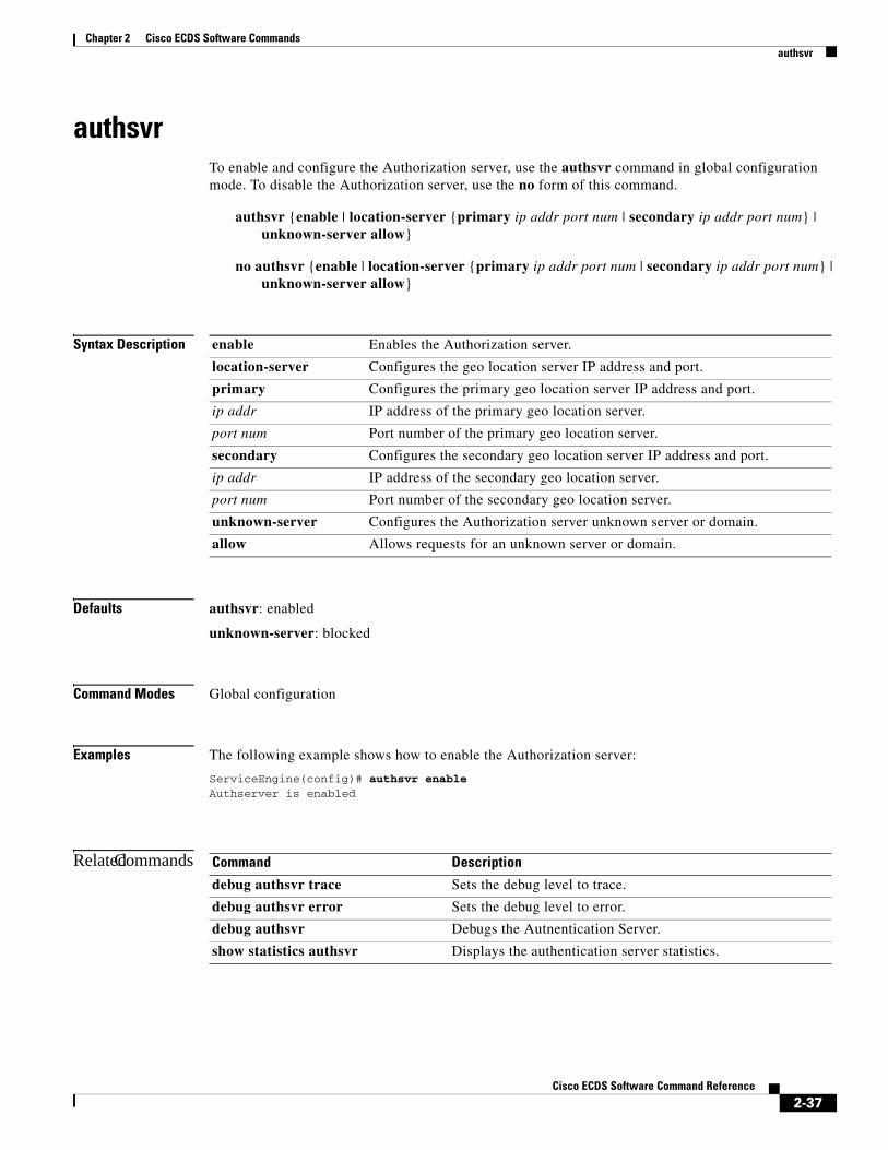
Chapter 2 Cisco ECDS Software Commandsauthsvr
authsvrTo enable and configure the Authorization server, use the authsvr command in global configuration mode. To disable the Authorization server, use the no form of this command.
authsvr {enable | location-server {primary ip addr port num | secondary ip addr port num} | unknown-server allow}
no authsvr {enable | location-server {primary ip addr port num | secondary ip addr port num} | unknown-server allow}
Syntax Description
Defaults authsvr: enabled
unknown-server: blocked
Command Modes Global configuration
Examples The following example shows how to enable the Authorization server:
ServiceEngine(config)# authsvr enableAuthserver is enabled
Related Commands
enable Enables the Authorization server.
location-server Configures the geo location server IP address and port.
primary Configures the primary geo location server IP address and port.
ip addr IP address of the primary geo location server.
port num Port number of the primary geo location server.
secondary Configures the secondary geo location server IP address and port.
ip addr IP address of the secondary geo location server.
port num Port number of the secondary geo location server.
unknown-server Configures the Authorization server unknown server or domain.
allow Allows requests for an unknown server or domain.
Command Description
debug authsvr trace Sets the debug level to trace.
debug authsvr error Sets the debug level to error.
debug authsvr Debugs the Autnentication Server.
show statistics authsvr Displays the authentication server statistics.
2-37Cisco ECDS Software Command Reference

Chapter 2 Cisco ECDS Software Commandsbandwidth (global configuration)
bandwidth (global configuration)To set an allowable bandwidth usage limit and its duration for Cisco Streaming Engine WMT streaming media, use the bandwidth command in global configuration mode. To remove individual options, use the no form of this command.
bandwidth {movie-streamer {incoming bandwidth | outgoing bandwidth {default | max-bandwidth start-time day hour end-time day hour}} | wmt {incoming bandwidth | outgoing bandwidth}}
no bandwidth {movie-streamer {incoming bandwidth | outgoing bandwidth {default | max-bandwidth start-time day hour end-time day hour}} | wmt {incoming bandwidth | outgoing bandwidth}}
Syntax Description
Defaults No default behavior or values
Command Modes Global configuration
Usage Guidelines With the various types of traffic originating from a device, every type of traffic, such as streaming media, HTTP, and metadata, consumes network resources. Use the bandwidth command to limit the amount of network bandwidth used by the WMT streaming media.
The content services bandwidth includes the bandwidth allocation for WMT. WMT bandwidth settings apply to WMT streaming of live, cached, and prepositioned content.
movie-streamer Configures the maximum pacing bit rate, in kilobits per second (kbps), for the Movie Streamer.
incoming Configures the duration of allowable incoming bandwidth settings for WMT.
bandwidth Bandwidth size for the Movie Streamer, in kbps. The range is from 0 to 2147483647.
outgoing Configures the duration of allowable outgoing bandwidth settings for WMT.
default Specifies the default value for bandwidth if the scheduled bandwidth is not configured.
max-bandwidth Specifies the maximum value of bandwidth, in kbps.
start-time Specifies the start time for this bandwidth setting.
day Day of the week.
hour Time to start (hh:mm) (0 to 23:0 to 59)
end-time Specifies the end time for this bandwidth setting.
wmt Configures the duration of allowable bandwidth settings for WMT. For more information, see the “Configuring Incoming and Outgoing WMT Bandwidth” section on page 2-39.
2-38Cisco ECDS Software Command Reference

Chapter 2 Cisco ECDS Software Commandsbandwidth (global configuration)
For each type of bandwidth, you can specify the amount of bandwidth to be used for a particular time period. This type is called scheduled bandwidth. The default bandwidth is the amount of bandwidth associated with each content service type when there is no scheduled bandwidth. In centrally managed deployments (the SEs are registered with a CDSM), if an SE is assigned to a device group and no default bandwidth has been configured for the SE itself, the device group default bandwidth settings are applied. However, if the default bandwidth has been configured for the SE, then that setting overrides the device group settings. If the SE is a member of multiple device groups, the most recently updated default bandwidth settings are applied.
The maximum bandwidth specifies the upper limit for the allowable bandwidth. The total bandwidth configured for all content services must not exceed the bandwidth limits specified for any SE platform model in the ECDS network. In addition, the license keys configured for WMT further restrict the maximum bandwidth available for each SE model.
Configuring Incoming and Outgoing WMT Bandwidth
The bandwidth between the WMT proxy server (the SE) and the WMT client is called the WMT outgoing bandwidth.
The bandwidth between the WMT proxy and the origin streaming server is called the incoming bandwidth. Because the bandwidth from the edge to the outside IP WAN is limited, you must specify a per session limit (the maximum bit rate per request) for each service that is running on the SE and that consumes the incoming bandwidth (for example, the WMT streaming service), and an aggregate limit (the maximum incoming bandwidth.) You need to control the outgoing bandwidth based on the WMT license that is configured on the SE.
The bandwidth wmt outgoing and bandwidth incoming commands enable you to specify a WMT incoming and an outgoing bandwidth as follows:
• Use the bandwidth wmt outgoing kbits command in global configuration mode to specify the outgoing WMT bandwidth in kbps. This command sets the maximum bandwidth for the WMT content that can delivered to a client that is requesting WMT content. The range of values is between 0 and 2,147,483,647 kilobits per second (kbps).
If the specified outgoing bandwidth is above the limit specified by the WMT license, then a warning message displays. However, the specified outgoing bandwidth setting is applied to the SE because the outgoing bandwidth may be configured before the WMT licenses are enabled or an enabled WMT license could be changed to a higher value at a later time.
• Use the bandwidth wmt incoming kbits command in global configuration mode to specify the incoming WMT bandwidth in kbps. This command sets the maximum bandwidth for the WMT content that can delivered to an SE from the origin streaming server or another SE in the case of a cache miss. The specified bit rate is the maximum incoming WMT per session bit rate. The range of values is between 0 and 2,147,483,647 kbps. The incoming bandwidth applies to VoD content from the origin server for a cache miss.
2-39Cisco ECDS Software Command Reference

Chapter 2 Cisco ECDS Software Commandsbandwidth (global configuration)
Related Commands Command Description
bandwidth (interface configuration) Sets the specified interface bandwidth to 10, 100, or 1000 Mbps.
interface Configures a Gigabit Ethernet or port-channel interface. Provides access to interface configuration mode.
show bandwidth Displays the bandwidth allocated to a particular device.
show interface Displays the hardware interface information.
show running-config Displays the current operating configuration.
show startup-config Displays the startup configuration.
2-40Cisco ECDS Software Command Reference

Chapter 2 Cisco ECDS Software Commandsbandwidth (interface configuration)
bandwidth (interface configuration)To configure an interface bandwidth, use the bandwidth command in interface configuration mode. To restore default values, use the no form of this command.
bandwidth {10 | 100 | 1000}
no bandwidth {10 | 100 | 1000}
Syntax Description
Defaults No default behavior or values
Command Modes Interface configuration
Usage Guidelines The bandwidth is specified in megabits per second (Mbps). The 1000 Mbps option is not available on all ports. On a Service Engine model that has an optical Gigabit Ethernet interface, you cannot change the of this interface. Therefore, Gigabit Ethernet interfaces only run at 1000 Mbps. For newer models of the SE that have a Gigabit Ethernet interface over copper, this restriction does not apply; you can configure these Gigabit Ethernet interfaces to run at 10, 100, or 1000 Mbps.
You can configure the Gigabit Ethernet interface settings (bandwidth, and duplex settings) if the Gigabit-over-copper-interface is up or down. If the interface is up, it applies the specific interface settings. If the interface is down, the specified settings are stored and then applied when the interface is brought up. For example, you can specify any of the following commands for a Gigabit-over-copper-interface, which is currently down, and have these settings automatically applied when the interface is brought up:
ServiceEngine(config-if)# bandwidth 10ServiceEngine(config-if)# bandwidth 100ServiceEngine(config-if)# bandwidth 1000
You cannot configure the Gigabit Ethernet interface settings on an optical Gigabit Ethernet interface.
Examples The following example shows how to set an interface bandwidth to 10 Mbps:
ServiceEngine(config-if)# bandwidth 10
The following example shows how to restore default bandwidth values on an interface:
ServiceEngine(config-if)# no bandwidth
10 Sets the bandwidth to 10 megabits per second (Mbps).
100 Sets the bandwidth to 100 Mbps.
1000 Sets the bandwidth to 1000 Mbps. This option is not available on all ports.
2-41Cisco ECDS Software Command Reference

Chapter 2 Cisco ECDS Software Commandsbandwidth (interface configuration)
Related Commands Command Description
interface Configures a Gigabit Ethernet or port-channel interface. Provides access to interface configuration mode.
2-42Cisco ECDS Software Command Reference

Chapter 2 Cisco ECDS Software Commandsbanner
bannerTo configure the EXEC, login, and message-of-the-day (MOTD) banners, use the banner command in global configuration mode. To disable the banner feature, use the no form of this command.
banner {enable | exec {message line | message_text} | login {message line | message_text} | motd {message line | message_text}}
no banner {enable | exec [message] | login [message] | motd [message]}
Syntax Description enable Enables banner support on the SE.
exec Configures an EXEC banner.
message Specifies a message to be displayed when an EXEC process is created.
line EXEC message text on a single line. The SE translates the \n portion of the message to a new line when the EXEC banner is displayed to the user.
message_text EXEC message text on one or more lines. Press the Return key or enter delimiting characters (\n) to specify an EXEC message to appear on a new line. Supports up to a maximum of 980 characters, including new-line characters (\n). Enter a period (.) at the beginning of a new line to save the message and return to the prompt for the global configuration mode.
Note The EXEC banner content is obtained from the command line input that the user enters after being prompted for the input.
login Configures a login banner.
message Specifies a message to be displayed before the username and password login prompts.
line Login message text on a single line. The SE translates the \n portion of the message to a new line when the login banner is displayed to the user.
message_text Login message text on one or more lines. Press the Return key or enter delimiting characters (\n) to specify a login message to appear on a new line. Supports up to a maximum of 980 characters, including new-line characters (\n). Enter a period (.) at the beginning of a new-line to save the message and return to the prompt for the global configuration mode.
Note The login banner content is obtained from the command line input that the user enters after being prompted for the input.
motd Configures an MOTD banner.
message Specifies an MOTD message.
line MOTD message text on a single line. The SE translates the \n portion of the message to a new line when the MOTD banner is displayed to the user.
message_text MOTD message text on one or more lines. Press the Return key or enter delimiting characters (\n) to specify an MOTD message to appear on a new line. Supports up to a maximum of 980 characters, including new-line characters (\n). Enter a period (.) at the beginning of a new line to save the message and return to the prompt for the global configuration mode.
Note The MOTD banner content is obtained from the command line input that the user enters after being prompted for the input.
2-43Cisco ECDS Software Command Reference

Chapter 2 Cisco ECDS Software Commandsbanner
Defaults Banner support is disabled by default.
Command Modes Global configuration
Usage Guidelines You can configure the following three types of banners in any ECDS software device mode:
• MOTD banner sets the message of the day. This message is the first message that is displayed when a login is attempted.
• Login banner is displayed after the MOTD banner but before the actual login prompt appears.
• EXEC banner is displayed after the EXEC CLI shell has started.
Note All these banners are effective on a console, Telnet, or a Secure Shell (SSH) version 2 session.
After you configure the banners, enter the banner enable command to enable banner support on the SE. Enter the show banner command in EXEC configuration mode to display information about the configured banners.
Note When you run an SSH version 1 client and log in to the SE, the MOTD and login banners are not displayed. You need to use SSH version 2 to display the banners when you log in to the SE.
Examples The following example shows how to enable banner support on the SE:
ServiceEngine(config)# banner enable
The following example shows how to use the banner motd message command to configure the MOTD banner. In this example, the MOTD message consists of a single line of text.
ServiceEngine(config)# banner motd message This is an ECDS 2.6 device
The following example shows how to use the banner motd message global command to configure a MOTD message that is longer than a single line. In this case, the SE translates the \n portion of the message to a new line when the MOTD message is displayed to the user.
ServiceEngine(config)# banner motd message "This is the motd message.\nThis is an ECDS 2.6 device\n"
The following example shows how to use the banner login message command to configure a MOTD message that is longer than a single line. In this case, SE A translates the \n portion of the message to a new line in the login message that is displayed to the user.
ServiceEngine(config)# banner login message "This is login banner.\nUse your password to login\n"
2-44Cisco ECDS Software Command Reference

Chapter 2 Cisco ECDS Software Commandsbanner
The following example shows how to use the banner exec command to configure an interactive banner. The banner exec command is similar to the banner motd message commands except that for the banner exec command, the banner content is obtained from the command line input that the user enters after being prompted for the input.
ServiceEngine(config)# banner execPlease type your MOTD messages below and end it with '.' at beginning of line:(plain text only, no longer than 980 bytes including newline)This is the EXEC banner.\nUse your ECDS username and password to log in to this SE.\n.Message has 99 characters.ServiceEngine(config)#
Assume that an SE has been configured with the MOTD, login, and EXEC banners as shown in the previous examples. When a user uses an SSH session to log in to the SE, the user sees a login session that includes a MOTD banner and a login banner that asks the user to enter a login password as follows:
This is the motd banner.This is an ECDS 2.6 deviceThis is login banner.Use your password to login.
Cisco SE
admin@ce's password:
After the user enters a valid login password, the EXEC banner is displayed, and the user is asked to enter the ECDS username and password as follows:
Last login: Fri Oct 1 14:54:03 2004 from clientSystem Initialization Finished.This is the EXEC banner.Use your ECDS username and password to log in to this SE.
After the user enters a valid ECDS username and password, the SE CLI is displayed. The CLI prompt varies depending on the privilege level of the login account. In the following example, because the user entered a username and password that had administrative privileges (privilege level of 15), the EXEC configuration mode CLI prompt is displayed:
ServiceEngine#
Related Commands Command Description
show banner Enables banner support on the SE.
2-45Cisco ECDS Software Command Reference

Chapter 2 Cisco ECDS Software Commandsbitrate
bitrateTo configure the maximum pacing bit rate for large files for the Movie Streamer and to separately configure WMT bit-rate settings, use the bitrate command in global configuration mode. To remove the bit-rate settings, use the no form of this command.
bitrate {movie-streamer bitrate | wmt {incoming bitrate | outgoing bitrate}}
no bitrate {movie-streamer bitrate | wmt {incoming | outgoing}}
Syntax Description
Defaults movie-streamer bitrate: 1500 kbps
wmt incoming bitrate: 0 (no limit)
wmt outgoing bitrate: 0 (no limit)
Command Modes Global configuration
Usage Guidelines The ECDS software includes the Windows Media Technologies (WMT) proxy, which has the ability to cache on-demand media files when the user requests these files for the first time. All subsequent requests for the same file are served by the WMT proxy using the RTSP protocol. The WMT proxy can also live-split a broadcast, which causes only a single unicast stream to be requested from the origin server in response to multiple client requests for the stream.
The bit rate between the proxy and the origin server is called the incoming bit rate. Use the bitrate command to limit the maximum bit rate per session for large files. The bitrate wmt incoming and bitrate wmt outgoing commands enable you to specify a WMT incoming and outgoing WMT per session bit rate as follows:
• Use the bitrate wmt incoming bitrate command to specify the maximum incoming streaming bit rate per session that can be delivered to the WMT proxy server (an SE) from the origin streaming server or another SE in the case of a cache miss. The specified bit rate is the maximum incoming WMT per session bit rate. The range of values is between 0 and 2,147,483,647 kbps. The default value is 0 (no bit-rate limit).
movie-streamer Configures the maximum pacing bit rate in kilobits per second (kbps) for the Movie Streamer.
bitrate Bit rate in kbps. The range is from 1 to 2147483647.
wmt Configures the bit rate, in kbps, for large files sent using the WMT protocol.
incoming Sets the incoming bit-rate settings.
bitrate Incoming bit rate in kbps. The range is from 0 to 2147483647.
outgoing Sets the outgoing bit-rate settings.
bitrate Outgoing bit rate in kbps. The range is from 0 to 2147483647.
2-46Cisco ECDS Software Command Reference

Chapter 2 Cisco ECDS Software Commandsbitrate
• Use the bitrate wmt outgoing bitrate command to set the maximum outgoing streaming bit rate per session that can delivered to a client that is requesting WMT content. The specified bit rate is the maximum outgoing WMT per session bit rate). The range of values is between 0 and 2,147,483,647 kbps. The default value is 0 (no bit-rate limit). The outgoing bandwidth applies to VoD content from the WMT proxy server on the SE in the case of a cache miss.
Note The aggregate bandwidth used by all concurrent users is still limited by the default device bandwidth or by the limit configured using the bandwidth command.
Variable WMT Bit Rates
A content provider can create streaming media files at different bit rates to ensure that different clients who have different connections—for example, modem, DSL, or LAN—can choose a particular bit rate. The WMT caching proxy can cache multiple bit-rate files or variable bit-rate (VBR) files, and based on the bit rate specified by the client, it serves the appropriate stream. Another advantage of creating variable bit-rate files is that you only need to specify a single URL for the delivery of streaming media.
Note In the case of multiple bit-rate files, the SE that is acting as the WMT proxy server only retrieves the bit rate that the client has requested.
Examples The following example shows how to configure an incoming bit rate for the Movie Streamer:
ServiceEngine(config)# bitrate movie-streamer incoming 100
The following example shows how to configure an incoming bit rate for a file sent using WMT. Use the show wmt command to verify that the incoming bit rate has been modified.
ServiceEngine(config)# bitrate wmt incoming 300000 ServiceEngine(config)# exitServiceEngine# show wmt--------- WMT Server Configurations -----------------WMT is enabledWMT disallowed client protocols: noneWMT bandwidth platform limit: 1000000 Kbits/secWMT outgoing bandwidth configured is 500000 Kbits/secWMT incoming bandwidth configured is 500000 Kbits/secWMT max sessions configured: 14000WMT max sessions platform limit: 14000WMT max sessions enforced: 14000 sessionsWMT max outgoing bit rate allowed per stream has no limitWMT max incoming bit rate allowed per stream has no limitWMT cache is enabledWMT cache max-obj-size: 25600 MBWMT cache revalidate for each request is not enabledWMT cache age-multiplier: 30%WMT cache min-ttl: 60 minutesWMT cache max-ttl: 1 daysWMT debug client ip not setWMT debug server ip not setWMT accelerate live-split is enabledWMT accelerate proxy-cache is enabledWMT accelerate VOD is enabledWMT fast-start is enabledWMT fast-start max. bandwidth per player is 3500 (Kbps)WMT fast-cache is enabledWMT fast-cache acceleration factor is 5
2-47Cisco ECDS Software Command Reference
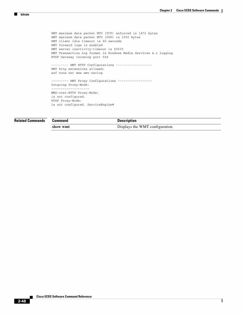
Chapter 2 Cisco ECDS Software Commandsbitrate
WMT maximum data packet MTU (TCP) enforced is 1472 bytesWMT maximum data packet MTU (UDP) is 1500 bytesWMT client idle timeout is 60 secondsWMT forward logs is enabledWMT server inactivity-timeout is 65535WMT Transaction Log format is Windows Media Services 4.1 loggingRTSP Gateway incoming port 554
--------- WMT HTTP Configurations -------------------WMT http extensions allowed:asf none nsc wma wmv nsclog
--------- WMT Proxy Configurations ------------------Outgoing Proxy-Mode:--------------------MMS-over-HTTP Proxy-Mode:is not configured.RTSP Proxy-Mode:is not configured. ServiceEngine#
Related Commands Command Description
show wmt Displays the WMT configuration.
2-48Cisco ECDS Software Command Reference

Chapter 2 Cisco ECDS Software Commandsbypass
bypassTo enable transparent error handling and dynamic authentication bypass, and to configure static bypass lists, use the bypass global configuration command. To disable the bypass feature, use the no form of this command.
bypass {load {enable | time-interval minutes} | static {clientip | any-client | port number except-server} | timer minutes}
no bypass {load {enable | time-interval minutes} | static {clientip | any-client | port number except-server} | timer minutes}
Syntax Description
Defaults bypass timer: 20 minutes
time-interval: 10 minutes
Command Modes global configuration
Usage Guidelines Bypass refers to a method that the Service Engine can use to handle various error responses (including authentication failure) from an origin server. When the Service Engine receives an error response from an origin server, it adds an entry for the server to its bypass list.
auth-traffic Sets the authenticated traffic bypass configuration.
enable Enables the authenticated traffic bypass.
load Sets the bypass load configuration.
enable Enables the bypass load.
time-interval Sets the time interval between one bucket being bypassed and the next.
minutes Time in minutes (1–1440).
static Adds a static entry to the bypass list.
clientip IP address from which requests will bypass the Service Engine.
any-client Bypasses the HTTP traffic from any client destined to a particular server.
serverip IP address to which requests will bypass the Service Engine.
timer Sets the authentication bypass timer in minutes. The bypass entry is removed from the dynamic list when the timer expires.
minutes Time in minutes (1–1440).
port Port of the only server to be accepted while others are bypassed.
number Port number (1-65535).
except-server The system bypasses all the traffic to this port, except the traffic that has a destination IP on the configured list.
2-49Cisco ECDS Software Command Reference
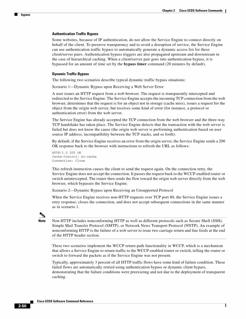
Chapter 2 Cisco ECDS Software Commandsbypass
Authentication Traffic Bypass
Some websites, because of IP authentication, do not allow the Service Engine to connect directly on behalf of the client. To preserve transparency and to avoid a disruption of service, the Service Engine can use authentication traffic bypass to automatically generate a dynamic access list for these client/server pairs. Authentication bypass triggers are also propagated upstream and downstream in the case of hierarchical caching. When a client/server pair goes into authentication bypass, it is bypassed for an amount of time set by the bypass timer command (20 minutes by default).
Dynamic Traffic Bypass
The following two scenarios describe typical dynamic traffic bypass situations:
Scenario 1—Dynamic Bypass upon Receiving a Web Server Error
A user issues an HTTP request from a web browser. The request is transparently intercepted and redirected to the Service Engine. The Service Engine accepts the incoming TCP connection from the web browser, determines that the request is for an object not in storage (cache miss), issues a request for the object from the origin web server, but receives some kind of error (for instance, a protocol or authentication error) from the web server.
The Service Engine has already accepted the TCP connection from the web browser and the three-way TCP handshake has taken place. The Service Engine detects that the transaction with the web server is failed but does not know the cause (the origin web server is performing authentication based on user source IP address, incompatibility between the TCP stacks, and so forth).
By default, if the Service Engine receives an error from the origin server, the Service Engine sends a 200 OK response back to the browser with instructions to refresh the URL as follows:
HTTP/1.0 200 OKCache-Control; no-cacheConnection: Close
This refresh instruction causes the client to send the request again. On the connection retry, the Service Engine does not accept the connection. It passes the request back to the WCCP-enabled router or switch unintercepted. The router then sends the flow toward the origin web server directly from the web browser, which bypasses the Service Engine.
Scenario 2—Dynamic Bypass upon Receiving an Unsupported Protocol
When the Service Engine receives non-HTTP requests over TCP port 80, the Service Engine issues a retry response, closes the connection, and does not accept subsequent connections in the same manner as in scenario 1.
Note Non-HTTP includes nonconforming HTTP as well as different protocols such as Secure Shell (SSH), Simple Mail Transfer Protocol (SMTP), or Network News Transport Protocol (NNTP). An example of nonconforming HTTP is the failure of a web server to issue two carriage return and line feeds at the end of the HTTP header section.
These two scenarios implement the WCCP return-path functionality in WCCP, which is a mechanism that allows a Service Engine to return traffic to the WCCP-enabled router or switch, telling the router or switch to forward the packets as if the Service Engine was not present.
Typically, approximately 3 percent of all HTTP traffic flows have some kind of failure condition. These failed flows are automatically retried using authentication bypass or dynamic client bypass, demonstrating that the failure conditions were preexisting and not due to the deployment of transparent caching.
2-50Cisco ECDS Software Command Reference

Chapter 2 Cisco ECDS Software Commandsbypass
Overload Bypass
If a Service Engine becomes overwhelmed with traffic, it can use the bypass load feature to reroute the overload traffic.
Static Bypass
The bypass static command permits traffic from specified sources to bypass the Service Engine. The types of traffic sources are as follows:
• Specific web client to a specific web server
• Specific web client to any web server
• Any web client to a specific web server
Wildcards in either the source or the destination field are not supported.
To clear all static configuration lists, use the no form of the command.
Note You must not exceed 50 bypass list entries for any one Service Engine.
Examples The following example forces HTTP traffic from a specified client to a specified server to bypass the Service Engine:
ServiceEngine(config)# bypass static 10.1.17.1 172.16.7.52
The following example forces all HTTP traffic destined to a specified server to bypass the Service Engine:
ServiceEngine(config)# bypass static any-client 172.16.7.52
The following example forces all HTTP traffic from a specified client to any web server to bypass the Service Engine:
ServiceEngine(config)# bypass static 10.1.17.1 any-server
To bypass all except a specific server on a specific port:
bypass static port 80 except-server 1.1.1.1
The system bypasses all the traffic to this port, except the traffic that has a destination IP on the configured list.
A static list of source and destination addresses helps to isolate instances of problem-causing clients and servers. You can display the list as follows:
• To display static configuration list items, use the show bypass list command as follows:
ServiceEngine# show bypass listClient Server Entry type------ ------ ----------10.1.17.1:0 172.16.7.52:0 static-configany-client:0 172.16.7.52:0 static-config10.1.17.2:0 any-server:0 static-config
• The total number of entries in the bypass list is reported by the show bypass summary command as follows:
Total number of HTTP connections bypassed = 0 Connections bypassed due to system overload = 0
2-51Cisco ECDS Software Command Reference

Chapter 2 Cisco ECDS Software Commandsbypass
Connections bypassed due to authentication issues = 0 Connections bypassed due to facilitate error transparency = 0 Connections bypassed due to static configuration = 0
Total number of entries in the bypass list = 3 Number of Authentication bypass entries = 0 Number of Error bypass entries = 0 Number of Static Configuration entries = 3
Related Commands clear bypasshttp l4-switchrtsp l4-switchruleshow bypassshow statistics bypass
2-52Cisco ECDS Software Command Reference

Chapter 2 Cisco ECDS Software Commandscache
cacheTo restrict the maximum number of contents in the CDS, use the cache command in global configuration mode.
cache content max-cached-entries num
Syntax Description
Defaults The max-cached-entries default is 3000000 entries.
Command Modes Global configuration
Usage Guidelines The cache command configures the cached content maximum entries. The CDS, by default, allows a maximum of three million cached entries, regardless of the amount of space available in the cdnfs.
Examples The following example shows how to configure the cache content:
ServiceEngine# cache content max-cached-entries 1000
Related Commands
content Browses the cdnfs directories and files.
max-cached-entries Cleans up the unwanted entries in the cdnfs.
num Max cached entries. The range is from 1 to 10000000.
Command Description
show cache Displays a list of cached contents.
2-53Cisco ECDS Software Command Reference

Chapter 2 Cisco ECDS Software Commandscache-router
cache-routerTo configure cache-router, use the cache-router command in global configuration mode.
To nullify these actions, use the no form of this command.
cache content max-cached-entries num
cache-router { liveness-query-timeout | single-pass-timeout } Timeout in milli-seconds
Syntax Description
Defaults The default timeout value is 200 milliseconds.
Command Modes Global configuration
Usage Guidelines The cache-router liveness query is sent from the Edge Se to CA periodically. The CLI Liveness query timeout is applicable to normal liveness queries. Single pass timeout is applicable to initial query triggered when an initial request comes to Edge SE.
Examples The following example shows how to configure the cache content:
sanity-edge(config)#cache-router liveness-query-timeout 200sanity-edge(config)#cache-router single-pass-timeout 200
content Browses the cdnfs directories and files.
liveness-query-timeout To set the liveness query interval between Edge SE to upstream SE. The range is from 1 to 1000.
single-pass-timeout To set the time interval for initial query triggered when an initial request comes to Edge SE.Applicable for FMS live. The range is from 1 to 1000.
2-54Cisco ECDS Software Command Reference

Chapter 2 Cisco ECDS Software Commandscapability
capabilityTo modify the capability configuration, use the capability command in global configuration mode. To disable capability, use the no form of this command.
capability config profile number [add attrib {capability-url url | user-agent name} | description]
no capability config
Syntax Description
Defaults No default behavior or values
Command Modes Global configuration
Related Commands
config Enters the capability exchange submode.
profile Populates the profile database.
number The profile ID. The range is from 1 to 65535.
add (Optional) Adds the capability attributes.
attrib Adds the capability attributes.
capability-url Specifies the capability URL.
url The capability URL string.
user-agent Specifies the user-agent.
name The user-agent name.
description (Optional) Specifies the profile description.
Command Description
show capability Displays information for the Cap-X profile ID.
2-55Cisco ECDS Software Command Reference

Chapter 2 Cisco ECDS Software Commandscd
cdTo change from one directory to another directory, use the cd command in EXEC configuration mode.
cd directoryname
Syntax Description
Defaults No default behavior or values
Command Modes EXEC
Usage Guidelines Use this command to maneuver between directories and for file management. The directory name becomes the default prefix for all relative paths. Relative paths do not begin with a slash (/). Absolute paths begin with a slash (/).
Examples The following example shows how to use a relative path:
ServiceEngine(config)# cd local1
The following example shows how to use an absolute path:
ServiceEngine(config)# cd /local1
Related Commands
directoryname Directory name.
Command Description
deltree Deletes a directory and its subdirectories.
dir Displays the files in a long list format.
lls Displays the files in a long list format.
ls Lists the files and subdirectories in a directory.
mkdir Makes a directory.
pwd Displays the present working directory.
2-56Cisco ECDS Software Command Reference

Chapter 2 Cisco ECDS Software Commandscdn-select
cdn-selectCDN Selector is not supported.
2-57Cisco ECDS Software Command Reference

Chapter 2 Cisco ECDS Software Commandscdnfs
cdnfsTo manage the ECDS network file system (cdnfs), use the cdnfs command in EXEC configuration mode.
cdnfs {browse | cleanup {info | start {force} | stop}}
Syntax Description
Defaults No default behavior or values
Command Modes EXEC
Usage Guidelines The ECDS network file systems (cdnfs) stores the pre-positioned ECDS network content to be delivered by all supported protocols. You can configure the cdnfs size of each SE using the disk configure command.
The cdnfs cleanup command cleans up the content of deleted channels from the acquisition and distribution database. In certain cases, the acquirer is not notified by the Centralized Management System (CMS) about deleted channels, and it fails to clear all unified name space (UNS) content. In such cases, the cdnfs cleanup command in EXEC configuration mode can be used to clean up all UNS content associated with deleted channels.
Note You can use the cdnfs cleanup start to clean up the orphan content. The orphan content is content that is not associated with any channel to which an SE is subscribed.
The cdnfs browse command is an interactive command and has the following subcommands used to view ECDS network files and directories:
ServiceEngine# cdnfs browse
------ CDNFS interactive browsing ------dir, ls: list directory contentscd,chdir: change current working directoryinfo: display attributes of a filemore: page through a filecat: display a fileexit,quit: quit CDNFS browse shell
/>dir www.gidtest.com//>cd www.gidtest.com
browse Browses the cdnfs directories and files.
cleanup Cleans up the unwanted entries in the cdnfs.
info Summarizes the information about unwanted entries without starting the cleanup process.
start Starts the cleanup of unwanted entries in the cdnfs.
force Removes objects that are in transient states.
stop Stops the cleanup of unwanted entries in the cdnfs.
2-58Cisco ECDS Software Command Reference

Chapter 2 Cisco ECDS Software Commandscdnfs
/www.gidtest.com/>dir764 Bytes index.html/www.gidtest.com/>info index.html
CDNFS File Attributes: Status 3 (Ready) File Size 764 Bytes Start Time null End Time null Last-modified Time Sun Sep 9 01:46:40 2001
Internal path to data file: /disk06-00/d/www.gidtest.com/05/05d201b7ca6fdd41d491eaec7cfc6f14.0.data.html note: data file actual last-modified time: Tue Feb 15 00:47:35 2005
/www.gidtest.com/>
Because the cdnfs is empty in this example, the ls command does not show any results. Typically, if the cdnfs contained information, it would list the websites as directories, and file attributes and content could be viewed using these subcommands.
The cdnfs cleanup command synchronizes the state of the acquisition and distribution database with the content stored on the cdnfs. You should use this command after replacing a failed disk drive.
Examples The following example shows the output of the cdnfs cleanup info command:
ServiceEngine# cdnfs cleanup info Gathering cleanup information. This may take some time....(Use Ctrl+C or 'cdnfs cleanup stop' to interrupt)..............................
Summary of garbage resource entries found-------------------------------------------Number of entries : 605Size of entries (KB) : 60820911
Related Commands Command Description
show cdnfs Displays the ECDS network file system information.
show statistics cdnfs Displays the SE ECDS network file system statistics.
2-59Cisco ECDS Software Command Reference

Chapter 2 Cisco ECDS Software Commandscdsm
cdsmTo configure the Content Delivery System (CDSM) IP address to be used for the SEs or SRs, or to configure the role and GUI parameters on a CDSM device, use the cdsm command in global configuration mode. To negate these actions, use the no form of this command.
cdsm {ip {hostname | ip-address | role {primary | standby} | ui port port-num}}
no cdsm {ip | role {primary | standby} | ui port}
Syntax Description
Defaults No default behavior or values
Command Modes Global configuration
Usage Guidelines You can use the cdsm ui port command to change the CDSM GUI port from the standard number 8443 as follows:
CDSM(config)# cdsm ui port 35535
Note The role and ui options are available on CDSM devices only. Changing the CDSM GUI port number automatically restarts the Centralized Management System (CMS) service if this has been enabled.
The cdsm ip command associates the device with the CDSM so that the device can be approved as a part of the network.
After the device is configured with the CDSM IP address, it presents a self-signed security certificate and other essential information, such as its IP address or hostname, disk space allocation, and so forth, to the CDSM.
ip Configures the CDSM hostname or IP address.
hostname Hostname of the CDSM.
ip-address IP address of the CDSM.
role Configures the CDSM role to either primary or standby (available from the CDSM CLI only).
primary Configures the CDSM to be the primary CDSM.
standby Configures the CDSM to be the standby CDSM.
ui Configures the CDSM GUI port address (available from the CDSM CLI only).
port Configures the CDSM GUI port.
port-num Port number. The range is from 1 to 65535.
2-60Cisco ECDS Software Command Reference

Chapter 2 Cisco ECDS Software Commandscdsm
Configuring Devices Inside a NAT
In an ECDS network, there are two methods for a device registered with the CDSM (SEs, SRs, or standby CDSM) to obtain configuration information from the primary CDSM. The primary method is for the device to periodically poll the primary CDSM on port 443 to request a configuration update. You cannot configure this port number. The backup method is when the CDSM pushes configuration updates to a registered device as soon as possible by issuing a notification to the registered device on port 443. This method allows changes to take effect in a timelier manner. You cannot configure this port number even when the backup method is being used. ECDS networks do not work reliably if devices registered with the CDSM are unable to poll the CDSM for configuration updates. Similarly, when a receiver SE requests content and content metadata from a forwarder SE, it contacts the forwarder SE on port 443.
All the above methods become complex in the presence of Network Address Translation (NAT) firewalls. When a device (SEs at the edge of the network, SRs, and primary or standby CDSMs) is inside a NAT firewall, those devices that are inside the same NAT use one IP address (the inside local IP address) to access the device and those devices that are outside the NAT use a different IP address (the inside global IP address) to access the device. A centrally managed device advertises only its inside local IP address to the CDSM. All other devices inside the NAT use the inside local IP address to contact the centrally managed device that resides inside the NAT. A device that is not inside the same NAT as the centrally managed device is not able to contact it without special configuration.
If the primary CDSM is inside a NAT, you can allow a device outside the NAT to poll it for getUpdate requests by configuring a static translation (inside global IP address) for the CDSM’s inside local IP address on its NAT, and using this address, rather than the CDSM’s inside local IP address, in the cdsm ip ip-address command when you register the device to the CDSM. If an SE or SR is inside a NAT and the CDSM is outside the NAT, you can allow the SE or SR to poll for getUpdate requests by configuring a static translation (inside global IP address) for the SE or SIR’s inside local address on its NAT and specifying this address in the Use IP Address field under the NAT Configuration heading in the Device Activation window.
Note Static translation establishes a one-to-one mapping between your inside local address and an inside global address. Static translation is useful when a host on the inside must be accessible by a fixed address from the outside.
Standby CDSMs
The Cisco ECDS software implements a standby CDSM. This process allows you to maintain a copy of the ECDS network configuration. If the primary CDSM fails, the standby can be used to replace the primary.
For interoperability, when a standby CDSM is used, it must be at the same software version as the primary CDSM to maintain the full CDSM configuration. Otherwise, the standby CDSM detects this status and does not process any configuration updates that it receives from the primary CDSM until the problem is corrected.
Note We recommend that you upgrade your standby CDSM first and then upgrade your primary CDSM. We also recommend that you create a database backup on your primary CDSM and copy the database backup file to a safe place before you upgrade the software.
Switching a CDSM from Warm Standby to Primary
If your primary CDSM becomes inoperable for some reason, you can manually reconfigure one of your warm standby CDSMs to be the primary CDSM. Configure the new role by using the global configuration cdsm role primary command as follows:
2-61Cisco ECDS Software Command Reference

Chapter 2 Cisco ECDS Software Commandscdsm
ServiceEngine# configureServiceEngine(config)# cdsm role primary
This command changes the role from standby to primary and restarts the management service to recognize the change.
Note Check the status of recent updates from the primary CDSM. Use the show cms info command in EXEC configuration mode and check the time of the last update. To be current, the update time should be between 1 and 5 minutes old. You are verifying that the standby CDSM has fully replicated the primary CDSM configuration. If the update time is not current, check whether there is a connectivity problem or if the primary CDSM is down. Fix the problem, if necessary, and wait until the configuration has replicated as indicated by the time of the last update. Make sure that both CDSMs have the same Coordinated Universal Time (UTC) configured.
If you switch a warm standby CDSM to primary while your primary CDSM is still online and active, both CDSMs detect each other, automatically shut themselves down, and disable management services. The CDSMs are switched to halted, which is automatically saved in flash memory.
Examples The following example configures an IP address and a primary role for a CDSM:
CDSM(config)# cdsm ip 10.1.1.1CDSM(config)# cdsm role primary
The following example configures a new GUI port to access the CDSM GUI:
CDSM(config)# cdsm ui port 8550
The following example configures the CDSM as the standby CDSM:
CDSM(config)# cdsm role standbySwitching CDSM to standby will cause all configuration settings made on this CDSM to be lost.Please confirm you want to continue [ no ] ?yesRestarting CMS services
The following example configures the standby CDSM with the IP address of the primary CDSM by using the cdsm ip ip-address command. This command associates the device with the primary CDSM so that it can be approved as a part of the network.
CDSM# cdsm ip 10.1.1.1
2-62Cisco ECDS Software Command Reference

Chapter 2 Cisco ECDS Software CommandsCIMC url
CIMC urlTo expose the device CIMC interface to the ECDSM, use the CIMC url command in global configuration mode.
CIMC url url
no CIMC url url
Syntax Description
Defaults No default behavior or values
Command Modes Global configuration
Usage Guidelines This command does not set the CIMC URL. It exposes the existing CIMC URL for the device to the ECDSM. Exposing the CIMC URL lets you to launch the CIMC interface from the Device Management Interface button on the Devices > Devices > Device Home page in ECDSM.
The “CIMC” part of the command is capitalized.
Examples The following sets exposes the IP address 10.1.1.1 as the CIMC interface for the device:
hostname# configurehostname(config)# CIMC url 10.1.1.1
url The URL of the device CIMC interface. The URL must be in one of the following formats:
• ip_address
• http://ip_address
• https://ip_address
2-63Cisco ECDS Software Command Reference

Chapter 2 Cisco ECDS Software Commandsclear cache
clear cacheTo clear the HTTP object cache use the clear command in EXEC configuration mode.
clear cache [all | content 1-1000000 | flash-media-streaming]
Syntax Description
Defaults No default behavior or values
Command Modes EXEC
Usage Guidelines The clear cache command removes all cached contents from the currently mounted cache volumes. Objects being read or written are removed when they stop being busy. The equivalent to this command is the cache clear command.
The clear cache flash-media-streaming command only clears the FMS application specific cache, which only includes the flash content retrieved via RTMP, not the ingested flash content from dynamic caching or pre-ingestion which uses web engine via HTTP. Use clear cache all to remove flash media cached VOD content.
If there are a large number of dynamically cached files (for example, a million files), it may take a while for the number of cache entries and the cache size to reach zero after using the clear cache all command. You can use the show cdnfs usage command to display the number of items remaining in the cache. This number should decrement with subsequent use of the show cdnfs usage command. If the number of items remaining in the cache stops decrementing before reaching 0, enter the clear cache all command again.
Caution This command is irreversible, and all cached content is erased.
all (Optional) Clears all cached objects.
content (Optional) Clears cached content.
1-1000000 Free space in MBs.
flash-media-streaming Clears the Flash Media Streaming edge server cached content and DVR cached content.
2-64Cisco ECDS Software Command Reference
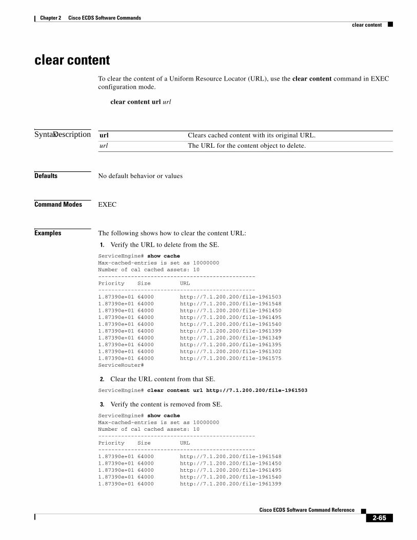
Chapter 2 Cisco ECDS Software Commandsclear content
clear contentTo clear the content of a Uniform Resource Locator (URL), use the clear content command in EXEC configuration mode.
clear content url url
Syntax Description
Defaults No default behavior or values
Command Modes EXEC
Examples The following shows how to clear the content URL:
1. Verify the URL to delete from the SE.
ServiceEngine# show cacheMax-cached-entries is set as 10000000Number of cal cached assets: 10------------------------------------------------Priority Size URL------------------------------------------------1.87390e+01 64000 http://7.1.200.200/file-19615031.87390e+01 64000 http://7.1.200.200/file-19615481.87390e+01 64000 http://7.1.200.200/file-19614501.87390e+01 64000 http://7.1.200.200/file-19614951.87390e+01 64000 http://7.1.200.200/file-19615401.87390e+01 64000 http://7.1.200.200/file-19613991.87390e+01 64000 http://7.1.200.200/file-19613491.87390e+01 64000 http://7.1.200.200/file-19613951.87390e+01 64000 http://7.1.200.200/file-19613021.87390e+01 64000 http://7.1.200.200/file-1961575ServiceRouter#
2. Clear the URL content from that SE.
ServiceEngine# clear content url http://7.1.200.200/file-1961503
3. Verify the content is removed from SE.
ServiceEngine# show cacheMax-cached-entries is set as 10000000Number of cal cached assets: 10------------------------------------------------Priority Size URL------------------------------------------------1.87390e+01 64000 http://7.1.200.200/file-19615481.87390e+01 64000 http://7.1.200.200/file-19614501.87390e+01 64000 http://7.1.200.200/file-19614951.87390e+01 64000 http://7.1.200.200/file-19615401.87390e+01 64000 http://7.1.200.200/file-1961399
url Clears cached content with its original URL.
url The URL for the content object to delete.
2-65Cisco ECDS Software Command Reference

Chapter 2 Cisco ECDS Software Commandsclear content
1.87390e+01 64000 http://7.1.200.200/file-19613491.87390e+01 64000 http://7.1.200.200/file-19613951.87390e+01 64000 http://7.1.200.200/file-19613021.87390e+01 64000 http://7.1.200.200/file-19615751.87390e+01 64000 http://7.1.200.200/file-1961529ServiceEngine#
2-66Cisco ECDS Software Command Reference

Chapter 2 Cisco ECDS Software Commandsclear ip
clear ip To clear the IP configuration, use the clear ip command in EXEC configuration mode.
On the SE:
clear ip access-list counters [acl-num | acl-name]
On the SR:
clear ip access-list counters [acl-num | acl-name] | bgp {ip address | all} | ospf {neighbor {all | GigabitEthernet slot/port num | PortChannel num} | rspf route [router-id} | traffic}
Syntax Description
Defaults No default behavior or values
Command Modes EXEC
access-list Clears the IP access list statistical information.
counters Clears the IP access list counters.
acl-name (Optional) Counters for the specified access list, identified using an alphanumeric identifier up to 30 characters, beginning with a letter.
acl-num (Optional) Counters for the specified access list, identified using a numeric identifier (standard access list: 1 to 99; extended access list: 100 to 199).
bgp Clears the BGP1 neighbors.
all Specifies that all current BGP sessions are reset.
ip-address Specifies that only the identified BGP neighbor are reset.
ospf Clears the OSPF2 tables.
neighbor Neighbor statistics per interface.
all Clears all neighbors.
GigabitEthernet Selects a GigabitEthernet interface.
slot/port num Slot and port number for the selected interface. The slot range is 0 to 14; the port range is 0 to 0. The slot number and port number are separated with a forward slash character (/).
PortChannel Selects the Ethernet Channel of interfaces.
num Specifies the Port-Channel interface number. The range is from 1 to 4.
rspf OSPF rspf.
route Internal OSPF rspf routes.
router-id (Optional) Specifies the ID of a router for clear routing information.
traffic OSPF traffic counters.
1. BGP = border gateway protocol
2. OSPF = open shortest path first
2-67Cisco ECDS Software Command Reference

Chapter 2 Cisco ECDS Software Commandsclear ip
Usage Guidelines Use the clear ip bgp command whenever any of the following changes occur:
• Additions or changes to the BGP-related access lists
• Changes to BGP-related weights
• Changes to BGP-related distribution lists
• Changes to BGP-related route maps
Examples The clear ip bgp all command is entered to clear all routes in the local routing table. In the following example, the Proximity Engine has only one neighbor, 192.168.86.3.
ServiceRouter# clear ip bgp all ServiceRouter# show ip bgp summary
BGP router identifier 172.20.168.47, local AS number 23BGP table version is 815342, IPv4 Unicast config peers 2, capable peers 14021 network entries and 4021 paths using 852452 bytes of memoryBGP attribute entries [ 7/1120 ] , BGP AS path entries [ 0/0 ] BGP community entries [ 0/0 ] , BGP clusterlist entries [ 0/0 ]
Neighbor V AS MsgRcvd MsgSent TblVer InQ OutQ Up/Down State/PfxRcd
192.168.86.3 4 23 172 8 0 0 0 00:00:04 Closing
ServiceRouter# show ip bgp summary
BGP router identifier 172.20.168.47, local AS number 23BGP table version is 815342, IPv4 Unicast config peers 2, capable peers 14021 network entries and 4021 paths using 852452 bytes of memoryBGP attribute entries [ 7/1120 ] , BGP AS path entries [ 0/0 ] BGP community entries [ 0/0 ] , BGP clusterlist entries [ 0/0 ]
Neighbor V AS MsgRcvd MsgSent TblVer InQ OutQ Up/Down State/PfxRcd
192.168.86.3 4 23 172 8 0 0 0 00:00:06 Idle
ServiceRouter# show ip bgp summary
BGP router identifier 172.20.168.47, local AS number 23BGP table version is 815342, IPv4 Unicast config peers 2, capable peers 14021 network entries and 4021 paths using 852452 bytes of memoryBGP attribute entries [ 7/1120 ] , BGP AS path entries [ 0/0 ] BGP community entries [ 0/0 ] , BGP clusterlist entries [ 0/0 ]
Neighbor V AS MsgRcvd MsgSent TblVer InQ OutQ Up/Down State/PfxRcd
192.168.86.3 4 23 218 11 25680 0 19 00:00:06 8516 ServiceRouter#
The following example clears OSPF of all neighbors:
ServiceRouter# clear ip ospf neighbor *ServiceRouter#
The following example clears OSPF of all neighbors at interface GigabitEthernet 1/0:
ServiceRouter# clear ip ospf neighbor GigabitEthernet 1/0ServiceRouter#
2-68Cisco ECDS Software Command Reference

Chapter 2 Cisco ECDS Software Commandsclear ip
The following example clears OSPF RSPF information for all routers:
ServiceRouter# clear ip ospf rspf route ServiceRouter#
The following example clears OSPF RSPF information for the router with the ID 172. 20.168.41:
ServiceRouter# clear ip ospf rspf route 172.20.168.41 ServiceRouter#
2-69Cisco ECDS Software Command Reference

Chapter 2 Cisco ECDS Software Commandsclear logging
clear loggingTo clear the syslog messages saved in the disk file, use the clear logging command in EXEC configuration mode.
clear logging
Syntax Description This command has no keywords or arguments.
Defaults No default behavior or values
Command Modes EXEC
Usage Guidelines The clear logging command removes all current entries from the syslog.txt file, but does not make an archive of the file. It puts a “Syslog cleared” message in the syslog.txt file to indicate that the syslog has been cleared, as shown in the following example:
Feb 14 12:17:18 ServiceEngine# exec_clear_logging:Syslog cleared
Examples The following example shows how to clear the syslogs.
ServiceRouter# clear logging U11-MDE1100-2#
2-70Cisco ECDS Software Command Reference

Chapter 2 Cisco ECDS Software Commandsclear service-router
clear service-routerTo clear the proximity-based-routing proximity cache, use the clear service-router command in EXEC configuration mode.
clear service-router proximity-based-routing proximity-cache
Syntax Description
Defaults Clears the cache for all proximity ratings.
Command Modes EXEC
Usage Guidelines When an SR receives a redirect request from a client network 1 with proximity based routing enabled, the SR queries the proximity server for the proximity rating of the SEs. The ratings returned from the proximity server are cached, and the default timeout for the cache is 1800 seconds. If there is any network or proximity rating change within this period, the SR does not know as it redirects based on the ratings cached for that network. The clear service-router command is used to force clear cache.
Examples The following example shows how to clear the Service Router.
ServiceRouter# clear service-router proximity-based-routing proximity-cache ServiceRouter#
Related Commands
proximity-based-routing Clears proximity based routing.
proximity-cache Clears proximity cache.
Command Description
show service-router Shows the cache-timeout period.
2-71Cisco ECDS Software Command Reference
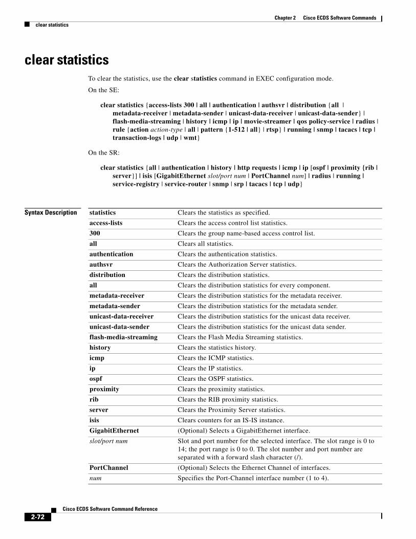
Chapter 2 Cisco ECDS Software Commandsclear statistics
clear statisticsTo clear the statistics, use the clear statistics command in EXEC configuration mode.
On the SE:
clear statistics {access-lists 300 | all | authentication | authsvr | distribution {all | metadata-receiver | metadata-sender | unicast-data-receiver | unicast-data-sender} | flash-media-streaming | history | icmp | ip | movie-streamer | qos policy-service | radius | rule {action action-type | all | pattern {1-512 | all} | rtsp} | running | snmp | tacacs | tcp | transaction-logs | udp | wmt}
On the SR:
clear statistics {all | authentication | history | http requests | icmp | ip [ospf | proximity {rib | server}] | isis [GigabitEthernet slot/port num | PortChannel num] | radius | running | service-registry | service-router | snmp | srp | tacacs | tcp | udp}
Syntax Description statistics Clears the statistics as specified.
access-lists Clears the access control list statistics.
300 Clears the group name-based access control list.
all Clears all statistics.
authentication Clears the authentication statistics.
authsvr Clears the Authorization Server statistics.
distribution Clears the distribution statistics.
all Clears the distribution statistics for every component.
metadata-receiver Clears the distribution statistics for the metadata receiver.
metadata-sender Clears the distribution statistics for the metadata sender.
unicast-data-receiver Clears the distribution statistics for the unicast data receiver.
unicast-data-sender Clears the distribution statistics for the unicast data sender.
flash-media-streaming Clears the Flash Media Streaming statistics.
history Clears the statistics history.
icmp Clears the ICMP statistics.
ip Clears the IP statistics.
ospf Clears the OSPF statistics.
proximity Clears the proximity statistics.
rib Clears the RIB proximity statistics.
server Clears the Proximity Server statistics.
isis Clears counters for an IS-IS instance.
GigabitEthernet (Optional) Selects a GigabitEthernet interface.
slot/port num Slot and port number for the selected interface. The slot range is 0 to 14; the port range is 0 to 0. The slot number and port number are separated with a forward slash character (/).
PortChannel (Optional) Selects the Ethernet Channel of interfaces.
num Specifies the Port-Channel interface number (1 to 4).
2-72Cisco ECDS Software Command Reference

Chapter 2 Cisco ECDS Software Commandsclear statistics
Defaults No default behavior or values
Command Modes EXEC
Usage Guidelines The clear statistics command clears all statistical counters from the parameters given. Use this command to monitor fresh statistical data for some or all features without losing cached objects or configurations.
This command is used to reset to zero proximity statistics related to the Proximity Engine components that are used for the proximity function. Use the show statistics ip proximity command to display proximity statistics.
movie-streamer Clears the Movie Streamer statistics.
qos Clears the QoS statistics.
policy-service Specifies the Camiant cdn-am service.
radius Clears the RADIUS statistics.
rule Clears the rules statistics.
action Clears the statistics of all the rules with the same action.
action-type Specifies one of the following actions:
allowblockgenerate-url-signatureno-cacheredirectrewritevalidate-url-signature
all Clears the statistics of all the rules.
pattern Clears the statistics of the pattern lists.
1-512 Pattern list number.
all Clears the statistics for all the pattern lists.
rtsp Clears the statistics for the configured RTSP rules (rules configured for RTSP requests from RealMedia players [the RTSP rules] and rules configured for RTSP requests from Windows Media 9 players [the WMT-RTSP rules]).
running Clears the running statistics.
snmp Clears the SNMP statistics.
srp Resets to zero all statistics counters kept by the local DHT service
tacacs Clears the TACACS+ statistics.
tcp Clears the TCP statistics.
transaction-logs Clears the transaction log export statistics.
udp Clears the UDP statistics.
web-engine Clears the Web Engine statistics.
wmt Clears all WMT statistics.
2-73Cisco ECDS Software Command Reference

Chapter 2 Cisco ECDS Software Commandsclear statistics
The DHT service keeps several counters, such as the number of requests and responses for DHT lookups. These counters can be displayed using the show statistics srp command.
Examples The following example shows how to clear proximity statistics with the clear statistics ip proximity command.
ServiceRouter# clear statistics ip proximity serverServiceRouter# show statistics ip proximity server
Proximity server: Requests received = 0Proximity server: Responses sent = 0Proximity server: Faults sent = 0ServiceRouter#
ServiceRouter# show statistics ip proximity ribTotal number of proximity requests received from applications: 0Total number of proximity replies sent to applications: 0Proximity msg exchanges between urib and routing protocols: Sent Prox Req Received Prox Respisis-p1 0 0ospf-p1 0 0isis-p1-te 0 0ospf-p1-te 0 0bgp-123 0 0mbgp-123 0 0Local proximity requests from applications: 0Invalid proximity requests from applications: 0PSA non-rankable proximity requests from applications: 0Failed proximity requests to routing protocols: 0Failed PSA lookups: 0Failed PTA lookups: 0ServiceRouter#
The following is sample output from the show statistics isis command before and after running clear statistics isis command.
ServiceRouter# show statistics isis
IS-IS statistics:PDU Received Sent RcvAuthErr OtherRcvErrLAN-IIH 51 14 0 0P2P-IIH 0 0 0 0CSNP 67 0 0 0PSNP 0 0 0 0PDU Received Flooded RcvAuthErr OtherRcvErr ReTransmitLSP 69 4 0 0 0DIS elections: 10 SPF calculations: 82 LSPs sourced: 0 LSPs refreshed: 8 LSPs purged: 0
ServiceRouter#
ServiceRouter# clear statistics isis *
ServiceRouter# show statistics isis
IS-IS statistics:PDU Received Sent RcvAuthErr OtherRcvErrLAN-IIH 1 0 0 0
2-74Cisco ECDS Software Command Reference

Chapter 2 Cisco ECDS Software Commandsclear statistics
P2P-IIH 0 0 0 0CSNP 4 0 0 0PSNP 0 0 0 0PDU Received Flooded RcvAuthErr OtherRcvErr ReTransmitLSP 1 0 0 0 0DIS elections: 0 SPF calculations: 1 LSPs sourced: 0 LSPs refreshed: 0 LSPs purged: 0
ServiceRouter#
The following example shows the use of the clear statistics srp command. The show statistics srp command is used to verify that the SRP counters have been reset to zero.
ServiceRouter# show statistics srp
Sent Received NeighborsJoin request 0 22 1Join response 22 0 0LS exchange request 309 310 0LS exchange response 310 309 0Route exchange request 65 0 0Route exchange response 0 64 0Ping request 410 412 1Ping response 412 410 0Lookup request 34 867 3Lookup response 867 34 0Ping traceroute request 0 0 0Ping traceroute response 0 0 0
ServiceRouter# clear statistics srp
Clearing all statistics counters
ServiceRouter# show statistics srp
Sent Received NeighborsJoin request 0 0 0Join response 0 0 0LS exchange request 1 1 0LS exchange response 1 1 0Route exchange request 1 0 0Route exchange response 0 1 0Ping request 2 2 0Ping response 2 2 0Lookup request 0 2 0Lookup response 2 0 0Ping traceroute request 0 0 0Ping traceroute response 0 0 0ServiceRouter#
Related Commands Command Description
show statistics srp Displays SRP statistics information.
2-75Cisco ECDS Software Command Reference

Chapter 2 Cisco ECDS Software Commandsclear transaction-logs
clear transaction-logsTo clear and archive the working transaction log files, use the clear transaction-log command in EXEC configuration mode.
clear transaction-logs
Syntax Description This command has no keywords or arguments.
Defaults No default behavior or values
Command Modes EXEC
Usage Guidelines The clear transaction-log command causes the transaction log to be archived immediately to the SE hard disk. This command has the same effect as the transaction-log force archive command.
Examples The following example shows that the clear transaction-log command forces the working transaction log file to be archived:
ServiceEngine# clear transaction-log
2-76Cisco ECDS Software Command Reference

Chapter 2 Cisco ECDS Software Commandsclear users
clear usersTo clear the connections (login) of authenticated users, use the clear users command in EXEC configuration mode.
clear users administrative
Syntax Description
Defaults No default behavior or values
Command Modes EXEC
Usage Guidelines The clear users administrative command clears the connections for all administrative users who are authenticated through a remote login service, such as TACACS. This command does not affect an administrative user who is authenticated through the local database.
Examples The following example shows how to clear the connections of the authenticated users.
ServiceRouter# clear users administrative ServiceRouter#
administrative Clears the connections of administrative users authenticated through a remote login service.
2-77Cisco ECDS Software Command Reference

Chapter 2 Cisco ECDS Software Commandsclear wmt
clear wmtTo clear the WMT streams, use the clear wmt command in EXEC configuration mode.
clear wmt stream-id 1-999999
Syntax Description
Defaults No default behavior or values
Command Modes EXEC
Examples The following examples shows how to clear a WMT stream for a stream ID of 22689:
ServiceEngine# clear wmt stream-id 22689ServiceEngine#
wmt Clears the WMT streams.
stream-id Clears the WMT streams that have the specified WMT stream ID. Also stops the SE’s WMT process that is associated with the specified stream ID.
1-999999 WMT stream ID to clear.
2-78Cisco ECDS Software Command Reference

Chapter 2 Cisco ECDS Software Commandsclock (EXEC)
clock (EXEC)To set or clear clock functions or update the calendar, use the clock command in EXEC configuration mode.
clock {read-calendar | set time day month year | update-calendar}
Syntax Description
Defaults No default behavior or values
Command Modes EXEC
Usage Guidelines If you have an outside source on your network that provides time services (such as a Network Time Protocol [NTP] server), you do not need to set the system clock manually. Enter the local time when setting the clock. The SE calculates the Coordinated Universal Time (UTC) based on the time zone set by the clock timezone command.
Note We strongly recommend that you configure all ECDS devices to use the Network Time Protocol (NTP) to keep their time synchronized. See the “ntp” section on page -202 for more details.
Note If you change the local time on the device, you must change the BIOS clock time as well; otherwise, the timestamps on the error logs are not synchronized. Changing the BIOS clock is required because the kernel does not handle time zones.
Two clocks exist in the system: the software clock and the hardware clock. The software uses the software clock. The hardware clock is used only at bootup to initialize the software clock. The calendar clock is the same as the hardware clock that runs continuously on the system, even if the system is powered off or rebooted. This clock is separate from the software clock settings, which are erased when the system is powered cycled or rebooted.
The set keyword sets the software clock. If the system is synchronized by a valid outside timing mechanism, such as a Network Time Protocol (NTP) clock source, you do not need to set the system clock. Use this command if no other time sources are available. The time specified in this command is relative to the configured time zone.
read-calendar Reads the calendar and updates the system clock.
set Sets the time and date.
time Current time in hh:mm:ss format (hh: 00 to 23; mm: 00 to 59; ss: 00 to 59).
day Day of the month (1 to 31).
month Month of the year (January, February, March, April, May, June, July, August, September, October, November, December).
year Year (1993 to 2035).
update-calendar Updates the calendar with the system clock.
2-79Cisco ECDS Software Command Reference
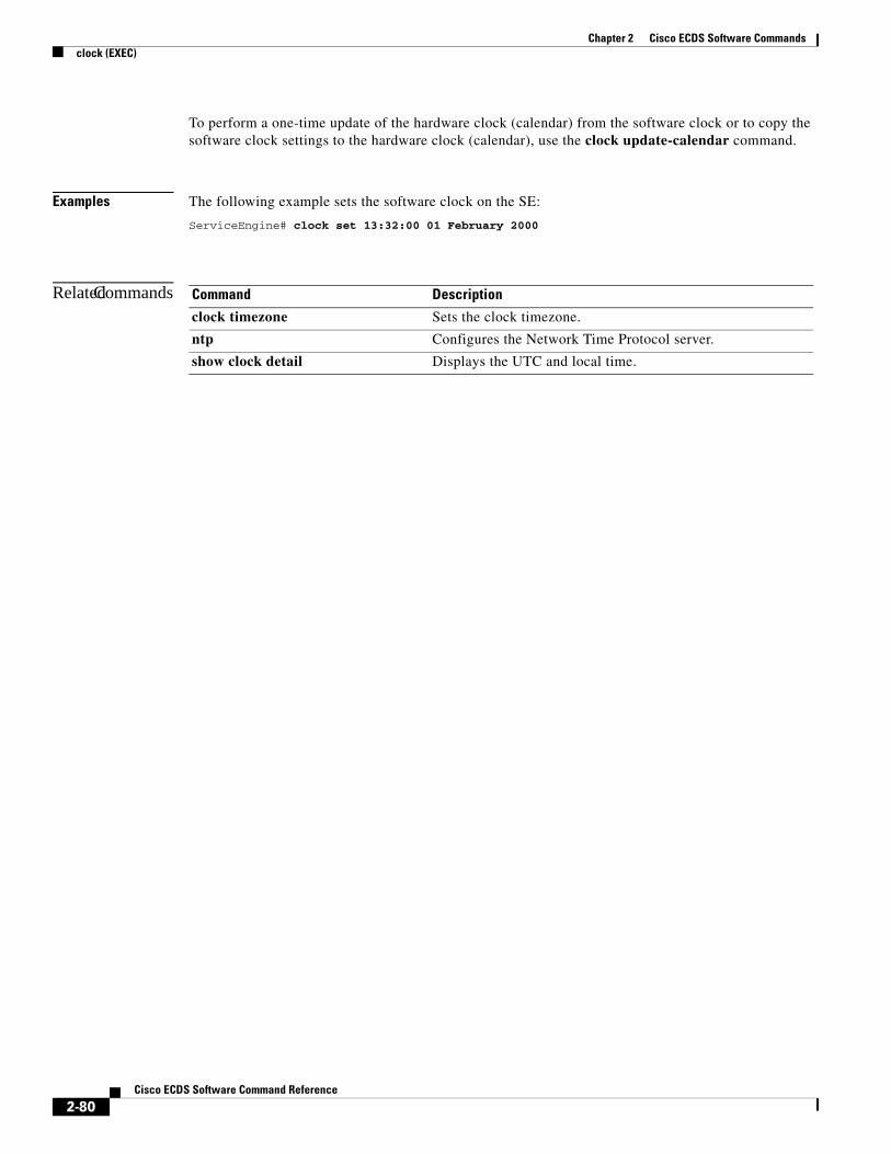
Chapter 2 Cisco ECDS Software Commandsclock (EXEC)
To perform a one-time update of the hardware clock (calendar) from the software clock or to copy the software clock settings to the hardware clock (calendar), use the clock update-calendar command.
Examples The following example sets the software clock on the SE:
ServiceEngine# clock set 13:32:00 01 February 2000
Related Commands Command Description
clock timezone Sets the clock timezone.
ntp Configures the Network Time Protocol server.
show clock detail Displays the UTC and local time.
2-80Cisco ECDS Software Command Reference

Chapter 2 Cisco ECDS Software Commandsclock (global configuration)
clock (global configuration)To set the summer daylight saving time and time zone for display purposes, use the clock command in global configuration mode. To disable this function, use the no form of this command.
clock {summertime timezone {date startday startmonth startyear starthour endday endmonth endyear offset | recurring {1-4 startweekday startmonth starthour endweekday endmonth endhour offset | first startweekday startmonth starthour endweekday endmonth endhour offset | last startweekday startmonth starthour endweekday endmonth endhour offset}} | timezone {timezone hoursoffset minutesoffset}}
Syntax Description
Defaults No default behavior or values
summertime Configures the summer or daylight saving time.
timezone Name of the summer time zone.
date Configures the absolute summer time.
startday Date (1 to 31) to start.
startmonth Month (January through December) to start.
startyear Year (1993–2032) to start.
starthour Hour (0 to 23) to start in (hh:mm) format.
endday Date (1 to 31) to end.
endmonth Month (January through December) to end.
endyear Year (1993 to 2032) to end.
endhour Hour (0 to 23) to end in (hh:mm) format.
offset Minutes offset (see Table B-1) from Coordinated Universal Time (UTC) (0–59).
recurring Configures the recurring summer time.
1-4 Configures the starting week number 1 to 4.
first Configures the summer time to recur beginning the first week of the month.
last Configures the summer time to recur beginning the last week of the month.
startweekday Day of the week (Monday to Friday) to start.
startmonth Month (January to December) to start.
starthour Hour (0 to 23) to start in (hh:mm) format.
endweekday Weekday (Monday to Friday) to end.
endmonth Month (January to December) to end.
endhour Hour (0 to 23) to end in hour:minute (hh:mm) format.
offset Minutes offset (see Table B-1) from UTC (0 to 59).
timezone Configures the standard time zone.
timezone Name of the time zone.
hoursoffset Hours offset (see Table B-1) from UTC (–23 to +23).
minutesoffset Minutes offset (see Table B-1) from UTC (0–59).
2-81Cisco ECDS Software Command Reference

Chapter 2 Cisco ECDS Software Commandsclock (global configuration)
Command Modes Global configuration
Usage Guidelines To set and display the local and UTC current time of day without an NTP server, use the clock timezone command with the clock set command. The clock timezone parameter specifies the difference between UTC and local time, which is set with the clock set command in EXEC configuration mode. The UTC and local time are displayed with the show clock detail command in EXEC configuration mode.
Use the clock timezone offset command to specify a time zone, where timezone is the desired time zone entry from Table B-1 and 0 0 is the offset (ahead or behind) Coordinated Universal Time (UTC) in hours and minutes. UTC was formerly known as Greenwich mean time (GMT).
SE(config)# clock timezone timezone 0 0
Note The time zone entry is case sensitive and must be specified in the exact notation listed in the time zone table as shown in Appendix B, “Standard Time Zones.” When you use a time zone entry from Table B-1, the system is automatically adjusted for daylight saving time.
Note If you change the local time on the device, you must change the BIOS clock time as well; otherwise, the timestamps on the error logs are not synchronized. Changing the BIOS clock is required because the kernel does not handle time zones.
The offset (ahead or behind) UTC in hours, as displayed in Table B-1, is in effect during winter time. During summer time or daylight saving time, the offset may be different from the values in the table and are calculated and displayed accordingly by the system clock.
Note An accurate clock and timezone setting is required for the correct operation of the HTTP proxy caches.
Examples The following example specifies the local time zone as Pacific Standard Time with an offset of 8 hours behind UTC:
ServiceEngine(config)# clock timezone PST -8Custom Timezone: PST will be used.
The following example configures a standard time zone on the SE:
ServiceEngine(config)# clock timezone US/Pacific 0 0Resetting offset from 0 hour(s) 0 minute(s) to -8 hour(s) 0 minute(s)Standard Timezone: US/Pacific will be used.ServiceEngine(config)#
The following example negates the time zone setting on the SE:
ServiceEngine(config)# no clock timezone
The following example configures daylight saving time:
ServiceEngine(config)# clock summertime PDT date 10 October 2001 23:59 29 April 2002 23:59 60
2-82Cisco ECDS Software Command Reference

Chapter 2 Cisco ECDS Software Commandsclock (global configuration)
Related Commands Command Description
clock To set the summer daylight saving time and time zone for display purposes
show clock detail Displays the UTC and local time.
2-83Cisco ECDS Software Command Reference

Chapter 2 Cisco ECDS Software Commandscms (EXEC)
cms (EXEC)To configure the Centralized Management System (CMS) embedded database parameters, use the cms command in EXEC configuration mode.
cms {config-sync | database {backup | create | delete | downgrade [script filename] | maintenance {full | regular} | restore filename | validate} | deregister [force] | recover {identity word}}
Syntax Description
Defaults No default behavior or values
Command Modes EXEC
Usage Guidelines The CDS network is a collection of SR, SE, and CDSM nodes. One primary CDSM retains the CDS network settings and provides other CDS network nodes with updates. Communication between nodes occurs over secure channels using the Secure Shell Layer (SSL) protocol, where each node on the CDS network uses a Rivest, Shamir, Adelman (RSA) certificate-key pair to communicate with other nodes.
Use the cms config-sync command to enable registered SRs, SEs, and standby CDSM to contact the primary CDSM immediately for a getUpdate (get configuration poll) request before the default polling interval of 5 minutes. For example, when a node is registered with the primary CDSM and activated, it
config-sync Sets the node to synchronize configuration with the CDSM.
database Creates, backs up, deletes, restores, or validates the CMS-embedded database management tables or files.
backup Backs up the database management tables.
create Creates the embedded database management tables.
delete Deletes the embedded database files.
downgrade Downgrades the CMS database.
script (Optional) Downgrades the CMS database by applying a downgrade script.
filename Downgraded script filename.
maintenance Cleans and reindexes the embedded database tables.
full Specifies a full maintenance routine for the embedded database tables.
regular Specifies a regular maintenance routine for the embedded database tables.
restore Restores the database management tables using the backup local filename.
filename Database local backup filename.
validate Validates the database files.
deregister Removes the registration of the CMS proto device.
force (Optional) Forces the removal of the node registration.
recover Recovers the identity of an CDS network device.
identity Specifies the identity of the recovered device.
word Identity of the recovered device.
2-84Cisco ECDS Software Command Reference

Chapter 2 Cisco ECDS Software Commandscms (EXEC)
appears as Pending in the CDSM GUI until it sends a getUpdate request. The cms config-sync command causes the registered node to send a getUpdate request at once, and the status of the node changes as Online.
Use the cms database create command to initialize the CMS database. Before a node can join an CDS network, it must first be registered and then activated. The cms enable command automatically registers the node in the database management tables and enables the CMS. The node sends its attribute information to the CDSM over the SSL protocol and then stores the new node information. The CDSM accepts these node registration requests without admission control and replies with registration confirmation and other pertinent security information required for getting updates. Activate the node using the CDSM GUI.
Once the node is activated, it automatically receives configuration updates and the necessary security RSA certificate-key pair from the CDSM. This security key allows the node to communicate with any other node in the CDS network. The cms deregister command removes the node from the CDS network by deleting registration information and database tables.
Note The cms deregister command cleans up the database automatically. You do not need to use the cms database delete command. If the deregistration fails, the best practice is to resolve any issues that caused the deregistration failure; for example, the Service Engine is the Content Acquirer of a delivery service and cannot be deleted or deactivated. Assign a different SE as the Content Acquirer in each delivery service where this SE is assigned as the Content Acquirer and try the cms deregister command again.
To back up the existing management database for the CDSM, use the cms database backup command. For database backups, specify the following items:
• Location, password, and user ID
• Dump format in PostgreSQL plain text syntax
The naming convention for backup files includes the time stamp.
When you use the cms recover identity word command when recovering lost registration information, or replacing a failed node with a new node that has the same registration information, you must specify the device recovery key that you configured in the Modifying Config Property, System.device.recovery.key window of the CDSM GUI.
Use the lcm command to configure local or central management (LCM) on an CDS network device. The LCM feature allows settings configured using the device CLI or GUI to be stored as part of the CDS network-wide configuration data (enable or disable).
When you enter the cms lcm enable command, the CMS process running on SEs, SRs, and the standby CDSM detects the configuration changes that you made on these devices using CLIs and sends the changes to the primary CDSM.
When you enter the cms lcm disable command, the CMS process running on SEs, SRs, and the standby CDSM does not send the CLI changes to the primary CDSM. Settings configured using the device CLIs are not sent to the primary CDSM.
If LCM is disabled, the settings configured through the CDSM GUI overwrite the settings configured from the SE or SR; however, this rule applies only to those local device settings that have been overwritten by the CDSM when you have configured the local device settings. If you (as the local CLI user) change the local device settings after the particular configuration has been overwritten by the CDSM, the local device configuration is applicable until the CDSM requests a full device statistics update from the SE or SR (clicking the Force full database update button from the Device Home window of the CDSM GUI triggers a full update). When the CDSM requests a full update from the device, the CDSM settings overwrite the local device settings.
2-85Cisco ECDS Software Command Reference

Chapter 2 Cisco ECDS Software Commandscms (EXEC)
The cms deregister force command should only be used as the last option, because the CDSM does not know about the device being removed. When executing the cms deregister force command, take note of any messages stating that the deregistration failed and make sure to resolve them before reregistering the device with the same CDSM or registering the device to another CDSM. The cms deregister force command forces the deregistration to continue.
Examples The following example backs up the database management tables:
CDSM# cms database backup creating backup file with label `backup'backup file local1/CDS-db-9-22-2002-17-36.dump is ready. use `copy' commands to move the backup file to a remote host.
The following example validates the database management tables:
CDSM# cms database validate Management tables are valid
In the following example, the CMS deregistration process has problems deregistering the SE, but it proceeds to deregister it from the CMS database when the force option is used:
ServiceEngine# cms deregister force Deregistration requires management service to be stopped.You will have to manually start it. Stopping management service on this node...This operation needs to restart http proxy and streaming proxies/servers (if running) for memory reconfiguration. Proceed? [ no ] yesmanagement services stoppedThu Jun 26 13:17:34 UTC 2003 [ I ] main: creating 24 messagesThu Jun 26 13:17:34 UTC 2003 [ I ] main: creating 12 dispatchersThu Jun 26 13:17:34 UTC 2003 [ I ] main: sending eDeRegistration message to CDSM 10.107.192.168...ServiceEngine#
The following example shows the use of the cms recover identity command when the recovery request matches the SE record, and the CDSM updates the existing record and sends a registration response to the requesting SE:
ServiceEngine# cms recover identity defaultRegistering this node as Service Engine...Sending identity recovery request with key defaultThu Jun 26 12:54:42 UTC 2003 [ I ] main: creating 24 messagesThu Jun 26 12:54:42 UTC 2003 [ I ] main: creating 12 dispatchersThu Jun 26 12:54:42 UTC 2003 [ I ] main: Sending registration message to CDSM 10.107.192.168Thu Jun 26 12:54:44 UTC 2003 [ W ] main: Unable to load device info file in TestServerThu Jun 26 12:54:44 UTC 2003 [ I ] main: Connecting storeSetup for SE.Thu Jun 26 12:54:44 UTC 2003 [ I ] main: Instantiating AStore 'com.cisco.unicorn.schema.PSqlStore'...Thu Jun 26 12:54:45 UTC 2003 [ I ] main: Successfully connected to databaseThu Jun 26 12:54:45 UTC 2003 [ I ] main: Registering object factories for persistent store...Thu Jun 26 12:54:51 UTC 2003 [ I ] main: Dropped Sequence IDSET.Thu Jun 26 12:54:51 UTC 2003 [ I ] main: Successfully removed old management tablesThu Jun 26 12:54:51 UTC 2003 [ I ] main: Registering object factories for persistent store......Thu Jun 26 12:54:54 UTC 2003 [ I ] main: Created Table FILE_CDSM.Thu Jun 26 12:54:55 UTC 2003 [ I ] main: Created SYS_MESS_TIME_IDX index.
2-86Cisco ECDS Software Command Reference

Chapter 2 Cisco ECDS Software Commandscms (EXEC)
Thu Jun 26 12:54:55 UTC 2003 [ I ] main: Created SYS_MESS_NODE_IDX index.Thu Jun 26 12:54:55 UTC 2003 [ I ] main: No Consistency check for store.Thu Jun 26 12:54:55 UTC 2003 [ I ] main: Successfully created management tablesThu Jun 26 12:54:55 UTC 2003 [ I ] main: Registering object factories for persistent store...Thu Jun 26 12:54:55 UTC 2003 [ I ] main: AStore Loading store data...Thu Jun 26 12:54:56 UTC 2003 [ I ] main: ExtExpiresRecord Loaded 0 Expires records.Thu Jun 26 12:54:56 UTC 2003 [ I ] main: Skipping Construction RdToClusterMappings on non-CDSM node.Thu Jun 26 12:54:56 UTC 2003 [ I ] main: AStore Done Loading. 327Thu Jun 26 12:54:56 UTC 2003 [ I ] main: Created SYS_MESS_TIME_IDX index.Thu Jun 26 12:54:56 UTC 2003 [ I ] main: Created SYS_MESS_NODE_IDX index.Thu Jun 26 12:54:56 UTC 2003 [ I ] main: No Consistency check for store.Thu Jun 26 12:54:56 UTC 2003 [ I ] main: Successfully initialized management tablesNode successfully registered with id 103Registration complete.ServiceEngine#
The following example shows the use of the cms recover identity command when the hostname of the SE does not match the hostname configured in the CDSM graphical user interface:
ServiceEngine# cms recover identity defaultRegistering this node as Service Engine...Sending identity recovery request with key defaultThu Jun 26 13:16:09 UTC 2003 [ I ] main: creating 24 messagesThu Jun 26 13:16:09 UTC 2003 [ I ] main: creating 12 dispatchersThu Jun 26 13:16:09 UTC 2003 [ I ] main: Sending registration message to CDSM 10.107.192.168There are no SE devices in CDNregister: Registration failed.ServiceEngine#
Related Commands Command Description
cms enable Enables the CMS.
show cms Displays the CMS protocol, embedded database content, maintenance status, and other information.
2-87Cisco ECDS Software Command Reference

Chapter 2 Cisco ECDS Software Commandscms (global configuration)
cms (global configuration)To schedule maintenance and enable the Centralized Management System (CMS) on a given node, use the cms command in global configuration mode. To negate these actions, use the no form of this command.
cms {database maintenance {full {enable | schedule weekday at time} | regular {enable | schedule weekday at time}} | enable | rpc timeout {connection 5-1800 | incoming-wait 10-600 | transfer 10-7200}}
no cms {database maintenance {full {enable | schedule weekday at time} | regular {enable | schedule weekday at time}} | enable | rpc timeout {connection 5-1800 | incoming-wait 10-600 | transfer 10-7200}}
Syntax Description database maintenance Configures the embedded database clean or reindex maintenance routine.
full Configures the full maintenance routine and cleans the embedded database tables.
enable Enables the full maintenance routine to be performed on the embedded database tables.
schedule Sets the schedule for performing the maintenance routine.
weekday Day of the week to start the maintenance routine.
every-day Every dayFri every FridayMon every MondaySat every SaturdaySun every SundayThu every ThursdayTue every TuesdayWed every Wednesday
at Sets the maintenance schedule time of day to start the maintenance routine.
time Time of day to start the maintenance routine (0 to 23:0 to 59) (hh:mm).
regular Configures the regular maintenance routine and reindexes the embedded database tables.
enable Enables the node CMS process.
rpc timeout Configures the timeout values for remote procedure call connections.
connection Specifies the maximum time to wait when making a connection.
5-1800 Timeout period, in seconds. The default for the CDSM is 30; the default for the SE and the SR is 180.
incoming-wait Specifies the maximum time to wait for a client response.
10-600 Timeout period, in seconds. The default is 30.
transfer Specifies the maximum time to allow a connection to remain open.
10-7200 Timeout period, in seconds. The default is 300.
2-88Cisco ECDS Software Command Reference
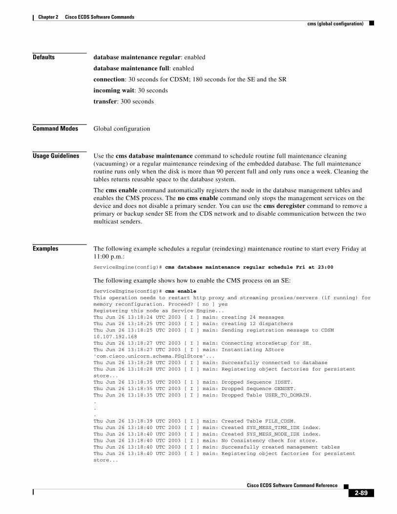
Chapter 2 Cisco ECDS Software Commandscms (global configuration)
Defaults database maintenance regular: enabled
database maintenance full: enabled
connection: 30 seconds for CDSM; 180 seconds for the SE and the SR
incoming wait: 30 seconds
transfer: 300 seconds
Command Modes Global configuration
Usage Guidelines Use the cms database maintenance command to schedule routine full maintenance cleaning (vacuuming) or a regular maintenance reindexing of the embedded database. The full maintenance routine runs only when the disk is more than 90 percent full and only runs once a week. Cleaning the tables returns reusable space to the database system.
The cms enable command automatically registers the node in the database management tables and enables the CMS process. The no cms enable command only stops the management services on the device and does not disable a primary sender. You can use the cms deregister command to remove a primary or backup sender SE from the CDS network and to disable communication between the two multicast senders.
Examples The following example schedules a regular (reindexing) maintenance routine to start every Friday at 11:00 p.m.:
ServiceEngine(config)# cms database maintenance regular schedule Fri at 23:00
The following example shows how to enable the CMS process on an SE:
ServiceEngine(config)# cms enableThis operation needs to restart http proxy and streaming proxies/servers (if running) for memory reconfiguration. Proceed? [ no ] yesRegistering this node as Service Engine...Thu Jun 26 13:18:24 UTC 2003 [ I ] main: creating 24 messagesThu Jun 26 13:18:25 UTC 2003 [ I ] main: creating 12 dispatchersThu Jun 26 13:18:25 UTC 2003 [ I ] main: Sending registration message to CDSM 10.107.192.168Thu Jun 26 13:18:27 UTC 2003 [ I ] main: Connecting storeSetup for SE.Thu Jun 26 13:18:27 UTC 2003 [ I ] main: Instantiating AStore 'com.cisco.unicorn.schema.PSqlStore'...Thu Jun 26 13:18:28 UTC 2003 [ I ] main: Successfully connected to databaseThu Jun 26 13:18:28 UTC 2003 [ I ] main: Registering object factories for persistent store...Thu Jun 26 13:18:35 UTC 2003 [ I ] main: Dropped Sequence IDSET.Thu Jun 26 13:18:35 UTC 2003 [ I ] main: Dropped Sequence GENSET.Thu Jun 26 13:18:35 UTC 2003 [ I ] main: Dropped Table USER_TO_DOMAIN....Thu Jun 26 13:18:39 UTC 2003 [ I ] main: Created Table FILE_CDSM.Thu Jun 26 13:18:40 UTC 2003 [ I ] main: Created SYS_MESS_TIME_IDX index.Thu Jun 26 13:18:40 UTC 2003 [ I ] main: Created SYS_MESS_NODE_IDX index.Thu Jun 26 13:18:40 UTC 2003 [ I ] main: No Consistency check for store.Thu Jun 26 13:18:40 UTC 2003 [ I ] main: Successfully created management tablesThu Jun 26 13:18:40 UTC 2003 [ I ] main: Registering object factories for persistent store...
2-89Cisco ECDS Software Command Reference

Chapter 2 Cisco ECDS Software Commandscms (global configuration)
Thu Jun 26 13:18:40 UTC 2003 [ I ] main: AStore Loading store data...Thu Jun 26 13:18:41 UTC 2003 [ I ] main: ExtExpiresRecord Loaded 0 Expires records.Thu Jun 26 13:18:41 UTC 2003 [ I ] main: Skipping Construction RdToClusterMappings on non-CDSM node.Thu Jun 26 13:18:41 UTC 2003 [ I ] main: AStore Done Loading. 336Thu Jun 26 13:18:41 UTC 2003 [ I ] main: Created SYS_MESS_TIME_IDX index.Thu Jun 26 13:18:41 UTC 2003 [ I ] main: Created SYS_MESS_NODE_IDX index.Thu Jun 26 13:18:41 UTC 2003 [ I ] main: No Consistency check for store.Thu Jun 26 13:18:41 UTC 2003 [ I ] main: Successfully initialized management tablesNode successfully registered with id 28940Registration complete.Warning: The device will now be managed by the CDSM. Any configuration changesmade via CLI on this device will be overwritten if they conflict with settings on the CDSM.Please preserve running configuration using 'copy running-config startup-config'.Otherwise management service will not be started on reload and node will be shown'offline' in CDSM UI.management services enabledServiceEngine(config)#
Related Commands Command Description
cms database Creates, backs up, deletes, restores, or validates the CMS-embedded database management tables or files.
show cms Displays the CMS protocol, embedded database content, maintenance status, and other information.
2-90Cisco ECDS Software Command Reference
Chapter 2 Cisco ECDS Software Commandsconfigure
configureTo enter global configuration mode, use the configure command in EXEC configuration mode. You must be in global configuration mode to enter command in global configuration modes.
configure
To exit global configuration mode, use the end or exit commands. In addition, you can press Ctrl-Z to exit from global configuration mode.
Syntax Description This command has no arguments or keywords.
Defaults No default behavior or values
Command Modes EXEC
Examples The following example shows how to enable global configuration mode:
ServiceEngine# configure ServiceEngine(config)#
Related Commands Command Description
end Exits configuration and privileged EXEC configuration modes.
exit Exits from interface, global configuration, or privileged EXEC configuration modes.
show running-config Displays the current operating configuration.
show startup-config Displays the startup configuration.
2-91Cisco ECDS Software Command Reference

Chapter 2 Cisco ECDS Software Commandscopy
copyTo copy the configuration or image data from a source to a destination, use the copy command in EXEC configuration mode.
copy cdnfs disk url sysfs-filename
copy cdrom install filedir filename
copy disk {ftp {hostname | ip-address} remotefiledir remotefilename localfilename | startup-config filename}
copy ftp {disk {hostname | ip-address} remotefiledir remotefilename localfilename | install {hostname | ip-address} remotefiledir remotefilename}
copy http install {{hostname | ip-address} remotefiledir remotefilename} [port port-num [proxy {hostname | ip-address} | username username password [proxy {hostname | ip-address} proxy_portnum]] | proxy {hostname | ip-address} proxy_portnum | username username password [proxy {hostname | ip-address} proxy_portnum]]
copy running-config {disk filename | startup-config}
copy startup-config {disk filename | running-config}
copy system-status disk filename
copy tech-support {disk filename | remotefilename}
copy sftp install {{ip-address} remotefiledir remotefilename}
Syntax Description cdnfs Copies a file from the cdnfs to the sysfs.
disk Copies a file to the disk.
url URL of the cdnfs file to be copied to the sysfs.
sysfs-filename Filename to be copied in the sysfs.
cdrom Copies a file from the CD-ROM.
install Installs the software release file.
filedir Directory location of the software release file.
filename Filename of the software release file.
disk Copies a local disk file.
ftp Copies to a file on an FTP server.
sftp Copies to a file on an SFTP server.
hostname Hostname of the FTP server.
ip-address IP address of the FTP server.
remotefiledir Directory on the FTP server to which the local file is copied.
remotefilename Name of the local file once it has been copied to the FTP server.
localfilename Name of the local file to be copied.
startup-config Copies the configuration file from the disk to startup configuration (NVRAM).
2-92Cisco ECDS Software Command Reference

Chapter 2 Cisco ECDS Software Commandscopy
filename Name of the existing configuration file.
ftp Copies a file from an FTP server.
disk Copies a file to a local disk.
hostname Hostname of the FTP server.
ip-address IP address of the FTP server.
remotefiledir Directory on the FTP server where the file to be copied is located.
remotefilename Name of the file to be copied to the local disk.
localfilename Name of the copied file as it appears on the local disk.
install Copies the file from an FTP server and installs the software release file to the local device.
hostname Name of the FTP server.
ip-address IP address of the FTP server.
remotefiledir Remote file directory.
remotefilename Remote filename.
http install Copies the file from an HTTP server and installs the software release file on a local device.
hostname Name of the HTTP server.
ip-address IP address of the HTTP server.
remotefiledir Remote file directory.
remotefilename Remote filename.
port (Optional) Specifies the port to connect to the HTTP server. The default is 80.
port-num HTTP server port number. The range is from 1 to 65535.
proxy Allows the request to be redirected to an HTTP proxy server.
hostname Name of the HTTP server.
ip-address IP address of the HTTP server.
proxy_portnum HTTP proxy server port number. The range is from 1 to 65535.
username Specifies the username to access the HTTP proxy server.
username User login name.
running-config Copies the current system configuration.
disk Copies the current system configuration to a disk file.
filename Name of the file to be created on disk.
startup-config Copies the running configuration to the startup configuration (NVRAM).
startup-config Copies the startup configuration.
disk Copies the startup configuration to a disk file.
filename Name of the startup configuration file to be copied to the local disk.
running-config Copies the startup configuration to a running configuration.
system-status disk Copies the system status to a disk file.
filename Name of the file to be created on the disk.
tech-support Copies system information for technical support.
disk Copies system information for technical support to a disk file.
2-93Cisco ECDS Software Command Reference

Chapter 2 Cisco ECDS Software Commandscopy
Defaults HTTP server port: 80
Default working directory for sysfs files: /local1
Command Modes EXEC
Usage Guidelines The copy cdnfs command in EXEC configuration mode copies data files out of the cdnfs to the sysfs for further processing. For example, you can use the install imagefilename command in EXEC configuration mode to provide the copied files to the command.
The copy disk ftp command copies files from a sysfs partition to an FTP server. The copy disk startup-config command copies a startup configuration file to NVRAM.
The copy ftp disk command copies a file from an FTP server to a sysfs partition.
Use the copy ftp install command to install an image file from an FTP server. Part of the image goes to the disk and part goes to the flash memory.
Use the copy http install command to install an image file from an HTTP server and install it on a local device. It transfers the image from an HTTP server to the SE using HTTP as the transport protocol and installs the software on the device. Part of the image goes to the disk and part goes to the flash memory. You can also use this command to redirect your transfer to a different location or HTTP proxy server, by specifying the proxy hostname | ip-address option. A username and a password have to be authenticated with the remote HTTP server if the server is password protected and requires authentication before the transfer of the software release file to the SE is allowed.
Use the copy cdrom install command to install the image from the rescue CD.
ServiceEngine# copy cdrom install /images CDS24.bin
Use the copy running-config command to copy the running system configuration to a sysfs partition or flash memory. The copy running-config startup-config command is equivalent to the write memory command.
The copy startup-config command copies the startup configuration file to a sysfs partition.
The copy system-status command creates a file on a sysfs partition containing hardware and software status information.
The copy tech-support tftp command can copy technical support information to a a sysfs partition.
Related Commands
filename Name of the file to be created on disk.
remotefilename Remote filename of the system information file to be created on the TFTP server. Use the complete pathname.
Command Description
install Installs a new version of the caching application.
reload Halts a device and performs a cold restart.
show running-config Displays the current operating configuration.
2-94Cisco ECDS Software Command Reference

Chapter 2 Cisco ECDS Software Commandscopy
show startup-config Displays the startup configuration.
write Writes or erases the startup configurations to NVRAM or to a terminal session, or writes the MIB persistence configuration to disk.
2-95Cisco ECDS Software Command Reference

Chapter 2 Cisco ECDS Software Commandscpfile
cpfileTo make a copy of a file, use the cpfile command in EXEC configuration mode.
cpfile oldfilename newfilename
Syntax Description
Defaults No default behavior or values
Command Modes EXEC
Usage Guidelines Use this command to create a copy of a file. Only sysfs files can be copied.
Examples The following example shows how to create a copy of a file:
ServiceEngine# cpfile syslog.txt syslog.txt.save
Related Commands
oldfilename Name of the file to copy.
newfilename Name of the copy to be created.
Command Description
copy Copies the configuration or image files to and from the CD-ROM, flash memory, disk, or remote hosts.
dir Displays the files in a long list format.
lls Displays the files in a long list format.
ls Lists the files and subdirectories in a directory.
mkfile Makes a file (for testing).
rename Renames a file.
rmdir Removes a directory.
2-96Cisco ECDS Software Command Reference

Chapter 2 Cisco ECDS Software Commandsdebug
debugTo monitor and record caching application functions, use the debug command in EXEC configuration mode. To disable debug, use the no form of this command.
debug option
no debug option
Syntax Description
Defaults No default behavior or values
Command Modes EXEC
Usage Guidelines
Note We recommend that you use the debug command only at the direction of Cisco TAC because the SE performance is affected when you enter the debug command.
You can use the logging disk priority debug command with the debug command. This configuration causes the debugging messages to be logged in the syslog file, which is available in the /local1 directory by default. You can then download the messages from the SE, copy them to a local disk file (for example, using the copy disk ftp command), and forward the logs to Cisco TAC for further investigation. By default, system log messages are logged to the console and you need to copy and paste the output to a file. However, this method of obtaining logs is more prone to errors than capturing all messages in the syslog.txt file. When you use system logging to a disk file instead of system logging to a console, there is no immediate feedback that debug logging is occurring, except that the syslog.txt file gets larger (you can track the lines added to the syslog.txt file by entering the type-tail syslog.txt follow command). When you have completed downloading the system logs to a local disk, you must disable the debugging functions by using the undebug command (see the “undebug” section on page -536 section for more details), and reset the level of logging disk priority to any other setting that you want (for example, notice priority).
Valid values for option are as follows:
option Specifies the debugger type; see the Usage Guidelines section for valid values.
access-lists 300
dump
query
username username
groupname groupnames
Debugs the access control list.
Dumps the access control list contents.
Queries the access control list configuration.
Queries the access control list username.
Queries the access control list group name or names of groups of which the user is a member. Each group name must be separated by a comma.
2-97Cisco ECDS Software Command Reference

Chapter 2 Cisco ECDS Software Commandsdebug
acquirer
error
trace
Debugs the acquirer.
Sets the debug level to error.
Sets the debug level to trace.
all Enables all debugging.
authentication
user
Debugs authentication.
Debugs the user login against the system authentication.
authsvr
error
trace
Debugs the Autnentication Server.
Sets the debug level to error.
Sets the debug level to trace.
bandwidth
advanced
error
trace
Debugs the bandwidth module.
Advanced bandwidth controller debug commands.
Sets the debug level to error.
Sets the debug level to trace.
buf
all
dmbuf
dmsg
Debugs the buffer manager.
Debugs all buffer manager functions.
Debugs the buffer manager dmbuf.
Debugs the buffer manager dmsg.
cache-content
all
error
trace
Debugs the caching service.
(Optional) Sets the debug level to all.
(Optional) Sets the debug level to error.
(Optional) Sets the debug level to trace.
cache-router
error
trace
Debugs the caching router.
Sets the debug level to error.
Sets the debug level to trace.
cdnfs Debugs the CDS network file system (cdnfs).
cli
all
bin
parser
Debugs the CLI command.
Debugs all CLI commands.
Debugs the CLI command binary program.
Debugs the CLI command parser.
cms Debugs the CMS.
dataserver
all
clientlib
server
Debugs the data server.
Debuts all data server functions.
Debugs the data server client library module.
Debugs the data server module.
2-98Cisco ECDS Software Command Reference

Chapter 2 Cisco ECDS Software Commandsdebug
dfs
all
api
diskcache
memcache
rawio
Debugs the DFS.
Sets the debug level to all.
Debugs the DFS application API.
Debugs the DFS in-memory disk-directory cache management.
Debugs the DFS in-memory cache.
Debugs the DFS raw disk I/O.
dhcp Debugs the DHCP.
distribution
all
error
trace
metadata-receiver
error
trace
metadata-sender
error
trace
mcast-data-receiver
error
trace
mcast-data-sender
error
trace
unicast-data-receiver
error
trace
unicast-data-sender
error
trace
Debugs the distribution components.
Debugs all distribution components.
Debugs all distribution components to error level 1 (show error).
Debugs all distribution components to trace level 2 (show error and trace).
Debugs the metadata receiver distribution component.
Debugs the metadata receiver distribution component to error level 1.
Debugs the metadata receiver distribution component to trace level 2.
Debugs the metadata sender distribution component.
Debugs the metadata sender distribution component to error level 1.
Debugs the metadata sender distribution component to trace level 2.
Debugs the multicast receiver distribution component.
Debugs the multicast receiver distribution component to error level 1.
Debugs the multicast receiver distribution component to trace level 2.
Debugs the multicast sender distribution component.
Debugs the multicast sender distribution component to error level 1.
Debugs the multicast sender distribution component to trace level 2.
Debugs the unicast receiver distribution component.
Debugs the unicast receiver distribution component to error level 1.
Debugs the unicast receiver distribution component to trace level 2.
Debugs the unicast sender distribution component.
Debugs the unicast sender distribution component to error level 1.
Debugs the unicast sender distribution component to trace level 2.
2-99Cisco ECDS Software Command Reference

Chapter 2 Cisco ECDS Software Commandsdebug
emdb
level
(0-16)
Debugs the embedded database.
(Optional) Debug level.
Debug level 0 through 16.
flash-media-streaming
error
trace
Debugs Flash Media Streaming.
Debugs the Flash Media Streaming log level error.
Debugs the Flash Media Streaming log level debug.
http
all
cache
content-router
header
hit
miss
pac-file-server
parser
plugin
proxy
server
Debugs the HTTP commands.
Debugs all HTTP functions.
Debugs the HTTP cache.
Debugs the HTTP content routing.
Debugs an HTTP header.
Debugs an HTTP hit.
Debugs an HTTP miss.
Debugs HTTP for the dynamic proxy autoconfiguration feature.
Debugs the HTTP parser.
Debugs the HTTP plug-in.
Debugs the HTTP proxy.
Debugs the HTTP server.
http-authcache
all
application
cli
daemon
Debugs the authentication cache.
Debugs all the authentication cache functions.
Debugs the application module.
Debugs the CLI module.
Debugs the daemon client module.
https
all
cli
header
parser
proxy
Debugs HTTPS.
Debugs all HTTPS functions.
Debugs the HTTPS CLI.
Debugs the HTTPS header.
Debugs the HTTPS parser.
Debugs the HTTPS proxy.
2-100Cisco ECDS Software Command Reference

Chapter 2 Cisco ECDS Software Commandsdebug
isis
adjacency
all
csnp
dis
esis
event
hello
lsp
mpls
psnp
spf
timer
Debugs IS-IS Routing for IP.
Debugs IS-IS adjacency information.
Debugs all IS-IS debugging.
Debugs IS-IS Complete Sequence Number PDU (CSNP) information.
Debugs IS-IS DIS election information.
Debugs IS-IS ESIS information.
Debugs IS-IS event information.
Debugs IS-IS hello information.
Debugs IS-IS timer LSP information.
Debugs IS-IS MPLS information.
Debugs IS-IS PSNP information.
Debugs IS-IS SPF information.
Debugs IS-IS timer information.
logging
all
Debugs logging.
Debugs all logging functions.
malloc
cache-app
all
caller-accounting
catch-double-free
check-boundaries
check-free-chunks
clear-on-alloc
statistics
dns-server
all
caller-accounting
catch-double-free
check-boundaries
log-directory
word
Debug commands for memory allocation.
Debugging commands for cache application memory allocation.
Sets the debug level to all.
Collects statistics for every distinct allocation call-stack.
Alerts if application attempts to release the same memory twice.
Checks boundary over and under run scribble.
Checks if free chunks are over-written after release.
Ensures all allocations are zero-cleared.
Allocator use statistical summary.
DNS Caching Service memory allocation debugging.
Sets the debug level to all.
Collects statistics for every distinct allocation call-stack.
Alerts if application attempts to release the same memory twice.
Checks boundary over and under run scribble.
Memory allocation debugging log directory.
Directory path name.
movie-streamer
error
trace
Debug commands for the Movie Streamer.
Sets the debug level to error.
Sets the debug level to trace.
ntp Debugs NTP.
2-101Cisco ECDS Software Command Reference

Chapter 2 Cisco ECDS Software Commandsdebug
qos
policy service
error
trace
Debug commands for the QoS component.
Debug commands for the policy service.
Sets the debug level to error.
Sets the debug level to trace.
rbcp Debugs the RBCP (Router Blade Configuration Protocol) functions.
rpc
detail
trace
Displays the remote procedure calls (RPC) logs.
Displays the RPC logs of priority “detail” level or higher.
Displays the RPC logs of priority “trace” level or higher.
rtsp
gateway
error
trace
Debugs the RTSP functions.
Debugs the RTSP gateway.
Debugs the RTSP gateway to level 1 (show error).
Debugs the RTSP gateway to level 2 (show error and trace).
rule
action
all
pattern
Debugs the Rules Template.
Debugs the rule action.
Debugs all rule functions.
Debugs the rule pattern.
service-router
servicemonitor
Debug commands for the Service Router.
Debug commands for the service monitor.
servicemonitor Debugs the service monitor.
session-manager
critical
error
trace
Session manager debug commands.
Sets the debug level to critical.
Sets the debug level to error.
Sets the debug level to trace.
snmp
all
cli
main
mib
traps
Debugs SNMP.
Debugs all SNMP functions.
Debugs the SNMP CLI.
Debugs the SNMP main.
Debugs the SNMP MIB.
Debugs the SNMP traps.
standby
all
Debugs standby.
(Optional) Debugs all standby functions.
stats
all
collection
computation
history
Debugs the statistics.
Debugs all statistics functions.
Debugs the statistics collection.
Debugs the statistics computation.
Debugs the statistics history.
2-102Cisco ECDS Software Command Reference
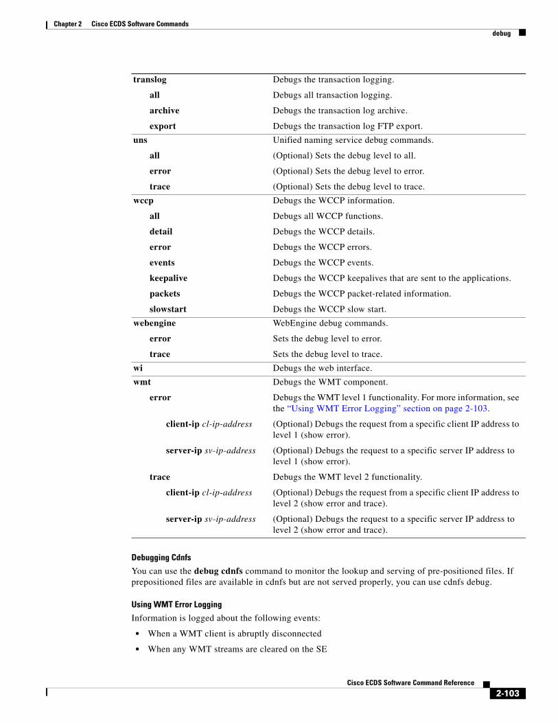
Chapter 2 Cisco ECDS Software Commandsdebug
Debugging Cdnfs
You can use the debug cdnfs command to monitor the lookup and serving of pre-positioned files. If prepositioned files are available in cdnfs but are not served properly, you can use cdnfs debug.
Using WMT Error Logging
Information is logged about the following events:
• When a WMT client is abruptly disconnected
• When any WMT streams are cleared on the SE
translog
all
archive
export
Debugs the transaction logging.
Debugs all transaction logging.
Debugs the transaction log archive.
Debugs the transaction log FTP export.
uns
all
error
trace
Unified naming service debug commands.
(Optional) Sets the debug level to all.
(Optional) Sets the debug level to error.
(Optional) Sets the debug level to trace.
wccp
all
detail
error
events
keepalive
packets
slowstart
Debugs the WCCP information.
Debugs all WCCP functions.
Debugs the WCCP details.
Debugs the WCCP errors.
Debugs the WCCP events.
Debugs the WCCP keepalives that are sent to the applications.
Debugs the WCCP packet-related information.
Debugs the WCCP slow start.
webengine
error
trace
WebEngine debug commands.
Sets the debug level to error.
Sets the debug level to trace.
wi Debugs the web interface.
wmt
error
client-ip cl-ip-address
server-ip sv-ip-address
trace
client-ip cl-ip-address
server-ip sv-ip-address
Debugs the WMT component.
Debugs the WMT level 1 functionality. For more information, see the “Using WMT Error Logging” section on page 2-103.
(Optional) Debugs the request from a specific client IP address to level 1 (show error).
(Optional) Debugs the request to a specific server IP address to level 1 (show error).
Debugs the WMT level 2 functionality.
(Optional) Debugs the request from a specific client IP address to level 2 (show error and trace).
(Optional) Debugs the request to a specific server IP address to level 2 (show error and trace).
2-103Cisco ECDS Software Command Reference

Chapter 2 Cisco ECDS Software Commandsdebug
Error logs are in the same format and location as syslogs. The WMT log messages are logged to /local1/errorlog/wmt_errorlog.current.
You can configure the SE for WMT error logging by using the debug wmt error command in EXEC configuration mode. This command debugs WMT level 1 functionality.
Logging WMT Client Disconnects
When a WMT client is disconnected abruptly, the reasons for the client disconnect (for example, the request was blocked by the rules, the maximum incoming or outgoing bit-rate limit was reached, the maximum incoming or outgoing bandwidth limit was reached) are logged in ECDS software error logs.
The client information includes the client IP address, the server IP address, the requested URL, the client protocol, the version of the client media player, the number of packets that the client received, and the number of packets that the server sent.
Related Commands Command Description
logging Configures system logging (syslog).
show debugging Displays the state of each debugging option.
undebug Disables the debugging functions (see also debug).
2-104Cisco ECDS Software Command Reference

Chapter 2 Cisco ECDS Software Commandsdelfile
delfileTo delete a file, use the delfile command in EXEC configuration mode.
delfile filename
Syntax Description
Defaults No default behavior or values
Command Modes EXEC
Usage Guidelines Use this command to remove a file from a sysfs partition.
Examples The following example shows how to delete a file:
ServiceEngine# delfile /local1/tempfile
Related Commands
filename Name of the file to delete.
Command Description
cpfile Copies a file.
deltree Deletes a directory and its subdirectories.
mkdir Makes a directory.
mkfile Makes a file (for testing).
rmdir Removes a directory.
2-105Cisco ECDS Software Command Reference

Chapter 2 Cisco ECDS Software Commandsdeltree
deltreeTo remove a directory with its subdirectories and files, use the deltree command in EXEC configuration mode.
deltree directory
Syntax Description
Defaults No default behavior or values
Command Modes EXEC
Usage Guidelines Use this command to remove a directory and all files within the directory from the SE sysfs file system. Do not remove files or directories required for proper SE functioning.
Examples The following example shows how to delete a directory from the /local1 directory:
ServiceEngine# deltree /local1/testdir
Related Commands
directory Name of the directory tree to delete.
Command Description
delfile Deletes a file.
mkdir Makes a directory.
mkfile Makes a file (for testing).
rmdir Removes a directory.
2-106Cisco ECDS Software Command Reference

Chapter 2 Cisco ECDS Software Commandsdevice
deviceTo configure the mode of operation on a device as a CDSM, SE or SR, use the device command in global configuration mode. To reset the mode of operation on a device, use the no form of this command.
device mode {content-delivery-system-manager | service-engine | service-router}
no device mode {content-delivery-system-manager | service-engine | service-router}
Syntax Description
Defaults The default device operation mode is SE.
Command Modes Global configuration
Usage Guidelines A CDSM is the content management and device management station of an CDS network that allows you to specify what content is to be distributed, and where the content should be distributed. If an SR is deployed in the CDS network, the SR redirects the client based on redirecting policy. An SE is the device that serves content to the clients. There are typically many SEs deployed in an CDS network, each serving a local set of clients. IP/TV brings movie-quality video over enterprise networks to the desktop of the CDS network user.
Because different device modes require disk space to be used in different ways, disk space must also be configured when the device mode changes from being an SE or SR to CDSM (or the other way around). You must reboot the device before the configuration changes to the device mode take effect.
Disks must be configured before device configuration is changed. Use the disk configure command to configure the disk before reconfiguring the device to the SE or SR mode. Disk configuration changes using the disk configure command takes effect after the next device reboot.
To enable CDS network-related applications and services, use the cms enable command. Use the no form of this command to disable the CDS network.
All CDS devices ship from the factory as SEs. Before configuring network settings for CDSMs and SRs using the CLI, you must change the device from an SE to the proper device mode.
Configuring the device mode is not a supported option on all hardware models. However, you can configure some hardware models to operate as any one of the four content networking device types. Devices that can be reconfigured using the device mode command are shipped from the factory by default as SEs.
To change the device mode of your SE, you must also configure the disk space allocations, as required by the different device modes, and reboot the device for the new configuration to take effect.
mode Sets the mode of operation of a device to CDSM, SE or SR.
content-delivery-system-manager
Configures the device operation mode as a CDSM.
service-engine Configures the device operation mode as an SE.
service-router Configures the device operation mode as an SR.
2-107Cisco ECDS Software Command Reference

Chapter 2 Cisco ECDS Software Commandsdevice
When you change the device mode of an SE to an SR or CDSM, you may need to reconfigure the system file system (sysfs). However, SRs and CDSMs do not require any disk space other than sysfs. When you change the device mode to an SR or a CDSM, disk configuration changes are not required because the device already has some space allotted for sysfs. sysfs disk space is always preconfigured on a factory-fresh CDS network device. See the “Disk Space-Allocation Guidelines for Service Routers” section on page 2-113 and “Disk Space-Allocation Guidelines for CDSMs” section on page 2-113 for more information.
If you are changing the device mode of an SR or a CDSM back to an SE, you must configure disk space allocations for the caching, pre-positioning (cdnfs) and system use (sysfs) file systems that are used on the SE. You can configure disk space allocations either before or after you change the device mode to an SE.
Examples The following examples show the configuration from the default mode, SE, to the CDSM, SR, and SE modes:
ServiceEngine(config)# device mode content-delivery-system-manager
CDSM(config)# device mode service-router
ServiceRouter(config)# device mode service-engine
Related Commands Command Description
show device-mode Displays the configured or current mode of a CDSM, SE, or SR device.
2-108Cisco ECDS Software Command Reference

Chapter 2 Cisco ECDS Software Commandsdir
dirTo view a long list of files in a directory, use the dir command in EXEC configuration mode.
dir [directory]
Syntax Description
Defaults No default behavior or values
Command Modes EXEC
Usage Guidelines Use this command to view a detailed list of files contained within the working directory, including names, sizes, and time created. The equivalent command is lls.
Examples The following example shows how to view a list of files in a directory:
ServiceEngine# dir size time of last change name -------------- ------------------------- ----------- 3931934 Tue Sep 19 10:41:32 2000 errlog-cache-20000918-164015 431 Mon Sep 18 16:57:40 2000 ii.cfg 431 Mon Sep 18 17:27:46 2000 ii4.cfg 431 Mon Sep 18 16:54:50 2000 iii.cfg 1453 Tue Sep 19 10:34:03 2000 syslog.txt 1024 Tue Sep 19 10:41:31 2000 <DIR> testdir
Related Commands
directory (Optional) Name of the directory to list.
Command Description
lls Displays the files in a long list format.
ls Lists the files and subdirectories in a directory.
2-109Cisco ECDS Software Command Reference

Chapter 2 Cisco ECDS Software Commandsdirect-server-return
direct-server-returnTo enable a VIP for direct server return, use the direct-server-return command in global configuration mode. To disable direct server return, use the no form of this command.
direct-server-return vip ip address
no direct-server-return vip ip address
Syntax Description
Defaults No default behavior or values
Command Modes Global configuration
Usage Guidelines Direct Server Return (DSR) is a method used by load balancer servers in a load balancing configuration. DSR responds directly to the client, bypassing the load balancer in the response path. Table 2-4 shows the Direct Server Return flow.
Examples The following example shows how to enable direct server return:
ServiceEngine(config)# direct-server-return vip 1.1.1.1 ServiceEngine(config)#
Related Commands
vip Specifies the VIP for direct-server-return.
ip address VIP for direct-server-return.
Table 2-4 Direct Server Return Flow
Step Process Source IP Destination IP Destination MAC
Step 1 Client to load balancer 171.71.50.140 170.1.1.45 00:30:48:C3:C7:C5
Step 2 Load balancer to SR 171.71.50.140 170.1.1.45 00:14:5E:83:6E:7E
Step 3 SR to client 170.1.1.45 171.71.50.140 Default Gateway MAC
Command Description
show direct-server-return Displays the Direct Server return information.
2-110Cisco ECDS Software Command Reference

Chapter 2 Cisco ECDS Software Commandsdisable
disableTo turn off privileged command in EXEC configuration modes, use the disable command in EXEC configuration mode.
disable
Syntax Description This command has no arguments or keywords.
Defaults No default behavior or values
Command Modes EXEC
Usage Guidelines The disable command places you in the user-level EXEC shell. To turn privileged EXEC configuration mode back on, use the enable command.
Examples The following example shows how to enter the user-level EXEC configuration mode:
ServiceEngine# disableServiceEngine>
Related Commands Command Description
enable Accesses the privileged EXEC commands.
2-111Cisco ECDS Software Command Reference

Chapter 2 Cisco ECDS Software Commandsdisk (EXEC)
disk (EXEC)To configure disks and allocate disk space for devices that are using the CDS software, use the disk command in EXEC configuration mode.
disk {reformat diskname | mark diskname {bad | good} | recover-system-volumes | unuse diskname}
Syntax Description
Defaults No default behavior or values
Command Modes EXEC
Usage Guidelines The disk space in the CDS software is allocated on a per-file system basis, rather than on a per-disk basis. You can configure your overall disk storage allocations according to the kinds of client protocols that you expect to use and the amount of storage that you need to provide for each of the functions.
Note For details on the Cisco ECDS software disk storage and configuration requirements for SEs, see Cisco ECDS 2.6 Software Configuration Guide.
The cndfs and sysfs partitions use the ext2 file system. With ext2 file systems, if the system crashed or if the system is not shut down cleanly, a file system check of these partitions takes a long time. If there are sector failures on the disk, the time to perform a file system check with an ext2 file system increases even more. By migrating to the ext3 file system, the amount of time required to perform a file system check of the cndfs and sysfs partitions is decreased, which increases the availability of the SE.
The cdnfs amounts are reported by the actual usable amounts of storage for applications. Because of the internal file system overhead of approximately 3 percent, the reported amounts may be smaller than what you configured.
reformat Reformats drive (DANGEROUS).
diskname Name of the disk to be erased (disk00, disk01, and so on).
mark Marks a disk drive as good or bad.
diskname Name of the disk to be marked (disk01, disk02, and so on).
bad Marks the disk drive as bad.
good Marks the disk drive as good.
recover-system-volumes Erases all SYSTEM and SYSFS volumes.
unuse Stops applications from using a disk drive.
diskname Name of the disk to be stopped for application use (disk01, disk02, and so on).
2-112Cisco ECDS Software Command Reference

Chapter 2 Cisco ECDS Software Commandsdisk (EXEC)
To view disk details, use the show disk details command.
Note The show disk details command shows the amount of disk space that is allocated to system use. This detail is not shown by using the show disk current command.
To show the space allocation in each individual file system type, use the show statistics cdnfs command.
Note For information on disk allocation guidelines for SEs, see the Cisco ECDS 2.6 Software Configuration Guide.
For higher-end models that might be used as a dedicated HTTP cache or RealProxy cache, you could give cache storage more disk space.
Disk Space-Allocation Guidelines for Service Routers
In Cisco ECDS software, SRs are used as DNS servers for the delegated DNS zone used in simplified hybrid routing. The DNS servers do not store any content and do not participate in acquisition or distribution of the pre-positioned content. The only disk space that needs to be configured on the SR is the sysfs.
Disk Space-Allocation Guidelines for CDSMs
CDSMs are used to manage content distribution for CDS networks. Because the CDSM does not store the content, the only file system that needs to be configured is the sysfs.
Remapping of Bad Sectors on Disk Drives
The disk erase command in EXEC configuration mode performs a low-level format of the SCSI, IDE, or SATA disks. This command erases all the content on the disk.
If a disk drive continues to report a failure after you have used the disk erase command, you must replace the disk drive.
Caution Be careful when using the disk reformat command because this command causes all content on the specified disk to be deleted.
SCSI and SATA drives can be reformatted.
Erasing Disk Drives
The disk reformat command erases all the content on the disk. The sequence to erase a disk is to enter the disk unuse command first, then enter the disk reformat and disk policy apply commands. If a disk drive continues to report a failure after you have used the disk reformat command, you must replace the disk drive.
Caution Be careful when using the disk reformat command because this command causes all content on the specified disk to be deleted.
2-113Cisco ECDS Software Command Reference

Chapter 2 Cisco ECDS Software Commandsdisk (EXEC)
Disk Latent Sector Error Handling
Latent Sector Errors (LSEs) are when a particular disk sector cannot be read from or written to, or when there is an uncorrectable ECC error. Any data previously stored in the sector is lost. There is also a high probability that sectors in close proximity to the known bad sector have as yet undetected errors, and therefore are included in the repair process.
The syslog file shows the following disk I/O error message and smartd error message when there are disk sector errors:
Apr 28 21:00:26 U11-CDE220-2 kernel: %SE-SYS-4-900000: end_request: I/O error, dev sdd, sector 4660
Apr 28 21:00:26 U11-CDE220-2 kernel: %SE-SYS-3-900000: Buffer I/O error on device sdd, logical block 582
Apr 28 21:04:54 U11-CDE220-2 smartd[7396]: %SE-UNKNOWN-6-899999: Device: /dev/sdd, SMART Prefailure Attribute: 1 Raw_Read_Error_Rate changed from 75 to 73
Apr 28 21:04:54 U11-CDE220-2 smartd[7396]: %SE-UNKNOWN-6-899999: Device: /dev/sdd, SMART Usage Attribute: 187 Reported_Uncorrect changed from 99 to 97
Apr 28 21:04:54 U11-CDE220-2 smartd[7396]: %SE-UNKNOWN-2-899999: Device: /dev/sdd, ATA error count increased from 1 to 3
Stopping Applications from Using a Disk Drive
The disk unuse command in EXEC configuration mode allows you to stop applications from using a specific disk drive (for example, disk01) without having to reboot the device.
The disk unuse command has the following behavior:
• Cannot be used with SYSFS disk if the state of RAID-1 is not “Normal”.
• Cannot be used with the cdnfs disk, which contains the “/uns-symlink-tree” directory.
• Can be used with any disk except as in scenario 1 and 2 above.
Examples The following examples show usage of the disk unuse command and the resultant actions:
ServiceEngine# disk unuse disk00disk00 has key CDNFS data and can not be unused!
ServiceEngine# disk unuse disk01This will restart applications currently using disk01and unmount all partitions on disk01.Do you want to continue? (Yes/No): yes[WARNING] CDNFS and RAID SYSTEM partitions detected on disk01To safely remove a RAID SYSTEM disk, the entire drive must be erased. Thisoperation has little effect on the RAID-ed SYSTEM volumes, as their data canbe resynced. However, because the drive also contains non-RAID CDNFSdata, it will result in loss of all CDNFS data for this drive!Unuse disk01, erasing all CDNFS data? (Yes/No): yesdisk01 is now unused.All partitions on disk01 have been erased.
ServiceEngine# disk unuse disk02This will restart applications currently using disk02and unmount all partitions on disk02.Do you want to continue? (Yes/No): yesdisk02 is now unused
The following example shows how to view disk details:
2-114Cisco ECDS Software Command Reference

Chapter 2 Cisco ECDS Software Commandsdisk (EXEC)
ServiceEngine# show disk detailsdisk00: Normal (h02 c00 i00 l00 - mptsas) 476940MB(465.8GB)disk00/01: SYSTEM 5120MB( 5.0GB) mounted internallydisk00/02: SYSTEM 2560MB( 2.6GB) mounted internallydisk00/04: SYSTEM 1536MB( 1.5GB) mounted internallydisk00/05: SYSFS 32767MB( 32.0GB) mounted at /local1disk00/06: CDNFS 434948MB(424.8GB) mounted internallydisk01: Normal (h02 c00 i01 l00 - mptsas) 476940MB(465.8GB)Unallocated: 476940MB(465.8GB)disk02: Normal (h02 c00 i02 l00 - mptsas) 476940MB(465.8GB)disk02/01: CDNFS 476932MB(465.8GB) mounted internally
The following example shows how to display the current disk space configuration:
ServiceEngine# show disk currentLocal disks:
SYSFS 32.0GB 0.7%CDNFS 4616.0GB 99.3%
The following examples show how to view space allocation in each file system type:
ServiceEngine# show statistics cdnfs
CDNFS Statistics:------------------Volume on : size of physical filesystem: 444740904 KB space assigned for CDNFS purposes: 444740904 KB number of CDNFS entries: 40 entries space reserved for CDNFS entries: 436011947 KB available space for new entries: 8728957 KB physical filesystem space in use: 435593864 KB physical filesystem space free: 9147040 KB physical filesystem percentage in use: 98 %
Volume on : size of physical filesystem: 444740904 KB space assigned for CDNFS purposes: 444740904 KB number of CDNFS entries: 43 entries space reserved for CDNFS entries: 436011384 KB available space for new entries: 8729520 KB physical filesystem space in use: 435593720 KB physical filesystem space free: 9147184 KB physical filesystem percentage in use: 98 %
Volume on : size of physical filesystem: 488244924 KB space assigned for CDNFS purposes: 488244924 KB number of CDNFS entries: 48 entries space reserved for CDNFS entries: 479612533 KB available space for new entries: 8632391 KB physical filesystem space in use: 479152708 KB physical filesystem space free: 9092216 KB physical filesystem percentage in use: 99 %
Related Commands Command Description
disk (global configuration mode) Configures how the disk errors should be handled.
show cdnfs Displays the ECDS network file system information.
show disk Displays the disk configurations.
2-115Cisco ECDS Software Command Reference

Chapter 2 Cisco ECDS Software Commandsdisk (EXEC)
show disk details Displays more detailed SMART disk-monitoring information.
show statistics Displays statistics by module.
2-116Cisco ECDS Software Command Reference

Chapter 2 Cisco ECDS Software Commandsdisk (global configuration)
disk (global configuration)To configure how disk errors should be handled and to define a disk device error-handling threshold, use the disk command in global configuration mode. To remove the device error-handling options, use the no form of this command.
disk error-handling {reload | threshold number}
no disk error-handling {reload | threshold number}
Syntax Description
Defaults error-handling threshold number: 10
Command Modes Global configuration
Usage Guidelines To operate properly, the SE must have critical disk drives. A critical disk drive is the first disk drive that also contains the first sysfs (system file system) partition. It is referred to as disk00.
The sysfs partition is used to store log files, including transaction logs, system logs (syslogs), and internal debugging logs. It can also be used to store image files and configuration files on an SE.
Note A critical drive is a disk drive that is either disk00 or a disk drive that contains the first sysfs partition. Smaller single disk drive SEs have only one critical disk drive. Higher-end SEs that have more than one disk drive may have more than one critical disk drive.
When an SE is booted and a critical disk drive is not detected at system startup time, the CDS system on the SE runs at a degraded state. If one of the critical disk drives goes bad at run time, the CDS system applications can malfunction, hang, or crash, or the CDS system can hang or crash. You must monitor the critical disk drives on an SE and report any disk drive errors to Cisco TAC.
With an CDS system, a disk device error is defined as any of the following events:
• Small Computer Systems Interface (SCSI) or Integrated Drive Electronics (IDE) device error is printed by a Linux kernel.
• Disk device access by an application (for example, an open(2), read(2), or write(2) system call) fails with an EIO error code.
• Disk device that existed at startup time is not accessible at run time.
error-handling Configures disk error handling.
reload Reloads the disk if the system file system (sysfs) (disk00) has problems.
threshold Sets the number of disk errors allowed before the disk is marked as bad.
number Number of disk errors allowed before the disk is marked as bad. The range is from 0 to 100. The default is 1. The value 0 means that the disk should never be marked as bad.
2-117Cisco ECDS Software Command Reference

Chapter 2 Cisco ECDS Software Commandsdisk (global configuration)
The disk status is recorded in flash (nonvolatile storage). When an error on an SE disk device occurs, a message is written to the system log (syslog) if the sysfs partition is still intact, and an SNMP trap is generated if SNMP is configured on the SE.
In addition to tracking the state of critical disk drives, you can define a disk device error-handling threshold on the SE. If the number of disk device errors reaches the specified threshold, the corresponding disk device is automatically marked as bad. The CDS system does not stop using the bad disk device immediately; it stops using the bad disk drive after the next reboot.
If the specified threshold is exceeded, the SE either records this event or reboots. If the automatic reload feature is enabled and this threshold is exceeded, then the CDS system automatically reboots the SE. For more information about specifying this threshold, see the “Specifying the Disk Error-Handling Threshold” section on page 2-118.
In Cisco ECDS software, you can remap bad (but unused) sectors on a SCSI drive and SATA drives.
Specifying the Disk Error-Handling Threshold
In Cisco ECDS software, you can configure a disk error-handling threshold. This threshold determines how many disk errors can be detected before the disk drive is automatically marked as bad. By default, this threshold is set to 10.
The disk error-handling threshold option determines how many disk errors can be detected before the disk drive is automatically marked as bad. By default, this threshold is set to 10.
To change the default threshold, use the disk error-handling threshold command. Specify 0 if you never want the disk drive to be marked as bad.
If the bad disk drive is a critical disk drive, and the automatic reload feature (disk error-handling reload command) is enabled, then the ECDS software marks the disk drive as bad and the SE is automatically reloaded. After the SE is reloaded, a syslog message and an SNMP trap are generated.
By default, the automatic reload feature is disabled on an SE. To enable the automatic reload feature, use the disk error-handling reload command. After enabling the automatic reload feature, use the no disk error-handling reload command to disable it.
Examples The following example shows that five disk drive errors for a particular disk drive (for example, disk00) are allowed before the disk drive is automatically marked as bad:
ServiceEngine(config)# disk error-handling threshold 5
Related Commands Command Description
disk (EXEC mode) Allocates the disks among the cdnfs and sysfs file systems.
show disk Displays the disk configurations.
show disk details Displays currently effective configurations with more details.
2-118Cisco ECDS Software Command Reference

Chapter 2 Cisco ECDS Software Commandsdistribution
distributionTo reschedule and refresh content redistribution for a specified delivery service ID or name, use the distribution command in EXEC configuration mode.
distribution {failover {delivery-service-id delivery-service-num | delivery-service-name name} [force] | fallback {delivery-service-id delivery-service-num | delivery-service-name name}}
distribution primary-ip-fallback {forwarder-id forwarder-num | forwarder-name name}
distribution refresh {meta-data delivery-service-id delivery-service-num | object object-url}
Syntax Description
Defaults No default behavior or values
Command Modes EXEC
Usage Guidelines When the Content Acquirer fails, use the distribution failover command in EXEC configuration mode on an SE that is going to be the temporary Content Acquirer to trigger an immediate failover to the temporary Content Acquirer if you do not want to wait for the automatic failover process to occur. When
failover Triggers the root or forwarder SE to fail over and make this SE the temporary Content Acquirer.
delivery-service-id Specifies the delivery service ID to be used.
delivery-service-num Delivery service number. The range is from 0 to 4294967295.
delivery-service-name Specifies the delivery service name descriptor to be used.
name Delivery service name.
force (Optional) Forces a failover regardless of whether the root or forwarder SE is active.
fallback Forces the temporary Content Acquirer to become a receiver SE.
primary-ip-fallback Triggers the downstream receiver SEs to contact a forwarder using the forwarder’s primary IP address. For more information, see the “distribution primary-ip-fallback Command” section on page 2-120.
forwarder-id Specifies the forwarder SE ID that is contacted by the receiver SE.
forwarder-num Forwarder SE ID.
forwarder-name Specifies the name of the forwarder SE that is contacted by the receiver SE.
name Forwarder SE name.
refresh Forces the redistribution of content to be refreshed on every SE.
meta-data Forces the redistribution of metadata to be refreshed on every SE.
delivery-service-id Specifies the delivery service ID to be used in the distribution.
delivery-service-num Delivery service number. The range is from 0 to 4294967295.
object Forces the distribution of objects to be refreshed on every SE.
object-url Specifies the object URL that needs to be refreshed on every SE.
2-119Cisco ECDS Software Command Reference

Chapter 2 Cisco ECDS Software Commandsdistribution
you enter this command, the current SE becomes the temporary Content Acquirer if its forwarder is an inactive Content Acquirer. If the Content Acquirer has not failed, a failover to the temporary Content Acquirer does not occur if you use the distribution failover command in EXEC configuration mode. Use the distribution failover force command to force a failover even if the Content Acquirer is active.
Use the distribution fallback command on an SE that is currently the temporary Content Acquirer to cause it to become a receiver SE.
Use the distribution refresh meta-data {delivery-service-id delivery-service-num} command to request that the metadata receiver repeat a previous request for all the content metadata for the specified delivery service from its forwarder SE. This method allows you to start over if the metadata receiver fails to replicate some metadata properly. The content metadata (machine-readable information that describes the characteristics of the content) must be distributed to a receiver first before the content can be replicated. The content metadata helps to define what content to retrieve, how content is retrieved, how recently the content has been updated, how the content is to be pre-positioned (for example, expiration time), and so forth. The metadata is always distributed using unicast. The content, however, can be replicated using unicast.
Use the distribution refresh object object-url command to reissue a request for unicast distribution of the specified object. This command lets you obtain a new copy of an object if there is a corrupted copy on the SE. After you enter this command, if the distribution is unicast, the unicast receiver reissues the request to its forwarder SE. The old content on the SE is removed and a new copy is replicated.
NACK Interval Multiplier
To identify missing content and trigger a resend of a file, receiver SEs send a negative acknowledgement (NACK) message to the sender SE. NACK messages generated by many receiver SEs could generate more traffic than the sender can handle. The Cisco ECDS software allows you to adjust the average interval between NACKs by configuring a NACK interval multiplier for an individual receiver SE. This value (an integer between 0.1 to 10) adjusts the default average NACK interval (the default is 20 minutes) by the value configured as the interval multiplier. For example, if you set the NACK interval multiplier to 3, the interval between NACKs becomes 20 minutes x 3, or 60 minutes. This adjustment can be made as needed by choosing Devices > Devices > Prepositioning > Distribution in the CDSM GUI.
distribution primary-ip-fallback Command
When downstream receiver SEs at the edge of the network try to access a forwarder SE that is inside a NAT firewall, those receiver SEs that are inside the same NAT use one IP address (called the inside local IP address) to access the forwarder, but other receiver SEs that are outside the NAT need to use a different forwarder’s IP address (called the inside global IP address or NAT address) to access the forwarder. A forwarder SE registers the IP address configured on its primary interface with the CDSM, and the CDSM uses the primary IP address for communication with devices in the CDS network. If the registered primary IP address is the inside local IP address and the forwarder is behind a NAT firewall, a receiver that is not inside the same NAT as the forwarder cannot contact it without special configuration. All other receivers inside the NAT use the inside local IP address to contact the forwarder that resides inside the NAT.
Cisco ECDS software supports NAT for unicast distribution (see the “NAT Firewall” section on page 2-121 for more information). When the receiver SE polls its forwarder from an upstream location for the content metadata or content, the receiver first connects to the forwarder using the forwarder’s primary IP address. If it fails and the NAT address of the forwarder has been configured, then the unicast receiver tries to poll the forwarder using the forwarder’s NAT address. If the receiver polls the forwarder successfully using the NAT address, the receiver continues to use the forwarder’s NAT address during the subsequent polling intervals with the same forwarder. The unicast receiver retries to connect to the forwarder using the forwarder’s primary IP address only after one hour. Even if the unicast receiver is able to poll the forwarder using the forwarder’s primary IP address, it would take one hour for the receiver to fall back to the forwarder's primary IP address automatically. You can use the distribution
2-120Cisco ECDS Software Command Reference

Chapter 2 Cisco ECDS Software Commandsdistribution
primary-ip-fallback command to enable the receiver that is using the NAT address of the forwarder to fall back to the primary IP address immediately, if you are certain that the forwarder’s primary IP address is working.
NAT Firewall
Network Address Translation (NAT) enables private IP internetworks that use nonregistered IP addresses to connect to the Internet. NAT is configured on the firewall at the border of a stub domain (referred to as the inside network) and a public network such as the Internet (referred to as the outside network). NAT translates the internal local addresses to globally unique IP addresses before sending packets to the outside network. You can configure NAT to advertise only one address for the entire network to the outside world. This configuration provides additional security, effectively hiding the entire internal network from the world behind that address. NAT has the dual functionality of security and address conservation and is typically implemented in remote access environments.
In the inside network’s domain, hosts have addresses in the one address space. While on the outside, they appear to have addresses in another address space when NAT is configured. The first address space is referred to as the local address space while the second is referred to as the global address space.
Hosts in outside networks can be subject to translation and can have local and global addresses.
NAT uses the following definitions:
• Inside local address—The IP address that is assigned to a host on the inside network. The address is probably not a legitimate IP address assigned by the Network Information Center (NIC) or service provider.
• Inside global address—A legitimate IP address (assigned by the NIC or service provider) that represents one or more inside local IP addresses to the outside world.
• Outside local address—The IP address of an outside host as it appears to the inside network. Not necessarily a legitimate address, it was allocated from an address space routable on the inside.
• Outside global address—The IP address assigned to a host on the outside network by the host’s owner. The address was allocated from a globally routable address or network space.
Related Commands Command Description
show statistics distribution Displays the simplified statistics for content distribution components.
2-121Cisco ECDS Software Command Reference
Chapter 2 Cisco ECDS Software Commandsdnslookup
dnslookupTo resolve a host or domain name to an IP address, use the dnslookup command in EXEC configuration mode.
dnslookup {hostname | domainname}
Syntax Description
Defaults No default behavior or values
Command Modes EXEC
Examples The following examples show that the dnslookup command is used to resolve the hostname myhost to IP address 172.31.69.11, cisco.com to IP address 192.168.219.25, and an IP address used as a hostname to 10.0.11.0:
ServiceEngine# dnslookup myhostofficial hostname: myhost.cisco.com address: 172.31.69.11
ServiceEngine# dnslookup cisco.comofficial hostname: cisco.com address: 192.168.219.25
ServiceEngine# dnslookup 10.0.11.0official hostname: 10.0.11.0 address: 10.0.11.0
hostname Name of host on the network.
domainname Name of domain.
2-122Cisco ECDS Software Command Reference

Chapter 2 Cisco ECDS Software Commandsenable
enableTo access privileged command in EXEC configuration modes, use the enable command in EXEC configuration mode.
enable
Syntax Description This command has no arguments or keywords.
Defaults No default behavior or values
Command Modes EXEC
Usage Guidelines To access privileged EXEC configuration mode from user EXEC configuration mode, use the enable command. The disable command takes you from privileged EXEC configuration mode to user EXEC configuration mode.
Examples The following example shows how to access privileged EXEC configuration mode:
ServiceEngine> enableServiceEngine#
Related Commands Command Description
disable Turns off the privileged EXEC commands.
exit Exits from interface, global configuration, or privileged EXEC configuration modes.
2-123Cisco ECDS Software Command Reference
Chapter 2 Cisco ECDS Software Commandsend
endTo exit global configuration mode, use the end command in global configuration mode.
end
Syntax Description This command has no arguments or keywords.
Defaults No default behavior or values
Command Modes Global configuration
Usage Guidelines Use the end command to exit global configuration mode after completing any changes to the running configuration. To save new configurations to NVRAM, use the write command.
In addition, you can press Ctrl-Z to exit global configuration mode.
Examples The following example shows how to exit global configuration mode:
ServiceEngine(config)# endServiceEngine#
Related Commands Command Description
exit Exits from interface, global configuration, or privileged EXEC configuration modes.
2-124Cisco ECDS Software Command Reference

Chapter 2 Cisco ECDS Software Commandsexec-timeout
exec-timeoutTo configure the length of time that an inactive Telnet or Secure Shell (SSH) session remains open, use the exec-timeout command in global configuration mode. To revert to the default value, use the no form of this command.
exec-timeout timeout
no exec-timeout
Syntax Description
Defaults The default is 15 minutes.
Command Modes Global configuration
Usage Guidelines A Telnet or SSH session with the SE can remain open and inactive for the interval of time specified by the exec-timeout command. When the exec-timeout interval elapses, the SE automatically closes the Telnet or SSH session.
Configuring a timeout interval of 0 minutes by entering the exec-timeout 0 command is equivalent to disabling the session-timeout feature.
Examples The following example configures a timeout of 100 minutes:
ServiceEngine(config)# exec-timeout 100
The following example negates the configured timeout of 100 minutes and reverts to the default value of 15 minutes:
ServiceEngine(config)# no exec-timeout
Related Commands
timeout Timeout in minutes. The range is from 0–44640. The default is 15.
Command Description
telnet enable Enables the Telnet services.
sshd Configures the SSH service parameters.
2-125Cisco ECDS Software Command Reference

Chapter 2 Cisco ECDS Software Commandsexit
exitTo access the command in EXEC configuration mode shell from the global, interface, and debug configuration command shells, use the exit command.
exit
Syntax Description This command has no arguments or keywords.
Defaults No default behavior or values
Command Modes EXEC, global configuration, and interface configuration
Usage Guidelines Use the exit command in any configuration mode to return to EXEC configuration mode. Using this command is equivalent to pressing the Ctrl-Z key or entering the end command.
The exit command issued in the user-level EXEC shell terminates the console or Telnet session. You can also use the exit command to exit other configuration modes that are available from the global configuration mode for managing specific features (see the commands marked with a footnote in Table 2-1).
Examples The following example terminates global configuration mode and returns to the privileged-level EXEC configuration mode:
ServiceEngine(config)# exitServiceEngine#
The following example terminates privileged-level EXEC configuration mode and returns to the user-level EXEC configuration mode:
ServiceEngine# exitServiceEngine>
Related Commands Command Description
end Exits configuration and privileged EXEC configuration modes.
2-126Cisco ECDS Software Command Reference

Chapter 2 Cisco ECDS Software Commandsexpert-mode password
expert-mode passwordTo set the customer configurable password, use the expert-mode password command in global configuration mode.
expert-mode password [encrypted] password
Syntax Description
Defaults No default behavior or values
Command Modes Global configuration
Usage Guidelines This is a customer configurable password for allowing Cisco to enter engineering mode for troubleshooting purposes. The function prompts the user for the current admin password to verify that the user attempting to set the expert-mode password is authorized to do so. If the user is authenticated, the user is prompted twice to enter the new expert-mode password. The new expert-mode password is encrypted prior to being persisted.
Examples The following example configures four external NAT IP addresses:
ServiceEngine(config)# expert-mode password encrypted xxxxNew Expert Mode Password: xxxxConfirm New Expert Mode Password: xxxxPassword successfully changed
encrypted (Optional) Encrypts the password.
password The encrypted password.
2-127Cisco ECDS Software Command Reference

Chapter 2 Cisco ECDS Software Commandsexternal-ip
external-ipTo configure up to eight external Network Address Translation (NAT) IP addresses, use the external-ip command in global configuration mode. To remove the NAT IP addresses, use the no form of this command.
external-ip ip-addresses
no external-ip ip-addresses
Syntax Description
Defaults No default behavior or values
Command Modes Global configuration
Usage Guidelines Use this command to configure up to eight Network Address Translation IP addresses to allow the router to translate up to eight internal addresses to registered unique addresses and translate external registered addresses to addresses that are unique to the private network. If the IP address of the RTSP gateway has not been configured on the SE, then the external IP address is configured as the IP address of the RTSP gateway.
In an CDS network, there are two methods for a device registered with the CDSM (SEs, SRs, or the standby CDSM) to obtain configuration information from the primary CDSM. The primary method is for the device to periodically poll the primary CDSM on port 443 to request a configuration update. You cannot configure this port number. The backup method is when the CDSM pushes configuration updates to a registered device as soon as possible by issuing a notification to the registered device on port 443. This method allows changes to take effect in a timelier manner. You cannot configure this port number even when the backup method is being used. CDS networks do not work reliably if devices registered with the CDSM are unable to poll the CDSM for configuration updates. When a receiver SE requests the content and content metadata from a forwarder SE, it contacts the forwarder SE on port 443.
When a device (SEs at the edge of the network, SRs, and primary or standby CDSMs) is inside a NAT firewall, those devices that are inside the same NAT use one IP address (the inside local IP address) to access the device and those devices that are outside the NAT use a different IP address (the NAT IP address or inside global IP address) to access the device. A centrally managed device advertises only its inside local IP address to the CDSM. All other devices inside the NAT use the inside local IP address to contact the centrally managed device that resides inside the NAT. A device that is not inside the same NAT as the centrally managed device cannot contact it without a special configuration.
If the primary CDSM is inside a NAT, you can allow a device outside the NAT to poll it for getUpdate requests by configuring a static translation (NAT IP address or inside global IP address) for the CDSM’s inside local IP address on its NAT, and using this address, rather than the CDSM’s inside local IP address in the cdsm ip ip-address command when you register the device to the CDSM. If an SE or SR is inside a NAT and the CDSM is outside the NAT, you can allow the SE or SR to poll for getUpdate requests by configuring a static translation (NAT IP address or inside global IP address) for the SE or SR’s inside local address on its NAT.
ip-addresses A maximum of eight external or NAT IP addresses can be configured.
2-128Cisco ECDS Software Command Reference

Chapter 2 Cisco ECDS Software Commandsexternal-ip
Note Static translation establishes a one-to-one mapping between your inside local address and an inside global address. Static translation is useful when a host on the inside must be accessible by a fixed address from the outside.
Examples The following example configures four external NAT IP addresses:
ServiceEngine(config)# external-ip 192.168.43.1 192.168.43.2 192.168.43.3 192.168.43.4
2-129Cisco ECDS Software Command Reference

Chapter 2 Cisco ECDS Software Commandsfind-pattern
find-patternTo search for a particular pattern in a file, use the find-pattern command in EXEC configuration mode.
find-pattern {binary filename | case {binary filename | count filename | lineno filename | match filename | nomatch filename | recursive filename} | count filename | lineno filename | match filename | nomatch filename | recursive filename}
Syntax Description
Defaults No default behavior or values
Command Modes EXEC
Usage Guidelines Use this command to search for a particular regular expression pattern in a file.
Examples The following example searches a file recursively for a case-sensitive pattern:
ServiceEngine# find-pattern case recursive admin removed_core-rw------- 1 admin root 95600640 Oct 12 10:27 /local/local1/core_dir/core.2.2.1.b5.eh.2796-rw------- 1 admin root 97054720 Jan 11 11:31 /local/local1/core_dir/core.cache.5.3.0.b131.cnbuild.14086-rw------- 1 admin root 96845824 Jan 11 11:32 /local/local1/core_dir/core.cache.5.3.0.b131.cnbuild.14823-rw------- 1 admin root 101580800 Jan 11 12:01 /local/local1/core_dir/core.cache.5.3.0.b131.cnbuild.15134-rw------- 1 admin root 96759808 Jan 11 12:59 /local/local1/core_dir/core.cache.5.3.0.b131.cnbuild.20016-rw------- 1 admin root 97124352 Jan 11 13:26 /local/local1/core_dir/core.cache.5.3.0.b131.cnbuild.30249-rw------- 1 admin root 98328576 Jan 11 11:27 /local/local1/core_dir/core.cache.5.3.0.b131.cnbuild.8095
binary Does not suppress the binary output.
filename Filename.
case Matches the case-sensitive pattern.
count Prints the number of matching lines.
lineno Prints the line number with output.
match Prints the matching lines.
nomatch Prints the nonmatching lines.
recursive Searches a directory recursively.
2-130Cisco ECDS Software Command Reference

Chapter 2 Cisco ECDS Software Commandsfind-pattern
The following example searches a file for a pattern and prints the matching lines:
ServiceEngine# find-pattern match 10 removed_coreTue Oct 12 10:30:03 UTC 2004-rw------- 1 admin root 95600640 Oct 12 10:27 /local/local1/core_dir/core.5.2.1.b5.eh.2796-rw------- 1 admin root 101580800 Jan 11 12:01 /local/local1/core_dir/core.cache.5.3.0.b131.cnbuild.15134
The following example searches a file for a pattern and prints the number of matching lines:
ServiceEngine# find-pattern count 10 removed_core3
Related Commands Command Description
cd Changes the directory.
dir Displays the list of files in a directory.
lls Displays the files in a long list format.
ls Lists the files and subdirectories in a directory.
2-131Cisco ECDS Software Command Reference

Chapter 2 Cisco ECDS Software Commandsflash-media-streaming
flash-media-streamingTo enable and configure Flash Media Streaming, use the flash-media-streaming command in global configuration mode. To disable Flash Media Streaming, use the no form of this command.
On the SE:
flash-media-streaming {admin-api [ip {allow ip address}] | application-virtual-path vod-ecds map mapping string | enable | max-bandwidth number | max-sessions number | monitoring enable | non-wholesale-license-bandwidth number | wholesale-license {install number license-name name bandwidth number start-date date duration number | no-alerts number}}
no flash-media-streaming
On the SR:
flash-media-streaming {enable | monitoring enable}
no flash-media-streaming
Syntax Description admin-api Allows accessing admin API from the IP.
ip Allows an IP Address.
allow Allows an IP Address.
ip address IP Address or hostname (input maximum 32 of partial or full IP address or hostname, such as 10.60, 10.60.1.133, or foo.com).
application-virtual-path
Configures the virtual-path for applications.
vod-ecds Configures the virtual-path for VOD applications.
map Maps to a directory.
mapping string Mapping string.
enable Enables Flash Media Streaming.
max-bandwidth Configures max-bandwidth for Flash Media Streaming.
number Max-bandwidth number (1000 to 8000000) Kbps.
max-sessions Configures maximum sessions for Flash Media Streaming.
number Maximum sessions number. The range is from 1 to 15000.
monitoring Configures Flash Media Streaming monitoring.
enable Enables monitoring.
non-wholesale- license-bandwidth
Configures non-wholesale-license-bandwidth for Flash Media Streaming.
number Non-wholesale-license-bandwidth number (1000 to 8000000) Kbps.
wholesale-license Adds, modifies, and configures Flash Media Streaming wholesale licenses.
install Installs wholesale licenses for Flash Media Streaming.
number License sequence number. The range is from 1 to 200.
license-name Specifies the wholesale license name.
name Name of the wholesale license.
bandwidth Specifies the bandwidth of the wholesale license purchased.
2-132Cisco ECDS Software Command Reference

Chapter 2 Cisco ECDS Software Commandsflash-media-streaming
Defaults No default behavior or values
Command Modes Global configuration
Command History
Usage Guidelines Flash Media Streaming needs an application name (vod or live) as part of a client’s request. In the case of a VOD application, the origin server should have a first level directory of “vod” for dynamic ingestion. For example, in a Flash Media Streaming VOD cache miss case, the request from the client should be rtmp://cdnsecure.bbc.co.uk/vod/iplayerstreaming/secure_auth/scifi.flv, and the origin server should have http://cdnsecure.bbc.co.uk/vod/iplayerstreaming/secure_auth/scifi.flv. However, this restricts customer deployments when “vod” is the only folder name they can use. Therefore, Cisco ECDS software contains an application-virtual-path vod-ecds command so customers can map to whichever folder they want on the origin server.
For VOD streams, all RTMP calls in the SWF file must be in the following format:
rtmp://rfqdn/vod-ecds/path/foo.flv
In this format, rfqdn is the routing domain name of the Service Router, vod is the required directory, and path is the directory path to the content file that conforms to the standard URL specification.
If you are unable to store the VOD content in the required “vod” directory on your origin server, you can create a VOD virtual path for all RTMP requests. All client requests for RTMPcalls still use the rtmp://rfqdn/vod-ecds/path/foo.flv format for VOD streams, but the SE replaces the “vod” directory with the string specified in the flash-media-streaming application-virtual-path vod-ecds map command.
Use the flash-media-streaming application-virtual-path vod-ecds map <mapping string> command on each SE participating in a Flash Media Streaming delivery service. The mapping string variable accepts all alpha-numeric characters and the slash (/) character, and can be from 1 to 128 characters. For example, to map the “vod” directory to “media” for the go-tv-stream.com origin server, use the flash-media-streaming application-virtual-path vod-ecds map media command. If comedy.flv is the content being requested, the RTMP call in the SWF file would be rtmp://go-tv-stream.com/vod/
number Wholesale license bandwidth number (1000 to 4000000) Kbps.
start-date Specifies the start date of the wholesale license.
date The start date of the wholesale license in mm-dd-yyyy format, year between 1970 and 2037.
duration Specifies the duration of the wholesale license, at least 1 month.
number Duration of the wholesale license.
no-alerts Disables alerts for Flash Media Streaming wholesale licenses.
number License sequence number. The range is from 1 to 200.
enable Enables Flash Media Streaming.
monitoring Configures Flash Media Streaming monitoring.
enable Enables monitoring.
Command Description
vod This keyword is changed to vod-ecds in Cisco ECDS Release 2.5.5.
2-133Cisco ECDS Software Command Reference

Chapter 2 Cisco ECDS Software Commandsflash-media-streaming
comedy.flv. The SE would replace the “vod” directory and request http://go-tv-stream.com/media/ comedy.flv from the upstream SE or origin server. If just the slash (/) character is used to replace the “vod” directory, the SE request would be http://go-tv-stream.com/comedy.flv.
Editing a Wholesale License
The wholesale license feature has four operations from the CLI—adding and removing licenses and enabling and disabling alerts. Users read license details from the documentation and add them to the CLI and CDSM. If a user enters a license incorrectly, the only way to edit it is to delete the license and add the it again.
Examples The following example shows how to map a VOD folder:
ServiceEngine(config)# flash-media-streaming application-virtual-path vod-ecds map media
This means mapping VOD folder to media. When client request cache-miss case: rtmp://Tem4.se.cdsfms.com/vod-ecds/foo.flv, is mapped to rtmp://Temp4.se.cdsfms.com/media/foo.flv
ServiceEngine(config)# flash-media-streaming application-virtual-path vod-ecds map /
This means mapping VOD folder to /.
When client request cache-miss case: rtmp://Tem4.se.cdsfms.com/vod-ecds/abc/foo.flv, is mapped to rtmp://Temp4.se.cdsfms.com/abc/foo.flv
When client request cache-miss case: rtmp://Tem4.se.cdsfms.com/vod-ecds/bar/foo.flv, is mapped to rtmp://Temp4.se.cdsfms.com/bar/foo.flv.
Related Commands Command Description
show flash-media-streaming Displays the Flash Media Streaming information.
show statistics flash-media-streaming
Displays the statistics for Flash Media Streaming.
2-134Cisco ECDS Software Command Reference

Chapter 2 Cisco ECDS Software Commandshelp
helpTo obtain online help for the command-line interface, use the help command in EXEC and global configuration modes.
help
Syntax Description This command has no arguments or keywords.
Defaults No default behavior or values
Command Modes EXEC and global configuration
Usage Guidelines You can get help at any point in a command by entering a question mark (?). If nothing matches, the help list is empty, and you must back up until entering a ? shows the available options.
Two styles of help are provided:
• Full help is available when you are ready to enter a command argument (for example, show ?). In addition, full help describes each possible argument.
• Partial help is provided when you enter an abbreviated command and you want to know what arguments match the input (for example, show stat?).
Examples The following example shows the output of the help command in EXEC configuration mode:
ServiceEngine# helpHelp may be requested at any point in a command by entering a question mark '?'. If nothing matches, the help list will be empty and you must backup until entering a '?' shows the available options.Two styles of help are provided:1. Full help is available when you are ready to enter a command argument (e.g. 'show ?') and describes each possible argument.2. Partial help is provided when an abbreviated argument is entered and you want to know what arguments match the input (e.g. 'show stat?'.)
2-135Cisco ECDS Software Command Reference

Chapter 2 Cisco ECDS Software Commandshostname
hostnameTo configure the device’s network hostname, use the hostname command in global configuration mode. To reset the hostname to the default setting, use the no form of this command.
hostname name
no hostname
Syntax Description
Defaults The default hostname is the SE model number.
Command Modes Global configuration
Usage Guidelines Use this command to configure the hostname for the SE. The hostname is used for the command prompts and default configuration filenames. This name is also used by content routing and conforms to the following rules:
• It can use only alphanumeric characters and hyphens (-).
• Maximum length is 30 characters.
• Following characters are considered illegal and cannot be used when naming a device: @, # , $,%, ^, &, *, (), | , \””/, <>.
Examples The following example changes the hostname to Sandbox:
ServiceEngine(config)# hostname SandboxSandbox(config)#
The following example removes the hostname:
ServiceEngine(config)# no hostnameNO-HOSTNAME(config)#
Related Commands
2
name New hostname for the device; the name is case sensitive. The name may be from 1 to 30 alphanumeric characters.
Command Description
dnslookup Resolves a host or domain name to an IP address.
ip Configures the Internet Protocol.
show hosts Displays the IP domain name, name servers, IP addresses, and host table.
2-136Cisco ECDS Software Command Reference

Chapter 2 Cisco ECDS Software Commandshttp
httpTo configure HTTP-related parameters, use the http command in global configuration mode. To disable HTTP related-parameters, use the no form of this command.
add-cookie string
age-multiplier num
cache-cookies
cache-fill-range
cache-noncacheable
cache-on-abort
cache-querystring
cache-on-abort {enable | percent num}
ipspoofing
max-ttl {days num | hours num | minutes num | seconds num}
http min-ttl minutes
http object max-size maxsize
http proxy {incoming ports | outgoing {host {hostname | ip-address} port}}
http reval-each-request all
no http
Syntax Description add-cookie Add a cookie to going HTTP requests to the origin server.
string Specifies string to be set as the cookie.
age-multiplier Specifies the HTTP caching heuristic modifiers.
num Expiration time of text objects as a percentage of their age. The range is from 0 to 100.
cache-cookies Caches the web objects with associated cookies.
cache-fill-range Completes cache-fill for a range request starting from 0.
cache-noncacheable Caches web objects that cannot be cached.
cache-on-abort Sets the cache-on-abort configuration options.
cache-querystring Allows caching of HTTP requests with query string.
percent Sets the percent threshold.
num Percentage value. The range is from 1 to 99.
ipspoofing Enables IP Spoofing on HTTP.
enable Enables the cache-on-abort feature.
max-ttl Sets the maximum Time To Live for objects in the cache.
2-137Cisco ECDS Software Command Reference
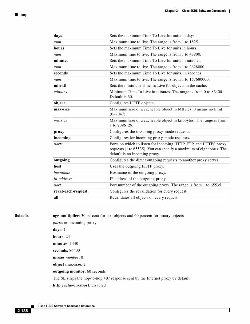
Chapter 2 Cisco ECDS Software Commandshttp
Defaults age-multiplier: 30 percent for text objects and 60 percent for binary objects
ports: no incoming proxy
days: 1
hours: 24
minutes: 1440
seconds: 86400
misses number: 0
object max-size: 2
outgoing monitor: 60 seconds
The SE strips the hop-to-hop 407 response sent by the Internet proxy by default.
http cache-on-abort: disabled
days Sets the maximum Time To Live for units in days.
num Maximum time to live. The range is from 1 to 1825.
hours Sets the maximum Time To Live for units in hours.
num Maximum time to live. The range is from 1 to 43800.
minutes Sets the maximum Time To Live for units in minutes.
num Maximum time to live. The range is from 1 to 2628000.
seconds Sets the maximum Time To Live for units, in seconds.
num Maximum time to live. The range is from 1 to 157680000.
min-ttl Sets the minimum Time To Live for objects in the cache.
minutes Minimum Time To Live in minutes. The range is from 0 to 86400. Default is 60.
object Configures HTTP objects.
max-size Maximum size of a cacheable object in MBytes, 0 means no limit (0–2047).
maxsize Maximum size of a cacheable object in kilobytes. The range is from 1 to 2096128.
proxy Configures the incoming proxy-mode requests.
incoming Configures for incoming proxy-mode requests.
ports Ports on which to listen for incoming HTTP, FTP, and HTTPS proxy requests (1 to 65535). You can specify a maximum of eight ports. The default is no incoming proxy.
outgoing Configures the direct outgoing requests to another proxy server.
host Uses the outgoing HTTP proxy.
hostname Hostname of the outgoing proxy.
ip-address IP address of the outgoing proxy.
port Port number of the outgoing proxy. The range is from 1 to 65535.
reval-each-request Configures the revalidation for every request.
all Revalidates all objects on every request.
2-138Cisco ECDS Software Command Reference

Chapter 2 Cisco ECDS Software Commandshttp
The default is no incoming proxy.
Command Modes Global configuration
Usage Guidelines Use these commands to configure specific parameters for caching HTTP objects.
Note Text objects refer to HTML pages. Binary objects refer to all other web objects (for example, GIFs or JPEGs).
Configuring Cookies
Starting in Cisco ECDS software, users can configure a cookie on a per-delivery service basis. Now there can be more than one cookie added to an SE because each cookie is tied to the delivery service, so the correct cookie is used for each request. To configure a cookie on an edge SE, use the http add-cookie <cookie-string> command.
Transaction Logging
Once a user has been authenticated through LDAP or a RADIUS server, all transaction logs generated by the SE for that user contain user information. If the SE is acting in proxy mode, the user ID is included in the transaction logs. If the SE is acting in transparent mode, the user IP address is included instead.
The cache-cookies option enables the SE to cache the binary content served with HTTP Set-cookie headers and no explicit expiration information.
The reval-each-request option enables the SE to revalidate all objects requested from the cache.
Use the object max-size option to specify the maximum size in kilobytes of a cacheable object. The default is no maximum size for a cacheable object. The no form of the command resets the default value.
The http proxy option enables the SE to operate in environments where client browsers have previously been configured to use a legacy proxy server. The SE accepts proxy-style requests when the incoming proxy ports are configured with the http proxy incoming ports option. Up to eight incoming proxy ports can be specified on a single command line or on multiple command lines.
To configure the SE to direct all HTTP miss traffic to a parent cache (without using ICP), use the http proxy outgoing host port option, where host is the system name or IP address of the outgoing proxy server, and port is the port number designated by the outgoing (upstream) server to accept proxy requests.
Caching Policy for Client-Aborted Downloads
Typically, a client aborts a download of an object by clicking the Stop icon on the browser or by closing the browser during a download. By default, the SE continues to download an object to the cache even after a client aborts the download.
The cache-on-abort option lets you specify if and when the SE completes the download of a cacheable object after the client aborts the request. However, if the SE determines that there is another client currently requesting the same object, caching is always completed.
If the cache-on-abort option is enabled and no thresholds are enabled, the SE always aborts downloading an object to the cache. You can use any combination of the following thresholds, which are specified in the HTTP header. If the option is not enabled, the client receives an error response. Response errors and read errors are returned to the client, because it is not possible to detect whether these errors are generated at the origin server or at the proxy.
2-139Cisco ECDS Software Command Reference

Chapter 2 Cisco ECDS Software Commandshttp
Examples The following example specifies that the host 10.1.1.1 on port 8088 is designated as the primary proxy server and host 10.1.1.2 is designated as a backup proxy server:
ServiceEngine(config)# http proxy outgoing host 10.1.1.1 8088 primary ServiceEngine(config)# http proxy outgoing host 10.1.1.2 220
The following example shows the output for the show http proxy command:
ServiceEngine# show http proxy Incoming Proxy-Mode: Servicing Proxy mode HTTP connections on ports: 8080
Outgoing Proxy-Mode: Primary proxy server: 172.16.63.150 port 1 Failed Backup proxy servers: 172.16.236.151 port 8005 172.16.236.152 port 123 172.16.236.153 port 65535 Failed 172.16.236.154 port 10 Monitor Interval for Outgoing Proxy Servers is 60 seconds Use of Origin Server upon Proxy Failures is disabled.
The following example shows the output for the show statistics http requests command:
ServiceEngine# show statistics http requestsStatistics - Requests Total % of Requests --------------------------------------------------- Total Received Requests: 49103 - Forced Reloads: 109 0.2 Client Errors: 23 0.0 Server Errors: 348 0.7 URL Blocked: 0 0.0 Sent to Outgoing Proxy: 0 0.0Failures from Outgoing Proxy: 0 0.0Excluded from Outgoing Proxy: 0 0.0 ICP Client Hits: 0 0.0 ICP Server Hits: 0 0.0 HTTP 0.9 Requests: 2 0.0 HTTP 1.0 Requests: 49101 100.0 HTTP 1.1 Requests: 0 0.0 HTTP Unknown Requests: 0 0.0 Non HTTP Requests: 0 0.0 Non HTTP Responses: 46 0.1 Chunked HTTP Responses: 0 0.0 Http Miss Due To DNS: 0 0.0 Http Deletes Due To DNS: 0 0.0 Objects cached for min ttl: 2674 5.0
The following example shows the output for the show statistics http proxy outgoing command:
ServiceEngine# show statistics http proxy outgoing
HTTP Outgoing Proxy Statistics IP PORT ATTEMPTS FAILURES ---------------------------------------------------172.16.23.150 8000 0 0 172.16.23.151 8080 0 0 172.16.23.152 9000 0 0 172.16.23.153 9001 0 0 172.16.23.154 9005 0 0
Requests when all proxies were failed: 0
2-140Cisco ECDS Software Command Reference

Chapter 2 Cisco ECDS Software Commandshttp
The following example shows that with the default configuration (all cache-on-abort command thresholds disabled), client abort processing is configured to always abort downloading an object to the cache:
ServiceEngine(config)# http cache-on-abort enable
The following example shows that the SE is configured to always continue downloading an object to the cache (this configuration is the default):
ServiceEngine(config)# no http cache-on-abort
The following example shows that the SE is configured to use the default minimum threshold when the cache-on-abort option has been enabled and the threshold is set to 16 kilobytes:
ServiceEngine(config)# http cache-on-abort min 16
The following example shows that the SE is configured to ignore the minimum threshold:
ServiceEngine(config)# no http cache-on-abort min
Related Commands Command Description
acquirer (EXEC mode) Configures the content acquirer.
dnslookup Resolves a host or domain name to an IP address.
ip name-server Specifies the address of the name server.
show acquirer Displays the acquirer delivery service information and progress for a specified delivery service number or name.
show http Displays the HTTP-related caching configuration.
show http proxy Displays the proxy mode configuration.
show statistics http requests Displays HTTP request statistics.
2-141Cisco ECDS Software Command Reference

Chapter 2 Cisco ECDS Software Commandshttps (EXEC)
https (EXEC)To create, remove, and import certificates and private keys when using the Service Engine as an HTTPS server, use the https EXEC command.
https {cert cert-name {create | import url URL | remove} | certgroup certgroup-name {add-cert | create | remove} | key key_name {create | import url URL | remove}}
Syntax Description
Defaults No default behavior or values
Command Modes EXEC (privileged)
cert Enables creating, removing, and importing certificates.
cert-name Name of the certificate object.
Note A certificate object is a container that stores the certificate. You create an empty certificate object when you do not specify the URL from which the certificate must be imported.
create Creates a certificate object with the name specified.
import Imports a certificate from an external source.
url Enables the use of a URL to point to the location of the private key.
URL URL (HTTP, FTP-over-HTTP, or HTTPS) that points to the location of the private key.
remove Removes a certificate object with a given name.
certgroup Enables adding, creating, or removing a certificate group.
certgroup-name Name of the certificate group.
add-cert Adds a certificate to the certificate group, starting from the end entity’s certificate to the root certificate authority’s (CA) certificate.
create Creates a certificate group with the specified name.
remove Removes a certificate group with the specified name.
key Enables creating, removing, and importing a private key.
key_name Name of the private key object.
create Creates a private key object with the given name.
import Imports a private key from an external source into the key object.
Note A key object is a container that stores the private key. You create an empty key object when you do not specify the URL from which the HTTPS key must be imported.
url Enables the use of a URL to point to the location of the private key.
URL URL (HTTP, FTP-over-HTTP, or HTTPS) that points to the location of the private key.
remove Removes a key object with the given name.
2-142Cisco ECDS Software Command Reference

Chapter 2 Cisco ECDS Software Commandshttps (EXEC)
Usage Guidelines In the ECDS software, you can configure your Service Engine to use a set of Secure Sockets Layer (SSL) certificates and keys to enable the Service Engine to act as an origin HTTPS server. This method can reduce WAN traffic and increase data security, because authorized clients from remote branch offices can use HTTPS caching solutions deployed on the Service Engine at their branch offices. HTTPS proxy mode enables the Service Engine to service HTTPS requests sent by the web clients, which have been configured to use an HTTPS proxy server.
The Service Engine decodes HTTPS traffic from a client and performs normal HTTP operations on it, such as caching and request processing. The Service Engine initiates HTTPS connections to an origin server and fetches the content from origin servers when a cache miss occurs.
For specific requested content to be cached, you must import the proper certificates and keys for these sites (HTTPS servers) into the Service Engine and instruct the Service Engine to cache these sites. The Service Engine presents the certificate to HTTPS clients that make requests to the HTTPS server.
Note For information on the restrictions concerning the use of certificates, keys, and certificate groups, see the Cisco ECDS 2.6 Software Configuration Guide.
A digital certificate is a credential that allows the Service Engine to be presented to an HTTPS client as the original HTTPS server.
You can assign a certificate and associate a key with the HTTPS server if you have configured the Service Engine with the https server global configuration command. The Service Engine presents the certificate to HTTPS clients that make requests to the HTTPS server.
The Service Engine accepts certificates in Privacy-Enhanced Mail (PEM) format which is used by Apache servers, and Public-Key Cryptography Standards (PKCS) #12 format, which is used by Microsoft Internet Information Services (IIS).
The Service Engine uses PEM format internally and automatically converts certificates in PKCS #12 format to PEM format. If you need to use a certificate in a different format, first convert it to one of these supported formats.
Use the https cert EXEC command to create certificate objects with a given name, to import a certificate from external sources into a certificate object, or to remove existing certificate objects. Use any name you like for the certificate and the key. Use a URL where the Service Engine can obtain the certificate and key files.
A certificate object is a container that stores the certificate. You create an empty certificate object when you do not specify the URL from which the certificate must be imported. Certificate object names can consist of Arabic numerals, uppercase and lowercase letters, underscores, and hyphens. Certificate object names must begin with a letter, a numeral, an underscore (_), or a hyphen (-), and have a limit of 64 characters. You need to create a certificate object before you can import the certificate from an external source and associate it with an HTTPS server. Only certificate names are stored in the CMS database. Actual certificates are stored only on the Service Engine.
Note Once you create a certificate object, you cannot modify the name. To modify a name, you must delete the existing certificate and create a new one.
Note It is possible for a certificate object to exist without its certificate being imported. However, only certificate objects with imported certificates can be associated with an HTTPS server or added to a certificate group. Two different certificates can be imported from the same URL and two different HTTPS servers can be associated with the same certificate.
2-143Cisco ECDS Software Command Reference

Chapter 2 Cisco ECDS Software Commandshttps (EXEC)
If the external location from which the certificate is to be imported into the certificate object is password protected, you must specify the username required to access the external source from which the certificate is being imported and the password used to authenticate users who want to gain access to the external source from which the certificate is being imported. When the external source is password protected, the URL should use any one of the following formats:
• ftp://user:password@domainname/path
• http://user:password@domainname/path
• https://user:password@domainname/path
The https certgroup EXEC command allows you to create or remove certificate groups or import a certificate from an external source and add it to an existing certificate chain. Certificate groups constitute a chain of trust relationships from the root Certificate Authority to the end entity. Each one of the certificates in a certificate group, except the end entity’s certificate, signs and trusts the next one in the chain. An end entity’s certificate can be trusted only if all certificates in the certificate group leading to this certificate can be trusted. A certificate group can be configured on the Service Engine (acting as an HTTPS server) to support HTTPS caching just like a single certificate, but with the added benefit that the client does not need to have all certificates locally. A certificate group can also be used to verify and authenticate an HTTPS server by comparing the server’s certificates to those certificates in the certificate group.
Use the https certgroup certgroup-name create EXEC command to create a certificate group with a given name. Certificate group names can consist of Arabic numerals, uppercase and lowercase letters, underscores, and hyphens. Certificate group names must begin with a letter, a numeral, an underscore (_), or a hyphen (-), and have a limit of 64 characters.
Note Once you create a certificate group, you cannot modify the name. To modify a name, you must delete the existing certificate group and create a new one.
Note Two different certificate groups can have the same combination of HTTPS certificates.
Use the https key EXEC command to create a private key object with a given name, to import a private key object from an external source, or to remove a private key object with a given name. A private key is the secret half of a key pair used in a public key encryption algorithm. Private keys are typically used to encrypt a symmetric session key, digitally sign a message, or decrypt a message that has been encrypted with the corresponding public key. PKCS # 12 defines a portable format for storing or transporting a user’s private keys and certificate information. The private key that the Service Engine uses to act as an origin HTTPS server must match the selected authentication certificate.
A key object is a container that stores the private key. You create an empty key object when you do not specify the URL from which the HTTPS key must be imported. Key object names can consist of Arabic numerals, uppercase and lowercase letters, underscores, and hyphens. Key object names must begin with a letter, a numeral, an underscore (_), or a hyphen (-), and have a limit of 64 characters.
You need to create a private key object before you can import the HTTPS key from an external source and associate it with an HTTPS server. Only HTTPS key names are stored in the CMS database. Actual certificates are stored only on the Service Engine.
Note Once you create a key object, you cannot modify the name. To modify a name, you must delete the existing key and create a new one.
2-144Cisco ECDS Software Command Reference

Chapter 2 Cisco ECDS Software Commandshttps (EXEC)
Note It is possible for a key object to exist without its key being imported. However, only key objects with imported keys can be associated with an HTTPS server. Two different keys can be imported from the same URL and two different HTTPS servers can be associated with the same key.
If the external location from which the private key is to be imported into the key object is password protected, you must specify the username required to access the external source from which the key is being imported and the password used to authenticate users who want to gain access to the external source from which the key is being imported. When the external source is password protected, the URL should use any one of the following formats:
• ftp://user:password@domainname/path
• http://user:password@domainname/path
• https://user:password@domainname/path
Examples The following example shows how to load the certificates and private key on the Service Engine:
ServiceEngine# https cert mycert createServiceEngine# https cert mycert import http://www.myca.com/myservercertServiceEngine# https cert mykey createServiceEngine# https cert mykey import http://www.myca.com/myprivatekey
Related Commands Command Description
show https Displays HTTPS proxy status and port policies.
2-145Cisco ECDS Software Command Reference

Chapter 2 Cisco ECDS Software Commandshttps server
https serverTo configure the Service Engine to act as an origin HTTPS server, use the https server global configuration command. This command enables HTTPS configuration mode. To disable individual options, use the no form of this command.
https server name {cert cert-name | certgroup {chain | serverauth} certgroup-name | enable | host {hostname | ip-address} | key {keyname | password password} | port port-number}}
no https server name {cert cert-name | certgroup {chain | serverauth} certgroup-name | enable | host {hostname | ip-address} | key {keyname | password password} | port port-number}}
Syntax Description
Defaults The HTTPS server is disabled by default.
Command Modes global configuration
Usage Guidelines The https server name command invokes a configuration mode that you use to enter commands for configuring a specific instance of the HTTPS server. After entering the HTPTPS configuration mode, you can enter the specific commands required to configure the HTTPS server without having to repeatedly type the https server name command.
name Name of the HTTPS server.
cert Sets the certificate for the HTTPS server.
cert-name Certificate name.
certgroup Sets the certificate chains and authentication needed to access the HTTPS server.
chain Sets the certificate chain needed to access the HTTPS server.
serverauth Sets the certificate chains and authentication needed to access the HTTPS server.
certgroup-name Certificate chain name.
enable Enables caching and SSL termination for the HTTPS server.
host Configures the hostname for the HTTPS server.
hostname Hostname of the HTTPS server.
ip-address IP address of the HTTPS server.
key Configures the private key for the HTTPS server.
keyname Private key name.
password Sets the password needed to decrypt the private key file.
password Password needed to decrypt the private key file.
port Maps a port with a server name.
port-number Port number association for the HTTPS server. Range is 1-65535. Default is 443.
2-146Cisco ECDS Software Command Reference

Chapter 2 Cisco ECDS Software Commandshttps server
Use the https server name command to configure an HTTPS server and configure a Service Engine to act as an origin HTTPS server. This configuration can reduce the WAN traffic and increase data security, because authorized clients from remote branch offices can use HTTPS to access their own Service Engines configured as HTTPS servers, which reside in central locations.
The Service Engine will decode HTTPS traffic from a client and perform normal HTTP operations, such as caching and request processing. The Service Engine initiates HTTPS connections to an origin server and fetches the content from origin servers upon cache miss or cache validation.
The https server name cert command configures a Service Engine to use a specific SSL certificate so that the Service Engine can act as an origin HTTPS server.
The https server name certgroup chain command identifies the certificate group for the HTTPS server. The certificate group is included in the SSL handshake that is sent to SSL clients. Only one certificate or certificate group can be selected for an HTTPS server at any time.
The https server name enable command enables HTTPS server caching. Using the no form of this command disables caching if it is enabled.
The https server name host command specifies the IP address or fully qualified domain name for the origin HTTPS server.
The https server name key command specifies the private key to use so that the Service Engine can act as an origin HTTPS server. This private key must match the selected certificate. If the key file is encrypted, use the password option to specify the password required to decrypt it.
The https server name serverauth enable command causes verification of the origin HTTPS server’s certificate, which is the default behavior.
You can use other options provided by the serverauth keyword to ignore authentication errors such as invalid certification, domain name mismatches, certificate expiration errors, and unrecognized Certificate Authorities (CAs).
Note For information on how to enable HTTPS on a Service Engine in an ECDS network see theCisco ECDS 2.6 Software Configuration Guide.
Troubleshooting Transparent HTTPS Caching
Use the show statistics https requests EXEC command to determine how many HTTPS requests go through the Service Engine.
Use the show bypass list EXEC command to determine whether the origin HTTPS server has been added to the WCCP accept list.
Problems with certificate verification between the HTTPS client and the HTTPS server running on the Service Engine will cause the user to see a prompt asking if the certificate should be trusted.
Problems with certificate verification between the Service Engine and the origin HTTPS server will prevent the connection because no user is available to accept the certificate.
Note If specific requested content is to be cached, you must import the proper certificates and keys for these sites onto the Service Engine and instruct the Service Engine to cache these sites.
Examples The following example shows how to load the certificates and private key from EXEC mode on the Service Engine:
ServiceEngine# https cert mycert create
2-147Cisco ECDS Software Command Reference

Chapter 2 Cisco ECDS Software Commandshttps server
ServiceEngine# https cert mycert import http://www.myca.com/myservercertServiceEngine# https cert mykey createServiceEngine# https cert mykey import http://www.myca.com/myprivatekey
Note You can use any name for the certificate and the key. Replace the URLs in the example with the URLs where the Service Engine can obtain the certificate and key files.
The Service Engine uses PEM format internally and automatically converts certificates in PKCS #12 format to PEM format. If you need to use a certificate in a different format, first convert it to one of these supported formats.
The following example shows that when you enter the https server test command from the global configuration prompt, the CLI prompt changes:
ServiceEngine(config)# https server testServiceEngine(config-https)#
The following example shows that you can then enter the specific commands required to configure the HTTPS server without having to repeatedly type the https server name command:
ServiceEngine(config-https)# cert testcertServiceEngine(config-https)# key testkeyServiceEngine(config-https)# host www.mycompany-testserver.comServiceEngine(config-https)# port 443ServiceEngine(config-https)# enable
The following example displays the output from the show running-configuration EXEC command entered on a Service Engine with the HTTPS server enabled:
ServiceEngine# show running-config!!wccp router-list 1 10.77.157.217wccp https-cache router-list-num 1 password ****wccp version 2!https server UNI certgroup chain uni-grouphttps server UNI key uni-key password ****https server UNI host 10.77.157.170https server UNI enablehttps server DSA210 certgroup chain dsa-grouphttps server DSA210 key dsa-210-key password ****https server DSA210 host 10.77.157.210https server DSA210 enablehttps server test-w2k cert iis-crthttps server test-w2k key iis-key password ****https server test-w2k host 10.77.140.131https server test-w2k enable
Related Commands https (EXEC) Creates, removes, and imports certificates and private keys when using the Service Engine as an HTTPS server.
show bypass list Displays bypass configuration information.
show https Displays HTTPS proxy status and port policies.
show https server Displays HTTPS proxy status and port policies.
show statistics https error
Displays statistics for HTTPS errors.
2-148Cisco ECDS Software Command Reference

Chapter 2 Cisco ECDS Software Commandshttps server
show statistics https requests
Displays statistics for HTTPS requests.
wccp https-cache Enables Web Cache Communication Protocol (WCCP) flow redirection to a Service Engine configured as an HTTPS server
wccp router-list Configures a router list for Web Cache Communication Protocol (WCCP) Version 2.
wccp version Specifies the version of Web Cache Communication Protocol (WCCP) that the Service Engine should use.
2-149Cisco ECDS Software Command Reference

Chapter 2 Cisco ECDS Software Commandshttps server (mine)
https server (mine)To create, remove, and import certificates and private keys when using the Service Engine as an HTTPS server, use the https EXEC command.
https {{server name} | {cert name} | {certgroup name {chain name | serverauth name} | {enable} | host name} | {key name password} | {port}}
Syntax Description
Defaults No default behavior or values
Command Modes Global configuration
Usage Guidelines In the ECDS software, you can configure a Service Engine to use a set of Secure Sockets Layer (SSL) certificates and keys to enable the Service Engine to act as an origin HTTPS server. This method can reduce WAN traffic and increase data security, because authorized clients from remote branch offices can use HTTPS caching solutions deployed on the Service Engine at their branch offices. HTTPS proxy mode enables the Service Engine to service HTTPS requests sent by the web clients, which have been configured to use an HTTPS proxy server.
The Service Engine decodes HTTPS traffic from a client and performs normal HTTP operations on it, such as caching and request processing. The Service Engine initiates HTTPS connections to an origin server and fetches the content from origin servers when a cache miss occurs.
server Enters HTTPS server caching commands.
name HTTPS server name.
cert Selects a certificate to use for the HTTPS server.
name Name of the certificate object.
certgroup Selects certificate chains for the HTTPS server.
name Name of the certificate group.
chain Certificate chain to use for the HTTPS server.
name Certificate chain name.
serverauth Certificate chain to use for authenticating the origin HTTPS server.
name Certificate chain name.
enable Enables caching of the HTTPS server.
host Inputs the hostname or IP address of the origin HTTPS server.
name FQDN or IP address of the origin HTTPS server
key Selects the private key to use for the HTTPS server.
name Private key name.
password Password to decrypt the private key file.
port Maps a port with a server name. Port number association for the HTTPS server. Range is 1-65535. Default is 443.
2-150Cisco ECDS Software Command Reference
Chapter 2 Cisco ECDS Software Commandshttps server (mine)
For specific requested content to be cached, you must import the proper certificates and keys for these sites (HTTPS servers) into the Service Engine and instruct the Service Engine to cache these sites. The Service Engine presents the certificate to HTTPS clients that make requests to the HTTPS server.
Note For information on the restrictions concerning the use of certificates, keys, and certificate groups, see Cisco ECDS Software Configuration Guide.
A digital certificate is a credential that allows the Service Engine to be presented to an HTTPS client as the original HTTPS server.
You can assign a certificate and associate a key with the HTTPS server if you have configured the Service Engine with the https server global configuration command. The Service Engine presents the certificate to HTTPS clients that make requests to the HTTPS server.
The Service Engine accepts certificates in Privacy-Enhanced Mail (PEM) format which is used by Apache servers, and Public-Key Cryptography Standards (PKCS) #12 format, which is used by Microsoft Internet Information Services (IIS).
The Service Engine uses PEM format internally and automatically converts certificates in PKCS #12 format to PEM format. If you need to use a certificate in a different format, first convert it to one of these supported formats.
Use the https cert EXEC command to create certificate objects with a given name, to import a certificate from external sources into a certificate object, or to remove existing certificate objects. Use any name you like for the certificate and the key. Use a URL where the Service Engine can obtain the certificate and key files.
A certificate object is a container that stores the certificate. You create an empty certificate object when you do not specify the URL from which the certificate must be imported. Certificate object names can consist of Arabic numerals, uppercase and lowercase letters, underscores, and hyphens. Certificate object names must begin with a letter, a numeral, an underscore (_), or a hyphen (-), and have a limit of 64 characters. You need to create a certificate object before you can import the certificate from an external source and associate it with an HTTPS server. Only certificate names are stored in the CMS database. Actual certificates are stored only on the Service Engine.
Note Once you create a certificate object, you cannot modify the name. To modify a name, you must delete the existing certificate and create a new one.
Note It is possible for a certificate object to exist without its certificate being imported. However, only certificate objects with imported certificates can be associated with an HTTPS server or added to a certificate group. Two different certificates can be imported from the same URL and two different HTTPS servers can be associated with the same certificate.
If the external location from which the certificate is to be imported into the certificate object is password protected, you must specify the username required to access the external source from which the certificate is being imported and the password used to authenticate users who want to gain access to the external source from which the certificate is being imported. When the external source is password protected, the URL should use any one of the following formats:
• ftp://user:password@domainname/path
• http://user:password@domainname/path
• https://user:password@domainname/path
2-151Cisco ECDS Software Command Reference

Chapter 2 Cisco ECDS Software Commandshttps server (mine)
The https certgroup EXEC command allows you to create or remove certificate groups or import a certificate from an external source and add it to an existing certificate chain. Certificate groups constitute a chain of trust relationships from the root Certificate Authority to the end entity. Each one of the certificates in a certificate group, except the end entity’s certificate, signs and trusts the next one in the chain. An end entity’s certificate can be trusted only if all certificates in the certificate group leading to this certificate can be trusted. A certificate group can be configured on the Service Engine (acting as an HTTPS server) to support HTTPS caching just like a single certificate, but with the added benefit that the client does not need to have all certificates locally. A certificate group can also be used to verify and authenticate an HTTPS server by comparing the server’s certificates to those certificates in the certificate group.
Use the https certgroup certgroup-name create EXEC command to create a certificate group with a given name. Certificate group names can consist of Arabic numerals, uppercase and lowercase letters, underscores, and hyphens. Certificate group names must begin with a letter, a numeral, an underscore (_), or a hyphen (-), and have a limit of 64 characters.
Note Once you create a certificate group, you cannot modify the name. To modify a name, you must delete the existing certificate group and create a new one.
Note Two different certificate groups can have the same combination of HTTPS certificates.
Use the https key EXEC command to create a private key object with a given name, to import a private key object from an external source, or to remove a private key object with a given name. A private key is the secret half of a key pair used in a public key encryption algorithm. Private keys are typically used to encrypt a symmetric session key, digitally sign a message, or decrypt a message that has been encrypted with the corresponding public key. PKCS # 12 defines a portable format for storing or transporting a user’s private keys and certificate information. The private key that the Service Engine uses to act as an origin HTTPS server must match the selected authentication certificate.
A key object is a container that stores the private key. You create an empty key object when you do not specify the URL from which the HTTPS key must be imported. Key object names can consist of Arabic numerals, uppercase and lowercase letters, underscores, and hyphens. Key object names must begin with a letter, a numeral, an underscore (_), or a hyphen (-), and have a limit of 64 characters.
You need to create a private key object before you can import the HTTPS key from an external source and associate it with an HTTPS server. Only HTTPS key names are stored in the CMS database. Actual certificates are stored only on the Service Engine.
Note Once you create a key object, you cannot modify the name. To modify a name, you must delete the existing key and create a new one.
Note It is possible for a key object to exist without its key being imported. However, only key objects with imported keys can be associated with an HTTPS server. Two different keys can be imported from the same URL and two different HTTPS servers can be associated with the same key.
2-152Cisco ECDS Software Command Reference

Chapter 2 Cisco ECDS Software Commandshttps server (mine)
If the external location from which the private key is to be imported into the key object is password protected, you must specify the username required to access the external source from which the key is being imported and the password used to authenticate users who want to gain access to the external source from which the key is being imported. When the external source is password protected, the URL should use any one of the following formats:
• ftp://user:password@domainname/path
• http://user:password@domainname/path
• https://user:password@domainname/path
Examples The following example shows how to load the certificates and private key on the Service Engine:
ServiceEngine# https cert mycert createServiceEngine# https cert mycert import http://www.myca.com/myservercertServiceEngine# https cert mykey createServiceEngine# https cert mykey import http://www.myca.com/myprivatekey
Related Commands show https
2-153Cisco ECDS Software Command Reference

Chapter 2 Cisco ECDS Software Commandsicap
icapICAP is not supported.
2-154Cisco ECDS Software Command Reference

Chapter 2 Cisco ECDS Software Commandsinstall
installTo install the ECDS software image, use the install command in EXEC configuration mode.
install imagefilename
Syntax Description
Defaults No default behavior or values
Command Modes EXEC
Usage Guidelines The install command loads the system image into flash memory and the disk.
To install a system image, copy the image file to the sysfs directory local1 or local2. Before entering the install command, change the present working directory to the directory where the system image resides. When the install command is executed, the image file is expanded. The expanded files overwrite the existing files in the SE. The newly installed version takes effect after the system image is reloaded.
Note The install command does not accept .pax files. Files should be of the .bin type (for example, ECDS-2.5.3.7-K9.bin). Also, if the release being installed does not require a new system image, then it may not be necessary to write to flash memory. If the newer version has changes that require a new system image to be installed, then the install command may result in a write to flash memory.
Examples The following example shows how to install a .bin file on the SE:
ServiceEngine# install CDS-2.5.3.7-K9.bin
Related Commands
imagefilename Name of the .bin file that you want to install.
Command Description
copy ftp install Installs an image file from an FTP server onto a local device.
copy http install Installs an image file from an HTTP server onto a local device.
reload Halts a device and performs a cold restart.
2-155Cisco ECDS Software Command Reference

Chapter 2 Cisco ECDS Software Commandsinterface
interfaceTo configure a Gigabit Ethernet or port-channel interface, use the interface command in global configuration mode. To disable selected options, restore default values, or enable a shutdown interface, use the no form of this command.
interface {GigabitEthernet slot/port num | PortChannel {1 | 2} | standby group number}
no interface {GigabitEthernet slot/port num | PortChannel {1 | 2} | Standby group number}
Syntax Description
Defaults No default behavior or values
Command Modes Global configuration
Usage Guidelines Configuring Interfaces for DHCP
During the initial configuration of an SE, you have the option of configuring a static IP address for the SE or using interface-level DHCP to dynamically assign IP addresses to the interfaces on the SE.
If you do not enable interface-level DHCP on the SE, you must manually specify a static IP address and network mask for the SE. If the SE moves to another location in another part of the network, you must manually enter a new static IP address and network mask for this SE.
Note All static route entries are lost when removing the IP configuration from the network interface.
An interface can be enabled for DHCP by using the ip address dhcp [client_id | hostname] command in interface configuration mode. The client identifier is an ASCII value. The SE sends its configured client identifier and hostname to the DHCP server when requesting network information. DHCP servers can be configured to identify the client identifier information and the hostname information that the SE is sending and then send back the specific network settings that are assigned to the SE.
GigabitEthernet Selects a Gigabit Ethernet interface to configure.
slot/port num Slot and port number for the selected interface. The slot range is from 0 to 12; the port range is from 0 to 0. The slot number and port number are separated with a forward slash character (/).
PortChannel Selects the EtherChannel of interfaces to configure.
1 Sets the port-channel interface number to 1.
2 Sets the port-channel interface number to 2.
Standby Sets the standby group for the interface.
group number Group number for the selected interface (the range is from 1 to 4).
2-156Cisco ECDS Software Command Reference

Chapter 2 Cisco ECDS Software Commandsinterface
String to Be Set as Cookie Port-Channel (EtherChannel) Interface
EtherChannel for Cisco ECDS Release software supports the grouping of up to four same- network interfaces into one virtual interface. This grouping allows the setting or removing of a virtual interface that consists of two Gigabit Ethernet interfaces. EtherChannel also provides interoperability with Cisco routers, switches, and other networking devices or hosts supporting EtherChannel, load balancing, and automatic failure detection and recovery based on current link status of each interface.
You can use the Gigabit Ethernet ports to form an EtherChannel. A physical interface can be added to an EtherChannel subject to the device configuration.
Configuring Multiple IP Addresses
The Multiple Logical IP Addresses feature supports up to 24 unique IP addresses within the same subnet for the same interface.
When you configure multiple IP addresses on an SE using either the range option or using individual commands, the “show running-config” output displays all the IP addresses individually. The netmask value is unique for each interface, so under a single interface you cannot have multiple IP addresses with different netmask values.
Examples The following example creates an EtherChannel. The port channel is port channel 2 and is assigned an IP address of 10.10.10.10 and a netmask of 255.0.0.0:
ServiceEngine# configureServiceEngine(config)# interface PortChannel 2 ServiceEngine(config-if)# exit
The following example removes an EtherChannel:
ServiceEngine(config)# interface PortChannel 2 ServiceEngine(config-if)# exitServiceEngine(config)# no interface PortChannel 2
The following example shows a sample output of the show running-config command in EXEC configuration mode:
ServiceEngine# show running-config...interface GigabitEthernet 0/0 description This is an interface to the WAN ip address dhcp ip address 192.168.1.200 255.255.255.0bandwidth 100exit..
The following example shows the sample output of the show interface command:
ServiceEngine# show interface GigabitEthernet 1/0Description: This is the interface to the labtype: Ethernet
The following example shows how to create standby groups on SEs:
ServiceEngine(config)# interface GigabitEthernet 1/0 standby 2 priority 300 ServiceEngine(config)# interface GigabitEthernet 2/0 standby 2 priority 200 ServiceEngine(config)# interface GigabitEthernet 3/0 standby 2 priority 100 ServiceEngine(config)# interface standby 2 errors 10000
2-157Cisco ECDS Software Command Reference

Chapter 2 Cisco ECDS Software Commandsinterface
The following example shows how to configure multiple IP addresses using a range command:
ServiceEngine(config)# interface PortChannel 2 ServiceEngine(config-if)# ip address range 2.2.2.3 2.2.2.5 255.255.255.0
The following example shows a sample output of the show running-config command in EXEC configuration mode after configuring multiple IP addresses:
ServiceEngine# show running-config.interface PortChannel 4 ip address 2.2.2.3 255.255.255.0 ip address 2.2.2.4 255.255.255.0 ip address 2.2.2.5 255.255.255.0 ip address 2.2.2.6 255.255.255.0 exit
Related Commands Command Description
show interface Displays the hardware interface information.
show running-config Displays the current operating configuration.
show startup-config Displays the startup configuration.
2-158Cisco ECDS Software Command Reference

Chapter 2 Cisco ECDS Software Commandsip (global configuration)
ip (global configuration)To change initial network device configuration settings, use the ip command in global configuration mode. To delete or disable these settings, use the no form of this command. The dscp option allows you to set the global Type of Service (ToS) or differentiated services code point (DSCP) values in IP packets.
ip access list (see the “ip access-list” section on page 170)
ip default-gateway ip-address [gateway ip addr 2 gateway ip addr 3]
ip domain-name name1 name2 name3
ip dscp {client {cache-hit {match-server | set-dscp dscp-packets | set-tos tos-packets} | cache-miss {match-server | set-dscp dscp-packets | set-tos tos-packets}} | server {match-client | set-dscp dscp-packets | set-tos tos-packets}}
ip name-server ip-addresses
ip path-mtu-discovery enable
ip route dest_IP_addr dest_netmask default_gateway [interface source_IP_addr]
no ip {default-gateway [gateway ip addr 2 gateway ip addr 3] | domain-name | dscp {client {cache-hit | cache-miss} | server} | name-server ip-addresses | path-mtu-discovery enable | route dest_IP_addr dest_netmask default_gateway [interface source_IP_addr]}
Syntax Description default-gateway Specifies the default gateway (if not routing IP).
ip-address IP address of the default gateway.
gateway ip addr Gateway IP address (maximum of 14).
domain-name Specifies domain names.
name1 through name3 Domain name (up to three can be specified).
dscp Configures IP differentiated services code point (DSCP) and Type of Service (ToS) fields.
client Configures DSCP for responses to the client.
cache-hit Configures the cache hit responses to the client.
cache-miss Configures the cache miss responses to the client.
match-server Uses the original ToS or DSCP value of the server.
set-dscp Configures differentiated services code point (DSCP) values.
dscp-packets DSCP values; see Table 2-5 for valid values.
set-tos Configures Type of Service (ToS).
tos-packets ToS value; see Table 2-7 for valid values.
server Configures DSCP for outgoing requests.
match-client Uses the original ToS or DSP value of the client.
name-server Specifies the address of the name server.
ip-addresses IP addresses of the name servers (up to a maximum of eight).
path-mtu-discovery Configures RFC 1191 Path Maximum Transmission Unit (MTU) discovery.
2-159Cisco ECDS Software Command Reference
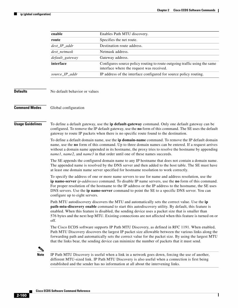
Chapter 2 Cisco ECDS Software Commandsip (global configuration)
Defaults No default behavior or values
Command Modes Global configuration
Usage Guidelines To define a default gateway, use the ip default-gateway command. Only one default gateway can be configured. To remove the IP default gateway, use the no form of this command. The SE uses the default gateway to route IP packets when there is no specific route found to the destination.
To define a default domain name, use the ip domain-name command. To remove the IP default domain name, use the no form of this command. Up to three domain names can be entered. If a request arrives without a domain name appended in its hostname, the proxy tries to resolve the hostname by appending name1, name2, and name3 in that order until one of these names succeeds.
The SE appends the configured domain name to any IP hostname that does not contain a domain name. The appended name is resolved by the DNS server and then added to the host table. The SE must have at least one domain name server specified for hostname resolution to work correctly.
To specify the address of one or more name servers to use for name and address resolution, use the ip name-server ip-addresses command. To disable IP name servers, use the no form of this command. For proper resolution of the hostname to the IP address or the IP address to the hostname, the SE uses DNS servers. Use the ip name-server command to point the SE to a specific DNS server. You can configure up to eight servers.
Path MTU autodiscovery discovers the MTU and automatically sets the correct value. Use the ip path-mtu-discovery enable command to start this autodiscovery utility. By default, this feature is enabled. When this feature is disabled, the sending device uses a packet size that is smaller than 576 bytes and the next hop MTU. Existing connections are not affected when this feature is turned on or off.
The Cisco ECDS software supports IP Path MTU Discovery, as defined in RFC 1191. When enabled, Path MTU Discovery discovers the largest IP packet size allowable between the various links along the forwarding path and automatically sets the correct value for the packet size. By using the largest MTU that the links bear, the sending device can minimize the number of packets that it must send.
Note IP Path MTU Discovery is useful when a link in a network goes down, forcing the use of another, different MTU-sized link. IP Path MTU Discovery is also useful when a connection is first being established and the sender has no information at all about the intervening links.
enable Enables Path MTU discovery.
route Specifies the net route.
dest_IP_addr Destination route address.
dest_netmask Netmask address.
default_gateway Gateway address.
interface Configures source policy routing to route outgoing traffic using the same interface where the request was received.
source_IP_addr IP address of the interface configured for source policy routing.
2-160Cisco ECDS Software Command Reference

Chapter 2 Cisco ECDS Software Commandsip (global configuration)
IP Path MTU Discovery is started by the sending device. If a server does not support IP Path MTU Discovery, the receiving device has no mechanism available to avoid fragmenting datagrams generated by the server.
Use the ip route command to add a specific static route for a network or host. Any IP packet designated for the specified destination uses the configured route.
To configure static IP routing, use the ip route command. To remove the route, use the no form of this command. Do not use the ip route 0.0.0.0 0.0.0.0 command to configure the default gateway; use the ip default-gateway command instead.
In the CDS network, you can configure SEs, SRs, and CDSMs for the Type of Service (ToS) or differentiated services code point (DSCP) using the ip dscp command.
Source Policy Routes
To configure source policy routing, use the ip route command with the interface option. By using source policy routing, the reply packet to a client will leaves the SE on the same interface where the request came in. Source policy routing tables are automatically instantiated based on the interface subnets defined on the system. The policy routes are added automatically to the policy routing tables based on the nexthop gateway of the routes in the main routing table.
When configuring multiple ip address you must configure a default gateway in the same subnet.
Differentiated Services
The differentiated services (DiffServ) architecture is based on a simple model where traffic entering a network is classified and possibly conditioned at the boundaries of the network. The class of traffic is then identified with a differentiated services (DS) code point or bit marking in the IP header. Within the core of the network, packets are forwarded according to the per-hop behavior associated with the DS code point.
To set the global ToS or DSCP values for the IP header from the CLI, use the ip dscp command.
DiffServ describes a set of end-to-end QoS (Quality of Service) capabilities. End-to-end QoS is the ability of the network to deliver service required by specific network traffic from one end of the network to another. QoS in the ECDS software supports differentiated services.
With differentiated services, the network tries to deliver a particular kind of service based on the QoS specified by each packet. This specification can occur in different ways, for example, using the 6-bit DSCP setting in IP packets or source and destination addresses. The network uses the QoS specification to classify, mark, shape, and police traffic, and to perform intelligent queueing.
Differentiated services is used for several mission-critical applications and for providing end-to-end QoS. Typically, differentiated services is appropriate for aggregate flows because it performs a relatively coarse level of traffic classification.
Use the ip dscp {client | server} {cache-hit | cache-miss} set-dscp dscp-packets command to set the DSCP values for the IP header. Valid values for dscp-packets are listed in Table 2-5.
Table 2-5 dscp-packets Values
Value or Keyword Description1
0–63 Sets DSCP values.
af11 Sets packets with AF11 DSCP (001010).
af12 Sets packets with AF12 DSCP (001100).
af13 Sets packets with AF13 DSCP (001110).
af21 Sets packets with AF21 DSCP (010010).
2-161Cisco ECDS Software Command Reference

Chapter 2 Cisco ECDS Software Commandsip (global configuration)
DS Field Definition
A replacement header field, called the DS field, is defined by differentiated services. The DS field supersedes the existing definitions of the IPv4 ToS octet (RFC 791) and the IPv6 traffic class octet. Six bits of the DS field are used as the DSCP to select the Per Hop Behavior (PHB) at each interface. A currently unused (CU) 2-bit field is reserved for explicit congestion notification (ECN). The value of the CU bits is ignored by DS-compliant interfaces when determining the PHB to apply to a received packet.
Per-Hop Behaviors
RFC 2475 defines PHB as the externally observable forwarding behavior applied at a DiffServ-compliant node to a DiffServ Behavior Aggregate (BA).
With the ability of the system to mark packets according to the DSCP setting, collections of packets that have the same DSCP setting and that are sent in a particular direction can be grouped into a BA. Packets from multiple sources or applications can belong to the same BA.
A PHB refers to the packet scheduling, queueing, policing, or shaping behavior of a node on any given packet belonging to a BA, as configured by a service level agreement (SLA) or a policy map.
There are four available standard PHBs as follows:
• Default PHB (as defined in RFC 2474)
• Class-Selector PHB (as defined in RFC 2474)
• Assured Forwarding (AFny) PHB (as defined in RFC 2597)
• Expedited Forwarding (EF) PHB (as defined in RFC 2598)
af22 Sets packets with AF22 DSCP (010100).
af23 Sets packets with AF23 DSCP (010110).
af31 Sets packets with AF31 DSCP (011010).
af32 Sets packets with AF32 DSCP (011100).
af33 Sets packets with AF33 DSCP (011110).
af41 Sets packets with AF41 DSCP (100010).
af42 Sets packets with AF42 DSCP (100100).
af43 Sets packets with AF43 DSCP (100110).
cs1 Sets packets with CS1 (precedence 1) DSCP (001000).
cs2 Sets packets with CS2 (precedence 2) DSCP (010000).
cs3 Sets packets with CS3 (precedence 3) DSCP (011000).
cs4 Sets packets with CS4 (precedence 4) DSCP (100000).
cs5 Sets packets with CS5 (precedence 5) DSCP (101000).
cs6 Sets packets with CS6 (precedence 6) DSCP (110000).
cs7 Sets packets with CS7 (precedence 7) DSCP (111000).
default Sets packets with the default DSCP (000000).
ef Sets packets with EF DSCP (101110).
1. The number in parentheses denotes the DSCP value for each per-hop behavior keyword.
Table 2-5 dscp-packets Values (continued)
Value or Keyword Description1
2-162Cisco ECDS Software Command Reference

Chapter 2 Cisco ECDS Software Commandsip (global configuration)
The following sections describe the PHBs.
Default PHB
The default PHB specifies that a packet marked with a DSCP value of 000000 (recommended) receives the traditional best-effort service from a DS-compliant node (a network node that complies with all the core DiffServ requirements). Also, if a packet arrives at a DS-compliant node, and the DSCP value is not mapped to any other PHB, the packet gets mapped to the default PHB.
Class-Selector PHB
To preserve backward compatibility with any IP precedence scheme currently in use on the network, DiffServ has defined a DSCP value in the form xxx000, where x is either 0 or 1. These DSCP values are called Class-Selector Code Points. (The DSCP value for a packet with default PHB 000000 is also called the Class-Selector Code Point.)
The PHB associated with a Class-Selector Code Point is a Class-Selector PHB. These Class-Selector PHBs retain most of the forwarding behavior as nodes that implement IP precedence-based classification and forwarding.
For example, packets with a DSCP value of 110000 (the equivalent of the IP precedence-based value of 110) have preferential forwarding treatment (for scheduling, queueing, and so on), as compared to packets with a DSCP value of 100000 (the equivalent of the IP precedence-based value of 100). These Class-Selector PHBs ensure that DS-compliant nodes can coexist with IP precedence-based nodes.
Assured Forwarding PHB
Assured Forwarding PHB is nearly equivalent to Controlled Load Service, which is available in the integrated services model. AFny PHB defines a method by which BAs can be given different forwarding assurances.
For example, network traffic can be divided into the following classes:
• Gold—Traffic in this category is allocated 50 percent of the available bandwidth.
• Silver—Traffic in this category is allocated 30 percent of the available bandwidth.
• Bronze—Traffic in this category is allocated 20 percent of the available bandwidth.
The AFny PHB defines four AF classes: AF1, AF2, AF3, and AF4. Each class is assigned a specific amount of buffer space and interface bandwidth according to the SLA with the service provider or policy map.
Within each AF class, you can specify three drop precedence (dP) values: 1, 2, and 3. Assured Forwarding PHB can be expressed as shown in the following example: AFny. In this example, n represents the AF class number (1, 2, or 3) and y represents the dP value (1, 2, or 3) within the AFn class.
In instances of network traffic congestion, if packets in a particular AF class (for example, AF1) need to be dropped, packets in the AF1 class are dropped according to the following guideline:
dP(AFny) >= dP(AFnz) >= dP(AFnx)
where dP (AFny) is the probability that packets of the AFny class are dropped and y denotes the dP within an AFn class.
In the following example, packets in the AF13 class are dropped before packets in the AF12 class, which in turn are dropped before packets in the AF11 class:
dP(AF13) >= dP (AF12) >= dP(AF11)
The dP method penalizes traffic flows within a particular BA that exceed the assigned bandwidth. Packets on these offending flows could be re-marked by a policer to a higher drop precedence.
2-163Cisco ECDS Software Command Reference

Chapter 2 Cisco ECDS Software Commandsip (global configuration)
An AFx class can be denoted by the DSCP value, xyzab0, where xyz can be 001, 010, 011, or 100, and ab represents the dP value.
Table 2-6 lists the DSCP value and corresponding dP value for each AF PHB class.
.
Expedited Forwarding PHB
Resource Reservation Protocol (RSVP), a component of the integrated services model, provides a guaranteed bandwidth service. Applications, such as Voice over IP (VoIP), video, and online trading programs, require this type of service. The EF PHB, a key ingredient of DiffServ, supplies this kind of service by providing low loss, low latency, low jitter, and assured bandwidth service.
You can implement EF by using priority queueing (PQ) and rate limiting on the class (or BA). When implemented in a DiffServ network, EF PHB provides a virtual leased line or premium service. For optimal efficiency, however, you should reserve EF PHB for only the most critical applications because, in instances of traffic congestion, it is not feasible to treat all or most traffic as high priority.
EF PHB is suited for applications such as VoIP that require low bandwidth, guaranteed bandwidth, low delay, and low jitter.
IP Precedence for ToS
IP precedence allows you to specify the class of service (CoS) for a packet. You use the three precedence bits in the IPv4 header’s type of service (ToS) field for this purpose.
Using the ToS bits, you can define up to six classes of service. Other features configured throughout the network can then use these bits to determine how to treat the packet. These other QoS features can assign appropriate traffic-handling policies including congestion management strategy and bandwidth allocation. For example, although IP precedence is not a queueing method, queueing methods such as weighted fair queueing (WFQ) and Weighted Random Early Detection (WRED) can use the IP precedence setting of the packet to prioritize traffic.
By setting precedence levels on incoming traffic and using them with the ECDS software QoS queueing features, you can create differentiated service. You can use features, such as policy-based routing (PBR) and Committed Access Rate (CAR), to set the precedence based on an extended access list classification. For example, you can assign the precedence based on the application or user or by destination and source subnetwork.
So that each subsequent network element can provide service based on the determined policy, IP precedence is usually deployed as close to the edge of the network or the administrative domain as possible. IP precedence is an edge function that allows core or backbone QoS features, such as WRED, to forward traffic based on CoS. You can also set IP precedence in the host or network client, but this setting can be overridden by the service provisioning policy of the domain within the network.
The following QoS features can use the IP precedence field to determine how traffic is treated:
• Distributed-WRED
• WFQ
• CAR
Table 2-6 DSCP Values and Corresponding Drop Precedence Values for Each AF PHB Class
Drop Precedence Class 1 Class 2 Class 3 Class 4
Low drop precedence 001010 010010 011010 100010
Medium drop precedence 001100 010100 011100 100100
High drop precedence 001110 010110 011110 100110
2-164Cisco ECDS Software Command Reference

Chapter 2 Cisco ECDS Software Commandsip (global configuration)
How the IP Precedence Bits Are Used to Classify Packets
You use the three IP precedence bits in the ToS field of the IP header to specify a CoS assignment for each packet. You can partition traffic into up to six classes—the remaining two classes are reserved for internal network use—and then use policy maps and extended ACLs to define network policies in terms of congestion handling and bandwidth allocation for each class.
Each precedence corresponds to a name. These names, which continue to evolve, are defined in RFC 791. The numbers and their corresponding names, are listed from least to most important.
IP precedence allows you to define your own classification mechanism. For example, you might want to assign the precedence based on an application or an access router. IP precedence bit settings 96 and 112 are reserved for network control information, such as routing updates.
The IP precedence field occupies the three most significant bits of the ToS byte. Only the three IP precedence bits reflect the priority or importance of the packet, not the full value of the ToS byte.
Use the ip dscp {client | server} {cache-hit | cache-miss} set-tos tos-packets command to specify either of the two arguments—IP precedence or ToS byte value—to set the same ToS. You may specify either the ToS byte value or IP precedence; one is required. IP precedence uses the three precedence bits in the ToS field of the IPv4 header to specify the class of service for each packet. The ToS byte in the IP header defines the three high-order bits as IP precedence bits and the five low-order bits as ToS bits. The ToS byte value is written to the five low-order bits (bits 0 to 4) of the ToS byte in the IP header of a packet. The IP precedence value is written to the three high-order bits (bits 5 to 7) of the ToS byte in the IP header of a packet.
The following is a list of precedence names:
• critical
• flash
• flash-override
• immediate
• internet
• network
• priority
• routine
The following is a list of ToS names:
• max-reliability
• max-throughput
• min-delay
• min-monetary-cost
• normal
Table 2-7 lists the valid values for tos-packets.
Table 2-7 tos-packets Values
Value, Precedence, or ToS Name Description1
0–127 Sets the ToS value.
critical Sets packets with critical precedence (80).
2-165Cisco ECDS Software Command Reference

Chapter 2 Cisco ECDS Software Commandsip (global configuration)
Examples The following example configures a default gateway for the SE:
ServiceEngine(config)# ip default-gateway 192.168.7.18
The following example disables the default gateway:
ServiceEngine(config)# no ip default-gateway
The following example configures a static IP route for the SE:
ServiceEngine(config)# ip route 172.16.227.128 255.255.255.0 172.16.227.250
The following example negates the static IP route:
ServiceEngine(config)# no ip route 172.16.227.128 255.255.255.0 172.16.227.250
The following example configures a default domain name for the SE:
ServiceEngine(config)# ip domain-name cisco.com
The following example negates the default domain name:
ServiceEngine(config)# no ip domain-name
The following example configures a name server for the SE:
ServiceEngine(config)# ip name-server 10.11.12.13
The following example disables the name server:
ServiceEngine(config)# no ip name-server 10.11.12.13
The following example configures source policy routing for the SE interface assigned with the IP address 192.168.1.5:
ServiceEngine(config)# ip route 0.0.0.0 0.0.0.0 192.168.1.1 interface 192.168.1.5
flash Sets packets with flash precedence (48).
flash-override Sets packets with flash override precedence (64).
immediate Sets packets with immediate precedence (32).
internet Sets packets with internetwork control precedence (96).
max-reliability Sets packets with maximum reliable ToS (2).
max-throughput Sets packets with maximum throughput ToS (4).
min-delay Sets packets with minimum delay ToS (8).
min-monetary-cost Sets packets with minimum monetary cost ToS (1).
network Sets packets with network control precedence (112).
normal Sets packets with normal ToS (0).
priority Sets packets with priority precedence (16).
1. The number in parentheses denotes the ToS value for each IP precedence or ToS name setting.
Table 2-7 tos-packets Values (continued)
Value, Precedence, or ToS Name Description1
2-166Cisco ECDS Software Command Reference

Chapter 2 Cisco ECDS Software Commandsip (global configuration)
Related Commands Command Description
show ip routes Displays the IP routing table.
2-167Cisco ECDS Software Command Reference

Chapter 2 Cisco ECDS Software Commandsip (interface configuration)
ip (interface configuration)To configure the interface Internet Protocol, use the interface command in interface configuration mode. To delete or disable these settings, use the no form of this command.
ip {access-group {num {in | out} {name {in | out} | address {ip_addr netmask}
no ip {access-group {num {in | out} {name {in | out} | address {ip_addr netmask}
Syntax Description
Defaults No default behavior or values
Command Modes Interface configuration
Examples If the interface PortChannel 1 has the following configuration:
interface PortChannel 1ip address 2.2.2.2 255.255.255.0ip address 2.2.2.5 255.255.255.0ip address 2.2.2.12 255.255.255.0
And you enter the following commands:
ServiceEngine# configure terminalServiceEngine(config)# interface PortChannel 1ServiceEngine(config-if)# ip address range 2.2.3.9 2.2.3.15 255.255.255.0ServiceEngine(config-if)# end
It is an invalid IP address range and an incompatible netmask.
Configuring an IP Address
The following example shows how to configure an individual IP address:
ServiceEngine(config)# interface PortChannel 1ServiceEngine(config-if)# ip address 2.2.2.2 255.255.255.0
access-group Specifies access control for incoming or outgoing packets.
num Specifies an IP access list by number (in standard or extended form) (1-199).
in Configures the IP access list that apply to inbound packets.
out Configures the IP access list that apply to outbound packets.
name Specifies an access list by name.
in Configures the access list name inbound packets.
out Configures the access list name outbound packets.
address Set the IP address of an interface.
ip-addr IP address of the interface.
netmask Netmask of the interface.
netmask Netmask of the interface.
2-168Cisco ECDS Software Command Reference

Chapter 2 Cisco ECDS Software Commandsip (interface configuration)
ServiceEngine(config-if)# ip address 2.2.2.3 255.255.255.0ServiceEngine(config-if)# ip address 2.2.2.10 255.255.255.0
Removing an IP Address
The following example shows how to remove an IP address range configuration:
ServiceEngine(config)# interface PortChannel 1ServiceEngine(config-if)# no ip address range 2.2.2.3 2.2.2.10 255.255.255.0
The following example shows how to remove an IP address configuration:
ServiceEngine(config)# interface PortChannel 1ServiceEngine(config-if)# no ip address 2.2.2.3 255.255.255.
Related Commands Command Description
interface Configures a Gigabit Ethernet or port-channel interface.
show interface Displays the hardware interface information.
show running-config Displays the current operating configuration.
2-169Cisco ECDS Software Command Reference

Chapter 2 Cisco ECDS Software Commandsip access-list
ip access-listTo create and modify access lists for controlling access to interfaces or applications, use the ip access-list standard or ip access-list extended command in global configuration modes. To remove access control lists, use the no form of this command.
ip access-list {extended {acl-name | acl-num {delete num | deny {num {ip address | any | host} | gre {ip address | any | host} | icmp {ip address | any | host} | ip {ip address | any | host} | tcp {ip address | any | host} | udp {ip address | any | host}} | insert {num {deny | permit} | list {start-line-num | end-line-num} | move {old-line-num | new-line-num} | permit {num {ip address | any | host} | gre {ip address | any | host} | icmp {ip address | any | host} | ip {ip address | any | host} | tcp {ip address | any | host} | udp {ip address | any | host}}} | {standard {acl-num | acl-name {delete num | deny {num {ip address | any | host} | gre {ip address | any | host} | icmp {ip address | any | host} | ip {ip address | any | host} | tcp {ip address | any | host} | udp {ip address | any | host}} | insert {num {deny | permit} | list {start-line-num | end-line-num} | move {old-line-num | new-line-num} | permit {ip address | any | host}}}}
no ip access-list {extended {acl-name | acl-num {delete num | deny {num {ip address | any | host} | gre {ip address | any | host} | icmp {ip address | any | host} | ip {ip address | any | host} | tcp {ip address | any | host} | udp {ip address | any | host}} | insert {num {deny | permit} | list {start-line-num | end-line-num} | move {old-line-num | new-line-num} | permit {num {ip address | any | host} | gre {ip address | any | host} | icmp {ip address | any | host} | ip {ip address | any | host} | tcp {ip address | any | host} | udp {ip address | any | host}}} | {standard {acl-num | acl-name {delete num | deny {num {ip address | any | host} | gre {ip address | any | host} | icmp {ip address | any | host} | ip {ip address | any | host} | tcp {ip address | any | host} | udp {ip address | any | host}} | insert {num {deny | permit} | list {start-line-num | end-line-num} | move {old-line-num | new-line-num} | permit {ip address | any | host}}}}
Syntax Description standard Enables the standard ACL configuration mode.
acl-num Access list to which all commands entered from access list configuration mode apply, using a numeric identifier. For standard access lists, the valid range is 1 to 99; for extended access lists, the valid range is 100 to 199.
acl-name Access list to which all commands entered from ACL configuration mode apply, using an alphanumeric string of up to 30 characters, beginning with a letter.
delete (Optional) Deletes the specified entry.
num (Optional) Position of condition to delete. The range is from 1 to 500.
deny (Optional) Causes packets that match the specified conditions to be dropped.
num An IP Protocol Number.
ip address Source IP address.
any Any source host.
host A single host address.
gre GRE Tunneling by Cisco.
icmp Internet Control Message Protocol.
ip Any IP Protocol.
tcp Transport Control Protocol.
2-170Cisco ECDS Software Command Reference

Chapter 2 Cisco ECDS Software Commandsip access-list
Defaults An access list drops all packets unless you configure at least one permit entry.
Command Modes Global configuration
Usage Guidelines Standard ACL Configuration Mode Commands
To work with a standard access list, enter the ip access-list standard command from the global configuration mode prompt. The CLI enters a configuration mode in which all subsequent commands apply to the current access list.
To add a line to the standard IP ACL, enter the following command:
For example, choose a purpose (permit or deny) that specifies whether a packet is to be passed or dropped, enter the source IP address, and enter the source IP wildcard address as follows:
[insert line-num] {deny | permit} {source-ip [wildcard] | host source-ip | any}
To delete a line from the standard IP ACL, enter the following command:
delete line-num
To display a list of specified entries within the standard IP ACL, enter the following command:
list [start-line-num [end-line-num]]
To move a line to a new position within the standard IP ACL, enter the following command:
move old-line-num new-line-num
udp User Datagram Protocol.
insert (Optional) Inserts the conditions following the specified line number into the access list.
num Identifies the position at which to insert a new condition.
deny Specifies packets to deny.
permit Specifies packets to permit.
list (Optional) Lists the specified entries (or all entries when none are specified).
start-line-num (Optional) Line number from which the list begins.
end-line-num (Optional) Last line number in the list.
move (Optional) Moves the specified entry in the access list to a new position in the list.
old-line-num Line number of the entry to move.
new-line-num New position of the entry. The existing entry is moved to the following position in the access list.
permit (Optional) Causes packets that match the specified conditions to be accepted for further processing.
extended Enables the extended ACL configuration mode.
2-171Cisco ECDS Software Command Reference

Chapter 2 Cisco ECDS Software Commandsip access-list
To return to the CLI global configuration mode prompt, enter the following command:
exit
To negate a standard IP ACL, enter the following command:
no {deny | permit} {source-ip [wildcard] | host source-ip | any}
Extended ACL Configuration Mode Commands
To work with an extended access list, enter the ip access-list extended command from the global configuration mode prompt. The CLI enters a configuration mode in which all subsequent commands apply to the current access list.
To delete a line from the extended IP ACL, enter the following command:
delete line-num
To move a line to a new position within the extended IP ACL, enter the following command:
move old-line-num new-line-num
To display a list of specified entries within the standard IP ACL, enter the following command:
list [start-line-num [end-line-num]]
To return to the CLI global configuration mode prompt, enter the following command:
exit
To add a condition to the extended IP ACL, note that the options depend on the chosen protocol.
For IP, enter the following command to add a condition:
[insert line-num] {deny | permit} {gre | ip | proto-num} {source-ip [wildcard] | host source-ip | any} {dest-ip [wildcard] | host dest-ip | any}
no {deny | permit} {gre | ip | proto-num} {source-ip [wildcard] | host source-ip | any} {dest-ip [wildcard] | host dest-ip | any}
where if you enter proto-num is 47 or 0, they represent the equivalent value for GRE or IP.
For TCP, enter the following command to add a condition:
[insert line-num] {deny | permit} {tcp | proto-num} {source-ip [wildcard] | host source-ip | any} [operator port [port]] {dest-ip [wildcard] | host dest-ip | any} [operator port [port]] [established]
no {deny | permit} {tcp | proto-num} {source-ip [wildcard] | host source-ip | any} [operator port [port]] {dest-ip [wildcard] | host dest-ip | any} [operator port [port]] [established]
where proto-num can be 6, which is the equivalent value for TCP.
For UDP, enter the following command to add a condition:
[insert line-num] {deny | permit} {udp | proto-num} {source-ip [wildcard] | host source-ip | any} [operator port [port]] {dest-ip [wildcard] | host dest-ip | any} [operator port [port]]
2-172Cisco ECDS Software Command Reference

Chapter 2 Cisco ECDS Software Commandsip access-list
no {deny | permit} {udp | proto-num} {source-ip [wildcard] | host source-ip | any} [operator port [port]] {dest-ip [wildcard] | host dest-ip | any} [operator port [port]]
where proto-num can be 17, which is the equivalent value for UDP.
For ICMP, enter the following command to add a condition:
[insert line-num] {deny | permit} {icmp | proto-num} {source-ip [wildcard] | host source-ip | any} {dest-ip [wildcard] | host dest-ip | any} [icmp-type [code] | icmp-msg]
no {deny | permit} {icmp | proto-num} {source-ip [wildcard] | host source-ip | any} {dest-ip [wildcard] | host dest-ip | any} [icmp-type [code] | icmp-msg]
where proto-num can be 2, which is the equivalent value for ICMP.
For extended IP ACLs, the wildcard keyword is required if the host keyword is not specified. For a list of the keywords that you can use to match specific ICMP message types and codes, see Table 2-10. For a list of supported UDP and TCP keywords, see Table 2-8 and Table 2-9.
Use access lists to control access to specific applications or interfaces on an SE. An access control list consists of one or more condition entries that specify the kind of packets that the SE drops or accepts for further processing. The SE applies each entry in the order in which it occurs in the access list, which by default, is the order in which you configured the entry.
The following are some examples of how IP ACLs can be used in environments that have SEs:
• SE resides on the customer premises and is managed by a service provider, and the service provider wants to secure the device for its management only.
• SE is deployed anywhere within the enterprise. As with routers and switches, the administrator wants to limit Telnet, SSH, and SE GUI access to the IT source subnets.
• Application layer proxy firewall with a hardened outside interface has no ports exposed. (Hardened means that the interface carefully restricts which ports are available for access, primarily for security reasons. With an outside interface, many types of security attacks are possible.) The SE's outside address is Internet global, and its inside address is private. The inside interface has an IP ACL to limit Telnet, SSH, and SE GUI access to the SE.
• SE is deployed as a reverse proxy in an untrusted environment. The SE administrator wishes to allow only port 80 inbound traffic on the outside interface and outbound connections on the back-end interface.
Within ACL configuration mode, you can use the editing commands (list, delete, and move) to display the current condition entries, to delete a specific entry, or to change the order in which the entries are evaluated. To return to global configuration mode, enter exit at the ACL configuration mode prompt.
To create an entry, use a deny or permit keyword and specify the type of packets that you want the SE to drop or to accept for further processing. By default, an access list denies everything because the list is terminated by an implicit deny any entry. You must include at least one permit entry to create a valid access list.
After creating an access list, you can include the access list in an access group using the access-group command, which determines how the access list is applied. You can also apply the access list to a specific application using the appropriate command. A reference to an access list that does not exist is the equivalent of a permit any condition statement.
To work with access lists, enter either the ip access-list standard or ip access-list extended global configuration command. Identify the new or existing access list with a name up to 30 characters long beginning with a letter or with a number. If you use a number to identify a standard access list, it must be between 1 and 99; for an extended access list, use a number from 100 to 199. You must use a standard access list for providing access to the SNMP server or to the TFTP gateway/server.
2-173Cisco ECDS Software Command Reference
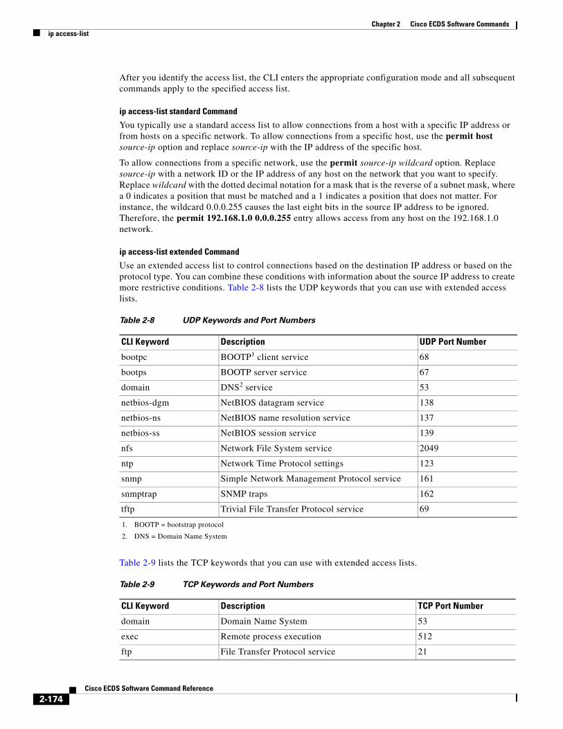
Chapter 2 Cisco ECDS Software Commandsip access-list
After you identify the access list, the CLI enters the appropriate configuration mode and all subsequent commands apply to the specified access list.
ip access-list standard Command
You typically use a standard access list to allow connections from a host with a specific IP address or from hosts on a specific network. To allow connections from a specific host, use the permit host source-ip option and replace source-ip with the IP address of the specific host.
To allow connections from a specific network, use the permit source-ip wildcard option. Replace source-ip with a network ID or the IP address of any host on the network that you want to specify. Replace wildcard with the dotted decimal notation for a mask that is the reverse of a subnet mask, where a 0 indicates a position that must be matched and a 1 indicates a position that does not matter. For instance, the wildcard 0.0.0.255 causes the last eight bits in the source IP address to be ignored. Therefore, the permit 192.168.1.0 0.0.0.255 entry allows access from any host on the 192.168.1.0 network.
ip access-list extended Command
Use an extended access list to control connections based on the destination IP address or based on the protocol type. You can combine these conditions with information about the source IP address to create more restrictive conditions. Table 2-8 lists the UDP keywords that you can use with extended access lists.
Table 2-9 lists the TCP keywords that you can use with extended access lists.
Table 2-8 UDP Keywords and Port Numbers
CLI Keyword Description UDP Port Number
bootpc BOOTP1 client service
1. BOOTP = bootstrap protocol
68
bootps BOOTP server service 67
domain DNS2 service
2. DNS = Domain Name System
53
netbios-dgm NetBIOS datagram service 138
netbios-ns NetBIOS name resolution service 137
netbios-ss NetBIOS session service 139
nfs Network File System service 2049
ntp Network Time Protocol settings 123
snmp Simple Network Management Protocol service 161
snmptrap SNMP traps 162
tftp Trivial File Transfer Protocol service 69
Table 2-9 TCP Keywords and Port Numbers
CLI Keyword Description TCP Port Number
domain Domain Name System 53
exec Remote process execution 512
ftp File Transfer Protocol service 21
2-174Cisco ECDS Software Command Reference

Chapter 2 Cisco ECDS Software Commandsip access-list
Table 2-10 lists the keywords that you can use to match specific ICMP message types and codes.
ftp-data FTP data connections (used infrequently) 20
nfs Network File System service applications 2049
rtsp Real-Time Streaming Protocol applications 554
ssh Secure Shell login 22
telnet Remote login using telnet 23
www World Wide Web (HTTP) service 80
Table 2-9 TCP Keywords and Port Numbers (continued)
CLI Keyword Description TCP Port Number
Table 2-10 Keywords for ICMP Message Type and Code
Field Description
administratively-prohibited Messages that are administratively prohibited from being allowed access.
alternate-address Messages that specify alternate IP addresses.
conversion-error Messages that denote a datagram conversion error.
dod-host-prohibited Messages that signify a DoD1 protocol Internet host denial.
dod-net-prohibited Messages that specify a DoD protocol network denial.
echo Messages that are used to send echo packets to test basic network connectivity.
echo-reply Messages that are used to send echo reply packets.
general-parameter-problem Messages that report general parameter problems.
host-isolated Messages that indicate that the host is isolated.
host-precedence-unreachable Messages that have been received with the protocol field of the IP header set to one (ICMP) and the type field in the ICMP header set to three (Host Unreachable). This is the most common response. Large numbers of this datagram type on the network are indicative of network difficulties or may be indicative of hostile actions.
host-redirect Messages that specify redirection to a host.
host-tos-redirect Messages that specify redirection to a host for type of service-based (ToS) routing.
host-tos-unreachable Messages that denote that the host is unreachable for ToS-based routing.
host-unknown Messages that specify that the host or source is unknown.
host-unreachable Messages that specify that the host is unreachable.
information-reply Messages that contain domain name replies.
information-request Messages that contain domain name requests.
mask-reply Messages that contain subnet mask replies.
mask-request Messages that contain subnet mask requests.
mobile-redirect Messages that specify redirection to a mobile host.
2-175Cisco ECDS Software Command Reference

Chapter 2 Cisco ECDS Software Commandsip access-list
net-redirect Messages that are used for redirection to a different network.
net-tos-redirect Messages that are used for redirection to a different network for ToS-based routing.
net-tos-unreachable Messages that specify that the network is unreachable for the ToS-based routing.
net-unreachable Messages that specify that the network is unreachable.
network-unknown Messages that denote that the network is unknown.
no-room-for-option Messages that specify the requirement of a parameter, but that no room is unavailable for it.
option-missing Messages that specify the requirement of a parameter, but that parameter is not available.
packet-too-big Messages that specify that the ICMP packet requires fragmentation but the DF2 bit is set.
parameter-problem Messages that signify parameter-related problems.
port-unreachable Messages that specify that the port is unreachable.
precedence-unreachable Messages that specify that host precedence is not available.
protocol-unreachable Messages that specify that the protocol is unreachable.
reassembly-timeout Messages that specify a timeout during reassembling of packets.
redirect Messages that have been received with the protocol field of the IP header set to one (ICMP) and the type field in the ICMP header set to five (Redirect). ICMP redirect messages are used by routers to notify the hosts on the data link that a better route is available for a particular destination.
router-advertisement Messages that contain ICMP router discovery messages called router advertisements.
router-solicitation Messages that are multicast to ask for immediate updates on neighboring router interface states.
source-quench Messages that have been received with the protocol field of the IP header set to one (ICMP) and the type field in the ICMP header set to four (Source Quench). This datagram may be used in network management to provide congestion control. A source quench packet is issued when a router is beginning to lose packets because of the transmission rate of a source. The source quench is a request to the source to reduce the rate of a datagram transmission.
source-route-failed Messages that specify the failure of a source route.
time-exceeded Messages that specify information about all instances when specified times were exceeded.
timestamp-reply Messages that contain time-stamp replies.
timestamp-request Messages that contain time-stamp requests.
traceroute Messages that specify the entire route to a network host from the source.
Table 2-10 Keywords for ICMP Message Type and Code (continued)
Field Description
2-176Cisco ECDS Software Command Reference

Chapter 2 Cisco ECDS Software Commandsip access-list
Examples The following example shows how to create an access list to allow all web traffic and to only allow a specific host administrative access using Secure Shell (SSH):
ServiceEngine(config)# ip access-list extended exampleServiceEngine(config-ext-nacl)# permit tcp any any eq wwwServiceEngine(config-ext-nacl)# permit tcp host 10.1.1.5 any eq sshServiceEngine(config-ext-nacl)# exit
The following example shows how to activate the access list for an interface:
ServiceEngine(config)# interface gigabitethernet 1/0ServiceEngine(config-if)# exit
The following example shows how this configuration appears when you enter the show running-configuration command:
...!ip access-list extended example permit tcp any any eq www permit tcp host 10.1.1.5 any eq ssh exit. . .
Related Commands
ttl-exceeded Messages that specify that ICMP packets have exceeded the Time-To-Live configuration.
unreachable Messages that are sent when packets are denied by an access list; these packets are not dropped in the hardware but generate the ICMP-unreachable message.
1. DoD = department of defense
2. DF = do not fragment
Table 2-10 Keywords for ICMP Message Type and Code (continued)
Field Description
Command Description
clear ip access-list counters Clears the IP access list statistical information.
show ip access-list Displays the access lists that are defined and applied to specific interfaces or applications.
2-177Cisco ECDS Software Command Reference

Chapter 2 Cisco ECDS Software Commandsipv6
ipv6To specify the default gateway’s IPv6 address, use the ipv6 command in global configuration mode. To disable the IPv6 address, use the no form of this command.
ipv6 default-gateway ip-address
no ipv6 default-gateway ip-address
Syntax Description
Defaults No default behavior or values
Command Modes Global configuration
Examples The following example shows how to configure an IPv6-related address:
ServiceRouter(config)# ipv6 default-gateway fec0::100/64
Related Commands
default-gateway Specifies the default gateway’s IPv6 address.
ip-address IPv6 address of the default gateway.
Command Description
traceroute6 Traces the route to a remote IPv6-enabled host.
2-178Cisco ECDS Software Command Reference

Chapter 2 Cisco ECDS Software Commandskernel kdb
kernel kdbTo enable access to the kernel debugger (kdb), use the kernel kdb command in global configuration mode. To disable the kernel debugger, use the no form of this command.
kernel kdb
no kernel kdb
Syntax Description This command has no arguments or keywords.
Defaults Kdb is disabled by default.
Command Modes Global configuration
Usage Guidelines Once enabled, kdb is automatically activated when kernel problems occur. Once activated, all normal functioning of the CDS device is suspended until kdb is manually deactivated. The kdb prompt looks like this prompt:
[ 0 ] kdb>
To deactivate kdb, enter go at the kdb prompt. If kdb was automatically activated because of kernel problems, you must reboot to recover from the issue. If you activated kdb manually for diagnostic purposes, the system resumes normal functioning in whatever state it was when you activated kdb. In either case, if you enter reboot, the system restarts and normal operation resumes.
If kdb has been previously enabled, you can enter the no kernel kdb global configuration command to disable it. When kdb is enabled, you can activate it manually from the local console by pressing Esc-KDB (press Escape and then press KDB in capitalization).
Examples The following example shows how to enable kdb:
ServiceEngine(config)# kernel kdb
The following example shows how to disable kdb:
ServiceEngine(config)# no kernel kdb
2-179Cisco ECDS Software Command Reference

Chapter 2 Cisco ECDS Software Commandskey
keyTo create a key ID and enter into key configuration submode, use the key command in global configuration mode. To exit key chain configuration submode, use the no form of this command.
key keyid
no key keyid
Syntax Description
Defaults No default behavior or values
Command Modes Global configuration
Usage Guidelines Multiple key ID’s may be configured under the same key chain. The key chain string cannot exceed 63 characters.
When ISIS is configured to use a particular key chain for the authentication and the corresponding key chain is not configured in the system, it causes ISIS to always reject incoming packets that require the key chain.
When a key chain has multiple keys, ISIS should advertise the first key in the chain. For validation of received packets, it should iterate through all the keys until there is a match.
They key command is within the key chain command context, not simply the key chain itself.
Examples The following example shows how to create a key ID and enter the key configuration submode:
ServiceRouter(config)# key chain my-keyServiceRouter(config-keychain)#
Related Commands
keyid Key identifier. The range is from 0 to 65535.
Command Description
key-string Creates a key string to be used for authentication.
key chain Creates a key chain and enter into key chain configuration submode.
show key chain Displays the key chains in the system.
2-180Cisco ECDS Software Command Reference

Chapter 2 Cisco ECDS Software Commandskey-string
key-stringTo create a key string to be used for authentication, use the key chain command in Key ID configuration submode. To remove the key-string, use the no form of this command.
key-string keyid
no key-string keyid
Syntax Description
Defaults No default behavior or values
Command Modes Key ID configuration submode
Usage Guidelines The key-string command creates a key string to be used for authentication.
A key string is always valid upon creation.
You can only create one key-string per key ID.
Key-chain string cannot exceed 63 characters.
Examples The following example shows how to specify terminal line settings:
ServiceRouter(config-keychain-key)# key-string topos123ServiceRouter(config-keychain-key)#
Related Commands
keyid The unencrypted (cleartext) user password.
Command Description
key Creates a key chain and enter into key chain configuration submode.
key chain Creates a key chain and enter into key chain configuration submode.
show key chain Displays the key chains in the system.
2-181Cisco ECDS Software Command Reference

Chapter 2 Cisco ECDS Software Commandskey chain
key chainTo create a key chain and enter into key chain configuration submode, use the key chain command in global configuration mode. To exit key chain configuration submode, use the no form of this command.
key chain name
no key chain name
Syntax Description
Defaults No default behavior or values
Command Modes Global configuration
Usage Guidelines Multiple key ID’s may be configured under the same key chain. Key chain string cannot exceed 63 characters.
When ISIS is configured to use a particular key chain for the authentication and the corresponding key chain is not configured in the system, it results ISIS to always reject incoming packets that requires the key chain.
When a key chain has multiple keys, ISIS should advertise the first key in the chain. For validation of received packets, it should iterate through all the keys until there is a match.
Examples The following example shows how to create a key and enter into key ID configuration submode:
ServiceRouter(config)# key chain my-keyServiceRouter(config-keychain)#
The following example shows a complete sample configuration for ISIS MD5 authentication:
ServiceRouter(config)# key chain lsp-keyServiceRouter(config-keychain)# key 1ServiceRouter(config-keychain-key)# key-string lspServiceRouter(config-keychain-key)# exitServiceRouter(config-keychain)# exitServiceRouter(config)# key chain int-keyServiceRouter(config-keychain)# key 1ServiceRouter(config-keychain-key)# key-string topos123ServiceRouter(config-keychain-key)# exitServiceRouter(config-keychain)# exitServiceRouter(config)# router isisServiceRouter(config-isis)# net 10.1111.1111.1111.00ServiceRouter(config-isis)# is-type level-1ServiceRouter(config-isis)# authentication-type md5 level-1ServiceRouter(config-isis)# authentication key-chain lsp-key level-1ServiceRouter(config-isis)# interface giagabitethernet 1/0ServiceRouter(config-isis-if)# isis authentication-type md5 level-1ServiceRouter(config-isis-if)# isis authentication key-chain int-key level-1
name Key-chain name.
2-182Cisco ECDS Software Command Reference

Chapter 2 Cisco ECDS Software Commandskey chain
Related Commands Command Description
key Creates a key chain and enter into key chain configuration submode.
key-string Creates a key string to be used for authentication.
show key chain Displays the key chains in the system.
2-183Cisco ECDS Software Command Reference

Chapter 2 Cisco ECDS Software Commandsline
lineTo specify terminal line settings, use the line command in global configuration mode. To disable terminal line settings, use the no form of this command.
line console carrier-detect
no line console carrier-detect
Syntax Description
Defaults This feature is disabled by default.
Command Modes Global configuration
Usage Guidelines You should enable carrier detection if you connect the SE, SR, or CDSM to a modem for receiving calls. If you are using a null-modem cable with no carrier detect pin, the device might appear unresponsive on the console until the carrier detect signal is asserted. To recover from a misconfiguration, you should reboot the device and set the 0x2000 bootflag to ignore the Carrier Detect (CD) setting.
Examples The following example shows how to specify terminal line settings:
ServiceEngine(config)# line console carrier-detect
console Configures the console terminal line settings.
carrier-detect Sets the device to check the carrier detect signal before writing to the console.
2-184Cisco ECDS Software Command Reference

Chapter lls
llsTo view a long list of directory names, use the lls user command in user EXEC configuration mode.
lls [directory]
Syntax Description
Supported User Roles No default behavior or values
Command Modes User EXEC
Usage Guidelines This command provides detailed information about files and subdirectories stored in the present working directory (including size, date, time of creation, sysfs name, and long name of the file). This information can also be viewed with the dir command.
Examples The following example shows how to view a long list of directory names:
ServiceEngine# lls size time of last change name -------------- ------------------------- ----------- 4096 Mon Jan 10 14:02:26 2005 <DIR> WebsenseEnterprise 4096 Mon Jan 10 14:02:26 2005 <DIR> Websense_config_backup 10203 Mon Feb 28 04:24:53 2005 WsInstallLog 4096 Wed Feb 9 00:59:48 2005 <DIR> core_dir 4096 Mon Jan 10 13:49:27 2005 <DIR> crash 382 Tue Mar 1 03:32:13 2005 crka.log 1604 Tue Feb 22 03:55:04 2005 dbupgrade.log 4096 Mon Jan 10 14:02:31 2005 <DIR> downgrade 4096 Mon Feb 28 04:17:32 2005 <DIR> errorlog 53248 Tue Mar 1 03:01:53 2005 <DIR> logs 16384 Mon Jan 10 13:49:26 2005 <DIR> lost+found 438 Tue Jan 11 05:37:57 2005 new_file.xml 8192 Tue Mar 1 00:00:00 2005 <DIR> preload_dir 4096 Tue Mar 1 03:26:00 2005 <DIR> sa 40960 Tue Mar 1 03:32:15 2005 <DIR> service_logs 4096 Tue Feb 22 03:51:25 2005 <DIR> smartfilter 384802 Mon Feb 28 03:46:00 2005 syslog.txt 16296 Mon Feb 21 04:42:12 2005 test 4096 Mon Jan 10 14:02:24 2005 <DIR> var 4096 Sat Feb 12 07:15:23 2005 <DIR> wmt_vod
Related Commands
directory (Optional) Name of the directory for which you want a long list of files.
Command Description
dir Displays a detailed list of files contained within the working directory, including names, sizes, and time created.
ls Lists the files or subdirectory names within a directory.
-185

Chapter logging
loggingTo configure system logging, use the logging command in global configuration mode. To disable logging functions, use the no form of this command.
logging {console {enable | priority loglevel} | disk {enable | filename filename | priority loglevel | recycle size} | facility facility | host {hostname | ip-address} [port port_num | priority loglevel | rate-limit message_rate]}
no logging {console {enable | priority loglevel} | disk {enable | filename filename | priority loglevel | recycle size} | facility facility | host {hostname | ip-address} [port port_num | priority loglevel | rate-limit message_rate]}
Syntax Description console Sets system logging to a console.
enable Enables system logging to a console.
priority Sets which priority level messages to send to a syslog file.
loglevel
alert Immediate action needed. Priority 1.
critical Immediate action needed. Priority 2.
debug Debugging messages. Priority 7.
emergency System is unusable. Priority 0.
error Error conditions. Priority 3.
information Informational messages. Priority 6.
notice Normal but significant conditions. Priority 5.
warning Warning conditions. Priority 4.
disk Sets system logging to a disk file.
enable Enables system logging to a disk file.
filename Sets the name of the syslog file.
filename Specifies the name of the syslog file.
recycle Overwrites the syslog.txt when it surpasses the recycle size.
size Size of the syslog file in bytes (100000000 to 500000000).
facility Sets the facility parameter for syslog messages.
facility
auth Authorization system.
daemon System daemons.
kernel Kernel.
local0 Local use.
local1 Local use.
local2 Local use.
local3 Local use.
local4 Local use.
local5 Local use.
local6 Local use.
-186

Chapter logging
Defaults Logging: on
Priority of message for console: warning
Priority of message for log file: debug
Priority of message for a host: warning
Log file: /local1/syslog.txt
Log file recycle size: 10,000,000
Command Modes Global configuration
local7 Local use.
mail Mail system.
news USENET news.
syslog Syslog itself.
user User process.
uucp UUCP system.
host Sets the system logging to a remote host.
hostname Hostname of the remote syslog host. Specifies up to four remote syslog hosts.
Note To specify more than one syslog host, use multiple command lines; specify one host per command.
ip-address IP address of the remote syslog host. Specifies up to four remote syslog hosts.
Note To specify more than one syslog host, use multiple command lines; specify one host per command.
port (Optional) Specifies the port to be used when logging to a host.
port_num Port to be used when logging to a host. The default port is 514.
priority (Optional) Sets the priority level for messages when logging messages to a host. The default priority is warning.
loglevel
alert Immediate action needed. Priority 1.
critical Immediate action needed. Priority 2.
debug Debugging messages. Priority 7.
emergency System is unusable. Priority 0.
error Error conditions. Priority 3.
information Informational messages. Priority 6.
notice Normal but significant conditions. Priority 5.
warning Warning conditions. Priority 4.
rate-limit (Optional) Sets the rate limit (in messages per second) for sending messages to a host.
message_rate Rate limit (in messages per second) for sending messages to the host. (0 to 10000). Setting the rate limit to 0 disables rate limiting.
-187

Chapter logging
Usage Guidelines Use the logging command to set specific parameters of the system log file. System logging is always enabled internally on the SE. The system log file is located on the sysfs partition as /local1/syslog.txt. This file contains the output from many of the CDS components running on the SE, such as authentication entries, privilege levels, administrative details, and diagnostic output during the boot process.
To view information about events that have occurred in all devices in your CDS network, you can use the system message log feature. When a problem occurs in the CDS network, use the system message logs to diagnose and correct such problems.
The syslog.txt file on the CDSM contains information about events that have occurred on the CDSM and not on the registered nodes. The messages written to the syslog.txt file depend on specific parameters of the system log file that you have set using the logging global configuration command. For example, a critical error message logged on a registered node does not appear in the syslog.txt file on the CDSM because the problem never occurred on the CDSM but occurred only on the registered node. However, such an error message is displayed in the syslog.txt file on the registered node.
A disk failure syslog message is generated every time that a failed sector is accessed. Support for filtering multiple syslog messages for a single failed sector on an IDE disk was added. Support for filtering multiple syslog messages for a single failed section for SCSI disks and SATA disks exists.
To configure the SE to send varying levels of event messages to an external syslog host, use the logging host command. Logging can be configured to send various levels of messages to the console using the logging console priority command.
The no logging disk recycle size command sets the file size to the default value. Whenever the current log file size surpasses the recycle size, the log file is rotated. The log file cycles through at most five rotations, and they are saved as [log file name]. [1-5] under the same directory as the original log. The rotated log file is the one configured using the logging disk filename command.
Configuring System Logging to Remote Syslog Hosts
Cisco ECDS Release 2.6 software supports logging to only a single remote syslog host, and the following two commands are used to configure a single remote syslog host for an SE:
ServiceEngine(config)# logging host hostnameServiceEngine(config)# logging priority priority
You can configure an SE to send varying levels of messages to up to four remote syslog hosts. To accommodate this, logging host priority priority global configuration command (shown above) is deprecated, and the logging host hostname global configuration command is extended as follows:
ServiceEngine(config)# [no] logging host hostname [priority priority-code | port port | rate-limit limit]
where the following is true:
• hostname is the hostname or IP address of the remote syslog host. Specify up to four remote syslog hosts. To specify more than one syslog host, use multiple command lines; specify one host per command.
• priority-code is the severity level of the message that should be sent to the specified remote syslog host. The default priority-code is “warning” (level 4). Each syslog host can receive a different level of event messages.
Note You can achieve syslog host redundancy by configuring multiple syslog hosts on the SE and assigning the same priority code to each configured syslog host (for example, assigning a priority code of “critical” level 2 to syslog host 1, syslog host 2, and syslog host 3).
-188

Chapter logging
• port is the destination port of the remote syslog host to which the SE is to send the messages. The default port is port 514.
• rate-limit specifies the number of messages that are allowed to be sent to the remote syslog host per second. To limit bandwidth and other resource consumption, messages to the remote syslog host can be rate limited. If this limit is exceeded, messages to the specified remote syslog host are dropped. There is no default rate limit, and by default all syslog messages are sent to all the configured syslog hosts. If the rate limit is exceeded, a message of the day (MOTD) is printed for any CLI EXEC shell login.
Mapping syslog Priority Levels to RealProxy Error Codes
The RealProxy system generates error messages and writes them to the RealProxy log file. These error messages are captured by the caching application and passed to the system log file. A one-to-one mapping exists between the RealProxy error codes and the syslog priority levels.
Examples The following example shows that the SE is configured to send messages that have a priority code of “error” (level 3) to the console:
ServiceEngine(config)# logging console priority warnings
The following example shows that the SE is configured to disable sending of messages that have a priority code of “error” (level 3) to the console:
ServiceEngine(config)# no logging console warnings
The following example shows that the SE is configured to send messages that have a priority code of “error” (level 3) to the remote syslog host that has an IP address of 172.31.2.160:
ServiceEngine(config)# logging host 172.31.2.160 priority error
Related Commands Command Description
clear logging Removes all current entries from the syslog.txt file, but does not make an archive of the file.
debug Monitors and records caching application functions.
show logging Displays the system message log confirmation.
-189

Chapter ls
lsTo view a list of files or subdirectory names within a directory, use the ls command in EXEC configuration mode.
ls [directory]
Syntax Description
Defaults No default behavior or values
Command Modes EXEC
Usage Guidelines To list the filenames and subdirectories within a particular directory, use the ls directory command; to list the filenames and subdirectories of the current working directory, use the ls command. To view the present working directory, use the pwd command.
Examples The following example displays a list of files within the current working directory:
ServiceEngine# ls/local1
The following example displays a list of files within the /local1 directory:
ServiceEngine# ls /local1core_dircrasherrorloglogslost+foundservice_logssmartfiltersyslog.txt
Related Commands
directory (Optional) Name of the directory for which you want a list of files.
Command Description
dir Displays a detailed list of files contained within the working directory, including names, sizes, and time created.
lls Provides detailed information about files and subdirectories stored in the present working directory, including size, date, time of creation, sysfs name, and long name of the file.
pwd Displays the present working directory of the SE.
-190

Chapter mkdir
mkdirTo create a directory, use the mkdir command in EXEC configuration mode.
mkdir directory
Syntax Description
Defaults No default behavior or values
Command Modes EXEC
Usage Guidelines Use this command to create a new directory or subdirectory in the SE file system.
Examples The following example shows how to create a new directory under local1:
ServiceEngine# mkdir /local1/mydir
Related Commands
directory Name of the directory to create.
Command Description
dir Displays a detailed list of files contained within the working directory, including names, sizes, and time created.
lls Provides detailed information about files and subdirectories stored in the present working directory, including size, date, time of creation, sysfs name, and long name of the file.
ls Lists the files or subdirectory names within a directory.
pwd Displays the present working directory of the SE.
rmdir Removes a directory from the SE file system.
-191

Chapter mkfile
mkfileTo create a new file, use the mkfile command in EXEC configuration mode.
mkfile filename
Syntax Description
Defaults No default behavior or values
Command Modes EXEC
Usage Guidelines Use this command to create a new file in any directory of the SE.
Examples The following example shows how to create a new file:
ServiceEngine# mkfile traceinfo
Related Commands
filename Name of the file that you want to create.
Command Description
lls Provides detailed information about files and subdirectories stored in the present working directory, including size, date, time of creation, sysfs name, and long name of the file.
ls Lists the files or subdirectory names within a directory.
mkdir Creates a new directory or subdirectory in the SE file system.
-192

Chapter movie-streamer
movie-streamerTo enable and configure the Movie Streamer server, use the movie-streamer command in global configuration mode. To disable the Movie Streamer, use the no form of this command.
movie-streamer accelerate vod enable
movie-streamer advanced {client {idle-timeout num | rtp-timeout} | origin server idle-interval num}
movie-streamer broadcast port-list num port num
movie-streamer cache {age-multiplier num | enable | max-ttl {days num | hours num | minutes num | seconds num} | reval-each-request}
movie-streamer enable
movie-streamer max-concurrent-sessions num
movie-streamer proxy outgoing rtsp host ip address port num
movie-streamer transport-src-address ip address
no movie streamer {accelerate vod enable | advanced {client {idle-timeout num | rtp-timeout} | origin server idle-interval num} | broadcast port-list num port num | cache {age-multiplier num | enable | max-ttl {days num | hours num | minutes num | seconds num} | reval-each-request} | enable | max-concurrent-sessions num | proxy outgoing rtsp host ip address port num | transport-src-address ip address}
Syntax Description accelerate Configures Movie Streamer kernel streaming acceleration.
vod Configures kernel streaming acceleration for VOD.
enable Enables kernel streaming acceleration.
advanced Configures Movie Streamer Advanced features.
client Configures advanced client features.
idle-timeout Sets the RTSP timeout.
num Client idle timeout, in seconds. The range is from 0 to 300.
rtp-timeout Sets the RTP timeout.
origin-server Configures the advanced origin server.
idle-interval Sets the origin server idle interval.
num Server idle interval, in seconds. The range is from 1 to 10.
broadcast Configures the Movie Streamer live broadcast.
port-list Specifies a port list.
num Broadcast list number. The range is from 1 to 1024.
port num Broadcast port number.
cache Configures the Movie Streamer cache.
age-multiplier Sets the Movie Streamer cache heuristic modifier.
num Expiration time as a percentage of their age. The range is from 0 to 100.
-193

Chapter movie-streamer
Defaults days: 1hours: 72minutes: 4320seconds: 259200
Command Modes Global configuration
Usage Guidelines The movie-streamer accelerate vod enable command enables kernel streaming acceleration for VOD.
The movie-streamer advanced client command sets the RTSP or RTP timeout value.
The movie-streamer advanced origin-server command sets the origin-server idle-interval value, which can determine the origin-server RTP timeout value.
The Idle Timeout field and the movie-streamer advanced client idle-timeout command (as well as the movie-streamer advanced client rtp-timeout command), are only intended for performance testing when using certain testing tools that do not have full support of the RTCP receiver report. Setting these timeouts to high values causes inefficient tear-down of client connections when the streaming sessions have ended.
For typical deployments, it is preferable to leave these parameters set to their defaults. The default is 60.
enable Enables the Movie Streamer media cache.
max-ttl Sets the maximum time to live for objects in the cache.
days Specifies the maximum time to live units in days.
num Maximum time to live. The range is from 1 to 1825.
hours Specifies the maximum time to live units in hours.
num Maximum time to live. The range is from 1 to 43800.
minutes Specifies the maximum time to live units in minutes.
num Maximum time to live. The range is from 1 to 2628000.
seconds Specifies the maximum time to live units, in seconds.
num Maximum time to live. The range is from 1 to 157680000.
reval-each-request Sets the scope of revalidation for the request.
enable Enables the Movie Streamer.
max-concurrent-sessions Specifies the Movie Streamer maximum concurrent sessions.
num The maximum concurrent sessions. The range is from 1 to 16000.
proxy Configures the Movie Streamer proxy.
outgoing Configures the Outgoing proxy.
rtsp Configures the Outgoing RTSP proxy.
host Specifies the outgoing proxy server.
ip address IP address of outgoing proxy server.
port num Port number of outgoing proxy server. The range is from 1 to 65535.
transport-src-address Specifies the source IP address to be set in transport header (useful if behind NAT).
ip address Source IP address in transport header.
-194

Chapter movie-streamer
The movie-streamer advanced client idle-timeout command has a range from 0 to 300, whereas the Idle Timeout field has a range from 30 to 180. This is by design.
Examples The following example shows how to set the original server interval:
ServiceEngine(config)# movie-streamer advanced origin-server idle-interval 5
The following example shows how to set the broadcast port list:
ServiceEngine(config)# movie-streamer broadcast port-list 1 5000 5002
The following example shows how to set the expiration time as a percentage of the age:
ServiceEngine(config)# movie-streamer cache age-multiplier 50
The following example shows how to set the content cache maximum TTL:
ServiceEngine(config)# movie-streamer cache max-ttl days 100
The following example shows how to set the maximum concurrent sessions:
ServiceEngine(config)# movie-streamer max-concurrent-sessions 7000
The following example shows how to set the outgoing proxy:
ServiceEngine(config)# movie-streamer proxy outgoing rtsp host 10.74.61.98 554
The following example shows how to set the source IP of the transport header while behind NAT:
ServiceEngine(config)# movie-streamer transport-src-address 10.74.61.99
The following example shows how to set the client timeout:
ServiceEngine(config)# movie-streamer advanced client idle-timeout 150
The following example shows how to set the RPT time out:
ServiceEngine(config)# movie-streamer advanced client rtp-timeout 150
Set original server interval is 5 secondServiceEngine(config)# movie-streamer advanced origin-server idle-interval 5
Set broadcast port listServiceEngine(config)# movie-streamer broadcast port-list 1 5000 5002
Set Expiration time as a percentage of their age's 50%ServiceEngine(config)# movie-streamer cache age-multiplier 50
Set cache content max ttl is 100 daysServiceEngine(config)# movie-streamer cache max-ttl days 100
Set max con-current sessions is 7000ServiceEngine(config)# movie-streamer max-concurrent-sessions 7000
Set out going proxyServiceEngine(config)# movie-streamer proxy outgoing rtsp host 10.74.61.98 554
Set the source Ip of transport header while behind NATServiceEngine(config)# movie-streamer transport-src-address 10.74.61.99
-195

Chapter movie-streamer
Related Commands Command Description
show movie-streamer Displays the Movie Streamer configuration.
show statistics movie-streamer
Displays statistics for the Movie Streamer.
-196

Chapter mtu
mtuTo set the interface maximum transmission unit (MTU) packet size, use the mtu interface configuration
command. Use the no form of this command to reset the MTU packet size.
mtu mtusize
no mtu mtusize
Syntax Description
Command Default The default MTU packet size for an Ethernet interface is 1500 bytes.
Command Modes Interface configuration
Usage Guidelines The MTU is the largest size of IP datagram that can be transferred using a specific data link connection. Use the mtu command to set the maximum packet size in bytes.
Examples The following example sets the MTU packet size as 1500 bytes:
ServiceEngine(config-if)# mtu 1500
The following example resets the MTU packet size:
ServiceEngine(config-if)# no mtu 1500
Related Commands
mtusize MTU packet size in bytes (576 to 1500).
Command Description
show interface Displays the hardware interface information.
show running-config Displays the current running configuration information on the terminal.
show startup-config Displays the startup configuration.
-197

Chapter nat
natTo configure the Network Address Translation (NAT) IP, use the nat command in global configuration mode. To disable this function, use the no form of this command.
nat ip ip-address
no nat ip ip-address
Syntax Description
Command Default No default behavior or values.
Command Modes EXEC
Usage Guidelines Configure the NAT command, to include the NAT IP in the SNMP traps.
Examples The following example shows how to configure an NAT IP:
CDSM(config)#nat ip 10.126.252.10CDSM(config)#end
ip-address NAT IP address of the device.
-198

Chapter no (global configuration)
no (global configuration)To undo a command in global configuration mode or set its defaults, use the no form of a command in global configuration mode.
no command
Note The commands you can use with a CDS device (including the no form of each command) vary based on whether the device is configured as a CDSM, SE, or SR. See Table 2-1 to identify the commands available for a specific device.
Syntax Description
Defaults No default behavior or values
Command Modes Global configuration
Usage Guidelines Valid values for command are as follows:
command Specifies the command type; see the Usage Guidelines section for valid values.
aaa Configures AAA1.
access-lists Configures access control list entries.
acquirer Configures acquisition parameters.
asset Configures the asset tag name string.
authentication Configures the authentication.
bandwidth Configures bandwidth controls.
banner Defines a login banner.
bitrate Configures the bit rate.
cdsm Configures the CDSM settings.
clock Configures the time-of-day clock.
cms Configures the CMS2.
device Configures the device mode.
direct-server-return Configures direct-server-return.
disk Configures disk-related settings.
dns Configures the SE DNS cache.
exec-timeout Configures the EXEC timeout.
external-ip Configures up to eight external (NAT) IP addresses.
ftp Configures FTP caching-related parameters.
help Configures the assistance for the command-line interface.
-199
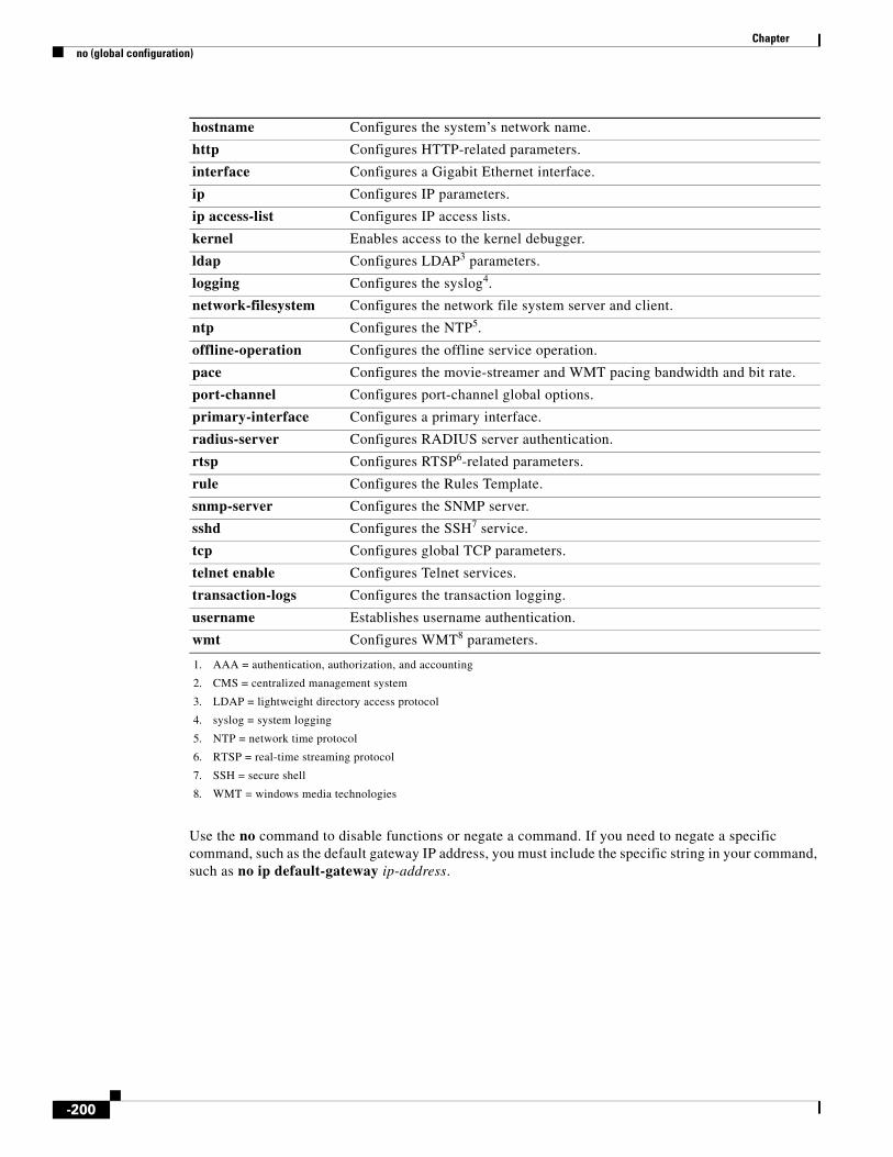
Chapter no (global configuration)
Use the no command to disable functions or negate a command. If you need to negate a specific command, such as the default gateway IP address, you must include the specific string in your command, such as no ip default-gateway ip-address.
hostname Configures the system’s network name.
http Configures HTTP-related parameters.
interface Configures a Gigabit Ethernet interface.
ip Configures IP parameters.
ip access-list Configures IP access lists.
kernel Enables access to the kernel debugger.
ldap Configures LDAP3 parameters.
logging Configures the syslog4.
network-filesystem Configures the network file system server and client.
ntp Configures the NTP5.
offline-operation Configures the offline service operation.
pace Configures the movie-streamer and WMT pacing bandwidth and bit rate.
port-channel Configures port-channel global options.
primary-interface Configures a primary interface.
radius-server Configures RADIUS server authentication.
rtsp Configures RTSP6-related parameters.
rule Configures the Rules Template.
snmp-server Configures the SNMP server.
sshd Configures the SSH7 service.
tcp Configures global TCP parameters.
telnet enable Configures Telnet services.
transaction-logs Configures the transaction logging.
username Establishes username authentication.
wmt Configures WMT8 parameters.
1. AAA = authentication, authorization, and accounting
2. CMS = centralized management system
3. LDAP = lightweight directory access protocol
4. syslog = system logging
5. NTP = network time protocol
6. RTSP = real-time streaming protocol
7. SSH = secure shell
8. WMT = windows media technologies
-200

Chapter no (interface configuration)
no (interface configuration)To negate a Gigabit Ethernet or port-channel command in interface configuration mode or set its defaults, use the no command in interface configuration mode.
no interface {GigabitEthernet slot/port | PortChannel {1 | 2} | Standby group num}
Syntax Description
Defaults No default behavior or values
Command Modes Interface configuration
Related Commands
GigabitEthernet Selects a Gigabit Ethernet interface to configure.
slot/port Slot and port number for the selected interface. The slot range is 0 to 2; the port range is 0 to 3. The slot number and port number are separated with a forward slash character (/).
PortChannel Selects the EtherChannel of interfaces to configure.
1 Sets the port-channel interface number to 1.
2 Sets the port-channel interface number to 2.
Standby Sets the standby group for the interface.
group num Group number for the selected interface. The group number range is 1 to 4.
Command Description
interface Configures a Gigabit Ethernet or port-channel interface.
show interface Displays the hardware interface information.
show running-config Displays the current running configuration information on the terminal.
show startup-config Displays the startup configuration.
-201

Chapter ntp
ntpTo configure the Network Time Protocol (NTP) server and to allow the system clock to be synchronized by a time server, use the ntp command in global configuration mode. To disable this function, use the no form of this command.
ntp server {ip-address | hostname} [ip-addresses | hostnames]
no ntp server {ip-address | hostname} [ip-addresses | hostnames]
Syntax Description
Defaults No default behavior or values
Command Modes Global configuration
Usage Guidelines Use this command to synchronize the SE, SR or CDSM clock with the specified NTP server. The ntp server command enables NTP servers for timekeeping purposes and is the only way to synchronize the system clock with a time server.
When you synchronize the CDSM clock with an NTP server, there is a possibility of all devices registered with the CDSM being shown as offline and then reverted to online status. This situation can occur when synchronization with the NTP server sets the CDSM clock forward in time by an interval greater than at least two polling intervals or when the software clock on the CDSM is changed by a similar value using the clock command in EXEC configuration mode. The CDSM determines the status of devices in the CDS network depending on when it was last contacted by the devices for a getUpdate request. If you set the CDSM clock ahead in time, you have added that amount of time to the period since the CDSM received the last getUpdate request. However, it is only a transient effect. Once the devices contact the CDSM for their next getUpdate request after the clock setting change, the CDSM GUI reports the status of all devices correctly.
Examples The following example configures the IP address of the time server providing the clock synchronization:
ServiceEngine(config)# ntp 172.16.22.44
The following example resets the time server providing the clock synchronization:
ServiceEngine(config)# no ntp 172.16.22.44
server Sets the NTP server IP address.
ip-address NTP server IP address.
hostname NTP server hostname.
ip-addresses (Optional) IP address of the time server providing the clock synchronization (maximum of four).
hostnames (Optional) Hostname of the time server providing the clock synchronization (maximum of four).
-202

Chapter ntp
Related Commands Command Description
clock Sets or clears clock functions or updates the calendar.
show clock Displays the system clock.
show ntp status Displays the Network Time Protocol parameters.
-203

Chapter ntpdate
ntpdateTo set the software clock (time and date) using a Network Time Protocol (NTP) server, use the ntpdate command in EXEC configuration mode.
ntpdate {hostname | ip-address}
Syntax Description
Defaults No default behavior or values
Command Modes EXEC
Usage Guidelines Use NTP to find the current time of day and set the SE current time to match. The ntpdate command synchronizes the software clock with the hardware clock.
Examples The following example sets the software clock of the SE using an NTP server:
ServiceEngine# ntpdate 10.11.23.40
Related Commands
hostname NTP hostname.
ip-address NTP server IP address.
Command Description
clock set Sets the time and date.
show clock Displays the system clock.
-204

Chapter ping
pingTo send echo packets for diagnosing basic network connectivity on networks, use the ping command in EXEC configuration mode.
On the CDSM and SE:
ping {hostname | ip-address}
On the SR:
ping {hostname | ip-address | srp {hostname | ip-address}}
Syntax Description
Defaults No default behavior or values
Command Modes EXEC
Usage Guidelines To use this command with the hostname argument, be sure that DNS functionality is configured on your SE. To force the timeout of a nonresponsive host or to eliminate a loop cycle, press Ctrl-C.
Following are sample results of the ping command:
• Normal response—The normal response occurs in 1 to 10 seconds, depending on network traffic.
• Destination does not respond—If the host does not respond, a “no answer from host” appears in 10 seconds.
• Destination unreachable—The gateway for this destination indicates that the destination is unreachable.
• Network or host unreachable—The SE found no corresponding entry in the route table.
Examples The following example shows how to test the basic network connectivity with a host:
ServiceEngine# ping 172.19.131.189PING 172.19.131.189 (172.19.131.189) from 10.1.1.21 : 56(84) bytes ofdata.64 bytes from 172.19.131.189: icmp_seq=0 ttl=249 time=613 usec64 bytes from 172.19.131.189: icmp_seq=1 ttl=249 time=485 usec64 bytes from 172.19.131.189: icmp_seq=2 ttl=249 time=494 usec64 bytes from 172.19.131.189: icmp_seq=3 ttl=249 time=510 usec64 bytes from 172.19.131.189: icmp_seq=4 ttl=249 time=493 usec
--- 172.19.131.189 ping statistics ---5 packets transmitted, 5 packets received, 0% packet lossround-trip min/avg/max/mdev = 0.485/0.519/0.613/0.047 msServiceEngine#
hostname Hostname of system to ping.
ip-address IP address of system to ping.
srp Pings the Service Routing Protocol.
-205

Chapter ping6
ping6To ping the IPv6 address, use the ping6 command in EXEC configuration mode.
ping6 line ip-address
Syntax Description
Defaults No default behavior or values
Command Modes EXEC
Examples The following example shows how to ping the IPv6 address:
ServiceEngine# ping6 fec0::100/64
Related Commands
line Destination Host or IP Address.
ip-address IP address of system to ping.
Command Description
ping Sends echo packets for diagnosing basic network connectivity on networks.
-206

Chapter port-channel
port-channelTo configure the port-channel load-balancing, use the port-channel command in global configuration mode. To disable load-balancing, use the no form of this command.
port-channel load-balance {dst-ip | dst-mac | dst-port | round-robin | src-dst-mac | src-dst-port | src-port}
no port-channel load-balance
Syntax Description
Defaults Round-robin is the default load-balancing method.
Command Modes Global configuration
Usage Guidelines The port-channel load-balance command configures one of three load-balancing algorithms and provides flexibility in choosing interfaces when an Ethernet frame is sent. The round-robin keyword allows evenly balanced usage of identical network interfaces in a channel group. Because this command takes effect globally, if two channel groups are configured, they must use the same load-balancing.
The other balancing options give you the flexibility to choose specific interfaces (by IP address, MAC address, port) when sending an Ethernet frame. The source and destination options, while calculating the outgoing interface, take into account both the source and destination (MAC address or port).
Because the ECDS software normally starts IP packets or Ethernet frames, it does not support hashing based on the source IP address and source MAC address. Cisco ECDS software adds the round-robin keyword, which is the default load-balancing algorithm, to evenly distribute traffic among several identical network interfaces.
Note To remove a port channel, use the no port-channel interface PortChannel command. See the “port-channel” section on page -207 for more information.
Examples The following example shows how to configure the round-robin load-balancing method on an SE:
ServiceEngine(config)# port-channel load-balance round-robin
load-balance Configures the load-balancing method.
dst-ip Specifies the load-balancing method using destination IP addresses.
dst-mac Specifies the load-balancing method using destination MAC addresses.
dst-port Specifies the load-balancing method using destination port.
round-robin Specifies the load-balancing method using round-robin sequential, cyclical resource allocation (each interface in the channel group).
src-dst-mac Specifies the load-balancing method using source and destination MAC address.
src-dst-port Specifies the load-balancing method using source and destination port.
src-port Specifies the load-balancing method using source port.
-207

Chapter port-channel
Related Commands Command Description
interface Configures a Gigabit Ethernet or port-channel interface
-208

Chapter primary-interface
primary-interfaceTo configure the primary interface for the CDS network, use the primary-interface command in global configuration mode. Use the no form of the command to remove the configured primary interface.
primary-interface {GigabitEthernet 1-2/port | PortChannel 1-2 | Standby group_num}
no primary-interface {GigabitEthernet 1-2/port | PortChannel 1-2 | Standby group_num}
Syntax Description
Defaults The default primary interface is the first operational interface on which a link beat is detected. Interfaces with lower-number IDs are polled first (for example, GigabitEthernet 0/0 is checked before 1/0). Primary interface configuration is required for the proper functioning of the Centralized Management System (CMS). After devices are registered to the CDSM, the CDSM uses the configured primary interface to communicated with the registered devices.
You cannot enable the CDS network without specifying the primary interface. Also, you must have chosen the primary interface before you enable the CMS. The primary interface can be changed without disabling the CDS network. The primary interface specifies the default route for an interface. To change the primary interface, choose a different interface as the primary interface.
In Cisco ECDS software and later releases, you can select a standby interface as the primary interface (you can enter the primary-interface Standby group_num command) to specify a standby group as the primary interface on an SE.
Command Modes Global configuration
Usage Guidelines The primary-interface command in global configuration mode allows the administrator to specify the primary interface for the CDS network.
The primary interface can be changed without disabling the CDS network. To change the primary interface, reenter the command string and specify a different interface.
Note If you use the restore factory-default preserve basic-config command, the configuration for the primary interface is not preserved. On a device in a CDS network, if you want to re-enable the CDS network after using the restore factory-default preserve basic-config command, make sure to reconfigure the primary interface after the factory defaults are restored.
GigabitEthernet Selects a Gigabit Ethernet interface as the CDS network primary interface.
1-2/ Gigabit Ethernet slot numbers 1 or 2.
port Port number of the Gigabit Ethernet interface.
PortChannel Selects a port-channel interface as the CDS network primary interface.
1-2 Port channel number 1 or 2.
Standby Selects a standby group as the CDS network primary interface.
group_num Standby group number.
-209

Chapter primary-interface
Examples The following example shows how to specify the GigabitEthernet slot 1 port 0 as the primary interface on an SE:
ServiceEngine(config)# primary-interface GigabitEthernet 1/0
The following example shows how to specify the GigabitEthernet slot 2 port 0 as the primary interface on an SE:
ServiceEngine(config)# primary-interface GigabitEthernet 2/0
-210

Chapter proximity algorithm bgp
proximity algorithm bgpThe Proximity Engine is not supported in this release.
-211

Chapter proximity engine enable
proximity engine enableThe Proximity Engine is not supported in this release.
-212

Chapter pwd
pwdTo view the present working directory, use the pwd command in EXEC configuration mode.
pwd
Syntax Description This command has no arguments or keywords.
Defaults No default behavior or values
Command Modes EXEC
Usage Guidelines Use this command to display the present working directory of the SE.
Examples The following example shows how to view the present working directory:
ServiceEngine# pwd/local1
Related Commands Command Description
cd Changes from one directory to another directory.
dir Displays a detailed list of files contained within the working directory, including names, sizes, and time created.
lls Provides detailed information about files and subdirectories stored in the present working directory, including size, date, time of creation, sysfs name, and long name of the file.
ls Lists the files or subdirectory names within a directory.
-213

Chapter qos
qosTo globally enable QoS functionality on the switch, use the qos command. To globally disable QoS functionality, use the no form of this command.
qos {device-policy-service {config-file url | enable} | dsvc num name name fqdn icap ip address num list request-type {all num num name redirect-url {no-redirect list num | url list num} | http-download num num name {no-redirect list num | url list num} | wmt-streaming num num name redirect-url {no-redirect list num | url list num}}
no qos {device-policy-service {config-file url | enable} | dsvc num name name fqdn icap ip address num list request-type {all num num name redirect-url {no-redirect list num | url list num} | http-download num num name {no-redirect list num | url list num} | wmt-streaming num num name redirect-url {no-redirect list num | url list num}}
Syntax Description device-policy-service Configures Camiant qos cdn-am policy service.
config-file Specifies the policy service configuration file.
url URL or local configuration file.
enable Enables Camiant policy service.
dsvc Configures PCMM QoS details for the delivery service.
num Delivery service ID, which is obtained from the CDSM. The range is from 1 to 4294967295.
name Delivery Service Name as obtained from the CDSM.
name Service Routed Domain for delivery service.
fqdn Service FQDN for delivery service
icap Specifies that authorization needed using ICAP.
ip address IP address of the Policy Server.
num Port of the Policy Server for authorization. The range is from 1 to 65535.
list List of URI extension separated by commas for which authorization is to be done.
request-type Configures the QoS setting needed for Windows Media Streaming or download.
all Configures the QoS setting for Windows Media Streaming and download.
num Signature details as key ID.
num Signature details as key ID.
name Signature details as key.
redirect-url Specifies the redirect URL string on signature validation failure.
no-redirect Always returns forbidden if validation fails.
url Redirect URL String on signature validation failure.
list List of URI extensions separated by commas for which Signature validation is to be done.
num (1) Enable or (0) Disable the setting given.
http-download Specifies the QoS setting for download.
wmt-streaming Specifies the QoS setting for Windows Media Streaming.
-214

Chapter qos
Defaults QoS functionality is disabled.
Command Modes Global configuration
Usage Guidelines If QoS functionality is globally enabled, it is enabled on all interfaces, except on the interfaces where QoS has been disabled. If QoS functionality is globally disabled, all traffic is passed in QoS pass-through mode.
Examples This example shows how to enable QoS functionality globally on the switch:
ServiceEngine(config)# qos device-policy-service enable
Related Commands Command Description
show qos Displays QoS information.
show statistics qos Displays statistics for the QoS policy service.
-215

Chapter radius-server
radius-serverTo configure RADIUS authentication parameters, use the radius-server command in global configuration mode. To disable RADIUS authentication parameters, use the no form of this command.
radius-server {enable | host {hostname | hostipaddr} [auth-port port] | key keyword | redirect {enable | message reply location url} | retransmit retries | timeout seconds}
no radius-server {enable | host {hostname | hostipaddr} [auth-port port] | key keyword | redirect {enable | message reply location url} | retransmit retries | timeout seconds}
Syntax Description
Defaults auth-port port: UDP port 1645
retransmit retries: 2
timeout seconds: 5
Command Modes Global configuration
Usage Guidelines RADIUS is a client/server authentication and authorization access protocol used by an CDS network device to authenticate users attempting to connect to a network device. The CDS network device functions as a client, passing user information to one or more RADIUS servers. The CDS network device
enable Enables HTTP RADIUS authentication.
host Specifies a RADIUS server.
hostname Hostname of the RADIUS server.
hostipaddr IP address of the RADIUS server.
auth-port (Optional) Sets the UDP port for the RADIUS authentication server.
port UDP port number (from 1 to 65535). The default is 1645.
key Specifies the encryption key shared with the RADIUS servers.
keyword Text of the shared key (maximum of 15 characters).
redirect Redirects the response if an authentication request fails.
enable Enables the redirect feature.
message Replies with an authentication failure message.
reply Reply message text string (maximum of 24 characters).
location Sets the HTML page location, for example, http://www.cisco.com.
url URL destination of authentication failure instructions.
retransmit Specifies the number of transmission attempts to an active server.
retries Number of transmission attempts for a transaction (from 1 to 3).
timeout Time to wait for a RADIUS server to reply.
seconds Wait time in seconds (from 1 to 20).
-216
Chapter radius-server
permits or denies network access to a user based on the response that it receives from one or more RADIUS servers. RADIUS uses the User Datagram Protocol (UDP) for transport between the RADIUS client and server.
You can configure a RADIUS key on the client and server. If you configure a key on the client, it must be the same as the one configured on the RADIUS servers. The RADIUS clients and servers use the key to encrypt all RADIUS packets sent. If you do not configure a RADIUS key, packets are not encrypted. The key itself is never sent over the network.
Note For more information about how the RADIUS protocol operates, see RFC 2138, Remote Authentication Dial In User Service (RADIUS).
RADIUS authentication usually occurs in these instances:
• Administrative login authentication—When an administrator first logs in to the SE to configure the SE for monitoring, configuration, or troubleshooting purposes. For more information, see the “Enabling and Disabling Administrative Login Authentication and Authorization Through RADIUS” section on page -217.
• HTTP request authentication—When an end user sends a service request that requires privileged access to content that is served by the SE. For more information, see the “Configuring RADIUS Authentication of HTTP Requests” section on page -218.
RADIUS authentication is disabled by default. You can enable RADIUS authentication and other authentication methods at the same time. You can also specify which method to use first.
To configure RADIUS parameters, use the radius-server command in global configuration mode. To disable RADIUS authentication parameters, use the no form of this command.
The redirect keyword of the radius-server command redirects an authentication response to a different authentication server if an authentication request using the RADIUS server fails.
Note The following rule command is relevant to RADIUS authentication only if the redirect keyword has been configured.
To exclude domains from RADIUS authentication, use the rule no-auth domain command. RADIUS authentication takes place only if the site requested does not match the specified pattern.
Enabling and Disabling Administrative Login Authentication and Authorization Through RADIUS
When configuring an SE to use RADIUS to authenticate and authorize administrative login requests, follow these guidelines:
• By default, RADIUS authentication and authorization is disabled on an SE.
• Before enabling RADIUS authentication on the SE, you must specify at least one RADIUS server for the SE to use.
• You can enable RADIUS authentication and other authentication methods at the same time. You can specify which method to use first using the primary keyword. When local authentication is disabled, if you disable all other authentication methods, local authentication is re-enabled automatically.
• You can use the SE GUI or the CLI to enable RADIUS authentication and authorization on an SE.
-217

Chapter radius-server
Tip From the SE GUI, choose Devices > General Settings > Authentication. Use the displayed Authentication Configuration window.
To use the SE CLI to enable RADIUS authentication and authorization on an SE, enable RADIUS authentication for normal login mode by entering the authentication login radius command in global configuration mode as follows:
ServiceEngine(config)# authentication login radius enable [primary] [secondary]
Use the authentication configuration radius command in global configuration mode to enable RADIUS authorization as follows:
ServiceEngine(config)# authentication configuration radius enable [primary] [secondary]
Note To disable RADIUS authentication and authorization on an SE, use the no radius-server enable command.
Configuring RADIUS Authentication of HTTP Requests
To configure RADIUS authentication for HTTP requests on an SE, configure the RADIUS server settings on the SE and enable RADIUS authentication for HTTP requests on the SE using the radius-server command in global configuration mode.
Examples The following example enables the RADIUS client, specifies a RADIUS server, specifies the RADIUS key, accepts retransmit defaults, and excludes the domain name, mydomain.net, from RADIUS authentication. You can verify the configuration with the show radius-server and show rule all commands.
ServiceEngine(config)# radius-server enableServiceEngine(config)# radius-server host 172.16.90.121 ServiceEngine(config)# radius-server key myradiuskeyServiceEngine(config)# rule action no-auth pattern-list 2 ServiceEngine(config)# rule pattern-list 2 domain mydomain.net
ServiceEngine# show radius-serverLogin Authentication for Console/Telnet/Ftp/SSH Session: enabledConfiguration Authentication for Console/Telnet/Ftp/SSH Session: enabled (secondary)
Radius Configuration:---------------------Radius Authentication is onTimeout = 5Retransmit = 2Key = ****Radius Redirect is offThere is no URL to authentication failure instructionsServers-------IP 172.16.90.121 Port = 1645
ServiceEngine# show rule allRules Template Configuration----------------------------Rule Processing Enabledrule no-auth domain mydomain.net
-218

Chapter radius-server
The following example disables RADIUS authentication on the SE:
ServiceEngine(config)# no radius-server enable
The following example shows how to force the SE to try RADIUS authentication first:
ServiceEngine(config)# authentication login radius enable primary
Related Commands Command Description
debug authentication user
Debugs the user login against the system authentication.
rule Sets the rules by which the SE filters HTTP, HTTPS, and RTSP traffic.
show radius-server Displays RADIUS information.
-219

Chapter rcp
rcpTo enable the Remote Copy Program (RCP), use the rcp command in global configuration mode. To disable RCP, use the no form of this command.
rcp enable
no rcp enable
Syntax Description
Defaults No default behavior or values
Command Modes Global configuration
Examples The following example shows how to enable RCP:
ServiceEngine(config)# rcp enable
Related Commands
enable Enables RCP services.
Command Description
show rcp Displays RCP information.
-220

Chapter rea
reaTo start the remote execution agent, use the rea command in EXEC configuration mode.
rea {start | stop}
Syntax Description
Defaults No default behavior or values
Command Modes EXEC
Examples The following example shows the remote execution agent services being started.
ServiceEngine(config)# rea start
Related Commands
start Starts the remote execution agent services.
stop Stops the remote execution agent services.
Command Description
show rea Displays REA information.
-221
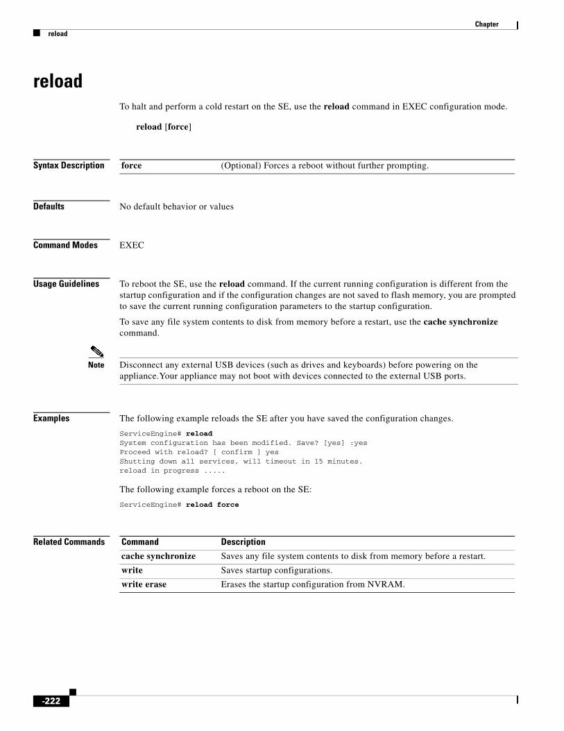
Chapter reload
reloadTo halt and perform a cold restart on the SE, use the reload command in EXEC configuration mode.
reload [force]
Syntax Description
Defaults No default behavior or values
Command Modes EXEC
Usage Guidelines To reboot the SE, use the reload command. If the current running configuration is different from the startup configuration and if the configuration changes are not saved to flash memory, you are prompted to save the current running configuration parameters to the startup configuration.
To save any file system contents to disk from memory before a restart, use the cache synchronize command.
Note Disconnect any external USB devices (such as drives and keyboards) before powering on the appliance.Your appliance may not boot with devices connected to the external USB ports.
Examples The following example reloads the SE after you have saved the configuration changes.
ServiceEngine# reloadSystem configuration has been modified. Save? [yes] :yesProceed with reload? [ confirm ] yesShutting down all services, will timeout in 15 minutes.reload in progress .....
The following example forces a reboot on the SE:
ServiceEngine# reload force
Related Commands
force (Optional) Forces a reboot without further prompting.
Command Description
cache synchronize Saves any file system contents to disk from memory before a restart.
write Saves startup configurations.
write erase Erases the startup configuration from NVRAM.
-222

Chapter rename
renameTo rename a file on the SE, use the rename command in EXEC configuration mode.
rename oldfilename newfilename
Syntax Description
Defaults No default behavior or values
Command Modes EXEC
Usage Guidelines Use this command to rename any sysfs file without making a copy of the file.
Examples The following example renames a file named errlog.txt as old_errlog.txt:
ServiceEngine# rename errlog.txt old_errlog.txt
Related Commands
oldfilename Original filename.
newfilename New filename.
Command Description
cpfile Creates a copy of a file.
-223

Chapter restore
restoreTo restore the device to its manufactured default status, removing the user data from the disk and flash memory, use the restore command in EXEC configuration mode. This command erases all existing content on the device.
restore factory-default [preserve basic-config]
Syntax Description
Defaults No default behavior or values
Command Modes EXEC
Usage Guidelines Use this command to restore data on disk and in flash memory to the factory default, while preserving particular time-stamp evaluation data. You need to enter this command from the root directory, or else the following error message is displayed:
ServiceEngine# restore factory-default
Need to cd to / before issuing this command
Command aborted.SERVICEENGINE#
Be sure to back up the CDSM database and copy the backup file to a safe location that is separate from that of the CDSM, or change over from the primary to a standby CDSM before you use the restore factory-default command on your primary CDSM. The primary CDSM operation must be halted before proceeding with backup and restore commands.
Caution This command erases user-specified configuration information stored in the flash image and removes the data on the disk, the user-defined disk partitions, and the entire CDSM database. User-defined disk partitions that are removed include the sysfs and cdnfs partitions. The configuration being removed includes the starting configuration of the device.
By removing the CDSM database, all configuration records for the entire CDS network are deleted. If you do not have a valid backup file or a standby CDSM, you must use the cms deregister force command and reregister every SE and SR after you have reconfigured the CDSM, because all previously configured data is lost.
If you used your standby CDSM to store the database while you reconfigured the primary, you can simply register the former primary as a new standby CDSM.
If you created a backup file while you configured the primary CDSM, you can copy the backup file to this newly reconfigured CDSM and use the cms database restore command.
factory-default Resets the device configuration and data to their manufactured default status.
preserve (Optional) Preserves certain configurations and data on the device.
basic-config (Optional) Selects basic network configurations.
-224

Chapter restore
Caution If you upgraded your software after you received your software recovery CD-ROM, using the CD-ROM software images may downgrade your system.
Cisco ECDS software consists of three basic components:
• Disk-based software
• Flash-based software
• Hardware platform cookie (stored in flash memory)
All these components must be correctly installed for Cisco ECDS software to work properly.
Examples The following two examples show the results of using the restore factory-default and restore factory-default preserve basic-config commands. Because configuration parameters and data are lost, prompts are given before initiating the restore operation to ensure that you want to proceed.
Note If you use the restore factory-default preserve basic-config command, the configuration for the primary interface is not preserved. On a device running the Cisco ECDS software, if you want to re-enable the CDS network after using the restore factory-default preserve basic-config command, make sure to reconfigure the primary interface after the factory defaults have been restored.
CDSM# restore factory-default This command will wipe out all of data on the disksand wipe out CDS CLI configurations you have ever made.If the box is in evaluation period of certain product,the evaluation process will not be affected though.
It is highly recommended that you stop all active servicesbefore this command is run.
Are you sure you want to go ahead? [ yes/no ]
CDSM# restore factory-default preserve basic-config This command will wipe out all of data on the disksand all of CDS CLI configurations except basic network configurations for keeping the device online.The to-be-preserved configurations are network interfaces,default gateway, domain name, name server and hostname.If the box is in evaluation period of certain product,the evaluation process will not be affected.It is highly recommended that you stop all active servicesbefore this command is run.
Are you sure you want to go ahead? [ yes/no ]
Note You can enter basic configuration parameters (such as the IP address, hostname, and name server) at this point or later through entries in the command-line interface.
The following example shows that entering the show disks command after the restore command verifies that the restore command has removed data from the partitioned file systems (sysfs and cdnfs):
ServiceEngine# show disks
SYSFS 0.0GB 0.0%
-225

Chapter restore
CDNFS 0.0GB 0.0%FREE 29.9GB 100.0%
Because flash memory configurations were removed after the restore command was used, the show startup-config command does not return any flash memory data. The show running-config command returns the default running configurations.
The show wmt commands continue to display the same license evaluation periods as before the restore factory-default command was invoked, because the evaluation period is not affected by this restore command. For example, if there were 21 days remaining in the evaluation period before the restore factory-default command was used, there would continue to be 21 days remaining in the evaluation period.
Related Commands Command Description
cms database backup Backs up the existing management database for the CDSM.
cms database restore Restores the database management tables using the backup local filename.
show disks Displays the names of the disks currently attached to the SE.
show running-config Displays the current running configuration information on the terminal.
show startup-config Displays the startup configuration.
show wmt Displays WMT bandwidth and proxy mode configuration.
-226

Chapter rmdir
rmdirTo delete a directory, use the rmdir command in EXEC configuration mode.
rmdir directory
Syntax Description
Defaults No default behavior or values
Command Modes EXEC
Usage Guidelines Use this command to remove any directory from the SE file system. The rmdir command removes only empty directories.
Examples The following example removes the oldfiles directory under /local1:
ServiceEngine# rmdir /local1/oldfiles
Related Commands
directory Name of the directory that you want to delete.
Command Description
lls Provides detailed information about files and subdirectories stored in the present working directory, including size, date, time of creation, sysfs name, and long name of the file.
ls Lists the files or subdirectory names within a directory.
mkdir Creates a new directory or subdirectory in the SE file system.
-227

Chapter rtsp
rtspTo configure the Real-Time Streaming Protocol (RTSP)-related parameters, use the rtsp command in global configuration mode. To disable individual options, use the no form of this command.
rtsp {advanced ip address {bypass-gateway movie-streamer | max-initial-setup-delay time_delay | max-request-rate num} | ip-address ip address}
no rtsp {advanced ip address {bypass-gateway movie-streamer | max-initial-setup-delay time_delay | max-request-rate num} | ip-address ip address}
Syntax Description
Defaults max-initial-setup-delay time_delay: 10
max-request-rate num: 40 requests
Command Modes Global configuration
Usage Guidelines Real-Time Streaming Protocol (RTSP) is a standard Internet streaming control protocol (RFC 2326). It is an application-level protocol that controls the delivery of data with real-time properties, such as video and audio. Apple QuickTime, Real Networks, and the Cisco Streaming Engine use RTSP as the streaming control protocol.
Live Streaming with the Cisco Streaming Engine
The ECDS software supports live streaming content with many kinds of network topologies and deployment scenarios. This feature allows the integration of streaming content from Cisco IP/TV Servers and QuickTime live broadcast servers with the CDS network. Support for broadcast of playlists is included (except for SEs at the network edge), allowing you to convert one or more disk files into a playlist and to send them out through simulated live streaming.
An RTSP source is a fully qualified RTSP URL that references an external streaming server, such as a parent SE, which provides the corresponding RTSP request point.
advanced Performs advanced configuration of the RTSP gateway.
ip address The IP address of RTSP gateway.
bypass-gateway Allows bypassing the RTSP gateway for RTSP requests.
movie-streamer Allows bypassing the RTSP gateway for Movie Streamer RTSP requests.
max-initial-setup-delay Specifies the maximum delay, in seconds, between the TCP accept and first RTSP message from the client. The default is 10.
time_delay The RTSP advanced maximum initial setup delay, in seconds. The range is from 0-2147483647.
max-request-rate Specifies the maximum incoming requests allowed by the RTSP Gateway per second.
num The maximum requests per second. The range is from 1 to 2147483647.
ip-address Configures the IP address for the RTSP gateway.
ip-address The IP address of the RTSP gateway.
-228

Chapter rtsp
RTSP Gateway
The RTSP gateway is a process that runs on the SE. The RTSP gateway accepts an RTSP request and performs the initial RTSP handshake with RTSP-based clients (for example, Windows Media 9 players) on behalf of the back-end RTSP servers (for example, the WMT RTSP server) that are running on the SE.
For every RTSP request, the RTSP gateway examines the following properties of the request:
• URL and its position in the Unified Name Space (UNS)
• User agent
• IP address of the final destination
• Media type
After the successful completion of uniformity checks, the RTSP gateway tunnels the request to the appropriate back-end RTSP server that is running on the SE. The RTSP gateway can tunnel the request to RealProxy, RealSubscriber, or the Cisco Streaming Engine on the SE, depending on the requested media type, the back-end RTSP servers that are currently enabled on the SE, and the media player that is requesting the content.
After the RTSP gateway tunnels the request to a particular back-end RTSP server that is running on the SE and the back-end server and the client negotiate the UDP ports, the RTSP gateway continues with RTSP message passing (SETUP). When the RTSP client issues a PLAY request, the streaming server starts streaming the data to the client over UDP.
Based on the properties of the incoming request, including user agent, final destination, and media file type, the RTSP gateway performs the following tasks with SEs:
• Forwards the incoming request to the appropriate back-end RTSP server that is running on the SE. The incoming request goes to the WMT RTSP server if the client is a Windows Media 9 player. The SE uses the IETF standard RTSP protocol and proprietary Microsoft extensions to serve the content to Windows Media 9 players.
• Redirects the incoming request.
• Rejects the incoming request.
If the SE is registered with a CDSM, the RTSP gateway also redirects the incoming requests to other content distributors (for example, RealSubscriber or Cisco Streaming Engine) that are configured on the SE.
Network Address Translation (NAT) is designed for IP address simplification and conservation because it enables private IP internetworks that use nonregistered IP addresses to connect to the Internet. NAT operates on a router, usually connecting two networks together, and translates the private addresses in the internal network into legal addresses before packets are forwarded onto another network. As part of this functionality, NAT can be configured to advertise only one external address for the entire network. This configuration provides additional security, effectively hiding the entire internal network from the world behind that address. NAT has the dual functionality of security and address conservation and is typically implemented in remote access environments.
Note If the SE is behind a NAT-enabled router, you must specify the IP address of the RTSP gateway that is running on the SE. By default, no IP address is specified.
Default RTSP Gateway Settings
The RTSP gateway is automatically enabled on the SE and cannot be disabled with a command. Table 3-11 lists the default settings for the RTSP gateway.
-229

Chapter rtsp
By default, the RTSP gateway is always enabled on an SE and cannot be disabled by entering a CLI command. As Table 3-11 shows, the RTSP gateway has a set of default settings. You only need to change these default settings under the following conditions:
• You want to configure the RTSP gateway to listen for incoming RTSP requests on a port other than the default port (port 554).
• SE is behind a NAT-enabled router. In this case, you must specify the IP address of the RTSP gateway. By default, an IP address for the RTSP gateway is not specified.
Note A description of the Real-Time Streaming Protocol (RTSP) is available as IETF RFC 2326.
Examples The following example shows how to set up the Movie Streamer RTSP bypass gateway:
ServiceEngine(config)# rtsp advanced bypass-gateway movie-streamer
The following example shows how to establish the maximum initial setup delay:
ServiceEngine(config)# rtsp advanced max-initial-setup-delay 15
The following example shows how to establish the maximum request rate:
ServiceEngine(config)# rtsp advanced max-request-rate 50
The following example shows how to assign the RTSP IP address:
ServiceEngine(config)# rtsp ip-address 10.74.61.1
Related Commands
Table 3-11 Default Settings for the RTSP Gateway
RTSP Gateway Setting Default Setting
IP address of RTSP gateway Not specified
Incoming RTSP port Port 554
Incoming RTSP request rate 40 requests per second
Layer 4 switching Not enabled, not supported
Maximum initial setup delay 10 seconds
Maximum request rate 40 requests per second
Command Description
show rtsp Displays the RTSP configurations.
-230

Chapter rule
ruleTo set the rules by which the SE filters HTTP, HTTPS, and RTSP traffic, use the rule command in global configuration mode. To disable individual options, use the no form of this command.
The general rule command is as follows:
rule {action action-type pattern-list list_num [protocol {all | protocol-type}] | enable | pattern-list list_num pattern-type}
The specific rule commands are as follows:
rule action allow pattern-list list_num [protocol {all | http | rtmp | rtsp}]
rule action block pattern-list list_num [protocol {all | http | rtmp | rtsp}]
rule action generate-url-signature {include-client-src-ip | key-id-owner 1-32 {key-id-number 1-16} {pattern-list 1-512} [protocol {all | http}]}
rule action no-cache pattern-list list_num [protocol {all | http | rtmp | rtsp}]
rule action redirect url pattern-list list_num [protocol {all | http | rtmp | rtsp}]
rule action refresh pattern-list list_num [protocol {all | http}]
rule action replace pattern-list list_num [protocol {all | http | rtmp | rtsp}]
rule action rewrite pattern-list list_num [protocol {all | http | rtmp | rtsp}]
rule action use-icap-service service-name pattern-list list_num [protocol {all | http}]
rule action validate-url-signature {error-redirect-url url | exclude {all error-redirect-url url pattern-list num [protocol {all | http | rtmp | rtsp}] | client-ip error-redirect-url url pattern-list num [protocol {all | http | rtmp | rtsp}] | expiry-time error-redirect-url url pattern-list num [protocol {all | http | rtmp | rtsp}]}}
rule enable
rule pattern-list list-num domain dn_regexp
rule pattern-list list-num group-type {and | or}
rule pattern-list list-num header-field {referer ref_regexp | request-line req_regexp | user-agent ua_regexp}
rule pattern-list list-num src-ip s_ipaddress s_subnet
rule pattern-list list-num url-regex url_regexp
rule pattern-list list-num url-regsub url_regexp url_sub
no rule action {allow pattern-list list_num [protocol {all | http | https | rtsp}] | block pattern-list list_num [protocol {all | http | https | rtsp}] | generate-url-signature {include-client-src-ip | key-id-owner 1-32 {key-id-number 1-16} {pattern-list 1-512} [protocol {all | http}]} | no-cache pattern-list list_num [protocol {all | http | https}] | redirect url pattern-list list_num [protocol {all | http | https | rtsp}] | refresh pattern-list list_num [protocol {all |
-231

Chapter rule
http | https}] | replace pattern-list list_num [protocol {all | http | https | rtsp}] | rewrite pattern-list list_num [protocol {all | http | https | rtsp}] | use-icap-service service-name pattern-list list_num [protocol {all | http | https}] | validate-url-signature pattern-list error-redirect-url url | exclude {all error-redirect-url url pattern-list num [protocol {all | http | rtmp | rtsp}] | client-ip error-redirect-url url pattern-list num [protocol {all | http | rtmp | rtsp}] | expiry-time error-redirect-url url pattern-list num [protocol {all | http | rtmp | rtsp}]}
no rule enable
no rule pattern-list list-num {domain dn_regexp | group-type {and | or} | header-field {referer ref_regexp | src-ip s_ipaddress s_subnet | url-regex url_regexp | url-regsub url_regexp url_sub}}
Syntax Description action Describes the action that the rule is to take.
action-type Types of actions that you can associate with a defined pattern list.
pattern-list Configures the pattern list.
list_num Pattern list number. The range is from 1 to 512.
protocol Specifies the protocol for which this rule is to be matched.
all Matches this rule with all applicable protocols for this action.
protocol-type Protocol types that support rule actions, namely, http, https, and rtsp.
Note The term http traffic is used to see requests over HTTP including HTTP, FTP over HTTP, and HTTPS over HTTP. The Rules Template is not supported for FTP native requests.
enable Enables rules processing on the SE.
pattern-type Types of rule patterns that you can add to a pattern list.
allow Allows the incoming request that matches the pattern list. This can be used in combination with block actions to allow selective types of requests. Allow does not carry any meaning as a standalone action.
http Matches this rule with HTTP.
rtmp Matches this rule with RTMP.
rtsp Matches this rule with RTSP.
block Blocks this request and allows all others.
generate-url-signature Specifies that the SE generates a signed URL that is included in the autogenerated ASX file when content routing is in use and the pattern matches.
include-client-src-ip Specifies the client IP to be included in the signed URL.
key-id-owner Specifies the owner of the key which ranges from 1 to 32. The key is a shared secret string.
1-32 Specifies the owner of the key.
key-id-number Specifies the identification number of the key. The range is from 1 to 16.
1-16 Specifies the identification number of the key.
pattern-list Specifies the number of the pattern list. The range is from 1 to 512. Valid patterns are domain, url-regex, or dst-ip.
-232

Chapter rule
Defaults The default is rule processing disabled.
The group-type pattern is OR by default.
1-512 Specifies the number of the pattern list.
no-cache Does not cache the object.
redirect Redirects the request to the rewritten URL.
url Redirect URL.
refresh Revalidates the object with the web server.
replace Replaces the text string in the object.
rewrite Rewrites the original request as a specified URL and fetches the rewritten URL on a cache miss.
use-icap-service Uses a specific ICAP server.
service-name Service name used for handling a request through an ICAP server.
validate-url-signature Validates a signed URL.
error-redirect-url Specifies the error HTTP URL.
Note This keyword is only supported for HTTP URLs.
exclude Specifies what field in the URL signature must be validated.
all Specifies both client-ip and expiry time fields are excluded in validation.
client-ip Specifies that the client-ip field is excluded in validation.
expiry-time Specifies that the expire-time field is excluded in validation.
domain Specifies the regular expression to match the domain name.
dn_regexp Regular expression to be matched with the domain name.
group-type Specifies whether the pattern list is an AND or OR type.
and Specifies an AND pattern to the pattern list.
or Specifies an OR pattern to the pattern list.
header-field Pattern type—Specifies the header field pattern of the request and substitute replacement pattern.
referer Specifies the referer request header.
ref_regexp Regular expression to be matched with the referer request header.
request-line Specifies the request method line.
req_regexp Regular expression to be matched with the request method line.
user-agent Specifies the user agent request header.
ua_regexp Regular expression to be matched with the User Agent request header.
src-ip Specifies the source IP address of the request.
s_ipaddress Source IP address of the request.
s_subnet Source IP subnet mask.
url-regex Specifies the regular expression to match a substring of the URL.
url_regexp Regular expression to be matched with the URL string.
url-regsub Sets the regular expression to match the URL and replacement pattern.
url_sub URL string replacement pattern.
-233
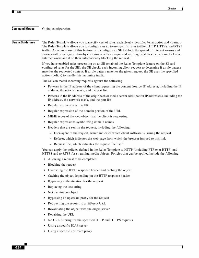
Chapter rule
Command Modes Global configuration
Usage Guidelines The Rules Template allows you to specify a set of rules, each clearly identified by an action and a pattern. The Rules Template allows you to configure an SE to use specific rules to filter HTTP, HTTPS, and RTSP traffic. A common use of this feature is to configure an SE to block the spread of Internet worms and viruses within an organization by checking whether a requested web page matches the pattern of a known Internet worm and if so then automatically blocking the request.
If you have enabled rules processing on an SE (enabled the Rules Template feature on the SE and configured rules for the SE), the SE checks each incoming client request to determine if a rule pattern matches the requested content. If a rule pattern matches the given request, the SE uses the specified action (policy) to handle this incoming traffic.
The SE can match incoming requests against the following:
• Patterns in the IP address of the client requesting the content (source IP address), including the IP address, the network mask, and the port list
• Patterns in the IP address of the origin web or media server (destination IP addresses), including the IP address, the network mask, and the port list
• Regular expression of the URL
• Regular expression of the domain portion of the URL
• MIME types of the web object that the client is requesting
• Regular expressions symbolizing domain names
• Headers that are sent in the request, including the following:
– User-agent of the request, which indicates which client software is issuing the request
– Referer, which indicates the web page from which the browser jumped to this link
– Request line, which indicates the request line itself
You can apply the policies defined in the Rules Template to HTTP (including FTP over HTTP) and HTTPS and to RTSP for streaming media objects. Policies that can be applied include the following:
• Allowing a request to be completed
• Blocking the request
• Overriding the HTTP response header and caching the object
• Caching the object depending on the HTTP response header
• Bypassing authentication for the request
• Replacing the text string
• Not caching an object
• Bypassing an upstream proxy for the request
• Redirecting the request to a different URL
• Revalidating the object with the origin server
• Rewriting the URL
• No URL filtering for the specified HTTP and HTTPS requests
• Using a specific ICAP server
• Using a specific upstream proxy
-234

Chapter rule
• Using a specific server for the request
Note To enter a question mark (?) in a rule regular expression from the command-line interface, use the escape character followed by a question mark (?). Use of the escape sequence prevents the command-line interface from displaying context-sensitive help.
Supported Rule Actions per Protocol
For RTSP, the redirect and the redirect_url_for_cdn rule actions are supported for RTSP requests from RealMedia players. These two rule actions are not supported for RTSP requests from Windows Media Players. For example, Windows Media Services 9 (WMS 9) supports the block, rewrite, and allow rule actions for RTSP requests, but does not support the redirect and redirect_url_for cdn rule actions for RTSP requests.
Supported Action and Pattern Combinations
Not all actions support all patterns for request matching because some patterns do not make sense for some actions.
Understanding Actions and Patterns
A rule is specified by an action and a pattern list. An action is performed on a request if this request matches the pattern list specified in the rule pattern-list command.
An action is something that the SE performs when processing a request; for instance, an action could be blocking the request, using an alternative proxy, and so forth.
A pattern list defines the limits of a request; for instance, a pattern list may specify that the source IP address falls in the subnet range 172.16.*.*.
Rules can be dynamically added, displayed, or deleted from the SE. The rules are preserved across reboots because they are written into persistent storage, such as NVRAM, using the appropriate CLI commands, the SE GUI, or the CDSM GUI. Only the system resources limit the number of rules that the SE can support. Because rules consume resources, the more rules that you define can greatly impact how the SE performs.
Note The number of actions is limited only by available resources. The maximum number of pattern lists is 512. The maximum number of patterns per action is 128. A single pattern list can contain up to 128 patterns of a particular pattern type.
Actions
The Rules Template supports the following types of actions:
• Allow—Allows incoming requests that match the pattern list.
This rule action can be used in combination with block actions to allow selective types of requests. Allow does not carry any meaning as a standalone action.
• Block—Blocks this request and allows all others.
• No-cache—Does not cache this object.
• Redirect—Redirects the original request to a specified URL. Redirect is relevant to the RADIUS server only if the RADIUS server has been configured for redirect.
• Refresh—For a cache hit, forces an object freshness check with the server.
• Replace—Replaces the text string in the object.
-235

Chapter rule
• Rewrite—Rewrites the original request as a specified URL. The SE searches for the rewritten URL in the cache, and then on a cache miss, fetches the rewritten URL and returns the object transparently to the client. You should use a redirect rule instead of a rewrite rule because of possible performance impacts. The reason for the performance impact is that, for a redirect rule, the SE sends a 302 (Found) message to the client with the new redirect URL. The client issues a separate request to the redirected URL. However, for a rewrite action, the original request URL is rewritten as the specified URL. The URL rewrite could change the domain name of the URL, which necessitates a Domain Name Server (DNS) lookup to find the destination IP address of the new rewritten server to which the request must be sent.
• Use-icap-service—Uses a specified ICAP server.
• Validate-url-signature—Validates a signed URL.
Actions can be applied to specific protocols or to a set of protocols. If no protocol is configured, then the specified action is taken for all the traffic that goes through the SE.
Patterns
The Rules Template supports the following pattern types:
• Domain—Matches the domain name in the URL or the Host header against a regular expression. For example, .*ibm.* matches any domain name that contains the ibm substring. The \.foo\.com$domain name matches any domain name that ends with the .foo.com substring.
Note In regular expression syntax, the dollar sign ($) metacharacter directs that a match is made only when the pattern is found at the end of a line.
• Group-type—Specifies whether the pattern list is an AND or OR type. The default is OR.
• Src-ip—Matches the request’s source IP address and netmask. Specify an IP address and a netmask.
• URL-regex—Matches the URL against a regular expression. The match is case insensitive. Specify a regular expression.
• Header-field—Matches the header field pattern of the request.
Request header field patterns referer, request-line, and user-agent are supported for the actions block, redirect, and rewrite. The referer pattern is matched against the Referer header in the request, the request-line pattern is matched against the first line of the request, and the user-agent pattern is matched against the User-Agent header in the request.
• URL-regsub—Matches the URL against a regular expression to form a new URL per pattern substitution specification for the rewrite and redirect actions. The match is case insensitive. The valid substitution index range is from 1 to 9.
If an empty string is given as a replacement pattern, the Referer header is stripped. Stripping of the Referer header occurs in the user-agent pattern.
Multiple patterns can be entered on the same pattern list. If any of them matches the incoming request, the corresponding action is taken.
Multiple patterns for the same pattern list must be entered on different lines.
Rules Template Processing Considerations
Actions and patterns have a predefined order of execution. A group of rules with the same action is always executed either before or after another group of rules with a different action. The block, rewrite, and redirect rule actions support the following additional patterns: request-line, referer, and user-agent regular expressions. The request-line regular expression matches the first line of the request.
-236

Chapter rule
The user-agent regular expression matches the User-Agent header value of the request. The referer regular expression matches the Referer header value of the request. The order is not affected by the order in which the rules are entered using CLI commands.
Allow and block carry the same precedence. The order of execution depends on the order of configuration between allow and block actions. Other actions always take precedence over allow.
Among rules of the same action, a predefined execution order exists among the rule patterns, which means that within a group of rules of the same action, one group of rules with the same pattern is always executed either before or after another group of rules with a different pattern.
Among all rules of the same action and of the same rules pattern, the rules are evaluated in a Last-Entered-First-Examined fashion (the reverse of the order in which the rules were entered). This order is not affected by the order in which the rules are entered using CLI commands.
Most actions do not have any parameters.
Service Rules for URLs
There are three cases for service rules:
1. If allow rules are configured, then it is an implicit deny.
2. If deny rules are configured then it is implicit allow.
3. If both allow and deny are configured, then it is an implicit allow.
For example, if all URL requests that match HTML are blocked, implicitly, all requests that match other URL requests are allowed.
If all URL requests that match WMV are allowed, implicitly, all request that match other URL requests are blocked.
If both of the above rules are configured, then HTML URL requests are blocked, and all other URL requests are allowed.
Examples The following example shows that the SE is configured to replace the internal.domain.com string in a request to the server named dummy:
ServiceEngine(config)# rule action rewrite header-field referer internal.domain.com dummy
The following example shows that if an empty string is given as a replacement pattern, then the referer header is stripped. This rule states that all requests, which have a referer header that indicates a corporate internal server in ABCBigCorp, strip the referer field so that the outside web server does not see the name of the corporate internal server.
ServiceEngine(config)# rule action rewrite header-field referer internal.abcbigcorp.com ""
The following example shows that the rule pattern-list command is configured to add a pattern to an existing pattern list to perform an action to be defined on destination IP address 172.16.25.25 using the dst-ip pattern:
ServiceEngine# show rule pattern-list 10 all Rules Template Configuration----------------------------Rule Processing Enabled
Pattern-Lists :
rule pattern-list 11 dst-ip 172.16.25.25 255.255.255.0rule pattern-list 11 domain foo.com
-237

Chapter rule
The following example shows that the rule action block command is configured and associated with an existing pattern list:
ServiceEngine(config)# rule action block pattern-list 10 protocol allServiceEngine# show rule action block Rules Template Configuration----------------------------Rule Processing Enabled
Actions :
rule action block pattern-list 10 protocol all
The following example shows that the rule action block command is configured and associated with an existing pattern list, which lists as its pattern the domain yahoo.com:
ServiceEngine(config)# rule pattern-list 10 domain yahoo.comServiceEngine# show rule pattern-list 10 allRules Template Configuration----------------------------Rule Processing Enabled
Pattern-Lists :
rule pattern-list 10 domain yahoo.comServiceEngine(config)# rule action block pattern-list 10 protocol all
In this example, the request (using HTTP) to yahoo.com was denied three times.
The following example shows that the rule action block command (action) blocks all patterns specified with the rule pattern-list 12 command:
ServiceEngine(config)# rule pattern-list 12 domain \.foo.comServiceEngine(config)# rule action block pattern-list 12ServiceEngine(config)#
The following example prevents caching of requests that match a URL request that contains the *cgi-bin* string:
ServiceEngine(config)# rule pattern-list 13 url-regex \.*cgi-bin.*ServiceEngine(config)# rule action no-cache pattern-list 13ServiceEngine(config)#
The actions that are to be taken by the rules are configured through the rule action commands. Patterns that are to be matched to a particular pattern that you specify are configured through rule pattern-list commands.
The following example shows how patterns use AND by configuring patterns with the same pattern list number and applying that pattern list to an action:
ServiceEngine(config)# rule action block pattern-list 1ServiceEngine(config)# rule pattern-list 1 url-regex yahooServiceEngine(config)# rule pattern-list 1 dst-port 80
Other options of the rule command work similarly to the preceding examples.
The following example redirects a request for old-domain-name that has been changed to new-domain-name:
Cache(config)# rule action redirect http://old-domain-name/ pattern-list 1 protocol httpCache(config)# rule pattern-list 1 url-regsub http://old-domain-name/ http://new-domain-name/
The following example redirects requests from an IETF site to a site that is locally mirrored:
-238

Chapter rule
Cache(config)# rule action redirect http://www.ietf.org/rfc/(.*) pattern-list 2 protocol http
The following example shows that if the request URL is http://www.ietf.org/rfc/rfc1111.txt, the SE rewrites the URL as http://wwwin-eng.cisco.com/RFC/RFC/rfc1111.txt and sends a 302 Temporary Redirect response with the rewritten URL in the Location header to the client. The browser automatically starts a request to the rewritten URL.
Cache(config)# rule pattern-list 2 url-regsub http://www.ietf.org/rfc/(.*) http://wwwin-eng.cisco.com/RFC/RFC/\1
The following example redirects all requests for linux.org to a local server in India that is closer to where the SE is located:
Cache(config)# rule action redirect http://linux.org/(.*) pattern-list 3 protocol http
The following example shows that two URLs are to be matched if the pattern is url-regsub. If the URLs that are given in the action configuration are invalid, a warning is displayed during the configuration of this rule. The action URL is taken when the header field patterns are configured.
Cache(config)# rule pattern-list 3 url-regsub http://linux.org/(.*) http://linux.org.in/\1
The following example bypasses requests with cisco.com as the domain from URL filtering:
ServiceEngine(config)# rule action no-url-filtering pattern-list 6 protocol allServiceEngine(config)# rule pattern-list 6 domain cisco.com
The following example enables the service rule to support Apple HLS:
SE(config)# rule enableSE(config)# rule action no-cache pattern-list 20SE(config)# rule pattern-list 20 url-regex .m3u8SE(config)#
Related Commands Command Description
clear Clears the HTTP object cache, the hardware interface, statistics, archive working transaction logs, and other settings.
show rule Displays rules configuration information.
-239

Chapter script
scriptTo execute a script provided by Cisco or check the script for errors, use the script command in EXEC configuration mode.
script {check | execute} file_name
Syntax Description
Defaults No default behavior or values
Command Modes EXEC
Usage Guidelines The script command in EXEC configuration mode opens the script utility, which allows you to execute scripts supplied by Cisco or check errors in those scripts. The script utility can read standard terminal input from the user if the script you run requires inputs from the user.
Note The script utility is designed to run only in scripts supplied by Cisco. You cannot execute script files that lack Cisco signatures or that have been corrupted or modified.
Examples The following example checks for errors in the script file foo.script:
ServiceEngine# script check foo.script
Script file foo.script is valid.
check Checks the validity of the script.
execute Executes the script. The script file must be a sysfs file in the current directory.
file_name Name of the script file.
-240

Chapter service-monitor
service-monitorTo configure service monitor parameters, use the service-monitor command in global configuration mode. To disable, use the no form of this command.
On the SE and CDSM:
service-monitor {number-of-samples {all num | cpu num | disk num | fms num | kmemory num | memory num | wmt num | nic num} | sample-period {all num | cpu num | disk num | fms num | kmemory num | memory num | movie-streamer num | nic num | webengine num | wmt num} | threshold {burstcnt num | cpu num | disk num | failcntdisk num | fms num | kmemory num | memory num | nic num | wmt num} | type {all | cpu | disk | fms | kmemory | memory | nic | wmt}}}
no service-monitor {number-of-samples {all num | cpu num | disk num | fms num | kmemory num | memory num | wmt num | nic num} | sample-period {all num | cpu num | disk num | fms num | kmemory num | memory num | movie-streamer num | nic num | webengine num | wmt num} | threshold {burstcnt num | cpu num | disk num | failcntdisk num | fms num | kmemory num | memory num | nic num | wmt num} | type {all | cpu | disk | fms | kmemory | memory | nic | wmt}}}
Syntax Description number-of-samples Counts the latest sampled values to be used when calculating average.
all Sets to all monitor types.
num Count of latest sampled values to be used when calculating average. The range is from 1 to 120.
cpu Enables the monitor CPU load.
disk Sets the disk monitor type.
fms Sets the FMS1 monitor type.
kmemory Sets the monitor kernel memory type.
memory Sets the monitor memory type.
wmt Sets the WMT2 monitor type.
nic Sets the Network Interface Card monitor type.
sample-period Configures the time interval, in seconds, between two consecutive samples.
num Time interval between two consecutive samples, in seconds. The range is from 1 to 160.
threshold Configures threshold values.
failcntdisk Sets the disk failure monitor type.
num The disk FailureCnt threshold value.
burstcnt Configures the Protocol Engine Burst License Control monitor type.
num Configures the Protocol Engine Burst License Control threshold value.
movie-streamer Sets the Movie Streamer monitor type.
type Configures the type to be monitored.
access-policy Configures the service-router access-policy.
enable Enables the access-policy.
cdn-select Configures the service-router cdn-select.
-241

Chapter service-monitor
config-file Not supported in this release.
name Not supported in this release.
content-based-routing Configures content based routing.
enable Enables content based routing.
redundant Specifies the number of redundant copies of the content.
num Number of redundant copies of the content. The range is from 1 to 4.
dns-ttl Configures TTL3 of DNS4 records issued by SR.
num Number of seconds. The range is from 1 to 60.
lastresort Configures the lastresort domain.
domain Configures the domain.
name Domain name.
allow Allows the client to be routed through an alternate domain or origin server.
all Allows all requests.
alternate Configures an alternate domain.
name Alternate domain name.
error-domain Configures error domain.
name Error domain name.
error-file Configures error file name.
name Error file name.
location-based-routing Configures location-based routing.
enable Enables location-based routing.
geo-location-server Configures geo5 location server IP address and port.
primary Configures the primary geo location server IP address and port.
ip address IP address of primary geo location server.
num Port number of primary geo location server.
secondary Configures the secondary geo location server IP address and port.
ip address IP address of secondary geo location server.
num Port number of secondary geo location server.
proximity-based-routing Configures proximity-based routing.
enable Enables proximity-based routing.
proximity-cache Configures proximity cache.
timeout Configures proximity cache timeout.
num Proximity cache timeout, in seconds. The range is from 1 to 86400.
proximity-server Configures proximity server IP address and port.
ip address IP address of proximity server.
redirect-burst-control Configures the redirect burst control.
enable Enables Redirect burst control.
rate Configures the redirect burst control rate (requests per second).
num Redirect burst control rate. The range is from 1 to 100000.
redirect-mode Enables the redirect mode. The redirect mode is disabled by default.
dns-redirect Sets the redirect mode to DNS-based redirection.
-242

Chapter service-monitor
Defaults keepalive-interval: 2
sample-period: 1
nic sample-period: 3
number of samples: 2
Command Modes Global configuration
Command History
Examples The following example shows how to configure the service monitor type:
ServiceEngine(config)# service-monitor type all
all Enables the DNS-based redirection for all domains.
domain Enables the DNS-based redirection for a specific domain.
domain Name of the domain.
ip-redirect Sets the redirect mode to IP-based redirection.
service-monitor Configures service monitor parameters.
number-of-samples Counts the latest sampled values to be used when calculating average.
all Allows all monitor types.
num Count of latest sampled values to be used when calculating average. The range is from 1 to 120.
cpu Sets the CPU monitor type.
disk Sets the disk monitor type.
kmemory Sets the monitor kernel memory.
memory Sets the monitor memory.
failcntdisk Sets the disk failure monitor type.
sample-period Configures the time interval between two consecutive samples.
threshold Configures threshold values.
type Configures the type to be monitored.
1. FMS = flash media server
2. WMT = windows media technology 3. TTL = time to live
4. DNS = domain name server
5. geo = geographical
ECDS Release Description
2.5.5 This command was changed from service-router service-monitor to service-monitor. See also the service-router command.
-243

Chapter service-monitor
Related Commands Command Description
show service-monitor Displays the Service Monitor configuration.
-244

Chapter service-router
service-routerTo configure service routing, use the service-router command in global configuration mode. To disable last-resort routing, use the no form of this command.
On the CDSM and SE:
service-router {keepalive-interval num}
no service-router {keepalive-interval num}
On the SR:
service-router {access-policy enable | cdn-select {config-file name | enable} | content-based-routing {enable | redundant} | dns-ttl num | lastresort {domain name {allow all | alternate name} | error-domain name error-file } | location-based-routing {enable | geo-location-server {primary ip address num | secondary ip address num}} | proximity-based-routing {enable | proximity-cache timeout num | proximity-server ip address} | redirect-burst-control {enable | rate num} | redirect-mode {dns-redirect {all | domain domain} | ip-redirect} | service-monitor {number-of-samples {all num | cpu num | disk num | kmemory num | memory num}} | sample-period {cpu num | disk num | failcntdisk num | kmemory num | memory num} | threshold {all num | cpu num | disk num | kmemory num | memory num} | type {all | cpu | disk | kmemory | memory}}
no service-router {access-policy enable | content-based-routing {enable | redundant} | dns-ttl num | lastresort {domain name {allow all | alternate name} | error-domain name error-file } | location-based-routing {enable | geo-location-server {primary ip address num | secondary ip address num}} | proximity-based-routing {enable | proximity-cache timeout num | proximity-server ip address} | redirect-burst-control {enable | rate num} | redirect-mode {dns-redirect {all | domain domain} | ip-redirect} | service-monitor {number-of-samples {all num | cpu num | disk num | kmemory num | memory num}} | sample-period {cpu num | disk num | failcntdisk num | kmemory num | memory num} | threshold {all num | cpu num | disk num | kmemory num | memory num} | type {all | cpu | disk | kmemory | memory}}
On the CDSM:
service-monitor {number-of-samples {all num | cpu num | disk num | kmemory num | memory num} | sample-period {all num | cpu num | disk num | kmemory num | memory num} | threshold {all num | cpu num | disk num | failcntdisk num | kmemory num | memory num} | type {all | cpu | disk | kmemory | memory}}
no service-monitor {number-of-samples {all num | cpu num | disk num | kmemory num | memory num} | sample-period {all num | cpu num | disk num | kmemory num | memory num} | threshold {all num | cpu num | disk num | failcntdisk num | kmemory num | memory num} | type {all | cpu | disk | kmemory | memory}}
Syntax Description keepalive-interval Specifies the SR keepalive interval in seconds.
num Number of seconds. The range is from 1 to 120.
service-monitor Configures Service Monitor related parameters.
license-universal Universal license feature to clear all alarms for Protocol Engines.
enable Enables the universal license feature.
-245

Chapter service-router
number-of-samples Counts the latest sampled values to be used when calculating average.
all Sets to all monitor types.
num Count of latest sampled values to be used when calculating average. The range is from 1 to 120.
cpu Enables the monitor CPU load.
disk Sets the disk monitor type.
fms Sets the FMS1 monitor type.
kmemory Sets the monitor kernel memory type.
memory Sets the monitor memory type.
wmt Sets the WMT2 monitor type.
nic Sets the Network Interface Card monitor type.
sample-period Configures the time interval, in seconds, between two consecutive samples.
num Time interval between two consecutive samples, in seconds. The range is from 1 to 160.
threshold Configures threshold values.
burstcnt Configures the Protocol Engine Burst License Control monitor type.
num Configures the Protocol Engine Burst License Control threshold value.
failcntdisk Sets the disk failure monitor type.
num The disk FailureCnt threshold value.
movie-streamer Sets the Movie Streamer monitor type.
type Configures the type to be monitored.
access-policy Configures the service-router access-policy.
enable Enables the access-policy.
cdn-select Configures the service-router cdn-select.
config-file Not supported in this release.
name Not supported in this release.
content-based-routing Configures content based routing.
enable Enables content based routing.
redundant Specifies the number of redundant copies of the content.
num Number of redundant copies of the content. The range is from 1 to 4.
dns-ttl Configures TTL3 of DNS4 records issued by SR.
num Number of seconds. The range is from 1 to 60.
lastresort Configures the lastresort domain.
domain Configures the domain.
name Domain name.
allow Allows the client to be routed through an alternate domain or origin server.
all Allows all requests.
alternate Configures an alternate domain.
name Alternate domain name.
error-domain Configures error domain.
-246

Chapter service-router
name Error domain name.
error-file Configures error file name.
name Error file name.
location-based-routing Configures location-based routing.
enable Enables location-based routing.
geo-location-server Configures geo5 location server IP address and port.
primary Configures the primary geo location server IP address and port.
ip address IP address of primary geo location server.
num Port number of primary geo location server.
secondary Configures the secondary geo location server IP address and port.
ip address IP address of secondary geo location server.
num Port number of secondary geo location server.
proximity-based-routing Configures proximity-based routing.
enable Enables proximity-based routing.
proximity-cache Configures proximity cache.
timeout Configures proximity cache timeout.
num Proximity cache timeout, in seconds. The range is from 1 to 86400.
proximity-server Configures proximity server IP address and port.
ip address IP address of proximity server.
redirect-burst-control Configures the redirect burst control.
enable Enables Redirect burst control.
rate Configures the redirect burst control rate (requests per second).
num Redirect burst control rate. The range is from 1 to 100000.
redirect-mode Enables the redirect mode. The redirect mode is disabled by default.
dns-redirect Sets the redirect mode to DNS-based redirection.
all Enables the DNS-based redirection for all domains.
domain Enables the DNS-based redirection for a specific domain.
domain Name of the domain.
ip-redirect Sets the redirect mode to IP-based redirection.
service-monitor Configures service monitor parameters.
number-of-samples Counts the latest sampled values to be used when calculating average.
all Allows all monitor types.
num Count of latest sampled values to be used when calculating average. The range is from 1 to 120.
cpu Sets the CPU monitor type.
disk Sets the disk monitor type.
kmemory Sets the monitor kernel memory.
memory Sets the monitor memory.
failcntdisk Sets the disk failure monitor type.
sample-period Configures the time interval between two consecutive samples.
threshold Configures threshold values.
type Configures the type to be monitored.
-247

Chapter service-router
Defaults keepalive-interval: 2
redundant copies: 1
dns-ttl: 60
proximity cache timeout: 1800
sample-period: 1
nic sample-period: 3
number of samples: 2
Command Modes Global configuration
Usage Guidelines To configure last-resort routing, use the service-router command in global configuration mode, where domain is the service routing domain name, and alternate is where to route requests.
Last-resort routing is applicable when load-based routing is enabled and all SEs have exceeded their thresholds or all SEs in the domain are offline. The SR can redirect requests to a configurable alternate domain when all SEs serving a client network region are overloaded.
Note If the last-resort domain is not configured and the SE thresholds are exceeded, requests are redirected to the origin server.
Location-Based-Routing
The Geo-Location servers were introduced with the location-based routing method in Cisco ECDS software. Once you enable location-based routing, you must specify the Geo-Location servers.
The Authorization Service uses an XML file to allow or deny client requests based on the client's IP address or geographic location. The country, state, and city names in the Authorization XML file must match what is used by the Geo-Location server and the names are case sensitive.
Crossdomain Support
When a client requests the content from a portal and the content then makes a request to a different remote domain (or origin server), the request cannot be served unless the origin server or the remote domain has a crossdomain.xml that grants access to the original portal to continue with the streaming.
For example, a client request for abc.com/streaming.html (which has the content), makes a request for cds-origin.com/vod/sample.flv (which is a different domain), then the client must request a crossdomain.xml. The crossdomain.xml allows access to abc.com and can then stream sample.flv. If the cds-origin.com does not have crossdomain.xml, then the request is denied.
1. FMS = flash media server
2. WMT = windows media technology 3. TTL = time to live
4. DNS = domain name server
5. geo = geographical
-248

Chapter service-router
Note In the case of Flash, the request is made for crossdomain.xml. In the case of Silverlight the request is made for clientaccesspolicy.xml.
Instead of directly going to cds-origin.com, the request first comes to the Service Router. So when the request for crossdomain.xml comes to the Service Router, it is served to the client. This xml grants access to the portal for the file requested. So the client then sends the request for the file which is served.
Note For Silverlight the client access policy is requested only when web service calls are made. Depending on the client player, for both Silverlight and Flash applications, the clientaccesspolicy.xml and crossdomain.xml need to be provisioned on the origin server.
FLVPlaybackComponent does not currently crossdomain requests for video files. The crossdomain request is issued only when a query string is present. In such cases, the video gets downloaded but does not play.
The number of the HTTP Requests (normal) in Request Received (“show statistics service-router summary”) should increase.
Examples The following example shows how to configure the keepalive interval:
ServiceRouter(config)# service-router keepalive-interval 2
The following example shows how to configure the service monitor type:
ServiceRouter(config)# service-monitor type all
Crossdomain Support
The following example shows how to enable crossdomain support:
ServiceEngine(config)# service-router access-policy enable
The following example shows how to disable crossdomain support:
ServiceEngine(config)# no service-router access-policy enable
The following example enables DNS-based redirection with the cdsfms.com domain as the domain used to redirect all client requests to:
ServiceRouter(config)# service-router redirect-mode dns-redirect domain cdsfms.com
The following example displays information about the redirect mode by entering the show service-router redirect-mode command:
ServiceRouter# show service-router redirect-modeip-redirect is enableddns-redirect domain fms.cds.comdns-redirect domain cds.comdns-redirect domain abc.comdns-redirect domain cdsfms.com
To display the statistics, use the show statistics service-router summary command and the show statistics se sename command. The new output for the DNS-Based Redirection feature is highlighted in boldface type in the examples below. In addition to these two show commands, there is also the show statistics service-router dns command, which displays the same output as before:
ServiceRouter# show statistics service-router summary
-249

Chapter service-router
----- SR Summary Statistics -----
Requests Received : 2 HTTP Requests (normal) : 0 HTTP Requests (ASX) : 0 RTSP Requests : 0 RTMP Requests : 0 DNS Requests : 2
Requests Served : 0 HTTP Requests Served : 0
Requests Redirected : 1 HTTP 302 Redirects : 0 ASX Redirects : 0 RTSP redirects : 0 RTMP redirects : 0 DNS redirects : 1
Requests Overflowed : 1 HTTP 302 Redirects : 0 ASX Redirects : 0 RTSP redirects : 0 RTMP redirects : 0 DNS redirects : 1
Requests Not Redirected : 0 No SE Covering Client : 0 Unknown Content Origin : 0 Route Table Locked : 0
"Stale SE" Requests : 0
ServiceRouter# show statistics service-router se temp2
----- Statistics Of SE: temp2 -----IP Address : 2.225.2.59Aliveness : upHTTP 302 Redirects : 0ASX Redirects : 0RTSP Redirects : 0RTMP Redirects : 0DNS Redirects : 1Number Of Keepalives : 85261
Related Commands Command Description
show service-router Displays the Service Router configuration.
-250

Chapter service snmp restart
service snmp restart To restart snmp service when required, use the service snmp restart command in EXEC mode.
service snmp restart
Syntax Description This command has no arguments or keywords.
Defaults No default behavior or values
Command Modes EXEC
Examples SE# service snmp restartThe service snmpced has been restarted successfully!
setupTo configure basic configuration settings (general settings, device network settings, and disk configuration) on the SE and a set of commonly used caching services, use the setup command in EXEC configuration mode. You can also use the setup command in EXEC configuration mode to complete basic configuration after upgrading.
setup
Syntax Description This command has no arguments or keywords.
Defaults No default behavior or values
Command Modes EXEC
Examples The following example shows the part of the output when you enter the setup command in EXEC configuration mode on an SE running the ECDS software:
ServiceEngine# setup
Here is the current profile of this device
CDN device : Yes
Do you want to change this (y/n) [ n ] :
-251

Chapter setup
Press the ESC key at any time to quit this session
-252

Chapter show access-lists 300
show access-lists 300To display the access control list (ACL) configuration, use the show access-lists 300 command in EXEC configuration mode.
show access-lists 300
Syntax Description This command has no arguments or keywords.
Command Default No default behavior or values
Command Modes EXEC
Examples Table 3-12 describes the fields shown in the show access-lists 300 display.
Related Commands
Table 3-12 show access-lists Field Descriptions
Field Description
Access Control List is enabled
Configuration status of the access control list.
Groupname and username-based List
Lists the group name-based access control lists.
Command Description
access-lists Configures access control list entries.
-253

Chapter show acquirer
show acquirerTo display the acquirer information and progress of content acquisition for a specified channel number or name, use the show acquirer command in EXEC configuration mode.
show acquirer [delivery-service {delivery-service-id delivery-service-id | delivery-service-name delivery-service-name} | progress {delivery-service-id delivery-service-id | delivery-service-name delivery-service-name} | proxy authentication]
Syntax Description
Defaults No default behavior or values
Command Modes EXEC
Usage Guidelines The show acquirer progress command displays information for all channels for which the SE is the Content Acquirer. It displays the number of acquired objects in relation to the total number of objects for both a single item or crawler jobs. When an acquisition is in progress, it displays the number of data bytes currently being downloaded in relation to the total size of the object and its URL. The show acquirer progress command also displays information about the authentication that allows the acquirer to access content through a transparent or nontransparent proxy server.
The show acquirer proxy authentication command displays the proxy authentication configuration for the acquirer if you have enabled content acquisition through a proxy server and proxy authentication is configured. Use the acquirer proxy authentication outgoing command in global configuration mode to configure authentication when you enable content acquisition through a proxy server. You must first configure the proxy host and the port using the http proxy outgoing host command in global configuration mode.
When you enable content acquisition through a proxy server, you can provide the proxy configuration and proxy authentication information in the manifest file. If the proxy and proxy authentication are configured in the manifest file, the show acquirer proxy authentication command does not display any proxy details.
Examples The show acquirer progress command in EXEC configuration mode displays the progress of the acquirer for a specified channel. If a specific channel is not mentioned, the display shows the progress for all the channels for which the SE is the root.
delivery-service (Optional) Displays acquirer information for the delivery service.
delivery-service-id Displays the ID for the delivery service.
delivery-service-id Delivery service ID.
delivery-service-name Displays the name for the delivery service.
delivery-service-name Delivery service name.
progress (Optional) Displays the acquisition progress for the specified channel.
proxy (Optional) Displays the proxy information for the acquirer.
authentication (Optional) Displays the proxy authentication details for the acquirer.
-254

Chapter show acquirer
Table 3-13 describes the fields shown in the show acquirer progress display.
The following example shows the output from the show acquirer proxy authentication command when there are no proxies configured using the acquirer proxy authentication command in global configuration mode:
ServiceEngine# show acquirer proxy authenticationNo proxy authentication information configured
The following example shows the output from the show acquirer proxy authentication command after configuring the proxy using the acquirer proxy authentication command in global configuration mode:
ServiceEngine# show acquirer proxy authenticationacquirer proxy authentication outgoing 172.28.225.29 8080 admin password **** My-Domain basic-auth-disable acquirer proxy authentication transparent admin password **** My-Domain basic-auth-disable
Related Commands
Table 3-13 show acquirer progress Field Descriptions
Field Description
Channel-id Numerical identifier for the channel.
Channel-Name Name for the channel.
Acquired Single Items
Total number of single items completed out of all the single items specified in the manifest. For example, 200/301 shows that all 200 items out of a total of 301 items have been acquired.
Acquired Crawl Items Total number of links with crawling completed out of the total crawlable items for each crawling task specified in the manifest, along with the starting URL.
Download Size (Bytes)
Current URL fetched by the acquirer for the channel, if applicable, along with the file size details.
Command Description
acquirer (global configuration)
Provides authentication when the acquirer obtains content through a proxy server.
http Configures HTTP-related parameters.
show statistics acquirer
Displays SE acquirer channel statistics.
-255

Chapter show alarms
show alarmsTo display information on various types of alarms, their status, and history, use the show alarms command in EXEC configuration mode.
show alarms [critical [detail [support]] | detail [support] | history [[start_num [end_num [detail [support]] | detail [support]]] | critical [start_num [end_num [detail [support]] | detail [support]]] | detail [support] | major [start_num [end_num [detail [support]] | detail [support]]] | minor [start_num [end_num [detail [support]]] | detail [support]]] | major [detail [support]] | minor [detail [support]] | status]
Syntax Description
Defaults No default behavior or values
Command Modes EXEC
Usage Guidelines The Node Health Manager enables CDS applications to raise alarms to draw attention to error or significant conditions. The Node Health Manager, which is the data repository for such alarms, aggregates the health and alarm information for the applications, services (for example, the cache service), and resources (for example, disk drives) that are being monitored on the SE. For example, the Node Health Manager gives you a mechanism to determine if a monitored application (for example, the HTTP proxy caching service) is alive on the SE. These alarms are referred to as ECDS software alarms.
The ECDS software uses SNMP to report error conditions by generating SNMP traps. In the ECDS software, the following SE applications can generate an ECDS software alarm:
• Node Health Manager (alarm overload condition and Node Manager aliveness)
• Node Manager for service failures (aliveness of monitored applications)
• System Monitor (sysmon) for disk failures
critical (Optional) Displays critical alarm information.
detail (Optional) Displays detailed information for each alarm.
support (Optional) Displays additional information about each alarm.
history (Optional) Displays information about the history of various alarms.
start_num (Optional) Alarm number that appears first in the alarm history.
end_num (Optional) Alarm number that appears last in the alarm history.
major (Optional) Displays information about major alarms.
minor (Optional) Displays information about minor alarms.
status (Optional) Displays the status of various alarms and alarm overload settings.
-256

Chapter show alarms
The three levels of alarms in the ECDS software are as follows:
• Critical—Alarms that affect the existing traffic through the SE and are considered fatal (the SE cannot recover and continue to process traffic).
• Major—Alarms that indicate a major service (for example, the cache service) has been damaged or lost. Urgent action is necessary to restore this service. However, other node components are fully functional and the existing service should be minimally impacted.
• Minor—Alarms that indicate that a condition that will not affect a service has occurred but corrective action is required to prevent a serious fault from occurring.
You can configure alarms using the snmp-server enable traps alarm command in global configuration mode.
Use the show alarms critical command in EXEC configuration mode to display the current critical alarms being generated by the ECDS software applications. Use the show alarms critical detail command in EXEC configuration mode to display additional details for each of the critical alarms being generated. Use the show alarms critical detail support command in EXEC configuration mode to display an explanation about the condition that triggered the alarm and how you can find out the cause of the problem. Similarly, you can use the show alarms major and show alarms minor command in EXEC configuration modes to display the details of major and minor alarms.
Use the show alarms history command in EXEC configuration mode to display a history of alarms that have been raised and cleared by the ECDS software on the SE. The ECDS software retains the last 100 alarm raise and clear events only.
Use the show alarm status command in EXEC configuration mode to display the status of current alarms and the SE’s alarm overload status and alarm overload configuration.
Examples Table 3-14 describes the fields shown in the show alarms history display.
Table 3-15 describes the fields shown in the show alarms status display.
Table 3-14 show alarms history Field Descriptions
Field Description
Op Operation status of the alarm. Values are R—Raised or C—Cleared.
Sev Severity of the alarm. Values are Cr—Critical, Ma—Major, or Mi—Minor.
Alarm ID Type of event that caused the alarm.
Module/Submodule Software module affected.
Instance Object that this alarm event is associated with. For example, for an alarm event with the Alarm ID disk_failed, the instance would be the name of the disk that failed. The Instance field does not have pre-defined values and is application specific.
Table 3-15 show alarms status Field Descriptions
Field Description
Critical Alarms Number of critical alarms.
Major Alarms Number of major alarms.
Minor Alarms Number of minor alarms.
-257

Chapter show alarms
Related Commands
Overall Alarm Status Aggregate status of alarms.
Device is NOT in alarm overload state.
Status of the device alarm overload state.
Device enters alarm overload state @ 999 alarms/sec.
Threshold number of alarms per second at which the device enters the alarm overload state.
Device exits alarm overload state @ 99 alarms/sec.
Threshold number of alarms per second at which the device exits the alarm overload state.
Overload detection is enabled. Status of whether overload detection is enabled on the device.
Table 3-15 show alarms status Field Descriptions (continued)
Field Description
Command Description
alarm overload-detect Detects alarm overload situations.
snmp-server enable traps
Enables the SE to send SNMP traps.
-258

Chapter show arp
show arpTo display the Address Resolution Protocol (ARP) table, use the show arp command in EXEC configuration mode.
show arp
Syntax Description This command has no arguments or keywords.
Defaults No default behavior or values
Command Modes EXEC
Examples The show arp command displays the Internet-to-Ethernet address translation tables of the Address Resolution Protocol. Without flags, the current ARP entry for the hostname is displayed.
Table 3-16 describes the fields shown in the show arp display.
Table 3-16 show arp Field Descriptions
Field Description
Protocol Type of protocol.
Address Ethernet address of the hostname.
Flags Current ARP flag status.
Hardware Addr Hardware Ethernet address given as six hexadecimal bytes separated by colons.
Type Type of wide-area network.
Interface Type of Ethernet interface.
-259

Chapter show authentication
show authenticationTo display the authentication configuration, use the show authentication command in EXEC configuration mode.
show authentication user
Syntax Description
Defaults No default behavior or values
Command Modes EXEC
Related Commands
user Displays the authentication configuration for the user login to the system.
Command Description
authentication Specifies authentication and authorization methods.
clear Clears the HTTP object cache, the hardware interface, statistics, archive working transaction logs, and other settings.
show statistics authentication
Displays SE authentication statistics.
-260

Chapter show authsvr
show authsvrTo display the status of the Authorization server, use the show authsvr command in EXEC configuration mode.
show authsvr [unknown-server | location-server]
Syntax Description
Defaults No default behavior or values
Command Modes EXEC
Examples The following example shows the status of the Authorization server:
ServiceEngine# show authsvrAuthserver is Enabled
The following example shows the status of the Location server:
ServiceEngine# show authsvr location-server Primary geo location server 4.0.1.3 7000 Secondary geo location server 171.71.50.140 7000
Related Commands
unknown-server (Optional) Shows the allow and deny rule for unknown configured servers or domains.
location-server (Optional) Shows the Location server configuration. It includes both primary and secondary geo location server information.
Command Description
authsvr Enables and configures the Authorization server.
-261

Chapter show bandwidth
show bandwidthTo display the bandwidth allocated to a particular device, use the show bandwidth command in EXEC configuration mode.
show bandwidth [flash-media-streaming | movie-streamer | wmt]
Syntax Description
Defaults No default behavior or values
Command Modes EXEC
Examples Table 3-17 describes the fields shown in the show bandwidth display.
flash-media-streaming (Optional) Displays the Flash Media Streaming bandwidth settings.
movie-streamer (Optional) Displays the Movie Streamer bandwidth settings.
wmt (Optional) Displays Windows Media Technology (WMT) bandwidth settings.
Table 3-17 show bandwidth Field Descriptions
Field Description
Module Types of application servers for which bandwidth allocation is displayed:
• wmt incoming is for incoming WMT streaming content requests from end users.
• wmt outgoing is for outgoing WMT media from SEs.
• movie-streamer incoming is for incoming Movie Streamer content requests from end users.
• movie-streamer outgoing is for outgoing Movie Streamer media from SEs.
• flash-media-streaming is for Flash Media Streaming.
Bandwidth Kbps Maximum amount of bandwidth that you want allowed in kbps1 for a particular period of time. Incoming and outgoing bandwidth enforced is 8000000 kbps.
Start Time Time of the day for the bandwidth rate setting to begin, using a 24-hour clock in local time on the SE (hh:mm).
End Time Time of the day for the bandwidth rate setting to end, using a 24-hour clock in local time on the SE (hh:mm).
-262

Chapter show bandwidth
Related Commands
Default Bandwidth Kbps Amount of default bandwidth (in kbps). The default bandwidth is the amount of bandwidth associated with each content service type when there is no scheduled bandwidth.
Max Bandwidth Kbps Maximum bandwidth (in kbps) permitted by the system license. This bandwidth specifies the upper limit of allowable bandwidth.
1. kbps = kilobits per second
Table 3-17 show bandwidth Field Descriptions (continued)
Field Description
Command Description
bandwidth (global configuration)
Sets an allowable bandwidth usage limit and its duration for Cisco Streaming Engine WMT streaming media.
-263

Chapter show banner
show bannerTo display information on various types of banners, use the show banner command in EXEC configuration mode.
show banner
Syntax Description This command has no arguments or keywords.
Defaults No default behavior or values
Command Modes EXEC
Examples Table 3-18 describes the fields shown in the show banner display.
Related Commands
Table 3-18 show banner Field Descriptions
Field Description
Banner is enabled. Configuration status of the banner feature.
MOTD banner is: abc Displays the configured message of the day.
Login banner is: acb Displays the configured login banner.
Exec banner is: abc Displays the configured EXEC banner.
Command Description
banner Configures the EXEC, login, and message-of-the-day (MOTD) banners.
-264

Chapter show bitrate
show bitrateTo display the bit rate allocated to a particular device, use the show bitrate command in EXEC configuration mode.
show bitrate [movie-streamer | wmt]
Syntax Description
Defaults No default behavior or values
Command Modes EXEC
Examples Table 3-19 describes the fields shown in the show bitrate display.
Related Commands
movie-streamer (Optional) Displays the Movie Streamer bit rate settings.
wmt (Optional) Displays Windows Media Technology (WMT) bit rate settings.
Table 3-19 show bitrate Field Descriptions
Field Description
Module Types of application servers for which the bit rate is displayed:
• wmt outgoing is the maximum bit rate per WMT stream that can be served by the SE.
• wmt incoming is the maximum bit rate per WMT stream that can be received by the SE.
• movie-streamer outgoing is the maximum bit rate per streamer that can be served by the SE.
• movie-streamer incoming is the maximum bit rate per streamer that can be received by the SE.
Default Bitrate Kbps Bit rate associated with the application servers when the bit rate has not been configured on the SE.
Configured Bitrate Kbps Bit rate configured on the SE in kilobits per second.
Command Description
bitrate Configures the maximum pacing bit rate for large files for the Movie Streamer and separately configures WMT bit-rate settings.
-265

Chapter show bypass
show bypassTo display bypass configuration information, use the show bypass EXEC command.
show bypass [list | statistics {auth-traffic | load} | summary | settings]
Syntax Description
Defaults No default behavior or values
Command Modes EXEC
Usage Guidelines The total number of bypass entries is equal to the number of dynamic bypass entries plus the number of static bypass entries, which is equal to 4960. The maximum number of static bypass entries is 50.
Examples Table 3-20 describes the fields shown in the show bypass display.
list (Optional) Specifies the bypass list entries.
settings (Optional) Displays timer setting information.
statistics (Optional) Specifies the IP bypass statistics. Enter the following:
• auth-traffic—Displays authentication bypass statistics.
• load—Displays load bypass statistics.
summary (Optional) Specifies the summary of bypass information.
Table 3-20 show bypass Field Descriptions
Field Description
Total number of HTTP connections bypassed
Total number of HTTP connections bypassed.
Connections bypassed due to system overload
Number of connections bypassed due to system overload.
Connections bypassed due to authentication issues
Number of connections bypassed due to authentication issues.
Connections bypassed to facilitate error transparency
Number of connections bypassed to facilitate error transparency.
Connections bypassed due to static configuration
Number of connections bypassed due to static configuration.
Total number of entries in the bypass list Total number of entries in the bypass list.
Number of Authentication bypass entries Number of authentication bypass entries.
Number of Error bypass entries Number of error bypass entries.
Number of Static Configuration entries Number of static configuration entries.
-266

Chapter show bypass
Table 3-21 describes the fields shown in the show bypass list display.
The show bypass statistics authsvr EXEC command displays authentication traffic bypass statistics.
Table 3-22 describes the fields shown in the command display.
The show bypass statistics load command displays overload bypass statistics.
Table 3-23 describes the fields shown in the command display.
Table 3-21 show bypass list Field Descriptions
Field Description
Client IP address and port of the client. For any client with this IP address, the WAE will not process the packet, but will bypass it and send it back to the router.
Server IP address and port of the server.
Entry type Type of bypass list entry. The Entry type field contains one of the following values: static-config, auth-traffic, server-error, or accept.
A static-config entry is a bypass list entry that is user-configured. An auth-traffic entry is a type of dynamic entry that the internal software adds automatically when the server requests authentication.
Table 3-22 show bypass statistics auth-traffic Field Descriptions
Field Description
Authentication Bypass Statistics
HTTP connections bypassed due to authentication
Number of HTTP connections bypassed due to authentication.
Number of authentication bypass entries
Number of authentication bypass entries.
Table 3-23 show bypass statistics load Field Descriptions
Field Description
Load Bypass Statistics
Load Bypass is enabled Configuration status for load bypass.
System bypass mode - not available Availability status of system bypass mode.
Number of bypassed buckets not available
Number of bypassed buckets when system bypass mode is available.
Number of bypassed connections not available
Number of bypassed connections when system bypass mode is available.
Number of transitions from Bypass mode to Normal mode
Number of transitions from bypass mode to normal mode.
Number of transitions from Normal mode to Bypass mode
Number of transitions from normal mode to bypass mode.
MODULE Name of the module.
Normal Number of bypassed connections in normal mode.
-267
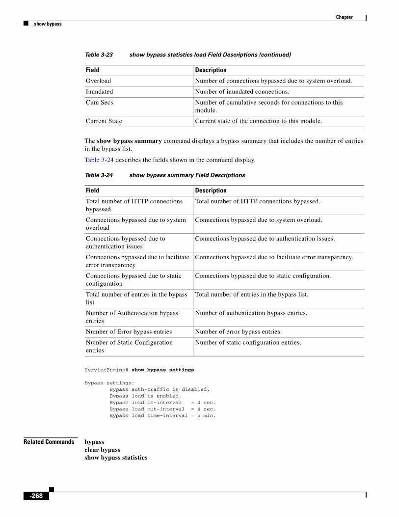
Chapter show bypass
The show bypass summary command displays a bypass summary that includes the number of entries in the bypass list.
Table 3-24 describes the fields shown in the command display.
ServiceEngine# show bypass settings
Bypass settings: Bypass auth-traffic is disabled. Bypass load is enabled. Bypass load in-interval = 2 sec. Bypass load out-interval = 4 sec. Bypass load time-interval = 5 min.
Related Commands bypassclear bypassshow bypass statistics
Overload Number of connections bypassed due to system overload.
Inundated Number of inundated connections.
Cum Secs Number of cumulative seconds for connections to this module.
Current State Current state of the connection to this module.
Table 3-23 show bypass statistics load Field Descriptions (continued)
Field Description
Table 3-24 show bypass summary Field Descriptions
Field Description
Total number of HTTP connections bypassed
Total number of HTTP connections bypassed.
Connections bypassed due to system overload
Connections bypassed due to system overload.
Connections bypassed due to authentication issues
Connections bypassed due to authentication issues.
Connections bypassed due to facilitate error transparency
Connections bypassed due to facilitate error transparency.
Connections bypassed due to static configuration
Connections bypassed due to static configuration.
Total number of entries in the bypass list
Total number of entries in the bypass list.
Number of Authentication bypass entries
Number of authentication bypass entries.
Number of Error bypass entries Number of error bypass entries.
Number of Static Configuration entries
Number of static configuration entries.
-268

Chapter show cache
show cacheTo display a list of cached contents, use the show cache command in EXEC configuration mode.
show cache [content num]
Syntax Description
Defaults Number of cached contents is 100.
Command Modes EXEC
Usage Guidelines The show cache command allows users to check the cached content in an SE. Users can also view the priority, size, and URL information through this command.
Examples The following example shows the cached contents:
ServiceEngine# show cache content 1000Max-cached-entries is set as 1000Number of cal cached assets: 12------------------------------------------------Priority Size URL------------------------------------------------1.09887e+00 16 rtsp://72.163.255.118/c.wmv1.04340e+00 416 rtsp://72.163.255.118/c.wmv.Ui4HeLMPgB5lLH_+bo2d.03.bmp6.71782e-01 957 rtsp://72.163.255.118/c.wmv.hdr5.74964e-01 16 rtsp://72.163.255.118/4.wmv5.60340e-01 664997 rtsp://72.163.255.118/c.wmv.Ui4HeLMPgB5lLH_+bo2d.033.15230e-01 665107 http://72.163.255.118/c.wmv2.39938e-01 5409 rtsp://72.163.255.118/4.wmv.hdr2.02040e-01 35256 rtsp://72.163.255.118/4.wmv.rPgfTr1Lo0dT6FJWaxDs.03.bmp1.59027e-01 873664 http://72.163.255.118/4.flv1.45368e-01 3603032 http://72.163.255.118/b.wmv1.23161e-01 70517409 rtsp://72.163.255.118/4.wmv.rPgfTr1Lo0dT6FJWaxDs.037.88076e-02 29180088 http://72.163.255.118/4.wmv
Related Commands
content Displays a list of cached contents in order of decreasing priority.
num Specifies number of cached contents to be displayed. The range is from 1 to 1000.
Command Description
cache Configures the cached content maximum entries in the CDS.
-269

Chapter show capability
show capabilityTo display the capabilities of the Cap-X profile ID, use the show capability command in EXEC configuration mode.
show capability profile ID profile ID
Syntax Description
Defaults No default behavior or values
Command Modes EXEC
Related Commands
profile ID Displays information for the Cap-X profile.
profile ID Profile ID number. The range is from 1 to 65535.
Command Description
capability Modifies the capability configuration.
-270

Chapter show cdn-select
show cdn-selectCDN Selector is not supported in this release.
-271

Chapter show cdnfs
show cdnfsTo display CDS network file system (cdnfs) information, use the show cdnfs command in EXEC configuration mode.
show {cdnfs volumes | usage}
Syntax Description
Defaults No default behavior or values
Command Modes EXEC
Examples Table 3-25 describes the fields shown in the show cdnfs volumes display.
Related Commands
volumes Displays CDS network file system volumes.
usage Displays Content Delivery Network (CDN) current usage.
Table 3-25 show cdnfs volumes Field Descriptions
Field Description
cdnfs 00–04 CDS network file system and disk number.
nnnnnnKB Size of the volume in kilobytes.
Command Description
cdnfs Manages the ECDS network file system (cdnfs).
disk (EXEC) Configures disks and allocates disk space for devices that are using the CDS software.
show disks Displays the names of the disks currently attached to the SE.
show statistics cdnfs Displays SE CDS network file system (cdnfs) statistics.
-272

Chapter show clock
show clockTo display the system clock, use the show clock command in EXEC configuration mode.
show clock [detail | standard-timezones {all | details timezone | regions | zones region-name}]
Syntax Description
Defaults No default behavior or values
Command Modes EXEC
Usage Guidelines The CDS has several predefined standard time zones. Some of these time zones have built-in summertime information while others do not. For example, if you are in an eastern region of the United States (US), you must use the US/Eastern time zone that includes summertime information and adjusts the clock automatically every April and October. There are about 1500 standard time zone names.
The clock summertime command is disabled when a standard time zone is configured. You can only configure summertime if the time zone is not a standard time zone (if the time zone is a customized zone).
In addition, CLI commands exist to enable you to display a list of all the standard time zones. The show clock standard-timezones all command in EXEC configuration mode enables you to browse through all standard time zones and choose from these predefined time zones. You can choose a customized name that does not conflict with the predefined names of the standard time zones. Most predefined names of the standard time zones have two components, a region name and a zone name. You can list time zones by several criteria, such as regions and zones.
detail (Optional) Displays detailed information; indicates the Network Timing Protocol (NTP) clock source and the current summer time setting (if any).
standard-timezones (Optional) Displays information about the standard time zones.
all Displays all the standard time zones (approximately 1500 time zones). Each time zone is listed on a separate line.
details Displays detailed information for the specified time zone.
timezone Name of the time zone.
regions Displays the region name of all the standard time zones. All 1500 time zones are organized into directories by region.
zones Displays the name of every time zone that is within the specified region.
region-name Name of the region.
-273

Chapter show clock
Examples Table 3-26 describes the field in the show clock display.
Table 3-27 describes the fields shown in the show clock detail display.
The following example shows an excerpt of the output from the show clock standard-timezones all command in EXEC configuration mode. As the following example shows, all the standard time zones (approximately 1500 time zones) are listed. Each time zone is listed on a separate line.
ServiceEngine # show clock standard-timezones allAfrica/AbidjanAfrica/AccraAfrica/Addis_AbabaAfrica/AlgiersAfrica/AsmeraAfrica/BamakoAfrica/BanguiAfrica/BanjulAfrica/BissauAfrica/BlantyreAfrica/BrazzavilleAfrica/BujumburaAfrica/CasablancaAfrica/CeutaAfrica/ConakryAfrica/DakarAfrica/Dar_es_SalaamAfrica/Djibouti...
The following example shows an excerpt of the output from the show clock standard-timezones region command in EXEC configuration mode. As the example shows, all first level time zone names or directories are listed. All 1500 time zones are organized into directories by region.
ServiceEngine # show clock standard-timezones regionsAfrica/America/Antarctica/Arctic/Asia/Atlantic/Australia/
Table 3-26 show clock Field Description
Field Description
Local time Day of the week, month, date, time (hh:mm:ss), and year in local time relative to the UTC offset.
Table 3-27 show clock detail Field Descriptions
Field Description
Local time Local time relative to UTC.
UTC time Coordinated Universal Time (UTC) date and time.
Epoch Number of seconds since Jan. 1, 1970.
UTC offset UTC offset, in seconds, hours, and minutes.
-274

Chapter show clock
Brazil/CET...
The following example shows an excerpt of the output from the show clock standard-timezones zones command in EXEC configuration mode. As the following example shows, this command lists the name of every time zone that is within the specified region (for example, the US region).
ServiceEngine # show clock standard-timezones zones USAlaskaAleutianArizonaCentralEast-IndianaEasternHawaiiIndiana-StarkeMichiganMountainPacificSamoa
The following example shows an excerpt of the output from the show clock standard-timezones details command in EXEC configuration mode. This command shows details about the specified time zone (for example, the US/Eastern time zone). The command output also includes the standard offset from the Greenwich mean time (GMT).
ServiceEngine # show clock standard-timezones details US/EasternUS/Eastern is standard timezone.Getting offset information (may take a while) ...Standard offset from GMT is -300 minutes (-5 hour(s)).It has built-in summertime.Summer offset from GMT is -240 minutes. (-4 hour(s)).
Related Commands Command Description
clock (EXEC) Sets or clears clock functions or updates the calendar.
clock (global configuration
Sets the summer daylight saving time and time zone for display purposes.
-275

Chapter show cms
show cmsTo display the Centralized Management System (CMS) embedded database content and maintenance status and other information, use the show cms command in EXEC configuration mode.
show cms {database {content {dump filename | text | xml} | maintenance [detail]} | info | processes}
Syntax Description
Defaults No default behavior or values
Command Modes EXEC
Examples Table 3-28 describes the fields shown in the CDSM show cms info display.
database Displays embedded database maintenance information.
content Writes the database content to a file.
dump Dumps all database content to a text file.
filename Name of the file to be saved under local1 directory.
text Writes the database content to a file in text format.
xml Writes the database content to a file in XML format.
maintenance Shows the current database maintenance status.
detail (Optional) Displays database maintenance details and errors.
info Displays CMS application information.
processes Displays CMS application processes.
Table 3-28 show cms Field Descriptions for the CDSM
Field Description
CDN information
Model Model name of the device.
Node Id Unique identifier given to the device by the CDSM at registration, which is used to manage the device.
Device Mode Configured mode of device used during registration.
Current CDSM role Role of the current CDSM: Primary or Standby.
CMS services information
Service cms_httpd is running
Status of the cms_httpd management service (running or not running). This field is specific to the CDSM only.
Service cms_cdsm is running
Status of the cms_cdsm management service (running or not running). This field is specific to the CDSM only.
-276

Chapter show cms
Table 3-29 describes the fields shown in the SE show cms info display.
The following example writes the database content to a file in text format:
CDSM# show cms database content text Database content can be found in /local1/cms-db-12-12-2002-17:06:08:070.txt.
The following example writes the database content to a file in XML format:
CDSM# show cms database content xml Database content can be found in /local1/cms-db-12-12-2002-17:07:11:629.xml.
The following example shows the output of the show cms database maintenance detail on an SE:
ServiceEngine# show cms database maintenance detailDatabase maintenance is not running.Regular database maintenance is enabled.Regular database maintenance schedule is set on Sun, Mon, Tue, Wed, Thu, Fri, Sat at 02:00Full database maintenance is enabled.Full database maintenance schedule is set on Sun, Mon, Tue, Wed, Thu, Fri, Sat at 04:00Disk usage for STATE partition: Total: 1523564K, Available: 1443940K, Use: 6%
DATABASE VACUUMING DETAILS AND ERRORS-------------------------------------Database Vacuuming never performed or it did not complete due to error.Latest Vacuuming status :No ErrorLast Vacuum Error : No ErrorLast Reindex Time : Thu Jul 15 02:02:49 2004Latest Reindexing status :No ErrorLast Reindex Error: No ErrorServiceEngine#
Related Commands
Table 3-29 show cms Field Descriptions for the SE
Field Description
CDN information
Model Model name of the device.
Node Id Unique identifier given to the device by the CDSM at registration, which is used to manage the device.
Device Mode Configured mode of device used during registration.
Current CDSM address Address of the CDSM as currently configured in the cdsm ip command in global configuration mode. This address may differ from the registered address if a standby CDSM is managing the device instead of the primary CDSM with which the device is registered.
Registered with CDSM Address of the CDSM with which the device is registered.
Status Connection status of the device to the CDSM. This field may contain one of three values: Online, Offline, or Pending.
Time of last config-sync Time when the device management service last contacted the CDSM for updates.
Command Description
cms (EXEC) Configures the CMS embedded database parameters.
cms (global) Schedules maintenance and enables the CMS on a given node.
-277
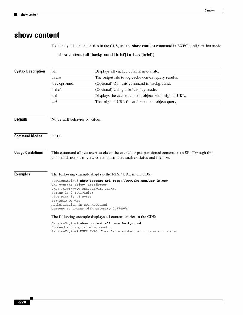
Chapter show content
show contentTo display all content entries in the CDS, use the show content command in EXEC configuration mode.
show content {all [background | brief] | url url [brief]}
Syntax Description
Defaults No default behavior or values
Command Modes EXEC
Usage Guidelines This command allows users to check the cached or pre-positioned content in an SE. Through this command, users can view content attributes such as status and file size.
Examples The following example displays the RTSP URL in the CDS:
ServiceEngine# show content url rtsp://www.cht.com/CHT_2M.wmvCAL content object attributes:URL: rtsp://www.cht.com/CHT_2M.wmvStatus is 2 (Servable)File size is 16 BytesPlayable by WMTAuthorization is Not RequiredContent is CACHED with priority 0.574964
The following example displays all content entries in the CDS:
ServiceEngine# show content all name backgroundCommand running in background...ServiceEngine# USER INFO: Your 'show content all' command finished
all Displays all cached content into a file.
name The output file to log cache content query results.
background (Optional) Run this command in background.
brief (Optional) Using brief display mode.
url Displays the cached content object with original URL.
url The original URL for cache content object query.
-278

Chapter show debugging
show debuggingTo display the state of each debugging option, use the show debugging user command in user EXEC configuration mode.
show debugging [ip {bgp | ospf | rib} | isis | srp]
Syntax Description
Command Default No default behavior or values
Command Modes User EXEC
Usage Guidelines The show debugging ip bgp command is used to display the debugging flags that have been set for BGP.
The show debugging ip ospf command is used to display debug options for OSPF processes that are enabled.
The show debugging ip rib command is used to display debug options for rib processes that are enabled.
The show debugging isis command is used to display debug options for IS-IS processes that are enabled.
The show debugging srp command is used to displays the debug flags that are turned on for the SRP.
Examples The following is sample output from the show debugging ip bgp command:
ServiceRouter# debug ip bgp keepalivesServiceRouter# show debugging ip bgpBGP keepalives debug is onServiceRouter# debug ip bgp allServiceRouter# show debugging ip bgpBGP events debug is onBGP internal debug is onBGP RIB debug is onBGP BRIB debug is onBGP updates debug is onBGP keepalives debug is onBGP packets debug is onBGP IO debug is onBGP list debug is onBGP dampening debug is on
ip (Optional) Displays the debug options for IP.
bgp Displays the debugging flags that have been set for BGP.
ospf Displays the debug options for OSPF processes that are enabled.
rib Displays the debug options that are enabled for the rib process.
isis (Optional) Displays the debug options that are enabled for the IS-IS process.
srp (Optional) This command displays the debug flags that are turned on for the SRP.
-279

Chapter show debugging
ServiceRouter#
The following is sample output from the show debugging ip ospf command:
ServiceRouter# show debugging ip ospf
All OSPF debug is onAdjacency events debug is onOSPF LSDB changes debug is onOSPF LSDB timers debug is onOSPF related events debug is onLSA flooding debug is on
ServiceRouter#
The following is sample output from the show debugging isis command.
ServiceRouter# show debugging isis
SRP error debug is onSRP api debug is onSRP multicast debug is onSRP session debug is onSRP srhp packet debug is onSRP replica debug is onSRP packet asiii debug is onSRP function debug is onSRP replay is on
ServiceRouter#
The following example shows the use of show srp debug command:
ServiceRouter# show debugging srp
SRP packet debug is onSRP error debug is onSRP database debug is onSRP api debug is onSRP host debug is onSRP multicast packet debug is onSRP session debug is onSRP srhp packet debug is onSRP replica debug is onSRP sync debug is onSRP configuration debug is onSRP ippc debug is onSRP packet ascii debug is onSRP function debug is on
ServiceRouter#
In the following example, the debug icp client command coupled with the show debugging command shows that Internet Cache Protocol (ICP) debugging is enabled:
ServiceEngine# debug icp client ServiceEngine# show debuggingDebug icp (client) is on
-280

Chapter show debugging
Related Commands Command Description
debug Monitors and records caching application functions.
undebug Disables debugging functions.
-281

Chapter show device-mode
show device-modeTo display the configured or current mode of a device, use the show device-mode command in EXEC configuration mode.
show device-mode {configured | current}
Syntax Description
Defaults No default behavior or values
Command Modes EXEC
Usage Guidelines If the configured and current device modes differ, a reload is required for the configured device mode to take effect.
Examples The configured device mode field in the show device-mode configured display shows the device mode that has been configured, but has not yet taken effect. The current device mode field in the show device-mode current command display shows the current mode in which the CDS device is operating.
The following example shows how to use the show device-mode command to show the device mode when you change the device from an SE to an SR using the device mode command:
Acmehost# show device-mode currentCurrent device mode: service-engineAcmehost# show device-mode configuredConfigured device mode: service-engineAcmehost(config)# device mode service-routerThe new configuration will take effect after a reloadAcmehost(config)# exitAcmehost# show device-mode currentCurrent device mode: service-engineNote: The configured and current device modes differ,a reload is required for the configured device mode totake effect.Acmehost# show device-mode configuredConfigured device mode: service-routerNote: The configured and current device modes differ,a reload is required for the configured device mode totake effect.Acmehost# write memoryAcmehost# reload force...reload...
Acmehost# show running-configdevice mode service-router!hostname Acmehost
configured Displays the configured device mode.
current Displays the current device mode.
-282

Chapter show device-mode
..
Acmehost# show device-mode configuredConfigured device mode: service-routerAcmehost# show device-mode currentCurrent device mode: service-router
Related Commands Command Description
device Configures the mode of operation on a device as a CDSM, SE or SR.
-283

Chapter show direct-server-return
show direct-server-returnTo display the Direct Server return information, use the show direct-server-return command in EXEC configuration mode.
show direct-server-return
Syntax Description This command has no keywords or arguments.
Defaults No default behavior or values
Command Modes EXEC
Examples The following example displays the Direct Server return information:
ServiceEngine# show direct-server-returndirect-server-return vip 11.11.11.11
Related Commands Command Description
direct-server-return Enables a VIP for direct server return.
-284

Chapter show disks
show disksTo view information about your disks, use the show disks command in EXEC configuration mode.
show disks [current | details | raid-state | SMART-info [details]]
Syntax Description
Defaults No default behavior or values
Command Modes EXEC
Usage Guidelines The show disks command displays the names of the disks currently attached to the SE.
Proactively Monitoring Disk Health with SMART
The ability to proactively monitor the health of disks with Self Monitoring, Analysis, and Reporting Technology (SMART) was added. SMART provides you with hard drive diagnostic information and information about impending disk failures.
SMART is supported by most disk vendors and is a standard method used to determine the health of a disk. SMART has several read-only attributes (for example, the power-on hours attribute, the load and unload count attribute) that provide the CDS software with information about the operating and environmental conditions that may indicate an impending disk failure.
To display more detailed information, enter the show disks SMART-info details command in EXEC configuration mode. The output from the show disks SMART-info and the show disks SMART-info details commands differ based on the disk vendor and the type of drive technology (Integrated Drive Electronics [IDE], Small Computer Systems Interface [SCSI], and Serial Advanced Technology Attachment [SATA] disk drives).
Even though SMART attributes are vendor dependent, there is a common way of interpreting most SMART attributes. Each SMART attribute has a normalized current value and a threshold value. When the current value exceeds the threshold value, the disk is considered as failed. The CDS software monitors the SMART attributes and reports any impending failure through syslog messages, SNMP traps, and alarms.
The output from the show tech-support command in EXEC configuration mode also includes SMART information.
Examples Table 3-30 describes the fields shown in the show disks details display.
current (Optional) Displays currently effective configurations.
details (Optional) Displays currently effective configurations with more details.
raid-state (Optional) Shows the volume and progress information for the RAID disks.
SMART-info (Optional) Displays hard drive diagnostic information and information about impending disk failures.
details (Optional) Shows SMART disk monitoring info with more details.
-285
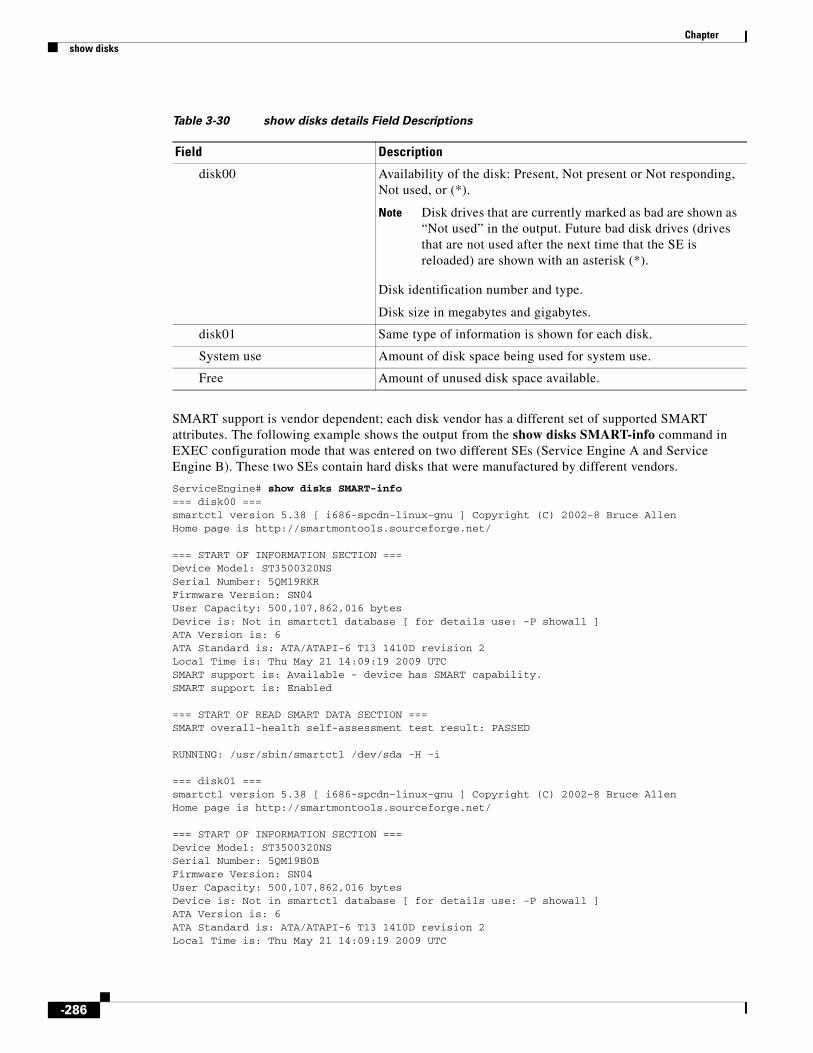
Chapter show disks
SMART support is vendor dependent; each disk vendor has a different set of supported SMART attributes. The following example shows the output from the show disks SMART-info command in EXEC configuration mode that was entered on two different SEs (Service Engine A and Service Engine B). These two SEs contain hard disks that were manufactured by different vendors.
ServiceEngine# show disks SMART-info=== disk00 ===smartctl version 5.38 [ i686-spcdn-linux-gnu ] Copyright (C) 2002-8 Bruce AllenHome page is http://smartmontools.sourceforge.net/
=== START OF INFORMATION SECTION ===Device Model: ST3500320NSSerial Number: 5QM19RKRFirmware Version: SN04User Capacity: 500,107,862,016 bytesDevice is: Not in smartctl database [ for details use: -P showall ] ATA Version is: 6ATA Standard is: ATA/ATAPI-6 T13 1410D revision 2Local Time is: Thu May 21 14:09:19 2009 UTCSMART support is: Available - device has SMART capability.SMART support is: Enabled
=== START OF READ SMART DATA SECTION ===SMART overall-health self-assessment test result: PASSED
RUNNING: /usr/sbin/smartctl /dev/sda -H -i
=== disk01 ===smartctl version 5.38 [ i686-spcdn-linux-gnu ] Copyright (C) 2002-8 Bruce AllenHome page is http://smartmontools.sourceforge.net/
=== START OF INFORMATION SECTION ===Device Model: ST3500320NSSerial Number: 5QM19B0BFirmware Version: SN04User Capacity: 500,107,862,016 bytesDevice is: Not in smartctl database [ for details use: -P showall ] ATA Version is: 6ATA Standard is: ATA/ATAPI-6 T13 1410D revision 2Local Time is: Thu May 21 14:09:19 2009 UTC
Table 3-30 show disks details Field Descriptions
Field Description
disk00 Availability of the disk: Present, Not present or Not responding, Not used, or (*).
Note Disk drives that are currently marked as bad are shown as “Not used” in the output. Future bad disk drives (drives that are not used after the next time that the SE is reloaded) are shown with an asterisk (*).
Disk identification number and type.
Disk size in megabytes and gigabytes.
disk01 Same type of information is shown for each disk.
System use Amount of disk space being used for system use.
Free Amount of unused disk space available.
-286

Chapter show disks
SMART support is: Available - device has SMART capability.SMART support is: Enabled
=== START OF READ SMART DATA SECTION ===SMART overall-health self-assessment test result: PASSED
RUNNING: /usr/sbin/smartctl /dev/sdb -H -i
=== disk02 ===smartctl version 5.38 [ i686-spcdn-linux-gnu ] Copyright (C) 2002-8 Bruce AllenHome page is http://smartmontools.sourceforge.net/
=== START OF INFORMATION SECTION ===Device Model: ST3500320NSSerial Number: 5QM19SK9Firmware Version: SN04User Capacity: 500,107,862,016 bytesDevice is: Not in smartctl database [ for details use: -P showall ] ATA Version is: 6ATA Standard is: ATA/ATAPI-6 T13 1410D revision 2Local Time is: Thu May 21 14:09:19 2009 UTCSMART support is: Available - device has SMART capability.SMART support is: Enabled
=== START OF READ SMART DATA SECTION ===SMART overall-health self-assessment test result: PASSED
RUNNING: /usr/sbin/smartctl /dev/sdc -H -i
Table 3-31 describes some typical fields in the show disks SMART-info display.
The following example shows the output from the show disks raid-state command, which shows all the disk partitions on an MDE:
ServiceEngine# #show disks raid-stateSYSFS : RAID-1 Status: Normal Partitions: disk00/05 disk02/05SYSTEM: RAID-1 Status: Normal
Table 3-31 show disks SMART-info Field Descriptions
Field Description
disk00—disk05 Shows information for disk drives.
Device Model Vendor number and version number of the disk.
Serial Number Serial number for the disk.
Device type Type of device.
Transport protocol Physical layer connector information, for example: Parallel SCSI (SPI-4).
Local time is Day of the week, month, date, time (hh:mm:ss), year, clock standard.
Device supports SMART and SMART is Enabled
Status of SMART support: Enabled or Disabled.
Temperature Warning Enabled Temperature warning status: Enabled or Disabled.
SMART Health Status: Health status of the disk: OK or Failed.
-287

Chapter show disks
Partitions: disk00/01 disk02/01SYSTEM: RAID-1 Status: Normal Partitions: disk00/02 disk02/02SYSTEM: RAID-1 Status: Normal Partitions: disk00/04 disk02/04
Related Commands Command Description
disk (EXEC) Configures disks and allocates disk space for devices that are using the CDS software.
-288

Chapter show distribution
show distributionTo display the distribution information for a specified delivery service and to probe a remote SE for the liveness of its associated delivery service, use the show distribution command in EXEC configuration mode.
show distribution [delivery-services {delivery-service-id delivery-service-num | delivery-service-name delivery-service-name}]
show distribution [forwarder-list {delivery-service-id delivery-service-num | delivery-service-name delivery-service-name} | detail]
show distribution [location {forwarder-load-weight | live-load-weight | location-leader-preference} {delivery-service-id delivery-service-num | delivery-service-name delivery-service-name}]
show distribution [object-status object-url]
show distribution [processes]
show distribution [remote ip-address {metadata-sender delivery-service-id delivery-service-num [start-generation-id gen-id end-generation-id gen-id] | unicast-sender delivery-service-id delivery-service-num {cdn-url cdn_url | probe | relative-cdn-url cdn_url}}]
show distribution [remote traceroute {forwarder-next-hop delivery-service-id delivery-service-num {max-hop maxhop_num | trace-till-good | trace-till-root} | unicast-sender delivery-service-id delivery-service-num {cdn-url cdn-url | probe | relative-cdn-url cdn-url} {max-hop maxhop_num | trace-till-good | trace-till-root}}]
Syntax Description delivery-services (Optional) Displays information about the specified delivery service.
delivery-service-id (Optional) Specifies the delivery service ID.
delivery-service-num Delivery service number (64-bit number).
delivery-service-name (Optional) Specifies the delivery service name.
delivery-service-name Delivery service name.
forwarder-list (Optional) Displays the forwarder lists for all delivery services subscribed to by the SE.
detail (Optional) Displays detailed forwarder lists for all delivery services subscribed to by the SE.
location (Optional) Displays delivery service routing-related parameters for the SEs in the location (specified by the delivery service ID).
forwarder-load- weight
Displays the forwarder load weight value of the SEs in the location (specified by the delivery service ID). For more information, see the “Forwarder Probability” section on page -291.
live-load-weight Displays the live load weight value of the SEs in the location (specified by the delivery service ID). For more information, see the “Live Splitting Probability” section on page -293.
-289

Chapter show distribution
Defaults No default behavior or values
Command Modes EXEC
location-leader-preference
Displays the location leader preference value of the SEs in the location (specified by the delivery service ID). For more information, see the “Location Leader Preference” section on page -292.
object-status (Optional) Displays information on the status of a prepositioned object.
object-url URL of the prepositioned object.
processes (Optional) Displays information on distribution processes.
remote (Optional) Displays delivery service information about a remote SE.
ip-address IP address of the remote SE.
metadata-sender Displays the metadata from a remote SE.
start-generation-id (Optional) Specifies the beginning database value of the current version of the multicast cloud.
gen_id Beginning database value.
end-generation-id Specifies the ending database value of the current version of the multicast cloud.
gen_id Ending database value.
unicast-sender Displays the unicast data from a remote SE.
cdn-url Checks the object on a remote SE using the specified URL.
cdn_url CDS network URL used to check the object on a remote SE.
probe Probes the remote unicast sender.
relative-cdn-url Checks the object on a remote SE using the specified URL.
traceroute Displays the traceroute for the delivery service routing status.
forwarder-next-hop Displays the next forwarder in the path for the SE.
Note This keyword lets you display the forwarding SEs to the Content Acquirer in a manner similar to the traceroute command.
delivery-service-id Specifies the delivery service ID with which the unicast sender is associated.
delivery-service-num Delivery service number of the delivery service with which the unicast sender is associated.
max-hop Displays the maximum number of hops needed to reach the unicast sender.
maxhop_num Maximum number of hops. The range is from 1 to 1024.
trace-till-good Allows the device to trace the route of an object until the object is found.
trace-till-root Allows the device to trace the route of an object until the device reaches the Content Acquirer.
-290

Chapter show distribution
Usage Guidelines Use the show distribution remote ip-address metadata-sender delivery-service-id delivery-service-num [start-generation-id gen_id end-generation-id gen_id] command option to retrieve the metadata from a remote SE assigned to a specified delivery service ID. The start and end generation IDs specify the beginning and ending database values representing the current version of the multicast cloud stored in the local database.
Note Generation IDs must be greater than zero. Also, you must specify both the start and the end generation IDs, or neither ID.
The show distribution remote ip-address unicast-sender delivery-service-id delivery-service-num relative-cdn-url cdn-url command shows the status of the relative CDS network URL of an object at a remote SE assigned to a specified delivery service ID. A relative CDS network URL is one that lacks the prefix of the protocol and hostname. For example, the relative CDS network URL for http://www.mycompany.com/abc.def.html is abc.def.html.
Use the show distribution remote ip-address unicast-sender delivery-service-id delivery-service-num probe command to probe a remote SE for the liveness of the delivery service to which it is assigned.
The show distribution object-status object-url command can be used to display the properties of a pre-positioned object.
You can view the location leader preference and forwarder weight for the SE using the show distribution command. However, you can configure the location leader preference and forwarder weight only using the CDSM GUI for each SE. Default values are assumed if you do not manually configure them.
The show distribution location forwarder-load-weight command displays the probability of SEs assigned to the delivery service within the location being selected as a forwarder. The show distribution location location-leader-preference command displays the location leader preference value of SEs that are assigned to the delivery service within the location.
Use the show distribution delivery-services command to view the forwarder for the SEs. If a receiver SE is unable to find its forwarder SE, one of the following reasons is displayed in the Status/Reason column of the output of the show distribution delivery-services command:
• LLMT—Home SE cannot find the forwarder because the home SE has a limit on the forwarder lookup level.
• FAIL—Home SE cannot find the forwarder because there is a failed SE along the path within the specified forwarder lookup level.
• NGWT—Home SE cannot find the forwarder because there is an SE with a negative forwarder-load-weight along the path within the specified forwarder lookup level.
Forwarder Probability
When an SE (location leader) selects its forwarder from an upstream location, it uses the forwarderLoad-weight value configured for each SE in its upstream location. The weight value of each SE corresponds to the probability of the SE being selected as the forwarder.
Each SE generates a unique random number. When an SE needs to select an inter-location forwarder, it views all the SEs in one remote location as a collection, with the size corresponding to their weight. It uses the generated random number to select an SE as a forwarder. SEs with a higher weight are more likely to be selected as forwarders.
-291

Chapter show distribution
Note The forwarderLoad-weight value represents a probabilistic value. When a large number of children SEs select a forwarder from a location, the load on the forwarder represents the weight.
The load on the forwarder is the replication load per delivery service on the SE because all SEs subscribed to the delivery service select a forwarder to balance the load. However, as the number of SEs assigned to different delivery services might differ, a forwarder might receive requests for content from SEs in other delivery services, which increases the load. Therefore, it is possible that the total load (of replicating content) on the forwarder does not reflect the weight but depends on the number of SEs assigned to a delivery service.
Location Leader Preference
For intra-location (list of SEs in an SE’s own location) forwarder selection, the delivery service routing algorithm first creates an ordered list of the SEs based on their location leader-preference in a descending order. Next, the delivery service routing algorithm selects the first SE in the ordered list as the location leader.
When multiple SEs have the same location leader-preference, the delivery service routing algorithm guarantees that all the SEs assigned to each delivery service in the location still generate the same ordered list, which avoids routing loops. A routing loop is a deadlock situation in which the forwarder selection among multiple SEs within the loop prevents the SEs from receiving the content from upstream locations. For example, SE1 uses SE2 as the forwarder and SE2 uses SE1 as the forwarder for the same delivery service.
However, for two different delivery services, the ordered list could be different (when multiple SEs have the same location leader probability value) even if the subscribed SEs are the same. When multiple SEs have the highest location leader-preference, although each SE has an equal chance of acting as the location leader (for different delivery services), only one SE always acts as the location leader for one particular delivery service. If you configure all the SEs in your network to have the same location leader-preference value, then each SE has an equal chance of acting as a location leader. When each SE has an equal probability of being selected as the location leader for any particular delivery service, only one particular SE is always selected as the location leader.
Note If there are two SEs in the same location (SE1, SE2) and both of them are assigned to two delivery services (CH1, CH2), and if you want SE1 to be the location leader for CH1 and SE2 to be the location leader for CH2, you cannot configure them using location leader-preference and forwarderLoad-weight.
In a location, you can specify the probability for each SE acting as the location leader. The specification is delivery service independent.
The following limitations are associated with specifying a location leader preference:
• When multiple SEs are configured with the same location leader-preference value and assigned to a delivery service, they have an equal probability of being selected as the location leader. In such a case, you do not have a control mechanism to decide which SE should be selected as the location leader.
• Only the order among the SEs with the highest preference is randomized to determine the location leader preference and not other SEs with the same preference value. It is possible that if the SE(s) with the highest preference failed and there are several other SEs with the second highest preference value, they are not balanced across the different delivery services. The same SE is the location leader for all delivery services.
-292

Chapter show distribution
• If an SE with a high location leader-preference is assigned to many delivery services, it is possible that the SE can be selected as the location leader for all these delivery services.
Live Splitting Probability
Similar to the delivery service routing application used for content replication that assigns weight and priority to SEs to tune location leader and forwarder selections, you can specify a configuration parameter liveSplit-load-weight for each SE. This parameter represents the relative probability that an SE is likely to receive live stream splitting traffic as compared to other SEs. The specification is delivery service independent. If you do not configure liveSplit-load-weight, the algorithm should work as it currently does.
A weighted load balancing scheme splits the live stream load on the SEs according to the liveSplit-load-weight value because SEs of different types have an equal probability of being selected as the splitting SE on the location path.
The liveSplit-load-weight is used when the delivery service routing generates the ordered list of SEs for each location. The SEs are ordered in a way that the higher the weight, the greater probability that the SEs are being ordered at the beginning of the list.
The weight represents a relative value. The liveSplit-load-weight assigned to one SE is compared against the weights of other SEs in the same location.
The weight is a probabilistic value. For one particular URL, all SEs generate the same ordered list for a location.
It is possible that an SE with a lower weight is being ordered at the beginning while an SE with a higher weight is being ordered at the end of the list. The weighted load balancing is useful only when there are multiple live stream URLs.
The liveSplit-load-weight parameter applies both within the home location and upstream locations. This setting is different from the distribution settings where locationLeader-priority controls how you choose SEs from the home location, while forwarderLoad-weight controls how you choose SEs from upstream locations.
Examples The following example shows the status of the object at a remote SE with the IP address 172.16.2.160 and delivery service ID 631. The URL of the content object specified in the command must not be the complete source URL. Instead, it must be the relative CDS network URL of the object.
ServiceEngine# show distribution remote 172.16.2.160 unicast-sender delivery-service-id 631 relative-cdn-url 101files/100.txt Forwarder-Name : AD-SE08 Forwarder-ID : 140 Forwarder IP : 2.43.10.70 Forwarder Location : default-locationRelative CDN URL : 101files/100.txt Actual Size : 58 Size Transferred : 58 Resource-ID : roVe2aMzp+YhmbhGUfMPpQ Content-ID : 7LC5xOlMp4YvkBJlHaQucQLast Modified Time : 10:52:38 Jan 04 2005
The following example retrieves the metadata from a remote SE with the IP address 172.16.2.160 assigned to delivery service ID 4999:
ServiceEngine# show distribution remote 172.16.2.160 metadata-sender delivery-service-id 4999 Getting meta data for delivery service(4999) from genid -1 to 2
-293

Chapter show distribution
Connecting to 2.43.10.101Remote SE replied with the following headers: Action : Processing metadata records Latest Gen id is : 2 Have more records to process : No Is metadata still in full reload: Noadd-size: 2, del-size: 0 Add Logs: 1 to 2 add # 1: UBsSUMwbTdJzzpqDvxSdYg.., basic_auth/public.html add # 2: NJyVL9CZwpnyCfw+Is26yw.., index.txt
The following example probes the remote SE with the IP address 172.16.2.160 for the liveness of its assigned delivery service ID 153:
ServiceEngine# show distribution remote 172.16.2.160 unicast-sender delivery-service-id 153 probeProbe Successful
The following example shows the beginning database value of the current version of the multicast cloud at a remote SE with the IP address 10.43.10.101 and delivery service ID 4999:
ServiceEngine# show distribution remote 10.43.10.101 metadata-sender delivery-service-id 4999 start-generation-id 0 end-generation-id 5Getting meta data for delivery service(4999) from genid -1 to 5Connecting to 10.43.10.101Remote SE replied with the following headers: Action : Processing metadata records Latest Gen id is : 2 Have more records to process : No Is metadata still in full reload: Noadd-size: 2, del-size: 0 Add Logs: 1 to 2 add # 1: UBsSUMwbTdJzzpqDvxSdYg.., basic_auth/public.html add # 2: NJyVL9CZwpnyCfw+Is26yw.., index.txt
Note When start and end generation IDs are not specified in the show distribution remote command, the current maximum generation ID of –100 is the start generation ID. The end generation ID is equal to the sum of the start generation ID and 100.
The following example shows the list of forwarders in the path toward the Content Acquirer:
ServiceEngine# show distribution remote traceroute forwarder-next-hop delivery-service-id 4999 trace-till-root Hop NextHop_SEId NextHop_SEName NextHop_SEIp GenID Status/Reason--- ------------ -------------- ------------ ----- ------------- 1 5884 AD-SE07 192.168.1.69 1 REGULAR 2 6035 AD-SE13 2.43.10.101 1 LOC-LEAD 3 5683 AD-SE12 2.43.10.100 1 LOC-LEAD 4 6026 gnadaraj-507 2.43.27.2 1 LOC-LEAD 5 5638 devi-507 2.43.27.36 1 LOC-LEAD (Reached RootSE)
The following example shows output from the show distribution object-status command:
ServiceEngine# show distribution object-status http://www.cisco.com/index.txt ========== Website Information ========== Name : cisco-crawlOrigin Server FQDN : www.cisco.comRequest Routed FQDN : N/A
-294
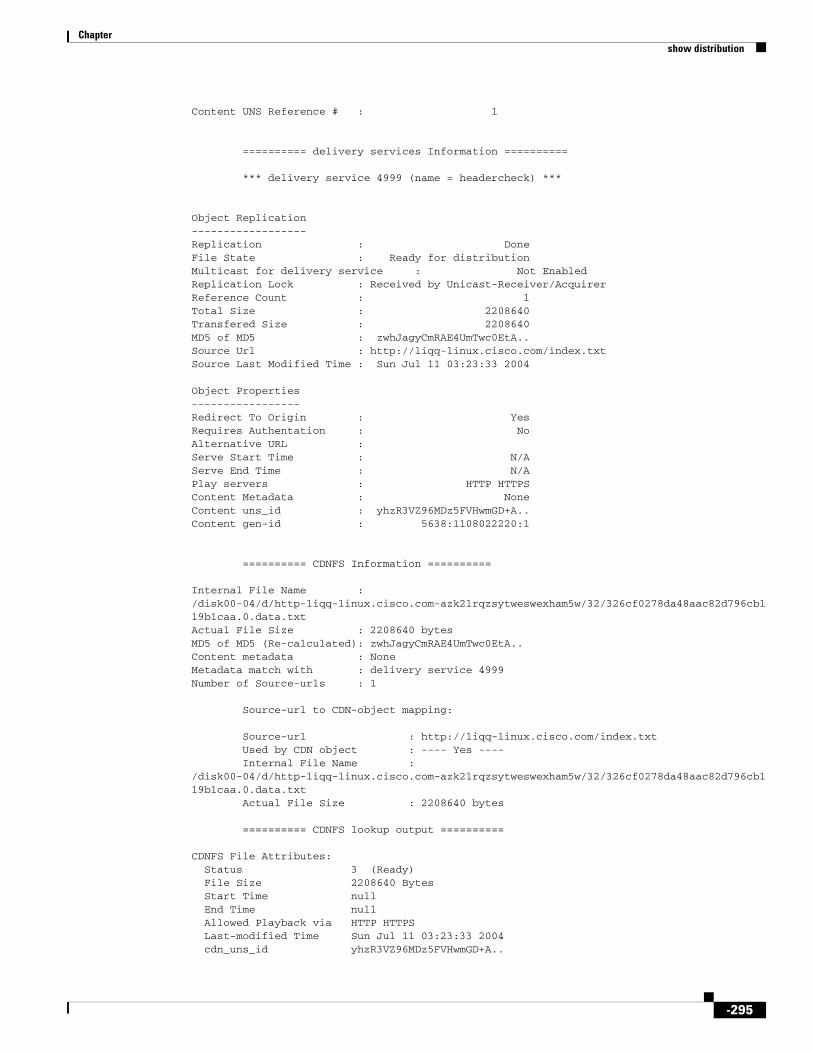
Chapter show distribution
Content UNS Reference # : 1
========== delivery services Information ========== *** delivery service 4999 (name = headercheck) ***
Object Replication------------------Replication : DoneFile State : Ready for distributionMulticast for delivery service : Not EnabledReplication Lock : Received by Unicast-Receiver/AcquirerReference Count : 1Total Size : 2208640Transfered Size : 2208640MD5 of MD5 : zwhJagyCmRAE4UmTwc0EtA..Source Url : http://liqq-linux.cisco.com/index.txtSource Last Modified Time : Sun Jul 11 03:23:33 2004 Object Properties-----------------Redirect To Origin : YesRequires Authentation : NoAlternative URL :Serve Start Time : N/AServe End Time : N/APlay servers : HTTP HTTPSContent Metadata : NoneContent uns_id : yhzR3VZ96MDz5FVHwmGD+A..Content gen-id : 5638:1108022220:1
========== CDNFS Information ========== Internal File Name : /disk00-04/d/http-liqq-linux.cisco.com-azk2lrqzsytweswexham5w/32/326cf0278da48aac82d796cb119b1caa.0.data.txtActual File Size : 2208640 bytesMD5 of MD5 (Re-calculated): zwhJagyCmRAE4UmTwc0EtA..Content metadata : NoneMetadata match with : delivery service 4999Number of Source-urls : 1 Source-url to CDN-object mapping: Source-url : http://liqq-linux.cisco.com/index.txt Used by CDN object : ---- Yes ---- Internal File Name : /disk00-04/d/http-liqq-linux.cisco.com-azk2lrqzsytweswexham5w/32/326cf0278da48aac82d796cb119b1caa.0.data.txt Actual File Size : 2208640 bytes
========== CDNFS lookup output ==========
CDNFS File Attributes: Status 3 (Ready) File Size 2208640 Bytes Start Time null End Time null Allowed Playback via HTTP HTTPS Last-modified Time Sun Jul 11 03:23:33 2004 cdn_uns_id yhzR3VZ96MDz5FVHwmGD+A..
-295

Chapter show distribution
last-modified Sun, 11 Jul 2004 03:23:33 GMTInternal path to data file: /disk00-04/d/http-liqq-linux.cisco.com-azk2lrqzsytweswexham5w/32/326cf0278da48aac82d796cb119b1caa.0.data.txt
The show distribution delivery-services output and the show distribution forwarder-list output display additional delivery service routing information. The newly added Status/Reason field displays whether the SE is a location leader and the reason for not having a forwarder SE.
The following example shows the delivery service distribution information:
ServiceEngine# show distribution delivery-servicesDelivery Service Name ID Priority Root Forwarder Status/Reason ------------ -- -------- ---- --------- ------------- ----------00-AD 527 500 No Rack89-SE-11 REGULAR N/A01-AD 586 500 Yes N/A N/A N/A00-Live 588 500 Yes N/A LIVE N/A LOC-LEAD: This SE is the location leader for this delivery service REGULAR: This SE is not the location leader for this delivery service LLMT: This SE cannot find forwarder because this SE has limit on the forwarder lookup level FAIL: This SE cannot find forwarder because there is failed SE along the path within specified forwarder lookup level NGWT: This SE cannot find forwarder because there is SE with negative forwarder-load-weight along the path within the specified forwarder lookup level LIVE: The specified delivery service is live delivery service, forwarder not applicable *: MetaData forwarder and Unicast forwarder are different
The following example provides delivery service distribution information for delivery service ID 962:
SE2#sh distribution delivery-service delivery-service-id 962Delivery Service Configuration---------------------Delivery Service ID : 962Delivery Service Name : VODContent Origin Name : WMTContent Origin fqdn : www.wmt.comContent Origin Origin FQDN : 5.2.3.2Delivery Service Priority : 500Configured Distribution Type : Unicast only
Content Acquirer Information-------------------ID of Configured Content Acquirer : 643Name of Configured Content Acquirer : SE2IP of Configured Content Acquirer : 5.1.3.12ID of Effective Content Acquirer : 643Current content-Acquirer-uid : 1400131927This SE's Role : Configured Content AcquirerThis SE in Full Reload : No
QoS Configuration-----------------MetaData QoS (system config) : 32 [0X 20] (Effective)Unicast QoS (system config) : 48 [0X 30]Unicast QoS (delivery service config) : 26 [0X 1a]Effective Unicast QoS config : 26 [0X 1a]Content Delivery QoS (delivery service) : 10 [0X a]
Content Acquirer Failover/Fallback Information---------------------------------------
-296

Chapter show distribution
Content Acquirer Failover/Fallback Interval: 120 Mins
Metadata Information--------------------Metadata-Forwarder ID : 0Metadata-Forwarder Name : N/AMetadata-Forwarder Primary IP : N/AMetadata-Forwarder NAT IP/Port : N/AAddress to Poll Metadata-Forwarder : N/AMetadata-Forwarder Status : N/ALast gen-id Switch : 18857 Secs agoCurrent low-water-marker : 1Current max-gen-id : 0Current max-del-gen-id : 0
Unicast Information-------------------Ucast-Forwarder ID : 0Ucast-Forwarder Name : N/AUcast-Forwarder Primary IP : N/AUcast-Forwarder NAT IP/Port : N/AAddress to Poll Ucast-Forwarder : N/AUcast-Forwarder Status : N/A
LOC-LEAD: This SE is the location leader for this delivery serviceREGULAR: This SE is not the location leader for this delivery serviceLLMT: This SE cannot find forwarder because this SE has limit on the forwarder lookup levelFAIL: This SE cannot find forwarder because there is failed SE alongthe path within specified forwarder lookup levelNGWT: This SE cannot find forwarder because there is SE with negativeforwarder-load-weight along the path within the specifiedforwarder lookup levelLIVE: The specified delivery service is live delivery service,forwarder not applicable*: MetaData forwarder and Unicast forwarder are different
Note The Has Unfinished Job line is only available if the SE is not a Content Acquirer. It is only available on a receiver SE.
Related Commands Command Description
show statistics distribution
Displays the statistics of the content distribution components.
-297

Chapter show flash
show flashTo display the flash memory version and usage information, use the show flash command in EXEC configuration mode.
show flash
Syntax Description This command has no arguments or keywords.
Defaults No default behavior or values
Command Modes EXEC
Usage Guidelines If a new software image has been installed and is waiting to be run after a reboot, the show flash command displays this information and the version of ECDS software that runs on the device after reload.
Examples The following example displays the flash information:
ServiceEngine# show flashCDS software version (disk-based code): CDS-2.5.3-b360
System image on flash:Version: 2.5.3.360
System flash directory:System image: 274 sectorsBootloader, rescue image, and other reserved areas: 59 sectors512 sectors total, 179 sectors free.
Table 3-32 describes the fields shown in the show flash display.
Table 3-32 show flash Field Descriptions
Field Description
ECDS software version (disk-based code)
ECDS software version and build number that is running on the device.
System image on flash:
Version Version and build number of the software that is stored in flash memory.
System flash directory:
System image Number of sectors used by the system image.
Bootloader, rescue image, and other reserved areas
Number of sectors used by the bootloader, rescue image, and other reserved areas.
XX sectors total, XX sectors free Total number of sectors. Number of free sectors.
-298

Chapter show flash-media-streaming
show flash-media-streamingTo display the Flash Media Streaming information, use the show flash-media-streaming command in EXEC configuration mode.
On the SE:
show flash-media-streaming [license | logging name | mtrack | stream-status {dvrcast [all name] | live [all name]}]
On the SR:
show flash-media-streaming
Syntax Description
Defaults No default behavior or values
Command Modes EXEC
Usage Guidelines When you execute the show flash-media-streaming stream-status live command and the Forwarder is a Content Origin server running Linux, the show command does not show statistics for the Content Origin server.
Examples The following example displays the Flash Media Streaming information:
ServiceEngine# show flash-media-streaming Flash Media Streaming is disabled.Max. Allowed concurrent sessions are 200.Flash Media Streaming Monitoring is enabled.Admin list allow: 1.1.1.1 Total number of wholesale licenses is 0.Bandwidth Details:Non wholesale bandwidth (Perpetual) is 200000 kbps.Configured max bandwidth is 10000 kbps.Total wholesale bandwidth (Term Based) is 0 kbps.Allowed bandwidth is 10000 kbps.
license (Optional) Shows the Flash Media Streaming licenses.
logging (Optional) Sets the Tar Flash Media Streaming transaction logs to /local/local1/filename.tar.gz.
name (Optional) Filename.
mtrack (Optional) Displays the Flash Media Streaming memory usage.
stream-status (Optional) Displays the Flash Media Streaming stream status.
dvrcast Displays dvrcast stream status.
all (Optional) Dumps detail statistics into /local/local1/filename.
live (Optional) Displays the live stream status.
-299

Chapter show flash-media-streaming
Related Commands Command Description
flash-media-streaming Enables and configures Flash Media Streaming.
show statistics flash-media-streaming
Displays the statistics for Flash Media Streaming.
-300

Chapter show ftp
show ftpTo display the caching configuration of the File Transfer Protocol (FTP), use the show ftp command in EXEC configuration mode.
show ftp
Syntax Description This command has no arguments or keywords.
Defaults No default behavior or values
Command Modes EXEC
Examples This example lists the caching configuration of FTP:
ServiceEngine# show ftp
FTP heuristic age-multipliers: directory-listing 30% file 60%Maximum Time To Live in days : directory-listing 3 file 7Minimum Time To Live in minutes: 60No objects are revalidated on every request.Serve-IMS without revalidation if...Directory listing object is less than 50% of max ageFile object is less than 80% of max ageIncoming Proxy-Mode:Servicing Proxy mode FTP connections on ports: 22 23 88 66 48 488 449 90Outgoing Proxy-Mode:Not using outgoing proxy mode.Maximum size of a cacheable object is unlimited.
-301

Chapter show hardware
show hardwareTo display the system hardware status, use the show hardware command in EXEC configuration mode.
show hardware
Syntax Description This command has no arguments or keywords.
Defaults No default behavior or values
Command Modes EXEC
Usage Guidelines In Cisco ECDS Release 2.6, the output of the show hardware command in EXEC configuration mode displays the version of the TV-out hardware that the SE is equipped with. In the following excerpt of the sample output from the show hardware command, this particular information is highlighted in bold. Rev 3 in the command output indicates that the TV-out hardware uses the newer Revision 3 MPEG decoder PCI part. The Vela II Revision D and Revision E cards use the Revision 3 part.
ServiceEngine# show hardware
Total 1 CPU.1024 Mbytes of Physical memory.1 CD ROM drive (CD-224E)1 AV card (Vela II)2 GigabitEthernet interfaces1 Console interface2 USB interfaces [ Not supported in this version of software ]
The following PCI cards were found:PCI-Slot-1 MPEG-Decoder-AV [ 1105:8476 (Sigma Designs, Inc.) (rev 3) ] PCI-Slot-2 SCSIManufactured As: Pre-FCS 565 [ 867383Z ]
The output of the show hardware command in EXEC configuration mode notifies you if the SE is running a version of the CDS software that does not support the TV-out hardware contained in the SE. In the following example, you are notified that the SE has a Vela II audio-video (AV) card that is not supported by the version of the CDS software that is running on the SE. In the following excerpt of the sample output from the show hardware command, this particular information is highlighted in bold:
ServiceEngine # show hardware
CPU 0 is GenuineIntel Intel(R) Celeron(R) CPU 1.70GHz (rev 1) running at 1699MHz
Total 1 CPU.1024 Mbytes of Physical memory.1 CD ROM drive (CD-224E)1 AV card (Vela II) [ ***Revision not supported in this version of software*** ] 2 GigabitEthernet interfaces1 Console interface2 USB interfaces [ Not supported in this version of software ] The following PCI cards were found:
-302

Chapter show hardware
Examples Table 3-33 describes the fields shown in the show hardware display.
Table 3-33 show hardware Field Descriptions
Field Description
Compiled hour:minute:second month day year by cnbuild
Compile information for the software build.
System was restarted on day of week month day hour:minute:second year
Date and time that the system was last restarted.
The system has been up for X hours, X minutes, X seconds
Length of time the system has been running since the last reboot.
CPU 0 is CPU manufacturer information.
Total X CPU Number of CPUs on the device.
XXXX Mbytes of Physical memory Number of megabytes of physical memory on the device.
X CD ROM drive Number of CD-ROM drives on the device.
X Console interface Number of console interfaces on the device.
Cookie info
SerialNumber Serial number of the device.
SerialNumber (raw) Serial number of the device as an ASCII value.
TestDate Date that the device was tested.
ModelNum (text) Hardware model of the device.
ModelNum (raw) Internal model number (ASCII value) that corresponds to the ExtModel number.
HWVersion Number of the current hardware version.
PartNumber Not implemented.
BoardRevision Number of revisions for the current system board.
ChipRev Number of revisions for the current chipset.
VendID Vendor ID of the cookie.
CookieVer Version number of the cookie.
Chksum Checksum of the cookie showing whether the cookie is valid.
List of all disk drives
Physical disk information Lists the disks by number.
disk00 Availability of the disk: Present, Not present or Not responding, or Not used (*).
Disk identification number and type.
Disk size in megabytes and gigabytes.
disk01 Same type of information is shown for each disk.
Mounted filesystems
Device Path to the partition on the disk.
Type Type of the file system. Values include PHYS-FS, SYSFS, or cdnfs.
-303

Chapter show hardware
Related Commands
3
Size Total size of the file system in megabytes and gigabytes.
Mount point Mount point for the file system. For example, the mount point for SYSFS is /local/local1.
System use Amount of disk space being used for system use.
Free Amount of unused disk space available.
Table 3-33 show hardware Field Descriptions (continued)
Field Description
Command Description
show version Displays version information about the SE software.
-304
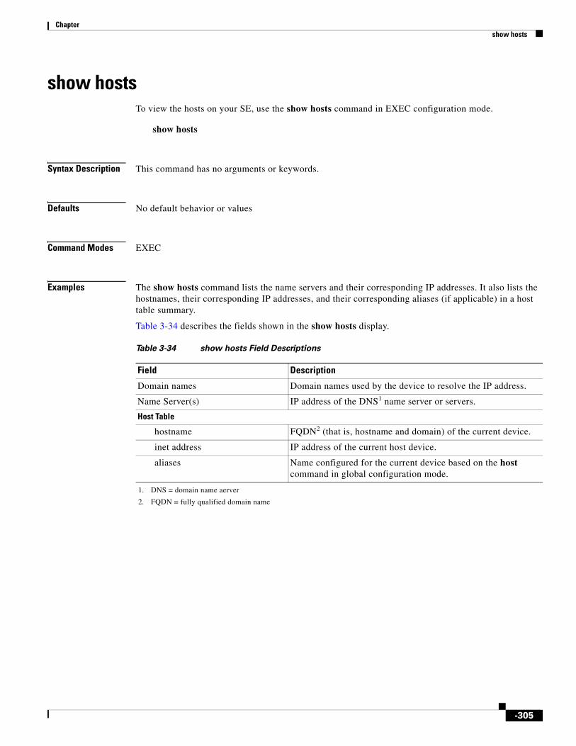
Chapter show hosts
show hostsTo view the hosts on your SE, use the show hosts command in EXEC configuration mode.
show hosts
Syntax Description This command has no arguments or keywords.
Defaults No default behavior or values
Command Modes EXEC
Examples The show hosts command lists the name servers and their corresponding IP addresses. It also lists the hostnames, their corresponding IP addresses, and their corresponding aliases (if applicable) in a host table summary.
Table 3-34 describes the fields shown in the show hosts display.
Table 3-34 show hosts Field Descriptions
Field Description
Domain names Domain names used by the device to resolve the IP address.
Name Server(s) IP address of the DNS1 name server or servers.
1. DNS = domain name aerver
Host Table
hostname FQDN2 (that is, hostname and domain) of the current device.
2. FQDN = fully qualified domain name
inet address IP address of the current host device.
aliases Name configured for the current device based on the host command in global configuration mode.
-305

Chapter show http
show httpTo display HTTP caching parameters, use the show http EXEC command.
show http {age-mult | all | anonymizer | append {host-header | proxy-auth-header | via-header | www-auth-header | x-forwarded-for-header} | cache-cookie | cache-fill-range | cache-noncacheable | cache-on-abort | object | proxy | request-header | reval-each- request | ttl}
Syntax Description
Defaults No default behavior or values
Command Modes EXEC
Usage Guidelines The show http custom-error-page messages and their meanings are shown in Table 3-35.
age-mult Displays HTTP/1.0 caching heuristic modifiers.
all Displays all HTTP-related caching configurations.
anonymizer Displays the HTTP anonymizer configuration.
append Displays the configuration of HTTP headers appended by the Content Engine.
host-header Displays the Host header configuration.
proxy-auth-header Displays the Proxy-Authorization header configuration.
via-header Displays the Via header configuration.
www-auth-header Displays the WWW-Authorization header configuration.
x-forwarded-for-header Displays the X-Forwarded-For header configuration.
all Displays the configuration for caching of all authenticated web objects.
cache-cookie Displays the configuration for caching of web objects with associated cookies.
cache-fill-range Displays configuration for cache-fill, for a range request starting from 0.
cache-noncacheable Displays status of cached non-cacheable objects.
cache-on-abort Displays the cache-on-abort configuration.
custom-error-page Displays the information about custom error pages.
message (Optional) Message; see Table 3-35.
object Displays the configuration of HTTP objects.
proxy Displays the proxy-mode configuration.
reval-each-request Displays the revalidation configuration for every request.
ttl Displays the Time To Live for objects in the cache.
Maximum time to live in days: 1
Minimum time to live for all objects in minutes: 60
-306

Chapter show http
Table 3-35 Custom Error Page Messages
Message Identifier Usage
blocked-dueto-filter-error Error response when a request is blocked because of a filter.
cache-read-error Error response when a cache file system (CFS) read fails.
cache-write-error Error response when a CFS write fails.
cdn-not-found-error Error response when CDN URL is not found.
client-access-denied-msg Error response when client access is denied.
dns-not-available-error Error response when DNS is unavailable for resolution.
error-signature Signature that will be appended to the error pages.
expect-failed-error Error response when the Expect specifier in the HTTP request header cannot be met.
ftp-bad-login-error Error response when an FTP login fails.
ftp-bad-url-error Error response when an FTP request receives a bad URL.
ftp-disabled-error Error response when FTP is disabled.
ftp-failure-error Error response when FTP fails.
ftp-internal-error Error response when an FTP interval is exceeded.
ftp-not-found-error Error response when an FTP file is not found.
ftp-put-created-msg Error response when an FTP PUT is successful.
ftp-put-error Error response when an FTP PUT fails.
ftp-put-modified-msg Response when an FTP update is successful.
ftp-unavailable-msg Error response when an FTP file is unavailable.
http-blocked-port-msg Error response when an HTTP request comes through a blocked port.
https-blocked-port-msg Error response when an HTTPS request comes through a blocked port.
icap-processing-error Error response when an error occurred in ICAP processing.
invalid-port-error Error response when an invalid port is accessed.
looped-req-error Error response when a looped request is unsuccessful.
not-enough-resources-error Error response when enough resources are not available for the request process.
not-in-cache Error response when the object is not found in the cache.
offline-miss-error Error response when SE offline finds a cache miss.
outgoing-proxy-fail-error Error response when all outgoing proxies fail.
proxy-allow-domain-error Error response when domain is not allowed to
authenticate in proxy mode
proxy-no-default-domain-error Error response when no default domain is available to authenticate in proxy mode.
proxy-unauthenticated-error Error response when proxy authentication fails.
radius-redirect-error Error response for a RADIUS redirect message.
-307

Chapter show http
Examples The following example lists the configuration and status of HTTP:
ServiceEngine# show http allBasic authenticated objects are not cached.HTTP heuristic age-multipliers: text 30% binary 60%Serve-IMS without revalidation if... Text object is less than 50% of max age Binary object is less than 80% of max ageObjects with associated cookies are not cachedClient no-cache requests are retrieved from the origin serverCache on abort feature is disabledObjects will always continue to be cached on a client abort Maximum threshold is disabled Minimum threshold is disabled Percent threshold is disabledMaximum time to live in days: text 3 binary 7Minimum time to live for all objects in minutes: 5Objects are not revalidated on each requestIncoming Proxy-Mode: Not servicing incoming proxy mode connections.Outgoing Proxy-Mode: Not using outgoing proxy mode.
Monitor Interval for Outgoing Proxy Servers is 60 seconds
Timeout period for probing Outgoing Proxy Servers is 300000 microseconds
Use of Origin Server upon Proxy Failures is disabled.Persistent connection is enabled and set to allPersistent connection timeout is 600 secondsWWW-Authenticate headers containingNo host configured to receive Proxy-Authorization headerNo host configured to receive WWW-Authorization headerMaximum size of a cacheable object is unlimitedRequested Object URL validation is enabledHealing client is disabled
Timeout for responses = 0 secondsMax number of misses allowed before stop healing mode = 0 Port number for healing request/response = 14333 Http-port to forward http request to healing server = 80
The following example shows the IP address and port numbers of the HTTP incoming and outgoing proxy modes:
request-blocked-msg Error response when a request is blocked.
request-malformed-error Error response when request headers are malformed.
rev-dns-not-available-msg Error response when DNS is not available.
server-connection-broken-error Error response when the server connection is lost.
ssl-server-error Error response when the SSL handshake with the server fails.
www-allow-domain-error Error response when domain is not allowed to authenticate
www-no-default-domain-error Error response when no default domain is available to authenticate.
www-unauthenticated-error Error response when server authentication fails.
Table 3-35 Custom Error Page Messages (continued)
Message Identifier Usage
-308

Chapter show http
ServiceEngine# show http proxyIncoming Proxy-Mode: Servicing Proxy mode HTTP connections on port: 8080Outgoing Proxy-Mode: Directing request to proxy server at 10.1.1.1 port 7777
Related Commands Command Description
http Configure HTTP-related parameters.
show statistics http Displays SE HTTP statistics.
-309

Chapter show https
show httpsTo display HTTPS proxy status and port policies, use the show https EXEC command.
show https {all | cert [cert-name] | certgroup [certchain_name] | destination-port | key [key_name] | proxy | server [name]}
Syntax Description
Defaults No default behavior or values
Command Modes EXEC
Usage Guidelines The ECDS software offers the capability to cache HTTPS information. The Service Engine can cache key and certificate information and store it securely. You can also configure your own HTTPS server, which can be located at a central location and which can then be accessed from remote sites, using the secure connection offered by the Service Engine.
Use the show https command to display all HTTPS certificate and key information and HTTPS server configuration parameters.
Examples The following example displays all HTTPS configuration parameters:
ServiceEngine# show https allIncoming HTTPS proxy:Incoming Proxy-Mode: Not servicing incoming proxy mode connections.Outgoing HTTPS proxy:Outgoing Proxy-Mode: Not using outgoing proxy mode.
Monitor Interval for Outgoing Proxy Servers is 60 seconds
Timeout period for probing Outgoing Proxy Servers is 300000 microseconds
all Displays all HTTPS configuration parameters.
cert Displays the HTTPS certificate information.
cert-name (Optional) Name of the certificate.
certgroup Displays the HTTPS certificate chain information.
certchain-name (Optional) Name of the certificate chain.
destination-port Displays destination port restrictions.
key Displays the HTTPS private key information.
key_name (Optional) Name of the private key.
proxy Displays the proxy-mode configuration.
server Displays the HTTPS server caching configuration.
name (Optional) Name of the HTTPS server.
-310

Chapter show https
Use of Origin Server upon Proxy Failures is disabled.Destination port restrictions:Allow 443 563HTTPS caching certificate information: 1. Certificate Name : d Subject : <empty>
HTTPS caching certificate group information:HTTPS caching private key information: 1. Private Key Name : key1 Attributes : <empty>
Display all https server caching information: 1: name name, host <not configured>, disabledServiceEngine#
The following example displays the HTTPS proxy configuration details:
ServiceEngine# show https proxyIncoming HTTPS proxy:Incoming Proxy-Mode: Configured Proxy mode HTTPS connections on ports: 9090Outgoing HTTPS proxy:Outgoing Proxy-Mode:
Primary Proxy Server: 10.77.155.221 port 8088 Failed
Monitor Interval for Outgoing Proxy Servers is 20 seconds
Timeout period for probing Outgoing Proxy Servers is 3000 microseconds
Use of Origin Server upon Proxy Failures is enabled.ServiceEngine#
Related Commands https proxyhttps serverproxy-protocolsshow statistics https requests
-311

Chapter show interface
show interfaceTo display the hardware interface information, use the show interface command in EXEC configuration mode.
show interface {GigabitEthernet slot/port | PortChannel {1 | 2} | standby group num}
Syntax Description
Defaults No default behavior or values
Command Modes EXEC
Examples Table 3-36 describes the fields shown in the show interface GigabitEthernet display.
GigabitEthernet Selects a Gigabit Ethernet interface to configure.
slot/port Slot and port number for the selected interface. The slot range is 0 to 2; the port range is 0 to 3. The slot number and port number are separated with a forward slash character (/).
PortChannel Selects the EtherChannel of interfaces to configure.
1 Sets the port channel interface number to 1.
2 Sets the port channel interface number to 2.
standby Sets the standby group for the interface.
group num Group number for the selected interface. The group number range is 1 to 4.
Table 3-36 show interface GigabitEthernet Field Descriptions
Field Description
Type Type of interface. Always Ethernet.
Ethernet address Layer 2 MAC address.
Maximum Transfer Unit Size Current configured MTU value.
Metric Metric setting for the interface. The default is 1. The routing metric is used by the routing protocol to determine the most favorable route. Metrics are counted as additional hops to the destination network or host; the higher the metric value, the less favorable the route.
Packets Received Total number of packets received by this interface.
Input Errors Number of incoming errors on this interface.
Input Packets Dropped Number of incoming packets that were dropped on this interface.
Input Packets Overruns Number of incoming packet overrun errors.
Input Packets Frames Number of incoming packet frame errors.
Packet Sent Total number of packets sent from this interface.
-312
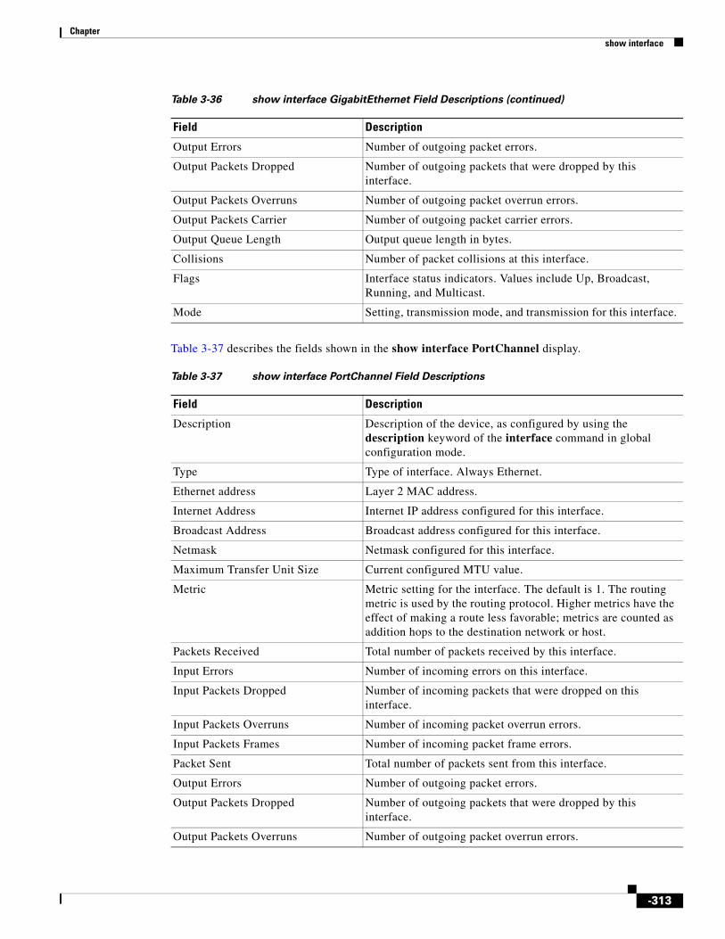
Chapter show interface
Table 3-37 describes the fields shown in the show interface PortChannel display.
Output Errors Number of outgoing packet errors.
Output Packets Dropped Number of outgoing packets that were dropped by this interface.
Output Packets Overruns Number of outgoing packet overrun errors.
Output Packets Carrier Number of outgoing packet carrier errors.
Output Queue Length Output queue length in bytes.
Collisions Number of packet collisions at this interface.
Flags Interface status indicators. Values include Up, Broadcast, Running, and Multicast.
Mode Setting, transmission mode, and transmission for this interface.
Table 3-36 show interface GigabitEthernet Field Descriptions (continued)
Field Description
Table 3-37 show interface PortChannel Field Descriptions
Field Description
Description Description of the device, as configured by using the description keyword of the interface command in global configuration mode.
Type Type of interface. Always Ethernet.
Ethernet address Layer 2 MAC address.
Internet Address Internet IP address configured for this interface.
Broadcast Address Broadcast address configured for this interface.
Netmask Netmask configured for this interface.
Maximum Transfer Unit Size Current configured MTU value.
Metric Metric setting for the interface. The default is 1. The routing metric is used by the routing protocol. Higher metrics have the effect of making a route less favorable; metrics are counted as addition hops to the destination network or host.
Packets Received Total number of packets received by this interface.
Input Errors Number of incoming errors on this interface.
Input Packets Dropped Number of incoming packets that were dropped on this interface.
Input Packets Overruns Number of incoming packet overrun errors.
Input Packets Frames Number of incoming packet frame errors.
Packet Sent Total number of packets sent from this interface.
Output Errors Number of outgoing packet errors.
Output Packets Dropped Number of outgoing packets that were dropped by this interface.
Output Packets Overruns Number of outgoing packet overrun errors.
-313

Chapter show interface
Table 3-38 describes the fields shown in the show interface standby display.
Related Commands
Output Packets Carrier Number of outgoing packet carrier errors.
Output Queue Length Output queue length in bytes.
Collisions Number of packet collisions at this interface.
Flags Interface status indicators. Values include Up, Broadcast, Running, and Multicast.
Table 3-37 show interface PortChannel Field Descriptions
Field Description
Table 3-38 show interface standby Field Descriptions
Field Description
Standby Group Number that identifies the standby group.
Description Description of the device, as configured by using the description keyword of the interface command in global configuration mode.
IP address, netmask IP address and netmask of the standby group.
Member interfaces Member interfaces of the standby group. Shows which physical interfaces are part of the standby group. Shows the interface definition, such as GigabitEthernet 1/0.
Active interface Interfaces that are currently active in the standby group.
Command Description
interface Configures a Gigabit Ethernet or port-channel interface.
show running-config Displays the current running configuration information on the terminal.
show startup-config Displays the startup configuration.
-314

Chapter show inventory
show inventoryTo display the system inventory information, use the show inventory command in EXEC configuration mode.
show inventory
Syntax Description This command has no arguments or keywords.
Defaults No default behavior or values
Command Modes EXEC
Usage Guidelines The show inventory command allows you to view the unique device identifier information (UDI) for an SE. Typically, Cisco SEs contain the following three identification items, which make up the UDI:
• Product ID (PID)
• Version ID (VID)
• Serial number (SN)
This identity information is stored in the SE nonvolatile memory. Each SE has a unique device identifier (UDI). The UDI shows PID, VID and SN.
The UDI is electronically accessed by the product operating system or network management application to enable identification of unique hardware devices. The data integrity of the UDI is vital to customers. The UDI that is programmed into the SE’s nonvolatile memory is equivalent to the UDI that is printed on the product label and on the carton label. This UDI is also equivalent to the UDI that can be viewed through any electronic means and in all customer-facing systems and tools. Currently, there is only CLI access to the UDI; there is no SNMP access to the UDI information.
On newer SE models, you can use the show inventory command in EXEC configuration mode to display the SE’s UDI. On older SE models, use the show tech-support command in EXEC configuration mode to display the SE’s UDI.
Examples The following example shows the inventory information for one of the newer SE models (SE-565):
ServiceEngine# show inventory
PID: SE-565-K9 VID: 0 SN: serial_number
In the preceding example, serial number is the serial number of the SE. The version ID is displayed as “0” because the version number is not available.
Table 3-39 describes the fields shown in the show inventory display.
-315

Chapter show inventory
The following example shows that you must use the show tech-support command in EXEC configuration mode to display the inventory information on an older SE model:
ServiceEngine# show inventoryPlease look at 'sh tech-support' for information!ServiceEngine# show tech-support
Related Commands
Table 3-39 show inventory Field Descriptions
Field Description
PID Product ID number of the device.
VID Version ID number of the device. Displays as 0 if the version number is not available.
SN Serial number of the device.
Command Description
show tech-support Displays system information necessary for TAC to assist you with your SE.
-316

Chapter show ip access-list
show ip access-listTo display the access lists that are defined and applied to specific interfaces or applications, use the show ip access-list command in EXEC configuration mode.
show ip access-list [acl-name | acl-num]
Syntax Description
Defaults Displays information about all defined access lists.
Command Modes EXEC
Usage Guidelines Use the show ip access-list command in EXEC configuration mode to display the access lists that have been defined on the current system. Unless you identify a specific access list by name or number, the system displays information about all the defined access lists, including the following sections:
• Available space for new lists and conditions
• Defined access lists
• References by interface and application
Examples The following example shows sample output from the show ip access-list command:
ServiceEngine# show ip access-listSpace available: 47 access lists 492 access list conditions
Standard IP access list 1 1 permit 10.1.1.2 2 deny 10.1.2.1 (implicit deny any: 2 matches) total invocations: 2Extended IP access list 100 1 permit tcp host 10.1.1.1 any 2 permit tcp host 10.1.1.2 any 3 permit tcp host 10.1.1.3 any (implicit fragment permit: 0 matches) (implicit deny ip any any: 0 matches) total invocations: 0Standard IP access list test 1 permit 1.1.1.1 (10 matches) 2 permit 1.1.1.3 3 permit 1.1.1.2 (implicit deny: 2 matches) total invocations: 12
acl-name (Optional) Information for a specific access list, using an alphanumeric identifier up to 30 characters, beginning with a letter.
acl-num (Optional) Information for a specific access list, using a numeric identifier (0 to 99 for standard access lists and 100 to 199 for extended access lists).
-317

Chapter show ip access-list
Interface access list references: GigabitEthernet 0/0 inbound 100
Application access list references: tftp_server standard 1 UDP ports: 69
The following example shows sample output from the show ip access-list command for the access list named test:
ServiceEngine# show ip access-list testStandard IP access list test 1 permit 1.1.1.1 (10 matches) 2 permit 1.1.1.3 3 permit 1.1.1.2 (implicit deny: 2 matches) total invocations: 12
Note The system displays the number of packets that have matched a condition statement only if the number is greater than zero.
Related Commands Command Description
clear Clears the HTTP object cache, the hardware interface, statistics, archive working transaction logs, and other settings.
ip access-list Creates and modifies access lists for controlling access to interfaces or applications.
-318

Chapter show ip interface
show ip interfaceTo display the IP interface state and address/mask for all interfaces, use the show ip interface command in user EXEC configuration mode.
show ip interface
Syntax Description
Defaults No default behavior or values
Command Modes User EXEC
Usage Guidelines This command is used to display a Summary of the IP interface status and configuration.
Examples The following example is sample output from the show ip bgp summary command:
ServiceRouter# show ip interface brief
Interface IP Address Interface StatusPortChannel 1 3.1.14.71 protocol-up/link-up/admin-upPortChannel 2 4.0.8.12 protocol-up/link-up/admin-up
ServiceRouter#
brief Displays a summary of the IP interface status and configuration.
-319

Chapter show ip routes
show ip routesTo display the IP routing table, use the show ip routes command in EXEC configuration mode.
show ip routes
Syntax Description This command has no arguments or keywords.
Defaults No default behavior or values
Command Modes EXEC
Examples The show ip routes command displays the IP routing table that shows actual routes in the system.
Table 3-40 describes the fields shown in the show ip routes display.
.
The following example shows sample output from the show ip routes command.
ServiceRouter# sh ip routesDestination Gateway Netmask---------------- ---------------- ----------------202.0.0.22 203.0.0.1 255.255.255.25520.0.40.1 2.8.1.204 255.255.255.25512.0.0.2 203.0.0.1 255.255.255.25520.0.60.1 2.8.1.206 255.255.255.25513.0.0.3 203.0.0.1 255.255.255.2552.2.2.2 203.0.0.1 255.255.255.255204.0.0.2 203.0.0.1 255.255.255.25520.0.50.1 2.8.1.205 255.255.255.25513.0.0.1 203.0.0.1 255.255.255.25512.0.0.1 203.0.0.1 255.255.255.25520.0.10.1 2.8.1.201 255.255.255.25520.0.70.1 2.8.1.207 255.255.255.255201.0.0.12 203.0.0.1 255.255.255.25520.0.30.1 2.8.1.203 255.255.255.25520.0.20.1 2.8.1.202 255.255.255.25520.0.80.1 2.8.1.208 255.255.255.2552.8.1.0 0.0.0.0 255.255.255.020.0.0.0 2.8.1.201 255.0.0.0172.0.0.0 2.8.1.1 255.0.0.010.0.0.0 2.8.1.1 255.0.0.0203.0.0.0 0.0.0.0 255.0.0.00.0.0.0 2.8.1.1 0.0.0.0
Table 3-40 show ip routes Field Descriptions
Field Description
Destination Destination address IP route mask.
Gateway IP address or IP alias of the gateway router.
Netmask Subnet mask of the gateway router.
-320

Chapter show ip routes
Related Commands Command Description
ip Changes initial network device configuration settings.
-321

Chapter show key chain
show key chainTo display the key chains in the system, use the show key chain command in user EXEC configuration mode.
show key chain [decrypt | name]
Syntax Description
Command Default No default behavior or values
Command Modes User EXEC
Examples The following is sample output from the show key chain command:
ServiceRouter# show key chainshow key chainKey-Chain lsp Key 1 -- text <encrypted-string> accept lifetime (00:00:00 Jan 01 1970) - (always valid) [valid now] send lifetime (00:00:00 Jan 01 1970) - (always valid) [valid now]
ServiceRouter#
Related Commands
decrypt (Optional) Displays key chain information.
name (Optional) Key chain name.
Command Description
key Creates a key chain and enter into key chain configuration submode.
key-string Creates a key string to be used for authentication.
key chain Creates a key chain and enter into key chain configuration submode.
-322

Chapter show logging
show loggingTo display the system message log configuration, use the show logging command in EXEC configuration mode.
show logging
Syntax Description This command has no arguments or keywords.
Defaults No default behavior or values
Command Modes EXEC
Usage Guidelines The following is an example of a syslog message for proxy-mode native FTP support:
SE-FTP_PROXY-3-252009: Failed to configure FTP Proxy-mode listener on port ' [ port ] '.
Explanation: Could not start proxy-mode listener for FTP control connection for the specified port. The port is temporarily in an un-bindable state, or is in use by some other application.
Action: Check whether the port has been configured for use by a different application. If not, retry the incoming proxy command after 2 minutes. If this error repeats frequently, contact Cisco TAC.
To view information about events that have occurred in all devices in your CDS network, you can use the system message log in the CDSM GUI. The CDSM logs only severity level critical or higher messages from registered nodes. Also, the CDSM logs certain other status messages that are considered important to the Centralized Management System (CMS). The messages displayed in the system message log for device, SE, are not related to the messages logged in the system log file on the sysfs partition on the CDSM as /local1/syslog.txt.
The syslog.txt file on the CDSM contains information about events that have occurred on the CDSM and not on the registered nodes. The messages that are written to the syslog.txt file depend on specific parameters of the system log file that you have set by using the logging global configuration command. For example, a critical error message logged on a registered node does not appear in the syslog.txt file on the CDSM because the problem never occurred on the CDSM but only on the registered node. However, this error message is displayed in the system message log for device the SE device.
-323

Chapter show logging
Examples The following example displays the syslog host configuration on an SE:
ServiceEngine# show loggingSyslog to host is disabledPriority for host logging is set to: warning
Syslog to console is disabledPriority for console logging is set to: warning
Syslog to disk is enabledPriority for disk logging is set to: noticeFilename for disk logging is set to: /local1/syslog.txt
Syslog facility is set to *
Syslog disk file recycle size is set to 500000
Related Commands Command Description
clear Clears the HTTP object cache, the hardware interface, statistics, archive working transaction logs, and other settings.
logging Configures system logging.
-324

Chapter show movie-streamer
show movie-streamerTo display the Movie Streamer configuration, use the show movie-streamer command in EXEC configuration mode.
show movie-streamer [bandwidth | cache | proxy]
Syntax Description
Defaults No default behavior or values
Command Modes EXEC
Examples The following example shows the Movie Streamer configuration:
ServiceEngine# show movie-streamer Movie Streamer version mde1100-5.0.3Movie Streamer is not enabled------ Movie Streamer General Configurations ------Movie Streamer max sessions configured: 8000Movie Streamer transport source ip address is not configuredMovie Streamer accelerate for VOD is enabledMovie Streamer client idle timeout is 300 secondsMovie Streamer origin-server idle interval is 10 secondsMovie Streamer client rtp timeout is 180 secondsMovie Streamer outgoing bitrate per streamer has no limitMovie Streamer incoming bitrate per streamer has no limit------ Movie Streamer Bandwidth Configurations ----Movie Streamer Outgoing bandwidth enforced is 2000000 kbpsMovie Streamer Incoming bandwidth enforced is 2000000 kbps------ Movie Streamer Cache Configurations --------Movie Streamer cache is enabledMovie Streamer cache age-multiplier: 30%Movie Streamer cache max-ttl: 1 (days)Movie Streamer cache revalidate for each request is enabled------ Movie Streamer Proxy Configurations --------Movie Streamer proxy has not been configured.------ Movie Streamer Broadcast List --------------
Related Commands
bandwidth (Optional) Displays Movie Streamer bandwidth configuration.
cache (Optional) Displays Movie Streamer cache configuration.
proxy (Optional) Displays Movie Streamer proxy configuration.
Command Description
movie-streamer Enables and configures the Movie Streamer server.
show statistics movie-streamer
Displays statistics for the Movie Streamer.
-325

Chapter show ntp
show ntpTo display the Network Time Protocol (NTP) parameters, use the show ntp command in EXEC configuration mode.
show ntp status
Syntax Description
Defaults No default behavior or values
Command Modes EXEC
Examples Table 3-41 describes the fields shown in the show ntp status display.
status Displays the NTP status.
Table 3-41 show ntp status Field Descriptions
Field Description
NTP Status of whether NTP is enabled or disabled.
server list NTP server IP and subnet addresses.
remote Name (first 15 characters) of remote NTP server.
* In the remote column, identifies the system peer to which the clock is synchronized.
+ In the remote column, identifies a valid or eligible peer for NTP synchronization.
space In the remote column, indicates that the peer was rejected. (The peer could not be reached or excessive delay occurred in reaching the NTP server.)
x In the remote column, indicates a false tick and is ignored by the NTP server.
- In the remote column, indicates a reading outside the clock tolerance limits and is ignored by the NTP server.
refid Clock reference ID to which the remote NTP server is synchronized.
st Clock server stratum or layer.
t Type of peer (local, unicast, multicast, or broadcast).
when Status of when the last packet was received from the server, in seconds.
poll Time check or correlation polling interval, in seconds.
reach 8-bit reachability register. If the server was reachable during the last polling interval, a 1 is recorded; otherwise, a 0 is recorded. Octal values 377 and above indicate that every polling attempt reached the server.
delay Estimated delay (in milliseconds) between the requester and the server.
offset Clock offset relative to the server.
jitter Clock jitter.
-326

Chapter show ntp
Related Commands Command Description
clock Sets or clears clock functions or updates the calendar.
ntp Configures the NTP server and allows the system clock to be synchronized by a time server.
-327

Chapter show processes
show processesTo display CPU or memory processes, use the show processes command in EXEC configuration mode.
show processes [cpu | debug pid | memory | system [delay 1-60 | count 1-100]]
Syntax Description
Defaults No default behavior or values
Command Modes EXEC
Usage Guidelines Use the commands shown in this section to track and analyze system CPU utilization.
The show processes debug command displays the extensive internal system call information and a detailed account of each system call (and arguments) made by each process and the signals that it has received.
Use the show processes system command to display system updates. The delay option specifies the delay between updates, in seconds. The count option specifies the number of updates that are displayed. This command displays these items:
• List of all processes in wide format.
• Two tables listing the processes that use CPU resources. The first table displays the list of processes in descending order of utilization of CPU resources based on a snapshot taken after the processes system (ps) output is displayed. The second table displays the same processes based on a snapshot taken 5 seconds after the first snapshot.
• Virtual memory used by the corresponding processes in a series of five snapshots, each separated by 1 second.
Note CPU utilization and system performance may be affected when you use the show process command. We recommend that you avoid using the show process command with keywords system and especially debug, unless it is absolutely necessary.
cpu (Optional) Displays the CPU utilization.
debug (Optional) Displays the system call and signal traces for a specified process identifier (PID) to display system progress.
pid Process identifier.
memory (Optional) Displays memory allocation processes.
system (Optional) Displays system load information in terms of updates.
delay (Optional) Specifies the delay between updates, in seconds. The range is from 1–60.
1-60 Displays delays between updates, in seconds.
count (Optional) Specifies the number of updates that are displayed. The range is from 1–100.
1-100 Displays the number of updates displayed.
-328

Chapter show processes
Examples Table 3-42 describes the fields shown in the show processes displays.
Table 3-42 show processes Field Descriptions
Field Description
CPU Usage CPU utilization as a percentage for user, system overhead, and idle.
PID Process identifier.
STATE Current state of corresponding processes.
R = RunningS = Sleeping in an interruptible waitD = Sleeping in an uninterruptible wait or swappingZ = ZombieT = Traced or stopped on a signal
PRI Priority of processes.
User T User time utilization, in seconds.
Sys T System time utilization, in seconds.
COMMAND Process command.
Total Total available memory in bytes.
Used Memory currently used in bytes.
Free Free memory available in bytes.
Shared Shared memory currently used in bytes.
Buffers Buffer memory currently used in bytes.
Cached Cache memory currently used in bytes.
TTY TTY to which the process is attached. For example, TTY may indicate which processes belong to network Telnet sessions.
%MEM Percentage of memory used by corresponding processes.
VM Size Virtual memory size (in bytes) allocated to the corresponding process.
RSS (pages) Resident set size, which indicates the number of pages that the process has in real memory minus three (–3) for administrative purposes. These pages count toward text, data, and stack space but do not count demand-loaded or swapped-out pages.
Name Filename of the executable in parentheses.
-329

Chapter show programs
show programsTo display a list of programs on the SE, use the show programs command in EXEC configuration mode.
show programs [movie-streamer [cli | live | rebroadcast] | program-id id | program-name name]
Syntax Description
Defaults No default behavior or values
Command Modes EXEC
Usage Guidelines Typically, users create programs using the CDSM by defining programs in the manifest file or by using the Program API. The show programs command output displays the program type, the channel with which the program is associated, the current status of the program, and the next time that the program starts and ends.
A program in the ECDS software is defined as a scheduled event in which the content is presented to the end user. Attributes of the program include the start and end time of the program, whether the content is pre-positioned or live, the set of SEs assigned to the program, and the streaming server to be used for content delivery.
Program types determine the hardware or software component involved in delivering content to the user. Different program types that are shown in the output of the show programs command are as follows:
• Movie streamer live
• Movie streamer rebroadcast
The CDSM GUI allows you to create a program, schedule it, and deliver it over your multicast-enabled CDS network. Programs can consist of prerecorded video or live events. In the case of live events, the ECDS software interoperates with third-party encoders and IP/TV Broadcast Servers to transmit the live stream across the CDS network.
movie-streamer (Optional) Displays the list of programs served by the Movie Streamer.
cli (Optional) Displays the list of CLI programs served by the Movie Streamer.
live (Optional) Displays the list of live programs served by the Movie Streamer.
rebroadcast (Optional) Displays the list of rebroadcast programs served by the Movie Streamer.
program-id (Optional) Displays detailed program information for the specified program ID.
id Unique number identifying the program.
program-name (Optional) Displays detailed program information for the specified program name.
name (Optional) Name of the program.
-330

Chapter show programs
When creating a program in the CDSM GUI, the administrator specifies the following information:
• Streaming server—How the program is streamed or delivered to the end user.
– Movie streamer—The event is played from a PC using the Apple QuickTime application or using the IP/TV Viewer application.
– Exported—The program is exported over HTTP to a set-top box.
• Media source
– Live stream transmitted from a third-party encoder or an IP/TV Broadcast Server
– Pre-positioned content stored on SEs
• Destination
– A set of SEs or device groups
– A channel (live or export)
• Delivery method
– Unicast or multicast live events
– Multicast scheduled rebroadcasts
– TV-out or export playlists
• Schedule
– Start time and duration
– Looping forever (enabled or disabled)
– Multiple playback times
– Repeating playback times
• Publishing URL—The URL used to view the program
Live Events
Live events are streamed from third-party encoders (such as the Windows Media encoder Version 9 and the QuickTime encoder) or from streaming servers (such as Windows Media Server). The live stream is acquired by the Content Acquirer and transmitted to edge SEs using unicast. From the edge SEs, the live stream is transmitted to end users using either multicast or multicast and unicast live splitting. The live program is available to viewers only during its scheduled times.
Before setting up a live event in the CDSM GUI, the administrator must complete the following tasks:
1. Set up the live event on the encoder or streaming server. This task is done externally to the CDSM GUI.
2. In the CDSM GUI, accept the streaming server’s license agreement on the SEs designated to acquire and distribute the stream.
3. Create a live channel (or designate an existing channel as a live channel), assign SEs to the live channel, and designate a Content Acquirer to acquire the stream.
After you have completed the preceding tasks, you are ready to define the program and configure the program settings in the CDSM GUI. The CDSM allows you to define two types of live events based on the streaming server being used:
• WMT live
• Cisco Streaming Engine live
-331

Chapter show programs
Configuration Requirements for Managed Live Events
If you have channels for live programs configured in your Cisco ECDS network, make sure that there are no external proxy servers physically located between your SEs and your Content Acquirer that require proxy authentication. Also, make sure that proxy authentication is not enabled on any receiver SEs that might be in the logical, hierarchical path between the Content Acquirer and the receiver SE that is going to serve the live stream to the requesting clients. If a live stream encounters any device that requires proxy authentication, the stream is dropped before it reaches its destination.
If your network is set up with intermediary devices that require proxy authentication, you can work around the problem by configuring rules to bypass authentication on these devices.
For example, to enable the formation of the unicast splitting tree and, in turn, enable live broadcasting from all receiver SEs, you can specify the following rule on all the parent SEs in the channel:
ServiceEngine(config)# rule pattern-list 1 downstream-SE-ipaddress ServiceEngine(config)# rule no-auth pattern-list 1
Live Stream Interruptions
During a WMT live broadcast, any interruption of the live stream that lasts 5 minutes or longer causes the multicast broadcast to stop for the duration of the currently scheduled period. If the live stream is interrupted for less than five minutes, the broadcast resumes.
Live stream interruptions can be caused by unexpected encoder failures or by an operational restart. If you have early trials scheduled before the live event, we recommend that you configure multiple schedules, one for each trial. We also recommend that you start the encoder before the scheduled time.
If the live stream stops for more than 5 minutes and resumes later while the program is still scheduled, you can modify the schedule or any other attribute of the program (such as the description) to trigger a restart of the multicast broadcast. Restarting might take up to 5 minutes under these circumstances. This setting does not apply to Movie Streamer live programs.
Scheduled Rebroadcasts
In a scheduled rebroadcast, the pre-positioned content is scheduled to be streamed from edge SEs using multicast. To define a program for a rebroadcast event, the administrator must complete the following tasks:
1. Create a content acquisition channel and pre-position the content.
2. Assign media files to the program.
3. Specify the multicast address and port or define a program address pool.
4. Specify the days and times for the rebroadcast.
Note For rebroadcast programs, the media can only be selected from one channel. The SEs and device groups assigned to the channel are selected automatically when you choose the media files for the program.
The CDSM allows you to define a program as a Movie Streamer rebroadcast.
Fast Encoder Failover
In Cisco ECDS, the show programs command was enhanced to support encoder failover. Issues with the previous release were as follows:
• In the forwarder list item, only the primary origin server’s IP address showed. If the device failed over to the backup origin server, the forwarder list presented the primary origin server’s IP address and did not reflect the real origin server that was connected by the Content Acquirer.
-332

Chapter show programs
• In the source item, it presented every track’s server IP address and port in the source, and there were no other explanations and tips. If the source included two tracks in the same server, the output was confusing.
• In the non-Content Acquirer, users could not obtain the information about the serving origin server.
With this release, the output of the command looks like the following:
ServiceEngine# show programs program-name live2Current Time : May 18 2009 @ 10:10:33 IST (1242621633)Program ID : 1341Program Name : live2Delivery Service ID : 1340Delivery Service Name : live2Type : WMT Managed Scheduled Live
Forwarder List : 3.1.2.11 <- 172.22.28.104
Schedules :Schedule # 1: Start Time (loc) : May 18 2009 @ 10:11:00 IST (1242621660) End Time (loc) : May 18 2009 @ 10:12:00 IST (1242621720) Duration : 60 secs Repeat : N/A Repeatdays : N/A Time spec : local
Source : Server : http://172.22.28.104:1881
Destination : Unicast Access URL: rtsp://kinswmt.spcdn.net/live2 Multicast URL : http://kinswmt.spcdn.net/live2.nsc.asx Multicast Address : 224.2.2.68:94
Start Time (loc) : May 18 2009 @ 10:11:00 IST (1242621660)Start Time : May 18 2009 @ 04:41:00 GMT (1242601860)End Time (loc) : May 18 2009 @ 10:12:00 IST (1242621720)End Time : May 18 2009 @ 04:42:00 GMT (1242601920)
Current Status : ScheduledTime left : N/A
ServiceEngine# show clockLocal time: Mon May 18 10:10:47 IST 2009RT-612-2# sh programs program-name live2Current Time : May 18 2009 @ 10:11:05 IST (1242621665)Program ID : 1341Program Name : live2Delivery Service ID : 1340Delivery Service Name : live2Type : WMT Managed Scheduled Live
Forwarder List : 3.1.2.11 <- 172.22.28.104
Schedules :Schedule # 1: Start Time (loc) : May 18 2009 @ 10:11:00 IST (1242621660) End Time (loc) : May 18 2009 @ 10:12:00 IST (1242621720) Duration : 60 secs Repeat : N/A Repeatdays : N/A Time spec : local
-333

Chapter show programs
Source : Server : http://172.22.28.104:1881
Destination : Unicast Access URL: rtsp://kinswmt.spcdn.net/live2 Multicast URL : http://kinswmt.spcdn.net/live2.nsc.asx Multicast Address : 224.2.2.58:94
Start Time (loc) : May 18 2009 @ 10:11:00 IST (1242621660)Start Time : May 18 2009 @ 04:41:00 GMT (1242601860)End Time (loc) : May 18 2009 @ 10:12:00 IST (1242621720)End Time : May 18 2009 @ 04:42:00 GMT (1242601920)
Current Status : PlayingTime left : 55 secs
ServiceEngine# show clockLocal time: Mon May 18 10:11:10 IST 2009RT-612-2# sh programs program-name live2Current Time : May 18 2009 @ 10:12:10 IST (1242621730)Program ID : 1341Program Name : live2Delivery Service ID : 1340Delivery Service Name : live2Type : WMT Managed Scheduled Live
Forwarder List : 3.1.2.11 <- 172.22.28.104
Schedules :Schedule # 1: Start Time (loc) : May 18 2009 @ 10:11:00 IST (1242621660) End Time (loc) : May 18 2009 @ 10:12:00 IST (1242621720) Duration : 60 secs Repeat : N/A Repeatdays : N/A Time spec : local
Source : Server : http://172.22.28.104:1881
Destination : Unicast Access URL: rtsp://kinswmt.spcdn.net/live2 Multicast URL : http://kinswmt.spcdn.net/live2.nsc.asx Multicast Address : 224.2.2.58:94
Start Time (loc) : End of Program ReachedStart Time : End of Program ReachedEnd Time (loc) : End of Program ReachedEnd Time : End of Program Reached
Current Status : StoppedTime left : N/A
ServiceEngine# show clockLocal time: Mon May 18 10:12:14 IST 2009
Now the show programs command output contains the forwarder list with the backup source, and the Content Acquirer and non-Content Acquirer output is consistent. Also, if the user executes the show statistics wmt streamstat command from the Content Acquirer, the output shows which server is currently serving.
-334

Chapter show programs
The source URL displays in the source section and the CLI and CDSM are consistent. Because the non-content acquirer cannot get the information on which source is serving, the output contains tips, such as “Please check which source is serving in content acquirer.”
The CDSM parses the backup SDP file and puts the results into the database. The item video_file_back_up saves the backup source server’s IP address and port in the play_media table.
Note It is not possible to monitor non-primed streams because they are played directly from the origin server. Primed streams can be monitored because they are buffered on the SE.
Stream-SE#sh prog program-name wmt-live-videoCurrent Time : Aug 05 2013 @ 12:39:10 UTC (1375706350)Program ID : 4105Program Name : wmt-live-videoDelivery Service ID : 998Delivery Service Name : wmt-liveType : WMT Managed Continuous Live
Forwarder List : 10.77.166.139 <- 10.77.138.142 <- rrr.sz.xlcdn.com
Schedules :Schedule #1:Start Time (loc) : Always startedEnd Time (loc) : N/ADuration : ForeverRepeat : N/ARepeatdays : N/ATime spec : local
Source :Server : http://rrr.sz.xlcdn.com/?account=pro-trmms&file=demo-win-300k&type=live&service=windowsmedia&protocol=http&port=80&output=wmx
Destination :Unicast Access URL: rtsp://www.ecds.com/wmt-live-video
Start Time (loc) : Always startedStart Time : Always startedEnd Time (loc) : N/AEnd Time : N/A
Current Status : Playing (not monitored)Time left : N/A
Priming Status :Primed : NoCurrent Status : N/ARestarts : 0
Note From Release 2.6, the Live Source URL field is enhanced to accept query-string characters in the URL field.
Table 3-43 describes the fields shown in the show programs program-name and program-id display.
-335

Chapter show programs
Table 3-43 show programs Field Descriptions
Field Description
Current Time Date and time of the output.
Program ID Unique number identifying the program.
Program Name Name of the program.
Delivery Service ID Unique number identifying the delivery service.
Delivery Service Name Unique name identifying the delivery service.
Type Program type. Program types are as follows:
• Movie streamer live
• Movie streamer rebroadcast
• Windows Media live
• Windows Media rebroadcast
Forwarder List List with primary and backup origin server’s IP address.
Schedules Schedule list. Information is as follows:
• Start Time (loc)
• End Time (loc)
• Duration
• Repeat
• Repeatdays
• Time spec
Source (for Content Acquirer) Primary and backup source URLs.
Source (for Non-content Acquirer) Primary and backup source URLs and tips.
Destination Unicast URLs.
-336

Chapter show qos
show qosTo display Quality of Service (QoS) information, use the show qos command in EXEC configuration mode.
show qos
Syntax Description This command has no arguments or keywords.
Defaults No default behavior or values
Command Modes EXEC
Examples This example shows the output that might be displayed if you do not enter any keywords:
ServiceRouter# show qosCamiant policy service config file is not configuredCamiant policy service is running
Related Commands Command Description
qos Globally enables QoS functionality on the switch.
show statistics qos Displays statistics for the QoS policy service.
-337

Chapter show radius-server
show radius-serverTo display RADIUS information, use the show radius-server command in EXEC configuration mode.
show radius-server
Syntax Description This command has no arguments or keywords.
Defaults No default behavior or values
Command Modes EXEC
Examples Table 3-44 describes the fields shown in the show radius-server display.
Table 3-44 show radius-server Field Descriptions
Field Description
Login Authentication for Console/Telnet Session
Status of whether RADIUS server is enabled for login authentication.
Configuration Authentication for Console/Telnet Session
Status of whether RADIUS server is enabled for authorization or configuration authentication.
Authentication scheme fail-over reason
Status of whether SEs fail over to the secondary method of administrative login authentication whenever the primary administrative login authentication method fails.
RADIUS Configuration RADIUS authentication settings.
RADIUS Authentication Status of whether RADIUS authentication is enabled on the SE.
Key Key used to encrypt and authenticate all communication between the RADIUS client (the SE) and the RADIUS server.
Timeout Number of seconds that the SE waits for a response from the specified RADIUS authentication server before declaring a timeout.
Retransmit Number of times that the SE is to retransmit its connection to the RADIUS if the RADIUS timeout interval is exceeded.
Radius Redirect Status of whether the RADIUS server redirects the response if an authentication request fails.
Reply-Message Message sent to the user if redirection occurs.
URL(s) to authentication failure instructions expired
HTML page location or URL where the redirect message should be sent.
Servers RADIUS servers that the SE is to use for RADIUS authentication.
-338

Chapter show radius-server
Related Commands
IP Hostname or IP address of the RADIUS server.
Port Port number on which the RADIUS server is listening.
Table 3-44 show radius-server Field Descriptions (continued)
Field Description
Command Description
radius-server Configures RADIUS authentication parameters.
-339

Chapter show rcp
show rcpTo display Remote Copy Program (RCP) information, use the show rcp command in EXEC configuration mode.
show rcp
Syntax Description This command has no keywords or arguments.
Defaults No default behavior or values
Command Modes EXEC
Examples This example shows how to display RCP information:
ServiceEngine# show rcprcp service configurations:rcp enable
Related Commands Command Description
rcp Enables the RCP.
-340

Chapter show rea
show reaTo display the remote execution agent (REA) information use the show rea command in EXEC configuration mode.
show rea info
Syntax Description
Defaults No default behavior or values
Command Modes EXEC
Examples The following example displays the REA information:
ServiceEngine# show rea inforea agent is running
Related Commands
info (Optional) Displays the agent information.
Command Description
rea Starts the remote execution agent.
-341

Chapter show rtsp
show rtspTo display the Real-Time Streaming Protocol (RTSP) configurations, use the show rtsp command in EXEC configuration mode.
show rtsp [gateway]
Syntax Description
Defaults No default behavior or values
Command Modes EXEC
Examples The following example display the output of the show rtsp gateway command in EXEC configuration mode:
ServiceEngine# show rtsp gateway RTSP Gateway ip-address 10.107.193.30RTSP Gateway incoming port 67 RTSP Gateway L4-switch not enabled RTSP Gateway Transparent Interception: Not configured.
Related Commands
gateway (Optional) Displays the RTSP gateway configuration.
Command Description
rtsp Configure the RTSP-related parameters.
-342

Chapter show rule
show ruleTo display rules configuration information, use the show rule command in EXEC configuration mode.
show rule action all [protocol {http | rtmp | rtsp}]
show rule action allow [protocol {http | rtmp | rtsp}]
show rule action block [protocol {http | rtmp | rtsp}]
show rule action generate-url-signature [protocol {http | rtmp | rtsp}]
show rule action no-cache [protocol {http | rtmp | rtsp}]
show rule action [protocol {http | rtmp | rtsp}]
show rule action redirect [protocol {http | rtmp | rtsp}]
show rule action refresh [protocol {http | rtmp | rtsp}]
show rule action rewrite [protocol {http | rtmp | rtsp}]
show rule action use-icap-service [protocol {http | rtmp | rtsp}]
show rule action validate-url-signature [protocol {http | rtmp | rtsp}]
show rule all
show rule pattern-list {1-512 pattern-type | all}
Syntax Description all Displays rules with all action types.
http Displays HTTP-related requests for this action.
rtmp Displays RTMP-related requests for this action.
rtsp Displays RTSP-related requests for this action.
protocol (Optional) Specifies the protocol to which actions apply.
allow Allows the request.
block Blocks the request.
generate-url-signature Generates a signed URL.
no-cache Does not cache the object.
redirect Redirects the request to the rewritten URL.
refresh Revalidates the object with the web server.
rewrite Rewrites the URL and fetch.
use-icap-service Sets ICAP service.
validate-url-signature Validates a signed URL.
all Displays all the configured actions and pattern lists.
pattern-list Displays the rules with the specified patterns.
1-512 Specifies the pattern number. The range is from 1 to 512.
-343

Chapter show rule
Defaults No default behavior or values
Command Modes EXEC
Usage Guidelines You can use the show rule pattern-list pattern-type command to display rules using a specific pattern type. For a more complete explanation of specific rules, see the “rule” section on page -231.Table 3-45 shows the permitted pattern types and describes each pattern type.
Examples The following example displays all rules with the configured action types and pattern lists:
ServiceEngine# show rule allRules Template Configuration----------------------------Rule Processing Enabledrule block domain bar.comrule block domain \.foo.comrule rewrite url-regsub http://www.ietf.org/rfc/.* http://wwwin-eng.cisco.com/RFC/$1rule no-cache dst-ip 172.31.120.0 255.255.192.0rule no-cache url-regex \.*cgi-bin*
Related Commands
pattern-type Pattern type (see Table 3-45).
all Displays rules with all pattern lists.
Table 3-45 Pattern Types
Pattern Type Description
all Displays configured patterns for all pattern types.
domain Regular expression to match the domain name.
dst-ip Destination IP address of the request.
header-field Request header field pattern.
src-ip Source IP address of the request.
url-regex Regular expression to be matched against the URL.
url-regsub Regular expression to match URL and replacement pattern.
Command Description
clear Clears the HTTP object cache, the hardware interface, statistics, archive working transaction logs, and other settings.
rule Sets the rules by which the SE filters HTTP, HTTPS, and RTSP traffic.
-344

Chapter show running-config
show running-configTo display the current running configuration information on the terminal, use the show running-config command in EXEC configuration mode.
show running-config
Syntax Description This command has no arguments or keywords.
Defaults No default behavior or values
Command Modes EXEC
Usage Guidelines Use this command with the show startup-config command to compare the information in running memory to the startup configuration used during bootup.
Note This command replaces the write terminal command.
Examples The following example displays the current running configuration information:
ServiceEngine# show running-config! CDS version 2.5.6!device mode service-engine!!hostname U11-MDE1100-1!!!exec-timeout 0!!!!interface Standby 1 ip address 8.1.0.2 255.255.0.0 exitinterface Standby 2 ip address 8.2.1.2 255.255.255.0 exit!interface PortChannel 1 ip address 6.21.1.2 255.255.255.0 exitinterface PortChannel 2 standby 1 exitinterface PortChannel 3
-345

Chapter show running-config
standby 1 priority 90 exitinterface PortChannel 4 ip address 8.2.2.2 255.255.255.0 exit!interface GigabitEthernet 1/0 channel-group 1 exitinterface GigabitEthernet 2/0 channel-group 1 exitinterface GigabitEthernet 3/0 channel-group 2 exitinterface GigabitEthernet 4/0 channel-group 2 exitinterface GigabitEthernet 5/0 channel-group 2 exitinterface GigabitEthernet 6/0 channel-group 2 exitinterface GigabitEthernet 7/0 channel-group 3 exitinterface GigabitEthernet 8/0 channel-group 3 exitinterface GigabitEthernet 9/0 channel-group 4 exitinterface GigabitEthernet 10/0 channel-group 4 exit!streaming-interface PortChannel 4streaming-interface Standby 1!!ip default-gateway 8.2.1.1ip default-gateway 8.1.0.1ip default-gateway 8.2.2.1!!port-channel load-balance round-robinprimary-interface Standby 1!!!ip name-server 3.22.0.7!ip route 171.71.50.0 255.255.254.0 8.1.0.1 ip route 0.0.0.0 0.0.0.0 8.2.1.1 interface 8.2.1.2ip route 0.0.0.0 0.0.0.0 8.1.0.1 interface 8.1.0.2ip route 0.0.0.0 0.0.0.0 8.2.2.1 interface 8.2.2.2!!logging console enable!ntp server 171.68.10.150!!
-346

Chapter show running-config
!!!!username admin password 1 $5$bVz2jc/k$QYvCAKrBmq3YqM5IklvuGrXQACMelfONdq3/siTpqV8username admin privilege 15!!!!authentication login local enable primaryauthentication configuration local enable primary!!!!cdsm ip 8.1.0.5cms enable!!!!service-monitor threshold nic 5!delivery-service origin-server 3.22.0.10 service-routed-fqdn www.vcpbu.com http bitrate-in-kbps 1000!!!!! End of CDS configurationServiceEngine#
Related Commands Command Description
configure Enters global configuration mode.
copy Copies the configuration or image data from a source to a destination.
-347

Chapter show service-monitor
show service-monitorTo display the service monitor configuration information, use the show service-monitor command in EXEC configuration mode.
On the SE or on the CDSM:
show service-monitor
Syntax Description There are no arguments or keywords.
Defaults No default behavior or values
Command Modes EXEC
Usage Guidelines This command allows users to check the service monitor configuration.
Examples The following example displays the Service Router information on the SE:
ServiceEngine# show service-monitor Monitor types configured:-------------------------CPU,MEM,KMEM,WMT,FMS,WEB,MS,DISK,NIC
Threshold values configured:---------------------------CPU : 80%MEM : 80%KMEM : 50%WMT : 50%FMS : 90%MS : 90%WEB : 90%NIC : 90%DISK : 80%DISKFAILCNT : 7
Sample periods configured:--------------------------CPU : 1 (secs)MEM : 1 (secs)KMEM : 1 (secs)WMT : 15 (secs)FMS : 1 (secs)NIC : 3 (secs)DISK : 1 (secs)
Sample counts configured to use in calculating average:-------------------------------------------------------CPU : 2MEM : 2KMEM : 2
-348

Chapter show service-monitor
WMT : 5FMS : 2NIC : 2DISK : 2
Device Status-------------
CPUCurrent load : 0%Average load : 0%Threshold : Not reached
DISKCurrent load : 0%Average load : 0%Threshold : Not reachedStatus : Operational
MEMAverage Used Memory : 4%Threshold : Not reached
KMEMAverage Kernel Memory : 1%Threshold : Not reached
NICAverage BW In : 0%Average BW Out : 0%Threshold : Not reached
Average Device load : 0%
Services Status---------------
Critical Service(s) : Running
WEBEnabled : YesThreshold : Not reachedStopped : No
WMTEnabled : YesCurrent Stream Count : 0Threshold : Not reachedStopped : No
MSEnabled : No
FMSEnabled : No
The following example displays the Service Router information on the CDSM:
CDSM# show service-monitor Monitor types configured:-------------------------CPU,MEM,KMEM,DISK
-349

Chapter show service-monitor
Threshold values configured:---------------------------CPU : 80%MEM : 80%KMEM : 50%DISK : 80%DISKFAILCNT : 1
Sample periods configured:--------------------------CPU : 1 (secs)MEM : 1 (secs)KMEM : 1 (secs)DISK : 1 (secs)
Sample counts configured to use in calculating average:-------------------------------------------------------CPU : 2MEM : 2KMEM : 2DISK : 2
Device Status-------------
CPUCurrent load : 0%Average load : 0%Threshold : Not reached
DISKCurrent load : 0%Average load : 0%Threshold : Not reachedStatus : Operational
MEMAverage Used Memory : 13%Threshold : Not reached
KMEMAverage Kernel Memory : 1%Threshold : Not reached
Average Device load : 0%
Related Commands Command Description
service-router Configures service routing.
clear service-router Cleara the proximity-based-routing proximity cache.
-350

Chapter show service-router
show service-routerTo display the Service Router configuration, use the show service-router command in EXEC configuration mode.
On the SE or on the CDSM:
show service-router {keepalive-interval | service-monitor}
On the SR:
show service-router {access-policy | content-based-routing | dns-ttl | forwarding [content-origin content-origin] | lastresort [domain name] | load {all | sename sename} | location-based-routing | proximity-based-routing | routes [content-origin content-origin] | service-monitor | services {all | sename sename} | summary [content-origin content-origin]}
Syntax Description
Defaults No default behavior or values
access-policy Configures the service-router access-policy.
content-based-routing Displays the content-based routing configuration.
dns-ttl Displays the TTL1 of DNS2 record.
forwarding Displays the content origin forwarding tables.
content-origin (Optional) Displays information for one content origin.
content-origin Content origin FQDN3.
lastresort Displays the domain and alternate domain configured.
domain (Optional) Displays information for one domain.
name Domain name.
load Displays the load and threshold reached status.
all Displays for all SEs.
sename Displays for one SE.
sename SE name.
location-based-routing
Displays the location-based routing configurations.
proximity-based-routing
Displays the proximity-based routing configurations.
routes Displays the content origin routing tables.
service-monitor Displays the service monitor configuration.
services Displays the services status.
summary Displays the content origin routing table summary statistics.
keepalive-interval Displays the keepalive interval.
1. TTL = time to live
2. DNS = domain name server 3. FQDN = fully qualified domain name
-351

Chapter show service-router
Command Modes EXEC
Usage Guidelines This command allows users to check the Service Router-releated configuration. Through this command, users can view the configured features of an SR, such as location-based routing and content-based routing.
Examples The following example displays the Service Router information on the SE:
ServiceEngine# show service-monitor Monitor types configured:-------------------------CPU,MEM,KMEM,WMT,FMS,WEB,MS,DISK,NIC
Threshold values configured:---------------------------CPU : 80%MEM : 80%KMEM : 50%WMT : 50%FMS : 90%MS : 90%WEB : 90%NIC : 90%DISK : 80%DISKFAILCNT : 7
Sample periods configured:--------------------------CPU : 1 (secs)MEM : 1 (secs)KMEM : 1 (secs)WMT : 15 (secs)FMS : 1 (secs)NIC : 3 (secs)DISK : 1 (secs)
Sample counts configured to use in calculating average:-------------------------------------------------------CPU : 2MEM : 2KMEM : 2WMT : 5FMS : 2NIC : 2DISK : 2
Device Status-------------
CPUCurrent load : 0%Average load : 0%Threshold : Not reached
DISKCurrent load : 0%Average load : 0%Threshold : Not reachedStatus : Operational
-352

Chapter show service-router
MEMAverage Used Memory : 4%Threshold : Not reached
KMEMAverage Kernel Memory : 1%Threshold : Not reached
NICAverage BW In : 0%Average BW Out : 0%Threshold : Not reached
Average Device load : 0%
Services Status---------------
Critical Service(s) : Running
WEBEnabled : YesThreshold : Not reachedStopped : No
WMTEnabled : YesCurrent Stream Count : 0Threshold : Not reachedStopped : No
MSEnabled : No
FMSEnabled : No
The following example displays the Service Router information on the CDSM:
CDSM# show service-monitor Monitor types configured:-------------------------CPU,MEM,KMEM,DISK
Threshold values configured:---------------------------CPU : 80%MEM : 80%KMEM : 50%DISK : 80%DISKFAILCNT : 1
Sample periods configured:--------------------------CPU : 1 (secs)MEM : 1 (secs)KMEM : 1 (secs)DISK : 1 (secs)
Sample counts configured to use in calculating average:-------------------------------------------------------CPU : 2
-353

Chapter show service-router
MEM : 2KMEM : 2DISK : 2
Device Status-------------
CPUCurrent load : 0%Average load : 0%Threshold : Not reached
DISKCurrent load : 0%Average load : 0%Threshold : Not reachedStatus : Operational
MEMAverage Used Memory : 13%Threshold : Not reached
KMEMAverage Kernel Memory : 1%Threshold : Not reached
Average Device load : 0%
Related Commands Command Description
service-router Configures service routing.
clear service-router Clears the proximity-based-routing proximity cache.
-354

Chapter show services
show servicesTo display services-related information, use the show services command in EXEC configuration mode.
show services {ports [port-num] | summary}
Syntax Description
Defaults No default behavior or values
Command Modes EXEC
Examples The following example displays the services information by the port number:
CDSM# show services portsService information by port --------------------------- 550 Started on Mon Oct 14 12:13:20 2002 Runs 1 service Cisco_Streaming_Engine 553 Started on Mon Oct 14 12:13:20 2002 Runs 1 service RTSP_Gateway 554 Started on Mon Oct 14 12:13:20 2002 Runs 1 service RTSP_Gateway
.
.
.15256 Started on Mon Oct 14 12:13:20 2002 Runs 1 service CMS27999 Started on Mon Oct 14 12:13:20 2002 Runs 1 service Real_Server28000 Started on Mon Oct 14 12:13:20 2002 Runs 1 service Real_Proxy
The following example displays a services information summary, showing the service and the associated port numbers:
CDSM# show services summary
Service Ports----------------------------------------------------- CMS 15256 2000 2001 2002 2003 2004 2005 GUI 8001 Wmt 1755 1756 1757 1799
ports Displays services by port number.
port-num (Optional) Displays up to eight port numbers. The port number range is from 1 to 65535.
summary Displays the services summary.
-355

Chapter show services
icp 3128 emdb 5432 CertMgr 6001 MgmtAgent 5252 Real_Proxy 1090 8082 9002 555 28000 7879 6060 7071 3031 Cdsm_UI_http 8443 Real_Server 7070 8081 9091 27999 7878 7802 1554 3030 4040 5050 RTSP_Gateway 554 553 RPC_APACHE_PORT 6550 temp_RPC_APACHE_PORT 8008 Cisco_Streaming_Engine 550 SNMP
-356

Chapter show snmp
show snmpTo check the status of Simple Network Management Protocol (SNMP) communications, use the show snmp command in EXEC configuration mode.
show snmp {alarm-history | engineID | group | stats | user}
Syntax Description
Defaults No default behavior or values
Command Modes EXEC
Usage Guidelines This command provides information on various SNMP variables and statistics on SNMP operations.
Examples Table 3-46 describes the fields shown in the snmp alarm-history display.
Table 3-47 describes themapping of module names to module ids.
alarm-history Displays SNMP alarm history information.
engineID Displays the local SNMP engine identifier.
group Displays SNMP groups.
stats Displays SNMP statistics.
user Displays SNMP users.
Table 3-46 show snmp alarm-history Field Descriptions
Field Description
Index Serial number of the listed alarms.
Type Status of whether the alarm has been Raised or Cleared.
Sev Levels of alarm severity (Critical, Major, or Minor).
Alarm ID Traps sent by a CDS device contain numeric alarm IDs.
ModuleID Traps sent by a CDS device contain numeric module IDs. See Table 3-47 to map module names to module IDs.
Category Traps sent by an CDS device contain numeric category IDs. See Table 3-48 to map category names to category IDs.
Descr Description of the ECDS software alarm and the application that generated the alarm.
-357

Chapter show snmp
Table 3-48 describes the mapping of category names to category ids.
Table 3-49 describes the fields shown in the show snmp stats display.
Table 3-47 Mapping of Module Names to Module IDs
Module Name Module ID
acquirer 4000
AD_DATABASE 8000
cms 3000
NHM 1
NHM/NHM 2500
nodemgr 2000
standby 4000
sysmon 1000
UNICAST_DATA_RECEIVER 5000
UNICAST_DATA_SENDER 6000
Table 3-48 Mapping of Category Names to Category IDs
Category Name Category ID
Communications 1
Service Quality 2
Processing Error 3
Equipment 4
Environment 5
Content 6
Table 3-49 show snmp stats Field Descriptions
Field Description
SNMP packets input Total number of SNMP packets input.
Bad SNMP version errors Number of packets with an invalid SNMP version.
Unknown community name Number of SNMP packets with an unknown community name.
Illegal operation for community name supplied
Number of packets requesting an operation not allowed for that community.
Encoding errors Number of SNMP packets that were improperly encoded.
Number of requested variables
Number of variables requested by SNMP managers.
Number of altered variables Number of variables altered by SNMP managers.
Get-request PDUs Number of GET requests received.
Get-next PDUs Number of GET-NEXT requests received.
-358

Chapter show snmp
Table 3-50 describes the fields shown in the show snmp engineID display.
Table 3-51 describes the fields shown in the show snmp group display.
Table 3-52 describes the fields shown in the show snmp user display.
Set-request PDUs Number of SET requests received.
SNMP packets output Total number of SNMP packets sent by the router.
Too big errors Number of SNMP packets that were larger than the maximum packet size.
Maximum packet size Maximum size of SNMP packets.
No such name errors Number of SNMP requests that specified a MIB object that does not exist.
Bad values errors Number of SNMP SET requests that specified an invalid value for a MIB object.
General errors Number of SNMP SET requests that failed because of some other error. (It was not a No such name error, Bad values error, or any of the other specific errors.)
Response PDUs Number of responses sent in reply to requests.
Trap PDUs Number of SNMP traps sent.
Table 3-49 show snmp stats Field Descriptions (continued)
Field Description
Table 3-50 show snmp engineID Field Descriptions
Field Description
Local SNMP Engine ID String that identifies the copy of SNMP on the local device.
Table 3-51 show snmp group Field Descriptions
Field Description
groupname Name of the SNMP group, or collection of users who have a common access policy.
security_model Security model used by the group (v1, v2c, or v3).
readview String identifying the read view of the group.
writeview String identifying the write view of the group.
notifyview String identifying the notify view of the group.
Table 3-52 show snmp user Field Descriptions
Field Description
User name String identifying the name of the SNMP user.
-359

Chapter show snmp
Related Commands
Engine ID String identifying the name of the copy of SNMP on the device.
Group Name Name of the SNMP group, or collection of users who have a common access policy.
Table 3-52 show snmp user Field Descriptions (continued)
Field Description
Command Description
snmp-server community
Configures the community access string to permit access to the SNMP1.
snmp-server contact Sets the system server contact (sysContact) string.
snmp-server enable traps
Enables the SE to send SNMP traps.
snmp-server group Defines a user security model group.
snmp-server host Specifies the recipient of a host SNMP trap operation.
snmp-server location Sets the SNMP system location string.
snmp-server notify inform
Configures the SNMP notify inform request.
snmp-server user Defines a user who can access the SNMP server.
snmp-server view Defines a SNMP V2 MIB view.
1. SNMP = simple network management protocol
-360

Chapter show ssh
show sshTo display Secure Shell (SSH) status and configuration information, use the show ssh command in EXEC configuration mode.
show ssh
Syntax Description This command has no arguments or keywords.
Defaults No default behavior or values
Command Modes EXEC
Related Commands Command Description
sshd Enables the SSH daemon.
-361

Chapter show standby
show standbyTo display standby interface information, use the show standby command in EXEC configuration mode.
show standby
Syntax Description This command has no arguments or keywords.
Defaults No default behavior or values
Command Modes EXEC
Examples Table 3-53 describes the fields shown in the show standby display.
Related Commands
Table 3-53 show standby Field Descriptions
Field Description
Standby Group Number that identifies the standby group.
Description Description of the device, as configured by using the description option of the interface global configuration command.
IP address IP address of the standby group.
netmask Netmask of the standby group.
Member interfaces Member interfaces of the standby group. Shows which physical interfaces are part of the standby group. Shows the interface definition, such as GigabitEthernet 1/0.
priority Priority status of each interface.
Active interface Interfaces that are currently active in the standby group.
Maximum errors allowed on the active interface
Maximum number of errors allowed on the active interface.
Command Description
show interface Displays the hardware interface information.
show running-config Displays the current running configuration information on the terminal.
show startup-config Displays the startup configuration.
-362

Chapter show startup-config
show startup-configTo display the startup configuration, use the show startup-config command in EXEC configuration mode.
show startup-config
Syntax Description This command has no keywords or arguments.
Defaults No default behavior or values
Command Modes EXEC
Usage Guidelines Use this command to display the configuration used during an initial bootup, stored in nonvolatile random-access memory (NVRAM).
Examples The following example displays the startup configuration details on the SE:
ServiceEngine# show startup-config! CDS version 2.3.9!device mode service-engine!!hostname V2-MDE1100-3!!!primary-interface PortChannel 1!!interface PortChannel 1 ip address 3.1.14.72 255.255.255.0 exitinterface PortChannel 2 ip address 4.0.8.13 255.255.255.0 exit!interface GigabitEthernet 1/0 channel-group 2 exitinterface GigabitEthernet 2/0 channel-group 2 exitinterface GigabitEthernet 3/0 channel-group 1 exitinterface GigabitEthernet 4/0 channel-group 1 exitinterface GigabitEthernet 5/0
-363

Chapter show startup-config
channel-group 1 exitinterface GigabitEthernet 6/0 channel-group 1 exit!!ip default-gateway 3.1.14.1!!offline-operation enable!!!rule action block pattern-list 3 rule action redirect http://www.baidu.com pattern-list 2 rule pattern-list 1 url-regex http://chunliu.com/b.wmvrule pattern-list 2 header-field request-line b.wmvrule pattern-list 3 header-field request-line c.wmv!icap service camiant server icap://trythis/servername exit!!!transaction-logs enabletransaction-logs archive interval 120!username admin password 1 bVmDmMMmZAPjYusername admin privilege 15!!authentication login local enable primaryauthentication configuration local enable primary!access-lists 300 deny groupname Disneyaccess-lists 300 permit groupname anyaccess-lists enable!!telnet enable!!!cdsm ip 4.0.8.10cms enable!!!service-monitor threshold wmt 50service-monitor number-of-samples wmt 5service-monitor sample-period wmt 15qos device-policy-service enable!!cache content max-cached-entries 1000! End of CDS configuration
-364

Chapter show startup-config
Related Commands Command Description
configure Enters global configuration mode.
copy Copies the configuration or image data from a source to a destination.
show running-config Displays the current running configuration information on the terminal.
-365

Chapter show statistics access-lists 300
show statistics access-lists 300To display SE access control list statistics, use the show statistics access-lists 300 command in EXEC configuration mode.
show statistics access-lists 300
Syntax Description This command has no keywords or arguments.
Defaults No default behavior or values
Command Modes EXEC
Usage Guidelines The access control list statistics display the number of access requests, denials, and permissions recorded. Use the show statistics access-lists 300 command to display the number of group name accesses recorded.
Examples Table 3-54 describes the fields shown in the show statistics access-lists 300 display.
Related Commands
Table 3-54 show statistics access-lists 300 Field Descriptions
Field Description
Access Control Lists Statistics
Groupname and username-based List
Lists the group name-based access control lists.
Number of requests
Number of requests.
Number of deny responses
Number of deny responses.
Number of permit responses
Number of permit responses.
Command Description
clear Clears the HTTP object cache, the hardware interface, statistics, archive working transaction logs, and other settings.
-366

Chapter show statistics acquirer
show statistics acquirerTo display SE acquirer channel statistics, use the show statistics acquirer command in EXEC configuration mode.
show statistics acquirer [contents {delivery-service-id delivery-service-id | delivery-service-name delivery-service-name} | delivery-service-id delivery-service-id | delivery-service-name delivery-service-name | errors {delivery-service-id delivery-service-id | delivery-service-name delivery-service-name} | job-list {delivery-service-id delivery-service-id | delivery-service-name delivery-service-name}]
Syntax Description
Defaults No default behavior or values
Command Modes EXEC
Usage Guidelines The show statistics acquirer command displays acquirer statistics for all channels for which the SE is the Content Acquirer. The output of the command displays any manifest file parsing or fetch errors if any errors occur. It displays the total number of acquired objects, number of failed objects, and total disk space used by the acquired objects. When a channel ID or name is specified, acquirer statistics are displayed for that channel specified by ID or name.
The show statistics acquirer contents command displays all the acquired content, its size, and its last-modified time, specified by channel ID or name.
The show statistics acquirer errors command displays acquisition errors, if any, for the channel specified by ID or name. Manifest file parsing and fetch errors, as well as single item or crawler job errors, are displayed.
The show statistics acquirer job-list command displays the details of all the single items and crawler jobs for the channel specified by ID or name.
contents (Optional) Displays the acquired contents of the specified channel.
delivery-service-id Displays acquirer statistics for the specified delivery service id.
delivery-service-id Delivery service ID.
delivery-service-name Displays acquirer statistics for the specified delivery service name.
delivery-service-name Delivery service name.
errors (Optional) Displays the acquisition error logs for the specified channel.
job-list (Optional) Displays the job list statistics for the specified channel.
-367
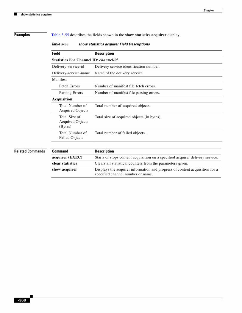
Chapter show statistics acquirer
Examples Table 3-55 describes the fields shown in the show statistics acquirer display.
Related Commands
Table 3-55 show statistics acquirer Field Descriptions
Field Description
Statistics For Channel ID: channel-id
Delivery-service-id Delivery service identification number.
Delivery-service-name Name of the delivery service.
Manifest
Fetch Errors Number of manifest file fetch errors.
Parsing Errors Number of manifest file parsing errors.
Acquisition
Total Number of Acquired Objects
Total number of acquired objects.
Total Size of Acquired Objects (Bytes)
Total size of acquired objects (in bytes).
Total Number of Failed Objects
Total number of failed objects.
Command Description
acquirer (EXEC) Starts or stops content acquisition on a specified acquirer delivery service.
clear statistics Clears all statistical counters from the parameters given.
show acquirer Displays the acquirer information and progress of content acquisition for a specified channel number or name.
-368

Chapter show statistics authentication
show statistics authenticationTo display SE authentication statistics, use the show statistics authentication command in EXEC configuration mode.
show statistics authentication
Syntax Description This command has no arguments or keywords.
Defaults No default behavior or values
Command Modes EXEC
Usage Guidelines Authentication statistics display the number of access requests, denials, and allowances recorded. Use the show statistics authentication command to display the number of authentication accesses recorded.
Examples The fields shown in the show statistics authentication display include the following:
• Number of access requests
• Number of access deny responses
• Number of access allow responses
Related Commands Command Description
authentication Specifies authentication and authorization methods.
clear statistics Clears all statistical counters from the parameters given.
show authentication Displays the authentication configuration.
show statistics authentication
Displays SE authentication statistics.
-369

Chapter show statistics authsvr
show statistics authsvrTo view the authentication server statistics, use the show statistics authsvr command in EXEC configuration mode.
show statistics authsvr
Syntax Description This command has no arguments or keywords.
Command Default No default behavior or values
Command Modes EXEC
Usage Guidelines This command displays the authentication server statistics.
Examples The following is sample authentication server statistics:
ServiceEngine# show statistics authsvr
Authserver Statistics
---------------------Allowed : 0Blocked : 0Unknown Server Allowed : 0Unknown Server Blocked : 0Errors : 0
ServiceEngine#
Related Commands Command Description
authsvr Enables and configures the Authorization server.
show authsvr Displays the status of the Authorization server.
-370

Chapter show statistics cdnfs
show statistics cdnfsTo display SE CDS network file system (cdnfs) statistics, use the show statistics cdnfs command in EXEC configuration mode.
show statistics cdnfs
Syntax Description This command has no arguments or keywords.
Defaults No default behavior or values
Command Modes EXEC
Examples Table 3-56 describes the show statistics cdnfs command fields displayed in the command output.
Table 3-56 show statistics cdnfs Fields
Field Description
Size of physical file system Physical disk size of the CDS network file system.
Space assigned for cdnfs purposes
Amount of physical disk space on the CDS network file system that has been assigned to hold pre-positioned objects. The space can be less than the size of the file system.
Number of cdnfs entries Number of cdnfs objects in the CDS network file system.
Note One pre-positioned file internally uses two cdnfs entries. The count of cdnfs entries is twice the number of actual files displayed to users.
Space reserved for cdnfs entries Amount of disk space reserved for existing pre-positioned objects. This space is reserved for cdnfs objects before the file is created and written to the file system.
Available space for new entries Amount of physical disk space available in the CDS network file system for new pre-positioned objects.
Physical file system in use Amount of physical disk space currently in use by the CDS network file system.
Physical file system space free Amount of unused physical disk space in the CDS network file system.
Physical file system percentage in use
Percentage of physical disk space in use relative to the total disk space available.
-371

Chapter show statistics cdnfs
Related Commands Command Description
cdnfs Manages the ECDS network file system (cdnfs).
clear Clears the HTTP object cache, the hardware interface, statistics, archive working transaction logs, and other settings.
show cdnfs Displays CDS network file system (cdnfs) information.
show disks Displays the names of the disks currently attached to the SE.
-372

Chapter 3
-373

Chapter show statistics distribution
show statistics distributionTo display the statistics of the content distribution components, use the show statistics distribution command in EXEC configuration mode.
show statistics distribution [all | errors {delivery-service-id delivery-service-id | delivery-service-name delivery-service-name} | metadata-receiver | metadata-sender | unicast-data-receiver [delivery-service-id delivery-service-id | delivery-service-name delivery-service-name | hot-forwarders [forwarder_id | forwarder_name] | idle-forwarders max_idle_forwarders] | unicast-data-sender]
Syntax Description
Defaults The idle-forwarders max_idle_forwarders default is 3.
Command Modes EXEC
all (Optional) Displays the content distribution statistics for all distribution components.
errors (Optional) Displays the distribution error records for the specified channel.
delivery-service-id Displays statistics about the specified delivery service ID.
delivery-service-id Delivery service number.
delivery-service-name Displays statistics about the specified delivery service name.
delivery-service-name Delivery service name.
metadata-receiver (Optional) Displays the content distribution statistics of the metadata receiver.
metadata-sender (Optional) Displays the content distribution statistics of the metadata sender.
unicast-data-receiver (Optional) Displays the content distribution statistics of the unicast data receiver.
delivery-service-id (Optional) Displays statistics about the specified delivery service ID.
delivery-service-id (Optional) Delivery service number.
delivery-service-name (Optional) Displays statistics about the specified delivery service name.
delivery-service-name (Optional) Delivery service name.
hot-forwarders (Optional) Displays the content distribution statistics of hot forwarders.
forwarder_id (Optional) Identifier for the hot forwarder SE.
forwarder_name (Optional) Name of the hot forwarder SE.
idle-forwarders (Optional) Displays the content distribution statistics of idle forwarders.
max_idle_forwarders (Optional) Maximum number of idle forwarder SEs to be displayed.
unicast-data-sender (Optional) Displays the content distribution statistics of the unicast data sender.
-374

Chapter show statistics distribution
Usage Guidelines Cisco ECDS software supports multicast file transfer features that enhance the reliability and performance of multicast file distribution. Previously, the file transfer session depended on a window of time to resend the missing packets. The sender had to send the packets within this window of time for each retransmission request (NACK) from receiver SEs. If a multicast receiver joined the session too late and missed blocks of data that were outside the transmission window, the sender would not resend the missing blocks. The receiver could not receive the entire file, and the transmission failed. The receiver had to wait until a subsequent carousel pass to recover the missed files. The receiver could only receive the entire file or nothing. A slow receiver often failed to receive a large file if the receiving rate lagged behind the sending rate.
The multicast file transfer enhancements resolve these issues by eliminating the window of time for file transmissions. This feature is called checkpoint. Checkpoint allows the sender to divide the transferring file into blocks and to retransmit any and all blocks until the transfer session ends. At any time during the transfer session, a receiver can request retransmission of any block that it has missed. Also, receiver SEs can receive the blocks of a transfer in any order. Data transmission can occur over a longer period, and receivers can recover missed data blocks to successfully complete the transfer in most situations. File transfers are much more resistant to loss of data.
This feature also solves the problem of a multicast receiver joining a transfer session late. Even if a receiver goes offline and restarts during a transfer, it can recover missing data without requesting retransmission of the blocks that it has already received.
Examples Table 4-57 describes the fields shown in the show statistics distribution unicast-data-receiver display.
Table 4-57 show statistics distribution unicast-data-receiver Field Descriptions
Field Description
Channel ID Numerical identifier for the channel.
Channel name Name for the channel.
Current unicast forwarder ID
Numerical identifier for the current unicast forwarder.
Current unicast forwarder name
Name for the current unicast forwarder.
Use hot forwarder Status of the forwarder SE. Values are Yes or No.
Yes means that the forwarder is active, and the job for this channel can be started immediately.
No means that the forwarder is currently inactive and may become active some time later depending on the failure reason. For example, any new forwarder must wait at least one minute before starting active jobs.
Current running job Shows statistics for jobs that are currently running.
relative-cdn-url Relative URL for the current job.
channel-id Numerical identifier for the channel for this job.
fwdr ip address IP address of the current unicast forwarder for this job.
bytes written/total Total number of bytes written for this job.
last write time Number of seconds since the last write time for this job.
Cumulative bps Number of cumulative bits per second.
-375

Chapter show statistics distribution
Related Commands
Last successful job was done at
Time of completion of the last successful job.
# Consecutive failures Number of consecutive failures.
# Jobs in pending queue(P_Q)
Number of jobs pending.
# Jobs in suspended queue(S_Q)
Number of jobs suspended.
# Jobs in waiting queue(W_Q)
Number of jobs waiting.
# Bytes of jobs in P_Q and W_Q
Total number of bytes for jobs that are pending and waiting.
# Bytes of jobs in S_Q Number of bytes for jobs that are suspended.
# Bytes of running jobs Number of bytes for jobs that are currently running.
Table 4-57 show statistics distribution unicast-data-receiver Field Descriptions (continued)
Field Description
Command Description
clear Clears the HTTP object cache, the hardware interface, statistics, archive working transaction logs, and other settings.
show distribution Displays the distribution information for a specified delivery service.
-376

Chapter show statistics flash-media-streaming
show statistics flash-media-streamingTo display the statistics for Flash Media Streaming, use the show statistics flash-media-streaming command in EXEC configuration mode.
show statistics flash-media-streaming [connections | dvrcast | errors | flvcache | livestats | performance | proxy | rules | server | vod-edcs]
Syntax Description
Defaults No default behavior or values
Command Modes EXEC
Examples The following example displays the statistics for Flash Media Streaming:
ServiceEngine# show statistics flash-media-streaming Flash Media Streaming StatisticsStatistics have not been cleared since last Flash Media Streaming starts
Connections-----------Current Connections Total : 0VOD : 0LIVE : 0DVRCast : 0Proxy : 0Max Concurrent : 0Total Connections Total : 0VOD : 0LIVE : 0DVRCast : 0Proxy : 0
VOD Streaming-----Current Connections : 0
connections (Optional) Displays Flash Media Streaming connections statistics.
dvrcast DVRCast is not supported in this release.
errors (Optional) Displays Flash Media Streaming errors statistics.
flvcache (Optional) Displays Flash Media Streaming FLV cache statistics.
livestats (Optional) Displays Flash Media Streaming live application statistics.
performance (Optional) Displays Flash Media Streaming performance statistics.
proxy (Optional) Displays Flash Media Streaming proxy application statistics.
rules (Optional) Displays Flash Media Streaming rules statistics.
server (Optional) Displays Flash Media Streaming server level statistics.
vod-edcs (Optional) Displays Flash Media Streaming vod application statistics.
-377

Chapter show statistics flash-media-streaming
Total Connections : 0DownStream Bytes : 0UpStream Bytes : 0DownStream BW : 0 KbpsPreposition Hit : 0Cache Hit : 0Cache Miss : 0Proxy Case : 0Cache Hit Percentage : 0.00Local Disk Reads : 0HTTP Based Reads : 0Bytes From Local Disk: 0Bytes Through HTTP : 0
Live Streaming-----Current Connections : 0Total Connections : 0UpStream BW : 0 KbpsDownStream BW : 0 KbpsUpStream Bytes : 0DownStream Bytes : 0Downstream CDS-IS total conn.: 0
DVRCast Streaming-----Current Connections : 0Total Connections : 0UpStream BW : 0 KbpsDownStream BW : 0 KbpsUpStream Bytes : 0DownStream Bytes : 0
Proxy Streaming -----Current Connections : 0Total Connections : 0UpStream BW : 0 KbpsDownStream BW : 0 KbpsUpStream Bytes : 0DownStream Bytes : 0
Rules-----------Action Allow : 0Action Block : 0Validate url Sign : 0URL Signing errors: Invalid Client : 0 Invalid Signature : 0 No signing : 0 Expired URL : 0Auth server validation: Auth Server Allow : 0 Auth Server Deny : 0
Error-----Disk Error File Open Error : 0 File Read Error : 0 File GetAttributes Error : 0 File Close Error : 0
-378

Chapter show statistics flash-media-streaming
HTTP Error Invalid Error : 0 Server Error : 0 Media Not Found : 0 Media Unauthorize : 0 Invalid Request : 0 Bad Gateway : 0 Service Unavailable : 0 Gateway Timeout : 0 Request Failed : 0 Invalid Response : 0 Too many Redirect : 0 Invalid Redirect : 0 Invalid Cache Type : 0
Server-----------Total UpStream BW : 0 KbpsTotal DownStream BW : 0 KbpsTotal UpStream Bytes : 0Total DownStream Bytes : 0Total Server Bytes : 0
Performance-----------Server Up Time : 31 SMem Usage : 3 %Max Mem Usage : 3 %Total Messages Dropped: 0
Num of Active VOD Instances : 0Num of Active Live Instances : 0Num of Active DVRCast Instances : 0
Flash Video Cache Statistics-----------Hits : 0 Misses : 0 Released : 0 Bytes in cache : 0 Bytes in use : 0 Disk Usage : 4096
Table 4-58 describes the fields shown in the show statistics flash-media-streaming display.
Table 4-58 show statistics flash-media-streaming Field Descriptions
Field Description
Connections
Current Connections
Total Total number of current active connections to Flash Media Streaming.
VOD Total number of current active connections to VOD applications to Flash Media Streaming.
Live Total number of current active connections to Live applications to Flash Media Streaming.
DVRCast DVRCast is not supported in this release.
-379

Chapter show statistics flash-media-streaming
Proxy Total number of current active connections to non VOD, Live or DVR applications to Flash Media Streaming.
Max Current Max concurrent connections to Flash Media Streaming since it has started.
Total Connections
Total Total number of connections to Flash Media Streaming since it has started.
VOD Total number of connections to VOD applications to Flash Media Streaming since it has started.
LIVE Total number of connections to Live applications to Flash Media Streaming since it has started.
DVRCast DVRCast is not supported in this release.
Proxy Total number of connections to non VOD, Live or DVR applications to Flash Media Streaming since it has started.
VOD Streaming
Current Connections Total number of current active connections to VOD applications to Flash Media Streaming.
Total Connections Total number of connections to VOD applications to Flash Media Streaming since it has started.
DownStream Bytes Total bytes transferred from server to client by VOD applications of Flash Media Streaming since it has started.
UpStream Bytes Total bytes transferred from client to server by VOD applications of Flash Media Streaming since it has started.
DownStream BW Current Bandwidth from server to client by VOD applications of Flash Media Streaming in Kbps.
Preposition Hit Total requests for prepositioned content by VOD applications of Flash Media Streaming since it has started.
Cache Hit Total requests for cache hit content by VOD applications of Flash Media Streaming since it has started.
Cache Miss Total cache miss requests by VOD applications of Flash Media Streaming since it has started.
Proxy Case Total requests for non cached and non prepositioned content by VOD applications of Flash Media Streaming since it has started.
Cache Hit Percentage Percentage of cache hit requests to total requests.
Local Disk Reads Number of read calls to local disk by VOD applications.
HTTP Based Reads Number of read calls to HTTP sockets by VOD applications.
Bytes from Local Disk Total bytes read through HTTP by VOD applications.
Bytes through HTTP Total bytes read from local disk by VOD applications.
Table 4-58 show statistics flash-media-streaming Field Descriptions (continued)
Field Description
-380

Chapter show statistics flash-media-streaming
Live Streaming
Current Connections Total number of current active connections to Live applications to Flash Media Streaming.
Total Connections Total number of connections to Live applications to Flash Media Streaming since it has started.
UpStream BW Current bandwidth from client to server by Live applications of Flash Media Streaming in Kbps.
DownStream BW Current bandwidth from server to client by Live applications of Flash Media Streaming in Kbps.
UpStream Bytes Total bytes transferred from client to server by Live applications of Flash Media Streaming since it has started.
DownStream Bytes Total bytes transferred from server to client by Live applications of Flash Media Streaming since it has started.
Downstream CDS-IS Total Connections
Total live connections from CDS-IS devices that are on a lower level in a tree hierarchy.
Proxy Streaming
Current Connections Total number of current active connections non VOD, Live or DVR applications to Flash Media Streaming.
Total Connections Total number of connections non VOD, Live or DVR applications to Flash Media Streaming since it has started.
UpStream BW Current bandwidth from client to server by non VOD, Live or DVR applications of Flash Media Streaming in Kbps.
DownStream BW Current bandwidth from server to client by non VOD, Live or DVR applications of Flash Media Streaming in Kbps.
UpStream Bytes Total bytes transferred from client to server by non VOD, Live or DVR applications of Flash Media Streaming since it has started.
DownStream Bytes Total bytes transferred from server to client by non VOD, Live or DVR applications of Flash Media Streaming since it has started.
Rules
Action Allow Total number of requests allowed by configured rules.
Action Block Total number of requests blocked by configured rules.
Validate url Sign Total number of requests for which URL sign validation was performed.
URL Signing errors
Invalid Client Total requests where URL signing failed as request was from an invalid client IP address.
Invalid Signature Total requests where URL signing failed as request had an invalid signature.
No signing Total requests where URL signing failed as request was sent without URL signature.
Expired URL Total requests where URL signing failed as the signature had expired its lifetime.
Table 4-58 show statistics flash-media-streaming Field Descriptions (continued)
Field Description
-381

Chapter show statistics flash-media-streaming
Auth server validation
Auth Server Allow Total number of requests allowed by auth server process.
Auth Server Deny Total number of requests denied by auth server process.
Error
Disk Error
File Open Error Total errors when trying to open a file by Flash Media Streaming.
File Read Error Total errors when trying to read a file by Flash Media Streaming.
File GetAttributes Error Total errors when trying to get file attributes by Flash Media Streaming.
File Close Error Total errors when trying to close a file by Flash Media Streaming.
HTTP Error
Invalid Error Invalid HTTP error code received by Flash Media Streaming.
Server Error HTTP error code 500 received by Flash Media Streaming.
Media Not Found HTTP error code 404 received by Flash Media Streaming.
Media Unauthorize Unauthorized access, HTTP error code 401-407 except 404 received by Flash Media Streaming.
Invalid Request HTTP error code 400 received by Flash Media Streaming.
Bad Gateway HTTP error code 502 received by Flash Media Streaming.
Service Unavailable HTTP error code 503 received by Flash Media Streaming.
Gateway Timeout HTTP error code 504 received by Flash Media Streaming.
Request Failed Null reply received by Flash Media Streaming.
Invalid Response HTTP error code 0 received by Flash Media Streaming.
Too many Redirect More than allowed number of HTTP redirects received by Flash Media Streaming.
Invalid Redirect Invalid redirect URL received by Flash Media Streaming.
Invalid Cache Type Invalid cache type received from web engine by Flash Media Streaming.
Server
Total UpStream BW Total instantaneous BW from client to server for Flash Media Streaming.
Total DownStream BW Total instantaneous BW from server to client for Flash Media Streaming.
Total UpStream Bytes Total bytes transferred from client to server for Flash Media Streaming.
Total DownStream Bytes Total bytes transferred from server to client for Flash Media Streaming.
Total Server Bytes Total bytes served by Flash Media Streaming.
Performance
Server Up Time Time since the Flash Media Streaming has been running.
Mem Usage Current memory usage of Flash Media Streaming.
Max Mem Usage Maximum memory usage of Flash Media Streaming.
Table 4-58 show statistics flash-media-streaming Field Descriptions (continued)
Field Description
-382

Chapter show statistics flash-media-streaming
Related Commands
Total Messages Dropped Total messages dropped by Flash Media Streaming.
Num of Active VOD Instances
Total active VOD instances.
Num of Active Live Instances
Total active Live instances.
Num of Active DVRCast Instances
DVRCast is not supported in this release.
Flash Video Cache Statistics
Hits Total hits on Flash video cache.
Misses Total misses on Flash video cache.
Released Total number of segments released by Flash video cache since Flash Media Streaming has started.
Bytes in cache Current number of bytes in cache.
Bytes in use Current number of bytes in cache being used.
Disk Usage Size of flash video cache on disk.
Table 4-58 show statistics flash-media-streaming Field Descriptions (continued)
Field Description
Command Description
flash-media-streaming Enables and configures FMS.
show flash-media-streaming Displays the FMS information.
-383

Chapter show statistics http
show statistics httpTo display SE HTTP statistics, use the show statistics http command in EXEC configuration mode.
show statistics http {ims | object | pcmm | performance | requests | rule}
Syntax Description
Defaults No default behavior or values
Command Modes EXEC
Examples Table 4-59 describes the fields shown in the show statistics http ims displays.
Table 4-60 describes the fields shown in the show statistics http object displays.
ims Displays HTTP if-modified-since statistics.
object Displays HTTP object statistics.
pcmm Displays PacketCable Multimedia (PCMM) statistics.
performance Displays HTTP performance statistics.
requests Displays HTTP request statistics.
rule Displays rule statistics.
Table 4-59 show statistics http ims Field Descriptions
Field Description
Total Issued Number of If-Modified-Since request sent to the upstream streamer or origin server.
Range Issued Number of If-Range request sent to the upstream streamer or origin server.
Fresh Number of requests for which upstream streamer or Origin Server responded as content is fresh for a If-Modified-Since Request.
Revalid Number of requests for which upstream streamer or Origin Server responded as content needs to be revalidated.
Partial Fresh Number of requests for which upstream streamer or Origin Server responded as content as fresh for a If-Range Request.
Table 4-60 show statistics http object Field Descriptions
Field Description
Revalidate Requests Number of revalidate request sent because the WE received revalidation request from client or child SE.
Stale Content Number of revalidate request sent because content in the cache was stale.
-384

Chapter show statistics http
Table 4-61 describes the fields shown in the show statistics http pcmm displays.
Table 4-62 describes the fields shown in the show statistics http performance displays.
No-Cache Requests Number of revalidate request sent because the WE received no-cache request.
Min TTL Expired Number of revalidate request sent because min-ttl value had expired.
Max TTL Expired Number of revalidate request sent because max-ttl value had expired.
Object Expired Number of revalidate request sent because content in the cache had expired.
Max Age Header Number of revalidate request sent because the max-age header had expired.
Large File Size Number of contents not stored because the file size is larger than the “max object size”.
Content Not Modified Number of contents or responses not stored because WE received a 304 Not modified response.
No Content Length Number of contents not stored because content length was not given in the response header.
Range Request Number of contents not stored because the response was for a range request sent by client or downstream streamer.
No Store Number of no-store request received.
Private Number of private request received.
Auth Required Number of authorization request received.
Non Cacheable Number of non-cacheable request received.
Head Request Number of Head request received.
Vary Header Number of Vary header request received.
Miscellaneous Any other cache control request received because of which WE cannot cache the content.
Table 4-60 show statistics http object Field Descriptions (continued)
Field Description
Table 4-61 show statistics http pcmm Field Descriptions
Field Description
No: of Signature Generation Number of request for which signature generation was done.
No: of Signature Validation Number of request for which signature validation was done.
Table 4-62 show statistics http performance Field Descriptions
Field Description
Total Accesses Total number of request.
Total kBytes Total KB of content served.
Request Per Second Average request per second.
-385

Chapter show statistics http
Table 4-63 describes the fields shown in the show statistics http requests displays.
kBytes Per Second Average number of KB served per second.
kBytes Per Request Average number of KB served per request.
Table 4-62 show statistics http performance Field Descriptions (continued)
Field Description
Table 4-63 show statistics http requests Field Descriptions
Field Description
Cache Hit Number of requests that resulted in a cache hit for all SEs in the CDS network.
Cache Miss Number of requests that resulted in a cache miss (the web object was not available in the cache) for all SEs in the CDS network.
Range Requests Number of requests in the range.
Partial Hit–Live fill Number of requests that resulted in a partial hit-live fill.
Partial Hit–Refill Number of requests that resulted in a partial hit-refill.
Partial Caching–Bypassed Number of bypassed partial caching requests.
Preposition Hits Number of preposition hit requests.
Reply Meta Number of reply meta requests.
Alternate Media Number of alternate media requests.
Num Lookups Number of lookup requests.
Lookup Errors Number of lookup request errors.
Streaming Redirected Requests
Number of client requests for the content redirected by the SR to the closest SE in the CDS network containing that content.
WMT Liveness Requests Number of WMT liveness requests.
Hierarchical Cache Liveness Requests
Number of hierarchical cache liveness requests.
Client Errors Number of client error requests or authentication failures handled by the SE.
Server Errors Number of origin server errors or authentication failures handled by the SE.
HTTP 0.9 Requests Number of requests made using the HTTP 0.9 version. HTTP/0.9 cannot manage caches because document transfers are not optimized. HTTP/0.9, which is the first version of HTTP, has only the GET method. Everything is performed with this method, including sending data to the server (the requested URI looks like the following: http://www.foo.bar/url?var1=foo; the string that follows the first question mark means that the variable called var1 is set to foo).
-386

Chapter show statistics http
Related Commands
HTTP 1.0 Requests Number of requests made using the HTTP 1.0 version. HTTP/1.0 provides a simple caching mechanism. An origin server may mark a response, using the Expires header, with a time until which the cache could return the response without violating semantic transparency. A cache may check the current validity of a response using a conditional request. It may include an If-Modified-Since header in a request for the resource, specifying the value in the cached response’s Last-Modified header. The server may then either respond with a 304 (Not Modified) status code, implying that the cache entry is valid, or it may send a normal 200 (OK) response to replace the cache entry.
HTTP/1.0 also included a mechanism, the Pragma: no-cache header, for the client to indicate that a request should not be satisfied from a cache.
HTTP 1.1 Requests Number of requests made using the HTTP 1.1 version. HTTP/1.1 includes several new conditional request-headers, in addition to If-Modified-Since. The most basic is If-None-Match, which allows a client to present one or more entity tags from its cache entries for a resource. If none of these matches the resource’s current entity tag value, the server returns a normal response; otherwise, it may return a 304 (Not Modified) response with an ETag header that indicates which cache entry is currently valid. This mechanism allows the server to cycle through a set of possible responses, while the If-Modified-Since mechanism only generates a cache hit if the most recent response is valid.
HTTP/1.1 also adds new conditional headers called If-Unmodified-Since and If-Match, which create other forms of preconditions on requests.
Http Invalid Requests Number of invalid HTTP requests.
Blocked Number of blocked requests.
Allowed Number of allowed requests.
Table 4-63 show statistics http requests Field Descriptions (continued)
Field Description
Command Description
clear Clears the HTTP object cache, the hardware interface, statistics, archive working transaction logs, and other settings.
show ftp Displays the caching configuration of the FTP.
-387

Chapter show statistics icap
show statistics icapICAP is not supported in this release.
-388

Chapter show statistics icmp
show statistics icmpTo display SE Internet Control Message Protocol (ICMP) statistics, use the show statistics icmp command in EXEC configuration mode.
show statistics icmp
Syntax Description This command has no arguments or keywords.
Defaults No default behavior or values
Command Modes EXEC
Usage Guidelines ICMP messages are sent in several situations, such as when a datagram cannot reach its destination, when the gateway does not have the buffering capacity to forward a datagram, and when the gateway can direct the host to send traffic on a shorter route. The purpose of these control messages is to provide feedback about problems in the communication environment, not to make IP reliable. There is still no guarantee that a datagram is delivered or a control message is returned. Some datagrams may still be undelivered without any report of their loss.
The ICMP messages typically report errors in the processing of datagrams. To avoid the infinite regress of messages about messages, no ICMP messages are sent about ICMP messages. Also, ICMP messages are only sent about errors in handling fragment zero of fragmented datagrams.
ICMP messages are sent using the basic IP header. The first octet of the data portion of the datagram is on a ICMP type field; the value of this field determines the format of the remaining data.
Many of the type fields contain more specific information about the error condition identified by a code value. ICMP messages have two types of codes:
• Query
• Error
Queries contain no additional information because they ask for information and show a value of 0 in the code field. ICMP uses the queries as shown in Table 4-64.
Table 4-64 Queries
Query Type Field Value
Echo Reply 0
Echo Request 8
Router Advertisement 9
Router Solicitation 10
Time-stamp Request 13
Time-stamp Reply 14
Information Request (obsolete) 15
-389

Chapter show statistics icmp
Error messages give specific information and have varying values that further describe conditions. Error messages always include a copy of the offending IP header and up to 8 bytes of the data that caused the host or gateway to send the error message. The source host uses this information to identify and fix the problem reported by the ICMP error message. ICMP uses the error messages as shown in Table 4-65.
Examples Table 4-66 describes the fields shown in the show statistics icmp display.
Information Reply (obsolete) 16
Address Mask Request 17
Address Mask Reply 18
Table 4-64 Queries (continued)
Query Type Field Value
Table 4-65 Errors
Error Type Field Value
Destination Unreachable 3
Source Quench 4
Redirect 5
Time Exceeded 11
Parameter Problems 12
Table 4-66 show statistics icmp Field Descriptions
Field Description
ICMP messages received Total number of ICMP messages received by the SE.
ICMP messages receive failed Total number of ICMP messages that were not received by the SE.
Destination unreachable Number of destination-unreachable ICMP packets received by the SE. A destination-unreachable message (Type 1) is generated in response to a packet that cannot be delivered to its destination address for reasons other than congestion. The reason for the nondelivery of a packet is described by the code field value. Destination-unreachable packets use the code field values to further describe the function of the ICMP message being sent.
-390

Chapter show statistics icmp
Timeout in transit Number of ICMP time-exceeded packets received by the SE. The time-exceeded message occurs when a router receives a datagram with a TTL of 0 or 1. IP uses the TTL field to prevent infinite routing loops. A router cannot forward a datagram that has a TTL of 0 or 1. Instead, it trashes the datagram and sends a time-exceeded message. Two different time-exceeded error codes can occur, as follows:
• 0 = Time-To-Live Equals 0 During Transit
• 1 = Time-To-Live Equals 0 During Reassembly
A router cannot forward a datagram with a TTL of 0 or 1 both during transit or reassembly. The TTL timer is measured, in seconds, and originally was used before the existence of routers to guarantee that a datagram did not live on the Internet forever. Each gateway processing a datagram reduces this value by at least one if it takes longer to process and forward the datagram. When this value expires, the gateway trashes the datagram and sends a message back to the sender notifying the host of the situation.
Wrong parameters Number of ICMP packets with parameter problems received by the SE. An IP datagram that has been received with the protocol field of the IP header set to 1 (ICMP) and the type field in the ICMP header set to 12 denote a parameter problem on a datagram. ICMP parameter-problem datagrams are issued when a router has had to drop a malformed datagram. This condition is a normal and necessary type of network traffic; however, large numbers of this datagram type on the network can indicate network difficulties or hostile actions. A host or gateway can send this message when no other ICMP message covering the problem can be used to alert the sending host.
Source quenches Number of ICMP source-quench packets received by the SE. A receiving host generates a source-quench message when it cannot process datagrams at the speed requested because of a lack of memory or internal resources. This message serves as a simple flow control mechanism that a receiving host can use to alert a sender to slow down its data transmission. When the source host receives this message, it must pass this information on to the upper-layer process, such as TCP, which then must control the flow of the application’s data stream. A router generates this message when, in the process of forwarding datagrams, it has run low on buffers and cannot queue the datagram for delivery.
Table 4-66 show statistics icmp Field Descriptions (continued)
Field Description
-391

Chapter show statistics icmp
Redirects Number of ICMP redirect packets received by the SE. A router sends a redirect error to the sender of an IP datagram when the sender should have sent the datagram to a different router or directly to an end host (if the end host is local). The message assists the sending host to direct a misdirected datagram to a gateway or host. This alert does not guarantee proper delivery; the sending host has to correct the problem if possible.
Only gateways generate redirect messages to inform source hosts of misguided datagrams. A gateway receiving a misdirected frame does not trash the offending datagram if it can forward it.
Echo requests Number of echo ICMP packets received by the SE. An echo request is an IP datagram that has been received with the protocol field of the IP header set to 1 (ICMP) and the type field in the ICMP header set to 8. The ICMP echo request is issued by the source to determine if the destination is alive. When the destination receives the request, it replies with an ICMP echo reply. This request and reply pair is most commonly implemented using the ping utility. Many network management tools use this utility or some derivative of it, and this condition is common as a part of network traffic.
Note You should be suspicious when a large number of these packets are found on the network.
Echo replies Number of echo-reply ICMP packets received by the SE. An echo reply is the message that is generated in response to an echo request message. An echo reply is an IP datagram that has been received with the protocol field of the IP header set to 1 (ICMP) and the type field in the ICMP header set to 0. This condition is common as a part of network traffic.
Note You should be suspicious when a large number of these packets are found on the network.
Timestamp requests Number of ICMP time-stamp request packets received by the SE. An ICMP time-stamp request is an IP datagram that has been received with the protocol field of the IP header set to 1 (ICMP) and the type field in the ICMP header set to 13. The ICMP time-stamp request and reply pair can be used to synchronize system clocks on the network. The requesting system issues the time-stamp request bound for a destination, and the destination system responds with a time-stamp reply message. This condition is normal as a part of network traffic but is uncommon on most networks.
Note You should be suspicious when a large number of these packets are found on the network.
Table 4-66 show statistics icmp Field Descriptions (continued)
Field Description
-392

Chapter show statistics icmp
Timestamp replies Number of ICMP time-stamp reply packets received by the SE. Time-stamp request and reply messages work in tandem. You have the option of using time stamps. When used, a time-stamp request permits a system to query another for the current time. It expects a recommended value returned to be the number of milliseconds since midnight, UTC. This message provides millisecond resolution. The two systems compare the three time stamps and use a round-trip time to adjust the sender’s or receiver’s time if necessary. Most systems set the transmit and receive time as the same value.
Address mask requests Number of ICMP address mask request packets received by the SE. An ICMP address mask request is an IP datagram that has been received with the protocol field of the IP header set to 1 (ICMP) and the type field in the ICMP header set to 17. ICMP address mask requests could be used to perform reconnaissance sweeps of networks. The ICMP address mask request and reply pair can be used to determine the subnet mask used on the network. When the requesting system issues the address mask request bound for a destination, the destination system responds with an address mask reply message. This condition can be a part of normal network traffic but is uncommon on most networks.
Note You should be suspicious when a large number of these packets are found on the network.
Address mask replies Number of ICMP address mask reply packets received by the SE. An address mask ICMP reply is an IP datagram that has been received with the protocol field of the IP header set to 1 (ICMP) and the type field in the ICMP header set to 18. No known exploits incorporate this option. The ICMP address mask request and reply pair can be used to determine the subnet mask used on the network. When the requesting system issues the address mask request bound for a destination, the destination system responds with an address mask reply message. This condition can be a part of normal network traffic but is uncommon on most networks.
Note You should be suspicious when a large number of these packets are found on the network.
ICMP messages sent Total number of ICMP messages sent by the SE.
ICMP messages send failed Total number of ICMP messages that failed to be sent by the SE.
Destination unreachable Number of destination-unreachable ICMP packets sent by the SE.
Timeout in transit Number of ICMP time-exceeded packets sent by the SE.
Wrong parameters Number of ICMP packets with parameter problems sent by the SE.
Source quenches Number of ICMP source-quench packets sent by the SE.
Redirects Number of ICMP redirect packets sent by the SE.
Echo requests Number of echo ICMP packets sent by the SE.
Table 4-66 show statistics icmp Field Descriptions (continued)
Field Description
-393

Chapter show statistics icmp
Related Commands
Echo replies Number of echo-reply ICMP packets sent by the SE.
Timestamp requests Number of ICMP time-stamp request packets sent by the SE.
Timestamp replies Number of ICMP time-stamp reply packets sent by the SE.
Address mask requests Number of ICMP address mask requests sent by the SE.
Address mask replies Number of ICMP address mask replies sent by the SE.
Table 4-66 show statistics icmp Field Descriptions (continued)
Field Description
Command Description
clear Clears the HTTP object cache, the hardware interface, statistics, archive working transaction logs, and other settings.
-394

Chapter show statistics ip
show statistics ipTo display the IP statistics, use the show statistics ip command in user EXEC configuration mode.
On the SE and CDSM:
show statistics ip
On the SR:
show statistics ip {ospf | proximity {rib | server}}
Syntax Description
Command Default No default behavior or values
Command Modes User EXEC
Usage Guidelines The show statistics ip OSPF command is used to display OSPF counters.
The show statistics ip proximity command is used to display proximity statistics that are tracked in the RIB.
Examples The following is sample output from the show statistics ip ospf command:
ServiceRouter# show statistics ip ospf
Generic counters: OSPF Process ID p1, Event statistics (cleared 06:57:01 ago) Router ID changes: 0 DR elections: 0 Older LSAs received: 0 Neighbor state changes: 0 Neighbor dead postponed: 0 Neighbor dead interval expirations: 0 Neighbor bad lsreqs: 0 Neighbor sequence number mismatches: 0 SPF computations: 2926 full, 0 summary, 0 external
LSA Type Generated Refreshed Flushed Aged out Router 0 14 0 2 Network 0 0 0 0 Summary Net 0 0 0 0 Summary ASBR 0 0 0 0 AS External 0 0 0 0 Opaque Link 0 0 0 0
ospf Displays the different OSPF counters.
proximity Displays the proximity statistics.
rib Displays the RIB proximity statistics.
server Displays the proximity server statistics.
-395
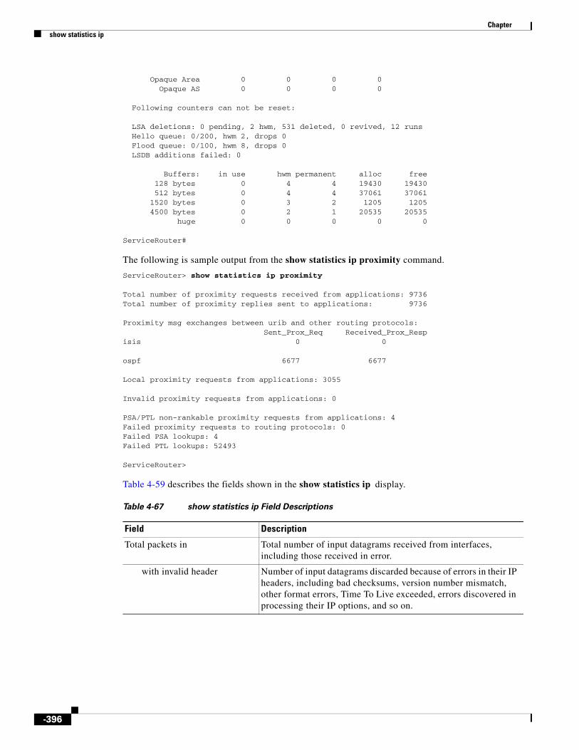
Chapter show statistics ip
Opaque Area 0 0 0 0 Opaque AS 0 0 0 0
Following counters can not be reset:
LSA deletions: 0 pending, 2 hwm, 531 deleted, 0 revived, 12 runs Hello queue: 0/200, hwm 2, drops 0 Flood queue: 0/100, hwm 8, drops 0 LSDB additions failed: 0
Buffers: in use hwm permanent alloc free 128 bytes 0 4 4 19430 19430 512 bytes 0 4 4 37061 37061 1520 bytes 0 3 2 1205 1205 4500 bytes 0 2 1 20535 20535 huge 0 0 0 0 0
ServiceRouter#
The following is sample output from the show statistics ip proximity command.
ServiceRouter> show statistics ip proximity
Total number of proximity requests received from applications: 9736Total number of proximity replies sent to applications: 9736
Proximity msg exchanges between urib and other routing protocols:Sent_Prox_Req Received_Prox_Resp
isis 0 0
ospf 6677 6677
Local proximity requests from applications: 3055
Invalid proximity requests from applications: 0
PSA/PTL non-rankable proximity requests from applications: 4Failed proximity requests to routing protocols: 0Failed PSA lookups: 4Failed PTL lookups: 52493
ServiceRouter>
Table 4-59 describes the fields shown in the show statistics ip display.
Table 4-67 show statistics ip Field Descriptions
Field Description
Total packets in Total number of input datagrams received from interfaces, including those received in error.
with invalid header Number of input datagrams discarded because of errors in their IP headers, including bad checksums, version number mismatch, other format errors, Time To Live exceeded, errors discovered in processing their IP options, and so on.
-396

Chapter show statistics ip
with invalid address Number of input datagrams discarded because the IP address in the IP header’s destination field was not a valid address to be received at this entity. This count includes invalid addresses (for example, 0.0.0.0) and addresses of unsupported classes (for example, Class E). For entities that are not IP routers and do not forward datagrams, this counter includes datagrams discarded because the destination address was not a local address.
forwarded Number of input datagrams for which this entity was not the final IP destination, but the SE attempted to find a route to forward them to that final destination. In entities that do not act as IP routers, this counter includes only those packets that were source-routed through this entity, and the source-route option processing was successful.
unknown protocol Number of locally addressed datagrams received successfully but discarded because of an unknown or unsupported protocol.
discarded Number of input IP datagrams that were discarded even though the datagrams encountered no problems to prevent their continued processing. This counter does not include any datagrams discarded while awaiting reassembly.
delivered Total number of input datagrams successfully delivered to IP user protocols (including ICMP).
Total packets out Total number of IP datagrams that local IP user protocols (including ICMP) supplied to IP in requests for transmission. This counter does not include any datagrams counted in the forwarded field.
dropped Number of output IP datagrams that were discarded even though the datagrams encountered no problems that would prevent their transmission to their destination. This counter would include datagrams counted in the forwarded field if any such packets met this (discretionary) discard criterion.
dropped (no route) Number of IP datagrams that were discarded because the SE found no route to send them to their destination. This counter includes any packets counted in the forwarded field that meet this no-route criterion including any datagrams that a host cannot route because all its default routers are down.
Fragments dropped after timeout Number of received fragments at this entity that are dropped after being held for the maximum number of seconds while awaiting reassembly at this entity.
Reassemblies required Number of IP fragments received that needed to be reassembled at this entity.
Packets reassembled Number of IP datagrams successfully reassembled.
Table 4-67 show statistics ip Field Descriptions (continued)
Field Description
-397

Chapter show statistics ip
Related Commands
Packets reassemble failed Number of failures detected by the IP reassembly algorithm (because of reasons such as timed out and errors.) This counter is not necessarily a count of discarded IP fragments because some algorithms (notably the algorithm in RFC 815) can lose track of the number of fragments by combining them as they are received.
Fragments received Number of IP datagrams that have been successfully fragmented at this entity.
Fragments failed Number of IP datagrams that have been discarded because they needed to be fragmented at this entity but could not be fragmented for reasons such as the Don’t Fragment flag was set.
Fragments created Number of IP datagram fragments that have been generated because of fragmentation at this entity.
Table 4-67 show statistics ip Field Descriptions (continued)
Field Description
Command Description
clear statistics ip Clears Internet Protocol statistics counters.
ip Configures the Internet Protocol.
show ip routes Displays the IP routing table.
-398

Chapter show statistics movie-streamer
show statistics movie-streamerTo display statistics for the Movie Streamer, use the show statistics movie-streamer command in EXEC configuration mode.
show statistics movie-streamer {all | bw-usage | error | performance | requests | rule}
Syntax Description
Defaults No default behavior or values
Command Modes EXEC
Examples The following example shows all the Movie Streamer statistics:
ServiceEngine# show statistics movie-streamer all
Movie Streamer Request StatisticsTotal---------------------------------------------------Current RTSP Sessions: 3400Total RTSP Sessions: 283299Current RTP Connections: 2739Total RTP Connections: 282885
CDN Related Statistics--------Preposition Hits: 0Cache Hits: 0Cache Miss: 0Live Requests: 283299
Cache Revalidation Statistics--------Fresh Content Requests: 0Revalidated Requests: 0
Movie Streamer Bandwidth Usage StatisticsTotal---------------------------------------------------Current Incoming Bandwidth: 0 bpsCurrent Outgoing Bandwidth: 3921755 bpsCurrent Total Bandwidth: 3921755 bps
Average Incoming Bandwidth: 475217 bpsAverage Outgoing Bandwidth: 13038460 bps
all Displays all statistics.
bw-usage Displays bandwidth usage statistics.
error Displays error statistics.
performance Displays server performance.
requests Displays request statistics.
rule Displays rule statistics.
-399
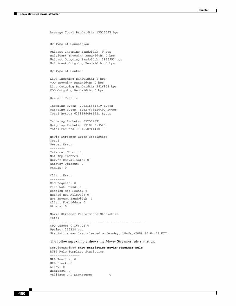
Chapter show statistics movie-streamer
Average Total Bandwidth: 13513677 bps
By Type of Connection--------Unicast Incoming Bandwidth: 0 bpsMulticast Incoming Bandwidth: 0 bpsUnicast Outgoing Bandwidth: 3816953 bpsMulticast Outgoing Bandwidth: 0 bps
By Type of Content--------Live Incoming Bandwidth: 0 bpsVOD Incoming Bandwidth: 0 bpsLive Outgoing Bandwidth: 3816953 bpsVOD Outgoing Bandwidth: 0 bps
Overall Traffic--------Incoming Bytes: 709316834819 BytesOutgoing Bytes: 62627648126402 BytesTotal Bytes: 63336964961221 Bytes
Incoming Packets: 652577871Outgoing Packets: 191008363529Total Packets: 191660941400
Movie Streamer Error StatisticsTotal Server Error--------Internal Error: 0Not Implemented: 0Server Unavailable: 0Gateway Timeout: 0Others: 0
Client Error--------Bad Request: 0File Not Found: 6Session Not Found: 0Method Not Allowed: 0Not Enough Bandwidth: 0Client Forbidden: 0Others: 0
Movie Streamer Performance StatisticsTotal---------------------------------------------------CPU Usage: 0.166702 %Uptime: 254328 secStatistics was last cleared on Monday, 18-May-2009 20:04:42 UTC.
The following example shows the Movie Streamer rule statistics:
ServiceEngine# show statistics movie-streamer ruleRTSP Rule Template Statistics================URL Rewrite: 0URL Block: 0Allow: 0Redirect: 0Validate URL Signature: 0
-400

Chapter show statistics movie-streamer
Related Commands Command Description
movie-streamer Enables and configures the Movie Streamer server.
show movie-streamer Displays the Movie Streamer configuration.
-401

Chapter show statistics netstat
show statistics netstatTo display SE Internet socket connection statistics, use the show statistics netstat command in EXEC configuration mode.
show statistics netstat
Syntax Description This command has no arguments or keywords.
Defaults No default behavior or values
Command Modes EXEC
Examples Table 4-68 describes the fields shown in the show statistics netstat display.
Table 4-68 show statistics netstat Field Descriptions
Field Description
Proto Layer 4 protocol used on the Internet connection, such as TCP, UDP, and so forth.
Recv-Q Amount of data buffered by the Layer 4 protocol stack in the receive direction on a connection.
Send-Q Amount of data buffered by the Layer 4 protocol stack in the send direction on a connection.
Local Address IP address and Layer 4 port used at the device end point of a connection.
Foreign Address IP address and Layer 4 port used at the remote end point of a connection.
State Layer 4 state of a connection. TCP states include the following: ESTABLISHED, TIME-WAIT, LAST-ACK, CLOSED, CLOSED-WAIT, SYN-SENT, SYN-RCVD, SYN-SENT, SYN-ACK-SENT, and LISTEN.
-402

Chapter show statistics qos
show statistics qosTo display statistics for the QoS policy service, use the show statistics qos command in EXEC configuration mode.
show statistics qos policy-service
Syntax Description
Defaults No default behavior or values
Command Modes EXEC
Examples The following example displays the statistics for the QoS policy service:
ServiceEngine# show statistics qos policy-service Camiant CDN-AM Policy Service Statistics ----------------------------------------
Application : WMT Protocol : RTSP PLAY : 0 PAUSE : 0 STOP : 0
Protocol : HTTP PLAY : 0 PAUSE : 0 STOP : 0
Application : WEB-ENGINE Protocol : HTTP PLAY : 0 STOP : 0
Errors : 0
Related Commands
policy-service Displays statistics of Camiant cdn-am policy service
Command Description
qos Enables QoS functionality globally on the device.
show qos Displays QoS information.
-403

Chapter show statistics radius
show statistics radiusTo display SE RADIUS authentication statistics, use the show statistics radius command in EXEC configuration mode.
show statistics radius
Syntax Description This command has no arguments or keywords.
Defaults No default behavior or values
Command Modes EXEC
Examples The fields in the show statistics radius display are as follows:
• Number of access requests
• Number of access deny responses
• Number of access allow responses
• Number of authorization requests
• Number of authorization failure responses
• Number of authorization success responses
Related Commands Command Description
clear Clears the HTTP object cache, the hardware interface, statistics, archive working transaction logs, and other settings.
radius-server Configures the RADIUS authentication.
show radius-server Displays the RADIUS server information.
-404

Chapter show statistics replication
show statistics replicationTo display delivery service replication status and related statistical data, use the following show statistics replication command in EXEC configuration mode.
On the CDSM:
show statistics replication {content-items {selected-delivery-service delivery-service-name} | delivery-service [selected-delivery-service delivery-service-name] | item url | service engines {selected-delivery-service delivery-service-name}}
On the SE:
show statistics replication content-items content-name | selected-delivery-service delivery-service-name}
Syntax Description
Defaults No default behavior or values
Command Modes EXEC
Usage Guidelines The show statistics replication command displays the delivery service replication status on the CDSM and the SE and shows the progressive file count status during acquisition and replication.
Examples Table 4-69 describes the fields shown in the show statistics replication displays.
content-items Displays the replication status of the specified content items.
content-name Content item name or pattern including an asterisk (*) and question mark (?). Use an asterisk to select all content items.
selected-delivery-service Selects a delivery service.
delivery-service-name Delivery service name.
delivery-service Displays replication status of the delivery service.
item Displays the detailed replication status of a content item across all SEs in a delivery service.
url URL of the content item.
service-engines Displays the replication status of the specified SEs.
Table 4-69 show statistics replication Field Descriptions
Field Description
Delivery service Delivery service name.
State Overall state of the delivery service. Values are Complete or Failed.
User Selected Content Acquirer
Name of the Content Acquirer that has been selected for delivery service.
-405

Chapter show statistics replication
Current Content Acquirer
Name of the currently acting Content Acquirer for the delivery service.
Receiver SEs Completed
Total number of SEs that have completed content replication for the delivery service.
Receiver SEs In Progress
Total number of SEs for which content replication is in progress for the delivery service.
Receiver SEs Failed Total number of SEs that have some error condition and are treated as failed.
Receiver SEs Not Responding
Total number of SEs not responding to the replication status queries from the CDSM.
Device Name and ID of the device.
Website Name of the website used for the delivery service.
Type Role of the device, such as Root or Receiver.
State State of the SE replication. For receiver SEs, states are Failed, Replicating, or Completed. For the Content Acquirer, states are Acquiring Content, Rechecking Content, or Completed.
Status Replication status. Values are Red for failure and Green for success.
Completed Number of content items completed.
To Do Number of content items pending for the delivery service.
Failed Number of failed content items.
Total Total number of content items.
Last Report Time Time that this status was obtained.
Disk Quota Used Total disk quota used for the delivery service.
Manifest Last Modified
Time at which the manifest file was last modified.
Manifest Last Check Time at which the manifest file was last checked for freshness.
Manifest State State of the manifest. Values are Complete or Error with details of the error displayed.
Table 4-69 show statistics replication Field Descriptions (continued)
Field Description
-406

Chapter show statistics service-router
show statistics service-routerTo display Service Router statistics, use the show statistics service-router command in EXEC configuration mode.
show statistics service-router {all | content-origin name | dns | history | keepalive | se name | summary}
Syntax Description
Defaults No default behavior or values
Command Modes EXEC
Examples The following example displays the content origin specific statistics on the number of requests and redirects:
ServiceRouter# show statistics service-router content-origin
----- SR Statistics Of Content Origin -----domain: sr.sylvia.com (Origin Server: sylvia.com)HTTP Requests (normal) : 0HTTP Requests (ASX) : 0HTTP Requests (API) : 0RTSP Requests : 0RTMP Requests : 0HTTP 302 Redirects : 0ASX Redirects : 0HTTP API Redirects : 0RTSP Redirects : 0RTMP Redirects : 0Overflow Redirects : 0
----- SR Statistics Of Content Origin -----domain: cdsfms.com (Origin Server: 171.71.50.185, Alternate Domain: 171.71.50.185)HTTP Requests (normal) : 0HTTP Requests (ASX) : 0HTTP Requests (API) : 0RTSP Requests : 0RTMP Requests : 0
all Displays all statistics.
content-origin Displays content origin specific statistics.
name Content origin name to show.
dns Displays DNS statistics.
history Displays statistics history.
keepalive Displays keepalive statistics.
se Displays Service Engine specific statistics.
name Service Engine name to show.
summary Displays summary statistics.
-407

Chapter show statistics service-router
HTTP 302 Redirects : 0ASX Redirects : 0HTTP API Redirects : 0RTSP Redirects : 0RTMP Redirects : 0Overflow Redirects : 0
----- SR Statistics Of Content Origin -----domain: chunliu.com (Origin Server: 72.163.255.111)HTTP Requests (normal) : 0HTTP Requests (ASX) : 0HTTP Requests (API) : 0RTSP Requests : 0RTMP Requests : 0HTTP 302 Redirects : 0ASX Redirects : 0HTTP API Redirects : 0RTSP Redirects : 0RTMP Redirects : 0Overflow Redirects : 0
----- SR Statistics Of Content Origin -----domain: install3.com (Origin Server: 10.74.115.24)HTTP Requests (normal) : 0HTTP Requests (ASX) : 0HTTP Requests (API) : 0RTSP Requests : 0RTMP Requests : 0HTTP 302 Redirects : 0ASX Redirects : 0HTTP API Redirects : 0RTSP Redirects : 0RTMP Redirects : 0Overflow Redirects : 0V2-MDE1100-2#
The following example displays the DNS statistics, including the number of DNS queries for each type (Content Origin FQDN, Service Engine aliases), and the response sent (aliases for down Service Engines, unknown domains, failed, dropped).
:
ServiceRouter# show statistics service-router dns
----- SR DNS Statistics -----Total DNS queries : 0 Content Origin FQDNs : 0 Service Engine aliases : 0 Aliases for Down SEs : 0 Unknown domains : 0 PTR queries : 0 Failed : 0 Dropped : 0
ServiceRouter#
The following example shows how to display the statistics history on the number of redirect requests (maximum, minimum, average, last [in the past hour/minute]):
ServiceRouter# show statistics service-router history
----- SR Statistics History -----Type Minimum Maximum Average Last (in past hour/per minute)---------- --------- --------- --------- ---------
-408

Chapter show statistics service-router
REQUESTS 0 0 0 0REDIRECTS 0 0 0 0
The following example shows how to display keepalive statistics on the number of keepalives received from Service Engines, unknown source, and number of keepalives dropped:
ServiceRouter# show statistics service-router keepalive
----- SR Keepalive Statistics ----- Dropped : 0 Service Engine keepalives : 0 From unknown source : 0
ServiceRouter#
The following example shows how to display Service Engine statistics including liveness of the SE, number of redirects to that particular SE, and the total number of keepalives received from that SE.
ServiceRouter# show statistics service-router se
----- Statistics Of SE: V2-MDE1100-1 -----Aliveness : downHTTP 302 Redirects : 0ASX Redirects : 0HTTP API Redirects : 0RTSP Redirects : 0RTMP Redirects : 0DNS Redirects : 0Number Of Keepalives : 0
----- Statistics Of SE: V2-MDE1100-3 -----Aliveness : downHTTP 302 Redirects : 0ASX Redirects : 0HTTP API Redirects : 0RTSP Redirects : 0RTMP Redirects : 0DNS Redirects : 0Number Of Keepalives : 0V2-MDE1100-2#
The following example shows how to display summary statistics including the number of requests received, requests redirected, requests served, and requests not redirected:
ServiceRouter# show statistics service-router summary
----- SR Summary Statistics -----
Requests Received : 0 HTTP Requests (normal) : 0 HTTP Requests (ASX) : 0 HTTP Requests (API) : 0 RTSP Requests : 0 RTMP Requests : 0 DNS Requests : 0
Requests Served : 0 HTTP Requests Served : 0
Requests Redirected : 0 HTTP 302 Redirects : 0 ASX Redirects : 0 HTTP API Redirects : 0 RTSP redirects : 0
-409

Chapter show statistics service-router
RTMP redirects : 0 DNS redirects : 0
Requests Overflowed : 0 HTTP 302 Redirects : 0 ASX Redirects : 0 HTTP API Redirects : 0 RTSP redirects : 0 RTMP redirects : 0 DNS redirects : 0
Requests Not Redirected : 0 No SE Covering Client : 0 Unknown Content Origin : 0 Route Table Locked : 0
"Stale SE" Requests : 0
Related Commands Command Description
service-router Configures service routing.
show service-router Displays the Service Router configuration.
-410

Chapter show statistics services
show statistics servicesTo display SE services statistics, use the show statistics services command in EXEC configuration mode.
show statistics services
Syntax Description This command has no arguments or keywords.
Defaults No default behavior or values
Command Modes EXEC
Examples Table 4-70 describes the fields shown in the show statistics services display.
Related Commands
Table 4-70 show statistics services Field Descriptions
Field Description
Port Statistics Service-related statistics for each port on the WAAS1 device.
1. WAAS = wide area application service
Port Port number.
Total Connections Number of total connections.
Command Description
show services Displays the services-related information.
-411

Chapter show statistics snmp
show statistics snmpTo display SE Simple Network Management Protocol (SNMP) statistics, use the show statistics snmp command in EXEC configuration mode.
show statistics snmp
Syntax Description This command has no arguments or keywords.
Defaults No default behavior or values
Command Modes EXEC
Examples Table 4-71 describes the fields shown in the show statistics snmp display.
Table 4-71 show statistics snmp Field Descriptions
Field Description
SNMP packets input Total number of SNMP packets input.
Bad SNMP version errors Number of packets with an invalid SNMP version.
Unknown community name Number of SNMP packets with an unknown community name.
Illegal operation for community name supplied
Number of packets requesting an operation not allowed for that community.
Encoding errors Number of SNMP packets that were improperly encoded.
Number of requested variables
Number of variables requested by SNMP managers.
Number of altered variables Number of variables altered by SNMP managers.
Get-request PDUs Number of GET requests received.
Get-next PDUs Number of GET-NEXT requests received.
Set-request PDUs Number of SET requests received.
SNMP packets output Total number of SNMP packets sent by the router.
Too big errors Number of SNMP packets that were larger than the maximum packet size.
Maximum packet size Maximum size of SNMP packets.
No such name errors Number of SNMP requests that specified a MIB object that does not exist.
Bad values errors Number of SNMP SET requests that specified an invalid value for a MIB object.
-412

Chapter show statistics snmp
Related Commands
General errors Number of SNMP SET requests that failed because of some other error. (It was not a No such name error, Bad values error, or any of the other specific errors.)
Response PDUs Number of responses sent in reply to requests.
Trap PDUs Number of SNMP traps sent.
Table 4-71 show statistics snmp Field Descriptions (continued)
Field Description
Command Description
show snmp Displays the SNMP parameters.
snmp-server community Configures the community access string to permit access to the SNMP.
snmp-server contact Sets the system server contact string.
snmp-server enable Enables the SE to send SNMP traps.
snmp-server group Defines a user security model group.
snmp-server host Specifies the hosts to receive SNMP traps.
snmp-server location Sets the SNMP system location string.
snmp-server notify inform Configures the SNMP notify inform request.
snmp-server user Defines a user who can access the SNMP engine.
-413
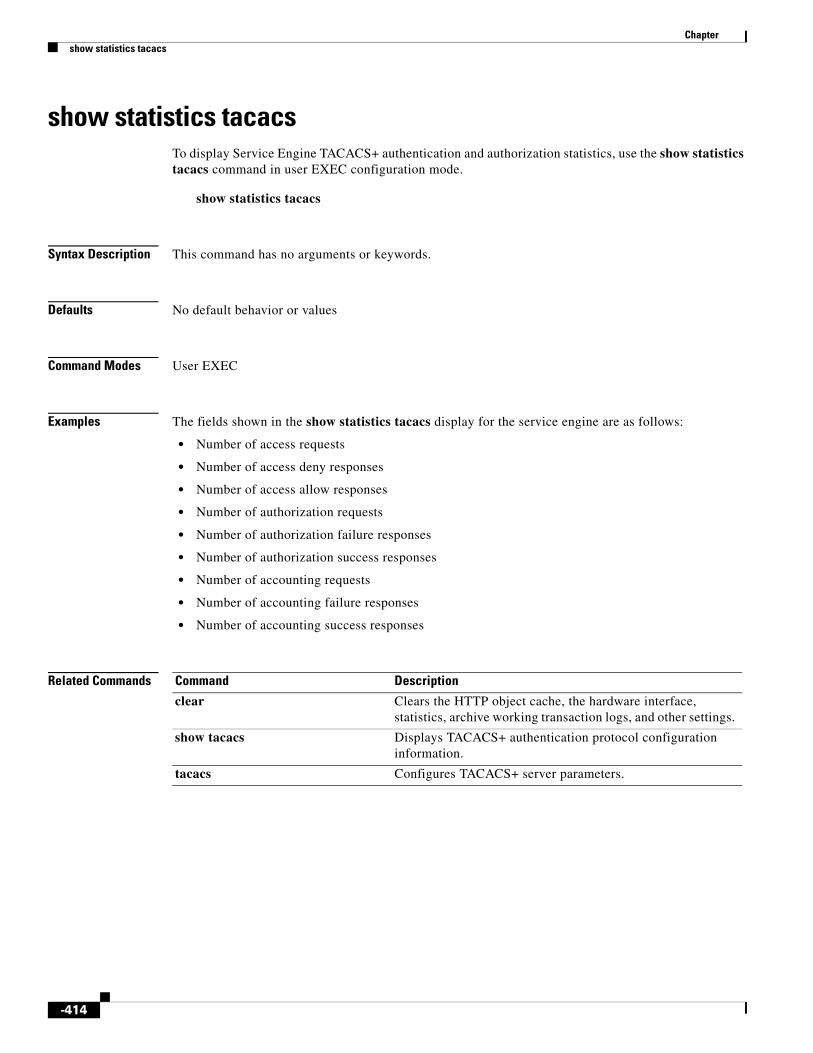
Chapter show statistics tacacs
show statistics tacacsTo display Service Engine TACACS+ authentication and authorization statistics, use the show statistics tacacs command in user EXEC configuration mode.
show statistics tacacs
Syntax Description This command has no arguments or keywords.
Defaults No default behavior or values
Command Modes User EXEC
Examples The fields shown in the show statistics tacacs display for the service engine are as follows:
• Number of access requests
• Number of access deny responses
• Number of access allow responses
• Number of authorization requests
• Number of authorization failure responses
• Number of authorization success responses
• Number of accounting requests
• Number of accounting failure responses
• Number of accounting success responses
Related Commands Command Description
clear Clears the HTTP object cache, the hardware interface, statistics, archive working transaction logs, and other settings.
show tacacs Displays TACACS+ authentication protocol configuration information.
tacacs Configures TACACS+ server parameters.
-414

Chapter show statistics tcp
show statistics tcpTo display SE Transmission Control Protocol (TCP) statistics, use the show statistics tcp command in EXEC configuration mode.
show statistics tcp
Syntax Description This command has no arguments or keywords.
Defaults No default behavior or values
Command Modes EXEC
Examples Table 4-72 describes the fields shown in the show statistics tcp display.
Table 4-72 show statistics tcp Field Descriptions
Field Description
Server connection openings Number of connections opened from the SE to the server.
Client connection openings Number of connections opened from the client to the SE.
Failed connection attempts Number of incoming SYN connections rejected because of rate limiting or resource shortage.
Connections established Number of incoming connections that have been set up.
Connections resets received Number of RSTs1 received by the SE.
Connection resets sent Number of RSTs sent by the SE.
Segments received Number of TCP segments received from the client and the server. The value of this field is almost equal to the sum of the values of the Server segments received and the Client segments received fields.
Segments sent Number of TCP segments sent by the client and the server. The value of this field is almost equal to the sum of the values of the Server segments sent and the Client segments sent fields.
Bad segments received Number of incoming segments dropped because of checksum or being outside the TCP window.
Segments retransmitted Number of TCP segments retransmitted by the client and the server. The value of this field is almost equal to the sum of the values of the Server segments retransmitted and the Client segments retransmitted fields.
-415

Chapter show statistics tcp
Retransmit timer expirations Number of times that the TCP retransmit timer expires. The TCP sender uses a timer to measure the time that has elapsed between sending a data segment and receiving the corresponding ACK from the receiving side of the TCP transmission. When this retransmit timer expires, the sender (according to the RFC standards for TCP congestion control) must reduce its sending rate.
Server segments received Number of TCP segments received by the SE from the server.
Server segments sent Number of TCP segments sent by the SE to the server.
Server segments retransmitted Number of TCP segments retransmitted by the SE from the server.
Client segments received Number of TCP segments received by the SE from the client.
Client segments sent Number of TCP segments sent by the SE to the server.
Client segments retransmitted Number of TCP segments retransmitted by the SE to the client.
Sync cookies sent Number of SYN2 cookies sent by the SE. TCP requires unacknowledged data to be retransmitted. The server is supposed to retransmit the SYN.ACK packet before giving up and dropping the connection. When SYN.ACK arrives at the client but the ACK gets lost, there is a disparity about the establishment state between the client and server. Typically, this problem can be solved by the server’s retransmission. But in the case of a SYN cookie, there is no state kept on the server and retransmission is impossible.
Sync cookies received Number of SYN cookies received by the SE. The entire process of establishing the connection is performed by the ACK packet sent by the client, making the connection process independent of the preceding SYN and SYN.ACK packets. This type of connection establishment opens the possibility of ACK flooding, in the hope that the client has the correct value to establish a connection. This method also allows you to bypass firewalls that normally only filter packets with SYN bit set.
Sync cookies failed Number of SYN cookies rejected by the SE. The SYN cookies feature attempts to protect a socket from a SYN flood attack. This feature is a violation of TCP and conflicts with other areas of TCP such as TCP extensions. It can cause problems for clients and relays. We do not recommend that you use this feature as a tuning mechanism for heavily loaded servers to help with overloaded or misconfigured conditions.
Embryonic connection resets Number of TCP connections that have been reset before the SE accepted the connection.
Prune message called Number of calls that the SE makes to the function that tries to reduce the number of received but not acknowledged packets.
Packets pruned from receive queue Number of packets that the TCP drops from the receive queue (usually because of low memory).
Table 4-72 show statistics tcp Field Descriptions (continued)
Field Description
-416

Chapter show statistics tcp
Out-of-order-queue pruned Number of times that the packet was dropped from the out-of-order queue.
Out-of-window Icmp messages Number of ICMP packets that were outside the TCP window and dropped.
Lock dropped Icmp messages Number of ICMP packets that hit a locked (busy) socket and were dropped.
Arp filter Number of ARPs3 not sent because they were meant for the SE.
Time-wait sockets Number of current sockets in the TIME-WAIT state. The TIME-WAIT state removes old duplicates for fast or long connections. The clock-driven ISN selection is unable to prevent the overlap of the old and new sequence spaces. The TIME-WAIT delay allows enough time for all old duplicate segments to die in the Internet before the connection is reopened.
Time-wait sockets recycled Number of TIME-WAIT sockets that were recycled (the address or port was reused before the waiting period was over). In TCP, the TIME-WAIT state is used as protection against old duplicate segments
Time-wait sockets killed Number of TIME-WAIT sockets that were terminated to reclaim memory.
PAWS passive Number of passive connections that were made with PAWS4 numbers enabled. PAWS operates within a single TCP connection using a state that is saved in the connection control block.
PAWS active Number of active connections that were made with PAWS enabled. PAWS uses the same TCP time stamps as the round-trip time measurement mechanism and assumes that every received TCP segment (including the data and ACK segments) contains a time-stamp SEG.TSval that has values that are monotone and nondecreasing in time. A segment can be discarded as an old duplicate if it is received with a time-stamp SEG.TSval less than some time stamp recently received on this connection.
PAWS established Number of current connections that were made with PAWS enabled.
Delayed acks sent Number of delayed ACK counters sent by the SE.
Delayed acks blocked by socket lock Number of delayed ACK counters that were blocked because the socket was in use.
Delayed acks lost Number of delayed ACK counters lost during transmission.
Listen queue overflows Number of times that the three-way TCP handshake was completed, but enough space was not available in the listen queue.
Connections dropped by listen queue
Number of TCP connections dropped because of a resource shortage.
Table 4-72 show statistics tcp Field Descriptions (continued)
Field Description
-417
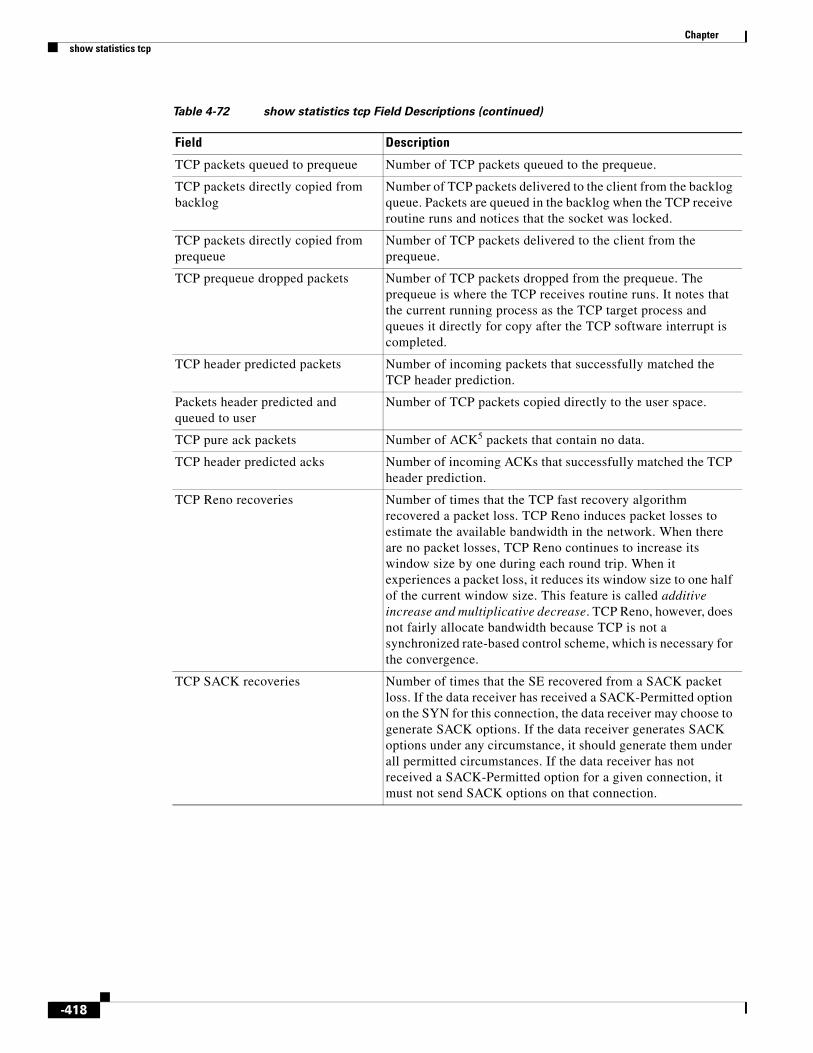
Chapter show statistics tcp
TCP packets queued to prequeue Number of TCP packets queued to the prequeue.
TCP packets directly copied from backlog
Number of TCP packets delivered to the client from the backlog queue. Packets are queued in the backlog when the TCP receive routine runs and notices that the socket was locked.
TCP packets directly copied from prequeue
Number of TCP packets delivered to the client from the prequeue.
TCP prequeue dropped packets Number of TCP packets dropped from the prequeue. The prequeue is where the TCP receives routine runs. It notes that the current running process as the TCP target process and queues it directly for copy after the TCP software interrupt is completed.
TCP header predicted packets Number of incoming packets that successfully matched the TCP header prediction.
Packets header predicted and queued to user
Number of TCP packets copied directly to the user space.
TCP pure ack packets Number of ACK5 packets that contain no data.
TCP header predicted acks Number of incoming ACKs that successfully matched the TCP header prediction.
TCP Reno recoveries Number of times that the TCP fast recovery algorithm recovered a packet loss. TCP Reno induces packet losses to estimate the available bandwidth in the network. When there are no packet losses, TCP Reno continues to increase its window size by one during each round trip. When it experiences a packet loss, it reduces its window size to one half of the current window size. This feature is called additive increase and multiplicative decrease. TCP Reno, however, does not fairly allocate bandwidth because TCP is not a synchronized rate-based control scheme, which is necessary for the convergence.
TCP SACK recoveries Number of times that the SE recovered from a SACK packet loss. If the data receiver has received a SACK-Permitted option on the SYN for this connection, the data receiver may choose to generate SACK options. If the data receiver generates SACK options under any circumstance, it should generate them under all permitted circumstances. If the data receiver has not received a SACK-Permitted option for a given connection, it must not send SACK options on that connection.
Table 4-72 show statistics tcp Field Descriptions (continued)
Field Description
-418
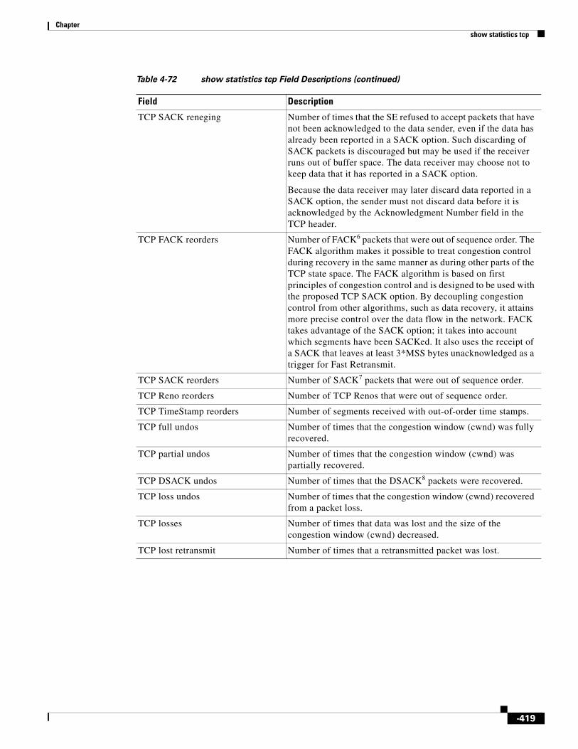
Chapter show statistics tcp
TCP SACK reneging Number of times that the SE refused to accept packets that have not been acknowledged to the data sender, even if the data has already been reported in a SACK option. Such discarding of SACK packets is discouraged but may be used if the receiver runs out of buffer space. The data receiver may choose not to keep data that it has reported in a SACK option.
Because the data receiver may later discard data reported in a SACK option, the sender must not discard data before it is acknowledged by the Acknowledgment Number field in the TCP header.
TCP FACK reorders Number of FACK6 packets that were out of sequence order. The FACK algorithm makes it possible to treat congestion control during recovery in the same manner as during other parts of the TCP state space. The FACK algorithm is based on first principles of congestion control and is designed to be used with the proposed TCP SACK option. By decoupling congestion control from other algorithms, such as data recovery, it attains more precise control over the data flow in the network. FACK takes advantage of the SACK option; it takes into account which segments have been SACKed. It also uses the receipt of a SACK that leaves at least 3*MSS bytes unacknowledged as a trigger for Fast Retransmit.
TCP SACK reorders Number of SACK7 packets that were out of sequence order.
TCP Reno reorders Number of TCP Renos that were out of sequence order.
TCP TimeStamp reorders Number of segments received with out-of-order time stamps.
TCP full undos Number of times that the congestion window (cwnd) was fully recovered.
TCP partial undos Number of times that the congestion window (cwnd) was partially recovered.
TCP DSACK undos Number of times that the DSACK8 packets were recovered.
TCP loss undos Number of times that the congestion window (cwnd) recovered from a packet loss.
TCP losses Number of times that data was lost and the size of the congestion window (cwnd) decreased.
TCP lost retransmit Number of times that a retransmitted packet was lost.
Table 4-72 show statistics tcp Field Descriptions (continued)
Field Description
-419

Chapter show statistics tcp
TCP Reno failures Number of times that the congestion window (cwnd) failed because the TCP fast recovery algorithm failed to recover from a packet loss. The congestion avoidance mechanism, which is adopted by TCP Reno, causes the window size to vary. This situation causes a change in the round-trip delay of the packets, larger delay jitter, and an inefficient use of the available bandwidth because of many retransmissions of the same packets after the packet drops occur. The rate at which each connection updates its window size depends on the round-trip delay of the connection. The connections with shorter delays can update their window sizes faster than other connections with longer delays.
TCP SACK failures Number of times that the cwnd9 shrunk because the SE failed to recover from a SACK packet loss. The selective acknowledgment extension uses two TCP options. The first is an enabling option, SACK-permitted, which may be sent in a SYN segment to indicate that the SACK option can be used once the connection is established. The other is the SACK option, which may be sent over an established connection once permission has been given by the SACK-permitted option.
TCP loss failures Number of times that the TCP timeout occurred and data recovery failed.
TCP fast retransmissions Number of TCP fast retransmission counters. TCP may generate an immediate acknowledgment (a duplicate ACK) when an out-of-order segment is received. The duplicate ACK lets the other end know that a segment was received out of order and tells it what sequence number is expected. Because TCP does not know whether a duplicate ACK is caused by a lost segment or just a reordering of segments, it waits for a small number of duplicate ACKs to be received. If there is just a reordering of the segments, there is only one or two duplicate ACKs before the reordered segment is processed, which then generates a new ACK. If three or more duplicate ACKs are received in a row, it is a strong indication that a segment has been lost. TCP then retransmits what appears to be the missing segment without waiting for a retransmission timer to expire.
Table 4-72 show statistics tcp Field Descriptions (continued)
Field Description
-420

Chapter show statistics tcp
TCP forward retransmissions Number of TCP forward retransmission counters. This field applies only to SACK-negotiated connections; this field is the counter for FACK segments. The value of this field is for segments that were retransmitted even though there is no indication that they were actually lost. Retransmission is stopped when either one of the following occurs:
• Maximum time to wait for a remote response is reached. This timeout occurs when the total time of all retransmission intervals exceeds the maximum time to wait for a remote response.
• Number of retransmissions configured in maximum retransmissions per packet is reached.
TCP slowstart retransmissions Number of TCP slow-start retransmission counters. The slow-start algorithm begins by sending packets at a rate that is determined by the congestion window. The algorithm continues to increase the sending rate until it reaches the limit set by the slow-start threshold (ssthresh) variable. (Initially, the value of the ssthresh variable is adjusted to the receiver’s maximum window size [RMSS]. However, when congestion occurs, the ssthresh variable is set to half the current value of the cwnd variable, marking the point of the onset of network congestion for future reference.)
TCP Timeouts Number of times that a TCP timeout occurred.
TCP Reno recovery fail Number of times that the TCP fast recovery algorithm failed to recover from a packet loss. In TCP Reno, the maximum number of recoverable packet losses in a congestion window without timeout is limited to one or two packets. No more than six losses can be recovered with a maximum window size of 128 packets. This failure of recovery is because TCP Reno cuts the congestion window by half for each recovered loss.
TCP Sack recovery fail Number of times that the SE failed to recover from a SACK packet loss. When receiving an ACK containing a SACK option, the data sender should record the selective acknowledgment for future reference. The data sender is assumed to have a retransmission queue that contains the segments that have been sent but not yet acknowledged in sequence number order. If the data sender performs repacketization before retransmission, the block boundaries in a SACK option that it receives may not fall within the boundaries of segments in the retransmission queue.
TCP scheduler failed Number of times that the TCP scheduler failed.
TCP receiver collapsed Number of times that the data in an out-of-order queue collapsed.
Table 4-72 show statistics tcp Field Descriptions (continued)
Field Description
-421

Chapter show statistics tcp
TCP DSACK old packets sent Number of D-SACKs10 sent by the SE. The use of D-SACK does not require a separate negotiation between a TCP sender and receiver that have already negotiated SACK. The absence of a separate negotiation for D-SACK means that the TCP receiver could send D-SACK blocks when the TCP sender does not understand this extension to SACK. In this case, the TCP sender discards any D-SACK blocks and processes the other SACK blocks in the SACK option field as it normally would.
TCP DSACK out-of-order packets sent
Number of out-of-order D-SACK packets sent by the SE. A D-SACK block is used only to report a duplicate contiguous sequence of data received by the receiver in the most recent packet. Each duplicate contiguous sequence of data received is reported in at most one D-SACK block. (The receiver sends two identical D-SACK blocks in subsequent packets only if the receiver receives two duplicate segments.) If the D-SACK block reports a duplicate contiguous sequence from a (possibly larger) block of data in the receiver's data queue above the cumulative acknowledgement, then the second SACK block in that SACK option should specify that (possibly larger) block of data.
TCP DSACK packets received Number of D-SACK packets received by the SE. TCP senders receiving D-SACK blocks should be aware that a segment reported as a duplicate segment could possibly have been from a prior cycle through the sequence number space. This awareness of the TCP senders is independent of the use of PAWS by the TCP data receiver.
TCP DSACK out-of-order packets received
Number of out-of-order D-SACK packets received by the SE. Following a lost data packet, the receiver receives an out-of-order data segment, which triggers the SACK option as specified in RFC 2018. Because of several lost ACK packets, the sender then retransmits a data packet. The receiver receives the duplicate packet and reports it in the first D-SACK block.
TCP connections abort on sync Number of times that a valid SYN segment was sent in the TCP window and the connection was reset.
TCP connections abort on data Number of times that the connection closed after reading the data.
TCP connections abort on close Number of times that the connection aborted with pending data.
TCP connections abort on memory Number of times that memory was not available for graceful closing of the connection resulting in the connection being aborted immediately.
TCP connections abort on timeout Number of times that the connection timed out.
TCP connections abort on linger Number of times that the linger timeout expired resulting in the data being discarded and closing of the connection.
Table 4-72 show statistics tcp Field Descriptions (continued)
Field Description
-422

Chapter show statistics tcp
Related Commands
TCP connections abort failed Number of times that the TCP connection ran out of memory, transmits failed, or peer TCP Reset (RST) could not be sent.
TCP memory pressures Number of times that the TCP subsystem encounters memory constraints.
1. RST = resets
2. SYN = synchronized
3. ARP = address resolution protocol
4. PAWS = protection against wrapped sequence
5. ACK = acknowledgment
6. FACK = forward acknowledgment
7. SACK = selective acknowledgment
8. DSACK = duplicate selective acknowledgment
9. cwnd = congestion window
10. D-SACKs = duplicate selective acknowledgments
Table 4-72 show statistics tcp Field Descriptions (continued)
Field Description
Command Description
clear Clears the HTTP object cache, the hardware interface, statistics, archive working transaction logs, and other settings.
-423
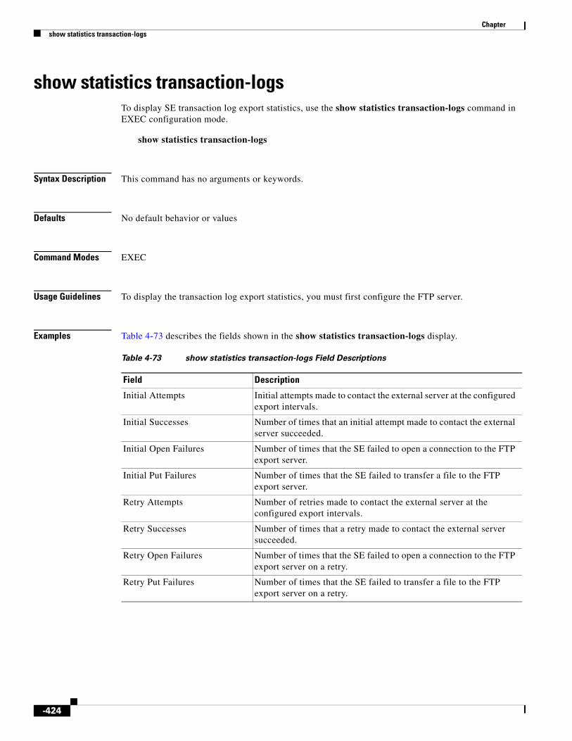
Chapter show statistics transaction-logs
show statistics transaction-logsTo display SE transaction log export statistics, use the show statistics transaction-logs command in EXEC configuration mode.
show statistics transaction-logs
Syntax Description This command has no arguments or keywords.
Defaults No default behavior or values
Command Modes EXEC
Usage Guidelines To display the transaction log export statistics, you must first configure the FTP server.
Examples Table 4-73 describes the fields shown in the show statistics transaction-logs display.
Table 4-73 show statistics transaction-logs Field Descriptions
Field Description
Initial Attempts Initial attempts made to contact the external server at the configured export intervals.
Initial Successes Number of times that an initial attempt made to contact the external server succeeded.
Initial Open Failures Number of times that the SE failed to open a connection to the FTP export server.
Initial Put Failures Number of times that the SE failed to transfer a file to the FTP export server.
Retry Attempts Number of retries made to contact the external server at the configured export intervals.
Retry Successes Number of times that a retry made to contact the external server succeeded.
Retry Open Failures Number of times that the SE failed to open a connection to the FTP export server on a retry.
Retry Put Failures Number of times that the SE failed to transfer a file to the FTP export server on a retry.
-424

Chapter show statistics transaction-logs
Related Commands
Authentication Failures Number of times that the SE failed to authenticate with the FTP export server. This situation might occur if the SE is misconfigured with the wrong password for the FTP server or the password on the FTP server has been changed since the SE was configured.
Invalid Server Directory Failures
Number of times the SE failed to direct traffic to the correct server directory.
Table 4-73 show statistics transaction-logs Field Descriptions (continued)
Field Description
Command Description
clear Clears the HTTP object cache, the hardware interface, statistics, archive working transaction logs, and other settings.
show transaction-logging Displays the transaction log configuration settings and a list of archived transaction log files.
transaction-log force Forces the archive or export of the transaction log.
-425

Chapter show statistics udp
show statistics udpTo display SE User Datagram Protocol (UDP) statistics, use the show statistics udp command in EXEC configuration mode.
show statistics udp
Syntax Description This command has no arguments or keywords.
Defaults No default behavior or values
Command Modes EXEC
Examples Table 4-74 describes the fields shown in the show statistics udp display.
Table 4-74 show statistics udp Field Descriptions
Field Description
Packets received Total number of UDP packets received.
Packets to unknown port received
Number of packets to unknown ports received.
Packet receive error Number of packet receive errors.
Packet sent Number of UDP packets sent.
-426

Chapter show statistics wccp
show statistics wccpTo display Service Engine WCCP statistics, use the show statistics wccp EXEC command.
show statistics wccp gre
Syntax Description
Defaults No default behavior or values
Command Modes EXEC
Usage Guidelines GRE is a Layer 3 technique that allows datagrams to be encapsulated into IP packets at the WCCP-enabled router and then redirected to a Service Engine (the transparent proxy server). At this intermediate destination, the datagrams are decapsulated and then routed to an origin server to satisfy the request if a cache miss occurs. In doing so, the trip to the origin server appears to the inner datagrams as one hop. Usually, the redirected traffic using GRE is referred to as GRE tunnel traffic. With GRE, all redirection is handled by the router software.
With WCCP redirection, a Cisco router does not forward the TCP SYN packet to the destination because the router has WCCP enabled on the destination port of the connection. Instead, the WCCP-enabled router encapsulates the packet using GRE tunneling and sends it to the Service Engine that has been configured to accept redirected packets from this WCCP-enabled router.
After receiving the redirected packet, the Service Engine does the following:
1. Strips the GRE layer from the packet.
2. Decides whether it should accept this redirected packet and process the request for the content as follows:
a. If the Service Engine decides to accept the request, it sends a TCP SYN ACK packet to the client. In this response packet, the Service Engine uses the IP address of the original destination (origin server) that was specified as the source address so that the Service Engine can be invisible (transparent) to the client; it pretends to be the destination that the client’s TCP SYN packet was trying to reach.
b. If the Service Engine decides not to accept the request, it reencapsulates the TCP SYN packet in GRE and sends it back to the WCCP-enabled router. The router understands that the Service Engine is not interested in this connection and forwards the packet to its original destination (the origin server).
For example, a Service Engine would decide not to accept the request because it is configured to bypass requests that originate from a certain set of clients or that are destined to a particular set of servers.
Examples Table 4-75 describes the fields shown in the show statistics wccp gre display.
gre Displays WCCP generic routing encapsulation packet-related statistics.
-427

Chapter show statistics wccp
Table 4-75 show statistics wccp gre Field Descriptions
Field Description
Transparent GRE packets received
Total number of GRE packets received by the Service Engine, regardless of whether they have been intercepted by WCCP or not. GRE is a Layer 3 technique that allows packets to reach the Service Engine even if there are any number of routers in the path to the Service Engine.
Transparent non-GRE packets received
Number of non-GRE packets received by the Service Engine either using the traffic interception and redirection functions of WCCP in the router hardware at Layer 2 that redirects requests transparently to the Service Engine.
Transparent non-GRE packets passed through
Number of non-GRE packets transparently intercepted by a Layer 4 switch and redirected to the Service Engine.
Total packets accepted Total number of packets that are transparently intercepted and redirected to the Service Engine to serve client requests for content.
Invalid packets received Number of packets that are dropped either because the redirected packet is a GRE packet and the WCCP GRE header has invalid data or the IP header of the redirected packet is invalid.
Packets received with invalid service
Number of WCCP version 2 GRE redirected packets that contain an invalid WCCP service number.
Packets received on a disabled service
Number of WCCP version 2 GRE redirected packets that specify the WCCP service number for a service that is not enabled on the Service Engine. For example, a HTTPS request redirected to the Service Engine when the HTTPS-caching service (service 70) is not enabled.
Packets received too small Number of GRE packets redirected to the Service Engine that do not contain the minimum amount of data required for a WCCP GRE header.
Packets dropped due to zero TTL Number of GRE packets that are dropped by the Service Engine because the redirected packet’s IP header has a zero TTL.
Packets dropped due to bad buckets
Number of packets that are dropped by the Service Engine because the WCCP flow redirection could not be performed due to a bad mask or hash determination.
Packets dropped due to no redirect address
Number of packets that are dropped because the flow redirection destination IP address could not be determined.
Packets dropped due to loopback redirect
Number of packets that are dropped by the Service Engine when the destination IP address is the same as the loopback address.
Connections bypassed due to load Number of connection flows that are bypassed when the Service Engine is overloaded. When the overload bypass option is enabled, the Service Engine bypasses a bucket and reroutes the overload traffic. If the load remains too high, another bucket is bypassed, and so on, until the Service Engine can handle the load.
-428
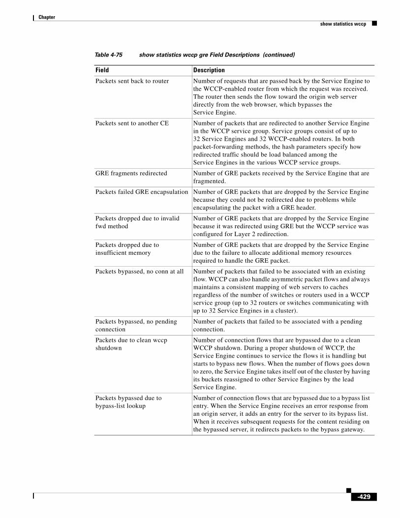
Chapter show statistics wccp
Packets sent back to router Number of requests that are passed back by the Service Engine to the WCCP-enabled router from which the request was received. The router then sends the flow toward the origin web server directly from the web browser, which bypasses the Service Engine.
Packets sent to another CE Number of packets that are redirected to another Service Engine in the WCCP service group. Service groups consist of up to 32 Service Engines and 32 WCCP-enabled routers. In both packet-forwarding methods, the hash parameters specify how redirected traffic should be load balanced among the Service Engines in the various WCCP service groups.
GRE fragments redirected Number of GRE packets received by the Service Engine that are fragmented.
Packets failed GRE encapsulation Number of GRE packets that are dropped by the Service Engine because they could not be redirected due to problems while encapsulating the packet with a GRE header.
Packets dropped due to invalid fwd method
Number of GRE packets that are dropped by the Service Engine because it was redirected using GRE but the WCCP service was configured for Layer 2 redirection.
Packets dropped due to insufficient memory
Number of GRE packets that are dropped by the Service Engine due to the failure to allocate additional memory resources required to handle the GRE packet.
Packets bypassed, no conn at all Number of packets that failed to be associated with an existing flow. WCCP can also handle asymmetric packet flows and always maintains a consistent mapping of web servers to caches regardless of the number of switches or routers used in a WCCP service group (up to 32 routers or switches communicating with up to 32 Service Engines in a cluster).
Packets bypassed, no pending connection
Number of packets that failed to be associated with a pending connection.
Packets due to clean wccp shutdown
Number of connection flows that are bypassed due to a clean WCCP shutdown. During a proper shutdown of WCCP, the Service Engine continues to service the flows it is handling but starts to bypass new flows. When the number of flows goes down to zero, the Service Engine takes itself out of the cluster by having its buckets reassigned to other Service Engines by the lead Service Engine.
Packets bypassed due to bypass-list lookup
Number of connection flows that are bypassed due to a bypass list entry. When the Service Engine receives an error response from an origin server, it adds an entry for the server to its bypass list. When it receives subsequent requests for the content residing on the bypassed server, it redirects packets to the bypass gateway.
Table 4-75 show statistics wccp gre Field Descriptions (continued)
Field Description
-429

Chapter show statistics wccp
Related Commands
Packets received with client IP addresses
Number of packets that are associated to a connection flow that is being spoofed. By spoofing a client’s IP address, the Service Engine can receive packets with the client IP (which is different from the Service Engine’s own IP address) and send the packet to the correct application that is waiting for the packet.
Conditionally Accepted connections
Number of connection flows that are accepted by the Service Engine due to the conditional accept feature.
Conditionally Bypassed connections
Number of connection flows that are bypassed by the Service Engine due to the conditional accept feature.
L2 Bypass packets destined for loopback
Number of packets that are dropped by the Service Engine due to the destination IP address being the loopback address when the WCCP-enabled router or switch tries to perform Layer 2 redirection.
L2 Packets fragmented for bypass Number of GRE packets that do not contain enough data to hold an IP header.
Packets dropped due to IP access-list deny
Number of packets that are dropped by the Service Engine when an IP access list that the Service Engine applies to WCCP GRE encapsulated packets denies access to WCCP applications (the wccp access-list command).
Packets w/WCCP GRE received too small
Number of packets transparently intercepted by the WCCP-enabled router at Layer 2 and sent to the Service Engine that need to be fragmented for the packets to be redirected using GRE.
Table 4-75 show statistics wccp gre Field Descriptions (continued)
Field Description
wccp version Specifies the version of Web Cache Communication Protocol (WCCP) that the Service Engine should use.
-430

Chapter show statistics wmt
show statistics wmtTo display the SE Windows Media Technologies (WMT) statistics, use the show statistics wmt command in EXEC configuration mode.
show statistics wmt {all | bytes [incoming | outgoing] | cache | errors | multicast | requests | rule | savings | streamstat [incoming | live-ecds | outgoing [client | se] | stream-id 1-999999] | usage}
Syntax Description
Defaults No default behavior or values
Command Modes EXEC
Command History
Usage Guidelines The output of the show statistics wmt command includes information about WMT RTSP requests. For example, the output from the show statistics wmt command was changed as follows:
• RTSP-related information was added to the show statistics wmt all command output.
all Displays all WMT statistics.
bytes Displays unicast byte statistics.
incoming (Optional) Displays unicast incoming byte statistics.
outgoing (Optional) Displays unicast outgoing byte statistics.
cache Displays cache validation statistics.
errors Displays error statistics.
multicast Displays multicast statistics.
requests Displays unicast request statistics.
rule Displays the Rule Template statistics.
savings Displays savings statistics.
streamstat Displays Windows Media streaming connections.
incoming (Optional) Displays statistics of all incoming WMT streams from the SE.
live-ecds (Optional) Displays aggregated live stream statistics.
outgoing (Optional) Displays statistics of all outgoing WMT streams from the SE.
client Shows all the outgoing streams to clients.
se Shows all the outgoing streams to SEs.
stream-id (Optional) Displays statistics of the WMT streams that have the specified stream ID.
1-999999 WMT stream ID to display.
usage Displays current usage statistics.
live This keyword is changed to live-ecds in Cisco ECDS Release 2.5.5
-431

Chapter show statistics wmt
• Information about RTSPT and RTSPU was added in the transport protocol portion of the show statistics wmt bytes command output.
• RTSPT and RTSPU errors were added to the show statistics wmt errors command output.
• The show statistics wmt requests command output includes the RTSPT and RTSPU protocols and Fast Start and Fast Cache data.
The live option was added to the show statistics wmt streamstat command to enable you to display aggregated live statistics. Also, the incoming, outgoing, and stream-id options were added to the show statistics wmt streamstat command to display statistics of all incoming WMT streams, outgoing WMT streams, and streams with the specified ID.
The show statistics wmt streamstat command has been extended with the client and SE options. By using the client or se argument, all client or SE outgoing streams are listed. A history of streams sent to the client are not listed, only current streams are listed. By specifying the IP address of the SE, all current WM streams that are being sent from that SE are listed, which includes all outgoing streams not only to clients but to other SEs as well.
Configuring the HTTP Allow/Block Rule
For the MMS over HTTP request rule, even though the request is served by WMT, it doesn’t increment the statistics. The user needs the statistics for all WMT requests. Now the user can execute the show statistics http rule command as the rules daemon check is done from the HTTP side, and the request is redirected to WMT.
Examples Table 4-76 describes the fields shown in the show statistics wmt all display.
Table 4-76 show statistics wmt all Field Descriptions
Field Description
Unicast Requests Statistics
Total unicast requests received
Total number of unicast requests received.
Display shows the number of requests in each category and calculates the percentage of the total for each category.
Streaming Requests served
Number of streaming requests received.
Multicast nsc file Request
Number of multicast NSC file requests received.
Authenticate Requests
Number of authenticated requests received.
Requests error Number of request errors received.
By Type of Content
Live content Number of live content requests received.
On-Demand Content
Number of on-demand content requests received.
By Transport Protocol
HTTP Number of HTTP requests received.
RTSPT Number of RTSPT requests received.
-432

Chapter show statistics wmt
RTSPU Number of RTSPU requests received.
Unicast Savings Statistics
Total bytes saved Total number of bytes saved.
By Source of Content
Local Number of local bytes saved.
Remote HTTP Number of remote HTTP bytes saved.
Remote RTSP Number of remote RTSP bytes saved.
Multicast Number of multicast bytes saved.
CDN-Related WMT Requests
CDN Content Hits
Number of CDN content request hits.
CDN Content Misses
Number of CDN content request misses.
CDN Content Live
Number of CDN live content requests.
CDN Content Errors
Number of CDN content request errors.
Fast Streaming-related WMT Requests
Normal Speed Number of normal-speed Fast Streaming-related WMT requests.
Fast Start Only Number of Fast Start WMT requests.
Fast Cache Only Number of Fast Cache WMT requests.
Fast Start and Fast Cache
Number of Fast Start and Fast Cache WMT requests.
Authenticated Requests
By Type of Authentication
Negotiate Number of negotiated authentication authenticated requests.
Digest Number of digest authentication authenticated requests.
Basic Number of basic authentication authenticated requests.
Unicast Bytes Statistics
Total unicast incoming bytes
Total number of bytes incoming as unicast streams.
By Type of Content
Live content Number of bytes incoming as unicast streams for live content.
On-Demand Content
Number of bytes incoming as unicast streams for on-demand content.
By Transport Protocol
HTTP Number of bytes incoming as unicast streams using the HTTP transport protocol.
Table 4-76 show statistics wmt all Field Descriptions (continued)
Field Description
-433
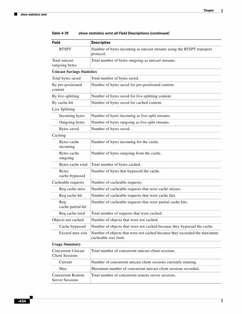
Chapter show statistics wmt
RTSPT Number of bytes incoming as unicast streams using the RTSPT transport protocol.
Total unicast outgoing bytes
Total number of bytes outgoing as unicast streams.
Unicast Savings Statistics
Total bytes saved Total number of bytes saved.
By pre-positioned content
Number of bytes saved for pre-positioned content.
By live-splitting Number of bytes saved for live-splitting content.
By cache-hit Number of bytes saved for cached content.
Live Splitting
Incoming bytes Number of bytes incoming as live-split streams.
Outgoing bytes Number of bytes outgoing as live-split streams.
Bytes saved Number of bytes saved.
Caching
Bytes cache incoming
Number of bytes incoming for the cache.
Bytes cache outgoing
Number of bytes outgoing from the cache.
Bytes cache total Total number of bytes cached.
Bytes cache-bypassed
Number of bytes that bypassed the cache.
Cacheable requests Number of cacheable requests.
Req cache-miss Number of cacheable requests that were cache misses.
Req cache-hit Number of cacheable requests that were cache hits.
Req cache-partial-hit
Number of cacheable requests that were partial cache hits.
Req cache-total Total number of requests that were cached.
Objects not cached Number of objects that were not cached.
Cache bypassed Number of objects that were not cached because they bypassed the cache.
Exceed max-size Number of objects that were not cached because they exceeded the maximum cacheable size limit.
Usage Summary
Concurrent Unicast Client Sessions
Total number of concurrent unicast client sessions.
Current Number of concurrent unicast client sessions currently running.
Max Maximum number of concurrent unicast client sessions recorded.
Concurrent Remote Server Sessions
Total number of concurrent remote server sessions.
Table 4-76 show statistics wmt all Field Descriptions (continued)
Field Description
-434
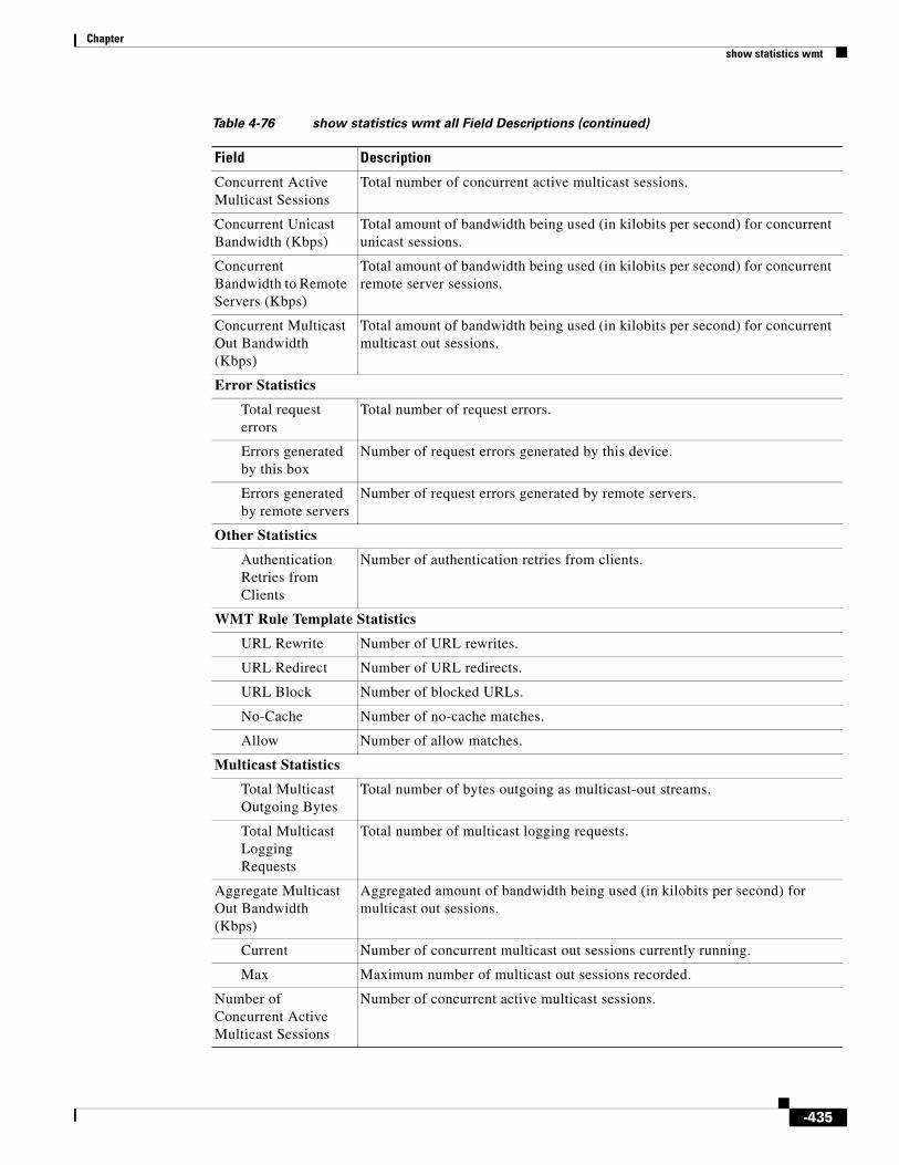
Chapter show statistics wmt
Concurrent Active Multicast Sessions
Total number of concurrent active multicast sessions.
Concurrent Unicast Bandwidth (Kbps)
Total amount of bandwidth being used (in kilobits per second) for concurrent unicast sessions.
Concurrent Bandwidth to Remote Servers (Kbps)
Total amount of bandwidth being used (in kilobits per second) for concurrent remote server sessions.
Concurrent Multicast Out Bandwidth (Kbps)
Total amount of bandwidth being used (in kilobits per second) for concurrent multicast out sessions.
Error Statistics
Total request errors
Total number of request errors.
Errors generated by this box
Number of request errors generated by this device.
Errors generated by remote servers
Number of request errors generated by remote servers.
Other Statistics
Authentication Retries from Clients
Number of authentication retries from clients.
WMT Rule Template Statistics
URL Rewrite Number of URL rewrites.
URL Redirect Number of URL redirects.
URL Block Number of blocked URLs.
No-Cache Number of no-cache matches.
Allow Number of allow matches.
Multicast Statistics
Total Multicast Outgoing Bytes
Total number of bytes outgoing as multicast-out streams.
Total Multicast Logging Requests
Total number of multicast logging requests.
Aggregate Multicast Out Bandwidth (Kbps)
Aggregated amount of bandwidth being used (in kilobits per second) for multicast out sessions.
Current Number of concurrent multicast out sessions currently running.
Max Maximum number of multicast out sessions recorded.
Number of Concurrent Active Multicast Sessions
Number of concurrent active multicast sessions.
Table 4-76 show statistics wmt all Field Descriptions (continued)
Field Description
-435

Chapter show statistics wmt
Related Commands Command Description
clear Clears the HTTP object cache, the hardware interface, statistics, archive working transaction logs, and other settings.
show wmt Displays WMT bandwidth and proxy mode configuration.
wmt Configures the WMT.
-436

Chapter show tacacs
show tacacsTo display TACACS+ authentication protocol configuration information, use the show tacacs command in EXEC configuration mode.
show tacacs
Syntax Description This command has no arguments or keywords.
Defaults No default behavior or values
Command Modes EXEC
Examples The show tacacs command displays the TACACS+ configuration for the Service Engine.
Table 4-77 describes the fields shown in the show tacacs display.
Table 4-77 show tacacs Field Descriptions
Field Description
Login Authentication for Console/Telnet Session
Status of whether TACACS+ server is enabled for login authentication.
Configuration Authentication for Console/Telnet Session
Status of whether TACACS+ server is enabled for authorization or configuration authentication.
Authentication scheme fail-over reason
Status of whether Service Engines fail over to the secondary method of administrative login authentication whenever the primary administrative login authentication method is used.
TACACS+ Configuration TACACS+ server parameters.
TACACS+ Authentication Status of whether TACACS+ authentication is enabled on the Service Engine.
Key Secret key that the Service Engine uses to communicate with the TACACS+ server. The maximum number of characters in the TACACS+ key should not exceed 99 printable ASCII characters (except tabs).
Timeout Number of seconds that the Service Engine waits for a response from the specified TACACS+ authentication server before declaring a timeout.
Retransmit Number of times that the Service Engine is to retransmit its connection to the TACACS+ server if the TACACS+ timeout interval is exceeded.
Password type Mechanism for password authentication. By default, the PAP1 is the mechanism for password authentication.
-437

Chapter show tacacs
Related Commands
Server Hostname or IP address of the TACACS+ server.
Status Status of whether server is the primary or secondary host.
1. PAP = password authentication protocol
Table 4-77 show tacacs Field Descriptions (continued)
Field Description
Command Description
clear Clears the HTTP object cache, the hardware interface, statistics, archive working transaction logs, and other settings.
show statistics tacacs Displays the SE TACACS+ authentication and authorization statistics.
tacacs Configures TACACS+ server parameters.
-438

Chapter show tech-support
show tech-supportTo view information necessary for the Cisco Technical Assistance Center (TAC) to assist you, use the show tech-support command in EXEC configuration mode.
show tech-support list-files directory name
show tech-support [page]
show tech-support service authentication [acquisition-distribution | cms | flash-media-streaming | http | kernel | movie-streamer | rules | wmt]
show tech-support service cms [acquisition-distribution | authentication | flash-media-streaming | http | kernel | movie-streamer | rules | wmt]
show tech-support service flash-media-streaming [acquisition-distribution | authentication | cms | http | kernel | movie-streamer | rules | wmt]
show tech-support service http [acquisition-distribution | authentication | cms | flash-media-streaming | kernel | movie-streamer | rules | wmt]
show tech-support service kernel [acquisition-distribution | authentication | cms | flash-media-streaming | http | movie-streamer | rules | wmt]
show tech-support service movie-streamer [acquisition-distribution | authentication | cms | flash-media-streaming | http | kernel | rules | wmt]
show tech-support service rules [acquisition-distribution | authentication | cms | flash-media-streaming | http | kernel | movie-streamer | wmt]
show tech-support service wmt [acquisition-distribution | authentication | cms | flash-media-streaming | http | kernel | movie-streamer | rules]
Syntax Description list-files (Optional) Displays the list of files under a directory.
directory name Directory name (use absolute path, such as /local1/logs).
page (Optional) Specifies the pages through the output.
service (Optional) Displays technical support information specific to a service.
authentication Displays technical support information related to HTTP authentication.
acquisition-distribution Displays technical support information related to acquisition and distribution.
cms Displays technical support information related to CMS.
flash-media-streaming Displays technical support information related to Flash Media Streaming.
http Displays technical support information related to HTTP.
kernel Displays technical support information related to the kernel.
movie-streamer Displays technical support information related to the Movie Streamer.
rules Displays technical support information related to rules.
wmt Displays technical support information related to WMT.
-439

Chapter show tech-support
Defaults No default behavior or values
Command Modes EXEC
Usage Guidelines Use this command to view system information necessary for TAC to assist you with your SE. We recommend that you log the output to a disk file. Use the streaming option to view information specific to the streaming feature.
The following types of information are available when using the streaming option with the show tech-support command.
General Information
You can access the following general information when you enter the show tech-support command:
• Version and hardware (show version)
• Running configuration (show running-config)
• Processes (show processes)
• Process memory (show processes memory)
• System memory
• File system information
• Interface information
• Media file system statistics
• Application and kernel core dump information
• Netstat
Information Common to WMT and RTSP
Information that is common to both WMT and RTSP is as follows:
• CPU or memory processes (show programs)
• WMT streaming connections (show statistics wmt streamstat)
• Bandwidth allocation (show bandwidth)
• Bit rate allocation (show bitrate)
• Acquirer information (show acquirer)
• Rules (show rule all)
• Distribution channel details
-440

Chapter show tech-support
Information Specific to WMT
Information that is specific to WMT is as follows:
• WMT bandwidth and proxy mode configuration (show wmt)
• WMT statistics (show statistics wmt)
Information Specific to RTSP
Information that is specific to RTSP is as follows:
• RTSP configuration (show rtsp)
Examples The following example shows the types of information available about the CDS software. Because the show tech-support command output is comprehensive and can be extensive, only excerpts are shown in the following example:
ServiceEngine# show tech-support
CPU Usage: cpu: 0.39% User, 0.42% System, 0.33% User(nice), 98.86% Idle cpu0: 0.39% User, 0.42% System, 0.33% User(nice), 98.86% Idle-------------------------------------------------------------------- PID STATE PRI User T SYS T COMMAND ----- ----- --- ------ ------ -------------------- 1 S 0 4386 1706 (init) 2 S 0 0 0 (keventd) 3 S 19 0 0 (ksoftirqd_CPU0) 4 S 0 0 0 (kswapd) 5 S 0 0 0 (bdflush) 6 S 0 0 0 (kupdated) 7 S 0 0 0 (scsi_eh_0) 45 S 0 4733 4114 (nodemgr) 46 S 0 0 0 (syslogd) 47 R 0 83 65 (dataserver) 920 S 0 0 0 (login)1207 S 0 0 0 (parser_server)
1208 S 0 0 0 (eval_timer_mana) 1211 S 0 46 1 (parser_server)1443 S 0 0 0 (overload)
1444 S 0 0 0 (standby) 1445 S 0 13 29 (cache) 1446 S 0 0 0 (proxy_poll) 1447 S 0 0 0 (snmpced) 1448 S 0 0 0 (http_authmod) 1458 S 0 0 0 (http_authmod) 1465 S 0 0 0 (http_authmod) 1466 S 0 0 0 (http_authmod) 1467 S 0 0 0 (http_authmod) 1537 S 0 0 0 (cache) 1538 S 0 0 0 (unified_log)1540 S 0 0 1 (webserver)
1541 S 0 2 2 (mcm) 1542 S 0 0 0 (cache) 1543 S 0 0 0 (cache)1550 S 0 0 0 (cache)
1551 S 0 0 0 (cache) 1556 S 0 0 0 (cache) 1567 S 0 0 0 (mcm) 1568 S 0 0 0 (mcm) 1629 S 0 18982 4140 (crond) 1936 S 0 1669 611 (bootnet)
-441

Chapter show tech-support
1937 S 10 0 0 (tracknet) 1938 S 10 33545 5556 (checkup) 1983 S 0 0 0 (srcpd) 2023 S 0 1 0 (admin-shell) 2024 S 0 0 0 (parser_server) 2150 S 0 0 0 (rsvpd) 2152 S 0 0 0 (rtspd) 2153 S 0 1635 1067 (httpsd) 2164 S 0 0 0 (librarian) 2167 S 0 1667 2105 (libaux) 2170 S 0 0 0 (mapper) 2178 S 0 32 37 (cache) 2179 S 0 0 0 (router) 2180 S 0 0 0 (fill) 2183 S 0 0 0 (remotereq) 2185 S -20 0 0 (videosvr) 2188 S 0 9 4 (contentsvr) 2189 S 0 0 0 (routeraux) 2190 S 0 0 1 (dfcontrolsvr) 2226 S 0 0 0 (smbd) 2228 S 0 0 0 (nmbd) 2973 Z 0 0 0 (cache) 8446 S 0 0 0 (httpsd) 8447 S 0 0 0 (gcache)18173 S 0 0 0 (in.telnetd)18174 S 0 0 0 (login)18175 S 0 2 2 (admin-shell)18176 S 0 0 0 (parser_server)19426 S 0 0 0 (httpsd)19427 S 0 0 0 (httpsd)19456 Z 0 0 0 (cache)19503 Z 0 30 3 (crond)19515 S 0 0 0 (more)19516 S 0 6 18 (exec_show_tech-)19553 R 0 0 0 (exec_show_proce)
------------------ process memory --------------------
Total Used Free Shared Buffers Cached1050943488 564785152 486158336 0 5222400 475176960
PID State TTY %MEM VM Size RSS (pages) Name------ ----- ------ ----- ---------- ----------- ---- 1 S 0 0.0 1146880 119 (init) 2 S 0 0.0 0 0 (keventd) 3 S 0 0.0 0 0 (ksoftirqd_CPU0) 4 S 0 0.0 0 0 (kswapd) 5 S 0 0.0 0 0 (bdflush) 6 S 0 0.0 0 0 (kupdated) 7 S 0 0.0 0 0 (scsi_eh_0) 45 S 0 0.0 1208320 143 (nodemgr) 46 S 0 0.0 1630208 194 (syslogd) 47 R 0 0.0 1974272 238 (dataserver) 920 S 1088 0.0 1728512 236 (login)
1207 S 0 0.3 4980736 847 (parser_server) 1208 S 0 0.0 1933312 151 (eval_timer_mana) 1211 S 0 0.3 4980736 847 (parser_server) 1443 S 0 0.0 1548288 154 (overload) 1444 S 0 0.0 1724416 161 (standby) 1445 S 0 5.9 65646592 15266 (cache) 1446 S 0 0.0 1957888 173 (proxy_poll)
-442

Chapter show tech-support
1447 S 0 0.1 2097152 290 (snmpced) 1448 S 0 0.0 1757184 205 (http_authmod) 1458 S 0 0.0 1757184 205 (http_authmod) 1465 S 0 0.0 1757184 205 (http_authmod) 1466 S 0 0.0 1757184 205 (http_authmod) 1467 S 0 0.0 1757184 205 (http_authmod) 1537 S 0 5.9 65646592 15266 (cache) 1538 S 0 0.0 1789952 169 (unified_log)
1540 S 0 0.4 10817536 1164 (webserver) 1541 S 0 0.0 2150400 251 (mcm) 1542 S 0 5.9 65646592 15266 (cache) 1543 S 0 5.9 65646592 15266 (cache)
1550 S 0 5.9 65646592 15266 (cache) 1551 S 0 5.9 65646592 15266 (cache) 1556 S 0 5.9 65646592 15266 (cache) 1567 S 0 0.0 2150400 251 (mcm) 1568 S 0 0.0 2150400 251 (mcm) 1629 S 0 0.0 1187840 137 (crond) 1936 S 0 0.6 7532544 1605 (bootnet) 1937 S 0 0.2 3215360 545 (tracknet) 1938 S 0 0.2 3637248 654 (checkup) 1983 S 0 0.3 4374528 838 (srcpd) 2023 S 1088 0.0 2146304 182 (admin-shell) 2024 S 0 0.3 4980736 847 (parser_server) 2150 S 0 0.0 1679360 188 (rsvpd) 2152 S 0 0.3 6217728 881 (rtspd) 2153 S 0 0.1 2527232 329 (httpsd) 2164 S 0 0.3 6533120 990 (librarian) 2167 S 0 0.4 7110656 1144 (libaux) 2170 S 0 0.3 5955584 863 (mapper) 2178 S 0 0.3 6135808 927 (cache) 2179 S 0 0.3 6287360 948 (router) 2180 S 0 0.3 5955584 926 (fill) 2183 S 0 0.3 5832704 852 (remotereq) 2185 S 0 0.3 8269824 873 (videosvr) 2188 S 0 0.4 7651328 1196 (contentsvr) 2189 S 0 0.3 6103040 953 (routeraux) 2190 S 0 0.4 10272768 1075 (dfcontrolsvr) 2226 S 0 0.1 3559424 504 (smbd) 2228 S 0 0.0 2084864 247 (nmbd) 2973 Z 0 0.0 0 0 (cache) 8446 S 0 0.1 2506752 327 (httpsd) 8447 S 0 0.0 1421312 116 (gcache) 18173 S 0 0.0 1220608 132 (in.telnetd) 18174 S 34816 0.0 1736704 238 (login) 18175 S 34816 0.0 2162688 184 (admin-shell) 18176 S 0 0.3 4980736 847 (parser_server) 19426 S 0 0.1 2551808 350 (httpsd) 19427 S 0 0.1 2576384 354 (httpsd) 19456 Z 0 0.0 0 0 (cache) 19503 Z 0 0.0 0 0 (crond) 19515 S 34816 0.0 1163264 109 (more) 19516 S 34816 0.0 1941504 168 (exec_show_tech-) 19554 R 34816 0.1 2277376 266 (exec_show_proce)
------------------ system memory --------------------
Total physical memory : 1026312 KBTotal free memory : 474692 KBTotal memory shared : 0 KBTotal buffer memory : 5100 KBTotal cached memory : 464040 KB
------------------ interfaces --------------------
-443

Chapter show tech-support
Interface type: GigabitEthernet Slot: 0 Port: 0Type:EthernetEthernet address:00:05:32:02:DD:74Internet address:172.16.5.234Netmask:255.255.255.0Maximum Transfer Unit Size:1500Metric:1Packets Received: 513241Input Errors: 0Input Packets Dropped: 0Input Packets Overruns: 0Input Packets Frames: 0Packet Sent: 153970Output Errors: 0Output Packets Dropped: 0Output Packets Overruns: 0Output Packets Carrier: 0Output Queue Length:100Collisions: 0Interrupts:9MULTICASTMode:autoselect, 100baseTX
-444

Chapter show telnet
show telnetTo display the Telnet services configuration, use the show telnet command in EXEC configuration mode.
show telnet
Syntax Description This command has no arguments or keywords.
Defaults Enabled.
Command Modes EXEC
Examples The following example displays the Telnet service details:
ServiceEngine# show telnettelnet service is enabled
Related Commands Command Description
exec-timeout Configures the length of time that an inactive Telnet or SSH session remains open.
telnet enable Enables the Telnet services.
-445

Chapter show transaction-logging
show transaction-loggingTo display the transaction log configuration settings and a list of archived transaction log files, use the show transaction-logging command in EXEC configuration mode.
show transaction-logging
Syntax Description This command has no arguments or keywords.
Defaults No default behavior or values
Command Modes EXEC
Usage Guidelines To display information about the current configuration of transaction logging on an SE, use the show transaction-logging command. Transaction log file information is displayed for HTTP and WMT caching proxy transactions and TFTP transactions.
Examples The following example displays information about the current configuration of transaction logging on an SE:
ServiceEngine# show transaction-loggingTransaction log configuration:---------------------------------------Logging is enabled.Archive interval: 1800 secondsMaximum size of archive file: 2000000 KBMaximum number of archive files: 50 filesLog File format is apache.Windows domain is not logged with the authenticated username
Exporting files to ftp servers is enabled.File compression is disabled.Export interval: 30 minutes
server type username directory10.77.153.110 ftp root /var/ftp/test
WMT MMS Caching Proxy/Server Transaction Log File Info Working Log file - size : 556 age: 483497 Archive Log file - mms_export_3.1.18.8_20090522_074807 size: 556
WMT MMS Caching Proxy/Server Transaction Log File Info (WMS-90 format) Working Log file - size : 665 age: 483497 Archive Log file - mms_export_wms_90_3.1.18.8_20090522_074807 size: 665
WMT MMS Caching Proxy/Server Transaction Log File Info (Ext. WMS-90 format) Working Log file - size : 702
-446

Chapter show transaction-logging
age: 483497 Archive Log file - mms_export_e_wms_90_3.1.18.8_20090522_074807 size: 702
WMT MMS Caching Proxy/Server Transaction Log File Info (Ext. WMS-41 format) Working Log file - size : 584 age: 483497 Archive Log file - mms_export_e_wms_41_3.1.18.8_20090522_074807 size: 584
A&D Transaction Log File Info Working Log file - size : 138 age: 483497 Archive Log file - acqdist_3.1.18.8_20090522_074807 size: 138Movie Streamer Transaction Log File Info Working Log file - size : 488 age: 482196 Archive Log file - movie-streamer_3.1.18.8_20090522_062602 size: 648 Archive Log file - movie-streamer_3.1.18.8_20090522_064309 size: 805 Archive Log file - movie-streamer_3.1.18.8_20090522_065857 size: 645 Archive Log file - movie-streamer_3.1.18.8_20090522_070038 size: 648 Archive Log file - movie-streamer_3.1.18.8_20090522_074807 size: 645 Archive Log file - movie-streamer_3.1.18.8_20090522_080016 size: 648 Archive Log file - movie-streamer_3.1.18.8_20090523_030829 size: 645ICAP Transaction Log File Info Working Log file - size : 61 age: 483496 Archive Log file - icap_3.1.18.8_20090522_074807 size: 61
Web Engine Transaction Log File Info - Apache format Working Log file - size : 86 age: 483497 Archive Log file - we_accesslog_apache_3.1.18.8_20090522_074807 size: 82
Web Engine Transaction Log File Info - CLF format Working Log file - size : 3 age: 483497 Archive Log file - we_accesslog_clf_3.1.18.8_20090522_074807 size: 3
Web Engine Transaction Log File Info - Extended Squid format Working Log file - size : 102 age: 483497 Archive Log file - we_accesslog_extsqu_3.1.18.8_20090522_074807 size: 102
Cached Content Log File Info Working Log file - size : 41 age: 483496 Archive Log file - cache_content_3.1.18.8_20090522_074807 size: 41
Flash Media Streaming Access Transaction Log File Info Working Log file - size : 36 age: 482196 Archive Log file - fms_access_3.1.18.8_20090522_062602 size: 650 Archive Log file - fms_access_3.1.18.8_20090522_064309 size: 509 Archive Log file - fms_access_3.1.18.8_20090522_065857 size: 650 Archive Log file - fms_access_3.1.18.8_20090522_074807 size: 509 Archive Log file - fms_access_3.1.18.8_20090522_080016 size: 509 Archive Log file - fms_access_3.1.18.8_20090523_030830 size: 650
Flash Media Streaming Authorization Transaction Log File Info Working Log file - size : 43 age: 482196 Archive Log file - fms_auth_3.1.18.8_20090522_062602 size: 4826
-447

Chapter show transaction-logging
Archive Log file - fms_auth_3.1.18.8_20090522_063036 size: 281 Archive Log file - fms_auth_3.1.18.8_20090522_064309 size: 596 Archive Log file - fms_auth_3.1.18.8_20090522_065857 size: 4789 Archive Log file - fms_auth_3.1.18.8_20090522_070038 size: 277 Archive Log file - fms_auth_3.1.18.8_20090522_074807 size: 596 Archive Log file - fms_auth_3.1.18.8_20090523_030830 size: 4790
Authserver Transaction Log File Info Working Log file - size : 108 age: 483496 Archive Log file - authsvr_3.1.18.8_20090522_065857 size: 108ServiceEngine#
The following example displays information about the current configuration of transaction logging on an SR:
ServiceRouter# show transaction-loggingTransaction log configuration:---------------------------------------Logging is enabled.Archive interval: 120 secondsMaximum size of archive file: 2000000 KBMaximum number of archive files: 50 files
Exporting files to ftp servers is enabled.File compression is disabled.Export interval: 1 minute
server type username directory10.74.115.12 sftp xinwwang /workspace/xinwwang/test10.74.124.156 sftp root /root/test10.74.124.157 sftp root /root/test171.71.50.162 sftp root /test
Service Router Log File Info Working Log file - size : 96 age: 169813 Archive Log file - service_router_3.1.14.70_20090421_222006 size: 256 Archive Log file - service_router_3.1.14.70_20090422_020038 size: 223 Archive Log file - service_router_3.1.14.70_20090422_210022 size: 351 Archive Log file - service_router_3.1.14.70_20090423_020006 size: 1248 Archive Log file - service_router_3.1.14.70_20090423_210021 size: 456 Archive Log file - service_router_3.1.14.70_20090521_000218 size: 402 Archive Log file - service_router_3.1.14.70_20090521_014815 size: 243 Archive Log file - service_router_3.1.14.70_20090521_015020 size: 225 Archive Log file - service_router_3.1.14.70_20090521_015227 size: 243 Archive Log file - service_router_3.1.14.70_20090521_015417 size: 272 Archive Log file - service_router_3.1.14.70_20090521_015601 size: 390 Archive Log file - service_router_3.1.14.70_20090521_015816 size: 243 Archive Log file - service_router_3.1.14.70_20090521_020033 size: 243 Archive Log file - service_router_3.1.14.70_20090521_020249 size: 143 Archive Log file - service_router_3.1.14.70_20090521_032633 size: 168 Archive Log file - service_router_3.1.14.70_20090526_025027 size: 143 Archive Log file - service_router_3.1.14.70_20090526_030002 size: 176 Archive Log file - service_router_3.1.14.70_20090526_030226 size: 250 Archive Log file - service_router_3.1.14.70_20090526_052206 size: 250 Archive Log file - service_router_3.1.14.70_20090526_052413 size: 143 Archive Log file - service_router_3.1.14.70_20090526_200213 size: 168 Archive Log file - service_router_3.1.14.70_20090526_200413 size: 481 Archive Log file - service_router_3.1.14.70_20090526_200645 size: 173 Archive Log file - service_router_3.1.14.70_20090526_201010 size: 250
-448

Chapter show transaction-logging
Related Commands Command Description
clear Clears the HTTP object cache, the hardware interface, statistics, archive working transaction logs, and other settings.
show statistics transaction-logs Displays the SE transaction log export statistics.
transaction-log force Forces the archive or export of the transaction log.
-449

Chapter show url-signature
show url-signatureTo display the URL signature information, use the show url-signature command in EXEC configuration mode.
show url-signature
Syntax Description This command has no arguments or keywords.
Defaults No default behavior or values
Command Modes EXEC
Examples The following example displays the URL signature information:
ServiceEngine# show url-signature key-id-owner key-id-number key-------------------------------
-450

Chapter show user
show userTo display the user identification number and username information for a particular user, use the show command in EXEC configuration mode.
show user {uid number | username name}
Syntax Description
Defaults No default behavior or values
Command Modes EXEC
Examples Table 4-78 describes the fields shown in the show user display.
Related Commands
uid Displays the user’s identification number.
number Identification number. The range is from 0 to 65535.
username Displays the name of user.
name Name of the user.
Table 4-78 show user Field Descriptions
Field Description
Uid User ID number.
Username Username.
Password Login password. This field does not display the actual password.
Privilege Privilege level of the user.
Configured in Database in which the login authentication is configured.
Command Description
clear Clears the HTTP object cache, the hardware interface, statistics, archive working transaction logs, and other settings.
show users Displays the specified users.
username Establishes the username authentication.
-451

Chapter show users
show usersTo display users, use the show users command in EXEC configuration mode.
show users administrative
Syntax Description
Defaults No default behavior or values
Command Modes EXEC
Examples The following example displays the list of users with administrative privileges:
ServiceEngine# show users administrativeUID USERNAME0 admin
Related Commands
administrative Lists users with administrative privileges.
Command Description
clear Clears the HTTP object cache, the hardware interface, statistics, archive working transaction logs, and other settings.
show user Displays the user identification number and username information for a particular user.
username Establishes the username authentication.
-452

Chapter show version
show versionTo display version information about the SE software, use the show version command in EXEC configuration mode.
show version
Syntax Description This command has no arguments or keywords.
Defaults No default behavior or values
Command Modes EXEC
Examples Table 4-79 describes the fields shown in the show version display.
Table 4-79 show version Field Descriptions
Field Description
Compiled hour:minute:second month day year by cnbuild
Compile information for the software build.
System was restarted on day of week month day hour:minute:second year
Date and time that the system was last restarted.
The system has been up for X hours, X minutes, X seconds
Length of time the system has been running since the last reboot.
-453

Chapter show wccp
show wccpTo display Web Cache Communication Protocol (WCCP) information, use the show wccp EXEC command.
show wccp flows {custom-web-cache | https-cache | rtmp | rtsp | service-number service_num | web-cache | wmt | wmt-rtspu} [summary]
show wccp gre
show wccp masks {custom-web-cache | https-cache | rtmp | rtsp | service-number service_num | web-cache | wmt | wmt-rtspu}
show wccp modules
show wccp port-list
show wccp routers
show wccp services [detail]
show wccp slowstart {custom-web-cache | https-cache | rtmp | rtsp | service-number service_num | web-cache | wmt | wmt-rtspu}
show wccp status
Syntax Description content-engines Displays which Service Engines are seen by which routers.
flows Displays the WCCP packet flow count by bucket.
custom-web-cache Displays custom web caching service packet flows.
https-cache Displays the state of HTTPS caching services.
rtsp Displays RTSP caching service packet flows.
service-number Displays the WCCP service number.
service_num Service number (90–97).
service-engines Displays WCCP Version 2 service engine information and verifies successful connection.
web-cache Displays standard web caching service packet flows.
wmt Displays WMT caching service packet flows.
wmt-rtspu Displays WMT RTSPU caching service packet flows.
summary (Optional) Displays summary information.
gre Displays WCCP generic routing encapsulation packet-related information.
masks Displays WCCP mask assignments for a given service.
modules Displays the running status of WCCP registered modules.
port-list Displays the running status of WCCP port lists.
routers Displays routers seen and not seen by this Service Engine.
services Displays WCCP services configured.
detail (Optional) Displays the detail of services.
-454

Chapter show wccp
Defaults No default behavior or values
Command Modes EXEC
Usage Guidelines Use the show wccp services command to list all the services that are configured on the Service Engine.
Use the show wccp services detail command to display the details for a particular WCCP service.
Examples Table 4-80 describes the fields shown in the show wccp gre command.
slowstart Displays the WCCP slow-start state for the selected service.
status Displays the version of WCCP that is enabled and running or whether WCCP is not enabled.
Table 4-80 show statistics wccp gre Field Descriptions
Field Description
Transparent GRE packets received
Total number of GRE packets received by the Service Engine, regardless of whether they have been intercepted by WCCP or not. GRE is a Layer 3 technique that allows packets to reach the Service Engine even if there are any number of routers in the path to the Service Engine.
Transparent non-GRE packets received
Number of non-GRE packets received by the Service Engine either using the traffic interception and redirection functions of WCCP in the router hardware at Layer 2 or Layer 4 switching (a Content Services Switch [CSS]) that redirects requests transparently to the Service Engine.
Transparent non-GRE packets passed through
Number of non-GRE packets transparently intercepted by a Layer 4 switch and redirected to the Service Engine.
Total packets accepted Total number of packets that are transparently intercepted and redirected to the Service Engine to serve client requests for content.
Invalid packets received Number of packets that are dropped either because the redirected packet is a GRE packet and the WCCP GRE header has invalid data or the IP header of the redirected packet is invalid.
Packets received with invalid service
Number of WCCP version 2 GRE redirected packets that contain an invalid WCCP service number.
Packets received on a disabled service
Number of WCCP version 2 GRE redirected packets that specify the WCCP service number for a service that is not enabled on the Service Engine. For example, a HTTPS request redirected to the Service Engine when the HTTPS-caching service (service 70) is not enabled.
-455

Chapter show wccp
Packets received too small Number of GRE packets redirected to the Service Engine that do not contain the minimum amount of data required for a WCCP GRE header.
Packets dropped due to zero TTL Number of GRE packets that are dropped by the Service Engine because the redirected packet’s IP header has a zero TTL.
Packets dropped due to bad buckets
Number of packets that are dropped by the Service Engine because the WCCP flow redirection could not be performed due to a bad mask or hash bucket determination.
Note A bucket is defined as a certain subsection of the allotted hash assigned to each Service Engine in a Service Engine cluster. If only one Service Engine exists in this environment, it has 256 buckets assigned to it.
Packets dropped due to no redirect address
Number of packets that are dropped because the flow redirection destination IP address could not be determined.
Packets dropped due to loopback redirect
Number of packets that are dropped by the Service Engine when the destination IP address is the same as the loopback address.
Connections bypassed due to load Number of connection flows that are bypassed when the Service Engine is overloaded. When the overload bypass option is enabled, the Service Engine bypasses a bucket and reroutes the overload traffic. If the load remains too high, another bucket is bypassed, and so on, until the Service Engine can handle the load.
Packets sent back to router Number of requests that are passed back by the Service Engine to the WCCP-enabled router from which the request was received. The router then sends the flow toward the origin web server directly from the web browser, which bypasses the Service Engine.
Packets sent to another CE Number of packets that are redirected to another Service Engine in the WCCP service group. Service groups consist of up to 32 Service Engines and 32 WCCP-enabled routers. In both packet-forwarding methods, the hash parameters specify how redirected traffic should be load balanced among the Service Engines in the various WCCP service groups.
GRE fragments redirected Number of GRE packets received by the Service Engine that are fragmented.
Packets failed GRE encapsulation Number of GRE packets that are dropped by the Service Engine because they could not be redirected due to problems while encapsulating the packet with a GRE header.
Packets dropped due to invalid fwd method
Number of GRE packets that are dropped by the Service Engine because it was redirected using GRE but the WCCP service was configured for Layer 2 redirection.
Packets dropped due to insufficient memory
Number of GRE packets that are dropped by the Service Engine due to the failure to allocate additional memory resources required to handle the GRE packet.
Table 4-80 show statistics wccp gre Field Descriptions (continued)
Field Description
-456

Chapter show wccp
Packets bypassed, no connection at all
Number of packets that failed to be associated with an existing flow. WCCP can also handle asymmetric packet flows and always maintains a consistent mapping of web servers to caches regardless of the number of switches or routers used in a WCCP service group (up to 32 routers or switches communicating with up to 32 Service Engines in a cluster).
Packets bypassed, no pending connection
Number of packets that failed to be associated with a pending connection.
Packets due to clean WCCP shutdown
Number of connection flows that are bypassed due to a clean WCCP shutdown. During a proper shutdown of WCCP, the Service Engine continues to service the flows it is handling but starts to bypass new flows. When the number of flows goes down to zero, the Service Engine takes itself out of the cluster by having its buckets reassigned to other Service Engines by the lead Service Engine.
Packets bypassed due to bypass-list lookup
Number of connection flows that are bypassed due to a bypass list entry. When the Service Engine receives an error response from an origin server, it adds an entry for the server to its bypass list. When it receives subsequent requests for the content residing on the bypassed server, it redirects packets to the bypass gateway.
Packets received with client IP addresses
Number of packets that are associated to a connection flow that is being spoofed. By spoofing a client’s IP address, the Service Engine can receive packets with the client IP (which is different from the Service Engine’s own IP address) and send the packet to the correct application that is waiting for the packet.
Conditionally Accepted connections
Number of connection flows that are accepted by the Service Engine due to the conditional accept feature.
Conditionally Bypassed connections
Number of connection flows that are bypassed by the Service Engine due to the conditional accept feature.
L2 Bypass packets destined for loopback
Number of packets that are dropped by the Service Engine due to the destination IP address being the loopback address when the WCCP-enabled router or switch tries to perform Layer 2 redirection.
L2 Packets fragmented for bypass Number of GRE packets that do not contain enough data to hold an IP header.
Packets dropped due to IP access-list deny
Number of packets that are dropped by the Service Engine when an IP access list that the Service Engine applies to WCCP GRE encapsulated packets denies access to WCCP applications (the wccp access-list command).
Packets w/WCCP GRE received too small
Number of packets transparently intercepted by the WCCP-enabled router at Layer 2 and sent to the Service Engine that need to be fragmented for the packets to be redirected using GRE.
Table 4-80 show statistics wccp gre Field Descriptions (continued)
Field Description
-457

Chapter show wccp
Table 4-81 describes the fields shown in the show wccp modules display.
Table 4-82 describes the fields in the show wccp routers display.
Related Commands
Table 4-81 show wccp modules Field Descriptions
Field Description
Modules registered with WCCP on this Service Engine
Module Number used by WCCP to identify the module.
Socket Socket used by the module to communicate with WCCP.
Expire(sec) Number of seconds after which the module is assumed to be inactive if it does not respond to keepalive messages.
Name Names of the WCCP registered modules.
Supported Services Services supported by a module.
Table 4-82 show wccp routers Field Descriptions
Field Description
Router Information for Service: Name of WCCP service.
Routers Configured and Seeing this Service Engine
Number of routers configured and that are seeing this CE.
Router Id Address obtained from the I_SEE_YOU message sent by the router. This address is used to identify the router to which this Service Engine is connected.
Sent To IP address to which the Service Engine sends the HERE_I_AM message.
Recv ID Number that is used to synchronize the Service Engine with the router.
Routers not Seeing this Service Engine
IP addresses of all routers that are not seeing this Service Engine.
Routers Notified of but not Configured
Addresses obtained from the I_SEE_YOU message sent by the router when the router is not configured in the router-list.
Multicast Addresses Configured Multicast addresses, if configured in the router-list. If no multicast addresses are configured, the display will show NONE.
Command Description
wccp Series of commands to manage WCCP.
-458

Chapter show wmt
show wmtTo display Windows Media Technologies (WMT) bandwidth and proxy mode configuration, use the show wmt command in EXEC configuration mode.
show wmt [bandwidth [incoming bypass-list] | detail | diagnostics {header-info {stream-file word | nsc-file .nsc-filename} | network-trace word} http allow extension | proxy]
Syntax Description
Defaults No default behavior or values
Command Modes EXEC
Usage Guidelines You can access the following three WMT diagnostic tools through the SE CLI:
• asfhead—Examine the headers of a Windows Media file (for example, an .asf, .wmv, or .wma file). To access the asfhead tool, enter the show wmt diagnostics header-info stream-file word command.
• nschead—Examine the .nsc file headers. To access the nschead tool, enter the show wmt diagnostics header-info nsc-file .ncs-filename command.
• mmsdig—Use this text-based tool to decode the Multimedia Messaging Service (MMS) protocol (a binary protocol) that is captured in tcpdump traces (or any standard network trace output). To access this tool, enter the show wmt diagnostics network trace word command.
The mmsdig tool does not currently support decoding for RTSP, RTP, and RTCP.
bandwidth (Optional) Displays WMT bandwidth settings.
incoming (Optional) Displays WMT incoming bandwidth settings.
bypass-list Displays the WMT incoming bandwidth bypass list.
detail (Optional) Displays the detailed WMT configuration.
diagnostics (Optional) Displays a set of WMT diagnostics tools.
header-info Displays the file header information.
stream-file Displays the headers of a Windows Media file.
word An .asf, .wma, .wmv URL, or local file.
nsc-file Displays the .nsc file headers.
.nsc-filename Name of a local or remote WMT station.
network-trace Displays WMT diagnostics information.
word Name of a local tcpdump file.
http (Optional) Displays HTTP configurations.
allow Displays the HTTP filename extensions allowed to be served using WMT.
extension (Optional) Displays the list of HTTP filename extensions to be served using WMT.
proxy (Optional) Displays proxy mode configuration.
-459

Chapter show wmt
Examples The following example shows sample output of the show wmt diagnostics header-info stream-file command. In this example, this command is used to display the headers of a .wmv file named 256.wmv.
ServiceEngine# show wmt diagnostics header-info stream-file 256.wmvStart dumping ASF header objects... Obj: ASF_Header_Object (size 30) Header Len: 5342 Header Num Of Objs: 8Obj: ASF_File_Properties_Object (size 104) file_size: 429275084 creation_time: 128208475755620000 packet_count: 53656 play_duration: 36050290000 send_duration: 35992950000 preroll: 5000 flags: 2 min_pktsize: 8000 max_pktsize: 8000 min_bitrate: 1003200Obj: ASF_Stream_Properties_Object (size 114) time_offset: 0 stream_type: ASF_Audio_Media ecc_type: ASF_Audio_Spread type_data_len: 28 ecc_data_len: 8 flags: 0x0001 (stream # : 1) ASF type specific data: -------- id_tag: 161 num_channels: 2 sample_per_sec: 48000 bytes_per_sec: 15875 block_align: 2032 bits_per_sample: 16 codec_data(size: 10): 0x00 0x88 0x00 0x00 0x0f 0x00 0xf0 0x07 0x00 0x00 ASF Ecc data: -------- span: 1 packet_len: 2032 chunk_len: 2032 silence_data (1 bytes): 0x00Obj: ASF_Stream_Properties_Object (size 133) time_offset: 0 stream_type: ASF_Video_Media ecc_type: ASF_No_Error_Correction type_data_len: 55 ecc_data_len: 0 flags: 0x0002 (stream # : 2) ASF type specific data: -------- image_width: 320 image_height: 240 flags: 2 data_size: 44 width: 320 height: 240 bits_per_pixel: 24 compression_id: 861293911 data_size: 44 image_size: 0 h_pixels_per_meter: 0 v_pixels_per_meter: 0 color_count: 0 important_color_count: 0 codec_data (4 bytes): 0x4e 0xd9 0x1a 0x01Obj: ASF_Extended_Content_Description_Object (size 208)Obj: ASF_Content_Description_Object (size 42) title: author: copyright: description: rating:Obj: ASF_Stream_Bitrate_Properties_Object (size 38) bitrate record count: 2
-460

Chapter show wmt
# 0: flags = 0x0001, bitrate = 129550 # 1: flags = 0x0002, bitrate = 873650Obj: ASF_Codec_List_Object (size 252) codec_list_entry count: 2 entry # 0: name = Windows Media Audio 9.1 description = 127 kbps, 48 kHz, stereo Low Delay 1-pass CBR 0x61 0x01 entry # 1: name = Windows Media Video 9 description = 0x57 0x4d 0x56 0x33Obj: ASF_Header_Extension_Object (size 4421)Obj: ASF_Language_List_Object (size 39)Obj: ASF_Extended_Stream_Properties_Object (size 88)Obj: ASF_Extended_Stream_Properties_Object (size 110)Obj: ASF_Compatibility_Object (size 26)Obj: ASF_Metadata_Object (size 224)Obj: ASF_Padding_Object (size 3850)Obj: ASF_GUID_Invalid/Unknown_Object (size 38) 0x20 0xde 0xaa 0xd9 0x17 0x7c 0x9c 0x4f 0xbc 0x28 0x85 0x55 0xdd 0x98 0xe2 0xa2Obj: ASF_Data_Object (size 50) data_size: 429248050 packet_count: 53656
The following example shows an excerpt of sample output from the show wmt diagnostics header-info nsc-file command. In this example, this command is used to display the headers of the .nsc file named live1.nsc:
ServiceEngine# show wmt diagnostics header-info nsc-file live1.nscPress Ctrl-C to abort, if no information is shown within 30 secs.
========Dumping NSC file - live1.nsc======== [ Address ] Name=(null) NSC Format Version=3.0 Multicast Adapter=(null) IP Address=224.2.2.3 IP Port=96 Time To Live=15 Default Ecc=10 Log URL=http://kinslive.spcdn.net/live1.nsclog Unicast URL=rtsp://kinslive.spcdn.net/live1 Allow Splitting=1 Allow Caching=1 Cache Expiration Time=86400 [ Formats ] Format1= [ Binary data skipped ] , len = 5316, key = 1111 --------Now trying to dump ASF header(0)-------- Obj: ASF_Header_Object (size 30) Header Len: 5266 Header Num Of Objs: 8Obj: ASF_File_Properties_Object (size 104) file_size: 5268 creation_time: 128880472543590000 packet_count: 4294967295 play_duration: 0 send_duration: 0 preroll: 5000 flags: 9
-461

Chapter show wmt
min_pktsize: 8000 max_pktsize: 8000 min_bitrate: 1003200Obj: ASF_Stream_Properties_Object (size 114) time_offset: 0 stream_type: ASF_Audio_Media ecc_type: ASF_Audio_Spread type_data_len: 28 ecc_data_len: 8 flags: 0x0001 (stream # : 1) ASF type specific data: -------- id_tag: 161 num_channels: 2 sample_per_sec: 48000 bytes_per_sec: 15875 block_align: 2032 bits_per_sample: 16 codec_data(size: 10): 0x00 0x88 0x00 0x00 0x0f 0x00 0xf0 0x07 0x00 0x00 ASF Ecc data: -------- span: 1 packet_len: 2032 chunk_len: 2032 silence_data (1 bytes): 0x00Obj: ASF_Stream_Properties_Object (size 133) time_offset: 0 stream_type: ASF_Video_Media ecc_type: ASF_No_Error_Correction type_data_len: 55 ecc_data_len: 0 flags: 0x0002 (stream # : 2) ASF type specific data: -------- image_width: 320 image_height: 240 flags: 2 data_size: 44 width: 320 height: 240 bits_per_pixel: 24 compression_id: 861293911 data_size: 44 image_size: 0 h_pixels_per_meter: 0 v_pixels_per_meter: 0 color_count: 0 important_color_count: 0 codec_data (4 bytes): 0x4e 0xd9 0x1a 0x01Obj: ASF_Stream_Bitrate_Properties_Object (size 38) bitrate record count: 2 # 0: flags = 0x0001, bitrate = 129550 # 1: flags = 0x0002, bitrate = 873650Obj: ASF_Extended_Content_Description_Object (size 164)Obj: ASF_Codec_List_Object (size 252) codec_list_entry count: 2 entry # 0: name = Windows Media Audio 9.1 description = 127 kbps, 48 kHz, stereo Low Delay 1-pass CBR 0x61 0x01 entry # 1: name = Windows Media Video 9 description = 0x57 0x4d 0x56 0x33Obj: ASF_Error_Correction_Object (size 48) ecc type: ASF_Error_Correction_Default data_len: 4 ecc span: 10Obj: ASF_Header_Extension_Object (size 4383)Obj: ASF_Language_List_Object (size 39)Obj: ASF_Extended_Stream_Properties_Object (size 88)Obj: ASF_Extended_Stream_Properties_Object (size 110)Obj: ASF_Compatibility_Object (size 26)Obj: ASF_Metadata_Object (size 224)Obj: ASF_Padding_Object (size 3850)Obj: ASF_Data_Object (size 50)
-462

Chapter show wmt
data_size: 50 packet_count: 0
Some of the fields are common between the command output from the show wmt diagnostics header-info stream-file and show wmt diagnostics header-info nsc-file commands.
The following example shows the WMT server configurations, the WMT HTTP configurations, and the WMT proxy configurations for the SE. The output of the show wmt and show wmt detail commands is identical.
ServiceEngine# show wmt--------- WMT Server Configurations -----------------WMT is enabledWMT disallowed client protocols: httpWMT bandwidth platform limit: 2000000 Kbits/secWMT outgoing bandwidth configured is 2000000 Kbits/secWMT incoming bandwidth configured is 2000000 Kbits/secWMT max sessions configured: 400 WMT max sessions platform limit: 14000 WMT max sessions enforced: 400 sessionsWMT max outgoing bit rate allowed per stream has no limitWMT max incoming bit rate allowed per stream has no limitWMT cache is enabledWMT cache max-obj-size: 10000 MBWMT cache revalidate for each request is enabledWMT cache age-multiplier: 100%WMT cache min-ttl: 75 minutesWMT cache max-ttl: 7 daysWMT debug client ip not setWMT debug server ip not setWMT accelerate live-split is enabledWMT accelerate proxy-cache is enabledWMT accelerate VOD is enabledWMT fast-start is enabledWMT fast-start max. bandwidth per player is 65535 (Kbps)WMT fast-cache is enabledWMT fast-cache acceleration factor is 65535WMT maximum data packet MTU (TCP) enforced is 1472 bytesWMT maximum data packet MTU (UDP) is 16000 bytesWMT client idle timeout is 300 secondsWMT forward logs is enabledWMT server inactivity-timeout is 65535WMT Transaction Log format is Windows Media Services 9.0 logging and SE specific informationRTSP Gateway incoming port 554
--------- WMT HTTP Configurations -------------------WMT http extensions allowed: asf none nsc wma wmv nsclog
--------- WMT Proxy Configurations ------------------Outgoing Proxy-Mode:--------------------MMS-over-HTTP Proxy-Mode: is not configured.RTSP Proxy-Mode: is configured: 2.2.23.19:86ServiceEngine#
-463

Chapter show wmt
The following example displays the WMT bandwidth settings configured on an SE:
ServiceEngine# show wmt bandwidthOutgoing bandwidth configured 2000000 kbpsIncoming bandwidth configured 2000000 kbpsIncoming bandwidth configured 50000 kbps
Related Commands Command Description
clear Clears the HTTP object cache, the hardware interface, statistics, archive working transaction logs, and other settings.
show statistics wmt Displays the SE WMT statistics.
wmt Configures the WMT.
-464

Chapter shutdown (interface configuration)
shutdown (interface configuration)To shut down a specific hardware interface, use the shutdown command in interface configuration mode. To restore an interface to operation, use the no form of this command.
shutdown
no shutdown
Syntax Description This command has no arguments or keywords.
Defaults No default behavior or values
Command Modes Interface configuration
Usage Guidelines See the “interface” section on page 2-156 for alternative mechanism.
Examples The following example shows how to shut down an interface configured on an SE:
ServiceEngine(config-if)# shutdown
Related Commands Command Description
interface Configures a Gigabit Ethernet or port-channel interface.
show interface Displays the hardware interface information.
show running-config Displays the current operating configuration.
show startup-config Displays the startup configuration.
-465

Chapter shutdown (EXEC)
shutdown (EXEC)To shut down the Service Engine (SE), Service Router (SR), or Content Delivery System Manager (CDSM), use the shutdown command in EXEC configuration mode.
shutdown [poweroff]
Syntax Description
Defaults No default behavior or values
Command Modes EXEC
Usage Guidelines A controlled shutdown refers to the process of properly shutting down an SE without turning off the power on the device. With a controlled shutdown, all the application activities and the operating system are properly stopped on an SE but the power is still on. Controlled shutdowns of an SE can help you minimize the downtime when the SE is being serviced.
The shutdown command enables you to shut down and optionally power off an SE:
• Shutdown means that all application activities (applications and operating system) are stopped, but the power is still on. This shutdown is similar to the Linux halt command.
• Shutdown poweroff means that the SE is powered down by the ECDS software after being shut down. This operation is also referred to as a software poweroff. The implementation of the shutdown poweroff feature uses the Advanced Configuration and Power Interface (ACPI) power management interface.
Caution If you do not perform a controlled shutdown, the SE file system can be corrupted. It also takes longer to reboot the SE if the SE is not properly shut down.
Note You cannot power on SEs again through software after a software poweroff operation. You must press the power button once on these SEs to bring these SEs back online.
The shutdown command facilitates a proper shutdown for SEs, SRs, or CDSMs. Where the shutdown command is supported on all content networking hardware models, the shutdown poweroff command is supported only on those models that support ACPI.
poweroff (Optional) Turns off the power after closing all applications and the operating system.
-466

Chapter shutdown (EXEC)
The shutdown command closes all applications and stops all system activities but keeps the power on. The fans continue to run and the power LED is on, indicating that the device is still powered on. When you enter the shutdown command, you are prompted to save your configuration changes, if any. The device console displays a menu after the shutdown process is completed. You need to log in to the SE using a console to display the following menu:
ServiceEngine# shutdownSystem configuration has been modified. Save? [ yes ] :yesDevice can not be powered on again through software after shutdown.Proceed with shutdown? [ confirm ] yesShutting down all services, will timeout in 15 minutes.shutdown in progress ..Halt requested by [email protected] success
Cisco Service Engine Console
Username: adminPassword:
================= SHUTDOWN SHELL ================= System has been shut down.
You can either Power down system by pressing and holding power button or 1. Reload system through software 2. Power down system through software Please select [ 1-2 ] :
The shutdown poweroff command closes all applications and the operating system, stops all system activities, and turns off the power. The fans stop running and the power LED starts flashing, indicating that the device has been powered off.
Note If you use the shutdown or shutdown poweroff commands, the device does not perform a file system check when you power on and boot the device the next time.
Table 4-83 describes the shutdown and shutdown power-off operations for SEs.
-467

Chapter shutdown (EXEC)
You can enter the shutdown command from a console session or from a remote session (Telnet or SSH version 1 or SSH version 2) to perform a shutdown on an SE.
To perform a shutdown on an SE, enter the shutdown command as follows:
ServiceEngine# shutdown
When you are asked if you want to save the system configuration, enter yes as follows:
System configuration has been modified. Save? [ yes ] :yes
When you are asked if you want to proceed with the shutdown, press Enter to proceed with the shutdown operation as follows:
Device can not be powered on again through software after shutdown.Proceed with shutdown? [ confirm ]
The following message appears, reporting that all services are being shut down on this SE:
Shutting down all services, will timeout in 15 minutes.shutdown in progress ..System halted.
Table 4-83 Shutting Down Service Engines Through CLI Commands
Activity All Service Engine Models Service Engines with Power Management Capability
User performs ashutdown operation onthe SE
ServiceEngine# shutdown ServiceEngine# shutdown poweroff
User intervention tobring SEback online
To bring an SE that has an on/off switch on the back online after a shutdown operation, flip the on/off switch twice.
To bring an SE that has a power button (instead of an on/off switch on the back) back online after a shutdown operation, first press and hold the power button for several seconds to power off these models, and then press the power button once again.
After a shutdown poweroff, you must press the power button once to bring the SE back online.
File system check Is not performed after you turn the power on again and reboot the SE.
Is not performed after you turn the power on again and reboot the SE.
-468

Chapter shutdown (EXEC)
After the system is shut down (the system has halted), an ECDS software shutdown shell displays the current state of the system (for example, “System has been shut down”) on the console. You are asked whether you want to perform a software power off (the Power down system by software option), or if you want to reload the system through the software.
================= SHUTDOWN SHELL =================System has been shut down.You can either Power down system by pressing and holding power buttonor1. Reload system through software2. Power down system through software
To power down the SE, press and hold the power button on the SE, or use one of the following methods to perform a shutdown poweroff:
• From the console command line, enter 2 when prompted as follows:
================= SHUTDOWN SHELL =================System has been shut down.You can either Power down system by pressing and holding power buttonor1. Reload system through software2. Power down system through software
• From the SE CLI, enter the shutdown poweroff command as follows:
ServiceEngine# shutdown poweroff
When you are asked if you want to save the system configuration, enter yes as follows:
System configuration has been modified. Save? [ yes ] :yes
When you are asked to confirm your decision, press Enter.
Device can not be powered on again through software after poweroff.Proceed with poweroff? [ confirm ] Shutting down all services, will timeout in 15 minutes.poweroff in progress ..Power down.
Examples The following example shows that the shutdown command is used to close all applications and stop all system activities:
ServiceEngine1# shutdownSystem configuration has been modified. Save? [ yes ] :yesDevice can not be powered on again through software after shutdown.Proceed with shutdown? [ confirm ] Shutting down all services, will timeout in 15 minutes.shutdown in progress ..System halted.
The following example shows that the shutdown poweroff command is used to close all applications, stop all system activities, and then turn off power to the SE:
ServiceEngine2# shutdown poweroffSystem configuration has been modified. Save? [ yes ] :yesDevice can not be powered on again through software after poweroff.Proceed with poweroff? [ confirm ] Shutting down all services, will timeout in 15 minutes.poweroff in progress ..Power down.
-469

Chapter snmp-server community
snmp-server communityTo configure the community access string to permit access to the Simple Network Management Protocol (SNMP), use the snmp-server community command in global configuration mode. To remove the specified community string, use the no form of this command.
snmp-server community community-string [group group name | rw]
no snmp-server community community-string [group group name | rw]
Syntax Description
Defaults An SNMP community string permits read-only access to all MIB objects.
A community string is assigned to the Secure Domain Router (SDR) owner.
Command Modes Global configuration
Usage Guidelines To use this command, you must be in a user group associated with a task group that includes the proper task IDs. Use the snmp-server community command to configure the community access string to permit access to SNMP. To remove the specified community string, use the no form of this command.
Note In a non-owner SDR, a community name provides access only to the object instances that belong to that SDR, regardless of the access privilege assigned to the community name. Access to the owner SDR and system-wide access privileges are available only from the owner SDR.
Examples The following example shows how to add the community comaccess:
ServiceEngine(config)# snmp-server community comaccess rw
The following example shows how to remove the community comaccess:
ServiceEngine(config)# no snmp-server community comaccess
Related Commands
community-string Community string that acts like a password and permits access to SNMP.
group (Optional) Specifies the group to which this community name belongs.
group name (Optional) Name of the group.
rw (Optional) Specifies read-write access with this community string.
Command Description
snmp-server view Defines a Version 2 SNMP (SNMPv2) MIB view.
-470
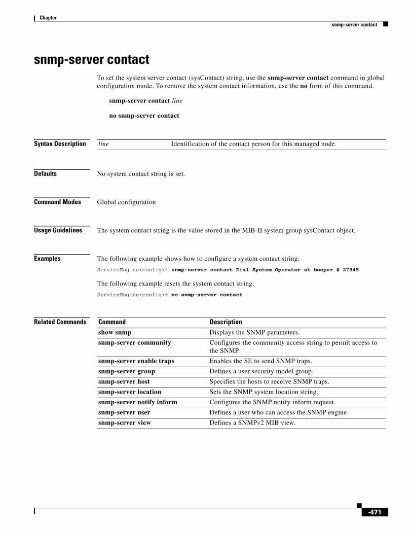
Chapter snmp-server contact
snmp-server contactTo set the system server contact (sysContact) string, use the snmp-server contact command in global configuration mode. To remove the system contact information, use the no form of this command.
snmp-server contact line
no snmp-server contact
Syntax Description
Defaults No system contact string is set.
Command Modes Global configuration
Usage Guidelines The system contact string is the value stored in the MIB-II system group sysContact object.
Examples The following example shows how to configure a system contact string:
ServiceEngine(config)# snmp-server contact Dial System Operator at beeper # 27345
The following example resets the system contact string:
ServiceEngine(config)# no snmp-server contact
Related Commands
line Identification of the contact person for this managed node.
Command Description
show snmp Displays the SNMP parameters.
snmp-server community Configures the community access string to permit access to the SNMP.
snmp-server enable traps Enables the SE to send SNMP traps.
snmp-server group Defines a user security model group.
snmp-server host Specifies the hosts to receive SNMP traps.
snmp-server location Sets the SNMP system location string.
snmp-server notify inform Configures the SNMP notify inform request.
snmp-server user Defines a user who can access the SNMP engine.
snmp-server view Defines a SNMPv2 MIB view.
-471

Chapter snmp-server enable traps
snmp-server enable trapsTo enable the SE to send SNMP traps, use the snmp-server enable traps command in global configuration mode. To disable all SNMP traps or only SNMP authentication traps, use the no form of this command.
snmp-server enable traps [alarm [clear-critical | clear-major | clear-minor | raise-critical | raise-major | raise-minor] | config | entity | event | service-engine [disk-fail | disk-read | disk-write | transaction-log] | snmp [authentication | cold-start]]
no snmp-server enable traps [alarm [clear-critical | clear-major | clear-minor | raise-critical | raise-major | raise-minor] | config | entity | event | service-engine [disk-fail | disk-read | disk-write | transaction-log] | snmp [authentication | cold-start]]
Syntax Description
Defaults This command is disabled by default. No traps are enabled.
Command Modes Global configuration
Usage Guidelines You can configure an SE to generate an SNMP trap for a specific alarm condition. You can configure the generation of SNMP alarm traps on SEs based on the following:
• Severity of the alarm (critical, major, or minor)
• Action (the alarm is raised or cleared)
alarm (Optional) Enables SE alarm traps.
clear-critical (Optional) Enables the clear-critical alarm trap.
clear-major (Optional) Enables the clear-major alarm trap.
clear-minor (Optional) Enables the clear-minor alarm trap.
raise-critical (Optional) Enables the raise-critical alarm trap.
raise-major (Optional) Enables the raise-major alarm trap.
raise-minor (Optional) Enables the raise-minor alarm trap.
config (Optional) Enables CiscoConfigManEvent traps.
entity (Optional) Enables SNMP entity traps.
event (Optional) Enables Event MIB traps.
service-engine (Optional) Enables SNMP SE traps.
disk-fail (Optional) Enables the disk failure error trap.
disk-read (Optional) Enables the disk read error trap.
disk-write (Optional) Enables the disk write error trap.
transaction-log (Optional) Enables the transaction log write error trap.
snmp (Optional) Enables SNMP-specific traps.
authentication (Optional) Enables the authentication trap.
cold-start (Optional) Enables the cold-start trap.
-472

Chapter snmp-server enable traps
Cisco ECDS software supports six generic alarm traps. These six generic alarm traps provide SNMP and Node Health Manager integration. Each trap can be enabled or disabled through the SE CLI.
Note Some SNMP traps are different between v1 and v2 and v3 when configure the trap.
SNMP notifications can be sent as traps or inform requests. The snmp-server enable traps command enables both traps and inform requests for the specified notification types.
To configure traps, you must enter the snmp-server enable traps command. If you do not enter the snmp-server enable traps command, no traps are sent.
If you do not enter an snmp-server enable traps command, no notifications controlled by this command are sent. To configure the SE to send these SNMP notifications, you must enter at least one snmp-server enable traps command. If you enter the command with no keywords, all notification types are enabled. If you enter the command with a keyword, only the notification type related to that keyword is enabled. To enable multiple types of notifications, you must enter a separate snmp-server enable traps command for each notification type and notification option.
The snmp-server enable traps command is used with the snmp-server host command. Use the snmp-server host command to specify which host or hosts receive SNMP traps. To send traps, you must configure at least one host using the snmp-server host command.
For a host to receive a trap, you must enable both the snmp-server enable traps command and the snmp-server host command for that host.
In addition, you must enable SNMP with the snmp-server community command.
To disable the sending of the MIB-II SNMP authentication trap, you must enter the no snmp-server enable traps snmp authentication command.
Examples The following example enables the SE to send all traps to the host 172.31.2.160 using the community string public:
ServiceEngine(config)# snmp-server enable trapsServiceEngine(config)# snmp-server host 172.31.2.160 public
The following example disables all traps:
ServiceEngine(config)# no snmp-server enable traps
Related Commands Command Description
show snmp Displays the SNMP parameters.
snmp-server community Configures the community access string to permit access to the SNMP.
snmp-server contact Sets the system server contact string.
snmp-server group Defines a user security model group.
snmp-server host Specifies the hosts to receive SNMP traps.
snmp-server location Sets the SNMP system location string.
snmp-server notify inform Configures the SNMP notify inform request.
snmp-server user Defines a user who can access the SNMP engine.
snmp-server view Defines a SNMPv2 MIB view.
-473

Chapter snmp-server group
snmp-server groupTo define a user security model group, use the snmp-server group command in global configuration mode. To remove the specified group, use the no form of this command.
snmp-server group name {v1 [notify name] [read name] [write name] | v2c [notify name] [read name] [write name] | v3 {auth [notify name] [read name] [write name] | noauth [notify name] [read name] [write name] | priv [notify name] [read name] [write name]}}
no snmp-server group name {v1 [notify name] [read name] [write name] | v2c [notify name] [read name] [write name] | v3 {auth [notify name] [read name] [write name] | noauth [notify name] [read name] [write name] | priv [notify name] [read name] [write name]}}
Syntax Description
Defaults The default is that no user security model group is defined.
Command Modes Global configuration
Usage Guidelines The maximum number of SNMP groups that can be created is 10.
Select one of three SNMP security model groups: Version 1 (v1) Security Model, Version 2c (v2c) Security Model, or the User Security Model (v3 or SNMPv3). Optionally, you then specify a notify, read, or write view for the group for the particular security model chosen. The v3 option allows you to specify the group using one of three security levels: auth (AuthNoPriv Security Level), noauth (noAuthNoPriv Security Level), or priv (AuthPriv Security Level).
name Name of the SNMP group. Supports up to a maximum of 64 characters.
v1 Specifies the group using the Version 1 Security Model.
notify (Optional) Specifies a notify view for the group that enables you to specify a notify, inform, or trap.
name Notify view name. Supports up to a maximum of 64 characters.
read (Optional) Specifies a read view for the group that enables you only to view the contents of the agent.
name Read view name. Supports up to a maximum of 64 characters.
write (Optional) Specifies a write view for the group that enables you to enter data and configure the contents of the agent.
name Write view name. Supports up to a maximum of 64 characters.
v2c Specifies the group using the Version 2c Security Model.
v3 Specifies the group using the User Security Model (SNMPv3).
auth Specifies the group using the AuthNoPriv Security Level.
noauth Specifies the group using the noAuthNoPriv Security Level.
priv Specifies the group using the AuthPriv Security Level.
-474

Chapter snmp-server group
The Cisco ECDS software supports the following versions of SNMP:
• Version 1 (SNMPv1)—This version is the initial implementation of SNMP. See RFC 1157 for a full description of its functionality.
• Version 2 (SNMPv2c)—This version is the second release of SNMP, described in RFC 1902. It provides additions to data types, counter size, and protocol operations.
• Version 3 (SNMPv3)—This version is the most recent SNMP version, defined in RFC 2271 through RFC 2275.
SNMP Security Models and Security Levels
SNMPv1 and SNMPv2c do not have any security (authentication or privacy) mechanisms to keep SNMP packet traffic on the wire confidential. As a result, packets on the wire can be detected and SNMP community strings can be compromised.
To solve the security shortcomings of SNMPv1 and SNMPv2c, SNMPv3 provides secure access to SEs by authenticating and encrypting packets over the network. The SNMP agent in the Cisco ECDS software supports SNMPv3, SNMPv1, and SNMPv2c.
Using SNMPv3, users can securely collect management information from their SNMP agents. Also, confidential information, such as SNMP set packets that change an SE’s configuration, can be encrypted to prevent their contents from being exposed on the wire. Also, the group-based administrative model allows different users to access the same SNMP agent with varying access privileges.
Examples The following example configures the SNMP group name, security model, and notify view on the SE:
ServiceEngine(config)# snmp-server group acme v1 notify mymib
Related Commands Command Description
show snmp Displays the SNMP parameters.
snmp-server community Configures the community access string to permit access to the SNMP.
snmp-server contact Sets the system server contact string.
snmp-server enable traps Enables the SE to send SNMP traps.
snmp-server host Specifies the hosts to receive SNMP traps.
snmp-server location Sets the SNMP system location string.
snmp-server notify inform Configures the SNMP notify inform request.
snmp-server user Defines a user who can access the SNMP engine.
snmp-server view Defines a SNMPv2 MIB view.
-475
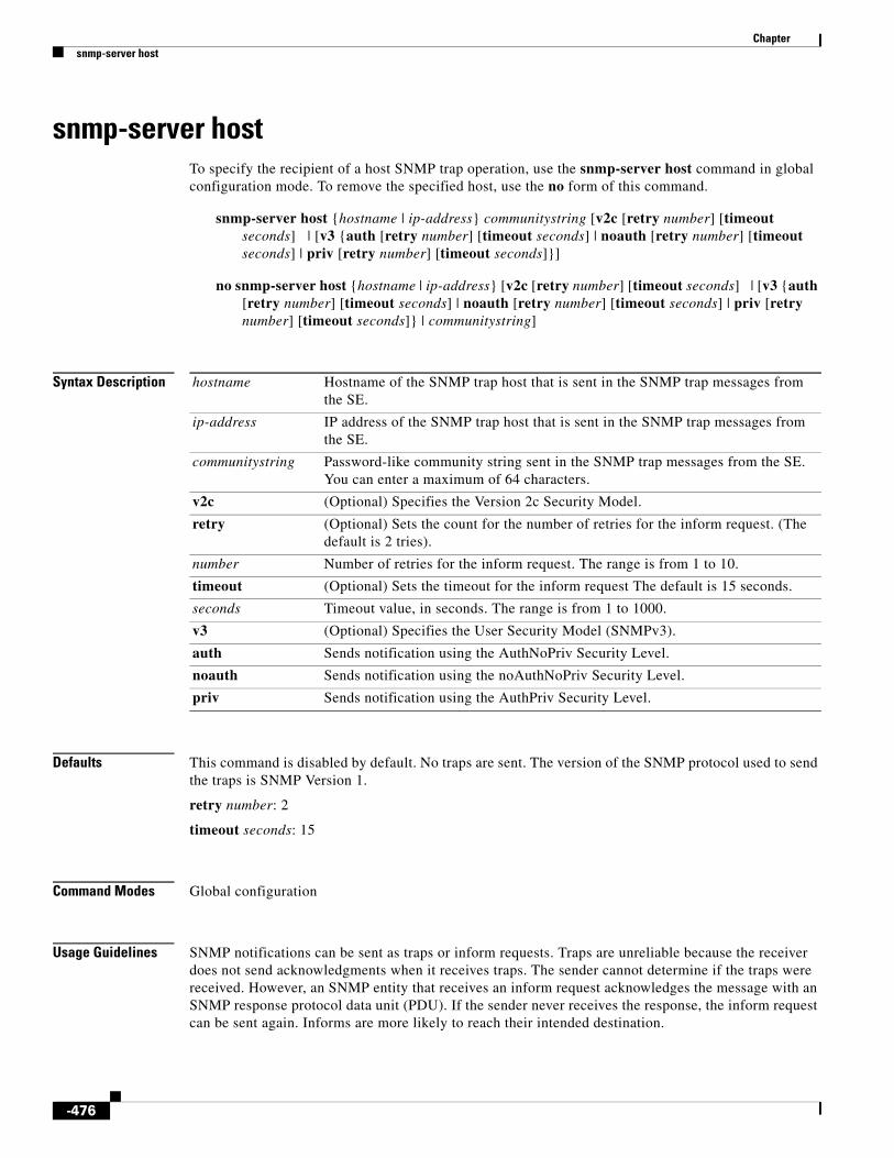
Chapter snmp-server host
snmp-server hostTo specify the recipient of a host SNMP trap operation, use the snmp-server host command in global configuration mode. To remove the specified host, use the no form of this command.
snmp-server host {hostname | ip-address} communitystring [v2c [retry number] [timeout seconds] | [v3 {auth [retry number] [timeout seconds] | noauth [retry number] [timeout seconds] | priv [retry number] [timeout seconds]}]
no snmp-server host {hostname | ip-address} [v2c [retry number] [timeout seconds] | [v3 {auth [retry number] [timeout seconds] | noauth [retry number] [timeout seconds] | priv [retry number] [timeout seconds]} | communitystring]
Syntax Description
Defaults This command is disabled by default. No traps are sent. The version of the SNMP protocol used to send the traps is SNMP Version 1.
retry number: 2
timeout seconds: 15
Command Modes Global configuration
Usage Guidelines SNMP notifications can be sent as traps or inform requests. Traps are unreliable because the receiver does not send acknowledgments when it receives traps. The sender cannot determine if the traps were received. However, an SNMP entity that receives an inform request acknowledges the message with an SNMP response protocol data unit (PDU). If the sender never receives the response, the inform request can be sent again. Informs are more likely to reach their intended destination.
hostname Hostname of the SNMP trap host that is sent in the SNMP trap messages from the SE.
ip-address IP address of the SNMP trap host that is sent in the SNMP trap messages from the SE.
communitystring Password-like community string sent in the SNMP trap messages from the SE. You can enter a maximum of 64 characters.
v2c (Optional) Specifies the Version 2c Security Model.
retry (Optional) Sets the count for the number of retries for the inform request. (The default is 2 tries).
number Number of retries for the inform request. The range is from 1 to 10.
timeout (Optional) Sets the timeout for the inform request The default is 15 seconds.
seconds Timeout value, in seconds. The range is from 1 to 1000.
v3 (Optional) Specifies the User Security Model (SNMPv3).
auth Sends notification using the AuthNoPriv Security Level.
noauth Sends notification using the noAuthNoPriv Security Level.
priv Sends notification using the AuthPriv Security Level.
-476

Chapter snmp-server host
However, informs consume more resources in the agent and in the network. Unlike a trap, which is discarded as soon as it is sent, an inform request must be held in the memory until a response is received or the request times out. Also, traps are sent only once, while an inform may be retried several times. The retries increase traffic and contribute to a higher overhead on the network.
If you do not enter an snmp-server host command, no notifications are sent. To configure the SE to send SNMP notifications, you must enter at least one snmp-server host command. To enable multiple hosts, you must enter a separate snmp-server host command for each host. You can specify multiple notification types in the command for each host.
When multiple snmp-server host commands are given for the same host and kind of security model, each succeeding command overwrites the previous command. Only the last snmp-server host command is in effect. For example, if you enter an snmp-server host v2c command for a host and then enter another snmp-server host v3 command for the same host, the second command replaces the first.
The maximum number of SNMP hosts that can be created by entering the snmp-server host commands is eight.
When multiple snmp-server host commands are given for the same host, the community string in the last command is used.
The snmp-server host command is used with the snmp-server enable traps command. Use the snmp-server enable traps command to specify which SNMP notifications are sent globally. For a host to receive most notifications, at least one snmp-server enable traps command and the snmp-server host command for that host must be enabled.
Note You must enable SNMP with the snmp-server community command.
Examples The following example sends the SNMP traps defined in RFC 1157 to the host specified by the IP address 172.16.2.160. The community string is comaccess:
ServiceEngine(config)# snmp-server enable trapsServiceEngine(config)# snmp-server host 172.16.2.160 comaccess
The following example removes the host 172.16.2.160 from the SNMP trap recipient list:
ServiceEngine(config)# no snmp-server host 172.16.2.160
Related Commands Command Description
show snmp Displays the SNMP parameters.
snmp-server community Configures the community access string to permit access to the SNMP.
snmp-server contact Sets the system server contact string.
snmp-server enable traps Enables the SE to send SNMP traps.
snmp-server group Defines a user security model group.
snmp-server location Sets the SNMP system location string
snmp-server notify inform Configures the SNMP notify inform request.
snmp-server user Defines a user who can access the SNMP engine.
snmp-server view Defines a SNMPv2 MIB view.
-477
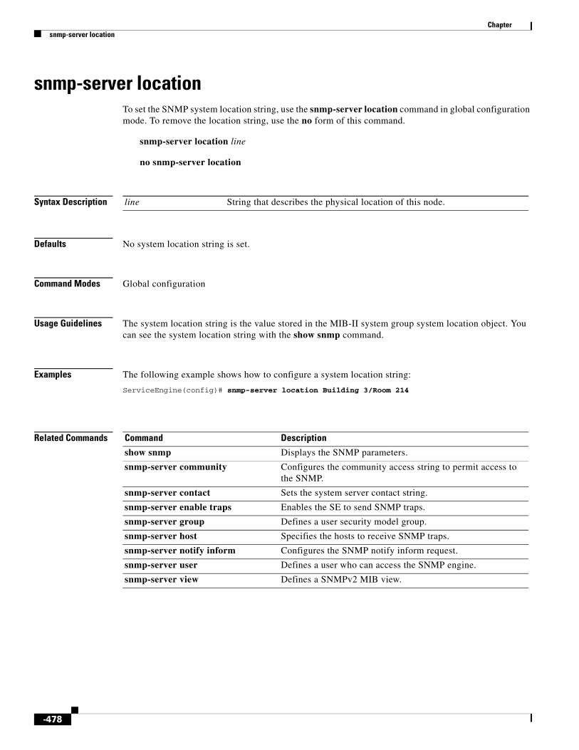
Chapter snmp-server location
snmp-server locationTo set the SNMP system location string, use the snmp-server location command in global configuration mode. To remove the location string, use the no form of this command.
snmp-server location line
no snmp-server location
Syntax Description
Defaults No system location string is set.
Command Modes Global configuration
Usage Guidelines The system location string is the value stored in the MIB-II system group system location object. You can see the system location string with the show snmp command.
Examples The following example shows how to configure a system location string:
ServiceEngine(config)# snmp-server location Building 3/Room 214
Related Commands
line String that describes the physical location of this node.
Command Description
show snmp Displays the SNMP parameters.
snmp-server community Configures the community access string to permit access to the SNMP.
snmp-server contact Sets the system server contact string.
snmp-server enable traps Enables the SE to send SNMP traps.
snmp-server group Defines a user security model group.
snmp-server host Specifies the hosts to receive SNMP traps.
snmp-server notify inform Configures the SNMP notify inform request.
snmp-server user Defines a user who can access the SNMP engine.
snmp-server view Defines a SNMPv2 MIB view.
-478
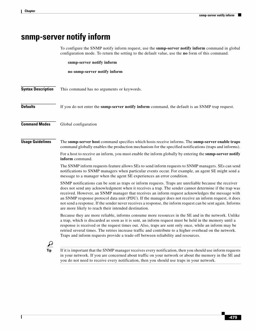
Chapter snmp-server notify inform
snmp-server notify informTo configure the SNMP notify inform request, use the snmp-server notify inform command in global configuration mode. To return the setting to the default value, use the no form of this command.
snmp-server notify inform
no snmp-server notify inform
Syntax Description This command has no arguments or keywords.
Defaults If you do not enter the snmp-server notify inform command, the default is an SNMP trap request.
Command Modes Global configuration
Usage Guidelines The snmp-server host command specifies which hosts receive informs. The snmp-server enable traps command globally enables the production mechanism for the specified notifications (traps and informs).
For a host to receive an inform, you must enable the inform globally by entering the snmp-server notify inform command.
The SNMP inform requests feature allows SEs to send inform requests to SNMP managers. SEs can send notifications to SNMP managers when particular events occur. For example, an agent SE might send a message to a manager when the agent SE experiences an error condition.
SNMP notifications can be sent as traps or inform requests. Traps are unreliable because the receiver does not send any acknowledgment when it receives a trap. The sender cannot determine if the trap was received. However, an SNMP manager that receives an inform request acknowledges the message with an SNMP response protocol data unit (PDU). If the manager does not receive an inform request, it does not send a response. If the sender never receives a response, the inform request can be sent again. Informs are more likely to reach their intended destination.
Because they are more reliable, informs consume more resources in the SE and in the network. Unlike a trap, which is discarded as soon as it is sent, an inform request must be held in the memory until a response is received or the request times out. Also, traps are sent only once, while an inform may be retried several times. The retries increase traffic and contribute to a higher overhead on the network. Traps and inform requests provide a trade-off between reliability and resources.
Tip If it is important that the SNMP manager receives every notification, then you should use inform requests in your network. If you are concerned about traffic on your network or about the memory in the SE and you do not need to receive every notification, then you should use traps in your network.
-479

Chapter snmp-server notify inform
Examples The following example configures the SNMP notify inform request on the SE:
ServiceEngine(config)# snmp-server notify inform
Related Commands Command Description
show snmp Displays the SNMP parameters.
snmp-server community Configures the community access string to permit access to the SNMP.
snmp-server contact Sets the system server contact string.
snmp-server enable traps Enables the SE to send SNMP traps.
snmp-server group Defines a user security model group.
snmp-server host Specifies the hosts to receive SNMP traps.
snmp-server location Sets the SNMP system location string.
snmp-server user Defines a user who can access the SNMP engine.
snmp-server view Defines a SNMPv2 MIB view.
-480
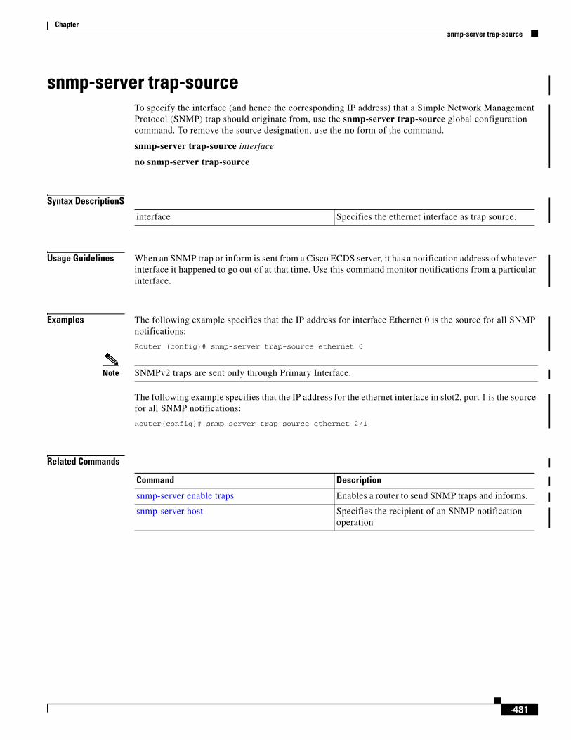
Chapter snmp-server trap-source
snmp-server trap-source To specify the interface (and hence the corresponding IP address) that a Simple Network Management Protocol (SNMP) trap should originate from, use the snmp-server trap-source global configuration command. To remove the source designation, use the no form of the command.
snmp-server trap-source interface
no snmp-server trap-source
Syntax DescriptionS
Usage Guidelines When an SNMP trap or inform is sent from a Cisco ECDS server, it has a notification address of whatever interface it happened to go out of at that time. Use this command monitor notifications from a particular interface.
Examples The following example specifies that the IP address for interface Ethernet 0 is the source for all SNMP notifications:
Router (config)# snmp-server trap-source ethernet 0
Note SNMPv2 traps are sent only through Primary Interface.
The following example specifies that the IP address for the ethernet interface in slot2, port 1 is the source for all SNMP notifications:
Router(config)# snmp-server trap-source ethernet 2/1
Related Commands
interface Specifies the ethernet interface as trap source.
Command Description
snmp-server enable traps Enables a router to send SNMP traps and informs.
snmp-server host Specifies the recipient of an SNMP notification operation
-481

Chapter snmp-server user
snmp-server userTo define a user who can access the SNMP server, use the snmp-server user command in global configuration mode. To remove access, use the no form of this command.
snmp-server user name group [auth {md5 password [priv password] | sha password [priv password]} | remote octetstring [auth {md5 password [priv password] | sha password [priv password]}]]
no snmp-server user name group [auth {md5 password [priv password] | sha password [priv password]} | remote octetstring [auth {md5 password [priv password] | sha password [priv password]}]]
Syntax Description
Defaults No default behavior or values
Command Modes Global configuration
name Name of the SNMP user. Use letters, numbers, dashes, and underscores, but no blanks. This is the name of the user on the SNMP host who wants to communicate with the SNMP agent on the SE. You can enter a maximum of 64 characters.
group Name of the group to which the SNMP user belongs. You can enter a maximum of 64 characters.
auth (Optional) Configures user authentication parameters.
md5 Configures the Hashed-Based Message Authentication Code Message Digest 5 (HMAC MD5) authentication algorithm.
password HMAC MD5 user authentication password.
priv (Optional) Configures authentication parameters for the packet.
password HMAC MD5 user private password. You can enter a maximum of 256 characters.
sha Configures the HMAC Secure Hash Algorithm (SHA) authentication algorithm.
password HMAC SHA authentication password. You can enter a maximum of 256 characters.
remote (Optional) Specifies the engine identity of the remote SNMP entity to which the user belongs.
octetstring Globally unique identifier for a remote SNMP entity (for example, the SNMP network management station) for at least one of the SNMP users.
-482

Chapter snmp-server user
Usage Guidelines The maximum number of SNMP users that can be created is 10. Follow these guidelines when defining SNMP users for SEs:
• If SNMPv3 is going to be used for SNMP requests, you must define at least one SNMPv3 user account on the SE for the SE to be accessed through SNMP.
• Group defined with the SNMPv1 or SNMPv2c security model should not be associated with SNMP users; they should only be associated with the community strings.
Tip To send an SNMPv3 inform message, you must configure at least one SNMPv3 user with a remote SNMP ID option on the SE. The SNMP ID is entered in octet string form. For example, if the IP address of a remote SNMP entity is 192.147.142.129, then the octet string would be 00:00:63:00:00:00:a1:c0:93:8e:81.
Examples The following example shows that an SNMPv3 user account is created on the SE. The SNMPv3 user is named acme and belongs to the group named admin. Because this SNMP user account has been set up with no authentication password, the SNMP agent on the SE does not perform authentication on SNMP requests from this user.
ServiceEngine(config)# snmp-server user acme admin
Related Commands Command Description
show snmp Displays the SNMP parameters.
snmp-server community Configures the community access string to permit access to the SNMP.
snmp-server contact Sets the system server contact string.
snmp-server enable traps Enables the SE to send SNMP traps.
snmp-server group Defines a user security model group.
snmp-server host Specifies the hosts to receive SNMP traps.
snmp-server location Sets the SNMP system location string.
snmp-server notify inform Configures the SNMP notify inform request.
snmp-server view Defines a SNMPv2 MIB view.
-483

Chapter snmp-server view
snmp-server viewTo define a SNMP Version 2 (SNMPv2) MIB view, use the snmp-server view command in global configuration mode. To undefine the MIB view, use the no form of this command.
snmp-server view viewname MIBfamily {excluded | included}
no snmp-server view viewname MIBfamily {excluded | included}
Syntax Description
Defaults No default behavior or values
Command Modes Global configuration
Usage Guidelines An SNMP view is a mapping between SNMP objects and the access rights available for those objects. An object can have different access rights in each view. Access rights indicate whether the object is accessible by either a community string or a user. The snmp-server view command is used with the snmp-server group to limit the read-write access of MIB trees based on the group. Because the group can be associated with the SNMP community string or users, using the snmp-server view command extends the limit to users and community strings. If the view is not configured, read-write access to the community string applies to the MIB tree and all users (SNMPv3).
The maximum number of views that can be created is 10. You can configure the SNMP view settings only if you have previously configured the SNMP server settings.
To remove a view record, use the no snmp-server view command.
You can enter the snmp-server view command multiple times for the same view record. Later lines take precedence when an object identifier is included in two or more lines.
Examples The following example shows how to configure the view name, family name, and view type:
ServiceEngine(config)# snmp-server view contentview ciscoServiceEngineMIB included
The following example creates a view that includes all objects in the MIB-II system group and all objects in the Cisco enterprise MIB:
ServiceEngine(config)# snmp-server view phred system includedServiceEngine(config)# snmp-server view phred cisco included
viewname Name of this family of view subtrees. You can enter a maximum of 64 characters.
MIBfamily An object identifier that identifies a subtree of the MIB. You can enter a maximum of 64 characters.
excluded Excludes the MIB family from the view.
included Includes the MIB family from the view.
-484

Chapter snmp-server view
The following example creates a view that includes all objects in the MIB-II system group except for sysServices (System 7) in the MIB-II interfaces group:
ServiceEngine(config)# snmp-server view agon system includedServiceEngine(config)# snmp-server view agon system.7 excluded
Related Commands Command Description
show snmp Displays the SNMP parameters.
snmp-server community Configures the community access string to permit access to the SNMP.
snmp-server contact Sets the system server contact string.
snmp-server enable traps Enables the SE to send SNMP traps.
snmp-server group Defines a user security model group.
snmp-server host Specifies the hosts to receive SNMP traps.
snmp-server location Sets the SNMP system location string.
snmp-server notify inform Configures the SNMP notify inform request.
snmp-server user Defines a user who can access the SNMP engine.
-485

Chapter sshd
sshdTo enable the Secure Shell (SSH) daemon, use the sshd command in global configuration mode. To disable SSH, use the no form of this command.
sshd {enable | timeout seconds | version {1 | 2}}
no sshd {enable | password-guesses | timeout | version {1 | 2}}
Syntax Description
Defaults timeout seconds: 300
version: Both SSH version 1 and 2 are enabled.
Command Modes Global configuration
Usage Guidelines SSH enables login access to the SE through a secure and encrypted channel. SSH consists of a server and a client program. Like Telnet, you can use the client program to remotely log on to a machine that is running the SSH server, but unlike Telnet, messages transported between the client and the server are encrypted. The functionality of SSH includes user authentication, message encryption, and message authentication.
When you enable the SSH server, the Secure File Transfer Protocol (SFTP) server is also enabled. The SFTP is a file transfer program that provides a secure and authenticated method for transferring files between CDS devices and other workstations or clients.
Note SFTP is the standard file transfer protocol introduced in SSH version 2. The SFTP client functionality is provided as part of the SSH component. If you use SSH version 1 on the SE, SFTP support is not available.
enable Enables the SSH feature.
timeout Configures the number of seconds for which an SSH session is active during the negotiation (authentication) phase between the client and the server before it times out.
Note If you have established an SSH connection to the SE but have not entered the username when prompted at the login prompt, the connection is terminated by the SE even after successful login if the grace period expires.
seconds SSH login grace time value, in seconds. The range is from 1 to 99999. The default is 300.
version Configures the SSH version to be supported on the SE.
1 Specifies that SSH version 1 is supported on the SE.
2 Specifies that SSH version 2 is supported on the SE.
-486

Chapter sshd
The sshd version command in global configuration mode allows you to enable support for either SSH version 1 or SSH version 2. When you enable SSH using the sshd enable command in global configuration mode, the ECDS software enables support for both SSH version 1 and SSH version 2 on the SE. If you want the SE to support only one version of SSH (for example SSH version 2), you must disable the other version (in this example, SSH version 1) by using the no sshd version 1 command.
When support for both SSH version 1 and SSH version 2 are enabled in the SE, the show running-config command output does not display any sshd configuration. If you have disabled the support for one version of SSH, the show running-config command output contains the following line:
no sshd version version_number
Note You cannot disable both SSH versions in an SE. Use the no sshd enable command in global configuration mode to disable SSH on the SE.
Examples The following example shows how to enable the SSH daemon and configure the number of allowable password guesses and timeout for the SE:
ServiceEngine(config)# sshd enableServiceEngine(config)# sshd password-guesses 4ServiceEngine(config)# sshd timeout 20
The following example disables the support for SSH version 1 in the SE:
ServiceEngine(config)# no sshd version 1
Related Commands Command Description
show ssh Displays the SSH status and configuration.
-487

Chapter streaming-interface
streaming-interfaceTo configure the streaming interface, use the streaming-interface command in Global configuration mode. To remove a streaming interface, use the no form of this command.
streaming-interface {GigabitEthernet num | PortChannel num | Standby num}
Syntax Description
Command Default No default behavior or values
Command Modes Global configuration
Usage Guidelines When upgrading from a previous software release, the primary interface is converted to a streaming-interface by the upgrade process. When configuring new delivery traffic interfaces, either because of a new installation or because of removing existing configuration, you must use the streaming-interface command.
Examples The following example shows how to configure PortChannel 1 as the streaming interface:
ServiceEngine# streaming-interface portChannel 1
ServiceEngine#
GigabitEthernet Selects a gigabit Ethernet interface as Streaming interface.
num GigabitEthernet slot/port (1 to 14/0 to 0).
PortChannel Selects a PortChannel interface as Streaming interface.
num PortChannel port.
Standby Selects a standby group as Streaming interface.
num Standby group number.
-488
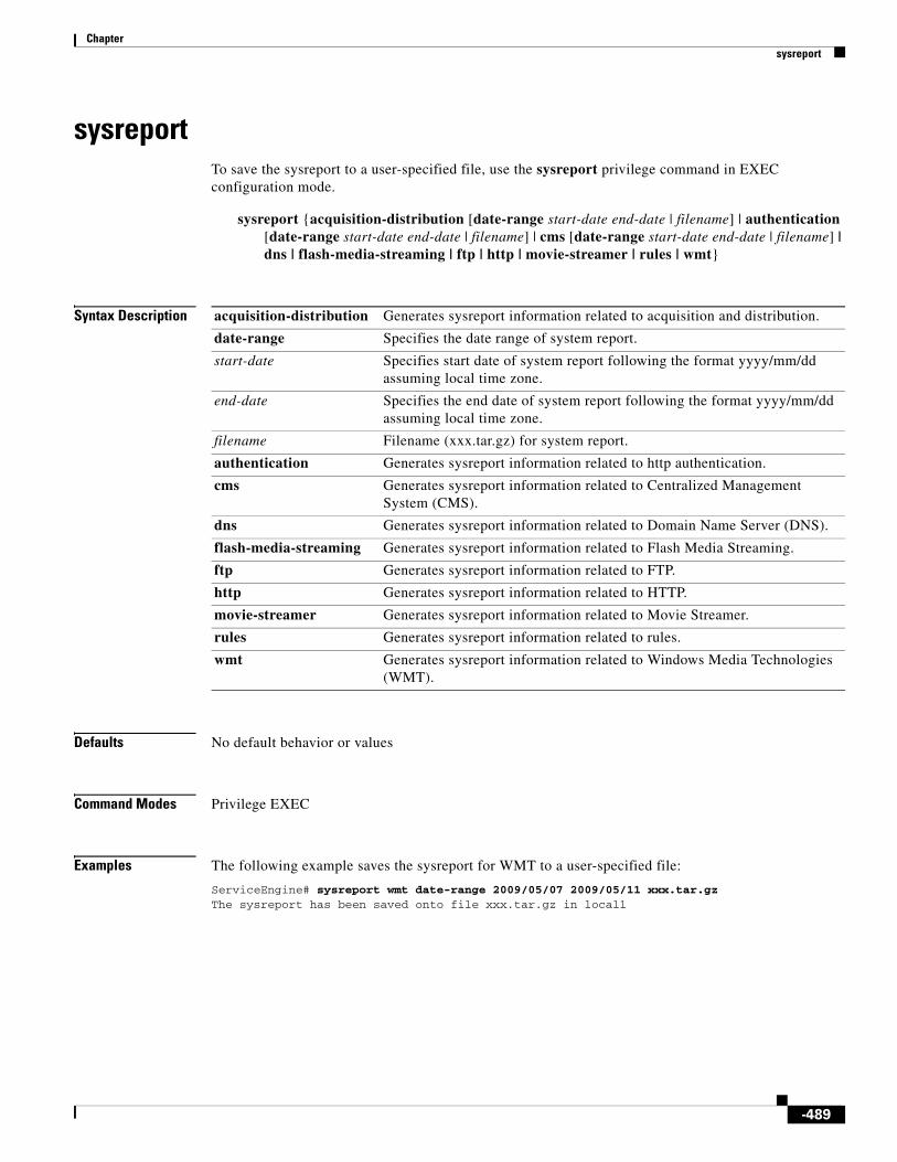
Chapter sysreport
sysreportTo save the sysreport to a user-specified file, use the sysreport privilege command in EXEC configuration mode.
sysreport {acquisition-distribution [date-range start-date end-date | filename] | authentication [date-range start-date end-date | filename] | cms [date-range start-date end-date | filename] | dns | flash-media-streaming | ftp | http | movie-streamer | rules | wmt}
Syntax Description
Defaults No default behavior or values
Command Modes Privilege EXEC
Examples The following example saves the sysreport for WMT to a user-specified file:
ServiceEngine# sysreport wmt date-range 2009/05/07 2009/05/11 xxx.tar.gz The sysreport has been saved onto file xxx.tar.gz in local1
acquisition-distribution Generates sysreport information related to acquisition and distribution.
date-range Specifies the date range of system report.
start-date Specifies start date of system report following the format yyyy/mm/dd assuming local time zone.
end-date Specifies the end date of system report following the format yyyy/mm/dd assuming local time zone.
filename Filename (xxx.tar.gz) for system report.
authentication Generates sysreport information related to http authentication.
cms Generates sysreport information related to Centralized Management System (CMS).
dns Generates sysreport information related to Domain Name Server (DNS).
flash-media-streaming Generates sysreport information related to Flash Media Streaming.
ftp Generates sysreport information related to FTP.
http Generates sysreport information related to HTTP.
movie-streamer Generates sysreport information related to Movie Streamer.
rules Generates sysreport information related to rules.
wmt Generates sysreport information related to Windows Media Technologies (WMT).
-489

Chapter tacacs
tacacs To configure TACACS+ server parameters, use the tacacs command in global configuration mode. To disable individual options, use the no form of this command.
tacacs {enable | host {hostname | ip-address} [primary] | key keyword | password ascii | retransmit retries | timeout seconds}
no tacacs {enable | host {hostname | ip-address} [primary] | key | password ascii | retransmit | timeout}
Syntax Description
Defaults keyword: none (empty string)
timeout seconds: 5
retransmit retries: 2
password ascii: PAP
Command Modes Global configuration
Usage Guidelines Using the tacacs command, configure the TACACS+ key, the number of retransmits, the server hostname or IP address, and the timeout.
You must execute the following two commands to enable user authentication with a TACACS+ server:
ServiceEngine(config)# authentication login tacacs enableServiceEngine(config)# authentication configuration tacacs enable
You must enable TACACS+ for HTTP request authentication as follows:
ServiceEngine(config)# tacacs enable
enable Enables the TACACS+ authentication.
host Sets a server address.
hostname Hostname of the TACACS+ server.
ip-address IP address of the TACACS+ server.
primary (Optional) Sets the server as the primary server.
key Sets the security word.
keyword Keyword. An empty string is the default.
password ascii Specifies ASCII as the TACACS+ password type.
retransmit Sets the number of times that requests are retransmitted to a server.
retries Number of retry attempts allowed. The range is from 1 to 3. The default is 2.
timeout Sets the number of seconds to wait before a request to a server is timed out.
seconds Timeout, in seconds. The range is from 1 to 20. The default is 5.
-490

Chapter tacacs
TACACS+ can be disabled but remain configured for user authentication with a TACACS+ server if you use the no option of the command as follows:
ServiceEngine(config)# no tacacs enable
HTTP request authentication is independent of user authentication options and must be disabled with the following separate commands:
ServiceEngine(config)# no authentication login tacacs enableServiceEngine(config)# no authentication configuration tacacs enable
The Users GUI page or the username command in global configuration provide a way to add, delete, or modify usernames, passwords, and access privileges in the local database. The TACACS+ remote database can also be used to maintain login and configuration privileges for administrative users. The tacacs host command or the TACACS+ Service Engine GUI page allows you to configure the network parameters required to access the remote database.
One primary and two backup TACACS+ servers can be configured; authentication is attempted on the primary server first and then on the others in the order in which they were configured. The primary server is the first server configured unless another server is explicitly specified as primary with the tacacs host hostname primary command.
Use the tacacs key command to specify the TACACS+ key that is used to encrypt the packets sent to the server. This key must be the same as the one specified on the server daemon. The maximum number of characters in the key should not exceed 99 printable ASCII characters (except tabs). An empty key string is the default. All leading spaces are ignored; spaces within and at the end of the key string are not ignored. Double quotes are not required even if there are spaces in the key, unless the quotes themselves are part of the key.
The tacacs timeout is the number of seconds that the Service Engine waits before declaring a timeout on a request to a particular TACACS+ server. The range is from 1 to 20 seconds with 5 seconds as the default. The number of times that the Service Engine repeats a retry-timeout cycle before trying the next TACACS+ server is specified by the tacacs retransmit command. The default is two retry attempts.
Three unsuccessful login attempts are permitted. TACACS+ logins may appear to take more time than local logins depending on the number of TACACS+ servers and the configured timeout and retry values.
Use the tacacs password ascii command to specify the TACACS+ password type as ASCII. The default password type is Password Authentication Protocol (PAP).
Note When the no tacacs password ascii command is used to disable the ASCII password type, the password type is once again reset to PAP.
The TACACS+ client can send different requests to the server for user authentication. The client can send a TACACS+ request with the PAP password type. In this scenario, the authentication packet includes both the username and the user’s password. The server must have an appropriately configured user’s account.
Alternatively, the client can send a TACACS+ request with the ASCII password type as another option. In this scenario, the authentication packet includes the username only and waits for the server response. Once the server confirms that the user’s account exists, the client sends another Continue request with the user’s password. The authentication server must have an appropriately configured user’s account to support either type of password.
Examples The following example configures the key used in encrypting packets:
ServiceEngine(config)# tacacs key human789
-491

Chapter tacacs
The following example configures the host named spearhead as the primary TACACS+ server:
ServiceEngine(config)# tacacs host spearhead primary
The following example sets the timeout interval for the TACACS+ server:
ServiceEngine(config)# tacacs timeout 10
The following example sets the number of times that authentication requests are retried (retransmitted) after a timeout:
ServiceEngine(config)# tacacs retransmit 5
The following example shows the password type to be PAP by default:
ServiceEngine# show tacacs Login Authentication for Console/Telnet Session: enabled (secondary) Configuration Authentication for Console/Telnet Session: enabled (secondary)
TACACS+ Configuration: --------------------- TACACS+ Authentication is off Key = ***** Timeout = 5 Retransmit = 2 Password type: pap
Server Status ---------------------------- ------ 10.107.192.148 primary 10.107.192.168 10.77.140.77 ServiceEngine#
However, you can configure the password type to be ASCII using the tacacs password ascii command. You can then verify the changes using the show tacacs command as follows:
ServiceEngine(config)# tacacs password ascii ServiceEngine(config)# exitServiceEngine# show tacacs Login Authentication for Console/Telnet Session: enabled (secondary) Configuration Authentication for Console/Telnet Session: enabled (secondary)
TACACS+ Configuration: --------------------- TACACS+ Authentication is off Key = ***** Timeout = 5 Retransmit = 2 Password type: ascii
-492

Chapter tacacs
Server Status ---------------------------- ------ 10.107.192.148 primary 10.107.192.168 10.77.140.77
Related Commands Command Description
authentication Specifies the authentication and authorization methods.
show authentication Displays the authentication configuration.
show statistics authentication Displays the SE authentication statistics.
show statistics tacacs Displays the Service Engine TACACS+ authentication and authorization statistics.
show tacacs Displays TACACS+ authentication protocol configuration information.
-493
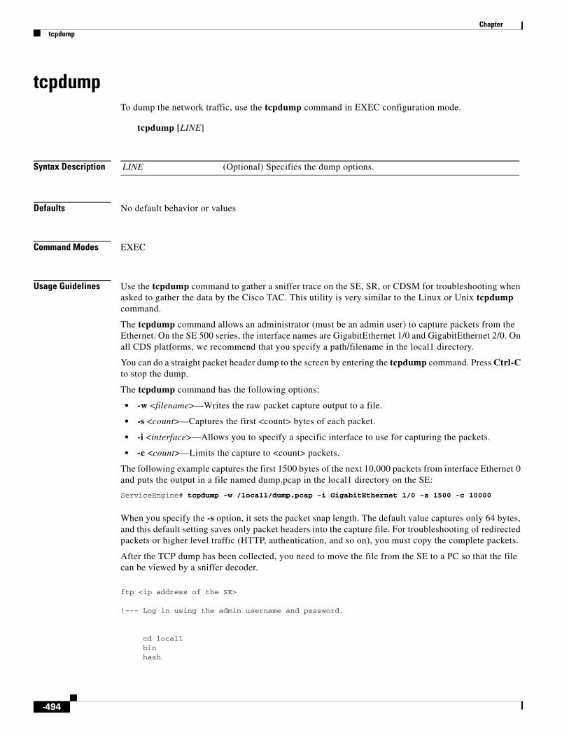
Chapter tcpdump
tcpdumpTo dump the network traffic, use the tcpdump command in EXEC configuration mode.
tcpdump [LINE]
Syntax Description
Defaults No default behavior or values
Command Modes EXEC
Usage Guidelines Use the tcpdump command to gather a sniffer trace on the SE, SR, or CDSM for troubleshooting when asked to gather the data by the Cisco TAC. This utility is very similar to the Linux or Unix tcpdump command.
The tcpdump command allows an administrator (must be an admin user) to capture packets from the Ethernet. On the SE 500 series, the interface names are GigabitEthernet 1/0 and GigabitEthernet 2/0. On all CDS platforms, we recommend that you specify a path/filename in the local1 directory.
You can do a straight packet header dump to the screen by entering the tcpdump command. Press Ctrl-C to stop the dump.
The tcpdump command has the following options:
• -w <filename>—Writes the raw packet capture output to a file.
• -s <count>—Captures the first <count> bytes of each packet.
• -i <interface>—Allows you to specify a specific interface to use for capturing the packets.
• -c <count>—Limits the capture to <count> packets.
The following example captures the first 1500 bytes of the next 10,000 packets from interface Ethernet 0 and puts the output in a file named dump.pcap in the local1 directory on the SE:
ServiceEngine# tcpdump -w /local1/dump.pcap -i GigabitEthernet 1/0 -s 1500 -c 10000
When you specify the -s option, it sets the packet snap length. The default value captures only 64 bytes, and this default setting saves only packet headers into the capture file. For troubleshooting of redirected packets or higher level traffic (HTTP, authentication, and so on), you must copy the complete packets.
After the TCP dump has been collected, you need to move the file from the SE to a PC so that the file can be viewed by a sniffer decoder.
ftp <ip address of the SE>
!--- Log in using the admin username and password.
cd local1 bin hash
LINE (Optional) Specifies the dump options.
-494

Chapter tcpdump
get <name of the file>
!--- Using the above example, it would be dump.pcap.
bye
We recommend that you use Ethereal as the software application for reading the TCP dump. With Ethereal, you can decode packets that are encapsulated into a GRE tunnel. See the Ethereal website for further information.
Note In most cases, redirected packets captured by the tcpdump facility with the CDS CLI differ from the data received on the interface. The destination IP address and TCP port number are modified to reflect the device IP address and the port number 8999.
Examples The following example shows how to dump the TCP network traffic:
ServiceEngine# tcpdumptcpdump: verbose output suppressed, use -v or -vv for full protocol decodelistening on GigabitEthernet 1/0, link-type EN10MB (Ethernet), capture size 68 bytes12:45:42.617677 IP ServiceEngine.cisco.com.ssh > 10.77.140.97.4314: P 3342832089:3342832201(112) ack 1248615673 win 1523212:45:42.618950 IP 172.19.226.63 > ServiceEngine.cisco.com: icmp 36: 172.19.226.63 udp port 2048 unreachable12:45:42.619327 IP ServiceEngine.cisco.com.10015 > dns-sj2.cisco.com.domain: 49828+ [ | domain ] 12:45:42.621158 IP dns-sj2.cisco.com.domain > ServiceEngine.cisco.com.10015: 49828 NXDomain* [ | domain ] 12:45:42.621942 IP ServiceEngine.cisco.com.10015 > dns-sj2.cisco.com.domain: 49829+ [ | domain ] 12:45:42.623799 IP dns-sj2.cisco.com.domain > ServiceEngine.cisco.com.10015: 49829 NXDomain* [ | domain ] 12:45:42.624240 IP ServiceEngine.cisco.com.10015 > dns-sj2.cisco.com.domain: 49830+ [ | domain ] 12:45:42.626164 IP dns-sj2.cisco.com.domain > ServiceEngine.cisco.com.10015: 49830* [ | domain ] 12:45:42.702891 802.1d config TOP_CHANGE 8000.00:03:9f:f1:10:63.8042 root 8000.00:01:43:9a:c8:63 pathcost 26 age 3 max 20 hello 2 fdelay 15 12:45:42.831404 IP 10.77.140.97.4314 > ServiceEngine.cisco.com.ssh: . ack 112 win 6435112:45:42.831490 IP ServiceEngine.cisco.com.ssh > 10.77.140.97.4314: . 112:1444(1332) ack 1 win 1523212:45:42.831504 IP ServiceEngine.cisco.com.ssh > 10.77.140.97.4314: P 1444:1568(124) ack 1 win 1523212:45:42.831741 IP ServiceEngine.cisco.com.ssh > 10.77.140.97.4314: P 1568:1696(128) ack 1 win 1523212:45:43.046176 IP 10.77.140.97.4314 > ServiceEngine.cisco.com.ssh: . ack 1568 win 6553512:45:43.046248 IP ServiceEngine.cisco.com.ssh > 10.77.140.97.4314: P 1696:2128(432) ack 1 win 1523212:45:43.046469 IP ServiceEngine.cisco.com.ssh > 10.77.140.97.4314: P 2128:2256(128) ack 1 win 1523212:45:43.046616 IP ServiceEngine.cisco.com.ssh > 10.77.140.97.4314: P 2256:2400(144) ack 1 win 1523212:45:43.107700 802.1d config TOP_CHANGE 8000.00:03:9f:f1:10:63.8042 root 8000.00:01:43:9a:c8:63 pathcost 26 age 3 max 20 hello 2 fdelay 15 12:45:43.199710 IP 10.77.140.97.4314 > ServiceEngine.cisco.com.ssh: . ack 1696 win 6540712:45:43.199784 IP ServiceEngine.cisco.com.ssh > 10.77.140.97.4314: P 2400:2864(464) ack 1 win 1523212:45:43.199998 IP ServiceEngine.cisco.com.ssh > 10.77.140.97.4314: P 2864:2992(128) ack 1 win 15232
-495

Chapter tcpdump
12:45:43.259968 IP 10.77.140.97.4314 > ServiceEngine.cisco.com.ssh: . ack 2400 win 6470312:45:43.260064 IP ServiceEngine.cisco.com.ssh > 10.77.140.97.4314: P 2992:3280(288) ack 1 win 1523212:45:43.260335 IP ServiceEngine.cisco.com.ssh > 10.77.140.97.4314: P 3280:3408(128) ack 1 win 1523212:45:43.260482 IP ServiceEngine.cisco.com.ssh > 10.77.140.97.4314: P 3408:3552(144) ack 1 win 1523212:45:43.260621 IP ServiceEngine.cisco.com.ssh > 10.77.140.97.4314: P 3552:3696(144) ack 1 win 1523212:45:43.413320 IP 10.77.140.97.4314 > ServiceEngine.cisco.com.ssh: . ack 2992 win 6553512:45:43.413389 IP ServiceEngine.cisco.com.ssh > 10.77.140.97.4314: P 3696:3984(288) ack 1 win 1523212:45:43.413597 IP ServiceEngine.cisco.com.ssh > 10.77.140.97.4314: P 3984:4112(128) ack 1 win 1523212:45:43.413741 IP ServiceEngine.cisco.com.ssh > 10.77.140.97.4314: P 4112:4256(144) ack 1 win 1523212:45:43.473601 IP 10.77.140.97.4314 > ServiceEngine.cisco.com.ssh: . ack 3552 win 6497512:45:43.473659 IP ServiceEngine.cisco.com.ssh > 10.77.140.97.4314: P 4256:4544(288) ack 1 win 1523212:45:43.473853 IP ServiceEngine.cisco.com.ssh > 10.77.140.97.4314: P 4544:4672(128) ack 1 win 1523212:45:43.473994 IP ServiceEngine.cisco.com.ssh > 10.77.140.97.4314: P 4672:4816(144) ack 1 win 1523212:45:43.474132 IP ServiceEngine.cisco.com.ssh > 10.77.140.97.4314: P 4816:4960(144) ack 1 win 1523212:45:43.484117 IP 10.77.140.97.4314 > ServiceEngine.cisco.com.ssh: P 1:81(80) ack 3696 win 6483112:45:43.484167 IP ServiceEngine.cisco.com.ssh > 10.77.140.97.4314: P 4960:5248(288) ack 81 win 1523212:45:43.484424 IP ServiceEngine.cisco.com.ssh > 10.77.140.97.4314: P 5248:5392(144) ack 81 win 1523212:45:43.627125 IP 10.77.140.97.4314 > ServiceEngine.cisco.com.ssh: . ack 4112 win 6441512:45:43.627204 IP ServiceEngine.cisco.com.ssh > 10.77.140.97.4314: P 5392:5680(288) ack 81 win 1523212:45:43.627439 IP ServiceEngine.cisco.com.ssh > 10.77.140.97.4314: P 5680:5808(128) ack 81 win 1523212:45:43.627586 IP ServiceEngine.cisco.com.ssh > 10.77.140.97.4314: P 5808:5952(144) ack 81 win 1523212:45:43.688261 IP 10.77.140.97.4314 > ServiceEngine.cisco.com.ssh: . ack 4544 win 6553512:45:43.688316 IP ServiceEngine.cisco.com.ssh > 10.77.140.97.4314: P 5952:6240(288) ack 81 win 1523212:45:43.688495 IP ServiceEngine.cisco.com.ssh > 10.77.140.97.4314: P 6240:6368(128) ack 81 win 1523212:45:43.688638 IP ServiceEngine.cisco.com.ssh > 10.77.140.97.4314: P 6368:6512(144) ack 81 win 1523212:45:43.689012 IP 10.77.140.97.4314 > ServiceEngine.cisco.com.ssh: . ack 4960 win 6511912:45:43.689046 IP ServiceEngine.cisco.com.ssh > 10.77.140.97.4314: P 6512:6800(288) ack 81 win 1523212:45:43.689170 IP ServiceEngine.cisco.com.ssh > 10.77.140.97.4314: P 6800:6928(128) ack 81 win 1523212:45:43.689309 IP ServiceEngine.cisco.com.ssh > 10.77.140.97.4314: P 6928:7072(144) ack 81 win 1523212:45:43.689447 IP ServiceEngine.cisco.com.ssh > 10.77.140.97.4314: P 7072:7216(144) ack 81 win 1523212:45:43.698391 IP 10.77.140.97.4314 > ServiceEngine.cisco.com.ssh: . ack 5392 win 6468712:45:43.698437 IP ServiceEngine.cisco.com.ssh > 10.77.140.97.4314: P 7216:7504(288) ack 81 win 1523212:45:43.698599 IP ServiceEngine.cisco.com.ssh > 10.77.140.97.4314: P 7504:7632(128) ack 81 win 1523212:45:43.698740 IP ServiceEngine.cisco.com.ssh > 10.77.140.97.4314: P 7632:7776(144) ack 81 win 1523212:45:43.840558 IP 10.77.140.97.4314 > ServiceEngine.cisco.com.ssh: . ack 5808 win 6427112:45:43.840622 IP ServiceEngine.cisco.com.ssh > 10.77.140.97.4314: P 7776:8064(288) ack 81 win 15232
-496

Chapter tcpdump
12:45:43.840819 IP ServiceEngine.cisco.com.ssh > 10.77.140.97.4314: P 8064:8192(128) ack 81 win 1523212:45:43.840962 IP ServiceEngine.cisco.com.ssh > 10.77.140.97.4314: P 8192:8336(144) ack 81 win 1523212:45:43.901868 IP 10.77.140.97.4314 > ServiceEngine.cisco.com.ssh: . ack 6368 win 6553512:45:43.901938 IP ServiceEngine.cisco.com.ssh > 10.77.140.97.4314: P 8336:8624(288) ack 81 win 1523212:45:43.901887 IP 10.77.140.97.4314 > ServiceEngine.cisco.com.ssh: . ack 6928 win 6497512:45:43.901910 IP 10.77.140.97.4314 > ServiceEngine.cisco.com.ssh: . ack 7216 win 6468712:45:43.902137 IP ServiceEngine.cisco.com.ssh > 10.77.140.97.4314: P 8624:8752(128) ack 81 win 1523212:45:43.902281 IP ServiceEngine.cisco.com.ssh > 10.77.140.97.4314: P 8752:8896(144) ack 81 win 1523212:45:43.902414 IP ServiceEngine.cisco.com.ssh > 10.77.140.97.4314: P 8896:9024(128) ack 81 win 1523212:45:43.902547 IP ServiceEngine.cisco.com.ssh > 10.77.140.97.4314: P 9024:9152(128) ack 81 win 1523212:45:43.902687 IP ServiceEngine.cisco.com.ssh > 10.77.140.97.4314: P 9152:9296(144) ack 81 win 1523212:45:43.902826 IP ServiceEngine.cisco.com.ssh > 10.77.140.97.4314: P 9296:9440(144) ack 81 win 1523212:45:43.902965 IP ServiceEngine.cisco.com.ssh > 10.77.140.97.4314: P 9440:9584(144) ack 81 win 1523212:45:43.903104 IP ServiceEngine.cisco.com.ssh > 10.77.140.97.4314: P 9584:9728(144) ack 81 win 1523212:45:43.922413 IP 10.77.140.97.4314 > ServiceEngine.cisco.com.ssh: . ack 7632 win 6427112:45:43.922459 IP ServiceEngine.cisco.com.ssh > 10.77.140.97.4314: P 9728:10304(576) ack 81 win 1523212:45:43.922622 IP ServiceEngine.cisco.com.ssh > 10.77.140.97.4314: P 10304:10432(128) ack 81 win 1523212:45:43.922764 IP ServiceEngine.cisco.com.ssh > 10.77.140.97.4314: P 10432:10576(144) ack 81 win 1523212:45:44.053872 IP 10.77.140.97.4314 > ServiceEngine.cisco.com.ssh: . ack 8192 win 6553512:45:44.053972 IP ServiceEngine.cisco.com.ssh > 10.77.140.97.4314: P 10576:10864(288) ack 81 win 1523212:45:44.054308 IP ServiceEngine.cisco.com.ssh > 10.77.140.97.4314: P 10864:11104(240) ack 81 win 1523212:45:44.054453 IP ServiceEngine.cisco.com.ssh > 10.77.140.97.4314: P 11104:11248(144) ack 81 win 1523212:45:44.054596 IP ServiceEngine.cisco.com.ssh > 10.77.140.97.4314: P 11248:11392(144) ack 81 win 1523212:45:44.111702 802.1d config TOP_CHANGE 8000.00:03:9f:f1:10:63.8042 root 8000.00:01:43:9a:c8:63 pathcost 26 age 3 max 20 hello 2 fdelay 15 12:45:44.114626 IP 10.77.140.97.4314 > ServiceEngine.cisco.com.ssh: . ack 8752 win 6497512:45:44.114712 IP ServiceEngine.cisco.com.ssh > 10.77.140.97.4314: P 11392:11712(320) ack 81 win 1523212:45:44.115219 IP ServiceEngine.cisco.com.ssh > 10.77.140.97.4314: P 11712:11952(240) ack 81 win 1523212:45:44.115381 IP ServiceEngine.cisco.com.ssh > 10.77.140.97.4314: P 11952:12096(144) ack 81 win 1523212:45:44.115426 IP 10.77.140.97.4314 > ServiceEngine.cisco.com.ssh: . ack 9152 win 6457512:45:44.115617 IP ServiceEngine.cisco.com.ssh > 10.77.140.97.4314: P 12096:12336(240) ack 81 win 1523212:45:44.115760 IP ServiceEngine.cisco.com.ssh > 10.77.140.97.4314: P 12336:12480(144) ack 81 win 1523212:45:44.115904 IP ServiceEngine.cisco.com.ssh > 10.77.140.97.4314: P 12480:12624(144) ack 81 win 1523212:45:44.116045 IP ServiceEngine.cisco.com.ssh > 10.77.140.97.4314: P 12624:12768(144) ack 81 win 1523212:45:44.116094 IP 10.77.140.97.4314 > ServiceEngine.cisco.com.ssh: . ack 9440 win 6428712:45:44.116114 IP 10.77.140.97.4314 > ServiceEngine.cisco.com.ssh: . ack 9728 win 6553512:45:44.116332 IP ServiceEngine.cisco.com.ssh > 10.77.140.97.4314: P 12768:13088(320) ack 81 win 15232
-497

Chapter tcpdump
12:45:44.116473 IP ServiceEngine.cisco.com.ssh > 10.77.140.97.4314: P 13088:13232(144) ack 81 win 1523212:45:44.116614 IP ServiceEngine.cisco.com.ssh > 10.77.140.97.4314: P 13232:13376(144) ack 81 win 1523212:45:44.116755 IP ServiceEngine.cisco.com.ssh > 10.77.140.97.4314: P 13376:13520(144) ack 81 win 1523212:45:44.116895 IP ServiceEngine.cisco.com.ssh > 10.77.140.97.4314: P 13520:13664(144) ack 81 win 1523212:45:44.135947 IP 10.77.140.97.4314 > ServiceEngine.cisco.com.ssh: . ack 10432 win 6483112:45:44.135996 IP ServiceEngine.cisco.com.ssh > 10.77.140.97.4314: P 13664:13808(144) ack 81 win 1523212:45:44.136223 IP ServiceEngine.cisco.com.ssh > 10.77.140.97.4314: P 13808:14048(240) ack 81 win 1523212:45:44.136366 IP ServiceEngine.cisco.com.ssh > 10.77.140.97.4314: P 14048:14192(144) ack 81 win 1523212:45:44.144104 IP 10.77.140.97.4314 > ServiceEngine.cisco.com.ssh: P 81:161(80) ack 10576 win 64687
102 packets captured105 packets received by filter0 packets dropped by kernel
The following example shows how to dump the TCP network traffic and redirect it to a file named test:
ServiceEngine# tcpdump port 8080 -w testtcpdump: listening on GigabitEthernet 1/0, link-type EN10MB (Ethernet), capture size 68 bytes216 packets captured216 packets received by filter0 packets dropped by kernel
-498

Chapter tcp timestamp
tcp timestampTo enable and disable the TCP timestamp, use the tcp timestamp command in Global configuration mode. To disable the TCP timestamp, use the no form of this command.
tcp timestamp
no tcp timestamp
Syntax Description This command has no arguments or keywords.
Defaults TCP timestamp is enabled by default.
Command Modes Global configuration
Examples The following example shows how to disable the TCP timestamp:
ServiceEngine# no tcp timestampServiceEngine#
-499

Chapter telnet
telnetTo log in to a network device using the Telnet client, use the telnet command in EXEC configuration mode.
telnet {hostname | ip-address} [portnum]
Syntax Description
Defaults The default port number is 23.
Command Modes EXEC
Usage Guidelines Some UNIX shell functions, such as escape and the suspend command, are not available in the Telnet client. In addition, multiple Telnet sessions are also not supported.
The Telnet client allows you to specify a destination port. By entering the telnet command, you can test websites by attempting to open a Telnet session to the website from the SE CLI.
Examples The following example shows how to open a Telnet session to a network device using the hostname:
ServiceEngine# telnet cisco-ce
The following example shows how to open a Telnet session to a network device using the IP address:
ServiceEngine# telnet 172.16.155.224
The following example shows how to open a Telnet session to a network device on port 8443 using the hostname:
ServiceEngine# telnet cisco-ce 8443
The following example shows how to open a Telnet session to a network device on port 80 using the hostname:
ServiceEngine# telnet www.yahoo.com 80
hostname Hostname of the network device.
ip-address IP address of the network device.
portnum (Optional) Port number. The range is from 1 to 65535. Default port number is 23.
-500

Chapter telnet enable
telnet enableTo enable Telnet, use the telnet enable command in global configuration mode. To disable Telnet, use the no form of this command.
telnet enable
no telnet enable
Syntax Description This command has no arguments or keywords.
Defaults Enabled
Command Modes Global configuration
Usage Guidelines Use this Terminal Emulation protocol for a remote terminal connection. The telnet enable command allows users to log in to other devices using a Telnet session.
Examples The following example shows how to enable Telnet on the SE:
ServiceEngine(config)# telnet enable
Related Commands Command Description
show telnet Displays the Telnet services configuration.
-501

Chapter terminal
terminalTo set the number of lines displayed in the console window, or to display the current console debug command output, use the terminal command in EXEC configuration mode.
terminal {length length | monitor [disable]}
Syntax Description
Defaults The default length is 24 lines.
Command Modes EXEC
Usage Guidelines When 0 is entered as the length parameter, the output to the screen does not pause. For all nonzero values of length, the -More- prompt is displayed when the number of output lines matches the specified length number. The -More- prompt is considered a line of output. To view the next screen, press the Spacebar. To view one line at a time, press the Enter key.
The terminal monitor command allows a Telnet session to display the output of the debug commands that appear on the console. Monitoring continues until the Telnet session is terminated.
Examples The following example sets the number of lines to display to 20:
ServiceEngine# terminal length 20
The following example configures the terminal for no pausing:
ServiceEngine# terminal length 0
Related Commands All show commands.
length Sets the length of the display on the terminal.
length Length of the display on the terminal (0 to 512). Setting the length to 0 means that there is no pausing.
monitor Copies the debug output to the current terminal.
disable (Optional) Disables monitoring at this specified terminal.
-502

Chapter test-url
test-urlTo test the accessibility of a URL using FTP, HTTP, or HTTPS, use the test-url command in EXEC configuration mode.
test-url {ftp url [use-ftp-proxy proxy-url] | http url [custom-header header [head-only] [use-http-proxy proxy-url] | head-only [custom-header header] [use-http-proxy proxy-url] | use-http-proxy proxy-url [custom-header header] [head-only]]}
Syntax Description
Defaults No default behavior or values
Command Modes EXEC
ftp Specifies the FTP URL to be tested.
url FTP URL to be tested. Use one of the following formats to specify the FTP URL:
• ftp://domainname/path
• ftp://user:password@domainname/path
use-ftp-proxy (Optional) Specifies the FTP proxy that is used to test the URL.
proxy-url FTP proxy URL. Use one of the following formats to specify the proxy URL:
• proxy IP Address:proxy Port
• proxy Username:proxy Password@proxy IP Address:proxy Port
http Specifies the HTTP URL to be tested.
url HTTP URL to be tested. Use one of the following formats to specify the HTTP URL:
• http://domainname/path
• http://user:password@domainname/path
custom-header (Optional) Specifies the custom header information to be sent to the server.
header Custom header information to be sent to the server. Use the format header:line to specify the custom header.
head-only (Optional) Specifies that only the HTTP header information must be retrieved.
use-http-proxy (Optional) Specifies the HTTP proxy that is used to test the URL.
proxy-url HTTP proxy URL. Use one of the following formats to specify the HTTP proxy URL:
http://proxyIp:proxyPort
http://proxyUser:proxypasswd@proxyIp:proxyPort
head-only (Optional) Specifies that only the HTTPS header information must be retrieved.
-503

Chapter test-url
Usage Guidelines The test-url command allows the users to test whether a URL is accessible over the FTP, HTTP, and HTTPS protocols. This capability allows you to test connectivity and debug caching issues.
Note The test-url command is not supported on SRs.
When you test the connectivity using the test-url command, the SE sends a request using the protocol that you have specified to the server and fetches the requested contents. The actual content is dumped into the path /dev/null, and the server response with the header information is displayed to the user.
You can use the test-url ftp command to test the following for the specified URL:
• Connectivity to the URL
• Connectivity to the URL through the FTP proxy (using the use-ftp-proxy option)
• Authentication
• FTP proxy authentication
You can use the test-url http command to test the following for the specified URL:
• Test the connectivity to the URL
• Test the connectivity to the URL through the HTTP proxy (using the use-http-proxy option)
• Authentication
• HTTP proxy authentication
• Header information only for the specified page (using the head-only option) or additional header information (using the custom-header option)
Examples The following example tests the accessibility to the URL http://192.168.171.22 using HTTP:
ServiceEngine# test-url http http://ce1.server.com--02:27:20-- http://ce1.server.com/ => `/dev/null'Len - 22 , Restval - 0 , contlen - 0 , Res - 134728056Resolving ce1.server.com..
done.Connecting to ce1.server.com [ 192.168.171.22 ] :80... connected.HTTP request sent, awaiting response... 1 HTTP/1.1 200 OK 2 Date: Mon, 26 Jul 2004 08:41:34 GMT 3 Server: Apache/1.2b8 4 Last-Modified: Fri, 25 Apr 2003 12:23:04 GMT 5 ETag: "1aee29-663-3ea928a8" 6 Content-Length: 1635 7 Content-Type: text/html 8 Via: 1.1 Content Delivery System Software 5.2 9 Connection: Keep-Alive (1635 to go) 0% [ ] 0 --.--K/s ETA --:--Len - 0 ELen - 1635 Keepalive - 1100% [ ====================================> ] 1,635 1.56M/s ETA 00:00
02:27:20 (1.56 MB/s) - `/dev/null' saved [ 1635/1635 ]
The following example tests the accessibility to the URL http://192.168.171.22 through the HTTP proxy 10.107.192.148:
ServiceEngine# test-url http http://192.168.171.22 use-http-proxy 10.107.192.148:8090
-504

Chapter test-url
--15:22:51-- http://10.77.155.246/ => `/dev/null'Len - 1393 , Restval - 0 , contlen - 0 , Res - 134728344Connecting to 10.107.192.148:8090... connected.Proxy request sent, awaiting response... 1 HTTP/1.1 401 Authorization Required 2 Date: Mon, 27 Sep 2004 15:29:18 GMT 3 Server: Apache/1.3.27 (Unix) tomcat/1.0 4 WWW-Authenticate: Basic realm="IP/TV Restricted Zone" 5 Content-Type: text/html; charset=iso-8859-1 6 Via: 1.1 Content Delivery System Software 5.2.1 7 Connection: CloseLen - 0 , Restval - 0 , contlen - -1 , Res - -1Connecting to 10.107.192.148:8090... connected.Proxy request sent, awaiting response... 1 HTTP/1.1 401 Authorization Required 2 Date: Mon, 27 Sep 2004 15:29:19 GMT 3 Server: Apache/1.3.27 (Unix) tomcat/1.0 4 WWW-Authenticate: Basic realm="IP/TV Restricted Zone" 5 Content-Type: text/html; charset=iso-8859-1 6 Via: 1.1 Content Delivery System Software 5.2.1 7 Connection: Keep-Alive (1635 to go) 0% [ ] 0 --.--K/s ETA --:--Len - 0 ELen - 1635 Keepalive - 1100% [ ====================================> ] 1,635 1.56M/s ETA 00:00
02:27:20 (1.56 MB/s) - `/dev/null' saved [ 1635/1635 ]
The following example tests the accessibility to the URL ftp://ssivakum:[email protected] using FTP:
ServiceEngine# test-url ftp ftp://ssivakum:[email protected]/antinat-0.90.tarMar 30 14:33:44 nramaraj-ce admin-shell: %SE-PARSER-6-350232: CLI_LOG shell_parser_log: test-url ftp ftp://ssivakum:[email protected]/antinat-0.90.tar--14:33:44-- ftp://ssivakum:*password*@10.77.157.148/antinat-0.90.tar => `/dev/null'Connecting to 10.77.157.148:21... connected.Logging in as ssivakum ...220 (vsFTPd 1.1.3)--> USER ssivakum
331 Please specify the password.--> PASS Turtle Power!230 Login successful. Have fun.--> SYST
215 UNIX Type: L8--> PWD
257 "/home/ssivakum"--> TYPE I
200 Switching to Binary mode.==> CWD not needed.--> PORT 10,1,1,52,82,16
200 PORT command successful. Consider using PASV.--> RETR antinat-0.90.tar
150 Opening BINARY mode data connection for antinat-0.90.tar (1771520 bytes).Length: 1,771,520 (unauthoritative)
-505

Chapter test-url
0% [ ] 0 --.--K/s ETA --:--Len - 0 ELen - 1771520 Keepalive - 0100% [ =====================================================================================> ] 1,771,520 241.22K/s ETA 00:00
226 File send OK.14:33:53 (241.22 KB/s) - `/dev/null' saved [ 1771520 ]
ServiceEngine#
Related Commands Command Description
acquirer (EXEC) Starts or stops content acquisition on a specified acquirer delivery service.
-506

Chapter traceroute
tracerouteTo trace the route to a remote host, use the traceroute command in EXEC configuration mode.
On the CDSM and SE:
traceroute {hostname | ip-address}
On the SR:
traceroute {hostname | ip-address | srp name}
Syntax Description
Defaults No default behavior values
Command Modes EXEC
Usage Guidelines Traceroute is a widely available utility on most operating systems. Similar to ping, traceroute is a valuable tool for determining connectivity in a network. Ping allows the user to find out if there is a connection between the two end systems. Traceroute does this as well, but additionally lists the intermediate routers between the two systems. Users can see the routes that packets can take from one system to another. Use the traceroute command to find the route to a remote host when either the hostname or the IP address is known.
The traceroute command uses the TTL field in the IP header to cause routers and servers to generate specific return messages. Traceroute starts by sending a UDP datagram to the destination host with the TTL field set to 1. If a router finds a TTL value of 1 or 0, it drops the datagram and sends back an ICMP time-exceeded message to the sender. The traceroute facility determines the address of the first hop by examining the source address field of the ICMP time-exceeded message.
To identify the next hop, traceroute sends a UDP packet with a TTL value of 2. The first router decrements the TTL field by 1 and sends the datagram to the next router. The second router sees a TTL value of 1, discards the datagram, and returns the time-exceeded message to the source. This process continues until the TTL is incremented to a value large enough for the datagram to reach the destination host (or until the maximum TTL is reached).
To determine when a datagram has reached its destination, traceroute sets the UDP destination port in the datagram to a very large value that the destination host is unlikely to be using. When a host receives a datagram with an unrecognized port number, it sends an ICMP “port unreachable” error to the source. This message indicates to the traceroute facility that it has reached the destination.
Examples The following example shows how to trace the route to a remote host from the SE:
hostname Name of the remote host.
ip-address IP address of the remote host.
srp Specifies Traceroute Service Routing Protocol.
name Name of the DHT Key.
-507

Chapter traceroute
ServiceEngine# traceroute 10.77.157.43traceroute to 10.77.157.43 (10.77.157.43), 30 hops max, 38 byte packets 1 10.1.1.50 (10.1.1.50) 2.024 ms 2.086 ms 2.219 ms 2 sblab2-rtr.cisco.com (192.168.10.1) 3.718 ms 172.19.231.249 (172.19.231.249) 0.653 ms 0.606 ms 3 sjc22-00lab-gw1.cisco.com (172.24.115.65) 0.666 ms 0.624 ms 0.597 ms 4 sjc20-lab-gw2.cisco.com (172.24.115.109) 0.709 ms 0.695 ms 0.616 ms 5 sjc20-sbb5-gw2.cisco.com (128.107.180.97) 0.910 ms 0.702 ms 0.674 ms 6 sjc20-rbb-gw5.cisco.com (128.107.180.9) 0.762 ms 0.702 ms 0.664 ms 7 sjc12-rbb-gw4.cisco.com (128.107.180.2) 0.731 ms 0.731 ms 0.686 ms 8 sjc5-gb3-f1-0.cisco.com (10.112.2.158) 1.229 ms 1.186 ms 0.753 ms 9 capnet-hkidc-sjc5-oc3.cisco.com (10.112.2.238) 146.784 ms 147.016 ms 147.051 ms10 hkidc-capnet-gw1-g3-1.cisco.com (10.112.1.250) 147.163 ms 147.319 ms 148.050 ms11 hkidc-gb3-g0-1.cisco.com (10.112.1.233) 148.137 ms 148.332 ms 148.361 ms12 capnet-singapore-hkidc-oc3.cisco.com (10.112.2.233) 178.137 ms 178.273 ms 178.005 ms13 singapore-capnet2-fa4-0.cisco.com (10.112.2.217) 179.236 ms 179.606 ms 178.714 ms14 singapore-gb1-fa2-0.cisco.com (10.112.2.226) 179.499 ms 179.914 ms 179.873 ms15 capnet-chennai-singapore-ds3.cisco.com (10.112.2.246) 211.858 ms 212.167 ms 212.854 ms16 hclodc1-rbb-gw2-g3-8.cisco.com (10.112.1.213) 213.639 ms 212.680 ms 211.211 ms17 10.77.130.18 (10.77.130.18) 212.248 ms 212.478 ms 212.645 ms18 codc-tbd.cisco.com (10.77.130.34) 212.315 ms 212.688 ms 213.063 ms19 10.77.130.38 (10.77.130.38) 212.955 ms 214.353 ms 218.169 ms20 10.77.157.9 (10.77.157.9) 217.217 ms 213.424 ms 222.023 ms21 10.77.157.43 (10.77.157.43) 212.750 ms 217.260 ms 214.610 ms
The following example shows how the traceroute command fails to trace the route to a remote host from the SE:
ServiceEngine# traceroute 10.0.0.1 traceroute to 10.0.0.1 (10.0.0.1), 30 hops max, 38 byte packets 1 10.1.1.50 (10.1.1.50) 2.022 ms 1.970 ms 2.156 ms 2 sblab2-rtr.cisco.com (192.168.10.1) 3.955 ms 172.19.231.249 (172.19.231.249) 0.654 ms 0.607 ms 3 sjc22-00lab-gw1.cisco.com (172.24.115.65) 0.704 ms 0.625 ms 0.596 ms 4 sjc20-lab-gw1.cisco.com (172.24.115.105) 0.736 ms 0.686 ms 0.615 ms 5 sjc20-sbb5-gw1.cisco.com (128.107.180.85) 0.703 ms 0.696 ms 0.646 ms 6 sjc20-rbb-gw5.cisco.com (128.107.180.22) 0.736 ms 0.782 ms 0.750 ms 7 sjce-rbb-gw1.cisco.com (171.69.7.249) 1.291 ms 1.314 ms 1.218 ms 8 sjce-corp-gw1.cisco.com (171.69.7.170) 1.477 ms 1.257 ms 1.221 ms 9 * * *10 * * *...29 * * *30 * * *
-508

Chapter traceroute
Table 4-84 describes the fields in the traceroute command output.
Related Commands
Table 4-84 traceroute Command Output Fields
Field Description
30 hops max, 38 byte packets Maximum TTL value and the size of the ICMP datagrams being sent.
2.022 ms 1.970 ms 2.156 ms Total time (in milliseconds) for each ICMP datagram to reach the router or host plus the time it took for the ICMP time-exceeded message to return to the host.
An exclamation point following any of these values (for example, 20 ms !) indicates that the port-unreachable message returned by the destination had a TTL of 0 or 1. Typically, this situation occurs when the destination uses the TTL value from the arriving datagram as the TTL in its ICMP reply. The reply does not arrive at the source until the destination receives a traceroute datagram with a TTL equal to the number of hops between the source and destination.
* An asterisk (*) indicates that the timeout period (default of 5 seconds) expired before an ICMP time-exceeded message was received for the datagram.
Command Description
ping Sends echo packets for diagnosing basic network connectivity on networks.
-509

Chapter traceroute srp
traceroute srpNot supported in this release.
-510

Chapter traceroute6
traceroute6To trace the route to a remote IPv6-enabled host, use the traceroute6 command in EXEC configuration mode.
traceroute6 ip-address
Syntax Description
Defaults No default behavior values
Command Modes EXEC
Examples The following example shows how to trace the route to a remote IPv6-enabled host from the SE:
ServiceEngine# traceroute6 <IP address>
Related Commands
ip-address Remote IPv6-enabled host or IP address.
Command Description
ipv6 Specifies the IPv6 address of the default gateway.
-511

Chapter transaction-log force
transaction-log forceTo force the archive or export of the transaction log, use the transaction-log force command in EXEC configuration mode.
transaction-log force {archive | export}
Syntax Description
Defaults No default behavior or values
Command Modes EXEC
Usage Guidelines The transaction-log force archive command causes the transaction log working.log file to be archived to the SE hard disk following the next transaction. This command has the same effect as the clear transaction-log command.
The transaction-log force export command causes the transaction log to be exported to an FTP server designated by the transaction-logs export ftp-server command.
The transaction-log force commands do not change the configured or default schedule for archive or export of transaction log files. If the archive interval is configured, in seconds, or the export interval is configured in minutes, the forced archive or export interval period is restarted after the forced operation.
If a scheduled archive or export job is in progress when a corresponding transaction-log force command is entered, the command has no effect. If a transaction-log force command is in progress when an archive or export job is scheduled to run, the forced operation is completed and the archive or export is rescheduled for the next configured interval.
Examples The following example shows how to archive the transaction log file to the SE hard disk:
ServiceEngine# transaction-log force archive
The following example shows that the SE is configured to export its transaction logs to two FTP servers:
ServiceEngine(config)# transaction-logs export ftp-server 10.1.1.1 mylogin mypasswd /ftpdirectory ServiceEngine(config)# transaction-logs export ftp-server myhostname mylogin mypasswd /ftpdirectory
The following example shows how to export the transaction log file from the SE hard disk to an FTP server designated by the transaction-logs export ftp-server command:
ServiceEngine# transaction-log force export
archive Forces the archive of the working.log file.
export Forces the archived files to be exported to the server.
-512

Chapter transaction-log force
Related Commands Command Description
clear Clears the HTTP object cache, the hardware interface, statistics, archive working transaction logs, and other settings.
show statistics transaction-logs Displays the SE transaction log export statistics.
show transaction-logging Displays the transaction log configuration settings and a list of archived transaction log files.
transaction-logs Configures and enables the transaction logging parameters.
-513

Chapter transaction-logs
transaction-logsTo configure and enable transaction logs, use the transaction-logs command in global configuration mode. To disable transaction logs, use the no form of this command.
transaction-logs archive {interval {seconds | every-day {at hour:minute | every hours} | every-hour {at minute | every minutes} | every-week [on weekdays at hour:minute]} | max-file-number filenumber | max-file-size filesize}
transaction-logs enable
transaction-logs export {compress | enable | ftp-server {hostname | servipaddrs} login passw directory | interval {minutes | every-day {at hour:minute | every hours} | every-hour {at minute | every minutes} | every-week [on weekdays at hour:minute]} | sftp-server {hostname | servipaddrs} login passw directory
transaction-logs format {apache | custom string | extended-squid}
transaction-logs log-windows-domain
no transaction-logs {archive {interval | max-file-number | max-file-size} | enable | export {compress | enable | ftp-server {hostname | servipaddrs} | interval | sftp-server {hostname | servipaddrs}} | format | log-windows-domain}
Syntax Description archive Configures archive parameters.
interval Determines how frequently the archive file is to be saved.
seconds Frequency of archiving, in seconds. The range is from120 to 604800.
every-day Archives using intervals of 1 day or less.
at Specifies the local time at which to archive each day.
hour:minute Time of day at which to archive in local time (hh:mm).
every Specifies the interval in hours. Interval aligns with midnight.
hours Number of hours for daily file archive.
1—Hourly12—Every 12 hours2—Every 2 hours24—Every 24 hours3—Every 3 hours4—Every 4 hours6—Every 6 hours8—Every 8 hours
every-hour Specifies the archives using intervals of 1 hour or less.
at Sets the time to archive at each hour.
minute Minute alignment for the hourly archive. The range is from 0 to 59.
every Specifies the interval in minutes for hourly archive that aligns with the top of the hour.
-514
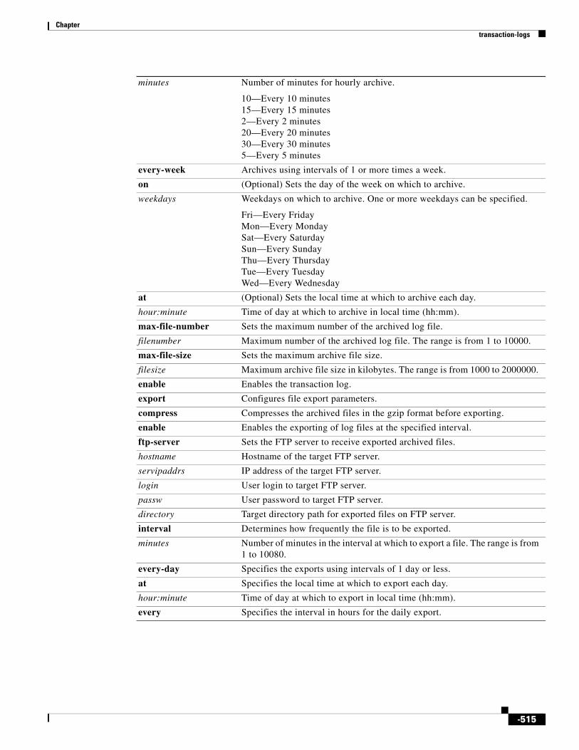
Chapter transaction-logs
minutes Number of minutes for hourly archive.
10—Every 10 minutes15—Every 15 minutes2—Every 2 minutes20—Every 20 minutes30—Every 30 minutes5—Every 5 minutes
every-week Archives using intervals of 1 or more times a week.
on (Optional) Sets the day of the week on which to archive.
weekdays Weekdays on which to archive. One or more weekdays can be specified.
Fri—Every FridayMon—Every MondaySat—Every SaturdaySun—Every SundayThu—Every ThursdayTue—Every TuesdayWed—Every Wednesday
at (Optional) Sets the local time at which to archive each day.
hour:minute Time of day at which to archive in local time (hh:mm).
max-file-number Sets the maximum number of the archived log file.
filenumber Maximum number of the archived log file. The range is from 1 to 10000.
max-file-size Sets the maximum archive file size.
filesize Maximum archive file size in kilobytes. The range is from 1000 to 2000000.
enable Enables the transaction log.
export Configures file export parameters.
compress Compresses the archived files in the gzip format before exporting.
enable Enables the exporting of log files at the specified interval.
ftp-server Sets the FTP server to receive exported archived files.
hostname Hostname of the target FTP server.
servipaddrs IP address of the target FTP server.
login User login to target FTP server.
passw User password to target FTP server.
directory Target directory path for exported files on FTP server.
interval Determines how frequently the file is to be exported.
minutes Number of minutes in the interval at which to export a file. The range is from 1 to 10080.
every-day Specifies the exports using intervals of 1 day or less.
at Specifies the local time at which to export each day.
hour:minute Time of day at which to export in local time (hh:mm).
every Specifies the interval in hours for the daily export.
-515

Chapter transaction-logs
hours Number of hours for the daily export.
1—Hourly12—Every 12 hours2— Every 2 hours24—Every 24 hours3— Every 3 hours4—Every 4 hours6—Every 6 hours8—Every 8 hours
every-hour Specifies the exports using intervals of 1 hour or less.
at Specifies the time at which to export each hour.
minute Minute alignment for the hourly export. The range is from 0 to 59.
every Specifies the interval in minutes that align with the top of the hour.
minutes Number of minutes for the hourly export.
10—Every 10 minutes15—Every 15 minutes2—Every 2 minutes20—Every 20 minutes30—Every 30 minutes5—Every 5 minutes
every-week Specifies the exports using intervals of 1 of more times a week.
on (Optional) Specifies the days of the week for the export.
weekdays Weekdays on which to export. One or more weekdays can be specified.
Fri—Every FridayMon—Every MondaySat—Every SaturdaySun—Every SundayThu—Every ThursdayTue—Every TuesdayWed—Every Wednesday
at (Optional) Specifies the time of day at which to perform the weekly export.
hour:minute Time of day at which to export in the local time (hh:mm).
sftp-server Sets the SFTP1 server to receive exported archived files.
hostname Hostname of the target SFTP server.
servipaddrs IP address of the target SFTP server.
login User login to the target SFTP server (less than 40 characters).
passw User password to the target SFTP server (less than 40 characters).
directory Target directory path for exported files on the SFTP server.
format Sets the format to use for the HTTP transaction log entries in the working.log file.
apache Configures the HTTP transaction logs output to the Apache CLF2.
custom Configures the HTTP transaction logs output to the custom log format.
string Quoted log format string containing the custom log format.
extended-squid Configures the HTTP transaction logs output to the Extended Squid log format.
-516

Chapter transaction-logs
log-windows-domain Logs the Windows domain with an authenticated username if available in HTTP transaction log entries.
enable Enables the remote transaction logging.
entry-type Specifies the type of transaction log entry.
all Sets the SE to send all transaction log messages to the remote syslog server.
request-auth-failures Sets the SE to log to the remote syslog server only those transactions that the SE failed to authenticate with the authentication server.
Note Only those authentication failures that are associated with an end user who is attempting to contact the authentication server are logged. The transactions in pending state (that have contacted the authentication server, but waiting for a response from the authentication server) are not logged.
facility Configures a unique facility to create a separate log on the remote syslog host for real-time transaction log entries.
parameter Specifies one of the following facilities:
auth—Authorization systemdaemon—System daemonskern—Kernellocal0—Local uselocal1—Local uselocal2—Local uselocal3—Local uselocal4—Local uselocal5—Local uselocal6—Local uselocal7—Local use mail—Mail systemnews—USENET newssyslog—Syslog itselfuser—User processuucp—UUCP system
host Configures the remote syslog server.
hostname Hostname of the remote syslog server.
ip-address IP address of the remote syslog server.
port Configures the port to use when sending transaction log messages to the syslog server.
port-num Port number to use when sending transaction log messages to the syslog server. The default is 514.
rate-limit Configures the rate at which the transaction logger is allowed to send messages to the remote syslog server.
rate Rate (number of messages per second) at which the transaction logger is allowed to send messages to the remote syslog server.
1. SFTP = secure file transfer protocol
2. CLF = common log format
-517

Chapter transaction-logs
Defaults archive: disabled
enable: disabled
export compress: disabled
export: disabled
file-marker: disabled
archive interval: every day, every one hour
archive max-file-size: 2,000,000 KB
export interval: every day, every one hour
format: apache
logging port port-num: 514
Command Modes Global configuration
Usage Guidelines SEs that are running Cisco ECDS software can record all errors and access activities. Each content service module on the SE provides logs of the requests that were serviced. These logs are referred to as transaction logs.
Typical fields in the transaction log are the date and time when a request was made, the URL that was requested, whether it was a cache hit or a cache miss, the type of request, the number of bytes transferred, and the source IP address. Transaction logs are used for problem identification and solving, load monitoring, billing, statistical analysis, security problems, and cost analysis and provisioning.
The translog module on the SE handles transaction logging and supports the Apache Common Log Format (CLF), Extended Squid format, and the World Wide Web Consortium (W3C) customizable logging format.
Note For RTSP, when you choose the Repeat option from the Play menu in the Windows Media player to play media files continuously in a loop, an extra entry is logged in the transaction logs for each playback of the file. This situation occurs mostly with the WMT RTSPU protocol because of the behavior of the player.
Enable transaction log recording with the transaction-logs enable command. The transactions that are logged include HTTP and FTP. In addition, Extensible Markup Language (XML) logging for MMS-over-HTTP and MMS-over-RTSP (RTSP over Windows Media Services 9) is also supported.
When enabled, daemons create a working.log file in /local1/logs/ on the sysfs volume for HTTP and FTP transactions and a separate working.log file in /local1/logs/export for Windows Media transactions. The posted XML log file from the Windows Media Player to the SE (Windows Media server) can be parsed and saved to the normal WMT transaction logs that are stored on the SE.
The working.log file is a link to the actual log file with the timestamp embedded in its filename. When you configure the transaction-logs archive interval command, the first transaction that arrives after the interval elapses is logged to the working.log file as usual, and then actual log file is archived and a new log file is created. Only transactions subsequent to the archiving event are recorded in the new log file. The working.log file is then updated to point to the newly created log file. The transaction log archive file naming conventions are shown in Table 4-91. The SE default archive interval is once an hour every day.
-518
Chapter transaction-logs
Use the transaction-logs archive max-file-size command to specify the maximum size of an archive file. The working.log file is archived when it attains the maximum file size if this size is reached before the configured archive interval time.
Use the transaction-logs file-marker option to mark the beginning and end of the HTTP, HTTPS, and FTP proxy logs. By examining the file markers of an exported archive file, you can determine whether the FTP process transferred the entire file. The file markers are in the form of dummy transaction entries that are written in the configured log format.
The following example shows the start and end dummy transactions in the default native Squid log format.
• 970599034.130 0 0.0.0.0 TCP_MISS/000 0 NONE TRANSLOG_FILE_START - NONE/- -
• 970599440.130 0 0.0.0.0 TCP_MISS/000 0 NONE TRANSLOG_FILE_END - NONE/- -
Use the format option to format the HTTP, HTTPS, and FTP proxy log files for custom format, native Squid or Extended Squid formats, or Apache Common Log Format (CLF).
The transaction-logs format custom command allows you to use a log format string to log additional fields that are not included in the predefined native Squid or Extended Squid formats or the Apache CLF format. The log format string is a string that contains the tokens listed in Table 4-85 and mimics the Apache log format string. The log format string can contain literal characters that are copied into the log file. Two backslashes (\\) can be used to represent a literal backslash, and a backslash followed by a single quotation mark (\’) can be used to represent a literal single quotation mark. A literal double quotation mark cannot be represented as part of the log format string. The control characters \t and \n can be used to represent a tab and a new line character, respectively.
Table 4-85 lists the acceptable format tokens for the log format string. The ellipsis (...) portion of the format tokens shown in this table represent an optional condition. This portion of the format token can be left blank, as in %a. If an optional condition is included in the format token and the condition is met, then what is shown in the Value column of Table 4-85 is included in the transaction log output. If an optional condition is included in the format token but the condition is not met, the resulting transaction log output is replaced with a hyphen (-). The form of the condition is a list of HTTP status codes, which may or may not be preceded by an exclamation point (!). The exclamation point is used to negate all the status codes that follow it, which means that the value associated with the format token is logged if none of the status codes listed after the exclamation point (!) match the HTTP status code of the request. If any of the status codes listed after the exclamation point (!) match the HTTP status code of the request, then a hyphen (-) is logged.
For example, %400,501 {User-Agent} i logs the User-Agent header value on 400 errors and 501 errors (Bad Request, Not Implemented) only, and %!200,304,302 {Referer} i logs the Referer header value on all requests that did not return a normal status.
The custom format currently supports the following request headers:
• User-Agent
• Referer
• Host
• Cookie
The output of each of the following Request, Referer, and User-Agent format tokens specified in the custom log format string is always enclosed in double quotation marks in the transaction log entry:
%r
% {Referer} i
% {User-Agent} i
-519

Chapter transaction-logs
The % {Cookie} i format token is generated without the surrounding double quotation marks, because the Cookie value can contain double quotes. The Cookie value can contain multiple attribute-value pairs that are separated by spaces. We recommend that when you use the Cookie format token in a custom format string, you should position it as the last field in the format string so that it can be easily parsed by the transaction log reporting tools. By using the format token string \’% {Cookie} i\’ the Cookie header can be surrounded by single quotes (’).
The following command can generate the well-known Apache Combined Log Format:
transaction-log format custom “ [ % { %d } t/% { %b } t/% { %Y } t:% { %H } t:% { %M } t:% { %S } t % { %z } t ] %r %s %b % { Referer } i % { User-Agent } i”
The following transaction log entry example in the Apache Combined Format is configured using the preceding custom format string:
[ 11/Jan/2003:02:12:44 -0800 ] "GET http://www.cisco.com/swa/i/site_tour_link.gif HTTP/1.1" 200 3436 "http://www.cisco.com/" "Mozilla/4.0 (compatible; MSIE 5.5; Windows NT 5.0)"
Table 4-85 Custom Format “Log Format String” Values
Format Token Value
%...a IP address of the requesting client.
%...A IP address of the SE.
%...B%...b
Bytes sent excluding HTTP headers.
%...c Connection status when response is completed where
X = Connection was aborted before the response was completed.+ = Connection can be kept alive after the response is sent.– = Connection is closed after the response is sent.
%...f Filename.
%...h Remote host (IP address of the requesting client is logged).
%...H Request protocol.
%... {Foobar} i
Contents of Foobar: header lines in the request that is sent to the server. The value of Foobar can be one of the following headers: User-Agent, Referer, Host, or Cookie.
%...l Remote log name.
Not implemented on the SE, so a hyphen (-) is logged.
%...m Request method.
%...p Canonical port of the server servicing the request. Not applicable on the SE, so a hyphen (-) is logged.
%...P Process ID of the child that serviced the request.
%...q Query string (that is preceded by a question mark (?) if a query string exists; otherwise, it is an empty string).
%...r First line of the request.
%...s Status. The translog code always returns the HTTP response code for the request.
%...t Time in common log time format (or standard English format).
%... {format} t Time in the form given by the format token specified in Table 4-86.
-520

Chapter transaction-logs
Table 4-86 specifies the format token for the date and time of the format token %... {format} t that is listed in Table 4-87.
%...T Time consumed to serve the request, in seconds (a floating point number with three decimal places).
%...u Remote user.
%...U URL path requested not including query strings.
%...v%...V
Value of the host request header field reported if the host appeared in the request. If the host did not appear in the host request header, the IP address of the server specified in the URL is reported.
Table 4-85 Custom Format “Log Format String” Values (continued)
Format Token Value
Table 4-86 Format Token for Date and Time
Format Token Value
%a Abbreviated weekday name.
%A Full weekday name.
%b Abbreviated month name.
%B Full month name.
%c Date and time representation.
%C Century number (year/100) as a 2-digit integer.
%d Day of the month as a decimal number. The range is from 01 to 31.
%D Equivalent to %m/%d/%y. (In countries other than the USA, %d/%m/%y is common. In an international context, this format is ambiguous and should not be used.)
%e Similar to %d, the day of the month as a decimal number, but a leading zero is replaced by a space.
%G ISO 8601 year with the century as a decimal number. The 4-digit year corresponding to the ISO week number (see %V). This format token has the same format and value as %y, except that if the ISO week number belongs to the previous or next year, that year is used instead.
%g Similar to %G, but without a century; that is, with a 2-digit year. The range is from 00 to 99.
%h Equivalent to %b.
%H Hour as a decimal number using a 24-hour clock. The range is from 00 to 23.
%I Hour as a decimal number using a 12-hour clock. The range is from 01 to12.
%j Day of the year as a decimal number. The range is from 001 to 366.
%k Hour (24-hour clock) as a decimal number (0 to 23); single digits are preceded by a blank. (See also %H.)
%l Hour (12-hour clock) as a decimal number (1 to 12); single digits are preceded by a blank. (See also %I.)
%m Month as a decimal number. The range is from 01 to 12.
%M Minute as a decimal number. The range is from 00 to 59.
-521

Chapter transaction-logs
The Extended Squid log format uses the RFC 981 field of the Squid log format for the username. The Extended Squid format logs the associated username for authentication for each record in the log file, if available. The username is also used for billing purposes.
The W3C Customizable Logging Format is limited in that it was defined from the HTTP web server perspective and does not offer certain web cache-specific custom options such as those supplied by the fixed Squid format. Format tokens that are extensions to the W3C Customized Logging Format support additional Cisco and Squid customized logging fields. These format tokens provide support for a Squid-like logging format from within the W3C customizable token set.
The W3C Customizable Logging Format was extended to include support for the following special token sequence:
%n New line character.
%p Either AM or PM according to the given time value, or the corresponding strings for the current locale. Noon is treated as PM and midnight as AM.
%P Similar to %p but in lowercase: am or pm or a corresponding string for the current locale.
%r Time in a.m. or p.m. notation. This format token is equivalent to “%I:%M:%S %p.”
%R Time in 24-hour notation (%H:%M). For a version including the seconds, see %T below.
%s Number of seconds since the epoch; that is, since 1970-01-01 00:00:00 UTC.
%S Second as a decimal number. The range is from 00 to 61.
%t Tab character.
%T Time in 24-hour notation (%H:%M:%S).
%u Day of the week as a decimal, 1 to 7, Monday being 1. See also %w.
%U Week number of the current year as a decimal number (00 to 53), starting with the first Sunday as the first day of week 01. See also %V and %W.
%V ISO 8601:1988 week number of the current year as a decimal number (01 to 53), where week 1 is the first week that has at least 4 days in the current year, and with Monday as the first day of the week. See also %U and %W.
%w Day of the week as a decimal (0 to 6) with Sunday as 0. See also %u.
%W Week number of the current year as a decimal number (00 to 53), starting with the first Monday as the first day of week 01.
%x Date representation without the time.
%X Time representation without the date.
%y Year as a decimal number without a century. The range is from 00 to 99.
%Y Year as a decimal number, including the century.
%z Time zone as an hour offset from GMT. Required to emit RFC822-conformant dates (using %a, %d %b %Y %H:%M:%S %z).
%Z Time zone or name or abbreviation.
%% Literal % character.
Table 4-86 Format Token for Date and Time (continued)
Format Token Value
-522

Chapter transaction-logs
%... {<translog-token>} C
The ellipsis (...) is optional. If specified, it can be a sequence of conditional HTTP response codes separated by commas. The uppercase C defines the extended customizable behavior token set, for which tokens are defined by the <translog-token> directive, which is a two-character token directive.
Table 4-87 lists the existing and new <translog-token> directives from the Extended Squid format, which are not immediately supported by the W3C definitions but are supported in the ECDS software.
In addition to the tokens listed in Table 4-87, you can condense multiple %... {xx} C style tokens into a single embedded token sequence within the %... {xx} C style. A limited customized logging string validation mechanism has been implemented for all the %... {xy} C style format tokens. This mechanism ensures that the tokens are valid and rejects invalid tokens. To condense multiple style tokens into a single embedded token sequence, you must specify multiple tokens within the { } braces and prefix each token with the percent (%) symbol as follows:
% { rh } C % { rt } C % { as } C
can be reexpressed in a condensed embedded token format as the following:
% { %rh %rt %as } C
Table 4-87 Translog Token Directives
Format Token Value
%... {es} C Current time presented as the number of seconds that have elapsed since the Epoch (Jan. 1st. 1970).
%... {em} C Current number of milliseconds that have elapsed since the Epoch (Jan. 1st. 1970).
%... {te} C Number of milliseconds that have elapsed until the request was completed.
%... {rd} C Squid-like cache-status code string (for example, TCP_HIT and TCP_CLIENT_REFRESH_MISS).
%.. {cs} C Number of bytes sent to the client (including the protocol headers).
%... {rh} C Strict Squid-style hierarchy as it applies to the SE.
%... {rh} SE Extended Squid-style hierarchy. Same as %... {rh} C except when an outgoing-proxy is explicitly defined and is used to satisfy a request, then the DEFAULT_PARENT/proxy_ip_addess is logged instead of the DIRECT/origin_server_ip_address.
%... {rt} C Cisco ECDS software supports login with the MIME type of an object that is being requested. When a request is served, an appropriate MIME type will be logged.
Tip A MIME-type association enables the browser to invoke a particular application when it encounters an object with a particular MIME-type suffix. A set of default association rules covers the common object types on the Internet. You can edit, add, or delete these MIME-type association rules in the browsers. For example, through a MIME-type association, the client browser launches the Adobe Acrobat reader when it encounters a *.pdf file, and it launches the Windows Media Player when it encounters an *.asf or *.asx file.
%... {ru} C URL being requested including any additional query strings.
%... {as} C Application-specific information. Certain request handling applications might want to log a certain string here, which is supported as part of the Squid format specification. For example, SmartFilter URL filtering logs information where this token sequence is used.
-523

Chapter transaction-logs
The command line syntax accepts single tokens represented as the following:
% { %rh } C
and
% { rh } C
as equivalents.
Any character that is not part of an embedded token sequence (for example, the space character) is repeated verbatim in the output file.
The above set of tokens allow you to configure an extended Squid-like format line within the W3C Customizable Logging format specification as follows:
% { es } C.% { em } C % { te } C %a % { rd } C/%s % { cs } C %m % { ru } C %u % { rh } C % { rt } C % { as } C
The following is an example of a Extended Squid-like format that specifies that user-readable time-stamps are used instead of Squid’s “seconds-since-epoch” time-stamp format, and that a configured out-going proxy (as specified by “%... { rH } C”) is logged:
[ % { %d/%b/%Y:%H:%M:%S %z } t ] % { te } C %a % { rd } C/%s % { cs } C %m % { ru } C %u % { rH } C % { rt } C % { as } C
Unknown or unsupported translog tokens are logged within the log file as the characters that made up the token. For example, % { xy } C is logged into the log file as xy. All characters outside of a token specification sequence are repeated verbatim within the log file.
Sanitizing Transaction Logs
Use the sanitized option to disguise the IP address of clients in the transaction log file. The default is that transaction logs are not sanitized. A sanitized transaction log disguises the network identity of a client by changing the IP address in the transaction logs to 0.0.0.0.
The no form of this command disables the sanitize feature. The transaction-logs sanitize command does not affect the client IP (%a) value associated with a custom log format string that is configured with the CLI (configured with the transaction-logs format custom string command in global configuration mode in which the string is the quoted log format string that contains the custom log format). To hide the identity of the client IP in the custom log format, either hard code 0.0.0.0 in the custom log format string or exclude the %a token, which represents the client IP, from the format string.
Exporting Transaction Log Files
To facilitate the postprocessing of cache log files, you could export transaction logs to an external host.
This feature allows log files to be exported automatically by FTP to an external host at configurable intervals. The username and password used for FTP are configurable. The directory to which the log files are uploaded is also configurable.
The log files automatically have the following naming convention:
• Module name
• Host IP address
• Date
• Time
• File generation number
For example, the filename for a Web Engine access log would be the following:
we_accesslog_apache_192.0.2.22_20091207_065624_00001
-524

Chapter transaction-logs
where we_accesslog_apache is the module name, 192.0.2.22 is the IP address of the device, 20091207 is the date of the log file (December 7, 2009), and 065624_00001 is the file generation number. The File Generation Number ranges from 00001 to 99999.
Note WMT logs have no .txt extension in the filename.
Exporting and Archiving Intervals
The transaction log archive and export functions are configured with the following commands:
• The transaction-logs archive interval command in global configuration mode allows the administrator to specify when the working.log file is archived.
• The transaction-logs export interval command in global configuration mode allows the administrator to specify when the archived transaction logs are exported.
The following limitations apply:
• When the interval is scheduled in units of hours, the value must divide evenly into 24. For example, the interval can be every 4 hours, but not every 5 hours.
• When the interval is scheduled in units of minutes, the value must divide evenly into 60.
• Only the more common choices of minutes are supported. For example, the interval can be 5 minutes or 10 minutes, but not 6 minutes.
• Selection of interval alignment is limited. If an interval is configured for every 4 hours, it aligns with midnight. It cannot align with 12:30 or with 7 a.m.
• Feature does not support different intervals within a 24-hour period. For example, it does not support an interval that is hourly during regular business hours and then every 4 hours during the night.
Transaction Log Archive Filenaming Convention
The archive transaction log file is named as follows for HTTP and WMT caching:
celog_10.1.118.5_20001228_235959.txt
mms_export_10.1.118.5_20001228_235959
If the export compress feature is enabled when the file is exported, then the file extension is .gz after the file is compressed for the export operation, as shown in the following example:
celog_10.1.118.5_20001228_235959.txt.gz
mms_export_10.1.118.5_20001228_235959.gz
Table 4-91 describes the name elements.
Table 4-88 Archive Log Name Element Descriptions
Sample of Element Description
acqdist_ Acquisition and distribution archive log file.
celog_ HTTP caching proxy server archive file.
cifs_server_ Windows file sharing server archive file.
cseaccess Cisco Streaming Engine archive file.
mms_export_ Standard Windows Media Services 4.1 caching proxy server archive file.
-525

Chapter transaction-logs
Table 4-89 lists the directory names and the corresponding examples of the archive filenames.
Compressing Archive Files
The transaction-logs export compress option compresses an archive into a gzip file format before exporting it. Compressing the archive file uses less disk space on both the SE and the FTP export server. The compressed file uses less bandwidth when transferred. The archive filename of the compressed file has the extension .gz.
Exporting Transaction Logs to External FTP Servers
The transaction-logs export ftp-server option can support up to four FTP servers. To export transaction logs, you must first enable the feature and configure the FTP server parameters. The following information is required for each target FTP server:
• FTP server IP address or the hostname
mms_export_e_wms_41_ Extended Windows Media Services 4.1 caching proxy server archive file.
mms_export_wms_90_ Standard Windows Media Services 9.0 caching proxy server archive file.
mms_export_e_wms_90_ Extended Windows Media Services 9.0 caching proxy server archive file.
rproxyaccess.log. RealProxy archive file.
rmsvraccess.log. RealSubscriber archive file.
tftp_server_ TFTP server archive file.
tvout_ TV-out program archive file.
10.1.118.5_ IP address of the SE creating the archive file.
20001228_ Date on which the archive file was created (yyyy/mm/dd).
235959 Time when the archive file was created (hh/mm/ss).
Table 4-88 Archive Log Name Element Descriptions (continued)
Sample of Element Description
Table 4-89 Archive Filename Examples and Directories
Directory Archive Filename
logs celog_10.1.94.4_20050310_231500.txt
logs/export mms_export_10.1.94.4_20050315_001545
logs/export/extended-wms-41 mms_export_e_wms_41_10.1.94.4_20050315_001545
logs/wms-90 mms_export_wms_90_10.1.94.4_20050315_001545
logs/export/extended-wms-90 mms_export_e_wms_90_10.1.94.4_20050315_001545
logs/acqdist acqdist_10.1.94.4_20050315_001545
logs/cifs_server cifs_server_10.1.94.4_20050315_001545
logs/cisco-streaming-engine cseaccess10.1.94.4__050315000.log
logs/real-proxy rproxyaccess.log.10.1.94.4_.20050315_001545
logs/real-subscriber rmsvraccess.log.10.1.94.4_.20050315_001545
logs/tftp_server tftp_server_10.1.94.4_20050315_001545
logs/tvout tvout_10.1.94.4_20050315_001545
-526

Chapter transaction-logs
The SE translates the hostname with a DNS lookup and then stores the IP address in the configuration.
• FTP user login and user password
• Path of the directory where transferred files are written
Use a fully qualified path or a relative path for the user login. The user must have write permission to the directory.
Use the no form of the transaction-logs export enable command to disable the entire transaction logs feature while retaining the rest of the configuration.
Exporting Transaction Logs to External SFTP Servers
Use the transaction-logs export sftp-server option to export transaction logs. You must first enable the feature and configure the Secure File Transfer Protocol (SFTP) server parameters. The following information is required for each target SFTP server:
• SFTP server IP address or the hostname
The SE translates the hostname with a DNS lookup and then stores the IP address in the configuration.
• SFTP user login and user password
• Path of the directory where transferred files are written
Use a fully qualified path or a relative path for the user login. The user must have write permission to the directory.
Use the no form of the transaction-logs export enable command to disable the entire transaction logs feature while retaining the rest of the configuration.
Receiving a Permanent Error from the External FTP Server
A permanent error (Permanent Negative Completion Reply, RFC 959) occurs when the FTP command to the server cannot be accepted, and the action does not take place. Permanent errors can be caused by invalid user logins, invalid user passwords, and attempts to access directories with insufficient permissions.
When an FTP server returns a permanent error to the SE, the export is retried at 10-minute intervals or sooner if the configured export interval is sooner. If the error is a result of a misconfiguration of the transaction-logs export ftp server command, then you must reenter the SE parameters to clear the error condition. The show statistics transaction-logs command displays the status of logging attempts to export servers.
The show statistics transaction-logs command shows that the SE failed to export archive files.
The transaction-logs format command has four options: extended-squid, apache, and custom.
Use the no form of the transaction-logs export enable command to disable the entire transaction logs feature while retaining the rest of the configuration.
Configuring Intervals Between 1 Hour and 1 Day
The archive or export interval can be set for once a day with a specific time stamp. It can also be set for hour frequencies that align with midnight. For example, every 4 hours means archiving occurs at 0000, 0400, 0800, 1200, and 1600. It is not possible to archive at half-hour intervals such as 0030, 0430, or 0830. The following intervals are acceptable: 1, 2, 3, 4, 6, 8, 12, and 24.
-527

Chapter transaction-logs
Configuring Intervals of 1 Hour or Less
The interval can be set for once an hour with a minute alignment. It can also be set for frequencies of less than an hour; these frequencies align with the top of the hour. Every 5 minutes means that archiving occurs at 1700, 1705, and 1710.
Configuring Export Interval on Specific Days
The export interval can be set for specific days of the week at a specific time. One or more days can be specified. The default time is midnight.
You must be aware that archived logs are automatically deleted when free disk space is low. It is important to select an export interval that exports files frequently enough so that files are not automatically removed before export.
Monitoring HTTP Request Authentication Failures in Real Time
Cisco ECDS software supports sending HTTP transaction log messages to a remote syslog server so that you can monitor the remote syslog server for HTTP request authentication failures in real time. This real-time transaction log allows you to monitor transaction logs in real time for particular errors such as HTTP request authentication errors. The existing transaction logging to the local file system remains unchanged.
Note Because system logging (syslog) occurs through UDP, the message transport to the remote syslog host is not reliable.
Summary Line
Transaction logs include a summary line as the last line in the transaction log, which includes a summary of all the requests that appear in the transaction log.
Examples The following example shows how to configure an FTP server:
ServiceEngine(config)# transaction-logs export ftp-server 10.1.1.1 mylogin mypasswd /ftpdirectory
ServiceEngine(config)# transaction-logs export ftp-server myhostname mylogin mypasswd /ftpdirectory
The following example shows how to delete an FTP server:
ServiceEngine(config)# no transaction-logs export ftp-server 10.1.1.1ServiceEngine(config)# no transaction-logs export ftp-server myhostname
-528

Chapter transaction-logs
Use the no form of the command to disable the entire transaction log export feature while retaining the rest of the configuration:
ServiceEngine(config)# no transaction-logs export enable
The following example shows how to change a username, password, or directory:
ServiceEngine(config)# transaction-logs export ftp-server 10.1.1.1 mynewname mynewpass /newftpdirectory
Note For security reasons, passwords are never displayed.
The following example shows how to restart the export of archive transaction logs:
ServiceEngine(config)# transaction-logs export ftp-server 172.16.10.5 goodlogin pass /ftpdirectory
The following example shows how to delete an SFTP server from the current configuration:
ServiceEngine(config)# no transaction-logs export sftp-server sftphostname
The following examples show how to configure the archiving intervals:
ServiceEngine(config)# transaction-logs archive interval every-day at Specify the time at which to archive each day every Specify the interval in hours. It will align with midnight
ServiceEngine(config)# transaction-logs archive interval every-day at<0-23>: Time of day at which to archive (hh:mm)
ServiceEngine(config)# transaction-logs archive interval every-day every<1-24> Interval in hours: { 1, 2, 3, 4, 6, 8, 12 or 24 }
The following example shows that the SE has failed to export archive files:
ServiceEngine# show statistics transaction-logsTransaction Log Export Statistics:
Server:172.16.10.5 Initial Attempts:1 Initial Successes:0 Initial Open Failures:0 Initial Put Failures:0 Retry Attempts:0 Retry Successes:0 Retry Open Failures:0 Retry Put Failures:0 Authentication Failures:1 Invalid Server Directory Failures:0
The following example shows how to correct a misconfiguration:
ServiceEngine(config)# transaction-logs export ftp-server 10.1.1.1 goodlogin pass /ftpdirectory
The working.log file and archived log files are listed for HTTP and WMT.
The following example shows how to export transaction logs to an SFTP server:
ServiceEngine(config)# transaction-logs export sftp-server 10.1.1.100 mylogin mypasswd /mydir
-529

Chapter transaction-logs
The following example shows how to archive every 4 hours and align with the midnight local time (0000, 0400, 0800, 1200, 1600, and 2000):
ServiceEngine(config)# transaction-logs archive interval every-day every 4
The following example shows how to export once a day at midnight local time:
ServiceEngine(config)# transaction-logs export interval every-day every 24
The following example shows how to configure export intervals:
ServiceEngine(config)# transaction-logs archive interval every-hour ? at Specify the time at which to archive each day every Specify interval in minutes. It will align with top of the hour
ServiceEngine(config)# transaction-logs archive interval every-hour at ? <0-59> Specify the minute alignment for the hourly archive ServiceEngine(config)# transaction-logs archive interval every-hour every ? <2-30> Interval in minutes: { 2, 5, 10, 15, 20, 30 }
Related Commands Command Description
clear Clears the HTTP object cache, the hardware interface, statistics, archive working transaction logs, and other settings.
show statistics transaction-logs Displays the SE transaction log export statistics.
show transaction-logging Displays the transaction log configuration settings and a list of archived transaction log files.
transaction-log force Forces the archive or export of the transaction log.
-530

Chapter type
type To display the contents of a file, use the type command in EXEC configuration mode.
type filename
Syntax Description
Defaults No default behavior or values
Command Modes EXEC
Usage Guidelines Use this command to display the contents of a file within any SE file directory. This command may be used to monitor features such as transaction logging or system logging (syslog).
Examples The following example displays the syslog file on the SE:
ServiceEngine# type /local1/syslog.txt
Jan 10 22:02:46 (none) populate_ds: %SE-CLI-5-170050: Cisco Internet Streamer CDS Software starts bootingJan 10 22:02:47 (none) create_etc_hosts.sh: %SE-CLI-5-170051: HOSTPLUSDOMAIN: NO-HOSTNAMEJan 10 22:02:47 NO-HOSTNAME : %SE-CLI-5-170053: Recreated etc_hosts (1, 0) Jan 10 22:02:48 NO-HOSTNAME Nodemgr: %SE-NODEMGR-5-330082: [ CLI_VER_NTP ] requests stop service ntpd Jan 10 22:02:49 NO-HOSTNAME Nodemgr: %SE-NODEMGR-5-330082: [ ver_tvout ] requests stop service tvoutsvr Jan 10 22:02:50 NO-HOSTNAME Nodemgr: %SE-NODEMGR-5-330084: [ ver_rtspg ] requests restart service rtspg Jan 10 22:02:50 NO-HOSTNAME Nodemgr: %SE-NODEMGR-5-330082: [ ver_iptv ] requests stop service sbss Jan 10 22:02:51 NO-HOSTNAME Nodemgr: %SE-NODEMGR-5-330080: [ ver_telnetd ] requests start service telnetd Jan 10 22:02:52 NO-HOSTNAME Nodemgr: %SE-NODEMGR-5-330082: [ ver_wmt ] requests stop service wmt_mms Jan 10 22:02:53 NO-HOSTNAME Nodemgr: %SE-NODEMGR-5-330082: [ ver_wmt ] requests stop service wmt_logd Jan 10 22:02:55 NO-HOSTNAME Nodemgr: %SE-NODEMGR-5-330082: [ Unknown ] requests stop service mcast_sender Jan 10 22:02:55 NO-HOSTNAME Nodemgr: %SE-NODEMGR-5-330082: [ Unknown ] requests stop service mcast_receiver Jan 10 22:02:56 NO-HOSTNAME Nodemgr: %SE-NODEMGR-5-330024: Service 'populate_ds' exited normally with code 0 Jan 10 22:02:56 NO-HOSTNAME Nodemgr: %SE-NODEMGR-5-330040: Start service 'parser_server' using: '/ruby/bin/parser_server' with pid: 1753 Jan 10 22:02:56 NO-HOSTNAME Nodemgr: %SE-NODEMGR-5-330040: Start service 'syslog_bootup_msgs' using: '/ruby/bin/syslog_bootup_msgs' with pid: 1754 Jan 10 22:02:56 NO-HOSTNAME syslog_bootup_msgs: %SE-SYS-5-900001: <4>Linux version 2.4.16 ([email protected]) (gcc version 3.0.4) # 1 SMP Fri Jan 7 19:26:58 PST 2005
filename Name of file.
-531

Chapter type
Jan 10 22:02:56 NO-HOSTNAME syslog_bootup_msgs: %SE-SYS-5-900001: <6>setup.c: handling flash window at [ 15MB..16MB) Jan 10 22:02:56 NO-HOSTNAME syslog_bootup_msgs: %SE-SYS-5-900001: <6>BIOS-provided physical RAM map: Jan 10 22:02:56 NO-HOSTNAME syslog_bootup_msgs: %SE-SYS-5-900001: <4> BIOS-e820: 0000000000000000 - 000000000009ec00 (usable) Jan 10 22:02:56 NO-HOSTNAME syslog_bootup_msgs: %SE-SYS-5-900001: <4> BIOS-e820: 000000000009ec00 - 00000000000a0000 (reserved) Jan 10 22:02:56 NO-HOSTNAME syslog_bootup_msgs: %SE-SYS-5-900001: <4> BIOS-e820: 00000000000e0800 - 0000000000100000 (reserved) Jan 10 22:02:56 NO-HOSTNAME syslog_bootup_msgs: %SE-SYS-5-900001: <4> BIOS-e820: 0000000000100000 - 0000000000f00000 (usable) Jan 10 22:02:56 NO-HOSTNAME syslog_bootup_msgs: %SE-SYS-5-900001: <4> BIOS-e820: 0000000000f00000 - 0000000001000000 (reserved) Jan 10 22:02:56 NO-HOSTNAME syslog_bootup_msgs: %SE-SYS-5-900001: <4> BIOS-e820: 0000000001000000 - 0000000010000000 (usable) Jan 10 22:02:56 NO-HOSTNAME syslog_bootup_msgs: %SE-SYS-5-900001: <4> BIOS-e820: 00000000fff00000 - 0000000100000000 (reserved) Jan 10 22:02:56 NO-HOSTNAME syslog_bootup_msgs: %SE-SYS-5-900001: <6>setup.c: reserved bootmem for INITRD_START = 0x6000000, INITRD_SIZE = 11709348 Jan 10 22:02:56 NO-HOSTNAME syslog_bootup_msgs: %SE-SYS-5-900001: <4>On node 0 totalpages: 65536 Jan 10 22:02:56 NO-HOSTNAME syslog_bootup_msgs: %SE-SYS-5-900001: <4>zone(0): 4096 pages. Jan 10 22:02:56 NO-HOSTNAME syslog_bootup_msgs: %SE-SYS-5-900001: <4>zone(1): 61440 pages. Jan 10 22:02:56 NO-HOSTNAME syslog_bootup_msgs: %SE-SYS-5-900001: <4>zone(2): 0 pages. Jan 10 22:02:56 NO-HOSTNAME syslog_bootup_msgs: %SE-SYS-5-900001: <4>Local APIC disabled by BIOS -- reenabling. Jan 10 22:02:56 NO-HOSTNAME syslog_bootup_msgs: %SE-SYS-5-900001: <4>Found and enabled local APIC! Jan 10 22:02:56 NO-HOSTNAME syslog_bootup_msgs: %SE-SYS-5-900001: <4>Kernel command line: root=/dev/ram ramdisk_size=100000 ramdisk_start=0x6000000 console=ttyS0,9600n8 Jan 10 22:02:56 NO-HOSTNAME syslog_bootup_msgs: %SE-SYS-5-900001: <6>Initializing CPU# 0 --More--.
Related Commands Command Description
cpfile Copies a file.
dir Displays the files in a directory in a long list format.
lls Displays a long list of directory names.
ls Lists the files and subdirectories in a directory.
mkfile Makes a file (for testing).
-532

Chapter type-tail
type-tailTo view a specified number of lines of the end of a log file or to view the end of the file continuously as new lines are added to the file, use the type-tail command in EXEC configuration mode.
type-tail filename [line | follow]
Syntax Description
Defaults The default is ten lines shown.
Command Modes EXEC
Usage Guidelines This command allows you to monitor a log file by letting you view the end of the file. You can specify the number of lines at the end of the file that you want to view, or you can follow the last line of the file as it continues to log new information. To stop the last line from continuously scrolling, press Ctrl-C.
Examples The following example shows the list of log files in the /local1 directory:
stream-ServiceEngine# ls /local1WS441WebsenseWebsenseEnterpriseWebsense_config_backupWsInstallLogbadfile.txtcodecoveragecore.stunnel.5.3.0.b100.cnbuild.5381core_dircrashcrka.logcse_livecse_voddbdowngrade.logdbupgrade.logdowngradeerrorloghttp_authmod.unstripindex.htmllogslost+foundnetscape-401-proxynetscape-401-proxy1netscape-dumpnewwebsenseoldWsInstallLogpreload_dirproxy-basic1
filename File to be examined.
line (Optional) The number of lines from the end of the file to be displayed (1 to 65535).
follow (Optional) Displays the end of the file continuously as new lines are added to the file.
-533

Chapter type-tail
proxy1proxy2proxy3proxy4proxy5proxy6proxy7proxy8proxyreplyproxyreply-407real_vodruby.bin.cli_fixruby.bin.no_ws_fixruby.bin.ws_edir_fixsaservice_logssmartfiltersmfnaveensuperwebsensesyslog.txtsyslog.txt.1syslog.txt.2temptwo.txturl.txturllist.txtvarvpd.propertieswebsense.pre-200webtarball44webtarball520wmt_vodws_upgrade.log
The following example displays the last ten lines of the syslog.txt file. In this example, the number of lines to display is not specified; however, ten lines is the default.
stream-ServiceEngine# type-tail /local1/syslog.txtOct 8 21:49:15 stream-ce syslog:(26830)TRCE:input_serv.c:83-> select_withreturn 0, ready = 0Oct 8 21:49:15 stream-ce syslog:(26832)TRCE:al_master.c:246-> select_withreturn 0, ready = 0Oct 8 21:49:15 stream-ce syslog:(26832)TRCE:in_mms.c:1747-> tv = NULLOct 8 21:49:17 stream-ce syslog:(26830)TRCE:input_serv.c:83-> select_withreturn 0, ready = 0Oct 8 21:49:17 stream-ce syslog:(26832)TRCE:al_master.c:246-> select_withreturn 0, ready = 0Oct 8 21:49:17 stream-ce syslog:(26832)TRCE:in_mms.c:1747-> tv = NULLOct 8 21:49:19 stream-ce syslog:(26830)TRCE:input_serv.c:83-> select_withreturn 0, ready = 0Oct 8 21:49:19 stream-ce syslog:(26832)TRCE:al_master.c:246-> select_withreturn 0, ready = 0Oct 8 21:49:19 stream-ce syslog:(26832)TRCE:in_mms.c:1747-> tv = NULLOct 8 21:49:21 stream-ce syslog:(26830)TRCE:input_serv.c:83-> select_withreturn 0, ready = 0
The following example displays the last 20 lines of the syslog.text file:
stream-ServiceEngine# type-tail /local1/syslog.txt 20Oct 8 21:49:11 stream-ce syslog:(26832)TRCE:al_master.c:246-> select_withreturn 0, ready = 0Oct 8 21:49:11 stream-ce syslog:(26832)TRCE:in_mms.c:1747-> tv = NULLOct 8 21:49:13 stream-ce syslog:(26830)TRCE:input_serv.c:83-> select_withreturn 0, ready = 0
-534

Chapter type-tail
Oct 8 21:49:13 stream-ce syslog:(26832)TRCE:al_master.c:246-> select_withreturn 0, ready = 0Oct 8 21:49:13 stream-ce syslog:(26832)TRCE:in_mms.c:1747-> tv = NULLOct 8 21:49:15 stream-ce syslog:(26830)TRCE:input_serv.c:83-> select_withreturn 0, ready = 0Oct 8 21:49:15 stream-ce syslog:(26832)TRCE:al_master.c:246-> select_withreturn 0, ready = 0Oct 8 21:49:15 stream-ce syslog:(26832)TRCE:in_mms.c:1747-> tv = NULLOct 8 21:49:17 stream-ce syslog:(26830)TRCE:input_serv.c:83-> select_withreturn 0, ready = 0Oct 8 21:49:17 stream-ce syslog:(26832)TRCE:al_master.c:246-> select_withreturn 0, ready = 0Oct 8 21:49:17 stream-ce syslog:(26832)TRCE:in_mms.c:1747-> tv = NULLOct 8 21:49:19 stream-ce syslog:(26830)TRCE:input_serv.c:83-> select_withreturn 0, ready = 0Oct 8 21:49:19 stream-ce syslog:(26832)TRCE:al_master.c:246-> select_withreturn 0, ready = 0Oct 8 21:49:19 stream-ce syslog:(26832)TRCE:in_mms.c:1747-> tv = NULLOct 8 21:49:21 stream-ce syslog:(26830)TRCE:input_serv.c:83-> select_withreturn 0, ready = 0Oct 8 21:49:21 stream-ce syslog:(26832)TRCE:al_master.c:246-> select_withreturn 0, ready = 0Oct 8 21:49:21 stream-ce syslog:(26832)TRCE:in_mms.c:1747-> tv = NULLOct 8 21:49:23 stream-ce syslog:(26830)TRCE:input_serv.c:83-> select_withreturn 0, ready = 0Oct 8 21:49:23 stream-ce syslog:(26832)TRCE:al_master.c:246-> select_withreturn 0, ready = 0Oct 8 21:49:23 stream-ce syslog:(26832)TRCE:in_mms.c:1747-> tv = NULL
The following example follows the file as it grows:
stream-ServiceEngine# type-tail /local1/syslog.txt ? <1-65535> The numbers of lines from end follow Follow the file as it grows <cr>stream-ServiceEngine# type-tail /local1/syslog.txt followOct 8 21:49:39 stream-ce syslog:(26832)TRCE:in_mms.c:1747-> tv = NULLOct 8 21:49:41 stream-ce syslog:(26830)TRCE:input_serv.c:83-> select_withreturn 0, ready = 0Oct 8 21:49:41 stream-ce syslog:(26832)TRCE:al_master.c:246-> select_withreturn 0, ready = 0Oct 8 21:49:41 stream-ce syslog:(26832)TRCE:in_mms.c:1747-> tv = NULLOct 8 21:49:43 stream-ce syslog:(26830)TRCE:input_serv.c:83-> select_withreturn 0, ready = 0Oct 8 21:49:43 stream-ce syslog:(26832)TRCE:al_master.c:246-> select_withreturn 0, ready = 0Oct 8 21:49:43 stream-ce syslog:(26832)TRCE:in_mms.c:1747-> tv = NULLOct 8 21:49:45 stream-ce syslog:(26830)TRCE:input_serv.c:83-> select_withreturn 0, ready = 0Oct 8 21:49:45 stream-ce syslog:(26832)TRCE:al_master.c:246-> select_withreturn 0, ready = 0Oct 8 21:49:45 stream-ce syslog:(26832)TRCE:in_mms.c:1747-> tv = NULLOct 8 21:49:47 stream-ce syslog:(26830)TRCE:input_serv.c:83-> select_withreturn 0, ready = 0Oct 8 21:49:47 stream-ce syslog:(26832)TRCE:al_master.c:246-> select_withreturn 0, ready = 0Oct 8 21:49:47 stream-ce syslog:(26832)TRCE:in_mms.c:1747-> tv = NULLOct 8 21:49:49 stream-ce syslog:(26830)TRCE:input_serv.c:83-> select_withreturn 0, ready = 0Oct 8 21:49:49 stream-ce syslog:(26832)TRCE:al_master.c:246-> select_withreturn 0, ready = 0Oct 8 21:49:49 stream-ce syslog:(26832)TRCE:in_mms.c:1747-> tv = NULL
-535

Chapter undebug
undebugTo disable debugging functions, use the undebug command in EXEC configuration mode.
undebug option
Syntax Description See the table of options in the “Usage Guidelines” section on page 2-97 for the debug command and for a list of options for this command.
Defaults No default behavior or values
Command Modes EXEC
Usage Guidelines We recommend that you use the debug and undebug commands only at the direction of Cisco TAC.
See the “debug” section on page 2-97 for more information about debug functions.
Related Commands Command Description
debug Configures the debugging options.
show debugging Displays the state of each debugging option.
-536

Chapter url-signature
url-signatureThe CDS uses a combination of key owners, key ID numbers, and a word value to generate URL signature keys. To configure the url signature, use the url-signature command in global configuration mode.
url-signature key-id-owner num key-id-number num {key word | public key url [symetric key word | private key url]}
no url-signature key-id-owner num key-id-number num
Syntax Description
Command Modes Global configuration
Usage Guidelines Service Rules for Directing Requests to a Policy Server
If your network is configured to work with Camiant PCMM-compliant third-party policy servers for servicing requests that require guaranteed bandwidth, you can use the following rule patterns and rule actions to filter the requests and to direct them to the policy server. The rule patterns and rule actions also enable you to generate URL signatures in the response for a valid request for a Windows Media metafile (.asx file extension), Movie Streamer file, or Flash Media Streaming file, and to validate the URL signature on incoming requests to the SE. URL signature key authentication is implemented by using the generate-url-signature and validate-url-signature rule actions that can be applied to specific rule patterns.
Note Movie Streamer and Flash Media Streaming support URL signing. Flash Media Streaming only supports the following actions: allow, block, and validate-url-signature.
key-id-owner Configures the owner ID for this key.
num Specifies the ID for the owner of this key. The range is from 1 to 32.
key-id-number Configures the number ID for this key.
num Specifies the ID for the number of this key. The range is from 1 to 16.
key Configures the encryption key for signing a URL.
word Text of encryption key (maximum of 16 characters, no spaces).
public-key Configures the Public Key file location (PEM).
url The URL from where the Public Key file can be downloaded (maximum of 54 characters).
symmetric-key (Optional) Configure the Symmetric Key.
word The Symmetric Key (Must be 16 characters, no spaces).
private-Key (Optional) Configures the Private Key file location (PEM).
url The URL from where the Private Key file can be downloaded (maximum of 54 characters).
-537

Chapter url-signature
Note When configuring service rules, you must configure the same service rules on all SEs participating in a delivery service for the service rules to be fully implemented. The rule action must be common for all client requests because the SR may redirect a client request to any SE in a delivery service depending on threshold conditions.
URL Signing Components
However, because any of these strings in the URL could potentially be edited manually and circumvented by any knowledgeable user, it is important to generate and attach a signature to the URL. This can be achieved by attaching a keyed hash to the URL, using a secret key shared only between the signer (the portal) and the validating component (CDS).
The URL signing script offers three different versions:
• MD5 hash algorithm
• SHA-1 hash algorithm
• SHA-1 hash algorithm with the protocol removed from the beginning of the URL
When a URL is signed for RTSP and a player does a fallback to HTTP for the same URL, the validation fails because the URL signature includes RTSP. If the URL signature does not include the protocol, the fallback URL is validated correctly even though the protocol is HTTP.
If you do not specify a version for the script, MD5 is used and the SIGV string in the script is not added.
At the portal, URLs can be signed for a particular user (client IP address) and expiry time using a URL signing script. The URL signing script example included in this section requires Python 2.3.4 or higher.
Examples Following is an example of the URL signing script using the MD5 security hash algorithm:
python cds-ims-urlsign.py http://www.cisco.com/index.html 8.1.0.4 200000 1 2 cisco
An example of the resulting signed URL follows:
http://www.cisco.com/index.html?IS=0&ET=1241194518&CIP=8.1.0.4&KO=1&KN=2&US=deebacde45bf716071c8b2fecaa755b9
If you specify version 1 for the script, SHA-1 is used and the SIGV=1 string is added.
Following is an example of the URL signing script using the SHA-1 security hash algorithm:
python cds-ims-urlsign.py http://www.cisco.com/index.html 8.1.0.4 200000 1 2 cisco 1
An example of the resulting signed URL follows:
http://www.cisco.com/index.html?SIGV=1&IS=0&ET=1241194679&CIP=8.1.0.4&KO=1&KN=2&US=8349348ffac7987d11203122a98e7e64e410fa18
If you specify version 2 for the script, SHA-1 is used. The protocol from the beginning of the URL is also removed before the signature is generated, and the SIGV=2 string is added. The protocol is RTSP, HTTP, or RTMP. The URL is signed without the protocol, but the final signed URL is printed with the protocol.
Following is an example of the URL signing script using the SHA-1 security hash algorithm with version 2 specified:
python cds-ims-urlsign.py http://www.cisco.com/index.html 8.1.0.4 200000 1 2 cisco 2
An example of the resulting signed URL follows:
-538

Chapter url-signature
http://www.cisco.com/index.html?SIGV=2&IS=0&ET=1241194783&CIP=8.1.0.4&KO=1&KN=2&US=68b5f5ed97d1255a0ec42a42a4f779e794df679c
For additional information on URL Sigining, see the “Configuring URL Signing” section and the “URL Siging and Validation” appendix in Cisco ECDS 2.6 Software Configuration Guide.
-539

Chapter username
usernameTo establish username authentication, use the username command in global configuration mode.
username name {cifs-password | samba-password} {0 plainword | 1 lancrypto ntcrypto | cleartext} | password {0 plainword | 1 cryptoword | cleartext} [uid uid] | privilege {0 | 15}}
no username name
Syntax Description
Defaults The password value is set to 0 (clear text) by default.
Default administrator account:
• Uid: 0
• Username: admin
• Password: default
• Privilege: superuser (15)
Command Modes Global configuration
Usage Guidelines The username command changes the password and privilege level for existing user accounts.
name Username.
cifs-password Sets the Windows user password.
samba-password Deprecated, same as cifs-password.
0 Specifies a clear-text password. This is the default password setting.
plainword Clear-text user password.
1 Specifies a type 1 encrypted password.
lancrypto Encrypted password for LAN Manager networks.
ntcrypto Encrypted password for Windows NT networks.
cleartext Unencrypted (clear-text) password for Windows NT networks.
password Sets the user password.
cryptoword Encrypted user password.
uid Sets the user ID for a clear-text password or an encrypted password.
uid Encrypted password user ID (2001–65535).
privilege Sets the user privilege level.
0 Sets the user privilege level for a normal user.
15 Sets the user privilege level for a superuser.
-540

Chapter username
User Authentication
User access is controlled at the authentication level. For every HTTP or HTTPS request that applies to the administrative interface, including every CLI and API request that arrives at the CDS network devices, the authentication level has visibility into the supplied username and password. Based on CLI-configured parameters, a decision is then made to either accept or reject the request. This decision is made either by checking local authentication or by performing a query against a remote authentication server. The authentication level is decoupled from the authorization level, and there is no concept of role or domain at the authentication level.
When local CLI authentication is used, all configured users can be displayed by entering the show running-config command. Normally, only administrative users need to have username authentication configured.
Note Every CDS network device should have an administrative password that can override the default password.
User Authorization
Domains and roles are applied by the CDSM at the authorization level. Requests must be accepted by the authentication level before they are considered by the authorization level. The authorization level regulates the access to resources based on the CDSM GUI role and domain configuration.
Regardless of the authentication mechanism, all user authorization configuration is visible in the GUI.
Examples When you first connect an CDS device to an CDS network, you should immediately change the password for the username admin, which has the password default, and the privilege level superuser.
The following example shows how to change the password:
ServiceEngine(config)# username admin password yoursecret
The following example shows how passwords and privilege levels are reconfigured:
ServiceEngine# show user username abeddoeUid : 2003Username : abeddoePassword : ghQ.GyGhP96K6Privilege : normal userServiceEngine# show user username bwhidneyUid : 2002Username : bwhidneyPassword : bhlohlbIwAMOkPrivilege : normal user ServiceEngine(config)# username bwhidney password 1 victoriaServiceEngine(config)# username abeddoe privilege 15User's privilege changed to super user (=15) ServiceEngine# show user username abeddoeUid : 2003Username : abeddoePassword : ghQ.GyGhP96K6Privilege : super user
ServiceEngine# show user username bwhidneyUid : 2002Username : bwhidneyPassword : mhYWYw.7P1Ld6Privilege : normal user
-541

Chapter username
Related Commands Command Description
show user Displays the user identification number and username information for a particular user.
show users Displays the specified users.
-542

Chapter wccp custom-web-cache
wccp custom-web-cacheTo enable the Service Engine to accept redirected HTTP traffic on a port other than 80, use the wccp custom-web-cache global configuration command. To disable custom web caching, use the no form of this command.
wccp custom-web-cache {mask {[dst-ip-mask hex_num] [dst-port-mask port_hex_num] [src-ip-mask hex_num] [src-port-mask port_hex_num]} | router-list-num num port port [assign-method-strict] [hash-destination-ip] [hash-destination-port] [hash-source-ip] [hash-source-port] [l2-redirect] [l2-return] [mask-assign] [password key] [weight percentage]}
no wccp custom-web-cache
Syntax Description mask Sets the mask used for Service Engine assignment. Configure at least one mask; the maximum is four masks.
dst-ip-mask (Optional) Sets the mask used to match the packet destination IP address.
hex_num IP address mask defined by a hexadecimal number (for example, 0xFC000000). The range is 0x00000000–FE000000.
dst-port-mask (Optional) Sets the mask used to match the packet destination port number.
port_hex_num Port mask defined by a hexadecimal number (for example, 0xFC00). The port range is 0–65024.
src-ip-mask (Optional) Sets the mask used to match the packet source IP address.
src-port-mask (Optional) Sets the mask used to match the packet source port number.
router-list-num Sets the router list number.
num Router list number (1–8).
port Sets the port number.
port Port number (1–65535).
assign-method-strict (Optional) Forces WCCP to strictly use only the configured assignment method.
hash-destination-ip (Optional) Defines the load-balancing hash of the destination IP address (the default).
hash-destination-port (Optional) Defines the load-balancing hash of the destination port.
hash-source-ip (Optional) Defines the load-balancing hash of the source IP address.
hash-source-port (Optional) Defines the load-balancing hash of the source port.
l2-redirect (Optional) Sets the packet forwarding by Layer 2 redirect.
l2-return (Optional) Specifies the packet forwarding by Layer 2 return.
mask-assign (Optional) Uses the mask method for the Service Engine assignment.
password (Optional) Sets the authentication password to be used for secure traffic among the Service Engines within a cluster and the router for a specified service.
Note Be sure to enable all other Service Engines and routers within the cluster with the same password.
key WCCP service password key. Passwords must not exceed eight characters.
-543

Chapter wccp custom-web-cache
Defaults wccp custom-web-cache: default
dst-ip-mask: 0x00001741
src-ip-mask: 0x00000000
dst-port-mask: 0x0
src-port-mask: 0x0
Command Modes global configuration
Usage Guidelines The wccp custom-web-cache command causes the Service Engine to establish WCCP Version 2 redirection services automatically with a Cisco router on a user-specified port number. The Service Engine then performs transparent web caching for all HTTP requests over that port while port 80 transparent web caching continues without interruption. For custom web caching, service 98 must be enabled on the router. WCCP Version 1 does not support custom web caching.
Transparent caching on ports other than port 80 can be performed by the Service Engine when WCCP is not enabled or when client browsers have previously been configured to use a legacy proxy server. See the http proxy command for further information.
WCCP Layer 2 Support
WCCP on a router or switch can take advantage of switching hardware that either partially or fully implements the traffic interception and redirection functions of WCCP in the hardware at Layer 2. This WCCP function allows the Service Engine to perform a Layer 2 or MAC address rewrite redirection if it is directly connected to a compatible Cisco switch. This redirection processing is accelerated in the switching hardware, which makes this method more efficient than Layer 3 redirection using GRE.
The Service Engine must have a Layer 2 connection with the switch. Because there is no requirement for a GRE tunnel between the switch and the Service Engine, the switch can use a cut-through method of forwarding encapsulated packets by entering the l2-redirect option in the CLI.
Layer 2 Multicast Addresses
The IEEE LAN specifications made provisions for the transmission of broadcast and multicast packets. In the 802.3 standard, bit 0 of the first octet is used to indicate a broadcast or multicast frame. This bit indicates that the frame is destined for a group of hosts or all hosts on the network (in the case of the broadcast address 0xFFFF.FFFF.FFFF).
IP multicast sends IP packets to a group of hosts on a LAN segment.
The IANA owns a block of Ethernet MAC addresses that start with 01:00:5E in hexadecimal format. Half of this block is allocated for multicast addresses. The range from 0100.5e00.0000 through 0100.5e7f.ffff is the available range of Ethernet MAC addresses for IP multicast.
This allocation allows for 23 bits in the Ethernet address to correspond to the IP multicast group address. The mapping places the lower 23 bits of the IP multicast group address into these available 23 bits in the Ethernet address. Because the upper five bits of the IP multicast address are dropped in this mapping, the resulting address is not unique; 32 different multicast group IDs map to the same Ethernet address.
weight (Optional) Sets the weight percentage for load balancing.
percentage Percentage value (0–100).
-544

Chapter wccp custom-web-cache
For example, 224.1.1.1 and 225.1.1.1 map to the same multicast MAC address on a Layer 2 switch. If one user subscribed to Group A (as designated by 224.1.1.1) and the other users subscribed to Group B (as designated by 225.1.1.1), they would both receive both A and B streams. This situation limits the effectiveness of this multicast deployment.
You can specify one load-balancing method (hashing and masking) per WCCP service in a Service Engine cluster. For example, if you define three WCCP services for Service Engine Cluster A, two of the services in Cluster A could be using the hash load-balancing method, and the third service in Cluster A could be using the mask load-balancing method.
Note You can only enable Layer 2 redirection with the mask assignment load-balancing method through the Service Engine CLI (this method is not supported through the Service Engine GUI).
Note For information on the default hashing assignment for WCCP Version 2 services, see the Cisco ECDS Software Configuration Guide.
Note The default hashing assignment for predefined WCCP services is fixed and cannot be changed.
Assignment Method
The assignment method denotes the method used by WCCP to perform load distribution across Service Engines. There are two possible load-balancing methods assignment methods: hashing and masking. If the mask load-balancing method is not specified, then the hash load-balancing method, which is the default method, is used.
The redirection mode is controlled by the Service Engine. The first Service Engine that joins the WCCP service group decides the forwarding method (GRE or Layer 2 redirection) and the assignment method (hashing or masking). The mask assignment is used to refer to WCCP Layer 2 Policy Feature Card 2 (PFC2) input redirection.
The Service Engine falls back to the assignment method supported in the hardware unless the assign-method-strict option is used (for example, if the wccp custom-web-cache assign-method-strict command is used to specify the assign-method-strict option for the custom-web-cache service) rather than remain out of the Service Engine cluster indefinitely. If masking is selected with WCCP output redirection, then the Service Engine falls back to the original hardware acceleration that is used with the Multilayer Switch Feature Card (MSFC) and the Policy Feature Card (PFC).
For example, WCCP Version 2 filters packets to determine which redirected packets have been returned from the Service Engine and which packets have not returned. It does not redirect the packets that have been returned, because the Service Engine has determined that these packets should not be processed. WCCP Version 2 returns packets that the Service Engine does not service to the same router from which they were transmitted.
-545

Chapter wccp custom-web-cache
Load Balancing
WCCP Version 2 supports dynamic load distribution that allows the routers to adjust the loads that are forwarded to the individual Service Engines in the cluster. It uses two techniques to perform this task:
The weight parameter represents a percentage of the load that is redirected to the Service Engine cluster (for example, a Service Engine with a weight of 30 receives 30 percent of the total load). If the total of all weight parameters in the Service Engine cluster exceeds 100, the percentage load for each Service Engine is recalculated as the percentage that its weight parameter represents of the combined total.
See the Cisco ECDS Software Configuration Guide for a description on how to configure the custom-web-cache service (service 98) on a Service Engine and a router.
Examples The following example shows the configuration for starting custom web caching on Ethernet interface 3 of a WCCP Version 2-enabled router:
Router(config): ip wccp 98
[Output not shown]
Router(config): ip interface ethernet 3Router(config-if): ip web-cache 98 redirect out
[Output not shown]
The following example shows how to enable WCCP Version 2 on the Service Engine:
ServiceEngine(config)# wccp version 2
The Service Engine must be running WCCP Version 2 to support the custom-web-cache service (service 98). WCCP Version 2 is required for any of the WCCP services other than the standard web-cache service (service 0).
The following example creates a router list that specifies the routers that will support the custom-web-cache service. In this example, there is only one router on router list 1 (the router that you just configured for the custom-web-cache service, which has an IP address of 10.0.1.1). The l2-redirect option specifies Layer 2 redirection as the packet-forwarding method (instead of GRE) and the mask-assign option specifies the mask assignment as the load-balancing method for this WCCP service.
ServiceEngine(config)# wccp router-list 1 10.0.1.1 l2-redirect mask-assign
The following example shows how to inform the WCCP-enabled router in the specified router list that this Service Engine is accepting redirected custom web cache requests on port 31:
ServiceEngine(config)# wccp custom-web-cache router-list-num 1 port 31
The following example shows how to turn on WCCP Version 2 on the router:
Router# configure terminalRouter(config)# ip wccp version 2
The following example shows the configuration on the Service Engine:
ServiceEngine(config)# wccp custom-web-cache router-list-num 5 port 82 weight 30 password Allied hash-destination-ip hash-source-port ServiceEngine(config)# http proxy outgoing ans.allied.com 82 no-local-domain
The following example shows the running configuration on the Service Engine:
ServiceEngine# show running-config Building configuration... Current configuration:
-546

Chapter wccp custom-web-cache
! .... ! http proxy outgoing 192.168.200.68 82 no-local-domain ! wccp router-list 5 10.1.1.1 wccp custom-web-cache router-list 5 port 82 weight 30 password Allied hash-destination-ip hash-source-port wccp home-router 10.1.1.2 wccp version 2 ! end
Related Commands http proxy incominghttp proxy outgoingshow wccp content-enginesshow wccp flows web-cacheshow wccp masks web-cacheshow wccp routersshow wccp slowstart web-cacheshow wccp statuswccp version 2wccp web-cache
-547

Chapter wccp flow-redirect
wccp flow-redirectTo enable Web Cache Communication Protocol (WCCP) flow redirection, use the wccp flow-redirect enable global configuration command. To disable flow redirection, use the no form of this command.
wccp flow-redirect enable
no wccp flow-redirect enable
Syntax Description
Defaults Enabled
Command Modes global configuration
Usage Guidelines When transparent traffic interception or redirection first begins, WCCP flow protection ensures that no existing HTTP flows are broken by allowing preexisting, established HTTP flows to continue. WCCP flow protection also ensures that when a new Service Engine joins an existing Service Engine cluster, existing flows serviced by preexisting Service Engines in the cluster will continue to receive those existing flows.
The mechanisms used by WCCP flow protection result in all of the benefits of maintaining per flow state information in a centralized location but without the overhead, scaling issues, and redundancy or resiliency issues (for example, asymmetrical traffic flows) associated with keeping per flow state information in the switching layer.
Use the wccp flow-redirect enable global configuration command to implement WCCP flow protection. This command works with WCCP Version 2 only. Flow protection is designed to keep the TCP flow intact as well as to not overwhelm Service Engines when they are first started up or are reassigned new traffic. This feature also has a slow-start mechanism that allows the Service Engines to take a load that is appropriate for their capacity.
Note When bypass is enabled, the client tries to reach the origin web server. You must disable all bypass options to eliminate an unnecessary burden on the network.
Examples The following example shows how to enable WCCP flow protection on a Service Engine:
ServiceEngine(config)# wccp flow-redirect enable
The following example shows how to disable WCCP flow protection on a Service Engine:
ServiceEngine(config)# no wccp flow-redirect enable
Related Commands
enable Enables flow redirection.
wccp slow-start enable Enables the slow-start capability of the caching service on the Service Engine with Web Cache Communication Protocol (WCCP).
-548

Chapter wccp https-cache
wccp https-cache To enable Web Cache Communication Protocol (WCCP) flow redirection to a Service Engine configured as an HTTPS server, use the wccp https-cache global configuration command. To disable this function, use the no form of this command.
wccp https-cache {accept-all | mask {[dst-ip-mask hex_num] [dst-port-mask port_hex_num] [src-ip-mask hex_num] [src-port-mask port_hex_num]} | router-list-num num [assign-method-strict] [hash-destination-ip] [hash-destination-port] [hash-source-ip] [hash-source-port] [l2-redirect] [mask-assign] [password key] [weight percentage]}
no wccp https-cache
Syntax Description accept-all Enables the Service Engine to accept all HTTPS traffic by default, regardless of whether the origin HTTPS server is configured on the Service Engine.
mask Sets the mask used for Service Engine assignment. Configure at least one mask; the maximum is four masks.
dst-ip-mask (Optional) Sets the mask used to match the packet destination IP address.
hex_num IP address mask defined by a hexadecimal number (for example, 0xFC000000). The range is 0x00000000–FE000000.
dst-port-mask (Optional) Sets the mask used to match the packet destination port number.
port_hex_num Source port mask defined by a hexadecimal number (for example, 0xFC00). The port range is 0–65024.
src-ip-mask (Optional) Sets the mask used to match the packet source IP address.
src-port-mask (Optional) Sets the mask used to match the packet source port number.
router-list-num Sets the router list number.
num Router list number (1–8).
assign-method-strict (Optional) Forces WCCP to strictly use only the configured assignment method. For more information, see the “Assignment Method” section on page -545.
hash-destination-ip (Optional) Defines the load-balancing hash of the destination IP address (the default).
hash-destination-port (Optional) Defines the load-balancing hash of the destination port.
hash-source-ip (Optional) Defines the load-balancing hash of the source IP address.
hash-source-port (Optional) Defines the load-balancing hash of the source port.
l2-redirect (Optional) Sets the packet forwarding by Layer 2 redirect. For more information, see the “WCCP Layer 2 Support” section on page -544.
mask-assign (Optional) Uses the mask method for the Service Engine assignment.
password (Optional) Sets the authentication password to be used for secure traffic among the Service Engines within a cluster and the router for a specified service. Be sure to enable all other Service Engines and routers within the cluster with the same password.
key WCCP service password key. Passwords must not exceed eight characters.
-549

Chapter wccp https-cache
Defaults wccp https-cache: disabled
dst-ip-mask: 0x00001741
src-ip-mask: 0x00000000
dst-port-mask: 0x0
src-port-mask: 0x0
Command Modes global configuration command
Usage Guidelines By default, the wccp https-cache command instructs the corresponding router to intercept port 443 TCP traffic and forward it to the Service Engine. However, the Service Engine will only accept the traffic if the HTTPS server is configured using the https server command.
The router administrator must use the ip wccp 70 and ip wccp 70 redirect out commands on the redirect interface of the WCCP router.
The Service Engine accepts redirected HTTPS traffic only if the HTTPS server was configured on the Service Engine (if you entered the https server global configuration command to specify the IP address or hostname and the private key and certificate of the origin HTTPS server on the Service Engine).
WCCP service number 70 handles HTTPS traffic (the default port for such traffic is 443), and instructs the corresponding router to intercept port 443 TCP traffic and forward it to the Service Engine. The HTTPS service has a special feature that other WCCP services do not have. It uses an accept list of destination IP addresses to selectively redirect traffic to an application instead of redirecting all traffic to related applications. When the destination server’s IP address in a client request matches any of the destination IP addresses in the accept list, WCCP redirects HTTPS traffic to the proper listening application. All other traffic is redirected to the corresponding router (normal bypass behavior). If static bypass is configured to allow traffic from specified sources to bypass the Service Engine, traffic is intercepted and is passed directly to the origin server. If an IP address is present on both the accept list and the bypass list, the Service Engine can return traffic to the WCCP-enabled router or switch and inform the router or switch to forward the packets as if the Service Engine were not present.
To intercept all HTTPS requests, use the wccp https-cache accept-all command regardless of whether the origin HTTPS servers are configured on the Service Engine. If the private key or certificate of the origin HTTPS server is not configured on the Service Engine, the Service Engine tunnels (no SSL termination) the request to the origin HTTPS server. The Service Engine can negotiate an SSL connection with the client and serve HTTPS requests if the origin HTTPS server is configured on the Service Engine. Otherwise, HTTPS traffic is tunneled through the Service Engine (no SSL termination; the Service Engine passes traffic from client to server without modifying anything, except for filtering). When the SmartFilter software or Websense filtering software is enabled on the Service Engine, the Service Engine sends URLs corresponding to tunneled HTTPS traffic to the filtering server. Filtering servers might decide to block or pass the traffic. If traffic needs to be blocked, the Service Engine closes the connection with the client, and the request is not served.
weight (Optional) Sets the weight percentage for load balancing. For more information, see the “Load Balancing” section on page -546.
percentage Percentage value (0–100).
-550

Chapter wccp https-cache
To configure a Service Engine to support HTTPS transparent caching, you must configure the Service Engine and a router to support the WCCP Version 2 HTTPS caching service. The https-cache service is the WCCP HTTPS caching service that permits WCCP Version 2-enabled routers to intercept port 443 TCP traffic and redirect this HTTPS traffic to the Service Engine (that is acting as a transparent forward proxy server, which is configured for HTTPS transparent caching). The Service Engine retrieves the requested content, stores a copy locally (performs HTTPS transparent caching) if the content is cacheable, and serves the requested content to the client.
The Service Engine listens for redirected HTTPS requests on the standard HTTPS port (default port 443). To intercept HTTPS traffic on ports other than the default port, configure a user-defined WCCP service (services 90 to 97).
See the Cisco ECDS Software Configuration Guide for a description on how to configure HTTPS transparent caching on a Service Engine and a single router running WCCP Version 2.
Examples The following example enables the Service Engine to accept redirected HTTPS requests from a WCCP-enabled router:
ServiceEngine(config)# wccp version 2ServiceEngine(config)# wccp https-cache router-list-num 1ServiceEngine(config)# wccp router-list 1 172.16.202.1
The following example shows how to configure the WCCP-enabled router to support the https-cache service (service 70) by enabling WCCP Version 2 on the router (for example, Router A):
RouterA# configure terminalRouterA(config)# ip wccp version 2
The following example shows how to configure Router A to run the https-cache service (service 70):
RouterA(config)# ip wccp 70
The following example shows how to configure Router A to intercept all outgoing HTTPS traffic:
Router(config)# ip wccp 70 redirect out
The following example shows how to configure the Service Engine to support the https-cache service by configuring the list of routers to support the https-cache service:
ServiceEngine(config)# wccp router-list 1 10.1.202.1
In this example, router list number 1 is created and consists of only one router (Router A, which has an IP address of 10.2.202.1).
The following example shows how to configure the Service Engine to accept transparently redirected HTTPS requests from the routers listed in router list 1 (Router A):
ServiceEngine(config)# wccp https-cache router-list-num 1 l2-redirect mask-assign
The l2-redirect option specifies Layer 2 redirection as the packet-forwarding method (instead of GRE). The mask-assign option specifies the mask assignment as the load-balancing method for this WCCP service.
The following example shows how to enable WCCP Version 2 on the Service Engine:
ServiceEngine(config)# wccp version 2
The following example shows how to enable the Service Engine to intercept all HTTPS traffic and tunnel the HTTPS traffic for which it does not have a private key or certificate and how to enable the accept-all mode on the Service Engine:
-551
Chapter wccp https-cache
ServiceEngine(config)# wccp https-cache accept-all
This feature is typically used for filtering purposes (for example, to enable the Service Engine to use SmartFilter or Websense software to filter tunneled HTTPS requests).
The following example shows how to specify the server name of an origin HTTPS server from which the Service Engine caches the content:
ServiceEngine(config)# https server abc1ServiceEngine(config-https)#
In the example, the origin HTTPS server named abc1 is configured on the Service Engine. After you specify the server name, the submode for HTTPS configuration is invoked and the prompt changes to ServiceEngine(config-https)#.
The following example shows how to enter the certificate, the private key, and the hostname of the HTTPS server (abc1), and then enable these settings (enter enable from the submode, as shown below) on the Service Engine from HTTPS configuration submode:
ServiceEngine(config-https)# cert ?ServiceEngine(config-https)# cert mycert createServiceEngine(config-https)# cert mycert import http://www.myca.com/myservercertServiceEngine(config-https)# cert mykey createServiceEngine(config-https)# cert mykey import http://www.myca.com/myprivatekeyServiceEngine(config-https)# host abc1ServiceEngine(config-https)# enable
These settings are the minimal settings for HTTPS that you need for enabling the content caching of the specified HTTPS server.
The cert and key command options configure a Service Engine to use a set of SSL certificates and keys that enables the Service Engine to act as the origin HTTPS server. The Service Engine is able to decode HTTPS traffic from a client and perform normal HTTP operations on it, such as caching and request processing. The Service Engine is able to initiate HTTPS connections to an origin server and fetch the content from origin servers upon a cache miss (or a cache validation). For more information, see the https server command.
The following example shows how to configure the Service Engine to use SSL Version 2 only either from HTTPS configuration submode or global configuration mode:
ServiceEngine(config-https)# protocol-version sslv2-only
or
ServiceEngine(config)# https server name protocol-version sslv2-only
Related Commands https servershow httpsshow statistics httpsshow wccp content-enginesshow wccp flows https-cacheshow wccp masks https-cacheshow wccp routersshow wccp slowstart https-cacheshow wccp statuswccp version 2
-552

Chapter wccp port-list
wccp port-listTo associate ports with specific Web Cache Communication Protocol (WCCP) Version 2 dynamic services, use the wccp port-list global configuration command. To disassociate ports from WCCP Version 2 dynamic services, use the no form of this command.
wccp port-list listnum portnum
no wccp port-list listnum portnum
Syntax Description
Defaults No default behavior or values
Command Modes global configuration
Usage Guidelines If a router is configured for WCCP Version 2, additional TCP ports other than port 80 can be configured on the WCCP-enabled router to redirect traffic to a Service Engine.
Up to eight port numbers can be included in a single port list. The port list is referenced by the wccp service-number command that configures a specific WCCP Version 2 dynamic service (90–97) to operate on the listed ports.
By default, the Service Engine listens for incoming traffic on port 80. Create one port list for each of the eight user-defined WCCP services that you will be creating (services 90 to 97). You can define up to eight ports per port list.
Examples The following example shows that ports 10, 200, 3000, 110, 220, 330, 440, and 40000 are included in port list 3:
ServiceEngine(config)# wccp port-list 3 10 200 3000 110 220 330 440 40000
Related Commands wccp service-number
listnum Port list number (1–8).
portnum Port number (1–65535). Up to eight ports per list number are allowed.
-553

Chapter wccp router-list
wccp router-list To configure a router list for Web Cache Communication Protocol (WCCP) Version 2, use the wccp router-list global configuration command. To disable this function, use the no form of this command.
wccp router-list number ip-address
no wccp router-list number ip-address
Syntax Description
Defaults Disabled
Command Modes global configuration
Usage Guidelines As part of configuring a WCCP Version 2 service on a Service Engine, you must create a list of WCCP Version 2-enabled routers that will support a specific WCCP Version 2 service (for example, the rtsp service) for the Service Engine.
Use the wccp router-list command to configure various router lists for use with WCCP Version 2 services. Enter the IP address of every WCCP Version 2-enabled router that will support a particular WCCP service for the Service Engine. If different routers will be used for different WCCP services, you must create more than one router list. When you create a router list, up to six IP addresses can be added per line. Multiple lines can be used to represent a router list with a maximum of 32 routers. For example, you can specify one router list for the WCCP Version 2 web cache service and another list for reverse proxy at the same time without having to reconfigure groups of routers or Service Engines. You can add up to 8 router lists and up to 32 IP addresses per list.
Note You must enter the ip wccp global configuration command to enable WCCP on each router that is included on the router list.
When configuring a Service Engine for WCCP Version 2, you can configure an IP multicast address instead of a list of routers on the Service Engine. Using a list of routers on the Service Engine precludes the need to use IP multicast but requires more configuration on each Service Engine. Using an IP multicast address reduces the configuration on the Service Engine and the protocol overhead.
With IP multicasting, an IP multicast address is configured on the Service Engine. The WCCP Version 2-enabled routers are configured to receive the IP multicast address on one or more interfaces. These routers then send their redirected requests to the specified IP multicast address on the Service Engine. Multicast addresses must be between 224.0.0.0 and 239.255.255.255. The Internet Assigned Numbers Authority (IANA) controls the assignment of IP multicast addresses. The IANA has assigned the IPv4 Class D address space to be used for IP multicast. Therefore, all IP multicast group addresses fall in the range from 224.0.0.0 through 239.255.255.255. However, some combinations of source and group address should not be routed for multicasting purposes.
number Router list number (1–8).
ip-address IP address of router to add to the list.
-554

Chapter wccp router-list
Additional configuration is required on the WCCP Version 2-enabled routers that are intended to become members of the service group when IP multicast is used is as follows:
• You must configure the IP multicast address for use by the service group.
• You need to configure the interface or interfaces so that the WCCP Version 2-enabled router can receive the IP multicast address by entering the ip wccp {web-cache | service-number} group-listen command.
For the network configurations in which another router must be traversed to get to the target router, you must configure the router being traversed to perform IP multicast routing as follows:
• Enable IP multicast routing by entering the ip multicast-routing command.
• Configure the router interfaces that connect to the Service Engines to receive multicasting by entering the ip pim command.
Examples The following example shows how router list number 7 is created and contains a single router (the WCCP Version 2-enabled router with IP address 172.31.68.98):
ServiceEngine(config)# wccp router-list 7 172.31.68.98
The following example deletes the router list number 7 created in the previous example:
ServiceEngine(config)# no wccp router-list 7 172.31.68.98
The following example shows how to create a router list (router list 1) and then configure the Service Engine to accept redirected WMT traffic (the WCCP service named wmt) from the WCCP Version 2-enabled router on router list 1:
ServiceEngine(config)# wccp router-list 1 10.10.10.2ServiceEngine(config)# wccp wmt router-list 1ServiceEngine(config)# wccp version 2
Related Commands wccp reverse-proxywccp version 2wccp web-cache
-555

Chapter wccp rtmp
wccp rtmpTo configure Web Cache Communication Protocol (WCCP) Version 2 Real-Time Messaging Protocol (RTMP) media stream transparent interception, use the wccp rtmp global configuration command. To disable this function, use the no form of the command.
wccp rtmp {mask {[dst-ip-mask hex_num] [dst-port-mask port_hex_num] [src-ip-mask hex_num] [src-port-mask port_hex_num]} | router-list-num num [hash-destination-ip] [hash-destination-port] [hash-source-ip] [hash-source-port] [l2-redirect] [l2-return] [mask-assign] [password key] [weight percentage]}
no wccp rtmp
Syntax Description
Defaults dst-ip-mask: 0x00000000
src-ip-mask: 0x00001741
mask Sets the mask used for the Service Engine assignment. Configure at least one mask; the maximum is four masks.
dst-ip-mask (Optional) Sets the mask used to match the packet destination IP address.
hex_num IP address mask defined by a hexadecimal number (for example, 0xFC000000). The range is 0x00000000–FE000000.
dst-port-mask (Optional) Sets the mask used to match the packet destination port number.
port_hex_num Port mask defined by a hexadecimal number (for example, 0xFC00). The port range is 0–65024.
src-ip-mask (Optional) Sets the mask used to match the packet source IP address.
src-port-mask (Optional) Sets the mask used to match the packet source port number.
router-list-num Sets the router list number.
num Router list number (1–8).
hash-destination-ip (Optional) Defines the load-balancing hash of the destination IP address (the default).
hash-destination-port (Optional) Defines the load-balancing hash of the destination port.
hash-source-ip (Optional) Defines the load-balancing hash of the source IP address.
hash-source-port (Optional) Defines the load-balancing hash of the source port.
l2-redirect (Optional) Specifies the packet forwarding by Layer 2 redirect.
l2-return (Optional) Specifies the packet forwarding by Layer 2 return.
mask-assign (Optional) Uses the mask method for the Service Engine assignment.
password (Optional) Sets the authentication password to be used for secure traffic among the Service Engines within a cluster and the router for a specified service. Be sure to enable all other Service Engines and routers within the cluster with the same password.
key WCCP service password key. Passwords must not exceed eight characters.
weight (Optional) Sets the weight percentage for load balancing. For more information, see the “Load Balancing” section.
percentage Percentage value (0–100).
-556

Chapter wccp rtmp
dst-port-mask: 0x0
src-port-mask: 0x0
Command Modes global configuration
Usage Guidelines This command applies only to WCCP Version 2.
Examples The following example associates the router list 8 with the RTMP service, sets the authentication password to be used for secure traffic among the Service Engines within a cluster and the router for the reverse-proxy service, and sets the weight percentage for load balancing:
ServiceEngine(config)# wccp rtmp router-list-num 8 password mysecret weight 100
The following example disables RTMP transparent interception:
ServiceEngine(config)# no wccp rtmp
Related Commands show rtmp allshow wccp content-enginesshow wccp flows rtmpshow wccp masks rtmpshow wccp servicesshow wccp slowstart rtmpshow wccp statuswccp router-listwccp version 2
-557
Chapter wccp rtsp
wccp rtspTo configure Web Cache Communication Protocol (WCCP) Version 2 Real-Time Streaming Protocol (RTSP) protocol transparent interception, use the wccp rtsp global configuration command. To disable this function, use the no form of this command.
wccp rtsp {mask {[dst-ip-mask hex_num] [dst-port-mask port_hex_num] [src-ip-mask hex_num] [src-port-mask port_hex_num]} | router-list-num num [hash-destination-ip] [hash-destination-port] [hash-source-ip] [hash-source-port] [l2-redirect] [l2-return] [mask-assign] [password key] [weight percentage]}
no wccp rtsp
Syntax Description
Defaults wccp reverse-proxy: disabled
dst-ip-mask: 0x00000000
mask Sets the mask used for the Service Engine assignment. Configure at least one mask; the maximum is four masks.
dst-ip-mask (Optional) Sets the mask used to match the packet destination IP address.
hex_num IP address mask defined by a hexadecimal number (for example, 0xFC000000). The range is 0x00000000–FE000000.
dst-port-mask (Optional) Sets the mask used to match the packet destination port number.
port_hex_num Port mask defined by a hexadecimal number (for example, 0xFC00). The port range is 0–65024.
src-ip-mask (Optional) Sets the mask used to match the packet source IP address.
src-port-mask (Optional) Sets the mask used to match the packet source port number.
router-list-num Sets the router list number.
num Router list number (1–8).
hash-destination-ip (Optional) Defines the load-balancing hash of the destination IP address (the default).
hash-destination-port (Optional) Defines the load-balancing hash of the destination port.
hash-source-ip (Optional) Defines the load-balancing hash of the source IP address.
hash-source-port (Optional) Defines the load-balancing hash of the source port.
l2-redirect (Optional) Specifies the packet forwarding by Layer 2 redirect.
l2-return (Optional) Specifies the packet forwarding by Layer 2 return.
mask-assign (Optional) Uses the mask method for the Service Engine assignment.
password (Optional) Sets the authentication password to be used for secure traffic among the Service Engines within a cluster and the router for a specified service. Be sure to enable all other Service Engines and routers within the cluster with the same password.
key WCCP service password key. Passwords must not exceed eight characters.
weight (Optional) Sets the weight percentage for load balancing. For more information, see the “Load Balancing” section.
percentage Percentage value (0–100).
-558

Chapter wccp rtsp
src-ip-mask: 0x00001741
dst-port-mask: 0x0
src-port-mask: 0x0
Command Modes global configuration
Usage Guidelines This command applies only to WCCP Version 2.
Examples The following example associates the router list 8 with the RTSP service, sets the authentication password to be used for secure traffic among the Service Engines within a cluster and the router for the reverse-proxy service, and sets the weight percentage for load balancing:
ServiceEngine(config)# wccp rtsp router-list-num 8 password mysecret weight 100
The following example disables RTSP transparent interception:
ServiceEngine(config)# no wccp rtsp
Related Commands show rtsp allshow wccp content-enginesshow wccp flows rtspshow wccp masks rtspshow wccp servicesshow wccp slowstart rtspshow wccp statuswccp router-listwccp version 2
-559

Chapter wccp service-number
wccp service-numberTo enable up to eight dynamic Web Cache Communication Protocol (WCCP) redirection services on the Service Engine, use the wccp service-number global configuration command. The services must also be configured on the router running WCCP Version 2. To disable this function, use the no form of this command.
wccp service-number servnumber {mask {[dst-ip-mask hex_num] [dst-port-mask port_hex_num] [src-ip-mask hex_num] [src-port-mask port_hex_num]} | router-list-num num port-list-num port-list application {cache | https-cache | streaming} [assign-method-strict] [hash-destination-ip] [hash-destination-port] [hash-source-ip] [hash-source-port] [l2-redirect] [l2-return] [mask-assign] [match-source-port] [password key] [weight percentage]}
no wccp service-number servnumber
Syntax Description servnumber WCCP Version 2 service number (90–97).
mask Sets the mask used for the Service Engine assignment. Configure at least one mask; the maximum is four masks.
dst-ip-mask (Optional) Sets the mask used to match the packet destination IP address.
hex_num IP address mask defined by a hexadecimal number (for example, 0xFC000000). The range is 0x00000000–FE000000.
dst-port-mask (Optional) Sets the mask used to match the packet destination port number.
port_hex_num Port mask defined by a hexadecimal number (for example, 0xFC00). The port range is 0–65024.
src-ip-mask (Optional) Sets the mask used to match the packet source IP address.
src-port-mask (Optional) Sets the mask used to match the packet source port number.
router-list-num Sets the router list number.
num Router list number (1–8).
port-list-num Sets the port list number.
port-list Port list number (1–8).
application Specifies the application (caching or streaming media).
cache Redirects traffic to the caching application running on the Service Engine.
https-cache Redirects traffic to the HTTPS caching application running on the Service Engine.
streaming Redirects traffic to the streaming media application running on the Service Engine.
assign-method-strict (Optional) Forces WCCP to strictly use only the configured assignment method. For more information, see the “Assignment Method” section.
hash-destination-ip (Optional) Defines the load-balancing hash of the destination IP address (the default).
hash-destination-port (Optional) Defines the load-balancing hash of the destination port.
hash-source-ip (Optional) Defines the load-balancing hash of the source IP address.
hash-source-port (Optional) Defines the load-balancing hash of the source port.
l2-redirect (Optional) Sets the packet forwarding by Layer 2 redirect.
-560

Chapter wccp service-number
Defaults wccp service-number: disabled
dst-ip-mask: 0x00001741
src-ip-mask: 0x00000000
dst-port-mask: 0x0
src-port-mask: 0x0
If a load-balancing hash is defined, the destination IP address is the default.
Command Modes global configuration
Usage Guidelines The application cache option redirects traffic to the Service Engine cache processes. The application https-cache option redirects traffic to the Service Engine HTTPS cache processes. The application streaming option redirects traffic to the Service Engine streaming media processes.
Proxy Mode
The Service Engine supports up to eight incoming ports each for File Transfer Protocol (FTP), HTTPS, and HTTP proxy modes. The RTSP proxy currently permits only one proxy port. The incoming proxy ports can be the same ports that are used by transparent-mode services. The incoming proxy ports can be changed without stopping any WCCP services running on the Service Engine or on other Service Engines in the farm.
The Service Engine parses requests received on a port to determine the protocol to be serviced. If the Service Engine is not configured to support a received protocol, the proxy server returns an error. For example, if port 8080 is configured to run an HTTP and HTTPS proxy service, an FTP request coming to this port is rejected.
Some TCP ports are reserved for system or network services and should not be used for proxying services in transparent mode or in proxy mode. If more than eight ports are required, you can configure multiple custom WCCP services. Intercepted FTP, HTTP, and HTTPS requests addressed to other proxy servers (received on transparent-mode ports) are serviced according to the proxy-protocols transparent command parameters.
l2-return (Optional) Specifies the packet forwarding by Layer 2 return.
mask-assign (Optional) Uses the mask method for the Service Engine assignment.
match-source-port (Optional) Matches the source port for redirection.
password (Optional) Sets the authentication password to be used for secure traffic among the Service Engines within a cluster and the router for a specified service. Be sure to enable all other Service Engines and routers within the cluster with the same password.
key WCCP service password key. Passwords must not exceed eight characters.
weight (Optional) Sets the weight percentage for load balancing. For more information, see the “Load Balancing” section.
percentage Percentage value (0–100).
-561

Chapter wccp service-number
Transparent Mode
Transparent and proxy mode requests can be distinguished by comparing the destination IP address of the request and the IP address of the Service Engine. A nonmatching IP address indicates that the request has been redirected and is transparent. The style of the URL within the request can be proxy-style or server-style (a server-style URL does not include the protocol and hostname). Transparent requests have a server-style URL, but proxy-style ones may also be received, for example, when the Service Engine is intercepting a request destined for a proxy. If a server-style URL is received, only HTTP is supported. If a proxy-style URL is received, all of the protocols enabled on the Service Engine are supported.
The wccp service-number command can enable up to eight WCCP redirection services on a Service Engine, provided that the services are also configured on the router. Eight dynamic WCCP services (90 to 97) are available.
Each wccp service-number command specifies a router list, single port list (containing up to eight ports), application type, hash parameters, password, and weight. With eight custom services using a maximum number of eight ports each, the maximum number of ports that can be specified for transparent redirection is 64.
The legacy custom web cache and reverse proxy services (service numbers 98 and 99) can be configured with only one port each. If only one legacy service is configured, the total maximum number of transparent redirection ports is 57. If both legacy services are configured, the maximum port total is 50.
All ports receiving HTTP that are configured as members of the same WCCP service share the following characteristics:
• They have the same hash parameters as configured with the wccp service-number command.
• The service on individual ports cannot be stopped or started individually (WCCP Version 2 restriction).
With Service Engines in a farm, the following restrictions apply:
• All Service Engines that use the same WCCP service are required to configure the same list of ports and the same hash parameters.
• A Service Engine that tries to join the farm with the same WCCP service using a different list of ports or different hash parameters is rejected by the router.
• To change the port list for a particular WCCP service, WCCP service must be stopped on all involved Service Engines and then all must be restarted with the new parameters.
The Service Engine WCCP implementation currently allows global settings that apply to all WCCP services, such as healing parameters, slow start, and others. The multiple service model does not change that, and the settings remain global for the whole WCCP system.
Modifying Configurations
For proxy-mode and transparent-mode commands, entering a new command replaces the old one. In proxy mode, a no command that specifies the protocol and no ports disables the service for that protocol. To add or remove ports in proxy mode, enter a new command that specifies all the ports to be used. Ports can also be removed by a no command with a list of ports to remove. A no command that specifies only some of the configured ports removes these ports from the list, and the service continues to run on the remaining ports. For example, if HTTPS is received on 8080, 8081, and 8082, the no https proxy incoming 8081 command disables port 8081 but permits the HTTPS proxy service to continue on ports 8080 and 8082.
In transparent mode, to add or remove ports for a WCCP service, modify the port list or create a new port list for the WCCP service. In transparent mode, a no command that specifies the WCCP service number disables the service.
-562

Chapter wccp service-number
To use the l2-redirect forwarding method, the Service Engine must be directly connected at Layer 2 to a switch or router that supports accelerated hardware switching.
See the Cisco ECDS Software Configuration Guide for a description on how to configure a Service Engine and router to use WCCP Version 2 to support a user-defined WCCP service (services 90 to 97).
Examples The following example shows that the WCCP dynamic service 90 is configured with router list 1 and port list 1. Port 8080 is the only element in port list 1.
ServiceEngine(config)# wccp 90 router-list-num 1 port-list-number 1 hash-source-ip hash-destination-port ServiceEngine(config)# wccp port-list 1 8080
IThe following example shows that the Service Engine is configured to accept HTTP and HTTPS proxy requests on ports 81, 8080, and 8081:
ServiceEngine(config)# http proxy incoming 81 8080 8081ServiceEngine(config)# https proxy incoming 81 8080 8081
The following example shows how to configure a WCCP-enabled router to support dynamic WCCP services by turning on WCCP Version 2 on the router:
Router# configure terminalRouter(config)# ip wccp version 2
The following example shows how to turn on the WCCP feature for the user-defined service (for example, service 90):
Router(config)# ip wccp 90
The following example shows how to specify the interface on which service 90 will run on the router:
Router(config)# interface type number
The following example shows how to configure the Service Engine to use the outbound interface for service 90:
Router(config-if)# ip wccp 90 redirect out
The following example shows how to configure user-defined services (services 90 to 97) on the Service Engine by creating a router list that specifies the routers that support the user-defined service or a set of services:
ServiceEngine(config)# wccp router-list 1 10.1.202.1
In this example, router list 1 has only a single router (the WCCP Version 2-enabled router with an IP address of 10.1.202.1). Only one router list is created to enable the same router to be used for different WCCP services.
-563

Chapter wccp service-number
These port lists specify the port numbers on which the Service Engine will listen for incoming traffic from specific WCCP Version 2-enabled routers. These ports lists allow you to configure the Service Engine to listen for incoming WCCP requests on more than one port. By default, the Service Engine listens for incoming traffic on port 80. Create one port list for each of the eight user-defined WCCP Version 2 services that you will be creating (services 90 to 97). You can define up to eight ports per port list. In this case, each port list has a single port (for example, port list 1 contains only port 32).
ServiceEngine(config)# wccp port-list 1 32ServiceEngine(config)# wccp port-list 2 33ServiceEngine(config)# wccp port-list 3 34ServiceEngine(config)# wccp port-list 4 35ServiceEngine(config)# wccp port-list 5 36ServiceEngine(config)# wccp port-list 6 37ServiceEngine(config)# wccp port-list 7 38ServiceEngine(config)# wccp port-list 8 39
The port lists in the example specify the port lists number 1 through 8.
The following example shows how to enable WCCP Version 2 on the Service Engine:
ServiceEngine(config)# wccp version 2
The following example shows how to enable the first user-defined WCCP service (service 90) on the Service Engine and associate router list 1 and port list 1 with this service. This example specifies that the traffic is to be redirected to the caching application on the Service Engine by entering the application cache option:
ServiceEngine(config)# wccp service-number 90 router-list-num 1 port-list-num 1application cache
This example configures the Service Engine to listen on the ports listed in port list 1 (port 32) for redirected requests from the routers on router list 1.
Tip You must specify the application cache option for each user-defined WCCP services (services 90 to 97) that are created in this sample scenario because you want the WCCP routers to redirect the traffic to the caching application (instead of the streaming application) on the Service Engine.
The following example shows how to enable the second user-defined WCCP service (service 91) on the Service Engine and associate router list 1 and port list 2 with this service:
ServiceEngine(config)# wccp service-number 91 router-list-num 1 port-list-num 2application cache
This example configures the Service Engine to listen on the ports listed in port list 2 (port 33) for redirected requests from the WCCP Version 2-enabled routers in router list 1.
The following example shows how to enable the third user-defined WCCP service (service 92) on the Service Engine and associate router list 1 and port list 3 with this service:
ServiceEngine(config)# wccp service-number 92 router-list-num 1 port-list-num 3application cache
This example configures the Service Engine to listen on the ports listed in port list 3 (port 34) for redirected requests from the routers on router list 1.
The following example shows how to enable the fourth user-defined WCCP service (service 93) on the Service Engine and associate router list 1 and port list 4 with this service:
ServiceEngine(config)# wccp service-number 93 router-list-num 1 port-list-num 4application cache
-564

Chapter wccp service-number
This example configures the Service Engine to listen on the ports listed in port list 4 (port 35) for redirected requests from the routers in router list 1.
The following example shows how to enable the fifth user-defined WCCP service (service 94) on the Service Engine and associate router list 1 and port list 5 with this service:
ServiceEngine(config)# wccp service-number 94 router-list-num 1 port-list-num 5application cache
This example configures the Service Engine to listen on the ports listed in port list 5 (port 36) for redirected requests from the routers on router list 1.
The following example shows how to enable the sixth user-defined WCCP service (service 95) on the Service Engine and associate router list 1 and port list 6 with this service:
ServiceEngine(config)# wccp service-number 95 router-list-num 1 port-list-num 6application cache
This example configures the Service Engine to listen on the ports listed in port list 6 (port 37) for redirected requests from the routers on router list 1.
The following example shows how to enable the seventh user-defined WCCP service (service 96) on the Service Engine and associate router list 1 and port list 7 with this service:
ServiceEngine(config)# wccp service-number 96 router-list-num 1 port-list-num 7application cache
This example configures the Service Engine to listen on the ports listed in port list 7 (port 38) for redirected requests from the routers on router list 1.
The following example shows how to enable the eighth user-defined WCCP service (service 97) on the Service Engine and associate router list 1 and port list 8 with this service:
ServiceEngine(config)# wccp service-number 97 router-list-num 1 port-list-num 8application cache
This example configures the Service Engine to listen on the ports listed in port list 8 (port 39) for redirected requests from the routers on router list 1.
Related Commands ftp proxy incominghttp proxy incoming https proxy incoming proxy-protocolsrtsp proxy incomingshow http proxyshow https proxyshow wccp flows service-numbershow wccp masks service-numbershow wccp servicesshow wccp slowstart service-numbershow wccp statuswccp version 2
-565

Chapter wccp shutdown
wccp shutdownTo set the maximum time interval after which the Service Engine will perform a clean shutdown of Web Cache Communication Protocol (WCCP), use the wccp shutdown global configuration command. To disable the clean shutdown, use the no form of the command.
wccp shutdown max-wait seconds
no wccp shutdown max-wait
Syntax Description
Defaults The maximum time interval before a clean shutdown is 120 seconds by default.
Command Modes global configuration
Usage Guidelines To prevent broken TCP connections, the Service Engine performs a clean shutdown of WCCP after a reload or wccp version command is entered. The Service Engine does not reboot until either all connections have been serviced or the configured max-wait interval has elapsed.
During a clean shutdown, the Service Engine continues to service the flows it is handling but starts to bypass new flows. When the number of flows goes down to zero, the Service Engine takes itself out of the cluster by having its buckets reassigned to other Service Engines by the lead Service Engine. TCP connections can still be broken if the Service Engine crashes or is rebooted without WCCP being cleanly shut down. The clean shutdown can be aborted while in progress.
You cannot shut down an individual WCCP service on a particular port (for example, you cannot shut down the reverse proxy service on port 80) on a Service Engine; you must shut down WCCP on the Service Engine. After WCCP is shut down on the Service Engine, the Service Engine still preserves its WCCP configuration settings and still services proxy-style requests (for example, HTTP requests that the Service Engine receives directly from a client browser).
Examples The following example shows how to configure the Service Engine to wait for 1000 seconds before shutdown:
ServiceEngine(config)# wccp shutdown max-wait 1000
The following example shows how to shut down WCCP Version 2 on the Service Engine by entering the no wccp version 2 command. After you enter the no wccp version 2 command, the Service Engine waits for a maximum of 1000 seconds before it shuts down WCCP Version 2.
Service Engine(config)# no wccp version 2
The following countdown message appears, indicating how many seconds remain before WCCP shuts down on the Service Engine:
Waiting (999 seconds) for WCCP shutdown. Press ^C to skip shutdownn
max-wait Sets the clean shutdown time interval.
seconds Time in seconds (0–86400). The default is 120 seconds.
-566

Chapter wccp shutdown
The clean shutdown can be aborted while in progress by simultaneously pressing Ctrl-C after the countdown message appears.
Related Commands wccp flow-redirectwccp slow-startwccp version
-567

Chapter wccp slow-start
wccp slow-start To enable the slow-start capability of the caching service on the Service Engine with Web Cache Communication Protocol (WCCP), use the wccp slow-start enable global configuration command. To disable the slow-start capability, use the no form of this command.
wccp slow-start enable
no wccp slow-start enable
Syntax Description
Defaults Enabled
Command Modes global configuration
Usage Guidelines Within a cluster of Service Engines, TCP connections are redirected to other Service Engines as units are added or removed. A Service Engine can be overloaded if it is reassigned new traffic too quickly or introduced abruptly into a fat pipe.
WCCP slow start performs the following tasks to prevent a Service Engine from being overwhelmed when it comes online or is reassigned new traffic:
• TCP flow protection when WCCP 2 is enabled and a Service Engine is introduced into the cluster
• TCP flow protection when WCCP 2 is disabled and a Service Engine is leaving the cluster
• Load assignment to the Service Engine in slow increments rather than a full load at bootup
Slow start is applicable only in the following cases:
• Initial bootup when there is no Service Engine present in the server farm
• When a new Service Engine is added to a cluster that is not handling the full load; for example, when there are some buckets that are being shed by the cluster
• When a Service Engine in a cluster has failed
In all other cases, slow start is not necessary and all the Service Engines can be assigned their share of traffic.
Examples The following example shows how to enable the slow-start capability of the caching service on a Service Engine:
ServiceEngine# wccp slow-start enable
The following example shows how to disable the slow-start capability of the caching service on a Service Engine:
ServiceEngine# no wccp slow-start enable
enable Enables WCCP slow start.
-568

Chapter wccp slow-start
Related Commands wccp flow-redirect
-569

Chapter wccp version
wccp versionTo specify the version of Web Cache Communication Protocol (WCCP) that the Service Engine should use, enter the wccp version global configuration command. To disable the currently running version, use the no form of this command.
Note The ECDS uses only Version 2.
wccp version {1 | 2}
no wccp version {1 | 2}
Syntax Description
Defaults No default behavior or values
Command Modes global configuration
Usage Guidelines Both WCCP versions allow transparent caching of web content. Only one version of WCCP can be enabled on a Service Engine at the same time. We recommend that you run WCCP Version 2 because it supports a broader set of WCCP options and services and provides multiple router support (router lists). For a detailed description of both versions, see the Cisco ECDS Software Configuration Guide. It is not necessary to disable WCCP Version 1 before enabling WCCP Version 2, and vice versa. Be sure the routers used in the WCCP environment are running a software version that supports the WCCP version configured on the Service Engine.
When operating with WCCP Version 2, the Service Engine performs a clean shutdown after a reload or when the no wccp version 2 command is entered. A clean shutdown prevents broken TCP connections.
Examples The following example shows how to enable WCCP version 2 on a Service Engine:
ServiceEngine(config)# wccp version 2
Related Commands wccp home-router
1 WCCP Version 1. Version 1 is not supported on Cisco ECDS.
2 WCCP Version 2.
-570

Chapter wccp web-cache
wccp web-cacheTo configure the router to run the web cache service with Web Cache Communication Protocol (WCCP) Version 2, use the wccp web-cache global configuration command. To disable this function, use the no form of this command.
wccp web-cache {mask {[dst-ip-mask hex_num] [dst-port-mask port_hex_num] [src-ip-mask hex_num] [src-port-mask port_hex_num]} | router-list-num num [assign-method-strict] [l2-redirect] [l2-return] [mask-assign] [password key] [weight percentage]}
no wccp web-cache
Syntax Description
Defaults wccp web-cache: disabled
dst-ip-mask: 0x00001741
src-ip-mask: 0x00000000
dst-port-mask: 0x0
mask Sets the mask used for the Service Engine assignment. Configure at least one mask; the maximum is four masks.
dst-ip-mask (Optional) Sets the mask used to match the packet destination IP address.
hex_num IP address mask defined by a hexadecimal number (for example, 0xFC000000). The range is 0x00000000–FE000000.
dst-port-mask (Optional) Sets the mask used to match the packet destination port number.
port_hex_num Destination port mask defined by a hexadecimal number (for example, 0xFC00). The port range is 0–65024.
src-ip-mask (Optional) Sets the mask used to match the packet source IP address.
src-port-mask (Optional) Sets the mask used to match the packet source port number.
router-list-num Sets the router list number.
num Router list number (1–8).
assign-method-strict (Optional) Forces WCCP to strictly use only the configured assignment method. For more information, see the “Assignment Method” section.
l2-redirect (Optional) Sets the packet forwarding by Layer 2 redirect. For more information, see the “WCCP Layer 2 Support” section on page -544.
l2-return (Optional) Specifies the packet forwarding by Layer 2 return.
mask-assign (Optional) Uses the mask method for the Service Engine assignment.
password (Optional) Sets the authentication password to be used for secure traffic among the Service Engines within a cluster and the router for a specified service. Be sure to enable all other Service Engines and routers within the cluster with the same password.
key WCCP service password key. Passwords must not exceed eight characters.
weight (Optional) Sets the weight percentage for load balancing. For more information, see the “Load Balancing” section.
percentage Percentage value (0–100).
-571

Chapter wccp web-cache
src-port-mask: 0x0
Command Modes global configuration
Usage Guidelines The standard web-cache service (service 0) permits a single WCCP Version 1-enabled router or one or more WCCP Version 2-enabled routers to redirect HTTP traffic to Service Engines on port 80 only. In order for a Service Engine to accept redirected HTTP requests on port 80, you must configure the standard web-cache service on the Service Engine (transparent HTTP forward proxy caching).
Use the wccp web-cache command to enable web cache service with WCCP Version 2. With web cache service, the router balances the traffic load within a Service Engine cluster based on the destination IP address (for example, the web server IP address).
You must set the wccp router-list command before you use this command.
Both weight and password are optional and can be used together or separately.
To enable the use of a password for a secure web cache cluster, use the password key option and be sure to enable all other Service Engines and routers within the cluster with the same password.
The l2-redirect option permits the Service Engine to receive transparently redirected traffic from a WCCP Version 2-enabled switch or router if the Service Engine has a Layer 2 connection with the device, and the device is configured for Layer 2 redirection.
The weight parameter represents a percentage of the total load redirected to the Service Engine (for example, a Service Engine with a weight of 30 receives 30 percent of the total load). If the total of all weight parameters in a Service Engine cluster exceeds 100, the percentage load for each Service Engine is recalculated as the percentage that its weight parameter represents of the combined total.
The web-cache service (service 0) needs to be configured both on a Service Engine and a WCCP-enabled router. By configuring this WCCP service on the router, the WCCP router redirects HTTP requests transparently to the Service Engine on port 80. By configuring this service on the Service Engine, the Service Engine listens on port 80 for redirected HTTP requests. If the Service Engine determines that it should accept and process the redirected HTTP request, it retrieves the requested information from the origin server if it is not already stored in its cache, caches a copy of the content in its local storage if the content is cacheable, and then sends the requested content to the client browser.
Examples The following example shows how to associate the router list 1 with the standard web cache service:
ServiceEngine(config)# wccp web-cache router-list-num 1
The following example shows how to disable the web cache service:
ServiceEngine(config)# no wccp web-cache
The following example shows how to configure the standard web-cache service (service 0) on a Service Engine by enabling WCCP Version 1 or Version 2 on the Service Engine:
ServiceEngine(config)# wccp version 1
or
ServiceEngine(config)# wccp version 2
-572

Chapter wccp web-cache
The Service Engine must be running WCCP Version 2 to support any of the WCCP services other than the web-cache service (service 0). If you enable WCCP Version 1 instead of Version 2 on this Service Engine, only a single WCCP router can be configured to support the only supported service (the standard web-cache service). If you select Version 2, up to 32 WCCP routers can be specified to support a particular WCCP service, and all WCCP services are supported.
The following example shows how to create a router list that specifies the routers that will support the web cache service:
ServiceEngine(config)# wccp router-list 1 10.0.1.1
The IP address or multicast address specifies which router will support the web-cache service for this Service Engine. If different routers will be used for different WCCP services, you must create more than one router list. In this example, there is only one router on router list 1 (the router that you just configured for the standard web-cache service, which has an IP address of 10.0.1.1).
The following example shows how to inform the WCCP-enabled router in the specified router list that this Service Engine is accepting redirected web cache requests on port 80:
ServiceEngine(config)# wccp web-cache router-list-num 1 l2-redirect mask-assign
The l2-redirect option specifies Layer 2 redirection as the packet-forwarding method (instead of GRE). The mask-assign option specifies the mask assignment as the load-balancing method (instead of the default hash assignment method) for this WCCP service.
The following example shows how to exit global configuration mode:
ServiceEngine(config)# exit
The following example shows how to write the running configurations to the nonvolatile memory:
ServiceEngine# write memory
The following example shows how to configure the standard web-cache service (service 0) on a WCCP router by turning on WCCP Version 2 on the router:
Router# configure terminalRouter(config)# ip wccp version 2
The following example shows how to configure the standard web-cache service on the WCCP-enabled router and set a password for this router:
Router(config)# ip wccp web-cache password 0 password
where
• password directs the WCCP-enabled router to apply MD5 authentication to messages received from the specified service group. Messages that are not accepted by the authentication are discarded.
• 0 is an optional value that indicates that the HMAC MD5 algorithm is used to encrypt the password. This value is generated when an encrypted password is created for the Service Engine.
• password is the optional password name that is combined with the HMAC MD5 value to create a secure connection between the WCCP-enabled router and the Service Engine.
The following example shows how to turn on the standard web-cache service on the router:
Router(config)# ip wccp web-cache
The following example shows how to specify the Ethernet interface 0/1 on which the standard web-cache service will run:
Router(config)# interface ethernet 0/1
-573

Chapter wccp web-cache
The following example shows how to configure the router to check the HTTP traffic that arrives on the interface on which the standard web-cache service is configured (for example, Ethernet interface 0/1):
Router(config-if)# ip wccp web-cache redirect in
The router determines whether it should redirect these packets to the Service Engine. This Service Engine functions as a transparent forward proxy server that accepts redirected HTTP requests on port 80 from this WCCP Version 2 router.
To configure IP Spoofing on a service group with a single router and a single Service Engine:
3. Two WCCP services need to be configured on the Service Engine:
a. Configure WCCP HTTP redirection.
wccp web-cache router-list-num [number]
b. Configure WCCP dynamic service.
wccp service-number [number] router-list-num [number] port-list-num [number] application cache match-source-port
4. Two WCCP services need to be configured on the Router:
ip wccp web-cacheip wccp [91]
5. Two interface interception and redirection instances need to be configured on the Router:
a. Enter the following on the interface to the Origin Server:
ip wccp web-cache redirect out
b. Enter the following on the interface to Origin Server Clients:
ip wccp [91] redirect out
6. Enter the following on the interface to the Service Engine:
ip wccp redirect exclude in
Caution If you are using IP Spoofing with multiple Service Engines, the traffic coming back from Origin Server must be redirected to the correct service engine or the flow will break. Because WCCP assignment cannot be controlled, IP Spoofing with multiple Service Engines is not recommended.
Use caution configuring multiple Service Engines to use HTTP proxy; the traffic destination IP will be different than expected.
Related Commands show statistics wmt allshow wccp content-enginesshow wccp flows web-cacheshow wccp masks web-cacheshow wccp routersshow wccp servicesshow wccp slowstart web-cacheshow wccp statusshow wmtwccp version 2
-574

Chapter wccp wmt
wccp wmtTo configure the router to run the web cache service with Web Cache Communication Protocol (WCCP) and Windows Media Technologies (WMT), use the wccp wmt global configuration command. To disable this function, use the no form of this command.
wccp wmt {mask {[dst-ip-mask hex_num] [dst-port-mask port_hex_num] [src-ip-mask hex_num] [src-port-mask port_hex_num]} | router-list-num num [assign-method-strict] [hash-destination-ip] [hash-destination-port] [hash-source-ip] [hash-source-port] [l2-redirect] [l2-return] [mask-assign] [password key] [weight percentage]}
no wccp wmt
Syntax Description mask Sets the mask used for the Service Engine assignment. Configure at least one mask; the maximum is four masks.
dst-ip-mask (Optional) Sets the mask used to match the packet destination IP address.
hex_num IP address mask defined by a hexadecimal number (for example, 0xFC000000). The range is 0x00000000–FE000000.
dst-port-mask (Optional) Sets the mask used to match the packet destination port number.
port_hex_num Port mask defined by a hexadecimal number (for example, 0xFC00). The port range is 0–65024.
src-ip-mask (Optional) Sets the mask used to match the packet source IP address.
src-port-mask (Optional) Sets the mask used to match the packet source port number.
router-list-num Specifies the router list number.
num Router list number (1–8).
assign-method-strict (Optional) Forces WCCP to strictly use only the configured assignment method. For more information, see the “Assignment Method” section.
hash-destination-ip (Optional) Defines the load-balancing hash of the destination IP address (the default).
hash-destination-port (Optional) Defines the load-balancing hash of the destination port.
hash-source-ip (Optional) Defines the load-balancing hash of the source IP address.
hash-source-port (Optional) Defines the load-balancing hash of the source port.
l2-redirect (Optional) Sets the packet forwarding by Layer 2 redirect. For more information, see the “WCCP Layer 2 Support” section on page -544.
l2-return (Optional) Specifies the packet forwarding by Layer 2 return.
mask-assign (Optional) Uses the mask method for the Service Engine assignment.
password (Optional) Sets the authentication password to be used for secure traffic among the Service Engines within a cluster and the router for a specified service. Be sure to enable all other Service Engines and routers within the cluster with the same password.
key WCCP service password key. Passwords must not exceed eight characters.
weight (Optional) Sets the weight percentage for load balancing. For more information, see the “Load Balancing” section.
percentage Percentage value (0–100).
-575

Chapter wccp wmt
Defaults wccp wmt: disabled
dst-ip-mask: 0x00000000
src-ip-mask: 0x00001741
dst-port-mask: 0x0
src-port-mask: 0x0
Command Modes global configuration
Usage Guidelines Use the router-list-num num option to specify the router list.
The l2-redirect option permits the Service Engine to receive transparently redirected traffic from a WCCP Version 2-enabled switch or router if the Service Engine has a Layer 2 connection with the device, and the device is configured for Layer 2 redirection.
Both weight and password are optional and may be used in combination or separately.
To enable the use of a password for a secure web cache cluster, use the password key option and enable all other Service Engines and routers within the cluster with the same key.
The weight parameter is the percentage of the total load redirected to the Service Engine. If the total percentage of every weight parameter in a Service Engine cluster exceeds 100, the percentage for each load is recalculated as a percentage that its weight parameter represents of the combined total.
Note Although typical router configuration in a branch office scenario involves configuring the outgoing interface, you can also configure the incoming interface on the router for traffic redirection (using the ip wccp service number redirect in interface configuration command).
Examples The following examples show that the wccp wmt router-list-num command sets the router to run the WMT service with assigned router list 2 and sets the Layer 2 redirect, the authentication password key, and the cluster load balancing weight percentages:
ServiceEngine(config)# wccp wmt router-list-num 2
ServiceEngine(config)# wccp wmt router-list-num 2 password cisco
ServiceEngine(config)# wccp wmt router-list-num 2 l2-redirect
ServiceEngine(config)# wccp wmt router-list-num 2 weight 45
The following example shows how to configure transparent redirection of WMT requests through WCCP Version 2 on the Service Engine that will be functioning as the transparent proxy server for redirected WMT requests from Router A by enabling WCCP Version 2 on the Service Engine:
Note This example assumes that you have enabled the licensed WMT feature on the Service Engine.
ServiceEngine(config)# wccp version 2
-576

Chapter wccp wmt
The following example shows how to create the numbered router list that you want to associate with this WCCP Version 2 service:
ServiceEngine(config)# wccp router-list 1 172.16.25.25
In the example, there is one WCCP Version 2-enabled router (Router A) associated with router list 1. Router A has an IP addresses of 172.16.25.25.
The following example shows how to enable the router list (router list 1) that you just created in the previous example:
ServiceEngine(config)# wccp wmt router-list-num 1
The following example shows how to save the new configuration on the Service Engine:
ServiceEngine# copy running-config startup-config
Related Commands show statistics wmt allshow wccp content-enginesshow wccp flows wmtshow wccp masks wmtshow wccp routersshow wccp servicesshow wccp slowstart wmtshow wccp statusshow wmtwccp version 2
-577

Chapter wccp wmt-rtspu
wccp wmt-rtspuTo configure Web Cache Communication Protocol (WCCP) Version 2 WMT Real-Time Streaming Protocol (RTSP) transparent interception, use the wccp wmt-rtspu global configuration command. To disable this function, use the no form of this command.
wccp wmt-rtspu {mask {[dst-ip-mask hex_num] [dst-port-mask port_hex_num] [src-ip-mask hex_num] [src-port-mask port_hex_num]} | router-list-num num [assign-method-strict] [hash-destination-ip] [hash-destination-port] [hash-source-ip] [hash-source-port] [l2-redirect] [l2-return] [mask-assign] [password key] [weight percentage]}
no wccp wmt-rtspu
Syntax Description mask Sets the mask used for the Service Engine assignment. Configure at least one mask; the maximum is four masks.
dst-ip-mask (Optional) Sets the mask used to match the packet destination IP address.
hex_num IP address mask defined by a hexadecimal number (for example, 0xFC000000). The range is 0x00000000–FE000000.
dst-port-mask (Optional) Sets the mask used to match the packet destination port number.
port_hex_num Port mask defined by a hexadecimal number (for example, 0xFC00). The port range is 0–65024.
src-ip-mask (Optional) Sets the mask used to match the packet source IP address.
src-port-mask (Optional) Sets the mask used to match the packet source port number.
router-list-num Specifies the router list number.
num Router list number (1–8).
assign-method-strict (Optional) Forces WCCP to strictly use only the configured assignment method. For more information, see the “Assignment Method” section.
hash-destination-ip (Optional) Defines the load-balancing hash of the destination IP address (the default).
hash-destination-port (Optional) Defines the load-balancing hash of the destination port.
hash-source-ip (Optional) Defines the load-balancing hash of the source IP address.
hash-source-port (Optional) Defines the load-balancing hash of the source port.
l2-redirect (Optional) Sets the packet forwarding by Layer 2 redirect. For more information, see the “WCCP Layer 2 Support” section on page -544.
l2-return (Optional) Specifies the packet forwarding by Layer 2 return.
mask-assign (Optional) Uses the mask method for the Service Engine assignment.
password (Optional) Sets the authentication password to be used for secure traffic among the Service Engines within a cluster and the router for a specified service. Be sure to enable all other Service Engines and routers within the cluster with the same password.
key WCCP service password key. Passwords must not exceed eight characters.
weight (Optional) Sets the weight percentage for load balancing. For more information, see the “Load Balancing” section.
percentage Percentage value (0–100).
-578

Chapter wccp wmt-rtspu
Defaults wccp wmt-rtspu: disabled
dst-ip-mask: 0x00000000
src-ip-mask: 0x00001741
dst-port-mask: 0x0
src-port-mask: 0x0
Command Modes global configuration
Usage Guidelines Use the router-list-num num option to specify the router list.
The l2-redirect option permits the Service Engine to receive transparently redirected traffic from a WCCP Version 2-enabled switch or router if the Service Engine has a Layer 2 connection with the device, and the device is configured for Layer 2 redirection.
Both weight and password are optional and may be used in combination or separately.
To enable the use of a password for a secure web cache cluster, use the password key option and enable all other Service Engines and routers within the cluster with the same key.
The weight parameter is the percentage of the total load redirected to the Service Engine. If the total percentage of every weight parameter in a Service Engine cluster exceeds 100, the percentage for each load is recalculated as a percentage that its weight parameter represents of the combined total.
With transparent redirection of WMT requests, a WCCP Version 2-enabled router or a Layer 4 switch transparently redirects WMT RTSP requests to the Service Engine (acting as a transparent proxy server). WMT RTSP transparent redirection is used to support WMT transparent caching on a Service Engine that is running the ECDS 5.3 software and later releases. With this type of transparent redirection, you must configure WMT RTSP redirection on the WCCP Version 2-enabled routers or the Layer 4 switch and on the Service Engine that will receive these redirected WMT requests.
Note To perform WCCP transparent redirection of WMT RTSP traffic, you must enable service 80 and service 83 on the WCCP Version 2-enabled router.
To configure WMT transparent redirection of WMT requests (WMT RTSP redirection) through WCCP Version 2, you must perform both of these tasks:
• Configure WMT RTSP transparent redirection (WCCP Version 2 services 80 and 83) on the WCCP Version 2 routers that will support this Windows Media service
• Configure WMT RTSP transparent redirection on the Service Engine
Note Although typical router configuration in a branch office scenario involves configuring the outgoing interface, you can also configure the incoming interface on the router for traffic redirection (using the ip wccp service number redirect in interface configuration command).
Examples The following example shows how to configure WMT RTSP transparent interception through WCCP Version 2 on a router by turning on WCCP Version 2 on the router (Router A):
RouterA# configure terminal
-579

Chapter wccp wmt-rtspu
RouterA(config)# ip wccp version 2
The following example shows how to turn on service 80 (the rtsp redirection service) on Router A:
RouterA(config)# ip wccp 80
The following example shows how to turn on service 83 (the wmt-rtspu redirection service) on Router A:
RouterA(config)# ip wccp 83
The following example shows how to use the interface global configuration command to specify an interface on which the RTSP redirection services will run on Router A:
RouterA(config)# interface Ethernet 0
The example shows how to configure the outgoing interface to the Internet as Ethernet 0 on Router A.
The following example shows how to enable WCCP redirection to service 80 and 83 on the specified router interface (in this case, the outgoing interface) from interface configuration mode on Router A:
RouterA(config-if)# ip wccp 80 redirect outRouterA(config-if)# ip wccp 83 redirect out
The following example shows how to configure WMT RTSP transparent through WCCP Version 2 on the Service Engine that will be functioning as the transparent proxy server for redirected WMT requests from Router A by enabling WCCP Version 2 on the Service Engine:
ServiceEngine(config)# wccp version 2
Note This example assumes that you have enabled the licensed WMT feature on the Service Engine, as described in the “Enabling WMT on the Service Engine” section on page -586.
The following example shows how to create the numbered router list that you want to associate with services 80 and 83:
ServiceEngine(config)# wccp router-list 1 172.16.25.25
In the example, there is one WCCP Version 2-enabled router (Router A) associated with router list 1. Router A has an IP addresses of 172.16.25.25.
The following example shows how to enable the router list (router list 1) that you just created in the previous example:
ServiceEngine(config)# wccp wmt-rtspu router-list-num 1
The following example shows how to save the new configuration on the Service Engine:
ServiceEngine# copy running-config startup-config
Related Commands show wccp content-enginesshow wccp flows wmt-rtspushow wccp masks wmt-rtspushow wccp routersshow wccp servicesshow wccp slowstart wmt-rtspushow wccp statuswccp version 2
-580

Chapter whoami
whoamiTo display the username of the current user, use the whoami command in EXEC configuration mode.
whoami
Syntax Description This command has no arguments or keywords.
Defaults No default behavior or values
Command Modes EXEC
Usage Guidelines Use this command to display the username of the current user.
Examples The following example displays the username of the user who has logged in to the SE:
ServiceEngine# whoamiadmin
Related Commands Command Description
pwd Displays the present working directory.
-581

Chapter wmt
wmtTo configure Windows Media Technologies (WMT), use the wmt command in global configuration mode. To negate these actions, use the no form of this command.
wmt accelerate {proxy-cache | vod-ecds} enable
wmt advanced client {maximum-packet-size number | idle-timeout number}
wmt advanced server {log-forwarding enable | inactivity-timeout number}
wmt bandwidth incoming bypass-list name
wmt cache {age-multiplier number | enable | max-obj-size size | max-ttl {days number | hours number | minutes number | seconds number} | min-ttl number | reval-each-request}
wmt disallowed-client-protocols http [rtspt | rtspu] | rtspt [http | rtspu] | rtspu [http | rtspt]}
wmt enable
wmt fast-cache {enable | max-delivery-rate number}
wmt fast-start {enable | max-bandwidth number}
wmt http allow extension file_extensions
wmt max-concurrent-sessions number
wmt proxy outgoing {http | rtsp} host {hostname | ip-address} port
wmt transaction-logs format {extended {wms-41 | wms-90} | wms-41 | wms-90}
no wmt {accelerate {proxy-cache | vod} enable | advanced {client {maximum-packet-size number | idle-timeout} | server {log-forwarding | inactivity-timeout} enable} | cache {age-multiplier number | enable | max-obj-size size | max-ttl {days number | hours number | minutes number | seconds number} | min-ttl number | reval-each-request} | disallowed-client-protocols {http [rtspt | rtspu] | rtspt [http | rtspu] | rtspu [http | rtspt]} | enable | fast-cache {enable | max-delivery-rate number} | fast-start {enable | max-bandwidth number} | http allow extension file_extensions | max-concurrent-sessions | proxy outgoing {http | rtsp} | transaction-logs format {extended {wms-41 | wms-90} | wms-41 | wms-90}}
Syntax Description accelerate Configures the WMT streaming acceleration.
enable Enables the performance improvement for live splitting.
proxy-cache Configures the performance improvement for proxy caching.
enable Enables the performance improvement for proxy caching.
vod Sets the SE to accelerate the performance of the video on demand.
enable Enables the performance improvement for the video on demand.
advanced Configures WMT advanced settings.
client Configures WMT advanced client features on the SE.
-582

Chapter wmt
maximum-packet-size Specifies the client maximum packet size (WMT maximum IP packet size), used in Virtual Private Network (VPN) environments.
number Maximum packet size of WMT stream in bytes. The range is from 512 to 2048.
idle-timeout Specifies the maximum amount of time that the SE is to wait for a response from a WMT client before timing out the connection.
number Timeout value, in seconds. The range is from 30 to 300.
server Configures WMT advanced server features on the SE.
log-forwarding Specifies whether the Windows Media transaction logs should be sent to the upstream WMT server or upstream SEs. This setting applies to all protocols, such as HTTP, RTSPT, and RTSPU.
inactivity-timeout Specifies the server data channel inactivity timeout.
number Server data channel inactivity timeout. The range is from 60 to 65535.
bandwidth Configures WMT bandwidth.
incoming Specifies WMT incoming bandwidth configurations.
bypass-list Specifies the hostname or IP address of the host for bypassing bandwidth limits.
name Specifies the hostname or IP address of the host.
cache Configures the WMT cache.
age-multiplier Specifies the WMT caching heuristic modifiers.
number Expiration time as a percentage of their age. The range is from 0 to 100.
enable Enables the WMT media cache.
max-obj-size Sets the maximum size of the object to be cached.
size Object size in megabytes. The range is from 1 to 1000000. The default is 1024 megabytes.
max-ttl Specifies the maximum time to live for objects in the cache.
days Specifies the maximum time to live units, in days.
number Maximum time to live. The range is from 1 to 1825.
hours Specifies the maximum time to live units, in hours.
number Maximum time to live. The range is from 1 to 43800.
minutes Specifies the maximum time to live units, in minutes.
number Maximum time to live. The range is from 1 to 2628000.
seconds Specifies the maximum time to live units, in seconds.
number Maximum time to live. The range is from 1 to157680000.
min-ttl Specifies the minimum time to live for objects in the cache.
number Minimum time to live. The range is from 0 to 86400.
reval-each-request Revalidates cache on every request.
disallowed-client-protocols Specifies disallowed WMT client protocols.
http Disallows streaming over the HTTP protocol (http://).
rtspt Disallows streaming over the RTSPT protocol (rtspt://).
rtspu Disallows streaming over the RTSPU protocol (rtspu://).
enable Enables the WMT server.
-583

Chapter wmt
fast-cache Configures WMT Fast Cache. Fast Cache is supported for MMS-over-HTTP only.
enable Enables WMT Fast Cache.
max-delivery-rate Configures the maximum delivery rate allowed per media player when Fast Cache is used to serve packets to the media player.
number Maximum delivery rate per player when Fast Cache is used to serve packets to the media player, expressed as a multiple of the normal delivery rate of a media stream. The range is from 1 to 65535.
fast-start Configures WMT Fast Start.
enable Enables WMT Fast Start.
max-bandwidth Configures the maximum burst bandwidth allowed per media player when Fast Start is used to serve packets to the media player.
number Limit for maximum burst bandwidth allowed per player when Fast Start is used to serve packets to the media player. The default is 3500 kbps.
http Sets HTTP configurations.
allow Configures the HTTP filename extensions to be served.
extension Sets the HTTP filename extensions to be served.
file_extensions Filename extensions to be served. A maximum of 20 filename extensions is allowed, with a maximum of 10 characters per extension.
max-concurrent-sessions Configures the maximum number of unicast clients that can be served concurrently.
number Limit for incoming unicast requests; this limit is subject to physical resources on the platform. The range is from 1 to 8000.
proxy Configures a proxy.
outgoing Configures an outgoing proxy.
http Configures an outgoing HTTP proxy server for Windows Media requests.
rtsp Configures an RTSP outgoing server for WMT RTSP requests from Windows Media 9 players.
host Configures the host of an outgoing MMS-over-HTTP proxy.
hostname Hostname of an outgoing proxy.
ip-address IP address of an outgoing proxy.
port Port number of an outgoing proxy. The range is from 1 to 65535.
transaction-logs Configures the logging format of the WMT transaction logs.
format Sets the format for WMT transaction logs.
extended Specifies the WMT-extended configuration for transaction logs. Enables username logging in the WMT transaction log.
wms-41 Sets the WMT to generate transaction logs in the extended Windows Media Services version 4.1 format.
wms-90 Sets the WMT to generate transaction logs in the extended Windows Media Services Version 9.0 format.
-584

Chapter wmt
Defaults wmt: disabled
advanced client maximum-packet-size: 1500
advanced client idle-timeout: 60
advanced server log-forwarding: enabled
wmt cache max-ttl days: 1
wmt cache max-ttl hours: 72
wmt cache max-ttl minutes: 4320
wmt cache max-ttl seconds: 259200
wmt cache min-ttl: 60
wmt fast-cache: enabled
wmt fast-start: enabled
max-object-size: 1
wmt http allow extension file_extensions: asf, none, nsc, wma, wmv
Command Modes Global configuration
Usage Guidelines The Windows Media Services (WMS) is the Microsoft streaming solution for creating, distributing, and playing back digital media files on the Internet. Windows Media Services 9 Series (WMS 9) is the new Windows Media solutions from Microsoft.
See the following sections for details about this command:
• Enabling WMT on the Service Engine
• Enabling Conventional WMT Proxy Service
• Enabling Fast Cache
• Enabling Fast Start
• Adding or Removing WMT HTTP Allowed Filename Extensions
• WMT Unique Stream Key
• Automatically Restarting Multicast Stations
• Configuring WMT Multicasting
• Using WMT Multicast
• WMT Multicast Logging
• Using WMT Broadcast
• Configuring Unicast-In Multicast-Out
wms-41 Sets the WMT to generate transaction logs in the standard Windows Media Services Version 4.1 format.
wms-90 Sets the WMT to generate transaction logs in the standard Windows Media Services Version 9.0 format.
-585

Chapter wmt
• Configuring Multicast-In Multicast-Out
• Configuring Multicast to SE and Multicast to Client
• Configuring Multicast-In Unicast-Out
• Configuring Unicast-In Unicast-Out
• Configuring Outgoing WMT Proxy Servers
• Configuring WMT Transaction Logs
• Log Formats Accepted by Windows Media Services 9
• WMT Multicast Logging
• Forwarding WMT Logs to Upstream Servers
• WMT Outgoing HTTP Proxy Bypass
• WMT Outgoing RTSP Proxy Bypass
Enabling WMT on the Service Engine
Before enabling licenses for streaming media services on an SE, make sure that your SE clock and calendar settings are correct; otherwise, you see an error message and the services fail to install. Use the show clock command to display the system clock. To set the system clock, use the clock set command.
Enabling Conventional WMT Proxy Service
During conventional proxy caching, the user media player is pointed to the SE to access the streaming media. Before enabling conventional WMT proxy service, be sure you have fulfilled the following requirements:
• You have a Microsoft WMT license key.
• You have the IP address of the SE.
Enabling Fast Cache
Fast Cache allows streaming of content to the Windows Media Player’s cache as fast as the network allows, reducing the likelihood of an interruption in play because of network problems. When used with the Windows Media Player 9 Series, Fast Cache provides a way to stream content to clients faster than the data rate specified by the stream format. For example, with Fast Cache enabled, the server can transmit a 128-kbps stream at 700 kbps. In Windows Media Player, the stream is still rendered at the specified data rate, but the media player can buffer a much larger portion of the content before rendering it. This buffering allows the client to handle variable network conditions without impacting the playback quality of on-demand content.
Enabling Fast Start
Fast Start helps reduce buffering time. Typically, Windows Media Player must buffer a certain amount of data before it can start rendering content. If the clients connecting to the SE are using Windows Media Player for Windows XP or a later version of Windows Media Player, Fast Start can be used to provide data directly to the buffer at speeds higher than the bit rate of the content requested. This buffering enables users to start receiving content more quickly. After the initial buffer requirement has been fulfilled, on-demand content is streamed at the bit rate defined by the content stream.
Note Fast Start is not available to the first client connecting to a live stream.
-586

Chapter wmt
When Fast Start is enabled on the SE, the increased bandwidth that Fast Start initially uses to send data to the media players can overburden a network if many media players connect to the stream at the same time. To reduce the risk of network congestion, use the wmt fast-start max-bandwidth command in global configuration mode to limit the amount of bandwidth that Fast Start can use to stream content to each media player.
Adding or Removing WMT HTTP Allowed Filename Extensions
SEs use a list of filename extensions to decide whether a type of media file should be served by WMT. Typically, SEs are shipped with a default list of filename extensions to be served by WMT.
The default list in the SE contains the following filename extensions:
• asf
• none
• nsc
• wma
• wmv
Note The default list of filename extensions includes “none” to enable SEs to serve media files without file extensions, such as URLs of live encoders. The filename extension nsc is included in the list to enable SEs to multicast media files.
Use the wmt http allow extension file_extensions command in global configuration mode to add new filename extensions to the list. Use the no wmt http allow extension file_extensions command to remove filename extensions from the list.
The following restrictions apply to adding new filename extensions to the list:
• You cannot have more than 20 extensions in the list of allowed filename extensions.
• Filename extensions must be alphanumeric, and the first character of every extension must be a letter.
• You cannot have more than ten characters in a filename extension.
WMT Unique Stream Key
Normally, a caching proxy uses the URL string as the content identifier, so that a cache hit occurs when the request URL matches the content URL. This process is often unreliable, because some websites use dynamically generated URLs, which create different URL strings for the same content. When the URL string is used as the content identifier in this case, the likelihood of a cache hit is reduced. The unique stream key produces an identifier that is based on domain name, file size, bit rate, and other content-specific properties. This identifier is almost always unique for a piece of content. Using the unique stream key feature increases the likelihood of a cache hit.
Automatically Restarting Multicast Stations
If a WMT multicast station has been started before reloading an SE, it will not run after the SE is reloaded because the multicast station schedule configured using the wmt EXEC command is not preserved across reboots. In releases of the ECDS Software prior to Release 5.3, you had to restart the multicast station by using the wmt EXEC command. However, in the CDS 5.3 software and later releases, you can use the wmt multicast station-configuration name schedule-start now to automatically restart the station after reloading the SE.
-587

Chapter wmt
Configuring WMT Multicasting
An SE can receive and deliver WMT streaming content through IP multicast as described in the next few sections.
Unicast-in multicast-out multicast delivery enables you to distribute streaming media efficiently by allowing different devices on the IP multicast to receive a single stream of media content from the SE simultaneously. This delivery mechanism can save significant network bandwidth consumption, because a single stream is sent to many devices, rather than sending a single stream to a single device every time that this stream is requested. This multicast delivery feature is enabled by setting up a multicast address on the SE to which different devices, configured to receive the content from the same channel, can subscribe. The delivering device sends the content to the multicast address set up at the SE, from which it becomes available to all subscribed receiving devices.
Multicast-in multicast-out multicast receive enables you to receive multicast WMT streams delivered through IP multicasting and then relay them to end users through another delivery channel (unicast or multicast).
The two WMT multicast-out features combined enable you to receive and deliver WMT streaming media content through IP multicasting and to do conversions from multicast to unicast (and vice versa).
The multicast-in unicast-out scenario enables you to create a broadcasting publishing point to deliver an incoming stream live to requesting clients using multicast as the source of the streaming media.
Using WMT Multicast
Use the wmt multicast {schedule-start name minute hour day month | station-configuration name dest_addr dest_port media_source [log {local | webserver}] [play-forever] [unicast-url url] | time-to-live ttl} global configuration command to enable WMT multicasting for the unicast-in multicast-out and multicast-in multicast-out scenarios on the SE. The schedule-start name minute hour day month option creates a scheduling option to allow the SE to start a multicast at a specified time. This option only works if you have configured a multicast station first using the wmt multicast station-configuration command.
Note A multicast station is a defined location (a multicast IP address and multicast port) from which a player can receive streams. This multicast IP address is not related to the IP address of the SE.
You must enable WMT on the SE before you can use the wmt multicast and wmt broadcast commands.See the “Enabling WMT on the Service Engine, page -586”
The wmt multicast station-configuration name dest_addr dest_port media_source option specifies a multicast station name, an IP multicast address, a port number, and a media source for the multicast station created. Each station needs a multicast IP address. You must enter a valid Class D IP address multicast address in the range 224.0.0.0 to 239.255.255.255, except for the reserved IP ranges based on
RFC 1700 and related documents as follows:
• 224.0.0.0–224.0.6.255
• 224.0.13.0–224.0.13.255
• 224.1.0.0–224.2.255.255
• 232.0.0.0–232.255.255.255
-588

Chapter wmt
Note You must choose a multicast IP address that does not conflict internally within the same multicast-enabled network configuration. This multicast IP address is not related to the IP address of the SE.
The allowed multicast port range defined by the dest_port option is 1 through 65535. However, themulticast-enabled network may impose certain restrictions on your choice of port. Normally, port numbers below 1024 should be avoided, but the SE does not enforce any restrictions
The media_source option determines the source of the multicast. The source can be any valid WMT URL. If you can play the URL on your Windows Media player, then you can make this URL the source of your multicast.
In the Cisco ECDS Software releases prior to Release 5.2, the maximum TTL value for the multicasting of WMT packets was set to five hops and was not user configurable. For clients who were more than five router hops away from an SE functioning as a multicast server, requested content could not be delivered, because the maximum number of hops was exceeded between the server and the clients.
In the Cisco ECDS Software, Release 5.2 and later releases, a global configuration command is available to configure the TTL for WMT multicast. Use the wmt multicast time-to-live ttl command to set the value for the TTL between 0 and 255 hops. The default is five hops.
WMT Multicast Logging
Use the log option to provide multicast statistics to multicast server administrators. These statistics include a multicast IP address, a port number, a start time, and several clients. When configuring this option, you can choose to provide either a local URL where the multicast logging statistics can be sent, or an external fully qualified server URL that can receive these statistics. The multicast logging URL option can point to the multicast server or to any web server that can process the posted information from the users who subscribed to the multicast address.
Using WMT Broadcast
Use the wmt broadcast {alias-name name source url} command to configure the multicast-in unicast-out broadcast scenario on the SE. With this command, you create a broadcasting alias to deliver an incoming stream live to requesting clients using multicast as the source of the streaming media.
You can also configure WMT multicasting parameters with the SE GUI. Click the WMT Config button to access these parameters.
Configuring Unicast-In Multicast-Out
The SE supports several different sources for a unicast-in multicast-out stream, otherwise known as stream splitting. A unicast input can be from a video-on-demand (VoD) publishing point, a live unicast publishing point, an encoder, or a streaming media source from a local disk. The ASF header obtained from the unicast input and the parameters used to configure the multicast station are used by the SE to automatically create the multicast description .nsc file. The clients use this file to subscribe to the multicast.
Note If a live stream is interrupted on the server side, you must stop the multicast station and then restart the same station to resume live multicasting. Use the wmt multicast-station stop stationname command in EXEC mode to stop this station. Use the wmt multicast-station start stationname command in EXEC mode to restart the same station.
-589

Chapter wmt
Note For information on enabling a WMT multicasting for unicast-in multicast-out, see Chapter 9 of the Cisco CDS Software Configuration Guide for Locally Managed Deployments publication
Configuring Multicast-In Multicast-Out
In this multicasting scenario, a description file *.nsc is created that is accessible through multicast-out to clients. This scenario is similar to the unicast-in multicast-out scenario except that the input source is multicast. The clients use this description file to subscribe to the multicast.
Configuring Multicast to SE and Multicast to Client
The administrator can configure inter-SE multicast for live programs if the network is multicast enabled. If the network is not multicast enabled, the result is undefined and streaming may not work as expected. Therefore, this requires a special configuration on the Live Programs page to turn this feature on and off.
To enable multicast delivery to the SEs for a program, you must choose multicast as a delivery mechanism. Choose Services > Live Video > Live Programs > Live Streaming. The Live Stream Settings page is displayed. Check the Enable Multicast Delivery to SE check box and click Submit.
Configuring Multicast-In Unicast-Out
In this scenario, a unicast-out publishing point is created to deliver the incoming stream live to requesting clients.
Configuring Unicast-In Unicast-Out
Unicast-in unicast-out provides a point-to-point connection between the client and the SE. The advantage of unicasting when streaming media over a network is that only a single stream needs to be pulled over the network between the origin server and SE, but that stream can be delivered to multiple clients in a nonmulticast environment. A server running Windows Media Services can provide a unicast video stream to multiple clients through a single stream delivered to the SE. Typically, unicast-in unicast-out is used to broadcast live events.
In this scenario, unicast-in unicast-out provides a point-to-point connection between the client and the SE. The SE makes a single connection to the media server. Multiple requests for the same stream can be split by the SE so that each client receives a distinct data stream directly from the SE, while the SE maintains its single stream connection to the media server.
You can configure unicast-in unicast-out using live splitting without any configuration. The SE acts as a proxy. When clients request the same unicast URL, the SE proxy automatically splits the stream from the source to the clients.
Configuring Outgoing WMT Proxy Servers
You can specify the external WMT server that the SE should use as its upstream WMT server. The SE contacts the specified outgoing proxy server upon a cache miss (if the SE does not have the requested WMT content already stored in its local cache).
Configuring WMT Transaction Logs
WMT transaction logs allow content providers to track what content customers viewed, how long they viewed it, and the quality of transmission. The ECDS software uses the enhanced logging support provided by Windows Media Services 9 Series in addition to the Windows Media Services Version 4.1 logging format.
The following transaction log formats are supported for WMT:
• Standard Windows Media Services 4.1
-590

Chapter wmt
• Extended Windows Media Services 4.1
• Standard Windows Media Services 9.0
• Extended Windows Media Services 9.0
Note For RTSP, when you choose the Repeat option from the Play menu in the Windows Media player to play media files continuously in a loop, an extra entry is logged in the transaction logs for each playback of the file. This situation occurs with the WMT RTSPU protocol because of the behavior of the Windows Media player.
The SE’s transaction logging format for WMT streaming is consistent with that of the Windows Media Services and the World Wide Web Consortium (W3C)-compliant log format. A log line is written for every stream accessed by the client. The location of the log is not configurable. These logs can be exported using FTP. When transaction logging is enabled, daemons create a separate working.log file in /local1/logs/export for WMT transactions.
All client information in the transaction logs is sent to the origin server by default.
Log Formats Accepted by Windows Media Services 9
Windows Media Players connect to a Windows Media Server using the following protocols:
• Windows Media Players earlier than Version 9.0 (Windows Media 6 and 7 Players) use HTTP 1.0 or the MMS protocol.
• Windows Media 9 Players use HTTP 1.0, HTTP 1.1, and RTSP.
Depending on the version of the Windows Media Player, logs are sent in different formats, such as text, binary, or Extensible Markup Language (XML). See Table 4-90.
Table 4-90 Log Formats Accepted by Windows Media Services 9
Protocol Player and Distributor Log Type
HTTP/1.0 Windows Media Player earlier than Version 9.0 (for example, Windows Media 6.4 or 7.0 Players)
SE (caching and proxy server) is running Windows Media Services Version 9.0 and streaming from a WMT server that is running Windows Media Services 4.1
World Wide Web Consortium (W3C) standard space-delimited text log
MMS Windows Media Player earlier than Version 9.0 (for example, Windows Media 6.4 or 7.0 Players)
Binary structure log
HTTP/1.1 Windows Media Player Version 9.0
Distribution server is running Windows Media Services 9.0
SE (caching and proxy server) is running Windows Media Services 9.0
XML structure log
RTSP Windows Media Player Version 9.0
Distribution server is running Windows Media Services 9.0
SE (caching and proxy server) is running Windows Media Services 9.0
XML structure log
-591

Chapter wmt
The posted XML log file from the Windows Media Player to the SE (Windows Media Server) can be parsed and saved to the normal WMT transaction logs that are stored on the SE.
To specify the format for the WMT transaction logs on SEs, use the wmt transaction-logs format command in global configuration mode. By default, the standard Windows Media Services 4.1 logging format is used (no SE-specific details are logged).
When you use the extended format in Windows Media Services 4.1 and 9.0, the SE includes the following three additional fields in the transaction log:
• SE-action—cache hit, cache miss, VoD, or live create
• SE-bytes—number of bytes served by the SE in the case of a cache hit
• username (username of the person who made the WMT request when Microsoft Negotiate authentication, Microsoft Digest authentication, and basic authentication are used)
Note Microsoft Negotiate authentication is an authentication method in which the WMS Negotiate Authentication plug-in is used to authenticate the client. This method of authentication uses the client’s logon credentials. It uses the encrypted password and username that the user entered during the login process.
Microsoft Digest authentication is an authentication method in which an initial authentication of the client is performed when the server receives the first challenge response from the client. After the server verifies that the client has not been authenticated yet, it accesses the services of a domain controller to perform the initial authentication of the client. When the initial authentication of the client is successfully completed, the server receives a Digest session key. The server caches the session key and uses it to authenticate subsequent requests for resources from the authenticated client.
If the SE is configured to use the extended format of WMT transaction logging and the extended WMT logging feature is enabled, then the SE logs usernames for any authenticated WMT requests. Usernames are logged for Negotiate, Digest, and basic authentication.
Note Negotiate and Digest authentication is applicable for the HTTP protocol only.
By default, the extended WMT logging feature is disabled. If the extended logging format is enabled (using the wmt transaction-logs format extended command in global configuration mode) but the extended WMT logging feature is disabled, the username field in the WMT transaction log is empty.
Note The SE logs usernames associated with authenticated WMT requests only when the extended logging formats (extended wms-41 and extended wms-90) are used.
WMT Multicast Logging
WMT logs are logged to a working log on the local disk in one of the following files, depending upon where the sysfs is mounted on the SE:
• File named /local1/logs/export/working.log
• File named /local2/logs/export/working.log
-592

Chapter wmt
Forwarding WMT Logs to Upstream Servers
You can decide whether you want this SE to forward its WMT logs to the upstream server (a Windows Media server or another SE). By default, SEs forward their WMT logs to the upstream server. This feature applies to all the supported protocols. To disable this feature and configure the SE to not forward its WMT logs to the upstream server, enter the no wmt advanced server log-forwarding enable command in global configuration mode. To re-enable this feature, enter the wmt advanced server log-forwarding enable command in global configuration mode.
WMT Outgoing HTTP Proxy Bypass
Step 1 To add a domain to the outgoing HTTP proxy bypass list, enter the following command:
SE(config)# wmt proxy outgoing http bypass domain-name [domain]
Multiple domains can be added to the outgoing HTTP proxy bypass list using the follow format:
SE(config)# wmt proxy outgoing http bypass domain-name [domain 1] [domain 2]...
Up to 32 domains can be entered.
Step 2 To remove a domain from the outgoing HTTP proxy bypass list, enter the following command:
SE(config)# no wmt proxy outgoing http bypass domain-name [domain 1] [domain 2]...
Multiple domains can be removed at a time.
Step 3 To add a single IP address to the outgoing HTTP proxy bypass list, enter the following command:
SE(config)# wmt proxy outgoing http bypass ip-address [IP-address] subnet-mask 255.255.255.255
Step 4 To add a subnet to the outgoing HTTP proxy bypass list, enter the following command:
SE(config)# wmt proxy outgoing http bypass ip-address [IP-address] subnet-mask [Netmask]
Note The mask address is not in CIDR notation, and will be in standard IP mask notation, for example 255.255.255.0
Step 5 To remove an IP address or subnet from the outgoing HTTP proxy bypass list, enter the following command:
SE(config)# no wmt proxy outgoing http bypass ip-address [IP-address] subnet-mask [Netmask]
WMT Outgoing RTSP Proxy Bypass
Step 1 To add a domain to the outgoing RTSP proxy bypass list, enter the following command:
SE(config)# wmt proxy outgoing rtsp bypass domain-name [domain]
Multiple domains can be added to the outgoing RTSP proxy bypass list using the follow format:
SE(config)# wmt proxy outgoing rtsp bypass domain-name [domain 1] [domain 2]...
Up to 32 domains can be entered.
Step 2 To remove a domain from the outgoing RTSP proxy bypass list, enter the following command:
SE(config)# no wmt proxy outgoing rtsp bypass domain-name [domain 1] [domain 2]...
-593

Chapter wmt
Multiple domains can be removed at a time.
Step 3 To add a single IP address to the outgoing RTSP proxy bypass list, enter the following command:
SE(config)# wmt proxy outgoing rtsp bypass ip-address [IP-address] subnet-mask 255.255.255.255
Step 4 To add a subnet to the outgoing RTSP proxy bypass list, enter the following command:
SE(config)# wmt proxy outgoing rtsp bypass ip-address [IP-address] subnet-mask [Netmask]
Note The mask address is not in CIDR notation, and will be in standard IP mask notation, for example 255.255.255.0.
Step 5 To remove an IP address or subnet from the outgoing RTSP proxy bypass list, enter the following command:
SE(config)# no wmt proxy outgoing rtsp bypass ip-address [IP-address] subnet-mask [Netmask]
Examples The following example displays request statistics. In this example, the statistics reported are the total number of requests served, type of content (live or VoD), transport protocol, and source of content:
ServiceEngine# show statistics wmt requests
Unicast Requests Statistics===========================Total unicast requests received: 0-------------------------------
Total % of Total Unicast Requests --------------------------------------------
Streaming Requests served: 0 0.00% Mcast nsc file Request: 0 0.00% Authenticate Requests: 0 0.00% Requests error: 0 0.00%
Total % of Total Streaming Requests --------------------------------------------
By Type of Content------------------ Live content: 0 0.00% On-Demand Content: 0 0.00%
By Transport Protocol--------------------- HTTP: 0 0.00% RTSPT: 0 0.00% RTSPU: 0 0.00%
By Source of Content-------------------- Local: 0 0.00%
-594

Chapter wmt
Remote HTTP: 0 0.00% Remote RTSP: 0 0.00% Multicast: 0 0.00%
CDN-Related WMT Requests------------------------ CDN Content Hits: 0 0.00% CDN Content Misses: 0 0.00% CDN Content Live: 0 0.00% CDN Content Errors: 0 0.00%
Fast Streaming related WMT Requests------------------------------------ Normal Speed: 0 0.00% Fast Start Only: 0 0.00% Fast Cache Only: 0 0.00%Fast Start and Fast Cache: 0 0.00%
Total % of Total Authenticated Requests --------------------------------------------
By Type of Authentication------------------------- Negotiate: 0 0.00%
NTLM:0 0.00%Digest: 0 0.00%
Basic: 0 0.00%
The following example displays the multicast logging statistics sent to the multicast server:
10.1.101.2 2003-05-11 13:39:21 - asfm://239.1.4.5:4000 0 30 1 200 { 5DC90EEB-CEB1-467C-9F7A-BCF5EEEDE3FF } 10.1.0.3055 en-US - - wmplayer.exe 10.1.0.3055 Windows_2000 10.0.0.2195 Pentium 0 152543 65389 asfm UDP WINDOWS_MEDIA_AUDIO_V2 MICROSOFT_MPEG-4_VIDEO_CODEC_V3 http://172.16.192.91/cisco.nsc - 166245 - 176 0 0 0 0 0 01 0 100 239.1.4.5 - - -
The format of the example shown is as follows:
c-ip date time c-dns cs-uri-stem c-starttime x-duration c-rate c-status c-playerid c-playerversion c-playerlanguage cs(User-Agent) cs(Referer) c-hostexe c-hostexever c-os c-osversion c-cpu filelength filesize avgbandwidth protocol transport audiocodec videocodec channelURL sc-bytes c-bytes s-pkts-sent c-pkts-received c-pkts-lost-client c-pkts-lost-net c-pkts-lost-cont-net c-resendreqs c-pkts-recovered-ECC c-pkts-recovered-resent c-buffercount c-totalbuffertime c-quality s-ip s-dns s-totalclients s-cpu-util SE-action SE-bytes Username
Table 4-91 describes the fields shown in this example.
Table 4-91 wmt multicast logging Field Descriptions
Field Description
c-ip IP address of the client computer. A client that is not connected properly provides a client proxy server IP address, not the client IP address.
date Date (according to Greenwich mean time) when an entry is generated in the log file.
time Time (according to Greenwich mean time) when an entry is generated in the log file.
c-dns Domain Name Server (DNS) name of the client computer.
-595
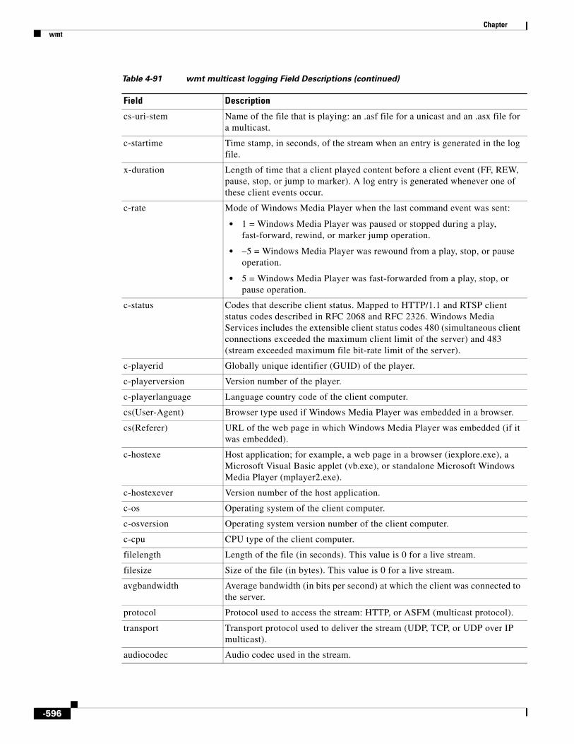
Chapter wmt
cs-uri-stem Name of the file that is playing: an .asf file for a unicast and an .asx file for a multicast.
c-startime Time stamp, in seconds, of the stream when an entry is generated in the log file.
x-duration Length of time that a client played content before a client event (FF, REW, pause, stop, or jump to marker). A log entry is generated whenever one of these client events occur.
c-rate Mode of Windows Media Player when the last command event was sent:
• 1 = Windows Media Player was paused or stopped during a play, fast-forward, rewind, or marker jump operation.
• –5 = Windows Media Player was rewound from a play, stop, or pause operation.
• 5 = Windows Media Player was fast-forwarded from a play, stop, or pause operation.
c-status Codes that describe client status. Mapped to HTTP/1.1 and RTSP client status codes described in RFC 2068 and RFC 2326. Windows Media Services includes the extensible client status codes 480 (simultaneous client connections exceeded the maximum client limit of the server) and 483 (stream exceeded maximum file bit-rate limit of the server).
c-playerid Globally unique identifier (GUID) of the player.
c-playerversion Version number of the player.
c-playerlanguage Language country code of the client computer.
cs(User-Agent) Browser type used if Windows Media Player was embedded in a browser.
cs(Referer) URL of the web page in which Windows Media Player was embedded (if it was embedded).
c-hostexe Host application; for example, a web page in a browser (iexplore.exe), a Microsoft Visual Basic applet (vb.exe), or standalone Microsoft Windows Media Player (mplayer2.exe).
c-hostexever Version number of the host application.
c-os Operating system of the client computer.
c-osversion Operating system version number of the client computer.
c-cpu CPU type of the client computer.
filelength Length of the file (in seconds). This value is 0 for a live stream.
filesize Size of the file (in bytes). This value is 0 for a live stream.
avgbandwidth Average bandwidth (in bits per second) at which the client was connected to the server.
protocol Protocol used to access the stream: HTTP, or ASFM (multicast protocol).
transport Transport protocol used to deliver the stream (UDP, TCP, or UDP over IP multicast).
audiocodec Audio codec used in the stream.
Table 4-91 wmt multicast logging Field Descriptions (continued)
Field Description
-596

Chapter wmt
videocodec Video codec used to encode the stream.
channelURL URL to the .nsc file. A unicast client information log file records a hyphen (-) for this field.
sc-bytes Bytes sent by the server to the client.
c-bytes Number of bytes received by the client from the server. For unicast, the c-bytes value and sc-bytes value must be identical. If not, packet loss has occurred.
s-pkts-sent Total number of packets sent by the server.
c-pkts-received Number of packets from the server (s-pkts-send) that are received correctly by the client on the first try.
c-pkts-lost-client Number of packets lost during transmission from the server to the client and not recovered at the client layer through an error correction or at the network layer through User Datagram Protocol (UDP) resends.
c-pkts-lost-net Number of packets lost on the network layer.
c-pkts-lost-cont-net Maximum number of continuously lost packets on the network layer during a transmission from the server to the client.
c-resendreqs Number of client requests to receive new packets. This field contains a value only if the client is using UDP resend.
c-pkts-recovered-ECC Number of packets repaired and recovered on the client layer. Packets repaired and recovered at the client layer are equal to the difference between c-pkts-lost-net and c-pkts-lost-client.
c-pkts-recovered-resent Number of packets recovered because they were resent using UDP.
c-buffercount Number of times that the client buffered while playing the stream.
c-totalbuffertime Time (in seconds) that the client used to buffer the stream. If the client buffers the stream more than once before a log entry is generated, c-totalbuffertime is the total amount of time that the client spent buffering the stream.
c-quality The percentage of packets that were received by the client, indicating the quality of the stream.
If cPacketsRendered is all packets received by the client, including packets recovered by error correction and UDP resend (c-pkts-received + c-pkts-recovered-ECC + c-pkts-recovered-resent), then c-quality can be calculated as: [cPacketsRendered / (cPacketsRendered + c-pkts-lost-client)] * 100.
s-ip Server IP address.
s-dns Server DNS.
s-totalclients Clients connected to the server (but not necessarily receiving streams).
s-cpu-util Average load on the server processor as a percentage (0–100%). If multiple processors exist, this value is the average for all processors.
SE-action Action performed by the SE.
Table 4-91 wmt multicast logging Field Descriptions (continued)
Field Description
-597

Chapter wmt
The following example adds the filename extension mp3 to the list of filename extensions to be served by WMT:
ServiceEngine# wmt http allow extension mp3
The show wmt http allow extension command shows the filename extensions included in the list after you have added or deleted filename extensions.
The following example shows that the filename extension mp3 has been added to the list of file extensions:
ServiceEngine# show wmt http allow extension
WMT http extensions allowed :asf mp3 none nsc wma wmv
The following example shows that an SE at a branch office is configured to send all its WMT cache miss traffic to a central SE at 172.16.30.30 through port 8080:
ServiceEngine(config)# wmt proxy outgoing http host 172.16.30.30 8080
The following example shows that an SE at a branch office is configured to send all its cache miss traffic to a central SE at 172.16.30.31 through port 1700:
ServiceEngine(config)# wmt proxy outgoing http host 172.16.30.31 1700
The following example sets the SE to generate WMT transaction logs in the extended Windows Media Services, Version 9.0 format:
ServiceEngine# wmt transaction-logs format extended wms-90
The following example enables the logging of usernames to the WMT transaction log:
ServiceEngine# wmt extended transaction-log enable
Related Commands
SE-bytes Number of bytes received by the SE.
Username Username required to access the streaming media retrieved by the WMT player.
Table 4-91 wmt multicast logging Field Descriptions (continued)
Field Description
Command Description
clear Clears the HTTP object cache, the hardware interface, statistics, archive working transaction logs, and other settings.
show running-config Displays the current operating configuration.
show tech-support Displays the system information for Cisco technical support.
show statistics wmt Displays the WMT statistics.
show wmt Displays WMT bandwidth and proxy mode configuration.
-598
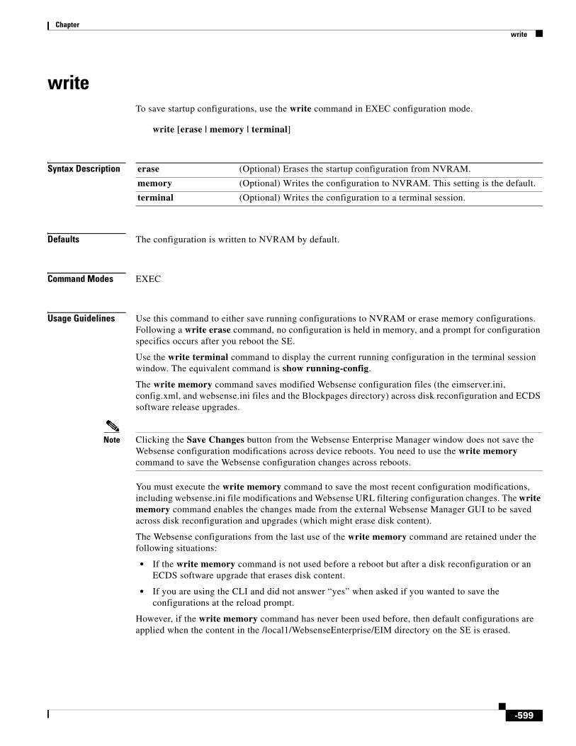
Chapter write
writeTo save startup configurations, use the write command in EXEC configuration mode.
write [erase | memory | terminal]
Syntax Description
Defaults The configuration is written to NVRAM by default.
Command Modes EXEC
Usage Guidelines Use this command to either save running configurations to NVRAM or erase memory configurations. Following a write erase command, no configuration is held in memory, and a prompt for configuration specifics occurs after you reboot the SE.
Use the write terminal command to display the current running configuration in the terminal session window. The equivalent command is show running-config.
The write memory command saves modified Websense configuration files (the eimserver.ini, config.xml, and websense.ini files and the Blockpages directory) across disk reconfiguration and ECDS software release upgrades.
Note Clicking the Save Changes button from the Websense Enterprise Manager window does not save the Websense configuration modifications across device reboots. You need to use the write memory command to save the Websense configuration changes across reboots.
You must execute the write memory command to save the most recent configuration modifications, including websense.ini file modifications and Websense URL filtering configuration changes. The write memory command enables the changes made from the external Websense Manager GUI to be saved across disk reconfiguration and upgrades (which might erase disk content).
The Websense configurations from the last use of the write memory command are retained under the following situations:
• If the write memory command is not used before a reboot but after a disk reconfiguration or an ECDS software upgrade that erases disk content.
• If you are using the CLI and did not answer “yes” when asked if you wanted to save the configurations at the reload prompt.
However, if the write memory command has never been used before, then default configurations are applied when the content in the /local1/WebsenseEnterprise/EIM directory on the SE is erased.
erase (Optional) Erases the startup configuration from NVRAM.
memory (Optional) Writes the configuration to NVRAM. This setting is the default.
terminal (Optional) Writes the configuration to a terminal session.
-599

Chapter write
Examples The following command saves the running configuration to NVRAM:
ServiceEngine# write memory
Related Commands Command Description
copy Copies the configuration or image files to and from the CD-ROM, flash memory, disk, or remote hosts.
show running-config Displays the current operating configuration.
-600

A
P P E N D I X A AcronymsTable A-1 defines the acronyms and abbreviations that are used in this publication.
Table A-1 List of Acronyms
Acronym Expansion
AAA authentication, authorization, and accounting
ACL access control list
ACPI Advanced Configuration and Power Interface
API application program interface
ARP Address Resolution Protocol
AS Autonomous System
AUP acceptable use policy
BA Behavior Aggregate
BGP Border Gateway Protocol
BIOS basic input/output system
CAR Committed Access Rate
CD Carrier Detect
CDNFS CDS network file system; also pre-positioned file system
CDS Content Delivery System
CDSM Content Delivery System Manager
CIFS Common Internet File System
CLF Common Log format
CLI command-line interface
CLNS Connectionless Network Service
CMS Centralized Management System
CoS class of service
CSNP Complete Sequence Number PDU
CSS Content Services Switch
CTE chunked transfer encoding
DC domain controller
A-1

Appendix A Acronyms
DHCP Dynamic Host Configuration Protocol
DHT distributed hash table
DNS Domain Name System
DSCP differentiated services code point
DSL Digital Subscriber Line
ECN Explicit Congestion Notification
EBGP External Border Gateway Protocol
EIM employee Internet management
ESIS End System to Intermediate System
EULA end user license agreement
FEC forward error correction
FQDN fully qualified domain name
FTP File Transfer Protocol
GMT Greenwich Mean Time
GRE generic routing encapsulation
GUI graphical user interface
HTTP Hypertext Transfer Protocol
HTTPS Hypertext Transfer Protocol over Secure Socket Layer
IANA Internet Assigned Numbers Authority
ICP Internet Cache Protocol
ICAP Internet Content Adaptation Protocol
ICMP Internet Control Message Protocol
IDE Integrated Drive Electronics
IFP Internet Filtering Protocol
IIPC Inter-process procedure
IPV6 Internet Protocol Version 6
IIS Internet Information Services or Internet Information Server (Microsoft)
IMS if-modified-since
IS-IS Intermediate System-to-Intermediate System
ISO-IGRP Intermediate System-to-Intermediate System Interior Gateway Routing Protocol
LDAP Lightweight Directory Access Protocol
LCM local/central management
LRU least-recently-used
LSA Link-state advertisement
LSDB Link-state packet database
Table A-1 List of Acronyms (continued)
Acronym Expansion
A-2

Appendix A Acronyms
LSP Link-state packet
MAC Media Access Control
MDE Media Delivery Engine
MIB Management Information Base
MOTD message-of-the-day
MPLS Multiprotocol Label Switching
MSFC Multilayer Switch Feature Card
MTU maximum transmission unit
NACK negative acknowledgement
NAS network attached storage; network access server
NAT Network Address Translation
NET Network Entity Title
NFS Network File System
NIC Network Information Center
NNTP Network News Transport Protocol
NSAP network service access point
NSSA not-so-stubby-area
NTP Network Time Protocol
NTSC National Television Systems Committee
NVRAM nonvolatile random-access memory
OSPF Open Shortest Path First
PAC proxy autoconfiguration
PAL Phase Alternating Line
PAWS Protection Against Wrapped Sequence
PBR policy-based routing
PDC primary domain controller
PEM Privacy Enhanced Mail
PFC Policy Feature Card
PGM Pragmatic General Multicast
PHB Per Hop Behavior
PID process identifier
PKCS Public Key Cryptography Standards
PPP Point-to-Point Protocol
QoS Quality of Service
RADIUS Remote Authentication Dial-In User Service
RBCP Router Blade Configuration Protocol
Table A-1 List of Acronyms (continued)
Acronym Expansion
A-3

Appendix A Acronyms
RCP Remote Copy Program
REA remote execution agent
RIB Routing Information Base
RPC remote procedure call
RRM Received Routing Message
RSA Rivest, Shamir, Adelman
RSPF OSPF reverse shortest path first
RSVP Resource Reservation Protocol
RTP Real-Time Transport Protocol
RTSP Real-Time Streaming Protocol
SAN Storage Area Network
SASL Secure Authentication and Security Layer
SATA Serial Advanced Technology Attachment
SCSI Small Computer Systems Interface
SDP Session Description Protocol
SE Service Engine
SE-NM Service Engine Network Module
SFTP Secure File Transfer Protocol
SLA service level agreement
SLIP Serial Line Internet Protocol
SMART Self Monitoring, Analysis, and Reporting Technology
SMB Server Message Blocks (protocol)
SMTP Simple Mail Transfer Protocol
SNMP Simple Network Management Protocol
SPE Synchronous Payload Envelope
SPF Shortest Path First
SR Service Router
SRAM static random-access memory
SRHP service routing host packet
SRM Send Routing Message
SRP Service Routing Protocol
SSH Secure Shell
SSL Secure Sockets Layer
SSN Send Sequence Number
swfs software file system
sysfs system file system
Table A-1 List of Acronyms (continued)
Acronym Expansion
A-4

Appendix A Acronyms
syslog system logging
TAC Technical Assistance Center
TACACS+ Terminal Access Controller Access Control System Plus
TCP/IP Transmission Control Protocol/Internet Protocol
TFTP Trivial File Transfer Protocol
ToS Type of Service
TPS transactions per second
TTL Time-to-Live
UDI unique device identifier
UDP User Datagram Protocol
UNC uniform naming convention
UNS unified name space
UTC Coordinated Universal Time
VBR variable bit rate
VOD video on demand
W3C World Wide Web Consortium
WFQ Weighted Fair Queueing
WMS 9 Windows Media Services 9 Series
WMT Windows Media Technologies
WRED Weighted Random Early Detection
XML Extensible Markup Language
Table A-1 List of Acronyms (continued)
Acronym Expansion
A-5

Appendix A Acronyms
A-6

A
P P E N D I X B Standard Time ZonesTable B-1 lists all the standard time zones that you can configure on an MDE and the offset from Coordinated Universal Time (UTC) for each standard time zone. The offset (ahead or behind) UTC in hours, as displayed in Table B-1, is in effect during winter time. During summer time or daylight saving time, the offset may be different from the values in the table and are calculated and displayed accordingly by the system clock.
Note The time zone entry is case sensitive and must be specified in the exact notation listed in the following time zone table. When you use a time zone entry from the following time zone table, the system is automatically adjusted for daylight saving time.
Table B-1 List of Standard Time Zones and Offsets from UTC
Time Zone Offset from UTC
Africa/Abidjan 0
Africa/Accra 0
Africa/Addis_Ababa +3
Africa/Algiers +1
Africa/Asmera +3
Africa/Bamako 0
Africa/Bangui +1
Africa/Banjul 0
Africa/Bissau 0
Africa/Blantyre +2
Africa/Brazzaville +1
Africa/Bujumbura +2
Africa/Cairo +2
Africa/Casablanca 0
Africa/Ceuta +1
Africa/Conakry 0
Africa/Dakar 0
Africa/Dar_es_Salaam +3
B-1

Appendix B Standard Time Zones
Africa/Djibouti +3
Africa/Douala +3
Africa/El_Aaiun +1
Africa/Freetown 0
Africa/Gaborone +2
Africa/Harare +2
Africa/Johannesburg +2
Africa/Kampala +3
Africa/Khartoum +3
Africa/Kigali +2
Africa/Kinshasa +1
Africa/Lagos +1
Africa/Libreville +1
Africa/Lome 0
Africa/Luanda +1
Africa/Lubumbashi +2
Africa/Lusaka +2
Africa/Malabo +1
Africa/Maputo +2
Africa/Maseru +2
Africa/Mbabane +2
Africa/Mogadishu +3
Africa/Monrovia 0
Africa/Nairobi +3
Africa/Ndjamena +1
Africa/Niamey +1
Africa/Nouakchott 0
Africa/Ouagadougou 0
Africa/Porto-Novo +1
Africa/Sao_Tome 0
Africa/Timbuktu 0
Africa/Tripoli +2
Africa/Tunis +1
Africa/Windhoek +1
America/Anguilla –4
America/Antigua –4
Table B-1 List of Standard Time Zones and Offsets from UTC (continued)
Time Zone Offset from UTC
B-2

Appendix B Standard Time Zones
America/Araguaina –3
America/Aruba –4
America/Asuncion –4
America/Barbados –4
America/Belem –3
America/Belize –6
America/Boa_Vista –4
America/Bogota –5
America/Boise –7
America/Buenos_Aires –3
America/Cambridge_Bay –7
America/Cancun –6
America/Caracas –4
America/Catamarca –3
America/Cayenne –3
America/Cayman –5
America/Chihuahua –7
America/Cordoba –3
America/Costa_Rica –6
America/Cuiaba –4
America/Curacao –4
America/Dawson –8
America/Dawson_Creek –7
America/Dominica –4
America/Eirunepe –5
America/El_Salvador –6
America/Fortaleza –3
America/Glace_Bay –4
America/Godthab –3
America/Goose_Bay –4
America/Grand_Turk –5
America/Grenada –4
America/Guadeloupe –4
America/Guatemala –6
America/Guayaquil –5
America/Guyana –4
Table B-1 List of Standard Time Zones and Offsets from UTC (continued)
Time Zone Offset from UTC
B-3

Appendix B Standard Time Zones
America/Hermosillo –7
America/Indiana/Marengo –5
America/Indiana/Vevay –5
America/Indiana/Indianapolis –5
America/Indiana/Knox –5
America/Inuvik –7
America/Iqaluit –5
America/Jujuy –3
America/Juneau –9
America/Kentucky/Monticello –5
America/Kentucky/Louisville –5
America/La_Paz –4
America/Lima –5
America/Louisville –8
America/Maceio –3
America/Managua –6
America/Martinique –4
America/Mendoza –3
America/Menominee –6
America/Merida –6
America/Miquelon –3
America/Monterrey –6
America/Montevideo –3
America/Montserrat –4
America/Nassau –5
America/Nipigon –5
America/Nome –9
America/Panama –5
America/Pangnirtung –3
America/Paramaribo –3
America/Port-au-Prince –5
America/Port_of_Spain –4
America/Porto_Velho –4
America/Rainy_River –6
America/Rankin_Inlet –6
America/Recife –3
Table B-1 List of Standard Time Zones and Offsets from UTC (continued)
Time Zone Offset from UTC
B-4

Appendix B Standard Time Zones
America/Rosario –3
America/Santo_Domingo –4
America/Scoresbysund –1
America/St_Kitts –4
America/St_Lucia –4
America/St_Vincent –4
America/Swift_Current –6
America/Tegucigalpa –6
America/Thule –4
America/Thunder_Bay –5
America/Tortola –4
America/Virgin –4
America/St_Thomas –4
America/Yakutat –9
America/Yellowknife –7
America/Porto_Acre –5
America/Rio_Branco –5
America/Noronha –2
America/Sao_Paulo –3
America/Manaus –4
America/Winnipeg –6
America/Montreal –5
America/Edmonton –7
America/St_Johns –3.30
America/Vancouver –8
America/Whitehorse –8
America/Santiago –4
America/Havana –5
America/Jamaica –5
America/Ensenada –8
America/Tijuana –8
America/Mazatlan –7
America/Mexico_City –6
America/Puerto_Rico –4
America/Halifax –4
America/Regina –6
Table B-1 List of Standard Time Zones and Offsets from UTC (continued)
Time Zone Offset from UTC
B-5

Appendix B Standard Time Zones
America/Anchorage –9
America/Adak –10
America/Atka –10
America/Phoenix –7
America/Chicago –6
America/Fort_Wayne –5
America/Indianapolis –5
America/Knox_IN –5
America/Detroit –7
America/Denver –5
America/Shiprock –7
America/Los_Angeles –8
America/New_York –5
Antarctica/Casey +8
Antarctica/Davis +7
Antarctica/DumontDUrville +10
Antarctica/Mawson +6
Antarctica/Palmer –4
Antarctica/South_Pole +12
Antarctica/McMurdo +12
Antarctica/Syowa +3
Antarctica/Vostok +6
Arctic/Longyearbyen +1
Asia/Aden +3
Asia/Almaty +6
Asia/Amman +2
Asia/Anadyr +12
Asia/Aqtau +4
Asia/Aqtobe +5
Asia/Ashkhabad +5
Asia/Ashgabat +5
Asia/Baghdad +3
Asia/Bahrain +3
Asia/Baku +4
Asia/Bangkok +7
Asia/Beirut +2
Table B-1 List of Standard Time Zones and Offsets from UTC (continued)
Time Zone Offset from UTC
B-6

Appendix B Standard Time Zones
Asia/Bishkek +5
Asia/Brunei +8
Asia/Calcutta +5.30
Asia/Chungking +8
Asia/Colombo +6
Asia/Damascus +2
Asia/Dhaka +6
Asia/Dacca +6
Asia/Dili +9
Asia/Dubai +4
Asia/Dushanbe +5
Asia/Gaza +2
Asia/Harbin +8
Asia/Hovd +7
Asia/Irkutsk +8
Asia/Jakarta +7
Asia/Jayapura +9
Asia/Kabul +4.30
Asia/Kamchatka +12
Asia/Karachi +5
Asia/Kashgar +8
Asia/Katmandu +5.45
Asia/Krasnoyarsk +7
Asia/Kuala_Lumpur +8
Asia/Kuching +8
Asia/Kuwait +3
Asia/Macao +8
Asia/Magadan +11
Asia/Manila +8
Asia/Muscat +4
Asia/Novosibirsk +6
Asia/Omsk +6
Asia/Phnom_Penh +7
Asia/Pontianak +7
Asia/Pyongyang +9
Asia/Qatar +3
Table B-1 List of Standard Time Zones and Offsets from UTC (continued)
Time Zone Offset from UTC
B-7

Appendix B Standard Time Zones
Asia/Rangoon +6.30
Asia/Riyadh +3
Asia/Saigon +7
Asia/Samarkand +5
Asia/Tashkent +5
Asia/Tbilisi +3
Asia/Thimphu +6
Asia/Thimbu +6
Asia/Ujung_Pandang +8
Asia/Ulan_Bator +8
Asia/Ulaanbaatar +8
Asia/Urumqi +8
Asia/Vientiane +7
Asia/Vladivostok +10
Asia/Yakutsk +9
Asia/Yekaterinburg +5
Asia/Yerevan +4
Asia/Nicosia +2
Asia/Hong_Kong +8
Asia/Tehran +3.30
Asia/Jerusalem +2
Asia/Tel_Aviv +2
Asia/Tokyo +9
Asia/Riyadh87 +3.07
Asia/Riyadh88 +3.07
Asia/Riyadh89 +3.07
Asia/Shanghai +8
Asia/Taipei +8
Asia/Seoul +9
Asia/Singapore +8
Asia/Istanbul +2
Atlantic/Azores –1
Atlantic/Bermuda –4
Atlantic/Canary 0
Atlantic/Cape_Verde –1
Atlantic/Faeroe 0
Table B-1 List of Standard Time Zones and Offsets from UTC (continued)
Time Zone Offset from UTC
B-8

Appendix B Standard Time Zones
Atlantic/Madeira 0
Atlantic/South_Georgia –2
Atlantic/St_Helena 0
Atlantic/Stanley –4
Atlantic/Jan_Mayen +1
Atlantic/Reykjavik 0
Australia/Lindeman +10
Australia/Lord_Howe +10.30
Australia/LHI +10.30
Australia/North +9.30
Australia/Darwin +9.30
Australia/Queensland +10
Australia/Brisbane +10
Australia/South +9.30
Australia/Adelaide +9.30
Australia/Sydney +10
Australia/ACT +10
Australia/Canberra +10
Australia/NSW +10
Australia/Tasmania +10
Australia/Hobart +10
Australia/Victoria +10
Australia/Melbourne +10
Australia/West +8
Australia/Perth +8
Australia/Yancowinna +9.30
Australia/Broken_Hill +9.30
Brazil/Acre –5
Brazil/DeNoronha –2
Brazil/East –3
Brazil/West –4
CET +1
Canada/Central –6
Canada/Eastern –5
Canada/Mountain –7
Canada/Newfoundland –3.30
Table B-1 List of Standard Time Zones and Offsets from UTC (continued)
Time Zone Offset from UTC
B-9

Appendix B Standard Time Zones
Canada/Pacific –8
Canada/Yukon –8
Canada/Atlantic –4
Canada/East-Saskatchewan –6
Canada/Saskatchewan –6
Chile/Continental –4
Chile/EasterIsland –6
Cuba –5
EET +2
Egypt +2
Europe/Amsterdam +1
Europe/Andorra +1
Europe/Athens +2
Europe/Belfast 0
Europe/Berlin +1
Europe/Brussels +1
Europe/Bucharest +2
Europe/Budapest +1
Europe/Copenhagen +1
Europe/Dublin 0
Europe/Gibraltar 0
Europe/Helsinki +2
Europe/Kaliningrad +2
Europe/Kiev +2
Europe/Luxembourg +1
Europe/Madrid +1
Europe/Malta +1
Europe/Minsk +2
Europe/Monaco +1
Europe/Nicosia +2
Europe/Oslo +1
Europe/Paris +1
Europe/Prague +1
Europe/Bratislava +1
Europe/Riga +2
Europe/Samara +4
Table B-1 List of Standard Time Zones and Offsets from UTC (continued)
Time Zone Offset from UTC
B-10

Appendix B Standard Time Zones
Europe/Simferopol +2
Europe/Sofia +2
Europe/Stockholm +1
Europe/Tallinn +2
Europe/Tirane +1
Europe/Tiraspol +2
Europe/Chisinau +2
Europe/Uzhgorod +2
Europe/Vaduz +1
Europe/Vatican +1
Eire 0
GB-Eire 0
GB 0
Greenwich 0
GMT 0
GMT+0 0
GMT-0 0
GMT0 0
Hongkong +8
Iceland 0
Indian/Antananarivo +3
Indian/Chagos +6
Indian/Christmas +7
Indian/Cocos +6.30
Indian/Comoro +3
Indian/Kerguelen +5
Indian/Mahe +4
Indian/Maldives +5
Indian/Mauritius +4
Indian/Mayotte +3
Indian/Reunion +4
Iran +3.30
Israel +2
Jamaica –5
Japan +9
Libya +2
Table B-1 List of Standard Time Zones and Offsets from UTC (continued)
Time Zone Offset from UTC
B-11

Appendix B Standard Time Zones
MET +1
Mexico/BajaNorte –8
Mexico/BajaSur –7
Mexico/General –6
Mideast/Riyadh87 +3.07
Mideast/Riyadh88 +3.07
Mideast/Riyadh89 +3.07
PRC +8
Pacific/Apia –11
Pacific/Auckland +12
Pacific/Chatham +12.45
Pacific/Easter –6
Pacific/Efate +11
Pacific/Enderbury +13
Pacific/Fakaofo –10
Pacific/Fiji +12
Pacific/Funafuti +12
Pacific/Galapagos –6
Pacific/Guadalcanal +11
Pacific/Guam +10
Pacific/Johnston –10
Pacific/Kiritimati +14
Pacific/Kosrae +11
Pacific/Kwajalein +12
Pacific/Majuro +12
Pacific/Marquesas –9.30
Pacific/Midway –11
Pacific/Nauru +12
Pacific/Niue –11
Pacific/Norfolk +11.30
Pacific/Noumea +11
Pacific/Palau +9
Pacific/Ponape +11
Pacific/Port_Moresby +10
Pacific/Rarotonga –10
Pacific/Saipan +10
Table B-1 List of Standard Time Zones and Offsets from UTC (continued)
Time Zone Offset from UTC
B-12

Appendix B Standard Time Zones
Pacific/Tahiti –10
Pacific/Tarawa +12
Pacific/Tongatapu +13
Pacific/Truk +10
Pacific/Wake +12
Pacific/Wallis +12
Pacific/Yap +10
Pacific/Pitcairn –8
Pacific/Gambier –9
Pacific/Honolulu –10
Pacific/Pago_Pago –11
Pacific/Samoa –11
NZ +12
NZ-CHAT +12.45
Kwajalein +12
Poland +1
Portugal 0
ROC +8
ROK +9
Singapore +8
Turkey +2
UCT 0
US/Alaska –9
US/Aleutian –10
US/Arizona –7
US/Central –6
US/East-Indiana –5
US/Hawaii –10
US/Indiana-Starke –5
US/Michigan –5
US/Mountain –7
US/Pacific –8
US/Samoa –11
US/Eastern –5
MST +7
CST6CDT –6
Table B-1 List of Standard Time Zones and Offsets from UTC (continued)
Time Zone Offset from UTC
B-13

Appendix B Standard Time Zones
EST –5
HST –10
MST7MDT +7
Navajo –7
PST8PDT –8
W-SU +3
WET 0
Zulu 0
UTC 0
Universal 0
EST5EDT –5
Table B-1 List of Standard Time Zones and Offsets from UTC (continued)
Time Zone Offset from UTC
B-14

A
P P E N D I X C Unsupported FeaturesThe following sections list features and functions that are not supported:
• Unsupported in Cisco ECDS, page C-1
• Unsupported in Cisco ECDS with WCCP, page C-1
• Where to Go Next, page C-2
Unsupported in Cisco ECDSThe following features may appear in the Enterprise CDSM interface but are not supported in the current release:
• DVRCAST
• ICAP
• IP-based Redirection
• IP multicast routing
• Geo-Location Server integration
• Proximity Server
• PCMM
• RTMPT
• RTMPTE
• Session Shifting
• Show and Share over SSL
• Wholesale licensing
• Windows Media Services Multi Bit Rate
Unsupported in Cisco ECDS with WCCPThe following features may be supported by WCCP but are not supported on Cisco ECDS, the Service Engine, or other components of the system:
• Access Control Lists with WCCP
C-1

Appendix C Unsupported FeaturesWhere to Go Next
• Bypass Error handling
• HTTPS without WCCP
• IP ACL
• IP multicast routing
• IP Spoofing with non-HTTP protocols or multiple Service Engines
• L4 Switch for the bypass gateway.
• Reverse proxy
• RTMP unmanaged domain
• Security proxy
• Show and Share over SSL
• WCCP CIF/FTP/DNS traffic caching
• WCCP Web cache packet return
Where to Go NextFor complete ECDS hardware and software support information, see the Cisco ECDS 2.6 Release Notes on Cisco.com.
C-2

I N D E X
Symbols
! (exclamation point) 508, 518
- (hyphen) 135, 142, 150, 518, 522, 604
... (ellipsis) 518, 522
.bin files
installing 154
.nsc file 459, 597
.pax files
installing 154
/ (slash) 54
? (question mark) 134
A
aaa accounting
statistics for 411
accelerated WCCP support 543
access lists
configuration, displaying 252
configuring 18
enabling 18
group names 19
interfaces and applications
applying to 169
status 316
statistics
clearing 70
displaying 364
ACLs
See IP ACLs
ACPI
models supporting 466
acquirer
delivery service information and content acquisition progress, displaying 253
delivery service statistics, displaying 365
proxy authentication 22
starting and stopping acquisition on a specific delivery service 20
acquisition and distribution
starting and stopping 24
action rule
configuring 234
address translation tables 258
administrative login authentication and authorization
default 32
local database
description of 33
RADIUS
enabling and disabling 217
overview of 34
TACACS+
enabling and disabling 489
administrative privileges
users, clearing 76
alarm information
for all alarms 255
for critical alarms 256
for major alarms 256
for minor alarms 256
alarm overload 28
alarms
displaying status and history 255
NIC shutdown alarm 26
alarm traps
configuring 472
IN-1

Index
generating 472
Apache CLF transaction log format 518
applications
applying access lists to 169
archive log file
compressing 525
marking beginning and end 518
maximum size 518
naming convention 524
ARP table, displaying 258
authentication
access lists, enabling 18
configuration, displaying 259
configuring 31
outgoing proxy 22
proxy server 22
server redundancy 33
statistics, clearing 70
traffic bypass 49
users
creating 539
local 32
TACACS+ 32
authentication command 33
authorization
administrative login authorization 31
authorization server
configuring 36
enabling 36
statistics, displaying 367, 368
B
bandwidth
displaying 261
interface, configuring 40
network resources 37
setting for streaming media 37
bandwidth configuration
IN-2
incoming and outgoing 38
banners
configuration of 42
displaying 263
enabling 43
types of
EXEC 43
login 43
motd 43
basic configuration settings
setting up 251
bit rate
displaying 264
movie-streamer and WMT, configuring 45
bypass
authentication 49
configuration, displaying 147, 265
disabling and enabling 48
dynamic traffic 49
maximum number of static entries 265
overload 50
static 50
static lists, configuring 48
total number of entries 265
WCCP Version 2 and 48
C
cache
content 52
information, displaying 268
caching
HTTP
configuring 138
objects 62
HTTPS
configuration 145
status 309
matching against parameters for requests 234

Index
caching services
setting up 251
calendar
setting 78
capability
configuring 53
Cap-X profile ID
information, displaying 269
CAR
IP precedence
ToS 163
CDN file system
See cdnfs
cdnfs
information, displaying 271
managing 56
statistics, displaying 369
CDS
content, displaying 277
installing 154
Centralized Management System
See CMS
certificates
HTTPS 141, 149
CIMC 61
CISCO-ENTITY-ASSET-MIB
configuring 30
Cisco script
executing 240
Cisco Streaming Engine server
live streaming with 228
Cisco Technical Assistance Center (TAC) 438
classification
IP precedence
ToS field 163
clean shutdown 565
clock
clearing and setting 78
daylight saving and local time, setting 80
displaying standard timezones 272
Service Engine, synchronizing 202
software time and date, setting 204
system clock settings, displaying 272
UTC current time of day, setting 81
UTC offset, setting 81
CMS
database, configuring 84
enabling 87
maintenance routines, scheduling 87
process information, displaying 275
cold restart 222
command-line processing 1
command modes
EXEC 3
global configuration 3
interface configuration 3
command syntax 4
configuration modes
extended ACL 170
HTTPS server 145
standard ACL 170
configuring
alarm traps 472
disk space allocation 111
https-cache service
on Service Engines 550
RADIUS authentication 34
console
setting length of display 501
content acquisition
database cleanup 24
starting and stopping 24
Content Delivery System Manager
configuring IP address 58
disk space allocation 112
primary role 83
SSL 84
standby role 58
IN-3

Index
content distribution
statistics, display 371
copying
configuration data 91
files 93, 94
image data 91
crossdomain support 248
custom transaction log format 518
custom web caching
WCCP, enabling 542
D
database cleanup
content acquisition and distribution 24
date and time
setting 204
daylight saving time
setting 80
debug
disabling 535
information, displaying 278
software functions 95
debug cdnfs command 102
default gateway
defining 159
IPv6 address, configuring 177
removing 159
default status
restoring 224
deleting
directories 105, 227
directory trees 105
files 104
delivery service distribution
information, displaying 288
device mode
and linked CLI commands 1
configuring 106
IN-4
displaying 281
devices
shutting down 466
DHCP services
enabling 155
DHT
clearing counters 71
differentiated service model
classification 163
directories
changing 54
creating 191
deleting 105, 227
files, viewing 108, 185
Direct Server Return (DSR)
enabling a VIP 109
information, displaying 283
disk drives
error handling thresholds
description of 117
specifying 117
disks
configuring 111
space allocation 111
details, viewing 284
partitions, removing 224
space allocation 111, 112
disk space allocated to system use 112
distribution
delivery service, displaying 288
refresh content 118
statistics
displaying 288
DNS lookup 121
domain name
resolving to IP address 121
DSCP
setting 158
dumping network traffic 493

Index
DWRED
IP precedence
ToS 163
dynamic bypass entries 265
dynamic traffic bypass 49
dynamic WCCP services 552
E
echo packets
sending 205
ellipsis (...) 518, 522
embedded database parameters
configuring 83
enabling
dynamic authentication bypass 49
login authentication and authorization 31
RADIUS authentication and authorization 218
rules processing 232
TACACS+ authentication and authorization 489
WCCP 569
error handling
enabling 48
Ethernet MAC address mapping 543
exclamation point (!) 508, 518
EXEC command mode
described 2
returning to 125
exiting
from configuration modes 125
from privileged EXEC mode 110
exporting transaction logs
forced 511
to FTP server 526
to SFTP server 526
extended access lists 170
extended IP ACLs
configuration examples 176
configuring 171
ICMP message types 174
supported keywords 173
TCP keywords 173
Extended Squid transaction log format 518
external FTP server
exporting transaction logs to 526
permanent error from 526
F
failover
for administrative login authentication 33
Fast Cache
enabling 593
Fast Start
enabling 594
file
copying 94
creating 192, 511
deleting 104
displaying name 185, 530
management 54
renaming 223
File Transfer Protocol (FTP)
caching configuration, displaying 300
Flash Media Streaming
configuring 131
enabling 131
information, displaying 298
statistics, displaying 374
flash memory
configuring upon reload 222
data, removing 224
version and usage, displaying 297
flow redirection
WCCP, enabling 547
FTP
access lists 171
FTP over HTTP
IN-5

Index
Rules Template 234
FTP servers
exporting transaction logs to 526
G
generic routing encapsulation
See GRE encapsulation
Gigabit Ethernet
configuring 155
negating interface configuration command 201
global configuration command mode
entering 90
exiting 123
negating command 199
setting 90
global configuration mode
description 3
GMT
changing local time in content to 20
UTC and 81
GRE encapsulation 424
Greenwich Mean Time
See GMT
group names
access lists 19
H
hardware interface
displaying information 311
shutting down 465
hardware status, displaying 301
help system 6, 134
history
statistics, clearing 70
hostname
of Service Engine 135
IN-6
resolving to IP address 121
hosts
name servers and IP addresses, displaying 304
HTTP
object cache
clearing 62
configuring 138
proxy
support for root Service Engine 22
related parameters, configuring 136
statistics, displaying 307, 381
status codes 518
transaction logging 517
users, managing 540
HTTPS
caching 145
certificates 141, 149
proxy
displaying status 144, 147, 309
Rules Template with 234
server configuration mode 145
server status 309
https-cache service
configuring
on Service Engines 550
HTTPS outgoing proxy servers
displaying current state of 310
HTTPS server
WCCP flow redirection to 548
HTTPS statistics
displaying 144, 147, 309
HTTP transparent caching
configuring 543
hyphen (-) 135, 142, 143, 150, 151, 518
I
IANA 553
ICMP

Index
access lists 171
keywords for message type and code 174
statistics
clearing 70
displaying 386
image data
copying 91
initial network device settings
changing 158
installing system image 154
interface
bandwidth 40
configuring 155
displaying hardware status 311
standby 360
interface configuration command mode 3
interface IP
configuring 167
Internet Assigned Numbers Authority
See IANA
Internet socket connection statistics
displaying 399
inventory information
displaying 314
IP ACLs
activating on an interface 176
clearing IP ACL counter 65
creating and modifying 169
description of 172
extended configuration mode
accessing 171
extended IP ACLs 173
standard configuration mode
accessing 170
standard IP ACLs 173
typical uses of 172
IP address
Content Delivery System Manager, configuring 58
starting autodiscovery utility 159
statistics, clearing 70
IP default domain name
defining 159
removing 159
IP default gateway
defining 159
removing 159
IP interface
information, displaying 318
IP multicasting
Layer 2 multicast address considerations 543
IP precedence
edge function 163
ToS field
classification 163
IP route table, displaying 319
IP statistics, display 392
IS-IS (Intermediate System-to-Intermediate System)
clearing counters 70
K
kernel debugger 178
key chain
creating 181
displaying 321
key id 179
key string 180
keystroke combinations, CLI 2
L
Last-Modified-Time 20
launching
Setup utility 251
Layer 2
multicast address 543
redirection 543
IN-7

Index
lists
directory names 185
file 190
live events
about 330
configuration requirements 331
live streaming
with Cisco Streaming Engine 228
live stream interruptions 331
load balancing
for Port Channel 207
local time, changing to GMT 20
log file
number of lines to view 532
log files
exporting 523
restarting the export of 528
logging
configuring 186
file rotation of logs 188
RealProxy errors 189
WMT multicast 587
logging in
to Service Engine
using SSH 485
using Telnet 500
login authentication 32
M
mapping syslog priority levels to RealProxy error codes 189
maximum transmission unit (MTU)
interface 198
MIB view
defining 483
modes
command
EXEC 2
IN-8
global configuration 3
interface configuration 3
configuration
extended ACL 4
HTTP server 4
standard ACL 4
Movie Streamer
configuration, displaying 324
configuring 193
enabling 193
statistics, displaying 396
movie-streamer
bit rate, setting 45
multicast
disabling backup senders 88
overview 595
WMT, logging 596
multicast cloud, displaying information 288
multicast-in and multicast-out 595
multicast-in and unicast-out 596
multicast logging
WMT 596, 600
multicast stations
defining 595
description of 595
starting and stopping 586
N
NAT
configuring 126, 127
negating interface configurations 201
Network Address Translation
See NAT
network connectivity
testing 205
network host name
Service Engine 135
network interfaces

Index
configuring for DHCP 155
EtherChannel 156
Network Time Protocol
See NTP
Network Time Protocol (NTP) 5
network traffic
dumping 493
node
activating 84
communication over secure channels 83
NTP
configuring and enabling 202
setting software time and date 204
status, displaying 325
system clock, synchronizing 202
number of lines displayed 501
NVRAM
configuration stored, displaying 361
startup configuration, writing or erasing 607
O
offset from UTC 1
online help 134
outgoing proxy
authentication 22
overload bypass 50
P
pacing bit rate
movie-streamer and WMT 45
patterns
lists described 235
rules for lists 234
searching in files 129
permanent errors
FTP server 526
ping 205
ping IPv6 address 206
policies
and the Rules Template 234
Port Channel
configuring 155
load-balancing options 207
negating interface configuration 201
port lists
WCCP services and 552
powering off 466
present working directory
information, displaying 185, 213
preserving configurations on device restore 224
preserving data on device restore 224
primary Content Delivery System Manager 58
primary interface
changing to a different interface 209
configuring for Ethernet 209
private keys
HTTPS 141, 149
privileged level EXEC commands
accessing 122
disabling 110
processes
CPU or memory, displaying 327
programs
displaying 329
live 330
movie streamer rebroadcast 331
WMT rebroadcast
about 331
proxy
overview 560
proxy mode
redirection services 560
IN-9

Index
Q
QoS
enabling 214
statistics, displaying 400
question mark (?) 134
QuickTime 228
R
RADIUS authentication
configuring 34
overview 34
RADIUS key
specifying on Service Engine 34
RADIUS server
authentication 216
excluding domains 217
information, displaying 336
parameters, configuring 216
statistics
clearing 71
displaying 401
RADIUS servers
as authentication servers 34
authentication settings 34
RealProxy
access control 230
error logging 189
Real-Time Streaming Protocol
See RTSP
rebooting Service Engine 222
redirected HTTP traffic 542
redirection services for WCCP
enabling 559
regular pattern expression
searching 129
reload 222
reloading Service Engine
IN-10
automatic reload option 117
Remote Copy Program (RCP) 338
enabling 220
remote execution agent (REA) 339
starting 221
remote host route trace 506, 510
removing
nodes from the CDS network 84
renaming a file 223
replication status and statistics, displaying 402
resetting
device to default condition 224
restart, cold 222
restoring
device to default condition 224
retransmit count
for RADIUS server authentication 34
rotated log files 188
router lists
defining for WCCP 553
routes
displaying table 319
traceroute6 510
tracing 506
RTSP
configurations and license agreements 340
configuring 228
gateway overview 229
Rules Template 234
RTSP gateway
purpose of 229
rule actions
supported action and pattern combinations 235
rules
configuration, displaying 341
general and specific commands 231
matching against regular expressions 234
setting filters 231
statistics, clearing 71

Index
See also Rules Template
Rules Template
actions
description 235
patterns
description 236
running configuration
current profile, displaying 343
saving 607
running statistics, clearing 71
S
saving
configuration changes 6
file system contents 222
scheduled WMT rebroadcasts
about 331
script
executing 240
secret keys
RADIUS 34, 217
TACACS+ 490
Secure Shell
See SSH
Secure Sockets Layer
See HTTPS
send echo packets (ping) 205, 206
Service Engine
automatic reload 117
Service Routers
configuration 346, 349
crossdomain support 248
disk space allocation 112
statistics, displaying 404
service rules
configuring Apple HLS 239
services
access lists 169
information 353
statistics 408
setup
configuring 251
shutting down
Content Delivery System Managers 466
Program Managers 466
Service Engines 466
Service Routers 466
WCCP 565
shutting down hardware interfaces 465
slash (/) 54
slow start 547, 567
SNMP
communications status, displaying 355
community string, configuring 470
host trap recipient, setting 476
security model group, defining 474
server user, defining 481
statistics, clearing 71
statistics, displaying 409
system location string, setting 478
system notify inform string, configuring 479
system server contact string, setting 471
traps, enabling 472
Version 2 MIB view, defining 483
SNMP traps
configuring 472
disabling 472
enabling 472
socket connection
statistics, displaying 399
software clock
setting 204
source IP routing
configuring 160
Squid transaction log format 518
SRP
statistics
IN-11

Index
clearing 71
SSH
configuration and status, displaying 359
enabling daemon 485
session timeout 124
SSL
See HTTPS
standard access lists
creating 170
standard time zones
and offsets from UTC 1
list of 1
standard timezones, displaying 272
standard web-cache service
configuring
on Service Engines 571
on WCCP-enabled routers 572
standby Content Delivery System Manager 58
standby interface
displaying information 360
starting and stopping
WMT multicast stations 586
startup configuration
displaying 361
static bypass
configuring 50
entries, displaying 265
static IP routing
configuring 160
statistics
clearing 70
storage
pre-positioned CDS network content 56
streaming media players
IP/TV Viewer 330
QuickTime 330
stream splitting 597
subdirectories
viewing names 185
IN-12
summer daylight saving time
setting 80
synchronizing
cdnfs 57
system clock 202
syslog
configuration, displaying 322
configuring 186
RealProxy priority level error mapping 189
sysfs location 188
syslog hosts, configuring 188
system clock
synchronized by time server 202
system disk space usage 112
system hardware
displaying status 301
system help 6
system image
installing 154
system inventory
displaying 314
system logging
configuring 188
to console 186
to disk 186
to remote hosts 188
T
TAC
viewing technical support information 438
TACACS+
authentication information, displaying 436
configuring server parameters 489
statistics
clearing 71
displaying 411
TCP
access lists 171

Index
keywords and port numbers 173
statistics
clearing 71
displaying 412
tcp timestamp 498
technical support information
viewing 438
Telnet services
configuration, displaying 444
enabling 500
session timeout 4, 124
terminal
setting number of lines to be displayed 501
testing
connectivity of URLs
for FTP-over-HTTP 503
for HTTP 503
TFTP
access lists 171
thresholds
disk error handling 117
time, correcting 20
time and date
setting 204
timeout intervals
for RADIUS server authentication 34
timeout of a nonresponsive host 205
timestamp
tcp 498
time zone
offset setting 81
setting 80
time zones
list of 1
token strings 518
ToS
classification 163
setting 158
trace the route of remote host 506, 510
transaction logging
archive file naming convention 524
archiving working log files 75
authentication 138
clearing log export statistics 71
compressing archive files 525
configuration and archived files, displaying 445
configuring and enabling 513
exporting 526
forcing archive or export 511
formats 518
log export statistics, displaying 421
permanent errors from external server 526
transaction logs
archiving of 524
clearing 75
displaying configuration of 445
exporting 523
sanitizing 523
transparent caching
and Layer 2 redirection 543
custom web cache and 542
dynamic WCCP redirection service 559
flow redirection and 547
HTTPS cache and 148, 548
RTSP using WCCP 555, 557
WCCP slow-start 547, 567
WMT RTSP using WCCP 16, 577
transparent error handling 48
transparent mode
redirection services 561
requests 561
traps
enabling 472
troubleshooting
with ping 205
with Telnet client 499
with traceroute 506
IN-13

Index
U
UDI compliance 314
UDP
access lists 171
keywords and port numbers 173
statistics
clearing 71
displaying 423
undoing global configuration commands 199
unicast-in and multicast-out 595
Universal Coordinated Time
See UTC 1
unsupported features 1
updating the calendar 78
URL signature 536
information, displaying 449
shared key 537
user authentication
local 32
RADIUS 32
user-level EXEC command mode 3
username
displaying 585
users
administrative and authenticated, displaying 451
authenticated users, clearing 76
authentication 539
defining for SNMP server 481
removing data from disk 224
user identification number and name, displaying 450
UTC
and standard time zones 1
clock EXEC command 81
offsets from 1
V
variable bit rates 46
IN-14
version
displaying information about 452
WCCP
specifying 569
VOD 597
W
WCCP
accelerated 543
associating ports with dynamic services 552
clean shutdown 565
configuring
user-defined services 559
custom web caching, enabling 542
defining
port lists 552
router lists 148, 553
displaying
list of configured routers 457
dynamic redirection services, enabling 559
flow redirection, enabling 547
information, displaying 453
port lists 552
redirected HTTP traffic, accepting 542
redirecting traffic
to Service Engine HTTPS server 548
router lists 553
RTSP transparent interception, configuring 555, 557
setting maximum time interval before shutdown 565
shutting down 565
slow start, enabling 547, 567
statistics
displaying 424
version, setting 569
web cache service
Version 2 570
WMT 574
WCCP flow protection

Index
disabling 547
displaying summary information about 453
enabling 547
WCCP services
configuring
load balancing 545
port lists 552
router lists 148, 553
user-defined services 559
dynamic WCCP services 559
predefined WCCP services
custom web cache 542
HTTPS 148, 548
RTMP 555
RTSP 557
web cache 570
WMT 574
WMT RTSP 16, 577
WCCP slow start
description of 567
WCCP version 2
enabling 569
web cache packet return 544
web cache service
with WCCP Version 2 570
with WMT 574
Web Engine
configuring 580, 582
web-engine
statistics
clearing 71
WFQ
IP precedence
ToS 163
windows media
proxy bypass commands 600
RTSP proxy bypass commands 601
WMT
bit rate, setting 45
broadcast 596
configuration and license information, displaying 459
configuring 587
conventional proxy service 593
enabling 593
Fast Cache
enabling 593
Fast Start
enabling 594
multicast
logging 596
overview 595
starting and stopping stations 586
multicast-in and multicast-out 597
multicast-in and unicast-out 597
multicast logging 596, 600
statistics
clearing 71
displaying 429
unicast-in and multicast-out 597
unicast-out and multicast-in 597
WCCP and 574
web cache service 574
WMT caching proxy
variable bit rates 46
WMT live splitting 597
WMT multicast-in multicast-out
description of 597
WMT multicast-in unicast-out 597
WMT multicasts, types of
multicast-in multicast-out 597
multicast-in unicast-out 597
unicast-in multicast-out 597
WMT multicast stations
automatically restarting 595
configuring schedules for 595
starting and stopping 586
WMT rebroadcasts 331
IN-15

Index
WMT RTSP
transparent caching and 16, 577
WMT streaming and caching
displaying WMT statistics 429
WMT transaction logs
formats accepted by Windows Media Services 9 598
logging usernames 600
specifying format of 598
WMT transparent caching 574
WMT unicast-in multicast-out
description of 597
WMT unicast-in unicast-out
description of 597
working.log file 517
IN-16