cisco integrated services router generation 2 network ......americas headquarters: cisco systems,...
TRANSCRIPT

Americas Headquarters:Cisco Systems, Inc., 170 West Tasman Drive, San Jose, CA 95134-1706 USA
Cisco Integrated Services Router Generation 2 Network Manageability Guide
First Published: October 8, 2009Last Updated: February 4, 2011
This document provides information about new and changed Management Information Databases (MIBs), new Simple Network Management Protocol (SNMP) traps, new and critical system log(SYSLOG) messages, and new Cisco Internet Operating System (IOS) commands for the Integrated Services Router Generation 2 (ISR G2) routers. It also includes new commands that are critical to monitor the network, and information to diagnose and troubleshoot network problems.
In addition, this document provides information about Cisco tools, applications, and technologies for monitoring network performance and managing Cisco ISR G2 devices on the borderless network. These tools, applications, and technologies are designed to keep devices interacting in a secure and reliable fashion so network configurations and connectivity is maintained across network borders for the seamless delivery of voice- and video-ready applications and services.
Contents • About this Document, page 2
• Interface Numbering Scheme, page 2
• LED Indicators, page 4
• New MIBs, page 6
• Simple Network Management Protocol, page 13
• Critical SNMP Traps, page 13
• Critical Syslog Messages, page 14
• Network Management Tools, Applications, and Technologies, page 31
• Cisco IOS Command Reference, page 41
• Additional References, page 93

Cisco Integrated Services Router Generation 2 Network Manageability Guide About this Document
2Integrated Services Router (ISR) G2 Manageability Document
About this DocumentThe following topics cover network management features provided on the ISR G2 routers. It also provides information about Cisco tools, applications, and technologies that let you monitor network performance and manage devices on the borderless network.
Table 1 lists the topics in this document.
Interface Numbering SchemeBefore you configure an interface, you must know the physical location of the module in the chassis, and the slot and port assignment. The interface numbering follows the three-tier interface numbering scheme.
This section provides a rough summary of the new slot numbering convention on the ISR G2 platform. For the specific slot numbering of each module, see the router’s hardware installation guide.
• Motherboard is slot 0.
• Embedded Service Engine is slot 0.
• Service Module slots are numbered from 1 to 4.
• EHWICs are numbered from 0 to 3.
• ISM slot is 0.
Command Line Syntax
• Command line syntax for interfaces in the SM slot appears as follows, interface name slot/port
• Command line syntax for interfaces in the WIC slot of a SM follows, interface name slot/subslot/port
Table 1 Document topics
Topic Description
Interface Numbering Scheme Describes interface numbering on the ISR G2 platforms, command line syntax to configure the interface, and the physical slot and port assignments.
LED Indicators Describes the LED status for modules and interfaces on the ISR G2 platforms.
New MIBs Describes new and changed MIBs for the ISR G2 platforms.
Simple Network Management Protocol
Describes new and critical SNMP traps.
Critical Syslog Messages Describes critical syslog messages for the ISR G2 platforms.
Network Management Tools, Applications, and Technologies
Provides links to documents that describe Cisco Network Management tools, applications, and technologies that are supported on ISR G2 platforms.
Cisco IOS Command Reference
Describes new commands released with the ISR G2s platforms.
Additional References Provides additional network management resources.

Cisco Integrated Services Router Generation 2 Network Manageability Guide Interface Numbering Scheme
3Integrated Services Router (ISR) G2 Manageability Document
Table 2 describes the interface numbering scheme for modules in the Cisco 1900, 2901, 2911, 2921, 2951, 3925, 3925E, 3945, and 3945E ISR G2 platforms.
Table 2 Interface Numbering Scheme
Module Cisco 1900 Cisco 2901Cisco 2911Cisco 2921
Cisco 2951Cisco 3925 Cisco 3945
Cisco 3925E Cisco 3945E
Onboard GE ports GigabitEthernet0/0 GigabitEthernet0/1
GigabitEthernet0/0 GigabitEthernet0/1
GigabitEthernet0/0 GigabitEthernet0/1
GigabitEthernet0/0 GigabitEthernet0/1 GigabitEthernet0/2
GigabitEthernet0/0 GigabitEthernet0/1 GigabitEthernet0/2 GigabitEthernet0/3
Onboard WLAN Wlan-ap0 — — — —
Onboard WLAN–GE switch port
Wlan- GigabitEthernet 0/0
— — — —
Onboard ISM interface on the PCIe
ism 0/0 ism 0/0 ism 0/0 ism 0/0 N/A
Onboard ISM interface to the MGF switch
ism 0/1 ism 0/1 ism 0/1 ism 0/1 N/A
SM interface on the PCIe
sm 0/0 sm 0/0 sm 0/0 sm 0/0 sm 0/0
SM interface to the MGF
sm 0/1 sm 0/1 sm 0/1 sm 0/1 sm 0/1
Interfaces on (H/V)WIC
<int>0/0/<port> <int>0/1/<port>
<int>0/0/<port> <int>0/1/<port> <int>0/2/<port> <int>0/3/<port>
<int>0/0/<port> <int>0/1/<port> <int>0/2/<port> <int>0/3/<port>
<int>0/0/<port> <int>0/1/<port> <int>0/2/<port> <int>0/3/<port>
<int>0/0/<port> <int>0/1/<port> <int>0/2/<port>
Interfaces on DW-HWIC
<int>0/1/<port> <int>0/1/<port> <int>0/3/<port>
<int>0/1/<port> <int>0/3/<port>
<int>0/1/<port> <int>0/3/<port>
<int>0/1/<port>
Interfaces on SM — — <int>1/<port> <int><1-2>/<port>1 <int><1-3>/<port>2 <int><1-4>/<port>4
<int><1-2>/<port>3 <int><1-4>/<port>4
Interfaces on DW-SM
— — — <int><2>/<port> 3 <int><4>/<port> 4
<int><4>/<port> 5 <int><4>/<port> 6
Interfaces on (H/V)WIC on SM
— — <int>1/<wic-slot>/<port>
<int><1-2>/<wic-slot>/<port>7
<int><1-4>/<wic-slot>/<port>8
<int><1-2>/<wic-slot>/<port>9
<int><1-4>/<wic-slot>/<port> 10

Cisco Integrated Services Router Generation 2 Network Manageability Guide LED Indicators
4Integrated Services Router (ISR) G2 Manageability Document
LED IndicatorsThis section provides an all inclusive list of LED indicators that appear on the modules and ISR G2 platforms that are noted in Table 3, Table 4, and Table 5.
Note See your router’s hardware installation guide for specific LEDs that appear on the platform that you purchased.
• Indicators for Dual Color LEDs, page 4
• Indicators for Router LEDs, page 4
• Indicators for Service Module LEDs, page 6
1. Supports only Cisco 2951platform.
2. Supports only Cisco 3925 and Cisco 3925E platforms.
3. Supports only Cisco 2951 and 3925 platforms.
4. Supports only Cisco 3945 platform.
5. Supports only Cisco 3945E platform.
6. Supports only Cisco 3925E platforms.
7. Supports only Cisco 3925 platform.
8. Supports only Cisco 3945 platform.
9. Supports only Cisco 3925E platform.
10. Supports only Cisco 3945E platform.
Table 3 Indicators for Dual Color LEDs
Color Description
Off Power off and the module is not installed
Green Power on and the module is installed
Amber Power on and the module is in failure status
Table 4 Indicators for Router LEDs
LED Label Color Description
SYS Green System is active
Blinking Green System is booting up
Amber System failed
Blinking Amber Rommon failed
ACT Green Packet activity
Blinking Green
POE PWR Green IP phone power is available
Amber IP phone power is not available
RPS Green System is running on RPS power

Cisco Integrated Services Router Generation 2 Network Manageability Guide LED Indicators
5Integrated Services Router (ISR) G2 Manageability Document
SYS PWR1 Green PSU1 active
Amber PSU1 is failed
POE PWR1 Green POE PSU1 is available
Amber POE PSU1 is failed
SYS PWR2 Green PSU2 is active
Amber PSU2 is failed
POE PWR2 Green POE PSU2 is available
Amber POE PSU2 is failed
CON/AUX Green Indicates CON/AUX operation
USB CON Green Indicates USB Console operation
GE Link Green GE port link is up
GE Speed Blinking Green Indicates port speed
ISM Green ISM is active
Amber ISM is failed
PVDM Green PVDM is active
Amber PVDM is failed
HWIC Green HWIC is active
Amber HWIC is failed
2.4 GHz Green Radio1
5.8 GHz Green Radio2
Link Green Radio status.
Radio Card
Present
Green Card is present and enabled
Amber Reserved
CF Amber CF is present and failed
Blinking Green & OFF
• When you insert and remove the compact flash drive
• When you access the compact flash drive by using a software for reading and writing data
USB Green USB device is present and active
Amber USB device is present and failed
Blinking Green & OFF
USB is ready for OIR removal
SM Green SM is present and active
Amber SM is present and failed
Blinking Green & OFF
SM is ready for OIR removal
OFF SM is in shut mode (Energywise)
Table 4 Indicators for Router LEDs
LED Label Color Description

Cisco Integrated Services Router Generation 2 Network Manageability Guide New MIBs
6Integrated Services Router (ISR) G2 Manageability Document
New MIBs Cisco Integrated Services Router (ISR) G2 platforms support existing IOS SNMP MIBs, which are also supported in the legacy Integrated Services Router (ISR) platforms.
Note This section only lists the new and changed MIBs for the ISR G2 platform.
SFP Amber SFP is present and in failure mode
OFF SFP is not active and ready for OIR removal
Table 4 Indicators for Router LEDs
LED Label Color Description
Table 5 Indicators for Service Module LEDs
Configuration Failure Condition SM LEDSM Adaptor LED NM LED Description
SM Adaptor only None — Amber — SM adaptor is plugged in at boot up and analyzed. If there is no NM, the adaptor is powered off.
SM Adaptor only SM adaptor analyze fails
— Amber — Quack or some other analyze failure detected. Console message is logged for errors. If there is no NM, the adaptor is powered off.
SM adaptor + NM None — Green Green In working condition.
SM adaptor + NM SM adaptor analyze fails
— Amber OFF Quack, or some other analyze failure detected on the adaptor. After the Adaptor fails, the NM is not analyzed.
SM adaptor + NM NM analyze fails — Amber OFF Quack, or some other analyze failure detected on the NM.
SM None Green — — In working condition.
SM SM analyze fails Amber — — Quack, or some other analyze failure detected on the SM.
SM SM application failure
Green — — SM application failure is not reflected on the SM LED. The SM should have specific LED indication for this event.

Cisco Integrated Services Router Generation 2 Network Manageability Guide New MIBs
7Integrated Services Router (ISR) G2 Manageability Document
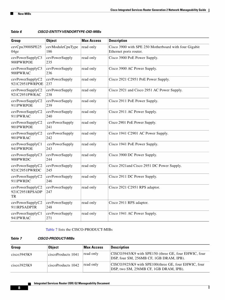
• Table 6 lists the CISCO-ENTITY-VENDOR-OID-MIBs
• Table 7 lists the CISCO-PRODUCT-MIBs
• Table 8 lists the CISCO-LICENSE-MGMT-MIBs
Table 6 CISCO-ENTITY-VENDORTYPE-OID-MIBs
Group Object Max Access Description
cevChassisC1941 cevChassis 803 read only Supports two EHWIC slots, one ISM and one WLAN slot, and two Gigabit Ethernet ports router.
cevChassisC2901 cevChassis 804 read only Supports four EHWIC slots, one ISM slot, two PVDM slots, and two Gigabit Ethernet ports router.
cevChassisC2911 cevChassis 805 read only Supports four EHWIC slots, one SM slot, one ISM slot, two PVDM slots, and three Gigabit Ethernet port router.
cevChassisC2921 cevChassis 806 read only Supports four EHWIC slots, one SM or one DW-SM slot, one ISM slot, three PVDM slots, and three Gigabit Ethernet port router.
cevChassisC2951 cevChassis 807 read only Supports four EHWIC slots, two SM or one DW-SM slot, one ISM slot, three PVDM slots, and three Gigabit Ethernet port router.
cevChassisC3925 cevChassis 808 read only Supports four EHWIC slots, two SM or one SM with one DW-SM slot, one ISM slot, four PVDM slots, and three Gigabit Ethernet port router.
cevChassisC3945 cevChassis 809 read only Supports four EHWIC slots, four SM or two SM with one DW-SM slot, one ISM slot, four PVDM slots, and three Gigabit Ethernet port router.
cevChassisC1941W cevChassis 827 read only Supports two EHWIC slots, one WLAN controller, two Gigabit Ethernet ports router.
cevCpu19412ge cevModuleCpuType 160
read only Cisco 1941 motherboard with two Gigabit Ethernet ports router.
cevCpu29012ge cevModuleCpuType 161
read only Cisco 2901 motherboard with two Gigabit Ethernet ports router.
cevCpu29113ge cevModuleCpuType 162
read only Cisco 2911 Motherboard with three Gigabit Ethernet ports router.
cevCpu29213ge cevModuleCpuType 163
read only Cisco 2921 Motherboard with three Gigabit Ethernet ports router.
cevCpu29513ge cevModuleCpuType 164
read only Cisco 2951 Motherboard with three Gigabit Ethernet ports router.
cevCpu39253ge cevModuleCpuType 165
read only Cisco 3925 Motherboard with three Gigabit Ethernet ports router.
cevCpu39453ge cevModuleCpuType 166
read only Cisco 3945 Motherboard with three Gigabit Ethernet ports router.
cevCpu1941w2ge cevModuleCpuType 168
read only Cisco 1941 Motherboard with two Gigabit Ethernet ports router and one WLAN Controller.
cevCpu3900SPE2004ge
cevModuleCpuType 179
read only Cisco 3900 with SPE 200 Motherboard with four Gigabit Ethernet ports router.
Cisco Integrated Services Router Generation 2 Network Manageability Guide New MIBs
8Integrated Services Router (ISR) G2 Manageability Document
Table 7 lists the CISCO-PRODUCT-MIBs
cevCpu3900SPE2504ge
cevModuleCpuType186
read only Cisco 3900 with SPE 250 Motherboard with four Gigabit Ethernet ports router.
cevPowerSupplyC3900PWRPOE
cevPowerSupply 235
read only Cisco 3900 PoE Power Supply.
cevPowerSupplyC3900PWRAC
cevPowerSupply 236
read only Cisco 3900 AC Power Supply.
cevPowerSupplyC2921C2951PWRPOE
cevPowerSupply 237
read only Cisco 2921 C2951 PoE Power Supply.
cevPowerSupplyC2921C2951PWRAC
cevPowerSupply 238
read only Cisco 2921 and Cisco 2951 AC Power Supply.
cevPowerSupplyC2911PWRPOE
cevPowerSupply 239
read only Cisco 2911 PoE Power Supply.
cevPowerSupplyC2911PWRAC
cevPowerSupply 240
read only Cisco 2911 AC Power Supply.
cevPowerSupplyC2901PWRPOE
cevPowerSupply 241
read only Cisco 2901 PoE Power Supply.
cevPowerSupplyC2901PWRAC
cevPowerSupply 242
read only Cisco 1941 C2901 AC Power Supply.
cevPowerSupplyC1941PWRPOE
cevPowerSupply 243
read only Cisco 1941 PoE Power Supply.
cevPowerSupplyC3900PWRDC
cevPowerSupply 244
read only Cisco 3900 DC Power Supply.
cevPowerSupplyC2921C2951PWRDC
cevPowerSupply 245
read only Cisco 2921and Cisco 2951 DC Power Supply.
cevPowerSupplyC2911PWRDC
cevPowerSupply 246
read only Cisco 2911 DC Power Supply.
cevPowerSupplyC2921C2951RPSADPTR
cevPowerSupply 247
read only Cisco 2921 C2951 RPS adaptor.
cevPowerSupplyC2911RPSADPTR
cevPowerSupply 248
read only Cisco 2911 RPS adaptor.
cevPowerSupplyC1941PWRAC
cevPowerSupply 271
read only Cisco 1941 AC Power Supply.
Table 6 CISCO-ENTITY-VENDORTYPE-OID-MIBs
Group Object Max Access Description
Table 7 CISCO-PRODUCT-MIBs
Group Object Max Access Description
cisco3945K9 ciscoProducts 1041 read only CISCO3945/K9 with SPE150 (three GE, four EHWIC, four DSP, four SM, 256MB CF, 1GB DRAM, IPB).
cisco3925K9 ciscoProducts 1042 read only CISCO3925/K9 with SPE100(three GE, four EHWIC, four DSP, two SM, 256MB CF, 1GB DRAM, IPB).

Cisco Integrated Services Router Generation 2 Network Manageability Guide New MIBs
9Integrated Services Router (ISR) G2 Manageability Document
cisco2951K9 ciscoProducts 1043 read only CISCO2951/K9 with three GE, four EHWIC, three DSP, two SM, 256 MB CF, 512 MB DRAM, IPB.
cisco2921K9 ciscoProducts 1044 read only CISCO2921/K9 with three GE, four EHWIC, three DSP, one SM, 256 MB CF, 512 MB DRAM, IPB.
cisco2911K9 ciscoProducts 1045 read only CISCO2911/K9 with three GE, four EHWIC, two DSP, one SM, 256 MB CF, 512MB DRAM, IPB.
cisco2901K9 ciscoProducts 1046 read only CISCO2901/K9 with two GE, four EHWIC, two DSP, 256 MB CF, 512 MBDRAM, IP BASE.
cisco1941K9 ciscoProducts 1047 read only CISCO1941/K9 with two GE, two EHWIC, 256 MB CF, 256 MB DRAM, IP BASE.
cisco1941WAK9 ciscoProducts 1095 read only CISCO1941W-A/K9 with 802.11 a/b/g/ n FCC compliant WLAN ISM.
cisco1941WNK9 ciscoProducts 1174 read only CISCO1941W-N/K9 Router w/ 802.11 a/b/g/n Aus, NZ Compliant WLAN ISM.
cisco1941WPK9 ciscoProducts 1173 read only CISCO1941W-P/K9 Router w/ 802.11 a/b/g/n Japan Compliant WLAN ISM.
cisco1941WEK9 ciscoProducts 1172 read only CISCO1941W-E/K9 Router w/ 802.11 a/b/g/n ETSI Compliant WLAN ISM.
ciscoPwrC3900Poe ciscoProducts 1071 read only Cisco 3925/3945 AC Power Supply with Power Over Ethernet (PWR-3900-POE).
ciscoPwrC3900AC ciscoProducts 1072 read only Cisco 3925/3945 AC Power Supply (PWR-3900-AC).
ciscoPwrC2921C2951Poe
ciscoProducts 1073 read only Cisco 2921/2951 AC Power Supply with Power Over Ethernet (PWR-2921-51-POE).
ciscoPwrC2921C2951AC
ciscoProducts 1074 read only Cisco 2921/2951 AC Power Supply (PWR-2921-51-AC).
ciscoPwrC2911Poe ciscoProducts 1075 read only Cisco 2911 AC Power Supply with Power Over Ethernet (PWR-2911-POE).
ciscoPwrC2911AC ciscoProducts 1076 read only Cisco 2911 AC Power Supply (PWR-2911-AC).
ciscoPwrC2901Poe ciscoProducts 1077 read only Cisco 2901 AC Power Supply with Power Over Ethernet (PWR-2901-POE).
ciscoPwrC2901AC ciscoProducts 1078 read only Cisco 2901 AC Power Supply (PWR-2901-AC).
ciscoPwrC1941Poe ciscoProducts 1079 read only Cisco 1941 AC Power Supply with Power Over Ethernet (PWR-1941-POE).
ciscoPwrC3900DC ciscoProducts 1080 read only Cisco 3925/3945 DC Power Supply (PWR-3900-DC).
ciscoPwrC2921C2951DC
ciscoProducts 1081 read only Cisco 2921/2951 DC Power Supply (PWR-2921-51-DC).
ciscoPwrC2911DC ciscoProducts 1082 read only Cisco 2911 DC power Supply (PWR-2911-DC).
ciscoRpsAdptrC2921C2951
ciscoProducts 1083 read only Cisco 2921/2951 RPS Adaptor for use with external rps (RPS-ADPTR-2921-51).
Table 7 CISCO-PRODUCT-MIBs
Group Object Max Access Description

Cisco Integrated Services Router Generation 2 Network Manageability Guide New MIBs
10Integrated Services Router (ISR) G2 Manageability Document
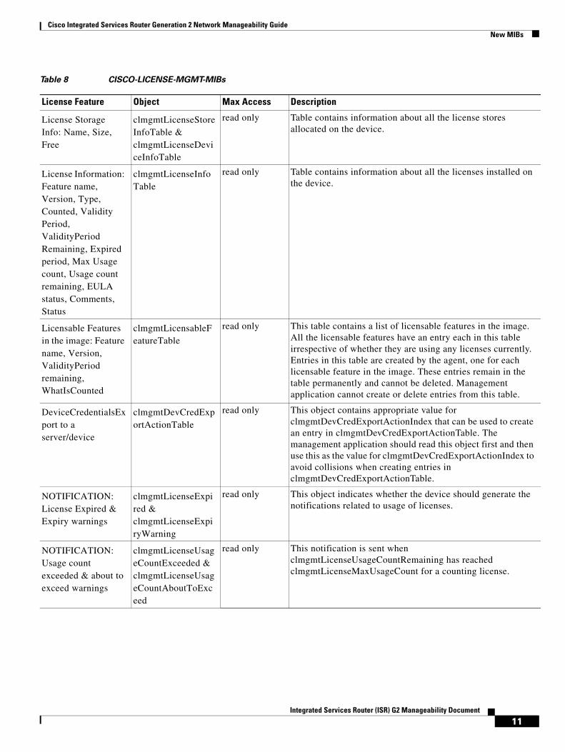
Table 8 lists the CISCO-LICENSE-MGMT-MIBs
ciscoRpsAdptrC2911 ciscoProducts 1084 read only Cisco 2911 RPS Adaptor for use with external rps (RPS-ADPTR-2911).
cisco1941W ciscoProducts 1095 read only CISCO194W-A/K9 with 802.11 a/b/g/ n FCC compliant WLAN ISM.
cisco3925SPE200 ciscoProducts 1144 read only CISCO3925E/K9 with SPE 200 motherboard, with four GE, four EHWIC, three DSP, and two SM slots.
cisco3945SPE250 ciscoProducts 1145 read only CISCO3945E/K9 with SPE 250 motherboard, with four GE, four EHWIC, three DSP, and four SM slots.
ciscoPwr1941AC ciscoProducts1168 read only Cisco 1941 AC Power Supply.
Table 7 CISCO-PRODUCT-MIBs
Group Object Max Access Description
Table 8 CISCO-LICENSE-MGMT-MIBs
License Feature Object Max Access Description
Install License clmgmtLicenseActionTable & clmgmtLicenseActionResultTable
read only Table for invoking license management actions. Management application must create a row in this table to trigger any of the license management actions.
Clear License clmgmtLicenseActionTable & clmgmtLicenseActionResultTable
read only Table for invoking license management actions. Management application must create a row in this table to trigger any of the license management actions.
ReHost License clmgmtLicenseActionTable & clmgmtLicenseActionResultTable
read only Table for invoking license management actions. Management application must create a row in this table to trigger any of the license management actions.
Regenerate last rehost ticket
clmgmtLicenseActionTable & clmgmtLicenseActionResultTable
read only Table for invoking license management actions. Management application must create a row in this table to trigger any of the license management actions.
Backup all licenses clmgmtLicenseActionTable & clmgmtLicenseActionResultTable
read only Table for invoking license management actions. Management application must create a row in this table to trigger any of the license management actions.
Generate and export EULA
clmgmtLicenseActionTable & clmgmtLicenseActionResultTable
read only Table for invoking license management actions. Management application must create a row in this table to trigger any of the license management actions.
Cisco Integrated Services Router Generation 2 Network Manageability Guide New MIBs
11Integrated Services Router (ISR) G2 Manageability Document
License Storage Info: Name, Size, Free
clmgmtLicenseStoreInfoTable & clmgmtLicenseDeviceInfoTable
read only Table contains information about all the license stores allocated on the device.
License Information: Feature name, Version, Type, Counted, Validity Period, ValidityPeriod Remaining, Expired period, Max Usage count, Usage count remaining, EULA status, Comments, Status
clmgmtLicenseInfoTable
read only Table contains information about all the licenses installed on the device.
Licensable Features in the image: Feature name, Version, ValidityPeriod remaining, WhatIsCounted
clmgmtLicensableFeatureTable
read only This table contains a list of licensable features in the image. All the licensable features have an entry each in this table irrespective of whether they are using any licenses currently. Entries in this table are created by the agent, one for each licensable feature in the image. These entries remain in the table permanently and cannot be deleted. Management application cannot create or delete entries from this table.
DeviceCredentialsExport to a server/device
clmgmtDevCredExportActionTable
read only This object contains appropriate value for clmgmtDevCredExportActionIndex that can be used to create an entry in clmgmtDevCredExportActionTable. The management application should read this object first and then use this as the value for clmgmtDevCredExportActionIndex to avoid collisions when creating entries in clmgmtDevCredExportActionTable.
NOTIFICATION: License Expired & Expiry warnings
clmgmtLicenseExpired & clmgmtLicenseExpiryWarning
read only This object indicates whether the device should generate the notifications related to usage of licenses.
NOTIFICATION: Usage count exceeded & about to exceed warnings
clmgmtLicenseUsageCountExceeded & clmgmtLicenseUsageCountAboutToExceed
read only This notification is sent when clmgmtLicenseUsageCountRemaining has reached clmgmtLicenseMaxUsageCount for a counting license.
Table 8 CISCO-LICENSE-MGMT-MIBs
License Feature Object Max Access Description

Cisco Integrated Services Router Generation 2 Network Manageability Guide New MIBs
12Integrated Services Router (ISR) G2 Manageability Document
Note For a detailed explanation of the MIB and to download the MIB, see SNMP Object Navigator.
NOTIFICATION: License installed, Cleared & Revoked
clmgmtLicenseInstalled, clmgmtLicenseCleared & clmgmtLicenseRevoked
read only This notification is sent when a license is installed successfully.
NOTIFICATION: EULA Accepted
clmgmtLicenseEULAAceepted
read only A collection of notifications related to license deployment.
NOTIFICATION: LicenseNotEnforced
clmgmtLicenseNotEnforced
read only A collection of notifications related to license errors.
Table 8 CISCO-LICENSE-MGMT-MIBs
License Feature Object Max Access Description

Cisco Integrated Services Router Generation 2 Network Manageability Guide Simple Network Management Protocol
13Integrated Services Router (ISR) G2 Manageability Document
Simple Network Management ProtocolSNMP is a manager-agent model that consists of the following elements:
• SNMP manager— Provides an interface between the human manager and the management system.
• SNMP agent— Provides an interface between the manager and the physical device being managed.
A database of management information, managed SNMP devices, and SNMP protocol are additional elements required for an SNMP managed network.
The SNMP agent exchanges network management information with the SNMP manager software that is running on a network management system (NMS).
An SNMP-managed network consists of the following items on the network:
• Managed device—A network node that contains an SNMP agent that resides on a managed network. Managed devices collect and store management information and use SNMP to make this information available to the NMS. Managed devices, sometimes called network elements, can include routers and access servers, switches and bridges, hubs, computer hosts, and printers.
• Agent—A network management software module that resides in a managed device. An agent has local knowledge of management information and translates that information into a form compatible with SNMP. The agent responds to requests for information and actions from the managed device. The agent controls access to the agent’s MIB, the collection of objects that can be viewed or changed by the SNMP manager.
• Network Management System (NMS)—Executes applications that monitor and control managed devices. NMSs provide most of the processing and memory resources required for network management. Every managed network must have one or more NMS.
Critical SNMP TrapsSNMPv1 and SNMPv2c, and the associated MIBs, enable trap-directed notification.
If a manager is responsible for a large number of devices, and each device has a large number of objects, it is impractical for the manager to poll or request information from every object on every device. The solution in this case is to have each agent on the managed device notify the manager without solicitation. It does this by sending a message, or trap, of the event. This is known as trap-directed notifications.
After the manager receives the event, the manager displays it and can choose to take an action based on the event. For instance, to get a better understanding of the event, the manager can poll the agent directly, or poll other associated device agents.
Trap-directed notification can result in a substantial savings of network and agent resources by eliminating the need for excessive SNMP requests. However, it is not possible to totally eliminate SNMP polling. SNMP requests are required for discovery and topology changes. SNMP polling is also needed because a managed device agent cannot send a trap if the device has had a catastrophic outage.
For a management system to understand a trap sent by an agent, the management system must know what the object identifier (OID) defines. Therefore, it must have the MIB for that trap loaded. This provides the correct OID information so that the network management system can understand the traps that are sent.
For traps that are supported by Cisco devices in specific MIBs, refer to the Cisco SNMP Object Navigator tool.
Table 9 lists the new and critical SNMP traps.

Cisco Integrated Services Router Generation 2 Network Manageability Guide Critical Syslog Messages
14Integrated Services Router (ISR) G2 Manageability Document
Note For detailed examples of traps sent by Cisco IOS, see Understanding Simple Network Management Protocol (SNMP) Traps.
Critical Syslog MessagesSyslog is a method of collecting messages from devices and sending them to a server that is running a syslog daemon. Logging to a central syslog server helps to aggregate logs and alerts. Cisco devices can send their log messages to a Unix-style SYSLOG service. A SYSLOG service simply accepts messages and stores the messages in files or prints according to a simple configuration file. These messages are useful in routine troubleshooting and for incident handling.
Cisco devices have thousands of different messages that are sent to a central server (at the customer site) when an identified event occurs in the network. Events range from catastrophic (priority 0) to informational (priority 6).
The syslog daemon handles the recording of syslog messages and events in log files. The syslog message is composed of two main parts:
• Header—Contains the date and time information along with the IP address or the computer name from which the message has originated.
• Message—Includes the program or subsystem name and the message. The program or subsystem name and the message are separated by a colon.
Note For additional information about syslog, see the “Additional References” section on page 93.
Table 9 New and Critical SNMP Traps and MIBs
Trap Name MIB
ciscoEnvMonFanNotification CISCO-ENVMON-MIB
ciscoEnvMonFanStatusChangeNotif CISCO-ENVMON-MIB
ciscoEnvMonVoltStatusChangeNotif CISCO-ENVMON-MIB
ciscoEnvMonTempStatusChangeNotif CISCO-ENVMON-MIB
ciscoEnvMonSuppStatusChangeNotif CISCO-ENVMON-MIB
clmgmtLicenseInstalled CISCO-LICENSE-MGMT-MIB
clmgmtLicenseCleared CISCO-LICENSE-MGMT-MIB
clmgmtLicenseExpired CISCO-LICENSE-MGMT-MIB
clmgmtLicenseExpiryWarning CISCO-LICENSE-MGMT-MIB
clmgmtLicenseUsageCountExceeded CISCO-LICENSE-MGMT-MIB
clmgmtLicenseUsageCountAboutToExceed CISCO-LICENSE-MGMT-MIB
clmgmtLicenseRevoked CISCO-LICENSE-MGMT-MIB
clmgmtLicenseEULAAccepted CISCO-LICENSE-MGMT-MIB
clmgmtLicenseNotEnforced CISCO-LICENSE-MGMT-MIB

Cisco Integrated Services Router Generation 2 Network Manageability Guide Critical Syslog Messages
15Integrated Services Router (ISR) G2 Manageability Document
Error MessagesThe following are the critical syslog messages for the ISR G2 platform:
Error Message Could not init buffer pools
Explanation The driver failed to get a pool of buffers from IOS.
Recommended Action Could not init buffer pools. The driver failed to get a pool of buffers from IOS Software due to a bug - open a case with Development Engineering.
Error Message The Ethernet port initialization failed due to insufficient memory
Explanation The Ethernet port initialization failed due to insufficient memory.
Recommended Action The router requires more packet memory. Consider a software upgrade.
Error Message %s, PHY configuration failed
Explanation The Ethernet device driver tried to configure the Ethernet PHY device, but the PHY configuration failed.
Recommended Action The Ethernet device driver tried to configure the Ethernet PHY device, but the PHY configuration failed.
Error Message PLATFORM-2-NO_POLL_TIMER
Explanation The system cannot allocate a polling timer. The Voice DSP driver requests a hardware poll timer, but the system does not allocate the resource. As a result, the voice application does not function correctly.
Recommended Action This is a software error message. Reload your router to recover from this problem. Copy the message exactly as it appears on the console or in the system log. Research and attempt to resolve the issue using the tools and utilities provided at http://www.cisco.com/tac. With some messages, these tools and utilities supply clarifying information. Search for resolved software issues using the Bug Toolkit at the following URL: http://www.cisco.com/cgi-bin/Support/Bugtool/launch_bugtool.pl. If you still require assistance, open a case with the Technical Assistance Center via the Internet at the following URL: http://tools.cisco.com/ServiceRequestTool/create, Provide the information that you have gathered.

Cisco Integrated Services Router Generation 2 Network Manageability Guide Critical Syslog Messages
16Integrated Services Router (ISR) G2 Manageability Document
Error Message PLATFORM-1-SPUR_INT
Explanation The platform detected an unauthentic timer interrupt. An unexpected interrupt event was detected by your CPU. There is no interrupt service routine assigned to this interrupt.
Recommended Action If the error recurs, the system is in an unstable state. Copy the message exactly as it appears on the console or in the system log. Research and attempt to resolve the issue using the tools and utilities provided at http://www.cisco.com/tac. With some messages, these tools and utilities supply clarifying information. Search for resolved software issues using the Bug Toolkit at http://www.cisco.com/cgi-bin/Support/Bugtool/launch_bugtool.pl. If you still require assistance, open a case with the Technical Assistance Center via the Internet at http://tools.cisco.com/ServiceRequestTool/create, or contact your Cisco technical support representative and provide the representative with the information that you have gathered.
Error Message PLATFORM-2-ISR_ERR_MSG
Explanation Detected ISR error, 0x%08lx, 0x%08lx. Platform interrupt service routine detects abnormal events.
Recommended Action This is a software error. Copy the message exactly as it appears on the console or in the system log. Research and attempt to resolve the issue using the tools and utilities provided at http://www.cisco.com/tac. With some messages, these tools and utilities supply clarifying information. Search for resolved software issues using the Bug Toolkit at http://www.cisco.com/cgi-bin/Support/Bugtool/launch_bugtool.pl. If you still require assistance, open a case with the Technical Assistance Center via the Internet at http://tools.cisco.com/ServiceRequestTool/create, or contact your Cisco technical support representative and provide the representative with the information that you have gathered.
Error Message PLATFORM-0-PCIE_ERR
Explanation Detected PCIe error: 0x%08lx, 0x%08lx, 0x%08lx, 0x%08lx, 0x%08lx. System detects a severe PCIe error. For example, PCIe fatal error messages received by root complex.
Recommended Action This can be a hardware issue.This is a fatal error that cannot be recovered. Reset the system to resolve this problem. Copy the message exactly as it appears on the console or in the system log. Research and attempt to resolve the issue using the tools and utilities provided at http://www.cisco.com/tac. With some messages, these tools and utilities supply clarifying information. If you still require assistance, open a case with the Technical Assistance Center via the Internet at http://tools.cisco.com/ServiceRequestTool/create, or contact your Cisco technical support representative and provide the representative with the information that you have gathered.
Error Message PLATFORM-2-BOOT_BUS_ERR
Explanation Detected MIO boot bus error: 0x%08lx. Boot bus is one of the hardware units inside the processor. It connects to flash memory and compact flash for initial booting purpose. When the boot bus hardware unit encounters either address-decode or wait-mode error, the boot bus notifies the CPU.
Recommended Action This can be a hardware issue. This is a fatal error that cannot be recovered, reset the system to resolve this problem. Copy the message exactly as it appears on the console or in the system log. Research and attempt to resolve the issue using the tools and utilities provided at

Cisco Integrated Services Router Generation 2 Network Manageability Guide Critical Syslog Messages
17Integrated Services Router (ISR) G2 Manageability Document
http://www.cisco.com/tac. With some messages, these tools and utilities supply clarifying information. If you still require assistance, open a case with the Technical Assistance Center via the Internet at http://tools.cisco.com/ServiceRequestTool/create, or contact your Cisco technical support representative and provide the representative with the information that you have gathered.
Error Message PLATFORM-2-PHY_CONFIG
Explanation Onboard Gigabit Ethernet physical configuration failed. The Onboard Gigabit Ethernet device driver tries to configure the Ethernet PHY device, but the PHY configuration fails.
Recommended Action This is a transient error. Although a transient issue is possible, this condition is a software problem. In rare cases, a hardware failure of one specific component can cause this condition. Reload the system and try again. If the issue recurs, extract the debug information by issuing the debug ethernet-interface command before entering the configuration information. The output of the C3900_ERRMSG_CLI_OUTPUT commands are helpful to resolve the problem. Research and attempt to resolve the issue using the tools and utilities provided at http://www.cisco.com/tac.With some messages, these tools and utilities will supply clarifying information. Search for resolved software issues using the Bug Toolkit at http://www.cisco.com/cgi-bin/Support/Bugtool/launch_bugtool.pl. If you still require assistance, open a case with the Technical Assistance Center via the Internet at http://tools.cisco.com/ServiceRequestTool/create, or contact your Cisco technical support representative and provide the representative with the information that you have gathered. Attach the following information to your case in nonzipped, plain-text (.txt) format: the output of the show logging and show tech-support commands, and your pertinent troubleshooting logs.
Error Message PLATFORM-2-SM_ERROR
Explanation The Software attempts to access the Service Module slot which is not present on the IO Controller. This is caused by a software error where the software attempts to set the access for the Service Module slot that is not defined.
Recommended Action This is a serious error which is integral to the proper operation of the router.There is no recommended workaround. This is an unexpected internal software error.If the issue recurs, extract information by issuing the show version, show run, and show platform commands. Search for resolved software issues using the Bug Toolkit at http://www.cisco.com/cgi-bin/Support/Bugtool/launch_bugtool.pl. If you still require assistance, open a case with the Technical Assistance Center via the Internet at http://tools.cisco.com/ServiceRequestTool/create, or contact your Cisco technical support representative and provide the representative with the information that you have gathered. Attach the following information to your case in nonzipped, plain-text (.txt) format: the output of the show version, show run, and show platform commands; and your pertinent troubleshooting logs.
Error Message PLATFORM-0-SURPRISE_OIR
Explanation Non-managed online removal of card from the slot. The service module is unexpectedly removed from the slot, while the service module is online.
Recommended Action Unexpected online removal of the service module is not supported. The managed Online Insertion and Removal (OIR) command should be used before removing the online service module. Use the hw-module slot [n] stop command before removing the online service

Cisco Integrated Services Router Generation 2 Network Manageability Guide Critical Syslog Messages
18Integrated Services Router (ISR) G2 Manageability Document
module. If you still require assistance, open a case with the Technical Assistance Center via the Internet at http://tools.cisco.com/ServiceRequestTool/create, or contact your Cisco technical support representative and provide the representative with the information that you have gathered.
Error Message PLATFORM-0-NM_REMOVED_SM2NM
Explanation The network module is removed from the SM2NM adapter.
Recommended Action For online insertion and removal, the network module must be removed with the SM2NM adapter. Use the managed OIR command for both the online removal of the network module and the SM2NM adapter. Use the hw-module slot [n] stop command before removing the service module and the SM2NM adapter. If you still require assistance, open a case with the Technical Assistance Center via the Internet at http://tools.cisco.com/ServiceRequestTool/create, or contact your Cisco technical support representative and provide the representative with the information that you have gathered.
Error Message ENVMON-1-POWER_WARNING
Explanation An error has occurred in the power supply.
Recommended Action Make sure that the power supply is connected to the input source. Also, check whether the power supply unit and redundant power supply are supported by this router. Research and attempt to resolve the issue using the tools and utilities provided at http://www.cisco.com/tac.With some messages, these tools and utilities supply clarifying information. If you still require assistance, open a case with the Technical Assistance Center via the Internet at http://tools.cisco.com/ServiceRequestTool/create, or contact your Cisco technical support representative and provide the representative with the information that you have gathered.
Error Message ENVMON-2-POWER_OVERTEMP_SHUTDOWN
Explanation Temperature exceeds the threshold limit. If the high temperature condition is not resolved, the power supply will automatically shuts down.
Recommended Action To prevent the damage caused by over heating, save the system configuration and power down the system. This problem can be caused by an operational environment or faulty components. If this warning recurs after disconnecting the power supply, replace the hardware. Research and attempt to resolve the issue using the tools and utilities provided at http://www.cisco.com/tac.With some messages, these tools and utilities supply clarifying information. If you still require assistance, open a case with the Technical Assistance Center via the Internet at http://tools.cisco.com/ServiceRequestTool/create, or contact your Cisco technical support representative and provide the representative with the information that you have gathered.
Error Message ENVMON-2-POWER_OVERTEMP
Explanation Temperature exceeds the threshold. The system power supply temperature exceeds critical temperature threshold. Resolve the system cooling to prevent system damage.
Recommended Action To prevent the damage caused by over heating, save the system configuration and power down the system. This problem can be caused by an operational environment or faulty components. If this warning recurs after disconnecting the power supply, replace the hardware.

Cisco Integrated Services Router Generation 2 Network Manageability Guide Critical Syslog Messages
19Integrated Services Router (ISR) G2 Manageability Document
Research and attempt to resolve the issue using the tools and utilities provided at http://www.cisco.com/tac.With some messages, these tools and utilities supply clarifying information. If you still require assistance, open a case with the Technical Assistance Center via the Internet at http://tools.cisco.com/ServiceRequestTool/create, or contact your Cisco technical support representative and provide the representative with the information that you have gathered.
Error Message ENVMON-2-FAN_TRAY_MISSING
Explanation Fan tray is removed. To prevent the system from overheating, reinsert the fan tray. The environmental monitor cannot detect fan tray on system chassis.
Recommended Action Make sure that the fan tray is properly inserted. If the problem persists, replace the fan tray. Research and attempt to resolve the issue using the tools and utilities provided at http://www.cisco.com/tac. With some messages, these tools and utilities supply clarifying information. If you still require assistance, open a case with the Technical Assistance Center via the Internet at http://tools.cisco.com/ServiceRequestTool/create, or contact your Cisco technical support representative and provide the representative with the information that you have gathered.
Error Message ENVMON-2-SYSTEM_FAN_FAILED
Explanation System fan is not rotating.
Recommended Action Make sure that the fan power cable is properly attached to the mainboard fan tray power connector. If problem persists, replace the system fan.Research and attempt to resolve the issue using the tools and utilities provided at http://www.cisco.com/tac.With some messages, these tools and utilities will supply clarifying information. If you still require assistance, open a case with the Technical Assistance Center via the Internet at http://tools.cisco.com/ServiceRequestTool/create, or contact your Cisco technical support representative and provide the representative with the information that you have gathered.
Error Message ENVMON-2-ONE_FAN_FAILED
Explanation Fan is running at low RPM. One of the fans in the system is not rotating and all other fans are rotating at high speed.
Recommended Action Make sure that the fan power cable is properly attached to the mainboard fan tray power connector. If problem persists, replace the Fan Tray or the system fan. Research and attempt to resolve the issue using the tools and utilities provided at http://www.cisco.com/tac.With some messages, these tools and utilities will supply clarifying information. If you still require assistance, open a case with the Technical Assistance Center via the Internet at http://tools.cisco.com/ServiceRequestTool/create, or contact your Cisco technical support representative and provide the representative with the information that you have gathered.

Cisco Integrated Services Router Generation 2 Network Manageability Guide Critical Syslog Messages
20Integrated Services Router (ISR) G2 Manageability Document
Error Message ENVMON-2-MULTI_FAN_FAILED
Explanation Multiple fans are running at low RPM. Multiple fan failures detected and some of the fans in the system are rotating at high speed.
Recommended Action Make sure that the fan power cable is properly attached to the mainboard fan tray power connector. If problem persists, replace the fan tray. Research and attempt to resolve the issue using the tools and utilities provided at http://www.cisco.com/tac. With some messages, these tools and utilities supply clarifying information. If you still require assistance, open a case with the Technical Assistance Center via the Internet at http://tools.cisco.com/ServiceRequestTool/create, or contact your Cisco technical support representative and provide the representative with the information that you have gathered.
Error Message ENVMON-1-NO_PROCESS
Explanation Failed to create environmental monitor process.
Recommended Action The amount of memory available in the router may not be sufficient. Research and attempt to resolve the issue using the tools and utilities provided at http://www.cisco.com/tac. With some messages, these tools and utilities supply clarifying information. If you still require assistance, open a case with the Technical Assistance Center via the Internet at http://tools.cisco.com/ServiceRequestTool/create, or contact your Cisco technical support representative and provide the representative with the information that you have gathered.
Error Message ENVMON-1-CPU_CRITICAL_OVERTEMP
Explanation CPU temperature exceeds the threshold limit. To prevent system damage, resolve the problem in the system cooling process.
Recommended Action To prevent the damage caused by over heating, save the system configuration and power down the system.The system CPU temperature has exceeded the maximum threshold. This problem can be caused by an operational environment or faulty components. If this warning reoccurs after powering down system, replace the hardware. Research and attempt to resolve the issue using the tools and utilities provided at http://www.cisco.com/tac. With some messages, these tools and utilities supply clarifying information. If you still require assistance, open a case with the Technical Assistance Center via the Internet at http://tools.cisco.com/ServiceRequestTool/create, or contact your Cisco technical support representative and provide the representative with the information that you have gathered.
Error Message ENVMON-2-IN_OUTLET_OVERTEMP
Explanation The temperature of the system sensor exceeds the threshold limit. To prevent system damage, resolve the problem in the system cooling process.
Recommended Action To prevent the damage caused by over heating, resolve the problem in the system cooling process or power down the system. The system temperature has exceeded the maximum threshold. This problem can be caused by an operational environment or faulty components. Research and attempt to resolve the issue using the tools and utilities provided at http://www.cisco.com/tac. With some messages, these tools and utilities supply clarifying information. If this warning reoccurs, replace the hardware. If this warning reoccurs after you power down the system, replace the hardware. If you still require assistance, open a case with the Technical
Cisco Integrated Services Router Generation 2 Network Manageability Guide Critical Syslog Messages
21Integrated Services Router (ISR) G2 Manageability Document
Assistance Center via the Internet at http://tools.cisco.com/ServiceRequestTool/create, or contact your Cisco technical support representative and provide the representative with the information that you have gathered.
Error Message MAINBOARD_SFP-1-FAILURE
Explanation Transceiver module SFP is failed in port.
Recommended Action Copy the message exactly as it appears on the console or in the system log. Research and attempt to resolve the issue using the tools and utilities provided at http://www.cisco.com/tac. With some messages, these tools and utilities supply clarifying information. Search for resolved software issues using the Bug Toolkit at http://www.cisco.com/cgi-bin/Support/Bugtool/launch_bugtool.pl. If you still require assistance, open a case with the Technical Assistance Center via the Internet at http://tools.cisco.com/ServiceRequestTool/create, or contact your Cisco technical support representative and provide the representative with the information that you have gathered.
Error Message MAINBOARD_SFP-1-NOT_IDENTIFIED
Explanation Unidentified transceiver module in port.
Recommended Action Copy the message exactly as it appears on the console or in the system log. Research and attempt to resolve the issue using the tools and utilities provided at http://www.cisco.com/tac. With some messages, these tools and utilities supply clarifying information. Search for resolved software issues using the Bug Toolkit at http://www.cisco.com/cgi-bin/Support/Bugtool/launch_bugtool.pl. If you still require assistance, open a case with the Technical Assistance Center via the Internet at http://tools.cisco.com/ServiceRequestTool/create, or contact your Cisco technical support representative and provide the representative with the information that you have gathered.
Error Message NVRAM-2-NO_GOOD_SECTORS
Explanation No good sectors in the region.
Recommended Action Copy the message exactly as it appears on the console or in the system log. Research and attempt to resolve the issue using the tools and utilities provided at http://www.cisco.com/tac. With some messages, these tools and utilities supply clarifying information. Search for resolved software issues using the Bug Toolkit at http://www.cisco.com/cgi-bin/Support/Bugtool/launch_bugtool.pl. If you still require assistance, open a case with the Technical Assistance Center via the Internet at http://tools.cisco.com/ServiceRequestTool/create, or contact your Cisco technical support representative and provide the representative with the information that you have gathered.
Error Message NVRAM-2-INIT_STAT_ERASE_FAILED
Explanation Status sector erase failed during initialization.
Recommended Action Copy the message exactly as it appears on the console or in the system log. Research and attempt to resolve the issue using the tools and utilities provided at http://www.cisco.com/tac. With some messages, these tools and utilities supply clarifying

Cisco Integrated Services Router Generation 2 Network Manageability Guide Critical Syslog Messages
22Integrated Services Router (ISR) G2 Manageability Document
information. Search for resolved software issues using the Bug Toolkit at http://www.cisco.com/cgi-bin/Support/Bugtool/launch_bugtool.pl. If you still require assistance, open a case with the Technical Assistance Center via the Internet at http://tools.cisco.com/ServiceRequestTool/create, or contact your Cisco technical support representative and provide the representative with the information that you have gathered.
Error Message NVRAM-2-INIT_STAT_FAILED
Explanation Status sector initialization failed.
Recommended Action Copy the message exactly as it appears on the console or in the system log. Research and attempt to resolve the issue using the tools and utilities provided at http://www.cisco.com/tac. With some messages, these tools and utilities supply clarifying information. Search for resolved software issues using the Bug Toolkit at http://www.cisco.com/cgi-bin/Support/Bugtool/launch_bugtool.pl. If you still require assistance, open a case with the Technical Assistance Center via the Internet at http://tools.cisco.com/ServiceRequestTool/create, or contact your Cisco technical support representative and provide the representative with the information that you have gathered.
Error Message NVRAM-2-ERASE_INT_LEVEL
Explanation Erase function called with interrupt level.
Recommended Action Copy the message exactly as it appears on the console or in the system log. Research and attempt to resolve the issue using the tools and utilities provided at http://www.cisco.com/tac. With some messages, these tools and utilities supply clarifying information. Search for resolved software issues using the Bug Toolkit at http://www.cisco.com/cgi-bin/Support/Bugtool/launch_bugtool.pl. If you still require assistance, open a case with the Technical Assistance Center via the Internet at http://tools.cisco.com/ServiceRequestTool/create, or contact your Cisco technical support representative and provide the representative with the information that you have gathered.
Error Message PQ3_TSEC-1-GRSFAIL
Explanation The software failed to perform Graceful Receive Stop (GRS) on the Ethernet/Fast Ethernet/Gigabit Ethernet interface. This happens while throttling the interface due to excess traffic.
Recommended Action This is a software error and the interface can stop functioning properly. The interface can be restored by resetting the interface. You can reset the interface by issuing the shut followed by the no shut command on the interface. Important information of the interface can be obtained by issuing the show controllers command on the interface on which the error occurred. Copy the message exactly as it appears on the console or in the system log. Research and attempt to resolve the issue using the tools and utilities provided at http://www.cisco.com/tac. With some messages, these tools and utilities supply clarifying information. Search for resolved software issues using the Bug Toolkit at http://www.cisco.com/cgi-bin/Support/Bugtool/launch_bugtool.pl. If you still require assistance, open a case with the Technical Assistance Center via the Internet at http://tools.cisco.com/ServiceRequestTool/create, or contact your Cisco technical support representative and provide the representative with the information that you have gathered. Attach the following information to your case in nonzipped, plain-text (.txt) format: the output of the shut, no shut, and show controllers commands; and your pertinent troubleshooting logs.

Cisco Integrated Services Router Generation 2 Network Manageability Guide Critical Syslog Messages
23Integrated Services Router (ISR) G2 Manageability Document
Error Message HDV2-1-INITIALIZATION
Explanation The HDV2 port module in the given slot does not initialize correctly. The voice ports or interfaces do not function properly.
Recommended Action Reload the router. After reloading the router, if the HDV2 fails to initialize, make sure that a valid HDV2 is plugged into the slot. Reset the module, if necessary. Copy the message exactly as it appears on the console or in the system log. Research and attempt to resolve the issue using the tools and utilities provided at http://www.cisco.com/tac. With some messages, these tools and utilities supply clarifying information. Search for resolved software issues using the Bug Toolkit at http://www.cisco.com/cgi-bin/Support/Bugtool/launch_bugtool.pl. If you still require assistance, open a case with the Technical Assistance Center via the Internet at http://tools.cisco.com/ServiceRequestTool/create, or contact your Cisco technical support representative and provide the representative with the information that you have gathered.
Error Message MRVL_GE_PHY-2-READ
Explanation An attempt to read the contents of a register associate with the gigabit ethernet hardware was unsuccessful. This may result in failure to setup the Gigabit-ethernet correctly, and possibly network outage. This implies a bigger problem in hardware.
Recommended Action Reload the router. After reloading the router, if the system fails, then this is an indication of a hardware issue. Copy the message exactly as it appears on the console or in the system log. Research and attempt to resolve the issue using the tools and utilities provided at http://www.cisco.com/tac. With some messages, these tools and utilities supply clarifying information. Search for resolved software issues using the Bug Toolkit at http://www.cisco.com/cgi-bin/Support/Bugtool/launch_bugtool.pl. If you still require assistance, open a case with the Technical Assistance Center via the Internet at http://tools.cisco.com/ServiceRequestTool/create, or contact your Cisco technical support representative and provide the representative with the information that you have gathered. Attach the following information to your case in nonzipped, plain-text (.txt) format: the output of the show controllers command on all GigE ports and your pertinent troubleshooting logs.
Error Message XFR_GE_PHY-2-PAGE_RESET
Explanation Marvel Phy Page reset to page zero failed. If PHY behavior is not guaranteed to work properly, the subsequent operation is set on wrong pages and it can lead to unexpected behavior.
Recommended Action Use the shut and no shut commands on the interface for which the page selection fails. Copy the message exactly as it appears on the console or in the system log. Research and attempt to resolve the issue using the tools and utilities provided at http://www.cisco.com/tac. With some messages, these tools and utilities supply clarifying information. Search for resolved software issues using the Bug Toolkit at http://www.cisco.com/cgi-bin/Support/Bugtool/launch_bugtool.pl. If you still require assistance, open a case with the Technical Assistance Center via the Internet at http://tools.cisco.com/ServiceRequestTool/create, or contact your Cisco technical support representative and provide the representative with the information that you have gathered. Attach the following information to your case in nonzipped, plain-text (.txt) format: the output of the shut and no shut command, and your pertinent troubleshooting logs.

Cisco Integrated Services Router Generation 2 Network Manageability Guide Critical Syslog Messages
24Integrated Services Router (ISR) G2 Manageability Document
Error Message MGF-2-INTERNAL
Explanation Multi-Gigabit Fabric Internal Error: An internal error occurred.
Recommended Action Copy the message exactly as it appears on the console or in the system log. Research and attempt to resolve the issue using the tools and utilities provided at http://www.cisco.com/tac. With some messages, these tools and utilities supply clarifying information. Search for resolved software issues using the Bug Toolkit at http://www.cisco.com/cgi-bin/Support/Bugtool/launch_bugtool.pl. If you still require assistance, open a case with the Technical Assistance Center via the Internet at http://tools.cisco.com/ServiceRequestTool/create, or contact your Cisco technical support representative and provide the representative with the information that you have gathered.
Error Message PSE_HW-3-PSE2_FPGA_UPGRADE_FAIL
Explanation A FPGA Image upgrade is aborted due to read or write failure.
Recommended Action Power cycle the system and try the operation again. If the same issue is encountered. Copy the message exactly as it appears on the console or in the system log. Research and attempt to resolve the issue using the tools and utilities provided at http://www.cisco.com/tac. With some messages, these tools and utilities supply clarifying information. Search for resolved software issues using the Bug Toolkit at http://www.cisco.com/cgi-bin/Support/Bugtool/launch_bugtool.pl. If you still require assistance, open a case with the Technical Assistance Center via the Internet at http://tools.cisco.com/ServiceRequestTool/create, or contact your Cisco technical support representative and provide the representative with the information that you have gathered.
Error Message PSE_HW-3-PSE2_FPGA_UNCOMPRESS_FAIL
Explanation A software error occurred and unable to uncompress the new FPGA image.
Recommended Action Power cycle the system and try the operation again. If the same issue is encountered. Copy the message exactly as it appears on the console or in the system log. Research and attempt to resolve the issue using the tools and utilities provided at http://www.cisco.com/tac. With some messages, these tools and utilities supply clarifying information. Search for resolved software issues using the Bug Toolkit at http://www.cisco.com/cgi-bin/Support/Bugtool/launch_bugtool.pl. If you still require assistance, open a case with the Technical Assistance Center via the Internet at http://tools.cisco.com/ServiceRequestTool/create, or contact your Cisco technical support representative and provide the representative with the information that you have gathered.
Error Message PSE_HW-3-PSE2_FPGA_SECTOR_ERASE_FAIL
Explanation An FPGA image upgrade is aborted, since it was unable to erase the sector.
Recommended Action Power cycle the system and try the operation again. Copy the message exactly as it appears on the console or in the system log. Research and attempt to resolve the issue using the tools and utilities provided at http://www.cisco.com/tac. With some messages, these tools and utilities will supply clarifying information. Search for resolved software issues using the Bug Toolkit at http://www.cisco.com/cgi-bin/Support/Bugtool/launch_bugtool.pl. If you still require

Cisco Integrated Services Router Generation 2 Network Manageability Guide Critical Syslog Messages
25Integrated Services Router (ISR) G2 Manageability Document
assistance, open a case with the Technical Assistance Center via the Internet at http://tools.cisco.com/ServiceRequestTool/create, or contact your Cisco technical support representative and provide the representative with the information that you have gathered.
Error Message PSE_HW-3-PSE2_FPGA_COMPARE_FAIL
Explanation An FPGA image upgrade was aborted, as the read and the write options did not match.
Recommended Action Power cycle the system and try the operation again. Copy the message exactly as it appears on the console or in the system log. Research and attempt to resolve the issue using the tools and utilities provided at http://www.cisco.com/tac. With some messages, these tools and utilities supply clarifying information. Search for resolved software issues using the Bug Toolkit at http://www.cisco.com/cgi-bin/Support/Bugtool/launch_bugtool.pl. If you still require assistance, open a case with the Technical Assistance Center via the Internet at http://tools.cisco.com/ServiceRequestTool/create, or contact your Cisco technical support representative and provide the representative with the information that you have gathered.
Error Message PSE_HW-3-PSE2_FPGA_ACTIVATE_FAIL
Explanation An FPGA image upgrade is unsuccessful.
Recommended Action Power cycle the system and try the operation again. If the same issue is encountered. Copy the message exactly as it appears on the console or in the system log. Research and attempt to resolve the issue using the tools and utilities provided at http://www.cisco.com/tac. With some messages, these tools and utilities supply clarifying information. Search for resolved software issues using the Bug Toolkit at http://www.cisco.com/cgi-bin/Support/Bugtool/launch_bugtool.pl. If you still require assistance, open a case with the Technical Assistance Center via the Internet at http://tools.cisco.com/ServiceRequestTool/create, or contact your Cisco technical support representative and provide the representative with the information that you have gathered.
Error Message PSE_HW-3-PSE2_FPGA_INVALID_FLASH
Explanation An FPGA Image upgrade is aborted due to invalid flash detected.
Recommended Action Power cycle the system and try the operation again. If the same issue is encountered. Copy the message exactly as it appears on the console or in the system log. Research and attempt to resolve the issue using the tools and utilities provided at http://www.cisco.com/tac. With some messages, these tools and utilities supply clarifying information. Search for resolved software issues using the Bug Toolkit at http://www.cisco.com/cgi-bin/Support/Bugtool/launch_bugtool.pl. If you still require assistance, open a case with the Technical Assistance Center via the Internet at http://tools.cisco.com/ServiceRequestTool/create, or contact your Cisco technical support representative and provide the representative with the information that you have gathered.
Cisco Integrated Services Router Generation 2 Network Manageability Guide Critical Syslog Messages
26Integrated Services Router (ISR) G2 Manageability Document
Error Message WLAN_AP_INTF-1-CREATE_INTERFACE
Explanation User cannot access the console of the embedded AP module. The creation of the wlan-ap0 interface failed. This is because of the interface internal hardware and software failures.
Recommended Action Copy the message exactly as it appears on the console or in the system log. Research and attempt to resolve the issue using the tools and utilities provided at http://www.cisco.com/tac. With some messages, these tools and utilities supply clarifying information. Search for resolved software issues using the Bug Toolkit at http://www.cisco.com/cgi-bin/Support/Bugtool/launch_bugtool.pl. If you still require assistance, open a case with the Technical Assistance Center via the Internet at http://tools.cisco.com/ServiceRequestTool/create, or contact your Cisco technical support representative and provide the representative with the information that you have gathered.
Error Message WLAN_AP_SM-1-INITFAIL
Explanation The registration of the embedded AP with the RBCP/SMM failed. This is because of the internal errors.
Recommended Action Make sure that the interface is not in shut down state. Copy the message exactly as it appears on the console or in the system log. Research and attempt to resolve the issue using the tools and utilities provided at http://www.cisco.com/tac. With some messages, these tools and utilities will supply clarifying information. Search for resolved software issues using the Bug Toolkit at http://www.cisco.com/cgi-bin/Support/Bugtool/launch_bugtool.pl. If you still require assistance, open a case with the Technical Assistance Center via the Internet at http://tools.cisco.com/ServiceRequestTool/create, or contact your Cisco technical support representative and provide the representative with the information that you have gathered.
Error Message SSLVPN-1-LICENSE_EXPIRED
Explanation IOS SSLVPN evaluation license has expired.
Recommended Action IOS SSLVPN evaluation license has expired and a new license needs to be obtained. Existing user sessions continue until they are closed and no new sessions are allowed. See http://www.cisco.com/go/sslvpn for instructions on how to obtain a IOS SSLVPN license. If you still require assistance, open a case with the Technical Assistance Center via the Internet at http://tools.cisco.com/ServiceRequestTool/create, or contact your Cisco technical support representative and provide the representative with the information that you have gathered.
Error Message MAINBOARD-1-UNKNOWN_WIC
Explanation WIC card in location has an unknown ID.
Recommended Action The software does not recognize the type of WIC card plugged into the port module. Check the part number on the WIC card to verify that the WIC card is supported on the IOS release. Verify that WIC supported is this network module with this IOS release. Collect the output of the show version, show platform, show diag commands. Research and attempt to resolve the issue using the tools and utilities provided at http://www.cisco.com/tac. With some messages, these tools and utilities supply clarifying information. Search for resolved software issues using the Bug Toolkit at http://www.cisco.com/cgi-bin/Support/Bugtool/launch_bugtool.pl. If you still require assistance, open a case with the Technical Assistance Center via the Internet at

Cisco Integrated Services Router Generation 2 Network Manageability Guide Critical Syslog Messages
27Integrated Services Router (ISR) G2 Manageability Document
http://tools.cisco.com/ServiceRequestTool/create, or contact your Cisco technical support representative and provide the representative with the information that you have gathered. Attach the following information to your case in nonzipped, plain-text (.txt) format: the output of the show version, show platform, and show diag commands and your pertinent troubleshooting logs.
Error Message MAINBOARD-2-SCCFAIL
Explanation Failed to start SCC for port on interface.
Recommended Action The software failed to initialize and restart a Serial Communication Controller (SCC) of the indicated serial interface. Copy the message exactly as it appears on the console or in the system log. Research and attempt to resolve the issue using the tools and utilities provided at http://www.cisco.com/tac. With some messages, these tools and utilities supply clarifying information. Search for resolved software issues using the Bug Toolkit at http://www.cisco.com/cgi-bin/Support/Bugtool/launch_bugtool.pl.If you still require assistance, open a case with the Technical Assistance Center via the Internet at http://tools.cisco.com/ServiceRequestTool/create, or contact your Cisco technical support representative and provide the representative with the information that you have gathered.
Error Message MAINBOARD-2-INVALID_TXRX
Explanation The software does not support different tx speed and rx speed.
Recommended Action Configure the tx speed and rx speed to be equal. This message does not indicate an error in IOS. The tx speed and rx speed are configured incorrectly. Research and attempt to resolve the issue using the tools and utilities provided at http://www.cisco.com/tac. With some messages, these tools and utilities supply clarifying information. Search for resolved software issues using the Bug Toolkit at http://www.cisco.com/cgi-bin/Support/Bugtool/launch_bugtool.pl. If you still require assistance, open a case with the Technical Assistance Center via the Internet at http://tools.cisco.com/ServiceRequestTool/create, or contact your Cisco technical support representative and provide the representative with the information that you have gathered.
Error Message MAINBOARD-0-ECC_MULTIPLE
Explanation An uncorrectable multiple bit error has occurred in DRAM.
Recommended Action This may be a transient error if the memory is corrupt and unstable. The router forces a reload. If it does not recur, no further action is required. Transient errors can occur due to unusual environmental conditions. If the problem recurs, replace the DRAM or mainboard. The debug information can be obtained by issuing the show platform error, show version, show run, and show platform commands. If you still require assistance, open a case with the Technical Assistance Center via the Internet at http://tools.cisco.com/ServiceRequestTool/create, or contact your Cisco technical support representative and provide the representative with the information that you have gathered. Attach the following information to your case in nonzipped, plain-text (.txt) format: the output of the show platform error, show version, show platform, and show diag commands; and your pertinent troubleshooting logs.

Cisco Integrated Services Router Generation 2 Network Manageability Guide Critical Syslog Messages
28Integrated Services Router (ISR) G2 Manageability Document
Error Message MAINBOARD-2-PARITY
Explanation An uncorrectable parity error has occurred in the component.
Recommended Action An internal component experienced a parity error. To restore data integrity, the router should be reloaded. If the event recurs repeatedly, then replace the mainboard to fix the hardware problem. If you still require assistance, open a case with the Technical Assistance Center via the Internet at http://tools.cisco.com/ServiceRequestTool/create, or contact your Cisco technical support representative and provide the representative with the information that you have gathered.
Error Message MAINBOARD-2-SCC_STI_ERR
Explanation An error has occurred in the SCC STI.
Recommended Action Copy the message exactly as it appears on the console or in the system log. Research and attempt to resolve the issue using the tools and utilities provided at http://www.cisco.com/tac. With some messages, these tools and utilities supply clarifying information. Search for resolved software issues using the Bug Toolkit at http://www.cisco.com/cgi-bin/Support/Bugtool/launch_bugtool.pl. If you still require assistance, open a case with the Technical Assistance Center via the Internet at http://tools.cisco.com/ServiceRequestTool/create, or contact your Cisco technical support representative and provide the representative with the information that you have gathered.
Error Message MAINBOARD-2-SCC_RAM_PARITY_ERR
Explanation An uncorrectable parity error has occurred in the SCC.
Recommended Action The SCC experienced a parity error. To restore data integrity, the router should be reloaded. If the event recurs repeatedly, then replace the mainboard to fix the hardware problem. If you still require assistance, open a case with the Technical Assistance Center via the Internet at http://tools.cisco.com/ServiceRequestTool/create, or contact your Cisco technical support representative and provide the representative with the information that you have gathered.
Error Message MAINBOARD-2-HDLC_ERR
Explanation An error has occurred in HDLC gasket.
Recommended Action Copy the message exactly as it appears on the console or in the system log. Research and attempt to resolve the issue using the tools and utilities provided at http://www.cisco.com/tac. With some messages, these tools and utilities supply clarifying information. Search for resolved software issues using the Bug Toolkit at http://www.cisco.com/cgi-bin/Support/Bugtool/launch_bugtool.pl. If you still require assistance, open a case with the Technical Assistance Center via the Internet at http://tools.cisco.com/ServiceRequestTool/create, or contact your Cisco technical support representative and provide the representative with the information that you have gathered.

Cisco Integrated Services Router Generation 2 Network Manageability Guide Critical Syslog Messages
29Integrated Services Router (ISR) G2 Manageability Document
Error Message MAINBOARD-2-HDLC_STI_ERR
Explanation .An error has occurred in the HDLC STI gasket.
Recommended Action Copy the message exactly as it appears on the console or in the system log. Research and attempt to resolve the issue using the tools and utilities provided at http://www.cisco.com/tac. With some messages, these tools and utilities supply clarifying information. Search for resolved software issues using the Bug Toolkit at http://www.cisco.com/cgi-bin/Support/Bugtool/launch_bugtool.pl. If you still require assistance, open a case with the Technical Assistance Center via the Internet at http://tools.cisco.com/ServiceRequestTool/create, or contact your Cisco technical support representative and provide the representative with the information that you have gathered.
Error Message MAINBOARD-2-HWIC_CRC_ERR
Explanation A CRC error has occurred in HWIC gasket.
Recommended Action Copy the message exactly as it appears on the console or in the system log. Research and attempt to resolve the issue using the tools and utilities provided at http://www.cisco.com/tac. With some messages, these tools and utilities will supply clarifying information. Search for resolved software issues using the Bug Toolkit at http://www.cisco.com/cgi-bin/Support/Bugtool/launch_bugtool.pl. If you still require assistance, open a case with the Technical Assistance Center via the Internet at http://tools.cisco.com/ServiceRequestTool/create, or contact your Cisco technical support representative and provide the representative with the information that you have gathered.
Error Message LICENSE-1-EXPIRING
Explanation If the evaluation license expiration period is less than four weeks, the system displays the expiration warning message LICENSE-1-EXPIRING once a week. If the evaluation license expiration period is less than one week, the system displays the expiration warning message LICENSE-1-EXPIRING daily. If the evaluation license expiration period is less than one day, the system displays the expiration warning message LICENSE-1-EXPIRING every hour.
Recommended Action If this message recurs, customer should buy the license for the feature from Cisco because the feature does not run after the license expires.
Error Message LICENSE-1-EXPIRED
Explanation If the evaluation license expiry period is zero minute and zero second (which means license expired), the system displays the expiration warning message LICENSE-1-EXPIRED every five minutes until you reload the system.
Recommended Action If this message recurs, customer should buy the license from Cisco because the feature will does not run.

Cisco Integrated Services Router Generation 2 Network Manageability Guide Critical Syslog Messages
30Integrated Services Router (ISR) G2 Manageability Document
Error Message LICENSE-1-ENFORCEMENT
Explanation If the evaluation license expiry period is zero minute and zero second (which means the license has expired), the system displays the expiry warning message LICENSE-1-ENFORCEMENT every ten minutes until you reload the system.
Explanation It is recommended to buy and install the license for the feature immediately. If you are seeing this message after installation, open a case with the Technical Assistance Center via the Internet at http://tools.cisco.com/ServiceRequestTool/create, or contact your Cisco technical support representative and provide the representative with the ouput from the show license file and show license detail commands.
Error Message LICENSE-1-VALIDITY_ENDING
Explanation License for the feature specified expire at the specified time.
Recommended Action If this message recurs, the customer should buy the license for the feature from Cisco because the feature does not run after license Validity Ended.
Error Message LICENSE-1-VALIDITY_EXT_ENDING
Explanation License for the feature specified is running in grace period.
Recommended Action If this message recurs, customer should buy license for the feature from Cisco since feature will not run after license Validity Ended.
Error Message LICENSE-1-VALIDITY_ENDED
Explanation The license for the feature specified has expired.
Recommended Action If this message recurs, customer should buy the license for the feature from Cisco because the feature does not run after license Validity Ended.

Cisco Integrated Services Router Generation 2 Network Manageability Guide Network Management Tools, Applications, and Technologies
31Integrated Services Router (ISR) G2 Manageability Document
Network Management Tools, Applications, and TechnologiesCisco provides tools, applications, and technologies for monitoring network performance and managing Cisco ISR Generation 2 (ISR G2) devices on the borderless network. These tools, applications, and technologies are designed to keep devices interacting in a secure and reliable fashion so network configurations and connectivity is maintained across network borders for the seamless delivery of voice- and video-ready applications and services.
For a summary of the management capabilities that are supported on ISR G2 platforms, see Cisco ISR G2 Management Overview: http://www.cisco.com/en/US/prod/collateral/routers/ps10538/white_paper_c78_556613_ps10536_Products_White_Paper.html
For detailed information about tools, applications, and technologies supported on Cisco ISR G2 platforms, see the following sections:
• XML Programmatic Interface, page 31
• TR-069 Agent, page 32
• Embedded Event Manager (EEM), page 32
• Cisco Networking Services (CNS) Agent, page 33
• IOS IP SLA, page 34
• Netflow, page 34
• Cisco Licensing Manager, page 35
• Cisco Configuration Professional, page 35
• CiscoWorks, page 35
– Cisco View, page 35
– Campus Manager, page 36
– Resource Manager, page 36
– Device Fault Manager, page 37
– Network Compliance Manager, page 37
– QoS Policy Manager, page 37
• Cisco Security Manager, page 38
• Cisco Security Monitoring, Analysis, and Response System, page 39
• Cisco Unified Service Statistics Manager, page 39
• Cisco Unified Service Monitor, page 40
XML Programmatic InterfaceIn a network management context, a programmatic interface (PI) is an interface for management applications to control and monitor networking devices. It is crafted specifically to meet the needs of network management applications. This is in contrast to a command line interface (CLI), which is intended and crafted for human operators.

Cisco Integrated Services Router Generation 2 Network Manageability Guide Network Management Tools, Applications, and Technologies
32Integrated Services Router (ISR) G2 Manageability Document
Likewise, the Cisco E-DI provides an XML PI based on the NETCONF configuration protocol (draft-ietf-netconf-prot-07.txt). Cisco E-DI acts as the NETCONF agent on behalf of a managed device. NETCONF specifies the protocol operations. Currently, the device data model used in an operation is not specified by the protocol. Cisco E-DI defines the device data model based on the device command structure. The data models are described in XML schema definition (XSD) files.
Some users have management applications using the XML-based data model and script-based tools using CLI. To accommodate users who continue using the CLI rather than the XML command model, the PI operations allow the transport of CLI commands and responses. For details about how to use the XML data mode and CLI mode in NETCONF operations, see the XML Programmatic Interface module and CLI Mode module in Cisco Enhanced Device Interface Programmer's Guide, 2.2. http://www.cisco.com/en/US/docs/net_mgmt/enhanced_device_interface/2.2/developer/guide/edi_pg_2_2.html
TR-069 AgentThe digital subscriber line (DSL) Forum's TR-069, CPE WAN Management Protocol (CWMP), is used for communications between a customer premise equipment (CPE) and an auto-configuration server (ACS). The TR-069 Agent feature manages a collection of CPEs, with the primary capability for auto-configuration and dynamic service provisioning, software image management, status and performance monitoring and diagnostics.
The TR-069 Agent allows an ACS to provision a CPE or collection of CPEs. The provisioning mechanism includes specific provisioning parameters and a general mechanism for adding vendor-specific provisioning capabilities as needed. The identification mechanisms included in the protocol allow CPE provisioning based on either the requirements of each specific CPE or on collective criteria such as the CPE vendor, model or software version, or another criteria.
The provisioning mechanism allows CPE provisioning at the time of the initial connection to the broadband has access network and the ability to reprovision at any subsequent time. This includes support for asynchronous ACS-initiated reprovisioning of a CPE.
The TR-069 Agent also supports image upgrade, configuration application, file downloads, configuration and log file uploads, and CPE monitoring. For information about how to configure and enable the agent, see the TR-069 Agent document: http://www.cisco.com/en/US/docs/ios/bbdsl/configuration/guide/bba_tr069_agent.html#wp1053996
Embedded Event Manager (EEM)Embedded Event Manager (EEM) is a distributed and customized approach to event detection and recovery offered directly in a Cisco IOS device. EEM offers the ability to monitor events and take informational, corrective, or any desired EEM action when the monitored events occur or when a threshold is reached. An EEM policy is an entity that defines an event and the actions to be taken when that event occurs.
Event tracking and management has traditionally been performed by devices external to the networking device. Embedded Event Manager (EEM) is designed to offer event management capability within Cisco IOS devices. This on-device event management is useful because not all event management can be performed off the router. Some problems compromise communication between the router and the external network management device. Capturing the state of the router during an incident is invaluable

Cisco Integrated Services Router Generation 2 Network Manageability Guide Network Management Tools, Applications, and Technologies
33Integrated Services Router (ISR) G2 Manageability Document
when taking immediate recovery actions and gathering information to perform root-cause analysis. Network availability is also improved if automatic recovery actions are performed without the need to perform a full reboot of the routing device.
EEM uses a policy-driven framework that supports in-box monitoring of different components of the system with the help of software agents known as event detectors. Event publishers screen events and publish them when there is a match on an event specification that is provided by the event subscriber. Event detectors notify the EEM server when an event of interest occurs. The EEM policies that are configured using the Cisco IOS command-line interface (CLI) then implement recovery on the basis of the current state of the system and the actions specified in the policy for the given event.
EEM offers the ability to monitor events and take informational or corrective action when the monitored events occur or when a threshold is reached. An EEM policy is an entity that defines an event and the actions to be taken when that event occurs. There are two types of EEM policies: an applet or a script. An applet is a simple form of policy that is defined within the CLI configuration. A script is a form of policy that is written in Tool Command Language (Tcl).
For details about configuring policies, see the Embedded Event Manager module in the Cisco IOS Network Management Configuration Guide, Release 12.4T: http://www.cisco.com/en/US/docs/ios/netmgmt/configuration/guide/12_4t/nm_12_4t_book.html
Cisco Networking Services (CNS) AgentCisco Networking Services (CNS) Agent is a foundation technology for linking users to networking services and provides the infrastructure for the automated configuration of large numbers of network devices. Many IP networks are complex with many devices, and each device must be configured individually. When standard configurations do not exist or have been modified, the time involved in initial installation and subsequent upgrading is considerable. The volume of smaller, more standardized, customer networks is also growing faster than the number of available network engineers. Internet service providers (ISPs) now need a method for sending out partial configurations to introduce new services. To address all these issues, CNS has been designed to provide "plug-and-play" network services using a central directory service and distributed agents. CNS features include CNS configuration and event agents and a Flow-Through Provisioning structure. The configuration and event agents use a CNS configuration engine to provide methods for automating initial Cisco IOS device configurations, incremental configurations, and synchronized configuration updates, and the configuration engine reports the status of the configuration load as an event to which a network monitoring or workflow application can subscribe. The CNS Flow-Through Provisioning uses the CNS configuration and event agents to provide an automated workflow, eliminating the need for an onsite technician.
The CNS configuration agent is involved in the initial configuration and subsequent partial configurations on a Cisco IOS device. To activate the CNS configuration agent, enter any of the cns config CLI commands. To activate the CNS agent in the infrastructure, see the Configuring Cisco Networking Services module in the Cisco IOS Network Management Configuration Guide, Release 12.4T, http://www.cisco.com/en/US/docs/ios/netmgmt/configuration/guide/12_4t/nm_12_4t_book.html

Cisco Integrated Services Router Generation 2 Network Manageability Guide Network Management Tools, Applications, and Technologies
34Integrated Services Router (ISR) G2 Manageability Document
IOS IP SLACisco IOS IP Service Level Agreements (SLAs) allow users to monitor network performance between Cisco routers, or from a Cisco router to a remote IP device.
Cisco IOS IP SLAs capabilities include:
• Voice-over-IP (VoIP), video, and VPN network monitoring
• SLA monitoring
• Network performance monitoring and network performance visibility
• IP service network health readiness or assessment
• Edge-to-edge network availability monitoring
• Troubleshooting of network operation
• Multiprotocol Label Switching (MPLS) network monitoring
For technology information and troubleshooting and alerts, see the Cisco IOS IP Service Level Agreements Introduction at the following URL on Cisco.com. http://www.cisco.com/en/US/tech/tk920/tsd_technology_support_sub-protocol_home.html
NetflowNetFlow services consist of high-performance IP switching features that capture a rich set of traffic statistics exported from routers and switches while they perform their switching functions. The exported NetFlow data consists of traffic flows, which are unidirectional sequences of packets between a particular source device and destination device that share the same protocol and transport-layer information. The captured traffic statistics can be used for a wide variety of purposes, such as network analysis and planning, network management, accounting, billing, and data mining.
Because of their unidirectional nature, flows from a client to a server are differentiated from flows from the server to the client. Flows are also differentiated on the basis of protocol. For example, Hypertext Transfer Protocol (HTTP) Web packets from a particular source host to a particular destination host constitute a separate flow from File Transfer Protocol (FTP) file transfer packets between the same pair of hosts.
Routers and switches identify flows by looking for the following fields within IP packets:
• Source IP address
• Destination IP address
• Source port number
• Destination port number
• Protocol type
• Type of service (ToS)
• Input interface
For details about how to configure the collector, see the Configuring NetFlow Collector module in the NetFlow Collector Installation and Configuration Guide: http://www.cisco.com/en/US/docs/net_mgmt/netflow_collection_engine/6.0/tier_one/installation/guide/install_1.html

Cisco Integrated Services Router Generation 2 Network Manageability Guide Network Management Tools, Applications, and Technologies
35Integrated Services Router (ISR) G2 Manageability Document
Cisco Licensing ManagerFor a network-wide deployment, the Cisco License Manager can automate all license-related work flows by securely communicating with the licensing back-end fulfillment systems at Cisco.com and deploying the obtained licenses to managed devices on a network-wide basis. The application also keeps an inventory of deployed licenses and generates license reports.
Cisco License Manager is available at no cost and can be downloaded by registered Cisco.com users from http://www.cisco.com/go/clm.
For additional information on Cisco License Manager see the Cisco Software Activation Conceptual Overview chapter in the Cisco IOS Software Activation Configuration Guide and the documents at http://www.cisco.com/en/US/products/ps7138/tsd_products_support_series_home.html.
Cisco Configuration ProfessionalCisco Configuration Professional (Cisco CP), or Cisco Configuration Professional Express (Cisco CP Express), is a GUI-based LAN configuration tool for the router. The software and documentation is available on Cisco.com at http://www.cisco.com/go/ciscocp.
The tool provides easy-to-use wizards that assist you in the configuration of the system. Cisco CP Express is included on the system's compact flash (unless it is not selected during the ordering process) and it is a lightweight version of Cisco CP. You can use Cisco CP Express to configure basic security and routing features on the router's LAN and WAN interfaces. For start up information, See Cisco CP Quick Start Guide: http://www.cisco.com/en/US/products/ps9422/tsd_products_support_series_home.html
CiscoWorksCiscoWorks includes components that let you manage devices on the network.
• Cisco View, page 35
• Cisco View, page 35
• Resource Manager, page 36
• Device Fault Manager, page 37
• Network Compliance Manager, page 37
• QoS Policy Manager, page 37
Cisco View
CiscoView is a graphical SNMP-based device management tool that provides real-time views of networked Cisco Systems devices. These views deliver a continuously updated physical and logical picture of device configuration and performance conditions. Simultaneous views are also available for multiple device sessions.
Use CiscoView to:
• View a graphical representation of the device, including component (interface, card, power supply, LED) status.
• Configure parameters for devices, cards, and interfaces.

Cisco Integrated Services Router Generation 2 Network Manageability Guide Network Management Tools, Applications, and Technologies
36Integrated Services Router (ISR) G2 Manageability Document
• Monitor real-time statistics for interfaces, resource utilization, and device performance.
• Set user preferences.
• Perform device-specific operations as defined in each device package.
• Manage groups of stackable devices.
For details about how to use this management tool, see the User Guide for CiscoView 6.1.9 (With LMS 3.2) on Cisco.com: http://www.cisco.com/en/US/products/ps7198/products_user_guide_list.html
Campus Manager
Campus Manager is an integral component of CiscoWorks LAN Management Solution. As an enterprise solution to network management, Campus Manager provides a suite of web-based network management tools that enable administrators to obtain various types of graphical views of their network topology and end-user information. It also reports network inconsistencies, anomalies, and configuration errors in the discovered network.
Campus Manager provides advanced capabilities to manage Spanning-Tree protocols, and a user friendly interface for creating, modifying, or deleting VLANs, LANEs, or assigning switch ports to VLANs. Campus Manager is based on a client-server architecture that connects multiple web-based clients to a server on the network.
For details about how to use these tools, see the User Guide for Campus Manager 5.1 (With LMS 3.1) on Cisco.com: http://www.cisco.com/en/US/docs/net_mgmt/ciscoworks_campus_manager/5.1/user/guide/CampusHelp.html
Resource Manager
The Resource Manager Essentials (RME) suite is part of the CiscoWorks family of products. It is an Enterprise solution to network management. RME is a powerful suite of Web-based applications offering network management solutions for Cisco switches, access servers, and routers.
The Resource Manager Essentials browser interface allows easy access to information critical to network uptime and simplifies time-consuming administrative tasks.
RME is based on a client/server architecture that connects multiple web-based clients to a server on the network. As the number of network devices increases, additional servers or collection points can be added to manage network growth with minimal impact on the client browser application.
Taking advantage of the scalability inherent in the intranet architecture, RME supports multiple users anywhere on the network. The web-based infrastructure gives network operators, administrators, technicians, Help Desk staff, IS managers, and end users access to network management tools, applications, and services.
RME allows the network administrators to view and update the status and configuration of all Cisco devices from anywhere on the network through a standard Web browser as the RME client.
RME maintains a database of current network information. It can generate a variety of reports that can be used for troubleshooting and capacity planning. When devices are initially added to the RME, the network administrator can schedule RME to periodically retrieve and update device information, such as hardware, software, and configuration files, to ensure that the most current network information is stored.
RME applications provide the network monitoring and fault information you need for tracking devices that are critical to network uptime. They also provide tools that you can use to rapidly and reliably deploy Cisco software images and view configurations of Cisco routers and switches.

Cisco Integrated Services Router Generation 2 Network Manageability Guide Network Management Tools, Applications, and Technologies
37Integrated Services Router (ISR) G2 Manageability Document
RME applications, together with links to Cisco.com service and support, automate software maintenance to help you maintain and control your Enterprise network.
For details about how to configure the RME client, see the User Guide for CiscoWorks Resource Manager Essentials 4.3 (with LMS 3.2) on Cisco.com: http://www.cisco.com/en/US/docs/net_mgmt/ciscoworks_resource_manager_essentials/4.3/user/guide/rme_ug.html
Device Fault Manager
Device Fault Manager (DFM) assists network operations personnel monitor and display the operational health of the network, analyze events that occur in these environments, determine when a probable fault has occurred, and notify users of alert conditions through an online display and through other notification services.
DFM performs the following tasks after you import a device:
• Obtains basic information from the Device and Credentials Repository (DCR).
• Discovers the device.
• Assigns the device to system-defined groups.
• Starts to poll the device.
You can see alerts for a device on the Alerts and Activities display when events occur on the device. You can see the polling and threshold group that DFM uses for DFM polling parameters and threshold values for the device on the Polling Parameters Summary and Thresholds Summary pages.
For directions on how to import a device and start polling, see the User Guide for Device Fault Manager 3.2 (With LMS 3.2) on Cisco.com: http://www.cisco.com/en/US/docs/net_mgmt/ciscoworks_device_fault_manager/3.2/user/guide/dfm32ug_Book.html
Network Compliance Manager
CiscoWorks Network Compliance Manager (NCM) tracks and regulates configuration and software changes throughout a multi-vendor network infrastructure. It provides visibility into network changes and can track compliance with a broad variety of regulatory, IT, corporate governance, and technology requirements. CiscoWorks NCM helps IT staff identify and correct trends that could lead to problems such as network instability and service interruption.
See the CiscoWorks Network Compliance Manager documentation on Cisco.com at the following URL, http://www.cisco.com/en/US/products/ps6923/tsd_products_support_series_home.html.
QoS Policy Manager
CiscoWorks QoS Policy Manager (QPM) provides a scalable platform for defining, applying, and monitoring QoS policy on a system-wide basis for Cisco devices, including routers and switches.
QPM enables you to baseline profile network traffic, create QoS policies at an abstract level, control the deployment of policies, and then monitor QoS to verify intended results. As a centralized tool QPM is used to monitor and provision QoS for groups of interfaces and devices.
QPM provides a web-based intuitive user interface to define QoS policies, and translates those policies into the device's command line interface (CLI) commands.
Cisco Integrated Services Router Generation 2 Network Manageability Guide Network Management Tools, Applications, and Technologies
38Integrated Services Router (ISR) G2 Manageability Document
QPM runs on the CiscoWorks Common Services server, which provides the infrastructure required by QPM to run from the CiscoWorks Home page environment, and also provides management of user roles and privileges, allowing you to control who gets access to specific tasks in QPM.
For information about applying policies, see the CiscoWorks QoS Policy Manager documentation on Cisco.com, http://www.cisco.com/en/US/docs/net_mgmt/ciscoworks_qos_policy_manager/4.0/user/guide/qpm40ug.html
Cisco Security ManagerCisco Security Manager is an enterprise-class management application designed to configure firewall, VPN, and intrusion prevention (IPS) security services on Cisco network and security devices. Cisco Security Manager can be used in networks of all sizes—from small networks to large networks consisting of thousands of devices—by using policy-based management techniques.
Cisco Security Manager works in conjunction with the Cisco Security Monitoring, Analysis, and Response System, page 39. Used together, these two products provide a comprehensive network security management solution that addresses configuration management, security monitoring, analysis, and mitigation.
• Firewall Management—Device-agnostic, unified interface for managing firewall rules across different Cisco devices supporting the firewall feature set; flexible rule specification methods for improved productivity and organization of rules; powerful toolset to identify configuration errors and optimize firewall rules
• VPN Management—VPN Wizard for rapid, simple definition of site-to-site and remote access VPNs
• IPS Management—Comprehensive solution for configuration management of all Cisco IPS technologies and automation of signature updates
• Policy-based Management—Ability to define aspects of a device's configuration into a named, shareable policy, which can be re-used across multiple devices; support for policy hierarchies to allow logical structuring and maximum re-usability
• Rich-client Graphical User Interface—Integrated, easy-to-use interface providing multiple views optimized around specific configuration tasks; device-centric view, map-centric view, and policy-centric view
• Workflow—Approval framework, whereby proposed configuration changes and deployments can be reviewed and approved
• Role-based Access Control—Integration with Cisco ACS for granular, role-based access control to devices and management functions
• Flexible Deployment Options—Support for various methods of deploying configuration changes such as direct to device, to file, or using call-home based techniques
• Integration with Cisco Security MARS—Cross-correlation between firewall rules and related events and between IPS signatures and related events
To learn more about the product, see the Cisco Security Manager page on Cisco.com, https://www.cisco.com/en/US/prod/collateral/vpndevc/ps5739/ps6498/product_bulletin_c25-546732. html

Cisco Integrated Services Router Generation 2 Network Manageability Guide Network Management Tools, Applications, and Technologies
39Integrated Services Router (ISR) G2 Manageability Document
Cisco Security Monitoring, Analysis, and Response SystemCisco Security Monitoring, Analysis, and Response System (MARS) provides security monitoring for network devices and host applications supporting both Cisco and other vendors. Security monitoring with MARS greatly reduces false positives by providing an end-to-end topological view of the network, which helps improve threat identification, mitigation responses, and compliance.
The features of Cisco Security MARS follow:
• "Learns" the topology, configuration and behavior of your environment.
• Automatically updates knowledge of new Cisco IPS signatures, for up-to-the minute reporting on your environment.
• Promotes awareness of environmental anomalies with network behavior analysis using NetFlow and syslog.
• Provides access to audit compliance reports with more than 150 ready-to-use customizable reports.
• Makes precise recommendations for threat mitigation, including the ability to visualize the attack path and identify the source of the threat with detailed topological graphs that simplify security response at Layer 2 and Layer 3.
• Integrates with Cisco Security Manager to correlate security events with the configured firewall rules and intrusion prevention system (IPS) signatures that can affect the security event.
To learn more about the product, see Cisco Install and Setup Guide for Cisco Security MARS, Release 4.3.x on Cisco.com, http://www.cisco.com/en/US/docs/security/security_management/cs-mars/4.3/installation/guide/ IG_43X.html.
Cisco Unified Service Statistics ManagerCisco Unified Service Statistics Manager (Service Statistics Manager) is a product from Cisco Unified Communications Management Suite that collects and stores short-term operational data to perform longer-term analysis of IP telephony service quality, service availability, call volume, service trends, and resource utilization. Service Statistics Manager does the following:
• Extracts data collected by Cisco Unified Operations Manager (Operations Manager) and Cisco Unified Service Monitor (Service Monitor) and stores this short-term data in the Service Statistics Manager database. Operations Manager and Service Monitor collect Cisco Unified Communications statistics from various Cisco devices and systems.
• Analyzes the stored data and generates out-of-the box reports designed for users in executive, operations, capacity planning, and network administration roles. Depending on your license level, Service Statistics Manager lets you define Service Level Agreements (SLAs) as well as measure and verify them based on collected statistics.
Service Statistics Manager Components
When you install Service Statistics Manager, the following components are installed:
• Service Statistics Manager
– Application server with the database and the backend processes that analyze data and creates reports.
– Web server that lets you access a user interface and view reports.

Cisco Integrated Services Router Generation 2 Network Manageability Guide Network Management Tools, Applications, and Technologies
40Integrated Services Router (ISR) G2 Manageability Document
• SSM Agent—Obtains data for Service Statistics Manager on the Operations Manager or Service Monitor system where it is installed.
• SSM Administration Console—Manages groups, users, and roles. Only a user with admin privilege can log into this console.
See the Quick Start Guide for Cisco Unified Service Statistics Manager 1.2 on Cisco.com, http://www.cisco.com/en/US/docs/net_mgmt/cisco_unified_service_statistics_manager/1.2/quick/ guide/QuickStartGuideCiscoUnifiedServiceStatisticsManager1_2.html#wp40781.
Cisco Unified Service MonitorCisco Unified Service Monitor (Service Monitor) is a product from the Cisco Unified Communications Management Suite that receives and analyzes Mean Opinion Scores (MOSs) from Cisco Unified Communications Manager (Unified Communications Manager) clusters and sensors—Cisco 1040 Sensors (Cisco 1040s) and Cisco Network Analysis Modules (NAMs)—sending traps when violations occur.
For configuration information, see the User Guide for Cisco Unified Service Monitor on Cisco.com, http://cisco.com/en/US/docs/net_mgmt/cisco_unified_service_monitor/2.2/user/guide/ UserGuideforCiscoUnifiedServiceMonitor2_2.html.
Cisco Unified Provisioning ManagerProvisioning Manager is a product from the Cisco Unified Communications Management Suite. It provides provisioning for Cisco Unified Communications initial deployments and implementations, and then remains deployed to provide ongoing operational provisioning and activation services for individual subscriber changes. Provisioning Manager provides a single, consolidated view of subscribers across the organization. It provides a set of business-level management abstractions, which are policy-driven through the use of automation, for managing subscriber services across the Cisco Unified Communications infrastructure.
For configuration information, see the User Guide for Cisco Unified Provisioning Manager 1.3.1 on Cisco.com, http://www.cisco.com/en/US/docs/net_mgmt/cisco_unified_provisioning_manager/1.3.1/user/guide/cupm_UG.html
Cisco Unified Operations Manager Cisco Unified Operations Manager is a member of the Cisco Unified Communications family of products, which provides a comprehensive and efficient solution for network management, provisioning, and monitoring of Cisco Unified Communications deployments.
Operations Manager monitors and evaluates the current status of both the IP communications infrastructure and the underlying transport infrastructure in your network. Operations Manager uses open interfaces such as Simple Network Management Protocol (SNMP) and Hypertext Transfer Protocol (HTTP) to remotely poll data from different devices in the IP communications deployment.
For configuration information, see the User Guide for Cisco Unified Operations Manager 2.2 on Cisco.com, http://www.cisco.com/en/US/docs/net_mgmt/cisco_unified_operations_manager/2.2/user/guide/OM_user_guide.html
Cisco Integrated Services Router Generation 2 Network Manageability Guide Cisco IOS Command Reference
41Integrated Services Router (ISR) G2 Manageability Document
Cisco IOS Command ReferenceThe following commands are introduced or modified in the ISR G2 platform.
• crypto engine accelerator bandwidth-allocation ssl, page 42
• hw-module sm oir-start, page 44
• hw-module sm oir-stop, page 45
• license boot module technology-package, page 46
• license feature snasw, page 48
• media-type auto-failover, page 49
• mode border-element, page 51
• show license udi modules, page 53
• show platform cerm-information, page 54
• show platform cf, page 56
• show platform dma, page 58
• show platform error, page 60
• show platform gpio, page 62
• show platform discover-devices, page 64
• show platform hw-module-power, page 66
• show platform interrupt, page 68
• show platform io-controller, page 71
• show platform led, page 74
• show platform mgf, page 76
• show platform nvram, page 79
• show platform tlb, page 81
• show platform trace, page 83
• show platform uarts, page 85
• show platform smbdev, page 87
• show platform versions, page 89
• show platform watchdog, page 91

Cisco Integrated Services Router Generation 2 Network Manageability Guide crypto engine accelerator bandwidth-allocation ssl
42Integrated Services Router (ISR) G2 Manageability Document
crypto engine accelerator bandwidth-allocation sslTo enable or disable hardware acceleration of SSLVPN on the router, use the crypto engine accelerator bandwidth-allocation ssl command in global configuration mode.
crypto engine accelerator bandwidth-allocation ssl [fair | none]
Cisco 3900 Series Integrated Services Routers
• C3925E
• C3945E
Syntax Descriptionc
Command Default Disabled
Command Modes Global configuration mode
Command History
Usage Guidelines Cisco 3900 series ISRs with either Services Performance Engine 200 (C3900-SPE200/K9) or Services Performance Engine 250 (C3900-SPE250/K9) have an onboard cryptographic accelerator that is shared between SSLVPN and IPSec protocols. By default, acceleration of SSL is disabled so IPSec protocol performance is maximized. Use the crypto engine accelerator bandwidth-allocation ssl fair command in global configuration mode to set up the router as an SSLVPN gateway with this feature.
The following example shows how to enable the SSLVPN feature on the router.
Router# config tRouter(config)#crypto engine accelerator bandwidth-allocation ssl fair
Feature Verification
To confirm the SSLVPN feature has been enabled, enter the show crypto engine configuration | inc SSL command from EXEC mode. The following example shows the output when you verify the SSLVPN feature has been enabled.
Router# show crypto engine configuration | inc SSL SSL Acceleration: YesRouter#
Likewise, the following example shows the output when the SSLVPN feature is not enabled.
Router# show crypto engine configuration | inc SSL SSL Acceleration: NoRouter#
fair Enables SSL acceleration
none Disables SSL acceleration
Release Modification
15.1(1)T This command was introduced for Cisco 3900 ISRs with Services Performance Engine 200 or Services Performance Engine 250.

Cisco Integrated Services Router Generation 2 Network Manageability Guide crypto engine accelerator bandwidth-allocation ssl
43Integrated Services Router (ISR) G2 Manageability Document
Related Commands Command Description
show crypto engine accelerator statistic
Displays current run-time statistics and error counters for the cryptographic engine.
show crypto engine configuration
Displays configuration information for the router's onboard hardware accelerator engine.

Cisco Integrated Services Router Generation 2 Network Manageability Guide hw-module sm oir-start
44Integrated Services Router (ISR) G2 Manageability Document
hw-module sm oir-startTo restart a module when the module is not removed after issuing the hardware module removal command, use the hw-module sm oir-start command in the privileged EXEC mode. Use the no form of this command to stop the restart process of the module.
hw-module sm slot number oir-start
Syntax Description
Command Default No default behavior or values.
Command Modes Privileged EXEC (#)
Command History
Usage Guidelines Use the hw-module sm oir-start command to restart the module when the module is not removed.
Examples The following example shows how the hw-module sm oir-start command is used at the router prompt.
Router#hw-module sm 1 oir-start
Related Commandsf
slot number Defines the slot number.
Release Modification
15.0(1)M This command was introduced.
Command Description
hw-module sm oir-stop Stops the module before the online removal of the module.

Cisco Integrated Services Router Generation 2 Network Manageability Guide hw-module sm oir-stop
45Integrated Services Router (ISR) G2 Manageability Document
hw-module sm oir-stopTo shutdown the module before removing the module when it is online, use the hw-module sm oir-stop command in the privileged EXEC mode. Use the no form of this command to disable the online removal of the module.
hw-module sm slot number oir-stop
no hw-module sm slot number oir-stop
Syntax Description
Command Default No default behavior or values.
Command Modes Privileged EXEC (#)
Command History
Usage Guidelines Use the hw-module sm oir-stop command to remove a module online.
Examples The following example shows how the hw-module sm oir-stop command is used at the router prompt.
Router#hw-module sm 1 oir-stop
Related Commandsf
slot number Defines the slot number.
Release Modification
15.0(1)M This command was introduced.
Command Description
hw-module sm oir-start
Restarts the module.
Cisco Integrated Services Router Generation 2 Network Manageability Guide license boot module technology-package
46Integrated Services Router (ISR) G2 Manageability Document
license boot module technology-packageTo upgrade or downgrade a software license, or to enable or disable an evaluation license, use the license boot module technology command in global configuration mode.
license boot module module-name technology-package package-name {disable}
no license boot module module-name technology-package package-name {disable}
Syntax Description
Command Modes Global configuration mode.
Command History
Usage Guidelines The license boot module technology-package command is used for the following purposes:
• Downgrade or upgrade licenses
• Enable or disable an evaluation or extension license
• Clear an upgrade license
This command forces the licensing infrastructure to boot the configured license level instead of the license hierarchy maintained by the licensing infrastructure for a given module.
1. When rebooting the router, the licensing infrastructure checks the configuration in the startup-config/rommon for any licenses. If there is a license, the router boots with that license. If there is no license in the configuration, the licensing infrastructure follows the image hierarchy to check for licenses.
2. If the forced boot evaluation license expires then the licensing infrastructure will follow the regular hierarchy to check for licenses.
3. If the configured boot license is already expired, then the licensing infrastructure will follow the hierarchy to check for licenses.
To make the evaluation license inactive, use the no license boot module technology command. To re-activate the evaluation license, use the license boot module technology command.
Examples The following example shows how to enable an evaluation license:
Router(config)# license boot module c3900 technology-package data
module-name Router to be configured (for example, c3900).
package-name Package or feature set the given module should boot (for example, data).
disable Disables the package or feature set.
Release Modification
15.0(1)M This command was introduced for the Cisco 3900 Series, 2900 Series, and the 1900 Series Integrated Services Router platforms.

Cisco Integrated Services Router Generation 2 Network Manageability Guide license boot module technology-package
47Integrated Services Router (ISR) G2 Manageability Document
The following example shows how to make an evaluation license inactive:
Router(config)# no license boot module c3900 technology-package data
Related Commands Command Description
license install Installs a license stored in a license file on a device.
license save Saves a copy of a permanent license in a specified license file.

Cisco Integrated Services Router Generation 2 Network Manageability Guide license feature snasw
48Integrated Services Router (ISR) G2 Manageability Document
license feature snasw To activate the SNA switching feature license with the data technology-package, use the license feature snasw command in the Configuration mode. Use the no form of this command to deactivate the SNA switching feature.
license feature snasw
no license feature snasw
Syntax Description This command has no arguments or keywords.
Command Default No default behavior or values.
Command Modes Configuration
Command History
Usage Guidelines Use the license feature snasw command to activate the SNA switching feature.
Examples The following example shows how the license feature snasw command is used at the router prompt.
Router#enableRouter#configure terminal Router(config)#license feature snasw
Related Commands
Release Modification
15.0(1)M This command was introduced.
Command Description
hw-module sm oir-start
Enables or disable the evaluation licenses.
Cisco Integrated Services Router Generation 2 Network Manageability Guide media-type auto-failover
49Integrated Services Router (ISR) G2 Manageability Document
media-type auto-failoverTo assign primary and secondary failover media on the GE-SFP port enter the media-type auto-failover command in interface configuration mode. To automatically detect which media is connected, use the no form of this command.
media-type {sfp | rj45} auto-failover
no media-type
Syntax Description
Command Default No media-type. The primary media is not configured.
Command Modes Interface configuration mode.
Command History
Usage Guidelines None.
Examples The following example shows how to configure the primary media as RJ45 and the secondary failover media as SFP:
Router(config-if)# media-type rj45 auto-failover
The following example shows how to configure the primary media as SFP and the secondary failover media as RJ45:
Router(config-if)# media-type sfp auto-failover
The following example shows how to configure the router to automatically detect which media is connected:
Router(config-if)# no media-type
Related Commands
sfp Designates the SFP port as the primary media.
rj45 Designates the RJ45 port as the primary media
auto-failover Configures the port with the primary media for automatic failover from SFP to RJ45 or vice-versa when the system goes down, reloads, and is unable to bring up primary media.
Release Modification
15.0 (1) M This command was introduced.

Cisco Integrated Services Router Generation 2 Network Manageability Guide media-type auto-failover
50Integrated Services Router (ISR) G2 Manageability Document
Command Description
media-type sfp Specifies an SFP physical connection.
media-type rj45 Specifies an RJ-45 physical connection.

Cisco Integrated Services Router Generation 2 Network Manageability Guide mode border-element
51Integrated Services Router (ISR) G2 Manageability Document
mode border-elementTo enable the set of commands used in border-element configuration on the Cisco 2900 and Cisco 3900 series platforms, use the mode border-element command in voice service configuration mode. To disable the set of commands used in border-element configuration, use the no form of this command.
mode border-element
no mode border-element
Syntax Description This command has no arguments or keywords.
Command Default The mode border-element command is disabled by default, so the commands specific to border-element configuration are unavailable on the Cisco 2900 and Cisco 3900 series platforms.
Command Modes Voice service configuration (conf-voi-serv)
Command History
Usage Guidelines Use this command to enable the commands used in border-element configuration on Cisco 2900 and Cisco 3900 series platforms with a universal feature set. These commands are part of the media command. For more information about these commands, see the media command in the Cisco IOS Voice Command Reference.
If the mode border-element command is not entered, border-element-related commands are not available for Cisco Unified Border Element voice connections on the Cisco 2900 and Cisco 3900 series platforms with a universal feature set. The mode border-element command is not available on any other platforms.
For the mode border-element or the no mode border-element command to take effect, you need to save the running-config file and reload the router after you enter the command. The command-line interface (CLI) displays the following reminder after the command is entered:
You need to save and reload the router for this configuration change to be effective.
If you do not reload the router, the mode border-element or no mode border-element command does not take effect, and the availability of the commands used in border-element configuration is not affected.
Note The show running-config command displays the mode border-element or no mode border-element command in its output, even if a reload has not been done and either command is not in effect.
Release Modification
15.0(1)M This command was introduced.

Cisco Integrated Services Router Generation 2 Network Manageability Guide mode border-element
52Integrated Services Router (ISR) G2 Manageability Document
Exampless The following example shows how to configure mode border-element and media-monitoring capability for a maximum of 200 Cisco Unified Border Element calls:
Router(config)# voice service voip Router(conf-voi-serv)# mode border-elementRouter(conf-voi-serv)# media monitoring 200
The following example shows how to configure the media transcoder command for high density on all VoIP calls:
Router(config)# voice service voip Router(conf-voi-serv)# mode border-elementRouter(conf-voi-serv)# media transcoder high-density
The following example shows how to configure the mode border-element and media flow-around for all VoIP calls:
Router(config)# voice service voip Router(conf-voi-serv)# mode border-elementRouter(config-voi-serv) media flow-around
Related Commands Command Description
codec (voice port) Specifies voice compression.
codec complexity Specifies call density and codec complexity based on the codec used.
media Enables media packets to pass directly between the endpoints without the intervention of the IP-to-IP gateway and enables the incoming and outgoing IP-IP call gain/loss feature for audio call scoring on either the incoming dial peer or the outgoing dial peer.
show dial peer voice Displays the codec setting for dial peers.
show running-config Displays the contents of the currently running configuration file on the router.

Cisco Integrated Services Router Generation 2 Network Manageability Guide show license udi modules
53Integrated Services Router (ISR) G2 Manageability Document
show license udi modules To display the udi license information, use the show license udi modules command in privileged EXEC mode.
show license udi modules
Syntax Description
Command Modes Privileged EXEC (#)
Command History
Usage Guidelines This command displays the udi license information.
Examples The following is sample output for the show license udi modules command:
Router#show license udi modules
Location# UDI(PID:SN)-----------------------------------------------------------------Motherboard C3900-SPE150/K9:FHH12250057SM slot 1 NME-16ES-1G-P :FOC1112093CSM slot 2 NM-1A-OC3-POM:FOC12054B2C
Related Commands
module Indicates the module.
Release Modification
15.0(1)M This command was introduced.
Command Description
hw-module sm oir-start
Enables or disable the evaluation licenses.
hw-module sm oir-start
Activates the SNA switching feature license.

Cisco Integrated Services Router Generation 2 Network Manageability Guide show platform cerm-information
54Integrated Services Router (ISR) G2 Manageability Document
show platform cerm-informationTo display the platform CERM information, use the show platform cerm-information command in privileged EXEC mode.
show platform cerm-information
Syntax Description
Command Modes Privileged EXEC (#)
Command History
Usage Guidelines This command displays the CERM related information.
Examples The following is sample output for the show platform cerm-information command:
Router#show platform cerm-information
Crypto Export Restrictions Manager(CERM) Information:CERM functionality: ENABLED
---------------------------------------------------------------- Resource Maximum Limit Available ---------------------------------------------------------------- Tx Bandwidth(in kbps) 0 0 Rx Bandwidth(in kbps) 0 0 Number of tunnels 0 0 Number of TLS sessions 0 0
Resource reservation information: ----------------------------------------------------------------------- Client Tx Bandwidth Rx Bandwidth Tunnels TLS Sessions (in kbps) (in kbps) ----------------------------------------------------------------------- VOICE 0 0 0 0 IPSEC 0 0 0 0 SSLVPN 0 0 0 0
Statistics information: Failed tunnels : 0 Failed sessions : 0 Failed tx bandwidth: 0 Failed rx bandwidth: 0 Failed encrypt pkts: 0 Failed decrypt pkts: 0 Failed encrypt pkt bytes: 0 Failed decrypt pkt bytes: 0 Passed encrypt pkts: 0
cerm-information Displays Crypto Export Restrictions Manager (CERM) information.
Release Modification
15.0(1)M This command was introduced.
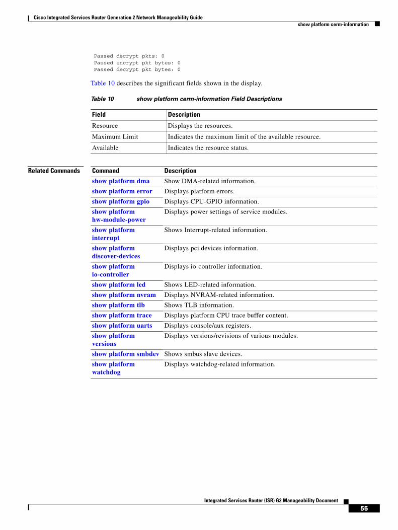
Cisco Integrated Services Router Generation 2 Network Manageability Guide show platform cerm-information
55Integrated Services Router (ISR) G2 Manageability Document
Passed decrypt pkts: 0 Passed encrypt pkt bytes: 0 Passed decrypt pkt bytes: 0
Table 10 describes the significant fields shown in the display.
Related Commands
Table 10 show platform cerm-information Field Descriptions
Field Description
Resource Displays the resources.
Maximum Limit Indicates the maximum limit of the available resource.
Available Indicates the resource status.
Command Description
show platform dma Show DMA-related information.
show platform error Displays platform errors.
show platform gpio Displays CPU-GPIO information.
show platform hw-module-power
Displays power settings of service modules.
show platform interrupt
Shows Interrupt-related information.
show platform discover-devices
Displays pci devices information.
show platform io-controller
Displays io-controller information.
show platform led Shows LED-related information.
show platform nvram Displays NVRAM-related information.
show platform tlb Shows TLB information.
show platform trace Displays platform CPU trace buffer content.
show platform uarts Displays console/aux registers.
show platform versions
Displays versions/revisions of various modules.
show platform smbdev Shows smbus slave devices.
show platform watchdog
Displays watchdog-related information.

Cisco Integrated Services Router Generation 2 Network Manageability Guide show platform cf
56Integrated Services Router (ISR) G2 Manageability Document
show platform cfTo display the platform compact flash information, use the show platform cf command in privileged EXEC mode.
show platform cf
Syntax Description
Command Modes Privileged EXEC (#)
Command History
Usage Guidelines This command displays the CF support-related information.
Examples The following is sample output for the show platform cf command:
Router#show platform cf
Platform Support status of Compact Flash:===========================================CF flash0: Compact Flash plugged in is Supported.CF flash1: Compact Flash not plugged in.
Table 11 describes the significant fields shown in the display.
Related Commands
cf Shows CF support-related information.
Release Modification
15.0(1)M This command was introduced.
Table 11 show platform cf Field Descriptions
Field Description
Platform Displays the available platforms.
Support Status of Compact Flash
Displays the compact flash plug in status.
Command Description
show platform cf Shows CF support-related information.
show platform dma Show DMA-related information.
show platform error Displays platform errors.
show platform gpio Displays CPU-GPIO information.
show platform discover-devices
Displays pci devices information.

Cisco Integrated Services Router Generation 2 Network Manageability Guide show platform cf
57Integrated Services Router (ISR) G2 Manageability Document
show platform hw-module-power
Displays power settings of service modules.
show platform interrupt
Shows Interrupt-related information.
show platform io-controller
Displays io-controller information.
show platform led Shows LED-related information.
show platform nvram Displays NVRAM-related information.
show platform tlb Shows TLB information.
show platform trace Displays platform CPU trace buffer content.
show platform uarts Displays console/aux registers.
show platform versions
Displays versions/revisions of various modules.
show platform smbdev Shows smbus slave devices.
show platform watchdog
Displays watchdog-related information.
Command Description

Cisco Integrated Services Router Generation 2 Network Manageability Guide show platform dma
58Integrated Services Router (ISR) G2 Manageability Document
show platform dmaTo display the DMA-related information, use the show platform dma command in privileged EXEC mode.
show platform dma
Syntax Description
Command Modes Privileged EXEC (#)
Command History
Usage Guidelines This command displays the DMA-related information.
Examples The following is sample output for the show platform dma command:
Router#show platform dma
DMA entries :=========== vc (load) complete consolidate exhaust ch (load) shared[pak coalesce engine] 0 (0 /255 ) 15257930 90739763 0 0 (0 /63) yes
Related Commands
dma Shows DMA-related information.
Release Modification
15.0(1)M This command was introduced.
Command Description
show platform cf Shows CF support-related information.
show platform error Displays platform errors.
show platform gpio Displays CPU-GPIO information.
show platform hw-module-power
Displays power settings of service modules.
show platform interrupt
Shows Interrupt-related information.
show platform discover-devices
Displays pci devices information.
show platform io-controller
Displays io-controller information.
show platform led Shows LED-related information.
show platform nvram Displays NVRAM-related information.
show platform tlb Shows TLB information.

Cisco Integrated Services Router Generation 2 Network Manageability Guide show platform dma
59Integrated Services Router (ISR) G2 Manageability Document
show platform trace Displays platform CPU trace buffer content.
show platform uarts Displays console/aux registers.
show platform versions
Displays versions/revisions of various modules.
show platform smbdev Shows smbus slave devices.
show platform watchdog
Displays watchdog-related information.
Command Description

Cisco Integrated Services Router Generation 2 Network Manageability Guide show platform error
60Integrated Services Router (ISR) G2 Manageability Document
show platform error To display the platform errors, use the show platform error command in privileged EXEC mode.
show platform error
Syntax Description
Command Modes Privileged EXEC (#)
Command History
Usage Guidelines This command displays the platform errors.
Examples The following is sample output for the show platform error command:
Router#show platform error
Related Commands
error Displays platform errors.
Release Modification
15.0(1)M This command was introduced.
Command Description
show platform cf Shows CF support-related information.
show platform dma Show DMA-related information.
show platform gpio Displays CPU-GPIO information.
show platform hw-module-power
Displays power settings of service modules.
show platform interrupt
Shows Interrupt-related information.
show platform discover-devices
Displays pci devices information.
show platform io-controller
Displays io-controller information.
show platform led Shows LED-related information.
show platform nvram Displays NVRAM-related information.
show platform tlb Shows TLB information.
show platform trace Displays platform CPU trace buffer content.
show platform uarts Displays console/aux registers.
show platform versions
Displays versions/revisions of various modules.

Cisco Integrated Services Router Generation 2 Network Manageability Guide show platform error
61Integrated Services Router (ISR) G2 Manageability Document
show platform smbdev Shows smbus slave devices.
show platform watchdog
Displays watchdog-related information.
Command Description
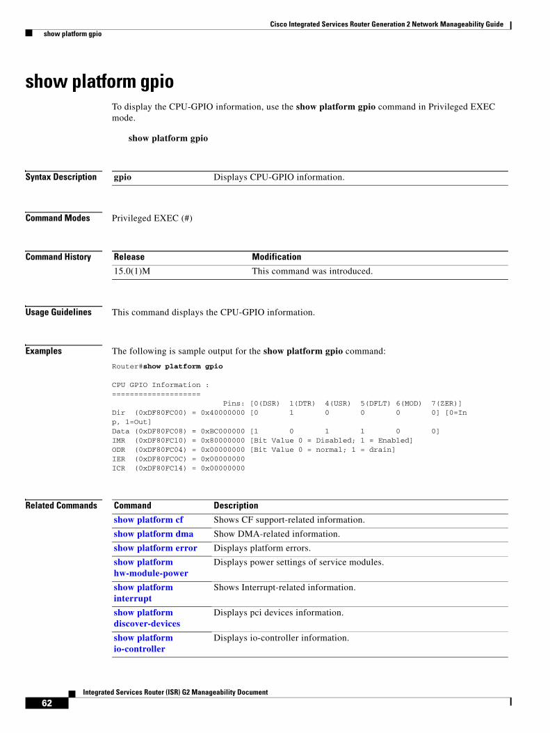
Cisco Integrated Services Router Generation 2 Network Manageability Guide show platform gpio
62Integrated Services Router (ISR) G2 Manageability Document
show platform gpioTo display the CPU-GPIO information, use the show platform gpio command in Privileged EXEC mode.
show platform gpio
Syntax Description
Command Modes Privileged EXEC (#)
Command History
Usage Guidelines This command displays the CPU-GPIO information.
Examples The following is sample output for the show platform gpio command:
Router#show platform gpio
CPU GPIO Information :==================== Pins: [0(DSR) 1(DTR) 4(USR) 5(DFLT) 6(MOD) 7(ZER)]Dir (0xDF80FC00) = 0x40000000 [0 1 0 0 0 0] [0=Inp, 1=Out]Data (0xDF80FC08) = 0xBC000000 [1 0 1 1 0 0]IMR (0xDF80FC10) = 0x80000000 [Bit Value 0 = Disabled; 1 = Enabled]ODR (0xDF80FC04) = 0x00000000 [Bit Value 0 = normal; 1 = drain]IER (0xDF80FC0C) = 0x00000000ICR (0xDF80FC14) = 0x00000000
Related Commands
gpio Displays CPU-GPIO information.
Release Modification
15.0(1)M This command was introduced.
Command Description
show platform cf Shows CF support-related information.
show platform dma Show DMA-related information.
show platform error Displays platform errors.
show platform hw-module-power
Displays power settings of service modules.
show platform interrupt
Shows Interrupt-related information.
show platform discover-devices
Displays pci devices information.
show platform io-controller
Displays io-controller information.

Cisco Integrated Services Router Generation 2 Network Manageability Guide show platform gpio
63Integrated Services Router (ISR) G2 Manageability Document
show platform led Shows LED-related information.
show platform nvram Displays NVRAM-related information.
show platform tlb Shows TLB information.
show platform trace Displays platform CPU trace buffer content.
show platform uarts Displays console/aux registers.
show platform versions
Displays versions/revisions of various modules.
show platform smbdev Shows smbus slave devices.
show platform watchdog
Displays watchdo-related information.
Command Description
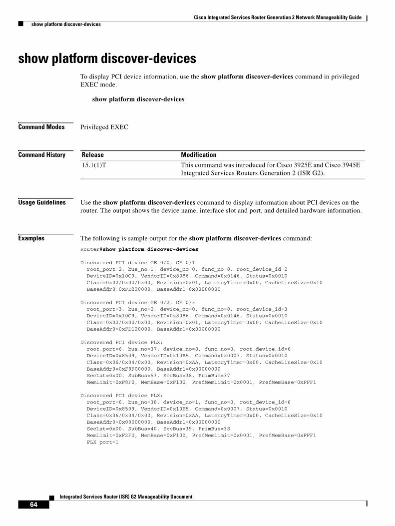
Cisco Integrated Services Router Generation 2 Network Manageability Guide show platform discover-devices
64Integrated Services Router (ISR) G2 Manageability Document
show platform discover-devicesTo display PCI device information, use the show platform discover-devices command in privileged EXEC mode.
show platform discover-devices
Command Modes Privileged EXEC
Command History
Usage Guidelines Use the show platform discover-devices command to display information about PCI devices on the router. The output shows the device name, interface slot and port, and detailed hardware information.
Examples The following is sample output for the show platform discover-devices command:
Router#show platform discover-devices
Discovered PCI device GE 0/0, GE 0/1 root_port=2, bus_no=1, device_no=0, func_no=0, root_device_id=2 DeviceID=0x10C9, VendorID=0x8086, Command=0x0146, Status=0x0010 Class=0x02/0x00/0x00, Revision=0x01, LatencyTimer=0x00, CacheLineSize=0x10 BaseAddr0=0xFD220000, BaseAddr1=0x00000000
Discovered PCI device GE 0/2, GE 0/3 root_port=3, bus_no=2, device_no=0, func_no=0, root_device_id=3 DeviceID=0x10C9, VendorID=0x8086, Command=0x0146, Status=0x0010 Class=0x02/0x00/0x00, Revision=0x01, LatencyTimer=0x00, CacheLineSize=0x10 BaseAddr0=0xFD120000, BaseAddr1=0x00000000
Discovered PCI device PLX: root_port=6, bus_no=37, device_no=0, func_no=0, root_device_id=6 DeviceID=0x8509, VendorID=0x10B5, Command=0x0007, Status=0x0010 Class=0x06/0x04/0x00, Revision=0xAA, LatencyTimer=0x00, CacheLineSize=0x10 BaseAddr0=0xF8F00000, BaseAddr1=0x00000000 SecLat=0x00, SubBus=53, SecBus=38, PrimBus=37 MemLimit=0xF8F0, MemBase=0xF100, PrefMemLimit=0x0001, PrefMemBase=0xFFF1
Discovered PCI device PLX: root_port=6, bus_no=38, device_no=1, func_no=0, root_device_id=6 DeviceID=0x8509, VendorID=0x10B5, Command=0x0007, Status=0x0010 Class=0x06/0x04/0x00, Revision=0xAA, LatencyTimer=0x00, CacheLineSize=0x10 BaseAddr0=0x00000000, BaseAddr1=0x00000000 SecLat=0x00, SubBus=40, SecBus=39, PrimBus=38 MemLimit=0xF2F0, MemBase=0xF100, PrefMemLimit=0x0001, PrefMemBase=0xFFF1 PLX port=1
Release Modification
15.1(1)T This command was introduced for Cisco 3925E and Cisco 3945E Integrated Services Routers Generation 2 (ISR G2).
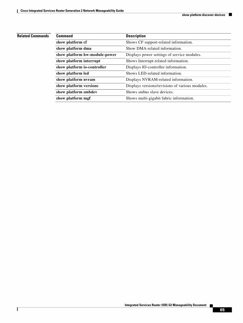
Cisco Integrated Services Router Generation 2 Network Manageability Guide show platform discover-devices
65Integrated Services Router (ISR) G2 Manageability Document
Related Commands Command Description
show platform cf Shows CF support-related information.
show platform dma Show DMA-related information.
show platform hw-module-power Displays power settings of service modules.
show platform interrupt Shows Interrupt-related information.
show platform io-controller Displays IO-controller information.
show platform led Shows LED-related information.
show platform nvram Displays NVRAM-related information.
show platform versions Displays versions/revisions of various modules.
show platform smbdev Shows smbus slave devices.
show platform mgf Shows multi-gigabit fabric information.
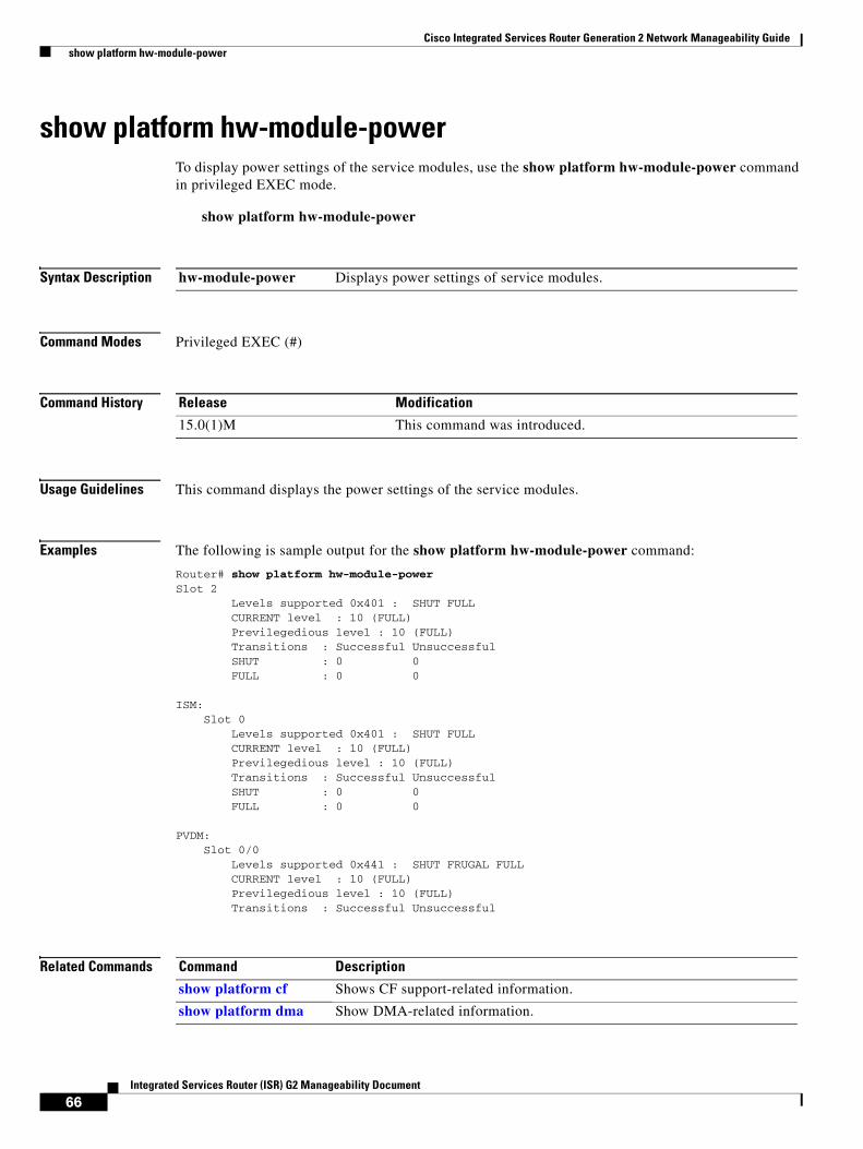
Cisco Integrated Services Router Generation 2 Network Manageability Guide show platform hw-module-power
66Integrated Services Router (ISR) G2 Manageability Document
show platform hw-module-powerTo display power settings of the service modules, use the show platform hw-module-power command in privileged EXEC mode.
show platform hw-module-power
Syntax Description
Command Modes Privileged EXEC (#)
Command History
Usage Guidelines This command displays the power settings of the service modules.
Examples The following is sample output for the show platform hw-module-power command:
Router# show platform hw-module-powerSlot 2 Levels supported 0x401 : SHUT FULL CURRENT level : 10 (FULL) Previlegedious level : 10 (FULL) Transitions : Successful Unsuccessful SHUT : 0 0 FULL : 0 0
ISM: Slot 0 Levels supported 0x401 : SHUT FULL CURRENT level : 10 (FULL) Previlegedious level : 10 (FULL) Transitions : Successful Unsuccessful SHUT : 0 0 FULL : 0 0
PVDM: Slot 0/0 Levels supported 0x441 : SHUT FRUGAL FULL CURRENT level : 10 (FULL) Previlegedious level : 10 (FULL) Transitions : Successful Unsuccessful
Related Commands
hw-module-power Displays power settings of service modules.
Release Modification
15.0(1)M This command was introduced.
Command Description
show platform cf Shows CF support-related information.
show platform dma Show DMA-related information.

Cisco Integrated Services Router Generation 2 Network Manageability Guide show platform hw-module-power
67Integrated Services Router (ISR) G2 Manageability Document
show platform error Displays platform errors.
show platform gpio Displays CPU-GPIO information
show platform interrupt
Shows Interrupt-related information.
show platform io-controller
Displays io-controller information.
show platform discover-devices
Displays pci devices information.
show platform led Shows LED-related information.
show platform nvram Displays NVRAM-related information.
show platform tlb Shows TLB information.
show platform trace Displays platform CPU trace buffer content.
show platform uarts Displays console/aux registers.
show platform versions
Displays versions/revisions of various modules.
show platform smbdev Shows smbus slave devices.
show platform watchdog
Displays watchdog-related information.
Command Description

Cisco Integrated Services Router Generation 2 Network Manageability Guide show platform interrupt
68Integrated Services Router (ISR) G2 Manageability Document
show platform interruptTo display the interrupt-related information, use the show platform interrupt command in privileged EXEC mode.
show platform interrupt
Syntax Description
Command Modes Privileged EXEC (#)
Command History
Usage Guidelines This command displays the interrupt-related information.
Examples The following is sample output for the show platform interrupt command:
Router#show platform interruptInterrupts:=========== Assigned Handlers... Vect Handler # of Ints Name 2 04148130 87680 FPGA Interrupt 5 0418C0AC 76 USB Host controller interrupt 16 040F0AD8 0 c1800_l2_cache_interrupt 18 041478D8 0 DRAM Error Int Handler 20 0411B904 15258670 DMA Ch 1 Int Handler 21 0411B904 0 DMA Ch 2 Int Handler 22 0411B904 0 DMA Ch 3 Int Handler 23 0411B904 0 DMA Ch 4 Int Handler 25 0412ABFC 0 PCIe Root Complex 2 26 0412ABFC 0 PCIe Root Complex 1 29 0417D1AC 60138792 pq3 tsec1 tx interrupt 30 0417D1AC 301070 pq3 tsec1 rx interrupt 31 0417D1AC 0 pq3 tsec3 tx interrupt 32 0417D1AC 0 pq3 tsec3 rx interrupt 33 0417D1AC 0 pq3 tsec3 error interrupt 34 0417D1AC 0 pq3 tsec1 error interrupt 35 0417D1AC 0 pq3 tsec2 tx interrupt 36 0417D1AC 5 pq3 tsec2 rx interrupt 37 0417D1AC 31440 pq3 tsec4 tx interrupt 38 0417D1AC 29991 pq3 tsec4 rx interrupt 39 0417D1AC 0 pq3 tsec4 error interrupt 40 0417D1AC 0 pq3 tsec2 error interrupt 42 04103AE4 1946 16552 Con/Aux Interrupt 45 086F9B88 0 SEC Interrupt Handler 47 04148150 1 GPIO Interrupt 76 0411B904 0 DMA 2 Ch 1 Int Handler 77 0411B904 0 DMA 2 Ch 2 Int Handler
interrupt Displays interrupt-related information.
Release Modification
15.0(1)M This command was introduced.

Cisco Integrated Services Router Generation 2 Network Manageability Guide show platform interrupt
69Integrated Services Router (ISR) G2 Manageability Document
78 0411B904 0 DMA 2 Ch 3 Int Handler 79 0411B904 0 DMA 2 Ch 4 Int Handler 80 048FFCE0 20287003 M8500_TIMER_INTERRUPT 81 049001D8 23114586 C3900_POLL_TIMER_INTERRUPT 83 040F06C4 0 Timebase Reference Interrupt 96 0412D37C 16220 Network I/O Int Handler 97 0412D444 0 Network Management Int Handler 99 0412D5C8 7910 ISM I/O Int Handler 100 0412D680 0 SM1 I/O Int Handler 101 0412D74C 33058502 SM2 I/O Int Handler 102 0412D818 0 SM3 I/O Int Handler 103 0412D8E4 5413 SM4 I/O Int Handler
IOS Priority Masks mapped to internal levels... Level 0 = [ 00000001 ] Level 1 = [ 00000003 ] Level 2 = [ 00000005 ] Level 3 = [ 00000007 ] Level 4 = [ 00000009 ] Level 5 = [ 0000000B ] Level 6 = [ 0000000D ] Level 7 = [ 0000000F ]
CTPR = 00000001 Current Level = 00
Interrupt Throttling: Throttle Count = 0 Timer Count = 0 Netint(usec) = 20000 Netint Mask(usec) = 1000 Real Netint(usec) = 4000 Real Netint Mask(usec) = 200 Active = 0 Configured = 1 Longest IRQ(usec) = 2152
MSI Interrupt info:===================MSI 0, name: wic_mbrd_hdlc_intr, hdlr 0x437F1BC, cnt 0, ctx 0x0, slot 0, IO_Controller, NETIO, number 0MSI 1, name: wic_mbrd_hdlc_intr, hdlr 0x437F1BC, cnt 0, ctx 0x1, slot 0, IO_Controller, NETIO, number 1MSI 2, name: wic_mbrd_hdlc_intr, hdlr 0x437F1BC, cnt 0, ctx 0x2, slot 0, IO_Controller, NETIO, number 2MSI 3, name: wic_mbrd_hdlc_intr, hdlr 0x437F1BC, cnt 0, ctx 0x3, slot 0, IO_Controller, NETIO, number 3MSI 4, name: wic_mbrd_hdlc_intr, hdlr 0x437F1BC, cnt 0, ctx 0x4, slot 0, IO_Controller, NETIO, number 4MSI 5, name: wic_mbrd_hdlc_intr, hdlr 0x437F1BC, cnt 0, ctx 0x5, slot 0, IO_Controller, NETIO, number 5MSI 6, name: wic_mbrd_hdlc_intr, hdlr 0x437F1BC, cnt 0, ctx 0x6, slot 0, IO_ContMSI 167, name: PSE2 FPGA Err Inter, hdlr 0x40DF520, cnt 0, ctx 0x11F9D36C, slot2, SM, NETIO, number 7MSI 201, name: SM2NM - NM removal, hdlr 0x41198C4, cnt 0, ctx 0x3, slot 3, NM, NETIO, number 6MSI 207, name: hdv2_interrupt, hdlr 0x75EF62C, cnt 0, ctx 0x3, slot 3, NM, NETIO, number 0MSI 233, name: SM2NM - NM removal, hdlr 0x41198C4, cnt 0, ctx 0x4, slot 4, NM, NETIO, number 6MSI 239, name: pse_interrupt, hdlr 0x40D37C0, cnt 5413, ctx 0x4, slot 4, NM, NETIO, number 0
Debug counters/Info: unreg_msi_int_cnt 0

Cisco Integrated Services Router Generation 2 Network Manageability Guide show platform interrupt
70Integrated Services Router (ISR) G2 Manageability Document
Related Commands Command Description
show platform cf Shows CF support-related information.
show platform dma Show DMA-related information.
show platform error Displays platform errors.
show platform gpio Displays CPU-GPIO information.
show platform hw-module-power
Displays power settings of service modules.
show platform io-controller
Displays io-controller information.
show platform discover-devices
Displays pci devices information.
show platform led Shows LED-related information.
show platform nvram Displays NVRAM-related information.
show platform tlb Shows TLB information.
show platform trace Displays platform CPU trace buffer content.
show platform uarts Displays console/aux registers.
show platform versions
Displays versions/revisions of various modules.
show platform smbdev Shows smbus slave devices.
show platform watchdog
Displays watchdog-related information.

Cisco Integrated Services Router Generation 2 Network Manageability Guide show platform io-controller
71Integrated Services Router (ISR) G2 Manageability Document
show platform io-controllerTo display the io-controller information, use the show platform io-controller command in privileged EXEC mode.
show platform io-controller
Syntax Description
Command Modes Privileged EXEC (#)
Command History
Usage Guidelines This command displays io-controller information.
Examples The following is sample output for the show platform io-controller command:
Router#show platform io-controllerio-controller global register (addr 0xEC900400): jtag_id (addr 0xEC900400): 0x10316447 revision_id (addr 0xEC900404): 0x47410101 diag_echo (addr 0xEC900408): 0xFFFFFFFF software_memory_bist (addr 0xEC90040C): 0x00000004 five_mhz_prescale (addr 0xEC900410): 0x00000072 reset_sampled_inputs (addr 0xEC900414): 0x00000000 slew_rate_control_gpio1 (addr 0xEC900420): 0x0000FFFF slew_rate_control_gpio0 (addr 0xEC900424): 0xFFFFFFFF slew_rate_control_pvdm (addr 0xEC900428): 0x000FFFFF slew_rate_control_slowgpio (addr 0xEC90042C): 0x0000003F slew_rate_control_wic0 (addr 0xEC900430): 0x003FFFFF slew_rate_control_wic1 (addr 0xEC900434): 0x003FFFFF slew_rate_control_wic2 (addr 0xEC900438): 0x003FFFFF slew_rate_control_wic3 (addr 0xEC90043C): 0x003FFFFF wic_spi_control0 (addr 0xEC900440): 0x2455077F wic_spi_control1 (addr 0xEC900444): 0x00000000
io-controller gpio (addr 0xEC900200): in_out_config2 (addr 0xEC900204): 0x40154415 in_out_config1 (addr 0xEC900208): 0x44155145 in_out_config0 (addr 0xEC90020C): 0x14504015 polarity_ctrl1 (addr 0xEC900210): 0x0000C0C0 polarity_ctrl0 (addr 0xEC900214): 0xC0DB6FC0 debounce_ctrl1 (addr 0xEC900218): 0x00000000 debounce_ctrl0 (addr 0xEC90021C): 0x00249000 debounce_time5 (addr 0xEC900220): 0x00000000 debounce_time4 (addr 0xEC900224): 0x00000000 debounce_time3 (addr 0xEC900228): 0x00000000 debounce_time2 (addr 0xEC90022C): 0x0000C351 debounce_time1 (addr 0xEC900230): 0x0000C351
io-controller Displays io-controller information.
Release Modification
15.0(1)M This command was introduced.

Cisco Integrated Services Router Generation 2 Network Manageability Guide show platform io-controller
72Integrated Services Router (ISR) G2 Manageability Document
debounce_time0 (addr 0xEC900234): 0x00000000 reg_input_value1 (addr 0xEC900238): 0x0000382C reg_input_value0 (addr 0xEC90023C): 0x2C00222C reg_output_value1 (addr 0xEC900240): 0x00000024 reg_output_value0 (addr 0xEC900244): 0x24002004 intr_type2 (addr 0xEC90024C): 0xEFFFEFFF intr_type1 (addr 0xEC900250): 0xEFFFFBEF intr_type0 (addr 0xEC900254): 0xBEFEEFFF latch_unlatch_intr1 (addr 0xEC900258): 0x00000000 latch_unlatch_intr0 (addr 0xEC90025C): 0x00249000 err_intr_status1 (addr 0xEC900260): 0x00000000 err_intr_status0 (addr 0xEC900264): 0x00000000 mgmt_intr_status1 (addr 0xEC900268): 0x00000000 mgmt_intr_status0 (addr 0xEC90026C): 0x00000000 ntwk_intr_status1 (addr 0xEC900270): 0x00000000 ntwk_intr_status0 (addr 0xEC900274): 0x00000000 err_intr_enable1 (addr 0xEC900278): 0x00000040 err_intr_enable0 (addr 0xEC90027C): 0x00249000 mgmt_intr_enable1 (addr 0xEC900280): 0x00000000 mgmt_intr_enable0 (addr 0xEC900284): 0x00000000 ntwk_intr_enable1 (addr 0xEC900288): 0x00000000 ntwk_intr_enable0 (addr 0xEC90028C): 0x00000000 intr_test1 (addr 0xEC900290): 0x00000000 intr_test0 (addr 0xEC900294): 0x00000000 slow_output1 (addr 0xEC9002A0): 0x00000080 slow_output0 (addr 0xEC9002A4): 0xA06810A0 slow_input1 (addr 0xEC9002A8): 0x00000000 slow_input0 (addr 0xEC9002AC): 0x0000FF8F slow_shift_reg_config (addr 0xEC9002B0): 0x0000813E slow_debounce_ctrl1 (addr 0xEC9002B8): 0x00000000 slow_debounce_ctrl0 (addr 0xEC9002BC): 0x00000000 slow_debounce_time5 (addr 0xEC9002C8): 0x00000000
Related Commands Command Description
show platform cf Shows CF support-related information.
show platform dma Show DMA-related information.
show platform error Displays platform errors.
show platform gpio Displays CPU-GPIO information.
show platform hw-module-power
Displays power settings of service modules.
show platform interrupt
Shows Interrupt-related information.
show platform discover-devices
Displays pci devices information.
show platform led Shows LED-related information.
show platform nvram Displays NVRAM-related information.
show platform tlb Shows TLB information.
show platform trace Displays platform CPU trace buffer content.
show platform uarts Displays console/aux registers.
show platform versions
Displays versions/revisions of various modules.

Cisco Integrated Services Router Generation 2 Network Manageability Guide show platform io-controller
73Integrated Services Router (ISR) G2 Manageability Document
show platform smbdev Shows smbus slave devices.
show platform watchdog
Displays watchdog-related information.
Command Description

Cisco Integrated Services Router Generation 2 Network Manageability Guide show platform led
74Integrated Services Router (ISR) G2 Manageability Document
show platform ledTo display the LED-related information, use the show platform led command in privileged EXEC mode.
show platform led
Syntax Description
Command Modes Privileged EXEC (#)
Command History
Usage Guidelines This command displays the LED-related information.
Examples The following is sample output for the show platform led command:
Router#show platform ledLEDS : SYSTEM ACTIVITY POE BOOST PS2 PS1STATUS: GREEN OFF AMBER OFF AMBER OFF
CFLASH and ISM : CF0 CF1 ISMLED STATUS : OFF OFF GREEN
DSP LED : PVDM0 PVDM1 PVDM2 PVDM3STATUS : AMBER AMBER GREEN OFF
PORTS : GE0/0 GE0/1 GE0/2 SFP1 SFP2LINK/ENABLE LED : GREEN OFF OFF OFF OFFSPEED LED : 100Mb/s OFF OFF OFF OFF
LEDS : USB RJ45STATUS: OFF GREEN
Table 10 describes the significant fields shown in the display.
led Shows LED-related information.
Release Modification
15.0(1)M This command was introduced.
Table 12 show platform led Field Descriptions
Field Description
LEDs Status Displays the LED status.
CFlash and ISM LED Status
Displays the CFlash and ISM LED status.
DSP LED Status Displays the DSP LED status.

Cisco Integrated Services Router Generation 2 Network Manageability Guide show platform led
75Integrated Services Router (ISR) G2 Manageability Document
Related Commands Command Description
show platform cf Shows CF support related information.
show platform dma Show DMA-related information
show platform error Displays platform errors.
show platform gpio Displays CPU-GPIO information
show platform hw-module-power
Displays power settings of service modules.
show platform interrupt
Shows Interrupt-related information.
show platform io-controller
Displays io-controller information.
show platform discover-devices
Displays pci devices information.
show platform led Shows LED-related information.
show platform nvram Displays NVRAM-related information.
show platform tlb Shows TLB information.
show platform trace Displays platform CPU trace buffer content.
show platform uarts Displays console/aux registers.
show platform versions
Displays versions/revisions of various modules.
show platform smbdev Shows smbus slave devices.
show platform watchdog
Displays watchdog-related information.
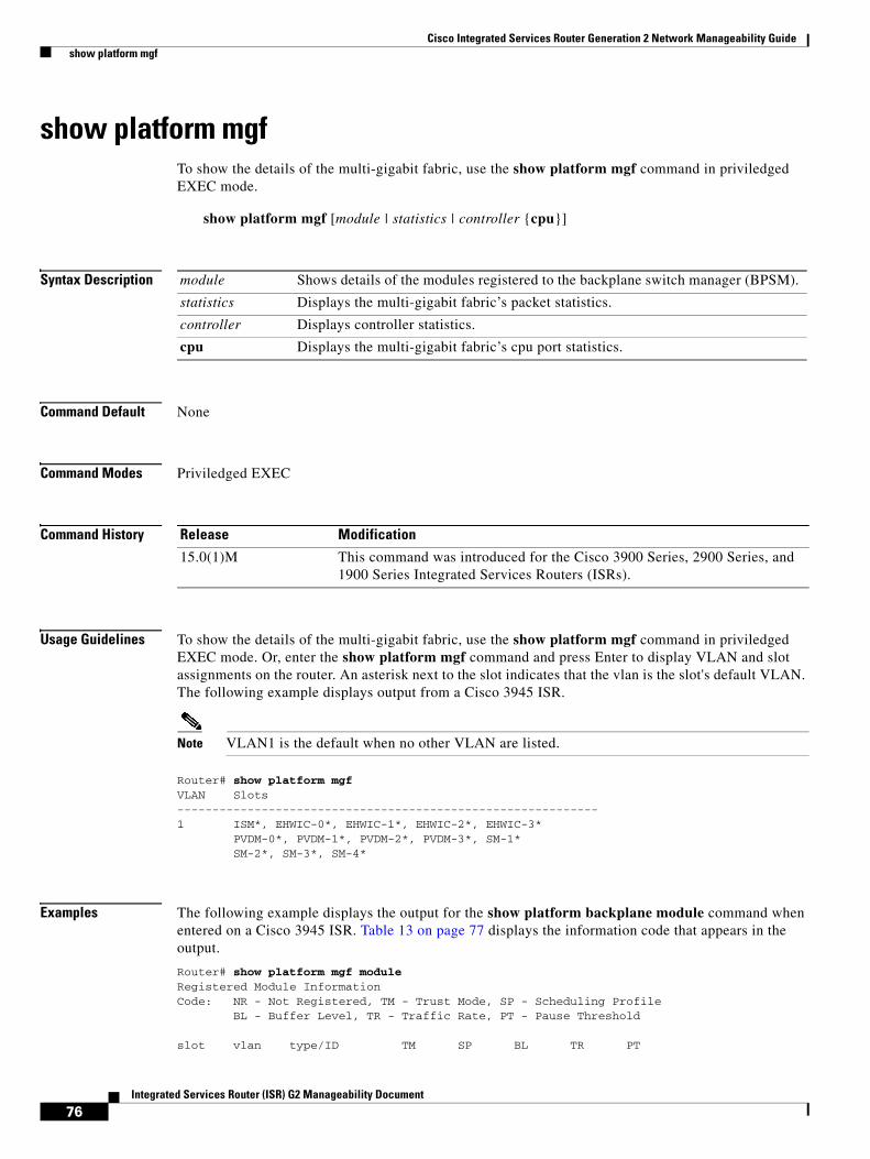
Cisco Integrated Services Router Generation 2 Network Manageability Guide show platform mgf
76Integrated Services Router (ISR) G2 Manageability Document
show platform mgfTo show the details of the multi-gigabit fabric, use the show platform mgf command in priviledged EXEC mode.
show platform mgf [module | statistics | controller {cpu}]
Syntax Description
Command Default None
Command Modes Priviledged EXEC
Command History
Usage Guidelines To show the details of the multi-gigabit fabric, use the show platform mgf command in priviledged EXEC mode. Or, enter the show platform mgf command and press Enter to display VLAN and slot assignments on the router. An asterisk next to the slot indicates that the vlan is the slot's default VLAN. The following example displays output from a Cisco 3945 ISR.
Note VLAN1 is the default when no other VLAN are listed.
Router# show platform mgfVLAN Slots------------------------------------------------------------1 ISM*, EHWIC-0*, EHWIC-1*, EHWIC-2*, EHWIC-3* PVDM-0*, PVDM-1*, PVDM-2*, PVDM-3*, SM-1* SM-2*, SM-3*, SM-4*
Examples The following example displays the output for the show platform backplane module command when entered on a Cisco 3945 ISR. Table 13 on page 77 displays the information code that appears in the output.
Router# show platform mgf moduleRegistered Module InformationCode: NR - Not Registered, TM - Trust Mode, SP - Scheduling Profile BL - Buffer Level, TR - Traffic Rate, PT - Pause Threshold
slot vlan type/ID TM SP BL TR PT
module Shows details of the modules registered to the backplane switch manager (BPSM).
statistics Displays the multi-gigabit fabric’s packet statistics.
controller Displays controller statistics.
cpu Displays the multi-gigabit fabric’s cpu port statistics.
Release Modification
15.0(1)M This command was introduced for the Cisco 3900 Series, 2900 Series, and 1900 Series Integrated Services Routers (ISRs).

Cisco Integrated Services Router Generation 2 Network Manageability Guide show platform mgf
77Integrated Services Router (ISR) G2 Manageability Document
---- ---- ---------- ------- --- ------ ----- ----ISM NREHWIC-0 NREHWIC-1 NREHWIC-2 NREHWIC-3 NRPVDM-0 NRPVDM-1 NRPVDM-2 NRPVDM-3 NRSM-1 1 SM/6 UP 1 high 1000 highSM-2 1 SM/6 UP 1 high 1000 highSM-3 NRSM-4 NR
Table 13 Show Platform Backplane Module Information Code
The following example displays output for the show platform backplane statistics command when entered on a Cisco 1941 ISR.
Router# show platform mgf statistics
Interface statistics for slot: ISM (port 1)-----------------------------------------------------30 second input rate 0 packets/sec30 second output rate 0 packets/sec0 packets input, 0 bytes, 0 overrunsReceived 0 broadcasts, 0 multicast, 0 unicast 0 runts, 0 giants, 0 jabbers 0 input errors, 0 CRC, 0 fragments, 0 pause input 0 packets output, 0 bytes, 0 underruns 0 broadcast, 0 multicast, 0 unicast 0 late collisions, 0 collisions, 0 deferred 0 bad bytes received, 0 multiple, 0 pause output
Interface statistics for slot: EHWIC-0 (port 2)-----------------------------------------------------30 second input rate 13844 packets/sec30 second output rate 13844 packets/sec3955600345 packets input, 1596845471340 bytes, 26682 overruns Received 0 broadcasts, 0 multicast, 3955600345 unicast 0 runts, 0 giants, 0 jabbers 0 input errors, 0 CRC, 0 fragments, 0 pause input3955738564 packets output, 1596886171288 bytes, 0 underruns 0 broadcast, 0 multicast, 3955738564 unicast 0 late collisions, 0 collisions, 0 deferred 0 bad bytes received, 0 multiple, 94883 pause output
Interface statistics for slot: EHWIC-1 (port 3)-----------------------------------------------------30 second input rate 13844 packets/sec30 second output rate 13844 packets/sec
Code Description
NR Not registered
TM Trust mode
SP Scheduling profile
BL Buffer level
TR Traffic rate
PT Pause threshold
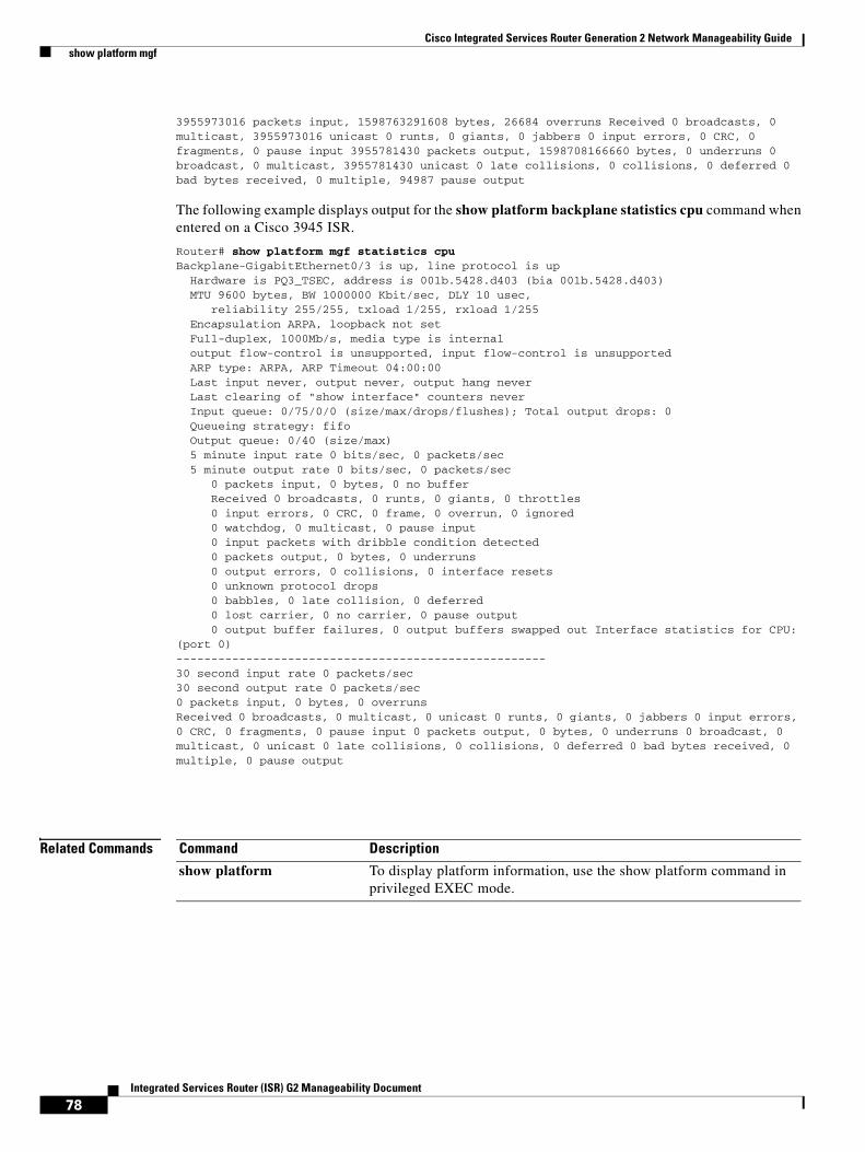
Cisco Integrated Services Router Generation 2 Network Manageability Guide show platform mgf
78Integrated Services Router (ISR) G2 Manageability Document
3955973016 packets input, 1598763291608 bytes, 26684 overruns Received 0 broadcasts, 0 multicast, 3955973016 unicast 0 runts, 0 giants, 0 jabbers 0 input errors, 0 CRC, 0 fragments, 0 pause input 3955781430 packets output, 1598708166660 bytes, 0 underruns 0 broadcast, 0 multicast, 3955781430 unicast 0 late collisions, 0 collisions, 0 deferred 0 bad bytes received, 0 multiple, 94987 pause output
The following example displays output for the show platform backplane statistics cpu command when entered on a Cisco 3945 ISR.
Router# show platform mgf statistics cpuBackplane-GigabitEthernet0/3 is up, line protocol is up Hardware is PQ3_TSEC, address is 001b.5428.d403 (bia 001b.5428.d403) MTU 9600 bytes, BW 1000000 Kbit/sec, DLY 10 usec, reliability 255/255, txload 1/255, rxload 1/255 Encapsulation ARPA, loopback not set Full-duplex, 1000Mb/s, media type is internal output flow-control is unsupported, input flow-control is unsupported ARP type: ARPA, ARP Timeout 04:00:00 Last input never, output never, output hang never Last clearing of "show interface" counters never Input queue: 0/75/0/0 (size/max/drops/flushes); Total output drops: 0 Queueing strategy: fifo Output queue: 0/40 (size/max) 5 minute input rate 0 bits/sec, 0 packets/sec 5 minute output rate 0 bits/sec, 0 packets/sec 0 packets input, 0 bytes, 0 no buffer Received 0 broadcasts, 0 runts, 0 giants, 0 throttles 0 input errors, 0 CRC, 0 frame, 0 overrun, 0 ignored 0 watchdog, 0 multicast, 0 pause input 0 input packets with dribble condition detected 0 packets output, 0 bytes, 0 underruns 0 output errors, 0 collisions, 0 interface resets 0 unknown protocol drops 0 babbles, 0 late collision, 0 deferred 0 lost carrier, 0 no carrier, 0 pause output 0 output buffer failures, 0 output buffers swapped out Interface statistics for CPU: (port 0)-----------------------------------------------------30 second input rate 0 packets/sec30 second output rate 0 packets/sec0 packets input, 0 bytes, 0 overrunsReceived 0 broadcasts, 0 multicast, 0 unicast 0 runts, 0 giants, 0 jabbers 0 input errors, 0 CRC, 0 fragments, 0 pause input 0 packets output, 0 bytes, 0 underruns 0 broadcast, 0 multicast, 0 unicast 0 late collisions, 0 collisions, 0 deferred 0 bad bytes received, 0 multiple, 0 pause output
Related Commands Command Description
show platform To display platform information, use the show platform command in privileged EXEC mode.

Cisco Integrated Services Router Generation 2 Network Manageability Guide show platform nvram
79Integrated Services Router (ISR) G2 Manageability Document
show platform nvramTo display the NVRAM-related information, use the show platform nvram command in privileged EXEC mode.
show platform nvram
Syntax Description
Command Modes Privileged EXEC (#)
Command History
Usage Guidelines This command displays the NVRAM-related information.
Examples The following is sample output for the show platform nvram command:
Router#show platform nvramNVRAM Information=================Stats/Counter :------------- Current Addr : Primary 0xFE000000 (0), Backup 0xFE180000 (12) Write Erase Cnt: Primary 129, Backup 130, Stat 0 Status : Primary 1, Backup 1, EEP State 1, NVR State 1 State : 18 (Stat Update Done) Write Mem ID : 770 Block Magic : 0xF0A55A0F
Runtime stats :------------- Next Free Addr : Primary 0xFE040000 (2), Backup 0xFE1C0000 (14) Stats Addr : Current 0xFE389030 (24), Next Free 0xFE389060 (24) Last Write done by PID : 108
Duration (millisec) :------------------- Primary : Erase 1056, Write 1088 Backup : Erase 1092, Write 1124 Stat : Erase 0, Write 0 Total Time : 4624, HWM Total Time 4648 I2C (Size,Time,1=write) :(1, 20, 1), (1, 16, 1), (1, 16, 1), (1, 16, 1), (1, 20, 1), (1, 16, 1), (1, 16, 1), (1, 16, 1), (4, 16, 1), (48, 104, 1), (48, 8, 0),
Statistics :----------
nvram Displays NVRAM-related information.
Release Modification
15.0(1)M This command was introduced.

Cisco Integrated Services Router Generation 2 Network Manageability Guide show platform nvram
80Integrated Services Router (ISR) G2 Manageability Document
Sector Erase : Failed 0, Retry failed 0 Primary Write Failed : Config 0, Magic 0, No Addr 0 Backup Write Failed : Config 0, Magic 0, No Addr 0 Stats Failed : Write NV 0, Read back 0, No Addr 0, Write EEPROM 0 Eeprom Write : Failed 0, Retry failed 0 Eeprom Read Failed 0 Eeprom Readback Failed 0 Write Failed (Primary/Backup/Stat) : (0/0/0) Primary Read failed due to : CRC 0, Magic 0 Backup Read failed due to : CRC 0, Magic 0 Previleged NVRAM State : 18 (Stat Update Done) Previleged EEP State : 18 (Stat Update Done)
RAM pointer = 0x1294C00
Related Commands Command Description
show platform cf Shows CF support-related information.
show platform dma Show DMA related information.
show platform error Displays platform errors.
show platform gpio Displays CPU-GPIO information.
show platform hw-module-power
Displays power settings of service modules.
show platform interrupt
Shows Interrupt-related information.
show platform discover-devices
Displays pci devices information.
show platform io-controller
Displays io-controller information.
show platform led Shows LED-related information.
show platform mgf Shows Multi-gigabit Frabric related information.
show platform tlb Shows TLB information.
show platform trace Displays platform CPU trace buffer content.
show platform uarts Displays console/aux registers.
show platform versions
Displays versions/revisions of various modules.
show platform smbdev Shows smbus slave devices.
show platform watchdog
Displays watchdog-related information.

Cisco Integrated Services Router Generation 2 Network Manageability Guide show platform tlb
81Integrated Services Router (ISR) G2 Manageability Document
show platform tlbTo display the TLB information, use the show platform tlb command in privileged EXEC mode.
show platform tlb
Syntax Description
Command Modes Privileged EXEC (#)
Command History
Usage Guidelines This command displays the TLD information.
Examples The following is sample output for the show platform command:
Router#show platform tlb
TLB entries :===========tlb no. size paddr vaddr w i m g e perm1 0 16 MB 0x00FF000000 0xFF000000 B G B 0x00331 1 16 MB 0x00FF000000 0xFE000000 B I G B 0x000F1 2 16 MB 0x00DF000000 0xDF000000 B I G B 0x000F1 3 256MB 0x00E0000000 0xE0000000 B I G B 0x000F1 4 16 MB 0x0000000000 0x00000000 B C G B 0x003F1 5 64 MB 0x0004000000 0x04000000 B C B 0x00331 6 64 MB 0x0008000000 0x08000000 B C B 0x00331 7 64 MB 0x000C000000 0x0C000000 B C G B 0x00031 8 256MB 0x0010000000 0x10000000 B C G B 0x000F1 9 256MB 0x0020000000 0x20000000 B C G B 0x000F1 10 256MB 0x0030000000 0x30000000 B C G B 0x000F1 11 16 MB 0x0001000000 0x01000000 B C G B 0x000F1 12 16 MB 0x0002000000 0x02000000 B C G B 0x000F1 13 16 MB 0x0003000000 0x03000000 B C G B 0x000F1 14 (not in use)1 15 (not in use)
.text: 73 MB [0x04000000 - 0x0893CD3C]
.rodata: 30 MB [0x0C000000 - 0x0DED3A83]
.rwdata: 23 MB [0x10000000 - 0x11770ACC]
Related Commands
tlb Displays TLB information.
Release Modification
15.0(1)M This command was introduced.
Command Description
show platform cf Shows CF support-related information.
show platform dma Show DMA-related information.

Cisco Integrated Services Router Generation 2 Network Manageability Guide show platform tlb
82Integrated Services Router (ISR) G2 Manageability Document
show platform error Displays platform errors.
show platform gpio Displays CPU-GPIO information.
show platform hw-module-power
Displays power settings of service modules.
show platform interrupt
Shows Interrupt-related information.
show platform io-controller
Displays io-controller information.
show platform discover-devices
Displays pci devices information.
show platform led Shows LED-related information.
show platform nvram Displays NVRAM-related information.
show platform trace Displays platform CPU trace buffer content.
show platform uarts Displays console/aux registers.
show platform versions
Displays versions/revisions of various modules.
show platform smbdev Shows smbus slave devices.
show platform watchdog
Displays watchdog related information.
Command Description

Cisco Integrated Services Router Generation 2 Network Manageability Guide show platform trace
83Integrated Services Router (ISR) G2 Manageability Document
show platform traceTo display the platform CPU trace buffer content, use the show platform trace command in privileged EXEC mode.
show platform trace
Syntax Description
Command Modes Privileged EXEC (#)
Command History
Usage Guidelines This command displays the platform CPU trace buffer content.
Examples The following is sample output for the show platform trace command:
Router#show platform trace
Related Commands
trace Displays platform CPU trace buffer content.
Release Modification
15.0(1)M This command was introduced.
Command Description
show platform cf Shows CF support-related information.
show platform dma Show DMA-related information.
show platform error Displays platform errors.
show platform gpio Displays CPU-GPIO information.
show platform hw-module-power
Displays power settings of service modules.
show platform interrupt
Shows Interrupt-related information.
show platform io-controller
Displays io-controller information.
show platform discover-devices
Displays pci devices information.
show platform led Shows LED-related information.
show platform nvram Displays NVRAM-related information.
show platform tlb Shows TLB information.
show platform uarts Displays console/aux registers.
show platform versions
Displays versions/revisions of various modules.

Cisco Integrated Services Router Generation 2 Network Manageability Guide show platform trace
84Integrated Services Router (ISR) G2 Manageability Document
show platform smbdev Shows smbus slave devices.
show platform watchdog
Displays watchdog-related information.
Command Description

Cisco Integrated Services Router Generation 2 Network Manageability Guide show platform uarts
85Integrated Services Router (ISR) G2 Manageability Document
show platform uartsTo display the console / auxiliary registers, use the show platform uarts command in privileged EXEC mode.
show platform uarts
Syntax Description
Command Modes Privileged EXEC (#)
Command History
Usage Guidelines This command displays the console / auxiliary registers.
Examples The following is sample output for the show platform uarts command:
Router#show platform uartsUART Information:=================AUX (Uart 0) Port Registers:----------------------- SR: 0x00 IER: 0x0D IIR: 0xC1 LCR: 0x07MCR: 0x03 LSR: 0x60 MSR: 0x00 FCR: 0xC1
Parity Error = 0, Framing Error = 0, Receive Error = 0Outcount = 0, TotalOut = 39, Incount = 0, Total In = 0Overrun = 0, Overflow = 0Brk Character: Received 0, Brk Processed 0
Console (Uart 1) Port Registers:----------------------- SR: 0x11 IER: 0x0D IIR: 0xC1 LCR: 0x07MCR: 0x03 LSR: 0x60 MSR: 0x10 FCR: 0xC1
Parity Error = 0, Framing Error = 0, Receive Error = 0Outcount = 0, TotalOut = 23358, Incount = 0, Total In = 407Overrun = 0, Overflow = 0Brk Character: Received 0, Brk Processed 0
Related Commands
uarts Displays console/aux registers.
Release Modification
15.0(1)M This command was introduced.
Command Description
show platform cf Shows CF support-related information.
show platform dma Show DMA-related information.

Cisco Integrated Services Router Generation 2 Network Manageability Guide show platform uarts
86Integrated Services Router (ISR) G2 Manageability Document
show platform error Displays platform errors.
show platform gpio Displays CPU-GPIO information.
show platform hw-module-power
Displays power settings of service modules.
show platform interrupt
Shows Interrupt-related information.
show platform discover-devices
Displays pci devices information.
show platform io-controller
Displays io-controller information.
show platform led Shows LED-related information.
show platform nvram Displays NVRAM-related information.
show platform tlb Shows TLB information.
show platform trace Displays platform CPU trace buffer content.
show platform versions
Displays versions/revisions of various modules.
show platform smbdev Shows smbus slave devices.
show platform watchdog
Displays watchdog-related information.
Command Description

Cisco Integrated Services Router Generation 2 Network Manageability Guide show platform smbdev
87Integrated Services Router (ISR) G2 Manageability Document
show platform smbdevTo display the smbus slave devices, use the show platform smbdev command in privileged EXEC mode.
show platform smbdev
Command Modes Privileged EXEC
Command History
Usage Guidelines Use the show platform smbdev command to display smbus slave devices on the motherboard. The output shows the device id, addresses, name, and function.
Examples The following is sample output for the show platform smbdev command:
Router#show platform smbdev
Smbus slave devices:id: 0 addr: 44 (88) ICH9[ICH9 device]id: 1 addr: 60 (C0) MCH[MCH device]id: 2 addr: 8 (10) Nitrox[Nitrox security]id: 3 addr: 71 (E2) Mux0[I2C MUX 0: PCA9495] [mux0:0] id: 4 addr: 58 (B0) Goofy[Goofy debug port] [mux0:0] id: 5 addr: 4A (94) MPtemp[Mid Plane Temperature Sensor] [mux0:0] id: 6 addr: 51 (A2) MPCook[Mid Plane Cookie] [mux0:0] id: 7 addr: 40 (80) MCU[Environment MCU controller] [mux0:0] id: 8 addr: 57 (AE) EEPROM[EEPROM] [mux0:0] id: 9 addr: 4E (9C) CPUtmp[LM75 CPU ambient temperature sensor] [mux0:1] id: 10 addr: 34 (68) PwrSeq[Power Sequencer R5F21262SNFP] [mux0:1] id: 11 addr: 33 (66) usbC[USB console CY7C64215] [mux0:1] id: 12 addr: 63 (C6) usbCAp[USB console app CY7C64215] [mux0:1] id: 13 addr: 68 (D0) RTC[Real time clock DS1337C] [mux0:1] id: 14 addr: 4C (98) clk1[Clock 1 ICS844S24161 Goofy clocks] [mux0:1] id: 15 addr: 38 (70) plx[PLX PEX8509] [mux0:1] id: 16 addr: 70 (E0) Mux1[I2C MUX 1: PCA9495] [mux0:1 mux1:0] id: 17 addr: 49 (92) ps1tmp[PSU temperature sensor LM75] [mux0:1 mux1:0] id: 18 addr: 52 (A4) ps1Cook[PSU cookie] [mux0:1 mux1:0] id: 19 addr: 53 (A6) pwr1ob[Power OBFL cookie] [mux0:1 mux1:1] id: 20 addr: 49 (92) ps1tmp[PSU temperature sensor LM75] [mux0:1 mux1:1] id: 21 addr: 52 (A4) ps2Cook[PSU cookie] [mux0:1 mux1:1] id: 22 addr: 53 (A6) pwr2ob[Power OBFL cookie] [mux0:1 mux1:2] id: 23 addr: 50 (A0) sfp1[SFP 1] [mux0:1 mux1:3] id: 24 addr: 50 (A0) sfp2[SFP 2] [mux0:2] id: 25 addr: 69 (D2) clk2[Clock 2 CK505 Intel Clock] [mux0:2] id: 26 addr: 6E (DC) clkCpu[CPU Clock buffer] [mux0:3] id: 27 addr: 6E (DC) clkPCI[PCIE clock buffer for PCIe]
Release Modification
15.0(1)T This command was introduced for Cisco 3925E and Cisco 3945E Integrated Services Routers Generation 2 (ISR G2).

Cisco Integrated Services Router Generation 2 Network Manageability Guide show platform smbdev
88Integrated Services Router (ISR) G2 Manageability Document
Related Commands Command Description
show platform cf Shows CF support-related information.
show platform dma Show DMA-related information.
show platform hw-module-power Displays power settings of service modules.
show platform interrupt Shows Interrupt-related information.
show platform io-controller Displays IO-controller information.
show platform led Shows LED-related information.
show platform nvram Displays NVRAM-related information.
show platform versions Displays versions/revisions of various modules.
show platform discover-devices Displays PCI device information.

Cisco Integrated Services Router Generation 2 Network Manageability Guide show platform versions
89Integrated Services Router (ISR) G2 Manageability Document
show platform versionsTo display the versions / revisions of various modules, use the show platform versions command in privileged EXEC mode.
show platform versions
Syntax Description
Command Modes Privileged EXEC (#)
Command History
Usage Guidelines This command displays the versions / revisions of various modules.
Examples The following is sample output for the show platform versions command:
Router#show platform versions
Platform Revisions/Versions :===========================FPGA : 5.00 [Val = 0x500]Board Rev : 0 [Val = 0x8; Type = 8]Env Rev : 4.4 [Val = 0x404, Bit 15 = 0]PSEQ Rev : 3.01 [Val = 0x301]Rework Rev : REV2F CPU1.1I/O Ctl Nm : GA 1.1 [Val = 0x47410101]I/O Ctl Ver: 1 [Val = 0x10316447]CPU Name : MPC8572ECPU Ver : 1.1 [Val = SVR:0x80E80011]Core Rev : 3.0 [Val = PVR:0x80210030]USB Con BL : 1.01 (Boot Loader)USB Con FW : 1.10 (Application Firmware)USB Con FWU: 2.02 (Application Firmware Upgrade)
IOS :Cisco IOS Software, C3900 Software (C3900-UNIVERSALK9-M), Version 12.4(24.6)M0.3, INTERIM SOFTWARETechnical Support: http://www.cisco.com/techsupportCopyright (c) 1986-2009 by Cisco Systems, Inc.Compiled Sun 13-Sep-09 21:09 by stshen
ROMMON (Readonly) :System Bootstrap, Version 15.0(1r)M1, RELEASE SOFTWARE (fc1)Technical Support: http://www.cisco.com/techsupportCopyright (c) 2009 by cisco Systems, Inc.
versions Displays versions/revisions of various modules.
Release Modification
15.0(1)M This command was introduced.
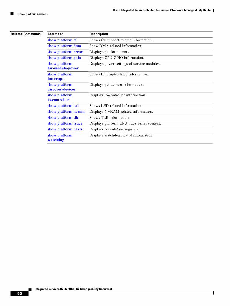
Cisco Integrated Services Router Generation 2 Network Manageability Guide show platform versions
90Integrated Services Router (ISR) G2 Manageability Document
Related Commands Command Description
show platform cf Shows CF support-related information.
show platform dma Show DMA-related information.
show platform error Displays platform errors.
show platform gpio Displays CPU-GPIO information.
show platform hw-module-power
Displays power settings of service modules.
show platform interrupt
Shows Interrupt-related information.
show platform discover-devices
Displays pci devices information.
show platform io-controller
Displays io-controller information.
show platform led Shows LED-related information.
show platform nvram Displays NVRAM-related information.
show platform tlb Shows TLB information.
show platform trace Displays platform CPU trace buffer content.
show platform uarts Displays console/aux registers.
show platform watchdog
Displays watchdog related information.

Cisco Integrated Services Router Generation 2 Network Manageability Guide show platform watchdog
91Integrated Services Router (ISR) G2 Manageability Document
show platform watchdogTo display the watchdog-related information, use the show platform watchdog command in privileged EXEC mode.
show platform watchdog
Syntax Description
Command Modes Privileged EXEC (#)
Command History
Usage Guidelines This command displays the watchdog-related information.
Examples The following is sample output for the show platform watchdog command:
Router#show platform watchdogWatchdog Information:=====================Critical input and watchdog timer interrupt: enabledWatchdog: Interrupt disabled, Next watchdog enabled, Event not occurred Reset control: Second timeout generates machine check Reset status: No watchdog timer reset will occur Length: 913 msDecrementer: interrupt disabled, event occurred
Related Commands
watchdog Displays watchdog-related information.
Release Modification
15.0(1)M This command was introduced.
Command Description
show platform cf Shows CF support-related information.
show platform dma Show DMA-related information.
show platform error Displays platform errors.
show platform gpio Displays CPU-GPIO information.
show platform hw-module-power
Displays power settings of service modules.
show platform interrupt
Shows Interrupt-related information.
show platform io-controller
Displays io-controller information.
show platform led Shows LED-related information.
show platform nvram Displays NVRAM-related information.
show platform tlb Shows TLB information.

Cisco Integrated Services Router Generation 2 Network Manageability Guide show platform watchdog
92Integrated Services Router (ISR) G2 Manageability Document
show platform trace Displays platform CPU trace buffer content.
show platform uarts Displays Console/Aux registers.
show platform versions
Displays versions/revisions of various modules.
Command Description

Cisco Integrated Services Router Generation 2 Network Manageability Guide Additional References
93Integrated Services Router (ISR) G2 Manageability Document
Additional ReferencesThe following websites describes additional information about network management.
• The Output Interpreter website is a troubleshooting website that reports potential problems by analyzing supported show command output. You must be a registered Cisco.com user to access this document. To visit the Output Interpreter website, go to this URL:
https://www.cisco.com/cgi-bin/Support/OutputInterpreter/home.pl
• The Error Message Decoder website allows you to determine the explanation and recommended action for an existing Cisco syslog message. You must be a registered Cisco.com user to access this document. To visit the Error Message Decoder website, go to this URL:
http://www.cisco.com/cgi-bin/Support/Errordecoder/home.pl
• You can find information about MIBs and OIDs at the Cisco IOS MIB Locator and SNMP Object Identifier website. The MIB Locator finds MIBs in Cisco IOS software releases. The SNMP Object Navigator translates OID's into SNMP names. To visit the Cisco IOS MIB Locator and SNMP Object Identifier website, go to this URL:
http://tools.cisco.com/ITDIT/MIBS/servlet/index
• The SNMP Inform Requests document provides information about how users configure routers to send informs and traps on a Cisco router. To see the SNMP Inform Requests document, go to this URL:
http://www.cisco.com/en/US/docs/ios/11_3/feature/guide/snmpinfm.html
• The Traps Sent with SNMP-Server Enabled Traps Configured document provides information about traps that are enabled on a Cisco device. To see The Traps Sent with SNMP-Server Enabled Traps Configured document, go to this URL:
http://www.cisco.com/en/US/tech/tk648/tk362/technologies_tech_note09186a008021de3e.shtml
• “Configuring SNMP Support” is a chapter in the Cisco IOS Configuration Fundamentals Configuration Guide that provides information about SNMP and Cisco MIB configuration. To see the “Configuring SNMP Support” chapter go to this URL:
http://www.cisco.com/en/US/docs/ios/12_2/configfun/configuration/guide/fcf014.html
• The TAC FAQ sheet SNMP: Frequently Asked Questions About MIBs provides information about the evolution of Cisco MIBs and how to determine which MIBs are supported by a Cisco device. You must be a registered Cisco.com user to access this document. To see the TAC FAQ sheet SNMP: Frequently Asked Questions About MIBs, go to this URL:
http://www.cisco.com/en/US/customer/tech/tk648/tk362/technologies_q_and_a_item09186a0080094bc0.shtml
• You can find information about which MIBs are supported by which Cisco products at the Network Management Software website. To visit the Network Management Software website, go to this URL:
http://www.cisco.com/public/sw-center/netmgmt/cmtk/mibs.shtml
• The Cisco IOS Management for High Availability Networking: Best Practices White Paper provides information about Cisco IOS syslog and problem management. To see the Cisco IOS Management for High Availability Networking: Best Practices White Paper, go to this URL:
http://www.cisco.com/en/US/tech/tk869/tk769/technologies_white_paper09186a00800a998b.shtml

Cisco Integrated Services Router Generation 2 Network Manageability Guide Additional References
94Integrated Services Router (ISR) G2 Manageability Document
• The Cisco IOS System Message Guide provides information about Cisco IOS syslog messages. To see the Cisco IOS System Message Guide, go to this URL:
http://www.cisco.com/en/US/docs/ios/12_2sx/system/messages/122sxsms.htmll
Cisco and the Cisco Logo are trademarks of Cisco Systems, Inc. and/or its affiliates in the U.S. and other countries. A listing of Cisco's trademarks can be found at www.cisco.com/go/trademarks. Third party trademarks mentioned are the property of their respective owners. The use of the word partner does not imply a partnership relationship between Cisco and any other company. (1005R)
Any Internet Protocol (IP) addresses and phone numbers used in this document are not intended to be actual addresses and phone numbers. Any examples, command display output, network topology diagrams, and other figures included in the document are shown for illustrative purposes only. Any use of actual IP addresses or phone numbers in illustrative content is unintentional and coincidental. © 2011 Cisco Systems, Inc. All rights reserved.