cisco meeting server single server simplified setup guide · singleserversimplifiedsetupguide...
TRANSCRIPT

Cisco Meeting ServerSingle Server Simplified Setup Guide
September 25, 2019
Cisco Systems, Inc. www.cisco.com

Single Server Simplified Setup Guide : Simplified Meeting Server Deployment 2
What's newVersion Change
September 26, 2019 Minor correction.
October 25, 2018 First version published.
What's new
Single Server Simplified Setup Guide : Simplified Meeting Server Deployment 3
Contents
What's new 2
1 Introduction 5
2 Configuration outline 72.1 Prerequisites 7
2.1.1 Software Versions 7Task 1: Configuring IP interface for admin and/or A interface 8Task 2: Setting host name 10Task 3: Setting MMP accounts 10Task 4: Upgrading software, if necessary 11Task 5: Obtaining and assigning Multiparty licenses 12Task 6: Configuring Network Time Protocol (NTP) server 12Task 7: Generating certificate for Meeting Server 13Task 8: Enabling Call Bridge service 14Task 9: Enabling Web Admin service 15Task 10: Configuring basic call settings 15Task 11: Configuring incoming call rules for answering calls 16Task 12: Configuring outgoing call rules 17Task 13: Creating a test space 18Task 14: Configuring Call Control to route to the Meeting Server 19
14a) Cisco Expressway/VCS: adding calling rules to Call Control for MeetingServer 19
14b) Unified CM: adding calling rules to Call Control for Meeting Server 21Task 15: Optional. Configuring Unified CM adhoc conference escalation 26Task 16: Enabling Web Bridge 27
Enable XMPP service 27Add Call Bridge to XMPP Server 27Enable Web Bridge on Interface A 28Configure Call Bridge to register with the XMPP service 28Configure XMPP Server settings via Web Admin Interface 29Configuring Web Bridge for Call Bridge 30
Task 17: Configuring user import 31LDAP Settings description 312.1.2 Configuring LDAP Import 322.1.3 Confirm Web Bridge Logins 33
What's new

Single Server Simplified Setup Guide : Simplified Meeting Server Deployment 4
Appendix A Additional information 35A.1 Firewall ports information 35A.2 Adding firewall traversal and external networks 35A.3 LDAP Tips and Examples 35
A.3.1 Tips on LDAP 36Example 1: Import all Active Directory Users, set JID based on sAMAccountName,
and create a space 36Example 2: Import all users that are members of a specific Active Directory group,
cn=CMSAdmins,cn=Users,=dc=company,dc=com and create spaces foreach 36
A.3.2 Common user LDAP filters 37A.4 Microsoft deployment information 38
Cisco Legal Information 39
What's new
Single Server Simplified Setup Guide : Simplified Meeting Server Deployment 5
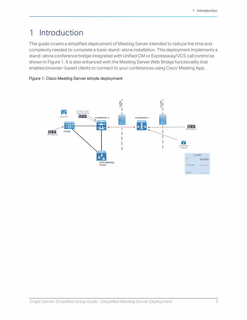
1 IntroductionThis guide covers a simplified deployment of Meeting Server intended to reduce the time andcomplexity needed to complete a basic stand-alone installation. This deployment implements astand-alone conference bridge integrated with Unified CM or Expressway/VCS call control asshown in Figure 1. It is also enhanced with the Meeting Server Web Bridge functionality thatenables browser-based clients to connect to your conferences using Cisco Meeting App.
Figure 1: Cisco Meeting Server simple deployment
1 Introduction
Single Server Simplified Setup Guide : Simplified Meeting Server Deployment 6
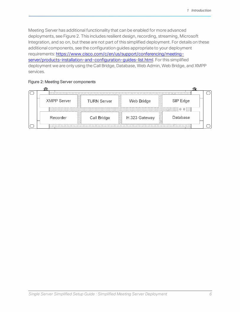
Meeting Server has additional functionality that can be enabled for more advanceddeployments, see Figure 2. This includes resilient design, recording, streaming, MicrosoftIntegration, and so on, but these are not part of this simplified deployment. For details on theseadditional components, see the configuration guides appropriate to your deploymentrequirements: https://www.cisco.com/c/en/us/support/conferencing/meeting-server/products-installation-and-configuration-guides-list.html. For this simplifieddeployment we are only using the Call Bridge, Database, Web Admin, Web Bridge, and XMPPservices.
Figure 2: Meeting Server components
1 Introduction

Single Server Simplified Setup Guide : Simplified Meeting Server Deployment 7
2 Configuration outlineThis guide assumes you are deploying Meeting Server as a virtual machine, either on a spec-based Hypervisor or on the Cisco Meeting Server 1000 platform.
l For the Cisco Meeting Server 1000 platform, the Hypervisor should have its networkconfigured and be accessible via the network to complete these tasks. Refer to the: CiscoMeeting Server 2.x, Installation Guide for Cisco Meeting Server 1000 and VirtualizedDeployments for specific instructions on how to complete the initial setup of the MeetingServer 1000 platform to get to where you can connect with the VMware client.
l For Virtual Machine installations, this guide assumes you have deployed the MeetingServer OVA file and allocated memory and CPU resources as necessary for the size of yourdeployment. Please refer to the Cisco Meeting Server 2.x, Installation Guide for CiscoMeeting Server 1000 and Virtualized Deployments for specific instructions on deployingthe OVA and sizing your virtual machine.
To set up your Meeting Server to operate in this simple deployment scenario, check thePrerequisites and follow the configuration tasks.
2.1 PrerequisitesBefore you proceed with the configuration tasks, we recommend that the followingrequirements are in place:
l DNS A record should be created for the Meeting Server IP address using an alias you wantend-users to be comfortable with; for example: meetingserver.company.com
l XMPP Domain name should be chosen. This is the domain name user will use to log in forCisco Meeting App. These configuration tasks assume using the company's top leveldomain to allow using existing email addresses for XMPP login. If another application hasalready claimed this name for XMPP, you must use a different domain name, such as asubdomain, for example: meet.company.com
l To support Cisco Meeting App users, a DNS SRV record for XMPP domain name must beadded to your DNS server. An SRV record for _xmpp-client._tcp.<xmpp domain>for TCP port 5222 is needed. Note: You do not need to do this if you are only usingMeeting App for WebRTC.
l SIP Domain for Meeting Server; we suggest using a subdomain, such asmeet.company.com
2.1.1 Software Versions
This guide is intended for a deployment using the following versions:
2 Configuration outline

Single Server Simplified Setup Guide : Simplified Meeting Server Deployment 8
l Meeting Server 2.3 or 2.4
l Cisco Unified CM 10.5.2, 11.0, 11.5, 12.0
l Expressway X8.10 or X8.11
Caveats or steps for other versions are not detailed in this guide.
Task 1: Configuring IP interface for admin and/or A interfaceBefore using the console to complete this task, you need to do the initial login as follows:
1. Using your VMware client, power on your Meeting Server virtual machine and open thevirtual console for the machine.
2. When the initial power on is complete, the Meeting Server login prompt displays.
3. Log in with the user name “admin” and the initial password “admin”. If this is the first timethe machine has been logged into, you will be prompted to enter a new password andconfirm it. If so, set the new password for the admin account.
CAUTION: Passwords automatically expire after 6 months. Password policies, includingstrength and expiration rules can be customized using theuser ruleMMP commands.Please see the Password Rules section of the Cisco Meeting Server MMP CommandReference for more information.
4. After successful login, a command prompt displays. This is the Meeting Server MMPinterface and is accessible via local machine console, or SSH after the networkinginterface has been configured.
Note: Meeting Server enforces an inactivity timer on all management interfaces. Afterapproximately 30 seconds of inactivity on any management interface, the software willautomatically log you out. You must log back in with your credentials to continue with yourtasks.
A virtual instance of Meeting Server can have up to 4 network interfaces, a, b, c, d. For thisdeployment example, we will only use one interface, "a". The "a" interface must be configuredwith ethernet and IP address information to match the connected network.
1. To set network interface speed, duplex and auto-negotiation parameters use the ifacecommand e.g. to display the current configuration on the "a" interface, in the MMP type:
iface a
a. Set the network interface speed, duplex and auto negotiation parameters using thecommand iface (admin|a|b|c|d) <speed> (full|on|off). For example,set the interface to 1GE, full duplex:
2 Configuration outline

Single Server Simplified Setup Guide : Simplified Meeting Server Deployment 9
iface a 1000 full
b. Switch auto negotiation on or off using the command iface a autoneg<on|off>. For example:
iface a autoneg on
Note: We recommend that the network interface is set to auto negotiation "on" unlessyou have a specific reason not to.
2. The “a” interface is initially configured to use DHCP. To view the existing configuration, type:
ipv4 a
a. If you are using DHCP IP assignment, no further IP configuration is needed, go to step 3.
b. If you are using Static IP assignment:
Use the ipv4 add command to add a static IP address to the interface with a specifiedsubnet mask and default gateway.
For example, to add address 10.1.2.4 with prefix length 16 (netmask 255.255.0.0) withgateway 10.1.1.1 to the interface, type:
ipv4 a add 10.1.2.4/16 10.1.1.1
To remove the IPv4 address, type:
ipv4 a del
3. Set DNS Configuration
Meeting Server requires DNS lookups for many of its activities including looking up SRVrecords and is required for a simplified deployment. We recommend you point MeetingServer to the default DNS resolver for your network using a period "." for the forwardzonevalue.
a. To output the dns configuration, type:
dns
b. To set the application DNS server use the command:
dns add forwardzone <domain name> <server IP>
Note: A forward zone is a pair consisting of a domain name and a server address: if aname is below the given domain name in the DNS hierarchy, then the DNS resolver canquery the given server. Multiple servers can be given for any particular domain name toprovide load balancing and fail over. A common usage will be to specify "." as thedomain name i.e. the root of the DNS hierarchy which matches every domain name.
for example:dns add forwardzone . 10.1.1.33
2 Configuration outline

Single Server Simplified Setup Guide : Simplified Meeting Server Deployment 10
c. If you need to delete a DNS entry use the command:
dns del forwardzone <domain name> <server IP>
for example:
dns del forwardzone . 10.1.1.33
The MMP interface should now be accessible via SSH to the IP address that was configured.Check that you can connect with your preferred SSH client.
Task 2: Setting host nameMeeting Server requires the hostname be configured to identify the server in logs andmessages. We recommend you set the hostname to the FQDN of the server.
1. If necessary, SSH into the MMP and log in.
2. To set the hostname, use the command: hostname <name>, for example:
hostname meetingserver
3. Type:reboot
Note: A reboot is required after issuing the hostname command.
Task 3: Setting MMP accountsFor security purposes, you are advised to create your own administrator accounts as username“admin” is not very secure. In addition, it is good practice to have two admin accounts in caseyou lose the password for one account. If you do, then you can still log in with the other accountand reset the lost password.
1. While logged into the MMP console, create a new user with admin permissions with thecommand user add <name> admin.
for example:
user add jbloggs admin.
You will be prompted to supply a password, and to confirm the password. Note that thefirst time the new user logs in, they will be prompted to set their own password.
CAUTION: Passwords automatically expire after 6 months. Password policies, includingstrength and expiration rules can be customized using theuser ruleMMP commands.Please see the Password Rules section of the Cisco Meeting Server MMP CommandReference for more information.
2 Configuration outline

Single Server Simplified Setup Guide : Simplified Meeting Server Deployment 11
2. We recommend you create a second admin account — repeat the commands in step 1 tocreate a second admin level account.
3. After creating your new admin accounts delete the default “admin” username account. Toremove this account, use the command user del admin.
See the MMP Command Reference Guide for more information on user accounts, passwords,and permissions.
Note: Any MMP user account at the admin level can also be used to log into the Web AdminInterface of the Call Bridge. You cannot create users through the Web Admin Interface.
Task 4: Upgrading software, if necessary1. To find out which version the Meeting Server is running, SSH into the MMP, log in and type:
version
2. Before upgrading your Meeting Servers:
a. take a backup of the current configuration on each of the servers. Use the MMPcommand backup snapshot <name>. Save the backup safely to a local server.See the MMP Command Reference guide for full details. Do NOT use the automaticbackup file that is created during the upgrade process.
b. save the cms.lic and certificate files to the local server.
c. using the Web Admin interface, check the database cluster status, and that all calls(SIP and clients) are working and no fault conditions are listed.
3. To upgrade, first download and extract the appropriate software file from the Ciscowebsite. Click on this link, then click on the appropriate Meeting Server type listed in theright-hand column of the web page and follow any instructions displayed with thedownload link.
4. Use an SFTP client to upload the new software image to the MMP. For example:
sftp [email protected]
put upgrade.img
where 10.1.x.y is an IP address or domain name.
5. Then to complete the upgrade, connect via SSH to the MMP and type:
upgrade
Allow several minutes for the server to restart.
6. To verify that the upgrade was successful, SSH into the MMP, log in and type the followingcommand:
version
2 Configuration outline

Single Server Simplified Setup Guide : Simplified Meeting Server Deployment 12
Task 5: Obtaining and assigning Multiparty licensesYou need license files specific to your Meeting Server instance to complete the deployment.Meeting Server licenses are delivered using Cisco’s Product Activation Keys (PAK) and fulfilledusing Cisco’s License Registration Portal.
Note: For detailed information on different Meeting Server licensing models, see the CiscoLicensing chapter in the larger deployment guides.
This section assumes that you have already purchased the licenses that will be required for yourMeeting Server from your Cisco Partner and you have received your PAK code(s).
Follow these steps to register the PAK code with the MAC address of your Meeting Server usingthe Cisco License Registration Portal.
1. Obtain the MAC address of your Meeting Server by logging in to the MMP of your server,and enter the following command: iface a
Note: This is the MAC address of your VM (i.e. Meeting Server), not the MAC address of theserver platform that the VM is installed on (i.e. host server).
2. Open the Cisco License Registration Portal and register the PAK code and the MAC addressof your Meeting Server.
3. The license portal will provide a zipped copy of the license file. Extract the zip file andrename the resulting .lic file to cms.lic.
4. Using your SFTP client, log into Meeting Server and copy thecms.lic file to the MeetingServer file system.
5. Restart the Call Bridge using the command callbridge restart
6. After restarting the Call Bridge, the license status can be checked by typing license
The activated features and expirations will be displayed.
Task 6: Configuring Network Time Protocol (NTP) serverConfigure Network Time Protocol (NTP) server to synchronize time between the Meeting Servercomponents.
Note: Sharing a common view of time is important for multiple reasons. Time synchronization isnecessary when checking for certificate validity and to prevent replay attacks..
1. SSH into the MMP and log in.
2 Configuration outline

Single Server Simplified Setup Guide : Simplified Meeting Server Deployment 13
2. To set up an NTP server, use the command:
ntp server add <domain name or IP address of NTP server>
for example:
ntp server add ntp.example.com
To find the status of configured NTP servers, type ntp status
See the MMP Command Reference for a full list of ntp commands.
Task 7: Generating certificate for Meeting ServerMeeting Server uses x.509 certificates to configure secure (TLS) connections in its services andfor some authentication tasks. In this deployment, certificate configuration is required for theCall Bridge, XMPP, Web Bridge, and Web Admin services. Certificates can be self-signed orsigned by internal or external certificate authorities. For a full explanation of certificate uses andrequirements, please see the Certificate Guidelines.
For this simplified deployment we will use one x.509 certificate with the correct attributessigned by an internal or external CA. Using a self-signed certificate here is possible, but is notrecommended as it will cause errors to be seen in web pages and will prevent you fromincorporating Meeting Server into Unified CM as a conference bridge.
For this deployment, our certificate should have the server FQDN as the Common Name (CN)and must have the XMPP domain in the Subject Alternate Name (SAN) attribute of thecertificate. To generate a Certificate Signing Request (CSR) and private key locally:
1. Log in to the MMP using SSH or console.
2. Type the pki csr command using this syntax:pki csr <key/cert basename> <CN:value> [OU:<value>] [O:<value>] [ST:<-value>] [C:<value>] [subjectAltName:<value>]
For example:
pki csr singleCert CN:meetingserver.company.com subjectAltName:company.com
Note: The CN,OU,O,ST,C values and other attributes are optional in the certificate and areomitted here for simplicity. They can be defined and included if desired, see the CertificateGuidelines for a complete breakdown of the commands.
Note: The CN value should always be part of the SubjectAltName (SAN) list. The MeetingServer pki csr command adds the CN to the SAN list automatically so you do not have tolist it separately.
The output of this command generates a private key file with the extension .key and aCertificate Signing Request (CSR) file with the extension .csr on the local file system.
2 Configuration outline

Single Server Simplified Setup Guide : Simplified Meeting Server Deployment 14
3. Using your SFTP client, log into Meeting Server and copy the CSR file to your machine so itcan be supplied to your signing certificate authority.
The output from your signing certificate authority should be a PEM encoded certificate file(for example, singleCert.crt). You will also need a PEM encoded bundle (consisting ofroot certificate, or intermediate certificates and a root certificate) of the chain of certificateauthorities that signed your certificate (for example, ca-bundle.crt). Your certificateauthority may return files to you in a different format, which usually can be repackaged orreformatted with common certificate tools. See the Certificate Guidelines for moreinformation.
4. Upload this PEM encoded bundle (for example: ca-bundle.crt) to Meeting Server. Usingyour SFTP client, log into Meeting Server and copy the signed certificate file and certificateauthority bundle to the Meeting Server file system.
Note: File names are restricted on Meeting Server, so your files must use common fileextensions such as .crt, .cer, .key, .pem or .der
Note: If you self-sign a certificate, and use it, you may see a warning message that theservice is untrusted. To avoid these messages, re-issue the certificate and have it signed bya trusted CA; this can be an internal CA unless you want public access to this component.
Task 8: Enabling Call Bridge serviceThe Call Bridge service must be configured with the certificate to use and which networkinterface to listen on.
The command callbridge listen <interface> allows you to configure a listening interface(chosen from A, B, C or D). By default the Call Bridge listens on no interfaces.
1. Sign into the MMP and configure the Call Bridge to listen on interface A.
callbridge listen a
Note: the Call Bridge must be listening on a network interface that is not NAT’d to another IPaddress. This is because the Call Bridge is required to convey the same IP that is configuredon the interface in SIP messages when talking to a remote site.
2. Configure the Call Bridge to use the certificate, key, and bundle generated in Task 7, usingcallbridge certs <keyfile> <certificatefile> <ca bundle>, for example:
callbridge certs singleCert.key singleCert.crt ca-bundle.crt
3. Restart the Call Bridge interface to apply the changes.
callbridge restart
2 Configuration outline

Single Server Simplified Setup Guide : Simplified Meeting Server Deployment 15
If successful, you will get SUCCESS lines returned stating that the Call Bridge is correctlyconfigured for network and certificate values.
Task 9: Enabling Web Admin serviceThe Web Admin Interface is the browser-based interface to Meeting Server and the Call Bridgeservice. The Web Admin service must be configured with the certificate to use and whichinterface to listen on before it can be enabled. By default, Web Admin will listen on the standardHTTPS port of 443. However, in this deployment we will also enable the Web Bridge forconference users and would like that service to be available on the default HTTPS port. Toenable both services to co-exist, we will configure Web Admin to listen on port 445 and requireadministrators to supply the extra port information when browsing to the Web Admin interface.
1. Use the MMP command webadmin listen <interface> <port> to instruct Web Adminto listen on interface a port 445:webadmin listen a 445
2. Use the MMP command webadmin certs <keyfile> <certificatefile> <ca
bundle> to configure Web Admin with the certificate files generated in Task 7, forexample:
webadmin certs singleCert.key singleCert.crt ca-bundle.crt
3. Use the MMP command webadmin enable to start the Web Admin service.
webadmin enable
If successful, you will get SUCCESS lines returned stating Web Admin is correctly configured fornetwork and certificate values. Check the service is operational by using a web browser andenter the Web Admin address, for example: https://meetingserver.company.com:445
Note: The specific use of https in the prefix and the :445 at the end of the address.
If you do not get the success messages or the page did not load properly, enter the MMPcommand webadmin by itself to display the existing configuration. Check for any typing errorswith the files specified. Correct any errors and try enabling the service again before proceeding.
Task 10: Configuring basic call settingsThe Call Bridge service is now running, but is using only the system defaults. In this task we willconfigure some common settings needed before making test calls.
1. Log in to the Web Admin Interface using your browser and go to Configuration > Callsettings.
2. Select the appropriate SIP media encryption setting (allowed, required or disabled).
2 Configuration outline

Single Server Simplified Setup Guide : Simplified Meeting Server Deployment 16
The SIP media encryption setting must be compatible with your existing call control andendpoints. The setting recommended for most usages is allowed — this allows bothencrypted and non-encrypted connections. Take care before setting to required if youwant to specify encryption is required before calls can connect — a mismatch ofencryption between Meeting Server and devices will prevent calls from connecting.Choose your setting and click Submit.
3. On the same page, you can optionally:
l Choose to enable SIP call participant labels if you want site names to display overlaidon video images. Enabling participant labels is encouraged for those migrating fromMCUs that use this feature.
l Customize the maximum bandwidth per call to use for the different call types.Bandwidth numbers are in bits/sec. We recommend leaving bandwidth values attheir default settings.
3. Click Submit after making any changes.
Task 11: Configuring incoming call rules for answering callsThe Configuration > Incoming calls page determines how the Meeting Server handles incomingSIP calls. Any call routed to the Meeting Server will have the alias being called checked againstthe rules in the Call matching table to determine where Meeting Server should look for potentialmatches. Each rule can be set to match for any combination of users, spaces, IVRs, or MicrosoftSkype/Lync lookups. Meeting Server matches incoming calls by checking the value after the "@"symbol with the values in the domain column.
The example Call matching rule below seeks to match all calls coming in on themeet.company.com domain to both Cisco Meeting App users and spaces.
We recommend that rules are created for every domain expected for incoming calls. With somecall control solutions the domain in the alias may be the IP address or hostname of the MeetingServer.
Rules with a higher priority value are matched first. In cases where multiple rules have the samepriority, matching occurs based on alphabetical order of the domain.
After a rule is matched and executed, rules further down the list are ignored for the call.
If all Call matching rules fail, the next table (Call forwarding) is checked. Note that Callforwarding is not covered in this deployment.
2 Configuration outline
Single Server Simplified Setup Guide : Simplified Meeting Server Deployment 17
Points to note:
l Once a domain is matched, matching for space and/or users is only done on the part ofthe URI before the "@" symbol.
l The highest priority rule that matches a space is used to form the URI in the invitationscreated by Cisco Meeting App. It is expected that the highest priority rules are for thedeployment as a whole, rather than for individual IP addesses or hostnames.
To configure incoming call rules:
1. Log in to the Web Admin Interface using your browser and go to Configuration > Incomingcalls.
2. Configure the highest priority incoming rule to be the SIP domain you will be using forspaces. Use the empty row to add a rule with the following values:
l Domain name: <your SIP domain for Meeting Server> (for example,meet.company.com)
l Priority: 100
l Target spaces, users, IVRs: set to yes
Click Add New to save the changes.
3. To ensure compatibility with different trunk configurations, add a rule for the FQDN of yourMeeting Server. (If your SIP domain and Meeting Server FQDN are the same, you can skipthis step.) Use the empty row to add a rule with the following values:
l Domain name: <your FQDN for Meeting Server> (for example,meetingserver.company.com)
l Priority: 90
l Target spaces, users, IVRs: set to yes
Click Add New to save the changes.
4. To ensure compatibility with different trunk configurations, add a rule for the IP address ofyour Meeting Server. Use the empty row to add a rule with the following values:
l Domain name: <IP address of interface of whereCall Bridge is listening>
l Priority: 90
l Target spaces, users, IVRs: set to yes
Click Add New to save the changes.
Task 12: Configuring outgoing call rulesTo make calls out from Meeting Server, calls must be directed via the Outbound calls rules to adestination, such as Unified CM or Expressway/VCS. Similar to the incoming call rules, allrouting is based on the domain of the dialed alias. Rules are processed highest priority to lowest,
2 Configuration outline

Single Server Simplified Setup Guide : Simplified Meeting Server Deployment 18
and if matched, Meeting Server attempts to send the call to the SIP proxy defined. The Behaviorsetting in a rule controls whether further rules are processed if the rule matches, but the remoteproxy rejects the call. For this simplified deployment, we will route all outbound calls to oursingular call control (Unified CM or Expressway/VCS). More advanced configuration details arecovered in the larger Meeting Server deployment guides.
To configure outgoing call rules:
1. Log in to the Web Admin Interface using your browser and go to Configuration >Outbound calls.
2. Create a new outbound rule with the following values:
l Domain name: [Leave blank. Note that this is a special use that allows us to match alldomains]
l SIP Proxy to use: Enter the FQDN of your Unified CM or Expressway/VCS call controlnode (IP Address can be used, but FQDN is recommended)
l Local contact domain: [Leave blank]
l Local from domain: Enter your SIP domain for Meeting Server (for example:meet.company.com)
l Trunk type: Standard SIP
l Behavior: Continue
l Priority: 1
l Encryption: Auto
Click Add New to save the changes.
3. Optional. If you wish to define additional proxies for failover or other domains, you can doso, but it is not required. For most scenarios, we recommend that you route to call control,and do your destination routing there.
Task 13: Creating a test spaceCreating a test space allows verification of your configuration once call control has beenconfigured in Task 14. Aliases defined in this table will only include the left-hand side of the SIPURI. The incoming call rules table handles matching on the right-hand side of the alias.
1. Log in to the Web Admin Interface using your browser and go to Configuration > Spaces.
2. Use an empty row to create a new space. Fill in the fields with the following values:
l Name: Test Meeting
l URI: test
2 Configuration outline

Single Server Simplified Setup Guide : Simplified Meeting Server Deployment 19
l Secondary URI: 881000
l CallID: 881000
For secondary URI, use an E.164 value that will be compatible with the dial plan you will berouting to Meeting Server. For CallID, the value can be any number not already in use, inthis example, for simplicity, it is set to the same value as the secondary URI.
3. Click Add New to save the new values.
Task 14: Configuring Call Control to route to the Meeting ServerThe previous tasks configured Meeting Server to listen to incoming calls and where to sendcalls. Next, you need to configure your Call Control to identify calls intended for Meeting Serverand where to send them.
In this deployment, Meeting Server will listen for SIP calls on the "a" network interface where CallBridge is listening on TCP ports 5060 or 5061. You must configure your Call Control to identifywhich alias patterns are intended for Meeting Server and the trunks/zones of where to send thecalls.
This guide has both Cisco Expressway/VCS and Cisco Unified CM examples. Complete Task14a for Cisco Expressway/VCS deployments, or Task 14b if using Cisco Unified CM.
14a) Cisco Expressway/VCS: adding calling rules to Call Control for Meeting Server
This task will add dial plan configuration to an existing Cisco Expressway/VCS to route SIP URIsand E.164 dial patterns to Meeting Server using SIP TLS. Use of TLS is described as bestpractice, however use of SIP TCP port 5060 is also valid.
1. Sign in to the Expressway as an administrator.
2. Set up a zone to route calls to the Meeting Server:
a. In the Expressway web interface, go to Configuration > Zones
b. Click New to create a new Zone with the settings below:
l Name = <Label for your zone. Example: CMS1>
l Type = Neighbor
l Hop Count = [Leave Default]
l H.323 Mode = Off.
l SIP Mode = On
l SIP Port = 5061
l Transport = TLS
l TLS verify = Off
2 Configuration outline

Single Server Simplified Setup Guide : Simplified Meeting Server Deployment 20
l SIP Accept Proxied Registrations = Allow
l Media encryption mode = Auto
l ICE support = Off
l Multistream Mode = On
l Preloaded SIP routes support = Off
l AES GCM support = Off
l Authentication Policy = Treat as authenticated
l SIP Authentication Trust Mode = Off
l Look up Peers By = Address
l Peer 1 Address = <theCall Bridge FQDN> (example: meetingserver.company.com)
Note: FQDN is recommended as TLS is being used. IP Address can also be usedprovided TLS verify = Off
l Zone Profile = Default
c. Click Create New to save the new zone.
3. Add a search rule to route to the Meeting Server:
a. In the Expressway web interface, go to Configuration > Dial Plan > Search rules
b. Click New to create a new search rule with the settings below, edit domain and priorityvalues to match your deployment:
l Name = <Label for your rule. Example: SIP URI to CMS1>
l Priority = <Set relative to your other search rules>
l Protocol = Any
l Source = Any
l Request Must be Authenticated = No
l Mode = Alias pattern match
l Pattern type = Regex
l Pattern string = .*@meet.company.com
l Pattern Behavior = Leave
l On Successful Match = Stop
l Target = <Select the Zone created for Meeting Server>
2 Configuration outline

Single Server Simplified Setup Guide : Simplified Meeting Server Deployment 21
l State = Enabled
c. Click Create search rule to save your new zone.
4. The rule created in the previous step routed calls using the Meeting Server SIP domain. If youalso use an E.164 dial plan, create another search rule to route based on the E.164 numberpattern you will use for Meeting Server.
a. In the VCS web interface, go to Configuration > Dial Plan > Search rules
b. Click New to create a new search rule with the settings below. Edit the example regexpattern to match your dial plan. The example routes 88XXXX patterns to Meeting Server.
l Name = <Label for your rule. Example: e164 aliases to CMS1>
l Priority = <Set relative to your other search rules>
l Protocol = Any
l Source = Any
l Request Must be Authenticated = No
l Mode = Alias pattern match
l Pattern type = Regex
l Pattern string = (88\d{4}).*
l Pattern Behavior = Replace
l Replace String: \[email protected]
l On Successful Match = Stop
l Target = <Select the Zone created for Meeting Server>
l State = Enabled
c. Click Create search rule to save your new zone.
After completing these steps, the new zone should show in the Configuration > Zones pageas SIP Status = Active and Search Rule Status should show 2 enabled search rules.
5. Now that call control is configured, you can dial into the Meeting Server test conferencecreated in Task 13 to validate the configuration. With an endpoint registered to your callcontrol, dial the SIP URI of the test meeting created earlier (for example:[email protected]). Repeat the test using the E.164 alias.
If your calls fail to connect, use the Event Log in the Web Admin interface of Meeting Serverand the Search and Call history pages in the Expressway/VCS web interface to see whereyour call is failing.
14b) Unified CM: adding calling rules to Call Control for Meeting Server
This task adds dial plan configuration to an existing Cisco Unified CM to route SIP URIs andE.164 dial patterns to Meeting Server using SIP TLS. Use of TLS is described as best practice,
2 Configuration outline

Single Server Simplified Setup Guide : Simplified Meeting Server Deployment 22
however use of SIP TCP port 5060 is also valid. SIP TCP configuration is not covered in thisguide.
See Cisco Meeting Server 2.x with Cisco Unified Communications Manager Deployment Guidefor more details.
Our testing has been done on trunks without Media Termination Point (MTP)configured. Therefore:
n Disable MTP if this will not negatively affect your deployment. Turning off MTP might have anegative impact on your deployment if you are using SCCP phones and need to send DTMFto the Meeting Server.
n If the above is not a valid implementation, you may need to increase the MTP capacity on theCisco Unified Communications Manager depending on the number of simultaneous calls.
1. If not done so already, install a CA signed certificate for the CallManager service on eachCisco Unified Communications Manager which has the CallManager service activated.
Note: This is a recommendation and not a requirement as Meeting Server does not validatereceived certificates by default, it accepts all valid certificates and will accept Call Manager'sself-signed certificate.
a. Log into the Cisco Unified Communications Manager OS Administration page, chooseSecurity > Certificate Management.
b. In the Certificate List window, click Generate CSR.
c. From the Certificate Name drop-down list, choose CallManager.
d. Click Generate CSR to generate a Certificate Signing Request.
e. Once the CSR is successfully generated, click Download CSR. From the DownloadSigning Request dialog box choose CallManager and click Download CSR.
f. Get this CSR signed by a Certificate Authority. An internal CA signed certificate isacceptable.
g. Once a certificate is returned from the CA, go to the Upload Certificate/Certificatechain window. From the Certificate Purpose drop-down list select CallManager-trust.Browse and upload first the root certificate, followed by the intermediate certificates.From the Certificate Purpose drop-down list select CallManager. Browse and uploadthe certificate for the CallManager Service.
h. For the new certificate to take effect you need to restart the CallManager service inCisco Unified Serviceability, do this during a maintenance period.
2. Upload the root and intermediate certificates of the certificate you generated in Task 7 tothe CallManager-trust store.
2 Configuration outline

Single Server Simplified Setup Guide : Simplified Meeting Server Deployment 23
a.a. From the Cisco Unified Communications Manager OS Administration page, chooseSecurity > Certificate Management.
b. Click Upload Certificate/Certificate Chain. The Upload Certificate/Certificate Chainpopup window appears.
c. From the Certificate Purpose drop-down list choose CallManager-trust.
d. Browse and upload first the root certificate, followed by the intermediate certificates toCallManager-trust.
3. Create a SIP trunk security profile.
Cisco Unified Communications Manager applies a default security profile called Non SecureSIP Trunk when you create the SIP Trunk, this is for TCP. To use TLS, or something otherthan the standard security profile, follow these steps:
a. Log into Cisco Unified Communications Manager Administration.
b. Go to System > Security > SIP Trunk Security Profile.
c. Click Add New.
d. Complete the fields as follows:
l Name = type in a name, e.g. "CMS_SecureTrunk"
l Device Security Mode =select Encrypted
l Incoming Transport Type = select TLS
l Outgoing Transport Type = select TLS
l X.509 Subject Name = enter the CN of the Call Bridge certificate. This should be theFQDN of your Meeting Server.
l Incoming Port = enter the port that will receive TLS requests. The default for TLS is5061
l Accept Replaces Header = check this box if you intend to use Call Bridge Grouping.
e. Click Save
4. Check that your SIP Profile is configured correctly. If using the default Standard SIP ProfileFor TelePresence Conferencing on Cisco Unified Communications Manager version 10.5.2or later, this should be sufficient. The key values to ensure are checked are: Allow iXApplication Media, Use Fully Qualified Domain Name in SIP Requests, and AllowPresentation Sharing use BFCP.
5. Create the SIP trunk.
a. In Cisco Unified Communications Manager, go to Device >Trunk.
b. Click Add New.
c. Configure these fields:
2 Configuration outline

Single Server Simplified Setup Guide : Simplified Meeting Server Deployment 24
l Trunk Type = SIP trunk
l DeviceProtocol =SIP
l Trunk Service Type = None (default)
d. Click Next
e. Configure the destination information for the SIP trunk, see Table 1 below.
Table 1: Destination information for the SIP Trunk
Field Description
Device name Type in a name e.g. CiscoMeetingServer (no spaces allowed)
Device pool The pool you want your device to belong to (as configured in System >Device Pool in Cisco Unified Communications Manager
SRTP Allowed Select SRTP Allowed to allow media encryption
Inbound Calls > Calling SearchSpace
Select default, not required if only allowing escalated 2-way adhoc callsfrom Cisco Unified Communications Manager to a meeting on the Meet-ing Server.
Outbound Calls > Calling PartyTransformation CSS
Select as appropriate.
SIP Information > Destinationaddress
Enter the FQDN of a single Meeting Server, it must match the CN of theMeeting Server certificate. Note: For clusters, enter the FQDN of asingle Meeting Server
SIP Information > DestinationPort
Enter 5061 for TLS
SIP Trunk Security Profile Select the security profile that you created in step 3.
Rerouting Calling Search Space When doing call bridge grouping, set this to a calling search space thatcontains the partitions of the calling parties.
SIP Profile Select the Standard SIP Profile For TelePresence Conferencing
Normalization Script Assign the cisco-meeting-server-interop script to this SIP trunk. Note:ideally download the latest normalization script from the Cisco website.For older UCM versions that do not have the Meeting Serverscript,download the latest interop scripts or alternatively use the cisco-telepresence-conductor-interop script as it has similiar interopbehaviors.
Run On All Active Unified CMNodes
Check this checkbox if you wish calls to egress other CUCM nodes aswell.
6. Click Save and apply the configuration.
7. Use the Trunk List to confirm that the trunk goes into service after a few minutes.
2 Configuration outline

Single Server Simplified Setup Guide : Simplified Meeting Server Deployment 25
Configure route patterns (dial plans for outbound calls)
You can configure domain based routing e.g. meet.company.com, and/or number basedrouting e.g. 88XXXX, to the Meeting Server through the Cisco Unified CommunicationsManager interface.
Domain based routing example
To route all domain based calls from Cisco Unified Communications Manager to the MeetingServer:
1. Go to Call Routing > Sip Route Pattern.
2. If none are appropriate, click Add New.
3. Complete the following:
l Pattern Usage = Domain Routing
l IPv4 pattern = for example, meet.company.com
l Description = anything you want
l Route Partition = the route partition you want this rule to belong to
Note: Various dial plan rules are attached to a route partition and a Calling Search Space(CSS) comprises a list of route partitions. You can have a different CSS for differentpeople, each phone, or trunk. When a call is made, Cisco Unified CommunicationsManager goes through each route partition in the CSS until it finds one that has amatching rule.
l SIP Trunk / Route List = the trunk you have already configured.
4. Click Save.
2 Configuration outline

Single Server Simplified Setup Guide : Simplified Meeting Server Deployment 26
Numeric dialing example
This basic example routes 6 digit numbers that start with 88. This example should be modifiedto match your target dial plan.
1. Go to Call Routing > Route/Hunt > Route Pattern. A list of existing Route Patterns isdisplayed.
2. If none are appropriate, click Add New.
3. Complete the following:
l Route pattern = 88XXXX (Further down the page you can set various transforms, ifdesired)
l Route partition = the route partition you want this rule to belong to
Note: : Various dial plan rules are attached to a route partition and a Calling Search Space(CSS) comprises a list of route partitions. You can have a different CSS for differentpeople, each phone, or trunk. When a call is made, Cisco Unified CommunicationsManager goes through each route partition in the CSS until it finds one that has amatching rule.
l Description = any appropriate text
ll From the Gateway/Route List drop-down, select the SIP trunk created in the previoussteps
4. Click Save.
5. Now call control is configured, you can dial into the Meeting Server test conference createdin Task 13 to validate the configuration. With an endpoint registered to your call control, dialthe SIP URI of the test meeting created earlier (for example: [email protected]).Repeat the test using the E.164 alias.
If your calls fail to connect, use the Event Log in the Web Admin interface of Meeting Serverand tracing diagnostics in Unified CM to identify where your call is failing.
Task 15: Optional. Configuring Unified CM adhoc conference escalationMeeting Server can act as the video and audio bridge for Unified CM devices that requestbridging multiple parties using the Conference button on the device. This feature is optional butrecommended for Unified CM deployments. You can add this feature to your deployment byfollowing the steps in Chapter 4 "Setting up escalated ad hoc calls" in the Cisco Meeting Server2.x with Cisco Unified Communications Manager Deployment Guide.
Complete that configuration if desired and then return to the next task in this guide.
2 Configuration outline

Single Server Simplified Setup Guide : Simplified Meeting Server Deployment 27
Task 16: Enabling Web BridgeTo support the Web Bridge functionality, the XMPP service must also be deployed. This task has3 steps: enable XMPP service, configure it to work with Call Bridge, and then enable WebBridge.
Enable XMPP service
1. Establish an SSH connection to the MMP and log in.
2. To configure the XMPP server to use the "a" interface, use the MMP command xmpplisten <interface whitelist>
For example:
xmpp listen a
3. Assign the certificate and private key files that were generated earlier in Task 7, using thecommand:
xmpp certs <keyfile> <certfile> <ca bundle>
For example:
xmpp certs singleCert.key singleCert.crt ca-bundle.crt
4. Define the XMPP domain for the deployment with the command xmpp domain <domainname>
For example, where the domain name is company.com:
xmpp domain company.com
5. Enable the XMPP service with the following command:
xmpp enable
The server should respond with SUCCESS messages if completed successfully.
Add Call Bridge to XMPP Server
The Call Bridge requires a set of credentials to connect to the XMPP server. These credentialsare created in the XMPP server and subsequently added to the Call Bridge configuration.
1. Log in to the MMP using SSH or console.
2. Provide a component name for the Call Bridge to use to authenticate, for example. cb_1using the MMP command xmpp callbridge add <component name>.
For example
xmpp callbridge add cb_1
3. A secret is generated; for example, you see:
cms>xmpp callbridge add cb_1Added callbridge: Secret: aB45d98asdf9gabgAb1
2 Configuration outline

Single Server Simplified Setup Guide : Simplified Meeting Server Deployment 28
Make a note of the domain, component name and secret generated because they are requiredwhen you use the Web Admin interface to configure the Call Bridge access to the XMPP serverin Task 16.
Note: If you lose the details, use the MMP command xmpp callbridge list to display them.
Enable Web Bridge on Interface A
1. Log in to the MMP using SSH or console.
2. Configure the Web Bridge to listen on interface "a" on port 443:
webbridge listen <interface[:port]
For example:
webbridge listen a:443
3. Configure Web Bridge service with the certificate files generated in Task 7 using the MMPcommand webbridge certs <keyfile> <certfile> <ca bundle>, for example:
webbridge certs singleCert.key singleCert.crt ca-bundle.crt
4. The Web Bridge supports HTTPS. It will forward HTTP to HTTPS if configured to use “http-redirect”. To enable HTTP redirect use the following command:
webbridge http-redirect enable
5. For Call Bridge to instruct Web Bridge to trust connections from the Call Bridge, use theMMP command webbridge trust <certfile>with the combined certificate usedearlier. For example:
webbridge trust singleCert.crt
7. Enable the Web Bridge service with the following command:
webbridge enable
The server should respond with SUCCESS messages if completed properly
Configure Call Bridge to register with the XMPP service
With the XMPP service now running, configure Call Bridge to register with the XMPP service.
The deployment requires the _xmpp-client SRV record be created for your XMPP domain. Tosupport use of Cisco Meeting App for Desktop and iOS, this DNS record must be created inyour DNS servers as outlined in the Prerequisites. If not supporting Cisco Meeting App forDesktop and iOS, and only using Cisco Meeting App for WebRTC, this requirement can bereplaced by using a local DNS RR record on Meeting Server itself. Do not create this DNS RRrecord if you create the SRV record in your normal DNS servers.
To create a local DNS RR record:
2 Configuration outline
Single Server Simplified Setup Guide : Simplified Meeting Server Deployment 29
1. Log into the MMP console using SSH and admin credentials.
2. Create the DNS RR record for the XMPP domain using the following example(ensure youuse names to match your deployment):
dns add rr "_xmpp-client._tcp.<xmpp domain>. 86400 IN SRV 0 5 5222 <CMSFQDN>."
For example, if the Meeting Server FQDN is meetingserver.company.com and XMPPdomain is company.com, enter:
dns add rr "_xmpp-client._tcp.company.com. 86400 IN SRV 0 5 5222meetingserver.company.com."
Note: The use of periods "."at the end of the addresses are required.
3. Clear the DNS cache of the Meeting Server so the new record will be used. In the MMPconsole, enter the dns flush command: dns flush
If you need to remove a local DNS RR record, use the command: dns del rr _xmpp-client._tcp.<xmpp domain> <type>, for example: dns del _xmpp-client._tcp.company.com. srv
The DNS record can be tested using the MMP commands.
1. Flush the existing DNS cache, enter: dns flush.
2. Enter dns lookup command on the SRV record created:
dns lookup srv _xmpp-client._tcp.company.com
The result should point to the FQDN of the Meeting Server and resolve to the Meeting Server's IPaddress.
Configure XMPP Server settings via Web Admin Interface
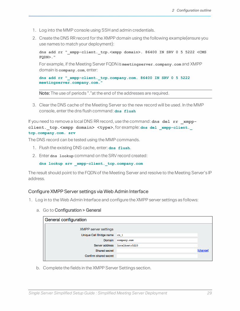
1. Log in to the Web Admin Interface and configure the XMPP server settings as follows:
a. Go to Configuration > General
b. Complete the fields in the XMPP Server Settings section.
2 Configuration outline

Single Server Simplified Setup Guide : Simplified Meeting Server Deployment 30
l Unique Call Bridge name (this is the component name set up previously, no domainpart is required, as shown):
cb_1
l Domain (this is the XMPP server domain set up previously):
company.com
l Server Address is the IP address or hostname of the XMPP server, with an optional<port> (default is 5223):
localhost:5223
l Shared secret: as generated during the XMPP server configuration. Click Change linkto edit the password fields.
c. Click Submit to save your configuration.
5. Go to Status > General and verify the server connection.You should see details similar to the following in the XMPP Connection field:
Configuring Web Bridge for Call Bridge
To enable Guest access to the Web Bridge, the Call Bridge must be configured to locate theWeb Bridge.
1. Log in to the Web Admin Interface using your browser and go to Configuration > General.
2. Set Guest Account Client URI to the HTTPS URL for your Meeting Server. For example:https://meetingserver.company.com
3. Set Guest Account JID domain to your XMPP domain. For example: company.com
4. Set the Web Bridge URI — go to External Access and enter the HTTPS URL for yourMeeting Server. For example: https://meetingserver.company.com
Note: This value will change if you opt to add Expressway web proxy. It is the address thatis advertised in invites to invited users, and used for generating the cross-launch URL forthe Meeting App.
5. Click Submit to save your changes.
6. Confirm the Call Bridge is not reporting errors for the Web Bridge — go to Status > Generaland check that there are no alarms in the Fault conditions panel.
2 Configuration outline

Single Server Simplified Setup Guide : Simplified Meeting Server Deployment 31
Once you have confirmed that there are no faults, you can test the Web Bridge functionalityusing guest access.
1. Using a browser (supported by Cisco Meeting App for WebRTC), enter the web addressto your Meeting Server. For example, https://meetingserver.company.com.
2. Click the Join Meeting link and when prompted, enter the CallID that was set up in your testspace in Task 13. Enter a name for the guest user, and join the call. The WebRTC appshould load and allow the user into the space. You can also connect other computers tothe test meeting, or dial in with SIP participants to populate the meeting.
Task 17: Configuring user importImporting users from an LDAP directory allows conference participants to log into CiscoMeeting App using their own account to manage their spaces and join meetings. Participantscan also join meetings as ‘guest’ users, however, guest users cannot manage meetings orcreate/manage spaces.
Note: This task does not need to be completed if you only wish to enable Guest access.
The LDAP import in Meeting Server allows you to specify which users to target from an existingdirectory, and the values to use for the resulting accounts. The import also optionally supportscreating a personal space for each imported user. Which users and specific values to import is adeployment-specific decision.
As an example configuration, we will import all users from Active Directory, set their login thatthey will use for Meeting App, and create a space for each user.
LDAP Settings description
l LDAP Server Location/Port: network location of the LDAP Server
l LDAP Username/Password: credentials used to connect to the LDAP server. Uses LDAPDN syntax
l Base Distinguished Name: LDAP location where Meeting Server’s search will start. UsesLDAP DN syntax
l Filter: Search filter that defines which LDAP objects to include in the search. Uses LDAPfilter syntax
For each user matched by the above search settings, Meeting Server creates a user in MeetingServer using the Field Mapping values that the administrator defines. The Mappings can useregex expressions and LDAP property names to construct transformations of the importedLDAP values. The Field Mappings used are:
2 Configuration outline
Single Server Simplified Setup Guide : Simplified Meeting Server Deployment 32
l Display Name: Name shown for the user in user searches and directories
l Username: XMPP JID the user will login with – must result in the format of<value>@<xmpp domain> and the result must be unique
l Space Name: Label given to the auto-generated space for that user
l Space URI user part: Defines the user portion of the URI for the auto-generated space forthat user – result must be unique
l Space secondary URI user part: Defines a secondary URI for the auto-generated space forthe user (optional) – result must be unique
l Space call ID: Sets the call ID for the auto-generated space for the user (optional). If notdefined, a random call ID is generated automatically – result must be unique
To create mappings that are unique to each user, the mappings usually include references to theLDAP properties of the imported user. These references can be made using the syntax$propertyName$, for example $sAMAccountName$
2.1.2 Configuring LDAP Import
These steps are required if you want users to log into the Web Bridge to use the Cisco MeetingApp for WebRTC.
1. Log into the Web Admin interface of Meeting Server with your administrator account.
2. Go to Configuration > Active Directory
Configure the Active Directory Server Settings values to point to a domain controller inyour Windows environment. The username should be in the LDAP DN format, but forActive Directory servers, you can use the simpler UPN format, i.e.username@domainFQDN. The username supplied does not need to be an administratoror have special access, it just needs to be a valid domain user to read the directory.
3. Configure the Active Directory Server Settings values. Example values below must beupdated to match your environment.
l Address: pdc1.company.com
l Port: 636
l Secure Connection: Mark Checkbox
l Username: [email protected]
l Password: <Password for supplied user>
Note: For environments with multiple domains, using a Global Catalog server instead of aDomain Controller is recommended. Global Catalog Servers listen on TCP 3268 andSecure 3269
2 Configuration outline

Single Server Simplified Setup Guide : Simplified Meeting Server Deployment 33
4. Configure the Import Settings. Example values below must be updated to match yourenvironment.
l Base distinguished name: cn=Users,dc=company,dc=com
l Filter: (&(sAMAccountType=805306368)(sAMAccountName=*)(mail=*))
Note: Change the Base distinguished name to your own domain names, however, you canuse this Filter example as it appears here.
Note: If your directory has a large number of users (more than10,000) or you do not wantto enable all users, the Base distinguished name and Filter should be changed to target amore specific group or set of users. Importing a large number of users increases the timerequired to complete the LDAP sync.
5. Configure the Field Mapping Expressions. The Username example must be edited tomatch your configured XMPP domain.
l Display Name: $cn$
l User name: [email protected]
l Space Name: $cn$ space
l Space URI user part: $sAMAccountName$.space
l Space Secondary URI user part: [leave blank]
l Space call id: [leave blank]
6. Click Submit to save the changes.
7. Click Sync Now to start the LDAP import.
After a minute or two, go to Status > Users which should display the users created by theLDAP import. And Configuration > Spaces should display the spaces that were createdfor the imported users.
If the user list is empty, go to Logs > Event Log and locate the entries starting with LDAPsync operation. Any errors about attributes missing or duplicate entries means your FieldMappings or search criteria needs adjusting to avoid errors. Go to Configuration > ActiveDirectory and modify your import settings and click Sync Now to retry the import.
For further tips and examples around the LDAP Import settings, see "LDAP Tips andExamples" on page 35.
2.1.3 Confirm Web Bridge Logins
1. To verify your Web Bridge and LDAP deployment, go to the Meeting Server's webinterface https://meetingserver.company.com using a supported WebRTC App
2 Configuration outline

Single Server Simplified Setup Guide : Simplified Meeting Server Deployment 34
browser.
The welcome screen should display with Sign In and Join Meeting as Guest buttons.
2. Click Sign In and log in using a username that was included in the LDAP import. Thepassword is the user’s password from the LDAP directory.
Ensure you enter the username as imported, if you are unsure of the format, log into theWeb Admin interface, go to Status > Users; the username format is shown in the XMPP IDcolumn for each user.
3. Once logged in successfully, the WebRTC App will load and the user can open theirexisting space, dial out to remote participants, or have other participants dial into thespace.
2 Configuration outline

Single Server Simplified Setup Guide : Simplified Meeting Server Deployment 35
Appendix A Additional information
A.1 Firewall ports informationOpen the appropriate Firewall ports, for example: TCP 445, TCP 80, TCP 443, TCP 5222, TCP5061, UDP 3478, UDP 32768-65535, TCP 32768-65535.
See Appendix B of Cisco Meeting Server 2.x, Single Combined Server Deployment Guide for allport information.
A.2 Adding firewall traversal and external networksSIP and Lync calls can traverse local firewalls using the Cisco Expressway, you will need toconfigure trust between the Call Bridge and the Cisco Expressway. Cisco Expressway must berunning X8.9 or later. For more information, seeCisco ExpresswayOptionswith Cisco MeetingServer and/orMicrosoft Infrastructure (ExpresswayX8.9.2) or if running X8.10 seeCiscoExpresswayWeb Proxy for Cisco Meeting Server (X8.10) and Cisco ExpresswaySessionClassification Deployment Guide (X8.10).
Go to: https://www.cisco.com/c/en/us/support/unified-communications/expressway-series/products-installation-and-configuration-guides-list.html
A.3 LDAP Tips and ExamplesImportant points to note:
l Case sensitivity: the LDAP attribute names are case sensitive. For example, when using$cn$ or $sAMAccountName$
l Username: Required field. All resulting user names as imported must be unique (includesthe full string)—any duplicates (or empty values) will cause the import to be aborted.
l Space name: Optional field. Does not require uniqueness.
l Space URI user part: Optional field. All resulting space URIs must be unique within thetenant (in spaces and user JIDs).
l Space secondary URI user part: Optional field. All resulting space URIs must be uniquewithin the tenant (in spaces and user JIDs).
l Space Call ID: Optional field. All resultingCall IDs must be unique
Appendix A Additional information

Single Server Simplified Setup Guide : Simplified Meeting Server Deployment 36
A.3.1 Tips on LDAP
l To find the LDAP path or Domain Name of a specific user or location, use the Users &Computers Snap In on Windows, navigate to the object, and select Properties. Select theAttribute Editor tab, and find the attribute you want to look up in the list.
l Missing attributes on a user can cause an import to abort, so it is always good practice toput the attributes you depend on in the ldap filter so objects without those attributes areexcluded.
l If using Active Directory, using the filter (sAMAccountType=805306368) automaticallylimits your search to just user objects and reduces load on the AD server.
l Filter example to import members of a security group recursively, use a filter such as:(&(objectclass=person(memberOf:1.2.840.113556.1.4.1941:=cn=groupName,cn=Users,dc=company,dc=com))
l Filter example to exclude a specific user, use a filter such as:(&(sAMAccountType=805306368)(sAMAccountName=*)(!(cn=Joe Smith)))
l Regex example to take the left side of the email address (portion before the @) andappend it to your XMPP domain, for example:$mail|'/\@.*//'[email protected]
Example 1: Import all Active Directory Users, set JID based on sAMAccountName, andcreate a space
Example uses XMPP domain of company.com
l Display Name: $cn$
l User name: [email protected]
l space Name: $cn$ space
l space URI user part: $cn$.space
l space Secondary URI user part: [leave blank]
l space call id: [leave blank]
l Use LDAP base: cn=Users,dc=company,dc=com
l Use LDAP filter: (&(sAMAccountName=*)(sAMAccountType=805306368))
Example 2: Import all users that are members of a specific Active Directory group,cn=CMSAdmins,cn=Users,=dc=company,dc=com and create spaces for each
Example uses XMPP domain of company.com
Appendix A Additional information

Single Server Simplified Setup Guide : Simplified Meeting Server Deployment 37
l User name: [email protected]
l space Name: $cn$ space
l space URI user part: $cn$.space
l space Secondary URI user part: (leave blank)
l space call id: (leave blank)
l Use LDAP base: cn=Users,dc=company,dc=com
l Use LDAP filter: (sAMAccountType=805306368)(memberOf:1.2.840.113556.1.4.1941:=cn=CMSAdmins,cn=Users,dc=company,dc=com))
A.3.2 Common user LDAP filters
To import users that belong to a specific group, you can filter on the memberOf attribute.For example:memberOf=cn=apac,cn=Users,dc=Example,dc=com
This imports both groups and people that are members of the APAC group.
To restrict to people (and omit groups), use:(&(memberOf=cn=apac,cn=Users,dc=Example,dc=com)(objectClass=person))
Using an extensible matching rule (LDAP_MATCHING_RULE_IN_CHAIN /1.2.840.113556.1.4.1941), it is possible to filter on membership of any group in amembership hierarchy (below the specified group); for example:(&(memberOf:1.2.840.113556.1.4.1941:=cn=apac,cn=Users,dc=Example,dc=com)(objectClass=person))
Other good examples which you can adapt to your LDAP setup include:
Filter that adds all Person and User except the ones defined with a !(&(objectCategory=person)(objectClass=user)(!(cn=Administrator))(!(cn=Guest))(!(cn=krbtgt)))
Filter that adds same as above (minus krbtgt user) and only adds if they have asAMAccountName(&(objectCategory=person)(objectClass=user)(!(cn=Administrator))(!(cn=Guest))(sAMAccountName=*))
Filter that adds same as above (Including krbtgt user) and only adds if they have asAMAccountName(&(objectCategory=person)(objectClass=user)(!(cn=Administrator))(!(cn=Guest))(!(cn=krbtgt))(sAMAccountName=*))
This filter only imports specified users within (|( tree(&(objectCategory=person)(objectClass=user)(|(cn=accountname)(cn=anotheraccountname)))
Appendix A Additional information

Single Server Simplified Setup Guide : Simplified Meeting Server Deployment 38
Global Catalog query to import only members of specified security group (signified with=cn=xxxxx(&(memberOf:1.2.840.113556.1.4.1941:=cn=groupname,cn=Users,dc=example,dc=com)(objectClass=person))
A.4 Microsoft deployment informationFor an example deployment, see: Cisco Meeting Server clustered with on-premises MicrosoftLync or Skype for Business
For more information on Microsoft deployments, see Cisco Expressway Options with CiscoMeeting Server and/or Microsoft Infrastructure (Expressway X8.9.2) or if running X8.10 seeCisco Expressway Web Proxy for Cisco Meeting Server (X8.10) and Cisco Expressway SessionClassification Deployment Guide (X8.10):
https://www.cisco.com/c/en/us/support/unified-communications/expressway-series/products-installation-and-configuration-guides-list.html
Appendix A Additional information

Single Server Simplified Setup Guide : Simplified Meeting Server Deployment 39
Cisco Legal InformationTHE SPECIFICATIONS AND INFORMATION REGARDING THE PRODUCTS IN THIS MANUAL ARESUBJECT TO CHANGE WITHOUT NOTICE. ALL STATEMENTS, INFORMATION, ANDRECOMMENDATIONS IN THIS MANUAL ARE BELIEVED TO BE ACCURATE BUT AREPRESENTED WITHOUT WARRANTY OF ANY KIND, EXPRESS OR IMPLIED. USERS MUST TAKEFULL RESPONSIBILITY FOR THEIR APPLICATION OF ANY PRODUCTS.
THE SOFTWARE LICENSE AND LIMITED WARRANTY FOR THE ACCOMPANYING PRODUCTARE SET FORTH IN THE INFORMATION PACKET THAT SHIPPED WITH THE PRODUCT AND AREINCORPORATED HEREIN BY THIS REFERENCE. IF YOU ARE UNABLE TO LOCATE THESOFTWARE LICENSE OR LIMITED WARRANTY, CONTACT YOUR CISCO REPRESENTATIVEFOR A COPY.
The Cisco implementation of TCP header compression is an adaptation of a programdeveloped by the University of California, Berkeley (UCB) as part of UCB’s public domain versionof the UNIX operating system. All rights reserved. Copyright © 1981, Regents of the Universityof California.
NOTWITHSTANDING ANY OTHER WARRANTY HEREIN, ALL DOCUMENT FILES ANDSOFTWARE OF THESE SUPPLIERS ARE PROVIDED “AS IS” WITH ALL FAULTS. CISCO AND THEABOVE-NAMED SUPPLIERS DISCLAIM ALL WARRANTIES, EXPRESSED OR IMPLIED,INCLUDING, WITHOUT LIMITATION, THOSE OF MERCHANTABILITY, FITNESS FOR APARTICULAR PURPOSE AND NONINFRINGEMENT OR ARISING FROM A COURSE OF DEALING,USAGE, OR TRADE PRACTICE.
IN NO EVENT SHALL CISCO OR ITS SUPPLIERS BE LIABLE FOR ANY INDIRECT, SPECIAL,CONSEQUENTIAL, OR INCIDENTAL DAMAGES, INCLUDING, WITHOUT LIMITATION, LOSTPROFITS OR LOSS OR DAMAGE TO DATA ARISING OUT OF THE USE OR INABILITY TO USETHIS MANUAL, EVEN IF CISCO OR ITS SUPPLIERS HAVE BEEN ADVISED OF THE POSSIBILITYOF SUCH DAMAGES.
Any Internet Protocol (IP) addresses and phone numbers used in this document are not intendedto be actual addresses and phone numbers. Any examples, command display output, networktopology diagrams, and other figures included in the document are shown for illustrativepurposes only. Any use of actual IP addresses or phone numbers in illustrative content isunintentional and coincidental.
All printed copies and duplicate soft copies of this document are considered uncontrolled. Seethe current online version for the latest version.
Cisco has more than 200 offices worldwide. Addresses and phone numbers are listed on theCisco website at www.cisco.com/go/offices.
© INSERT IN TARGET Cisco Systems, Inc. All rights reserved.
Cisco Legal Information