cisco multicloud portfolio: cloud connect · the cisco multicloud portfolio is a set of essential...
TRANSCRIPT

© 2018 Cisco and/or its affiliates. All rights reserved. This document is Cisco Public Information. Page 1 of 105
Cisco Multicloud Portfolio:
Cloud Connect
Design and Deployment Guide for
Private Data Center to AWS VPC
October 2018
Design and Deployment Guide

© 2018 Cisco and/or its affiliates. All rights reserved. This document is Cisco Public Information. Page 2 of 105
Contents
Executive summary ................................................................................................................................................. 3 Cisco Multicloud Portfolio: overview ...................................................................................................................... 3 Cloud Connect: overview ...................................................................................................................................... 4 Cloud Connect: Use cases.................................................................................................................................... 4 Cloud Connect: Benefits ....................................................................................................................................... 5
Technology overview .............................................................................................................................................. 5
Solution design ........................................................................................................................................................ 6 Design principles ................................................................................................................................................... 6
Solution deployment ............................................................................................................................................... 8 Configure the native IPsec VPN connections in the AWS VPC ............................................................................ 9
Procedure 1: Create two AWS customer gateways .......................................................................................... 9 Procedure 2: Create AWS virtual private gateways (VGWs) .......................................................................... 11 Procedure 3: Create the AWS VPN connections ............................................................................................ 12
Configure the IPsec VPN connections on the Cisco ASR 1000 Series Routers to the AWS VPC ...................... 16 Procedure 1: Configure a BFD template ........................................................................................................ 16 Procedure 2: Configure IKEv1 ........................................................................................................................ 17 Procedure: 3 Configure IPsec ........................................................................................................................ 19 Procedure 4: Configure tunnel interfaces ....................................................................................................... 20 Procedure 5: Configure routing ...................................................................................................................... 22 Procedure 5: Verify that the VPN connections are working properly .............................................................. 28
Configure the IPsec VPN connections on the Cisco CSR 1000V Routers in the AWS Transit VPC ................... 30 Procedure 1: Configure a VRF for the tunnel interface to the private network................................................ 30 Procedure 2: Configure a BFD template ........................................................................................................ 31 Procedure 3: Configure IKEv1 ........................................................................................................................ 32 Procedure 4: Configure IPsec ........................................................................................................................ 33 Procedure 5: Configure tunnel interfaces ....................................................................................................... 34 Procedure 6: Configure dynamic routing ........................................................................................................ 35
Configure the IPsec VPN connections on the Cisco ASR 1000 Series Routers to the AWS Transit VPC .......... 38 Procedure 1: Configure IKEv1 ........................................................................................................................ 38 Procedure 2: Configure IPsec ........................................................................................................................ 39 Procedure 3: Configure tunnel interfaces ....................................................................................................... 39 Procedure 4: Configure routing ...................................................................................................................... 40 Procedure 5: Verify that the VPN connections are working properly .............................................................. 42
Configure visibility into application flows ............................................................................................................. 45 Procedure 1: Configure AVC .......................................................................................................................... 45 Procedure 2: View AVC data via the CLI ........................................................................................................ 46 Optional Procedure 3: View AVC data through the web interface .................................................................. 48 Procedure 3: Configure flow monitoring and data export ............................................................................... 51 Procedure 4. View flow-monitoring information via the LiveNX client ............................................................. 53 Procedure 5. View flow-monitoring information via the LiveAction web interface ........................................... 55
Appendix A: Design considerations .................................................................................................................... 57 Positioning of the VPN gateway in the private network .................................................................................. 57 Network Address Translation (NAT) ............................................................................................................... 59 High availability .............................................................................................................................................. 59 Symmetric routing for AVC ............................................................................................................................. 62 Access control and path isolation ................................................................................................................... 64
Appendix B: Cisco ASR 1000 Series Router configuration ............................................................................... 67
Appendix C: AWS VPN configuration example ................................................................................................... 90
Appendix D: Flow configuration example ........................................................................................................... 99
Additional resources ........................................................................................................................................... 104

© 2018 Cisco and/or its affiliates. All rights reserved. This document is Cisco Public Information. Page 3 of 105
Executive summary
This guide focuses on how to deploy an Amazon Web Services (AWS) virtual private cloud (VPC) with VPN
connectivity back to a private network using a redundant pair of Cisco® ASR 1000 Series Aggregation Services
Routers at the corporate site. The design uses an AWS managed VPN connection through a virtual private
gateway (VGW) attached to the VPC. Advanced features such as Application Visibility & Control (AVC) / Next-
Generation Network-Based Application Recognition (NBAR2) and Flexible NetFlow data export are discussed for
traffic and application-level visibility at the ASR 1000 Series routers within the private network.
The audience for this document includes network design engineers, network operations personnel, and security
operations personnel who wish to implement secure VPN connectivity from their private data centers to an AWS
VPC. This guide also discusses the connection of an AWS Transit VPC to a private network using IPSec VPN
connectivity. The AWS Transit VPC design is documented in the following link:
https://www.cisco.com/c/en/us/products/collateral/routers/cloud-services-router-1000v-series/guide-c07-740270.pdf
Cisco Multicloud Portfolio: overview
In a multicloud world, growing complexity is driving a cloud gap between what your customers require and what
your people, processes, and tools can support. With the Cisco Multicloud Portfolio, we make it simple: simple to
connect, simple to protect, and simple to consume.
The Cisco Multicloud Portfolio is a set of essential products, software, and services supported with simplified
ordering and design deployment guides to help you when it comes to multicloud adoption. The Cisco Multicloud
Portfolio consists of four component portfolios (Figure 1):
● Cloud Advisory: Helps you design, plan, accelerate, and remove risk from your multicloud migration.
● Cloud Connect: Securely extends your private networks into public clouds and helps ensure the appropriate
application experience.
● Cloud Protect: Protects your multicloud identities, direct-to-cloud connectivity, data, and applications,
including software as a service (SaaS), and detects infrastructure and application threats on premises and
in public clouds.
● Cloud Consume: Helps you deploy, monitor, and optimize applications in multicloud and container
environments.

© 2018 Cisco and/or its affiliates. All rights reserved. This document is Cisco Public Information. Page 4 of 105
Figure 1. Multicloud Portfolio: Cloud Advisory, Cloud Connect, Cloud Protect, and Cloud Consume
Cloud Connect: overview
Cloud Connect consists of essential products that help securely extend your private networks – including the data
center, branches, and campuses – to public clouds and to help ensure that the application experience is optimal:
● Cisco Cloud Services Router (CSR) 1000V Series
● Cisco vEdge with Cisco Umbrella™
For detailed use cases, see the section about Cloud Connect on the portfolio’s solution page at
https://www.cisco.com/go/multicloud.
Cloud Connect: Use cases
Cloud Connect delivers value in the following use cases:
● Securely extending a private network to single or multiple public cloud environments. Includes multiple
clouds (for example, multiple AWS and Azure), multiple regions in a cloud, or multiple VPCs in a cloud;
VPN; multicloud and multi-VPC connectivity; scaling; and performance optimization- transit VPC. Also
supports extending data centers into the cloud and enabling direct branch-to-cloud connectivity (when a
branch has a Cisco 4000 Series Integrated Services Router [ISR] and wants to connect the clouds or a
branch has vEdge and requires a software-defined WAN [SD-WAN] extension to the cloud).
● Optimizing data center and branch connectivity performance to cloud infrastructure as a Service (IaaS) and
SaaS. Includes best path to destination (SD-WAN), cloud segmentation, monitoring to assure best
performance, visibility into traffic going to applications, and traffic shaping/Quality of Service (QoS). Also
supports extending data centers into the cloud and enabling direct branch-to-cloud connectivity (when a
branch has a 4000 Series ISR and wants to connect the clouds or a branch has vEdge and requires an SD-
WAN extension to the cloud).

© 2018 Cisco and/or its affiliates. All rights reserved. This document is Cisco Public Information. Page 5 of 105
● Securing access to the Internet and SaaS from the branch. Includes connecting and protecting branch office
users directly to the multicloud environment using Direct Internet Access (DIA), SD-WAN (vEdge), and
secure Internet gateways (Cisco Umbrella).
Cloud Connect: Benefits
Cloud Connect benefits include the ability to:
● Extend a private network to a multicloud environment while leveraging existing investments
● Apply consistent security policies across a private and public cloud footprint
● Enhance and secure the app experience on a cloud network by enabling visibility and path selection and
optimization
● Centralize management in a manner that is intuitive, fast, and easy to design, provision, and apply policies
across the entire network
● Achieve faster and more simple adoption of cloud
● Improve TCO
● Access a richer networking security feature set and higher performance
● Improve ease of use through consistency of management tools for both on-premises and cloud
● Simplify implementation through increased visibility into the public cloud network
Technology overview
In a multicloud world, IT managers are quickly realizing the benefits of cloud computing services such as
infrastructure as a service (IaaS). IaaS providers, such as AWS, allow organizations to more rapidly and cost-
effectively prototype new applications. Instead of procuring, installing, and managing hardware – which could takes
months to accomplish – you can easily use the on-demand and scalable compute services in AWS. This allows
you to focus your resources on applications rather than on managing the data center and physical infrastructure.
With the use of IaaS, expenses shift from fixed costs for hardware, software, and data center infrastructure to
variable costs based on the usage of compute resources and the amount of data transferred between the private
data center and the IaaS provider. Thus, you must also be able to monitor the usage of such resources for cost
tracking and/or internal billing purposes.
To realize the full benefits that IaaS offers, secure, highly available connectivity to the AWS VPC must be
established. The use of VPN connectivity to an AWS VPC provides a cost-effective solution for providing that
connectivity. IP Security (IPsec) encryption of traffic, using strong cryptographic cipher suites, provides secure
connectivity between your private data center and the AWS VPC. High availability is accomplished through the
deployment of redundant VPN gateways. This deployment guide uses a pair of Cisco ASR 1002-X Routers running
Cisco IOS® XE Software Release 16.06.02 code licensed with the Advanced Enterprise feature set to provide
IPsec VPN and routing services to connect to AWS Virtual Private Gateways (VGWs). Configuration of the ASR
1002-X routers is through the Command-Line Interface (CLI) for this version of this guide.
Cisco ASR 1002-X Routers support AVC/NBAR2 and Flexible NetFlow. The application-flow information provided
by the Cisco ASR 1002-X Routers can be leveraged by a flow collector provided by a Cisco partner, LiveAction
(https://www.liveaction.com/), through the LiveNX network performance and analytics platform. LiveNX Enterprise
Edition, Version 7.0.1, was used for this guide. LiveNX provides a centralized console for visualizing application
flows through the ASR 1002-X routers.

© 2018 Cisco and/or its affiliates. All rights reserved. This document is Cisco Public Information. Page 6 of 105
Finally, the AWS web-based console (https://console.aws.amazon.com) was used for configuring the AWS VPN
connections.
Solution design
Design principles
The procedures in this section provide examples for most settings. The actual settings and values that you use
are determined by your current network configuration. Figure 2 shows the overall high-level design for this
deployment guide. A redundant set of Cisco ASR 1000 Series Routers serve as dedicated VPN gateways for
the private network.
Figure 2. Private network to AWS VPC design
The top part of the figure shows the connectivity from the private network to an AWS Transit VPC, using a
redundant pair of Cisco CSR 1000V Routers deployed in the Transit VPC. Each Cisco ASR 1000 Series Router in
the private network establishes a single IPsec VPN tunnel to one of the Cisco CSR 1000V routers deployed in the
Transit VPC.

© 2018 Cisco and/or its affiliates. All rights reserved. This document is Cisco Public Information. Page 7 of 105
The bottom part of the figure shows connectivity from the private network to a VPC using the native IPsec VPN
gateway of AWS. Each Cisco ASR 1000 Series Router in the private network establishes two IPsec VPN tunnels to
the public IP addresses of the AWS VGWs in the VPC, for a total of four IPsec VPN tunnels in this design. (For
more information, see Tables 1 and 2.)
Each of the Cisco CSR 1000V Routers in the Transit VPC also establishes two IPsec VPN tunnels to the public IP
addresses of the AWS VGWs in the spoke VPCs – as shown in the top right section of the figure above. For more
information, refer to the AWS Transit VPC with Cisco Cloud Services Router 1000V deployment guide at the
following URL:
https://www.cisco.com/c/en/us/products/collateral/routers/cloud-services-router-1000v-series/guide-c07-740270.pdf
Note: You may not necessarily deploy both native IPsec VPN connectivity directly to an AWS VPC and IPsec
VPN connectivity through an AWS Transit VPC design simultaneously. However, this design demonstrates full
routing from the spoke VPCs connected through the Transit VPC, all the way out to the VPC connected through
the native IPsec VPN connection directly from the private network. This scenario may also be temporarily deployed
during a transition to a Transit VPC design, because the AWS deployment scales beyond one or two VPCs
connected directly through AWS-native IPsec VPN connections.
Table 1. AWS VPC native IPsec VPN information
Description Name IP address
First AWS customer gateway Multi-Cloud_ASR1K-1 173.36.197.52
Second AWS customer gateway Multi-Cloud_ASR1K-2 173.36.197.53
AWS virtual private gateway (VGW) Multi-Cloud_VGW –
AWS first VPN connection outside IP addresses Multi-Cloud_VPN1 18.233.2.243 and 52.5.66.86
AWS first VPN connection tunnel addresses Multi-Cloud_VPN1 169.254.47.149/30 and 169.254.45.137/30
AWS second VPN connection outside IP address Multi-Cloud_VPN2 34.231.13.229 and 34.236.23.79
AWS second VPN connection tunnel addresses Multi-Cloud_VPN2 169.254.47.73 /30 and 169.254.47.17/30
AWS BGP ASN 65030 –
AWS VPC Multi-Cloud_VPC 10.0.0.0/16
AWS VPC VPN-only subnet Multi-Cloud_Subnet1 10.0.1.0/24
Table 2. AWS Transit VPC VPN information
Description Name IP address
Transit VPC CSR1 public IP address TVPC-CSR1 35.168.251.31
Transit VPC CSR2 public IP address TVPC-CSR2 54.83.140.40
TVPC-CSR1 to ASR1K-1 IPsec VPN connection tunnel addresses
TVPC-CSR1 Tunnel100 10.1.0.97 /30
TVPC-CSR2 to ASR1K-2 IPsec VPN connection tunnel addresses
TVPC-CSR2 Tunnel100 10.1.0.101/30
Transit VPC BGP ASN 64512 –
Table 3. Private network VPN information
Description Name IP address
Public IP address of first VPN router – 173.36.197.52
Public IP address of second VPN router – 173.36.197.53

© 2018 Cisco and/or its affiliates. All rights reserved. This document is Cisco Public Information. Page 8 of 105
Description Name IP address
Front-side interface of first VPN router (1:1 NAT to 173.36.197.52)
ASR1K-1 GigabitEthernet0/0/0
10.1.0.84/29
Back-side interface of first VPN router ASR1K-1 GigabitEthernet0/0/2
10.1.0.124/29
VPC tunnel addresses of first VPN router ASR1K-1 Tunnel1 and Tunnel2
169.254.47.150/30 Tunnel1 and 169.254.45.138/30 Tunnel2
Transit VPC tunnel address of the first VPN router ASR 1K-1 Tunnel100 10.1.0.98/30
Front-side interface of second VPN router (1:1 NAT to 173.36.197.53)
ASR1K-2 GigabitEthernet0/0/0
10.1.0.85/29
Back-side interface of second VPN router ASR1K-2 GigabitEthernet0/0/2
10.1.0.125/29
VPC tunnel addresses of second VPN router ASR1K-2 Tunnel1 and Tunnel2
169.254.47.74/30 Tunnel1 and 169.254.47.18/30 Tunnel2
Transit VPC tunnel address of the second VPC router ASR1K-2 Tunnel100 10.1.0.102/30
Outside interface of ASAv data center firewall active/standby pair
ASAv-1 GigabitEthernet0/0 10.1.0.121/29
Inside interface of ASAv data center firewall active/standby pair
ASAv-1 GigabitEthernet0/1 10.1.0.129/29
Nexus 5000 Series distribution-layer switch #1 SVI for VLAN 20
N5K-1 VLAN 20 10.1.0.82/29
Nexus 5000 Series distribution-layer switch #1 SVI for VLAN 70
N5K-1 VLAN 70 10.1.0.132/29
Nexus 5000 Series distribution-layer switch #2 SVI for VLAN 20
N5K-2 VLAN 20 10.1.0.83/29
Nexus 5000 Series distribution-layer switch #2 SVI for VLAN 70
N5K-2 VLAN 70 10.1.0.133/29
Nexus 5000 Series distribution-layer switch shared HSRP IP address
HSRP Group 20 10.1.0.81/29
Private network BGP ASN 65000 N/A
Private network EIGRP ASN 100 NA
Solution deployment
The overall processes for this deployment guide are split into three sections. The first set of processes configures
IPsec VPN connectivity between the private network and a VPC, using the native IPsec VPN connectivity of AWS.
The processes are as follows:
● Configure the native IPsec VPN connections in the AWS VPC
● Configure the IPsec VPN connections on the Cisco ASR 1000 Series Routers to the AWS VPC
The second set of processes configures the IPsec VPN connectivity between the private network and an AWS
Transit VPC, using the Cisco CSR 1000V Routers already deployed in the Transit VPC. Only deploy these
processes if you are connecting a Transit VPC to the private network. The processes are as follows:
● Configure the IPsec VPN connections on the Cisco CSR 1000V Routers in the AWS Transit VPC
● Configure the IPsec VPN connections on the Cisco ASR 1000 Series Routers to the AWS Transit VPC
The final process is optional. The below process provides visibility into application flows to and from the private
network and the AWS VPCs.
Configure visibility into application flows
The below figure provides guidelines on how to read the commands given in this guide.

© 2018 Cisco and/or its affiliates. All rights reserved. This document is Cisco Public Information. Page 9 of 105
Figure 3. How to read the commands in this guide
Configure the native IPsec VPN connections in the AWS VPC
Use this process to create the following:
● The AWS customer gateways to which the AWS virtual private gateway will establish IPsec
VPN connections
● The AWS virtual private gateway (VGW)
● The VPN connections that connect the AWS virtual private gateway with the AWS customer gateways
This process assumes that the AWS VPC and a subnet (VPN-only subnet) within that VPC have already
been created.
Procedure 1: Create two AWS customer gateways
In order to support a redundant pair of Cisco ASR 1000 Series Routers in your private data center, you need to
create two AWS customer gateways. Each AWS customer gateway must have a unique public IP address (an IP
address routable over the Internet). Each AWS customer gateway is paired with a single AWS VPN connection.
From the AWS VPC Dashboard, select Customer Gateways from the panel on the left side of the screen. Click
the Create Customer Gateway button at the top of the screen to bring up the Create Customer Gateway screen
(see Figure 4).
Figure 4. Create Customer Gateway screen

© 2018 Cisco and/or its affiliates. All rights reserved. This document is Cisco Public Information. Page 10 of 105
Step 1. Name the two AWS customer gateways.
An AWS customer gateway is the logical construct configured within AWS that represents the VPN router at your
private data center to which the AWS VGW will establish an IPsec VPN connection. Provide a name for each AWS
customer gateway you are creating. In this example, the first AWS customer gateway is named Multi-
Cloud_ASR1K-1 and the second AWS customer gateway is named Multi-Cloud_ASR1K-2.
Step 2. Select the type of routing.
Routing between the AWS VPC and your private network can be done via either static routes or dynamic routing
using Border Gateway Protocol (BGP). For this deployment guide, dynamic routing is used. Select the Dynamic
radio button next to Routing.
Step 3. Configure the BGP ASN of the private network.
This guide uses dynamic routing, so BGP peering between two autonomous systems (AWS and the private
network) must be established. You must configure a BGP autonomous system number (ASN) for your private
network. AWS will provide a default ASN of 65000 if you do not configure your ASN. This deployment guide uses
the default ASN of 65000 provided by AWS for the private network.
Step 4. Configure the IP addresses of the AWS customer gateways.
For this guide, the IP addresses of the Cisco ASR 1000 Series Routers that function as the AWS customer
gateways are both be-hind a firewall that is performing static 1:1 NAT. Therefore the external NAT-translated IP
addresses (public IP addresses) of the “front-side” interfaces (GigabitEthernet0/0/0) of the routers are used when
creating the AWS customer gateways. These addresses are provided in Table 2.
Step 5. Create an AWS customer gateway.
Click the Create Customer Gateway button when you have provided the information for each of the four steps
above. This will bring up a screen indicating that a customer gateway was successfully created. Close this screen
and you will be taken back to the main Customer Gateways screen. It should show the customer gateway you just
created, and its state should be “available” (see Figure 5).
Figure 5. Customer Gateways screen with AWS customer gateway

© 2018 Cisco and/or its affiliates. All rights reserved. This document is Cisco Public Information. Page 11 of 105
Step 6. Create a second AWS customer gateway.
Repeat steps 1 through 5 to create a second AWS customer gateway. When completed, the main screen should
show the availability of both gateways (see Figure 5).
Procedure 2: Create AWS virtual private gateways (VGWs)
Each AWS VPC supports a single AWS VGW. From the AWS VPC dashboard, select Virtual Private Gateways
from the left panel. Click the Create Virtual Private Gateway button at the top of the screen to bring up the Create
Virtual Private Gateway screen (see Figure 6).
Figure 6. Creating an AWS virtual private gateway
Step 1. Name the virtual private gateway
The virtual private gateway is a logical construct that represents the VPN router at AWS. It will establish IPsec VPN
connections to your private network. Provide a name for the virtual private gateway. In this guide, the virtual private
gateway is named Multi-Cloud_VGW.
Step 2. Configure the BGP ASN of the AWS side of the VPN connection.
Since this deployment guide uses dynamic routing, BGP peering between two autonomous systems (AWS and the
private network) must be established. You must configure the BGP ASN for the AWS side of the VPN connection.
AWS will provide an ASN of 7224 if you select the Amazon default ASN. Alternatively, you can select Custom ASN
and provide an ASN. This deployment guide uses a BGP ASN of 65030 for the VPC.
Step 3. Create the AWS virtual private gateway.
Click the Create Virtual Private Gateway button when you have provided the information for each of the two steps
above. This will bring up a screen indicating that the AWS virtual private gateway was successfully created. Close
this screen and you will be taken back to the main Virtual Private Gateways screen. It should show the AWS virtual
private gateway you just created (see Figure 7). Note that, unlike Figure 7, the state of your AWS virtual private
gateway will be "detached" because it is not attached to any VPC when it is first created.
© 2018 Cisco and/or its affiliates. All rights reserved. This document is Cisco Public Information. Page 12 of 105
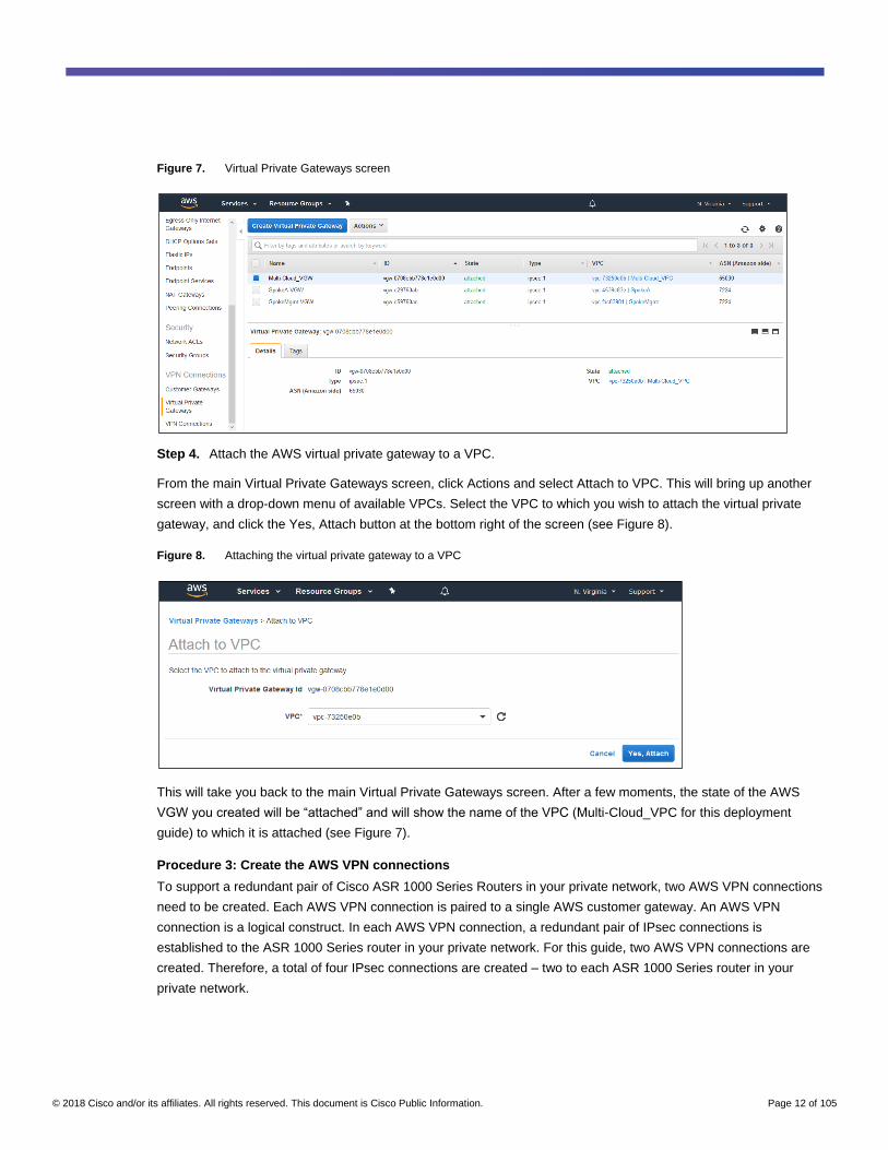
Figure 7. Virtual Private Gateways screen
Step 4. Attach the AWS virtual private gateway to a VPC.
From the main Virtual Private Gateways screen, click Actions and select Attach to VPC. This will bring up another
screen with a drop-down menu of available VPCs. Select the VPC to which you wish to attach the virtual private
gateway, and click the Yes, Attach button at the bottom right of the screen (see Figure 8).
Figure 8. Attaching the virtual private gateway to a VPC
This will take you back to the main Virtual Private Gateways screen. After a few moments, the state of the AWS
VGW you created will be “attached” and will show the name of the VPC (Multi-Cloud_VPC for this deployment
guide) to which it is attached (see Figure 7).
Procedure 3: Create the AWS VPN connections
To support a redundant pair of Cisco ASR 1000 Series Routers in your private network, two AWS VPN connections
need to be created. Each AWS VPN connection is paired to a single AWS customer gateway. An AWS VPN
connection is a logical construct. In each AWS VPN connection, a redundant pair of IPsec connections is
established to the ASR 1000 Series router in your private network. For this guide, two AWS VPN connections are
created. Therefore, a total of four IPsec connections are created – two to each ASR 1000 Series router in your
private network.
© 2018 Cisco and/or its affiliates. All rights reserved. This document is Cisco Public Information. Page 13 of 105
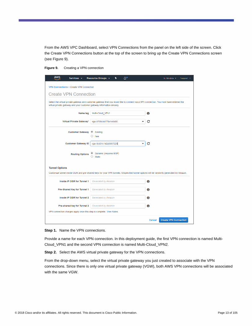
From the AWS VPC Dashboard, select VPN Connections from the panel on the left side of the screen. Click
the Create VPN Connections button at the top of the screen to bring up the Create VPN Connections screen
(see Figure 9).
Figure 9. Creating a VPN connection
Step 1. Name the VPN connections.
Provide a name for each VPN connection. In this deployment guide, the first VPN connection is named Multi-
Cloud_VPN1 and the second VPN connection is named Multi-Cloud_VPN2.
Step 2. Select the AWS virtual private gateway for the VPN connections.
From the drop-down menu, select the virtual private gateway you just created to associate with the VPN
connections. Since there is only one virtual private gateway (VGW), both AWS VPN connections will be associated
with the same VGW.

© 2018 Cisco and/or its affiliates. All rights reserved. This document is Cisco Public Information. Page 14 of 105
Step 3. Select the customer gateway for the VPN connections.
An AWS VPN connection is actually a redundant pair of IPsec VPN connections between the AWS virtual private
gateway and a Cisco ASR 1000 Series Router in the private network (represented logically by an AWS customer
gateway). Since the customer gateways have already been created within AWS, select the Existing radio button.
Select the first customer gateway created in the procedure above from the Customer Gateway ID drop-down menu
for the first VPN connection. For the second VPN connection, select the second customer gateway created in
Procedure 1, above.
Step 4. Select the routing method.
The design followed in this deployment guide uses BGP routing between the AWS VPC and the private network.
Select the Dynamic (which requires BGP) radio button adjacent to Routing Options.
Step 5. Select tunnel options.
The VPN connection between the AWS virtual private gateway and the Cisco ASR 1000 Series Routers uses
IPsec virtual tunnel interfaces (VTIs). Tunnel Options allow you to select the IP addresses used for the tunnel
interfaces. Since two IPsec tunnels are created with each VPN connection, the IP address ranges for Tunnels 1
and 2 can be specified. If an IPv4 Classless Inter-Domain Routing (CIDR) subnet is not specified, AWS will
automatically assign subnets for each tunnel. The IP address ranges for Tunnels 1 and 2 are generated by AWS
for both VPN connections in this deployment guide.
VPN connections between AWS virtual private gateways and Cisco ASR 1000 Series Routers use preshared keys
for Internet Security Association and Key Management Protocol (ISAKMP) authentication of the VPN peers. Tunnel
Options allow you to select the preshared key for each of the tunnel interfaces, each of which corresponds to an
ISAKMP peer configured on the ASR 1000 Series routers. If preshared keys are not specified, AWS will
automatically assign them for each tunnel. The preshared keys are generated by AWS for both VPN connections in
this deployment guide.
Step 6. Create the VPN connection.
Click the Create VPN Connection button when you have provided the information for each of the five steps above.
This will bring up a screen indicating that the AWS VPN connection was successfully created. Close this screen
and you will be taken back to the main VPN Connections screen. It should show the AWS VPN Connection you
just created (see Figure 10). Note that the initial state of the AWS VPN connection just created may be “pending.”
After a few moments, the state should be “available” (see Figure 10).

© 2018 Cisco and/or its affiliates. All rights reserved. This document is Cisco Public Information. Page 15 of 105
Figure 10. VPN Connections screen
If the Cisco ASR 1000 Series Routers at the private network have not been configured yet, the Tunnel Details tab
may show the status of the two IPsec connections as being “DOWN.” However, as soon as the ASR 1000 Series
routers are configured, both VPN tunnels should show a status of “UP” (see Figure 10). This provides a quick
means of troubleshooting the status of the VPN tunnels from AWS.
Step 7. Download the configuration information for the customer gateway.
AWS provides an example of how the customer gateway should be configured in order to establish the two IPsec
connections between the AWS virtual private gateway and the device used as the VPN gateway at your private
network. From the main VPN Connections screen, click the Download Configuration button.
Figure 11. Selecting the device for configuration download

© 2018 Cisco and/or its affiliates. All rights reserved. This document is Cisco Public Information. Page 16 of 105
The design followed in this deployment guide uses Cisco ASR 1000 Series Routers at the private network. Select
Cisco Systems, Inc. as the Vendor, Cisco ASR 1000 as the Platform, and IOS 12.4+ as the Software (see Figure
11). Click the Download button to download the configuration information to your PC. You can close the pop-up
window once the download is complete. You will use this information when configuring the ASR 1000 Series
routers. An example of the configuration information downloaded from AWS is shown in Appendix B.
Step 8. Create the second VPN connection.
Repeat steps 1 through 7 above to create a second AWS VPN connection. Use the second AWS customer
gateway created in Step 6 of Procedure 1 above for this AWS VPN connection.
Configure the IPsec VPN connections on the Cisco ASR 1000 Series Routers to the AWS VPC
Use this process to configure the IPsec VPN connections on the Cisco ASR 1000 Series Routers in your private
network. These connect to the native IPsec VPN connections in the AWS VPC that you created in the previous
process.
The following procedures use the configurations downloaded for each of the two AWS VPN connections you have
already created. This process configures the following:
● BFD for more rapid convergence
● IKEv1
● IPsec
● Tunnel interfaces for the VPN connections
● Dynamic routing
The final procedure verifies that the IPsec VPN connections are up and dynamic routing has been established.
Procedure 1: Configure a BFD template
BFD can be used to more rapidly detect the loss of connectivity between devices and have routing protocols
converge faster.
Step 1. Configure a BFD template on both of the Cisco ASR 1000 Series Routers (ASR1K-1 and ASR1K-2) in the
private network:
bfd-template single-hop bfdtemplate1
interval min-tx 1000 min-rx 1000 multiplier 3
The minimum transmit and receive interval is set for 1000 milliseconds (1 second) in the configuration above. A
loss of three consecutive messages (3 seconds) causes the BFD peer to be declared down. The BFD transmit-
and-receive intervals are not aggressive in this deployment guide. This is done intentionally to minimize the
possibility of route flapping. Tune the intervals and multiplier based on the requirements for convergence within
your network and the capabilities of your network devices.

© 2018 Cisco and/or its affiliates. All rights reserved. This document is Cisco Public Information. Page 17 of 105
Step 2. Apply the BFD template to the required interface on both ASR 1000 Series routers (ASR1K-1 and
ASR1K-2):
interface GigabitEthernet0/0/2
bfd template bfdtemplate1
BFD is not supported over AWS-native IPsec VPN connections; therefore, BFD is not implemented across the
tunnel interfaces. For this deployment guide, BFD is implemented for the iBGP peering that connects both ASR
1000 Series routers (ASR1K-1 and ASR1K-2). The iBGP peering will be established across the
GigabitEthernet0/0/2 interface.
You will still need to configure BGP to use BFD to determine when the peer is down. This will be done in an
upcoming procedure.
Note: BFD can also be implemented between Enhanced Interior Gateway Routing Protocol (EIGRP) peers
within the private network. Since the primary focus of this deployment guide is the connectivity out to AWS, this
configuration is outside the guide’s scope.
Procedure 2: Configure IKEv1
An IKEv1 policy defines a combination of security parameters to be used during Internet Key Exchange (IKE)
negotiation. Policy numbers must be unique within the router configuration. The ISAKMP security association (SA)
is configured to propose a timeout of 28,800 seconds (8 hours).
We recommend that, for increased security, you configure the following in the IKEv1 policies:
● Use Advanced Encryption Standard (AES) encryption with a 256-bit key (AES-256) rather than the 128-bit
key (AES-128) shown in the configuration example downloaded from AWS in the previous process.
● Use the Secure Hash Algorithm 2 (SHA-2) hashing algorithm with a 256-bit digest, rather than the SHA-1
algorithm show in the configuration example downloaded from AWS in the previous process. This is also
known as SHA-256.
● Use Diffie-Hellman group 14 and above, rather than group 2, shown in the configuration example
downloaded from AWS in the previous process. This design document configures Diffie-Hellman group 24.
All of the above security parameters are currently supported by the AWS virtual private gateway. The AWS VGW
supports only IKEv1 and preshared keys for authentication of peers. If IKEv2 and/or a different authentication
method such as RSA signatures or RSA-encrypted nonces is required, you will need to deploy a VPN appliance
such as the Cisco CSR 1000V Router. This guide covers only the deployment of the AWS VGW at the VPC,
configured in the previous process.
Step 1. Configure the IKEv1 policy for the IPsec VPN tunnels on both Cisco ASR 1000 Series routers (ASR1K-1
and ASR1K-2):
crypto isakmp policy 200
encr aes 256
hash sha256
authentication pre-share
group 24
lifetime 28800
Note: IKEv1 policies are configured as ISAKMP policies within Cisco IOS and IOS-XE devices.

© 2018 Cisco and/or its affiliates. All rights reserved. This document is Cisco Public Information. Page 18 of 105
Step 2. Configure the IKE preshared keys on both ASR 1000 Series routers (ASR1K-1 and ASR1K-2).
IKE preshared keys are used to authenticate the ASR 1000 Series router with the AWS VGW during the
establishment of the ISAKMP SA. The configuration uses keyrings to store the preshared keys for each of the
IPsec VPN tunnels.
The following is the configuration for the first ASR 1000 Series router (ASR1K-1):
crypto keyring keyring-vpn-0e69ba34dc79a6a1c-1
local-address GigabitEthernet0/0/0
pre-shared-key address 52.5.66.86 key <secret-key>
!
crypto keyring keyring-vpn-0e69ba34dc79a6a1c-0
local-address GigabitEthernet0/0/0
pre-shared-key address 18.233.2.243 key <secret key>
The following is the configuration for the second ASR 1000 Series router (ASR1K-2):
crypto keyring keyring-vpn-09d08c4b37976753c-1
local-address GigabitEthernet0/0/0
pre-shared-key address 34.236.23.79 key <secret key>
!
crypto keyring keyring-vpn-09d08c4b37976753c-0
local-address GigabitEthernet0/0/0
pre-shared-key address 34.231.13.229 key <secret key>
A separate preshared key is configured for each of the two IPsec VPN tunnels from each ASR 1000 Series router
to each AWS VPN connection.
Step 3. Associate the keyrings with the AWS VPN connection peer.
The following is the configuration for the first ASR 1000 Series router (ASR1K-1):
crypto isakmp profile isakmp-vpn-0e69ba34dc79a6a1c-0
keyring keyring-vpn-0e69ba34dc79a6a1c-0
match identity address 18.233.2.243 255.255.255.255
local-address GigabitEthernet0/0/0
!
crypto isakmp profile isakmp-vpn-0e69ba34dc79a6a1c-1
keyring keyring-vpn-0e69ba34dc79a6a1c-1
match identity address 52.5.66.86 255.255.255.255
local-address GigabitEthernet0/0/0

© 2018 Cisco and/or its affiliates. All rights reserved. This document is Cisco Public Information. Page 19 of 105
The following is the configuration for the second ASR 1000 Series router (ASR1K-2):
crypto isakmp profile isakmp-vpn-0e69ba34dc79a6a1c-0
keyring keyring-vpn-0e69ba34dc79a6a1c-0
match identity address 18.233.2.243 255.255.255.255
local-address GigabitEthernet0/0/0
!
crypto isakmp profile isakmp-vpn-0e69ba34dc79a6a1c-1
keyring keyring-vpn-0e69ba34dc79a6a1c-1
match identity address 52.5.66.86 255.255.255.255
local-address GigabitEthernet0/0/0
Procedure: 3 Configure IPsec
An IPsec transform set defines a combination of security parameters to be used for IPsec SAs. The transform set
names must be unique within the Cisco ASR 1000 Series Router configuration. We recommended that you
configure the following within the IPsec transform sets for increased security:
● Use AES-256 rather than AES-128 shown in the configuration example downloaded from AWS in the
previous process.
● Use the SHA-2 hashing algorithm with a 256-bit digest, rather than the SHA-1 algorithm show in the
configuration example downloaded from AWS in the previous process. This is also known as SHA-256.
● Use Diffie-Hellman group 14 or higher, rather than group 2, shown in the configuration example downloaded
from AWS in the previous process, for perfect forward secrecy (PFS). This deployment guide configures
Diffie-Hellman group 24.
The above security parameters are currently supported by the AWS virtual private gateway.
Step 1. Configure the IPsec transform sets.
The following is the configuration for the first Cisco ASR 1000 Series Router (ASR1K-1):
crypto ipsec transform-set ipsec-prop-vpn-0e69ba34dc79a6a1c-0 esp-aes 256 esp-
sha256-hmac
mode tunnel
!
crypto ipsec transform-set ipsec-prop-vpn-0e69ba34dc79a6a1c-1 esp-aes 256 esp-
sha256-hmac
mode tunnel
The following is the configuration for the second ASR 1000 Series router (ASR1K-2):
crypto ipsec transform-set ipsec-prop-vpn-09d08c4b37976753c-0 esp-aes 256 esp-
sha256-hmac
mode tunnel
!
crypto ipsec transform-set ipsec-prop-vpn-09d08c4b37976753c-1 esp-aes 256 esp-
sha256-hmac
mode tunnel

© 2018 Cisco and/or its affiliates. All rights reserved. This document is Cisco Public Information. Page 20 of 105
Step 2. Configure the IPsec profiles.
The following is the configuration for the first Cisco ASR 1000 Series Router (ASR1K-1):
crypto ipsec profile ipsec-vpn-0e69ba34dc79a6a1c-0
set transform-set ipsec-prop-vpn-0e69ba34dc79a6a1c-0
set pfs group24
!
crypto ipsec profile ipsec-vpn-0e69ba34dc79a6a1c-1
set transform-set ipsec-prop-vpn-0e69ba34dc79a6a1c-1
set pfs group24
The following is the configuration for the second ASR 1000 Series router (ASR1K-2):
crypto ipsec profile ipsec-vpn-09d08c4b37976753c-0
set transform-set ipsec-prop-vpn-09d08c4b37976753c-0
set pfs group24
!
crypto ipsec profile ipsec-vpn-09d08c4b37976753c-1
set transform-set ipsec-prop-vpn-09d08c4b37976753c-1
set pfs group24
We also recommend that you configure the following:
● Increase the IPsec anti-replay window to the full 1024 window size, in order to eliminate any potential anti-
replay problems.
● Configure IKE dead-peer detection (DPD) between the peers on an on-demand basis with a keepalive
interval of 10 seconds, and a retry interval of 10 seconds. An on-demand basis means that IKE DPD
packets are sent only if no traffic has been received from the peer for 10 seconds. IKE DPD is used to
ensure the IPsec tunnels are not torn down during idle periods.
Step 3. Configure additional IKE and IPsec parameters specified in the AWS configuration on both ASR 1000
routers (ASR1K-1 and ASR1K-2):
crypto ipsec df-bit clear
crypto isakmp keepalive 10 10 on-demand
crypto ipsec security-association replay window-size 1024
crypto ipsec fragmentation before-encryption
Procedure 4: Configure tunnel interfaces
The IPsec connections on the Cisco ASR 1000 Series Routers in your private network use IPsec virtual tunnel
interface (VTI) configurations. Two tunnel interfaces are created for each AWS VPN connection on each ASR 1000
Series router, since each AWS VPN connection establishes a redundant pair of IPsec connections to the router.
Step 1. Configure the tunnel interfaces.

© 2018 Cisco and/or its affiliates. All rights reserved. This document is Cisco Public Information. Page 21 of 105
The following is the configuration for the first Cisco ASR 1000 Series Router (ASR1K-1):
interface Tunnel1
description IPsec VPN Tunnel for AWS Connection ID vpn-0e69ba34dc79a6a1c-0
ip address 169.254.47.150 255.255.255.252
ip tcp adjust-mss 1387
tunnel source GigabitEthernet0/0/0
tunnel destination 18.233.2.243
tunnel mode ipsec ipv4
tunnel protection ipsec profile ipsec-vpn-0e69ba34dc79a6a1c-0
ip virtual-reassembly
no shutdown
!
interface Tunnel2
description IPsec VPN Tunnel for AWS Connection ID vpn-0e69ba34dc79a6a1c-1
ip address 169.254.45.138 255.255.255.252
ip tcp adjust-mss 1387
tunnel source GigabitEthernet0/0/0
tunnel destination 34.239.25.225
tunnel mode ipsec ipv4
tunnel protection ipsec profile ipsec-vpn-0e69ba34dc79a6a1c-1
ip virtual-reassembly
no shutdown
The following is the configuration for the second ASR 1000 router (ASR1K-2):
interface Tunnel1
description IPsec VPN Tunnel for AWS Connection ID vpn-09d08c4b37976753c-0
ip address 169.254.47.74 255.255.255.252
ip tcp adjust-mss 1387
tunnel source GigabitEthernet0/0/0
tunnel destination 34.231.13.229
tunnel mode ipsec ipv4
tunnel protection ipsec profile ipsec-vpn-09d08c4b37976753c-0
ip virtual-reassembly
no shutdown
!
interface Tunnel2
description IPsec VPN Tunnel for AWS Connection ID vpn-09d08c4b37976753c-1
ip address 169.254.47.18 255.255.255.252
ip tcp adjust-mss 1387
tunnel source GigabitEthernet0/0/0

© 2018 Cisco and/or its affiliates. All rights reserved. This document is Cisco Public Information. Page 22 of 105
tunnel destination 34.236.23.79
tunnel mode ipsec ipv4
tunnel protection ipsec profile ipsec-vpn-09d08c4b37976753c-1
ip virtual-reassembly
no shutdown
Procedure 5: Configure routing
This guide uses BGP routing between the AWS VPC and your private network. Within your private network,
Enhanced Interior Gateway Routing Protocol (EIGRP) and static routing are implemented. EIGRP is configured
with an MD5 hashed key for additional security. The routes learned via BGP are redistributed into EIGRP.
Step 1. Configure the EIGRP key chain and key on both ASR 1000 Series routers (ASR1K-1 and ASR1K-2):
key chain EIGRP-KEY
key 1
key-string <secret key>
Note: Use the global configuration command “service password-encryption” as an additional security setting
within Cisco routers to hide passwords when viewing the configuration.
Step 2. Configure EIGRP routing on both Cisco ASR 1000 Series Routers (ASR1K-1 and ASR1K-2). Note that
EIGRP autono-mous-system 100 is configured within the private network:
router eigrp Multicloud
!
address-family ipv4 unicast autonomous-system 100
!
af-interface default
passive-interface
exit-af-interface
!
af-interface GigabitEthernet0/0/2
authentication mode md5
authentication key-chain EIGRP-KEY
no passive-interface
exit-af-interface
!
network 10.1.0.0 0.0.255.255
exit-address-family
This guide uses two interfaces (GigabitEthernet0/0/0 and GigabitEthernet0/0/2) on each of the Cisco ASR 1000
Series Routers to separate encrypted traffic from unencrypted traffic. They also keep the ASR 1000 Series routers
from being "one-armed routers" for VPN connections to the AWS VPC.

© 2018 Cisco and/or its affiliates. All rights reserved. This document is Cisco Public Information. Page 23 of 105
Interface GigabitEthernet0/0/0 is the source interface for the IPsec connections on both routers. This has been
configured under interfaces Tunnel1 and Tunnel2, above. Interface GigabitEthernet0/0/0 is intended only for
encrypted traffic to the AWS VPC. However, interface GigabitEthernet0/0/2 is intended to be the interface through
which unencrypted traffic destined for the AWS VPC passes. EIGRP routing is only active on this interface.
Step 3. Configure static routes.
The following is the configuration for the first ASR 1000 Series router (ASR1K-1):
ip route 18.233.2.243 255.255.255.255 10.1.0.81
ip route 52.5.66.86 255.255.255.255 10.1.0.81
The following is the configuration for the second ASR 1000 Series router (ASR1K-2):
ip route 34.231.13.229 255.255.255.255 10.1.0.81
ip route 34.236.23.79 255.255.255.255 10.1.0.81
To prevent routing of traffic not destined for the AWS VPC through the Cisco ASR 1000 Series Routers, EIGRP
routing is not configured to be active on interface GigabitEthernet0/0/0. Instead, configure static routes to the public
IP addresses of the AWS VPN connections pointing to a shared IP address of a Hot Standby Router Protocol
(HSRP) group on the pair of redundant upstream data center distribution-layer switches. This ensures that normal
traffic in the private network is not routed through the ASR 1000 Series routers. The upstream HSRP group
ensures that, if one of the two upstream distribution-layer switches fails, the second switch will take over to
minimize the disruption.
Step 4. Configure BGP routing.
This guide uses BGP routing between the AWS VPC and your private network. The BGP ASN specified for your
private network in the AWS customer gateway configurations was 65000. The BGP ASN of the AWS VPC was
specified as 65030.
The following is the configuration for the first Cisco ASR 1000 Series Router (ASR1K-1):
route-map ipsec-vpn-0e69ba34dc79a6a1c permit 10
set as-path prepend 65000
!
router bgp 65000
bgp router-id interface Loopback0
bgp log-neighbor-changes
neighbor 10.1.0.125 remote-as 65000
neighbor 10.1.0.125 timers 10 30 30
neighbor 10.1.0.125 password <secret key>
neighbor 10.1.0.124 update-source GigabitEthernet0/0/2
neighbor 169.254.45.137 remote-as 65030
neighbor 169.254.45.137 update-source Tunnel2
neighbor 169.254.45.137 timers 10 30 30
neighbor 169.254.47.149 remote-as 65030
neighbor 169.254.47.149 update-source Tunnel1

© 2018 Cisco and/or its affiliates. All rights reserved. This document is Cisco Public Information. Page 24 of 105
neighbor 169.254.47.149 timers 10 30 30
!
address-family ipv4
neighbor 10.1.0.125 activate
neighbor 10.1.0.125 soft-reconfiguration inbound
neighbor 169.254.45.137 activate
neighbor 169.254.45.137 default-originate
neighbor 169.254.45.137 soft-reconfiguration inbound
neighbor 169.254.45.137 route-map ipsec-vpn-0e69ba34dc79a6a1c out
neighbor 169.254.47.149 activate
neighbor 169.254.47.149 default-originate
neighbor 169.254.47.149 soft-reconfiguration inbound
neighbor 169.254.47.149 route-map ipsec-vpn-0e69ba34dc79a6a1c out
exit-address-family
The following is the configuration for the second ASR 1000 Series router (ASR1K-2):
route-map ipsec-vpn-09d08c4b37976753c permit 10
set as-path prepend 65000 65000
!
router bgp 65000
bgp router-id interface Loopback0
bgp log-neighbor-changes
neighbor 10.1.0.124 remote-as 65000
neighbor 10.1.0.124 timers 10 30 30
neighbor 10.1.0.124 password <secret key>
neighbor 10.1.0.124 update-source GigabitEthernet0/0/2
neighbor 10.1.0.124 fall-over bfd
neighbor 169.254.47.17 remote-as 65030
neighbor 169.254.47.17 timers 10 30 30
neighbor 169.254.47.73 remote-as 65030
neighbor 169.254.47.73 timers 10 30 30
!
address-family ipv4
neighbor 10.1.0.124 activate
neighbor 10.1.0.124 soft-reconfiguration inbound
neighbor 169.254.47.17 activate
neighbor 169.254.47.17 default-originate
neighbor 169.254.47.17 soft-reconfiguration inbound
neighbor 169.254.47.17 route-map ipsec-vpn-09d08c4b37976753c out
neighbor 169.254.47.73 activate

© 2018 Cisco and/or its affiliates. All rights reserved. This document is Cisco Public Information. Page 25 of 105
neighbor 169.254.47.73 default-originate
neighbor 169.254.47.73 soft-reconfiguration inbound
neighbor 169.254.47.73 route-map ipsec-vpn-09d08c4b37976753c out
exit-address-family
In the configuration above, the IP addresses that are the remote side of interfaces Tunnel1 and Tunnel2 are
configured as BGP peers. Since AWS virtual private gateways support only IPv4, only "address-family ipv4" is
configured.
Because this deployment guide utilizes Application Visibility and Control (AVC) deployed on the Cisco ASR 1000
Series Routers in the private network, asymmetric routing to and from the VPC is required. ASR1K-1 is used as
the primary path to and from the VPC. In order to ensure that the AWS VGW sends traffic destined for endpoints
in the private network to ASR1K-1, autonomous system (AS) prepending is implemented and configured differently
for ASR1K-1 and ASR1K-2.
For ASR1K-1, a route map in the outbound direction is applied to each external BGP (eBGP) neighbor. The route
map prepends the AS number 65000 once to the AS path, as follows:
route-map ipsec-vpn-0e69ba34dc79a6a1c permit 10
set as-path prepend 65000
For ASR1K-2, a route map in the outbound direction is also applied to each eBGP neighbor. However, the route
map prepends the AS number 65000 twice to the AS path, as follows:
route-map ipsec-vpn-09d08c4b37976753c permit 10
set as-path prepend 65000 65000
Since BGP routing uses the AS-path length in determining which is the preferred path, the AWS VGW sees the
path to routes available at the private network as being preferred through ASR1K-1 over ASR1k-2. If ASR1K-1
fails, or the IPsec tunnels to ASR1K-1 go down, the route through ASR1K-2 will automatically become the
preferred route.
This deployment guide assumes the VPC subnet has no Internet access through AWS; therefore, default routes
are originated by the Cisco ASR 1000 Series Routers (ASR1K-1 and ASR1K-2) for each of the AWS BGP peers.
All routing to the Internet is backhauled from the VPC to the private network before exiting the private network at
the Internet edge firewall (see Figure 2, above).
An internal BGP (iBGP) peer is established between both ASR 1000 Series routers. This is created by adding the
IP address of the inside (GigabitEthernet0/0/2) interface of the second ASR Series 1000 router as another BGP
peer using an ASN of 65000. BFD is implemented on the iBGP peer. An authentication password is implemented
between the iBGP peers as an added security measure.
For this deployment guide, routes learned via BGP are redistributed into EIGRP. A route map named “bgp-to-
eigrp” is used to control which BGP-learned routes are redistributed into EIGRP.

© 2018 Cisco and/or its affiliates. All rights reserved. This document is Cisco Public Information. Page 26 of 105
Step 5. Configure the route-map and prefix-list commands for redistributing BGP routes into EIGRP on both Cisco
ASR 1000 Series Routers (ASR1K-1 and ASR1K-2):
ip prefix-list bgp-to-eigrp seq 100 permit 10.0.0.0/16
ip prefix-list bgp-to-eigrp seq 110 permit 10.255.48.0/20
ip prefix-list bgp-to-eigrp seq 120 permit 10.255.64.0/20
ip prefix-list bgp-to-eigrp seq 130 permit 100.64.127.224/27
!
route-map bgp-to-eigrp permit 10
description Route-map for BGP to EIGRP Redistribution
match ip address prefix-list bgp-to-eigrp
Step 6. Redistribute routes learned from BGP into EIGRP.
The following is the configuration for the first ASR 1000 Series router (ASR1K-1):
router eigrp Multicloud
!
address-family ipv4 unicast autonomous-system 100
!
topology base
default-metric 2000 100 250 100 1500
redistribute bgp 65000 route-map bgp-to-eigrp
exit-af-topology
exit-address-family
The following is the configuration for the second ASR 1000 Series router (ASR1K-2):
router eigrp Multicloud
!
address-family ipv4 unicast autonomous-system 100
!
topology base
default-metric 1000 100 250 100 1500
redistribute bgp 65000 route-map bgp-to-eigrp
exit-af-topology
exit-address-family
The VPC network address range of 10.0.0.0/16, and the Transit VPC address ranges of 10.255.48.0/20,
10.255.64.0/20, and 100.64.127.224/27 redistributed from BGP to EIGRP.
Because this deployment guide utilizes AVC deployed on the ASR 1000 Series routers in the private network,
asymmetric routing to and from the VPC is required. ASR1K-1 is used as the primary path to and from the VPC. In
order to ensure that all Layer 3 switches and routers in the private network send traffic destined for endpoints in the
VPC to ASR1K-1, the default metrics for redistribution of BGP routes into EIGRP are different for ASR1K-1 and
ASR1K-2.

© 2018 Cisco and/or its affiliates. All rights reserved. This document is Cisco Public Information. Page 27 of 105
The “default-metric” command for EIGRP includes the following five parameters (listed in their order of appearance
in the commands shown above):
● Bandwidth: Bandwidth of the route in kilobytes per second (KB/sec)
● Delay: Route delay in tens of microseconds from 1 to any multiple of 39.1 microseconds
● Reliability: Reliability of the route from 255 (100 percent reliable) to 0 (no reliability)
● Loading: Effective bandwidth of the router from 255 (100 percent loaded) to 1 (no loading)
● MTU: The smallest value allowed for maximum transmission unit (MTU), from 1 byte to 65535 bytes
For ASR1K-1, set the “default-metric” command as follows for this deployment guide:
default-metric 2000 100 250 100 1500
For ASR1K-2, set the “default-metric” command as follows for this deployment guide:
default-metric 1000 100 250 100 1500
This will configure the bandwidth parameter such that ASR1K-1 advertises that it has double the bandwidth to the
VPC than ASR1K-2. This causes the path to the VPC network (10.0.0.0/16) through ASR1K-1 to be the preferred
route. Should ASR1K-1 fail, or the IPsec tunnels to ASR1K-1 go down, the route through ASR1K-2 will
automatically become the preferred route.
Step 7. Configure the route-map and prefix-list commands for redistributing EIGRP routes into BGP on both ASR
1000 Series routers (ASR1K-1 and ASR1K-2):
ip prefix-list eigrp-to-bgp seq 10 permit 10.1.0.0/30
ip prefix-list eigrp-to-bgp seq 20 permit 10.1.0.4/30
ip prefix-list eigrp-to-bgp seq 30 permit 10.1.0.8/30
ip prefix-list eigrp-to-bgp seq 40 permit 10.1.0.20/32
ip prefix-list eigrp-to-bgp seq 50 permit 10.1.0.21/32
ip prefix-list eigrp-to-bgp seq 60 permit 10.1.0.22/32
ip prefix-list eigrp-to-bgp seq 70 permit 10.1.0.23/32
ip prefix-list eigrp-to-bgp seq 80 permit 10.1.0.24/32
ip prefix-list eigrp-to-bgp seq 90 permit 10.1.0.28/30
ip prefix-list eigrp-to-bgp seq 100 permit 10.1.0.32/30
ip prefix-list eigrp-to-bgp seq 110 permit 10.1.0.64/28
ip prefix-list eigrp-to-bgp seq 120 permit 10.1.0.80/29
ip prefix-list eigrp-to-bgp seq 130 permit 10.1.0.88/29
ip prefix-list eigrp-to-bgp seq 140 permit 10.1.0.120/29
ip prefix-list eigrp-to-bgp seq 150 permit 10.1.0.128/29
ip prefix-list eigrp-to-bgp seq 160 permit 192.168.0.0/24
!
route-map eigrp-to-bgp permit 10
description Route-map for EIGRP to BGP Redistribution
match ip address prefix-list eigrp-to-bgp

© 2018 Cisco and/or its affiliates. All rights reserved. This document is Cisco Public Information. Page 28 of 105
A route map named “eigrp-to-bgp” is used to control which EIGRP-learned routes are redistributed into BGP. For
this deployment guide, all of the private network subnets are advertised.
Step 8. Redistribute routes learned via EIGRP into BGP on both ASR 1000 Series routers (ASR1K-1 and
ASR1K-2):
router bgp 65000
address-family ipv4
redistribute eigrp 100 route-map eigrp-to-bgp
exit-address-family
For this deployment guide, routes learned via EIGRP are redistributed into BGP. This can aid in troubleshooting,
since the private network routes will appear within the VPC subnet route table if routes are propagated in the route
table. Note that some caution needs to be taken when implementing this method. AWS only supports up to 100
propagated routes per route table. If more than 100 prefixes are required, you may need to deploy a VPN router
such as the Cisco CSR 1000V Router instead of the AWS VGW. Alternatives such as just having the eBGP peer
originate a default route, or simply configuring a network under the IPv4 address-family configuration, could also be
implemented, depending on your requirements.
Procedure 5: Verify that the VPN connections are working properly
The IPsec VPN connections should come up automatically once the configurations on the Cisco ASR 1000 Series
Routers and the AWS VPC are completed. The following are the steps to verify that these VPN connections are
operating properly:
Step 1. Run a "show interface" command on both tunnel interfaces. The tunnel interfaces should appear with no
errors, as shown in the example below:
ASR1K-1#show interface Tunnel1
Tunnel1 is up, line protocol is up
Hardware is Tunnel
Description: IPsec VPN Tunnel for AWS Connection ID vpn-0e69ba34dc79a6a1c-0
Internet address is 169.254.47.150/30
MTU 9922 bytes, BW 100 Kbit/sec, DLY 50000 usec,
reliability 255/255, txload 1/255, rxload 1/255
Encapsulation TUNNEL, loopback not set
Keepalive not set
Tunnel linestate evaluation up
Tunnel source 10.1.0.84 (GigabitEthernet0/0/0), destination 18.233.2.243
Tunnel Subblocks:
src-track:
Tunnel1 source tracking subblock associated with GigabitEthernet0/0/0
Set of tunnels with source GigabitEthernet0/0/0, 3 members (includes
iterators), on interface <OK>
Tunnel protocol/transport IPSEC/IP
Tunnel TTL 255
Tunnel transport MTU 1422 bytes

© 2018 Cisco and/or its affiliates. All rights reserved. This document is Cisco Public Information. Page 29 of 105
Tunnel transmit bandwidth 8000 (kbps)
Tunnel receive bandwidth 8000 (kbps)
Tunnel protection via IPSec (profile "ipsec-vpn-0e69ba34dc79a6a1c-0")
Last input never, output never, output hang never
Last clearing of "show interface" counters 1w0d
Input queue: 0/375/0/0 (size/max/drops/flushes); Total output drops: 5
Queueing strategy: fifo
Output queue: 0/0 (size/max)
5 minute input rate 0 bits/sec, 0 packets/sec
5 minute output rate 0 bits/sec, 0 packets/sec
10564 packets input, 520576 bytes, 0 no buffer
Received 0 broadcasts (0 IP multicasts)
0 runts, 0 giants, 0 throttles
0 input errors, 0 CRC, 0 frame, 0 overrun, 0 ignored, 0 abort
10463 packets output, 525008 bytes, 0 underruns
0 output errors, 0 collisions, 0 interface resets
0 unknown protocol drops
0 output buffer failures, 0 output buffers swapped out
Step 2. Run a "show ip route" command to verify that the BGP route to the AWS VPC address space appears
within the ASR 1000 Series routers:
ASR1K-1# show ip route
Codes: L - local, C - connected, S - static, R - RIP, M - mobile, B - BGP
D - EIGRP, EX - EIGRP external, O - OSPF, IA - OSPF inter area
N1 - OSPF NSSA external type 1, N2 - OSPF NSSA external type 2
E1 - OSPF external type 1, E2 - OSPF external type 2
i - IS-IS, su - IS-IS summary, L1 - IS-IS level-1, L2 - IS-IS level-2
ia - IS-IS inter area, * - candidate default, U - per-user static route
o - ODR, P - periodic downloaded static route, H - NHRP, l - LISP
a - application route
+ - replicated route, % - next hop override, p - overrides from PfR
Gateway of last resort is 10.1.0.121 to network 0.0.0.0
D*EX 0.0.0.0/0 [170/537600] via 10.1.0.121, 1w0d, GigabitEthernet0/0/2
10.0.0.0/8 is variably subnetted, 34 subnets, 7 masks
B 10.0.0.0/16 [20/100] via 169.254.47.149, 02:51:09
D 10.1.0.0/30 [90/20480] via 10.1.0.121, 1w0d, GigabitEthernet0/0/2
D 10.1.0.4/30 [90/20480] via 10.1.0.121, 1w0d, GigabitEthernet0/0/2
…

© 2018 Cisco and/or its affiliates. All rights reserved. This document is Cisco Public Information. Page 30 of 105
The route to network 10.0.0.0/16 in the route table above – known through BGP via 169.254.47.149 – indicates
that BGP routes are being distributed between the AWS VPC and the private network.
The next two processes configure the IPsec VPN connectivity between the private network and an AWS Transit
VPC, using the Cisco CSR 1000V Routers already deployed within the Transit VPC. Only deploy these processes
if you are connecting a Transit VPC to the private network.
Configure the IPsec VPN connections on the Cisco CSR 1000V Routers in the AWS Transit VPC
AWS automatically generates the VPN configurations that are used for connecting spoke VPCs to the transit VPC
on the Cisco CSR 1000V routers in the Transit VPC. For more information, refer the following deployment guide:
https://www.cisco.com/c/en/us/products/collateral/routers/cloud-services-router-1000v-series/guide-c07-740270.pdf
AWS will not automatically generate the IPsec VPN connections required to connect a private network to the
Transit VPC. Use this process to configure one IPsec VPN connection on each of the CSR 1000V routers within
the Transit VPC. Each of these IPsec VPN connections will connect to one of the Cisco ASR 1000 Series Routers
in the private network.
This process assumes you have Security Shell Protocol (SSH) access to the CSR 1000V routers in the Transit
VPC, and that you have downloaded the AWS key pair used to access the instances when you created the CSR
1000V routers.
This process configures the following:
● A new VRF for the tunnel interface to the private network
● BFD for more rapid convergence
● IKEv1
● IPsec
● Tunnel interfaces for the VPN connection
● Dynamic routing
Procedure 1: Configure a VRF for the tunnel interface to the private network
The AWS Transit VPC model uses a separate VRF for each spoke VPC. Multi-Protocol BGP (MP-BGP) is then
used to leak routes between the spokes. The following configuration shows an example of how this is done with
two spoke VPCs:
ip vrf vpn-43bca022
rd 64512:101
route-target export 64512:0
route-target import 64512:0
!
ip vrf vpn-49bca028
rd 64512:103
route-target export 64512:0
route-target import 64512:0
!

© 2018 Cisco and/or its affiliates. All rights reserved. This document is Cisco Public Information. Page 31 of 105
ip vrf vpn0
rd 64512:0
In this example, the two spoke VRFs “vpn-43bca022” and ‘vpn-49bca028” are automatically defined by AWS with
route distinguishers that reflect the BGP ASN (64512) and one of the tunnel interfaces of each spoke (101 and
102). Spokes use the AWS-native IPsec VPN service, which automatically creates two IPsec VPN connections,
and therefore two tunnel interfaces to each spoke. A third VRF, “vpn0,” is also automatically defined with a route
distinguisher (RD) of 64512:0, as in the example above. Each of the spoke VPCs exports routes to, and imports
routes from, VRF “vpn0” through the route-target statements defined under each spoke VRF. This allows for full
BGP reachability between the VRFs. Note that the IP address ranges between the VPCs do not overlap.
The design followed in this deployment guide connects the private network to the Transit VPC as if it were
another spoke.
Step 1. Configure a VRF for the private network connection on both of the Cisco CSR 1000V Routers (TVPC-
CSR1 and TVPC-CSR2) in the Transit VPC:
ip vrf vpn-private-dc
rd 64512:100
route-target export 64512:0
route-target import 64512:0
The private network VPC “vpn-private-dc” is defined with a route distinguisher that reflects the BGP ASN
(64512) and the tunnel interface of the connection (100) that will be configured in an upcoming procedure.
Keeping with the conventions used by AWS minimizes any chances of issues when any new spoke VPCs are
added in the future. The private network VPC exports routes to, and imports routes from, VRF “vpn0” through the
route-target statements defined under the VRF. This allows for full BGP reachability between the spoke VRFs and
the private network VRF.
Procedure 2: Configure a BFD template
BFD can be used to rapidly detect the loss of connectivity between devices and have routing protocols converge
faster. Although BFD is not supported on AWS-native IPsec VPN connections, it can be added on the IPsec VPN
connections between the Cisco CSR 1000V Routers (TVPC-CSR1 and TVPC-CSR2) in the Transit VPC and the
Cisco ASR 1000 Series Routers (ASR1K-1 and ASR1K-2) in the private network.
Note: Adding BFD will incrementally increase the traffic across the VPN connections from the private network to
the Transit VPC. You should note that part of the overall AWS costs include data transfer costs, which are based
on the amount of data transferred to or from EC2 instances in the VPC. This includes CSR 1000V routers that run
on EC2 instances.
Step 1. Configure a BFD template on both Cisco CSR 1000V Routers (TVPC-CSR1 and TVPC-CSR2) in the
Transit VPC:
bfd-template single-hop bfdtemplate1
interval min-tx 1000 min-rx 1000 multiplier 3

© 2018 Cisco and/or its affiliates. All rights reserved. This document is Cisco Public Information. Page 32 of 105
The minimum transmit and receive interval is set to 1000 milliseconds (1 second) in the configuration above. A loss
of three consecutive messages (3 seconds) causes the BFD peer to be declared down. The BFD transmit-and-
receive intervals are not aggressive in this deployment guide. This is done intentionally to minimize the possibility
of route flapping. Tune the intervals and multiplier based on the requirements for convergence within your network
and the capabilities of your network devices.
The BFD template will be applied when the tunnel interfaces are created in an upcoming procedure. You will still
need to configure BGP to use BFD to determine when the peer is down. Further information is provided in the later
procedures in this document.
Procedure 3: Configure IKEv1
This deployment guide uses IKEv1 policies to be consistent with AWS-native VPN service, which only supports
IKEv1 policies. The AWS native VPN service is already used to connect spoke VPCs with the Transit VPC. Cisco
CSR 1000V Routers also support IKEv2, if your security policy requires IKEv2.
An IKEv1 policy defines a combination of security parameters to be used during IKE negotiation. Policy numbers
must be unique within the router configuration. The ISAKMP security association (SA) is configured to propose a
timeout of 28,800 seconds (8 hours).
We recommend that, for increased security, you configure the following in the IKEv1 policies:
● Use Advanced Encryption Standard (AES) encryption with a 256-bit key (AES-256).
● Use the Secure Hash Algorithm 2 (SHA-2) hashing algorithm with a 256-bit digest. This is also known as
SHA-256.
● Use Diffie-Hellman group 24.
Step 1. Configure the IKE policy for the IPsec VPN tunnel on both of the Cisco CSR 1000V Routers (TVPC-CSR1
and TVPC-CSR2) in the Transit VPC:
crypto isakmp policy 500
encr aes 256
hash sha256
authentication pre-share
group 24
lifetime 28800
Note: IKEv1 policies are configured as ISAKMP policies within Cisco IOS and IOS-XE devices.
Step 2. Configure the IKE preshared key on both of the CSR 1000V routers (TVPC-CSR1 and TVPC-CSR2) in
the Transit VPC.
IKE preshared keys are used to authenticate CSR 1000V routers during the establishment of the ISAKMP SA. The
following configuration uses a keyring to store a preshared key for the IPsec VPN tunnel.

© 2018 Cisco and/or its affiliates. All rights reserved. This document is Cisco Public Information. Page 33 of 105
The following is the configuration for the first CSR 1000V router (TVPC-CSR1) in the Transit VPC:
crypto keyring keyring-vpn-private-dc
local-address GigabitEthernet1
pre-shared-key address 173.36.197.52 key <secret key>
The preshared key configured for the first CSR 1000V router (TVPC-CSR1) in the Transit VPC points to the public
IP address of the first Cisco ASR 1000 Series Router (ASR1K-1) in the private network.
The following is the configuration for the second CSR 1000V router (TVPC-CSR2) in the Transit VPC:
crypto keyring keyring-vpn-private-dc
local-address GigabitEthernet1
pre-shared-key address 173.36.197.53 key <secret key>
The preshared key configured for the second CSR 1000V router (TVPC-CSR2) in the Transit VPC points to the
public IP address of the second ASR 1000 Series router (ASR1K-2) in the private network.
Step 3. Associate the keyring with the IPSec connection peer on both of the CSR 1000V routers (TVPC-CSR1
and TVPC-CSR2) in the Transit VPC.
The following is the configuration for the first CSR 1000V router (TVPC-CSR1) in the Transit VPC:
crypto isakmp profile isakmp-vpn-private-dc
keyring keyring-vpn-private-dc
match identity address 173.36.197.52 255.255.255.255
local-address GigabitEthernet1
The identity address configured for the first CSR 1000V router (TVPC-CSR1) in the Transit VPC points to the
public IP address of the first ASR 1000 Series router (ASR1K-1) in the private network.
The following is the configuration for the second CSR 1000V router (TVPC-CSR2) in the Transit VPC:
crypto isakmp profile isakmp-vpn-private-dc
keyring keyring-vpn-private-dc
match identity address 173.36.197.53 255.255.255.255
local-address GigabitEthernet1
The identity address configured for the second CSR 1000V router (TVPC-CSR2) in the Transit VPC points to the
public IP address of the second Cisco ASR 1000 Series router (ASR1K-2) in the private network.
Procedure 4: Configure IPsec
An IPsec transform set defines a combination of security parameters to be used for IPsec SAs. The transform set
name must be unique within the Cisco CSR 1000V Router configuration. We recommended that, for increased
security, you configure the following within the IPsec transform set:
● Use AES-256.
● Use the SHA-2 hashing algorithm with a 256-bit digest. This is also known as SHA-256.
● Use Diffie-Hellman group 24.

© 2018 Cisco and/or its affiliates. All rights reserved. This document is Cisco Public Information. Page 34 of 105
Step 1. Configure the IPsec transform set on both Cisco CSR 1000V Routers (TVPC-CSR1 and TVPC-CSR2) in
the Transit VPC:
crypto ipsec transform-set ipsec-prop-private-dc esp-aes 256 esp-sha256-hmac
mode tunnel
Step 2. Configure the IPsec profile on both CSR 1000V routers (TVPC-CSR1 and TVPC-CSR2) in the
Transit VPC:
crypto ipsec profile ipsec-vpn-private-dc
set transform-set ipsec-prop-private-dc
set pfs group24
Additional IKE and IPsec parameters such as the IPsec anti-replay window size and IKE dead-peer detection
(DPD) should already be set automatically on the CSR 1000V routers (TVPC-CSR1 and TVPC-CSR2) in the
Transit VPC when AWS configures IPsec for the spoke VPCs.
Procedure 5: Configure tunnel interfaces
The IPsec connections on the Cisco CSR 1000V Routers in the Transit VPC use IPsec virtual tunnel interface (VTI)
configurations. A single tunnel interface is created on each CSR 1000V, connecting to one of the Cisco ASR 1000
Series Routers in the private network.
Step 1. Configure the tunnel interfaces.
The following is the configuration for the first Cisco CSR 1000V Router (TVPC-CSR1):
interface Tunnel100
description VPN from private dc ASR1K-1 to transit vpc TVPC-CSR1
ip vrf forwarding vpn-private-dc
ip address 10.1.0.97 255.255.255.252
ip tcp adjust-mss 1387
bfd template bfdtemplate1
tunnel source GigabitEthernet1
tunnel destination 173.36.197.52
tunnel mode ipsec ipv4
tunnel protection ipsec profile ipsec-vpn-private-dc
ip virtual-reassembly
no shutdown
The following is the configuration for the second CSR 1000V router (TVPC-CSR2):
interface Tunnel100
description VPN from private dc ASR1K-2 to transit vpc TVPC-CSR2
ip vrf forwarding vpn-private-dc
ip address 10.1.0.101 255.255.255.252
ip tcp adjust-mss 1387
bfd template bfdtemplate1
tunnel source GigabitEthernet1
tunnel destination 173.36.197.53

© 2018 Cisco and/or its affiliates. All rights reserved. This document is Cisco Public Information. Page 35 of 105
tunnel mode ipsec ipv4
tunnel protection ipsec profile ipsec-vpn-private-dc
ip virtual-reassembly
no shutdown
Note that the tunnel interfaces between the CSR 1000V routers (TVPC-CSR1 and TVPC-CSR2) in the Transit VPC
and the Cisco ASR 1000 Series Routers (ASR1K-1 and ASR1K-2) in the private network use the private network
address space (10.1.0.0) in this deployment guide. This choice was arbitrary and designed to make sure these
tunnel addresses never conflict with any future tunnel interfaces that may be dynamically generated by AWS when
adding future spoke VPCs. You can use a completely different address space, separate from the Transit VPC,
spoke VPCs, and the private network, according to your requirements.
Procedure 6: Configure dynamic routing
This guide uses BGP routing between the Transit VPC and your private network. The BGP ASN specified for your
private network in the AWS customer gateway configurations was 65000. The BGP ASN of the AWS Transit VPC
was specified as 64512.
The AWS Transit VPC model includes the ability to add a tag to the virtual private gateway (VGW) of each spoke
VPC, indicating the preferred path from the spoke VPC to the Transit VPC. An example of the preference tag is
shown below for a spoke VPC.
Figure 12. Spoke VPC preference tag

© 2018 Cisco and/or its affiliates. All rights reserved. This document is Cisco Public Information. Page 36 of 105
The format of the tag is as follows:
Key: transitvpc:preferred-path
Value: CSR1 or CSR2
A value of CSR1 corresponds to the first Cisco CSR 1000V Router (TVPC-CSR1) in the Transit VPC. A value of
CSR2 corresponds to the second CSR 1000V router (TVPC-CSR2) in the Transit VPC.
The effect of configuring a preferred path is that AWS will automatically configure two route maps on both of the
CSR 1000V routers in the Transit VPC. The following is an example of the route maps configured on the first CSR
1000V router (TVPC-CSR1) in the Transit VPC.
route-map rm-vpn-42bca022 permit 10
set as-path prepend 64512 64512
!
route-map rm-vpn-42bca028 permit 10
set as-path prepend 64512
The following is an example of the route maps configured on the second CSR 1000V router (TVPC-CSR2) in the
Transit VPC:
route-map rm-vpn-42bca023 permit 10
set as-path prepend 64512 64512
!
route-map rm-vpn-42bca029 permit 10
set as-path prepend 64512
These same route maps will be leveraged to configure a preference from the private network to the Transit VPC.
Step 1. Configure BGP routing on both CSR 1000V routers (TVPC-CSR1 and TVPC-CSR2) in the Transit VPC.
BGP routing should already be automatically configured on both CSR 1000V routers in the Transit VPC. This is a
result of adding spoke VPCs to the Transit VPC. The following shows the additional BGP configuration needed to
establish a BGP routing peer from each CSR 1000V router to one of the Cisco ASR 1000 Series Routers (ASR1K-
1 or ASR1K-2) in the private network.
The following is the configuration for the first CSR 1000V router (TVPC-CSR1), which peers with ASR1K-1 in the
private network:
router bgp 64512
address-family ipv4 vrf vpn-private-dc
neighbor 10.1.0.98 remote-as 65000
neighbor 10.1.0.98 password <secret key>
neighbor 10.1.0.98 timers 10 30 30
neighbor 10.1.0.98 fall-over bfd
neighbor 10.1.0.98 activate
neighbor 10.1.0.98 next-hop-self
neighbor 10.1.0.98 as-override

© 2018 Cisco and/or its affiliates. All rights reserved. This document is Cisco Public Information. Page 37 of 105
neighbor 10.1.0.98 soft-reconfiguration inbound
neighbor 10.1.0.98 route-map rm-vpn-49bca028 out
exit-address-family
The following is the configuration for the second CSR 1000V router (TVPC-CSR2), which peers with ASR1K-2 in
the private network:
router bgp 64512
address-family ipv4 vrf vpn-private-dc
neighbor 10.1.0.98 remote-as 65000
neighbor 10.1.0.98 password <secret key>
neighbor 10.1.0.98 timers 10 30 30
neighbor 10.1.0.98 fall-over bfd
neighbor 10.1.0.98 activate
neighbor 10.1.0.98 next-hop-self
neighbor 10.1.0.98 as-override
neighbor 10.1.0.98 soft-reconfiguration inbound
exit-address-family
In the configuration above, the IP addresses that are the remote side of Tunnel100 interfaces are configured as
BGP peers.
Because this deployment guide utilizes AVC deployed on the Cisco ASR 1000 Series Routers in the private
network, asymmetric routing to and from the Transit VPC is required. The path between TVPC-CSR1 and ASR1K-
1 is used as the primary path to and from the Transit VPC.
In order to ensure the private network sends traffic destined for endpoints in the spoke VPCs to TVPC-CSR1, AS
prepending is implemented and configured differently for TVPC-CSR1 and TVPC-CSR2. For TVPC-CSR1, the
route map used in the BGP configuration prepends BGP AS 64512 once to the routes advertised to ASR1K-1. For
TVPC-CSR2, the route map used in the BGP configuration prepends BGP AS 64512 twice to the routes advertised
to ASR1K-2. Since BGP routing uses the AS path length in determining which is the preferred path, the private
network sees the path to routes available in the spoke VPCs as being preferred through ASR1K-1 over ASR1K-2.
Should ASR1K-1 fail, or the IPsec tunnel to ASR1K-1 go down, the route through ASR1K-2 will automatically
become the preferred route.
BFD is enabled on the BGP peers between the CSR 1000V routers in the Transit VPC and the ASR 1000 Series
routers in the private network for more rapid convergence.

© 2018 Cisco and/or its affiliates. All rights reserved. This document is Cisco Public Information. Page 38 of 105
Configure the IPsec VPN connections on the Cisco ASR 1000 Series Routers to the AWS
Transit VPC
This process configures the following:
● BFD for more rapid convergence
● IKEv1
● IPsec
● Tunnel interfaces for the VPN connection
● Routing
Procedure 1: Configure IKEv1
This deployment guide uses IKEv1 policies to be consistent with AWS-native VPN service, which only supports
IKEv1 policies. Cisco CSR 1000V Routers also support IKEv2, if the latter is required by your security policy.
An IKEv1 policy was previously configured in “Configuring the Cisco ASR 1000 Series Router VPN connections,”
above. This same policy will be used for the IPsec VPN connections between the Cisco ASR 1000 Series Routers
(ASR1K-1 and ASR1K-2) and the Cisco CSR 1000V Routers (TVPC-CSR1 and TVPC-CSR2) in the Transit VPC.
Step 1. Configure the IKE preshared key on both of the Cisco ASR 1000 Series Routers (ASR1K-1 and ASR1K-2)
in the private network.
IKE preshared keys are used to authenticate the ASR 1000 Series routers during the establishment of the ISAKMP
SA. The following configuration uses a keyring to store a preshared key for the IPsec VPN tunnel.
The following is the configuration for the first ASR 1000 Series router (ASR1K-1) in the private network:
crypto keyring keyring-vpn-private-dc
local-address GigabitEthernet0/0/0
pre-shared-key address 35.168.251.31 key <secret key>
The preshared key configured for the first ASR 1000 Series router (ASR1K-1) in the private network points to the
public IP address of the first CSR 1000V router (TVPC-CSR1) in the Transit VPC.
The following is the configuration for the second ASR 1000 Series router (ASR1K-2) in the private network:
crypto keyring keyring-vpn-private-dc
local-address GigabitEthernet0/0/0
pre-shared-key address 54.83.140.40 key <secret key>
The preshared key configured for the second ASR 1000 Series router (ASR1K-2) in the private network points to
the public IP address of the second CSR 1000V router (TVPC-CSR2) in the Transit VPC.
Step 2. Associate the keyring with the IPsec connection peer on both of the ASR 1000 Series routers (ASR1K-1
and ASR1k-2) in the private network.
The following is the configuration for the first ASR 1000 Series router (ASR1K-1) in the private network:
crypto isakmp profile isakmp-vpn-private-dc
keyring keyring-vpn-private-dc
match identity address 35.168.251.31 255.255.255.255
local-address GigabitEthernet0/0/0

© 2018 Cisco and/or its affiliates. All rights reserved. This document is Cisco Public Information. Page 39 of 105
The identity address configured for the first ASR 1000 Series router (ASR1K-1) in the private network points to the
public IP address of the first CSR 1000V router (TVPC-CSR1) in the Transit VPC.
The following is the configuration for the second ASR 1000 Series router (ASR1K-2) in the private network:
crypto isakmp profile isakmp-vpn-private-dc
keyring keyring-vpn-private-dc
match identity address 54.83.140.40 255.255.255.255
local-address GigabitEthernet0/0/0
The identity address configured for the second ASR 1000 Series router (ASR1K-2) in the private network points to
the public IP address of the second CSR 1000V router (TVPC-CSR2) in the Transit VPC.
Procedure 2: Configure IPsec
An IPsec transform set defines a combination of security parameters to be used for IPsec SAs. The transform set
name must be unique in the Cisco ASR 1000 Series Router configuration. We recommended that you configure
the following within the IPsec transform set for increased security:
● Use AES-256.
● Use the SHA-2 hashing algorithm with a 256-bit digest. This is also known as SHA-256.
● Use Diffie-Hellman group 24.
Step 1. Configure the IPsec transform set on both ASR 1000 Series routers (ASR1K-1 and ASR1K-2) in the
private network.
crypto ipsec transform-set ipsec-prop-private-dc esp-aes 256 esp-sha256-hmac
mode tunnel
Step 2. Configure the IPsec profile on both ASR 1000 Series routers (ASR1K-1 and ASR1K-2) in the private
network.
crypto ipsec profile ipsec-vpn-private-dc
set transform-set ipsec-prop-private-dc
set pfs group24
Additional IKE and IPsec parameters such as the IPsec anti-replay window size and IKE dead-peer detection
(DPD) were already configured in “Configuring the Cisco ASR 1000 Series Router VPN connections,” above.
Procedure 3: Configure tunnel interfaces
The IPsec connections on the Cisco ASR 1000 Series Routers in the private network use IPsec virtual tunnel
interface (VTI) configurations. A single tunnel interface is created for each ASR 1000 Series router, connecting the
router to one of the Cisco CSR 1000V Routers in the Transit VPC.
Step 1. Configure the tunnel interfaces.
The following is the configuration for the first ASR 1000 Series router (ASR1K-1):
interface Tunnel100
description VPN from private dc ASR1K-1 to transit vpc TVPC-CSR1
ip address 10.1.0.98 255.255.255.252
ip tcp adjust-mss 1387
bfd template bfdtemplate1

© 2018 Cisco and/or its affiliates. All rights reserved. This document is Cisco Public Information. Page 40 of 105
tunnel source GigabitEthernet0/0/0
tunnel destination 35.168.251.31
tunnel mode ipsec ipv4
tunnel protection ipsec profile ipsec-vpn-private-dc
ip virtual-reassembly
no shutdown
The following is the configuration for the second ASR 1000 Series router (ASR1K-2):
interface Tunnel100
description VPN from private dc ASR1K-2 to transit vpc TVPC-CSR2
ip vrf forwarding vpn-private-dc
ip address 10.1.0.102 255.255.255.252
ip tcp adjust-mss 1387
bfd template bfdtemplate1
tunnel source GigabitEthernet0/0/0
tunnel destination 54.83.140.40
tunnel mode ipsec ipv4
tunnel protection ipsec profile ipsec-vpn-private-dc
ip virtual-reassembly
no shutdown
Note that the tunnel interfaces between the ASR 1000 Series routers (ASR1K-1 and ASR1K-2) in the private
network and the CSR 1000V routers (TVPC-CSR1 and TVPC-CSR2) in the Transit VPC use the private network
address space (10.1.0.0) in this deployment guide. This choice was arbitrary and designed to make sure these
tunnel addresses never conflict with any future tunnel interfaces that may be dynamically generated by AWS when
adding future spoke VPCs. You can use a completely different address space, separate from the Transit VPC,
spoke VPCs, and the private network, according to your requirements.
Procedure 4: Configure routing
This guide uses two interfaces (GigabitEthernet0/0/0 and GigabitEthernet0/0/2) on each of the Cisco ASR 1000
Series Routers to separate encrypted traffic from unencrypted traffic. The two interfaces also keep the ASR 1000
Series routers from being "one-armed routers" for VPN connections to the AWS Transit VPC.
Interface GigabitEthernet0/0/0 is the source interface for the IPsec connections on both routers. This has been
configured under interface Tunnel100 above. In other words, interface GigabitEthernet0/0/0 is intended only for
encrypted traffic to the AWS Transit VPC. Interface GigabitEthernet0/0/2 is intended to be the interface through
which unencrypted traffic destined for the AWS Transit VPC passes.
Step 1. Configure static routes.
The following is the configuration for the first ASR 1000 Series router (ASR1K-1):
ip route 35.168.251.31 255.255.255.255 10.1.0.81
The following is the configuration for the second ASR 1000 Series router (ASR1K-2):
ip route 54.83.140.40 255.255.255.255 10.1.0.81

© 2018 Cisco and/or its affiliates. All rights reserved. This document is Cisco Public Information. Page 41 of 105
To prevent routing of traffic not destined for the AWS VPC through the ASR 1000 Series routers, EIGRP routing is
not configured to be active on interface GigabitEthernet0/0/0. Instead, configure static routes to the public IP
addresses of the AWS VPN connections pointing to a shared IP address of a Hot Standby Router Protocol (HSRP)
group on the pair of redundant upstream data center distribution-layer switches. This ensures that normal traffic in
the private network is not routed through the ASR 1000 Series routers. The upstream HSRP group ensures that if
one of the two upstream distribution-layer switches fails, the second switch will take over to minimize the
disruption.
This guide uses BGP routing between the Transit VPC and the private network. The BGP ASN specified for your
private network in the AWS customer gateway configurations was 65000. The BGP ASN of the AWS Transit VPC
was specified as 64512.
The route maps configured in “Configure the IPsec VPN connections on the Cisco ASR 1000 Series Routers to
the AWS Transit VPC,” above, will again be leveraged to configure a preference from the Transit VPC to the
private network.
Step 2. Configure BGP routing on both ASR 1000 Series routers (ASR1K-1 and ASR1K-2) in the private network.
BGP routing should already be configured on both ASR 1000 Series routers in the private network, as part of the
“Configure the IPsec VPN connections on the Cisco ASR 1000 Series Routers to the AWS Transit VPC” process
described previously. This is a result of connecting individual VPCs to the private network using the AWS-native
IPsec VPN service. The following shows an additional BGP configuration needed to establish a BGP routing peer
from each of the ASR 1000 Series routers (ASR1K-1 or ASR1K-2) in the private network to one of the Cisco CSR
1000V Routers in the Transit VPC.
The following is the configuration for the first ASR 1000 Series router (ASR1K-1), which peers with TVPC-CSR1 in
the Transit VPC:
router bgp 65000
neighbor 10.1.0.97 remote-as 64512
neighbor 10.1.0.97 password <secret key>
neighbor 10.1.0.97 timers 10 30 30
neighbor 10.1.0.97 fall-over bfd
address-family ipv4
neighbor 10.1.0.97 activate
neighbor 10.1.0.97 soft-reconfiguration inbound
neighbor 10.1.0.98 route-map ipsec-vpn-0e69ba34dc79a6a1c out
exit-address-family
The following is the configuration for the second ASR 1000 Series router (ASR1K-2), which peers with TVPC-
CSR2 in the Transit VPC:
router bgp 65000
neighbor 10.1.0.101 remote-as 64512
neighbor 10.1.0.101 password <secret key>
neighbor 10.1.0.101 timers 10 30 30
neighbor 10.1.0.101 fall-over bfd

© 2018 Cisco and/or its affiliates. All rights reserved. This document is Cisco Public Information. Page 42 of 105
address-family ipv4
neighbor 10.1.0.101 activate
neighbor 10.1.0.101 soft-reconfiguration inbound
neighbor 10.1.0.101 route-map ipsec-vpn-09d08c4b37976753c out
exit-address-family
In the configuration above, the IP addresses that are the remote side of Tunnel100 interfaces are configured as
BGP peers.
Because this deployment guide utilizes AVC deployed on the ASR 1000 Series routers in the private network,
asymmetric routing to and from the Transit VPC is required. The path between TVPC-CSR1 and ASR1K-1 is used
as the primary path to and from the Transit VPC.
In order to ensure the Transit VPC sends traffic destined for endpoints in the private network to ASR1K-1, AS
prepending is implemented and configured differently for ASR1K-1 and ASR1K-2. For ASR1K-1, the route map
used in the BGP configuration prepends BGP AS 65000 once to the routes advertised to TVPC-CSR1. For
ASR1K-2, the route map used in the BGP configuration prepends BGP AS 6500 twice to the routes advertised to
TVPC-CSR2. Since BGP routing uses the AS path length in determining which is the preferred path, the spoke
VPCs see the path to routes available in the private network as being preferred through TVPC-CSR1 over TVPC-
CSR2. Should TVPC-CSR1 fail, or the IPsec tunnel to TVPC-CSR1 go down, the route through TVPC-CSR2 will
automatically become the preferred route.
BFD is enabled on the BGP peers between the CSR 1000V routers in the Transit VPC and the ASR 1000 Series
routers in the private network for more rapid convergence.
Procedure 5: Verify that the VPN connections are working properly
The IPsec VPN connections should come up automatically once the configurations on the Cisco ASR 1000 Series
Routers and the Cisco CSR 1000V Routers in the AWS Transit VPC are completed. The following are the steps to
verify that these VPN connections are operating properly:
Step 1. Run a "show interface" command interface Tunnel100 on both ASR 1000 Series routers in the private
network and both CSR 1000V routers in the AWS Transit VPC. The tunnel interfaces should appear with
no errors, as shown in the example below:
ASR1K-1#show interface Tunnel100
Tunnel100 is up, line protocol is up
Hardware is Tunnel
Description: vpn from private dc ASR1K-1 to transit vpc TVPC-CSR1
Internet address is 10.1.0.98/30
MTU 9922 bytes, BW 100 Kbit/sec, DLY 50000 usec,
reliability 255/255, txload 1/255, rxload 1/255
Encapsulation TUNNEL, loopback not set
Keepalive not set
Tunnel linestate evaluation up
Tunnel source 10.1.0.84 (GigabitEthernet0/0/0), destination 35.168.251.31
Tunnel Subblocks:
src-track:

© 2018 Cisco and/or its affiliates. All rights reserved. This document is Cisco Public Information. Page 43 of 105
Tunnel100 source tracking subblock associated with GigabitEthernet0/0/0
Set of tunnels with source GigabitEthernet0/0/0, 3 members (includes
iterators), on interface <OK>
Tunnel protocol/transport IPSEC/IP
Tunnel TTL 255
Tunnel transport MTU 1422 bytes
Tunnel transmit bandwidth 8000 (kbps)
Tunnel receive bandwidth 8000 (kbps)
Tunnel protection via IPSec (profile "ipsec-vpn-private-dc")
Last input never, output never, output hang never
Last clearing of "show interface" counters 1w1d
Input queue: 0/375/0/0 (size/max/drops/flushes); Total output drops: 15
Queueing strategy: fifo
Output queue: 0/0 (size/max)
30 second input rate 0 bits/sec, 0 packets/sec
30 second output rate 0 bits/sec, 0 packets/sec
181131 packets input, 10855077 bytes, 0 no buffer
Received 0 broadcasts (0 IP multicasts)
0 runts, 0 giants, 0 throttles
0 input errors, 0 CRC, 0 frame, 0 overrun, 0 ignored, 0 abort
16641 packets output, 1151125 bytes, 0 underruns
0 output errors, 0 collisions, 0 interface resets
0 unknown protocol drops
0 output buffer failures, 0 output buffers swapped out
Step 2. Run a "show ip route" command to verify that the BGP routes to the AWS spoke VPC address spaces
appear in the ASR 1000 Series routers:
ASR1K-1# show ip route
Codes: L - local, C - connected, S - static, R - RIP, M - mobile, B - BGP
D - EIGRP, EX - EIGRP external, O - OSPF, IA - OSPF inter area
N1 - OSPF NSSA external type 1, N2 - OSPF NSSA external type 2
E1 - OSPF external type 1, E2 - OSPF external type 2
i - IS-IS, su - IS-IS summary, L1 - IS-IS level-1, L2 - IS-IS level-2
ia - IS-IS inter area, * - candidate default, U - per-user static route
o - ODR, P - periodic downloaded static route, H - NHRP, l - LISP
a - application route
+ - replicated route, % - next hop override, p - overrides from PfR
Gateway of last resort is 10.1.0.121 to network 0.0.0.0
D*EX 0.0.0.0/0 [170/537600] via 10.1.0.121, 1w1d, GigabitEthernet0/0/2

© 2018 Cisco and/or its affiliates. All rights reserved. This document is Cisco Public Information. Page 44 of 105
10.0.0.0/8 is variably subnetted, 32 subnets, 7 masks
B 10.0.0.0/16 [20/100] via 169.254.47.149, 01:04:14
D 10.1.0.0/30 [90/20480] via 10.1.0.121, 1w1d, GigabitEthernet0/0/2
D 10.1.0.4/30 [90/20480] via 10.1.0.121, 1w1d, GigabitEthernet0/0/2
D 10.1.0.8/30 [90/25600] via 10.1.0.121, 1w1d, GigabitEthernet0/0/2
C 10.1.0.20/32 is directly connected, Loopback0
D 10.1.0.21/32 [90/10880] via 10.1.0.125, 1w1d, GigabitEthernet0/0/2
D 10.1.0.24/32 [90/21120] via 10.1.0.121, 1w1d, GigabitEthernet0/0/2
D 10.1.0.27/32 [90/21120] via 10.1.0.121, 1w1d, GigabitEthernet0/0/2
C 10.1.0.28/30 is directly connected, GigabitEthernet0/0/1
L 10.1.0.29/32 is directly connected, GigabitEthernet0/0/1
D 10.1.0.32/30 [90/15360] via 10.1.0.125, 1w1d, GigabitEthernet0/0/2
D 10.1.0.40/29 [90/20480] via 10.1.0.121, 1w1d, GigabitEthernet0/0/2
D 10.1.0.48/29 [90/20480] via 10.1.0.121, 1w1d, GigabitEthernet0/0/2
D 10.1.0.64/28 [90/20480] via 10.1.0.121, 1w1d, GigabitEthernet0/0/2
C 10.1.0.80/29 is directly connected, GigabitEthernet0/0/0
L 10.1.0.84/32 is directly connected, GigabitEthernet0/0/0
D 10.1.0.88/29 [90/20480] via 10.1.0.121, 1w1d, GigabitEthernet0/0/2
C 10.1.0.96/30 is directly connected, Tunnel100
L 10.1.0.98/32 is directly connected, Tunnel100
C 10.1.0.120/29 is directly connected, GigabitEthernet0/0/2
L 10.1.0.124/32 is directly connected, GigabitEthernet0/0/2
D 10.1.0.128/29 [90/15360] via 10.1.0.121, 1w1d, GigabitEthernet0/0/2
D EX 10.100.1.0/24
[170/51220480] via 10.1.0.121, 2d09h, GigabitEthernet0/0/2
D EX 10.100.2.0/24
[170/51220480] via 10.1.0.121, 2d09h, GigabitEthernet0/0/2
D EX 10.119.202.0/24
[170/5637120] via 10.1.0.125, 1d03h, GigabitEthernet0/0/2
B 10.119.203.3/32 [20/0] via 10.1.0.30, 2d09h
B 10.119.203.4/32 [20/0] via 10.1.0.30, 2d09h
B 10.119.203.5/32 [20/0] via 10.1.0.30, 2d09h
B 10.119.204.0/24 [20/0] via 10.1.0.30, 2d09h
B 10.119.205.0/24 [20/0] via 10.1.0.30, 2d09h
B 10.255.48.0/20 [20/0] via 10.1.0.97, 01:03:37
B 10.255.64.0/20 [20/0] via 10.1.0.97, 01:03:37
18.0.0.0/32 is subnetted, 1 subnets
S 18.233.2.243 [1/0] via 10.1.0.81
35.0.0.0/32 is subnetted, 1 subnets
S 35.168.251.31 [1/0] via 10.1.0.81

© 2018 Cisco and/or its affiliates. All rights reserved. This document is Cisco Public Information. Page 45 of 105
52.0.0.0/32 is subnetted, 1 subnets
S 52.5.66.86 [1/0] via 10.1.0.81
169.254.0.0/16 is variably subnetted, 4 subnets, 2 masks
C 169.254.45.136/30 is directly connected, Tunnel2
L 169.254.45.138/32 is directly connected, Tunnel2
C 169.254.47.148/30 is directly connected, Tunnel1
L 169.254.47.150/32 is directly connected, Tunnel1
D 192.168.0.0/24 [90/20480] via 10.1.0.121, 1w1d, GigabitEthernet0/0/2
The routes to networks 10.255.48.0/20 and 10.255.64.0/20 in the route table above – known through BGP via
10.1.0.97 – indicate that BGP routes are being distributed between the AWS Transit VPC and the private network.
The final process is optional. This process provides visibility into application flows to and from the private network
and the AWS VPCs.
Configure visibility into application flows
Applications running on AWS Elastic Compute Cloud (EC2) instances within an AWS VPC are not usually under
the administrative control of network operations personnel. You can configure visibility into which application flows
are using the VPN connections between the private network and the AWS VPC (including the Transit VPC), as well
as how much data is being sent. This can prove valuable in managing the costs of the overall AWS service. It can
also potentially simplify internal billing of the cost of the service back to the various internal organizations. The
following procedures show how to provide visibility into application-level flows between AWS VPCs and your
private network.
Procedure 1: Configure AVC
Cisco Application Visibility and Control (AVC) can be enabled on Cisco ASR 1000 Series Routers to provide
application-level visibility into traffic flows between AWS VPCs and your private network. This is accomplished by
enabling Network-Based Application Recognition (NBAR2) protocol discovery on one or more interfaces on the
ASR 1000 Series routers.
Step 1. Enable NBAR2 protocol discovery.
interface GigabitEthernet0/0/2
ip nbar protocol-discovery
!
This guide separates IPsec-encrypted traffic (GigabitEthernet0/0/0) from unencrypted traffic
(GigabitEthernet0/0/2). Since all traffic to and from the AWS VPC will pass through GigabitEthernet0/0/2
unencrypted, NBAR2 can be enabled on this interface to gain visibility into application traffic running over the
VPN connections to the AWS VPCs.

© 2018 Cisco and/or its affiliates. All rights reserved. This document is Cisco Public Information. Page 46 of 105
Procedure 2: View AVC data via the CLI
Step 1. Run the "show ip nbar protocol-discovery" command from the CLI.
You can gain application visibility via the CLI using the "show ip nbar protocol-discovery" command executed at the
exec-level command interface of an ASR 1000 Series router. An example of the output is shown below:
ASR1K-1#show ip nbar protocol-discovery
GigabitEthernet0/0/2
Last clearing of "show ip nbar protocol-discovery" counters 7w2d
Input Output
----- ------
Protocol Packet Count Packet Count
Byte Count Byte Count
30sec Bit Rate (bps) 30sec Bit Rate (bps)
30sec Max Bit Rate (bps) 30sec Max Bit Rate (bps)
------------------------ ------------------------ ------------------------
http 51594 0
73187290 0
0 0
5553000 0
ipfix 0 3142966
0 3465077904
0 0
0 102000
ssl 189 0
256810 0
0 0
57000 0
snmp 1740693 1740692
185747771 1933765841
0 0
4000 39000
ping 5563 5566
545334 545708
0 0
11000 11000
ssh 3997 2413
418610 339853

© 2018 Cisco and/or its affiliates. All rights reserved. This document is Cisco Public Information. Page 47 of 105
0 0
5000 17000
eigrp 2856796 951531
325661612 108464526
0 0
2000 1000
icmp 214009 43
48356687 3010
0 0
3000 0
isakmp 0 162936
0 27999124
0 0
0 2000
ipsec 0 18
0 2804
0 0
0 1000
unknown 1020006 1807
95863888 123571
0 0
0 0
bgp 654527 651254
41632083 41465952
0 0
0 0
ntp 0 1153
0 103770
0 0
0 0
dns 0 48
0 4300
0 0
0 0
Total 6547374 6660427
771670085 5577896363
0 0
5635000 173000
© 2018 Cisco and/or its affiliates. All rights reserved. This document is Cisco Public Information. Page 48 of 105
Aggregate packet counts and byte counts since the last time the counters were cleared are displayed for each
application identified by NBAR2. Incremental bit rates and maximum bit rates are also shown. The interval over
which incremental bit rates are shown is based on the interface-level "load-interval" command. By default, the load
interval is set to 5 minutes. You can adjust this. In the example above, the load interval has been adjusted down to
30 seconds.
In addition, the output from the "show ip nbar protocol-discovery" command shows the total packet counts and byte
counts since the last time the counters were cleared, as well as incremental total bit rates and maximum bit rates.
Optional Procedure 3: View AVC data through the web interface
You can gain application visibility via the web interface of Cisco ASR 1000 Series or Cisco CSR 1000V routers, as
an alternative to the CLI. In order to access the web interface, you must first enable the secure web server within
the ASR 1000 Series or CSR 1000V router.
Step 1. Enable secure web access:
ip http secure-server
transport-map type persistent webui https-webui
secure-server
exit
transport type persistent webui input https-webui
!
These commands enable the built-in web server in the ASR 1000 Series or CSR 1000V router and enables access
via the HTTPS protocol. You should always implement a cryptographically secure protocol, such as SSH for CLI
access and HTTP for web access, to network infrastructure devices.
Note: This deployment guide assumes that RSA key pairs for cryptographically secure protocols have already
been generated via the “crypto key generate rsa” command, since this is necessary for accessing the ASR 1000
Series or CSR 1000V router via the SSH protocol for CLI access. The cryptographically secure protocols, including
IPsec, require time synchronization of network devices. This deployment guide assumes that time synchronization
has already been configured through one or more “ntp server” commands configured on the ASR 1000 Series or
CSR 1000V routers.
Step 2. View top applications from the ASR 1000 Series or CSR 1000V dashboard.
The following figure shows an example of the dashboard screen that is presented after you log into an ASR 1000
Series router through the built-in web server.

© 2018 Cisco and/or its affiliates. All rights reserved. This document is Cisco Public Information. Page 49 of 105
Figure 13. Cisco ASR 1000 Series web dashboard
The dashboard includes a panel that shows the top applications seen, in terms of usage in bytes, by the overall
ASR 1000 Series router over the past two hours.
Step 3. View Application Visibility screen.
For additional detail, you can click on Monitoring Services Application Visibility in the navigation panel on the
left side of the screen, to bring up the Application Visibility screen. An example is shown in the following figure.
Figure 14. Cisco ASR 1000 Series Application Visibility screen

© 2018 Cisco and/or its affiliates. All rights reserved. This document is Cisco Public Information. Page 50 of 105
The web interface provides you somewhat different application information than the CLI interface.
You can specify the traffic direction through the drop-down menu at the top of the screen. The choices are ingress,
egress, and both. This affects the graphical display directly below, as well as the textual information within the table
further below. For example, when you select both directions, the usage percentage for each application is relative
to the total of both ingress and egress traffic. However, if you select the ingress direction, the usage percentage
for each application is relative to all ingress traffic only. In contrast, the CLI interface does not provide any
percentage utilization statistics for applications.
The time interval over which statistics are displayed within the web interface has three options – the last two hours,
the last 24 hours, or the last 48 hours. Statistics are presented as bytes sent, received, or total, as well as
percentage usage. In contrast, statistics from the CLI include rates, specified in bits per second, based on the
“load-interval” command configured for the interface, which can be set from between 30 and 600 seconds only. CLI
statistics also include total byte and packet counts for applications viewed since the counters were last cleared.
Step 4. Enable the NBAR2 HTTP-based Visibility Dashboard feature.
The NBAR2 HTTP-based Visibility Dashboard feature enables a task on the ASR 1000 Series or CSR 1000V
router that periodically collects NBAR2 discovery data. This feature is enabled through the following configuration-
level command:
ip nbar http-services
Step 5. View graphical data from the NBAR2 HTTP-based Visibility Dashboard.
Graphical data from the NBAR2 HTTP-based Visibility Dashboard feature is visible through the following URL:
https://<router-ip-address or hostname>/flash/nbar2/home.html
Figure 15 provides an example of the graphical output, which is similar to the Application Visibility screen shown in
Figure 14:

© 2018 Cisco and/or its affiliates. All rights reserved. This document is Cisco Public Information. Page 51 of 105
Figure 15. Example output from the NBAR2 HTTP-based Visibility Dashboard
Procedure 3: Configure flow monitoring and data export
Although displaying application-level statistics on the Cisco ASR 1000 Series or the Cisco CSR 1000V router itself
can prove useful, additional value can be gained by collecting and exporting application-level flow data in the form
of Flexible NetFlow (FNF), Performance Monitor (PerfMon), and/or Application Response Time (ART) data to a
centralized collector. All three types are supported by the ASR 1000 Series and CSR 1000V router.
Note: Enabling AVC, ART, and PerfMon, along with Flexible NetFlow (FNF) data export will decrease the overall
performance/throughput of the ASR 1000 Series or CSR 1000V router, due to the increased CPU required for
these services. Enabling PerfMon with FNF data export has the greatest impact on performance. You should first
determine if the application visibility needs of your deployment require enabling PerfMon or ART on the ASR 1000
Series or CSR 1000V routers functioning as VPN gateways, or whether just FNF with AVC is all that is required.
The NetFlow collector used for this guide is provided by a Cisco partner, LiveAction (https://www.liveaction.com/),
through their LiveNX network performance and analytics platform. The LiveNX platform can automatically provision
the FNF, PerfMon, and ART configurations onto various network equipment, including ASR 1000 Series and CSR
1000V routers. This guide assumes that LiveNX is already running within the network and that the ASR 1000
Series and CSR 1000V routers have been discovered. LiveNX Enterprise Edition, Version 7.0.1, was used for this
guide.
Export of flow information was enabled only for the ASR 1000 Series routers in the private network for this
deployment guide.

© 2018 Cisco and/or its affiliates. All rights reserved. This document is Cisco Public Information. Page 52 of 105
Step 1. Navigate to the flow configuration screen for the desired ASR 1000 series router.
From the main window of the LiveNX client, highlight the ASR 1000 Series router for which you want to enable flow
monitoring. Right-click on the device to bring up the drop-down menu, and select Flow. Right-click again and select
Configure Flow from the submenu (see Figure 16).
Figure 16. Navigating to flow configuration on LiveAction
Note: Enable Flow Polling must be checked for the device to receive flow information.
This will bring up a window similar to that shown in Figure 17. You can then select which interfaces to configure for
flow monitoring and the type of flow monitoring desired.
Figure 17. Enabling flow monitoring on a device

© 2018 Cisco and/or its affiliates. All rights reserved. This document is Cisco Public Information. Page 53 of 105
Step 2. Select the interfaces to be monitored.
From the Flow Configuration screen, select the interfaces to be monitored, then select the type of monitoring you
want. Your choices are as follows:
Traffic Statistics Flexible NetFlow (FNF): This will configure a traditional FNF flow-record and flow-monitor
configuration to the ASR 1000 Series platform. It will apply the flow monitor in both the inbound and outbound
directions on the interface(s). A flow exporter pointing to the LiveAction server is also automatically provisioned.
Application Response Time (AVC): This will configure an AVC-specific flow-record and flow-monitor configuration
to the ASR 1000 Series platform and apply the PerfMon policy in both the inbound and outbound directions on the
interface(s). A flow exporter pointing to the LiveAction server is also automatically provisioned.
Voice/Video Performance (Medianet): This will configure a media-specific flow-record and flow-monitor
configuration to the ASR 1000 Series platform and apply the PerfMon policy in both the inbound and outbound
directions on the interface(s). A flow exporter pointing to the LiveAction server is also automatically provisioned.
Note: Selecting either Application Response Time (AVC) or Voice/Video Performance (Medianet) causes the
other to also be selected. A combined unified PerfMon policy with both policies is created and applied in the
inbound and outbound directions on the interface or interfaces.
Step 3. Save the flow configuration.
Click the Save to Devices button when you are done selecting interfaces and flow-monitoring configuration. This
will automatically generate the NetFlow and PerfMon configuration for the ASR 1000 Series router and provision it
to the router.
Step 4. Copy the running configuration to the startup configuration
You will be prompted whether you want to save the running configuration, with the new commands provisioned on
the platform, to the startup configuration. Select Yes to save the flow configuration to the startup configuration.
An example of the configuration provisioned to an ASR 1000 Series router when selecting all three types of flow
monitoring within LiveNX is shown in Appendix C.
Procedure 4. View flow-monitoring information via the LiveNX client
To view flow information collected from the ASR 1000 Series routers, select the name of the router from within the
LiveNX client. Then select the Flow tab for the device (see Figure 18).
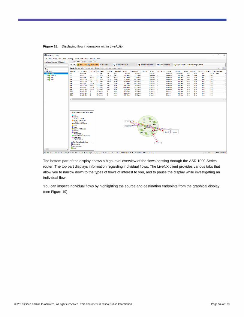
© 2018 Cisco and/or its affiliates. All rights reserved. This document is Cisco Public Information. Page 54 of 105
Figure 18. Displaying flow information within LiveAction
The bottom part of the display shows a high-level overview of the flows passing through the ASR 1000 Series
router. The top part displays information regarding individual flows. The LiveNX client provides various tabs that
allow you to narrow down to the types of flows of interest to you, and to pause the display while investigating an
individual flow.
You can inspect individual flows by highlighting the source and destination endpoints from the graphical display
(see Figure 19).

© 2018 Cisco and/or its affiliates. All rights reserved. This document is Cisco Public Information. Page 55 of 105
Figure 19. Highlighting an individual flow within LiveAction
For example, application response time information for individual client flows reaching individual servers can be
collected by enabling Application Response Time (AVC) monitoring within LiveAction. Such information may be
useful when positioning web-based services in the AWS VPC that are accessed from inside an organization.
Procedure 5. View flow-monitoring information via the LiveAction web interface
Flow information can also be viewed by running ad hoc reports from the LiveAction web interface.
Step 1. Log into the LiveAction server through a browser.
When you login to the LiveAction server through the web interface, you will be taken to the main dashboard.
Step 2. Navigate to the View Reports screen
e
View Reports screen. An example is shown in Figure 20 below:
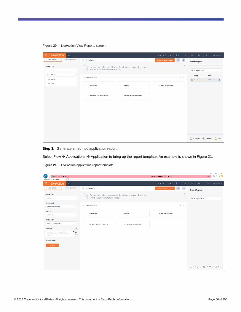
© 2018 Cisco and/or its affiliates. All rights reserved. This document is Cisco Public Information. Page 56 of 105
Figure 20. LiveAction View Reports screen
Step 3. Generate an ad-hoc application report.
Select Flow Applications Application to bring up the report template. An example is shown in Figure 21.
Figure 21. LiveAction application report template

© 2018 Cisco and/or its affiliates. All rights reserved. This document is Cisco Public Information. Page 57 of 105
Step 4. Select the report parameters.
From the report template, select the time range, the devices, the interfaces, and the flow direction for the report.
For this example, the time range selected is 15 minutes. The device selected is ASR1K-1, since traffic between the
private network and the VPCs traverse this VPN gateway. The interface selected is the back-side interface
(GigabitEthernet0/0/2), since traffic is unencrypted on this interface. The flow direction is selected through the
Advanced settings to be both inbound and outbound.
Step 5. Execute the report.
Click on the Execute button at the bottom of the report template screen to execute the ad-hoc report. An example
of the output of the report is shown in Figure 22.
Figure 22. Example output from applications ad hoc report
The ad-hoc application report shows the total bytes and packets seen over the time interval for each application in
the table at the bottom of the report. Additionally, the average bit rate and average packet rate over the time
interval are also displayed in the table. The graph at the top of the report displays the bit rate of each application in
smaller increments over the time range of the report, as opposed to just an average bit rate.
Appendix A: Design considerations
The following sections discuss some of the considerations and choices behind the design for this deployment
guide.
Positioning of the VPN gateway in the private network
You have multiple choices regarding the positioning of the Cisco ASR 1000 Series Routers (functioning as
dedicated VPN gateways) in the private network. For example, the VPN gateways can be positioned in the Internet
edge of the private network, as shown in the figure below.
Note: Redundancy is not shown in order to simplify the following figures.

© 2018 Cisco and/or its affiliates. All rights reserved. This document is Cisco Public Information. Page 58 of 105
Figure 23. VPN gateway deployed in the Internet edge
An advantage of this design is that all Internet-related connectivity is isolated to the Internet edge module of the
private network. The Internet edge firewall can be used to control inbound access to the VPN gateway from the
Internet. Optionally, unencrypted traffic from the ‘back-side’ of the VPN gateway can be sent through the Internet
edge firewall for stateful inspection and access control.
Alternatively, you can position the VPN gateway in the data center of the private network, as shown in the following
figure.
Figure 24. VPN gateway deployed in the data center
With the positioning of the VPN gateway in the data center, Internet connectivity could still be provided at the
Internet edge. Alternatively, separate Internet connectivity could be provisioned directly in the data center, used
solely for establishing IPsec VPN connectivity to the AWS VPC. The organization’s security policy may determine
whether all Internet connectivity passes through the Internet edge, or if separate Internet connectivity, provisioned
directly to the data center, is allowed.
When positioning the VPN gateway within either the Internet edge or the data center, the organization’s security
policy may also determine whether the Cisco ASR 1000 Series Routers must be placed behind a stateful firewall
that may also implement Network Address Translation (NAT). Alternatively, the security policy of the organization
may allow the ASR 1000 Series routers to be placed in parallel to the stateful firewall, and therefore may not
require NAT.

© 2018 Cisco and/or its affiliates. All rights reserved. This document is Cisco Public Information. Page 59 of 105
The design implemented within this deployment guide, shown in Figure 2 above, implements a pair of ASR 1000
Series routers, functioning as dedicated VPN gateways, in the data center of the private network. Separate Internet
connectivity within the data center is not implemented for this deployment guide. Instead, the VPN gateways utilize
the Internet connectivity provisioned in the Internet edge of the private network to establish IPsec VPN connections
to the AWS VPC. Because of the design choice in this deployment guide, NAT is implemented at the Internet edge
firewall.
Network Address Translation (NAT)
Because the VPN gateways are placed behind the Internet Edge firewall, the design followed in this deployment
guide uses 1:1 NAT from the front-side interface (GigabitEthernet0/0/0) IP addresses of the Cisco ASR 1000
Series Routers to public IP addresses (IP addresses routable on the Internet) implemented on the stateful firewall
in the Internet edge. The NAT configuration of the firewall is not shown in this deployment guide. The inbound
access-control policy of the outside interface of the stateful firewall prevents any inbound connections initiated from
outside the private network. The stateful firewall allows reverse connections (User Datagram Protocol [UDP] 500
for the Internet Key Exchange (IKE) protocol and UDP 4500 for NAT-Traversal [NAT-T]) initiated from the ASR
1000 Series routers within the private network, back into the private network.
High availability
You have multiple design options for implementing high availability in the private network and the AWS VPC,
including redundant VPN gateways and redundant IPsec VPN connections. Depending on the choice of VPN
gateway platform, these include active/active or active/standby configurations. This section discusses the specific
high-availability design implemented for this deployment guide.
High availability in the private network data center
Although a single Cisco ASR 1000 Series Router can provide redundancy in case of a single IPsec VPN tunnel
failure, it cannot provide high availability in case of the failure of the ASR 1000 Series router itself. For this
deployment guide, high availability is implemented through a redundant pair of active/active ASR 1000 Series
routers, dedicated as VPN gateways, deployed in the private network data center.
Figure 25 shows the details regarding the logical connectivity of the ASR 1000 Series routers to the data center
distribution-layer switches and firewalls. A pair of Cisco Nexus® 5000 Series Layer 3 switches (N5K-1 and N5K-2)
serves as the data center distribution-layer switches. An active/standby pair of ASAv firewalls serve as data center
firewalls, dedicated for the VPC connectivity.

© 2018 Cisco and/or its affiliates. All rights reserved. This document is Cisco Public Information. Page 60 of 105
Figure 25. High availability details in the private network data center
Each of the ASR 1000 Series routers is configured to establish two IPsec VPN connections, each via a virtual
tunnel interface (VTI) configuration to the AWS VGW. This is because each AWS VPN connection automatically
establishes two IPsec VPN connections to the same IP address corresponding to an AWS customer gateway, and
each ASR 1000 Series router functions as an AWS customer gateway. In other words, each ASR 1000 Series
router supports a level of resiliency through two IPsec connections. Both IPsec VPN tunnels (Tunnel1 and
Tunnel2) on each ASR 1000 Series router are normally established and up (however, AWS may periodically
perform maintenance that results in one of the two IPsec VPN tunnels being temporarily down). Since both ASR
1000 Series routers are active, a total of four IPsec VPN tunnels between the private network data center and the
AWS VPC are normally established and operational. BGP routing is configured between the tunnel interfaces of
the ASR 1000 Series routers to the AWS VPC.
Additionally, each of the ASR 1000 Series routers is configured to establish one IPsec VPN connection, via a VTI
configuration (Tunnel100), to one of the CSR 1000V routers in the AWS Transit VPC. Since both ASR 1000 Series
routers are active, a total of two IPsec VPN tunnels between the private network data center and the AWS Transit
VPC are normally established and operational. Again, BGP routing is configured between the tunnel interfaces of
the ASR 1000 Series routers to the AWS Transit VPC.

© 2018 Cisco and/or its affiliates. All rights reserved. This document is Cisco Public Information. Page 61 of 105
Each of the ASR 1000 Series routers has two GigabitEthernet interfaces. The front-side interfaces
(GigabitEthernet0/0/0) are configured as the source interfaces for the IPsec protected VTIs to AWS. The front-side
interfaces of both ASR 1000 Series routers are each connected to one of the Cisco Nexus 5000 Series Switches
via a Layer 2 interface. The Layer 2 interfaces are part of the same VLAN (VLAN 20) that extends across the two
Cisco Nexus 5000 Series Switches via an EtherChannel connection consisting of two TenGigabitEthernet
interfaces in a logical port-channel configuration.
A Hot Standby Router Protocol (HSRP) group (20) is configured between the two Layer-3 switched virtual
interfaces (SVIs) that provide the Layer 3 connectivity for the VLAN, configured on the Cisco Nexus 5000 Series
switches. The priority of N5K-1, which connects to ASR1K-1, is increased, so that N5K-1 is the active router in the
HSRP pair. This is because ASR1K-1 serves as the preferred path to the AWS VPC, as discussed in the following
section.
Active routing is not configured on the front-side interfaces of the ASR 1000 Series routers. Instead, each ASR
1000 Series router is configured with static routes corresponding to the publically routable IP addresses of the
AWS VPN gateways and the CSR 1000Vs in the Transit VPC, to which each ASR 1000 Series router establishes
IPsec connections. All static routes on each ASR 1000 Series router point to the shared virtual IP address of the
HSRP group configured on the Cisco Nexus 5000 Series routers. This configuration also ensures that traffic within
the private network is never accidently routed through the ASR 1000 Series routers.
The back-side interfaces (GigabitEthernet0/0/2) of each of the ASR 1000 Series routers are where the unencrypted
traffic from AWS enters the private network. The back-side interfaces of both ASR 1000 Series routers are each
connected to a VLAN (VLAN 60) that spans both Cisco Nexus 5000 Series distribution-layer switches via the
EtherChannel trunk. Also connected to the VLAN is the outside (GigabitEthernet0/0) interface of an active/standby
pair of ASAv firewalls. No SVI interface is defined on the distribution-layer Nexus 5000 Series switches. Hence,
VLAN 60 on the Nexus 5000 Series switches provides Layer 2 connectivity between the back-side interfaces
(GigabitEthernet0/0/2) of each of the ASR 1000 Series routers and the outside (GigabitEthernet0/0) interface of the
active/standby ASAv firewall pair.
The inside (GigabitEthernet0/1) interface of the active/standby pair of ASAv firewalls also connect to the Nexus
5000 Series switches via another VLAN (VLAN 70). Each Nexus 5000 Series switch is configured with an SVI that
provides the Layer 3 connectivity for the VLAN. Under normal conditions the active firewall is connected to N5K-1
whereas the standby firewall is connected to N5K-2. This is because ASR1K-1 serves as the preferred path to the
AWS VPC, as discussed in the following section.
Note: For this deployment guide, both ASAv firewalls were deployed on a single VMware ESXi 6.5 server.
Therefore, the failover interface (GigabitEthernet0/8) is internal to the ESXi server, and not connected to the Nexus
5000 Series distribution-layer switches. In a production deployment, you should deploy each ASAv firewall on a
separate ESXi server. This may require the failover connection to also be trunked via a separate VLAN between
the Nexus 5000 Series distribution-layer switches.

© 2018 Cisco and/or its affiliates. All rights reserved. This document is Cisco Public Information. Page 62 of 105
Active routing, using the Enhanced Interior Gateway Routing Protocol (EIGRP), is implemented across the Nexus
5000 Series switches, the ASAv active/standby firewall pair, and the back-side (GigabitEthernet0/0/2) interfaces of
both ASR 1000 Series routers, and the rest of the private network. Routes learned via BGP from the AWS VPC are
redistributed into EIGRP on both ASR 1000 Series routers. The routing metrics for routes redistributed into EIGRP
are tuned such that ASR1K-1 advertises a path to the AWS VPC, which is always preferred over the path
advertised by ASR1K-2. This provides both redundancy and ensures that the path to the AWS VPC is always
through ASR1K-1 to meet the requirements for symmetric routing. Routes learned via EIGRP from the private
network are redistributed into BGP. A route map is used to filter the routes that are redistributed from EIGRP to
BGP.
High availability in the AWS VPC and Transit VPC
High Availability within the AWS VPC using the native IPsec VPN service is implemented by provisioning two AWS
VPN connections. Each AWS VPN connection maps to a unique publicly routed IPv4 address, logically
represented as an AWS customer gateway. Each ASR 1000 Series router corresponds to one of the two AWS
customer gateways. However, since the ASR 1000 Series routers sit within the private network, they only have
private IPv4 addresses. Because there are two ASR 1000 Series routers, port address translation (PAT) cannot be
implemented at the Internet Edge firewall. Therefore, static 1:1 NAT translations are configured, mapping the front-
side interfaces (GigabitEthernet0/0/0) of each of the ASR 1000 Series routers to publicly routed IPv4 addresses on
the Internet Edge firewall.
In the VPC with native IPsec VPN service, AWS provides hardware redundancy. Each AWS VPN connection
consists of two IPsec tunnels. Each IPsec tunnel originates from a unique publicly routable IPv4 address owned by
AWS. The combination of two IPsec tunnels per AWS VPN connection, along with two AWS VPN connections,
results in a total of four IPsec tunnels between the VPN and the private network.
In the AWS Transit VPC, redundancy is achieved through two CSR 1000V routers. Each of the CSR 1000V routers
has a public IP address. IPsec VPN connections are established from each ASR 1000 Series router in the private
network to each of the CSR 1000V routers in the AWS Transit VPC. In turn, each CSR 1000V router in the Transit
VPC established two IPsec VPN connections to the spoke VPCs, which implement the AWS-native IPsec VPN
service.
Symmetric routing for AVC
You should note that multiple paths do not necessarily mean load-balancing of traffic across both ASR 1000 Series
routers, or across both of the IPsec VPN connections from each ASR 1000 Series router, when using BGP. BGP
routing will select a single path between autonomous systems (in each direction) unless BGP multipath is
supported and configured. A single path in each direction does not necessarily mean symmetric routing either. As
shown in the figure below, traffic to the VPC could pass through one ASR 1000 Series router while return traffic
from the VPC could pass through the other ASR 1000 Series router.

© 2018 Cisco and/or its affiliates. All rights reserved. This document is Cisco Public Information. Page 63 of 105
Figure 26. Asymmetric routing across VPN connections
Asymmetric routing is not necessarily a bad thing. However, in some situations it is undesirable. In particular,
Application Visibility and Control (AVC) running on the ASR 1000 Series routers may not function correctly with
asymmetric routing. In order to correctly classify some applications, AVC must have visibility into the first few
packets of the flow in both directions.
You can ensure symmetric routing through several methods. For this deployment guide, when redistributing routes
learned via BGP into EIGRP, the routing metrics are modified in order to make one of the ASR 1000 Series routers
more favorable from the viewpoint of EIGRP. EIGRP is the interior gateway protocol (IGP) implemented in the
private network for this deployment guide. All internal routers and Layer 3 switches will then send traffic destined to
the VPC to only one of the ASR 1000 Series routers.
In order to make the path to the routes available through one of the ASR 1000 Series routers more favorable to the
AWS VGW at the VPC and to the CSR 1000V routers in the Transit VPC, BGP AS prepending is implemented on
the ASR 1000 Series routers. The effect of this technique is shown in Figure 27, below.

© 2018 Cisco and/or its affiliates. All rights reserved. This document is Cisco Public Information. Page 64 of 105
Figure 27. Symmetric routing across VPN connections
Note: AS prepending was chosen as the method for ensuring symmetric routing in order to be consistent with
the AWS Transit VPC design, which also makes use of AS prepending to ensure symmetric routing through a
transit VPC.
In order to make the path to the routes available through one of the CSR 1000V Series routers in the AWS Transit
VPC more favorable to the ASR 1000 Series routers in the private network, BGP AS prepending is also
implemented on the CSR 1000V routers in the Transit VPC.
Because traffic to and from the AWS VPCs passes through ASR1K-1, Application Visibility and Control (AVC) can
be implemented on the back-side interface (GigabitEthernet0/0/2) connecting ASR1K-1 to the internal private
network. Since traffic is encrypted within the IPsec tunnel after it enters ASR1K-1, AVC implemented on the back-
side interface has visibility into the applications traversing the IPsec VPN connections to the AWS VPCs. AVC is
also implemented on the back-side interface (GigabitEthernet0/0/2) connecting ASR1K-2 to the internal private
network routers. In case of a failure of the VPN connections from ASR1K-1 to the AWS VPC, AVC will still provide
visibility to traffic to and from the VPC via ASR1K-2.
Note: AVC can be configured on the tunnel (Tunnel1 and Tunnel2) interfaces as an alternative to the back-side
interfaces (GigabitEthernet0/0/2) of the ASR 1000 Series routers. However, since there are two tunnel interfaces,
and traffic could asymmetrically route to and from the private network to the VPC across both tunnel interfaces
unless further BGP parameters are tuned appropriately, this method was not implemented for this version of the
deployment guide.
Specific configuration for implementing symmetric routing is discussed in the “Solution deployment” section of this
design guide.
Access control and path isolation
You can apply access control and/or path isolation at various points when deploying Infrastructure as a Service
(IaaS) cloud connectivity.

© 2018 Cisco and/or its affiliates. All rights reserved. This document is Cisco Public Information. Page 65 of 105
AWS security groups
Most IaaS cloud providers provide some form of inbound and outbound access control to virtual machine instances
deployed in VPCs. AWS provides access control via inbound and outbound rules configured within security groups
that are then associated with network interfaces of virtual machine instances. Access control is based on protocol
(TCP, UDP, etc.) and port, specifying an IP address range or a security group as the source or destination,
depending on whether the rule is an inbound or outbound rule. This is the most basic form of access control
applied to instances running in the VPC. Security group rules are stateful and only specify traffic that is to be
allowed to or from the instance. Since rules are stateful, the return traffic from an inbound security group rule is
automatically allowed, and vice-versa.
Up to five security groups can be applied to each network interface of an instance. Up to 50 inbound and 50
outbound rules can be configured for each security group. These limits can be increased. However, the combined
limit of security groups per network interface and inbound and outbound rules per security group cannot exceed
250. The maximum number of security groups per VPC is set at 500. This limit can also be increased. However,
the combined limit of the number of VPCs in a region and the number of security groups per VPC cannot exceed
5000.
This deployment guide assumes an AWS VPC, subnet, and any virtual machine instances have already been
created before configuring the IPsec VPN connectivity. Any security groups associated with the instances are also
assumed to have been created and applied to the instances. For more information regarding creation of AWS
security groups, please refer to the AWS VPC User Guide listed in the “Additional resources” section at the end of
this deployment guide.
AWS network Access Control Lists (ACLs)
Most IaaS providers also provide some form of inbound and outbound access control of traffic between subnets
within a VPC. AWS provides network Access Controls Lists (ACLs) that are associated with VPC subnets. Access
control is again based on protocol and port, but also includes source IP address ranges for inbound rules and a
destination IP address ranges for outbound rules. Network ACLs provide a second line of access control, in
addition to security groups, in that they control traffic between virtual machine instances deployed on different IP
subnets, based on the source and/or destination IP address ranges, as well as protocol and/or port. Since network
ACL rules are stateless, the return traffic from an outbound rule must explicitly be allowed with an inbound rule,
and vice-versa.
Each VPC subnet can only be associated with one network ACL at a time. However, the same network ACL can
apply to multiple subnets. Up to 200 network ACLs can be configured within a single VPC. Up to 20 inbound rules
and 20 outbound rules can be configured per network ACL. This can be increased, though doing so may slow
down network performance, due to the additional overhead required to process the longer rules list.
This deployment guide assumes that an AWS VPC, a subnet, and any virtual machine instances have already
been created before configuring the IPsec VPN connectivity. The default network ACL, which permits all traffic from
all IP address ranges inbound and outbound, is applied to the VPC subnet.
For VPC subnets that have direct inbound or outbound Internet access, AWS security groups and network ACLs
may be the only means for providing access control between hosts on the Internet and the VPC subnets and virtual
machine instances.

© 2018 Cisco and/or its affiliates. All rights reserved. This document is Cisco Public Information. Page 66 of 105
ACLs and/or stateful firewalling at the private network
For VPC subnets that have just IPsec VPN connectivity (no direct inbound or outbound Internet access), all traffic
to and from the VPC subnet traverses the VPN. In such scenarios, it may be desirable to implement access control
at the private network rather than send the traffic across the IPsec VPN connection, only to drop it at the VPC. This
also provides a third line of access control to the VPC subnets and virtual machine instances.
You can accomplish access control at the private network via multiple mechanisms. If the VPN gateway is a router
platform, such as the ASR 1000 Series appliance or the CSR 1000v Series virtual router, simple stateless ACLs
applied at the VPN gateway can control traffic based on protocol and port, with little or no performance impact.
Features such as Zone-Based Firewall (ZBFW) implemented on the router platform can provide more granular and
stateful access control. However, this needs to be balanced with additional complexity and performance impacts of
running ZBWF. Also, when considering a redundant pair of VPN concentrators for resiliency, the network
administrator must be aware that individual flows must pass through the same stateful firewall in a symmetric
manner. In other words, flows cannot exit one stateful firewall from the private network to the VPC, and return from
the VPC to the private network on the other stateful firewall, in an asymmetric manner. This is why high-availability
in firewall pairs is typically deployed in an active/standby manner.
Dedicated firewalls deployed behind the VPN gateway can also provide stateful and granular access control, but
without the performance impact or additional complexity of deploying ZBWF on a router platform. Stateful firewalls
such as the Cisco Adaptive Security Appliance (ASA) Series firewall appliance or the ASAv virtual firewall can be
deployed in an active/standby high-availability pair, which eliminates the issue of asymmetric routing and stateful
firewalling, albeit at the cost of deploying additional hardware or Virtual Network Functions (VNFs).
Additional service chains (intrusion detection and/or prevention, advanced malware protection, web filtering, etc.)
could also be included, depending on the specific business use for the VPC and the applications deployed on the
virtual machine instances at the VPC subnet. Such service chains could be delivered within the firewall platform
itself, as with the Cisco Firepower Series appliances or the Cisco® Next Generation Firewall Virtual (NGFWv), or
through separate appliances and/or VNFs.
This deployment guide implements a pair of Cisco ASAv virtual firewalls in an active/standby high-availability (HA)
pair behind the VPN gateways. This allows for stateful access control of the unencrypted traffic between the VPC
and the private network, deployed at the private network rather than at the VPC. The ASAv HA pair is deployed
such that the outside (less trusted) interfaces are connected to the back-side interfaces of the ASR 1000 Series
routers functioning as VPN gateways. The inside (more trusted) interfaces are connected to the Cisco Nexus 5000
Series switches, which function as distribution layer switches in the private network data center. Figure 25, above,
shows the details of these connections. The specific access control policy deployed on the ASAv firewalls is
dependent on the requirements of the VPC and is outside the scope of this document.

© 2018 Cisco and/or its affiliates. All rights reserved. This document is Cisco Public Information. Page 67 of 105
Path isolation
Whether or not path isolation of the traffic to and from the VPC is required within the private network depends on
the business use-case for deploying the VPC and the applications running on the virtual machine instances within
the VPC. With a VPN gateway deployed in the Internet edge, path isolation would need to be done by extending
network virtualization throughout the private network, to the Internet edge. Depending on where the end users of
the applications that reside on the virtual machine instances within the VPC sit in the private network, this could
mean extending the virtual network to the data center, the building distribution modules, or even across the WAN to
branch locations. To achieve this could involve the deployment of VLANs, VRFs, VRF-Lite, MPLS, Software
Defined Access (SD-Access), Software Defined WAN (SD-WAN), or Application Centric Infrastructure (ACI)
technologies throughout the private network.
With a VPN gateway deployed in the data center, path isolation would require extending network virtualization in
the data center out to the rest of the private network, and possibly even the WAN to branch locations, depending
on which groups require access to the applications and instances deployed in the VPC. To achieve this could
involve the deployment of VLANs, VRFs, VRF-Lite, MPLS, Software Defined Access (SD-Access), Software
Defined WAN (SD-WAN), or Application Centric Infrastructure (ACI) technologies throughout the private network.
Path isolation in the private network has not been implemented in this version of the deployment guide. Future
versions of this guide may explore how path isolation can be implemented from the VPN gateways across the
private network infrastructure to isolate network connectivity to the VPC.
Appendix B: Cisco ASR 1000 Series Router configuration
For this guide, a pair of Cisco ASR 1002-X Routers running IOS-XE 16.06.02 code licensed with the Advanced
Enterprise feature set were implemented in the private network.
The following is the configuration of the first Cisco ASR 1000 Series Router, minus the flow configuration
information provisioned by LiveAction, which is shown in Appendix D:
ASR1K-1#show running-config
Building configuration...
Current configuration : 36304 bytes
!
! Last configuration change at 22:12:48 UTC Thu Sep 20 2018 by netadmin
! NVRAM config last updated at 22:12:51 UTC Thu Sep 20 2018 by netadmin
!
version 16.6
service timestamps debug datetime msec
service timestamps log datetime msec show-timezone
service password-encryption
platform qfp utilization monitor load 80
no platform punt-keepalive disable-kernel-core
!
hostname ASR1K-1

© 2018 Cisco and/or its affiliates. All rights reserved. This document is Cisco Public Information. Page 68 of 105
!
boot-start-marker
boot system flash bootflash:asr1002x-universalk9.16.06.02.SPA.bin
boot system flash bootflash:asr1002x-universalk9.16.03.05c.SPA.bin
boot-end-marker
!
!
vrf definition Mgmt-intf
!
address-family ipv4
exit-address-family
!
address-family ipv6
exit-address-family
!
enable secret 5 $1$.7pq$YSYCRvHnARfG.zzSC4MZZ1
!
!
transport-map type persistent webui https-webui
secure-server
!
aaa new-model
!
!
aaa authentication login default local
aaa authorization exec default local
!
!
aaa session-id common
!
!
ip nbar http-services
!
!
ip name-server 10.1.0.68
ip name-server vrf Mgmt-intf 100.119.4.10
ip domain name sjc23.lint
!
!
subscriber templating

© 2018 Cisco and/or its affiliates. All rights reserved. This document is Cisco Public Information. Page 69 of 105
!
!
flow exporter 192.168.1.10
destination 192.168.1.10
!
!
multilink bundle-name authenticated
!
!
key chain EIGRP-KEY
key 1
key-string 7 132646010803557878
!
!
crypto pki trustpoint TP-self-signed-1948098125
enrollment selfsigned
subject-name cn=IOS-Self-Signed-Certificate-1948098125
revocation-check none
rsakeypair TP-self-signed-1948098125
!
crypto pki trustpoint DNAC-CA
enrollment mode ra
enrollment terminal
usage ssl-client
revocation-check crl none
!
!
crypto pki certificate chain TP-self-signed-1948098125
certificate self-signed 01
30820330 30820218 A0030201 02020101 300D0609 2A864886 F70D0101 05050030
31312F30 2D060355 04031326 494F532D 53656C66 2D536967 6E65642D 43657274
69666963 6174652D 31393438 30393831 3235301E 170D3138 30323130 32313537
34335A17 0D323030 31303130 30303030 305A3031 312F302D 06035504 03132649
4F532D53 656C662D 5369676E 65642D43 65727469 66696361 74652D31 39343830
39383132 35308201 22300D06 092A8648 86F70D01 01010500 0382010F 00308201
0A028201 0100CADE 141ADBB2 8CE5E6DC 5B3F21FE 2D3A4237 A1A24F60 671B9538
2CB70193 27D4CB13 5BD37533 AA5247C9 5F478997 EF3BE05E 9DBA61B7 08782D62
0F2DA853 AC528832 868B8391 5A3DA40A 0A8D6661 5A62BD03 FB195344 3D5D8E3D
E087482A C995C579 A74B683A 7E2A9680 C62D63B7 55301D52 A0632A3E 3B49C0DD
EE704023 8479A515 41DFBA97 7A3F22B2 0E1B250C CFEEF43A 2C58288D FA5E9EFC

© 2018 Cisco and/or its affiliates. All rights reserved. This document is Cisco Public Information. Page 70 of 105
E8A61E7E 4C1052FE B0536013 60DE7D7D 3EA1CFB0 FE0B7746 F80AD3C9 9838693A
30CFCAE6 B7B77180 161C24D7 BA53F865 3E7A25B0 9F3314CE 8B4AABEB 37EE1221
ADB71EC9 07E773D0 87F4C2F3 DA91FC54 D92CEDB1 39F74E5E 01102450 217A8B8F
71A454D9 E4610203 010001A3 53305130 0F060355 1D130101 FF040530 030101FF
301F0603 551D2304 18301680 145353EA A13700D9 955D0752 41294EBA B77F0167
7F301D06 03551D0E 04160414 5353EAA1 3700D995 5D075241 294EBAB7 7F01677F
300D0609 2A864886 F70D0101 05050003 82010100 CAD0405E 7658EF81 0ACD89A1
8F6DAF1B 93A947F0 D69B2025 21E0A878 689BA40C 4396D54E 8D2DCF95 7EB83952
4326E639 3DF399FF 6F695277 D811694A 825A5544 A220BBF3 6BFAAC39 8691E87C
41D9D047 EF74E2E8 5C9B0B47 E9876E02 978EC61A 64E764E4 F640A01D 5CC1611F
A8B13DA1 4C250A46 0E5FB866 F9972F28 C856A3F1 3EED8815 2A9175EA A28A248E
A44071D8 D29F6AB9 3576B018 F57885B5 70424AEF C808A218 43DDBB88 98AEC63A
57EAE59F 6158BCC8 19FC0A0A 0D5C7274 615653C4 BBBC1571 43D73F20 2B90DDB8
3C855E63 2DF26496 88C783BA BC6B8E43 D6570318 488D7C67 59E52629 99FAF32B
C12670ED 3B1DF2F6 174F6766 D567C538 0B2E2EA8
quit
crypto pki certificate chain DNAC-CA
certificate ca 00D7F18906F9F6301D
308202F7 308201DF A0030201 02020900 D7F18906 F9F6301D 300D0609 2A864886
F70D0101 0B050030 12311030 0E060355 04030C07 6B756265 2D636130 1E170D31
38303830 38303030 3535395A 170D3231 30353034 30303035 35395A30 12311030
0E060355 04030C07 6B756265 2D636130 82012230 0D06092A 864886F7 0D010101
05000382 010F0030 82010A02 82010100 C5763EEE F86E0DFD A16AFE49 7FDC097B
F0B5AD40 2B719175 2BEE1A11 7D91272B F295D41C A92D127B 9D394EE2 756C6B78
ADF67A34 2993C3DC ABEEB734 6516F5EB 1F47FD05 8AB91618 660B25A0 292E75F1
AE26EE36 8DA55BFA 289F0F71 00A07321 91CAD808 B55CB7CF 98D8CF26 2FC3BF61
520787D6 8A703E32 7CD1A816 C31B0CB9 4C2439D3 7AA39083 0CC5D3BC 7482DC33
70622F92 36E87787 54206DA8 B6354C8C BD72910B 7245539F CF88A350 A22AE72E
290DF63C FED23B12 861A993E 2DE3978A CC3C3A52 62CD1C8D 8EBADA2F E02CC24C
BC0FB852 E31C8233 D7E24B44 7DACABA4 039A6400 DB5C02C8 FF0F934B 1A4D3A66
4F656ECC 6E16335F A00BEDAF 53A5A509 02030100 01A35030 4E301D06 03551D0E
04160414 D89BB227 25E8B1A8 5F4F6E23 385939F6 6E9E9A6E 301F0603 551D2304
18301680 14D89BB2 2725E8B1 A85F4F6E 23385939 F66E9E9A 6E300C06 03551D13
04053003 0101FF30 0D06092A 864886F7 0D01010B 05000382 010100AB 887E3747
6C5BC451 601D2540 D6E08892 38FCF68B E5FC4A05 3F03EBD7 38E2A70D CF7B14B7
A1021E31 8D81DB99 A9A33B81 AACF62E0 CB6A986A 1757C76B 4094F275 F282890D
592A134A A1E13ADD D967C92D 6821C488 211225A4 CA022431 15B10798 99558D93
476742B4 0CB95207 51DE022C 62E946E3 4F7BADD2 E43BEF38 322DC3ED F83ACF63
BD6E80EC EB186E8E 5AD61368 59EC16D4 4579FC9F 3C35DED3 C82F1EF2 EE66290E
42877190 407E1D02 720C7E93 6C5C11C7 F8D526FC 6C7BDCF9 81CA4948 1D110527

© 2018 Cisco and/or its affiliates. All rights reserved. This document is Cisco Public Information. Page 71 of 105
8B7B97EE 0042961B 16DB588C 973C2B31 A09B6958 90A73D14 69A36D4C E5AD008E
557E3D5A 612DC675 0F9B3910 EE1E6413 C87CB1D6 8A05C941 582B08
quit
!
!
license udi pid ASR1002-X sn JAE19430CC3
license accept end user agreement
license boot level adventerprise
spanning-tree extend system-id
diagnostic bootup level minimal
!
netconf-yang
!
!
username netadmin privilege 15 secret 5 $1$F45X$nnJeHpLbOojbX4VGwzZTG/
!
redundancy
mode none
bfd-template single-hop bfdtemplate1
interval min-tx 1000 min-rx 1000 multiplier 3
!
!
cdp run
!
class-map match-any DNA-EZQOS_12C#REALTIME
match dscp cs4
class-map match-any DNA-MARKING_IN#REALTIME_CUSTOM
class-map match-all DNA-MARKING_IN#MM_STREAM
match protocol attribute traffic-class multimedia-streaming
match protocol attribute business-relevance business-relevant
class-map match-all DNA-MARKING_IN#OAM
match protocol attribute traffic-class ops-admin-mgmt
match protocol attribute business-relevance business-relevant
class-map match-all DNA-MARKING_IN#CONTROL
match protocol attribute traffic-class network-control
match protocol attribute business-relevance business-relevant
class-map match-any DNA-MARKING_IN#TRANS_DATA_CUSTOM
class-map match-any LIVEACTION-CLASS-AVC
match access-group name LIVEACTION-ACL-AVC
class-map match-all DNA-MARKING_IN#MM_CONF

© 2018 Cisco and/or its affiliates. All rights reserved. This document is Cisco Public Information. Page 72 of 105
match protocol attribute traffic-class multimedia-conferencing
match protocol attribute business-relevance business-relevant
class-map match-all DNA-MARKING_IN#SCAVENGER
match protocol attribute business-relevance business-irrelevant
class-map match-all DNA-MARKING_IN#SIGNALING
match protocol attribute traffic-class signaling
match protocol attribute business-relevance business-relevant
class-map match-all DNA-MARKING_IN#BROADCAST
match protocol attribute traffic-class broadcast-video
match protocol attribute business-relevance business-relevant
class-map match-all DNA-MARKING_IN#BULK_DATA
match protocol attribute traffic-class bulk-data
match protocol attribute business-relevance business-relevant
class-map match-any DNA-EZQOS_12C#TRANS_DATA
match dscp af23
match dscp af21
match dscp af22
class-map match-all DNA-MARKING_IN#VOICE
match protocol attribute traffic-class voip-telephony
match protocol attribute business-relevance business-relevant
class-map match-any DNA-MARKING_IN#CONTROL_CUSTOM
class-map match-any DNA-MARKING_IN#MM_STREAM_CUSTOM
class-map match-any DNA-MARKING_IN#OAM_CUSTOM
class-map match-all DNA-MARKING_IN#REALTIME
match protocol attribute traffic-class real-time-interactive
match protocol attribute business-relevance business-relevant
class-map match-any DNA-EZQOS_12C#MM_STREAM
match dscp af32
match dscp af33
match dscp af31
class-map match-any DNA-EZQOS_12C#OAM
match dscp cs2
class-map match-any DNA-EZQOS_12C#CONTROL
match dscp cs6
class-map match-any DNA-MARKING_IN#VOICE_CUSTOM
class-map match-any DNA-EZQOS_12C#MM_CONF
match dscp af43
match dscp af41
match dscp af42
class-map match-any DNA-EZQOS_12C#SCAVENGER

© 2018 Cisco and/or its affiliates. All rights reserved. This document is Cisco Public Information. Page 73 of 105
match dscp cs1
class-map match-any DNA-EZQOS_12C#SIGNALING
match dscp cs3
class-map match-any DNA-EZQOS_12C#BROADCAST
match dscp cs5
class-map match-any DNA-EZQOS_12C#BULK_DATA
match dscp af12
match dscp af13
match dscp af11
class-map match-any DNA-MARKING_IN#SCAVENGER_CUSTOM
class-map match-any DNA-MARKING_IN#SIGNALING_CUSTOM
class-map match-any DNA-MARKING_IN#BROADCAST_CUSTOM
class-map match-any DNA-MARKING_IN#BULK_DATA_CUSTOM
class-map match-all DNA-MARKING_IN#TRANS_DATA
match protocol attribute traffic-class transactional-data
match protocol attribute business-relevance business-relevant
class-map match-any LIVEACTION-CLASS-MEDIANET
match protocol telepresence-media
match protocol rtp
class-map match-any DNA-EZQOS_12C#VOICE
match dscp ef
class-map match-any DNA-MARKING_IN#MM_CONF_CUSTOM
class-map match-any DNA-MARKING_IN#TUNNELED-NBAR
match protocol capwap-data
!
policy-map DNA-dscp#EQ_SPP3-6Class
class DNA-EZQOS_12C#VOICE
police rate percent 10
priority
set dscp ef
class DNA-EZQOS_12C#BROADCAST
bandwidth remaining percent 10
set dscp af41
class DNA-EZQOS_12C#REALTIME
bandwidth remaining percent 14
set dscp af41
class DNA-EZQOS_12C#MM_CONF
bandwidth remaining percent 10
fair-queue
set dscp af41

© 2018 Cisco and/or its affiliates. All rights reserved. This document is Cisco Public Information. Page 74 of 105
random-detect dscp-based
class DNA-EZQOS_12C#MM_STREAM
bandwidth remaining percent 10
fair-queue
set dscp af31
random-detect dscp-based
class DNA-EZQOS_12C#CONTROL
bandwidth remaining percent 3
set dscp default
class DNA-EZQOS_12C#SIGNALING
bandwidth remaining percent 3
set dscp af21
class DNA-EZQOS_12C#OAM
bandwidth remaining percent 3
set dscp af21
class DNA-EZQOS_12C#TRANS_DATA
bandwidth remaining percent 14
fair-queue
set dscp af21
random-detect dscp-based
class DNA-EZQOS_12C#BULK_DATA
bandwidth remaining percent 5
fair-queue
set dscp af21
random-detect dscp-based
class DNA-EZQOS_12C#SCAVENGER
bandwidth remaining percent 1
set dscp af11
class class-default
bandwidth remaining percent 27
fair-queue
set dscp default
random-detect dscp-based
policy-map DNA-dscp#EQ_SPP3-6Class#shape#100.0
class class-default
shape average 100000000
service-policy DNA-dscp#EQ_SPP3-6Class
policy-map DNA-dscp#QUEUING_OUT
class DNA-EZQOS_12C#VOICE
police rate percent 10

© 2018 Cisco and/or its affiliates. All rights reserved. This document is Cisco Public Information. Page 75 of 105
priority
class DNA-EZQOS_12C#BROADCAST
police rate percent 10
priority
class DNA-EZQOS_12C#REALTIME
police rate percent 13
priority
class DNA-EZQOS_12C#MM_CONF
bandwidth remaining percent 15
fair-queue
random-detect dscp-based
class DNA-EZQOS_12C#MM_STREAM
bandwidth remaining percent 15
fair-queue
random-detect dscp-based
class DNA-EZQOS_12C#CONTROL
bandwidth remaining percent 4
class DNA-EZQOS_12C#SIGNALING
bandwidth remaining percent 3
class DNA-EZQOS_12C#OAM
bandwidth remaining percent 3
class DNA-EZQOS_12C#TRANS_DATA
bandwidth remaining percent 15
fair-queue
random-detect dscp-based
class DNA-EZQOS_12C#BULK_DATA
bandwidth remaining percent 6
fair-queue
random-detect dscp-based
class DNA-EZQOS_12C#SCAVENGER
bandwidth remaining percent 1
class class-default
bandwidth remaining percent 38
fair-queue
random-detect dscp-based
policy-map DNA-MARKING_IN
class DNA-MARKING_IN#TUNNELED-NBAR
class DNA-MARKING_IN#VOICE_CUSTOM
set dscp ef
class DNA-MARKING_IN#BROADCAST_CUSTOM

© 2018 Cisco and/or its affiliates. All rights reserved. This document is Cisco Public Information. Page 76 of 105
set dscp cs5
class DNA-MARKING_IN#REALTIME_CUSTOM
set dscp cs4
class DNA-MARKING_IN#MM_CONF_CUSTOM
set dscp af41
class DNA-MARKING_IN#MM_STREAM_CUSTOM
set dscp af31
class DNA-MARKING_IN#CONTROL_CUSTOM
set dscp cs6
class DNA-MARKING_IN#SIGNALING_CUSTOM
set dscp cs3
class DNA-MARKING_IN#OAM_CUSTOM
set dscp cs2
class DNA-MARKING_IN#TRANS_DATA_CUSTOM
set dscp af21
class DNA-MARKING_IN#BULK_DATA_CUSTOM
set dscp af11
class DNA-MARKING_IN#SCAVENGER_CUSTOM
set dscp cs1
class DNA-MARKING_IN#VOICE
set dscp ef
class DNA-MARKING_IN#BROADCAST
set dscp cs5
class DNA-MARKING_IN#REALTIME
set dscp cs4
class DNA-MARKING_IN#MM_CONF
set dscp af41
class DNA-MARKING_IN#MM_STREAM
set dscp af31
class DNA-MARKING_IN#CONTROL
set dscp cs6
class DNA-MARKING_IN#SIGNALING
set dscp cs3
class DNA-MARKING_IN#OAM
set dscp cs2
class DNA-MARKING_IN#TRANS_DATA
set dscp af21
class DNA-MARKING_IN#BULK_DATA
set dscp af11
class DNA-MARKING_IN#SCAVENGER

© 2018 Cisco and/or its affiliates. All rights reserved. This document is Cisco Public Information. Page 77 of 105
set dscp cs1
class class-default
set dscp default
!
!
crypto keyring keyring-vpn-private-dc
local-address GigabitEthernet0/0/0
pre-shared-key address 35.168.251.31 key 81fe301f239058935e6818af42a04d48
crypto keyring keyring-vpn-0e69ba34dc79a6a1c-1
local-address GigabitEthernet0/0/0
pre-shared-key address 52.5.66.86 key HEjS6vbDKBkyzX4c0IU2BbI5rJB1cxBE
crypto keyring keyring-vpn-0e69ba34dc79a6a1c-0
local-address GigabitEthernet0/0/0
pre-shared-key address 18.233.2.243 key RwPjTXc6M_7ujv4zvIygx6d8yupKbE..
!
!
crypto isakmp policy 200
encr aes 256
hash sha256
authentication pre-share
group 24
lifetime 28800
crypto isakmp keepalive 10 10
crypto isakmp profile isakmp-vpn-private-dc
keyring keyring-vpn-private-dc
match identity address 35.168.251.31 255.255.255.255
local-address GigabitEthernet0/0/0
crypto isakmp profile isakmp-vpn-0e69ba34dc79a6a1c-0
keyring keyring-vpn-0e69ba34dc79a6a1c-0
match identity address 18.233.2.243 255.255.255.255
local-address GigabitEthernet0/0/0
crypto isakmp profile isakmp-vpn-0e69ba34dc79a6a1c-1
keyring keyring-vpn-0e69ba34dc79a6a1c-1
match identity address 52.5.66.86 255.255.255.255
local-address GigabitEthernet0/0/0
!
crypto ipsec security-association replay window-size 1024
!
crypto ipsec transform-set ipsec-prop-private-dc esp-aes 256 esp-sha256-hmac
mode tunnel

© 2018 Cisco and/or its affiliates. All rights reserved. This document is Cisco Public Information. Page 78 of 105
crypto ipsec transform-set ipsec-prop-vpn-0e69ba34dc79a6a1c-0 esp-aes 256 esp-
sha256-hmac
mode tunnel
crypto ipsec transform-set ipsec-prop-vpn-0e69ba34dc79a6a1c-1 esp-aes 256 esp-
sha256-hmac
mode tunnel
crypto ipsec df-bit clear
!
!
crypto ipsec profile ipsec-vpn-0e69ba34dc79a6a1c-0
set transform-set ipsec-prop-vpn-0e69ba34dc79a6a1c-0
set pfs group24
!
crypto ipsec profile ipsec-vpn-0e69ba34dc79a6a1c-1
set transform-set ipsec-prop-vpn-0e69ba34dc79a6a1c-1
set pfs group24
!
crypto ipsec profile ipsec-vpn-private-dc
set transform-set ipsec-prop-private-dc
set pfs group24
!
!
interface Loopback0
description Loopback Interface
ip address 10.1.0.20 255.255.255.255
!
interface Tunnel1
description IPsec VPN Tunnel for AWS Connection ID vpn-0e69ba34dc79a6a1c-0
ip address 169.254.47.150 255.255.255.252
ip tcp adjust-mss 1387
shutdown
tunnel source GigabitEthernet0/0/0
tunnel mode ipsec ipv4
tunnel destination 18.233.2.243
tunnel protection ipsec profile ipsec-vpn-0e69ba34dc79a6a1c-0
ip virtual-reassembly
!
interface Tunnel2
description IPsec VPN Tunnel for AWS Connection ID vpn-0e69ba34dc79a6a1c-1
ip address 169.254.45.138 255.255.255.252

© 2018 Cisco and/or its affiliates. All rights reserved. This document is Cisco Public Information. Page 79 of 105
ip tcp adjust-mss 1387
shutdown
tunnel source GigabitEthernet0/0/0
tunnel mode ipsec ipv4
tunnel destination 52.5.66.86
tunnel protection ipsec profile ipsec-vpn-0e69ba34dc79a6a1c-1
ip virtual-reassembly
!
interface Tunnel100
description vpn from private dc ASR1K-1 to transit vpc TVPC-CSR1
ip address 10.1.0.98 255.255.255.252
ip tcp adjust-mss 1387
load-interval 30
shutdown
bfd template bfdtemplate1
tunnel source GigabitEthernet0/0/0
tunnel mode ipsec ipv4
tunnel destination 35.168.251.31
tunnel protection ipsec profile ipsec-vpn-private-dc
ip virtual-reassembly
!
interface GigabitEthernet0/0/0
description VPN Outside via N5K-1 Eth1/2
ip address 10.1.0.84 255.255.255.248
ip nbar protocol-discovery
load-interval 30
negotiation auto
plim qos input map ip dscp-based
plim qos input map ip dscp 32 40 queue strict-priority
cdp enable
service-policy input DNA-MARKING_IN
service-policy output DNA-dscp#QUEUING_OUT
!
interface GigabitEthernet0/0/1
description #WAN#100M#SPP:SPP3-6Class#
ip address 10.1.0.29 255.255.255.252
ip nbar protocol-discovery
load-interval 30
negotiation auto
plim qos input map ip dscp-based

© 2018 Cisco and/or its affiliates. All rights reserved. This document is Cisco Public Information. Page 80 of 105
plim qos input map ip dscp 32 40 queue strict-priority
bfd template bfdtemplate1
cdp enable
service-policy input DNA-MARKING_IN
service-policy output DNA-dscp#EQ_SPP3-6Class#shape#100.0
!
interface GigabitEthernet0/0/2
description ASAv Inside via N5K-1 Eth1/8
ip address 10.1.0.124 255.255.255.248
ip nbar protocol-discovery
load-interval 30
negotiation auto
plim qos input map ip dscp-based
plim qos input map ip dscp 32 40 queue strict-priority
bfd template bfdtemplate1
cdp enable
service-policy input DNA-MARKING_IN
service-policy output DNA-dscp#QUEUING_OUT
!
interface GigabitEthernet0/0/3
description FPR2K Inside via N5K-1 Eth1/7
ip address 10.1.0.116 255.255.255.248
load-interval 30
shutdown
negotiation auto
plim qos input map ip dscp-based
plim qos input map ip dscp 32 40 queue strict-priority
cdp enable
service-policy input DNA-MARKING_IN
service-policy output DNA-dscp#QUEUING_OUT
!
interface GigabitEthernet0/0/4
no ip address
shutdown
negotiation auto
plim qos input map ip dscp-based
plim qos input map ip dscp 32 40 queue strict-priority
cdp enable
service-policy input DNA-MARKING_IN
service-policy output DNA-dscp#QUEUING_OUT
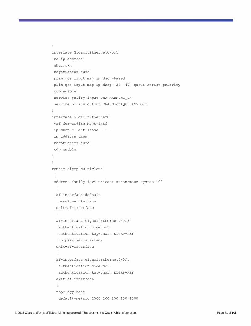
© 2018 Cisco and/or its affiliates. All rights reserved. This document is Cisco Public Information. Page 81 of 105
!
interface GigabitEthernet0/0/5
no ip address
shutdown
negotiation auto
plim qos input map ip dscp-based
plim qos input map ip dscp 32 40 queue strict-priority
cdp enable
service-policy input DNA-MARKING_IN
service-policy output DNA-dscp#QUEUING_OUT
!
interface GigabitEthernet0
vrf forwarding Mgmt-intf
ip dhcp client lease 0 1 0
ip address dhcp
negotiation auto
cdp enable
!
!
router eigrp Multicloud
!
address-family ipv4 unicast autonomous-system 100
!
af-interface default
passive-interface
exit-af-interface
!
af-interface GigabitEthernet0/0/2
authentication mode md5
authentication key-chain EIGRP-KEY
no passive-interface
exit-af-interface
!
af-interface GigabitEthernet0/0/1
authentication mode md5
authentication key-chain EIGRP-KEY
exit-af-interface
!
topology base
default-metric 2000 100 250 100 1500
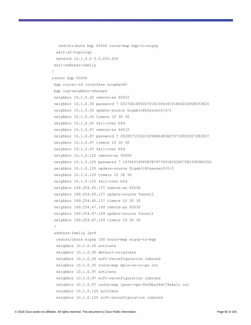
© 2018 Cisco and/or its affiliates. All rights reserved. This document is Cisco Public Information. Page 82 of 105
redistribute bgp 65000 route-map bgp-to-eigrp
exit-af-topology
network 10.1.0.0 0.0.255.255
exit-address-family
!
router bgp 65000
bgp router-id interface Loopback0
bgp log-neighbor-changes
neighbor 10.1.0.30 remote-as 65010
neighbor 10.1.0.30 password 7 03270A180500701E1D4434101B06020F08253E20
neighbor 10.1.0.30 update-source GigabitEthernet0/0/1
neighbor 10.1.0.30 timers 10 30 30
neighbor 10.1.0.30 fall-over bfd
neighbor 10.1.0.97 remote-as 64512
neighbor 10.1.0.97 password 7 0528571C22431F5B4A483A0707180D29272B3D37
neighbor 10.1.0.97 timers 10 30 30
neighbor 10.1.0.97 fall-over bfd
neighbor 10.1.0.125 remote-as 65000
neighbor 10.1.0.125 password 7 143443180F0B7B7977651E202E070E150F0E435D
neighbor 10.1.0.125 update-source GigabitEthernet0/0/2
neighbor 10.1.0.125 timers 10 30 30
neighbor 10.1.0.125 fall-over bfd
neighbor 169.254.45.137 remote-as 65030
neighbor 169.254.45.137 update-source Tunnel2
neighbor 169.254.45.137 timers 10 30 30
neighbor 169.254.47.149 remote-as 65030
neighbor 169.254.47.149 update-source Tunnel1
neighbor 169.254.47.149 timers 10 30 30
!
address-family ipv4
redistribute eigrp 100 route-map eigrp-to-bgp
neighbor 10.1.0.30 activate
neighbor 10.1.0.30 default-originate
neighbor 10.1.0.30 soft-reconfiguration inbound
neighbor 10.1.0.30 route-map mpls-ce-to-pe out
neighbor 10.1.0.97 activate
neighbor 10.1.0.97 soft-reconfiguration inbound
neighbor 10.1.0.97 route-map ipsec-vpn-0e69ba34dc79a6a1c out
neighbor 10.1.0.125 activate
neighbor 10.1.0.125 soft-reconfiguration inbound

© 2018 Cisco and/or its affiliates. All rights reserved. This document is Cisco Public Information. Page 83 of 105
neighbor 169.254.45.137 activate
neighbor 169.254.45.137 default-originate
neighbor 169.254.45.137 soft-reconfiguration inbound
neighbor 169.254.45.137 route-map ipsec-vpn-0e69ba34dc79a6a1c out
neighbor 169.254.47.149 activate
neighbor 169.254.47.149 default-originate
neighbor 169.254.47.149 soft-reconfiguration inbound
neighbor 169.254.47.149 route-map ipsec-vpn-0e69ba34dc79a6a1c out
exit-address-family
!
ip forward-protocol nd
ip ftp source-interface GigabitEthernet0
ip ftp username admin
ip ftp password 7 106D580A061843595F
no ip http server
ip http secure-server
ip http client source-interface Loopback0
ip tftp source-interface GigabitEthernet0
ip route 18.233.2.243 255.255.255.255 10.1.0.81
ip route 35.168.251.31 255.255.255.255 10.1.0.81
ip route 52.5.66.86 255.255.255.255 10.1.0.81
ip route vrf Mgmt-intf 0.0.0.0 0.0.0.0 100.119.113.1
!
ip ssh time-out 60
ip ssh authentication-retries 2
ip ssh source-interface Loopback0
ip ssh version 2
ip scp server enable
!
!
ip prefix-list bgp-to-eigrp seq 10 permit 10.2.1.0/24
ip prefix-list bgp-to-eigrp seq 11 permit 10.2.4.0/24
ip prefix-list bgp-to-eigrp seq 20 permit 10.119.202.0/24
ip prefix-list bgp-to-eigrp seq 30 permit 10.119.203.3/32
ip prefix-list bgp-to-eigrp seq 40 permit 10.119.203.4/32
ip prefix-list bgp-to-eigrp seq 50 permit 10.119.203.5/32
ip prefix-list bgp-to-eigrp seq 51 permit 10.119.203.6/32
ip prefix-list bgp-to-eigrp seq 52 permit 10.119.203.7/32
ip prefix-list bgp-to-eigrp seq 60 permit 10.119.204.0/24
ip prefix-list bgp-to-eigrp seq 70 permit 10.119.205.0/24

© 2018 Cisco and/or its affiliates. All rights reserved. This document is Cisco Public Information. Page 84 of 105
ip prefix-list bgp-to-eigrp seq 90 permit 10.119.207.0/24
ip prefix-list bgp-to-eigrp seq 91 permit 10.119.208.0/24
ip prefix-list bgp-to-eigrp seq 92 permit 10.119.209.0/24
ip prefix-list bgp-to-eigrp seq 100 permit 10.0.0.0/16
ip prefix-list bgp-to-eigrp seq 110 permit 10.255.48.0/20
ip prefix-list bgp-to-eigrp seq 120 permit 10.255.64.0/20
ip prefix-list bgp-to-eigrp seq 130 permit 100.64.127.224/27
!
ip prefix-list eigrp-to-bgp seq 10 permit 10.1.0.0/30
ip prefix-list eigrp-to-bgp seq 20 permit 10.1.0.4/30
ip prefix-list eigrp-to-bgp seq 30 permit 10.1.0.8/30
ip prefix-list eigrp-to-bgp seq 40 permit 10.1.0.20/32
ip prefix-list eigrp-to-bgp seq 50 permit 10.1.0.21/32
ip prefix-list eigrp-to-bgp seq 60 permit 10.1.0.22/32
ip prefix-list eigrp-to-bgp seq 70 permit 10.1.0.23/32
ip prefix-list eigrp-to-bgp seq 80 permit 10.1.0.24/32
ip prefix-list eigrp-to-bgp seq 90 permit 10.1.0.28/30
ip prefix-list eigrp-to-bgp seq 100 permit 10.1.0.32/30
ip prefix-list eigrp-to-bgp seq 110 permit 10.1.0.64/28
ip prefix-list eigrp-to-bgp seq 120 permit 10.1.0.80/29
ip prefix-list eigrp-to-bgp seq 130 permit 10.1.0.88/29
ip prefix-list eigrp-to-bgp seq 140 permit 10.1.0.120/29
ip prefix-list eigrp-to-bgp seq 150 permit 10.1.0.128/29
ip prefix-list eigrp-to-bgp seq 160 permit 192.168.0.0/24
ip radius source-interface Loopback0
!
ip access-list extended LIVEACTION-ACL-AVC
permit tcp any any
ip sla 100
http get http://10.0.1.5/ source-ip 10.1.0.20 version 1.1
frequency 90
logging history debugging
logging snmp-trap emergencies
logging snmp-trap alerts
logging snmp-trap critical
logging snmp-trap errors
logging snmp-trap warnings
logging snmp-trap notifications
logging snmp-trap informational
logging snmp-trap debugging

© 2018 Cisco and/or its affiliates. All rights reserved. This document is Cisco Public Information. Page 85 of 105
logging host 192.168.1.10
logging host 192.168.1.1
!
!
route-map eigrp-to-bgp permit 10
description Route-map for EIGRP to BGP Redistribution
match ip address prefix-list eigrp-to-bgp
!
route-map bgp-to-eigrp permit 10
description Route-map for BGP to EIGRP Redistribution
match ip address prefix-list bgp-to-eigrp
!
route-map mpls-ce-to-pe permit 10
set as-path prepend 65000
!
route-map ipsec-vpn-0e69ba34dc79a6a1c permit 10
set as-path prepend 65000
!
snmp-server community cisco RO
snmp-server community cisco123 RW
snmp-server trap link ietf
snmp-server enable traps snmp authentication linkdown linkup coldstart warmstart
snmp-server enable traps vrrp
snmp-server enable traps pfr
snmp-server enable traps flowmon
snmp-server enable traps ds1
snmp-server enable traps entity-perf throughput-notif
snmp-server enable traps call-home message-send-fail server-fail
snmp-server enable traps tty
snmp-server enable traps eigrp
snmp-server enable traps casa
snmp-server enable traps ospf state-change
snmp-server enable traps ospf errors
snmp-server enable traps ospf retransmit
snmp-server enable traps ospf lsa
snmp-server enable traps ospf cisco-specific state-change nssa-trans-change
snmp-server enable traps ospf cisco-specific state-change shamlink interface
snmp-server enable traps ospf cisco-specific state-change shamlink neighbor
snmp-server enable traps ospf cisco-specific errors
snmp-server enable traps ospf cisco-specific retransmit

© 2018 Cisco and/or its affiliates. All rights reserved. This document is Cisco Public Information. Page 86 of 105
snmp-server enable traps ospf cisco-specific lsa
snmp-server enable traps smart-license
snmp-server enable traps license
snmp-server enable traps atm subif
snmp-server enable traps bfd
snmp-server enable traps memory bufferpeak
snmp-server enable traps config-copy
snmp-server enable traps config
snmp-server enable traps config-ctid
snmp-server enable traps dial
snmp-server enable traps diameter
snmp-server enable traps dlsw
snmp-server enable traps dsp card-status
snmp-server enable traps dsp oper-state
snmp-server enable traps dsp video-usage
snmp-server enable traps dsp video-out-of-resource
snmp-server enable traps fru-ctrl
snmp-server enable traps entity
snmp-server enable traps event-manager
snmp-server enable traps frame-relay multilink bundle-mismatch
snmp-server enable traps frame-relay
snmp-server enable traps frame-relay subif
snmp-server enable traps hsrp
snmp-server enable traps pppoe
snmp-server enable traps cpu threshold
snmp-server enable traps ipsla
snmp-server enable traps syslog
snmp-server enable traps l2tun session
snmp-server enable traps l2tun pseudowire status
snmp-server enable traps pki
snmp-server enable traps adslline
snmp-server enable traps vdsl2line
snmp-server enable traps ethernet evc status create delete
snmp-server enable traps ether-oam
snmp-server enable traps ethernet cfm cc mep-up mep-down cross-connect loop
config
snmp-server enable traps ethernet cfm crosscheck mep-missing mep-unknown service-
up
snmp-server enable traps entity-qfp mem-res-thresh throughput-notif
snmp-server enable traps entity-state

© 2018 Cisco and/or its affiliates. All rights reserved. This document is Cisco Public Information. Page 87 of 105
snmp-server enable traps flash insertion removal lowspace
snmp-server enable traps firewall serverstatus
snmp-server enable traps netsync
snmp-server enable traps sbc adj-status
snmp-server enable traps sbc blacklist
snmp-server enable traps sbc congestion-alarm
snmp-server enable traps sbc h248-ctrlr-status
snmp-server enable traps sbc media-source
snmp-server enable traps sbc radius-conn-status
snmp-server enable traps sbc sla-violation
snmp-server enable traps sbc sla-violation-rev1
snmp-server enable traps sbc svc-state
snmp-server enable traps sbc qos-statistics
snmp-server enable traps srp
snmp-server enable traps isdn call-information
snmp-server enable traps isdn layer2
snmp-server enable traps isdn chan-not-avail
snmp-server enable traps isdn ietf
snmp-server enable traps cnpd
snmp-server enable traps entity-diag boot-up-fail hm-test-recover hm-thresh-
reached scheduled-test-fail
snmp-server enable traps cef resource-failure peer-state-change peer-fib-state-
change inconsistency
snmp-server enable traps sonet
snmp-server enable traps resource-policy
snmp-server enable traps otn
snmp-server enable traps ip local pool
snmp-server enable traps trustsec-sxp conn-srcaddr-err msg-parse-err conn-config-
err binding-err conn-up conn-down binding-expn-fail oper-nodeid-change binding-
conflict
snmp-server enable traps lisp
snmp-server enable traps aaa_server
snmp-server enable traps dhcp
snmp-server enable traps auth-framework sec-violation
snmp-server enable traps pw vc
snmp-server enable traps mpls rfc ldp
snmp-server enable traps mpls ldp
snmp-server enable traps mpls rfc traffic-eng
snmp-server enable traps mpls traffic-eng
snmp-server enable traps mpls fast-reroute protected
snmp-server enable traps rsvp

© 2018 Cisco and/or its affiliates. All rights reserved. This document is Cisco Public Information. Page 88 of 105
snmp-server enable traps ipmulticast
snmp-server enable traps msdp
snmp-server enable traps pim neighbor-change rp-mapping-change invalid-pim-
message
snmp-server enable traps mvpn
snmp-server enable traps pimstdmib neighbor-loss invalid-register invalid-join-
prune rp-mapping-change interface-election
snmp-server enable traps isis
snmp-server enable traps bgp
snmp-server enable traps bgp cbgp2
snmp-server enable traps ospfv3 state-change
snmp-server enable traps ospfv3 errors
snmp-server enable traps nhrp nhs
snmp-server enable traps nhrp nhc
snmp-server enable traps nhrp nhp
snmp-server enable traps nhrp quota-exceeded
snmp-server enable traps ike policy add
snmp-server enable traps ike policy delete
snmp-server enable traps ike tunnel start
snmp-server enable traps ike tunnel stop
snmp-server enable traps ipsec cryptomap add
snmp-server enable traps ipsec cryptomap delete
snmp-server enable traps ipsec cryptomap attach
snmp-server enable traps ipsec cryptomap detach
snmp-server enable traps ipsec tunnel start
snmp-server enable traps ipsec tunnel stop
snmp-server enable traps ipsec too-many-sas
snmp-server enable traps gdoi gm-start-registration
snmp-server enable traps gdoi gm-registration-complete
snmp-server enable traps gdoi gm-re-register
snmp-server enable traps gdoi gm-rekey-rcvd
snmp-server enable traps gdoi gm-rekey-fail
snmp-server enable traps gdoi ks-rekey-pushed
snmp-server enable traps gdoi gm-incomplete-cfg
snmp-server enable traps gdoi ks-no-rsa-keys
snmp-server enable traps gdoi ks-new-registration
snmp-server enable traps gdoi ks-reg-complete
snmp-server enable traps gdoi ks-role-change
snmp-server enable traps gdoi ks-gm-deleted
snmp-server enable traps gdoi ks-peer-reachable
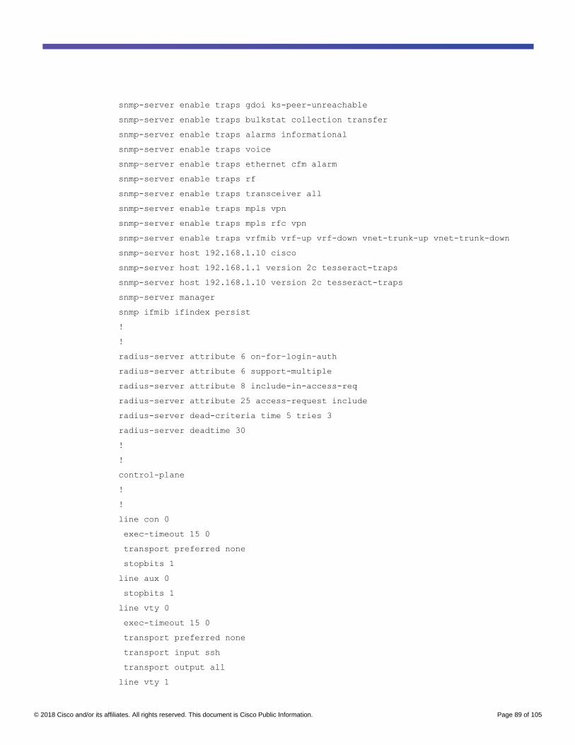
© 2018 Cisco and/or its affiliates. All rights reserved. This document is Cisco Public Information. Page 89 of 105
snmp-server enable traps gdoi ks-peer-unreachable
snmp-server enable traps bulkstat collection transfer
snmp-server enable traps alarms informational
snmp-server enable traps voice
snmp-server enable traps ethernet cfm alarm
snmp-server enable traps rf
snmp-server enable traps transceiver all
snmp-server enable traps mpls vpn
snmp-server enable traps mpls rfc vpn
snmp-server enable traps vrfmib vrf-up vrf-down vnet-trunk-up vnet-trunk-down
snmp-server host 192.168.1.10 cisco
snmp-server host 192.168.1.1 version 2c tesseract-traps
snmp-server host 192.168.1.10 version 2c tesseract-traps
snmp-server manager
snmp ifmib ifindex persist
!
!
radius-server attribute 6 on-for-login-auth
radius-server attribute 6 support-multiple
radius-server attribute 8 include-in-access-req
radius-server attribute 25 access-request include
radius-server dead-criteria time 5 tries 3
radius-server deadtime 30
!
!
control-plane
!
!
line con 0
exec-timeout 15 0
transport preferred none
stopbits 1
line aux 0
stopbits 1
line vty 0
exec-timeout 15 0
transport preferred none
transport input ssh
transport output all
line vty 1

© 2018 Cisco and/or its affiliates. All rights reserved. This document is Cisco Public Information. Page 90 of 105
exec-timeout 15 0
length 0
transport preferred none
transport input ssh
transport output all
line vty 2 4
exec-timeout 15 0
transport preferred none
transport input ssh
transport output all
!
transport type persistent webui input https-webui
!
ntp source GigabitEthernet0
ntp server vrf Mgmt-intf ntp1.lint
ntp server vrf Mgmt-intf ntp2.lint
!
wsma agent exec
!
wsma agent config
!
wsma agent filesys
!
wsma agent notify
!
!
end
Appendix C: AWS VPN configuration example
The following is an example of the configuration information that is downloaded from AWS to configure the Cisco
ASR 1000 Series Routers in the private network. Note that actual preshared keys have been replaced with “<secret
key>”.
! Amazon Web Services
! Virtual Private Cloud
! AWS utilizes unique identifiers to manipulate the configuration of
! a VPN Connection. Each VPN Connection is assigned an identifier and is
! associated with two other identifiers, namely the
! Customer Gateway Identifier and Virtual Private Gateway Identifier.
!
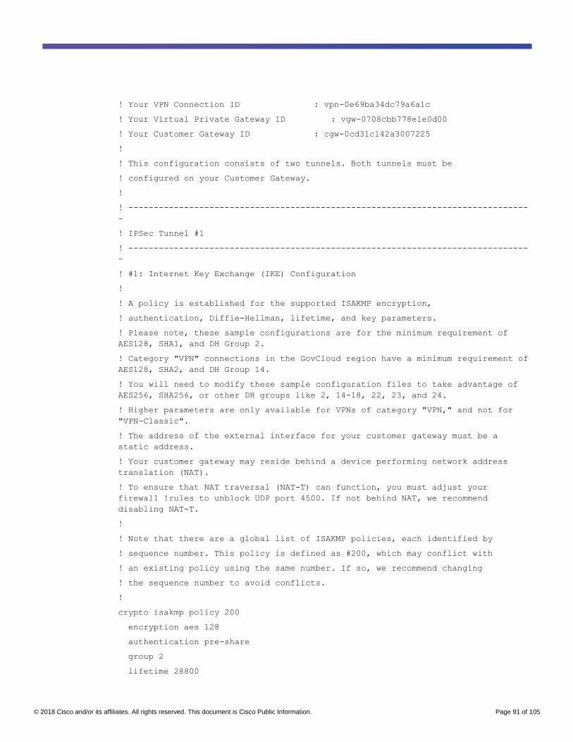
© 2018 Cisco and/or its affiliates. All rights reserved. This document is Cisco Public Information. Page 91 of 105
! Your VPN Connection ID : vpn-0e69ba34dc79a6a1c
! Your Virtual Private Gateway ID : vgw-0708cbb778e1e0d00
! Your Customer Gateway ID : cgw-0cd31c142a3007225
!
! This configuration consists of two tunnels. Both tunnels must be
! configured on your Customer Gateway.
!
! -------------------------------------------------------------------------------
-
! IPSec Tunnel #1
! -------------------------------------------------------------------------------
-
! #1: Internet Key Exchange (IKE) Configuration
!
! A policy is established for the supported ISAKMP encryption,
! authentication, Diffie-Hellman, lifetime, and key parameters.
! Please note, these sample configurations are for the minimum requirement of
AES128, SHA1, and DH Group 2.
! Category "VPN" connections in the GovCloud region have a minimum requirement of
AES128, SHA2, and DH Group 14.
! You will need to modify these sample configuration files to take advantage of
AES256, SHA256, or other DH groups like 2, 14-18, 22, 23, and 24.
! Higher parameters are only available for VPNs of category "VPN," and not for
"VPN-Classic".
! The address of the external interface for your customer gateway must be a
static address.
! Your customer gateway may reside behind a device performing network address
translation (NAT).
! To ensure that NAT traversal (NAT-T) can function, you must adjust your
firewall !rules to unblock UDP port 4500. If not behind NAT, we recommend
disabling NAT-T.
!
! Note that there are a global list of ISAKMP policies, each identified by
! sequence number. This policy is defined as #200, which may conflict with
! an existing policy using the same number. If so, we recommend changing
! the sequence number to avoid conflicts.
!
crypto isakmp policy 200
encryption aes 128
authentication pre-share
group 2
lifetime 28800

© 2018 Cisco and/or its affiliates. All rights reserved. This document is Cisco Public Information. Page 92 of 105
hash sha
exit
! The ISAKMP keyring stores the Pre Shared Key used to authenticate the
! tunnel endpoints.
!
crypto keyring keyring-vpn-0e69ba34dc79a6a1c-0
local-address 173.36.197.52
pre-shared-key address 18.233.2.243 key <secret key>
exit
! An ISAKMP profile is used to associate the keyring with the particular
! endpoint.
!
crypto isakmp profile isakmp-vpn-0e69ba34dc79a6a1c-0
local-address 173.36.197.52
match identity address 18.233.2.243
keyring keyring-vpn-0e69ba34dc79a6a1c-0
exit
! #2: IPSec Configuration
!
! The IPSec transform set defines the encryption, authentication, and IPSec
! mode parameters.
! Category "VPN" connections in the GovCloud region have a minimum requirement of
AES128, SHA2, and DH Group 14.
! Please note, you may use these additionally supported IPSec parameters for
encryption like AES256 and other DH groups like 2, 5, 14-18, 22, 23, and 24.
! Higher parameters are only available for VPNs of category "VPN," and not for
"VPN-Classic".
!
crypto ipsec transform-set ipsec-prop-vpn-0e69ba34dc79a6a1c-0 esp-aes 128 esp-
sha-hmac
mode tunnel
exit
! The IPSec profile references the IPSec transform set and further defines
! the Diffie-Hellman group and security association lifetime.
!
crypto ipsec profile ipsec-vpn-0e69ba34dc79a6a1c-0
set pfs group2

© 2018 Cisco and/or its affiliates. All rights reserved. This document is Cisco Public Information. Page 93 of 105
set security-association lifetime seconds 3600
set transform-set ipsec-prop-vpn-0e69ba34dc79a6a1c-0
exit
! Additional parameters of the IPSec configuration are set here. Note that
! these parameters are global and therefore impact other IPSec
! associations.
! This option instructs the router to clear the "Don't Fragment"
! bit from packets that carry this bit and yet must be fragmented, enabling
! them to be fragmented.
!
crypto ipsec df-bit clear
! This option enables IPSec Dead Peer Detection, which causes periodic
! messages to be sent to ensure a Security Association remains operational.
!
crypto isakmp keepalive 10 10 on-demand
! This configures the gateway's window for accepting out of order
! IPSec packets. A larger window can be helpful if too many packets
! are dropped due to reordering while in transit between gateways.
!
crypto ipsec security-association replay window-size 128
! This option instructs the router to fragment the unencrypted packets
! (prior to encryption).
!
crypto ipsec fragmentation before-encryption
! -------------------------------------------------------------------------------
-
! #3: Tunnel Interface Configuration
!
! A tunnel interface is configured to be the logical interface associated
! with the tunnel. All traffic routed to the tunnel interface will be
! encrypted and transmitted to the VPC. Similarly, traffic from the VPC
! will be logically received on this interface.
!
! Association with the IPSec security association is done through the

© 2018 Cisco and/or its affiliates. All rights reserved. This document is Cisco Public Information. Page 94 of 105
! "tunnel protection" command.
!
! The address of the interface is configured with the setup for your
! Customer Gateway. If the address changes, the Customer Gateway and VPN
! Connection must be recreated with Amazon VPC.
!
interface Tunnel1
ip address 169.254.47.150 255.255.255.252
ip virtual-reassembly
tunnel source 173.36.197.52
tunnel destination 18.233.2.243
tunnel mode ipsec ipv4
tunnel protection ipsec profile ipsec-vpn-0e69ba34dc79a6a1c-0
! This option causes the router to reduce the Maximum Segment Size of
! TCP packets to prevent packet fragmentation.
ip tcp adjust-mss 1379
no shutdown
exit
! -------------------------------------------------------------------------------
-
! #4: Border Gateway Protocol (BGP) Configuration
!
! BGP is used within the tunnel to exchange prefixes between the
! Virtual Private Gateway and your Customer Gateway. The Virtual Private Gateway
! will announce the prefix corresponding to your VPC.
!
! Your Customer Gateway may announce a default route (0.0.0.0/0),
! which can be done with the 'network' and 'default-originate' statements.
!
! The BGP timers are adjusted to provide more rapid detection of outages.
!
! The local BGP Autonomous System Number (ASN) (65000) is configured
! as part of your Customer Gateway. If the ASN must be changed, the
! Customer Gateway and VPN Connection will need to be recreated with AWS.
!
router bgp 65000
neighbor 169.254.47.149 remote-as 65030
neighbor 169.254.47.149 activate

© 2018 Cisco and/or its affiliates. All rights reserved. This document is Cisco Public Information. Page 95 of 105
neighbor 169.254.47.149 timers 10 30 30
address-family ipv4 unicast
neighbor 169.254.47.149 remote-as 65030
neighbor 169.254.47.149 timers 10 30 30
neighbor 169.254.47.149 default-originate
neighbor 169.254.47.149 activate
neighbor 169.254.47.149 soft-reconfiguration inbound
! To advertise additional prefixes to Amazon VPC, copy the 'network' statement
! and identify the prefix you wish to advertise. Make sure the prefix is present
! in the routing table of the device with a valid next-hop.
network 0.0.0.0
exit
exit
!
! -------------------------------------------------------------------------------
-
! IPSec Tunnel #2
! -------------------------------------------------------------------------------
-
! #1: Internet Key Exchange (IKE) Configuration
!
! A policy is established for the supported ISAKMP encryption,
! authentication, Diffie-Hellman, lifetime, and key parameters.
! Please note, these sample configurations are for the minimum requirement of
AES128, SHA1, and DH Group 2.
! Category "VPN" connections in the GovCloud region have a minimum requirement of
AES128, SHA2, and DH Group 14.
! You will need to modify these sample configuration files to take advantage of
AES256, SHA256, or other DH groups like 2, 14-18, 22, 23, and 24.
! Higher parameters are only available for VPNs of category "VPN," and not for
"VPN-Classic".
! The address of the external interface for your customer gateway must be a
static address.
! Your customer gateway may reside behind a device performing network address
translation (NAT).
! To ensure that NAT traversal (NAT-T) can function, you must adjust your
firewall !rules to unblock UDP port 4500. If not behind NAT, we recommend
disabling NAT-T.
!
! Note that there are a global list of ISAKMP policies, each identified by
! sequence number. This policy is defined as #201, which may conflict with
! an existing policy using the same number. If so, we recommend changing

© 2018 Cisco and/or its affiliates. All rights reserved. This document is Cisco Public Information. Page 96 of 105
! the sequence number to avoid conflicts.
!
crypto isakmp policy 201
encryption aes 128
authentication pre-share
group 2
lifetime 28800
hash sha
exit
! The ISAKMP keyring stores the Pre Shared Key used to authenticate the
! tunnel endpoints.
!
crypto keyring keyring-vpn-0e69ba34dc79a6a1c-1
local-address 173.36.197.52
pre-shared-key address 52.5.66.86 key <secret key>
exit
! An ISAKMP profile is used to associate the keyring with the particular
! endpoint.
!
crypto isakmp profile isakmp-vpn-0e69ba34dc79a6a1c-1
local-address 173.36.197.52
match identity address 52.5.66.86
keyring keyring-vpn-0e69ba34dc79a6a1c-1
exit
! #2: IPSec Configuration
!
! The IPSec transform set defines the encryption, authentication, and IPSec
! mode parameters.
! Category "VPN" connections in the GovCloud region have a minimum requirement of
AES128, SHA2, and DH Group 14.
! Please note, you may use these additionally supported IPSec parameters for
encryption like AES256 and other DH groups like 2, 5, 14-18, 22, 23, and 24.
! Higher parameters are only available for VPNs of category "VPN," and not for
"VPN-Classic".
!
crypto ipsec transform-set ipsec-prop-vpn-0e69ba34dc79a6a1c-1 esp-aes 128 esp-
sha-hmac
mode tunnel

© 2018 Cisco and/or its affiliates. All rights reserved. This document is Cisco Public Information. Page 97 of 105
exit
! The IPSec profile references the IPSec transform set and further defines
! the Diffie-Hellman group and security association lifetime.
!
crypto ipsec profile ipsec-vpn-0e69ba34dc79a6a1c-1
set pfs group2
set security-association lifetime seconds 3600
set transform-set ipsec-prop-vpn-0e69ba34dc79a6a1c-1
exit
! Additional parameters of the IPSec configuration are set here. Note that
! these parameters are global and therefore impact other IPSec
! associations.
! This option instructs the router to clear the "Don't Fragment"
! bit from packets that carry this bit and yet must be fragmented, enabling
! them to be fragmented.
!
crypto ipsec df-bit clear
! This option enables IPSec Dead Peer Detection, which causes periodic
! messages to be sent to ensure a Security Association remains operational.
!
crypto isakmp keepalive 10 10 on-demand
! This configures the gateway's window for accepting out of order
! IPSec packets. A larger window can be helpful if too many packets
! are dropped due to reordering while in transit between gateways.
!
crypto ipsec security-association replay window-size 128
! This option instructs the router to fragment the unencrypted packets
! (prior to encryption).
!
crypto ipsec fragmentation before-encryption
! -------------------------------------------------------------------------------
-
! #3: Tunnel Interface Configuration

© 2018 Cisco and/or its affiliates. All rights reserved. This document is Cisco Public Information. Page 98 of 105
!
! A tunnel interface is configured to be the logical interface associated
! with the tunnel. All traffic routed to the tunnel interface will be
! encrypted and transmitted to the VPC. Similarly, traffic from the VPC
! will be logically received on this interface.
!
! Association with the IPSec security association is done through the
! "tunnel protection" command.
!
! The address of the interface is configured with the setup for your
! Customer Gateway. If the address changes, the Customer Gateway and VPN
! Connection must be recreated with Amazon VPC.
!
interface Tunnel2
ip address 169.254.45.138 255.255.255.252
ip virtual-reassembly
tunnel source 173.36.197.52
tunnel destination 52.5.66.86
tunnel mode ipsec ipv4
tunnel protection ipsec profile ipsec-vpn-0e69ba34dc79a6a1c-1
! This option causes the router to reduce the Maximum Segment Size of
! TCP packets to prevent packet fragmentation.
ip tcp adjust-mss 1379
no shutdown
exit
! -------------------------------------------------------------------------------
-
! #4: Border Gateway Protocol (BGP) Configuration
!
! BGP is used within the tunnel to exchange prefixes between the
! Virtual Private Gateway and your Customer Gateway. The Virtual Private Gateway
! will announce the prefix corresponding to your VPC.
!
! Your Customer Gateway may announce a default route (0.0.0.0/0),
! which can be done with the 'network' and 'default-originate' statements.
!
! The BGP timers are adjusted to provide more rapid detection of outages.
!

© 2018 Cisco and/or its affiliates. All rights reserved. This document is Cisco Public Information. Page 99 of 105
! The local BGP Autonomous System Number (ASN) (65000) is configured
! as part of your Customer Gateway. If the ASN must be changed, the
! Customer Gateway and VPN Connection will need to be recreated with AWS.
!
router bgp 65000
neighbor 169.254.45.137 remote-as 65030
neighbor 169.254.45.137 activate
neighbor 169.254.45.137 timers 10 30 30
address-family ipv4 unicast
neighbor 169.254.45.137 remote-as 65030
neighbor 169.254.45.137 timers 10 30 30
neighbor 169.254.45.137 default-originate
neighbor 169.254.45.137 activate
neighbor 169.254.45.137 soft-reconfiguration inbound
! To advertise additional prefixes to Amazon VPC, copy the 'network' statement
! and identify the prefix you wish to advertise. Make sure the prefix is present
! in the routing table of the device with a valid next-hop.
network 0.0.0.0
exit
exit
!
! Additional Notes and Questions
! - Amazon Virtual Private Cloud Getting Started Guide:
! http://docs.amazonwebservices.com/AmazonVPC/latest/GettingStartedGuide
! - Amazon Virtual Private Cloud Network Administrator Guide:
! http://docs.amazonwebservices.com/AmazonVPC/latest/NetworkAdminGuide
! - XSL Version: 2009-07-15-1119716
Appendix D: Flow configuration example
The following is an example of the configuration information that is automatically provisioned by LiveAction when
enabling flow monitoring for Traffic Statistics Flexible NetFlow (FNF), Application Response Time (AVC), and
Voice/Video Performance (Medianet) on interface GigabitEthernet0/0/2:
!
flow record LIVEACTION-FLOWRECORD
description DO NOT MODIFY. USED BY LIVEACTION.
match flow direction
match interface input
match ipv4 destination address
match ipv4 protocol
match ipv4 source address

© 2018 Cisco and/or its affiliates. All rights reserved. This document is Cisco Public Information. Page 100 of 105
match ipv4 tos
match transport destination-port
match transport source-port
collect application http host
collect application name
collect application ssl common-name
collect counter bytes
collect counter packets
collect flow sampler
collect interface output
collect ipv4 destination mask
collect ipv4 dscp
collect ipv4 id
collect ipv4 source mask
collect ipv4 source prefix
collect routing destination as
collect routing next-hop address ipv4
collect routing source as
collect timestamp sys-uptime first
collect timestamp sys-uptime last
collect transport tcp flags
!
flow record type performance-monitor LIVEACTION-FLOWRECORD-AVC
description DO NOT MODIFY. USED BY LIVEACTION.
match application name account-on-resolution
match connection client ipv4 address
match connection server ipv4 address
match connection server transport port
match ipv4 protocol
match routing vrf input
collect application http host
collect application ssl common-name
collect connection client counter bytes long
collect connection client counter bytes network long
collect connection client counter packets long
collect connection client counter packets retransmitted
collect connection delay application sum
collect connection delay network client-to-server sum
collect connection delay network to-client sum
collect connection delay network to-server sum

© 2018 Cisco and/or its affiliates. All rights reserved. This document is Cisco Public Information. Page 101 of 105
collect connection delay response client-to-server sum
collect connection delay response to-server histogram late
collect connection delay response to-server sum
collect connection initiator
collect connection new-connections
collect connection server counter bytes long
collect connection server counter bytes network long
collect connection server counter packets long
collect connection server counter responses
collect connection sum-duration
collect connection transaction counter complete
collect connection transaction duration max
collect connection transaction duration min
collect connection transaction duration sum
collect interface input
collect interface output
collect ipv4 destination address
collect ipv4 dscp
collect ipv4 source address
collect ipv4 ttl
!
flow record type performance-monitor LIVEACTION-FLOWRECORD-MEDIANET
description DO NOT MODIFY. USED BY LIVEACTION.
match flow direction
match ipv4 destination address
match ipv4 protocol
match ipv4 source address
match transport destination-port
match transport rtp ssrc
match transport source-port
collect application media bytes counter
collect application media bytes rate
collect application media event
collect application media packets counter
collect application media packets rate
collect application name
collect counter bytes
collect counter bytes rate
collect counter packets
collect interface input

© 2018 Cisco and/or its affiliates. All rights reserved. This document is Cisco Public Information. Page 102 of 105
collect interface output
collect ipv4 dscp
collect ipv4 ttl
collect monitor event
collect routing forwarding-status
collect timestamp interval
collect transport event packet-loss counter
collect transport packets expected counter
collect transport packets lost counter
collect transport packets lost rate
collect transport rtp jitter maximum
collect transport rtp jitter mean
collect transport rtp jitter minimum
!
flow exporter LIVEACTION-FLOWEXPORTER-IPFIX
description DO NOT MODIFY. USED BY LIVEACTION.
destination 10.1.0.69
source GigabitEthernet0/0/2
transport udp 2055
export-protocol ipfix
option interface-table
option vrf-table
option sampler-table
option application-table
option application-attributes
option c3pl-class-table
option c3pl-policy-table
!
flow monitor type performance-monitor LIVEACTION-FLOWMONITOR-AVC
description DO NOT MODIFY. USED BY LIVEACTION.
record LIVEACTION-FLOWRECORD-AVC
exporter LIVEACTION-FLOWEXPORTER-IPFIX
cache entries 6500
!
flow monitor type performance-monitor LIVEACTION-FLOWMONITOR-MEDIANET
description DO NOT MODIFY. USED BY LIVEACTION.
record LIVEACTION-FLOWRECORD-MEDIANET
exporter LIVEACTION-FLOWEXPORTER-IPFIX
!
flow monitor LIVEACTION-FLOWMONITOR

© 2018 Cisco and/or its affiliates. All rights reserved. This document is Cisco Public Information. Page 103 of 105
description DO NOT MODIFY. USED BY LIVEACTION.
exporter LIVEACTION-FLOWEXPORTER-IPFIX
cache timeout inactive 10
cache timeout active 60
record LIVEACTION-FLOWRECORD
!
class-map match-any LIVEACTION-CLASS-AVC
match access-group name LIVEACTION-ACL-AVC
!
class-map match-any LIVEACTION-CLASS-MEDIANET
match protocol telepresence-media
match protocol rtp
!
policy-map type performance-monitor LIVEACTION-POLICY-UNIFIED
class LIVEACTION-CLASS-AVC
flow monitor LIVEACTION-FLOWMONITOR-AVC
class LIVEACTION-CLASS-MEDIANET
flow monitor LIVEACTION-FLOWMONITOR-MEDIANET
!
interface GigabitEthernet0/0/2
description Connection to N5K-1 Eth1/8
ip flow monitor LIVEACTION-FLOWMONITOR input
ip flow monitor LIVEACTION-FLOWMONITOR output
ip address 10.1.0.124 255.255.255.248
ip nbar protocol-discovery
load-interval 30
negotiation auto
cdp enable
service-policy type performance-monitor input LIVEACTION-POLICY-UNIFIED
service-policy type performance-monitor output LIVEACTION-POLICY-UNIFIED
!
ip access-list extended LIVEACTION-ACL-AVC
permit tcp any any
!

© 2018 Cisco and/or its affiliates. All rights reserved. This document is Cisco Public Information. Page 104 of 105
Additional resources
If you have further questions, refer to the following additional resources:
● Cisco Multicloud Portfolio: Cloud Connect Design Considerations and Overview:
https://www.cisco.com/c/en/us/solutions/collateral/cloud/guide-c07-741193.pdf
● Cisco Multicloud: Cloud Connect Design Deployment Guide for AWS Transit VPC Cisco Cloud Services
Router 1000V:
https://www.cisco.com/c/en/us/products/collateral/routers/cloud-services-router-1000v-series/guide-c07-
740270.pdf
● Cisco ASR 1000 Series Aggregation Services Routers:
https://www.cisco.com/c/en/us/products/routers/asr-1000-series-aggregation-services-routers/index.html
● Cisco Cloud Services Router 1000V:
https://www.cisco.com/c/en/us/support/routers/cloud-services-router-1000v/model.html
● Viptela® SD-WAN:
https://viptela.com/sd-wan/
● LiveAction:
https://www.liveaction.com
● Amazon Web Services:
https://aws.amazon.com
● Amazon Virtual Private Cloud Documentation:
https://aws.amazon.com/documentation/vpc/
For a complete list of all of our design and deployment guides for the Cisco Multicloud Portfolio, including Cloud
Protect, visit https://www.cisco.com/go/clouddesignguides.
About Cisco design and deployment guides
Cisco design and deployment guides consist of systems and/or solutions designed, tested, and documented to
facilitate faster, more reliable, and more predictable customer deployments. For more information visit:
https://www.cisco.com/go/designzone.
ALL DESIGNS, SPECIFICATIONS, STATEMENTS, INFORMATION, AND RECOMMENDATIONS
(COLLECTIVELY, "DESIGNS") IN THIS MANUAL ARE PRESENTED "AS IS," WITH ALL FAULTS. CISCO AND
ITS SUPPLIERS DISCLAIM ALL WARRANTIES, INCLUDING, WITHOUT LIMITATION, THE WARRANTY OF
MERCHANTABILITY, FITNESS FOR A PARTICULAR PURPOSE AND NONINFRINGEMENT OR ARISING
FROM A COURSE OF DEALING, USAGE, OR TRADE PRACTICE. IN NO EVENT SHALL CISCO OR ITS
SUPPLIERS BE LIABLE FOR ANY INDIRECT, SPECIAL, CONSEQUENTIAL, OR INCIDENTAL DAMAGES,
INCLUDING, WITHOUT LIMITATION, LOST PROFITS OR LOSS OR DAMAGE TO DATA ARISING OUT OF THE
USE OR INABILITY TO USE THE DESIGNS, EVEN IF CISCO OR ITS SUPPLIERS HAVE BEEN ADVISED OF
THE POSSIBILITY OF SUCH DAMAGES.

© 2018 Cisco and/or its affiliates. All rights reserved. This document is Cisco Public Information. Page 105 of 105
THE DESIGNS ARE SUBJECT TO CHANGE WITHOUT NOTICE. USERS ARE SOLELY RESPONSIBLE FOR
THEIR APPLICATION OF THE DESIGNS. THE DESIGNS DO NOT CONSTITUTE THE TECHNICAL OR OTHER
PROFESSIONAL ADVICE OF CISCO, ITS SUPPLIERS, OR PARTNERS. USERS SHOULD CONSULT THEIR
OWN TECHNICAL ADVISORS BEFORE IMPLEMENTING THE DESIGNS. RESULTS MAY VARY DEPENDING
ON FACTORS NOT TESTED BY CISCO.
CCDE, CCENT, Cisco Eos, Cisco Lumin, Cisco Nexus, Cisco StadiumVision, Cisco TelePresence, Cisco WebEx,
the Cisco logo, DCE, and Welcome to the Human Network are trademarks; Changing the Way We Work, Live,
Play, and Learn and Cisco Store are service marks; and Access Registrar, Aironet, AsyncOS, Bringing the Meeting
To You, Catalyst, CCDA, CCDP, CCIE, CCIP, CCNA, CCNP, CCSP, CCVP, Cisco, the Cisco Certified
Internetwork Expert logo, Cisco IOS, Cisco Press, Cisco Systems, Cisco Systems Capital, the Cisco Systems logo,
Cisco Unified Computing System (Cisco UCS), Cisco UCS B-Series Blade Servers, Cisco UCS C-Series Rack
Servers, Cisco UCS S-Series Storage Servers, Cisco UCS Manager, Cisco UCS Management Software, Cisco
Unified Fabric, Cisco Application Centric Infrastructure, Cisco Nexus 9000 Series, Cisco Nexus 7000 Series. Cisco
Prime Data Center Network Manager, Cisco NX-OS Software, Cisco MDS Series, Cisco Unity, Collaboration
Without Limitation, EtherFast, EtherSwitch, Event Center, Fast Step, Follow Me Browsing, FormShare, GigaDrive,
HomeLink, Internet Quotient, IOS, iPhone, iQuick Study, LightStream, Linksys, MediaTone, MeetingPlace,
MeetingPlace Chime Sound, MGX, Networkers, Networking Academy, Network Registrar, PCNow, PIX,
PowerPanels, ProConnect, ScriptShare, SenderBase, SMARTnet, Spectrum Expert, StackWise, The Fastest Way
to Increase Your Internet Quotient, TransPath, WebEx, and the WebEx logo are registered trademarks of Cisco
Systems, Inc. and/or its affiliates in the United States and certain other countries.
All other trademarks mentioned in this document or website are the property of their respective owners. The use of
the word partner does not imply a partnership relationship between Cisco and any other company. (0809R)
© 2018 Cisco Systems, Inc. All rights reserved.
Printed in USA C07-740253-03 10/18