cisco nexus 7000 series connectivity solutions for the...
TRANSCRIPT
White Paper
Cisco Nexus 7000 Series Connectivity Solutions for the Cisco Unified Computing System
About the Cisco Nexus 7000 Series Switches The Cisco Nexus® 7000 Series Switches combine the highest level of scalability with operational flexibility.
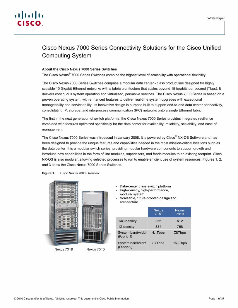
The Cisco Nexus 7000 Series Switches comprise a modular data center - class product line designed for highly scalable 10 Gigabit Ethernet networks with a fabric architecture that scales beyond 15 terabits per second (Tbps). It delivers continuous system operation and virtualized, pervasive services. The Cisco Nexus 7000 Series is based on a proven operating system, with enhanced features to deliver real-time system upgrades with exceptional manageability and serviceability. Its innovative design is purpose built to support end-to-end data center connectivity, consolidating IP, storage, and interprocess communication (IPC) networks onto a single Ethernet fabric.
The first in the next generation of switch platforms, the Cisco Nexus 7000 Series provides integrated resilience combined with features optimized specifically for the data center for availability, reliability, scalability, and ease of management.
The Cisco Nexus 7000 Series was introduced in January 2008. It is powered by Cisco® NX-OS Software and has been designed to provide the unique features and capabilities needed in the most mission-critical locations such as the data center. It is a modular switch series, providing modular hardware components to support growth and introduce new capabilities in the form of line modules, supervisors, and fabric modules to an existing footprint. Cisco NX-OS is also modular, allowing selected processes to run to enable efficient use of system resources. Figures 1, 2, and 3 show the Cisco Nexus 7000 Series Switches.
Figure 1. Cisco Nexus 7000 Overview
© 2010 Cisco and/or its affiliates. All rights reserved. This document is Cisco Public Information. Page 1 of 37

White Paper
Figure 2. Cisco Nexus 7010 Chassis - front and rear views
Figure 3. Cisco Nexus 7018 Chassis - front and rear views
About the Cisco Unified Computing System The Cisco Unified Computing System™ was introduced in 2009. One of its unique differentiators is the establishment of a server farm architecture that enables system resources to be allocated dynamically and flexibly to meet individual virtual machine requirements within a common, consistent resource pool. Virtualized environments need consistent I/O configurations that provide uniform support for hypervisors across all the servers within a resource pool. They also need I/O configurations that support the movement of virtual machines across servers in a resource pool while maintaining individual virtual machine bandwidth and security requirements. The Cisco Unified Computing System meets this need by providing a system built on a low-latency, lossless, 10-Gbps unified network fabric. The result is rapid deployment and movement of workloads without the need to be concerned about application or virtual placement. Blade servers in the Cisco UCS 5108 Blade Server Chassis have access to the fabric through mezzanine-card adapters that provide up to 40 Gbps of throughput per blade server.
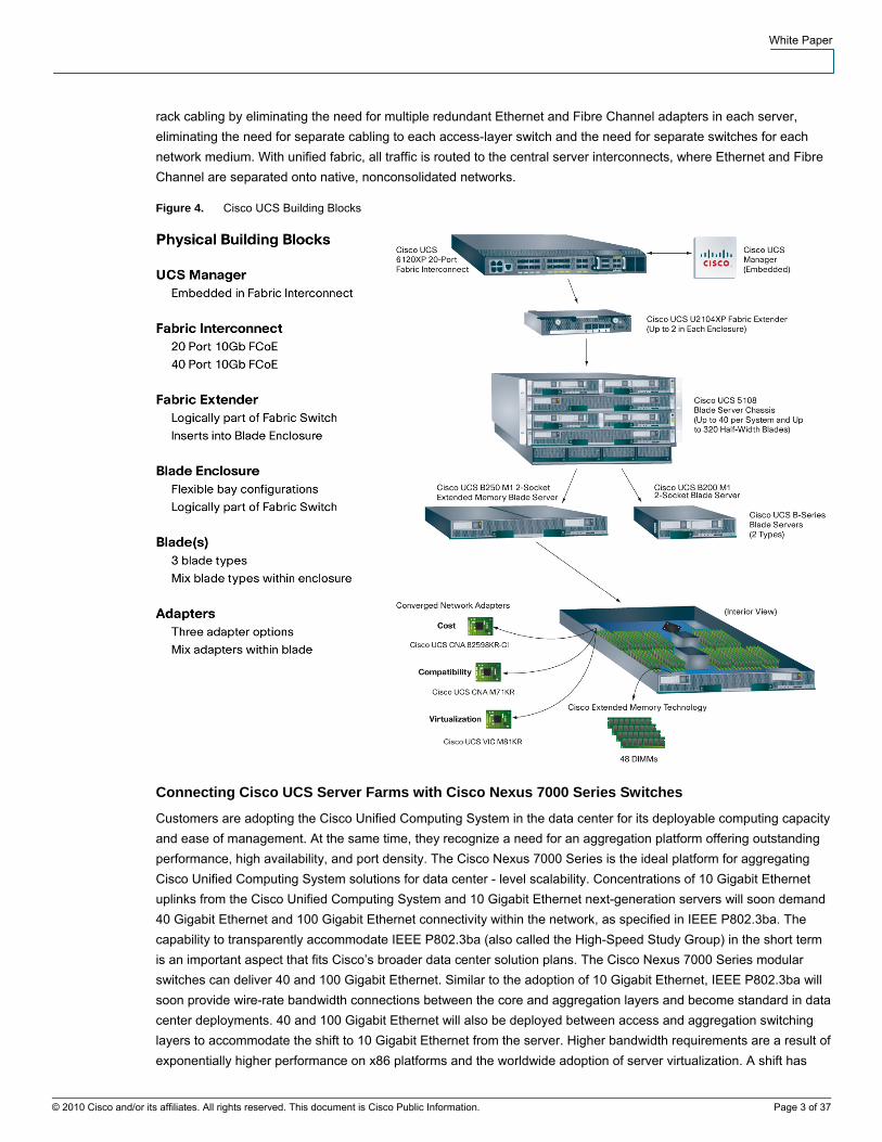
The unified fabric enables a "wire once" deployment model in which chassis are cabled to the fabric interconnects just one time, and I/O configuration changes are made through the management system, unlike solutions that require installation of host adapters and recabling of racks and switches (Figure 4). A unified fabric dramatically simplifies
© 2010 Cisco and/or its affiliates. All rights reserved. This document is Cisco Public Information. Page 2 of 37
White Paper
rack cabling by eliminating the need for multiple redundant Ethernet and Fibre Channel adapters in each server, eliminating the need for separate cabling to each access-layer switch and the need for separate switches for each network medium. With unified fabric, all traffic is routed to the central server interconnects, where Ethernet and Fibre Channel are separated onto native, nonconsolidated networks.
Figure 4. Cisco UCS Building Blocks
Connecting Cisco UCS Server Farms with Cisco Nexus 7000 Series Switches
Customers are adopting the Cisco Unified Computing System in the data center for its deployable computing capacity and ease of management. At the same time, they recognize a need for an aggregation platform offering outstanding performance, high availability, and port density. The Cisco Nexus 7000 Series is the ideal platform for aggregating Cisco Unified Computing System solutions for data center - level scalability. Concentrations of 10 Gigabit Ethernet uplinks from the Cisco Unified Computing System and 10 Gigabit Ethernet next-generation servers will soon demand 40 Gigabit Ethernet and 100 Gigabit Ethernet connectivity within the network, as specified in IEEE P802.3ba. The capability to transparently accommodate IEEE P802.3ba (also called the High-Speed Study Group) in the short term is an important aspect that fits Cisco’s broader data center solution plans. The Cisco Nexus 7000 Series modular switches can deliver 40 and 100 Gigabit Ethernet. Similar to the adoption of 10 Gigabit Ethernet, IEEE P802.3ba will soon provide wire-rate bandwidth connections between the core and aggregation layers and become standard in data center deployments. 40 and 100 Gigabit Ethernet will also be deployed between access and aggregation switching layers to accommodate the shift to 10 Gigabit Ethernet from the server. Higher bandwidth requirements are a result of exponentially higher performance on x86 platforms and the worldwide adoption of server virtualization. A shift has
© 2010 Cisco and/or its affiliates. All rights reserved. This document is Cisco Public Information. Page 3 of 37
White Paper
begun for many enterprises; organizations were previously cautious about ratios of physical to virtual servers in excess of 1:5, but today it is not uncommon to see ratios of 1:20 and higher. This increase is motivating the adoption of 10 Gigabit Ethernet in the server farm, resulting in higher aggregate bandwidth requirements between access, aggregation, and core blocks.
Data center operators are looking for ways to reduce costs and provide greener environments. Government regulations (EPA-EU code of conduct [CoC], etc.) as well as branding and marketing play a crucial role in influencing the creation of a “green” operation along with actual cost savings. One common way to achieve more efficient power and cooling is to reduce the overall footprint of the operation. Closer proximity for delivery of power and cooling to the heat source is an important factor, requiring the IT operation to reduce its surface while increasing its overall performance. The mechanical and electrical facilities, which can account for 100 percent overhead on the electrical and power bill and the carbon footprint, can be used more efficiently through modularity if higher-density computing data centers are built.
The combination of the highly scalable architecture of the Cisco Unified Computing System and Cisco Nexus 7000 Series modular switches results in a network architecture that can support growth in bandwidth, performance, and computing density in a highly available solution.
Deploying the Cisco Unified Computing System with the Cisco Nexus 7000 Series The Cisco UCS 6100 Series Fabric Interconnects are crucial components of the Cisco Unified Computing System. The fabric interconnect is the centerpoint of the Cisco Unified Computing System. It contains all the combined network and server configuration settings, policies, resource pools, and templates, and it provides a single management interface for rapid network and computing service provisioning.
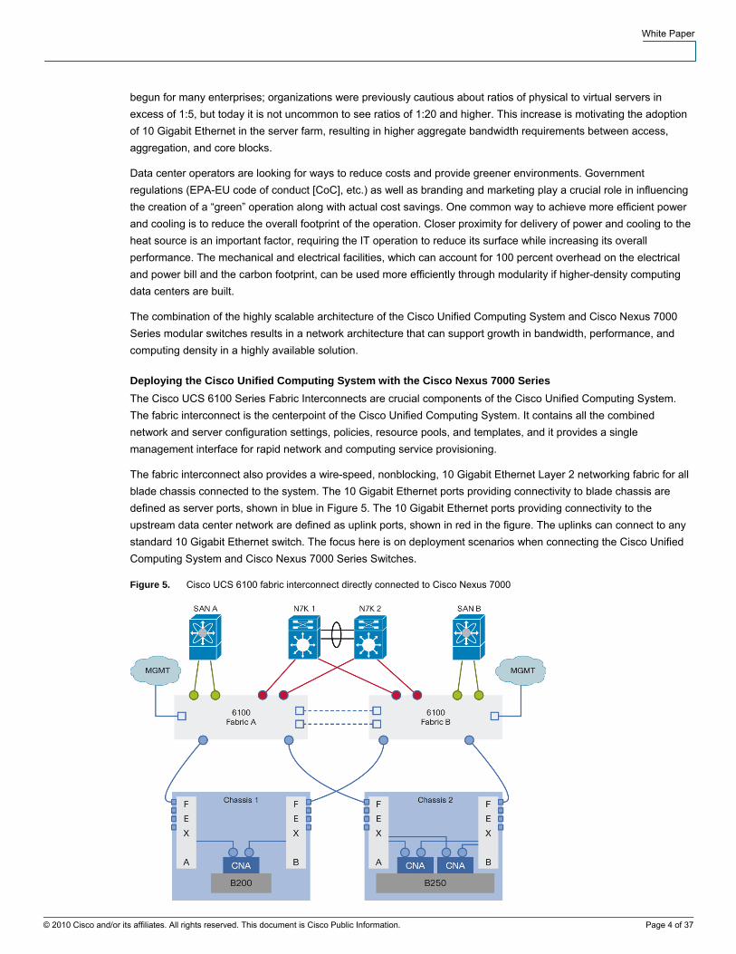
The fabric interconnect also provides a wire-speed, nonblocking, 10 Gigabit Ethernet Layer 2 networking fabric for all blade chassis connected to the system. The 10 Gigabit Ethernet ports providing connectivity to blade chassis are defined as server ports, shown in blue in Figure 5. The 10 Gigabit Ethernet ports providing connectivity to the upstream data center network are defined as uplink ports, shown in red in the figure. The uplinks can connect to any standard 10 Gigabit Ethernet switch. The focus here is on deployment scenarios when connecting the Cisco Unified Computing System and Cisco Nexus 7000 Series Switches.
Figure 5. Cisco UCS 6100 fabric interconnect directly connected to Cisco Nexus 7000
© 2010 Cisco and/or its affiliates. All rights reserved. This document is Cisco Public Information. Page 4 of 37

White Paper
Cisco UCS Switch Mode and End-Host Mode The Cisco UCS fabric interconnects can run in one of two networking modes: switch mode or end-host mode. Both modes of operation provide local Layer 2 switching for the server environment; however, uplinks to the data center network are handled differently by the two different modes. The default, and preferred, mode of operation is end-host mode; however, in some scenarios switch mode may be necessary or preferred.
Switch Mode In switch mode, the Cisco UCS fabric interconnect behaves like a normal Layer 2 switch in the way it handles both its uplinks and downlinks. Just as would be the case with any normal Layer 2 switch, switch mode provides local Layer 2 switching for all ports, including uplinks to the data center and downlinks to the servers (server ports). Because of this typical switching behavior, the Cisco UCS fabric interconnect attaches to the upstream data center network like a switch using spanning tree for loop detection and avoidance (Figure 6).
Figure 6. Cisco UCS in Switch Mode
The uplinks in switch mode participate in the data center network spanning-tree topology, and the typical result is that only one uplink actively forwards for any given VLAN. All servers connected to the same VLAN will use the same uplink for traffic entering or leaving the system. The local switching behavior on all ports of the fabric interconnect in switch mode will perform source MAC address learning on all ports, including uplinks, and will build a fully populated MAC address table proportional to the number of hosts in the data center network for the VLANs to which the Cisco Unified Computing System is exposed.
The uplinks in switch mode participate in the data center spanning-tree topology for loop avoidance, so the interfaces on the upstream Cisco Nexus switches should be configured as trunks in a normal spanning-tree topology:
spanning-tree port type normal
switchport mode trunk
This configuration will help ensure that the upstream Cisco Nexus switches wait the normal spanning-tree forwarding delay interval to detect and prevent potential loops before forwarding traffic.
© 2010 Cisco and/or its affiliates. All rights reserved. This document is Cisco Public Information. Page 5 of 37
White Paper
Switch mode is not the preferred mode of operation. End-host mode offers some elegant enhancements to switch mode. Switch mode may be required in some cases, however, such as when the Cisco Unified Computing System is attached to separate, isolated networks.
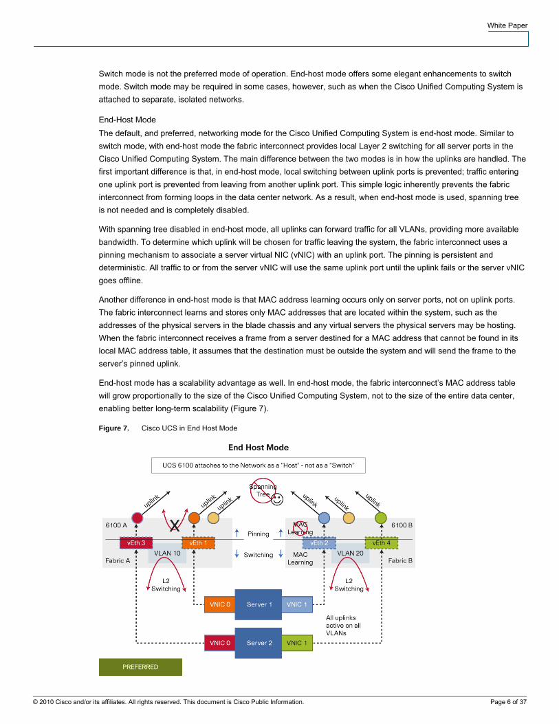
End-Host Mode The default, and preferred, networking mode for the Cisco Unified Computing System is end-host mode. Similar to switch mode, with end-host mode the fabric interconnect provides local Layer 2 switching for all server ports in the Cisco Unified Computing System. The main difference between the two modes is in how the uplinks are handled. The first important difference is that, in end-host mode, local switching between uplink ports is prevented; traffic entering one uplink port is prevented from leaving from another uplink port. This simple logic inherently prevents the fabric interconnect from forming loops in the data center network. As a result, when end-host mode is used, spanning tree is not needed and is completely disabled.
With spanning tree disabled in end-host mode, all uplinks can forward traffic for all VLANs, providing more available bandwidth. To determine which uplink will be chosen for traffic leaving the system, the fabric interconnect uses a pinning mechanism to associate a server virtual NIC (vNIC) with an uplink port. The pinning is persistent and deterministic. All traffic to or from the server vNIC will use the same uplink port until the uplink fails or the server vNIC goes offline.
Another difference in end-host mode is that MAC address learning occurs only on server ports, not on uplink ports. The fabric interconnect learns and stores only MAC addresses that are located within the system, such as the addresses of the physical servers in the blade chassis and any virtual servers the physical servers may be hosting. When the fabric interconnect receives a frame from a server destined for a MAC address that cannot be found in its local MAC address table, it assumes that the destination must be outside the system and will send the frame to the server’s pinned uplink.
End-host mode has a scalability advantage as well. In end-host mode, the fabric interconnect’s MAC address table will grow proportionally to the size of the Cisco Unified Computing System, not to the size of the entire data center, enabling better long-term scalability (Figure 7).
Figure 7. Cisco UCS in End Host Mode
© 2010 Cisco and/or its affiliates. All rights reserved. This document is Cisco Public Information. Page 6 of 37
White Paper
© 2010 Cisco and/or its affiliates. All rights reserved. This document is Cisco Public Information. Page 7 of 37
End-host mode inherently prevents loops by disallowing local switching on uplink ports. Therefore, when attaching the Cisco Unified Computing System in end-host mode to the upstream Cisco Nexus 7000 Series Switch ports, the Cisco Nexus 7000 Series ports are configured as if a host is attached to that port, not a switch. The ideal configuration is a trunk port in spanning-tree edge mode:
spanning-tree port type edge trunk
switchport mode trunk
This configuration allows the interfaces to begin forwarding immediately after a link is established.
Best Practices in Connecting the Cisco Unified Computing System to the Cisco Nexus 7000 Series
The Cisco Nexus 7000 Series, with 10 Gigabit Ethernet density, high performance, virtual PortChannel (vPC) capabilities, and high availability, including a modular operating system with transparent software upgrades and grid-level power redundancy, is the ideal platform for aggregating Cisco UCS deployments.
Connecting the Cisco Unified Computing System to the Cisco Nexus 7000 Series is a straightforward and simple process.
Dual-Connect Each Fabric Interconnect to Multiple Cisco Nexus 7000 Series Switches Always dual-attach each fabric interconnect to two Cisco Nexus 7000 Series Switches for high availability and redundancy whether using vPC uplinks or individual uplinks without vPC.
In a dual-connection configuration, if a Cisco Nexus 7000 Series Switch is taken out of service, a fabric interconnect that has dual connections will not be isolated from the network. In most cases, there will be some traffic traveling between the two Cisco UCS fabrics in a clustered system (interfabric traffic). When the fabric interconnects are connected to the same redundant pair of Cisco Nexus 7000 Series Switches, interfabric traffic can be locally switched by a single Cisco Nexus 7000 Series chassis rather than having to be forwarded across an interswitch link (ISL) to the second Cisco Nexus 7000 Series Switch, because each Cisco Nexus 7000 Series Switch is connected to both Cisco UCS fabrics. This local forwarding probability increases to 100 percent when you use vPC uplinks from the Cisco Unified Computing System to the Cisco Nexus 7000 Series Switch.
Preferred Configuration: Cisco UCS End-Host Mode with vPC Uplinks to Cisco Nexus 7000 Series Switches Enabling the vPC capabilities in Cisco Nexus 7000 Series and using vPC uplinks from the Cisco Unified Computing System in end-host mode simplifies the topology and provides additional synergies between the two platforms.
vPC uplinks from the Cisco Unified Computing System to the Cisco Nexus 7000 Series provide higher availability and faster failover from links or switches being taken out of service. If a link or switch is taken out of service, the Cisco UCS vPC uplink remains intact, and dynamic repinning of server vNICs to a new uplink is not required. No additional failure recovery mechanisms need to be engaged, such as gratuitous Address Resolution Protocol (ARPs) messages, because the topology has not changed from the perspectives of both the upstream network and the Cisco Unified Computing System. As a result, bidirectional convergence is faster and more deterministic during failures.
In Figure 8, the Cisco UCS 6100 Series Fabric Interconnect 6100-A has one logical vPC uplink connected to a pair of Cisco Nexus 7000 Series Switches configured for vPC. All Cisco UCS server vNICs on 6100-A are pinned to the one logical vPC uplink. From the perspective of the Cisco Nexus 7000 Series Switch, all MAC addresses from the server vNICs and any virtual machines are learned on one logical vPC interface synchronized between the two Cisco Nexus 7000 Series Switches. If any one of the Cisco Nexus 7000 Series Switches or links is taken out of service, the Cisco UCS vPC uplink will remain intact with no effect on the Cisco UCS servers. The fabric interconnect will move traffic on the affected vPC member links to any one of the remaining member links, which can be located on a different Cisco Nexus 7000 Series Switch. Because vPC has synchronized MAC address learning between the two Cisco Nexus 7000 Series Switches, no relearning of a new MAC address location is necessary; the MAC address location

White Paper
in the topology has not changed. Under these circumstances, even the failure of a complete switch affects only the network capacity, not the network topology.
Figure 8. Cisco UCS connected to Nexus 7000 with vPC
vPC uplinks also offer the added benefit of greater available bandwidth for each server, consistent latency, and deterministic traffic patterns for Cisco UCS interfabric traffic. With vPC uplinks from the Cisco Unified Computing System to the Cisco Nexus 7000 Series, all interfabric traffic is locally switched by the Cisco Nexus 7000 Series Switch and never traverses an ISL.
Use vPC Uplinks from the Cisco Unified Computing System When vPC Is Enabled on Cisco Nexus 7000 Series Switches vPC is a NX-OS software base level feature that comes with the Cisco Nexus 7000. Cisco Unified Computing System can be added to a pair of Cisco Nexus 7000 Series Switches already configured as a vPC domain. In this case, vPC uplinks are used when attaching to the Cisco Unified Computing System (Figure 9).
© 2010 Cisco and/or its affiliates. All rights reserved. This document is Cisco Public Information. Page 8 of 37

White Paper
Figure 9. Adding Cisco UCS to a Nexus 7000 vPC domain
In the scenario shown in Figure 9, the Cisco Unified Computing System is attached with vPC uplinks to a pair of existing Cisco Nexus 7000 Series Switches already configured with vPC.
The system responds favorably when a vPC peer link is taken out of service. When the vPC peer link is down and the keep-alive link remains up, the vPC secondary switch (N7K2) will look for any vPC member ports to shut down and will shut down the Layer 3 VLAN interfaces. Since fabric interconnect 6100-B’s uplink (shown in red) is a vPC uplink, N7K2 sees those interfaces as vPC member ports and shuts them down. As a result, the corresponding port on 6100-B is also brought down, while the vPC uplink (shown in red) remains intact, but with one less member link. The 6100-B fabric interconnect no longer sends any traffic to N7K2 because a member link that is down; all traffic is directed to N7K1, which is the vPC primary switch and still has connectivity to both 6100-A’s uplink (shown in green) and 6100-B’s uplink (shown in red). The vPC configuration creates a resilient solution with no fabric isolation; all interfabric traffic is forwarded locally by N7K1.
If vPC is not used with the Cisco UCS uplinks, the result may be unnecessary peer-link traffic and major failure scenarios that can lead to isolation between the Cisco UCS fabrics as shown in Figure 10.
© 2010 Cisco and/or its affiliates. All rights reserved. This document is Cisco Public Information. Page 9 of 37
White Paper
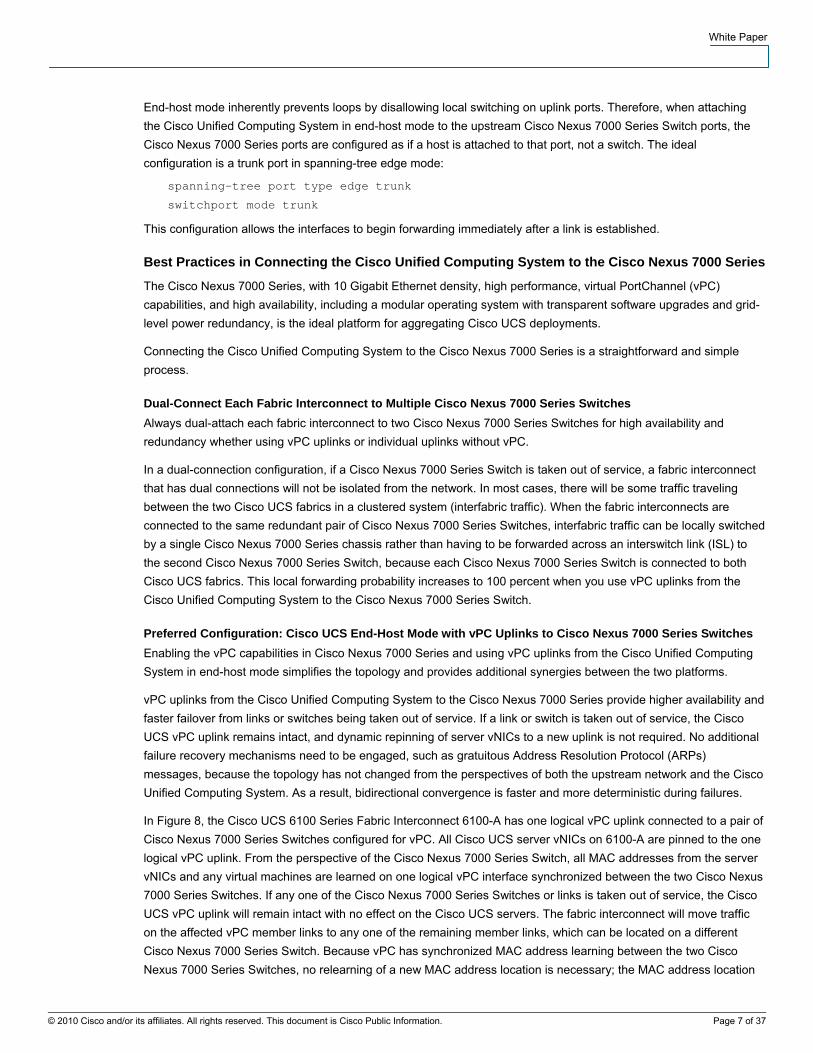
Figure 10. Attaching to a vPC domain without vPC uplinks
In the scenario in Figure 10, before any failure occurs in the network, unnecessary traffic will appear on the peer link between Cisco Nexus 7000 Series Switches. Any interfabric traffic from the uplink shown in green that needs to reach the uplink shown in red will have no other route but across the vPC peer link. This suboptimal traffic flow can be avoided by using vPC uplinks as shown in the previous examples.
Figure 10 shows a scenario in which the vPC peer link fails while the vPC keepalive link stays up. In this case, the vPC secondary switch is N7K2. In the normal logical failure sequence, the vPC secondary switch brings down all its vPC member ports and Layer 3 interfaces for VLANs forwarded on the vPC peer link. The uplink shown in red from 6100-B is not a vPC uplink, and it is not viewed as a vPC member port on N7K2 and therefore is not brought down; instead, the red uplink stays up. As a result, 6100-B has no knowledge of an upstream error and will continue to forward traffic to N7K2. N7K2 will proceed to bring down its Layer 3 VLAN interfaces, with the result that 6100-B will have no Layer 3 gateway. Furthermore, the two fabrics have become isolated, and interfabric traffic will be negatively affected.
Attaching the Cisco Unified Computing System with vPC uplinks to a pair of Cisco Nexus 7000 Series Switches already configured for vPC avoids all these problems (Figure 11).
© 2010 Cisco and/or its affiliates. All rights reserved. This document is Cisco Public Information. Page 10 of 37
White Paper
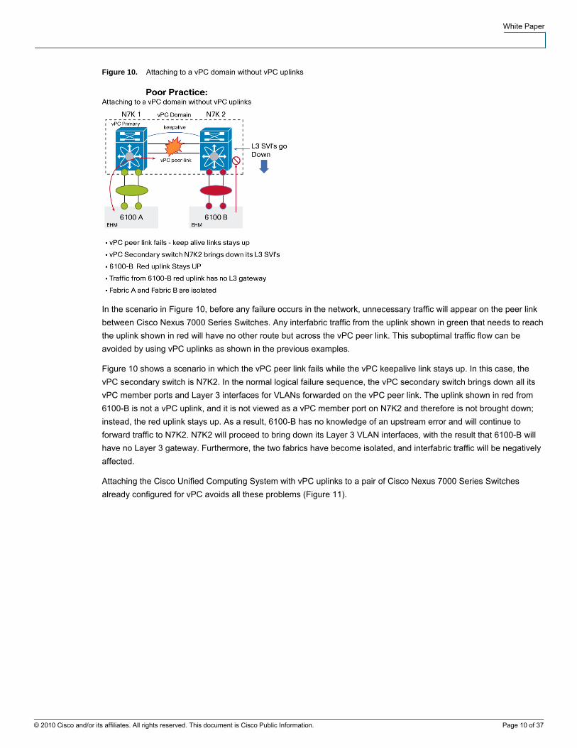
Figure 11. Best Practice - Dual attached Nexus 7000 with vPC
The same local switching advantage applies to traffic destined for the Cisco Unified Computing System that enters the Cisco Nexus 7000 Series Switch from elsewhere in the network. With each Cisco Nexus 7000 Series Switch connected to the same vPC uplinks, all traffic from the network to the Cisco Unified Computing System will be locally forwarded and not traverse an ISL (Figure 12).
Figure 12. Network to UCS with no peer link traffic
When the Cisco Unified Computing System is dual-attached to a pair of Cisco Nexus 7000 Series Switches in a vPC configuration, no data traffic needs to traverse the vPC peer-link connections, and they will be used for vPC control traffic. As shown in Figure 12, it does not matter whether N7K1 or N7K2 receives traffic from the network destined for either the red or the green uplink; all traffic will be locally forwarded simply because both Cisco Nexus 7000 Series Switches have access connections to all the same uplinks from the Cisco Unified Computing System.
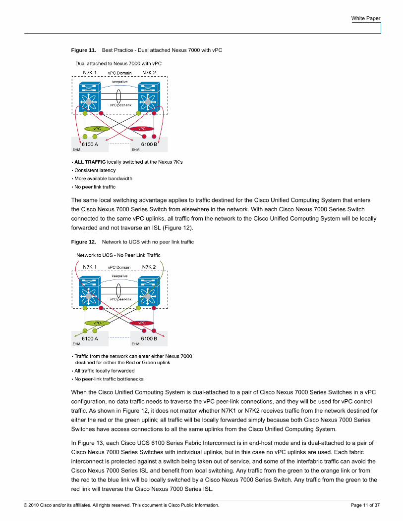
In Figure 13, each Cisco UCS 6100 Series Fabric Interconnect is in end-host mode and is dual-attached to a pair of Cisco Nexus 7000 Series Switches with individual uplinks, but in this case no vPC uplinks are used. Each fabric interconnect is protected against a switch being taken out of service, and some of the interfabric traffic can avoid the Cisco Nexus 7000 Series ISL and benefit from local switching. Any traffic from the green to the orange link or from the red to the blue link will be locally switched by a Cisco Nexus 7000 Series Switch. Any traffic from the green to the red link will traverse the Cisco Nexus 7000 Series ISL.
© 2010 Cisco and/or its affiliates. All rights reserved. This document is Cisco Public Information. Page 11 of 37
White Paper
Figure 13. Dual Attached without using vPC
Connecting the Cisco Unified Computing System to Separate Isolated Networks
A Cisco Unified Computing System connecting to separate and isolated upstream networks requires different considerations.
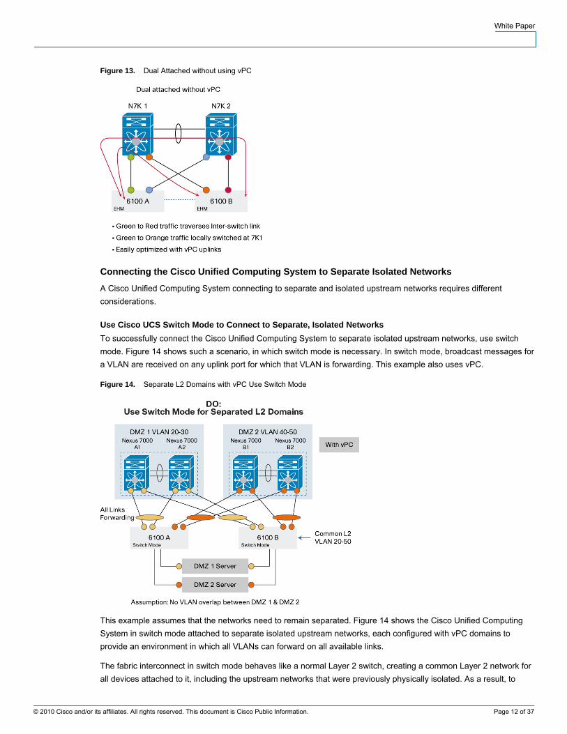
Use Cisco UCS Switch Mode to Connect to Separate, Isolated Networks To successfully connect the Cisco Unified Computing System to separate isolated upstream networks, use switch mode. Figure 14 shows such a scenario, in which switch mode is necessary. In switch mode, broadcast messages for a VLAN are received on any uplink port for which that VLAN is forwarding. This example also uses vPC.
Figure 14. Separate L2 Domains with vPC Use Switch Mode
This example assumes that the networks need to remain separated. Figure 14 shows the Cisco Unified Computing System in switch mode attached to separate isolated upstream networks, each configured with vPC domains to provide an environment in which all VLANs can forward on all available links.
The fabric interconnect in switch mode behaves like a normal Layer 2 switch, creating a common Layer 2 network for all devices attached to it, including the upstream networks that were previously physically isolated. As a result, to
© 2010 Cisco and/or its affiliates. All rights reserved. This document is Cisco Public Information. Page 12 of 37
White Paper
preserve Layer 2 isolation, the Cisco UCS fabric interconnect should not attach to the same VLAN IDs on each isolated network.
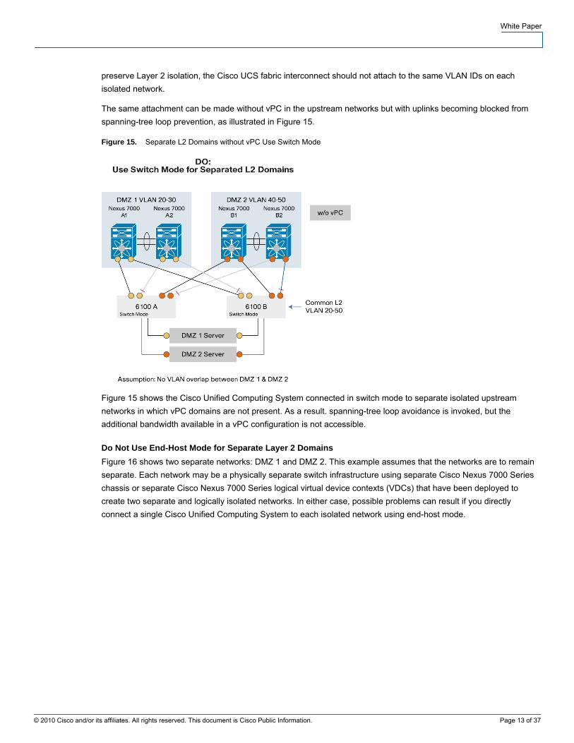
The same attachment can be made without vPC in the upstream networks but with uplinks becoming blocked from spanning-tree loop prevention, as illustrated in Figure 15.
Figure 15. Separate L2 Domains without vPC Use Switch Mode
Figure 15 shows the Cisco Unified Computing System connected in switch mode to separate isolated upstream networks in which vPC domains are not present. As a result. spanning-tree loop avoidance is invoked, but the additional bandwidth available in a vPC configuration is not accessible.
Do Not Use End-Host Mode for Separate Layer 2 Domains Figure 16 shows two separate networks: DMZ 1 and DMZ 2. This example assumes that the networks are to remain separate. Each network may be a physically separate switch infrastructure using separate Cisco Nexus 7000 Series chassis or separate Cisco Nexus 7000 Series logical virtual device contexts (VDCs) that have been deployed to create two separate and logically isolated networks. In either case, possible problems can result if you directly connect a single Cisco Unified Computing System to each isolated network using end-host mode.
© 2010 Cisco and/or its affiliates. All rights reserved. This document is Cisco Public Information. Page 13 of 37
White Paper
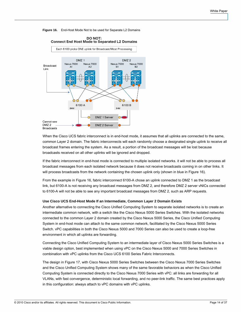
Figure 16. End-Host Mode Not to be used for Separate L2 Domains
When the Cisco UCS fabric interconnect is in end-host mode, it assumes that all uplinks are connected to the same, common Layer 2 domain. The fabric interconnects will each randomly choose a designated single uplink to receive all broadcast frames entering the system. As a result, a portion of the broadcast messages will be lost because broadcasts received on all other uplinks will be ignored and dropped.
If the fabric interconnect in end-host mode is connected to multiple isolated networks. it will not be able to process all broadcast messages from each isolated network because it does not receive broadcasts coming in on other links. It will process broadcasts from the network containing the chosen uplink only (shown in blue in Figure 16).
From the example in Figure 16, fabric interconnect 6100-A chose an uplink connected to DMZ 1 as the broadcast link, but 6100-A is not receiving any broadcast messages from DMZ 2, and therefore DMZ 2 server vNICs connected to 6100-A will not be able to see any important broadcast messages from DMZ 2, such as ARP requests.
Use Cisco UCS End-Host Mode If an Intermediate, Common Layer 2 Domain Exists Another alternative to connecting the Cisco Unified Computing System to separate isolated networks is to create an intermediate common network, with a switch like the Cisco Nexus 5000 Series Switches. With the isolated networks connected to the common Layer 2 domain created by the Cisco Nexus 5000 Series, the Cisco Unified Computing System in end-host mode can attach to the same common network, facilitated by the Cisco Nexus 5000 Series Switch. vPC capabilities in both the Cisco Nexus 5000 and 7000 Series can also be used to create a loop-free environment in which all uplinks are forwarding.
Connecting the Cisco Unified Computing System to an intermediate layer of Cisco Nexus 5000 Series Switches is a viable design option, best implemented when using vPC on the Cisco Nexus 5000 and 7000 Series Switches in combination with vPC uplinks from the Cisco UCS 6100 Series Fabric Interconnects.
The design in Figure 17, with Cisco Nexus 5000 Series Switches between the Cisco Nexus 7000 Series Switches and the Cisco Unified Computing System shows many of the same favorable behaviors as when the Cisco Unified Computing System is connected directly to the Cisco Nexus 7000 Series with vPC: all links are forwarding for all VLANs, with fast convergence, deterministic local forwarding, and no peer-link traffic. The same best practices apply in this configuration: always attach to vPC domains with vPC uplinks.
© 2010 Cisco and/or its affiliates. All rights reserved. This document is Cisco Public Information. Page 14 of 37

White Paper
Figure 17. Cisco UCS with Nexus 5000, Nexus 7000 and vPC
This design combines two layers of vPCs between the Cisco Nexus 5000 and 7000 Series Switches, shown with the yellow links, creating one logical 40 Gigabit Ethernet PortChannel that spans all switches. This setup is common when the Cisco Nexus 5000 Series is connected to the Cisco Nexus 7000 Series, taking advantage of vPC. The Cisco Nexus 5000 and 7000 Series Switches are forwarding on all links for all VLANs in each direction using the vPC shown in yellow in the figure.
In Figure 18, the Cisco UCS 6100 Series Fabric Interconnects in end-host mode have uplinks to the Cisco Nexus 5000 Series Switches with a single vPC uplink and forwarding for all VLANs present in the common Layer 2 domain. The Cisco Nexus 5000 Series Switches each have uplinks to the separate Cisco Nexus 7000 Series physical networks (the design also would work with logical VDCs), with a separate vPC uplink for each isolated network (shown in orange, and yellow in the figure). To preserve Layer 2 isolation between DMZ 1 and DMZ 2, the Cisco Nexus 5000 Series orange and yellow vPC uplinks are not attached to the same VLAN IDs.
© 2010 Cisco and/or its affiliates. All rights reserved. This document is Cisco Public Information. Page 15 of 37

White Paper
Figure 18. End Host Mode with common L2 Domain with vPC
Figure 19 shows a similar physical deployment without vPC. The Cisco Nexus 5000 Series Switches are still creating the common Layer 2 domain for the fabric interconnects in end-host mode. However, without vPC configured on the Cisco Nexus 5000 Series, the fabric interconnect attaches with individual uplinks and not a vPC uplink. The Cisco Nexus 5000 Series Switches are running spanning tree for loop avoidance and blocking redundant paths to the upstream isolated networks.
© 2010 Cisco and/or its affiliates. All rights reserved. This document is Cisco Public Information. Page 16 of 37

White Paper
Figure 19. End Host Mode with common L2 Domain without vPC
In either scenario, when using switch mode or when using intermediate Cisco Nexus 5000 Series Switches, the end result is that separate networks that may have been previously physically isolated are now only logically isolated at Layer 2 by VLANs. If the IT security policy does not allow only logical VLAN-based isolation, the alternative is to deploy a physically separate Cisco Unified Computing System for each isolated network to maintain the physical separation.
If the IT security policy does allow logical VLAN-based isolation between the separate networks, the opportunity also exists to consolidate the upstream network onto fewer physical switches (or fewer logical VDCs) in a common Layer 2 infrastructure with VLANs unique to each DMZ, as shown in Figure 20.
Figure 20. Isolated Network using Virtualization and Consolidation with vPC
© 2010 Cisco and/or its affiliates. All rights reserved. This document is Cisco Public Information. Page 17 of 37
White Paper
Connect Cisco Unified Computing System Without vPC: Two Uplink Ports While there are clear advantages to using vPC uplinks, not all data center networks have deployed the Cisco Nexus 7000 Series with vPC configured. While the vPC configuration option is the best practice, the Cisco Unified Computing System can be integrated into existing data center environments without vPC.
When connecting the Cisco Unified Computing System without vPC uplinks to the Cisco Nexus 7000 Series, make switch redundant connections the first priority and PortChannel uplinks the second priority, and use end-host mode.
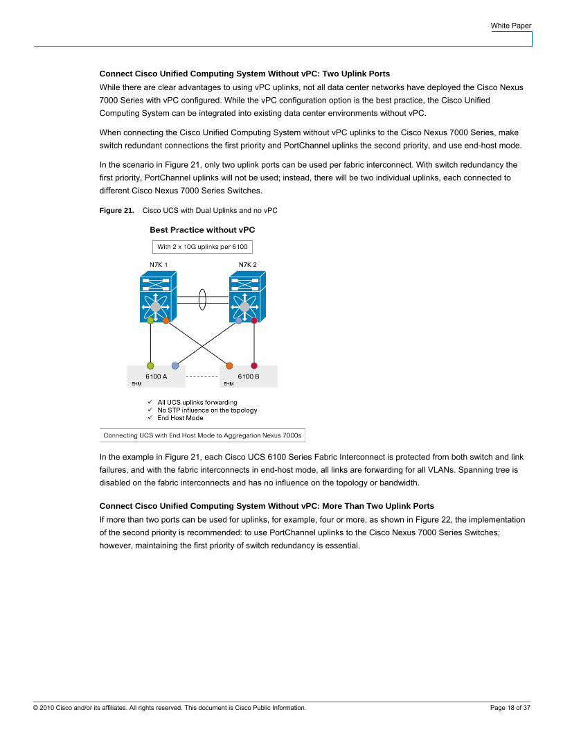
In the scenario in Figure 21, only two uplink ports can be used per fabric interconnect. With switch redundancy the first priority, PortChannel uplinks will not be used; instead, there will be two individual uplinks, each connected to different Cisco Nexus 7000 Series Switches.
Figure 21. Cisco UCS with Dual Uplinks and no vPC
In the example in Figure 21, each Cisco UCS 6100 Series Fabric Interconnect is protected from both switch and link failures, and with the fabric interconnects in end-host mode, all links are forwarding for all VLANs. Spanning tree is disabled on the fabric interconnects and has no influence on the topology or bandwidth.
Connect Cisco Unified Computing System Without vPC: More Than Two Uplink Ports If more than two ports can be used for uplinks, for example, four or more, as shown in Figure 22, the implementation of the second priority is recommended: to use PortChannel uplinks to the Cisco Nexus 7000 Series Switches; however, maintaining the first priority of switch redundancy is essential.
© 2010 Cisco and/or its affiliates. All rights reserved. This document is Cisco Public Information. Page 18 of 37
White Paper
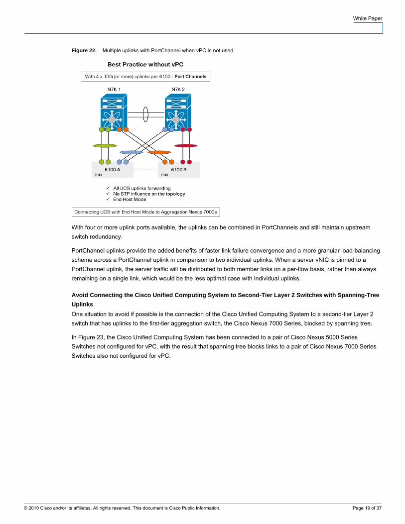
Figure 22. Multiple uplinks with PortChannel when vPC is not used
With four or more uplink ports available, the uplinks can be combined in PortChannels and still maintain upstream switch redundancy.
PortChannel uplinks provide the added benefits of faster link failure convergence and a more granular load-balancing scheme across a PortChannel uplink in comparison to two individual uplinks. When a server vNIC is pinned to a PortChannel uplink, the server traffic will be distributed to both member links on a per-flow basis, rather than always remaining on a single link, which would be the less optimal case with individual uplinks.
Avoid Connecting the Cisco Unified Computing System to Second-Tier Layer 2 Switches with Spanning-Tree Uplinks One situation to avoid if possible is the connection of the Cisco Unified Computing System to a second-tier Layer 2 switch that has uplinks to the first-tier aggregation switch, the Cisco Nexus 7000 Series, blocked by spanning tree.
In Figure 23, the Cisco Unified Computing System has been connected to a pair of Cisco Nexus 5000 Series Switches not configured for vPC, with the result that spanning tree blocks links to a pair of Cisco Nexus 7000 Series Switches also not configured for vPC.
© 2010 Cisco and/or its affiliates. All rights reserved. This document is Cisco Public Information. Page 19 of 37

White Paper
Figure 23. STP Uplinks not recommended - Use vPC
In the scenario in Figure 23, the intermediate Layer 2 switch with spanning-tree uplinks results in a choke point for bandwidth to the Cisco UCS fabric interconnects. Furthermore, there is no usable transit link for interfabric Layer 2 traffic, resulting in inconsistent traffic patterns, latencies, and lack of available bandwidth. For example, traffic from the green uplink on fabric interconnect 6100 A destined for the red uplink on fabric interconnect 6100-B will need to traverse the Cisco Nexus 7000 Series Switches while passing two spanning-tree blocking-link choke points along the way. Layer 2 traffic from the green uplink on 6100-A destined for the orange uplink on 6100-B will be forwarded locally by switch N5K1.
Unlike a vPC network that supports fast link recovery and fast switch failure recovery, in this scenario any link or switch failure at the Cisco Nexus 7000 Series Switches would be subject to spanning-tree recovery timers, which could result in a 1-to-3-second traffic blockage for the Cisco UCS fabric interconnect uplinks. Spanning tree is much less desirable than vPC.
In this scenario, it would be better to connect the Cisco Unified Computing System directly to the Cisco Nexus 7000 Series Switches with end-host mode, as shown previously, or to use vPC on the Cisco Nexus 5000 Series Switches as discussed earlier.
Summary of Best Practices ● Use end-host mode in the Cisco Unified Computing System wherever possible (the default mode). End-host
mode removes spanning-tree blocked paths, and as a result all uplinks forward for all VLANs. End-host mode needs to learn only MAC addresses present in the local Cisco Unified Computing System, not the entire data center Layer 2 network, resulting in better long-term scalability and efficiency.
● Do not connect end-host mode directly to separate and isolated Cisco Nexus 7000 Series Switches or VDCs. Use switch mode to connect to isolated networks or implement a common Layer 2 network with an intermediate switching layer.
● If possible, attach the Cisco Unified Computing System with vPC uplinks to Cisco Nexus 5000 or 7000 Series Switches.
● When attaching the Cisco Unified Computing System to an existing network already configured with vPC, use vPC uplinks.
© 2010 Cisco and/or its affiliates. All rights reserved. This document is Cisco Public Information. Page 20 of 37

White Paper
© 2010 Cisco and/or its affiliates. All rights reserved. This document is Cisco Public Information. Page 21 of 37
● Always dual-attach each fabric interconnect to multiple Cisco Nexus 5000 or 7000 Series Switches, with or without vPC.
● When attaching the Cisco Unified Computing System without vPC, use end-host mode and make dual attachment the first priority and PortChannel uplinks the second priority.
● If possible, avoid connecting the Cisco Unified Computing System to an intermediate switch with spanning-tree blocking links. Connect the Cisco Unified Computing System directly to the Cisco Nexus 7000 Series aggregation switch, or use a vPC design between the intermediate switch (Cisco Nexus 5000 Series) and the Cisco Nexus 7000 Series Switches.
Cisco Nexus 7000 Series: Additional Information
The Cisco Nexus 7000 Series is the ideal platform for aggregating Cisco Unified Computing System instances. The Cisco Nexus 7000 Series is a dense platform for both Layer 2 and 3 10 Gigabit Ethernet switching that can locally service all flows for the Cisco Unified Computing System while providing consistent and predictable traffic patterns for Layer 2 and 3 switched traffic to, from, and between Cisco UCS fabrics.
Both the Cisco Unified Computing System and the Cisco Nexus 7000 Series run on Cisco NX-OS, a modular, highly available, purpose-built OS for the data center. Moreover, the Cisco Nexus 7000 Series has specific high-availability design features that make it the common platform for aggregating Cisco Unified Computing System instances in the data center. Table 1 presents some of the main features of the Cisco Nexus 7000 Series that support resilient network architectures for Cisco UCS deployments.
Table 1. Cisco Nexus 7000 Architectural Advantages
Multi-threaded Real-Time Modularity Separation Control Plane and Data Plane
Line Card Offloading
● Scalability with SMP and multi-core CPUs
● Faster Route Re-convergence
● Lower mean-time-to-recovery
● Real-Time preemptive scheduling
● System still operational when CPU is 100%. The user will still be able to login and debug the problem
● Most of the features are conditional
● Can be enabled/disabled independently
● Maximizes efficiency ● Minimizes resources
utilization
● No “software forwarding feature”
● Fully distributed hardware forwarding
● Offload to line card CPUs
● Scales with # of line cards
● Optimal hardware programming
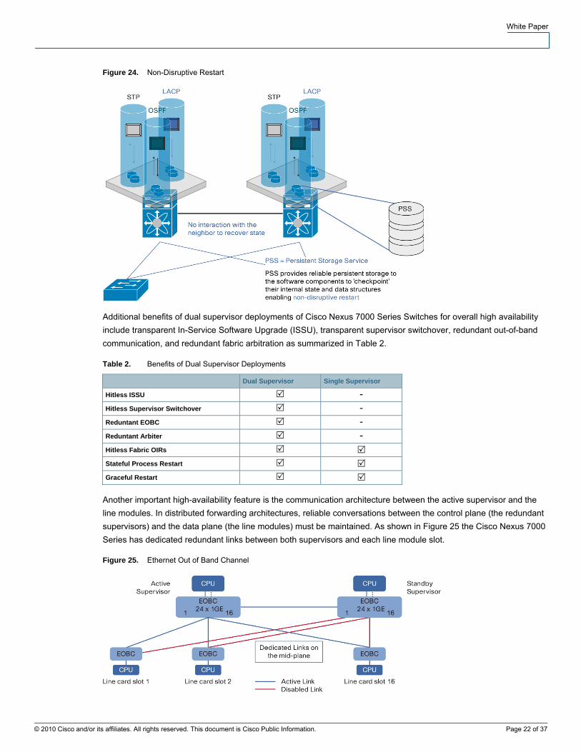
Stateful process restart is another important feature for maintaining exceptional levels of high availability on the Cisco Nexus 7000 Series platform (Figure 24).
White Paper
Figure 24. Non-Disruptive Restart
Additional benefits of dual supervisor deployments of Cisco Nexus 7000 Series Switches for overall high availability include transparent In-Service Software Upgrade (ISSU), transparent supervisor switchover, redundant out-of-band communication, and redundant fabric arbitration as summarized in Table 2.
Table 2. Benefits of Dual Supervisor Deployments
Dual Supervisor Single Supervisor
Hitless ISSU - Hitless Supervisor Switchover - Reduntant EOBC - Reduntant Arbiter - Hitless Fabric OIRs Stateful Process Restart Graceful Restart
Another important high-availability feature is the communication architecture between the active supervisor and the line modules. In distributed forwarding architectures, reliable conversations between the control plane (the redundant supervisors) and the data plane (the line modules) must be maintained. As shown in Figure 25 the Cisco Nexus 7000 Series has dedicated redundant links between both supervisors and each line module slot.
Figure 25. Ethernet Out of Band Channel
© 2010 Cisco and/or its affiliates. All rights reserved. This document is Cisco Public Information. Page 22 of 37

White Paper
● Ethernet Out of Band Channel:
◦ The connectivity between the CPU on the Supervisor and the CPU on each line card is provided by the EOBC
◦ Given its role, the EOBC on the Nexus 7000 has been built to provide the highest level of availability
● Advantages of the Nexus 7000 EOBC:
◦ The Nexus 7000 EOBC is a gigabit ethernet switched architecture between line cards and Supervisors
Fault domains can be designed into the network switching architecture on the Cisco Nexus 7000 Series with VDCs. VDCs are used to logically subdivide the hardware switch logically down to the physical port level. Each VDC runs a separate instantiation of Cisco NX-OS, enabling independent and unique configurations on each VDC (Figure 26).
Figure 26. Cisco Nexus 7000 Virtual Device Contexts
VDCs offer:
● Complete software fault isolation
● Securely delineated administrative contexts
● Per-VDC high-availability policy
◦ Reset: Issues a system reset of a single VDC
◦ Restart: Deletes the VDC and re-creates it
◦ Bring-down: Deletes the VDC but does not bring it back online
All these high-availability benefits are crucial to providing a highly available switching system to support resilient Cisco UCS designs.
Cisco Unified Computing System: Additional Information Cisco Unified Computing System Design The Cisco Unified Computing System combines computing, network, storage access, and virtualization in an integrated, multichassis platform in which all resources are managed in a unified domain. Cisco UCS Manager enables storage, network, and server administrators to collaboratively define service profiles for applications.
Service profiles are logical representations of desired physical configurations and infrastructure policies. They help automate provisioning and increase business agility, allowing data center managers to provision resources in minutes instead of days. With service profiles, server attributes are no longer tied to physical hardware, freeing virtual servers for transparent server mobility.
© 2010 Cisco and/or its affiliates. All rights reserved. This document is Cisco Public Information. Page 23 of 37
White Paper
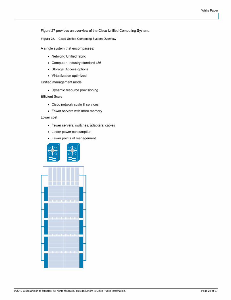
Figure 27 provides an overview of the Cisco Unified Computing System.
Figure 27. Cisco Unified Computing System Overview
A single system that encompasses:
● Network: Unified fabric
● Computer: Industry standard x86
● Storage: Access options
● Virtualization optimized
Unified management model
● Dynamic resource provisioning
Efficient Scale
● Cisco network scale & services
● Fewer servers with more memory
Lower cost
● Fewer servers, switches, adapters, cables
● Lower power consumption
● Fewer points of management
© 2010 Cisco and/or its affiliates. All rights reserved. This document is Cisco Public Information. Page 24 of 37
White Paper
Cisco UCS Chassis The Cisco UCS 5108 Blade Server Chassis incorporates unified fabric and fabric-extender technology, resulting in fewer physical components and improved energy efficiency compared to traditional blade server chassis. It eliminates the need for dedicated chassis management and blade switches, and it reduces cabling.
The Cisco Unified Computing System scales up to 40 chassis without adding complexity. Each chassis is six rack units (6RU) high, can mount in an industry-standard 19-inch rack, and uses standard front-to-back cooling. The front of each chassis accommodates up to eight Cisco UCS B200 M1 Blade Servers for a maximum of 320 per system (8 per chassis with 40 chassis) or Cisco four UCS B-250 M1 Extended Memory Blade Servers for a maximum of 160. The front also accommodates four power supplies. On the back, the chassis has slots for eight fans, two fabric extenders, and the power entry module.
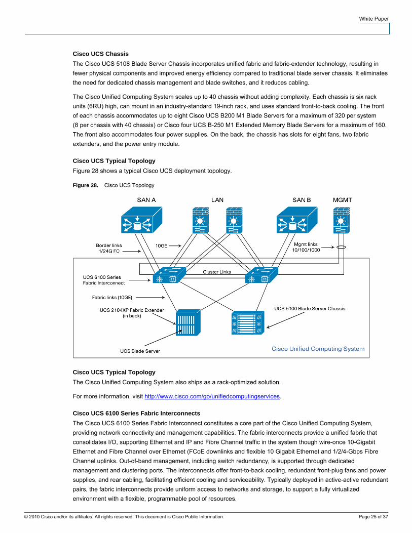
Cisco UCS Typical Topology Figure 28 shows a typical Cisco UCS deployment topology.
Figure 28. Cisco UCS Topology
Cisco UCS Typical Topology The Cisco Unified Computing System also ships as a rack-optimized solution.
For more information, visit http://www.cisco.com/go/unifiedcomputingservices.
Cisco UCS 6100 Series Fabric Interconnects The Cisco UCS 6100 Series Fabric Interconnect constitutes a core part of the Cisco Unified Computing System, providing network connectivity and management capabilities. The fabric interconnects provide a unified fabric that consolidates I/O, supporting Ethernet and IP and Fibre Channel traffic in the system though wire-once 10-Gigabit Ethernet and Fibre Channel over Ethernet (FCoE downlinks and flexible 10 Gigabit Ethernet and 1/2/4-Gbps Fibre Channel uplinks. Out-of-band management, including switch redundancy, is supported through dedicated management and clustering ports. The interconnects offer front-to-back cooling, redundant front-plug fans and power supplies, and rear cabling, facilitating efficient cooling and serviceability. Typically deployed in active-active redundant pairs, the fabric interconnects provide uniform access to networks and storage, to support a fully virtualized environment with a flexible, programmable pool of resources.
© 2010 Cisco and/or its affiliates. All rights reserved. This document is Cisco Public Information. Page 25 of 37
White Paper
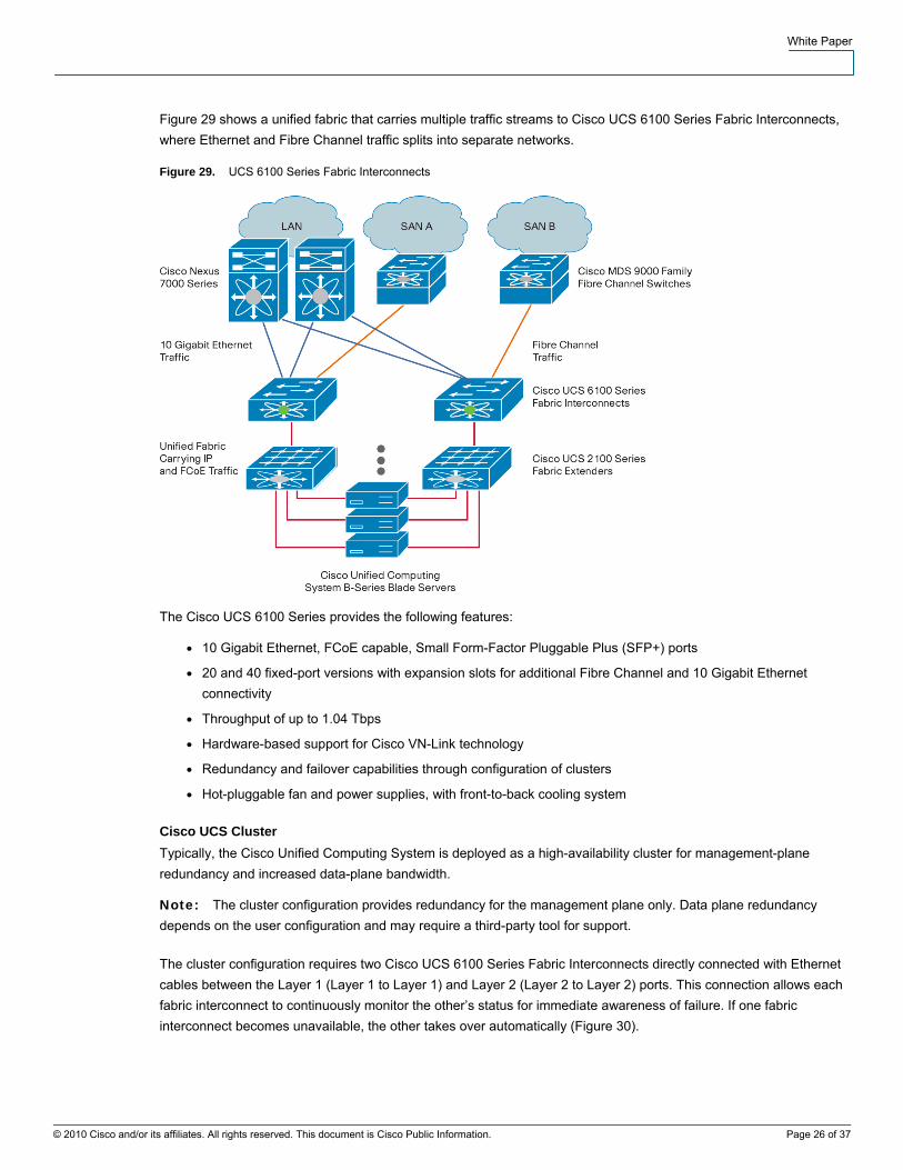
Figure 29 shows a unified fabric that carries multiple traffic streams to Cisco UCS 6100 Series Fabric Interconnects, where Ethernet and Fibre Channel traffic splits into separate networks.
Figure 29. UCS 6100 Series Fabric Interconnects
The Cisco UCS 6100 Series provides the following features:
● 10 Gigabit Ethernet, FCoE capable, Small Form-Factor Pluggable Plus (SFP+) ports
● 20 and 40 fixed-port versions with expansion slots for additional Fibre Channel and 10 Gigabit Ethernet connectivity
● Throughput of up to 1.04 Tbps
● Hardware-based support for Cisco VN-Link technology
● Redundancy and failover capabilities through configuration of clusters
● Hot-pluggable fan and power supplies, with front-to-back cooling system
Cisco UCS Cluster Typically, the Cisco Unified Computing System is deployed as a high-availability cluster for management-plane redundancy and increased data-plane bandwidth.
Note: The cluster configuration provides redundancy for the management plane only. Data plane redundancy depends on the user configuration and may require a third-party tool for support.
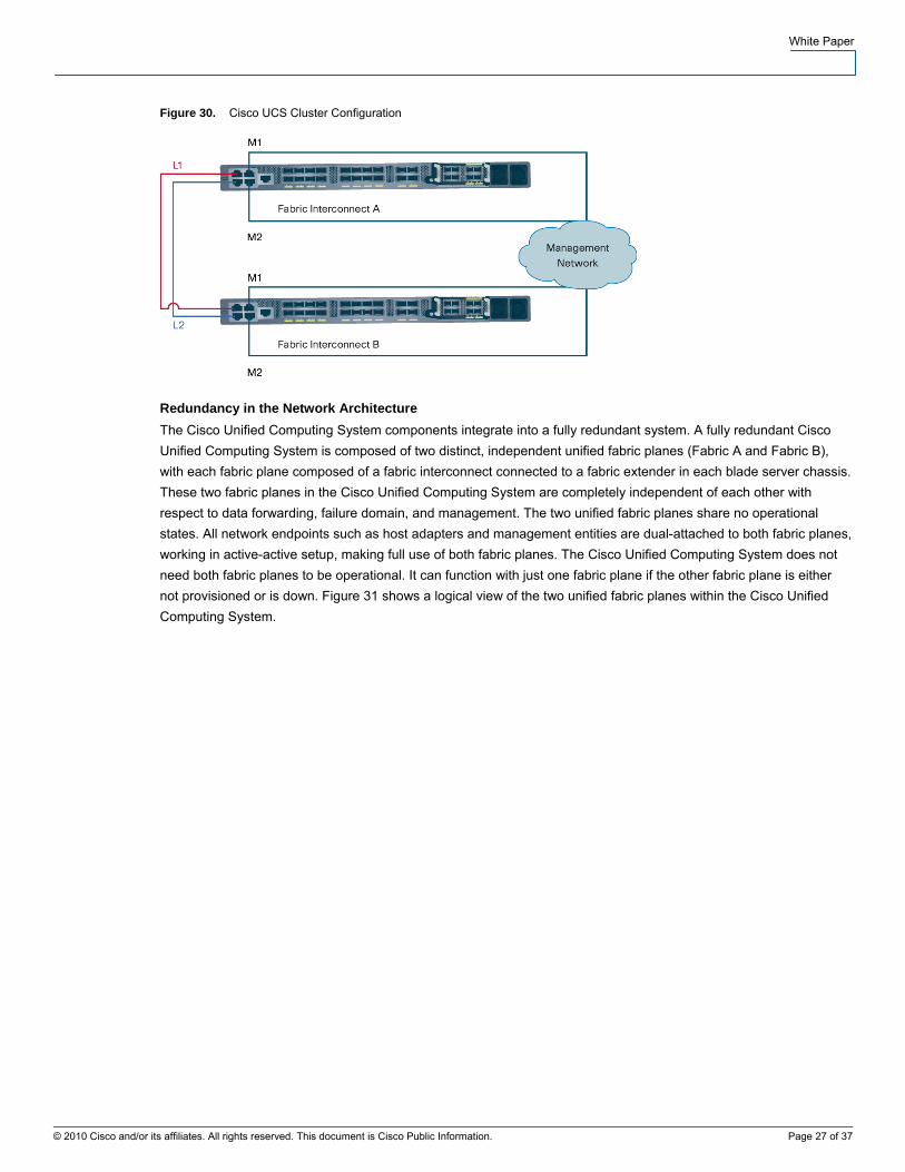
The cluster configuration requires two Cisco UCS 6100 Series Fabric Interconnects directly connected with Ethernet cables between the Layer 1 (Layer 1 to Layer 1) and Layer 2 (Layer 2 to Layer 2) ports. This connection allows each fabric interconnect to continuously monitor the other’s status for immediate awareness of failure. If one fabric interconnect becomes unavailable, the other takes over automatically (Figure 30).
© 2010 Cisco and/or its affiliates. All rights reserved. This document is Cisco Public Information. Page 26 of 37
White Paper
Figure 30. Cisco UCS Cluster Configuration
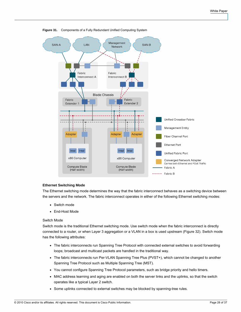
Redundancy in the Network Architecture The Cisco Unified Computing System components integrate into a fully redundant system. A fully redundant Cisco Unified Computing System is composed of two distinct, independent unified fabric planes (Fabric A and Fabric B), with each fabric plane composed of a fabric interconnect connected to a fabric extender in each blade server chassis. These two fabric planes in the Cisco Unified Computing System are completely independent of each other with respect to data forwarding, failure domain, and management. The two unified fabric planes share no operational states. All network endpoints such as host adapters and management entities are dual-attached to both fabric planes, working in active-active setup, making full use of both fabric planes. The Cisco Unified Computing System does not need both fabric planes to be operational. It can function with just one fabric plane if the other fabric plane is either not provisioned or is down. Figure 31 shows a logical view of the two unified fabric planes within the Cisco Unified Computing System.
© 2010 Cisco and/or its affiliates. All rights reserved. This document is Cisco Public Information. Page 27 of 37
White Paper
Figure 31. Components of a Fully Redundant Unified Computing System
Ethernet Switching Mode The Ethernet switching mode determines the way that the fabric interconnect behaves as a switching device between the servers and the network. The fabric interconnect operates in either of the following Ethernet switching modes:
● Switch mode
● End-Host Mode
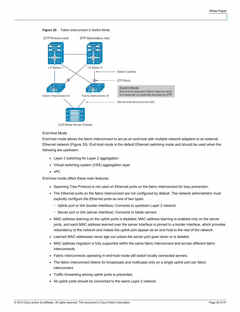
Switch Mode Switch mode is the traditional Ethernet switching mode. Use switch mode when the fabric interconnect is directly connected to a router, or when Layer 3 aggregation or a VLAN in a box is used upstream (Figure 32). Switch mode has the following attributes:
● The fabric interconnects run Spanning Tree Protocol with connected external switches to avoid forwarding loops; broadcast and multicast packets are handled in the traditional way.
● The fabric interconnects run Per-VLAN Spanning Tree Plus (PVST+), which cannot be changed to another Spanning Tree Protocol such as Multiple Spanning Tree (MST).
● You cannot configure Spanning Tree Protocol parameters, such as bridge priority and hello timers.
● MAC address learning and aging are enabled on both the server links and the uplinks, so that the switch operates like a typical Layer 2 switch.
● Some uplinks connected to external switches may be blocked by spanning-tree rules.
© 2010 Cisco and/or its affiliates. All rights reserved. This document is Cisco Public Information. Page 28 of 37
White Paper
Figure 32. Fabric Interconnect in Switch Mode
End-Host Mode End-host mode allows the fabric interconnect to act as an end-host with multiple network adapters to an external Ethernet network (Figure 33). End-host mode is the default Ethernet switching mode and should be used when the following are upstream:
● Layer 2 switching for Layer 2 aggregation
● Virtual switching system (VSS) aggregation layer
● vPC
End-host mode offers these main features:
● Spanning Tree Protocol is not used on Ethernet ports on the fabric interconnect for loop prevention.
● The Ethernet ports on the fabric interconnect are not configured by default. The network administrator must explicitly configure the Ethernet ports as one of two types:
◦ Uplink port or link (border interface): Connects to upstream Layer 2 network.
◦ Server port or link (server interface): Connects to blade servers.
● MAC address learning on the uplink ports is disabled. MAC address learning is enabled only on the server ports, and each MAC address learned over the server interface is pinned to a border interface, which provides redundancy to the network and makes the uplink port appear as an end host to the rest of the network.
● Learned MAC addresses never age out unless the server port goes down or is deleted.
● MAC address migration is fully supported within the same fabric interconnect and across different fabric interconnects.
● Fabric interconnects operating in end-host mode still switch locally connected servers.
● The fabric interconnect listens for broadcasts and multicasts only on a single uplink port per fabric interconnect.
● Traffic forwarding among uplink ports is prevented.
● All uplink ports should be connected to the same Layer 2 network.
© 2010 Cisco and/or its affiliates. All rights reserved. This document is Cisco Public Information. Page 29 of 37
White Paper
● All uplink ports are used for traffic forwarding, with active-active use of uplink ports regardless of the number of uplink Layer 2 switches connected.
● Fabric interconnects in end-host mode are more scalable than those in switch mode because the control plane is not stressed as in a Layer 2 switch.
Figure 33. Fabric Interconnects operation in End-host mode
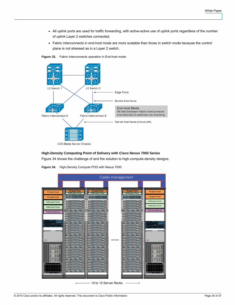
High-Density Computing Point of Delivery with Cisco Nexus 7000 Series Figure 34 shows the challenge of and the solution to high-compute-density designs.
Figure 34. High-Density Compute POD with Nexus 7000
© 2010 Cisco and/or its affiliates. All rights reserved. This document is Cisco Public Information. Page 30 of 37
White Paper
© 2010 Cisco and/or its affiliates. All rights reserved. This document is Cisco Public Information. Page 31 of 37
The figure depicts a common server aisle of 14 to 16 racks, with 12 to 14 racks designated to server farms, and 2 racks for telco and communications equipment. With power densities varying between 21 and 30 kW per rack, operators will want to consolidate as many server blades per 42-inch rack as physically and logically feasible. With Cisco UCS B-Series Blade Servers, a balance between computing power and I/O capacity per rack is achieved. Consolidating 10 Gigabit Ethernet Twinax or OM-3 fiber optics from Cisco UCS 6120XP 20-Port or 6140XP 40-Port Fabric Interconnects requires a platform with scalable 10 Gigabit Ethernet port-density switching capacity that provides performance at the aggregation layer. The Cisco Nexus 7000 Series is designed to address these needs through massive 10 Gigabit Ethernet scalability, performance, and availability.
Scaling The Cisco Unified Computing System scales well to consolidate virtual and physical workloads. The supporting network infrastructure needs to be able to meet high-density computing requirements.
An often overlooked aspect of server virtualization is MAC address scalability. Every virtual machine represents both a MAC address at Layer 2 and an IP address at Layer 3. Some business cases specific to the Cisco Unified Computing System (for example, Cisco Virtual Desktop Infrastructure Services [VDI]) will mandate very high physical-to-virtual ratios; in these cases, the overall scalability of a single aggregation block may be determined by the number of MAC addresses rather than raw performance. The Cisco Nexus 7000 Series can handle128.000 MAC addresses, making it the target platform to support MAC address scalability for Cisco Unified Computing System implementations.
A common requirement for a server aisle with 12 to 14 racks based on the Cisco Unified Computing System with Cisco UCS 6120XP or 6140XP Fabric Interconnects is a solution with more than 700 10 Gigabit Ethernet ports. A single Cisco Nexus 7000 18-Slot Switch chassis with dual supervisors can handle this requirement in a robust way, but dual Cisco 7000 Series chassis designs are still the most effective method for customers to design and distribute the load for end-of-row or middle-of-row topologies.
Because they can support stateless provisioning, Cisco Unified Computing System solutions are often used in service-oriented data centers. One common factor in such environments is the need for large Layer 2 domains. Typically in these designs, the Layer 2 domain is delimited by the aggregation layer. Although this design principle is still a best practice, a need is evolving to span multiple aggregation blocks for many, or all, server VLANs, to support workload mobility.
To support this level of mobility, data centers based on aggregation switches with higher 10 Gigabit Ethernet port densities and best-in-class Spanning Tree Protocol scalability are desirable. The Cisco Nexus 7000 Series platform offers outstanding 10 Gigabit Ethernet port densities. In the Cisco Nexus 7000 Series, the total number of logical ports (number of logical ports = [number of trunks] x [number of VLANs per trunk]) scales up to 75,000 when MST is used or 16,000 when Rapid Per-VLAN Spanning Tree (RPVST) is deployed.
Support for next-generation Layer 2 protocols such as Cisco FabricPath and Transparent Interconnection of IETF Lots of Links (TRILL) is another benefit of the Cisco Nexus 7000 Series platform, enabling even higher levels of Layer 2 scalability and performance without any dependencies on Spanning Tree Protocol.
Fault-Domain Considerations Cisco UCS server farms, with their high-density computing base, require a different approach to the overall availability of servers than for traditional servers. The Cisco Nexus 7000 Series and Cisco NX-OS meet the requirements through their inherently highly available architecture.
The overall server footprint is shrinking, while the number of active workloads in a single server rack is growing and can easily exceed 400 as a consequence of the ability of the Cisco Unified Computing System to accommodate a large number of virtual machines per server blade. In a more traditional, lower-density server farm design without
White Paper
© 2010 Cisco and/or its affiliates. All rights reserved. This document is Cisco Public Information. Page 32 of 37
virtualization, a more common density is 400 servers distributed across four aisles. Although the actual number of virtual interfaces per Cisco UCS blade server can be anywhere from 1 to 127, overall higher levels of high availability are required to support increased computing density.
Provisioning and Management Cisco UCS Manager Cisco UCS Manager centralizes management, creates a unified management domain, and serves as the central administrative interface for the Cisco Unified Computing System. Cisco UCS Manager is embedded device-management software that manages the system from end to end as a single logical entity through a GUI, the command-line interface (CLI), or an XML API.
With Cisco UCS Manager, a multi-tenancy design can be created to divide a large physical infrastructure into logical entities called organizations. Logical isolation can be achieved between organizations without providing a dedicated physical infrastructure for each organization.
In a multi-tenant environment, all organizations are hierarchical. The top-level organization is always the root. The policies and pools created in the root are systemwide and are available to all organizations in the system. However, policies and pools created in other organizations are available only to those organizations below it in the same hierarchy.
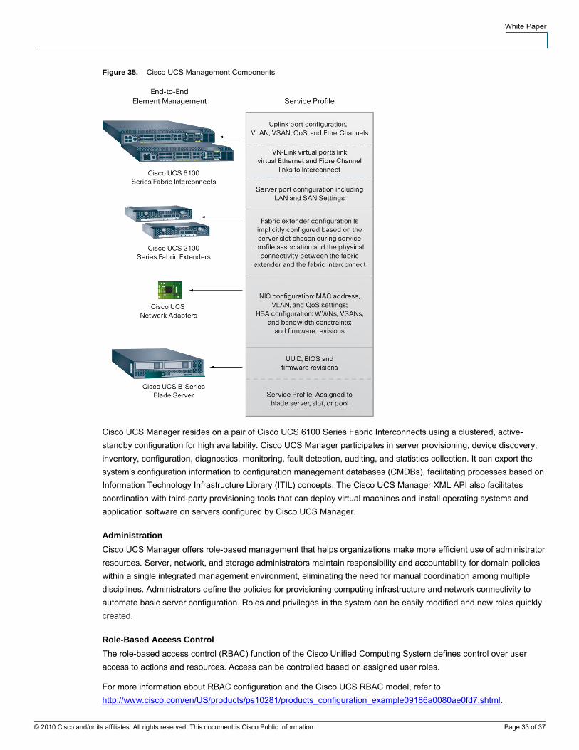
Unique resources can be assigned to each tenant through the related organization. These resources can include different policies, pools, and quality-of-service (QoS) definitions. Locales can also be assigned to Cisco Unified Computing System user privileges and roles by organization to restrict access to specific organizations. Cisco UCS Manager implements role- and policy-based management using service profiles and templates. Figure 35 summarizes the scope of the service profile elements that can be configured in each component at each level of the system.
White Paper
Figure 35. Cisco UCS Management Components
Cisco UCS Manager resides on a pair of Cisco UCS 6100 Series Fabric Interconnects using a clustered, active-standby configuration for high availability. Cisco UCS Manager participates in server provisioning, device discovery, inventory, configuration, diagnostics, monitoring, fault detection, auditing, and statistics collection. It can export the system's configuration information to configuration management databases (CMDBs), facilitating processes based on Information Technology Infrastructure Library (ITIL) concepts. The Cisco UCS Manager XML API also facilitates coordination with third-party provisioning tools that can deploy virtual machines and install operating systems and application software on servers configured by Cisco UCS Manager.
Administration Cisco UCS Manager offers role-based management that helps organizations make more efficient use of administrator resources. Server, network, and storage administrators maintain responsibility and accountability for domain policies within a single integrated management environment, eliminating the need for manual coordination among multiple disciplines. Administrators define the policies for provisioning computing infrastructure and network connectivity to automate basic server configuration. Roles and privileges in the system can be easily modified and new roles quickly created.
Role-Based Access Control The role-based access control (RBAC) function of the Cisco Unified Computing System defines control over user access to actions and resources. Access can be controlled based on assigned user roles.
For more information about RBAC configuration and the Cisco UCS RBAC model, refer to http://www.cisco.com/en/US/products/ps10281/products_configuration_example09186a0080ae0fd7.shtml.
© 2010 Cisco and/or its affiliates. All rights reserved. This document is Cisco Public Information. Page 33 of 37
White Paper
© 2010 Cisco and/or its affiliates. All rights reserved. This document is Cisco Public Information. Page 34 of 37
Server IP Keyboard, Video, and Mouse Availability The keyboard, video, and mouse (KVM) console is a video-over-IP (VoIP) representation of the video output on the blade. With it, the Cisco Unified Computing System offers access to blades similar to other KVM consoles in the blade industry. To use the KVM console to access the blade server, a pool of IP addresses must be assigned as a management interface for the blade servers. These IP addresses must be externally routable for remote access to servers through the KVM console.
Note: (1) The IP addresses are used in reverse order: for example, if the IP address range is 10.0.0.1 to 10.0.0.10, the first IP KVM address is 10.0.0.10. When the block is used up, a new block must be defined, and IP addresses then are again pulled from the end of the range; (2) It is not necessary to keep track of the IP addresses given to each server because the Cisco Unified Communications Manager automatically uses the IP address it receives when a connection attempt is made; (3) IP KVM IP addresses must be on the same subnet as the management port of the Cisco Unified Communications Manager because there is no tagging or Layer 3 for connections from that port.
For more information about configuring IP KVM, refer to http://www.cisco.com/en/US/products/ps10281/products_configuration_example09186a0080aefd13.shtml.
Syslog Setup The Cisco Unified Computing System provides several diagnostic tools to help you troubleshoot and monitor the environment. Syslog is the mechanism processes and scripts use to write log entries. Callers can fully specify characteristics of log entries. A syslog daemon in the system captures logs and saves them in a rotating buffer. These logs can be viewed internally or exported to syslog collectors. Multiple syslog collectors can be specified through configuration.
For more information about configuring syslog with Cisco UCS Manager, refer to http://www.cisco.com/en/US/products/ps10281/products_configuration_example09186a0080ae0f24.shtml.
Note: Although three syslog servers are configurable, the highest logging level set is applied to the host and sent to each syslog server that has been configured.
Servers Cisco UCS Manager uses service profiles to provision servers and their I/O properties. Service profiles are created by server, network, and storage administrators and are stored in the Cisco UCS 6100 Series Fabric Interconnects. They maintain configuration information about the server hardware, interfaces, fabric connectivity, and server and network identity. Service profiles are centrally managed and stored in a database on the fabric interconnect.
Note: Every server must be associated with a service profile.
Service profile templates simplify the creation of service profiles, helping ensure consistent policies within the system for a given service or application. This automation reduces the number of manual steps that need to be taken, reducing human error, improving consistency, and reducing server and network deployment times.
Service profiles also dissociate hardware-specific attributes from the design. If a specific server in the deployment is replaced, the service profile associated with the old server is applied to the newly installed server, enabling nearly transparent replacement of hardware if needed.
Service Profiles Service profiles are central to blade management in the Cisco Unified Computing System. A service profile presents a logical view of a single blade server without the need to specify the exact physical blade on which it will reside. Cisco Unified Computing System supports two types of service profiles:
● Service profiles that inherit server identity
White Paper
© 2010 Cisco and/or its affiliates. All rights reserved. This document is Cisco Public Information. Page 35 of 37
● Service profiles that override server identity
The engineer deploying servers must decide which type of service profile to use.
Timesaver: For large deployments, service profiles should be created from templates for quick and consistent provisioning of many servers.
For information about the differences between types and how to configure service profiles, refer to http://www.cisco.com/en/US/products/ps10281/products_configuration_example09186a0080af7515.shtml.
For information about configuring service profiles from templates, refer to http://www.cisco.com/en/US/products/ps10281/products_configuration_example09186a0080ae0642.shtml.
Service Profile Policies With Cisco UCS Manager, multiple polices can be configured that are specific to the service profile. Each policy applied is specific to the service profile for which it is configured, although similar or identical policies can be applied to each service profile in the system. These policies include the following:
● Server pool: A server pool contains a set of servers that share the same characteristics. Those characteristics can be the servers’ location in the chassis or an attribute, such as server type, amount of memory, local storage, type of CPU, or local drive configuration. A server can be assigned manually to a server pool, or server pool policies and server pool policy qualifications can be assigned automatically.
● vNIC connection: A vNIC can be configured through the LAN tab in Cisco UCS Manager. A vNIC template can be used to apply properties to the NIC hardware in each server.
● Local disk configuration: Local disk policies can be configured and applied to specify the type of local storage for a server in its associated service profile. The options available are:
◦ No Local Storage
◦ No RAID
◦ RAID Mirrored
◦ RAID Striped
When servers boot from SAN storage, no local disks are used, and the No Local Storage policy is applied to each server. If local disks are present for use, other policies may be preferred.
● Serial over LAN (SoL): This policy sets the configuration for the SoL connection for servers associated with service profiles that use the policy. By default, the SoL connection is disabled.
● Firmware: Firmware policies can be configured to set the overall server firmware policy for the BIOS, NIC, HBA, and RAID controller. These policies are provided as a bundle and used when updating firmware settings for hardware installed and used in the server.
● Intelligent Platform Management Interface (IPMI) profile: The IPMI profile can be used to determine whether IPMI commands can be sent directly to the server using the IP address: for example, to allow commands to be sent to retrieve sensor data from the baseboard management controller (BMC). This policy defines IPMI access, including a username and password that can be authenticated locally on the server and whether access is read-only or read-write.
● Statistics: Statistics threshold policies can be configured through the LAN tab in Cisco UCS Manager. These policies can be configured to report an error when a certain statistic exceeds a certain set threshold value.
● World Wide Node Name (WWNN): The WWNN policy allows the server WWNN configuration to come from a pool or to be derived from the hardware defaults.
White Paper
© 2010 Cisco and/or its affiliates. All rights reserved. This document is Cisco Public Information. Page 36 of 37
● Scrub policy: This policy determines what happens to local data on a server during the discovery process and when the server is disassociated from a service profile. This policy can help ensure that the data on local drives is erased at those times. In a design in which the scrub policy is disabled, the time required to dissociate service profiles can be optimized.
Warning: In a production environment, scrub policies should be used with caution.
vNIC Configuration View the vNIC configuration to be applied to each server in the Service Profile area on the Server tab in Cisco UCS Manager. In this view, vNICs can be added or deleted.
vHBA Configuration View the vHBA configuration applied to each server in the Service Profile area on the Server tab in Cisco UCS Manager. In this view, vHBAs can be added or deleted.
Cisco UCS Best Practices Resources ● Best practices in deploying Cisco Nexus 1000V Series Switches on the Cisco Unified Computing System:
http://www.cisco.com/en/US/prod/collateral/switches/ps9441/ps9902/white_paper_c11-558242.html.
● Cisco Unified Computing System firmware management best practices: http://www.cisco.com/en/US/products/ps10281/products_configuration_example09186a0080aee43e.sh.
Glossary
Cisco Nexus 7000 Series Switches: The Cisco Nexus 7000 Series of switches is a modular data center - class product line designed for highly scalable 10 Gigabit Ethernet networks with a fabric architecture that scales beyond 15 terabits per second (Tbps) and provides support for 40 Gigabit and 100 Gigabit Ethernet. The Cisco Nexus 7000 Series is designed for outstanding scalability, continuous system operation, operational manageability, and transport flexibility. The Cisco Nexus 7000 Series is powered by Cisco NX-OS Software, a state-of-the art operating system. The Cisco NX-OS Software and the Cisco Nexus 7000 Series hardware together provide an excellent platform for hosting, co-location, and other allied service provider data center applications.
Cisco Unified Computing System: The Cisco Unified Computing System is a next-generation data center platform that unites compute, network, storage access, and virtualization into a cohesive system designed to reduce total cost of ownership (TCO) and increase business agility. It system offers simplified setup, improved business results, and just-in-time resource provisioning. The system integrates a low-latency, lossless 10 Gigabit Ethernet unified network fabric with enterprise-class, x86-architecture servers. The system is an integrated, scalable, multichassis platform in which all resources participate in a unified management domain.
End-Host Mode: Cisco UCS end-host mode allows the fabric interconnect to act as an end host with multiple network adapters to an external Ethernet network.
High Availability: A high-availability network design does not have a single point of failure in the device or network architecture. High availability is the measure of a system’s redundancy and resiliency in support of business continuance: that is, the capability of the system and components to keep running without failure or loss of data.
Switch Mode: Switch mode is the traditional Ethernet switching mode. Use switch mode when the fabric interconnect is directly connected to a router or when Layer 3 aggregation or VLAN in a box is used upstream.
Virtual Device Context (VDC): VDC is a feature of the Cisco Nexus 7000 Series that allows the creation of separate logical switches on the same physical hardware platform. Each VDC runs a duplicate image in a separate instantiation of the Cisco NX-OS modular software, with separate Layer 3 routing protocols, VLANs, and Layer 2 protocols. The VDC can be isolated down to the physical port level, creating logically separated routing and switching

White Paper
contexts. Each process in each VDC can be started and stopped separately without affecting any other VDC running on the Cisco Nexus 7000 Series.
Virtual Local Area Network (VLAN): A VLAN is a logical LAN that connects a group of hosts with a common set of requirements that communicate as if they were attached to the same broadcast domain, regardless of their physical location. A VLAN has the same attributes as a physical LAN, but it allows end stations to be grouped together even if they were not located on the same physical switch in the network.
virtual Network Interface Card (vNIC): Each vNIC in a virtual machine corresponds to a virtual interface in the fabric interconnect. The purpose of virtualizing the interface is to tag each packet with a unique tag, known as a virtual network tag (VNTag) for outgoing traffic and to remove the VNTag and direct the packet to the specified vNIC for the incoming traffic. Traffic can then be identified at the virtual machine level as if there were a physical interface on the virtual machine. If the traffic can be identified, it can receive unique treatment, differentiated from other virtual hosts’ traffic on the same hardware. A vNIC or virtual host bus adapter (vHBA) logically connects a virtual machine to a virtual interface on the Cisco UCS 6100 Series Fabric Interconnects and allows the virtual machine to send and receive traffic through that interface.
virtual PortChannel (vPC): A vPC allows links that are physically connected to two different Cisco Nexus devices to appear as a single PortChannel to a third device. The third device can be a Cisco Nexus 2000 Series Fabric Extender or a switch, server, or any other networking device. A vPC provides Layer 2 multipathing, which allows the creation of redundancy and increases bandwidth, enabling multiple parallel paths between nodes and load-balancing traffic where alternative paths exist.
Please refer to the Cisco.com Internetworking Terms and Acronyms Guide at http://www.cisco.com/univercd/cc/td/doc/cisintwk/ita/index.htm for additional terms.
Printed in USA C11-623265-00 11/10
© 2010 Cisco and/or its affiliates. All rights reserved. This document is Cisco Public Information. Page 37 of 37