cisco nx-os unicast routing configuration guide, release 4 · 2016-12-27 · configuring ipv6...
TRANSCRIPT

Send document comments to nexus7k -doc feedback@c i sco .com.
Cisco NX-OS Unicast Routing Configuration Guide, Release 4.0 March 31, 2008
Americas HeadquartersCisco Systems, Inc.170 West Tasman DriveSan Jose, CA 95134-1706 USAhttp://www.cisco.comTel: 408 526-4000
800 553-NETS (6387)Fax: 408 527-0883
Text Part Number: OL-12912-01

Send document comments to nexus7k -doc feedback@c i sco .com.
THE SPECIFICATIONS AND INFORMATION REGARDING THE PRODUCTS IN THIS MANUAL ARE SUBJECT TO CHANGE WITHOUT NOTICE. ALL STATEMENTS, INFORMATION, AND RECOMMENDATIONS IN THIS MANUAL ARE BELIEVED TO BE ACCURATE BUT ARE PRESENTED WITHOUT WARRANTY OF ANY KIND, EXPRESS OR IMPLIED. USERS MUST TAKE FULL RESPONSIBILITY FOR THEIR APPLICATION OF ANY PRODUCTS.
THE SOFTWARE LICENSE AND LIMITED WARRANTY FOR THE ACCOMPANYING PRODUCT ARE SET FORTH IN THE INFORMATION PACKET THAT SHIPPED WITH THE PRODUCT AND ARE INCORPORATED HEREIN BY THIS REFERENCE. IF YOU ARE UNABLE TO LOCATE THE SOFTWARE LICENSE OR LIMITED WARRANTY, CONTACT YOUR CISCO REPRESENTATIVE FOR A COPY.
The Cisco implementation of TCP header compression is an adaptation of a program developed by the University of California, Berkeley (UCB) as part of UCB’s public domain version of the UNIX operating system. All rights reserved. Copyright © 1981, Regents of the University of California.
NOTWITHSTANDING ANY OTHER WARRANTY HEREIN, ALL DOCUMENT FILES AND SOFTWARE OF THESE SUPPLIERS ARE PROVIDED “AS IS” WITH ALL FAULTS. CISCO AND THE ABOVE-NAMED SUPPLIERS DISCLAIM ALL WARRANTIES, EXPRESSED OR IMPLIED, INCLUDING, WITHOUT LIMITATION, THOSE OF MERCHANTABILITY, FITNESS FOR A PARTICULAR PURPOSE AND NONINFRINGEMENT OR ARISING FROM A COURSE OF DEALING, USAGE, OR TRADE PRACTICE.
IN NO EVENT SHALL CISCO OR ITS SUPPLIERS BE LIABLE FOR ANY INDIRECT, SPECIAL, CONSEQUENTIAL, OR INCIDENTAL DAMAGES, INCLUDING, WITHOUT LIMITATION, LOST PROFITS OR LOSS OR DAMAGE TO DATA ARISING OUT OF THE USE OR INABILITY TO USE THIS MANUAL, EVEN IF CISCO OR ITS SUPPLIERS HAVE BEEN ADVISED OF THE POSSIBILITY OF SUCH DAMAGES.
CCDE, CCENT, Cisco Eos, Cisco StadiumVision, the Cisco logo, DCE, and Welcome to the Human Network are trademarks; Changing the Way We Work, Live, Play, and Learn is a service mark; and Access Registrar, Aironet, AsyncOS, Bringing the Meeting To You, Catalyst, CCDA, CCDP, CCIE, CCIP, CCNA, CCNP, CCSP, CCVP, Cisco, the Cisco Certified Internetwork Expert logo, Cisco IOS, Cisco Press, Cisco Systems, Cisco Systems Capital, the Cisco Systems logo, Cisco Unity, Collaboration Without Limitation, Enterprise/Solver, EtherChannel, EtherFast, EtherSwitch, Event Center, Fast Step, Follow Me Browsing, FormShare, GigaDrive, HomeLink, Internet Quotient, IOS, iPhone, iQ Expertise, the iQ logo, iQ Net Readiness Scorecard, iQuick Study, IronPort, the IronPort logo, LightStream, Linksys, MediaTone, MeetingPlace, MGX, Networkers, Networking Academy, Network Registrar, PCNow, PIX, PowerPanels, ProConnect, ScriptShare, SenderBase, SMARTnet, Spectrum Expert, StackWise, The Fastest Way to Increase Your Internet Quotient, TransPath, WebEx, and the WebEx logo are registered trademarks of Cisco Systems, Inc. and/or its affiliates in the United States and certain other countries.
All other trademarks mentioned in this document or Website are the property of their respective owners. The use of the word partner does not imply a partnership relationship between Cisco and any other company. (0803R)
Any Internet Protocol (IP) addresses used in this document are not intended to be actual addresses. Any examples, command display output, and figures included in the document are shown for illustrative purposes only. Any use of actual IP addresses in illustrative content is unintentional and coincidental.
Cisco NX-OS Unicast Routing Configuration Guide, Release 4.0 ©2008 Cisco Systems, Inc. All rights reserved.

Send document comments to nexus7k -doc feedback@c i sco .com.
OL-12912-01
C O N T E N T S
Preface i
Audience i
Organization i
Document Conventions ii
Related Documentation iii
Obtaining Documentation and Submitting a Service Request iv
C H A P T E R 1 Overview 1-1
Information About Layer 3 Unicast Routing 1-1
Routing Fundamentals 1-2
Packet Switching 1-2
Routing Metrics 1-3
Path Length 1-4
Reliability 1-4
Routing Delay 1-4
Bandwidth 1-4
Load 1-4
Communication Cost 1-4
Router IDs 1-5
Autonomous Systems 1-5
Convergence 1-6
Load Balancing and Equal Cost Multipath 1-6
Route Redistribution 1-6
Administrative Distance 1-6
Stub Routing 1-7
Routing Algorithms 1-8
Static Routes and Dynamic Routing Protocols 1-8
Interior and Exterior Gateway Protocols 1-8
Distance Vector Protocols 1-8
Link State Protocols 1-9
Layer 3 Virtualization 1-9
Cisco NX-OS Fowarding Architecture 1-10
Unicast RIB 1-10
Adjacency Manager 1-11
1Cisco NX-OS Unicast Routing Configuration Guide, Release 4.0

Send document comments to nexus7k -doc feedback@c i sco .com.
Contents
Unicast Forwarding Distribution Module 1-11
Unicast FIB 1-12
Displaying Routing and Forwarding Information 1-12
Hardware Forwarding 1-13
Software Forwarding 1-13
Summary of Layer 3 Unicast Routing Features 1-13
IPv4 and IPv6 1-14
IP Services 1-14
OSPF 1-14
EIGRP 1-14
IS-IS 1-14
BGP 1-15
RIP 1-15
Static Routing 1-15
Layer 3 Virtualization 1-15
Route Policy Manager 1-15
Policy-Based Routing 1-15
First-Hop Redundancy Protocols 1-16
Object Tracking 1-16
Related Topics 1-16
IP
C H A P T E R 2 Configuring IPv4 2-1
Information About IPv4 2-1
Multiple IPv4 Addresses 2-2
Address Resolution Protocol 2-2
ARP Caching 2-3
Static and Dynamic Entries in the ARP Cache 2-3
Devices that do not use ARP 2-3
Inverse ARP 2-4
Reverse ARP 2-4
Proxy ARP 2-5
Local Proxy ARP 2-5
ICMP 2-5
Virtualization Support 2-6
Licensing Requirements for IPv4 2-6
Prerequisites for IPv4 2-6
Guidelines and Limitations 2-6
2Cisco NX-OS Unicast Routing Configuration Guide, Release 4.0
OL-12912-01

Send document comments to nexus7k -doc feedback@c i sco .com.
Contents
Configuring IPv4 2-6
Configuring IPv4 Addressing 2-7
Configuring Multiple IP Addresses 2-8
Configuring a Static ARP Entry 2-9
Configuring Proxy ARP 2-10
Configuring Local Proxy ARP 2-11
Verifying the IPv4 Configuration 2-12
IPv4 Example Configuration 2-12
Default Settings 2-12
Additional References 2-12
Related Documents 2-13
Standards 2-13
2-13
C H A P T E R 3 Configuring IPv6 3-1
Information About IPv6 3-1
IPv6 Address Formats 3-2
IPv6 Unicast Addresses 3-3
Aggregatable Global Addresses 3-3
Link-Local Addresses 3-5
IPv4-Compatible IPv6 Addresses 3-5
Unique Local Addresses 3-6
Site-Local Address 3-7
IPv6 Anycast Addresses 3-7
IPv6 Multicast Addresses 3-7
IPv4 Packet Header 3-9
Simplified IPv6 Packet Header 3-9
DNS for IPv6 3-12
Path MTU Discovery for IPv6 3-12
Cisco Discovery Protocol IPv6 Address Support 3-12
ICMP for IPv6 3-12
IPv6 Neighbor Discovery 3-13
IPv6 Neighbor Solicitation Message 3-13
IPv6 Router Advertisement Message 3-15
IPv6 Neighbor Redirect Message 3-16
Virtualization Support 3-17
Licensing Requirements for IPv6 3-18
Prerequisites for IPv6 3-18
Guidelines and Limitations for IPv6 3-18
3Cisco NX-OS Unicast Routing Configuration Guide, Release 4.0
OL-12912-01
Send document comments to nexus7k -doc feedback@c i sco .com.
Contents
Configuring IPv6 3-18
Configuring IPv6 Addressing 3-19
Configuring IPv6 Neighbor Discovery 3-20
Optional IPv6 Neighbor Discovery 3-22
Verifying the IPv6 Configuration 3-23
IPv6 Example Configuration 3-23
Default Settings 3-23
Additional References 3-23
Related Documents 3-24
Standards 3-24
C H A P T E R 4 Configuring DNS 4-1
Information About DNS Clients 4-1
DNS Client Overview 4-1
Name Servers 4-2
DNS Operation 4-2
High Availability 4-2
Virtualization Support 4-2
Licensing Requirements for DNS Clients 4-2
Prerequisites for DNS Clients 4-3
Configuration Guidelines and Limitations 4-3
Configuring DNS Clients 4-3
Configuring the DNS Client 4-3
Configuring Virtualization 4-5
Verifying the DNS Client Configuration 4-7
DNS Client Example Configuration 4-7
Default Settings 4-7
Additional References 4-8
Related Documents 4-8
Standards 4-8
Routing
C H A P T E R 5 Configuring OSPFv2 5-1
Information About OSPFv2 5-1
Hello Packet 5-2
Neighbors 5-2
Adjacency 5-3
4Cisco NX-OS Unicast Routing Configuration Guide, Release 4.0
OL-12912-01

Send document comments to nexus7k -doc feedback@c i sco .com.
Contents
Designated Routers 5-3
Areas 5-4
Link-State Advertisements 5-5
LSA Types 5-5
Link Cost 5-6
Flooding and LSA Group Pacing 5-6
Link-State Database 5-7
Opaque LSAs 5-7
OSPFv2 and the Unicast RIB 5-7
Authentication 5-7
Simple Password Authentication 5-8
MD5 Authentication 5-8
Advanced Features 5-8
Stub Area 5-8
Not-So-Stubby Area 5-9
Virtual Links 5-9
Route Redistribution 5-10
Route Summarization 5-10
High Availability and Graceful Restart 5-11
OSPFv2 Stub Router Advertisements 5-12
Multiple OSPFv2 Instances 5-12
SPF Optimization 5-12
Virtualization Support 5-12
Licensing Requirements for OSPFv2 5-12
Prerequisites for OSPFv2 5-13
Configuration Guidelines and Limitations 5-13
Configuring Basic OSPFv2 5-13
Enabling the OSPFv2 Feature 5-13
Creating an OSPFv2 Instance 5-14
Configuring Optional Parameters on an OSPFv2 Instance 5-16
Configuring Networks in OSPFv2 5-16
Configuring Authentication for an Area 5-19
Configuring Authentication for an Interface 5-20
Configuring Advanced OSPFv2 5-22
Configuring Filter Lists for Border Routers 5-23
Configuring Stub Areas 5-24
Configuring a Totally Stubby Area 5-26
Configuring NSSA 5-26
Configuring Virtual Links 5-28
5Cisco NX-OS Unicast Routing Configuration Guide, Release 4.0
OL-12912-01

Send document comments to nexus7k -doc feedback@c i sco .com.
Contents
Configuring Redistribution 5-30
Configuring Route Summarization 5-32
Configuring Stub Route Advertisements 5-33
Modifying the Default Timers 5-34
Configuring Graceful Restart 5-37
Restarting an OSPFv2 Instance 5-38
Configuring OSPFv2 with Virtualization 5-39
Verifying the OSPFv2 Configuration 5-41
Displaying OSPFv2 Statistics 5-42
OSPFv2 Example Configuration 5-42
Default Settings 5-42
Additional References 5-43
Related Documents 5-43
MIBs 5-43
C H A P T E R 6 Configuring OSPFv3 6-1
Information About OSPFv3 6-1
Comparison of OSPFv3 and OSPFv2 6-2
Hello Packet 6-2
Neighbors 6-3
Adjacency 6-3
Designated Routers 6-4
Areas 6-5
Link-State Advertisement 6-5
LSA Types 6-6
Link Cost 6-6
Flooding and LSA Group Pacing 6-6
Link-State Database 6-7
OSPFv3 and the IPv6 Unicast RIB 6-7
Authentication 6-8
Address Family Support 6-8
Advanced Features 6-8
Stub Area 6-8
Not-So-Stubby Area 6-9
Virtual Links 6-9
Route Redistribution 6-10
Route Summarization 6-10
High Availability and Graceful Restart 6-11
Multiple OSPFv3 Instances 6-11
6Cisco NX-OS Unicast Routing Configuration Guide, Release 4.0
OL-12912-01

Send document comments to nexus7k -doc feedback@c i sco .com.
Contents
SPF Optimization 6-12
Virtualization Support 6-12
Licensing Requirements for OSPFv3 6-12
Prerequisites for OSPFv3 6-12
Configuration Guidelines and Limitations 6-13
Configuring Basic OSPFv3 6-13
Enabling the OSPFv3 Feature 6-13
Creating an OSPFv3 Instance 6-14
Configuring Networks in OSPFv3 6-16
Configuring Advanced OSPFv3 6-19
Configuring Filter Lists for Border Routers 6-19
Configuring Stub Areas 6-21
Configuring a Totally Stubby Area 6-22
Configuring NSSA 6-22
Configuring Virtual Links 6-24
Configuring Redistribution 6-26
Configuring Route Summarization 6-28
Modifying the Default Timers 6-30
Configuring Graceful Restart 6-32
Restarting an OSPFv3 Instance 6-34
Configuring OSPFv3 with Virtualization 6-34
Verifying OSPFv3 Configuration 6-36
Displaying OSPFv3 Statistics 6-37
OSPFv3 Example Configuration 6-37
Related Topics 6-37
Default Settings 6-38
Additional References 6-38
Related Documents 6-39
MIBs 6-39
C H A P T E R 7 Configuring EIGRP 7-1
Information About EIGRP 7-1
EIGRP Components 7-2
Reliable Transport Protocol 7-2
Neighbor Discovery and Recovery 7-2
Diffusing Update Algorithm 7-2
EIGRP Route Updates 7-3
Internal Route Metrics 7-3
7Cisco NX-OS Unicast Routing Configuration Guide, Release 4.0
OL-12912-01

Send document comments to nexus7k -doc feedback@c i sco .com.
Contents
External Route Metrics 7-4
EIGRP and the Unicast RIB 7-4
Advanced EIGRP 7-4
Authentication 7-4
Stub Routers 7-5
Route Summarization 7-5
Route Redistribution 7-5
Load Balancing 7-6
Split Horizon 7-6
Virtualization Support 7-6
Graceful Restart and High Availability 7-6
Licensing Requirements for EIGRP 7-7
Prerequisites for EIGRP 7-7
Configuration Guidelines and Limitations 7-8
Configuring Basic EIGRP 7-8
Enabling the EIGRP Feature 7-8
Creating an EIGRP Instance 7-9
Restarting an EIGRP Instance 7-11
Disabling an EIGRP Instance 7-12
Disabling EIGRP on an Interface 7-12
Configuring Advanced EIGRP 7-12
Configuring Authentication in EIGRP 7-12
Configuring EIGRP Stub Routing 7-14
Configuring a Summary Address for EIGRP 7-15
Redistributing Routes into EIGRP 7-15
Configuring Load Balancing in EIGRP 7-17
Configuring Graceful Restart for EIGRP 7-18
Adjusting the Interval Between Hello Packets and the Hold Time 7-19
Disabling Split Horizon 7-20
Tuning EIGRP 7-20
Configuring Virtualization for EIGRP 7-22
Verifying EIGRP Configuration 7-23
Displaying EIGRP Statistics 7-24
EIGRP Example Configuration 7-24
Related Topics 7-24
Default Settings 7-24
Additional References 7-25
Related Documents 7-25
8Cisco NX-OS Unicast Routing Configuration Guide, Release 4.0
OL-12912-01

Send document comments to nexus7k -doc feedback@c i sco .com.
Contents
C H A P T E R 8 Configuring IS-IS 8-1
Information about IS-IS 8-1
IS-IS Overview 8-2
IS-IS Areas 8-2
NET and System ID 8-3
Designated Intermediate System 8-3
IS-IS Authentication 8-3
Mesh Groups 8-4
Overload Bit 8-4
Route Summarization 8-4
Route Redistribution 8-5
Load Balancing 8-5
Virtualization Support 8-5
High Availability and Graceful Restart 8-5
Multiple IS-IS Instances 8-6
Licensing Requirements for IS-IS 8-6
Prerequisites for IS-IS 8-6
Configuration Guidelines and Limitations 8-6
Configuring IS-IS 8-6
IS-IS Configuration Modes 8-7
Enabling the IS-IS Feature 8-8
Creating an IS-IS Instance 8-9
Restarting an IS-IS Instance 8-11
Configuring IS-IS on an Interface 8-11
Configuring IS-IS Authentication in an Area 8-13
Configuring IS-IS Authentication on an Interface 8-14
Configuring a Mesh Group 8-15
Configuring a Designated Intermediate System 8-16
Configuring Dynamic Host Exchange 8-16
Setting the Overload Bit 8-16
Configuring a Summary Address 8-17
Configuring Redistribution 8-18
Configuring a Graceful Restart 8-20
Configuring Virtualization 8-21
Tuning IS-IS 8-24
Verifying IS-IS Configuration 8-26
Displaying IS-IS Statistics 8-27
IS-IS Example Configuration 8-27
9Cisco NX-OS Unicast Routing Configuration Guide, Release 4.0
OL-12912-01

Send document comments to nexus7k -doc feedback@c i sco .com.
Contents
Related Topics 8-28
Default Settings 8-28
Additional References 8-28
Related Documents 8-29
Standards 8-29
C H A P T E R 9 Configuring Basic BGP 9-1
Information About Basic BGP 9-1
BGP Autonomous Systems 9-2
Administrative Distance 9-2
BGP Peers 9-2
BGP Router Identifier 9-3
BGP Path Selection 9-3
Comparing Pairs of Paths 9-4
Order of Comparisons 9-5
Best Path Change Suppression 9-5
BGP and the Unicast RIB 9-6
BGP Virtualization 9-6
Licensing Requirements for Basic BGP 9-6
Prerequisites for BGP 9-6
Guidelines and Limitations for BGP 9-7
CLI Configuration Modes 9-7
Global Configuration Mode 9-7
Address Family Configuration Mode 9-8
Neighbor Configuration Mode 9-8
Neighbor Address Family Configuration Mode 9-8
Configuring Basic BGP 9-9
Enabling the BGP Feature 9-9
Creating a BGP Instance 9-10
Restarting a BGP Instance 9-12
Configuring BGP Peers 9-12
Verifying Basic BGP Configuration 9-14
Displaying BGP Statistics 9-15
Basic BGP Example Configuration 9-15
Related Topics 9-16
Where to Go Next 9-16
Default Settings 9-16
Additional References 9-16
10Cisco NX-OS Unicast Routing Configuration Guide, Release 4.0
OL-12912-01
Send document comments to nexus7k -doc feedback@c i sco .com.
Contents
Related Documents 9-17
MIBs 9-17
Technical Assistance 9-17
C H A P T E R 10 Configuring Advanced BGP 10-1
Information About Advanced BGP 10-1
Peer Templates 10-2
Authentication 10-2
Route Policies and Resetting BGP Sessions 10-3
eBGP 10-3
iBGP 10-3
AS Confederations 10-4
Router Reflector 10-5
Capabilities Negotiation 10-6
Route Dampening 10-6
Load Sharing and Multipath 10-6
Route Aggregation 10-7
Route Redistribution 10-7
Tuning BGP 10-7
BGP Timers 10-8
Tuning the Best-Path Algorithm 10-8
Multiprotocol BGP 10-8
Graceful Restart and High Availability 10-8
ISSU 10-9
Virtualization Support 10-9
Licensing Requirements for Advanced BGP 10-9
Prerequisites for BGP 10-10
Guidelines and Limitations for BGP 10-10
Configuring Advanced BGP 10-10
Configuring BGP Session Templates 10-11
Configuring BGP Peer-Policy Templates 10-13
Configuring BGP Peer Templates 10-16
Configuring Prefix Peering 10-18
Configuring BGP Authentication 10-19
Resetting a BGP Session 10-19
Modifying the Next-Hop Address 10-20
Disabling Capabilities Negotiation 10-20
Configuring eBGP 10-21
Disabling eBGP Single-Hop Checking 10-21
11Cisco NX-OS Unicast Routing Configuration Guide, Release 4.0
OL-12912-01

Send document comments to nexus7k -doc feedback@c i sco .com.
Contents
Configuring eBGP Multihop 10-21
Disabling a Fast External Failover 10-22
Configuring AS Confederations 10-22
Configuring Router Reflector 10-22
Configuring Route Dampening 10-24
Configuring Load Sharing and ECMP 10-25
Configuring Maximum Prefixes 10-25
Configuring Dynamic Capability 10-26
Configuring Aggregate Addresses 10-26
Configuring Route Redistribution 10-26
Tuning BGP 10-28
Configuring a Graceful Restart 10-31
Configuring Virtualization 10-32
Verifying Advanced BGP Configuration 10-34
Displaying BGP Statistics 10-35
Related Topics 10-35
Default Settings 10-36
Additional References 10-36
Related Documents 10-36
MIBs 10-36
C H A P T E R 11 Configuring RIP 11-1
Information About RIP 11-1
RIP Overview 11-2
RIPv2 Authentication 11-2
Split Horizon 11-2
Route Filtering 11-3
Route Summarization 11-3
Route Redistribution 11-3
Load Balancing 11-4
High Availability 11-4
Virtualization Support 11-4
Licensing Requirements for RIP 11-4
Prerequisites for RIP 11-4
Configuration Guidelines and Limitations 11-4
Configuring RIP 11-5
Enabling the RIP Feature 11-5
Creating a RIP Instance 11-6
12Cisco NX-OS Unicast Routing Configuration Guide, Release 4.0
OL-12912-01

Send document comments to nexus7k -doc feedback@c i sco .com.
Contents
Restarting a RIP Instance 11-8
Configuring RIP on an Interface 11-8
Configuring RIP Authentication 11-9
Configuring a Passive Interface 11-10
Configuring Split Horizon with Poison Reverse 11-11
Configuring Route Summarization 11-11
Configuring Route Redistribution 11-11
Configuring Virtualization 11-13
Tuning RIP 11-15
Verifying RIP Configuration 11-17
Displaying RIP Statistics 11-17
RIP Example Configuration 11-18
Related Topics 11-18
Where to Go Next 11-18
Default Settings 11-18
Additional References 11-18
Related Documents 11-19
Standards 11-19
C H A P T E R 12 Configuring Static Routing 12-1
Information About Static Routing 12-1
Administrative Distance 12-2
Directly Connected Static Routes 12-2
Fully Specified Static Routes 12-2
Floating Static Routes 12-2
Remote Next Hops for Static Routes 12-3
Virtualization Support 12-3
Licensing Requirements for Static Routing 12-3
Prerequisites for Static Routing 12-3
Guidelines and Limitations 12-3
Configuring Static Routing 12-3
Configuring a Static Route 12-4
Configuring Virtualization 12-5
Verifying Static Routing Configuration 12-6
Static Routing Example Configuration 12-6
Default Settings 12-7
Additional References 12-7
Related Documents 12-7
13Cisco NX-OS Unicast Routing Configuration Guide, Release 4.0
OL-12912-01

Send document comments to nexus7k -doc feedback@c i sco .com.
Contents
C H A P T E R 13 Configuring Layer 3 Virtualization 13-1
Layer 3 Virtualization 13-1
Overview of Layer 3 Virtualization 13-1
VRF and Routing 13-2
VRF-Aware Services 13-3
Reachability 13-4
Filtering 13-4
Combining Reachability and Filtering 13-5
Licensing Requirements for VRFs 13-5
Prerequisites for VRF 13-5
Guidelines and Limitations 13-5
Configuring VRFs 13-6
Creating a VRF 13-6
Assigning VRF Membership to an Interface 13-7
Configuring VRF Parameters for a Routing Protocol 13-8
Configuring a VRF-Aware Service 13-10
Setting the VRF Scope 13-11
Verifying VRF Configuration 13-12
VRF Example Configuration 13-12
Related Topics 13-12
Default Settings 13-13
Additional References 13-13
Related Documents 13-13
Standards 13-13
C H A P T E R 14 14-1
Configuring Route Policy Manager 14-1
Information About Route Policy Manager 14-1
Prefix Lists 14-2
Route Maps 14-2
Match Criteria 14-2
Set Changes 14-3
Access Lists 14-3
AS-path Lists for BGP 14-3
Community Lists for BGP 14-3
Route Redistribution and Route Maps 14-4
Policy-Based Routing 14-4
14Cisco NX-OS Unicast Routing Configuration Guide, Release 4.0
OL-12912-01

Send document comments to nexus7k -doc feedback@c i sco .com.
Contents
Licensing Requirements for Route Policy Manager 14-4
Prerequisites for Route Policy Manager 14-4
Guidelines and Limitations 14-4
Configuring Route Policy Manager 14-5
Configuring IP Prefix Lists 14-5
Configuring AS-path Lists 14-7
Configuring Community Lists 14-7
Configuring Route Maps 14-9
Verifying Route Policy Manager Configuration 14-13
Route Policy Manager Example Configuration 14-13
Related Topics 14-13
Default Settings 14-13
Additional References 14-14
Related Documents 14-14
Standards 14-14
C H A P T E R 15 Configuring Policy-Based Routing 15-1
Information About Policy Based Routing 15-1
Policy Route Maps 15-2
Set Criteria for Policy-Based Routing 15-2
Licensing Requirements for Policy-Based Routing 15-3
Prerequisites for Policy-Based Routing 15-3
Guidelines and Limitations 15-3
Configuring Policy-Based Routing 15-3
Enabling the Policy-based Routing Feature 15-4
Configuring a Route Policy 15-4
Verifying Policy-Based Routing Configuration 15-7
Policy Based-Routing Example Configuration 15-7
Related Topics 15-7
Default Settings 15-7
Additional References 15-8
Related Documents 15-8
Standards 15-8
First-Hop Redundancy Protocols
15Cisco NX-OS Unicast Routing Configuration Guide, Release 4.0
OL-12912-01

Send document comments to nexus7k -doc feedback@c i sco .com.
Contents
C H A P T E R 16 Configuring GLBP 16-1
Information About GLBP 16-1
GLBP Overview 16-2
GLBP Active Virtual Gateway 16-2
GLBP Virtual MAC Address Assignment 16-2
GLBP Virtual Gateway Redundancy 16-2
GLBP Virtual Forwarder Redundancy 16-3
GLBP Authentication 16-4
GLBP Load Balancing and Tracking 16-4
High Availability 16-5
Virtualization Support 16-5
Licensing Requirements for GLBP 16-6
Prerequisites for GLBP 16-6
Guidelines and Limitations 16-6
Configuring GLBP 16-7
Enabling the GLBP Feature 16-7
Configuring GLBP Authentication 16-8
Configuring GLBP Load Balancing 16-9
Configuring GLBP Weighting and Tracking 16-10
Customizing GLBP 16-12
Enabling a GLBP Group 16-13
Verifying GLBP Configuration 16-15
GLBP Example Configuration 16-15
Default Settings 16-16
Additional References 16-16
Related Documents 16-17
Standards 16-17
C H A P T E R 17 Configuring HSRP 17-1
Information About HSRP 17-1
HSRP Overview 17-2
HSRP Versions 17-3
HSRP Authentication 17-3
HSRP Addressing 17-4
HSRP Messages 17-4
HSRP Load Sharing 17-4
Object Tracking and HSRP 17-5
High Availability 17-5
16Cisco NX-OS Unicast Routing Configuration Guide, Release 4.0
OL-12912-01

Send document comments to nexus7k -doc feedback@c i sco .com.
Contents
Virtualization Support 17-6
Licensing Requirements for HSRP 17-6
Prerequisites for HSRP 17-6
Guidelines and Limitations 17-6
Configuring HSRP 17-7
Enabling the HSRP Feature 17-7
Configuring an HSRP Group 17-7
Configuring the HSRP Version 17-9
Configuring the HSRP Virtual MAC Address 17-9
Authenticating HSRP 17-10
Configuring HSRP Object Tracking 17-12
Customizing HSRP 17-14
Verifying HSRP Configuration 17-15
HSRP Example Configuration 17-16
Default Settings 17-16
Additional References 17-17
Related Documents 17-17
Standards 17-17
C H A P T E R 18 Configuring VRRP 18-1
Information About VRRP 18-1
VRRP Operation 18-2
VRRP Benefits 18-3
Multiple VRRP Groups 18-3
VRRP Router Priority and Preemption 18-4
VRRP Advertisements 18-5
VRRP Authentication 18-5
VRRP Tracking 18-5
High Availability 18-5
Virtualization Support 18-5
Licensing Requirements for VRRP 18-6
Guidelines and Limitations 18-6
Configuring VRRP 18-6
Enabling the VRRP Feature 18-6
Configuring VRRP Groups 18-7
Configuring VRRP Priority 18-8
Configuring VRRP Authentication 18-10
Configuring Time Intervals for Advertisement Packets 18-12
17Cisco NX-OS Unicast Routing Configuration Guide, Release 4.0
OL-12912-01

Send document comments to nexus7k -doc feedback@c i sco .com.
Contents
Disabling Preemption 18-14
Configuring VRRP Interface State Tracking 18-16
Verifying the VRRP Configuration 18-18
Displaying VRRP Statistics 18-19
VRRP Example Configuration 18-19
Default Settings 18-20
Additional References 18-21
Related Documents 18-21
C H A P T E R 19 Configuring Object Tracking 19-1
Information About Object Tracking 19-1
Object Tracking Overview 19-1
High Availability 19-2
Virtualization Support 19-2
Licensing Requirements for Object Tracking 19-2
Prerequisites for Object Tracking 19-3
Guidelines and Limitations 19-3
Configuring Object Tracking 19-3
Configuring Object Tracking for an Interface 19-3
Configuring Object Tracking for Route Reachability 19-4
Configuring Object Tracking for a nonDefault VRF 19-5
Verifying Object Tracking Configuration 19-7
Object Tracking Example Configuration 19-7
Related Topics 19-7
Default Settings 19-7
Additional References 19-7
Related Documents 19-8
Standards 19-8
A P P E N D I X A IETF RFCs supported by Cisco NX-OS Unicast Features, Release 4.x A-1
BGP RFCs A-1
First-Hop Redundancy ProtocolsRFCs A-2
IP Services RFCs A-2
IPv6 RFCs A-2
IS-IS RFCs A-3
OSPF RFCs A-3
RIP RFCs A-3
18Cisco NX-OS Unicast Routing Configuration Guide, Release 4.0
OL-12912-01

Send document comments to nexus7k -doc feedback@c i sco .com.
Contents
G L O S S A R Y
A P P E N D I X 2 Configuration Limits for Cisco NX-OS Layer 3 Unicast Features, Release 4.x 2-1
19Cisco NX-OS Unicast Routing Configuration Guide, Release 4.0
OL-12912-01

Send document comments to nexus7k -doc feedback@c i sco .com.
Contents
20Cisco NX-OS Unicast Routing Configuration Guide, Release 4.0
OL-12912-01

Send document comments to nexus7k -doc feedback@c i sco .com.
Preface
This document describes the configuration details for Cisco NX-OS unicast routing.
AudienceTo use this guide, you must be familiar with IP and routing technology.
OrganizationThis document is organized into the following chapters:
Title Description
Chapter 1, “Overview” Presents an overview of unicast routing and brief descriptions of each feature.
Chapter 2, “Configuring IPv4” Describes how to configure and manage IPv4, including ARP and ICMP.
Chapter 3, “Configuring IPv6” Describes how to configure and manage IPv6, including Neighbor Discovery Protocol and ICMPv6.
Chapter 4, “Configuring DNS” Describes how to configure DHCP and DNS clients.
Chapter 5, “Configuring OSPFv2” Describes how to configure the OSPFv2 routing protocol for IPv4 networks.
Chapter 6, “Configuring OSPFv3” Describes how to configure the OSPFv3 routing protocol for IPv6 networks.
Chapter 7, “Configuring EIGRP” Describes how to configure the Cisco EIGRP routing protocol for IPv4 networks.
Chapter 8, “Configuring IS-IS” Describes how to configure the IS-IS routing protocol for IPv4 and IPv6 networks.
Chapter 9, “Configuring Basic BGP” Describes how to configure basic features for the BGP routing protocol for IPv4 and IPv6 networks.
Chapter 10, “Configuring Advanced BGP” Describes how to configure advanced features for the BGP routing protocol for IPv4 and IPv6 networks, including route redistribution and route aggregation.
iCisco NX-OS Unicast Routing Configuration Guide, Release 4.0
OL-12912-01

Send document comments to nexus7k -doc feedback@c i sco .com.
Preface
Document ConventionsCommand descriptions use these conventions:
Screen examples use these conventions:
Chapter 11, “Configuring RIP” Describes how to configure the RIP and RIPng routing protocols for IPv4 and IPv6 networks.
Chapter 12, “Configuring Static Routing” Describes how to configure static routing for IPv4 and IPv6 networks.
Chapter 13, “Configuring Layer 3 Virtualization”
Describes how to configure layer 3 virtualization.
Chapter 14, “Configuring Route Policy Manager”
Describes how to configure the Route Policy Manager, including IP prefix lists and route-maps for filtering and redistribution.
Chapter 15, “Configuring Policy-Based Routing”
Describes how to configure route maps for policy based routing.
Chapter 17, “Configuring HSRP” Describes how to configure the Hot Standby Routing Protocol.
Chapter 16, “Configuring GLBP” Describes how to configure GLBP.
Chapter 19, “Configuring Object Tracking”
Describes how to configure object tracking.
Chapter 18, “Configuring VRRP” Describes how to configure the Virtual Router Redundancy Protocol.
Appendix A, “IETF RFCs supported by Cisco NX-OS Unicast Features, Release 4.x”
Lists IETF RFCs supported by Cisco NX-OS.
Title Description
Convention Description
boldface font Commands and keywords are in boldface.
italic font Arguments for which you supply values are in italics.
[ ] Elements in square brackets are optional.
[ x | y | z ] Optional alternative keywords are grouped in brackets and separated by vertical bars.
string A nonquoted set of characters. Do not use quotation marks around the string or the string will include the quotation marks.
screen font Terminal sessions and information that the switch displays are in screen font.
boldface screen font
Information that you must enter is in boldface screen font.
italic screen font Arguments for which you supply values are in italic screen font.
< > Nonprinting characters, such as passwords, are in angle brackets.
iiCisco NX-OS Unicast Routing Configuration Guide, Release 4.0
OL-12912-01

Send document comments to nexus7k -doc feedback@c i sco .com.
Preface
This document uses the following conventions:
Note Means reader take note. Notes contain helpful suggestions or references to material not covered in the manual.
Caution Means reader be careful. In this situation, you might do something that could result in equipment damage or loss of data.
Related DocumentationThe documentation set for Cisco NX-OS includes the following documents:
Release Notes
Cisco NX-OS Release Notes, Release 4.0
NX-OS Configuration Guides
Cisco NX-OS Getting Started with Virtual Device Contexts, Release 4.0
Cisco NX-OS Fundamentals Configuration Guide, Release 4.0
Cisco NX-OS Interfaces Configuration Guide, Release 4. 0
Cisco NX-OS Layer 2 Switching Configuration Guide, Release 4.0
Cisco NX-OS Quality of Service Configuration Guide, Release 4.0
Cisco NX-OS Unicast Routing Configuration Guide, Release 4.0
Cisco NX-OS Multicast Routing Configuration Guide, Release 4.0
Cisco NX-OS Security Configuration Guide, Release 4.0
Cisco NX-OS Virtual Device Context Configuration Guide, Release 4.0
Cisco NX-OS Software Upgrade Guide, Release 4.0
Cisco NX-OS Licensing Guide, Release 4.0
Cisco NX-OS High Availability and Redundancy Guide, Release 4.0
Cisco NX-OS System Management Configuration Guide, Release 4.0
Cisco NX-OS XML Management Interface User Guide, Release 4.0
Cisco NX-OS System Messages Reference
Cisco NX-OS MIB Quick Reference
[ ] Default responses to system prompts are in square brackets.
!, # An exclamation point (!) or a pound sign (#) at the beginning of a line of code indicates a comment line.
iiiCisco NX-OS Unicast Routing Configuration Guide, Release 4.0
OL-12912-01

Send document comments to nexus7k -doc feedback@c i sco .com.
Preface
NX-OS Command References
Cisco NX-OS Command Reference Master Index, Release 4.0
Cisco NX-OS Fundamentals Command Reference, Release 4.0
Cisco NX-OS Interfaces Command Reference, Release 4.0
Cisco NX-OS Layer 2 Switching Command Reference, Release 4.0
Cisco NX-OS Quality of Service Command Reference, Release 4.0
Cisco NX-OS Unicast Routing Command Reference, Release 4.0
Cisco NX-OS Multicast Routing Command Reference, Release 4.0
Cisco NX-OS Security Command Reference, Release 4.0
Cisco NX-OS Virtual Device Context Command Reference, Release 4.0
Cisco NX-OS High Availability and Redundancy Command Reference, Release 4.0
Cisco NX-OS System Management Command Reference, Release 4.0
Other Software Document
Cisco NX-OS Troubleshooting Guide, Release 4.0
Obtaining Documentation and Submitting a Service RequestFor information on obtaining documentation, submitting a service request, and gathering additional information, see the monthly What’s New in Cisco Product Documentation, which also lists all new and revised Cisco technical documentation, at:
http://www.cisco.com/en/US/docs/general/whatsnew/whatsnew.html
Subscribe to the What’s New in Cisco Product Documentation as a Really Simple Syndication (RSS) feed and set content to be delivered directly to your desktop using a reader application. The RSS feeds are a free service and Cisco currently supports RSS version 2.0.
ivCisco NX-OS Unicast Routing Configuration Guide, Release 4.0
OL-12912-01

Send document comments to nexus7k -doc feedback@c i sco .com.
Cisco NX-OOL-12912-01
C H A P T E R 1
OverviewThis chapter introduces the underlying concepts for Layer 3 unicast routing protocols in Cisco NX-OS.
This chapter includes the following sections:
• Information About Layer 3 Unicast Routing, page 1-1
• Routing Algorithms, page 1-8
• Layer 3 Virtualization, page 1-9
• Cisco NX-OS Fowarding Architecture, page 1-10
• Summary of Layer 3 Unicast Routing Features, page 1-13
• Related Topics, page 1-16
Information About Layer 3 Unicast RoutingLayer 3 unicast routing involves two basic activities: determining optimal routing paths and packet switching. You can use routing algorithms to calculate the optimal path from the router to a destination. This calculation depends on the algorithm selected, route metrics, and other considerations such as load balancing and alternate path discovery.
This section includes the following topics:
• Routing Fundamentals, page 1-2
• Packet Switching, page 1-2
• Routing Metrics, page 1-3
• Router IDs, page 1-5
• Autonomous Systems, page 1-5
• Convergence, page 1-6
• Load Balancing and Equal Cost Multipath, page 1-6
• Route Redistribution, page 1-6
• Administrative Distance, page 1-6
• Stub Routing, page 1-7
1-1S Unicast Routing Configuration Guide, Release 4.0

Send document comments to nexus7k -doc feedback@c i sco .com.
Chapter 1 OverviewInformation About Layer 3 Unicast Routing
Routing FundamentalsRouting protocols use a metric to evaluate the best path to the destination. A metric is a standard of measurement, such as a path bandwidth, that routing algorithms use to determine the optimal path to a destination. To aid path determination, routing algorithms initialize and maintain routing tables, that contain route information such as the IP destination address and the address of the next router or next hop. Destination and next-hop associations tell a router that an IP destination can be reached optimally by sending the packet to a particular router that represents the next hop on the way to the final destination. When a router receives an incoming packet, it checks the destination address and attempts to associate this address with the next hop. See the “Unicast RIB” section on page 1-10 for more information about the route table.
Routing tables can contain other information, such as the data about the desirability of a path. Routers compare metrics to determine optimal routes, and these metrics differ depending on the design of the routing algorithm used. See the “Routing Metrics” section on page 1-3.
Routers communicate with one another and maintain their routing tables by transmitting a variety of messages. The routing update message is one such message that consists of all or a portion of a routing table. By analyzing routing updates from all other routers, a router can build a detailed picture of the network topology. A link-state advertisement, another example of a message sent between routers, informs other routers of the link state of the sending router. You can also use link information to enable routers to determine optimal routes to network destinations. For more information, see the “Routing Algorithms” section on page 1-8.
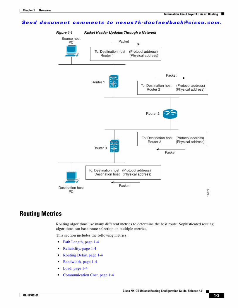
Packet SwitchingIn packet switching,a host determines that it must send a packet to another host. Having acquired a router address by some means, the source host sends a packet addressed specifically to the router physical (Media Access Control [MAC]-layer) address but with the IP (network layer) address of the destination host.
The router examines the destination IP address and tries to find the IP address in the routing table. If the router does not know how to forward the packet, it typically drops the packet. If the router knows how to forward the packet, it changes the destination MAC address to the MAC address of the next hop router and transmits the packet.
The next hop might be the ultimate destination host or another router that executes the same switching decision process. As the packet moves through the internetwork, its physical address changes, but its protocol address remains constant (see Figure 1-1).
1-2Cisco NX-OS Unicast Routing Configuration Guide, Release 4.0
OL-12912-01
Send document comments to nexus7k -doc feedback@c i sco .com.
Chapter 1 OverviewInformation About Layer 3 Unicast Routing
Figure 1-1 Packet Header Updates Through a Network
Routing MetricsRouting algorithms use many different metrics to determine the best route. Sophisticated routing algorithms can base route selection on multiple metrics.
This section includes the following metrics:
• Path Length, page 1-4
• Reliability, page 1-4
• Routing Delay, page 1-4
• Bandwidth, page 1-4
• Load, page 1-4
• Communication Cost, page 1-4
Source hostPC
Destination hostPC
Packet
Packet
Packet
Packet
Router 1
Router 2
Router 3
To: Destination host (Protocol address) Destination host (Physical address)
To: Destination host (Protocol address) Router 3 (Physical address)
To: Destination host (Protocol address) Router 2 (Physical address)
To: Destination host (Protocol address) Router 1 (Physical address)
1829
78
1-3Cisco NX-OS Unicast Routing Configuration Guide, Release 4.0
OL-12912-01

Send document comments to nexus7k -doc feedback@c i sco .com.
Chapter 1 OverviewInformation About Layer 3 Unicast Routing
Path Length
The path length is the most common routing metric. Some routing protocols allow you to assign arbitrary costs to each network link. In this case, the path length is the sum of the costs associated with each link traversed. Other routing protocols define hop count, a metric that specifies the number of passes through internetworking products, such as routers, that a packet must take from a source to a destination.
Reliability
The reliability, in the context of routing algorithms, is the dependability (in terms of the bit-error rate) of each network link. Some network links might go down more often than others. After a network fails, certain network links might be repaired more easily or more quickly than other links. The reliability factors that you can take into account when assigning the reliability rating are arbitrary numeric values that you usually assign to network links.
Routing Delay
The routing delay is the length of time required to move a packet from a source to a destination through the internetwork. The delay depends on many factors, including the bandwidth of intermediate network links, the port queues at each router along the way, the network congestion on all intermediate network links, and the physical distance that the packet needs to travel. Becauset the routing delay is a combination of several important variables, it is a common and useful metric.
Bandwidth
The bandwidth is the available traffic capacity of a link. For example, a 10-Gigabit Ethernet link would be preferable to a 1-Gigabit Ethernet link. Although the bandwidth is the maximum attainable throughput on a link, routes through links with greater bandwidth do not necessarily provide better routes than routes through slower links. For example, if a faster link is busier, the actual time required to send a packet to the destination could be greater.
Load
The load is the degree to which a network resource, such as a router, is busy. You can calculate the load in a variety of ways, including CPU utilization and packets processed per second. Monitoring these parameters on a continual basis can be resourceintensive.
Communication Cost
The communication cost is a measure of the operating cost to route over a link. The communication cost is another important metric, especially if you do not care about performance as much as operating expenditures. For example, the line delay for a private line might be longer than a public line, but you can send packets over your private line rather than through the public lines that cost money for usage time.
1-4Cisco NX-OS Unicast Routing Configuration Guide, Release 4.0
OL-12912-01

Send document comments to nexus7k -doc feedback@c i sco .com.
Chapter 1 OverviewInformation About Layer 3 Unicast Routing
Router IDsEach routing process has an associated router ID. You can configure the router ID to any interface in the system. If you do not configure the router ID, Cisco NX-OS selects the router ID based on the following criteria:
• Cisco NX-OS prefers loopback0 over any other interface. If loopback0 does not exist, then Cisco NX-OS prefers the first loopback interface over any other interface type.
• If you have not configured no loopback interfaces, Cisco NX-OS uses the first interface in the configuration file as the router ID. If you configure any loopback interface after Cisco NX-OS selects the router ID, the loopback interface becomes the router ID. If the loopback interface is not loopback0 and you configure loopback0 later with an IP address, the router ID changes to the IP address of loopback0.
• If the interface that the router ID is based on changes, that new IP address becomes the router ID. If any other interface changes its IP address, there is no router ID change.
Autonomous SystemsAn autonomous system (AS) is a network controlled by a single technical administration entity. Autonomous systems divide global external networks into individual routing domains, where local routing policies are applied. This organization simplifies routing domain administration and simplifies consistent policy configuration.
Each autonomous system can support multiple interior routing protocols that dynamically exchange routing information through route redistribution. The Regional Internet Registries assign a unique number to each public autonomous system that directly connects to the Internet. This unique number identifies both the routing process and the autonomous system. Table 1-1 lists the autonomous system number (AS number) ranges.
Private autonomous system numbers are used for internal routing domains but must be translated by the router for traffic that is routed out to the Internet. You should not configure routing protocols to advertise private autonomous system numbers to external networks. By default, Cisco NX-OS does not remove private autonomous system numbers from routing updates.
Note The autonomous system number assignment for public and private networks is governed by the Internet Assigned Number Authority (IANA). For information about autonomous system numbers, including the reserved number assignment, or to apply to register an autonomous system number, refer to the following URL: http://www.iana.org/
Table 1-1 Autonomous System Numbers
16-bit Numbers 32-bit Numbers Purpose
1 to 64511 0.1 to 0.64511 Public AS (assigned by RIR)1
1. RIR=Regional Internet Registries
64512 to 65534 0.64512 to 0.65534 Private AS (assigned by local administrator)
65535 0.65535 Reserved
N/A 1.0 to 65535.65535 Public AS (assigned by RIR)
1-5Cisco NX-OS Unicast Routing Configuration Guide, Release 4.0
OL-12912-01

Send document comments to nexus7k -doc feedback@c i sco .com.
Chapter 1 OverviewInformation About Layer 3 Unicast Routing
ConvergenceA key aspect to measure for any routing algorithm is how much time a router takes to react to network topology changes. When a part of the network changes for any reason, such as a link failure, the routing information in different routers might not match. Some routers will have updated information about the changed topology, other routers will still have the old information. The convergence is the amount of time before all routers in the network have updated, matching routing information. The convergence time varies depending on the routing algorithm. Fast convergence minimizes the chance of lost packets caused by inaccurate routing information.
Load Balancing and Equal Cost MultipathRouting protocols can use load balancing or equal cost multipath (ECMP) to share traffic across multiple paths.When a router learns multiple routes to a specific network, it installs the route with the lowest administrative distance in the routing table. If the router receives and installs multiple paths with the same administrative distance and cost to a destination, load balancing can occur. Load balancing distributes the traffic across all the paths, sharing the load. The number of paths used is limited by the number of entries that the routing protocol puts in the routing table. Cisco NX-OS supports up to 16 paths to a destination.
The Enhanced Interior Gateway Routing Protocol (EIGRP) also supports unequal cost load-balancing. For more information, see Chapter 7, “Configuring EIGRP.”
Route RedistributionIf you have multiple routing protocols configured in your network, you can configure these protocols to share routing information by configuring route redistribution in each protocol. For example, you can configure Open Shortest Path First (OSPF) to advertise routes learned from the Border Gateway Protocol (BGP). You can also redistribute static routes into any dynamic routing protocol. The router that is redistributing routes from another protocol sets a fixed route metric for those redistributed routes. This avoids the problem of incompatible route metrics between the different routing protocols. For example, routes redistributed from EIGRP into OSPF are assigned a fixed link cost metric that OSPF understands.
Route redistribution also uses an administrative distance (see the “Administrative Distance” section on page 1-6) to distinguish between routes learned from two different routing protocols. The preferred routing protocol is given a lower administrative distance so that its routes are picked over routes from another protocol with a higher administrative distance assigned.
Administrative DistanceAn administrative distance is a rating of the trustworthiness of a routing information source. The higher the value, the lower the trust rating. Typically, a route can be learned through more than one protocol. Administrative distance is used to discriminate between routes learned from more than one protocol. The route with the lowest administrative distance is installed in the IP routing table.
1-6Cisco NX-OS Unicast Routing Configuration Guide, Release 4.0
OL-12912-01

Send document comments to nexus7k -doc feedback@c i sco .com.
Chapter 1 OverviewInformation About Layer 3 Unicast Routing
Stub RoutingYou can use stub routing in a hub-and-spoke network topology, where one or more end (stub) networks are connected to a remote router (the spoke) that is connected to one or more distribution routers (the hub). The remote router is adjacent only to one or more distribution routers. The only route for IP traffic to follow into the remote router is through a distribution router. This type of configuration is commonly used in WAN topologies in which the distribution router is directly connected to a WAN. The distribution router can be connected to many more remote routers. Often, the distribution router is connected to 100 or more remote routers. In a hub-and-spoke topology, the remote router must forward all nonlocal traffic to a distribution router, so it becomes unnecessary for the remote router to hold a complete routing table. Generally, the distribution router sends only a default route to the remote router.
Only specified routes are propagated from the remote (stub) router. The stub router responds to all queries for summaries, connected routes, redistributed static routes, external routes, and internal routes with the message “inaccessible.” A router that is configured as a stub sends a special peer information packet to all neighboring routers to report its status as a stub router.
Any neighbor that receives a packet informing it of the stub status does not query the stub router for any routes, and a router that has a stub peer does not query that peer. The stub router depends on the distribution router to send the proper updates to all peers.
Figure 1-2 shows a simple hub-and-spoke configuration.
Figure 1-2 Simple Hub-and-Spoke Network
Stub routing does not prevent routes from being advertised to the remote router. Figure 1-2 shows that the remote router can access the corporate network and the Internet through the distribution router only. A full route table on the remote router, in this example, serves no functional purpose because the path to the corporate network and the Internet would always be through the distribution router. A larger route table would reduce only the amount of memory required by the remote router. The bandwidth and memory used can be lessened by summarizing and filtering routes in the distribution router. In this network topology, the remote router does not need to receive routes that have been learned from other networks because the remote router must send all nonlocal traffic, regardless of its destination, to the distribution router. To configure a true stub network, you should configure the distribution router to send only a default route to the remote router.
OSPF supports stub areas and EIGRP supports stub routers.
Internet
Coporatenetwork
Distributionrouter(hub)
Remoterouter
(spoke)
192.
0.2.
0/24
1829
79
1-7Cisco NX-OS Unicast Routing Configuration Guide, Release 4.0
OL-12912-01

Send document comments to nexus7k -doc feedback@c i sco .com.
Chapter 1 OverviewRouting Algorithms
Routing AlgorithmsRouting algorithms determine how a router gathers and reports reachability information, how it deals with topology changes, and how it determines the optimal route to a destination. Various types of routing algorithms exist, and each algorithm has a different impact on network and router resources. Routing algorithms use a variety of metrics that affect calculation of optimal routes. You can classify routing algorithms by type, such as static or dynamic, and interior or exterior.
This section includes the following topics:
• Static Routes and Dynamic Routing Protocols, page 1-8
• Interior and Exterior Gateway Protocols, page 1-8
• Distance Vector Protocols, page 1-8
• Link State Protocols, page 1-9
Static Routes and Dynamic Routing ProtocolsStatic routes are route table entries that you manually configure. These static routes do not change unless you reconfigure them. Static routes are simple to design and work well in environments where network traffic is relatively predictable and where network design is relatively simple.
Because static routing systems cannot react to network changes, you should not uses them for today’s large, constantly changing networks. Most routing protocols today use dynamic routing algorithms, which adjust to changing network circumstances by analyzing incoming routing update messages. If the message indicates that a network change has occurred, the routing software recalculates routes and sends out new routing update messages. These messages permeate the network, triggering routers to rerun their algorithms and change their routing tables accordingly.
You can supplement dynamic routing algorithms with static routes where appropriate. For example, you should configure each subnetwork with a static route to the IP default gateway or router of last resort (a router to which all unroutable packets are sent).
Interior and Exterior Gateway ProtocolsYou can separate networks into unique routing domains or autonomous systems. An autonomous system is a portion of an internetwork under common administrative authority that is regulated by a particular set of administrative guidelines. Routing protocols that route between autonomous systems are called exterior gateway protocols or interdomain protocols. BGP is an example of an exterior gateway protocol. Routing protocols used within an autonomous system are called interior gateway protocols or intradomain protocols. EIGRP and OSPF are examples of interior gateway protocols.
Distance Vector ProtocolsDistance vector protocols use distance vector algorithms (also known as Bellman-Ford algorithms) that call for each router to send all or some portion of its routing table to its neighbors. Distance vector algorithms define routes by distance (for example, the number of hops to the destination) and direction (for example, the next-hop router). These routes are then broadcast to the directly connected neighbor routers. Each router uses these updates to verify and update the routing tables.
1-8Cisco NX-OS Unicast Routing Configuration Guide, Release 4.0
OL-12912-01
Send document comments to nexus7k -doc feedback@c i sco .com.
Chapter 1 OverviewLayer 3 Virtualization
To prevent routing loops, most distance vector algorithms use split horizon with poison reverse which means that the routes learned from an interface are set as unreachable and advertised back along the interface that they were learned on during the next periodic update. This prevents the router from seeing its own route updates coming back.
Distance vector algorithms send updates at fixed intervals but can also send updates in response to changes in route metric values. These triggered updates can speed up the route convergence time. The Routing Information Protocol (RIP) is a distance vector protocol.
Link State ProtocolsThe link-state protocols, also known as shortest path first (SPF), share information with neighboring routers. Each router builds a link-state advertisement (LSA), which contains information about each link and directly connected neighbor router.
Each LSA has a sequence number. When a router receives and LSA and updates its link-state database, the LSA is flooded to all adjacent neighbors. If a router receives two LSAs with the same sequence number (from the same router), the router does not flood the last LSA received to its neighbors to prevent an LSA update loop. Because the router floods the LSAs immediately after they receive them, convergence time for link-state protocols is minimized.
Discovering neighbors and establishing adjacency is an important part of a link state protocol. Neighbors are discovered using special Hello packets that also serve as keepalive notifications to each neighbor router. Adjacency is the establishment of a common set of operating parameters for the link-state protocol between neighbor routers.
The LSAs received by a router are added to its link-state database. Each entry consists of the following parameters:
• Router ID (for the router that originated the LSA)
• Neighbor ID
• Link cost
• Sequence number of the LSA
• Age of the LSA entry
The router runs the SPF algorithm on the link-state database, building the shortest path tree for that router. This SPF tree is used to populate the routing table.
In link-state algorithms, each router builds a picture of the entire network in its routing tables. The link-state algorithms send small updates everywhere, while distance vector algorithms send larger updates only to neighboring routers.
Because they converge more quickly, link-state algorithms are somewhat less prone to routing loops than distance vector algorithms. However, link-state algorithms require more CPU power and memory than distance vector algorithms. Link-state algorithms can be more expensive to implement and support. Link-state protocols are generally more scalable than distance vector protocols.
OSPF is an example of a link-state protocol.
Layer 3 Virtualization Cisco NX-OS introduces the virtual device context (VDC), which provides separate management domains per VDC and software fault isolation. Each VDC supports multiple Virtual Routing and Forwarding Instances (VRFs) and multiple routing information bases (RIBs) to support multiple address
1-9Cisco NX-OS Unicast Routing Configuration Guide, Release 4.0
OL-12912-01

Send document comments to nexus7k -doc feedback@c i sco .com.
Chapter 1 OverviewCisco NX-OS Fowarding Architecture
domains. Each VRF is associated with a routing information base (RIB) and this information is collected by the Forwarding Information Base(FIB). Figure 1-3 shows the relationship between VDC, VRF, and the Cisco NX-OS system.
Figure 1-3 Layer 3 Virtualization Example
A VRF represents a layer 3 addressing domain. Each layer 3 interface (logical or physical) belongs to one VRF. A VRF belongs to one VDC. Each VDC can support multiple VRFs. For more information, see Chapter 13, “Configuring Layer 3 Virtualization.”
See to the Cisco NX-OS Virtual Device Context Configuration Guide, Release 4.0 for details on VDCs.
Cisco NX-OS Fowarding Architecture The Cisco NX-OS forwarding architecture is responsible for processing all routing updates and populating the forwarding information to all modules in the chassis.
This section includes the following topics:
• Unicast RIB, page 1-10
• Adjacency Manager, page 1-11
• Unicast Forwarding Distribution Module, page 1-11
• Unicast FIB, page 1-12
• Hardware Forwarding, page 1-13
• Software Forwarding, page 1-13
Unicast RIBThe Cisco NX-OS forwarding architecture consists of multiple components, as shown in Figure 1-4.
Cisco NX-OS System
VDC 1 VDC n
RoutingProtocol VRF
Routing Protocol
RoutingProtocol VRF
RIBs
RIB table RIB table
VRF n
VRF 1
RIBs
RIB table RIB table
Forwarding Information Bases
1829
80
1-10Cisco NX-OS Unicast Routing Configuration Guide, Release 4.0
OL-12912-01

Send document comments to nexus7k -doc feedback@c i sco .com.
Chapter 1 OverviewCisco NX-OS Fowarding Architecture
Figure 1-4 Cisco NX-OS Forwarding Architecture
The unicast RIB exists on the active supervisor. It maintains the routing table with directly connected routes, static routes, and routes learned from dynamic unicast routing protocols. The unicast RIB also collects adjacency information from sources such as the Address Resolution Protocol (ARP). The unicast RIB determines the best next-hop for a given route and populates the unicast forwarding information bases (FIB) on the supervisors and modules by using the services of unicast FIB distribution module (FDM).
Each dynamic routing protocol must update the unicast RIB for any route that has timed out. The unicast RIB then deletes that route and recalculates the best next-hop for that route (if an alternate path is available).
Adjacency Manager The adjacency manager exists on the active supervisor and maintains adjacency information for different protocols including ARP, Neighbor Discovery Protocol (NDP), and static configuration. The most basic adjacency information is the layer 3 to layer 2 address mapping discovered by these protocols. Outgoing layer 2 packets use the adjacency information to complete the layer 2 header.
The adjacency manager can trigger ARP requests to find a particular layer 3 to layer 2 mapping. The new mapping becomes available when the corresponding ARP reply is received and processed. For IPv6, the adjacency manager finds the layer 3 to layer 2 mapping information from NDP. See Chapter 3, “Configuring IPv6.”
Unicast Forwarding Distribution ModuleThe unicast forwarding distribution module exists on the active supervisor and distributes the forwarding path information from the unicast RIB and other sources. The unicast RIB generates forwarding information which the unicast FIB programs into the hardware forwarding tables on the standby supervisor and the modules. The unicast forwarding distribution module also downloads the FIB information to newly inserted modules.
URIB
Unicast FIB Distribution Module (uFDM)
Unicast Forwarding Information Base (UFIB)
Adjacenty Manager (AM)
ISIS BGP OSPF ARP
Supervisor and module components
Supervisor components
1829
81
1-11Cisco NX-OS Unicast Routing Configuration Guide, Release 4.0
OL-12912-01

Send document comments to nexus7k -doc feedback@c i sco .com.
Chapter 1 OverviewCisco NX-OS Fowarding Architecture
The unicast forwarding distribution module gathers adjacency information, rewrite information, and other platform-dependent information when updating routes in the unicast FIB. The adjacency and rewrite information consists of interface, next-hop, and Layer 3 to Layer 2 mapping information. The interface and next-hop information is received in route updates from the unicast RIB. The Layer 3 to Layer 2 mapping is received from the adjacency manager.
Unicast FIBThe unicast FIB exists on supervisors and switching modules and builds the information used for the hardware forwarding engine. The unicast FIB receives route updates from the unicast forwarding distribution module and sends the information along to be programmed in the hardware forwarding engine. The unicast FIB controls the addition, deletion, and modification of routes, paths, and adjacencies.
The unicast FIBs are maintained on a per-VRF and per-address-family basis, that is, one for IPv4 and one for IPv6 for each configured VRF. Based on route update messages, the unicast FIB maintains a per-VRF prefix and next-hop adjacency information database. The next-hop adjacency data structure contains the next-hop IP address and the Layer 2 rewrite information. Multiple prefixes could share a next-hop adjacency information structure.
Displaying Routing and Forwarding InformationYou can use the CLI to view the routing and forwarding tables.
This example displays the show routing command output:
switch# show routingIP Route Table for Context "default"'*' denotes best ucast next-hop '**' denotes best mcast next-hop'[x/y]' denotes [preference/metric]
0.0.0.0/0, 1 ucast next-hops, 0 mcast next-hops *via 10.1.1.1, mgmt0, [1/0], 5d21h, static0.0.0.0/32, 1 ucast next-hops, 0 mcast next-hops *via Null0, [220/0], 1w6d, local, discard10.1.0.0/22, 1 ucast next-hops, 0 mcast next-hops, attached *via 10.1.1.55, mgmt0, [0/0], 5d21h, direct10.1.0.0/32, 1 ucast next-hops, 0 mcast next-hops, attached *via 10.1.0.0, Null0, [0/0], 5d21h, local10.1.1.1/32, 1 ucast next-hops, 0 mcast next-hops, attached *via 10.1.1.1, mgmt0, [2/0], 5d16h, am10.1.1.55/32, 1 ucast next-hops, 0 mcast next-hops, attached *via 10.1.1.55, mgmt0, [0/0], 5d21h, local10.1.1.253/32, 1 ucast next-hops, 0 mcast next-hops, attached *via 10.1.1.253, mgmt0, [2/0], 5d20h, am10.1.3.255/32, 1 ucast next-hops, 0 mcast next-hops, attached *via 10.1.3.255, mgmt0, [0/0], 5d21h, local255.255.255.255/32, 1 ucast next-hops, 0 mcast next-hops *via Eth Inband Port, [0/0], 1w6d, local
This example shows the adjacency information from the show ip adjacency CLI command:
switch# show ip adjacency
IP Adjacency Table for context defaultTotal number of entries: 2Address Age MAC Address Pref Source Interface Best
1-12Cisco NX-OS Unicast Routing Configuration Guide, Release 4.0
OL-12912-01

Send document comments to nexus7k -doc feedback@c i sco .com.
Chapter 1 OverviewSummary of Layer 3 Unicast Routing Features
10.1.1.1 02:20:54 00e0.b06a.71eb 50 arp mgmt0 Yes10.1.1.253 00:06:27 0014.5e0b.81d1 50 arp mgmt0 Yesswitch
You can also use the show ip fib command to display details on the unicast FIB.
Hardware ForwardingCisco NX-OS supports distributed packet forwarding. The ingress port takes relevant information from the packet header and passes the information to the local switching engine. The local switching engine does the Layer 3 lookup and uses this information to rewrite the packet header. The ingress module forwards the packet to the egress port. If the egress port is on a different module, the packet is forwarded using the switch fabric to the egress module. The egress module does not participate in the Layer 3 forwarding decision.
The forwarding tables are identical on the supervisor and all the modules.
You also use the show platform fib or show platform forwarding commands to display details on hardware forwarding.
Software ForwardingThe software forwarding path in Cisco NX-OS is used mainly to handle features that are not supported in hardware or to handle errors encountered during hardware processing. Typically, packets with IP options or packets that need fragmentation are passed to the CPU on the active supervisor. All packets that should be switched in software or terminated go to the supervisor. The supervisor uses the information provided by the unicast RIB and the adjacency manager to make the forwarding decisions. The module is not involved in the software forwarding path.
Software forwarding is controlled by control plane policies and rate limiters. (see theCisco NX-OS Security Configuration Guide, Release 4.0).
Summary of Layer 3 Unicast Routing FeaturesThis section provides a brief introduction to the Layer 3 unicast features and protocols supported in Cisco NX-OS.
This section includes the following topics:
• IPv4 and IPv6, page 1-14
• IP Services, page 1-14
• OSPF, page 1-14
• EIGRP, page 1-14
• IS-IS, page 1-14
• BGP, page 1-15
• RIP, page 1-15
• Static Routing, page 1-15
• Layer 3 Virtualization, page 1-15
• Route Policy Manager, page 1-15
1-13Cisco NX-OS Unicast Routing Configuration Guide, Release 4.0
OL-12912-01

Send document comments to nexus7k -doc feedback@c i sco .com.
Chapter 1 OverviewSummary of Layer 3 Unicast Routing Features
• Policy-Based Routing, page 1-15
• First-Hop Redundancy Protocols, page 1-16
• Object Tracking, page 1-16
IPv4 and IPv6
Layer 3 uses either the IPv4 or IPv6 protocol. IPv6 is a new IP protocol designed to replace IPv4, the Internet protocol that is predominantly deployed and used throughout the world. IPv6 increases the number of network address bits from 32 bits (in IPv4) to 128 bits. For more information, see Chapter 2, “Configuring IPv4” or Chapter 3, “Configuring IPv6.”
IP Services
IP Services includes Dynamic Host Configuration Protocol (DHCP) and Domain Name System (DNS Client) clients. For more information, see Chapter 4, “Configuring DNS.”
OSPF
The OSPF protocol is a link-state routing protocol used to exchange network reachability information within an autonomous system. Each OSPF router advertises information about its active links to its neighbor routers. Link information consists of the link type, the link metric, and the neighbor router connected to the link. The advertisements that contain this link information are called link-state advertisements. For more information, see Chapter 5, “Configuring OSPFv2.”
EIGRP
The EIGRP protocol is a unicast routing protocol that has the characteristics of both distance vector and link-state routing protocols. It is an improved version of IGRP, which is a Cisco proprietary routing protocol. EIGRP relies on its neighbors to provide the routes, typical to a distance vector routing protocol. It constructs the network topology from the routes advertised by its neighbors, similar to a link-state protocol, and uses this information to select loop-free paths to destinations. For more information, see Chapter 7, “Configuring EIGRP.”
IS-IS
The Intermediate System-to-Intermediate System (IS-IS) protocol is an intradomain Open System Interconnection (OSI) dynamic routing protocol specified in International Organization for Standardization (ISO) 10589. The IS-IS routing protocol is a link-state protocol. Features of IS-IS are as follows:
• Hierarchical routing
• Classless behavior
• Rapid flooding of new information
• Fast Convergence
• Very scalable
For more information, see the Chapter 8, “Configuring IS-IS.”
1-14Cisco NX-OS Unicast Routing Configuration Guide, Release 4.0
OL-12912-01

Send document comments to nexus7k -doc feedback@c i sco .com.
Chapter 1 OverviewSummary of Layer 3 Unicast Routing Features
BGP
The Border Gateway Protocol (BGP) is an inter-autonomous system routing protocol. A BGP router advertises network reachability information to other BGP routers using Transmission Control Protocol (TCP) as its reliable transport mechanism. The network reachability information includes the destination network prefix, a list of autonomous systems that needs to be traversed to reach the destination, and the next-hop router. Reachability information contains additional path attributes such as preference to a route, origin of the route, community and others. For more information, see Chapter 9, “Configuring Basic BGP” and Chapter 10, “Configuring Advanced BGP.”
RIP
The Routing Information Protocol (RIP) is a distance-vector protocol that uses a hop count as its metric. RIP is widely used for routing traffic in the global Internet and is an Interior Gateway Protocol (IGP), which means that it performs routing within a single autonomous system. For more information, see Chapter 11, “Configuring RIP.”
Static Routing
Static routing allows you to enter a fixed route to a destination. This feature is useful for small networks where the topology is simple. Static routing is also used with other routing protocols to control default routes and route distribution. For more information, see Chapter 12, “Configuring Static Routing.”
Layer 3 Virtualization
Virtualization allos you to share physical resources across separate management domains. Cisco NX-OS supports Virtual Device Contexts (VDCs) which allow you to create separate virtual systems within a Cisco NX-OS system. Each VDC is isolated from the others, which means that a problem in one VDC does not affect any other VDCs. VDCs are also secure from the other. You can assign separate network operators to each VDC and these network operators cannot control or view the configuration of a different VDC.
Cisco NX-OS also supports Layer 3 virtualization with VPN Routing and Forwarding (VRF). A VRF provides a separate address domain for configuring layer 3 routing protocols. For more information, see Chapter 13, “Configuring Layer 3 Virtualization.”
Route Policy Manager
The Route Policy Manager provides a route filtering capability in Cisco NX-OS. It uses route maps to filter routes distributed across various routing protocols and between different entities within a given routing protocol. Filtering is based on specific match criteria, which is similar to packet filtering by access control lists. For more information, see Chapter 14, “Configuring Route Policy Manager.”
Policy-Based Routing
Policy-based routing uses the Route Policy Manager to create policy route filters. These policy route filters can forward a packet to a specified next hop based on the source of the packet or other fields in the packet header. Policy routes can be linked to extended IP access lists so that routing might be based on such things as protocol types and port numbers. For more information, see Chapter 15, “Configuring Policy-Based Routing.”
1-15Cisco NX-OS Unicast Routing Configuration Guide, Release 4.0
OL-12912-01

Send document comments to nexus7k -doc feedback@c i sco .com.
Chapter 1 OverviewRelated Topics
First-Hop Redundancy ProtocolsFirst-hop redundancy protocols allow you to provide redundant connections to your hosts. In the event that an active first-hop router fails, the FHRP automatically selects a standby router to take over. You do not need to update the hosts with new IP addresses since the address is virtual and shared between each router in the FHRP group. For more informatin on the Gateway Load Balancing Protocol (GLBP), ssee Chapter 16, “Configuring GLBP”.
Object TrackingObject tracking allows you to track specific objects on the network, such as the interface line protocol state, IP routing, and route reachability, and take action when the tracked object’s state changes. This feature allows you to increase the availability of the network and shorten recovery time if an object state goes down. For more information, see Chapter 19, “Configuring Object Tracking”.
Related TopicsThe following Cisco documents are related to the Layer 3 features:
• Cisco NX-OS Multicast Routing Configuration Guide, Release 4.0
• Cisco NX-OS High Availability and Redundancy Guide, Release 4.0
• Cisco NX-OS Virtual Device Context Configuration Guide, Release 4.0
• Exploring Autonomous System Numbers: http://www.cisco.com/web/about/ac123/ac147/archived_issues/ipj_9-1/autonomous_system_numbers.html
1-16Cisco NX-OS Unicast Routing Configuration Guide, Release 4.0
OL-12912-01

Send document comments to nexus7k -doc feedback@c i sco .com.
P A R T 1
IP

Send document comments to nexus7k -doc feedback@c i sco .com.

Send document comments to nexus7k -doc feedback@c i sco .com.
Cisco NX-OOL-12912-01
C H A P T E R 2
Configuring IPv4This chapter describes how to configure Internet Protocol version 4 (IPv4), which includes addressing, Address Resolution Protocol (ARP), and Internet Control Message Protocol (ICMP), on the device.
This chapter includes the following sections:
• Information About IPv4, page 2-1
• Licensing Requirements for IPv4, page 2-6
• Prerequisites for IPv4, page 2-6
• Guidelines and Limitations, page 2-6
• Configuring IPv4, page 2-3
• Verifying the IPv4 Configuration, page 2-12
• IPv4 Example Configuration, page 2-12
• Default Settings, page 2-12
• Additional References, page 2-12
Information About IPv4You can configure IP on the device to assign IP addresses to network interfaces. When you assign IP addresses, you enable the interfaces and allow communication with the hosts on those interfaces.
You can configure an IP address as primary or secondary on a device. An interface can have one primary IP address and multiple secondary addresses. All networking devices on an interface should share the same primary IP address because the packets that are generated by the device always use the primary IPv4 address. Each IPv4 packet is based on the information from a source or destination IP address. See the “Multiple IPv4 Addresses” section on page 2-2.
You can use a subnet to mask the IP addresses. A mask is used to determine what subnet an IP address belongs to. An IP address contains the network address and the host address. A mask identifies the bits that denote the network number in an IP address. When you use the mask to subnet a network, the mask is then referred to as a subnet mask. Subnet masks are 32-bit values that allow the recipient of IP packets to distinguish the network ID portion of the IP address from the host ID portion of the IP address.
The IP feature in the Cisco NX-OS system is responsible for handling IPv4 packets that terminate in the supervisor module, as well as forwarding of IPv4 packets, which includes IPv4 unicast/multicast route lookup, reverse path forwarding (RPF) checks, and software access control list/policy based routing (ACL/PBR) forwarding. The IP feature also manages the network interface IP address configuration, duplicate address checks, static routes, and packet send/receive interface for IP clients.
2-1S Unicast Routing Configuration Guide, Release 4.0
Send document comments to nexus7k -doc feedback@c i sco .com.
Chapter 2 Configuring IPv4Information About IPv4
This section includes the following topics:
• Multiple IPv4 Addresses, page 2-2
• Address Resolution Protocol, page 2-2
• ARP Caching, page 2-3
• Static and Dynamic Entries in the ARP Cache, page 2-3
• Devices that do not use ARP, page 2-3
• Inverse ARP, page 2-4
• Reverse ARP, page 2-4
• Proxy ARP, page 2-5
• Local Proxy ARP, page 2-5
• ICMP, page 2-5
• Virtualization Support, page 2-6
Multiple IPv4 AddressesThe Cisco NX-OS system supports multiple IP addresses per interface. You can specify an unlimited number of secondary addresses for a variety of situations. The most common are as follows:
• When there are not enough host IP addresses for a particular network interface. For example, if your subnetting allows up to 254 hosts per logical subnet, but on one physical subnet you must have 300 host addresses, then you can use secondary IP addresses on the routers or access servers to allow you to have two logical subnets using one physical subnet.
• Two subnets of a single network might otherwise be separated by another network. You can create a single network from subnets that are physically separated by another network by using a secondary address. In these instances, the first network is extended, or layered on top of the second network. A subnet cannot appear on more than one active interface of the router at a time.
Note If any device on a network segment uses a secondary IPv4 address, all other devices on that same network interface must also use a secondary address from the same network or subnet. The inconsistent use of secondary addresses on a network segment can quickly cause routing loops.
Address Resolution ProtocolNetworking devices and Layer 3 switches use Address Resolution Protocol (ARP) to map IP (network layer) addresses to (Media Access Control [MAC]-layer) addresses to enable IP packets to be sent across networks. Before a device sends a packet to another device, it looks in its own ARP cache to see if there is a MAC address and corresponding IP address for the destination device. If there is no entry, the source device sends a broadcast message to every device on the network.
Each device compares the IP address to its own. Only the device with the matching IP address replies to the device that sends the data with a packet that contains the MAC address for the device. The source device adds the destination device MAC address to its ARP table for future reference, creates a data-link header and trailer that encapsulates the packet, and proceeds to transfer the data. Figure 2-1 shows the ARP broadcast and response process.
2-2Cisco NX-OS Unicast Routing Configuration Guide, Release 4.0
OL-12912-01

Send document comments to nexus7k -doc feedback@c i sco .com.
Chapter 2 Configuring IPv4Information About IPv4
Figure 2-1 ARP Process
When the destination device lies on a remote network which is beyond another device, the process is the same except that the device that sends the data sends an ARP request for the MAC address of the default gateway. After the address is resolved and the default gateway receives the packet, the default gateway broadcasts the destination IP address over the networks connected to it. The device on the destination device network uses ARP to obtain the MAC address of the destination device and delivers the packet. ARP is enabled by default.
ARP CachingARP caching minimizes broadcasts and limits wasteful use of network resources. The mapping of IP addresses to MAC addresses occurs at each hop (device) on the network for every packet sent over an internetwork, which may affect network performance.
ARP caching stores network addresses and the associated data-link addresses in memory for a period of time, which minimizes the use of valuable network resources to broadcast for the same address each time a packet is sent. You must maintain the cache entries since the cache entries are set to expire periodically because the information might become outdated. Every device on a network updates its tables as addresses are broadcast.
Static and Dynamic Entries in the ARP CacheYou must manually configure the IP addresses, subnet masks, gateways, and corresponding MAC addresses for each interface of each device when using static routes. Static routing enables more control but requires more work to maintain the route table. You must update the table each time you add or change routes.
Dynamic routing uses protocols that enable the devices in a network to exchange routing table information with each other. Dynamic routing is more efficient than static routing because the route table is automatically updated unless you add a time limit to the cache. The default time limit is 25 minutes but you can modify the time limit if the network has many routes that are added and deleted from the cache.
Devices that do not use ARPWhen a network is divided into two segments, a bridge joins the segments and filters traffic to each segment based on MAC addresses. The bridge builds its own address table, which uses MAC addresses only, as opposed to a device, which has an ARP cache that contains both IP addresses and the corresponding MAC addresses.
Passive hubs are central-connection devices that physically connect other devices in a network. They send messages out on all their ports to the devices and operate at Layer 1, but do not maintain an address table.
I need the address of 10.1.1.2. I heard that broadcast. The message is for me.Here is my MAC address: 4523.7985.7734.
Barney
1350
75
Fred
2-3Cisco NX-OS Unicast Routing Configuration Guide, Release 4.0
OL-12912-01

Send document comments to nexus7k -doc feedback@c i sco .com.
Chapter 2 Configuring IPv4Information About IPv4
Layer 2 switches determine which port is connected to a device to which the message is addressed and send only to that port, unlike a hub, which sends the message out all its ports. However, Layer 3 switches are devices that build an ARP cache (table).
Inverse ARPInverse ARP, which is enabled by default in Asynchronous Transfer Mode (ATM) networks, builds an ATM map entry and is necessary to send unicast packets to a server (or relay agent) on the other end of a connection. Inverse ARP is only supported for the aal5snap encapsulation type.
You can acquire an IP address using other encapsulation types for multiple interfaces because broadcast packets are used. However, unicast packets to the other end will fail because there is no ATM map entry and Dynamic Host Configuration Protocol (DHCP) renewals and releases also fail.
Reverse ARPReverse ARP (RARP) as defined by RFC 903 works the same way as ARP, except that the RARP request packet requests an IP address instead of a MAC address. RARP often is used by diskless workstations because this type of device has no way to store IP addresses to use when they boot. The only address that is known is the MAC address because it is burned into the hardware.
Use of RARP requires an RARP server on the same network segment as the router interface. Figure 2-2 illustrates how RARP works.
Figure 2-2 Reverse ARP
There are several limitations of RARP. Because of these limitations, most businesses use DHCP to assign IP addresses dynamically. DHCP is cost effective and requires less maintenance than RARP. The following are the most important limitations:
• Since RARP uses hardware addresses, if the internetwork is large with many physical networks, a RARP server must be on every segment with an additional server for redundancy. Maintaining two servers for every segment is costly.
• Each server must be configured with a table of static mappings between the hardware addresses and IP addresses. Maintenance of the IP addresses is difficult.
• RARP only provides IP addresses of the hosts and not subnet masks or default gateways.
I am device A and sendinga broadcast that uses myhardware address.Can somone on the networktell me what my IP address is?
Okay, your hardware addressis 2222.8048.1644.1234 andyour IP address is 10.0.0.2
RARP server
1352
18
Device A
2-4Cisco NX-OS Unicast Routing Configuration Guide, Release 4.0
OL-12912-01

Send document comments to nexus7k -doc feedback@c i sco .com.
Chapter 2 Configuring IPv4Information About IPv4
Proxy ARPProxy ARP enables a device that is physically located on one network appear to be logically part of a different physical network connected to the same device or firewall. Proxy ARP allows you to hide a device with a public IP address on a private network behind a router, and still have the device appear to be on the public network in front of the router. By hiding its identity, the router accepts responsibility for routing packets to the real destination. Proxy ARP can help devices on a subnet reach remote subnets without configuring routing or a default gateway.
When devices are not in the same data link layer network but in the same IP network, they try to transmit data to each other as if they are on the local network. However, the router that separates the devices does not send a broadcast message because routers do not pass hardware-layer broadcasts and the addresses cannot be resolved.
When you enable Proxy ARP on the device and it receives an ARP request, it identifies the request as a request for a system that is not on the local LAN. The device responds as if it is the remote destination for which the broadcast is addressed, with an ARP response that associates the device’s MAC address with the remote destination's IP address. The local device believes that it is directly connected to the destination, while in reality its packets are being forwarded from the local subnetwork toward the destination subnetwork by their local device. By default, Proxy ARP is disabled.
Local Proxy ARPYou can use local Proxy ARP to enable a device to respond to ARP requests for IP addresses within a subnet where normally no routing is required. When you enable local Proxy ARP, ARP responds to all ARP requests for IP addresses within the subnet and forwards all traffic between hosts in the subnet. Use this feature only on subnets where hosts are intentionally prevented from communicating directly by the configuration on the device to which they are connected.
ICMPYou can use ICMP to provide message packets that report errors and other information that is relevant to IP processing. ICMP generates error messages, such as ICMP destination unreachable messages, ICMP Echo Requests (which send a packet on a round trip between two hosts) and Echo Reply messages. ICMP also provides many diagnostic functions and can send and redirect error packets to the host. By default, ICMP is enabled.
Some of the ICMP message types are as follows:
• Network error messages
• Network congestion messages
• Troubleshooting information
• Timeout announcements
Note ICMP redirects are disabled on interfaces where the local proxy ARP feature is enabled.
2-5Cisco NX-OS Unicast Routing Configuration Guide, Release 4.0
OL-12912-01

Send document comments to nexus7k -doc feedback@c i sco .com.
Chapter 2 Configuring IPv4Licensing Requirements for IPv4
Virtualization SupportIPv4 supports Virtual Routing and Forwarding instances (VRFs). VRFs exist within virtual device contexts (VDCs). By default, Cisco NX-OS places you in the default VDC and default VRF unless you specifically configure another VDC and VRF. For more information, see the Cisco NX-OS Virtual Device Context Configuration Guide and see Chapter 13, “Configuring Layer 3 Virtualization.”
Licensing Requirements for IPv4The following table shows the licensing requirements for this feature:
Prerequisites for IPv4IPv4 has the following prerequisites:
• Can only be configured on Layer 3 interfaces.
Guidelines and LimitationsIPv4 has the following guidelines and limitations and restrictions:
• You can configure a secondary IP address only after you configure the primary IP address.
Configuring IPv4This section includes the following topics:
• Configuring IPv4 Addressing, page 2-7
• Configuring Multiple IP Addresses, page 2-8
• Configuring a Static ARP Entry, page 2-9
• Configuring Proxy ARP, page 2-10
• Configuring Local Proxy ARP, page 2-11
Note If you are familiar with the Cisco IOS CLI, be aware that the Cisco NX-OS commands for this feature might differ from the Cisco IOS commands that you would use.
Product License Requirement
NX-OS IP requires no license. Any feature not included in a license package is bundled with the Cisco NX-OS system images and is provided at no extra charge to you. For a complete explanation of the NX-OS licensing scheme, see the Cisco NX-OS Licensing Guide.
2-6Cisco NX-OS Unicast Routing Configuration Guide, Release 4.0
OL-12912-01
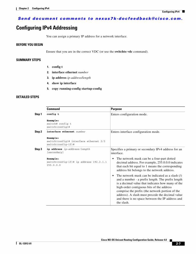
Send document comments to nexus7k -doc feedback@c i sco .com.
Chapter 2 Configuring IPv4Configuring IPv4
Configuring IPv4 AddressingYou can assign a primary IP address for a network interface.
BEFORE YOU BEGIN
Ensure that you are in the correct VDC (or use the switchto vdc command).
SUMMARY STEPS
1. config t
2. interface ethernet number
3. ip address ip-address/length
4. show ip interface
5. copy running-config startup-config
DETAILED STEPS
Command Purpose
Step 1 config t
Example:switch# config tswitch(config)#
Enters configuration mode.
Step 2 interface ethernet number
Example:switch(config)# interface ethernet 2/3switch(config-if)#
Enters interface configuration mode.
Step 3 ip address ip-address/length[secondary]
Example:switch(config-if)# ip address 192.2.1.1 255.0.0.0
Specifies a primary or secondary IPv4 address for an interface.
• The network mask can be a four-part dotted decimal address. For example, 255.0.0.0 indicates that each bit equal to 1 means the corresponding address bit belongs to the network address.
• The network mask can be indicated as a slash (/) and a number - a prefix length. The prefix length is a decimal value that indicates how many of the high-order contiguous bits of the address comprise the prefix (the network portion of the address). A slash must precede the decimal value and there is no space between the IP address and the slash.
2-7Cisco NX-OS Unicast Routing Configuration Guide, Release 4.0
OL-12912-01

Send document comments to nexus7k -doc feedback@c i sco .com.
Chapter 2 Configuring IPv4Configuring IPv4
This example shows how to assign an IPv4 address:
switch# config tswitch(config)# interface ethernet 2/3switch(config-if)# ip address 192.2.1.1 255.0.0.0switch(config-if)# copy running-config startup-config
Configuring Multiple IP AddressesYou can only add secondary IP addresses after you configure primary IP addresses.
BEFORE YOU BEGIN
Ensure that you are in the correct VDC (or use the switchto vdc command).
SUMMARY STEPS
1. config t
2. interface ethernet number
3. ip address ip-address/length
4. show ip interface
5. copy running-config startup-config
DETAILED STEPS
Step 4 show ip interface
Example:switch(config-if)# show ip interface
(Optional) Displays interfaces configured for IPv4.
Step 5 copy running-config startup-config
Example:switch(config-if)# copy running-config startup-config
(Optional) Saves this configuration change.
Command Purpose
Command Purpose
Step 1 config t
Example:switch# config tswitch(config)#
Enters configuration mode.
Step 2 interface ethernet number
Example:switch(config)# interface ethernet 2/3switch(config-if)#
Enters interface configuration mode.
2-8Cisco NX-OS Unicast Routing Configuration Guide, Release 4.0
OL-12912-01

Send document comments to nexus7k -doc feedback@c i sco .com.
Chapter 2 Configuring IPv4Configuring IPv4
Configuring a Static ARP EntryYou can configure a static ARP entry on the device to map IP addresses to MAC hardware addresses.
BEFORE YOU BEGIN
Ensure that you are in the correct VDC (or use the switchto vdc command).
SUMMARY STEPS
1. config t
2. interface ethernet number
3. ip arp ipaddr mac_addr
4. copy running-config startup-config
DETAILED STEPS
Step 3 ip address ip-address/length[secondary]
Example:switch(config-if)# ip address 192.2.1.1 255.0.0.0 secondary
Specifies the configured address as a secondary IPv4 address.
Step 4 show ip interface
Example:switch(config-if)# show ip interface
(Optional) Displays interfaces configured for IPv4.
Step 5 copy running-config startup-config
Example:switch(config-if)# copy running-config startup-config
(Optional) Saves this configuration change.
Command Purpose
Command Purpose
Step 1 config t Enters configuration mode.
Step 2 interface ethernet number
Example:switch(config)# interface ethernet 2/3switch(config-if)#
Enters interface configuration mode.
Step 3 ip arp ipaddr mac_addr
Example:switch(config-if)# ip arp 192.2.1.1 0019.076c.1a78
Associates an IP address with a MAC address as a static entry.
Step 4 copy running-config startup-config
Example:switch(config-if)# copy running-config startup-config
(Optional) Saves this configuration change.
2-9Cisco NX-OS Unicast Routing Configuration Guide, Release 4.0
OL-12912-01

Send document comments to nexus7k -doc feedback@c i sco .com.
Chapter 2 Configuring IPv4Configuring IPv4
This example shows how to configure a static ARP entry:
switch# config tswitch(config)# interface ethernet 2/3switch(config-if)# ip arp 92.2.1.1 0019.076c.1a78switch(config-if)# copy running-config startup-config
Configuring Proxy ARPYou can configure Proxy ARP on the device to determine the media addresses of hosts on other networks or subnets.
BEFORE YOU BEGIN
Ensure that you are in the correct VDC (or use the switchto vdc command).
SUMMARY STEPS
1. config t
2. interface ethernet number
3. ip proxy-arp
4. copy running-config startup-config
DETAILED STEPS
This example shows how to configure Proxy ARP:
switch# config tswitch(config)# interface ethernet 2/3switch(config-if)# ip proxy-arpswitch(config-if)# copy running-config startup-config
Command Purpose
Step 1 config t Enters configuration mode.
Step 2 interface ethernet number
Example:switch(config)# interface ethernet 2/3switch(config-if)#
Enters interface configuration mode.
Step 3 ip proxy-arp
Example:switch(config-if)# ip proxy-arp
Enables Proxy ARP on the interface.
Step 4 copy running-config startup-config
Example:switch(config-if)# copy running-config startup-config
(Optional) Saves this configuration change.
2-10Cisco NX-OS Unicast Routing Configuration Guide, Release 4.0
OL-12912-01

Send document comments to nexus7k -doc feedback@c i sco .com.
Chapter 2 Configuring IPv4Configuring IPv4
Configuring Local Proxy ARPYou can configure Local Proxy ARP on the device.
BEFORE YOU BEGIN
Ensure that you are in the correct VDC (or use the switchto vdc command).
SUMMARY STEPS
1. config t
2. interface ethernet number
3. ip local-proxy-arp
4. copy running-config startup-config
DETAILED STEPS
This example shows how to configure Local Proxy ARP:
switch# config tswitch(config)# interface ethernet 2/3switch(config-if)# ip local-proxy-arpswitch(config-if)# copy running-config startup-config
Command Purpose
Step 1 config t Enters configuration mode.
Step 2 interface ethernet number
Example:switch(config)# interface ethernet 2/3switch(config-if)#
Enters interface configuration mode.
Step 3 ip local-proxy-arp
Example:switch(config-if)# ip local-proxy-arp
Enables Local Proxy ARP on the interface.
Step 4 copy running-config startup-config
Example:switch(config-if)# copy running-config startup-config
(Optional) Saves this configuration change.
2-11Cisco NX-OS Unicast Routing Configuration Guide, Release 4.0
OL-12912-01

Send document comments to nexus7k -doc feedback@c i sco .com.
Chapter 2 Configuring IPv4Verifying the IPv4 Configuration
Verifying the IPv4 ConfigurationTo verify configuration information, use the following commands:
IPv4 Example ConfigurationMake the configuration example consistent with example commands in the Detailed Steps table.
This example shows how to configure IPv4:
config t command keyword argument
Default SettingsTable 2-1 lists the default settings for IP parameters.
Additional ReferencesFor additional information related to implementing IP, see the following sections:
• Related Documents, page 2-13
• Standards, page 2-13
Command Purpose
show ip adjacency Displays the adjacency table.
show ip arp Displays the ARP table.
show ip interface Displays IP related interface information.
show ip arp statistics Displays the ARP statistics.
Table 2-1 Default IP Parameters
Parameters Default
proxy ARP disabled
2-12Cisco NX-OS Unicast Routing Configuration Guide, Release 4.0
OL-12912-01

Send document comments to nexus7k -doc feedback@c i sco .com.
Chapter 2 Configuring IPv4Additional References
Related Documents
Standards
Related Topic Document Title
IP CLI commands Cisco NX-OS Unicast Routing Command Reference, Release 4.0
Standards Title
No new or modified standards are supported by this feature, and support for existing standards has not been modified by this feature.
—
2-13Cisco NX-OS Unicast Routing Configuration Guide, Release 4.0
OL-12912-01

Send document comments to nexus7k -doc feedback@c i sco .com.
Chapter 2 Configuring IPv4Additional References
2-14Cisco NX-OS Unicast Routing Configuration Guide, Release 4.0
OL-12912-01

Send document comments to nexus7k -doc feedback@c i sco .com.
Cisco NX-OOL-12912-01
C H A P T E R 3
Configuring IPv6This chapter describes how to configure Internet Protocol version 6 (IPv6), which includes addressing, Neighbor Discovery Protocol (ND), and Internet Control Message Protocol version 6 (ICMPv6), on the device.
This chapter includes the following sections:
• Information About IPv6, page 3-1
• Licensing Requirements for IPv6, page 3-18
• Prerequisites for IPv6, page 3-18
• Guidelines and Limitations for IPv6, page 3-18
• Configuring IPv6, page 3-18
• Verifying the IPv6 Configuration, page 3-23
• IPv6 Example Configuration, page 3-23
• Default Settings, page 3-23
• Additional References, page 3-23
Information About IPv6IPv6, which is designed to replace IPv4, increases the number of network address bits from 32 bits (in IPv4) to 128 bits. IPv6 is based on IPv4 but it includes a much larger address space and other improvements such as a simplified main header and extension headers.
The larger IPv6 address space allows networks to scale and provide global reachability. The simplified IPv6 packet header format handles packets more efficiently. The flexibility of the IPv6 address space reduces the need for private addresses and the use of Network Address Translation (NAT), which translates private (not globally unique) addresses into a limited number of public addresses. IPv6 enables new application protocols that do not require special processing by border routers at the edge of networks.
IPv6 functionality, such as prefix aggregation, simplified network renumbering, and IPv6 site multihoming capabilities, enable more efficient routing. IPv6 supports Routing Information Protocol (RIP), Integrated Intermediate System-to-Intermediate System (IS-IS), Open Shortest Path First (OSPF) for IPv6, and multiprotocol Border Gateway Protocol (BGP).
This section includes the following topics:
• IPv6 Address Formats, page 3-2
3-1S Unicast Routing Configuration Guide, Release 4.0

Send document comments to nexus7k -doc feedback@c i sco .com.
Chapter 3 Configuring IPv6Information About IPv6
• IPv6 Unicast Addresses, page 3-3
• IPv6 Anycast Addresses, page 3-7
• IPv6 Multicast Addresses, page 3-7
• IPv4 Packet Header, page 3-9
• Simplified IPv6 Packet Header, page 3-9
• DNS for IPv6, page 3-12
• Path MTU Discovery for IPv6, page 3-12
• Cisco Discovery Protocol IPv6 Address Support, page 3-12
• ICMP for IPv6, page 3-12
• IPv6 Neighbor Discovery, page 3-13
• IPv6 Neighbor Solicitation Message, page 3-13
• IPv6 Router Advertisement Message, page 3-15
• IPv6 Neighbor Redirect Message, page 3-16
• Virtualization Support, page 3-17
IPv6 Address FormatsAn IPv6 address has 128 bits or 16 bytes. The address is divided into eight, 16-bit hexadecimal blocks separated by colons (:) in the format: x:x:x:x:x:x:x:x. Two examples of IPv6 addresses are as follows:
2001:0DB8:7654:3210:FEDC:BA98:7654:32102001:0DB8:0:0:8:800:200C:417A
IPv6 addresses contain consecutive zeros within the address. You can use two colons (::) at the beginning, middle, or end of an IPv6 address to replace the consecutive zeros. Table 3-1 shows a list of compressed IPv6 address formats.
Note You can use two colons (::) only once in an IPv6 address to replace the longest string of consecutive zeros within the address.
You can use a double colon as part of the IPv6 address when consecutive 16-bit values are denoted as zero. You can configure multiple IPv6 addresses per interface but only one link-local address.
The hexadecimal letters in IPv6 addresses are not case sensitive.
Table 3-1 Compressed IPv6 Address Formats
IPv6 Address Type Preferred Format Compressed Format
Unicast 2001:0:0:0:0DB8:800:200C:417A 2001::0DB8:800:200C:417A
Multicast FF01:0:0:0:0:0:0:101 FF01::101
Loopback 0:0:0:0:0:0:0:0:1 ::1
Unspecified 0:0:0:0:0:0:0:0:0 ::
3-2Cisco NX-OS Unicast Routing Configuration Guide, Release 4.0
OL-12912-01

Send document comments to nexus7k -doc feedback@c i sco .com.
Chapter 3 Configuring IPv6Information About IPv6
A node may use the loopback address listed in Table 3-1 to send an IPv6 packet to itself. The loopback address in IPv6 is the same as the loopback address in IPv4. For more information, see Chapter 1, “Overview.”
Note You cannot assign the IPv6 loopback address to a physical interface. A packet that contains the IPv6 loopback address as its source or destination address must remain within the node that created the packet. IPv6 routers do not forward packets that have the IPv6 loopback address as their source or destination address.
Note You cannot assign an IPv6 unspecified address to an interface. You should not use the unspecified IPv6 addresses as destination addresses in IPv6 packets or the IPv6 routing header.
The IPv6-prefix is in the form documented in RFC 2373 where the IPv6 address is specified in hexadecimal using 16-bit values between colons. The prefix length is a decimal value that indicates how many of the high-order contiguous bits of the address comprise the prefix (the network portion of the address). For example, 2001:0DB8:8086:6502::/32 is a valid IPv6 prefix.
IPv6 Unicast AddressesAn IPv6 unicast address is an identifier for a single interface, on a single node. A packet that is sent to a unicast address is delivered to the interface identified by that address. This section includes the following topics:
• Aggregatable Global Addresses, page 3-3
• Link-Local Addresses, page 3-5
• IPv4-Compatible IPv6 Addresses, page 3-5
• Unique Local Addresses, page 3-6
• Site-Local Address, page 3-7
Aggregatable Global Addresses
An aggregatable global address is an IPv6 address from the aggregatable global unicast prefix. The structure of aggregatable global unicast addresses enables strict aggregation of routing prefixes that limits the number of routing table entries in the global routing table. Aggregatable global addresses are used on links that are aggregated upward through organizations, and eventually to the Internet service providers (ISPs).
Aggregatable global IPv6 addresses are defined by a global routing prefix, a subnet ID, and an interface ID. Except for addresses that start with binary 000, all global unicast addresses have a 64-bit interface ID. The IPv6 global unicast address allocation uses the range of addresses that start with binary value 001 (2000::/3). Figure 3-1 shows the structure of an aggregatable global address.
3-3Cisco NX-OS Unicast Routing Configuration Guide, Release 4.0
OL-12912-01

Send document comments to nexus7k -doc feedback@c i sco .com.
Chapter 3 Configuring IPv6Information About IPv6
Figure 3-1 Aggregatable Global Address Format
Addresses with a prefix of 2000::/3 (001) through E000::/3 (111) are required to have 64-bit interface identifiers in the extended universal identifier (EUI)-64 format. The Internet Assigned Numbers Authority (IANA) allocates the IPv6 address space in the range of 2000::/16 to regional registries.
The aggregatable global address consists of a 48-bit global routing prefix and a 16-bit subnet ID or Site-Level Aggregator (SLA). In the IPv6 aggregatable global unicast address format document (RFC 2374), the global routing prefix included two other hierarchically structured fields called Top-Level Aggregator (TLA) and Next-Level Aggregator (NLA). The IETF decided to remove the TLS and NLA fields from the RFCs because these fields are policy based. Some existing IPv6 networks deployed before the change might still use networks that are on the older architecture.
A subnet ID, which is a 16-bit subnet field, can be used by individual organizations to create a local addressing hierarchy and to identify subnets. A subnet ID is similar to a subnet in IPv4, except that an organization with an IPv6 subnet ID can support up to 65,535 individual subnets.
An interface ID identifies interfaces on a link. The interface ID is unique to the link. In many cases, an interface ID is the same as or based on the link-layer address of an interface. Interface IDs used in aggregatable global unicast and other IPv6 address types are 64 bits long and are in the modified EUI-64 format.
Interface IDs are in the modified EUI-64 format in one of the following ways:
• For all IEEE 802 interface types (for example, Ethernet, and Fiber Distributed Data interfaces), the first three octets (24 bits) are the Organizationally Unique Identifier (OUI) of the 48-bit link-layer address (MAC address) of the interface, the fourth and fifth octets (16 bits) are a fixed hexadecimal value of FFFE, and the last three octets (24 bits) are the last three octets of the MAC address. The Universal/Local (U/L) bit, which is the seventh bit of the first octet, has a value of 0 or 1. Zero indicates a locally administered identifier; 1 indicates a globally unique IPv6 interface identifier.
• For all other interface types (for example, serial, loopback, ATM, Frame Relay, and tunnel interface types—except tunnel interfaces used with IPv6 overlay tunnels), the interface ID is similar to the interface ID for IEEE 802 interface types; however, the first MAC address from the pool of MAC addresses in the router is used as the identifier (because the interface does not have a MAC address).
• For tunnel interface types that are used with IPv6 overlay tunnels, the interface ID is the IPv4 address assigned to the tunnel interface with all zeros in the high-order 32 bits of the identifier.
Note For interfaces that use the Point-to-Point Protocol (PPP), where the interfaces at both ends of the connection might have the same MAC address, the interface identifiers at both ends of the connection are negotiated (picked randomly and, if necessary, reconstructed) until both identifiers are unique. The first MAC address in the router is used as the identifier for interfaces using PPP.
8811
9
Interface IDGlobal Routing Prefix SLA
45 bits
001
16 bits 64 bits3
Provider Site Host
3-4Cisco NX-OS Unicast Routing Configuration Guide, Release 4.0
OL-12912-01

Send document comments to nexus7k -doc feedback@c i sco .com.
Chapter 3 Configuring IPv6Information About IPv6
If no IEEE 802 interface types are in the router, link-local IPv6 addresses are generated on the interfaces in the router in the following sequence:
1. The router is queried for MAC addresses (from the pool of MAC addresses in the router).
2. If no MAC addresses are available in the router, the serial number of the router is used to form the link-local addresses.
3. If the serial number of the router cannot be used to form the link-local addresses, the router uses a Message Digest 5 (MD5) hash to determine the MAC address of the router from the hostname of the router.
Link-Local Addresses
A link-local address is an IPv6 unicast address that can be automatically configured on any interface using the link-local prefix FE80::/10 (1111 1110 10) and the interface identifier in the modified EUI-64 format. Link-local addresses are used in the neighbor discovery protocol and the stateless autoconfiguration process. Nodes on a local link can use link-local addresses to communicate; the nodes do not need globally unique addresses to communicate. Figure 3-2 shows the structure of a link-local address.
IPv6 routers cannot forward packets that have link-local source or destination addresses to other links.
Figure 3-2 Link-Local Address Format
IPv4-Compatible IPv6 Addresses
An IPv4-compatible IPv6 address is an IPv6 unicast address that has zeros in the high-order 96 bits of the address and an IPv4 address in the low-order 32 bits of the address. The format of an IPv4-compatible IPv6 address is 0:0:0:0:0:0:A.B.C.D or ::A.B.C.D. The entire 128-bit IPv4-compatible IPv6 address is used as the IPv6 address of a node and the IPv4 address embedded in the low-order 32 bits is used as the IPv4 address of the node. IPv4-compatible IPv6 addresses are assigned to nodes that support both the IPv4 and IPv6 protocol stacks and are used in automatic tunnels. Figure 3-3 shows the structure of an IPv4-compatible IPv6 address and a few acceptable formats for the address.
5266
9
128 bits
10 bits
1111 1110 10
Interface ID0
FE80::/10
3-5Cisco NX-OS Unicast Routing Configuration Guide, Release 4.0
OL-12912-01

Send document comments to nexus7k -doc feedback@c i sco .com.
Chapter 3 Configuring IPv6Information About IPv6
Figure 3-3 IPv4-Compatible IPv6 Address Format
Unique Local Addresses
A unique local address is an IPv6 unicast address that is globally unique and is intended for local communications. It is not expected to be routable on the global Internet and is routable inside of a limited area, such as a site and it may be routed between a limited set of sites. Applications may treat unique local addresses like global scoped addresses.
A unique local address has the following characteristics:
• It has a globally unique prefix (it has a high probability of uniqueness).
• It has a well-known prefix to allow for easy filtering at site boundaries.
• It allows sites to be combined or privately interconnected without creating any address conflicts or requiring renumbering of interfaces that use these prefixes.
• It is ISP-independent and can be used for communications inside of a site without having any permanent or intermittent Internet connectivity.
• If it is accidentally leaked outside of a site via routing or Domain Name Server (DNS), there is no conflict with any other addresses.
Figure 3-4 shows the structure of a unique local address.
Figure 3-4 Unique Local Address Structure
5272
7
::192.168.30.1= ::C0A8:1E01
IPv4 address0
96 bits 32 bits
•
•
•
•
FC00 Global ID 41 bits
/48 /64
Local IPv6
/7
Interface ID
Prefix — FC00::/7 prefix to identify local IPv6 unicast addresses.
Global ID — 41-bit global identifier used to create a globally unique prefix.
Subnet ID — 16-bit subnet ID is an identifier of a subnet within the site.
Interface ID — 64-bit IID
Link prefix
Subnet prefix
2323
89
3-6Cisco NX-OS Unicast Routing Configuration Guide, Release 4.0
OL-12912-01

Send document comments to nexus7k -doc feedback@c i sco .com.
Chapter 3 Configuring IPv6Information About IPv6
Site-Local Address
Because RFC 3879 deprecates the use of site-local addresses, you should follow the recommendations of unique local addressing (ULA) in RFC 4193 when you configure private IPv6 addresses.
IPv6 Anycast AddressesAn anycast address is an address that is assigned to a set of interfaces that belong to different nodes. A packet sent to an anycast address is delivered to the closest interface—as defined by the routing protocols in use—identified by the anycast address. Anycast addresses are syntactically indistinguishable from unicast addresses because anycast addresses are allocated from the unicast address space. Assigning a unicast address to more than one interface turns a unicast address into an anycast address. You must configure the nodes to which the anycast address to recognize that the address is an anycast address.
Note Anycast addresses can be used only by a router, not a host. Anycast addresses cannot be used as the source address of an IPv6 packet.
Figure 3-5 shows the format of the subnet router anycast address; the address has a prefix concatenated by a series of zeros (the interface ID). The subnet router anycast address can be used to reach a router on the link that is identified by the prefix in the subnet router anycast address.
Figure 3-5 Subnet Router Anycast Address Format
IPv6 Multicast AddressesAn IPv6 multicast address is an IPv6 address that has a prefix of FF00::/8 (1111 1111). An IPv6 multicast address is an identifier for a set of interfaces that belong to different nodes. A packet sent to a multicast address is delivered to all interfaces identified by the multicast address. The second octet following the prefix defines the lifetime and scope of the multicast address. A permanent multicast address has a lifetime parameter equal to 0; a temporary multicast address has a lifetime parameter equal to 1. A multicast address that has the scope of a node, link, site, or organization, or a global scope, has a scope parameter of 1, 2, 5, 8, or E, respectively. For example, a multicast address with the prefix FF02::/16 is a permanent multicast address with a link scope. Figure 3-6 shows the format of the IPv6 multicast address.
5267
0
128 bits
0000000000000...000Prefix
3-7Cisco NX-OS Unicast Routing Configuration Guide, Release 4.0
OL-12912-01

Send document comments to nexus7k -doc feedback@c i sco .com.
Chapter 3 Configuring IPv6Information About IPv6
Figure 3-6 IPv6 Multicast Address Format
IPv6 nodes (hosts and routers) are required to join (where received packets are destined for) the following multicast groups:
• All-nodes multicast group FF02:0:0:0:0:0:0:1 (the scope is link-local)
• Solicited-node multicast group FF02:0:0:0:0:1:FF00:0000/104 for each of its assigned unicast and anycast addresses
IPv6 routers must also join the all-routers multicast group FF02:0:0:0:0:0:0:2 (the scope is link-local).
The solicited-node multicast address is a multicast group that corresponds to an IPv6 unicast or anycast address. IPv6 nodes must join the associated solicited-node multicast group for every unicast and anycast address to which it is assigned. The IPv6 solicited-node multicast address has the prefix FF02:0:0:0:0:1:FF00:0000/104 concatenated with the 24 low-order bits of a corresponding IPv6 unicast or anycast address (see Figure 3-7). For example, the solicited-node multicast address that corresponds to the IPv6 address 2037::01:800:200E:8C6C is FF02::1:FF0E:8C6C. Solicited-node addresses are used in neighbor solicitation messages.
Figure 3-7 IPv6 Solicited-Node Multicast Address Format
Note IPv6 has no broadcast addresses. IPv6 multicast addresses are used instead of broadcast addresses.
5267
1
128 bits
4 bits4 bits
0 if permanent1 if temporary
Interface ID0
1111 1111
8 bits 8 bits
F F Lifetime Scope Lifetime =
1 = node2 = link5 = site8 = organizationE = global
Scope =
5267
2
128 bits
Interface ID
IPv6 unicast or anycast address
Solicited-node multicast address
Prefix
Lower 24
24 bits
FF02 0 1 FF
3-8Cisco NX-OS Unicast Routing Configuration Guide, Release 4.0
OL-12912-01

Send document comments to nexus7k -doc feedback@c i sco .com.
Chapter 3 Configuring IPv6Information About IPv6
IPv4 Packet HeaderThe basic IPv4 packet header has 12 fields with a total size of 20 octets (160 bits) (see Figure 3-8). The 12 fields may be followed by an Options field, which is followed by a data portion that is usually the transport-layer packet. The variable length of the Options field adds to the total size of the IPv4 packet header. The shaded fields of the IPv4 packet header are not included in the IPv6 packet header.
Figure 3-8 IPv4 Packet Header Format
Simplified IPv6 Packet HeaderThe basic IPv6 packet header has 8 fields with a total size of 40 octets (320 bits) (see Figure 3-9). Fragmentation is handled by the source of a packet and checksums at the data link layer and transport layer are used. The User Datagram Protocol (UDP) checksum checks the integrity of the inner packet and the basic IPv6 packet header and Options field are aligned to 64 bits, which can facilitate the processing of IPv6 packets.
Table 3-2 lists the fields in the basic IPv6 packet header.
Version Hd Len Type of Service Total Length
20octets
Identification Flags Fragment Offset
Time to Live Protocol Header Checksum
Source Address
Destination Address
Data Portion
32 bits
Options Padding Variablelength
5145
7
Table 3-2 Basic IPv6 Packet Header Fields
Field Description
Version Similar to the Version field in the IPv4 packet header, except that the field lists number 6 for IPv6 instead of number 4 for IPv4.
Traffic Class Similar to the Type of Service field in the IPv4 packet header. The Traffic Class field tags packets with a traffic class that is used in differentiated services.
Flow Label New field in the IPv6 packet header. The Flow Label field tags packets with a specific flow that differentiates the packets at the network layer.
Payload Length Similar to the Total Length field in the IPv4 packet header. The Payload Length field indicates the total length of the data portion of the packet.
3-9Cisco NX-OS Unicast Routing Configuration Guide, Release 4.0
OL-12912-01

Send document comments to nexus7k -doc feedback@c i sco .com.
Chapter 3 Configuring IPv6Information About IPv6
Figure 3-9 IPv6 Packet Header Format
Optional extension headers and the data portion of the packet are after the eight fields of the basic IPv6 packet header. If present, each extension header is aligned to 64 bits. There is no fixed number of extension headers in an IPv6 packet. Each extension header is identified by the Next Header field of the previous header. Typically, the final extension header has a Next Header field of a transport-layer protocol, such as TCP or UDP. Figure 3-10 shows the IPv6 extension header format.
Next Header Similar to the Protocol field in the IPv4 packet header. The value of the Next Header field determines the type of information following the basic IPv6 header. The type of information following the basic IPv6 header can be a transport-layer packet, for example, a TCP or UDP packet, or an Extension Header, as shown in Figure 3-9.
Hop Limit Similar to the Time to Live field in the IPv4 packet header. The value of the Hop Limit field specifies the maximum number of routers that an IPv6 packet can pass through before the packet is considered invalid. Each router decrements the value by one. Because no checksum is in the IPv6 header, the router can decrement the value without needing to recalculate the checksum, which saves processing resources.
Source Address Similar to the Source Address field in the IPv4 packet header, except that the field contains a 128-bit source address for IPv6 instead of a 32-bit source address for IPv4.
Destination Address Similar to the Destination Address field in the IPv4 packet header, except that the field contains a 128-bit destination address for IPv6 instead of a 32-bit destination address for IPv4.
Table 3-2 Basic IPv6 Packet Header Fields (continued)
Field Description
Version Traffic Class Flow Label
40octets
Payload Length Next Header Hop Limit
Data Portion
32 bits
Next HeaderVariablelength
5145
8
Source Address
Destination Address
Extension Header information
3-10Cisco NX-OS Unicast Routing Configuration Guide, Release 4.0
OL-12912-01

Send document comments to nexus7k -doc feedback@c i sco .com.
Chapter 3 Configuring IPv6Information About IPv6
Figure 3-10 IPv6 Extension Header Format
Table 3-3 lists the extension header types and their Next Header field values.
IPv6packet
IPv6 basic header(40 octets)
Any number ofextension headers
5145
9
Next Header Ext Header Length
Extension Header Data
Data (for example,TCP or UDP)
Table 3-3 IPv6 Extension Header Types
Header TypeNext Header Value Description
Hop-by-hop options header 0 Header that is processed by all hops in the path of a packet. When present, the hop-by-hop options header always follows immediately after the basic IPv6 packet header.
Destination options header 6 Header that can follow any hop-by-hop options header. The header is processed at the final destination and at each visited address specified by a routing header. Alternatively, the destination options header can follow any Encapsulating Security Payload (ESP) header. The destination options header is processed only at the final destination.
Routing header 43 Header that is used for source routing.
Fragment header 44 Header that is used when a source fragments a packet that is larger than the Maximum Transmission Unit (MTU) for the path between itself and a destination. The Fragment header is used in each fragmented packet.
Upper-layer headers 6 (TCP)
17 (UDP)
Headers that are used inside a packet to transport the data. The two main transport protocols are TCP and UDP.
3-11Cisco NX-OS Unicast Routing Configuration Guide, Release 4.0
OL-12912-01
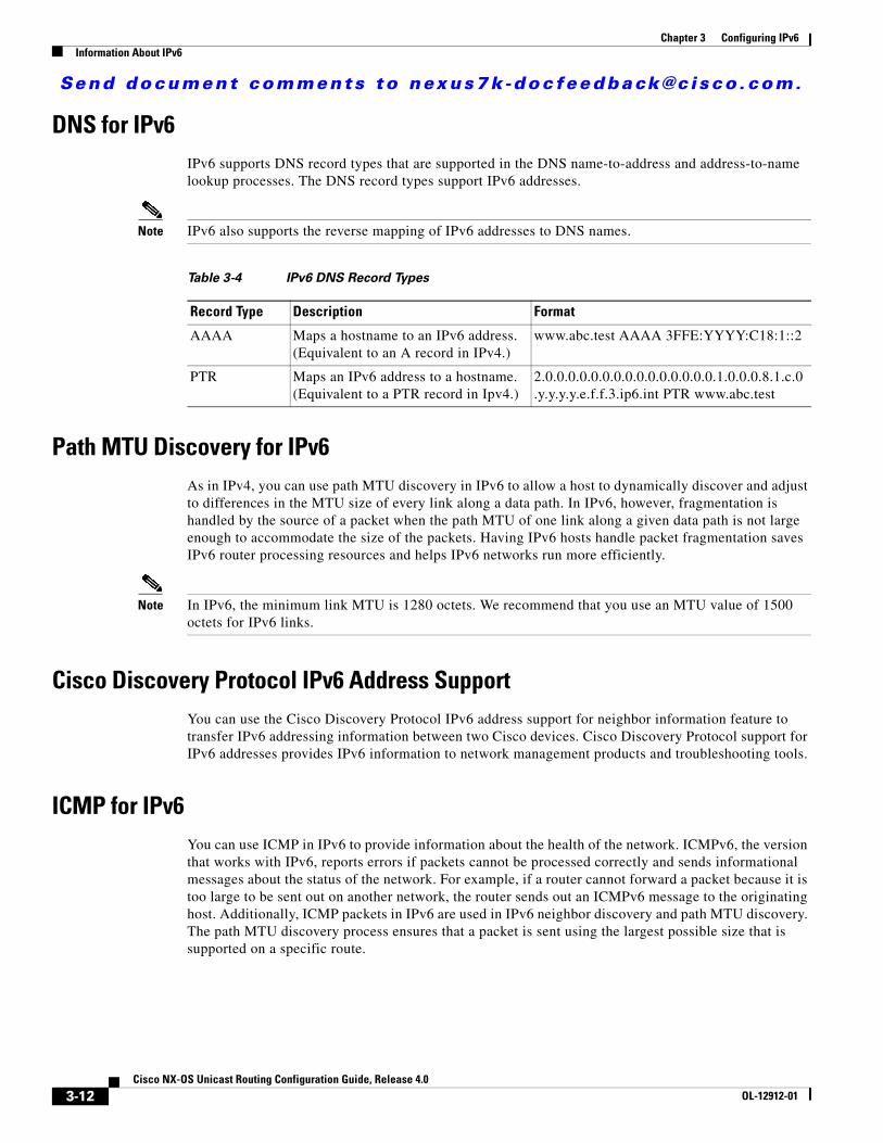
Send document comments to nexus7k -doc feedback@c i sco .com.
Chapter 3 Configuring IPv6Information About IPv6
DNS for IPv6IPv6 supports DNS record types that are supported in the DNS name-to-address and address-to-name lookup processes. The DNS record types support IPv6 addresses.
Note IPv6 also supports the reverse mapping of IPv6 addresses to DNS names.
Path MTU Discovery for IPv6As in IPv4, you can use path MTU discovery in IPv6 to allow a host to dynamically discover and adjust to differences in the MTU size of every link along a data path. In IPv6, however, fragmentation is handled by the source of a packet when the path MTU of one link along a given data path is not large enough to accommodate the size of the packets. Having IPv6 hosts handle packet fragmentation saves IPv6 router processing resources and helps IPv6 networks run more efficiently.
Note In IPv6, the minimum link MTU is 1280 octets. We recommend that you use an MTU value of 1500 octets for IPv6 links.
Cisco Discovery Protocol IPv6 Address SupportYou can use the Cisco Discovery Protocol IPv6 address support for neighbor information feature to transfer IPv6 addressing information between two Cisco devices. Cisco Discovery Protocol support for IPv6 addresses provides IPv6 information to network management products and troubleshooting tools.
ICMP for IPv6You can use ICMP in IPv6 to provide information about the health of the network. ICMPv6, the version that works with IPv6, reports errors if packets cannot be processed correctly and sends informational messages about the status of the network. For example, if a router cannot forward a packet because it is too large to be sent out on another network, the router sends out an ICMPv6 message to the originating host. Additionally, ICMP packets in IPv6 are used in IPv6 neighbor discovery and path MTU discovery. The path MTU discovery process ensures that a packet is sent using the largest possible size that is supported on a specific route.
Table 3-4 IPv6 DNS Record Types
Record Type Description Format
AAAA Maps a hostname to an IPv6 address. (Equivalent to an A record in IPv4.)
www.abc.test AAAA 3FFE:YYYY:C18:1::2
PTR Maps an IPv6 address to a hostname. (Equivalent to a PTR record in Ipv4.)
2.0.0.0.0.0.0.0.0.0.0.0.0.0.0.0.1.0.0.0.8.1.c.0.y.y.y.y.e.f.f.3.ip6.int PTR www.abc.test
3-12Cisco NX-OS Unicast Routing Configuration Guide, Release 4.0
OL-12912-01

Send document comments to nexus7k -doc feedback@c i sco .com.
Chapter 3 Configuring IPv6Information About IPv6
A value of 58 in the Next Header field of the basic IPv6 packet header identifies an IPv6 ICMP packet. The ICMP packet follows all the extension headers and is the last piece of information in the IPv6 packet.Within the IPv6 ICMP packets, the ICMPv6 Type and ICMPv6 Code fields identify IPv6 ICMP packet specifics, such as the ICMP message type. The value in the Checksum field is computed by the sender and checked by the receiver from the fields in the IPv6 ICMP packet and the IPv6 pseudo header.
Note The IPv6 header does not have a checksum. But a checksum is important on the transport layer to determine mis-delivery of packets. All checksum calculations that include the IP address in the calculation must be modified for IPv6 to accommodate the new 128-bit address. A checksum is generated using a pseudo header.
The ICMPv6 Data field contains error or diagnostic information that relates to IP packet processing. Figure 3-11 shows the IPv6 ICMP packet header format.
Figure 3-11 IPv6 ICMP Packet Header Format
IPv6 Neighbor DiscoveryYou can use the IPv6 Neighbor Discovery Protocol (NDP) to determine whether a neighboring router is reachable. IPv6 nodes use neighbor discovery to determine the addresses of nodes on the same network (local link), to find neighboring routers that can forward their packets, to verify whether neighboring routers are reachable or not, and to detect changes to link-layer addresses. NDP uses ICMP messages to detect whether packets are sent to neighboring routers that are unreachable.
IPv6 Neighbor Solicitation MessageA node sends a Neighbor solicitation message, which has a value of 135 in the Type field of the ICMP packet header, on the local link when it wants to determine the link-layer address of another node on the same local link (see Figure 3-12). The source address is the IPv6 address of the node that sends the neighbor solicitation message. The destination address is the solicited-node multicast address that corresponds to the IPv6 address of the destination node. The neighbor solicitation message also includes the link-layer address of the source node.
5272
8
Checksum
ICMPv6 packet
IPv6 basic headerNext header = 58ICMPv6 packet
ICMPv6 Code
ICMPv6 Data
ICMPv6 Type
3-13Cisco NX-OS Unicast Routing Configuration Guide, Release 4.0
OL-12912-01

Send document comments to nexus7k -doc feedback@c i sco .com.
Chapter 3 Configuring IPv6Information About IPv6
Figure 3-12 IPv6 Neighbor Discovery—Neighbor Solicitation Message
After receiving the neighbor solicitation message, the destination node replies by sending a neighbor advertisement message, which has a value of 136 in the Type field of the ICMP packet header, on the local link. The source address is the IPv6 address of the node (the IPv6 address of the node interface that sends the neighbor advertisement message). The destination address is the IPv6 address of the node that sent the neighbor solicitation message. The data portion includes the link-layer address of the node that sends the neighbor advertisement message.
After the source node receives the neighbor advertisement, the source node and destination node can communicate.
Neighbor solicitation messages can verify the reachability of a neighbor after a node identifies the link-layer address of a neighbor. When a node wants to verify the reachability of a neighbor, it uses the destination address in a neighbor solicitation message as the unicast address of the neighbor.
Neighbor advertisement messages are also sent when there is a change in the link-layer address of a node on a local link. When there is a change, the destination address for the neighbor advertisement is the all-nodes multicast address.
Neighbor unreachability detection identifies the failure of a neighbor or the failure of the forward path to the neighbor, and is used for all paths between hosts and neighboring nodes (hosts or routers). Neighbor unreachability detection is performed for neighbors to which only unicast packets are being sent and is not performed for neighbors to which multicast packets are being sent.
A neighbor is considered reachable when a positive acknowledgment is returned from the neighbor (indicating that packets previously sent to the neighbor have been received and processed). A positive acknowledgment—from an upper-layer protocol (such as TCP)—indicates that a connection is making forward progress (reaching its destination). If packets are reaching the peer, they are also reaching the next-hop neighbor of the source. Forward progress is also a confirmation that the next-hop neighbor is reachable.
For destinations that are not on the local link, forward progress implies that the first-hop router is reachable. When acknowledgments from an upper-layer protocol are not available, a node probes the neighbor using unicast neighbor solicitation messages to verify that the forward path is still working. The return of a solicited neighbor advertisement message from the neighbor is a positive acknowledgment that the forward path is still working (neighbor advertisement messages that have the solicited flag set to a value of 1 are sent only in response to a neighbor solicitation message). Unsolicited messages confirm only the one-way path from the source to the destination node; solicited neighbor advertisement messages indicate that a path is working in both directions.
5267
3
A and B can now exchangepackets on this link
ICMPv6 Type = 135Src = ADst = solicited-node multicast of BData = link-layer address of AQuery = what is your link address?
ICMPv6 Type = 136Src = BDst = AData = link-layer address of B
3-14Cisco NX-OS Unicast Routing Configuration Guide, Release 4.0
OL-12912-01

Send document comments to nexus7k -doc feedback@c i sco .com.
Chapter 3 Configuring IPv6Information About IPv6
Note A neighbor advertisement message that has the solicited flag set to a value of 0 is not considered as a positive acknowledgment that the forward path is still working.
Neighbor solicitation messages are also used in the stateless auto-configuration process to verify the uniqueness of unicast IPv6 addresses before the addresses are assigned to an interface. Duplicate address detection is performed first on a new, link-local IPv6 address before the address is assigned to an interface (the new address remains in a tentative state while duplicate address detection is performed). A node sends a neighbor solicitation message with an unspecified source address and a tentative link-local address in the body of the message. If another node is already using that address, the node returns a neighbor advertisement message that contains the tentative link-local address. If another node is simultaneously verifying the uniqueness of the same address, that node also returns a neighbor solicitation message. If no neighbor advertisement messages are received in response to the neighbor solicitation message and no neighbor solicitation messages are received from other nodes that are attempting to verify the same tentative address, the node that sent the original neighbor solicitation message considers the tentative link-local address to be unique and assigns the address to the interface.
IPv6 Router Advertisement MessageRouter advertisement (RA) messages, which have a value of 134 in the Type field of the ICMP packet header, are periodically sent out to each configured interface of an IPv6 router. For stateless auto-configuration to work properly, the advertised prefix length in RA messages must always be 64 bits.
The RA messages are sent to the all-nodes multicast address (see Figure 3-13).
Figure 3-13 IPv6 Neighbor Discovery—RA Message
RA messages typically include the following information:
• One or more onlink IPv6 prefixes that nodes on the local link can use to automatically configure their IPv6 addresses
• Life-time information for each prefix included in the advertisement
• Sets of flags that indicate the type of auto-configuration (stateless or stateful) that can be completed
• Default router information (whether the router sending the advertisement should be used as a default router and, if so, the amount of time in seconds that the router should be used as a default router)
• Additional information for hosts, such as the hop limit and MTU that a host should use in packets that it originates
5267
4
Router advertisement packet definitions:ICMPv6 Type = 134Src = router link-local addressDst = all-nodes multicast addressData = options, prefix, lifetime, autoconfig flag
Routeradvertisement
Routeradvertisement
3-15Cisco NX-OS Unicast Routing Configuration Guide, Release 4.0
OL-12912-01

Send document comments to nexus7k -doc feedback@c i sco .com.
Chapter 3 Configuring IPv6Information About IPv6
RAs are also sent in response to router solicitation messages. Router solicitation messages, which have a value of 133 in the Type field of the ICMP packet header, are sent by hosts at system startup so that the host can immediately auto-configure without needing to wait for the next scheduled RA message. The source address is usually the unspecified IPv6 address (0:0:0:0:0:0:0:0). If the host has a configured unicast address, the unicast address of the interface that sends the router solicitation message is used as the source address in the message. The destination address is the all-routers multicast address with a scope of the link. When an RA is sent in response to a router solicitation, the destination address in the RA message is the unicast address of the source of the router solicitation message.
You can configure the following RA message parameters:
• The time interval between periodic RA messages
• The router life-time value, which indicates the usefulness of a router as the default router (for use by all nodes on a given link)
• The network prefixes in use on a given link
• The time interval between neighbor solicitation message retransmissions (on a given link)
• The amount of time that a node considers a neighbor reachable (for use by all nodes on a given link)
The configured parameters are specific to an interface. The sending of RA messages (with default values) is automatically enabled on Ethernet interfaces. For other interface types, you must enter the no ipv6 nd suppress-ra command to send RA messages. You can disable the RA message feature on individual interfaces by entering the ipv6 nd suppress-ra command.
IPv6 Neighbor Redirect MessageRouters send neighbor redirect messages to inform hosts of better first-hop nodes on the path to a destination (see Figure 3-14). A value of 137 in the Type field of the ICMP packet header identifies an IPv6 neighbor redirect message.
3-16Cisco NX-OS Unicast Routing Configuration Guide, Release 4.0
OL-12912-01

Send document comments to nexus7k -doc feedback@c i sco .com.
Chapter 3 Configuring IPv6Information About IPv6
Figure 3-14 IPv6 Neighbor Discovery—Neighbor Redirect Message
Note A router must be able to determine the link-local address for each of its neighboring routers in order to ensure that the target address (the final destination) in a redirect message identifies the neighbor router by its link-local address. For static routing, you should specify the address of the next-hop router using the link-local address of the router. For dynamic routing, you must configure all IPv6 routing protocols to exchange the link-local addresses of neighboring routers.
After forwarding a packet, a router sends a redirect message to the source of the packet under the following circumstances:
• The destination address of the packet is not a multicast address.
• The packet was not addressed to the router.
• The packet is about to be sent out the interface on which it was received.
• The router determines that a better first-hop node for the packet resides on the same link as the source of the packet.
• The source address of the packet is a global IPv6 address of a neighbor on the same link or a link-local address.
Virtualization SupportIPv6 supports Virtual Routing and Forwarding instances (VRFs). VRFs exist within virtual device contexts (VDCs). By default, Cisco NX-OS places you in the default VDC and default VRF unless you specifically configure another VDC and VRF. For more information, see the Cisco NX-OS Virtual Device Context Configuration Guide and see Chapter 13, “Configuring Layer 3 Virtualization.”
Router B Router AHost H
IPv6 packet
Neighbor redirect packet definitions:ICMPv6 Type = 137Src = link-local address of Router ADst = link-local address of Host HData = target address (link-localaddress of Router B), options(header of redirected packet)
Note: If the target is a host, the targetaddress is equal to the destinationaddress of the redirect packet andthe options include the link-layeraddress of the target host (if known).
Subsequent IPv6 packets 6098
1
3-17Cisco NX-OS Unicast Routing Configuration Guide, Release 4.0
OL-12912-01

Send document comments to nexus7k -doc feedback@c i sco .com.
Chapter 3 Configuring IPv6Licensing Requirements for IPv6
Licensing Requirements for IPv6The following table shows the licensing requirements for this feature:
Prerequisites for IPv6IPv6 has the following prerequisites:
• You must be familiar with IPv6 basics such as IPv6 addressing, IPv6 header information, ICMPv6, and IPv6 Neighbor Discovery (ND) Protocol.
• Ensure that you follow the memory/processing guidelines when you make a device a dual-stack device (IPv4/IPv6).
Guidelines and Limitations for IPv6IPv6 has the following guidelines and limitations and restrictions:
• IPv6 packets are transparent to Layer 2 LAN switches because the switches do not examine Layer 3 packet information before forwarding IPv6 frames. IPv6 hosts can be directly attached to Layer 2 LAN switches.
• You can configure multiple IPv6 global addresses within the same prefix on an interface. However, multiple IPv6 link-local addresses on an interface are not supported.
• Because RFC 3879 deprecates the use of site-local addresses, you should configure private IPv6 addresses according to the recommendations of unique local addressing (ULA) in RFC 4193.
Configuring IPv6This section includes the following topics:
• Configuring IPv6 Addressing, page 3-19
• Configuring IPv6 Neighbor Discovery, page 3-20
Note If you are familiar with the Cisco IOS CLI, be aware that the Cisco NX-OS commands for this feature might differ from the Cisco IOS commands that you would use.
Product License Requirement
NX-OS IPv6 requires no license. Any feature not included in a license package is bundled with the Cisco NX-OS system images and is provided at no extra charge to you. For a complete explanation of the NX-OS licensing scheme, see the Cisco NX-OS Licensing Guide.
3-18Cisco NX-OS Unicast Routing Configuration Guide, Release 4.0
OL-12912-01

Send document comments to nexus7k -doc feedback@c i sco .com.
Chapter 3 Configuring IPv6Configuring IPv6
Configuring IPv6 AddressingYou must configure an IPv6 address on an interface for the interface to forward IPv6 traffic. When you configure a global IPv6 address on an interface, it automatically configures a link-local address and activates IPv6 for that interface.
BEFORE YOU BEGIN
Ensure that you are in the correct VDC (or use the switchto vdc command).
SUMMARY STEPS
1. config t
2. interface ethernet number
3. ipv6 address ipv6-address mask [secondary]
or
ipv6 address ipv6-address use-link-local-only
4. show ipv6 interface
5. copy running-config startup-config
DETAILED STEPS
Command Purpose
Step 1 config t
Example:switch# config tswitch(config)#
Enters configuration mode.
Step 2 interface ethernet number
Example:switch(config)# interface ethernet 2/3switch(config-if)#
Enters interface configuration mode.
Step 3 ipv6 address ipv6-address mask [secondary}oripv6 address ipv6-address use-link-local-only
Example:switch(config-if)# ipv6 address 2001:0DB8::1/10orswitch(config-if)# ipv6 address use-link-local-only
Specifies an IPv6 address assigned to the interface and enables IPv6 processing on the interface.
Specifying the ipv6 address command configures global IPv6 addresses with an interface identifier (ID) in the low-order 64 bits of the IPv6 address. Only the 64-bit network prefix for the address needs to be specified; the last 64 bits are automatically computed from the interface ID.
Specifying the ipv6 address link-local command configures a link-local address on the interface that is used instead of the link-local address that is automatically configured when IPv6 is enabled on the interface.
Enables IPv6 processing on an interface without configuring an IPv6 address.
3-19Cisco NX-OS Unicast Routing Configuration Guide, Release 4.0
OL-12912-01

Send document comments to nexus7k -doc feedback@c i sco .com.
Chapter 3 Configuring IPv6Configuring IPv6
This example shows how to configure an IPv6 address:
switch# config tswitch(config)# interface ethernet 3/1switch(config-if)# ipv6 address ?A:B::C:D/LEN IPv6 prefix format: xxxx:xxxx/ml, xxxx:xxxx::/ml,xxxx::xx/128use-link-local-only Enable IPv6 on interface using only a single link-localaddressswitch(config-if)# ipv6 address dc3:dc3::/64 eui64
This example shows how to display an IPv6 interface:
switch(config-if)# show ipv6 interface ethernet 3/1Ethernet3/1, Interface status: protocol-down/link-down/admin-down, iod: 36
IPv6 address: 0dc3:0dc3:0000:0000:0218:baff:fed8:239dIPv6 subnet: 0dc3:0dc3:0000:0000:0000:0000:0000:0000/64IPv6 link-local address: fe80::0218:baff:fed8:239d (default)IPv6 multicast routing: disabledIPv6 multicast groups locally joined:
ff02::0001:ffd8:239d ff02::0002 ff02::0001 ff02::0001:ffd8:239dIPv6 multicast (S,G) entries joined: noneIPv6 MTU: 1500 (using link MTU)IPv6 RP inbound packet-filtering policy: noneIPv6 RP outbound packet-filtering policy: noneIPv6 inbound packet-filtering policy: noneIPv6 outbound packet-filtering policy: noneIPv6 interface statistics last reset: neverIPv6 interface RP-traffic statistics: (forwarded/originated/consumed)
Unicast packets: 0/0/0Unicast bytes: 0/0/0Multicast packets: 0/0/0Multicast bytes: 0/0/0
Configuring IPv6 Neighbor DiscoveryYou can configure IPv6 neighbor discovery on the router. The neighbor discovery protocol enables IPv6 nodes and routers to determine the link-layer address of a neighbor on the same link, find neighboring routers, and keep track of neighbors.
BEFORE YOU BEGIN
Ensure that you are in the correct VDC (or use the switchto vdc command). You must first enable IPv6 on the interface.
Step 4 show ipv6 interface
Example:switch(config-if)# show ipv6 interface
(Optional) Displays interfaces configured for IPv6.
Step 5 copy running-config startup-config
Example:switch(config-if)# copy running-config startup-config
(Optional) Saves this configuration change.
Command Purpose
3-20Cisco NX-OS Unicast Routing Configuration Guide, Release 4.0
OL-12912-01

Send document comments to nexus7k -doc feedback@c i sco .com.
Chapter 3 Configuring IPv6Configuring IPv6
SUMMARY STEPS
1. config t
2. interface ethernet number
3. ipv6 nd
4. show ipv6 nd interface
5. copy running-config startup-config
DETAILED STEPS
This example shows how to configure IPv6 neighbor discovery reachable time:
switch# config tswitch(config)# interface ethernet 3/1switch(config-if)# ipv6 nd reachable-time 10
This example shows how to display an IPv6 neighbor discovery interface:
switch(config-if)# show ipv6 nd interface ethernet 3/1ICMPv6 ND Interfaces for VRF "default"Ethernet3/1, Interface status: protocol-down/link-down/admin-downIPv6 address: 0dc3:0dc3:0000:0000:0218:baff:fed8:239d
ICMPv6 active timers:Last Neighbor-Solicitation sent: neverLast Neighbor-Advertisement sent: neverLast Router-Advertisement sent:neverNext Router-Advertisement sent in: 0.000000
Router-Advertisement parameters:Periodic interval: 200 to 600 secondsSend "Managed Address Configuration" flag: false
Command Purpose
Step 1 config t
Example:switch# config tswitch(config)#
Enters configuration mode.
Step 2 interface ethernet number
Example:switch(config)# interface ethernet 2/31switch(config-if)#
Enters interface configuration mode.
Step 3 ipv6 nd
Example:switch(config-if)# ipv6 nd
Enables IPv6 neighbor discovery on the interface.
Step 4 show ipv6 nd interface
Example:switch(config-if)# show ipv6 nd interface
(Optional) Displays interfaces configured for IPv6 neighbor discovery.
Step 5 copy running-config startup-config
Example:switch(config-if)# copy running-config startup-config
(Optional) Saves this configuration change.
3-21Cisco NX-OS Unicast Routing Configuration Guide, Release 4.0
OL-12912-01

Send document comments to nexus7k -doc feedback@c i sco .com.
Chapter 3 Configuring IPv6Configuring IPv6
Send "Other Stateful Configuration" flag: falseSend "Current Hop Limit" field: 64Send "MTU" option value: 1500Send "Router Lifetime" field: 1800 secsSend "Reachable Time" field: 10 msSend "Retrans Timer" field: 0 ms
Neighbor-Solicitation parameters:NS retransmit interval: 1000 ms
ICMPv6 error message parameters:Send redirects: falseSend unreachables: false
Optional IPv6 Neighbor DiscoveryYou can use the following optional IPv6 Neighbor Discovery commands:
Command Purpose
ipv6 nd hop-limit Configures the maximum number of hops used in router advertisements and all IPv6 packets that are originated by the router.
ipv6 nd managed-config-flag Sets the managed address configuration flag in IPv6 router advertisements.
ipv6 nd mtu Sets the maximum transmission unit (MTU) size of IPv6 packets sent on an interface.
ipv6 nd ns-interval Configures the interval between IPv6 neighbor solicitation retransmissions on an interface.
ipv6 nd other-config-flag Configures the other stateful configuration flag in IPv6 router advertisements.
ipv6 nd ra-interval Configures the interval between IPv6 router advertisement (RA) transmissions on an interface.
ipv6 nd ra-lifetime Configures the router lifetime value in IPv6 router advertisements on an interface.
ipv6 nd reachable-time Configures the amount of time that a remote IPv6 node is considered reachable after some reachability confirmation event has occurred.
ipv6 nd redirects Enables ICMPv6 redirect messages to be sent.
ipv6 nd retrans-timer Configures the advertised time between neighbor solicitation messages in router advertisements.
ipv6 nd suppress-ra Suppresses IPv6 router advertisement transmissions on a LAN interface.
3-22Cisco NX-OS Unicast Routing Configuration Guide, Release 4.0
OL-12912-01

Send document comments to nexus7k -doc feedback@c i sco .com.
Chapter 3 Configuring IPv6Verifying the IPv6 Configuration
Verifying the IPv6 ConfigurationTo verify configuration information, use the following commands:
IPv6 Example ConfigurationThis example shows how to configure IPv6:
config t nterface ethernet 3/1 ipv6 address dc3:dc3::/64 eui64 ipv6 nd reachable-time 10
Default SettingsTable 3-5 lists the default settings for IPv6 parameters.
Additional ReferencesFor additional information related to implementing IPv6, see the following sections:
• Related Documents, page 3-24
• Standards, page 3-24
Command Purpose
show ipv6 interface Displays IPv6 related interface information.
show ipv6 adjacency Displays the adjacency table.
show ipv6 icmp Displays ICMPv6 information.
show ipv6 nd Displays IPv6 neighbor discovery interface information.
show ipv6 neighbor Displays IPv6 neighbor entry.
Table 3-5 Default IPv6 Parameters
Parameters Default
ND reachable time 0 milliseconds
neighbor solicitation retransmit interval 1000 milliseconds
3-23Cisco NX-OS Unicast Routing Configuration Guide, Release 4.0
OL-12912-01

Send document comments to nexus7k -doc feedback@c i sco .com.
Chapter 3 Configuring IPv6Additional References
Related Documents
Standards
Related Topic Document Title
IPv6 CLI commands Cisco NX-OS Unicast Routing Command Reference, Release 4.0
Standards Title
No new or modified standards are supported by this feature, and support for existing standards has not been modified by this feature.
—
3-24Cisco NX-OS Unicast Routing Configuration Guide, Release 4.0
OL-12912-01

Send document comments to nexus7k -doc feedback@c i sco .com.
Cisco NX-OOL-12912-01
C H A P T E R 4
Configuring DNSThis chapter describes how to configure the Domain Name Server (DNS) client.
This chapter includes the following sections:
• Information About DNS Clients, page 4-1
• Licensing Requirements for DNS Clients, page 4-2
• Prerequisites for DNS Clients, page 4-3
• Configuration Guidelines and Limitations, page 4-3
• Configuring DNS Clients, page 4-3
• Verifying the DNS Client Configuration, page 4-7
• DNS Client Example Configuration, page 4-7
• DNS Client Example Configuration, page 4-7
• Default Settings, page 4-7
• Additional References, page 4-8
Information About DNS ClientsThis section includes the following topics:
• DNS Client Overview, page 4-1
• High Availability, page 4-2
• Virtualization Support, page 4-2
DNS Client OverviewIf your network devices require connectivity with devices in networks for which you do not control name assignment, you can assign device names that uniquely identify your devices within the entire internetwork using the domain name server (DNS). DNS uses a hierarchical scheme for establishing host names for network nodes. This allows local control of the segments of the network through a client-server scheme. The DNS system can locate a network device by translating the host name of the device into its associated IP address.
4-1S Unicast Routing Configuration Guide, Release 4.0

Send document comments to nexus7k -doc feedback@c i sco .com.
Chapter 4 Configuring DNSLicensing Requirements for DNS Clients
On the Internet, a domain is a portion of the naming hierarchy tree that refers to general groupings of networks based on organization type or geography. Domain names are pieced together with periods (.) as the delimiting characters. For example, Cisco is a commercial organization that the Internet identifies by a com domain, so its domain name is cisco.com. A specific host name in this domain, the File Transfer Protocol (FTP) system, for example, is identified as ftp.cisco.com.
Name Servers
Name servers keep track of domain names and know the parts of the domain tree for which they have complete information. A name server may also store information about other parts of the domain tree. To map domain names to IP addresses in Cisco NX-OS, you must first identify the host names, then specify a name server, and enable the DNS service.
Cisco NX-OS allows you to statically map IP addresses to domain names. You can also configure Cisco NX-OS to use one or more domain name servers to find an IP address for a host name.
DNS Operation
A name server handles client-issued queries to the DNS server for locally defined hosts within a particular zone as follows:
• An authoritative name server responds to DNS user queries for a domain name that is under its zone of authority by using the permanent and cached entries in its own host table. If the query is for a domain name that is under its zone of authority but for which it does not have any configuration information, the authoritative name server simply replies that no such information exists.
• A name server that is not configured as the authoritative name server responds to DNS user queries by using information that it has cached from previously received query responses. If no router is configured as the authoritative name server for a zone, queries to the DNS server for locally defined hosts will receive nonauthoritative responses.
Name servers answer DNS queries (forward incoming DNS queries or resolve internally generated DNS queries) according to the forwarding and lookup parameters configured for the specific domain.
High AvailabilityCisco NX-OS supports stateless restarts for the DNS client. After a reboot or supervisor switchover, Cisco NX-OS applies the running configuration.
Virtualization SupportCisco NX-OS supports multiple instances of the DNS clients that run on the same system. You can configure a DNS client in each VDC.You can optionally have a different DNS client configuration in each VRF within a VDC. By default, Cisco NX-OS places you in the default VDC and default VRF unless you specifically configure another VDC and VRF. See the Cisco NX-OS Virtual Device Context Configuration Guide and Chapter 13, “Configuring Layer 3 Virtualization.”
Licensing Requirements for DNS ClientsThe following table shows the licensing requirements for this feature:
4-2Cisco NX-OS Unicast Routing Configuration Guide, Release 4.0
OL-12912-01

Send document comments to nexus7k -doc feedback@c i sco .com.
Chapter 4 Configuring DNSPrerequisites for DNS Clients
Prerequisites for DNS ClientsThe DNS client has the following prerequisites:
• You must have a DNS name server on your network.
• If you configure VDCs, install the Advanced Services license and enter the desired VDC (see to the Cisco NX-OS Virtual Device Context Configuration Guide).
Configuration Guidelines and LimitationsYou configure the DNS client in a specific VRF. If you do not specify a VRF, Cisco NX-OS uses the default VRF.
Configuring DNS ClientsThis section describes how to configure DNS clients and includes the following topics:
• Configuring the DNS Client, page 4-3
• Configuring Virtualization, page 4-5
Note If you are familiar with the Cisco IOS CLI, be aware that the Cisco NX-OS commands for this feature might differ from the Cisco IOS commands that you would use.
Configuring the DNS ClientYou can configure the DNS client to use a DNS server on your network.
BEFORE YOU BEGIN
Ensure that you have a domain name server on your network.
Ensure that you are in the correct VDC (or use the switchto vdc command).
SUMMARY STEPS
1. config t
2. ip host name address1 [address2 ... address6]
3. ip domain-name name [all-vrfs use-vrf vrf-name]
Product License Requirement
NX-OS DNS requires no license. Any feature not included in a license package is bundled with the Cisco NX-OS system images and is provided at no extra charge to you. For a complete explanation of the NX-OS licensing scheme, see the Cisco NX-OS Licensing Guide.
4-3Cisco NX-OS Unicast Routing Configuration Guide, Release 4.0
OL-12912-01

Send document comments to nexus7k -doc feedback@c i sco .com.
Chapter 4 Configuring DNSConfiguring DNS Clients
4. ip domain-list name [all-vrfs use-vrf vrf-name]
5. ip name-server server-address1 [server-address2 ... server-address6] [all-vrfs use-vrf vrf-name]
6. ip domain lookup
7. show hosts
8. copy running-config startup-config
DETAILED STEPS
Command Purpose
Step 1 config t
Example:switch# config tswitch(config)#
Enters configuration mode.
Step 2 ip host name address1 [address2 ... address6]
Example:switch(config)# ip host cisco-rtp 192.0.2.1
Defines up to six static host name-to-address mappings in the host name cache. The address can be either an IPv4 address or an IPv6 address.
Step 3 ip domain-name name [all-vrfs use-vrf vrf-name]
Example:switch(config)# ip domain-name myserver.com
(Optional) Defines the default domain name server that Cisco NX-OS uses to complete unqualified host names. You can optionally define this domain name server across all VRFs on the device and specify a VRF that overrides the VRF that you configured this domain name under.
Cisco NX-OS appends the default domain name to any host name that does not contain a complete domain name before starting a domain-name lookup.
Step 4 ip domain-list name [all-vrfs use-vrf vrf-name]
Example:switch(config)# ip domain-list mycompany.com
(Optional) Defines additional domain name servers that Cisco NX-OS can use to complete unqualified host names.You can optionally define this domain list across all VRFs on the device and specify a VRF that overrides the VRF that you configured this domain list under.
Cisco NX-OS uses each entry in the domain list to append the that domain name to any host name that does not contain a complete domain name before starting a domain-name lookup. Cisco NX-OS continues this for each entry in the domain list until it finds a match.
Step 5 ip name-server address1 [address2 ... address6] [all-vrfs use-vrf vrf-name]
Example:switch(config)# ip name-server 192.0.2.22
(Optional) Defines up to six name servers. The address can be either an IPv4 address or an IPv6 address.
You can optionally define this name server across all VRFs on the device and specify a VRF that overrides the VRF that you configured this name server under.
4-4Cisco NX-OS Unicast Routing Configuration Guide, Release 4.0
OL-12912-01

Send document comments to nexus7k -doc feedback@c i sco .com.
Chapter 4 Configuring DNSConfiguring DNS Clients
The following example shows how to configure a default domain name and enable DNS lookup:
switch# config tswitch(config)# ip domain-name cisco.com 192.0.2.1 all-vrfs use-vrf managementswitch(config)# ip domain-lookupswitch(config# copy running-config startup-config
Configuring VirtualizationYou can configure a DNS client within a VRF. If you do not enter vrf configuration mode, your DNS client configuration applies to the default VRF.
You can optionally configure a DNS client to use a specified VRF other than the VRF under which you configured the DNS client . For example, you can configure a DNS client in the Red VRF but use the Blue VRF to communicate with the DNS server.
BEFORE YOU BEGIN
Ensure that you have a domain name server on your network.
Ensure that you are in the correct VDC (or use the switchto vdc command).
SUMMARY STEPS
9. config t
10. vrf context vrf-name
11. ip domain-name name [all-vrfs use-vrf vrf-name]
12. ip domain-list name [all-vrfs use-vrf vrf-name]
13. ip name-server server-address1 [server-address2 ... server-address6] [all-vrfs use-vrf vrf-name]
14. ip domain lookup
15. show hosts
16. copy running-config startup-config
Step 6 ip domain-lookup
Example:switch(config)# ip domain-lookup
(Optional) Enables DNS-based address translation. Enabled by default.
Step 7 show hosts
Example:switch(config)# show hosts
(Optional) Displays information about DNS.
Step 8 copy running-config startup-config
Example:switch(config)# copy running-config startup-config
(Optional) Saves this configuration change.
Command Purpose
4-5Cisco NX-OS Unicast Routing Configuration Guide, Release 4.0
OL-12912-01
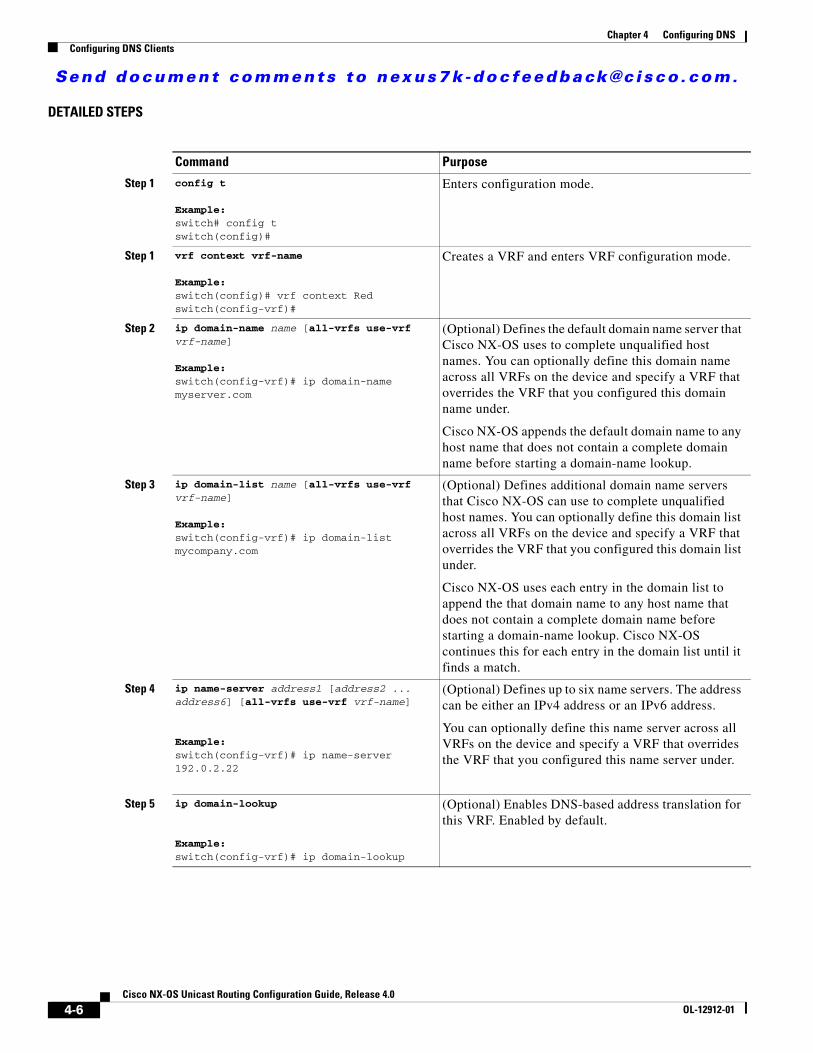
Send document comments to nexus7k -doc feedback@c i sco .com.
Chapter 4 Configuring DNSConfiguring DNS Clients
DETAILED STEPS
Command Purpose
Step 1 config t
Example:switch# config tswitch(config)#
Enters configuration mode.
Step 1 vrf context vrf-name
Example:switch(config)# vrf context Redswitch(config-vrf)#
Creates a VRF and enters VRF configuration mode.
Step 2 ip domain-name name [all-vrfs use-vrf vrf-name]
Example:switch(config-vrf)# ip domain-name myserver.com
(Optional) Defines the default domain name server that Cisco NX-OS uses to complete unqualified host names. You can optionally define this domain name across all VRFs on the device and specify a VRF that overrides the VRF that you configured this domain name under.
Cisco NX-OS appends the default domain name to any host name that does not contain a complete domain name before starting a domain-name lookup.
Step 3 ip domain-list name [all-vrfs use-vrf vrf-name]
Example:switch(config-vrf)# ip domain-list mycompany.com
(Optional) Defines additional domain name servers that Cisco NX-OS can use to complete unqualified host names. You can optionally define this domain list across all VRFs on the device and specify a VRF that overrides the VRF that you configured this domain list under.
Cisco NX-OS uses each entry in the domain list to append the that domain name to any host name that does not contain a complete domain name before starting a domain-name lookup. Cisco NX-OS continues this for each entry in the domain list until it finds a match.
Step 4 ip name-server address1 [address2 ... address6] [all-vrfs use-vrf vrf-name]
Example:switch(config-vrf)# ip name-server 192.0.2.22
(Optional) Defines up to six name servers. The address can be either an IPv4 address or an IPv6 address.
You can optionally define this name server across all VRFs on the device and specify a VRF that overrides the VRF that you configured this name server under.
Step 5 ip domain-lookup
Example:switch(config-vrf)# ip domain-lookup
(Optional) Enables DNS-based address translation for this VRF. Enabled by default.
4-6Cisco NX-OS Unicast Routing Configuration Guide, Release 4.0
OL-12912-01

Send document comments to nexus7k -doc feedback@c i sco .com.
Chapter 4 Configuring DNSVerifying the DNS Client Configuration
The following example shows how to configure a default domain name and enable DNS lookup within a VRF:
switch# config tswitch(config)# vrf context Redswitch(config-vrf)# ip domain-name cisco.com 192.0.2.1 all-vrfs use-vrf managementswitch(config-vrf)# ip domain-lookupswitch(config-vrf)# copy running-config startup-config
Verifying the DNS Client ConfigurationTo verify the DNS client configuration, use the following commands:
DNS Client Example Configuration This example establishes a domain list with several alternate domain names:
ip domain list csi.comip domain list telecomprog.eduip domain list merit.edu
This example configures the host name-to-address mapping process and specifies IP DNS-based translation, The example also configures the addresses of the name servers and the default domain name.
ip domain lookupip name-server 192.168.1.111 192.168.1.2ip domain name cisco.com
Default SettingsTable 4-1 lists the default settings for DNS Client parameters.
Step 6 show hosts
Example:switch(config)-vrf# show hosts
(Optional) Displays information about DNS.
Step 7 copy running-config startup-config
Example:switch(config-vrf)# copy running-config startup-config
(Optional) Saves this configuration change.
Command Purpose
Command Purpose
show hosts Displays information about DNS.
4-7Cisco NX-OS Unicast Routing Configuration Guide, Release 4.0
OL-12912-01

Send document comments to nexus7k -doc feedback@c i sco .com.
Chapter 4 Configuring DNSAdditional References
Additional ReferencesFor additional information related to implementing DNS Client, see the following sections:
• Related Documents, page 4-8
• Standards, page 4-8
Related Documents
Standards
Table 4-1 Default DNS Client Parameters
Parameters Default
DNS client Enabled
Related Topic Document Title
DNS Client CLI commands Cisco NX-OS Command Line Reference
VDCs and VRFs Cisco NX-OS Virtual Device Contexts Configuration Guide
Standards Title
No new or modified standards are supported by this feature, and support for existing standards has not been modified by this feature.
—
4-8Cisco NX-OS Unicast Routing Configuration Guide, Release 4.0
OL-12912-01

Send document comments to nexus7k -doc feedback@c i sco .com.
P A R T 2
Routing

Send document comments to nexus7k -doc feedback@c i sco .com.

Send document comments to nexus7k -doc feedback@c i sco .com.
Cisco NX-OOL-12912-01
C H A P T E R 5
Configuring OSPFv2This chapter describes how to configure Open Shortest Path First version 2 (OSPFv2) for IPv4 networks.
This chapter includes the following sections:
• Information About OSPFv2, page 5-1
• Licensing Requirements for OSPFv2, page 5-12
• Prerequisites for OSPFv2, page 5-13
• Configuration Guidelines and Limitations, page 5-13
• Configuring Basic OSPFv2, page 5-13
• Configuring Advanced OSPFv2, page 5-22
• Verifying the OSPFv2 Configuration, page 5-41
• Displaying OSPFv2 Statistics, page 5-42
• OSPFv2 Example Configuration, page 5-42
• Default Settings, page 5-42
• Additional References, page 5-43
Information About OSPFv2OSPFv2 is an IETF link-state protocol (see the “Link State Protocols” section on page 1-9) for IPv4 networks. An OSPFv2 router sends a special message, called a hello packet, out each OSPF-enabled interface to discover other OSPFv2 neighbor routers. Once a neighbor is discovered, the two routers compare information in the Hello packet to determine if the routers have compatible configurations. The neighbor routers attempt to establish adjacency, which means that the routers synchronize their link-state databases to ensure that they have identical OSPFv2 routing information. Adjacent routers share link-state advertisements (LSAs) that include information about the operational state of each link, the cost of the link, and any other neighbor information. The routers then flood these received LSAs out every OSPF-enabled interface so that all OSPFv2 routers eventually have identical link-state databases. When all OSPFv2 routers have identical link-state databases, the network is converged (see the “Convergence” section on page 1-6). Each router then uses Dijkstra’s Shortest Path First (SPF) algorithm to build its route table.
You can divide OSPFv2 networks into areas. Routers send most LSAs only within one area, which reduces the CPU and memory requirements for an OSPF-enabled router.
OSPFv2 supports IPv4, while OSPFv3 supports IPv6. For more information, see Chapter 6, “Configuring OSPFv3.”
5-1S Unicast Routing Configuration Guide, Release 4.0

Send document comments to nexus7k -doc feedback@c i sco .com.
Chapter 5 Configuring OSPFv2Information About OSPFv2
This section includes the following topics:
• Hello Packet, page 5-2
• Neighbors, page 5-2
• Adjacency, page 5-3
• Designated Routers, page 5-3
• Areas, page 5-4
• Link-State Advertisements, page 5-5
• OSPFv2 and the Unicast RIB, page 5-7
• Authentication, page 5-7
• Advanced Features, page 5-8
Hello PacketOSPFv2 routers periodically send Hello packets on every OSPF-enabled interface. The hello interval determines how frequently the router sends these Hello packets and is configured per interface. OSPFv2 uses Hello packets for the following tasks:
• Neighbor discovery
• Keepalives
• Bidirectional communications
• Designated router election (see the “Designated Routers” section on page 5-3)
The Hello packet contains information about the originating OSPFv2 interface and router, including the assigned OSPFv2 cost of the link, the hello interval, and optional capabilities of the originating router. An OSPFv2 interface that receives these Hello packets determines if the settings are compatible with the receiving interface settings. Compatible interfaces are considered neighbors and are added to the neighbor table (see the “Neighbors” section on page 5-2).
Hello packets also include a list of router IDs for the routers that the originating interface has communicated with. If the receiving interface sees its own router ID in this list, then bidirectional communication has been established between the two interfaces.
OSPFv2 uses Hello packets as a keepalive message to determine if a neighbor is still communicating. If a router does not receive a Hello packet by the configured dead interval (usually a multiple of the hello interval), then the neighbor is removed from the local neighbor table.
NeighborsAn OSPFv2 interface must have a compatible configuration with a remote interface before the two can be considered neighbors. The two OSPFv2 interfaces must match the following criteria:
• Hello interval
• Dead interval
• Area ID (see the “Areas” section on page 5-4)
• Authentication
• Optional capabilities
5-2Cisco NX-OS Unicast Routing Configuration Guide, Release 4.0
OL-12912-01

Send document comments to nexus7k -doc feedback@c i sco .com.
Chapter 5 Configuring OSPFv2Information About OSPFv2
If there is a match, the following information is entered into the neighbor table:
• Neighbor ID—The router ID of the neighbor.
• Priority—Priority of the neighbor. The priority is used for designated router election (see the “Designated Routers” section on page 5-3).
• State—Indication of whether the neighbor has just been heard from, is in the process of setting up bidirectional communications, is sharing the link-state information, or has achieved full adjacency.
• Dead time—Indication of the time since the last Hello packet was received from this neighbor.
• IP Address—The IP address of the neighbor.
• Designated Router—Indication of whether the neighbor has been declared as the designated router or as the backup designated router (see the “Designated Routers” section on page 5-3).
• Local interface—The local interface that received the Hello packet for this neighbor.
AdjacencyNot all neighbors establish adjacency. Depending on the network type and designated router establishment, some neighbors become fully adjacent and share LSAs with all their neighbors, while other neighbors do not. For more information, see the “Designated Routers” section on page 5-3.
Adjacency is established using Database Description packets, Link State Request packets, and Link State Update packets in OSPF. The Database Description packet includes just the LSA headers from the link-state database of the neighbor (see the “Link-State Database” section on page 5-7). The local router compares these headers with its own link-state database and determines which LSAs are new or updated. The local router sends a Link State Request packet for each LSA that it needs new or updated information on. The neighbor responds with a Link State Update packet. This exchange continues until both routers have the same link-state information.
Designated RoutersNetworks with multiple routers present a unique situation for OSPF. If every router floods the network with LSAs, the same link-state information will be sent from multiple sources. Depending on the type of network, OSPFv2 might use a single router, the designated router (DR), to control the LSA floods and represent the network to the rest of the OSPFv2 area (see the “Areas” section on page 5-4). If the DR fails, OSPFv2 selects a backup designated router (BDR). If the DR fails, OSPFv2 uses the BDR.
Network types are as follows:
• Point-to-point—A network that exists only between two routers. All neighbors on a point-to-point network establish adjacency and there is no DR.
• Broadcast—A network with multiple routers that can communicate over a shared medium that allows broadcast traffic, such as Ethernet. OSPFv2 routers establish a DR and BDR that controls LSA flooding on the network. OSPFv2 uses the well-known IPv4 multicast addresses 224.0.0.5 and a MAC address of 0100.5300.0005 to communicate with neighbors.
The DR and BDR are selected based on the information in the Hello packet. When an interface sends a Hello packet, it sets the priority field and the DR and BDR field if it knows who the DR and BDR are. The routers follow an election procedure based on which routers declare themselves in the DR and BDR fields and the priority field in the Hello packet. As a final tie breaker, OSPFv2 chooses the highest router IDs as the DR and BDR.
5-3Cisco NX-OS Unicast Routing Configuration Guide, Release 4.0
OL-12912-01

Send document comments to nexus7k -doc feedback@c i sco .com.
Chapter 5 Configuring OSPFv2Information About OSPFv2
All other routers establish adjacency with the DR and the BDR and use the IPv4 multicast address 224.0.0.6 to send LSA updates to the DR and BDR. Figure 5-1 shows this adjacency relationship between all routers and the DR.
DRs are based on a router interface. A router might be the DR for one network and not for another network on a different interface.
Figure 5-1 DR in Multi-Access Network
AreasYou can limit the CPU and memory requirements that OSPFv2 puts on the routers by dividing an OSPFv2 network into areas. An area is a logical division of routers and links within an OSPFv2 domain that creates separate subdomains. LSA flooding is contained within an area, and the link-state database is limited to links within the area. You can assign an area ID to the interfaces within the defined area. The Area ID is a 32-bit value that can be expressed as a number or in dotted decimal notation, such as 10.2.3.1.
If you define more than one area in an OSPFv2 network, you must also define the backbone area, which has the reserved area ID of 0. If you have more than one area, then one or more routers become area border routers (ABRs). An ABR connects to both the backbone area and at least one other defined area (see Figure 5-2).
Router A Router B Router C
Router ERouter Dor DR
= Multi-access network= Logical connectivity to Designated Router for OSPF 18
2982
5-4Cisco NX-OS Unicast Routing Configuration Guide, Release 4.0
OL-12912-01

Send document comments to nexus7k -doc feedback@c i sco .com.
Chapter 5 Configuring OSPFv2Information About OSPFv2
Figure 5-2 OSPFv2 Areas
The ABR has a separate link-state database for each area to which it connects. The ABR sends Network Summary (type 3) LSAs (see the “Route Summarization” section on page 5-10) from one connected area to the backbone area. The backbone area sends summarized information about one area to another area. In Figure 5-2, Area 0 sends summarized information about Area 5 to Area 3.
OSPFv2 defines one other router type: the autonomous system boundary router (ASBR). This router connects an OSPFv2 area to another autonomous system. An autonomous system is a network controlled by a single technical administration entity. OSPFv2 can redistribute its routing information into another autonomous system or receive redistributed routes from another autonomous system. For more information, see “Advanced Features” section on page 5-8.)
Link-State AdvertisementsOSPFv2 uses link-state advertisements (LSAs) to build its routing table.
This section includes the following topics:
• LSA Types, page 5-5
• Link Cost, page 5-6
• Flooding and LSA Group Pacing, page 5-6
• Link-State Database, page 5-7
• Opaque LSAs, page 5-7
LSA Types
Table 5-1 shows the LSA types supported by Cisco NX-OS.
ABR1
ABR2
Area 0 Area 3
Area 5
1829
83
5-5Cisco NX-OS Unicast Routing Configuration Guide, Release 4.0
OL-12912-01

Send document comments to nexus7k -doc feedback@c i sco .com.
Chapter 5 Configuring OSPFv2Information About OSPFv2
Link Cost
Each OSPFv2 interface is assigned a link cost. The cost is an arbitrary number. By default, Cisco NX-OS assigns a cost that is the configured reference bandwidth divided by the interface bandwidth. By default, the reference bandwidth is 40 Gb/s. The link cost is carried in the LSA updates for each link.
Flooding and LSA Group Pacing
When an OSPFv2 router receives an LSA, it forwards that LSA out every OSPF-enabled interface, flooding the OSPFv2 area with this information. This LSA flooding guarantees that all routers in the network have identical routing information. LSA flooding depends on the OSPFv2 area configuration (see the “Areas” section on page 5-4). The LSAs are flooded based on the link-state refresh time (every 30 minutes by default). Each LSA has its own link-state refresh time.
You can control the flooding rate of LSA updates in your network by using the LSA group pacing feature. LSA group pacing can reduce high CPU or buffer utilization. This feature groups LSAs with similar link-state refresh times to allow OSPFv2 to pack multiple LSAs into an OSPFv2 Update message.
By default, LSAs with link-state refresh times within four minutes of each other are grouped together. You should lower this value for large link-state databases or raise it for smaller databases to optimize the OSPFv2 load on your network.
Table 5-1 LSA Types
Type Name Description
1 Router LSA LSA sent by every router. This LSA includes the state and the cost of all links and a list of all OSPFv2 neighbors on the link. Router LSAs trigger an SPF recalculation. Router LSAs are flooded to local OSPFv2 area.
2 Network LSA LSA sent by the DR. This LSA lists all routers in the multi-access network. Network LSAs trigger an SPF recalculation. See the “Designated Routers” section on page 5-3.
3 Network Summary LSA
LSA sent by the area border router to an external area for each destination in the local area. This LSA includes the link cost from the area border router to the local destination. See the “Areas” section on page 5-4.
4 ASBR Summary LSA
LSA sent by the area border router to an external area. This LSA advertises the link cost to the ASBR only. See the “Areas” section on page 5-4.
5 AS External LSA
LSA generated by the ASBR. This LSA includes the link cost to an external autonomous system destination. AS External LSAs are flooded throughout the autonomous system. See the “Areas” section on page 5-4.
7 NSSA External LSA
LSA generated by the ASBR within a not-so-stubby area (NSSA). This LSA includes the link cost to an external autonomous system destination. NSSA External LSAs are looded only within the local NSSA. See the “Areas” section on page 5-4.
9–11 Opaque LSAs LSA used to extend OSPF. See the “Opaque LSAs” section on page 5-7.
5-6Cisco NX-OS Unicast Routing Configuration Guide, Release 4.0
OL-12912-01
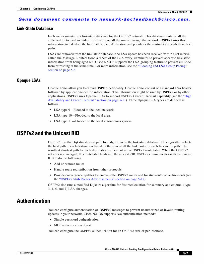
Send document comments to nexus7k -doc feedback@c i sco .com.
Chapter 5 Configuring OSPFv2Information About OSPFv2
Link-State Database
Each router maintains a link-state database for the OSPFv2 network. This database contains all the collected LSAs, and includes information on all the routes through the network. OSPFv2 uses this information to calculate the bast path to each destination and populates the routing table with these best paths.
LSAs are removed from the link-state database if no LSA update has been received within a set interval, called the MaxAge. Routers flood a repeat of the LSA every 30 minutes to prevent accurate link-state information from being aged out. Cisco NX-OS supports the LSA grouping feature to prevent all LSAs from refreshing at the same time. For more information, see the “Flooding and LSA Group Pacing” section on page 5-6.
Opaque LSAs
Opaque LSAs allow you to extend OSPF functionality. Opaque LSAs consist of a standard LSA header followed by application-specific information. This information might be used by OSPFv2 or by other applications. OSPFv2 uses Opaque LSAs to support OSPFv2 Graceful Restart capability (see the “High Availability and Graceful Restart” section on page 5-11). Three Opaque LSA types are defined as follows:
• LSA type 9—Flooded to the local network.
• LSA type 10—Flooded to the local area.
• LSA type 11—Flooded to the local autonomous system.
OSPFv2 and the Unicast RIBOSPFv2 runs the Dijkstra shortest path first algorithm on the link-state database. This algorithm selects the best path to each destination based on the sum of all the link costs for each link in the path. The resultant shortest path for each destination is then put in the OSPFv2 route table. When the OSPFv2 network is converged, this route table feeds into the unicast RIB. OSPFv2 communicates with the unicast RIB to do the following:
• Add or remove routes
• Handle route redistribution from other protocols
• Provide convergence updates to remove stale OSPFv2 routes and for stub router advertisements (see the “OSPFv2 Stub Router Advertisements” section on page 5-12)
OSPFv2 also runs a modified Dijkstra algorithm for fast recalculation for summary and external (type 3, 4, 5, and 7) LSA changes.
AuthenticationYou can configure authentication on OSPFv2 messages to prevent unauthorized or invalid routing updates in your network. Cisco NX-OS supports two authentication methods:
• Simple password authentication
• MD5 authentication digest
You can configure the OSPFv2 authentication for an OSPFv2 area or per interface.
5-7Cisco NX-OS Unicast Routing Configuration Guide, Release 4.0
OL-12912-01

Send document comments to nexus7k -doc feedback@c i sco .com.
Chapter 5 Configuring OSPFv2Information About OSPFv2
Simple Password Authentication
Simple password authentication uses a simple clear-text password that is sent as part of the OSPFv2 message. The receiving OSPFv2 router must be configured with the same clear-text password to accept the OSPFv2 message as a valid route update. Because the password is in clear text, anyone who can watch traffic on the network can learn the password.
MD5 Authentication
You should use MD5 authentication to authenticate OSPFv2 messages. You configure a password that is shared at the local router and all remote OSPFv2 neighbors. For each OSPFv2 message, Cisco NX-OS creates an MD5 one-way message digest based on the message itself and the encrypted password. The interface sends this digest with the OSPFv2 message. The receiving OSPFv2 neighbor validates the digest using the same encrypted password. If the message has not changed, the digest calculation is identical and the OSPFv2 message is considered valid.
MD5 authentication includes a sequence number with each OSPFv2 message to ensure that no message is replayed in the network.
Advanced FeaturesCisco NX-OS supports a number of advanced OSPFv2 features that enhance the usability and scalability of OSPFv2 in the network. This section includes the following topics:
• Stub Area, page 5-8
• Not-So-Stubby Area, page 5-9
• Virtual Links, page 5-9
• Route Redistribution, page 5-10
• Route Summarization, page 5-10
• High Availability and Graceful Restart, page 5-11
• OSPFv2 Stub Router Advertisements, page 5-12
• Multiple OSPFv2 Instances, page 5-12
• SPF Optimization, page 5-12
• Virtualization Support, page 5-12
Stub Area
You can limit the amount of external routing information that floods an area by making it a stub area. A stub area is an area that does not allow AS External (type 5) LSAs (see the “Link-State Advertisements” section on page 5-5). These LSAs are usually flooded throughout the local autonomous system to propagate external route information. Stub areas have the following requirements:
• All routers in the stub area are stub routers. See the “Stub Routing” section on page 1-7.
• No ASBR routers exist in the stub area.
• You cannot configure virtual links in the stub area.
Figure 5-3 shows an example of an OSPFv2 autonomous system where all routers in Area 10 have to go through the ABR to reach external autonomous systems. Area 10 can be configured as a stub area.
5-8Cisco NX-OS Unicast Routing Configuration Guide, Release 4.0
OL-12912-01

Send document comments to nexus7k -doc feedback@c i sco .com.
Chapter 5 Configuring OSPFv2Information About OSPFv2
Figure 5-3 Stub Area
Stub areas use a default route for all traffic that needs to go through the backbone area to the external autonomous system. The default route is 0.0.0.0 for IPv4.
Not-So-Stubby Area
A Not-so-Stubby Area (NSSA) is similar to a stub area, except that an NSSA allows you to import autonomous system external routes within an NSSA using redistribution. The NSSA ASBR redistributes these routes and generates NSSA External (type 7) LSAs that it floods throughout the NSSA. You can optionally configure the ABR that connects the NSSA to other areas to translate this NSSA External LSA to AS External (type 5) LSAs. The ABR then floods these AS External LSAs throughout the OSPFv2 autonomous system. Summarization and filtering are supported during the translation. See the “Link-State Advertisements” section on page 5-5 for details on NSSA External LSAs.
You can, for example, use NSSA to simplify administration if you are connecting a central site using OSPFv2 to a remote site that is using a different routing protocol. Before NSSA, the connection between the corporate site border router and a remote router could not be run as an OSPFv2 stub area because routes for the remote site could not be redistributed into a stub area. With NSSA, you can extend OSPFv2 to cover the remote connection by defining the area between the corporate router and remote router as an NSSA (see the “Configuring NSSA” section on page 5-26).
The backbone Area 0 cannot be an NSSA.
Virtual Links
Virtual links allow you to connect an OSPFv2 area ABR to a backbone area ABR when a direct physical connection is not available. Figure 5-4 shows a virtual link that connects Area 3 to the backbone area through Area 5.
ABR
ASBR
Backbone Area 10
1829
84
Stub area
5-9Cisco NX-OS Unicast Routing Configuration Guide, Release 4.0
OL-12912-01

Send document comments to nexus7k -doc feedback@c i sco .com.
Chapter 5 Configuring OSPFv2Information About OSPFv2
Figure 5-4 Virtual Links
You can also use virtual links to temporarily recover from a partitioned area, which occurs when a link within the area fails, isolating part of the area from reaching the designated ABR to the backbone area.
Route Redistribution
OSPFv2 can learn routes from other routing protocols by using route redistribution. See the “Route Redistribution” section on page 1-6. You configure OSPFv2 to assign a link cost for these redistributed routes or a default link cost for all redistributed routes.
Route redistribution uses route maps to control which external routes are redistributed. See Chapter 14, “Configuring Route Policy Manager,” for details on configuring route maps. You can use route maps to modify parameters in the AS External (type 5) and NSSA External (type 7) LSAs before these external routes are advertised in the local OSPFv2 autonomous system.
Route Summarization
Because OSPFv2 shares all learned routes with every OSPF-enabled router, you might want to use route summarization to reduce the number of unique routes that are flooded to every OSPF-enabled router. Route summarization simplifies route tables by replacing more-specific addresses with an address that represents all the specific addresses. For example, you can replace 10.1.1.0/24, 10.1.2.0/24, and 10.1.3.0/24 with one summary address, 10.1.0.0/16.
Typically, you would summarize at the boundaries of area border routers (ABRs). Although you could configure summarization between any two areas, it is better to summarize in the direction of the backbone so that the backbone receives all the aggregate addresses and injects them, already summarized, into other areas. The two types of summarization are as follows:
• Inter-area route summarization
• External route summarization
You configure inter-area route summarization on ABRs, summarizing routes between areas in the autonomous system. To take advantage of summarization, you should assign network numbers in areas in a contiguous way to be able to lump these addresses into one range.
ABR1ABR2
Area 0
Area 3Area 5
1829
85
5-10Cisco NX-OS Unicast Routing Configuration Guide, Release 4.0
OL-12912-01

Send document comments to nexus7k -doc feedback@c i sco .com.
Chapter 5 Configuring OSPFv2Information About OSPFv2
External route summarization is specific to external routes that are injected into OSPFv2 using route redistribution. You should make sure that external ranges that are being summarized are contiguous. Summarizating overlapping ranges from two different routers could cause packets to be sent to the wrong destination. Configure external route summarization on ASBRs that are redistributing routes into OSPF.
When you configure a summary address, Cisco NX-OS automatically configures a discard route for the summary address to prevent routing black holes and route loops.
High Availability and Graceful Restart
Cisco NX-OS supports high-availability. If a Cisco NX-OS system experiences a cold reboot, the network stops forwarding traffic to the system and removes the system from the network topology. In this scenario, OSPFv2 experiences a stateless restart, and removes all neighbor adjacencies on the local system. Cisco NX-OS applies the startup configuration and OSPFv2 rediscovers the neighbors and establishes the adjacencies again.
A platform with two supervisors that run Cisco NX-OS can experience a stateful supervisor switchover. Before the switchover happens, OSPFv2 initiates a graceful restart by announcing that OSPFv2 will be unavailable for some time. During a switchover, the network continues to forward traffic and keeps the system in the network topology.
After a switchover, Cisco NX-OS applies the running configuration, and OSPFv2 informs the neighbors that it is operational again. The neighbors help to reestablish adjacencies.
OSPFv2 automatically restarts if the process experiences problems. After the restart, OSPFv2 initiates a graceful restart so that the platform is not taken out of the network topology. If you manually restart OSPF, it performs a graceful restart, which is similar to a stateful switchover. The running configuration is applied in both cases.
A graceful restart, or nonstop forwarding (NSF), allows OSPFv2 to remain in the data forwarding path through a process restart. When OSPFv2 needs to restart, it first sends a link-local opaque (type 9) LSA, called a grace LSA (see the “Opaque LSAs” section on page 5-7). This restarting OSPFv2 platform is called NSF capable.
The grace LSA includes a grace period, which is a specified time that the neighbor OSPFv2 interfaces hold onto the LSAs from the restarting OSPFv2 interface. (Typically, OSPFv2 tears down the adjacency and discards all LSAs from a down or restarting OSPFv2 interface.) The participating neighbors, which are called NSF helpers, keep all LSAs that originate from the restarting OSPFv2 interface as if the interface were still adjacent.
When the restarting OSPFv2 interface is operational again, it rediscovers its neighbors, establishes adjacency, and starts sending its LSA updates again. At this point, the NSF helpers recognize that graceful restart has finished.
Note If the restarting OSPFv2 interface does not come back up before the end of the grace period, or if the network experiences a topology change, the OSPFv2 neighbors tear down adjacency with the restarting OSPFv2 and treat it as a normal OSPFv2 restart.
Note You must enable graceful restart to support in-service software upgrades (ISSU) for OSPFv2. If you disable graceful restart, Cisco NX-OS issues a warning that ISSU cannot be supported with this configuration.
5-11Cisco NX-OS Unicast Routing Configuration Guide, Release 4.0
OL-12912-01

Send document comments to nexus7k -doc feedback@c i sco .com.
Chapter 5 Configuring OSPFv2Licensing Requirements for OSPFv2
OSPFv2 Stub Router Advertisements
You can configure an OSPFv2 interface to act as a stub router using the OSPFv2 Stub Router Advertisements feature. Use this feature when you want to limit the OSPFv2 traffic through this router, such as when you want to introduce a new router to the network in a controlled manner or limit the load on a router that is already overloaded. You might also want to use this feature for various administrative or traffic engineering reasons.
OSPFv2 stub router advertisements do not remove the OSPFv2 router from the network topology, but they do prevent other OSPFv2 routers from using this router to route traffic to other parts of the network. Only the traffic that is destined for this router or directly connected to this router is sent.
OSPFv2 stub router advertisements mark all stub links (directly connected to the local router) to the cost of the local OSPFv2 interface. All remote links are marked with the maximum cost (0xFFFF).
Multiple OSPFv2 Instances
Cisco NX-OS supports multiple instances of the OSPFv2 protocol that run on the same node. You cannot configure multiple instances over the same interface. By default, every instance uses the same system router ID. You must manually configure the router ID for each instance if the instances are in the same OSPFv2 autonomous system.
SPF Optimization
Cisco NX-OS optimizes the SPF algorithm in the following ways:
• Partial SPF for Network (type 2) LSAs, Network Summary (type 3) LSAs, and AS External (type 5) LSAs—When there is a change on any of these LSAs, Cisco NX-OS performs a faster partial calculation rather than running the whole SPF calculation.
• SPF timers—You can configure different timers for controlling SPF calculations. These timers include exponential backoff for subsequent SPF calculations. The exponential backoff limits the CPU load of multiple SPF calculations.
Virtualization Support
OSPFv2 supports Virtual Routing and Forwarding instances (VRFs). VRFs exist within virtual device contexts (VDCs). By default, Cisco NX-OS places you in the default VDC and default VRF unless you specifically configure another VDC and VRF. You can have up to four instances of OSPFv2 in a VDC. For more information, see the Cisco NX-OS Virtual Device Context Configuration Guide and see Chapter 13, “Configuring Layer 3 Virtualization.”
Licensing Requirements for OSPFv2The following table shows the licensing requirements for this feature:
Product License Requirement
NX-OS OSPFv2 requires an Enterprise Services license. For a complete explanation of the NX-OS licensing scheme and how to obtain and apply licenses, see the Cisco NX-OS Licensing Guide.
5-12Cisco NX-OS Unicast Routing Configuration Guide, Release 4.0
OL-12912-01

Send document comments to nexus7k -doc feedback@c i sco .com.
Chapter 5 Configuring OSPFv2Prerequisites for OSPFv2
Prerequisites for OSPFv2OSPFv2 has the following prerequisites:
• You must be familiar with routing fundamentals to configure OSPF.
• You are logged on to the switch.
• You have configured at least one interface for IPv4 that is capable of communicating with a remote OSPFv2 neighbor.
• You have installed the Enterprise Services license.
• You have completed the OSPFv2 network strategy and planning for your network. For example, you must decide whether multiple areas are required.
• You have enabled the OSPF feature (see the “Enabling the OSPFv2 Feature” section on page 5-13).
• You have installed the Advanced Services license and entered the desired VDC (see to the Cisco NX-OS Virtual Device Context Configuration Guide) if youare configuring VDCs.
Configuration Guidelines and LimitationsOSPFv2 has the following configuration guidelines and limitations:
• You can have up to four instances of OSPFv2 in a VDC.
Note If you are familiar with the Cisco IOS CLI, be aware that the Cisco NX-OS commands for this feature might differ from the Cisco IOS commands that you would use.
Configuring Basic OSPFv2Configure OSPFv2 after you have designed your OSPFv2 network.
This section includes the following topics:
• Enabling the OSPFv2 Feature, page 5-13
• Creating an OSPFv2 Instance, page 5-14
• Configuring Optional Parameters on an OSPFv2 Instance, page 5-16
• Configuring Optional Parameters on an OSPFv2 Instance, page 5-16
• Configuring Networks in OSPFv2, page 5-16
• Configuring Authentication for an Area, page 5-19
Enabling the OSPFv2 FeatureYou must enable the OSPFv2 feature before you can configure OSPFv2.
BEFORE YOU BEGIN
Ensure that you are in the correct VDC (or use the switchto vdc command).
5-13Cisco NX-OS Unicast Routing Configuration Guide, Release 4.0
OL-12912-01

Send document comments to nexus7k -doc feedback@c i sco .com.
Chapter 5 Configuring OSPFv2Configuring Basic OSPFv2
SUMMARY STEPS
1. config t
2. feature ospf
3. copy running-config startup-config
DETAILED STEPS
Use the no feature ospf command to disable the OSPFv2 feature and remove all associated configuration.
Creating an OSPFv2 InstanceThe first step in configuring OSPFv2 is to create an OSPFv2 instance. You assign a unique instance tag for this OSPFv2 instance. The instance tag can be any string.
For more information about OSPFv2 instance parameters, see the “Configuring Advanced OSPFv2” section on page 5-22.
BEFORE YOU BEGIN
Ensure that you have enabled the OSPF feature (see the “Enabling the OSPFv2 Feature” section on page 5-13).
Use the show ip ospf instance-tag command to verify that the instance tag is not in use.
OSPFv2 must be able to obtain a router identifier (for example, a configured loopback address) or you must configure the router ID option.
Ensure that you are in the correct VDC (or use the switchto vdc command).
Command Purpose
Step 1 config t
Example:switch# config tswitch(config)#
Enters configuration mode.
Step 2 feature ospf
Example:switch(config)# feature ospf
Enables the OSPFv2 feature.
Step 3 copy running-config startup-config
Example:switch(config)# copy running-config startup-config
(Optional) Saves this configuration change.
Command Purpose
no feature ospf
Example:switch(config)# no feature ospf
Disables the OSPFv2 feature and removes all associated configuration.
5-14Cisco NX-OS Unicast Routing Configuration Guide, Release 4.0
OL-12912-01

Send document comments to nexus7k -doc feedback@c i sco .com.
Chapter 5 Configuring OSPFv2Configuring Basic OSPFv2
SUMMARY STEPS
1. config t
2. router ospf instance-tag
3. router-id ip-address
4. show ip ospf instance-tag
5. copy running-config startup-config
DETAILED STEPS
Use the no router ospf command to remove the OSPFv2 instance and all associated configuration.
Note This command does not remove OSPF configuration in interface mode. You must manually remove any OSPFv2 commands configured in interface mode.
Command Purpose
Step 1 config t
Example:switch# config tswitch(config)#
Enters configuration mode.
Step 2 router ospf instance-tag
Example:switch(config)# router ospf 201switch(config-router)#
Creates a new OSPFv2 instance with the configured instance tag.
Step 3 router-id ip-address
Example:switch(config-router)# router-id 209.0.2.1
(Optional) Configures the OSPFv2 router ID. This IP address identifies this OSPFv2 instance and must exist on a configured interface in the system.
Step 4 show ip ospf instance-tag
Example:switch(config-router)# show ip ospf 201
(Optional) Displays OSPF information.
Step 5 copy running-config startup-config
Example:switch(config)# copy running-config startup-config
(Optional) Saves this configuration change.
Command Purpose
no router ospf instance-tag
Example:switch(config)# no router ospf 201
Deletes the OSPF instance and the associated configuration.
5-15Cisco NX-OS Unicast Routing Configuration Guide, Release 4.0
OL-12912-01

Send document comments to nexus7k -doc feedback@c i sco .com.
Chapter 5 Configuring OSPFv2Configuring Basic OSPFv2
Configuring Optional Parameters on an OSPFv2 InstanceYou can configure optional parameters for OSPF.
For more information about OSPFv2 instance parameters, see the “Configuring Advanced OSPFv2” section on page 5-22.
BEFORE YOU BEGIN
Ensure that you have enabled the OSPF feature (see the “Enabling the OSPFv2 Feature” section on page 5-13).
OSPFv2 must be able to obtain a router identifier (for example, a configured loopback address) or you must configure the router ID option.
Ensure that you are in the correct VDC (or use the switchto vdc command).
DETAILED STEPS
You can configure the following optional parameters for OSPFv2 in router configuration mode:
The following example shows how to create an OSPFv2 instance:
switch# config tswitch(config)# router ospf 201switch(config-router)# copy running-config startup-config
Configuring Networks in OSPFv2You can configure a network to OSPFv2 by associating it through the interface that the router uses to connect to that network (see the “Neighbors” section on page 5-2). You can add all networks to the default backbone area (Area 0), or you can create new areas using any decimal number or an IP address.
Note All areas must connect to the backbone area either directly or through a virtual link.
Command Purpose
distance number
Example:switch(config-router)# distance 25
Configures the administrative distance for this OSPFv2 instance. The range is from 1 to 255. The default is 110.
log-adjacency-changes [detail]
Example:switch(config-router)# log-adjacency-changes
Generates a system message whenever a neighbor changes state.
maximum-paths path-number
Example:switch(config-router)# maximum-paths 4
Configures the maximum number of equal OSPFv2 paths to a destination in the route table. This command is used for load balancing. The range is from 1 to 16. The default is 8.
5-16Cisco NX-OS Unicast Routing Configuration Guide, Release 4.0
OL-12912-01

Send document comments to nexus7k -doc feedback@c i sco .com.
Chapter 5 Configuring OSPFv2Configuring Basic OSPFv2
Note OSPF is not enabled on an interface until you configure a valid IP address for that interface.
BEFORE YOU BEGIN
Ensure that you have enabled the OSPF feature (see the “Enabling the OSPFv2 Feature” section on page 5-13).
Ensure that you are in the correct VDC (or use the switchto vdc command).
SUMMARY STEPS
1. config t
2. interface interface-type slot/port
3. ip address ip-prefix/length
4. ip router ospf instance-tag area area-id [secondaries none]
5. show ip ospf instance-tag interface interface-type slot/port
6. copy running-config startup-config
DETAILED STEPS
Command Purpose
Step 1 config t
Example:switch# config tswitch(config)#
Enters configuration mode.
Step 2 interface interface-type slot/port
Example:switch(config)# interface ethernet 1/2switch(config-if)#
Enters interface configuration mode.
Step 3 ip address ip-prefix/length
Example:switch(config-if)# ip address 209.0.2.1/16
Assigns an IP address and subnet mask to this interface.
Step 4 ip router ospf instance-tag area area-id [secondaries none]
Example:switch(config-if)# ip router ospf 201 area 0
Adds the interface to the OSPFv2 instance and area.
5-17Cisco NX-OS Unicast Routing Configuration Guide, Release 4.0
OL-12912-01

Send document comments to nexus7k -doc feedback@c i sco .com.
Chapter 5 Configuring OSPFv2Configuring Basic OSPFv2
You can configure the following optional parameters for OSPFv2 in interface configuration mode:
Step 5 show ip ospf instance-tag interface interface-type slot/port
Example:switch(config-if)# show ip ospf 201 interface ethernet 1/2
(Optional) Displays OSPF information.
Step 6 copy running-config startup-config
Example:switch(config)# copy running-config startup-config
(Optional) Saves this configuration change.
Command Purpose
Command Purposeip ospf cost number
Example:switch(config-if)# ip ospf cost 25
Configures the OSPFv2 cost metric for this interface. The default is to calculate cost metric, based on reference bandwidth and interface bandwidth. The range is from 1 to 65535.
ip ospf dead-interval seconds
Example:switch(config-if)# ip ospf dead-interval 50
Configures the OSPFv2 dead interval, in seconds. The range is from 1 to 65535. The default is four times the hello interval, in seconds.
ip ospf hello-interval seconds
Example:switch(config-if)# ip ospf hello-interval 25
Configures the OSPFv2 hello interval, in seconds. The range is from 1 to 65535. The default is 10 seconds.
ip ospf mtu-ignore
Example:switch(config-if)# ip ospf mtu-ignore
Configures OSPFv2 to ignore any IP MTU mismatch with a neighbor. The default is to not establish adjacency if the neighbor MTU does not match the local interface MTU.
ip ospf passive-interface
Example:switch(config-if)# ip ospf passive-interface
Suppresses routing updates on the interface.
ip ospf priority number
Example:switch(config-if)# ip ospf priority 25
Configures the OSPFv2 priority, used to determine the DR for an area. The range is from 0 to 255. The default is 1. See the “Designated Routers” section on page 5-3.
ip ospf shutdown
Example:switch(config-if)# ip ospf shutdown
Shuts down the OSPFv2 instance on this interface.
5-18Cisco NX-OS Unicast Routing Configuration Guide, Release 4.0
OL-12912-01

Send document comments to nexus7k -doc feedback@c i sco .com.
Chapter 5 Configuring OSPFv2Configuring Basic OSPFv2
The following example shows how to add a network area 10 in OSPFv2 instance 201:
switch# config tswitch(config)# interface ethernet 1/2switch(config-if)# ip address 209.0.2.1/16switch(config-if)# ip router ospf 201 area 10switch(config-if)# copy running-config startup-config
Use the show ip ospf interface command to verify the interface configuration. Use the show ip ospf neighbor command to see the neighbors for this interface.
Configuring Authentication for an AreaYou can configure authentication for all networks in an area or for individual interfaces in the area. Interface authentication configuration overrides area authentication.
BEFORE YOU BEGIN
Ensure that you have enabled the OSPF feature (see the “Enabling the OSPFv2 Feature” section on page 5-13).
Ensure that all neighbors on an interface share the same authentication configuration, including the shared authentication key.
Create the key-chain for this authentication configuration. See the Cisco NX-OS Security Configuration Guide.
Ensure that you are in the correct VDC (or use the switchto vdc command).
SUMMARY STEPS
1. config t
2. router ospf instance-tag
3. area area-id authentication [message-digest]
4. interface interface-type slot/port
5. ip ospf authentication-key [0 | 3] key
or
ip ospf message-digest-key key-id md5 [0 | 3] key
6. show ip ospf instance-tag interface interface-type slot/port
7. copy running-config startup-config
5-19Cisco NX-OS Unicast Routing Configuration Guide, Release 4.0
OL-12912-01

Send document comments to nexus7k -doc feedback@c i sco .com.
Chapter 5 Configuring OSPFv2Configuring Basic OSPFv2
DETAILED STEPS
Configuring Authentication for an InterfaceYou can configure authentication for individual interfaces in the area. Interface authentication configuration overrides area authentication.
Command Purpose
Step 1 config t
Example:switch# config tswitch(config)#
Enters configuration mode.
Step 2 router ospf instance-tag
Example:switch(config)# router ospf 201switch(config-router)#
Creates a new OSPFv2 instance with the configured instance tag.
Step 3 area area-id authentication [message-digest]
Example:switch(config-router)# area 10 authentication
Configures the authentication mode for an area.
Step 4 interface interface-type slot/port
Example:switch(config-router)# interface ethernet 1/2switch(config-if)#
Enters interface configuration mode.
Step 5 ip ospf authentication-key [0 | 3] key
Example:switch(config-if)# ip ospf authentication-key 0 mypass
(Optional) Configures simple password authentication for this interface. Use this command if the authentication is not set to key-chain or message-digest. 0 configures the password in clear text. 3 configures the password as 3DES encrypted.
ip ospf message-digest-key key-id md5 [0 | 3] key
Example:switch(config-if)# ip ospf message-digest-key 21 md5 0 mypass
(Optional) Configures message digest authentication for this interface. Use this command if the authentication is set to message-digest. The key-id range is from 1 to 255. The MD5 option 0 configures the password in clear text and 3 configures the pass key as 3DES encrypted.
Step 6 show ip ospf instance-tag interface interface-type slot/port
Example:switch(config-if)# show ip ospf 201 interface ethernet 1/2
(Optional) Displays OSPF information.
Step 7 copy running-config startup-config
Example:switch(config)# copy running-config startup-config
(Optional) Saves this configuration change.
5-20Cisco NX-OS Unicast Routing Configuration Guide, Release 4.0
OL-12912-01

Send document comments to nexus7k -doc feedback@c i sco .com.
Chapter 5 Configuring OSPFv2Configuring Basic OSPFv2
BEFORE YOU BEGIN
Ensure that you have enabled the OSPF feature (see the “Enabling the OSPFv2 Feature” section on page 5-13).
Ensure that all neighbors on an interface share the same authentication configuration, including the shared authentication key.
Create the key-chain for this authentication configuration. See the Cisco NX-OS Security Configuration Guide.
Ensure that you are in the correct VDC (or use the switchto vdc command).
SUMMARY STEPS
1. config t
2. interface interface-type slot/port
3. ip ospf authentication [key-chain key-id | message-digest | null]
4. ip ospf authentication-key [0 | 3] key
or
ip ospf message-digest-key key-id md5 [0 | 3] key
5. show ip ospf instance-tag interface interface-type slot/port
6. copy running-config startup-config
DETAILED STEPS
Command Purpose
Step 1 config t
Example:switch# config tswitch(config)#
Enters configuration mode.
Step 2 interface interface-type slot/port
Example:switch(config)# interface ethernet 1/2switch(config-if)#
Enters interface configuration mode.
Step 3 ip ospf authentication [key-chain key-name | message-digest | null]
Example:switch(config-if)# ip ospf authentication message-digest
Configures interface authentication mode for OSPFv2. Overrides area-based authentication for this interface. All neighbors must share this authentication type.
See the Cisco NX-OS Security Configuration Guide, Release 4.0 for details on key chains.
5-21Cisco NX-OS Unicast Routing Configuration Guide, Release 4.0
OL-12912-01

Send document comments to nexus7k -doc feedback@c i sco .com.
Chapter 5 Configuring OSPFv2Configuring Advanced OSPFv2
The following example shows how to set an interface for simple, unencrypted passwords and set the password for Ethernet interface 1/2:
switch# config tswitch(config)# router ospf 201switch(config-router)# exitswitch(config)# interface ethernet 1/2switch(config-if)# ip router ospf 201 area 10switch(config-if)# ip ospf authentication switch(config-if)# ip ospf authentication-key 0 mypassswitch(config-if)# copy running-config startup-config
Configuring Advanced OSPFv2Configure OSPFv2 after you have designed your OSPFv2 network.
This section includes the following topics:
• Configuring Filter Lists for Border Routers, page 5-23
• Configuring Stub Areas, page 5-24
Step 4 ip ospf authentication-key [0 | 3 | 7] key
Example:switch(config-if)# ip ospf authentication-key 0 mypass
(Optional) Configures simple password authentication for this interface. Use this command if the authentication is not set to key-chain or message-digest.
The options are as follows:
• 0—configures the password in clear text.
• 3—configures the pass key as 3DES encrypted.
7—configures the key as Cisco type 7 encrypted.
Step 5 ip ospf message-digest-key key-id md5 [0 | 3 | 7] key
Example:switch(config-if)# ip ospf message-digest-key 21 md5 0 mypass
(Optional) Configures message digest authentication for this interface. Use this command if the authentication is set to message-digest.The key-id range is from 1 to 255. The MD5 options are as follows:
• 0—configures the password in clear text.
• 3—configures the pass key as 3DES encrypted.
• 7—configures the key as Cisco type 7 encrypted.
Step 6 show ip ospf instance-tag interface interface-type slot/port
Example:switch(config-if)# show router ospf 201 interface ethernet 1/2
(Optional) Displays OSPF information.
Step 7 copy running-config startup-config
Example:switch(config)# copy running-config startup-config
(Optional) Saves this configuration change.
Command Purpose
5-22Cisco NX-OS Unicast Routing Configuration Guide, Release 4.0
OL-12912-01

Send document comments to nexus7k -doc feedback@c i sco .com.
Chapter 5 Configuring OSPFv2Configuring Advanced OSPFv2
• Configuring a Totally Stubby Area, page 5-26
• Configuring NSSA, page 5-26
• Configuring Virtual Links, page 5-28
• Configuring Redistribution, page 5-30
• Configuring Route Summarization, page 5-32
• Configuring Stub Route Advertisements, page 5-33
• Modifying the Default Timers, page 5-34
• Configuring Graceful Restart, page 5-37
• Restarting an OSPFv2 Instance, page 5-38
• Configuring Graceful Restart, page 5-37
Configuring Filter Lists for Border RoutersYou can separate your OSPFv2 domain into a series of areas that contain related networks. All areas must connect to the backbone area through an area border router (ABR). OSPFv2 domains can connect to external domains as well, through an autonomous system border router (ASBR). See the “Areas” section on page 5-4.
ABRs have the following optional configuration parameters:
• Area range—Configures route summarization between areas. See the “Configuring Route Summarization” section on page 5-32.
• Filter list—Filters the Network Summary (type 3) LSAs on an ABR that are allowed in from an external area.
ASBRs also support filter lists.
BEFORE YOU BEGIN
Ensure that you have enabled the OSPF feature (see the “Enabling the OSPFv2 Feature” section on page 5-13).
Create the route map that the filter list uses to filter IP prefixes in incoming or outgoing Network Summary (type 3) LSAs. See Chapter 14, “Configuring Route Policy Manager.”
Ensure that you are in the correct VDC (or use the switchto vdc command).
SUMMARY STEPS
1. config t
2. router ospf instance-tag
3. area area-id filter-list route-map map-name {in | out}
4. show ip ospf policy statistics
5. copy running-config startup-config
5-23Cisco NX-OS Unicast Routing Configuration Guide, Release 4.0
OL-12912-01

Send document comments to nexus7k -doc feedback@c i sco .com.
Chapter 5 Configuring OSPFv2Configuring Advanced OSPFv2
DETAILED STEPS
The following example shows how to configure a filter list in Area 10:
switch# config tswitch(config)# router ospf 201switch(config-router)# area 10 filter-list route-map FilterLSAs inswitch(config-router)# copy running-config startup-config
Configuring Stub AreasYou can configure a stub area for part of an OSPFv2 domain where external traffic is not necessary. Stub areas block AS External (type 5) LSAs, limiting unnecessary routing to and from selected networks. See the “Stub Area” section on page 5-8. You can optionally block all summary routes from going into the stub area.
BEFORE YOU BEGIN
Ensure that you have enabled the OSPF feature (see the “Enabling the OSPFv2 Feature” section on page 5-13).
Ensure that there are no virtual links or ASBRs in the proposed stub area.
Ensure that you are in the correct VDC (or use the switchto vdc command).
Command Purpose
Step 1 config t
Example:switch# config tswitch(config)#
Enters configuration mode.
Step 2 router ospf instance-tag
Example:switch(config)# router ospf 201switch(config-router)#
Creates a new OSPFv2 instance with the configured instance tag.
Step 3 area area-id filter-list route-map map-name {in | out}
Example:switch(config-router)# area 10 filter-list route-map FilterLSAs in
Filters incoming or outgoing Network Summary (type 3) LSAs on an ABR.
Step 4 show ip ospf policy statistics area id filter-list {in | out}
Example:switch(config-if)# show ip ospf policy statistics area 10 filter-list in
(Optional) Displays OSPF policy information.
Step 5 copy running-config startup-config
Example:switch(config)# copy running-config startup-config
(Optional) Saves this configuration change.
5-24Cisco NX-OS Unicast Routing Configuration Guide, Release 4.0
OL-12912-01
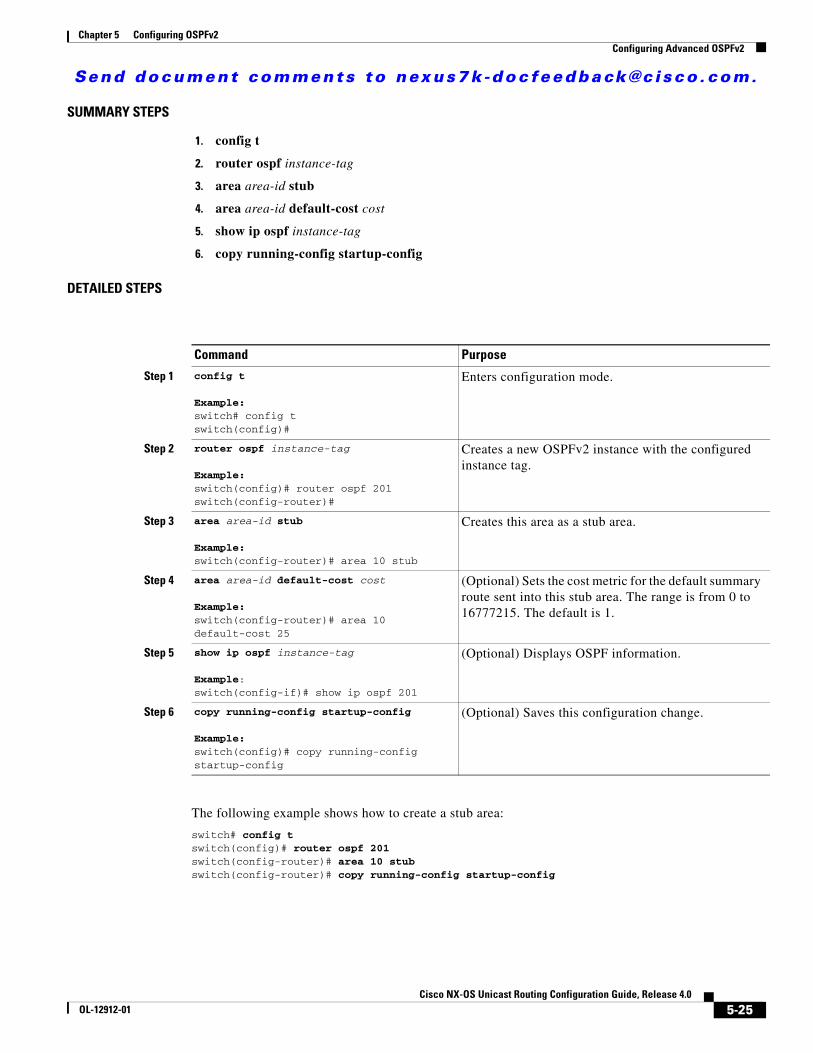
Send document comments to nexus7k -doc feedback@c i sco .com.
Chapter 5 Configuring OSPFv2Configuring Advanced OSPFv2
SUMMARY STEPS
1. config t
2. router ospf instance-tag
3. area area-id stub
4. area area-id default-cost cost
5. show ip ospf instance-tag
6. copy running-config startup-config
DETAILED STEPS
The following example shows how to create a stub area:
switch# config tswitch(config)# router ospf 201switch(config-router)# area 10 stub switch(config-router)# copy running-config startup-config
Command Purpose
Step 1 config t
Example:switch# config tswitch(config)#
Enters configuration mode.
Step 2 router ospf instance-tag
Example:switch(config)# router ospf 201switch(config-router)#
Creates a new OSPFv2 instance with the configured instance tag.
Step 3 area area-id stub
Example:switch(config-router)# area 10 stub
Creates this area as a stub area.
Step 4 area area-id default-cost cost
Example:switch(config-router)# area 10 default-cost 25
(Optional) Sets the cost metric for the default summary route sent into this stub area. The range is from 0 to 16777215. The default is 1.
Step 5 show ip ospf instance-tag
Example:switch(config-if)# show ip ospf 201
(Optional) Displays OSPF information.
Step 6 copy running-config startup-config
Example:switch(config)# copy running-config startup-config
(Optional) Saves this configuration change.
5-25Cisco NX-OS Unicast Routing Configuration Guide, Release 4.0
OL-12912-01

Send document comments to nexus7k -doc feedback@c i sco .com.
Chapter 5 Configuring OSPFv2Configuring Advanced OSPFv2
Configuring a Totally Stubby AreaYou can create a totally stubby area and prevent all summary route updates from going into the stub area.
To create a totally stubby area , use the following command in router configuration mode:
Configuring NSSA You can configure an NSSA for part of an OSPFv2 domain where limited external traffic is required. See the “Not-So-Stubby Area” section on page 5-9. You can optionally translate this external traffic to an AS External (type 5) LSA and flood the OSPFv2 domain with this routing information. An NSSA can be configured with the following optional parameters:
• No redistribution—Redistributed routes bypass the NSSA and are redistributed to other areas in the OSPFv2 autonomous system. Use this option when the NSSA ASBR is also an ABR.
• Default information originate—Generates an NSSA External (type 7) LSA for a default route to the external autonomous system. Use this option on an NSSA ASBR if the ASBR contains the default route in the routing table. This option can be used on an NSSA ABR whether or not the ABR contains the default route in the routing table.
• Route map—Filters the external routes so that only those routes that you want are flooded throughout the NSSA and other areas.
• Translate—Translates NSSA External LSAs to AS External LSAs for areas outside the NSSA. Use this command on an NSSA ABR to flood the redistributed routes throughout the OSPFv2 autonomous system. You can optionally suppress the forwarding address in these AS External LSAs. If you choose this option, the forwarding address is set to 0.0.0.0.
• No summary—Blocks all summary routes from flooding the NSSA. Use this option on the NSSA ABR.
BEFORE YOU BEGIN
Ensure that you have enabled the OSPF feature (see the “Enabling the OSPFv2 Feature” section on page 5-13).
Ensure that there are no virtual links in the proposed NSSA and that it is not the backbone area.
Ensure that you are in the correct VDC (or use the switchto vdc command).
SUMMARY STEPS
1. config t
2. router ospf instance-tag
3. area area-id nssa [no-redistribution] [default-information-originate [route-map map-name]] [no-summary] [translate type7 {always | never} [suppress-fa]]
Command Purpose
area area-id stub no-summary
Example:switch(config-router)# area 20 stub no-summary
Creates this area as a totally stubby area.
5-26Cisco NX-OS Unicast Routing Configuration Guide, Release 4.0
OL-12912-01

Send document comments to nexus7k -doc feedback@c i sco .com.
Chapter 5 Configuring OSPFv2Configuring Advanced OSPFv2
4. area area-id default-cost cost
5. show ip ospf instance-tag
6. copy running-config startup-config
DETAILED STEPS
The following example shows how to create an NSSA that blocks all summary route updates:
switch# config tswitch(config)# router ospf 201switch(config-router)# area 10 nssa no-summaryswitch(config-router)# copy running-config startup-config
The following example shows how to create an NSSA that generates a default route:
switch# config tswitch(config)# router ospf 201switch(config-router)# area 10 nssa default-info-originateswitch(config-router)# copy running-config startup-config
Command Purpose
Step 1 config t
Example:switch# config tswitch(config)#
Enters configuration mode.
Step 2 router ospf instance-tag
Example:switch(config)# router ospf 201switch(config-router)#
Creates a new OSPFv2 instance with the configured instance tag.
Step 3 area area-id nssa [no-redistribution] [default-information-originate][route-map map-name]] [no-summary] [translate type7 {always | never} [suppress-fa]]
Example:switch(config-router)# area 10 nssa
Creates this area as an NSSA.
Step 4 area area-id default-cost cost
Example:switch(config-router)# area 10 default-cost 25
(Optional) Sets the cost metric for the default summary route sent into this NSSA.
Step 5 show ip ospf instance-tag
Example:switch(config-if)# show ip ospf 201
(Optional) Displays OSPF information.
Step 6 copy running-config startup-config
Example:switch(config)# copy running-config startup-config
(Optional) Saves this configuration change.
5-27Cisco NX-OS Unicast Routing Configuration Guide, Release 4.0
OL-12912-01

Send document comments to nexus7k -doc feedback@c i sco .com.
Chapter 5 Configuring OSPFv2Configuring Advanced OSPFv2
The following example shows how to create an NSSA that filters external routes and blocks all summary route updates:
switch# config tswitch(config)# router ospf 201switch(config-router)# area 10 nssa route-map ExternalFilter no-summaryswitch(config-router)# copy running-config startup-config
The following example shows how to create an NSSA that always translates NSSA External (type 5) LSAs to AS External (type 7) LSAs:
switch# config tswitch(config)# router ospf 201switch(config-router)# area 10 nssa translate type 7 alwaysswitch(config-router)# copy running-config startup-config
Configuring Virtual LinksA virtual link connects an isolated area to the backbone area through an intermediate area. See the “Virtual Links” section on page 5-9. You can configure the following optional parameters for a virtual link:
• Authentication—Sets a simple password or MD5 message digest authentication and associated keys.
• Dead interval—Sets the time that a neighbor waits for a Hello packet before declaring the local router as dead and tearing down adjacencies.
• Hello interval—Sets the time between successive Hello packets.
• Retransmit interval—Sets the estimated time between successive LSAs.
• Transmit delay—Sets the estimated time to transmit an LSA to a neighbor.
Note You must configure the virtual link on both routers involved before the link becomes active.
You cannot add a virtual link to a stub area.
BEFORE YOU BEGIN
Ensure that you have enabled the OSPF feature (see the “Enabling the OSPFv2 Feature” section on page 5-13).
Ensure that you are in the correct VDC (or use the switchto vdc command).
SUMMARY STEPS
1. config t
2. router ospf instance-tag
3. area area-id virtual-link router-id
4. show ip ospf virtual-link [brief]
5. copy running-config startup-config
5-28Cisco NX-OS Unicast Routing Configuration Guide, Release 4.0
OL-12912-01

Send document comments to nexus7k -doc feedback@c i sco .com.
Chapter 5 Configuring OSPFv2Configuring Advanced OSPFv2
DETAILED STEPS
You can configure the following optional commands in virtual link configuration mode:
Command Purpose
Step 1 config t
Example:switch# config tswitch(config)#
Enters configuration mode.
Step 2 router ospf instance-tag
Example:switch(config)# router ospf 201switch(config-router)#
Creates a new OSPFv2 instance with the configured instance tag.
Step 3 area area-id virtual-link router-id
Example:switch(config-router)# area 10 virtual-link 10.1.2.3switch(config-router-vlink)#
Creates one end of a virtual link to a remote router. You must create the virtual link on that remote router to complete the link.
Step 4 show ip ospf virtual-link [brief]
Example:switch(config-router-vlink)# show ip ospf virtual-link
(Optional) Displays OSPF virtual link information.
Step 5 copy running-config startup-config
Example:switch(config-router-vlink)# copy running-config startup-config
(Optional) Saves this configuration change.
Command or Action Purpose
authentication [key-chain key-id | message-digest | null]
Example:switch(config-router-vlink)# authentication message-digest
(Optional) Overrides area-based authentication for this virtual link.
authentication-key [0 | 3] key
Example:switch(config-router-vlink)# authentication-key 0 mypass
(Optional) Configures a simple password for this virtual link. Use this command if the authentication is not set to key-chain or message-digest. 0 configures the password in clear text. 3 configures the password as 3DES encrypted.
dead-interval seconds
Example:switch(config-router-vlink)# dead-interval 50
(Optional) Configures the OSPFv2 dead interval, in seconds. The range is from 1 to 65535. The default is four times the hello interval, in seconds.
hello-interval seconds
Example:switch(config-router-vlink)# hello-interval 25
(Optional) Configures the OSPFv2 hello interval, in seconds. The range is from 1 to 65535. The default is 10 seconds.
5-29Cisco NX-OS Unicast Routing Configuration Guide, Release 4.0
OL-12912-01

Send document comments to nexus7k -doc feedback@c i sco .com.
Chapter 5 Configuring OSPFv2Configuring Advanced OSPFv2
The following example shows how to create a simple virtual link between two ABRs.
The configuration for ABR 1 (router ID 27.0.0.55) is as follows:
switch# config tswitch(config)# router ospf 201switch(config-router)# area 10 virtual-link 10.1.2.3switch(config-router)# copy running-config startup-config
The configuration for ABR 2 (Router ID 10.1.2.3) is as follows:
switch# config tswitch(config)# router ospf 101switch(config-router)# area 10 virtual-link 27.0.0.55switch(config-router)# copy running-config startup-config
Configuring RedistributionYou can redistribute routes learned from other routing protocols into an OSPFv2 autonomous system through the ASBR.
You can configure the following optional parameters for route redistribution in OSPF:
• Default information originate—Generates an AS External (type 5) LSA for a default route to the external autonomous system.
• Default metric—Sets all redistributed routes to the same cost metric.
BEFORE YOU BEGIN
Ensure that you have enabled the OSPF feature (see the “Enabling the OSPFv2 Feature” section on page 5-13).
Create the necessary route maps used for redistribution.
Ensure that you are in the correct VDC (or use the switchto vdc command).
SUMMARY STEPS
1. config t
message-digest-key key-id md5 [0 | 3] key
Example:switch(config-router-vlink)#message-digest-key 21 md5 0 mypass
(Optional) Configures message digest authentication for this virtual link. Use this command if the authentication is set to message-digest. 0 configures the password in cleartext. 3 configures the pass key as 3DES encrypted.
retransmit-interval seconds
Example:switch(config-router-vlink)# retransmit-interval 50
(Optional) Configures the OSPFv2 retransmit interval, in seconds. The range is from 1 to 65535. The default is 5.
transmit-delay seconds
Example:switch(config-router-vlink)# transmit-delay 2
(Optional) Configures the OSPFv2 transmit-delay, in seconds. The range is from 1 to 450. The default is 1.
Command or Action Purpose
5-30Cisco NX-OS Unicast Routing Configuration Guide, Release 4.0
OL-12912-01

Send document comments to nexus7k -doc feedback@c i sco .com.
Chapter 5 Configuring OSPFv2Configuring Advanced OSPFv2
2. router ospf instance-tag
3. redistribute {bgp id | direct | eigrp id | isis id | ospf id | rip id | static} route-map map-name
4. default-information originate [always] [route-map map-name]
5. default-metric cost
6. exit
7. copy running-config startup-config
DETAILED STEPS
The following example shows how to redistribute the Border Gateway Protocol (BGP) into OSPF:
switch# config tswitch(config)# router ospf 201switch(config-router)# redistribute bgp route-map FilterExternalBGPswitch(config-router)# copy running-config startup-config
Command Purpose
Step 1 config t
Example:switch# config tswitch(config)#
Enters configuration mode.
Step 2 router ospf instance-tag
Example:switch(config)# router ospf 201switch(config-router)#
Creates a new OSPFv2 instance with the configured instance tag.
Step 3 redistribute {bgp id | direct | eigrp id | isis id | ospf id | rip id | static} route-map map-name
Example:switch(config-router)# redistribute bgp route-map FilterExternalBGP
Redistributes the selected protocol into OSPF through the configured route map.
Step 4 default-information originate [always] [route-map map-name]
Example:switch(config-router)# default-information-originate route-map DefaultRouteFilter
Creates a default route into this OSPF domain. always == always generate the default. Conditinally (if the default route is in the rib) route-map - generate default if route map returns true. (add to redistribut concept)
Step 5 default-metric cost
Example:switch(config-router)# default-metric 25
Sets the cost metric for the redistributed routes.
Step 6 copy running-config startup-config
Example:switch(config-router)# copy running-config startup-config
(Optional) Saves this configuration change.
5-31Cisco NX-OS Unicast Routing Configuration Guide, Release 4.0
OL-12912-01

Send document comments to nexus7k -doc feedback@c i sco .com.
Chapter 5 Configuring OSPFv2Configuring Advanced OSPFv2
Configuring Route SummarizationYou can configure route summarization for inter-area routes by configuring an address range that is summarized. You can also configure route summarization for external, redistributed routes by configuring a summary address for those routes on an ASBR. See the “Route Summarization” section on page 5-10.
BEFORE YOU BEGIN
Ensure that you have enabled the OSPF feature (see the “Enabling the OSPFv2 Feature” section on page 5-13).
Ensure that you are in the correct VDC (or use the switchto vdc command).
SUMMARY STEPS
1. config t
2. router ospf instance-tag
3. area area-id range ip-prefix/length [no-advertise]
or
4. summary-address ip-prefix/length [no-advertise | tag tag-id]
5. show ip ospf summary-address
6. copy running-config startup-config
DETAILED STEPS
Command Purpose
Step 1 config t
Example:switch# config tswitch(config)#
Enters configuration mode.
Step 2 router ospf instance-tag
Example:switch(config)# router ospf 201switch(config-router)#
Creates a new OSPFv2 instance with the configured instance tag.
Step 3 area area-id range ip-prefix/length [no-advertise]
Example:switch(config-router)# area 10 range 10.3.0.0/16
Creates a summary address on an ABR for a range of addresses and optionally does note advertise this summary address in a Network Summary (type 3) LSA.
Step 4 summary-address ip-prefix/length [no-advertise | tag tag]
Example:switch(config-router)# summary-address 10.5.0.0/16 tag 2
Creates a summary address on an ASBR for a range of addresses and optionally assigns a tag for this summary address that can be used for redistribution with route maps.
5-32Cisco NX-OS Unicast Routing Configuration Guide, Release 4.0
OL-12912-01

Send document comments to nexus7k -doc feedback@c i sco .com.
Chapter 5 Configuring OSPFv2Configuring Advanced OSPFv2
The following example shows how to create summary addresses between areas on an ABR:
switch# config tswitch(config)# router ospf 201switch(config-router)# area 10 range 10.3.0.0/16switch(config-router)# copy running-config startup-config
The following example shows how to create summary addresses on an ASBR;
switch# config tswitch(config)# router ospf 201switch(config-router)# summary-address 10.5.0.0/16switch(config-router)# copy running-config startup-config
Configuring Stub Route AdvertisementsUse Stub Route Advertisements when you want to limit the OSPFv2 traffic through this router for a short time. See the “OSPFv2 Stub Router Advertisements” section on page 5-12.
Stub route advertisements can be configured with the following optional parameters:
• On startup—Sends stub route advertisements for the specified announce time.
• Wait for BGP—Sends stub router advertisements until BGP converges.
BEFORE YOU BEGIN
Ensure that you have enabled the OSPF feature (see the “Enabling the OSPFv2 Feature” section on page 5-13).
Ensure that you are in the correct VDC (or use the switchto vdc command).
SUMMARY STEPS
1. config t
2. router ospf instance-tag
3. max-metric router-lsa [on-startup [announce-time] [wait-for bgp tag]]
4. copy running-config startup-config
Note You should not save the running configuration of a router when it is configured for a graceful shutdown because the router will continue to advertise a maximum metric after it is reloaded.
Step 5 show ip ospf summary-address
Example:switch(config-router)# show ip ospf summary-address
(Optional) Displays information about OSPF summary addresses.
Step 6 copy running-config startup-config
Example:switch(config-router)# copy running-config startup-config
(Optional) Saves this configuration change.
Command Purpose
5-33Cisco NX-OS Unicast Routing Configuration Guide, Release 4.0
OL-12912-01

Send document comments to nexus7k -doc feedback@c i sco .com.
Chapter 5 Configuring OSPFv2Configuring Advanced OSPFv2
DETAILED STEPS
The following example shows how to enable the Stub Router Advertisements feature on startup for the default 600 seconds:
switch# config tswitch(config)# router ospf 201switch(config-router)# max-metric router-lsa on-startup switch(config-router)# copy running-config startup-config
Modifying the Default TimersOSPFv2 includes a number of timers that control the behavior of protocol messages and shortest path first (SPF) calculations. OSPFv2 includes the following optional timer parameters:
• LSA arrival time—Sets the minimum interval allowed between LSAs arriving from a neighbor. LSAs that arrive faster than this time are dropped.
• Pacing LSAs—Set the interval at which LSAs are collected into a group and refreshed, checksummed, or aged. This timer controls how frequently LSA updates occur and optimizes how many are sent in an LSA update message (see the “Flooding and LSA Group Pacing” section on page 5-6).
• Throttle LSAs—Set rate limits for generating LSAs. This timer controls how frequently an LSA is generated if no topology change occurs.
• Throttle SPF calculation—Controls how frequently the SPF calculation is run.
At the interface level, you can also control the following timers:
• Retransmit interval—Sets the estimated time between successive LSAs.
• Transmit delay—Sets the estimated time to transmit an LSA to a neighbor.
Command Purpose
Step 1 config t
Example:switch# config tswitch(config)#
Enters configuration mode.
Step 2 router ospf instance-tag
Example:switch(config)# router ospf 201switch(config-router)#
Creates a new OSPFv2 instance with the configured instance tag.
Step 3 max-metric router-lsa [on-startup [announce-time] [wait-for bgp tag]]Example:switch(config-router)# max-metric router-lsa
Configures OSPFv2 stub route advertisements. on-start-up - advertise when it fisrt comes up or system start time. wait for that instance of bgp to come up. add to concepts
Step 4 copy running-config startup-config
Example:switch(config-router)# copy running-config startup-config
(Optional) Saves this configuration change.
5-34Cisco NX-OS Unicast Routing Configuration Guide, Release 4.0
OL-12912-01

Send document comments to nexus7k -doc feedback@c i sco .com.
Chapter 5 Configuring OSPFv2Configuring Advanced OSPFv2
See the “Configuring Networks in OSPFv2” section on page 5-16 for information about the hello interval and dead timer.
BEFORE YOU BEGIN
Ensure that you have enabled the OSPF feature (see the “Enabling the OSPFv2 Feature” section on page 5-13).
Ensure that you are in the correct VDC (or use the switchto vdc command).
SUMMARY STEPS
1. config t
2. router ospf instance-tag
3. timers lsa-arrival msec
4. timers lsa-group-pacing seconds
5. timers throttle lsa {network hold-interval | router hold-interval}
6. timers throttle spf delay-time hold-time
7. interface type slot/port
8. ip ospf hello-interval seconds
9. ip ospf dead-interval seconds
10. ip ospf retransmit-interval seconds
11. ip ospf transmit-delay seconds
12. show ip ospf
13. copy running-config startup-config
DETAILED STEPS
Command Purpose
Step 1 config t
Example:switch# config tswitch(config)#
Enters configuration mode.
Step 2 router ospf instance-tag
Example:switch(config)# router ospf 201switch(config-router)#
Creates a new OSPFv2 instance with the configured instance tag.
Step 3 timers lsa-arrival msec
Example:switch(config-router)# timers lsa-arrival 2000
Sets the LSA arrival time in milliseconds. The range is from 10 to 600000. The default is 1000 milliseconds.
5-35Cisco NX-OS Unicast Routing Configuration Guide, Release 4.0
OL-12912-01

Send document comments to nexus7k -doc feedback@c i sco .com.
Chapter 5 Configuring OSPFv2Configuring Advanced OSPFv2
Step 4 timers lsa-group-pacing seconds
Example:switch(config-router)# timers lsa-group-pacing 2000
Sets the interval in seconds for grouping LSAs. The range is from 1 to 1800. The default is 240 seconds.
Step 5 timers throttle lsa {network delay-interval | router hold-interval}
Example:switch(config-router)# timers throttle lsa network 3000
Sets the rate limit in milliseconds for generating LSAs. The range is from 10 to 600000. The default is 5000 milliseconds.
Step 6 timers throttle spf delay-time hold-time max-wait
Example:switch(config-router)# timers throttle spf 3000 2000 4000
Sets the SPF best path schedule initial delay time and the minimum hold time in seconds between SPF best path calculations. The range is from 1 to 600000. The default is no delay time and 5000 millisecond hold time.
Step 7 interface type slot/port
Example:switch(config)# interface ethernet 1/2switch(config-if)#
Enters interface configuration mode.
Step 8 ip ospf hello-interval seconds
Example:switch(config-if)# ip ospf retransmit-interval 30
Sets the hello interval this interface. The range is from 1 to 65535. The default is 10.
Step 9 ip ospf dead-interval seconds
Example:switch(config-if)# ip ospf retransmit-interval 30
Sets the dead interval for this interface. The range is from 1 to 65535.
Step 10 ip ospf retransmit-interval seconds
Example:switch(config-if)# ip ospf retransmit-interval 30
Sets the estimated time in seconds between LSAs transmitted from this interface. The range is from 1 to 65535. The default is 5.
Step 11 ip ospf transmit-delay seconds
Example:switch(config-if)# ip ospf transmit-delay 600switch(config-if)#
Sets the estimated time in seconds to transmit an LSA to a neighbor. The range is from 1 to 450. The default is 1.
Step 12 show ip ospf
Example:switch(config-if)# show ip ospf
(Optional) Displays information about OSPF.
Step 13 copy running-config startup-config
Example:switch(config-if)# copy running-config startup-config
(Optional) Saves this configuration change.
Command Purpose
5-36Cisco NX-OS Unicast Routing Configuration Guide, Release 4.0
OL-12912-01

Send document comments to nexus7k -doc feedback@c i sco .com.
Chapter 5 Configuring OSPFv2Configuring Advanced OSPFv2
The following example shows how to control LSA flooding with the lsa-group-pacing option:
switch# config tswitch(config)# router ospf 201switch(config-router)# timers lsa-group-pacing 300switch(config-router)# copy running-config startup-config
Configuring Graceful RestartGraceful restart is enabled by default. You can configure the following optional parameters for graceful restart in an OSPFv2 instance:
• Grace period—Configures how long neighbors should wait after a graceful restart has started before tearing down adjacencies.
• Helper mode disabled—Disables helper mode on the local OSPFv2 instance. OSPFv2 will not participate in the graceful restart of a neighbor.
• Planned graceful restart only—Configures OSPFv2 to support graceful restart only in the event of a planned restart.
BEFORE YOU BEGIN
Ensure that you have enabled the OSPF feature (see the “Enabling the OSPFv2 Feature” section on page 5-13).
Ensure that all neighbors are configured for graceful restart with matching optional parameters set.
Ensure that you are in the correct VDC (or use the switchto vdc command).
SUMMARY STEPS
1. config t
2. router ospf instance-tag
3. graceful-restart
4. graceful-restart grace-period seconds
5. graceful-restart helper-disable
6. graceful-restart planned-only
7. show ip ospf instance-tag
8. copy running-config startup-config
5-37Cisco NX-OS Unicast Routing Configuration Guide, Release 4.0
OL-12912-01

Send document comments to nexus7k -doc feedback@c i sco .com.
Chapter 5 Configuring OSPFv2Configuring Advanced OSPFv2
DETAILED STEPS
The following example shows how to enable a graceful restart if it has been disabled and set the grace period to 120 seconds:
switch# config tswitch(config)# router ospf 201switch(config-router)# graceful-restartswitch(config-router)# graceful-restart grace-period 120switch(config-router)# copy running-config startup-config
Restarting an OSPFv2 InstanceYou can restart an OSPv2 instance. This clears all neighbors for the instance.
Command Purpose
Step 1 config t
Example:switch# config tswitch(config)#
Enters configuration mode.
Step 2 router ospf instance-tag
Example:switch(config)# router ospf 201switch(config-router)#
Creates a new OSPFv2 instance with the configured instance tag.
Step 3 graceful-restart
Example:switch(config-router)# graceful-restart
Enables a graceful restart. A graceful restart is enabled by default.
Step 4 graceful-restart grace-period seconds
Example:switch(config-router)# graceful-restart grace-period 120
(Optional) Sets the grace period, in seconds. The range is from 5 to 1800. The default is 60 seconds.
Step 5 graceful-restart helper-disable
Example:switch(config-router)# graceful-restart helper-disable
(Optional) Disables helper mode. Enabled by default.
Step 6 graceful-restart planned-only
Example:switch(config-router)# graceful-restart planned-only
(Optional) Configures a graceful restart for planned restarts only.
Step 7 show ip ospf instance-tag
Example:switch(config-if)# show ip ospf 201
(Optional) Displays OSPF information.
Step 8 copy running-config startup-config
Example:switch(config)# copy running-config startup-config
(Optional) Saves this configuration change.
5-38Cisco NX-OS Unicast Routing Configuration Guide, Release 4.0
OL-12912-01

Send document comments to nexus7k -doc feedback@c i sco .com.
Chapter 5 Configuring OSPFv2Configuring Advanced OSPFv2
To restart an OSPFv2 instance and remove all associated neighbors, use the following command:
Configuring OSPFv2 with VirtualizationYou can configure multiple OSPFv2 instances in each VDC. You can also create multiple VRFs within each VDC and use the same or multiple OSPFv2 instances in each VRF. You assign an OSPFv2 interface to a VRF.
Note Configure all other parameters for an interface after you configure the VRF for an interface. Configuring a VRF for an interface deletes all the configuration for that interface.
BEFORE YOU BEGIN
Create the VDCs.
Ensure that you have enabled the OSPF feature (see the “Enabling the OSPFv2 Feature” section on page 5-13).
Ensure that you are in the correct VDC (or use the switchto vdc command).
SUMMARY STEPS
1. config t
2. vrf context vrf_name
3. exit
4. router ospf instance-tag
5. vrf vrf-name
6. <optional parameters configured>
7. interface interface-type slot/port
8. vrf member vrf-name
9. ip-address ip-prefix/length
10. router ospf instance-tag area area-id
11. copy running-config startup-config
Command Purposerestart ospf instance-tag
Example:switch(config)# restart ospf 201
Restarts the OSPFv2 instance and removes all neighbors.
5-39Cisco NX-OS Unicast Routing Configuration Guide, Release 4.0
OL-12912-01

Send document comments to nexus7k -doc feedback@c i sco .com.
Chapter 5 Configuring OSPFv2Configuring Advanced OSPFv2
DETAILED STEPS
Command Purpose
Step 1 config t
Example:switch# config tswitch(config)#
Enters configuration mode.
Step 2 vrf context vrf-name
Example:switch(config)# vrf context RemoteOfficeVRFswitch(config-vrf)#
Creates a new VRF and enters VRF configuration mode.
Step 3 router ospf instance-tag
Example:switch(config-vrf)# router ospf 201switch(config-router)#
Creates a new OSPFv2 instance with the configured instance tag.
Step 4 vrf vrf-name
Example:switch(config-router)# vrf RemoteOfficeVRFswitch(config-router-vrf)#
Enters VRF configuration mode.
Step 5 maximum-paths paths
Example:switch(config-router-vrf)# maximum-paths 4
(Optional) Configures the maximum number of equal OSPFv2 paths to a destination in the route table for this VRF. Used for load balancing.
Step 6 interface interface-type slot/port
Example:switch(config-router-vrf)# interface ethernet 1/2switch(config-if)#
Enters interface configuration mode.
Step 7 vrf member vrf-name
Example:switch(config-if)# vrf member RemoteOfficeVRF
Adds this interface to a VRF.
Step 8 ip address ip-prefix/length
Example:switch(config-if)# ip address 209.0.2.1/16
Configures an IP address for this interface. You must do this step after you assign this interface to a VRF.
Step 9 ip router ospf instance-tag area area-id
Example:switch(config-if)# ip router ospf 201 area 0
Assigns this interface to the OSPFv2 instance and area configured.
Step 10 copy running-config startup-config
Example:switch(config)# copy running-config startup-config
(Optional) Saves this configuration change.
5-40Cisco NX-OS Unicast Routing Configuration Guide, Release 4.0
OL-12912-01

Send document comments to nexus7k -doc feedback@c i sco .com.
Chapter 5 Configuring OSPFv2Verifying the OSPFv2 Configuration
The following example shows how to create a VRF and add an interface to the VRF:
switch# config tswitch(config)# vrf context NewVRFswitch(config)# router ospf 201switch(config)# interface ethernet 1/2switch(config-if)# vrf member NewVRFswitch(config-if)# ip address 209.0.2.1/16switch(config-if)# ip router ospf 201 area 0switch(config)# copy running-config startup-config
Verifying the OSPFv2 ConfigurationTo verify the OSPFv2 configuration, use the following commands:
Command Purpose
show ip ospf Displays the OSPFv2 configuration.
show ip ospf border-routers [vrf {vrf-name | all | default | management}]
Displays the OSPFv2 border router configuration.
show ip ospf database [vrf {vrf-name | all | default | management}]
Displays the OSPFv2 link-state database summary.
show ip ospf interface number [vrf {vrf-name | all | default | management}]
Displays the OSPFv2 interface configuration.
show ip ospf lsa-content-changed-list interface-type number [vrf {vrf-name | all | default | management}]
Displays the OSPFv2 LSAs that have changed.
show ip ospf neighbors [neighbor-id] [detail] [interface-type number] [vrf {vrf-name | all | default | management}] [summary]
Displays the list of OSPFv2 neighbors.
show ip ospf request-list neighbor-id [interface-type number] [vrf {vrf-name | all | default | management}]
Displays the list of OSPFv2 link-state requests.
show ip ospf retransmission-list neighbor-id [interface-type number] [vrf {vrf-name | all | default | management}]
Displays the list of OSPFv2 link-state retransmissions.
show ip ospf route [ospf-route] [summary] [vrf {vrf-name | all | default | management}]
Displays the internal OSPFv2 routes.
show ip ospf summary-address [vrf {vrf-name | all | default | management}]
Displays information about the OSPFv2 summary addresses.
show ip ospf virtual-links [brief] [vrf {vrf-name | all | default | management}]
Displays information about OSPFv2 virtual links.
5-41Cisco NX-OS Unicast Routing Configuration Guide, Release 4.0
OL-12912-01

Send document comments to nexus7k -doc feedback@c i sco .com.
Chapter 5 Configuring OSPFv2Displaying OSPFv2 Statistics
Displaying OSPFv2 StatisticsTo display OSPFv2 statistics, use the following commands:
OSPFv2 Example Configuration The following example shows how to configure OSPFv2:
feature ospfrouter ospf 201 router-id 290.0.2.1
interface ethernet 1/2 ip router ospf 201 area 10 ip ospf authentication ip ospf authentication-key 0 mypass
Default SettingsTable 5-2 lists the default settings for OSPFv2 parameters.
show ip ospf vrf {vrf-name | all | default | management}
Displays information about VRF-based OSPFv2 configuration.
show running-configuration ospf Displays the current running OSPFv2 configuration.
Command Purpose
Command Purpose
show ip ospf memory Displays the OSPFv2 memory usage statistics.
show ip ospf policy statistics area area-id filter-list {in | out} [vrf {vrf-name | all | default | management}]
Displays the OSPFv2 route policy statistics for an area.
show ip ospf policy statistics redistribute {bgp id| direct | eigrp id | isis id | ospf id | rip id | static} vrf {vrf-name | all | default | management}]
Displays the OSPFv2 route policy statistics.
show ip ospf statistics [vrf {vrf-name | all | default | management}]
Displays the OSPFv2 event counters.
show ip ospf traffic [interface-type number] [vrf {vrf-name | all | default | management}]
Displays the OSPFv2 packet counters.
5-42Cisco NX-OS Unicast Routing Configuration Guide, Release 4.0
OL-12912-01

Send document comments to nexus7k -doc feedback@c i sco .com.
Chapter 5 Configuring OSPFv2Additional References
Additional ReferencesFor additional information related to implementing OSPF, see the following sections:
• Related Documents, page 5-43
• MIBs, page 5-43
Related Documents
MIBs
Table 5-2 Default OSPFv2 Parameters
Parameters Default
Hello interval 10 seconds
Dead interval 40 seconds
Graceful restart grace period 60 seconds
Graceful restart notify period 15 seconds
OSPFv2 feature Disabled
Stub router advertisement announce time 600 seconds
Reference bandwidth for link cost calculation 40 Gb/s
LSA minimal arrival time 1000 milliseconds
LSA group pacing 240 seconds
SPF calculation initial delay time 0 milliseconds
SPF calculation hold time 5000 milliseconds
SPF calculation initial delay time 0 milliseconds
Related Topic Document Title
OSPFv2 CLI commands Cisco NX-OS Unicast Routing Command Line Reference
VDCs Cisco NX-OS Virtual Device Contexts Configuration Guide
OSPFv3 for IPv6 networks Chapter 6, “Configuring OSPFv3”
Route maps Chapter 14, “Configuring Route Policy Manager”
MIBs MIBs Link
• OSPF-MIB
• OSPF-TRAP-MIB
To locate and download MIBs, go to the following URL:
http://www.cisco.com/public/sw-center/netmgmt/cmtk/mibs.shtml
5-43Cisco NX-OS Unicast Routing Configuration Guide, Release 4.0
OL-12912-01

Send document comments to nexus7k -doc feedback@c i sco .com.
Chapter 5 Configuring OSPFv2Additional References
5-44Cisco NX-OS Unicast Routing Configuration Guide, Release 4.0
OL-12912-01

Send document comments to nexus7k -doc feedback@c i sco .com.
Cisco NX-OOL-12912-01
C H A P T E R 6
Configuring OSPFv3This chapter describes how to configure Open Shortest Path First version 3(OSPFv3) for IPv6 networks.
This chapter includes the following sections:
• Information About OSPFv3, page 6-1
• Licensing Requirements for OSPFv3, page 6-12
• Prerequisites for OSPFv3, page 6-12
• Configuration Guidelines and Limitations, page 6-13
• Configuring Basic OSPFv3, page 6-13
• Configuring Advanced OSPFv3, page 6-19
• Verifying OSPFv3 Configuration, page 6-36
• Displaying OSPFv3 Statistics, page 6-37
• OSPFv3 Example Configuration, page 6-37
• Related Topics, page 6-37
• Default Settings, page 6-38
• Additional References, page 6-38
Information About OSPFv3OSPFv3 is an IETF link-state protocol (see “Overview” section on page 1-1). An OSPFv3 router sends a special message, called a hello packet, out each OSPF-enabled interface to discover other OSPFv3 neighbor routers. Once a neighbor is discovered, the two routers compare information in the Hello packet to determine if the routers have compatible configurations. The neighbor routers attempt to establish adjacency, which means that the routers synchronize their link-state databases to ensure that they have identical OSPFv3 routing information. Adjacent routers share link-state advertisements (LSAs) that include information about the operational state of each link, the cost of the link, and any other neighbor information. The routers then flood these received LSAs out every OSPF-enabled interface so that all OSPFv3 routers eventually have identical link-state databases. When all OSPFv3 routers have identical link-state databases, the network is converged (see the “Convergence” section on page 1-6). Each router then uses Dijkstra’s Shortest Path First (SPF) algorithm to build its route table.
You can divide OSPFv3 networks into areas. Routers send most LSAs only within one area, which reduces the CPU and memory requirements for an OSPF-enabled router.
OSPFv3 supports IPv6. For information about OSPF for IPv4, see Chapter 5, “Configuring OSPFv2”.
6-1S Unicast Routing Configuration Guide, Release 4.0

Send document comments to nexus7k -doc feedback@c i sco .com.
Chapter 6 Configuring OSPFv3Information About OSPFv3
This section includes the following topics:
• Comparison of OSPFv3 and OSPFv2, page 6-2
• Hello Packet, page 6-2
• Neighbors, page 6-3
• Adjacency, page 6-3
• Designated Routers, page 6-4
• Areas, page 6-5
• Link-State Advertisement, page 6-5
• OSPFv3 and the IPv6 Unicast RIB, page 6-7
• Authentication, page 6-8
• Address Family Support, page 6-8
• Advanced Features, page 6-8
Comparison of OSPFv3 and OSPFv2Much of the OSPFv3 protocol is the same as in OSPFv2. OSPFv3 is described in RFC 2740.
The key differences between the OSPFv3 and OSPFv2 protocols are as follows:
• OSPFv3 expands on OSPFv2 to provide support for IPv6 routing prefixes and the larger size of IPv6 addresses.
• LSAs in OSPFv3 are expressed as prefix and prefix length instead of address and mask.
• The router ID and area ID are 32-bit numbers with no relationship to IPv6 addresses.
• OSPFv3 uses link-local IPv6 addresses for neighbor discovery and other features.
• OSPFv3 uses IPv6 for authentication.
• OSPFv3 redefines LSA types.
Hello PacketOSPFv3 routers periodically send Hello packets on every OSPF-enabled interface. The hello interval determines how frequently the router sends these Hello packets and is configured per interface. OSPFv3 uses Hello packets for the following tasks:
• Neighbor discovery
• Keepalives
• Bidirectional communications
• Designated router election (see the “Designated Routers” section on page 6-4)
The Hello packet contains information about the originating OSPFv3 interface and router, including the assigned OSPFv3 cost of the link, the hello interval, and optional capabilities of the originating router. An OSPFv3 interface that receives these Hello packets determines if the settings are compatible with the receiving interface settings.Compatible interfaces are considered neighbors and are added to the neighbor table (see the “Neighbors” section on page 6-3).
6-2Cisco NX-OS Unicast Routing Configuration Guide, Release 4.0
OL-12912-01

Send document comments to nexus7k -doc feedback@c i sco .com.
Chapter 6 Configuring OSPFv3Information About OSPFv3
Hello packets also include a list of router IDs for the routers that the originating interface has communicated with. If the receiving interface sees its own router ID in this list, then bidirectional communication has been established between the two interfaces.
OSPFv3 uses Hello packets as a keepalive message to determine if a neighbor is still communicating. If a router does not receive a Hello packet by the configured dead interval (usually a multiple of the hello interval), then the neighbor is removed from the local neighbor table.
NeighborsAn OSPFv3 interface must have a compatible configuration with a remote interface before the two can be considered neighbors. The two OSPFv3 interfaces must match the following criteria:
• Hello interval
• Dead interval
• Area ID (see the “Areas” section on page 6-5)
• Authentication
• Optional capabilities
If there is a match, the information is entered into the neighbor table:
• Neighbor ID—The router ID of the neighbor router.
• Priority—Priority of the neighbor router. The priority is used for designated router election (see the “Designated Routers” section on page 6-4).
• State—Indication of whether the neighbor has just been heard from, is in the process of setting up bidirectional communications, is sharing the link-state information, or has achieved full adjacency.
• Dead time—Indication of how long since the last Hello packet was received from this neighbor.
• Link-local IPv6 Address—The link-local IPv6 address of the neighbor.
• Designated Router—Indication of whether the neighbor has been declared the designated router or backup designated router (see the “Designated Routers” section on page 6-4).
• Local interface—The local interface that received the Hello packet for this neighbor.
When the first Hello packet is received from a new neighbor, the neighbor is entered into the neighbor table in the init state. Once bidirectional communication is established, the neighbor state becomes 2-way. ExStart and exchange states come next, as the two interfaces exchange their link-state database. Once this is all complete, the neighbor moves into the full state, signifying full adjacency. If the neighbor fails to send any Hello packets in the dead interval, then the neighbor is moved to the down state and is no longer considered adjacent.
AdjacencyNot all neighbors establish adjacency. Depending on the network type and designated router establishment, some neighbors become fully adjacent and share LSAs with all their neighbors, while other neighbors do not. For more information, see the “Designated Routers” section on page 6-4.
Adjacency is established using Database Description packets, Link State Request packets, and Link State Update packets in OSPFv3. The Database Description packet includes just the LSA headers from the link-state database of the neighbor (see the “Link-State Database” section on page 6-7). The local router compares these headers with its own link-state database and determines which LSAs are new or
6-3Cisco NX-OS Unicast Routing Configuration Guide, Release 4.0
OL-12912-01

Send document comments to nexus7k -doc feedback@c i sco .com.
Chapter 6 Configuring OSPFv3Information About OSPFv3
updated. The local router sends a Link State Request packet for each LSA that it needs new or updated information on. The neighbor responds with a Link State Update packet. This exchange continues until both routers have the same link-state information.
Designated RoutersNetworks with multiple routers present a unique situation for OSPFv3. If every router floods the network with LSAs, the same link-state information will be sent from multiple sources. Depending on the type of network, OSPFv3 might use a single router, the designated router (DR), to control the LSA floods and represent the network to the rest of the OSPFv3 area (see the “Areas” section on page 6-5). If the DR fails, OSPFv3 selects a backup designated router (BDR). If the DR fails, OSPFv3 uses the BDR.
Network types are as follows:
• Point-to-point—A network that exists only between two routers. All neighbors on a point-to-point network establish adjacency and there is no DR.
• Broadcast—A network with multiple routers that can communicate over a shared medium that allows broadcast traffic, such as Ethernet. OSPFv3 routers establish a DR and BDR that controls LSA flooding on the network. OSPFv3 uses the well-known IPv6 multicast addresses, FF02::5, and a MAC address of 0100.5300.0005 to communicate with neighbors.
The DR and BDR are selected based on the information in the Hello packet. When an interface sends a Hello packet, it sets the priority field and the DR and BDR field if it knows who the DR and BDR are. The routers follow an election procedure based on which routers declare themselves in the DR and BDR fields and the priority field in the Hello packet. As a final tie breaker, OSPFv3 chooses the highest router IDs as the DR and BDR.
All other routers establish adjacency with the DR and the BDR and use the IPv6 multicast address FF02::6 to send LSA updates to the DR and BDR. Figure 6-1 shows this adjacency relationship between all routers and the DR.
DRs are based on a router interface. A router might be the DR for one network and not for another network on a different interface.
Figure 6-1 DR in Multi-Access Network
Router A Router B Router C
Router ERouter Dor DR
= Multi-access network= Logical connectivity to Designated Router for OSPF 18
2982
6-4Cisco NX-OS Unicast Routing Configuration Guide, Release 4.0
OL-12912-01

Send document comments to nexus7k -doc feedback@c i sco .com.
Chapter 6 Configuring OSPFv3Information About OSPFv3
AreasYou can limit the CPU and memory requirements that OSPFv3 puts on the routers by dividing an OSPFv3 network into areas. An area is a logical division of routers and links within an OSPFv3 domain that creates separate subdomains. LSA flooding is contained within an area, and the link-state database is limited to links within the area. You can assign an area ID to the interfaces within the defined area. The Area ID is a 32-bit value that can be expressed as a number or in dotted decimal notation, such as 10.2.3.1.
If you define more than one area in an OSPFv3 network, you must also define the backbone area, which has the reserved area ID of 0. If you have more than one area, then one or more routers become area border routers (ABRs). An ABR connects to both the backbone area and at least one other defined area (see Figure 6-2).
Figure 6-2 OSPFv3 Areas
The ABR has a separate link-state database for each area which it connects to. The ABR sends Inter-Area Prefix(type 3) LSAs (see the “Route Summarization” section on page 6-10) from one connected area to the backbone area. The backbone area sends summarized information about one area to another area. In Figure 6-2, Area 0 sends summarized information about Area 5 to Area 3.
OSPFv3 defines one other router type: the autonomous system boundary router (ASBR). This router connects an OSPFv3 area to another autonomous system. An autonomous system is a network controlled by a single technical administration entity. OSPFv3 can redistribute its routing information into another autonomous system or receive redistributed routes from another autonomous system. For more information, see “Advanced Features” section on page 6-8.
Link-State AdvertisementOSPFv3 uses link-state advertisements (LSAs) to build its routing table.
This section includes the following topics:
• LSA Types, page 6-6
• Link Cost, page 6-6
ABR1
ABR2
Area 0 Area 3
Area 5
1829
83
6-5Cisco NX-OS Unicast Routing Configuration Guide, Release 4.0
OL-12912-01

Send document comments to nexus7k -doc feedback@c i sco .com.
Chapter 6 Configuring OSPFv3Information About OSPFv3
• Flooding and LSA Group Pacing, page 6-6
• Link-State Database, page 6-7
LSA Types
Table 6-1 shows the LSA types supported by Cisco NX-OS.
Link Cost
Each OSPFv3 interface is assigned a link cost. The cost is an arbitrary number. By default, Cisco NX-OS assigns a cost that is the configured reference bandwidth divided by the interface bandwidth. By default, the reference bandwidth is 40 Gb/s. The link cost is carried in the LSA updates for each link.
Flooding and LSA Group Pacing
OSPFv3 floods LSA updates to different sections of the network, depending on the LSA type. OSPFv3 uses the following flooding scopes:
Table 6-1 LSA Types
Type Name Description
1 Router LSA LSA sent by every router. This LSA includes state and cost of all links. Does not include prefix information. Router LSAs trigger an SPF recalculation. Router LSAs are flooded to the local OSPFv3 area.
2 Network LSA LSA sent by the DR. Lists all routers in the multi-access network. This LSA does not include prefix information. Network LSAs trigger an SPF recalculation. See the “Designated Routers” section on page 6-4.
3 Inter-Area Prefix LSA
LSA sent by the area border router to an external area for each destination in local area. This LSA includes the link cost from area the border router to the local destination. See the “Areas” section on page 6-5.
4 Inter-Area Router LSA
LSA sent by the area border router to an external area. This LSA advertises the link cost to the ASBR only. See the “Areas” section on page 6-5.
5 AS External LSA
LSA generated by the ASBR. This LSA includes the link cost to an external autonomous system destination. AS External LSAs are flooded throughout the autonomous system. See the “Areas” section on page 6-5.
7 Type-7 LSA LSA generated by the ASBR within an NSSA. This LSA includes the link cost to an external autonomous system destination. Type-7 LSAs are flooded only within the local NSSA. See the “Areas” section on page 6-5.
8 Link LSA LSA sent by every router, using a link-local flooding scope (see the “Flooding and LSA Group Pacing” section on page 6-6. This LSA includes the link-local address and IPv6 prefixes for this link.
9 Intra-Area Prefix LSA
LSA sent by every router. This LSA includes any prefix or link state changes. Intra-Area Prefix LSAs are flooded to the local OSPFv3 area. This LSA does not trigger an SPF recalculation.
11 Grace LSAs LSA sent by a restarting router, using a link-local flooding scope. This LSA is used for a graceful restart of OSPFv3. See the “High Availability and Graceful Restart” section on page 6-11.
6-6Cisco NX-OS Unicast Routing Configuration Guide, Release 4.0
OL-12912-01

Send document comments to nexus7k -doc feedback@c i sco .com.
Chapter 6 Configuring OSPFv3Information About OSPFv3
• Link-local—LSA is flooded only on the local link, and no further. Used for Link LSAs and Grace LSAs.
• Area-local—LSA is flooded throughout a single OSPF area only. Used for Router LSAs, Network LSAs, Inter-Area-Prefix LSAs, Inter-Area-Router LSAs, and Intra-Area-Prefix LSAs.
• AS scope—LSA is flooded throughout the routing domain. Used for AS External LSAs.
LSA flooding guarantees that all routers in the network have identical routing information. LSA flooding depends on the OSPFv3 area configuration (see the “Areas” section on page 6-5). The LSAs are flooded based on the link-state refresh time (every 30 minutes by default). Each LSA has its own link-state refresh time.
You can control the flooding rate of LSA updates in your network by using the LSA group pacing feature. LSA group pacing can reduce high CPU or buffer utilization. This feature groups LSAs with similar link-state refresh times to allow OSPFv3 to pack multiple LSAs into an OSPFv3 Update message.
By default, LSAs with link-state refresh times within four minutes of each other are grouped together. You should lower this value for large link-state databases or raise it for smaller databases to optimize the OSPFv3 load on your network.
Link-State Database
Each router maintains a link-state database for the OSPFv3 network. This database contains all the collected LSAs, and includes information on all the routes through the network. OSPFv3 uses this information to calculate the bast path to each destination and populates the routing table with these best paths.
LSAs are removed from the link-state database if no LSA update has been received within a set interval, called the MaxAge. Routers flood a repeat of the LSA every 30 minutes to prevent accurate link-state information from being aged out. Cisco NX-OS supports the LSA grouping feature to prevent all LSAs from refreshing at the same time. For more information, see the “Flooding and LSA Group Pacing” section on page 6-6.
OSPFv3 and the IPv6 Unicast RIBOSPFv3 runs the Dijkstra shortest path first algorithm on the link-state database. This algorithm selects the best path to each destination based on the sum of all the link costs for each link in the path. The resultant shortest path for each destination is then put in the OSPFv3 route table. When the OSPFv3 network is converged, this route table feeds into the IPv6 unicast RIB. OSPFv3 communicates with the IPv6 unicast RIB to do the following:
• Add or remove routes
• Handle route redistribution from other protocols
• Provide convergence updates to remove stale OSPFv3 routes and for stub router advertisements (see the “Multiple OSPFv3 Instances” section on page 6-11)
OSPFv3 also runs a modified Dijkstra algorithm for fast recalculation for Inter-Area Prefix, Inter-Area Router, AS-External, Type-7, and Intra-Area Prefix (type 3, 4, 5, 7, 8) LSA changes.
6-7Cisco NX-OS Unicast Routing Configuration Guide, Release 4.0
OL-12912-01

Send document comments to nexus7k -doc feedback@c i sco .com.
Chapter 6 Configuring OSPFv3Information About OSPFv3
AuthenticationOSPFv3 relies on the IPv6 Authentication Header and the IPv6 Encapsulating Security Payload to ensure integrity, authentication, and confidentiality of OSPFv3 packets. (see Chapter 3, “Configuring IPv6”).
Address Family SupportCisco NX-OS supports multiple address families, such as unicast IPv6 and multicast IPv6. OSPFv3 features that are specific to an address family are as follows:
• Default routes
• Route summarization
• Route redistribution
• Filter lists for border routers
• SPF optimization
Use the address-family ipv6 unicast command to enter the IPv6 unicast address family configuration mode when configuring these features.
Advanced FeaturesCisco NX-OS supports a number of advanced OSPFv3 features that enhance the usability and scalability of OSPFv3 in the network.
This section includes the following topics:
• Stub Area, page 6-8
• Not-So-Stubby Area, page 6-9
• Virtual Links, page 6-9
• Route Redistribution, page 6-10
• Route redistribution uses route maps to control which external routes are redistributed. See Chapter 14, “Configuring Route Policy Manager,” for details on configuring route maps. You can use route maps to modify parameters in the AS External (type 5) and Type-7 LSAs before these external routes are advertised in the local OSPFv3 autonomous system., page 6-10
• Route Summarization, page 6-10
• High Availability and Graceful Restart, page 6-11
• Multiple OSPFv3 Instances, page 6-11
• SPF Optimization, page 6-12
• Virtualization Support, page 6-12
Stub Area
You can limit the amount of external routing information that floods an area by making it a stub area. A stub area is an area that does not allow AS External (type 5) LSAs (see the “Link-State Advertisement” section on page 6-5). These LSAs are usually flooded throughout the local autonomous system to propagate external route information. Stub areas have the following requirements:
6-8Cisco NX-OS Unicast Routing Configuration Guide, Release 4.0
OL-12912-01

Send document comments to nexus7k -doc feedback@c i sco .com.
Chapter 6 Configuring OSPFv3Information About OSPFv3
• All routers in the stub area are stub routers. See the “Stub Routing” section on page 1-7.
• No ASBR routers exist in the stub area.
• You cannot configure virtual links in the stub area.
Figure 6-3 shows an example an OSPFv3 autonomous system where all routers in Area 10 have to go through the ABR to reach external autonomous systems. Area 10 can be configured as a stub area.
Figure 6-3 Stub Area
Stub areas use a default route for all traffic that needs to go through the backbone area to the external autonomous system. The default route is an Inter-Area-Prefix LSA with prefix length set to 0 for IPv6.
Not-So-Stubby Area
A Not-So-Stubby Area (NSSA) is similar to the stub area, except that an NSSA allows you to import autonomous system external routes within an NSSA using redistribution. The NSSA ASBR redistributes these routes and generates Type-7 LSAs that it floods throughout the NSSA. You can optionally configure the ABR that connects the NSSA to other areas to translate this Type-7 LSA to AS External (type 5) LSAs. The ABR then floods these AS External LSAs throughout the OSPFv3 autonomous system. Summarization and filtering are supported during the translation. See the “Link-State Advertisement” section on page 6-5 for details on Type-7 LSAs.
You can, for example, use NSSA to simplify administration if you are connecting a central site using OSPFv3 to a remote site that is using a different routing protocol. Before NSSA, the connection between the corporate site border router and a remote router could not be run as an OSPFv3 stub area because routes for the remote site could not be redistributed into a stub area. You needed to maintain two routing protocols. With NSSA, you can extend OSPFv3 to cover the remote connection by defining the area between the corporate router and remote router as an NSSA (see the “Configuring NSSA” section on page 6-22).
The backbone Area 0 cannot be an NSSA.
Virtual Links
Virtual links allow you to connect an OSPFv3 area ABR to a backbone area ABR when a direct physical connection is not available. Figure 6-4 shows a virtual link that connects Area 3 to the backbone area through Area 5.
ABR
ASBR
Backbone Area 10
1829
84
Stub area
6-9Cisco NX-OS Unicast Routing Configuration Guide, Release 4.0
OL-12912-01

Send document comments to nexus7k -doc feedback@c i sco .com.
Chapter 6 Configuring OSPFv3Information About OSPFv3
Figure 6-4 Virtual Links
You can also use virtual links to temporarily recover from a partitioned area, which occurs when a link within the area fails, isolating part of the area from reaching the designated ABR to the backbone area.
Route Redistribution
OSPFv3 can learn routes from other routing protocols by using route redistribution. See the “Route Redistribution” section on page 1-6. You configure OSPFv3 to assign a link cost for these redistributed routes or a default link cost for all redistributed routes.
Route redistribution uses route maps to control which external routes are redistributed. See Chapter 14, “Configuring Route Policy Manager,” for details on configuring route maps. You can use route maps to modify parameters in the AS External (type 5) and Type-7 LSAs before these external routes are advertised in the local OSPFv3 autonomous system.
Route Summarization
Because OSPFv3 shares all learned routes with every OSPF-enabled router, you might want to use route summarization to reduce the number of unique routes that are flooded to every OSPF-enabled router. Route summarization simplifies route tables by replacing more-specific addresses with an address that represents all the specific addresses. For example, you can replace 2010:11:22:0:1000::1 and 2010:11:22:0:2000:679:1 with one summary address, 2010:11:22::/32.
Typically, you would summarize at the boundaries of area border routers (ABRs). Although you could configure summarization between any two areas, it is better to summarize in the direction of the backbone so that the backbone receives all the aggregate addresses and injects them, already summarized, into other areas. The two types of summarization are as follows:
• Inter-area route summarization
• External route summarization
You configure inter-area route summarization on ABRs, summarizing routes between areas in the autonomous system. To take advantage of summarization, you should assign network numbers in areas in a contiguous way to be able to lump these addresses into one range.
ABR1ABR2
Area 0
Area 3Area 5
1829
85
6-10Cisco NX-OS Unicast Routing Configuration Guide, Release 4.0
OL-12912-01

Send document comments to nexus7k -doc feedback@c i sco .com.
Chapter 6 Configuring OSPFv3Information About OSPFv3
External route summarization is specific to external routes that are injected into OSPFv3 using route redistribution. You should make sure that external ranges that are being summarized are contiguous. Summarizing overlapping ranges from two different routers could cause packets to be sent to the wrong destination. Configure external route summarization on ASBRs that are redistributing routes into OSPF
When you configure a summary address, Cisco NX-OS automatically configures a discard route for the summary address to prevent routing black holes and route loops.
High Availability and Graceful Restart
Cisco NX-OS supports high-availability. If a Cisco NX-OS system experiences a cold reboot, the network stops forwarding traffic to the system and removes the system from the network topology. In this scenario, OSPFv3 experiences a stateless restart, and removes all neighbor adjacencies on the local system. Cisco NX-OS applies the startup configuration and OSPFv3 rediscovers the neighbors and establishes the adjacencies again.
OSPFv3 automatically restarts if the process experiences problems. After the restart, OSPFv3 initiates a graceful restart so that the platform is not taken out of the network topology. If you manually restart OSPF, it performs a graceful restart, which is similar to a stateful switchover. The running configuration is applied in both cases.
A graceful restart, or nonstop forwarding (NSF), allows OSPFv3 to remain in the data forwarding path through a process restart. When OSPFv3 needs to restart, it first sends a link-local Grace (type 11) LSA. This restarting OSPFv3 platform is called NSF capable.
The Grace LSA includes a grace period, which is a specified time that the neighbor OSPFv3 interfaces hold onto the LSAs from the restarting OSPFv3 interface. (Typically, OSPFv3 tears down the adjacency and discards all LSAs from a down or restarting OSPFv3 interface.) The participating neighbors, which are called NSF helpers, keep all LSAs that originate from the restarting OSPFv3 interface as if the interface were still adjacent.
When the restarting OSPFv3 interface is operational again, it rediscovers its neighbors, establishes adjacency, and starts sending its LSA updates again. At this point, the NSF helpers recognize that graceful restart has finished.
Note If the restarting OSPFv3 interface does not come back up before the end of the grace period, or if the network experiences a topology change, the OSPFv3 neighbors tear down adjacency with the restarting OSPFv3 and treat it as a normal OSPFv3 restart.
Note You must enable graceful restart to support in-service software upgrades (ISSU) for OSPFv3. If you disable graceful restart, Cisco NX-OS issues a warning that ISSU cannot be supported with this configuration.
Multiple OSPFv3 Instances
Cisco NX-OS supports multiple instances of the OSPFv3 protocol. By default, every instance uses the same system router ID. You must manually configure the router ID for each instance if the instances are in the same OSPFv3 autonomous system.
The OSPFv3 header includes an instance ID field to identify that OSPFv3 packet for a particular OSPFv3 instance. You can assign the OSPFv3 instance. The interface drops all OSPFv3 packets that do not have a matching OSPFv3 instance ID in the packet header.
6-11Cisco NX-OS Unicast Routing Configuration Guide, Release 4.0
OL-12912-01

Send document comments to nexus7k -doc feedback@c i sco .com.
Chapter 6 Configuring OSPFv3Licensing Requirements for OSPFv3
Cisco NX-OS allows only one OSPFv3 instance on an interface.
SPF Optimization
Cisco NX-OS optimizes the SPF algorithm in the following ways:
• Partial SPF for Network (type 2) LSAs, Inter-Area Prefix (type 3) LSAs, and AS External (type 5) LSAs—When there is a change on any of these LSAs, Cisco NX-OS performs a faster partial calculation rather than running the whole SPF calculation.
• SPF timers—You can configure different timers for controlling SPF calculations. These timers include exponential backoff for subsequent SPF calculations. The exponential backoff limits the CPU load of multiple SPF calculations.
Virtualization Support
OSPFv3 supports Virtual Routing and Forwarding instances (VRFs). VRFs exist within virtual device contexts (VDCs). By default, Cisco NX-OS places you in the default VDC and default VRF unless you specifically configure another VDCand VRF. For more information, see the Cisco NX-OS Virtual Device Context Configuration Guide and see Chapter 13, “Configuring Layer 3 Virtualization.”
Licensing Requirements for OSPFv3The following table shows the licensing requirements for this feature:
Prerequisites for OSPFv3OSPFv3 has the following prerequisites:
• You must be familiar with routing fundamentals to configure OSPFv3.
• You must be logged on to the switch.
• You have configured at least one interface for IPv6 that is capable of communicating with a remote OSPFv3 neighbor.
• You have installed the Enterprise Services license.
• You have completed the OSPFv3 network strategy and planning for your network. For example, you must decide whether multiple areas are required.
• You have enabled the OSPF feature (see the “Enabling the OSPFv3 Feature” section on page 6-13).
• You have installed the Advanced Services license and entered the desired VDC (see to the Cisco NX-OS Virtual Device Context Configuration Guide) if youare configuring VDCs.
• You are familiar with IPv6 addressing and basic configuration. See Chapter 3, “Configuring IPv6” for information on IPv6 routing and addressing.
Product License Requirement
NX-OS OSPFv3 requires an Enterprise Services license. For a complete explanation of the NX-OS licensing scheme and how to obtain and apply licenses, see the Cisco NX-OS Licensing Guide.
6-12Cisco NX-OS Unicast Routing Configuration Guide, Release 4.0
OL-12912-01

Send document comments to nexus7k -doc feedback@c i sco .com.
Chapter 6 Configuring OSPFv3Configuration Guidelines and Limitations
Configuration Guidelines and LimitationsOSPFv3 has the following configuration guidelines and limitations:
• You can have up to four instances of OSPFv3 in a VDC.
Note If you are familiar with the Cisco IOS CLI, be aware that the Cisco NX-OS commands for this feature might differ from the Cisco IOS commands that you would use.
Configuring Basic OSPFv3Configure OSPFv3 after you have designed your OSPFv3 network.
This section includes the following topics:
• Enabling the OSPFv3 Feature, page 6-13
• Creating an OSPFv3 Instance, page 6-14
• Configuring Networks in OSPFv3, page 6-16
Enabling the OSPFv3 FeatureYou must enable the OSPFv3 feature before you can configure OSPFv3.
BEFORE YOU BEGIN
Ensure that you are in the correct VDC (or use the switchto vdc command).
SUMMARY STEPS
1. config t
2. feature ospfv3
3. copy running-config startup-config
DETAILED STEPS
Command Purpose
Step 1 config t
Example:switch# config tswitch(config)#
Enters configuration mode.
6-13Cisco NX-OS Unicast Routing Configuration Guide, Release 4.0
OL-12912-01

Send document comments to nexus7k -doc feedback@c i sco .com.
Chapter 6 Configuring OSPFv3Configuring Basic OSPFv3
Use the no feature ospfv3 command to disable the OSPFv3 feature and remove all associated configuration.
Creating an OSPFv3 InstanceThe first step in configuring OSPFv3 is to create an instance or OSPFv3 instance. You assign a unique instance tag for this OSPFv3 instance. The instance tag can be any string. For each OSPFv3 instance, you can also configure the following optional parameters:
• Router ID—Configures the router ID for this OSPFv3 instance. If you do not use this parameter, the router ID selection algorithm is used. See the “Router IDs” section on page 1-5.
• Administrative distance—Rates the trustworthiness of a routing information source. See the “Administrative Distance” section on page 1-6.
• Log adjacency changes—Creates a system message whenever an OSPFv3 neighbor changes its state.
• Maximum paths—Sets the maximum number of equal paths that OSPFv3 installs in the route table for a particular destination. Use this parameter for load balancing between multiple paths.
• Reference bandwidth—Controls the calculated OSPFv3 cost metric for a network. The calculated cost is the reference bandwidth divided by the interface bandwidth. You can override the calculated cost by assigning a link cost when a network is added to the OSPFv3 instance. See the “Configuring Networks in OSPFv3” section on page 6-16.
For more information about OSPFv3 instance parameters, see the“Configuring Advanced OSPFv3” section on page 6-19.
BEFORE YOU BEGIN
Ensure that you have enabled the OSPFv3 feature (see the “Enabling the OSPFv3 Feature” section on page 6-13).
Ensure that the OSPFv3 instance tag that you plan on using is not already in use on this router.
Use the show ospfv3 instance-tag command to verify that the instance tag is not in use.
Step 2 feature ospfv3
Example:switch(config)# feature ospfv3
Enables the OSPFv3 feature.
Step 3 copy running-config startup-config
Example:switch(config)# copy running-config startup-config
(Optional) Saves this configuration change.
Command Purpose
Command Purpose
no feature ospfv3
Example:switch(config)# no feature ospfv3
Disables the OSPFv3 feature and removes all associated configuration.
6-14Cisco NX-OS Unicast Routing Configuration Guide, Release 4.0
OL-12912-01

Send document comments to nexus7k -doc feedback@c i sco .com.
Chapter 6 Configuring OSPFv3Configuring Basic OSPFv3
OSPFv3 must be able to obtain a router identifier (for example, a configured loopback address) or you must configure the router ID option.
Ensure that you are in the correct VDC (or use the switchto vdc command).
SUMMARY STEPS
1. config t
2. router ospfv3 instance-tag
3. router-id ip-address
4. show ipv6 ospfv3 instance-tag
5. copy running-config startup-config
DETAILED STEPS
Use the no router ospfv3 command to remove the OSPFv3 instance and all associated configuration.
Command Purpose
Step 1 config t
Example:switch# config tswitch(config)#
Enters configuration mode.
Step 2 router ospfv3 instance-tag
Example:switch(config)# router ospfv3 201switch(config-router)#
Creates a new OSPFv3 instance with the configured instance tag.
Step 3 router-id id
Example:switch(config-router)# router-id 209.0.2.1
(Optional) Configures the OSPFv3 router ID. This ID uses the dotted decimal notation and identifies this OSPFv3 instance and must exist on a configured interface in the system.
Step 4 show ipv6 ospfv3 instance-tag
Example:switch(config-router)# show ipv6 ospfv3 201
(Optional) Displays OSPFv3 information.
Step 5 copy running-config startup-config
Example:switch(config)# copy running-config startup-config
(Optional) Saves this configuration change.
Command Purpose
no router ospfv3 instance-tag
Example:switch(config)# no router ospfv3 201
Deletes the OSPFv3 instance and all associated configuration.
6-15Cisco NX-OS Unicast Routing Configuration Guide, Release 4.0
OL-12912-01

Send document comments to nexus7k -doc feedback@c i sco .com.
Chapter 6 Configuring OSPFv3Configuring Basic OSPFv3
Note This command does not remove OSPF configuration in interface mode. You must manyally remove any OSPFv3 commands configured in interface mode.
You can configure the following optional parameters for OSPFv3 in router configuration mode:
Use the address-family ipv6 unicast command to configure the following optional parameters for OSPFv3 in address family configuration mode:
The following example shows how to create an OSPFv3 instance:
switch# config tswitch(config)# router ospfv3 201switch(config-router)# copy running-config startup-config
Configuring Networks in OSPFv3You can configure a network to OSPFv3 by associating it through the interface that the router uses to connect to that network(see the “Neighbors” section on page 6-3). You can add all networks to the default backbone area (Area 0), or you can create new areas using any decimal number or an IP address.
Note All areas must connect to the backbone area either directly or through a virtual link.
Note OSPFv3 is not enabled on an interface until you configure a valid IPv6 address for that interface.
BEFORE YOU BEGIN
Ensure that you have enabled the OSPFv3 feature (see the “Enabling the OSPFv3 Feature” section on page 6-13).
Command Purpose
log-adjacency-changes [detail]
Example:switch(config-router)# log-adjacency-changes
Generates a system message whenever a neighbor changes state.
Command Purpose
distance number
Example:switch(config-router-af)# distance 25
Configures the administrative distance for this OSPFv3 instance. The range is from 1 to 255. The default is 110.
maximum-paths paths
Example:switch(config-router-af)# maximum-paths 4
Configures the maximum number of equal OSPFv3 paths to a destination in the route table. The range is from 1 to 16. The default is 8. Used for load balancing.
6-16Cisco NX-OS Unicast Routing Configuration Guide, Release 4.0
OL-12912-01

Send document comments to nexus7k -doc feedback@c i sco .com.
Chapter 6 Configuring OSPFv3Configuring Basic OSPFv3
Ensure that you are in the correct VDC (or use the switchto vdc command).
SUMMARY STEPS
1. config t
2. interface interface-type slot/port
3. ipv6 address ipv6-prefix/length
4. ipv6 router ospfv3 instance-tag area area-id [secondaries none]
5. show ipv6 ospfv3 instance-tag interface interface-type slot/port
6. copy running-config startup-config
DETAILED STEPS
You can configure the following optional parameters for OSPFv3 in interface configuration mode:
Command Purpose
Step 1 config t
Example:switch# config tswitch(config)#
Enters configuration mode.
Step 2 interface interface-type slot/port
Example:switch(config)# interface ethernet 1/2switch(config-if)#
Enters interface configuration mode.
Step 3 ipv6 address ipv6-prefix/length
Example:switch(config-if)# ipv6 address 2001:0DB8::1/48
Assigns an IPv6 address to this interface.
Step 4 ipv6 router ospfv3 instance-tag area area-id [secondaries none]
Example:switch(config-if)# ipv6 router ospfv3 201 area 0
Adds the interface to the OSPFv3 instance and area.
Step 5 show ipv6 ospfv3 instance-tag interface interface-type slot/port
Example:switch(config-if)# show ipv6 ospfv3 201 interface ethernet 1/2
(Optional) Displays OSPFv3 information.
Step 6 copy running-config startup-config
Example:switch(config)# copy running-config startup-config
(Optional) Saves this configuration change.
6-17Cisco NX-OS Unicast Routing Configuration Guide, Release 4.0
OL-12912-01

Send document comments to nexus7k -doc feedback@c i sco .com.
Chapter 6 Configuring OSPFv3Configuring Basic OSPFv3
The following example shows how to add a network area 10 in OSPFv3 instance 201:
switch# config tswitch(config)# interface ethernet 1/2switch(config-if)# ipv6 address 2001:0DB8::1/48switch(config-if)# ipv6 ospfv3 201 area 10switch(config-if)# copy running-config startup-config
Command Purpose
ospfv3 cost number
Example:switch(config-if)# ospfv3 cost 25
Configures the OSPFv3 cost metric for this interface. The default is to calculate cost metric, based on reference bandwidth and interface bandwidth. The range is from 1 to 65535.
ospfv3 dead-interval seconds
Example:switch(config-if)# ospfv3 dead-interval 50
Configures the OSPFv3 dead interval, in seconds. The range is from 1 to 65535. The default is four times the hello interval, in seconds.
ospfv3 hello-interval seconds
Example:switch(config-if)# ospfv3 hello-interval 25
Configures the OSPFv3 hello interval, in seconds. The range is from 1 to 65535. The default is 10 seconds.
ospfv3 instance instance
Example:switch(config-if)# ospfv3 instance 25
Configures the OSPFv3 instance ID. The range is from 0 to 255. The default is 0. The instance ID is link-local in scope.
ospfv3 mtu-ignore
Example:switch(config-if)# ospfv3 mtu-ignore
Configures OSPFv3 to ignore any IP maximum transmission unit (MTU) mismatch with a neighbor. The default is to not establish adjacency if the neighbor MTU does not match the local interface MTU.
ospfv3 network {broadcast | point-point}
Example:switch(config-if)# ospfv3 network broadcast
Sets the OSPFv3 network type.
ospfv3 passive-interface
Example:switch(config-if)# ospfv3 passive-interface
Suppresses routing updates on the interface.
ospfv3 priority number
Example:switch(config-if)# ospfv3 priority 25
Configures the OSPFv3 priority, used to determine the DR for an area. The range is from 0 to 255. The default is 1. See the “Designated Routers” section on page 6-4.
ospfv3 shutdown
Example:switch(config-if)# ospfv3 shutdown
Shuts downthe OSPFv3 instance on this interface.
6-18Cisco NX-OS Unicast Routing Configuration Guide, Release 4.0
OL-12912-01

Send document comments to nexus7k -doc feedback@c i sco .com.
Chapter 6 Configuring OSPFv3Configuring Advanced OSPFv3
Configuring Advanced OSPFv3Configure OSPFv3 after you have designed your OSPFv3 network.
This section includes the following topics:
• Configuring Filter Lists for Border Routers, page 6-19
• Configuring Stub Areas, page 6-21
• Configuring a Totally Stubby Area, page 6-22
• Configuring NSSA, page 6-22
• Configuring Virtual Links, page 6-24
• Configuring Redistribution, page 6-26
• Configuring Route Summarization, page 6-28
• Modifying the Default Timers, page 6-30
• Configuring Graceful Restart, page 6-32
• Restarting an OSPFv3 Instance, page 6-34
• Configuring OSPFv3 with Virtualization, page 6-34
Configuring Filter Lists for Border RoutersYou can separate your OSPFv3 domain into a series of areas that contain related networks. All areas must connect to the backbone area through an area border router (ABR). OSPFv3 domains can connect to external domains as well, through an autonomous system border router (ASBR). See the “Areas” section on page 6-5.
ABRs have the following optional configuration parameters:
• Area range—Configures route summarization between areas. See the “Configuring Route Summarization” section on page 6-28.
• Filter list—Filters the Inter-Area Prefix (type 3) LSAs on an ABR that are allowed in from an external area.
ASBRs also support filter lists.
BEFORE YOU BEGIN
Create the route map that the filter list uses to filter ip prefixes in incoming or outgoing Inter-Area Prefix (type 3) LSAs. See Chapter 14, “Configuring Route Policy Manager.”
Ensure that you have enabled the OSPFv3 feature (see the “Enabling the OSPFv3 Feature” section on page 6-13).
Ensure that you are in the correct VDC (or use the switchto vdc command).
SUMMARY STEPS
1. config t
2. router ospfv3 instance-tag
3. address-family ipv6 unicast
6-19Cisco NX-OS Unicast Routing Configuration Guide, Release 4.0
OL-12912-01

Send document comments to nexus7k -doc feedback@c i sco .com.
Chapter 6 Configuring OSPFv3Configuring Advanced OSPFv3
4. area area-id filter-list route-map map-name {in | out}
5. show ipv6 ospfv3 policy statistics area id filter-list {in | out}
6. copy running-config startup-config
DETAILED STEPS
The following example shows how to enable graceful restart if it has been disabled:
switch# config tswitch(config)# router ospfv3 201switch(config-router)# address-family ipv6 unicastswitch(config-router-af)# area 10 filter-list route-map FilterLSAs inswitch(config-router-af)# copy running-config startup-config
Command Purpose
Step 1 config t
Example:switch# config tswitch(config)#
Enters configuration mode.
Step 2 router ospfv3 instance-tag
Example:switch(config)# router ospfv3 201switch(config-router)#
Creates a new OSPFv3 instance with the configured instance tag.
Step 3 address-family ipv6 unicast
Example:switch(config-router)# address-family ipv6 unicastswitch(config-router-af)#
Enters IPv6 unicast address family mode.
Step 4 area area-id filter-list route-map map-name {in | out}
Example:switch(config-router-af)# area 10 filter-list route-map FilterLSAs in
Filters incoming or outgoing Inter-Area Prefix (type 3) LSAs on an ABR.
Step 5 show ipv6 ospfv3 policy statistics area id filter-list {in | out}
Example:switch(config-if)# show ipv6 ospfv3 policy statistics area 10 filter-list in
(Optional) Displays OSPFv3 policy information.
Step 6 copy running-config startup-config
Example:switch(config-router)# copy running-config startup-config
(Optional) Saves this configuration change.
6-20Cisco NX-OS Unicast Routing Configuration Guide, Release 4.0
OL-12912-01

Send document comments to nexus7k -doc feedback@c i sco .com.
Chapter 6 Configuring OSPFv3Configuring Advanced OSPFv3
Configuring Stub AreasYou can configure a stub area for part of an OSPFv3 domain where external traffic is not necessary. Stub areas block AS External (type 5) LSAs, limiting unnecessary routing to and from selected networks. See the “Stub Area” section on page 6-8. You can optionally block all summary routes from going into the stub area.
BEFORE YOU BEGIN
Ensure that you have enabled the OSPF feature (see the “Enabling the OSPFv3 Feature” section on page 6-13).
Ensure that there are no virtual links or ASBRs in the proposed stub area.
Ensure that you are in the correct VDC (or use the switchto vdc command).
SUMMARY STEPS
1. config t
2. router ospfv3 instance-tag
3. area area-id stub
4. address-family ipv6 unicast
5. area area-id default-cost cost
6. copy running-config startup-config
DETAILED STEPS
Command Purpose
Step 1 config t
Example:switch# config tswitch(config)#
Enters configuration mode.
Step 2 router ospfv3 instance-tag
Example:switch(config)# router ospfv3 201switch(config-router)#
Creates a new OSPFv3 instance with the configured instance tag.
Step 3 area area-id stub
Example:switch(config-router)# area 10 stub
Creates this area as a stub area.
Step 4 address-family ipv6 unicast
Example:switch(config-router)# address-family ipv6 unicastswitch(config-router-af)#
(Optional) Enters IPv6 unicast address family mode.
6-21Cisco NX-OS Unicast Routing Configuration Guide, Release 4.0
OL-12912-01

Send document comments to nexus7k -doc feedback@c i sco .com.
Chapter 6 Configuring OSPFv3Configuring Advanced OSPFv3
The following example shows how to create a stub area that blocks all summary route updates:
switch# config tswitch(config)# router ospfv3 201switch(config-router)# area 10 stub no-summaryswitch(config-router)# copy running-config startup-config
Configuring a Totally Stubby AreaYou can create a totally stubby area and prevent all summary route updates from going into the stub area.
To create a totally stubby area , use the following command in router configuration mode:
Configuring NSSA You can configure an NSSA for part of an OSPFv3 domain where limited external traffic is required. See the “Not-So-Stubby Area” section on page 6-9. You can optionally translate this external traffic to an AS External (type 5) LSA and flood the OSPFv3 domain with this routing information. An NSSA can be configured with the following optional parameters:
• No redistribution—Redistributed routes bypass the NSSA and are redistributed to other areas in the OSPFv3 autonomous system. Use this option when the NSSA ASBR is also an ABR.
• Default information originate—Generates a Type-7 LSA for a default route to the external autonomous system. Use this option on an NSSA ASBR if the ASBR contains the default route in the routing table. This option can be used on an NSSA ABR whether or not the ABR contains the default route in the routing table.
• Route map—Filters the external routes so that only those routes you want are flooded throughout the NSSA and other areas.
• Translate—Translates Type-7 LSAs to AS External (type 5) LSAs for areas outside the NSSA. Use this command on an NSSA ABR to flood the redistributed routes throughout the OSPFv3 autonomous system. You can optionally suppress the forwarding address in these AS External LSAs.
Step 5 area area-id default-cost cost
Example:switch(config-router-af)# area 10 default-cost 25
(Optional) Sets the cost metric for the default summary route sent into this stub area. The range is from 0 to 16777215.
Step 6 copy running-config startup-config
Example:switch(config-router)# copy running-config startup-config
(Optional) Saves this configuration change.
Command Purpose
Command Purpose
area area-id stub no-summary
Example:switch(config-router)# area 20 stub no-summary
Creates this area as a totally stubby area.
6-22Cisco NX-OS Unicast Routing Configuration Guide, Release 4.0
OL-12912-01
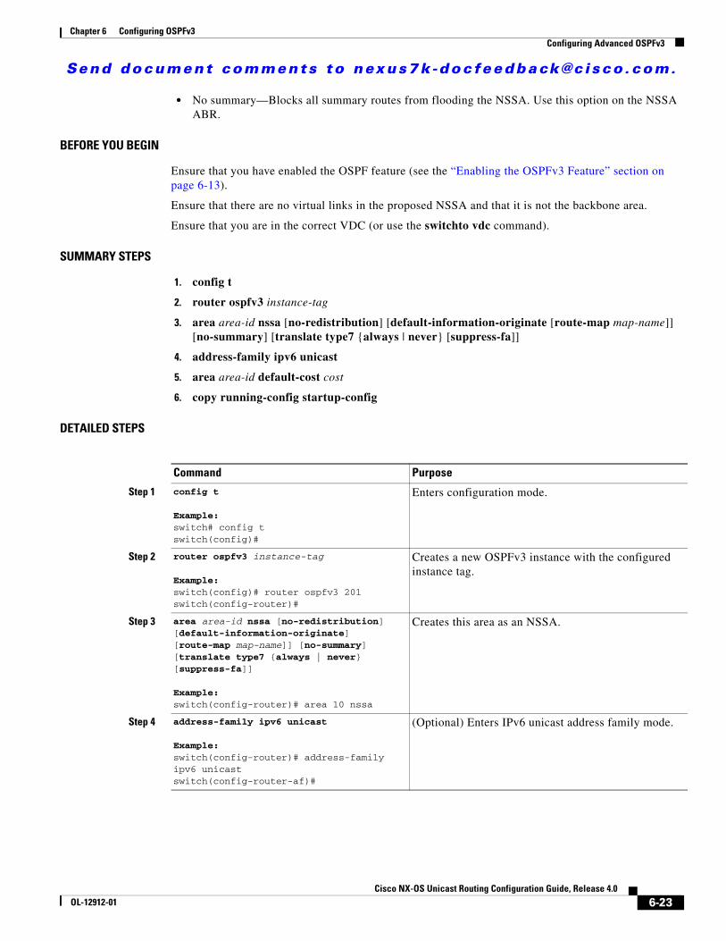
Send document comments to nexus7k -doc feedback@c i sco .com.
Chapter 6 Configuring OSPFv3Configuring Advanced OSPFv3
• No summary—Blocks all summary routes from flooding the NSSA. Use this option on the NSSA ABR.
BEFORE YOU BEGIN
Ensure that you have enabled the OSPF feature (see the “Enabling the OSPFv3 Feature” section on page 6-13).
Ensure that there are no virtual links in the proposed NSSA and that it is not the backbone area.
Ensure that you are in the correct VDC (or use the switchto vdc command).
SUMMARY STEPS
1. config t
2. router ospfv3 instance-tag
3. area area-id nssa [no-redistribution] [default-information-originate [route-map map-name]] [no-summary] [translate type7 {always | never} [suppress-fa]]
4. address-family ipv6 unicast
5. area area-id default-cost cost
6. copy running-config startup-config
DETAILED STEPS
Command Purpose
Step 1 config t
Example:switch# config tswitch(config)#
Enters configuration mode.
Step 2 router ospfv3 instance-tag
Example:switch(config)# router ospfv3 201switch(config-router)#
Creates a new OSPFv3 instance with the configured instance tag.
Step 3 area area-id nssa [no-redistribution] [default-information-originate][route-map map-name]] [no-summary] [translate type7 {always | never} [suppress-fa]]
Example:switch(config-router)# area 10 nssa
Creates this area as an NSSA.
Step 4 address-family ipv6 unicast
Example:switch(config-router)# address-family ipv6 unicastswitch(config-router-af)#
(Optional) Enters IPv6 unicast address family mode.
6-23Cisco NX-OS Unicast Routing Configuration Guide, Release 4.0
OL-12912-01

Send document comments to nexus7k -doc feedback@c i sco .com.
Chapter 6 Configuring OSPFv3Configuring Advanced OSPFv3
The following example shows how to create an NSSA that blocks all summary route updates:
switch# config tswitch(config)# router ospfv3 201switch(config-router)# area 10 nssa no-summaryswitch(config-router)# copy running-config startup-config
The following example shows how to create an NSSA that generates a default route;
switch# config tswitch(config)# router ospfv3 201switch(config-router)# area 10 nssa default-info-originateswitch(config-router)# copy running-config startup-config
The following example shows how to create an NSSA that filters external routes and blocks all summary route updates:
switch# config tswitch(config)# router ospfv3 201switch(config-router)# area 10 nssa route-map ExternalFilter no-summaryswitch(config-router)# copy running-config startup-config
The following example shows how to create an NSSA that always translates Type-7 LSAs to AS External (type 5) LSAs:
switch# config tswitch(config)# router ospfv3 201switch(config-router)# area 10 nssa translate type 7 alwaysswitch(config-router)# copy running-config startup-config
The following example shows how to create an NSSA that blocks all summary route updates:
switch# config tswitch(config)# router ospfv3 201switch(config-router)# area 10 nssa no-summaryswitch(config-router)# copy running-config startup-config
Configuring Virtual LinksA virtual link connects an isolated area to the backbone area through an intermediate area. See the “Virtual Links” section on page 6-9. You can configure the following optional parameters for a virtual link:
• Authentication—Sets simple password or MD5 message digest authentication and associated keys.
• Dead interval—Sets the time that a neighbor waits for a Hello packet before declaring the local router as dead and tearing down adjacencies.
Step 5 area area-id default-cost cost
Example:switch(config-router-af)# area 10 default-cost 25
(Optional) Sets the cost metric for the default summary route sent into this NSSA. The range is from 0 to 16777215.
Step 6 copy running-config startup-config
Example:switch(config-router)# copy running-config startup-config
(Optional) Saves this configuration change.
Command Purpose
6-24Cisco NX-OS Unicast Routing Configuration Guide, Release 4.0
OL-12912-01

Send document comments to nexus7k -doc feedback@c i sco .com.
Chapter 6 Configuring OSPFv3Configuring Advanced OSPFv3
• Hello interval—Sets the time between successive Hello packets.
• Retransmit interval—Sets the estimated time between successive LSAs.
• Transmit delay—Sets the estimated time to transmit an LSA to a neighbor.
Note You must configure the virtual link on both routers involved before the link becomes active.
BEFORE YOU BEGIN
Ensure that you have enabled the OSPF feature (see the “Enabling the OSPFv3 Feature” section on page 6-13).
Ensure that you are in the correct VDC (or use the switchto vdc command).
SUMMARY STEPS
1. config t
2. router ospfv3 instance-tag
3. area area-id virtual-link router-id
4. show ipv6 ospfv3 virtual-link [brief]
5. copy running-config startup-config
DETAILED STEPS
Command Purpose
Step 1 config t
Example:switch# config tswitch(config)#
Enters configuration mode.
Step 2 router ospfv3 instance-tag
Example:switch(config)# router ospfv3 201switch(config-router)#
Creates a new OSPFv3 instance with the configured instance tag.
Step 3 area area-id virtual-link router-id
Example:switch(config-router)# area 10 virtual-link 2001:0DB8::1switch(config-router-vlink)#
Creates one end of a virtual link to a remote router. You must create the virtual link on that remote router to complete the link.
Step 4 show ipv6 ospfv3 virtual-link [brief]
Example:switch(config-if)# show ipv6 ospfv3 virtual-link
(Optional) Displays OSPFv3 virtual link information.
Step 5 copy running-config startup-config
Example:switch(config-router)# copy running-config startup-config
(Optional) Saves this configuration change.
6-25Cisco NX-OS Unicast Routing Configuration Guide, Release 4.0
OL-12912-01

Send document comments to nexus7k -doc feedback@c i sco .com.
Chapter 6 Configuring OSPFv3Configuring Advanced OSPFv3
You can configure the following optional commands in virtual link configuration mode:
The following example shows how to create a simple virtual link between two ABRs:
Configuration for ABR 1 (router ID 2001:0DB8::1) is as follows:
switch# config tswitch(config)# router ospfv3 201switch(config-router)# area 10 virtual-link 2001:0DB8::10switch(config-router)# copy running-config startup-config
Configuration for ABR 2 (router ID 2001:0DB8::10) is as follows:
switch# config tswitch(config)# router ospf 101switch(config-router)# area 10 virtual-link 2001:0DB8::1switch(config-router)# copy running-config startup-config
Configuring RedistributionYou can redistribute routes learned from other routing protocols into an OSPFv3 autonomous system through the ASBR.
You can configure the following optional parameters for route redistribution in OSPF:
• Default information originate—Generates an AS External (type 5) LSA for a default route to the external autonomous system.
• Default metric—Sets all redistributed routes to the same cost metric.
BEFORE YOU BEGIN
Create the necessary route maps used for redistribution.
Command or Action Purposedead-interval seconds
Example:switch(config-router-vlink)# dead-interval 50
(Optional) Configures the OSPFv3 dead interval, in seconds. The range is from 1 to 65535. The default is four times the hello interval, in seconds.
hello-interval seconds
Example:switch(config-router-vlink)# hello-interval 25
(Optional) Configures the OSPFv3 hello interval, in seconds. The range is from 1 to 65535. The default is 10 seconds.
retransmit-interval seconds
Example:switch(config-router-vlink)# retransmit-interval 50
(Optional) Configures the OSPFv3 retransmit interval, in seconds. The range is from 1 to 65535. The default is 5.
transmit-delay seconds
Example:switch(config-router-vlink)# transmit-delay 2
(Optional) Configures the OSPFv3 transmit-delay, in seconds. The range is from 1 to 450. The default is 1.
6-26Cisco NX-OS Unicast Routing Configuration Guide, Release 4.0
OL-12912-01

Send document comments to nexus7k -doc feedback@c i sco .com.
Chapter 6 Configuring OSPFv3Configuring Advanced OSPFv3
Ensure that you have enabled the OSPF feature (see the “Enabling the OSPFv3 Feature” section on page 6-13).
Ensure that you are in the correct VDC (or use the switchto vdc command).
SUMMARY STEPS
1. config t
2. router ospfv3 instance-tag
3. address-family ipv6 unicast
4. redistribute {bgp id | direct | isis id | rip id | static} route-map map-name
5. default-information originate [always] [route-map map-name]
6. default-metric cost
7. copy running-config startup-config
DETAILED STEPS
Command Purpose
Step 1 config t
Example:switch# config tswitch(config)#
Enters configuration mode.
Step 2 router ospfv3 instance-tag
Example:switch(config)# router ospfv3 201switch(config-router)#
Creates a new OSPFv3 instance with the configured instance tag.
Step 3 address-family ipv6 unicast
Example:switch(config-router)# address-family ipv6 unicastswitch(config-router-af)#
Enters IPv6 unicast address family mode.
Step 4 redistribute {bgp id | direct | isis id | rip id | static} route-map map-name
Example:switch(config-router-af)# redistribute bgp route-map FilterExternalBGP
Redistributes the selected protocol into OSPFv3, through the configured route map.
Step 5 default-information originate [always] [route-map map-name]
Example:switch(config-router-af)# default-information-originate route-map DefaultRouteFilter
Creates a default route into this OSPFv3 domain.
6-27Cisco NX-OS Unicast Routing Configuration Guide, Release 4.0
OL-12912-01

Send document comments to nexus7k -doc feedback@c i sco .com.
Chapter 6 Configuring OSPFv3Configuring Advanced OSPFv3
The following example shows how to redistribute the Border Gateway Protocol (BGP) into OSPFv3:
switch# config tswitch(config)# router ospfv3 201switch(config-router)# address-family ipv6 unicastswitch(config-router)# redistribute bgp route-map FilterExternalBGPswitch(config-router)# copy running-config startup-config
Configuring Route SummarizationYou can configure route summarization for inter-area routes by configuring an address range that is summarized. You can also configure route summarization for external, redistributed routes by configuring a summary address for those routes on an ASBR. See the “Route Summarization” section on page 6-10.
BEFORE YOU BEGIN
Ensure that you have enabled the OSPF feature (see the “Enabling the OSPFv3 Feature” section on page 6-13).
Ensure that you are in the correct VDC (or use the switchto vdc command).
SUMMARY STEPS
1. config t
2. router ospfv3 instance-tag
3. address-family ipv6 unicast
4. area area-id range ipv6-prefix/length [no-advertise]
or
5. summary-address ipv6-prefix/length [no-advertise] [tag tag]
6. show ipv6 ospfv3 summary-address
7. copy running-config startup-config
Step 6 default-metric cost
Example:switch(config-router-af)# default-metric 25
Sets the cost metric for the redistributed routes. The range is from 1 to 16777214.
Step 7 copy running-config startup-config
Example:switch(config-router)# copy running-config startup-config
(Optional) Saves this configuration change.
Command Purpose
6-28Cisco NX-OS Unicast Routing Configuration Guide, Release 4.0
OL-12912-01

Send document comments to nexus7k -doc feedback@c i sco .com.
Chapter 6 Configuring OSPFv3Configuring Advanced OSPFv3
DETAILED STEPS
The following example shows how to create summary addresses between areas on an ABR:
switch# config tswitch(config)# router ospfv3 201switch(config-router)# address-family ipv6 unicastswitch(config-router)# area 10 range 2001:0DB8::/48 switch(config-router)# copy running-config startup-config
The following example shows how to create summary addresses on an ASBR:
switch# config tswitch(config)# router ospf 201switch(config-router)# address-family ipv6 unicastswitch(config-router)# summary-address 2001:0DB8::/48 switch(config-router)# copy running-config startup-config
Command Purpose
Step 1 config t
Example:switch# config tswitch(config)#
Enters configuration mode.
Step 2 router ospfv3 instance-tag
Example:switch(config)# router ospfv3 201switch(config-router)#
Creates a new OSPFv3 instance with the configured instance tag.
Step 3 address-family ipv6 unicast
Example:switch(config-router)# address-family ipv6 unicastswitch(config-router-af)#
Enters IPv6 unicast address family mode.
Step 4 area area-id range ipv6-prefix/length [no-advertise]
Example:switch(config-router-af)# area 10 range 2001:0DB8::/48 advertise
Creates a summary address on an ABR for a range of addresses . Optionally advertises this summary address in a Inter-Area Prefix (type 3) LSA.
Step 5 summary-address ipv6-prefix/length [no-advertise][tag tag]Example:switch(config-router-af)# summary-address 2001:0DB8::/48 tag 2
Creates a summary address on an ASBR for a range of addresses and optionally assigns a tag for this summary address that can be used for redistribution with route maps.
Step 6 show ipv6 ospfv3 summary-address
Example:switch(config-router)# show ipv6 ospfv3 summary-address
(Optional) Displays information about OSPFv3 summary addresses.
Step 7 copy running-config startup-config
Example:switch(config-router)# copy running-config startup-config
(Optional) Saves this configuration change.
6-29Cisco NX-OS Unicast Routing Configuration Guide, Release 4.0
OL-12912-01

Send document comments to nexus7k -doc feedback@c i sco .com.
Chapter 6 Configuring OSPFv3Configuring Advanced OSPFv3
Modifying the Default TimersOSPFv3 includes a number of timers that control the behavior of protocol messages and shortest path first (SPF) calculations. OSPFv3 includes the following optional timer parameters:
• LSA arrival time—Sets the minimum interval allowed between LSAs arriving from a neighbor. LSAs that arrive faster than this time are dropped.
• Pacing LSAs—Set the interval at which LSAs are collected into a group and refreshed, checksummed, or aged. This timer controls how frequently LSA updates occur and optimizes how many are sent in an LSA update message (see the “Flooding and LSA Group Pacing” section on page 6-6).
• Throttle LSAs—Set rate limits for generating LSAs. This timer controls how frequently an LSA is generated if no topology change occurs.
• Throttle SPF calculation—Controls how frequently the SPF calculation is run.
At the interface level, you can also control the following timers:
• Retransmit interval—Sets the estimated time between successive LSAs.
• Transmit delay—Sets the estimated time to transmit an LSA to a neighbor.
See the “Configuring Networks in OSPFv3” section on page 6-16 for information on the hello interval and dead timer.
BEFORE YOU BEGIN
Ensure that you are in the correct VDC (or use the switchto vdc command).
SUMMARY STEPS
1. config t
2. router ospfv3 instance-tag
3. timers lsa-arrival msec
4. timers lsa-group-pacing seconds
5. timers throttle lsa intra-area-prefix hold-interval
6. timers throttle lsa link hold-interval
7. timers throttle lsa network hold-interval
8. timers throttle lsa router hold-interval
9. address-family ipv6 unicast
10. timers throttle spf delay-time hold-time
11. interface type slot/port
12. ospfv3 retransmit-interval seconds
13. ospfv3 transmit-delay seconds
14. copy running-config startup-config
6-30Cisco NX-OS Unicast Routing Configuration Guide, Release 4.0
OL-12912-01

Send document comments to nexus7k -doc feedback@c i sco .com.
Chapter 6 Configuring OSPFv3Configuring Advanced OSPFv3
DETAILED STEPS
Command Purpose
Step 1 config t
Example:switch# config tswitch(config)#
Enters configuration mode.
Step 2 router ospfv3 instance-tag
Example:switch(config)# router ospfv3 201switch(config-router)#
Creates a new OSPFv3 instance with the configured instance tag.
Step 3 timers lsa-arrival msec
Example:switch(config-router)# timers lsa-arrival 2000
Sets the LSA arrival time in milliseconds. The range is from 10 to 600000. The default is 1000 milliseconds.
Step 4 timers lsa-group-pacing seconds
Example:switch(config-router)# timers lsa-group-pacing 2000
Sets the interval in seconds for grouping LSAs. The range is from 1 to 1800. The default is 240 seconds.
Step 5 timers throttle lsa intra-area-prefix hold-interval}
Example:switch(config-router)# timers throttle lsa intra-area-prefix 3000
Sets the rate limit in milliseconds for generating intra-area prefix LSAs. The range is from 10 to 600000. The default is 5000 milliseconds.
Step 6 timers throttle lsa link hold-interval}
Example:switch(config-router)# timers throttle lsa intra-area-prefix 3000
Sets the rate limit in milliseconds for generating link LSAs. The range is from 10 to 600000. The default is 5000 milliseconds.
Step 7 timers throttle lsa network delay-interval
Example:switch(config-router)# timers throttle lsa network 3000
Sets the rate limit in milliseconds for generating LSAs. The range is from 10 to 600000. The default is 5000 milliseconds.
Step 8 timers throttle lsa router hold-interval}
Example:switch(config-router)# timers throttle lsa network 3000
Sets the rate limit in milliseconds for generating LSAs. The range is from 10 to 600000. The default is 5000 milliseconds.
Step 9 address-family ipv6 unicast
Example:switch(config-router)# address-family ipv6 unicastswitch(config-router-af)#
Enters IPv6 unicast address family mode.
6-31Cisco NX-OS Unicast Routing Configuration Guide, Release 4.0
OL-12912-01

Send document comments to nexus7k -doc feedback@c i sco .com.
Chapter 6 Configuring OSPFv3Configuring Advanced OSPFv3
The following example shows how to control LSA flooding with the lsa-group-pacing option:
switch# config tswitch(config)# router ospf 201switch(config-router)# timers lsa-group-pacing 300switch(config-router)# copy running-config startup-config
Configuring Graceful RestartGraceful restart is enabled by default. You can configure the following optional parameters for graceful restart in an OSPFv3 instance:
• Grace period—Configures how long neighbors should wait after a graceful restart has started before tearing down adjacencies.
• Helper mode disabled—Disables helper mode on the local OSPFv3 instance. OSPFv3 will not participate in the graceful restart of a neighbor.
• Planned graceful restart only—Configures OSPFv3 to support graceful restart only in the event of a planned restart.
BEFORE YOU BEGIN
Ensure that you have enabled the OSPFv3 feature (see the “Enabling the OSPFv3 Feature” section on page 6-13).
Ensure that all neighbors are configured for graceful restart with matching optional parameters set.
Step 10 timers throttle spf delay-time hold-time
Example:switch(config-router)# timers throttle spf 3000 2000
Sets the SPF best path schedule initial delay time and the minimum hold time in seconds between SPF best path calculations. The range is from 1 to 600000. The default is no delay time and 5000 millisecond hold time.
Step 11 interface type slot/port
Example:switch(config)# interface ethernet 1/2switch(config-if)#
Enters interface configuration mode.
Step 12 ospfv3 retransmit-interval seconds
Example:switch(config-if)# ospfv3 retransmit-interval 30
Sets the estimated time in seconds between LSAs transmitted from this interface. The range is from 1 to 65535. The default is 5.
Step 13 ospfv3 transmit-delay seconds
Example:switch(config-if)# ospfv3 transmit-delay 600switch(config-if)#
Sets the estimated time in seconds to transmit an LSA to a neighbor. The range is from 1 to 450. The default is 1.
Step 14 copy running-config startup-config
Example:switch(config-if)# copy running-config startup-config
(Optional) Saves this configuration change.
Command Purpose
6-32Cisco NX-OS Unicast Routing Configuration Guide, Release 4.0
OL-12912-01

Send document comments to nexus7k -doc feedback@c i sco .com.
Chapter 6 Configuring OSPFv3Configuring Advanced OSPFv3
Ensure that you are in the correct VDC (or use the switchto vdc command).
SUMMARY STEPS
1. config t
2. router ospfv3 instance-tag
3. graceful-restart
4. graceful-restart grace-period seconds
5. graceful-restart helper-disable
6. graceful-restart planned-only
7. show ipv6 ospfv3 instance-tag
8. copy running-config startup-config
DETAILED STEPS
Command Purpose
Step 1 config t
Example:switch# config tswitch(config)#
Enters configuration mode.
Step 2 router ospfv3 instance-tag
Example:switch(config)# router ospfv3 201switch(config-router)#
Creates a new OSPFv3 instance with the configured instance tag.
Step 3 graceful-restart
Example:switch(config-router)# graceful-restart
Enables graceful restart. A graceful restart is enabled by default.
Step 4 graceful-restart grace-period seconds
Example:switch(config-router)# graceful-restart grace-period 120
Sets the grace period, in seconds. The range is from 5 to 1800. The default is 60 seconds.
Step 5 graceful-restart helper-disable
Example:switch(config-router)# graceful-restart helper-disable
Disables helper mode. Enabled by default.
Step 6 graceful-restart planned-only
Example:switch(config-router)# graceful-restart planned-only
Configures graceful restart for planned restarts only.
6-33Cisco NX-OS Unicast Routing Configuration Guide, Release 4.0
OL-12912-01

Send document comments to nexus7k -doc feedback@c i sco .com.
Chapter 6 Configuring OSPFv3Configuring Advanced OSPFv3
The following example shows how to enable graceful restart if it has been disabled, and set the grace period to 120 seconds:
switch# config tswitch(config)# router ospfv3 201switch(config-router)# graceful-restartswitch(config-router)# graceful-restart grace-period 120switch(config-router)# copy running-config startup-config
Restarting an OSPFv3 InstanceYou can restart an OSPv3 instance. This clears all neighbors for the instance.
To restart an OSPFv3 instance and remove all associated neighbors, use the following command:
Configuring OSPFv3 with VirtualizationYou can configure multiple OSPFv3 instances in each VDC. You can also create multiple VRFs within each VDC and use the same or multiple OSPFv3 instances in each VRF. You assign an OSPFv3 interface to a VRF.
Note Configure all other parameters for an interface after you configure the VRF for an interface. Configuring a VRF for an interface deletes all the configuration for that interface.
BEFORE YOU BEGIN
Create the VDCs.
Ensure that you have enabled the OSPF feature (see the “Enabling the OSPFv3 Feature” section on page 6-13).
Ensure that you are in the correct VDC (or use the switchto vdc command).
Step 7 show ipv6 ospfv3 instance-tag
Example:switch(config-if)# show ipv6 ospfv3 201
(Optional) Displays OSPFv3 information.
Step 8 copy running-config startup-config
Example:switch(config)# copy running-config startup-config
(Optional) Saves this configuration change.
Command Purpose
Command Purpose
restart ospfv3 instance-tag
Example:switch(config)# restart ospfv3 201
Restarts the OSPFv3 instance and removes all neighbors.
6-34Cisco NX-OS Unicast Routing Configuration Guide, Release 4.0
OL-12912-01

Send document comments to nexus7k -doc feedback@c i sco .com.
Chapter 6 Configuring OSPFv3Configuring Advanced OSPFv3
SUMMARY STEPS
1. config t
2. vrf context vrf_name
3. router ospfv3 instance-tag
4. vrf vrf-name
5. <optional parameters configured>
6. interface type slot/port
7. vrf member vrf-name
8. ipv6 address ipv6-prefix/length
9. ipv6 ospfv3 instance-tag area area-id
10. copy running-config startup-config
DETAILED STEPS
Command Purpose
Step 1 config t
Example:switch# config tswitch(config)#
Enters configuration mode.
Step 2 vrf context vrf-name
Example:switch(config)# vrf context RemoteOfficeVRFswitch(config-vrf)#
Creates a new VRF and enters VRF configuration mode.
Step 3 router ospfv3 instance-tag
Example:switch(config)# router ospfv3 201switch(config-router)#
Creates a new OSPFv3 instance with the configured instance tag.
Step 4 vrf vrf-name
Example:switch(config-router)# vrf RemoteOfficeVRFswitch(config-router-vrf)#
Enters VRF configuration mode.
Step 5 maximum-paths paths
Example:switch(config-router-vrf)# maximum-paths 4
(Optional) Configures the maximum number of equal OSPFv3 paths to a destination in the route table for this VRF. Used for load balancing.
Step 6 interface type slot/port
Example:switch(config)# interface ethernet 1/2switch(config-if)#
Enters interface configuration mode.
6-35Cisco NX-OS Unicast Routing Configuration Guide, Release 4.0
OL-12912-01

Send document comments to nexus7k -doc feedback@c i sco .com.
Chapter 6 Configuring OSPFv3Verifying OSPFv3 Configuration
The following example shows how to create a VRF and add an interface to the VRF:
switch# config tswitch(config)# vrf context NewVRFswitch(config-vrf)# exitswitch(config)# router ospfv3 201switch(config-router)# exitswitch(config)# interface ethernet 1/2switch(config-if)# vrf member NewVRFswitch(config-if)# ipv6 address 2001:0DB8::1/48switch(config-if)# ipv6 ospfv3 201 area 0switch(config-if)# copy running-config startup-config
Verifying OSPFv3 ConfigurationTo verify OSPFv3 configuration, use one of the following commands:
Step 7 vrf member vrf-name
Example:switch(config-if)# vrf member RemoteOfficeVRF
Adds this interface to a VRF.
Step 8 ipv6 address ipv6-prefix/length
Example:switch(config-if)# ipv6 address 2001:0DB8::1/48
Configures an IP address for this interface. You must do this step after you assign this interface to a VRF.
Step 9 ipv6 ospfv3 instance-tag area area-id
Example:switch(config-if)# ipv6 ospfv3 201 area 0
Assigns this interface to the OSPFv3 instance and area configured.
Step 10 copy running-config startup-config
Example:switch(config)# copy running-config startup-config
(Optional) Saves this configuration change.
Command Purpose
Command Purpose
show ipv6 ospfv3 Displays the OSPFv3 configuration.
show ipv6 ospfv3 border-routers Displays the internal OSPF routing table entries to an ABR and ASBR.
show ipv6 ospfv3 database Displays lists of information related to the OSPFv3 database for a specific router.
show ipv6 ospfv3 interface type number [vrf {vrf-name | all | default | management}]
Displays the OSPFv3 interface configuration.
show ipv6 ospfv3 neighbors Displays the neighbor information. Use the clear ospfv3 neighbors command to remove adjacency with all neighbors.
show ipv6 ospfv3 request-list Displays a list of LSAs requested by a router.
6-36Cisco NX-OS Unicast Routing Configuration Guide, Release 4.0
OL-12912-01

Send document comments to nexus7k -doc feedback@c i sco .com.
Chapter 6 Configuring OSPFv3Displaying OSPFv3 Statistics
Displaying OSPFv3 StatisticsTo display OSPFv3 statistics, use the following commands:
OSPFv3 Example Configuration The following example shows how to configure OSPFv3:
feature ospfv3router ospfv3 201 router-id 290.0.2.1
interface ethernet 1/2 ipv6 address 2001:0DB8::1/48 ipv6 ospfv3 201 area 10
Related TopicsThe following topics can give more information on OSPF:
• Chapter 5, “Configuring OSPFv2”
show ipv6 ospfv3 retransmission-list Displays a list of LSAs waiting to be retransmitted.
show ipv6 ospfv3 summary-address Displays a list of all summary address redistribution information configured under an OSPFv3 instance.
show running-configuration ospfv3 Displays the current runing OSPFv3 configuration.
Command Purpose
Command Purpose
show ipv6 ospfv3 memory Displays the OSPFv3 memory usage statistics.
show ipv6 ospfv3 policy statistics area area-id filter-list {in | out} [vrf {vrf-name | all | default | management}]
Displays the OSPFv3 route policy statistics for an area.
show ipv6 ospfv3 policy statistics redistribute {bgp id| direct | isis id | rip id | static} vrf {vrf-name | all | default | management}]
Displays the OSPFv3 route policy statistics.
show ipv6 ospfv3 statistics [vrf {vrf-name | all | default | management}]
Displays the OSPFv3 event counters.
show ipv6 ospfv3 traffic [interface-type number] [vrf {vrf-name | all | default | management}]
Displays the OSPFv3 packet counters.
6-37Cisco NX-OS Unicast Routing Configuration Guide, Release 4.0
OL-12912-01

Send document comments to nexus7k -doc feedback@c i sco .com.
Chapter 6 Configuring OSPFv3Default Settings
• Chapter 14, “Configuring Route Policy Manager”
Default SettingsTable 6-2 lists the default settings for OSPFv3 parameters.
Additional ReferencesFor additional information related to implementing OSPF, see the following sections:
• Related Documents, page 6-39
• MIBs, page 6-39
Table 6-2 Default OSPFv3 Parameters
Parameters Default
Hello interval 10 seconds
Dead interval 40 seconds
Graceful restart grace period 60 seconds
Graceful restart notify period 15 seconds
OSPFv3 feature Disabled
Stub router advertisement announce time 600 seconds
Reference bandwidth for link cost calculation 40 Gb/s
LSA minimal arrival time 1000 milliseconds
LSA group pacing 240 seconds
SPF calculation initial delay time 0 milliseconds
SPF calculation hold time 5000 milliseconds
SPF calculation initial delay time 0 milliseconds
6-38Cisco NX-OS Unicast Routing Configuration Guide, Release 4.0
OL-12912-01

Send document comments to nexus7k -doc feedback@c i sco .com.
Chapter 6 Configuring OSPFv3Additional References
Related Documents
MIBs
Related Topic Document Title
OSPFv3 CLI commands Cisco NX-OS Command Line Reference
VDCs Cisco NX-OS Virtual Device Contexts Configuration Guide
MIBs MIBs Link
• OSPF-MIB
• OSPF-TRAP-MIB
To locate and download MIBs, go to the following URL:
http://www.cisco.com/public/sw-center/netmgmt/cmtk/mibs.shtml
6-39Cisco NX-OS Unicast Routing Configuration Guide, Release 4.0
OL-12912-01

Send document comments to nexus7k -doc feedback@c i sco .com.
Chapter 6 Configuring OSPFv3Additional References
6-40Cisco NX-OS Unicast Routing Configuration Guide, Release 4.0
OL-12912-01

Send document comments to nexus7k -doc feedback@c i sco .com.
Cisco NX-OOL-12912-01
C H A P T E R 7
Configuring EIGRPThis chapter describes how to configure the Enhanced Interior Gateway Routing Protocol (EIGRP).
This chapter includes the following sections:
• Information About EIGRP, page 7-1
• Licensing Requirements for EIGRP, page 7-7
• Prerequisites for EIGRP, page 7-7
• Configuration Guidelines and Limitations, page 7-8
• Configuring Basic EIGRP, page 7-8
• Configuring Advanced EIGRP, page 7-12
• Configuring Advanced EIGRP, page 7-12
• Displaying EIGRP Statistics, page 7-24
• EIGRP Example Configuration, page 7-24
• Default Settings, page 7-24
• Additional References, page 7-25
Information About EIGRPEIGRP combines the benefits of distance vector protocols with the featurs of of link-state protocols. EIGRP sends out periodic Hello messages for neighbor discovery. Once EIGRP learns a new neighbor, it sends a one-time update of all the local EIGRP routes and route metrics. The receiving EIGRP router calculates the route distance based on the received metrics and the locally assigned cost of the link to that neighbor. After this initial full route table update, EIGRP sends incremental updates to only those neighbors affected by the route change. This process speeds convergence and minimizes the bandwidth used by EIGRP.
This section includes the following topics:
• EIGRP Components, page 7-2
• EIGRP Route Updates, page 7-3
• Advanced EIGRP, page 7-4
7-1S Unicast Routing Configuration Guide, Release 4.0
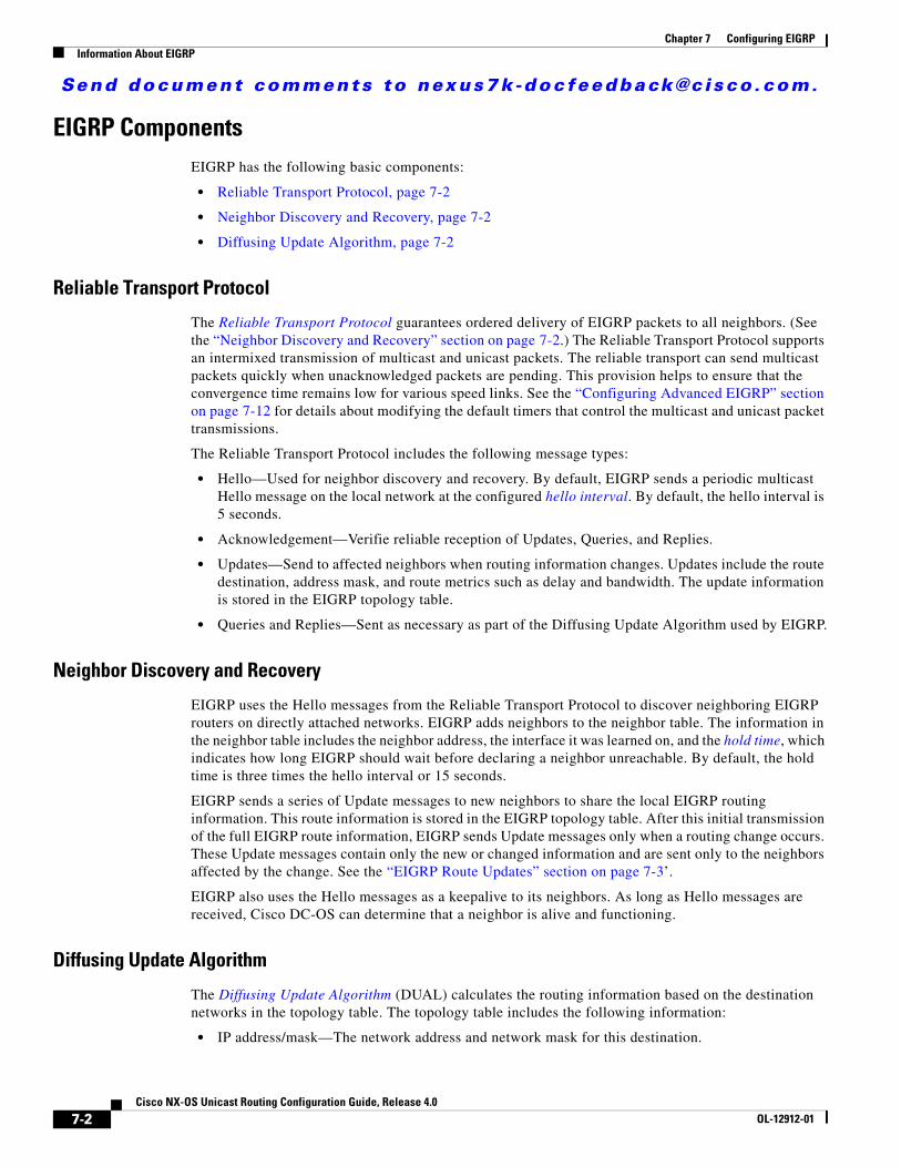
Send document comments to nexus7k -doc feedback@c i sco .com.
Chapter 7 Configuring EIGRPInformation About EIGRP
EIGRP ComponentsEIGRP has the following basic components:
• Reliable Transport Protocol, page 7-2
• Neighbor Discovery and Recovery, page 7-2
• Diffusing Update Algorithm, page 7-2
Reliable Transport Protocol
The Reliable Transport Protocol guarantees ordered delivery of EIGRP packets to all neighbors. (See the “Neighbor Discovery and Recovery” section on page 7-2.) The Reliable Transport Protocol supports an intermixed transmission of multicast and unicast packets. The reliable transport can send multicast packets quickly when unacknowledged packets are pending. This provision helps to ensure that the convergence time remains low for various speed links. See the “Configuring Advanced EIGRP” section on page 7-12 for details about modifying the default timers that control the multicast and unicast packet transmissions.
The Reliable Transport Protocol includes the following message types:
• Hello—Used for neighbor discovery and recovery. By default, EIGRP sends a periodic multicast Hello message on the local network at the configured hello interval. By default, the hello interval is 5 seconds.
• Acknowledgement—Verifie reliable reception of Updates, Queries, and Replies.
• Updates—Send to affected neighbors when routing information changes. Updates include the route destination, address mask, and route metrics such as delay and bandwidth. The update information is stored in the EIGRP topology table.
• Queries and Replies—Sent as necessary as part of the Diffusing Update Algorithm used by EIGRP.
Neighbor Discovery and Recovery
EIGRP uses the Hello messages from the Reliable Transport Protocol to discover neighboring EIGRP routers on directly attached networks. EIGRP adds neighbors to the neighbor table. The information in the neighbor table includes the neighbor address, the interface it was learned on, and the hold time, which indicates how long EIGRP should wait before declaring a neighbor unreachable. By default, the hold time is three times the hello interval or 15 seconds.
EIGRP sends a series of Update messages to new neighbors to share the local EIGRP routing information. This route information is stored in the EIGRP topology table. After this initial transmission of the full EIGRP route information, EIGRP sends Update messages only when a routing change occurs. These Update messages contain only the new or changed information and are sent only to the neighbors affected by the change. See the “EIGRP Route Updates” section on page 7-3’.
EIGRP also uses the Hello messages as a keepalive to its neighbors. As long as Hello messages are received, Cisco DC-OS can determine that a neighbor is alive and functioning.
Diffusing Update Algorithm
The Diffusing Update Algorithm (DUAL) calculates the routing information based on the destination networks in the topology table. The topology table includes the following information:
• IP address/mask—The network address and network mask for this destination.
7-2Cisco NX-OS Unicast Routing Configuration Guide, Release 4.0
OL-12912-01

Send document comments to nexus7k -doc feedback@c i sco .com.
Chapter 7 Configuring EIGRPInformation About EIGRP
• Successors—The IP address and local interface connection for all feasible successors or neighbors that advertise a shorter distance to the destination than the current feasible distance.
• Feasibility distance (FD)—The lowest calculated distance to the destination. The feasibility distance is the sum of the advertised distance from a neighbor plus the cost of the link to that neighbor.
DUAL uses the distance metric to select efficient, loop-free paths. DUAL selects routes to insert into the unicast Routing Information Base (RIB) based on feasible successors. When a topology change occurs, DUAL looks for feasible successors in the topology table. If there are feasible successors, DUAL selects the feasible successor with the lowest feasible distance and inserts that into the unicast RIB, avoiding unnecessary recomputation.
When there are no feasible successors but there are neighbors advertising the destination, DUAL transitions from the passive state to the active state and triggers a recomputation to determine a new successor or next-hop router to the destination. The amount of time required to recompute the route affects the convergence time. EIGRP sends Query messages to all neighbors, searching for feasible successors. Neighbors that have a feasible successor send a Reply message with that information. Neighbors that do not have feasible successors trigger a DUAL recomputation.
EIGRP Route UpdatesWhen a topology change occurs, EIGRP sends an Update message with only the changed routing information to affected neighbors. This Update message includes the distance information to the new or updated network destination.
The distance information in EIGRP is represented as a composite of available route metrics, including bandwidth, delay, load utilization, and link reliability. Each metric has an associated weight that determines if the metric is included in the distance calculation. You can configure these metric weights. You can fine-tune link characteristics to achieve optimal paths, but we recommend that you use the default settings for most configurable metrics.
This section includes the following topics:
• Internal Route Metrics, page 7-3
• External Route Metrics, page 7-4
• EIGRP and the Unicast RIB, page 7-4
Internal Route Metrics
Internal routes are routes that occur between neighbors within the same EIGRP autonomous system. These routes have the following metrics:
• Next hop—The IP address of the next-hop router.
• Delay—The sum of the delays configured on the interfaces that make up the route to the destination network. Configured in tens of microseconds.
• Bandwidth—The calculation from the lowest configured bandwidth on an interface that is part of the route to the destination.
Note We recommend that you use the default bandwidth value. This bandwidth parameter is also used by EIGRP.
• MTU—The smallest maximum transmission unit value along the route to the destination.
7-3Cisco NX-OS Unicast Routing Configuration Guide, Release 4.0
OL-12912-01

Send document comments to nexus7k -doc feedback@c i sco .com.
Chapter 7 Configuring EIGRPInformation About EIGRP
• Hop count—The number of hops or routers that the route passes through to the destination. This metric is not directly used in the DUAL computation.
• Reliability—An indication of the reliability of the links to the destination.
• Load—An indication of how much traffic is on the links to the destination.
By default, EIGRP uses the bandwidth and delay metrics to calculate the distance to the destination. You can modify the metric weights to include the other metrics in the calculation.
External Route Metrics
External routes are routes that occur between neighbors in different EIGRP autonomous systems. These routes have the following metrics:
• Next hop—The IP address of the next-hop router.
• Router ID—The router ID of the router that redistributed this route into EIGRP.
• AS Number—The autonomous system number of the destination.
• Protocol ID—A code that represents the routing protocol that learned the destination route.
• Tag—An arbitrary tag that can be used for route maps.
• Metric—The route metric for this route from the external routing protocol.
EIGRP and the Unicast RIB
EIGRP adds all learned routes to the EIGRP topology table and the unicast RIB. When a topology change occurs, EIGRP uses these routes to search for a feasible successor. EIGRP also listens for notifications from the unicast RIB for changes in any routes redistributed to EIGRP from another routing protocol.
Advanced EIGRPYou can use the advanced features of EIGRP to optimize your EIGRP configuration.
This section includes the following topics:
• Authentication, page 7-4
• Stub Routers, page 7-5
• Route Summarization, page 7-5
• Route Redistribution, page 7-5
• Load Balancing, page 7-6
• Split Horizon, page 7-6
• Virtualization Support, page 7-6
• Graceful Restart and High Availability, page 7-6
Authentication
You can configure authentication on EIGRP messages to prevent unauthorized or invalid routing updates in your network. Cisco NX-OS supports MD5 authentication digest.
7-4Cisco NX-OS Unicast Routing Configuration Guide, Release 4.0
OL-12912-01
Send document comments to nexus7k -doc feedback@c i sco .com.
Chapter 7 Configuring EIGRPInformation About EIGRP
You can configure the EIGRP authentication per interface using key-chain management for the authentication keys. Key-chain management allows you to control changes to the authentication keys used by MD5 authentication digest. See the Cisco NX-OS Security Configuration Guide for more details about creating key-chains.
For MD5 authentication, you configure a password that is shared at the local router and all remote EIGRP neighbors. When an EIGRP message is created, Cisco NX-OS creates an MD5 one-way message digest based on the message itself and the encrypted password and sends this digest along with the EIGRP message. The receiving EIGRP neighbor validates the digest using the same encrypted password. If the message has not changed, the calculation is identical and the EIGRP message is considered valid.
MD5 authentication also includes a sequence number with each EIGRP message that is used to ensure that no message is replayed in the network.
Stub Routers
You can use the EIGRP stub routing feature to improve network stability, reduce resource usage, and simplify stub router configuration. Stub routers connect to the EIGRP network through a remote router. See the “Stub Routing” section on page 1-7.
When using EIGRP stub routing, you need to configure the distribution and remote routers to use EIGRP and configure only the remote router as a stub. EIGRP stub routing does not automatically enable summarization on the distribution router. In most cases, you need to configure summarization on the distribution routers.
Without EIGRP stub routing, even after the routes that are sent from the distribution router to the remote router have been filtered or summarized, a problem might occur. For example, if a route is lost somewhere in the corporate network, EIGRP could send a query to the distribution router. The distribution router could then send a query to the remote router even if routes are summarized. If a problem communicating over the WAN link between the distribution router and the remote router occurs, EIGRP could get stuck in active condition and cause instability elsewhere in the network. EIGRP stub routing allows you to prevent queries to the remote router.
Route Summarization
You can configure a summary aggregate address for a specified interface. Route summarization simplifies route tables by replacing a number of more-specific addresses with an address that represents all the specific addresses. For example, you can replace 10.1.1.0/24, 10.1.2.0/24, and 10.1.3.0/24 with one summary address, 10.1.0.0/16.
If more specific routes are in the routing table, EIGRP advertises the summary address from the interface with a metric equal to the minimum metric of the more specific routes.
Note Cisco NX-OS does not support automatic route summarization.
Route Redistribution
You can use EIGRP to redistribute static routes, routes learned by other EIGRP autonomous systems, or routes from other protocols. You configure route policy with the redistribution to control which routes are passed into EIGRP. A route policy allows you to filter routes based on attributes such as the destination, origination protocol, route type, route tag, and so on. See Chapter 14, “Configuring Route Policy Manager.”
You also configure the default metric that is used for all imported routes into EIGRP.
7-5Cisco NX-OS Unicast Routing Configuration Guide, Release 4.0
OL-12912-01

Send document comments to nexus7k -doc feedback@c i sco .com.
Chapter 7 Configuring EIGRPInformation About EIGRP
Load Balancing
You can use load balancing to allow a router to distribute traffic over all the router network ports that are the same distance from the destination address. Load balancing increases the utilization of network segments which increases effective network bandwidth.
Cisco NX-OS supports the Equal Cost Multiple Paths (ECMP) feature with up to 16 equal-cost paths in the EIGRP route table and the unicast RIB. You can configure EIGRP to load balance traffic across some or all of those paths.
Split Horizon
You can use split horizon to ensure that EIGRP never advertises a route out of the interface where it was learned.
Split horizon is a method that controls the sending of EIGRP update and query packets. When you enable split horizon on an interface, Cisco NX-OS does not send update and query packets for destinations that were learned from this interface. Controlling update and query packets in this manner reduces the possibility of routing loops.
Split horizon with poison reverse configures EIGRP to advertise a learned route as unreachable back through that the interface that EIGRP learned the route from.
EIGRP uses split horizon or or split horizon with poison reverse in the following scenarios:
• Exchanging topology tables for the first time between two routers in startup mode.
• Advertising a topology table change.
• Sending a Query message.
By default, the split horizon feature is enabled on all interfaces.
Virtualization Support
Cisco NX-OS supports multiple instances of the EIGRP protocol that runs on the same system. EIGRP supports Virtual Routing and Forwarding instances (VRFs). VRFs exist within virtual device contexts (VDCs). By default, Cisco NX-OS places you in the default VDC and default VRF unless you specifically configure another VDC and VRF. See the Cisco NX-OS Virtual Device Context Configuration Guide and Chapter 13, “Configuring Layer 3 Virtualization.”
By default, every instance uses the same system router ID. You must manually configure the router ID for each instance if the instances are in the same EIGRP autonomous system.
Graceful Restart and High Availability
Cisco NX-OS supports nonstop forwarding and graceful restart for EIGRP.
You can use nonstop forwarding for EIGRP to forward data packets along known routes in the FIB while the EIGRP routing protocol information is being restored following a failover. With NSF, peer networking devices do not experience routing flaps. During failover, data traffic is forwarded through intelligent modules while the standby supervisor becomes active.
If a Cisco NX-OS system experiences a cold reboot, network does not forward traffic to the system and removes the system from the network topology. In this scenario, EIGRP experiences a stateless restart, and all neighbors are removed. Cisco NX-OS applies the startup configuration, and EIGRP rediscovers the neighbors and shares the full EIGRP routing information again.
7-6Cisco NX-OS Unicast Routing Configuration Guide, Release 4.0
OL-12912-01

Send document comments to nexus7k -doc feedback@c i sco .com.
Chapter 7 Configuring EIGRPLicensing Requirements for EIGRP
A dual supervisor platform that runs Cisco NX-OS can experience a stateful supervisor switchover. Before the switchover occurs, EIGRP uses a graceful restart to announce that EIGRP will be unavailable for some time. During a switchover, EIGRP uses nonstop forwarding to continue forwarding traffic based on the information in the FIB, and the system is not taken out of the network topology.
The graceful restart-capable router uses Hello messages to notify its neighbors that an graceful restart operation has started. When an graceful restart-aware router receives a notification from a graceful restart-capable neighbor that a graceful restart operation is in progress, both routers immediately exchange their topology tables. The graceful restart-aware router then performs the following actions to assist the restarting router:
• The router expires the EIGRP Hello hold timer to reduce the time interval set for Hello messages. This allows the graceful restart-aware router to reply to the restarting router more quickly and reduces the amount of time required for the restarting router to rediscover neighbors and rebuild the topology table.
• The router starts the route-hold timer. This timer sets the period of time that the graceful restart-aware router will hold known routes for the restarting neighbor. The default time period is 240 seconds.
• The router notes in the peer list that the neighbor is restarting, maintains adjacency, and holds known routes for the restarting neighbor until the neighbor signals that it is ready for the graceful restart-aware router to send its topology table or the route-hold timer expires. If the route-hold timer expires on the graceful restart-aware router, the graceful restart-aware router discards held routes and treats the restarting router as a new router joining the network and reestablishing adjacency.
After the switchover, Cisco NX-OS applies the running configuration, and EIGRP informs the neighbors that it is operational again.
Note You must enable graceful restart to support in-service software upgrades (ISSU) for EIGRP. If you disable graceful restart, Cisco NX-OS issues a warning that ISSU cannot be supported with this configuration.
Licensing Requirements for EIGRPThe following table shows the licensing requirements for this feature:
Prerequisites for EIGRPEIGRP has the following prerequisites:
• You must enable the EIGRP feature (see the “Enabling the EIGRP Feature” section on page 7-8).
• If you configure VDCs, install the Advanced Services license and enter the desired VDC (see to the Cisco NX-OS Virtual Device Context Configuration Guide).
Product License Requirement
NX-OS EIGRP requires an Enterprise Services license. For a complete explanation of the NX-OS licensing scheme and how to obtain and apply licenses, see the Cisco NX-OS Licensing Guide.
7-7Cisco NX-OS Unicast Routing Configuration Guide, Release 4.0
OL-12912-01

Send document comments to nexus7k -doc feedback@c i sco .com.
Chapter 7 Configuring EIGRPConfiguration Guidelines and Limitations
Configuration Guidelines and LimitationsEIGRP has the following configuration guidelines and limitations:
• A metric configuration (either through the default-metric configuration option or through a route policy) is required for redistribution from any other protocol, connected routes, or static routes (see Chapter 14, “Configuring Route Policy Manager”).
• For graceful restart, an NSF-aware router must be up and completely converged with the network before it can assist an NSF-capable router in a graceful restart operation.
• For graceful restart, neighboring devices participating in the graceful restart must be NSF-aware or NSF-capable.
• Cisco NX-OS EIGRP is compatible with EIGRP in Cisco IOS.
• Do not change the metric weights without a good reason. If you change the metric weights, you must apply the change to all EIGRP routers in the same autonomous system.
• Consider using stubs for larger networks.
• Avoid redistribution between different EIGRP autonomous systems because the EIGRP vector metric will not be preserved.
• The no ip next-hop-self command does not guarantee reachability of next hop.
• The ip passive-interface eigrp command suppresses neighbor formation.
• Cisco NX-OS does not support IGRP or connecting IGRP and EIGRP clouds.
• Autosummarization is not enabled by default.
• Cisco NX-OS supports only IP.
Note If you are familiar with the Cisco IOS CLI, be aware that the Cisco NX-OS commands for this feature might differ from the Cisco IOS commands that you would use.
Configuring Basic EIGRPThis section contains the following topics:
• Enabling the EIGRP Feature, page 7-8
• Creating an EIGRP Instance, page 7-9
• Restarting an EIGRP Instance, page 7-11
• Disabling an EIGRP Instance, page 7-12
• Disabling EIGRP on an Interface, page 7-12
Enabling the EIGRP FeatureYou must enable the EIGRP feature before you can configure EIGRP.
BEFORE YOU BEGIN
Ensure that you are in the correct VDC (or use the switchto vdc command).
7-8Cisco NX-OS Unicast Routing Configuration Guide, Release 4.0
OL-12912-01

Send document comments to nexus7k -doc feedback@c i sco .com.
Chapter 7 Configuring EIGRPConfiguring Basic EIGRP
SUMMARY STEPS
1. config t
2. feature eigrp
3. copy running-config startup-config
DETAILED STEPS
Use the no feature eigrp command to disable the EIGRP feature and remove all associated configuration.
Creating an EIGRP InstanceYou can create an EIGRP instance and associate an interface with that instance. You assign a unique autonomous system number for this EIGRP process (see the “Autonomous Systems” section on page 1-5). Routes are not advertised or accepted from eternal autonomous systems unless you enable route redistribution.
BEFORE YOU BEGIN
Ensure that you have enabled the EIGRP feature (see the “Enabling the EIGRP Feature” section on page 7-8).
EIGRP must be able to obtain a router ID (for example, a configured loopback address) or you must configure the router ID option.
Ensure that you are in the correct VDC (or use the switchto vdc command).
Command Purpose
Step 1 config t
Example:switch# config tswitch(config)#
Enters configuration mode.
Step 2 feature eigrp
Example:switch(config)# feature eigrp
Enables the EIGRP feature.
Step 3 copy running-config startup-config
Example:switch(config)# copy running-config startup-config
(Optional) Saves this configuration change.
Command Purpose
no feature eigrp
Example:switch(config)# no feature eigrp
Disables the EIGRP feature and removes all associated configuration.
7-9Cisco NX-OS Unicast Routing Configuration Guide, Release 4.0
OL-12912-01

Send document comments to nexus7k -doc feedback@c i sco .com.
Chapter 7 Configuring EIGRPConfiguring Basic EIGRP
SUMMARY STEPS
1. config t
2. router eigrp as-number
3. <configure optional parameters>
4. interface interface-type slot/port
5. ip router eigrp as-number
6. show ip eigrp interfaces
7. copy running-config startup-config
DETAILED STEPS
Command Purpose
Step 1 config t
Example:switch# config tswitch(config)#
Enters configuration mode.
Step 2 router eigrp as-number
Example:switch(config)# router eigrp 201switch(config-router)#
Creates a new EIGRP process with the configured autonomous system number.
Step 3 eigrp router-id ip-address
Example:switch(config-router)# eigrp router-id 192.0.2.1
(Optional) Configures the EIGRP router ID. This IP address identifies this EIGRP instance and must exist on a configured interface in the system.
router-id ip-address
Example:switch(config-router)# router-id 192.0.2.1
(Optional) Configures the EIGRP router ID. This command is identical to the eigrp router-id command.
Step 4 eigrp log-neighbor-changes
Example:switch(config-router)# eigrp log-neighbor-changes
(Optional). Generates a system message whenever a neighbor changes state. This command is enabled by default.
Step 5 eigrp log-neighbor-warnings [seconds]
Example:switch(config-router)# eigrp log-neighbor-warnings
(Optional) Generates a system message whenever a neighbor warning occurs. You can configure the time between warning messages, from 1 to 65535, in seconds. The default is 10 seconds. This command is nabled by default.
Step 6 interface interface-type slot/port
Example:switch(config-router)# interface ethernet 1/2switch(config-if)#
Enters interface configuration mode.
7-10Cisco NX-OS Unicast Routing Configuration Guide, Release 4.0
OL-12912-01

Send document comments to nexus7k -doc feedback@c i sco .com.
Chapter 7 Configuring EIGRPConfiguring Basic EIGRP
Use the no router eigrp command to remove the EIGRP process and the associated configuration.
Note You must also remove any EIGRP commands configured in interface mode.
The following example shows how to create an EIGRP process and configure an interface for EIGRP:
switch# config tswitch(config)# router eigrp 201switch(config)# interface ethernet 1/2switch(config-if)# ip router eigrp 201switch(config-if)# no shutdownswitch(config-if)# copy running-config startup-config
For more information about other EIGRP parameters, see the “Configuring Advanced EIGRP” section on page 7-12.
Restarting an EIGRP InstanceYou can restart an EIGRP instance. This clears all neighbors for the instance.
To restart an EIGRP instance and remove all associated neighbors, use the following command:
Step 7 ip router eigrp as-number
Example:switch(config-if)# ip router eigrp 201
Associates this interface with the configured EIGRP process.
Step 8 show ip eigrp interfaces
Example:switch(config-if)# show ip eigrp interfaces
Displays information about EIGRP interfaces.
Step 9 copy running-config startup-config
Example:switch(config)# copy running-config startup-config
(Optional) Saves this configuration change.
Command Purpose
Command Purposeno router eigrp as-number
Example:switch(config)# no router eigrp 201
Deletes the EIGRP process and all associated configuration.
Command Purpose
restart eigrp instance-tag
Example:switch(config)# restart eigrp 201
Restarts the EIGRP instance and removes all neighbors.
7-11Cisco NX-OS Unicast Routing Configuration Guide, Release 4.0
OL-12912-01

Send document comments to nexus7k -doc feedback@c i sco .com.
Chapter 7 Configuring EIGRPConfiguring Advanced EIGRP
Disabling an EIGRP InstanceTo disable an EIGRP instnace, use the following command in router configuration mode:
Disabling EIGRP on an InterfaceTo disable EIGRP on an interface, use the following command in interface configuration mode:
Configuring Advanced EIGRPThis section includes the following topics:
• Configuring Authentication in EIGRP, page 7-12
• Configuring EIGRP Stub Routing, page 7-14
• Configuring a Summary Address for EIGRP, page 7-15
• Redistributing Routes into EIGRP, page 7-15
• Configuring Load Balancing in EIGRP, page 7-17
• Configuring Graceful Restart for EIGRP, page 7-18
• Adjusting the Interval Between Hello Packets and the Hold Time, page 7-19
• Disabling Split Horizon, page 7-20
• Tuning EIGRP, page 7-20
• Configuring Virtualization for EIGRP, page 7-22
Configuring Authentication in EIGRPYou can configure authentication between neighbors for EIGRP. See the “Authentication” section on page 7-4.
Command Purpose
switch(config-router)# shutdown
Example:switch(config-router)# shutdown
Disables this instance of EIGRP
Command Purposeswitch(config-if)# ip eigrp as-numver shutdown
Example:switch(config-router)# ip eigrp 201 shutdown
Disables EIGRP on this interface.
7-12Cisco NX-OS Unicast Routing Configuration Guide, Release 4.0
OL-12912-01

Send document comments to nexus7k -doc feedback@c i sco .com.
Chapter 7 Configuring EIGRPConfiguring Advanced EIGRP
BEFORE YOU BEGIN
Ensure that you have enabled the EIGRP feature (see the “Enabling the EIGRP Feature” section on page 7-8).
Ensure that all neighbors for an EIGRP process share the same authentication configuration, including the shared authentication key.
Create the key-chain for this authentication configuration. See the Cisco NX-OS Security Configuration Guide.
Ensure that you are in the correct VDC (or use the switchto vdc command).
SUMMARY STEPS
1. config t
2. router eigrp as-number
3. interface interface-type slot/port
4. ip router eigrp as-number
5. ip authentication key-chain eigrp as-number key-chain
6. ip authentication mode eigrp as-number md5
7. copy running-config startup-config
DETAILED STEPS
Command Purpose
Step 1 config t
Example:switch# config tswitch(config)#
Enters configuration mode.
Step 2 router eigrp as-number
Example:switch(config)# router eigrp 201switch(config-router)#
Creates a new EIGRP process with the configured autonomous system number.
Step 3 interface interface-type slot/port
Example:switch(config)interface ethernet 1/2switch(config-if)#
Enters interface configuration mode.
Step 4 ip router eigrp as-number
Example:switch(config-if)# ip router eigrp 201
Associates this interface with the configured EIGRP process.
Step 5 ip authentication key-chain eigrp as-number key-chain
Example:switch(config-if)# ip authentication key-chain eigrp 201 routeKeys
Associates a key-chain with this EIGRP process for this interface.
7-13Cisco NX-OS Unicast Routing Configuration Guide, Release 4.0
OL-12912-01

Send document comments to nexus7k -doc feedback@c i sco .com.
Chapter 7 Configuring EIGRPConfiguring Advanced EIGRP
The following example shows how to configure MD5 message digest authentication for EIGRP over Ethernet interface 1/2:
switch# config tswitch(config)# router eigrp 201switch(config-router)# exitswitch(config)# interface ethernet 1/2switch(config-if)# ip router eigrp 201switch(config-if)# ip authentication key-chain eigrp 201 routeKeysswitch(config-if)# ip authentication mode eigrp 201 md5switch(config-if)# copy running-config startup-config
Configuring EIGRP Stub RoutingTo configure a router for EIGRP stub routing, use the following command in router configuration mode:
The following example shows how to configure a stub router to advertise directly connected and redistributed routes:
switch# config tswitch(config)# router eigrp 201switch(config-router)# eigrp stub direct redistributedswitch(config-router)# copy running-config startup-config
Use the show ip eigrp neighbor detail command to verify that a router has been configured as a stub router. The last line of the output shows the stub status of the remote or spoke router. The following example shows that output from the show ip eigrp neighbor detail command:
Router# show ip eigrp neighbor detailIP-EIGRP neighbors for process 201H Address Interface Hold Uptime SRTT RTO Q Seq Type (sec) (ms) Cnt Num0 10.1.1.2 Se3/1 11 00:00:59 1 4500 0 7 Version 12.1/1.2, Retrans: 2, Retries: 0
Step 6 ip authentication mode eigrp as-number md5
Example:switch(config-if)# ip authentication mode eigrp 201 md5
Configures MD5 message digest authentication mode for this interface.
Step 7 copy running-config startup-config
Example:switch(config)# copy running-config startup-config
(Optional) Saves this configuration change.
Command Purpose
Command Purpose
switch(config-router)# eigrp stub [leak-map map-name | receive-only | redistributed [direct]]
Example:switch(config-router)# eigrp stub redistributed
Configures a remote router as an EIGRP stub router.
7-14Cisco NX-OS Unicast Routing Configuration Guide, Release 4.0
OL-12912-01

Send document comments to nexus7k -doc feedback@c i sco .com.
Chapter 7 Configuring EIGRPConfiguring Advanced EIGRP
Stub Peer Advertising ( CONNECTED SUMMARY ) Routes
Configuring a Summary Address for EIGRPYou can configure a summary aggregate address for a specified interface. If any more specific routes are in the routing table, EIGRP will advertise the summary address out the interface with a metric equal to the minimum of all more specific routes. See the “Route Summarization” section on page 7-5.
To configure a summary aggregate address, use the following command in interface configuration mode:
The following example causes EIGRP to summarize network 209.0.2.0 out Ethernet 1/2 only:
switch(config)# interface ethernet 1/2switch(config-if)# ip summary-address eigrp 201 209.0.2.0 255.255.255.0
Redistributing Routes into EIGRPYou can redistribute routes in EIGRP from other routing protocols.
BEFORE YOU BEGIN
Ensure that you have enabled the EIGRP feature (see the “Enabling the EIGRP Feature” section on page 7-8).
You must configure the metric (either through the default-metric configuration option or through a route policy) for routes redistributed from any other protocol.
You must create a route map to control the types of routes that are redistributed into EIGRP. See Chapter 14, “Configuring Route Policy Manager.”
Ensure that you are in the correct VDC (or use the switchto vdc command).
SUMMARY STEPS
1. config t
2. router eigrp as-number
3. redistribute {{bgp | eigrp | isis | ospf | rip} as-number | direct | static} route-map name
4. default-metric bandwidth delay reliability loading mtu
5. show ip eigrp policy statistics redistribute
6. copy running-config startup-config
Command Purpose
switch(config-if)# ip summary-address eigrp as-number ip-prefix/length [distance | leak-map map-name]
Example:switch(config-if)# ip summary-address eigrp 201 209.0.2.0/8
Configures a summary aggregate address as either an IP address and network mask, or an IP prefix/length. You can optionally configure the administrative distance for this aggregate address. The default administrative distance is 5 for aggregate addresses.
7-15Cisco NX-OS Unicast Routing Configuration Guide, Release 4.0
OL-12912-01

Send document comments to nexus7k -doc feedback@c i sco .com.
Chapter 7 Configuring EIGRPConfiguring Advanced EIGRP
DETAILED STEPS
The following example shows how to redistribute BGP into EIGRP:
switch# config tswitch(config)# router eigrp 201switch(config-router)# redistribute bgp 100 route-map BGPFilterswitch(config-router)# default-metric 500000 30 200 1 1500switch(config-router)# copy running-config startup-config
Command Purpose
Step 1 config t
Example:switch# config tswitch(config)#
Enters configuration mode.
Step 2 router eigrp as-number
Example:switch(config)# router eigrp 201switch(config-router)#
Creates a new EIGRP process with the configured autonomous system number.
Step 3 redistribute {{bgp | eigrp | isis | ospf | rip} as-number | direct | static} route-map name
Example:switch(config-router)# redistribute bgp 100 route-map BGPFilter
Injects routes from one routing domain into EIGRP.
Step 4 default-metric bandwidth delay reliability loading mtu
Example:switch(config-router)# default-metric 500000 30 200 1 1500
Sets the metrics assigned to routes learned through route redistribution. The default values are as follows:
• bandwidth—100000 Kb/s
• delay—100 (10 microsecond units)
• reliability—255
• loading—1
• MTU—1500
Step 5 show ip eigrp policy statistics redistribute
Example:switch(config-router)# show ip eigrp policy statistics redistribute bgp
Displays information about EIGRP policy statistics.
Step 6 copy running-config startup-config
Example:switch(config)# copy running-config startup-config
(Optional) Saves this configuration change.
7-16Cisco NX-OS Unicast Routing Configuration Guide, Release 4.0
OL-12912-01

Send document comments to nexus7k -doc feedback@c i sco .com.
Chapter 7 Configuring EIGRPConfiguring Advanced EIGRP
Configuring Load Balancing in EIGRPYou can configure load balancing in EIGRP. You can configure the number of Equal Cost Multiple Path (ECMP) routes using the maximum paths option. See the “Configuring Load Balancing in EIGRP” section on page 7-17.
BEFORE YOU BEGIN
Ensure that you have enabled the EIGRP feature (see the “Enabling the EIGRP Feature” section on page 7-8).
Ensure that you are in the correct VDC (or use the switchto vdc command).
SUMMARY STEPS
1. config t
2. router eigrp as-number
3. maximum-paths num-paths
4. copy running-config startup-config
DETAILED STEPS
The following example shows how to configure equal cost load balancing for EIGRP with a maximum of 6 equal cost path:.
switch# config tswitch(config)# router eigrp 201switch(config-router)# maximum-paths 6switch(config-router)# copy running-config startup-config
Command Purpose
Step 1 config t
Example:switch# config tswitch(config)#
Enters configuration mode.
Step 2 router eigrp as-number
Example:switch(config)# router eigrp 201switch(config-router)#
Creates a new EIGRP process with the configured autonomous system number.
Step 3 maximum-paths num-paths
Example:switch(config-router)# maximum-paths 5
Sets the number of equal cost paths EIGRP will accept in the route table. The range is from 1 to 16. The default is 16.
Step 4 copy running-config startup-config
Example:switch(config-router)# copy running-config startup-config
(Optional) Saves this configuration change.
7-17Cisco NX-OS Unicast Routing Configuration Guide, Release 4.0
OL-12912-01

Send document comments to nexus7k -doc feedback@c i sco .com.
Chapter 7 Configuring EIGRPConfiguring Advanced EIGRP
Configuring Graceful Restart for EIGRPYou can configure graceful restart or nonstop forwarding for EIGRP. See the “Graceful Restart and High Availability” section on page 7-6.
Note You must enable NSF and graceful restart for this feature.
BEFORE YOU BEGIN
Ensure that you have enabled the EIGRP feature (see the “Enabling the EIGRP Feature” section on page 7-8).
An NSF-aware router must be up and completely converged with the network before it can assist an NSF-capable router in a graceful restart operation.
Neighboring devices participating in the graceful restart must be NSF-aware or NSF-capable.
Ensure that you are in the correct VDC (or use the switchto vdc command).
SUMMARY STEPS
1. config t
2. router eigrp as-number
3. nsf
4. eigrp graceful-restart
5. timers nsf converge seconds
6. timers nsf route-hold seconds
7. timers nsf signal seconds
8. copy running-config startup-config
DETAILED STEPS
Command Purpose
Step 1 config t
Example:switch# config tswitch(config)#
Enters configuration mode.
Step 2 router eigrp as-number
Example:switch(config)# router eigrp 201switch(config-router)#
Creates a new EIGRP process with the configured autonomous system number.
Step 3 nsf
Example:switch(config-router)# nsf
Enables nonstop forwarding. This feature is enabled by default.
7-18Cisco NX-OS Unicast Routing Configuration Guide, Release 4.0
OL-12912-01

Send document comments to nexus7k -doc feedback@c i sco .com.
Chapter 7 Configuring EIGRPConfiguring Advanced EIGRP
The following example shows how to configure graceful restart using the default timer values:
switch# config tswitch(config)# router eigrp 201switch(config-router)# nsfswitch(config-router)# graceful-restartswitch(config-router)# copy running-config startup-config
Adjusting the Interval Between Hello Packets and the Hold Time You can adjust the interval between Hello messages and the hold time.
By default, Hello messages are sent every 5 seconds. The hold time is advertised in Hello messages and indicates to neighbors the length of time that they should consider the sender valid. The default hold time is three times the hello interval, or 15 seconds.
To change the interval between hello packets, use the following command in interface configuration mode:
On very congested and large networks, the default hold time might not be sufficient time for all routers to receive hello packets from their neighbors. In this case, you might want to increase the hold time.
To change the hold time, use the following command in interface configuration mode:
Step 4 eigrp graceful-restart
Example:switch(config-router)# graceful-restart
Enables graceful restart. This feature is enabled by default.
Step 5 timers nsf converge seconds
Example:switch(config-router)# timers nsf converge 100
Sets the time limit for convergence after a switchover. The range is from 60 to 180 seconds. The default is 120.
Step 6 timers nsf route-hold seconds
Example:switch(config-router)# timers nsf route-hold 200
Sets the hold time for routes learned from the graceful restart-aware peer. The range is from 20 to 300 seconds. The default is 240.
Step 7 timers nsf signal seconds
Example:switch(config-router)# timers nsf signal 15
Sets the time limit for signaling a graceful restart. Range is 10 to 30 seconds. Default is 20.
Step 8 copy running-config startup-config
Example:switch(config-router)# copy running-config startup-config
(Optional) Saves this configuration change.
Command Purpose
Command Purpose
switch(config-if)# ip hello-interval eigrp as-number seconds
Configures the hello interval for an EIGRP routing process. The range is from 1 to 65535 seconds. The default is 5.
7-19Cisco NX-OS Unicast Routing Configuration Guide, Release 4.0
OL-12912-01

Send document comments to nexus7k -doc feedback@c i sco .com.
Chapter 7 Configuring EIGRPConfiguring Advanced EIGRP
Use the show ip eigrp interface detail command to verify timer configuration.
Disabling Split HorizonYou can use split horizon to block route information from being advertised by a router out of any interface from which that information originated. Split horizon usually optimizes communications among multiple routing devices, particularly when links are broken.
By default, split horizon is enabled on all interfaces.
To disable split horizon, use the following command in interface configuration mode:
Tuning EIGRPYou can configure optional parameters to tune EIGRP for your network.
You can configure the following optional parameters in router configuration mode:
Command Purpose
switch(config-if)# ip hold-time eigrp autonomous-system-number seconds
Configures the hold time for an EIGRP routing process. The range is from 1 to 65535.
Command Purpose
switch(config-if)# no ip split-horizon eigrp as-number
Disables split horizon.
Command Purpose
default-information originate [always | route-map map-name]
Example:switch(config-router)# default-information originate always
Originates or accepts the default route with prefix 0.0.0.0/0. When a route-map is supplied, the default route is originated only when the route-map yields a true condition.
distance internal external
Example:switch(config-router)# distance 25 100
Configures the administrative distance for this EIGRP process. Range is 1to 255. The internal value sets the distance for routes learned from within the same autonomous system (the default value is 90). The external value sets the distance for routes learned from an external autonomous system (the default value is 170).
metric max-hops hop-count
Example:switch(config-router)# metric max-hops 70
Set maximum allowed hops for an advertised route. Routes over this maximum are advertised as unreachable. The range is from 1 to 255. The default is 100.
7-20Cisco NX-OS Unicast Routing Configuration Guide, Release 4.0
OL-12912-01

Send document comments to nexus7k -doc feedback@c i sco .com.
Chapter 7 Configuring EIGRPConfiguring Advanced EIGRP
You can configure the following optional parameters in interface configuration mode:
metric weights tos k1 k2 k3 k4 k5
Example:switch(config-router)# metric weights 0 1 3 0 1 0
Adjusts the EIGRP metric or K value. EIGRP uses the following formula to determine the total metric to the network:
metric = [k1*bandwidth + (k2*bandwidth)/(256 – load) + k3*delay] * [k5/(reliability + k4)]
Default values and ranges are as follows:
• TOS—0. The range is from 0 to 8.
• k1—1. The range is froms 0 to 255.
• k2—0. The range is from 0 to 255.
• k3—1. The range is from 0 to 255.
• k4—0. The range is froms 0 to 255.
• k5—0. The range is from 0 to 255.
timers active-time {time-limit | disabled}
Example:switch(config-router)# timers active-time 200.
Sets the time the router waits in minutes (after sending a query) before declaring the route to be stuck in the active (SIA) state. The range is from 1 to 65535. The default is 3.
Command Purpose
Command Purpose
ip bandwidth eigrp as-number bandwidth Configures the bandwidth metric for EIGRP on an interface, The range is from 1 to 10000000 Kb/s.
ip bandwidth-percent eigrp as-number percent
Configures the percentage of bandwidth that EIGRP might use on an interface, The default is 50 percent.
no ip delay eigrp as-number delay Configures the delay metric for EIGRP on an interface, The range is from 1 to 16777215 (in tens of microseconds).
ip distribute-list eigrp as-number {prefix-list name| route-map name} {in | out}
Configures the route filtering policy for EIGRP on this interface.
no ip next-hop-self eigrp as-number Configures EIGRP to use the received next-hop address rather than the address for this interface. The default is to use the IP address of this interface for the next-hop address.
ip offset-list eigrp as-number {prefix-list name| route-map name} {in | out} offset
Adds an offset to incoming and outgoing metrics to routes learned by EIGRP.
ip passive-interface eigrp as-number Suppresses routing updates on an EIGRP interface.
7-21Cisco NX-OS Unicast Routing Configuration Guide, Release 4.0
OL-12912-01

Send document comments to nexus7k -doc feedback@c i sco .com.
Chapter 7 Configuring EIGRPConfiguring Virtualization for EIGRP
Configuring Virtualization for EIGRPYou can configure multiple EIGRP processes in each VDC. You can also create multiple VRFs within each VDC and use the same or multiple EIGRP processes in each VRF. You assign an interface to a VRF
Note Configure all other parameters for an interface after you configure the VRF for an interface. Configuring a VRF for an interface deletes all other configuration for that interface.
BEFORE YOU BEGIN
Ensure that you have enabled the EIGRP feature (see the “Enabling the EIGRP Feature” section on page 7-8).
Create the VDCs and VRFs.
Ensure that you are in the correct VDC (or use the switchto vdc command).
SUMMARY STEPS
1. config t
2. vrf context vrf-name
3. router eigrp as-number
4. interface ethernet slot/port
5. vrf member vrf-id
6. ip-address ip-prefix/length
7. ip router eigrp as-number
8. copy running-config startup-config
DETAILED STEPS
Command Purpose
Step 1 config t
Example:switch# config tswitch(config)#
Enters configuration mode.
Step 2 vrf context vrf-name
Example:switch(config)# vrf context RemoteOfficeVRFswitch(config-vrf)#
Creates a new VRF and enters VRF configuration mode.
Step 3 router eigrp as-number
Example:switch(config)# router eigrp 201switch(config-router)#
Creates a new EIGRP process with the configured autonomous system number.
7-22Cisco NX-OS Unicast Routing Configuration Guide, Release 4.0
OL-12912-01

Send document comments to nexus7k -doc feedback@c i sco .com.
Chapter 7 Configuring EIGRPVerifying EIGRP Configuration
The following example shows how to create a VRF and add an interface to the VRF:
switch# config tswitch(config)# vrf context NewVRFswitch(config-vrf)# router eigrp 201switch(config-router)# interface ethernet 1/2switch(config-if)# ip router eigrp 201switch(config-if)# vrf NewVRFswitch(config-if)# copy running-config startup-config
Verifying EIGRP ConfigurationTo verify the EIGRP configuration, use the following commands:
Step 4 interface ethernet slot/port
Example:switch(config)# interface ethernet 1/2switch(config-if)#
Enters interface configuration mode.
Step 5 vrf member vrf-name
Example:switch(config-if)# vrf member RemoteOfficeVRF
Adds this interface to a VRF.
Step 6 ip router eigrp as-number
Example:switch(config-if)# ip router eigrp 201
Adds this interface to the EIGRP process.
Step 7 copy running-config startup-config
Example:switch(config-if)# copy running-config startup-config
(Optional) Saves this configuration change.
Command Purpose
Command Purpose
show ip eigrp as-number Displays information about the EIGRP configuration.
show ip eigrp [as-number] interfaces [type number] [detail]
Displays information about the EIGRP configuration on an interface.
show ip eigrp as-number neighbors [type number] [detail]
Displays information about the EIGRP neighbors.
show ip eigrp [as-number] route [ip-prefix/length] [active] [all-links] [detail-links] [pending] [summary] [zero-successors] [vrf vrf-name]
Displays information about the EIGRP routes.
show ip eigrp [as-number] topology [ip-prefix/length] [active] [all-links] [detail-links] [pending] [summary] [zero-successors] [vrf vrf-name]
Displays information about the EIGRP topology.
show running-configuration eigrp Displays the current runing EIGRP configuration.
7-23Cisco NX-OS Unicast Routing Configuration Guide, Release 4.0
OL-12912-01

Send document comments to nexus7k -doc feedback@c i sco .com.
Chapter 7 Configuring EIGRPDisplaying EIGRP Statistics
Use the show ip eigrp neighbors command to verify the EIGRP neighbor configuration.
Displaying EIGRP StatisticsTo display EIGRP statistics, use the following commands:
EIGRP Example Configuration The following example shows how to configure EIGRP:
feature eigrpinterface ethernet 1/2 ip address 209.0.2.55/24 ip router eigrp 201 no shutdownrouter eigrp 201 router-id 209.0.2.1
Related TopicsSee the Chapter 14, “Configuring Route Policy Manager” for more information on route maps.
Default SettingsTable 7-1 lists the default settings for IP parameters.
Command Purpose
show ip eigrp [as-number] accounting [vrf vrf-name]
Displays accounting statistics for EIGRP.
show ip eigrp [as-number] policy statistics redistribute
Displays redistribution statistics for EIGRP.
show ip eigrp [as-number] traffic [vrf vrf-name]
Displays traffic statistics for EIGRP.
Table 7-1 Default IP Parameters
Parameters Default
Administrative distance • Internal routes—90
• External routes—170
Bandwidth percent 50 percent
7-24Cisco NX-OS Unicast Routing Configuration Guide, Release 4.0
OL-12912-01

Send document comments to nexus7k -doc feedback@c i sco .com.
Chapter 7 Configuring EIGRPAdditional References
Additional ReferencesFor additional information related to implementing EIGRP, see the following sections:
• Related Documents, page 7-25
Related Documents
Default metric for redistributed routes • bandwidth—100000 Kb/s
• delay—100 (10 microsecond units)
• reliability—255
• loading—1
• MTU—1500
EIGRP feature Disabled
Hello interval 5 seconds
Hold time 15 seconds
Maximum equal cost paths 16
Metric weights 1 0 1 0 0
Next-hop address advertised IP address of local interface
NSF convergence time 120
NSF route-hold time 240
NSF signal time 20
Redistribution Disabled
Split horizon Enabled
Table 7-1 Default IP Parameters (continued)
Parameters Default
Related Topic Document Title
EIGRP CLI commands Cisco NX-OS Command Line Reference
VDCs and VRFs Cisco NX-OS Virtual Device Contexts Configuration Guide
http://www.cisco.com/warp/public/103/1.html Introduction to EIGRP Tech Note
http://www.cisco.com/en/US/tech/tk365/technologies_q_and_a_item09186a008012dac4.shtml
EIGRP Frequently Asked Questions
7-25Cisco NX-OS Unicast Routing Configuration Guide, Release 4.0
OL-12912-01

Send document comments to nexus7k -doc feedback@c i sco .com.
Chapter 7 Configuring EIGRPAdditional References
7-26Cisco NX-OS Unicast Routing Configuration Guide, Release 4.0
OL-12912-01

Send document comments to nexus7k -doc feedback@c i sco .com.
Cisco NX-OOL-12912-01
C H A P T E R 8
Configuring IS-ISThis chapter describes how to configure Integrated Intermediate System-to-Intermediate System (IS-IS).
This chapter includes the following sections:
• Information about IS-IS, page 8-1
• Licensing Requirements for IS-IS, page 8-6
• Prerequisites for IS-IS, page 8-6
• Configuration Guidelines and Limitations, page 8-6
• Configuring IS-IS, page 8-6
• Verifying IS-IS Configuration, page 8-26
• Displaying IS-IS Statistics, page 8-27
• IS-IS Example Configuration, page 8-27
• Related Topics, page 8-28
• Default Settings, page 8-28
• Default Settings, page 8-28
• Additional References, page 8-28
Information about IS-ISIS-IS is an Interior Gateway Protocol (IGP) based on Standardization (ISO)/International Engineering Consortium (IEC) 10589. Cisco NX-OS supports Internet Protocol version 4 (IPv4) and IPv6.IS-IS is a dynamic link-state routing protocol that can detect changes in the network topology and calculate loop-free routes to other nodes in the network. Each router maintains a link-state database that describes the state of the network and sends packets on every configured link to discover neighbors. IS-IS floods the link-state information across the network to each neighbor. The router also sends advertisements and updates on the link-state database through all the existing neighbors.
This section includes the following topics:
• IS-IS Overview, page 8-2
• IS-IS Authentication, page 8-3
• Mesh Groups, page 8-4
• Overload Bit, page 8-4
• Route Summarization, page 8-4
8-1S Unicast Routing Configuration Guide, Release 4.0

Send document comments to nexus7k -doc feedback@c i sco .com.
Chapter 8 Configuring IS-ISInformation about IS-IS
• Route Redistribution, page 8-5
• Load Balancing, page 8-5
• Virtualization Support, page 8-5
• High Availability and Graceful Restart, page 8-5
• Multiple IS-IS Instances, page 8-6
IS-IS OverviewIS-IS sends a hello packet out every configured interface to discover IS-IS neighbor routers. The hello packet contains information, such as the authentication, area, and supported protocols, which the receiving interface uses to determine compatibility with the originating interface. Compatible interfaces form adjacencies, which update routing information in the link-state database through link-state update messages (LSPs). By default, the router sends a periodic LSP refresh every 10 minutes and the LSPs remain in the link-state database for 20 minutes (the LSP lifetime). If the router does not receive an LSP refresh before the end of the LSP lifetime, the router deletes the LSP from the database.
The LSP interval must be less than the LSP lifetime or the LSPs time out before they are refreshed.
IS-IS Areas
You can design IS-IS networks as a single area that includes all routers in the network or as multiple areas that connect into a backbone or Level 2 area. Routers in a nonbackbone area are Level 1 routers which establish adjacencies within a local area (intra-area routing). Level 2 area routers establish adjacencies to other Level 2 routers and perform routing between Level 1 areas (inter-area routing). A router can have both Level 1 and Level 2 areas configured. These Level 1/Level 2 routers act as area border routers which route information from the local area to the Level 2 backbone area (see Figure 8-1).
Within a Level 1 area, routers know how to reach all other routers in that area. Between areas, routers know how to reach the area border router to get to the Level 2 area. The Level 2 routers know how to reach other area border routers and other Level 2 routers. Level 1/Level 2 routers straddle the boundary between two areas, routing traffic to and from the Level 2 backbone area.
Each IS-IS instance in Cisco NX-OS supports either a single Level 1 or Level 2 area, or one of each. By default, all IS-IS instances automatically support Level 1 and Level 2 routing.
8-2Cisco NX-OS Unicast Routing Configuration Guide, Release 4.0
OL-12912-01
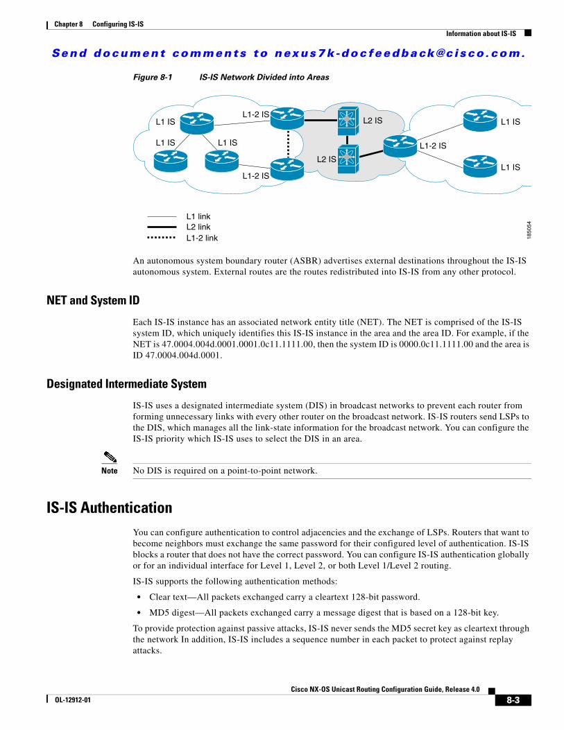
Send document comments to nexus7k -doc feedback@c i sco .com.
Chapter 8 Configuring IS-ISInformation about IS-IS
Figure 8-1 IS-IS Network Divided into Areas
An autonomous system boundary router (ASBR) advertises external destinations throughout the IS-IS autonomous system. External routes are the routes redistributed into IS-IS from any other protocol.
NET and System ID
Each IS-IS instance has an associated network entity title (NET). The NET is comprised of the IS-IS system ID, which uniquely identifies this IS-IS instance in the area and the area ID. For example, if the NET is 47.0004.004d.0001.0001.0c11.1111.00, then the system ID is 0000.0c11.1111.00 and the area is ID 47.0004.004d.0001.
Designated Intermediate System
IS-IS uses a designated intermediate system (DIS) in broadcast networks to prevent each router from forming unnecessary links with every other router on the broadcast network. IS-IS routers send LSPs to the DIS, which manages all the link-state information for the broadcast network. You can configure the IS-IS priority which IS-IS uses to select the DIS in an area.
Note No DIS is required on a point-to-point network.
IS-IS AuthenticationYou can configure authentication to control adjacencies and the exchange of LSPs. Routers that want to become neighbors must exchange the same password for their configured level of authentication. IS-IS blocks a router that does not have the correct password. You can configure IS-IS authentication globally or for an individual interface for Level 1, Level 2, or both Level 1/Level 2 routing.
IS-IS supports the following authentication methods:
• Clear text—All packets exchanged carry a cleartext 128-bit password.
• MD5 digest—All packets exchanged carry a message digest that is based on a 128-bit key.
To provide protection against passive attacks, IS-IS never sends the MD5 secret key as cleartext through the network In addition, IS-IS includes a sequence number in each packet to protect against replay attacks.
L1 IS L1 IS
L1 IS
L1-2 IS
L1-2 IS
L1-2 ISL1 IS L1 IS
L2 IS
L2 IS
L1 linkL2 linkL1-2 link 18
5054
8-3Cisco NX-OS Unicast Routing Configuration Guide, Release 4.0
OL-12912-01

Send document comments to nexus7k -doc feedback@c i sco .com.
Chapter 8 Configuring IS-ISInformation about IS-IS
You can use also keychains for hello and LSP authentication. See Cisco Cisco NX-OS Security Configuration Guide for information on keychain management.
Mesh GroupsA mesh group is a set of interfaces in which all routers reachable over the interfaces have at least one link to every other router. Many links can fail without isolating one or more routers from the network.
In normal flooding, an interface receives a new LSP and floods the LSP out over all other interfaces on the router. With mesh groups, when an interface that is part of a mesh group receives a new LSP, the interface does not flood the new LSP over the other interfaces that are part of that mesh group.
Note You may want to limit LSPs in certain mesh network topologies to improve network scalability. Limiting LSP floods may also reduce the reliability of the network (in case of failures). For this reason, we recommend that you use mesh groups only if specifically required, and then only after careful network design.
You can also configure mesh groups in block mode for parallel links between routers. In this mode, all LSPs are blocked on that interface in a mesh group after the routers initially exchange their link-state information.
Overload BitIS-IS uses the overload bit to tell other routers not to use the local router to forward traffic but to continue routing traffic destined for that local router.
You may want to use the overload bit in these situations:
• The router is in a critical condition.
• Graceful introduction and removal of the router to/from the network.
• Other (administrative or traffic engineering) reasons. For example, to wait for BGP convergence.
Route SummarizationYou can configure a summary aggregate address. Route summarization simplifies route tables by replacing a number of more-specific addresses with an address that represents all the specific addresses. For example, you can replace 10.1.1.0/24, 10.1.2.0/24, and 10.1.3.0/24 with one summary address, 10.1.0.0/16.
If more specific routes are in the routing table, IS-IS advertises the summary address with a metric equal to the minimum metric of the more specific routes.
Note Cisco NX-OS does not support automatic route summarization.
8-4Cisco NX-OS Unicast Routing Configuration Guide, Release 4.0
OL-12912-01

Send document comments to nexus7k -doc feedback@c i sco .com.
Chapter 8 Configuring IS-ISInformation about IS-IS
Route RedistributionYou can use IS-IS to redistribute static routes, routes learned by other IS-IS autonomous systems, or routes from other protocols. You configure redistribution by useing a route policy to control which routes are passed into IS-IS. A route policy allows you to filter routes based on attributes such as the destination, origination protocol, route type, route tag, and so on. For more information, see Chapter 14, “Configuring Route Policy Manager.”
Whenever you redistribute routes into an IS-IS routing domain, Cisco NX-OS does not, by default, redistribute the default route into the IS-IS routing domain. You can generate a default route into IS-IS, which can be controlled by a route policy.
You also configure the default metric that is used for all imported routes into IS-IS.
Load BalancingYou can use load balancing to allow a router to distribute traffic over all the router network ports that are the same distance from the destination address. Load balancing increases the utilization of network segments and increases effective network bandwidth.
Cisco NX-OS supports the Equal Cost Multiple Paths (ECMP) feature with up to 16 equal-cost paths in the IS-IS route table and the unicast RIB. You can configure IS-IS to load balance traffic across some or all of those paths.
Virtualization SupportCisco NX-OS supports multiple instances of the IS-IS protocol that runs on the same system. IS-IS supports Virtual Routing and Forwarding instances (VRFs). VRFs exist within virtual device contexts (VDCs). You can configure up to four IS-IS instances in a VDC.
By default, Cisco NX-OS places you in the default VDC and default VRF unless you specifically configure another VDC and VRF. See the Cisco NX-OS Virtual Device Context Configuration Guide and Chapter 13, “Configuring Layer 3 Virtualization.”
High Availability and Graceful RestartIf a Cisco NX-OS system experiences a cold reboot, the network does not forward traffic to the system and removes the system from the network topology. In this scenario, IS-IS experiences a stateless restart, and Cisco NX-OS removes all neighbors. Cisco NX-OS applies the startup configuration, and IS-IS rediscovers the neighbors and shares the full IS-IS routing information again.
Cisco NX-OS supports high-availability. If a Cisco NX-OS system experiences a cold reboot, the network stops forwarding traffic to the system and removes the system from the network topology. In this scenario, IS-IS experiences a stateless restart, and removes all neighbors on the local system. Cisco NX-OS applies the startup configuration and IS-IS rediscovers the neighbors and and shares the full IS-IS routing information again..
A platform with two supervisors that run Cisco NX-OS can experience a stateful supervisor switchover. Before the switchover happens, IS-IS initiates a graceful restart by announcing that IS-IS will be unavailable for some time. During a switchover, the network continues to forward traffic and keeps the system in the network topology.
8-5Cisco NX-OS Unicast Routing Configuration Guide, Release 4.0
OL-12912-01

Send document comments to nexus7k -doc feedback@c i sco .com.
Chapter 8 Configuring IS-ISLicensing Requirements for IS-IS
After a switchover, Cisco NX-OS applies the running configuration, and IS-IS informs the neighbors that it is operational again.
IS-IS automatically restarts if the process experiences problems. After the restart, IS-IS initiates a graceful restart so that the platform is not taken out of the network topology. If you manually restart IS-IS, it performs a graceful restart, which is similar to a stateful switchover. The running configuration is applied in both cases.
Note You must enable graceful restart to support in-service software upgrades (ISSU) for IS-IS. If you disable graceful restart, Cisco NX-OS issues a warning that ISSU cannot be supported with this configuration.
Multiple IS-IS Instances Cisco NX-OS supports a maximum of four instances of the IS-IS protocol that run on the same node. You cannot configure multiple instances over the same interface. Every instance uses the same system router ID.
Licensing Requirements for IS-ISThe following table shows the licensing requirements for this feature:
Prerequisites for IS-ISIS-IS has the following prerequisites:
• You must enable the IS-IS feature (see the “Enabling the IS-IS Feature” section on page 8-8).
• If you configure VDCs, install the Advanced Services license and enter the desired VDC (see the Cisco NX-OS Virtual Device Context Configuration Guide).
Configuration Guidelines and LimitationsIS-IS has the following configuration guidelines and limitations:
• You can configure a maximum of four IS-IS instances per VDC.
Configuring IS-ISTo confiure IS-IS, follow these steps:
Product License Requirement
NX-OS IS-IS requires an Enterprise Services license. For a complete explanation of the NX-OS licensing scheme and how to obtain and apply licenses, see the Cisco NX-OS Licensing Guide.
8-6Cisco NX-OS Unicast Routing Configuration Guide, Release 4.0
OL-12912-01

Send document comments to nexus7k -doc feedback@c i sco .com.
Chapter 8 Configuring IS-ISConfiguring IS-IS
Step 1 Enable the IS-IS feature (see the “Enabling the IS-IS Feature” section on page 8-8).
Step 2 Create an IS-IS instance (see the “Creating an IS-IS Instance” section on page 8-9).
Step 3 Add an interface to the IS-IS instance (see the “Configuring IS-IS on an Interface” section on page 8-11).
Step 4 Configure optional features, such as authentication, mesh groups, and dynamic host exchange.
This section contains the following topics:
• IS-IS Configuration Modes, page 8-7
• Enabling the IS-IS Feature, page 8-8
• Creating an IS-IS Instance, page 8-9
• Configuring IS-IS on an Interface, page 8-11
• Configuring IS-IS Authentication in an Area, page 8-13
• Configuring IS-IS Authentication on an Interface, page 8-14
• Configuring a Mesh Group, page 8-15
• Configuring a Designated Intermediate System, page 8-16
• Configuring Dynamic Host Exchange, page 8-16
• Setting the Overload Bit, page 8-16
• Configuring a Summary Address, page 8-17
• Configuring Redistribution, page 8-18
• Configuring Virtualization, page 8-21
• Tuning IS-IS, page 8-24
Note If you are familiar with the Cisco IOS CLI, be aware that the Cisco NX-OS commands for this feature might differ from the Cisco IOS commands that you would use.
IS-IS Configuration ModesThe following sections show how to enter each of the configuration modes. From a mode, you can enter the ? command to display the commands available in that mode.
This section includes the following topics:
• Router Configuration Mode, page 8-7
• Router Address Family Configuration Mode, page 8-8
Router Configuration Mode
The following example shows how to enter router configuration mode:
switch#: conf tswitch(config)# router isis ispswitch(config-router)#
8-7Cisco NX-OS Unicast Routing Configuration Guide, Release 4.0
OL-12912-01

Send document comments to nexus7k -doc feedback@c i sco .com.
Chapter 8 Configuring IS-ISConfiguring IS-IS
Router Address Family Configuration Mode
The following example shows how to enter router address family configuration mode:
switch(config)# router isis ispswitch(config-router)# address-family ipv6 unicastswitch(config-router-af)#
Enabling the IS-IS FeatureYou must enable the IS-IS feature before you can configure IS-IS.
BEFORE YOU BEGIN
Ensure that you are in the correct VDC (or use the switchto vdc command).
SUMMARY STEPS
1. config t
2. feature isis
3. copy running-config startup-config
DETAILED STEPS
Use the no feature isis command to disable the IS-IS feature and remove all associated configuration.
Command Purpose
Step 1 config t
Example:switch# config tswitch(config)#
Enters configuration mode.
Step 2 feature isis
Example:switch(config)# feature isis
Enables the IS-IS feature.
Step 3 copy running-config startup-config
Example:switch(config)# copy running-config startup-config
(Optional) Saves this configuration change.
Command Purpose
no feature isis
Example:switch(config)# no feature isis
Disables the IS-IS feature and removes all associated configuration.
8-8Cisco NX-OS Unicast Routing Configuration Guide, Release 4.0
OL-12912-01

Send document comments to nexus7k -doc feedback@c i sco .com.
Chapter 8 Configuring IS-ISConfiguring IS-IS
Creating an IS-IS InstanceYou can create an IS-IS instance and configure the area level for that instance.
BEFORE YOU BEGIN
Ensure that you have enabled the IS-IS feature (see the “Enabling the IS-IS Feature” section on page 8-8).
Ensure that you are in the correct VDC (or use the switchto vdc command).
SUMMARY STEPS
1. config t
2. router is-is instance-tag
3. net network-entity-title
4. is-type {level-1 | level-2 | level-1-2}
5. show isis [vrf vrf-name] process
6. copy running-config startup-config
DETAILED STEPS
Command Purpose
Step 1 config t
Example:switch# config tswitch(config)#
Enters configuration mode.
Step 2 router isis instance-tag
Example:switch(config)# router isis Enterpriseswitch(config-router)#
Creates a new IS-IS instance with the configured instance tag.
Step 3 net network-entity-title
Example:switch(config-router)# net 47.0004.004d.0001.0001.0c11.1111.00
Configures the NET for this IS-IS instance.
Step 4 is-type {level-1 | level-2 | level-1-2}
Example:switch(config-router)# is-type level-2
(Optional) Configures the area level for this IS-IS instance. The default is level-1-2.
Step 5 show isis [vrf vrf-name] process
Example:switch(config)# show isis process
(Optional) Displays a summary of IS-IS information for all IS-IS instances.
Step 6 copy running-config startup-config
Example:switch(config)# copy running-config startup-config
(Optional) Saves this configuration change.
8-9Cisco NX-OS Unicast Routing Configuration Guide, Release 4.0
OL-12912-01
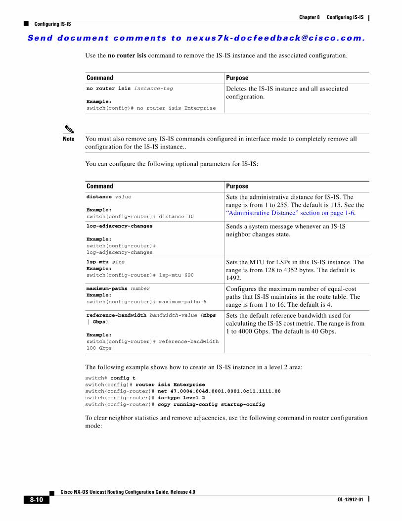
Send document comments to nexus7k -doc feedback@c i sco .com.
Chapter 8 Configuring IS-ISConfiguring IS-IS
Use the no router isis command to remove the IS-IS instance and the associated configuration.
Note You must also remove any IS-IS commands configured in interface mode to completely remove all configuration for the IS-IS instance..
You can configure the following optional parameters for IS-IS:
The following example shows how to create an IS-IS instance in a level 2 area:
switch# config tswitch(config)# router isis Enterpriseswitch(config-router)# net 47.0004.004d.0001.0001.0c11.1111.00switch(config-router)# is-type level 2switch(config-router)# copy running-config startup-config
To clear neighbor statistics and remove adjacencies, use the following command in router configuration mode:
Command Purposeno router isis instance-tag
Example:switch(config)# no router isis Enterprise
Deletes the IS-IS instance and all associated configuration.
Command Purposedistance value
Example:switch(config-router)# distance 30
Sets the administrative distance for IS-IS. The range is from 1 to 255. The default is 115. See the “Administrative Distance” section on page 1-6.
log-adjacency-changes
Example:switch(config-router)# log-adjacency-changes
Sends a system message whenever an IS-IS neighbor changes state.
lsp-mtu sizeExample:switch(config-router)# lsp-mtu 600
Sets the MTU for LSPs in this IS-IS instance. The range is from 128 to 4352 bytes. The default is 1492.
maximum-paths numberExample:switch(config-router)# maximum-paths 6
Configures the maximum number of equal-cost paths that IS-IS maintains in the route table. The range is from 1 to 16. The default is 4.
reference-bandwidth bandwidth-value {Mbps | Gbps}
Example:switch(config-router)# reference-bandwidth 100 Gbps
Sets the default reference bandwidth used for calculating the IS-IS cost metric. The range is from 1 to 4000 Gbps. The default is 40 Gbps.
8-10Cisco NX-OS Unicast Routing Configuration Guide, Release 4.0
OL-12912-01
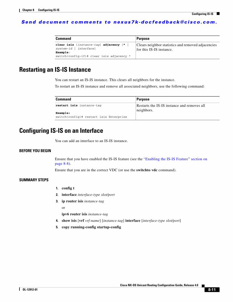
Send document comments to nexus7k -doc feedback@c i sco .com.
Chapter 8 Configuring IS-ISConfiguring IS-IS
Restarting an IS-IS InstanceYou can restart an IS-IS instance. This clears all neighbors for the instance.
To restart an IS-IS instance and remove all associated neighbors, use the following command:
Configuring IS-IS on an InterfaceYou can add an interface to an IS-IS instance.
BEFORE YOU BEGIN
Ensure that you have enabled the IS-IS feature (see the “Enabling the IS-IS Feature” section on page 8-8).
Ensure that you are in the correct VDC (or use the switchto vdc command).
SUMMARY STEPS
1. config t
2. interface interface-type slot/port
3. ip router isis instance-tag
or
ipv6 router isis instance-tag
4. show isis [vrf vrf-name] [instance-tag] interface [interface-type slot/port]
5. copy running-config startup-config
Command Purpose
clear isis [instance-tag] adjacency [* | system-id | interface]Example:switch(config-if)# clear isis adjacency *
Clears neighbor statistics and removed adjacencies for this IS-IS instance.
Command Purpose
restart isis instance-tag
Example:switch(config)# restart isis Enterprise
Restarts the IS-IS instance and removes all neighbors.
8-11Cisco NX-OS Unicast Routing Configuration Guide, Release 4.0
OL-12912-01

Send document comments to nexus7k -doc feedback@c i sco .com.
Chapter 8 Configuring IS-ISConfiguring IS-IS
DETAILED STEPS
You can configure the following optional parameters for IS-IS in interface mode:
Command Purpose
Step 1 config t
Example:switch# config tswitch(config)#
Enters configuration mode.
Step 2 interface interface-type slot/port
Example:switch(config)# interface ethernet 1/2switch(config-if)#
Enters interface configuration mode.
Step 3 ip router isis instance-tag
Example:switch(config-if)# ip router isis Enterprise
Associates this IPv4 interface with an IS-IS instance.
ipv6 router isis instance-tag
Example:switch(config-if)# ipv6 router isis Enterprise
Associates this IPv6 interface with an IS-IS instance.
Step 4 show isis [vrf vrf-name] [instance-tag] interface [interface-type slot/port]
Example:switch(config)# show isis Enterprise ethernet 1/2
(Optional) Displays IS-IS information for an interface.
Step 5 copy running-config startup-config
Example:switch(config)# copy running-config startup-config
(Optional) Saves this configuration change.
Command Purposeisis circuit-type {level-1 | level-2 | level-1-2}
Example:switch(config-if)# isis circuit-type level-2
Sets the type of adjacency that this interface participates in. Use this command only for routers that participate in both Level 1 and Level 2 areas.
isis metric value {level-1 | level-2}
Example:switch(config-if)# isis metric 30
Sets the IS-IS metric for this interface. The range is from 1 to 16777214. The default is 10.
isis passive {level-1 | level-2 | level-1-2}
Example:switch(config-if)# isis passive level-2
Prevents the interface from forming adjacencies but still advertises the prefix associated with the interface.
8-12Cisco NX-OS Unicast Routing Configuration Guide, Release 4.0
OL-12912-01

Send document comments to nexus7k -doc feedback@c i sco .com.
Chapter 8 Configuring IS-ISConfiguring IS-IS
The following example shows how to add Ethernet 1/2 interface to an IS-IS instance:
switch# config tswitch(config)# interface ethernet 1/2switch(config-if)# ip router isis Enterpriseswitch(config-if)# copy running-config startup-config
Configuring IS-IS Authentication in an AreaYou can configure IS-IS to authenticate LSPs in an area.
BEFORE YOU BEGIN
Ensure that you have enabled the IS-IS feature (see the “Enabling the IS-IS Feature” section on page 8-8).
Ensure that you are in the correct VDC (or use the switchto vdc command).
SUMMARY STEPS
1. config t
2. router isis instance-tag
3. authentication-type {cleartext | md5} {level-1 | level-2}
4. authentication-key keychain key {level-1 | level-2}
5. authentication-check {level-1 | level-2}
6. copy running-config startup-config
DETAILED STEPS
Command Purpose
Step 1 config t
Example:switch# config tswitch(config)#
Enters configuration mode.
Step 2 router isis instance-tag
Example:switch(config)# router isis Enterpriseswitch(config-router)#
Creates a new IS-IS instance with the configured instance tag.
Step 3 authentication-type {cleartext | md5} {level-1 | level-2}
Example:switch(config-router)# authentication-type cleartext level-2
Sets the authentication method used for a Level 1 or Level 2 area as cleartext or as an MD5 authentication digest.
8-13Cisco NX-OS Unicast Routing Configuration Guide, Release 4.0
OL-12912-01

Send document comments to nexus7k -doc feedback@c i sco .com.
Chapter 8 Configuring IS-ISConfiguring IS-IS
The following example shows how to configure cleartext authentication on an IS-IS instance:
switch# config tswitch(config)# router isis Enterpriseswitch(config-router)# authentication-type cleartext level-2switch(config-router)# authentication-key keychain ISISKey level-2switch(config-router)# copy running-config startup-config
Configuring IS-IS Authentication on an InterfaceYou can configure IS-IS to authenticate Hello packets on an interface.
BEFORE YOU BEGIN
Ensure that you have enabled the IS-IS feature (see the “Enabling the IS-IS Feature” section on page 8-8).
Ensure that you are in the correct VDC (or use the switchto vdc command).
SUMMARY STEPS
1. config t
2. interface interface-type slot/port
3. isis authentication-type {cleartext | md5} [level-1 | level-2]
4. isis authentication-key keychain key [level-1 | level-2]
5. isis authentication-check [level-1 | level-2]
6. copy running-config startup-config
Step 4 authentication-key keychain key {level-1 | level-2}
Example:switch(config-router)# authentication-key ISISKey level-2
Configures the authentication key used for an IS-IS area-level authentication.
Step 5 authentication-check {level-1 | level-2}
Example:switch(config-router)# authentication-check level-2
(Optional) Enables checking the authentication parameters in a received packet.
Step 6 copy running-config startup-config
Example:switch(config-router)# copy running-config startup-config
(Optional) Saves this configuration change.
Command Purpose
8-14Cisco NX-OS Unicast Routing Configuration Guide, Release 4.0
OL-12912-01

Send document comments to nexus7k -doc feedback@c i sco .com.
Chapter 8 Configuring IS-ISConfiguring IS-IS
DETAILED STEPS
The following example shows how to configure cleartext authentication on an IS-IS instance:
switch# config tswitch(config)# interface ethernet 1/2switch(config-if)# isis authentication-type cleartext level-2switch(config-if)# isis authentication-key keychain ISISKeyswitch(config-if)# copy running-config startup-config
Configuring a Mesh GroupYou can add an interface to a mesh group to limit the amount of LSP flooding for interfaces in that mesh group. You can optionally block all LSP flooding on an interface in a mesh group.
To add an interface to a mesh group, use the following command in interface configuration mode:
Command Purpose
Step 1 config t
Example:switch# config tswitch(config)#
Enters configuration mode.
Step 2 interface interface-type slot/port
Example:switch(config)# interface ethernet 1/2switch(config-if)#
Enters interface configuration mode.
Step 3 isis authentication-type {cleartext | md5} [level-1 | level-2]
Example:switch(config-if)# isis authentication-type cleartext level-2
Sets the authentication type for IS-IS on this interface as cleartext or as an MD5 authentication digest.
Step 4 isis authentication-key keychain key [level-1 | level-2]
Example:switch(config-if)# isis authentication-key ISISKey level-2
Configures the authentication key used for IS-IS on this interface.
Step 5 isis authentication-check {level-1 | level-2}
Example:switch(config-if)# isis authentication-check
Optional) Enables checking the authentication parameters in a received packet.
Step 6 copy running-config startup-config
Example:switch(config-if)# copy running-config startup-config
(Optional) Saves this configuration change.
8-15Cisco NX-OS Unicast Routing Configuration Guide, Release 4.0
OL-12912-01

Send document comments to nexus7k -doc feedback@c i sco .com.
Chapter 8 Configuring IS-ISConfiguring IS-IS
Configuring a Designated Intermediate SystemYou can configure a router to become the designated intermediate system (DIS) for a multiaccess network by setting the interface priority.
To configure the DIS, use the following command in interface configuration mode:
Configuring Dynamic Host ExchangeYou can configure IS-IS to map between the system ID and the hostname for a router using dynamic host exchange.
To configure dynamic host exchange, use the following command in router configuration mode:
Setting the Overload BitYou can configure the router to signal other routers not to use this router as an intermediate hop in their shortest path first (SPF) calculations. You can optionally configure the overload bit temporarily on startup, until BGP converges.
In addition to setting the overload bit, you might also want to suppress certain types of IP prefix advertisements from LSPs for Level 1 or Level 2 traffic.
To set the overload bit, use the following command in router configuration mode:
Command Purpose
isis mesh-group {blocked | mesh-id}
Example:switch(config-if)# isis mesh-group 1
Adds this interface to a mesh group. The range is from 1 to 4294967295.
Command Purpose
isis priority number
Example:switch(config-if)# isis priority 100
Sets the priority for DIS selection. Range is from 0 to 127. The default is 64.
Command Purpose
hostname dynamic
Example:switch(config-router)# hostname dynamic
Enables dynamic host exchange.
8-16Cisco NX-OS Unicast Routing Configuration Guide, Release 4.0
OL-12912-01

Send document comments to nexus7k -doc feedback@c i sco .com.
Chapter 8 Configuring IS-ISConfiguring IS-IS
Configuring a Summary AddressYou can create aggregate addresses that are represented in the routing table by a summary address. One summary address can include multiple groups of addresses for a given level. Cisco NX-OS advertises the smallest metric of all the more-specific routes.
BEFORE YOU BEGIN
Ensure that you have enabled the IS-IS feature (see the “Enabling the IS-IS Feature” section on page 8-8).
Ensure that you are in the correct VDC (or use the switchto vdc command).
SUMMARY STEPS
1. config t
2. router isis instance-tag
3. address-family {ipv4 | ipv6} {unicast | multicast}
4. summary-address {ip-prefix/mask-len | ipv6-prefix/mask-len} {level-1 | level-2 | level-1-2}
5. show isis [vrf vrf-name] ip summary-address ip-prefix [longer-prefixes]
6. show isis [vrf vrf-name] ipv6 summary-address ipv6-prefix [longer-prefixes]
7. copy running-config startup-config
DETAILED STEPS
Command Purpose
set-overload-bit {always | on-startup {seconds | wait-for bgp as-number}} [suppress [interlevel | external]]
Example:switch(config-router)# set-overload-bit on-startup 30
Sets the overload bit for IS-IS. The seconds range is from 5 to 86400.
Command Purpose
Step 1 config t
Example:switch# config tswitch(config)#
Enters configuration mode.
Step 2 router isis instance-tag
Example:switch(config)# router isis Enterpriseswitch(config-router)#
Creates a new IS-IS instance with the configured instance tag.
8-17Cisco NX-OS Unicast Routing Configuration Guide, Release 4.0
OL-12912-01

Send document comments to nexus7k -doc feedback@c i sco .com.
Chapter 8 Configuring IS-ISConfiguring IS-IS
The following example shows how to configure an IPv4 unicast summary address for IS-IS:
switch# config tswitch(config)# router isis Enterpriseswitch(config-router)# address-family ipv4 unicastswitch(config-router-af)# summary-address 192.0.2.0/24 level-2switch(config-router-af)# copy running-config startup-config
Configuring RedistributionYou can configure IS-IS to accept routing information from another routing protocol and redistribute that information through the IS-IS network. You can optionally assign a default route for redistributed routes.
BEFORE YOU BEGIN
Ensure that you have enabled the IS-IS feature (see the “Enabling the IS-IS Feature” section on page 8-8).
Ensure that you are in the correct VDC (or use the switchto vdc command).
Step 3 address-family {ipv4 | ipv6} {unicast | multicast}
Example:switch(config-router)# address-family ipv4 unicastswitch(config-router-af)#
Enters address family configuration mode.
Step 4 summary-address {ip-prefix/mask-len | ipv6-prefix/mask-len} {level-1 | level-2 | level-1-2}
Example:switch(config-router-af)# summary-address 192.0.2.0/24 level-2
Configures a summary address for an ISIS area for IPv4 or IPv6 addresses.
Step 5 show isis [vrf vrf-name] ip summary-address ip-prefix [longer-prefixes]]
Example:switch(config-if)# show isis ip summary-address
(Optional) Displays IS-IS IPv4 summary address information.
Step 6 show isis [vrf vrf-name] ipv6 summary-address ipv6-prefix [longer-prefixes]]
Example:switch(config-if)# show isis ipv6 summary-address
(Optional) Displays IS-IS IPv6 summary address information.
Step 7 copy running-config startup-config
Example:switch(config--if)# copy running-config startup-config
(Optional) Saves this configuration change.
Command Purpose
8-18Cisco NX-OS Unicast Routing Configuration Guide, Release 4.0
OL-12912-01

Send document comments to nexus7k -doc feedback@c i sco .com.
Chapter 8 Configuring IS-ISConfiguring IS-IS
SUMMARY STEPS
1. config t
2. router isis instance-tag
3. address-family {ipv4 | ipv6} {unicast | multicast}
4. redistribute {bgp as | direct | eigrp as | isis id | ospf id | ospfv3 id | rip id | static } route-map map-name
5. default-information originate [always] [route-map map-name]
6. distribute {level-1 | level-2} into {level-1 | level-2} {route-map route-map | all}
7. show isis [vrf vrf-name] {ip | ipv6} route {ip-prefix | ip6-prefix}[detail | longer-prefixes [summary | detail]]
8. copy running-config startup-config
DETAILED STEPS
Command Purpose
Step 1 config t
Example:switch# config tswitch(config)#
Enters configuration mode.
Step 2 router isis instance-tag
Example:switch(config)# router isis Enterpriseswitch(config-router)#
Creates a new IS-IS instance with the configured instance tag.
Step 3 address-family {ipv4 | ipv6} {unicast | multicast}
Example:switch(config-router)# address-family ipv4 unicastswitch(config-router-af)#
Enters address family configuration mode.
Step 4 redistribute {bgp as | direct | eigrp as | isis id | ospf id | ospfv3 id | rip id | static | direct} route-map map-name
Example:switch(config-router-af)# redistribute eigrp 201 route-map ISISmap
Redistributes routes from other protocols into IS-IS. See the “Configuring Route Maps” section on page 14-9 for more information about route maps.
Step 5 default-information originate [always] [route-map map-name]
Example:switch(config-router-af)# default-information originate always
(Optional) Generates a default route into IS-IS.
Step 6 distribute {level-1 | level-2} into {level-1 | level-2} {route-map route-map | all}
Example:switch(config-router-af)# distribute level-1 into level-2 all
(Optional) Redistributes routes from one IS-IS level to the other IS-IS level.
8-19Cisco NX-OS Unicast Routing Configuration Guide, Release 4.0
OL-12912-01

Send document comments to nexus7k -doc feedback@c i sco .com.
Chapter 8 Configuring IS-ISConfiguring IS-IS
The following example shows how to redistribute EIGRP into IS-IS:
switch# config tswitch(config)# router isis Enterpriseswitch(config-router)# address-family ipv4 unicastswitch(config-router-af)# redistribute eigrp 201 route-map ISISmapswitch(config-router-af)# copy running-config startup-config
Configuring a Graceful RestartYou can configure a graceful restart for IS-IS.
BEFORE YOU BEGIN
Ensure that you have enabled the IS-IS feature (see the “Enabling the IS-IS Feature” section on page 8-8).
Create the VDCs and VRFs.
Ensure that you are in the correct VDC (or use the switchto vdc command).
SUMMARY STEPS
1. config t
2. router isis instance-tag
3. graceful-restart
4. graceful-restart t3 manual time
5. show running-config isis
6. copy running-config startup-config
Step 7 show isis [vrf vrf-name] {ip | ipv6} route {ip-prefix ip6-prefix}[detail | longer-prefixes [summary | detail]]
Example:switch(config-router-af)# show isis ip route
(Optional) Shows the routes IS-IS.
Step 8 copy running-config startup-config
Example:switch(config-router-af)# copy running-config startup-config
(Optional) Saves this configuration change.
Command Purpose
8-20Cisco NX-OS Unicast Routing Configuration Guide, Release 4.0
OL-12912-01

Send document comments to nexus7k -doc feedback@c i sco .com.
Chapter 8 Configuring IS-ISConfiguring IS-IS
DETAILED STEPS
The following example shows how to enable a graceful restart:
switch# config tswitch(config)# router isis Enterpriseswitch(config-router)# graceful-restartswitch(config-router)# copy running-config startup-config
Configuring VirtualizationYou can configure multiple IS-IS instances in each VDC. You can also create multiple VRFs within each VDC and use the same or multiple IS-IS instances in each VRF. You assign an IS-IS interface to a VRF.
You must configure a NET for the configured VRF.
Note Configure all other parameters for an interface after you configure the VRF for an interface. Configuring a VRF for an interface deletes all the configuration for that interface.
Command Purpose
Step 1 config t
Example:switch# config tswitch(config)#
Enters configuration mode.
Step 2 router isis instance-tag
Example:switch(config)# router isis Enterpriseswitch(config-router)#
Creates a new IS-IS process with the configured name.
Step 3 graceful-restart
Example:switch(config-router)# graceful-restart
Enables a graceful restart and the graceful restart helper functionality. Enabled by default.
Step 4 graceful-restart t3 manual time
Example:switch(config-router)# graceful-restart t3 manual 300
Configures the graceful restart T3 timer. The range isfrom 30 to 65535 seconds. The default is 60.
Step 5 show running-config isis
Example:switch(config-router)# show running-config isis
(Optional) Displays the IS-IS configuration.
Step 6 copy running-config startup-config
Example:switch(config-router)# copy running-config startup-config
(Optional) Saves this configuration change.
8-21Cisco NX-OS Unicast Routing Configuration Guide, Release 4.0
OL-12912-01

Send document comments to nexus7k -doc feedback@c i sco .com.
Chapter 8 Configuring IS-ISConfiguring IS-IS
BEFORE YOU BEGIN
Ensure that you have enabled the IS-IS feature (see the “Enabling the IS-IS Feature” section on page 8-8).
Create the VDCs.
Ensure that you are in the correct VDC (or use the switchto vdc command).
SUMMARY STEPS
1. config t
2. vrf context vrf_name
3. exit
4. router isis instance-tag
5. vrf vrf_name
6. net network-entity-title
7. configure optional parameters
8. interface type slot/port
9. vrf member vrf-name
10. ip address ip-prefix/length
11. ip router isis instance-tag
or
ipv6 router isis instance-tag
12. show isis [vrf vrf-name] [instance-tag] interface [interface-type slot/port]
13. copy running-config startup-config
DETAILED STEPS
Command Purpose
Step 1 config t
Example:switch# config tswitch(config)#
Enters configuration mode.
Step 2 vrf context vrf-name
Example:switch(config)# vrf context RemoteOfficeVRFswitch(config-vrf)#
Creates a new VRF and enters VRF configuration mode.
Step 3 router isis instance-tag
Example:switch(config)# router isis Enterpriseswitch(config-router)#
Creates a new IS-IS instance with the configured instance tag.
8-22Cisco NX-OS Unicast Routing Configuration Guide, Release 4.0
OL-12912-01

Send document comments to nexus7k -doc feedback@c i sco .com.
Chapter 8 Configuring IS-ISConfiguring IS-IS
Step 4 vrf vrf-name
Example:switch(config-router)# vrf RemoteOfficeVRFswitch(config-router-vrf)#
(Optional) Enters VRF configuration mode.
Step 5 net network-entity-title
Example:switch(config-router-vrf)# net 47.0004.004d.0001.0001.0c11.1111.00
Configures the NET for this IS-IS instance.
Step 6 exit
Example:switch(config-router)# exitswitch(config-router)#
Exits router VRF configuration mode.
Step 7 address-family {ipv4 | ipv6} {unicast | multicast}
Example:switch(config-router)# address-family ipv4 unicastswitch(config-router-af)#
(Optional) Enters address family configuration mode.
Step 8 redistribute {bgp as | direct | eigrp as | isis id | ospf id | ospfv3 id | rip id | static | direct} route-map map-name
Example:switch(config-router-af)# redistribute eigrp 201 route-map ISISmap
(Optional) Redistributes routes from other protocols into IS-IS. See the “Configuring Route Maps” section on page 14-9 for more information about route maps.
Step 9 interface ethernet slot/port
Example:switch(config)# interface ethernet 1/2switch(config-if)#
Enters interface configuration mode.
Step 10 vrf member vrf-name
Example:switch(config-if)# vrf member RemoteOfficeVRF
Adds this interface to a VRF.
Step 11 ip address ip-prefix/length
Example:switch(config-if)# ip address 209.0.2.1/16
Configures an IP address for this interface. You must do this step after you assign this interface to a VRF.
Step 12 ip router isis instance-tag
Example:switch(config-if)# ip router isis Enterprise
Associates this IPv4 interface with an IS-IS instance.
ipv6 router isis instance-tag
Example:switch(config-if)# ipv6 router isis Enterprise
Associates this IPv6 interface with an IS-IS instance.
Command Purpose
8-23Cisco NX-OS Unicast Routing Configuration Guide, Release 4.0
OL-12912-01

Send document comments to nexus7k -doc feedback@c i sco .com.
Chapter 8 Configuring IS-ISConfiguring IS-IS
The following example shows how to create a VRF and add an interface to the VRF:
switch# config tswitch(config)# vrf context NewVRFswitch(config-vrf)# exitswitch(config)# router isis Enterpriseswitch(config-router)# vrf NewVRFswitch(config-router-vrf)# net 47.0004.004d.0001.0001.0c11.1111.00switch(config-router-vrf)# interface ethernet 1/2switch(config-if)# vrf membmer NewVRFswitch(config-if)# ip address 209.0.2.1/16switch(config-if)# ip router isis Enterpriseswitch(config-if)# copy running-config startup-config
Tuning IS-ISYou can tune IS-IS to match your network requirements.
You can use the following optional commands in router configuration mode to tune IS-IS:
Step 13 show isis [vrf vrf-name] [instance-tag] interface [interface-type slot/port]
Example:switch(config-if)# show isis Enterprise ethernet 1/2
(Optional) Displays IS-IS information for an interface. in a VRF.
Step 14 copy running-config startup-config
Example:switch(config-if)# copy running-config startup-config
(Optional) Saves this configuration change.
Command Purpose
Command Purpose
lsp-gen-interval [level-1 | level-2] lsp-max-wait [lsp-initial-wait lsp-second-wait]
Example:switch(config-router)# lsp-gen-interval level-1 500 500 500
Configures the IS-IS throttle for LSP generation. The optional parameters are as follows:
• lsp-max-wait—The maximum wait between the trigger and LSP generation. The range is from 500 to 65535 milliseconds.
• lsp-initial-wait—The initial wait between the trigger and LSP generation. The range is from 50 to 65535 milliseconds.
• lsp-second-wait—The second wait used for LSP throttle during backoff. The range is from 50 to 65535 milliseconds.
max-lsp-lifetime lifetime
Example:switch(config-router)# max-lsp-lifetime 500
Sets the maximum LSP lifetime in seconds. The range is from 1 to 65535. The default is 1200.
8-24Cisco NX-OS Unicast Routing Configuration Guide, Release 4.0
OL-12912-01

Send document comments to nexus7k -doc feedback@c i sco .com.
Chapter 8 Configuring IS-ISConfiguring IS-IS
You can use the following optional command in router address configuration mode:
You can use the following optional commands in interface configuration mode to tune IS-IS:
spf-interval [level-1 | level-2] spf-max-wait [spf-initial-wait spf-second-wait]
Example:switch(config-router)# spf-interval level-2 500 500 500
Configures the interval between LSA arrivals. The optional parameters are as follows:
• lsp-max-wait—The maximum wait between the trigger and SPF computation. The range is from 500 to 65535 milliseconds.
• lsp-initial-wait—The initial wait between the trigger and SPF computation. The range is from 50 to 65535 milliseconds.
• lsp-second-wait—The second wait used for SPF computation during backoff. The range is from 50 to 65535 milliseconds.
shutdown
Example:switch(config-router)# shutdown
Shuts down this IS-IS instance without removing the configuration.
wide-metric-only
Example:switch(config-router)# wide-metric-only
Configures the IS-IS instance to advertise a wide metric.
Command Purpose
Command Purpose
adjacency-checkExample:switch(config-router-af)# adjacency-check
Performs and ajacency check to verify that an IS-IS instance forms an adjacency only with a remote IS-IS entity that supports the same address family. Enabled by default.
Command Purpose
isis hello-interval seconds [level-1 | level-2]
Example:switch(config-if)# isis hello-interval 20
Sets the hello interval in seconds for IS-IS. The range is from 1 to 65535. The default is 10.
isis hello-multiplier num [level-1 | level-2]
Example:switch(config-if)# isis hello-multiplier 20
Specifies the number of IS-IS hello packets that a neighbor must miss before the router tears down an adjacency. The range is from 3 to 1000. The default is 3.
8-25Cisco NX-OS Unicast Routing Configuration Guide, Release 4.0
OL-12912-01

Send document comments to nexus7k -doc feedback@c i sco .com.
Chapter 8 Configuring IS-ISVerifying IS-IS Configuration
Verifying IS-IS ConfigurationTo verify the IS-IS configuration , use the following commands:
For detailed information about the fields in the output from these commands, see the Cisco NX-OS Command Reference.
isis hello-padding
Example:switch(config-if)# isis hello-padding
Pads the Hello packet to the full MTU. The default is enabled.
isis lsp-interval milliseconds
Example:switch(config-if)# isis lsp-interval 20
Sets the interval in milliseconds between LSPs sent on this interface during flooding. The range is from 10 to 65535. The default is 33.
Command Purpose
Command Purpose
show isis [vrf vrf-name] adjacency [interface] [detail | summary]
Displays the IS-IS adjacencies. Use the clear isis adjacency command to clear these statistics.
show isis [vrf vrf-name] database [level-1 | level-2] [detail | summary] [LSP ID] {[ip prefix ip-prefix] | [ipv6 prefix ipv6-prefix] | [router-id router-id] | [adjacency node-id]}
Displays the IS-IS LSP database.
show isis [vrf vrf-name] hostname Displays the dynamic host exchange information.
show isis [vrf vrf-name] [instance-tag] interface [interface]
Displays the IS-IS interface information.
show isis [vrf vrf-name] mesh-group Displays the mesh group information.
show isis [vrf vrf-name] process Displays the IS-IS information.
show isis [vrf vrf-name] [ipv6] route [ip-prefix | ipv6-prefix] [detail | longer-prefixes [summary | detail]]
Displays the IS-IS route table.
show isis [vrf vrf-name] spf-log [detail] Displays the IS-IS SPF calculation statistics.
show isis [vrf vrf-name] [ipv6] summary-address [ip-prefix | ipv6-prefix [longer-prefixes]]
Displays IS-IS the summary address information.
show running-configuration isis Displays the current running IS-IS configuration.
8-26Cisco NX-OS Unicast Routing Configuration Guide, Release 4.0
OL-12912-01

Send document comments to nexus7k -doc feedback@c i sco .com.
Chapter 8 Configuring IS-ISDisplaying IS-IS Statistics
Displaying IS-IS StatisticsTo display IS-IS statistics, use the following commands:
To clear IS-IS configuration statistics, perform one of the following tasks:
IS-IS Example Configuration [Make the configuration example consistent with example commands in the Detailed Steps table.]
The following example shows how to configure IS-IS:
router isis Enterprise is-type level-1 net 49.0001.0000.0000.0003.00 graceful-restart
interface Loopback0 passive address-family ipv4 unicast
interface POS0/3/0/1 hello-password text encrypted 05080F1C2243 address-family ipv4 unicast
Command Purpose
show isis [vrf vrf-name] [instance-tag] adjacency [interface] [system-ID]
Displays the IS-IS adjacency statistics.
show isis [vrf vrf-name] [instance-tag] statistics [interface]
Displays the IS-IS interface statistics.
show isis [vrf vrf-name] [ip | ipv4] route-map statistics redistribute {bgp id | direct | eigrp id | isis id | ospf id | rip id | static}
Displays the IS-IS redistribution statistics
show isis [vrf vrf-name] route-map statistics distribute {level-1 | level-2} into {level-1 | level-2}}
Displays IS-IS distribution statistics for routes distributed between levels.
Command Purpose
clear isis [vrf vrf-name] [instance-tag] adjacency [interface] [system-ID]
Clears the IS-IS adjacency statistics.
clear isis [vrf vrf-name] [instance-tag] statistics [interface]
Clears the IS-IS interface statistics.
clear isis [vrf vrf-name] [ip | ipv4] route-map statistics redistribute {bgp id | direct | eigrp id | isis id | ospf id | rip id | static}
Clears the IS-IS redistribution statistics
clear isis [vrf vrf-name] route-map statistics distribute {level-1 | level-2} into {level-1 | level-2}}
Clears IS-IS distribution statistics for routes distributed between levels.
8-27Cisco NX-OS Unicast Routing Configuration Guide, Release 4.0
OL-12912-01

Send document comments to nexus7k -doc feedback@c i sco .com.
Chapter 8 Configuring IS-ISRelated Topics
Related TopicsSee the Chapter 14, “Configuring Route Policy Manager” for more information on route maps.
Default SettingsTable 8-1 lists the default settings for IS-IS parameters.
Additional ReferencesFor additional information related to implementing IS-IS, see the following sections:
• Related Documents, page 8-29
• Standards, page 8-29
Table 8-1 Default IS-IS Parameters
Parameters Default
Administrative distance 115
Area level level-1-2
DIS priority 64
Graceful restart enabled
Hello multiplier 3
Hello padding enabled
Hello time 10 seconds
IS-IS feature disabled
LSP interval 33
LSP MTU 1492
Maximum LSP lifetime 1200 seconds
Maximum paths 4
Metric 10
Reference bandwidth 40 Gbps
8-28Cisco NX-OS Unicast Routing Configuration Guide, Release 4.0
OL-12912-01

Send document comments to nexus7k -doc feedback@c i sco .com.
Chapter 8 Configuring IS-ISAdditional References
Related Documents
Standards
Related Topic Document Title
IS-IS CLI commands Cisco NX-OS Command Line Reference
VDCs and VRFs Cisco NX-OS Virtual Device Contexts Configuration Guide
Standards Title
No new or modified standards are supported by this feature, and support for existing standards has not been modified by this feature.
—
8-29Cisco NX-OS Unicast Routing Configuration Guide, Release 4.0
OL-12912-01

Send document comments to nexus7k -doc feedback@c i sco .com.
Chapter 8 Configuring IS-ISAdditional References
8-30Cisco NX-OS Unicast Routing Configuration Guide, Release 4.0
OL-12912-01

Send document comments to nexus7k -doc feedback@c i sco .com.
Cisco NX-OOL-12912-01
C H A P T E R 9
Configuring Basic BGPThis chapter describes how to configure Border Gateway Protocol (BGP) on a Cisco NX-OS device.
This chapter includes the following sections:
• Information About Basic BGP, page 9-1
• Licensing Requirements for Basic BGP, page 9-6
• Prerequisites for BGP, page 9-6
• Guidelines and Limitations for BGP, page 9-7
• CLI Configuration Modes, page 9-7
• Configuring Basic BGP, page 9-9
• Verifying Basic BGP Configuration, page 9-14
• Displaying BGP Statistics, page 9-15
• Basic BGP Example Configuration, page 9-15
• Related Topics, page 9-16
• Where to Go Next, page 9-16
• Default Settings, page 9-16
• Additional References, page 9-16
Information About Basic BGPCisco NX-OS supports BGP version 4, which includes multiprotocol extensions that allow BGP to carry routing information for IP multicast routes and multiple Layer 3 protocol address families. BGP uses TCP as a reliable transport protocol to create TCP sessions with other BGP-enabled devices.
BGP uses a path-vector routing algorithm to exchange routing information between BGP-enabled networking devices or BGP speakers. Based on this information, each BGP speaker determines a path to reach a particular destination while detecting and avoiding paths with routing loops. The routing information includes the actual route prefix for a destination, the path of autonomous systems to the destination, and additional path attributes.
BGP selects a single path, by default, as the best path to a destination host or network. Each path carries well-known mandatory, well-known discretionary, and optional transitive attributes that are used in BGP best-path analysis. You can influence BGP path selection by altering some of these attributes, by configuring BGP policies. See the “Route Policies and Resetting BGP Sessions” section on page 10-3 for more information.
9-1S Unicast Routing Configuration Guide, Release 4.0

Send document comments to nexus7k -doc feedback@c i sco .com.
Chapter 9 Configuring Basic BGPInformation About Basic BGP
BGP also supports load balancing or equal-cost multipath (ECMP). See the “Load Sharing and Multipath” section on page 10-6 for more information.
To deploy and configure basic BGP in your network, you should understand the following concepts:
• BGP Autonomous Systems, page 9-2
• Administrative Distance, page 9-2
• BGP Peers, page 9-2
• BGP Router Identifier, page 9-3
• BGP Path Selection, page 9-3
• BGP and the Unicast RIB, page 9-6
• BGP Virtualization, page 9-6
BGP Autonomous SystemsAn autonomous system (AS) is a network controlled by a single technical administration entity. See the “Autonomous Systems” section on page 1-5. An autonomous system forms a routing domain with one or more interior gateway protocols (IGPs) and a consistent set of routing policies. BGP supports 16-bit and 32-bit autonomous system numbers.
Separate BGP autonomous systems dynamically exchange routing information through external BGP (eBGP) peering sessions. BGP speakers within the same autonomous system can exchange routing information through internal BGP (iBGP) peering sessions.
Administrative DistanceAn administrative distance is a rating of the trustworthiness of a routing information source. See the “Administrative Distance” section on page 1-6.
By default, BGP uses the administrative distances shown in Table 9-1.
Note Administrative distance does not influence the BGP path selection algorithm, but it does influence whether BGP-learned routes are installed in the IP routing table.
BGP PeersA BGP speaker does not discover another BGP speaker automatically. You must configure the relationships between BGP speakers. A BGP peer is a BGP speaker that has an active TCP connection to another BGP speaker.
Table 9-1 BGP Default Administrative Distances
Distance Default Value Function
External 20 Applied to routes learned from eBGP.
Internal 200 Applied to routes learned from iBGP.
Local 200 Applied to routes originated by the router.
9-2Cisco NX-OS Unicast Routing Configuration Guide, Release 4.0
OL-12912-01

Send document comments to nexus7k -doc feedback@c i sco .com.
Chapter 9 Configuring Basic BGPInformation About Basic BGP
BGP uses TCP port 179 to create a TCP session with a peer. When a TCP connection is established between peers, each BGP peer initially exchanges all of its routes—the complete BGP routing table—with the other peer. After this initial exchange, the BGP peers send only incremental updates when a topology change occurs in the network or when a routing policy change occurs. In the periods of inactivity between these updates, peers exchange special messages called keepalives. The hold time is the maximum time limit that can elapse between receiving consecutive BGP update or keepalive messages.
BGP Router IdentifierTo establish BGP sessions between peers, BGP must have a router ID. The router ID is sent to BGP peers in the OPEN message when a BGP session is established. The BGP router ID is a 32-bit value that is often represented by an IPv4 address. You can configure the router ID. By default, Cisco NX-OS sets the router ID to the IPv4 address of a loopback interface on the router. If no loopback interface is configured on the router, then the software chooses the highest IPv4 address configured to a physical interface on the router to represent the BGP router ID. The BGP router ID must be unique to the BGP peers in a network.
If BGP does not have a router ID, it cannot establish any peering sessions with BGP peers.
BGP Path SelectionBGP might receive advertisements for the same route from multiple sources. BGP selects only one path as the best path. When the path is selected, BGP puts the selected path in the IP routing table and propagates the path to its peers.
The best-path algorithm runs each time that a path is added or withdrawn for a given network. The best-path algorithm also runs if you change the BGP configuration. BGP selects the best path from the set of valid paths available for a given network.
Cisco NX-OS implements the BGP best-path algorithm in three parts:
• Part 1—Compares two paths to determine which is better (see “Comparing Pairs of Paths” section on page 9-4).
• Part 2—Iterates over all paths and determines in which order to compare the paths to select the overall best path (see “Order of Comparisons” section on page 9-5).
• Part 3—Determines whether the old and new best paths differ enough that the new best path should be used (see “Best Path Change Suppression” section on page 9-5).
Note The order of comparison determined in Part 2 is important. Consider the case where you have three paths, A, B, and C. When Cisco NX-OS compares A and B, it chooses A. When Cisco NX-OS compares B and C, it chooses B. But when Cisco NX-OS compares A and C, it might not choose A. This is because some BGP metrics apply only among paths from the same neighboring autonomous system and not among all paths.
The path selection uses the the BGP AS-path attribute. The AS-path attribute includes the list of autonomous system numbers (AS numbers) traversed in the advertised path. If you subdivide your BGP autonomous system to be a collection or confederation of autonomous systems, the AS-path contains confederation segments that list these locally defined autonomous systems.
9-3Cisco NX-OS Unicast Routing Configuration Guide, Release 4.0
OL-12912-01

Send document comments to nexus7k -doc feedback@c i sco .com.
Chapter 9 Configuring Basic BGPInformation About Basic BGP
Comparing Pairs of Paths
The following describes the basic steps that Cisco NX-OS uses to compare two paths and determine the better path:
1. Choose a valid path for comparison. (For example, a path that has an unreachable next-hop is not valid.)
2. Choose the path with the highest weight.
3. Choose the path with the highest local preference.
4. If one of the paths is locally originated, choose that path.
5. Choose the path with the shorter AS-path.
Note When calculating the length of the AS-path, Cisco NX-OS ignores confederation segments, and counts AS sets as 1. See the “AS Confederations” section on page 10-4 for more information.
6. Choose the path with the lower origin. Interior Gateway Protocol (IGP) is considered lower than EGP.
7. Choose the path with the lower multi exit discriminator (MED).
You can configure a number of options that affect whether or not this step is performed. In general, Cisco NX-OS compares the MED if both paths were received from peers in the same autonomous system; otherwise, Cisco NX-OS skips the MED comparison.
You can configure Cisco NX-OS to always perform the best-path algorithm MED comparison, regardless of the peer autonomous system in the paths. See the “Tuning the Best-Path Algorithm” section on page 10-8 for more information. Otherwise, the MED comparison depends on the AS-path attributes of the two paths being compared, as follows:
a. If a path has no AS-path or the AS-path starts with an AS_SET, then the path is internal, and compare the MED to other internal paths.
b. If the AS-path starts with an AS_SEQUENCE, then the peer autonomous system is the first AS number in the sequence, and compare the MED to other paths that have the same peer autonomous system.
c. If the AS_Path contains only confederation segments or starts with confederation segments followed by an AS_SET, the path is internal and compare the MED to other internal paths.
d. If the AS-path starts with confederation segments followed by an AS_SEQUENCE, then the peer autonomous system is the first AS number in the AS_SEQUENCE, and compare the MED to other paths that have the same peer autonomous system.
Note If Cisco NX-OS receives no MED attribute with the path, then Cisco NX-OS considers the MED to be 0 unless you configure the best-path algorithm to set a missing MED to the highest possible value. See the “Tuning the Best-Path Algorithm” section on page 10-8 for more information.
e. If the nondeterministic MED comparison feature is enabled, the best path algorithm uses the IOS style of MED comparison. See the “Tuning the Best-Path Algorithm” section on page 10-8 for more information.
8. If one path is from an internal peer and the other path is from an external peer, choose the path from the external peer.
9-4Cisco NX-OS Unicast Routing Configuration Guide, Release 4.0
OL-12912-01

Send document comments to nexus7k -doc feedback@c i sco .com.
Chapter 9 Configuring Basic BGPInformation About Basic BGP
9. If the paths have different IGP metrics to their next-hop addresses, choose the path with the lower IGP metric.
10. Use the path that was selected by the best-path algorithm the last time that it was run.
If all path parameters in Step 1 through Step 9 are the same, then you can configure the best path algorithm to compare the router IDs. See the “Tuning the Best-Path Algorithm” section on page 10-8 for more information. If the path includes an originator attribute, then Cisco NX-OS uses that attribute as the router ID to compare to; otherwise, Cisco NX-OS uses the router ID of the peer that sent the path. If the paths have different router IDs, Cisco NX-OS chooses the path with the lower router ID.
Note When using the originator as the router ID, it is possible that two paths have the same router ID. It is also possible to have two BGP sessions with the same peer router, and therefore you can receive two paths with the same router ID.
11. Select the path with the shorter cluster length is selected. If a path was not received with a cluster list attribute, the cluster length is 0.
12. Choose the path received from the peer with the lower IP address. Locally generated paths (for example, redistributed paths) have a peer IP address of 0.
Note Paths that are equal after step 9 can be used for multipath if you configure multipath. See the “Load Sharing and Multipath” section on page 10-6 for more information.
Order of Comparisons
The second part of the BGP best-path algorithm implementation determines the order in which the paths should be compared. Cisco NX-OS determines the order of comparison as follows:
1. Partition the paths into groups such that within each group the MED can be compared among all paths. The same rules as in the “Comparing Pairs of Paths” section on page 9-4 are used to determine whether MED can be compared between any two paths. Normally, this comparison results in one group for each neighbor autonomous system. If the bgp bestpath med always command is configured, then there is just one group containing all the paths.
2. Determine the best path in each group by iterating through all paths in the group and keeping track of the best one seen so far. Compare each path with the temporary best path found so far, and if it is better, it becomes the new temporary best path and is compared with the next path in the group.
3. Form a set of paths containing the best path selected from each group in Step 2. Select the overall best path from this set of paths by iterating through them as in Step 2.
Best Path Change Suppression
The next part of the implementation is to determine whether to use the new best path. The router can continue to use the existing best path if the new one is identical to the point at which the best-path selection algorithm becomes arbitrary (if the router ID is the same). Continuing to use the existing best path can avoid route changes in the network.
To turn off the suppression, configure the best path algorithm to compare the router IDs. See the “Tuning the Best-Path Algorithm” section on page 10-8 for more information. If you configure this feature, the new best path is always preferred to the existing one.
Otherwise, the best-path change cannot be suppressed if any of the following conditions occur:
9-5Cisco NX-OS Unicast Routing Configuration Guide, Release 4.0
OL-12912-01

Send document comments to nexus7k -doc feedback@c i sco .com.
Chapter 9 Configuring Basic BGPLicensing Requirements for Basic BGP
• The existing best path is no longer valid.
• Either the existing or new best paths were received from internal (or confederation) peers or were locally generated (for example, by redistribution).
• The paths were received from the same peer (the paths have the same router ID).
• The paths have different weights, local preferences, origins, or IGP metrics to their next-hop addresses.
• The paths have different MEDs.
BGP and the Unicast RIBBGP communicates with the unicast routing information base (unicast RIB) to store IPv4 routes in the unicast routing table. After selecting the best path, if BGP determines that the best path change needs to be reflected in the routing table, it sends a route update to the unicast RIB.
BGP receives route notifications regarding changes to its routes in the unicast RIB. It also receives route notifications about other protocol routes to support redistribution.
BGP also receives notifications from the unicast RIB regarding next-hop changes. BGP uses these notifications to keep track of the reachability and IGP metric to the next-hop addresses.
Whenever the next-hop reachability or IGP metrics in the unicast RIB change, BGP triggers a best-path recalculation for affected routes.
BGP communicates with the IPv6 unicast RIB to perform these operations for IPv6 routes.
BGP VirtualizationBGP supports supports Virtual Routing and Forwarding instances (VRFs). VRFs exist within virtual device contexts (VDCs). By default, Cisco NX-OS places you in the default VDC and default VRF unless you specifically configure another VDC and VRF. See to the Cisco NX-OS Virtual Device Context Configuration Guide and see Chapter 13, “Configuring Layer 3 Virtualization.”
Licensing Requirements for Basic BGPThe following table shows the licensing requirements for this feature:
Prerequisites for BGPBGP has the following prerequisites:
• You must enable the BGP feature (see the “Enabling the BGP Feature” section on page 9-9).
• You should have a valid router ID configured on the system.
Product License Requirement
NX-OS BGP requires an Enterprise Services license. For a complete explanation of the NX-OS licensing scheme and how to obtain and apply licenses, see the Cisco NX-OS Licensing Guide.
9-6Cisco NX-OS Unicast Routing Configuration Guide, Release 4.0
OL-12912-01

Send document comments to nexus7k -doc feedback@c i sco .com.
Chapter 9 Configuring Basic BGPGuidelines and Limitations for BGP
• You must have an AS number, either assigned by a Regional Internet Registry (RIR) or locally administered.
• You must configure at least one IGP that is capable of recursive next-hop resolution.
• You must configure an address family under a neighbor for the BGP session establishment.
Guidelines and Limitations for BGPUse the following guidelines and limitations to configure BGP:
• Configure a router ID for BGP to avoid automatic router ID changes and session flaps.
• Use the maximum-prefix configuration option per peer to restrict the number of routes received and system resources used.
• Configure the update-source to establish a session with BGP/EBGP multihop sessions.
• Specify a BGP policy if you configure redistribution.
• Define the BGP router ID within a VRF.
• If you decrease the keepalive and hold timer values, you might experience BGP session flaps.
• If you configure VDCs, install the Advanced Services license and enter the desired VDC (see to the Cisco NX-OS Virtual Device Context Configuration Guide).
• If you configure VRFs, install the Advanced Services license and enter the desired VRF (see Chapter 13, “Configuring Layer 3 Virtualization”).
CLI Configuration ModesThe following sections show how to enter each of the CLI configuration modes for BGP. From a mode, you can enter the ? command to display the commands available in that mode.
Global Configuration ModeUse global configuration mode to create a BGP process and configure advanced features such as AS confederation and route dampening See the Chapter 10, “Configuring Advanced BGP.” The following example shows how to enter router configuration mode:
switch# configurationswitch(config)# router bgp 5switch(config-router)#
BGP supports Virtual Routing and Forwarding (VRF). Configure BGP within the appropriate VRF if you are using VRFs in your network. See the “Configuring Virtualization” section on page 10-32 for more information.
The following example shows how to enter VRF configuration mode:
switch(config)# router bgp 7switch(config-router)# vrf context vrf_Aswitch(config-router-vrf)#
9-7Cisco NX-OS Unicast Routing Configuration Guide, Release 4.0
OL-12912-01
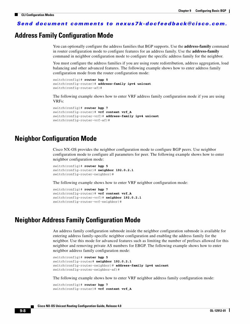
Send document comments to nexus7k -doc feedback@c i sco .com.
Chapter 9 Configuring Basic BGPCLI Configuration Modes
Address Family Configuration ModeYou can optionally configure the address families that BGP supports. Use the address-family command in router configuration mode to configure features for an address family. Use the address-family command in neighbor configuration mode to configure the specific address family for the neighbor.
You must configure the address families if you are using route redistribution, address aggregation, load balancing and other advanced features. The following example shows how to enter address family configuration mode from the router configuration mode:
switch(config)# router bgp 5switch(config-router)# address-family ipv4 unicastswitch(config-router-af)#
The following example shows how to enter VRF address family configuration mode if you are using VRFs:
switch(config)# router bgp 7switch(config-router)# vrf context vrf_Aswitch(config-router-vrf)# address-family ipv4 unicastswitch(config-router-vrf-af)#
Neighbor Configuration ModeCisco NX-OS provides the neighbor configuration mode to configure BGP peers. Use neighbor configuration mode to configure all parameters for peer. The following example shows how to enter neighbor configuration mode:
switch(config)# router bgp 5switch(config-router)# neighbor 192.0.2.1switch(config-router-neighbor)#
The following example shows how to enter VRF neighbor configuration mode:
switch(config)# router bgp 7switch(config-router)# vrf context vrf_Aswitch(config-router-vrf)# neighbor 192.0.2.1switch(config-router-vrf-neighbor)#
Neighbor Address Family Configuration ModeAn address family configuration submode inside the neighbor configuration submode is available for entering address family-specific neighbor configuration and enabling the address family for the neighbor. Use this mode for advanced features such as limiting the number of prefixes allowed for this neighbor and removing private AS numbers for EBGP. The following example shows how to enter neighbor address family configuration mode:
switch(config)# router bgp 5switch(config-router# neighbor 192.0.2.1switch(config-router-neighbor)# address-family ipv4 unicastswitch(config-router-neighbor-af)#
The following example shows how to enter VRF neighbor address family configuration mode:
switch(config)# router bgp 7switch(config-router)# vrf context vrf_A
9-8Cisco NX-OS Unicast Routing Configuration Guide, Release 4.0
OL-12912-01

Send document comments to nexus7k -doc feedback@c i sco .com.
Chapter 9 Configuring Basic BGPConfiguring Basic BGP
switch(config-router-vrf)# neighbor 209.165.201.1switch(config-router-vrf-neighbor)# address-family ipv4 unicastswitch(config-router-vrf-neighbor-af)#
Configuring Basic BGPTo configure a basic BGP, you need to enable BGP and configure a BGP peer. Configuring a basic BGP network consists of a few required tasks and many optional tasks. You must configure a BGP routing process and BGP peers.
This section includes the following topics:
• Enabling the BGP Feature, page 9-9
• Creating a BGP Instance, page 9-10
• Restarting a BGP Instance, page 9-12
Note If you are familiar with the Cisco IOS CLI, be aware that the Cisco NX-OS commands for this feature might differ from the Cisco IOS commands that you would use.
Enabling the BGP FeatureYou must enable the BGP feature before you can configure BGP.
BEFORE YOU BEGIN
Ensure that you are in the correct VDC (or use the switchto vdc command).
SUMMARY STEPS
1. config t
2. feature bgp
3. copy running-config startup-config
DETAILED STEPS
Command Purpose
Step 1 config t
Example:switch# config tswitch(config)#
Enters configuration mode.
9-9Cisco NX-OS Unicast Routing Configuration Guide, Release 4.0
OL-12912-01

Send document comments to nexus7k -doc feedback@c i sco .com.
Chapter 9 Configuring Basic BGPConfiguring Basic BGP
Use the no feature bgp command to disable the BGP feature and remove all associated configuration.
Creating a BGP InstanceYou can create a BGP instance and assign a router ID to the BGP instance. See the “BGP Router Identifier” section on page 9-3. Cisco NX-OS supports 2-byte or 4-byte autonomous system numbers (AS numbers).
BEFORE YOU BEGIN
Ensure that you have enabled the BGP feature (see the “Enabling the BGP Feature” section on page 9-9).
BGP must be able to obtain a router ID (for example, a configured loopback address).
Ensure that you are in the correct VDC (or use the switchto vdc command).
SUMMARY STEPS
1. config t
2. router bgp autonomous-system-number
3. router-id ip-address
4. address-family {ipv4 | ipv6} {unicast | multicast}
5. network ip-prefix [route-map map-name]
6. show bgp all
7. copy running-config startup-config
Step 2 feature bgp
Example:switch(config)# feature bgp
Enables the BGP feature.
Step 3 copy running-config startup-config
Example:switch(config)# copy running-config startup-config
(Optional) Saves this configuration change.
Command Purpose
Command Purpose
no feature bgp
Example:switch(config)# no feature bgp
Disables the BGP feature and removes all associated configuration.
9-10Cisco NX-OS Unicast Routing Configuration Guide, Release 4.0
OL-12912-01

Send document comments to nexus7k -doc feedback@c i sco .com.
Chapter 9 Configuring Basic BGPConfiguring Basic BGP
DETAILED STEPS
Use the no router bgp command to remove the BGP process and the associated configuration.
Command Purpose
Step 1 config t
Example:switch# config tswitch(config)#
Enters configuration mode.
Step 2 router bgp autonomous-system-number
Example:switch(config)# router bgp 40000switch(config-router)#
Enables BGP and assigns the autonomous system number to the local BGP speaker. The autonomous system number can be a 16-bit integer or a 32-bit integer in the form of <higher 16-bit decimal number>.<lower 16-bit decimal number>.
Step 3 router-id ip-address
Example:switch(config-router)# router-id 192.0.2.255
(Optional) Configures the BGP router ID. This IP address identifies this BGP speaker. This command triggers an automatic notification and sesion reset for the BGP neighbor sessions.
Step 4 address-family {ipv4 | ipv6}{unicast | multicast}
Example:switch(config-router)# address-family ipv4 unicastswitch(config-router-af)#
(Optional) Enters global address family configuration mode for the IPv4 address family. This command triggers an automatic notification and session reset for all BGP neighbors.
Step 5 network ip-prefix [route-map map-name]
Example:switch(config-router-af)# network 192.0.2.0
(Optional) Specifies a network as local to this autonomous system and adds it to the BGP routing table.
For exterior protocols, the network command controls which networks are advertised. Interior protocols use the network command to determine where to send updates.
Step 6 show bgp all
Example:switch(config-router-af)# show bgp all
(Optional) Displays information about all BGP address families.
Step 7 copy running-config startup-config
Example:switch(config-router-af)# copy running-config startup-config
(Optional) Saves this configuration change.
Command Purposeno router bgp autonomous-system-number
Example:switch(config)# no router bgp 201
Deletes the BGP process and the associated configuration.
9-11Cisco NX-OS Unicast Routing Configuration Guide, Release 4.0
OL-12912-01
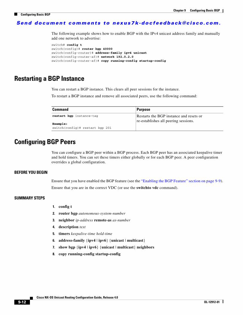
Send document comments to nexus7k -doc feedback@c i sco .com.
Chapter 9 Configuring Basic BGPConfiguring Basic BGP
The following example shows how to enable BGP with the IPv4 unicast address family and manually add one network to advertise:
switch# config tswitch(config)# router bgp 40000switch(config-router)# address-family ipv4 unicastswitch(config-router-af)# network 192.0.2.0switch(config-router-af)# copy running-config startup-config
Restarting a BGP InstanceYou can restart a BGP instance. This clears all peer sessions for the instance.
To restart a BGP instance and remove all associated peers, use the following command:
Configuring BGP PeersYou can configure a BGP peer within a BGP process. Each BGP peer has an associated keepalive timer and hold timers. You can set these timers either globally or for each BGP peer. A peer configuration overrides a global configuration.
BEFORE YOU BEGIN
Ensure that you have enabled the BGP feature (see the “Enabling the BGP Feature” section on page 9-9).
Ensure that you are in the correct VDC (or use the switchto vdc command).
SUMMARY STEPS
1. config t
2. router bgp autonomous-system-number
3. neighbor ip-address remote-as as-number
4. description text
5. timers keepalive-time hold-time
6. address-family {ipv4 | ipv6} {unicast | multicast}
7. show bgp {ipv4 | ipv6} {unicast | multicast} neighbors
8. copy running-config startup-config
Command Purpose
restart bgp instance-tag
Example:switch(config)# restart bgp 201
Restarts the BGP instance and resets or re-establishes all peering sessions.
9-12Cisco NX-OS Unicast Routing Configuration Guide, Release 4.0
OL-12912-01

Send document comments to nexus7k -doc feedback@c i sco .com.
Chapter 9 Configuring Basic BGPConfiguring Basic BGP
DETAILED STEPS
Command Purpose
Step 1 config t
Example:switch# config tswitch(config)#
Enters configuration mode.
Step 2 router bgp autonomous-system-number
Example:switch(config)# router bgp 40000switch(config-router)#
Enables BGP and assigns the autonomous system number to the local BGP speaker.
Step 3 neighbor ip-address remote-as as-number
Example:switch(config-router)# neighbor 209.165.201.1 remote-as 45000switch(config-router-neighbor)#
Configures the IP address and AS number for a remote BGP peer.
Step 4 description text
Example:switch(config-router-neighbor)# description Peer Router Bswitch(config-router-neighbor)#
(Optional) Adds a description for the neighbor. The description is an alphanumeric string up to 80 characters long.
Step 5 timers keepalive-time hold-time
Example:switch(config-router-neighbor)# timers 30 90
(Optional) Adds the keepalive and hold time BGP timer values for the neighbor. The range is from 0 to 3600 seconds. The default is 60 seconds for the keep-alive time and 180 seconds for the hold time.
Step 6 shutdown
Example:switch(config-router-neighbor)# shutdown
(Optional). Administratively shuts down this BGP neighbor. This command triggers an automatic notification and sesion reset for the BGP neighbor sessions.
Step 7 address-family {ipv4 | ipv6}{unicast | multicast}
Example:switch(config-router-neighbor)# address-family ipv4 unicastswitch(config-router-neighbor-af)#
Enters neighbor address family configuration mode for the unicast IPv4 address family.
Step 8 show bgp {ipv4 | ipv6}{unicast | multicast} neighbors
Example:switch(config-router-neighbor-af)# show bgp ipv4 unicast neighbors
(Optional) Displays information about BGP peers.
Step 9 copy running-config startup-config
Example:switch(config-router-neighbor-af) copy running-config startup-config
(Optional) Saves this configuration change.
9-13Cisco NX-OS Unicast Routing Configuration Guide, Release 4.0
OL-12912-01
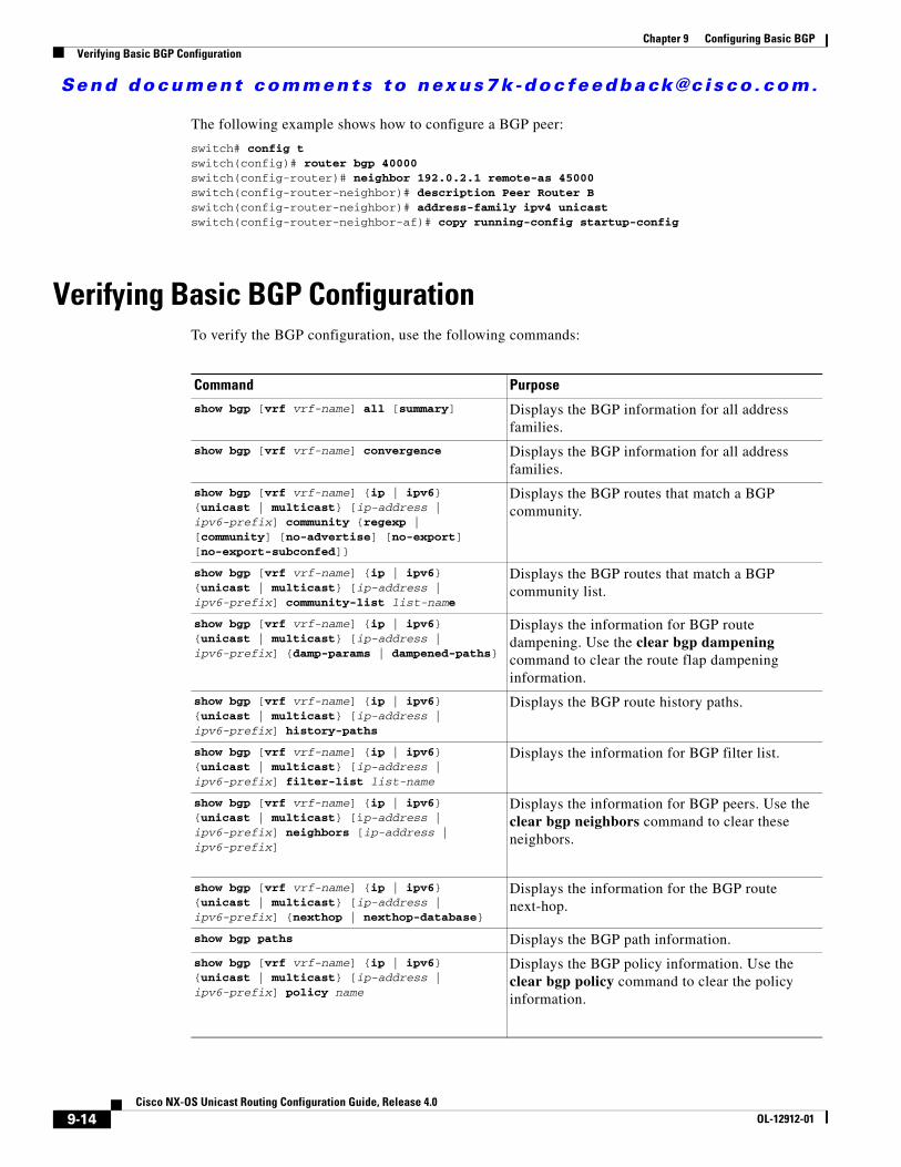
Send document comments to nexus7k -doc feedback@c i sco .com.
Chapter 9 Configuring Basic BGPVerifying Basic BGP Configuration
The following example shows how to configure a BGP peer:
switch# config tswitch(config)# router bgp 40000switch(config-router)# neighbor 192.0.2.1 remote-as 45000switch(config-router-neighbor)# description Peer Router Bswitch(config-router-neighbor)# address-family ipv4 unicastswitch(config-router-neighbor-af)# copy running-config startup-config
Verifying Basic BGP ConfigurationTo verify the BGP configuration, use the following commands:
Command Purpose
show bgp [vrf vrf-name] all [summary] Displays the BGP information for all address families.
show bgp [vrf vrf-name] convergence Displays the BGP information for all address families.
show bgp [vrf vrf-name] {ip | ipv6} {unicast | multicast} [ip-address | ipv6-prefix] community {regexp | [community] [no-advertise] [no-export] [no-export-subconfed]}
Displays the BGP routes that match a BGP community.
show bgp [vrf vrf-name] {ip | ipv6} {unicast | multicast} [ip-address | ipv6-prefix] community-list list-name
Displays the BGP routes that match a BGP community list.
show bgp [vrf vrf-name] {ip | ipv6} {unicast | multicast} [ip-address | ipv6-prefix] {damp-params | dampened-paths}
Displays the information for BGP route dampening. Use the clear bgp dampening command to clear the route flap dampening information.
show bgp [vrf vrf-name] {ip | ipv6} {unicast | multicast} [ip-address | ipv6-prefix] history-paths
Displays the BGP route history paths.
show bgp [vrf vrf-name] {ip | ipv6} {unicast | multicast} [ip-address | ipv6-prefix] filter-list list-name
Displays the information for BGP filter list.
show bgp [vrf vrf-name] {ip | ipv6} {unicast | multicast} [ip-address | ipv6-prefix] neighbors [ip-address | ipv6-prefix]
Displays the information for BGP peers. Use the clear bgp neighbors command to clear these neighbors.
show bgp [vrf vrf-name] {ip | ipv6} {unicast | multicast} [ip-address | ipv6-prefix] {nexthop | nexthop-database}
Displays the information for the BGP route next-hop.
show bgp paths Displays the BGP path information.
show bgp [vrf vrf-name] {ip | ipv6} {unicast | multicast} [ip-address | ipv6-prefix] policy name
Displays the BGP policy information. Use the clear bgp policy command to clear the policy information.
9-14Cisco NX-OS Unicast Routing Configuration Guide, Release 4.0
OL-12912-01

Send document comments to nexus7k -doc feedback@c i sco .com.
Chapter 9 Configuring Basic BGPDisplaying BGP Statistics
Displaying BGP StatisticsTo display BGP statistics, use the following commands:
Basic BGP Example ConfigurationThe following example shows a basic BGP configuration:
feature bgprouter bgp 40000 address-family ipv4 multicast network 192.0.2.0/24 network 209.165.201.0/27 address-family ipv4 unicast network 192.0.2.0/24 network 209.165.201.0/27
show bgp [vrf vrf-name] {ip | ipv6} {unicast | multicast} [ip-address | ipv6-prefix] prefix-list list-name
Displays the BGP routes that match the prefix list.
show bgp [vrf vrf-name] {ip | ipv6} {unicast | multicast} [ip-address | ipv6-prefix] received-paths
Displays the BGP paths stored for soft reconfiguration.
show bgp [vrf vrf-name] {ip | ipv6} {unicast | multicast} [ip-address | ipv6-prefix] regexp expression
Displays the BGP routes that match the AS_path regular expression.
show bgp [vrf vrf-name] {ip | ipv6} {unicast | multicast} [ip-address | ipv6-prefix] route-map map-name
Displays the BGP routes that match the route map.
show bgp [vrf vrf-name] peer-policy name Displays the information about BGP peer policies.
show bgp [vrf vrf-name] peer-session name Displays the information about BGP peer sessions.
show bgp [vrf vrf-name] peer-template name Displays the information about BGP peer templates. Use the clear bgp peer-template command to clear all neighbors in a peer template.
show running-configuration bgp Displays the current running BGP configuration.
Command Purpose
Command Purpose
show bgp [vrf vrf-name] {ip | ipv6} {unicast | multicast} [ip-address | ipv6-prefix] flap-statistics
Displays the BGP route flap statistics. Use the clear bgp flap-statistics command to clear these statistics.
show bgp [vrf vrf-name] {ip | ipv6} {unicast | multicast} [ip-address | ipv6-prefix] neighbors [ip-address | ipv6-prefix]
Displays the statistics for BGP peers. Use the clear bgp neighbors command to clear these statistics.
show bgp [vrf vrf-name] sessions Displays the BGP sessions for all peers. Use the clear bgp sessions command to clear these statistics.
9-15Cisco NX-OS Unicast Routing Configuration Guide, Release 4.0
OL-12912-01

Send document comments to nexus7k -doc feedback@c i sco .com.
Chapter 9 Configuring Basic BGPRelated Topics
address-family ipv6 multicast network 2001::0DB8::/64 network 2001::0DB8:0:1::/64 address-family ipv6 unicast network 2001:0DB8::/64 network 2001:0DB8:0:1::/64 neighbor 2001:ODB8:0:1::55 remote-as 30 address-family ipv6 multicast address-family ipv6 unicast neighbor 209.165.201.1 remote-as 45000 address-family ipv4 multicast address-family ipv4 unicast
Related TopicsThe following topics relate to BGP:
• Chapter 14, “Configuring Route Policy Manager.”
Where to Go Next See the Chapter 10, “Configuring Advanced BGP” for details on the following features:
• Peer templates
• Route redistribution
• Route maps
Default SettingsTable 9-2 lists the default settings for BGP parameters.
Additional ReferencesFor additional information related to implementing BGP, see the following sections:
• Related Documents, page 9-17
• MIBs, page 9-17
Table 9-2 Default BGP Parameters
Parameters Default
BGP feature disabled
keep alive interval 60 seconds
hold timer 180 seconds
9-16Cisco NX-OS Unicast Routing Configuration Guide, Release 4.0
OL-12912-01

Send document comments to nexus7k -doc feedback@c i sco .com.
Chapter 9 Configuring Basic BGPAdditional References
Related Documents
MIBs
Technical Assistance
Related Topic Document Title
BGP CLI commands Cisco NX-OS Command Line Reference
VDCs and VRFs Cisco NX-OS Virtual Device Contexts Configuration Guide
MIBs MIBs Link
BGP4-MIB
CISCO-BGP4-MIB
To locate and download MIBs, go to the following URL:
http://www.cisco.com/public/sw-center/netmgmt/cmtk/mibs.shtml
Descriptions Link
Technical Assistance Center (TAC) home page, containing 30,000 pages of searchable technical content, including links to products, technologies, solutions, technical tips, and tools. Registered Cisco.com users can log in from this page to access even more content.
http://www.cisco.com/public/support/tac/home.shtml
9-17Cisco NX-OS Unicast Routing Configuration Guide, Release 4.0
OL-12912-01

Send document comments to nexus7k -doc feedback@c i sco .com.
Chapter 9 Configuring Basic BGPAdditional References
9-18Cisco NX-OS Unicast Routing Configuration Guide, Release 4.0
OL-12912-01
Send document comments to nexus7k -doc feedback@c i sco .com.
Cisco NX-OOL-12912-01
C H A P T E R 10
Configuring Advanced BGPThis chapter describes how to configure advanced features of the Border Gateway Protocol (BGP).
This chapter includes the following sections:
• Information About Advanced BGP, page 10-1
• Licensing Requirements for Advanced BGP, page 10-9
• Prerequisites for BGP, page 10-10
• Guidelines and Limitations for BGP, page 10-10
• Configuring Advanced BGP, page 10-10
• Verifying Advanced BGP Configuration, page 10-34
• Displaying BGP Statistics, page 10-35
• Related Topics, page 10-35
• Default Settings, page 10-36
• Default Settings, page 10-36
• Additional References, page 10-36
Information About Advanced BGPBGP is an interdomain routing protocol that provides loop-free routing between organizations or autonomous systems. Cisco NX-OS supports BGP version 4. BGP version 4 includes multiprotocol extensions that allow BGP to carry routing information for IP multicast routes and multiple Layer 3 protocol address families. BGP uses TCP as a reliable transport protocol to create TCP sessions with other BGP-enabled devices called BGP peers. When connecting to an external organization, the router creates external BGP (eBGP) peering sessions. BGP peers within the same organization exchange routing information through internal BGP (iBGP) peering sessions.
This section includes the following topics:
• Peer Templates, page 10-2
• Authentication, page 10-2
• Route Policies and Resetting BGP Sessions, page 10-3
• eBGP, page 10-3
• iBGP, page 10-3
• Capabilities Negotiation, page 10-6
10-1S Unicast Routing Configuration Guide, Release 4.0

Send document comments to nexus7k -doc feedback@c i sco .com.
Chapter 10 Configuring Advanced BGPInformation About Advanced BGP
• AS Confederations, page 10-4
• Router Reflector, page 10-5
• Route Dampening, page 10-6
• Load Sharing and Multipath, page 10-6
• Route Aggregation, page 10-7
• Route Redistribution, page 10-7
• Tuning BGP, page 10-7
• Multiprotocol BGP, page 10-8
• Graceful Restart and High Availability, page 10-8
• Peer Templates, page 10-2
Peer TemplatesBGP peer templates allow you to create blocks of common configuration that you can reuse across similar BGP peers. Each block allows you to define a set of attributes that a peer then inherits. You can choose to override some of the inherited attributes as well, making it a very flexible scheme for simplifying the repetitive nature of BGP configurations.
Cisco NX-OS implements three types of peer templates:
• The peer-session template defines BGP peer session attributes, such as the transport details, remote autonomous system number of the peer, and session timers. A peer-session template can also inherit attributes from another peer-session template (with locally defined attributes that override the attributes from an inherited peer-session).
• A peer-policy template defines the address-family dependent policy aspects for a peer including the inbound and outbound policy, filter-lists, and prefix-lists. A peer-policy template can inherit from a set of peer-policy templates. Cisco NX-OS evaluates these peer-policy templates in the order specified by the preference value in the inherit configuration. The lowest number is preferred over higher numbers.
• The peer template can inherit the peer-session and peer-policy templates to allow for simplified peer definitions. It is not mandatory to use a peer template but it can simplify the BGP configuration by providing reusable blocks of configuration.
AuthenticationYou can configure authentication for a BGP neighbor session. This authentication method adds an MD5 authentication digest to each TCP segment sent to the neighbor to protect BGP against unauthorized messages and TCP security attacks.
Note The MD5 password must be identical between BGP peers.
10-2Cisco NX-OS Unicast Routing Configuration Guide, Release 4.0
OL-12912-01

Send document comments to nexus7k -doc feedback@c i sco .com.
Chapter 10 Configuring Advanced BGPInformation About Advanced BGP
Route Policies and Resetting BGP SessionsYou can associate a route policy to a BGP peer. Route policies use route maps to control or modify the routes that BGP recognizes. You can configure a route policy for inbound or outbound route updates. The route policies can match on different criteria, such as a prefix or AS_path attribute, and selectively accept or deny the routes. Route policies can also modify the path attributes. See Chapter 15, “Configuring Policy-Based Routing” for more information on route polices.
When you change a route policy applied to a BGP peer, you must reset the BGP sessions for that peer. Cisco NX-OS supports the following three mechanisms to reset BGP peering sessions:
• Hard reset—A hard reset tears down the specified peering sessions, including the TCP connection, and deletes routes coming from the specified peer. This option interrupts packet flow through the BGP network. Hard reset is disabled by default.
• Soft reconfiguration inbound—A soft reconfiguration inbound triggers routing updates for the specified peer without resetting the session. You can use this option if you change an inbound route policy. Soft reconfiguration inbound saves a copy of all routes received from the peer before processing the routes through the inbound route policy. If you change the inbound route policy, Cisco NX-OS passes these stored routes through the modified inbound route policy to update the route table without tearing down existing peering sessions. Soft reconfiguration inbound can use significant memory resources to store the unfiltered BGP routes. Soft reconfiguration inbound is disabled by default.
• Route Refresh—A route refresh updates the inbound routing tables dynamically by sending route refresh requests to supporting peers when you change an inbound route policy. The remote BGP peer responds with a new copy of its routes that the local BGP speaker processes with the modified route policy. Cisco NX-OS automatically sends an outbound route refresh of prefixes to the peer.
• BGP peers advertise the route refresh capability as part of the BGP capability negotiation when establishing the BGP peer session. Route refresh is the preferred option and enabled by default.
Note BGP also uses route maps for route redistribution, route aggregation, route dampening, and other features. See Chapter 14, “Configuring Route Policy Manager,” for more information on route maps.
eBGPExternal BGP (eBGP) allows you to connect BGP peers from different autonomous systems to exchange routing updates. Connecting to external networks enables traffic from your network to be forwarded to other networks and across the Internet.
You should use loopback interfaces for establishing eBGP peering sessions because loopback interfaces are less susceptible to interface flapping. An interface flap occurs when the interface is administratively brought up or down because of a failure or maintenance issue. See the “Configuring eBGP” section on page 10-21 for information on multihop, fast external failover and support for the General Time-To-Live Security Mechanism.
iBGPInternal BGP (iBGP) allows you to connect BGP peers within the same autonomous system. You can use iBGP for multihomed BGP networks (networks that have more than one connection to the same external autonomous system).
10-3Cisco NX-OS Unicast Routing Configuration Guide, Release 4.0
OL-12912-01

Send document comments to nexus7k -doc feedback@c i sco .com.
Chapter 10 Configuring Advanced BGPInformation About Advanced BGP
Figure 10-1 shows an iBGP network within a larger BGP network.
Figure 10-1 iBGP Network
iBGP networks are fully meshed. Each iBGP peer has a direct connection to all other iBGP peers to prevent network loops.
Note You should configure a separate interior gateway protocol in the iBGP network.
This section includes the following topics:
• AS Confederations, page 10-4
• Router Reflector, page 10-5
AS Confederations
A fully meshed iBGP network becomes complex as the number of iBGP peers grows. You can reduce the iBGP mesh is by dividing the autonomous system into multiple subautonomous systems and grouping them into a single confederation. A confederation is a group of iBGP peers that use the same autonomous system number to communicate to external networks. Each subautonomous system is fully meshed within itself and has a few connections to other subautonomous systems in the same confederation.
Z A
B
C
D
AS10AS20
iBGPeBGP
iBGP
iBGP
iBGPiBGP
1850
55
10-4Cisco NX-OS Unicast Routing Configuration Guide, Release 4.0
OL-12912-01

Send document comments to nexus7k -doc feedback@c i sco .com.
Chapter 10 Configuring Advanced BGPInformation About Advanced BGP
Figure 10-2 shows the BGP network from Figure 10-1, split into two subautonomous systems and one confederation.
Figure 10-2 AS Confederation
In this example, AS10 is split into two subautonomous systems, AS1 and AS2. Each subautonomous system is fully meshed, but there is only one link between the subautonomous systems. By using AS confederations, you can reduce the number of links compared to the fully meshed autonomous system in Figure 10-1.
Router Reflector
You can alternately reduce the iBGP mesh by using a router reflector configuration. router reflectors pass learned routes to neighbors s o that all iBGP peers do not need to be fully meshed.
Figure 10-1 shows a simple iBGP configuration with four meshed iBGP speakers (router A, B, C, and D). Without router reflectors, when router A receives a route from an external neighbor, it advertises the route to all three iBGP neighbors.
When you configure an iBGP peer to be a route reflector it becomes responsible for passing iBGP learned routes to a set of iBGP neighbors.
In Figure 10-3, router B is the router reflector. When the router reflector receives routes advertised from router A, it advertises (reflects) the routes to router C and D. Router A no longer has to advertise to both router C and D.
Figure 10-3 router reflector
Z A
B
C
D
AS10AS20
Confederationpeers
eBGP
iBGPiBGP
1850
56
AS1 AS2
Z A
B
C
D
AS10AS20
eBGP
iBGPiBGP
1850
57
10-5Cisco NX-OS Unicast Routing Configuration Guide, Release 4.0
OL-12912-01

Send document comments to nexus7k -doc feedback@c i sco .com.
Chapter 10 Configuring Advanced BGPInformation About Advanced BGP
The router reflector and its client peers form a cluster. You do not have to configure all iBGP peers to act as client peers of the router reflector. You must configure any nonclient peer as fully meshed to guarantee that complete BGP updates reach all peers.
Capabilities NegotiationA BGP speaker can learn about a BGP extensions supported by a peer by using the capabilities negotiation feature. Capabilities negotiation allows BGP to use only the set of features supported by both BGP peers on a link.
If a BGP peer does not support capabilities negotiation, Cisco NX-OS will attempt a new session to the peer without capabilities negotiation if you have configured the address family as IPv4. Any other multiprotocol configuration (such as IPv6) requires capability negotiation.
Route DampeningRoute dampening is a BGP feature that minimizes the propagation of flapping routes across an internetwork. A route flaps when it alternates between the available and unavailable states in rapid succession.
For example, consider a network with three BGP autonomous systems: AS1, AS2, and AS3. Suppose that a route in AS1 flaps (it becomes unavailable). Without route dampening, AS1 sends a withdraw message to AS2. AS2 propagates the withdrawal message to AS3. When the flapping route reappears, AS1 sends an advertisement message to AS2, which sends the advertisement to AS3. If the route repeatedly becomes unavailable, and then available, AS1 sends many withdrawal and advertisement messages that propagate through the other autonomous systems.
Route dampening can minimize flapping. Suppose that the route flaps. AS2 (in which route dampening is enabled) assigns the route a penalty of 1000. AS2 continues to advertise the status of the route to neighbors. Each time that the route flaps, AS2 adds to the penalty value. When the route flaps so often that the penalty exceeds a configurable suppression limit, AS2 stops advertising the route, regardless of how many times that it flaps. The route is now dampened.
The penalty placed on the route decays until the reuse limit is reached. At that time, AS2 advertises the route again. When the reuse limit is at 50 percent, AS2 removes the dampening information for the route.
Note The router does not apply a penalty to a resetting BGP peer when route dampening is enabled, even though the peer reset withdraws the route.
Load Sharing and MultipathBGP can install multiple equal-cost eBGP or iBGP paths into the routing table to reach the same destination prefix. Traffic to the destination prefix is then shared across all the installed paths.
The BGP best-path algorithm considers the paths as equal-cost paths if the following attributes are identical:
• Weight
• Local preference
• AS_path
10-6Cisco NX-OS Unicast Routing Configuration Guide, Release 4.0
OL-12912-01

Send document comments to nexus7k -doc feedback@c i sco .com.
Chapter 10 Configuring Advanced BGPInformation About Advanced BGP
• Origin code
• Multi-exit discriminator (MED)
• IGP cost to the BGP next hop
BGP selects only one of these multiple paths as the best-path and advertises the path to the BGP peers.
Note Paths received from different AS confederations are considered as equal-cost paths if the external AS_path values and the other attributes are identical.
Note When you configure a router reflector for iBGP multipath, and the router reflector advertises the selected best-path to its peers, the next hop for the path is not modified.
Route AggregationYou can configure a aggregate addresses. Route aggregation simplifies route tables by replacing a number of more specific addresses with an address that represents all the specific addresses. For example, you can replace these three more specific addresses, 10.1.1.0/24, 10.1.2.0/24, and 10.1.3.0/24 with one aggregate address, 10.1.0.0/16.
Aggregate prefixes are present in the BGP route table so that fewer routs are advertised.
Note Cisco NX-OS does not support automatic route aggregation.
Route aggregation can lead to forwarding loops. To avoid this problem, when BGP generates an advertisement for an aggregate address, it automatically installs a summary discard route for that aggregate address in the local routing table. BGP sets the administrative distance of the summary discard to 220 and sets the route type to discard. BGP does not use discard routes for next-hop resolution.
Route RedistributionYou can configure BGP to redistribute static routes or routes from other protocols. You configure a route policy with the redistribution to control which routes are passed into BGP. A route policy allows you to filter routes based on attributes such as the destination, origination protocol, route type, route tag, and so on. See Chapter 14, “Configuring Route Policy Manager,” for more information.
Tuning BGP You can modify the default behavior of BGP through BGP timers and by adjusting the best-path algorithm.
This section includes the following topics:
• BGP Timers, page 10-8
• Tuning the Best-Path Algorithm, page 10-8
10-7Cisco NX-OS Unicast Routing Configuration Guide, Release 4.0
OL-12912-01

Send document comments to nexus7k -doc feedback@c i sco .com.
Chapter 10 Configuring Advanced BGPInformation About Advanced BGP
BGP Timers
BGP uses different types of timers for neighbor session and global protocol events. Each established session has a minimum of two timers for sending periodic keepalive messages and for timing out sessions when peer keepalives do not arrive within the expected time. In addition, there are other timers for handling specific features. Typically, you configure these timers in seconds. The timers include a random adjustment so that the same timers on different BGP peers trigger at different times.
Tuning the Best-Path Algorithm
You can modify the default behavior of the best-path algorithm through optional configuration parameters, including changing how the algorithm handles the MED attribute and the router ID.
Multiprotocol BGPBGP on Cisco NX-OS supports multiple address families. Multiprotocol BGP (MBGP) carries a different sets of routes depending on the address family. For example, BGP can carry one set of routes for IPv4 unicast routing, one set of routes for IPv4 multicast routing, and one set of routes for IPv6 multicast routes.
Use the router address-family and neighbor address-family configuration modes to support multiprotocol BGP configurations.
A multiprotocol BGP network is backward compatible but BGP peers that do not support multiprotocol extensions cannot forward routing information, such as address family identifier information, that the multiprotocol extensions carry.
See the Cisco Cisco NX-OS Multicast Configuration Guide for multicast configuration examples using MBGP.
Graceful Restart and High AvailabilityCisco NX-OS supports nonstop forwarding and graceful restart for BGP.
You can use nonstop forwarding for BGP to forward data packets along known routes in the Forward Information Base (FIB) while the BGP routing protocol information is being restored following a failover. With NSF, BGP peers do not experience routing flaps. During a failover, the data traffic is forwarded through intelligent modules while the standby supervisor becomes active.
If a Cisco NX-OS router experiences a cold reboot, the network does not forward traffic to the router and removes the router from the network topology. In this scenario, BGP experiences a non-graceful restart and removes all routes. When Cisco NX-OS applies the startup configuration, BGP reestablishes peering sessions and relearns the routes.
A Cisco NX-OS router that has dual supervisors can experience a stateful supervisor switchover. Before the switchover occurs, BGP announces that a graceful restart is starting and that BGP will be unavailable for some time. During the switchover, BGP uses nonstop forwarding to forward traffic based on the information in the FIB, and the system is not taken out of the network topology. The router that is restarted marks these routes from its peers as stale.
When a router detects that a graceful restart operation is in progress, both routers exchange their topology tables. When the router has route updates from all BGP peers, it removes all the stale routes and runs the best-path algorithm on the updated routes.
10-8Cisco NX-OS Unicast Routing Configuration Guide, Release 4.0
OL-12912-01

Send document comments to nexus7k -doc feedback@c i sco .com.
Chapter 10 Configuring Advanced BGPLicensing Requirements for Advanced BGP
After the switchover, Cisco NX-OS applies the running configuration, and BGP informs the neighbors that it is operational again.
ISSUYou must enable graceful restart to support in-service software upgrades (ISSU) for BGP.
BGP uses a peer hold timer to tear down sessions for peers that have become inactive and stopped responding. As part of the ISSU process, BGP control packets might not be received or transmitted during the switchover and peers may notice loss of keepalive messages. However, as long as the hold time is greater than the switchover time, the peers should not tear down sessions with the local router.
Once switchover occurs, the peers receive TCP connection resets from the new active TCP on the local router. If you enabled graceful restart, the peers treat the resets as an indication that the router restarted and initiate the graceful-restart helper procedures.
Cisco NX-OS cannot guarantee ISSU if you configure the hold time less than the system switchover time (approximately 15 seconds).
BGP supports ISSU in the following ways:
• If you disable graceful restart, Cisco NX-OS issues a warning that ISSU cannot be supported with this configuration.
• If you configure the hold time to be less than the system switchover time, Cisco NX-OS issues a similar warning. If the peer negotiates a shorter hold time, Cisco NX-OS logs a message.
• When Cisco NX-OS executes the BGP ISSU-related callback routine prior to switchover, BGP checks both the graceful restart status and the hold time for all active peers. Cisco NX-OS issues appropriate warnings and ends the ISSU process if graceful restart is disabled or the hold times for the active peers is less than the system switchover time. and leave it to the discretion of the user to force a switchover.
• You can force a switchover if ISSU is not supported, but forwarding is not preserved during this forced switchover.
Virtualization SupportCisco NX-OS supports multiple instances of the BGP protocol that run on the same system. BGP supports Virtual Routing and Forwarding instances (VRFs) which exist within virtual device contexts (VDCs). You can configure one BGP instance in a VDC, but you can have multiple VDCs on the system.
By default, Cisco NX-OS places you in the default VDC and default VRF unless you specifically configure another VDC and VRF. See the Cisco NX-OS Virtual Device Context Configuration Guide and Chapter 13, “Configuring Layer 3 Virtualization.”
Licensing Requirements for Advanced BGPThe following table shows the licensing requirements for this feature:
Product License Requirement
NX-OS BGP requires an Enterprise Services license. For a complete explanation of the NX-OS licensing scheme and how to obtain and apply licenses, see the Cisco NX-OS Licensing Guide.
10-9Cisco NX-OS Unicast Routing Configuration Guide, Release 4.0
OL-12912-01

Send document comments to nexus7k -doc feedback@c i sco .com.
Chapter 10 Configuring Advanced BGPPrerequisites for BGP
Prerequisites for BGPBGP has the following prerequisites:
• You must enable the BGP feature (see the “Enabling the BGP Feature” section on page 9-9).
• You should have a valid router ID configured on the system.
• You must have an AS number, either assigned by a Regional Internet Registry (RIR) or locally administered.
• You must have reachability (such as IGP, static route or direct connection) to the peer that you are trying to make a neighbor relationship with.
• You must explicitly configure an address family under a neighbor for the BGP session establishment.
Guidelines and Limitations for BGPBGP has the following guidelines and limitations:
• Configure a router ID for BGP to avoid automatic router ID changes and session flaps.
• Use the maximum-prefix configuration option per peer to restrict the number of routes received and system resources used.
• Configure the update-source to establish a session with eBGP multihop sessions.
• Specify a BGP route map if you configure redistribution.
• Configure the BGP router ID within a VRF.
• If you decrease the keepalive and hold timer values, the network might experience session flaps.
• If you configure VDCs, install the Advanced Services license and enter the desired VDC (see to the Cisco NX-OS Virtual Device Context Configuration Guide).
Configuring Advanced BGPThis section describes how to configure advanced BGP and includes the following topics:
• Configuring BGP Session Templates, page 10-11
• Configuring BGP Peer-Policy Templates, page 10-13
• Configuring BGP Peer Templates, page 10-16
• Configuring Prefix Peering, page 10-18
• Configuring BGP Authentication, page 10-19
• Resetting a BGP Session, page 10-19
• Configuring AS Confederations, page 10-22
• Disabling Capabilities Negotiation, page 10-20
• Configuring eBGP, page 10-21
• Configuring AS Confederations, page 10-22
• Configuring Router Reflector, page 10-22
10-10Cisco NX-OS Unicast Routing Configuration Guide, Release 4.0
OL-12912-01

Send document comments to nexus7k -doc feedback@c i sco .com.
Chapter 10 Configuring Advanced BGPConfiguring Advanced BGP
• Configuring Route Dampening, page 10-24
• Configuring Load Sharing and ECMP, page 10-25
• Configuring Maximum Prefixes, page 10-25
• Configuring Dynamic Capability, page 10-26
• Configuring Aggregate Addresses, page 10-26
• Configuring Route Redistribution, page 10-26
• Tuning BGP, page 10-28
• Configuring a Graceful Restart, page 10-31
• Configuring Virtualization, page 10-32
Note If you are familiar with the Cisco IOS CLI, be aware that the Cisco NX-OS commands for this feature might differ from the Cisco IOS commands that you would use.
Configuring BGP Session TemplatesYou can use BGP session templates to simplify BGP configuration for multiple BGP peers with similar configuration needs. BGP templates allow you to reuse common configuration blocks. You configure BGP templates first, and then apply these templates to BGP peers.
With BGP session templates, you can configure session attributes such as inheritance, passwords, timers, and security.
A peer-session template can inherit from one other peer-session template. You can configure the second template to inherit from a third template, the first template also inherits this third template. This indirect inheritance can continue for up to seven peer-session templates.
Any attributes configured for the neighbor take priority over any attributes inherited by that neighbor from a BGP template.
BEFORE YOU BEGIN
Ensure that you have enabled the BGP feature (see the “Enabling the BGP Feature” section on page 9-9).
Ensure that you are in the correct VDC (or use the switchto vdc command).
Note When editing a template, you can use the no form of a command at either the peer or template level to explicitly override a setting in a template. You must use the default form of the command to reset that attribute to the default state.
SUMMARY STEPS
1. config t
2. router bgp autonomous-system-number
3. template peer-session template-name
4. Add appropriate attributes to the session template.
5. exit
10-11Cisco NX-OS Unicast Routing Configuration Guide, Release 4.0
OL-12912-01

Send document comments to nexus7k -doc feedback@c i sco .com.
Chapter 10 Configuring Advanced BGPConfiguring Advanced BGP
6. neighbor ip-address remote-as as-number
7. inherit peer-session template-name
8. Add appropriate neighbor attributes.
9. show bgp peer-session template-name
10. copy running-config startup-config
DETAILED STEPS
Command Purpose
Step 1 config t
Example:switch# config tswitch(config)#
Enters configuration mode.
Step 2 router bgp autonomous-system-number
Example:switch(config)# router bgp 45000switch(config-router)#
Enables BGP and assigns the autonomous system number to the local BGP speaker.
Step 3 template peer-session template-name
Example:switch(config-router)# template peer-session BaseSessionswitch(config-router-stmp)#
Enters peer-session template configuration mode.
Step 4 password number password
Example:switch(config-router-stmp)# password 0 test
(Optional) Adds the clear text password test to the neighbor. The password is stored and displayed in type 3 encrypted form (3DES).
Step 5 timers keepalive hold
Example:switch(config-router-stmp)# timers 30 90
(Optional) Adds the BGP keepalive and holdtimer values to the peer-session template.
The default keepalive interval is 60. The default hold time is 180.
Step 6 exit
Example:switch(config-router-stmp)# exitswitch(config-router)#
Exits peer-session template configuration mode.
Step 7 neighbor ip-address remote-as as-number
Example:switch(config-router)# neighbor 192.168.1.2 remote-as 40000switch(config-router-neighbor)#
Places the router in the neighbor configuration mode for BGP routing and configures the neighbor IP address.
Step 8 inherit peer-session template-name
Example:switch(config-router-neighbor)# inherit peer-session BaseSessionswitch(config-router-neighbor)
Applies a peer-session template to the peer.
10-12Cisco NX-OS Unicast Routing Configuration Guide, Release 4.0
OL-12912-01

Send document comments to nexus7k -doc feedback@c i sco .com.
Chapter 10 Configuring Advanced BGPConfiguring Advanced BGP
Use the show bgp neighbor command to see the template applied. See the Cisco NX-OS Unicast Routing Command Reference, Release 4.0 for details on all commands available in the template.
The following example shows how to configure a BGP peer-session template and apply it to a BGP peer:
switch# config tswitch(config)# router bgp 45000switch(config-router)# template peer-session BaseSessionswitch(config-router-stmp)# timers 30 90switch(config-router-stmp)# exitswitch(config-router)# neighbor 192.168.1.2 remote-as 40000switch(config-router-neighbor)# inherit peer-session BaseSessionswitch(config-router-neighbor)# description Peer Router Aswitch(config-router-neighbor)# address-family ipv4 unicastswitch(config-router-neighbor)# copy running-config startup-config
Configuring BGP Peer-Policy TemplatesYou can configure a peer-policy template to define attributes for a particular address family. You assign a preference to each peer-policy template and these templates are inherited in the order specified, for up to five peer-policy templates in a neighbor address family.
Cisco NX-OS evaluates multiple peer policies for an address family using the preference value. The lowest preference value is evaluated first. Any attributes configured for the neighbor take priority over any attributes inherited by that neighbor from a BGP template.
Peer-policy templates can configure address family-specific attributes such as AS-path filter lists, prefix lists, route reflection, and soft reconfiguration.
BEFORE YOU BEGIN
Ensure that you have enabled the BGP feature (see the “Enabling the BGP Feature” section on page 9-9).
Ensure that you are in the correct VDC (or use the switchto vdc command).
Step 9 description text
Example:switch(config-router-neighbor)# description Peer Router Aswitch(config-router-neighbor)
(Optional) Adds a description for the neighbor.
Step 10 show bgp peer-session template-name
Example:switch(config-router-neighbor)# show bgp peer-session BaseSession
(Optional) Displays the peer-policy template.
Step 11 copy running-config startup-config
Example:switch(config-router-neighbor)# copy running-config startup-config
(Optional) Saves this configuration change.
Command Purpose
10-13Cisco NX-OS Unicast Routing Configuration Guide, Release 4.0
OL-12912-01

Send document comments to nexus7k -doc feedback@c i sco .com.
Chapter 10 Configuring Advanced BGPConfiguring Advanced BGP
Note When editing a template, you can use the no form of a command at either the peer or template level to explicitly override a setting in a template. You must use the default form of the command to reset that attribute to the default state.
SUMMARY STEPS
1. config t
2. router bgp autonomous-system-number
3. template peer-policy template-name
4. Add appropriate attributes to the policy template.
5. exit
6. neighbor ip-address remote-as as-number
7. address-family {ipv4 | ipv6} {multicast | unicast}
8. inherit peer-policy template-name preference
9. show bgp peer-policy template-name
10. copy running-config startup-config
DETAILED STEPS
Command Purpose
Step 1 config t
Example:switch# config tswitch(config)#
Enters configuration mode.
Step 2 router bgp autonomous-system-number
Example:switch(config)# router bgp 45000switch(config-router)#
Enables BGP and assigns the autonomous system number to the local BGP speaker.
Step 3 template peer-policy template-name
Example:switch(config-router)# template peer-policy BasePolicyswitch(config-router-ptmp)#
Creates a peer-policy template.
Step 4 advertise-active-only
Example:switch(config-router-ptmp)# advertise-active-only
(Optional) Advertises only active routes to the peer.
Step 5 maximum-prefix number
Example:switch(config-router-ptmp)# maximum-prefix 20
(Optional) Sets the maximum number of prefixes allowed from this peer.
10-14Cisco NX-OS Unicast Routing Configuration Guide, Release 4.0
OL-12912-01

Send document comments to nexus7k -doc feedback@c i sco .com.
Chapter 10 Configuring Advanced BGPConfiguring Advanced BGP
Use the show bgp neighbor command to see the template applied. See the Cisco NX-OS Unicast Routing Command Reference, Release 4.0 for details on all commands available in the template.
The following example shows how to configure a BGP peer-session template and apply it to a BGP peer:
The following example shows how to configure a BGP peer-policy template and apply it to a BGP peer:
switch# config tswitch(config)# router bgp 40000switch(config-router)# template peer-session BasePolicyswitch(config-router-ptmp)# maximum-prefix 20switch(config-router-ptmp)# exitswitch(config-router)# neighbor 192.168.1.1 remote-as 45000switch(config-router-neighbor)# address-family ipv4 unicastswitch(config-router-neighbor-af)# inherit peer-policy BasePolicyswitch(config-router-neighbor-af)# copy running-config startup-config
Step 6 exit
Example:switch(config-router-ptmp)# exitswitch(config-router)#
Exits peer-policy template configuration mode.
Step 7 neighbor ip-address remote-as as-number
Example:switch(config-router)# neighbor 192.168.1.2 remote-as 40000switch(config-router-neighbor)#
Places the router in neighbor configuration mode for BGP routing and configures the neighbor IP address.
Step 8 address-family {ipv4 | ipv6}{multicast | unicast}
Example:switch(config-router-neighbor)# address-family ipv4 unicastswitch(config-router-neighbor-af)#
Enters global address family configuration mode for the IPv4 address family.
Step 9 inherit peer-policy template-name preference
Example:switch(config-router-neighbor-af)# inherit peer-policy BasePolicy 1
Applies a peer-policy template to the peer address family configuration and assigns the preference value for this peer policy.
Step 10 show bgp peer-policy template-name
Example:switch(config-router-neighbor-af)# show bgp peer-policy BasePolicy
(Optional) Displays the peer-policy template.
Step 11 copy running-config startup-config
Example:switch(config-router-neighbor-af)# copy running-config startup-config
(Optional) Saves this configuration change.
Command Purpose
10-15Cisco NX-OS Unicast Routing Configuration Guide, Release 4.0
OL-12912-01

Send document comments to nexus7k -doc feedback@c i sco .com.
Chapter 10 Configuring Advanced BGPConfiguring Advanced BGP
Configuring BGP Peer TemplatesYou can configure BGP peer templates to combine session and policy attributes in one reusable configuration block. Peer templates can also inherit peer-session or peer-policy templates. Any attributes configured for the neighbor take priority over any attributes inherited by that neighbor from a BGP template. You configure only one peer template for a neighbor, but that peer template can inherit peer-session and peer-policy templates.
Peer templates support session and address family attributes, such as eBGP multihop time-to-live, maximum prefix, next-hop self, and timers.
BEFORE YOU BEGIN
Ensure that you have enabled the BGP feature (see the “Enabling the BGP Feature” section on page 9-9).
Ensure that you are in the correct VDC (or use the switchto vdc command).
Note When editing a template, you can use the no form of a command at either the peer or template level to explicitly override a setting in a template. You must use the default form of the command to reset that attribute to the default state.
SUMMARY STEPS
1. config t
2. router bgp autonomous-system-number
3. template peer template-name
4. Add appropriate attributes to the peer template.
5. exit
6. neighbor ip-address
7. inherit peer template-name
8. Add appropriate neighbor attributes.
9. show bgp peer-template template-name
10. copy running-config startup-config
DETAILED STEPS
Command Purpose
Step 1 config t
Example:switch# config tswitch(config)#
Enters configuration mode.
Step 2 router bgp autonomous-system-number
Example:switch(config)# router bgp 45000
Enters BGP mode and assigns the autonomous system number to the local BGP speaker.
10-16Cisco NX-OS Unicast Routing Configuration Guide, Release 4.0
OL-12912-01

Send document comments to nexus7k -doc feedback@c i sco .com.
Chapter 10 Configuring Advanced BGPConfiguring Advanced BGP
Step 3 template peer template-name
Example:switch(config-router)# template peer BasePeerswitch(config-router-neighbor)#
Enters peer template configuration mode.
Step 4 inherit peer-session template-name
Example:switch(config-router-neighbor)# inherit peer-session BaseSession
(Optional) Inherits a peer-session template in the peer template.
Step 5 address-family {ipv4 | ipv6}{multicast | unicast}
Example:switch(config-router-neighbor)# address-family ipv4 unicastswitch(config-router-neighbor-af)#
(Optional) Configures the global address family configuration mode for the IPv4 address family.
Step 6 inherit peer-policy template-name preference
Example:switch(config-router-neighbor-af)# inherit peer-policy BasePolicy 1
(Optional) Applies a peer-policy template to the neighbor address family configuration and assigns the preference value for this peer policy.
Step 7 exit
Example:switch(config-router-neighbor-af)# exitswitch(config-router-neighbor)#
Exits BGP neighbor address family configuration mode.
Step 8 timers keepalive hold
Example:switch(config-router-neighbor)# timers 45 100
(Optional) Adds the BGP timer values to the peer.
These values override the timer values in the peer-session template, BaseSession.
Step 9 exit
Example:switch(config-router-neighbor)# exitswitch(config-router)#
Exits BGP peer template configuration mode.
Step 10 neighbor ip-address remote-as as-number
Example:switch(config-router)# neighbor 192.168.1.2 remote-as 40000switch(config-router-neighbor)#
Places the router in neighbor configuration mode for BGP routing and configures the neighbor IP address.
Step 11 inherit peer template-name
Example:switch(config-router-neighbor)# inherit peer BasePeer
Inherits the peer template.
Step 12 timers keepalive hold
Example:switch(config-router-neighbor)# timers 60 120
(Optional) Adds the BGP timer values to this neighbor.
These values override the timer values in the peer template and the peer-session template.
Command Purpose
10-17Cisco NX-OS Unicast Routing Configuration Guide, Release 4.0
OL-12912-01

Send document comments to nexus7k -doc feedback@c i sco .com.
Chapter 10 Configuring Advanced BGPConfiguring Advanced BGP
Use the show bgp neighbor command to see the template applied. See the Cisco NX-OS Unicast Routing Command Reference, Release 4.0 for details on all commands available in the template.
The following example shows how to configure a BGP peer-session template and apply it to a BGP peer:
The following example shows how to configure a BGP peer-policy template and apply it to a BGP peer:
switch# config tswitch(config)# router bgp 45000switch(config-router)# template peer BasePeerswitch(config-router-neighbor)# inherit peer-session BaseSessionswitch(config-router-neighbor)# address-family ipv4 unicastswitch(config-router-neighbor-af)# inherit peer-policy BasePolicy 1switch(config-router-neighbor-af)# exitswitch(config-router-neighbor)# exitswitch(config-router)# neighbor 192.168.1.2 remote-as 40000switch(config-router-neighbor)# inherit peer BasePeerswitch(config-router-neighbor)# copy running-config startup-config
Configuring Prefix PeeringBGP supports the definition of a set of peers using a prefix for both IPv4 and IPv6. This simplifies the configuration even further than using templates because you do not need to add each neighbor to the configuration.
When defining a prefix peering, you must specify the remote AS number along with the prefix. BGP accepts any peer connecting from that prefix and autonomous system as long as the prefix peering does not exceed the configured maximum peers allowed.
When a BGP peer that is part of a prefix peering disconnects, Cisco NX-OS holds its peer structures for defined prefix peer time-out value. This helps network stability by allowing an established peer to reset and reconnect without danger of being blocked because other peers have consumed all slots for that prefix peering. The default setting for prefix-peer-time-out is 30 seconds.
To configure BGP prefix peering time-out value, use the following command in router configuration mode:
Step 13 show bgp peer-template template-name
Example:switch(config-router-neighbor-af)# show bgp peer-template BasePeer
(Optional) Displays the peer template.
Step 14 copy running-config startup-config
Example:switch(config-router-neighbor-af)# copy running-config startup-config
(Optional) Saves this configuration change.
Command Purpose
Command Purpose
timers prefix-peer-timeout value
Example:switch(config-router-neighbor)# timers prefix-peer-timeout 120
• Configures the time-out value for prefix peering. The range is from 0 to 1200 seconds. The default value is 30.
10-18Cisco NX-OS Unicast Routing Configuration Guide, Release 4.0
OL-12912-01

Send document comments to nexus7k -doc feedback@c i sco .com.
Chapter 10 Configuring Advanced BGPConfiguring Advanced BGP
To configure the maximum number of peers, use the following commands in neighbor configuration mode:
This example shows how to configure a prefix peering that accepts up to 10 peers.
switch(config)# router bgp 1switch(config-router)# timers prefix-peer-timeout 120switch(config-router)# neighbor 10.100.200.0/24 remote-as 1switch(config-router-neighbor)# maximum-peers 10switch(config-router-neighbor)# address-family ipv4 unicastswitch(config-router-neighbor-af)#
Use the show ip bgp neighbor command to show the details of the configuration for that prefix peering along with a list of the currently accepted instances and the counts of active, maximum concurrent and total accepted peers.
Configuring BGP AuthenticationYou can configure BGP to authenticate route updates from peers using MD5 digests.
To configure BGP to use MD5 authentication, use the following command in neighbor configuration mode:
Resetting a BGP SessionIf you modify a route policy for BGP, you must reset the associated BGP peer sessions. If the BGP peers do not support route refresh, you can configure a soft reconfiguration for inbound policy changes. Cisco NX-OS automatically attempts a soft reset for the session.
To configure soft reconfiguration inbound, use the following command in neighbor address-family configuration mode:
Command Purposemaximum-peers value
Example:switch(config-router-neighbor)# timers prefix-peer-timeout 120
Configures the maximum number of peers for this prefix peering. The range is from 1 to 1000.
Command Purpose
password [0 | 3 | 7] string
Example:switch(config-router-neighbor)# password BGPpassword
Configures an MD5 password for BGP neighbor sessions.
10-19Cisco NX-OS Unicast Routing Configuration Guide, Release 4.0
OL-12912-01

Send document comments to nexus7k -doc feedback@c i sco .com.
Chapter 10 Configuring Advanced BGPConfiguring Advanced BGP
To reset a BGP neighbor session, use the following command in any mode:
Modifying the Next-Hop AddressYou can modify the next-hop address used in a route advertisement in the following ways:
• Disable next-hop calculation and use the local BGP speaker address as the next-hop address.
• Set the next-hop address as a third-party address. Use this in situations where the original next-hop address is on the same subnet as the peer that the route is being sent to. This saves an extra hop during forwarding.
You can modify the next-hop address by configuring the following parameters in neighbor address-family configuration mode:
Disabling Capabilities NegotiationYou can disable capabilities negotiations to interoperate with older BGP peers that do not support capabilities negotiation.
To disable capabilities negotiation, use the following command in neighbor configuration mode:
Command Purpose
soft-reconfiguration inbound
Example:switch(config-router-neighbor-af)# soft-reconfiguration inbound
Enables soft reconfiguration to store the inbound BGP route updates. This command triggers an automatic soft clear or refresh of BGP neighbor sessions.
Command Purposeclear bgp {ip | ipv6} {unicast | multicast} ip-address soft {in | out}
Example:switch# clear bgp ip unicast 192.0.2.1 soft in
Resets the BGP session without tearing down the TCP session.
Command Purpose
next-hop-selfExample:switch(config-router-neighbor-af)# next-hop-self
Uses the local BGP speaker address as the next-hop address in route updates. This command triggers an automatic soft clear or refresh of BGP neighbor sessions.
next-hop-third-partyExample:switch(config-router-neighbor-af)# next-hop-third-party
Sets the next-hop address as a third-party address. Use this command for single-hop EBGP peers that do not have next-hop-self configured
10-20Cisco NX-OS Unicast Routing Configuration Guide, Release 4.0
OL-12912-01

Send document comments to nexus7k -doc feedback@c i sco .com.
Chapter 10 Configuring Advanced BGPConfiguring Advanced BGP
Configuring eBGPThis section includes the following topics:
• Disabling eBGP Single-Hop Checking, page 10-21
• Configuring eBGP Multihop, page 10-21
• Disabling a Fast External Failover, page 10-22
• Configuring AS Confederations, page 10-22
Disabling eBGP Single-Hop Checking
You can configure eBGP to disable checking whether a single-hop eBGP peer is directly connected to the local router. Use this option for configuring a single-hop loopback eBGP session between directly connected switches.
To disable checking whether a single-hop eBGP peer is directly connected, use the following command in neighbor configuration mode:
Configuring eBGP Multihop
You can configure the eBGP time-to-live (TTL) value to support eBGP multihop. In some situations, an eBGP peer is not directly connected to another eBGP peer and requires multiple hops to reach the remote eBGP peer. You can configure the eBGP TTL value for a neighbor session to allow these multihop sessions.
To configure eBGP multihop, use the following command in neighbor configuration mode:
Command Purpose
dont-capability-negotiate
Example:switch(config-router-neighbor)# dont-capability-negotiate
Disables capabilities negotiation. You must manually reset the BGP sessions after configuring this command.
Command Purpose
disable-connected-check
Example:switch(config-router-neighbor)# soft-reconfiguration inbound
Disables checking whether a single-hop eBGP peer is directly connected. You must manually reset the BGP sessions after configuring this command.
Command Purpose
ebgp-multihop ttl-value
Example:switch(config-router-neighbor)# ebgp-multihop 5
Configures the eBGP TTL value for eBGP multihop. The range is from 2 to 255. You must manually reset the BGP sessions after configuring this command.
10-21Cisco NX-OS Unicast Routing Configuration Guide, Release 4.0
OL-12912-01

Send document comments to nexus7k -doc feedback@c i sco .com.
Chapter 10 Configuring Advanced BGPConfiguring Advanced BGP
Disabling a Fast External Failover
Typically, when a BGP router loses connectivity to a directly connected eBGP peer, BGP triggers a fast external failover by resetting the eBGP session to the peer. You can disable this fast external failover to limit the instability caused by link flaps.
To disable fast external failover, use the following command in router configuration mode:
Configuring AS ConfederationsTo configure an AS confederation, you must specify a confederation identifier. To the outside world, the group of autonomous systems within the AS confederation look like a single autonomous system with the confederation identifier as the autonomous system number.
To configure a BGP confederation identifier, use the following command in router configuration mode:
To configure the autonomous systems that belong to the AS confederation, use the following command in router configuration mode:
Configuring Router ReflectorYou can configure iBGP peers as router reflector clients to the local BGP speaker, which acts as the router reflector. Together, a router reflector and its clients form a cluster. A cluster of clients usually has a single router reflector. In such instances, the cluster is identified by the router ID of the router reflector. To increase redundancy and avoid a single point of failure in the network, you can configure a cluster with more than one router reflector. You must configure all router reflectors in the cluster with the same 4-byte cluster ID so that a router reflector can recognize updates from router reflectors in the same cluster.
Command Purpose
no fast-external-failover
Example:switch(config-router)# no fast-external-failover
Disables a fast external failover for eBGP peers. Enabled by default.
Command Purpose
confederation identifier as-number
Example:switch(config-router)# confederation identifier 4000
Configures a confederation identifier for an AS confederation. This command triggers an automatic notification and session reset for the BGP neighbor sessions.
Command Purposebgp confederation peers as-number [as-number2...]
Example:switch(config-router)# bgp confederation peers 5 33 44
Specifies a list of autonomous systems that belong to the confederation. This command triggers an automatic notification and session reset for the BGP neighbor sessions.
10-22Cisco NX-OS Unicast Routing Configuration Guide, Release 4.0
OL-12912-01

Send document comments to nexus7k -doc feedback@c i sco .com.
Chapter 10 Configuring Advanced BGPConfiguring Advanced BGP
BEFORE YOU BEGIN
Ensure that you have enabled the BGP feature (see the “Enabling the BGP Feature” section on page 9-9).
Ensure that you are in the correct VDC (or use the switchto vdc command).
SUMMARY STEPS
1. config t
2. router bgp as-number
3. cluster-id cluster-id
4. address-family {ipv4 | ipv6} {unicast | multicast}
5. client-to-client reflection
6. exit
7. neighbor ip-address remote-as as-number
8. address-family {ipv4 | ipv6} {unicast | multicast}
9. route-reflector-client
10. show bgp {ip | ipv6} {unicast | multicast} as-number
11. copy running-config startup-config
DETAILED STEPS
Command or Action Purpose
Step 1 config t
Example:switch# config tswitch(config)#
Enters configuration mode.
Step 2 router bgp as-number
Example:switch(config)# router bgp 45000switch(config-router)#
Enters BGP mode and assigns the autonomous system number to the local BGP speaker.
Step 3 cluster-id cluster-id
Example:switch(config-router)# cluster-id 192.0.2.1
Configures the local router as one of the router reflectors that serve the cluster. You specify a cluster ID to identify the cluster. This command triggers an automatic soft clear or refresh of BGP neighbor sessions.
Step 4 address-family {ipv4 | ipv6} {unicast | multicast}
Example:switch(config-router)# address-family ipv4 unicastswitch(config-router-af)#
Enters router address family configuration mode for the specified address family.
Step 5 client-to-client reflection
Example:switch(config-router-af)# client-to-client reflection
(Optional) Configures client-to-client route reflection. This feature is enabled by default. This command triggers an automatic soft clear or refresh of BGP neighbor sessions.
10-23Cisco NX-OS Unicast Routing Configuration Guide, Release 4.0
OL-12912-01

Send document comments to nexus7k -doc feedback@c i sco .com.
Chapter 10 Configuring Advanced BGPConfiguring Advanced BGP
The following example shows how to configure the router as a router reflector and add one neighbor as a client:
switch(config)# router bgp 45000switch(config-router)# neighbor 192.0.2.10 remote-as 40000switch(config-router-neighbor)# address-family ip unicastswitch(config-router-neighbor-af)# route-reflector-clientswitch(config-router-neighbor-af)# copy running-config startup-config
Configuring Route DampeningYou can configure route dampening to minimize route flaps propagating through your iBGP network.
To configure route dampening, use the following command in address-family or VRF address family configuration mode:
Step 6 exit
Example:switch(config-router-neighbor)# exitswitch(config-router)#
Exits router address configuration mode.
Step 7 neighbor ip-address remote-as as-number
Example:switch(config-router)# neighbor 192.0.2.10 remote-as 40000switch(config-router-neighbor)#
Configures the IP address and AS number for a remote BGP peer.
Step 8 address-family {ipv4 | ipv6}{unicast | multicast}
Example:switch(config-router-neighbor)# address-family ipv4 unicastswitch(config-router-neighbor-af)#
Enters neighbor address family configuration mode for the unicast IPv4 address family.
Step 9 route-reflector-client
Example:switch(config-router-neighbor-af)# route-reflector-client
Configures the switch as a BGP router reflector and configures the neighbor as its client. This command triggers an automatic notification and session reset for the BGP neighbor sessions.
Step 10 show bgp {ip | ipv6} {unicast | multicast} neighbors
Example:switch(config-router-neighbor-af)# show bgp ip unicast neighbors
(Optional) Displays the BGP peers.
Step 11 copy running-config startup-config
Example:switch(config-router-neighbor-af)# copy running-config startup-config
(Optional) Saves this configuration change.
Command or Action Purpose
10-24Cisco NX-OS Unicast Routing Configuration Guide, Release 4.0
OL-12912-01

Send document comments to nexus7k -doc feedback@c i sco .com.
Chapter 10 Configuring Advanced BGPConfiguring Advanced BGP
Configuring Load Sharing and ECMPYou can configure the maximum number of paths that BGP adds to the route table for equal-cost multipath load balancing.
To configure the maximum number of paths, use the following command in router address-family configuration mode:
Configuring Maximum PrefixesYou can configure the maximum number of prefixes that BGP can receive from a BGP peer. If the number of prefixes exceeds this value, you can optionally configure BGP to generate a warning message or tear down the BGP session to the peer.
To configure the maximum allowed prefixes for a BGP peer, use the following command in neighbor address-family configuration mode:
Command Purpose
dampening [{half-life reuse-limit suppress-limit max-suppress-time | route-map map-name}]
Example:switch(config-router-af)# dampening route-map bgpDamp
Disables capabilities negotiation. The parameter values are as follows:
• half-life—The range is from 1 to 45.
• reuse-limit—The range is from 1 to 20000.
• suppress-limit—The range is from 1 to 20000.
• max-suppress-time—The range is from 1 to 255.
Command Purpose
maximum-paths [ibgp] maxpathsExample:switch(config-router-af)# maximum-paths 12
Configures the maximum number of equal-cost paths for load sharing. The range is from 1 to 16.
Command Purposemaximum-prefix maximum [threshold] [restart time | warming-only]Example:switch(config-router-neighbor-af)# maximum-paths 12
Configures the maximum number of prefixes from a peer. The parameter ranges are as follows:
• maximum—The range is from 1 to 300000.
• Threshold—The range is from 1 to 100 percent. The default is 75 percent.
• time—The range is from 1 to 65535 minutes.
This command triggers an automatic notification and session reset for the BGP neighbor sessions if the prefix limit is exceeded.
10-25Cisco NX-OS Unicast Routing Configuration Guide, Release 4.0
OL-12912-01

Send document comments to nexus7k -doc feedback@c i sco .com.
Chapter 10 Configuring Advanced BGPConfiguring Advanced BGP
Configuring Dynamic CapabilityYou can configure dynamic capability for a BGP peer.
To configure dynamic capability, use the following command in neighbor configuration mode:
Configuring Aggregate AddressesYou can configure aggregate address entries in the BGP route table.
To configure an aggregate address, use the following command in router address-family configuration mode:
Configuring Route RedistributionYou can configure BGP to accept routing information from another routing protocol and redistribute that information through the BGP network. Optionally, you can assign a default route for redistributed routes.
BEFORE YOU BEGIN
Ensure that you have enabled the BGP feature (see the “Enabling the BGP Feature” section on page 9-9).
Command Purpose
dynamic-capability
Example:switch(config-router-neighbor)# dynamic-capability
Enables dynamic capability. This command triggers an automatic notification and session reset for the BGP neighbor sessions.
Disabled by default.
Command Purpose
aggregate-address ip-prefix/length [as-set] [summary-only] [advertise-map map-name] [attribute-map map-name] [suppress-map map-name]
Example:switch(config-router-af)# aggregate-address 192.0.2.0/8 as-set
Creates an aggregate address. The path advertised for this route is an autonomous system set that consists of all elements contained in all paths that are being summarized:
• The as-set keyword generates autonomous system set path information and community information from contributing paths.
• The summary-only keyword filters all more specific routes from updates.
• The advertise-map keyword and argument specify the route map used to select attribute information from selected routes.
• The attribute-map keyword and argument specify the route map used to select attribute information from the aggregate.
• The suppress-map keyword and argument conditionally filters more specific routes.
10-26Cisco NX-OS Unicast Routing Configuration Guide, Release 4.0
OL-12912-01

Send document comments to nexus7k -doc feedback@c i sco .com.
Chapter 10 Configuring Advanced BGPConfiguring Advanced BGP
Ensure that you are in the correct VDC (or use the switchto vdc command).
SUMMARY STEPS
1. config t
2. router bgp as-number
3. address-family {ipv4 | ipv6} {unicast | multicast}
4. redistribute {direct | eigrp as | isis id | ospf id | ospfv3 id | rip id | static route-map map-name
5. default-metric value
6. exit
7. copy running-config startup-config
DETAILED STEPS
Command Purpose
Step 1 config t
Example:switch# config tswitch(config)#
Enters configuration mode.
Step 2 router bgp as-number
Example:switch(config)# router bgp 45000switch(config-router)#
Enters BGP mode and assigns the autonomous system number to the local BGP speaker.
Step 3 address-family {ipv4 | ipv6} {unicast | multicast}
Example:switch(config-router)# address-family ipv4 unicastswitch(config-router-af)#
Enters address family configuration mode.
Step 4 redistribute {direct | eigrp as | isis id | ospf id | ospfv3 id | rip id | static | direct} route-map map-name
Example:switch(config-router-af)# redistribute eigrp 201 route-map Eigrpmap
Redistributes routes from other protocols into BGP. See the “Configuring Route Maps” section on page 14-9 for more information about route maps.
Step 5 default-metric value
Example:switch(config-router-af)# default-metric 33
(Optional) Generates a default route into BGP.
Step 6 copy running-config startup-config
Example:switch(config-router-af)# copy running-config startup-config
(Optional) Saves this configuration change.
10-27Cisco NX-OS Unicast Routing Configuration Guide, Release 4.0
OL-12912-01

Send document comments to nexus7k -doc feedback@c i sco .com.
Chapter 10 Configuring Advanced BGPConfiguring Advanced BGP
The following example shows how to redistribute EIGRP into BGP:
switch# config tswitch(config)# router bgpEnterpriseswitch(config-router)# address-family ipv4 unicastswitch(config-router-af)# redistribute eigrp 201 route-map Eigrpmapswitch(config-router-af)# copy running-config startup-config
Tuning BGPYou can tune BGP characteristics through a series of optional parameters.
To tune BGB, use the following optional commands in router configuration mode:
Command Purpose
bestpath [always-compare-med | compare-routerid | med {missing-as-worst | non-deterministic}]
Example:switch(config-router)# bestpath always-compare-med
Modifies the bestpath algorithm. The optional parameters are as follows:
• always-compare-med—Compares MED on paths from different autonomous systems.
• compare-routerid—Compares the router IDs for identical eBGP paths.
• med missing-as-worst—Treats a missing MED as the highest MED.
• med non-deterministic—Does not always pick the best MED path from among the paths from the same autonomous system.
enforce-first-as
Example:switch(config-router)# enforce-first-as
Enforces the neighbor autonomous system to be the first AS number listed in the AS_path attribute for eBGP.
log-neighbor-changes
Example:switch(config-router)# log-neighbor-changes
Generates a system message when a neighbor changes state.
10-28Cisco NX-OS Unicast Routing Configuration Guide, Release 4.0
OL-12912-01

Send document comments to nexus7k -doc feedback@c i sco .com.
Chapter 10 Configuring Advanced BGPConfiguring Advanced BGP
To tune BGP, use the following optional command in router address-family configuration mode:
To tune BGP, use the following optional commands in neighbor configuration mode:
router-id id
Example:switch(config-router)# router-id 209.165.20.1
Manually configures the router ID for this BGP speaker.
timers [bestpath-delay delay | bgp keepalive holdtime | prefix-peer-timeout timeout]Example:switch(config-router)# timers bgp 90 270
Sets the BGP timer values. The optional parameters are as follows:
• delay—Initial best-path timeout value after a restart. The range is from 0 to 3600 seconds. The default value is 300.
• keepalive—BGP session keepalive time. The range is from 0 to 3600 seconds. The default value is 60.
• holdtime—BGP session hold time.The range is from 0 to 3600 seconds. The default value is 180.
• timeout—Prefix peer timeout value. The range is from 0 to 1200 seconds. The default value is 30.
You must manually reset the BGP sessions after configuring this command.
Command Purpose
Command Purpose
distance ebgp-distance ibgp distance local-distanceExample:switch(config-router-af)# distance 20 100 200
Sets the administrative distance for BGP. The range is from 1 to 255. The defaults are as follows:
• eBGP distance—20.
• iBGP distance—200.
• local distance—220. Local-distance is the administrative distance used for aggregate discard routes when they are installed in the RIB.
10-29Cisco NX-OS Unicast Routing Configuration Guide, Release 4.0
OL-12912-01

Send document comments to nexus7k -doc feedback@c i sco .com.
Chapter 10 Configuring Advanced BGPConfiguring Advanced BGP
To tune BGP, use the following optional commands in neighbor address-family configuration mode:
Command Purpose
description string
Example:switch(config-router-neighbor)# description main site
Sets a descriptive string for this BGP peer. The string can be up to 80 alphanumeric characters.
transport connection-mode passive
Example:switch(config-router-neighbor)# transport connection-mode passive
Allows a passive connection setup only. This BGP speaker does not initiate a TCP connection to a BGP peer. You must manually reset the BGP sessions after configuring this command.
remove-private-as
Example:switch(config-router-neighbor)# remove-private-as
Removes private AS numbers from outbound route updates to an eBGP peer. This command triggers an automatic soft clear or refresh of BGP neighbor sessions.
update-source interface-type number
Example:switch(config-router-neighbor)# update-source ethernet 2/1
Configures the BGP speaker to use the source IP address of the configured interface for BGP sessions to the peer. This command triggers an automatic notification and session reset for the BGP neighbor sessions.
Command Purpose
suppress-inactive
Example:switch(config-router-neighbor-af)# suppress-inactive
Advertises the best (active) routes only to the BGP peer. This command triggers an automatic soft clear or refresh of BGP neighbor sessions.
default-originate [route-map map-name]
Example:switch(config-router-neighbor-af)# default-originate
Generates a default route to the BGP peer.
filter-list list-name {in | out}
Example:switch(config-router-neighbor-af)# filter-list BGPFilter in
Applies an AS_path filter list to this BGP peer for inbound or outbound route updates. This command triggers an automatic soft clear or refresh of BGP neighbor sessions.
prefix-list list-name {in | out}
Example:switch(config-router-neighbor-af)# prefix-list PrefixFilter in
Applies a prefix list to this BGP peer for inbound or outbound route updates. This command triggers an automatic soft clear or refresh of BGP neighbor sessions.
send-community
Example:switch(config-router-neighbor-af)# send-community
Sends the community attribute to this BGP peer. This command triggers an automatic soft clear or refresh of BGP neighbor sessions.
10-30Cisco NX-OS Unicast Routing Configuration Guide, Release 4.0
OL-12912-01

Send document comments to nexus7k -doc feedback@c i sco .com.
Chapter 10 Configuring Advanced BGPConfiguring Advanced BGP
Configuring a Graceful RestartYou can configure a graceful restart and enable the graceful restart helper feature for BGP.
BEFORE YOU BEGIN
Ensure that you have enabled the BGP feature (see the “Enabling the BGP Feature” section on page 9-9).
Create the VDCs and VRFs.
Ensure that you are in the correct VDC (or use the switchto vdc command).
SUMMARY STEPS
1. config t
2. router bgp as-number
3. graceful-restart
4. graceful-restart [restart-time time | stalepath-time time]
5. graceful-restart-helper
6. show running-config bgp
7. copy running-config startup-config
DETAILED STEPS
Command Purpose
Step 1 config t
Example:switch# config tswitch(config)#
Enters configuration mode.
Step 2 router bgp as-number
Example:switch(config)# router bgp 201switch(config-router)#
Creates a new BGP process with the configured autonomous system number.
Step 3 graceful-restart
Example:switch(config-router)# graceful-restart
Enables a graceful restart and the graceful restart helper functionality. Enabled by default.
This command triggers an automatic notification and session reset for the BGP neighbor sessions.
10-31Cisco NX-OS Unicast Routing Configuration Guide, Release 4.0
OL-12912-01

Send document comments to nexus7k -doc feedback@c i sco .com.
Chapter 10 Configuring Advanced BGPConfiguring Advanced BGP
The following example shows how to enable a graceful restart:
switch# config tswitch(config)# router bgp 201switch(config-router)# graceful-restartswitch(config-router)# copy running-config startup-config
Configuring VirtualizationYou can configure one BGP process in each VDC. You can create multiple VRFs within each VDC and use the same BGP process in each VRF.
BEFORE YOU BEGIN
Ensure that you have enabled the BGP feature (see the “Enabling the BGP Feature” section on page 9-9).
Ensure that you are in the correct VDC (or use the switchto vdc command).
SUMMARY STEPS
1. config t
Step 4 graceful-restart [restart-time time | stalepath-time time]
Example:switch(config-router)# graceful-restart restart-time 300
Configures the graceful restart timers.
The optional parameters are as follows:
• restart-time—Maximum time for a restart sent to the BGP peer. The range is from 1 to 3600 seconds. The default is 120.
• stalepath-time—Maximum time that BGP will keep the stale routes from the restarting BGP peer. The range is from 1 to 3600 seconds. The default is 300.
This command triggers an automatic notification and session reset for the BGP neighbor sessions.
Step 5 graceful-restart-helper
Example:switch(config-router)# graceful-restart-helper
Enables the graceful restart helper functionality. Use this command if you have disabled graceful restart but you still want to enable graceful restart helper functionality. This command triggers an automatic notification and session reset for the BGP neighbor sessions.
Step 6 show running-config bgp
Example:switch(config-router)# show running-config bgp
(Optional) Displays the BGP configuration.
Step 7 copy running-config startup-config
Example:switch(config-router)# copy running-config startup-config
(Optional) Saves this configuration change.
Command Purpose
10-32Cisco NX-OS Unicast Routing Configuration Guide, Release 4.0
OL-12912-01

Send document comments to nexus7k -doc feedback@c i sco .com.
Chapter 10 Configuring Advanced BGPConfiguring Advanced BGP
2. vrf context vrf-name
3. exit
4. router bgp as-number
5. vrf vrf-name
6. neighbor ip-address remote-as as-number
7. copy running-config startup-config
DETAILED STEPS
Command Purpose
Step 1 config t
Example:switch# config tswitch(config)#
Enters configuration mode.
Step 2 vrf context vrf-name
Example:switch(config)# vrf context RemoteOfficeVRFswitch(config-vrf)#
Creates a new VRF and enters VRF configuration mode.
Step 3 exit
Example:switch(config-vrf)# exitswitch(config)#
Exits VRF configuration mode.
Step 4 router bgp as-number
Example:switch(config)# router bgp 201switch(config-router)#
Creates a new BGP process with the configured autonomous system number.
Step 5 vrf vrf-name
Example:switch(config-router)# vrf RemoteOfficeVRFswitch(config-router-vrf)#
Enters the router VRF configuration mode and associates this BGP instance with a VRF.
Step 6 neighbor ip-address remote-as as-number
Example:switch(config-router-vrf)# neighbor 209.165.201.1 remote-as 45000switch(config-router--vrf-neighbor)#
Configures the IP address and AS number for a remote BGP peer.
Step 7 copy running-config startup-config
Example:switch(config-router-vrf-neighbor)# copy running-config startup-config
(Optional) Saves this configuration change.
10-33Cisco NX-OS Unicast Routing Configuration Guide, Release 4.0
OL-12912-01

Send document comments to nexus7k -doc feedback@c i sco .com.
Chapter 10 Configuring Advanced BGPVerifying Advanced BGP Configuration
The following example shows how to create a VRF and configure the router ID in the VRF:
switch# config tswitch(config)# vrf context NewVRFswitch(config-vrf)# exitswitch(config)# router bgp 201switch(config-router)# vrf NewVRFswitch(config-router-vrf)# neighbor 209.165.201.1 remote-as 45000switch(config-router-vrf-neighbor)# copy running-config startup-config
Verifying Advanced BGP ConfigurationTo verify the BGP configuration, use the following commands:
Command Purposeshow bgp [vrf vrf-name] all [summary] Displays the BGP information for all address
families.
show bgp [vrf vrf-name] convergence Displays the BGP information for all address families.
show bgp [vrf vrf-name] {ip | ipv6} {unicast | multicast} [ip-address | ipv6-prefix] community {regexp | [community] [no-advertise] [no-export] [no-export-subconfed]}
Displays the BGP routes that match a BGP community.
show bgp [vrf vrf-name] {ip | ipv6} {unicast | multicast} [ip-address | ipv6-prefix] community-list list-name
Displays the BGP routes that match a BGP community list.
show bgp [vrf vrf-name] {ip | ipv6} {unicast | multicast} [ip-address | ipv6-prefix] {damp-params | dampened-paths}
Displays the information for BGP route dampening. Use the clear bgp dampening command to clear the route flap dampening information.
show bgp [vrf vrf-name] {ip | ipv6} {unicast | multicast} [ip-address | ipv6-prefix] history-paths
Displays the BGP route history paths.
show bgp [vrf vrf-name] {ip | ipv6} {unicast | multicast} [ip-address | ipv6-prefix] filter-list list-name
Displays the information for BGP filter list.
show bgp [vrf vrf-name] {ip | ipv6} {unicast | multicast} [ip-address | ipv6-prefix] neighbors [ip-address | ipv6-prefix]
Displays the information for BGP peers. Use the clear bgp neighbors command to clear these neighbors.
show bgp [vrf vrf-name] {ip | ipv6} {unicast | multicast} [ip-address | ipv6-prefix] {nexthop | nexthop-database}
Displays the information for the BGP route next-hop.
show bgp paths Displays the BGP path information.
show bgp [vrf vrf-name] {ip | ipv6} {unicast | multicast} [ip-address | ipv6-prefix] policy name
Displays the BGP policy information. Use the clear bgp policy command to clear the policy information.
10-34Cisco NX-OS Unicast Routing Configuration Guide, Release 4.0
OL-12912-01

Send document comments to nexus7k -doc feedback@c i sco .com.
Chapter 10 Configuring Advanced BGPDisplaying BGP Statistics
Displaying BGP StatisticsTo display BGP statistics, use the following commands:
Related TopicsThe following topics can give more information on BGP:
• Chapter 9, “Configuring Basic BGP”
• Chapter 14, “Configuring Route Policy Manager”
show bgp [vrf vrf-name] {ip | ipv6} {unicast | multicast} [ip-address | ipv6-prefix] prefix-list list-name
Displays the BGP routes that match the prefix list.
show bgp [vrf vrf-name] {ip | ipv6} {unicast | multicast} [ip-address | ipv6-prefix] received-paths
Displays the BGP paths stored for soft reconfiguration.
show bgp [vrf vrf-name] {ip | ipv6} {unicast | multicast} [ip-address | ipv6-prefix] regexp expression
Displays the BGP routes that match the AS_path regular expression.
show bgp [vrf vrf-name] {ip | ipv6} {unicast | multicast} [ip-address | ipv6-prefix] route-map map-name
Displays the BGP routes that match the route map.
show bgp [vrf vrf-name] peer-policy name Displays the information about BGP peer policies.
show bgp [vrf vrf-name] peer-session name Displays the information about BGP peer sessions.
show bgp [vrf vrf-name] peer-template name Displays the information about BGP peer templates. Use the clear bgp peer-template command to clear all neighbors in a peer template.
show running-configuration bgp Displays the current running BGP configuration.
Command Purpose
Command Purpose
show bgp [vrf vrf-name] {ip | ipv6} {unicast | multicast} [ip-address | ipv6-prefix] flap-statistics
Displays the BGP route flap statistics. Use the clear bgp flap-statistics command to clear these statistics.
show bgp [vrf vrf-name] {ip | ipv6} {unicast | multicast} [ip-address | ipv6-prefix] neighbors [ip-address | ipv6-prefix]
Displays the statistics for BGP peers. Use the clear bgp neighbors command to clear these statistics.
show bgp [vrf vrf-name] sessions Displays the BGP sessions for all peers. Use the clear bgp sessions command to clear these statistics.
10-35Cisco NX-OS Unicast Routing Configuration Guide, Release 4.0
OL-12912-01

Send document comments to nexus7k -doc feedback@c i sco .com.
Chapter 10 Configuring Advanced BGPDefault Settings
Default SettingsTable 10-1 lists the default settings for BGP parameters.
Additional ReferencesFor additional information related to implementing BGP, see the following sections:
• Related Documents, page 10-36
• MIBs, page 10-36
Related Documents
MIBs
Table 10-1 Default BGP Parameters
Parameters Default
BGP feature disabled
keep alive interval 60 seconds
hold timer 180 seconds
Related Topic Document Title
BGP CLI commands Cisco NX-OS Command Line Reference
VDCs and VRFs Cisco NX-OS Virtual Device Contexts Configuration Guide
MIBs MIBs Link
BGP4-MIB
CISCO-BGP4-MIB
To locate and download MIBs, go to the following URL:
http://www.cisco.com/public/sw-center/netmgmt/cmtk/mibs.shtml
10-36Cisco NX-OS Unicast Routing Configuration Guide, Release 4.0
OL-12912-01

Send document comments to nexus7k -doc feedback@c i sco .com.
Cisco NX-OOL-12912-01
C H A P T E R 11
Configuring RIPThis chapter describes how to configure the Routing Information Protocol (RIP).
This chapter includes the following sections:
• Information About RIP, page 11-1
• Licensing Requirements for RIP, page 11-4
• Prerequisites for RIP, page 11-4
• Configuration Guidelines and Limitations, page 11-4
• Configuring RIP, page 11-5
• Verifying RIP Configuration, page 11-17
• Displaying RIP Statistics, page 11-17
• RIP Example Configuration, page 11-18
• Related Topics, page 11-18
• Where to Go Next, page 11-18
• Default Settings, page 11-18
• Additional References, page 11-18
Information About RIPThis section includes the following topics:
• RIP Overview, page 11-2
• RIPv2 Authentication, page 11-2
• Split Horizon, page 11-2
• Route Filtering, page 11-3
• Route Summarization, page 11-3
• Route Redistribution, page 11-3
• Load Balancing, page 11-4
• High Availability, page 11-4
• Virtualization Support, page 11-4
11-1S Unicast Routing Configuration Guide, Release 4.0

Send document comments to nexus7k -doc feedback@c i sco .com.
Chapter 11 Configuring RIPInformation About RIP
RIP OverviewRIP uses User Datagram Protocol (UDP) data packets to exchange routing information in small internetworks. RIPv2 supports IPv4 and RIPng supports IPv6. RIP next generation (RIPng) uses IPv6 authentication while RIPv2 uses an optional authentication feature supported by the RIPv2 protocol (see the “RIPv2 Authentication” section on page 11-2).
Note Unless otherwise noted, RIP refers to both RIPv2 and RIPng in this chapter.
RIP uses the following two message types:
• Request—Sent to a multicast address to request route updates from other RIP-enabled routers.
• Response—Sent every 30 seconds by default (see the “Verifying RIP Configuration” section on page 11-17). The router also sends response messages after it receives a Request message. The response message contains the entire RIP route table. RIP sends multiple response packets for a request if the RIP routing table cannot fit in one response packet.
RIP uses a hop count for the routing metric. The hop count is the number of routers that a packet can traverse before reaching its destination. A directly connected network has a metric of 1; an unreachable network has a metric of 16. This small range of metrics makes RIP an unsuitable routing protocol for large networks.
RIPv2 AuthenticationYou can configure authentication on RIP messages to prevent unauthorized or invalid routing updates in your network. Cisco NX-OS supports a simple password or an MD5 authentication digest.
You can configure the RIP authentication per interface by using key-chain management for the authentication keys. Key-chain management allows you to control changes to the authentication keys used by an MD5 authentication digest or simple text password authentication. See the Cisco NX-OS Security Configuration Guide for more details about creating key-chains.
To use an MD5 authentication digest, you configure a password that is shared at the local router and all remote RIP neighbors. Cisco NX-OS creates an MD5 one-way message digest based on the message itself and the encrypted password and sends this digest with the RIP message (Request or Response). The receiving RIP neighbor validates the digest by using the same encrypted password. If the message has not changed, the calculation is identical and the RIP message is considered valid.
An MD5 authentication digest also includes a sequence number with each RIP message to ensure that no message is replayed in the network.
Split HorizonYou can use split horizon to ensure that RIP never advertises a route out of the interface where it was learned.
Split horizon is a method that controls the sending of RIP update and query packets. When you enable split horizon on an interface, Cisco NX-OS does not send update packets for destinations that were learned from this interface. Controlling update packets in this manner reduces the possibility of routing loops.
11-2Cisco NX-OS Unicast Routing Configuration Guide, Release 4.0
OL-12912-01
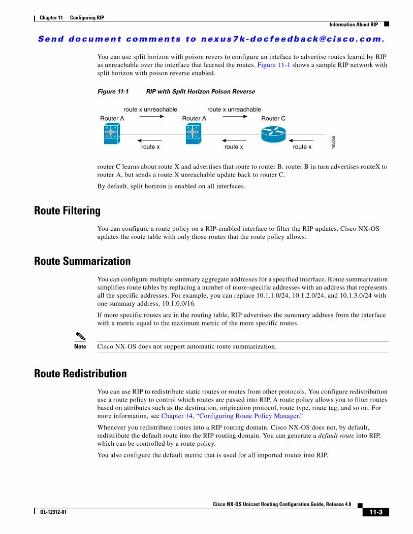
Send document comments to nexus7k -doc feedback@c i sco .com.
Chapter 11 Configuring RIPInformation About RIP
You can use split horizon with poison revers to configure an inteface to advertise routes learnd by RIP as unreachable over the interface that learned the routes. Figure 11-1 shows a sample RIP network with split horizon with poison reverse enabled.
Figure 11-1 RIP with Split Horizon Poison Reverse
router C learns about route X and advertises that route to router B. router B in turn advertises routeX to router A, but sends a route X unreachable update back to router C.
By default, split horizon is enabled on all interfaces.
Route FilteringYou can configure a route policy on a RIP-enabled interface to filter the RIP updates. Cisco NX-OS updates the route table with only those routes that the route policy allows.
Route SummarizationYou can configure multiple summary aggregate addresses for a specified interface. Route summarization simplifies route tables by replacing a number of more-specific addresses with an address that represents all the specific addresses. For example, you can replace 10.1.1.0/24, 10.1.2.0/24, and 10.1.3.0/24 with one summary address, 10.1.0.0/16.
If more specific routes are in the routing table, RIP advertises the summary address from the interface with a metric equal to the maximum metric of the more specific routes.
Note Cisco NX-OS does not support automatic route summarization.
Route RedistributionYou can use RIP to redistribute static routes or routes from other protocols. You configure redistribution use a route policy to control which routes are passed into RIP. A route policy allows you to filter routes based on attributes such as the destination, origination protocol, route type, route tag, and so on. For more information, see Chapter 14, “Configuring Route Policy Manager.”
Whenever you redistribute routes into a RIP routing domain, Cisco NX-OS does not, by default, redistribute the default route into the RIP routing domain. You can generate a default route into RIP, which can be controlled by a route policy.
You also configure the default metric that is used for all imported routes into RIP.
Router A Router A Router C
route x
route x unreachable route x unreachable
route x route x 1850
58
11-3Cisco NX-OS Unicast Routing Configuration Guide, Release 4.0
OL-12912-01

Send document comments to nexus7k -doc feedback@c i sco .com.
Chapter 11 Configuring RIPLicensing Requirements for RIP
Load BalancingYou can use load balancing to allow a router to distribute traffic over all the router network ports that are the same distance from the destination address. Load balancing increases the utilization of network segments and increases effective network bandwidth.
Cisco NX-OS supports the Equal Cost Multiple Paths (ECMP) feature with up to 16 equal-cost paths in the RIP route table and the unicast RIB. You can configure RIP to load balance traffic across some or all of those paths.
High AvailabilityCisco NX-OS supports stateless restarts for RIP. After a reboot or supervisor switchover, Cisco NX-OS applies the running configuration and RIP immediately sends request packets to repopulate its routing table.
Virtualization SupportCisco NX-OS supports multiple instances of the RIP protocol that runs on the same system. RIP supports Virtual Routing and Forwarding instances (VRFs). VRFs exist within virtual device contexts (VDCs).
You can configure up to four RIP instances on a VDC. By default, Cisco NX-OS places you in the default VDC and default VRF unless you specifically configure another VDC and VRF. See the Cisco NX-OS Virtual Device Context Configuration Guide and Chapter 13, “Configuring Layer 3 Virtualization.”
Licensing Requirements for RIPThe following table shows the licensing requirements for this feature:
Prerequisites for RIPRIP has the following prerequisites:
• You must enable the RIP feature (see the “Enabling the RIP Feature” section on page 11-5).
• If you configure VDCs, install the Advanced Services license and enter the desired VDC (see to the Cisco NX-OS Virtual Device Context Configuration Guide).
Configuration Guidelines and LimitationsRIP has the following configuration guidelines and limitations:
Product License Requirement
NX-OS RIP requires no license. Any feature not included in a license package is bundled with the Cisco NX-OS system images and is provided at no extra charge to you. For a complete explanation of the NX-OS licensing scheme, see the Cisco NX-OS Licensing Guide.
11-4Cisco NX-OS Unicast Routing Configuration Guide, Release 4.0
OL-12912-01

Send document comments to nexus7k -doc feedback@c i sco .com.
Chapter 11 Configuring RIPConfiguring RIP
• Cisco NX-OS does not support RIPv1. If Cisco NX-OS receives a RIPv1 packet, it logs a message and drops the packet.
• Cisco NX-OS does not establish adjacencies with RIPv1 routers.
Configuring RIPThis section includes the following topics:
• Enabling the RIP Feature, page 11-5
• Creating a RIP Instance, page 11-6
• Configuring RIP on an Interface, page 11-8
• Configuring a Passive Interface, page 11-10
• Configuring Route Summarization, page 11-11
• Configuring Route Summarization, page 11-11
• Configuring Route Redistribution, page 11-11
• Configuring Virtualization, page 11-13
• Tuning RIP, page 11-15
Note If you are familiar with the Cisco IOS CLI, be aware that the Cisco NX-OS commands for this feature might differ from the Cisco IOS commands that you would use.
Enabling the RIP FeatureYou must enable the RIP feature before you can configure RIP.
BEFORE YOU BEGIN
Ensure that you are in the correct VDC (or use the switchto vdc command).
SUMMARY STEPS
1. config t
2. feature rip
3. copy running-config startup-config
11-5Cisco NX-OS Unicast Routing Configuration Guide, Release 4.0
OL-12912-01

Send document comments to nexus7k -doc feedback@c i sco .com.
Chapter 11 Configuring RIPConfiguring RIP
DETAILED STEPS
Use the no feature rip command to disable the RIP feature and remove all associated configuration.
Creating a RIP InstanceYou can create a RIP instance and configure the address family for that instance.
BEFORE YOU BEGIN
Ensure that you have enabled the RIP feature (see the “Enabling the RIP Feature” section on page 11-5).
Ensure that you are in the correct VDC (or use the switchto vdc command).
SUMMARY STEPS
1. config t
2. router rip instance-tag
3. address-family {ip | ipv6} unicast
4. show {ip | ipv6} rip [instance instance-tag] [vrf vrf-name]
5. copy running-config startup-config
Command Purpose
Step 1 config t
Example:switch# config tswitch(config)#
Enters configuration mode.
Step 2 feature rip
Example:switch(config)# feature rip
Enables the RIP feature.
Step 3 copy running-config startup-config
Example:switch(config)# copy running-config startup-config
(Optional) Saves this configuration change.
Command Purpose
no feature rip
Example:switch(config)# no feature rip
Disables the RIP feature and removes all associated configuration.
11-6Cisco NX-OS Unicast Routing Configuration Guide, Release 4.0
OL-12912-01

Send document comments to nexus7k -doc feedback@c i sco .com.
Chapter 11 Configuring RIPConfiguring RIP
DETAILED STEPS
Use the no router rip command to remove the RIP instance and the associated configuration.
Note You must also remove any RIP commands configured in interface mode.
You can configure the following optional parameters for RIP in address-family configuration mode:
Command Purpose
Step 1 config t
Example:switch# config tswitch(config)#
Enters configuration mode.
Step 2 router rip instance-tag
Example:switch(config)# router RIP Enterpriseswitch(config-router)#
Creates a new RIP instance with the configured instance-tag.
Step 3 address-family {ipv4 | ipv6} unicast Example:switch(config-router)# address-family ipv4 unicastswitch(config-router-af)#
Configures the address family for this RIP instance and enters address-family configuration mode.
Step 4 show {ip | ipv6} rip [instance instance-tag] [vrf vrf-name]
Example:switch(config-router-af)# show ip rip
(Optional) Displays a summary of RIP information for all RIP instances.
Step 5 copy running-config startup-config
Example:switch(config-router-af)# copy running-config startup-config
(Optional) Saves this configuration change.
Command Purpose
no router rip instance-tag
Example:switch(config)# no router rip Enterprise
Deletes the RIP instance and all associated configuration.
Command Purposedistance value
Example:switch(config-router-af)# distance 30
Sets the administrative distance for RIP. The range is from 1 to 255. The default is 120. See the “Administrative Distance” section on page 1-6.
maximum-paths numberExample:switch(config-router-af)# maximum-paths 6
Configures the maximum number of equal-cost paths that RIP maintains in the route table. The range is from 1 to 16. The default is 16.
11-7Cisco NX-OS Unicast Routing Configuration Guide, Release 4.0
OL-12912-01

Send document comments to nexus7k -doc feedback@c i sco .com.
Chapter 11 Configuring RIPConfiguring RIP
The following example shows how to create a RIP instance for IPv4 and set the number of equal-cost paths for load balancing:
switch# config tswitch(config)# router rip Enterpriseswitch(config-router)# address-family ipv4 unicastswitch(config-router-af)# max-paths 10switch(config-router-af)# copy running-config startup-config
Restarting a RIP InstanceYou can restart a RIP instance. This clears all neighbors for the instance.
To restart an RIP instance and remove all associated neighbors, use the following command:
Configuring RIP on an InterfaceYou can add an interface to a RIP instance.
BEFORE YOU BEGIN
Ensure that you have enabled the RIP feature (see the “Enabling the RIP Feature” section on page 11-5).
Enter the correct VDC if necessary before configuring RIP.
SUMMARY STEPS
1. config t
2. interface interface-type slot/port
3. {ip | ipv6} router rip instance-tag
4. show{ip | ipv6} rip [instance instance-tag] interface [interface-type slot/port] [vrf vrf-name] [detail]
5. copy running-config startup-config
Command Purpose
restart rip instance-tag
Example:switch(config)# restart rip Enterprise
Restarts the RIP instance and removes all neighbors.
11-8Cisco NX-OS Unicast Routing Configuration Guide, Release 4.0
OL-12912-01

Send document comments to nexus7k -doc feedback@c i sco .com.
Chapter 11 Configuring RIPConfiguring RIP
DETAILED STEPS
The following example shows how to add Ethernet 1/2 interface to a RIP instance:
switch# config tswitch(config)# interface ethernet 1/2switch(config-if)# ip router rip Enterpriseswitch(config)# copy running-config startup-config
Configuring RIP AuthenticationYou can configure authentication for RIP packets on an interface.
BEFORE YOU BEGIN
Ensure that you have enabled the RIP feature (see the “Enabling the RIP Feature” section on page 11-5).
Ensure that you are in the correct VDC (or use the switchto vdc command).
Configure a key chain if necessary before enabling authentication. See the Cisco NX-OS Security Configuration Guide for details on implementing key chains.
SUMMARY STEPS
1. config t
Command Purpose
Step 1 config t
Example:switch# config tswitch(config)#
Enters configuration mode.
Step 2 interface interface-type slot/port
Example:switch(config)# interface ethernet 1/2switch(config-if)#
Enters interface configuration mode.
Step 3 {ip | ipv6} router rip instance-tag
Example:switch(config-if)# ip router rip Enterprise
Associates this interface with a RIP instance.
Step 4 show {ip | ipv6} rip [instance instance-tag] interface [interface-type slot/port] [vrf vrf-name] [detail]
Example:switch(config-if)# show ip rip Enterprise tethernet 1/2
(Optional) Displays RIP information for an interface.
Step 5 copy running-config startup-config
Example:switch(config-if)# copy running-config startup-config
(Optional) Saves this configuration change.
11-9Cisco NX-OS Unicast Routing Configuration Guide, Release 4.0
OL-12912-01

Send document comments to nexus7k -doc feedback@c i sco .com.
Chapter 11 Configuring RIPConfiguring RIP
2. interface interface-type slot/port
3. ip rip authentication mode{text | md5}
4. ip rip authentication keychain key
5. copy running-config startup-config
DETAILED STEPS
The following example shows how to create a key chain and configure MD5 authentication on a RIP interface:
switch# config tswitch(config)# key chain RIPKeyswitch(config)# key-string myripswitch(config)# accept-lifetime 00:00:00 Jan 01 2000 infiniteswitch(config)# send-lifetime 00:00:00 Jan 01 2000 infiniteswitch(config)# interface ethernet 1/2switch(config-if)# ip rip authentication mode md5 switch(config-if)# ip rip authentication keychain RIPKeyswitch(config-if)# copy running-config startup-config
Configuring a Passive InterfaceYou can configure a RIP interface to receive routes but not send route updates by setting the interface to passive mode.
Command Purpose
Step 1 config t
Example:switch# config tswitch(config)#
Enters configuration mode.
Step 2 interface interface-type slot/port
Example:switch(config)# interface ethernet 1/2switch(config-if)#
Enters interface configuration mode.
Step 3 ip rip authentication mode {text | md5}
Example:switch(config-if)# ip rip authentication mode md5
Sets the authentication type for RIP on this interface as cleartext or MD5 authentication digest.
Step 4 ip rip authentication keychain key
Example:switch(config-if)# ip rip authentication keychain RIPKey
Configures the authentication key used for RIP on this interface.
Step 5 copy running-config startup-config
Example:switch(config-if)# copy running-config startup-config
(Optional) Saves this configuration change.
11-10Cisco NX-OS Unicast Routing Configuration Guide, Release 4.0
OL-12912-01
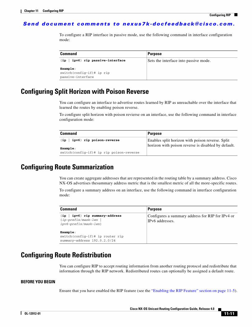
Send document comments to nexus7k -doc feedback@c i sco .com.
Chapter 11 Configuring RIPConfiguring RIP
To configure a RIP interface in passive mode, use the following command in interface configuration mode:
Configuring Split Horizon with Poison ReverseYou can configure an interface to advertise routes learned by RIP as unreachable over the interface that learned the routes by enabling poison reverse.
To configure split horizon with poison revierse on an interface, use the following command in interface configuration mode:
Configuring Route SummarizationYou can create aggregate addresses that are represented in the routing table by a summary address. Cisco NX-OS advertises thesummary address metric that is the smallest metric of all the more-specific routes.
To configure a summary address on an interface, use the following command in interface configuration mode:
Configuring Route RedistributionYou can configure RIP to accept routing information from another routing protocol and redistribute that information through the RIP network. Redistributed routes can optionally be assigned a default route.
BEFORE YOU BEGIN
Ensure that you have enabled the RIP feature (see the “Enabling the RIP Feature” section on page 11-5).
Command Purpose{ip | ipv6} rip passive-interface
Example:switch(config-if)# ip rip passive-interface
Sets the interface into passive mode.
Command Purpose
{ip | ipv6} rip poison-reverse
Example:switch(config-if)# ip rip poison-reverse
Enables split horizon with poison reverse. Split horizon with poison reverse is disabled by default.
Command Purpose{ip | ipv6} rip summary-address {ip-prefix/mask-len | ipv6-prefix/mask-len}
Example:switch(config-if)# ip router rip summary-address 192.0.2.0/24
Configures a summary address for RIP for IPv4 or IPv6 addresses.
11-11Cisco NX-OS Unicast Routing Configuration Guide, Release 4.0
OL-12912-01

Send document comments to nexus7k -doc feedback@c i sco .com.
Chapter 11 Configuring RIPConfiguring RIP
Enter the correct VDC if necessary before configuring RIP.
Configure a route map before configuring redistribution. See the“Configuring Route Maps” section on page 14-9 for details on configuring route maps.
SUMMARY STEPS
1. config t
2. router rip instance-tag
3. address-family {ipv4 | ipv6} unicast
4. redistribute {bgp as | direct | eigrp as | isis tag | rip tag | {ospf tag | ospfv3 tag } | static} route-map map-name
5. default-information originate [always] [route-map map-name]
6. default-metric value
7. show{ip | ipv6} rip route [{ip-prefix | ip6-prefix}[longer-prefixes | shorter-prefixes ]] [vrf vrf-name] [summary]
8. copy running-config startup-config
DETAILED STEPS
Command Purpose
Step 1 config t
Example:switch# config tswitch(config)#
Enters configuration mode.
Step 2 router rip instance-tag
Example:switch(config)# router rip Enterpriseswitch(config-router)#
Creates a new RIP instance with the configured instance-tag.
Step 3 address-family {ipv4 | ipv6} unicast
Example:switch(config-router)# address-family ipv4 unicastswitch(config-router-af)#
Enters address family configuration mode.
Step 4 redistribute {bgp as | direct | eigrp as |isis tag | rip tag | {ospf tag | ospfv3 tag} static} route-map map-name
Example:switch(config-router-af)# redistribute eigrp 201 route-map RIPmap
Redistributes routes from other protocols into RIP. See the “Configuring Route Maps” section on page 14-9 for more information about route maps.
Step 5 default-information originate [always] [route-map map-name]
Example:switch(config-router-af)# default-information originate always
(Optional) Generates a default route into RIP, optionally controlled by a route map.
11-12Cisco NX-OS Unicast Routing Configuration Guide, Release 4.0
OL-12912-01

Send document comments to nexus7k -doc feedback@c i sco .com.
Chapter 11 Configuring RIPConfiguring RIP
The following example shows how to redistribute EIGRP into RIP:
switch# config tswitch(config)# router rip Enterpriseswitch(config-router)# address-family ipv4 unicastswitch(config-router-af)# redistribute eigrp 201 route-map RIPmapswitch(config-router-af)# copy running-config startup-config
Configuring VirtualizationYou can configure multiple RIP instances in each VDC. You can also create multiple VRFs within each VDC and use the same or multiple RIP instances in each VRF. You assign a RIP interface to a VRF.
Note Configure all other parameters for an interface after you configure the VRF for an interface. Configuring a VRF for an interface deletes all the configuration for that interface.
BEFORE YOU BEGIN
Ensure that you have enabled the RIP feature (see the “Enabling the RIP Feature” section on page 11-5).
Create the VDCs.
SUMMARY STEPS
1. config t
2. vrf context vrf_name
3. exit
4. router rip instance-tag
5. vrf vrf-name
6. address-family {ipv4 | ipv6} unicast
Step 6 default-metric value
Example:switch(config-router-af)# distribute level-1 into level-2 all
(Optional) Sets the default metric for all redistributed routes. The range is from 1 to 15. The default is 1.
Step 7 show {ip | ipv6} rip route [{ip-prefix | ip6-prefix} [longer-prefixes | shorter-prefixes] [vrf vrf-name][summary]
Example:switch(config-router-af)# show ip rip route
(Optional) Shows the routes in RIP.
Step 8 copy running-config startup-config
Example:switch(config-router-af)# copy running-config startup-config
(Optional) Saves this configuration change.
Command Purpose
11-13Cisco NX-OS Unicast Routing Configuration Guide, Release 4.0
OL-12912-01

Send document comments to nexus7k -doc feedback@c i sco .com.
Chapter 11 Configuring RIPConfiguring RIP
7. configure optional parameters
8. interface ethernet slot/port
9. vrf member vrf-name
10. ip-address ip-prefix/length
11. {ip | ipv6} router rip instance-tag
12. show {ip | ipv6} rip [instance instance-tag] interface [interface-type slot/port] [vrf vrf-name]
13. copy running-config startup-config
DETAILED STEPS
Command Purpose
Step 1 config t
Example:switch# config tswitch(config)#
Enters configuration mode.
Step 2 vrf vrf-name
Example:switch(config)# vrf RemoteOfficeVRFswitch(config-vrf)#
Creates a new VRF.
Step 3 exit
Example:switch(config-vrf)# exitswitch(config)#
Exits VRF configuration mode.
Step 4 router rip instance-tag
Example:switch(config)# router rip Enterpriseswitch(config-router)#
Creates a new RIP instance with the configured instance tag.
Step 5 vrf context vrf-name
Example:switch(config)# vrf context RemoteOfficeVRFswitch(config-vrf)#
Creates a new VRF and enters VRF configuration mode.
Step 6 address-family {ipv4 | ipv6} unicast
Example:switch(config-router-vrf)# address-family ipv4 unicastswitch(config-router-vrf-af)#
(Optional) Configures the VRF address family for this RIP instance.
Step 7 redistribute {bgp as | direct | eigrp as | isis tag | rip tag | {ospf tag | ospfv3 tag} static} route-map map-name
Example:switch(config-router-vrf-af)# redistribute eigrp 201 route-map RIPmap
(Optional) Redistributes routes from other protocols into RIP. See the “Configuring Route Maps” section on page 14-9 for more information about route maps.
11-14Cisco NX-OS Unicast Routing Configuration Guide, Release 4.0
OL-12912-01
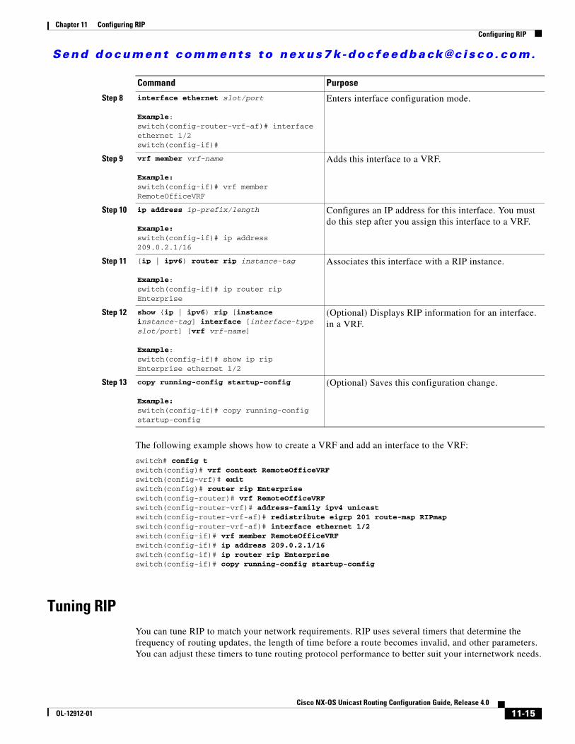
Send document comments to nexus7k -doc feedback@c i sco .com.
Chapter 11 Configuring RIPConfiguring RIP
The following example shows how to create a VRF and add an interface to the VRF:
switch# config tswitch(config)# vrf context RemoteOfficeVRFswitch(config-vrf)# exitswitch(config)# router rip Enterpriseswitch(config-router)# vrf RemoteOfficeVRFswitch(config-router-vrf)# address-family ipv4 unicastswitch(config-router-vrf-af)# redistribute eigrp 201 route-map RIPmapswitch(config-router-vrf-af)# interface ethernet 1/2switch(config-if)# vrf member RemoteOfficeVRFswitch(config-if)# ip address 209.0.2.1/16switch(config-if)# ip router rip Enterpriseswitch(config-if)# copy running-config startup-config
Tuning RIP You can tune RIP to match your network requirements. RIP uses several timers that determine the frequency of routing updates, the length of time before a route becomes invalid, and other parameters. You can adjust these timers to tune routing protocol performance to better suit your internetwork needs.
Step 8 interface ethernet slot/port
Example:switch(config-router-vrf-af)# interface ethernet 1/2switch(config-if)#
Enters interface configuration mode.
Step 9 vrf member vrf-name
Example:switch(config-if)# vrf member RemoteOfficeVRF
Adds this interface to a VRF.
Step 10 ip address ip-prefix/length
Example:switch(config-if)# ip address 209.0.2.1/16
Configures an IP address for this interface. You must do this step after you assign this interface to a VRF.
Step 11 {ip | ipv6) router rip instance-tag
Example:switch(config-if)# ip router rip Enterprise
Associates this interface with a RIP instance.
Step 12 show {ip | ipv6) rip [instance instance-tag] interface [interface-type slot/port] [vrf vrf-name]
Example:switch(config-if)# show ip rip Enterprise ethernet 1/2
(Optional) Displays RIP information for an interface. in a VRF.
Step 13 copy running-config startup-config
Example:switch(config-if)# copy running-config startup-config
(Optional) Saves this configuration change.
Command Purpose
11-15Cisco NX-OS Unicast Routing Configuration Guide, Release 4.0
OL-12912-01

Send document comments to nexus7k -doc feedback@c i sco .com.
Chapter 11 Configuring RIPConfiguring RIP
Note You must configure the same values for the RIP timers on all RIP-enabled routers in your network.
You can use the following optional commands in address-family configuration mode to tune RIP:
You can use the following optional commands in interface configuration mode to tune RIP:
Command Purpose
timers basic update timeout holddown garbage-collectionExample:switch(config-router-af)# timers basic 40 120 120 100
Sets the RIP timers in seconds. The parameters are as follows:
• update—The range is from 5 to any positive integer. The default is 30.
• timeout—The time that Cisco NX-OS waits before declaring a routeas invalid. If Cisco NX-OS does not receive route update information for this route before the timeout interval ends, Cisco NX-OS declares the route as invalid. The range isfrom 1 to any positive integer. The default is 180.
• holddown—The time during which Cisco NX-OS ignores better route information for an invalid route. The range is from 0 to any positive integer. The default is 180.
• garbage-collection—The time from when Cisco NX-OS marks a route as invalid until Cisco NX-OS removes the route from the routing table. The range is frome 1 to any positive integer. The default is 120.
Command Purpose
{ip | ipv6} rip metric-offset value
Example:switch(config-if)# ip rip metric-offset 10
Adds a value to the metric for every router received on this interface. The range is from 1 to 15. The default is 1.
{ip | ipv6} rip route-filter {prefix-list list-name | route-map map-name| [in | out]
Example:switch(config-if)# ip rip route-filter route-map InputMap in
Specifies a route map to filter incoming or outgoing RIP updates.
11-16Cisco NX-OS Unicast Routing Configuration Guide, Release 4.0
OL-12912-01

Send document comments to nexus7k -doc feedback@c i sco .com.
Chapter 11 Configuring RIPVerifying RIP Configuration
Verifying RIP ConfigurationTo verify RIP configuration, use the following commands:
Displaying RIP StatisticsTo display RIP statistics, use the following commands:
Use the clear {ip | ipv6} rip policy command to clear policy statistics.
Use the clear {ip | ipv6} rip statistics command to clear RIP statistics.
Command Purpose
show {ip | ipv6} rip instance [instance-tag] [vrf vrf-name]
Displays the status for an instance of RIP.
show {ip | ipv6} rip [instance instance-tag] interface slot/port detail [vrf vrf-name]
Displays the RIP status for an inteface.
show {ip | ipv6} rip [instance instance-tag] neighbor [interface-type number] [vrf vrf-name]
Displays the RIP neighbor table.
show {ip | ipv6} rip [instance instance-tag] route [{ip-prefix/lengh | ipv6-prefix/length} [longer-prefixes | shorter--prefixes]][summary] [vrf vrf-name]
Displays the RIP route table.
show running-configuration rip Displays the current running RIP configuration.
Command Purpose
show {ip | ipv6} rip [instance instance-tag] policy statistics redistribute {bgp as | direct | eigrp as | isis tag | rip tag | {ospf tag | ospfv3 tag} static} [vrf vrf-name]
Displays the RIP policy status.
show {ip | ipv6} rip [instance instance-tag] statistics interface-type number] [vrf vrf-name]
Displays the RIP statistics.
11-17Cisco NX-OS Unicast Routing Configuration Guide, Release 4.0
OL-12912-01

Send document comments to nexus7k -doc feedback@c i sco .com.
Chapter 11 Configuring RIPRIP Example Configuration
RIP Example Configuration The following example creates the Enterprise RIP instance in a VRF and adds Ethernet interface 1/2 to this RIP instance. The example also configures authentication for Ethernet interface 1/2 and redistributes EIGRP into this RIP domain.
vrf context NewVRF! feature rip router rip Enterprise vrf NewVRF address-family ip unicast redistribute eigrp 201 route-map RIPmap max-paths 10!interface ethernet 1/2 vrf NewVRF ip address 209.0.2.1/16 ip router rip Enterprise ip rip authentication mode md5 ip rip authentication keychain RIPKey
Related TopicsSee Chapter 14, “Configuring Route Policy Manager” for more information on route maps.
Where to Go Next <Description of next configuration task.>
Default SettingsTable 11-1 lists the default settings for RIP parameters.
Additional ReferencesFor additional information related to implementing RIP, see the following sections:
• Related Documents, page 11-19
• Standards, page 11-19
Table 11-1 Default RIP Parameters
Parameters Default
Maximum paths for load balancing 16
RIP feature Disabled
Split horizon Enabled
11-18Cisco NX-OS Unicast Routing Configuration Guide, Release 4.0
OL-12912-01

Send document comments to nexus7k -doc feedback@c i sco .com.
Chapter 11 Configuring RIPAdditional References
Related Documents
Standards
Related Topic Document Title
RIP CLI commands Cisco NX-OS Command Line Reference
VDCs and VRFs Cisco NX-OS Virtual Device Contexts Configuration Guide
Standards Title
No new or modified standards are supported by this feature, and support for existing standards has not been modified by this feature.
—
11-19Cisco NX-OS Unicast Routing Configuration Guide, Release 4.0
OL-12912-01

Send document comments to nexus7k -doc feedback@c i sco .com.
Chapter 11 Configuring RIPAdditional References
11-20Cisco NX-OS Unicast Routing Configuration Guide, Release 4.0
OL-12912-01

Send document comments to nexus7k -doc feedback@c i sco .com.
Cisco NX-OOL-12912-01
C H A P T E R 12
Configuring Static RoutingThis chapter describes how to configure static routing on the router.
This chapter includes the following sections:
• Information About Static Routing, page 12-1
• Licensing Requirements for Static Routing, page 12-3
• Prerequisites for Static Routing, page 12-3
• Guidelines and Limitations, page 12-3
• Configuring Static Routing, page 12-3
• Verifying Static Routing Configuration, page 12-6
• Static Routing Example Configuration, page 12-6
• Default Settings, page 12-7
• Additional References, page 12-7
Information About Static RoutingRouters forward packets using either route information from route table entries that you manually configure or the route information that is calculated using dynamic routing algorithms.
Static routes, which define explicit paths between two routers, cannot be automatically updated; you must manually reconfigure static routes when network changes occur. Static routes use less bandwidth than dynamic routes. No CPU cycles are used to calculate and analyze routing updates.
You can supplement dynamic routes with static routes where appropriate. You can redistribute static routes into dynamic routing algorithms but you cannot redistribute routing information calculated by dynamic routing algorithms into the static routing table.
You should use static routes in environments where network traffic is predictable and where the network design is simple. You should not use static routes in large, constantly changing networks because static routes cannot react to network changes. Most networks use dynamic routes to communicate between routers but may have one or two static routes configured for special cases. Static routes are also useful for specifying a gateway of last resort (a default router to which all unroutable packets are sent).
This section includes the following topics:
• Administrative Distance, page 12-2
• Directly Connected Static Routes, page 12-2
12-1S Unicast Routing Configuration Guide, Release 4.0

Send document comments to nexus7k -doc feedback@c i sco .com.
Chapter 12 Configuring Static RoutingInformation About Static Routing
• Fully Specified Static Routes, page 12-2
• Floating Static Routes, page 12-2
• Remote Next Hops for Static Routes, page 12-3
Administrative DistanceAn administrative distance is the metric used by routers to choose the best path when there are two or more routes to the same destination from two different routing protocols. An administrative distance guides the selection of one routing protocol (or static route) over another, when more than one protocol adds the same route to the unicast routing table. Each routing protocol is prioritized in order of most to least reliable using an administrative distance value.
Static routes have a default administrative distance of 1. A router prefers a static route to a dynamic route because the router considers a route with a low number to be the shortest. If you want a dynamic route to override a static route, you can specify an administrative distance for the static route. For example, if you have two dynamic routes with an administrative distance of 120, you would specify an administrative distance that is greater than 120 for the static route if you want the dynamic route to override the static route.
Directly Connected Static RoutesYou need to specify only the output interface (the interface on which all packets are sent to the destination network) in a directly connected static route. The router assumes the destination is directly attached to the output interface and the packet destination is used as the next hop address. The next-hop can be an interface, only for point-to-point interfaces. For broadcast interfaces, the next-hop must be an IPv4/IPv6 address.
Fully Specified Static RoutesYou must specify either the output interface (the interface on which all packets are sent to the destination network) or the next hop address in a fully specified static route. You can use a fully specified static route when the output interface is a multi-access interface and you need to identify the next-hop address. The next-hop address must be directly attached to the specified output interface.
Floating Static RoutesA floating static route is a static route that the router uses to back up a dynamic route. You must configure a floating static route with a higher administrative distance than the dynamic route that it backs up. In this instance, the router prefers a dynamic route to a floating static route. You can use a floating static route as a replacement if the dynamic route is lost.
Note By default, a router prefers a static route to a dynamic route because a static route has a smaller administrative distance than a dynamic route.
12-2Cisco NX-OS Unicast Routing Configuration Guide, Release 4.0
OL-12912-01

Send document comments to nexus7k -doc feedback@c i sco .com.
Chapter 12 Configuring Static RoutingLicensing Requirements for Static Routing
Remote Next Hops for Static RoutesYou can specify the next-hop address of a neighboring router which is not directly connected to the router for static routes with remote (non-directly attached) next-hops. If a static route has remote next-hops during data-forwarding, the next-hops are recursively used in the unicast routing table to identify the corresponding directly attached next-hop(s) that have reachability to the remote next-hops.
Virtualization SupportStatic routes support Virtual Routing and Forwarding instances (VRFs). VRFs exist within virtual device contexts (VDCs). By default, Cisco NX-OS places you in the default VDC and default VRF unless you specifically configure another VDC and VRF. For more information, see the Cisco NX-OS Virtual Device Context Configuration Guideand see Chapter 13, “Configuring Layer 3 Virtualization.”
Licensing Requirements for Static RoutingThe following table shows the licensing requirements for this feature:
Prerequisites for Static RoutingStatic routing has the following prerequisites:
• If the next-hop address for a static route is unreachable, the static route will not be added to the unicast routing table.
Guidelines and LimitationsStatic routing has the following guidelines and limitations:
• You can specify an interface as the next-hop address for a static route only for point-to-point interfaces such as GRE tunnels.
Configuring Static RoutingThis section includes the following topics:
• Configuring a Static Route, page 12-4
Product License Requirement
NX-OS Static routing requires no license. Any feature not included in a license package is bundled with the Cisco NX-OS system images and is provided at no extra charge to you. For a complete explanation of the NX-OS licensing scheme, see the Cisco NX-OS Licensing Guide.
12-3Cisco NX-OS Unicast Routing Configuration Guide, Release 4.0
OL-12912-01

Send document comments to nexus7k -doc feedback@c i sco .com.
Chapter 12 Configuring Static RoutingConfiguring Static Routing
Note If you are familiar with the Cisco IOS CLI, be aware that the Cisco NX-OS commands for this feature might differ from the Cisco IOS commands that you would use.
Configuring a Static RouteYou can configure a static route on the router.
BEFORE YOU BEGIN
Ensure that you are in the correct VDC (or use the switchto vdc command).
SUMMARY STEPS
1. config t
2. ip route {ip-prefix | ip-addr ip-mask} {next-hop | nh-prefix | interface} [tag tag-value [pref]
or
3. ipv6 route ip6-prefix{ {next-hop | nh-prefix} | interface | {link-local interface}} [pref]
4. show {ip | ipv6} static-route
5. copy running-config startup-config
DETAILED STEPS
Command Purpose
Step 1 config t
Example:switch# config tswitch(config)#
Enters configuration mode.
Step 2 ip route {ip-prefix | ip-addr ip-mask} {next-hop | nh-prefix | interface} [tag tag-value [pref]
Example:switch(config)# ip route 192.0.2.0/8 ethernet 1/2
Configures a static route and the interface for this static route. You can optionally configure the next-hop address. The preference value sets the administrative distance. The range is from 1 to 255. The default is 1.
ipv6 route {ip6-prefix{ {next-hop | nh-prefix} | interface |{link-local interface}} [pref]
Example:switch(config)# ipv6 route 2001:0DB8::/48 ethernet 1/2
Configures a static route and the interface for this static route. You can optionally configure the next-hop address. The preference value sets the administrative distance. The range is from 1 to 255. The default is 1.
12-4Cisco NX-OS Unicast Routing Configuration Guide, Release 4.0
OL-12912-01

Send document comments to nexus7k -doc feedback@c i sco .com.
Chapter 12 Configuring Static RoutingConfiguring Static Routing
This example shows how to configure a static route:
switch# config tswitch(config)# ip route 192.0.2.0/8 192.0.2.10switch(config)# copy running-config startup-config
Use the no {ip | ipv6} static-route command to remove the static route.
Configuring VirtualizationYou can configure a static route in a VRF.
BEFORE YOU BEGIN
Ensure that you are in the correct VDC (or use the switchto vdc command).
SUMMARY STEPS
1. config t
2. vrf context vrf-name
3. ip route {ip-prefix | ip-addr ip-mask} {next-hop | nh-prefix | interface} [tag tag-value [pref]
or
4. ipv6 route ip6-prefix{ {next-hop | nh-prefix} | interface | {link-local interface}} [pref]
5. show {ip | ipv6} static-route vrf vrf-name
6. copy running-config startup-config
DETAILED STEPS
Step 3 show {ip | ipv6} static-route
Example:switch(config)# show ip static-route
(Optional) Displays information about static routes.
Step 4 copy running-config startup-config
Example:switch(config)# copy running-config startup-config
(Optional) Saves this configuration change.
Command Purpose
Command Purpose
Step 1 config t
Example:switch# config tswitch(config)#
Enters configuration mode.
Step 1 vrf context vrf-name
Example:switch(config)# vrf context StaticVrf
Creates a VRF and enters VRF configuration mode.
12-5Cisco NX-OS Unicast Routing Configuration Guide, Release 4.0
OL-12912-01

Send document comments to nexus7k -doc feedback@c i sco .com.
Chapter 12 Configuring Static RoutingVerifying Static Routing Configuration
This example shows how to configure a static route:
switch# config tswitch(config)# vrf context StaticVrfswitch(config-vrf)# ip route 192.0.2.0/8 192.0.2.10switch(config-vrf)# copy running-config startup-config
Verifying Static Routing ConfigurationTo view configuration information, use the following commands:
Static Routing Example ConfigurationThis example shows how to configure static routing:
config t ip route 192.0.2.0/8 192.0.2.10 copy running-config startup-config
Step 2 ip route {ip-prefix | ip-addr ip-mask} {next-hop | nh-prefix | interface} [tag tag-value [pref]
Example:switch(config-vrf)# ip route 192.0.2.0/8 ethernet 1/2
Configures a static route and the interface for this static route. You can optionally configure the next-hop address. The preference value sets the administrative distance. The range is from 1 to 255. The default is 1.
ipv6 route {ip6-prefix{ {next-hop | nh-prefix} | interface |{link-local interface}} [pref]
Example:switch(config-vrf)# ipv6 route 2001:0DB8::/48 ethernet 1/2
Configures a static route and the interface for this static route. You can optionally configure the next-hop address. The preference value sets the administrative distance. The range is from 1 to 255. The default is 1.
Step 3 show {ip | ipv6} static-route vrf vrf-name
Example:switch(config-vrf)# show ip static-route
(Optional) Displays information on static routes.
Step 4 copy running-config startup-config
Example:switch(config-vrf)# copy running-config startup-config
(Optional) Saves this configuration change.
Command Purpose
Command Purpose
show ip static-route Displays the configured static routes.
show ipv6 static-route vrf vrf-name Displays static route information per-VRF.
show ipv6 static-route Displays the configured static routes.
12-6Cisco NX-OS Unicast Routing Configuration Guide, Release 4.0
OL-12912-01

Send document comments to nexus7k -doc feedback@c i sco .com.
Chapter 12 Configuring Static RoutingDefault Settings
Default SettingsTable 12-1 lists the default settings for static routing parameters.
Additional ReferencesFor additional information related to implementing static routing, see the following sections:
• Related Documents, page 12-7
Related Documents
Table 12-1 Default Static Routing Parameters
Parameters Default
administrative distance 1
RIP feature disabled
Related Topic Document Title
Static Routing CLI Cisco NX-OS Unicast Routing Command Line Reference
VDCs Cisco NX-OS Virtual Device Contexts Configuration Guide
12-7Cisco NX-OS Unicast Routing Configuration Guide, Release 4.0
OL-12912-01

Send document comments to nexus7k -doc feedback@c i sco .com.
Chapter 12 Configuring Static RoutingAdditional References
12-8Cisco NX-OS Unicast Routing Configuration Guide, Release 4.0
OL-12912-01

Send document comments to nexus7k -doc feedback@c i sco .com.
Cisco NX-OOL-12912-01
C H A P T E R 13
Configuring Layer 3 VirtualizationThis chapter describes how to configure Layer 3 virtualization.
This chapter includes the following sections:
• Layer 3 Virtualization, page 13-1
• Licensing Requirements for VRFs, page 13-5
• Prerequisites for VRF, page 13-5
• Guidelines and Limitations, page 13-5
• Configuring VRFs, page 13-6
• Verifying VRF Configuration, page 13-12
• VRF Example Configuration, page 13-12
• Related Topics, page 13-12
• Default Settings, page 13-13
• Default Settings, page 13-13
• Additional References, page 13-13
Layer 3 VirtualizationThis section contains the following topics:
• Overview of Layer 3 Virtualization, page 13-1
• VRF and Routing, page 13-2
• VRF-Aware Services, page 13-3
Overview of Layer 3 Virtualization
Cisco NX-OS supports a hierarchy of virtualization that can divide the physical system resources into multi-ple virtual device contexts (VDCs). Each VDC acts as a standalone device with both Layer 2 and Layer 3 services available. You can configure up to 15 VDCs, including the default VDC. See the Cisco NX-OS Vir-tualization Configuration Guide for more information on VDCs.
13-1S Unicast Routing Configuration Guide, Release 4.0

Send document comments to nexus7k -doc feedback@c i sco .com.
Chapter 13 Configuring Layer 3 VirtualizationLayer 3 Virtualization
Cisco NX-OS further virtualizes each VDC to support virtual routing and forwarding instances (VRFs). You can configure multiple VRFs in a VDC. Each VRF contains a separate address space with unicast and multicast route tables for IPv4 and IPv6 and makes routing decisions independent of any other VRF.
Figure 13-1 shows multiple independent VRFs in two different VDCs.
Figure 13-1 Multiple VRFs in VDCs
A VRF name is local to a VDC, so you can configure two VRFs with the same name if the VRFs exist in different VDCs. In Figure 13-1, VRF A in VDC 2 is independent of VRF B and VRF A in VDC n.
Each router has a default VRF and a management VRF. All Layer 3 interfaces and routing protocols exist in the default VRF until you assign them to another VRF. The mgmt0 interface exists in the management VRF and is accessible from any VDC. Each VDC has a unique IP address for the mgmt0 interface (see the Cisco NX-OS Fundamentals Configuration Guide, Release 4.0 ).
VRF and RoutingAll unicast and multicast routing protocols support VRFs. When you configure a routing protocol in a VRF, you set routing parameters for the VRF that are independent of routing parameters in another VRF for the same routing protocol instance.
You can assign interfaces and route protocols to a VRF to create virtual Layer 3 networks. An interface exists in only one VRF. Figure 13-2 shows one physical network split into two virtual networks with two VRFs. Routers Z, A, and B exist in VRF Red and form one address domain. These routers share route updates that do not include router C because router C is configured in a different VRF.
Physical Router
VDC 2 VDC n
routing protocol
routing protocol
routing protocolVRF A
VRF A VRF B
VRF B
RIBs RIBs
RIB-table RIB-table RIB-table RIB-table
Protocol stock Protocol stock
FIBs
Infrastructures
kernel
1864
15
13-2Cisco NX-OS Unicast Routing Configuration Guide, Release 4.0
OL-12912-01

Send document comments to nexus7k -doc feedback@c i sco .com.
Chapter 13 Configuring Layer 3 VirtualizationLayer 3 Virtualization
Figure 13-2 VRFs in a Network
By default, Cisco NX-OS uses the VRF of the incoming interface to select which routing table to use for a route lookup. You can configure a route policy to modify this behavior and set the VRF that Cisco NX-OS uses for incoming packets. See Chapter 15, “Configuring Policy-Based Routing” for more information.
VRF-Aware ServicesA VRF-aware service can select a particular VRF to reach a remote server or to filter information based on the selected VRF.
VRF-aware services include the following:
• AAA—See the Cisco Cisco NX-OS Security Configuration Guide for more information.
• Call Home—See the Cisco Cisco NX-OS System Management Configuration Guide for more information.
• DNS—See Chapter 4, “Configuring DNS” for more information.
• GLBP—See Chapter 16, “Configuring GLBP” for more information.
• HSRP—See Chapter 17, “Configuring HSRP” for more information.
• HTTP—See the Cisco Cisco NX-OS Getting Started Configuration Guide for more information.
• Licensing—See the Cisco Cisco NX-OS Licensing Configuration Guide for more information.
• Netflow—See the Cisco Cisco NX-OS Network Management Configuration Guide for more information.
• NTP—See the Cisco Cisco NX-OS System Management Configuration Guide for more information.
• RADIUS—See the Cisco Cisco NX-OS Security Configuration Guide for more information.
• Ping and Traceroute —See the Cisco Cisco NX-OS System Management Configuration Guide for more information.
• SSH—See the Cisco Cisco NX-OS System Management Configuration Guide for more information.
• SNMP—See the Cisco Cisco NX-OS System Management Configuration Guide for more information.
• Syslog—See the Cisco Cisco NX-OS System Management Configuration Guide for more information.
• TACACS+—See the Cisco Cisco NX-OS Security Configuration Guide for more information.
• TFTP—See the Cisco Cisco NX-OS Getting Started Configuration Guide for more information.
• VRRP—See Chapter 18, “Configuring VRRP” for more information.
• XML—See the Cisco Cisco NX-OS XML Configuration Guide for more information.
Ethernet 1/1
VRF Red
Ethernet 2/1
VRF Red
Ethernet 2/2
VRF Blue
Router ZRouter A
Router B
Router C 1864
16
13-3Cisco NX-OS Unicast Routing Configuration Guide, Release 4.0
OL-12912-01

Send document comments to nexus7k -doc feedback@c i sco .com.
Chapter 13 Configuring Layer 3 VirtualizationLayer 3 Virtualization
See the appropriate configuration guide for each service for more information on configuring VRF support in that service.
This section contains the following topics:
• Reachability, page 13-4
• Filtering, page 13-4
• Combining Reachability and Filtering, page 13-5
Reachability
Reachability indicates which VRF contains the routing information necessary to get to the server providing the service. For example, you can configure an SNMP server that is reachable on the management VRF. When you configure that server address on the router, you also configure which VRF that Cisco NX-OS must use to reach the server.
Figure 13-3 shows an SNMP server that is reachable over the management VRF. You configure router A to use the management VRF for SNMP server host 192.0.2.1.
Figure 13-3 Service VRF Reachability
Filtering
Filtering allows you to limit the type of information that goes to a VRF-aware service based on the VRF. For example, you can configure a syslog server to support a particular VRF. Figure 13-4 shows two syslog servers with each server supporting one VRF. syslog server A is configured in VRF Red, so Cisco NX-OS sends only system messages generated in VRF Red to syslog server A.
Figure 13-4 Service VRF Filtering
1864
17
Router A
mgmt0
VRF management
SNMP Server192.0.2.1
1864
18
Router A
Ethernet 2/1
VRF Red
Ethernet 2/2
VRF Blue
Syslog Server A
Syslog Server B
13-4Cisco NX-OS Unicast Routing Configuration Guide, Release 4.0
OL-12912-01

Send document comments to nexus7k -doc feedback@c i sco .com.
Chapter 13 Configuring Layer 3 VirtualizationLicensing Requirements for VRFs
Combining Reachability and Filtering
You can combine reachability and filtering for VRF-aware services. You configure the VRF that Cisco NX-OS uses to connect to that service as well as the VRF that the service supports. If you configure a service in the default VRF, you can optionally configure the service to support all VRFs.
Figure 13-5 shows an SNMP server that is reachable on the management VRF. You can configure the SNMP server to support only the SNMP notifications from VRF Red, for example.
Figure 13-5 Service VRF Reachability Filtering
Licensing Requirements for VRFsThe following table shows the licensing requirements for this feature:
Prerequisites for VRFVRFs have the following prerequisites:
• You must install the Advanced Services license to use VDCs besides the default VDC.
Guidelines and Limitations VRFs have the following guidelines and limitations:
• When you make an interface a member of an existing VRF, Cisco NX-OS removes all layer 3 configuration. You should configure all layer 3 parameters after adding an interface to a VRF.
• You should add the mgmt0 interface to the management VRF and configure the mgmt0 IP address and other parameters after you add it to the management VRF.
• If you configure an interface for a VRF before the VRF exists, the interface is operationally down until you create the VRF.
1864
19
Router AEthernet 2/1
VRF Red
Ethernet 2/2
VRF Blue
Router B
Router C
mgmt0VRF management
SNMP Server192.0.2.1
Product License Requirement
NX-OS VRFs require no license. Any feature not included in a license package is bundled with the Cisco NX-OS system images and is provided at no extra charge to you. For a complete explanation of the NX-OS licensing scheme, see the Cisco NX-OS Licensing Guide.
13-5Cisco NX-OS Unicast Routing Configuration Guide, Release 4.0
OL-12912-01

Send document comments to nexus7k -doc feedback@c i sco .com.
Chapter 13 Configuring Layer 3 VirtualizationConfiguring VRFs
• Cisco NX-OS creates the default and management VRFs by default. You should make the mgmt0 interface a member of the management VRF.
Configuring VRFsThis section contains the following topics:
• Creating a VRF, page 13-6
• Assigning VRF Membership to an Interface, page 13-7
• Configuring VRF Parameters for a Routing Protocol, page 13-8
• Configuring a VRF-Aware Service, page 13-10
• Setting the VRF Scope, page 13-11
Note If you are familiar with the Cisco IOS CLI, be aware that the Cisco NX-OS commands for this feature might differ from the Cisco IOS commands that you would use.
Creating a VRFYou can create a VRF in a VDC.
BEFORE YOU BEGIN
Ensure that you are in the correct VDC (or use the switchto vdc command).
SUMMARY STEPS
1. config t
2. vrf context vrf-name
3. configure optional parameters
4. show vrf [vrf-name]
5. copy running-config startup-config
DETAILED STEPS
Command Purpose
Step 1 config t
Example:switch# config tswitch(config)#
Enters configuration mode.
Step 2 vrf context name
Example:switch(config)# vrf definition Enterpriseswitch(config-vrf)#
Creates a new VRF and enters VRF configuration mode.
13-6Cisco NX-OS Unicast Routing Configuration Guide, Release 4.0
OL-12912-01

Send document comments to nexus7k -doc feedback@c i sco .com.
Chapter 13 Configuring Layer 3 VirtualizationConfiguring VRFs
Use the no vrf context command to delete the VRF and the associated configuration:
Any commands available in global configuration mode are also available in VRF configuration mode.
The following example shows how to create a VRF and add a static route to the VRF:
switch# config tswitch(config)# vrf context Enterpriseswitch(config-vrf)# ip route 192.0.2.0/8 ethernet 1/2switch(config-vrf)# exitswitch(config)# copy running-config startup-config
Assigning VRF Membership to an InterfaceYou can make an interface a member of a VRF.
BEFORE YOU BEGIN
Ensure that you are in the correct VDC (or use the switchto vdc command).
Assign the IP address for an interface after you have configured the interface for a VRF.
SUMMARY STEPS
1. config t
2. interface interface-type slot/port
3. vrf member vrf-name
4. ip-address ip-prefix/length
Step 3 ip route ip-prefix interface-type number
Example:switch(config-vrf)# ip route 192.0.2.0/8 ethernet 1/2
(Optional) Configures a static route.
Step 4 show vrf [vrf-name]
Example:switch(config-vrf)# show vrf Enterprise
(Optional) Displays VRF information.
Step 5 copy running-config startup-config
Example:switch(config)# copy running-config startup-config
(Optional) Saves this configuration change.
Command Purpose
Command Purpose
no vrf context name
Example:switch(config)# no vrf context Enterprise
Deletes the VRF and all associated configuration.
13-7Cisco NX-OS Unicast Routing Configuration Guide, Release 4.0
OL-12912-01

Send document comments to nexus7k -doc feedback@c i sco .com.
Chapter 13 Configuring Layer 3 VirtualizationConfiguring VRFs
5. show vrf vrf-name interface interface-type number
6. copy running-config startup-config
DETAILED STEPS
The following example shows how to add an interface to the VRF:
switch# config tswitch(config)# interface ethernet 1/2switch(config-if)# vrf member RemoteOfficeVRFswitch(config-if)# ip address 209.0.2.1/16switch(config-if)# copy running-config startup-config
Configuring VRF Parameters for a Routing ProtocolYou can associate a routing protocol with one or more VRFs. See the appropriate chapter for information on how to configure VRFs for the routing protocol. This section uses OSPFv2 as an example protocol for the detailed configuration steps.
Command Purpose
Step 1 config t
Example:switch# config tswitch(config)#
Enters configuration mode.
Step 2 interface interface-type slot/port
Example:switch(config)# interface ethernet 1/2switch(config-if)#
Enters interface configuration mode.
Step 3 vrf member vrf-name
Example:switch(config-if)# vrf member RemoteOfficeVRF
Adds this interface to a VRF.
Step 4 ip address ip-prefix/length
Example:switch(config-if)# ip address 209.0.2.1/16
Configures an IP address for this interface. You must do this step after you assign this interface to a VRF.
Step 5 show vrf vrf-name interface interface-type number
Example:switch(config-vrf)# show vrf Enterprise interface ethernet 1/2
(Optional) Displays VRF information.
Step 6 copy running-config startup-config
Example:switch(config)# copy running-config startup-config
(Optional) Saves this configuration change.
13-8Cisco NX-OS Unicast Routing Configuration Guide, Release 4.0
OL-12912-01
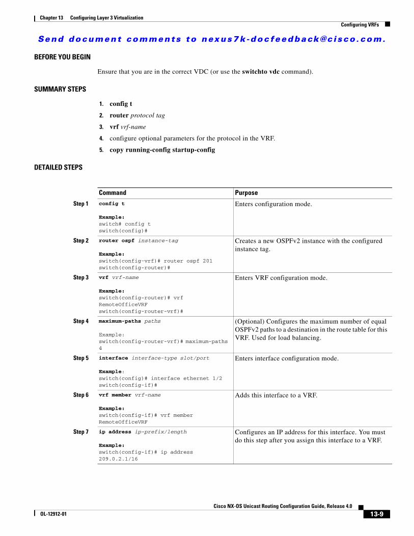
Send document comments to nexus7k -doc feedback@c i sco .com.
Chapter 13 Configuring Layer 3 VirtualizationConfiguring VRFs
BEFORE YOU BEGIN
Ensure that you are in the correct VDC (or use the switchto vdc command).
SUMMARY STEPS
1. config t
2. router protocol tag
3. vrf vrf-name
4. configure optional parameters for the protocol in the VRF.
5. copy running-config startup-config
DETAILED STEPS
Command Purpose
Step 1 config t
Example:switch# config tswitch(config)#
Enters configuration mode.
Step 2 router ospf instance-tag
Example:switch(config-vrf)# router ospf 201switch(config-router)#
Creates a new OSPFv2 instance with the configured instance tag.
Step 3 vrf vrf-name
Example:switch(config-router)# vrf RemoteOfficeVRFswitch(config-router-vrf)#
Enters VRF configuration mode.
Step 4 maximum-paths paths
Example:switch(config-router-vrf)# maximum-paths 4
(Optional) Configures the maximum number of equal OSPFv2 paths to a destination in the route table for this VRF. Used for load balancing.
Step 5 interface interface-type slot/port
Example:switch(config)# interface ethernet 1/2switch(config-if)#
Enters interface configuration mode.
Step 6 vrf member vrf-name
Example:switch(config-if)# vrf member RemoteOfficeVRF
Adds this interface to a VRF.
Step 7 ip address ip-prefix/length
Example:switch(config-if)# ip address 209.0.2.1/16
Configures an IP address for this interface. You must do this step after you assign this interface to a VRF.
13-9Cisco NX-OS Unicast Routing Configuration Guide, Release 4.0
OL-12912-01

Send document comments to nexus7k -doc feedback@c i sco .com.
Chapter 13 Configuring Layer 3 VirtualizationConfiguring VRFs
The following example shows how to create a VRF and add an interface to the VRF:
switch# config tswitch(config)# vrf context RemoteOfficeVRFswitch(config-vrf)# exitswitch(config)# router ospf 201switch(config-router)# vrf RemoteOfficeVRFswitch(config-router-vrf)# maximum-paths 4switch(config-router-vrf)# interface ethernet 1/2switch(config-if)# vrf member RemoteOfficeVRFswitch(config-if)# ip address 209.0.2.1/16switch(config-if)# ip router ospf 201 area 0switch(config-if)# exitswitch(config)# copy running-config startup-config
Configuring a VRF-Aware ServiceYou can configure a VRF-aware service for reachability and filtering. See the “VRF-Aware Services” section on page 13-3 for links to the appropriate chapter or configuration guide for information on how to configure the service for VRFs. This section uses SNMP and IP domain lists as example services for the detailed configuration steps.
BEFORE YOU BEGIN
Ensure that you are in the correct VDC (or use the switchto vdc command).
SUMMARY STEPS
1. config t
2. service parameters [filter_vrf vrf-name] [use-vrf vrf-name]
3. vrf context [vrf-name]
4. service parameters [all-vrfs][use-vrf vrf-name]
5. copy running-config startup-config
Step 8 ip router ospf instance-tag area area-id
Example:switch(config-if)# ip router ospf 201 area 0
Assigns this interface to the OSPFv2 instance and area configured.
Step 9 copy running-config startup-config
Example:switch(config)# copy running-config startup-config
(Optional) Saves this configuration change.
Command Purpose
13-10Cisco NX-OS Unicast Routing Configuration Guide, Release 4.0
OL-12912-01

Send document comments to nexus7k -doc feedback@c i sco .com.
Chapter 13 Configuring Layer 3 VirtualizationConfiguring VRFs
DETAILED STEPS
The following example shows how to send SNMP information for all VRFs to SNMP host 192.0.2.1, reachable on VRF Red:
switch# config tswitch(config)# snmp-server host 192.0.2.1 for-all-vrfs use-vrf Redswitch(config)# copy running-config startup-config
The following example shows how to Filter SNMP information for VRF Blue to SNMP host 192.0.2.12, reachable on VRF Red:
switch# config tswitch(config)# vrf definition Blueswitch(config-vrf)# snmp-server host 192.0.2.12 use-vrf Redswitch(config)# copy running-config startup-config
Setting the VRF ScopeYou can set the VRF scope for all EXEC commands (for example, show commands). This automatically restricts the scope of the output of EXEC commands to the configured VRF. You can override this scope by using the VRF keywords available for some EXEC commands.
Command Purpose
Step 1 config t
Example:switch# config tswitch(config)#
Enters configuration mode.
Step 2 snmp-server host ip-address [filter-vrf vrf-name] [use-vrf vrf-name]
Example:switch(config)# snmp-server host 192.0.2.1 use-vrf Redswitch(config-vrf)#
Configures a global SNMP server and configures the VRF that Cisco NX-OS uses to reach the service Use the filter-vrf keyword to filter information from the selected VRF to this server.
Step 3 vrf context vrf-name
Example:switch(config)# vrf context Blueswitch(config-vrf)#
Creates a new VRF.
Step 4 ip domail-list domain-name [all-vrfs][use-vrf vrf-name]
Example:switch(config-vrf)# ip domain-list List all-vrfs use-vrf Blueswitch(config-vrf)#
Configures the domain list in the VRF and optionally configures the VRF that Cisco NX-OS uses to reach the domain name listed..
Step 5 copy running-config startup-config
Example:switch(config)# copy running-config startup-config
(Optional) Saves this configuration change.
13-11Cisco NX-OS Unicast Routing Configuration Guide, Release 4.0
OL-12912-01

Send document comments to nexus7k -doc feedback@c i sco .com.
Chapter 13 Configuring Layer 3 VirtualizationVerifying VRF Configuration
To set the VRF scope, use the following command in EXEC mode:
To return to the default VRF scope, use the following command in EXEC mode:
Verifying VRF ConfigurationTo display VRF configuration information, use one of the following commands:
VRF Example Configuration The following example shows how to configure VRF Red, add an SNMP server to that VRF, and add an instance of OSPF to VRF Red:
config tvrf context Red snmp-server host 192.0.2.12 use-vrf Redrouter ospf 201interface ethernet 1/2 vrf member Red ip address 209.0.2.1/16 ip router ospf 201 area 0
Related TopicsThe following topics can give more information on VRFs:
• Cisco NX-OS Getting Started Configuration Guide
Command Purposerouting-context vrf vrf-name
Example:switch# routing-context vrf redswitch%red#
Sets the routing context for all EXEC commands. Default routing context is the default VRF.
Command Purpose
routing-context vrf default
Example:switch%red# routing-context vrf defaultswitch#
Sets the default routing context.
Command Purpose
show vrf [vrf-name] Displays the information for all or one VRF.
show vrf [vrf-name] detail Displays detailed information for all or one VRF.
show vrf [vrf-name] [interface interface-type slot/port]
Displays the VRF status for an interface.
13-12Cisco NX-OS Unicast Routing Configuration Guide, Release 4.0
OL-12912-01

Send document comments to nexus7k -doc feedback@c i sco .com.
Chapter 13 Configuring Layer 3 VirtualizationDefault Settings
• Cisco NX-OS Virtual Device Context Configuration Guide
Default SettingsTable 13-1 lists the default settings for VRF parameters.
Additional ReferencesFor additional information related to implementing VRFs, see the following sections:
• Related Documents, page 13-13
• Standards, page 13-13
Related Documents
Standards
Table 13-1 Default VRF Parameters
Parameters Default
Configured VRFs default, management
Related Topic Document Title
VRF CLI Cisco NX-OS Unicast Routing Command Line Reference
VDCs Cisco NX-OS Virtual Device Contexts Configuration Guide
Standards Title
No new or modified standards are supported by this feature, and support for existing standards has not been modified by this feature.
—
13-13Cisco NX-OS Unicast Routing Configuration Guide, Release 4.0
OL-12912-01

Send document comments to nexus7k -doc feedback@c i sco .com.
Chapter 13 Configuring Layer 3 VirtualizationAdditional References
13-14Cisco NX-OS Unicast Routing Configuration Guide, Release 4.0
OL-12912-01

Send document comments to nexus7k -doc feedback@c i sco .com.
Cisco NX-OOL-12912-01
C H A P T E R 14
Configuring Route Policy Manager
This chapter describes how to configure the Route Policy Manager.
This chapter includes the following sections:
• Information About Route Policy Manager, page 14-1
• Licensing Requirements for Route Policy Manager, page 14-4
• Prerequisites for Route Policy Manager, page 14-4
• Guidelines and Limitations, page 14-4
• Configuring Route Policy Manager, page 14-5
• Verifying Route Policy Manager Configuration, page 14-13
• Route Policy Manager Example Configuration, page 14-13
• Related Topics, page 14-13
• Default Settings, page 14-13
Information About Route Policy ManagerRoute Policy Manager supports route maps and IP prefix lists. These features are used for route redistribution and policy-based routing. A prefix list contains one or more IPv4 or IPv6 network prefixes and the associated prefix length values. You can use a prefix list by itself in features such as BGP templates, route filtering, or redistribution of routes that are exchanged between routing domains.
Route maps can apply to both routes and IP packets. Route filtering and redistribution pass a route through a route map while policy based routing passes IP packets through a route map.
This section includes the following topics:
• Prefix Lists, page 14-2
• Route Maps, page 14-2
• Route Redistribution and Route Maps, page 14-4
• Policy-Based Routing, page 14-4
14-1S Unicast Routing Configuration Guide, Release 4.0

Send document comments to nexus7k -doc feedback@c i sco .com.
Chapter 14 Configuring Route Policy ManagerInformation About Route Policy Manager
Prefix ListsYou can use prefix lists to permit or deny an address or range of addresses. Filtering by prefix list involves matching the prefixes of routes or packets with the prefixes listed in the prefix list. An implicit deny is assumed if a given prefix does not match any entries in a prefix list.
You can configure multiple entries in a prefix list and permit or deny the prefixes that match the entry. Each entry has an associated sequence number that you can configure. If you do not configure a sequence number, Cisco NX-OS assigns a sequence number automatically. Cisco NX-OS evaluates prefix lists starting with the lowest sequence number. Cisco NX-OS processes the first successful match for a given prefix. Once a match occurs, Cisco NX-OS processes the permit or deny statement and does not evaluate the rest of the prefix list.
Note An empty prefix list permits all routes.
Route MapsYou can use route maps for route redistribution or policy-based routing. Route map entries consist of a list of match and set criteria. The match criteria specify match conditions for incoming routes or packets and the set criteria specify the action taken if the match criteria are met.
You can configure multiple entries in the same route map. These entries contain the same route map name and are differentiated by a sequence number.
You create a route map with one or more route map entries arranged by the sequence number under a unique route map name. The route map entry has the following parameters:
• Sequence number
• Permission—permit or deny
• Match criteria
• Set changes
By default, a route map processes routes or IP packets in a linear fashion, that is, starting from the lowest sequence number. You can configure the route map to process in a different order using the continue statement, which allows you to determine which route map entry to process next.
Match Criteria
You can use a variety of criteria to match a route or IP packet in a route map. Some criteria, such as BGP community lists, are applicable only to a specific routing protocol, while other criteria, such as the IP source or the destination address, can be used for any route or IP packet.
When Cisco NX-OS processes a route or packet through a route map, it compares the route or packet to each of the match statements configured. If the route or packet matches the configured criteria, Cisco NX-OS processes it based on the permit or deny configuration for that match entry in the route map, and any set criteria configured.
The match categories and parameters are as follows:
• IP access lists—(For policy-based routing only). Match based on source or destination IP address, protocol, or QoS parameters .
• BGP parameters—Match based on AS-path or community attributes.
14-2Cisco NX-OS Unicast Routing Configuration Guide, Release 4.0
OL-12912-01

Send document comments to nexus7k -doc feedback@c i sco .com.
Chapter 14 Configuring Route Policy ManagerInformation About Route Policy Manager
• Prefix lists—Match based on an address or range of addresses.
• Multicast parameters—Match based on rendezvous point, groups, or sources.
• Other parameters—Match based on IP next-hop address or packet length.
Set Changes
Once a route or packet matches an entry in a route map, the route or packet can be changed based on one or more configured set statements.
The set changes are as follows:
• BGP parameters—Change the AS-path, tag, community, dampening, local preference, origin, or weight attributes.
• Metrics—Change the route-metric, the route-tag, or the route-type.
• Policy-based routing only—Change the interface or the default next-hop address.
• Other parameters—Change the forwarding address or the IP next-hop address.
Access Lists
IP access lists can match the packet to a number of IP packet fields such as the following:
• Source or destination IPv4 or IPv6 address
• Protocol
• Precedence
• ToS
You can use ACLs in a route map for policy-based routing only. See the Cisco NX-OS Security Configuration Guide, Release 4.0 for more information on ACLs.
AS-path Lists for BGP
You can configure an AS-path list to filter inbound or outbound BGP route updates. If the route update contains an AS-path attribute that matches an entry in the AS-path list, the router processes the route based on the permit or deny condition configured. You can configure AS-path lists within a route map.
You can configure multiple AS-path entries in an AS-path list by using the same AS-path list name. The router processes the first entry that matches.
Community Lists for BGP
You can filter BGP route updates based on the BGP community attribute by using community lists in a route map. A community list contains one or more community attributes. If you configure more than one community attribute in the same community list entry, then the BGP route must match all community attributes listed to be considered a match.
You can also configure multiple community attributes as individual entries in the community list by using the same community list name. In this case, the router processes the first community attribute that matches the BGP route, using the permit or deny configuration for that entry.
You can configure community attributes in the community list in one of the following formats:
• Named community attribute, such as internet or no-export
14-3Cisco NX-OS Unicast Routing Configuration Guide, Release 4.0
OL-12912-01

Send document comments to nexus7k -doc feedback@c i sco .com.
Chapter 14 Configuring Route Policy ManagerLicensing Requirements for Route Policy Manager
• A 4-byte value that represents the autonomous system (AS) number and a user-defined network number
• A regular expression
See the Cisco NX-OS Unicast Routing Command Reference, Release 4.0 for more information on regular expressions.
Route Redistribution and Route MapsYou can use route maps to control the redistribution of routes between routing domains. Route maps match on the attributes of the routes to redistribute only those routes that pass the match criteria. The route map can also modify the route attributes during this redistribution using the set changes.
The router matches redistributed routes against each route map entry.If there are multiple match statements, the route must pass all of the match criteria. If a route passes the match criteria defined in a route map entry, the actions defined in the entry are executed. If the route does not match the criteria, the router compares the route against subsequent route map entries. Route processing continues until a match is made or the route is processed by all entries in the route map with no match. If the router processes the route against all entries in a route map with no match, the router does accept the route (inbound route maps) or forward the route (outbound route maps).
Policy-Based RoutingYou can use policy-based routing to forward a packet to a specified next-hop address based on the source of the packet or other fields in the packet header. See Chapter 15, “Configuring Policy-Based Routing.”
Licensing Requirements for Route Policy ManagerThe following table shows the licensing requirements for this feature:
Prerequisites for Route Policy ManagerRoute Policy Manager has the following prerequisites:
• If you configure VDCs, install the Advanced Services license and enter the desired VDC (see to the Cisco NX-OS Virtual Device Context Configuration Guide).
Guidelines and LimitationsRoute Policy Manager has the following guidelines and limitations:
Product License Requirement
NX-OS Route Policy Manager requires no license. Any feature not included in a license package is bundled with the Cisco NX-OS system images and is provided at no extra charge to you. For a complete explanation of the NX-OS licensing scheme, see the Cisco NX-OS Licensing Guide.
14-4Cisco NX-OS Unicast Routing Configuration Guide, Release 4.0
OL-12912-01

Send document comments to nexus7k -doc feedback@c i sco .com.
Chapter 14 Configuring Route Policy ManagerConfiguring Route Policy Manager
• An empty route map denies all the routes.
• An empty prefix lists permits all the routes.
• Without any match statement in a route-map entry, the permission(permit or deny) of the route-map entry decides the result for all the routes or packets.
• If referred policies (for example, prefix lists) within a match statement of a route-map entry return either a no-match or a deny-match, Cisco NX-OS fails the match statement and processes the next route-map entry.
• When you change a route map, Cisco NX-OS hold all the changes until you exit from the rout- map configuration submode. Cisco NX-OS then sends all the changes to the protocol clients to take affect.
• Since you can use a route map before you define it, verify that all your route map exist when you finish a configuration change.
• You can view route-map usage for redistribution and filtering. Each individual routing protocol provides a way to display these statistics.
Configuring Route Policy ManagerRoute Policy Manager configuration includes the following topics:
• Configuring IP Prefix Lists, page 14-5
• Configuring AS-path Lists, page 14-7
• Configuring Community Lists, page 14-7
• Configuring Route Maps, page 14-9
Note If you are familiar with the Cisco IOS CLI, be aware that the Cisco NX-OS commands for this feature might differ from the Cisco IOS commands that you would use.
Configuring IP Prefix ListsIP prefix lists match the IP packet or route against a list of prefixes and prefix lengths. Create an IP prefix list for IPv4 and create an IPv6 prefix list for IPv6.
SUMMARY STEPS
1. config t
2. {ip | ipv6} prefix-list name description string
3. ip prefix-list name [seq number] [{permit | deny} prefix {[eq prefix-length] | [ge prefix-length] [le prefix-length]}]
or
ipv6 prefix-list name [seq number] [{permit | deny} prefix {[eq prefix-length] | [ge prefix-length] [le prefix-length]}]
4. show {ip | ipv6} prefix-list name
5. copy running-config startup-config
14-5Cisco NX-OS Unicast Routing Configuration Guide, Release 4.0
OL-12912-01

Send document comments to nexus7k -doc feedback@c i sco .com.
Chapter 14 Configuring Route Policy ManagerConfiguring Route Policy Manager
DETAILED STEPS
The following example shows how to create an IPv4 prefix list with two entries:
switch# config tswitch(config)# ip prefix-list AllowPrefix 10 permit 192.0.2.0 eq 24switch(config)# ip prefix-list AllowPrefix 20 permit 209.165.201.0 eq 27switch(config)# copy running-config startup-config
Command Purpose
Step 1 config t
Example:switch# config tswitch(config)#
Enters configuration mode.
Step 2 {ip | ipv6} prefix-list name description string
Example:switch(config)# ip prefix-list AllowPrefix description allows engineering server
(Optional) Adds an information string about the prefix list.
Step 3 ip prefix-list name [seq number] [{permit | deny} prefix {[eq prefix-length] | [ge prefix-length] [le prefix-length]}]
Example:switch(config)# ip prefix-list AllowPrefix 10 permit 192.0.2.0 eq 24
Creates an IPv4 prefix list or adds a prefix to an existing prefix list. The prefix length is matched as follows:
• eq—Match exact prefix length.
• ge—Match a prefix length that is equal to or greater than the configured prefix length.
• le—Match a prefix length that is equal to or less than the configured prefix length.
ipv6 prefix-list name [seq number] [{permit | deny} prefix {[eq prefix-length] | [ge prefix-length] [le prefix-length]}]
Example:switch(config)#ipv6 prefix-list AllowIPv6Prefix 10 permit 2001:0DB8:: le 32
Creates an IPv6 prefix list or adds a prefix to an existing prefix list. The prefix length is configured as:
• eq—Match exact prefix length.
• ge—Match a prefix length that is equal to or greater than the configured prefix length.
• le—Match a prefix length that is equal to or less than the configured prefix length.
Step 4 show {ip | ipv6} prefix-list name
Example:switch(config)# show ip prefix-list AllowPrefix
(Optional) Displays information about prefix lists.
Step 5 copy running-config startup-config
Example:switch# copy running-config startup-config
(Optional) Saves this configuration change.
14-6Cisco NX-OS Unicast Routing Configuration Guide, Release 4.0
OL-12912-01

Send document comments to nexus7k -doc feedback@c i sco .com.
Chapter 14 Configuring Route Policy ManagerConfiguring Route Policy Manager
Configuring AS-path ListsYou can specify an AS-path list filter on both inbound and outbound BGP routes. Each filter is an access list based on regular expressions. If the regular expression matches the representation of the AS-path attribute of the route as an ASCII string, then the permit or deny condition applies.
SUMMARY STEPS
1. config t
2. ip as-path access-list name {deny | permit} expression
3. show {ip | ipv6} as-path list name
4. copy running-config startup-config
DETAILED STEPS
The following example shows how to create an AS-path list with two entries:
switch# config tswitch(config)# ip as-path access-list AllowAS permit 40 switch(config)# ip as-path access-list AllowAS permit 40000 switch(config)# copy running-config startup-config
Configuring Community ListsYou can use community lists to filter BGP routes based on the community attribute. The community number consists of a 4-byte value in the aa:nn format. The first two bytes represent the autonomous system number, and the trailing two bytes represent a user-defined network number.
Command Purpose
Step 1 config t
Example:switch# config tswitch(config)#
Enters configuration mode.
Step 2 ip as-path access-list name {deny | permit} expression
Example:switch(config)# ip as-path access-list Allow40 permit 40
Creates a BGP AS-path list using a regular expression.
Step 3 show {ip | ipv6} as-path-access-list name
Example:switch(config)# show ip as-path-access-list Allow40
(Optional) Displays information about as-path access lists.
Step 4 copy running-config startup-config
Example:switch# copy running-config startup-config
(Optional) Saves this configuration change.
14-7Cisco NX-OS Unicast Routing Configuration Guide, Release 4.0
OL-12912-01

Send document comments to nexus7k -doc feedback@c i sco .com.
Chapter 14 Configuring Route Policy ManagerConfiguring Route Policy Manager
When you configure multiple values in the same community list statement, all community values must match to satisfy the community list filter. When you configure multiple values in separate community list statements, the first list that matches a condition is processed.
SUMMARY STEPS
1. config t
2. ip community-list standard list-name [community-list] [internet] [local-AS] [no-advertise] [no-export]
or
ip community-list expanded list-name {deny | permit} expresion
3. show ip community-list name
4. copy running-config startup-config
DETAILED STEPS
Command Purpose
Step 1 config t
Example:switch# config tswitch(config)#
Enters configuration mode.
Step 2 ip community-list standard list-name {deny | permit} [community-list] [internet] [local-AS] [no-advertise] [no-export]
Example:switch(config)# ip community-list standard BGPCommunity permit no-advertise 40000:20
Creates a standard BGP community list. The community-list can be one or more of the following:
• internet
• local-AS
• no-advertise
• no-export
• one or more communities in the aa:nn format.
ip community-list expanded list-name {deny | permit} line
Example:switch(config)# ip community-list expanded BGPComplex deny 50000:[0-9][0-9]_
Creates an expanded BGP community list using a regular expression.
Step 3 show ip community-list name
Example:switch(config)# show ip community-list BGPCommunity
(Optional) Displays information about prefix lists.
Step 4 copy running-config startup-config
Example:switch# copy running-config startup-config
(Optional) Saves this configuration change.
14-8Cisco NX-OS Unicast Routing Configuration Guide, Release 4.0
OL-12912-01

Send document comments to nexus7k -doc feedback@c i sco .com.
Chapter 14 Configuring Route Policy ManagerConfiguring Route Policy Manager
The following example shows how to create a community list with two entries:
switch# config tswitch(config)# ip community-list standard BGPCommunity permit no-advertise 40000:20 switch(config)# ip community-list standard BGPCommunity permit local-AS no-exportswitch(config)# copy running-config startup-config
Configuring Route MapsYou can use route maps for route redistribution or route filtering. Route maps can contain multiple match criteria and multiple set criteria.
Configuring a route map for BGP triggers an automatic soft clear or referesh of BGP neighbor sessions.
SUMMARY STEPS
1. config t
2. route-map map-name [permit | deny] [seq]
3. Add optional match or set parameters in route-map configuration mode
4. exit
5. copy running-config startup-config
DETAILED STEPS
Command Purpose
Step 1 config t
Example:switch# config tswitch(config)#
Enters configuration mode.
Step 2 route-map map-name [permit | deny] [seq]
Example:switch(config)# route-map Testmap permit 10switch(config-route-map)#
Creates a route map or enters route-map configuration mode for an existing route map. Use seq to order the entries in a route map.
Step 3 description string
Example:switch(config-route-map)# description A test route map
(Optional) Adds a description for the route-map sequence.
Step 4 continue seq
Example:switch(config-route-map)# continue 10
(Optional) Determines what sequence statement to process next in the route map. Used only for filtering and redistribution.
14-9Cisco NX-OS Unicast Routing Configuration Guide, Release 4.0
OL-12912-01

Send document comments to nexus7k -doc feedback@c i sco .com.
Chapter 14 Configuring Route Policy ManagerConfiguring Route Policy Manager
You can configure the following optional match parameters for route maps in route-map configuration mode:
Step 5 exit
Example:switch(config-route-map)# exit
(Optional) Exits route-map configuration mode.
Step 6 copy running-config startup-config
Example:switch(config)# copy running-config startup-config
(Optional) Saves this configuration change.
Command Purpose
Command Purpose
match as-path name [name...]
Example:switch(config-route-map)# match as-path Allow40
Matches against one or more AS-path lists. Create the AS-path list with the ip as-path access-list command.
match community name [name...][exact-match]
Example:switch(config-route-map)# match community BGPCommunity
Matches against one or more community lists. Create the AS-path list with the ip community-list command.
match ip address prefix-list name [name...]
Example:switch(config-route-map)# match ip address prefix-list AllowPrefix
Matches against one or more IPv4 prefix lists. Use the ip prefix-list command to create the prefix list.
match ipv6 address prefix-list name [name...]
Example:switch(config-route-map)# match ip address prefix-list AllowIPv6Prefix
Matches against one or more IPv6 prefix lists. Use the ipv6 prefix-list command to create the prefix list.
match ip multicast [source ipsource] [[group ipgroup] [rp iprp]]
Example:switch(config-route-map)# match ip multicast rp 192.0.2.1
Matches an IPv4 multicast packet based on multicast source, group, or rendezvous point.
match ipv6 multicast [source ipsource] [[group ipgroup] [rp iprp]]
Example:switch(config-route-map)# match ip multicast source 2001:0DB8::1
Matches an IPv6 multicast packet based on multicast source, group, or rendezvous point.
match ip next-hop prefix-list name [name...]
Example:switch(config-route-map)# match ip next-hop prefix-list AllowPrefix
Matches the IPv4 next-hop address of a route to one or more IP prefix lists. Use the ip prefix-list command to create the prefix list.
14-10Cisco NX-OS Unicast Routing Configuration Guide, Release 4.0
OL-12912-01

Send document comments to nexus7k -doc feedback@c i sco .com.
Chapter 14 Configuring Route Policy ManagerConfiguring Route Policy Manager
You can configure the following optional set parameters for route maps in route-map configuration mode:
match ipv6 next-hop prefix-list name [name...]
Example:switch(config-route-map)# match ip next-hop prefix-list AllowIPv6Prefix
Matches the IPv6 next-hop address of a route to one or more IP prefix lists. Use the ipv6 prefix-list command to create the prefix list.
match ip route-source prefix-list name [name...]
Example:switch(config-route-map)# match ip route-source prefix-list AllowPrefix
Matches the IPv4 route source address of a route to one or more IP prefix lists. Use the ip prefix-list command to create the prefix list.
match ipv6 route-source prefix-list name [name...]
Example:switch(config-route-map)# match ip route-source prefix-list AllowIPv6Prefix
Matches the IPv6 route-source address of a route to one or more IP prefix lists. Use the ipv6 prefix-list command to create the prefix list.
match route-type route-typeExample:switch(config-route-map)# match route-type level 1 level 2
Matches against a type of route. The route-type can be one or more of the following:
• external
• internal
• level-1
• level-2
• local
• nssa-external
• type-1
• type-2
match tag tagid [tagid...]
Example:switch(config-route-map)# match tag 2
Matches a route against one or more tags for filtering or redistribution.
Command Purpose
Command Purpose
set as-path {tag | prepend {last-as number | as-1 [as-2...]}}
Example:switch(config-route-map)# set as-path prepend 10 100 110
Modifies an AS-path attribute for a BGP route. You can prepend the configured number of last AS numbers or a string of particular AS-path values (as-1 as-2...as-n).
set comm-list name delete
Example:switch(config-route-map)# set comm-list BGPCommunity delete
Removes communities from the community attribute of an inbound or outbound BGP route update. Use the ip community-list command to create the community list.
14-11Cisco NX-OS Unicast Routing Configuration Guide, Release 4.0
OL-12912-01

Send document comments to nexus7k -doc feedback@c i sco .com.
Chapter 14 Configuring Route Policy ManagerConfiguring Route Policy Manager
set community {none |{additive | local-AS | no-advertise | no-export | community-1 [community-2...]}
Example:switch(config-route-map)# set community local-AS
Sets the community attribute for a BGP route update.
Note When you use both the set community and set comm-list delete commands in the same sequence of a route map attribute, the deletion operation is performed before the set operation.
set dampening halflife reuse suppress durationExample:switch(config-route-map)# set dampening 30 1500 10000 120
Sets the BGP route dampening parameters.
• halflife—The range is from 1 to 45 minutes. The default is 15.
• reuse—The range is from is 1 to 20000 seconds. The default is 750.
• suppress—The range is from is 1 to 20000. The default is 2000.
• duration—The range is from is 1 to 255 minutes. The default is 60.
set forwarding-address
Example:switch(config-route-map)# set forwarding-address
Sets the forwarding address for OSPF.
set level {backbone | level-1 | level-1-2 | level-2}
Example:switch(config-route-map)#
Sets what area to import routes to for IS-IS. The options for IS-IS are level-1, level-1-2, or level-2. Default is level-1.
set local-preference value
Example:switch(config-route-map)# set local-preference 4000
Sets the BGP local preference value. The range is from 0 to 4294967295.
set metric metric0 [metric1 metric2 metric3 metric4]
Example:switch(config-route-map)#
Sets the route metric values. Metrics are as follows:
• metric0—Bandwidth in Kb/s
• metric1—Delay in 10-microsecond units
• metric2—Reliability. The range is from 0 to 255 (100% reliable).
• metric3—Loading. The range is from 1 to 200 (100% loaded).
• metric4—MTU of the path.
set metric-type {external | internal | type-1 | type-2}
Example:switch(config-route-map)# set metric-type internal.
Sets the metric type for the destination routing protocol. The options are as follows:
external—IS-IS external metric
internal—Use IGP metric as the MED for BGP
type-1—OSPF external type 1 metric
type-2—OSPF external type 2 metric
Command Purpose
14-12Cisco NX-OS Unicast Routing Configuration Guide, Release 4.0
OL-12912-01

Send document comments to nexus7k -doc feedback@c i sco .com.
Chapter 14 Configuring Route Policy ManagerVerifying Route Policy Manager Configuration
The set metric-type internal command affects only on an outgoing policy and only for an eBGP neighbor. If you configure both metric and metric-type internal commands in the same BGP peer outgoing policy, then Cisco NX-OS ignores the metric-type internal command.
Verifying Route Policy Manager ConfigurationUse the show route-map command to verify the Route Policy Manager configuration.
Route Policy Manager Example Configuration The following example shows how to use an address family to configure BGP so that any unicast and multicast routes from neighbor 209.0.2.1 are accepted if they match access list 1:
router bgp 40000 address-family ipv4 unicast network 192.0.2.0/24 network 209.165.201.0/27 route-map filterBGProute-map filterBGP match ip next-hop prefix-list AllowPrefix
ip prefix-list AllowPrefix 10 permit 192.0.2.0 eq 24ip prefix-list AllowPrefix 20 permit 209.165.201.0 eq 27
Related TopicsThe following topics can give more information on Route Policy Manager:
• Chapter 9, “Configuring Basic BGP”
• Chapter 15, “Configuring Policy-Based Routing”
Default SettingsTable 14-1 lists the default settings for Route Policy Manager.
set origin {egp as-number | igp | incomplete}
Example:switch(config-route-map)#
Sets the BGP origin attribute. The EGP as-number range is from 0 to 65535.
set tag name
Example:switch(config-route-map)# set tag 33
Sets the tag value for the destination routing protocol. The name parameter is an unsigned integer.
set weight count
Example:switch(config-route-map)#
Sets the weight for the BGP route. The range is from 0 to 65535.
Command Purpose
14-13Cisco NX-OS Unicast Routing Configuration Guide, Release 4.0
OL-12912-01

Send document comments to nexus7k -doc feedback@c i sco .com.
Chapter 14 Configuring Route Policy ManagerAdditional References
Additional ReferencesFor additional information related to implementing IP, see the following sections:
• Related Documents, page 14-14
• Standards, page 14-14
Related Documents
Standards
Table 14-1 Default Route Policy Manager Parameters
Parameters Default
Route Policy Manager Enabled
Related Topic Document Title
Route Policy Manager CLI commands Cisco NX-OS Command Line Reference
VDCs and VRFs Cisco NX-OS Virtual Device Contexts Configuration Guide
Standards Title
No new or modified standards are supported by this feature, and support for existing standards has not been modified by this feature.
—
14-14Cisco NX-OS Unicast Routing Configuration Guide, Release 4.0
OL-12912-01

Send document comments to nexus7k -doc feedback@c i sco .com.
Cisco NX-OOL-12912-01
C H A P T E R 15
Configuring Policy-Based RoutingThis chapter describes how to configure policy based routing.
This chapter includes the following sections:
• Information About Policy Based Routing, page 15-1
• Licensing Requirements for Policy-Based Routing, page 15-3
• Prerequisites for Policy-Based Routing, page 15-3
• Guidelines and Limitations, page 15-3
• Configuring Policy-Based Routing, page 15-3
• Verifying Policy-Based Routing Configuration, page 15-7
• Policy Based-Routing Example Configuration, page 15-7
• Related Topics, page 15-7
• Default Settings, page 15-7
Information About Policy Based RoutingPolicy-based routing allows you to configure a defined policy for traffic flows, lessening reliance on routes derived from routing protocols. All packets received on an interface with policy-based routing enabled are passed through enhanced packet filters or route maps. The route maps dictate the policy, determining where to forward packets.
Route maps are composed of match and set statements that you can mark as permit or deny. You an interpret the statements as follows:
• If the packets match any route map statements, then all the set statements are applied. One of these actions involves choosing the next hop.
• If a statement is marked as deny, the packets that meet the match criteria are sent back through the normal forwarding channels and destination-based routing is performed.
• If the statement is marked as permit and the packets do not match any route map statements, the packets are sent back through the normal forwarding channels and destination-based routing is performed.
See the “Route Maps” section on page 14-2.
Policy-based routing includes the following features:
15-1S Unicast Routing Configuration Guide, Release 4.0

Send document comments to nexus7k -doc feedback@c i sco .com.
Chapter 15 Configuring Policy-Based RoutingInformation About Policy Based Routing
• Source-based routing—Routes traffic originating from different sets of users through different connections across the policy routers.
• Quality of Service (QoS)—Differentiates traffic by setting the precedence or type of service (ToS) values in the IP packet headers at the periphery of the network and leveraging queuing mechanisms to prioritize traffic in the core or backbone of the network (see the Cisco NX-OS Quality of Service Configuration Guide, Release 4.0).
• Load sharing—Distributes traffic among multiple paths based on the traffic characteristics.
This section includes the following topics:
• Policy Route Maps, page 15-2
• Set Criteria for Policy-Based Routing, page 15-2
Policy Route Maps
Each entry in a route map contains a combination of match and set statements. The match statements define the criteria for whether appropriate packets meet the particular policy (that is, the conditions to be met). The set clauses explain how the packets should be routed once they have met the match criteria.
You can mark the route map statements as permit or deny. If the statement is marked as a deny, the packets that meet the match criteria are sent back through the normal forwarding channels (destination-based routing is performed). If the statement is marked as permit and the packets meet the match criteria, all the set clauses are applied. If the statement is marked as permit and the packets do not meet the match criteria, then those packets are also forwarded through the normal routing channel.
Note Policy routing is specified on the interface that receives the packets, not on the interface from which the packets are sent.
Set Criteria for Policy-Based Routing
The set criteria in a route map is evaluated in the order listed in the route map. Set criteria specific to route maps used for policy-based routing are as follows:
1. List of interfaces through which the packets can be routed—If more than one interface is specified, then the first interface that is found to be up will be used for forwarding the packets.
2. List of specified IP addresses—The IP address can specify the adjacent next-hop router in the path toward the destination to which the packets should be forwarded. The first IP address associated with a currently up connected interface is used to route the packets.
3. List of default interfaces—If there is no explicit route available to the destination address of the packet being considered for policy routing, then the route map routes it to the first up interface in the list of specified default interfaces.
4. List of default next-hop IP addresses—Route to the interface or the next-hop address specified by this set statement only if there is no explicit route for the destination address of the packet in the routing table.
If the packets do not meet any of the defined match criteria, then those packets are routed through the normal destination-based routing process.
15-2Cisco NX-OS Unicast Routing Configuration Guide, Release 4.0
OL-12912-01

Send document comments to nexus7k -doc feedback@c i sco .com.
Chapter 15 Configuring Policy-Based RoutingLicensing Requirements for Policy-Based Routing
Licensing Requirements for Policy-Based RoutingThe following table shows the licensing requirements for this feature:
Prerequisites for Policy-Based RoutingPolicy-Based Routing has the following prerequisites:
• Install the correct license.
• You must enable the policy-based routing feature (see the “Enabling the Policy-based Routing Feature” section on page 15-4).
• Assign an IP address on the interface and bring the interface up before you apply a route map on the interface for policy-based routing.
• If you configure VDCs, install the Advanced Services license and enter the desired VDC (see to the Cisco NX-OS Virtual Device Context Configuration Guide).
Guidelines and LimitationsPolicy-based routing has the following guidelines and limitations:
• A policy-based routing route map can have only one route-map entry (with match and sets) in it.
• A policy-based routing route-map cannot have more than one match and one set command in a route-map entry.
• A match command cannot refer to more than one ACL in a route map used for policy-based routing .
• The same route map can be shared among different interfaces for policy-based routing as long as the interfaces belong to the same VRF.
Configuring Policy-Based RoutingThis section contains the following topics:
• Enabling the Policy-based Routing Feature, page 15-4
• Configuring a Route Policy, page 15-4
Note If you are familiar with the Cisco IOS CLI, be aware that the Cisco NX-OS commands for this feature might differ from the Cisco IOS commands that you would use.
Product License Requirement
NX-OS Policy-based routing requires an Enterprise Services license. For a complete explanation of the NX-OS licensing scheme and how to obtain and apply licenses, see the Cisco NX-OS Licensing Guide.
15-3Cisco NX-OS Unicast Routing Configuration Guide, Release 4.0
OL-12912-01

Send document comments to nexus7k -doc feedback@c i sco .com.
Chapter 15 Configuring Policy-Based RoutingConfiguring Policy-Based Routing
Enabling the Policy-based Routing FeatureYou must enable the policy-based routing feature before you can configure a route policy.
BEFORE YOU BEGIN
Ensure that you are in the correct VDC (or use the switchto vdc command).
SUMMARY STEPS
1. config t
2. feature pbr
3. copy running-config startup-config
DETAILED STEPS
Use the no feature pbr command to disable the policy-based routing feature and remove all associated configuration.
Configuring a Route PolicyYou can use route maps in policy-based routing to assign routing policies to the inbound interface. See “Configuring Route Maps” section on page 14-9.
SUMMARY STEPS
1. config t
Command Purpose
Step 1 config t
Example:switch# config tswitch(config)#
Enters configuration mode.
Step 2 feature pbr
Example:switch(config)# feature pbr
Enables the policy-based routing feature.
Step 3 copy running-config startup-config
Example:switch(config)# copy running-config startup-config
(Optional) Saves this configuration change.
Command Purpose
no feature pbr
Example:switch(config)# no feature pbr
Disables the policy-based routing feature and removes all associated configuration.
15-4Cisco NX-OS Unicast Routing Configuration Guide, Release 4.0
OL-12912-01

Send document comments to nexus7k -doc feedback@c i sco .com.
Chapter 15 Configuring Policy-Based RoutingConfiguring Policy-Based Routing
2. interface type slot/port
3. ip policy route-map map-name
or
4. ipv6 policy route-map map-nam
5. exit
6. copy running-config startup-config
DETAILED STEPS
The following example shows how to add a route map to an interface:
switch# config tswitch(config)# interface ethernet 1/2switch(config-if)# ip policy route-map Testmapswitch(config)# exitswitch(config)# copy running-config startup-config
Command Purpose
Step 1 config t
Example:switch# config tswitch(config)#
Enters configuration mode.
Step 2 interface type slot/port
Example:switch(config)# interface ethernet 1/2switch(config-if)#
Enters interface configuration mode.
Step 3 ip policy route-map map-name
Example:switch(config-if)# ip policy route-map Testmap
Assigns a route map for IPv4 policy-based routing to the interface.
ipv6 policy route-map map-name
Example:switch(config-if)# ipv6 policy route-map TestIPv6map
Assigns a route map for IPv6 policy-based routing to the interface.
Step 4 exit
Example:switch(config-route-map)# exit
(Optional) Exits route-map configuration mode.
Step 5 exit
Example:switch(config)# exit
(Optional) Exits route-map configuration mode.
Step 6 copy running-config startup-config
Example:switch# copy running-config startup-config
(Optional) Saves this configuration change.
15-5Cisco NX-OS Unicast Routing Configuration Guide, Release 4.0
OL-12912-01

Send document comments to nexus7k -doc feedback@c i sco .com.
Chapter 15 Configuring Policy-Based RoutingConfiguring Policy-Based Routing
You can configure the following optional match parameters for route maps in route-map configuration mode:
You can configure the following optional set parameters for route maps in route-map configuration mode:
Command Purposematch ip address access-list-name name [name...]
Example:switch(config-route-map)# match ip address access-list-name ACL1
Match an IPv4 address against one or more IP access control lists (ACLs). This command is used for policy-based routing and ignored by route filtering or redistribution.
match ipv6 address access-list-name name [name...]
Example:switch(config-route-map)# match ipv6 address access-list-name ACLv6
Match an IPv6 address against one or more IPv6 ACLs. This command is used for policy-based routing and ignored by route filtering or redistribution.
match length min max
Example:switch(config-route-map)# match length 64 1500
Match against the length of the packet. This ocmmand is used for policy-based routing.
Command Purpose
set interface ifname-1 [ifname-2...]
Example:switch(config-route-map)# set interface ethernet 1/2
Sets the output packet interface for policy-based routing. If ifname-1 is not operational, the system uses one of the optional interfaces configured, such as ifname-2.
set default interface ifname-1 [ifname-2...]
Example:switch(config-route-map)# set default interface ethernet 2/2
Sets the output packet interface for policy-based routing when there is no explicit route to a destination. If ifname-1 is not operational, the system uses one of the optional interfaces configured, such as ifname-2.
set ip next-hop address1 [address2...]
Example:switch(config-route-map)# set ip next-hop 209.0.2.1
Sets the IPv4 next-hop address for policy-based routing. This command uses the first valid next-hop address if multiple addresses are configured.
set ip default next-hop address1 [address2...]
Example:switch(config-route-map)# set ip default next-hop 209.0.2.2
Sets the IPv4 next-hop address for policy-based routing when there is no explicit route to a destination. This command uses the first valid next-hop address if multiple addresses are configured.
set ipv6 next-hop address1 [address2...]
Example:switch(config-route-map)# set ipv6 next-hop 2001:0DB8::1
Sets the IPv6 next-hop address for policy-based routing. This command uses the first valid next-hop address if multiple addresses are configured.
15-6Cisco NX-OS Unicast Routing Configuration Guide, Release 4.0
OL-12912-01

Send document comments to nexus7k -doc feedback@c i sco .com.
Chapter 15 Configuring Policy-Based RoutingVerifying Policy-Based Routing Configuration
Cisco NX-OS routes the packet as soon as it finds a next hop and an interface.
Verifying Policy-Based Routing ConfigurationUse the show ip policy command to verify policy-based routing.
Use the route-map map-name pbr-statistics to enable policy statistics. Use the show route-map map-name pbr-statistics to view policy statistics. Use the clear route-map map-name pbr-statistics to clear these policy statistics
Policy Based-Routing Example Configuration Theis example shows how to configure a simple route policy on an interface.
feature pbraccess-list 1 permit ip 209.0.2.1 ! interface ethernet 1/2 ip policy route-map equal-access route-map equal-access permit 10 match ip address 1 set ip default next-hop 209.0.2.10
Related TopicsThe following topics can give more information on Policy Based Routing:
• Chapter 14, “Configuring Route Policy Manager”
Default SettingsTable 15-1 lists the default settings for Policy-base routing parameters.
set ipv6 default next-hop address1 [address2...]
Example:switch(config-route-map)# set ipv6 default next-hop 2001:0DB8::2
Sets the IPv6 next-hop address for policy-based routing when there is no explicit route to a destination. This command uses the first valid next-hop address if multiple addresses are configured.
set vrf vrf-name
Example:switch(config-route-map)# set vrf MainVRF
Sets the VRF for next-hop resolution.
Command Purpose
15-7Cisco NX-OS Unicast Routing Configuration Guide, Release 4.0
OL-12912-01

Send document comments to nexus7k -doc feedback@c i sco .com.
Chapter 15 Configuring Policy-Based RoutingAdditional References
Additional ReferencesFor additional information related to implementing IP, see the following sections:
• Related Documents, page 15-8
• Standards, page 15-8
Related Documents
Standards
Table 15-1 Default Policy-based Routing Parameters
Parameters Default
Policy-based routing disabled
Related Topic Document Title
Policy-based routing CLI commands Cisco NX-OS Command Line Reference
VDCs and VRFs Cisco NX-OS Virtual Device Contexts Configuration Guide
Standards Title
No new or modified standards are supported by this feature, and support for existing standards has not been modified by this feature.
—
15-8Cisco NX-OS Unicast Routing Configuration Guide, Release 4.0
OL-12912-01

Send document comments to nexus7k -doc feedback@c i sco .com.
P A R T 3
First-Hop Redundancy Protocols

Send document comments to nexus7k -doc feedback@c i sco .com.
Send document comments to nexus7k -doc feedback@c i sco .com.
Cisco NX-OOL-12912-01
C H A P T E R 16
Configuring GLBPThis chapter describes how to configure the Gateway Load Balancing Protocol (GLBP).
This chapter includes the following sections:
• Information About GLBP, page 16-1
• Licensing Requirements for GLBP, page 16-6
• Prerequisites for GLBP, page 16-6
• Guidelines and Limitations, page 16-6
• Configuring GLBP, page 16-7
• Verifying GLBP Configuration, page 16-15
• GLBP Example Configuration, page 16-15
• Default Settings, page 16-16
• Additional References, page 16-16
Information About GLBPGLBP provides path redundancy for IP by sharing protocol and Media Access Control (MAC) addresses between redundant gateways. Additionally, GLBP allows a group of Layer 3 routers to share the load of the default gateway on a LAN. A GLBP router can automatically assume the forwarding function of another router in the group if the other router fails.
This section includes the following topics:
• GLBP Overview, page 16-2
• GLBP Active Virtual Gateway, page 16-2
• GLBP Virtual MAC Address Assignment, page 16-2
• GLBP Virtual Gateway Redundancy, page 16-2
• GLBP Virtual Forwarder Redundancy, page 16-3
• GLBP Authentication, page 16-4
• GLBP Load Balancing and Tracking, page 16-4
• High Availability, page 16-5
• Virtualization Support, page 16-5
16-1S Unicast Routing Configuration Guide, Release 4.0

Send document comments to nexus7k -doc feedback@c i sco .com.
Chapter 16 Configuring GLBPInformation About GLBP
GLBP OverviewGLBP provides automatic gateway backup for IP hosts configured with a single default gateway on an IEEE 802.3 LAN. Multiple routers on the LAN combine to offer a single virtual first-hop IP gateway while sharing the IP packet forwarding load. Other routers on the LAN may act as redundant GLBP gateways that become active if any of the existing forwarding gateways fail.
GLBP performs a similar function to the Hot Standby Redundancy Protocol (HSRP) and the Virtual Router Redundancy Protocol (VRRP). HSRP and VRRP allow multiple routers to participate in a virtual group configured with a virtual IP address. These protocols elect one member as the active router to forward packets to the virtual IP address for the group. The other routers in the group are redundant until the active router fails.
GLBP performs an additional load balancing function that the other protocols do not provide. GLBP load balances over multiple routers (gateways) using a single virtual IP address and multiple virtual MAC addresses. GLBP shares the forwarding load among all routers in a GLBP group instead of allowing a single router to handle the whole load while the other routers remain idle. You configure each host with the same virtual IP address, and all routers in the virtual group participate in forwarding packets. GLBP members communicate between each other using periodic hello messages.
GLBP Active Virtual GatewayGLBP prioritizes gateways to elect an active virtual gateway (AVG). If multiple gateways have the same priority, the gateway with the highest real IP address becomes the AVG. The AVG assigns a virtual MAC address to each member of the GLBP group. Each member is the active virtual forwarder (AVF) for its assigned virtual MAC address, forwarding packets sent to its assigned virtual MAC address.
The AVG also answers Address Resolution Protocol (ARP) requests for the virtual IP address. Load sharing is achieved when the AVG replies to the ARP requests with different virtual MAC addresses.
GLBP Virtual MAC Address AssignmentThe AVG assigns the virtual MAC addresses to each member of the group. The group members request a virtual MAC address after they discover the AVG through hello messages. The AVG assigns the next MAC address based on the load-balancing algorithm selected (see the “GLBP Load Balancing and Tracking” section on page 16-4). A gateway that is assigned with a virtual MAC address by the AVG is the primary virtual forwarder. The other members of the GLBP group that learn the virtual MAC addresses from hello messages are secondary virtual forwarders.
GLBP Virtual Gateway RedundancyGLBP provides virtual gateway redundancy. A member in a group can be in the active, standby, or listen state. GLBP uses a priority algorithm to elect one gateway as the AVG and elect another gateway as the standby virtual gateway. The remaining gateways go into the listen state. You can configure the GLBP priority on each gateway. If the GLBP priority is identical on multiple gateways, GLBP uses the gateway with the highest IP address as the AVG.
If an AVG fails, the standby virtual gateway assumes responsibility for the virtual IP address. GLBP elects a new standby virtual gateway from the gateways in the listen state.
16-2Cisco NX-OS Unicast Routing Configuration Guide, Release 4.0
OL-12912-01

Send document comments to nexus7k -doc feedback@c i sco .com.
Chapter 16 Configuring GLBPInformation About GLBP
GLBP Virtual Forwarder RedundancyGLBP provides virtual forwarder redundancy. Virtual forwarder redundancy is similar to virtual gateway redundancy with an active virtual forwarder (AVF). If the AVF fails, a secondary virtual forwarder in the listen state assumes responsibility for the virtual MAC address. This secondary virtual forwarder is also a primary virtual forwarder for a different virtual MAC address. GLBP migrates hosts away from the old virtual MAC address of the failed AVF, using the following two timers.
• Redirect timer—Specifies the interval during which the AVG continues to redirect hosts to the old virtual MAC address. When the redirect time expires, the AVG stops using the old virtual MAC address in ARP replies, although the secondary virtual forwarder continues to forward packets that were sent to the old virtual MAC address.
• Secondary hold timer—Specifies the interval during which the virtual MAC address is valid. When the secondary hold time expires, GLBP removes the virtual MAC address from all gateways in the GLBP group and load balances the traffic over the remaining AVFs. The expired virtual MAC address becomes eligible for reassignment by the AVG.
GLBP uses hello messages to communicate the current state of the timers.
In Figure 16-1, router A is the AVG for a GLBP group and is responsible for the virtual IP address 192.0.2.1. Router A is also an AVF for the virtual MAC address 0007.b400.0101. Router B is a member of the same GLBP group and is designated as the AVF for the virtual MAC address 0007.b400.0102. Client 1 has a default gateway IP address of 192.0.2.1, the virtual IP address, and a gateway MAC address of 0007.b400.0101 that points to router A. Client 2 shares the same default gateway IP address but receives the gateway MAC address 0007.b400.0102 because router B is sharing the traffic load with router A.
Figure 16-1 GLBP Topology
Router AAVG 1AVF 1.1
Router BAVF 1.2
Virtual IP address 192.0.2.1Virtual MAC 0007.b400.0101
Virtual MAC 0007.b400.0102
Default gateway:Gateway MAC:
Client 1Virtual IP address 192.0.2.1Virtual MAC 0007.b400.0101
Client 2Virtual IP address 192.0.2.1Virtual MAC 0007.b400.0102
AVG = active virtual gateway
AVF = active virtual forwarder
1850
62
WAN Link1 WAN Link2
16-3Cisco NX-OS Unicast Routing Configuration Guide, Release 4.0
OL-12912-01

Send document comments to nexus7k -doc feedback@c i sco .com.
Chapter 16 Configuring GLBPInformation About GLBP
If router A becomes unavailable, client 1 does not lose access to the WAN because router B assumes responsibility for forwarding packets sent to the virtual MAC address of router A and for responding to packets sent to its own virtual MAC address. Router B also assumes the role of the AVG for the entire GLBP group. Communication for the GLBP members continues despite the failure of a router in the GLBP group.
GLBP Authentication GLBP has three authentication types:
• MD5 authentication
• Plain text authentication
• No authentication
MD5 authentication provides greater security than plain text authentication. MD5 authentication allows each GLBP group member to use a secret key to generate a keyed MD5 hash that is part of the outgoing packet. At the receiving end, a keyed hash of an incoming packet is generated. If the hash within the incoming packet does not match the generated hash, the packet is ignored. The key for the MD5 hash can either be given directly in the configuration using a key string or supplied indirectly through a key chain.
You can also choose to use a simple password in plain text to authenticate GLBP packets, or choose no authentication for GLBP.
GLBP rejects packets in any of the following cases:
• The authentication schemes differ on the router and in the incoming packet.
• MD5 digests differ on the router and in the incoming packet.
• Text authentication strings differ on the router and in the incoming packet.
GLBP Load Balancing and TrackingYou can configure the following load-balancing methods for GLBP:
• Round-robin—GLBP cycles through the virtual MAC addresses sent in ARP replies, load balancing the traffic across all the AVFs.
• Weighted—AVG uses the advertised weight for an AVF to decide the load directed to the AVF. A higher weight means that the AVG directs more traffic to the AVF.
• Host dependent—GLBP uses the MAC address of the host to determine which virtual MAC address to direct the host to use. This algorithm guarantees that a host gets the same virtual MAC address if the number of virtual forwarders does not change.
The default for IPv4 networks is round-robin. You can disable all load balancing for GLBP on an interface. If you do not configure load balancing, the AVG handles all traffic for the hosts while the other GLBP group members are in standby or listen mode.
You can configure GLBP to track an interface or routes and enable the secondary virtual forwarder to take over if a tracked link goes down. GLBP tracking uses weighted load-balancing to determine whether a GLBP group member acts as an AVF. You must configure the initial weighting values and optional thresholds to enable or disable this group member as an AVF. You can also configure the interface to track and the value that will reduce the interface’s weighting if the interface goes down. When the GLBP
16-4Cisco NX-OS Unicast Routing Configuration Guide, Release 4.0
OL-12912-01
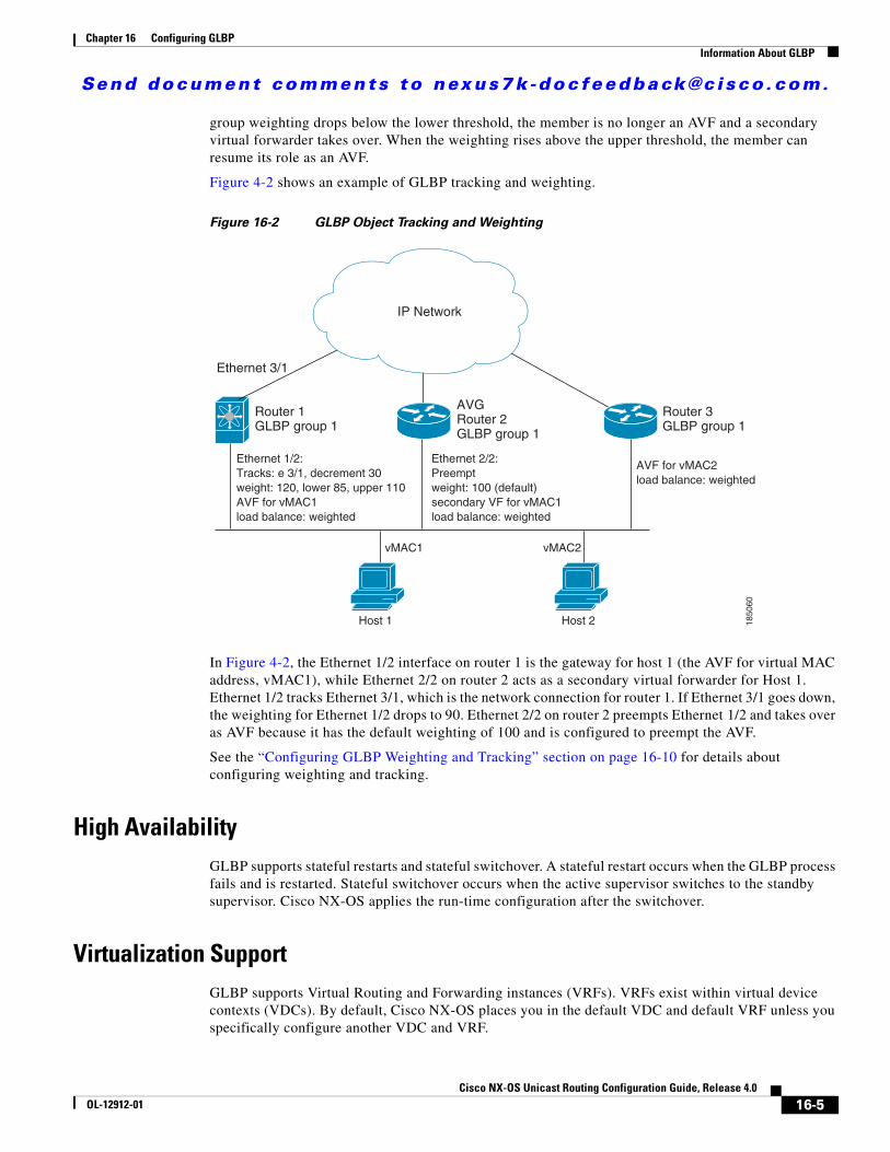
Send document comments to nexus7k -doc feedback@c i sco .com.
Chapter 16 Configuring GLBPInformation About GLBP
group weighting drops below the lower threshold, the member is no longer an AVF and a secondary virtual forwarder takes over. When the weighting rises above the upper threshold, the member can resume its role as an AVF.
Figure 4-2 shows an example of GLBP tracking and weighting.
Figure 16-2 GLBP Object Tracking and Weighting
In Figure 4-2, the Ethernet 1/2 interface on router 1 is the gateway for host 1 (the AVF for virtual MAC address, vMAC1), while Ethernet 2/2 on router 2 acts as a secondary virtual forwarder for Host 1. Ethernet 1/2 tracks Ethernet 3/1, which is the network connection for router 1. If Ethernet 3/1 goes down, the weighting for Ethernet 1/2 drops to 90. Ethernet 2/2 on router 2 preempts Ethernet 1/2 and takes over as AVF because it has the default weighting of 100 and is configured to preempt the AVF.
See the “Configuring GLBP Weighting and Tracking” section on page 16-10 for details about configuring weighting and tracking.
High AvailabilityGLBP supports stateful restarts and stateful switchover. A stateful restart occurs when the GLBP process fails and is restarted. Stateful switchover occurs when the active supervisor switches to the standby supervisor. Cisco NX-OS applies the run-time configuration after the switchover.
Virtualization SupportGLBP supports Virtual Routing and Forwarding instances (VRFs). VRFs exist within virtual device contexts (VDCs). By default, Cisco NX-OS places you in the default VDC and default VRF unless you specifically configure another VDC and VRF.
IP Network
Ethernet 3/1
Router 1GLBP group 1
Router 3GLBP group 1
AVGRouter 2GLBP group 1
Ethernet 1/2:Tracks: e 3/1, decrement 30weight: 120, lower 85, upper 110AVF for vMAC1load balance: weighted
Ethernet 2/2:Preemptweight: 100 (default)secondary VF for vMAC1load balance: weighted
AVF for vMAC2load balance: weighted
vMAC1 vMAC2
Host 1 Host 2 1850
60
16-5Cisco NX-OS Unicast Routing Configuration Guide, Release 4.0
OL-12912-01

Send document comments to nexus7k -doc feedback@c i sco .com.
Chapter 16 Configuring GLBPLicensing Requirements for GLBP
If you change the VRF membership of an interface, Cisco NX-OS removes all layer 3 configuration, including GLBP.
For more information, see the Cisco NX-OS Virtual Device Context Configuration Guide and see Chapter 13, “Configuring Layer 3 Virtualization.”
Licensing Requirements for GLBP The following table shows the licensing requirements for this feature:
Prerequisites for GLBPGLBP has the following prerequisites:
• Globally enable the GLBP feature (see the “Enabling the GLBP Feature” section on page 16-7).
• You can only configure GLBP on Layer 3 interfaces (see the Cisco NX-OS Interface Configuration Guide).
• If you configure VDCs, install the Advanced Services license and enter the desired VDC (see the Cisco NX-OS Virtual Device Context Configuration Guide).
Guidelines and LimitationsGLBP has the following guidelines and limitations:
• You should configure all customization options for GLBP on all GLBP member gateways before enabling a GLBP group by configuring a virtual IP address.
• GLBP supports a minimum hello time of 250 ms, and a minimum hold time of 1020 ms.
• You must configure an IP address for the interface that you configure GLBP on and enable that interface before GLBP becomes active.
• The GLBP virtual IP address must be in the same subnet as the interface IP address.
• We recommend that you do not configure more than one first-hop redundancy protocol on the same interface.
• Cisco NX-OS removes all layer 3 configuration on an interface when you change the VDC, interface VRF membership, port channel membership, or when you change the port mode to layer 2.
Product License Requirement
NX-OS GLBP requires no license. Any feature not included in a license package is bundled with the Cisco NX-OS system images and is provided at no extra charge to you. For a complete explanation of the NX-OS licensing scheme, see the Cisco NX-OS Licensing Guide.
16-6Cisco NX-OS Unicast Routing Configuration Guide, Release 4.0
OL-12912-01

Send document comments to nexus7k -doc feedback@c i sco .com.
Chapter 16 Configuring GLBPConfiguring GLBP
Configuring GLBPThis section includes the following topics:
• Enabling the GLBP Feature, page 16-7
• Configuring GLBP Authentication, page 16-8
• Configuring GLBP Load Balancing, page 16-9
• Configuring GLBP Weighting and Tracking, page 16-10
• Customizing GLBP, page 16-12
• Enabling a GLBP Group, page 16-13
Note If you are familiar with the Cisco IOS CLI, be aware that the Cisco NX-OS commands for this feature might differ from the Cisco IOS commands that you would use.
Enabling the GLBP FeatureYou must enable the GLBP feature before you can configure and enable any GLBP groups.
BEFORE YOU BEGIN
Ensure that you are in the correct VDC (or use the switchto vdc command).
DETAILED STEPS
To enable the GLBP feature, use the following command in global configuration mode:
To disable the GLBP feature in a VDC, use the following command in global configuration mode:
Command Purpose
feature glbp
Example:switch(config)# feature glbp
Enables GLBP.
Command Purposeno feature glbp
Example:switch(config)# no feature glbp
Disables the GLBP feature in a VDC.
16-7Cisco NX-OS Unicast Routing Configuration Guide, Release 4.0
OL-12912-01

Send document comments to nexus7k -doc feedback@c i sco .com.
Chapter 16 Configuring GLBPConfiguring GLBP
Configuring GLBP AuthenticationYou can configure GLBP to authenticate the protocol using cleartext or an MD5 digest. MD5 authentication uses a key chain (see the Cisco NX-OS Security Configuration Guide).
BEFORE YOU BEGIN
Ensure that you are in the correct VDC (or use the switchto vdc command).
Enable the GLBP feature (see the “Enabling the GLBP Feature” section on page 16-7).
Note You must configure the same authentication and keys on all members of the GLBP group.
SUMMARY STEPS
1. config t
2. interface interface-type slot/port
3. ip ip-address/length
4. glbp group-number
5. authentication text string
or
authentication md5 {key-chain key-chain | key-string {text | encrypted text}
6. ip [ip-address [secondary]]
7. show glbp [group group-number]
8. copy running-config startup-config
DETAILED STEPS
Command Purpose
Step 1 config t
Example:switch# config tswitch(config)#
Enters configuration mode.
Step 2 interface interface-type slot/port
Example:switch(config)# interface ethernet 1/2switch(config-if)#
Enters interface configuration mode.
Step 3 ip ip-address/length
Example:switch(config-if)# ip 192.0.2.1/8
Configures the IPv4 address for the interface.
Step 4 glbp group-number
Example:switch(config-if)# glbp 1 switch(config-if-glbp)#
Creates a GLBP group and enters GLBP configuration mode. The range is from 0 to 1024.
16-8Cisco NX-OS Unicast Routing Configuration Guide, Release 4.0
OL-12912-01

Send document comments to nexus7k -doc feedback@c i sco .com.
Chapter 16 Configuring GLBPConfiguring GLBP
The following example shows how to configure MD5 authentication for GLBP on Ethernet 1/2 after creating the key chain:
switch# config tswitch(config)# key chain glbp-keysswitch(config-keychain)# key 0switch(config-keychain-key)# key-string 7 zqdestswitch(config-keychain-key) accept-lifetime 00:00:00 Jun 01 2008 23:59:59 Sep 12 2008switch(config-keychain-key) send-lifetime 00:00:00 Jun 01 2008 23:59:59 Aug 12 2008switch(config-keychain-key) key 1switch(config-keychain-key) key-string 7 uaeqdyitoswitch(config-keychain-key) accept-lifetime 00:00:00 Aug 12 2008 23:59:59 Dec 12 2008switch(config-keychain-key) send-lifetime 00:00:00 Sep 12 2008 23:59:59 Nov 12 2008switch(config)# interface ethernet 1/2switch(config-if)# glbp 1 switch(config-if-glbp)# authenticate md5 key-chain glbp-keysswitch(config-if-glbp)# copy running-config startup-config
Configuring GLBP Load BalancingYou can configure GLBP to use load balancing based on round-robin, weighted, or host-dependent methods (see the “GLBP Load Balancing and Tracking” section on page 16-4).
Step 5 authentication text string
Example:switch(config-if-glbp)# authentication text mypassword
Configures cleartext authentication for GLBP on this interface.
authentication md5 {key-chain key-chain | key-string {text | encrypted text}
Example:switch(config-if-glbp)# authentication md5 key-chain glbp-keys
Configures MD5 authentication for GLBP on this interface.
Step 6 ip [ip-address [secondary]]
Example:switch(config-if-glbp)# ip 192.0.2.10
Enables GLBP on an interface and identifies the primary IP address of the virtual gateway.
After you identify a primary IP address, you can use the glbp group ip command again with the secondary keyword to indicate additional IP addresses supported by this group. If you only use the ip keyword, GLBP learns the virtual IP address from the neighbors.
Step 7 show glbp [group group-number]
Example:switch(config-if-glbp)# show glbp 1
(Optional) Displays GLBP information.
Step 8 copy running-config startup-config
Example:switch(config-if-glbp)# copy running-config startup-config
(Optional) Saves this configuration change.
Command Purpose
16-9Cisco NX-OS Unicast Routing Configuration Guide, Release 4.0
OL-12912-01

Send document comments to nexus7k -doc feedback@c i sco .com.
Chapter 16 Configuring GLBPConfiguring GLBP
To configure GLBP load balancing, use the following command in GLBP configuration mode:
Configuring GLBP Weighting and TrackingYou can configure GLBP weighting values and object tracking to work with the GLBP weighted load-balancing method.
You can optionally configure the interface to preempt an AVFif the interface was originally assigned with the virtual MAC address or if this interface has a higher weight than the AVF.
BEFORE YOU BEGIN
Ensure that you are in the correct VDC (or use the switchto vdc command).
Enable the GLBP feature (see the “Enabling the GLBP Feature” section on page 16-7).
SUMMARY STEPS
1. config t
2. track object-id interface interface-type number {ip routing | line-protocol}
3. track object-id ip route ip-prefix/length reachability
4. interface interface-type slot/port
5. ip ip-address/length
6. glbp group-number
7. weighting maximum [lower lower] [upper upper]
8. weighting track object-number [decrement value]
9. forwarder preempt [delay minimum seconds]
10. ip [ip-address [secondary]]
11. show glbp interface-type number
12. copy running-config startup-config
Command Purposeload-balancing [host-dependent | round-robin | weighted]
Example:switch(config-if-glbp)# load-balancing weighted
Sets the GLBP load-balancing method. The default is round-robin.
16-10Cisco NX-OS Unicast Routing Configuration Guide, Release 4.0
OL-12912-01

Send document comments to nexus7k -doc feedback@c i sco .com.
Chapter 16 Configuring GLBPConfiguring GLBP
DETAILED STEPS
Command or Action Purpose
Step 1 config t
Example:switch# config tswitch(config)#
Enters configuration mode.
Step 2 track object-id interface interface-type number {ip routing | line-protocol}
Example:switch(config)# track 1 interface ethernet 2/2 line-protocolswitch(config-track#
Configures the interface that this GLBP interface tracks. Changes in the state of the interface affect the priority of this GLBP interface as follows:
• You configure the interface and corresponding object number that you use with the track command in GLBP configuration mode.
• The line-protocol keyword tracks whether the interface is up. The ip keyword also checks that IP routing is enabled on the interface and an IP address is configured.
track object-id ip route ip-prefix/length reachability
Example:switch(config)# track 2 ip route 192.0.2.0/8 reachabilityswitch(config-track#
Creates a tracked object for a route nd enters tracking configuration mode. The object-id range is from 1 to 500.
Step 3 interface interface-type slot/port
Example:switch(config)# interface ethernet 1/2switch(config-if)#
Enters interface configuration mode.
Step 4 ip ip-address/length
Example:switch(config-if)# ip 192.0.2.1/8
Configures the IPv4 address for the interface.
Step 5 glbp group-number
Example:switch(config-if)# glbp 1 switch(config-if-glbp)#
Creates a GLBP group and enters GLBP configuration mode.
Step 6 weighting maximum [lower lower] [upper upper]
Example:switch(config-if-glbp)# weighting 110 lower 95 upper 105
Specifies the initial weighting value and the upper and lower thresholds for a GLBP gateway. The maximum range is from 1 to 254. The default weighting value is 100. The lower range is from 1 to 253. The upper range is from 1 to 254.
Step 7 weighting track object-number [decrement value]
Example:switch(config-if-glbp)# weighting track 2 decrement 20
Specifies an object to be tracked that affects the weighting of a GLBP gateway. The value argument specifies a reduction in the weighting of a GLBP gateway when a tracked object fails. The range is from 1 to 255.
16-11Cisco NX-OS Unicast Routing Configuration Guide, Release 4.0
OL-12912-01

Send document comments to nexus7k -doc feedback@c i sco .com.
Chapter 16 Configuring GLBPConfiguring GLBP
The following example shows how to configure GLBP weighting and tracking on Ethernet 1/2:
switch# config tswitch(config)# track 2 interface ethernet 2/2 ip routingswitch(config)# interface ethernet 1/2switch(config-if)# glbp 1 switch(config-if-glbp)# weighting 110 lower 95 upper 105switch(config-if-glbp)# weighting track 2 decrement 20switch(config-if-glbp)# copy running-config startup-config
Customizing GLBPCustomizing the behavior of GLBP is optional. Be aware that as soon as you enable a GLBP group by configuring a virtual IP address, that group is operational. If you enable a GLBP group before you customize GLBP, the router could take over control of the group and become the AVG before you finish customizing the feature. If you plan to customize GLBP, you should do so before enabling GLBP.
To customize GLBP, use the following commands in GLBP configuration mode:
Step 8 forwarder preempt [delay minimum seconds]
Example:switch(config-if-glbp)# forwarder preempt delay minimum 60
(Optional) Configures the router to take over as AVF for a GLBP group if the current AVF for a GLBP group falls below its low weighting threshold. The range is from 0 to 3600 seconds.
This command is enabled by default with a delay of 30 seconds.
Step 9 ip [ip-address [secondary]]
Example:switch(config-if-glbp)# ip 192.0.2.10
Enables GLBP on an interface and identifies the primary IP address of the virtual gateway.
After you identify a primary IP address, you can use the glbp group ip command again with the secondary keyword to indicate additional IP addresses supported by this group. If you only use the ip keyword, GLBP learns the virtual IP address from the neighbors.
Step 10 show glbp interface-type number
Example:switch(config-if-glbp)# show glbp ethernet 1/2
(Optional) Displays GLBP information for an interface.
Step 11 copy running-config startup-config
Example:switch(config-if-glbp)# copy running-config startup-config
(Optional) Saves this configuration change.
Command or Action Purpose
16-12Cisco NX-OS Unicast Routing Configuration Guide, Release 4.0
OL-12912-01

Send document comments to nexus7k -doc feedback@c i sco .com.
Chapter 16 Configuring GLBPConfiguring GLBP
Enabling a GLBP GroupYou can configure the virtual IP address on an interface to enable the GLBP group. You must configure each gateway in the GLBP group with the same group number. The GLBP member can learn all other required parameters from another GLBP member.
BEFORE YOU BEGIN
Ensure that you are in the correct VDC (or use the switchto vdc command).
Enable the GLBP feature (see the “Enabling the GLBP Feature” section on page 16-7).
Command or Action Purpose
timers [msec] hellotime [msec] holdtime
Example:switch(config-if-glbp)# timers 5 18
Configures the following hello and hold times for this GLBP member:
• hellotime—The interval between successive hello packets sent by the AVG in a GLBP group. The range is from 1 to 60 seconds or from 250 to 60000 milliseconds. The default value is 3 seconds.
• holdtime—The interval before the virtual gateway and virtual forwarder information in the hello packet is considered invalid. The range is from 2 to 180 seconds or from 1020 to 180000 milliseconds. The default is 10 seconds.
The optional msec keyword specifies that the argument is expressed in milliseconds, instead of the default seconds.
timers redirect redirect timeout
Example:switch(config-if-glbp)# timers redirect 600 7200
Configures the following timers:
• redirect—The time interval in seconds during which the AVG continues to redirect clients to an AVF. The range is from 0 to 3600 seconds. The default is 600 seconds.
• timeout—The interval in seconds before a secondary virtual forwarder becomes invalid. The range is from 610 to 64800 seconds. The default is 14,440 seconds.
priority level
Example:switch(config-if-glbp)# priority 254
Sets the priority level used to select the AVG in a GLBP group. The range is from 1 to 255. The default is 100.
preempt [delay minimum seconds]
Example:switch(config-if-glbp)# preempt delay minimum 60
Configures the router to take over as AVG for a GLBP group if it has a higher priority than the current AVG. This command is disabled by default.
Use the optional delay minimum keywords and the seconds argument to specify a minimum delay interval in seconds before preemption of the AVG takes place. The ranges is from 0 to 3600 seconds. The minimum delay default is 30 seconds.
16-13Cisco NX-OS Unicast Routing Configuration Guide, Release 4.0
OL-12912-01

Send document comments to nexus7k -doc feedback@c i sco .com.
Chapter 16 Configuring GLBPConfiguring GLBP
SUMMARY STEPS
1. config t
2. interface interface-type slot/port
3. ip ip-address/length
4. glbp group-number
5. ip [ip-address [secondary]]
6. show glbp [brief]
7. copy running-config startup-config
DETAILED STEPS
Command or Action Purpose
Step 1 config t
Example:switch# config tswitch(config)#
Enters configuration mode.
Step 2 interface interface-type slot/port
Example:switch(config)# interface ethernet 1/2switch(config-if)#
Enters interface configuration mode.
Step 3 ip ip-address/length
Example:switch(config-if)# ip 192.0.2.1/8
Configures the IPv4 address for the interface.
Step 4 glbp group-number
Example:switch(config-if)# glbp 1 switch(config-if-glbp)#
Creates a GLBP group and enters GLBP configuration mode.
Step 5 ip [ip-address [secondary]]
Example:switch(config-if-glbp)# ip 192.0.2.10
Enables GLBP on an interface and identifies the virtual IP address. The virtual IP should be in the same subnet as the interface IP address.
After you identify a virtual IP address, you can use the glbp group ip command again with the secondary keyword to indicate additional IP addresses supported by this group. If you only use the ip keyword, GLBP learns the virtual IP address from the neighbors.
16-14Cisco NX-OS Unicast Routing Configuration Guide, Release 4.0
OL-12912-01
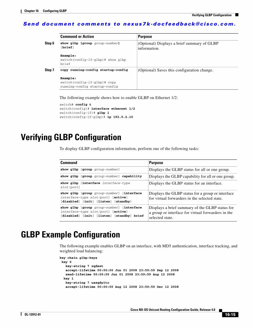
Send document comments to nexus7k -doc feedback@c i sco .com.
Chapter 16 Configuring GLBPVerifying GLBP Configuration
The following example shows how to enable GLBP on Ethernet 1/2:
switch# config tswitch(config)# interface ethernet 1/2switch(config-if)# glbp 1 switch(config-if-glbp)# ip 192.0.2.10
Verifying GLBP ConfigurationTo display GLBP configuration information, perform one of the following tasks:
GLBP Example Configuration The following example enables GLBP on an interface, with MD5 authentication, interface tracking, and weighted load balancing:
key chain glbp-keys key 0 key-string 7 zqdest accept-lifetime 00:00:00 Jun 01 2008 23:59:59 Sep 12 2008 send-lifetime 00:00:00 Jun 01 2008 23:59:59 Aug 12 2008 key 1 key-string 7 uaeqdyito accept-lifetime 00:00:00 Aug 12 2008 23:59:59 Dec 12 2008
Step 6 show glbp [group group-number] [brief]
Example:switch(config-if-glbp)# show glbp brief
(Optional) Displays a brief summary of GLBP information.
Step 7 copy running-config startup-config
Example:switch(config-if-glbp)# copy running-config startup-config
(Optional) Saves this configuration change.
Command or Action Purpose
Command Purpose
show glbp [group group-number] Displays the GLBP status for all or one group.
show glbp [group group-number] capability Displays the GLBP capability for all or one group.
show glbp [interface interface-type slot/port]
Displays the GLBP status for an interface.
show glbp [group group-number] [interface interface-type slot/port] [active] [disabled] [init] [listen] [standby]
Displays the GLBP status for a group or interface for virtual forwarders in the selected state.
show glbp [group group-number] [interface interface-type slot/port] [active] [disabled] [init] [listen] [standby] brief
Displays a brief summary of the GLBP status for a group or interface for virtual forwarders in the selected state.
16-15Cisco NX-OS Unicast Routing Configuration Guide, Release 4.0
OL-12912-01

Send document comments to nexus7k -doc feedback@c i sco .com.
Chapter 16 Configuring GLBPDefault Settings
send-lifetime 00:00:00 Sep 12 2008 23:59:59 Nov 12 2008feature glbptrack 2 interface ethernet 2/2 ipinterface ethernet 1/2 ip address 192.0.2.2/8 glbp 1 authentication md5 key-chain glbp-keys weighting 110 lower 95 upper 105 weighting track 2 decrement 20 ip 192.0.2.10 no shutdown
Default SettingsTable 16-1 lists the default settings for GLBP parameters.
Additional ReferencesFor additional information related to implementing GLBP, see the following sections:
• Related Documents, page 16-17
• Standards, page 16-17
Table 16-1 Default GLBP Parameters
Parameters Default
Authentication no authentication
Forwarder preemption delay 30 seconds
Forwarder timeout 14400 seconds
Hello timer 3 seconds
Hold timer 10 seconds
GLBP feature disable
Load balancing round robin
Preemption disabled
Priority 100
Redirect timer 600 seconds
Weighting 100
16-16Cisco NX-OS Unicast Routing Configuration Guide, Release 4.0
OL-12912-01

Send document comments to nexus7k -doc feedback@c i sco .com.
Chapter 16 Configuring GLBPAdditional References
Related Documents
Standards
Related Topic Document Title
Configuring the Hot Standby Redundancy protocol Chapter 16, “Configuring HSRP”
Configuring the Virtual Router Redundancy protocol Chapter 18, “Configuring VRRP”
GLBP CLI commands Cisco NX-OS Unicast Routing Command Reference
Configuring high availability Cisco NX-OS HA Configuration Guide
Standards Title
No new or modified standards are supported by this feature, and support for existing standards has not been modified by this feature.
—
16-17Cisco NX-OS Unicast Routing Configuration Guide, Release 4.0
OL-12912-01

Send document comments to nexus7k -doc feedback@c i sco .com.
Chapter 16 Configuring GLBPAdditional References
16-18Cisco NX-OS Unicast Routing Configuration Guide, Release 4.0
OL-12912-01

Send document comments to nexus7k -doc feedback@c i sco .com.
Cisco NX-OOL-12912-01
C H A P T E R 17
Configuring HSRPThis chapter describes how to configure the Hot Standby Router Protocol (HSRP).
This chapter includes the following sections:
• Information About HSRP, page 17-1
• Licensing Requirements for HSRP, page 17-6
• Prerequisites for HSRP, page 17-6
• Guidelines and Limitations, page 17-6
• Configuring HSRP, page 17-7
• Verifying HSRP Configuration, page 17-15
• HSRP Example Configuration, page 17-16
• Default Settings, page 17-16
• Additional References, page 17-17
Information About HSRPHSRP is a first-hop redundancy protocol (FHRP) that allows a transparent failover of the first-hop IP router. HSRP provides first-hop routing redundancy for IP hosts on Ethernet networks configured with a default gateway IP address. You use HSRP in a group of routers for selecting an active gateway and a standby gateway. In a group of gateways, the active gateway is the gateway that routes packets; the standby gateway is the gateway that takes over when the active gateway fails or when preset conditions are met.
Many host implementations do not support any dynamic router discovery mechanisms but can be configured with a default router. Running a dynamic router discovery mechanism on every host is not feasible for a number of reasons, including administrative overhead, processing overhead, and security issues. HSRP provides failover services to these hosts.
This section includes the following topics:
• HSRP Overview, page 17-2
• HSRP Versions, page 17-3
• HSRP Authentication, page 17-3
• HSRP Addressing, page 17-4
• HSRP Messages, page 17-4
17-1S Unicast Routing Configuration Guide, Release 4.0

Send document comments to nexus7k -doc feedback@c i sco .com.
Chapter 17 Configuring HSRPInformation About HSRP
• HSRP Load Sharing, page 17-4
• Object Tracking and HSRP, page 17-5
HSRP OverviewWhen you use HSRP, you configure the HSRP virtual IP address as the host’s default gateway (instead of the IP address of the actual gateway). The virtual IP address is an IP address that is shared among a group of gateways that run HSRP.
When you configure HSRP on a network segment, you provide a virtual MAC address and a virtual IP address for the HSRP group. You configure the same virtual addresses on each HSRP-enabled interface in the group. You also configure a unique IP address and MAC address on each interface that act as the real addresses. HSRP selects one of these interfaces to be the active router. The active router receives and routes packets destined for the virtual MAC address of the group.
HSRP detects when the designated active router fails. At that point, a selected standby router assumes control of the virtual MAC and IP addresses of the HSRP group. HSRP also selects a new standby router at that time.
HSRP uses a priority mechanism to determine which HSRP-configured interface becomes the default active router. To configure an interface as the active router, you assign it with a priority that is higher than the priority of all the other HSRP-configured interfaces in the group. The default priority is 100, so if you configure just one interface with a higher priority, that interface becomes the default active router.
Interfaces that run HSRP send and receive multicast User Datagram Protocol (UDP)-based hello messages to detect a failure and to designate active and standby routers. When the active router fails to send a hello message within a configurable period of time, the standby router with the highest priority becomes the active router. The transition of packet forwarding functions between the active and standby router is completely transparent to all hosts on the network.
You can configure multiple HSRP groups on an interface.
Figure 17-1 shows a network configured for HSRP. By sharing a virtual MAC address and a virtual IP address, two or more interfaces can act as a single virtual router. The virtual router does not physically exist but represents the common default gateway for interfaces that are configured to provide backup to each other. You do not need to configure the hosts on the LAN with the IP address of the active router. Instead, you configure them with the IP address (virtual IP address) of the virtual router as their default gateway. If the active router fails to send a hello message within the configurable period of time, the standby router takes over, responds to the virtual addresses, and becomes the active router, assuming the active router duties. From the host perspective, the virtual router remains the same.
17-2Cisco NX-OS Unicast Routing Configuration Guide, Release 4.0
OL-12912-01

Send document comments to nexus7k -doc feedback@c i sco .com.
Chapter 17 Configuring HSRPInformation About HSRP
Figure 17-1 HSRP Topology With Two Enabled Routers
HSRP VersionsCisco NX-OS supports HSRP version 1 by default. You can configure an interface to use HSRP version 2.
HSRP version 2 has the following enhancements to to HSRP version 1:
• Adds support for millisecond timers.
• Expands the group number range. HSRP version 1 supports group numbers from 0 to 255. HSPR version 2 supports group numbers from 0 to 4095.
• Uses the new IP multicast address 224.0.0.102 to send hello packets instead of the multicast address of 224.0.0.2, which is used by HSRP version 1.
• Uses MAC address range from 0000.0C9F.F000 to 0000.0C9F.FFFF. HSRP version 1 uses the MAC address range 0000.0C07.AC00 to 0000.0C07.ACFF.
• Adds support for MD5 digest authentication.
When you change the HSRP version, Cisco NX-OS reinitializes the group because it now has a new virtual MAC address.
HSRP version 2 has a different packet format than HSRP version 1. The packet format uses a type-length-value (TLV) format. HSRP version 2 packets received by an HSRP version 1 router are ignored.
HSRP AuthenticationHSRP message digest 5 (MD5) algorithm authentication protects against HSRP-spoofing software and uses the industry-standard MD5 algorithm for improved reliability and security.
192.0.2.1 192.0.2.2 192.0.2.3Activerouter
Virtualrouter
Standbyrouter
1850
61
Internet orISP backbone
Host A Host B
LAN
Host C Host D
17-3Cisco NX-OS Unicast Routing Configuration Guide, Release 4.0
OL-12912-01

Send document comments to nexus7k -doc feedback@c i sco .com.
Chapter 17 Configuring HSRPInformation About HSRP
HSRP AddressingHSRP routers communicate between each other by exchanging HSRP hello packets. These packets are sent to the destination IP multicast address 224.0.0.2 (reserved multicast address used to communicate to all routers) on UDP port 1985. The active router sources hello packets from its configured IP address and the HSRP virtual MAC address while the standby router sources hellos from its configured IP address and the interface MAC address, which may or may not be the Burned-In MAC address (BIA).
Because hosts are configured with their default gateway as the HSRP virtual IP address, hosts must communicate with the MAC address associated with the HSRP virtual IP address. This MAC address is a virtual MAC address, 0000.0C07.ACxy, where xy is the HSRP group number in hexadecimal based on the respective interface. For example, HSRP group one will use the HSRP virtual MAC address of 0000.0C07.AC01. Hosts on the adjoining LAN segment use the normal Address Resolution Protocol (ARP) process to resolve the associated MAC addresses.
HSRP version 2 uses the new IP multicast address 224.0.0.102 to send hello packets instead of the multicast address of 224.0.0.2, which is used by version 1. HSRP version 2 permits an expanded group number range of 0 to 4095 and uses a new MAC address range of 0000.0C9F.F000 to 0000.0C9F.FFFF.
HSRP MessagesRouters that are configured with HSRP exchange the following three types of multicast messages:
• Hello—The hello message conveys to other HSRP routers the HSRP priority and state information of the router.
• Coup—When a standby router wants to assume the function of the active router, it sends a coup message.
• Resign—A router that is the active router sends this message when it is about to shut down or when a router that has a higher priority sends a hello or coup message.
HSRP Load SharingHSRP allows you to configure an interface in multiple groups.You can configure two overlapping HSRP groups to load share traffic from the connected hosts while providing the default gateway redundancy expected from HSRP. Figure 17-2 shows an example of a load-sharing HSRP configuration.
17-4Cisco NX-OS Unicast Routing Configuration Guide, Release 4.0
OL-12912-01

Send document comments to nexus7k -doc feedback@c i sco .com.
Chapter 17 Configuring HSRPInformation About HSRP
Figure 17-2 HSRP Load Sharing
Figure 17-2 shows two routers A and B and two HSRP groups. Router A is the active router for group A, but the standby router for group B. Similarly, router B is the active router for group B and the standby router for group A. If both routers remain active, HSRP load balances the traffic from the hosts across both routers. If either router fails, the remaining router continues to process traffic for both hosts.
Object Tracking and HSRPYou can use object tracking to modify the priority of an HSRP interface based on the operational state of another interface. Object tracking allows you to router to a standby router if the interface to the main network fails.
Two objects that you can track are the line protocol state of an interface or the reachability of an IP route. If the specified object goes down, Cisco DC-OS reduces the HSRP priority by the configured amount. For more information, see the “Configuring HSRP Object Tracking” section on page 17-12.
High AvailabilityHSRP supports stateful restart. A stateful restart occurs on a supervisor switchover. Cisco NX-OS applies the runtime configuration after the switchover.
Router B
Router A
Standby
Standby
Active
Active
User Group ADefault Gateway = 192.0.2.1
User Group BDefault Gateway = 192.0.2.2
Group A = 192.0.2.1
Group B = 192.0.2.218
5059
17-5Cisco NX-OS Unicast Routing Configuration Guide, Release 4.0
OL-12912-01

Send document comments to nexus7k -doc feedback@c i sco .com.
Chapter 17 Configuring HSRPLicensing Requirements for HSRP
Virtualization SupportHSRP supports Virtual Routing and Forwarding instances (VRFs). VRFs exist within virtual device contexts (VDCs). By default, Cisco NX-OS places you in the default VDC and default VRF unless you specifically configure another VDC and VRF.
If you change the VRF membership of an interface, Cisco NX-OS removes all layer 3 configuration, including HSRP.
For more information, see the Cisco NX-OS Virtual Device Context Configuration Guide and see Chapter 13, “Configuring Layer 3 Virtualization.”
Licensing Requirements for HSRPThe following table shows the licensing requirements for this feature:
Prerequisites for HSRPHSRP has the following prerequisites:
• You must globally enable HSRP before you can configure and enable any HSRP groups.
• If you configure VDCs, install the Advanced Services license and enter the desired VDC (see to the Cisco NX-OS Virtual Device Context Configuration Guide).
Guidelines and LimitationsHSRP has the following guidelines and limitations:
• The minimum Hello timer value is 250 milliseconds.
• The minimum Hold timer value is 750 milliseconds.
• You must configure an IP address for the interface that you configure HSRP on and enable that interface before HSRP becomes active.
• The virtual IP address must be in the same subnet as the interface IP address.
• We recommend that you do not configure more than one first-hop redundancy protocol on the same interface.
• HSRP version 2 does not interoperate with HSRP version 1. An interface cannot operate both version 1 and version 2 because both versions are mutually exclusive. However, the different versions can be run on different physical interfaces of the same router.
• You cannot change from version 2 to version 1 if you have configured groups above the group number range allowed for version 1 (0 to 255).
Product License Requirement
NX-OS HSRP requires no license. Any feature not included in a license package is bundled with the Cisco NX-OS system images and is provided at no extra charge to you. For a complete explanation of the NX-OS licensing scheme, see the Cisco NX-OS Licensing Guide.
17-6Cisco NX-OS Unicast Routing Configuration Guide, Release 4.0
OL-12912-01

Send document comments to nexus7k -doc feedback@c i sco .com.
Chapter 17 Configuring HSRPConfiguring HSRP
• Cisco NX-OS removes all layer 3 configuration on an interface when you change the interface VRF membership, port channel membership, or when you change the port mode to layer 2.
Configuring HSRPThis section includes the following topics:
• Enabling the HSRP Feature, page 17-7
• Configuring an HSRP Group, page 17-7
• Configuring the HSRP Version, page 17-9
• Configuring the HSRP Virtual MAC Address, page 17-9
• Authenticating HSRP, page 17-10
• Configuring HSRP Object Tracking, page 17-12
• Customizing HSRP, page 17-14
Note If you are familiar with the Cisco IOS CLI, be aware that the Cisco NX-OS commands for this feature might differ from the Cisco IOS commands that you would use.
Enabling the HSRP FeatureYou must globally enable the HSRP feature before you can configure and enable any HSRP groups.
To enable the HSRP feature in a VDC, use the following command in global configuration mode:
To disable the HSRP feature in a VDC, use the following command in global configuration mode:
Configuring an HSRP GroupYou can configure an HSRP group on an interface and configure the virtual IP address and virtual MAC address for the HSRP group.
Command Purpose
feature hsrp
Example:switch(config)# feature hsrp
Enables HSRP.
Command Purposeno feature hsrp
Example:switch(config)# no feature hsrp
Disables HSRP for all groups in a VDC.
17-7Cisco NX-OS Unicast Routing Configuration Guide, Release 4.0
OL-12912-01

Send document comments to nexus7k -doc feedback@c i sco .com.
Chapter 17 Configuring HSRPConfiguring HSRP
BEFORE YOU BEGIN
Ensure that you have enabled the HSRP feature (see the “Enabling the HSRP Feature” section on page 17-7).
Cisco NX-OS enables an HSRP group once you configure the virtual IP address on any member interface in the group. You should configure HSRP attributes such as authentication, timers, and priority before you enable HSRP.
Ensure that you are in the correct VDC (or use the switchto vdc command).
SUMMARY STEPS
1. config t
2. interface type number
3. ip ip-address/length
4. hsrp group-number
5. ip [ip-address [secondary]]
6. exit
7. no shutdown
8. show hsrp [group group-number]
9. copy running-config startup-config
DETAILED STEPS
Command Purpose
Step 1 config t
Example:switch# config tswitch(config)#
Enters configuration mode.
Step 2 interface type number
Example:switch(config)# interface ethernet 1/2switch(config-if)#
Enters interface configuration mode.
Step 3 ip ip-address/length
Example:switch(config-if)# ip 192.0.2.2/8
Configures the IPv4 address of the interface.
Step 4 hsrp group-number
Example:switch(config-if)# hsrp 2 switch(config-if-hsrp)#
Creates a HSRP group and enters HSRP configuration mode. The range is from 0 to 4095. The default value is 0.
Step 5 ip [ip-address [secondary]]
Example:switch(config-if-hsrp)# ip 192.0.2.1
Configures the virtual IP address for the HSRP group and enables the group. This address should be in the same subnet as the IPv4 address of the interface.
17-8Cisco NX-OS Unicast Routing Configuration Guide, Release 4.0
OL-12912-01

Send document comments to nexus7k -doc feedback@c i sco .com.
Chapter 17 Configuring HSRPConfiguring HSRP
Note You should use the no shutdown command to enable the interface after you finish the configuration.
The following example shows how to configure an HSRP group on Ethernet 1/2:
switch# config tswitch(config)# interface ethernet 1/2switch(config-if)# ip 192.0.2.2/8switch(config-if)# hsrp 2 switch(config-if-hsrp)# ip 192.0.2.1switch(config-if-hsrp)# exitswitch(config-if)# no shutdownswitch(config-if)# copy running-config startup-config
Configuring the HSRP VersionYou can configure the HSRP version. If you change the version for existing groups, Cisco NX-OS reinitializes HSRP for those groups because the virtual MAC address changes. The HSRP version applies to all groups on the interface.
To configure the HSRP version, use the following command in interface configuration mode:
Configuring the HSRP Virtual MAC AddressYou can override the default virtual MAC address that HSRP derives from the configured group number.
Step 6 exit
Example:switch(config-if-hsrp)# exit
Exits HSRP configuration mode.
Step 7 no shutdown
Example:switch(config-if)# no shutdown
Enables the interface
Step 8 show hsrp [group group-number]
Example:switch(config-if)# show hsrp group 2
(Optional) Displays HSRP information.
Step 9 copy running-config startup-config
Example:switch(config-if)# copy running-config startup-config
(Optional) Saves this configuration change.
Command Purpose
Command Purposehsrp version {1 | 2}
Example:switch(config-if)# hsrp version 2
Configures the HSRP version. Version 1 by default.
17-9Cisco NX-OS Unicast Routing Configuration Guide, Release 4.0
OL-12912-01

Send document comments to nexus7k -doc feedback@c i sco .com.
Chapter 17 Configuring HSRPConfiguring HSRP
To manually configure the virtual MAC address for an HSRP group, use the following command in HSRP configuration mode:
To configure HSRP to use the burned-in MAC address of the interface for the virtual MAC address, use the following command in interface configuration mode:
Authenticating HSRPYou can configure HSRP to authenticate the protocol using cleartext or MD5 digest authentication. MD5 authentication uses a key chain (see the Cisco NX-OS Security Configuration Guide).
Note HSRP version 1 supports text authentication only.
BEFORE YOU BEGIN
Ensure that you have enabled the HSRP feature (see the “Enabling the HSRP Feature” section on page 17-7).
You must configure the same authentication and keys on all members of the HSRP group.
Ensure that you have created the key chain if you are using MD5 authentication.
Ensure that you are in the correct VDC (or use the switchto vdc command).
SUMMARY STEPS
1. config t
2. interface interface-type slot/port
3. hsrp group-number
4. authentication text string
or
authentication md5 {key-chain key-chain | key-string {0 | 7} text [timeout seconds]}
5. show hsrp [group group-number]
Command Purposemac-address string
Example:switch(config-if-hsrp)# mac-address 5000.1000.1060
Configures the virtual MAC address for an HSRP group. The string uses the standard MAC address format (xxxx.xxxx.xxxx).
Command Purpose
hsrp use-bia [scope interface]
Example:switch(config-if)# hsrp use-bia
Configures HSRP to use the burned-in MAC address of the interface for the HSRP virtual MAC address. You can optionally configure HSRP to use the burned-in MAC address for all groups on this interface by using the scope interface keywords.
17-10Cisco NX-OS Unicast Routing Configuration Guide, Release 4.0
OL-12912-01

Send document comments to nexus7k -doc feedback@c i sco .com.
Chapter 17 Configuring HSRPConfiguring HSRP
6. copy running-config startup-config
DETAILED STEPS
The following example shows how to configure MD5 authentication for HSRP on Ethernet 1/2 after creating the key chain:
switch# config tswitch(config)# key chain hsrp-keysswitch(config-keychain)# key 0switch(config-keychain-key)# key-string 7 zqdestswitch(config-keychain-key) accept-lifetime 00:00:00 Jun 01 2008 23:59:59 Sep 12 2008switch(config-keychain-key) send-lifetime 00:00:00 Jun 01 2008 23:59:59 Aug 12 2008switch(config-keychain-key) key 1switch(config-keychain-key) key-string 7 uaeqdyitoswitch(config-keychain-key) accept-lifetime 00:00:00 Aug 12 2008 23:59:59 Dec 12 2008
Command Purpose
Step 1 config t
Example:switch# config tswitch(config)#
Enters configuration mode.
Step 2 interface interface-type slot/port
Example:switch(config)# interface ethernet 1/2switch(config-if)#
Enters interface configuration mode.
Step 3 hsrp group-number
Example:switch(config-if)# hsrp 2 switch(config-if-hsrp)#
Creates a HSRP group and enters HSRP configuration mode.
Step 4 authentication text string
Example:switch(config-if-hsrp)# authentication text mypassword
Configures cleartext authentication for HSRP on this interface.
authentication md5 {key-chain key-chain | key-string {0 | 7} text [timeout seconds]}
Example:switch(config-if-hsrp)# authentication md5 key-chain hsrp-keys
Configures MD5 authentication for HSRP on this interface. You can use a key chain or key string. If you use a key string, you can optionally set the timeout for when HSRP will only accept a new key. The range is from 0 to 32767 seconds.
Step 5 show hsrp [group group-number]
Example:switch(config-if-hsrp)# show hsrp group 2
(Optional) Displays HSRP information.
Step 6 copy running-config startup-config
Example:switch(config-if-hsrp)# copy running-config startup-config
(Optional) Saves this configuration change.
17-11Cisco NX-OS Unicast Routing Configuration Guide, Release 4.0
OL-12912-01

Send document comments to nexus7k -doc feedback@c i sco .com.
Chapter 17 Configuring HSRPConfiguring HSRP
switch(config-keychain-key) send-lifetime 00:00:00 Sep 12 2008 23:59:59 Nov 12 2008switch(config-keychain-key)# interface ethernet 1/2switch(config-if)# hsrp 2 switch(config-if-hsrp)# authenticate md5 key-chain hsrp-keysswitch(config-if-hsrp)# copy running-config startup-config
Configuring HSRP Object TrackingYou can configure an HSRP group to adjust its priority based on the availability of other interfaces or routes. The priority of a device can change dynamically if it has been configured for object tracking and the object that is being tracked goes down. The tracking process periodically polls the tracked objects and notes any value change. The value change triggers HSRP to recalculate the priority. The HSRP interface with the higher priority becomes the active router if you configure the HSRP interface for preemption. For more information on object tracking, see the “Configuring HSRP Object Tracking” section on page 17-12.
BEFORE YOU BEGIN
Ensure that you have enabled the HSRP feature (see the “Enabling the HSRP Feature” section on page 17-7).
Ensure that you are in the correct VDC (or use the switchto vdc command).
SUMMARY STEPS
1. config t
2. track object-id interface interface-type number {ip routing | line-protocol}
3. track object-id ip route ip-prefix/length reachability
4. interface interface-type slot/port
5. hsrp group-number
6. priority [value]
7. track object-number [decrement value]
8. preempt [delay minimum seconds] [reload seconds] [sync seconds]
9. show hsrp interface interface-type number
10. copy running-config startup-config
17-12Cisco NX-OS Unicast Routing Configuration Guide, Release 4.0
OL-12912-01

Send document comments to nexus7k -doc feedback@c i sco .com.
Chapter 17 Configuring HSRPConfiguring HSRP
DETAILED STEPS
Command or Action Purpose
Step 1 config t
Example:switch# config tswitch(config)#
Enters configuration mode.
Step 2 track object-id interface interface-type number {ip routing | line-protocol}
Example:switch(config)# track 1 interface ethernet 2/2 line-protocolswitch(config-track#
Configures the interface that this HSRP interface tracks. Changes in the state of the interface affect the priority of this HSRP interface as follows:
• You configure the interface and corresponding object number that you use with the track command in HSRP configuration mode.
• The line-protocol keyword tracks whether the interface is up. The ip keyword also checks that IP routing is enabled on the interface and an IP address is configured.
track object-id ip route ip-prefix/length reachability
Example:switch(config)# track 2 ip route 192.0.2.0/8 reachabilityswitch(config-track#
Creates a tracked object for a route nd enters tracking configuration mode. The object-id range is from 1 to 500.
Step 3 interface interface-type slot/port
Example:switch(config)# interface ethernet 1/2switch(config-if)#
Enters interface configuration mode.
Step 4 hsrp group-number
Example:switch(config-if)# hsrp 2 switch(config-if-hsrp)#
Creates an HSRP group and enters HSRP configuration mode.
Step 5 priority [value]
Example:switch(config-if-hsrp)# priority 254
Sets the priority level used to select the active router in an HSRP group. The range is from 0 to 255. The default is 100.
Step 6 track object-number [decrement value]
Example:switch(config-if-hsrp)# track 1 decrement 20
Specifies an object to be tracked that affects the weighting of an HSRP interface.
The value argument specifies a reduction in the priority of an HSRP interface when a tracked object fails. The range is from 1 to 255. The default is 10.
Step 7 preempt [delay [minimum seconds] [reload seconds] [sync seconds]]
Example:switch(config-if-hsrp)# preempt delay minimum 60
Configures the router to take over as the active router for an HSRP group if it has a higher priority than the current active router. This command is disabled by default. The range is from 0 to 3600 seconds.
17-13Cisco NX-OS Unicast Routing Configuration Guide, Release 4.0
OL-12912-01

Send document comments to nexus7k -doc feedback@c i sco .com.
Chapter 17 Configuring HSRPConfiguring HSRP
The following example shows how to configure HSRP object tracking on Ethernet 1/2:
switch# config tswitch(config)# track 1 interface ethernet 2/2 line-protocolswitch(config)# interface ethernet 1/2switch(config-if)# hsrp 2 switch(config-if-hsrp)# track 1 decrement 20switch(config-if-hsrp)# copy running-config startup-config
Customizing HSRPYou can optionally customize the behavior of HSRP. Be aware that as soon as you enable an HSRP group by configuring a virtual IP address, that group is now operational. If you first enable a HSRP group before customizing HSRP, the router could take over control of the group and become the AVG before you finish customizing the feature.If you plan to customize HSRP, you should do so before you enable the HSRP group.
To customize HSRP, use the following commands in HSRP configuration mode:
Step 8 show hsrp interface interface-type number
Example:switch(config-if-hsrp)# show hsrp interface ethernet 1/2
(Optional) Displays HSRP information for an interface.
Step 9 copy running-config startup-config
Example:switch(config-if-hsrp)# copy running-config startup-config
(Optional) Saves this configuration change.
Command or Action Purpose
Command or Action Purpose
name string
Example:switch(config-if-hsrp)# name HSRP-1
Specifies the IP redundancy name for an HSRP group. The string is from 1 to 255 characters. The default string has the following format:
hsrp-<interface-short-name>-<group-id>. For example, hsrp-Eth2/1-1.
priority [level]
Example:switch(config-if-hsrp)# priority 254
Sets the priority level used to select the active router in an HSRP group. The range is from 0 to 255. The default is 100.
17-14Cisco NX-OS Unicast Routing Configuration Guide, Release 4.0
OL-12912-01

Send document comments to nexus7k -doc feedback@c i sco .com.
Chapter 17 Configuring HSRPVerifying HSRP Configuration
To customize HSRP, use the following commands in interface configuration mode:
Verifying HSRP ConfigurationTo verify HSRP configuration information, use one of the following commands:
preempt [delay [minimum seconds] [reload seconds] [sync seconds]]
Example:switch(config-if-hsrp)# preempt delay minimum 60
Configures the router to take over as an active router for a HSRP group if it has a higher priority than the current active router. This command is disabled by default. The range is from 0 to 3600 seconds.
timers [msec] hellotime [msec] holdtime
Example:switch(config-if-hsrp)# timers 5 18
Configures the hello and hold time for this HSRP member as follows.
• hellotime—The interval between successive hello packets sent. The range is from 1 to 254 seconds.
• holdtime—The interval before the information in the hello packet is considered invalid. The range is from 3 to 255.
The optional msec keyword specifies that the argument is expressed in milliseconds, instead of the default seconds.
Command or Action Purpose
Command or Action Purpose
hsrp delay minimum seconds
Example:switch(config-if)# hsrp delay minimum 30
Specifies the minimum amount of time that HSRP waits after a group is enabled before participating in the group. The range is from 0 to 10000 seconds. The default is 0.
hsrp delay reload seconds
Example:switch(config-if)# hsrp delay reload 30
Specifies the minimum amount of time that HSRP waits after reload before participating in the group. The range is from 0 to 10000 seconds. The default is 0.
Command Purpose
show hsrp [group group-number] Displays the HSRP status for all or one group.
show hsrp delay [interface interface-type slot/port]
Displays the HSRP delay value for all or one interface.
show hsrp [interface interface-type slot/port]
Displays the HSRP status for an interface.
17-15Cisco NX-OS Unicast Routing Configuration Guide, Release 4.0
OL-12912-01

Send document comments to nexus7k -doc feedback@c i sco .com.
Chapter 17 Configuring HSRPHSRP Example Configuration
HSRP Example Configuration The following example enables HSRP on an interface with MD5 authentication and interface tracking:
key chain hsrp-keys key 0 key-string 7 zqdest accept-lifetime 00:00:00 Jun 01 2008 23:59:59 Sep 12 2008 send-lifetime 00:00:00 Jun 01 2008 23:59:59 Aug 12 2008 key 1 key-string 7 uaeqdyito accept-lifetime 00:00:00 Aug 12 2008 23:59:59 Dec 12 2008 send-lifetime 00:00:00 Sep 12 2008 23:59:59 Nov 12 2008feature hsrptrack 2 interface ethernet 2/2 ipinterface ethernet 1/2 ip address 192.0.2.2/8 hsrp 1 authenticate md5 key-chain hsrp-keys priority 90 track 2 decrement 20 ip-address 192.0.2.10 no shutdown
Default SettingsTable 17-1 lists the default settings for HSRP parameters.
show hsrp [group group-number] [interface interface-type slot/port] [active] [all] [init] [learn] [listen] [speak] [standby]
Displays the HSRP status for a group or interface for virtual forwarders in the active, init, learn, listen, or standby state. Use the all keyword to see all states, including disabled.
show hsrp [group group-number] [interface interface-type slot/port] active] [all] [init] [learn] [listen] [speak] [standby] brief
Displays a brief summary of the HSRP status for a group or interface for virtual forwarders in the active, init, learn, listen, or standby state. Use the all keyword to see all states, including disabled.
Command Purpose
Table 17-1 Default HSRP Parameters
Parameters Default
HSRP Disabled
Authentication Enabled as text for version 1, with cisco as the password.
HSRP version Version 1
Preemption disabled
Priority 100
virtual MAC address Derived from HSRP group number
17-16Cisco NX-OS Unicast Routing Configuration Guide, Release 4.0
OL-12912-01

Send document comments to nexus7k -doc feedback@c i sco .com.
Chapter 17 Configuring HSRPAdditional References
Additional ReferencesFor additional information related to implementing IP, see the following sections:
• Related Documents, page 17-17
• Standards, page 17-17
Related Documents
Standards
Related Topic Document Title
Configuring the Gateway Load Balancing protocol Chapter 16, “Configuring GLBP”
Configuring the Virtual Router Redundancy protocol Chapter 18, “Configuring VRRP”
HSRP CLI commands Cisco NX-OS Unicast Routing Command Reference
Configuring high availability Cisco NX-OS HA Configuration Guide
Standards Title
No new or modified standards are supported by this feature, and support for existing standards has not been modified by this feature.
—
17-17Cisco NX-OS Unicast Routing Configuration Guide, Release 4.0
OL-12912-01

Send document comments to nexus7k -doc feedback@c i sco .com.
Chapter 17 Configuring HSRPAdditional References
17-18Cisco NX-OS Unicast Routing Configuration Guide, Release 4.0
OL-12912-01

Send document comments to nexus7k -doc feedback@c i sco .com.
Cisco NX-OOL-12912-01
C H A P T E R 18
Configuring VRRPThis chapter describes how to configure the Virtual Router Redundancy Protocol (VRRP) on a device
This chapter includes the following sections:
• Information About VRRP, page 18-1
• Licensing Requirements for VRRP, page 18-6
• Guidelines and Limitations, page 18-6
• Configuring VRRP, page 18-6
• Verifying the VRRP Configuration, page 18-18
• Displaying VRRP Statistics, page 18-19
• VRRP Example Configuration, page 18-19
• Default Settings, page 18-20
• Additional References, page 18-21
Information About VRRPVRRP allows for transparent failover at the first-hop IP router, by configuring a group of routers to share a virtual IP address. VRRP selects a master router in that group to handle all packets for the virtual IP address. The remaining routers are in standby and take over in the event that the master router fails.
This section includes the following topics:
• VRRP Operation, page 18-2
• VRRP Benefits, page 18-3
• Multiple VRRP Groups, page 18-3
• VRRP Router Priority and Preemption, page 18-4
• VRRP Advertisements, page 18-5
• VRRP Authentication, page 18-5
• VRRP Tracking, page 18-5
• High Availability, page 18-5
• Virtualization Support, page 18-5
18-1S Unicast Routing Configuration Guide, Release 4.0

Send document comments to nexus7k -doc feedback@c i sco .com.
Chapter 18 Configuring VRRPInformation About VRRP
VRRP OperationA LAN client can determine which router should be the first hop to a particular remote destination by using a dynamic process or static configuration. Examples of dynamic router discovery are as follows:
• Proxy ARP—The client uses Address Resolution Protocol (ARP) to get the destination it wants to reach, and a router will respond to the ARP request with its own MAC address.
• Routing protocol—The client listens to dynamic routing protocol updates (for example, from Routing Information Protocol [RIP]) and forms its own routing table.
• ICMP Router Discovery Protocol (IRDP) client—The client runs an Internet Control Message Protocol (ICMP) router discovery client.
The disadvantage to dynamic discovery protocols is that they incur some configuration and processing overhead on the LAN client. Also, in the event of a router failure, the process of switching to another router can be slow.
An alternative to dynamic discovery protocols is to statically configure a default router on the client. Although, this approach simplifies client configuration and processing, it creates a single point of failure. If the default gateway fails, the LAN client is limited to communicating only on the local IP network segment and is cut off from the rest of the network.
VRRP can solve the static configuration problem by enabling a group of routers (a VRRP group) to share a single virtual IP address. You can then configure the LAN clients with the virtual IP address as their default gateway.
Figure 18-1 shows a basic VLAN topology. In this example, Routers A, B, and C form a VRRP group. The IP address of the group is the same address that was configured for the Ethernet interface of Router A (10.0.0.1).
Figure 18-1 Basic VRRP Topology
Because the virtual IP address uses the IP address of the physical Ethernet interface of Router A, Router A is the master (also known as the IP address owner). As the master, Router A owns the virtual IP address of the VRRP group r and forwards packets sent to this IP address. Clients 1 through 3 are configured with the default gateway IP address of 10.0.0.1.
Router AVirtual router
master Virtualrouter groupIP address = 10.0.0.1
Client 1 Client 2 Client 3
10.0.0.1
Router BVirtual router
backup
10.0.0.2
Router CVirtual router
backup
10.0.0.3
56
62
3
18-2Cisco NX-OS Unicast Routing Configuration Guide, Release 4.0
OL-12912-01

Send document comments to nexus7k -doc feedback@c i sco .com.
Chapter 18 Configuring VRRPInformation About VRRP
Routers B and C function as backups. If the master fails, the backup router with the highest priority becomes the master and takes over the virtual IP address to provide uninterrupted service for the LAN hosts. When router A recovers, it becomes the r master again. For more information, see the “VRRP Router Priority and Preemption” section.
VRRP BenefitsThe benefits of VRRP are as follows:
• Redundancy–Enables you to configure multiple routers as the default gateway router, which reduces the possibility of a single point of failure in a network.
• Load Sharing–Allows traffic to and from LAN clients to be shared by multiple routers. The traffic load is shared more equitably among available routers.
• Multiple VRRP groups–Supports up to 255 VRRP groups on a router physical interface if the platform supports multiple MAC addresses. Multiple VRRP groups enable you to implement redundancy and load sharing in your LAN topology.
• Multiple IP Addresses–Allows you to manage multiple IP addresses, including secondary IP addresses. If you have multiple subnets configured on an Ethernet interface, you can configure VRRP on each subnet.
• Preemption–Enables you to preempt a backup router that has taken over for a failing master with a higher priority backup router that has become available.
• Advertisement Protocol–Uses a dedicated Internet Assigned Numbers Authority (IANA) standard multicast address (224.0.0.18) for VRRP advertisements. This addressing scheme minimizes the number of routers that must service the multicasts and allows test equipment to accurately identify VRRP packets on a segment. IANA has assigned the IP protocol number 112 to VRRP.
• VRRP Tracking–Ensures that the best VRRP router is the master for the group by altering VRRP priorities based on interface states.
Multiple VRRP GroupsYou can configure up to 255 VRRP groups on a physical interface. The actual number of VRRP groups that a router interface can support depends on the following factors:
• Router processing capability
• Router memory capability
In a topology where multiple VRRP groups are configured on a router interface, the interface can act as a master for one VRRP group and as a backup for one or more other VRRP groups.
Figure 18-2 shows a LAN topology in which VRRP is configured so that Routers A and B share the traffic to and from clients 1 through 4. Routers A and B act as backups to each other if either router fails.
18-3Cisco NX-OS Unicast Routing Configuration Guide, Release 4.0
OL-12912-01

Send document comments to nexus7k -doc feedback@c i sco .com.
Chapter 18 Configuring VRRPInformation About VRRP
Figure 18-2 Load Sharing and Redundancy VRRP Topology
In this topology contains two virtual IP addresses for two VRRP groups that overlap. For VRRP group 1, Router A is the owner of IP address 10.0.0.1 and is the master. Router B is the backup to router A. Clients 1 and 2 are configured with the default gateway IP address of 10.0.0.1.
For VRRP group 2, Router B is the owner of IP address 10.0.0.2 and is the master. Router A is the backup to router B. Clients 3 and 4 are configured with the default gateway IP address of 10.0.0.2.
VRRP Router Priority and PreemptionAn important aspect of the VRRP redundancy scheme is the VRRP router priority because the priority determines the role that each VRRP router plays and what happens if the master router fails.
If a VRRP router owns the virtual IP address and the IP address of the physical interface, this router functions as the master. The priority of the master is 255.
Priority also determines if a VRRP router functions as a backup router and the order of ascendancy to becoming a master if the master fails.
For example, if router A, the master in a LAN topology, fails, VRRP must determine if backups B or C should take over. If you configure router B with priority 101 and router C with the default priority of 100, VRRP selects router B to become the master because it has the higher priority. If you configure routers B and C with the default priority of 100, VRRP selects the backup with the higher IP address to become the master.
VRRP uses preemption to determine what happens after a VRRP backup router becomes the master. With preemption enabled by default, VRRP will switch to a backup if that backup comes online with a priority higher than the new master. For example, if Router A is the master and fails, VRRP selects Router B (next in order of priority). If Router C comes online with a higher priority than Router B, VRRP selects Router C as the new master, even though Router B has not failed.
If you disable preemption, VRRP will only switch if the original master recovers or the new master fails.
Router AMaster for virtual router 1Backup for virtual router 2
Router BBackup for virtual router 1Master for virtual router 2
Client 1Default gateway =
10.0.0.1
Client 2Default gateway =
10.0.0.1
Client 3Default gateway =
10.0.0.2
Client 4Default gateway =
10.0.0.2
10.0.0.1 10.0.0.2
1292
84
18-4Cisco NX-OS Unicast Routing Configuration Guide, Release 4.0
OL-12912-01

Send document comments to nexus7k -doc feedback@c i sco .com.
Chapter 18 Configuring VRRPInformation About VRRP
VRRP AdvertisementsThe VRRP master sends VRRP advertisements to other VRRP routers in the same group. The advertisements communicate the priority and state of the master. Cisco NX-OS encapsulates the VRRP advertisements in IP packets and sends them to the IP multicast address assigned to the VRRP group. Cisco NX-OS sends the advertisements once every second by default, but you can configure a different advertisement interval.
VRRP Authentication VRRP supports the following authentication mechanisms:
• No authentication
• Plain text authentication
VRRP rejects packets in any of the following cases:
• The authentication schemes differ on the router and in the incoming packet.
• Text authentication strings differ on the router and in the incoming packet.
VRRP TrackingVRRP uses the native tracking method to track interface states. You can track the state of an interface and use that state to determine the priority of the VRRP router in a VRRP group. If the tracked interface goes down, VRRP updates the priority based on what you configure the new priority to be for the tracked interface state. When the tracked interface comes up, VRRP restores the original priority for the virtual router group.
For example, you may want to lower the priority of a VRRP group member if its uplink to the network goes down so another group member can take over as master for the VRRP group.
High AvailabilityVRRP supports stateful restart. A stateful restart occurs on a supervisor switchover. Cisco NX-OS applies the runtime configuration after the switchover.
Virtualization SupportVRRP supports Virtual Routing and Forwarding instances (VRFs). VRFs exist within virtual device contexts (VDCs). By default, Cisco NX-OS places you in the default VDC and default VRF unless you specifically configure another VDC and VRF.
If you change the VRF membership of an interface, Cisco NX-OS removes all layer 3 configuration, including VRRP.
For more information, see the Cisco NX-OS Virtual Device Context Configuration Guide and see Chapter 13, “Configuring Layer 3 Virtualization.”
18-5Cisco NX-OS Unicast Routing Configuration Guide, Release 4.0
OL-12912-01

Send document comments to nexus7k -doc feedback@c i sco .com.
Chapter 18 Configuring VRRPLicensing Requirements for VRRP
Licensing Requirements for VRRPThe following table shows the licensing requirements for this feature:
Guidelines and LimitationsVRRP has the following guidelines and limitations:
• You cannot configure VRRP on the management interface.
• When VRRP is enabled, you should replicate the VRRP configuration across devices in your network.
• We recommend that you do not configure more than one first-hop redundancy protocol on the same interface.
• You must configure an IP address for the interface that you configure VRRP on and enable that interface before VRRP becomes active.
• Cisco NX-OS removes all layer 3 configuration on an interface when you change the interface VRF membership, port channel membership, or when you change the port mode to layer 2.
Configuring VRRPThis section includes the following topics:
• Enabling the VRRP Feature, page 18-6
• Configuring VRRP Groups, page 18-7
• Configuring VRRP Priority, page 18-8
• Configuring VRRP Authentication, page 18-10
• Configuring Time Intervals for Advertisement Packets, page 18-12
• Disabling Preemption, page 18-14
• Configuring VRRP Interface State Tracking, page 18-16
Note If you are familiar with the Cisco IOS CLI, be aware that the Cisco NX-OS commands for this feature might differ from the Cisco IOS commands that you would use.
Enabling the VRRP FeatureYou must globally enable the VRRP feature before you can configure and enable any VRRP groups.
Product License Requirement
NX-OS VRRP requires no license. Any feature not included in a license package is bundled with the Cisco NX-OS system images and is provided at no extra charge to you. For a complete explanation of the NX-OS licensing scheme, see the Cisco NX-OS Licensing Guide.
18-6Cisco NX-OS Unicast Routing Configuration Guide, Release 4.0
OL-12912-01

Send document comments to nexus7k -doc feedback@c i sco .com.
Chapter 18 Configuring VRRPConfiguring VRRP
To enable the VRRP feature, use the following command in global configuration mode:
To disable the VRRP feature in a VDC, use the following command in global configuration mode:
Configuring VRRP GroupsYou can create a VRRP group, assign the virtual IP address, and enable the group.
You can configure one virtual IPv4 address for a VRRP group. By default, the master VRRP router drops the packets addressed directly to the virtual IP address because the VRRP master is only intended as a next-hop router to forward packets. Some applications require that Cisco NX-OS accept packets addressed to the virtual router IP. Use the secondary option to the virtual IP address to accept these packets when the local router is the VRRP master.
Once you have configured the VRRP group, you must explicitly enable the group before it becomes active.
BEFORE YOU BEGIN
Ensure that you are in the correct VDC (or use the switchto vdc command).
Ensure that you configure an IP address on the interface (see the “Configuring IPv4 Addressing” section on page 2-7.
SUMMARY STEPS
1. config t
2. interface interface-type slot/port
3. vrrp number
4. address ip-address [secondary]
5. no shutdown
Command Purposefeature vrrp
Example:switch(config)# feature vrrp
Enables VRRP.
Command Purpose
no feature vrrp
Example:switch(config)# no feature vrrp
Disables the VRRP feature in a VDC.
18-7Cisco NX-OS Unicast Routing Configuration Guide, Release 4.0
OL-12912-01

Send document comments to nexus7k -doc feedback@c i sco .com.
Chapter 18 Configuring VRRPConfiguring VRRP
6. show vrrp
7. copy running-config startup-config
DETAILED STEPS
Configuring VRRP PriorityThe valid priority range for a virtual router is from 1 to 254 (1 is the lowest priority and 254 is the highest). The default priority value for backups is 100. For devices whose interface IP address is the same as the primary virtual IP address (the master), the default value is 255.
Command Purpose
Step 1 config t
Example:switch# config tswitch(config)#
Enters configuration mode.
Step 2 interface interface-type slot/port
Example:switch(config)#switch(config-if)# interface ethernet 2/1
Enters interface configuration mode.
Step 3 vrrp number
Example:switch(config-if)# vrrp 250switch(config-if-vrrp)#
Creates a virtual router group. The range is from 1 to 255.
Step 4 address ip-address [secondary]
Example: switch(config-if-vrrp)# address 192.0.2.8
Configures the virtual IPv4 address for the specified VRRP group. This address should be in the same subnet as the IPv4 address of the interface.
Use the secondary option only if applications require that VRRP routers accept the packets sent to the virtual router's IP address and deliver to applications.
Step 5 no shutdown
Example:switch(config-if-vrrp)# no shutdownswitch(config-if-vrrp)#
Enables the VRRP group. Disabled by default.
Step 6 show vrrp
Example:switch(config-if-vrrp)# show vrrp
(Optional) Displays VRRP information.
Step 7 copy running-config startup-config
Example:switch(config-if-vrrp)# copy running-config startup-config
(Optional) Saves this configuration change.
18-8Cisco NX-OS Unicast Routing Configuration Guide, Release 4.0
OL-12912-01

Send document comments to nexus7k -doc feedback@c i sco .com.
Chapter 18 Configuring VRRPConfiguring VRRP
Note If you have enabled the VRRP group, you must disable it first, before making configuration changes. Enable the VRRP group after you complete your configuration changes.
BEFORE YOU BEGIN
Ensure that you have enabled the VRRP feature (see the “Configuring VRRP” section on page 18-6).
Ensure that you have configured an IP address on the interface (see the “Configuring IPv4 Addressing” section on page 2-7.
Ensure that you are in the correct VDC (or use the switchto vdc command).
SUMMARY STEPS
1. config t
2. interface interface-type slot/port
3. vrrp number
4. shutdown
5. priority value
6. no shutdown
7. show vrrp
8. copy running-config startup-config
18-9Cisco NX-OS Unicast Routing Configuration Guide, Release 4.0
OL-12912-01

Send document comments to nexus7k -doc feedback@c i sco .com.
Chapter 18 Configuring VRRPConfiguring VRRP
DETAILED STEPS
Configuring VRRP AuthenticationYou can configure simple text authentication for a VRRP group.
Note If you have enabled the VRRP group, you must disable it first, before making configuration changes. Enable the VRRP group after you complete your configuration changes.
BEFORE YOU BEGIN
Ensure that the authentication configuration is identical for all VRRP devices in the network.
Command Purpose
Step 1 config t
Example:switch# config tswitch(config)#
Enters configuration mode.
Step 2 interface interface-type slot/port
Example:switch(config)# interface ethernet 2/1switch(config-if)#
Enters interface configuration mode.
Step 3 vrrp number
Example:switch(config-if)# vrrp 250switch(config-if-vrrp)#
Creates a virtual router group.
Step 4 shutdown
Example:switch(config-if-vrrp)# shutdownswitch(config-if-vrrp)#
Disables the VRRP group. Disabled by default.
Step 5 priority value
Example: switch(config-if-vrrp)# priority 2
Configures the priority for the selected VRRP.
The range is from 1 to 254. The default is 100 for backups and 255 for a master that has an interface IP address equal to the virtual IP address.
Step 6 no shutdown
Example:switch(config-if-vrrp)# no shutdownswitch(config-if-vrrp)#
Enables the VRRP group. Disabled by default.
Step 7 show vrrp
Example:switch(config-if-vrrp)# show vrrp
(Optional) Displays a summary of VRRP information.
Step 8 copy running-config startup-config
Example:switch(config-if-vrrp)# copy running-config startup-config
(Optional) Saves this configuration change.
18-10Cisco NX-OS Unicast Routing Configuration Guide, Release 4.0
OL-12912-01

Send document comments to nexus7k -doc feedback@c i sco .com.
Chapter 18 Configuring VRRPConfiguring VRRP
Ensure that you have enabled the VRRP feature (see the “Configuring VRRP” section on page 18-6).
Ensure that you have configured an IP address on the interface (see the “Configuring IPv4 Addressing” section on page 2-7.
Ensure that you are in the correct VDC (or use the switchto vdc command).
SUMMARY STEPS
1. config t
2. interface interface-type slot/port
3. vrrp number
4. shutdown
5. authentication text password
6. no shutdown
7. show vrrp
8. copy running-config startup-config
18-11Cisco NX-OS Unicast Routing Configuration Guide, Release 4.0
OL-12912-01

Send document comments to nexus7k -doc feedback@c i sco .com.
Chapter 18 Configuring VRRPConfiguring VRRP
DETAILED STEPS
Configuring Time Intervals for Advertisement Packets You can configure the time intervals for advertisement packets.
Note If you have enabled the VRRP group, you must disable it first, before making configuration changes. Enable the VRRP group after you complete your configuration changes.
BEFORE YOU BEGIN
Ensure that you have enabled the VRRP feature (see the “Configuring VRRP” section on page 18-6).
Command Purpose
Step 1 config t
Example:switch# config tswitch(config)#
Enters configuration mode.
Step 2 interface interface-type slot/port
Example:switch(config)# interface ethernet 2/1switch(config-if)#
Enters interface configuration mode.
Step 3 vrrp number
Example:switch(config-if)# vrrp 250switch(config-if-vrrp)#
Creates a virtual router group.
Step 4 shutdown
Example:switch(config-if-vrrp)# shutdownswitch(config-if-vrrp)#
Disables the VRRP group. Disabled by default.
Step 5 authentication text password
Example:switch(config-if-vrrp)# authentication md5 prd555oln47espn0 spi 0x0
Assigns the simple text authentication option and specifies the keyname password. The keyname range is from 1 to 255 characters. We recommend that you use at least 16 characters. The text password is up to eight alphanumeric characters.
Step 6 no shutdown
Example:switch(config-if-vrrp)# no shutdownswitch(config-if-vrrp)#
Enables the VRRP group. Disabled by default.
Step 7 show vrrp
Example:switch(config-if-vrrp)# show vrrp
(Optional) Displays a summary of VRRP information.
Step 8 copy running-config startup-config
Example:switch(config-if-vrrp)# copy running-config startup-config
(Optional) Saves this configuration change.
18-12Cisco NX-OS Unicast Routing Configuration Guide, Release 4.0
OL-12912-01

Send document comments to nexus7k -doc feedback@c i sco .com.
Chapter 18 Configuring VRRPConfiguring VRRP
Ensure that you have configured an IP address on the interface (see the “Configuring IPv4 Addressing” section on page 2-7.
Ensure that you are in the correct VDC (or use the switchto vdc command).
SUMMARY STEPS
1. config t
2. interface interface-type slot/port
3. vrrp number
4. shutdown
5. advertisement-interval seconds
6. no shutdown
7. show vrrp
8. copy running-config startup-config
18-13Cisco NX-OS Unicast Routing Configuration Guide, Release 4.0
OL-12912-01

Send document comments to nexus7k -doc feedback@c i sco .com.
Chapter 18 Configuring VRRPConfiguring VRRP
DETAILED STEPS
Disabling Preemption You can disable preemption for a VRRP group member. If you disable preemption, a higher-priority back up router will not take over for a lower-priority master router. Preemption is enabled by default.
Note If you have enabled the VRRP group, you must disable it first, before making configuration changes. Enable the VRRP group after you complete your configuration changes.
BEFORE YOU BEGIN
Ensure that you have enabled the VRRP feature (see the “Configuring VRRP” section on page 18-6).
Command Purpose
Step 1 config t
Example:switch# config tswitch(config)#
Enters configuration mode.
Step 2 interface interface-type slot/port
Example:switch(config)# interface ethernet 2/1switch(config-if)#
Enters interface configuration mode.
Step 3 vrrp number
Example:switch(config-if)# vrrp 250switch(config-if-vrrp)#
Creates a virtual router group.
Step 4 shutdown
Example:switch(config-if-vrrp)# shutdownswitch(config-if-vrrp)#
Disables the VRRP group. Disabled by default.
Step 5 advertisement-interval seconds
Example:switch(config-if-vrrp)# advertisement-interval 15
Sets the interval time in seconds between sending advertisement frames. The range is from 1 to 255. The default is 1 second.
Step 6 no shutdown
Example:switch(config-if-vrrp)# no shutdownswitch(config-if-vrrp)#
Enables the VRRP group. Disabled by default.
Step 7 show vrrp
Example:switch(config-if-vrrp)# show vrrp
(Optional) Displays a summary of VRRP information.
Step 8 copy running-config startup-config
Example:switch(config-if-vrrp)# copy running-config startup-config
(Optional) Saves this configuration change.
18-14Cisco NX-OS Unicast Routing Configuration Guide, Release 4.0
OL-12912-01

Send document comments to nexus7k -doc feedback@c i sco .com.
Chapter 18 Configuring VRRPConfiguring VRRP
Ensure that you have configured an IP address on the interface (see the “Configuring IPv4 Addressing” section on page 2-7.
Ensure that you are in the correct VDC (or use the switchto vdc command).
SUMMARY STEPS
1. config t
2. interface interface-type slot/port
3. vrrp number
4. shutdown
5. no preempt
6. no shutdown
7. show vrrp
8. copy running-config startup-config
18-15Cisco NX-OS Unicast Routing Configuration Guide, Release 4.0
OL-12912-01
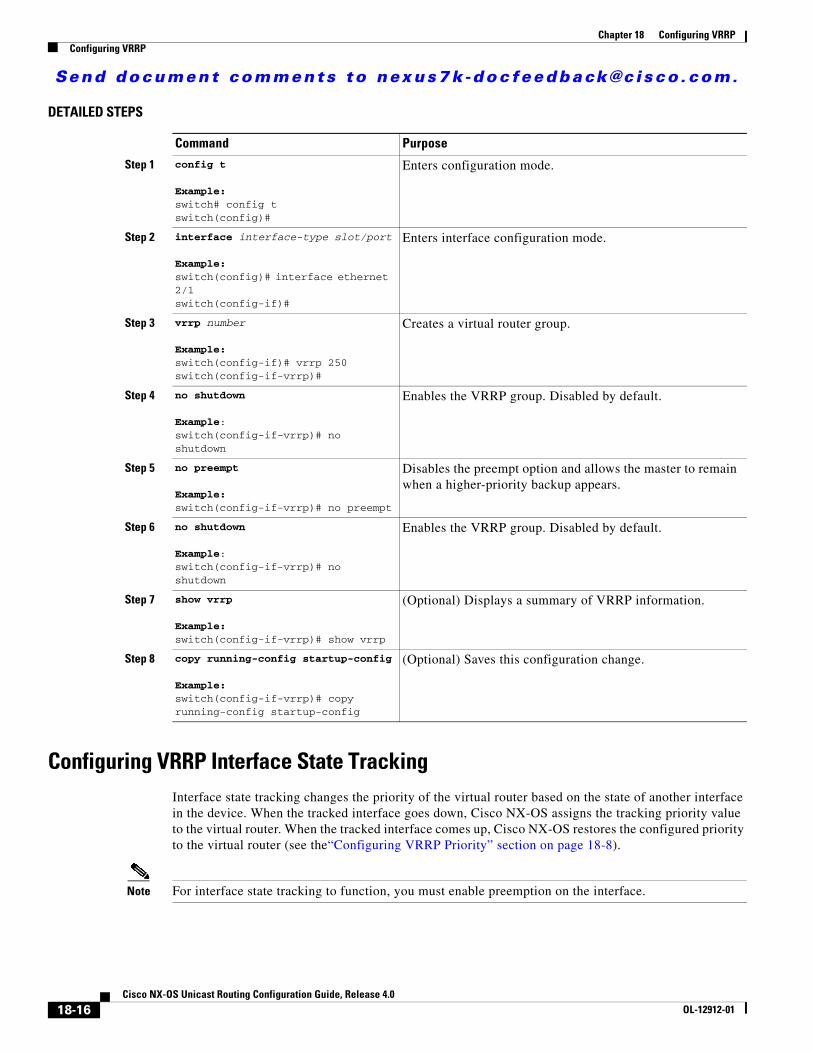
Send document comments to nexus7k -doc feedback@c i sco .com.
Chapter 18 Configuring VRRPConfiguring VRRP
DETAILED STEPS
Configuring VRRP Interface State TrackingInterface state tracking changes the priority of the virtual router based on the state of another interface in the device. When the tracked interface goes down, Cisco NX-OS assigns the tracking priority value to the virtual router. When the tracked interface comes up, Cisco NX-OS restores the configured priority to the virtual router (see the“Configuring VRRP Priority” section on page 18-8).
Note For interface state tracking to function, you must enable preemption on the interface.
Command Purpose
Step 1 config t
Example:switch# config tswitch(config)#
Enters configuration mode.
Step 2 interface interface-type slot/port
Example:switch(config)# interface ethernet 2/1switch(config-if)#
Enters interface configuration mode.
Step 3 vrrp number
Example:switch(config-if)# vrrp 250switch(config-if-vrrp)#
Creates a virtual router group.
Step 4 no shutdown
Example:switch(config-if-vrrp)# no shutdown
Enables the VRRP group. Disabled by default.
Step 5 no preempt
Example:switch(config-if-vrrp)# no preempt
Disables the preempt option and allows the master to remain when a higher-priority backup appears.
Step 6 no shutdown
Example:switch(config-if-vrrp)# no shutdown
Enables the VRRP group. Disabled by default.
Step 7 show vrrp
Example:switch(config-if-vrrp)# show vrrp
(Optional) Displays a summary of VRRP information.
Step 8 copy running-config startup-config
Example:switch(config-if-vrrp)# copy running-config startup-config
(Optional) Saves this configuration change.
18-16Cisco NX-OS Unicast Routing Configuration Guide, Release 4.0
OL-12912-01

Send document comments to nexus7k -doc feedback@c i sco .com.
Chapter 18 Configuring VRRPConfiguring VRRP
Note If you have enabled the VRRP group, you must disable it first, before making configuration changes. Enable the VRRP group after you complete your configuration changes.
BEFORE YOU BEGIN
Ensure that you have enabled the VRRP feature (see the “Configuring VRRP” section on page 18-6).
Ensure that you have configured an IP address on the interface (see the “Configuring IPv4 Addressing” section on page 2-7.
Ensure that you have enabled the virtual router (see the “Configuring VRRP Groups” section on page 18-7).
Ensure that you are in the correct VDC (or use the switchto vdc command).
SUMMARY STEPS
1. config t
2. interface interface-type slot/port
3. vrrp number
4. shutdown
5. track interface type number priority value
6. no shutdown
7. show vrrp
8. copy running-config startup-config
18-17Cisco NX-OS Unicast Routing Configuration Guide, Release 4.0
OL-12912-01

Send document comments to nexus7k -doc feedback@c i sco .com.
Chapter 18 Configuring VRRPVerifying the VRRP Configuration
DETAILED STEPS
Verifying the VRRP ConfigurationTo verify VRRP configuration information, use the following commands:
Command Purpose
Step 1 config t
Example:switch# config tswitch(config)#
Enters configuration mode.
Step 2 interface interface-type slot/port
Example:switch(config)# interface ethernet 2/1switch(config-if)#
Enters interface configuration mode.
Step 3 vrrp number
Example:switch(config-if)# vrrp 250switch(config-if-vrrp)#
Creates a virtual router group.
Step 4 shutdown
Example:switch(config-if-vrrp)# shutdownswitch(config-if-vrrp)#
Disables the VRRP group. Disabled by default.
Step 5 track interface type number priority value
Example:switch(config-if-vrrp)# track interface ethernet 2/10 priority 254
Enables interface priority tracking for a VRRP group. The priority range is from 1 to 254.
Step 6 no shutdown
Example:switch(config-if-vrrp)# no shutdownswitch(config-if-vrrp)#
Enables the VRRP group. Disabled by default.
Step 7 show vrrp
Example:switch(config-if-vrrp)# show vrrp
(Optional) Displays a summary of VRRP information.
Step 8 copy running-config startup-config
Example:switch(config-if-vrrp)# copy running-config startup-config
(Optional) Saves this configuration change.
Command Purpose
show vrrp Displays the VRRP status for all groups.
show vrrp vr group-number Displays the VRRP status for a VRRP group.
18-18Cisco NX-OS Unicast Routing Configuration Guide, Release 4.0
OL-12912-01

Send document comments to nexus7k -doc feedback@c i sco .com.
Chapter 18 Configuring VRRPDisplaying VRRP Statistics
Displaying VRRP StatisticsTo display VRRP statistics, use the following commands:
Use the clear vrrp statistics command to clear all the VRRP statistics for all interfaces in the device.
Use the clear vrrp vr command to clear the IPv4 VRRP statistics for a specified interface.
Use the clear vrrp ipv4 command to clear all the statistics for the specified IPv4 virtual router.
VRRP Example ConfigurationIn this example, Router A and Router B each belong to three VRRP groups. In the configuration, each group has the following properties:
• Group 1:
– Virtual IP address is 10.1.0.10.
– Router A will become the master for this group with priority 120.
– Advertising interval is 3 seconds.
– Preemption is enabled.
• Group 5:
– Router B will become the master for this group with priority 200.
– Advertising interval is 30 seconds.
– Preemption is enabled.
• Group 100:
– Router A will become the master for this group first because it has a higher IP address (10.1.0.2).
– Advertising interval is the default 1 second.
– Preemption is disabled.
Router Ainterface ethernet 1/0 ip address 10.1.0.2/16 no shutdown
show vrrp vr number interface interface-type port configuration
Displays the virtual router configuration for an interface.
show vrrp vr number interface interface-type port status
Displays the virtual router status for an interface.
Command Purpose
Command Purpose
show vrrp vr number interface interface-type port statistics
Displays the virtual router information.
show vrrp statistics Displays the VRRP statistics.
18-19Cisco NX-OS Unicast Routing Configuration Guide, Release 4.0
OL-12912-01

Send document comments to nexus7k -doc feedback@c i sco .com.
Chapter 18 Configuring VRRPDefault Settings
vrrp 1 priority 120 authentication text cisco advertisement-interval 3 address 10.1.0.10 no shutdownvrrp 5 priority 100 advertisement-interval 30 address 10.1.0.50 no shutdownvrrp 100 no preempt address 10.1.0.100 no shutdown
Router Binterface ethernet 1/0 ip address 10.2.0.1/2 no shutdown
vrrp 1 priority 100 authentication text cisco advertisement-interval 3 address 10.2.0.10 no shutdown
vrrp 5 priority 200 advertisement-interval 30 address 10.2.0.50 no shutdownvrrp 100 no preempt address 10.2.0.100 no shutdown
Default SettingsTable 18-1 lists the default settings for VRRP parameters.
Table 18-1 Default VRRP Parameters
Parameters Default
advertisement interval 1 seconds
authentication no authentication
preemption enabled
priority 100
VRRP feature disabled
18-20Cisco NX-OS Unicast Routing Configuration Guide, Release 4.0
OL-12912-01

Send document comments to nexus7k -doc feedback@c i sco .com.
Chapter 18 Configuring VRRPAdditional References
Additional ReferencesFor additional information related to implementing VRRP, see the following sections:
• Related Documents, page 18-21
Related Documents
Related Topic Document Title
Configuring the gateway load balancing protocol Chapter 16, “Configuring GLBP”
Configuring the hot standby routing protocol Chapter 17, “Configuring HSRP”
VRRP CLI commands Cisco NX-OS Unicast Routing Command Reference
Configuring high availability Cisco NX-OS HA Configuration Guide
18-21Cisco NX-OS Unicast Routing Configuration Guide, Release 4.0
OL-12912-01

Send document comments to nexus7k -doc feedback@c i sco .com.
Chapter 18 Configuring VRRPAdditional References
18-22Cisco NX-OS Unicast Routing Configuration Guide, Release 4.0
OL-12912-01

Send document comments to nexus7k -doc feedback@c i sco .com.
Cisco NX-OOL-12912-01
C H A P T E R 19
Configuring Object TrackingThis chapter describes how to configure object tracking on Cisco NX-OS devices.
This chapter includes the following sections:
• Information About Object Tracking, page 19-1
• Licensing Requirements for Object Tracking, page 19-2
• Prerequisites for Object Tracking, page 19-3
• Guidelines and Limitations, page 19-3
• Configuring Object Tracking, page 19-3
• Verifying Object Tracking Configuration, page 19-7
• Object Tracking Example Configuration, page 19-7
• Related Topics, page 19-7
• Default Settings, page 19-7
• Additional References, page 19-7
Information About Object TrackingObject tracking allows you to track specific objects on the network, such as the interface line protocol state, IP routing, and route reachability, and take action when the tracked object’s state changes. This feature allows you to increase the availability of the network and shorten recovery time if an object state goes down.
This section includes the following topics:
• Object Tracking Overview, page 19-1
• High Availability, page 19-2
• Virtualization Support, page 19-2
Object Tracking OverviewThe object tracking feature allows you to create a tracked object that multiple clients can use to modify the client behavior when a tracked object changes. Several clients register their interest with the tracking process, track the same object, and each take different actions when the object state changes.
Clients include the following features:
19-1S Unicast Routing Configuration Guide, Release 4.0
Send document comments to nexus7k -doc feedback@c i sco .com.
Chapter 19 Configuring Object TrackingLicensing Requirements for Object Tracking
• Hot Standby Redundancy Protocol (HSRP)
• Gateway Load Balancing Protocol (GLBP)
• Embedded Event Manager (EEM)
The object tracking monitors the status of the tracked objects and communicates any changes made to interested clients. Each tracked object is identified by a unique number that clients can use to configure the action to take when a tracked object changes state.
Cisco NX-OS tracks the following object types:
• Interface line protocol state—Tracks whether the line protocol state is up or down.
• Interface IP routing state—Tracks whether the interface has an IP address and IP routing is enabled and active.
• IP route reachability—Tracks whether the route exists and is reachable from the local device.
For example, you can configure HSRP to track the line protocol of the interface that connects one of the redundant routers to the rest of the network. If that link protocol goes down, you can modify the priority of the affected HSRP router and cause a switchover to a backup router that has better network connectivity
High AvailabilityObject tracking supports high availability through stateful restarts. A stateful restart occurs when the object tracking process crashes. Object tracking also supports stateful switchover on a dual supervisor system. Cisco NX-OS applies the runtime configuration after the switchover.
You can also use object tracking to modify the behavior of a client to improve overall network availability.
Virtualization SupportObject tracking supports Virtual Routing and Forwarding (VRF) instances. VRFs exist within virtual device contexts (VDCs). By default, Cisco NX-OS places you in the default VDC and default VRF unless you specifically configure another VDC and VRF. By default, Cisco NX-OS tracks the route reachability state of objects in the default VRF. If you want to track objects in another VRF, you must configure the object to be a member of that VRF (see “Configuring Object Tracking for a nonDefault VRF” section on page 19-5).
For more information, see the Cisco NX-OS Virtual Device Context Configuration Guide and see Chapter 13, “Configuring Layer 3 Virtualization.”
Licensing Requirements for Object TrackingThe following table shows the licensing requirements for this feature:
Product License Requirement
NX-OS Object tracking requires no license. Any feature not included in a license package is bundled with the Cisco NX-OS system images and is provided at no extra charge to you. For a complete explanation of the NX-OS licensing scheme, see the Cisco NX-OS Licensing Guide.
19-2Cisco NX-OS Unicast Routing Configuration Guide, Release 4.0
OL-12912-01

Send document comments to nexus7k -doc feedback@c i sco .com.
Chapter 19 Configuring Object TrackingPrerequisites for Object Tracking
Prerequisites for Object TrackingObject tracking has the following prerequisites:
• If you configure VDCs, install the Advanced Services license and enter the desired VDC (see the Cisco NX-OS Virtual Device Context Configuration Guide).
Guidelines and LimitationsObject tracking has the following guidelines and limitations:
• Supports up to 500 tracked objects per VDC.
• Supports IPv4 addresses only.
• Supports Ethernet, subinterfaces, port channels, loopback interfaces, and VLAN interfaces.
• Supports one tracked object per HSRP group or GLBP group.
Configuring Object TrackingThis section includes the following topics:
• Configuring Object Tracking for an Interface, page 19-3
• Configuring Object Tracking for Route Reachability, page 19-4
• Configuring Object Tracking for a nonDefault VRF, page 19-5
Note If you are familiar with the Cisco IOS CLI, be aware that the Cisco NX-OS commands for this feature might differ from the Cisco IOS commands that you would use.
Configuring Object Tracking for an InterfaceYou can configure Cisco NX-OS to track the line protocol or IP routing state of an interface.
BEFORE YOU BEGIN
Ensure that you are in the correct VDC (or use the switchto vdc command).
SUMMARY STEPS
1. config t
2. track object-id interface interface-type number {ip routing | line-protocol}
3. show track [object-id]
4. copy running-config startup-config
19-3Cisco NX-OS Unicast Routing Configuration Guide, Release 4.0
OL-12912-01

Send document comments to nexus7k -doc feedback@c i sco .com.
Chapter 19 Configuring Object TrackingConfiguring Object Tracking
DETAILED STEPS
This example shows how to configure object tracking for the line protocol state on Ethernet 1/2:
switch# config tswitch(config)# track 1 interface ethernet 1/2 line-protocolswitch(config-track)# copy running-config startup-config
Configuring Object Tracking for Route ReachabilityYou can configure Cisco NX-OS to track the existence and reachability of an IP route.
BEFORE YOU BEGIN
Ensure that you are in the correct VDC (or use the switchto vdc command).
SUMMARY STEPS
1. config t
2. track object-id ip route ip-prefix/length reachability
3. show track [object-id]
4. copy running-config startup-config
Command Purpose
Step 1 config t
Example:switch# config tswitch(config)#
Enters configuration mode.
Step 2 track object-id interface interface-type number {ip routing | line-protocol}
Example:switch(config)# track 1 interface ethernet 1/2 line-protocolswitch(config-track#
Creates a tracked object for an interface and enters tracking configuration mode. The object-id range is from 1 to 500.
Step 3 show track [object-id]
Example:switch(config-track)# show track 1
(Optional) Displays object tracking information.
Step 4 copy running-config startup-config
Example:switch(config-track)# copy running-config startup-config
(Optional) Saves this configuration change.
19-4Cisco NX-OS Unicast Routing Configuration Guide, Release 4.0
OL-12912-01

Send document comments to nexus7k -doc feedback@c i sco .com.
Chapter 19 Configuring Object TrackingConfiguring Object Tracking
DETAILED STEPS
This example shows how to configure object tracking for a route in the default VRF.
switch# config tswitch(config)# track 2 ip route 192.0.2.0/8 reachabilityswitch(config-track)# copy running-config startup-config
Configuring Object Tracking for a nonDefault VRFYou can configure Cisco NX-OS to track an object in a specific VRF.
BEFORE YOU BEGIN
Ensure that you are in the correct VDC (or use the switchto vdc command).
SUMMARY STEPS
1. config t
2. track object-id ip route ip-prefix/length reachability
3. vrf member vrf-name
4. show track [object-id]
5. copy running-config startup-config
Command Purpose
Step 1 config t
Example:switch# config tswitch(config)#
Enters configuration mode.
Step 2 track object-id ip route ip-prefix/length reachability
Example:switch(config)# track 2 ip route 192.0.2.0/8 reachabilityswitch(config-track)#
Creates a tracked object for a route and enters tracking configuration mode. The object-id range is from 1 to 500.
Step 3 show track [object-id]
Example:switch(config-track)# show track 1
(Optional) Displays object tracking information.
Step 4 copy running-config startup-config
Example:switch(config-track)# copy running-config startup-config
(Optional) Saves this configuration change.
19-5Cisco NX-OS Unicast Routing Configuration Guide, Release 4.0
OL-12912-01

Send document comments to nexus7k -doc feedback@c i sco .com.
Chapter 19 Configuring Object TrackingConfiguring Object Tracking
DETAILED STEPS
This example shows how to configure object tracking for a route and use VRF Red to look up reachability information for this object:
switch# config tswitch(config)# track 2 ip route 209.165.201.0/8 reachabilityswitch(config-track)# vrf member Redswitch(config-track)# copy running-config startup-config
This example shows how to modify tracked object 2 to use VRF Blue instead of VRF RED to look up reachability information for this object:
switch# config tswitch(config)# track 2switch(config-track)# vrf member Blueswitch(config-track)# copy running-config startup-config
Command Purpose
Step 1 config t
Example:switch# config tswitch(config)#
Enters configuration mode.
Step 2 track object-id ip route ip-prefix/length reachability
Example:switch(config)# track 3 ip route 209.165.201.0/8 reachabilityswitch(config-track)#
Creates a tracked object for a route and enters tracking configuration mode. The object-id range is from 1 to 500.
Step 3 vrf member vrf-name
Example:switch(config-track)# vrf member Red
Configures the VRF to use for tracking the configured object.
Step 4 show track [object-id]
Example:switch(config-track)# show track 3
(Optional) Displays object tracking information.
Step 5 copy running-config startup-config
Example:switch(config-track)# copy running-config startup-config
(Optional) Saves this configuration change.
19-6Cisco NX-OS Unicast Routing Configuration Guide, Release 4.0
OL-12912-01

Send document comments to nexus7k -doc feedback@c i sco .com.
Chapter 19 Configuring Object TrackingVerifying Object Tracking Configuration
Verifying Object Tracking ConfigurationTo verify object tracking configuration information, use the following commands:
Object Tracking Example Configuration This example shows how to configure object tracking for route reachability and use VRF Red to look up reachability information for this route:
switch# config tswitch(config)# track 2 ip route 209.165.201.0/8 reachabilityswitch(config-track)# vrf member Redswitch(config-track)# copy running-config startup-config
Related TopicsSee the following topics for information related to object tracking:
• Configuring GLBP, page 16-1
• Configuring HSRP, page 17-1
• Configuring Layer 3 Virtualization, page 13-1
Default SettingsTable 19-1 lists the default settings for object tracking parameters.
Additional ReferencesFor additional information related to implementing object tracking, see the following sections:
• Related Documents, page 19-8
Command Purpose
show track [object-id] [brief] Displays the object tracking information for one or more objects.
show track [object-id] interface [brief] Displays the interface-based object tracking information.
show track [object-id] ip route [brief] Displays the IP route-based object tracking information.
Table 19-1 Default Object Tracking Parameters
Parameters Default
Tracked Object VRF member of default VRF
19-7Cisco NX-OS Unicast Routing Configuration Guide, Release 4.0
OL-12912-01
Send document comments to nexus7k -doc feedback@c i sco .com.
Chapter 19 Configuring Object TrackingAdditional References
• Standards, page 19-8
Related Documents
Standards
Related Topic Document Title
Object Tracking CLI commands Cisco NX-OS Unicast Routing Command Reference
Configuring the Embedded Event Manager Cisco NX-OS System Management Configuration Guide
Standards Title
No new or modified standards are supported by this feature, and support for existing standards has not been modified by this feature.
—
19-8Cisco NX-OS Unicast Routing Configuration Guide, Release 4.0
OL-12912-01

Send document comments to nexus7k -doc feedback@c i sco .com.
Cisco NX-OS UnicOL-12912-01
A
P P E N D I X A IETF RFCs supported by Cisco NX-OS Unicast Features, Release 4.xThis appendix lists the IETF RFCs supported in Cisco NX-OS Release 4.x.
BGP RFCs
RFCs Title
RFC 1997 BGP Communities Attribute
RFC 2385 Protection of BGP Sessions via the TCP MD5 Signature Option
RFC 2439 BGP Route Flap Damping
RFC 2519 A Framework for Inter-Domain Route Aggregation
RFC 2545 Use of BGP-4 Multiprotocol Extensions for IPv6 Inter-Domain Routing
RFC 2858 Multiprotocol Extensions for BGP-4
RFC 3065 Autonomous System Confederations for BGP
RFC 3392 Capabilities Advertisement with BGP-4
RFC 4271 A Border Gateway Protocol 4 (BGP-4)
RFC 4273 Definitions of Managed Objects for BGP-4
RFC 4456 BGP Route Reflection: An Alternative to Full Mesh Internal BGP (IBGP)
RFC 4486 Subcodes for BGP Cease Notification Message
RFC 4724 Graceful Restart Mechanism for BGP
RFC 4893 BGP Support for Four-octet AS Number Space
draft-ietf-idr-avoid-transition-05.txt Avoid BGP Best Path Transitions from One External to Another
draft-ietf-idr-bgp4-mib-15.txt BGP4-MIB
draft-kato-bgp-ipv6-link-local-00.txt BGP4+ Peering Using IPv6 Link-local Address
A-1ast Routing Configuration Guide, Release 4.0

Send document comments to nexus7k -doc feedback@c i sco .com.
Appendix A IETF RFCs supported by Cisco NX-OS Unicast Features, Release 4.x
First-Hop Redundancy ProtocolsRFCs
IP Services RFCs
IPv6 RFCs
RFCs Title
RFC 2281 Hot Standby Redundancy Protocol
RFC 3768 Virtual Router Redundancy Protocol
RFCs Title
RFC 786 UDP
RFC 791 IP
RFC 792 ICMP
RFC 793 TCP
RFC 826 ARP
RFC 1027 Proxy ARP
RFC 1591 DNS Client
RFC 1812 IPv4 routers
RFCs Title
RFC 1981 Path MTU Discovery for IP version 6
RFC 2373 IP Version 6 Addressing Architecture
RFC 2374 An Aggregatable Global Unicast Address Format
RFC 2460 Internet Protocol, Version 6 (IPv6) Specification
RFC 2461 Neighbor Discovery for IP Version 6 (IPv6)
RFC 2462 IPv6 Stateless Address Autoconfiguration
RFC 2463 Internet Control Message Protocol (ICMPv6) for the Internet Protocol Version 6 (IPv6) Specification
RFC 2464 Transmission of IPv6 Packets over Ethernet Networks
RFC 2467 Transmission of IPv6 Packets over FDDI Networks
RFC 2472 IP Version 6 over PPP
RFC 2492 IPv6 over ATM Networks
RFC 2590 Transmission of IPv6 Packets over Frame Relay Networks Specification
RFC 3152 Delegation of IP6.ARPA
RFC 3162 RADIUS and IPv6
RFC 3513 Internet Protocol Version 6 (IPv6) Addressing Architecture
A-2Cisco NX-OS Unicast Routing Configuration Guide, Release 4.0
OL-12912-01

Send document comments to nexus7k -doc feedback@c i sco .com.
Appendix A IETF RFCs supported by Cisco NX-OS Unicast Features, Release 4.x
IS-IS RFCs
OSPF RFCs
RIP RFCs
RFC 3596 DNS Extensions to Support IP version 6
RFC 4193 Unique Local IPv6 Unicast Addresses
RFCs Title
RFC 1142 OSI 10589 Intermediate system to intermediate system intra-domain routing exchange protocol
RFC 1195 Use of OSI IS-IS for routng in TCP/IP and dual environment
RFC 2763 Dynamic Hostname Exchange Mechanism for IS-IS
RFC 2966 Domain-wide Prefix Distribution with Two-Level IS-IS
RFC 2972 IS-IS Mesh Groups
RFC 3273 Three-Way Handshake for IS-IS Point-to-Point Adjacencies
RFC 3277 IS-IS Transient Blackhole Avoidance
RFC 3567 IS-IS Cryptographic Authentication
RFC 3847 Restart Signaling for IS-IS
draft-ietf-isis-igp-p2p-over-lan-06.txt Internet Draft Point-to-point operation over LAN in link-state routing protocols
RFCs Title
RFC 2328 OSPF Version 2
RFC 2740 OSPF for IPv6
RFC 3623 Graceful OSPF Restart
RFC 3101 The OSPF Not-So-Stubby Area (NSSA) Option
RFC 2370 The OSPF Opaque LSA Option
RFC 3137 OSPF Stub Router Advertisement
draft-ietf-ospf-ospfv3-graceful-restart-04.txt OSPFv3 Graceful Restart
RFCs Title
RFC 2453 RIP Version 2
RFC 2080 RIPng for IPv6
RFC 2082 RIP-2 MD5 Authentication
RFCs Title
A-3Cisco NX-OS Unicast Routing Configuration Guide, Release 4.0
OL-12912-01

Send document comments to nexus7k -doc feedback@c i sco .com.
Appendix A IETF RFCs supported by Cisco NX-OS Unicast Features, Release 4.x
A-4Cisco NX-OS Unicast Routing Configuration Guide, Release 4.0
OL-12912-01

Send document comments to nexus7k -doc feedback@c i sco .com.
Cisco NX-OOL-12912-01
G L O S S A R Y
v
A
ABR See area border router.
address family A specific type of network addressing supported by a routing protocol. Examples include IPv4 unicast and IPv4 multicast.
adjacency Two OSPF routers that have compatible configurations and have synchronized their link-state databases.
administrative
distance
A rating of the trustworthiness of a routing information source. In general, the higher the value, the lower the trust rating.
area A logical division of routers and links within an OSPF domain that creates separate subdomains. LSA flooding is contained within an area.
area border router A router that connects one OSPF area to another OSPF area.
ARP Address resolution protocol. ARP discovers the MAC address for a known IPv4 address.
AS See autonomous system.
ASBR See autonomous system border router.
attributes Properties of a route that are sent in BGP UPDATE messages. These attributes include the path to the advertised destination as well as configurable options that modify the best path selection process.
autonomous
system
A network controlled by a single technical administration entity.
autonomous
system border
router
A router that connecta an OSPF autonomous system to an external autonomous system.
AVF Active virtual forwarder. A gateway within a GLBP group elected to forward traffic for a specified virtual MAC address.
AVG Active virtual gateway. One virtual gateway within a GLBP group is elected as the active virtual gateway and is responsible for the operation of the protocol.
B
backup designated
router
See BDR.
GL-1S Unicast Routing Configuration Guide, Release 4.0

Send document comments to nexus7k -doc feedback@c i sco .com.
Glossary
bandwidth The available traffic capacity of a link.
BDR Backup designated router. An elected router in a multi-access OSPF network that acts as the backup if the designated router fails. All neighbors form adjacencies with the backup designated router (BDR) as well as the designated router.
BGP Border Gateway Protocol. BGP is an interdomain or exterior gateway protocol.
BGP peer A remote BGP speaker that is an established neighbor of the local BGP speaker.
BGP speaker BGP-enabled router.
C
communication cost Measure of the operating cost to route over a link.
converged The point at which all routers in a network have identical routing information.
convergence See converged.
D
dead interval The time within which an OSPF router must receive a Hello packet from an OSPF neighbor. The dead interval is usually a multiple of the hello interval. If no Hello packet is received, the neighbor adjacency is removed.
default gateway A router to which all unroutable packets are sent. Also called the router of last resort.
delay The length of time required to move a packet from the source to the destination through the internetwork.
designated router See DR.
DHCP Dynamic Host Control Protocol.
Diffusing Update
Algorithm
See DUAL.
distance vector Defines routes by distance (for example, the number of hops to the destination) and direction (for example, the next-hop router) and then broadcasts to the directly connected neighbor routers.
DNS client Domain Name System client. Communicates with DNS server to translate a host name to an IP address.
DR Designated router. An elected router in a multi-access OSPF network that sends LSAs on behalf of all its adjacent neighbors. All neighbors establish adjacency with only the designated router and the backup designated router.
DUAL Diffusing Update Algorithm. EIGRP algorithm used to select optimal routes to a destination.
GL-2Cisco NX-OS Unicast Routing Configuration Guide, Release 4.0
OL-12912-01

Send document comments to nexus7k -doc feedback@c i sco .com.
Glossary
h
E
eBGP External Border Gateway Protocol (BGP). Operates between external systems.
EIGRP Enhanced Interior Gateway Protocol. A Cisco routing protocol that uses the Diffusing Update Algorithm to provide fast convergence and minimized bandwidth utilization.
F
feasible distance The lowest calculated distance to a network destination in EIGRP. The feasibility distance is the sum of the advertised distance from a neighbor plus the cost of the link to that neighbor.
feasible successor Neighbors in EIGRP that advertise a shorter distance to the destination than the current feasibility distance.
FIB Fowarding Information Base. The forwarding table on each module that is used to make the Layer 3 forwarding decisions per packet.
G
gateway A switch or router that forwards layer 3 traffic from a LAN to the rest of the network.
GLBP Gateway Load Balancing Protocol. A Cisco proprietary protocol that provides high availability features to end hosts.
graceful restart A feature that allows a router to remain in the data forwarding path while a routing protocol reboots.
H
hello interval The configurable time between each Hello packet sent by an OSPF or EIGRP router.
hello packet A special message used by OSPF or IS-IS to discover neighbors. Also acts as a keep alive messages between established neighbors.
high availability The ability of a system or component to limit or avoid network disruption when a component fails.
hold time In BGP - Maximum time limit allowed in BGP between UPDATE or KEEPALIVE messages. If this time is exceeded, the TCP connection between the BGP peers is closed.
In EIGRP, the maximum time allowed between EIGRP Hello messages. If this time is exceeded, the neighbor is declared unreachable.
hop count The number of routers that can be traversed in a route. Used by RIP.
HSRP
GL-3Cisco NX-OS Unicast Routing Configuration Guide, Release 4.0
OL-12912-01

Send document comments to nexus7k -doc feedback@c i sco .com.
Glossary
I
iBGP Internal Border Gateway Protocol (BGP). Operates within an autonomous system.
ICMP
IETF RFCs Internet Engineering Task Force Request for Comments.
IGP Interior gateway protocol. Used between routers within the same autonomous system.
instance An independent, configurable entity, typically a protocol.
IP tunnels
IPv4 Internet Protocol version 4.
IPv6 Internet Protocol version 6.
IS-IS Intermediate System to Intermediate System. An ISO interior gateway protocol.
K
keepalive A special message sent between routing peers to verify and maintain communications between the pair.
key-chain
management
A method of controling authentication keys. See the Cisco NX-OS Security Configuration Guide.
L
link cost An abitrary number configured on an OSPF interface which is in shortest path first calculations.
link-state Shares information about a link, link cost to neighboring routers.
link-state
advertisement
See LSA.
LSA Link-state advertisement. An OSPF message to share information on the operational state of a link, link cost, and other OSPF neighbor information.
link-state database OSPF database of all LSAs received. OSPF uses this database to calculate the best path to each destination in the network.
link-state refresh The time that OSPF floods the network with LSAs to ensure all OSPF routers have the same information.
load The degree to which a network resource, such as a router, is busy.
load balancing The distribution of network traffic across multiple paths to a given destination.
GL-4Cisco NX-OS Unicast Routing Configuration Guide, Release 4.0
OL-12912-01

Send document comments to nexus7k -doc feedback@c i sco .com.
Glossary
M
message digest A one-way hash applied to a message using a shared password and appended to the message to authenticate the message and ensure the message has not been altered in transit.
metric A standard of measurement, such as the path bandwidth, that is used by routing algorithms to determine the optimal path to a destination.
MD5 authentication
digest
A cryptographic construction that is calculated based on an authentication key and the original message and sent along with the message to the destination. Allows the destination to determine the authenticity of the sender and guarantees that the message has not been tampered with during transmission.
MTU Maximum transmission unit. The largest packet size that a network link will transmit without fragmentation.
N
NDP Neighbor Discovery Protocol. The procotol used by IPv6 to find the MAC address associated with an IPv6 address.
network layer
reachability
information
BGP network layer reachability information (NRLI). Contains the a list of network IP addresses and network masks for networks that are reachable from the advertising BGP peer.
next hop The next router that a packet is sent to on its way to the destination address.
NSSA Not-So-Stubby-Area. Limits AS external LSAs in an OSPF area.
O
OSPF Open Shortest Path First. An IETF link-state protocol. OSPFv2 supports IPv4 and OSPFv3 supports IPv6.
P
path length Sum of all link costs or the hop count that a packet experiences when routed from the source to the destination.
policy-based
routing
The method of using route maps to alter the route selected for a packet.
GL-5Cisco NX-OS Unicast Routing Configuration Guide, Release 4.0
OL-12912-01

Send document comments to nexus7k -doc feedback@c i sco .com.
Glossary
R
redistribution One routing protocol accepts route information from another routing protocol and advertises it in the local autonomous system.
Reliable Transport
Protocol
Responsible for guaranteed, ordered delivery of EIGRP packets to all neighbors.
reliability The dependability (usually described in terms of the bit-error rate) of each network link.
RIB Routing Information Base. Maintains the routing table with directly connected routes, static routes, and routes learned from dynamic unicast routing protocols.
Route Polciy
Manager
The process that controls route maps and policy-based routing.
routing information
base
See RIB.
route map A construct used to map a route or packet based on match criteria and optionally alter the route or packet based on set criteria. Used in route redistribution and policy-based routing.
route
summarization
A process that replaces a series of related, specific routes in a route table with a more generic route.
router ID A unique identifier used by routing protocols. If not manually configured, the routing protocol selects the highest IP address configured on the system.
S
SPF algorithm Shortest Path First algorithm. Dijkstra’s algorithm used by OSPF to determine the shortest route through a network to a particular destination.
split horizon Routes learned from an interface are not advertised back along the interface they were learned on, preventing the router from seeing its own route updates.
split horizon with
poison reverse
Routes learned from an interface are set as unreachable and advertised back along the interface they were learned on, preventing the router from seeing its own route updates.
static route A manually configured route.
stub area An OSPF area that does not allow AS External (type 5) LSAs.
stub router A router that has no direct connection to the main network and which routes to that network using a known remote router.
SVI Switched Virtual Interface. .
GL-6Cisco NX-OS Unicast Routing Configuration Guide, Release 4.0
OL-12912-01

Send document comments to nexus7k -doc feedback@c i sco .com.
Glossary
U
U6FIB Unicast IPv6 forwarding information base.
UFIB Unicast IPv4 forwarding information base.
U6RIB Unicast IPv6 routing information base. The unicast routing table that gathers information from all routing protocols and updates the forwarding information base for each module.
URIB Unicast IPv4 routinginformation base. The unicast routing table that gathers information from all routing protocols and updates the forwarding information base for each module.
V
VDC Virtual Device Context. Used to split a physical system into secure, independent, logical systems.
virtualization A method of making a physical entity act as multiple, independent logical entities.
VRF Virtual Routing and Forwarding. A method used to create separate, independent Layer 3 entities within a system.
VRRP Virtual Router Redundancy Protocol.
GL-7Cisco NX-OS Unicast Routing Configuration Guide, Release 4.0
OL-12912-01

Send document comments to nexus7k -doc feedback@c i sco .com.
Glossary
GL-8Cisco NX-OS Unicast Routing Configuration Guide, Release 4.0
OL-12912-01

Send document comments to nexus7k -doc feedback@c i sco .com.
Cisco NX-OS UnicOL-12912-01
A
P P E N D I X 2 Configuration Limits for Cisco NX-OS Layer 3 Unicast Features, Release 4.xThe features supported by Cisco DC-OS have maximum configuration limits. For some of the features, we have verified configurations that support limits less that the maximum. Table 2-1 lists the Cisco verified limits and maximum limits for switches running Cisco DC-OS Release 4.x.
Table 2-1 Cisco NX-OS Release 4.x Configuration Limits
Feature Verified Limit Maximum Limit
BGP 300 peers
150,000 prefixes per peer
20 million paths total
GLBP 1024 GLBP groups.
HSRP 2048 HSRP groups.
20 HSRP groups per interface.
OSPF 200 interfaces
1000 routers
300 adjacencies
200,000 LSAs
2-1ast Routing Configuration Guide, Release 4.0

Send document comments to nexus7k -doc feedback@c i sco .com.
Appendix 2 Configuration Limits for Cisco NX-OS Layer 3 Unicast Features, Release 4.x
2-2Cisco NX-OS Unicast Routing Configuration Guide, Release 4.0
OL-12912-01