cisco support community expert series webcast · 10/10/2011 · epg b epg contract 02 c the policy...
TRANSCRIPT

Vishal Mehta
Technical Marketing Engineer
February 24, 2015
Cisco Nexus 1000v Series Switches, Part 3: Game Changer: Silver Lining in the Cloud
Cisco Support Community
Deep Dive Expert Series Webcast

Upcoming Expert Series Webcast
March 17th, 2015
Ever wonder what VFC, VETH, VIF and HIF are in UCS and which path your packets are taking? UCS infrastructure has several virtual components and this makes it challenging to troubleshoot but it is critical to understand. Cisco Expert, Niles Pyelshak will discuss UCS interfaces and how packets travels from the UCS server.
Demystifying Unified Computing System (UCS)
Interfaces for troubleshooting.
https://supportforums.cisco.com/event/12413926/expert-webcast-demystifying-unified-computing-system-ucs-interfaces-troubleshooting

Now through March 13th
Ask the Expert Events – Active
Join the discussion for these Ask The Expert Events:
https://supportforums.cisco.com/expert-corner/knowledge-sharing
Cisco ServiceGrid — Service Integration in the
Cloud, with experts Alexander Kalaschek and
Patrick Schneider-Sturm
Cisco Email Security Appliance (ESA), Web
Security Appliance (WSA), and Content
Security Management Appliance (SMA).
Join Cisco Expert, Nasir Abbas

Rate Content Now your ratings on documents, videos, and blogs count give points to the authors!!!
So, when you contribute and receive ratings you now get the points in your profile.
Help us to recognize the quality content in the community and make your searches easier. Rate content in the community.
https://supportforums.cisco.com/blog/154746
Encourage and acknowledge people who generously share
their time and expertise
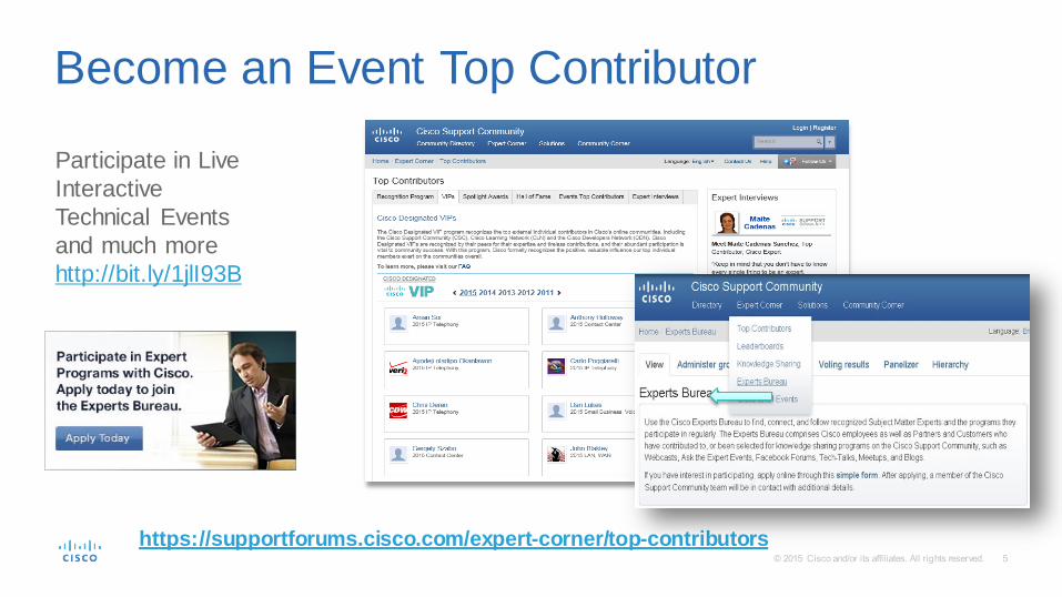
https://supportforums.cisco.com/expert-corner/top-contributors
Participate in Live
Interactive
Technical Events
and much more
http://bit.ly/1jlI93B
Become an Event Top Contributor

Cisco Support Community Expert Series Webcast
• Today’s featured expert is Cisco Technical Marketing Engineer Vishal Mehta
• Ask your questions now in the Q&A window
Vishal Mehta
Technical Marketing Engineer
February 24, 2015
Cisco Nexus 1000v Series Switches,
Part 3: Game Changer: Silver Lining
in the Cloud

Topic: Part 3: Game Changer: Silver Lining in the Cloud
Technical Expert – Question Manager
Gunjan Patel
If you would like a copy of the presentation slides, click the PDF file link in the chat box on the right or go to:
https://supportforums.cisco.com/document/12433991/expert-depth-series-cisco-nexus-1000v-series-switches-part-3-slides
Or, https://supportforums.cisco.com/expert-corner/knowledge-sharing
Thank You For Joining Us Today!

Now through March 4th
Ask the Expert Event following the Webcast
Join the discussion for these Ask The Expert Events:
https://supportforums.cisco.com/expert-corner/knowledge-sharing
Vishal will be continuing the discussion in an Ask
the Expert event. So if you have more questions,
please visit the Knowledge Center on the Cisco
Support Community
https://supportforums.cisco.com/discussion
/12412941/ask-expert-deepdive-cisco-nexus-
1000v-series-switches

Submit Your Questions Now! Use the Q & A panel to submit your questions
and the panel of experts will respond.
Please take a moment to
complete the survey at
the end of the webcast

Vishal Mehta
Technical Marketing Engineer
February 24, 2015
Cisco Support Community Deep Dive Expert Series Webcast
Cisco Nexus 1000V Series Switches Part 3: Game Changer: Silver Lining in the Cloud
Polling Question 1
Can Nexus 1000v be used for Cloud Computing ?
a. Yes
b. No

• Application Virtual Switch for ACI
• InterCloud Fabric (ICF)
Agenda

14 14
1000v L2-7 Services

Overloaded Network Constructs
VLAN VLAN VLAN
Subnet Subnet Subnet
Basic Network Policy
SLAs L4-7 Services
Network constructs are overloaded with unintended functionality.

Application Language Barriers
Developers
Application Tiers
Provider / Consumer
Relationships
Infrastructure Teams
VLANs
Subnets
Protocols
Ports
Developer and infrastructure teams must translate between disparate languages.

It is More than just a VM or Server
It is collection of all the Application’s End Points
‘plus’
The Application’s L2 – L7 Network Policies
‘plus’
The Relationship between these End Points and their Policies
External
Network
App Tier
End Points
DB Tier
End Points
Web Tier
End Points QoS
Service
Filter
QoS
Service
Filter
QoS
Service
Filter
What is an Application to the Network?
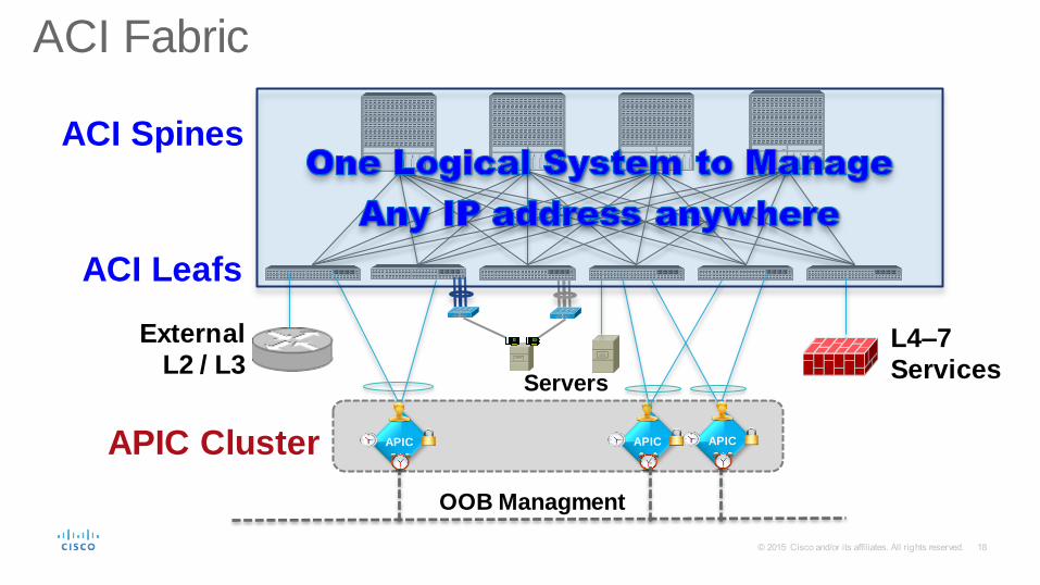
External
L2 / L3
ACI Fabric
APIC
L4–7
Services Servers
OOB Managment
APIC APIC
ACI Spines
ACI Leafs
APIC Cluster

APPLICATION
SECURITY
Web
Tier
App
Tier
DB
Tier
Trusted
Zone DB
Tier
DMZ
External
Zone
Cloud
Application Admin
Security Admin
Network Admin
Cloud Admin
Goal: Common Policy & Operations Framework
19

Application Admin
Security Admin
Network Admin
SECURITY
Trusted
Zone DB
Tier
DMZ
External Zone
APPLICATION
COMMON POOL OF RESOURCES
Cloud Admin
Cloud
Goal: Common Policy & Operations Framework
20

ACI policy model brings the concept of End-Point Group (EPG)
HTTPS Service
HTTPS Service
HTTPS Service
HTTPS Service
HTTP Service
HTTP Service
HTTP Service
HTTP Service
EPG - Web
EPGs are a grouping of end-points representing application or
application components independent of other network constructs.
POLICY MODEL
21

End-Points end EPG membership
Device connected to network directly or indirectly
Has address (identity), location, attributes (version, patch level)
Can be physical or virtual
• End Point Group (EPG) membership defined by:
• Ingress physical port (leaf or FEX)
• Ingress logical port (VM port group)
• VLAN ID
• VXLAN (VNID)
• IP address
• IP Prefix/Subnet
• NVGRE (VSID)
• DNS name
• Layer 4 ports
Server
VM
Virtual Machine
Storage
Client
22

Ex.: EPGs, Subnets and Policy
EPGs separate the addressing of an application
from it’s mapping and policy enforcement on the network.
10.10.10.x
10.10.11.x Policy/Security
enforcement occurs at the EPG level
HTTPS Service
HTTPS Service
HTTPS Service
HTTPS Service
HTTP Service
HTTP Service
HTTP Service
HTTP Service
EPG Web
23

EPG 100 EPG 200
App 1 App 2
10.10.40/24
10.10.30/24
10.10.20/24
10.10.10/24
VLAN 400
10.10.40/24
VLAN 300
10.10.30/24
VLAN 200
10.10.20/24
VLAN 100
10.10.10/24
Apps Coupled
to Location
ACL-based Policy Per
Interface
Visibility At Network or
VLAN Level
No Address Independence
or Policy Mobility
Apps Decoupled
from Location
Visibility At App or Group
Level
Policy Between Groups
Complete Address
Independence & Policy
Mobility
Traditional Network Model Application Centric Infrastructure
EPG 100
EPG 200
EPG 300
EPG 400
EPGs @ ACI bring true network abstraction
2
4

Applying Policy between EPGs: ACI contracts
EPG A
EPG B
EPG C Contract 02
The policy model allows for both unidirectional and bidirectional policies.
Contracts define the way in which EPGs interact.
Unidirectional
Communication
Bidirectional
Communication Contract 01
Ex: ACI Logical Model applied to the “3-Tier App” ANP
25

Building ACI Contracts
Subjects are a combination of A filter, an action and a label
Contracts define communication
between source and destination EPGs
Contracts are groups of subjects which define communication between EPGs.
Filter | Action | Label Subject
TCP Port 80
Filter
Permit
Action
Web Access
Label
Contract 1
Subject 1
Subject 2
Subject 3
26

Policy Options: Actions
Permit Deny
Redirect Log
… …
Copy Packet Mark Packet DSCP
There are six policy options supported: Permit the traffic Block the traffic Redirect the traffic Log the traffic Copy the traffic Mark the traffic (DSCP/CoS)
Policy encompasses traffic handling, quality of service, security monitoring and logging.
27

ACI Logical Model
Context
Application A
EPG EPG EPG
Application B
EPG EPG EPG
Application C
EPG EPG EPG
Context
Application Network Profile A
EPG EPG EPG
Application Network Profile B
EPG EPG EPG
Application Network Profile C
EPG EPG EPG
Application Network Profile (ANP) - B
Policy Policy
EPG EPG EPG
Tenant
28

Ex.: Contract Model
Application Network Profile C Contract Contracts define what an EPG
exposes to other app tiers and how
Contracts are reusable for multiple EPGs and
EPGs can inherit multiple contracts
The use of contracts separates ‘what’ a policy is from ‘where’ it exists, extending its use.
C
C
EPG NFS
EPG MGMT
EPG DB EPG App EPG Web C C C
29

• Tenant – A logical construct within the APIC to configure tenant policies, profiles and network configuration.
• Application Profile – A profile used to classify an application or traffic type and define network and policy configuration
• EPG – End point groups used to classify what traffic belongs to a particular application profile, and what contracts (similar to ACLs) are defined for a particular traffic type
• VMM Domain – Associated to a vCenter and a DVS on ESX Hosts. Each vCenter will be apart of a separate VMM domain
ACI Concepts

• APIC cluster is the distributed controller for managing all the policies and running state for ACI fabric and for interfacing with VM controllers
and L4-L7 services boxes
• It is a highly redundant cluster of linux based servers connected to Leaf switches on infra network
• It is not in the control plane or datapath
• Application networking needs are expressed in APIC as application-level policies through REST interface.
• The policies are automatically pushed and applied to the network infrastructure via embedded policy elements
APIC Cluster APIC APIC APIC
What is APIC
PE
PE
PE PE PE
PE PE PE PE PE
INBAND
Admin
OOB REST

ADC APP DB F/W
ADC WEB
HYPERVISO R HYPERVISO R HYPERVISO R
CONNECTIVIT
Y POLICY
SECURITY
POLICIES QOS
STORAGE
AND
COMPUTE
APPLICATION
L4..7
SERVICES
SLA
QoS
Security
Load Balancing
APP PROFILE
Application Network Profiles (ANP) & ACI: how it works ?
3
2

vSwitch (VMWare) vSwitch (MSFT)
Payload IP
Packet Sourced from VM attached to
Ingress Port Group or directly from
physical server
1
Payload IP VXLAN VTEP
vSwitch encapsulates frame and
forwards to Leaf VTEP
2
If Leaf has learned the Inner IP to egress
VTEP binding it will set required VTEP
address and forward directly to egress Leaf
4a
Payload IP VXLAN VTEP
Leaf swaps ingress
encapsulation with VXLAN and
performs any required policy
functions
3
Payload IP VXLAN VTEP
Egress Leaf will swap outer VXLAN
with correct egress encapsulation
and perform any required policy
5
Payload IP NVGRE GRE IP
Leaf forwards frame to vSwitch or
directly to physical server
6
Payload IP
Packet transmitted on vSwitch port
7
Payload IP VXLAN VTEP If ingress iLeaf does not contain cache entry for IP to egress VTEP binding set VTEP address
as anycast VTEP which will perform inline HW lookup and perform egress VTEP rewrite. No
additional latency nor any decrease in throughput due to lookup
4b
VTEP VTEP
VTEP
Overview of ACI Fabric Unicast Forwarding

OpFlex – A Flexible, Extensible Policy Protocol
OPFLEX is a new extensible policy resolution protocol designed for declarative management of any datacenter infrastructure. Unlike legacy protocols such as OVSDB, OPFLEX was designed to offer:
APIC
Opflex Agent Opflex Agent Opflex Agent Opflex Agent
Opflex Proxy
Hypervisor
Switch
Opflex
Agent
Firewall
Opflex
Agent
ADC
Opflex
Agent
Declarative resolution – Push + Pull API support
Abstract policies rather than device-specific configuration
Flexible, extensible definition of using XML / JSON
Support for any device – vswitch, physical switch, network services, servers, etc.
Legacy API
Policies Who can talk to whom What about Topology control Ops stuff
http://tools.ietf.org/html/draft-smith-opflex-00

Polling Question 2
Can ACI architecture influence Virtual Workloads ?
a. Yes
b. No

Backbone
Limitations of vSwitch
DVS DVS DVS DVS DVS
Directory/Proxy Service Nodes
APIC Policy Controller
ACI Leaf Nexus 9000
L2 Network
L3 Network
DVS
Support Local Switching
Single Layer 2 Set of Switches
Cannot support full Layer2 Existing
Network
No Inter EPG Optimal
Forwarding
No L3 OpFlex
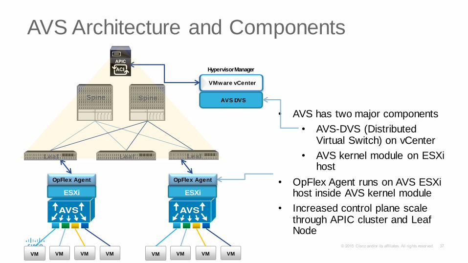
AVS Architecture and Components
37
• AVS has two major components
• AVS-DVS (Distributed Virtual Switch) on vCenter
• AVS kernel module on ESXi host
• OpFlex Agent runs on AVS ESXi host inside AVS kernel module
• Increased control plane scale through APIC cluster and Leaf Node
VMware vCenter
Hypervisor Manager
ESXi
VM VM VM VM
OpFlex Agent
AVS DVS Spine Spine
Leaf Leaf Leaf
ESXi
VM VM VM VM
OpFlex Agent

Nexus 1000V
• Only virtual networking and services solution across multiple hypervisors
• Single point of management for virtual networking via VSM with integration to cloud management platforms (Cisco UCS Director, OpenStack, SCVMM, vCD etc)
• L4-L7 integrated via vPath
• Firewall, Load Balancer, L3 services, WAN optimization, Network Monitoring
• Advanced edition includes distributed zone firewall (Virtual Security Gateway)
• Licensing : Licensed per CPU socket for advanced edition
Application Virtual Switch
• Purpose built ACI virtual leaf with OpFlex integration
• APIC specifies network policy for virtual and physical networks and does L4-L7 integration
• AVS does local switching/routing and provides distributed segmentation intra/inter EPG
Cisco Nexus 1000V & Application Virtual Switch

Existing IP Enabled Data Center Network
Extending ACI to Current DC: Remote vLeaf support
AVS
Directory/Proxy Service Nodes
AVS
Border Leaves
APIC Policy Controller ACI Leaf
Nexus 9000
ACI Virtual Leaf (AVS)
vSwitch
ACI Services
extended in to
any existing IP
enabled Data
Center
ACI Policy and Automation
Extended to Physical and
Virtual Servers via Cisco Nexus
9000
ACI Enabled L4-7
Virtual and Physical
Services (Existing
and New)
Extending ACI Policy and Automation into the Existing Data Center
ACI Policy and
Automation Extended
to Virtual Servers via
Cisco AVS
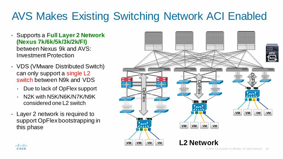
• Supports a Full Layer 2 Network (Nexus 7k/6k/5k/3k/2k/FI) between Nexus 9k and AVS: Investment Protection
• VDS (VMware Distributed Switch) can only support a single L2 switch between N9k and VDS
• Due to lack of OpFlex support
• N2K with N5K/N6K/N7K/N9K considered one L2 switch
• Layer 2 network is required to support OpFlex bootstrapping in this phase
AVS Makes Existing Switching Network ACI Enabled
L2 Network
Op
Fle
x
Op
Fle
x
Op
Fle
x
VM VM VM VM
VM VM VM VM
VM VM VM VM

APIC Admin
VI/Server Admin Instantiate VMs,
Assign to Port Groups
L/B
EPGAP
P
EPG DB
F/W
EPG WEB
Application Network Profile
Create Application Policy
W eb W eb W eb App
HYPERVISOR HYPERVISOR
Cisco AVS
WEB PORT GROUP
APP PORT GROUP
DB PORT GROUP
vCenter
Server
8
5
1
9 ACI
Fabric
Automatically Map
EPG To Port Groups
Push Policy
Create AVS-
DVS 2
Cisco APIC and
VMware vCenter Initial
Handshake
6
DB DB
7 Create Port
Groups
Cisco ACI Hypervisor Integration – Cisco AVS
APIC
3
Attach Hypervisor
to AVS
4 Learn location of ESX
Host through OpFlex
OpFlex Agent OpFlex Agent

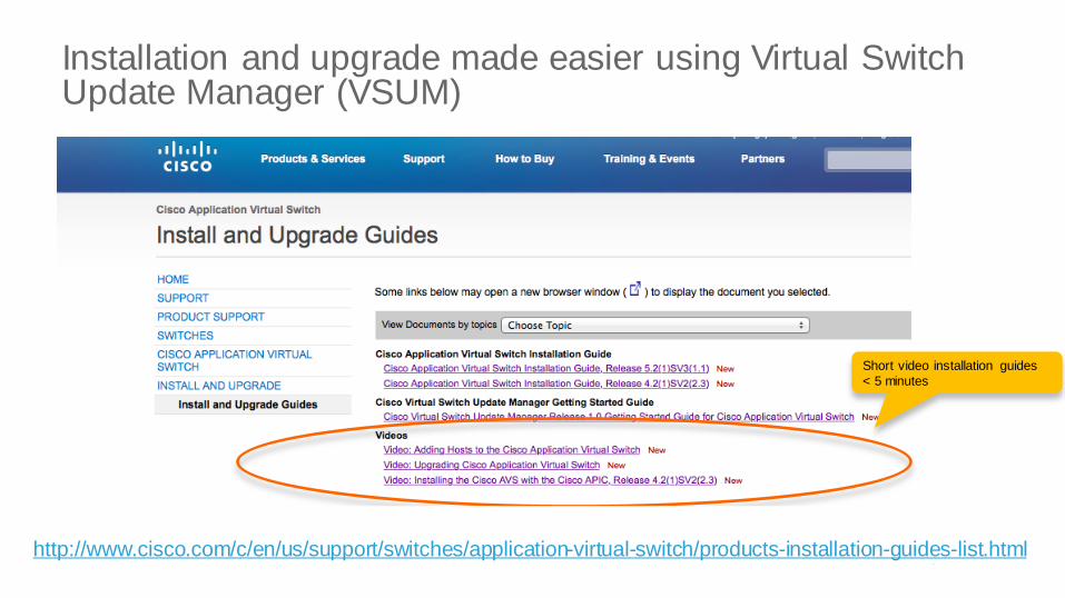
Installation and upgrade made easier using Virtual Switch Update Manager (VSUM)
http://www.cisco.com/c/en/us/support/switches/application-virtual-switch/products-installation-guides-list.html
Short video installation guides
< 5 minutes


Backbone
Data Center Traffic Patterns
AVS AVS AVS AVS AVS
L2/L3 Network
Traffic outside the host (East –West)
~80%
Traffic between VM’s on the same
host <3%
L3 Network
Traffic outside the host (North –South)
~15%

Virtual Leaf Switching Modes • FEX Mode: All traffic sent to Leaf for switching
• Local Switching (LS) Mode: Intra-EPGs traffic switched on the same host
• Full Switching (FS) Mode: Full APIC policy enforcement on server
Hypervisor
VM VM
EPG App
FEX Mode
VM VM
EPG Web
Punt to Leaf for all traffic
Hypervisor
VM VM
EPG App
Local Switching Mode
VM VM
EPG Web
Punt to Leaf for Inter-EPG traffic
Hypervisor
VM VM
EPG App
Full Switching Mode
VM VM
EPG Web
Full Policy Enforcement
AVS 1.0 AVS 2.0

1. All traffic, within and between EPG, is sent to Leaf (only intra-EPG within same server shown in diagram as example)
2. All traffic traverse through the Existing Network
3. Leaf switch atomic counters for enhanced statistics
AVS Packet Walk: FEX Mode
AVS AVS
EPG1
1. Sent out of server
EPG2 EPG1 EPG2 3. Unicast
AVS 1.0: Layer 2 Existing
Network/Local Switching
2. Sent to destination server
Layer 2 Existing Network

1. VM in EPG1 starts unicast packet to VM
2. AVS unicasts packet to destination VM within the server
LS Packet Walk: Unicast within EPG within Server
AVS AVS
EPG1
1. Unicast
EPG2 EPG1 EPG2
2. Unicast
AVS 1.0: Layer 2 Existing
Network/Local Switching

1. VM in EPG1 starts unicast packet
2. Leaf decides to send unicast to other locations have EPG1
3. Unicast delivered to other VM in EPG1
LS: Unicast within EPG Between Servers with VXLAN
AVS AVS
EPG1
1. Unicast
2. Unicast
3. Unicast
EPG2 EPG1 EPG2
AVS 1.0ƒ: Layer 2
Existing Network/Local Switching

1. VM in EPG1 starts unicast packet
2. Layer 2 Network forwards directly
3. Unicast delivered to other VM in EPG1
LS: Unicast within EPG Between Servers with VLAN
AVS AVS
EPG1
1. Unicast
2. Layer 2 Network Forwards Directly
3. Unicast
EPG2 EPG1 EPG2
AVS 1.0: Layer 2 Existing
Network/Local Switching

1. VM in EPG1 starts flooding packet, assuming BD is configured for flooding
2. Leaf decides to flood to all EPGs in the same BD
• Needed just in case other EPGs are in other Leaves
3. Multicast packet is sent for each EPG
LS Packet Walk: Flooding within EPG
AVS AVS
EPG1
1. Flood
2. Flood BD
3. Flood BD
EPG2 EPG1 EPG2
AVS 1.0: Layer 2 Existing
Network/Local Switching

1. VM in EPG1 unicast packet to VM in EPG2 on the same server
2. Leaf decides to send packet back to same link
3. VMs in EPG2 receives unicast
LS: Inter-EPG Traffic Within Server
AVS AVS
EPG1
1. Unicast to EPG2
2. Sent to EPG2
3. Sent to EPG2
EPG2 EPG1 EPG2
AVS 1.0: Layer 2 Existing
Network/Local Switching

1. VM in EPG1 unicast packet to VM in EPG2
2. Leaf decides to send packet to multiple links
3. VMs in EPG2 receives unicast
1. NOTE: Same behavior for VLAN and VXLAN
LS: Inter-EPG Traffic Between Servers
AVS AVS
EPG1
1. Unicast to EPG2
2. Sent to EPG2
3. Sent to EPG2
EPG2 EPG1 EPG2
AVS 1.0: Layer 2 Existing
Network/Local Switching

Backbone
Optimal Forwarding of Intra & Inter EPG Traffic
AVS AVS AVS AVS AVS
Directory/Proxy Service Nodes
APIC Policy Controller
ACI Leaf Nexus 9000
L2/L3 Network
Optimal Forwarding of Iintra- and Inter-
EPG Traffic through Existing
Network
L3 Network
• Intra- and Inter-EPG traffic from AVS goes directly through Existing
L3 & L2 Networks without going to
Leaf • Full Inter-EPG policy enforcement
within server
AVS 2.0: Layer 3 Existing Network / Full Switching

Backbone
Extending ACI to Current DC with Full Switching
AVS AVS AVS AVS AVS
Directory/Proxy Service Nodes
APIC Policy Controller
Extending ACI Policy and Automation into the Existing Data Center
ACI Leaf Nexus 9000
AVS
L2/L3 Network
L3 Network
AVS 2.0 Layer 3 Existing Network / Full Switching
Direct to N9k
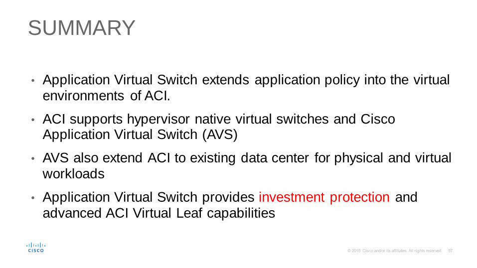
SUMMARY
• Application Virtual Switch extends application policy into the virtual environments of ACI.
• ACI supports hypervisor native virtual switches and Cisco Application Virtual Switch (AVS)
• AVS also extend ACI to existing data center for physical and virtual workloads
• Application Virtual Switch provides investment protection and advanced ACI Virtual Leaf capabilities

Polling Question 3
Is it possible to move Virtual Workloads across the clouds ?
a. Yes
b. No


Expanding Cloud
Provider Ecosystem
…
Cisco Intercloud Fabric
Cisco’s Hybrid Cloud Approach
Customer
Open
No Vendor Lock-In
Any Hypervisor to Any Provider
Heterogeneous Infrastructure
End-to-End Security
Unified Workload Management and Governance
Workload Mobility Across Clouds
Choice


Intercloud Fabric Enabling Dev/ Test Use Case Online Gaming Company Needs Faster Access to Resources to Test New Games
DC/Private Cloud
Provider Cloud A
Provider Cloud B
On Demand
Dev/Test
Environments
Promote to
Production in
Private Cloud
• Choice of Cloud Provider Based on SLAs
• Workload Portability to and from Cloud
• Policy Based Workload Placement
Need Dev/ Test
Environment in
Public Cloud
Choose
Alternate Cloud
for Production

Capacity
DC/Private Cloud
• Elastic Capacity
• Secure and Policy Driven
• No data migration necessary
Provider Cloud
Seamless Hybrid Cloud
Need More Capacity to
Support Marketing Campaign
Select Workload
Create Workload
in Cloud Size to Match
Demand
Intercloud Fabric Enables Capacity Augmentation Marketing Company Needs Resources to Run Time Sensitive Web Campaign

Secure Cloud Extension
Cisco Intercloud Fabric Architectural View
Intercloud Fabric
Provider Platform
VM Manager
Intercloud Fabric
for Providers
Intercloud Fabric Services
Intercloud
Fabric Director
End User and IT Admin Portal Workload and Fabric Management IT Admins End Users
Intercloud Fabric for Business
DC/Private Cloud Provider Cloud
VM VM
VM VM
Private Cloud Services
ICF
SHELL


Mgmt Interface
Tunnel Interface
ICX-Local Tunnel Peer
Mgmt Interface
1. ICX and ICS are installed. Control connection is established to each
2. ICX is initialized – receives ICS peer config
3. ICS is initialized – receives ICX peer config
4. Control connection is established between ICX and ICS
5. Tunnel connections are established (control and data)
6. Heartbeat and handshake process are initialized (HA mode)
7. Peers Exchange HA State
8. Deployment is completed
ICS-Tunnel Peer gateway
Secure Cloud Extension

Redundancy is offered on site to site connection
• Both ICX and ICS offer redundant peers
• Operation is active-standby
The HA mechanism leverages a handshake and heartbeat process
• A handshake to acknowledge initial state (initial role selected at configuration time)
• A heartbeat to determine ongoing state and trigger switchover
Private
Networks
Private
Networks on Public Cloud
Private Cloud Public Cloud
VLAN A
VLAN B
VLAN A
VLAN B
ICX-ACTIV E ICS-ACTIV E
ICX-STANDBY ICS-STANDBY
Secure Cloud Extension Site to Site Communications:: HA

Driver :: Functional Capabilities Driver Functions
• To control mgmt plane functions: keep the tunnel health
• To control data plane functions: establish tunnels and send/receive traffic
• Encapsulate / decapsulate traffic to and from cloud VMs
• Driver allows tunneled traffic (data) & control plane traffic :: drops everything else
L2H Tunnel Outer
MAC/IP Data
Data
L2H Tunnel Outer
MAC/IP Data
Data
Message sent
to cloud VM Driver Encrypted
Message Encrypted
Message at ICS
Data to and from
app layer
VM VM
Driver Driver
Secure Cloud Extension
ICS

Internet Router/Firewall must allow outbound/inbound traffic originating from enterprise network to the range of provider IP addresses for the following protocols and ports:
Intercloud Fabric Deployment Requirements
Protocols/ports in Use
• 80 – HTTP access for AWS calls and communicating with InterCloud VMs in provider cloud
• 443 – HTTPS access for AWS calls and communicating with InterCloud VMs in provider cloud
• 22 – SSH to InterCloud VMs in provider cloud
• UDP 6644 – TLS data tunnel (if UDP is used for transport)
• TCP 6646 – TLS data tunnel (if TCP is used for transport) – added as a choice given enterprise rules
• TCP 6644 – TLS control tunnel
Other Protocols in use
• ICX to ICX messages: UDP port 9984

ICF end-to-end

Intercloud
Fabric Services
VM is powered up on public cloud and management continues through Intercloud Fabric Director 4
VM Portability: Migration Across Hybrid Cloud
Intercloud Fabric Secure Extender
DC/Private Cloud
Provider Cloud
Intercloud Switch
Intercloud Fabric
Provider Platform
Cloud Providers
Intercloud Extender
IT Admins End Users
VM
VM VM
Image is converted to public cloud format (e.g., AMI) and migrated to public cloud
3
End user triggers VM migration to cloud 1
VM is shut down and Intercloud Fabric driver added 2
VM Manager Intercloud
Fabric Director
Intercloud Fabric for Business


Intercloud Fabric Secure Extender
(Secure Network Extension)
DC/Private Cloud
Provider Cloud
Intercloud Switch
Intercloud Extender
Intercloud
Fabric Director
Intercloud Fabric for Business
Core Services: Firewalling/Zoning
IT Admins Intercloud Fabric
Intercloud Fabric
VSG: Protects VMs
in Provider Cloud
Test VM
Test VM
Enterprise VSG: Protects VMs in Private Cloud
Single Security
Policy for Private and
Provider Clouds
Web VM

Intercloud Fabric for Business
Intercloud
Fabric Director
Enterprise VPN Access to Public cloud VMs
Core Services: Routing Across Hybrid Cloud
Direct access to public
cloud VMs through NAT
Intercloud Fabric Secure Extender
DC/Private Cloud
Provider Cloud
Intercloud Extender
VM VM
VM VM
VLAN App
19.2.168.x.x
Def ault Gateway f or VLAN A &B
VLAN Web
VM VM
VM VM
Prov ider Gateway
10.x..x.x
54.x..x.x
VLAN A Intercloud
Fabric CSR
Inter-VLAN communication
through ICF Routing
VLAN B
192.168.x.x
Remote/ Branch Office
ISR
VPN VPN
Mobile
Worker
Mobile
Worker
Intercloud Switch

N1K VEM
cVSM
N1K VEM
VM
ICS
InterCloud
VNMC
Enterprise Datacenter Cloud Datacenter
Secure
Tunnels
ICX
vCenter
VM
cVEM
Cloud VMs
CVM Kumo Driver
CVM Kumo Driver
VSM
I
n t
e r
n e
t
SSL (Control Plane)
Packet Flow: VM ICX ICS CVM


Physical to
Virtual to
Cloud Journey
Inter Cloud
Private
Cloud
Hybrid
Cloud
Virtualization
Public
Cloud

Submit Your Questions Now! Use the Q & A panel to submit your questions and our expert will respond

Collaborate within our Social Media
Facebook- http://bit.ly/csc-facebook
Twitter- http://bit.ly/csc-twitter
You Tube http://bit.ly/csc-youtube
Google+ http://bit.ly/csc-googleplus
LinkedIn http://bit.ly/csc-linked-in
Instgram http://bit.ly/csc-instagram
Newsletter Subscription http://bit.ly/csc-newsletter
Learn About Upcoming Events

Cisco has support communities in other languages!
Spanish https://supportforums.cisco.com/community/spanish
Portuguese https://supportforums.cisco.com/community/portuguese
Japanese https://supportforums.cisco.com/community/csc-japan
Russian https://supportforums.cisco.com/community/russian
Chinese
http://www.csc-china.com.cn
If you speak Spanish, Portuguese, Japanese, Russian or Chinese we invite you to participate and collaborate in your language

More IT Training Videos and Technical Seminars on the Cisco Learning Network
View Upcoming Sessions Schedule
https://cisco.com/go/techseminars

Please take a moment to complete the survey
Thank you for Your Time!
