cisco ucs security target - common criteria ucs consists of the following primary hardware elements...
TRANSCRIPT

Americas Headquarters: Cisco Systems, Inc., 170 West Tasman Drive, San Jose, CA 95134-1706 USA © 2012 Cisco Systems, Inc. All rights reserved. This document may be freely reproduced and distributed whole and intact including this copyright notice.
Cisco Unified Computing System (UCS) Security Target
This document provides the basis for an evaluation of a specific Target of Evaluation
(TOE), the Cisco Unified Computing System solution. This Security Target (ST) defines
a set of assumptions about the aspects of the environment, a list of threats that the product
intends to counter, a set of security objectives, a set of security requirements, and the IT
security functions provided by the TOE which meet the set of requirements.
Version 1.1
November 2012
Prepared By:
Cisco Systems, Inc.
170 West Tasman Dr.
San Jose, CA 95134

Cisco Unified Computing System Security Target
2 © 2012 Cisco Systems, Inc. All rights reserved. This document may be freely reproduced and distributed whole and intact including this copyright notice.
Table of Contents
List of Tables 5
List of Figures 5
Security Target Introduction 6
ST and TOE Identification 6
TOE Overview 7
TOE Product Type 7
Supported non-TOE Hardware/ Software/ Firmware 7
TOE Description 9
Cisco UCS 5108 Chassis 10
Cisco UCS 6120XP and 6140XP Fabric Switch Hardware 10
Cisco UCS 2104XP Fabric Extender 11
Cisco UCS Blade Servers 11
Cisco UCS Rack Mount Servers 12
Cisco UCS Manager Software 13
Physical Scope of the TOE 14
Logical Scope of the TOE 17
Audit 17
Identification & Authentication 17
Management 18
Cisco UCS Hardware Management 18
Cisco UCS Resource Management 18
Server Administration in a Cisco UCS Instance 19
Network Administration in a Cisco UCS Instance 19
Storage Administration in a Cisco UCS Instance 19
Tasks that Cannot be Performed in Cisco UCS Manager 19
UCS Secure Access 20
UCS XML API 20
Network Separation 20

Cisco Unified Computing System Security Target
3 © 2012 Cisco Systems, Inc. All rights reserved. This document may be freely reproduced and distributed whole and intact including this copyright notice.
VLAN Separation 20
VSAN Separation 21
Role Based Access Control 21
Privileges 21
User Roles 22
User Locales 23
TOE Evaluated Configuration 24
Excluded Functionality 25
Conformance Claims 25
Common Criteria Conformance Claim 25
Protection Profile Conformance 25
Security Problem Definition 25
Threat Agents 25
Assumptions 26
Threats 26
Security Objectives 27
Security Objectives for the TOE 27
Security Objectives for the Environment 28
Security Requirements 29
Conventions 29
TOE Security Functional Requirements 29
Security audit (FAU) 30
Cryptographic Support (FCS) 31
User Data Protection (FDP) 33
Identification and Authentication (FIA) 36
Security Management (FMT) 37
Protection of the TSF (FPT) 40
TOE SFR Hierarchies and Dependencies 40
TOE Security Assurance Requirements 42
Security Assurance Requirements Rationale 42
Assurance Measures 43

Cisco Unified Computing System Security Target
4 © 2012 Cisco Systems, Inc. All rights reserved. This document may be freely reproduced and distributed whole and intact including this copyright notice.
TOE Summary Specification 44
TOE Security Functional Requirement Measures 44
TOE Bypass and interference/logical tampering Protection Measures 49
Rationale 51
Rationale for the Security Objectives 51
Rationale for SFRs/TOE Objectives 53
Glossary: Acronyms and Abbreviations 57
Glossary: References and Related Documents 57
Obtaining Documentation, Support, and Security Guidelines 58
Cisco Unified Computing System Security Target
5 © 2012 Cisco Systems, Inc. All rights reserved. This document may be freely reproduced and distributed whole and intact including this copyright notice.
List of Tables Table 1 ST and TOE Identification 6 Table 2 Supported non-TOE Hardware/ Software/ Firmware 7
Table 3 Physical Scope of the TOE 15 Table 4 Privileges and Default Role Assignments 21 Table 5 Threat Agents 25 Table 6 TOE Assumptions 26 Table 7 Threats 26
Table 8 Security Objectives for the TOE 27
Table 9 Security Objectives for the Environment 28
Table 10 Security Functional Requirements 29 Table 11 Auditable Events 30 Table 12 - Cryptographic Key Generation (RSA and AES) 31 Table 13 - Cryptographic operation – symmetric encryption 32
Table 14 - Cryptographic operation – hashing 32 Table 15 - Cryptographic operation – message authentication 32
Table 16 - Cryptographic operation – digital signatures 32 Table 17 - Cryptographic operation – Key Establishment 33 Table 18 Security Functional Requirements 41
Table 19 SAR Requirements 42 Table 20 Assurance Measures 43
Table 21 TOE SFRs Measures 44 Table 22: Summary of Mappings between Threats, Policies and the Security Objectives (both TOE
and Operational Environment) 51 Table 23: Rationale for Mappings between Threats, Policies and the Security Objectives for the TOE
51 Table 24: Summary of Mappings between Assumptions and the Security Objectives for the
Operational Environment 52 Table 25: Rationale for Mappings between Threats, Policies and the Security Objectives for the
Operational Environment 52 Table 26: Summary of Mappings between SFRs and Security Objectives 52 Table 27 - Summary of Mappings between IT Security Objectives and SFRs 54
Table 28 Acronyms or Abbreviations 57
List of Figures Figure 1: Unified Computing System ................................................................................................... 9 Figure 2: Example TOE deployment .................................................................................................. 24

Cisco Unified Computing System Security Target
6 © 2012 Cisco Systems, Inc. All rights reserved. This document may be freely reproduced and distributed whole and intact including this copyright notice.
Security Target Introduction
The Security Target contains the following sections:
Security Target Introduction
TOE Description
Conformance Claims
Security Problem Definition
Security Objectives
Security Requirements
Assurance Measures
TOE Summary Specification
Rationale
The structure and content of this ST comply with the requirements specified in the
Common Criteria (CC), Part 1, Annex A, and Part 3, Chapter 4.
ST and TOE Identification This section provides information needed to identify and control this ST and its TOE.
Table 1 ST and TOE Identification
ST Title Cisco Unified Computing System Security Target
ST Revision 1.1
Publication Date November 2012
Vendor and ST Author Cisco Systems, Inc.
TOE Reference Cisco UCS 5100 Series Blade Server Chassis, B-Series Blade Servers, C-Series
Rack-Mount Servers, 2100 and 2200 Series Fabric Extenders, and 6100 and 6200
Series Fabric Interconnects with UCSM 2.0(4b)
TOE Hardware Models Cisco UCS 5108 Blade Server Chassis, Cisco UCS B200 M1/M2/M3, B230
M1/M2, B250 M1/M2, B420 M3, B440 M1/M2, and B22 M3 Blade Servers,
Cisco UCS C200 M1/M2/M2SFF, C210 M1/M2, C220 M3, C240 M3, C250
M1/M2, C260 M2, C460 M2, C22 M3, and C24 M3 Rack-Mount Servers, Cisco
UCS 6120XP, 6140XP, 6248UP, and 6296UP Fabric Interconnects, Cisco UCS
2104XP, 2204XP, 2208XP and 2232PP Fabric Extenders
TOE Software Version Cisco Unified Computing System (UCS) Manager Software 2.0(4b)
ST Evaluation Status Completed

Cisco Unified Computing System Security Target
7 © 2012 Cisco Systems, Inc. All rights reserved. This document may be freely reproduced and distributed whole and intact including this copyright notice.
Keywords Virtualization, role-based access control, authentication
TOE Overview The TOE is a unified computing solution, which provides access layer networking
and servers.
TOE Product Type The TOE consists of hardware and software components that support Cisco's unified
fabric, which run multiple types of data-center traffic over a single converged
network adapter. The UCS features a role based access control policy to control the
separation of administrative duties and provide a security log of all changes made.
A single Cisco Unified Computing System scales to up to forty chassis‟ and three
hundred and twenty blade servers or rack-mount servers, all of which are
administered through a single management entity called the Cisco UCS Manager. The
Cisco UCS consists of the following primary hardware elements – Cisco UCS 5108
Blade Server Chassis, Cisco UCS B200 M1/M2/M3, B230 M1/M2, B250 M1/M2,
B420 M3, B440 M1/M2, and B22 M3 Blade Servers, Cisco UCS C200
M1/M2/M2SFF, C210 M1/M2, C220 M3, C240 M3, C250 M1/M2, C260 M2, C460
M2, C22 M3, and C24 M3 Rack-Mount Servers, Cisco UCS 6120XP, 6140XP,
6248UP, and 6296UP Fabric Interconnects, Cisco UCS 2104XP, 2204XP, 2208XP
and 2232PP Fabric Extenders. The Fabric Interconnects and Fabric Extenders are
based on the same switching technology as the Cisco Nexus™ 5000 Series. In
addition, the Fabric switch provides additional centralized management capabilities
that form the basis of the Cisco UCS Manager Software.
Cisco UCS implements Cisco unified fabric within racks and groups of racks,
supporting Ethernet and Fibre Channel protocols over 10 Gigabit Cisco® Data Center
Ethernet and Fibre Channel over Ethernet (FCoE) links. The result of this network
unification is a reduction by up to two-thirds of the switches, cables, adapters, and
management points. All devices in a system remain under a single management
domain, which remains highly available through the use of redundant components.
Supported non-TOE Hardware/ Software/ Firmware The TOE supports (in some cases optionally) the following hardware, software, and
firmware in its environment: Table 2 Supported non-TOE Hardware/ Software/ Firmware
IT Environment
Component
Required Usage/ Purpose Description for TOE performance
UCS Management Yes The Cisco UCS Manager GUI is a Java-based application that

Cisco Unified Computing System Security Target
8 © 2012 Cisco Systems, Inc. All rights reserved. This document may be freely reproduced and distributed whole and intact including this copyright notice.
Platform requires Sun JRE 1.6 or later.
•The UCS Manager uses web start1 to present the GUI and
supports the following web browsers:
– Microsoft Internet Explorer 6.0 or higher
– Mozilla Firefox 3.0 or higher
•The UCS Manager is supported on the following operating
systems:
– Microsoft Windows XP SP2 or higher;
– Microsoft Windows Vista SP1 or higher;
– Red Hat Enterprise Linux 5.0 or higher
Note that that UCS Management software is installed on the
UCS system and the management platform is used to connect to
the UCS and run the UCSM.
Remote Authentication
Server
No A RADIUS, TACACS+, or LDAP server is an optional
component for use with the TOE.
SNMP v3 Server No An SNMPv3 server is an optional component for use with the
TOE.
Syslog Server For
capturing
and viewing
failure
events.
A syslog server is an optional component for use with the TOE.
It is a supplemental storage system for audit logs, but it does not
provide audit log storage for the TOE. The locally stored audit
data includes records of events that completed successfully.
Audit records for failed events are transmitted from the TOE to
a remote syslog server, so the complete set of successful and
failed audit events would need to be reviewed via the remote
syslog server.
NTP Server No An NTP server is an optional component for use with the ToE
that would allows for synchronizing the ToE clock with an
external time source
1 Java Web Start is a network deployment method for standalone Java applications. Note that although the deployment to
the administrator‟s browser is dynamic, the version deployed is a static version associated with the TOE.

Cisco Unified Computing System Security Target
9 © 2012 Cisco Systems, Inc. All rights reserved. This document may be freely reproduced and distributed whole and intact including this copyright notice.
TOE Description Figure 1: Unified Computing System
This section provides an overview of the Cisco Unified Computing System Target of
Evaluation (TOE). This section also defines the TOE components included in the
evaluated configuration of the TOE. The TOE consists of a minimum of one of each
of the following components:
Cisco UCS Manager components
o One or more Cisco UCS 6120XP, 6140XP, 6248UP, or 6296UP
Fabric Interconnects with
Cisco UCS Manager Software release 2.0(4b)
Server and Fabric Extenders (chose blade and/or rack mount)
o Blade server configurations:
One or more Cisco UCS 5108 Chassis with:
One or more Cisco UCS 2104XP Fabric Extenders
One or more Cisco UCS B200 M1/M2/M3, B230
M1/M2, B250 M1/M2, B420 M3, B440 M1/M2, or
B22 M3Blade Servers; and/or
o Rack-Mount Server configurations:
One or more Cisco Nexus 2204XP, 2208XP or 2232PP Fabric
Extenders
One or more Cisco UCS C200 M1/M2/M2SFF, C210 M1/M2,
C220 M3, C240 M3, C250 M1/M2, C260 M2, C460 M2, C22
M3, or C24 M3Rack-Mount Servers

Cisco Unified Computing System Security Target
10 © 2012 Cisco Systems, Inc. All rights reserved. This document may be freely reproduced and distributed whole and intact including this copyright notice.
Deployment note: One instance of the Cisco UCS Manager can manage two Cisco
UCS 61006200 Series Fabric Interconnects, multiple Cisco UCS 5100 Series Chassis,
80 Cisco UCS 2100 Series Fabric Extenders, and hundreds of Cisco UCS B-Series
Blade Servers and/or Rack-Mount Servers. [Capacity details are provided for
conceptual purposes only, and are not tested within the scope of the Common Criteria
evaluation.]
Cisco UCS 5108 Chassis The Cisco UCS 5108 Chassis physically houses blade servers and up to two fabric
extenders. The enclosure is 6RU high supporting up to 56 servers per rack density.
The UCS 5108 supports up to eight half slot or four full slot blade servers with four
power supplies and eight cooling fans. Both power supplies and fans are redundant
and hot swappable. Featuring 90%+ efficient power supplies, front to rear cooling,
and airflow optimized mid-plane, the Cisco UCS is optimized for energy efficiency
and reliability.
Even though the Blade Server Enclosure and Cisco UCS System can house multiple
blades, each blade acts as an individual physical server. Cisco UCS System provides
a centralized and simplified management paradigm for all the blades.
Cisco UCS 6120XP, 6140XP, 6248UP, and 6296UP Fabric Switch Hardware
The Cisco UCS 6120XP, 6140XP, 6248UP, and 6296UP Fabric Switch Hardware are
line-rate, low-latency, lossless 10 Gigabit Ethernet, Cisco Data Center Ethernet, and
Fiber Channel over Ethernet (FCoE) switches that consolidate I/O at the system level.
The Fabric Switches supply a unified network fabric that connects every server
resource in the system via wire once 10G Ethernet/FCoE downlinks and 10G Ethernet
and 1/2/4Gb FC uplink modules are configured. The Cisco UCS 6200 Series
interconnects support out-of-band management through a dedicated 10/100/1000-
Mbps Ethernet management port as well as in-band management. Out of band
management, switch redundancy, and console-based diagnostics are enabled through
dedicated management, clustering, and RS-232 ports. A single UCS Series Fabric
Switch unites up to 320 servers within a single system domain for maximum
scalability.
The Cisco UCS 6100 Series Fabric Switch has two flavors – a 1RU switch (Cisco
UCS 6120XP 20-Port Fabric Interconnect) and a 2RU switch (Cisco UCS 6140XP
40-Port Fabric Interconnect). The 1RU Fabric switch supports 20 fixed 10G FCoE
ports and 1 expansion module. It supports redundant power supplies and fans and a
front-to-back airflow. The 2RU Fabric switch supports 40 fixed 10G FCoE ports and
2 expansion modules. It supports redundant power supplies and fans and a front-to-
back airflow.

Cisco Unified Computing System Security Target
11 © 2012 Cisco Systems, Inc. All rights reserved. This document may be freely reproduced and distributed whole and intact including this copyright notice.
The Cisco UCS 6200 Series Fabric Switch has two flavors – a 1RU switch (6248UP
48-Port Fabric Interconnect) and a 2RU switch (6296UP 96-port Fabric Interconnect).
The 1RU Fabric switch supports 48 fixed 10G FCoE ports, up to 960 Gbps
throughput, 1 expansion module, 2 fan modules, and redundant power supplies. The
2RU Fabric switch supports 96 fixed 10G FCoE ports up to 1920 Gbps throughput, 3
expansion modules, 4 fan modules, and redundant power supplies.
The external authentication server can act as a repository for authentication
credentials. The Cisco UCS Fabric switch implements SSHv2, and SSL3.1/TLS1.0
for secure network management, and SNMPv3 for monitoring (read only). The
expansion modules supported on the Cisco UCS 6100 Series Fabric Switch include a
6-port Enhanced 10-Gbit Ethernet interface expansion module, a 4-port Enhanced 10-
Gbit Ethernet interface and 4-port 1/2/4Gbps Fibre-Channel expansion module and a
8-port 1/2/4Gbps Fibre-Channel expansion module. The expansion modules
supported on the Cisco UCS 6200 Series Fabric Switch can be used to increase the
number of 10-Gbit Ethernet, FCoE and FC ports. The unified port module provides
up to 16 ports that can be configured for 10 Gigabit Ethernet, FCoE and/or 1/2/4/8-
Gbps native Fibre Channel using the SFP.
Cisco UCS 2104XP Fabric Extender The Cisco UCS 2104XP Series Fabric Extender extends the I/O fabric into the blade
server enclosure providing a direct 10Gbs connection between blade servers and
fabric switch simplifying diagnostics, cabling, and management. The fabric extender
multiplexes and forwards all traffic using a cut-through architecture over one to four
10Gbps unified fabric.
Cisco UCS Blade Servers Cisco UCS B200 M1/M2/M3, B230 M1/M2, B250 M1/M2, B420 M3, B440 M1/M2,
or B22 M3 Blade Servers are designed for compatibility, performance, energy
efficiency, large memory footprints, manageability, and unified I/O connectivity.
Based on Intel® Xeon® 5500 series processors, B-Series Blade Servers adapt to
application demands, scale energy use, and offer a platform for virtualization. Each
Cisco UCS B-Series Blade Server utilizes converged network adapters for
consolidated access to the unified fabric with various levels of transparency to the
operating system. This design reduces the number of adapters, cables, and access-
layer switches for LAN and SAN connectivity at the rack level.
The Blade Servers include a Cisco Integrated Management Controller (CIMC). The
CIMC provides access to the Server for UCS at the BIOS level via the Intelligent
Platform Management Interface (IPMI) that can be used to monitor system health at

Cisco Unified Computing System Security Target
12 © 2012 Cisco Systems, Inc. All rights reserved. This document may be freely reproduced and distributed whole and intact including this copyright notice.
the hardware level and manage the server‟s firmware2. Configuration changes to the
BIOS for the server can be requested through the CIMC, however the CIMC is not
available for direct management use.
The Blade Servers support the following network adapters, none of which enforces
security functionality described in the ST. For a full compatibility matrix, refer to the
Hardware and Software Interoperability Matrix for B Series Servers referenced from
the Cisco UCS B-Series Servers Documentation Roadmap available at Cisco.com.
Cisco UCS 82598KR-10 Gigabit Ethernet Network Adapter
Cisco UCS 82598KR-CI 10 Gigabit Ethernet Adapter
Cisco UCS M71KR-Q QLogic Converged Network Adapter
Cisco UCS CNA M72KR-Q Qlogic Converged Network Adapter
Cisco UCS M71KR-E Emulex Converged Network Adapter
Cisco UCS CNA M72KR-E Emulex Converged Network Adapter
Cisco UCS CNA M73KR-Q QLogic Converged Network Adapter
Cisco UCS M81KR Virtual Interface Card
Cisco UCS CNA M61KR-I Intel Converged Network Adapter
Cisco UCS NIC M51KR-B Broadcom BCM57711 Network Adapter
Cisco UCS Rack Mount Servers Cisco UCS C200 M1/M2/M2SFF, C210 M1/M2, C220 M3, C240 M3, C250 M1/M2,
C260 M2, C22 M3, or C24 M3 Rack-Mount Servers extend UCS functionality to an
industry-standard form factor and are designed for compatibility, and performance,
and enable organizations to deploy systems incrementally, using as many or as few
servers as needed.
The Rack-mount Servers include a Cisco Integrated Management Controller (CIMC).
The CIMC provides access to the Server for UCS at the BIOS level via the Intelligent
Platform Management Interface (IPMI) that can be used to monitor system health at
the hardware level and manage the server‟s firmware3. Configuration changes to the
BIOS for the server can be requested through the CIMC. The C-Series servers are
managed through the UCSM, which interfaces with the CIMC.
2 Blade server firmware is outside the scope of the TOE. Blade server firmware does not provide any security
functionality described in this Security Target, and is not part of in the UCSM software bundle. 3 Blade server firmware is outside the scope of the TOE. Blade server firmware does not provide any security
functionality described in this Security Target, and is not part of in the UCSM software bundle.

Cisco Unified Computing System Security Target
13 © 2012 Cisco Systems, Inc. All rights reserved. This document may be freely reproduced and distributed whole and intact including this copyright notice.
The Rack Mount Servers support the following network adapters, none of which
enforces security functionality described in the ST. For a full compatibility matrix,
refer to the Hardware and Software Interoperability Matrix for B Series Servers
referenced from the Cisco UCS B-Series Servers Documentation Roadmap available
at Cisco.com:
Cisco UCS P81E Virtual Interface Card
Emulex OneConnect Universal Converged Network Adapter
Emulex OneConnect OCe10102-FX-C 10-Gbps FCoE Converged Network
Adapter
QLogic QLE8152 Dual Port 10 Gbps Enhanced Ethernet to PCIe Converged
Network Adapter
Broadcom NetXtreme II 5709 Quad Port Ethernet PCIe Adapter Card with
TOE and iSCSI HBA
Broadcom NetXtreme II 57711 Dual Port 10 Gb Ethernet PCIe Adapter Card
with TOE and iSCSI HBA
Emulex LightPulse LPe11000/LPe11002 4 Gbps Fibre Channel PCI Express
Dual Channel HBA
QLogic QLE2462, Dual Port 4 Gbps Fibre Channel to PCI Express HBA
Intel Ethernet X520 Server Adapters
Intel Gigabit ET, ET2, and EF Multi-Port Server Adapters
Cisco UCS Manager Software The Cisco UCS Manager Software integrates the components of a Cisco Unified
Computing System into a single, seamless entity. It can manage up to three hundred
and twenty blade servers as a single logical domain using a GUI, with both CLI and
XML API options, enabling near real time configuration and reconfiguration of
resources.
The software‟s role-based design supports existing best practices, allowing server,
network, and storage administrators to contribute their specific subject matter
expertise to a system design. Any user‟s role may be limited to a subset of the
system‟s resources using organizations and locales, so that a Cisco Unified
Computing System can be partitioned and shared between organizations using a
multi-tenant model. It allows secure management of the TOE using SSL3.1/TLS1.0,
and SSHv2, and monitoring using SNMPv3 (read only).
The UCS Manager software is divided into two components: server and client side.
The server side component is installed on the 6120XP, 6140XP, 6248UP or 6296UP
Fabric Switch hardware. The server side component contains the XML based server

Cisco Unified Computing System Security Target
14 © 2012 Cisco Systems, Inc. All rights reserved. This document may be freely reproduced and distributed whole and intact including this copyright notice.
daemon that receives requests from the three different client access methods: GUI,
CLI, and XML. The client side component is a java application that provides the
GUI for the administrator.
The UCS Manager software may be deployed in a standalone configuration, in which
each instance of the TOE is managed independently, or in a clustered configuration in
which management configuration data and event log storage are centralized in a
primary TOE instance and accessed by the other members of the cluster. Clusters
operate within the protected network boundary.
Physical Scope of the TOE The TOE is a hardware and software solution that makes up the Cisco Unified
Computing System.
The software / firmware for the TOE is bundled in a single image and is distributed to
components within the TOE by Cisco UCS Manager. The individual component
firmware versions are identified with the version listed in the Software / Firmware
section of the table below.
The TOE is comprised of the following:

Americas Headquarters: Cisco Systems, Inc., 170 West Tasman Drive, San Jose, CA 95134-1706 USA © 2012 Cisco Systems, Inc. All rights reserved. This document may be freely reproduced and distributed whole and intact including this copyright notice.
Table 3 Physical Scope of the TOE
TOE
Component
Cisco UCS
5100 Chassis
Cisco UCS
6100 and
6200 Series
Fabric
Switch
Hardware
Cisco UCS
2100 Series
Fabric
Extenders
Cisco UCS B-
Series Blade
Servers
Blade Server Network
Adapters
Cisco UCS C-
Series Rack
Mount Servers
Rack Mount Server
Network Adapters
Image
Component
Listing
(To be read
vertically,
not
horizontally)
Cisco UCS
5108 Cisco UCS
6120XP
Cisco UCS
2104XP Fabric
Extender
Cisco UCS
B200
M1/M2/M3
Cisco UCS 82598KR-10
Gigabit Ethernet Network
Adapter
Cisco UCS C200
M1/M2/M2SFF
Cisco UCS P81E Virtual
Interface Card
Cisco UCS
6140XP
Cisco UCS
2204XP Fabric
Extender
Cisco UCS
B230 M1/M2
Cisco UCS M71KR-Q
QLogic Converged
Network Adapter
Cisco UCS C210
M1/M2
Emulex OneConnect
Universal Converged
Network Adapter
Cisco UCS
6248UP
Cisco UCS
2208XP Fabric
Extender
Cisco UCS
B250 M1
Cisco UCS M71KR-E
Emulex Converged
Network Adapter
Cisco UCS C220
M3
QLogic QLE8152 Dual Port
10 Gb Ethernet to PCIe
Converged Network Adapter
Cisco UCS
6296UP
Cisco Nexus
2232PP Fabric
Extender
Cisco UCS
B420 M3
Cisco UCS M81KR
Virtual Interface Card
Cisco UCS C240
M3
Cisco UCS X520 Intel
Converged Network Adapter
Cisco UCS
B440 M1/M2
Cisco UCS M72KR-Q
Qlogic Converged
Network Adapter
Cisco UCS C250
M1/M2
Broadcom NetXtreme II 5709
Quad Port Ethernet PCIe
Adapter Card with TOE and
iSCSI HBA
Cisco UCS
B22 M3
Cisco UCS M72KR-E
Emulex Converged
Network Adapter
Cisco UCS C260
M2
Broadcom NetXtreme II
57711 Dual Port 10 Gb
Ethernet PCIe Adapter Card
with TOE and iSCSI HBA
Cisco UCS M61KR-I Intel
Converged Network
Adapter
Cisco UCS C460
M2
Emulex LightPulse LPe11002
4 Gbps Fibre Channel PCI
Express Dual Channel HBA
Cisco UCS NIC M51KR-B
Broadcom BCM57711
Network Adapter
Cisco UCS C22
M3
QLogic SANblade QLE2462,
Dual Port 4 Gbps Fibre
Channel to PCI Express HBA
Software /
Firmware
Unified Computing System (UCS) Complete Software Bundle version 2.0(4b) which includes Cisco UCS Manager Software 2.0(4b)

Cisco Unified Computing System Security Target
16 © 2012 Cisco Systems, Inc. All rights reserved. This document may be freely reproduced and distributed whole and intact including this copyright notice.

Cisco Unified Computing System Security Target 17 © 2012 Cisco Systems, Inc. All rights reserved. This document may be freely reproduced and distributed whole and intact including this copyright notice.
Logical Scope of the TOE The TOE is comprised of several security features. Each of the security features
consists of several security functions, as identified below.
1. Audit
2. Identification & Authentication
3. Management
4. Network Separation
5. Role Based Access Control
These features are described in more detail in the subsections below.
Audit
The Unified Computing System stores audit information in three different formats:
audit log, events, and faults. This information is compiled to assist the administrator
in monitoring the security state of the UCS as well as trouble shooting various
problems that arise throughout the operation of the system. All three types of
information are stored within an SQLite database stored on the Fabric Switch. The
database is internal only and does not provide any externally visible interfaces for
communication. When the UCS is deployed in a clustered configuration, all instances
of the UCS Manager record audit information with the primary UCS Manager
instance. In standalone mode, all audit data is stored locally. Regardless of
standalone or clustered configuration, the TOE may be configured to send records to
an external syslog server, in which case syslog is a supplemental service for
monitoring, alerting and reporting, not the audit log storage mechanism of the TOE.
Audit log storage and protection functionality comes from the TOE itself.
The UCS Manager TOE component provides the ability to audit the actions taken by
authorized administrators. Audited events include start-up and shutdown,
configuration changes, administrative authentication, and administrative log-off
(authentication via IPMI is not audited).
The TOE provides the capability for authorized administrators to review the audit
records stored within the TOE. The locally stored audit data includes records of
events that completed successfully. Audit records for failed events are transmitted
from the TOE to a remote syslog server, so the complete set of successful and failed
audit events would need to be reviewed via the remote syslog server.
Identification & Authentication
Cisco UCS supports two methods of authenticating administrator logins on the Cisco
UCS Manager: a local user database of passwords (and optionally SSH keys) or a
remote authentication server accessed either via LDAP, RADIUS, or TACACS+.
The TOE may be configured to use either the local user database or one of the remote
authentication methods, but multiple authentication methods may not be selected.
Remote authentication may be used to centralize user account management to an
external authentication server. When the UCS is deployed in a clustered
configuration, all instances of the UCS Manager share the local user database.
Cisco Unified Computing System Security Target
18 © 2012 Cisco Systems, Inc. All rights reserved. This document may be freely reproduced and distributed whole and intact including this copyright notice.
The system has a default user account, admin, which cannot be modified or deleted.
This account is the system administrator account and has full privileges.
Each local user account must have a unique user name that does not start with a
number. For authentication purposes, a password is required for each user account.
User accounts can be configured to expire at a predefined time. When the expiration
time is reached the account is locked and must be unlocked by an authorized
administrator. By default, user accounts do not expire.
Identification and Authentication services are also extended to the Cisco Integrated
Management Controller (CIMC) via IPMI Access Profiles. These provide the ability
to access the CIMC via the Intelligent Platform Management Interface (IPMI) using a
username/password database stored on the CIMC.
Management UCS can be managed using the graphical user interface (over SSL3.1/TLS1.0), the
command line (over SSHv2 or by local console access via the RS-232 port), or by
manipulating an XML API. Each of these interfaces can be used in the evaluated
configuration to administer the UCS. The interfaces all operate on the same XML
data structures and provide identical functionality. For all management channels,
users have a default read-only authorization to access non-sensitive management
objects (keys and passwords are never exposed to an external management interface).
Additional user privileges each grant access to modify specific management objects.
An administrator can use Cisco UCS Manager to perform management tasks for all
physical and virtual devices within a Cisco UCS instance.
Cisco UCS Hardware Management
An administrator can use Cisco UCS Manager to manage all hardware within a Cisco
UCS instance, including the following:
Chassis
Servers
Fabric interconnects
Fans
Ports
Cards
Slots
I/O modules
Cisco UCS Resource Management
An administrator can use Cisco UCS Manager to create and manage all resources
within a Cisco UCS instance, including the following:
Servers
World Wide Name (WWN) addresses, used in Storage Area Networks

Cisco Unified Computing System Security Target 19 © 2012 Cisco Systems, Inc. All rights reserved. This document may be freely reproduced and distributed whole and intact including this copyright notice.
MAC addresses
Universally Unique Identifiers (UUIDs), assigned to each server
Bandwidth
Server Administration in a Cisco UCS Instance
A server administrator can use Cisco UCS Manager to perform server management
tasks within a Cisco UCS instance, including the following:
Create server pools and policies related to those pools, such as qualification
policies
Create policies for the servers, such as discovery policies, scrub policies, and
IPMI policies
Create service profiles and, if desired, service profile templates
Apply service profiles to servers
Monitor faults, alarms, and the status of equipment
Network Administration in a Cisco UCS Instance
A network administrator can use Cisco UCS Manager to perform tasks required to
create LAN configuration for a Cisco UCS instance, including the following:
Configure uplink ports, port channels, and LAN PIN groups
Create VLANs
Configure the quality of service classes and definitions
Create the pools and policies related to network configuration, such as MAC
address pools and Ethernet adapter profiles
Storage Administration in a Cisco UCS Instance
A storage administrator can use Cisco UCS Manager to perform tasks required to
create SAN configuration for a Cisco UCS instance, including the following:
Configure ports, port channels, and SAN PIN groups
Create VSANs
Configure the quality of service classes and definitions
Create the pools and policies related to the network configuration, such as
WWN pools and Fibre Channel adapter profiles
Tasks that Cannot be Performed in Cisco UCS Manager
You cannot use Cisco UCS Manager to perform certain system management tasks
that are not specifically related to device management within a Cisco UCS instance
No Cross-System Management: An administrator cannot use Cisco UCS Manager to
manage systems or devices that are outside the Cisco UCS instance where Cisco UCS

Cisco Unified Computing System Security Target
20 © 2012 Cisco Systems, Inc. All rights reserved. This document may be freely reproduced and distributed whole and intact including this copyright notice.
Manager is located. For example, you cannot manage heterogeneous environments,
such as non-Cisco UCS x86 systems, SPARC systems, or PowerPC systems.
No Operating System or Application Provisioning or Management: Cisco UCS
Manager provisions servers and, as a result, exists below the operating system on a
server. Therefore, you cannot use it to provision or manage operating systems or
applications on servers.
UCS Secure Access
The UCS Manager provides access for an administrator using SSHv2,
SSL3.1/TLS1.0, or SNMPv3.
SSHv2 is used to access the command line interface for the UCS Manager. SSHv2
authentication uses the UCS Manager username and password. SSHv2 can also be
configured on a per-user basis for public key authentication. The command line
interface is also accessible over the local serial port.
SSL3.1/ TLS1.0 is used to access the UCS Manager interface. The UCS Manager
interface serves as a launch point for the Java application which also utilizes SSL3.1/
TLS1.0 to protect the confidentially of the information.
SNMPv3 is used to export system traps and support remote monitoring (read only).
SNMPv3 includes support for SHA authentication and AES-128 for protection of the
confidential system information.
UCS XML API
The XML API is a way to integrate or interact with the Unified Computing System
(UCS), because XML is the native format of communication within the UCS. For
example, both the CLI and GUI use the same XML API to communicate with the
UCS Manager. The UCS XML interface accepts XML documents (APIs) sent over
HTTPS. Client developers can use the programming language of their choice generate
XML documents containing the API methods.
Network Separation
VLAN Separation
VLANs enable efficient traffic separation, provide better bandwidth utilization, and
alleviate scaling issues by logically segmenting the physical local-area network
(LAN) infrastructure into different subnets so that VLAN packets are presented to
interfaces within the same VLAN.
The most important requirement of VLANs is the ability to identify the origination
point for packets with a VLAN tag to ensure packets can only travel to interfaces for
which they are authorized.
The Cisco UCS 6100and 6200 Series Fabric Switch Hardware requires VLANs to
function. When the administrator configures network adapters on a per server basis,
VLANs are specified for each adapter.
Cisco Unified Computing System Security Target 21 © 2012 Cisco Systems, Inc. All rights reserved. This document may be freely reproduced and distributed whole and intact including this copyright notice.
VSAN Separation
Virtual SAN (VSAN) technology partitions a single physical Storage Area Network
(SAN) into multiple VSANs. VSAN capabilities allow the Cisco UCS 6100 and 6200
Series Fabric Switch Hardware to logically divide a large physical fabric into separate
isolated environments to improve SAN scalability, availability, manageability, and
network security.
Each VSAN is a logically and functionally separate SAN with its own set of Fibre
Channel fabric services. This partitioning of fabric services greatly reduces network
instability by containing fabric reconfigurations and error conditions within an
individual VSAN. The strict traffic segregation provided by VSANs helps ensure that
the control and data traffic of a given VSAN is confined within its own domain,
increasing SAN security.
Traffic is contained within VSAN boundaries and devices reside only in one VSAN
thus ensuring absolute separation between user groups. This ensures the
confidentiality of data traversing the VSAN from users and devices belonging to
other VSANs. It should be noted that devices, such as file servers and tape storage
devices are not part of the TOE but part of the TOE environment and may be
configured to participate in a VSAN. Each network interface of a device connected to
the TOE may only participate in a single VSAN.
Role Based Access Control Role-Based Access Control (RBAC) is a method of restricting or authorizing system
access for users based on user roles and locales. A role defines the privileges of a user
in the system and the locale defines the organizations (domains) that a user is allowed
access. Because users are not directly assigned privileges, management of individual
user privileges is simply a matter of assigning the appropriate roles and locales.
A user is granted write access to desired system resources only if the assigned role
grants the access privileges and the assigned locale allows access. For example, a user
with the Server Administrator role in the Engineering organization could update
server configurations in the Engineering organization, but would not be able to update
server configurations in the Finance organization unless the locales assigned to the
user include the Finance organization.
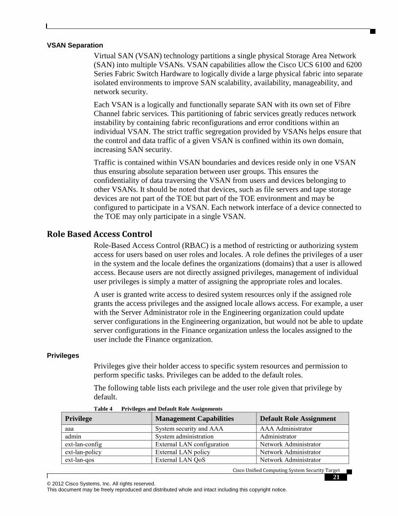
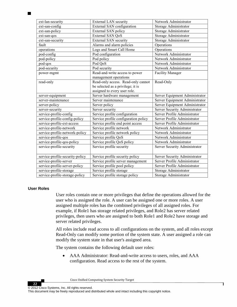
Privileges
Privileges give their holder access to specific system resources and permission to
perform specific tasks. Privileges can be added to the default roles.
The following table lists each privilege and the user role given that privilege by
default.
Table 4 Privileges and Default Role Assignments
Privilege Management Capabilities Default Role Assignment
aaa System security and AAA AAA Administrator
admin System administration Administrator
ext-lan-config External LAN configuration Network Administrator
ext-lan-policy External LAN policy Network Administrator
ext-lan-qos External LAN QoS Network Administrator
Cisco Unified Computing System Security Target
22 © 2012 Cisco Systems, Inc. All rights reserved. This document may be freely reproduced and distributed whole and intact including this copyright notice.
ext-lan-security External LAN security Network Administrator
ext-san-config External SAN configuration Storage Administrator
ext-san-policy External SAN policy Storage Administrator
ext-san-qos External SAN QoS Storage Administrator
ext-san-security External SAN security Storage Administrator
fault Alarms and alarm policies Operations
operations Logs and Smart Call Home Operations
pod-config Pod configuration Network Administrator
pod-policy Pod policy Network Administrator
pod-qos Pod QoS Network Administrator
pod-security Pod security Network Administrator
power-mgmt Read-and-write access to power
management operations
Facility Manager
read-only Read-only access. Read-only cannot
be selected as a privilege; it is
assigned to every user role.
Read-Only
server-equipment Server hardware management Server Equipment Administrator
server-maintenance Server maintenance Server Equipment Administrator
server-policy Server policy Server Equipment Administrator
server-security Server security Server Security Administrator
service-profile-config Service profile configuration Server Profile Administrator
service-profile-config-policy Service profile configuration policy Server Profile Administrator
service-profile-ext-access Service profile end point access Server Profile Administrator
service-profile-network Service profile network Network Administrator
service-profile-network-policy Service profile network policy Network Administrator
service-profile-qos Service profile QoS Network Administrator
service-profile-qos-policy Service profile QoS policy Network Administrator
service-profile-security Service profile security Server Security Administrator
service-profile-security-policy Service profile security policy Server Security Administrator
service-profile-server Service profile server management Server Profile Administrator
service-profile-server-policy Service profile pool policy Server Profile Administrator
service-profile-storage Service profile storage Storage Administrator
service-profile-storage-policy Service profile storage policy Storage Administrator
User Roles
User roles contain one or more privileges that define the operations allowed for the
user who is assigned the role. A user can be assigned one or more roles. A user
assigned multiple roles has the combined privileges of all assigned roles. For
example, if Role1 has storage related privileges, and Role2 has server related
privileges, then users who are assigned to both Role1 and Role2 have storage and
server related privileges.
All roles include read access to all configurations on the system, and all roles except
Read-Only can modify some portion of the system state. A user assigned a role can
modify the system state in that user's assigned area.
The system contains the following default user roles:
AAA Administrator: Read-and-write access to users, roles, and AAA
configuration. Read access to the rest of the system.
Cisco Unified Computing System Security Target 23 © 2012 Cisco Systems, Inc. All rights reserved. This document may be freely reproduced and distributed whole and intact including this copyright notice.
Administrator: Complete read-and-write access to the entire system. The
default admin account is assigned this role by default and this association
cannot be changed.
Facility Manager: Read-and-write access to power management operations.
Network Administrator: Read-and-write access to fabric interconnect
infrastructure and network security operations. Read access to the rest of the
system.
Operations: Read-and-write access to systems logs, including the syslog
servers, and faults. Read access to the rest of the system.
Read-Only: Read-only access to system configuration with no privileges to
modify the system state.
Server Equipment Administrator: Read-and-write access to physical server
related operations. Read access to the rest of the system.
Server Profile Administrator: Read-and-write access to logical server related
operations. Read access to the rest of the system.
Server Security Administrator: Read-and-write access to server security
related operations. Read access to the rest of the system.
Storage Administrator: Read-and-write access to storage operations. Read
access to the rest of the system.
New custom roles can be created, deleted, or modified to add or remove any
combination of privileges. Default roles can be deleted or modified except the
„admin‟ and „read-only‟ roles. When a role is modified, the new privileges are applied
to all users assigned to that role. Privilege assignment is not restricted to the
privileges defined for the default roles. That is, you can use a custom set of privileges
to create a unique role. For example, the default Server Administrator and Storage
Administrator roles have different set of privileges, but a new Server and Storage
Administrator role can be created that combines the privileges of both roles.
If a role is deleted after it has been assigned to users, it is also deleted from those user
accounts.
User profiles on AAA servers (RADIUS or TACACS+) contain the roles
corresponding to the privileges granted to that user. The cisco-av-pair vendor-specific
attribute is used to store the role information. The AAA servers return this attribute
with the request and parse it to get the roles. LDAP servers return the roles in the user
profile attributes.
User Locales
A user can be assigned one or more locales. Each locale defines one or more
organizations (domains) the user is allowed access, and access is limited to the
organizations specified in the locale. Access control based on locales is enforced on
all roles, including the full access Administrator role. A locale without any
organizations may be created, this grants unrestricted access to system resources in all
organizations.

Cisco Unified Computing System Security Target
24 © 2012 Cisco Systems, Inc. All rights reserved. This document may be freely reproduced and distributed whole and intact including this copyright notice.
Users with AAA Administrator privileges (AAA Administrator role) or the
Administrator role can assign organizations to the locale of other users. The
assignment of organizations is restricted to only those in the locale of the user
assigning the organizations. For example, if a locale contains only the Engineering
organization then a user assigned that locale can only assign the Engineering
organization to other users.
Administrators can hierarchically manage organizations. A user that is assigned at a
top-level organization has automatic access to all organizations under it. For example,
an Engineering organization can contain a Software Engineering organization and a
Hardware Engineering organization. A locale containing only the Software
Engineering organization has access to system resources only within that
organization; however, a locale that contains the Engineering organization has access
to the resources for both the Software Engineering and Hardware Engineering
organizations.
TOE Evaluated Configuration The following figure provides a visual depiction of an example TOE deployment.
The TOE boundary includes everything contained within Figure 2 with the following
two exceptions: 1) the Nexus 5000 Series switch is not part of the ToE; and 2) the
Nexus 2000 series Fabric Extender would be model 2104XP, which is part of the
ToE, and would be managed directly from the 6100 and 6200 (shown as 6100 in the
diagram) just as the 2200 Series Fabric Extender (shown as 2248TP in the diagram) is
depicted.
Figure 2: Example TOE deployment

Cisco Unified Computing System Security Target 25 © 2012 Cisco Systems, Inc. All rights reserved. This document may be freely reproduced and distributed whole and intact including this copyright notice.
Excluded Functionality
Stand-alone configuration of the C-Series (Rack Mount) Servers is not supported; C-
Series servers must be managed by UCS Manager.
Telnet is disabled by default and must remain disabled in the evaluated
configuration.; SSH must be used instead.
CIM XML is disabled by default, and must remain disabled in the evaluated
configuration.
All other functionality is supported in the evaluated configuration.
Conformance Claims
Common Criteria Conformance Claim
The TOE and ST are compliant with the Common Criteria (CC) Version 3.1,
Revision 2, dated: September 2007.
The TOE and ST are EAL4 Augmented with ALC_FLR.2 Part 3 conformant.
The TOE and ST are CC Part 2 conformant.
Protection Profile Conformance This ST claims no compliance to any Protection Profiles.
Security Problem Definition This chapter identifies the following:
• Significant assumptions about the TOE‟s operational environment.
• IT related threats to the organization countered by the TOE.
• Environmental threats requiring controls to provide sufficient protection.
This document identifies assumptions as A.assumption with “assumption” specifying
a unique name. Threats are identified as T.threat with “threat” specifying a unique
name.
Threat Agents Threat agents are the actors within the threat model that attempt to affect the TOE.
Their affect can be direct or accidental.
Table 5 Threat Agents
Agent Name Agent Definition
Remote Hacker The remote hacker is a semi-skilled attacker with
understanding of system and denial of service exploits.
Administrator The administrator account (admin) on the UCS is a single
account that is all-powerful and can perform any function on
the system.
Cisco Unified Computing System Security Target
26 © 2012 Cisco Systems, Inc. All rights reserved. This document may be freely reproduced and distributed whole and intact including this copyright notice.
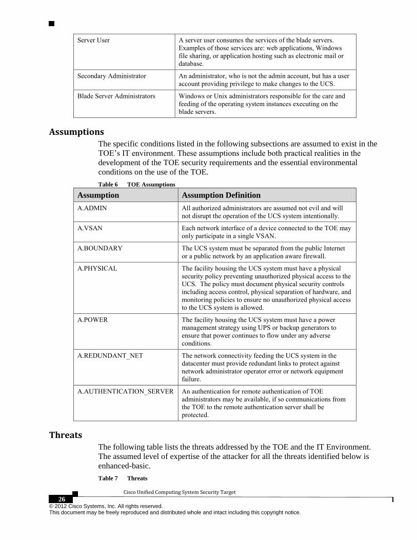
Server User A server user consumes the services of the blade servers.
Examples of those services are: web applications, Windows
file sharing, or application hosting such as electronic mail or
database.
Secondary Administrator An administrator, who is not the admin account, but has a user
account providing privilege to make changes to the UCS.
Blade Server Administrators Windows or Unix administrators responsible for the care and
feeding of the operating system instances executing on the
blade servers.
Assumptions The specific conditions listed in the following subsections are assumed to exist in the
TOE‟s IT environment. These assumptions include both practical realities in the
development of the TOE security requirements and the essential environmental
conditions on the use of the TOE.
Table 6 TOE Assumptions
Assumption Assumption Definition
A.ADMIN All authorized administrators are assumed not evil and will
not disrupt the operation of the UCS system intentionally.
A.VSAN Each network interface of a device connected to the TOE may
only participate in a single VSAN.
A.BOUNDARY The UCS system must be separated from the public Internet
or a public network by an application aware firewall.
A.PHYSICAL The facility housing the UCS system must have a physical
security policy preventing unauthorized physical access to the
UCS. The policy must document physical security controls
including access control, physical separation of hardware, and
monitoring policies to ensure no unauthorized physical access
to the UCS system is allowed.
A.POWER The facility housing the UCS system must have a power
management strategy using UPS or backup generators to
ensure that power continues to flow under any adverse
conditions.
A.REDUNDANT_NET The network connectivity feeding the UCS system in the
datacenter must provide redundant links to protect against
network administrator operator error or network equipment
failure.
A.AUTHENTICATION_SERVER An authentication for remote authentication of TOE
administrators may be available, if so communications from
the TOE to the remote authentication server shall be
protected.
Threats The following table lists the threats addressed by the TOE and the IT Environment.
The assumed level of expertise of the attacker for all the threats identified below is
enhanced-basic.
Table 7 Threats

Cisco Unified Computing System Security Target 27 © 2012 Cisco Systems, Inc. All rights reserved. This document may be freely reproduced and distributed whole and intact including this copyright notice.
Threat Name Threat Definition
T.NORMAL_USE A server user attacks the UCS infrastructure from an allowed
channel (web application, Windows share access, or
application) and compromises the TOE.
T.ROLE_ADMIN A secondary administrator configures the system in an
insecure manner (on purpose or accidentally) resulting in an
insecure configuration setting on the TOE.
T.NOAUTH A server user attempts to bypass the security of the UCS so as
to access and use security functions and/or non-security
functions resulting in a compromise of the TOE.
T.SNIFF A remote hacker places network-sniffing software between a
remote administrator and the UCS system and records
authentication information.
T.ACCOUNTABILITY
Role based administrators are not accountable for the actions
that they conduct because the audit records are not reviewed,
allowing their actions to go unnoticed.
T.CONFIGURE_NO A role based administrator from a different locale attempts to
make changes to configuration items they are not authorized
to change resulting in an insecure configuration setting on the
TOE.
T.ATTACK_ANOTHER A blade server administrator attempts to compromise a blade
server operating system for which he is not authorized to
access resulting in a compromise of the TOE.
Security Objectives This Chapter identifies the security objectives of the TOE and the IT Environment.
The security objectives identify the responsibilities of the TOE and the TOE‟s IT
environment in meeting the security needs.
This document identifies objectives of the TOE as O.objective with objective
specifying a unique name. Objectives that apply to the IT environment are designated
as OE.objective with objective specifying a unique name.
Security Objectives for the TOE The following table, Security Objectives for the TOE, identifies the security
objectives of the TOE. These security objectives reflect the stated intent to counter
identified threats and/or comply with any security policies identified. An explanation
of the relationship between the objectives and the threats/policies is provided in the
rationale section of this document.
Table 8 Security Objectives for the TOE
TOE Security
Obj.
TOE Security Objective Definition
O.IDAUTH The TOE must uniquely identify and authenticate the claimed identity of
all users, before granting a user access to TOE functions or, for certain
specified services, to a connected network.
O.ENCRYP The TOE must protect the confidentiality of its dialogue with an
authorized administrator through encryption, if the TOE allows

Cisco Unified Computing System Security Target
28 © 2012 Cisco Systems, Inc. All rights reserved. This document may be freely reproduced and distributed whole and intact including this copyright notice.
TOE Security
Obj.
TOE Security Objective Definition
administration to occur remotely from a connected network.
O.AUDREC The TOE must provide a means to record a readable audit trail of
security-related events, with accurate dates and times, and a means to
search and sort the audit trail based on relevant attributes.
O.ACCOUN The TOE must provide user accountability for information flows through
the TOE and for all use of security functions related to audit.
O.SECFUN The TOE must provide functionality that enables an authorized
administrator to use the TOE security functions, and must ensure that
only authorized administrators are able to access such functionality.
O.VLANSEC The TOE must ensure that IP packets received by the TOE are only
forwarded in a manner consistent with the VLAN for which the traffic is
associated.
O.VSANSEC The TOE must ensure that FC-2 frames received by the TOE are only
forwarded in a manner consistent with the VSAN for which the traffic is
associated.
O.ADMIN The TOE must provide a secure channel for administration.
Security Objectives for the Environment The assumptions identified previously are incorporated as security objectives for the
environment. They levy additional requirements on the environment, which are
largely satisfied through procedural or administrative measures. The following table,
Security Objectives for the Environment, identifies the security objectives for the
environment.
Table 9 Security Objectives for the Environment
Env. Security Obj. IT Environment Security Objective Definition
OE.ADMIN Personnel measures are in place to ensure well trained and trusted
administrators are authorized to manage the TOE.
OE.VSAN Each network interface of a storage devices in the operational
environment of the TOE may only participate in a single VSAN.
OE.BOUNDARY The UCS system must be separated from public networks by an
application aware firewall.
OE.PHYSICAL The operational environment of the TOE shall have a physical
security policy preventing unauthorized physical access to the
UCS. The policy must document physical security controls
including access control, physical separation of hardware, and
monitoring policies to ensure no unauthorized physical access to
the UCS system is allowed.
OE.POWER The operational environment of the TOE shall incorporate a power
management strategy using UPS or backup generators to ensure
that power continues to flow under any adverse conditions.
OE.REDUNDANT_NET The operational environment of the TOE shall provide redundant
network links to protect against network administrator operator
error or network equipment failure.
OE.AUTHENTICATION_SERVER The operational environment of the TOE shall optionally provide
an authentication server for remote authentication of TOE
administrators, with protected communications from the TOE to

Cisco Unified Computing System Security Target 29 © 2012 Cisco Systems, Inc. All rights reserved. This document may be freely reproduced and distributed whole and intact including this copyright notice.
the remote authentication server.
Security Requirements This section identifies the Security Functional Requirements for the TOE. The
Security Functional Requirements included in this section are derived verbatim from
Part 2 of the Common Criteria for Information Technology Security Evaluation,
Version 3.1, Revision 2, dated: September 2007 and all National Information
Assurance Partnership (NIAP) and international interpretations.
Conventions The CC defines operations on Security Functional Requirements: assignments,
selections, assignments within selections and refinements. This document uses the
following font conventions to identify the operations defined by the CC:
• Refinement: Indicated with bold text, or strikethrough as necessary;
• Selection: Indicated with underlined text;
• Assignment: text in brackets ([ ]);
• Assignment within a Selection: Indicated with underlined text in brackets;
• Iteration: Indicated by appending the iteration number in parenthesis, e.g., (1),
(2), (3).
TOE Security Functional Requirements This section identifies the Security Functional Requirements for the TOE. The TOE
Security Functional Requirements that appear in the following table are described in
more detail in the following subsections.
Table 10 Security Functional Requirements
SFR Component Name FAU_GEN.1 Audit data generation
FAU_SAR.1 Audit review
FAU_SAR.3 Selectable audit review
FAU_STG.1 Protected audit trail storage
FCS_CKM.1 Cryptographic key generation
FCS_CKM.4 Cryptographic key destruction
FCS_COP.1(1) Cryptographic operation – Symmetric Encryption
FCS_COP.1(2) Cryptographic operation – Hashing
FCS_COP.1(3) Cryptographic operation – Message Authentication
FCS_COP.1(4) Cryptographic operation – Digital Signatures
FCS_COP.1(5) Cryptographic operation – Key Establishment
FDP_ACC.2(1) Complete access control (RBAC)
FDP_ACC.2(2) Complete access control (IPMI Access Profiles)
FDP_ACF.1(1) Security attribute based access control (RBAC)
FDP_ACF.1(2) Security attribute based access control (IPMI Access Profiles)
FDP_IFC.1 (1) Subset information flow control (1) – VLAN
FDP_IFC.1 (2) Subset information flow control (2) – VSAN
FDP_IFF.1 (1) Simple security attributes (1) – VLAN
FDP_IFF.1 (2) Simple security attributes (2) – VSAN
FIA_ATD.1 User attribute definition

Cisco Unified Computing System Security Target
30 © 2012 Cisco Systems, Inc. All rights reserved. This document may be freely reproduced and distributed whole and intact including this copyright notice.
FIA_SOS.1 Verification of secrets
FIA_UAU.2 Timing of authentication
FIA_UAU.5 Multiple authentication mechanisms
FIA_UID.2 User identification before any action
FMT_MSA.1 (1) Management of security attributes (1)
FMT_MSA.1 (2) Management of security attributes (2)
FMT_MSA.1 (3) Management of security attributes (3)
FMT_MSA.1 (4) Management of security attributes (4)
FMT_MSA.3 (1) Static attribute initialization (1) – VLAN
FMT_MSA.3 (2) Static attribute initialization (2) – VSAN
FMT_MSA.3 (3) Static attribute initialization (3) - Role based access control
FMT_MSA.3 (4) Static attribute initialization (4) - IPMI
FMT_MTD.1 (1) Management of TSF data (1)
FMT_MTD.1 (2) Management of TSF data (2)
FMT_SAE.1 Time-based authorisation
FMT_SMF.1 Specification of Management Functions
FMT_SMR.1 Security roles
FPT_ITT.2 TSF data transfer separation
FPT_STM.1 Reliable time stamps
FTP_TRP.1 Trusted Path
Security audit (FAU)
FAU_GEN.1 Audit data generation
FAU_GEN.1.1 The TSF shall be able to generate an audit record of the
following auditable events:
a) Start-up and shutdown of the audit functions;
b) All auditable events for the not specified level of audit; and
c) [the events listed in Table 11].
FAU_GEN.1.2 The TSF shall record within each audit record at least the
following information:
a) Date and time of the event, type of event, subject identity, outcome
(success or failure) of the event; and
b) For each audit event type, based on the auditable event definitions
of the functional components included in the ST, [information
specified in column three of Table 11]. Table 11 Auditable Events
Functional
Component Auditable Event Additional Audit Record Content
FMT_SMR.1 Successful modifications to
user role assignments and
modifications to mappings
between roles and privileges.
The identity of the authorized administrator
performing the modification, user identity being
modified, and details being associated with the
authorized administrator role.
FIA_UAU.5 Successful and failed use of
the user authentication
mechanism on UCSM CLI
and GUI (authentication via
IPMI is not audited)
The user identities provided to the UCSM.
FDP_ACF.1(1) Successful role-based access
control requests submitted
via the UCSM CLI, and GUI.
The user identity requesting the change and the
object being accessed.
FPT_STM.1 Successful and failed The identity of the authorized administrator

Cisco Unified Computing System Security Target 31 © 2012 Cisco Systems, Inc. All rights reserved. This document may be freely reproduced and distributed whole and intact including this copyright notice.
attempts to change to the
time.
performing the operation
FTP_TRP.1 Successful and failed
attempts to use the trusted
path functions.
Success or failure of trusted path function.
Identification of the user associated with all
trusted path invocations including failures, if
available.
FAU_SAR.1 Audit review
FAU_SAR.1.1 The TSF shall provide [an authorized administrator] with the
capability to read [all locally stored audit trail data] from the audit
records.
FAU_SAR.1.2 The TSF shall provide the audit records in a manner suitable for the
user to interpret the information.
Application note: The locally stored audit data includes records of events that completed
successfully. Audit records for failed events are transmitted from the TOE to a remote syslog server,
so the complete set of successful and failed audit events would need to be reviewed via the remote
syslog server.
FAU_SAR.3 Selectable audit review
FAU_SAR.3.1 The TSF shall provide the ability to perform sorting and filtering of
audit data based on:
a) [record identifier;
b) affected object;
c) user]
FAU_STG.1 Protected audit trail storage
FAU_STG.1.1 The TSF shall protect the stored audit records from unauthorized
deletion.
FAU_STG.1.2 The TSF shall be able to prevent modifications to the audit records.
Cryptographic Support (FCS)
FCS_CKM.1 Cryptographic Key Generation – RSA and AES
FCS_CKM.1.1The TSF shall generate cryptographic keys in accordance with a
specified cryptographic key generation algorithm [RSA; AES] and
specified cryptographic key sizes [1024, 1536, and 2048 bits (RSA);
128 bits (AES)] that meet the following: [ANSI X9.31].
Application Note: The TOE provides RSA and AES Key Generation for the following purposes:
Table 12 - Cryptographic Key Generation (RSA and AES)
Usage Purpose SSH (RSA) Key used for SSH authentication
TLS (RSA) Key used for TLS authentication
SSH (AES) Key used for aes128-cbc encryption
TLS (AES) Key used for encryption in TLS_RSA_WITH_AES_128_CBC_SHA
SNMPv3 (AES) Key used for CFB128-AES-128 encryption

Cisco Unified Computing System Security Target
32 © 2012 Cisco Systems, Inc. All rights reserved. This document may be freely reproduced and distributed whole and intact including this copyright notice.
IPMIv2 (AES) Key used for AES-CBC-128 encryption
FCS_CKM.4 Cryptographic Key Destruction
FCS_CKM.4.1 The TSF shall destroy cryptographic keys in accordance with a
specified cryptographic key destruction method [overwrite with
zeroes] that meets the following: [FIPS 140-2].
FCS_COP.1(1) Cryptographic operation – Symmetric Encryption
FCS_COP.1.1(1) The TSF shall perform [encryption] in accordance with a
specified cryptographic algorithm: [AES] and cryptographic key sizes
[that are at least 128 binary digits in length] that meet the following:
[FIPS PUB 197].
Table 13 - Cryptographic operation – symmetric encryption
Usage Purpose SSH Provides data protection using symmetric encryption and decryption for SSH
communications with aes128-cbc, or aes256-cbc.
SNMPv3 Provides data protection using symmetric encryption and decryption for SNMPv3
communications.
TLS Provides data protection using symmetric encryption and decryption for TLS
communications.
IPMI v2.0 Uses AES-CBC-128 to provide data protection using symmetric encryption and
decryption.
FCS_COP.1(2) Cryptographic operation – Hashing
FCS_COP.1.1(2) The TSF shall perform [message hashing] in accordance with a
specified cryptographic algorithm [SHA-1] and cryptographic key
sizes [n/a] that meet the following: [FIPS 180-2]
Table 14 - Cryptographic operation – hashing
Usage Purpose SNMPv3 Used in HMAC-SHA-96 authentication
TLS Provides data integrity services
IPMI v2.0 Uses RAKP-HMAC-SHA1 for authentication, and HMAC-SHA1-96 for integrity.
FCS_COP.1(3) Cryptographic operation – Message Authentication
FCS_COP.1.1(3) The TSF shall perform [SNMPv3 HMAC-SHA-96 authentication] in
accordance with a specified cryptographic algorithm [HMAC, SHA-1]
and cryptographic key sizes [96 bit] that meet the following: [FIPS
180-2 , RFC2401, RFC3414]
Table 15 - Cryptographic operation – message authentication
Usage Purpose SNMPv3 Uses HMAC-SHA-96 for authentication
FCS_COP.1(4) Cryptographic operation – Digital Signature Generation/Verification
FCS_COP.1.1(4) The TSF shall perform [digital signature generation/verification] in
accordance with a specified cryptographic algorithm [RSA, SHA-1]
and cryptographic key sizes [1024, 2048 bit] that meet the following:
[PKCS#1v2]
Table 16 - Cryptographic operation – digital signatures

Cisco Unified Computing System Security Target 33 © 2012 Cisco Systems, Inc. All rights reserved. This document may be freely reproduced and distributed whole and intact including this copyright notice.
Usage Purpose TLS Used for TLS authentication
FCS_COP.1(5) Cryptographic operation – Key Establishment
FCS_COP.1.1(5) The TSF shall perform [key establishment] in accordance with a
specified cryptographic algorithm [Diffie Hellman] and cryptographic
key sizes [Group 1, 14] that meet the following: [RFC 2631]
Table 17 - Cryptographic operation – Key Establishment
Usage Purpose SSH Diffie Hellman used for key establishment
User Data Protection (FDP)
FDP_ACC.2(1) Complete access control (RBAC)
FDP_ACC.2.1(1) The TSF shall enforce the [role based access control SFP] on
[Subjects: Authenticated Administrators; Objects: Resources,
Configuration Settings] and all operations among subjects and objects
covered by the SFP.
FDP_ACC.2.2(1) The TSF shall ensure that all operations between any subject
controlled by the TSF and any object controlled by the TSF are
covered by an access control SFP.
FDP_ACC.2(2) Complete access control (IPMI Access Profiles)
FDP_ACC.2.1(2) The TSF shall enforce the [IPMI SFP] on [Subjects: IPMI
Users; Objects: Cisco Integrated management Controller (CIMC)] and
all operations among subjects and objects covered by the SFP.
FDP_ACC.2.2(2) The TSF shall ensure that all operations between any subject
controlled by the TSF and any object controlled by the TSF are
covered by an access control SFP.
FDP_ACF.1(1) Security attribute based access control (RBAC)
FDP_ACF.1.1(1) The TSF shall enforce the [role based access control SFP] to
objects based on the following: [
Subject security attributes:
Authenticated Administrators:
o User Identity – Identity of the administrator
o Locale – Identification of resources for which the user has
authority
o Privileges – The cumulative set of privileges obtained from
the roles assigned to the Authenticated Administrator.
Object security attributes:
Resource
o Locale - Identification of resource group
Configuration Settings

Cisco Unified Computing System Security Target
34 © 2012 Cisco Systems, Inc. All rights reserved. This document may be freely reproduced and distributed whole and intact including this copyright notice.
o Privilege – The privilege that an Authenticated
Administrator must hold in order to write to the
configuration setting].
FDP_ACF.1.2(1) The TSF shall enforce the following rules to determine if an
operation among controlled subjects and controlled objects is allowed:
[
Authenticated Administrators are granted access to Resources
in which the assigned locale for the Authenticated
Administrator and the assigned locale for the Resource are the
same. Authenticated Administrators assigned locales that are
different from the locales assigned to the Resources are not
granted access, and,
Authenticated Administrators whose set of Privileges includes
the Privilege attribute of the Configuration Setting being
accessed are granted read and write access to the object, or,
Authenticated Administrators whose set of Privileges does not
include the Privilege attribute of the Configuration Setting
being accessed are granted read-only to the Configuration
Setting for resources in which the Administrator has access
(per the locale)].
FDP_ACF.1.3(1) The TSF shall explicitly authorise access of subjects to objects
based on the following additional rules: [none].
FDP_ACF.1.4(1) The TSF shall explicitly deny access of subjects to objects
based on the [none].
FDP_ACF.1(2) Security attribute based access control (IPMI)
FDP_ACF.1.1(2) The TSF shall enforce the [IPMI SFP] to objects based on the
following: [
Subject security attributes:
IPMI Users (attributes defined in IPMI Access Profiles):
o Username
o IPMI User Role
o Password
Object security attributes:
CIMC (attributes defined in Service Profiles)
o External management IP Address].
FDP_ACF.1.2(2) The TSF shall enforce the following rules to determine if an
operation among controlled subjects and controlled objects is allowed:
[
An IPMI Access Profile with admin role is granted read-write
access to a CIMC.
An IPMI Access Profile with read-only role is granted read-
only access to a CIMC].
FDP_ACF.1.3(2) The TSF shall explicitly authorise access of subjects to objects
based on the following additional rules: [none].
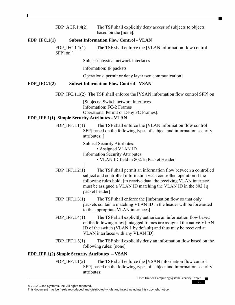
Cisco Unified Computing System Security Target 35 © 2012 Cisco Systems, Inc. All rights reserved. This document may be freely reproduced and distributed whole and intact including this copyright notice.
FDP_ACF.1.4(2) The TSF shall explicitly deny access of subjects to objects
based on the [none].
FDP_IFC.1(1) Subset Information Flow Control - VLAN
FDP_IFC.1.1(1) The TSF shall enforce the [VLAN information flow control
SFP] on [
Subject: physical network interfaces
Information: IP packets
Operations: permit or deny layer two communication]
FDP_IFC.1(2) Subset Information Flow Control - VSAN
FDP_IFC.1.1(2) The TSF shall enforce the [VSAN information flow control SFP] on
[Subjects: Switch network interfaces Information: FC-2 Frames Operations: Permit or Deny FC Frames].
FDP_IFF.1(1) Simple Security Attributes - VLAN
FDP_IFF.1.1(1) The TSF shall enforce the [VLAN information flow control
SFP] based on the following types of subject and information security
attributes: [
Subject Security Attributes:
• Assigned VLAN ID
Information Security Attributes:
• VLAN ID field in 802.1q Packet Header
]
FDP_IFF.1.2(1) The TSF shall permit an information flow between a controlled
subject and controlled information via a controlled operation if the
following rules hold: [to receive data, the receiving VLAN interface
must be assigned a VLAN ID matching the VLAN ID in the 802.1q
packet header]
FDP_IFF.1.3(1) The TSF shall enforce the [information flow so that only
packets contain a matching VLAN ID in the header will be forwarded
to the appropriate VLAN interfaces]
FDP_IFF.1.4(1) The TSF shall explicitly authorize an information flow based
on the following rules [untagged frames are assigned the native VLAN
ID of the switch (VLAN 1 by default) and thus may be received at
VLAN interfaces with any VLAN ID]
FDP_IFF.1.5(1) The TSF shall explicitly deny an information flow based on the
following rules: [none]
FDP_IFF.1(2) Simple Security Attributes – VSAN
FDP_IFF.1.1(2) The TSF shall enforce the [VSAN information flow control
SFP] based on the following types of subject and information security
attributes:

Cisco Unified Computing System Security Target
36 © 2012 Cisco Systems, Inc. All rights reserved. This document may be freely reproduced and distributed whole and intact including this copyright notice.
[Subject Security Attributes:
• Assigned VSAN ID
Information Security Attributes:
• VSAN ID field in the EISL Frame Header].
FDP_IFF.1.2(2) The TSF shall permit an information flow between a controlled
subject and controlled information via a controlled operation if the
following rules hold: [the VSAN ID in the EISL frame header must
match the VSAN ID associated with the FCoE VLAN that receives the
frame].
FDP_IFF.1.3(2) The TSF shall enforce the [information flow so that only
frames with a matching VSAN ID in the header will be forwarded].
FDP_IFF.1.4(2) The TSF shall explicitly authorize an information flow based
on the following rules: [untagged frames are assigned VSAN ID of 1
and thus may be received at VSAN interfaces with VSAN ID 1].
FDP_IFF.1.5(2) The TSF shall explicitly deny an information flow based on the
following rules [none].
Identification and Authentication (FIA)
FIA_ATD.1 User attribute definition
FIA_ATD.1.1 The TSF shall maintain the following list of security attributes
belonging to individual users:
For all user types (UCSM, SNMPv3, and IPMI):
a) [login id;
b) password;
and for UCSM and IPMI users:
c) role;
and for UCSM users only:
d) SSH key pair (optional instead of password);
e) account expiration date;
f) locale
And for SNMPv3 users only:
g) privacy password].
FIA_SOS.1 Verification of secrets
FIA_SOS.1.1 The TSF shall provide a mechanism to verify that secrets meet [
At least eight characters long
Does not contain more than three consecutive characters, such as
abcd
Does not contain more than two repeating characters, such as
aaabbb
Does not contain dictionary words
Does not contain common proper names].
Application Note: This requirement applies to the local password database and on
the password selection functions provided by the TOE, but remote authentication

Cisco Unified Computing System Security Target 37 © 2012 Cisco Systems, Inc. All rights reserved. This document may be freely reproduced and distributed whole and intact including this copyright notice.
servers may have pre-configured passwords which do not meet the quality metrics. It
does not apply to IPMI Access Profile passwords.
FIA_UAU.2 Timing of authentication
FIA_UAU.2.1 The TSF shall require each user to be successfully authenticated
before allowing any other TSF-mediated actions on behalf of that user.
FIA_UAU.5 Multiple authentication mechanisms
FIA_UAU.5.1 The TSF shall provide [
Local authentication (to UCSM):
o Password
o SSH public key authentication
Remote authentication (to UCSM):
o RADIUS
o LDAP
o TACACS+
IPMI authentication (to CIMC):
o Password
] to support user authentication.
FIA_UAU.5.2 The TSF shall authenticate any user's claimed identity according to the
[verification of local authentication password or proof of possession of
SSH private key or by querying a remote authentication server].
FIA_UID.2 User identification before any action
FIA_UID.2.1 The TSF shall require each user to be successfully identified before
allowing any other TSF-mediated actions on behalf of that user.
Security Management (FMT)
FMT_MSA.1(1) Management of security attributes - VLAN
FMT_MSA.1.1(1)The TSF shall enforce the [VLAN information flow control SFP]
to restrict the ability to query, modify, delete, [none] the security
attributes [sending and receiving VLAN interface and VLAN ID in
packet header specified in VLAN policies] to [an administrator
holding ext-lan-config, ext-lan-policy or admin privilege].
FMT_MSA.1(2) Management of security attributes - VSAN
FMT_MSA.1.1(2)The TSF shall enforce the [VSAN information flow control SFP] to
restrict the ability to modify, [none] the security attributes [sending
and receiving VSAN interface and VSAN ID specified in VLAN
policies] to [an administrator holding ext-san-config, ext-san-policy or
admin privilege].
FMT_MSA.1(3) Management of security attributes– Role based access control
FMT_MSA.1.1(3)The TSF shall enforce the [role based access control SFP] to
restrict the ability to modify, [none] the security attributes [listed in

Cisco Unified Computing System Security Target
38 © 2012 Cisco Systems, Inc. All rights reserved. This document may be freely reproduced and distributed whole and intact including this copyright notice.
section FDP_ACF1.1(1)] to [an administrator holding aaa or admin
privilege].
FMT_MSA.1(4) Management of security attributes – IPMI
FMT_MSA.1.1(4)The TSF shall enforce the [IPMI SFP] to restrict the ability to
modify, [none] the security attributes [listed in section
FDP_ACF.1.1(2)] to [an administrator holding either a) aaa or service-
profile-security or service-profile-security-policy (to create/configure
the IPMI Access Profile); or service-profile-config or service-profile-
server (to create/configure the Service Profile) or b) admin privilege].
FMT_MSA.3(1) Static attribute initialization - VLAN
FMT_MSA.3.1(1) The TSF shall enforce the [VLAN information flow control
SFP] to provide restrictive default values for information flow
security attributes that are used to enforce the SFP.
FMT_MSA.3.2(1) The TSF shall allow [an administrator holding ext-lan-config,
or ext-lan-policy or admin privilege] to specify alternative initial
values to override the default values when an object or information is
created.
FMT_MSA.3(2) Static attribute initialization - VSAN
FMT_MSA.3.1(2) The TSF shall enforce the [VSAN information flow control
SFP] to provide restrictive default values for information flow
security attributes that are used to enforce the SFP.
FMT_MSA.3.2(2) The TSF shall allow [an administrator holding ext-san-config,
ext-san-policy or admin privilege] to specify alternative initial values
to override the default values when an object or information is created.
FMT_MSA.3(3) Static attribute initialization – Role based access control
FMT_MSA.3.1(3) The TSF shall enforce the [role based access control SFP] to
provide restrictive default values for access control security attributes
that are used to enforce the SFP.
FMT_MSA.3.2(3) The TSF shall allow [an administrator holding aaa or admin
privilege] to specify alternative initial values to override the default
values when an object or information is created.
FMT_MSA.3(4) Static attribute initialization – IPMI
FMT_MSA.3.1(4) The TSF shall enforce the [IPMI SFP] to provide restrictive
default values for access control security attributes that are used to
enforce the SFP.
FMT_MSA.3.2(4) The TSF shall allow [an administrator holding either a) aaa or
service-profile-security or service-profile-security-policy (to
create/configure the IPMI Access Profile); or service-profile-config or
service-profile-server (to create/configure the Service Profile) or b)
admin privilege] to specify alternative initial values to override the
default values when an object or information is created.

Cisco Unified Computing System Security Target 39 © 2012 Cisco Systems, Inc. All rights reserved. This document may be freely reproduced and distributed whole and intact including this copyright notice.
FMT_MTD.1(1) Management of TSF data
FMT_MTD.1.1(1) The TSF shall restrict the ability to query, modify, delete, [and
assign] the [user attributes defined in FIA_ATD.1.1] to [an
administrator holding a) service-profile-security or service-profile-
security-policy (for IPMI users); or b) aaa or admin (for all user types)
privilege].
FMT_MTD.1(2) Management of TSF data
FMT_MTD.1.1(2) The TSF shall restrict the ability to [set] the [time and date
used to form the timestamps in FPT_STM.1.1] to [an administrator
holding admin, operations, ext-lan-config, or ext-lan-security
privilege].
FMT_SAE.1 Time-limited authorisation
FMT_SAE.1.1 The TSF shall restrict the capability to specify an expiration
time for [a user account] to [an administrator holding aaa or admin
privilege].
FMT_SAE.1.2 For each of these security attributes, the TSF shall be able to
[lock expired user accounts] after the expiration time for the indicated
security attribute has passed.
FMT_SMF.1 Specification of Management Functions
FMT_SMF.1.1 The TSF shall be capable of performing the following
management functions:
[a) Determine and modify the behavior of the audit trail management;
b) Query, modify, delete, and assign the user attributes defined in
FIA_ATD.1.1;
c) Set the system time for FPT_STM.1.1.].
FMT_SMR.1(1) Security roles (Administrators)
FMT_SMR.1.1 The TSF shall maintain the role privileges [
aaa
admin
ext-lan-config
ext-lan-policy
ext-lan-security
ext-san-config
ext-san-policy
operations
service-profile-config
service-profile-security
service-profile-security-policy
service-profile-server

Cisco Unified Computing System Security Target
40 © 2012 Cisco Systems, Inc. All rights reserved. This document may be freely reproduced and distributed whole and intact including this copyright notice.
].
FMT_SMR.1.2 The TSF shall be able to associate users with provide the
capability to assign the privileges to roles.
FMT_SMR.1(2) Security roles (IPMI Access Profiles)
FMT_SMR.1.1 The TSF shall maintain the IPMI User roles [
admin
read-only
].
FMT_SMR.1.2 The TSF shall be able to associate users with roles.
Application note: This SFR identifies the two default IPMI user roles which cannot
be deleted or modified.
Protection of the TSF (FPT)
FPT_ITT.2 TSF data transfer separation
FPT_ITT.2.1 The TSF shall protect TSF data from [disclosure, modification] when it
is transmitted between separate parts of the TOE.
FPT_ITT.2.2 The TSF shall separate user data from TSF data when such data is
transmitted between separate parts of the TOE.
FPT_STM.1 Reliable time stamps
FPT_STM.1.1 The TSF shall be able to provide reliable time stamps for its own use.
FTP_TRP.1 Trusted path
FTP_TRP.1.1 The TSF shall provide a communication path between itself and
[remote] users that is logically distinct from other communication
paths and provides assured identification of its end points and
protection of the communicated data from [modification, disclosure].
FTP_TRP.1.2 The TSF shall permit [remote users] to initiate communication via the
trusted path.
FTP_TRP.1.3 The TSF shall require the use of the trusted path for [initial user
authentication, management of the TOE via the CLI interface].
TOE SFR Hierarchies and Dependencies This section of the Security Target demonstrates that the identified TOE Security
Functional Requirements include the appropriate hierarchical SFRs and dependent
SFRs. The following table lists the TOE Security Functional Components and the
Security Functional Components each are hierarchical to and dependent upon and any
necessary rationale.
N/A in the Rationale column means the Security Functional Requirement has no
dependencies and therefore, no dependency rationale is required. Satisfied in the
Rationale column means the Security Functional Requirements dependency was
included in the ST.

Cisco Unified Computing System Security Target 41 © 2012 Cisco Systems, Inc. All rights reserved. This document may be freely reproduced and distributed whole and intact including this copyright notice.
Table 18 Security Functional Requirements
SFR Dependency Rationale FAU_GEN.1 FPT_STM.1 Met by FPT_STM.1
FAU_SAR.1 FAU_GEN.1 Met by FAU_GEN.1
FAU_SAR.3 FAU_SAR.1 Met by FAU_SAR.1
FAU_STG.1 FAU_GEN.1 Met by FAU_GEN.1
FCS_CKM.1 FCS_CKM.2 or
FCS_COP.1
FCS_CKM.4
Met by FCS_COP.1
Met by FCS_CKM.4
FCS_CKM.4 FDP_ITC.1 or 2
or FCS_CKM.1
Met by FCS_CKM.1
FCS_COP.1 FDP_ITC.1 or 2
or FCS_CKM.1
FCS_CKM.4
Met by FCS_CKM.1
Met by FCS_CKM.4
FDP_ACC.2(1) FDP_ACF.1 Met by FDP_ACF.1(1)
FDP_ACF.1(1) FMT_MSA.3
FDP_ACC.1
Met by FMT_MSA.3(3)
Met by FDP_ACC.2(1)
FDP_ACC.2(2) FDP_ACF.1 Met by FDP_ACF.1(2)
FDP_ACF.1(2) FMT_MSA.3
FDP_ACC.1
Met by FMT_MSA.3(3)
Met by FDP_ACC.2(2)
FDP_IFC.1(1) FDP_IFF.1 Met by FDP_IFF.1(1)
FDP_IFC.1(2) FDP_IFF.1 Met by FDP_IFF.1(2)
FDP_IFF.1(1) FDP_IFC.1
FMT_MSA.3
Met by FDP_IFC.1(1)
Met by FMT_MSA.3 (1)
FDP_IFF.1(2) FDP_IFC.1
FMT_MSA.3
Met by FDP_IFC.1(2)
Met by FMT_MSA.3 (2)
FIA_ATD.1 No dependencies N/A
FIA_SOS.1 No dependencies N/A
FIA_UAU.2 FIA_UID.1 Met by FIA_UID.2
FIA_UAU.5 No dependencies N/A
FIA_UID.2 No dependencies N/A
FMT_SAE.1 FMT_SMR.1
FPT_STM.1
Met by FMT_SMR.1 and
FPT_STM.1
FMT_MSA.1(1) FDP_ACC.1 or
FDP_IFC.1
FMT_SMR.1
FMT_SMF.1
Met by FDP_IFC.1 (1)
Met by FMT_SMR.1
Met by FMT_SMF.1
FMT_MSA.1(2) FDP_ACC.1 or
FDP_IFC.1
FMT_SMR.1
FMT_SMF.1
Met by FDP_IFC.1 (2)
Met by FMT_SMR.1
Met by FMT_SMF.1
FMT_MSA.1(3) FDP_ACC.1 or
FDP_IFC.1
FMT_SMR.1
FMT_SMF.1
Met by FDP_ACC.2(1)
Met by FMT_SMR.1
Met by FMT_SMF.1
FMT_MSA.1(4) FDP_ACC.1 or
FDP_IFC.1
FMT_SMR.1
FMT_SMF.1
Met by FDP_ACC.2(2)
Met by FMT_SMR.1
Met by FMT_SMF.1
FMT_MSA.3 (1) FMT_MSA.1
FMT_SMR.1
Met by FMT_MSA.1 (1)
Met by FMT_SMR.1
FMT_MSA.3 (2) FMT_MSA.1
FMT_SMR.1
Met by FMT_MSA.1 (2)
Met by FMT_SMR.1
FMT_MSA.3 (3) FMT_MSA.1
FMT_SMR.1
Met by FMT_MSA.1 (3)
Met by FMT_SMR.1

Cisco Unified Computing System Security Target
42 © 2012 Cisco Systems, Inc. All rights reserved. This document may be freely reproduced and distributed whole and intact including this copyright notice.
FMT_MSA.3 (4) FMT_MSA.1
FMT_SMR.1
Met by FMT_MSA.1 (4)
Met by FMT_SMR.1
FMT_MTD.1(1) FMT_SMF.1
FMT_SMR.1
Met by FMT_SMF.1
Met by FMT_SMR.1
FMT_MTD.1(2) FMT_SMF.1
FMT_SMR.1
Met by FMT_SMF.1
Met by FMT_SMR.1
FMT_SAE.1 FMT_SMF.1
FMT_SMR.1
Met by FMT_SMF.1
Met by FMT_SMR.1
FMT_SMF.1 No dependencies N/A
FMT_SMR.1(1) FIA_UID.1 Met by FIA_UID.2
FMT_SMR.1(2) FIA_UID.1 Met by FIA_UID.2
FPT_ITT.2 No dependencies N/A
FPT_STM.1 No dependencies N/A
FTP_TRP.1 No dependencies N/A
TOE Security Assurance Requirements
The TOE assurance requirements for this ST are EAL4 Augmented with ALC_FLR.2
derived from Common Criteria Version 3.1, Revision 2. The Security Target Claims
conformance to EAL4 Augmented with ALC_FLR.2. The assurance requirements are
summarized in the table below.
Table 19 SAR Requirements
Assurance Class Components Components Description
Development ADV_ARC.1 Architectural Design with domain separation and non-
bypassability
ADV_FSP.4 Complete functional specification
ADV_IMP.1 Implementation representation of the TSF
ADV_TDS.3 Basic modular design
Guidance Documents AGD_OPE.1 Operational user guidance
AGD_PRE.1 Preparative User guidance
Life Cycle Support ALC_CMC.4 Production support, acceptance procedures and automation
ALC_CMS.4 Problem tracking CM coverage
ALC_DEL.1 Delivery procedures
ALC_DVS.1 Identification of security measures
ALC _LCD.1 Developer defined life-cycle model
ALC_TAT.1 Well-defined development tools
ALC_FLR.2 Flaw Reporting Procedures
Tests ATE_COV.2 Analysis of coverage
ATE_DPT.2 Testing: security enforcing modules
ATE_FUN.1 Functional testing
ATE_IND.2 Independent testing – sample
Vulnerability Assessment AVA_VAN.3 Focused vulnerability analysis
Security Assurance Requirements Rationale
This Security Target claims conformance to EAL4 Augmented with ALC_FLR.2.
This target was chosen to ensure that the TOE has a moderate level of assurance in
enforcing its security functions when instantiated in its intended environment which
imposes no restrictions on assumed activity on applicable networks. Augmentation
was chosen to address having flaw remediation procedures and correcting security
flaws as they are reported.

Cisco Unified Computing System Security Target 43 © 2012 Cisco Systems, Inc. All rights reserved. This document may be freely reproduced and distributed whole and intact including this copyright notice.
Assurance Measures
The TOE satisfies the identified assurance requirements. This section identifies the
Assurance Measures applied by Cisco to satisfy the assurance requirements. The
table below lists the details.
Table 20 Assurance Measures
Component How the requirement will be met
ADV_ARC.1 The architecture of the TOE that is used to protect the TSF documented by
Cisco in their development evidence.
ADV_FSP.4 The externally visible interfaces of the TOE used by the users of the TOE along
with the description of the security functions and a correspondence between the
interfaces and the security functions from the ST are documented by Cisco in
their development evidence. The development evidence also contains a tracing
to the SFRs described in this ST.
ADV_IMP.1 Cisco provides access to the TSF implementation to the evaluation lab.
ADV_TDS.3 The design of the TOE will be described in the development evidence. This
evidence will also contain a tracing to the TSFI defined in the FSP.
AGD_OPE.1 The administrative guidance is detailed to provide descriptions of how
administrative users of the TOE can securely administer the TOE using those
functions and interfaces detailed in the guidance.
AGD_PRE.1 Cisco documents the installation, generation, and startup procedures so that the
users of the TOE can put the components of the TOE in the evaluated
configuration.
ALC_CMC.4 Cisco performs configuration management on configuration items of the TOE.
Configuration management is performed on the TOE and the implementation
representation of the TOE.
ALC_CMS.4 Cisco uniquely identifies configuration items and each release of the TOE has a
unique reference. The Configuration Management documentation contains a
configuration item list.
ALC_DEL.1 Cisco documents the delivery procedure for the TOE to include the procedure
on how to download certain components of the TOE from the Cisco website and
how certain components of the TOE are physically delivered to the user. The
delivery procedure detail how the end-user may determine if they have the TOE
and if the integrity of the TOE has been maintained. Further, the delivery
documentation describes how to acquire the proper license keys to use the TOE
components.
ALC_DVS.1 Cisco implements security controls over the development environment. Cisco
meets these requirements by documenting the security controls.
ALC_FLR.2 Cisco documents the flaw remediation and reporting procedures so that security
flaw reports from TOE users can be appropriately acted upon, and TOE users
can understand how to submit security flaw reports to the developer.
ALC_LCD.1 Cisco documents the TOE development life-cycle to meet these requirements.
ALC_TAT.1 Cisco uses well-defined development tools for creating the TOE.
ATE_COV.2 Cisco demonstrates the interfaces tested during functional testing using a
coverage analysis.

Cisco Unified Computing System Security Target
44 © 2012 Cisco Systems, Inc. All rights reserved. This document may be freely reproduced and distributed whole and intact including this copyright notice.
ATE_DPT.2 Cisco demonstrates the TSF subsystems tested during functional testing using a
depth analysis.
ATE_FUN.1 Cisco functional testing documentation contains a test plan, a description of the
tests, along with the expected and actual results of the test conducted against the
functions specified in the ST.
ATE_IND.2 Cisco will help meet the independent testing by providing the TOE to the
evaluation facility.
AVA_VAN.3 Cisco will provide the TOE for testing.
TOE Summary Specification
TOE Security Functional Requirement Measures This chapter identifies and describes how the Security Functional Requirements
identified above are met by the TOE.
Table 21 TOE SFRs Measures
TOE SFRs How the SFR is Met FAU_GEN.1 Shutdown and start-up of the audit functions are logged by events for reloading the UCS,
and the events when the UCS comes back up. Audit is enabled whenever the TOE is on.
The TOE also records an audit record whenever the TOE (and audit functionality) is
shutdown.
UCS generates events in the following format, with fields for date and time, type of event
(identifier code), subject identities, and outcome of the event as in this example:
19252,sys/user-ext/sh-login-admin-ttyS0_1_3947,session,internal,2009-06-
18T01:48:31,creation,Fabric A: local user admin logged in from console
Auditable events include:
Auditable Event Rationale Successful modifications to
user role assignments and
modifications to mappings
between roles and
privileges.
Successful modifications to users/roles/privileges are
logged in the local audit log. Failed attempts to make
such modifications are not logged.
Successful and failed use of
the user authentication
mechanism on UCSM CLI
and GUI (authentication via
IPMI is not audited)
All login attempts to the UCSM CLI and GUI are
logged. Successful attempts are logged to the local
audit log. All successful and failed attempts are
logged via syslog.
Successful role-based access
control requests submitted
via the UCSM CLI, and
GUI.
Successful changes to configuration data is logged to
the local admin log.
Successful and failed
attempts to change to the
time.
Successful attempts to change the system time and any
time-related parameters including time zone or NTP
server configuration are logged in the local audit log.
Manual setting of the clock can only be performed via
the CLI, and failed attempts to set the clock via CLI
are logged via syslog.
Successful and failed
attempts to use the trusted
path functions.
Successful and failed use of SSHv2 is logged via
syslog.

Cisco Unified Computing System Security Target 45 © 2012 Cisco Systems, Inc. All rights reserved. This document may be freely reproduced and distributed whole and intact including this copyright notice.
FAU_SAR.1 The UCS Manager restricts access of audit review to users having the operations or admin
privilege. These audit records are available to the authorized administrator through the
administrative GUI provided by the UCS Manager. The only way an administrator can
view TOE audit records is through the provided GUI interface. There are no other methods
to view the audit records. When the TOE is deployed in a clustered configuration, audit
review for the entire cluster is permitted.
FAU_SAR.3 The UCS stores the events in order by date. Events are added to the top of the buffer
display as they are generated, and UCS displays these new events at the top. The UCS
allows for sorting and filtering of the events based on one of the following, Audit record
ID, the affected object, or the user associated with the audit event. When the TOE is
deployed in a clustered configuration, audit review for the entire cluster is permitted.
FAU_STG.1 Audit records can be viewed by the authorized administrator via the UCS Manager. Audit
records are stored on the UCS in an internal file. The TOE does not provide any interfaces
that would allow unmediated access to the audit records. This file can only be deleted by
the authorized administrator through the UCS Manager. The file cannot be altered. When
the TOE is deployed in a clustered configuration, audit logs are stored centrally on the
primary UCS Manager instance and replicated to secondary instances for backup purposes.
FCS_CKM.1,
FCS_CKM.4
FCS_COP.1(1)
FCS_COP.1(2)
FCS_COP.1(3)
FCS_COP.1(4)
FCS_COP.1(5)
The cryptography used in this product has not been FIPS certified nor has it been analyzed
or tested to conform to cryptographic standards during this evaluation. All cryptography
has only been asserted as tested by the vendor.
The TOE provides cryptography (including AES encryption and associated key generation,
RSA key generation, and SHA hashing) in support of authentication, confidentiality and
integrity protection.
RSA keys are generated according to ANSI X9.31. AES keys are generated using random
numbers generated according to ANSI X9.31 Appendix A.2.4
All cryptographic keys used in administrative communications are zeroized by the TOE
after use.
The following communications protocols use cryptographic services:
SSHv2
o Used for command line interface.
o RFC 4251 and RFC 4252
o Options
Host key verification always used, other SSH authentication
methods never used
Public key authentication with RSA keys
Ciphers utilized: aes128-cbc
SSL3.1/TLS1.0
o Used for protection of GUI connection (via Java application, not
HTTPS), LDAP (over SSL/TLS), and CallHome messages
o RFC 2246, RFC 3268
o Options:
RSA key modulus 512, 1024, 1536, 2048 supported
Server authentication only, provides data confidentiality.
Session caching not supported
Ciphersuite utilized: TLS_RSA_WITH_AES_128_CBC_SHA
SNMPv3
o Used for system monitoring
o RFC 3411–RFC 3418, RFC 3826
o Options:
Supports HMAC-SHA-96 for authentication
Supports CFB128-AES-128 for encryption
IPMIv2.0

Cisco Unified Computing System Security Target
46 © 2012 Cisco Systems, Inc. All rights reserved. This document may be freely reproduced and distributed whole and intact including this copyright notice.
o Used for server monitoring
o Options:
Supports AES-CBC-128 encryption
Supports RAKP-HMAC-SHA1 for authentication
Supports HMAC-SHA1-96 for integrity
FDP_IFC.1(1)
and
FDP_IFF.1(1)
Network interfaces are grouped into VLANs, so Layer 2 broadcast packets will be issued
to only interfaces within that VLAN. Packets will have a VLAN ID associated to them
indicating which VLAN they are allowed to access. The TOE will enforce VLAN
separation by only allowing packets onto the VLAN that matches the VLAN ID. VLAN
traffic will not be forwarded to interfaces not in that VLAN.
FDP_IFC.1 (2)
and
FDP_IFF.1(2)
VSANs provide isolation among devices that are physically connected to the same fabric.
The underlying VSAN implementation allows creation of multiple logical SANs over a
common physical infrastructure. Each VSAN can contain up to 239 switches and has an
independent address space that allows identical Fibre Channel IDs (FCIDs) to be used
simultaneously in different VSANs.
Traffic is contained within VSAN boundaries and devices reside only in one VSAN thus
ensuring absolute separation between the data traversing separate VSANs. This ensures the
traffic flow control of data traversing the VSAN from users and devices belonging to other
VSANs. Each separate virtual fabric is isolated from one another using a hardware-based
frame tagging mechanism on VSAN member ports.
When traffic is sent or received on a VSAN interface the TOE examines the VSAN ID. If
the TOE is configured, through assignment of administrator-defined Service Policies, to
allow the frames to pass, the traffic will be allowed to flow. Otherwise, the traffic is not
allowed to pass.
FDP_ACC.2(1)
and
FDP_ACF.1(1)
The TOE implements an extensive Role Based Access Control system for administrative
access to the TOE. The TOE implements nine predefined administrative roles for
administrative users. Each predefined role is associated with privileges that grant access
permissions to the different configuration objects of the TOE. The TOE also provides the
ability to define custom roles with custom sets of privileges. During user creation each
administrator is assigned a User ID, a Locale, and role assignments. The Locale attribute
defines system resources that the administrator can access. If a resource is assigned a
different Locale than the Administrator, no access is granted. For resources that an
administrator may access, the role assigned to the administrator defines the administrative
capabilities that administrator is permitted for that resource. If an administrator is assigned
a role without access to a specific Configuration Setting, the administrator cannot access
the object.
FDP_ACC.2(2)
and
FDP_ACF.1(2)
The TOE implements a simple access control system for administrative access to the Cisco
Integrated Management Controller (CIMC) TOE components via IPMI. To authenticate to
a CIMC via IPMI, IPMI user accounts must first be created and applied to the CIMC via
UCSM. Authorized UCSM administrators with the service-profile-config or admin
privileges may configure IPMI Access Profiles defining IPMI users, along with their
passwords and roles, who would be permitted use IPMI to interact with the CIMC via
IPMI. IPMI users are defined in IPMI Access Profiles to have either read-only access, or
admin access. IPMI Access Profiles are associated with CIMCs through Service Profiles,
which define the IP address of the CIMC.
FIA_ATD.1 The UCS supports definition of administrators by individual user IDs, and these IDs are
associated with a specific role. For each administrator, the TOE maintains the following
attributes:
• Login ID,
• Password,
• SSH key pair,
• Account Expiration,
• Role, and
• Locale.
Roles are mapped to a collection of privileges that grant access to specific system

Cisco Unified Computing System Security Target 47 © 2012 Cisco Systems, Inc. All rights reserved. This document may be freely reproduced and distributed whole and intact including this copyright notice.
resources and permission to perform specific tasks.
For each IPMI Access Profile, there is a username, a password and a role.
FIA_SOS.1 To prevent users from choosing insecure passwords, each password must meet the
following requirements:
• At least eight characters long
• Does not contain more than three consecutive characters, such as abcd
• Does not contain more than two repeating characters, such as aaabbb
• Does not contain dictionary words
• Does not contain common proper names
This requirement applies to the local password database and on the password selection
functions provided by the TOE, but remote authentication servers may have pre-configured
passwords which do not meet the quality metrics. It does not apply to IPMI Access Profile
passwords.
FIA_UID.2 and
FIA_UAU.2
By default, UCS Manager uses the local database for identification and authentication.
Similarly the BCM uses its IPMI Access Profile database for identification and
authentication. No access is allowed without encountering an authentication prompt. Only
after authentication is an administrator able to perform any actions. Remote authentication
servers may be used in support of administrator access to the CLI and GUI but IPMI is
always governed by the IPMI Access Profile database for the server (i.e. blade) being
accessed.
FIA_UAU.5 The UCS Manager may be configured for local or remote authentication. In the case of
local authentication, account passwords are verified against hashes stored the /etc/shadow
system file. A user account may also be configured with an SSH public key to facilitate
SSH public key authentication. User SSH keys may be entered in OpenSSH, SECSH and
X.509 certificate formats.
In the case of remote authentication, user credentials are passed to a remote RADIUS,
TACACS+ or LDAP server for verification. In the remote authentication case, only
password authentication is used for SSH.
The HTTPS GUI authenticates against the local authentication database or remote
authentication server, per system configuration.
The SSH CLI authenticates users using SSH public key authentication if keys have been
provisioned for the user, otherwise it uses SSH password authentication, verified against
the local authentication database or remote authentication server.
The UCS Manager permits username/password authentication to the CIMC when
accessing the IPMI interface.
FMT_MSA.1(1)
FMT_MSA.1(2)
FMT_MSA.1(3)
FMT_MSA.1(4)
The UCS access policies are configured to protect the UCS itself and to restrict the ability
to enter privileged configuration mode to users with the correct role and privilege. Newly
created users are not associated with any role and do not have any privilege but read-only
unless roles are explicitly assigned by the AAA Administrator. Similarly, users are
associated with no locales (note this is distinct from being associated with an empty locale
with global organizational access).
The TOE provides the following access to TOE administrative functionality :
A. Users with the privileges associated with “Network Administrator” Role have
query, modify, and delete access to the VLAN Policies
B. Users with the privileges associated with “Storage Administrator” Role have
modify access to the VSAN Policies
C. Users with the admin, aaa, service-profile-security, or service-profile-security-
policy privileges can configure IPMI Access Profiles; and users with admin,
service-profile-config, or service-profile-server can create/configure the Service
Profile that associate IPMI Access Profiles with CIMCs.

Cisco Unified Computing System Security Target
48 © 2012 Cisco Systems, Inc. All rights reserved. This document may be freely reproduced and distributed whole and intact including this copyright notice.
D. Access to other administrative functionality of the TOE is provided to
administrative users in a manner consistent with the access policy defined in
FDP_ACF.1.
FMT_MSA.3
(1), (2), (3) and
(4)
Restrictive default values are provided for VLANs, VSANs, and role based access control.
No information flows are allowed for traffic (VLAN/VSAN) unless the traffic the attribute
combination of receiving/sending interface and VLAN/VSAN ID is explicitly allowed in
an administratively configured information flow policy.
No administrative access is granted unless the role associated with the administrative user
attempting to access the TOE is allowed access.
Restrictive default values are provided for IPMI Access Profiles – by default they have the
read-only role.
FMT_MTD.1(1)
FMT_MTD.1(2)
The UCS is configured to restrict the ability to enter privileged configuration operations to
those users with the correct role assigned. The TOE only allows users with the aaa or
admin privilege access to another user‟s security attributes (ID, Password, SSH Key,
Account Expiration Date, Role, and Locale), with the limitation that the assignment of
organizations is restricted to only those in the locale of the user assigning the
organizations. The TOE only allows users with the admin privilege the ability to set the
TOE time.
FMT_SAE.1 The TOE provides administrative users with the admin privilege the ability to set a time
period after which administrative accounts are deactivated.
FMT_SMF.1 The UCS is configured to restrict the ability to enter privileged configuration operations to
those users holding the correct privilege from their assigned role(s).
The TOE provides the ability manage the operation of the TOE, audit trail, administrative
access, administrative users and timestamps.
FMT_SMR.1(1) Table 4 lists the privileges associated with management capabilities and default roles
supported by the TOE. Other privileges exist in UCS that can be assigned to roles as
needed, but the other privileges defined in UCS are not relevant to supporting the security
functionality described in the FMT_* requirements in this ST.
Privilege Relevance to Evaluated Security Functions
aaa FMT_MSA.1.1(3)
FMT_MSA.1.1(4)
FMT_MSA.3.2(3)
FMT_MSA.3.2(4)
FMT_MTD.1.1(1)
FMT_SAE.1.1
admin FMT_MSA.1.1(1)
FMT_MSA.1.1(2)
FMT_MSA.1.1(3)
FMT_MSA.1.1(4)
FMT_MSA.3.2(1)
FMT_MSA.3.2(2)
FMT_MSA.3.2(3)
FMT_MSA.3.2(4)
FMT_MTD.1.1(1)
FMT_MTD.1.1(2)
FMT_SAE.1.1
ext-lan-config FMT_MSA.1.1(1)
FMT_MSA.3.2(1)
FMT_MTD.1.1(2)
ext-lan-policy FMT_MSA.1.1(1)
FMT_MSA.3.2(1)
FMT_MTD.1.1(2)
ext-lan-qos None
ext-lan-security None
ext-san-config FMT_MSA.1.1(2)

Cisco Unified Computing System Security Target 49 © 2012 Cisco Systems, Inc. All rights reserved. This document may be freely reproduced and distributed whole and intact including this copyright notice.
FMT_MSA.3.2(2)
ext-san-policy FMT_MSA.1.1(2)
FMT_MSA.3.2(2)
ext-san-qos None
ext-san-security None
fault None
operations FMT_MTD.1.1(2)
pod-config None
pod-policy None
pod-qos None
pod-security None
power-mgmt None
read-only None
server-equipment None
server-maintenance None
server-policy None
server-security None
service-profile-config FMT_MSA.1.1(4)
FMT_MSA.3.2(4)
service-profile-config-policy None
service-profile-ext-access None
service-profile-network None
service-profile-network-policy None
service-profile-qos None
service-profile-qos-policy None
service-profile-security FMT_MSA.1.1(4)
FMT_MSA.3.2(4)
FMT_MTD.1.1(1)
service-profile-security-policy FMT_MSA.1.1(4)
FMT_MSA.3.2(4)
FMT_MTD.1.1(1)
service-profile-server FMT_MSA.1.1(4)
FMT_MSA.3.2(4)
service-profile-server-policy None
service-profile-storage None
service-profile-storage-policy None
FMT_SMR.1(2) IPMI Access Profiles may have a role of either admin or read-only.
FPT_ITT.2 When operating in ;ing mode, the UCS Manager‟s configuration and event logs are
replicated to the secondary servers via direct physical connections or VLAN protected L2
communications. This allows clustered fabric interconnects to share data and continuously
monitor the status of each other and quickly know when one has failed.
FPT_STM.1 The UCS provides a source of date and time information for the system, used in audit
timestamps and in validating service requests. The clock function is reliant on the system
clock provided by the underlying hardware. This functionality can be set in UCSM.
FTP_TRP.1 The UCS permits command line access to management functions using the SSH protocol
for authentication, integrity protection and confidentiality. The SSH implementation RSA
keys of 1024 bit modulus. To achieve trusted path requires that an authorized
administrator holding the aaa or admin privilege configures user keys. Distribution of
those user keys is outside the scope of the TOE.
This requirement does not pertain to authentication over the IPMI interface.
TOE Bypass and interference/logical tampering Protection Measures The UCS TOE consists of a hardware and software solution. The UCS hardware
platform protects all operations in the TOE from interference and tampering by

Cisco Unified Computing System Security Target
50 © 2012 Cisco Systems, Inc. All rights reserved. This document may be freely reproduced and distributed whole and intact including this copyright notice.
untrusted subjects. All TSP enforcement functions must be invoked and succeed prior
to functions within the TSC proceeding.
The TOE has been designed so that all locally maintained TSF data can only be
manipulated via the secured management interface, a CLI and GUI (UCSM)
interface. The CLI interface achieves a trusted path via SSH public key authentication
and is recommended for authorized administrator access from outside the network
boundary protecting the TOE servers. The GUI interface is a partially trusted path,
but TLS client authentication is not performed, and it is recommended that the GUI
interface be used from within the trusted network. There are no undocumented
interfaces for managing the product.
All sub-components included in the TOE hardware rely on the main UCS chassis for
power, memory management, and access control. In order to access any portion of the
TOE, the Identification & Authentication mechanisms of the UCS must be invoked
and succeed.
No processes outside of the UCS are allowed direct access to any TOE memory. The
TOE only accepts traffic through legitimate TOE interfaces. None of these interfaces
provide any access to internal TOE resources.
The UCS provides a secure domain for its operation. Each component has its own
resources that other components within the same UCS platform are not able to affect.
There are no unmediated traffic flows into or out of the TOE. The information flow
policies identified in the SFRs are applied to all traffic received and sent by the UCS.
Both communication types including data plane communication and, control plane
communications are mediated by the TOE. Data plane communication refers to data-
center traffic that sent and received to/from external IT entities. Control plane
communications refer to administrative traffic used to control the operation of the
TOE. There is no opportunity for unaccounted traffic flows to flow into or out of the
TOE.
The TOE provides a secure domain for each VLAN to operate within. Each VLAN
has its own forwarding plane resources that other VLANs within the same TOE are
not able to affect.
The TOE provides a secure domain for each VSAN to operate within. Each VSAN
has its own resources that other VSANs within the same TOE are not able to affect.
The TOE includes the Cisco UCS Manager Software. This software includes a server
and client component. The server component is resident within the TOE hardware
and is protected by the mechanisms described above.
The client portion of the Cisco UCS Manager Software is dependent on the IT
environment. This software component runs on the operating systems identified in
Table 2, above. The software is protected by the Operating System on which the
software is installed.
This design, combined with the fact that only an administrative user with the
appropriate role may access the TOE security functions, provides a distinct protected
domain for the TOE that is logically protected from interference and is not
bypassable.

Cisco Unified Computing System Security Target 51 © 2012 Cisco Systems, Inc. All rights reserved. This document may be freely reproduced and distributed whole and intact including this copyright notice.
Rationale This section describes the rationale for the Security Objectives and Security
Functional Requirements as defined within this Security Target. Additionally, this
section describes the rationale for not satisfying all of the dependencies. The table
below illustrates the mapping from Security Objectives to Threats and Policies.
Rationale for the Security Objectives Table 22: Summary of Mappings between Threats, Policies and the Security Objectives (both TOE and
Operational Environment)
O.I
DA
UT
H
O.E
NC
RY
P
O.A
UD
RE
C
O.A
CC
OU
N
O.S
EC
FU
N
O.V
LA
NS
EC
O.V
SA
NS
EC
O.A
DM
IN
T.NORMAL_USE X X
T.ROLE_ADMIN X
T.NOAUTH X X X
T.SNIFF X X
T.ACCOUNTABILITY X X X
T.CONFIGURE_NO X
T.ATTACK_ANOTHER X X
Table 23: Rationale for Mappings between Threats, Policies and the Security Objectives for the TOE
Objective Rationale O.IDAUTH This security objective is necessary to counter the threat T.NOAUTH
because it ensures that all users must be authenticated.
O.ENCRYP This security objective is necessary to counter the threat T.SNIFF by
requiring that all administrative traffic be encrypted to prevent usable
information from being extracted from a sniffed session.
O.AUDREC This security objective is necessary to counter the threat
T.ACCOUNTABILITY by requiring the TOE to record any
administrative session allowing the identification of mistakes, by
recording all auditable information in a human reviewable format, and by
identifying attempted administrative actions even when the action is from
an administrator with inappropriate authorization.
O.ACCOUN This security objective is necessary to counter the threat
T.ACCOUNTABILITY by ensuring that all administrators are
accountable for their actions even when the action is from an administrator
with inappropriate authorization.
O.SECFUN Th
is
se cu rit
y
ob
je cti
ve
is
ne
ce ss ar y
to
co un
ter
th e thr
ea ts
T.
R O L E_
A D M IN , T.
A C C O U N T A BI
LI
T Y,
an d
T.
C O N FI
G U R E_
N O
by
en su rin
g
th e T O E
pr
ov
id es
th e m ea ns
fo r ad mi
ni
str
ati
ve
us
er s to
ap pr
op
ria
tel
y
co nfi
gu
re
th e T O E.
A dd
iti
on
all
y,
thi
s ob
je cti
ve
pr
ov
id es
th e ad mi
ni
str
ati
ve
ca pa
bil
ity
to
re co nfi
gu
re
pr
ev io us
ad mi
ni
str
ati
ve
ac tio
ns.
O.VLANSEC This security objective is necessary to counter the threats:
T.NORMAL_USER, T.NOAUTH, and T.ATTACK_ANOTHER by
requiring that the TOE only forward traffic in a manner consistent with the
VLANs for which the traffic is associated preventing access to resources
for which the traffic should not be associated.
O.VSANSEC This security objective is necessary to counter the threats:
T.NORMAL_USER, T.NOAUTH, and T.ATTACK_ANOTHER by
requiring that the TOE only forward traffic in a manner consistent with the
VSANs for which the traffic is associated preventing access to resources
for which the traffic should not be associated.

Cisco Unified Computing System Security Target
52 © 2012 Cisco Systems, Inc. All rights reserved. This document may be freely reproduced and distributed whole and intact including this copyright notice.
Objective Rationale O.ADMIN This security objective counters the threat T.SNIFF by providing a secure
channel for administration.
Table 24: Summary of Mappings between Assumptions and the Security Objectives for the Operational
Environment
Assumption
OE
.AD
MIN
OE
.VS
AN
OE
.BO
UN
DA
RY
OE
.PH
YS
ICA
L
OE
.PO
WE
R
OE
.RE
DU
ND
AN
T_
NE
T
OE
.AU
TH
EN
TIC
AT
ION
_
SE
RV
ER
A.ADMIN X
A.VSAN X
A.BOUNDARY X
A.PHYSICAL X
A.POWER X
A.REDUNDANT_NET X
A.AUTHENTICATION_SERVER X
Table 25: Rationale for Mappings between Threats, Policies and the Security Objectives for the
Operational Environment
Objective Rationale OE.ADMIN This security objective satisfies A.ADMIN by
ensuring that competent and trusted administrators
manage the TOE.
OE.VSAN This security objective satisfies A.VSAN by ensuring
that devices connected to the TOE will only participate
in one VSAN per network interface.
OE.BOUNDARY This security objective satisfies A.BOUNDARY by
ensuring that the UCS system is separated from public
networks by an application aware firewall.
OE.PHYSICAL This security objective satisfies A.PHYSICAL by
ensuring that the UCS system is physically protected
from unauthorized access.
OE.POWER This security objective satisfies A.POWER by
ensuring that the UCS system has sufficient power to
operate.
OE.REDUNDANT_NET This security objective satisfies
A.REDUNDANT_NET by ensuring network
availability.
OE.AUTHENTICATION_SERVER This security objective satisfies A.
AUTHENTICATION_SERVER by ensuring remote
authentication services for TOE administrators.
Table 26: Summary of Mappings between SFRs and Security Objectives

Cisco Unified Computing System Security Target 53 © 2012 Cisco Systems, Inc. All rights reserved. This document may be freely reproduced and distributed whole and intact including this copyright notice.
Rationale for SFRs/TOE Objectives This section provides rationale for the Security Functional Requirements
demonstrating that the Security Functional Requirements are suitable to address the
security objectives. The table below illustrates the mapping from SFRs to Security
Objectives.
SFR
O.I
DA
UT
H
O.E
NC
RY
P
O.A
UD
RE
C
O.A
CC
OU
N
O.S
EC
FU
N
O.V
LA
NS
EC
O.V
SA
NS
EC
O.A
DM
IN
FAU_GEN.1 X X
FAU_SAR.1 X X
FAU_SAR.3 X X
FAU_STG.1 X X
FCS_CKM.1 X
FCS_CKM.4 X
FCS_COP.1(1) X
FCS_COP.1(2) X
FCS_COP.1(3) X
FCS_COP.1(4) X
FCS_COP.1(5) X
FDP_ACC.2(1) X
FDP_ACF.1(1) X
FDP_ACC.2(2) X
FDP_ACF.1(2) X
FDP_IFC.1 (1) X
FDP_IFC.1 (2) X
FDP_IFF.1 (1) X
FDP_IFF.1 (2) X
FIA_ATD.1 X
FIA_SOS.1 X
FIA_UAU.2 X
FIA_UAU.5 X
FIA_UID.2 X
FMT_MSA.1 (1) X
FMT_MSA.1 (2) X
FMT_MSA.1 (3) X
FMT_MSA.1 (4) X
FMT_MSA.3 (1) X
FMT_MSA.3 (2) X
FMT_MSA.3 (3) X
FMT_MSA.3 (4) X
FMT_MTD.1 (1) X
FMT_MTD.1 (2) X
FMT_SAE.1 X
FMT_SMF.1 X
FMT_SMR.1(1) X
FMT_SMR.1(2) X
FPT_ITT.2 X X
FPT_STM.1 X
FTP_TRP.1 X

Cisco Unified Computing System Security Target
54 © 2012 Cisco Systems, Inc. All rights reserved. This document may be freely reproduced and distributed whole and intact including this copyright notice.
Table 27 - Summary of Mappings between IT Security Objectives and SFRs
SFR Rationale for Mapping to Objective
FAU_GEN.1 This component outlines what data must be included in audit records and what events must be
audited.
This component traces back to and aids in meeting the following objectives: O.AUDREC,
O.ACCOUN.
FAU_SAR.1
This component ensures that the audit trail is understandable.
This component traces back to and aids in meeting the following objectives: O.AUDREC,
O.ACCOUN.
FAU_SAR.3
This component ensures that a variety of searches and sorts can be performed on the audit trail.
This component traces back to and aids in meeting the following objectives: O.AUDREC,
O.ACCOUN.
FAU_STG.1 This component is chosen to ensure that the audit trail is protected from tampering, the security
functionality is limited to the authorized administrator and that start-up and recovery does not
compromise the audit records.
This component traces back to and aids in meeting the following objective: O.IDAUTH,
O.SECFUN.
FCS_CKM.1
This component ensures that cryptographic keys are generated in accordance to specified
algorithms and key sizes.
This component traces back to and aids in meeting the following objective: O.ENCRYP.
FCS_CKM.4
This component ensures that cryptographic keys are zeroized after use.
This component traces back to and aids in meeting the following objective: O.ENCRYP.
FCS_COP.1(1)
This component provides for confidentiality services via AES encryption to enable authorized
administrators to communicate with the TOE remotely.
This component traces back to and aids in meeting the following objective: O.ENCRYP.
FCS_COP.1(2)
This component provides for message hashing for data integrity and authentication.
This component traces back to and aids in meeting the following objective: O.ENCRYP.
FCS_COP.1(3)
This component provides for message authentication via a modified SHA-HMAC function.
This component traces back to and aids in meeting the following objective: O.ENCRYP.
FCS_COP.1(4)
This component provides for generation and verification of RSA digital signatures.
This component traces back to and aids in meeting the following objective: O.ENCRYP.
FCS_COP.1(5)
This component provides for Diffie-Hellman key establishment.
This component traces back to and aids in meeting the following objective: O.ENCRYP.
FDP_ACC.2(1)
This component ensures that the TOE provides administrative access to only TOE administrators
with the appropriate authorization.
This component traces back to and aids in meeting the following objective: O.SECFUN.
FDP_ACF.1(1)
This component ensures that the TOE provides administrative access to only TOE administrators
with the appropriate authorization.
This component traces back to and aids in meeting the following objective: O.SECFUN.
FDP_ACC.2(2)
This component ensures that the TOE provides administrative IPMI access only to configured
IPMI Access Profiles with the appropriate authorization.
This component traces back to and aids in meeting the following objective: O.SECFUN.
FDP_ACF.1(2)
This component ensures that the TOE provides administrative IPMI access only to configured
IPMI Access Profiles with the appropriate authorization.
This component traces back to and aids in meeting the following objective: O.SECFUN.
FDP_IFC.1 (1)
This component satisfies this policy by ensuring that all IP traffic received from an external entity
is only passed if it is associated with a configured VLAN.
This component traces back to and aids in meeting the following objective: O.VLANSEC.

Cisco Unified Computing System Security Target 55 © 2012 Cisco Systems, Inc. All rights reserved. This document may be freely reproduced and distributed whole and intact including this copyright notice.
FDP_IFC.1 (2)
This component satisfies this policy by ensuring that all FC-2 frames received from an external
entity are only passed if they are associated with a configured VSAN.
This component traces back to and aids in meeting the following objective: O.VSANSEC.
FDP_IFF.1 (1)
This component satisfies this policy by ensuring that all IP traffic received from an external entity
is only passed if it is associated with a configured VLAN.
This component traces back to and aids in meeting the following objective: O.VLANSEC.
FDP_IFF.1 (2)
This component satisfies this policy by ensuring that all FC-2 frames received from an external
entity are only passed if they are associated with a configured VSAN.
This component traces back to and aids in meeting the following objective: O.VSANSEC.
FIA_ATD.1
This component exists to provide users with attributes to distinguish one user from another, for
accountability purposes and to associate the role chosen in FMT_SMR.1(1) with a user.
This component traces back to and aids in meeting the following objective: O.IDAUTH.
FIA_SOS.1
This component ensures user passwords meet defined quality metrics.
This component traces back to and aids in meeting the following objective: O.IDAUTH.
FIA_UAU.2
This component ensures that before anything occurs on behalf of a user, the user's identity is
authenticated to the TOE.
This component traces back to and aids in meeting the following objective: O.IDAUTH.
FIA_UAU.5
This component identifies the multiple authentication mechanisms permitted for users.
This component traces back to and aids in meeting the following objective: O.IDAUTH.
FIA_UID.2
This component ensures that before anything occurs on behalf of a user, the user's identity is
identified to the TOE.
This component traces back to and aids in meeting the following objective: O.IDAUTH.
FMT_MSA.1 (1)
This component ensures the TSF enforces the VLAN SFP to restrict the ability to query, delete,
and modify those security attributes that are listed in section FDP_IFF.1 (1).
This component traces back to and aids in meeting the following objectives: O.SECFUN,.
FMT_MSA.1 (2)
This component ensures the TSF enforces the VSAN SFP to restrict the ability to modify those
security attributes that are listed in section FDP_IFF.1 (2).
This component traces back to and aids in meeting the following objectives: O.SECFUN.
FMT_MSA.1 (3)
This component ensures the TSF enforces the Role Based Administrative Access Control to
restrict the ability to modify those security attributes that are listed in section FDP_ACF.1(1).
This component traces back to and aids in meeting the following objectives: O.SECFUN.
FMT_MSA.1 (4)
This component ensures the TSF enforces the Role Based Administrative Access Control to
restrict the ability to modify those security attributes that are listed in section FDP_ACF.1(2).
This component traces back to and aids in meeting the following objectives: O.SECFUN.
FMT_MSA.3 (1)
This component ensures that there is a default deny policy for the VLAN information flow control
security rules.
This component traces back to and aids in meeting the following objectives: O.SECFUN
FMT_MSA.3 (2)
This component ensures that there is a default deny policy for the VSAN information flow control
security rules.
This component traces back to and aids in meeting the following objectives: O.SECFUN
FMT_MSA.3 (3)
This component ensures that there is a default deny policy for the Role Based Administrative
Access Control security rules.
This component traces back to and aids in meeting the following objectives: O.SECFUN
FMT_MSA.3 (4)
This component documents the default permissive policy for the IPMI Access Profiles.
This component traces back to meeting the following objectives: O.SECFUN
FMT_MTD.1 (1)
This component ensures that the TSF restrict abilities to query, modify, delete and assign certain
user attributes as defined in FIA_ATD.1.1 to only the authorized administrator.

Cisco Unified Computing System Security Target
56 © 2012 Cisco Systems, Inc. All rights reserved. This document may be freely reproduced and distributed whole and intact including this copyright notice.
This component traces back to and aids in meeting the following objective: O.SECFUN.
FMT_MTD.1 (2)
This component ensures that the TSF restrict abilities to set the time and date used to form
timestamps to only the authorized administrator.
This component traces back to and aids in meeting the following objective: O.SECFUN.
FMT_SAE.1
This component ensures user accounts can be given a time limit by administrators.
This component traces back to and aids in meeting the following objective: O.SECFUN.
FMT_SMF.1
This component ensures that the TSF restrict the set of management functions to the authorized
administrator.
This component traces back to and aids in meeting the following objective: O.SECFUN.
FMT_SMR.1(1)
This component ensures that the TOE maintains authorized administrator roles to manage the TOE
administrative security functionality.
This component traces back to and aids in meeting the following objective: O.SECFUN.
FMT_SMR.1(2)
This component ensures that the TOE maintains admin and read only roles for IPMI Access
Profiles.
This component traces back to and aids in meeting the following objective: O.SECFUN.
FPT_ITT.2
This component ensures that the TOE protects TSF data when it is transmitted between separate
parts of the TOE.
This component traces back to and aids in meeting the following objective: O.ADMIN.
FPT_STM.1
This component ensures that the date and time on the TOE is dependable. This is important for the
audit trail.
This component traces back to and aids in meeting the following objective: O.AUDREC.
FTP_TRP.1
This component ensures that administrators have a trusted path to access the TOE.
This component traces back to and aids in meeting the following objective: O.ADMIN.

Cisco Unified Computing System Security Target 57 © 2012 Cisco Systems, Inc. All rights reserved. This document may be freely reproduced and distributed whole and intact including this copyright notice.
Glossary: Acronyms and Abbreviations The following acronyms and abbreviations are used in this Security Target:
Table 28 Acronyms or Abbreviations
Acronym or
Abbreviation
Definition
BMC Baseboard Management Controller (renamed to CIMC)
CIMC Cisco Integrated Management Controller
DH-CHAP Diffie Hellman - Challenge Handshake Authentication Protocol
FCoE Fibre Channel over Ethernet
FC-SP Fibre Channel – Security Protocol
LAN Local Area Network
SAN Storage Area Network
SNMP Simple Network Management Protocol
SSH Secure Shell
SSL Secure Socket Layer
ST Security Target
TLS Transport Layer Security
TOE Target of Evaluation
UCS Unified Computing System
UUID Universally Unique IDentifier
VSAN Virtual Storage Area Network
Glossary: References and Related Documents The following documentation was used to prepare this ST:
[CC_PART1] Common Criteria for Information Technology Security Evaluation –
Part 1: Introduction and general model, dated September 2006, version 3.1, Revision
1, CCMB-2006-09-001
[CC_PART2] Common Criteria for Information Technology Security Evaluation –
Part 2: Security functional components, dated September 2007, version 3.1, Revision
2, CCMB--2007-09-002
[CC_PART3] Common Criteria for Information Technology Security Evaluation –
Part 3: Security assurance components, dated September 2007, version 3.1, Revision
2, CCMB-2007-09-003
[CEM] Common Methodology for Information Technology Security Evaluation –
Evaluation Methodology, dated September 2007, version 3.1, Revision 2, CCMB-
2007-09-004

Cisco Unified Computing System Security Target
58 © 2012 Cisco Systems, Inc. All rights reserved. This document may be freely reproduced and distributed whole and intact including this copyright notice.
Obtaining Documentation, Support, and Security Guidelines
For information on obtaining documentation, obtaining support, providing
documentation feedback, security guidelines, and also recommended aliases and
general Cisco documents, see the monthly What‟s New in Cisco Product
Documentation, which also lists all new and revised Cisco technical documentation,
at: http://www.cisco.com/en/US/docs/general/whatsnew/whatsnew.html
CCDE, CCENT, Cisco Eos, Cisco HealthPresence, the Cisco logo, Cisco Lumin, Cisco Nexus, Cisco StadiumVision, Cisco TelePresence, Cisco WebEx, DCE, and Welcome to the Human Network are trademarks; Changing the Way We Work, Live, Play, and Learn and Cisco Store are service marks; and Access Registrar, Aironet, AsyncOS, Bringing the Meeting To You, Catalyst, CCDA, CCDP, CCIE, CCIP, CCNA, CCNP, CCSP, CCVP, Cisco, the Cisco Certified Internetwork Expert logo, Cisco IOS, Cisco Press, Cisco Systems, Cisco Systems Capital, the Cisco Systems logo, Cisco Unity, Collaboration Without Limitation, EtherFast, EtherSwitch, Event Center, Fast Step, Follow Me Browsing, FormShare, GigaDrive, HomeLink, Internet Quotient, IOS, iPhone, iQuick Study, IronPort, the IronPort logo, LightStream, Linksys, MediaTone, MeetingPlace, MeetingPlace Chime Sound, MGX, Networkers, Networking Academy, Network Registrar, PCNow, PIX, PowerPanels, ProConnect, ScriptShare, SenderBase, SMARTnet, Spectrum Expert, StackWise, The Fastest Way to Increase Your Internet Quotient, TransPath, WebEx, and the WebEx logo are registered trademarks of Cisco Systems, Inc. and/or its affiliates in the United States and certain other countries. All other trademarks mentioned in this document or website are the property of their respective owners. The use of the word partner does not imply a partnership relationship between Cisco and any other company. (0812R) © 2012 Cisco Systems, Inc. All rights reserved.