cisco unified application environment administration guide...cisco unified application environment...
TRANSCRIPT
Cisco Unified Application Environment Administration GuideRelease 8.5
Americas HeadquartersCisco Systems, Inc.170 West Tasman DriveSan Jose, CA 95134-1706 USAhttp://www.cisco.comTel: 408 526-4000
800 553-NETS (6387)Fax: 408 527-0883
OL-21902-01

THE SPECIFICATIONS AND INFORMATION REGARDING THE PRODUCTS IN THIS MANUAL ARE SUBJECT TO CHANGE WITHOUT NOTICE. ALL STATEMENTS, INFORMATION, AND RECOMMENDATIONS IN THIS MANUAL ARE BELIEVED TO BE ACCURATE BUT ARE PRESENTED WITHOUT WARRANTY OF ANY KIND, EXPRESS OR IMPLIED. USERS MUST TAKE FULL RESPONSIBILITY FOR THEIR APPLICATION OF ANY PRODUCTS.
THE SOFTWARE LICENSE AND LIMITED WARRANTY FOR THE ACCOMPANYING PRODUCT ARE SET FORTH IN THE INFORMATION PACKET THAT SHIPPED WITH THE PRODUCT AND ARE INCORPORATED HEREIN BY THIS REFERENCE. IF YOU ARE UNABLE TO LOCATE THE SOFTWARE LICENSE OR LIMITED WARRANTY, CONTACT YOUR CISCO REPRESENTATIVE FOR A COPY.
The Cisco implementation of TCP header compression is an adaptation of a program developed by the University of California, Berkeley (UCB) as part of UCB’s public domain version of the UNIX operating system. All rights reserved. Copyright © 1981, Regents of the University of California.
NOTWITHSTANDING ANY OTHER WARRANTY HEREIN, ALL DOCUMENT FILES AND SOFTWARE OF THESE SUPPLIERS ARE PROVIDED “AS IS” WITH ALL FAULTS. CISCO AND THE ABOVE-NAMED SUPPLIERS DISCLAIM ALL WARRANTIES, EXPRESSED OR IMPLIED, INCLUDING, WITHOUT LIMITATION, THOSE OF MERCHANTABILITY, FITNESS FOR A PARTICULAR PURPOSE AND NONINFRINGEMENT OR ARISING FROM A COURSE OF DEALING, USAGE, OR TRADE PRACTICE.
IN NO EVENT SHALL CISCO OR ITS SUPPLIERS BE LIABLE FOR ANY INDIRECT, SPECIAL, CONSEQUENTIAL, OR INCIDENTAL DAMAGES, INCLUDING, WITHOUT LIMITATION, LOST PROFITS OR LOSS OR DAMAGE TO DATA ARISING OUT OF THE USE OR INABILITY TO USE THIS MANUAL, EVEN IF CISCO OR ITS SUPPLIERS HAVE BEEN ADVISED OF THE POSSIBILITY OF SUCH DAMAGES.
Cisco and the Cisco Logo are trademarks of Cisco Systems, Inc. and/or its affiliates in the U.S. and other countries. A listing of Cisco's trademarks can be found at www.cisco.com/go/trademarks. Third party trademarks mentioned are the property of their respective owners. The use of the word partner does not imply a partnership relationship between Cisco and any other company. (1005R)
Any Internet Protocol (IP) addresses used in this document are not intended to be actual addresses. Any examples, command display output, and figures included in the document are shown for illustrative purposes only. Any use of actual IP addresses in illustrative content is unintentional and coincidental.
Cisco Unified Application Environment Administration Guide, Release 8.5 ©2010 Cisco Systems, Inc. All rights reserved.
OL-21902-01
C O N T E N T S
Preface xi
Purpose xi
Audience xi
Organization i-xii
Related Documentation xii
Product Documentation xiii
Developer Documentation xiii
Document Conventions xiii
Obtaining Documentation and Submitting a Service Request xiv
C H A P T E R 1 Overview 1-1
Understanding the Cisco Unified Application Environment 1-1
Supported Application Development IP Telephony Functions 1-1
Supported Application Development and Deployment Technologies 1-2
Cisco Unified Application Environment Components 1-2
Cisco Unified Application Server 1-2
Cisco Unified Media Engine 1-3
Cisco Unified Application Environment Developer Tools 1-3
Understanding the Deployment of the Cisco Unified Application Environment 1-4
Deployment Topologies 1-4
Single Cisco Unified Application Server with a Single Cisco Unified Communications Manager Cluster 1-4
Single Application Server with Multiple Cisco Unified Communications Manager Clusters 1-5
Single Cisco Unified Application Server Controlling Multiple Cisco Unified Media Engines with Multiple Cisco Unified Communications Manager Clusters 1-6
Multiple Application Servers Controlling Multiple Media Engines with Multiple Cisco Unified Communications Manager Clusters 1-7
Understanding Network Port Usage 1-8
Port Usage 1-9
Running 3rd-Party Platform Agents 1-11
Overview 1-12
Support Policies for 3rd-Party Software 1-12
Utilizing Cisco Security Agent 1-13
Overview 1-13
Management Center for Cisco Security Agents 1-13
iiiCisco Unified Application Environment Administration Guide, Release 8.5
Contents
Backward Compatibility 1-14
Cisco Unified Communications Manager 1-14
Cisco Unified IP Phones 1-14
Cisco Unified Presence 1-15
Cisco Unified Messaging (Unity and Unity Connection 8.0) 1-15
C H A P T E R 2 What is New in This Release 2-1
New and Changed Information for Release 8.5 2-1
C H A P T E R 2 Getting Started 2-1
Before You Begin 2-1
Logging In 2-2
Understanding the Cisco Unified Application Environment Administration 2-2
Setting Up the Cisco Unified Application Environment 2-3
C H A P T E R 3 Managing System Settings 3-1
Setting Global Parameters 3-1
Setting Parameters for the Server 3-1
Setting Parameters for the Cisco Unified Application Server 3-2
Setting Parameters for the Cisco Unified Media Engine 3-3
Support for MCS Server 3-3
Installation and Deployment Requirements 3-4
Deployment on VMware ESXi 4.0’ 3-4
Managing Licenses 3-4
Overview 3-5
Viewing License Statistics and Modes 3-6
Managing License Files 3-6
Uploading a License 3-7
Deleting a License 3-7
Deployment and Licensing for VMware or Virtualized Environment 3-7
Redundant Licensing 3-7
Failover Strategies 3-8
License Limits 3-8
Configuring Redundancy 3-9
Overview 3-9
Setting Up Redundancy 3-10
Redundant Application Server 3-12
Redundant Media Server 3-13
ivCisco Unified Application Environment Administration Guide, Release 8.5
OL-21902-01
Contents
Configuring SSL Management 3-13
Overview 3-13
Uploading SSL Certificate and Key 3-13
Passphrase Protection 3-14
Certificate and Key Backups 3-14
Generating SSL Certificate and Key 3-14
Enabling SSL 3-14
Disabling SSL 3-15
Restarting the Apache Service 3-15
Managing Secure Connections to the Management Service 3-16
Generating the Certificate and Key 3-17
Managing the CUAE Command-line Tool Protocol 3-17
Enabling Authentication between CUAE Command-line Tool and Management Service 3-17
Disabling TLS on the Management Service 3-18
Configure Management Service Connection Details 3-18
Managing Secure Connections to the Etch Bridge 3-18
Understanding Client-Server Connections 3-19
Enabling TLS on the Etch Bridge 3-19
Disabling TLS on the Etch Bridge 3-20
Developer Tasks 3-20
Creating a New Etch-Bridge Certificate 3-21
Before You Begin 3-21
Etch Connection String URI 3-23
Overview 3-23
KeepAlive 3-23
Enabling KeepAlive 3-23
Modifying KeepAlive Parameters 3-24
Disabling KeepAlive 3-24
Max Packet Size 3-24
Using the Etch Bridge Max Packet Size 3-24
Using the Etch MaxPacketSize 3-25
ReconnectDelay 3-25
C H A P T E R 4 Managing Users 4-1
Viewing and Searching for Users 4-1
Adding a User 4-1
Deleting a User 4-2
Editing User Information 4-2
vCisco Unified Application Environment Administration Guide, Release 8.5
OL-21902-01
Contents
C H A P T E R 5 Managing Applications 5-1
Overview 5-1
Understanding Partitions 5-1
Understanding Scripts and Triggers 5-2
Application Configuration Example 5-3
Managing Applications 5-4
Viewing Applications 5-4
Installing an Application 5-5
Enabling or Disabling an Application 5-5
Uninstalling an Application 5-6
Viewing Application Details 5-6
Updating an Application 5-7
Managing Partitions 5-7
Adding a Partition 5-7
Deleting a Partition 5-9
Applying Partition Configurations 5-9
Enabling and Disabling Partition Configurations 5-9
Uninstalling Partition Configurations 5-10
Managing Triggers 5-10
Viewing Triggers 5-10
Viewing Trigger Details 5-11
Adding a Trigger Parameter 5-11
Deleting a Trigger Parameter 5-12
Updating a Trigger Parameter 5-12
C H A P T E R 6 Managing Plugins 6-1
Cisco Unified Application Environment Plugins 6-1
Cisco DeviceListX Provider 6-1
H.323 Provider 6-2
HTTP Provider 6-3
JTAPI Provider 6-3
Media Engine Provider 6-3
Presence Provider 6-4
SCCP Provider 6-5
SIP Provider 6-6
Timer Provider 6-6
Viewing the List of Plugins 6-7
Installing a Plugin 6-7
viCisco Unified Application Environment Administration Guide, Release 8.5
OL-21902-01
Contents
Enabling or Disabling a Plugin 6-7
Uninstalling a Plugin 6-8
Configuring Plugins 6-8
Invoking Extensions 6-9
C H A P T E R 7 Managing Connections 7-1
Managing Connections 7-1
Viewing and Searching for Connections 7-1
Viewing and Searching for Device Pools 7-2
Adding a Connection 7-3
Adding Device Pools 7-3
Managing Devices in a Device Pool 7-7
Adding a Cisco Unified Media Engine 7-9
Adding a Cisco Unified Communications Manager Cluster 7-10
Adding Cisco Unified Presence 7-12
Adding an H.323 Gateway 7-12
Adding IETF SIP Proxy Server 7-13
Adding a Nuance Server 7-13
Adding a Nuance License Server 7-14
Deleting a Connection 7-14
Deleting a Device Pool 7-14
Deleting a Cisco Unified Communications Manager Node 7-15
Deleting a Cisco Unified Communications Manager Cluster 7-15
Editing a Connection 7-16
Disabling a Connection 7-16
Managing Connection Groups 7-16
Viewing and Searching for Groups 7-17
Adding a Connection Group 7-17
Adding a Cisco Unified Media Engine Group 7-18
Adding an SCCP Device Pool Group 7-19
Adding an H.323 Gateway Group 7-19
Adding a SIP Device Pool Group 7-20
Adding a CTI Device Pool Group 7-20
Deleting a Connection Group 7-21
Editing a Connection Group 7-21
C H A P T E R 8 Serviceability 8-1
Managing Server Logs 8-1
Viewing Server Logs 8-2
viiCisco Unified Application Environment Administration Guide, Release 8.5
OL-21902-01
Contents
Deleting Server Logs 8-2
Archiving Server Logs 8-2
Managing Services 8-3
Configuring Trace Settings 8-4
Using Trace Settings for Troubleshooting 8-4
Configuring Logger Settings 8-4
Configuring Trace Levels 8-5
Viewing Usage Statistics 8-7
Using Diagnostics 8-7
Managing Alarms 8-7
Viewing Alarms 8-8
Configuring Alarm Managers 8-8
Setting Alarms to Ignored 8-9
C H A P T E R 9 Backing Up, Restoring, and Reinitializing the System 9-1
Backing Up the System 9-1
Restoring the System 9-2
Reinitializing the Cisco Unified Application Server 9-3
C H A P T E R 10 FAQs and Troubleshooting 10-1
FAQs 10-1
General FAQs 10-1
Hardware FAQs 10-2
Software FAQs 10-2
Troubleshooting 10-2
Connections 10-2
Licensing 10-3
A P P E N D I X A Configuring an Example Environment A-1
Setting Up an Example Deployment and Performing Configuration Tasks A-1
Task 1: Log in to the Cisco Unified Application Environment Administration A-2
Task 2: Create a Cisco Unified Media Engine Connection A-2
Task 3: Create a SIP Connection to Cisco Unified Communications Manager A-3
Task 4: Create a SIP Trunk A-5
Create the SIP Trunk Security Profile A-5
Create a SIP Profile A-6
Create the SIP Trunk A-7
Task 5: Set Up a Route Pattern A-8
viiiCisco Unified Application Environment Administration Guide, Release 8.5
OL-21902-01
Contents
Task 6: Create Phones in Cisco Unified Communications Manager A-9
Task 7: Configure Your Phone to Connect to the Cisco Unified Communications Server A-10
Task 8: Configure the SIP Provider Plugin A-11
Task 9: Install, Configure, and Test Sample Applications A-11
MakeCall Sample Application A-12
AnswerCall Sample Application A-14
JTAPIConnect Sample Application A-17
IN D E X
ixCisco Unified Application Environment Administration Guide, Release 8.5
OL-21902-01

Contents
xCisco Unified Application Environment Administration Guide, Release 8.5
OL-21902-01
Preface
This preface describes the purpose, audience, organization, and conventions of this guide and provides information on how to obtain additional information.
This section includes these topics:
• Purpose, page xi
• Audience, page xi
• Organization, page xii
• Related Documentation, page xii
• Document Conventions, page xiii
• Obtaining Documentation and Submitting a Service Request, page xiv
PurposeThis document explains how to administer and maintain the Cisco Unified Application Environment using the Cisco Unified Application Environment Administration.
AudienceThis guide is intended for system administrators who are familiar with the Windows operating system, have a basic understanding of IP telephony, and have full knowledge of Cisco Unified Communications Manager and the installed IP telephony environment.
xiCisco Unified Application Environment Administration Guide, Release 8.5
OL-21902-01
Preface Organization
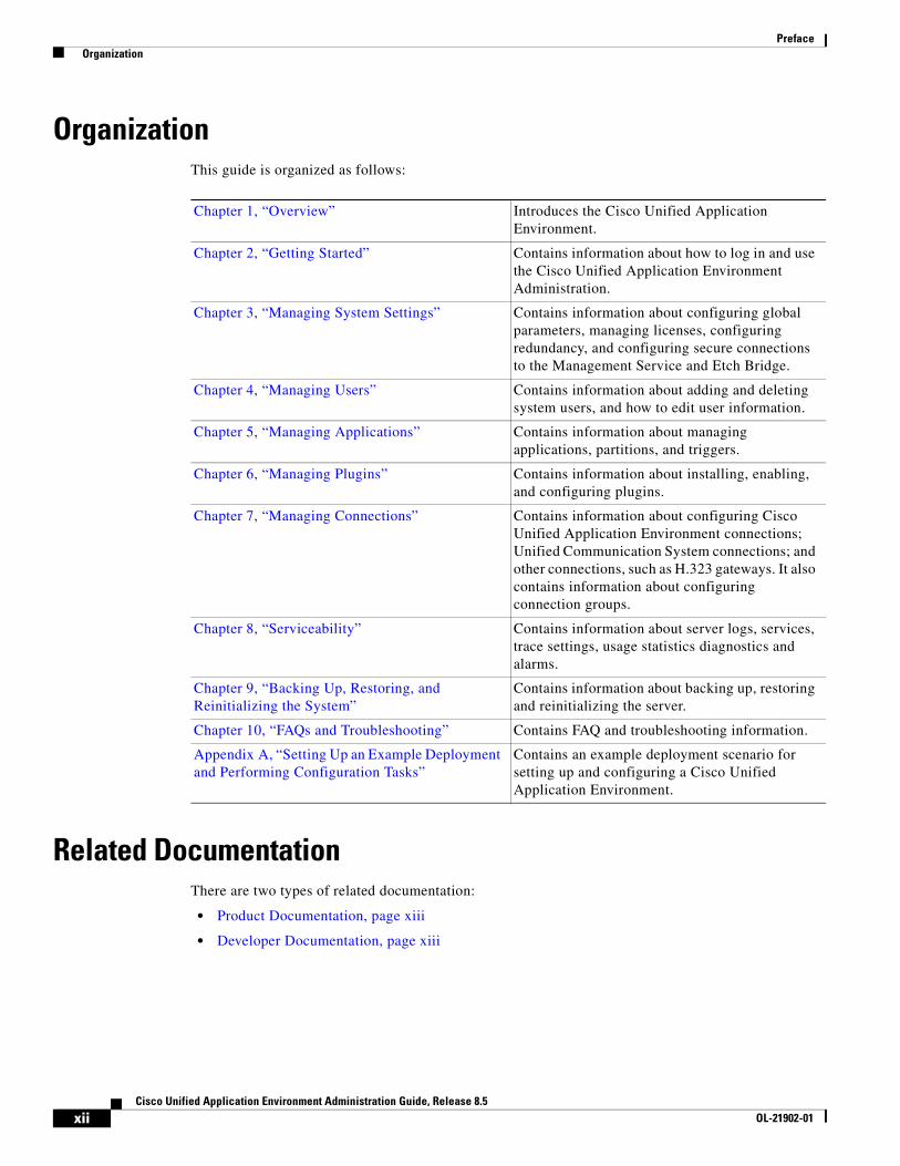
OrganizationThis guide is organized as follows:
Related DocumentationThere are two types of related documentation:
• Product Documentation, page xiii
• Developer Documentation, page xiii
Chapter 1, “Overview” Introduces the Cisco Unified Application Environment.
Chapter 2, “Getting Started” Contains information about how to log in and use the Cisco Unified Application Environment Administration.
Chapter 3, “Managing System Settings” Contains information about configuring global parameters, managing licenses, configuring redundancy, and configuring secure connections to the Management Service and Etch Bridge.
Chapter 4, “Managing Users” Contains information about adding and deleting system users, and how to edit user information.
Chapter 5, “Managing Applications” Contains information about managing applications, partitions, and triggers.
Chapter 6, “Managing Plugins” Contains information about installing, enabling, and configuring plugins.
Chapter 7, “Managing Connections” Contains information about configuring Cisco Unified Application Environment connections; Unified Communication System connections; and other connections, such as H.323 gateways. It also contains information about configuring connection groups.
Chapter 8, “Serviceability” Contains information about server logs, services, trace settings, usage statistics diagnostics and alarms.
Chapter 9, “Backing Up, Restoring, and Reinitializing the System”
Contains information about backing up, restoring and reinitializing the server.
Chapter 10, “FAQs and Troubleshooting” Contains FAQ and troubleshooting information.
Appendix A, “Setting Up an Example Deployment and Performing Configuration Tasks”
Contains an example deployment scenario for setting up and configuring a Cisco Unified Application Environment.
xiiCisco Unified Application Environment Administration Guide, Release 8.5
OL-21902-01
Preface Organization
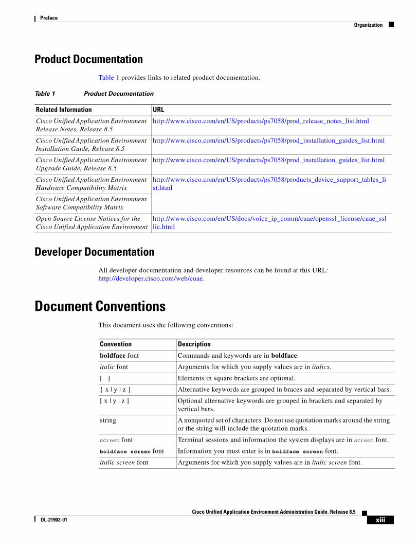
Product DocumentationTable 1 provides links to related product documentation.
Developer DocumentationAll developer documentation and developer resources can be found at this URL: http://developer.cisco.com/web/cuae.
Document ConventionsThis document uses the following conventions:
Table 1 Product Documentation
Related Information URL
Cisco Unified Application Environment Release Notes, Release 8.5
http://www.cisco.com/en/US/products/ps7058/prod_release_notes_list.html
Cisco Unified Application Environment Installation Guide, Release 8.5
http://www.cisco.com/en/US/products/ps7058/prod_installation_guides_list.html
Cisco Unified Application Environment Upgrade Guide, Release 8.5
http://www.cisco.com/en/US/products/ps7058/prod_installation_guides_list.html
Cisco Unified Application Environment Hardware Compatibility Matrix
http://www.cisco.com/en/US/products/ps7058/products_device_support_tables_list.html
Cisco Unified Application Environment Software Compatibility Matrix
Open Source License Notices for the Cisco Unified Application Environment
http://www.cisco.com/en/US/docs/voice_ip_comm/cuae/openssl_license/cuae_ssllic.html
Convention Description
boldface font Commands and keywords are in boldface.
italic font Arguments for which you supply values are in italics.
[ ] Elements in square brackets are optional.
{ x | y | z } Alternative keywords are grouped in braces and separated by vertical bars.
[ x | y | z ] Optional alternative keywords are grouped in brackets and separated by vertical bars.
string A nonquoted set of characters. Do not use quotation marks around the string or the string will include the quotation marks.
screen font Terminal sessions and information the system displays are in screen font.
boldface screen font Information you must enter is in boldface screen font.
italic screen font Arguments for which you supply values are in italic screen font.
xiiiCisco Unified Application Environment Administration Guide, Release 8.5
OL-21902-01
Preface Organization
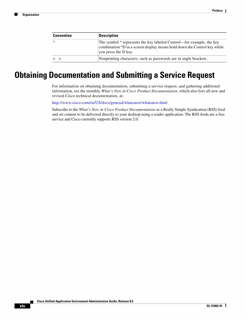
Obtaining Documentation and Submitting a Service RequestFor information on obtaining documentation, submitting a service request, and gathering additional information, see the monthly What’s New in Cisco Product Documentation, which also lists all new and revised Cisco technical documentation, at:
http://www.cisco.com/en/US/docs/general/whatsnew/whatsnew.html
Subscribe to the What’s New in Cisco Product Documentation as a Really Simple Syndication (RSS) feed and set content to be delivered directly to your desktop using a reader application. The RSS feeds are a free service and Cisco currently supports RSS version 2.0.
^ The symbol ^ represents the key labeled Control—for example, the key combination ^D in a screen display means hold down the Control key while you press the D key.
< > Nonprinting characters, such as passwords are in angle brackets.
Convention Description
xivCisco Unified Application Environment Administration Guide, Release 8.5
OL-21902-01
Cisco Unified ApplicaOL-21902-01
C H A P T E R 1
OverviewThe Cisco Unified Application Environment is a development and runtime platform designed for creating, deploying, and executing converged voice and data applications. It is integrated with Cisco Unified Communications Manager and Cisco Unified Presence.
This chapter includes these topics:
• Understanding the Cisco Unified Application Environment, page 1-1
• Understanding the Deployment of the Cisco Unified Application Environment, page 1-4
Understanding the Cisco Unified Application EnvironmentThis section includes these topics:
• Supported Application Development IP Telephony Functions, page 1-1
• Supported Application Development and Deployment Technologies, page 1-2
• Cisco Unified Application Environment Components, page 1-2
Supported Application Development IP Telephony FunctionsThe Cisco Unified Application Environment can be used to create applications supporting the following IP telephony functions:
• Presence
• Mobility
• Recording
• Paging
• Conferencing
• Speech-enabled applications
• IP phone services
• Other voice and data converged applications
1-1tion Environment Administration Guide, Release 8.5
Chapter 1 Overview Understanding the Cisco Unified Application Environment
Supported Application Development and Deployment TechnologiesIt supports these application development and deployment technologies:
• Telephony call control: Session Initiation Protocol (SIP), H.323, Skinny Call Control Protocol (SCCP), and Computer Telephony Integration (CTI)
• Java Telephony Application Programming Interface (JTAPI)
• Other telephony protocols: Cisco Unified IP Phone Services, DeviceListX, AXL-SOAP, Extension Mobility, and other Cisco Unified Communications Manager APIs
• Data services and protocols: Web Services, HTTP, Lightweight Directory Access Protocol (LDAP), Structured Query Language (SQL), Simple Mail Transfer Protocol (SMTP)
• Media processing capabilities: Integrated voice response (IVR), conferencing, transcoding, text-to-speech, speech recognition, speaker verification
• Extensible plug-in framework that customers and partners can use to add support for any standards-based or proprietary protocol or interface
Cisco Unified Application Environment ComponentsThe Cisco Unified Application Environment enables you to:
• Perform flexible deployment of Cisco Unified Application Servers and Cisco Unified Media Engines by determining the appropriate number and configuration of servers at the time of deployment.
• Avoid latency and bandwidth issues, by allowing you to distribute Cisco Unified Media Engines closer to the media endpoints used for a particular application, as they may generate considerable Real-time Transport Protocol (RTP) traffic.
The Cisco Unified Application Environment is made up of these components:
• Cisco Unified Application Server, page 1-2
• Cisco Unified Media Engine, page 1-3
• Cisco Unified Application Environment Developer Tools, page 1-3
Cisco Unified Application Server
The Cisco Unified Application server is supported on Cisco Media Convergence Servers (MCS). For a list of supported servers, see Cisco Unified Application Environment Hardware Compatibility Matrix listed in “Related Documentation” section on page xii.
The Cisco Unified Application Server provides these functions:
• Originates and receives calls over various IP telephony protocols.
• Provides application management.
• Starts, executes, manages, and terminates application scripts that are operating in their own runtime environment.
1-2Cisco Unified Application Environment Administration Guide, Release 8.5
OL-21902-01
Chapter 1 Overview Understanding the Cisco Unified Application Environment
• Hosts protocol providers that provide an interface to applications for systems outside the application environment.
• Controls Cisco Unified Media Engines to process, mix, analyze, and route digital audio data.
Note To serve as an application and runtime platform, each Cisco Unified Application Environment deployment must contain at least one Cisco Unified Application Server.
Cisco Unified Media Engine
The Cisco Unified Media Engine is a software-only server which provides media processing capabilities for applications that are developed using the Cisco Unified Application Designer. It runs on the Cisco MCS. For a list of supported servers, For a list of supported servers, see Cisco Unified Application Environment Hardware Compatibility Matrix listed in “Related Documentation” section on page xii.
If the applications do not have any media components, a Cisco Unified Media Engine is not required.
Note Each Cisco Unified Media Engine is controlled by one or more Cisco Unified Application Servers.
New Media Features
Three new media features — Seek, Pause, and Resume are added.
Seek
The SeekAndPlay API allows you to play the media file from a specified position. You must mention the position of the file (in seconds), audio sample size, and bit rate.
Note The Seek feature supports only the .wav file format and can be used only with a single audio file.
Pause and Resume
The Pause feature allows you to stop playing a media file that is started using either Play or SeekAndPlay API.
The Resume feature allows you to start playing the media file from the position where it was paused.
The Pause and Resume features use the existing Cisco Unified Application Environment features and SeekAndPlay API.
Cisco Unified Application Environment Developer Tools
Each one of these Cisco Unified Application Environment Developer tools enable you to create and deploy applications:
• Cisco Unified Application Designer
The Cisco Unified Application Designer is a PC-based client application which runs on Microsoft Windows XP Professional and Windows Server 2003. It is a visual Integrated Development Environment (IDE) which allows application designers to:
– Develop applications that combine voice with enterprise applications and data.
– Install applications directly from the PC or build an application package file.
1-3Cisco Unified Application Environment Administration Guide, Release 8.5
OL-21902-01
Chapter 1 Overview Understanding the Deployment of the Cisco Unified Application Environment
– Load application package files developed with the Cisco Unified Application Designer through the Cisco Unified Application Environment Administration.
• Etch
Etch is a framework for building, exposing, and consuming network services in a language- and platform-neutral way. Using Etch and the CUAE command-line tool you can create applications and plugins using your language of choice. The CUAE command-line tool also enables you to install, package, remove, and update applications.
For more information about Etch, see the Application Developer Getting Started Guide at this URL: http://www.cisco.com/en/US/docs/voice_ip_comm/cuae/2_5/english/developer/getting_started/guide/CUAE_Getting-Started_Book-Wrapper.html.
Understanding the Deployment of the Cisco Unified Application Environment
This section includes these topics:
• Deployment Topologies, page 1-4
• Understanding Network Port Usage, page 1-8
• Running 3rd-Party Platform Agents, page 1-11
• Utilizing Cisco Security Agent, page 1-13
Deployment TopologiesThe Cisco Unified Application Environment supports a variety of deployment topologies that incorporate Cisco Unified Application Servers and Cisco Unified Media Engines, and integrate them with one or more Cisco Unified Communications Manager clusters.
The deployment topology strategy should be based on scalability, redundancy, and networking requirements. This section describes these common topologies:
• Single Cisco Unified Application Server with a Single Cisco Unified Communications Manager Cluster, page 1-4
• Single Application Server with Multiple Cisco Unified Communications Manager Clusters, page 1-5
• Single Cisco Unified Application Server Controlling Multiple Cisco Unified Media Engines with Multiple Cisco Unified Communications Manager Clusters, page 1-6
• Multiple Application Servers Controlling Multiple Media Engines with Multiple Cisco Unified Communications Manager Clusters, page 1-7
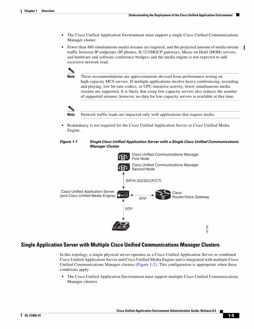
Single Cisco Unified Application Server with a Single Cisco Unified Communications Manager Cluster
In this topology, a single physical server operates as a Cisco Unified Application Server or combined Cisco Unified Application Server and Cisco Unified Media Engine, and is integrated with a single Cisco Unified Communications Manager cluster (Figure 1-1). This configuration is appropriate when the following conditions apply:
1-4Cisco Unified Application Environment Administration Guide, Release 8.5
OL-21902-01
Chapter 1 Overview Understanding the Deployment of the Cisco Unified Application Environment
• The Cisco Unified Application Environment must support a single Cisco Unified Communications Manager cluster.
• Fewer than 480 simultaneous media streams are required, and the projected amount of media stream traffic between IP endpoints (IP phones, H.323/MGCP gateways, Music on Hold (MOH) servers, and hardware and software conference bridges) and the media engine is not expected to add excessive network load.
Note These recommendations are approximations devised from performance testing on high-capacity MCS servers. If multiple applications involve heavy conferencing, recording and playing, low bit-rate codecs, or CPU-intensive activity, fewer simultaneous media streams are supported. It is likely that using low-capacity servers also reduces the number of supported streams; however, no data for low-capacity servers is available at this time.
Note Network traffic loads are impacted only with applications that require media.
• Redundancy is not required for the Cisco Unified Application Server or Cisco Unified Media Engine.
Figure 1-1 Single Cisco Unified Application Server with a Single Cisco Unified Communications
Manager Cluster
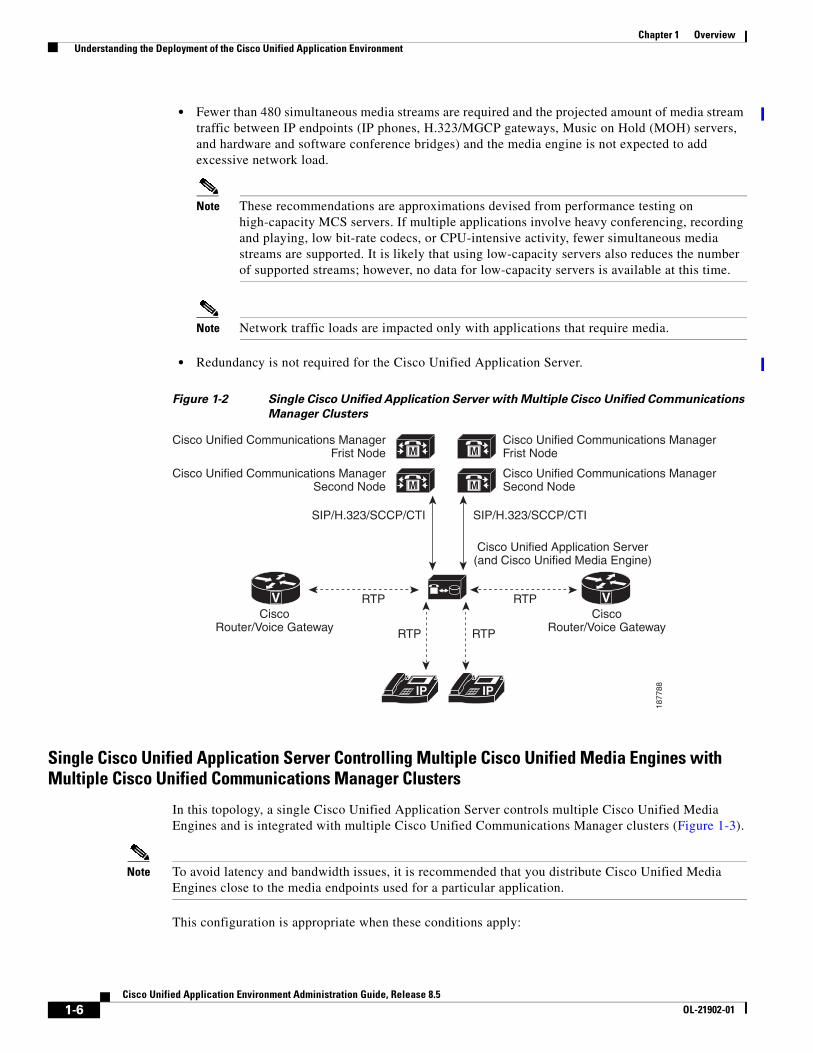
Single Application Server with Multiple Cisco Unified Communications Manager Clusters
In this topology, a single physical server operates as a Cisco Unified Application Server or combined Cisco Unified Application Server and Cisco Unified Media Engine and is integrated with multiple Cisco Unified Communications Manager clusters (Figure 1-2). This configuration is appropriate when these conditions apply:
• The Cisco Unified Application Environment must support multiple Cisco Unified Communications Manager clusters.
M
M
IP
V
Cisco Unified Application Server(and Cisco Unified Media Engine)
Cisco Unified Communications ManagerFirst Node
Cisco Unified Communications ManagerSecond Node
CiscoRouter/Voice GatewayRTP
RTP1
87
79
4
SIP/H.323/SCCP/CTI
1-5Cisco Unified Application Environment Administration Guide, Release 8.5
OL-21902-01
Chapter 1 Overview Understanding the Deployment of the Cisco Unified Application Environment
• Fewer than 480 simultaneous media streams are required and the projected amount of media stream traffic between IP endpoints (IP phones, H.323/MGCP gateways, Music on Hold (MOH) servers, and hardware and software conference bridges) and the media engine is not expected to add excessive network load.
Note These recommendations are approximations devised from performance testing on high-capacity MCS servers. If multiple applications involve heavy conferencing, recording and playing, low bit-rate codecs, or CPU-intensive activity, fewer simultaneous media streams are supported. It is likely that using low-capacity servers also reduces the number of supported streams; however, no data for low-capacity servers is available at this time.
Note Network traffic loads are impacted only with applications that require media.
• Redundancy is not required for the Cisco Unified Application Server.
Figure 1-2 Single Cisco Unified Application Server with Multiple Cisco Unified Communications
Manager Clusters
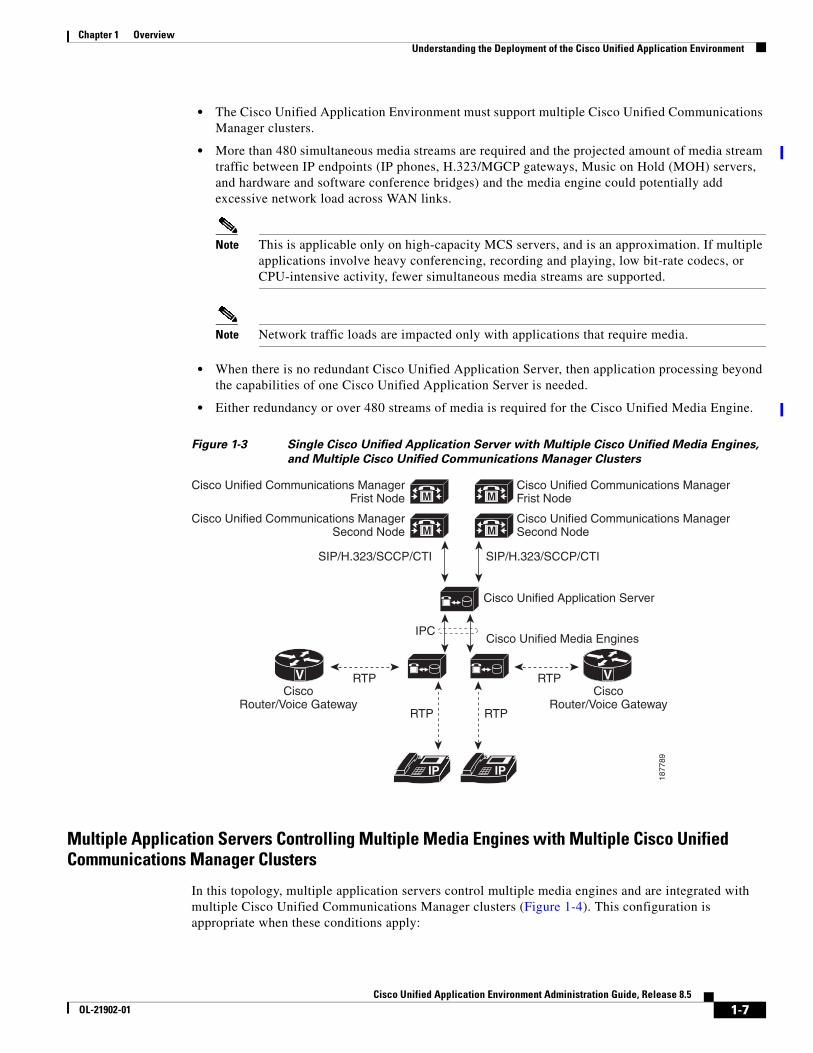
Single Cisco Unified Application Server Controlling Multiple Cisco Unified Media Engines with Multiple Cisco Unified Communications Manager Clusters
In this topology, a single Cisco Unified Application Server controls multiple Cisco Unified Media Engines and is integrated with multiple Cisco Unified Communications Manager clusters (Figure 1-3).
Note To avoid latency and bandwidth issues, it is recommended that you distribute Cisco Unified Media Engines close to the media endpoints used for a particular application.
This configuration is appropriate when these conditions apply:
M
M
IP
VV
Cisco Unified Application Server(and Cisco Unified Media Engine)
Cisco Unified Communications ManagerFrist Node
Cisco Unified Communications ManagerSecond Node
Cisco Unified Communications ManagerFrist Node
Cisco Unified Communications ManagerSecond Node
CiscoRouter/Voice Gateway
CiscoRouter/Voice Gateway
M
M
RTPRTP
RTP
IP
RTP
18
77
88
SIP/H.323/SCCP/CTISIP/H.323/SCCP/CTI
1-6Cisco Unified Application Environment Administration Guide, Release 8.5
OL-21902-01
Chapter 1 Overview Understanding the Deployment of the Cisco Unified Application Environment
• The Cisco Unified Application Environment must support multiple Cisco Unified Communications Manager clusters.
• More than 480 simultaneous media streams are required and the projected amount of media stream traffic between IP endpoints (IP phones, H.323/MGCP gateways, Music on Hold (MOH) servers, and hardware and software conference bridges) and the media engine could potentially add excessive network load across WAN links.
Note This is applicable only on high-capacity MCS servers, and is an approximation. If multiple applications involve heavy conferencing, recording and playing, low bit-rate codecs, or CPU-intensive activity, fewer simultaneous media streams are supported.
Note Network traffic loads are impacted only with applications that require media.
• When there is no redundant Cisco Unified Application Server, then application processing beyond the capabilities of one Cisco Unified Application Server is needed.
• Either redundancy or over 480 streams of media is required for the Cisco Unified Media Engine.
Figure 1-3 Single Cisco Unified Application Server with Multiple Cisco Unified Media Engines,
and Multiple Cisco Unified Communications Manager Clusters
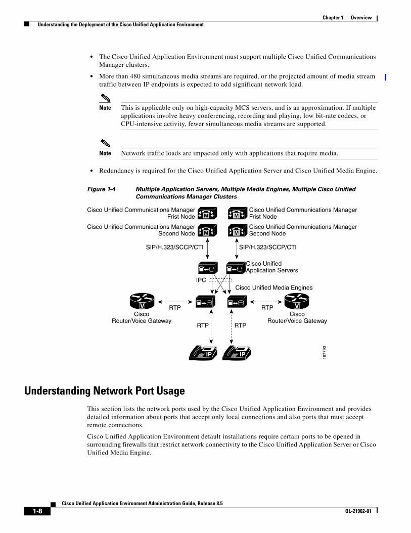
Multiple Application Servers Controlling Multiple Media Engines with Multiple Cisco Unified Communications Manager Clusters
In this topology, multiple application servers control multiple media engines and are integrated with multiple Cisco Unified Communications Manager clusters (Figure 1-4). This configuration is appropriate when these conditions apply:
IP
VV
Cisco Unified Application Server
Cisco Unified Media Engines
Cisco Unified Communications ManagerFrist Node
Cisco Unified Communications ManagerSecond Node
Cisco Unified Communications ManagerFrist Node
Cisco Unified Communications ManagerSecond Node
CiscoRouter/Voice Gateway
CiscoRouter/Voice Gateway
M
M
M
M
RTPRTP
RTP
IP
RTP
18
77
89
SIP/H.323/SCCP/CTISIP/H.323/SCCP/CTI
IPC
1-7Cisco Unified Application Environment Administration Guide, Release 8.5
OL-21902-01
Chapter 1 Overview Understanding the Deployment of the Cisco Unified Application Environment
• The Cisco Unified Application Environment must support multiple Cisco Unified Communications Manager clusters.
• More than 480 simultaneous media streams are required, or the projected amount of media stream traffic between IP endpoints is expected to add significant network load.
Note This is applicable only on high-capacity MCS servers, and is an approximation. If multiple applications involve heavy conferencing, recording and playing, low bit-rate codecs, or CPU-intensive activity, fewer simultaneous media streams are supported.
Note Network traffic loads are impacted only with applications that require media.
• Redundancy is required for the Cisco Unified Application Server and Cisco Unified Media Engine.
Figure 1-4 Multiple Application Servers, Multiple Media Engines, Multiple Cisco Unified
Communications Manager Clusters
Understanding Network Port UsageThis section lists the network ports used by the Cisco Unified Application Environment and provides detailed information about ports that accept only local connections and also ports that must accept remote connections.
Cisco Unified Application Environment default installations require certain ports to be opened in surrounding firewalls that restrict network connectivity to the Cisco Unified Application Server or Cisco Unified Media Engine.
IP
VV
Cisco UnifiedApplication Servers
Cisco Unified Media Engines
Cisco Unified Communications ManagerFrist Node
Cisco Unified Communications ManagerSecond Node
Cisco Unified Communications ManagerFrist Node
Cisco Unified Communications ManagerSecond Node
CiscoRouter/Voice Gateway
CiscoRouter/Voice Gateway
M
M
M
M
RTPRTP
IPC
RTP
IP
RTP1
87
79
0
SIP/H.323/SCCP/CTISIP/H.323/SCCP/CTI
1-8Cisco Unified Application Environment Administration Guide, Release 8.5
OL-21902-01
Chapter 1 Overview Understanding the Deployment of the Cisco Unified Application Environment
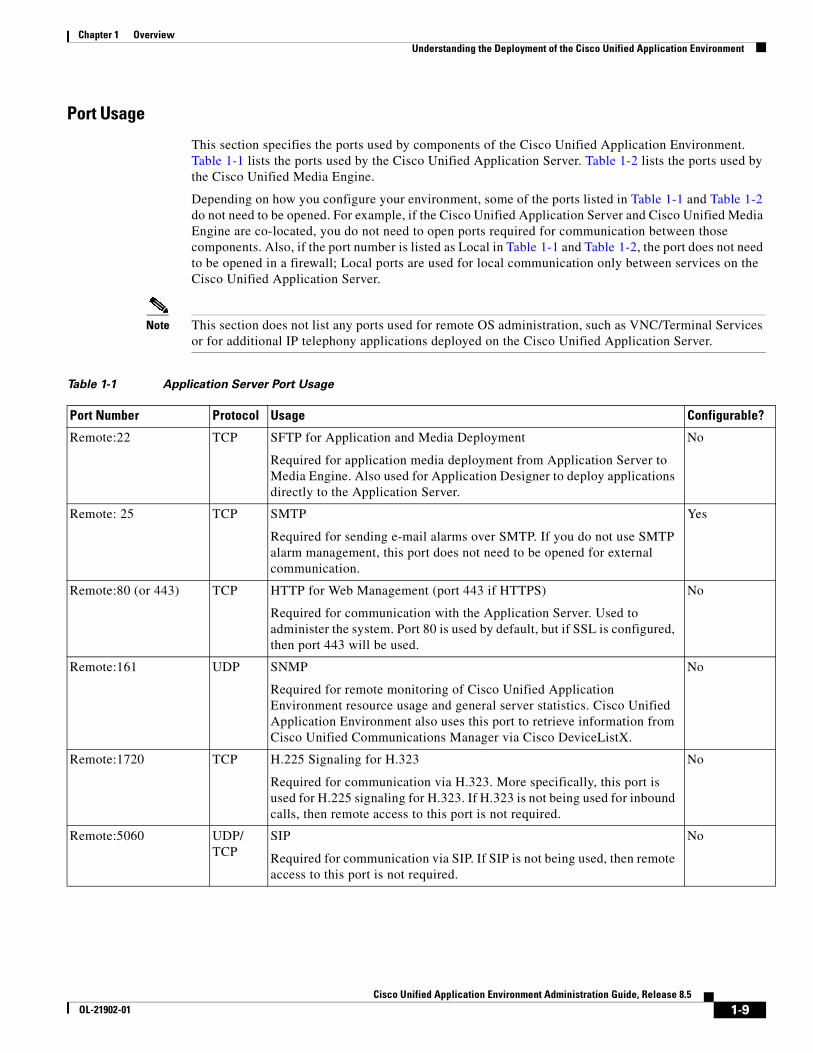
Port Usage
This section specifies the ports used by components of the Cisco Unified Application Environment. Table 1-1 lists the ports used by the Cisco Unified Application Server. Table 1-2 lists the ports used by the Cisco Unified Media Engine.
Depending on how you configure your environment, some of the ports listed in Table 1-1 and Table 1-2 do not need to be opened. For example, if the Cisco Unified Application Server and Cisco Unified Media Engine are co-located, you do not need to open ports required for communication between those components. Also, if the port number is listed as Local in Table 1-1 and Table 1-2, the port does not need to be opened in a firewall; Local ports are used for local communication only between services on the Cisco Unified Application Server.
Note This section does not list any ports used for remote OS administration, such as VNC/Terminal Services or for additional IP telephony applications deployed on the Cisco Unified Application Server.
Table 1-1 Application Server Port Usage
Port Number Protocol Usage Configurable?
Remote:22 TCP SFTP for Application and Media Deployment
Required for application media deployment from Application Server to Media Engine. Also used for Application Designer to deploy applications directly to the Application Server.
No
Remote: 25 TCP SMTP
Required for sending e-mail alarms over SMTP. If you do not use SMTP alarm management, this port does not need to be opened for external communication.
Yes
Remote:80 (or 443) TCP HTTP for Web Management (port 443 if HTTPS)
Required for communication with the Application Server. Used to administer the system. Port 80 is used by default, but if SSL is configured, then port 443 will be used.
No
Remote:161 UDP SNMP
Required for remote monitoring of Cisco Unified Application Environment resource usage and general server statistics. Cisco Unified Application Environment also uses this port to retrieve information from Cisco Unified Communications Manager via Cisco DeviceListX.
No
Remote:1720 TCP H.225 Signaling for H.323
Required for communication via H.323. More specifically, this port is used for H.225 signaling for H.323. If H.323 is not being used for inbound calls, then remote access to this port is not required.
No
Remote:5060 UDP/ TCP
SIP
Required for communication via SIP. If SIP is not being used, then remote access to this port is not required.
No
1-9Cisco Unified Application Environment Administration Guide, Release 8.5
OL-21902-01
Chapter 1 Overview Understanding the Deployment of the Cisco Unified Application Environment
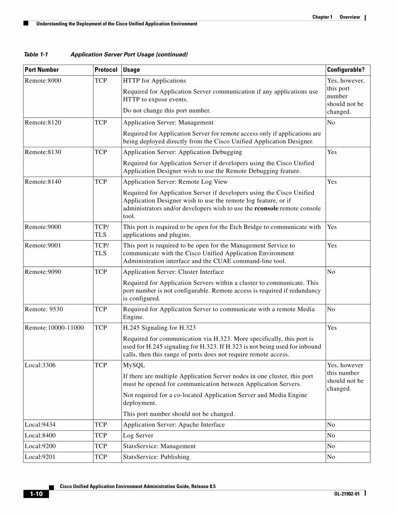
Remote:8000 TCP HTTP for Applications
Required for Application Server communication if any applications use HTTP to expose events.
Do not change this port number.
Yes, however, this port number should not be changed.
Remote:8120 TCP Application Server: Management
Required for Application Server for remote access only if applications are being deployed directly from the Cisco Unified Application Designer.
No
Remote:8130 TCP Application Server: Application Debugging
Required for Application Server if developers using the Cisco Unified Application Designer wish to use the Remote Debugging feature.
Yes
Remote:8140 TCP Application Server: Remote Log View
Required for Application Server if developers using the Cisco Unified Application Designer wish to use the remote log feature, or if administrators and/or developers wish to use the rconsole remote console tool.
Yes
Remote:9000 TCP/ TLS
This port is required to be open for the Etch Bridge to communicate with applications and plugins.
Yes
Remote:9001 TCP/ TLS
This port is required to be open for the Management Service to communicate with the Cisco Unified Application Environment Administration interface and the CUAE command-line tool.
Yes
Remote:9090 TCP Application Server: Cluster Interface
Required for Application Servers within a cluster to communicate. This port number is not configurable. Remote access is required if redundancy is configured.
No
Remote: 9530 TCP Required for Application Server to communicate with a remote Media Engine.
No
Remote:10000-11000 TCP H.245 Signaling for H.323
Required for communication via H.323. More specifically, this port is used for H.245 signaling for H.323. If H.323 is not being used for inbound calls, then this range of ports does not require remote access.
Yes
Local:3306 TCP MySQL
If there are multiple Application Server nodes in one cluster, this port must be opened for communication between Application Servers.
Not required for a co-located Application Server and Media Engine deployment.
This port number should not be changed.
Yes, however this number should not be changed.
Local:9434 TCP Application Server: Apache Interface No
Local:8400 TCP Log Server No
Local:9200 TCP StatsService: Management No
Local:9201 TCP StatsService: Publishing No
Table 1-1 Application Server Port Usage (continued)
Port Number Protocol Usage Configurable?
1-10Cisco Unified Application Environment Administration Guide, Release 8.5
OL-21902-01
Chapter 1 Overview Understanding the Deployment of the Cisco Unified Application Environment
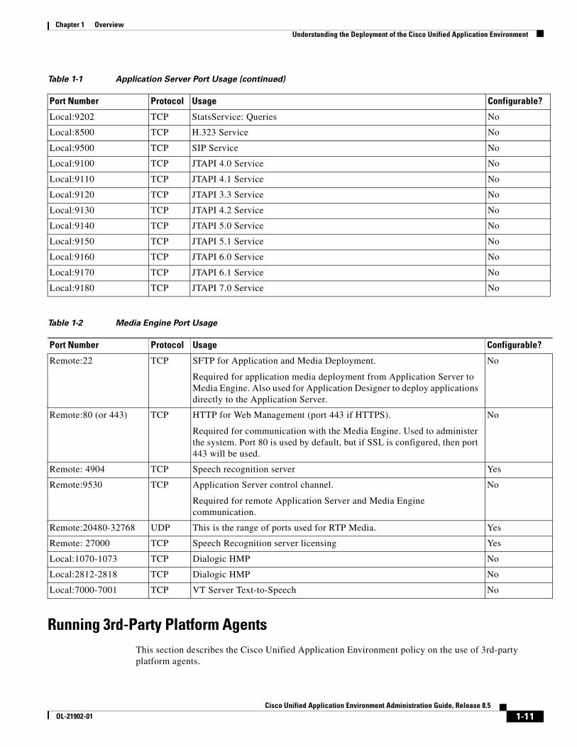
Running 3rd-Party Platform AgentsThis section describes the Cisco Unified Application Environment policy on the use of 3rd-party platform agents.
Local:9202 TCP StatsService: Queries No
Local:8500 TCP H.323 Service No
Local:9500 TCP SIP Service No
Local:9100 TCP JTAPI 4.0 Service No
Local:9110 TCP JTAPI 4.1 Service No
Local:9120 TCP JTAPI 3.3 Service No
Local:9130 TCP JTAPI 4.2 Service No
Local:9140 TCP JTAPI 5.0 Service No
Local:9150 TCP JTAPI 5.1 Service No
Local:9160 TCP JTAPI 6.0 Service No
Local:9170 TCP JTAPI 6.1 Service No
Local:9180 TCP JTAPI 7.0 Service No
Table 1-2 Media Engine Port Usage
Port Number Protocol Usage Configurable?
Remote:22 TCP SFTP for Application and Media Deployment.
Required for application media deployment from Application Server to Media Engine. Also used for Application Designer to deploy applications directly to the Application Server.
No
Remote:80 (or 443) TCP HTTP for Web Management (port 443 if HTTPS).
Required for communication with the Media Engine. Used to administer the system. Port 80 is used by default, but if SSL is configured, then port 443 will be used.
No
Remote: 4904 TCP Speech recognition server Yes
Remote:9530 TCP Application Server control channel.
Required for remote Application Server and Media Engine communication.
No
Remote:20480-32768 UDP This is the range of ports used for RTP Media. Yes
Remote: 27000 TCP Speech Recognition server licensing Yes
Local:1070-1073 TCP Dialogic HMP No
Local:2812-2818 TCP Dialogic HMP No
Local:7000-7001 TCP VT Server Text-to-Speech No
Table 1-1 Application Server Port Usage (continued)
Port Number Protocol Usage Configurable?
1-11Cisco Unified Application Environment Administration Guide, Release 8.5
OL-21902-01
Chapter 1 Overview Understanding the Deployment of the Cisco Unified Application Environment
Overview
Cisco engineers test the Cisco Unified Application Environment on specific hardware, operating system, and software configurations to maximize predictability and stability in customer deployments. Platform agents, also called onboard agents, on-box agents, or co-resident agents, are third-party applications that reside on the same hardware and operating system as Cisco Unified Application Environment products and interact with it to provide a desired function. Examples include virus protection and system management applications.
Cisco understands that certain customers want to use platform agents with Cisco Unified Application Environment as part of their operations strategy. Please note the following:
• The Cisco Technology Developer Program offers third-party technology integration (including agents) support with Cisco Unified Communications products. You should encourage your agents' vendors to join this program for deployment success. More information is available at: http://www.cisco.com/web/partners/pr46/tdp/index.html.
• Cisco performs "best effort or passive" testing of select agents from vendors that are not in the Cisco Technology Developer Program. For these agents, no agent-specific "test to fail" or "test to verify" tests are performed, but if standard Cisco testing succeeds with the agents loaded on select representative releases, support is claimed. In other words, not all combinations of agent versions with Cisco versions are explicitly tested (including regression), and application notes are updated less frequently. Agents are supported only on specific versions of Cisco Unified Application Environment running on the IP telephony (Windows) OS that Cisco provides.
• Installing agents with Cisco Unified Application Environment may affect functions and performance. Cisco or third-party labs have verified interoperability for the agents and versions listed for a single-agent scenario only. Multiple agents deployed together are not tested, so these deployments may experience additional effects on function and performance.
• If you are running Cisco Security Agent, you must disable Cisco Security Agent before installing any of the Cisco Unified Application Environment components or other 3rd party platform agents.
• The Cisco Technical Assistance Center (TAC) provides coordinated support for customers who install supported third-party platform agents with Cisco Unified Application Environment. If the root cause of a problem is with the third-party agent, Cisco TAC might ask you to remove a supported platform agent or to consult the third party.
Support Policies for 3rd-Party Software
Cisco support policy is that customers can deploy third-party software on the Cisco Unified Application Environment for the following purposes:
• Virus-scanning software
• Backup and restore
• Monitoring
• Security
However, Cisco expects that customers (or their systems integration partners) will have tested the interoperability of such products with Cisco Unified Application Environment before the products are deployed, to mitigate the risk of problems being discovered within the production environment between Cisco Unified Application Environment and the third-party products loaded on the Cisco Unified Application Environment server.
1-12Cisco Unified Application Environment Administration Guide, Release 8.5
OL-21902-01
Chapter 1 Overview Understanding the Deployment of the Cisco Unified Application Environment
If a customer calls Cisco TAC with a problem, a Cisco TAC engineer may require that such third-party software be turned off or even removed from the Cisco Unified Application Environment server during the course of troubleshooting. If it is determined that the interoperability between the third-party software and Cisco Unified Application Environment was the root cause of the problem, then the third-party software will be required to be disabled or removed from the Cisco Unified Application Environment server until such time that the interoperability issue is addressed, so that the customer can continue to have a functional Cisco Unified Application Environment system.
Before installing any qualified Microsoft service pack on the Cisco Unified Application Environment server, confirm that the manufacturer of any optional third-party software or hardware that you are using also supports the service pack for use with its product.
Note In general, you should not apply Microsoft updates unless instructed by TAC. You can apply the Cisco-provided SRs, which contain Microsoft updates, but have been tested by the Cisco OS team.
Utilizing Cisco Security AgentThis section describes how the Cisco Unified Application Environment utilizes the Cisco Security Agent for intrusion detection and prevention and how you can request the Cisco Unified Application Environment CSA Policy.
Overview
The Cisco Security Agent provides Windows platform security that is based on a tested security rules set —called a “policy”— which has rigorous levels of host intrusion detection and prevention. It controls system operations by adhering to the rules set to allow or deny specific system actions before system resources are accessed.
In Cisco Security Agent, security rules are grouped into containers called rule modules. Rule modules are then attached to a policy. A policy is attached to a group. The host systems are associated with one or more groups.
For more information about the Cisco Security Agent, such as Release Notes and other documentation, see the Cisco Security Agents support information page on Cisco.com: http://www.cisco.com/en/US/products/sw/secursw/ps5057/tsd_products_support_series_home.html
Management Center for Cisco Security Agents
The CSA profile for the Cisco Unified Application Environment uses a static security policy. As such, additional 3rd party applications deployed to the application server may not function properly with the base Cisco Unified Application Environment CSA profile. Contact the application developer for additional rule modules and policies required to make that application function with CSA.
To add, change, delete, or view policies you must purchase and install the fully-managed console product, Management Center for Cisco Security Agent.
If you have the Management Center for Cisco Security Agent and want access to the Cisco Unified Application Environment security policy, contact Cisco TAC.
1-13Cisco Unified Application Environment Administration Guide, Release 8.5
OL-21902-01
Chapter 1 Overview Understanding the Deployment of the Cisco Unified Application Environment
Backward CompatibilityCisco Unified Application Environment 8.5 supports the following core APIs by integrating with Unified CM, Cisco Unified Presence, and Cisco Unified Messaging:
• Call control
• Presence
• Messaging
Before you implement Cisco Unified Application Environment 8.5, you must ensure that it can interoperate with the following applications:
• Cisco Unified Communications Manager
• Cisco Unified IP Phones
• Cisco Unified Presence
• Cisco Unified Messaging (Unity & Unity Connection)
Cisco Unified Communications Manager
Cisco Unified Application Environment 8.5 is backward compatible with the following Unified CM versions:
• Unified CM 4.x
• Unified CM 5.x
• Unified CM 6.x
• Unified CM 7.x
• Unified CM 8.0(1)
• Unified CM 8.5(1)
Cisco Unified IP Phones
To support Cisco Unified IP Phone 6900 Series, Cisco Unified IP Phone 8900 Series and Cisco Unified IP Phone 9900 Series, the JTAPI Service component of the Cisco Unified Application Environment system has been modified. To support the new APIs, changes have been made to Cisco Unified Application Designer, Etch, Telephony Manager, JTAPI Provider and JTAPI Service.
Cisco Unified IP Phones 8900 and 9900 Series Device Family
Cisco Unified Application Designer and Etch support the new Cisco Unified IP Phone 8900 Series and Cisco Unified IP Phone 9900 Series phone features. This allows the Cisco Unified Application Designer and Etch Developers to develop applications using JTAPI APIs. Cisco Unified Application Environment supports CTI call control on Cisco Unified IP Phone 6900, 8900, and 9900 series phones. This includes support for new JTAPI APIs for Join and Direct Transfer. The following APIs are supported:
Join/Join Across Lines
Enables calls on different phone lines to be joined and can also be used to create a conference. You can use the JTAPI Conference API to support this feature. Cisco Unified IP Phone 8900 and 9900 series phones do not have a Common Transfer Controller, but Cisco Unified IP Phones 6900 Series phones do have a Common Transfer Controller.
1-14Cisco Unified Application Environment Administration Guide, Release 8.5
OL-21902-01
Chapter 1 Overview Understanding the Deployment of the Cisco Unified Application Environment
Direct Transfer/ Direct Transfer across Lines
Enables two calls on different addresses of the same terminal to be transferred by using the Transfer soft key on the phone or the Transfer API that is provided by JTAPI. This feature uses the JTAPI Transfer API which accepts Call Object as input.
Explicit Cancel
Explicit Cancel feature allows users to cancel a pending consultation transfer or conference. The held and active call remains, but the transfer/conference operation gets cancelled.
• Explicit Cancel results in a new event to be sent to applications
• Explicit Cancel is applicable only to Cisco Unified IP Phone 8900 and 9900 Series
• CiscoCallFeatureCancelledEv is delivered when CANCEL operation is invoked.
• Cisco Unified Application Environment does not need to handle this particular event.
Cisco Unified Presence
Applications developed using Cisco Unified Application Environment Presence APIs use the Cisco Unified Application Environment Presence plug-ins and reciprocate SIP stack to communicate with the Cisco Unified Presence Server. The communication between Cisco Unified Application Environment Presence and Cisco Unified Presence is based on the SIP SIMPLE interface and the SUBSCRIBE NOTIFY framework. Cisco Unified Application Environment Presence subscribes to Cisco Unified Presence for status changes. Whenever the status of the presentities changes, Cisco Unified Application Environment triggers the application and provides the details of the change. Using the Presence APIs, a Cisco Unified Application Environment application monitors the real time status changes of different presence entities.
Cisco Unified Application Environment 8.5 supports the following presence APIs:
• TriggeringSubscribe—Subscribes to Cisco Unified Presence Server to receive the presence status changes of presentities. Once, the application subscribes to this API, it receives a a Notify event that initiates a new script whenever the presence status of the watched entities changes.
• NonTriggeringSubscribe—Subscribes to Cisco Unified Presence Server to receive the presence status changes of presentities. After the application subscribes to this API, it receives a ‘Notify’ event whenever the presence status of the watched entities changes. The event will be received only by the script that initiated the ‘NonTriggeringSubscribe’ and when the script is running.
• Unsubscribe—Removes the subscription from Cisco Unified Presence Server to receive the presence status changes of presentities.
• SubscriptionTerminated—Indicates the application that the subscription is terminated. This event occurs when the ‘Unsubscribe’ API is called or when the subscription is terminated by the Cisco Unified Presence server.
• Notify—Indicates the application that the presence status of at least one presentity has changed. This event contains a string which stores the data about status changes. The data is stored in XML format. The application can read the data using the ‘PresenceNotification’ native types.
• PresenceNotification—A complex data type that parses the XML data in a format that is usable by the C# processing.
Cisco Unified Messaging (Unity and Unity Connection 8.0)
Cisco Unified Application Environment interoperates with the following Unity/Unity Connection versions:
1-15Cisco Unified Application Environment Administration Guide, Release 8.5
OL-21902-01

Chapter 1 Overview Understanding the Deployment of the Cisco Unified Application Environment
• Unity 7.x and 8.0(1)
• Unity Connection 7.x and 8.0(1)
1-16Cisco Unified Application Environment Administration Guide, Release 8.5
OL-21902-01
Cisco Unified ApplicaOL-21902-01
C H A P T E R 2
What is New in This ReleaseThis chapter gives information of the new and changed information of every release of the Cisco Unified Application Environment.
New and Changed Information for Release 8.5This section lists the updates in this release of the Cisco Unified Application Environment.
• Enhanced Limit for CTI Devices —Allows monitoring of upto 10,000 CTI devices. For more information see, Creating a Monitored CTI Device Pool, page 7-5.
• Increase in Media Port Density— The media port density is enhanced to 480 for RTP, Conference, Voice and to 240 for Speech Integration. For more information see, License Limits, page 3-8.
• New Media Features — The SeekAndPlay API allows you to play, stop or resume playing a media file from a particular position. For more information see, New Media Features, page 1-3.
2-1tion Environment Administration Guide, Release 8.5

Chapter 2 What is New in This Release New and Changed Information for Release 8.5
2-2Cisco Unified Application Environment Administration Guide, Release 8.5
OL-21902-01
Cisco Unified ApplicaOL-21902-01
C H A P T E R 2
Getting StartedThis chapter describes what you need to do to set up the Cisco Unified Application Environment and install applications.
It includes these topics:
• Before You Begin, page 2-1
• Logging In, page 2-2
• Understanding the Cisco Unified Application Environment Administration, page 2-2
• TipYou can automate administration tasks using the management service API. For examples and more information, see the Cisco Unified Application Environment wiki., page 2-3
Before You BeginBefore you begin setting up the Cisco Unified Application Environment make sure:
1. The Cisco MCS server is installed. See Cisco Unified Application Environment Hardware Compatibility Matrix listed in Related Documentation, page xii.
2. The operating system and the Cisco Unified Application Environment are installed using the DVDs shipped with the server. See Installation Guide for the Cisco Unified Application Environment listed in Related Documentation, page xii.
3. You have accessed the Cisco Unified Application Environment Administration using one of these supported browsers:
– Microsoft Internet Explorer (IE) 6.0 or later
– Mozilla Firefox
See Installation Guide for the Cisco Unified Application Environment, Release 8.5 listed in Related Documentation, page xii.
2-1tion Environment Administration Guide, Release 8.5
Chapter 2 Getting Started Logging In
4. You have obtained all the necessary the license files using the Product Authorization Key (PAK) in the Claim Certificate that is shipped with the server.
When you place an order for the Cisco Unified Application Environment, Cisco ships you a Claim Certificate with a Product Authorization Key (PAK). The Claim Certificate provides directions for registering the PAK to obtain the license. You must:
a. Register the PAK that you received using the License Registration web tool that is provided on Cisco.com at the following URL: https://tools.cisco.com/SWIFT/Licensing/PrivateRegistrationServlet.
b. Enter the MAC address of the server for which you are requesting the licenses, and a valid e-mail address.
A license file is generated per the license configuration you purchased, and sent to you using the e-mail address you provided.
Logging In To log in to the Cisco Unified Application Environment Administration, follow these steps:
Procedure
Step 1 If you have not already done so, in the address bar of the web browser, enter the following URL: http://<serverIPaddress>/cuaeadmin.
Step 2 At the login page, enter the username administrator, and the password you set the first time you accessed the console after installation.
Step 3 Click Log In.
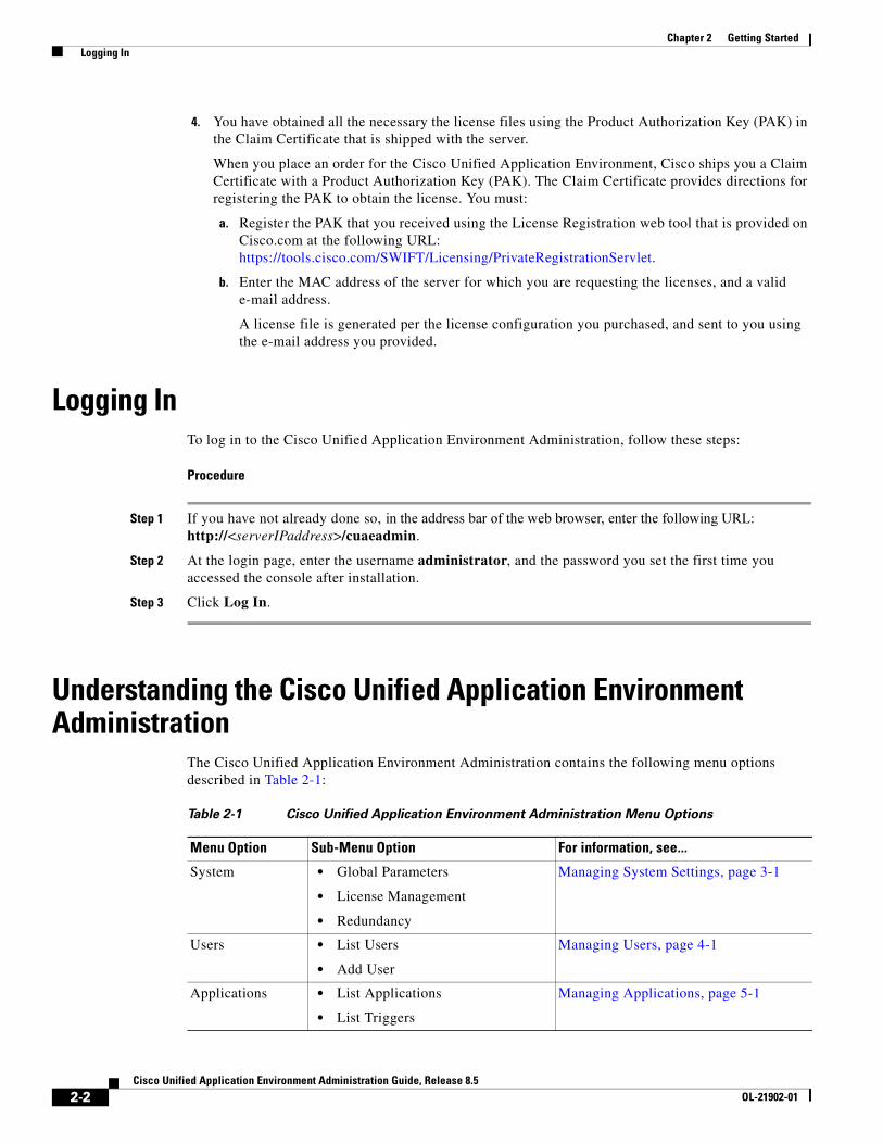
Understanding the Cisco Unified Application Environment Administration
The Cisco Unified Application Environment Administration contains the following menu options described in Table 2-1:
Table 2-1 Cisco Unified Application Environment Administration Menu Options
Menu Option Sub-Menu Option For information, see...
System • Global Parameters
• License Management
• Redundancy
Managing System Settings, page 3-1
Users • List Users
• Add User
Managing Users, page 4-1
Applications • List Applications
• List Triggers
Managing Applications, page 5-1
2-2Cisco Unified Application Environment Administration Guide, Release 8.5
OL-21902-01
Chapter 2 Getting Started Setting Up the Cisco Unified Application Environment
Tip You can automate administration tasks using the management service API. For examples and more information, see the Cisco Unified Application Environment wiki.
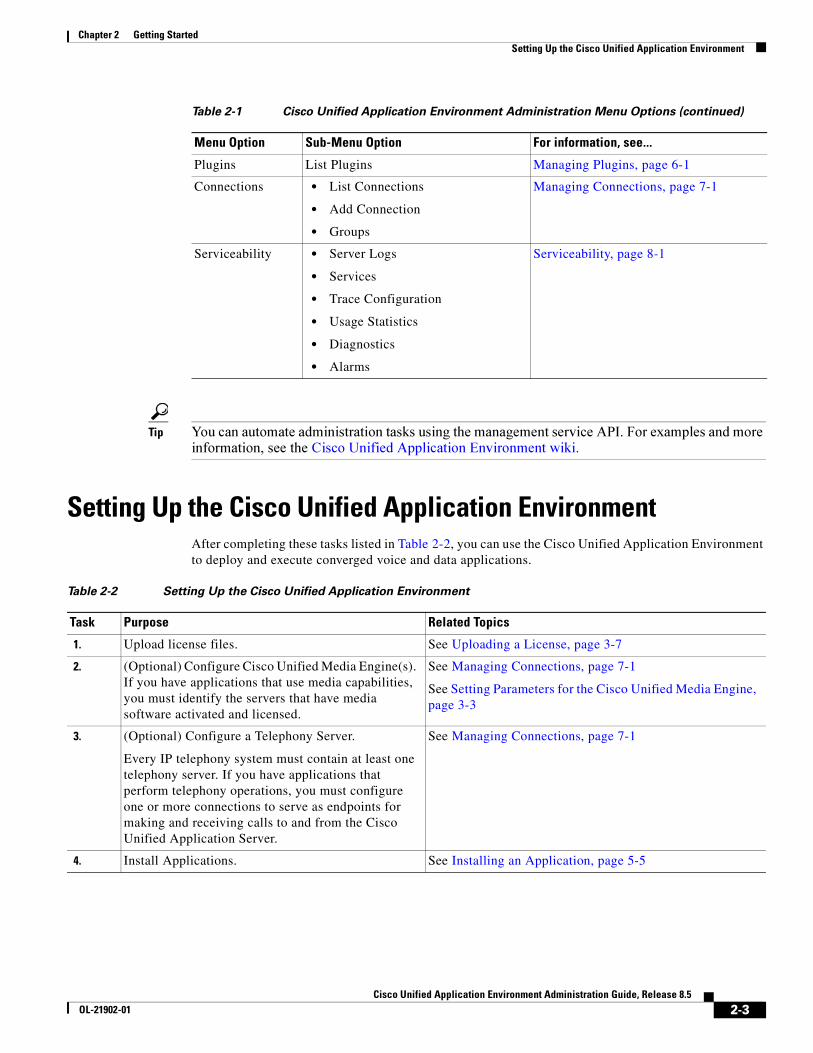
Setting Up the Cisco Unified Application EnvironmentAfter completing these tasks listed in Table 2-2, you can use the Cisco Unified Application Environment to deploy and execute converged voice and data applications.
Plugins List Plugins Managing Plugins, page 6-1
Connections • List Connections
• Add Connection
• Groups
Managing Connections, page 7-1
Serviceability • Server Logs
• Services
• Trace Configuration
• Usage Statistics
• Diagnostics
• Alarms
Serviceability, page 8-1
Table 2-1 Cisco Unified Application Environment Administration Menu Options (continued)
Menu Option Sub-Menu Option For information, see...
Table 2-2 Setting Up the Cisco Unified Application Environment
Task Purpose Related Topics
1. Upload license files. See Uploading a License, page 3-7
2. (Optional) Configure Cisco Unified Media Engine(s). If you have applications that use media capabilities, you must identify the servers that have media software activated and licensed.
See Managing Connections, page 7-1
See Setting Parameters for the Cisco Unified Media Engine, page 3-3
3. (Optional) Configure a Telephony Server.
Every IP telephony system must contain at least one telephony server. If you have applications that perform telephony operations, you must configure one or more connections to serve as endpoints for making and receiving calls to and from the Cisco Unified Application Server.
See Managing Connections, page 7-1
4. Install Applications. See Installing an Application, page 5-5
2-3Cisco Unified Application Environment Administration Guide, Release 8.5
OL-21902-01

Chapter 2 Getting Started Setting Up the Cisco Unified Application Environment
2-4Cisco Unified Application Environment Administration Guide, Release 8.5
OL-21902-01
Cisco Unified ApplicaOL-21902-01
C H A P T E R 3
Managing System SettingsThis chapter includes these topics:
• Setting Global Parameters, page 3-1
• Managing Licenses, page 3-4
• Configuring Redundancy, page 3-9
• Configuring SSL Management, page 3-13
• Managing Secure Connections to the Management Service, page 3-16
• Managing Secure Connections to the Etch Bridge, page 3-18
• Etch Connection String URI, page 3-23
Setting Global ParametersThis section includes these topics:
• Setting Parameters for the Server, page 3-1
• Setting Parameters for the Cisco Unified Application Server, page 3-2
• Setting Parameters for the Cisco Unified Media Engine, page 3-3
Setting Parameters for the Server To set parameters for the server, follow these steps:
Procedure
Step 1 Log in to the Cisco Unified Application Environment Administration.
Step 2 Choose System > Global Parameters.
Step 3 Under Server, in the Host Name/IP Address field, enter a fully-qualified host name or IP address that other servers can use to access the services on this server.
Step 4 Click Save.
3-1tion Environment Administration Guide, Release 8.5
Chapter 3 Managing System Settings Setting Global Parameters
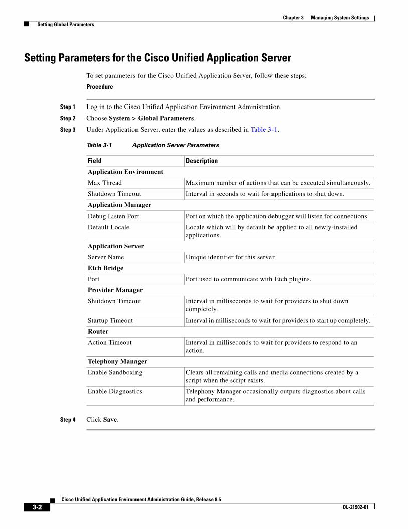
Setting Parameters for the Cisco Unified Application Server To set parameters for the Cisco Unified Application Server, follow these steps:
Procedure
Step 1 Log in to the Cisco Unified Application Environment Administration.
Step 2 Choose System > Global Parameters.
Step 3 Under Application Server, enter the values as described in Table 3-1.
Step 4 Click Save.
Table 3-1 Application Server Parameters
Field Description
Application Environment
Max Thread Maximum number of actions that can be executed simultaneously.
Shutdown Timeout Interval in seconds to wait for applications to shut down.
Application Manager
Debug Listen Port Port on which the application debugger will listen for connections.
Default Locale Locale which will by default be applied to all newly-installed applications.
Application Server
Server Name Unique identifier for this server.
Etch Bridge
Port Port used to communicate with Etch plugins.
Provider Manager
Shutdown Timeout Interval in milliseconds to wait for providers to shut down completely.
Startup Timeout Interval in milliseconds to wait for providers to start up completely.
Router
Action Timeout Interval in milliseconds to wait for providers to respond to an action.
Telephony Manager
Enable Sandboxing Clears all remaining calls and media connections created by a script when the script exists.
Enable Diagnostics Telephony Manager occasionally outputs diagnostics about calls and performance.
3-2Cisco Unified Application Environment Administration Guide, Release 8.5
OL-21902-01
Chapter 3 Managing System Settings Support for MCS Server
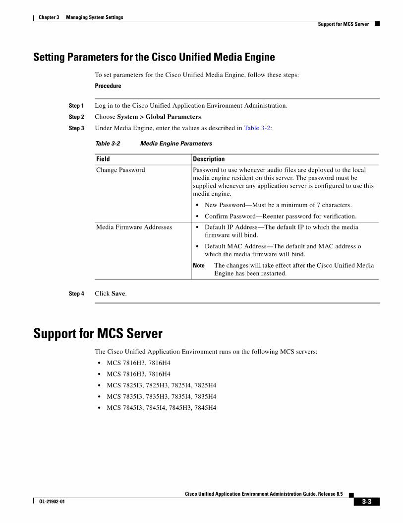
Setting Parameters for the Cisco Unified Media Engine To set parameters for the Cisco Unified Media Engine, follow these steps:
Procedure
Step 1 Log in to the Cisco Unified Application Environment Administration.
Step 2 Choose System > Global Parameters.
Step 3 Under Media Engine, enter the values as described in Table 3-2:
Step 4 Click Save.
Support for MCS Server The Cisco Unified Application Environment runs on the following MCS servers:
• MCS 7816H3, 7816H4
• MCS 7816H3, 7816H4
• MCS 7825I3, 7825H3, 7825I4, 7825H4
• MCS 7835I3, 7835H3, 7835I4, 7835H4
• MCS 7845I3, 7845I4, 7845H3, 7845H4
Table 3-2 Media Engine Parameters
Field Description
Change Password Password to use whenever audio files are deployed to the local media engine resident on this server. The password must be supplied whenever any application server is configured to use this media engine.
• New Password—Must be a minimum of 7 characters.
• Confirm Password—Reenter password for verification.
Media Firmware Addresses • Default IP Address—The default IP to which the media firmware will bind.
• Default MAC Address—The default and MAC address o which the media firmware will bind.
Note The changes will take effect after the Cisco Unified Media Engine has been restarted.
3-3Cisco Unified Application Environment Administration Guide, Release 8.5
OL-21902-01
Chapter 3 Managing System Settings Deployment on VMware ESXi 4.0’
Installation and Deployment RequirementsOnce the Operating System is installed on the MCS server, the Cisco Unified Application Environment software must be installed. The standard installation of the Cisco Unified Application Environment software on the MCS server takes approximately 15 minutes. For more information about installation, see http://www.cisco.com/en/US/docs/voice_ip_comm/cuae/8_0/english/install/guide/uaein.html
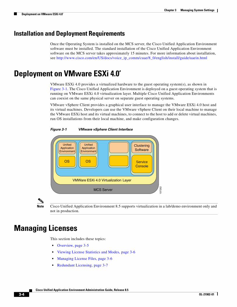
Deployment on VMware ESXi 4.0’VMware ESXi 4.0 provides a virtualized hardware to the guest operating system(s), as shown in Figure 3-1. The Cisco Unified Application Environment is deployed on a guest operating system that is running on VMware ESXi 4.0 virtualization layer. Multiple Cisco Unified Application Environments can coexist on the same physical server on separate guest operating systems.
VMware vSphere Client provides a graphical user interface to manage the VMware ESXi 4.0 host and its virtual machines. Developers can use the VMware vSphere Client on their local machine to manage the VMware ESXi host and its virtual machines, to connect to the host to add or delete virtual machines, run OS installations from their local machine, and make configuration changes.
Figure 3-1 VMware vSphere Client Interface
Note Cisco Unified Application Environment 8.5 supports virtualization in a lab/demo environment only and not in production.
Managing LicensesThis section includes these topics:
• Overview, page 3-5
• Viewing License Statistics and Modes, page 3-6
• Managing License Files, page 3-6
• Redundant Licensing, page 3-7
1972
62
Clustering Software
ServiceConsole
VMWare ESXi 4.0 Virtualization Layer
MCS Server
OSOS
UnifiedApplication
Environment
UnifiedApplication
Environment
3-4Cisco Unified Application Environment Administration Guide, Release 8.5
OL-21902-01
Chapter 3 Managing System Settings Managing Licenses
OverviewBy applying the appropriate licenses, you enable either the Cisco Unified Application Server software on the server or the Cisco Unified Media Engine software, or both. In addition, you can incrementally increase the capabilities for the Cisco Unified Application Server or for the Cisco Unified Media Engine with supplementary licenses. There are dedicated licenses files for both mode and for media resource instances.
• Mode (Premium, Standard, or Basic)
The mode of the Cisco Unified Application Server or Cisco Unified Media Engine defines the upper limit of script instances.
If no licenses are applied to the server, the server operates in software developer kit (SDK) mode.
Note This mode may not be used for commercial purposes.
It is intended to enable development, demos, and trials. In this mode, the server auto-licenses itself to:
– 6 script instances
– 6 RTP (G.711)
– 0 ERTP (Low-bit rate: G.723 & G.729)
– 6 Voice (Media operations such as Play, Record, and GatherDigits)
– 6 Conference
– 0 Speech Recognition (also known as continuous speech processing (CSP)
– 1 text-to-speech port
• Media Resource Instance Licenses
Licenses can be applied to the Cisco Unified Media Engine mode license to increase the number of media resources instances allowed to concurrently execute on the media engine.An incremental license increases the overall amount of media resources instances, but the total amount of media resources instances cannot exceed the upper limit dictated by the mode of the Cisco Unified Media Engine license. Therefore, if the number of licensed application instances exceeds this mode limit, the total allowed instances will not exceed the mode limit.
Licenses are node locked to the MAC address of the server. If you upload a licence that does not have the same MAC address as the server, the features specified by the license will not be enabled.
The MAC Address of the Server is shown in the License management page.
For both VMware and Virtual environment, the Cisco Unified Application Environment server generates the Virtual MAC address and displays it on the License Management page. The license file that you upload should be the same as the license file that is displayed on the License Management page.
3-5Cisco Unified Application Environment Administration Guide, Release 8.5
OL-21902-01
Chapter 3 Managing System Settings Managing Licenses
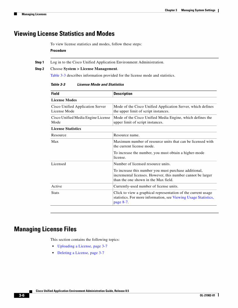
Viewing License Statistics and ModesTo view license statistics and modes, follow these steps:
Procedure
Step 1 Log in to the Cisco Unified Application Environment Administration.
Step 2 Choose System > License Management.
Table 3-3 describes information provided for the license mode and statistics.
Managing License FilesThis section contains the following topics:
• Uploading a License, page 3-7
• Deleting a License, page 3-7
Table 3-3 License Mode and Statistics
Field Description
License Modes
Cisco Unified Application Server License Mode
Mode of the Cisco Unified Application Server, which defines the upper limit of script instances.
Cisco Unified Media Engine License Mode
Mode of the Cisco Unified Media Engine, which defines the upper limit of script instances.
License Statistics
Resource Resource name.
Max Maximum number of resource units that can be licensed with the current license mode.
To increase the number, you must obtain a higher-mode license.
Licensed Number of licensed resource units.
To increase this number you must purchase additional, incremental licenses. However, this number cannot be larger than the one shown in the Max field.
Active Currently-used number of license units.
Stats Click to view a graphical representation of the current usage statistics. For more information, see Viewing Usage Statistics, page 8-7.
3-6Cisco Unified Application Environment Administration Guide, Release 8.5
OL-21902-01

Chapter 3 Managing System Settings Managing Licenses
Uploading a License
To upload a license, follow these steps:
Procedure
Step 1 Log in to the Cisco Unified Application Environment Administration.
Step 2 Choose System > License Management.
Step 3 Under Upload License File, click Browse to locate the license, then click Upload.
Deleting a License
To delete a license, follow these steps:
Procedure
Step 1 Log in to the Cisco Unified Application Environment Administration.
Step 2 Choose System > License Management.
Step 3 Under License File Management, select the license that you want to delete, then click Delete.
Deployment and Licensing for VMware or Virtualized Environment When the Cisco Unified Application Environment is deployed on a virtual environment, the MAC address used for licensing is not the one configured on the network interface of the virtual machine. The MAC address is generated from the system parameters such as Host name, IP address, and Subnet mask. When you obtain a license, make sure that you specify the MAC address that is displayed on the License Management page.
Caution Any change to the system parameters that are used for generating the MAC Address will make the existing license invalid.
Note Cisco Unified Application Environment 8.5 supports virtualization in a lab/demo environment only and not in production.
Redundant LicensingRedundant licensing is only applicable to the primary and backup Cisco Unified Application Environment application server deployment. Therefore, if you plan to deploy a Primary application/media and a redundant, backup application/media server, you must upload a redundant license file in the backup application/media server. Redundant license file is similar to the non-redundant/Primary/Stand-alone license file, except that it will contain the keyword ‘Redundant’.
3-7Cisco Unified Application Environment Administration Guide, Release 8.5
OL-21902-01
Chapter 3 Managing System Settings Managing Licenses
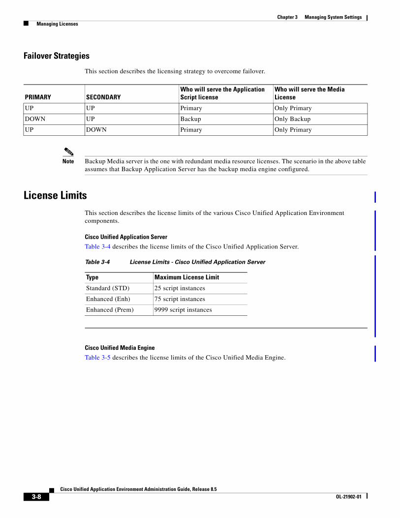
Failover Strategies
This section describes the licensing strategy to overcome failover.
Note Backup Media server is the one with redundant media resource licenses. The scenario in the above table assumes that Backup Application Server has the backup media engine configured.
License LimitsThis section describes the license limits of the various Cisco Unified Application Environment components.
Cisco Unified Application Server
Table 3-4 describes the license limits of the Cisco Unified Application Server.
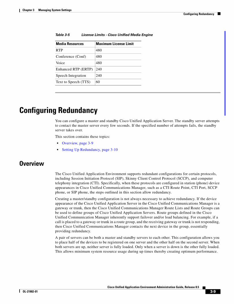
Cisco Unified Media Engine
Table 3-5 describes the license limits of the Cisco Unified Media Engine.
PRIMARY SECONDARYWho will serve the Application Script license
Who will serve the Media License
UP UP Primary Only Primary
DOWN UP Backup Only Backup
UP DOWN Primary Only Primary
Table 3-4 License Limits - Cisco Unified Application Server
Type Maximum License Limit
Standard (STD) 25 script instances
Enhanced (Enh) 75 script instances
Enhanced (Prem) 9999 script instances
3-8Cisco Unified Application Environment Administration Guide, Release 8.5
OL-21902-01
Chapter 3 Managing System Settings Configuring Redundancy
Configuring RedundancyYou can configure a master and standby Cisco Unified Application Server. The standby server attempts to contact the master server every few seconds. If the specified number of attempts fails, the standby server takes over.
This section contains these topics:
• Overview, page 3-9
• Setting Up Redundancy, page 3-10
OverviewThe Cisco Unified Application Environment supports redundant configurations for certain protocols, including Session Initiation Protocol (SIP), Skinny Client Control Protocol (SCCP), and computer telephony integration (CTI). Specifically, when these protocols are configured in station (phone) device appearances in Cisco Unified Communications Manager, such as a CTI Route Point, CTI Port, SCCP phone, or SIP phone, the steps outlined in this section allow redundancy.
Creating a master/standby configuration is not always necessary to achieve redundancy. If the device appearance of the Cisco Unified Application Server in the Cisco Unified Communications Manager is a gateway or trunk, then the Cisco Unified Communications Manager Route Lists and Route Groups can be used to define groups of Cisco Unified Application Servers. Route groups defined in the Cisco Unified Communication Manager inherently support failover and/or load balancing. For example, if a call is placed to a gateway or trunk in a route group, and the receiving gateway or trunk is not responding, then Cisco Unified Communications Manager contacts the next device in the group, essentially providing redundancy.
A pair of servers can be both a master and standby servers to each other. This configuration allows you to place half of the devices to be registered on one server and the other half on the second server. When both servers are up, neither server is fully loaded. Only when a server is down is the other fully loaded. This allows minimum system resource usage during up times thereby creating optimum performance.
Table 3-5 License Limits - Cisco Unified Media Engine
Media Resources Maximum License Limit
RTP 480
Conference (Conf) 480
Voice 480
Enhanced RTP (ERTP) 240
Speech Integration 240
Text to Speech (TTS) 60
3-9Cisco Unified Application Environment Administration Guide, Release 8.5
OL-21902-01
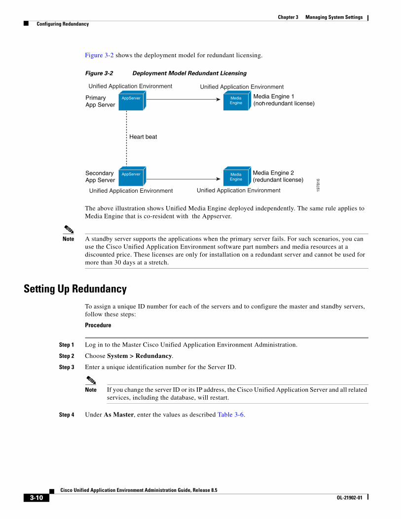
Chapter 3 Managing System Settings Configuring Redundancy
Figure 3-2 shows the deployment model for redundant licensing.
Figure 3-2 Deployment Model Redundant Licensing
The above illustration shows Unified Media Engine deployed independently. The same rule applies to Media Engine that is co-resident with the Appserver.
Note A standby server supports the applications when the primary server fails. For such scenarios, you can use the Cisco Unified Application Environment software part numbers and media resources at a discounted price. These licenses are only for installation on a redundant server and cannot be used for more than 30 days at a stretch.
Setting Up RedundancyTo assign a unique ID number for each of the servers and to configure the master and standby servers, follow these steps:
Procedure
Step 1 Log in to the Master Cisco Unified Application Environment Administration.
Step 2 Choose System > Redundancy.
Step 3 Enter a unique identification number for the Server ID.
Note If you change the server ID or its IP address, the Cisco Unified Application Server and all related services, including the database, will restart.
Step 4 Under As Master, enter the values as described Table 3-6.
1978
16
Primary App Server
Media Engine 1(non- redundant license)
SecondaryApp Server
Media Engine 2(redundant license)
Heart beat
Unified Application Environment Unified Application Environment
Unified Application Environment Unified Application Environment
AppServer
AppServer
MediaEngine
MediaEngine
-
3-10Cisco Unified Application Environment Administration Guide, Release 8.5
OL-21902-01
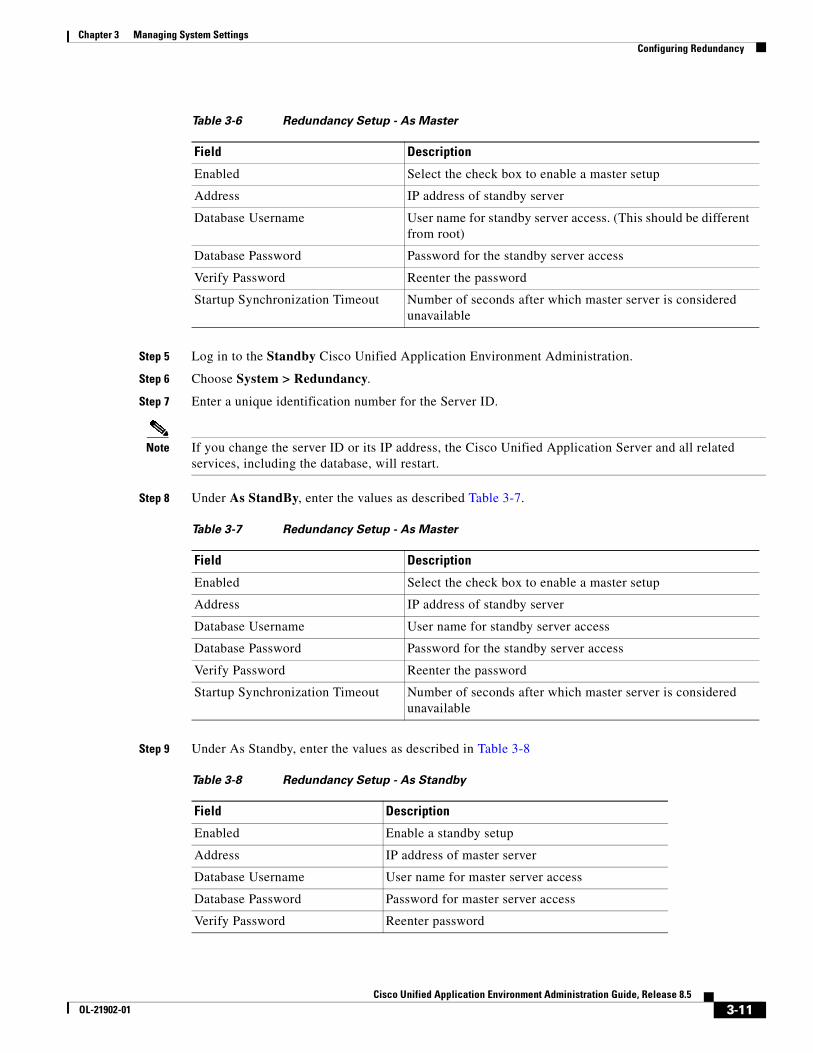
Chapter 3 Managing System Settings Configuring Redundancy
Step 5 Log in to the Standby Cisco Unified Application Environment Administration.
Step 6 Choose System > Redundancy.
Step 7 Enter a unique identification number for the Server ID.
Note If you change the server ID or its IP address, the Cisco Unified Application Server and all related services, including the database, will restart.
Step 8 Under As StandBy, enter the values as described Table 3-7.
Step 9 Under As Standby, enter the values as described in Table 3-8
Table 3-6 Redundancy Setup - As Master
Field Description
Enabled Select the check box to enable a master setup
Address IP address of standby server
Database Username User name for standby server access. (This should be different from root)
Database Password Password for the standby server access
Verify Password Reenter the password
Startup Synchronization Timeout Number of seconds after which master server is considered unavailable
Table 3-7 Redundancy Setup - As Master
Field Description
Enabled Select the check box to enable a master setup
Address IP address of standby server
Database Username User name for standby server access
Database Password Password for the standby server access
Verify Password Reenter the password
Startup Synchronization Timeout Number of seconds after which master server is considered unavailable
Table 3-8 Redundancy Setup - As Standby
Field Description
Enabled Enable a standby setup
Address IP address of master server
Database Username User name for master server access
Database Password Password for master server access
Verify Password Reenter password
3-11Cisco Unified Application Environment Administration Guide, Release 8.5
OL-21902-01
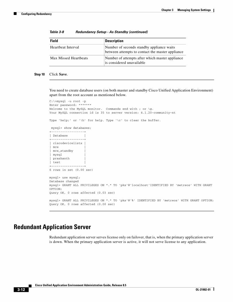
Chapter 3 Managing System Settings Configuring Redundancy
Step 10 Click Save.
You need to create database users (on both master and standby Cisco Unified Application Environment) apart from the root account as mentioned below.
C:\>mysql -u root -pEnter password: *******Welcome to the MySQL monitor. Commands end with ; or \g.Your MySQL connection id is 35 to server version: 4.1.20-community-nt
Type 'help;' or '\h' for help. Type '\c' to clear the buffer.
mysql> show databases;+------------------+| Database |+------------------+| ciscodevicelistx || mce || mce_standby || mysql || prashanth || test |+------------------+6 rows in set (0.00 sec)
mysql> use mysql;Database changedmysql> GRANT ALL PRIVILEGES ON *.* TO 'pks'@'localhost'IDENTIFIED BY 'metreos' WITH GRANT OPTION;Query OK, 0 rows affected (0.03 sec)
mysql> GRANT ALL PRIVILEGES ON *.* TO 'pks'@'%' IDENTIFIED BY 'metreos' WITH GRANT OPTION;Query OK, 0 rows affected (0.00 sec)
Redundant Application Server Redundant application server serves license only on failover, that is, when the primary application server is down. When the primary application server is active, it will not serve license to any application.
Heartbeat Interval Number of seconds standby appliance waits between attempts to contact the master appliance
Max Missed Heartbeats Number of attempts after which master appliance is considered unavailable
Table 3-8 Redundancy Setup - As Standby (continued)
Field Description
3-12Cisco Unified Application Environment Administration Guide, Release 8.5
OL-21902-01
Chapter 3 Managing System Settings Configuring SSL Management
Redundant Media ServerRedundant media server will not serve any license while Primary Application Server is active. It will serve license only when Backup application server is in failover mode, that is when primary application server is active, it will not serve any license.
The application server and media server checks for the availability of license before executing application script and requesting media resources respectively, applications will not run on a redundant server when it is in fail back (Primary Application Server is active) mode.
Configuring SSL ManagementThe Cisco Unified Application Environment uses OpenSSL to provide HTTPS secure client access to the Cisco Unified Application Environment Administration web interface. You can upload your own SSL certificate and private key or use the interface to generate a self-signed certificate and key. You can also enable or disable SSL, and restart the Apache service via the user interface.
This section contains these topics:
• Overview, page 3-13
• Uploading SSL Certificate and Key, page 3-13
• Generating SSL Certificate and Key, page 3-14
• Enabling SSL, page 3-14
• Disabling SSL, page 3-15
OverviewThe high-level steps involved in enabling SSL are:
1. Upload or generate an SSL certificate and key.
2. Enable SSL by clicking the Enable SSL button on the SSL Management page.
3. Restart the Apache service.
Uploading SSL Certificate and KeyTo upload your own SSL certificate and private key for the Cisco Unified Application Server, follow these steps:
Procedure
Step 1 Log in to the Cisco Unified Application Environment Administration.
Step 2 Choose System > SSL Management.
Step 3 Under Upload SSL Certificate/Key, click Browse to locate and select the SSL certificate.
Step 4 Click Browse to locate and select the SSL private key.
Step 5 When both the Certificate and Key fields are populated, click Upload.
The page refreshes and the Current Status section displays the Enable SSL button.
3-13Cisco Unified Application Environment Administration Guide, Release 8.5
OL-21902-01
Chapter 3 Managing System Settings Configuring SSL Management
Note SSL is not enabled until you click the Enable SSL button and receive a success message.
Passphrase Protection
The Cisco Unified Application Environment Administration interface will not prompt for a passphrase. Therefore, do not attempt to use passphrase protection for any private keys that you upload.
Certificate and Key Backups
If you upload or create a new SSL certificate and key when a set already exists, your previously installed certificates and keys are backed up automatically. Backups are stored in C:\Program Files\Apache Group\Apache\conf\ssl on the Cisco Unified Application Server machine and named in the format of [oldfilname.extension].[yyMMddHHmmssZ].bak. For example: my-server.cert.080919164130-0500.bak.
You can delete SSL certificate and key files from the file system manually.
Generating SSL Certificate and KeyTo generate an SSL certificate and key for the Cisco Unified Application Server, follow these steps:
Procedure
Step 1 Log in to the Cisco Unified Application Environment Administration.
Step 2 Choose System > SSL Management.
Step 3 Under Generate SSL Certificate/Key, provide the requested information.
Step 4 Click Generate.
The page refreshes and the Current Status section displays a new message to inform you if certificate and key generated successfully.
Tip In addition to the self-signed certificate and key, a certificate signing request is also created that you can use if you prefer to use an SSL certificate from a trusted certifying authority.
Note Generating an SSL certificate and key does not automatically enable SSL. SSL is enabled after you click the Enable SSL button and receive a success message.
Enabling SSLTo enable SSL after you have uploaded or generated a certificate and key, follow these steps:
3-14Cisco Unified Application Environment Administration Guide, Release 8.5
OL-21902-01
Chapter 3 Managing System Settings Configuring SSL Management
Procedure
Step 1 Log in to the Cisco Unified Application Environment Administration.
Step 2 Choose System > SSL Management.
Step 3 Under Current Status, click Enable SSL.
Step 4 After you enable or disable SSL, you must restart the Apache service. For instructions, see “Restarting the Apache Service” section on page 3-15
Note The Enable SSL button only appears when SSL is disabled and a certificate and key have been uploaded or generated.
Note Restarting the Apache service causes the Cisco Unified Application Environment to be unavailable until it finishes restarting.
Disabling SSLDisabling turns off SSL. After the Apache service is restarted, SSL will be turned off. The private key and certificate file are still present in the file system afterwards, but are not being used.
To disable SSL, follow these steps:
Procedure
Step 1 Log in to the Cisco Unified Application Environment Administration.
Step 2 Choose System > SSL Management.
Step 3 Under Current Status, click Disable SSL.
Step 4 After you enable or disable SSL, you must restart the Apache service. For instructions, see “Restarting the Apache Service” section on page 3-15
Note The Disable SSL button only appears when SSL is enabled.
Note Restarting the Apache service causes the Cisco Unified Application Environment to be unavailable until it finishes restarting.
Restarting the Apache ServiceAfter you enable or disable SSL, you must restart the Apache service.
3-15Cisco Unified Application Environment Administration Guide, Release 8.5
OL-21902-01
Chapter 3 Managing System Settings Managing Secure Connections to the Management Service
Note Restarting the Apache service causes the Cisco Unified Application Environment to be unavailable until it finishes restarting.
There are three ways to restart the Apache service:
• Using the command-line:
a. On the Application Server, open a command prompt.
b. Stop the Apache service:
net apache stop
c. Start the Apache service:
net apache start
• Using the Windows Services console:
a. Choose Start > Control Panel > Administrative Tools > Services.
b. Click the Apache service.
c. On the Action menu, click Restart.
• Using the Cisco Unified Application Environment Administration interface:
a. Log in to the Cisco Unified Application Environment Administration interface.
b. Choose System > SSL Management.
c. Under Current Status, click Restart Apache.
Managing Secure Connections to the Management ServiceBy default, Transport Layer Security (TLS) is enabled on the Management Service, which causes the CUAE command-line tool and Cisco Unified Application Environment Administration to consume the Management Service API using TLS. After installation, encryption is ON but authentication is OFF. Authentication can be enabled for the connection between the CUAE command-line tool and the Management Service.
Note There are two types of authentication possible between the CUAE command-line tool and the Management Service. Server authentication is on by default and developers are always prompted for the administration user name and password to install, remove, or update applications. Protocol authentication using TLS is configurable, but disabled by default.
This section describes the following configuration options:
• Generating the Certificate and Key, page 3-17
• Managing the CUAE Command-line Tool Protocol, page 3-17
• Enabling Authentication between CUAE Command-line Tool and Management Service, page 3-17
• Disabling TLS on the Management Service, page 3-18
3-16Cisco Unified Application Environment Administration Guide, Release 8.5
OL-21902-01
Chapter 3 Managing System Settings Managing Secure Connections to the Management Service
Generating the Certificate and Key The Cisco Unified Application Environment Platform Services installer automatically generates the TLS certificate and key during installation for production and places it in \MgmtServiceLauncher\conf. The keystore name is default.keystore.
Note You can create your own certificate and key using keytool. The keytool program is a security tool included in the bin directory of the Java SDK. For more information, see http://java.sun.com/j2se/1.5.0/docs/tooldocs/windows/keytool.html.
Managing the CUAE Command-line Tool ProtocolDevelopers use the CUAE command-line tool when creating and managing etch-based applications. When using the following commands, the developer is prompted to supply the protocol (TCP or TLS) to be used for communication between the application server and the developer’s client machine.
• cuae install
• cuae remove
• cuae update
The developer should supply the protocol that is set on the Management Service. TLS is the default supported protocol. If the user selects TLS, they have the option to select only encryption or encryption and authentication.
If you want developers to use authentication, follow the instructions in the “Enabling Authentication between CUAE Command-line Tool and Management Service” section on page 3-17.
If you want developers to use TCP, follow the instructions in the “Disabling TLS on the Management Service” section on page 3-18 to change the default URI of the Management Service before developers use these commands.
Enabling Authentication between CUAE Command-line Tool and Management Service
When using TLS, encryption is enabled by default. To enable TLS authentication, follow these steps:
Procedure
Step 1 Provide developers with the security certificate.
Note The private key's matching certificate is located by default in \MgmtServiceLauncher\conf\default.cer. However, if you create your own private key and matching certificate, you will have to first export the certificate before giving it to a developer by using the keytool -export command. For more information, see http://java.sun.com/j2se/1.5.0/docs/tooldocs/windows/keytool.html.
3-17Cisco Unified Application Environment Administration Guide, Release 8.5
OL-21902-01
Chapter 3 Managing System Settings Managing Secure Connections to the Etch Bridge
Step 2 Instruct developers to import the certificate into the truststore using keytool or makecert.exe on the machine where they will run the CUAE command-line tool. They will be prompted for the protocol details when running the CUAE command-line tool. For more information, direct developers to the Cisco Unified Application Environment wiki at this URL:http://developer.cisco.com/web/cuae/wikidocs.
Disabling TLS on the Management ServiceYou can disable TLS support for the Management Service. If you do, you must also modify the Cisco Unified Application Environment Administration configuration and inform developers to choose TCP when prompted by the CUAE command-line tools for the protocol.
To disable TLS on the Management Service, follow these steps:
Procedure
Step 1 Open \MgmtServiceLauncher\conf\production.properties on the Application Server.
Step 2 Locate and modify the URI setting to resemble the following:
listenerUri=tcp://0.0.0.0:9001#uncomment the following line to enable tls#listenerUri=tls://0.0.0.0:9001
Step 3 Restart the CUAE Management Server service.
Configure Management Service Connection Details
To configure the new Management Service connection to match the production.properties on the Cisco Unified Application Server, follow these procedures:
Procedure
Step 1 Open the Management Service Launcher file: C:\Program Files\Cisco Systems\Unified Application Environment\MgmtServiceLauncher\conf\mgmt-service-launcher.conf.
Step 2 Locate the Java Additional Parameters section of the code. It contains a series of wrapper.java.addtional.N properties, where N is an incrementing integer value.
Step 3 Pass the cuae.managment-service-uri system parameter to the JVM. For example, the following parameter syntax points the Cisco Unified Application Environment Administration to the local TCP connection on port 9001 configured in the above example:
wrapper.java.additional.5=-Dcuae.management-service-uri=tcp://localhost:9001/
Managing Secure Connections to the Etch BridgeBy default, Transport Layer Security (TLS) is enabled on the Etch Bridge, which allows etch-based applications and plugins to connect to the Etch Bridge using TLS.
3-18Cisco Unified Application Environment Administration Guide, Release 8.5
OL-21902-01
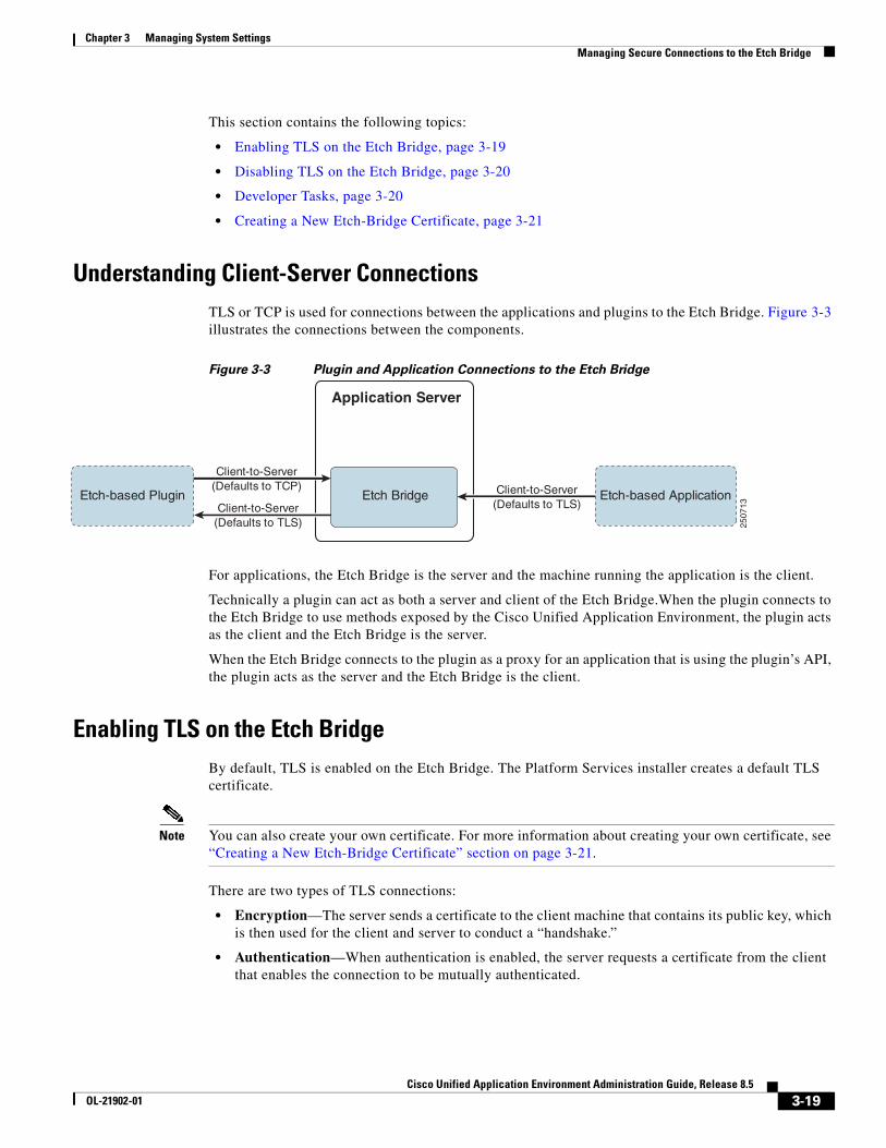
Chapter 3 Managing System Settings Managing Secure Connections to the Etch Bridge
This section contains the following topics:
• Enabling TLS on the Etch Bridge, page 3-19
• Disabling TLS on the Etch Bridge, page 3-20
• Developer Tasks, page 3-20
• Creating a New Etch-Bridge Certificate, page 3-21
Understanding Client-Server ConnectionsTLS or TCP is used for connections between the applications and plugins to the Etch Bridge. Figure 3-3 illustrates the connections between the components.
Figure 3-3 Plugin and Application Connections to the Etch Bridge
For applications, the Etch Bridge is the server and the machine running the application is the client.
Technically a plugin can act as both a server and client of the Etch Bridge.When the plugin connects to the Etch Bridge to use methods exposed by the Cisco Unified Application Environment, the plugin acts as the client and the Etch Bridge is the server.
When the Etch Bridge connects to the plugin as a proxy for an application that is using the plugin’s API, the plugin acts as the server and the Etch Bridge is the client.
Enabling TLS on the Etch BridgeBy default, TLS is enabled on the Etch Bridge. The Platform Services installer creates a default TLS certificate.
Note You can also create your own certificate. For more information about creating your own certificate, see “Creating a New Etch-Bridge Certificate” section on page 3-21.
There are two types of TLS connections:
• Encryption—The server sends a certificate to the client machine that contains its public key, which is then used for the client and server to conduct a “handshake.”
• Authentication—When authentication is enabled, the server requests a certificate from the client that enables the connection to be mutually authenticated.
Application Server
Etch Bridge
Client-to-Server
(Defaults to TCP)
Client-to-Server
(Defaults to TLS)
Client-to-Server
(Defaults to TLS)Etch-based Plugin Etch-based Application
25
07
13
3-19Cisco Unified Application Environment Administration Guide, Release 8.5
OL-21902-01
Chapter 3 Managing System Settings Managing Secure Connections to the Etch Bridge
Note No action is required by the administrator to enable either encryption or authentication on the Etch Bridge. However, the developer must modify the connection string URIs in their applications or plugins to connect properly to the Etch Bridge. See “Disabling TLS on the Etch Bridge” section on page 3-20 for more information.
Disabling TLS on the Etch BridgeIf you do not want to use TLS for encryption or authentication, you can disable it on the Etch Bridge by modifying the application server configuration file.
Note If you disable TLS, all connections to the Etch Bridge will use TCP. Inform developers of this change so that they can properly configure their application and plugin connection string URIs. See “Disabling TLS on the Etch Bridge” section on page 3-20 for more information.
To modify the application server configuration file, follow these steps:
Procedure
Step 1 Open %CUAE_HOME%/AppServer/AppServerService.exe.config on the Application Server.
Step 2 Locate and modify the value in the following line:
<add key="EtchBridgeCertificate" value="Etch"/>
Step 3 Remove the value, leaving only the opening and closing quotation marks.
<add key="EtchBridgeCertificate" value=""/>
Step 4 Restart the Cisco Unified Application Server.
Developer TasksTo configure etch-based client applications and plugins, the developer must know which protocol is supported, TCP or TLS, and whether or not to require authentication.
• Encryption—To enable encryption, application developers must modify the connection string URIs in their code for applications and plugins to connect to the Etch Bridge. The connection string is where the developers declare the connection protocol and the IP address and port of the server listener.
• Authentication—To enable authentication, developers must also copy the server certificate to the client machine and import it to a truststore.
For more information, direct developers to the Cisco Unified Application Environment wiki at this URL:http://developer.cisco.com/web/cuae/wikidocs.
3-20Cisco Unified Application Environment Administration Guide, Release 8.5
OL-21902-01
Chapter 3 Managing System Settings Managing Secure Connections to the Etch Bridge
Note To encrypt or authenticate a plugin server, the developer must create a certificate on the plugin machine. For authentication, you must copy that certificate to the Application Server, which acts as the client in this scenario.
Creating a New Etch-Bridge CertificateYou can create a new certificate to use on the Etch Bridge using the makecert.exe tool.
Before You Begin
To get the Microsoft Certificate Creation tool (makecert.exe), do one of the following things:
• Download and install Microsoft .NET 2.0 SDK; makecert.exe is included in the installed directory
• Copy makecert.exe from a machine that has Microsoft Visual Studio 2005 or Microsoft .NET 2.0 SDK installed.
To create a new Etch Bridge certificate, follow these steps:
Procedure
Step 1 Log on to the Cisco Unified Application Server as the CiscoUAE user.
This is required because Windows certificates created by makecert.exe belong to the current Windows user account. If you log in as a different user to create the certificate, the certificate will not work because the Cisco Unified Application Service runs using the CiscoUAE user credentials.
3-21Cisco Unified Application Environment Administration Guide, Release 8.5
OL-21902-01
Chapter 3 Managing System Settings Managing Secure Connections to the Etch Bridge
Step 2 Create a certificate using the makecert.exe tool. For example:
makecert -pe -n "CN=Test And Dev Root Authority" -ss my -sr LocalMachine -a sha1 -sky signature -r "Test And Dev Root Authority.cer"
Note The above command creates a Root certificate. Your personal certificates extend from this root certificate.
Step 3 To create a personal certificate:
makecert -pe -n "CN=PluginEt" -ss my -sr LocalMachine -a sha1 -sky exchange -in "Test And Dev Root Authority" -is my -ir LocalMachine -sp "Microsoft RSA SChannel Cryptographic Provider" -sy 12 PluginEt
Note In this example, you can change the certificate name options, but make sure the –in option matches the name of the root certificate.
Step 4 Run the MMC application.
Step 5 Add the Certificate snap-in:
a. Choose New > Add-Remove Snap-In.
b. Click Add.
c. Select Certificates and click Add.
d. Select Computer Account and click Next.
e. Select Local Computer.
f. Click Finish.
g. Click Close.
h. Click OK.
Step 6 Choose Certificates > Personal. You should see your newly created certificates.
Step 7 In the certificates snap-in, right-click the Test and Dev Root Authority certificate and copy it to the Trusted Root Certification Authorities node. Once done, if you expand this node, and then select certificates your newly created root certificate should appear.
Step 8 Choose Trusted Root Certification Authorities > Certificates.
Step 9 Open %CUAE_HOME%/AppServer/AppServerService.exe.config on the Application Server.
Step 10 Set the EtchBridgeCertificate value to the name of the personal certificate you created.
Step 11 Restart the Cisco Unified Application Server.
If you only intend to enable encryption with the new certificate, no further steps are necessary.
If you intend to enable authentication, you must also export certificate to a file that can be given to developer to copy to client application and plugin machines:
a. Right-click the root certificate you created and select All Tasks > Export.
b. In the Certificate Export wizard, click Next.
3-22Cisco Unified Application Environment Administration Guide, Release 8.5
OL-21902-01
Chapter 3 Managing System Settings Etch Connection String URI
c. Click No, do not export the private key.
d. Select DER encoded binary X509 for the Export File Format.
e. Enter any file name and click Finish (for example server.cer).
Etch Connection String URIFor applications and plugins to connect to the Etch Bridge, application developers must properly configure the connection stringURI in their applications and plugins. This section describes the connection string URI parameters and how settings on the Cisco Unified Application Server impact the parameters.
This section contains the following topics to further describe the connection string URI parameters:
• KeepAlive, page 3-23
• Max Packet Size, page 3-24
• ReconnectDelay, page 3-25
OverviewThe connection protocol and KeepAlive filter must be set on the connection string URI for applications and plugins to work correctly. Additional parameters, MaxPktSize parameter and ReconnectDelay parameter can also be included in the URI. For example:
tls://localhost:9000?TlsConnection.authReqd=false&filter=KeepAlive&KeepAlive.Count=5&Packetizer.maxPktSize=102400&TcpTransport.reconnectDelay=4000”
This URI connects to Etch Bridge on localhost using TLS without authentication, using KeepAlive and resetting the number of KeepAlive messages to 5, setting the Max Packet Size to 100 KB and setting the reconnect delay to 4 seconds.
KeepAliveIn order to rapidly detect connection failures, the Etch KeepAlive message filter periodically checks the health of the client-server connection and resets it if it is not responsive. By default, KeepAlive messages are 15 seconds apart, and if four KeepAlive messages fail, the connection is reset.
Note KeepAlive is enabled at the server by default. Developers must append the KeepAlive filter to the connection string URI in client applications and plugins or disable KeepAlive on the application server or connections will drop after 60 seconds.
Enabling KeepAlive
To enable KeepAlive, developers append the KeepAlive filter to the connection string URI. For example:
String uri = "tls://appserver_ipaddress:port?TlsConnection.authReqd=false&filter=KeepAlive";
3-23Cisco Unified Application Environment Administration Guide, Release 8.5
OL-21902-01
Chapter 3 Managing System Settings Etch Connection String URI
Modifying KeepAlive Parameters
The KeepAlive filter has two parameters: KeepAlive.Delay and KeepAlive.Count. Delay controls the number of seconds between KeepAlive messages and Count controls the number of messages sent before the connection is reset. By default, KeepAlive messages are 15 seconds apart and if four KeepAlive messages fail, the connection is reset. Developers can override the defaults by modifying the connection string URI.
Disabling KeepAlive
To disable KeepAlive, follow these steps:
Procedure
Step 1 Open %CUAE_HOME%/AppServer/AppServerService.exe.config on the Application Server.
Step 2 Locate the following line:
<add key="EtchBridgeKeepAliveDelay" value="15"/>
Step 3 Set the EtchBridgeKeepAliveDelay value to 0:
<add key="EtchBridgeKeepAliveDelay" value="0"/>
Step 4 Restart the Cisco Unified Application Server.
Max Packet SizeBy default, Etch sets the Max Packet Size at 16KB for applications and plugins and the Etch Bridge defaults to 100KB. The smaller of the two is the default.
Note You can also set the Max Packet Size to unlimited. To do so, you must set the value on the Etch Bridge to "" and the developer must also set the URI to "".
Using the Etch Bridge Max Packet Size
To change the Max Packet Size to 100KB, the developer must add a Packetizer.maxPktSize parameter to their connection string URIs to override the Etch default. For example:
tls://appserver_ipaddress:9000?TlsConnection.authReqd=false&filter=KeepAlive&Packetizer.maxPktSize="102392"
Note If the developer does not specify a Max Packet Size in the URI, it defaults to 16KB.
3-24Cisco Unified Application Environment Administration Guide, Release 8.5
OL-21902-01
Chapter 3 Managing System Settings Etch Connection String URI
Using the Etch MaxPacketSize
To use the default Etch MaxPacketSize, follow these steps:
Procedure
Step 1 Open %CUAE_HOME%/AppServer/AppServerService.exe.config on the Application Server.
Step 2 Locate the following line and remove the value from the EtchBridgeMaxPacketSize, leaving the quotations only:
<add key="EtchBridgeMaxPacketSize" value="102392"/>
Step 3 Remove the value from the EtchBridgeMaxPacketSize, leaving the quotations only:
<add key="EtchBridgeMaxPacketSize" value=""/>
Step 4 Restart the Cisco Unified Application Server.
ReconnectDelayIf set in the connection string URI, theTCPTransport.reconnectDelay setting causes the Etch transport to attempt to reconnect if the application or plugin connection to the Etch Bridge is dropped. If it is not set, there is no reconnect attempt made.
Note Developers must call registerApplication or registerPlugin when the connection is re-established.
3-25Cisco Unified Application Environment Administration Guide, Release 8.5
OL-21902-01

Chapter 3 Managing System Settings Etch Connection String URI
3-26Cisco Unified Application Environment Administration Guide, Release 8.5
OL-21902-01
Cisco Unified ApplicaOL-21902-01
C H A P T E R 4
Managing UsersA user account is required for each user who accesses the system. By creating a different account for each user, you can ensure that audit logs accurately record each user’s interactions with the system.
This section includes these topics:
• Viewing and Searching for Users, page 4-1
• Adding a User, page 4-1
• Deleting a User, page 4-2
• Editing User Information, page 4-2
Viewing and Searching for UsersTo view the list of users, or to search for a particular user, follow these steps:
Procedure
Step 1 Log in to the Cisco Unified Application Environment Administration.
Step 2 Choose Users > List Users. The List Users page appears with the list of user names and roles.
• To view user details, click the user name.
• To search for a user, enter the user name or partial user name with an asterisk (*) as a wildcard to denote numbers and letters, then click Search.
Adding a User To add a user, follow these steps:
Procedure
Step 1 Log in to the Cisco Unified Application Environment Administration.
Step 2 Choose Users > Add User. The Add User page appears.
4-1tion Environment Administration Guide, Release 8.5
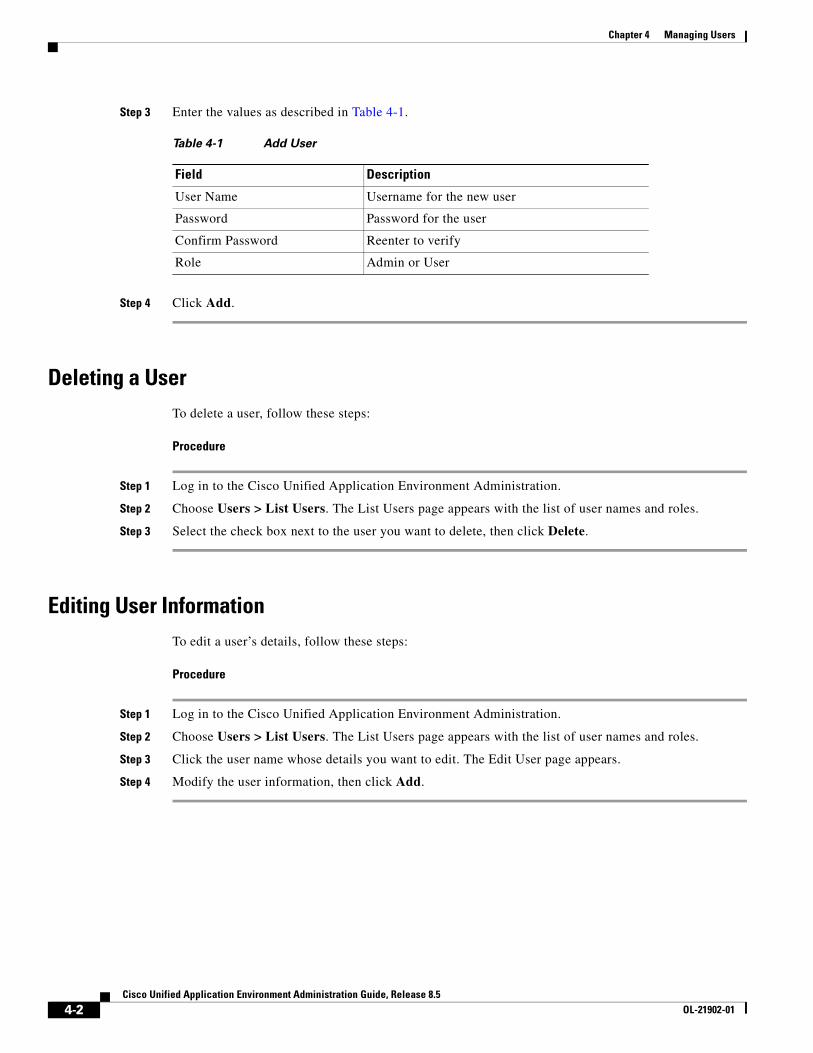
Chapter 4 Managing Users
Step 3 Enter the values as described in Table 4-1.
Step 4 Click Add.
Deleting a UserTo delete a user, follow these steps:
Procedure
Step 1 Log in to the Cisco Unified Application Environment Administration.
Step 2 Choose Users > List Users. The List Users page appears with the list of user names and roles.
Step 3 Select the check box next to the user you want to delete, then click Delete.
Editing User InformationTo edit a user’s details, follow these steps:
Procedure
Step 1 Log in to the Cisco Unified Application Environment Administration.
Step 2 Choose Users > List Users. The List Users page appears with the list of user names and roles.
Step 3 Click the user name whose details you want to edit. The Edit User page appears.
Step 4 Modify the user information, then click Add.
Table 4-1 Add User
Field Description
User Name Username for the new user
Password Password for the user
Confirm Password Reenter to verify
Role Admin or User
4-2Cisco Unified Application Environment Administration Guide, Release 8.5
OL-21902-01
Cisco Unified ApplicaOL-21902-01
C H A P T E R 5
Managing ApplicationsAn application typically includes configuration items that are unique to your deployment and which you must configure after the application is installed.
Applications can be developed using Cisco Unified Application Designer or with your language of choice using Etch. See Cisco Unified Application Environment Developer Tools, page 1-3.
This chapter includes these topics:
• Overview, page 5-1
• Managing Applications, page 5-4
• Managing Partitions, page 5-7
• Managing Triggers, page 5-10
OverviewApplication configuration occurs at the partition level. A partition is a configuration profile for an application. Applications can support multiple partitions, enabling you to create and execute multiple versions of the same application on a single Cisco Unified Application server.
This section includes these topics:
• Understanding Partitions, page 5-1
• Understanding Scripts and Triggers, page 5-2
• Application Configuration Example, page 5-3
Understanding PartitionsPartitions are flexible and can be useful in a variety of situations. For example, if an application is intended to serve end users located on distinct Cisco Unified Communications Manager clusters, it is often desirable for all call control and media streams to terminate to the network and telephony resources contained within each cluster. At the same time, it may be desirable to have another configurable protocol on the application, such as LDAP, which makes reference to the same central location, regardless of the partition.
5-1tion Environment Administration Guide, Release 8.5
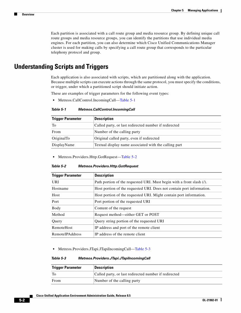
Chapter 5 Managing Applications Overview
Each partition is associated with a call route group and media resource group. By defining unique call route groups and media resource groups, you can identify the partitions that use individual media engines. For each partition, you can also determine which Cisco Unified Communications Manager cluster is used for making calls by specifying a call route group that corresponds to the particular telephony protocol and group.
Understanding Scripts and TriggersEach application is also associated with scripts, which are partitioned along with the application. Because multiple scripts can execute actions through the same protocol, you must specify the conditions, or trigger, under which a partitioned script should initiate action.
These are examples of trigger parameters for the following event types:
• Metreos.CallControl.IncomingCall—Table 5-1
• Metreos.Providers.Http.GotRequest—Table 5-2
• Metreos.Providers.JTapi.JTapiIncomingCall—Table 5-3
Table 5-1 Metreos.CallControl.IncomingCall
Trigger Parameter Description
To Called party, or last redirected number if redirected
From Number of the calling party
OriginalTo Original called party, even if redirected
DisplayName Textual display name associated with the calling part
Table 5-2 Metreos.Providers.Http.GotRequest
Trigger Parameter Description
URI Path portion of the requested URI. Must begin with a front slash (/).
Hostname Host portion of the requested URI. Does not contain port information.
Host Host portion of the requested URI. Might contain port information.
Port Port portion of the requested URI
Body Content of the request
Method Request method—either GET or POST
Query Query string portion of the requested URI
RemoteHost IP address and port of the remote client
RemoteIPAddress IP address of the remote client
Table 5-3 Metreos.Providers.JTapi.JTapiIncomingCall
Trigger Parameter Description
To Called party, or last redirected number if redirected
From Number of the calling party
5-2Cisco Unified Application Environment Administration Guide, Release 8.5
OL-21902-01
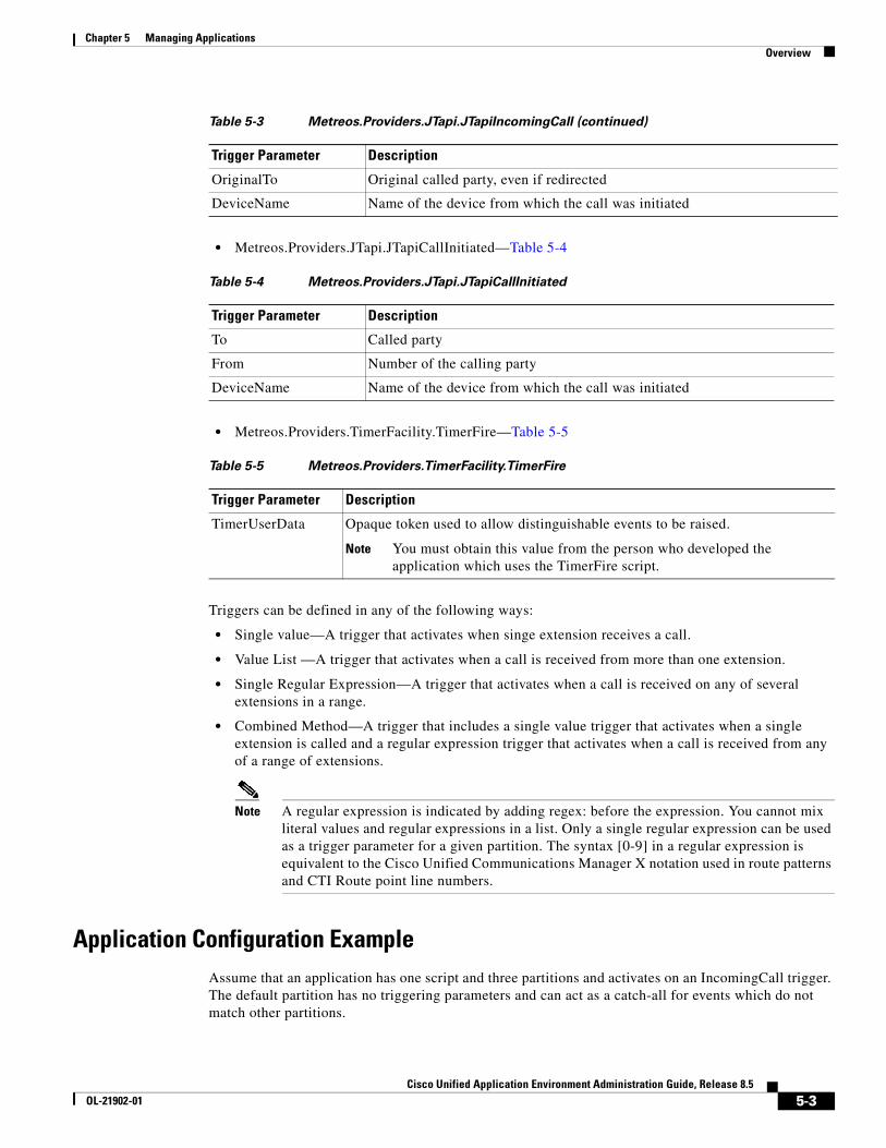
Chapter 5 Managing Applications Overview
• Metreos.Providers.JTapi.JTapiCallInitiated—Table 5-4
• Metreos.Providers.TimerFacility.TimerFire—Table 5-5
Triggers can be defined in any of the following ways:
• Single value—A trigger that activates when singe extension receives a call.
• Value List —A trigger that activates when a call is received from more than one extension.
• Single Regular Expression—A trigger that activates when a call is received on any of several extensions in a range.
• Combined Method—A trigger that includes a single value trigger that activates when a single extension is called and a regular expression trigger that activates when a call is received from any of a range of extensions.
Note A regular expression is indicated by adding regex: before the expression. You cannot mix literal values and regular expressions in a list. Only a single regular expression can be used as a trigger parameter for a given partition. The syntax [0-9] in a regular expression is equivalent to the Cisco Unified Communications Manager X notation used in route patterns and CTI Route point line numbers.
Application Configuration ExampleAssume that an application has one script and three partitions and activates on an IncomingCall trigger. The default partition has no triggering parameters and can act as a catch-all for events which do not match other partitions.
OriginalTo Original called party, even if redirected
DeviceName Name of the device from which the call was initiated
Table 5-3 Metreos.Providers.JTapi.JTapiIncomingCall (continued)
Trigger Parameter Description
Table 5-4 Metreos.Providers.JTapi.JTapiCallInitiated
Trigger Parameter Description
To Called party
From Number of the calling party
DeviceName Name of the device from which the call was initiated
Table 5-5 Metreos.Providers.TimerFacility.TimerFire
Trigger Parameter Description
TimerUserData Opaque token used to allow distinguishable events to be raised.
Note You must obtain this value from the person who developed the application which uses the TimerFire script.
5-3Cisco Unified Application Environment Administration Guide, Release 8.5
OL-21902-01
Chapter 5 Managing Applications Managing Applications
The application server determines the best match handler for a given event. Other partitions take effect if their trigger parameters are activated. For example, if Partition 2 specifies to=2000, then when a call comes in for extension 2000, partition 2 will activate. If no trigger matches, the default partition is active.
A partition is similar to a configuration template for a script and applies these rules:
• The application developer sets the event that triggers a script. The event applies to all partitions and cannot be changed.
• All installed script partitions across all applications are treated as equal.
• If any two partitions have identical triggering criteria, either one may trigger; therefore, it is important that all partitions have unique triggering criteria.
• The router will match the handler that best fits the events. For example, if partition A specifies to=2000 and partition B specifies to=2000 and from=1000, then a call from 1000 to 2000 triggers B.
Managing ApplicationsThis section includes these topics:
• Viewing Applications, page 5-4
• Installing an Application, page 5-5
• Enabling or Disabling an Application, page 5-5
• Uninstalling an Application, page 5-6
• Viewing Application Details, page 5-6
• Updating an Application, page 5-7
Viewing ApplicationsTo view a list of applications, follow these steps:
Procedure
Step 1 Log in to the Cisco Unified Application Environment Administration.
Step 2 Choose Applications > List Applications. The List Applications page appears.
5-4Cisco Unified Application Environment Administration Guide, Release 8.5
OL-21902-01
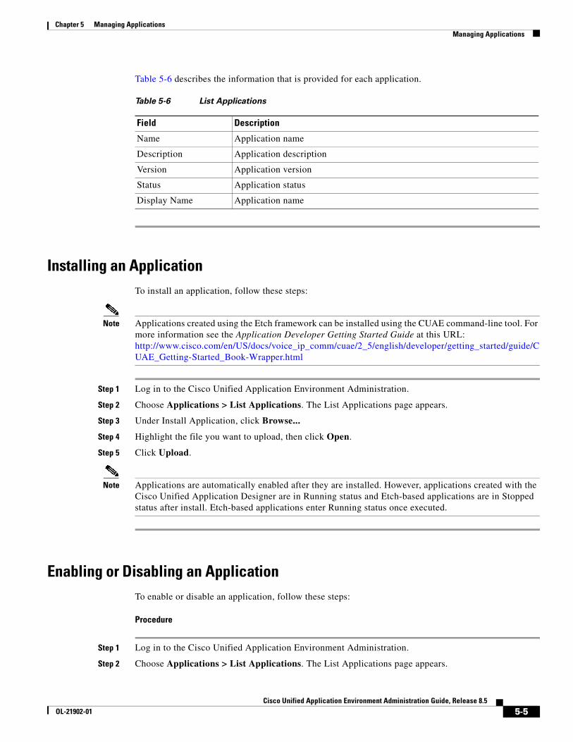
Chapter 5 Managing Applications Managing Applications
Table 5-6 describes the information that is provided for each application.
Installing an ApplicationTo install an application, follow these steps:
Note Applications created using the Etch framework can be installed using the CUAE command-line tool. For more information see the Application Developer Getting Started Guide at this URL: http://www.cisco.com/en/US/docs/voice_ip_comm/cuae/2_5/english/developer/getting_started/guide/CUAE_Getting-Started_Book-Wrapper.html
Step 1 Log in to the Cisco Unified Application Environment Administration.
Step 2 Choose Applications > List Applications. The List Applications page appears.
Step 3 Under Install Application, click Browse...
Step 4 Highlight the file you want to upload, then click Open.
Step 5 Click Upload.
Note Applications are automatically enabled after they are installed. However, applications created with the Cisco Unified Application Designer are in Running status and Etch-based applications are in Stopped status after install. Etch-based applications enter Running status once executed.
Enabling or Disabling an ApplicationTo enable or disable an application, follow these steps:
Procedure
Step 1 Log in to the Cisco Unified Application Environment Administration.
Step 2 Choose Applications > List Applications. The List Applications page appears.
Table 5-6 List Applications
Field Description
Name Application name
Description Application description
Version Application version
Status Application status
Display Name Application name
5-5Cisco Unified Application Environment Administration Guide, Release 8.5
OL-21902-01
Chapter 5 Managing Applications Managing Applications
Step 3 Select the check box next to the application name.
• To enable the application, click Enable.
• To disable the application, click Disable.
Uninstalling an ApplicationTo uninstall an application, follow these steps:
Note Applications created using the Etch framework can be uninstalled using the CUAE command-line interface. For more information see the Application Developer Getting Started Guide at this URL: http://www.cisco.com/en/US/docs/voice_ip_comm/cuae/2_5/english/developer/getting_started/guide/CUAE_Getting-Started_Book-Wrapper.html
Procedure
Step 1 Log in to the Cisco Unified Application Environment Administration.
Step 2 Choose Applications > List Applications. The List Applications page appears.
Step 3 Select the check box next to the application name, then click Uninstall.
Viewing Application DetailsTo view the list of scripts, partitions, and partition configurations for an application, follow these steps:
Procedure
Step 1 Log in to the Cisco Unified Application Environment Administration.
Step 2 Choose Applications > List Applications. The List Applications page appears.
Step 3 Click the application name. The Application Details page appears.
• The scripts associated with the application are listed under Scripts
• The default partition displays under Configurations. To view other partitions, select the partition name from the Partition Name list, and the configuration details for that partition are displayed.
5-6Cisco Unified Application Environment Administration Guide, Release 8.5
OL-21902-01
Chapter 5 Managing Applications Managing Partitions
Updating an ApplicationTo update an application, follow these steps:
Procedure
Step 1 Log in to the Cisco Unified Application Environment Administration.
Step 2 Choose Applications > List Applications. The List Application page appears.
Step 3 Click the application name. The Application Details page appears.
Step 4 Under Update Application, click Browse...
Step 5 Highlight the file you want to upload, then click Open.
Step 6 Click UploadFile.
Step 7 Click Done to return to the List Applications page.
Managing Partitions This section includes the following procedures:
• Adding a Partition, page 5-7
• Deleting a Partition, page 5-9
• Deleting a Partition, page 5-9
• Applying Partition Configurations, page 5-9
• Enabling and Disabling Partition Configurations, page 5-9
• Uninstalling Partition Configurations, page 5-10
Adding a PartitionTo add partition, follow these steps:
Procedure
Step 1 Log in to the Cisco Unified Application Environment Administration.
Step 2 Choose Applications > List Applications. The List Application page appears.
Step 3 Click the application name. The application details page appears.
Step 4 Under Partitions, click Add Partition. The Create Partitions page appears.
Step 5 Enter the values as described in Table 5-7.
5-7Cisco Unified Application Environment Administration Guide, Release 8.5
OL-21902-01
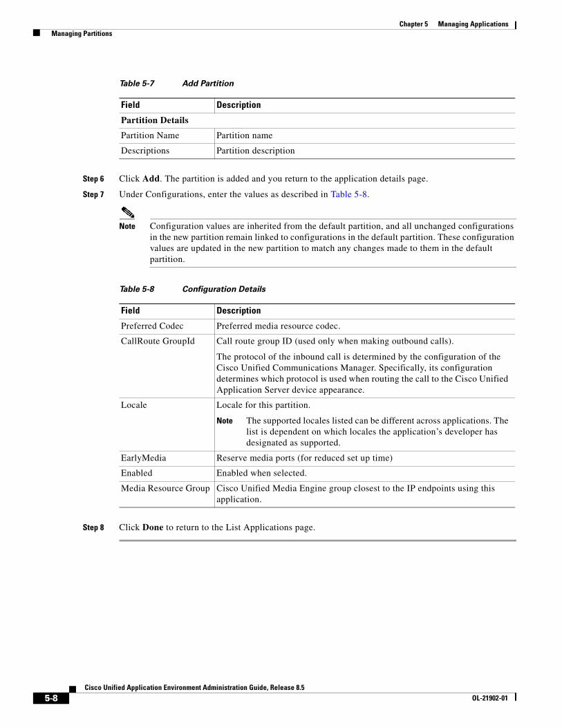
Chapter 5 Managing Applications Managing Partitions
Step 6 Click Add. The partition is added and you return to the application details page.
Step 7 Under Configurations, enter the values as described in Table 5-8.
Note Configuration values are inherited from the default partition, and all unchanged configurations in the new partition remain linked to configurations in the default partition. These configuration values are updated in the new partition to match any changes made to them in the default partition.
Step 8 Click Done to return to the List Applications page.
Table 5-7 Add Partition
Field Description
Partition Details
Partition Name Partition name
Descriptions Partition description
Table 5-8 Configuration Details
Field Description
Preferred Codec Preferred media resource codec.
CallRoute GroupId Call route group ID (used only when making outbound calls).
The protocol of the inbound call is determined by the configuration of the Cisco Unified Communications Manager. Specifically, its configuration determines which protocol is used when routing the call to the Cisco Unified Application Server device appearance.
Locale Locale for this partition.
Note The supported locales listed can be different across applications. The list is dependent on which locales the application’s developer has designated as supported.
EarlyMedia Reserve media ports (for reduced set up time)
Enabled Enabled when selected.
Media Resource Group Cisco Unified Media Engine group closest to the IP endpoints using this application.
5-8Cisco Unified Application Environment Administration Guide, Release 8.5
OL-21902-01
Chapter 5 Managing Applications Managing Partitions
Deleting a PartitionTo delete a partition, follow these steps:
Procedure
Step 1 Log in to the Cisco Unified Application Environment Administration.
Step 2 Choose Applications > List Applications. The List Application page appears.
Step 3 Click the application name. The application details page appears.
Step 4 Under Partitions, select the partition you want to delete from the Partition Name list, then click Delete Partition.
Step 5 Click Done to return to the List Applications page.
Applying Partition ConfigurationsTo apply a partition configuration, follow these steps:
Procedure
Step 1 Log in to the Cisco Unified Application Environment Administration.
Step 2 Click Applications > List Applications. The List Application page appears.
Step 3 Click the application name. The Application Details page appears.
Step 4 Under Partitions, select the partition from the Partition Name list.
Step 5 Under Configurations, click Apply.
Step 6 Click Done to return to the List Applications page.
Enabling and Disabling Partition ConfigurationsTo enable or disable a partition configuration, follow these steps:
Procedure
Step 1 Log in to the Cisco Unified Application Environment Administration.
Step 2 Click Applications > List Applications. The List Application page appears.
Step 3 Click the application name. The Application Details page appears.
5-9Cisco Unified Application Environment Administration Guide, Release 8.5
OL-21902-01
Chapter 5 Managing Applications Managing Triggers
Step 4 Under Partitions, select the partition from the Partition Name list.
Step 5 Under Configurations
• Click Enable to enable the partition configuration.
• Click Disable to disable the partition configuration.
Step 6 Click Done to return to the List Applications page.
Uninstalling Partition ConfigurationsTo uninstall a partition configuration, follow these steps:
Procedure
Step 1 Log in to the Cisco Unified Application Environment Administration.
Step 2 Click Applications > List Applications. The List Application page appears.
Step 3 Click the application name. The Application Details page appears.
Step 4 Under Partitions, select the partition from the Partition Name list.
Step 5 Under Configurations, click Uninstall.
Step 6 Click Done to return to the List Applications page.
Managing TriggersThis section includes the following procedures:
• Viewing Triggers, page 5-10
• Viewing Trigger Details, page 5-11
• Adding a Trigger Parameter, page 5-11
• Deleting a Trigger Parameter, page 5-12
Viewing TriggersTo view the applications being triggered on a particular event type, follow these steps:
Procedure
Step 1 Log in to the Cisco Unified Application Environment Administration.
Step 2 Choose Applications > List Triggers. The List Triggers page appears.
Step 3 Table 5-9 describes the information that is provided for each trigger.
5-10Cisco Unified Application Environment Administration Guide, Release 8.5
OL-21902-01
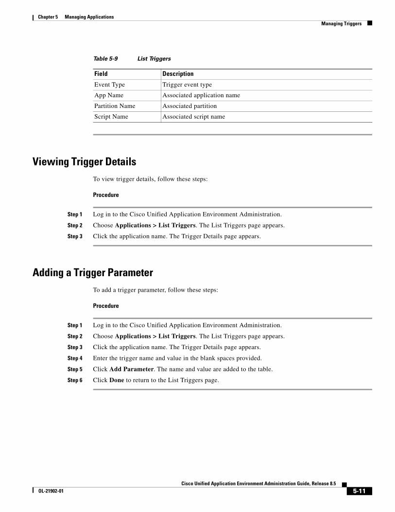
Chapter 5 Managing Applications Managing Triggers
Viewing Trigger DetailsTo view trigger details, follow these steps:
Procedure
Step 1 Log in to the Cisco Unified Application Environment Administration.
Step 2 Choose Applications > List Triggers. The List Triggers page appears.
Step 3 Click the application name. The Trigger Details page appears.
Adding a Trigger ParameterTo add a trigger parameter, follow these steps:
Procedure
Step 1 Log in to the Cisco Unified Application Environment Administration.
Step 2 Choose Applications > List Triggers. The List Triggers page appears.
Step 3 Click the application name. The Trigger Details page appears.
Step 4 Enter the trigger name and value in the blank spaces provided.
Step 5 Click Add Parameter. The name and value are added to the table.
Step 6 Click Done to return to the List Triggers page.
Table 5-9 List Triggers
Field Description
Event Type Trigger event type
App Name Associated application name
Partition Name Associated partition
Script Name Associated script name
5-11Cisco Unified Application Environment Administration Guide, Release 8.5
OL-21902-01
Chapter 5 Managing Applications Managing Triggers
Deleting a Trigger ParameterTo delete a trigger parameter, follow these steps:
Procedure
Step 1 Log in to the Cisco Unified Application Environment Administration.
Step 2 Choose Applications > List Triggers. The List Triggers page appears.
Step 3 Click the application name. The Trigger Details page appears.
Step 4 Select the parameter you want to delete, then click Delete Parameter.
Step 5 Click Done to return to the List Triggers page.
Updating a Trigger ParameterTo update a trigger parameter, follow these steps:
Procedure
Step 1 Log in to the Cisco Unified Application Environment Administration.
Step 2 Choose Applications > List Triggers. The List Triggers page appears.
Step 3 Click the application name. The Trigger Details page appears.
Step 4 Change the value.
Step 5 Click Update Parameter.
Step 6 Click Done to return to the List Triggers page.
5-12Cisco Unified Application Environment Administration Guide, Release 8.5
OL-21902-01
Cisco Unified ApplicaOL-21902-01
C H A P T E R 6
Managing PluginsPlugins are used to open network ports and allow the runtime environment to communicate with devices on the network. This chapter includes these topics:
• Cisco Unified Application Environment Plugins, page 6-1
• Viewing the List of Plugins, page 6-7
• Installing a Plugin, page 6-7
• Enabling or Disabling a Plugin, page 6-7
• Uninstalling a Plugin, page 6-8
• Configuring Plugins, page 6-8
• Invoking Extensions, page 6-9
Cisco Unified Application Environment PluginsThe following plugins ship with the Cisco Unified Application Environment.
• Cisco DeviceListX Provider, page 6-1
• H.323 Provider, page 6-2
• JTAPI Provider, page 6-3
• HTTP Provider, page 6-3
• Media Engine Provider, page 6-3
• Presence Provider, page 6-4
• SCCP Provider, page 6-5
• SIP Provider, page 6-6
• Timer Provider, page 6-6
Cisco DeviceListX ProviderThe Cisco DeviceListX Provider communicates with Cisco Unified Communications Manager to retrieve and cache real-time device information for application use. The Cisco DeviceListX (3.X, 4.X) Provider and SNMP (5.X, 6X) protocols are used to gather this information. Table 6-1 lists the provider parameters.
6-1tion Environment Administration Guide, Release 8.5
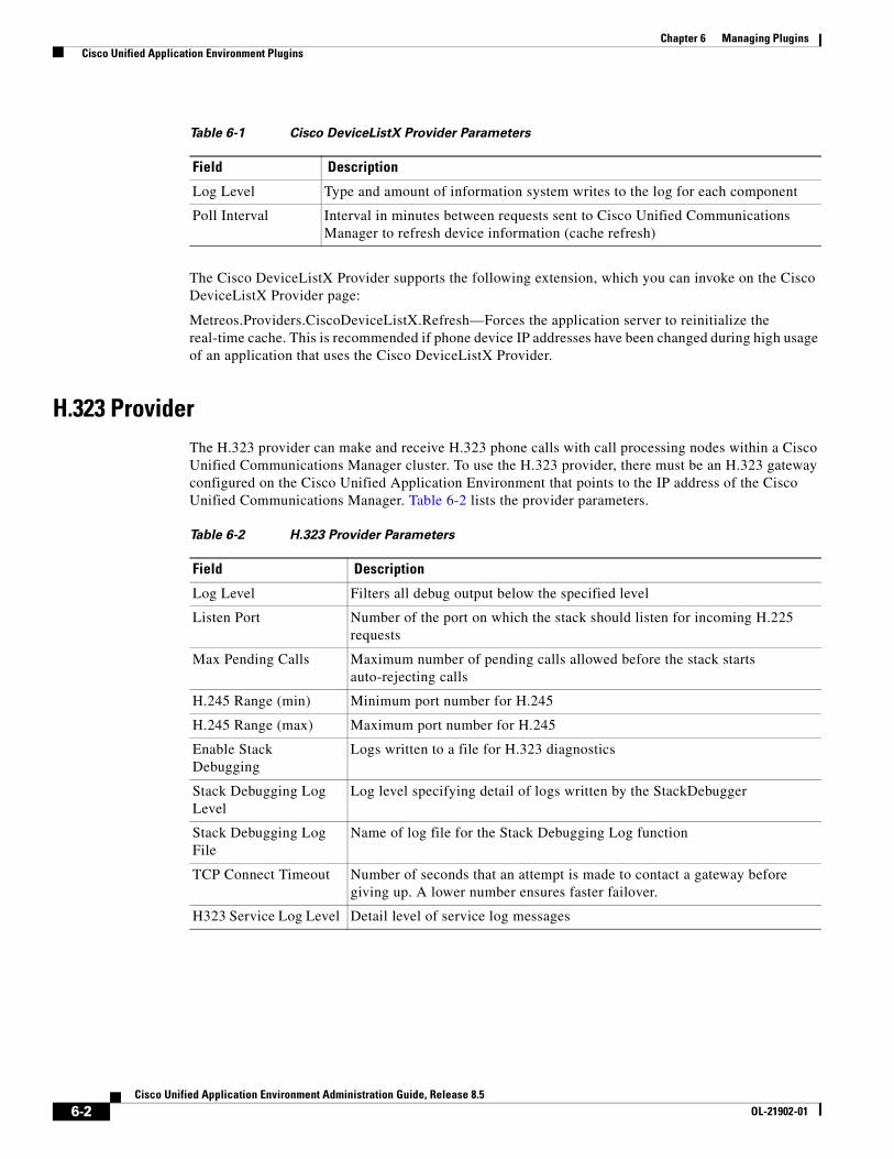
Chapter 6 Managing Plugins Cisco Unified Application Environment Plugins
The Cisco DeviceListX Provider supports the following extension, which you can invoke on the Cisco DeviceListX Provider page:
Metreos.Providers.CiscoDeviceListX.Refresh—Forces the application server to reinitialize the real-time cache. This is recommended if phone device IP addresses have been changed during high usage of an application that uses the Cisco DeviceListX Provider.
H.323 ProviderThe H.323 provider can make and receive H.323 phone calls with call processing nodes within a Cisco Unified Communications Manager cluster. To use the H.323 provider, there must be an H.323 gateway configured on the Cisco Unified Application Environment that points to the IP address of the Cisco Unified Communications Manager. Table 6-2 lists the provider parameters.
Table 6-1 Cisco DeviceListX Provider Parameters
Field Description
Log Level Type and amount of information system writes to the log for each component
Poll Interval Interval in minutes between requests sent to Cisco Unified Communications Manager to refresh device information (cache refresh)
Table 6-2 H.323 Provider Parameters
Field Description
Log Level Filters all debug output below the specified level
Listen Port Number of the port on which the stack should listen for incoming H.225 requests
Max Pending Calls Maximum number of pending calls allowed before the stack starts auto-rejecting calls
H.245 Range (min) Minimum port number for H.245
H.245 Range (max) Maximum port number for H.245
Enable Stack Debugging
Logs written to a file for H.323 diagnostics
Stack Debugging Log Level
Log level specifying detail of logs written by the StackDebugger
Stack Debugging Log File
Name of log file for the Stack Debugging Log function
TCP Connect Timeout Number of seconds that an attempt is made to contact a gateway before giving up. A lower number ensures faster failover.
H323 Service Log Level Detail level of service log messages
6-2Cisco Unified Application Environment Administration Guide, Release 8.5
OL-21902-01
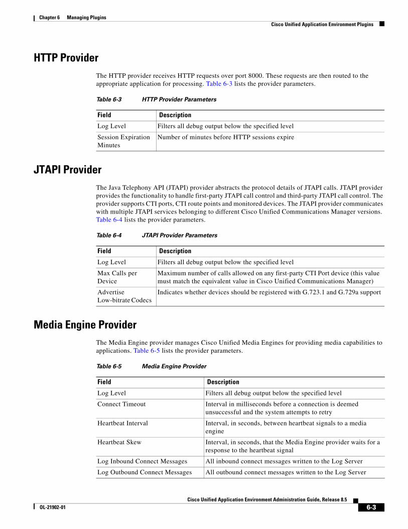
Chapter 6 Managing Plugins Cisco Unified Application Environment Plugins
HTTP ProviderThe HTTP provider receives HTTP requests over port 8000. These requests are then routed to the appropriate application for processing. Table 6-3 lists the provider parameters.
JTAPI ProviderThe Java Telephony API (JTAPI) provider abstracts the protocol details of JTAPI calls. JTAPI provider provides the functionality to handle first-party JTAPI call control and third-party JTAPI call control. The provider supports CTI ports, CTI route points and monitored devices. The JTAPI provider communicates with multiple JTAPI services belonging to different Cisco Unified Communications Manager versions. Table 6-4 lists the provider parameters.
Media Engine ProviderThe Media Engine provider manages Cisco Unified Media Engines for providing media capabilities to applications. Table 6-5 lists the provider parameters.
Table 6-3 HTTP Provider Parameters
Field Description
Log Level Filters all debug output below the specified level
Session Expiration Minutes
Number of minutes before HTTP sessions expire
Table 6-4 JTAPI Provider Parameters
Field Description
Log Level Filters all debug output below the specified level
Max Calls per Device
Maximum number of calls allowed on any first-party CTI Port device (this value must match the equivalent value in Cisco Unified Communications Manager)
Advertise Low-bitrate Codecs
Indicates whether devices should be registered with G.723.1 and G.729a support
Table 6-5 Media Engine Provider
Field Description
Log Level Filters all debug output below the specified level
Connect Timeout Interval in milliseconds before a connection is deemed unsuccessful and the system attempts to retry
Heartbeat Interval Interval, in seconds, between heartbeat signals to a media engine
Heartbeat Skew Interval, in seconds, that the Media Engine provider waits for a response to the heartbeat signal
Log Inbound Connect Messages All inbound connect messages written to the Log Server
Log Outbound Connect Messages All outbound connect messages written to the Log Server
6-3Cisco Unified Application Environment Administration Guide, Release 8.5
OL-21902-01
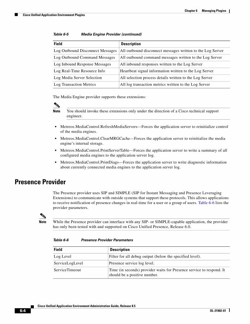
Chapter 6 Managing Plugins Cisco Unified Application Environment Plugins
The Media Engine provider supports these extensions:
Note You should invoke these extensions only under the direction of a Cisco technical support engineer.
• Metreos.MediaControl.RefreshMediaServers—Forces the application server to reinitialize control of the media engines.
• Metreos.MediaControl.ClearMRGCache—Forces the application server to reinitialize the media engine’s internal storage.
• Metreos.MediaControl.PrintServerTable—Forces the application server to write a summary of all configured media engines to the application server log.
• Metreos.MediaControl.PrintDiags—Forces the application server to write diagnostic information about currently connected media engines to the application server log.
Presence ProviderThe Presence provider uses SIP and SIMPLE (SIP for Instant Messaging and Presence Leveraging Extensions) to communicate with outside systems that support these protocols. This allows applications to receive notification of presence changes in real-time for a user or a group of users. Table 6-6 lists the provider parameters.
Note While the Presence provider can interface with any SIP- or SIMPLE-capable application, the provider has only been tested with and supported on Cisco Unified Presence, Release 6.0.
Log Outbound Disconnect Messages All outbound disconnect messages written to the Log Server
Log Outbound Command Messages All outbound command messages written to the Log Server
Log Inbound Response Messages All inbound responses written to the Log Server
Log Real-Time Resource Info Heartbeat signal information written to the Log Server
Log Media Server Selection All selection process details written to the Log Server
Log Transaction Metrics All log transaction metrics written to the Log Server
Table 6-5 Media Engine Provider (continued)
Field Description
Table 6-6 Presence Provider Parameters
Field Description
Log Level Filter for all debug output (below the specified level).
ServiceLogLevel Presence service log level.
ServiceTimeout Time (in seconds) provider waits for Presence service to respond. It should be a positive number.
6-4Cisco Unified Application Environment Administration Guide, Release 8.5
OL-21902-01
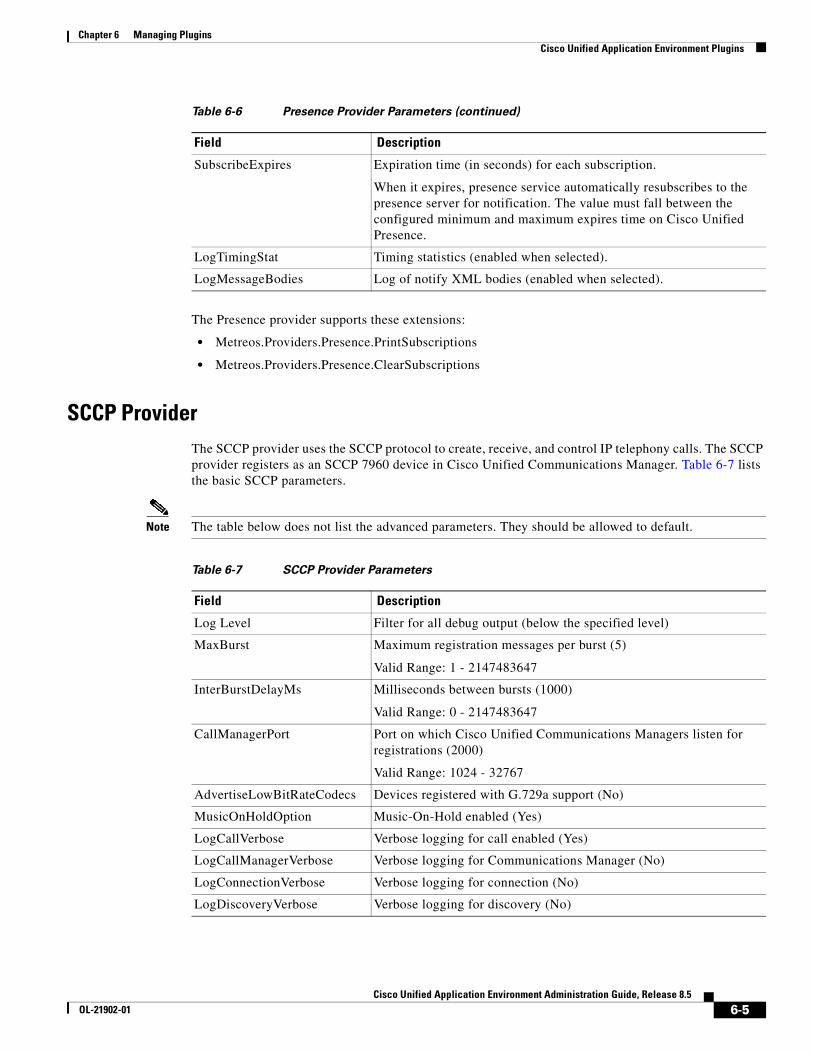
Chapter 6 Managing Plugins Cisco Unified Application Environment Plugins
The Presence provider supports these extensions:
• Metreos.Providers.Presence.PrintSubscriptions
• Metreos.Providers.Presence.ClearSubscriptions
SCCP ProviderThe SCCP provider uses the SCCP protocol to create, receive, and control IP telephony calls. The SCCP provider registers as an SCCP 7960 device in Cisco Unified Communications Manager. Table 6-7 lists the basic SCCP parameters.
Note The table below does not list the advanced parameters. They should be allowed to default.
SubscribeExpires Expiration time (in seconds) for each subscription.
When it expires, presence service automatically resubscribes to the presence server for notification. The value must fall between the configured minimum and maximum expires time on Cisco Unified Presence.
LogTimingStat Timing statistics (enabled when selected).
LogMessageBodies Log of notify XML bodies (enabled when selected).
Table 6-6 Presence Provider Parameters (continued)
Field Description
Table 6-7 SCCP Provider Parameters
Field Description
Log Level Filter for all debug output (below the specified level)
MaxBurst Maximum registration messages per burst (5)
Valid Range: 1 - 2147483647
InterBurstDelayMs Milliseconds between bursts (1000)
Valid Range: 0 - 2147483647
CallManagerPort Port on which Cisco Unified Communications Managers listen for registrations (2000)
Valid Range: 1024 - 32767
AdvertiseLowBitRateCodecs Devices registered with G.729a support (No)
MusicOnHoldOption Music-On-Hold enabled (Yes)
LogCallVerbose Verbose logging for call enabled (Yes)
LogCallManagerVerbose Verbose logging for Communications Manager (No)
LogConnectionVerbose Verbose logging for connection (No)
LogDiscoveryVerbose Verbose logging for discovery (No)
6-5Cisco Unified Application Environment Administration Guide, Release 8.5
OL-21902-01
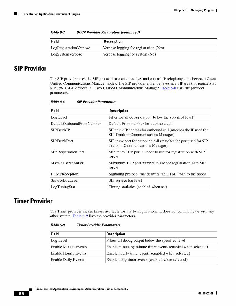
Chapter 6 Managing Plugins Cisco Unified Application Environment Plugins
SIP ProviderThe SIP provider uses the SIP protocol to create, receive, and control IP telephony calls between Cisco Unified Communications Manager nodes. The SIP provider either behaves as a SIP trunk or registers as SIP 7961G-GE devices in Cisco Unified Communications Manager. Table 6-8 lists the provider parameters.
Timer ProviderThe Timer provider makes timers available for use by applications. It does not communicate with any other system. Table 6-9 lists the provider parameters.
LogRegistrationVerbose Verbose logging for registration (Yes)
LogSystemVerbose Verbose logging for system (No)
Table 6-7 SCCP Provider Parameters (continued)
Field Description
Table 6-8 SIP Provider Parameters
Field Description
Log Level Filter for all debug output (below the specified level)
DefaultOutboundFromNumber Default From number for outbound call
SIPTrunkIP SIP trunk IP address for outbound call (matches the IP used for SIP Trunk in Communications Manager)
SIPTrunkPort SIP trunk port for outbound call (matches the port used for SIP Trunk in Communications Manager)
MinRegistrationPort Minimum TCP port number to use for registration with SIP server
MaxRegistrationPort Maximum TCP port number to use for registration with SIP server
DTMFReception Signaling protocol that delivers the DTMF tone to the phone.
ServiceLogLevel SIP service log level
LogTimingStat Timing statistics (enabled when set)
Table 6-9 Timer Provider Parameters
Field Description
Log Level Filters all debug output below the specified level
Enable Minute Events Enable minute by minute timer events (enabled when selected)
Enable Hourly Events Enable hourly timer events (enabled when selected)
Enable Daily Events Enable daily timer events (enabled when selected)
6-6Cisco Unified Application Environment Administration Guide, Release 8.5
OL-21902-01
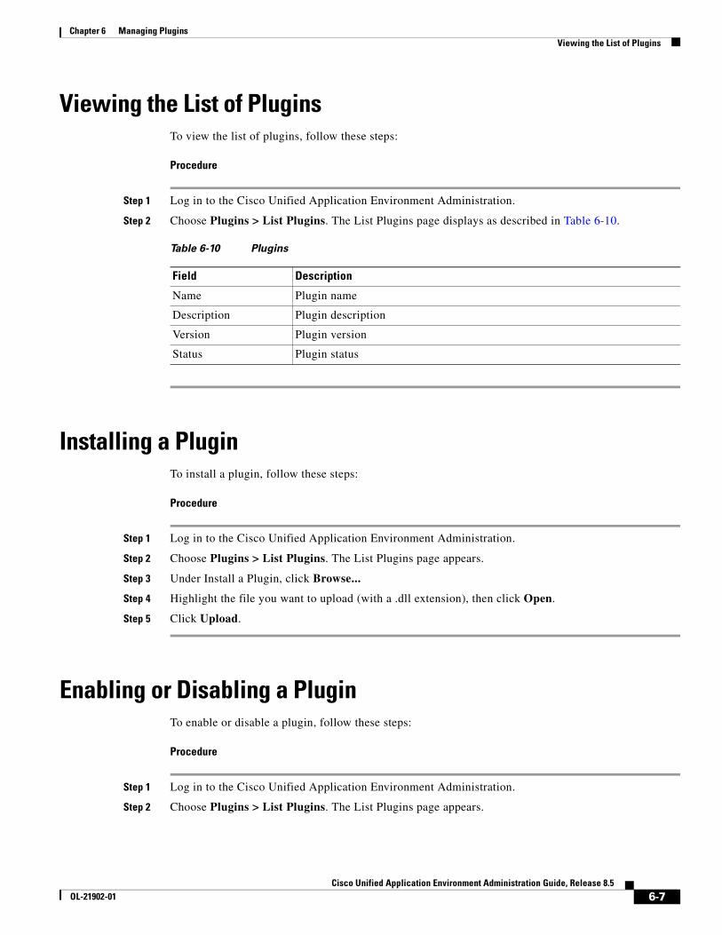
Chapter 6 Managing Plugins Viewing the List of Plugins
Viewing the List of PluginsTo view the list of plugins, follow these steps:
Procedure
Step 1 Log in to the Cisco Unified Application Environment Administration.
Step 2 Choose Plugins > List Plugins. The List Plugins page displays as described in Table 6-10.
Installing a PluginTo install a plugin, follow these steps:
Procedure
Step 1 Log in to the Cisco Unified Application Environment Administration.
Step 2 Choose Plugins > List Plugins. The List Plugins page appears.
Step 3 Under Install a Plugin, click Browse...
Step 4 Highlight the file you want to upload (with a .dll extension), then click Open.
Step 5 Click Upload.
Enabling or Disabling a PluginTo enable or disable a plugin, follow these steps:
Procedure
Step 1 Log in to the Cisco Unified Application Environment Administration.
Step 2 Choose Plugins > List Plugins. The List Plugins page appears.
Table 6-10 Plugins
Field Description
Name Plugin name
Description Plugin description
Version Plugin version
Status Plugin status
6-7Cisco Unified Application Environment Administration Guide, Release 8.5
OL-21902-01
Chapter 6 Managing Plugins Uninstalling a Plugin
Step 3 Select the check box next to the plugin name.
• To enable the plugin, click Enable.
• To disable the plugin, click Disable.
Uninstalling a PluginTo uninstall a plugin, follow these steps:
Note Before you uninstall a plugin, you must disable it and stop the application service. See Enabling or Disabling a Plugin, page 6-7 and Managing Services, page 8-3 for more information. Remember to restart the application service after you uninstall the plugin.
Procedure
Step 1 Log in to the Cisco Unified Application Environment Administration.
Step 2 Choose Plugins > List Plugins. The List Plugins page appears.
Step 3 Select the check box next to the plugin name, then click Uninstall.
Configuring Plugins To modify or apply configurations to a plugin, follow these steps:
Procedure
Step 1 Log in to the Cisco Unified Application Environment Administration.
Step 2 Choose Plugins > List Plugins. The List Plugins page appears.
Step 3 Select the plugin name. The Provider page appears.
Step 4 Enter or change values as needed, then click Apply.
For information about the plugins that ship with the Cisco Unified Application Environment, see Cisco Unified Application Environment Plugins, page 6-1.
Step 5 Click Done to return to the List Plugins page.
6-8Cisco Unified Application Environment Administration Guide, Release 8.5
OL-21902-01
Chapter 6 Managing Plugins Invoking Extensions
Invoking ExtensionsTo invoke a an extension, follow these steps:
Procedure
Step 1 Log in to the Cisco Unified Application Environment Administration.
Step 2 Choose Plugins > List Plugins. The List Plugins page appears.
Step 3 Select the plugin name. The Provider page appears.
Step 4 Under Extensions, locate the extension you want to invoke, then click Invoke Extension.
Step 5 Click Done to return to the List Plugins page.
6-9Cisco Unified Application Environment Administration Guide, Release 8.5
OL-21902-01

Chapter 6 Managing Plugins Invoking Extensions
6-10Cisco Unified Application Environment Administration Guide, Release 8.5
OL-21902-01
Cisco Unified ApplicaOL-21902-01
C H A P T E R 7
Managing ConnectionsYou can create and manage all connections and groups of connections using the Cisco Unified Application Environment Administration. Connections include: Cisco Unified Communications Manager clusters, Cisco Unified Presence servers, Cisco Unified Media Engines, device pools, H.323 gateways, IETF SIP proxy servers, and Nuance servers.
This chapter includes these topics:
• Managing Connections, page 7-1
• Managing Connection Groups, page 7-16
Managing ConnectionsThis section includes these topics:
• Viewing and Searching for Connections, page 7-1
• Viewing and Searching for Device Pools, page 7-2
• Adding a Connection, page 7-3
• Deleting a Connection, page 7-14
• Deleting a Device Pool, page 7-14
• Editing a Connection, page 7-16
Viewing and Searching for ConnectionsTo view the list of connections, or to search for a particular connection, follow these steps:
Procedure
Step 1 Log in to the Cisco Unified Application Environment Administration.
Step 2 Choose Connections > List Connections. The List Connections page appears.
7-1tion Environment Administration Guide, Release 8.5
Chapter 7 Managing Connections Managing Connections
Table 7-1 describes the information provided.
Step 3 To search for or view connections, do the following:
• To search for a connection, enter the connection name or partial name with an asterisk (*) as a wildcard to denote numbers and letters in the Filter box, then click Search.
• To view connections details, click on the connection name.
Viewing and Searching for Device Pools
Note This selection appears only when you have created device pools in your system.
To view the list of device pools, or to search for a particular device pool, follow these steps:
Procedure
Step 1 Log in to the Cisco Unified Application Environment Administration.
Step 2 Choose Connections > List Device Pools. The Device Pool page appears.
Table 7-9 describes the information provided.
Step 3 To view, edit, add, delete, or search for devices in the device pool, see Managing Devices in a Device Pool, page 7-7
Table 7-1 List Connections
Field Description
Connection Name IP address or hostname of the connection
Connection Type Connection type
Table 7-2 List Device Pools
Field Description
Device Pool Name Name of the device pool
Device Pool Type Type of device pool
7-2Cisco Unified Application Environment Administration Guide, Release 8.5
OL-21902-01
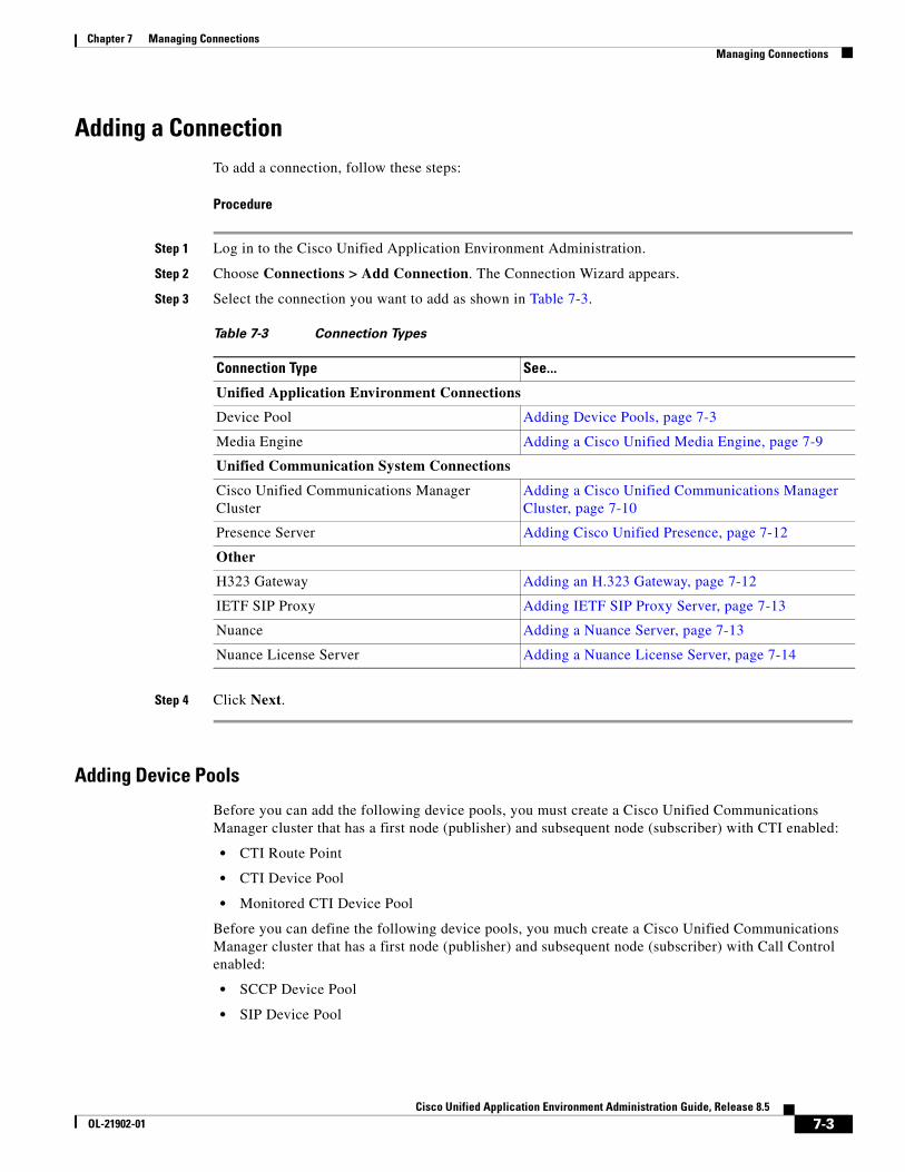
Chapter 7 Managing Connections Managing Connections
Adding a ConnectionTo add a connection, follow these steps:
Procedure
Step 1 Log in to the Cisco Unified Application Environment Administration.
Step 2 Choose Connections > Add Connection. The Connection Wizard appears.
Step 3 Select the connection you want to add as shown in Table 7-3.
Step 4 Click Next.
Adding Device Pools
Before you can add the following device pools, you must create a Cisco Unified Communications Manager cluster that has a first node (publisher) and subsequent node (subscriber) with CTI enabled:
• CTI Route Point
• CTI Device Pool
• Monitored CTI Device Pool
Before you can define the following device pools, you much create a Cisco Unified Communications Manager cluster that has a first node (publisher) and subsequent node (subscriber) with Call Control enabled:
• SCCP Device Pool
• SIP Device Pool
Table 7-3 Connection Types
Connection Type See...
Unified Application Environment Connections
Device Pool Adding Device Pools, page 7-3
Media Engine Adding a Cisco Unified Media Engine, page 7-9
Unified Communication System Connections
Cisco Unified Communications Manager Cluster
Adding a Cisco Unified Communications Manager Cluster, page 7-10
Presence Server Adding Cisco Unified Presence, page 7-12
Other
H323 Gateway Adding an H.323 Gateway, page 7-12
IETF SIP Proxy Adding IETF SIP Proxy Server, page 7-13
Nuance Adding a Nuance Server, page 7-13
Nuance License Server Adding a Nuance License Server, page 7-14
7-3Cisco Unified Application Environment Administration Guide, Release 8.5
OL-21902-01
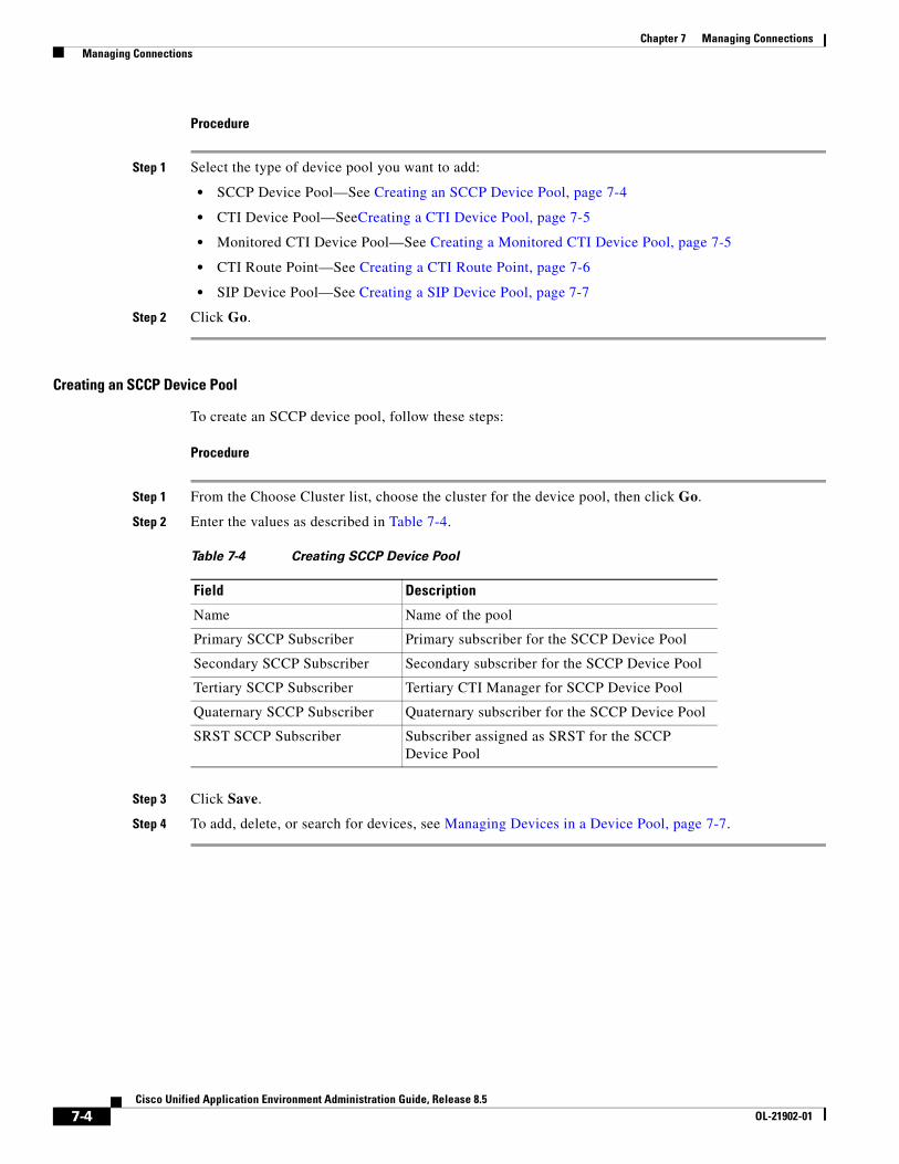
Chapter 7 Managing Connections Managing Connections
Procedure
Step 1 Select the type of device pool you want to add:
• SCCP Device Pool—See Creating an SCCP Device Pool, page 7-4
• CTI Device Pool—SeeCreating a CTI Device Pool, page 7-5
• Monitored CTI Device Pool—See Creating a Monitored CTI Device Pool, page 7-5
• CTI Route Point—See Creating a CTI Route Point, page 7-6
• SIP Device Pool—See Creating a SIP Device Pool, page 7-7
Step 2 Click Go.
Creating an SCCP Device Pool
To create an SCCP device pool, follow these steps:
Procedure
Step 1 From the Choose Cluster list, choose the cluster for the device pool, then click Go.
Step 2 Enter the values as described in Table 7-4.
Step 3 Click Save.
Step 4 To add, delete, or search for devices, see Managing Devices in a Device Pool, page 7-7.
Table 7-4 Creating SCCP Device Pool
Field Description
Name Name of the pool
Primary SCCP Subscriber Primary subscriber for the SCCP Device Pool
Secondary SCCP Subscriber Secondary subscriber for the SCCP Device Pool
Tertiary SCCP Subscriber Tertiary CTI Manager for SCCP Device Pool
Quaternary SCCP Subscriber Quaternary subscriber for the SCCP Device Pool
SRST SCCP Subscriber Subscriber assigned as SRST for the SCCP Device Pool
7-4Cisco Unified Application Environment Administration Guide, Release 8.5
OL-21902-01
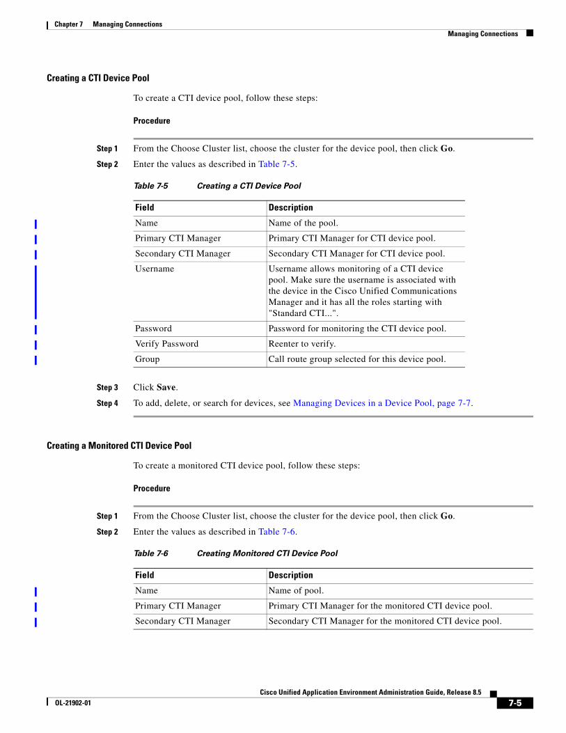
Chapter 7 Managing Connections Managing Connections
Creating a CTI Device Pool
To create a CTI device pool, follow these steps:
Procedure
Step 1 From the Choose Cluster list, choose the cluster for the device pool, then click Go.
Step 2 Enter the values as described in Table 7-5.
Step 3 Click Save.
Step 4 To add, delete, or search for devices, see Managing Devices in a Device Pool, page 7-7.
Creating a Monitored CTI Device Pool
To create a monitored CTI device pool, follow these steps:
Procedure
Step 1 From the Choose Cluster list, choose the cluster for the device pool, then click Go.
Step 2 Enter the values as described in Table 7-6.
Table 7-5 Creating a CTI Device Pool
Field Description
Name Name of the pool.
Primary CTI Manager Primary CTI Manager for CTI device pool.
Secondary CTI Manager Secondary CTI Manager for CTI device pool.
Username Username allows monitoring of a CTI device pool. Make sure the username is associated with the device in the Cisco Unified Communications Manager and it has all the roles starting with "Standard CTI...".
Password Password for monitoring the CTI device pool.
Verify Password Reenter to verify.
Group Call route group selected for this device pool.
Table 7-6 Creating Monitored CTI Device Pool
Field Description
Name Name of pool.
Primary CTI Manager Primary CTI Manager for the monitored CTI device pool.
Secondary CTI Manager Secondary CTI Manager for the monitored CTI device pool.
7-5Cisco Unified Application Environment Administration Guide, Release 8.5
OL-21902-01
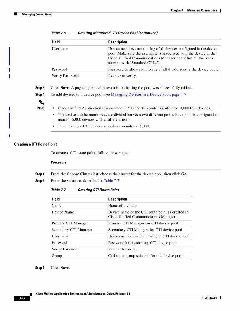
Chapter 7 Managing Connections Managing Connections
Step 3 Click Save. A page appears with two tabs indicating the pool was successfully added.
Step 4 To add devices to a device pool, see Managing Devices in a Device Pool, page 7-7
Note • Cisco Unified Application Environment 8.5 supports monitoring of upto 10,000 CTI devices.
• The devices, to be monitored, are divided between two different pools. Each pool is configured to monitor 5,000 devices with a different user.
• The maximum CTI devices a pool can monitor is 5,000.
Creating a CTI Route Point
To create a CTI route point, follow these steps:
Procedure
Step 1 From the Choose Cluster list, choose the cluster for the device pool, then click Go.
Step 2 Enter the values as described in Table 7-7.
Step 3 Click Save.
Username Username allows monitoring of all devices configured in the device pool. Make sure the username is associated with the device in the Cisco Unified Communications Manager and it has all the roles starting with "Standard CTI...".
Password Password to allow monitoring of all the devices in the device pool.
Verify Password Reenter to verify.
Table 7-6 Creating Monitored CTI Device Pool (continued)
Field Description
Table 7-7 Creating CTI Route Point
Field Description
Name Name of the pool
Device Name Device name of the CTI route point as created in Cisco Unified Communications Manager
Primary CTI Manager Primary CTI Manager for CTI device pool
Secondary CTI Manager Secondary CTI Manager for CTI device pool
Username Username to allow monitoring of CTI device pool
Password Password for monitoring CTI device pool
Verify Password Reenter to verify
Group Call route group selected for this device pool
7-6Cisco Unified Application Environment Administration Guide, Release 8.5
OL-21902-01
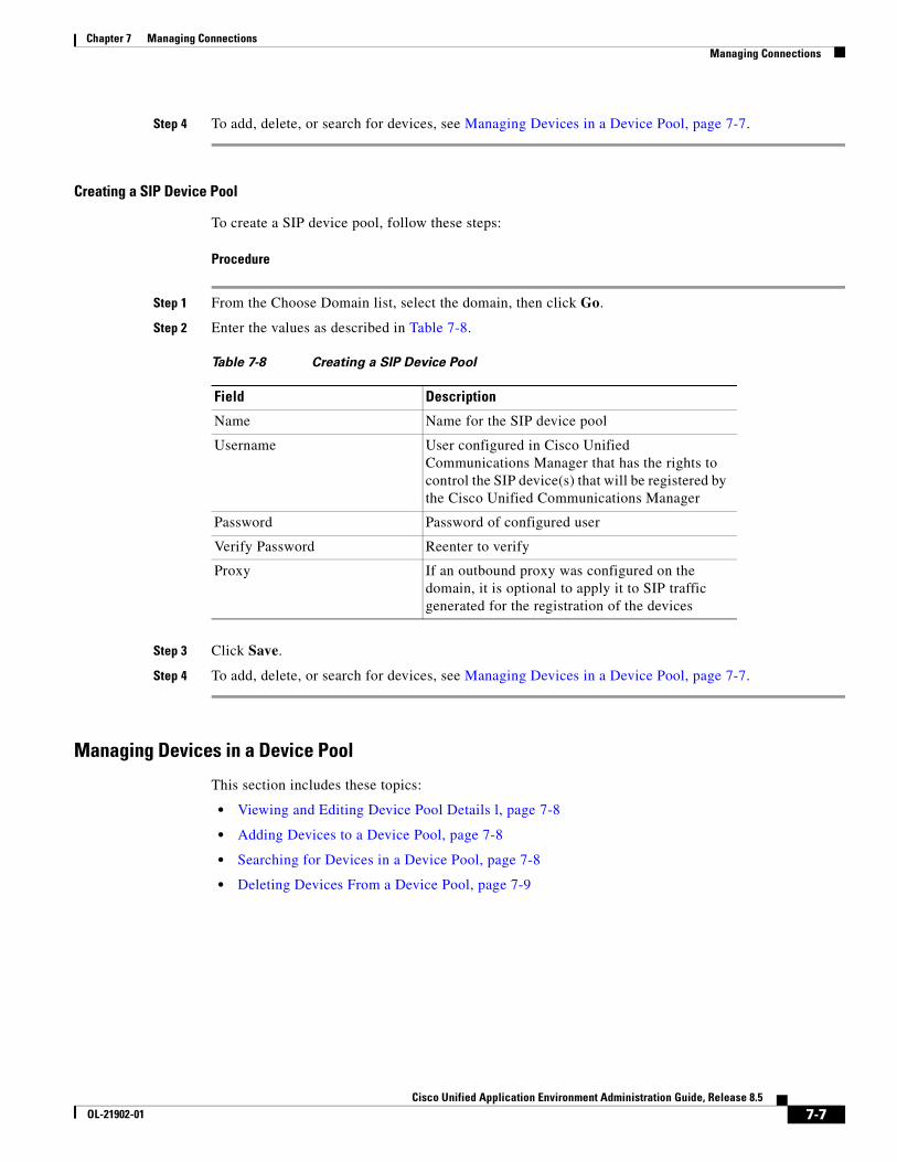
Chapter 7 Managing Connections Managing Connections
Step 4 To add, delete, or search for devices, see Managing Devices in a Device Pool, page 7-7.
Creating a SIP Device Pool
To create a SIP device pool, follow these steps:
Procedure
Step 1 From the Choose Domain list, select the domain, then click Go.
Step 2 Enter the values as described in Table 7-8.
Step 3 Click Save.
Step 4 To add, delete, or search for devices, see Managing Devices in a Device Pool, page 7-7.
Managing Devices in a Device Pool
This section includes these topics:
• Viewing and Editing Device Pool Details l, page 7-8
• Adding Devices to a Device Pool, page 7-8
• Searching for Devices in a Device Pool, page 7-8
• Deleting Devices From a Device Pool, page 7-9
Table 7-8 Creating a SIP Device Pool
Field Description
Name Name for the SIP device pool
Username User configured in Cisco Unified Communications Manager that has the rights to control the SIP device(s) that will be registered by the Cisco Unified Communications Manager
Password Password of configured user
Verify Password Reenter to verify
Proxy If an outbound proxy was configured on the domain, it is optional to apply it to SIP traffic generated for the registration of the devices
7-7Cisco Unified Application Environment Administration Guide, Release 8.5
OL-21902-01
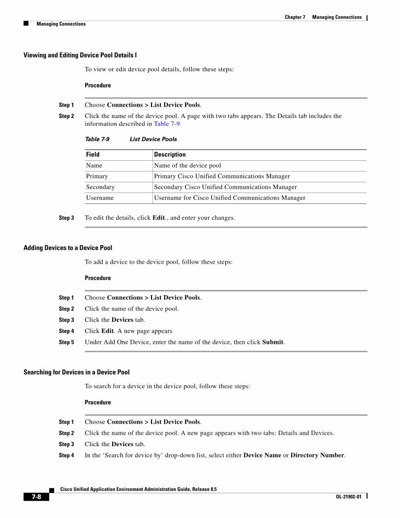
Chapter 7 Managing Connections Managing Connections
Viewing and Editing Device Pool Details l
To view or edit device pool details, follow these steps:
Procedure
Step 1 Choose Connections > List Device Pools.
Step 2 Click the name of the device pool. A page with two tabs appears. The Details tab includes the information described in Table 7-9
Step 3 To edit the details, click Edit., and enter your changes.
Adding Devices to a Device Pool
To add a device to the device pool, follow these steps:
Procedure
Step 1 Choose Connections > List Device Pools.
Step 2 Click the name of the device pool.
Step 3 Click the Devices tab.
Step 4 Click Edit. A new page appears
Step 5 Under Add One Device, enter the name of the device, then click Submit.
Searching for Devices in a Device Pool
To search for a device in the device pool, follow these steps:
Procedure
Step 1 Choose Connections > List Device Pools.
Step 2 Click the name of the device pool. A new page appears with two tabs: Details and Devices.
Step 3 Click the Devices tab.
Step 4 In the ‘Search for device by’ drop-down list, select either Device Name or Directory Number.
Table 7-9 List Device Pools
Field Description
Name Name of the device pool
Primary Primary Cisco Unified Communications Manager
Secondary Secondary Cisco Unified Communications Manager
Username Username for Cisco Unified Communications Manager
7-8Cisco Unified Application Environment Administration Guide, Release 8.5
OL-21902-01
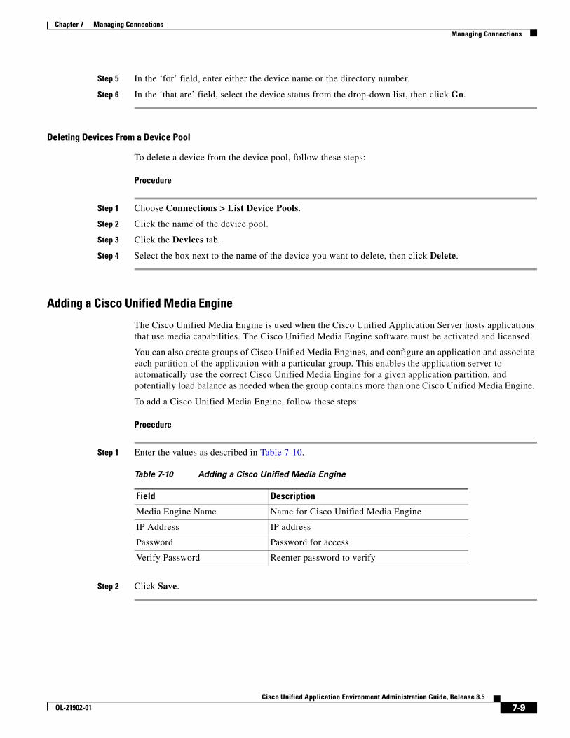
Chapter 7 Managing Connections Managing Connections
Step 5 In the ‘for’ field, enter either the device name or the directory number.
Step 6 In the ‘that are’ field, select the device status from the drop-down list, then click Go.
Deleting Devices From a Device Pool
To delete a device from the device pool, follow these steps:
Procedure
Step 1 Choose Connections > List Device Pools.
Step 2 Click the name of the device pool.
Step 3 Click the Devices tab.
Step 4 Select the box next to the name of the device you want to delete, then click Delete.
Adding a Cisco Unified Media Engine
The Cisco Unified Media Engine is used when the Cisco Unified Application Server hosts applications that use media capabilities. The Cisco Unified Media Engine software must be activated and licensed.
You can also create groups of Cisco Unified Media Engines, and configure an application and associate each partition of the application with a particular group. This enables the application server to automatically use the correct Cisco Unified Media Engine for a given application partition, and potentially load balance as needed when the group contains more than one Cisco Unified Media Engine.
To add a Cisco Unified Media Engine, follow these steps:
Procedure
Step 1 Enter the values as described in Table 7-10.
Step 2 Click Save.
Table 7-10 Adding a Cisco Unified Media Engine
Field Description
Media Engine Name Name for Cisco Unified Media Engine
IP Address IP address
Password Password for access
Verify Password Reenter password to verify
7-9Cisco Unified Application Environment Administration Guide, Release 8.5
OL-21902-01
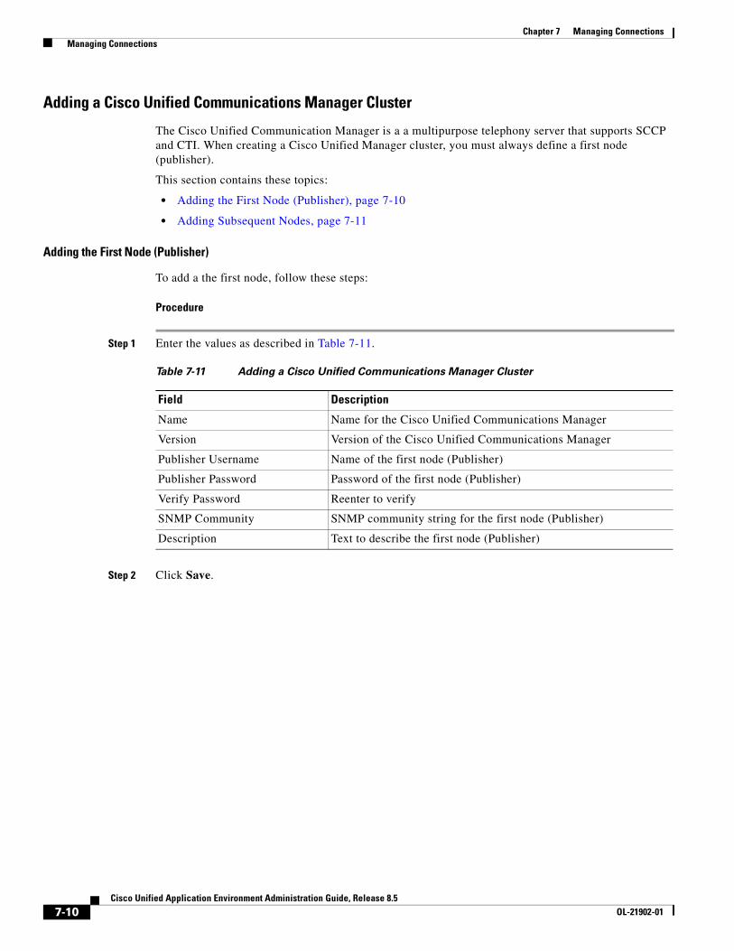
Chapter 7 Managing Connections Managing Connections
Adding a Cisco Unified Communications Manager Cluster
The Cisco Unified Communication Manager is a a multipurpose telephony server that supports SCCP and CTI. When creating a Cisco Unified Manager cluster, you must always define a first node (publisher).
This section contains these topics:
• Adding the First Node (Publisher), page 7-10
• Adding Subsequent Nodes, page 7-11
Adding the First Node (Publisher)
To add a the first node, follow these steps:
Procedure
Step 1 Enter the values as described in Table 7-11.
Step 2 Click Save.
Table 7-11 Adding a Cisco Unified Communications Manager Cluster
Field Description
Name Name for the Cisco Unified Communications Manager
Version Version of the Cisco Unified Communications Manager
Publisher Username Name of the first node (Publisher)
Publisher Password Password of the first node (Publisher)
Verify Password Reenter to verify
SNMP Community SNMP community string for the first node (Publisher)
Description Text to describe the first node (Publisher)
7-10Cisco Unified Application Environment Administration Guide, Release 8.5
OL-21902-01
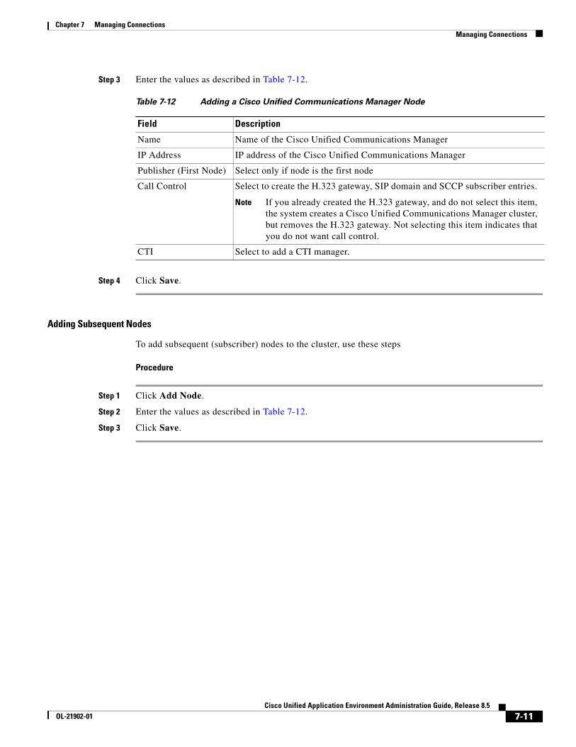
Chapter 7 Managing Connections Managing Connections
Step 3 Enter the values as described in Table 7-12.
Step 4 Click Save.
Adding Subsequent Nodes
To add subsequent (subscriber) nodes to the cluster, use these steps
Procedure
Step 1 Click Add Node.
Step 2 Enter the values as described in Table 7-12.
Step 3 Click Save.
Table 7-12 Adding a Cisco Unified Communications Manager Node
Field Description
Name Name of the Cisco Unified Communications Manager
IP Address IP address of the Cisco Unified Communications Manager
Publisher (First Node) Select only if node is the first node
Call Control Select to create the H.323 gateway, SIP domain and SCCP subscriber entries.
Note If you already created the H.323 gateway, and do not select this item, the system creates a Cisco Unified Communications Manager cluster, but removes the H.323 gateway. Not selecting this item indicates that you do not want call control.
CTI Select to add a CTI manager.
7-11Cisco Unified Application Environment Administration Guide, Release 8.5
OL-21902-01
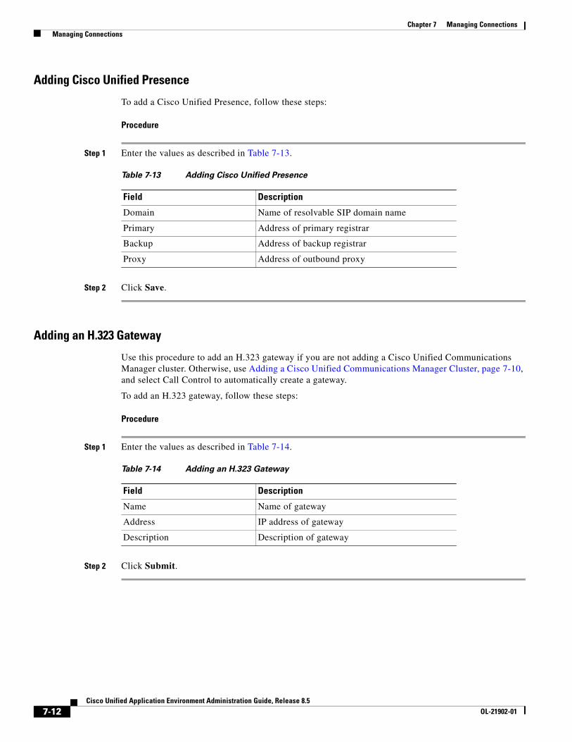
Chapter 7 Managing Connections Managing Connections
Adding Cisco Unified Presence
To add a Cisco Unified Presence, follow these steps:
Procedure
Step 1 Enter the values as described in Table 7-13.
Step 2 Click Save.
Adding an H.323 Gateway
Use this procedure to add an H.323 gateway if you are not adding a Cisco Unified Communications Manager cluster. Otherwise, use Adding a Cisco Unified Communications Manager Cluster, page 7-10, and select Call Control to automatically create a gateway.
To add an H.323 gateway, follow these steps:
Procedure
Step 1 Enter the values as described in Table 7-14.
Step 2 Click Submit.
Table 7-13 Adding Cisco Unified Presence
Field Description
Domain Name of resolvable SIP domain name
Primary Address of primary registrar
Backup Address of backup registrar
Proxy Address of outbound proxy
Table 7-14 Adding an H.323 Gateway
Field Description
Name Name of gateway
Address IP address of gateway
Description Description of gateway
7-12Cisco Unified Application Environment Administration Guide, Release 8.5
OL-21902-01
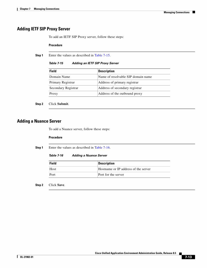
Chapter 7 Managing Connections Managing Connections
Adding IETF SIP Proxy Server
To add an IETF SIP Proxy server, follow these steps:
Procedure
Step 1 Enter the values as described in Table 7-15.
Step 2 Click Submit.
Adding a Nuance Server
To add a Nuance server, follow these steps:
Procedure
Step 1 Enter the values as described in Table 7-16.
Step 2 Click Save.
Table 7-15 Adding an IETF SIP Proxy Server
Field Description
Domain Name Name of resolvable SIP domain name
Primary Registrar Address of primary registrar
Secondary Registrar Address of secondary registrar
Proxy Address of the outbound proxy
Table 7-16 Adding a Nuance Server
Field Description
Host Hostname or IP address of the server
Port Port for the server
7-13Cisco Unified Application Environment Administration Guide, Release 8.5
OL-21902-01
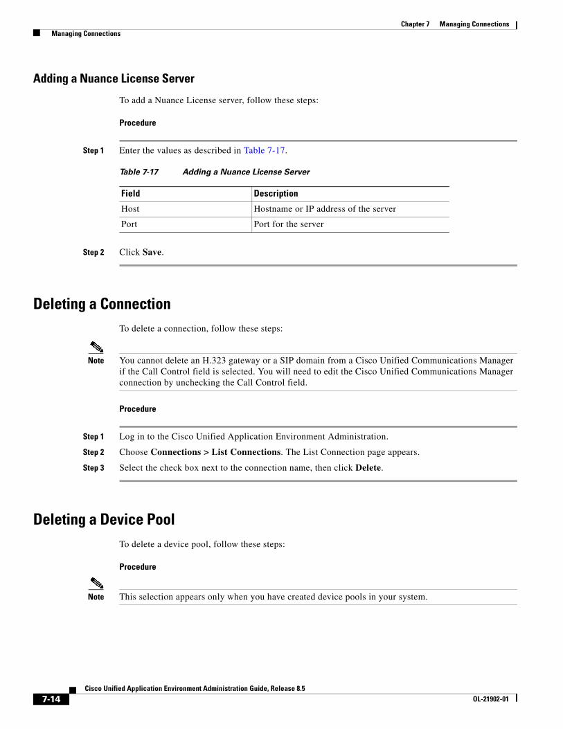
Chapter 7 Managing Connections Managing Connections
Adding a Nuance License Server
To add a Nuance License server, follow these steps:
Procedure
Step 1 Enter the values as described in Table 7-17.
Step 2 Click Save.
Deleting a ConnectionTo delete a connection, follow these steps:
Note You cannot delete an H.323 gateway or a SIP domain from a Cisco Unified Communications Manager if the Call Control field is selected. You will need to edit the Cisco Unified Communications Manager connection by unchecking the Call Control field.
Procedure
Step 1 Log in to the Cisco Unified Application Environment Administration.
Step 2 Choose Connections > List Connections. The List Connection page appears.
Step 3 Select the check box next to the connection name, then click Delete.
Deleting a Device PoolTo delete a device pool, follow these steps:
Procedure
Note This selection appears only when you have created device pools in your system.
Table 7-17 Adding a Nuance License Server
Field Description
Host Hostname or IP address of the server
Port Port for the server
7-14Cisco Unified Application Environment Administration Guide, Release 8.5
OL-21902-01
Chapter 7 Managing Connections Managing Connections
To delete a device pool, follow these steps:
Procedure
Step 1 Log in to the Cisco Unified Application Environment Administration.
Step 2 Choose Connections > List Device Pools. The Device Pool page appears.
Step 3 Select the box next to the name of the device pool you want to delete, then click Delete.
Deleting a Cisco Unified Communications Manager NodeTo delete a Cisco Unified Communications Manager node, follow these steps:
Procedure
Step 1 Log in to the Cisco Unified Application Environment Administration.
Step 2 Choose Connections > Add Connection. The Connection Wizard appears.
Step 3 Under Unified Communication System Connections, select Cisco Unified Communications Manager Cluster, then click Next.
Step 4 Under Unified Communications Manager Cluster Nodes, select the node you want to delete, then click Delete Node.
Deleting a Cisco Unified Communications Manager ClusterTo delete a Cisco Unified Communications Manager cluster, follow these steps:
Procedure
Step 1 Log in to the Cisco Unified Application Environment Administration.
Step 2 Choose Connections > Add Connection. The Connection Wizard appears.
Step 3 Under Unified Communication System Connections, select Cisco Unified Communications Manager Cluster, then click Next.
Step 4 Under Unified Communications Manager Cluster Nodes, click Delete Cluster.
7-15Cisco Unified Application Environment Administration Guide, Release 8.5
OL-21902-01
Chapter 7 Managing Connections Managing Connection Groups
Editing a Connection To edit a connection, follow these steps:
Procedure
Step 1 Log in to the Cisco Unified Application Environment Administration.
Step 2 Choose Connections > List Connections. The List Connection page appears.
Step 3 Click the connection name. The List Connection page appears.
Step 4 Click the name of the connection you want to edit. The Viewing connection page appears.
Step 5 Click Edit. the Editing connection page appears.
Step 6 Enter the necessary modifications, then click Submit or Save.
Disabling a ConnectionTo disable a connection, follow these steps:
Note Only the Cisco Unified Media Engine can be disabled.
Procedure
Step 1 Log in to the Cisco Unified Application Environment Administration.
Step 2 Choose Connections > List Connections. The List Connection page appears.
Step 3 Click the connection name for the Cisco Unified Media Engine. The Viewing connection page appears.
Step 4 Click Disable.
Managing Connection GroupsThis section includes these topics:
• Viewing and Searching for Groups, page 7-17
• Adding a Connection Group, page 7-17
• Deleting a Connection Group, page 7-21
• Editing a Connection Group, page 7-21
7-16Cisco Unified Application Environment Administration Guide, Release 8.5
OL-21902-01
Chapter 7 Managing Connections Managing Connection Groups
Viewing and Searching for GroupsTo view the list of groups, or to search for a particular group, follow these steps:
Procedure
Step 1 Log in to the Cisco Unified Application Environment Administration.
Step 2 Choose Connections > Groups > List Groups. The Groups page appears.
Table 7-18 describes the information provided.
Step 3 To search for or view groups, do the following:
• To search for a particular group, enter the name or partial name with an asterisk (*) as a wildcard to denote numbers and letters in the Filter box, then click Search.
• To view connection group details, click on the group name.
Adding a Connection GroupTo add a connection group, follow these steps:
Procedure
Step 1 Log in to the Cisco Unified Application Environment Administration.
Step 2 Choose Connections > Groups > Add Group. The Choose a Group Type page appears.
Table 7-18 Connection Groups
Field Description
Name IP address or hostname of the connection
Type Connection type
Default Group Shown as true if default group
7-17Cisco Unified Application Environment Administration Guide, Release 8.5
OL-21902-01
Chapter 7 Managing Connections Managing Connection Groups
Step 3 Select the connection you want to add as shown in Table 7-19.
Step 4 Click Go.
Adding a Cisco Unified Media Engine Group
To add a Cisco Unified Media Engine group, follow these steps:
Procedure
Step 1 Enter the values as described in Table 7-20.
Step 2 Using the Member Selector arrows, add and order the Cisco Unified Media Engines.
Step 3 Click Save.
Table 7-19 Connection Group Types
Connection Type For Information, See...
Media Engine Group Adding a Cisco Unified Media Engine Group, page 7-18
SCCP Device Pool Group Adding an SCCP Device Pool Group, page 7-19
H.323 Gateway Group Adding an H.323 Gateway Group, page 7-19
SIP Device Pool Group Adding a SIP Device Pool Group, page 7-20
CTI Device Pool Group Adding a CTI Device Pool Group, page 7-20
Table 7-20 Adding a Cisco Unified Application Environment Media Engine Group
Field Description
Name Name for the group
Description Description of the group
Failover Name of the failover
7-18Cisco Unified Application Environment Administration Guide, Release 8.5
OL-21902-01
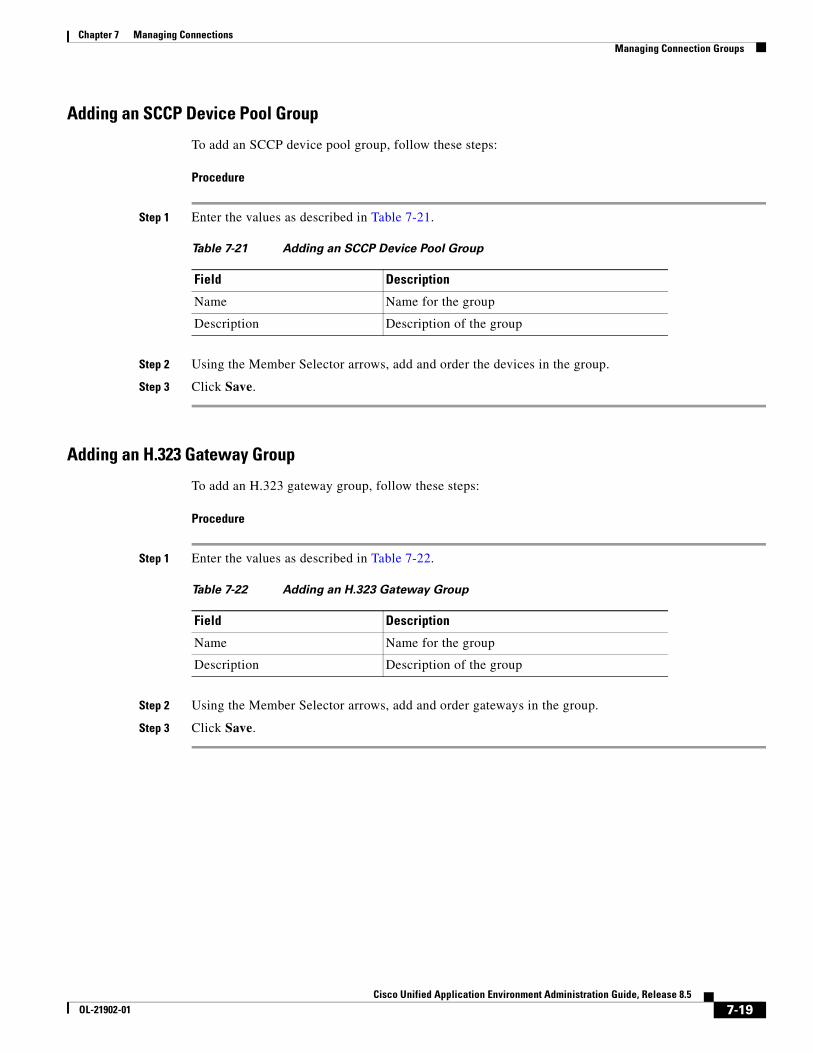
Chapter 7 Managing Connections Managing Connection Groups
Adding an SCCP Device Pool Group
To add an SCCP device pool group, follow these steps:
Procedure
Step 1 Enter the values as described in Table 7-21.
Step 2 Using the Member Selector arrows, add and order the devices in the group.
Step 3 Click Save.
Adding an H.323 Gateway Group
To add an H.323 gateway group, follow these steps:
Procedure
Step 1 Enter the values as described in Table 7-22.
Step 2 Using the Member Selector arrows, add and order gateways in the group.
Step 3 Click Save.
Table 7-21 Adding an SCCP Device Pool Group
Field Description
Name Name for the group
Description Description of the group
Table 7-22 Adding an H.323 Gateway Group
Field Description
Name Name for the group
Description Description of the group
7-19Cisco Unified Application Environment Administration Guide, Release 8.5
OL-21902-01
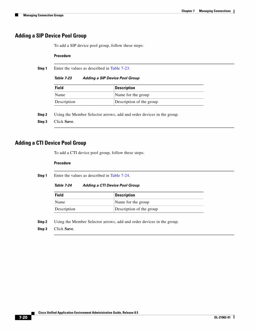
Chapter 7 Managing Connections Managing Connection Groups
Adding a SIP Device Pool Group
To add a SIP device pool group, follow these steps:
Procedure
Step 1 Enter the values as described in Table 7-23.
Step 2 Using the Member Selector arrows, add and order devices in the group.
Step 3 Click Save.
Adding a CTI Device Pool Group
To add a CTI device pool group, follow these steps:
Procedure
Step 1 Enter the values as described in Table 7-24.
Step 2 Using the Member Selector arrows, add and order devices in the group.
Step 3 Click Save.
Table 7-23 Adding a SIP Device Pool Group
Field Description
Name Name for the group
Description Description of the group
Table 7-24 Adding a CTI Device Pool Group
Field Description
Name Name for the group
Description Description of the group
7-20Cisco Unified Application Environment Administration Guide, Release 8.5
OL-21902-01
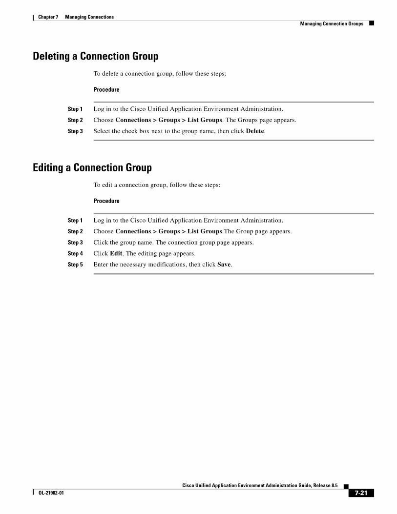
Chapter 7 Managing Connections Managing Connection Groups
Deleting a Connection GroupTo delete a connection group, follow these steps:
Procedure
Step 1 Log in to the Cisco Unified Application Environment Administration.
Step 2 Choose Connections > Groups > List Groups. The Groups page appears.
Step 3 Select the check box next to the group name, then click Delete.
Editing a Connection GroupTo edit a connection group, follow these steps:
Procedure
Step 1 Log in to the Cisco Unified Application Environment Administration.
Step 2 Choose Connections > Groups > List Groups.The Group page appears.
Step 3 Click the group name. The connection group page appears.
Step 4 Click Edit. The editing page appears.
Step 5 Enter the necessary modifications, then click Save.
7-21Cisco Unified Application Environment Administration Guide, Release 8.5
OL-21902-01

Chapter 7 Managing Connections Managing Connection Groups
7-22Cisco Unified Application Environment Administration Guide, Release 8.5
OL-21902-01
Cisco Unified ApplicaOL-21902-01
C H A P T E R 8
ServiceabilityServiceability provides tools to help you monitor, diagnose, and troubleshoot Cisco Unified Application Environment. This chapter includes these topics:
• Managing Server Logs, page 8-1
• Managing Services, page 8-3
• Configuring Trace Settings, page 8-4
• Viewing Usage Statistics, page 8-7
• Using Diagnostics, page 8-7
• Managing Alarms, page 8-7
Managing Server LogsThis section includes these topics:
• Viewing Server Logs, page 8-2
• Viewing Server Logs, page 8-2
• Deleting Server Logs, page 8-2
• Archiving Server Logs, page 8-2
8-1tion Environment Administration Guide, Release 8.5
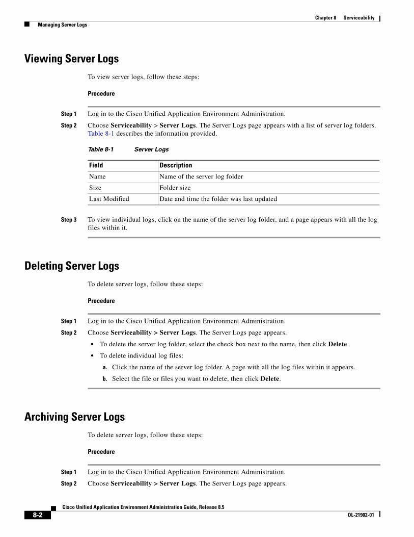
Chapter 8 Serviceability Managing Server Logs
Viewing Server LogsTo view server logs, follow these steps:
Procedure
Step 1 Log in to the Cisco Unified Application Environment Administration.
Step 2 Choose Serviceability > Server Logs. The Server Logs page appears with a list of server log folders. Table 8-1 describes the information provided.
Step 3 To view individual logs, click on the name of the server log folder, and a page appears with all the log files within it.
Deleting Server LogsTo delete server logs, follow these steps:
Procedure
Step 1 Log in to the Cisco Unified Application Environment Administration.
Step 2 Choose Serviceability > Server Logs. The Server Logs page appears.
• To delete the server log folder, select the check box next to the name, then click Delete.
• To delete individual log files:
a. Click the name of the server log folder. A page with all the log files within it appears.
b. Select the file or files you want to delete, then click Delete.
Archiving Server LogsTo delete server logs, follow these steps:
Procedure
Step 1 Log in to the Cisco Unified Application Environment Administration.
Step 2 Choose Serviceability > Server Logs. The Server Logs page appears.
Table 8-1 Server Logs
Field Description
Name Name of the server log folder
Size Folder size
Last Modified Date and time the folder was last updated
8-2Cisco Unified Application Environment Administration Guide, Release 8.5
OL-21902-01
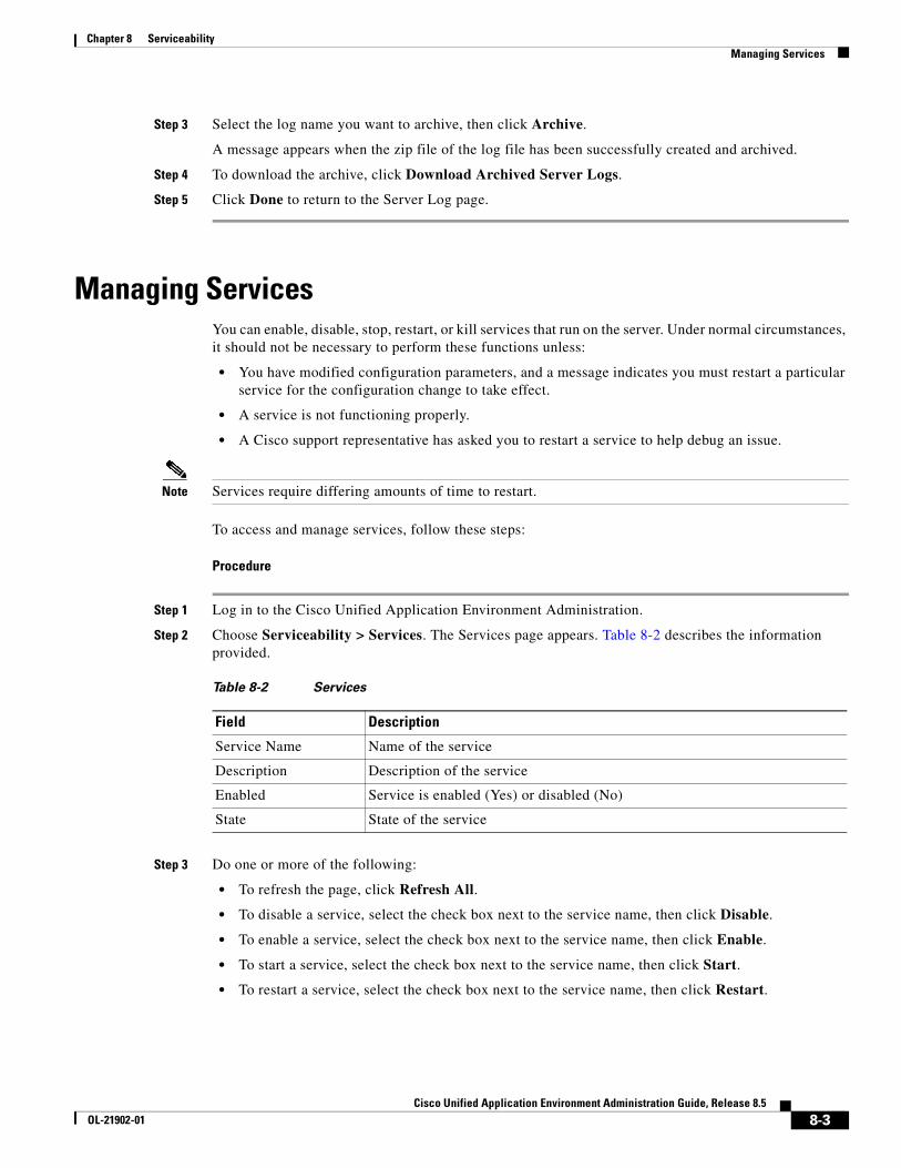
Chapter 8 Serviceability Managing Services
Step 3 Select the log name you want to archive, then click Archive.
A message appears when the zip file of the log file has been successfully created and archived.
Step 4 To download the archive, click Download Archived Server Logs.
Step 5 Click Done to return to the Server Log page.
Managing ServicesYou can enable, disable, stop, restart, or kill services that run on the server. Under normal circumstances, it should not be necessary to perform these functions unless:
• You have modified configuration parameters, and a message indicates you must restart a particular service for the configuration change to take effect.
• A service is not functioning properly.
• A Cisco support representative has asked you to restart a service to help debug an issue.
Note Services require differing amounts of time to restart.
To access and manage services, follow these steps:
Procedure
Step 1 Log in to the Cisco Unified Application Environment Administration.
Step 2 Choose Serviceability > Services. The Services page appears. Table 8-2 describes the information provided.
Step 3 Do one or more of the following:
• To refresh the page, click Refresh All.
• To disable a service, select the check box next to the service name, then click Disable.
• To enable a service, select the check box next to the service name, then click Enable.
• To start a service, select the check box next to the service name, then click Start.
• To restart a service, select the check box next to the service name, then click Restart.
Table 8-2 Services
Field Description
Service Name Name of the service
Description Description of the service
Enabled Service is enabled (Yes) or disabled (No)
State State of the service
8-3Cisco Unified Application Environment Administration Guide, Release 8.5
OL-21902-01
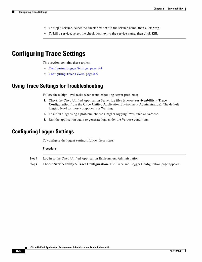
Chapter 8 Serviceability Configuring Trace Settings
• To stop a service, select the check box next to the service name, then click Stop.
• To kill a service, select the check box next to the service name, then click Kill.
Configuring Trace SettingsThis section contains these topics:
• Configuring Logger Settings, page 8-4
• Configuring Trace Levels, page 8-5
Using Trace Settings for TroubleshootingFollow these high-level tasks when troubleshooting server problems:
1. Check the Cisco Unified Application Server log files (choose Serviceability > Trace Configuration from the Cisco Unified Application Environment Administration). The default logging level for most components is Warning.
2. To aid in diagnosing a problem, choose a higher logging level, such as Verbose.
3. Run the application again to generate logs under the Verbose conditions.
Configuring Logger SettingsTo configure the logger settings, follow these steps:
Procedure
Step 1 Log in to the Cisco Unified Application Environment Administration.
Step 2 Choose Serviceability > Trace Configuration. The Trace and Logger Configuration page appears.
8-4Cisco Unified Application Environment Administration Guide, Release 8.5
OL-21902-01
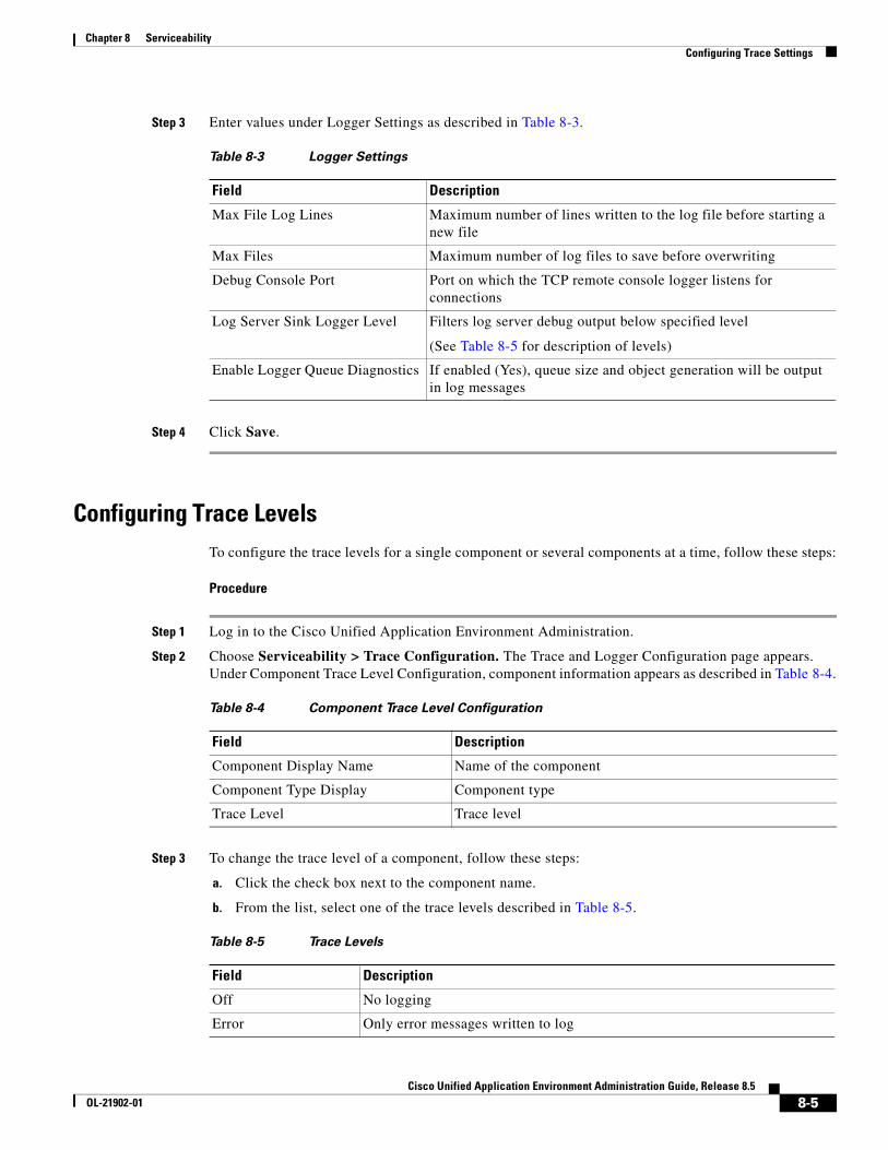
Chapter 8 Serviceability Configuring Trace Settings
Step 3 Enter values under Logger Settings as described in Table 8-3.
Step 4 Click Save.
Configuring Trace LevelsTo configure the trace levels for a single component or several components at a time, follow these steps:
Procedure
Step 1 Log in to the Cisco Unified Application Environment Administration.
Step 2 Choose Serviceability > Trace Configuration. The Trace and Logger Configuration page appears. Under Component Trace Level Configuration, component information appears as described in Table 8-4.
Step 3 To change the trace level of a component, follow these steps:
a. Click the check box next to the component name.
b. From the list, select one of the trace levels described in Table 8-5.
Table 8-3 Logger Settings
Field Description
Max File Log Lines Maximum number of lines written to the log file before starting a new file
Max Files Maximum number of log files to save before overwriting
Debug Console Port Port on which the TCP remote console logger listens for connections
Log Server Sink Logger Level Filters log server debug output below specified level
(See Table 8-5 for description of levels)
Enable Logger Queue Diagnostics If enabled (Yes), queue size and object generation will be output in log messages
Table 8-4 Component Trace Level Configuration
Field Description
Component Display Name Name of the component
Component Type Display Component type
Trace Level Trace level
Table 8-5 Trace Levels
Field Description
Off No logging
Error Only error messages written to log
8-5Cisco Unified Application Environment Administration Guide, Release 8.5
OL-21902-01
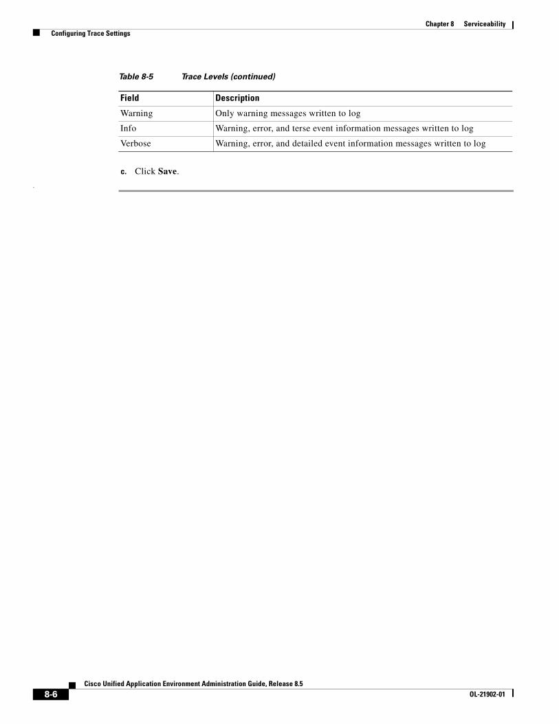
Chapter 8 Serviceability Configuring Trace Settings
c. Click Save.
.
Warning Only warning messages written to log
Info Warning, error, and terse event information messages written to log
Verbose Warning, error, and detailed event information messages written to log
Table 8-5 Trace Levels (continued)
Field Description
8-6Cisco Unified Application Environment Administration Guide, Release 8.5
OL-21902-01
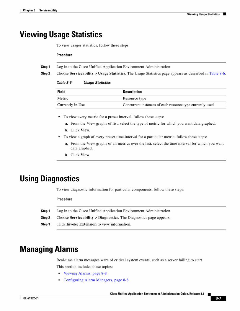
Chapter 8 Serviceability Viewing Usage Statistics
Viewing Usage StatisticsTo view usages statistics, follow these steps:
Procedure
Step 1 Log in to the Cisco Unified Application Environment Administration.
Step 2 Choose Serviceability > Usage Statistics. The Usage Statistics page appears as described in Table 8-6.
• To view every metric for a preset interval, follow these steps:
a. From the View graphs of list, select the type of metric for which you want data graphed.
b. Click View.
• To view a graph of every preset time interval for a particular metric, follow these steps:
a. From the View graphs of all metrics over the last, select the time interval for which you want data graphed.
b. Click View.
Using DiagnosticsTo view diagnostic information for particular components, follow these steps:
Procedure
Step 1 Log in to the Cisco Unified Application Environment Administration.
Step 2 Choose Serviceability > Diagnostics. The Diagnostics page appears.
Step 3 Click Invoke Extension to view information.
Managing AlarmsReal-time alarm messages warn of critical system events, such as a server failing to start.
This section includes these topics:
• Viewing Alarms, page 8-8
• Configuring Alarm Managers, page 8-8
Table 8-6 Usage Statistics
Field Description
Metric Resource type
Currently in Use Concurrent instances of each resource type currently used
8-7Cisco Unified Application Environment Administration Guide, Release 8.5
OL-21902-01
Chapter 8 Serviceability Managing Alarms
• Setting Alarms to Ignored, page 8-9
Viewing AlarmsTo view, acknowledge, and resolve alarms, and to download a MIB for monitoring the Cisco Unified Application Server and the Cisco Unified Media Engine, follow these steps:
Procedure
Step 1 Log in to the Cisco Unified Application Environment Administration.
Step 2 Choose Serviceability > Alarms > Active Alarms. The Active Alarms page appears.
• To acknowledge the alarms, click Set Acknowledged.
• To resolve the alarms, click Set Resolved.
• To download a MIB file, which can be loaded into network management software, click Download MIB. The MIB defines a number of traps and real-time statistics which are useful for SNMP monitoring systems.
Configuring Alarm ManagersTo configure or delete alarm managers, follow these steps:
Procedure
Step 1 Log in to the Cisco Unified Application Environment Administration.
Step 2 Choose Serviceability > Alarms > Alarm Manager. The Alarm Mangers page appears.
• To delete an alarm manager, select it, then click Delete.
• To add an SNMP manager, click Add SNMP Manager, follow these steps:
a. Enter the SNMP manager address.
b. Select he trigger level for the alarm.
c. Click Save.
8-8Cisco Unified Application Environment Administration Guide, Release 8.5
OL-21902-01
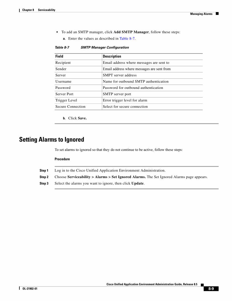
Chapter 8 Serviceability Managing Alarms
• To add an SMTP manager, click Add SMTP Manager, follow these steps:
a. Enter the values as described in Table 8-7.
b. Click Save.
Setting Alarms to IgnoredTo set alarms to ignored so that they do not continue to be active, follow these steps:
Procedure
Step 1 Log in to the Cisco Unified Application Environment Administration.
Step 2 Choose Serviceability > Alarms > Set Ignored Alarms. The Set Ignored Alarms page appears.
Step 3 Select the alarms you want to ignore, then click Update.
Table 8-7 SMTP Manager Configuration
Field Description
Recipient Email address where messages are sent to
Sender Email address where messages are sent from
Server SMPT server address
Username Name for outbound SMTP authentication
Password Password for outbound authentication
Server Port SMTP server port
Trigger Level Error trigger level for alarm
Secure Connection Select for secure connection
8-9Cisco Unified Application Environment Administration Guide, Release 8.5
OL-21902-01

Chapter 8 Serviceability Managing Alarms
8-10Cisco Unified Application Environment Administration Guide, Release 8.5
OL-21902-01
Cisco Unified ApplicaOL-21902-01
C H A P T E R 9
Backing Up, Restoring, and Reinitializing the SystemThis chapter contains these topics:
• Backing Up the System, page 9-1
• Restoring the System, page 9-2
• Reinitializing the Cisco Unified Application Server, page 9-3
Backing Up the SystemUse the system backup feature to take a snapshot of the current configuration settings in the Cisco Unified Application Environment Administration, to save applications, and to save application configurations. A system backup generates a tar file that can be stored in a safe location.
Note A backup can only be used to restore a system of the same version.
Cisco recommends backing up systems regularly to prevent data loss in the unlikely event of system failure. See Restoring the System, page 9-2 for instructions on restoring a previously backed up system.
To perform system backups, follow these steps:
Procedure
Step 1 Use the server console or VNC to open a command window.
Step 2 Change the current directory to C:\Program Files\Cisco Systems\Unified Application Environment\Framework\1.0, and locate the executable file: cuae-backup.exe
Note Arguments with spaces in their names must have double quotes around them.
For example:
cd "C:\Program Files\Cisco Systems\Unified Application Environment\Framework\1.0"
9-1tion Environment Administration Guide, Release 8.5
Chapter 9 Backing Up, Restoring, and Reinitializing the System Restoring the System
Step 3 Enter the following command:
cuae-legacy-backup.exe [ +database_name …]
where +database_name is the name of a database you want to backup in addition to the system database.
Note The system database is automatically backed up during the backup process. If you do not need to back up additional application-specific databases, do not specify database names.
In general, if you have any applications that use their own, customized, MySQL database on the server, you will need to specify their database names. Check with the developers who created the applications that are installed on the system to find out if there are custom databases associated with the applications, and whether they should be backed up. For example, to back up only the system database, enter:
cuae-backup.exe
After running the cuae-backup.exe tool, the backup file is saved in C:\Program Files\Cisco Systems\Unified Application Environment\Backups. Cisco strongly recommends you remove the backup file from the MCS server and store it elsewhere for safe keeping.
Restoring the SystemUse the system restore feature to install and activate a previously-generated system backup file. (See Backing Up the System, page 9-1.)
Caution The configuration in the backup folder overwrites the current configuration. Once started, the process cannot be stopped or undone. Always back up the system before you restore a system backup file.
To restore a backup, follow these steps:
Procedure
Step 1 Place the Backup folder anywhere on the MCS server.
Step 2 Log in to the Cisco Unified Application Environment Administration.
Step 3 From the Cisco Unified Application Environment Management, choose Serviceability >Services, select Watchdog Server, then click Stop to stop all the services.
Step 4 Use the server console or VNC to open a command window.
Step 5 Change the current directory to C:\Program Files\Cisco Systems\Unified Application Environment\Framework\1.0, and locate the executable file: cuae-restore.exe
Note Arguments with spaces in their names must have double quotes around them.
For example:
cd "C:\Program Files\Cisco Systems\Unified Application Environment\Framework\1.0"
9-2Cisco Unified Application Environment Administration Guide, Release 8.5
OL-21902-01
Chapter 9 Backing Up, Restoring, and Reinitializing the System Reinitializing the Cisco Unified Application Server
Step 6 Enter the following command to restore the data:
cuae-restore.exe [path_to_backup_file]
where path_to_backup_file is the location of the file generated by the cuae-legacy-backup tool, which is located in the Backup folder on the server.
For example, if you want to restore a file called backup1.cuae located in the C:\Program Files\Cisco Systems\Unified Application Environment\Backups folder, enter:
cuae-restore.exe "C:\Program Fil”s\Cisco Systems\Unified Application Environment\Backups\backup1.cuae"
Step 7 From the Cisco Unified Application Environment Management, choose Serviceability > Services, select Watchdog Server, then click Restart.
This restarts all the services in order of dependency.
Reinitializing the Cisco Unified Application ServerUse the DVDs that are shipped with the server to re-image the system to the factory settings. For details, see Installing the Cisco Unified Application Environment, Release 8.5 listed in Related Documentation, page xii.
9-3Cisco Unified Application Environment Administration Guide, Release 8.5
OL-21902-01

Chapter 9 Backing Up, Restoring, and Reinitializing the System Reinitializing the Cisco Unified Application Server
9-4Cisco Unified Application Environment Administration Guide, Release 8.5
OL-21902-01
Cisco Unified ApplicaOL-16626-01
C H A P T E R 10
FAQs and TroubleshootingThis chapter includes:
• FAQs, page 10-1
• Troubleshooting, page 10-2
FAQsThis section provides frequently asked questions (FAQs) about the following topics:
• General FAQs, page 10-1
• Hardware FAQs, page 10-2
• Software FAQs, page 10-2
General FAQs
Q. Who do I contact for technical support?
A. The Cisco Unified Application Environment provides product and developer support as follows:
– Product Support—Provided by the Technical Assistance Center (TAC), specifically for upgrading and installing the Cisco Unified Application Environment, administering it, and running applications.
Contact the TAC at the following URL if you have purchased a Cisco Unified Communications Essential Operate Service contract for your Cisco Unified Application Server and Cisco Unified Media Engine:
http://www.cisco.com/techsupport
– Developer Support—Provided by Developer Services, specifically for problems related to
developing applications, or when your applications are not operating correctly.
Contact Developer Services at the following URL if you have purchased a Developer Services contract:
http://www.cisco.com/web/developer/cuae/content/support.html
However, before contacting Developer Services, check the log files to try and locate a probable root cause. Reviewing the log messages will also help you determine whether the problem should be routed to the TAC instead.
10-1tion Environment Administration Guide, Release 8.5
Chapter 10 FAQs and Troubleshooting Troubleshooting
Hardware FAQs
Q. Do I have to have a Cisco Unified Media Engine, and if I do, does it have to be installed on a separate hardware platform from the Cisco Unified Application Server?
A. No. If the applications you are running do not have any media components, a Cisco Unified Media Engine is not required; and yes, it can be installed on the same hardware platform as the Cisco Unified Application Server.
Software FAQs
Q. Can a provider created with Release 2.4.3 or later run without being recompiled on Release 8.5?
A. Yes, a provider built with Release 2.4.3 or later does not have to be recompiled to run on Release 8.5.
Q. Can an application built under 2.4.3 or later run without recompile on 8.5?
A. Yes, a provider created with Release 2.4.3or later does not have to be recompiled to run on Release 8.5.
TroubleshootingThis section provides troubleshooting tips about the following topics:
• Connections, page 10-2
• Licensing, page 10-3
Connections
Symptom An H.323 gateway connection is created with the name ABC prior to creating a Cisco Unified Communications Manager connection with the name XYZ. After a about an hour, the H.323 gateway name is changed from ABC to XYZ.
Possible Cause The Call Control option was not selected when creating the Cisco Unified Communications Manager cluster. The system assumed no call control, and removed the H.323.
Recommended Action When the H.323 gateway is created before a Cisco Unified Communications Manager cluster, select the Call Control option.
10-2Cisco Unified Application Environment Administration Guide, Release 8.5
OL-16626-01
Chapter 10 FAQs and Troubleshooting Troubleshooting
Licensing
Symptom When a license file sent from the licensing team, and which has the correct MAC address, is uploaded to the machine, an error message displays stating that the MAC address on the license file does not match the MAC address on the machine.
Possible Cause The license file has an extension of .txt.
Recommended Action Change the file extension to .lic.
10-3Cisco Unified Application Environment Administration Guide, Release 8.5
OL-16626-01

Chapter 10 FAQs and Troubleshooting Troubleshooting
10-4Cisco Unified Application Environment Administration Guide, Release 8.5
OL-16626-01
Cisco Unified Application EnOL-21902-01
A
P P E N D I X A Configuring an Example EnvironmentThis appendix provides an example deployment scenario for setting up and configuring a Cisco Unified Application Environment.
The following section describes how to set up and configure an example environment having these properties:
• One Cisco Unified Application Server and one Cisco Unified Media Engine co-located on the same physical server
• SIP used for telephony integration
• One Cisco Unified Communications Manager cluster
• Test phones
• Sample applications used for integration
Note Actual IP addresses will differ in your own test environment.
The specific tasks required for setting up the Cisco Unified Application Environment will vary according to protocols and applications such as these:
• Number of Cisco Unified Application Servers and Cisco Unified Media Engines
• Number of Cisco Unified Communications Manager clusters
• Type of telephony protocol
• Types of applications used
Setting Up an Example Deployment and Performing Configuration Tasks
To set up your example deployment, you must perform these configuration tasks:
• Task 1: Log in to the Cisco Unified Application Environment Administration
• Task 2: Create a Cisco Unified Media Engine Connection
• Task 3: Create a SIP Connection to Cisco Unified Communications Manager
• Task 4: Create a SIP Trunk
• Task 5: Set Up a Route Pattern
A-1vironment Administration Guide, Release 8.5
Appendix A Configuring an Example Environment Setting Up an Example Deployment and Performing Configuration Tasks
• Task 6: Create Phones in Cisco Unified Communications Manager
• Task 7: Configure Your Phone to Connect to the Cisco Unified Communications Server
• Task 8: Configure the SIP Provider Plugin
• Task 9: Install, Configure, and Test Sample Applications
Task 1: Log in to the Cisco Unified Application Environment AdministrationTo log in to the Cisco Unified Application Environment Administration, follow these steps:
Procedure
Step 1 In the address bar of the web browser, enter the following URL: http://<serverIPaddress>/cuaeadmin.
Step 2 The Cisco Unified Application Environment Administration Login Screen appears.
Step 3 Enter your username and the password, and click Login.
Task 2: Create a Cisco Unified Media Engine ConnectionThe example applications in this guide use media capabilities. Therefore, you must identify at least one Cisco Unified Application Server that has Cisco Unified Media Engine software activated and licensed.
Note It is necessary to assign a Cisco Unified Media Engine to support media applications even if the Cisco Unified Application Server and Cisco Unified Media Engine are on the same hardware platform.
To assign a Cisco Unified Media Engine, follow these steps:
Procedure
Step 1 Choose Connections > Add Connections in the global navigation.
The Connection Wizard appears.
Step 2 Select Media Engine under Unified Application Environment Connections.
Step 3 Click Next.
The Adding Media Engine page appears.
A-2Cisco Unified Application Environment Administration Guide, Release 8.5
OL-21902-01
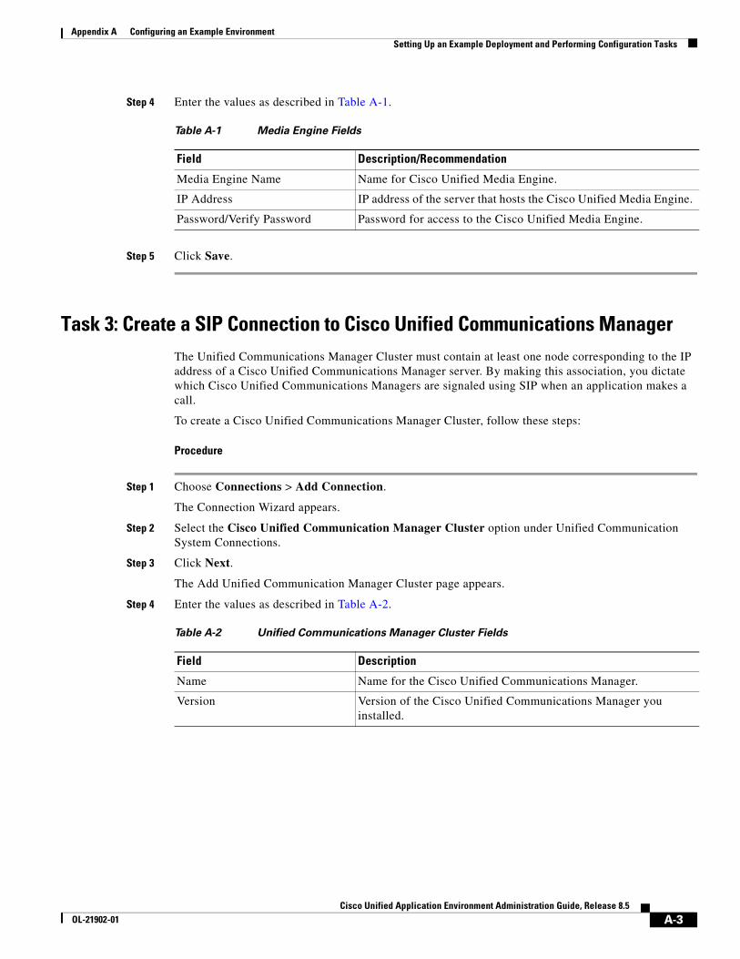
Appendix A Configuring an Example Environment Setting Up an Example Deployment and Performing Configuration Tasks
Step 4 Enter the values as described in Table A-1.
Step 5 Click Save.
Task 3: Create a SIP Connection to Cisco Unified Communications ManagerThe Unified Communications Manager Cluster must contain at least one node corresponding to the IP address of a Cisco Unified Communications Manager server. By making this association, you dictate which Cisco Unified Communications Managers are signaled using SIP when an application makes a call.
To create a Cisco Unified Communications Manager Cluster, follow these steps:
Procedure
Step 1 Choose Connections > Add Connection.
The Connection Wizard appears.
Step 2 Select the Cisco Unified Communication Manager Cluster option under Unified Communication System Connections.
Step 3 Click Next.
The Add Unified Communication Manager Cluster page appears.
Step 4 Enter the values as described in Table A-2.
Table A-1 Media Engine Fields
Field Description/Recommendation
Media Engine Name Name for Cisco Unified Media Engine.
IP Address IP address of the server that hosts the Cisco Unified Media Engine.
Password/Verify Password Password for access to the Cisco Unified Media Engine.
Table A-2 Unified Communications Manager Cluster Fields
Field Description
Name Name for the Cisco Unified Communications Manager.
Version Version of the Cisco Unified Communications Manager you installed.
A-3Cisco Unified Application Environment Administration Guide, Release 8.5
OL-21902-01
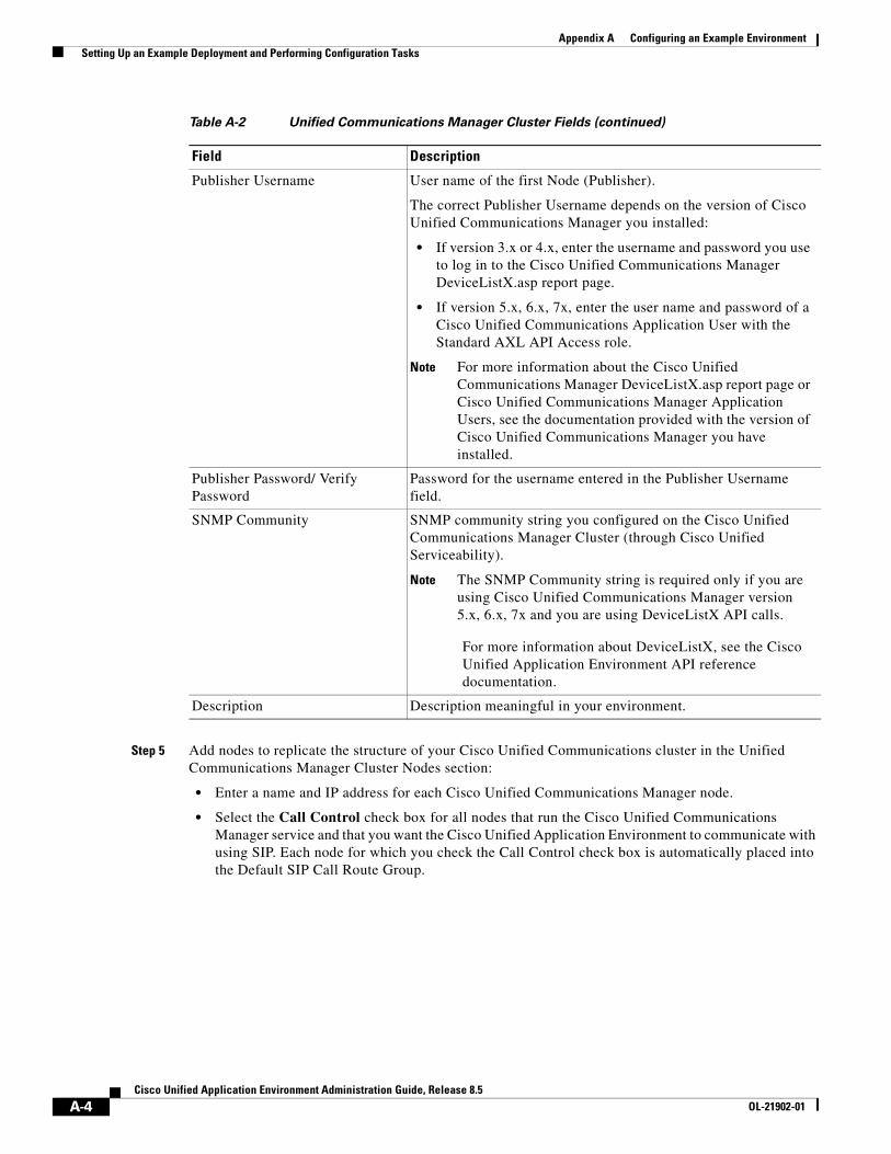
Appendix A Configuring an Example Environment Setting Up an Example Deployment and Performing Configuration Tasks
Step 5 Add nodes to replicate the structure of your Cisco Unified Communications cluster in the Unified Communications Manager Cluster Nodes section:
• Enter a name and IP address for each Cisco Unified Communications Manager node.
• Select the Call Control check box for all nodes that run the Cisco Unified Communications Manager service and that you want the Cisco Unified Application Environment to communicate with using SIP. Each node for which you check the Call Control check box is automatically placed into the Default SIP Call Route Group.
Publisher Username User name of the first Node (Publisher).
The correct Publisher Username depends on the version of Cisco Unified Communications Manager you installed:
• If version 3.x or 4.x, enter the username and password you use to log in to the Cisco Unified Communications Manager DeviceListX.asp report page.
• If version 5.x, 6.x, 7x, enter the user name and password of a Cisco Unified Communications Application User with the Standard AXL API Access role.
Note For more information about the Cisco Unified Communications Manager DeviceListX.asp report page or Cisco Unified Communications Manager Application Users, see the documentation provided with the version of Cisco Unified Communications Manager you have installed.
Publisher Password/ Verify Password
Password for the username entered in the Publisher Username field.
SNMP Community SNMP community string you configured on the Cisco Unified Communications Manager Cluster (through Cisco Unified Serviceability).
Note The SNMP Community string is required only if you are using Cisco Unified Communications Manager version 5.x, 6.x, 7x and you are using DeviceListX API calls.
For more information about DeviceListX, see the Cisco Unified Application Environment API reference documentation.
Description Description meaningful in your environment.
Table A-2 Unified Communications Manager Cluster Fields (continued)
Field Description
A-4Cisco Unified Application Environment Administration Guide, Release 8.5
OL-21902-01
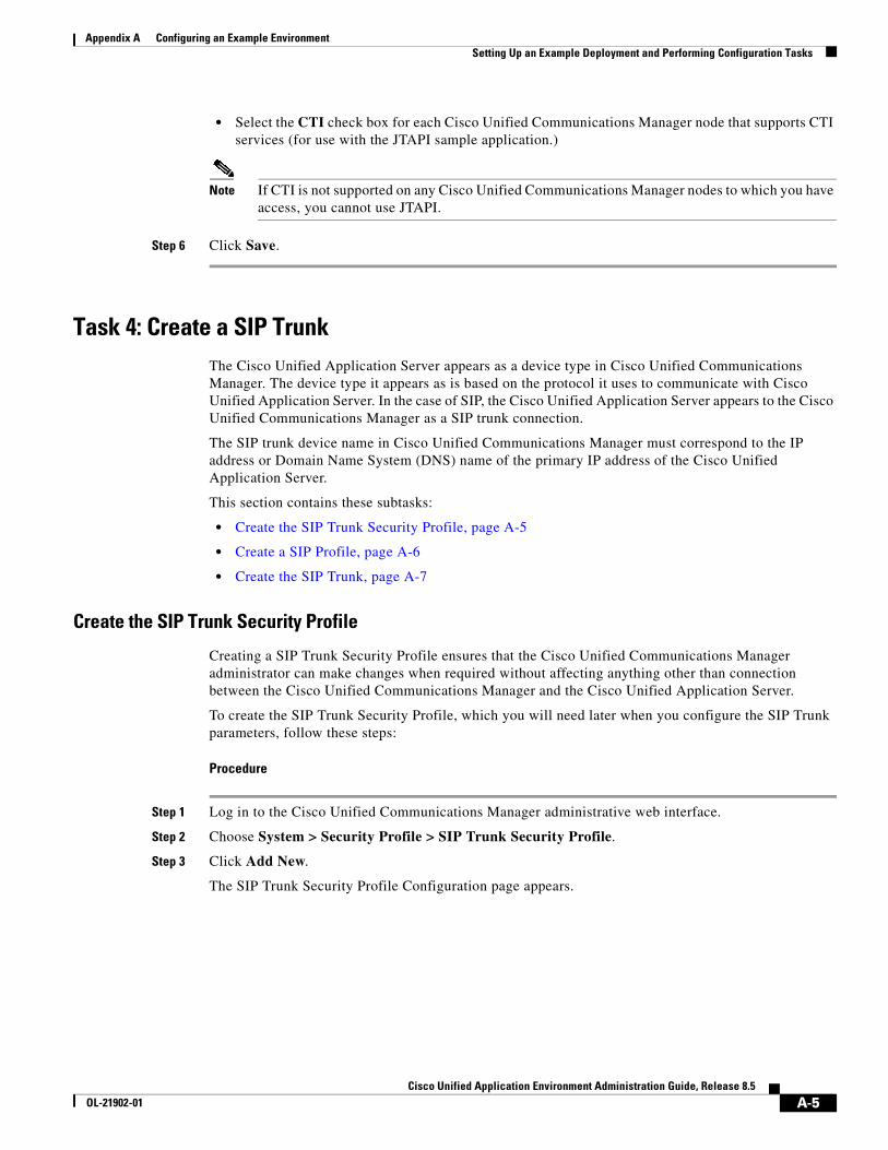
Appendix A Configuring an Example Environment Setting Up an Example Deployment and Performing Configuration Tasks
• Select the CTI check box for each Cisco Unified Communications Manager node that supports CTI services (for use with the JTAPI sample application.)
Note If CTI is not supported on any Cisco Unified Communications Manager nodes to which you have access, you cannot use JTAPI.
Step 6 Click Save.
Task 4: Create a SIP TrunkThe Cisco Unified Application Server appears as a device type in Cisco Unified Communications Manager. The device type it appears as is based on the protocol it uses to communicate with Cisco Unified Application Server. In the case of SIP, the Cisco Unified Application Server appears to the Cisco Unified Communications Manager as a SIP trunk connection.
The SIP trunk device name in Cisco Unified Communications Manager must correspond to the IP address or Domain Name System (DNS) name of the primary IP address of the Cisco Unified Application Server.
This section contains these subtasks:
• Create the SIP Trunk Security Profile, page A-5
• Create a SIP Profile, page A-6
• Create the SIP Trunk, page A-7
Create the SIP Trunk Security Profile
Creating a SIP Trunk Security Profile ensures that the Cisco Unified Communications Manager administrator can make changes when required without affecting anything other than connection between the Cisco Unified Communications Manager and the Cisco Unified Application Server.
To create the SIP Trunk Security Profile, which you will need later when you configure the SIP Trunk parameters, follow these steps:
Procedure
Step 1 Log in to the Cisco Unified Communications Manager administrative web interface.
Step 2 Choose System > Security Profile > SIP Trunk Security Profile.
Step 3 Click Add New.
The SIP Trunk Security Profile Configuration page appears.
A-5Cisco Unified Application Environment Administration Guide, Release 8.5
OL-21902-01
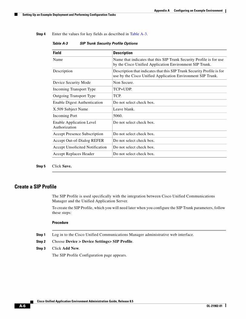
Appendix A Configuring an Example Environment Setting Up an Example Deployment and Performing Configuration Tasks
Step 4 Enter the values for key fields as described in Table A-3.
Step 5 Click Save.
Create a SIP Profile
The SIP Profile is used specifically with the integration between Cisco Unified Communications Manager and the Unified Application Server.
To create the SIP Profile, which you will need later when you configure the SIP Trunk parameters, follow these steps:
Procedure
Step 1 Log in to the Cisco Unified Communications Manager administrative web interface.
Step 2 Choose Device > Device Settings> SIP Profile.
Step 3 Click Add New.
The SIP Profile Configuration page appears.
Table A-3 SIP Trunk Security Profile Options
Field Description
Name Name that indicates that this SIP Trunk Security Profile is for use by the Cisco Unified Application Environment SIP Trunk.
Description Description that indicates that this SIP Trunk Security Profile is for use by the Cisco Unified Application Environment SIP Trunk.
Device Security Mode Non Secure.
Incoming Transport Type TCP+UDP.
Outgoing Transport Type TCP.
Enable Digest Authentication Do not select check box.
X.509 Subject Name Leave blank.
Incoming Port 5060.
Enable Application Level Authorization
Do not select check box.
Accept Presence Subscription Do not select check box.
Accept Out-of-Dialog REFER Do not select check box.
Accept Unsolicited Notification Do not select check box.
Accept Replaces Header Do not select check box.
A-6Cisco Unified Application Environment Administration Guide, Release 8.5
OL-21902-01
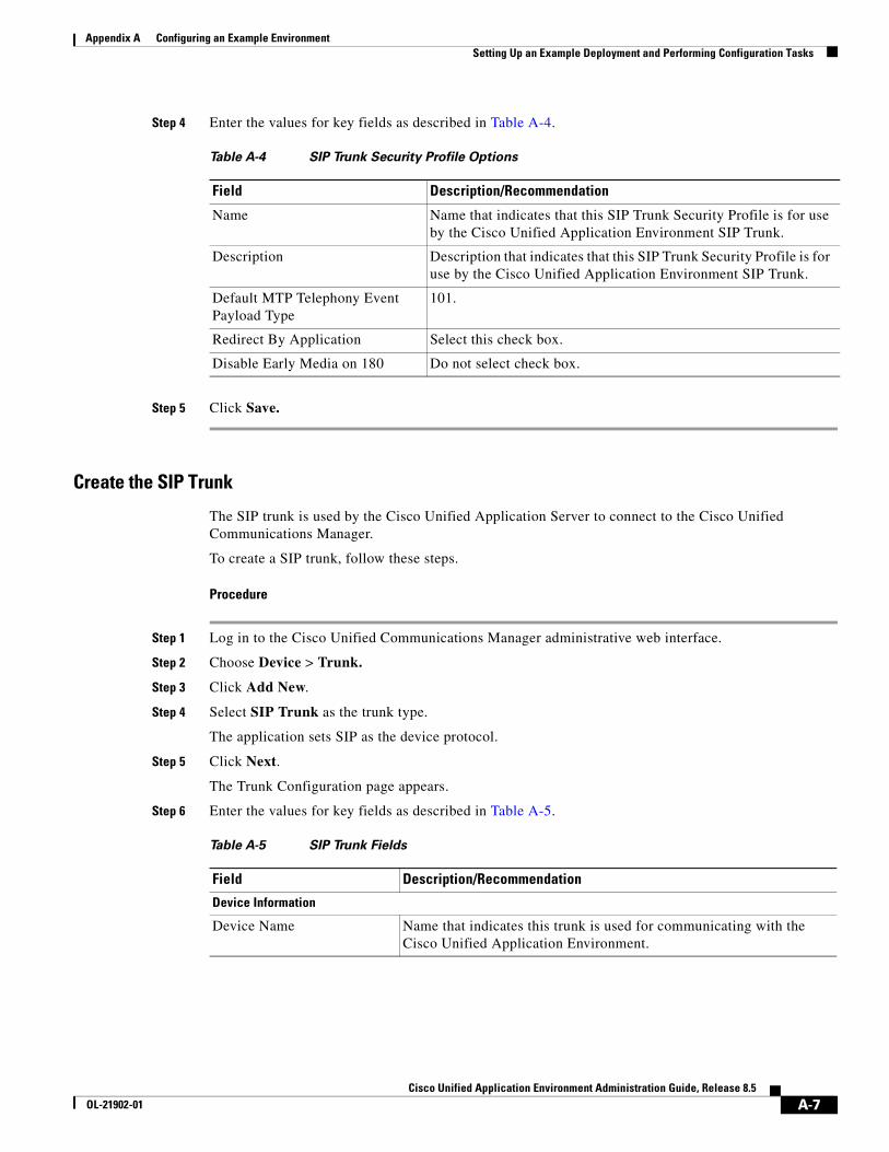
Appendix A Configuring an Example Environment Setting Up an Example Deployment and Performing Configuration Tasks
Step 4 Enter the values for key fields as described in Table A-4.
Step 5 Click Save.
Create the SIP Trunk
The SIP trunk is used by the Cisco Unified Application Server to connect to the Cisco Unified Communications Manager.
To create a SIP trunk, follow these steps.
Procedure
Step 1 Log in to the Cisco Unified Communications Manager administrative web interface.
Step 2 Choose Device > Trunk.
Step 3 Click Add New.
Step 4 Select SIP Trunk as the trunk type.
The application sets SIP as the device protocol.
Step 5 Click Next.
The Trunk Configuration page appears.
Step 6 Enter the values for key fields as described in Table A-5.
Table A-4 SIP Trunk Security Profile Options
Field Description/Recommendation
Name Name that indicates that this SIP Trunk Security Profile is for use by the Cisco Unified Application Environment SIP Trunk.
Description Description that indicates that this SIP Trunk Security Profile is for use by the Cisco Unified Application Environment SIP Trunk.
Default MTP Telephony Event Payload Type
101.
Redirect By Application Select this check box.
Disable Early Media on 180 Do not select check box.
Table A-5 SIP Trunk Fields
Field Description/Recommendation
Device Information
Device Name Name that indicates this trunk is used for communicating with the Cisco Unified Application Environment.
A-7Cisco Unified Application Environment Administration Guide, Release 8.5
OL-21902-01
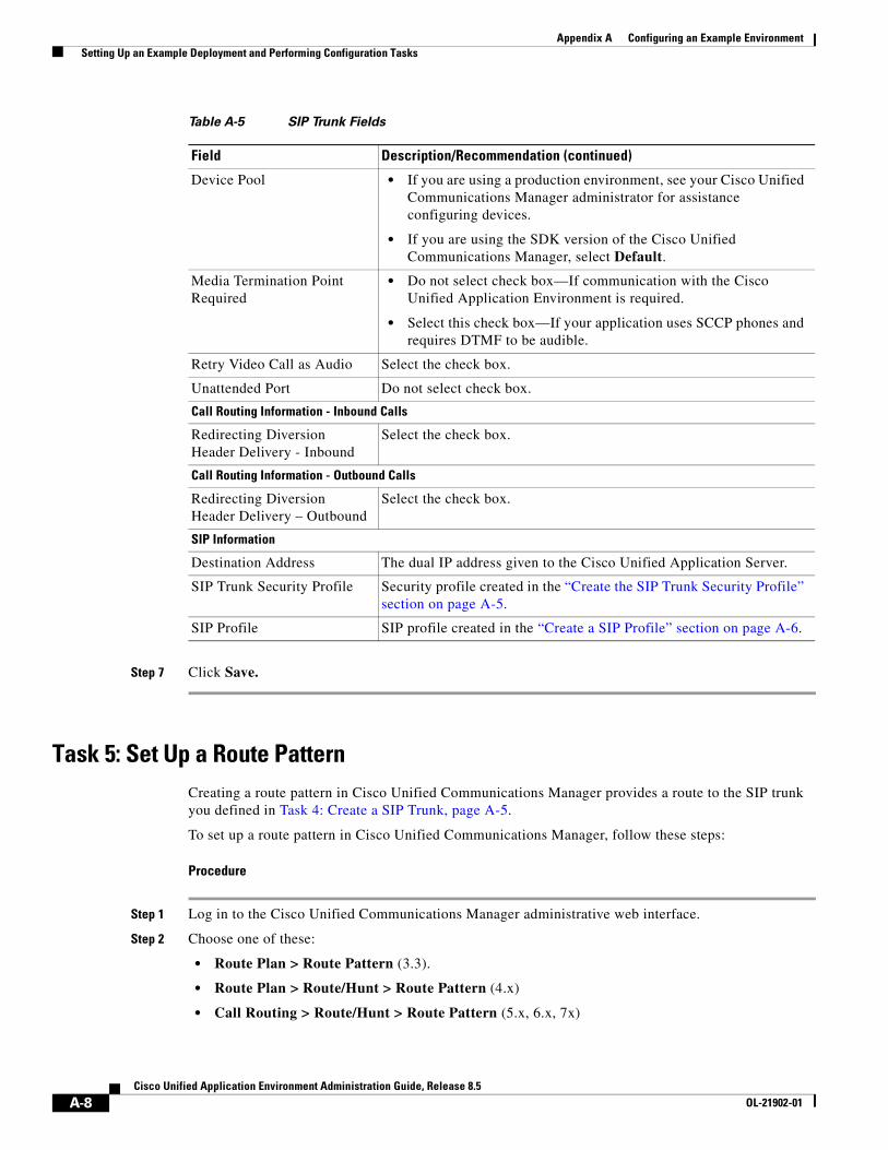
Appendix A Configuring an Example Environment Setting Up an Example Deployment and Performing Configuration Tasks
Step 7 Click Save.
Task 5: Set Up a Route PatternCreating a route pattern in Cisco Unified Communications Manager provides a route to the SIP trunk you defined in Task 4: Create a SIP Trunk, page A-5.
To set up a route pattern in Cisco Unified Communications Manager, follow these steps:
Procedure
Step 1 Log in to the Cisco Unified Communications Manager administrative web interface.
Step 2 Choose one of these:
• Route Plan > Route Pattern (3.3).
• Route Plan > Route/Hunt > Route Pattern (4.x)
• Call Routing > Route/Hunt > Route Pattern (5.x, 6.x, 7x)
Device Pool • If you are using a production environment, see your Cisco Unified Communications Manager administrator for assistance configuring devices.
• If you are using the SDK version of the Cisco Unified Communications Manager, select Default.
Media Termination Point Required
• Do not select check box—If communication with the Cisco Unified Application Environment is required.
• Select this check box—If your application uses SCCP phones and requires DTMF to be audible.
Retry Video Call as Audio Select the check box.
Unattended Port Do not select check box.
Call Routing Information - Inbound Calls
Redirecting Diversion Header Delivery - Inbound
Select the check box.
Call Routing Information - Outbound Calls
Redirecting Diversion Header Delivery – Outbound
Select the check box.
SIP Information
Destination Address The dual IP address given to the Cisco Unified Application Server.
SIP Trunk Security Profile Security profile created in the “Create the SIP Trunk Security Profile” section on page A-5.
SIP Profile SIP profile created in the “Create a SIP Profile” section on page A-6.
Table A-5 SIP Trunk Fields
Field Description/Recommendation (continued)
A-8Cisco Unified Application Environment Administration Guide, Release 8.5
OL-21902-01
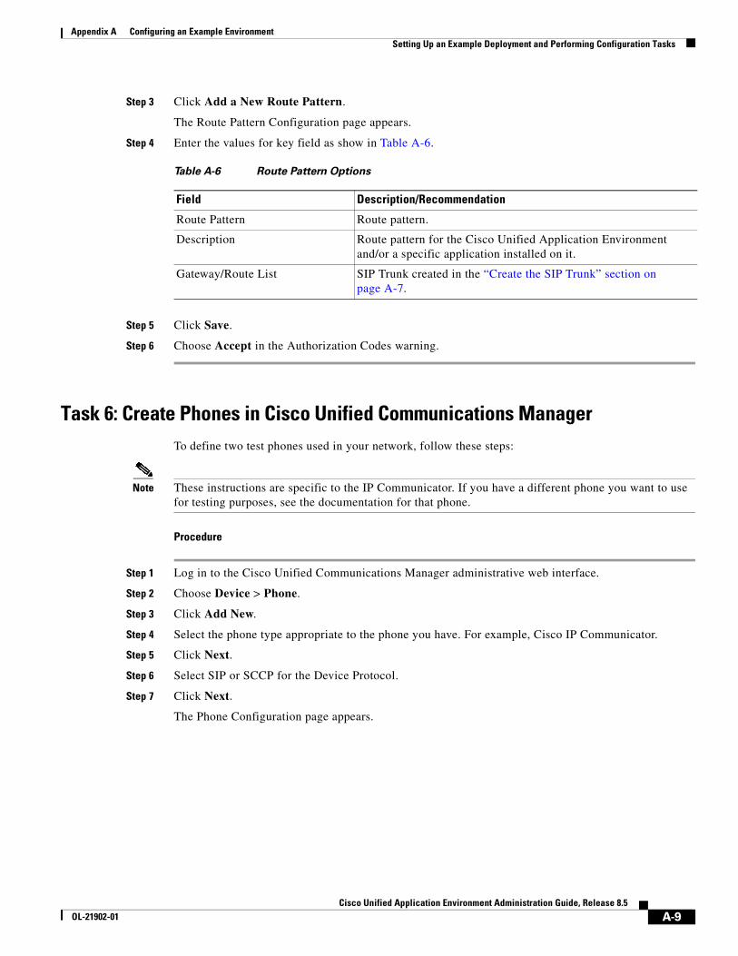
Appendix A Configuring an Example Environment Setting Up an Example Deployment and Performing Configuration Tasks
Step 3 Click Add a New Route Pattern.
The Route Pattern Configuration page appears.
Step 4 Enter the values for key field as show in Table A-6.
Step 5 Click Save.
Step 6 Choose Accept in the Authorization Codes warning.
Task 6: Create Phones in Cisco Unified Communications Manager To define two test phones used in your network, follow these steps:
Note These instructions are specific to the IP Communicator. If you have a different phone you want to use for testing purposes, see the documentation for that phone.
Procedure
Step 1 Log in to the Cisco Unified Communications Manager administrative web interface.
Step 2 Choose Device > Phone.
Step 3 Click Add New.
Step 4 Select the phone type appropriate to the phone you have. For example, Cisco IP Communicator.
Step 5 Click Next.
Step 6 Select SIP or SCCP for the Device Protocol.
Step 7 Click Next.
The Phone Configuration page appears.
Table A-6 Route Pattern Options
Field Description/Recommendation
Route Pattern Route pattern.
Description Route pattern for the Cisco Unified Application Environment and/or a specific application installed on it.
Gateway/Route List SIP Trunk created in the “Create the SIP Trunk” section on page A-7.
A-9Cisco Unified Application Environment Administration Guide, Release 8.5
OL-21902-01
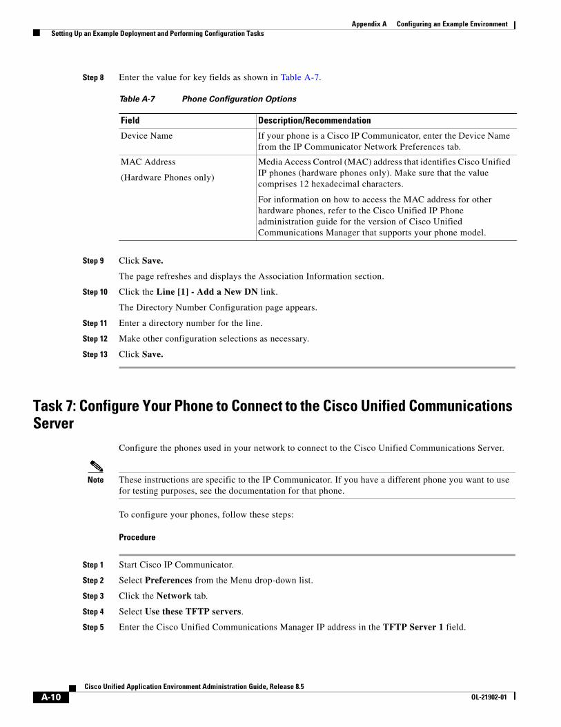
Appendix A Configuring an Example Environment Setting Up an Example Deployment and Performing Configuration Tasks
Step 8 Enter the value for key fields as shown in Table A-7.
Step 9 Click Save.
The page refreshes and displays the Association Information section.
Step 10 Click the Line [1] - Add a New DN link.
The Directory Number Configuration page appears.
Step 11 Enter a directory number for the line.
Step 12 Make other configuration selections as necessary.
Step 13 Click Save.
Task 7: Configure Your Phone to Connect to the Cisco Unified Communications Server
Configure the phones used in your network to connect to the Cisco Unified Communications Server.
Note These instructions are specific to the IP Communicator. If you have a different phone you want to use for testing purposes, see the documentation for that phone.
To configure your phones, follow these steps:
Procedure
Step 1 Start Cisco IP Communicator.
Step 2 Select Preferences from the Menu drop-down list.
Step 3 Click the Network tab.
Step 4 Select Use these TFTP servers.
Step 5 Enter the Cisco Unified Communications Manager IP address in the TFTP Server 1 field.
Table A-7 Phone Configuration Options
Field Description/Recommendation
Device Name If your phone is a Cisco IP Communicator, enter the Device Name from the IP Communicator Network Preferences tab.
MAC Address
(Hardware Phones only)
Media Access Control (MAC) address that identifies Cisco Unified IP phones (hardware phones only). Make sure that the value comprises 12 hexadecimal characters.
For information on how to access the MAC address for other hardware phones, refer to the Cisco Unified IP Phone administration guide for the version of Cisco Unified Communications Manager that supports your phone model.
A-10Cisco Unified Application Environment Administration Guide, Release 8.5
OL-21902-01
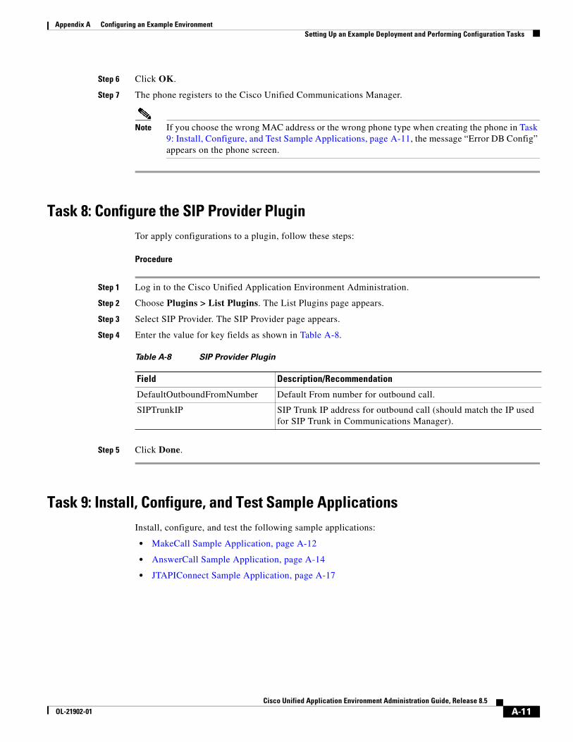
Appendix A Configuring an Example Environment Setting Up an Example Deployment and Performing Configuration Tasks
Step 6 Click OK.
Step 7 The phone registers to the Cisco Unified Communications Manager.
Note If you choose the wrong MAC address or the wrong phone type when creating the phone in Task 9: Install, Configure, and Test Sample Applications, page A-11, the message “Error DB Config” appears on the phone screen.
Task 8: Configure the SIP Provider PluginTor apply configurations to a plugin, follow these steps:
Procedure
Step 1 Log in to the Cisco Unified Application Environment Administration.
Step 2 Choose Plugins > List Plugins. The List Plugins page appears.
Step 3 Select SIP Provider. The SIP Provider page appears.
Step 4 Enter the value for key fields as shown in Table A-8.
Step 5 Click Done.
Task 9: Install, Configure, and Test Sample ApplicationsInstall, configure, and test the following sample applications:
• MakeCall Sample Application, page A-12
• AnswerCall Sample Application, page A-14
• JTAPIConnect Sample Application, page A-17
Table A-8 SIP Provider Plugin
Field Description/Recommendation
DefaultOutboundFromNumber Default From number for outbound call.
SIPTrunkIP SIP Trunk IP address for outbound call (should match the IP used for SIP Trunk in Communications Manager).
A-11Cisco Unified Application Environment Administration Guide, Release 8.5
OL-21902-01
Appendix A Configuring an Example Environment Setting Up an Example Deployment and Performing Configuration Tasks
Before You Begin
1. Download the sample applications to your system:
a. On the Cisco Unified Application Server, navigate to the directory C:\Program Files\Cisco Systems\Unified Application Environment\Tools\Apps.
b. Locate the sample application .mca files.
c. Store the files.
If you are logged in remotely to the Cisco Unified Application Environment Administration, store these files on your local machine.
If you are logged in directly to the Cisco Unified Application Environment Administration, copy them to the desktop.
2. Install the MakeCall, AnswerCall, and JTAPIConnect applications. See Installing an Application, page 5-5.
MakeCall Sample Application
This section contains these topics:
• Overview, page A-12
• Verifying the Trigger Parameter, page A-13
• Testing the MakeCall Application, page A-14
Overview
The MakeCall sample application tests outbound dialing from the Cisco Unified Application Server to Cisco Unified Communications Manager as follows:
1. Uses a configured number to place an outbound call to a specified directory number (DN).
2. Plays ‘goodbye’ three times.
3. Hangs up on the called party.
A successful outbound call indicates that the Cisco Unified Communications Manager cluster interprets the call as originating from the SIP trunk that represents the Cisco Unified Application Server.
Making a Call to an Internal IP Phone
Figure 1-1 shows the call flow in which the MakeCall application makes a call to an internal IP phone.
1. The Cisco Unified Application Server makes an SIP call to Cisco Unified Communications Manager.
2. Cisco Unified Communications Manager makes a call using SIP or SCCP to the IP phone as a result of the call from the Cisco Unified Application Server.
3. When the call is answered by the Cisco Unified Application Server, RTP streams are established between the IP phone and the Cisco Unified Media Engine.
A-12Cisco Unified Application Environment Administration Guide, Release 8.5
OL-21902-01
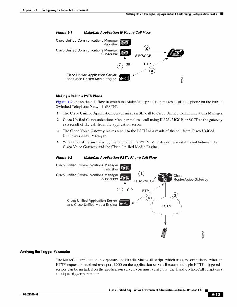
Appendix A Configuring an Example Environment Setting Up an Example Deployment and Performing Configuration Tasks
Figure 1-1 MakeCall Application IP Phone Call Flow
Making a Call to a PSTN Phone
Figure 1-2 shows the call flow in which the MakeCall application makes a call to a phone on the Public Switched Telephone Network (PSTN).
1. The Cisco Unified Application Server makes a SIP call to Cisco Unified Communications Manager.
2. Cisco Unified Communications Manager makes a call using H.323, MGCP, or SCCP to the gateway as a result of the call from the application server.
3. The Cisco Voice Gateway makes a call to the PSTN as a result of the call from Cisco Unified Communications Manager.
4. When the call is answered by the phone on the PSTN, RTP streams are established between the Cisco Voice Gateway and the Cisco Unified Media Engine.
Figure 1-2 MakeCall Application PSTN Phone Call Flow
Verifying the Trigger Parameter
The MakeCall application incorporates the Handle MakeCall script, which triggers, or initiates, when an HTTP request is received over port 8000 on the application server. Because multiple HTTP-triggered scripts can be installed on the application server, you must verify that the Handle MakeCall script uses a unique trigger parameter.
M
M
Cisco Unified Application Serverand Cisco Unified Media Engine
Cisco Unified Communications ManagerPublisher
Cisco Unified Communications ManagerSubscriber
RTP
18
90
51
SIP
IPSIP/SCCP
1
2
3
M
M
V
Cisco Unified Application Serverand Cisco Unified Media Engine
Cisco Unified Communications ManagerPublisher
Cisco Unified Communications ManagerSubscriber
CiscoRouter/Voice Gateway
RTP
18
90
52
SIP
H.323/MGCP
1
2
43
PSTN
A-13Cisco Unified Application Environment Administration Guide, Release 8.5
OL-21902-01
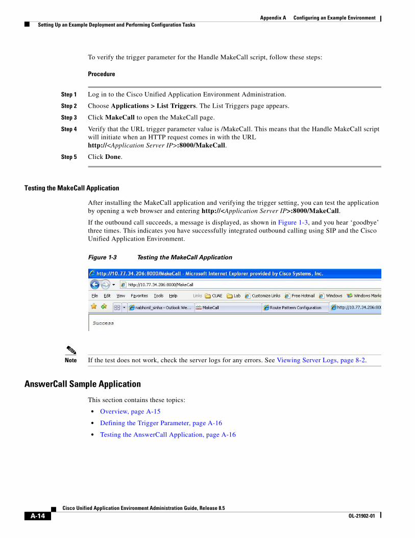
Appendix A Configuring an Example Environment Setting Up an Example Deployment and Performing Configuration Tasks
To verify the trigger parameter for the Handle MakeCall script, follow these steps:
Procedure
Step 1 Log in to the Cisco Unified Application Environment Administration.
Step 2 Choose Applications > List Triggers. The List Triggers page appears.
Step 3 Click MakeCall to open the MakeCall page.
Step 4 Verify that the URL trigger parameter value is /MakeCall. This means that the Handle MakeCall script will initiate when an HTTP request comes in with the URL http://<Application Server IP>:8000/MakeCall.
Step 5 Click Done.
Testing the MakeCall Application
After installing the MakeCall application and verifying the trigger setting, you can test the application by opening a web browser and entering http://<Application Server IP>:8000/MakeCall.
If the outbound call succeeds, a message is displayed, as shown in Figure 1-3, and you hear ‘goodbye’ three times. This indicates you have successfully integrated outbound calling using SIP and the Cisco Unified Application Environment.
Figure 1-3 Testing the MakeCall Application
Note If the test does not work, check the server logs for any errors. See Viewing Server Logs, page 8-2.
AnswerCall Sample Application
This section contains these topics:
• Overview, page A-15
• Defining the Trigger Parameter, page A-16
• Testing the AnswerCall Application, page A-16
A-14Cisco Unified Application Environment Administration Guide, Release 8.5
OL-21902-01
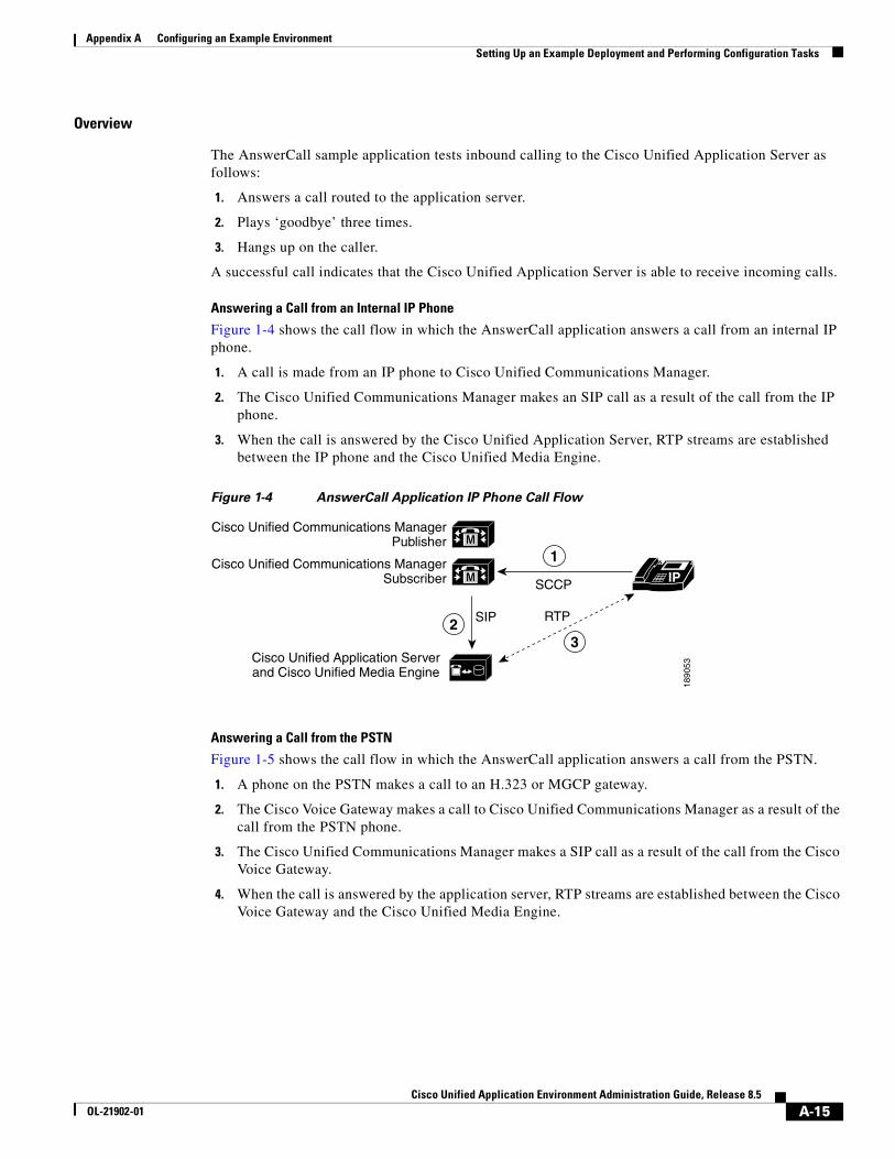
Appendix A Configuring an Example Environment Setting Up an Example Deployment and Performing Configuration Tasks
Overview
The AnswerCall sample application tests inbound calling to the Cisco Unified Application Server as follows:
1. Answers a call routed to the application server.
2. Plays ‘goodbye’ three times.
3. Hangs up on the caller.
A successful call indicates that the Cisco Unified Application Server is able to receive incoming calls.
Answering a Call from an Internal IP Phone
Figure 1-4 shows the call flow in which the AnswerCall application answers a call from an internal IP phone.
1. A call is made from an IP phone to Cisco Unified Communications Manager.
2. The Cisco Unified Communications Manager makes an SIP call as a result of the call from the IP phone.
3. When the call is answered by the Cisco Unified Application Server, RTP streams are established between the IP phone and the Cisco Unified Media Engine.
Figure 1-4 AnswerCall Application IP Phone Call Flow
Answering a Call from the PSTN
Figure 1-5 shows the call flow in which the AnswerCall application answers a call from the PSTN.
1. A phone on the PSTN makes a call to an H.323 or MGCP gateway.
2. The Cisco Voice Gateway makes a call to Cisco Unified Communications Manager as a result of the call from the PSTN phone.
3. The Cisco Unified Communications Manager makes a SIP call as a result of the call from the Cisco Voice Gateway.
4. When the call is answered by the application server, RTP streams are established between the Cisco Voice Gateway and the Cisco Unified Media Engine.
M
M
Cisco Unified Application Serverand Cisco Unified Media Engine
Cisco Unified Communications ManagerPublisher
Cisco Unified Communications ManagerSubscriber
RTP
18
90
53
SIP
IPSCCP
2
1
3
A-15Cisco Unified Application Environment Administration Guide, Release 8.5
OL-21902-01
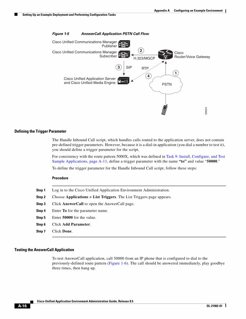
Appendix A Configuring an Example Environment Setting Up an Example Deployment and Performing Configuration Tasks
Figure 1-5 AnswerCall Application PSTN Call Flow
Defining the Trigger Parameter
The Handle Inbound Call script, which handles calls routed to the application server, does not contain pre-defined trigger parameters. However, because it is a dial-in application (you dial a number to test it), you should define a trigger parameter for the script.
For consistency with the route pattern 5000X, which was defined in Task 9: Install, Configure, and Test Sample Applications, page A-11, define a trigger parameter with the name “to” and value “50000.”
To define the trigger parameter for the Handle Inbound Call script, follow these steps:
Procedure
Step 1 Log in to the Cisco Unified Application Environment Administration.
Step 2 Choose Applications > List Triggers. The List Triggers page appears.
Step 3 Click AnswerCall to open the AnswerCall page.
Step 4 Enter To for the parameter name.
Step 5 Enter 50000 for the value.
Step 6 Click Add Parameter.
Step 7 Click Done.
Testing the AnswerCall Application
To test AnswerCall application, call 50000 from an IP phone that is configured to dial to the previously-defined route pattern (Figure 1-6). The call should be answered immediately, play goodbye three times, then hang up.
M
M
V
Cisco Unified Application Serverand Cisco Unified Media Engine
Cisco Unified Communications ManagerPublisher
Cisco Unified Communications ManagerSubscriber
CiscoRouter/Voice Gateway
RTP
18
90
54
SIP
H.323/MGCP
3
2
41
PSTN
A-16Cisco Unified Application Environment Administration Guide, Release 8.5
OL-21902-01
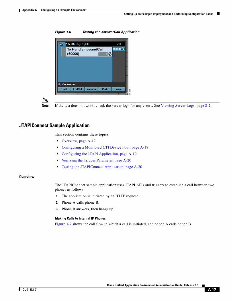
Appendix A Configuring an Example Environment Setting Up an Example Deployment and Performing Configuration Tasks
Figure 1-6 Testing the AnswerCall Application
Note If the test does not work, check the server logs for any errors. See Viewing Server Logs, page 8-2.
JTAPIConnect Sample Application
This section contains these topics:
• Overview, page A-17
• Configuring a Monitored CTI Device Pool, page A-18
• Configuring the JTAPI Application, page A-19
• Verifying the Trigger Parameter, page A-20
• Testing the JTAPIConnect Application, page A-20
Overview
The JTAPIConnect sample application uses JTAPI APIs and triggers to establish a call between two phones as follows:
1. The application is initiated by an HTTP request.
2. Phone A calls phone B.
3. Phone B answers, then hangs up.
Making Calls to Internal IP Phones
Figure 1-7 shows the call flow in which a call is initiated, and phone A calls phone B.
A-17Cisco Unified Application Environment Administration Guide, Release 8.5
OL-21902-01
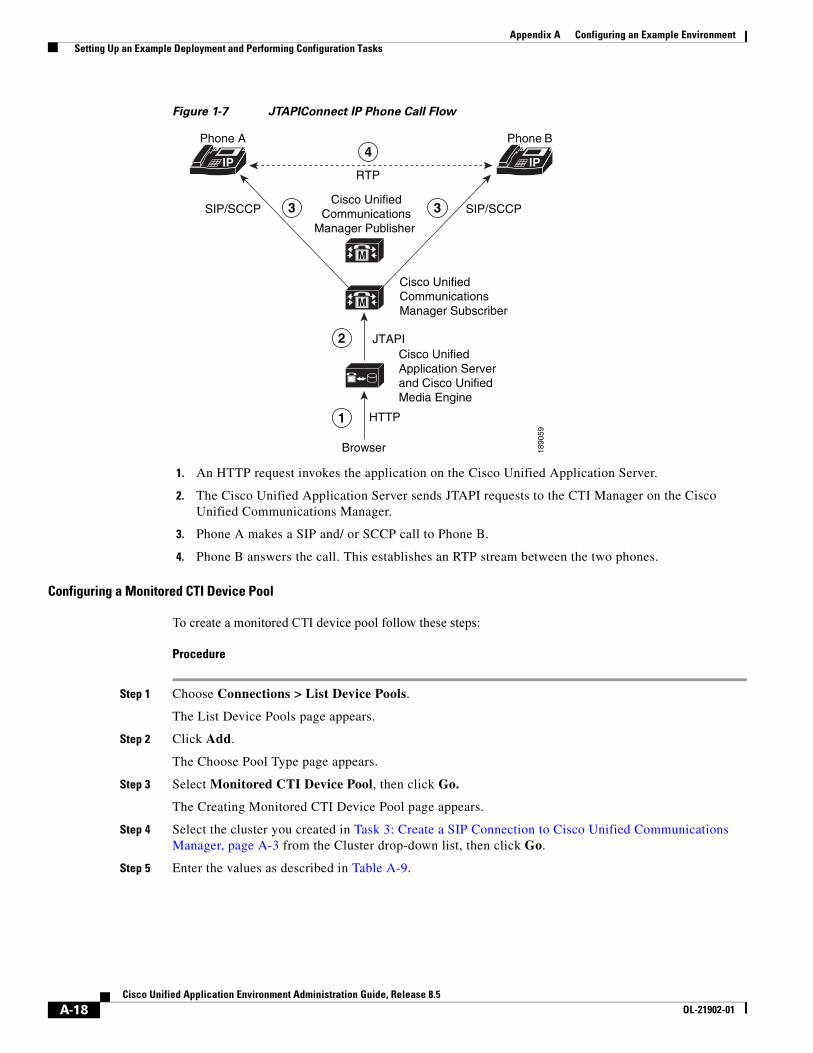
Appendix A Configuring an Example Environment Setting Up an Example Deployment and Performing Configuration Tasks
Figure 1-7 JTAPIConnect IP Phone Call Flow
1. An HTTP request invokes the application on the Cisco Unified Application Server.
2. The Cisco Unified Application Server sends JTAPI requests to the CTI Manager on the Cisco Unified Communications Manager.
3. Phone A makes a SIP and/ or SCCP call to Phone B.
4. Phone B answers the call. This establishes an RTP stream between the two phones.
Configuring a Monitored CTI Device Pool
To create a monitored CTI device pool follow these steps:
Procedure
Step 1 Choose Connections > List Device Pools.
The List Device Pools page appears.
Step 2 Click Add.
The Choose Pool Type page appears.
Step 3 Select Monitored CTI Device Pool, then click Go.
The Creating Monitored CTI Device Pool page appears.
Step 4 Select the cluster you created in Task 3: Create a SIP Connection to Cisco Unified Communications Manager, page A-3 from the Cluster drop-down list, then click Go.
Step 5 Enter the values as described in Table A-9.
Cisco Unified
Communications
Manager Publisher
Cisco Unified
Communications
Manager Subscriber
JTAPI
HTTP
Browser
Phone A
Phone B
RTP
SIP/SCCP SIP/SCCP
M
M
18
90
59
IPIP
1
2
3
4
3
Cisco Unified
Application Server
and Cisco Unified
Media Engine
A-18Cisco Unified Application Environment Administration Guide, Release 8.5
OL-21902-01
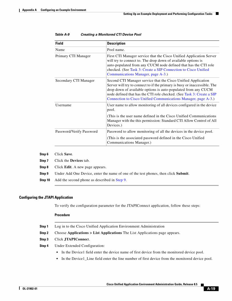
Appendix A Configuring an Example Environment Setting Up an Example Deployment and Performing Configuration Tasks
Step 6 Click Save.
Step 7 Click the Devices tab.
Step 8 Click Edit. A new page appears.
Step 9 Under Add One Device, enter the name of one of the test phones, then click Submit.
Step 10 Add the second phone as described in Step 9.
Configuring the JTAPI Application
To verify the configuration parameter for the JTAPIConnect application, follow these steps:
Procedure
Step 1 Log in to the Cisco Unified Application Environment Administration
Step 2 Choose Applications > List Applications The List Applications page appears.
Step 3 Click JTAPIConnect.
Step 4 Under Extended Configuration:
• In the Device1 field enter the device name of first device from the monitored device pool.
• In the Device1_Line field enter the line number of first device from the monitored device pool.
Table A-9 Creating a Monitored CTI Device Pool
Field Description
Name Pool name.
Primary CTI Manager First CTI Manager service that the Cisco Unified Application Server will try to connect to. The drop down of available options is auto-populated from any CUCM node defined that has the CTI role checked. (See Task 3: Create a SIP Connection to Cisco Unified Communications Manager, page A-3.)
Secondary CTI Manager Second CTI Manager service that the Cisco Unified Application Server will try to connect to if the primary is busy or inaccessible. The drop down of available options is auto-populated from any CUCM node defined that has the CTI role checked. (See Task 3: Create a SIP Connection to Cisco Unified Communications Manager, page A-3.)
Username User name to allow monitoring of all devices configured in the device pool.
(This is the user name defined in the Cisco Unified Communications Manager with the this permission: Standard CTI Allow Control of All Devices.)
Password/Verify Password Password to allow monitoring of all the devices in the device pool.
(This is the associated password defined in the Cisco Unified Communications Manager.)
A-19Cisco Unified Application Environment Administration Guide, Release 8.5
OL-21902-01
Appendix A Configuring an Example Environment Setting Up an Example Deployment and Performing Configuration Tasks
• In the Device2 field enter the device name of second device from the monitored device pool.
• In the Device2_Line field enter the line number of the second device from monitored device pool.
Step 5 Click Apply.
Step 6 Click Done.
Verifying the Trigger Parameter
The JTAPIConnect application triggers, or initiates when an HTTP request is received over port 8000 on the Cisco Unified Application Server. Because multiple HTTP-triggered scripts can be installed on the application server, you must verify that the application uses a unique trigger parameter. The default setting is JTAPIConnect.
To verify the trigger parameter for the JTAPIConnect application, follow these steps:
Procedure
Step 1 Log in to the Cisco Unified Application Environment Administration.
Step 2 Choose Applications > List Triggers. The List Triggers page appears.
Step 3 Click JTAPIConnect to open the JTAPIConnect page.
Step 4 Verify that the URL trigger parameter value is /JTAPIConnect. This means that the JTAPIConnect application will initiate when an HTTP request comes in with the URL http://<Application Server IP>:8000/JTAPIConnect.
Step 5 Click Done.
Testing the JTAPIConnect Application
To test the application by opening a web browser and entering http://<Application Server IP>:8000/JTAPIConnect.
Both devices (test phones) ring, then auto answer each other. After two seconds, the phones hang up.
Note If the test does not work, check the server logs for any errors. See Viewing Server Logs, page 8-2.
A-20Cisco Unified Application Environment Administration Guide, Release 8.5
OL-21902-01
Cisco Unified ApplicaOL-21902-01
I N D E X
Numerics
3rd-party platform agents
policy for use with Cisco Unified Application Environment 1-11
A
adding
connection
Cisco Unified Communications Manager cluster 7-3
Cisco Unified Media Engine 7-3
Cisco Unified Presence 7-3
device pool 7-3
H.323 gateway 7-3
IETF SIP proxy 7-3
Nuance license server 7-3
Nuance server 7-3
connection group
Cisco Unified Media Engine 7-17
CTI device pool group 7-17
H.323 gateway group 7-17
SCCP device pool group 7-17
SIP device pool group 7-17
devices to pool 7-8
group, connection 7-17
partitions 5-7
trigger 5-11
users 4-1
administration guide
audience i-xi
conventions i-xiii
organization of i-xii
related documentation i-xii
administration interface
See Cisco Unified Application Environment Administration
alarms
configuring manager 8-8
setting to ignored 8-9
viewing 8-8
Apache
restarting to enable SSL 3-15
application development
documentation and resources i-xiii
supported deployment 1-2
supported IP telephony functions 1-1
tools 1-3
application environment
See Cisco Unified Application Environment
applications
configuration example 5-3
disabling 5-5
enabling 5-5
installing 5-5
overview 5-1
partitions 5-1
scripts 5-2
triggers 5-2
uninstalling 5-6
updating 5-7
viewing 5-4
viewing details of 5-6
application server
See Cisco Unified Application Server
applying, partitions 5-9
IN-1tion Environment Administration Guide, Release 8.5
Index
AppServerService.exe.config 3-20, 3-22, 3-24, 3-25
archiving
logs, server 8-2
server logs 8-2
audience, administration guide i-xi
authentication 3-16, 3-17
definition 3-18
Etch Bridge 3-18
management service 3-17
B
backup
SSL certificate and key 3-14
back up, system 9-1
browsers, supported 2-1
C
caution, restoring the system 9-2
certificate, license 2-2
certificate. see SSL
Cisco Security Agent
See CSA
Cisco Unified Application Designer, overview 1-3
Cisco Unified Application Environment
3rd-party platform agents 1-11
Administration
logging in 2-2
menu options 2-2
browsers 2-1
components 1-2
deployment technologies 1-2
deployment topologies 1-4
IP telephony functions 1-1
network port usage 1-8
overview 1-1
plugins, shipped with 6-1
IN-2Cisco Unified Application Environment Administration Guide, Rele
prerequisites 2-1
setting up 2-3
Cisco Unified Application Server 1-2
AppServerService.exe.config 3-20, 3-22, 3-24, 3-25
overview 1-2
production.properties file 3-18
redundancy 3-9
reinitializing 9-3
setting global parameters 3-1, 3-2
Cisco Unified Application Service
mgmt-service-launcher.conf file 3-18
Cisco Unified Communications
node, deleting 7-15
Cisco Unified Communications Manager cluster
adding 7-3
deleting 7-14, 7-15
editing 7-16
searching for 7-1
viewing 7-1
Cisco Unified Media Engine
adding 7-3
disabling 7-16
editing 7-16
overview 1-3
searching for 7-1
setting global parameters 3-3
viewing 7-1
Cisco Unified Media Engine group
adding 7-17
deleting 7-21
editing 7-21
searching for 7-17
viewing 7-17
Cisco Unified Presence
adding 7-3
deleting 7-14
editing 7-16
searching for 7-1
viewing 7-1
ase 8.5OL-21902-01
Index
claim certificate 2-2
command-line tool, CUAE 1-4
configuring
alarm manager 8-8
logs 8-4
plugins 6-8
trace settings 8-4
connection
adding
Cisco Unified Communications Manager cluster 7-3
Cisco Unified Media Engine 7-3
Cisco Unified Presence 7-3
H.323 gateway 7-3
IETF SIP proxy 7-3
Nuance license server 7-3
Nuance server 7-3
deleting 7-14
disabling 7-16
editing 7-16
searching for 7-1
troubleshooting 10-2
viewing 7-1
connection groups
deleting 7-21
editing 7-21
searching for 7-17
viewing 7-17
connection string URI 3-23
KeepAlive 3-23, 3-24
MaxPktSize 3-24
plugins 3-20
reconnect delay 3-25
TLS 3-20
conventions
administration guide i-xiii
command i-xiii
text i-xiii
CSA
Cisco UnifiedOL-21902-01
Cisco Unified Application Environment policy 1-13
CTI device pool
adding 7-3
deleting 7-14
editing 7-16
CTI device pool, monitored
adding 7-3
deleting 7-14
editing 7-16
CTI device pool group
adding 7-17
deleting 7-21
editing 7-21
searching for 7-17
viewing 7-17
CTI route point
adding 7-3
deleting 7-14
editing 7-16
CUAE command-line tool 1-4, 3-16, 3-17, 3-18
TLS connection protocol 3-17
D
data services and protocols, supported 1-2
deleting 7-16
Cisco Unified Communications Manager
cluster 7-15
node 7-15
connection groups 7-21
connections 7-14
device pool 7-14
devices from a pool 7-9
groups, connection 7-21
license 3-7
logs, server 8-2
server logs 8-2
triggers 5-12
users 4-2
IN-3 Application Environment Administration Guide, Release 8.5
Index
deployment topologies 1-4
developer
tools
Cisco Unified Application Designer 1-3
Etch 1-4
developer documentation i-xiii
device pool
adding 7-3
deleting 7-14
editing 7-16
managing devices 7-7
searching for 7-2
viewing 7-2
devices
adding to a pool 7-8
deleting from pool 7-9
editing details 7-8
searching for in a pool 7-8
diagnostics, viewing 8-7
disabling
applications 5-5
connection 7-16
KeepAlive 3-24
partitions 5-9
plugins 6-7
services 8-3
TLS on Etch Bridge 3-20
TLS on management service 3-18
document conventions i-xiii
downloading MIB files 8-8
E
editing
connection groups 7-21
connections 7-16
groups, connection 7-21
users 4-2
enabling
IN-4Cisco Unified Application Environment Administration Guide, Rele
applications 5-5
KeepAlive 3-23
partition 5-9
plugins 6-7
services 8-3
SSL 3-14
encryption
definition 3-18
Etch Bridge 3-18, 3-20
plugins 3-20
Etch
Etch Bridge
disabling TLS 3-20
encryption 3-18
plugin acts as server and client 3-19
max packet size 3-24
reconnect delay 3-25
Etch, overview 1-4
example
AnswerCall application A-14
application configuration 5-3
configuration tasks, performing A-1
deployment, setting up A-1
MakeCall application A-11
route pattern, setting up A-8
sample application
installing A-11
testing A-11
triggers 5-2
extensions, invoking for plugins 6-9
F
FAQs 10-1
frequently asked questions
See FAQs
ase 8.5OL-21902-01
Index
G
global parameters
Cisco Unified Application Server 3-1, 3-2
Cisco Unified Media Engine 3-3
groups, connection
adding 7-17
deleting 7-21
editing 7-21
searching for 7-17
viewing 7-17
H
H.323 gateway
adding 7-3
deleting 7-14
editing 7-16
searching for 7-1
viewing 7-1
H.323 gateway group
adding 7-17
deleting 7-21
editing 7-21
searching for 7-17
viewing 7-17
H.323 provider 6-2
HTTP provider 6-3
I
IDE 1-3
IETF SIP proxy
adding 7-3
deleting 7-14
editing 7-16
searching for 7-1
viewing 7-1
ignore alarms 8-9
Cisco UnifiedOL-21902-01
installing
applications 5-5
integrated development environment
See IDE
IP telephony, supported functions 1-1
K
KeepAlive 3-23
disabling 3-24
enabling 3-23
modifying delay and count 3-24
killing
services 8-3
L
license
claim certificate 2-2
deleting 3-7
modes 3-6
Nuance server connection 7-3
overview 3-5
PAK 2-2
statistics 3-6
troubleshooting 10-3
uploading 3-7
logging in 2-2
logs
server
archiving 8-2
deleting 8-2
viewing 8-2
settings, configuring 8-4
M
makecert.exe tool 3-21
IN-5 Application Environment Administration Guide, Release 8.5
Index
management service
using TLS for connections to 3-16
max packet size 3-24
media engine
See Cisco Unified Media Engine
Media Engine provider 6-3
media processing capabilities 1-2
mgmt-service-launcher.conf 3-18
MIB file, downloading 8-8
mode, license 3-6
monitored CTI device pool
adding 7-3
deleting 7-14
editing 7-16
N
Nuance license server
adding 7-3
deleting 7-14
editing 7-16
searching for 7-1
viewing 7-1
Nuance server
adding 7-3
deleting 7-14
editing 7-16
searching for 7-1
viewing 7-1
O
options 3-23
overview
3rd-party platform agents 1-12
applications 5-1
Cisco Unified Application Designer 1-3
Cisco Unified Application Server 1-2
IN-6Cisco Unified Application Environment Administration Guide, Rele
Cisco Unified Media Engine 1-3
Etch 1-4
license 3-5
redundancy 3-9
SSL 3-13
TLS on Etch Bridge 3-18
TLS on Management Service 3-16
P
PAK 2-2
partitions
adding 5-7
applying 5-9
disabling 5-9
enabling 5-9
understanding 5-1
uninstalling 5-10
viewing 5-6
plugins
configuring 6-8
disabling 6-7
enabling 6-7
H.323 provider 6-2
HTTP provider 6-3
invoking extensions 6-9
Media Engine provider 6-3
Presence provider 6-4
SCCP provider 6-5
SIP provider 6-6
Timer provider 6-6
uninstalling 6-8
viewing 6-7
ports
used by Cisco Unified Application Environement 1-8
prerequisites
license, obtaining 2-2
setting up the Cisco Unified Application Environment 2-1
ase 8.5OL-21902-01
Index
Presence provider 6-4
Product Authorization Key
See PAK
production.properties 3-18
protocols 1-2
providers
See plugins
R
reconnectDelay 3-25
redundancy
overview 3-9
setting up 3-10
reinitializing the server 9-3
related documentation i-xii
restarting
services 8-3
restoring
caution 9-2
system 9-2
S
SCCP
device pool
adding 7-3
deleting 7-14
editing 7-16
provider 6-5
SCCP device pool group
adding 7-17
deleting 7-21
editing 7-21
searching for 7-17
viewing 7-17
scripts
in applications 5-2
Cisco UnifiedOL-21902-01
viewing 5-6
searching for
connection groups 7-17
connections 7-1
devices in a pool 7-8
users 4-1
server logs
archiving 8-2
deleting 8-2
viewing 8-2
services, managing 8-3
setting trace levels 8-5
setting up
application environment
media engines A-2
Cisco Unified Application Environment 2-3
redundancy 3-10
SIP
device pool
adding 7-3
deleting 7-14
editing 7-16
provider 6-6
SIP device pool group
adding 7-17
deleting 7-21
editing 7-21
searching for 7-17
viewing 7-17
SSL
certificate and key backups 3-14
enabling 3-14
generating certificate and key 3-14
overview 3-13
passphrase protection 3-14
restarting Apache 3-15
uploading certificate and key 3-13
starting, services 8-3
statistics
IN-7 Application Environment Administration Guide, Release 8.5
Index
license, viewing 3-6
usage, viewing 8-7
stopping, services 8-3
supported
application development functions 1-1
browsers 2-1
telephony call control protocols 1-2
system
backing up 9-1
caution restoring 9-2
reinitializing 9-3
restoring 9-2
settings
global parameters 3-1
license 3-4
redundancy 3-9
SSL Management 3-13
T
telephony
call control protocols 1-2
functions, supported 1-1
Timer provider 6-6
TLS
configuration 3-20
connection string URI 3-20
creating a new Etch Bridge certificate 3-21
CUAE command-line tool 3-17
disabling on management service 3-18
Etch Bridge 3-18, 3-20
generating certificate 3-19
management service 3-16
generating certificate 3-17
trace
levels
setting 8-5
settings
configuring 8-4
IN-8Cisco Unified Application Environment Administration Guide, Rele
for troubleshooting 8-4
Transport Layer Security
See TLS
triggers 5-10
adding 5-11
deleting 5-12
examples 5-2
in applications 5-2
updating 5-12
viewing 5-6, 5-10
viewing details 5-11
troubleshooting
using trace settings 8-4
troubleshooting tips 10-2
U
uninstalling
applications 5-6
partitions 5-10
plugins 6-8
updating
applications 5-7
triggers 5-12
usage statistics, viewing 8-7
users
adding 4-1
deleting 4-2
editing 4-2
searching for 4-1
viewing 4-1
V
viewing 5-10
alarms 8-8
application details 5-6
applications 5-4
ase 8.5OL-21902-01
Index
connection groups 7-17
connections 7-1
devices in a pool 7-8
diagnostics 8-7
groups, connection 7-17
license
modes 3-6
statistics 3-6
logs, server 8-2
partitions 5-6
plugins 6-7
scripts 5-6
server logs 8-2
statistics
license 3-6
usage 8-7
trigger details 5-11
triggers 5-6
users 4-1
W
watchdog server, starting and stopping 8-3
Cisco UnifiedOL-21902-01
IN-9Application Environment Administration Guide, Release 8.5

Index
IN-10Cisco Unified Application Environment Administration Guide, Rele
ase 8.5OL-21902-01