cisco wide area application engine 7341, 7371, and 674 ... memory in a wae-674 4-9 replacing a hard...
TRANSCRIPT

Americas HeadquartersCisco Systems, Inc.170 West Tasman DriveSan Jose, CA 95134-1706USAhttp://www.cisco.comTel: 408 526-4000
800 553-NETS (6387)Fax: 408 527-0883
Cisco Wide Area Application Engine 7341, 7371, and 674 Hardware Installation GuideOctober 2008
Text Part Number: OL-15012-02

THE SPECIFICATIONS AND INFORMATION REGARDING THE PRODUCTS IN THIS MANUAL ARE SUBJECT TO CHANGE WITHOUT NOTICE. ALL STATEMENTS, INFORMATION, AND RECOMMENDATIONS IN THIS MANUAL ARE BELIEVED TO BE ACCURATE BUT ARE PRESENTED WITHOUT WARRANTY OF ANY KIND, EXPRESS OR IMPLIED. USERS MUST TAKE FULL RESPONSIBILITY FOR THEIR APPLICATION OF ANY PRODUCTS.
THE SOFTWARE LICENSE AND LIMITED WARRANTY FOR THE ACCOMPANYING PRODUCT ARE SET FORTH IN THE INFORMATION PACKET THAT SHIPPED WITH THE PRODUCT AND ARE INCORPORATED HEREIN BY THIS REFERENCE. IF YOU ARE UNABLE TO LOCATE THE SOFTWARE LICENSE OR LIMITED WARRANTY, CONTACT YOUR CISCO REPRESENTATIVE FOR A COPY.
The following information is for FCC compliance of Class A devices: This equipment has been tested and found to comply with the limits for a Class A digital device, pursuant to part 15 of the FCC rules. These limits are designed to provide reasonable protection against harmful interference when the equipment is operated in a commercial environment. This equipment generates, uses, and can radiate radio-frequency energy and, if not installed and used in accordance with the instruction manual, may cause harmful interference to radio communications. Operation of this equipment in a residential area is likely to cause harmful interference, in which case users will be required to correct the interference at their own expense.
The following information is for FCC compliance of Class B devices: The equipment described in this manual generates and may radiate radio-frequency energy. If it is not installed in accordance with Cisco’s installation instructions, it may cause interference with radio and television reception. This equipment has been tested and found to comply with the limits for a Class B digital device in accordance with the specifications in part 15 of the FCC rules. These specifications are designed to provide reasonable protection against such interference in a residential installation. However, there is no guarantee that interference will not occur in a particular installation.
Modifying the equipment without Cisco’s written authorization may result in the equipment no longer complying with FCC requirements for Class A or Class B digital devices. In that event, your right to use the equipment may be limited by FCC regulations, and you may be required to correct any interference to radio or television communications at your own expense.
You can determine whether your equipment is causing interference by turning it off. If the interference stops, it was probably caused by the Cisco equipment or one of its peripheral devices. If the equipment causes interference to radio or television reception, try to correct the interference by using one or more of the following measures:
• Turn the television or radio antenna until the interference stops.
• Move the equipment to one side or the other of the television or radio.
• Move the equipment farther away from the television or radio.
• Plug the equipment into an outlet that is on a different circuit from the television or radio. (That is, make certain the equipment and the television or radio are on circuits controlled by different circuit breakers or fuses.)
Modifications to this product not authorized by Cisco Systems, Inc. could void the FCC approval and negate your authority to operate the product.
The Cisco implementation of TCP header compression is an adaptation of a program developed by the University of California, Berkeley (UCB) as part of UCB’s public domain version of the UNIX operating system. All rights reserved. Copyright © 1981, Regents of the University of California.
NOTWITHSTANDING ANY OTHER WARRANTY HEREIN, ALL DOCUMENT FILES AND SOFTWARE OF THESE SUPPLIERS ARE PROVIDED “AS IS” WITH ALL FAULTS. CISCO AND THE ABOVE-NAMED SUPPLIERS DISCLAIM ALL WARRANTIES, EXPRESSED OR IMPLIED, INCLUDING, WITHOUT LIMITATION, THOSE OF MERCHANTABILITY, FITNESS FOR A PARTICULAR PURPOSE AND NONINFRINGEMENT OR ARISING FROM A COURSE OF DEALING, USAGE, OR TRADE PRACTICE.
IN NO EVENT SHALL CISCO OR ITS SUPPLIERS BE LIABLE FOR ANY INDIRECT, SPECIAL, CONSEQUENTIAL, OR INCIDENTAL DAMAGES, INCLUDING, WITHOUT LIMITATION, LOST PROFITS OR LOSS OR DAMAGE TO DATA ARISING OUT OF THE USE OR INABILITY TO USE THIS MANUAL, EVEN IF CISCO OR ITS SUPPLIERS HAVE BEEN ADVISED OF THE POSSIBILITY OF SUCH DAMAGES.
CCDE, CCENT, Cisco Eos, Cisco Lumin, Cisco Nexus, Cisco StadiumVision, Cisco TelePresence, Cisco WebEx, the Cisco logo, DCE, and Welcome to the Human Network are trademarks; Changing the Way We Work, Live, Play, and Learn and Cisco Store are service marks; and Access Registrar, Aironet, AsyncOS, Bringing the Meeting To You, Catalyst, CCDA, CCDP, CCIE, CCIP, CCNA, CCNP, CCSP, CCVP, Cisco, the Cisco Certified Internetwork Expert logo, Cisco IOS, Cisco Press, Cisco Systems, Cisco Systems Capital, the Cisco Systems logo, Cisco Unity, Collaboration Without Limitation, EtherFast, EtherSwitch, Event Center, Fast Step, Follow Me Browsing, FormShare, GigaDrive, HomeLink, Internet Quotient, IOS, iPhone, iQuick Study, IronPort, the IronPort logo, LightStream, Linksys, MediaTone, MeetingPlace, MeetingPlace Chime Sound, MGX, Networkers, Networking Academy, Network Registrar, PCNow, PIX, PowerPanels, ProConnect, ScriptShare, SenderBase, SMARTnet, Spectrum Expert, StackWise, The Fastest Way to Increase Your Internet Quotient, TransPath, WebEx, and the WebEx logo are registered trademarks of Cisco Systems, Inc. and/or its affiliates in the United States and certain other countries.
All other trademarks mentioned in this document or website are the property of their respective owners. The use of the word partner does not imply a partnership relationship between Cisco and any other company. (0809R)
Any Internet Protocol (IP) addresses used in this document are not intended to be actual addresses. Any examples, command display output, and figures included in the document are shown for illustrative purposes only. Any use of actual IP addresses in illustrative content is unintentional and coincidental.
Cisco Wide Area Application Engine 7341, 7371, and 674 Hardware Installation Guide © 2007–2008 Cisco Systems, Inc. All rights reserved.


Cisco Wide Area ApOL-15012-02
C O N T E N T S
Preface ix
Introducing the Cisco Wide Area Application Engine 1-1
Supported Products 1-2
Hardware Features 1-2
Front Panel Controls and LEDs 1-3
Location of Ports and Connectors 1-7
Ethernet Port Connectors 1-7
Serial Port Connector 1-8
Preparing to Install the Wide Area Application Engine 2-1
Safety Warnings 2-1
Safety Guidelines 2-4
General Precautions 2-4
System Reliability Considerations 2-6
Working Inside the WAE with the Power On 2-7
Protecting Against Electrostatic Discharge 2-8
Installing the Wide Area Application Engine 3-1
Rack-Mounting Considerations 3-2
Rack Requirements 3-2
Tools and Parts Required 3-3
Installing the Wide Area Application Engine 3-5
vplication Engine 7341, 7371, and 674 Hardware Installation Guide

Contents
Installing the Chassis on a Tabletop 3-10
Connecting Cables 3-11
Connecting Power and Booting the System 3-11
Checking the LEDs 3-12
Removing or Replacing a WAE 3-12
Installing Hardware Options for the WAE-7371, WAE-7341, and WAE-674 4-1
Removing the Cover 4-1
Working with Adapters 4-3
Installing an Adapter 4-4
Completing the Installation 4-8
Installing Memory in a WAE-674 4-9
Replacing a Hard Disk Drive 4-13
Replacing a Power Supply 4-15
WAE Inline Network Adapter 5-1
Inline Network Adapter Description 5-1
Ports and LED Indicators 5-3
Adapter Specifications 5-4
Inline Network Adapter Cabling Requirements 5-5
Installation Scenarios and Cabling Examples for Fast Ethernet Connections 5-9
Troubleshooting the System Hardware 6-1
Identifying System Problems 6-2
Checking Connections and Switches 6-3
Using the System Diagnostic Programs 6-4
Diagnostic Tools Overview 6-5
POST Overview 6-6
viCisco Wide Area Application Engine 7341, 7371, and 674 Hardware Installation Guide
OL-15012-02

Contents
Diagnostic Programs and Error Messages 6-7
Starting the Diagnostic Programs 6-9
Viewing the Test Log 6-10
Viewing Error Logs 6-10
Viewing Diagnostic Error Message Tables 6-10
Checking the Power Subsystem 6-11
Troubleshooting the Ethernet Controller 6-12
Network Connection Problems 6-13
Ethernet Controller Troubleshooting Chart 6-14
Identifying Problems Using Trouble Indicators and Status LEDs 6-15
Power Supply LEDs 6-16
System Error LED 6-16
Diagnostic Panel LEDs 6-17
Remind Button 6-21
Using Light Path Diagnostics 6-21
Undetermined Problems 6-21
Problem-Solving Tips 6-23
Symptoms and Solutions 6-24
Beep Symptoms 6-25
No Beep Symptoms 6-29
System Error LED and the Diagnostic Panel LEDs 6-30
Diagnostic Error Codes 6-33
Error Symptoms 6-40
POST Error Codes 6-49
viiCisco Wide Area Application Engine 7341, 7371, and 674 Hardware Installation Guide
OL-15012-02
Contents
Wide Area Application Engine Hardware Specifications A-1
Appliance Specifications A-1
Adapter Specifications A-5
Maintaining the Wide Area Application Engine B-1
Maintaining Your Site Environment B-1
Temperature B-2
Humidity B-3
Altitude B-3
Dust and Particles B-4
Corrosion B-4
Electrostatic Discharge B-4
Electromagnetic and Radio Frequency Interference B-5
Magnetism B-5
Shock and Vibration B-6
Power Source Interruptions B-6
Using Power Protection Devices B-7
Surge Protectors B-7
Line Conditioners B-8
Uninterruptible Power Supplies B-8
Using the Configuration/Setup Utility Program C-1
About the Configuration/Setup Utility Program C-1
Starting the Configuration/Setup Utility Program C-2
Configuration/Setup Utility Menu Options C-2
I N D E X
viiiCisco Wide Area Application Engine 7341, 7371, and 674 Hardware Installation Guide
OL-15012-02

Preface
This preface describes the purpose of the Cisco Wide Area Application Engine 7341, 7371, and 674 Hardware Installation Guide, who should read it, how it is organized, and its document conventions.
This preface contains the following sections:
• Purpose, page ix
• Audience, page x
• Organization, page x
• Conventions, page xi
• Related Documentation, page xiii
• Obtaining Documentation, Obtaining Support, and Security Guidelines, page xiv
PurposeThis installation guide explains how to prepare your site for installation, how to install a Wide Area Application Engine (WAE) in an equipment rack, and how to maintain and troubleshoot the system hardware. After completing the hardware installation procedures covered in this guide, you will then use the appropriate related publications to configure your system. (See the “Related Documentation” section on page xiii.)
ixCisco Wide Area Application Engine 7341, 7371, and 674 Hardware Installation Guide
OL-15012-02

Preface
AudienceTo use this installation guide, you should be familiar with internetworking equipment and cabling, and have a basic knowledge of electronic circuitry and wiring practices.
To complete the installation, including the software configuration for your WAE appliance and for the router that works with the WAE appliance, you should be familiar with basic networking principles, router configuration, and web page protocols.
Warning Only trained and qualified personnel should be allowed to install, replace, or service this equipment. Statement 1030
OrganizationThis guide includes the following chapters:
Chapter Title Description
Chapter 1 Introducing the Cisco Wide Area Application Engine
Describes the physical properties and provides a functional overview of the Cisco Wide Area Application Engine 7371, 7341, and 674.
Chapter 2 Preparing to Install the Wide Area Application Engine
Describes safety considerations and gives an overview of the installation and procedures that you should perform before the actual installation.
Chapter 3 Installing the Wide Area Application Engine
Describes how to install the hardware and connect the external network interface cables.
Chapter 4 Installing Hardware Options for the WAE-7371, WAE-7341, and WAE-674
Describes how to install adapters and hard disk drives.
xCisco Wide Area Application Engine 7341, 7371, and 674 Hardware Installation Guide
OL-15012-02

Preface
ConventionsCommand descriptions use the following conventions:
Convention Description
boldface font Commands and keywords are in boldface.
italic font Variables for which you supply values are in italics.
[ ] Elements in square brackets are optional.
{x | y | z} Alternative keywords are grouped in braces and separated by vertical bars.
[x | y | z] Optional alternative keywords are grouped in brackets and separated by vertical bars.
string A nonquoted set of characters. Do not use quotation marks around the string, or the string will include the quotation marks.
Chapter 5 WAE Inline Network Adapter
Describes the features and cabling requirements of the Cisco WAE inline network adapter.
Chapter 6 Troubleshooting the System Hardware
Describes troubleshooting procedures for the hardware installation.
Appendix A Wide Area Application Engine Hardware Specifications
Gives a summary of the hardware features and specifications.
Appendix B Maintaining the Wide Area Application Engine
Describes how to maintain the Wide Area Application Engine.
Appendix C Using the Configuration/Setup Utility Program
Describes how to use the Configuration/Setup Utility.
Chapter Title Description
xiCisco Wide Area Application Engine 7341, 7371, and 674 Hardware Installation Guide
OL-15012-02

Preface
Screen examples use the following conventions:
Convention Description
screen font Terminal sessions and information the system displays are in screen font.
boldface screen font
Information you must enter is in boldface screen font.
italic screen font
Variables for which you supply values are in italic screen font.
^ The symbol ^ represents the key labeled Control—for example, the key combination ^D in a screen display means hold down the Control key while you press the D key.
< > Nonprinting characters, such as passwords, are in angle brackets.
[ ] Default responses to system prompts are in square brackets.
!, # An exclamation point (!) or a pound sign (#) at the beginning of a line of code indicates a comment line.
Notes, cautionary statements, and safety warnings use these conventions:
Note Means reader take note. Notes contain helpful suggestions or references to materials not contained in this manual.
Caution Means reader be careful. You are capable of doing something that might result in equipment damage or loss of data.
xiiCisco Wide Area Application Engine 7341, 7371, and 674 Hardware Installation Guide
OL-15012-02

Preface
Warning IMPORTANT SAFETY INSTRUCTIONS
This warning symbol means danger. You are in a situation that could cause bodily injury. Before you work on any equipment, be aware of the hazards involved with electrical circuitry and be familiar with standard practices for preventing accidents. Use the statement number provided at the end of each warning to locate its translation in the translated safety warnings that accompanied this device. Statement 1071
SAVE THESE INSTRUCTIONS
Related DocumentationThe WAE appliance supports the Cisco Wide Area Application Services software (WAAS). The WAE appliance can function as either a WAAS Central Manager or as an Application Acceleration Engine.
The Cisco WAAS software document set includes the following documents:
• Release Note for Cisco Wide Area Application Services
• Cisco Wide Area Application Services Command Reference
• Cisco Wide Area Application Services Quick Configuration Guide
• Cisco Wide Area Application Services Configuration Guide
The documentation for this product also includes the following hardware-related documents:
• Regulatory Compliance and Safety Information for the Cisco Content Networking Product Series
• Installing the Cisco WAE Inline Network Adapter
xiiiCisco Wide Area Application Engine 7341, 7371, and 674 Hardware Installation Guide
OL-15012-02

Preface
Obtaining Documentation, Obtaining Support, and Security Guidelines
For information on obtaining documentation, obtaining support, providing documentation feedback, security guidelines, and also recommended aliases and general Cisco documents, see the monthly What’s New in Cisco Product Documentation, which also lists all new and revised Cisco technical documentation, at:
http://www.cisco.com/en/US/docs/general/whatsnew/whatsnew.html
xivCisco Wide Area Application Engine 7341, 7371, and 674 Hardware Installation Guide
OL-15012-02
Cisco Wide Area Application Engine 7341, 7371, aOL-15012-02
C H A P T E R 1
Introducing the Cisco Wide Area Application EngineThis chapter provides a basic functional overview of the Cisco Wide Area Application Engine (WAE) 7371, 7341, and 674 appliances and describes the hardware, major components, and front and back panel indicators and controls.
The WAE-7371, WAE-7341, and WAE-674 appliances share an identical platform, but differ in the number of CPUs, installed memory, number of installed hard disks, and number of installed power supplies.
This chapter contains the following sections:
• Supported Products, page 1-2
• Hardware Features, page 1-2
Note Throughout this book, references to the WAE appliance include the WAE-7371, WAE-7341, and WAE-674 appliances, unless specifically noted otherwise.
1-1nd 674 Hardware Installation Guide

Chapter 1 Introducing the Cisco Wide Area Application Engine Supported Products
Supported ProductsThe Wide Area Application Engine (WAE) 7371, 7341, and 674 appliances support the following products and software versions:
• The WAE-7371 appliance supports Cisco Wide Area Application Services (WAAS) software version 4.0.13.23 or later.
• The WAE-7341 appliance supports the WAAS software version 4.0.13.23 or later and the Cisco Application and Content Networking System (ACNS) software version 5.5.9 or later.
• The WAE-674 appliance supports WAAS software version 4.0.15.6 or later and ACNS software version 5.5.9 or later.
Hardware FeaturesThis section illustrates and describes the front and back panel controls, ports, and LED indicators on the WAE-7371, WAE-7341, and WAE-674. It contains the following topics:
• Front Panel Controls and LEDs, page 1-3
• Location of Ports and Connectors, page 1-7
1-2Cisco Wide Area Application Engine 7341, 7371, and 674 Hardware Installation Guide
OL-15012-02
Chapter 1 Introducing the Cisco Wide Area Application Engine Hardware Features
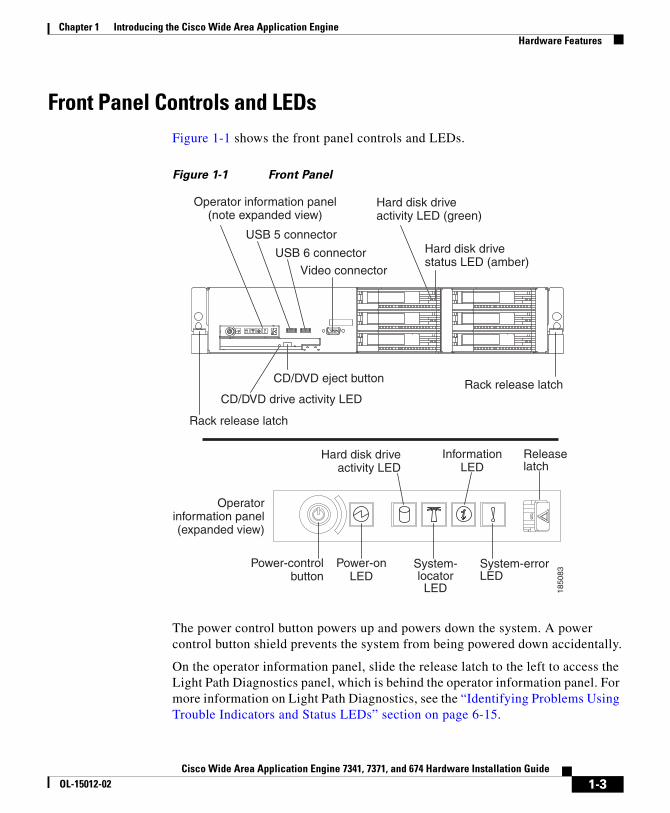
Front Panel Controls and LEDsFigure 1-1 shows the front panel controls and LEDs.
Figure 1-1 Front Panel
System-locatorLED
System-errorLED
Releaselatch
Power-onLED
Power-controlbutton
Hard disk driveactivity LED
InformationLED
Operatorinformation panel(expanded view)
1850
83
USB 5 connector
USB 6 connector
Video connector
Rack release latch
Rack release latchCD/DVD drive activity LED
CD/DVD eject button
Hard disk drivestatus LED (amber)
Hard disk driveactivity LED (green)
Operator information panel(note expanded view)
The power control button powers up and powers down the system. A power control button shield prevents the system from being powered down accidentally.
On the operator information panel, slide the release latch to the left to access the Light Path Diagnostics panel, which is behind the operator information panel. For more information on Light Path Diagnostics, see the “Identifying Problems Using Trouble Indicators and Status LEDs” section on page 6-15.
1-3Cisco Wide Area Application Engine 7341, 7371, and 674 Hardware Installation Guide
OL-15012-02

Chapter 1 Introducing the Cisco Wide Area Application Engine Hardware Features
Note The system software does not support the use of a keyboard or mouse (Personal System 2 [PS/2] or Universal Serial Bus [USB]). The BIOS does support a keyboard and a mouse for power-on self-test (POST) and the configuration/setup utility. To troubleshoot the BIOS boot process, you can connect a keyboard to any USB port and connect a monitor to the video connector. Video output is for troubleshooting only during the BIOS boot process. The video output stops displaying when the serial port becomes active. To monitor the boot process in normal operation, use the serial console port.
Table 1-1 describes the front panel LEDs and their functions.
Table 1-1 Front Panel LEDs
Color State Description
Power-on (on operator information panel)
Green On Flashing Off
Appliance is powered on. Appliance is powered off and still connected to an AC power source. AC power is not present. Power supply or LED has failed.
System-locator (on operator information panel)
Blue On Visually locates appliance among other appliances.
Hard disk drive activity (on operator information panel)
Green On There is activity on the SAS bus.
Information (on operator information panel)
Green On Noncritical error has occurred. An LED on the Light Path Diagnostics panel is also lit to help isolate the error.
System-error (on operator information panel)
Amber On System error has occurred. An LED on the Light Path Diagnostics panel is also lit to help isolate the error.
Hard disk drive activity Green Flashing Hard disk drive is in use.
1-4Cisco Wide Area Application Engine 7341, 7371, and 674 Hardware Installation Guide
OL-15012-02

Chapter 1 Introducing the Cisco Wide Area Application Engine Hardware Features
Figure 1-2 shows the location of back panel LEDs and connectors, and Table 1-2 describes the LED functions.
Figure 1-2 Back Panel LEDs and Connectors
Power-cordconnector
AC power LED
DC power LED
Powersupply 1
SASconnector
S -Ethernet connector
ystems management
Serialconnector Video
connector
USB 1connector
USB 2connector
USB 3connector
USB 4connector
Ethernet 2connector
Ethernet 1connector
Ethernetactivity LEDs
Ethernetlink LEDs
Power-on LEDSystem-locator LED
System-error LED 1850
85
Powersupply 2
Hard disk drive status Amber On Drive has failed.
Flashing slowly (one flash per second)
Drive is being rebuilt as part of a RAID configuration.
Flashing rapidly (three flashes per second)
Controller is identifying the drive.
CD/DVD drive activity Green On CD/DVD drive is in use.
Table 1-1 Front Panel LEDs (continued)
Color State Description
1-5Cisco Wide Area Application Engine 7341, 7371, and 674 Hardware Installation Guide
OL-15012-02

Chapter 1 Introducing the Cisco Wide Area Application Engine Hardware Features
Note You can connect a keyboard to any USB port and connect a monitor to the video connector to troubleshoot the BIOS boot process. However, video output is for troubleshooting only during the BIOS boot process. The video output stops displaying when the serial port becomes active. To monitor the boot process in normal operation, use the serial console port. The Serial Attached SCSI (SAS) connector is not supported. The systems-management Ethernet connector is not supported.
Table 1-2 Back Panel LEDs
Color State Description
Ethernet link Green On Active link connection on the 10BASE-T, 100BASE-TX, or 1000BASE-TX interface for the Ethernet port.
Ethernet activity Green On System is transmitting to or receiving signals from the Ethernet LAN that is connected to the Ethernet port.
Power-on Green On Flashing Off
Appliance is powered on. Appliance is powered off and still connected to an AC power source. AC power is not present. Power supply or LED has failed.
System-locator Blue On Visually locates the device among other devices.
System-error Amber On System error has occurred. An LED on the Light Path Diagnostics panel is also lit to help isolate the error.
AC Power Green On Sufficient AC power is coming into the power supply through the power cord. During typical operation, both the AC and the DC power LEDs are on.
DC Power Green On Power supply is supplying adequate DC power to the system. During typical operation, both the AC and the DC power LEDs are on.
1-6Cisco Wide Area Application Engine 7341, 7371, and 674 Hardware Installation Guide
OL-15012-02
Chapter 1 Introducing the Cisco Wide Area Application Engine Hardware Features
Location of Ports and ConnectorsThe WAE appliance supports two Ethernet connectors and one serial I/O connector on the front and back of the device.
• Ethernet Port Connectors
• Serial Port Connector
Figure 1-2 shows the back panel ports and connectors.
Warning To avoid electric shock, do not connect safety extra-low voltage (SELV) circuits to telephone-network voltage (TNV) circuits. LAN ports contain SELV circuits, and WAN ports contain TNV circuits. Some LAN and WAN ports both use RJ-45 connectors. Use caution when connecting cables. Statement 1021
Ethernet Port Connectors
Connect a Category 3, 4, or 5 unshielded twisted-pair cable to an Ethernet connector. 100BASE-TX and 1000BASE-T Fast Ethernet standards require Category 5 or higher cabling.
The WAE has three Ethernet connectors. Two of the Ethernet connectors are attached to the Ethernet controllers and the third connector is the systems-management Ethernet connector, which is not supported by the WAAS software.
The Ethernet controllers are integrated on the system board. They provide an interface for connecting to a 10-Mbps, 100-Mbps, or 1-Gbps network and provide full-duplex (FDX) capability, which enables simultaneous transmission and reception of data on the network. If the Ethernet ports in the server support auto negotiation, the controllers detect the data-transfer rate (10BASE-T, 100BASE-TX, or 1000BASE-T) and duplex mode (full duplex or half duplex) of the network and automatically operate at that rate and mode. You do not have to set any jumpers or configure the controllers.
If a problem occurs with the primary Ethernet connection, all Ethernet traffic associated with this primary connection is automatically switched to the redundant Ethernet connection. If the applicable device drivers are installed, switching occurs without data loss and without user intervention.
1-7Cisco Wide Area Application Engine 7341, 7371, and 674 Hardware Installation Guide
OL-15012-02

Chapter 1 Introducing the Cisco Wide Area Application Engine Hardware Features
Figure 1-3 Ethernet Port Connector
18
Link LED
(green)Activity LED
(green)
8319
5
Serial Port Connector
The WAE has one serial port connector. Use the serial port connector to connect a serial device.
Figure 1-4 Serial Port Connector
1 5
6 9
8319
3
1-8Cisco Wide Area Application Engine 7341, 7371, and 674 Hardware Installation Guide
OL-15012-02

Cisco Wide Area Application Engine 7341, 7371, aOL-15012-02
C H A P T E R 2
Preparing to Install the Wide Area Application EngineThis chapter contains important safety information that you should know before working with the WAE. Use the guidelines in this chapter to ensure your own personal safety and to help protect your appliance from potential damage.
This chapter contains the following sections:
• Safety Warnings, page 2-1
• Safety Guidelines, page 2-4
Note Read the Regulatory Compliance and Safety Information for the Cisco Content Networking Product Series document and the Site Preparation and Safety Guide that came with your appliance before you begin the installation.
Safety WarningsBefore you install the WAE, observe the following safety warnings.
Warning Only trained and qualified personnel should be allowed to install, replace, or service this equipment. Statement 1030
2-1nd 674 Hardware Installation Guide
Chapter 2 Preparing to Install the Wide Area Application Engine Safety Warnings
Warning Read the installation instructions before connecting the system to the power source. Statement 1004
Warning Before working on a system that has an on/off switch, turn OFF the power and unplug the power cord. Statement 1
Warning This unit might have more than one power supply connection. All connections must be removed to de-energize the unit. Statement 1028
Warning This unit is intended for installation in restricted access areas. A restricted access area is where access can only be gained by service personnel through the use of a special tool, lock and key, or other means of security, and is controlled by the authority responsible for the location. Statement 37
Warning To avoid electric shock, do not connect safety extra-low voltage (SELV) circuits to telephone-network voltage (TNV) circuits. LAN ports contain SELV circuits, and WAN ports contain TNV circuits. Some LAN and WAN ports both use RJ-45 connectors. Use caution when connecting cables. Statement 1021
Warning This product relies on the building’s installation for short-circuit (overcurrent) protection. Ensure that a fuse or circuit breaker no larger than 120 VAC, 15A U.S. (240 VAC, 10A international) is used on the phase conductors (all current-carrying conductors). Statement 13
Warning This equipment must be grounded. Never defeat the ground conductor or operate the equipment in the absence of a suitably installed ground conductor. Contact the appropriate electrical inspection authority or an electrician if you are uncertain that suitable grounding is available. Statement 1024
2-2Cisco Wide Area Application Engine 7341, 7371, and 674 Hardware Installation Guide
OL-15012-02

Chapter 2 Preparing to Install the Wide Area Application Engine Safety Warnings
Warning Do not work on the system or connect or disconnect cables during periods of lightning activity. Statement 1001
Warning Before working on equipment that is connected to power lines, remove jewelry (including rings, necklaces, and watches). Metal objects will heat up when connected to power and ground and can cause serious burns or weld the metal object to the terminals. Statement 43
Warning When installing or replacing the unit, the ground connection must always be made first and disconnected last. Statement 1046
Warning The safety cover is an integral part of the product. Do not operate the unit without the safety cover installed. Operating the unit without the cover in place will invalidate the safety approvals and pose a risk of fire and electrical hazards. Statement 117
Warning Blank faceplates and cover panels serve three important functions: they prevent exposure to hazardous voltages and currents inside the chassis; they contain electromagnetic interference (EMI) that might disrupt other equipment; and they direct the flow of cooling air through the chassis. Do not operate the system unless all cards, faceplates, front covers, and rear covers are in place. Statement 1029
Warning There is the danger of explosion if the battery is replaced incorrectly. Replace the battery only with the same or equivalent type recommended by the manufacturer. Dispose of used batteries according to the manufacturer’s instructions. Statement 1015
Warning Ultimate disposal of this product should be handled according to all national laws and regulations. Statement 1040
2-3Cisco Wide Area Application Engine 7341, 7371, and 674 Hardware Installation Guide
OL-15012-02
Chapter 2 Preparing to Install the Wide Area Application Engine Safety Guidelines
Warning Installation of the equipment must comply with local and national electrical codes. Statement 1074
Warning To prevent bodily injury when mounting or servicing this unit in a rack, you must take special precautions to ensure that the system remains stable. The following guidelines are provided to ensure your safety:
• This unit should be mounted at the bottom of the rack if it is the only unit in the rack.
• When mounting this unit in a partially filled rack, load the rack from the bottom to the top with the heaviest component at the bottom of the rack.
• If the rack is provided with stabilizing devices, install the stabilizers before mounting or servicing the unit in the rack. Statement 1006
Safety GuidelinesTo reduce the risk of bodily injury, electrical shock, fire, and damage to the equipment, observe the precautions in this section.
General PrecautionsObserve the following general precautions for using and working with the WAE:
• Observe and follow service markings. Do not service any Cisco product except as explained in your system documentation. Opening or removing covers that are marked with the triangular symbol with a lightning bolt may expose you to electrical shock. Components inside these compartments should be serviced only by a trained and qualified service technician.
2-4Cisco Wide Area Application Engine 7341, 7371, and 674 Hardware Installation Guide
OL-15012-02

Chapter 2 Preparing to Install the Wide Area Application Engine Safety Guidelines
• If any of the following conditions occur, unplug the product from the electrical outlet and replace the part or contact your customer service representative:
– The power cable or plug is damaged.
– An object has fallen into the product.
– The product has been exposed to water.
– The product has been dropped or damaged.
– The product does not operate correctly when you follow the operating instructions.
• Keep your system components away from radiators and heat sources. Also, do not block cooling vents.
• Do not spill food or liquids on your system components, and never operate the product in a wet environment.
• Do not push any objects into the openings of your system components. Doing so can cause fire or electric shock by shorting out interior components.
• Use the product only with other Cisco-approved equipment.
• Allow the product to cool before removing covers or touching internal components.
• Use the correct external power source. Operate the product only from the type of power source indicated on the electrical ratings label. If you are not sure of the type of power source required, consult your service representative or local power company.
• Use only approved power cables. If you have not been provided with a power cable for your WAE or for any AC-powered option intended for your system, purchase a power cable that is approved for use in your country. The power cable must be rated for the product and for the voltage and current marked on the product’s electrical ratings label. The voltage and current rating of the cable should be greater than the ratings marked on the product.
• To help prevent electric shock, plug the system components and peripheral power cables into properly grounded electrical outlets. These cables are equipped with three-prong plugs to help ensure proper grounding. Do not use adapter plugs or remove the grounding prong from a cable.
2-5Cisco Wide Area Application Engine 7341, 7371, and 674 Hardware Installation Guide
OL-15012-02
Chapter 2 Preparing to Install the Wide Area Application Engine Safety Guidelines
• Observe power strip ratings. Make sure that the total ampere rating of all products plugged into the power strip does not exceed 80 percent of the power strip ampere ratings limit.
• Do not use appliance or voltage converters or kits sold for appliances with your product.
• To help protect your system components from sudden, transient increases and decreases in electrical power, use a surge suppressor, line conditioner, or uninterruptible power supply (UPS).
• Position cables and power cords carefully; route cables and the power cord and plug so that they cannot be stepped on or tripped over. Be sure that nothing rests on your system components’ cables or power cord.
• Do not modify power cables or plugs. Consult a licensed electrician or your power company for site modifications. Always follow your local or national wiring rules.
System Reliability ConsiderationsTo help ensure proper cooling and system reliability, make sure the following occurs:
• Each of the drive bays has either a drive or a filler panel installed.
• Each of the power-supply bays has a power supply or a power supply-filler panel installed.
• For rack configurations, make sure that space is available around the appliance to enable the cooling system to work properly. See the documentation that comes with the rack for additional information.
• The appliance cover is in place during normal operation.
• The air baffle cover over the microprocessors remains closed during normal operation.
• The air baffle is installed between the fans and the power supply.
• A removed hot-swappable drive is replaced within 2 minutes of removal.
• Cables for optional adapters are routed according to the instructions provided with the adapters.
• A failed fan is replaced within 48 hours.
2-6Cisco Wide Area Application Engine 7341, 7371, and 674 Hardware Installation Guide
OL-15012-02

Chapter 2 Preparing to Install the Wide Area Application Engine Safety Guidelines
• The appliance is powered down and the power cords are disconnected before you open the air baffle cover.
• The air baffle assembly is always installed in the appliance except when you are installing or removing the components that are located under the air baffle cover.
• When the air baffle assembly is installed in the appliance, the air baffle cover is always closed.
• Microprocessor socket 2 always contains either a microprocessor baffle or a microprocessor.
Working Inside the WAE with the Power OnThe WAE is designed to operate safely with the cover removed for short periods (less than 30 minutes). You might need to remove the cover while the power is on, for example, to observe the Light Path diagnostic LEDs when troubleshooting. When you work inside an appliance that is powered on, follow these guidelines:
• Avoid loose-fitting clothing on your forearms. Button long-sleeved shirts before working inside the appliance; do not wear cuff links while you are working inside the appliance.
• Do not allow your necktie or scarf to hang inside the appliance.
• Remove jewelry, such as bracelets, necklaces, rings, and loose-fitting wristwatches.
• Remove items from your shirt pocket (such as pens or pencils) that could fall into the appliance as you lean over it.
• Do not drop any metallic objects, such as paper clips, hairpins, or screws, into the appliance.
• Be aware that there are hazardous moving parts exposed inside the appliance when the cover is removed.
2-7Cisco Wide Area Application Engine 7341, 7371, and 674 Hardware Installation Guide
OL-15012-02
Chapter 2 Preparing to Install the Wide Area Application Engine Safety Guidelines
Protecting Against Electrostatic DischargeStatic electricity can harm delicate components inside the appliance. To prevent static damage, discharge static electricity from your body before you touch any of your system’s electronic components. You can do so by touching an unpainted metal surface on the chassis.
You can also take the following steps to prevent damage from electrostatic discharge (ESD):
• When unpacking a static-sensitive component from its shipping carton, do not remove the component from the antistatic packing material until you are ready to install the component in your system. Just before unwrapping the antistatic packaging, be sure to discharge static electricity from your body.
• When transporting a sensitive component, first place it in an antistatic container or packaging.
• Handle all sensitive components in a static-safe area. If possible, use antistatic floor pads and workbench pads.
• Handle the device carefully, holding it by its edges or its frame.
• Do not touch solder joints, pins, or exposed printed circuitry.
• Do not leave the device where others can handle and possibly damage the device.
• Take additional care when handling devices during cold weather, because heating reduces indoor humidity and increases static electricity.
2-8Cisco Wide Area Application Engine 7341, 7371, and 674 Hardware Installation Guide
OL-15012-02

Cisco Wide Area Application Engine 7341, 7371, aOL-15012-02
C H A P T E R 3
Installing the Wide Area Application EngineThis chapter describes how to install a Wide Area Application Engine (WAE) in an equipment rack. It also provides general instructions for installing a WAE on a table or workbench. This chapter contains the following sections:
• Rack-Mounting Considerations, page 3-2
• Tools and Parts Required, page 3-3
• Installing the Wide Area Application Engine, page 3-5
• Connecting Cables, page 3-11
• Connecting Power and Booting the System, page 3-11
• Checking the LEDs, page 3-12
• Removing or Replacing a WAE, page 3-12
Before you begin the installation, read Chapter 2, “Preparing to Install the Wide Area Application Engine” and the Regulatory Compliance and Safety Information for the Cisco Content Networking Product Series document.
Warning Read the installation instructions before connecting the system to the power source. Statement 1004
3-1nd 674 Hardware Installation Guide

Chapter 3 Installing the Wide Area Application Engine Rack-Mounting Considerations
Rack-Mounting ConsiderationsBefore installing your WAE in a rack, review the following guidelines:
• Two or more people are required to install the device in a rack.
• Ensure that the room air temperature is below 95° F (35° C).
• Do not block any air vents; usually 6 inches (15 cm) of space provides proper airflow.
• Plan the device installation starting from the bottom of the rack.
• Install the heaviest device in the bottom of the rack.
• Do not extend more than one device out of the rack at the same time.
• Remove the rack doors and side panels to provide easier access during installation.
• Connect the WAE to a properly grounded outlet.
• Do not overload the power outlet when installing multiple devices in the rack.
Caution Use safe practices when lifting.
Caution Do not place any object weighing more than 110 lb (50 kg) on top of rack-mounted devices.
Caution Install the device only in a rack cabinet with perforated doors.
Rack RequirementsInstall your WAE in a rack that meets the following requirements:
• Minimum depth of 2.76 inches (70 mm) between the front mounting flange and inside of the front door.
• Minimum depth of 6.18 inches (157 mm) between the rear mounting flange and inside of the rear door.
3-2Cisco Wide Area Application Engine 7341, 7371, and 674 Hardware Installation Guide
OL-15012-02

Chapter 3 Installing the Wide Area Application Engine Tools and Parts Required
• Minimum depth of 28.27 inches (718 mm) and maximum depth of 30 inches (762 mm) between the front and rear mounting flanges to support the use of the cable-management arm.
Racks are marked in vertical increments of 1.75 inches (4.44 cm). Each increment is referred to as a rack unit (RU). A 1-RU device is 1.75 inches (4.44 cm) tall.
Tools and Parts RequiredA sliding rail rack-mount kit is included in your shipping container accessory box. The rack-mount kit is suitable for mounting the WAE-7371, WAE-7341, and WAE-674 appliances in 19-inch (48.26-cm), 4-post equipment racks. (See the “Rack Requirements” section on page 3-2.)
You need the following tools for the installation:
• Flat-blade screwdriver
• Phillips screwdriver
Figure 3-1 shows the items that you need to install the WAE in your rack or cabinet. If any items are missing or damaged, contact your customer service representative.
Warning To prevent bodily injury when mounting or servicing this unit in a rack, you must take special precautions to ensure that the system remains stable. The following guidelines are provided to ensure your safety:
• This unit should be mounted at the bottom of the rack if it is the only unit in the rack.
• When mounting this unit in a partially filled rack, load the rack from the bottom to the top with the heaviest component at the bottom of the rack.
• If the rack is provided with stabilizing devices, install the stabilizers before mounting or servicing the unit in the rack. Statement 1006
3-3Cisco Wide Area Application Engine 7341, 7371, and 674 Hardware Installation Guide
OL-15012-02

Chapter 3 Installing the Wide Area Application Engine Tools and Parts Required
Figure 3-1 Rack Installation Kit
1345
68
2
53
76
10
9
11
1
8
4
1 Cable-management assembly 7 Cable Clamp (5)
2 Cable-management arm bracket 8 Rear of rail
3 Hinge 9 Cable ties (5)
4 Cable strap (5) 10 M6 screws (5)
5 Cable-restraint bracket (2) 11 Front of rail
6 Slide rail (2)
Note The rack kit includes a left and a right slide rail.
3-4Cisco Wide Area Application Engine 7341, 7371, and 674 Hardware Installation Guide
OL-15012-02

Chapter 3 Installing the Wide Area Application Engine Installing the Wide Area Application Engine
Installing the Wide Area Application EnginePlace the WAE in the desired location. You can mount it in a rack or place it on a solid, stable surface. If you do not plan to install the appliance in an equipment rack, proceed to the “Installing the Chassis on a Tabletop” section on page 3-10.
To install the WAE in a rack, follow these steps:
Step 1 Push outward on the slide-rail latch (labeled 2 in Figure 3-2). Pull the latch back to open the slide rail. The latch will engage and stay open. Open the other end of the slide rail. Repeat the entire process for the other slide rail.
Note If you are installing the WAE in the top of the rack or directly under another device, remove the cable-management arm bracket from the cable-management assembly and install the cable-management arm bracket on the slide rail. Go to Step 6 to install the cable-management arm bracket, and continue with Step 2.
Figure 3-2 Latching the Slide Rails
1345
70
2
1
1 Right slide rail 2 Slide rail latch
3-5Cisco Wide Area Application Engine 7341, 7371, and 674 Hardware Installation Guide
OL-15012-02

Chapter 3 Installing the Wide Area Application Engine Installing the Wide Area Application Engine
Step 2 Align the slide rail with the front mounting flange. Use the score mark on the slide rail (labeled 1 in Figure 3-3) to align the slide rail. Push outward on the slide rail latch to close the latch and secure the slide rail. Do the same for the front of the other slide rail. Align the slide rail with the rear mounting flange. The slide rail occupies the full height of the device. Close the latches to secure the rear of both the slide rails.
Note Make sure that the slide rails are securely seated on the mounting flanges. When the slide is secure, the slide rail pins protrude from the slide rails.
Figure 3-3 Aligning the Slide Rails
1345
71
1
2
1 Slide rail score mark 2 Slide rail pins
Step 3 Extend the slide rails fully from the rack until the slide rails lock. Align the tabs on the slide rails (labeled 1 in Figure 3-4) with the matching inserts on the appliance and lower the appliance onto the slide rails.
Note Make sure that each slide rail tab is inserted in the matching insert on the appliance and that the appliance is resting on the top edge of the slide rail.
3-6Cisco Wide Area Application Engine 7341, 7371, and 674 Hardware Installation Guide
OL-15012-02
Chapter 3 Installing the Wide Area Application Engine Installing the Wide Area Application Engine
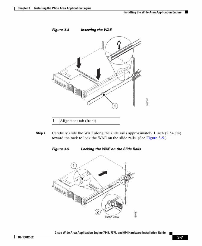
Figure 3-4 Inserting the WAE
1850
86
1
1 Alignment tab (front)
Step 4 Carefully slide the WAE along the slide rails approximately 1 inch (2.54 cm) toward the rack to lock the WAE on the slide rails. (See Figure 3-5.)
Figure 3-5 Locking the WAE on the Slide Rails
Rear view
1
2
1850
87
3-7Cisco Wide Area Application Engine 7341, 7371, and 674 Hardware Installation Guide
OL-15012-02

Chapter 3 Installing the Wide Area Application Engine Installing the Wide Area Application Engine
1 Lock indicator 2 Slide Rail Hooks
Note When locked in position, an indicator (labeled 1 in Figure 3-5) is visible on each side of the appliance. To remove the appliance from the rack, lift up on the lock indicator and slide the appliance forward.
Step 5 Lift the locking levers (labeled 1 in Figure 3-6) on the slide rails and slide the appliance into the rack until it extends approximately 4 inches (10.16 cm) from the edge of the rack.
Figure 3-6 Sliding in the WAE
1850
881
1 Locking levers
Step 6 Attach the cable-management assembly to the rear of the slide rail using a hinge pin (labeled 1 in Figure 3-7). Attach the free end of the cable-management assembly to the slide rail using a hinge pin.
3-8Cisco Wide Area Application Engine 7341, 7371, and 674 Hardware Installation Guide
OL-15012-02

Chapter 3 Installing the Wide Area Application Engine Installing the Wide Area Application Engine
Note If you installed the cable-management arm bracket in Step 1, complete the installation of the cable-management assembly.
Figure 3-7 Attaching the Cable-Management Assembly
1345
69
32
1
1 Hinge pin 3 Slide rail
2 Left mounting flange
Step 7 Attach the power cords and other cables to the rear of the WAE (including keyboard, monitor, and mouse, if required). Attach the power cords to the cable-restraint bracket. Secure the cable-restraint bracket to the slide rail.
Use cable clamps to secure the cables across the rear of the WAE. Route the cables along the cable-management arm channel, securing them with cable straps.
Note Allow slack in all cables to avoid tension in the cables.
3-9Cisco Wide Area Application Engine 7341, 7371, and 674 Hardware Installation Guide
OL-15012-02
Chapter 3 Installing the Wide Area Application Engine Installing the Wide Area Application Engine
Step 8 Slide the WAE into the rack until the release latches lock into place. To slide the WAE out of the rack, press the release latches.
Note Insert the optional M6 screws (labeled 10 in Figure 3-1) in the front and rear of the appliance when moving the rack, or if you install the rack in a vibration-prone area.
To remove the WAE from the rack, reverse these instructions. Store these installation instructions with your WAE documentation for future use.
Installing the Chassis on a TabletopWhen you install a WAE on a workbench or tabletop, ensure that the surface is clean and in a safe location and that you have considered the following points:
• The chassis should be installed off the floor. (Dust that accumulates on the floor is drawn into the interior of the chassis by the cooling fans. Excessive dust inside the WAE can cause overtemperature conditions and component failures.)
• There must be approximately 19 inches (48.26 cm) of clearance at the front and rear of the chassis for accessing network cables or equipment.
• The WAE will receive adequate ventilation (it is not being installed in an enclosed cabinet where ventilation is inadequate).
To install the WAE on a workbench or tabletop, follow these steps:
Step 1 Remove any debris and dust from the tabletop or workbench, as well as from the surrounding area. Also make sure that your path between the WAE and its new location is unobstructed.
Step 2 Attach the rubber feet to the bottom of the chassis. The rubber feet have an adhesive backing. Peel the protective tape off the adhesive and stick the feet to the bottom of a clean chassis surface. Place one foot in each corner.
Step 3 Place the chassis on the tabletop or workbench.
3-10Cisco Wide Area Application Engine 7341, 7371, and 674 Hardware Installation Guide
OL-15012-02

Chapter 3 Installing the Wide Area Application Engine Connecting Cables
Step 4 Ensure that no exhaust air from other equipment will be drawn into the chassis. Also make sure that there is adequate clearance at the front and rear of the chassis.
Connecting CablesTo connect cables to your WAE, follow these steps:
Step 1 Power down the appliance before connecting cables to or disconnecting any cables from the appliance.
Step 2 See the documentation that comes with your optional equipment for additional cabling instructions. It might be easier for you to route the cables before you install specific optional equipment.
Step 3 See the cable identifiers that are printed on the cables that come with the WAE and options. Use these identifiers to connect the cables to the correct connectors.
Figure 1-2 shows the locations of the input and output connectors on your device.
Connecting Power and Booting the SystemTo connect power to your system, follow these steps:
Step 1 Review the information in the “Safety Guidelines” section on page 2-4.
Step 2 Plug a power cord into each power cord receptacle on the back of the WAE.
Note For the WAE-7371 and WAE-7341 you must connect a power cord to both power supplies. If only one power supply is connected, when you turn on the power, the system error LED lights and the system makes a loud noise.
Step 3 Connect the other end of each power cord to a power source at your installation site.
3-11Cisco Wide Area Application Engine 7341, 7371, and 674 Hardware Installation Guide
OL-15012-02

Chapter 3 Installing the Wide Area Application Engine Checking the LEDs
Step 4 Power up all externally connected devices.
Step 5 Press the power control button on the front of the WAE.
The system should begin booting. Once the operating system boots, you are ready to initialize the basic software configuration. (See the software configuration guide for details.)
Note While the WAE is powering up, the green power-on LED on the front of the WAE is on.
Checking the LEDsWhen the WAE is up and running, observe the front panel LEDs (see Figure 1-1 and Table 1-1) to verify that your system is operating properly.
To troubleshoot using the LEDs, see Chapter 6, “Troubleshooting the System Hardware.”
Removing or Replacing a WAETo remove a WAE from your network, power it down, disconnect the power cords and network cables, and physically remove the chassis from the rack.
The WAE is in constant communication with the router on your network. When the router notices that the WAE is no longer responding to it, the router stops sending requests to the WAE. This action is transparent to users. If other WAEs are attached to the router, the router continues sending requests to the other WAEs.
When you remove a WAE, the pages that were cached on that device are no longer available to the router or other WAEs. You might see an increase in outgoing web traffic that might have otherwise been fulfilled by the WAE that you are removing. However, after a time, the router and other WAEs redistribute the load of web traffic.
3-12Cisco Wide Area Application Engine 7341, 7371, and 674 Hardware Installation Guide
OL-15012-02
Chapter 3 Installing the Wide Area Application Engine Removing or Replacing a WAE
If you remove the last WAE from your network, you can also disable WAE support on the router. However, this action is not necessary because leaving WAE support enabled when there are no WAEs attached has no effect on the router’s performance.
To replace a WAE, remove it from the network, and then install a new WAE and configure it using the same configuration parameters (IP address and so forth) that you used for the removed WAE.
3-13Cisco Wide Area Application Engine 7341, 7371, and 674 Hardware Installation Guide
OL-15012-02

Chapter 3 Installing the Wide Area Application Engine Removing or Replacing a WAE
3-14Cisco Wide Area Application Engine 7341, 7371, and 674 Hardware Installation Guide
OL-15012-02
Cisco Wide Area Application Engine 7341, 7371, aOL-15012-02
C H A P T E R 4
Installing Hardware Options for the WAE-7371, WAE-7341, and WAE-674This chapter provides basic instructions for installing hardware options in your Wide Area Application Engine (WAE). These instructions are intended for technicians who are experienced with setting up Cisco WAE hardware.
This chapter contains the following sections:
• Removing the Cover, page 4-1
• Working with Adapters, page 4-3
• Completing the Installation, page 4-8
• Installing Memory in a WAE-674, page 4-9
• Replacing a Hard Disk Drive, page 4-13
• Replacing a Power Supply, page 4-15
Removing the Cover
Warning Before working on a system that has an on/off switch, turn OFF the power and unplug the power cord. Statement 1
To remove the device top cover, follow these steps:
4-1nd 674 Hardware Installation Guide

Chapter 4 Installing Hardware Options for the WAE-7371, WAE-7341, and WAE-674 Removing the Cover
Step 1 Review the information in the “Safety Warnings” section on page 2-1 and the “Safety Guidelines” section on page 2-4.
Step 2 Power off the device and all attached devices and disconnect all external cables and power cords.
Step 3 Press down on the left and right side latches and pull the device out of the rack enclosure until both slide rails lock.
Note You can reach the cables on the back of the device when the device is in the locked position.
Step 4 Lift the cover-release latch (as shown in Figure 4-1). Lift the cover off the device and set the cover aside.
Figure 4-1 Removing the Cover
Cover-release latch
1850
89
4-2Cisco Wide Area Application Engine 7341, 7371, and 674 Hardware Installation Guide
OL-15012-02

Chapter 4 Installing Hardware Options for the WAE-7371, WAE-7341, and WAE-674 Working with Adapters
Caution For proper cooling and airflow, replace the cover before turning on the device. Operating the device for extended periods (over 30 minutes) with the cover removed might damage device components.
Working with AdaptersThe WAE-7371, WAE-7341, and WAE-674 have connectors for up to four PCI adapters on the system board and PCI riser card.
Before you install an adapter, review the following information:
• Locate the documentation that comes with the adapter and follow those instructions in addition to the instructions in this chapter. If you need to change the switch or jumper settings on your adapter, follow the instructions that come with the adapter.
• PCI-X slots 1 and 2, on the riser card, support standard full-length adapters, such as the Cisco WAE Inline Network Adapter.
• PCI Express slots 3 and 4, on the system board, support low-profile adapters, but are not used for any WAE adapters.
• PCI-X slot 1 and slot 2 are 64-bit slots and support only 3.3-V and universal PCI adapters.
• The PCI bus configuration is as follows:
– Non-hot-plug, low-profile PCI Express x8 (x4 lanes), slot 4
– Non-hot-plug, low-profile PCI Express x8 (x4 lanes), slot 3
– Non-hot-plug, 64-bit PCI-X slot 2 (133 MHz)
– Non-hot-plug, 64-bit PCI-X slot 1 (133 MHz)
• The system scans PCI slots 1 through 4 to assign system resources. The system starts (boots) the system devices in the following order, if you have not changed the default boot precedence:
– Integrated Ethernet controller
– Integrated Serial Attached SCSI (SAS) controller
4-3Cisco Wide Area Application Engine 7341, 7371, and 674 Hardware Installation Guide
OL-15012-02

Chapter 4 Installing Hardware Options for the WAE-7371, WAE-7341, and WAE-674 Working with Adapters
– PCI slots 1, 2, 3, and 4.
For information about the features of the Cisco WAE Inline Network Adapter and its cabling requirements, see Chapter 5, “WAE Inline Network Adapter.”
Installing an Adapter To install a PCI-X adapter in the riser-card assembly, follow these steps:
Step 1 Review the information in the “Safety Warnings” section on page 2-1 and the “Safety Guidelines” section on page 2-4.
Step 2 Power down the device and peripheral devices and disconnect all power cords and external cables.
Step 3 Remove the cover. (See the “Removing the Cover” section on page 4-1.)
Step 4 Remove the PCI-X riser-card assembly. (See Figure 4-2.) Push the two riser-card assembly release tabs toward the PCI-X slots. Grasp the assembly at the rear and side edges and lift it to remove it from the WAE. Place the riser-card assembly on a flat, static-protective surface.
4-4Cisco Wide Area Application Engine 7341, 7371, and 674 Hardware Installation Guide
OL-15012-02

Chapter 4 Installing Hardware Options for the WAE-7371, WAE-7341, and WAE-674 Working with Adapters
Figure 4-2 Removing the PCI-X Riser-Card Assembly
Access holes
Release tabs
1850
90
Step 5 Determine which expansion slot that you will use for the adapter. You can install the Cisco WAE Inline Network Adapter card in slot 1 or slot 2 on the riser-card.
Step 6 Slide the expansion-slot cover out of the PCI-X riser-card assembly expansion slot.
Step 7 Install the adapter, as shown in Figure 4-3. The riser-card assembly is shown inverted in Figure 4-3.
4-5Cisco Wide Area Application Engine 7341, 7371, and 674 Hardware Installation Guide
OL-15012-02

Chapter 4 Installing Hardware Options for the WAE-7371, WAE-7341, and WAE-674 Working with Adapters
Figure 4-3 Installing the Adapter in the Riser-Card Assembly
Inverted riser assembly 1850
91
Step 8 Connect any needed cables to the adapter.
Caution When you route cables, do not block any connectors or the ventilated space around any of the fans. Make sure that cables are not routed on top of components under the PCI-X riser-card assembly. Make sure that cables are not pinched by the device components.
Step 9 Carefully align the riser-card assembly with the release tab posts, the guides on the rear of the WAE, and the riser-card connector on the system board. Press down on the assembly. (See Figure 4-4.) Make sure that the riser-card assembly is fully seated in the riser-card connector on the system board.
4-6Cisco Wide Area Application Engine 7341, 7371, and 674 Hardware Installation Guide
OL-15012-02

Chapter 4 Installing Hardware Options for the WAE-7371, WAE-7341, and WAE-674 Working with Adapters
Figure 4-4 Installing the PCI-X Riser-Card Assembly
Access holes
Release tabs
Guide
Guide
1850
92
Step 10 Perform any configuration tasks required for the adapter.
Step 11 Reinstall the cover.
For instructions on completing the installation, see the “Completing the Installation” section on page 4-8.
4-7Cisco Wide Area Application Engine 7341, 7371, and 674 Hardware Installation Guide
OL-15012-02

Chapter 4 Installing Hardware Options for the WAE-7371, WAE-7341, and WAE-674 Completing the Installation
Completing the InstallationTo complete your installation, follow these steps:
Step 1 Install the top cover by placing the cover-release latch in the open (up) position. Insert the bottom tabs of the top cover into the matching slots in the WAE chassis. Press down on the cover-release latch to lock the cover in place, as shown in Figure 4-5.
Figure 4-5 Installing the Cover
Cover-release latch
1850
93
Step 2 Install the device in a rack.
For complete rack installation and removal instructions, see Chapter 3, “Installing the Wide Area Application Engine.”
Caution Install the device only in a rack cabinet with perforated doors.
4-8Cisco Wide Area Application Engine 7341, 7371, and 674 Hardware Installation Guide
OL-15012-02

Chapter 4 Installing Hardware Options for the WAE-7371, WAE-7341, and WAE-674 Installing Memory in a WAE-674
Caution Do not leave open spaces above or below an installed device in the rack cabinet. To help prevent damage to device components, always install a blank filler panel to cover the open space and to help ensure proper air circulation. See the documentation that comes with your rack cabinet for more information.
Step 3 Connect the cables and power cords. For information on connecting cables and power cords, see the “Connecting Cables” section on page 3-11.
Installing Memory in a WAE-674The WAE-674 features 4 GB of RAM. You can install an additional 4 GB of RAM to give your WAE-674 a total of 8 GB of RAM. This section describes how to install the optional 4 GB memory upgrade, which includes two 2-GB DIMMs.
To install additional memory in your WAE-674, follow these steps:
Step 1 Review the information in the “Safety Warnings” section on page 2-1 and the “Safety Guidelines” section on page 2-4.
Step 2 Power off the device and all attached devices and disconnect all external cables and power cords.
Step 3 Remove the device top cover. See the “Removing the Cover” section on page 4-1.
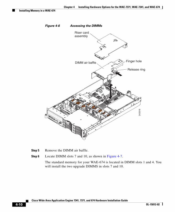
Step 4 Remove the riser-card assembly as shown in Figure 4-6.
4-9Cisco Wide Area Application Engine 7341, 7371, and 674 Hardware Installation Guide
OL-15012-02
Chapter 4 Installing Hardware Options for the WAE-7371, WAE-7341, and WAE-674 Installing Memory in a WAE-674
Figure 4-6 Accessing the DIMMs
DIMM air baffle Finger hole
Release ring
2433
16
Riser cardassembly
Step 5 Remove the DIMM air baffle.
Step 6 Locate DIMM slots 7 and 10, as shown in Figure 4-7.
The standard memory for your WAE-674 is located in DIMM slots 1 and 4. You will install the two upgrade DIMMS in slots 7 and 10.
4-10Cisco Wide Area Application Engine 7341, 7371, and 674 Hardware Installation Guide
OL-15012-02

Chapter 4 Installing Hardware Options for the WAE-7371, WAE-7341, and WAE-674 Installing Memory in a WAE-674
Figure 4-7 Locating the DIMM slots
DIMM 1
DIMM 4
DIMM 7
DIMM 10
2433
14
Step 7 Open the retaining clip on each end of the DIMM connector for slots 7 and 10, as shown in Figure 4-8.
4-11Cisco Wide Area Application Engine 7341, 7371, and 674 Hardware Installation Guide
OL-15012-02
Chapter 4 Installing Hardware Options for the WAE-7371, WAE-7341, and WAE-674 Installing Memory in a WAE-674
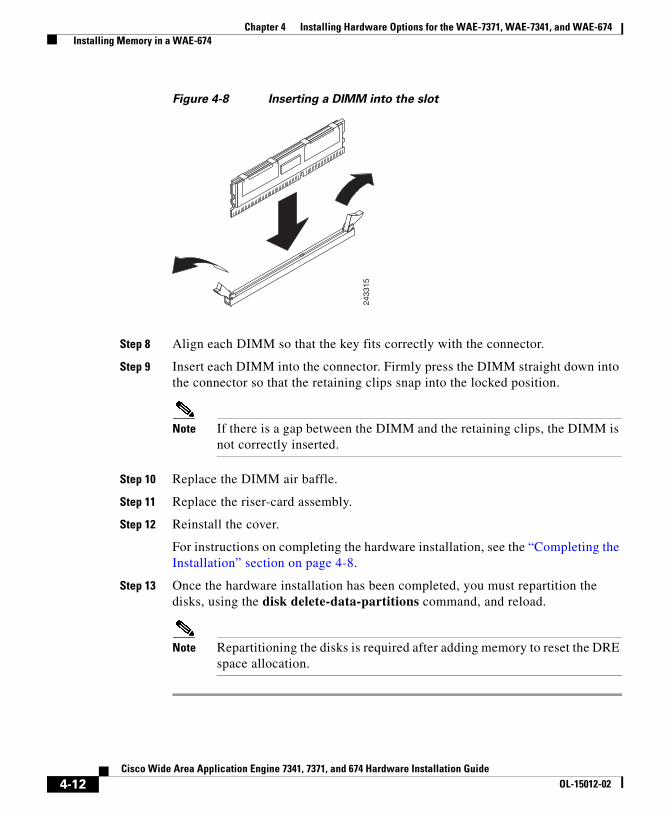
Figure 4-8 Inserting a DIMM into the slot
2433
15
Step 8 Align each DIMM so that the key fits correctly with the connector.
Step 9 Insert each DIMM into the connector. Firmly press the DIMM straight down into the connector so that the retaining clips snap into the locked position.
Note If there is a gap between the DIMM and the retaining clips, the DIMM is not correctly inserted.
Step 10 Replace the DIMM air baffle.
Step 11 Replace the riser-card assembly.
Step 12 Reinstall the cover.
For instructions on completing the hardware installation, see the “Completing the Installation” section on page 4-8.
Step 13 Once the hardware installation has been completed, you must repartition the disks, using the disk delete-data-partitions command, and reload.
Note Repartitioning the disks is required after adding memory to reset the DRE space allocation.
4-12Cisco Wide Area Application Engine 7341, 7371, and 674 Hardware Installation Guide
OL-15012-02
Chapter 4 Installing Hardware Options for the WAE-7371, WAE-7341, and WAE-674 Replacing a Hard Disk Drive
Replacing a Hard Disk DriveThe WAE supports as many as six 1-inch (26-mm) slim, 3.5-inch hard disk drives installed on Ultra-Slim hard disk drive trays for 3.5-inch drives.
You can replace one disk drive at a time in the RAID-5 disk array. If multiple hard disks fail, the RAID-5 logical drive automatically goes into the Offline state.
Note All hard disk drives being used in the device must be identical.
Note The SCSI ID assigned to each bay is printed on the bezel.
Caution To maintain proper system cooling, do not operate the device for more than 10 minutes without either a hard disk drive or a filler panel installed in each bay.
To replace a hard disk drive in a bay, follow these steps:
Step 1 Review the information in the “Safety Warnings” section on page 2-1 and the “Safety Guidelines” section on page 2-4.
Step 2 Enter the disk disk-name diskxx replace command in EXEC mode at the WAAS CLI on the WAE.
Step 3 Verify that the disk drive diskxx is in the Defunct state by entering the show disks details command in EXEC mode. The RAID logical drive is in the Critical state at this point.
Step 4 Move the handle (see Figure 4-9) on the drive to the open position (perpendicular to the drive).
4-13Cisco Wide Area Application Engine 7341, 7371, and 674 Hardware Installation Guide
OL-15012-02

Chapter 4 Installing Hardware Options for the WAE-7371, WAE-7341, and WAE-674 Replacing a Hard Disk Drive
Figure 4-9 Replacing a Hard Disk Drive
Tray handle
Hard disk drive
1850
94
Step 5 Pull the hot-swap drive assembly from the bay.
Step 6 Wait for 1 minute and then insert the new drive into the same slot by aligning the replacement drive assembly with guide rails in the bay and sliding the drive assembly into the bay until it stops. Make sure that the drive is properly seated in the bay.
Note Be sure there is no data on the replacement drive. The replacement hard drive should be new or newly-formatted.
Step 7 Close the drive handle.
Step 8 Check the hard disk drive status LED to verify that the hard disk drive is operating correctly. If the amber hard disk drive status LED for a drive is lit continuously, that drive is faulty and must be replaced. If the green hard disk drive activity LED is flashing, the drive is being accessed.
Step 9 Wait 1 minute and then verify that the replaced disk drive is in the Rebuilding state by using the show disks details command in EXEC mode.
Note The ServeRAID controller automatically starts the rebuild operation when it detects the removal and reinsertion of a drive that is part of the logical RAID drive.
4-14Cisco Wide Area Application Engine 7341, 7371, and 674 Hardware Installation Guide
OL-15012-02

Chapter 4 Installing Hardware Options for the WAE-7371, WAE-7341, and WAE-674 Replacing a Power Supply
Step 10 Wait until the rebuild operation is complete. You can check if the rebuild operation is complete by using the show disk details command in EXEC mode. The physical drive state will be Online and the RAID logical drive state will be Okay after the rebuild operation is completed.
A 300 GB SAS drive may take up to 5 hours to finish rebuilding.
If you have multiple disk failures and your RAID-5 logical status is Offline, you must recreate the RAID-5 array. For more information on disk removal and replacement procedures, see the Cisco Wide Area Application Services Configuration Guide, Chapter 15, “Maintaining Your WAAS System.”
Replacing a Power SupplyThe WAE supports two hot-swap power supplies.
Note If the device has two power supplies and you remove either of them, the device will not have redundant power; if the device power load exceeds 835 W, the device might not start or might not function correctly.
Warning Never remove the cover on a power supply or any part that has the following label attached.
1850
95
Hazardous voltage, current, and energy levels are present inside any
4-15Cisco Wide Area Application Engine 7341, 7371, and 674 Hardware Installation Guide
OL-15012-02

Chapter 4 Installing Hardware Options for the WAE-7371, WAE-7341, and WAE-674 Replacing a Power Supply
component that has this label attached. There are no serviceable parts inside these components. If you suspect a problem with one of these parts, contact a service technician.
To replace a power supply, complete the following steps:
1. Disconnect the power cord from the AC power supply that you are removing.
2. Grasp the power supply handle.
3. Press the orange release latch down and hold it down.
4. Pull the power supply part of the way out of the bay, as shown in Figure 4-10.
Figure 4-10 Replacing a Power Supply
1850
96
Hot-swappower supply
Power supplyrelease lever
Power supplyhandle
5. Release the release latch. Support the power supply underneath and pull it the rest of the way out of the bay.
4-16Cisco Wide Area Application Engine 7341, 7371, and 674 Hardware Installation Guide
OL-15012-02

Chapter 4 Installing Hardware Options for the WAE-7371, WAE-7341, and WAE-674 Replacing a Power Supply
6. Slide the replacement AC power supply into the bay until the retention latch clicks into place.
7. Connect the power cord for the new AC power supply to the power-cord connector on the power supply.
8. Route the power cord through the power-supply handle and through any cable clamps on the rear of the device to prevent the power cord from being accidentally pulled out when you slide the device in and out of the rack.
9. Connect the power cord to a properly grounded electrical outlet.
10. Make sure that the DC power LED and AC power LED on the power supply are lit, indicating that the power supply is operating correctly.
4-17Cisco Wide Area Application Engine 7341, 7371, and 674 Hardware Installation Guide
OL-15012-02

Chapter 4 Installing Hardware Options for the WAE-7371, WAE-7341, and WAE-674 Replacing a Power Supply
4-18Cisco Wide Area Application Engine 7341, 7371, and 674 Hardware Installation Guide
OL-15012-02

Cisco Wide Area Application Engine 7341, 7371, aOL-15012-02
C H A P T E R 5
WAE Inline Network AdapterThis chapter describes the following features of the Cisco WAE inline network adapter.
• Inline Network Adapter Description, page 5-1
• Ports and LED Indicators, page 5-3
• Inline Network Adapter Cabling Requirements, page 5-5
• Installation Scenarios and Cabling Examples for Fast Ethernet Connections, page 5-9
For adapter specifications, see Table A-2 in Appendix A.
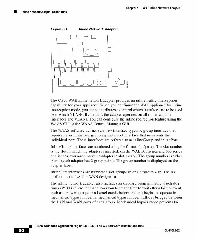
Inline Network Adapter DescriptionThe WAE appliance supports one optional 4-port Ethernet inline network adapter. The inline network adapter is a full-height, three-quarter-length PCI-X network interface card that contains four independent Gigabit Ethernet ports. (See Figure 5-1.)
5-1nd 674 Hardware Installation Guide
Chapter 5 WAE Inline Network Adapter Inline Network Adapter Description
Figure 5-1 Inline Network Adapter
1597
01
The Cisco WAE inline network adapter provides an inline traffic interception capability for your appliance. When you configure the WAE appliance for inline interception mode, you can set attributes to control which interfaces are to be used over which VLANs. By default, the adapter operates on all inline-capable interfaces and VLANs. You can configure the inline redirection feature using the WAAS CLI or the WAAS Central Manager GUI.
The WAAS software defines two new interface types: A group interface that represents an inline pair grouping and a port interface that represents the individual port. These interfaces are referred to as inlineGroup and inlinePort.
InlineGroup interfaces are numbered using the format slot/group. The slot number is the slot in which the adapter is inserted. (In the WAE 500 series and 600 series appliances, you must insert the adapter in slot 1 only.) The group number is either 0 or 1 (each adapter has 2 group pairs). The group number is displayed on the adapter label.
InlinePort interfaces are numbered slot/group/lan or slot/group/wan. The last attribute is the LAN or WAN designator.
The inline network adapter also includes an onboard programmable watch dog timer (WDT) controller that allows you to set the time to wait after a failure event, such as a power outage or a kernel crash, before the unit begins to operate in mechanical bypass mode. In mechanical bypass mode, traffic is bridged between the LAN and WAN ports of each group. Mechanical bypass mode prevents the
5-2Cisco Wide Area Application Engine 7341, 7371, and 674 Hardware Installation Guide
OL-15012-02
Chapter 5 WAE Inline Network Adapter Ports and LED Indicators
WAE from becoming a single point of failure and allows traffic to continue to flow between the router and the client while it passes through an unresponsive WAE without being processed.
For more information about configuring the inline network adapter, see the Cisco Wide Area Application Services Configuration Guide.
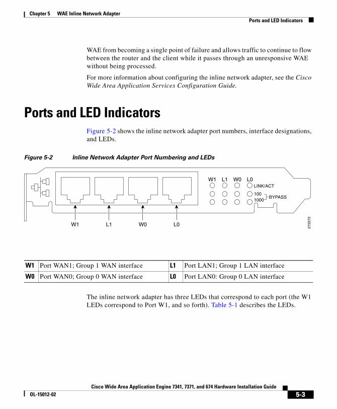
Ports and LED IndicatorsFigure 5-2 shows the inline network adapter port numbers, interface designations, and LEDs.
Figure 5-2 Inline Network Adapter Port Numbering and LEDs
W1 L1 W0 L0LINK/ACT
1001000
BYPASS
W1 L1 W0 L0
2720
72
W1 Port WAN1; Group 1 WAN interface L1 Port LAN1; Group 1 LAN interface
W0 Port WAN0; Group 0 WAN interface L0 Port LAN0: Group 0 LAN interface
The inline network adapter has three LEDs that correspond to each port (the W1 LEDs correspond to Port W1, and so forth). Table 5-1 describes the LEDs.
5-3Cisco Wide Area Application Engine 7341, 7371, and 674 Hardware Installation Guide
OL-15012-02

Chapter 5 WAE Inline Network Adapter Adapter Specifications
Table 5-1 Inline Network Adapter LEDs
LEDs State Description
Link / Activity On The 10/100/1000BASE-T interface is receiving power.
Blinking The Ethernet link is transmitting data.
100 On The speed of the Ethernet connection is 100BASE-TX.
1000 On The speed of the Ethernet connection is 1000BASE-TX.
Bypass Both the 100 and 1000 LEDs are on
The corresponding ports are in mechanical bypass mode.
Note On older inline network adapters, the LEDs are labelled 0, 1, 2, and 3. These correspond to W1, L1, W0, and L0 respectively.
Adapter SpecificationsTable 5-2 describes the inline network adapter technical and general specifications.
Table 5-2 Inline Network Adapter Specifications
Specification Description
Copper Gigabit Ethernet Specifications
IEEE standard Gigabit Ethernet, 1000BASE-T
Fast Ethernet, 100BASE-T
Ethernet, 10BASE-T
Full duplex and half duplex Supports both half-duplex and full-duplex operation in all operating speeds
Autonegotiation Autonegotiates between full-duplex and half-duplex operations and between 1000-Mbps, 100-Mbps, and 10-Mbps speeds
5-4Cisco Wide Area Application Engine 7341, 7371, and 674 Hardware Installation Guide
OL-15012-02

Chapter 5 WAE Inline Network Adapter Inline Network Adapter Cabling Requirements
Inline Network Adapter Cabling RequirementsThe inline network adapter ships with two types of cables: crossover and straight-through. When you connect the WAE inline network adapter, the cable that you use depends on the link speed (Gigabit Ethernet or Fast Ethernet) and the types of devices (DCE or DTE) being connected.
Data transfer rate 1000-Mbps, 100-Mbps, and 10-Mbps speeds per port in half-duplex mode
2000-Mbps, 200-Mbps, and 20-Mbps speeds per port in full-duplex mode
General Technical Specifications
Interface standard PCI v2.2 32/64 bit, 33/66 MHz
PCI-X v1.0 32/64 bit, 66/100/133 MHz
Size 6.6 x 4.2 in. (167.64 x 106.68 mm)
PCI connector Universal 64-bit connector
PCI voltage +12 V (minimum 11.4 V, maximum 12.6 V)
+3.3 V (minimum 3.0 V, maximum 3.6 V)
Weight 6.18 oz (175 g)
Operating humidity 0 to 90%, noncondensing
Operating temperature 32 to –122oF (0 to 50oC)
Storage temperature –4 to –149oF (–20 to –65oC)
Table 5-2 Inline Network Adapter Specifications (continued)
Specification Description
5-5Cisco Wide Area Application Engine 7341, 7371, and 674 Hardware Installation Guide
OL-15012-02

Chapter 5 WAE Inline Network Adapter Inline Network Adapter Cabling Requirements
Note You must retain the same link speed from one end of the connection to the other end. Inline adapter interfaces are able to autonegotiate link speeds. If you configure any of your connecting interfaces for Fast Ethernet (whether on a switch or a router), your WAE inline adapter uses Fast Ethernet. If you configure any of your connecting interfaces for Gigabit Ethernet, your WAE inline adapter uses Gigabit Ethernet. Speed and duplex settings are port specific so that two inline ports can negotiate different speeds independently.
If you are connecting a WAE inline appliance between two devices using Gigabit Ethernet, you can use either straight-through cables, crossover cables, or any combination of the two cable types, regardless of the type of device. However, for consistency, we recommend that you use straight-through cables for all Gigabit Ethernet connections.
Table 5-3 shows the cable requirements for WAE and non-WAE connections when you are using Gigabit Ethernet end to end.
Table 5-3 Cable Requirements for WAE Connections Using Gigabit
Ethernet
Connection Required Cable
Switch to switch (no WAE) Crossover or straight-through
Switch to router (no WAE) Crossover or straight-through
Router to router (no WAE) Crossover or straight-through
Switch to WAE and
WAE to Router
Crossover or straight-through
Crossover or straight-through
Switch to WAE and
WAE to Switch
Crossover or straight-through
Crossover or straight-through
Router to WAE and
WAE to Router
Crossover or straight-through
Crossover or straight-through
WAE to WAE Crossover or straight-through
Some switches support automatic medium-dependent interface crossover (MDIX). You can configure MDIX by using the mdix auto global configuration switch command. If your switch supports MDIX, you do not need to follow these
5-6Cisco Wide Area Application Engine 7341, 7371, and 674 Hardware Installation Guide
OL-15012-02
Chapter 5 WAE Inline Network Adapter Inline Network Adapter Cabling Requirements
cabling rules because MDIX automatically adjusts transmit and receive pairs when an incorrect cable type (crossover or straight-through) is installed on a 10/100 Fast Ethernet port. However, when you configure MDIX, you must also configure the port to use autosense (not manual selection of speed/duplex).
Caution If you are connecting to Fast Ethernet ports on both the LAN and the WAN sides of the WAE inline appliance, you must consider the types of devices that are being connected, and you must use the correct cables. You must follow these cabling instructions for the inline network adapter to work properly. (See Table 5-4. For illustrations and examples, see the “Installation Scenarios and Cabling Examples for Fast Ethernet Connections” section on page 5-9.)
To connect the inline network adapter using the correct cables for Fast Ethernet connections, follow these steps:
Step 1 Determine the type of cable that you would use for a direct connection between your two end devices (without a WAE inline network appliance connected between them) by using the following standard cabling rules:
• When you are directly connecting two network devices that are similar, such as two switches, use a crossover cable.
• When you are directly connecting two network devices that are different, such as a switch and router, use a straight-through cable.
Note Because the inline network adapter has an internal crossover connection that becomes active when the InlineGroup interface is placed in mechanical bypass mode, you must decide which cable you would use to connect the two network devices directly, and then you must install the other cable type (on one side, usually the WAN side of the inline appliance) instead.
Table 5-4 shows the cable requirements for WAE and non-WAE connections when you are using Fast Ethernet end to end.
5-7Cisco Wide Area Application Engine 7341, 7371, and 674 Hardware Installation Guide
OL-15012-02

Chapter 5 WAE Inline Network Adapter Inline Network Adapter Cabling Requirements
Table 5-4 Cable Requirements for WAE Connections Using Fast Ethernet
Connection Required Cable
Switch to switch (no WAE) Crossover
Switch to router (no WAE) Straight-through
Router to router (no WAE) Crossover
Switch to WAE and
WAE to Router
Straight-through
Crossover
Switch to WAE and
WAE to Switch
Straight-through
Straight-through
Router to WAE and
WAE to Router
Straight-through
Straight-through
WAE to WAE Crossover
Step 2 Connect Fast Ethernet ports on both the LAN and the WAN sides of the WAE inline appliance by using the following cable types:
• On the LAN side of the connection, use a straight-through cable between the WAE inline appliance and the network device.
• On the WAN side of the connection, use the cable that is different from the cable that you would use to connect the two network devices directly (as determined in Step 1).
For example, if you are connecting a router and a switch (two different devices) through the WAE inline appliance, use a straight-through cable on the LAN side of the connection and use a crossover cable on the WAN side of the connection. (If you were connecting the two different devices directly, you would use a straight-through cable, so use the crossover cable instead.)
If you are connecting two switches (or two similar devices), use straight-through cables on both the LAN and the WAN sides of the WAE inline appliance.
Figure 5-3 through Figure 5-5 show which cables to use for the WAE LAN and WAN connections between Fast Ethernet ports.
5-8Cisco Wide Area Application Engine 7341, 7371, and 674 Hardware Installation Guide
OL-15012-02

Chapter 5 WAE Inline Network Adapter Installation Scenarios and Cabling Examples for Fast Ethernet Connections
Installation Scenarios and Cabling Examples for Fast Ethernet Connections
WAE appliances can be installed physically between two network devices (such as the branch office router and branch office LAN switch) by connecting the WAE inline network adapter ports to the network devices using the proper cables.
If you are connecting a WAE inline appliance between two devices using Gigabit Ethernet, you can use either straight-through cables, crossover cables, or any combination of the two cable types, regardless of the type of device. This section shows cabling examples for Fast Ethernet connections only, because Fast Ethernet has specific cabling requirements.
The inline network adapter has four ports that are divided into two inline groups (see the “Ports and LED Indicators” section on page 5-3). The WAE can be physically placed inline between two distinct network paths, creating redundant WAN links. (See Figure 5-3.)
Two WAEs with inline network adapters can also be installed back-to-back in a serial fashion between two network devices for failover purposes. In this serial cluster configuration, if one WAE fails or becomes overloaded, the other WAE can provide optimization. (See Figure 5-4.)
Note When you connect two WAE inline appliances to each other serially, always use a crossover cable between the two WAEs. (See Figure 5-5.)
5-9Cisco Wide Area Application Engine 7341, 7371, and 674 Hardware Installation Guide
OL-15012-02

Chapter 5 WAE Inline Network Adapter Installation Scenarios and Cabling Examples for Fast Ethernet Connections
Figure 5-3 Cabling for a Single Inline WAE with Redundant WAN Connections
MGMT
2400
87
WAE
WAN
WAN
Router A
Router B
LAN switch
1
4
5
2
3
1 Connection: Management
Gigabit Ethernet: 1/0
Cable type: Straight-through (recommended)
2 Connection: WAE to LAN switch (using InlineGroup 1/0)
Fast Ethernet: LAN0 (InlinePort 1/0/lan)
Cable type: Straight-through
3 Connection: WAE to LAN switch (using InlineGroup 1/1)
Fast Ethernet: LAN1 (InlinePort 1/1/lan)
Cable type: Straight-through
4 Connection: WAE to WAN router A (using InlineGroup 1/0)
Fast Ethernet: WAN0 (InlinePort 1/0/wan)
Cable type: Crossover
5 Connection: WAE to WAN router B (using InlineGroup 1/1)
Fast Ethernet: WAN1 (InlinePort 1/1/wan)
Cable type: Crossover
5-10Cisco Wide Area Application Engine 7341, 7371, and 674 Hardware Installation Guide
OL-15012-02

Chapter 5 WAE Inline Network Adapter Installation Scenarios and Cabling Examples for Fast Ethernet Connections
Figure 5-4 Cabling for Serial Cluster Inline WAEs with a Single WAN Connection
MGMT
2400
88
WAE1
WAN
Router BWAE2LAN switch31 2
1 Connection: WAE 1 to LAN switch
Fast Ethernet: LAN0 (InlinePort 1/0/lan)
Cable type: Straight-through
2 Connection: WAE 1 to WAE 2
Fast Ethernet: WAE1 WAN0 (InlinePort 1/0/wan) to WAE 2 LAN0 (InlinePort 1/0/lan)
Cable type: Crossover
3 Connection: WAE 2 to WAN router
Fast Ethernet: WAE 2 WAN0 (InlinePort 1/0/wan)
Cable type: Crossover
5-11Cisco Wide Area Application Engine 7341, 7371, and 674 Hardware Installation Guide
OL-15012-02
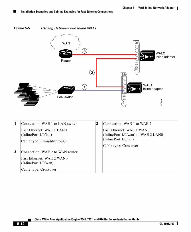
Chapter 5 WAE Inline Network Adapter Installation Scenarios and Cabling Examples for Fast Ethernet Connections
Figure 5-5 Cabling Between Two Inline WAEs
01
23
LINK
/AC
T
1001000
BY
PAS
S
01
23
LINK
/AC
T
1001000
BY
PAS
S
2400
89
WAE1inline adapter
WAE2inline adapter
WAN
Router
LAN switch
1
3
2
1 Connection: WAE 1 to LAN switch
Fast Ethernet: WAE 1 LAN0 (InlinePort 1/0/lan)
Cable type: Straight-through
2 Connection: WAE 1 to WAE 2
Fast Ethernet: WAE 1 WAN0 (InlinePort 1/0/wan) to WAE 2 LAN0 (InlinePort 1/0/lan)
Cable type: Crossover
3 Connection: WAE 2 to WAN router
Fast Ethernet: WAE 2 WAN0 (InlinePort 1/0/wan)
Cable type: Crossover
5-12Cisco Wide Area Application Engine 7341, 7371, and 674 Hardware Installation Guide
OL-15012-02

Cisco Wide Area Application Engine 7341, 7371, aOL-15012-02
C H A P T E R 6
Troubleshooting the System HardwareThis chapter provides basic troubleshooting information to help you identify some common problems that might occur with your Wide Area Application Engine (WAE).
This chapter contains the following sections:
• Identifying System Problems, page 6-2
• Checking Connections and Switches, page 6-3
• Using the System Diagnostic Programs, page 6-4
• Checking the Power Subsystem, page 6-11
• Troubleshooting the Ethernet Controller, page 6-12
• Identifying Problems Using Trouble Indicators and Status LEDs, page 6-15
• Undetermined Problems, page 6-21
• Symptoms and Solutions, page 6-24
Use the information in this chapter to determine whether a problem originates with the hardware or the software. For further assistance, contact your customer service representative.
Note The WAAS software does not support the use of a keyboard or mouse (Personal System/2 [PS/2] or Universal Serial Bus [USB]) for Linux and WAAS software troubleshooting. However, the keyboard and mouse are supported by the BIOS for power-on self-test (POST) and the diagnostic programs that are located in the device ROM.
6-1nd 674 Hardware Installation Guide

Chapter 6 Troubleshooting the System Hardware Identifying System Problems
When console redirection is enabled, all the tests available from a keyboard are accessible through the console connection as well. (Mouse support, however, is not available through the console connection.)
You can run all the diagnostics and tests that are supported by the BIOS, with a few exceptions. Tests for ports (such as the systems-management Ethernet connector and the SAS connector) that are not supported by the WAAS software are invalid.
Caution Customer-replaceable components include the Inline Network adapter, hard disk drives, and power supplies. All other components that are not orderable as spare hardware options can only be replaced by a qualified service technician. Once you have identified a faulty component, contact the Cisco Technical Assistance Center (TAC).
Note Read the “Working Inside the WAE with the Power On” section on page 2-7 before opening the chassis cover.
Identifying System ProblemsTo identify system problems, follow these steps:
Step 1 Check the power supply LEDs. (See Table 6-1 on page 6-12.)
Step 2 Power down the device and all external devices.
Step 3 Check all cables and power cords. (See the “Checking Connections and Switches” section on page 6-3.)
Step 4 Set all display controls on the terminal or display device to the middle position.
Step 5 Power up all external devices.
Step 6 Power up the device.
Step 7 Check the system error LED on the front panel (see Figure 1-1); if it is on, see the “System Error LED and the Diagnostic Panel LEDs” section on page 6-30.
6-2Cisco Wide Area Application Engine 7341, 7371, and 674 Hardware Installation Guide
OL-15012-02
Chapter 6 Troubleshooting the System Hardware Checking Connections and Switches
Step 8 Record any POST error messages that are displayed on the screen. If an error is displayed, look up the first error in the “POST Error Codes” section on page 6-49.
Step 9 If you did not hear a single beep, indicating successful completion of POST, take one of the following actions:
• If no beeps sounded, run the diagnostic programs. For information on how to use the diagnostic programs, see the “Using the System Diagnostic Programs” section on page 6-4.
If the diagnostic programs were completed successfully and you still suspect a problem, see the “Undetermined Problems” section on page 6-21.
• If you hear more than a single beep, find the beep code in the “Beep Symptoms” section on page 6-25. If necessary, see the “Undetermined Problems” section on page 6-21.
Step 10 Check the system error log. If an error was recorded by the system, see the “Symptoms and Solutions” section on page 6-24.
Checking Connections and SwitchesImproperly set switches and controls and loose or improperly connected cables are the most likely source of problems for the chassis or other external equipment. A quick check of all the switches, controls, and cable connections can easily solve these problems. (See Figure 1-1 for the location of front panel controls and indicators. See Figure 1-2 for the location of back panel connectors on the system.)
To check all the connections and switches, follow these steps:
Step 1 Power down the system, including any attached peripherals such as external drives. Disconnect all the power cables from their electrical outlets.
Step 2 If the system is connected to a power strip (or power distribution unit), turn the power strip off and then on again.
Is the power strip receiving power?
Yes. Go to Step 5.
No. Go to Step 3.
6-3Cisco Wide Area Application Engine 7341, 7371, and 674 Hardware Installation Guide
OL-15012-02

Chapter 6 Troubleshooting the System Hardware Using the System Diagnostic Programs
Step 3 Plug the power strip into another electrical outlet.
Is the power strip receiving power?
Yes. The original electrical outlet probably does not function. Use a different electrical outlet.
No. Go to Step 4.
Step 4 Plug a system that you know works into the electrical outlet.
Does the system receive power?
Yes. The power strip is probably not functioning properly. Use another power strip.
No. Go to Step 5.
Step 5 Reconnect the system to the electrical outlet or power strip.
Make sure that all connections fit tightly together.
Step 6 Power up the system.
Is the problem resolved?
Yes. The connections were loose. You have fixed the problem.
No. Call your customer service representative. (See the “Obtaining Documentation, Obtaining Support, and Security Guidelines” section on page xiv.)
Using the System Diagnostic ProgramsThe device diagnostic programs are stored in read-only memory (ROM) on the system board. These programs are the primary method of testing the following major components of the device: the system board, Ethernet controller, RAM, serial ports, and hard disk drives. See the “Diagnostic Programs and Error Messages” section on page 6-7.
If you cannot determine whether a problem is caused by the hardware or by the software, you can run the diagnostic programs to confirm that the hardware is working properly.
6-4Cisco Wide Area Application Engine 7341, 7371, and 674 Hardware Installation Guide
OL-15012-02
Chapter 6 Troubleshooting the System Hardware Using the System Diagnostic Programs
When you run the diagnostic programs, a single problem might cause several error messages. When this situation occurs, you should correct the cause of the first error message. After the cause of the first error message is corrected, the other error messages might not occur the next time you run the test.
When troubleshooting, note the following points:
• If multiple error codes are displayed, diagnose the first error code that is displayed.
• If the device stops with a POST error, go to the “POST Error Codes” section on page 6-49.
• If the device stops and no error message is displayed, go to the “Undetermined Problems” section on page 6-21.
• For power supply problems, see the “Checking the Power Subsystem” section on page 6-11.
• For safety information, see Chapter 2, “Preparing to Install the Wide Area Application Engine.”
• For intermittent problems, check the error log.
This section contains the following topics:
• Diagnostic Tools Overview, page 6-5
• POST Overview, page 6-6
• Diagnostic Programs and Error Messages, page 6-7
Diagnostic Tools OverviewThe following tools are available to help you identify and resolve hardware-related problems:
• POST beep codes and error messages
The power-on self-test (POST) generates beep codes and messages to indicate successful test completion or the detection of a problem. See the next section, “POST Overview,” for more information.
• Error log
The POST error log contains the three most recent error codes and messages that the system has generated during POST. The system error log contains all the error messages that were issued during POST.
6-5Cisco Wide Area Application Engine 7341, 7371, and 674 Hardware Installation Guide
OL-15012-02

Chapter 6 Troubleshooting the System Hardware Using the System Diagnostic Programs
• Diagnostic programs and error messages
The device diagnostic programs are stored in ROM on the system board. These programs are the primary method of testing the major components of your device. See the “Diagnostic Programs and Error Messages” section on page 6-7 for more information.
• Light Path Diagnostics
Your device has LEDs to help you identify problems with device components. These LEDs are part of the Light Path Diagnostics that are built into your device. By following the path of LEDs, you can quickly identify the type of system error that occurred. See the “Using Light Path Diagnostics” section on page 6-21 for more information.
• Error symptom charts
These charts list problem symptoms, along with suggested steps to correct the problems. See the “Error Symptoms” section on page 6-40 for more information.
POST OverviewWhen you power up the device, it performs a series of tests to check the operation of device components and some of the hardware options installed in the device. This series of tests is called the power-on self-test, or POST.
If POST finishes without detecting any problems, a single beep sounds, and the first screen of your operating system or application program appears.
If POST detects a problem, more than one beep sounds, and an error message appears on your screen. See the “Beep Symptoms” section on page 6-25 and “POST Error Codes” section on page 6-49 for more information.
Note If you have a power-up password or administrator password set, you must enter the password and press Enter when prompted, before POST will continue.
6-6Cisco Wide Area Application Engine 7341, 7371, and 674 Hardware Installation Guide
OL-15012-02
Chapter 6 Troubleshooting the System Hardware Using the System Diagnostic Programs
Note A single problem might cause several error messages. When this situation occurs, you should correct the cause of the first error message. After you correct the cause of the first error message, the other error messages usually will not occur the next time that you run the test.
The POST error log contains the three most recent error codes and messages that the system generated during POST. The system error log contains all messages issued during POST and all system status messages from the service processor.
You can view the contents of the system error log from the diagnostic programs.
Diagnostic Programs and Error MessagesThe device diagnostic programs are stored in ROM on the system board. These programs are the primary method of testing the major components of your device.
Diagnostic error messages indicate that a problem exists; they are not intended to be used to identify a failing part. Troubleshooting and servicing of complex problems that are indicated by error messages should be performed by trained service personnel.
Sometimes the first error to occur causes additional errors. In this case, the device displays more than one error message. Always follow the suggested action instructions for the first error message that appears.
The following sections contain the error codes that might appear in the detailed test log and summary log when the diagnostic programs are run.
The error code format is as follows:
fff-ttt-iii-date-cc-text message
The following are the meanings of the error message elements:
Error Message Element Explanation
fff 3-digit function code that indicates the function being tested when the error occurred. For example, function code 089 is for the microprocessor.
ttt 3-digit failure code that indicates the exact test failure that was encountered. (These codes are for trained service personnel; see the “Diagnostic Error Codes” section on page 6-33.)
6-7Cisco Wide Area Application Engine 7341, 7371, and 674 Hardware Installation Guide
OL-15012-02
Chapter 6 Troubleshooting the System Hardware Using the System Diagnostic Programs
This section contains the following topics:
• Starting the Diagnostic Programs, page 6-9
• Viewing the Test Log, page 6-10
iii 3-digit device ID. (These codes are for trained service personnel; see the “Diagnostic Error Codes” section on page 6-33.)
date The date that the diagnostic test was run and the error recorded.
cc Check value that is used to verify the validity of the information.
text message Message that indicates the reason for the problem.The format is as follows:
Function Name: Result (test-specific string)
where
Function Name is the name of the function being tested when the error occurred. This corresponds to the function code (fff) shown in the error code format in the previous section.
The result can be one of the following:
• Passed—This result occurs when the diagnostic test is completed without any errors.
• Failed—This result occurs when the diagnostic test discovers an error.
• User Aborted—This result occurs when you stop the diagnostic test before it is complete.
• Not Applicable—This result occurs when you specify a diagnostic test for a device that is not present.
• Aborted—This result occurs when the test could not proceed, for example, because of the system configuration.
• Warning—This result occurs when the test could not be run. There was no failure of the hardware that was being tested, but there might be a hardware failure elsewhere, or another problem prevented the test from running. For example, there might be a configuration problem, or the hardware might be missing or is not being recognized.
The test-specific string is additional information that you can use to analyze the problem.
Error Message Element Explanation
6-8Cisco Wide Area Application Engine 7341, 7371, and 674 Hardware Installation Guide
OL-15012-02

Chapter 6 Troubleshooting the System Hardware Using the System Diagnostic Programs
• Viewing Error Logs, page 6-10
• Viewing Diagnostic Error Message Tables, page 6-10
Starting the Diagnostic Programs
To start the diagnostic programs, follow these steps:
Step 1 Power up the device and watch the console.
Note To run the diagnostic programs, you must start the device with the highest level password that is set. That is, if an administrator password is set, you must enter the administrator password, not the power-up password, to run the diagnostic programs.
Step 2 Press F2 when this message appears:
F2 for Diagnostics
Step 3 Enter the appropriate password and then press Enter.
Step 4 From the top of the window, choose either Extended or Basic.
Step 5 When the Diagnostic Programs window appears, choose the test that you want to run from the list that appears. Follow the instructions in the window:
• Press F1 while running the diagnostic programs to obtain help information. You also can press F1 from within a help window to obtain online documentation from which you can choose different categories. To exit from the help information and return to your last location, press Esc.
• If the device stops during testing and you cannot continue, restart the device and try running the diagnostic programs again. If the problem remains, the component that was being tested when the device stopped needs to be replaced.
• If you run the diagnostic programs with no mouse attached to your device, you will not be able to navigate between test categories using the Next Cat and Prev Cat buttons. All other functions provided by mouse-selectable buttons are also available using the function keys. You can use the regular keyboard test to test a USB keyboard, and you can use the regular mouse test to test a USB mouse.
6-9Cisco Wide Area Application Engine 7341, 7371, and 674 Hardware Installation Guide
OL-15012-02
Chapter 6 Troubleshooting the System Hardware Using the System Diagnostic Programs
Note The WAAS software does not support USB peripheral devices, but you can use these devices with the diagnostic programs.
• You can view device configuration information (such as system configuration, memory contents, interrupt request [IRQ] use, direct memory access [DMA] use, device drivers, and so on) by choosing Hardware Info from the top of the window.
If the diagnostic programs do not detect any hardware errors but the problem persists during normal device operations, a software error might be the cause. If you suspect a software problem, see the Cisco WAAS software documentation.
Viewing the Test Log
When the tests are completed, you can view the test log by choosing Utility > View Test Log.
Note You can view the test log only while you are in the diagnostic programs. When you exit the diagnostic programs, the test log is cleared. To save the test log to a file on the hard disk, click Save Log on the diagnostic programs screen and specify a location and name for the saved log file.
Viewing Error Logs
Start the diagnostic programs. Choose Hardware Info > System Error Log, and then follow the instructions in the window.
Viewing Diagnostic Error Message Tables
For descriptions of the error messages that might appear when you run the diagnostic programs, see the “Diagnostic Error Codes” section on page 6-33.
6-10Cisco Wide Area Application Engine 7341, 7371, and 674 Hardware Installation Guide
OL-15012-02
Chapter 6 Troubleshooting the System Hardware Checking the Power Subsystem
Note Depending on your device configuration, some of the error messages might not appear when you run the diagnostic programs.
Note If diagnostic error messages appear that are not listed in the tables, make sure that your device has the latest levels of BIOS and diagnostics microcode installed.
Checking the Power SubsystemPower problems can be difficult to solve. For example, a short circuit can exist anywhere on any of the power distribution buses. Usually a short circuit will cause the power subsystem to shut down because of an overcurrent condition.
To perform a general procedure for troubleshooting power problems, follow these steps:
Step 1 Power down the device and disconnect all AC power cords.
Step 2 Check for loose cables in the power subsystem. Also check for short circuits. For example, check if there is a loose screw that is causing a short circuit on a circuit board.
Step 3 Remove adapters and disconnect the cables and power connectors to all internal and external devices until the device is at the minimum configuration required to start it.
Step 4 Reconnect all AC power cords and power up the device. If the device starts up successfully, replace adapters and devices one at a time until the problem is isolated. If the device does not start up from the minimal configuration, replace components of a minimal configuration one at a time until the problem is isolated.
To use this method, it is important to know the minimum configuration required for a system to start. The following are the minimum operating requirements:
• One power supply
• Power backplane
6-11Cisco Wide Area Application Engine 7341, 7371, and 674 Hardware Installation Guide
OL-15012-02
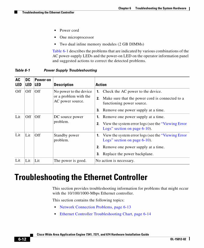
Chapter 6 Troubleshooting the System Hardware Troubleshooting the Ethernet Controller
• Power cord
• One microprocessor
• Two dual inline memory modules (2 GB DIMMs)
Table 6-1 describes the problems that are indicated by various combinations of the AC power-supply LEDs and the power-on LED on the operator information panel and suggested actions to correct the detected problems.
Table 6-1 Power Supply Troubleshooting
AC LED
DC LED
Power-on LED Description Action
Off Off Off No power to the device or a problem with the AC power source.
1. Check the AC power to the device.
2. Make sure that the power cord is connected to a functioning power source.
3. Remove one power supply at a time.
Lit Off Off DC source power problem.
1. Remove one power supply at a time.
2. View the system error logs (see the “Viewing Error Logs” section on page 6-10).
Lit Lit Off Standby power problem.
1. View the system error logs (see the “Viewing Error Logs” section on page 6-10).
2. Remove one power supply at a time.
3. Replace the power backplane.
Lit Lit Lit The power is good. No action is necessary.
Troubleshooting the Ethernet ControllerThis section provides troubleshooting information for problems that might occur with the 10/100/1000-Mbps Ethernet controller.
This section contains the following topics:
• Network Connection Problems, page 6-13
• Ethernet Controller Troubleshooting Chart, page 6-14
6-12Cisco Wide Area Application Engine 7341, 7371, and 674 Hardware Installation Guide
OL-15012-02

Chapter 6 Troubleshooting the System Hardware Troubleshooting the Ethernet Controller
Network Connection ProblemsIf the Ethernet controller cannot connect to the network, check the following conditions:
• Make sure that the cable is installed correctly.
The network cable must be securely attached at all connections. If the cable is attached but the problem remains, try a different cable.
If you set the Ethernet controller to operate at either 100 Mbps or 1000 Mbps, you must use Category 5 or higher cabling.
• Determine whether the switch or device to which the WAE is connected supports autonegotiation. If it does not, try configuring the integrated Ethernet controller manually to match the speed and duplex mode of the switch.
• Check the Ethernet controller LEDs on the device back panel. (See Figure 1-2.)
These LEDs indicate whether a problem exists with the connector, cable, or switch:
– The Ethernet link status LED is on when the Ethernet controller receives a link pulse from the switch. If the LED is off, there might be a defective connector or cable or a problem with the switch.
– The Ethernet activity LED is on when the Ethernet controller sends or receives data over the Ethernet network. If the Ethernet activity LED is off, make sure that the switch and network are operating and that the correct device drivers are installed.
• Make sure that you are using the correct device drivers that are supplied with your device and that the device drivers on the client and the device are using the same protocol.
• Check for operating system-specific causes for the problem.
• Test the Ethernet controller.
The method used to test the Ethernet controller depends on which operating system that you are using (see the Ethernet controller device driver README files).
6-13Cisco Wide Area Application Engine 7341, 7371, and 674 Hardware Installation Guide
OL-15012-02

Chapter 6 Troubleshooting the System Hardware Troubleshooting the Ethernet Controller
Ethernet Controller Troubleshooting ChartTable 6-2 lists solutions to 10/100/1000-Mbps Ethernet controller problems.
Table 6-2 Ethernet Troubleshooting Chart
Ethernet Controller Problem Actions
Ethernet link status LED does not work.
Check the following:
• Make sure that the switch to which the WAE is connected is powered on.
• Check all connections at the Ethernet controller and the switch.
• Use another port on the switch.
• If the switch does not support autonegotiation, manually configure the Ethernet controller to match the switch.
• If you manually configured duplex mode, make sure that you also manually configure the speed.
• Run diagnostics on the LEDs.
• Reseat or replace the adapter.
The Ethernet activity LED does not work.
Check the following:
• The network might be idle. Try sending data from this device.
• Run diagnostics on the LEDs.
Data is incorrect or sporadic.
Check the following:
• Make sure that you are using Category 5 or higher cabling when operating the device at 100 Mbps or 1000 Mbps.
• Make sure that the cables do not run close to noise-inducing sources such as fluorescent lights.
6-14Cisco Wide Area Application Engine 7341, 7371, and 674 Hardware Installation Guide
OL-15012-02
Chapter 6 Troubleshooting the System Hardware Identifying Problems Using Trouble Indicators and Status LEDs
Identifying Problems Using Trouble Indicators and Status LEDs
If the system error LED on the front of the device is on, one or more LEDs inside the device or on the power supply will be on. Your device has LEDs to help you identify problems with some device components. These LEDs are part of the Light Path Diagnostics feature built into the device. By following the path of lights, you can quickly identify the type of system error that occurred.
Your device is designed so that any LEDs that are on remain on when the device shuts down as long as the AC power source is good and the power supply can supply +5 VDC current to the device. This feature helps you isolate the problem if an error causes the device to shut down. (See Table 6-8 on page 6-30.)
The Ethernet controller stopped working when another adapter was added to the device.
Check the following:
• Make sure that the cable is connected to the Ethernet controller.
• Make sure that your PCI system BIOS code is current.
• Reseat the adapter.
• Determine if the interrupt (IRQ) setting assigned to the Ethernet adapter is also assigned to another device in the system. Use the configuration/setup utility program to determine if this is the case.
• Although interrupt sharing is allowed for PCI devices, some devices do not function well when they share an interrupt with a dissimilar PCI device. Try changing the IRQ assigned to the Ethernet adapter or the other device.
• Reseat or replace the adapter.
The Ethernet controller stopped working without apparent cause.
Check the following:
• Run diagnostics for the Ethernet controller.
• Try a different connector on the switch.
• Reseat or replace the adapter.
Table 6-2 Ethernet Troubleshooting Chart (continued)
Ethernet Controller Problem Actions
6-15Cisco Wide Area Application Engine 7341, 7371, and 674 Hardware Installation Guide
OL-15012-02
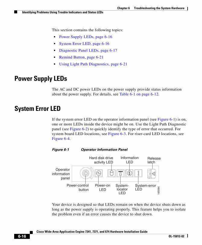
Chapter 6 Troubleshooting the System Hardware Identifying Problems Using Trouble Indicators and Status LEDs
This section contains the following topics:
• Power Supply LEDs, page 6-16
• System Error LED, page 6-16
• Diagnostic Panel LEDs, page 6-17
• Remind Button, page 6-21
• Using Light Path Diagnostics, page 6-21
Power Supply LEDsThe AC and DC power LEDs on the power supply provide status information about the power supply. For details, see Table 6-1 on page 6-12.
System Error LEDIf the system error LED on the operator information panel (see Figure 6-1) is on, one or more LEDs inside the device might be on. Use the Light Path Diagnostic panel (see Figure 6-2) to quickly identify the type of error that occurred. For system board LED locations, see Figure 6-3. For riser-card LED locations, see Figure 6-4.
Figure 6-1 Operator Information Panel
System-locatorLED
System-errorLED
Releaselatch
Power-onLED
Power-controlbutton
Hard disk driveactivity LED
InformationLED
Operatorinformation
panel
1850
84
Your device is designed so that LEDs remain on when the device shuts down as long as the power supply is operating properly. This feature helps you to isolate the problem even if an error causes the device to shut down.
6-16Cisco Wide Area Application Engine 7341, 7371, and 674 Hardware Installation Guide
OL-15012-02
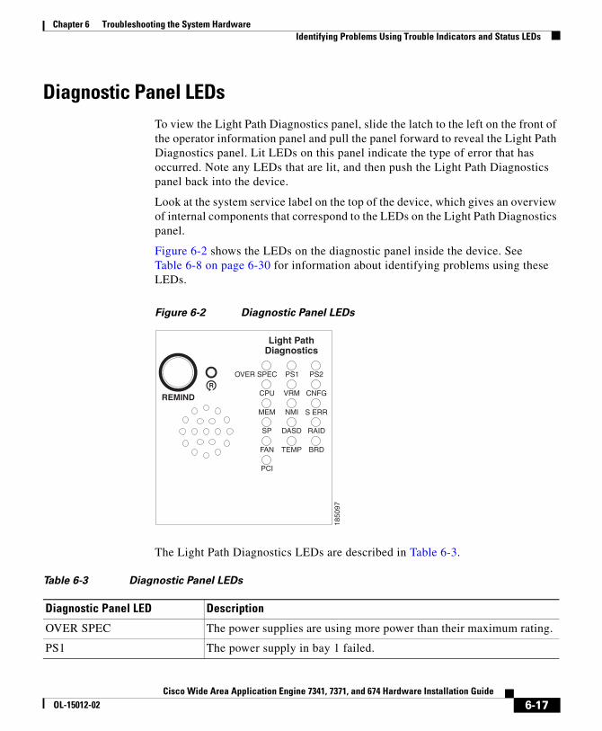
Chapter 6 Troubleshooting the System Hardware Identifying Problems Using Trouble Indicators and Status LEDs
Diagnostic Panel LEDsTo view the Light Path Diagnostics panel, slide the latch to the left on the front of the operator information panel and pull the panel forward to reveal the Light Path Diagnostics panel. Lit LEDs on this panel indicate the type of error that has occurred. Note any LEDs that are lit, and then push the Light Path Diagnostics panel back into the device.
Look at the system service label on the top of the device, which gives an overview of internal components that correspond to the LEDs on the Light Path Diagnostics panel.
Figure 6-2 shows the LEDs on the diagnostic panel inside the device. See Table 6-8 on page 6-30 for information about identifying problems using these LEDs.
Figure 6-2 Diagnostic Panel LEDs
DASD
NMI
PCI
PS1
SP
PS2
CNFG
MEM
CPU
FAN
VRM
OVER SPEC
TEMP
REMIND
S ERR
Light PathDiagnostics
RAID
BRD
1850
97
The Light Path Diagnostics LEDs are described in Table 6-3.
Table 6-3 Diagnostic Panel LEDs
Diagnostic Panel LED Description
OVER SPEC The power supplies are using more power than their maximum rating.
PS1 The power supply in bay 1 failed.
6-17Cisco Wide Area Application Engine 7341, 7371, and 674 Hardware Installation Guide
OL-15012-02
Chapter 6 Troubleshooting the System Hardware Identifying Problems Using Trouble Indicators and Status LEDs
PS2 The power supply in bay 2 failed.
CPU A microprocessor failed.
VRM An error occurred on the microprocessor voltage regulator module (VRM).
CNFG A hardware configuration error has occurred.
MEM A memory error has occurred.
NMI A machine check error has occurred.
S ERR Reserved.
SP Service processor failure.
DASD A hard disk drive error has occurred.
RAID A RAID controller error has occurred.
FAN A fan has failed, is operating too slowly, or has been removed.
TEMP The system temperature has exceeded a threshold level.
BRD An error has occurred on the system board.
PCI An error has occurred on a PCI bus or on the system board.
Table 6-3 Diagnostic Panel LEDs (continued)
Diagnostic Panel LED Description
6-18Cisco Wide Area Application Engine 7341, 7371, and 674 Hardware Installation Guide
OL-15012-02

Chapter 6 Troubleshooting the System Hardware Identifying Problems Using Trouble Indicators and Status LEDs
Figure 6-3 System Board LED Locations
DIMM 1 error LED
Riser-card-missingerror LED
RAID error LED
DIMM 2 error LEDDIMM 3 error LEDDIMM 4 error LEDDIMM 5 error LEDDIMM 6 error LEDDIMM 7 error LEDDIMM 8 error LEDDIMM 9 error LED
DIMM 12 error LEDDIMM 11 error LEDDIMM 10 error LED
VRMerror LED
Power channel Berror LED
Power channel Aerror LED
Power channel Derror LED
Power channel Cerror LED
BMC heartbeat LED
3 V batteryerror LED
PCI slot 3error LED
PCI slot 4error LED
Remote SupervisorAdapter II SlimLineerror LED
Microprocessor 1error LED
Microprocessor 2error LED
1850
98
Power channel error LEDs indicate an overcurrent condition. Table 6-4 identifies the components associated with each power channel, and the order in which to troubleshoot the components.
6-19Cisco Wide Area Application Engine 7341, 7371, and 674 Hardware Installation Guide
OL-15012-02

Chapter 6 Troubleshooting the System Hardware Identifying Problems Using Trouble Indicators and Status LEDs
Table 6-4 Power Channel LEDs
Power-Channel Error LED Components
A Fan 4, fan 6, fan 8, fan 9, microprocessor 1, system board (integrated voltage regulator)
B Fan 1, fan 2, fan 3, fan 5, VRM1, IDE2 CD/DVD cable, IDE
1. VRM = Voltage Regulator Module
2. IDE = Integrated Drive Electronics
CD/DVD media backplane, microprocessor 2, system board
C ServeRAID SAS controller, DIMMs, system board
D Low-profile PCI Express adapter (PCI slots 3 and 4), adapter on PCI riser card (PCI slots 1 and 2), system board
Figure 6-4 shows the LEDs on the riser card.
Figure 6-4 Riser-Card LED locations
PCI Slot 1 error LED
PCI Slot 2 error LED
1851
05
6-20Cisco Wide Area Application Engine 7341, 7371, and 674 Hardware Installation Guide
OL-15012-02

Chapter 6 Troubleshooting the System Hardware Undetermined Problems
Remind ButtonYou can use the Remind button on the Light Path Diagnostics panel to place the front panel system error LED into the Remind mode. By pressing the button, you acknowledge the failure but indicate that you will not take immediate action. If a new failure occurs, the system error LED comes on again.
In the Remind mode, the system error LED flashes and remains in the Remind mode until one of the following situations occurs:
• All known problems are resolved.
• The system is restarted.
• A new problem occurs.
You can use the Remind button to delay device maintenance until a later time. Also, resetting the system error LED enables the LED to react to another error. If the LED is still flashing from the first error, it masks additional errors.
Using Light Path DiagnosticsThe system error LED on the front of the device is on when certain system errors occur. If the system error LED on your device is on, use Table 6-8 on page 6-30 to help determine the cause of the error and the action needed. These actions should only be performed by trained and qualified personnel.
Undetermined ProblemsUse the information in this section if the diagnostic tests did not identify the failure, the devices list is incorrect, or the system is inoperative.
Note Damaged data in CMOS can cause undetermined problems.
Note Damaged data in BIOS code can cause undetermined problems.
6-21Cisco Wide Area Application Engine 7341, 7371, and 674 Hardware Installation Guide
OL-15012-02

Chapter 6 Troubleshooting the System Hardware Undetermined Problems
Check the LEDs on all the power supplies. If the LEDs indicate the power supplies are working correctly, follow these steps:
Step 1 Power down the device.
Step 2 Be sure the device is cabled correctly.
Step 3 Remove or disconnect the following devices (one at a time) until you find the failure (power up the device and reconfigure it each time):
• Any external devices
• Surge suppressor device (on the device)
• Modem, printer, mouse, or non-Cisco devices
• Each adapter
• Disk drives
• Memory modules (minimum requirement = 4 GB; two banks of 2 GB DIMMs)
Note Any component that is internal to the device, with the exception of customer-replaceable adapters, must be serviced by trained and qualified personnel. Contact your customer service representative.
Step 4 Power up the device. If the problem remains, check the following parts in the order listed:
a. Power backplane
b. System board
Note If the problem goes away when you remove an adapter from the system, and replacing that adapter does not correct the problem, check the system board.
6-22Cisco Wide Area Application Engine 7341, 7371, and 674 Hardware Installation Guide
OL-15012-02

Chapter 6 Troubleshooting the System Hardware Undetermined Problems
Note If you suspect a networking problem and all the system tests pass, check if there is a network cabling problem external to the system.
Problem-Solving TipsBecause of the variety of hardware and software combinations that can be encountered, use the following information to assist you in identifying the problems. If possible, have this information available when requesting technical assistance.
• Machine type and model
• Microprocessor or hard disk upgrades
• Failure symptom
– Do diagnostics fail?
– What, when, where; single or multiple systems?
– Is the failure repeatable?
– Has this configuration ever worked?
– If it has been working, what changes were made before it failed?
– Is this the original reported failure?
• Diagnostics type and version level
• Hardware configuration
– Print (print screen) configuration currently in use
– BIOS level
• Operating system software type and version level
To eliminate confusion, identical systems are considered identical only if they meet all these conditions:
• Are the exact machine type and models
• Have the same BIOS level
• Have the same adapters or attachments in the same locations
6-23Cisco Wide Area Application Engine 7341, 7371, and 674 Hardware Installation Guide
OL-15012-02

Chapter 6 Troubleshooting the System Hardware Symptoms and Solutions
• Have the same address jumpers, terminators, and cabling
• Have the same software versions and levels
• Have the same diagnostics code
• Have the same configuration options set in the system
• Have the same setup for the operating system control files
Comparing the configuration and software setup in working and nonworking systems might help to resolve the problem.
Symptoms and SolutionsThis section lists symptoms, errors, and the possible causes. The most likely cause is listed first. Use this symptom-to-solution index to help you decide which components your service representative needs to have available when servicing the system.
The first column of the three-column tables in this section lists the error code or message, the second column describes the error, and the third column lists one or more suggested actions or components that need to be reseated or replaced. Use the table to identify possible causes for the error message and then call your service representative.
The POST BIOS code displays POST error codes and messages on the screen.
This section includes the following topics:
• Beep Symptoms, page 6-25
• No Beep Symptoms, page 6-29
• System Error LED and the Diagnostic Panel LEDs, page 6-30
• Diagnostic Error Codes, page 6-33
• Error Symptoms, page 6-40
• POST Error Codes, page 6-49
6-24Cisco Wide Area Application Engine 7341, 7371, and 674 Hardware Installation Guide
OL-15012-02

Chapter 6 Troubleshooting the System Hardware Symptoms and Solutions
Beep SymptomsBeep symptoms are short tones or a series of short tones separated by pauses (intervals without sound). See the examples in Table 6-5.
Table 6-5 Beep Examples
Beeps Description
1-2-3 1. One beep
2. A pause (or break)
3. Two beeps
4. A pause (or break)
5. Three beeps
4 Four continuous beeps
One beep after a successful POST indicates that the system is functioning properly.
Table 6-6 lists the beep symptoms, describes the error, and suggests causes and possible actions to solve the problems. The most likely cause of the symptom is listed first.
Table 6-6 Beep Symptoms
Beep Symptom Error Cause and Action
1-1-2 Microprocessor register test failed. 1. Check the optional microprocessor (if installed).
2. Check the microprocessor.
3. Check the system board.
1-1-3 CMOS1 write/read test failed. 1. Check the battery.
2. Check the system board.
1-1-4 BIOS EEPROM checksum failed. 1. Recover the BIOS.
2. Check the system board.
6-25Cisco Wide Area Application Engine 7341, 7371, and 674 Hardware Installation Guide
OL-15012-02
Chapter 6 Troubleshooting the System Hardware Symptoms and Solutions
1-2-1 Programmable interval timer failed.
Check the system board.
1-2-2 DMA2 initialization failed. Check the system board.
1-2-3 DMA page register write/read failed.
Check the system board.
1-2-4 RAM refresh verification failed. 1. Check the DIMMs.
2. Check the system board.
1-3-1 First 64K RAM test failed. Check the DIMMs.
2-1-1 Secondary DMA register failed. Check the system board.
2-1-2 Primary DMA register failed. Check the system board.
2-1-3 Primary interrupt mask register failed.
Check the system board.
2-1-4 Secondary interrupt mask register failed.
Check the system board.
2-2-1 Interrupt vector loading failed. Check the system board.
2-2-2 Keyboard3 controller failed. Not applicable.
2-2-3 CMOS power failure and checksum checks failed.
1. Check the battery.
2. Check the system board.
2-2-4 CMOS configuration information validation failed.
1. Check the battery.
2. Check the system board.
2-3-1 Screen initialization failed. Check the system board.
2-3-2 Screen memory failed. Check the system board.
2-3-3 Screen retrace failed. Check the system board.
2-3-4 Search for video ROM failed. Check the system board.
2-4-1 Video failed; screen believed operable.
Check the system board.
3-1-1 Timer tick interrupt failed. Check the system board.
3-1-2 Interval timer channel 2 failed. Check the system board.
Table 6-6 Beep Symptoms (continued)
Beep Symptom Error Cause and Action
6-26Cisco Wide Area Application Engine 7341, 7371, and 674 Hardware Installation Guide
OL-15012-02

Chapter 6 Troubleshooting the System Hardware Symptoms and Solutions
3-1-3 RAM test failed above address OFFFFH.
1. Check the DIMMs.
2. Check the system board.
3-1-4 Time of day clock failed. 1. Check the battery.
2. Check the system board.
3-2-1 Serial port failed. Check the system board.
3-2-2 Parallel port failed. Check the system board.
3-2-3 Math coprocessor test failed. 1. Check the microprocessors.
2. Check the system board.
3-2-4 Failure comparing CMOS memory size against actual.
1. Check the DIMMs.
2. Check the battery.
3-3-1 Memory size mismatch occurred. 1. Check the DIMMs.
2. Check the battery.
3-3-2 Critical SMBUS error occurred. 1. Check the power cord connection.
Disconnect the device power cord from the outlet, wait 30 seconds, and retry.
2. Check the DIMMs.
3. Check the hard disk drive backplane.
4. Check the power supply.
5. Check the system board.
3-3-3 No operational memory in system. 1. Check the memory modules.
The memory modules need to be installed or reseated and then a 3-boot reset needs to be performed. Contact your customer service representative.
2. Check the DIMMs.
3. Check the system board.
Table 6-6 Beep Symptoms (continued)
Beep Symptom Error Cause and Action
6-27Cisco Wide Area Application Engine 7341, 7371, and 674 Hardware Installation Guide
OL-15012-02
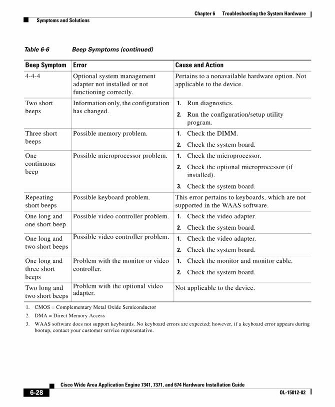
Chapter 6 Troubleshooting the System Hardware Symptoms and Solutions
4-4-4 Optional system management adapter not installed or not functioning correctly.
Pertains to a nonavailable hardware option. Not applicable to the device.
Two short beeps
Information only, the configuration has changed.
1. Run diagnostics.
2. Run the configuration/setup utility program.
Three short beeps
Possible memory problem. 1. Check the DIMM.
2. Check the system board.
One continuous beep
Possible microprocessor problem. 1. Check the microprocessor.
2. Check the optional microprocessor (if installed).
3. Check the system board.
Repeating short beeps
Possible keyboard problem. This error pertains to keyboards, which are not supported in the WAAS software.
One long and one short beep
Possible video controller problem. 1. Check the video adapter.
2. Check the system board.
One long and two short beeps
Possible video controller problem. 1. Check the video adapter.
2. Check the system board.
One long and three short beeps
Problem with the monitor or video controller.
1. Check the monitor and monitor cable.
2. Check the system board.
Two long and two short beeps
Problem with the optional video adapter.
Not applicable to the device.
1. CMOS = Complementary Metal Oxide Semiconductor
2. DMA = Direct Memory Access
3. WAAS software does not support keyboards. No keyboard errors are expected; however, if a keyboard error appears during bootup, contact your customer service representative.
Table 6-6 Beep Symptoms (continued)
Beep Symptom Error Cause and Action
6-28Cisco Wide Area Application Engine 7341, 7371, and 674 Hardware Installation Guide
OL-15012-02

Chapter 6 Troubleshooting the System Hardware Symptoms and Solutions
No Beep SymptomsTable 6-7 describes the no beep symptoms.
Table 6-7 No Beep Symptoms
No Beep Symptom Error Cause and Action
No beep and the system operates correctly.
Possible problem with the operator information panel.
1. Check the operator information panel cable.
2. Check the system board.
No beeps occur after POST is successfully completed.
The power-on status is disabled.
1. Run the Configuration/Setup Utility program and choose Start Options. Set the Power-On Status to Enable.
2. Check the operator information panel cable.
3. Check the system board.
No beep and no video.
Unknown problem. See the “Undetermined Problems” section on page 6-21.
No beep occurs, and the power-supply AC LED is off.
Possible power problem. 1. Check the power cord.
2. Check the power supplies and reseat them. (If two are installed, swap them to determine if one is defective.)
3. Disconnect the cable from the hard disk drive backplane power connector (J13) on the power backplane. If the AC power LED comes on, see the “Undetermined Problems” section on page 6-21.
No beep occurs, the device does not start, and the power-supply AC LED is lit.
Possible power problem. See the “Checking the Power Subsystem” section on page 6-11.
6-29Cisco Wide Area Application Engine 7341, 7371, and 674 Hardware Installation Guide
OL-15012-02

Chapter 6 Troubleshooting the System Hardware Symptoms and Solutions
System Error LED and the Diagnostic Panel LEDsThe system error LED is on when an error is detected. If the system error LED is on, remove the cover and check the diagnostic panel LEDs. Table 6-8 lists all the diagnostic panel LEDs followed by the component or action for correcting the problem. The information in the table is valid only when the system error LED is on.
When checking the diagnostic panel LEDs, note the following information:
• If a diagnostic panel LED is on and the front panel system error LED is off, there is probably an LED problem. Run the LED diagnostics.
• To locate the LEDs on the system board, see Figure 6-3 on page 6-19.
• Check the system error log for additional information before replacing a component. (See the “Viewing Error Logs” section on page 6-10.)
• The DIMM error LEDs, microprocessor error LEDs, and VRM error LEDs on the system board go off when the system is powered down.
Table 6-8 provides the diagnostic panel LED error definitions. The third column lists one or more suggested actions or components that need to be reseated or replaced. Use this table to identify possible causes for the error message and then call your customer service representative.
Table 6-8 Diagnostic-Panel LED Error Definitions
Diagnostic-Panel LED Description Cause and Action
None, but the System Error LED is lit.
An error has occurred and cannot be diagnosed, The error is not represented by a light path diagnostics LED.
Use the Configuration/Setup utility program to check the system error log for information about the error. See Appendix C, “Using the Configuration/Setup Utility Program.”
OVER SPEC The power supplies are using more power than their maximum rating.
1. Remove optional devices from the WAE.
2. Replace the failing power supply.
PS1 The power supply in bay 1 has failed.
1. Check the DC good LED on power supply 1. If it is off, power supply 1 needs to be replaced.
2. Check that the power supply is correctly seated.
6-30Cisco Wide Area Application Engine 7341, 7371, and 674 Hardware Installation Guide
OL-15012-02

Chapter 6 Troubleshooting the System Hardware Symptoms and Solutions
PS2 The power supply in bay 2 has failed.
1. Check the DC good LED on power supply 2. If it is off, power supply 2 needs to be replaced.
2. Check that the power supply is correctly seated.
CPU The LED next to the failing CPU is on.
1. Verify that all microprocessors have identical cache sizes, dock speeds, and clock frequencies.
2. Check microprocessor 1 or 2.
3. Check the system board.
VRM An error occurred on the microprocessor voltage regulator (VRM).
Check the voltage regulator module.
CNFG A hardware configuration error has occurred.
1. Check the microprocessors just installed to be sure that they are compatible with each other and with the VRM
2. Check the system error logs for information about the error. Replace any components that are indicated. (See the “Viewing Error Logs” section on page 6-10.)
MEM The LED next to the failing DIMM is on.
Replace the failing DIMM.
NMI A machine check error has occurred.
Check the system error log. (See the “Viewing Error Logs” section on page 6-10.)
S ERR Reserved
SP The service processor has failed. 1. Unplug the device for 30 seconds, and then retry.
2. Reflash or update firmware for the BMC.
3. Check the system board.
Table 6-8 Diagnostic-Panel LED Error Definitions (continued)
Diagnostic-Panel LED Description Cause and Action
6-31Cisco Wide Area Application Engine 7341, 7371, and 674 Hardware Installation Guide
OL-15012-02

Chapter 6 Troubleshooting the System Hardware Symptoms and Solutions
DASD A hard disk drive error has occurred.
The error pertains to DASD devices, which are not supported in the WAAS software.
RAID A RAID controller error has occurred.
1. Check the RAID controller
2. Check the system error log. (See the “Viewing Error Logs” section on page 6-10.)
FAN A fan has failed, is operating too slowly, or has been removed. The LED next to the failing fan is on. A failing fan can also cause the TEMP LED to be lit.
Replace the failing fan.
TEMP The temperature has exceeded one of the following thresholds:
• The internal temperature for CPU1 or CPU2 has exceeded 207°F (97°C).
• The ambient temperature has exceeded 104°F (40°C).
A failing fan can cause the TEMP LED to be lit.
1. The ambient temperature must be within normal operating specifications. See the Appendix A, “Wide Area Application Engine Hardware Specifications.”
2. Ensure that fans are operating correctly, and replace one if it has failed.
3. Ensure that the air vents are not blocked.
Table 6-8 Diagnostic-Panel LED Error Definitions (continued)
Diagnostic-Panel LED Description Cause and Action
6-32Cisco Wide Area Application Engine 7341, 7371, and 674 Hardware Installation Guide
OL-15012-02

Chapter 6 Troubleshooting the System Hardware Symptoms and Solutions
Diagnostic Error CodesIn the following error codes, if XXX is 000, 195, or 197, do not replace a component. The descriptions for these error codes are as follows:
• 000—The test passed.
• 195—The Esc key was pressed to stop the test.
• 197—Warning; a hardware failure might not have occurred.
BRD An error has occurred on the system board.
1. Check the LEDs on the system board to identify the component that is causing the error.
2. Check the system error log. (See the “Viewing Error Logs” section on page 6-10.)
PCI An error has occurred on a PCI bus or on the system board. An additional LED will be lit next to a failing PCI slot.
1. Check the LEDs on the PCI slots to identify the component that is causing the error.
2. Check the system error log. (See the “Viewing Error Logs” section on page 6-10.)
3. If you cannot isolate the failing adapter through the LEDs and the information in the system error log, remove one adapter at a time from the failing PCI bus, and restart the device after each adapter is removed.
4. Check the PCI riser card.
5. Check the system board.
Table 6-8 Diagnostic-Panel LED Error Definitions (continued)
Diagnostic-Panel LED Description Cause and Action
6-33Cisco Wide Area Application Engine 7341, 7371, and 674 Hardware Installation Guide
OL-15012-02

Chapter 6 Troubleshooting the System Hardware Symptoms and Solutions
For all remaining error codes, the solution is to check the component or take the action indicated. Table 6-9 lists all the diagnostic error codes. Use this table to identify a faulty component, and then call your customer service representative for assistance.
Table 6-9 Error Code Definitions
Error Code Problem Action
001-XXX-000 Failed core tests. Check the system board.
001-XXX-001 Failed core tests. Check the system board.
001-250-000 Failed system board ECC. Check the system board.
001-250-001 Failed system board ECC. Check the system board.
005-XXX-000 Failed video test. 1. Reseat the video adapter.
2. Check the system board.
011-XXX-000 Failed COM1 serial port test. Check the system board.
011-XXX-001 Failed COM2 serial port test. Check the system board.
014-XXX-000 Failed parallel port test. Check the system board.
015-XXX-001 USB1 interface not found; board damaged.
Not applicable. The USB interface is not supported in the WAAS software.
015-XXX-015 Failed USB1 external loopback test.
Not applicable. The USB interface is not supported in the WAAS software.
015-XXX-198 USB1 device connected during USB test.
Not applicable. USB peripheral devices are not supported in the WAAS software.
020-XXX-000 Failed PCI interface test. 1. Reseat the riser-card assembly.
2. Check the system board.
030-XXX-099 Failed internal SCSI interface test.
Check the system board.
035-285-001 Adapter Communication Error. 1. Update the ServeRAID SAS controller firmware.
2. Reseat the ServeRAID SAS controller.
3. Replace the ServeRAID SAS controller.
6-34Cisco Wide Area Application Engine 7341, 7371, and 674 Hardware Installation Guide
OL-15012-02

Chapter 6 Troubleshooting the System Hardware Symptoms and Solutions
035-286-001 Adapter CPU Test Error. 1. Update the ServeRAID SAS controller firmware.
2. Reseat the ServeRAID SAS controller.
3. Replace the ServeRAID SAS controller.
035-287-001 Adapter Local RAM Test Error. 1. Update the ServeRAID SAS controller firmware.
2. Reseat the ServeRAID SAS controller.
3. Replace the ServeRAID SAS controller.
035-288-001 Adapter NVSRAM Test Error. 1. Update the ServeRAID SAS controller firmware.
2. Reseat the ServeRAID SAS controller.
3. Replace the ServeRAID SAS controller.
035-289-001 Adapter Cache Test Error. 1. Update the ServeRAID SAS controller firmware.
2. Reseat the ServeRAID SAS controller.
3. Replace the ServeRAID SAS controller.
035-292-001 Adapter Parameter Set Error. 1. Update the ServeRAID SAS controller firmware.
2. Reseat the ServeRAID SAS controller.
3. Replace the ServeRAID SAS controller.
035-230-001 Battery Low. Replace the battery module on the ServeRAID SAS controller.
035-231-001 Abnormal Battery Temperature. Replace the battery module on the ServeRAID SAS controller.
035-231-001 Battery Status Unknown. Replace the battery module on the ServeRAID SAS controller.
Table 6-9 Error Code Definitions (continued)
Error Code Problem Action
6-35Cisco Wide Area Application Engine 7341, 7371, and 674 Hardware Installation Guide
OL-15012-02

Chapter 6 Troubleshooting the System Hardware Symptoms and Solutions
089-XXX-00n Failed microprocessor test.
n = APIC ID for failing microprocessor:
• 0, 1, 2, 3 = microprocessor 1
• 4, 5, 6, 7 = microprocessor 2
Check the microprocessor.
166-250-000 System Management: Failed. I2C cable is disconnected.
1. Check the I2C cable between the operator information panel assembly and the system board.
2. Check the system board.
166-400-000 System Management: Failed. BMC self-test failed.
1. Reflash or update firmware to the latest level.
2. Check the system board.
166-404-001 System Management: Failed. BMC indicates failure in I2C bus test.
1. Disconnect all power cords and external cables from the device, wait 30 seconds, reconnect, and retry.
2. Reflash or update firmware to the latest level.
3. Reseat the power backplane.
4. Check the system board.
166-406-001 System Management: Failed. BMC indicates failure in I2C bus test.
1. Disconnect all power cords and external cables from the device, wait 30 seconds, reconnect, and retry.
2. Reflash or update firmware to the latest level.
3. Reseat the hard disk drive signal cable and backplane.
4. Check the system board.
Table 6-9 Error Code Definitions (continued)
Error Code Problem Action
6-36Cisco Wide Area Application Engine 7341, 7371, and 674 Hardware Installation Guide
OL-15012-02

Chapter 6 Troubleshooting the System Hardware Symptoms and Solutions
166-407-001 System Management: Failed. BMC indicates failure in I2C bus test.
1. Disconnect all power cords and external cables from the device, wait 30 seconds, reconnect, and retry.
2. Reflash or update firmware to the latest level.
3. Reseat the operator information panel cable.
4. Check the system board.
166-nnn-001 System Management: Failed. nnn indicates the failure type:
• 300 to 320: Self-test failure
• 400 to 420 (excluding 412, 414, and 415): I2C bus test failure
1. Disconnect all power cords and external cables from the device, wait 30 seconds, reconnect, and retry.
2. Reflash or update firmware to the latest level.
3. Check the system board.
166-412-001 System Management: Failed. I2C bus failure.
1. Disconnect all power cords and external cables from the device, wait 30 seconds, reconnect, and retry.
2. Reflash or update firmware to the latest level.
3. Reseat the power backplane.
4. Check the system board.
166-414-001 System Management: Failed. I2C bus failure.
1. Disconnect all power cords and external cables from the device, wait 30 seconds, reconnect, and retry.
2. Reflash or update firmware to the latest level.
3. Reseat the hard disk drive signal cable.
4. Check the system board.
Table 6-9 Error Code Definitions (continued)
Error Code Problem Action
6-37Cisco Wide Area Application Engine 7341, 7371, and 674 Hardware Installation Guide
OL-15012-02
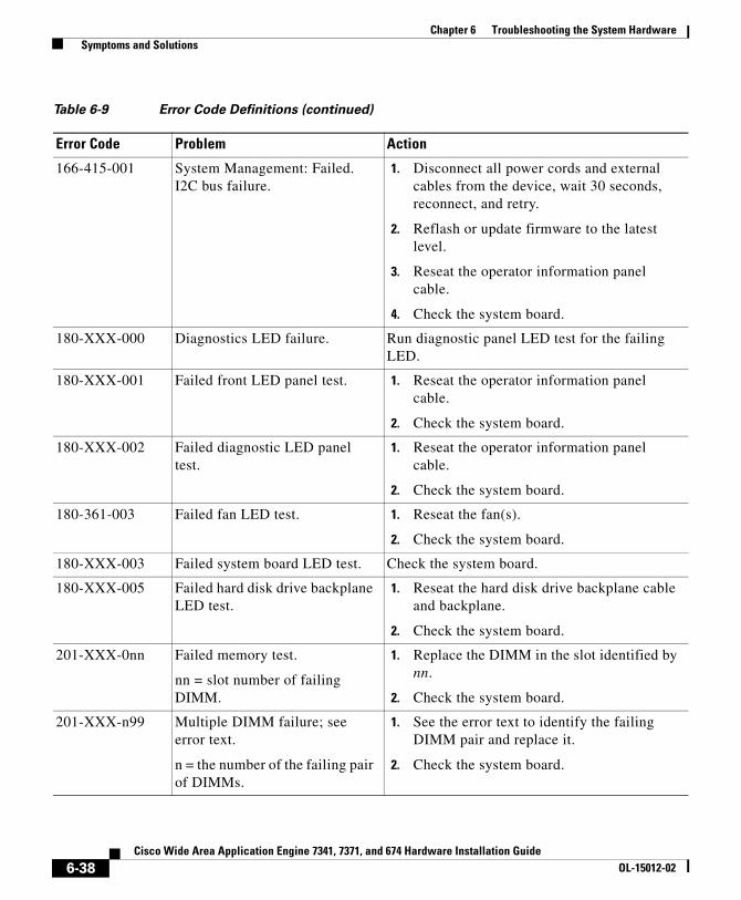
Chapter 6 Troubleshooting the System Hardware Symptoms and Solutions
166-415-001 System Management: Failed. I2C bus failure.
1. Disconnect all power cords and external cables from the device, wait 30 seconds, reconnect, and retry.
2. Reflash or update firmware to the latest level.
3. Reseat the operator information panel cable.
4. Check the system board.
180-XXX-000 Diagnostics LED failure. Run diagnostic panel LED test for the failing LED.
180-XXX-001 Failed front LED panel test. 1. Reseat the operator information panel cable.
2. Check the system board.
180-XXX-002 Failed diagnostic LED panel test.
1. Reseat the operator information panel cable.
2. Check the system board.
180-361-003 Failed fan LED test. 1. Reseat the fan(s).
2. Check the system board.
180-XXX-003 Failed system board LED test. Check the system board.
180-XXX-005 Failed hard disk drive backplane LED test.
1. Reseat the hard disk drive backplane cable and backplane.
2. Check the system board.
201-XXX-0nn Failed memory test.
nn = slot number of failing DIMM.
1. Replace the DIMM in the slot identified by nn.
2. Check the system board.
201-XXX-n99 Multiple DIMM failure; see error text.
n = the number of the failing pair of DIMMs.
1. See the error text to identify the failing DIMM pair and replace it.
2. Check the system board.
Table 6-9 Error Code Definitions (continued)
Error Code Problem Action
6-38Cisco Wide Area Application Engine 7341, 7371, and 674 Hardware Installation Guide
OL-15012-02
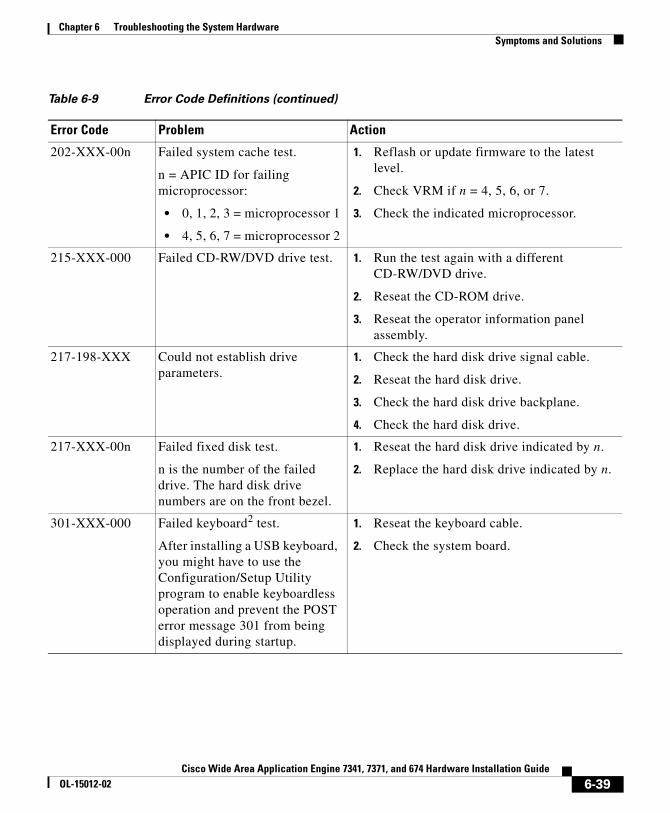
Chapter 6 Troubleshooting the System Hardware Symptoms and Solutions
202-XXX-00n Failed system cache test.
n = APIC ID for failing microprocessor:
• 0, 1, 2, 3 = microprocessor 1
• 4, 5, 6, 7 = microprocessor 2
1. Reflash or update firmware to the latest level.
2. Check VRM if n = 4, 5, 6, or 7.
3. Check the indicated microprocessor.
215-XXX-000 Failed CD-RW/DVD drive test. 1. Run the test again with a different CD-RW/DVD drive.
2. Reseat the CD-ROM drive.
3. Reseat the operator information panel assembly.
217-198-XXX Could not establish drive parameters.
1. Check the hard disk drive signal cable.
2. Reseat the hard disk drive.
3. Check the hard disk drive backplane.
4. Check the hard disk drive.
217-XXX-00n Failed fixed disk test.
n is the number of the failed drive. The hard disk drive numbers are on the front bezel.
1. Reseat the hard disk drive indicated by n.
2. Replace the hard disk drive indicated by n.
301-XXX-000 Failed keyboard2 test.
After installing a USB keyboard, you might have to use the Configuration/Setup Utility program to enable keyboardless operation and prevent the POST error message 301 from being displayed during startup.
1. Reseat the keyboard cable.
2. Check the system board.
Table 6-9 Error Code Definitions (continued)
Error Code Problem Action
6-39Cisco Wide Area Application Engine 7341, 7371, and 674 Hardware Installation Guide
OL-15012-02

Chapter 6 Troubleshooting the System Hardware Symptoms and Solutions
Error SymptomsYou can use the error symptom tables to find solutions to problems that have definite symptoms.
If you cannot find the problem in the error symptom tables, go to the “Starting the Diagnostic Programs” section on page 6-9 to test the device.
If you have just added new software or a new hardware option and your device is not working, complete the following steps before using the error symptom tables:
Step 1 Remove the software or hardware option that you just added.
Step 2 Run the diagnostic tests to determine if your device is running correctly.
Step 3 Reinstall the new software or new hardware option.
In the following tables (Table 6-10 to Table 6-19), the first entry in the “Cause and Action” column is the most likely cause of the symptom.
405-XXX-000 Failed Ethernet test on Ethernet controller.
1. Verify that Ethernet is not disabled in the BIOS.
2. Check the system board.
405-XXX-00n Failed Ethernet test on adapter in PCI slot n.
1. Check the adapter in PCI slot n.
2. Check the system board.
1. USB = Universal Serial Bus. The WAAS software does not support USB peripheral devices.
2. The WAAS software does not support keyboards. No keyboard errors are expected; however, if a keyboard error appears during bootup, contact your customer service representative.
Table 6-9 Error Code Definitions (continued)
Error Code Problem Action
6-40Cisco Wide Area Application Engine 7341, 7371, and 674 Hardware Installation Guide
OL-15012-02

Chapter 6 Troubleshooting the System Hardware Symptoms and Solutions
Table 6-10 CD-RW/DVD Drive Problems
Symptom Cause and Action
CD-RW/DVD drive is not recognized.
1. Verify the following items:
a. The IDE channel to which the CD-RW/DVD drive is attached (primary) is enabled in the configuration/setup utility program.
b. All cables and jumpers are installed correctly.
c. The correct device driver is installed for the CD-RW/DVD drive.
2. Run the CD-RW/DVD drive diagnostic programs.
3. Check the CD-RW/DVD drive.
The CD-RW/DVD drive is not working correctly.
1. Clean the CD or DVD.
2. Run the CD-RW/DVD drive diagnostic programs.
3. Check the CD-RW/DVD drive.
The CD-RW/DVD drive tray is not working.
1. Make sure that the device is turned on.
2. Insert the end of a straightened paper clip into the manual tray-release opening.
3. Check the CD-RW/DVD drive.
Table 6-11 Hard Disk Drive Problems
Symptom Cause and Action
Not all drives are recognized by the hard disk drive diagnostic test (fixed disk test).
1. Remove the first drive not recognized and try the hard disk drive diagnostic test again.
2. If the remaining drives are recognized, the drive that you removed needs to be replaced.
System stops responding during hard disk drive diagnostic test.
1. Remove the hard disk drive being tested when the device stopped responding and try the diagnostic test again.
2. If the hard disk drive diagnostic test runs successfully, the drive that you removed needs to be replaced.
6-41Cisco Wide Area Application Engine 7341, 7371, and 674 Hardware Installation Guide
OL-15012-02

Chapter 6 Troubleshooting the System Hardware Symptoms and Solutions
A hard disk drive was not detected while the operating system was being started.
Reseat all hard disk drives and cables. Run the hard disk drive diagnostic tests again.
A hard disk drive passes the diagnostic Fixed Disk Test, but the problem remains.
Run the diagnostic SCSI Attached Disk Test.
Table 6-12 General Problems
Symptom Cause and Action
Problems such as broken cover locks or indicator LEDs not working.
Broken component. Call your customer service representative.
Table 6-13 Intermittent Problems
Symptom Cause and Action
A problem occurs only occasionally and is difficult to detect.
1. Verify the following items:
a. All cables and cords are connected securely to the rear of the device and attached hardware options.
b. When the device is powered on, air is flowing from the rear of the device at the fan grille. If there is no airflow, the fans are not working. This causes the device to overheat and shut down.
2. Check the system error log.
3. See the “Undetermined Problems” section on page 6-21.
Table 6-11 Hard Disk Drive Problems (continued)
Symptom Cause and Action
6-42Cisco Wide Area Application Engine 7341, 7371, and 674 Hardware Installation Guide
OL-15012-02

Chapter 6 Troubleshooting the System Hardware Symptoms and Solutions
Table 6-14 Memory Problems
Symptom Cause and Action
The amount of system memory displayed is less than the amount of physical memory installed.
1. Verify the following items:
a. No error LEDs are lit on the operator information panel.
b. The memory modules are seated properly.
c. The correct type of memory has been installed.
d. All banks of memory on the DIMMs are enabled. The device might have automatically disabled a DIMM bank when it detected a problem, or a DIMM bank could have been manually disabled.
2. Check the POST error log for error message 289:
a. If the DIMM was disabled by a system management interrupt (SMI), the DIMM needs to be replaced. Have the system serviced.
b. If the DIMM was disabled by the user or by POST, follow these steps:
– Start the configuration/setup utility program.
– Enable the DIMM.
– Save the configuration and restart the device.
3. Run the memory diagnostics.
4. Check the DIMM.
5. Check the system board.
Table 6-15 Microprocessor Problems
Symptom Cause and Action
The device emits a continuous tone during POST, indicating that the microprocessor is not working correctly.
1. Correct any errors that are indicated by the LEDs (see the “Diagnostic Panel LEDs” section on page 6-17).
2. Check the microprocessor and the VRM.
6-43Cisco Wide Area Application Engine 7341, 7371, and 674 Hardware Installation Guide
OL-15012-02
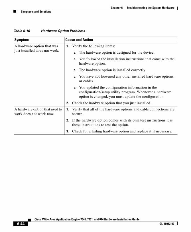
Chapter 6 Troubleshooting the System Hardware Symptoms and Solutions
Table 6-16 Hardware Option Problems
Symptom Cause and Action
A hardware option that was just installed does not work.
1. Verify the following items:
a. The hardware option is designed for the device.
b. You followed the installation instructions that came with the hardware option.
c. The hardware option is installed correctly.
d. You have not loosened any other installed hardware options or cables.
e. You updated the configuration information in the configuration/setup utility program. Whenever a hardware option is changed, you must update the configuration.
2. Check the hardware option that you just installed.
A hardware option that used to work does not work now.
1. Verify that all of the hardware options and cable connections are secure.
2. If the hardware option comes with its own test instructions, use those instructions to test the option.
3. Check for a failing hardware option and replace it if necessary.
6-44Cisco Wide Area Application Engine 7341, 7371, and 674 Hardware Installation Guide
OL-15012-02

Chapter 6 Troubleshooting the System Hardware Symptoms and Solutions
Table 6-17 Power Problems
Symptom FRU or Action
The power-control button does not work, and the reset button does not work (the device does not start).
Note The power-control button will not function until 20 seconds after the device has been connected to power.
1. Verify the following items:
a. The power cables are properly connected to the device.
b. The electrical outlet functions properly.
c. The type of memory installed is correct.
d. The LEDs on the power supply do not indicate a problem (see the “Power Supply LEDs” section on page 6-16).
2. Make sure that the power-control button and the reset button are working correctly:
a. Disconnect the device power cords.
b. Reseat the operator information panel assembly cable.
c. Reconnect the power cords.
d. Press the power-control button to restart the device. If the button does not work, replace the operator information panel assembly.
e. Press the reset button (on the Light Path Diagnostics panel) to restart the device. If the button does not work, replace the operator information panel assembly.
3. If you just installed a hardware option, remove it, and restart the device.
4. Reseat the power backplane and restart the device.
5. Check the power backplane and the hot-swap power supplies.
6. See the “Checking the Power Subsystem” section on page 6-11 and the “Undetermined Problems” section on page 6-21.
6-45Cisco Wide Area Application Engine 7341, 7371, and 674 Hardware Installation Guide
OL-15012-02

Chapter 6 Troubleshooting the System Hardware Symptoms and Solutions
The OVER SPEC LED on the Light Path Diagnostics panel is lit, and the power channel A LED on the system board is lit.
1. Remove fans 4, 6, 8, and 9 and restart the device. If the OVER SPEC and power channel LEDs are still lit, do the following:
a. Check the hot-swap power supplies, replacing them one at a time. Restart the device each time that you reinstall a power supply.
b. Check the power backplane.
c. Check the system board.
2. Reinstall the fans listed in Step 1, one at a time, in the order shown. Restart the device each time that you reinstall a fan. If the power channel A LED is lit, the component that you just reinstalled is defective. Replace the defective component.
The OVER SPEC LED on the Light Path Diagnostics panel is lit, and the power channel B LED on the system board is lit.
1. Remove fans 1, 2, 3, 5, and the IDE CD/DVD cable, and restart the device. If the OVER SPEC and power channel LEDs are still lit, do the following:
a. Check the hot-swap power supplies, replacing them one at a time. Restart the device each time that you reinstall a power supply.
b. Check the power backplane.
c. Check the system board.
2. Reinstall the IDE CD/DVD cable and drive and restart the device. If the OVER SPEC and power channel LEDs are still off, replace the CD-RW/DVD drive.
3. Reinstall the components listed in Step 1, one at a time, in the order shown. Restart the device each time that you reinstall a component. If the power channel B LED is lit, the component that you just reinstalled is defective. Replace the defective component.
Table 6-17 Power Problems (continued)
Symptom FRU or Action
6-46Cisco Wide Area Application Engine 7341, 7371, and 674 Hardware Installation Guide
OL-15012-02

Chapter 6 Troubleshooting the System Hardware Symptoms and Solutions
The OVER SPEC LED on the Light Path Diagnostics panel is lit, and the power channel C LED on the system board is lit.
1. Remove the DIMMs and the ServerRAID SAS controller, and restart the device. If the OVER SPEC and power channel LEDs are still lit, do the following:
a. Check the hot-swap power supplies, replacing them one at a time. Restart the device each time that you reinstall a power supply.
b. Check the power backplane.
c. Check the system board.
2. Restart the device. If the OVER SPEC and power channel LEDs are off, reinstall the DIMMs, one pair at a time. Restart the device each time that you reinstall a DIMM. If the power channel C LED is lit, the pair of DIMMs that you just reinstalled is defective. Replace the defective DIMMs.
3. Reinstall the ServeRAID SAS controller and restart the device. If the OVER SPEC and power channel LEDs are off, replace the ServeRAID SAS controller.
The OVER SPEC LED on the Light Path Diagnostics panel is lit, and the power channel D LED on the system board is lit.
1. Remove all PCI adapters (the low-profile PCI Express adapters in PCI slots 3 and 4, and the adapters on the PCI riser card in PCI slots 1 and 2). If the OVER SPEC and power channel LEDs are still lit, do the following:
a. Check the hot-swap power supplies, replacing them one at a time. Restart the device each time that you reinstall a power supply.
b. Check the power backplane.
c. Check the system board.
2. Reinstall the adapters, one at a time. Restart the device each time that you reinstall an adapter. If the power channel D LED is lit, the adapter that you just reinstalled is defective. Replace the defective adapter.
Table 6-17 Power Problems (continued)
Symptom FRU or Action
6-47Cisco Wide Area Application Engine 7341, 7371, and 674 Hardware Installation Guide
OL-15012-02
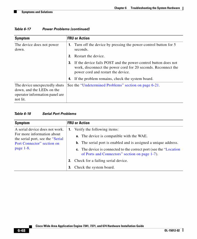
Chapter 6 Troubleshooting the System Hardware Symptoms and Solutions
The device does not power down.
1. Turn off the device by pressing the power-control button for 5 seconds.
2. Restart the device.
3. If the device fails POST and the power-control button does not work, disconnect the power cord for 20 seconds. Reconnect the power cord and restart the device.
4. If the problem remains, check the system board.
The device unexpectedly shuts down, and the LEDs on the operator information panel are not lit.
See the “Undetermined Problems” section on page 6-21.
Table 6-18 Serial Port Problems
Symptom FRU or Action
A serial device does not work. For more information about the serial port, see the “Serial Port Connector” section on page 1-8.
1. Verify the following items:
a. The device is compatible with the WAE.
b. The serial port is enabled and is assigned a unique address.
c. The device is connected to the correct port (see the “Location of Ports and Connectors” section on page 1-7).
2. Check for a failing serial device.
3. Check the system board.
Table 6-17 Power Problems (continued)
Symptom FRU or Action
6-48Cisco Wide Area Application Engine 7341, 7371, and 674 Hardware Installation Guide
OL-15012-02

Chapter 6 Troubleshooting the System Hardware Symptoms and Solutions
Table 6-19 Software Problems
Symptom Cause and Action
Suspected software problem. 1. To determine if problems are caused by the software, verify the following items:
a. Your device has the minimum memory needed to use the software. For memory requirements, see the information that comes with the software.
Note If you have just installed an adapter or memory, you might have a memory address conflict.
b. The software is designed to operate on your device.
c. Other software works on your device.
d. The software that you are using works on another device.
2. If you received any error messages when using the software program, see the information that comes with the software for a description of the messages and suggested solutions to the problem.
POST Error CodesIn the error codes in Table 6-20, X can be any number or letter.
Table 6-20 POST Error Codes
Error Code Symptom Cause and Action
062 Three consecutive startup failures using the default configuration.
1. Run the configuration/setup utility program.
2. Check the battery.
3. Check the microprocessor.
4. Check the system board.
101, 102 System and processor error. Check the system board.
106 System and processor error. Check the system board.
6-49Cisco Wide Area Application Engine 7341, 7371, and 674 Hardware Installation Guide
OL-15012-02

Chapter 6 Troubleshooting the System Hardware Symptoms and Solutions
151 Real-time clock error. 1. Check the battery.
2. Check the system board.
161 Real-time clock battery error. 1. Check the battery.
2. Check the system board.
162 Device configuration error. 1. Run the Configuration/Setup Utility program, choose Load Default Settings, and save the settings.
2. Check the battery.
3. Check for failing device.
4. Check the system board.
163 Real-time clock error (time of day not set).
1. Run the Configuration/Setup Utility program, choose Load Default Settings, make sure that the date and time are correct, and save the settings.
2. Check the battery.
3. Check the system board.
175 Hardware error. Check the system board.
184 Power-on password damaged. 1. Restart the device and enter the administrator password; then, run the Configuration/Setup Utility program, choose Load Default Settings, and save the settings.
2. Check the battery.
3. Check the system board.
187 VPD serial number not set. Check the system board.
189 An attempt was made to access the device with invalid passwords.
Check your passwords.
289 DIMM disabled by POST or user. Check for a disabled DIMM, if not disabled by the user.
Table 6-20 POST Error Codes (continued)
Error Code Symptom Cause and Action
6-50Cisco Wide Area Application Engine 7341, 7371, and 674 Hardware Installation Guide
OL-15012-02

Chapter 6 Troubleshooting the System Hardware Symptoms and Solutions
301 Keyboard1 or keyboard controller error.
1. Reseat the keyboard cable in the USB connector.
2. Move the keyboard cable to a different USB connector.
3. Check the keyboard
4. Check the internal USB cable.
5. Check the system board.
303 Keyboard1controller error. 1. Reseat the keyboard cable in the USB connector.
2. Check the keyboard.
3. Check the system board.
1600 The service processor is not functioning.
Not applicable.
178X Fixed disk error. (x is the drive that has the error.)
1. Run the hard disk drive diagnostic tests on drive x.
2. Check the hard disk drive.
3. Check the cable from the system board to the backplane.
4. Check the system board.
1800 No more hardware interrupts available for PCI adapter.
Check for failing adapter.
1801 An adapter has requested memory resources that are not available.
1. Check for failing adapter.
2. Check the system board.
Table 6-20 POST Error Codes (continued)
Error Code Symptom Cause and Action
6-51Cisco Wide Area Application Engine 7341, 7371, and 674 Hardware Installation Guide
OL-15012-02
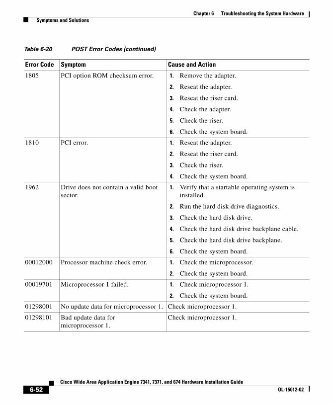
Chapter 6 Troubleshooting the System Hardware Symptoms and Solutions
1805 PCI option ROM checksum error. 1. Remove the adapter.
2. Reseat the adapter.
3. Reseat the riser card.
4. Check the adapter.
5. Check the riser.
6. Check the system board.
1810 PCI error. 1. Reseat the adapter.
2. Reseat the riser card.
3. Check the riser.
4. Check the system board.
1962 Drive does not contain a valid boot sector.
1. Verify that a startable operating system is installed.
2. Run the hard disk drive diagnostics.
3. Check the hard disk drive.
4. Check the hard disk drive backplane cable.
5. Check the hard disk drive backplane.
6. Check the system board.
00012000 Processor machine check error. 1. Check the microprocessor.
2. Check the system board.
00019701 Microprocessor 1 failed. 1. Check microprocessor 1.
2. Check the system board.
01298001 No update data for microprocessor 1. Check microprocessor 1.
01298101 Bad update data for microprocessor 1.
Check microprocessor 1.
Table 6-20 POST Error Codes (continued)
Error Code Symptom Cause and Action
6-52Cisco Wide Area Application Engine 7341, 7371, and 674 Hardware Installation Guide
OL-15012-02
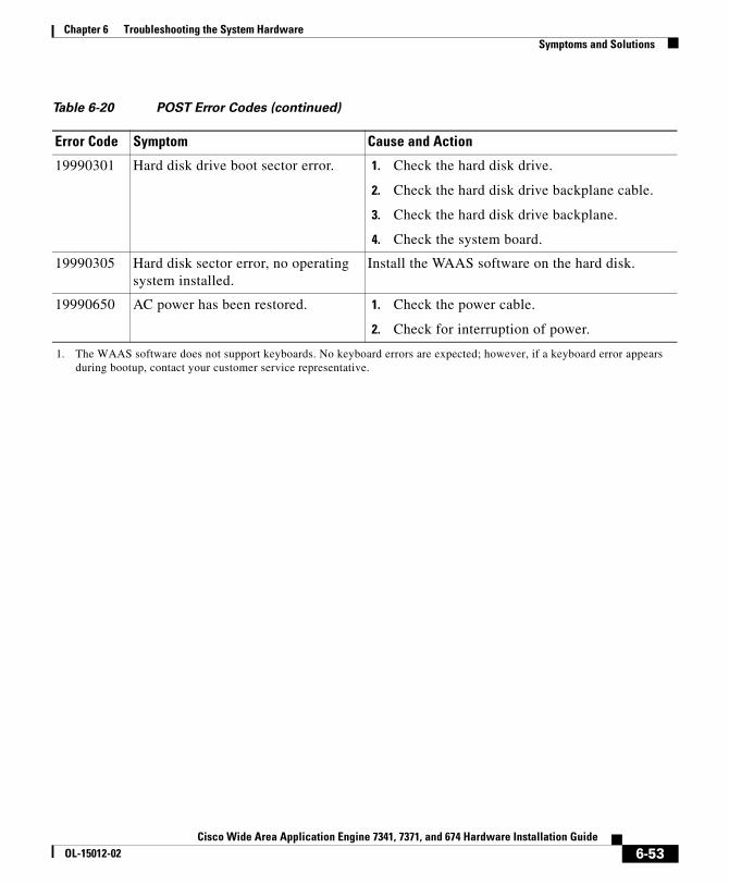
Chapter 6 Troubleshooting the System Hardware Symptoms and Solutions
19990301 Hard disk drive boot sector error. 1. Check the hard disk drive.
2. Check the hard disk drive backplane cable.
3. Check the hard disk drive backplane.
4. Check the system board.
19990305 Hard disk sector error, no operating system installed.
Install the WAAS software on the hard disk.
19990650 AC power has been restored. 1. Check the power cable.
2. Check for interruption of power.
1. The WAAS software does not support keyboards. No keyboard errors are expected; however, if a keyboard error appears during bootup, contact your customer service representative.
Table 6-20 POST Error Codes (continued)
Error Code Symptom Cause and Action
6-53Cisco Wide Area Application Engine 7341, 7371, and 674 Hardware Installation Guide
OL-15012-02

Chapter 6 Troubleshooting the System Hardware Symptoms and Solutions
6-54Cisco Wide Area Application Engine 7341, 7371, and 674 Hardware Installation Guide
OL-15012-02

Cisco Wide Area Application Engine 7341, 7371, aOL-15012-02
A P P E N D I X A
Wide Area Application Engine Hardware SpecificationsThis appendix provides hardware specifications for the WAE-7371, WAE-7341, and WAE-674 appliances and the optional Cisco WAE inline network adapter. It contains the following sections:
• Appliance Specifications, page A-1
• Adapter Specifications, page A-5
Appliance SpecificationsTable A-1 provides a summary of the features and specifications of the Wide Area Application Engine (WAE) 7371, 7341, and 674.
A-1nd 674 Hardware Installation Guide

Appendix A Wide Area Application Engine Hardware Specifications Appliance Specifications
Table A-1 WAE 7371, 7341, and 674 Features and Specifications
Specification Description
Microprocessor • WAE-7371: 2 Xeon quad-core processors, 2.33 GHz
• WAE-7341: 1 Xeon quad-core processor, 2.33 GHz
• WAE-674: 1 Xeon quad-core processor, 2.00 GHz
• 8 MB Level 2 cache
• 1333-MHz front-side bus (FSB)
Note Use the Configuration/Setup utility program to determine the type and speed of the microprocessors.
Memory • WAE-7371: 24 GB
• WAE-7341: 12 GB
• WAE-674: 4 GB (optionally 8 GB)
Drives standard • DVD-ROM/CD-RW combination drive
• WAE-7371: RAID-5 array with six 300-GB SAS hard disk drives
• WAE-7341: RAID-5 array with four 300-GB SAS hard disk drives
• WAE-674: RAID-5 array with three 300-GB SAS hard disk drives
Expansion bays • 6 hot-swap, 3.5-inch hard disk drive bays
• 1 5.25-inch (13.34-cm) bay (DVD-ROM/CD-RW combination drive installed)
Fans • WAE-7371 and WAE-7341: 10 fans
• WAE-674: 5 fans (optionally 10 fans)
Hot-swap Power supplies • WAE-7371 and WAE-7341: 2 hot-swap, 835 W, 100–240 VAC
• WAE-674: 1 hot-swap, 835 W, 100–240 VAC (optionally 2 power supplies)
Expansion slots • 2 PCI-X non-hot-pluggable 133-MHz/64-bit (one full length and one half length)
• 2 PCI-Express non-hot-pluggable (low profile)
A-2Cisco Wide Area Application Engine 7341, 7371, and 674 Hardware Installation Guide
OL-15012-02

Appendix A Wide Area Application Engine Hardware Specifications Appliance Specifications
Size • Height: 3.36 in. (85.4 mm)
• Depth: 27.8 in. (705.0 mm)
• Width: 17.5 in. (443.6 mm)
Weight 46.5 lb (21.09 kg) to 64 lb (29.03 kg) depending upon configuration
Integrated functions • Baseboard management controller
• 2 Broadcom 10/100/1000 Ethernet controllers (dual-port design) with Wake on LAN support
• 1 serial port
• 1 RAID controller
• 1 serial attached SCSI (SAS) controller
Note The baseboard management controller is also known as the service processor.
Electrical Input • Sine wave input (50–60 Hz) required
• Input voltage range automatically selected
• Input voltage low range:
– Minimum: 100 VAC
– Maximum: 127 VAC
• Input voltage high range:
– Minimum: 200 VAC
– Maximum: 240 VAC
• Input kilovolt-amperes (kVA) approximately:
– Minimum: 0.29 kVA
– Maximum: 1.0 kVA
Table A-1 WAE 7371, 7341, and 674 Features and Specifications (continued)
Specification Description
A-3Cisco Wide Area Application Engine 7341, 7371, and 674 Hardware Installation Guide
OL-15012-02
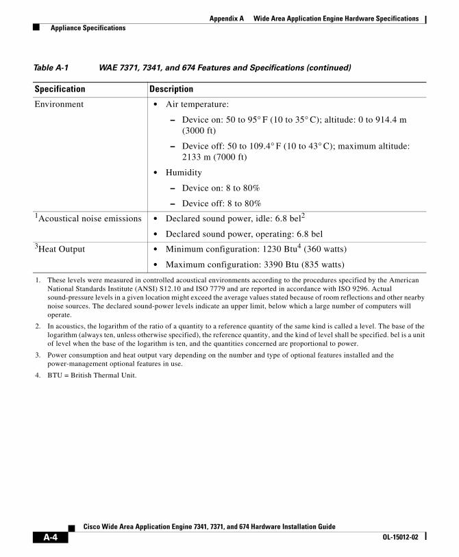
Appendix A Wide Area Application Engine Hardware Specifications Appliance Specifications
Environment • Air temperature:
– Device on: 50 to 95° F (10 to 35° C); altitude: 0 to 914.4 m (3000 ft)
– Device off: 50 to 109.4° F (10 to 43° C); maximum altitude: 2133 m (7000 ft)
• Humidity
– Device on: 8 to 80%
– Device off: 8 to 80%1Acoustical noise emissions • Declared sound power, idle: 6.8 bel2
• Declared sound power, operating: 6.8 bel3Heat Output • Minimum configuration: 1230 Btu4 (360 watts)
• Maximum configuration: 3390 Btu (835 watts)
1. These levels were measured in controlled acoustical environments according to the procedures specified by the American National Standards Institute (ANSI) S12.10 and ISO 7779 and are reported in accordance with ISO 9296. Actual sound-pressure levels in a given location might exceed the average values stated because of room reflections and other nearby noise sources. The declared sound-power levels indicate an upper limit, below which a large number of computers will operate.
2. In acoustics, the logarithm of the ratio of a quantity to a reference quantity of the same kind is called a level. The base of the logarithm (always ten, unless otherwise specified), the reference quantity, and the kind of level shall be specified. bel is a unit of level when the base of the logarithm is ten, and the quantities concerned are proportional to power.
3. Power consumption and heat output vary depending on the number and type of optional features installed and the power-management optional features in use.
4. BTU = British Thermal Unit.
Table A-1 WAE 7371, 7341, and 674 Features and Specifications (continued)
Specification Description
A-4Cisco Wide Area Application Engine 7341, 7371, and 674 Hardware Installation Guide
OL-15012-02

Appendix A Wide Area Application Engine Hardware Specifications Adapter Specifications
Adapter SpecificationsTable A-2 describes the inline network adapter technical and general specifications.
Table A-2 Inline Network Adapter Specifications
Specification Description
Copper Gigabit Ethernet Specifications
IEEE standard • Gigabit Ethernet, 1000BASE-T
• Fast Ethernet, 100BASE-T
• Ethernet, 10BASE-T
Full duplex and half duplex Supports both half-duplex and full-duplex operation in all operating speeds
Autonegotiation Autonegotiates between full-duplex and half-duplex operations and between 1000-Mbps, 100-Mbps, and 10-Mbps speeds
Data transfer rate • 1000-Mbps, 100-Mbps, and 10-Mbps speeds per port in half-duplex mode
• 2000-Mbps, 200-Mbps, and 20-Mbps speeds per port in full-duplex mode
General Technical Specifications
Interface standard • PCI v2.2 32/64 bit, 33/66 MHz
• PCI-X v1.0 32/64 bit, 66/100/133 MHz
Size 6.6 x 4.2 in. (167.64 x 106.68 mm)
PCI connector Universal 64-bit connector
PCI voltage • +12 V (minimum 11.4 V, maximum 12.6 V)
• +3.3 V (minimum 3.0 V, maximum 3.6 V)
Weight 6.18 oz (175 g)
Operating humidity 0 to 90%, noncondensing
Operating temperature 32 to –122oF (0 to 50oC)
Storage temperature –4 to –149oF (–20 to –65oC)
A-5Cisco Wide Area Application Engine 7341, 7371, and 674 Hardware Installation Guide
OL-15012-02

Appendix A Wide Area Application Engine Hardware Specifications Adapter Specifications
A-6Cisco Wide Area Application Engine 7341, 7371, and 674 Hardware Installation Guide
OL-15012-02

Cisco Wide Area Application Engine 7341, 7371, aOL-15012-02
A P P E N D I X B
Maintaining the Wide Area Application EngineProper use of preventive maintenance procedures can keep the Wide Area Application Engine (WAE) in good operating condition and minimize the need for costly, time-consuming service procedures. This chapter contains maintenance procedures that you should perform regularly.
This chapter covers the tasks required for maintaining a WAE or a WAE farm:
• Maintaining Your Site Environment, page B-1
• Using Power Protection Devices, page B-7
Maintaining Your Site EnvironmentAn exhaust fan in the power supply cools the power supply and system by drawing air in through various openings in the system and blowing it out the back. However, the fan also draws dust and other particles into the system, causing contaminant buildup, which results in an increase in the system’s internal temperature and interferes with the operation of various system components.
To avoid these conditions, we recommend keeping your work environment clean to reduce the amount of dust and dirt around the system, thereby reducing the amount of contaminants drawn into the system by the power supply fan.
This section discusses various environmental factors that can adversely affect system performance and longevity.
• Temperature, page B-2
B-1nd 674 Hardware Installation Guide

Appendix B Maintaining the Wide Area Application Engine Maintaining Your Site Environment
• Humidity, page B-3
• Altitude, page B-3
• Dust and Particles, page B-4
• Corrosion, page B-4
• Electrostatic Discharge, page B-4
• Electromagnetic and Radio Frequency Interference, page B-5
• Magnetism, page B-5
• Shock and Vibration, page B-6
• Power Source Interruptions, page B-6
TemperatureTemperature extremes can cause a variety of problems, including premature aging and failure of chips or mechanical failure of devices. Extreme temperature fluctuations can cause chips to become loose in their sockets and can cause expansion and contraction of disk drive platters, resulting in read or write data errors.
To minimize the negative effects of the temperature on system performance, follow these guidelines:
• Ensure that the system is operated in an environment no colder than 50° F (10° C) or hotter than 95° F (35° C).
• Ensure that the system has adequate ventilation. Do not place it within a closed-in wall unit or on top of cloth, which can act as insulation. Do not place it where it will receive direct sunlight, particularly in the afternoon. Do not place it next to a heat source of any kind, including heating vents during winter.
Adequate ventilation is particularly important at high altitudes. System performance may not be optimum when the system is operating at high temperatures as well as high altitudes.
• Make sure that all slots and openings on the system remain unobstructed, especially the fan vent on the back of the system.
• Clean the system at regular intervals to avoid any buildup of dust and debris, which can cause a system to overheat.
B-2Cisco Wide Area Application Engine 7341, 7371, and 674 Hardware Installation Guide
OL-15012-02
Appendix B Maintaining the Wide Area Application Engine Maintaining Your Site Environment
• If the system has been exposed to abnormally cold temperatures, allow a 2-hour warm-up period to bring it up to a normal operating temperature before turning it on. Failure to do so may cause damage to internal components, particularly the hard disk drive.
• If intermittent system failures are noticed, try reseating any socketed chips, which might have become loose because of temperature fluctuations.
HumidityHigh-humidity conditions can cause moisture migration and penetration into the system. This moisture can cause corrosion of internal components and degradation of properties such as electrical resistance and thermal conductivity. Extreme moisture buildup inside the system can result in electrical shorts, which can cause serious damage to the system.
Each system is rated to operate at 8 to 80 percent relative humidity, with a humidity gradation of 10 percent per hour. Buildings in which climate is controlled by air conditioning in the warmer months and by heat during the colder months usually maintain an acceptable level of humidity for system equipment. However, if a system is located in an unusually humid location, a dehumidifier can be used to maintain the humidity within an acceptable range.
AltitudeOperating a system at high altitude (low pressure) reduces the efficiency of forced and convection cooling and can result in electrical problems related to arcing and corona effects. This condition can also cause sealed components with internal pressure, such as electrolytic capacitors, to fail or perform at reduced efficiency.
Each system is designed to operate at a maximum altitude of 3000 feet (914.4 meters) and can be stored at a maximum altitude of 7000 feet (2133 meters).
B-3Cisco Wide Area Application Engine 7341, 7371, and 674 Hardware Installation Guide
OL-15012-02

Appendix B Maintaining the Wide Area Application Engine Maintaining Your Site Environment
Dust and ParticlesA clean operating environment can greatly reduce the negative effects of dust and other particles, which act as insulators and interfere with the operation of a system’s mechanical components. In addition to regular cleaning, you should follow these guidelines to deter contamination of the system equipment:
• Do not permit smoking anywhere near the system.
• Do not permit food or drink near the system.
• Use dust covers when the system is not in use.
• Close windows and outside doors to keep out airborne particles.
CorrosionThe oil from a person’s fingers or prolonged exposure to high temperature or humidity can corrode the gold-plated edge connectors and pin connectors on various devices in the system. This corrosion on system connectors is a gradual process that can eventually lead to intermittent failures of electrical circuits.
To prevent corrosion, you should avoid touching contacts on boards and cards. Protecting the system from corrosive elements is especially important in moist and salty environments, which tend to promote corrosion. Also, as a further deterrent to corrosion, the system should not be used in extreme temperatures, as explained in the “Temperature” section on page B-2.
Electrostatic DischargeElectrostatic discharge (ESD) results from the buildup of static electricity on the human body and certain other objects. This static electricity is often produced by simple movements such as walking across a carpet. ESD is a discharge of a static electrical charge that occurs when a person whose body contains such a charge touches a component in the system. This static discharge can cause components, especially chips, to fail. ESD is a problem particularly in dry environments where the relative humidity is below 50 percent.
To reduce the effects of ESD, you should observe the following guidelines:
B-4Cisco Wide Area Application Engine 7341, 7371, and 674 Hardware Installation Guide
OL-15012-02

Appendix B Maintaining the Wide Area Application Engine Maintaining Your Site Environment
• Wear a grounding wrist strap. If a grounding wrist strap is unavailable, touch an unpainted metal surface on the chassis periodically to neutralize any static charge.
• Keep components in their antistatic packaging until they are installed.
• Avoid wearing clothing made of wool or synthetic materials.
Electromagnetic and Radio Frequency Interference Electromagnetic interference (EMI) and radio frequency interference (RFI) from a system can adversely affect devices such as radio and television (TV) receivers operating near the system. Radio frequencies emanating from a system can also interfere with cordless and low-power telephones. Conversely, RFI from high-power telephones can cause spurious characters to appear on the system’s monitor screen.
RFI is defined as any EMI with a frequency above 10 kilohertz (kHz). This type of interference can travel from the system to other devices through the power cable and power source or through the air like transmitted radio waves. The Federal Communications Commission (FCC) publishes specific regulations to limit the amount of EMI and RFI emitted by computing equipment. Each system meets these FCC regulations.
To reduce the possibility of EMI and RFI, follow these guidelines:
• Operate the system only with the system cover installed.
• Ensure that the screws on all peripheral cable connectors are securely fastened to their corresponding connectors on the back of the system.
• Always use shielded cables with metal connector shells for attaching peripherals to the system.
MagnetismBecause they store data magnetically, hard disk drives are extremely susceptible to the effects of magnetism. Hard disk drives should never be stored near magnetic sources such as the following:
• Monitors
• TV sets
B-5Cisco Wide Area Application Engine 7341, 7371, and 674 Hardware Installation Guide
OL-15012-02
Appendix B Maintaining the Wide Area Application Engine Maintaining Your Site Environment
• Printers
• Telephones with real bells
• Fluorescent lights
Shock and VibrationExcessive shock can damage the function, external appearance, and physical structure of a system. Each system has been designed to operate properly even after withstanding a minimum of six consecutively executed shock pulses in the positive and negative x, y, and z axes (one pulse on each side of the system). Each shock pulse can measure up to 5 gravities (G) for up to 11 milliseconds (ms). In storage, the system can withstand shock pulses of 20 G for 11 ms.
Excessive vibration can cause the same problems as mentioned earlier for shock, as well as causing components to become loose in their sockets or connectors. Systems can be subject to significant vibration when being transported by vehicle or when operated in an environment with machinery that causes vibration.
Power Source InterruptionsSystems are especially sensitive to variations in voltage supplied by the AC power source. Overvoltage, undervoltage, and transients (or spikes) can erase data from memory or even cause components to fail. To protect against these types of problems, power cables should always be properly grounded and one or both of the following methods should be used:
• Use one of the power protection devices described in the “Using Power Protection Devices” section on page B-7.
• Place the system on a dedicated power circuit (rather than sharing a circuit with other heavy electrical equipment). In general, do not allow the system to share a circuit with any of the following:
– Copier machines
– Air conditioners
– Vacuum cleaners
– Space heaters
– Power tools
B-6Cisco Wide Area Application Engine 7341, 7371, and 674 Hardware Installation Guide
OL-15012-02

Appendix B Maintaining the Wide Area Application Engine Using Power Protection Devices
– Teletype machines
– Adding machines
– Laser printers
– Facsimile machines
– Any other motorized equipment
Besides these appliances, the greatest threats to a system’s supply of power are surges or blackouts caused by electrical storms. Whenever possible, turn off the system and any peripherals and unplug them from their power sources during thunderstorms.
If a blackout occurs—even a temporary one—while the system is turned on, turn off the system immediately and disconnect it from the electrical outlet. Leaving the system on may cause problems when the power is restored; all other appliances left on in the area can create large voltage spikes that can damage the system.
Using Power Protection DevicesA number of devices are available that protect against power problems such as power surges, transients, and power failures. The following subsections describe some of these devices:
• Surge Protectors, page B-7
• Line Conditioners, page B-8
• Uninterruptible Power Supplies, page B-8
Surge ProtectorsSurge protectors are available in a variety of types and usually provide a level of protection commensurate with the cost of the device. Surge protectors prevent voltage spikes, such as those caused during an electrical storm, from entering a system through the electrical outlet. Surge protectors, however, do not offer protection against brownouts, which occur when the voltage drops more than 20 percent below the normal AC line voltage level.
B-7Cisco Wide Area Application Engine 7341, 7371, and 674 Hardware Installation Guide
OL-15012-02

Appendix B Maintaining the Wide Area Application Engine Using Power Protection Devices
Line ConditionersLine conditioners go beyond the overvoltage protection of surge protectors. Line conditioners keep a system’s AC power source voltage at a fairly constant level and therefore can handle brownouts. Because of this added protection, line conditioners cost more than surge protectors—up to several hundred dollars. However, these devices cannot protect against a complete loss of power.
Uninterruptible Power SuppliesUninterruptible power supply (UPS) systems offer the most complete protection against variations in power because they use battery power to keep the system running when AC power is lost. The battery is charged by the AC power while it is available, so once AC power is lost, the battery can provide power to the system for a limited amount of time—from 15 minutes to an hour or so—depending on the UPS system.
UPS systems range in price from a few hundred dollars to several thousand dollars, with the more expensive units allowing you to run larger systems for a longer period of time when AC power is lost. UPS systems that provide only 5 minutes of battery power let you conduct an orderly shutdown of the system but are not intended to provide continued operation. Surge protectors should be used with all UPS systems, and the UPS system should be Underwriters Laboratories (UL) safety-approved.
B-8Cisco Wide Area Application Engine 7341, 7371, and 674 Hardware Installation Guide
OL-15012-02

Cisco Wide Area Application Engine 7341, 7371, aOL-15012-02
A P P E N D I X C
Using the Configuration/Setup Utility ProgramThis appendix describes the Configuration/Setup Utility program and contains the following sections:
• About the Configuration/Setup Utility Program, page C-1
• Starting the Configuration/Setup Utility Program, page C-2
• Configuration/Setup Utility Menu Options, page C-2
About the Configuration/Setup Utility ProgramThe Configuration/Setup Utility program is part of the basic input/output system (BIOS) code in your WAE device. Use the Configuration/Setup Utility program to accomplish the following tasks:
• View configuration information
• View and change assignments for devices and I/O ports
• Set the date and time
• Set and change passwords
• Set and change the startup characteristics of the device and the order of startup devices (startup-drive sequence)
• Set and change settings for advanced hardware features
• View, set, and change settings for power-management features
C-1nd 674 Hardware Installation Guide

Appendix C Using the Configuration/Setup Utility Program Starting the Configuration/Setup Utility Program
• View and clear the error log
• Enable USB keyboard and mouse support
Starting the Configuration/Setup Utility Program To start the Configuration/Setup Utility program, follow these steps:
Step 1 Turn on the device.
Step 2 When the prompt Press F1 for Configuration/Setup appears, press F1.
If you have set both a user (power-on) password and a supervisor (administrator) password, you must type the supervisor password to access the full Configuration/Setup Utility menu. If you do not type the supervisor password, a limited Configuration/Setup Utility menu is available.
Step 3 Follow the instructions in the window.
Step 4 Choose the settings to view or change.
Configuration/Setup Utility Menu Options The following choices are on the Configuration/Setup Utility main menu. Depending on the version of your BIOS code, some menu choices might differ slightly from these descriptions.
System Summary
Choose this option to view configuration information, including the type, speed, and cache sizes of the microprocessors and the amount of installed memory. When you make configuration changes through other options in the Configuration/Setup Utility program, the changes are reflected in the system summary; you cannot change settings directly in the system summary.
This option is on the full and limited Configuration/Setup Utility menu.
C-2Cisco Wide Area Application Engine 7341, 7371, and 674 Hardware Installation Guide
OL-15012-02
Appendix C Using the Configuration/Setup Utility Program Configuration/Setup Utility Menu Options
System Information
Choose this option to view information about your device. When you make changes through other options in the Configuration/Setup Utility program, some of those changes are reflected in the system information; you cannot change settings directly in the system information.
This option is on the full Configuration/Setup Utility menu only.
Product Data
Choose this option to view the machine type and model of your device, the serial number, and the revision level or issue date of the BIOS code stored in electrically erasable programmable ROM (EEPROM).
System Card Data
Choose this option to view the identity of the system board, power supplies, DASD backplane, and power backplane.
Devices and I/O Ports
Choose this option to view or change assignments for devices and input/output (I/O) ports.
Choose this option to enable or disable integrated SAS and Ethernet controllers and all standard ports (such as serial and parallel). If you disable a device, it cannot be configured, and the operating system will not be able to detect it (this is equivalent to disconnecting the device).
This option is on the full Configuration/Setup Utility menu only.
Date and Time
Choose this option to set the date and time in the device in 24-hour format (hour:minute:second). This option is on the full Configuration/Setup Utility menu only.
System Security
Choose this option to set passwords. This option is on the full Configuration/Setup Utility menu only.
C-3Cisco Wide Area Application Engine 7341, 7371, and 674 Hardware Installation Guide
OL-15012-02
Appendix C Using the Configuration/Setup Utility Program Configuration/Setup Utility Menu Options
Start Options
Choose this option to view or change the start options. Startup sequences take effect when you start the device. The startup sequence specifies the order in which the device checks devices to find a boot record. The device starts from the first boot record that it finds.
This option is on the full Configuration/Setup Utility menu only.
Advanced Setup
Choose this option to change settings for advanced hardware features.
Caution The device might malfunction if these options are incorrectly configured. Follow the instructions in the window carefully.
This option is on the full Configuration/Setup Utility menu only.
Event/Error Logs
Choose this option to view the three most recent error codes and messages that the system generated during POST. You can use the arrow keys to move between pages in the error log. Choose Clear POST Error Log to clear the POST error log.
Save Settings
Choose this option to save the changes you have made in the settings.
Restore Settings
Choose this option to cancel the changes you have made in the settings and restore the previous settings.
Load Default Settings
Choose this option to cancel the changes you have made in the settings and restore the factory settings.
Exit Setup
Choose this option to exit from the Configuration/Setup Utility program. If you have not saved the changes you have made in the settings, you are asked whether you want to save the changes or exit without saving them.
C-4Cisco Wide Area Application Engine 7341, 7371, and 674 Hardware Installation Guide
OL-15012-02
Cisco Wide Area Application Engine 7341, 7371, OL-15012-02
I N D E X
A
AC power
specifications A-3
AC power LED 1-6
adapters
considerations 4-3
inline 5-1
PCI bus, identification 4-3
altitude
guidelines B-3
B
back panel
LEDs (figure) 1-5
beeps
lack of
troubleshooting 6-29
beep symptoms 6-25
boot order 4-3
BRD diagnostic panel LED 6-33
C
cables
connecting 3-11
cabling requirements
inline network adapter 5-5
inline network adapter (examples) 5-9
CD/DVD drive
problems 6-41
CD/DVD drive activity LED 1-5
CNFG diagnostic panel LED 6-31
Configuration/Setup Utility program
using C-1
connections
cables 3-11
power 3-11
troubleshooting 6-3
connectors and ports
inline network adapter 5-3
locations 1-7
corrosion
preventing damage B-4
cover
removing 4-1
IN-1and 674 Hardware Installation Guide

Index
CPU diagnostic panel LED 6-31
D
DASD diagnostic panel LED 6-32
DC power
installation precautions 2-6
DC power LED 1-6
diagnostic error codes 6-33
diagnostic panel
error definitions (table) 6-30
LEDs
figure 6-17
table 6-17
diagnostic programs
overview 6-7
starting 6-9
troubleshooting with 6-4
diagnostics LEDs
Light Path 6-17
diagnostic tools
overview 6-5
drives
installing 4-13
dust
preventing damage B-4
IN-2Cisco Wide Area Application Engine 7341, 7371, and
E
electromagnetic interference
See EMI
electrostatic discharge
See ESD
EMI
preventing effects of B-5
environment
maintaining B-1
error codes
definitions 6-33
format 6-7
error logs
viewing 6-10
ESD
preventing damage 2-8, B-4
Ethernet activity LED 1-6
Ethernet controller
troubleshooting 6-12
troubleshooting (chart) 6-14
Ethernet link LED 1-6
Ethernet port
connector pinouts 1-8
F
FAN diagnostic panel LED 6-32
front panel
674 Hardware Installation GuideOL-15012-02

Index
figure 1-3
LEDs 1-4
H
hard disk drive
installing 4-13
problems 6-41
hard disk drive activity LED 1-4
hard disk drive status LED 1-5
hardware
troubleshooting 6-1
hardware option
problems 6-44
humidity
maintenance guidelines B-3
I
I/O connectors 1-7
information LED 1-4
inline network adapter
cabling examples 5-9
cabling requirements 5-5
description 5-1
specifications 5-4, A-5
installation
rack 3-5
tabletop 3-10
Cisco Wide Area Application Engine 7OL-15012-02
warnings 2-1
installing
drives 4-13
intermittent problems
troubleshooting 6-42
L
LEDs
back panel (figure) 1-5
checking 3-12
description 1-4, 1-6
diagnosing problems using 6-15
diagnostic panel
figure 6-17
table 6-17
front panel (table) 1-4
front view 1-3
inline network adapter 5-3
power supply 6-16
rear view 1-5
troubleshooting 6-15
Light Path Diagnostics
LEDs 6-17
using 6-15, 6-16, 6-21
line conditioners
using B-8
IN-3341, 7371, and 674 Hardware Installation Guide

Index
M
magnetism
preventing effects of B-5
maintenance B-1 to B-7
MEM diagnostic panel LED 6-31
memory
problems 6-43
messages
diagnostic 6-7
microprocessor
problems 6-43
N
network
connection problems 6-13
removing WAE from 3-12
NMI diagnostic panel LED 6-31
no beep symptoms 6-29
O
operating requirements
minimum configuration 6-11
OVER SPEC diagnostic panel LED 6-30
IN-4Cisco Wide Area Application Engine 7341, 7371, and
P
PCI bus configuration 4-3
PCI diagnostic panel LED 6-33
ports
Ethernet 1-7
inline network adapter 5-3
serial 1-8
POST
description 6-6
error codes 6-49
power
connecting to system 3-11
problems 6-45
power on LED 1-4, 1-6
power-on self-test
See POST
power source interruptions
preventing damage from B-6
power subsystem
troubleshooting 6-11
power supplies
LEDs
troubleshooting with 6-16
specifications A-2
using uninterruptible B-8
power supply
replacing 4-15
problem solving
674 Hardware Installation GuideOL-15012-02
Index
overview 6-1
tips 6-23
PS1 diagnostic panel LED 6-30
PS2 diagnostic panel LED 6-31
R
rack installation 3-5
rack requirements 3-2
radio frequency interference
See RFI
RAID diagnostic panel LED 6-32
Remind button
description 6-21
removing or replacing WAE 3-12
replacing power supply 4-15
RFI
preventing effects of B-5
S
safety
general precautions 2-4
warnings 2-1
serial port
connector pinout 1-8
description 1-8
problems 6-48
S ERR diagnostic panel LED 6-31
Cisco Wide Area Application Engine 7OL-15012-02
shock
preventing damage B-6
short circuit 6-11
site environment
maintenance factors B-1
software problems
troubleshooting 6-49
SP diagnostic panel LED 6-31
status LEDs 1-5
troubleshooting 6-15
surge protectors
using B-7
switches
troubleshooting 6-3
symptoms and solutions
tables 6-24
system board LEDs
figure 6-19
system error LED 1-4, 1-6
description 6-30
troubleshooting with 6-16
system locator LED 1-4, 1-6
system problems
identifying 6-2
system reliability 2-6
T
tabletop installation
IN-5341, 7371, and 674 Hardware Installation Guide

Index
procedure 3-10
TEMP diagnostic panel LED 6-32
temperature
maintenance guidelines B-2
test log
viewing 6-10
troubleshooting
connections 6-3
diagnostic tools 6-5
Ethernet controller 6-12
LEDs 6-15
network connections 6-13
power subsystem 6-11
switches 6-3
system hardware 6-1
trouble indicators 6-15
undetermined problems 6-21
using diagnostic programs 6-4
U
undetermined problems
troubleshooting 6-21
uninterruptible power supplies
using B-8
V
vibration
IN-6Cisco Wide Area Application Engine 7341, 7371, and
preventing damage B-6
VRM diagnostic panel LED 6-31
W
WAE
installing 3-5
maintaining B-1
removing or replacing 3-12
warnings
installation 2-1
working inside WAE with power on 2-7
674 Hardware Installation GuideOL-15012-02