ciscocollaboration meetingrooms(cmr) premises · cmr...
TRANSCRIPT
Cisco CollaborationMeeting Rooms (CMR)
PremisesDeployment Guide
Release 4.0
Cisco TelePresence Conductor XC3.0Cisco TelePresenceManagement Suite 14.6
Cisco TelePresence Server 4.1Cisco TelePresenceMCUSeries 4.5
January 2015
Contents
Introduction 5
Fundamentals of CMR Premises 6Core Architecture 7Solution Components and Required Versions 8
Deployment Requirements and Best Practices 11TelePresence Conductor 11TelePresence Server Conference Bridges 11Encryption 11Resilience and Clustering 11SIP Early Offer Messaging in Unified CM-Centric Deployments 11Bridge Pools and Service Preferences 11Content Channel 12H.323 Interworking 12Escalated Conferencing 12
Upgrading an Existing Deployment 13Recommended Implementation Sequence 14Configuration Prerequisites for Upgrades 15Configuration Checklist for Upgrades 16
Task 1: Upgrade Product Versions 16Task 2: Verify New Versions in Existing Configuration 16Task 3: Check Prerequisites are Complete 16Task 4: Check Solution Release Notes 16Task 5: Configure the TelePresence Conductor 16Task 6: Add Latest Normalization Scripts to Unified CM (Unified CM-Centric Deployments) 16Task 7: Convert to SIP Early Offer (Unified CM-Centric Deployments) 17Task 8: Set Up Resource Optimization (Optional) 17Task 9: Configure the Cisco Expressway / Cisco VCS for Microsoft Lync (Optional) 17Task 10: Configure the iX Protocol for ActiveControl Support (Optional) 17Task 11: Configure Cisco TMS for Scheduled Conferencing 17Task 12: Set Up CMR Hybrid (Optional) 17Task 13: Check External Endpoints are Registered to the Enterprise Unified CM (Unified CM-CentricDeployments) 18
Differences when Scheduling TelePresence Conductor-Managed Bridges 19
First-Time Deployments 21Recommended Implementation Sequence 22Configuration Prerequisites for First-Time Deployments 23Configuration Checklist for First-Time Deployments 24
Task 1: Install Required Product Versions 24Task 2: Check Prerequisites are Complete 24Task 3: Check Solution Release Notes 24Task 4: Configure the TelePresence Conductor 24Task 5: Add Normalization Scripts to Unified CM (Unified CM-Centric Deployments) 24Task 6: Convert to SIP Early Offer (Unified CM-Centric Deployments) 24Task 7: Set Up Resource Optimization (Optional) 25Task 8: Configure the Cisco Expressway / Cisco VCS for Microsoft Lync (Optional) 25Task 9: Configure the iX Protocol for ActiveControl Support (Optional) 25
Cisco CollaborationMeeting Rooms (CMR) PremisesDeployment Guide (4.0) Page 2 of 87
Task 10: Configure Cisco TMS for Scheduled Conferencing 25Task 11: Set Up CMR Hybrid (Optional) 25
Configuring and Connecting the Solution Components 26Configuring the Unified CM for Early Offer 27Connecting TelePresence Conductor to the Unified CM 29Connecting TelePresence Conductor to the Cisco VCS 30Connecting the Unified CM and the Cisco Expressway Series or Cisco VCS 31
Process for Cisco Expressway Series 31Process for Cisco VCS 31
Configuring Security 32
Configuring Conferencing Services 33Enabling Personal CMRs 34
Using Host andGuest Roles in Personal CMRs 35Managing Changes to Personal CMRs 37
Enabling CMR Hybrid in Scheduled Conferences 39Using CMR Hybrid with Personal CMRs 41Setting UpCascading for Large-Scale or Critical Meetings 42Enabling Ad Hoc (Instant) Conferencing 44
Audio-Only Quality Setting in Ad Hoc Conferencing with TelePresence Servers 47EnablingMultiway (Instant) Conferencing 49Enabling Rendezvous Conferencing 50Provisioning Display Names Across the Solution 53
Provisioning Display Names on Unified CM 53Provisioning Display Names on Cisco VCS 55
Configuring Scheduled Conferences 57How SchedulingWorks in the Solution 58
TelePresence Conductor and Cisco TMS Interaction 58Limitations and Requirements for Scheduled Conferencing 60
Limitations 60Requirements 60Requirements for Dedicated Bridge Scheduling 61
How to Enable Scheduled Conferencing 62
Configuring Conferencing Features and Options 65Setting up TelePresence Server Resource Optimization (Optional) 66Changing the SwitchingMode on the TelePresence Server 67ConfiguringMicrosoft Lync 2013 Interoperability 68
Process for Cisco VCS-Centric Deployments 68Setting up Cisco ClearPath 69Setting up the ActiveControl Feature 70
Limitations 70Overview of Configuring the iX Protocol 70Process 74Troubleshooting 76
Related Documentation 77
Appendix 1: Adding the Unified CM Normalization Scripts 80
Cisco CollaborationMeeting Rooms (CMR) PremisesDeployment Guide (4.0) Page 3 of 87

Appendix 2: Migration Paths to CMR Premises Release 4.0 82
Document Revision History 86
Cisco CollaborationMeeting Rooms (CMR) PremisesDeployment Guide (4.0) Page 4 of 87
Introduction
About This DocumentThis document describes how to implement the Cisco CollaborationMeeting Rooms (CMR) Premisessolution across a video network. It summarizes the required processes and refers to the associated productguides for step-by-step details. For information about the solution architecture and features, see theaccompanyingCisco CollaborationMeeting Rooms (CMR) Premises Solution Guide 4.0.
This document and the product-related guides that it references are written for partners and technical salespeople who have a good technical understanding of Cisco video infrastructure products and their place in avideo architecture. We assume that you are familiar with installing and configuring the relevant products.
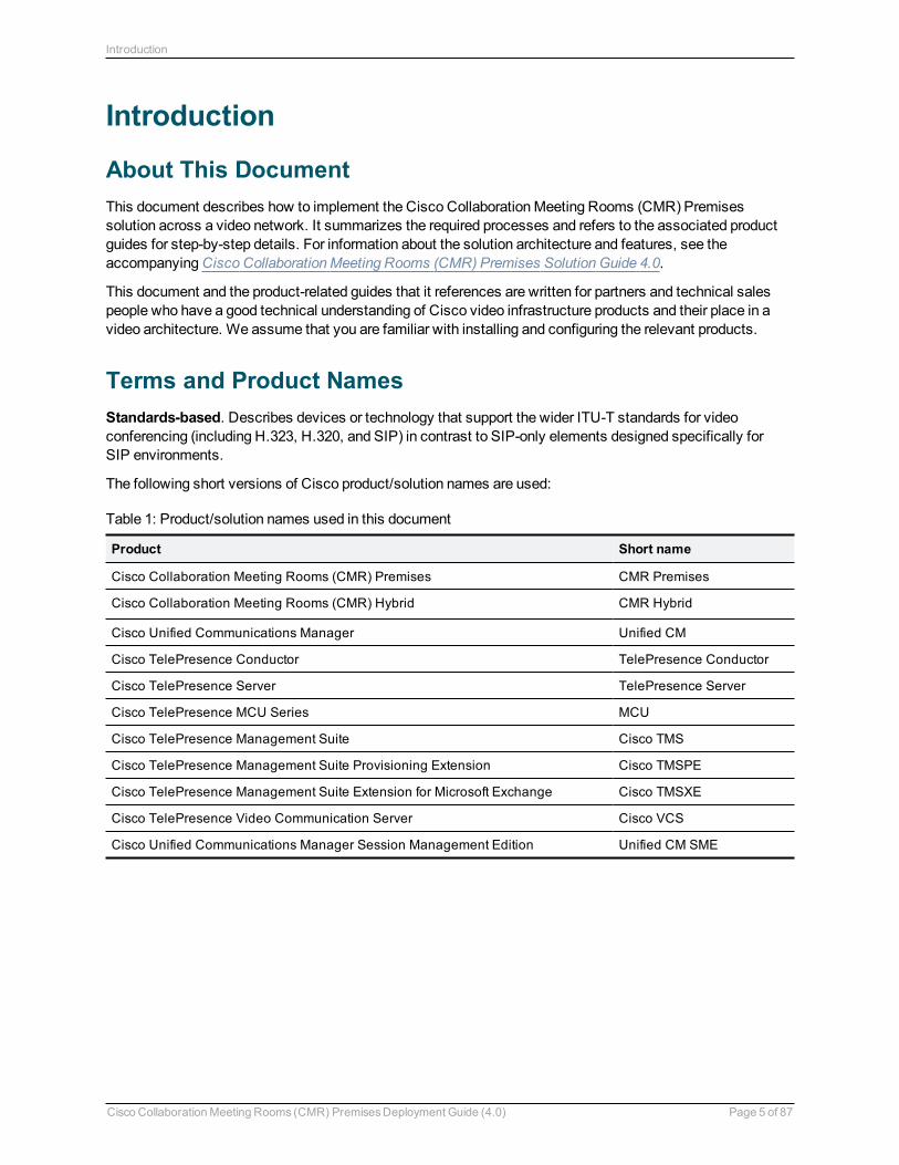
Terms and Product NamesStandards-based. Describes devices or technology that support the wider ITU-T standards for videoconferencing (including H.323, H.320, and SIP) in contrast to SIP-only elements designed specifically forSIP environments.
The following short versions of Cisco product/solution names are used:
Product Short name
Cisco Collaboration Meeting Rooms (CMR) Premises CMR Premises
Cisco Collaboration Meeting Rooms (CMR) Hybrid CMR Hybrid
Cisco Unified Communications Manager Unified CM
Cisco TelePresence Conductor TelePresence Conductor
Cisco TelePresence Server TelePresence Server
Cisco TelePresence MCU Series MCU
Cisco TelePresence Management Suite Cisco TMS
Cisco TelePresence Management Suite Provisioning Extension Cisco TMSPE
Cisco TelePresence Management Suite Extension for Microsoft Exchange Cisco TMSXE
Cisco TelePresence Video Communication Server Cisco VCS
Cisco Unified Communications Manager Session Management Edition Unified CM SME
Table 1: Product/solution names used in this document
Cisco CollaborationMeeting Rooms (CMR) PremisesDeployment Guide (4.0) Page 5 of 87
Introduction
Fundamentals of CMR PremisesCore Architecture 7Solution Components and Required Versions 8
Cisco CollaborationMeeting Rooms (CMR) PremisesDeployment Guide (4.0) Page 6 of 87
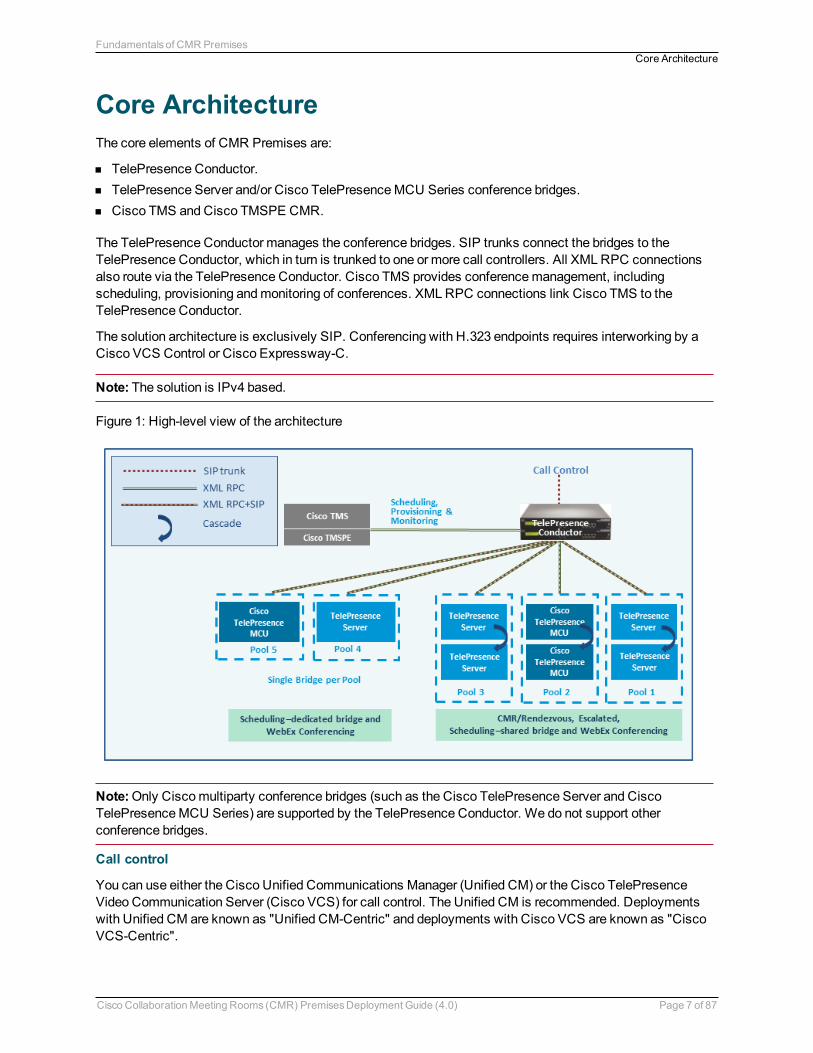
Core ArchitectureThe core elements of CMR Premises are:
n TelePresence Conductor.n TelePresence Server and/or Cisco TelePresenceMCU Series conference bridges.n Cisco TMS and Cisco TMSPE CMR.
The TelePresence Conductor manages the conference bridges. SIP trunks connect the bridges to theTelePresence Conductor, which in turn is trunked to one or more call controllers. All XMLRPC connectionsalso route via the TelePresence Conductor. Cisco TMS provides conferencemanagement, includingscheduling, provisioning andmonitoring of conferences. XMLRPC connections link Cisco TMS to theTelePresence Conductor.
The solution architecture is exclusively SIP. Conferencing with H.323 endpoints requires interworking by aCisco VCS Control or Cisco Expressway-C.
Note: The solution is IPv4 based.
Figure 1: High-level view of the architecture
Note:Only Ciscomultiparty conference bridges (such as the Cisco TelePresence Server and CiscoTelePresenceMCU Series) are supported by the TelePresence Conductor. We do not support otherconference bridges.
Call control
You can use either the Cisco Unified Communications Manager (Unified CM) or the Cisco TelePresenceVideo Communication Server (Cisco VCS) for call control. The Unified CM is recommended. Deploymentswith Unified CM are known as "Unified CM-Centric" and deployments with Cisco VCS are known as "CiscoVCS-Centric".
Cisco CollaborationMeeting Rooms (CMR) PremisesDeployment Guide (4.0) Page 7 of 87
Fundamentals of CMR PremisesCore Architecture
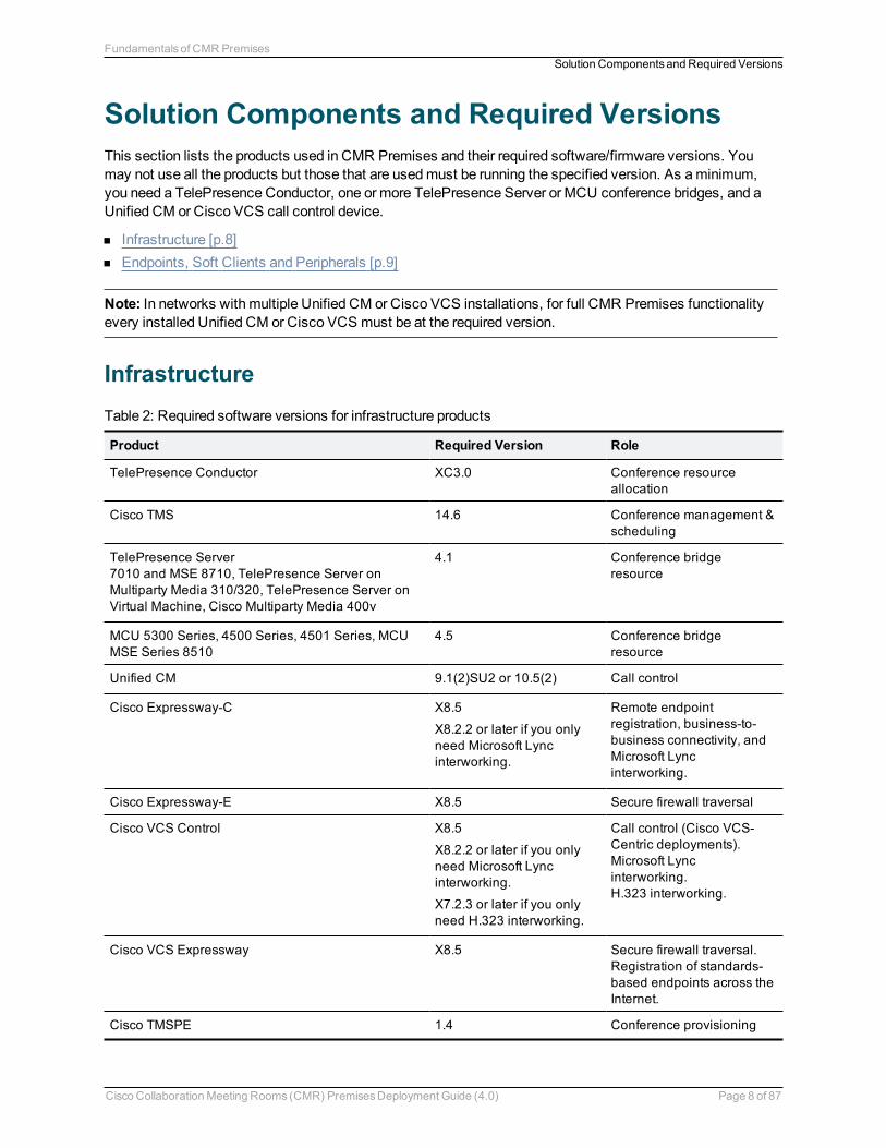
Solution Components and Required VersionsThis section lists the products used in CMR Premises and their required software/firmware versions. Youmay not use all the products but those that are usedmust be running the specified version. As aminimum,you need a TelePresence Conductor, one or more TelePresence Server or MCU conference bridges, and aUnified CM or Cisco VCS call control device.
n Infrastructure [p.8]n Endpoints, Soft Clients and Peripherals [p.9]
Note: In networks with multiple Unified CM or Cisco VCS installations, for full CMR Premises functionalityevery installed Unified CM or Cisco VCS must be at the required version.
Infrastructure
Product Required Version Role
TelePresence Conductor XC3.0 Conference resourceallocation
Cisco TMS 14.6 Conference management &scheduling
TelePresence Server7010 and MSE 8710, TelePresence Server onMultiparty Media 310/320, TelePresence Server onVirtual Machine, Cisco Multiparty Media 400v
4.1 Conference bridgeresource
MCU 5300 Series, 4500 Series, 4501 Series, MCUMSE Series 8510
4.5 Conference bridgeresource
Unified CM 9.1(2)SU2 or 10.5(2) Call control
Cisco Expressway-C X8.5
X8.2.2 or later if you onlyneed Microsoft Lyncinterworking.
Remote endpointregistration, business-to-business connectivity, andMicrosoft Lyncinterworking.
Cisco Expressway-E X8.5 Secure firewall traversal
Cisco VCS Control X8.5
X8.2.2 or later if you onlyneed Microsoft Lyncinterworking.
X7.2.3 or later if you onlyneed H.323 interworking.
Call control (Cisco VCS-Centric deployments).Microsoft Lyncinterworking.H.323 interworking.
Cisco VCS Expressway X8.5 Secure firewall traversal.Registration of standards-based endpoints across theInternet.
Cisco TMSPE 1.4 Conference provisioning
Table 2: Required software versions for infrastructure products
Cisco CollaborationMeeting Rooms (CMR) PremisesDeployment Guide (4.0) Page 8 of 87
Fundamentals of CMR PremisesSolution Components and Required Versions
Product Required Version Role
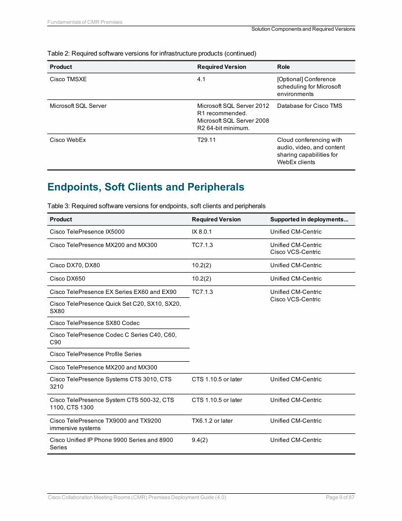
Cisco TMSXE 4.1 [Optional] Conferencescheduling for Microsoftenvironments
Microsoft SQL Server Microsoft SQL Server 2012R1 recommended.Microsoft SQL Server 2008R2 64-bit minimum.
Database for Cisco TMS
Cisco WebEx T29.11 Cloud conferencing withaudio, video, and contentsharing capabilities forWebEx clients
Table 2: Required software versions for infrastructure products (continued)
Endpoints, Soft Clients and Peripherals
Product Required Version Supported in deployments...
Cisco TelePresence IX5000 IX 8.0.1 Unified CM-Centric
Cisco TelePresence MX200 and MX300 TC7.1.3 Unified CM-CentricCisco VCS-Centric
Cisco DX70, DX80 10.2(2) Unified CM-Centric
Cisco DX650 10.2(2) Unified CM-Centric
Cisco TelePresence EX Series EX60 and EX90 TC7.1.3 Unified CM-CentricCisco VCS-Centric
Cisco TelePresence Quick Set C20, SX10, SX20,SX80
Cisco TelePresence SX80 Codec
Cisco TelePresence Codec C Series C40, C60,C90
Cisco TelePresence Profile Series
Cisco TelePresence MX200 and MX300
Cisco TelePresence Systems CTS 3010, CTS3210
CTS 1.10.5 or later Unified CM-Centric
Cisco TelePresence System CTS 500-32, CTS1100, CTS 1300
CTS 1.10.5 or later Unified CM-Centric
Cisco TelePresence TX9000 and TX9200immersive systems
TX6.1.2 or later Unified CM-Centric
Cisco Unified IP Phone 9900 Series and 8900Series
9.4(2) Unified CM-Centric
Table 3: Required software versions for endpoints, soft clients and peripherals
Cisco CollaborationMeeting Rooms (CMR) PremisesDeployment Guide (4.0) Page 9 of 87
Fundamentals of CMR PremisesSolution Components and Required Versions
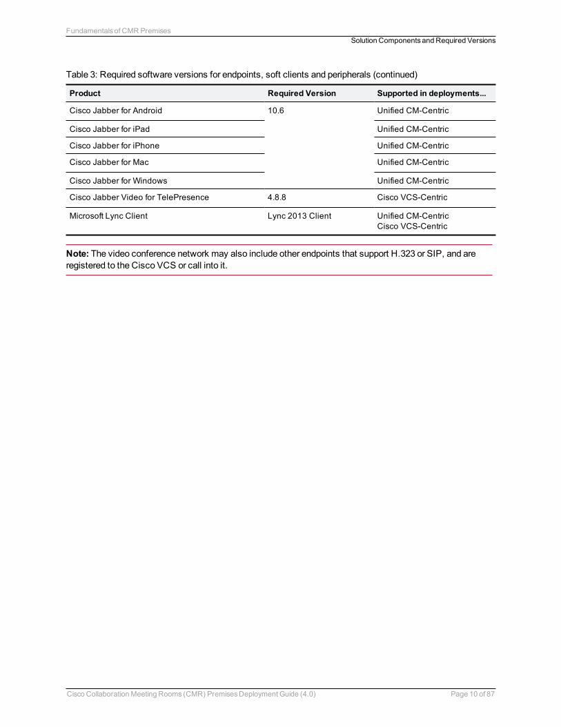
Product Required Version Supported in deployments...
Cisco Jabber for Android 10.6 Unified CM-Centric
Cisco Jabber for iPad Unified CM-Centric
Cisco Jabber for iPhone Unified CM-Centric
Cisco Jabber for Mac Unified CM-Centric
Cisco Jabber for Windows Unified CM-Centric
Cisco Jabber Video for TelePresence 4.8.8 Cisco VCS-Centric
Microsoft Lync Client Lync 2013 Client Unified CM-CentricCisco VCS-Centric
Table 3: Required software versions for endpoints, soft clients and peripherals (continued)
Note: The video conference network may also include other endpoints that support H.323 or SIP, and areregistered to the Cisco VCS or call into it.
Cisco CollaborationMeeting Rooms (CMR) PremisesDeployment Guide (4.0) Page 10 of 87
Fundamentals of CMR PremisesSolution Components and Required Versions
Deployment Requirements and Best Practices
TelePresence ConductorThe TelePresence Conductor must be deployed using its back-to-back user agent (B2BUA). The externalpolicy server interface is not supported.
TelePresence Server Conference BridgesTelePresence Server bridges are trunked to the TelePresence Conductor andmust be configured for remotemanagement by the TelePresence Conductor.
EncryptionAll TelePresence Conductor-to-bridge SIP communicationmust be encrypted.
Resilience and ClusteringWe recommend that the solution components are deployed in cluster configurations, to provide redundancyin case of a failure. Deploying clusters of TelePresence Conductors and bridges ensures service availabilityeven if individual conference bridges or Conductors are taken out of service.
CAUTION! For scheduled conferences, regardless of the number of TelePresence Conductor nodes in acluster, it is not possible to addmore than one Conductor node to Cisco TMS.
For details about Conductor clustering see the appropriate deployment guide:
n Cisco TelePresence Conductor Clustering with Cisco Unified Communications Manager DeploymentGuide
n Cisco TelePresence Conductor Clustering with Cisco VCS (B2BUA) Deployment Guide
SIP Early Offer Messaging in Unified CM-CentricDeploymentsEarly Offer messaging is strongly recommended for all Unified CM-connected SIP trunks that carryTelePresence calls, and is required for CMR Hybrid conferences and some third-party services. Cisco VCS-Centric deployments always run in Early Offer mode, except for H.323 to SIP interworked calls. (BecauseH.323 uses Slow Start signalingmode on Cisco VCS and Cisco Expressway, SIP messaging forinterworked calls is done using DelayedOffer.)
Bridge Pools and Service Preferencesn H.323must be disabled on the conference bridges.n At least one Service Preference is required in TelePresence Conductor. You can optionally place all
conference bridge pools into a single Service Preference.
Cisco CollaborationMeeting Rooms (CMR) PremisesDeployment Guide (4.0) Page 11 of 87
Deployment Requirements and Best Practices
n All conference bridges must be assigned to a conference bridge pool in TelePresence Conductor. Eachconference bridge can belong to only one pool.
n All conference bridges in a TelePresence Conductor pool must be of the same type (MCU orTelePresence Server). Usually it is best to configure a pool with bridges from the same location, althoughthis is optional, not mandatory.
n As with pools, all conference bridges in a Service Preferencemust be of the same type (MCU orTelePresence Server).
n If Unified CM call admission control is implemented to control bandwidth usage, each Service Preferencemust only contain pools of bridges for a single location.
n For scheduled conferences, if conference availability is a priority then we recommend dedicating aconference bridge for scheduling use only (to avoid resources being used up by unscheduled conferences).
Content ChannelMost TelePresence endpoints support the use of a second video channel known as the content channel.Typically this is used for presentations running alongside live video.
n ForMCU conference bridges, set theContent mode for the Conference template in TelePresenceConductor to Transcoded (Advanced parameters). When this mode is selected in a TelePresenceConductor template, a dedicated content port or video port will be allocated depending on theMCU modeland configuration.
n For TelePresence Server conference bridges, currently the content mode is always Transcoded and is notconfigurable.
H.323 InterworkingThe CMR Premises network is SIP-based. To connect H.323 endpoints to conferences within theCMR Premises network, the call must be interworked before reaching the TelePresence Conductor. To dothis configure the Cisco VCS Control or Cisco Expressway-C to perform the necessary SIP/H.323interworking.
n To interwork only for locally registered endpoints, set theH.323 <-> SIP interworking mode toRegistered only (accessed from VCS configuration > Protocols > Interworking).
n To optionally allow interworking of business-to-business H.323 calling between external networks and yourconferences, set theH.323 <-> SIP interworking mode toOn. This will interwork all incoming calls.
Escalated ConferencingWedo not support ad hoc conferencing (the Unified CMmethod of escalated conferencing) in Cisco VCS-Centric deployments, or Multiway (the Cisco VCS method) in Unified CM-Centric deployments.
Cisco CollaborationMeeting Rooms (CMR) PremisesDeployment Guide (4.0) Page 12 of 87
Deployment Requirements and Best Practices
Upgrading an Existing DeploymentThis section describes how to upgrade an existing solution Release 3.0 deployment to 4.0. Skip this sectionif you are installing CMR Premises for the first time.
Recommended Implementation Sequence 14Configuration Prerequisites for Upgrades 15Configuration Checklist for Upgrades 16Differences when Scheduling TelePresence Conductor-Managed Bridges 19
CAUTION: To ensure operational continuity in the network we recommend that the solution components areinstalled in the sequence specified in Recommended Implementation Sequence [p.22].
Cisco CollaborationMeeting Rooms (CMR) PremisesDeployment Guide (4.0) Page 13 of 87
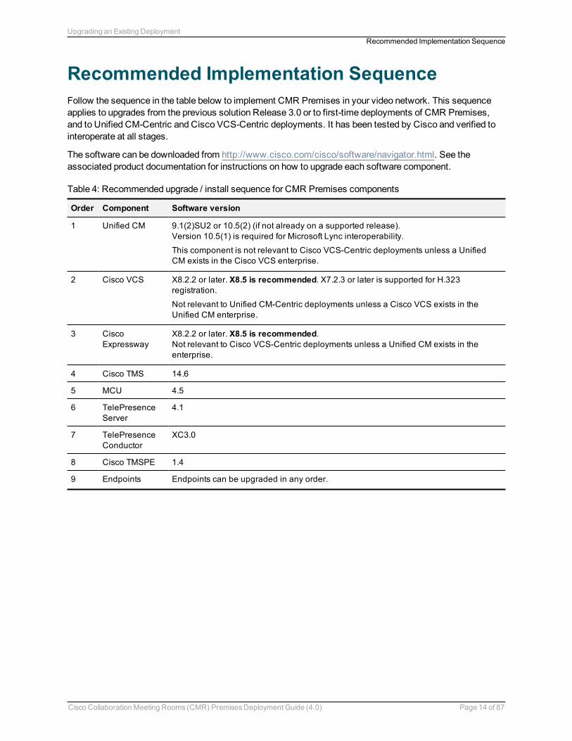
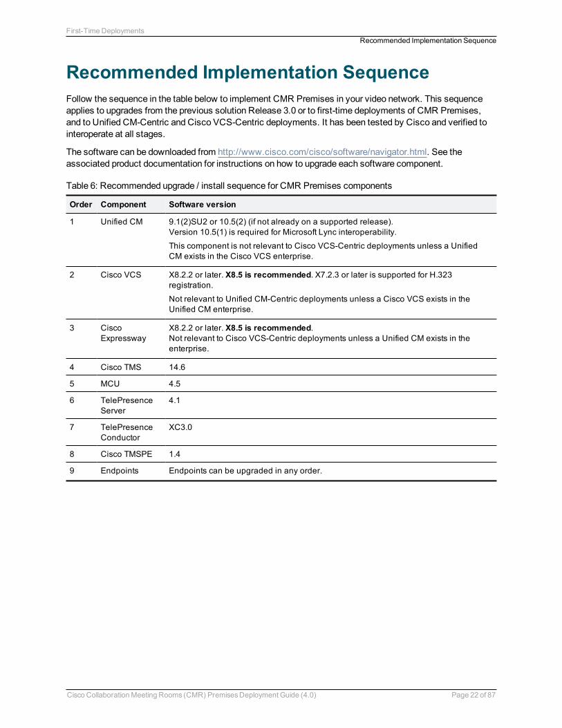
Recommended Implementation SequenceFollow the sequence in the table below to implement CMR Premises in your video network. This sequenceapplies to upgrades from the previous solution Release 3.0 or to first-time deployments of CMR Premises,and to Unified CM-Centric and Cisco VCS-Centric deployments. It has been tested by Cisco and verified tointeroperate at all stages.
The software can be downloaded from http://www.cisco.com/cisco/software/navigator.html. See theassociated product documentation for instructions on how to upgrade each software component.
Order Component Software version
1 Unified CM 9.1(2)SU2 or 10.5(2) (if not already on a supported release).Version 10.5(1) is required for Microsoft Lync interoperability.
This component is not relevant to Cisco VCS-Centric deployments unless a UnifiedCM exists in the Cisco VCS enterprise.
2 Cisco VCS X8.2.2 or later. X8.5 is recommended. X7.2.3 or later is supported for H.323registration.
Not relevant to Unified CM-Centric deployments unless a Cisco VCS exists in theUnified CM enterprise.
3 CiscoExpressway
X8.2.2 or later. X8.5 is recommended.Not relevant to Cisco VCS-Centric deployments unless a Unified CM exists in theenterprise.
4 Cisco TMS 14.6
5 MCU 4.5
6 TelePresenceServer
4.1
7 TelePresenceConductor
XC3.0
8 Cisco TMSPE 1.4
9 Endpoints Endpoints can be upgraded in any order.
Table 4: Recommended upgrade / install sequence for CMR Premises components
Cisco CollaborationMeeting Rooms (CMR) PremisesDeployment Guide (4.0) Page 14 of 87
Upgrading an Existing DeploymentRecommended Implementation Sequence
Configuration Prerequisites for UpgradesMake sure the following items are in place before you upgrade your earlier solution release configuration toCMR Premises 4.0.
n TelePresence Server bridges must be configured for remotemanagement by the TelePresenceConductor.
n Endpoints must be registered to Unified CM or to Cisco VCS as appropriate.n All devices must be running the software and firmware versions listed in Solution Components and
Required Versions [p.8].
Cisco CollaborationMeeting Rooms (CMR) PremisesDeployment Guide (4.0) Page 15 of 87
Upgrading an Existing DeploymentConfiguration Prerequisites for Upgrades
Configuration Checklist for UpgradesThis topic summarizes the CMR Premises configuration process to upgrade an existing solution deploymentto 4.0. For detailed upgrade paths, see Appendix 2: Migration Paths to CMR Premises Release 4.0 [p.82].
Task 1: Upgrade Product VersionsUpgrade / install each product in your solution deployment to the required version for 4.0. Follow thesequence specified in Recommended Implementation Sequence [p.22].
At this stage, do not update your configuration for 4.0 functionality.
Task 2: Verify New Versions in Existing ConfigurationVerify that the new software runs satisfactorily on your existing Release 3.0 configuration and the network isfunctioning as expected.
Task 3: Check Prerequisites are CompleteCheck that all prerequisites listed in Configuration Prerequisites for Upgrades [p.15] are complete.
Task 4: Check Solution Release NotesCheck the release-specific configuration considerations described in the latest solution release notes forCMR Premises 4.0 on Cisco.com.
Task 5: Configure the TelePresence ConductorConfigure the TelePresence Conductor for CMR Premises. The TelePresence Conductor settings forCMR Premises have changed in this release.
n For Unified CM-Centric deployments, see Connecting TelePresence Conductor to the Unified CM [p.29]n For Cisco VCS-Centric deployments, see Connecting TelePresence Conductor to the Cisco VCS [p.30].
Task 6: Add Latest Normalization Scripts to Unified CM(Unified CM-Centric Deployments)Skip this step for Cisco VCS-Centric deployments, unless a Unified CM exists in the enterprise. Unified CM-Centric deployments that use encryption and TLS on SIP trunks for TelePresencemust install the latestTelePresence normalization scripts on the trunks. See Appendix 1: Adding the Unified CM NormalizationScripts [p.80] for instructions.
Verify that the system is working as expected before you continue to the next step.
Cisco CollaborationMeeting Rooms (CMR) PremisesDeployment Guide (4.0) Page 16 of 87
Upgrading an Existing DeploymentConfiguration Checklist for Upgrades
Task 7: Convert to SIP Early Offer (Unified CM-CentricDeployments)Skip this step for Cisco VCS-Centric deployments. This step is recommended, and required for CMR Hybridconferences and some third party services. See Configuring Early Offer (and fallback to DelayedOffer) forSIP trunks [p.28] for instructions.
Task 8: Set Up Resource Optimization (Optional)To set up automatic resource allocation and optimization for TelePresence Server resources, see Setting upTelePresence Server Resource Optimization (Optional) [p.66].
Task 9: Configure the Cisco Expressway / Cisco VCS forMicrosoft Lync (Optional)If your deployment requires interoperability with Microsoft Lync, see ConfiguringMicrosoft Lync 2013Interoperability [p.68].
Task 10: Configure the iX Protocol for ActiveControl Support(Optional)To use ActiveControl in the CMR Premises network, see Setting up the ActiveControl Feature [p.70].
CAUTION: If your CMR Premises network connects to Unified CM systems running Version 8.x or earlier,or to third-party networks, before you enable ActiveControl youmust first disable the iX protocol on allrelevant trunks to isolate iX traffic from systems that do not support it. If you do not do this, theconsequences may be unpredictable and include dropped calls.
Task 11: Configure Cisco TMS for Scheduled ConferencingTo set up scheduled conferencing, see How to Enable Scheduled Conferencing [p.62]
Note: The differences between scheduling in the previous release (direct-managed conference bridges) andin this release (TelePresence Conductor-managed conference bridges) are summarized in CiscoCollaborationMeeting Rooms (CMR) Premises Solution Guide 4.0.
Task 12: Set Up CMR Hybrid (Optional)To set up an integration with CMR Hybrid, see Enabling CMR Hybrid in Scheduled Conferences [p.39].
After you have set up the integration, you can also optionally addWebEx meetings to personal CMRs. SeeUsing CMR Hybrid with Personal CMRs [p.41].
Cisco CollaborationMeeting Rooms (CMR) PremisesDeployment Guide (4.0) Page 17 of 87
Upgrading an Existing DeploymentConfiguration Checklist for Upgrades
Task 13: Check External Endpoints are Registered to theEnterprise Unified CM (Unified CM-Centric Deployments)Skip this step for Cisco VCS-Centric deployments. In older solution releases, endpoints that were externalfrom the local enterprise needed to be registered to a Cisco VCS Expressway. From Release 3.0 they can beregistered to Unified CM, through Cisco Expressway.
Cisco CollaborationMeeting Rooms (CMR) PremisesDeployment Guide (4.0) Page 18 of 87
Upgrading an Existing DeploymentConfiguration Checklist for Upgrades
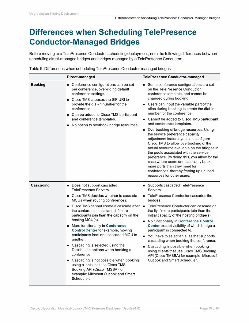
Differences when Scheduling TelePresenceConductor-Managed BridgesBeforemoving to a TelePresence Conductor scheduling deployment, note the following differences betweenscheduling direct-managed bridges and bridges managed by a TelePresence Conductor:
Direct-managed TelePresence Conductor-managed
Booking n Conference configurations can be setper conference, over-riding defaultconference settings.
n Cisco TMS chooses the SIP URI toprovide the dial-in number for theconference.
n Can be added to Cisco TMS participantand conference templates.
n No option to overbook bridge resources.
n Some conference configurations are seton the TelePresence Conductorconference template, and cannot bechanged during booking.
n Users can input the variable part of thealias during booking to create the dial-innumber for the conference.
n Cannot be added to Cisco TMS participantand conference templates.
n Overbooking of bridge resources: Usingthe service preference capacityadjustment feature, you can configureCisco TMS to allow overbooking of theactual resource available on the bridges inthe pools associated with the servicepreference. By doing this, you allow for thecase where users unnecessarily bookmore ports than they need forconferences, thereby freeing up unusedresources for other users.
Cascading n Does not support cascadedTelePresence Servers.
n Cisco TMS decides whether to cascadeMCUs when routing conferences.
n Cisco TMS cannot create a cascade afterthe conference has started if moreparticipants join than the capacity on thehosting MCU(s).
n More functionality in ConferenceControl Center for example, movingparticipants from one cascaded MCU toanother.
n Cascading is selected using theDistribution options when booking aconference.
n Cascading is not possible when bookingusing clients that use Cisco TMSBooking API (Cisco TMSBA) forexample: Microsoft Outlook and SmartScheduler.
n Supports cascaded TelePresenceServers.
n TelePresence Conductor cascades thebridges.
n TelePresence Conductor can cascade onthe fly if more participants join than theinitial capacity of the hosting bridge(s).
n No functionality in Conference ControlCenter except visibility of which bridge aparticipant is connected to.
n You have to select an alias that supportscascading when booking the conference.
n Cascading is possible when bookingusing clients that use Cisco TMS BookingAPI (Cisco TMSBA) for example: MicrosoftOutlook and Smart Scheduler.
Table 5: Differences when scheduling TelePresence Conductor-managed bridges
Cisco CollaborationMeeting Rooms (CMR) PremisesDeployment Guide (4.0) Page 19 of 87
Upgrading an Existing DeploymentDifferenceswhen Scheduling TelePresence Conductor-Managed Bridges
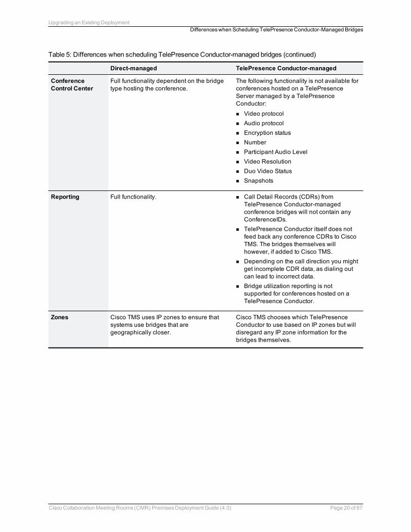
Direct-managed TelePresence Conductor-managed
ConferenceControl Center
Full functionality dependent on the bridgetype hosting the conference.
The following functionality is not available forconferences hosted on a TelePresenceServer managed by a TelePresenceConductor:
n Video protocoln Audio protocoln Encryption statusn Numbern Participant Audio Leveln Video Resolutionn Duo Video Statusn Snapshots
Reporting Full functionality. n Call Detail Records (CDRs) fromTelePresence Conductor-managedconference bridges will not contain anyConferenceIDs.
n TelePresence Conductor itself does notfeed back any conference CDRs to CiscoTMS. The bridges themselves willhowever, if added to Cisco TMS.
n Depending on the call direction you mightget incomplete CDR data, as dialing outcan lead to incorrect data.
n Bridge utilization reporting is notsupported for conferences hosted on aTelePresence Conductor.
Zones Cisco TMS uses IP zones to ensure thatsystems use bridges that aregeographically closer.
Cisco TMS chooses which TelePresenceConductor to use based on IP zones but willdisregard any IP zone information for thebridges themselves.
Table 5: Differences when scheduling TelePresence Conductor-managed bridges (continued)
Cisco CollaborationMeeting Rooms (CMR) PremisesDeployment Guide (4.0) Page 20 of 87
Upgrading an Existing DeploymentDifferenceswhen Scheduling TelePresence Conductor-Managed Bridges
First-Time DeploymentsThis section describes how to implement CMR Premises 4.0 as a first-time deployment. Skip this section ifyou are upgrading from an earlier solution release.
Recommended Implementation Sequence 22Configuration Prerequisites for First-Time Deployments 23Configuration Checklist for First-Time Deployments 24
CAUTION: To ensure operational continuity in the network we recommend that the solution components areinstalled in the sequence specified in Recommended Implementation Sequence [p.22].
Cisco CollaborationMeeting Rooms (CMR) PremisesDeployment Guide (4.0) Page 21 of 87
Recommended Implementation SequenceFollow the sequence in the table below to implement CMR Premises in your video network. This sequenceapplies to upgrades from the previous solution Release 3.0 or to first-time deployments of CMR Premises,and to Unified CM-Centric and Cisco VCS-Centric deployments. It has been tested by Cisco and verified tointeroperate at all stages.
The software can be downloaded from http://www.cisco.com/cisco/software/navigator.html. See theassociated product documentation for instructions on how to upgrade each software component.
Order Component Software version
1 Unified CM 9.1(2)SU2 or 10.5(2) (if not already on a supported release).Version 10.5(1) is required for Microsoft Lync interoperability.
This component is not relevant to Cisco VCS-Centric deployments unless a UnifiedCM exists in the Cisco VCS enterprise.
2 Cisco VCS X8.2.2 or later. X8.5 is recommended. X7.2.3 or later is supported for H.323registration.
Not relevant to Unified CM-Centric deployments unless a Cisco VCS exists in theUnified CM enterprise.
3 CiscoExpressway
X8.2.2 or later. X8.5 is recommended.Not relevant to Cisco VCS-Centric deployments unless a Unified CM exists in theenterprise.
4 Cisco TMS 14.6
5 MCU 4.5
6 TelePresenceServer
4.1
7 TelePresenceConductor
XC3.0
8 Cisco TMSPE 1.4
9 Endpoints Endpoints can be upgraded in any order.
Table 6: Recommended upgrade / install sequence for CMR Premises components
Cisco CollaborationMeeting Rooms (CMR) PremisesDeployment Guide (4.0) Page 22 of 87
First-TimeDeploymentsRecommended Implementation Sequence
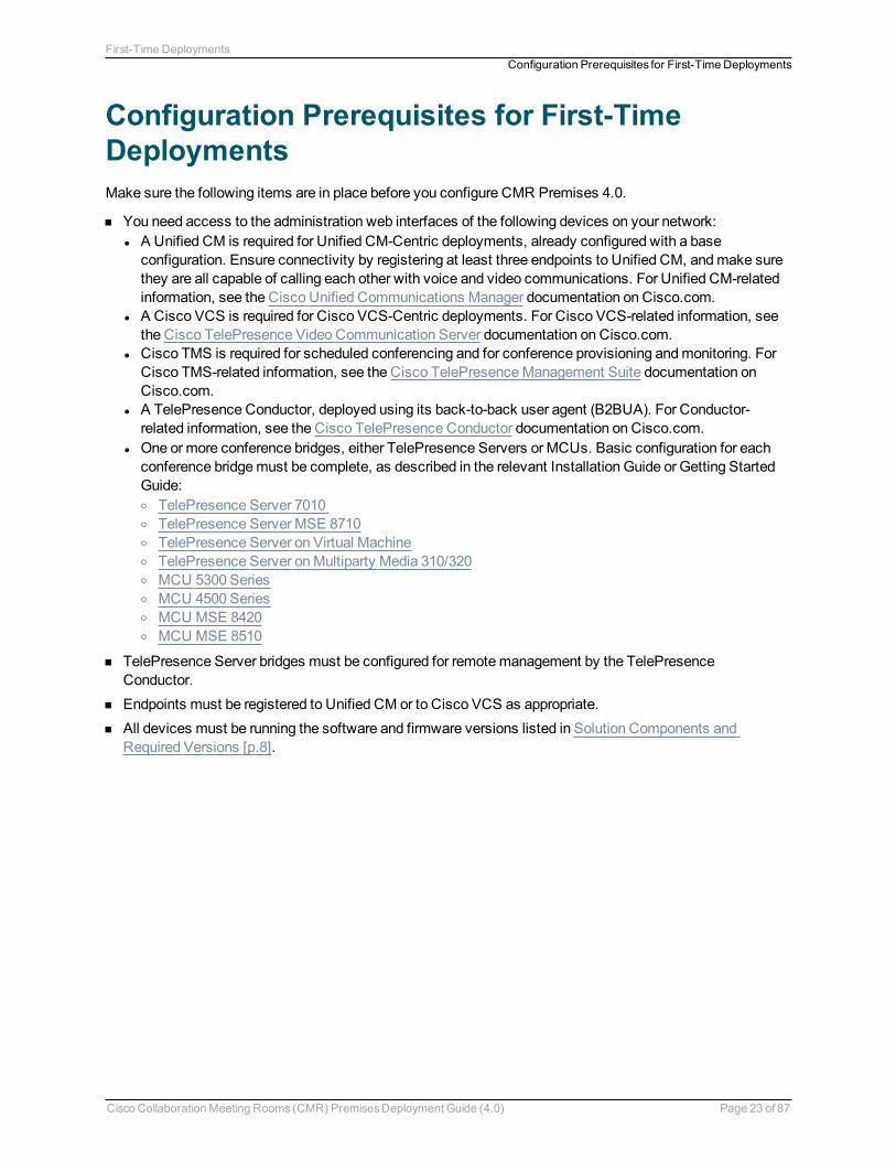
Configuration Prerequisites for First-TimeDeploymentsMake sure the following items are in place before you configure CMR Premises 4.0.
n You need access to the administration web interfaces of the following devices on your network:l A Unified CM is required for Unified CM-Centric deployments, already configured with a baseconfiguration. Ensure connectivity by registering at least three endpoints to Unified CM, andmake surethey are all capable of calling each other with voice and video communications. For Unified CM-relatedinformation, see the Cisco Unified Communications Manager documentation on Cisco.com.
l A Cisco VCS is required for Cisco VCS-Centric deployments. For Cisco VCS-related information, seethe Cisco TelePresence Video Communication Server documentation on Cisco.com.
l Cisco TMS is required for scheduled conferencing and for conference provisioning andmonitoring. ForCisco TMS-related information, see the Cisco TelePresenceManagement Suite documentation onCisco.com.
l A TelePresence Conductor, deployed using its back-to-back user agent (B2BUA). For Conductor-related information, see the Cisco TelePresence Conductor documentation on Cisco.com.
l One ormore conference bridges, either TelePresence Servers or MCUs. Basic configuration for eachconference bridgemust be complete, as described in the relevant Installation Guide or Getting StartedGuide:o TelePresence Server 7010o TelePresence Server MSE 8710o TelePresence Server on Virtual Machineo TelePresence Server onMultiparty Media 310/320o MCU 5300 Serieso MCU 4500 Serieso MCU MSE 8420o MCU MSE 8510
n TelePresence Server bridges must be configured for remotemanagement by the TelePresenceConductor.
n Endpoints must be registered to Unified CM or to Cisco VCS as appropriate.n All devices must be running the software and firmware versions listed in Solution Components and
Required Versions [p.8].
Cisco CollaborationMeeting Rooms (CMR) PremisesDeployment Guide (4.0) Page 23 of 87
First-TimeDeploymentsConfiguration Prerequisites for First-TimeDeployments
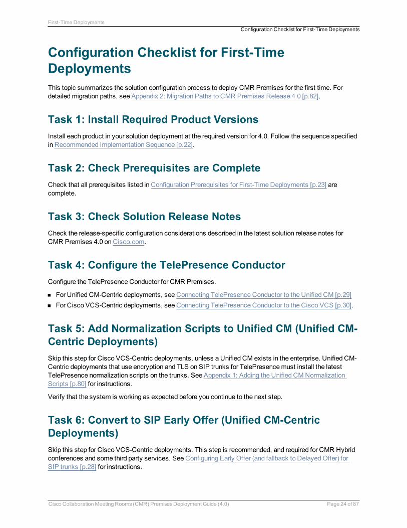
Configuration Checklist for First-TimeDeploymentsThis topic summarizes the solution configuration process to deploy CMR Premises for the first time. Fordetailedmigration paths, see Appendix 2: Migration Paths to CMR Premises Release 4.0 [p.82].
Task 1: Install Required Product VersionsInstall each product in your solution deployment at the required version for 4.0. Follow the sequence specifiedin Recommended Implementation Sequence [p.22].
Task 2: Check Prerequisites are CompleteCheck that all prerequisites listed in Configuration Prerequisites for First-Time Deployments [p.23] arecomplete.
Task 3: Check Solution Release NotesCheck the release-specific configuration considerations described in the latest solution release notes forCMR Premises 4.0 on Cisco.com.
Task 4: Configure the TelePresence ConductorConfigure the TelePresence Conductor for CMR Premises.
n For Unified CM-Centric deployments, see Connecting TelePresence Conductor to the Unified CM [p.29]n For Cisco VCS-Centric deployments, see Connecting TelePresence Conductor to the Cisco VCS [p.30].
Task 5: Add Normalization Scripts to Unified CM (Unified CM-Centric Deployments)Skip this step for Cisco VCS-Centric deployments, unless a Unified CM exists in the enterprise. Unified CM-Centric deployments that use encryption and TLS on SIP trunks for TelePresencemust install the latestTelePresence normalization scripts on the trunks. See Appendix 1: Adding the Unified CM NormalizationScripts [p.80] for instructions.
Verify that the system is working as expected before you continue to the next step.
Task 6: Convert to SIP Early Offer (Unified CM-CentricDeployments)Skip this step for Cisco VCS-Centric deployments. This step is recommended, and required for CMR Hybridconferences and some third party services. See Configuring Early Offer (and fallback to DelayedOffer) forSIP trunks [p.28] for instructions.
Cisco CollaborationMeeting Rooms (CMR) PremisesDeployment Guide (4.0) Page 24 of 87
First-TimeDeploymentsConfiguration Checklist for First-TimeDeployments
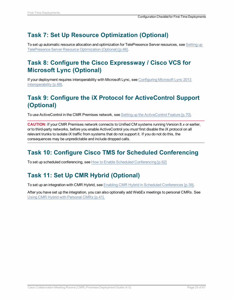
Task 7: Set Up Resource Optimization (Optional)To set up automatic resource allocation and optimization for TelePresence Server resources, see Setting upTelePresence Server Resource Optimization (Optional) [p.66].
Task 8: Configure the Cisco Expressway / Cisco VCS forMicrosoft Lync (Optional)If your deployment requires interoperability with Microsoft Lync, see ConfiguringMicrosoft Lync 2013Interoperability [p.68].
Task 9: Configure the iX Protocol for ActiveControl Support(Optional)To use ActiveControl in the CMR Premises network, see Setting up the ActiveControl Feature [p.70].
CAUTION: If your CMR Premises network connects to Unified CM systems running Version 8.x or earlier,or to third-party networks, before you enable ActiveControl youmust first disable the iX protocol on allrelevant trunks to isolate iX traffic from systems that do not support it. If you do not do this, theconsequences may be unpredictable and include dropped calls.
Task 10: Configure Cisco TMS for Scheduled ConferencingTo set up scheduled conferencing, see How to Enable Scheduled Conferencing [p.62]
Task 11: Set Up CMR Hybrid (Optional)To set up an integration with CMR Hybrid, see Enabling CMR Hybrid in Scheduled Conferences [p.39].
After you have set up the integration, you can also optionally addWebEx meetings to personal CMRs. SeeUsing CMR Hybrid with Personal CMRs [p.41].
Cisco CollaborationMeeting Rooms (CMR) PremisesDeployment Guide (4.0) Page 25 of 87
First-TimeDeploymentsConfiguration Checklist for First-TimeDeployments
Configuring and Connecting the SolutionComponentsBy the end of this section, you should have CMR Premises installed on all of the solution components, withthe components configured to talk to each other.
Configuring the Unified CM for Early Offer 27Connecting TelePresence Conductor to the Unified CM 29Connecting TelePresence Conductor to the Cisco VCS 30Connecting the Unified CM and the Cisco Expressway Series or Cisco VCS 31
Cisco CollaborationMeeting Rooms (CMR) PremisesDeployment Guide (4.0) Page 26 of 87
Configuring the Unified CM for Early OfferThis section is only relevant to Unified CM-Centric deployments. It provides the recommended approach forconfiguring outbound trunks as Early Offer.
Note: The default configuration for Unified CM trunks is Delayed Offer.
All trunks between the following CMR Premises elements should be enabled for Early Offer. Nomediatermination point (MTP) resources should bemade available to these trunks, directly or indirectly:
n Unified CM to Cisco Expressway-Cn Unified CM to Cisco VCS Controln Unified CM to TelePresence Conductorn Unified CM to TelePresence Servern Unified CM toMCUn Unified CM to Unified CM trunks which carry traffic originating from a TelePresence endpoint and any of
the network elements listed above should also be enabled for Early Offer, with nomedia termination point(MTP) resources. For example, in a call flow scenario of EX90 >> UCM1 >> UCM2 >> Conductor >>TelePresence Server, the trunk between UCM1 >> UCM2 and the trunk between UCM2 >> Conductorshould be enabled for Early Offer.
To restrict the use of MTPs, all MTP resources should be removed from all Cisco Unified CommunicationsManager SessionManagement Edition (Unified CM SME) clusters, and all MTP resources on Cisco UnifiedCommunications Manager clusters should be placed inMedia Resource Groups that are inaccessible both toTelePresence endpoints and to SIP trunks carrying TelePresence traffic.
Some specific points apply in various deployment scenarios:
Scenario 1. Configuring Early Offer in a single Unified CM system
TelePresence Conductor and conference bridges are connected to the Cisco Unified CommunicationsManager, with Cisco Unified Communications Manager trunked to the Cisco Expressway. Endpoints areregistered to the Cisco Unified Communications Manager. In this scenario the following trunks must beconfigured for Early Offer:
n Unified CM to Cisco Expressway-C.n Unified CM to the TelePresence Conductor.
Scenario 2. Configuring Early Offer in a multi-cluster system (TelePresence Conductor connectedto Unified CM SME)
One ormore Unified CM SME clusters with connected leaf Cisco Unified Communications Managerclusters. The TelePresence Conductor and conference bridges are connected to the Cisco UnifiedCommunications Manager SME. The Cisco Unified Communications Manager SME is trunked to the CiscoExpressway-C. In this scenario the following trunks must be configured for Early Offer:
n Unified CM SME to Cisco Expressway-C.n Unified CM SME to the TelePresence Conductor.
Cisco CollaborationMeeting Rooms (CMR) PremisesDeployment Guide (4.0) Page 27 of 87
Configuring and Connecting the Solution ComponentsConfiguring the Unified CM for EarlyOffer
Note: In multi-cluster systems with three or more clusters, where one Cisco Unified CommunicationsManager cluster is a dedicated Cisco Unified Communications Manager SME, endpoints never register tothe Cisco Unified Communications Manager SME but always to a leaf Cisco Unified CommunicationsManager cluster.
Scenario 3. Configuring Early Offer in a multi-cluster system (TelePresence Conductor connectedto leaf clusters)
One ormore Cisco Unified Communications Manager SME clusters with connected leaf Cisco UnifiedCommunications Manager clusters. The TelePresence Conductor and conference bridges are connected tothe leaf cluster(s). A single trunk connects the Cisco Unified Communications Manager SME to the CiscoExpressway-C. In this scenario the following trunks must be configured for Early Offer:
n Unified CM SME to Cisco Expressway-C.n Leaf Unified CM clusters to the TelePresence Conductor.n Leaf Unified CM clusters to the Unified CM SME.
Configuring Early Offer (and fallback to Delayed Offer) for SIP trunks
1. For each trunk, do one of the following depending on your Cisco Unified Communications Managerversion:l For Version 9.1(2) systems, enable theEarly Offer support for voice and video calls (insert MTP ifneeded).
l For Version 10.5(1) systems, in theEarly Offer support for voice and video calls dropdown, selectBest Effort (noMTP inserted).
2. Remove all MTP resources from the following elements:a. Unified CM SME clusters (in the case of Unified CM SME deployments).b. All TelePresence endpoints and SIP trunks on all Unified CM clusters.
3. Set SIP Trunk DTMF Signaling Method toRFC 2833 (the default).4. Enable theAccept Audio Codec Preference in Received Offer option on the following elements:
a. All Unified CM SME SIP trunks (in the case of Unified CM SME deployments).b. All SIP trunks that carry TelePresence calls on all Unified CM clusters.
Fallback to Delayed Offer
For outgoing calls, the default settings provide for automatic fallback to DelayedOffer in cases where noMTP resource exists. Without fallback, issues may arise in areas of the network that are not configured forthe solution. For incoming calls, Early Offer is supported with no requirement for MTP resources.
Cisco CollaborationMeeting Rooms (CMR) PremisesDeployment Guide (4.0) Page 28 of 87
Configuring and Connecting the Solution ComponentsConfiguring the Unified CM for EarlyOffer
Connecting TelePresence Conductor to theUnified CMNote: In CMR Premises, the TelePresence Conductor is deployed using its B2BUA. The external policyservice interface is not supported.
Before You Startn Cisco TelePresence Conductor must be installed according to the instructions in Cisco TelePresence
Conductor Getting Started or Cisco TelePresence Conductor Virtual Machine Installation Guide.n Cisco Unified Communications Manager must be installed and configured with a base configuration.
Ensure connectivity by registering at least three endpoints, andmake sure they are all capable of callingeach other with voice and video communications.
n One ormore conference bridges must be powered on and accessible to the Cisco TelePresence Conductorover HTTP/HTTPS and SIP TLS.
ProcessTo configure the TelePresence Conductor for CMR Premises in Unified CM-Centric deployments, follow thestep-by-step instructions inCisco TelePresence Conductor with Unified CM Deployment Guide (XC3.0).These instructions walk you through:
n Configuring the Cisco TelePresenceMCU Series.n Configuring the TelePresence Server.n Configuring the TelePresence Conductor's general settings and configuring it for ad hoc and rendezvous
conferences.n Configuring the Unified CM's general settings and configuring it for ad hoc and rendezvous conferences.
For information on setting up scheduled conferencing, see How to Enable Scheduled Conferencing [p.62].
Note: The preferred deployment is to deploy personal CMRs as described in Enabling Personal CMRs [p.34]later in this document. In this case you can skip the rendezvous conference configuration steps (the tasksthat set up conference templates, conference aliases and auto-dialed participants on the TelePresenceConductor).
Cisco CollaborationMeeting Rooms (CMR) PremisesDeployment Guide (4.0) Page 29 of 87
Configuring and Connecting the Solution ComponentsConnecting TelePresence Conductor to the Unified CM
Connecting TelePresence Conductor to the CiscoVCS
Before You Startn Cisco TelePresence Conductor must be installed according to the instructions in Cisco TelePresence
Conductor Getting Started or Cisco TelePresence Conductor Virtual Machine Installation Guide.n Cisco TelePresence Video Communication Server must be installed and configured to act as a
SIP registrar and proxy.n One ormore conference bridges must be powered on and accessible to the TelePresence Conductor over
HTTP/HTTPS and SIP TLS.
ProcessTo configure the TelePresence Conductor for CMR Premises in Cisco VCS-Centric deployments, follow thestep-by-step instructions in theCisco TelePresence Conductor with Cisco VCS (B2BUA) Deployment Guide(XC3.0), with the following caveat:
n The VCS Zone profile for the trunk between Cisco VCS Control and TelePresence Conductor should beset toCustom withAutomatically respond to SIP searches set toOn. For details, seeAdding theTelePresence Conductor as a neighbor zone inCisco TelePresence Conductor with Cisco TelePresenceVCS (B2BUA) Deployment Guide XC3.0.
The instructions walk you through:
n Designing a dial plan.n Configuring the Cisco TelePresenceMCU Series.n Configuring the TelePresence Server.n Configuring Cisco VCS with a neighbor zone and search rule for TelePresence Conductor.n Configuring the TelePresence Conductor in B2BUA mode (deployments using the Cisco VCS external
policy service are not supported)
For information on setting up scheduled conferencing, see How to Enable Scheduled Conferencing [p.62].
Note: The preferred deployment is to deploy personal CMRs as described in Enabling Personal CMRs [p.34]later in this document. In this case you can skip the rendezvous conference configuration steps (the tasksthat set up conference templates, conference aliases and auto-dialed participants on the TelePresenceConductor).
Cisco CollaborationMeeting Rooms (CMR) PremisesDeployment Guide (4.0) Page 30 of 87
Configuring and Connecting the Solution ComponentsConnecting TelePresence Conductor to the Cisco VCS
Connecting the Unified CM and the CiscoExpressway Series or Cisco VCSFor Unified CM-Centric deployments beyond the standard deployment model (external, with Microsoft Lync2013, or legacy deployments) your deployment must include either the Cisco Expressway Series or CiscoTelePresence Video Communication Server. For an overview of the deployment types, seeCiscoCollaborationMeeting Rooms (CMR) Premises Solution Guide.
Before You Startn Cisco Unified Communications Manager must be installed and configured with a base configuration.
Ensure connectivity by registering at least three endpoints, andmake sure they are all capable of callingeach other with voice and video communications.
n The Cisco Expressway-C or Cisco VCS Control must be configured with IP address, DNS and NTPinformation, and be accessible for management via its web interface.
n If you are using the Cisco Expressway Series, richmedia licenses must be installed.
Process for Cisco Expressway SeriesTo connect the Unified CM andCisco Expressway Series, follow the step-by-step instructions in the CiscoUnified Communications Manager with Cisco Expressway via SIP Trunk Deployment Guide. Theseinstructions walk you through:
n Configuring Unified CM for a Cisco Expressway trunkn Configuring Cisco Expressway routingn Connecting Cisco Expressway to Unified CM using TLS
Process for Cisco VCSTo connect the Unified CM andCisco VCS, follow the step-by-step instructions in the Cisco UnifiedCommunications Manager with Cisco VCS (SIP Trunk) Deployment Guide. These instructions walk youthrough:
n Enabling calls between endpoints registered on the Cisco VCS Controln Enabling calls between endpoints registered on Unified CMn Enabilng endpoints registered on Unified CM to call endpoints registered on Cisco VCS Controln Connecting Cisco VCS to Unified CM using TLS
Cisco CollaborationMeeting Rooms (CMR) PremisesDeployment Guide (4.0) Page 31 of 87
Configuring and Connecting the Solution ComponentsConnecting the Unified CM and the Cisco ExpresswaySeries or Cisco VCS
Configuring SecurityThis section assumes that the standard configuration requirements for CMR Premises are complete.
CMR Premises supports TLS encryption for signaling. TLS is mandatory for TelePresence Conductor-to-bridge SIP communication. Other SIP (and XMLRPC) communication can optionally be TLS-encryptedbetween the endpoint and the call manager, and between the call manager and TelePresence Conductor.
Communication security for conference participants is supported through SRTP encryptedmedia. For a callto support SRTP encryptedmedia, its associated SIP signalingmust use TLS for all hops. That is:
1. Between the endpoint and the call controller.2. Between the call controller and TelePresence Conductor.3. Between TelePresence Conductor and the conference bridge (always mandatory anyway).
CAUTION:Unless TLS signaling is in place for all three elements, the call cannot support SRTP.
Configuration information
Conference bridges must have the encryption key enabled and be configured to use TCP port 5061 andsignalingmode TLS (SIP Settings page).
Specify TCP port 5061 and TLS signalingmode on the TelePresence ConductorLocation and on the callcontroller (SIP Trunk Security Profile for Unified CM; Neighbor Zone for Cisco VCS).
See the appropriate deployment guide for details:
n Cisco TelePresence Conductor with Unified Communications Manager Deployment Guide for Unified CM-Centric deployments
n Cisco TelePresence Conductor with Cisco VCS (B2BUA) Deployment Guide for Cisco VCS-Centricdeployments
Cisco CollaborationMeeting Rooms (CMR) PremisesDeployment Guide (4.0) Page 32 of 87
Configuring Conferencing ServicesEnabling Personal CMRs 34Enabling CMR Hybrid in Scheduled Conferences 39Using CMR Hybrid with Personal CMRs 41Setting UpCascading for Large-Scale or Critical Meetings 42Enabling Ad Hoc (Instant) Conferencing 44EnablingMultiway (Instant) Conferencing 49Enabling Rendezvous Conferencing 50Provisioning Display Names Across the Solution 53
Cisco CollaborationMeeting Rooms (CMR) PremisesDeployment Guide (4.0) Page 33 of 87
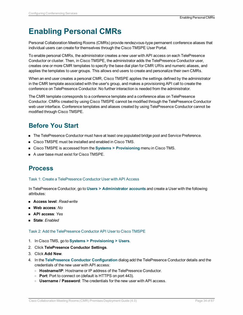
Enabling Personal CMRsPersonal CollaborationMeeting Rooms (CMRs) provide rendezvous-type permanent conference aliases thatindividual users can create for themselves through the Cisco TMSPE User Portal.
To enable personal CMRs, the administrator creates a new user with API access on each TelePresenceConductor or cluster. Then, in Cisco TMSPE, the administrator adds the TelePresence Conductor user,creates one or more CMR templates to specify the base dial plan for CMR URIs and numeric aliases, andapplies the templates to user groups. This allows end users to create and personalize their own CMRs.
When an end user creates a personal CMR, Cisco TMSPE applies the settings defined by the administratorin the CMR template associated with the user's group, andmakes a provisioning API call to create theconference on TelePresence Conductor. No further interaction is needed from the administrator.
The CMR template corresponds to a conference template and a conference alias on TelePresenceConductor. CMRs created by using Cisco TMSPE cannot bemodified through the TelePresence Conductorweb user interface. Conference templates and aliases created by using TelePresence Conductor cannot bemodified through Cisco TMSPE.
Before You Startn The TelePresence Conductor must have at least one populated bridge pool and Service Preference.n Cisco TMSPE must be installed and enabled in Cisco TMS.n Cisco TMSPE is accessed from theSystems > Provisioningmenu in Cisco TMS.n A user basemust exist for Cisco TMSPE.
ProcessTask 1: Create a TelePresence Conductor User with API Access
In TelePresence Conductor, go toUsers > Administrator accounts and create a User with the followingattributes:
n Access level: Read-writen Web access: Non API access: Yesn State: Enabled
Task 2: Add the TelePresence Conductor API User to Cisco TMSPE
1. In Cisco TMS, go toSystems > Provisioning > Users.2. Click TelePresence Conductor Settings.3. Click Add New.4. In the TelePresence Conductor Configuration dialog add the TelePresence Conductor details and the
credentials of the new user with API access:o Hostname/IP: Hostname or IP address of the TelePresence Conductor.o Port: Port to connect on (default is HTTPS on port 443).o Username / Password: The credentials for the new user with API access.
Cisco CollaborationMeeting Rooms (CMR) PremisesDeployment Guide (4.0) Page 34 of 87
Configuring Conferencing ServicesEnabling PersonalCMRs
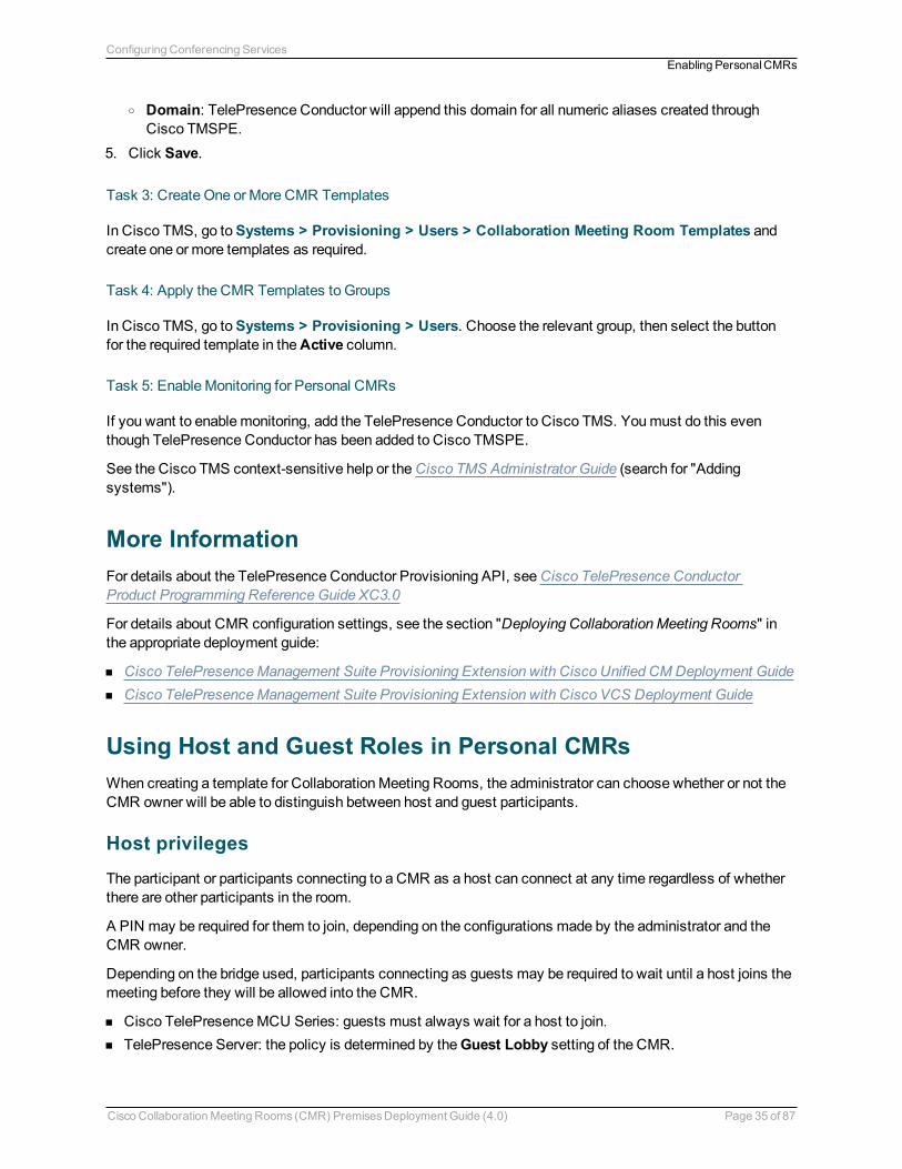
o Domain: TelePresence Conductor will append this domain for all numeric aliases created throughCisco TMSPE.
5. Click Save.
Task 3: Create One orMore CMR Templates
In Cisco TMS, go toSystems > Provisioning > Users > Collaboration Meeting Room Templates andcreate one or more templates as required.
Task 4: Apply the CMR Templates to Groups
In Cisco TMS, go toSystems > Provisioning > Users. Choose the relevant group, then select the buttonfor the required template in theActive column.
Task 5: EnableMonitoring for Personal CMRs
If you want to enablemonitoring, add the TelePresence Conductor to Cisco TMS. Youmust do this eventhough TelePresence Conductor has been added to Cisco TMSPE.
See the Cisco TMS context-sensitive help or theCisco TMS Administrator Guide (search for "Addingsystems").
More InformationFor details about the TelePresence Conductor Provisioning API, seeCisco TelePresence ConductorProduct Programming ReferenceGuide XC3.0
For details about CMR configuration settings, see the section "Deploying CollaborationMeeting Rooms" inthe appropriate deployment guide:
n Cisco TelePresenceManagement Suite Provisioning Extension with Cisco Unified CM Deployment Guiden Cisco TelePresenceManagement Suite Provisioning Extension with Cisco VCS Deployment Guide
Using Host and Guest Roles in Personal CMRsWhen creating a template for CollaborationMeeting Rooms, the administrator can choose whether or not theCMR owner will be able to distinguish between host and guest participants.
Host privileges
The participant or participants connecting to a CMR as a host can connect at any time regardless of whetherthere are other participants in the room.
A PIN may be required for them to join, depending on the configurations made by the administrator and theCMR owner.
Depending on the bridge used, participants connecting as guests may be required to wait until a host joins themeeting before they will be allowed into the CMR.
n Cisco TelePresenceMCU Series: guests must always wait for a host to join.n TelePresence Server: the policy is determined by theGuest Lobby setting of the CMR.
Cisco CollaborationMeeting Rooms (CMR) PremisesDeployment Guide (4.0) Page 35 of 87
Configuring Conferencing ServicesEnabling PersonalCMRs
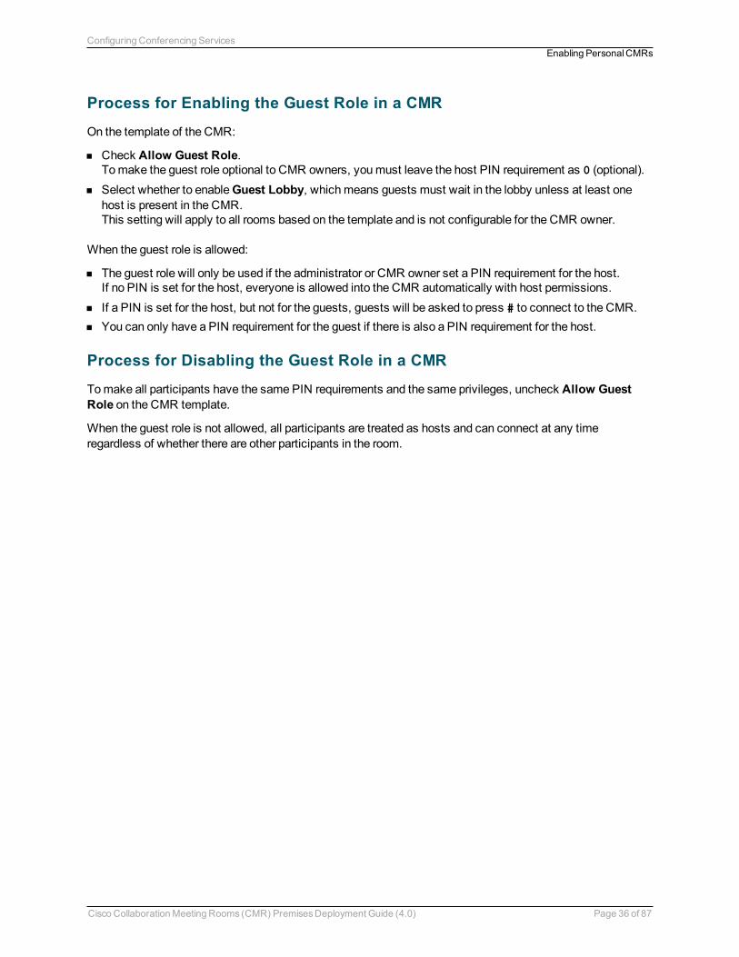
Process for Enabling the Guest Role in a CMR
On the template of the CMR:
n Check Allow Guest Role.Tomake the guest role optional to CMR owners, youmust leave the host PIN requirement as 0 (optional).
n Select whether to enableGuest Lobby, whichmeans guests must wait in the lobby unless at least onehost is present in the CMR.This setting will apply to all rooms based on the template and is not configurable for the CMR owner.
When the guest role is allowed:
n The guest role will only be used if the administrator or CMR owner set a PIN requirement for the host.If no PIN is set for the host, everyone is allowed into the CMR automatically with host permissions.
n If a PIN is set for the host, but not for the guests, guests will be asked to press # to connect to the CMR.n You can only have a PIN requirement for the guest if there is also a PIN requirement for the host.
Process for Disabling the Guest Role in a CMR
Tomake all participants have the same PIN requirements and the same privileges, uncheck Allow GuestRole on the CMR template.
When the guest role is not allowed, all participants are treated as hosts and can connect at any timeregardless of whether there are other participants in the room.
Cisco CollaborationMeeting Rooms (CMR) PremisesDeployment Guide (4.0) Page 36 of 87
Configuring Conferencing ServicesEnabling PersonalCMRs
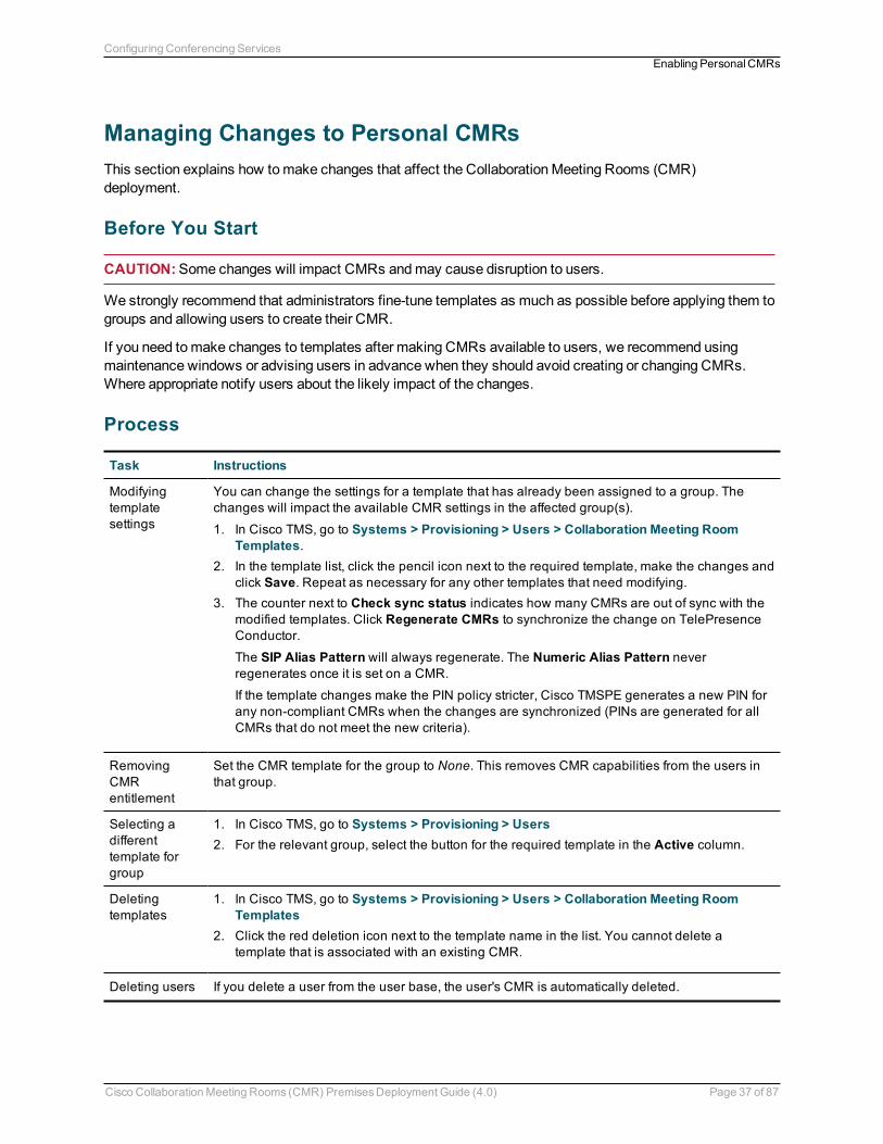
Managing Changes to Personal CMRsThis section explains how tomake changes that affect the CollaborationMeeting Rooms (CMR)deployment.
Before You Start
CAUTION:Some changes will impact CMRs andmay cause disruption to users.
We strongly recommend that administrators fine-tune templates as much as possible before applying them togroups and allowing users to create their CMR.
If you need tomake changes to templates after making CMRs available to users, we recommend usingmaintenance windows or advising users in advance when they should avoid creating or changing CMRs.Where appropriate notify users about the likely impact of the changes.
Process
Task Instructions
Modifyingtemplatesettings
You can change the settings for a template that has already been assigned to a group. Thechanges will impact the available CMR settings in the affected group(s).
1. In Cisco TMS, go to Systems > Provisioning > Users > Collaboration Meeting RoomTemplates.
2. In the template list, click the pencil icon next to the required template, make the changes andclick Save. Repeat as necessary for any other templates that need modifying.
3. The counter next to Check sync status indicates how many CMRs are out of sync with themodified templates. Click Regenerate CMRs to synchronize the change on TelePresenceConductor.
The SIP Alias Pattern will always regenerate. The Numeric Alias Pattern neverregenerates once it is set on a CMR.
If the template changes make the PIN policy stricter, Cisco TMSPE generates a new PIN forany non-compliant CMRs when the changes are synchronized (PINs are generated for allCMRs that do not meet the new criteria).
RemovingCMRentitlement
Set the CMR template for the group to None. This removes CMR capabilities from the users inthat group.
Selecting adifferenttemplate forgroup
1. In Cisco TMS, go to Systems > Provisioning > Users2. For the relevant group, select the button for the required template in the Active column.
Deletingtemplates
1. In Cisco TMS, go to Systems > Provisioning > Users > Collaboration Meeting RoomTemplates
2. Click the red deletion icon next to the template name in the list. You cannot delete atemplate that is associated with an existing CMR.
Deleting users If you delete a user from the user base, the user's CMR is automatically deleted.
Cisco CollaborationMeeting Rooms (CMR) PremisesDeployment Guide (4.0) Page 37 of 87
Configuring Conferencing ServicesEnabling PersonalCMRs
Moving usersbetweengroups
If a user's group changes in the user base (normally due to changes in Active Directory) theirassigned CMR template will also change if the new group has a different template.
Cisco TMSPE will register the change during the next health check (or a Run Health Checkcan also be initiated manually from the Provisioning Extension Diagnostics page).The user's CMR will be displayed as out of sync. To synchronize, click Regenerate CMRs tohave the change reflected on TelePresence Conductor.
More Information
For details about the TelePresence Conductor Provisioning API, seeCisco TelePresence ConductorProduct Programming ReferenceGuide XC3.0
For details about CMR configuration settings, see the section "Deploying CollaborationMeeting Rooms" inthe appropriate deployment guide:
n Cisco TelePresenceManagement Suite Provisioning Extension with Cisco Unified CM Deployment Guiden Cisco TelePresenceManagement Suite Provisioning Extension with Cisco VCS Deployment Guide
Cisco CollaborationMeeting Rooms (CMR) PremisesDeployment Guide (4.0) Page 38 of 87
Configuring Conferencing ServicesEnabling PersonalCMRs
Enabling CMR Hybrid in Scheduled ConferencesThis section describes how to enable CMR Hybrid for scheduled conferences in a CMR Premisesdeployment, for participation by CiscoWebEx and TelePresence users.
Before You Startn The standard requirements for enabling scheduled conferences apply.n In Unified CM-Centric deployments, SIP Early Offer messaging is required as described in the Early Offer
section.n In Cisco VCS-Centric deployments, SIP Early Offer messaging is the default. However, if you have a
Unified CM in the network and it is required to support WebEx, youmust ensure that Early Offer messagingis configured on the SIP trunks between the following elements:l Bridges used for calls between Early Offer-based services and the Cisco Expressway.l Any third-party call controller and the Cisco VCS Control.l Any Unified CM-managed endpoints and the Cisco Expressway. The entire path from the calling deviceto the servicemust be configured to support Early Offer.If you do not need external Early Offer-based services in an Cisco VCS-Centric deployment, then anyUnified CMs may be configured for either DelayedOffer or Early Offer.
ProcessTask 1: Configure TelePresence Applications for CiscoWebEx Support
If not already done, complete the first-time configuration steps in Cisco CollaborationMeeting Rooms (CMR)Hybrid Configuration Guide so that your Cisco TelePresence applications are enabled for CiscoWebEx-to-Cisco TelePresence interoperability. Detailed instructions and a first-time configuration checklist areprovided in that guide.
Task 2: Configure CiscoWebEx Site Administration
If not already done, after the first-time configuration steps in Task 1 are complete you need to set up CiscoWebEx site administration, as described in Cisco CollaborationMeeting Rooms (CMR) Hybrid ConfigurationGuide.
Task 3: Book the Conferences
In Cisco TMS, go toBooking > New Conference and complete the relevant fields on theBasic Settingstab. In particular, make sure Include WebEx Conference is checked and optionally create aWebExMeeting Password.
For details, see the chapter about scheduling CMR Hybrid meetings in Cisco TMS in Cisco CollaborationMeeting Rooms (CMR) Hybrid Configuration Guide.
Task 4: Cisco TMS calculates the route and issues email confirmation
This task is done by the Cisco TMS. When you save the conference, Cisco TMS calculates the route for themeeting and emails themeeting details, includingWebEx and TelePresence dial-in information, to theconference booker. Depending on your site configuration youmay also receive emails fromWebEx.
Cisco CollaborationMeeting Rooms (CMR) PremisesDeployment Guide (4.0) Page 39 of 87
Configuring Conferencing ServicesEnabling CMRHybrid in Scheduled Conferences

Task 5: Forward themeeting details
Forward themeeting emails issued in the previous step to the conference participants.
More Informationn For detailed information about Cisco TMS settings, see the context-sensitive help for Cisco TMS or Cisco
TMS Administrator Guide.n For detailed configuration steps to enable this feature, see Cisco CollaborationMeeting Rooms (CMR)
Hybrid Configuration Guide.
Cisco CollaborationMeeting Rooms (CMR) PremisesDeployment Guide (4.0) Page 40 of 87
Configuring Conferencing ServicesEnabling CMRHybrid in Scheduled Conferences
Using CMR Hybrid with Personal CMRsIf you have deployed CMR Hybrid, you can includeWebEx in CMRs so that users may connect using eitherTelePresence orWebEx.
When enabled through the CollaborationMeeting Room template, aCreate WebEx Connection button willappear on each user's CMR page on the TelePresence User Portal. The button allows the user to create atemporary WebEx connection for their CMR.
As the connection is temporary and will eventually time out, the portal page advises users to create theconnection and distribute theWebEx details shortly before themeeting starts.
Before You StartBefore you can enableWebEx in CMRs:
n CMR Hybrid must be deployed. SeeCisco CollaborationMeeting Rooms Hybrid Configuration Guide fordetails and instructions.
n The owner of each CMR must be a registeredWebEx user associated with a current WebEx site with theirown username and password. Otherwise, theCreate WebEx Connection button will not appear for theuser.
n If planning to change an existing template, readManaging Changes to Personal CMRs [p.37].n To prevent potential toll fraud issues, we recommend disablingCall-back teleconferencing on theWebEx
site that is used for CMRs.
ProcessYoumust enableWebEx for CMR before you can include the feature in one or more templates:
1. In Cisco TMS, go toAdministrative Tools > Configuration > Provisioning Extension Settings.2. Under CollaborationMeeting Room, set Allow WebEx Connections toYes.3. Go toSystems > Provisioning > Users.4. Select an existing template for editing or create a new template.5. Check Include WebEx.6. Click Save.7. Click Regenerate CMRs.
Cisco CollaborationMeeting Rooms (CMR) PremisesDeployment Guide (4.0) Page 41 of 87
Configuring Conferencing ServicesUsing CMRHybrid with PersonalCMRs
Setting Up Cascading for Large-Scale or CriticalMeetingsWithin the local CMR Premises enterprise network, larger conferences that exceed the capacity of a singleconference bridge can be cascaded (distributed) across one or more additional bridges. The bridges must beroutable with each other and with TelePresence Conductor.
Before You StartIn the case of cascading for scheduled conferences, the standard requirements for enabling scheduledconferences apply (see How to Enable Scheduled Conferencing [p.62]).
Note:Cascading is not supported from one conference bridge to another bridge that is outside the boundariesof the local enterprise network.
n Cascade links share only a single screen of video between TelePresence Server.n Cascading is not supported from a TelePresence Server bridge to anMCU, or from anMCU to a
TelePresence Server.n On cascade-enabled conferences, cascading resources are reserved from the start of the conference for
the configuredMaximum number of cascades, whether or not they are actually used. For this reason werecommend using the cascade option sparingly—typically for large-scale meetings or for rendezvousconferences / personal CMRs used by VIP personnel.
n Cascading should not be enabled where certainty of resource availability is critical, such as the dedicatedbridge scheduling case (where a single bridge in its own pool is reserved for scheduling).
n The ActiveControl feature on the TelePresence Server supports up to 500 participants.
Process for CMR ConferencesNote: This process uses the Cisco TMSPE provisioning extension of Cisco TMS. If your deployment doesnot use Cisco TMSPE, you can instead use the TelePresence Conductor to configure cascading, asdescribed in the Conductor documentation.
Task 1: Create a Cascade-Enabled CMR Template
1. In Cisco TMS, go toSystems > Provisioning > Users > Collaboration Meeting Room Templatesand create one or more templates as required.
2. Check theAllow Cascading check box.3. Specify themaximum number of cascades allowed for a conference.
Task 2: Apply the CMR Template to a Group
In Cisco TMS, go toSystems > Provisioning > Users. Choose the relevant group, then select the buttonfor the required template in theActive column.
More Information
For details, see the appropriate deployment guide:
Cisco CollaborationMeeting Rooms (CMR) PremisesDeployment Guide (4.0) Page 42 of 87
Configuring Conferencing ServicesSetting UpCascading for Large-Scale or CriticalMeetings
n For details about Cisco TMSPE settings in Unified CM-Centric deployments, seeCisco TelePresenceManagement Suite Provisioning Extension with Cisco Unified CM Deployment Guide
n For details about Cisco TMSPE settings in Cisco VCS-Centric deployments, seeCisco TelePresenceManagement Suite Provisioning Extension with Cisco VCS Deployment Guide
Process for Scheduled ConferencesFor deployments that use dedicated bridges for scheduling, cascading is not recommended (or possible inthe case of a single pool with a single bridge). For deployments with shared-use bridges, which support bothscheduled and non-scheduled conferences, the solution supports cascading of scheduled conferences onTelePresence Conductor-managed TelePresence Server or MCU conference bridges.
Cisco TMS will prompt you at booking time if the number of participants exceeds the single bridge capacity.
Task 1: Book the Scheduled Conference as Normal in Cisco TMS
Add the TelePresence Conductor to the conference (unless it is defined as the default MCU).
Task 2: Check TelePresence Conductor Settings
Check the associated TelePresence Conductor settings, andmodify as appropriate.
More Information
For details, seeCisco TelePresence Conductor with Cisco TelePresenceManagement Suite DeploymentGuide.
Cisco CollaborationMeeting Rooms (CMR) PremisesDeployment Guide (4.0) Page 43 of 87
Configuring Conferencing ServicesSetting UpCascading for Large-Scale or CriticalMeetings
Enabling Ad Hoc (Instant) ConferencingThis section does not apply to Cisco VCS-Centric deployments.
Ad hoc conferencing in CMR Premises requires conference bridges to bemanaged by TelePresenceConductor as media resources. TelePresence Conductor acts as a conference controller andmanagerbetween Unified CM and the bridges, through SIP trunks and registeredmedia resource conference bridges.
TelePresence Conductor conference templates are referenced by multiple virtual IP addresses. Theseaddresses register with Unified CM as ad hoc conference bridges and are used inmedia resource group lists(MRGLs) andmedia resource groups (MRGs). Unified CM uses MRGLs andMRGs to prioritize and allocatemedia resources, including conference bridges.
Note:A single TelePresence Conductor or cluster can havemultiple conference templates configured tosupport a variety of service levels and user experiences.
Before You Startn Ensure that the prerequisites and configuration process for the solution are complete. In particular:
l Ad hoc conferences are controlled by their originating Unified CM, which routes ad hoc calls directly toTelePresence Conductor. An API/SIP trunk pair is required between the TelePresence Conductor andevery Unified CM that supports ad hoc conferencing.
l The SIP trunks should be configured for Early Offer messaging.l The TelePresence Conductor needs at least one populated conference bridge pool and ServicePreference.
l The TelePresence Conductor needs a network IP address defined for ad hoc handling for each Locationand/or Conference template that is to support ad hoc calls.
l TelePresence Server conference bridges must be configured to bemanaged by the TelePresenceConductor.
n Ad hoc call flows cannot be used to add participants to other types of conference. Other call flows cannotbe used to add participants to ad hoc conferences.
n Wedo not recommend ad hoc escalations by participants in a rendezvous, Multiway, or scheduledconference. This will cause a "chained" conference. Clicking the conference button on the endpoint causesthe endpoint to try to create a new ad hoc conference escalation rather than extending the existingconference. The ad hoc conference will be chained with the existing conference. The endpoints will beacross the two chained conferences, causing a degraded conference experience for participants.
n Similarly, participants of ad hoc conferences should not be added to rendezvous, Multiway or scheduledconferences. Attempting to add a whole conference as a participant to an existing conference will alsolead to a chained conference.
n Some limitations exist for the audio-only quality setting with ad hoc conferencing on TelePresence Servers.These are described in Audio-Only Quality Setting in Ad Hoc Conferencing with TelePresence Servers[p.47].
n Unified CM delivers ad hoc and rendezvous conferences to different IP addresses on TelePresenceConductor.
Cisco CollaborationMeeting Rooms (CMR) PremisesDeployment Guide (4.0) Page 44 of 87
Configuring Conferencing ServicesEnabling Ad Hoc (Instant) Conferencing
ProcessTask 1: Configure General Settings on TelePresence Conductor
Define TelePresence Conductor settings to support integration with Unified CM, including the following:
1. Password administration.2. Define a user for Unified CM access.3. Update the DNS settings.4. Create conference bridge pools.5. Create Service Preferences.6. Add IP addresses for ad hoc and rendezvous Locations on TelePresence Conductor.
The settings are described inCisco TelePresence Conductor with Unified CM Deployment Guide (XC3.0),section "Configuring general settings on TelePresence Conductor".
Task 2: Create a Conference Template for Ad Hoc on TelePresence Conductor
In TelePresence Conductor, go toConference configuration > Conference templates and create atemplate for ad hoc.
n Set Conference type toMeeting.n Assign aService Preference.
n Disable cascade resource reservation (setMaximum number of cascade ports to '0').n For TelePresence Server bridges, specify aParticipant quality value.
Task 3: Create a Location on TelePresence Conductor
In TelePresence Conductor, go toConference configuration > Locations and create a Location for ad hoc(or you can optionally use the same Location for rendezvous calls).
1. Set Conference type toAd hoc (or toBoth to use the same Location for rendezvous calls).2. Set Ad hoc IP address to the TelePresence Conductor IP address for ad hoc calls in this location.3. InAd hoc template assign a template. TelePresence Conductor should be configured so that endpoints
use Service Preferences with conference bridges that are local to the endpoints.
Task 4: Add the Location to a Conference Bridge Pool on TelePresence Conductor
This task defines the Location for TelePresence Conductor to use for outbound calling.
In TelePresence Conductor, go toConference configuration > Conference bridge pools. Click therelevant pool and in the Location dropdown, select the Location defined in the previous step.
Task 5: Configure General Settings on Unified CM
To support integration with TelePresence Conductor, configure the settings described inCisco TelePresenceConductor with Unified CM Deployment Guide (XC3.0), section "Configuring general settings on UnifiedCM".
Cisco CollaborationMeeting Rooms (CMR) PremisesDeployment Guide (4.0) Page 45 of 87
Configuring Conferencing ServicesEnabling Ad Hoc (Instant) Conferencing
Task 6: Configure a SIP trunk to TelePresence Conductor (Unified CM Version 10.0 and later)
From Unified CM Version 10.0, a SIP trunk between Unified CM and TelePresence Conductor must beexplicitly configured on Unified CM for ad hoc conferences. In Unified CM, go toDevice > Trunk and createa trunk with the TelePresence Conductor's Location-specific ad hoc IP address.
Details are in "Adding a SIP trunk connecting to TelePresence Conductor" inCisco TelePresence Conductorwith Unified CM Deployment Guide (XC3.0) or refer to the context-sensitive help.
Task 7: Add TelePresence Conductor as a Conference Bridge
In Unified CM, go toMedia Resources > Conference Bridge and create a Conference Bridge for theTelePresence Conductor.
Details are in "Adding the TelePresence Conductor as a Conference bridge to Unified CM" inCiscoTelePresence Conductor with Unified CM Deployment Guide (XC3.0) or refer to the context-sensitive help.
Task 8: Add TelePresence Conductor to anMRG andMRGL
In Unified CM, go toMedia Resources > Media Resource Group andMedia Resources > MediaResource Group List respectively and create aMedia Resource Group and aMedia Resource Group List.Configure them with the Conference Bridge defined for TelePresence Conductor in the previous step.
Details are in "Adding the TelePresence Conductor to anMRG andMRGL" inCisco TelePresenceConductor with Unified CM Deployment Guide (XC3.0) or refer to the context-sensitive help.
Task 9: Add theMRGL to a Device Pool (or Endpoints)
Depending on the implementation, you can configure a Device Pool to apply to all endpoints, or assignindividual endpoints to a specific Media Resource Group List (MRGL). If anMRGL is applied to both a DevicePool and an endpoint, the endpoint setting will be used.
To configure a Device Pool, in Unified CM, go toSystem > Device Pool and select the appropriate deviceprofile for video.
More details are in "Adding anMRGL to a Device Pool or Device" inCisco TelePresence Conductor withUnified CM Deployment Guide (XC3.0) or refer to the context-sensitive help.
Task 10: Create an ad hoc call to test the deployment
For instructions on setting up an ad hoc call, see "Creating an ad hoc meeting" inCisco TelePresenceConductor with Unified CM Deployment Guide (XC3.0).
Third-party EndpointsEndpoints from other equipment providers can participate in ad hoc conferences using standard SIP:
n The endpoints must be registered to Unified CM.n Endpoints must have a conference button (or a join button or similar soft key) to initiate ad hoc
conferences. Endpoints without a conference button can still be participants, but they must be added to theconference by an endpoint that has a conference button.
Cisco CollaborationMeeting Rooms (CMR) PremisesDeployment Guide (4.0) Page 46 of 87
Configuring Conferencing ServicesEnabling Ad Hoc (Instant) Conferencing
TroubleshootingIf an ad hoc call fails, review the Troubleshooting section inCisco TelePresence Conductor with Unified CMDeployment Guide (XC3.0). The topic in "Specific issues > Ad hoc call does not connect" suggests variousdevice settings to check.
Audio-Only Quality Setting in Ad Hoc Conferencing withTelePresence ServersTelePresence Conductor supports audio-only as a quality setting (service level) for TelePresence Serverconference bridges. A default audio-only option is provided (Conference configuration > Quality settings)which like other quality settings is applied through the conference template, auto-dialed participant, or pre-configured endpoint codec values.
This section describes some limitations and recommendations to be aware of when using the audio-onlyquality setting with ad hoc conferencing in Unified CM deployments. System behavior may not be as youexpect.
Note: The issues described in this section apply to ad hoc conferences only and are not relevant torendezvous and CMR conferences.
Limitations for ad hoc conferencing
n For Intelligent Bridge Selection purposes, in ad hoc conferences Unified CM always treats TelePresenceConductor as a video resource regardless of the Conductor template settings. It does not differentiatebetween audio and video templates. The implications of this are described in the example below.
n TelePresence Conductor does not support the audio-only quality setting for MCU bridges.
Example: Audio-Only Handling for Ad Hoc Conferences
Assume a single-TelePresence Conductor configuration with these templates defined for Unified CMMediaResource Group 1:
n Cond-Video (HD specified forParticipant quality)n Cond-Audio (Audio-only specified forParticipant quality)
The Conductor is added to Unified CM as two separate conference bridges, using separate IP addresses.One address is linked to the Cond-Video template and the other to Cond-Audio.
Unified CM’s Intelligent Bridge Selection does not favor the Cond-Video resource for ad hoc conferencesinvolving two or more video endpoints, and the Cond-Audio resource for ad hoc conferences involving audio-only endpoints. Instead, because Unified CM believes all Conductor resources to be video resources, loadbalancing is performed between Cond-Video and Cond-Audio. This may result in a group of video endpointsbeing allocated to the Cond-Audio resource and having no video (because audio and video templates are notdifferentiated).
Recommendations for Audio-Only in Ad Hoc Conferences
1. In Unified CM, use a dedicatedMedia Resource Group (MRG) for TelePresence Conductor conferencebridges with an audio-only template.
2. Do not add any other type of audio conference bridge (such as PVDMs) to theMRG.
Cisco CollaborationMeeting Rooms (CMR) PremisesDeployment Guide (4.0) Page 47 of 87
Configuring Conferencing ServicesEnabling Ad Hoc (Instant) Conferencing

3. Assign theMRG to aMedia Resource Group List (MRGL) and assign this MRGL to your audio-onlyendpoints.
Cisco CollaborationMeeting Rooms (CMR) PremisesDeployment Guide (4.0) Page 48 of 87
Configuring Conferencing ServicesEnabling Ad Hoc (Instant) Conferencing
Enabling Multiway (Instant) ConferencingThis section does not apply to Unified CM-Centric deployments.
Cisco TelePresenceMultiway™ (Multiway) conference requests are routed from Cisco VCS direct to theTelePresence Conductor. TheMultiway conference is hosted on a bridge connected to TelePresenceConductor.
Before You Startn TelePresence Conductor and Cisco VCS must be configured for CMR Premises.n Cisco VCS needs the following option keys applied:
l H323-SIP interworkingl Non-traversal calls
n TelePresence Server conference bridges must be configured to bemanaged by the TelePresenceConductor.
n If you will be using Cisco TMS to provision endpoints with uniqueMultiway URIs, the supportedmethod isto use Cisco TelePresenceManagement Suite Provisioning Extension (Cisco TMSPE) in conjunctionwith a Cisco VCS running in Provisioning Extensionmode. The Device Provisioning option key isrequired.
ProcessComplete these configuration steps to routeMultiway calls through the Cisco VCS Control:
1. Configure a neighbor zone for the SIP trunk between Cisco VCS Control and the TelePresenceConductor.
2. Define a search rule in the Cisco VCS to routeMultiway aliases to the TelePresence Conductor neighborzone.
3. Configure aMultiway conference alias on the TelePresence Conductor.4. ConfigureMultiway on the relevant endpoints. You can do this manually or using Cisco TMSPE.
TheCisco TelePresenceMultiway™Deployment Guide provides detailed configuration information abouteach step.
Third-Party EndpointsEndpoints from other equipment providers can participate in Multiway conferences using standard SIP, ifthey meet these requirements:
n Support for the SIP REFER message.n Endpoints initiating aMultiway conferencemust haveMultiway support.n Endpoints joining aMultiway conferencemust have call hold and call forward functionality.
Cisco CollaborationMeeting Rooms (CMR) PremisesDeployment Guide (4.0) Page 49 of 87
Configuring Conferencing ServicesEnablingMultiway (Instant) Conferencing
Enabling Rendezvous ConferencingYou can enable rendezvous conferencing, if you decide not to use the new personal CollaborationMeetingRoom feature. In CMR Premises, rendezvous conferences are configured on the TelePresence Conductor.
Before You Startn Ensure that the prerequisites and configuration process for the solution are complete. In particular:
l A SIP trunk is required between the call controller and TelePresence Conductor.In Unified CM-Centric deployments, Unified CM routes rendezvous participants to the IP address ofthis SIP trunk.
l The SIP trunks should be configured for Early Offer messaging.l The TelePresence Conductor must be deployed using its back-to-back user agent (B2BUA). Theexternal policy server interface is not supported.
l The TelePresence Conductor needs at least one populated conference bridge pool and one ServicePreference.
l TelePresence Server conference bridges must be configured to bemanaged by the TelePresenceConductor.
n Rendezvous call flows cannot be used to add participants to ad hoc or other conference types. Ad hoc callflows cannot be used to add participants to rendezvous or other conference types.
n Unified CM delivers ad hoc and rendezvous conferences to different IP addresses on TelePresenceConductor.
Process for Unified CM-Centric DeploymentsThese are the configuration steps to enable Rendezvous calls in Unified CM-Centric deployments:
Task 1: Configure General Settings on TelePresence Conductor
Define TelePresence Conductor settings to support integration with Unified CM, including the following:
1. Password administration.2. Define a user for Unified CM access.3. Update the DNS settings.4. Create conference bridge pools.5. Create Service Preferences.6. Add IP addresses for ad hoc and rendezvous Locations on TelePresence Conductor.
The settings are described inCisco TelePresence Conductor with Unified CM Deployment Guide (XC3.0),section "Configuring general settings on TelePresence Conductor".
Task 2: Create a Conference Template for Rendezvous on TelePresence Conductor
In TelePresence Conductor, go toConference configuration > Conference templates and create atemplate for rendezvous.
n Set Conference type toMeeting.n Assign aService Preference.
Cisco CollaborationMeeting Rooms (CMR) PremisesDeployment Guide (4.0) Page 50 of 87
Configuring Conferencing ServicesEnabling RendezvousConferencing
n Configure cascade resource reservation (setMaximum number of cascade ports to '1' or a highernumber if you want to cascade to one or more bridges, or to '0' to disable cascading).
n For TelePresence Server bridges, specify aParticipant quality value.
Task 3: Create a Conference Alias for Rendezvous on TelePresence Conductor
In TelePresence Conductor, go toConference configuration > Conference aliases and create an alias.The alias can be for a specific user, or it can contain wildcards to allow a wide range of users to createconferences with the same conference settings applied. The Incoming alias setting lets you define a regularexpression tomatch the incoming string from Unified CM. SIP requests received from Unified CM are in theformat name@<IP address | FQDN>:<port>
The settings are described inCisco TelePresence Conductor with Unified CM Deployment Guide (XC3.0),section "Creating a conference alias for a rendezvous Meeting-type conference".
Task 4: Create a Location on TelePresence Conductor
In TelePresence Conductor, go toConference configuration > Locations and create a Location forrendezvous (or you can optionally use the same Location for ad hoc calls):
1. Set Conference type toRendezvous (or toBoth to use the same Location for ad hoc calls).2. Set Rendezvous IP address to the TelePresence Conductor IP address for rendezvous calls in this
location.3. [Optional] If you want to support out-dialing from the conference bridges to Unified CM, including auto-dial
participants or out-dialed calls initiated by Cisco TMS Conference Control Center or Cisco TMSscheduling, do the following:a. Define up to three trunk IP addresses for Trunk 1-3 IP address. Usemore than one address if you
have a Unified CM cluster. TelePresence Conductor considers all trunk IP addresses for a Locationas equivalent and it may use any of the trunk addresses, as long as the destination is reachable. If thecurrent SIP trunk destination becomes unreachable, TelePresence Conductor automatically usesanother reachable destination.Also set Trunk 1-3 Port to the receiving port of the Unified CM, typically 5061 for TLS and 5060 forTCP.
b. If you want to support encrypted calls, set Trunk transport protocol to TLS.4. In the template setting, assign a template which uses a Service Preference that contains pools of
conference bridges sited only at this location.
Task 5: Add the Location to a Conference Bridge Pool on TelePresence Conductor
This task defines the Location for TelePresence Conductor to use for outbound calling.
In TelePresence Conductor, go toConference configuration > Conference bridge pools. Click therelevant pool and in the Location dropdown, select the Location defined in the previous step.
Task 6: Configure General Settings on Unified CM
Various Unified CM settings are needed to support integration with TelePresence Conductor. The settingsare described inCisco TelePresence Conductor with Unified CM Deployment Guide (XC3.0), section"Configuring general settings on Unified CM".
Cisco CollaborationMeeting Rooms (CMR) PremisesDeployment Guide (4.0) Page 51 of 87
Configuring Conferencing ServicesEnabling RendezvousConferencing
Task 7: Configure a SIP trunk to TelePresence Conductor
A SIP trunk between Unified CM and TelePresence Conductor must be configured on Unified CM. In UnifiedCM, go toDevice > Trunk and create a trunk with the TelePresence Conductor's Location-specificrendezvous IP address.
Details are in "Adding a SIP trunk connecting to TelePresence Conductor" inCisco TelePresence Conductorwith Unified CM Deployment Guide (XC3.0) or refer to the context-sensitive help.
Task 8: Configure a Unified CM Route Pattern
In Unified CM, go toCall Routing> Route/Hunt > Route Pattern and create a route pattern tomatch thenumber plan used for TelePresence Conductor aliases to send the call over the SIP trunk to TelePresenceConductor for rendezvous conferences.
Task 9: Create a rendezvous call to test the deployment
For instructions on setting up a rendezvous call, see "Creating a rendezvous meeting" inCiscoTelePresence Conductor with Unified CM Deployment Guide (XC3.0).
Process for Cisco VCS-Centric DeploymentsThese are the configuration steps to enable Rendezvous calls in Cisco VCS-Centric deployments:
1. On TelePresence Conductor, go toSystem > IP and add an IP address for Cisco VCS rendezvousconferences. The address must be on the same subnet as the primary TelePresence Conductor IPinterface, andmust be reserved for use by this TelePresence Conductor alone.
2. On TelePresence Conductor, go toConference configuration > Locations and add a Location forCisco VCS.
3. On TelePresence Conductor, go toConference configuration > Conference aliases and create an aliasfor rendezvous conferencing
4. On the Cisco VCS:a. Configure a zone for the SIP trunk between Cisco VCS Control and the TelePresence Conductor.b. Define a search rule in the Cisco VCS to point to the appropriate zone.
The steps are described in detail inCisco TelePresenceConductor with Cisco VCS (B2BUA) DeploymentGuide.
Third-Party EndpointsEndpoints from other equipment providers can participate in rendezvous conferences using standard SIP.
Cisco CollaborationMeeting Rooms (CMR) PremisesDeployment Guide (4.0) Page 52 of 87
Configuring Conferencing ServicesEnabling RendezvousConferencing
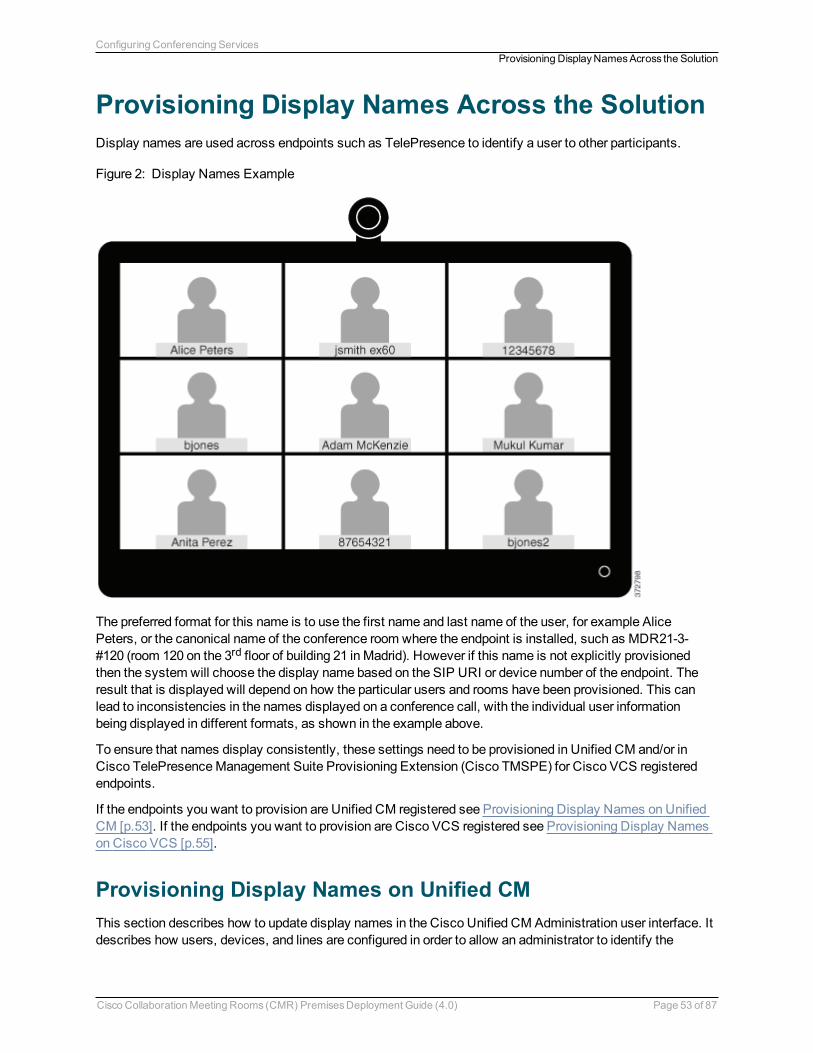
Provisioning Display Names Across the SolutionDisplay names are used across endpoints such as TelePresence to identify a user to other participants.
Figure 2: Display Names Example
The preferred format for this name is to use the first name and last name of the user, for example AlicePeters, or the canonical name of the conference room where the endpoint is installed, such as MDR21-3-#120 (room 120 on the 3rd floor of building 21 inMadrid). However if this name is not explicitly provisionedthen the system will choose the display name based on the SIP URI or device number of the endpoint. Theresult that is displayed will depend on how the particular users and rooms have been provisioned. This canlead to inconsistencies in the names displayed on a conference call, with the individual user informationbeing displayed in different formats, as shown in the example above.
To ensure that names display consistently, these settings need to be provisioned in Unified CM and/or inCisco TelePresenceManagement Suite Provisioning Extension (Cisco TMSPE) for Cisco VCS registeredendpoints.
If the endpoints you want to provision are Unified CM registered see Provisioning Display Names on UnifiedCM [p.53]. If the endpoints you want to provision are Cisco VCS registered see Provisioning Display Nameson Cisco VCS [p.55].
Provisioning Display Names on Unified CMThis section describes how to update display names in the Cisco Unified CM Administration user interface. Itdescribes how users, devices, and lines are configured in order to allow an administrator to identify the
Cisco CollaborationMeeting Rooms (CMR) PremisesDeployment Guide (4.0) Page 53 of 87
Configuring Conferencing ServicesProvisioning Display NamesAcross the Solution
correct fields and locations in which tomake those updates, so that the names display correctly. The sectiontitled Trunks [p.55] describes some optional advanced settings that may be useful to some users.
Users and Devices
On the Cisco Unified CM Administration user interface new users are configured in theUser Management >End Userwindow. It is possible to both create new users or to import them through Active Directory (AD) orLDAP.
New devices are configured in theDevice > Phonewindow. Users are then associated to a device. Thedetails supplied during this configuration will not be used for display name purposes. The display namemustbemanually configured on the line underCall routing > Directory Number, or by selecting the lineconfigured on the endpoint underDevice > Phone > Line#.
Line
Display names are configured on the line that is associated with the device. In this way, the display name isset for a particular device to which that user is associated. In the case of shared lines, it is possible to setdifferent display names on each appearance of the shared line. However, it is recommended that the samedisplay name be used across all devices using the first name and the last name of the user or the name of theconference room.
Setting Display Names for Unified CM Registered Endpoints using BulkAdministration
Bulk Administration can be used to set the display names for Unified CM registered endpoints for largenumbers of users.
Before You Start
Ensure that you have users configured and associated to devices. For more information on provisioningusers, seeCisco Unified Communications Manager Administration Guide, Release 10.0(1).
Process
1. To export user records, see Export User Records inCisco Unified Communications ManagerAdministration Guide, Release 10.0(1).
2. In the CSV file you have downloaded, copy the first name and last name columns into a new CSV file.3. To upload this CSV file to the correct device, see Update phones using custom file inCisco Unified
Communications Manager Administration Guide, Release 10.0(1).
Manually Setting Display Names for Unified CM Registered Endpoints
This procedure explains how to configure the display name for a device that is registered to Unified CM,whether the device is assigned to a user who is associated with a device, or the device is a sharedconference room device.
Before You Start
Ensure that you have users configured and associated to devices. For more information on provisioningusers, seeCisco Unified Communications Manager Administration Guide, Release 10.0(1).
Cisco CollaborationMeeting Rooms (CMR) PremisesDeployment Guide (4.0) Page 54 of 87
Configuring Conferencing ServicesProvisioning Display NamesAcross the Solution
Process
1. Log in to the Cisco Unified CM Administration user interface and chooseDevice > Phone to go to theFind and List Phonewindow.
2. Choose theDevice Name(Line) for the device you want to configure to get to thePhone Configurationwindow for that device.
3. Choose the line for the device from theAssociation area on the left hand side of the window. This bringsyou to theDirectory Number Configuration window.
4. In theDirectory Number Information area, enter the display name in theAlerting name andASCIIAlerting name fields. Note: This will be used to display the user’s namewhen communicating withdevices that are not in the Cisco Unified CM cluster.
5. In the Line 1 on Device area, enter the display name in theDisplay (Caller ID) andASCII Display(Caller ID) fields. Note: This will appear on devices which are on the same cluster as the Cisco UnifiedCM.
6. If this is a shared line, to ensure changes appear on all devices, check theUpdate Shared DeviceSettings check box, and click Propagate selected. Note:We recommend that the display name set inthe Alerting Name, ASCII Alerting Name, Display (Caller ID) and ASCII Display (Caller ID) field be theuser’s full name (for example First Name Last Name), for devices that are associated with a user, or thename of the conference room for endpoints that are in shared conference room spaces.
7. Click Save.
The changes are automatically propagated and will take effect immediately, unless the endpoint is on anactive call, in which case they will take effect immediately after the active call has ended.
Trunks
If required, the following features can also be configured to further control the behavior of display names.These settings are on the Trunk Configuration window.
n In theDevice Information area, checking the Transmit UTF-8 for Calling Party Name check box willtransmit the ASCII Alerting Name on devices that support UTF-8.
n It is possible to hide display names on a per-trunk basis. This is done in the Inbound Calls area byselectingRestricted from theConnected Name Presentation drop-down list.
n In theCaller Information area, individual device display names can also be overridden by setting theCaller Name field.
Provisioning Display Names on Cisco VCSOnCisco VCS there are twomethods which can be used to provision display names.
In the first method, Display Names are provisioned using FindMe templates. This method is used toprovision individual users. Each template contains the details for each individual user, including their DisplayName.
In the secondmethod, Display Names are provisioned using the Direct Managemethod. This method is usedto provision Conference Room endpoints. This means that each Display Name is individually provisioned foreach Conference Room endpoint on the endpoint itself.
Cisco CollaborationMeeting Rooms (CMR) PremisesDeployment Guide (4.0) Page 55 of 87
Configuring Conferencing ServicesProvisioning Display NamesAcross the Solution
FindMe
FindMe is a Cisco TMSPE feature which allows users to specify which video and audio devices should ringwhen someone calls their ID. As a result, a single ID can be used to reachmultiple devices which areassociated with that ID.
In FindMe the administrator provisions users with FindMe accounts and provisioning templates that containattributes, including the display name. Users can be newly added or imported using AD or LDAP.
For more information on FindMe, seeDeploying FindMe inCisco TelePresenceManagement SuiteProvisioning Extension with Cisco VCS Deployment Guide.
Setting Caller ID Display Names for Cisco VCS FindMe Users
This section describes how tomanually set display names for Cisco VCS FindMe users.
Note: If you are dealing with large numbers of users we recommend that you import their details using ActiveDirectory or LDAP. Using this method, user display names are imported and set automatically.
Before You Start
Ensure that you have installed and provisioned Cisco TMSPE. SeeConfiguring Cisco VCS for provisioning,Installing Cisco TMSPE, andSetting up users and provisioning inCisco TelePresenceManagement SuiteProvisioning Extension with Cisco VCS Deployment Guide.
Process
1. Log in to Cisco TMS, go toSystems > Provisioning > Users.2. In theUser Settings pane, click Edit. TheUser Settings dialog box opens.3. In theDisplay Name field, enter the first name and last name of the user. Note: If the user has been
imported using LDAP, the Display Namewill be already associated with the user.4. Click OK.
Setting Caller ID Display Names for Conference Rooms
This section explains how to set Display Names for Conference Rooms using the Direct Managemethod.
1. Log in to Cisco TMS, go toSystems > Provisioning > Users.2. In the Navigator, choose the conference room you want to update from the pane on the left side of the
window.3. Choose theAddress of the endpoint that you want to configure. This takes you to the user interface of the
selected endpoint.4. ChooseConfiguration > System Configuration, and search for the word ‘display’ in the search field on
the left side of the window.5. Enter the Display Name in theProfile 1 DisplayName field.
Note:Steps 4 and 5may vary depending on the endpoint model.6. Click Save.
Cisco CollaborationMeeting Rooms (CMR) PremisesDeployment Guide (4.0) Page 56 of 87
Configuring Conferencing ServicesProvisioning Display NamesAcross the Solution
Configuring Scheduled ConferencesHow SchedulingWorks in the Solution 58Limitations and Requirements for Scheduled Conferencing 60How to Enable Scheduled Conferencing 62
Cisco CollaborationMeeting Rooms (CMR) PremisesDeployment Guide (4.0) Page 57 of 87
Configuring Scheduled ConferencesProvisioning Display NamesAcross the Solution
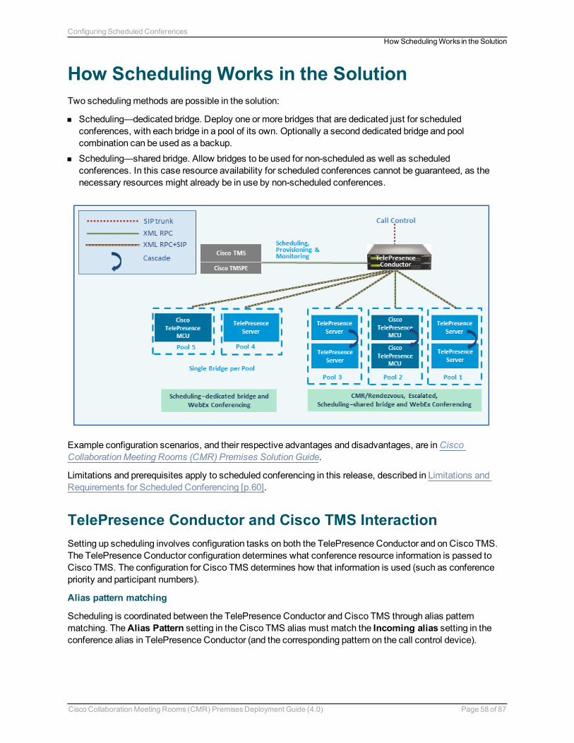
How Scheduling Works in the SolutionTwo schedulingmethods are possible in the solution:
n Scheduling—dedicated bridge. Deploy one or more bridges that are dedicated just for scheduledconferences, with each bridge in a pool of its own. Optionally a second dedicated bridge and poolcombination can be used as a backup.
n Scheduling—shared bridge. Allow bridges to be used for non-scheduled as well as scheduledconferences. In this case resource availability for scheduled conferences cannot be guaranteed, as thenecessary resources might already be in use by non-scheduled conferences.
Example configuration scenarios, and their respective advantages and disadvantages, are inCiscoCollaborationMeeting Rooms (CMR) Premises Solution Guide.
Limitations and prerequisites apply to scheduled conferencing in this release, described in Limitations andRequirements for Scheduled Conferencing [p.60].
TelePresence Conductor and Cisco TMS InteractionSetting up scheduling involves configuration tasks on both the TelePresence Conductor and on Cisco TMS.The TelePresence Conductor configuration determines what conference resource information is passed toCisco TMS. The configuration for Cisco TMS determines how that information is used (such as conferencepriority and participant numbers).
Alias pattern matching
Scheduling is coordinated between the TelePresence Conductor and Cisco TMS through alias patternmatching. TheAlias Pattern setting in the Cisco TMS alias must match the Incoming alias setting in theconference alias in TelePresence Conductor (and the corresponding pattern on the call control device).
Cisco CollaborationMeeting Rooms (CMR) PremisesDeployment Guide (4.0) Page 58 of 87
Configuring Scheduled ConferencesHow SchedulingWorks in the Solution
Cisco TMS sends its alias pattern to the TelePresence Conductor, which checks for amatching pattern in itsconference aliases. When TelePresence Conductor finds amatch, it returns to Cisco TMS the ServicePreference settings and other relevant information associated with thematching conference alias.
Multiple conference aliases can share the same Service Preference.
Service Preference and conference priority
The Service Preference on TelePresence Conductor is a key element in managing scheduling. Bridgeresources can optionally be reserved for scheduled conferences only (the Scheduling—dedicated bridgecase). To do this you "mark" the relevant conference bridge pools in the TelePresence Conductor ServicePreference (Pools to use for scheduling option). In its Capacity API responses to Cisco TMS, theTelePresence Conductor will only return pools that aremarked for scheduling.
To ensure that bridges are only used for scheduling, make sure that the relevant pool is only used in a singleService Preference, which is not used for non-scheduled conferencing, and set Scheduled conference inthe TelePresence Conductor template toYes.
Managing the priority of Cisco TMS conference aliases
Cisco TMS assigns a conference alias automatically when it creates a conference. Optionally you canchange the variable part during booking, per individual conference. Cisco TMS first tries to exhaust the firstalias with the lowest priority. If the capacity of that Service Preference is used up, Cisco TMS selects thenext lowest priority alias on another Service Preference.
Modeling tool
A Resource Cost Calculator tool is available in Cisco TMS from Systems > Navigator > Conductor >Service Preferences. This can be helpful in planning your configuration.
IP Zones in Cisco TMS
Only the IP Zone of the TelePresence Conductor itself is relevant to Cisco TMS bookings, sinceTelePresence Conductor is the entity that is scheduled. Individual IP Zones for different pools, ServicePreferences, or conference aliases in the TelePresence Conductor are not configured in Cisco TMS.
Conference Bridges in Cisco TMS
You can if you wish add TelePresence Conductor-managed conference bridges to Cisco TMS (the bridgesare automatically defined as non-bookable in Cisco TMS). This gives the following advantages:
n Conference snapshots in the Cisco TMS Conference Control Center are available for CiscoTelePresenceMCU bridges.
n Some reporting functionality. Calls are reported in Call Detail Records, but not tied to Cisco TMSconferences.
n Health monitoring for the bridges.
More Informationn Cisco TelePresenceManagement Suite Administrator Guiden Cisco TelePresence Conductor Administrator Guiden Cisco TelePresence Conductor API Guiden Cisco TelePresence Conductor with Unified Communications Manager Deployment Guiden Cisco TelePresence Conductor with Cisco TelePresenceManagement Suite Deployment Guide
Cisco CollaborationMeeting Rooms (CMR) PremisesDeployment Guide (4.0) Page 59 of 87
Configuring Scheduled ConferencesHow SchedulingWorks in the Solution
Limitations and Requirements for ScheduledConferencing
LimitationsCAUTION: If you use clustered TelePresence Conductors, be aware that Cisco TMS only recognizes oneTelePresence Conductor node. If that cluster node should fail, the Cisco TMS scheduling service and itsCMR provisioning service will be out of service (until the TelePresence Conductor is brought back up orCisco TMS is updated to communicate with a different TelePresence Conductor in the cluster).
It is not possible to schedule Cisco TMSPE-provisioned CMRs in CMR Premises.
If you use TSP Audio provided by a TSP that is configured to use the same bridge as the previous scheduledconference, we recommend that you turn off the auto-extend function in Cisco TMS.
The scheduling solution with TelePresence Conductor and Cisco TMS has some notable limitations at thistime, and significant differences exist from the previous method in Release 3.0 (scheduling to direct-managed bridges). We strongly recommend that before you enable scheduling, you review the followingdocuments:
n Table of differences between scheduling direct-managed bridges (previous release) and schedulingTelePresence Conductor-managed bridges (this release) inCisco TelePresence Conductor with CiscoTelePresenceManagement Suite Deployment Guide.
n Limitations section in the latest release notes for Cisco TMS 14.6.n Limitations section in the latest release notes for TelePresence Conductor XC3.0.
Requirementsn CMR Premises requires the Cisco TMS management tool for scheduling. Conferences are not scheduled
directly on TelePresence Conductor.n Ensure that the solution-level prerequisites and configuration process for CMR Premises are complete. In
particular:l A SIP trunk is required between the call controller and TelePresence Conductor.l The SIP trunks should be configured for Early Offer messaging.l The TelePresence Conductor must be deployed using its back-to-back user agent (B2BUA). Theexternal policy server interface is not supported.
l The TelePresence Conductor needs at least one populated conference bridge pool and one ServicePreference. At least one bridge pool in the Service Preferencemust have thePools to use forScheduling option enabled.
l [Unified CM-Centric deployments only] The telepresence-conductor-interop normalization script mustbe added to Cisco Unified Communications Manager if encryption is required.
l TelePresence Server conference bridges must be configured to bemanaged by the TelePresenceConductor.
n For the Scheduling—dedicated bridge case, some additional configuration requirements apply (seebelow).
n Participants in a scheduled conference should not escalate to an ad hoc / instant conference. This willcause a degraded conference experience for the participants.
Cisco CollaborationMeeting Rooms (CMR) PremisesDeployment Guide (4.0) Page 60 of 87
Configuring Scheduled ConferencesLimitationsand Requirements for Scheduled Conferencing
Requirements for Dedicated Bridge SchedulingIf you use a dedicated conference bridge for scheduling, the following points apply:
n The bridge resources will only be used for conferencing (subject to correct configuration). In Capacity APIresponses to Cisco TMS, the TelePresence Conductor only returns pools that are "marked" for schedulingin the Service Preference (Pools to use for scheduling option).
n For additional resilience you can include one or more additional bridges / pools in the Service Preferenceused for scheduling. These pools should not bemarked for scheduling (so they are not reported to CiscoTMS) and the additional bridges will only be used if the primary bridge becomes unavailable.
n To avoid wasting resources we recommend that you disable cascading. Even though cascading cannotphysically happen, resources will still be reserved if cascading is enabled.
n Although TelePresence Server resource optimization will occur, no benefit is gained when the primaryconference bridge is in use. Cisco TMS plans bridge usage ahead of actual usage, so the resourcesrecovered by optimization are not actually re-used. If you use backup bridges which are shared resourceswith non-scheduled conferences, then the optimization will reduce the capacity needed on the sharedbackup bridge(s).
Cisco CollaborationMeeting Rooms (CMR) PremisesDeployment Guide (4.0) Page 61 of 87
Configuring Scheduled ConferencesLimitationsand Requirements for Scheduled Conferencing
How to Enable Scheduled Conferencing
Before you Startn Ensure that the tasks in Limitations and Requirements for Scheduled Conferencing [p.60] are complete.n Read the guidelines for Bridge Pools and Service Preferences [p.11] in Deployment Requirements and
Best Practices [p.11].
ProcessTask 1: Add TelePresence Conductor to Cisco TMS
If you have not already done so, add each TelePresence Conductor that you plan to use for scheduling, as asystem in Cisco TMS, and associate each system with the appropriate zone. See the Cisco TMS context-sensitive help or theCisco TMS Administrator Guide (search for "Adding systems").
Note: If you use clustered TelePresence Conductors, define only one node per cluster to Cisco TMS.
Task 2: Define IP Zone for TelePresence Conductor in Cisco TMS
If you have not already done so, in Cisco TMS go toAdministrative Tools > Locations > IP Zones anddefine one IP zone per TelePresence Conductor, or per TelePresence Conductor cluster.
Task 3: Configure conference bridge resources in TelePresence Conductor
In TelePresence Conductor, configure one or more conference bridge pools and Service Preferences for theconference bridges to be used for scheduled conferences.
Various configurations are possible depending on the requirements of your organization. In particular,whether you need to allocate dedicated resources just for scheduled conferences or if it is acceptable toshare resources with non-scheduled conferences. The latter case has the risk that a scheduled conferencemay not be able to start if non-scheduled conferences have already used up the available resources.Configuration examples are given inCisco CollaborationMeeting Rooms (CMR) Premises Solution Guide.
To optionally implement the Scheduling—dedicated bridge case, youmust "mark" the relevant conferencebridge pool(s) for scheduling use. Do this on theService Preference page in TelePresence Conductor.
Note:When configuring conference bridge pools dedicated for scheduling, we recommend the following:
n Give the conference bridge pool a name indicating that it should only be used for scheduled conferences.n Check that the pool is only used in a single Service Preference.n Check that the Service Preference is not used in a CMR or ad hoc conference.
Task 4: Allocate the TelePresence Conductor Location
Allocate the appropriate Location to each conference bridge pool defined in the previous task. Scheduledconferences do not need a dedicated Location. Use the same Location that is assigned for rendezvousconferences.
Cisco CollaborationMeeting Rooms (CMR) PremisesDeployment Guide (4.0) Page 62 of 87
Configuring Scheduled ConferencesHow to Enable Scheduled Conferencing
Task 5: Configure conference templates in TelePresence Conductor
If a suitable conference template does not already exist in TelePresence Conductor, define one or moretemplates to reflect your scheduled conferencing requirements.
In TelePresence Conductor, go toConference configuration > Conference templates. Set Scheduledconference toYes.
Task 6: Configure conference aliases in TelePresence Conductor
Define one or more TelePresence Conductor aliases to reflect your scheduled conferencing requirements.
In TelePresence Conductor, go toConference configuration > Conference aliases.
These configuration requirements apply:
n Personal CMRs provisioned through Cisco TMSPE cannot be used for scheduled conferences.n A dedicated conference alias is required for scheduled conferences. Do not use a conference alias that is
already allocated to non-scheduled conferences.n Set Allow conference to be created toNo.
Task 7: Configure conference aliases in Cisco TMS
In Cisco TMS, go toSystems > Navigator > select the TelePresence Conductor> Aliases and select New.
The alias names do not have tomatch their corresponding conference aliases in TelePresence Conductor,but it may be administratively convenient to use the same names.
Specify theAlias Pattern setting tomatch the Incoming alias setting for the corresponding conferencealias in TelePresence Conductor. (Unlike the TelePresence Conductor the pattern is not specified as aregular expression.)
Note: Cisco TMS aliases are assigned dynamically by TMS when it creates conferences, and can bemanually modified.
Task 8: Edit Service Preferences in Cisco TMS (optional)
Unlike conference aliases, Cisco TMS automatically creates its Service Preferences. Values are populatedfrom the Service Preference in TelePresence Conductor that is associated with the relevant alias pattern.
To optionally change Service Preference settings, in Cisco TMS, go toSystems > Navigator > Conductor> Service Preferences and select Edit.
Note: In particular youmay want to change theCapacity Adjustment value, which defaults to 100%.
Task 9: Add conference bridges in Cisco TMS (optional)
As described above, there are some advantages in optionally configuring TelePresence Conductor-managedconference bridges in Cisco TMS.
Cisco CollaborationMeeting Rooms (CMR) PremisesDeployment Guide (4.0) Page 63 of 87
Configuring Scheduled ConferencesHow to Enable Scheduled Conferencing
Task 10: Configure TelePresence Conductor settings in Cisco TMS
In Cisco TMS, go toSystems > Navigator > select the TelePresence Conductor > Settings > EditSettings.
In TMS Scheduling Settings, select the booking and dialing options for the TelePresence Conductor.
1. Do not enable H.323 dialing in either direction.2. Do enable SIP URI dialing.3. Optionally, go toExtended Settings to configure customized conference ID ranges with a specific
number range and step value.
Task 11: Schedule the Conferences
Note: This guide describes the Cisco TMS Booking > New Conferencemethod to schedule conferences.You can also use one of the other Cisco TMS applications or the TelePresence Conductor API in conjunctionwith the Cisco TMS.
In Cisco TMS go toBooking > New Conference and define appropriate settings for the conference:
1. Use theBasic Settings to define a conference title, connectionmethod, conference owner, start and endtime, CiscoWebEx options, and options for recurrence.
2. Further options are available in theAdvanced Settings area.3. Use theParticipants tab to add users and endpoints to the conference.
When you save a conference, dial-in numbers for the conference are distributed via email to the organizerand/or participants. Updated numbers are distributed if you subsequently update a conference.
More Informationn Cisco TelePresenceManagement Suite Administrator Guiden Cisco TelePresence Conductor Administrator Guiden Cisco TelePresence Conductor API Guiden Cisco TelePresence Conductor with Unified Communications Manager Deployment Guiden Cisco TelePresence Conductor with Cisco TelePresenceManagement Suite Deployment Guide
Cisco CollaborationMeeting Rooms (CMR) PremisesDeployment Guide (4.0) Page 64 of 87
Configuring Scheduled ConferencesHow to Enable Scheduled Conferencing
Configuring Conferencing Features and OptionsThe tasks in this section assume that the basic configuration requirements for CMR Premises are complete.Typically you will already have completed some or all of the tasks in this section during initial implementationfor the solution. The tasks are summarized here for administrator convenience, from the perspective ofenabling specific elements of CMR Premises rather than the overall solution.
Setting up TelePresence Server Resource Optimization (Optional) 66Changing the SwitchingMode on the TelePresence Server 67ConfiguringMicrosoft Lync 2013 Interoperability 68Setting up Cisco ClearPath 69Setting up the ActiveControl Feature 70
Cisco CollaborationMeeting Rooms (CMR) PremisesDeployment Guide (4.0) Page 65 of 87
Setting up TelePresence Server ResourceOptimization (Optional)If you want to take advantage of automatic resource allocation and optimization of TelePresence Serverresources, the Conference template in TelePresence Conductor must define appropriate maximum screenand quality settings, and enable theOptimize resources setting. For details about Conductor templatesettings, see theCisco TelePresence Conductor Administrator Guide.
If you provision conferences through Cisco TMSPE these settings are configured through the Cisco TMSPE.
n For details about Cisco TMSPE settings in Unified CM-Centric deployments, seeCisco TelePresenceManagement Suite Provisioning Extension with Cisco Unified CM Deployment Guide
n For details about Cisco TMSPE settings in Cisco VCS-Centric deployments, seeCisco TelePresenceManagement Suite Provisioning Extension with Cisco VCS Deployment Guide
Cisco CollaborationMeeting Rooms (CMR) PremisesDeployment Guide (4.0) Page 66 of 87
Configuring Conferencing FeaturesandOptionsSetting up TelePresence Server ResourceOptimization (Optional)
Changing the Switching Mode on theTelePresence ServerThe TelePresence Server supports two different switchingmodes for displaying speakers from telepresencerooms:
n In the default 'segment-switched' mode (also known as speaker switching or panel switching) theTelePresence Server independently switches the display of individual cameras from amultiple camerasystem. Grouped endpoints andmulti-camera endpoints that cannot reveal which camera is associatedwith the loudest speaker are composed into a single pane, because the TelePresence Server cannotdetermine which of the segments actually shows the speaker for these types of endpoints.
n In 'room-switched' mode, the TelePresence Server simultaneously switches all of the streams from theroom into the display on another multiscreen endpoint.
An additional benefit of segment-switchedmode is that single-screen endpoints are no longer forced into theEqual layout (NxN grid) when the group is in the conference; they will see the group in a row, and in thecorrect order. However, if the display of grouped endpoints onmulti-screen systems is more important foryour environment than segment switching or the single-screen experience, youmay choose to change toroom-switchedmode.
ProcessChanging the Mode on Cisco TMS-Managed Conferences
If you use Cisco TMS to provision conferences on the TelePresence Conductor, set the following option inthe conference template Cisco TMS Custom Parameters, using this JSON command:
“callAttributes: {“displayLayoutSwitchingMode”: <******>}” where <******> shouldbe specified as switchingRoomSwitched or switchingSegmentSwitched
Changing the Mode on the TelePresence Conductor
On the TelePresence Conductor conference template, theSegment switching field determines whethersegment or room switching is used. Yes (the default) indicates segment switching, No indicates roomswitching.
Changing the Mode on Endpoints
Conference participants with Cisco CTS or TX Series endpoints canmanually choose between segment-switched or room-switchedmode during a live conference.
Cisco CollaborationMeeting Rooms (CMR) PremisesDeployment Guide (4.0) Page 67 of 87
Configuring Conferencing FeaturesandOptionsChanging the SwitchingMode on the TelePresence Server
Configuring Microsoft Lync 2013 InteroperabilityCMR Premises supports interoperability with Microsoft Lync 2013 environments via interworking by theCisco Expressway-C or Cisco VCS Control, which interworks as follows:
n BetweenMicrosoft H.264 SVC (Scalable Video Coding) and standard H.264 SVC.n BetweenMicrosoft H.264 SVC and standard H.264 AVC (Advanced Video Coding).
Lync users can participate in ad hoc, Personal CMR / rendezvous and scheduled conferences.
Before You Startn Familiarize yourself with the requirements for Lync 2013 interoperability in theCisco CollaborationMeeting
Rooms (CMR) Premises Solution Guide.n The following requirements apply in Unified CM-Centric deployments:
l The Cisco Unified Communications Manager must be configured for Early Offer as described inConfiguring the Unified CM for Early Offer [p.27]
l The Unified CMmust be connected to either Cisco Expressway-C or Cisco VCS Control as describedin Connecting the Unified CM and the Cisco Expressway Series or Cisco VCS [p.31].
Process for Unified CM-Centric DeploymentsIn Unified CM-Centric deployments, the Unified CM connects to the Lync server via the Cisco Expressway-C, which acts as a SIP back-to-back user agent andmedia helper. For configuration instructions, seeCiscoExpressway andMicrosoft Lync Deployment Guide (X8.5). When you have completed the steps in the guide,you will have configured:
n Static routes to route calls from Lync to a "Lync gateway" Expressway.n The Expressway B2BUA to route calls to Lync.n A SIP trunk between the "Lync gateway" Expressway and Unified CM.
Process for Cisco VCS-Centric DeploymentsIn Cisco VCS-Centric deployments, the Cisco VCS and Lync are peers. For configuration instructions, seeCisco VCS andMicrosoft Lync Deployment Guide (X8.5). When you have completed the steps in the guide,you will have configured:
n A SIP trunk to connect a Lync deployment and Cisco VCS Control across an IP network.n Static routes from Lync to the “Lync gateway” Cisco VCS.n (Optional) FindMe to provide amore integrated environment.
Cisco CollaborationMeeting Rooms (CMR) PremisesDeployment Guide (4.0) Page 68 of 87
Configuring Conferencing FeaturesandOptionsConfiguringMicrosoft Lync2013 Interoperability

Setting up Cisco ClearPathThe Cisco ClearPath video quality technology is enabled by default in all CMR Premises devices. No actionis required to enable it.
Cisco CollaborationMeeting Rooms (CMR) PremisesDeployment Guide (4.0) Page 69 of 87
Configuring Conferencing FeaturesandOptionsSetting up Cisco ClearPath
Setting up the ActiveControl FeatureActiveControl allows conference participants to administer a conference on TelePresence Server from anendpoint by using the video system interface (not available from the TRC5 remote control and on-screendisplay). With ActiveControl, users can see a list of participants and other information during a conference.On certain endpoints they can change the conference layout displayed locally, and disconnect otherparticipants.
Limitationsn If an ActiveControl enabled call traverses a Unified CM trunk with a Unified CM version lower than 9.1(2),
the call may fail. ActiveControl should not be enabled on older Unified CM trunks (Unified CM 8.x orearlier).
n The ActiveControl feature on the TelePresence Server supports up to 500 participants.n ActiveControl is a SIP only feature. H.323 interworking scenarios are not supported.n ActiveControl is not supported by Cisco Jabber or Cisco DX Series endpoints.n ActiveControl/iX protocol traffic is not encrypted.
Overview of Configuring the iX ProtocolActiveControl uses the iX protocol, which is advertised as an application line in the SIP Session DescriptionProtocol (SDP). Extensions to the SIP SDP are not fully supported in some older systems, which hasimplications for CMR Premises networks that connect to external networks or to older Unified CMs (UnifiedCM 8.x or earlier). No issues occur with iX in Unified CM 9.1(2) or later, or with iX in Cisco VCS systems.However, if you are enabling ActiveControl in CMR Premises networks which interface to older Unified CMs(8.x and earlier) or to third-party networks (business-to-business), youmust follow the instructions in thisdocument carefully to isolate the iX protocol traffic from systems that do not support it. Failure to do somaylead to unpredictable consequences, including call failures.
The iX protocol is enabled by default in TelePresence Server 4.1. In situations where the far end network isnot known or is known to have devices that do not support iX, it may be safest to disable iX on connectionsleaving the known environment:
n Unified CM-Centric deployments that connect to Unified CM 8.x or earlier systems. In these cases theolder Unified CM systems will reject calls from ActiveControl-enabled devices. To avoid these calls failing,leave iX disabled on any trunk towards the Unified CM 8.x device in the CMR Premises network. In caseswhere the 8.x device is reached via a SIP proxy, ensure that iX is disabled on the trunk towards that proxy.
n Unified CM-Centric deployments that connect to third-party networks. In these cases there is no way toknow how the third-party network will handle calls from ActiveControl-enabled devices, but in someinstances the handlingmechanismmay be to reject them. To avoid such calls failing, leave iX disabled onall trunks in the CMR Premises network towards third-party networks.
n Cisco VCS-Centric deployments which connect to external networks or connect internally to older UnifiedCM versions.l Starting in Cisco VCS X8.1, you can turn on a zone filter to disable iX for INVITE requests sent toexternal networks or older Unified CM systems. (By default, the filter is off.)
l With version X7.2.3, we recommend that you leave iX disabled throughout the Optimized Conferencingnetwork. (In some situations it is possible to enable iX in X7.2.3 with workarounds, but this should onlybe done with guidance from Cisco Technical Support.)
Cisco CollaborationMeeting Rooms (CMR) PremisesDeployment Guide (4.0) Page 70 of 87
Configuring Conferencing FeaturesandOptionsSetting up the ActiveControl Feature
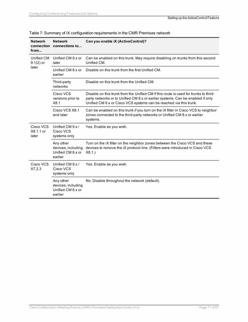
Networkconnectionfrom...
Networkconnections to…
Can you enable iX (ActiveControl)?
Unified CM9.1(2) orlater
Unified CM 9.x orlater
Can be enabled on this trunk. May require disabling on trunks from this secondUnified CM.
Unified CM 8.x orearlier
Disable on this trunk from the first Unified CM.
Third-partynetworks
Disable on this trunk from the Unified CM.
Cisco VCSversions prior toX8.1
Disable on this trunk from the Unified CM if this route is used for trunks to third-party networks or to Unified CM 8.x or earlier systems. Can be enabled if onlyUnified CM 9.x or Cisco VCS systems can be reached via this trunk.
Cisco VCS X8.1and later
Can be enabled on this trunk if you turn on the iX filter in Cisco VCS to neighborzones connected to the third-party networks or Unified CM 8.x or earliersystems.
Cisco VCSX8.1.1 orlater
Unified CM 9.x /Cisco VCSsystems only
Yes. Enable as you wish.
Any otherdevices, includingUnified CM 8.x orearlier
Turn on the iX filter on the neighbor zones between the Cisco VCS and thesedevices to remove the iX protocol line. (Filters were introduced in Cisco VCSX8.1.)
Cisco VCSX7.2.3
Unified CM 9.x /Cisco VCSsystems only
Yes. Enable as you wish.
Any otherdevices, includingUnified CM 8.x orearlier
No. Disable throughout the network (default).
Table 7: Summary of iX configuration requirements in the CMR Premises network
Cisco CollaborationMeeting Rooms (CMR) PremisesDeployment Guide (4.0) Page 71 of 87
Configuring Conferencing FeaturesandOptionsSetting up the ActiveControl Feature
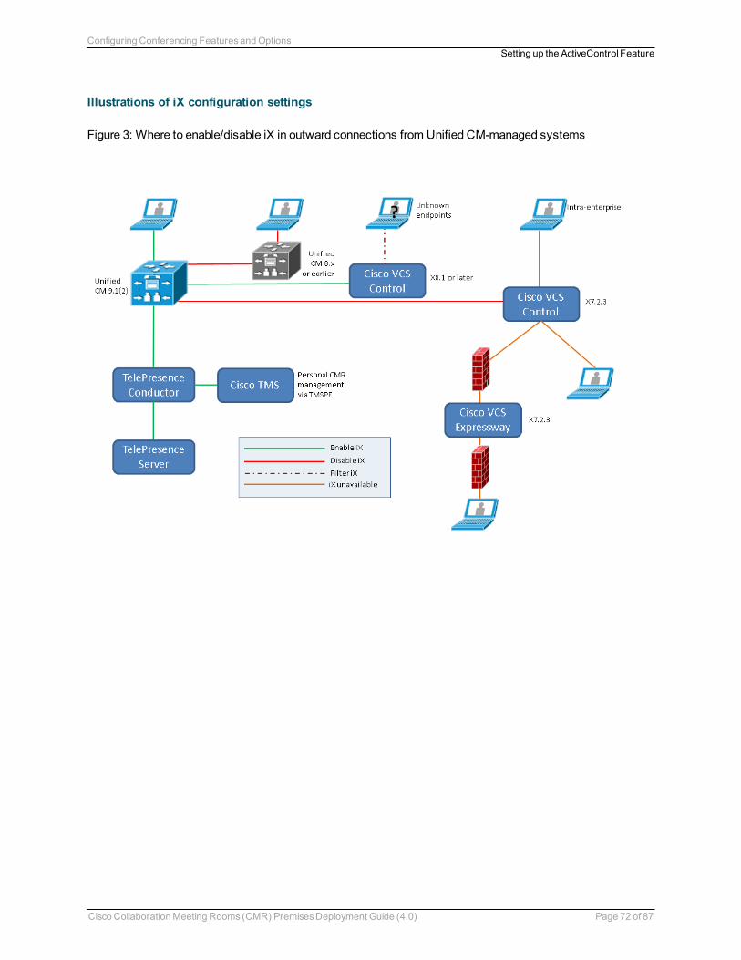
Illustrations of iX configuration settings
Figure 3: Where to enable/disable iX in outward connections from Unified CM-managed systems
Cisco CollaborationMeeting Rooms (CMR) PremisesDeployment Guide (4.0) Page 72 of 87
Configuring Conferencing FeaturesandOptionsSetting up the ActiveControl Feature
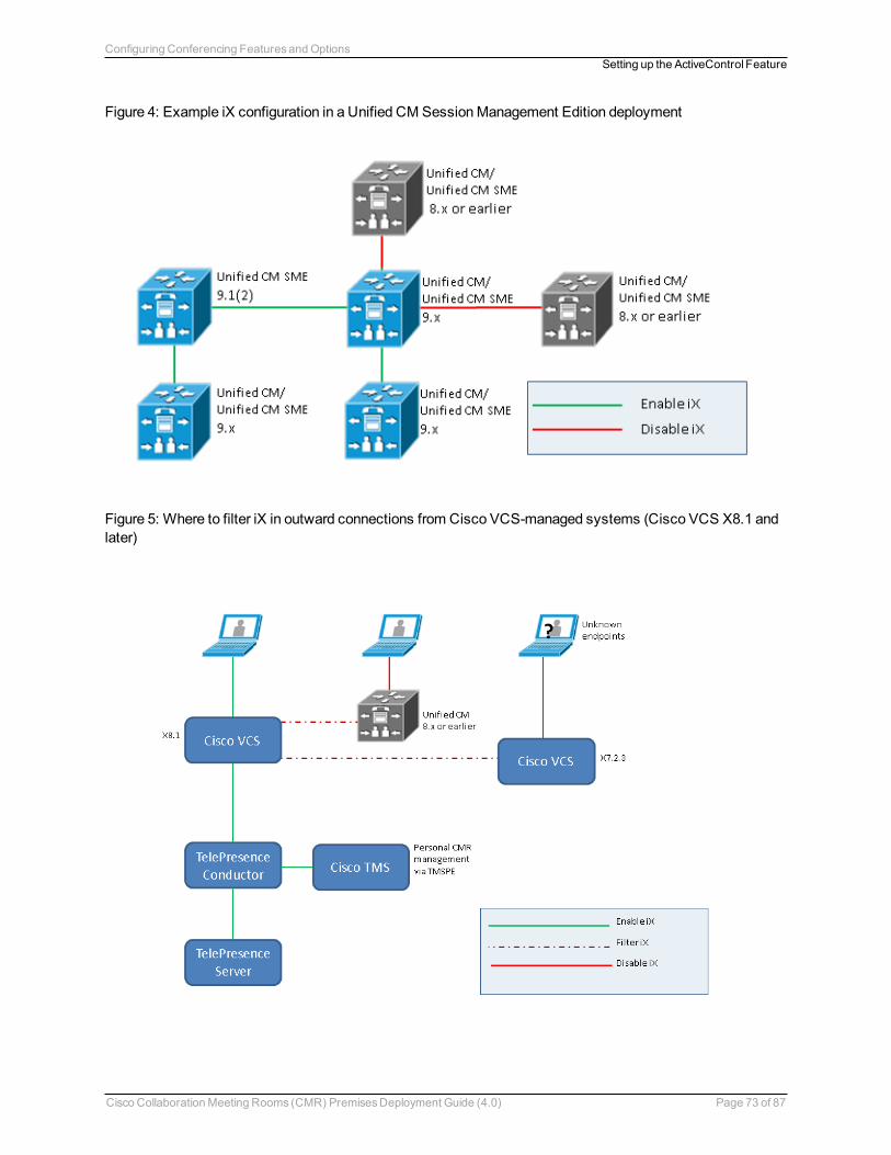
Figure 4: Example iX configuration in a Unified CM SessionManagement Edition deployment
Figure 5: Where to filter iX in outward connections from Cisco VCS-managed systems (Cisco VCS X8.1 andlater)
Cisco CollaborationMeeting Rooms (CMR) PremisesDeployment Guide (4.0) Page 73 of 87
Configuring Conferencing FeaturesandOptionsSetting up the ActiveControl Feature
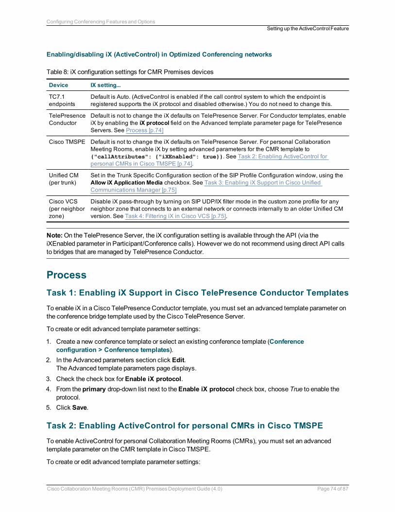
Enabling/disabling iX (ActiveControl) in Optimized Conferencing networks
Device IX setting...
TC7.1endpoints
Default is Auto. (ActiveControl is enabled if the call control system to which the endpoint isregistered supports the iX protocol and disabled otherwise.) You do not need to change this.
TelePresenceConductor
Default is not to change the iX defaults on TelePresence Server. For Conductor templates, enableiX by enabling the iX protocol field on the Advanced template parameter page for TelePresenceServers. See Process [p.74]
Cisco TMSPE Default is not to change the iX defaults on TelePresence Server. For personal CollaborationMeeting Rooms, enable iX by setting advanced parameters for the CMR template to{"callAttributes": {"iXEnabled": true}}. See Task 2: Enabling ActiveControl forpersonal CMRs in Cisco TMSPE [p.74].
Unified CM(per trunk)
Set in the Trunk Specific Configuration section of the SIP Profile Configuration window, using theAllow iX Application Media checkbox. See Task 3: Enabling iX Support in Cisco UnifiedCommunications Manager [p.75]
Cisco VCS(per neighborzone)
Disable iX pass-through by turning on SIP UDP/IX filter mode in the custom zone profile for anyneighbor zone that connects to an external network or connects internally to an older Unified CMversion. See Task 4: Filtering iX in Cisco VCS [p.75].
Table 8: iX configuration settings for CMR Premises devices
Note:On the TelePresence Server, the iX configuration setting is available through the API (via theiXEnabled parameter in Participant/Conference calls). However we do not recommend using direct API callsto bridges that aremanaged by TelePresence Conductor.
ProcessTask 1: Enabling iX Support in Cisco TelePresence Conductor Templates
To enable iX in a Cisco TelePresence Conductor template, youmust set an advanced template parameter onthe conference bridge template used by the Cisco TelePresence Server.
To create or edit advanced template parameter settings:
1. Create a new conference template or select an existing conference template (Conferenceconfiguration > Conference templates).
2. In the Advanced parameters section click Edit.The Advanced template parameters page displays.
3. Check the check box forEnable iX protocol.4. From the primary drop-down list next to theEnable iX protocol check box, choose True to enable the
protocol.5. Click Save.
Task 2: Enabling ActiveControl for personal CMRs in Cisco TMSPE
To enable ActiveControl for personal CollaborationMeeting Rooms (CMRs), youmust set an advancedtemplate parameter on the CMR template in Cisco TMSPE.
To create or edit advanced template parameter settings:
Cisco CollaborationMeeting Rooms (CMR) PremisesDeployment Guide (4.0) Page 74 of 87
Configuring Conferencing FeaturesandOptionsSetting up the ActiveControl Feature
1. Create a new CMR template or select an existing template (Systems > Provisioning > Users).2. On theEdit CMR Template page, check the check box forCustom Parameters.3. In theAdvanced parameters field, enter {"callAttributes": {"iXEnabled": true}}.4. Click Save.
Task 3: Enabling iX Support in Cisco Unified Communications Manager
Support for the iX protocol is disabled by default. To enable iX support in Unified CM , youmust firstconfigure support in the SIP profile and then apply that SIP profile to the SIP trunk.
Configuring iX support in a SIP profile
1. ChooseDevice > Device Settings > SIP Profile.The Find and List SIP Profiles window displays.
2. Do one of the following:l To add a new SIP profile, click Add New.l Tomodify an existing SIP profile, enter the search criteria and click Find. Click the name of the SIPprofile that you want to update.
The SIP Profile Configuration window displays.3. Check the check box forAllow iX Application Media.4. Make any additional configuration changes.5. Click Save.
Applying the SIP profile to a SIP trunk
1. ChooseDevice > Trunk.The Find and List Trunks window displays.
2. Do one of the following:l To add a new trunk, click Add New.l Tomodify a trunk, enter the search criteria and click Find. Click the name of the trunk that you want toupdate.
The Trunk Configuration window displays.3. From the SIP Profile drop-down list, choose the appropriate SIP profile.4. Click Save.5. To update an existing trunk, click Apply Config to apply the new settings.
Task 4: Filtering iX in Cisco VCS
To configure the Cisco VCS to filter out the iX application line for a neighbor zone that does not support theprotocol, the zonemust be configured with a custom zone profile that has theSIP UDP/IX filter modeadvanced configuration option set toOn.
To update advanced zone profile option settings:
1. Create a new neighbor zone or select an existing zone (Configuration > Zones > Zones).2. In the Advanced parameters section, for Zone profile, chooseCustom if it is not already selected.
The zone profile advanced configuration options display.
Cisco CollaborationMeeting Rooms (CMR) PremisesDeployment Guide (4.0) Page 75 of 87
Configuring Conferencing FeaturesandOptionsSetting up the ActiveControl Feature
3. From theSIP UDP/IX filter mode drop-down list, choose On.4. Click Save.
Troubleshooting
Scenario Outcome
Unified CM 8.x or earlier Calls fail
Unified CM 9.x earlier than 9.1(2) Calls handled normally but no ActiveControl
Unified CM 9.1(2) Calls handled normally plus ActiveControl
Endpoint - no support for iX and no SDP implementation Endpoint may reboot or calls may fail
Table 9: Call handling summary for calls that contain an iX header
Cisco CollaborationMeeting Rooms (CMR) PremisesDeployment Guide (4.0) Page 76 of 87
Configuring Conferencing FeaturesandOptionsSetting up the ActiveControl Feature
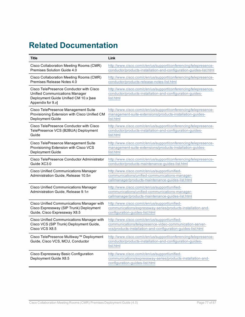
Related DocumentationTitle Link
Cisco Collaboration Meeting Rooms (CMR)Premises Solution Guide 4.0
http://www.cisco.com/c/en/us/support/conferencing/telepresence-conductor/products-installation-and-configuration-guides-list.html
Cisco Collaboration Meeting Rooms (CMR)Premises Release Notes 4.0
http://www.cisco.com/c/en/us/support/conferencing/telepresence-conductor/products-release-notes-list.html
Cisco TelePresence Conductor with CiscoUnified Communications ManagerDeployment Guide Unified CM 10.x [seeAppendix for 9.x]
http://www.cisco.com/c/en/us/support/conferencing/telepresence-conductor/products-installation-and-configuration-guides-list.html
Cisco TelePresence Management SuiteProvisioning Extension with Cisco Unified CMDeployment Guide
http://www.cisco.com/c/en/us/support/conferencing/telepresence-management-suite-extensions/products-installation-guides-list.html
Cisco TelePresence Conductor with CiscoTelePresence VCS (B2BUA) DeploymentGuide
http://www.cisco.com/c/en/us/support/conferencing/telepresence-conductor/products-installation-and-configuration-guides-list.html
Cisco TelePresence Management SuiteProvisioning Extension with Cisco VCSDeployment Guide
http://www.cisco.com/c/en/us/support/conferencing/telepresence-management-suite-extensions/products-installation-guides-list.html
Cisco TelePresence Conductor AdministratorGuide XC3.0
http://www.cisco.com/c/en/us/support/conferencing/telepresence-conductor/products-maintenance-guides-list.html
Cisco Unified Communications ManagerAdministration Guide, Release 10.5n
http://www.cisco.com/c/en/us/support/unified-communications/unified-communications-manager-callmanager/products-maintenance-guides-list.html
Cisco Unified Communications ManagerAdministration Guide, Release 9.1n
http://www.cisco.com/c/en/us/support/unified-communications/unified-communications-manager-callmanager/products-maintenance-guides-list.html
Cisco Unified Communications Manager withCisco Expressway (SIP Trunk) DeploymentGuide, Cisco Expressway X8.5
http://www.cisco.com/c/en/us/support/unified-communications/expressway-series/products-installation-and-configuration-guides-list.html
Cisco Unified Communications Manager withCisco VCS (SIP Trunk) Deployment Guide,Cisco VCS X8.5
http://www.cisco.com/c/en/us/support/unified-communications/telepresence-video-communication-server-vcs/products-installation-and-configuration-guides-list.html
Cisco TelePresence Multiway™ DeploymentGuide, Cisco VCS, MCU, Conductor
http://www.cisco.com/c/en/us/support/conferencing/telepresence-conductor/products-installation-and-configuration-guides-list.html
Cisco Expressway Basic ConfigurationDeployment Guide X8.5
http://www.cisco.com/c/en/us/support/unified-communications/expressway-series/products-installation-and-configuration-guides-list.html
Cisco CollaborationMeeting Rooms (CMR) PremisesDeployment Guide (4.0) Page 77 of 87
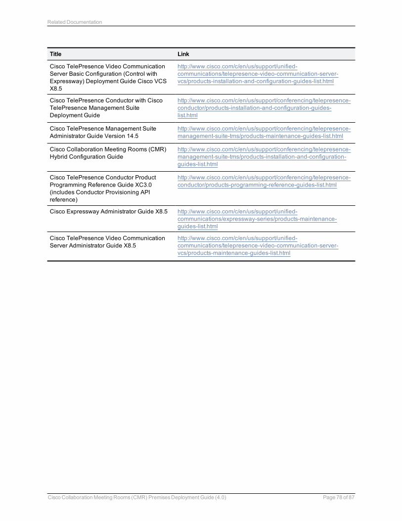
Title Link
Cisco TelePresence Video CommunicationServer Basic Configuration (Control withExpressway) Deployment Guide Cisco VCSX8.5
http://www.cisco.com/c/en/us/support/unified-communications/telepresence-video-communication-server-vcs/products-installation-and-configuration-guides-list.html
Cisco TelePresence Conductor with CiscoTelePresence Management SuiteDeployment Guide
http://www.cisco.com/c/en/us/support/conferencing/telepresence-conductor/products-installation-and-configuration-guides-list.html
Cisco TelePresence Management SuiteAdministrator Guide Version 14.5
http://www.cisco.com/c/en/us/support/conferencing/telepresence-management-suite-tms/products-maintenance-guides-list.html
Cisco Collaboration Meeting Rooms (CMR)Hybrid Configuration Guide
http://www.cisco.com/c/en/us/support/conferencing/telepresence-management-suite-tms/products-installation-and-configuration-guides-list.html
Cisco TelePresence Conductor ProductProgramming Reference Guide XC3.0(includes Conductor Provisioning APIreference)
http://www.cisco.com/c/en/us/support/conferencing/telepresence-conductor/products-programming-reference-guides-list.html
Cisco Expressway Administrator Guide X8.5 http://www.cisco.com/c/en/us/support/unified-communications/expressway-series/products-maintenance-guides-list.html
Cisco TelePresence Video CommunicationServer Administrator Guide X8.5
http://www.cisco.com/c/en/us/support/unified-communications/telepresence-video-communication-server-vcs/products-maintenance-guides-list.html
Cisco CollaborationMeeting Rooms (CMR) PremisesDeployment Guide (4.0) Page 78 of 87
Related Documentation
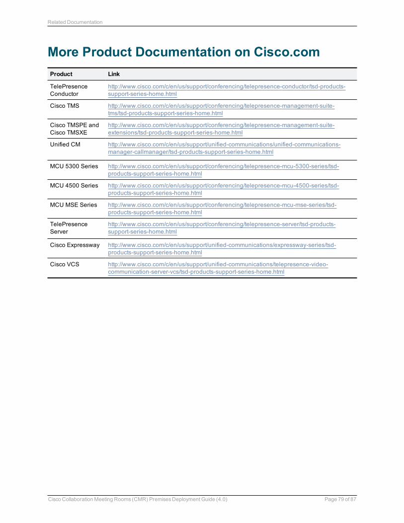
More Product Documentation on Cisco.comProduct Link
TelePresenceConductor
http://www.cisco.com/c/en/us/support/conferencing/telepresence-conductor/tsd-products-support-series-home.html
Cisco TMS http://www.cisco.com/c/en/us/support/conferencing/telepresence-management-suite-tms/tsd-products-support-series-home.html
Cisco TMSPE andCisco TMSXE
http://www.cisco.com/c/en/us/support/conferencing/telepresence-management-suite-extensions/tsd-products-support-series-home.html
Unified CM http://www.cisco.com/c/en/us/support/unified-communications/unified-communications-manager-callmanager/tsd-products-support-series-home.html
MCU 5300 Series http://www.cisco.com/c/en/us/support/conferencing/telepresence-mcu-5300-series/tsd-products-support-series-home.html
MCU 4500 Series http://www.cisco.com/c/en/us/support/conferencing/telepresence-mcu-4500-series/tsd-products-support-series-home.html
MCU MSE Series http://www.cisco.com/c/en/us/support/conferencing/telepresence-mcu-mse-series/tsd-products-support-series-home.html
TelePresenceServer
http://www.cisco.com/c/en/us/support/conferencing/telepresence-server/tsd-products-support-series-home.html
Cisco Expressway http://www.cisco.com/c/en/us/support/unified-communications/expressway-series/tsd-products-support-series-home.html
Cisco VCS http://www.cisco.com/c/en/us/support/unified-communications/telepresence-video-communication-server-vcs/tsd-products-support-series-home.html
Cisco CollaborationMeeting Rooms (CMR) PremisesDeployment Guide (4.0) Page 79 of 87
Related Documentation
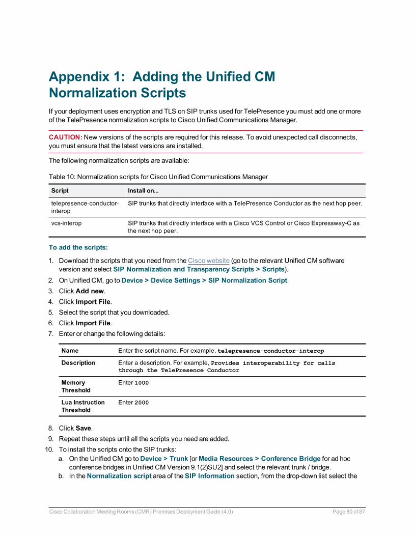
Appendix 1: Adding the Unified CMNormalization ScriptsIf your deployment uses encryption and TLS on SIP trunks used for TelePresence youmust add one or moreof the TelePresence normalization scripts to Cisco Unified Communications Manager.
CAUTION:New versions of the scripts are required for this release. To avoid unexpected call disconnects,youmust ensure that the latest versions are installed.
The following normalization scripts are available:
Script Install on...
telepresence-conductor-interop
SIP trunks that directly interface with a TelePresence Conductor as the next hop peer.
vcs-interop SIP trunks that directly interface with a Cisco VCS Control or Cisco Expressway-C asthe next hop peer.
Table 10: Normalization scripts for Cisco Unified Communications Manager
To add the scripts:
1. Download the scripts that you need from the Cisco website (go to the relevant Unified CM softwareversion and select SIP Normalization and Transparency Scripts > Scripts).
2. On Unified CM, go toDevice > Device Settings > SIP Normalization Script.3. Click Add new.4. Click Import File.5. Select the script that you downloaded.6. Click Import File.7. Enter or change the following details:
Name Enter the script name. For example, telepresence-conductor-interop
Description Enter a description. For example, Provides interoperability for callsthrough the TelePresence Conductor
MemoryThreshold
Enter 1000
Lua InstructionThreshold
Enter 2000
8. Click Save.9. Repeat these steps until all the scripts you need are added.10. To install the scripts onto the SIP trunks:
a. On the Unified CM go toDevice > Trunk [orMedia Resources > Conference Bridge for ad hocconference bridges in Unified CM Version 9.1(2)SU2] and select the relevant trunk / bridge.
b. In theNormalization script area of theSIP Information section, from the drop-down list select the
Cisco CollaborationMeeting Rooms (CMR) PremisesDeployment Guide (4.0) Page 80 of 87

appropriate script for the trunk / bridge.c. Click Save.d. Click Reset.
Cisco CollaborationMeeting Rooms (CMR) PremisesDeployment Guide (4.0) Page 81 of 87
Appendix 1: Adding the Unified CMNormalization Scripts
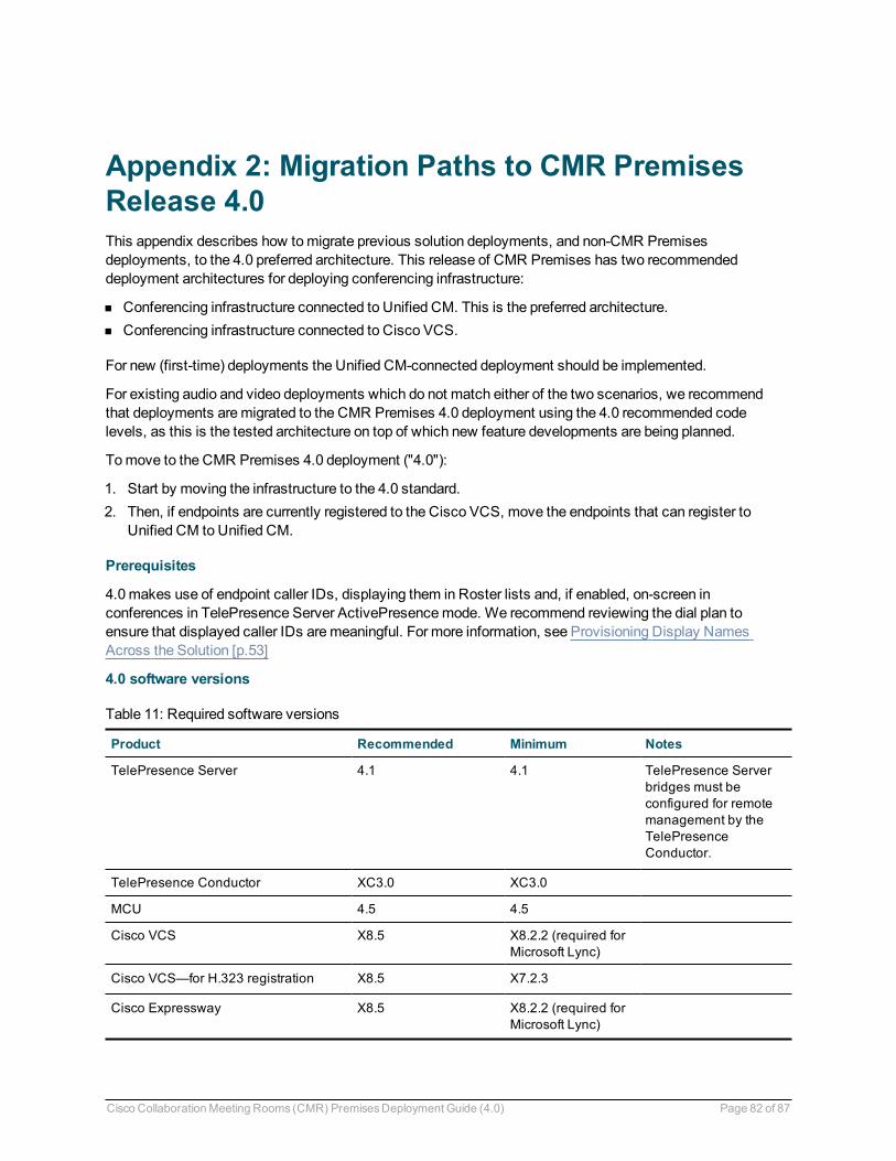
Appendix 2: Migration Paths to CMR PremisesRelease 4.0This appendix describes how tomigrate previous solution deployments, and non-CMR Premisesdeployments, to the 4.0 preferred architecture. This release of CMR Premises has two recommendeddeployment architectures for deploying conferencing infrastructure:
n Conferencing infrastructure connected to Unified CM. This is the preferred architecture.n Conferencing infrastructure connected to Cisco VCS.
For new (first-time) deployments the Unified CM-connected deployment should be implemented.
For existing audio and video deployments which do not match either of the two scenarios, we recommendthat deployments aremigrated to the CMR Premises 4.0 deployment using the 4.0 recommended codelevels, as this is the tested architecture on top of which new feature developments are being planned.
Tomove to the CMR Premises 4.0 deployment ("4.0"):
1. Start by moving the infrastructure to the 4.0 standard.2. Then, if endpoints are currently registered to the Cisco VCS, move the endpoints that can register to
Unified CM to Unified CM.
Prerequisites
4.0makes use of endpoint caller IDs, displaying them in Roster lists and, if enabled, on-screen inconferences in TelePresence Server ActivePresencemode. We recommend reviewing the dial plan toensure that displayed caller IDs aremeaningful. For more information, see Provisioning Display NamesAcross the Solution [p.53]
4.0 software versions
Product Recommended Minimum Notes
TelePresence Server 4.1 4.1 TelePresence Serverbridges must beconfigured for remotemanagement by theTelePresenceConductor.
TelePresence Conductor XC3.0 XC3.0
MCU 4.5 4.5
Cisco VCS X8.5 X8.2.2 (required forMicrosoft Lync)
Cisco VCS—for H.323 registration X8.5 X7.2.3
Cisco Expressway X8.5 X8.2.2 (required forMicrosoft Lync)
Table 11: Required software versions
Cisco CollaborationMeeting Rooms (CMR) PremisesDeployment Guide (4.0) Page 82 of 87
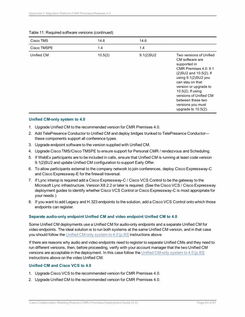
Cisco TMS 14.6 14.6
Cisco TMSPE 1.4 1.4
Unified CM 10.5(2) 9.1(2)SU2 Two versions of UnifiedCM software aresupported inCMR Premises 4.0: 9.1(2)SU2 and 10.5(2). Ifusing 9.1(2)SU2 youcan stay on thatversion or upgrade to10.5(2). If usingversions of Unified CMbetween these twoversions you mustupgrade to 10.5(2).
Table 11: Required software versions (continued)
Unified CM-only system to 4.0
1. Upgrade Unified CM to the recommended version for CMR Premises 4.0.2. Add TelePresence Conductor to Unified CM and deploy bridges trunked to TelePresence Conductor—
these components support all conference types.3. Upgrade endpoint software to the version supplied with Unified CM.4. Upgrade Cisco TMS/Cisco TMSPE to ensure support for Personal CMR / rendezvous and Scheduling.5. If WebEx participants are to be included in calls, ensure that Unified CM is running at least code version
9.1(2)SU2 and update Unified CM configuration to support Early Offer.6. To allow participants external to the company network to join conferences, deploy Cisco Expressway-C
and Cisco Expressway-E for the firewall traversal.7. If Lync interop is required add a Cisco Expressway-C / Cisco VCS Control to be the gateway to the
Microsoft Lync infrastructure. Version X8.2.2 or later is required. (See the Cisco VCS / Cisco Expresswaydeployment guides to identify whether Cisco VCS Control or Cisco Expressway-C is most appropriate foryour needs.)
8. If you want to add Legacy and H.323 endpoints to the solution, add a Cisco VCS Control onto which thoseendpoints can register.
Separate audio-only endpoint Unified CM and video endpoint Unified CM to 4.0
SomeUnified CM deployments use a Unified CM for audio-only endpoints and a separate Unified CM forvideo endpoints. The ideal solution is to run both systems at the sameUnified CM version, and in that caseyou should follow the Unified CM-only system to 4.0 [p.83] instructions above.
If there are reasons why audio and video endpoints need to register to separate Unified CMs and they need torun different versions, then, before proceeding, verify with your account manager that the two Unified CMversions are acceptable in the deployment. In this case follow the Unified CM-only system to 4.0 [p.83]instructions above on the video Unified CM.
Unified CM and Cisco VCS to 4.0
1. Upgrade Cisco VCS to the recommended version for CMR Premises 4.0.2. Upgrade Unified CM to the recommended version for CMR Premises 4.0.
Cisco CollaborationMeeting Rooms (CMR) PremisesDeployment Guide (4.0) Page 83 of 87
Appendix 2: Migration Paths to CMR PremisesRelease 4.0
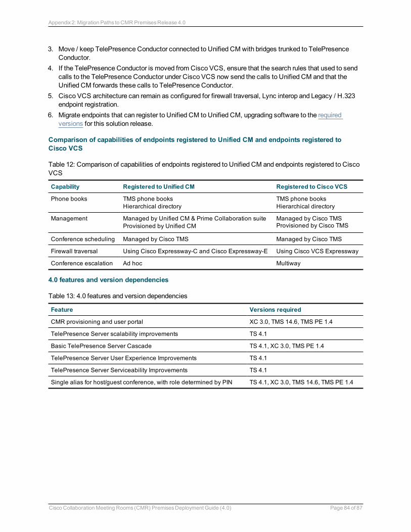
3. Move / keep TelePresence Conductor connected to Unified CM with bridges trunked to TelePresenceConductor.
4. If the TelePresence Conductor is moved from Cisco VCS, ensure that the search rules that used to sendcalls to the TelePresence Conductor under Cisco VCS now send the calls to Unified CM and that theUnified CM forwards these calls to TelePresence Conductor.
5. Cisco VCS architecture can remain as configured for firewall traversal, Lync interop and Legacy / H.323endpoint registration.
6. Migrate endpoints that can register to Unified CM to Unified CM, upgrading software to the requiredversions for this solution release.
Comparison of capabilities of endpoints registered to Unified CM and endpoints registered toCisco VCS
Capability Registered to Unified CM Registered to Cisco VCS
Phone books TMS phone booksHierarchical directory
TMS phone booksHierarchical directory
Management Managed by Unified CM & Prime Collaboration suiteProvisioned by Unified CM
Managed by Cisco TMSProvisioned by Cisco TMS
Conference scheduling Managed by Cisco TMS Managed by Cisco TMS
Firewall traversal Using Cisco Expressway-C and Cisco Expressway-E Using Cisco VCS Expressway
Conference escalation Ad hoc Multiway
Table 12: Comparison of capabilities of endpoints registered to Unified CM and endpoints registered to CiscoVCS
4.0 features and version dependencies
Feature Versions required
CMR provisioning and user portal XC 3.0, TMS 14.6, TMS PE 1.4
TelePresence Server scalability improvements TS 4.1
Basic TelePresence Server Cascade TS 4.1, XC 3.0, TMS PE 1.4
TelePresence Server User Experience Improvements TS 4.1
TelePresence Server Serviceability Improvements TS 4.1
Single alias for host/guest conference, with role determined by PIN TS 4.1, XC 3.0, TMS 14.6, TMS PE 1.4
Table 13: 4.0 features and version dependencies
Cisco CollaborationMeeting Rooms (CMR) PremisesDeployment Guide (4.0) Page 84 of 87
Appendix 2: Migration Paths to CMR PremisesRelease 4.0
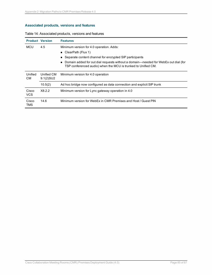
Associated products, versions and features
Product Version Features
MCU 4.5 Minimum version for 4.0 operation. Adds:
n ClearPath (Flux 1)n Separate content channel for encrypted SIP participantsn Domain added for out dial requests without a domain—needed for WebEx out dial (for
TSP conferenced audio) when the MCU is trunked to Unified CM.
UnifiedCM
Unified CM9.1(2)SU2
Minimum version for 4.0 operation
10.5(2) Ad hoc bridge now configured as data connection and explicit SIP trunk
CiscoVCS
X8.2.2 Minimum version for Lync gateway operation in 4.0
CiscoTMS
14.6 Minimum version for WebEx in CMR Premises and Host / Guest PIN
Table 14: Associated products, versions and features
Cisco CollaborationMeeting Rooms (CMR) PremisesDeployment Guide (4.0) Page 85 of 87
Appendix 2: Migration Paths to CMR PremisesRelease 4.0

Document Revision HistoryDate Description Changes
January 2015 Initial issue First version.
January 2015 Re-issue Updated links to product deployment guides.
Cisco CollaborationMeeting Rooms (CMR) PremisesDeployment Guide (4.0) Page 86 of 87
Document Revision History
THE SPECIFICATIONS AND INFORMATION REGARDING THE PRODUCTS IN THIS MANUAL ARESUBJECT TOCHANGEWITHOUT NOTICE. ALL STATEMENTS, INFORMATION, ANDRECOMMENDATIONS IN THIS MANUAL ARE BELIEVED TOBE ACCURATE BUT ARE PRESENTEDWITHOUTWARRANTY OF ANY KIND, EXPRESS OR IMPLIED. USERS MUST TAKE FULLRESPONSIBILITY FOR THEIR APPLICATION OF ANY PRODUCTS.
THE SOFTWARE LICENSE AND LIMITED WARRANTY FOR THE ACCOMPANYINGPRODUCT ARESET FORTH IN THE INFORMATION PACKET THAT SHIPPED WITH THE PRODUCT AND AREINCORPORATED HEREIN BY THIS REFERENCE. IF YOU ARE UNABLE TO LOCATE THESOFTWARE LICENSE OR LIMITED WARRANTY, CONTACT YOUR CISCOREPRESENTATIVE FORA COPY.
The Cisco implementation of TCP header compression is an adaptation of a program developed by theUniversity of California, Berkeley (UCB) as part of UCB's public domain version of the UNIX operatingsystem. All rights reserved. Copyright © 1981, Regents of the University of California.
NOTWITHSTANDINGANY OTHER WARRANTY HEREIN, ALL DOCUMENT FILES AND SOFTWAREOF THESE SUPPLIERS ARE PROVIDED "AS IS" WITH ALL FAULTS. CISCOAND THE ABOVE-NAMED SUPPLIERS DISCLAIM ALLWARRANTIES, EXPRESSED OR IMPLIED, INCLUDING,WITHOUT LIMITATION, THOSE OFMERCHANTABILITY, FITNESS FOR A PARTICULAR PURPOSEAND NONINFRINGEMENT OR ARISING FROM A COURSE OF DEALING, USAGE, OR TRADEPRACTICE.
IN NOEVENT SHALLCISCOOR ITS SUPPLIERS BE LIABLE FOR ANY INDIRECT, SPECIAL,CONSEQUENTIAL, OR INCIDENTALDAMAGES, INCLUDING, WITHOUT LIMITATION, LOSTPROFITS OR LOSS OR DAMAGE TODATA ARISINGOUTOF THE USE OR INABILITY TOUSE THISMANUAL, EVEN IF CISCOOR ITS SUPPLIERS HAVE BEEN ADVISED OF THE POSSIBILITY OFSUCH DAMAGES.
Cisco and the Cisco Logo are trademarks of Cisco Systems, Inc. and/or its affiliates in the U.S. and othercountries. A listing of Cisco's trademarks can be found at www.cisco.com/go/trademarks. Third partytrademarks mentioned are the property of their respective owners. The use of the word partner does not implya partnership relationship between Cisco and any other company. (1005R)
Any Internet Protocol (IP) addresses and phone numbers used in this document are not intended to be actualaddresses and phone numbers. Any examples, command display output, network topology diagrams, andother figures included in the document are shown for illustrative purposes only. Any use of actual IPaddresses or phone numbers in illustrative content is unintentional and coincidental.
© 2015 Cisco Systems, Inc. All rights reserved.
Cisco CollaborationMeeting Rooms (CMR) PremisesDeployment Guide (4.0) Page 87 of 87