ciscoworks campus manager tutorial · welcome to the ciscoworks campus manager v4.0 tutorial!...
TRANSCRIPT

© 2005 Cisco Systems, Inc. All rights reserved.
Introduction 1-1Campus v4.0 Tutorial
Release v4.0Release v4.0
CiscoWorks CiscoWorks Campus Manager Campus Manager TutorialTutorial

© 2005 Cisco Systems, Inc. All rights reserved.
Introduction 1-2Campus v4.0 Tutorial
Introduction 1-2© 2005 Cisco Systems, Inc. All rights reserved.Campus v4.0 Tutorial
About This Tutorial
• Identify the need for CiscoWorks network management tools
• Describe the features and benefits of Campus Manager
• View various scenarios explaining how to use several Campus Manager functions
• Provide guidelines for System Administrators
• Provide links to documentation on CiscoWorks and Campus Manager
About This TutorialThe CiscoWorks Campus Manager tutorial provides self-paced training focused on using Campus Manager to perform configuration management tasks. Campus Manager is a set of tools used to automate the collecting, monitoring, changing, and tracking of changes to device configuration information; saving both time and effort for the network administrator. Campus Manager is available with the purchase of the CiscoWorks LAN Management Solution (LMS) bundle. The LMS bundle is a suite of network management applications used for configuring, administering, monitoring, and troubleshooting a Cisco-based network. The tutorial is structured as a series of self-paced modules, or chapters, that conclude with self-administered exercises. The tutorial explores Campus Manager’s architecture, features, and installation. Also included as part of the tutorial is a helpful reference section containing links to technical documents on component products, concepts, and terminology. The tutorial material is presented through text, illustrations, hypertext links, and typical scenarios. This tutorial is not intended to teach you how to manage a network or what to use the collected data for, but rather to introduce you to CiscoWorks Campus Manager and its rich set of time-saving tools that will simplify the process of managing a network.

© 2005 Cisco Systems, Inc. All rights reserved.
Introduction 1-3Campus v4.0 Tutorial
Introduction 1-3© 2005 Cisco Systems, Inc. All rights reserved.Campus v4.0 Tutorial
How the Tutorial Is Organized
Chapter 1Introduction to Campus
Manager
Chapter 2Campus Manager Features
Chapter 3Scenarios
Chapter 4System Administration
Guidelines
Chapter 5Helpful Links to Reference
Material
Discuss the various challenges of performing network management and how Campus can help
Learn about the rich set of features and time-saving tools in Campus Manager
Using several examples, learn how to jump start Campus Manager and use it for various network
management tasks
Review important system requirements, installation guidelines, and system administrative functions
A comprehensive set of links to information on CiscoWorks and Campus Manager
How This Tutorial Is OrganizedThe tutorial is divided into five chapters: Chapter 1: Introduction to Campus ManagerThis chapter identifies the need for network management tools and the difficulties in collecting necessary data using traditional methods. Campus Manager is introduced as a set of tools to save time and effort to collect data and perform tasks associated with managing the enterprise network.
Chapter 2: Campus Manager Features This chapter discusses the key features of Campus Manager through both discussions of the major functional components and screen shots of specific tasks.
Chapter 3: ScenariosThis chapter walks you through step-by-step examples to provide hands-on experience using Campus Manager. The case studies begin with steps on how to get started, followed by using various Campus features to achieve specific results.
Chapter 4: System Administration GuidelinesThis chapter provides information about the CiscoWorks client and server requirements, software installation guidelines, and additional administrative tasks not covered in the “Getting Started” scenario in Chapter 3.
Chapter 5: ReferencesThis chapter contains a list of additional product information, such as links to related white papers and documentation.

© 2005 Cisco Systems, Inc. All rights reserved.
Introduction 1-4Campus v4.0 Tutorial
Chapter 1Chapter 1
Introduction to Introduction to Campus ManagerCampus Manager
© 2005 Cisco Systems, Inc. All rights reserved.
Introduction 1-5Campus v4.0 Tutorial
Introduction 1-5© 2005 Cisco Systems, Inc. All rights reserved.Campus v4.0 Tutorial
Chapter 1 Outline
• Managing Today’s Network- The proactive need
- A closer look at the challenges to network management
- Common solutions and pitfalls to network management
• Cisco’s Solution- Campus Manager v4.0
- CiscoWorks LAN Management Solution (LMS) v2.5
Chapter 1 OutlineWelcome to the CiscoWorks Campus Manager v4.0 tutorial! Before introducing Campus Manager, the first step is to acknowledge the importance of performing network management in today’s environment. As will be discussed, there is a real need for managing the network proactively; however, the effort to collect and analyze the necessary data is often time-consuming, repetitive, and often error-prone. The most common traditional mechanism for performing network management will be discussed along with associated pitfalls.This will set the stage to introduce the need for a tool to minimize effort and errors. Campus Manager is presented as Cisco’s solution to performing network management to achieve all the benefits while minimizing the challenges. Chapter 2 will then focus on all the features of Campus Manager, followed by usage scenarios in Chapter 3. Finally, Chapter 4 will present further administrative information for using Campus Manager.

© 2005 Cisco Systems, Inc. All rights reserved.
Introduction 1-6Campus v4.0 Tutorial
Managing Today’sManaging Today’sNetworkNetwork
Managing Today’s Network- The proactive need
- A closer look at the challenges
- Solutions and pitfalls to network management
The Cisco Solution

© 2005 Cisco Systems, Inc. All rights reserved.
Introduction 1-7Campus v4.0 Tutorial
Introduction 1-7© 2005 Cisco Systems, Inc. All rights reserved.Campus v4.0 Tutorial
Managing Today’s Network The Proactive Need
• The operation of the network is crucial to the success of a business!
• The use and complexity of the network far outpacingstaff resources
• A wealth of knowledge about the devices, their connections, and users in the network is invaluable to the IT staff
Network Usage andTechnology
Network Resources(Support Staff, $$)
Gro
wth
Time
The Proactive Need to Managing Today’s NetworkThere is no doubt that networks are the foundation that most organizations depend on for their day-to-day mission critical operations. Businesses today rely on their networks to provide reliable and responsive communications and services for departments and business partners located in every corner of the globe, enabling file and application sharing and providing portals for e-commerce services. With the network being such a crucial element in the operation of a business, the management of the network is essential. In particular, the configuration of network infrastructure devices contain the very rules that determine how and what packets are forwarded, thus dictating the overall network behavior. However, managing all the devices and users in the network can be a daunting task. Further complicating the task is the fact that the use and complexity of networks continues to increase exponentially, while the staff and other resource committed to its operation remain steady at best.Managing the devices and users in your network is not optional; it is essential to the business that it supports. Help is needed to overcome these obstacles!

© 2005 Cisco Systems, Inc. All rights reserved.
Introduction 1-8Campus v4.0 Tutorial
Introduction 1-8© 2005 Cisco Systems, Inc. All rights reserved.Campus v4.0 Tutorial
Managing Today’s Network A Closer Look at the Challenges
• Asset Managemento What types of devices exist in the network?o Where are the devices in the network?
• Network Connectivity / Troubleshootingo Physically, how are the devices interconnected?o Logically, how can devices communicate using
VLANs or Private VLANs?o What VLANs exist and which ports are assigned to
which VLANs?o Where is a user / IP phone connected in the
network?o How do packets traverse the network
(Point A Point B)?o Are there any physical or logical connectivity/
configuration issues?
A Closer Look at the ChallengesToday’s campus switches and routers are at the heart of the business and mission-critical systems. In order to manage these environments and deliver advanced networking services to users and customers, network administrators need to be able to easily change and control network relationships. They also need to be able to understand, monitor, and react to changing conditions. To accomplish these tasks, network administrators require sophisticated, but easy-to-use, network management tools for administering, monitoring, and configuring Layer 2 and 3 services.Below are just a few of the many network management challenges that network administrators face. Managing the Assets in the NetworkKnowing exactly how many switches and router types, or available switch ports are in the network can be a daunting task! Even if you know how many were purchased, do you know how many devices are deployed and where?Understanding the Network Connectivity of DevicesIf you have ever had to trace cables through a bundle of wires in a wiring closet to find out which wires are connected to which switch ports, you know how frustrating it can be. It can be a complicated and time-consuming task to locate specific physical connections and determine exactly which switch ports are connected to which end stations in a large network. It can also be time-consuming to determine if the configurations on both sides of a network connection match. You must access the command line for each device and compare the settings (speed, mode, and so on) on each, to identify any discrepancies.Maintaining Constantly Changing User and IP Phone ConnectionsIn a dynamic work environment, users can come and go, change workgroups, or change physical location quite often. Changing a user’s connectivity to the network can be an administrative nightmare, sometimes requiring recabling, readdressing, and hub or router reconfiguration. Without automated tools to help simplify the process of changing and tracking user and IP Phone connections to the network, this can be a very time-consuming and costly operation.

© 2005 Cisco Systems, Inc. All rights reserved.
Introduction 1-9Campus v4.0 Tutorial
Configuring and Maintaining VLANs in a Dynamic EnvironmentMaintaining information about which users and ports belong to which virtual LANs (VLANs) can also be a tedious task, requiring someone to log everything manually. Every time a VLAN assignment changes because someone has moved workgroups or changed physical locations, the information must be updated and communicated to everyone responsible for those VLANs. Keeping track of this information manually takes time and is prone to human error.
Managing Complex ATM EnvironmentsATM technology offers many benefits, including efficient, fast, predictable traffic flow over high-speed LAN and WAN links. It also includes quality-of-service (QoS) features that allow customers to prioritize certain types of traffic across the network, giving time-sensitive traffic such as voice and video higher priority than less important traffic. However, these advanced features come with a price. Building and maintaining an ATM network can be a difficult and complex task. Because ATM is connection oriented and most traditional LANs (such as Ethernet) are not, to connect multiple legacy LANs across an ATM backbone requires LAN Emulation (LANE) and a knowledge of LANE components. A network administrator must be able to configure and manage a LAN Emulation Configuration Server (LECS), LAN Emulation Server (LES), and broadcast and unknown server (BUS). These items must be configured and maintained for every connection point between an ATM backbone device and a legacy network, a task that can be very involved and complex on a large ATM network. In addition, when established, it can be difficult and time-consuming to keep track of all the virtual connections on an ATM network, and to monitor the utilization and error rates on each.
Troubleshooting Connectivity Problems on a Large InternetworkOn a large network with possibly hundreds of Layer 2 and Layer 3 devices, it can be very difficult to determine where the chain is broken when connectivity is lost, or to determine where significant delays exist between hops on the network. If individual users lose connectivity to specific resources or experience slow response time when accessing certain services, the network administrator has the challenge of determining the cause. This can be a very time-consuming process using basic tools such as ping and trace.
Managing Voice over IP NetworksIntegrating voice traffic over data networks can offer many financial benefits. In doing so, you need the tools to easily track voice over IP (VoIP) telephone handsets and their connections to Layer 2 Cisco switches and correlate the IP and MAC addresses of discovered VoIP handsets with their assigned phone number and users.

© 2005 Cisco Systems, Inc. All rights reserved.
Introduction 1-10Campus v4.0 Tutorial
Introduction 1-10© 2005 Cisco Systems, Inc. All rights reserved.Campus v4.0 Tutorial
Managing Today’s Network Common Solutions and Pitfalls to Network Management
• Common Solutions- Manual walk-through of
network, physical inventory, and trace cables
- Telnet / Command Line Interface to obtain configurations
- Trace Route utility to determine network paths
• Potential Pitfalls- Need to keep up-to-date
inventory of devices- Human errors (fat finger, missing
a device, etc.)- Network changing; users moving- Manual approach is time
consuming
Access via TelnetVirtual Terminal
Common Solutions and PitfallsThere is no real magic to performing network management tasks, all data is readily available through the Command Line Interface (CLI). The CLI provides direct access to the set-up, configuration, and statistics of a device. In fact, most skilled network administrators can quickly make necessary changes in this manner. So telnet, show commands, and ‘config t’ will always be important tools for configuration management tasks. This problem comes from when these tasks need to be performed for thousands of devices on an ever changing network. The biggest challenge being time! Cut and paste can help eliminate most errors, but even the most diligent can forget a device or two a couple hours into a task in the middle of the night. Plus, in the case of gathering data, the gathering part may be the easy portion of the task, the data still needs to be correlated and perhaps analysed before the goal of the task is achieved.

© 2005 Cisco Systems, Inc. All rights reserved.
Introduction 1-11Campus v4.0 Tutorial
Introduction 1-11© 2005 Cisco Systems, Inc. All rights reserved.Campus v4.0 Tutorial
Managing Today’s Network Tool Requirement
Network management tools should…- Relieve network administrators from mundane repetitive tasks
- Save time when troubleshooting, collecting network information, or making configuration changes
- Quickly report up-to-date device information
Deploy ToolDeploy Tool
Tool RequirementThe past few pages should have clearly detailed the need for a tool to assist the network administrator in performing many network management tasks. The minimum goals of a network management tool should be to relieve the network administrator from mundane repetitive tasks, save time for many time-consuming tasks, quickly provide up-to-date information, and to avoid configuration mistakes due to human errors.

© 2005 Cisco Systems, Inc. All rights reserved.
Introduction 1-12Campus v4.0 Tutorial
The Cisco SolutionThe Cisco Solution
Managing Today’s Network- The proactive need
- A closer look at the challenges
- Solutions and pitfalls to network management
The Cisco Solution
© 2005 Cisco Systems, Inc. All rights reserved.
Introduction 1-13Campus v4.0 Tutorial
Introduction 1-13© 2005 Cisco Systems, Inc. All rights reserved.Campus v4.0 Tutorial
The Cisco SolutionCiscoWorks Campus Manager
UnderstandingNetwork Connectivity Managing
VLAN Configurations
Tracking End Users & IP Phones
UnderstandingSTP Configurations, Reports
TroubleshootingLayer 2/3 Connectivity
CiscoWorks CiscoWorks Campus ManagerCampus Manager
NOC/Mgmt CenterNOC/Mgmt Center
IntelligentIntelligentCiscoCisco--basedbased
NetworkNetwork
Engineering VLAN
AdministrationVLAN
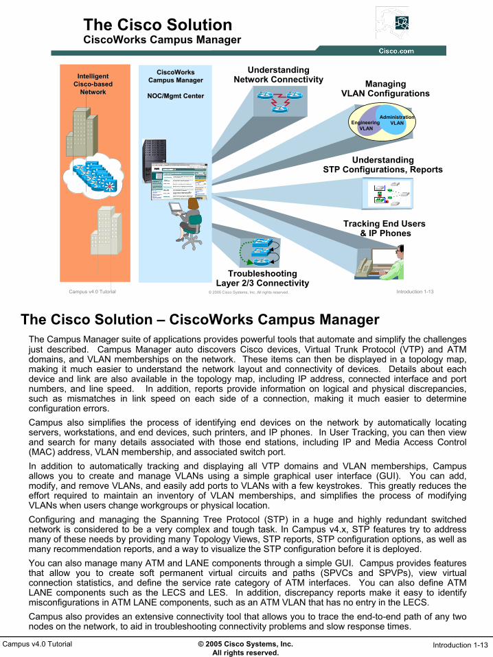
The Cisco Solution – CiscoWorks Campus ManagerThe Campus Manager suite of applications provides powerful tools that automate and simplify the challenges just described. Campus Manager auto discovers Cisco devices, Virtual Trunk Protocol (VTP) and ATM domains, and VLAN memberships on the network. These items can then be displayed in a topology map, making it much easier to understand the network layout and connectivity of devices. Details about each device and link are also available in the topology map, including IP address, connected interface and port numbers, and line speed. In addition, reports provide information on logical and physical discrepancies, such as mismatches in link speed on each side of a connection, making it much easier to determine configuration errors.Campus also simplifies the process of identifying end devices on the network by automatically locating servers, workstations, and end devices, such printers, and IP phones. In User Tracking, you can then view and search for many details associated with those end stations, including IP and Media Access Control (MAC) address, VLAN membership, and associated switch port.In addition to automatically tracking and displaying all VTP domains and VLAN memberships, Campus allows you to create and manage VLANs using a simple graphical user interface (GUI). You can add, modify, and remove VLANs, and easily add ports to VLANs with a few keystrokes. This greatly reduces the effort required to maintain an inventory of VLAN memberships, and simplifies the process of modifying VLANs when users change workgroups or physical location.Configuring and managing the Spanning Tree Protocol (STP) in a huge and highly redundant switched network is considered to be a very complex and tough task. In Campus v4.x, STP features try to address many of these needs by providing many Topology Views, STP reports, STP configuration options, as well as many recommendation reports, and a way to visualize the STP configuration before it is deployed.You can also manage many ATM and LANE components through a simple GUI. Campus provides features that allow you to create soft permanent virtual circuits and paths (SPVCs and SPVPs), view virtual connection statistics, and define the service rate category of ATM interfaces. You can also define ATM LANE components such as the LECS and LES. In addition, discrepancy reports make it easy to identify misconfigurations in ATM LANE components, such as an ATM VLAN that has no entry in the LECS. Campus also provides an extensive connectivity tool that allows you to trace the end-to-end path of any two nodes on the network, to aid in troubleshooting connectivity problems and slow response times.

© 2005 Cisco Systems, Inc. All rights reserved.
Introduction 1-14Campus v4.0 Tutorial
Introduction 1-14© 2005 Cisco Systems, Inc. All rights reserved.Campus v4.0 Tutorial
The Cisco SolutionA Closer Look At Campus Manager
Campus Manager is a suite of tools:
• Topology Services• Auto discovery of Cisco routers and
switches• Hierarchical mapping with topology
groups• Extensive Spanning Tree Analysis• VLAN / PVLAN, & ATM Management
• User Tracking (up to 100,000 end nodes)• HTML user interface for tracking end-
stations and IP Phones • Enhanced reports
• Path Analysis• Layer 2/3 Path Trace Analysis
STP Analysis
Path Analysis
Topology Mapping
A Closer Look At Campus ManagerCampus comprises three separate tools that can be used to manage and monitor layer 2 and 3 Cisco devices on your network, and help address the challenges mentioned at the beginning of this chapter.Topology ServicesWith topology services, you no longer have to trace cables from stack to stack through a wiring closet to determine which devices are connected through which ports. Topology Services auto discovers Cisco routers and switches on the network and displays the network layout in hierarchical topology maps. These maps make it easy to determine what types of devices are on the network, and how they are connected. In addition, topology services auto discovers ATM and VTP domains and VLAN memberships configured on the network, making it easy to view and track them. It also provides features to allow you to create and modify VLANs, LANE, and ATM services through an easy-to-use GUI. Automated discrepancy reports highlight physical and logical problems with the network configuration, making it easy to identify configuration errors such as line-speed mismatches on either end of a connection. User TrackingThe User Tracking tool greatly simplifies the task of tracking user and end-station connections to the network. User Tracking automatically identifies all end stations connected to Cisco devices that have been discovered on the network, including printers, servers, and PCs. User Tracking also collects detailed information about each end-station, including MAC address, IP address, Domain Name System (DNS) hostname, port assignment, and VLAN memberships. In addition, User Tracking can be configured to collect usernames associated with end stations, from UNIX hosts, a Windows NT primary domain controller (PDC), or Novell Directory Services (NDS), making it easier to locate specific users on the network. User Tracking provides a means to track VLAN memberships, port assignments, and end-user host specifications.Path AnalysisPath analysis is a diagnostic tool for troubleshooting connectivity-related problems between end stations and Layer 2 and 3 devices. You can trace the Layer 2 or 3 path between any two endpoints on the discovered network, making it much easier to narrow down where the problem might be when connectivity is lost. Path analysis provides more detailed information about each device than typical trace output, including interface type and speed and VLAN information. Output can be viewed in graphical, table, or trace output format.

© 2005 Cisco Systems, Inc. All rights reserved.
Introduction 1-15Campus v4.0 Tutorial
Introduction 1-15© 2005 Cisco Systems, Inc. All rights reserved.Campus v4.0 Tutorial
The Cisco SolutionCiscoWorks LAN Management Solution (LMS)
• Campus Manager v4.0 is available in the CiscoWorks LAN Management Solution (LMS) v2.5 bundle of applications
• All applications within a CiscoWorks bundle require the Common Services software to be installed
Campus Manager 4.0Topology Services,
Path Analysis, & User Tracking
Device Fault Manager 2.0Fault Detection and
Notification
Resource Manager
Essentials 4.0Device Inventory, Configuration & Software Mgmt
Common Services &
CiscoView 6.1CiscoWorks Server,
CiscoView & Integration Utility
Internetwork Performance Monitor 2.6
WAN Performance Monitoring
CiscoWorks LAN Management Solution (LMS)So where does one find Campus Manager? Campus Manager v4.0 is available in the CiscoWorks LMS (LAN Management Solution) v2.5 bundle of Cisco network management products. The applications within the CiscoWorks bundles all rely upon the Common Services software that is installed on the CiscoWorks server. These services provide the necessary background processes for accessing the database, web services, network discovery, process management, security, and more.All applications share the same device database information, simplifying the use of all applications and speeding up the startup time. Other CiscoWorks applications included in the LMS bundle are:
• CiscoView — Graphical device-management providing real-time device status and operational and configuration functions.
• Resource Manager Essentials — Suite of applications for inventory, configuration file, and software image management, as well as Syslog analysis, and more.
• Device Fault Manager (DFM) — Provides real-time fault analysis for Cisco devices. • Internetwork Performance Monitor (IPM) — Response time and availability troubleshooting application.

© 2005 Cisco Systems, Inc. All rights reserved.
Introduction 1-16Campus v4.0 Tutorial
Thank You!
Continue on to Chapter 2 to discover the many features of Campus Manager.

© 2005 Cisco Systems, Inc. All rights reserved.
Product Features 2-1Campus v4.0 Tutorial
Chapter 2Chapter 2
Campus Manager Campus Manager Product FeaturesProduct Features

© 2005 Cisco Systems, Inc. All rights reserved.
Product Features 2-2Campus v4.0 Tutorial
Product Features 2-2© 2005 Cisco Systems, Inc. All rights reserved.Campus v4.0 Tutorial
Chapter 2 Outline
• Campus Overview
• Campus Management Services–Topology Services
–User Tracking
–Path Analysis
• Additional Features
Chapter 2 OutlineChapter 1 presented common management challenges that are often time consuming to perform and/or prove difficult to collect the necessary data to make an informed management decision. The Campus Manager (referred to also as either CM or Campus) suite of tools was also introduced as a solution to not only automate the collection of difficult to acquire data, but to present the data in a manner to facilitate both troubleshooting activities and quick decision making. This chapter discusses the many features of Campus and how they can be used to help manage and troubleshoot problems on the network. First, Campus Manager is reintroduced and the major functional categories are presented along with some of key features and a functional flow. Next, each of the functional areas will be discussed in more detail – how the feature works and samples of associated tasks and reports. The final section of this chapter briefly discusses the Device Center application which includes a summary of the important data collected by the various CiscoWorks applications (including Campus) for a specific device, and launch points for various CiscoWorks tasks and reports. Also discussed is the Data Extraction Engine which allows for the retrieval of data collected by Campus in XML format.By the conclusion of this chapter, the reader should have a good understanding of the components of Campus Manager and what is possible with them. Chapter 3 will then provide the jump start to using Campus through a series of scenarios that takes you from Getting Started through use of many of the key features.

© 2005 Cisco Systems, Inc. All rights reserved.
Product Features 2-3Campus v4.0 Tutorial
Campus OverviewCampus Overview
Campus Overview• Campus Management Services
– Topology Services– User Tracking– Path Analysis
• Additional Features

© 2005 Cisco Systems, Inc. All rights reserved.
Product Features 2-4Campus v4.0 Tutorial
Product Features 2-4© 2005 Cisco Systems, Inc. All rights reserved.Campus v4.0 Tutorial
Campus ManagerOverview
Campus Manager is a suite of tools used to configure,monitor, and visualize complex physical and logical network connectivity
Campus Manager is a suite of tools used to configure,monitor, and visualize complex physical and logical network connectivity
• Network visualization• VLAN management• ATM/LANE management• STP visualization and configuration• Layer 2/3 discrepancy reporting
Topology Services
• Automatic acquisition of host, end-user, and IP Phone network connections
User Tracking
• Trace the physical and logical connectivity between two end devices
• Data or IP callPath Analysis
Campus Manager - OverviewThe CiscoWorks Campus application focuses primarily on connectivity related network management tasks. It automates the collection of data to monitor and visualize connectivity of devices and end users. Campus also supports the configuration tasks of many logical (i.e. VLAN) connections. As described in Chapter 1, Campus Manager is composed of three main functional components:
• Topology Manager - Builds and maintains an up-to-date database of physical and logical connectivity facilitating connectivity visualization, discovery of discrepancies, and in the configuration of physical and logical connectivity constructs (STP, ATM, VLAN, etc.).
• User Tracking – Builds and maintains an up-to-date database of end user connectivity to the network.• Path Analysis – Displays the actual network path (both physical and logical) between two end points.
Each of these components will be examined in more detail in the upcoming sections of this chapter.

© 2005 Cisco Systems, Inc. All rights reserved.
Product Features 2-5Campus v4.0 Tutorial
Product Features 2-5© 2005 Cisco Systems, Inc. All rights reserved.Campus v4.0 Tutorial
Campus ManagerKey Features
Discovers and displays physical network connectivity of Cisco devices− Numerous topology views and reports − Detects and reports physical discrepancies
Configure VLAN/LANE, Private VLANs, and ATM Services− VLAN port assignment, Trunk, and Ether Channel
configuration− Detects and reports logical discrepancies
Configure and visualize Spanning Tree configurations for PVSTP, MSTP, IEEE 802.1s− Recommendation reports (optimal root, instance,
instance reduction, VLAN to instance mapping)− Modeling tool to test “what-if” changes off-line
Discovers network connectivity and related information for end-users and IP phones
Layer 2/3 path trace for source and destination end-users and and IP phones
Support for SNMP v2, v3 and IPv6
STP Analysis
Path Analysis
Network Views
Campus Manager – Key FeaturesNetwork topology diagrams provide a wealth of information about the connectivity of the network devices. Unfortunately, more times than not, the existing hardcopy diagram is out of date due to the dynamic nature of the network. Campus, however, uses automatically collected CDP information to provide the network administrator with an up-to-date view of the current physical connectivity of the network. Further, Campus analyzes this information and can detect physical and logical errors that would otherwise be extremely difficult to pin-point and find. Can you imagine how much time it would take you to find out the membership of a VLAN in a VTP domain that includes 30 switches? Though not impossible, just very time consuming. Campus, however, collects this type of information and not only knows about every VTP domain in the network, but also every VLAN defined, and the ports that are assigned to them. A few clicks of the mouse and this information is available to the network administrator.Additional information that is difficult to obtain and collected and displayed by Campus includes Spanning Tree Protocol (STP) and end-user connectivity information. Campus will display the current STP state for ports for each instance of STP, and includes reports to help optimize and configure the STP configuration. The User Tracking tool will allow the network administrator to quickly obtain information about the connection of end users to the network devices. The above list is the short version of the many features of Campus and its associated components. The remainder of this chapter will highlight many key features and uses of Campus. The savvy reader will also certainly discover many additional uses for the tools and the data collected by Campus. Bottom line, Campus Manager automatically collects and displays difficult to obtain data, thus, saving time and reducing errors, resulting in better network operations.
© 2005 Cisco Systems, Inc. All rights reserved.
Product Features 2-6Campus v4.0 Tutorial
Product Features 2-6© 2005 Cisco Systems, Inc. All rights reserved.Campus v4.0 Tutorial
Campus ManagerFunctional Flow
CiscoWorksServer
SNMP v2 / v3
MIB
MIB
MIB
MIBMIB
MIB
CallManager
DNS
HTTP / HTTPS
Client Access Via Standard Web browser
Client Access Via Standard Web browser Common
Services
DCRDCR
Campus Mgr
DBDB
Devices must be in the DCR to be managed by any CiscoWorks
application
Devices must be in the DCR to be managed by any CiscoWorks
application
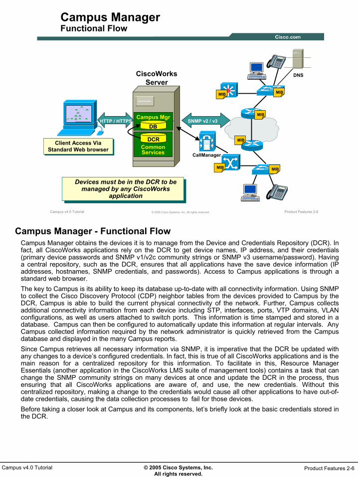
Campus Manager - Functional FlowCampus Manager obtains the devices it is to manage from the Device and Credentials Repository (DCR). In fact, all CiscoWorks applications rely on the DCR to get device names, IP address, and their credentials (primary device passwords and SNMP v1/v2c community strings or SNMP v3 username/password). Having a central repository, such as the DCR, ensures that all applications have the save device information (IP addresses, hostnames, SNMP credentials, and passwords). Access to Campus applications is through a standard web browser.The key to Campus is its ability to keep its database up-to-date with all connectivity information. Using SNMP to collect the Cisco Discovery Protocol (CDP) neighbor tables from the devices provided to Campus by the DCR, Campus is able to build the current physical connectivity of the network. Further, Campus collects additional connectivity information from each device including STP, interfaces, ports, VTP domains, VLAN configurations, as well as users attached to switch ports. This information is time stamped and stored in a database. Campus can then be configured to automatically update this information at regular intervals. Any Campus collected information required by the network administrator is quickly retrieved from the Campus database and displayed in the many Campus reports. Since Campus retrieves all necessary information via SNMP, it is imperative that the DCR be updated with any changes to a device’s configured credentials. In fact, this is true of all CiscoWorks applications and is the main reason for a centralized repository for this information. To facilitate in this, Resource Manager Essentials (another application in the CiscoWorks LMS suite of management tools) contains a task that can change the SNMP community strings on many devices at once and update the DCR in the process, thus ensuring that all CiscoWorks applications are aware of, and use, the new credentials. Without this centralized repository, making a change to the credentials would cause all other applications to have out-of-date credentials, causing the data collection processes to fail for those devices.Before taking a closer look at Campus and its components, let’s briefly look at the basic credentials stored in the DCR.

© 2005 Cisco Systems, Inc. All rights reserved.
Product Features 2-7Campus v4.0 Tutorial
Product Features 2-7© 2005 Cisco Systems, Inc. All rights reserved.Campus v4.0 Tutorial
Campus ManagerFunctional Flow – SNMP v2, v3 and Device Credentials
Credentials are usernames and passwords or SNMP community strings needed by the CiscoWorks applications to access the device information
Credentials are stored in the DCR and available to all CiscoWorks applications
Support for SNMP v1/v2 or v3
Credentials defined in the DCR must match those configured on the device
Add credentials to the DCR using Common Services
If both SNMP v2 and v3 are supplied, v3 is used.
The method of authenticationis SHA-1 or MD5.
Functional Flow – SNMP v2, v3 and Device CredentialsAs noted earlier, Campus Manager relies on the DCR to get device names, IP address, and their credentials that are needed to access the device and its configuration. The credentials needed are stored in the DCR and are made available to the CiscoWorks applications to use.Starting with Campus Manager v4.0, SNMP v3 is supported in addition to SNMP v2. The user has the option to use either version. SNMP v3 utilizes a configured username and password on the device. The method of authentication (SHA-1 or MD5) can be configured and selected.Note(s):
• Refer to the Common Services tutorial or on-line help for details on defining the credentials and adding them to the DCR.
• Refer to the Common Services on-line help or Cisco.com for details on configuring your devices for SNMP v2 or V3.
And finally, before taking a closer look at Campus and its components, let’s briefly explore a Campus task that can be used to populate the DCR (Device Discovery).

© 2005 Cisco Systems, Inc. All rights reserved.
Product Features 2-8Campus v4.0 Tutorial
Product Features 2-8© 2005 Cisco Systems, Inc. All rights reserved.Campus v4.0 Tutorial
Campus ManagerFunctional Flow - Device Discovery
Common Services
DCRDCR
Campus Manager
DBDBCDP
CDP
CDP
Device TypeSysObject IDIP AddressHost NameNeighbors
Device TypeSysObject IDIP AddressHost NameNeighbors
Device Discovery is a background process that auto-discovers Cisco devices on the network
Device Discovery is a background process that auto-discovers Cisco devices on the network
SNMP v2, v3
Functional Flow - Device DiscoveryThe primary requirement to managing any device with any of the CiscoWorks applications is that the device must be in the DCR. The DCR is part of Common Services and as such, Common Services has a few ways to populate the DCR with devices including manual entry and bulk import from either a file or another management application (see Common Services User Guide or tutorial for more information). Though effective and straight forward, these population mechanisms are not the most efficient. On the previous page, it was briefly explained how Campus uses the CDP tables to determine neighbors and build a connectivity map of the network. This same information could be used as a means to auto-discover the network. Hence, Campus includes a background process that can be used to automatically populate the DCR. (Refer to Chapter 3 for details on how to use this feature.)To use Device Discovery, the user must supply the SNMP credentials and one or more seed devices (starting point for discovering other neighboring devices). With this information, the CDP table of the seed device is read, and additional devices of the network are discovered. Now the CDP tables of those devices are read to retrieve even more devices in the network. This continues until all devices in the network are discovered.Note(s):
• For devices to be discovered, they must have CDP enabled, and be adjacent to other CDP devices (most non-Cisco devices do not use CDP and hence will stop a discovery).
• Multiple seed devices can be used if CDP is disabled in areas of the network.• Auto-discovery of devices to populate the DCR is not the same as collecting data for Campus. Once
the devices are in the DCR, then Campus can retrieve devices from the DCR and begin data collection activities.
• As illustrated in the Settings dialog, to facilitate device management, the auto-discovery mechanism has optional settings for selecting the loopback address as the management address (else the IP address on the first interface discovered in a CDP table is used), and numerous options on how to resolve the name of the device.

© 2005 Cisco Systems, Inc. All rights reserved.
Product Features 2-9Campus v4.0 Tutorial
Campus Management ServicesCampus Management ServicesTopology ServicesTopology Services
• Campus OverviewCampus Management Services
– Topology Services– User Tracking– Path Analysis
• Additional Features

© 2005 Cisco Systems, Inc. All rights reserved.
Product Features 2-10Campus v4.0 Tutorial
Product Features 2-10© 2005 Cisco Systems, Inc. All rights reserved.Campus v4.0 Tutorial
Topology ServicesWhat is it?
An up-to-date database about the connectivity details of the Cisco devices in the network
Network connectivity visualizations
Reports for both physical and logical connectivity and discrepancies
Configuration for layer 2/3 connectivity
3 main types of tasks for complete connectivity, discrepancy, VLAN/VTP,
STP, and ATM management
3 main types of tasks for complete connectivity, discrepancy, VLAN/VTP,
STP, and ATM management
Topology Services – What is it?Topology Services is basically knowing how devices are physically interconnected and their associated physical and logical configuration information. Though this sounds basic and simple, Topology Services contains a rich set of features and tools to display and configure this information.Topology Services provides comprehensive connectivity information that allows for network visualization including the exact endpoint ports for each connection and the link speed. Besides maps, Topology Services includes numerous reports to view different aspects of physical and logical connectivity, and a number of tasks that allow you to modify some of the physical (STP) and logical (VLANs) connectivity, and a complete set of ATM management tools.This section will break Topology Services down into these three categories (visualizations, reports, and configuration tasks) to discuss and present some of the key features of topology services for complete management of physical connectivity, discrepancies, VLANs and VTP, STP, and ATM.
© 2005 Cisco Systems, Inc. All rights reserved.
Product Features 2-11Campus v4.0 Tutorial
Product Features 2-11© 2005 Cisco Systems, Inc. All rights reserved.Campus v4.0 Tutorial
Topology ServicesConnectivity Visualizations
Many different possible viewsSummary informationMaps
LayoutFiltersPreferencesHierarchical
STP visualizations
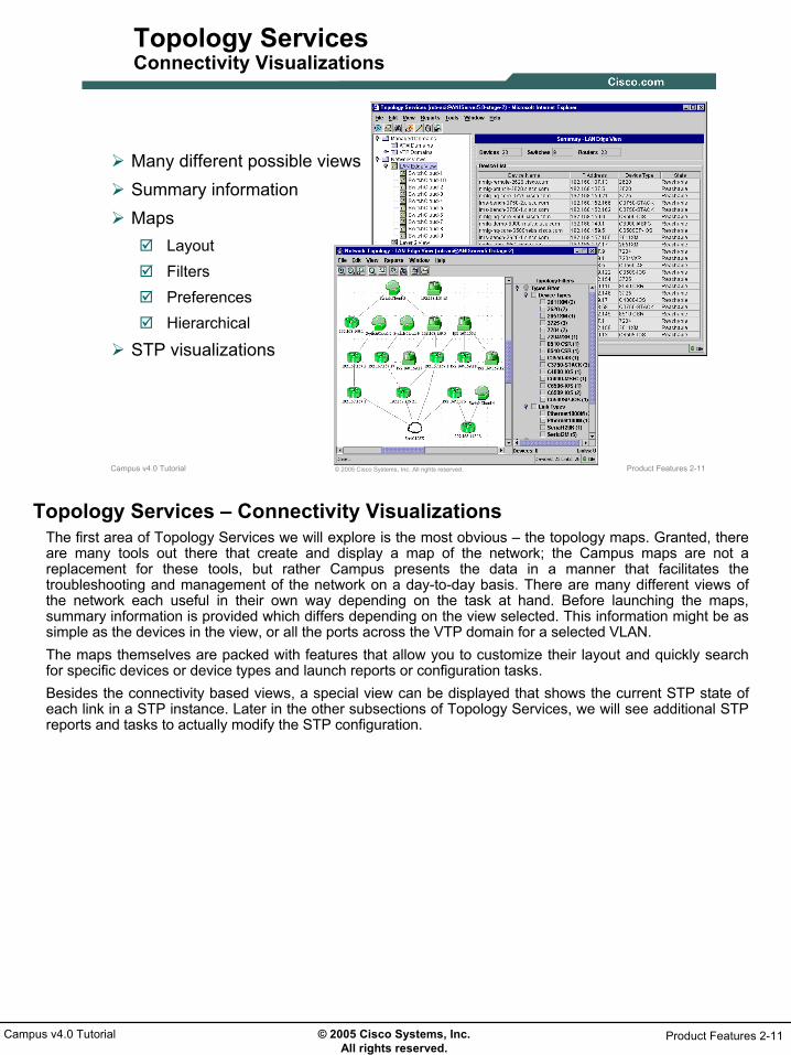
Topology Services – Connectivity VisualizationsThe first area of Topology Services we will explore is the most obvious – the topology maps. Granted, there are many tools out there that create and display a map of the network; the Campus maps are not a replacement for these tools, but rather Campus presents the data in a manner that facilitates the troubleshooting and management of the network on a day-to-day basis. There are many different views of the network each useful in their own way depending on the task at hand. Before launching the maps, summary information is provided which differs depending on the view selected. This information might be as simple as the devices in the view, or all the ports across the VTP domain for a selected VLAN.The maps themselves are packed with features that allow you to customize their layout and quickly search for specific devices or device types and launch reports or configuration tasks.Besides the connectivity based views, a special view can be displayed that shows the current STP state of each link in a STP instance. Later in the other subsections of Topology Services, we will see additional STP reports and tasks to actually modify the STP configuration.

© 2005 Cisco Systems, Inc. All rights reserved.
Product Features 2-12Campus v4.0 Tutorial
Product Features 2-12© 2005 Cisco Systems, Inc. All rights reserved.Campus v4.0 Tutorial
Topology ServicesMany Different Views
VLAN detailsVLAN details
LAN Edge view shows layer 3 interconnectivity (Layer 2
interconnectivity is represented by Switch
Clouds
LAN Edge view shows layer 3 interconnectivity (Layer 2
interconnectivity is represented by Switch
Clouds
Layer 2 views is connectivity at layer 2 for
all managed devices
Layer 2 views is connectivity at layer 2 for
all managed devices
Devices in VTPDevices in VTP
System and user-defined groupings of
devices
System and user-defined groupings of
devices
Topology Services – View TypesTopology Services contains many different views each with their own merits depending on the task at hand. When launched, the left-hand side of the topology window will contain a navigation tree of the possible views. Three main categories of views are available:
• Managed Domains – discovers all ATM and VTP domains. ATM domains are listed by fabric. Note(s):
• For a VTP v2 domain, VLANs under the server and client mode devices will be listed directly under the top level tree.
• For a VTP v3 domain, primary server, transparent and VTP-off mode devices will be listed under the top level tree and the VLANs on secondary servers and client mode devices will be listed under the Primary server mode devices.
• For a VTP v3 domain, switches listed and followed by a “P” are primary servers, and iffollowed by a “T” are configured in Transparent mode. Opening these will also list the VLANs defined on them. A switch followed by the letter “O” has VTP disabled.
• Network Views – Contains various device views of the network. • The LAN Edge View displays all layer 3 devices and clouds representing the switches.
Expanding the LAN Edge View entry reveals the Switch Clouds discovered and automatically labeled. Switch Clouds consist of layer 2 devices and by definition could be VTP domains and are STP domains. The default names of the Switch Cloud, which are sequentially numbered, can be renamed. The Layer 2 View simply displays all devices interconnected at layer 2, and the Unconnected Device View shows managed devices not connected to any other device. Expanding the VTP Views also lists all discovered VTP domains, but only lists the devices in them.
• Topology Groups – All CiscoWorks applications contain system defined groupings of devices and also allow the user to create their own groupings of devices. These groups are listed under this heading.

© 2005 Cisco Systems, Inc. All rights reserved.
Product Features 2-13Campus v4.0 Tutorial
Product Features 2-13© 2005 Cisco Systems, Inc. All rights reserved.Campus v4.0 Tutorial
Topology ServicesVTP Domain Views
• Selecting a VTP domain will list all VLANs and any switch that is not a server or client in VTP v1 or v2 domain
• Switches listed by a P, T, or O are in a VTP v3 domain
• VLAN icons different for normal and private VLANs
• Selecting a VTP domain will list all VLANs and any switch that is not a server or client in VTP v1 or v2 domain
• Switches listed by a P, T, or O are in a VTP v3 domain
• VLAN icons different for normal and private VLANs
Domain Name may represent various VTP v3 modes:
• P – VTP v3 Domain • T – Transparent mode • O – VTP disabled
Domain Name may represent various VTP v3 modes:
• P – VTP v3 Domain • T – Transparent mode • O – VTP disabled
Switches in VTP v3 domain
Switches in VTP v3 domain
CommunityIsolated
Topology Services – Summary InformationCampus Manager v4.x has expanded support for VLAN and VTP, including VTP v3. Information on VTPv2 or VTP v3 can be viewed in Topology Services. As illustrated, note the following:
• For a VTP v2 domain, VLANs under the server and client mode devices will be listed directly under the top level tree.
• For a VTP v3 domain, primary server, transparent and VTP-off mode devices will be listed under the top level tree and the VLANs on secondary servers and client mode devices will be listed under the Primary server mode devices.
• For a VTP v3 domain, switches listed and followed by a “P” are primary servers, and if followed by a “T” are configured in Transparent mode. Opening these will also list the VLANs defined on them. A switch followed by the letter “O” has VTP disabled.
Also illustrated are the various icons used to differentiate the normal VLANs and Private VLANS and their designated modes. More on Private VLANs is discussed later in this chapter and Chapter 3.
Note(s):• VTP v3 has additional support for advertising Private VLANs and Extended VLANs

© 2005 Cisco Systems, Inc. All rights reserved.
Product Features 2-14Campus v4.0 Tutorial
Product Features 2-14© 2005 Cisco Systems, Inc. All rights reserved.Campus v4.0 Tutorial
Topology ServicesSummary Information
Selecting a view displays summary information
relevant to the type of view
Selecting a view displays summary information
relevant to the type of view
Selecting a VLAN in the VTP Domains folder displays VLAN port membership and information
pertaining to the port’s VLAN configuration
Selecting a VLAN in the VTP Domains folder displays VLAN port membership and information
pertaining to the port’s VLAN configuration
Port Information forDevices in the VLAN
Topology Services – Summary InformationSelecting any view in the navigation tree of the main Topology Services window will list a summary of information about the view on the right-hand side of the window. The displayed summary information depends on the view selected. For instance, selecting a VTP Domain under the Managed Domain heading displays information about all ports in that domain, where as selecting a VTP domain under the Network Views category displays the devices participating in that VTP domain. Earlier it was mention that trying to find all ports in a VLAN could be a very time consuming task; now with Topology Services, the user simply needs to navigate to the desired VLAN and all ports in that VLAN will be displayed showing Port Status (up, down) and Port Mode (PVLAN-Host, Promiscuous, or non-PVLAN).
© 2005 Cisco Systems, Inc. All rights reserved.
Product Features 2-15Campus v4.0 Tutorial
Product Features 2-15© 2005 Cisco Systems, Inc. All rights reserved.Campus v4.0 Tutorial
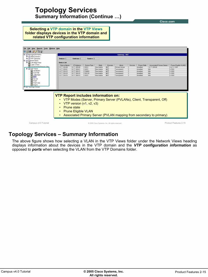
Topology ServicesSummary Information (Continue …)
Selecting a VTP domain in the VTP Views folder displays devices in the VTP domain and
related VTP configuration information
Selecting a VTP domain in the VTP Views folder displays devices in the VTP domain and
related VTP configuration information
VTP Configuration Information forDevices in the DEMO-LAN VTP Domain
VTP Report includes information on:• VTP Modes (Server, Primary Server (PVLANs), Client, Transparent, Off)• VTP version (v1, v2, v3)• Prune state• Prune Eligible VLAN• Associated Primary Server (PVLAN mapping from secondary to primary)
VTP Report includes information on:• VTP Modes (Server, Primary Server (PVLANs), Client, Transparent, Off)• VTP version (v1, v2, v3)• Prune state• Prune Eligible VLAN• Associated Primary Server (PVLAN mapping from secondary to primary)
Topology Services – Summary InformationThe above figure shows how selecting a VLAN in the VTP Views folder under the Network Views heading displays information about the devices in the VTP domain and the VTP configuration information as opposed to ports when selecting the VLAN from the VTP Domains folder.

© 2005 Cisco Systems, Inc. All rights reserved.
Product Features 2-16Campus v4.0 Tutorial
Product Features 2-16© 2005 Cisco Systems, Inc. All rights reserved.Campus v4.0 Tutorial
Topology ServicesMap Layout
Right-click any view to launch map
Right-click any view to launch map
Drag icons to customize layout
Drag icons to customize layout
Zoom and find featuresZoom and find features
View menu allows for layout
modifications
View menu allows for layout
modifications
Map layout saved per user
Map layout saved per user
Topology Services – Map LayoutTo view the map for any given view, right-click on the view and select Display View from the pop-up menu. The map will launch in a new window showing the devices in the view and the connections between them.The map window has many different features. First, most users want to re-layout the devices to their preference. This can be achieved by either selecting View > Relayout from the window menu then selecting one of the layout options, or one can simply drag devices to desired locations. The View menu also has options for displaying labels for each device, zoom options, and a Panner window to move around large networks. The Zoom features are also part of the tool bar.Once a layout is the way the user likes it, the map layout can be saved. Maps are saved per user. Let’s continue on to look at more features of the map window.Note(s):
• Even though the summary info for a selected VLAN shows ports belonging to the VLAN, the map will display the devices in the associated VTP domain. Devices part of the VLAN will be highlighted.

© 2005 Cisco Systems, Inc. All rights reserved.
Product Features 2-17Campus v4.0 Tutorial
Product Features 2-17© 2005 Cisco Systems, Inc. All rights reserved.Campus v4.0 Tutorial
Topology ServicesMap Filters
Mouse over links and devices for details
Mouse over links and devices for details
Find DeviceFind Device
Use filters to quickly find
devices, links, services, etc
Use filters to quickly find
devices, links, services, etc
Lists all IPv6 enabled
interfaces
Lists all IPv6 enabled
interfaces
Locate TDR linksLocate
TDR links
Quickly locate mis-
configurations
Quickly locate mis-
configurations
Topology Services – Map FiltersAs will be discussed in the next sub-section, reports can be launched against one or more devices. The map filters provide a mechanism for quickly finding device types or services. The filters are located on the right-hand side of the map window and are presented in a tree like fashion. Drilling down into the Device Types branch will display a list of all device types being managed. Selecting a filter will gray out all devices not matching the selected filter leaving the matches in color. These are known as filtered objects. Note(s):
• Devices not responding to Campus when polled using SNMP will be displayed red.

© 2005 Cisco Systems, Inc. All rights reserved.
Product Features 2-18Campus v4.0 Tutorial
Product Features 2-18© 2005 Cisco Systems, Inc. All rights reserved.Campus v4.0 Tutorial
Topology ServicesMap Preferences
Menu Edit > Map Preferences
Change basic layout, labels,
colors and map background
Change basic layout, labels,
colors and map background
Topology Services – Map PreferencesThe map displayed can be further modified to display a background and to change various colors. Selecting the Edit > Map Preferences menu option displays a dialog that allows for the addition of a background image, change colors of the map, and select various default display options.Note(s):
• Image is a fixed size and does not resize with the map.

© 2005 Cisco Systems, Inc. All rights reserved.
Product Features 2-19Campus v4.0 Tutorial
Product Features 2-19© 2005 Cisco Systems, Inc. All rights reserved.Campus v4.0 Tutorial
Topology ServicesHierarchical Maps
User-defined groups of devices
User-defined groups of devices
Topology Services – Hierarchical MapsIn large networks many of the map views appear cluttered often making them difficult to use even with the Panner feature. The views can be simplified by the creation of hierarchical groups using any variable collected by Campus (i.e. device type, device name, SysLocation, SysName, IP Address, etc).In the example above, user-defined groups were created by device location using a combination of device name and IP address variables. (Refer to Chapter 3 in this tutorial for an example of user-defined group creation.) Launching the top layer map shows any devices not included in a sub-group, and each of the sub-groups as a cloud icon. Selecting all the cloud icons, right-clicking and selecting Show Aggregate Links will display connections between the groups. Double-click on a cloud icon to launch the sub-map.

© 2005 Cisco Systems, Inc. All rights reserved.
Product Features 2-20Campus v4.0 Tutorial
Product Features 2-20© 2005 Cisco Systems, Inc. All rights reserved.Campus v4.0 Tutorial
Topology ServicesSTP Visualizations
Root BridgeRoot Bridge
Forwarding StateForwarding State
STP FiltersSTP Filters
Select VLAN to display STP forSelect VLAN to display STP for
Topology Services – STP VisualizationsSpanning Tree is something many people probably just take for granted. The Spanning Tree Protocol (STP) helps to prevent forwarding loops in highly redundant layer 2 networks.Optimizing STP can improve overall network performance. And misconfigurations can lead to STP failure and cause network outages.If you were asked to get information about the spanning tree for each VLAN, where would you start? Campus makes it easy. By selecting the appropriate filter for spanning tree type employed, one can visually see which ports are forwarding and which are blocking, as well as which device is the root bridge.

© 2005 Cisco Systems, Inc. All rights reserved.
Product Features 2-21Campus v4.0 Tutorial
Product Features 2-21© 2005 Cisco Systems, Inc. All rights reserved.Campus v4.0 Tutorial
Topology ServicesSTP Inconsistencies
Use filters to locate STP InconsistenciesFilters available in the Switch Cloud ViewComputed during every data collectionComputed on-demand. Devices in the switch cloud are polled when the filter is applied
STP Inconsistency
Filters
STP Inconsistency
Filters
Topology Services – STP InconsistenciesSTP Inconsistencies is an enhancement to STP and detects misconfigurations and puts corresponding ports into an “inconsistent” state preventing downtime. Notice in the figure above, the filters for displaying any STP inconsistencies in the configuration.Topology Services reports on the following STP Inconsistencies:
• Loop Inconsistency – detected by the Loop Guard feature• Root Inconsistency – detected by the Loop Guard feature• Port VLAN ID (PVID) Inconsistency – PVST and BPDU is received on different VLANs than it was
originated• Type Inconsistency - PVST and BPDU is received on non-802.1Q trunk
In the upcoming sections, we will also look at the STP parameters, view optimization reports, and how to make STP configuration changes.

© 2005 Cisco Systems, Inc. All rights reserved.
Product Features 2-22Campus v4.0 Tutorial
Product Features 2-22© 2005 Cisco Systems, Inc. All rights reserved.Campus v4.0 Tutorial
Topology ServicesReports
DiscrepanciesDevice
VLAN, PVLANDevice and Port AttributesIPv6 Addresses Service Modules
LinkLink and Trunk AttributesTime Domain ReflectometryATM Virtual Circuits
STPRecommendation Reports
- Optimal Root- Instance- Instance Reduction- VLAN to Instance Mapping
Current Configuration Sample Optimal Root Report
Topology Services – Connectivity ReportsIn the previous pages, we looked at some the different visualizations presented by Campus. Next, we will look at various reports provided by Campus. The outline above breaks the reports into different categories in an attempt to show the breadth of information collected by Campus and to facilitate presenting examples of the reports.The figure above shows an example of the Optimal Root Report which analyses the collected topology and STP data to determine the optimal root device. Note(s):
• Optimal Root Report: If a Network Analysis Module (NAM) or NetFlow Collector v3.6 is available in the STP domain, the optimal root can also be determined based on traffic loads.

© 2005 Cisco Systems, Inc. All rights reserved.
Product Features 2-23Campus v4.0 Tutorial
Product Features 2-23© 2005 Cisco Systems, Inc. All rights reserved.Campus v4.0 Tutorial
Topology ServicesSeveral Ways to Launch Reports
Each report may have multiple launch points for added user flexibility
Each report may have multiple launch points for added user flexibility
• Right-click– Device and links in map– Devices or ports in summary display
• Menu Bars– Main and Map Windows
– Options depend on map view – Some reports require an object to be
selected first
• CiscoWorks Homepage
Main WindowMain Window
Map WindowMap Window
Topology Services – Report Launch OptionsSo far we have seen two types of windows for Topology Services – the main window which lists the different views, and the map window. Reports can be launched from either of these windows, as well as the CiscoWorks Home Page (Discrepancy Reports). The available reports often depends on what is selected in the summary or map window or based on what view is selected (i.e STP recommendation reports only available from Switch Cloud Map window).Reports can be launched from the menu bar of either window or by selecting one or more devices in either Topology Services window and right-clicking which will display a menu of options including the launching of other applications.Next, let’s look at examples of various reports.

© 2005 Cisco Systems, Inc. All rights reserved.
Product Features 2-24Campus v4.0 Tutorial
Product Features 2-24© 2005 Cisco Systems, Inc. All rights reserved.Campus v4.0 Tutorial
Topology ServicesDiscrepancy Reports
Campus discovers Layer 2 and 3
discrepancies during the Data Collection
process
Campus discovers Layer 2 and 3
discrepancies during the Data Collection
process
Double-click entry for more details
Double-click entry for more details
Physical Discrepancies
Logical Discrepancies
Topology Services – Discrepancy ReportWhen Campus collects information about the connectivity between two devices or interfaces in general, it also analyze the configuration to determine if any inconsistencies exist. This is performed for both physical and logical connectivity. The discrepancy reports make it easy to identify configuration errors such as: link speed or duplex mismatch and VLAN Index conflicts. The discrepancies identified by Campus can be configured as shown in Chapter 3 (Scenarios) of this tutorial.Double-clicking any discrepancy or selecting the discrepancy in the table and clicking the Detail button will open up a Details window. This information, as most report information, can be exported to a file to make it easier to correct/review the discrepancies.

© 2005 Cisco Systems, Inc. All rights reserved.
Product Features 2-25Campus v4.0 Tutorial
Product Features 2-25© 2005 Cisco Systems, Inc. All rights reserved.Campus v4.0 Tutorial
Topology ServicesDevice Reports – VLAN and PVLAN
VLAN Information
• Normal VLAN• Private VLAN (Primary, Secondary)
• Secondary VLAN • Isolated• Community
• Normal VLAN• Private VLAN (Primary, Secondary)
• Secondary VLAN • Isolated• Community
Selected Switch
Selected Switch
If PVLAN, show secondary VLAN mapping to primary
VLAN
If PVLAN, show secondary VLAN mapping to primary
VLAN
Topology Services – Device Reports (VLAN and PVLAN)For a selected device the user can view a report detailing the components of the device (including IP address, device type, IP address, and more.).In particular, the VLAN Report illustrates VLANs and Private VLANs (PVLANs) configured on the device (including ID, name, status, VTP domain, VLAN type, etc.). This report can easily verify newly created VLANs, primary and secondary VLANs, and the associated primary VLAN mapping for PVLANs.Note(s):
• The VLAN Report can also be run for an entire VTP domain or Switch cloud by selecting the view and then selecting the Reports > Campus Reports option from the menu.

© 2005 Cisco Systems, Inc. All rights reserved.
Product Features 2-26Campus v4.0 Tutorial
Product Features 2-26© 2005 Cisco Systems, Inc. All rights reserved.Campus v4.0 Tutorial
Topology ServicesDevice Reports – Ports and Modules
Device reports contain information collected by Campus useful for quickly
determining Layer 2/3 connectivity configuration
Device reports contain information collected by Campus useful for quickly
determining Layer 2/3 connectivity configuration
Port Attributes
Service Modules
Device Modules
Topology Services – Device Reports (Ports and Modules)For a selected device the user can also view reports detailing the ports and modules of the device. Port attributes on the device (includes type, speed, duplex, VLAN, Trunk Encapsulation, etc.) can be displayed in the Port Attributes Report.Also, Service Modules and Device Modules for the device (includes module type, status, and launch point for associated application if applicable) can be displayed.Note(s):
• The Device and Port Attributes Reports can also be run for an entire VTP domain or Switch cloud by selecting the view and then selecting the Reports > Campus Reports option from the menu.

© 2005 Cisco Systems, Inc. All rights reserved.
Product Features 2-27Campus v4.0 Tutorial
Product Features 2-27© 2005 Cisco Systems, Inc. All rights reserved.Campus v4.0 Tutorial
Topology ServicesLink Reports
TDR report displays detected faults in a cable, such as:
• Open circuits• Short circuits• Sharp bends• Crimps• Kinks• Impedance
mismatches
TDR report displays detected faults in a cable, such as:
• Open circuits• Short circuits• Sharp bends• Crimps• Kinks• Impedance
mismatches
Time Domain Reflectometry
Topology Services – Link ReportsThe figure above displays a Link Attribute report that displays information for the selected link including endpoint interfaces, type, and speed.Also displayed, is a sample TDR (Time Domain Reflectometry) report. This report is available for devices running either CatOS or CatIOS with support for the CISCO-CABLE-DIAG-MIB. Selecting a supported link and executing this report will determine the status of a cable and if any opens, shorts, sharp bends, or crimps are detected. If detected, a measurement will help in locating where the cable is damaged.

© 2005 Cisco Systems, Inc. All rights reserved.
Product Features 2-28Campus v4.0 Tutorial
Product Features 2-28© 2005 Cisco Systems, Inc. All rights reserved.Campus v4.0 Tutorial
Topology ServicesSTP Recommendation Report
STP Recommendation Reports aids user to optimally configure STP to
reduce resource usage
STP Recommendation Reports aids user to optimally configure STP to
reduce resource usage
If two or more spanning tree instances use same forwarding topology then they can be replaced by a single spanning tree instance
If two or more spanning tree instances use same forwarding topology then they can be replaced by a single spanning tree instance
Topology Services – STP Recommendation ReportsCampus includes a number of reports to help determine the optimal configuration for STP. Campus supports all three popular forms of spanning tree – per VLAN (PSTP), Cisco’s multiple instance STP (MISTP), and theIEEE standard for multiple instances of spanning tree (IEEE 802.1s). Reports include: Optimal Root, Instance, Instance Reduction, VLAN to Instance Mapping.In the Instance Reduction Recommendation report shown above, Campus has determined that the 11 individual instances of STP can be reduced to 2 instances to reduce resource usage and allow for more efficient STP processing.

© 2005 Cisco Systems, Inc. All rights reserved.
Product Features 2-29Campus v4.0 Tutorial
Product Features 2-29© 2005 Cisco Systems, Inc. All rights reserved.Campus v4.0 Tutorial
Topology ServicesCurrent STP Configuration Report
• View various STP related parameters per Switch Cloud
• Also allows for the configuration of various STP parameters
• View various STP related parameters per Switch Cloud
• Also allows for the configuration of various STP parameters
Topology Services – Current STP Configuration ReportThis report not only displays the current STP configuration, but as will be seen later, can also be used to modify the configuration. This report, launched for a selected switch cloud, provides configuration information based on the following 4 categories:
• Port - STP parameter details applicable to switch ports in the cloud• Device - STP parameter details applicable to various switches in the cloud• Instance - VLANs mapped to various instances in a Switch• Trunk - preferred instances configured on various Trunk ports of a Switch

© 2005 Cisco Systems, Inc. All rights reserved.
Product Features 2-30Campus v4.0 Tutorial
Product Features 2-30© 2005 Cisco Systems, Inc. All rights reserved.Campus v4.0 Tutorial
Topology ServicesConfiguration Features
VLAN ManagementCreate (Ethernet, Token Ring) VLANsCreate Private VLANs (PVLAN)Configure Trunks and Ether ChannelVLAN, PVLAN Port Assignment
Spanning Tree Protocol (STP)VisualizerConfiguration
ATMLANE servicesCreate SPVC/SPVPInterface configuration
Topology Services –Configuration FeaturesThe final aspect of Topology Services is its ability to configure various connectivity constructs. This includes the configuration of both normal and private VLANs, as well as extending them across an ATM fabric using LAN Emulation (LANE), assigning ports to VLANs, and configuring Trunks and Ether Channels. Campus also includes a tool to perform “what-if” modifications to current STP configurations to determine their impact, as well as a tool to actually make the changes to the devices.The figure above shows the dialog for configuring an Ether Channel. The dialog is launched by selecting a link between two switch devices, right-clicking and selecting Configure Ether Channel from the pop-up menu. The Ether Channel Configuration dialog will display all potential links for participation in the channel. Campus only supports the PagP aggregation protocol and the Channel Mode of Desirable. However, the user can select both the Distribution Protocol and Distribution Address Type.The next few pages will present additional samples of Topology Services configuration capabilities.
© 2005 Cisco Systems, Inc. All rights reserved.
Product Features 2-31Campus v4.0 Tutorial
Product Features 2-31© 2005 Cisco Systems, Inc. All rights reserved.Campus v4.0 Tutorial
Topology ServicesVLAN Management Overview
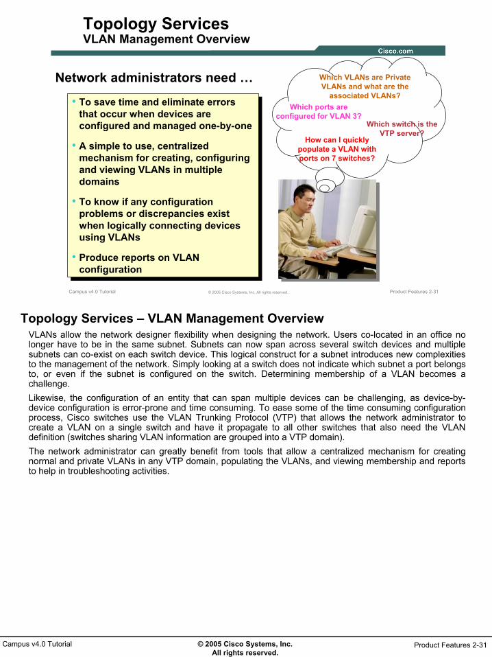
Network administrators need …
• To save time and eliminate errors that occur when devices are configured and managed one-by-one
• A simple to use, centralized mechanism for creating, configuring and viewing VLANs in multiple domains
• To know if any configuration problems or discrepancies exist when logically connecting devices using VLANs
• Produce reports on VLAN configuration
Which VLANs are Private VLANs and what are the
associated VLANs?Which ports are
configured for VLAN 3?Which switch is the
VTP server?How can I quickly
populate a VLAN with ports on 7 switches?
Topology Services – VLAN Management OverviewVLANs allow the network designer flexibility when designing the network. Users co-located in an office no longer have to be in the same subnet. Subnets can now span across several switch devices and multiple subnets can co-exist on each switch device. This logical construct for a subnet introduces new complexities to the management of the network. Simply looking at a switch does not indicate which subnet a port belongs to, or even if the subnet is configured on the switch. Determining membership of a VLAN becomes a challenge.Likewise, the configuration of an entity that can span multiple devices can be challenging, as device-by-device configuration is error-prone and time consuming. To ease some of the time consuming configuration process, Cisco switches use the VLAN Trunking Protocol (VTP) that allows the network administrator to create a VLAN on a single switch and have it propagate to all other switches that also need the VLAN definition (switches sharing VLAN information are grouped into a VTP domain).The network administrator can greatly benefit from tools that allow a centralized mechanism for creating normal and private VLANs in any VTP domain, populating the VLANs, and viewing membership and reports to help in troubleshooting activities.

© 2005 Cisco Systems, Inc. All rights reserved.
Product Features 2-32Campus v4.0 Tutorial
Product Features 2-32© 2005 Cisco Systems, Inc. All rights reserved.Campus v4.0 Tutorial
Topology ServicesVLAN Components
• VTP Domains
• VTP Domain membership
• Device VTP mode
• Device connectivity
• VLANs in VTP domain
• PVLANs in VTP domain
• Port Membership in VLANs, PVLANs Trunk
ISL or IEEE 802.1Q
VTP Client
VTP DomainVTP
Transparent
VTP Server
VTP Client Web Servers
DNS Servers
Topology Services – VLAN ComponentsA VLAN is used to provide any-to-any connectivity for all hosts within the VLANs. As segregation is required for hosts within a switch environment, more VLANs are created. The VLAN Trunking Protocol (VTP) helps to propagate the creation of VLANs within a defined domain.To utilize VTP to assist in VLAN creation, the network administrator needs the ability to manage and configure the components of both the VTP domain and the VLAN itself. The network administrator needs to be able to select the group of switches needing to share VLANs and configure them as members of a VTP domain. One or more of these switches must be designated as a VTP server, which is used to define the VLANs on, and propagate the information to the other members of the VTP domain. Once all switches have the VLAN configuration for the VTP domain, individual ports on the switch can become members of a VLAN or Private VLAN (PVLAN). Let’s now look at how Topology Services can be used to configure VLANs, PVLANs, and assign port membership.

© 2005 Cisco Systems, Inc. All rights reserved.
Product Features 2-33Campus v4.0 Tutorial
Product Features 2-33© 2005 Cisco Systems, Inc. All rights reserved.Campus v4.0 Tutorial
Topology ServicesCreate Ethernet or Token Ring VLANs
Select VTP Domain or Switch Cloud
Select VTP Domain or Switch Cloud
Extend across ATM if required
Extend across ATM if required
Topology Services – Create Ethernet or Token Ring VLANsWithout VTP, configuring VLANs could be a laborious task if a large number of switches existed in a VTP domain. In fact, even with VTP you need to know which switch is configured as the VTP server. Topology Services makes it much simpler, all the user must do is select which VTP domain to create the VLAN in, and enter a name and ID for the VLAN if the defaults are not acceptable. The user can also configure these VLANs on any transparent switches in the VTP domain using this dialog. Nice and simple; and no syntax to remember.Note(s):
• VLAN creation is launched from the Main Topology window by selecting either a VTP Domain or a Switch Cloud.

© 2005 Cisco Systems, Inc. All rights reserved.
Product Features 2-34Campus v4.0 Tutorial
Product Features 2-34© 2005 Cisco Systems, Inc. All rights reserved.Campus v4.0 Tutorial
Topology ServicesPrivate VLANs (PVLANs)
Server 1
Server 2
Promiscuous Port
Secondary VLAN Ports
Primary VLANTraffic Flows on
Secondary VLANs
Secondary VLANs
Building a Proper Trust Model
• Isolation at Layer 2 using PVLANs
• Servers are accessible from external clients as well as from the internal network
• Make sure servers can not talk to each other
• Servers should only reply with traffic corresponding to incoming connection
• No connection should originate from the outside world
Topology Services – Private LANsNext, what are Private VLANs (PVLANs) and how does Campus handle the configuration of PVLANs? One of the key factors to building a successful network security design is to identify and enforce a proper trust model. The proper trust model defines who needs to talk to whom and what kind of traffic needs to be exchanged; all other traffic should be denied. Typically, firewalls and packet filters are only used to control incoming connections, but nothing is usually done to restrict connections originated from within or from the Demilitarized Zone (DMZ), a small subnetwork that sits between a trusted network,such as the corporate LAN, and an untrusted external network, such as the Internet.Private VLANs (PVLANs) are a Cisco feature that allows segregating traffic at Layer 2 turning a broadcast segment into a non-broadcast multi-access-like segment. Traffic that comes to a switch from a promiscuous port (that is, a port that is capable of forwarding both primary and secondary VLANs) is able to go out on all the ports that belong to the same primary VLAN. Traffic that comes to a switch from a port mapped to a secondary VLAN (it can be either an isolated, a community, or a two-way community VLAN) can be forwarded to a promiscuous port or a port belonging to the same community VLAN. Multiple ports mapped to the same isolated VLAN cannot exchange any traffic.For example, in a proper trust model, servers are not supposed to talk to each other, but they still need to talk to the firewall or router to which they are connected. In this case, servers should be connected to isolated ports while routers and firewalls should be attached to promiscuous ports. By doing this, if one of the servers is compromised, the intruder won't be able to use the same server to source an attack to another server within the same segment. The switch will drop any packet at wire speed, without any performance penalty.

© 2005 Cisco Systems, Inc. All rights reserved.
Product Features 2-35Campus v4.0 Tutorial
Product Features 2-35© 2005 Cisco Systems, Inc. All rights reserved.Campus v4.0 Tutorial
Topology ServicesCreate Private VLANs (PVLANs)
Topology Services allows you to create PVLANs using these steps:
Topology Services allows you to create PVLANs using these steps:
1. Create a primary VLAN
2. Create secondary VLANs and define it as one of the following:
o Isolated VLAN – can only talk through promiscuous ports
o Community VLAN – can talk between endpoints and through promiscuous port
3. Associate the secondary VLANs with the primary VLAN
4. Assign ports to the secondary VLAN
5. Configure promiscuous ports Cannot talk between Servers
Cannot talk between ServersTalk within its
CommunityTalk within its Community
Topology Services – Create Private LANsThe figure above lists the steps to create PVLANs using Topology Services.First, create a primary VLAN. The primary VLAN uniquely identifies the private VLAN within secondary VLANs exist.These secondary VLANs can be configured with three different port designations: promiscuous, isolated, and community. Each port designation has its own unique set of rules, which regulate a connected endpoint’s ability to communicate with other endpoints connected to ports within the Private VLAN..An endpoint connected to a promiscuous port has the ability to communicate with any endpoint within the Private VLAN. Multiple promiscuous ports may be defined within a single Private VLAN. Layer 3 switches and default gateways are commonly connected to promiscuous ports.Isolated ports are typically used for those endpoints that only require access to a limited number of outgoing interfaces on the router or multi-layer switch. An endpoint connected to an isolated port will only possess the ability to communicate with those endpoints connected to promiscuous ports. Endpoints connected to adjacent isolated ports cannot communicate. Typically, isolated ports are reserved for hosts only requiring access to default gateways.In an ISP web hosting environment, communication may be required between endpoints belonging to the same customer. ‘Front-end’ content replication, high-availability NICs, and server clustering all require some form of ‘front-end’ replication. In such cases, the community feature of the Private VLANs becomes very useful. A Private VLAN community is a grouping of isolated ports belonging to one customer. Within the community, endpoints may communicate with one another and to any defined promiscuous port. Endpoints belonging to one community may not communicate with endpoints within a different community.Regardless of the combination of isolated, community, and promiscuous ports used within a Private VLAN, it is still one layer 2 domain and therefore only requires one IP subnet. The addressing model now changes whereby instead of allocating an individual subnet to each customer, a range of addresses from one or two common large IP networks is assigned. By allocating addressing from one or two common larger IP networks, the address waste is severely reduced.Let’s look at these steps in further detail.

© 2005 Cisco Systems, Inc. All rights reserved.
Product Features 2-36Campus v4.0 Tutorial
Product Features 2-36© 2005 Cisco Systems, Inc. All rights reserved.Campus v4.0 Tutorial
Topology ServicesCreate Private VLANs (PVLANs) - Primary
1. Create a primary VLAN : Select a VTP Domain and launch the PVLAN configuration window
1. Create a primary VLAN : Select a VTP Domain and launch the PVLAN configuration window
Define the primary VLAN
Define the primary VLAN
Topology Services – Create Private LANs (Primary)First, to create a Private VLAN (PVLAN), you must designate one VLAN as primary. Note(s):
• As can be seen in the figure above, the user can use Topology Services to configure Private VLANs (Tools > PVLAN Management).
• Refer to a scenario in Chapter 3 for a closer look at an example of configuring and reporting on PVLANs.

© 2005 Cisco Systems, Inc. All rights reserved.
Product Features 2-37Campus v4.0 Tutorial
Product Features 2-37© 2005 Cisco Systems, Inc. All rights reserved.Campus v4.0 Tutorial
Topology ServicesCreate Private VLANs (PVLANs) - Secondary
2. Create secondary VLAN(s) : Select a VTP Domain and launch the PVLAN configuration window
2. Create secondary VLAN(s) : Select a VTP Domain and launch the PVLAN configuration window
3. Associate secondary VLAN(s) with the primary VLAN3. Associate secondary VLAN(s) with the primary VLAN
Topology Services – Create Private LANs (Secondary)Next, you can create a secondary VLAN and designate it as either isolated, community, or two-way community VLAN. Then, you can assign additional VLANs as secondary VLANs.After creating primary and secondary VLANs you must associate the secondary VLANs to the respective primary VLANs.

© 2005 Cisco Systems, Inc. All rights reserved.
Product Features 2-38Campus v4.0 Tutorial
Product Features 2-38© 2005 Cisco Systems, Inc. All rights reserved.Campus v4.0 Tutorial
Topology ServicesVLAN and PVLAN Port Assignment
Query to find a set of portsQuery to find a set of ports
Select ports from query resultsSelect ports from query results
Select Secondary VLAN to move ports into
Select Secondary VLAN to move ports into
4. Assign ports to the secondary VLAN 4. Assign ports to the secondary VLAN
Select VTP domainSelect VTP domain
5. Configure Promiscuous Port(s)5. Configure Promiscuous Port(s)
Topology Services – VLAN and PVLAN Port AssignmentOnce the normal and private VLANs are created, the various ports throughout the VTP domain can be assigned to the VLAN. Instead of logging into each switch and using the CLI to assign ports to VLANs, Topology Services includes a tool to allow you to configure all switches in the VTP Domain at once. The VLAN Port Assignment tool allows you to query for ports in the VTP Domain, select the desired ports, and move them all at once to the VLAN of choice.The same tool can be used to Create Trunks, Configure Trunks, and Configure Promiscuous ports for Private VLANs.

© 2005 Cisco Systems, Inc. All rights reserved.
Product Features 2-39Campus v4.0 Tutorial
Product Features 2-39© 2005 Cisco Systems, Inc. All rights reserved.Campus v4.0 Tutorial
Topology ServicesPVLAN Promiscuous Port Assignment
<previous dialog>
Select secondary
VLAN(s) created earlier
Select secondary
VLAN(s) created earlier
From the previous dialog, select the port to be
configured as Promiscuous
From the previous dialog, select the port to be
configured as Promiscuous
Add>>Remove
Now the PVLANs can communicate through the
Promiscuous Port
Now the PVLANs can communicate through the
Promiscuous PortApply
Secondary VLANs will be displayed here when Promiscuous port has been configured
Secondary VLANs will be displayed here when Promiscuous port has been configured
Topology Services –PVLAN Promiscuous Port AssignmentThe last step in configuring Private VLANs is to configure the Promiscuous Port. This port is typically connected to the firewall or gateway router to the external network.Remember that the the Promiscuous Port is a port that is capable of forwarding both primary and secondary VLANs. In a proper trust model, servers are not supposed to talk to each other, but they still need to talk to the firewall or router to which they are connected. In this case, servers should be connected to isolated ports while routers and firewalls should be attached to promiscuous ports.The figure above illustrates the Configure Promiscuous Port dialog window. Once the firewall or default gateway port is selected, the user simply maps the newly created private secondary VLANs to this port so that the private VLANs can communicate through the promiscuous port to the external network.

© 2005 Cisco Systems, Inc. All rights reserved.
Product Features 2-40Campus v4.0 Tutorial
Product Features 2-40© 2005 Cisco Systems, Inc. All rights reserved.Campus v4.0 Tutorial
Topology ServicesCreate/Configure Trunk
Select a link on which to create trunk, select
encapsulation and prune if desired
Select a link on which to create trunk, select
encapsulation and prune if desired
Link End Point Information
Link End Point Information
Current VLANs configured on trunk
Current VLANs configured on trunk
Prune un-necessary VLANs
Prune un-necessary VLANs
Topology Services – Create/Configure TrunkTopology Services can be used to create a new trunk or configure an existing trunk. Like many tasks within Topology Services, these configuration dialogs can be launched from numerous places for example by selecting a link from the Switch Cloud or VTP domain map and right-clicking to get the pop-up menu, or by selecting a port from the VLAN Port Assignment dialog and right-clicking to get the pop-up menu.When creating a new trunk, the user can determine the encapsulation type to use. Pruning a trunk of un-necessary VLANs can be achieved during either creation of the trunk or after the fact using the Trunk Attributes dialog.

© 2005 Cisco Systems, Inc. All rights reserved.
Product Features 2-41Campus v4.0 Tutorial
Product Features 2-41© 2005 Cisco Systems, Inc. All rights reserved.Campus v4.0 Tutorial
Topology ServicesSTP Visualizer
Original STP for MSTP region 0Original STP for MSTP region 0
What happens if we change the root bridgeWhat happens if we
change the root bridge
Use the STP Visualizer to lower the bridge
priority of the switch to be tested as the root
Use the STP Visualizer to lower the bridge
priority of the switch to be tested as the root
View the newly computed Spanning Tree
forwarding topology(Note: The Visualizer only
shows the forwarding links)
View the newly computed Spanning Tree
forwarding topology(Note: The Visualizer only
shows the forwarding links)
“What if” kind-of visualized reportUse to determine impact of modifying STP parameters
like Root and Port Priority and Port Cost
“What if” kind-of visualized reportUse to determine impact of modifying STP parameters
like Root and Port Priority and Port Cost
0
Topology Services – STP VisualizerOptimally configured STP can help a network perform better and use less resources. In a previous sub-section of the Topology Services section, we saw a number of reports that would help recommend the optimal configuration for Spanning Tree. To avoid potential pitfalls when changing STP parameters, Campus includes a “What if” tool used to simulate the effect of changing STP parameters, such as:
• Root priority• Port cost• Port priority
The STP Visualizer provides a visualization of the resulting STP topology before enforcing them on the network. The STP Visualizer supports the MST region concepts (multiple instances), where MST allows you to build multiple spanning trees over trunks and group and associate VLANs to spanning tree instances.The example above illustrates the current spanning tree topology and then the impact of changing the root bridge. Select the spanning tree instance and change the root bridge by lowering the bridge priority of the new root bridge.Advantages of using the STP Visualizer include:
• Efficiently implementing spanning tree configuration changes in highly redundant switched networks• Assists in determining Spanning Tree load balancing, Root bridge placement, etc.• Reduces chance of downtime when making STP configuration changes without knowing the impact of
the changes
Note: Unlike the spanning tree filter view, the STP Visualizer will only show the forwarding links. Not the status of individual ports as you see in the spanning tree filter view.

© 2005 Cisco Systems, Inc. All rights reserved.
Product Features 2-42Campus v4.0 Tutorial
Product Features 2-42© 2005 Cisco Systems, Inc. All rights reserved.Campus v4.0 Tutorial
Topology ServicesSTP Parameter Configuration
Port tab allows for configuration of port specific STP parameters like Port Cost, Port Priority,
PortFast, LoopGuard, BPDUGuard, BPDUFilter
Port tab allows for configuration of port specific STP parameters like Port Cost, Port Priority,
PortFast, LoopGuard, BPDUGuard, BPDUFilter
Configurable Fields(Make changes here)Configurable Fields(Make changes here)
Select one or more rows
Select one or more rows
Modified Values with different color
Modified Values with different color
Uncheck Read-Only for doing configurations
Uncheck Read-Only for doing configurations
Configuration categories
Configuration categories
Topology Services – STP Parameter ConfigurationOnce the parameter changes have been tested using the STP Visualizer, the changes can be made to the actual devices using the Spanning Tree Configuration Tool. We looked at this tool earlier as a means to view the current STP configuration. To make changes, select the desired elements to make changes to, each of those elements will appear in the lower part of the dialog with only the fields capable of being edited displayed. Changes to these values are then highlighted in another color until the changes are applied.The following Configurations are available (by tab):
• Port - allows for configuration of port specific STP parameters like Port Cost, Port Priority, PortFast, LoopGuard, BPDUGuard, BPDUFilter
• Device - allows for configuration of bridge related STP Global parameters mainly Bridge priority, PortFast, BackboneFast, UplinkFast, LoopGuard, BPDUGuard, BPDUFilterNote: It is recommended to enable/disable BackboneFast on all switches in a SwitchCloud. (if not Campus reports BackboneFast discrepancy). When Configuring BackboneFast, user will prompted whether to apply the same BackboneFast configuration for all switches.
• Instance - allows for the mapping of VLANs to various MST or MISTP instances in the switchNote: MST requires the same instance to VLAN mapping on all switches participating in that MST region. Clicking Configure prompts the User with a message asking whether to apply the configuration on all switches participating in the MST region into which selected switch falls. If User selects “Yes”, same configuration is applied to all switches else will be applied only on the selected switch.
• Trunk - Displays Preferred VLANs configured on various Trunk ports for PVST. Displays preferred Instances configured on various trunk ports for MST/MISTP

© 2005 Cisco Systems, Inc. All rights reserved.
Product Features 2-43Campus v4.0 Tutorial
Product Features 2-43© 2005 Cisco Systems, Inc. All rights reserved.Campus v4.0 Tutorial
Topology ServicesSample ATM Interface Configuration
ILMI ConfigurationILMI Configuration
PNNI Administrative Weight
PNNI Administrative Weight Cell Delay Variation
Tolerance (CDVT)Cell Delay Variation Tolerance (CDVT)
Route OptimizationRoute Optimization
Topology Services – ATM Interface ConfigurationCampus allows you to tailor the settings on ATM interfaces to optimize routes and ensure that traffic across the interface is prioritized according to your network users’ needs. ATM interface configuration parameters include ILMI, PNNI, Cell Delay Variation Tolerance, and Route Optimization.This concludes the overview of the Topology Services features within Campus. Now, let’s look at the User Tracking features within Campus.

© 2005 Cisco Systems, Inc. All rights reserved.
Product Features 2-44Campus v4.0 Tutorial
<Intentionally Blank>

© 2005 Cisco Systems, Inc. All rights reserved.
Product Features 2-45Campus v4.0 Tutorial
Campus Management ServicesCampus Management ServicesUser TrackingUser Tracking
• Campus OverviewCampus Management Services
– Topology Services– User Tracking– Path Analysis
• Additional Features

© 2005 Cisco Systems, Inc. All rights reserved.
Product Features 2-46Campus v4.0 Tutorial
Product Features 2-46© 2005 Cisco Systems, Inc. All rights reserved.Campus v4.0 Tutorial
User TrackingWhat is it?
An up-to-date database about the connectivity of end-stations:
Extensive automatically collected customizable table of end-user stations and Layer 2 connectivity information that can be queried and sorted
Pre-defined reports to locate violations in port policies (i.e. duplicate MAC addresses)
User-Tracking Utility available for download for easy and quick queries from outside CiscoWorks GUI
User Tracking – What is it?Wouldn’t it be nice to have a table of all end stations automatically built that identifies associated switch port, VLAN memberships, and addressing information? This is exactly what the User Tracking tool does for you.Network administrators no longer have to trace wires or probe switch tables to figure out where end users are connected. The User Tracking tool is designed to assist in locating end-station connections at the access switch. This is a useful tool for troubleshooting or connectivity analysis. Through automated acquisition, a table of end-user stations and layer 2 connection information is constructed. This table can be sorted by column headings and queried, allowing administrators to easily find users by login name, MAC and IP address, or the switch port and switch to which the user is connected. In addition, predefined reports enable managers to locate mobile users or violations in port policies, such as duplicate MAC addresses per switch port or duplicate IP addresses. The User Tracking tool automatically locates end nodes, such as servers, workstations, or Cisco voice-over-IP (VoIP) telephone handsets, connected to Layer 2 Cisco devices on the network. During the discovery process, User Tracking collects and stores specific connection information about each end station, including:
• Domain Name System (DNS) host name, IP address, MAC address• Name and IP address of switch that end node is connected to, along with port number, name, and
status• VLAN Trunk Protocol (VTP) domain, VLAN name and type• User login name passed from Windows NT primary domain controller (PDC) or Novell Directory
Structure (NDS), or directly from the UNIX hostA user can also optionally download a Windows program to their desktop that allows for the quick query of the user tracking database without being logged into CiscoWorks. This program is called the User Tracking Utility and is discussed later.The rest of this section looks at the features of the User Tracking tool.

© 2005 Cisco Systems, Inc. All rights reserved.
Product Features 2-47Campus v4.0 Tutorial
Product Features 2-47© 2005 Cisco Systems, Inc. All rights reserved.Campus v4.0 Tutorial
User TrackingEnd-Station Database
User Name field populated by installing UTLite script
User Name field populated by installing UTLite script
Filter based on displayed infoFilter based on displayed info
Last Seen field illustrates last time that the end host was seen in a
switching table
Last Seen field illustrates last time that the end host was seen in a
switching table
User Tracking – End-Station DatabaseThe User Tracking tool is an incredible time saver, it automatically collects and presents information vital for troubleshooting the connectivity of end users or IP phones. The figure above displays the end-station database. As will be discussed shortly, the format of the display can be modified to fit the preference of a user, and displayed information can be quickly found through the use of filters. The particular figure above shows all entries, but as will also be seen shortly, the user can query the database to limit what is displayed to even further streamline the troubleshooting process.Detailed information collected and displayed by User Tracking includes: address, port and network switch connected to, and VLAN information. The Last Seen column indicates the last time that the end station was found in a switching table in the discovery process. If the date is different from the Last UT discovery date (located in the bottom right corner of the status bar), the end station might have been inactive on that switch during the last discovery period. The User Name field can also be automatically populated if the UTLite script is used. UTLite is a utility that allows the network administrators to collect user names from Primary Domain Controllers, Active Directory, and Novell servers. To use this script, the network administrator needs to install UTLite in the Windows Primary Domain Controllers and in the Novell servers. UTLite can also be installed in an Active Directory server. Refer to the Campus User Guide for details on installing the UTLite script.

© 2005 Cisco Systems, Inc. All rights reserved.
Product Features 2-48Campus v4.0 Tutorial
Product Features 2-48© 2005 Cisco Systems, Inc. All rights reserved.Campus v4.0 Tutorial
User TrackingIP Phone Database
Searchable database for discovered IP phones
Searchable database for discovered IP phones
User Tracking – IP Phone DatabaseBesides the database of end users (server, workstations, printers), User Tracking also keeps a separate table listing all discovered IP phones registered with discovered media convergence servers to facilitate the troubleshooting of VoIP operations.

© 2005 Cisco Systems, Inc. All rights reserved.
Product Features 2-49Campus v4.0 Tutorial
Product Features 2-49© 2005 Cisco Systems, Inc. All rights reserved.Campus v4.0 Tutorial
User TrackingCustom Layout
Create custom layouts with desired fields and order
Create custom layouts with desired fields and order
User Tracking > Reports > Custom Layout
User Tracking – Custom LayoutsUser Tracking collects lots of data about each end station. As seen previously, this information is presented using a standard (or default) format. The user may wish to view the data in a different format more accommodating to their needs. Using the Custom Layout feature, the user can determine the fields to display and their order. The layout can then be chosen when viewing a Quick Report or as the format of choice for a generated report.

© 2005 Cisco Systems, Inc. All rights reserved.
Product Features 2-50Campus v4.0 Tutorial
Product Features 2-50© 2005 Cisco Systems, Inc. All rights reserved.Campus v4.0 Tutorial
User TrackingDatabase Queries
Quick Report
Extensive query capabilities
Extensive query capabilities
Custom Report
Custom reports also allow for flexible queries
into the database
Custom reports also allow for flexible queries
into the databaseView the results immediately or
finish the wizard to save report to be run using the Report Generator
View the results immediately or finish the wizard to save report to be run using the Report Generator
User Tracking – Database QueriesWhen the User Tracking application is first launched (or the Reports tab is selected) the user is presented with a Quick Report dialog that allows for a query into the database using any of the collected fields of information and a variety of compare type operators. By using the wildcard “*” in the Pattern field, the resulting report will display all entries in the database.Alternatively, the user can create custom reports using the Custom Report Wizard which allows for more granular queries. After entering the Query Expressions, the user can select the View button to see the results. This Custom Report can also be saved (finish the wizard) and be run at a later date(s) using the Report Generator.

© 2005 Cisco Systems, Inc. All rights reserved.
Product Features 2-51Campus v4.0 Tutorial
Product Features 2-51© 2005 Cisco Systems, Inc. All rights reserved.Campus v4.0 Tutorial
User TrackingReport Generator
Schedule reports to run once or on a reoccurring basis
Schedule reports to run once or on a reoccurring basis
User Tracking > Reports > Report Generator
User Tracking > Reports > Archives
To view generated reports
To view generated reports
User Tracking – Report GeneratorAllows for the scheduled execution of Duplicates, Custom, All Entry, and Switch Port Usage reports. The user can select the layout format and the time to run the report either immediately, once, or on a reoccurring basis. Reports that are generated with the Run Type set to Immediate will be immediately displayed. Reports scheduled to run at a later date and/or time, will be archived and can be viewed by selecting the report in the archive.

© 2005 Cisco Systems, Inc. All rights reserved.
Product Features 2-52Campus v4.0 Tutorial
Product Features 2-52© 2005 Cisco Systems, Inc. All rights reserved.Campus v4.0 Tutorial
User TrackingViolation Reports
These reports are displayed with all
available fields
These reports are displayed with all
available fields
User Tracking > Reports > Report Generator
User Tracking – Violation ReportsUser Tracking provides several reports that can help you identify conflicts with end stations that could lead to potential problems on the network. The following four reports are available to identify certain kinds of duplicate connections that could result in network connectivity and performance problems.
• Duplicate IP addresses—Typically, each host must have its own, unique IP address. If two hosts have the same IP address, they might not function correctly. If you find duplicate IP addresses, assign new, unique IP addresses, as appropriate.
• Duplicate MAC addresses—Typically, each host has its own, unique MAC address. If two hosts have the same MAC address in the same VTP domain, they might not function correctly. If you find duplicate MAC addresses, assign them to different VTP domains or VLANs, as appropriate. Note: On a Sun workstation, you can assign the same MAC address to all the network interface cards.
• Duplicate MAC addresses and VLAN names—Typically, each host has a unique MAC/VTP/VLAN combination. Multiple hosts with the same MAC address and VLAN name indicate a network mis-configuration. If you find duplicate MAC addresses and VLAN names, assign them to different VTP domains or VLANs, as appropriate.
• Ports with multiple MAC addresses (hubs)—Ports being shared by multiple hosts might not yield the best performance. If you locate a server system on a port with multiple hosts, consider moving that system off the hub and connecting it to a direct port to improve performance.
These reports are executed using the Report Generator and selecting the Duplicates application and then the desired report. Like any report executed using the Report Generator, these reports can be run immediately, scheduled for a later date and time, or can be scheduled to run periodically.

© 2005 Cisco Systems, Inc. All rights reserved.
Product Features 2-53Campus v4.0 Tutorial
Product Features 2-53© 2005 Cisco Systems, Inc. All rights reserved.Campus v4.0 Tutorial
User TrackingSwitch Port Usage Reports
These reports can be run
against a user specified set of
devices
These reports can be run
against a user specified set of
devices
User Tracking > Reports > Report Generator
User Tracking – Switch Port Usage ReportsUser Tracking provides several reports that can help you identify usage of switch ports. The following three reports are available to identify different states of ports.
• Recently Down – Operating Status recently Up but is now Down, Administrative Status Up or Down• Unused Down – Operating Status Down, Administrative Status Down• Unused Up – Operating Status Down, Administrative Status Up
These reports are executed using the Report Generator and selecting the Switch Port Usage application and then the desired report. Like any report executed using the Report Generator, these reports can be run immediately, scheduled for a later date and time, or can be scheduled to run periodically.

© 2005 Cisco Systems, Inc. All rights reserved.
Product Features 2-54Campus v4.0 Tutorial
Product Features 2-54© 2005 Cisco Systems, Inc. All rights reserved.Campus v4.0 Tutorial
User TrackingUser Tracking Utility (UTU)
UTU is a Windows desktop utility that provides quick access to information about
end users discovered by User Tracking(Installed separately on client)
UTU is a Windows desktop utility that provides quick access to information about
end users discovered by User Tracking(Installed separately on client)Quick Search tool added
to Windows task barEnter User, Host/IP, or MAC
Quick Search tool added to Windows task bar
Enter User, Host/IP, or MAC
Results of searchResults of search
Details for the selected end user
Details for the selected end user
User Tracking – User Tracking UtilityThe User Tracking Utility is a Windows only application that can be downloaded from Cisco.com and installed on a client machine. During installation, the user is asked to configure the hostname or IP address of the CiscoWorks server where Campus Manager resides, and a valid CiscoWorks login and password. Once installed on the client’s machine, the tool bar will display a field to enter User Information. Using wild cards if desired, enter a User name, IP Address, Host Name, or MAC Address. A Pop-Up will display with all hosts found matching the query. Click on an entry to see all the details. Clicking Copy All to Clipboard puts detailed information on all returned devices to the clipboard.This application is extremely useful for quickly getting desired information on a user without having to navigate through the CiscoWorks user interface.This completes the brief look at the User Tracking features of Campus Manager. Now, let’s look at the Path Analysis tool within Campus Manager.

© 2005 Cisco Systems, Inc. All rights reserved.
Product Features 2-55Campus v4.0 Tutorial
Campus Management ServicesCampus Management ServicesPath AnalysisPath Analysis
• Campus Overview• Campus Management Services
– Topology Services– User Tracking
Path Analysis
• Additional Features

© 2005 Cisco Systems, Inc. All rights reserved.
Product Features 2-56Campus v4.0 Tutorial
Product Features 2-56© 2005 Cisco Systems, Inc. All rights reserved.Campus v4.0 Tutorial
Path AnalysisWhat is it?
Diagnostic tool that traces connectivity between two specified devices on the network:
Includes physical and logical paths
Data or IP call paths
Analysis can be scheduled
Support for IPv6 environmentsConfiguration of IPv6 addresses on NMS is required
Source & Destination fields accepts both IPv4/IPv6 addresses
IPv6 Path Trace is supported only on Solaris
Path Analysis – What is it?The Path Analysis application is an operations and diagnostic tool that traces the connectivity between two specified devices on your network; not just the layer 3 path like the trace route command, but also the physical path providing you with a much more complete picture of the path for troubleshooting. In addition to data traces, Path Analysis can also be used to trace the path for IP calls. For extended troubleshooting efforts, Path Analysis can also be schedule to occur at a specific time or repeated periodically.Note(s):
• While Layer 2 paths are displayed only where they exist, and where they can be determined, Layer 3 paths are always be displayed.

© 2005 Cisco Systems, Inc. All rights reserved.
Product Features 2-57Campus v4.0 Tutorial
Product Features 2-57© 2005 Cisco Systems, Inc. All rights reserved.Campus v4.0 Tutorial
Path AnalysisData Trace - Graphical
Mouse over on traces links for
details
Mouse over on traces links for
details
Layer 2Layer 3
Visual representation of both layer 3 trace and layer
2 trace
Visual representation of both layer 3 trace and layer
2 trace
IPv6 addressesIPv6 addresses
Path Analysis – Data Trace - GraphicalConducting a trace in Path Analysis is easy. You simply specify the source and destination nodes, and click Start Trace. Path Analysis uses information gathered from Topology Services (topology, STP, VLAN, and LANE configuration), User Tracking, SNMP requests, traceroute, and Internet Control Message Protocol (ICMP) pings to perform the trace. When the trace is complete, output can be displayed in one of three formats:
• Graphical map • Trace• Table
The graphical map output is displayed above. It includes an icon for each device determined to be in the path. On the left side of the device icons, links between the devices show the layer 3 path. On the right side of the device icons, links between the devices show the layer 2 path. Dashed lines indicate that the route is a “best guess” and might not be accurate because there is missing or conflicting information. Solid lines indicate that there is a high probability that the information is accurate because path analysis found supporting data from SNMP, traceroute, or NMS queries. Placing the cursor over any device or link will display additional details. For devices, information might include device type, class, and uptime. For links, it might include link type, delay, and from and to address. Information displayed will depend on the type of device or link, and the reliability of information that Path Analysis was able to obtain.Trace output can be saved by selecting File>Save Trace As from the Path Analysis menu. This will save all three formats (map, trace, and table) in a special .trc file that can be reopened and viewed in the path-analysis tool at any time.

© 2005 Cisco Systems, Inc. All rights reserved.
Product Features 2-58Campus v4.0 Tutorial
Product Features 2-58© 2005 Cisco Systems, Inc. All rights reserved.Campus v4.0 Tutorial
Path AnalysisData Trace - Text
Trace results in text formatTrace results in text format
Detailed trace results(Note: additional fields not
shown)
Detailed trace results(Note: additional fields not
shown)
View Hop delayView Hop delay
Path Analysis – Data Trace - TextBesides the graphical map output of the trace, Path Analysis also includes text output of the trace.The Trace tab displays results of the trace in a format very similar to the common trace route command. Use this output to determine the delay between hops along the path, which can help identify slow response times and bottlenecks. In addition to the information usually displayed from a trace route command, the Path Analysis trace output includes layer 2 hops and both incoming and outgoing interfaces. It also displays the method by which Path Analysis obtained the information, in the Learned By field. Path Analysis uses one of the following four methods to determine each hop on a traced route: SNMP requests, NMS server queries, trace route command, best guess. If “best guess” is listed in the Learned By column, this indicates that Path Analysis was not able to obtain the necessary information from one of the other three sources, or information from some of these sources was conflicting. Best-guess information might not be accurate, but it should not be considered very reliable.The Table tab provides additional information about the trace, if available. Details will be available only if Path Analysis can obtain the information from the server database or User Tracking table.The following information is listed in a table format:
• Device IP address, alias, class, type, and uptime• Connected interface name, address, mask, type, speed, MTU, and index number• MAC address• VTP domain and VLAN name• ATM fabric, ELAN name, virtual path identifier (VPI), and virtual channel identifier (VCI)

© 2005 Cisco Systems, Inc. All rights reserved.
Product Features 2-59Campus v4.0 Tutorial
Product Features 2-59© 2005 Cisco Systems, Inc. All rights reserved.Campus v4.0 Tutorial
Path AnalysisHighlight Data Trace on Map
Highlight trace on topology services map
Highlight trace on topology services map
Path Analysis – Highlight Data Trace on MapAny data or voice call trace can also be highlighted in a Topology Services network view. This provides extra visual reference during troubleshooting activities.

© 2005 Cisco Systems, Inc. All rights reserved.
Product Features 2-60Campus v4.0 Tutorial
Product Features 2-60© 2005 Cisco Systems, Inc. All rights reserved.Campus v4.0 Tutorial
Path AnalysisVoice Trace Setup
Select call to traceSelect call to trace
Query call databaseQuery call database
Results displayed in main Path Analysis Window
Results displayed in main Path Analysis Window
Path Analysis – Voice Trace Set-UpYou can determine the data paths and troubleshoot the signaling paths that voice-over-IP (VoIP) traffic uses on the network by data tracing the path from the IP Phone to the Cisco Call Manager. Additionally, you can trace the flow of voice packets for three types of VoIP telephone calls on your data network: completed calls, calls in progress, potential calls (calls that did not occur, but may occur in the future). For calls in progress or potential calls, use the IP phones IP addresses garnered from the User Tracking data base and perform a Data Trace.To trace a completed call, use the Voice Trace option. Performing a voice trace requires only slightly more effort when setting it up. From the Path Analysis window select Voice Trace. This will activate the button Find Call; select it. This will bring up the dialog to query the Call Details Record (CDR) database on any Cisco Call Manager known to Campus. Query the database to find the completed call to trace, highlight it, and select Start Trace.

© 2005 Cisco Systems, Inc. All rights reserved.
Product Features 2-61Campus v4.0 Tutorial
Product Features 2-61© 2005 Cisco Systems, Inc. All rights reserved.Campus v4.0 Tutorial
Path AnalysisVoice Trace Results
Visual representation of layer 2 and 3 path used by call
Visual representation of layer 2 and 3 path used by call
Right-click an icon to launch additional applications
Right-click an icon to launch additional applications
Path Analysis – Voice Trace ResultsThe outputs for the voice traces are exactly the same as the output for the data traces.

© 2005 Cisco Systems, Inc. All rights reserved.
Product Features 2-62Campus v4.0 Tutorial
Product Features 2-62© 2005 Cisco Systems, Inc. All rights reserved.Campus v4.0 Tutorial
Path AnalysisScheduled Path Analysis
Campus Manager > Administration > Admin > Schedule Path Analysis
Can schedule Path Analysis to run at specific times
Can schedule Path Analysis to run at specific times
Use Path Analysis Edit menu to view
results
Use Path Analysis Edit menu to view
results
Path Analysis – Scheduled Path AnalysisVarious operational tests or troubleshooting activities may require the running of a trace at a specific time, or to run it periodically. Therefore, Path Analysis can be scheduled. Scheduling a Path Analysis is not done from the Path Analysis window, but rather from the Campus Manager Administration screen. Once the Campus Manager Administration screen is launched, select the Admin tab and the Schedule Path Analysis option.In the dialog that is displayed, simply choose the desired execution schedule and the source and destination nodes.To view the results of the scheduled traces, return to the Path Analysis window an select Edit > View Scheduled Traces from the menu. Output will be the same as if running Path Analysis live.This completes are brief look at the features of Path Analysis. Next, we will look at a few additional features that add to the flexibility of the Campus product.

© 2005 Cisco Systems, Inc. All rights reserved.
Product Features 2-63Campus v4.0 Tutorial
Additional FeaturesAdditional Features
• Campus Overview• Campus Management Services
– Topology Services– User Tracking– Path Analysis
Additional Features

© 2005 Cisco Systems, Inc. All rights reserved.
Product Features 2-64Campus v4.0 Tutorial
Product Features 2-64© 2005 Cisco Systems, Inc. All rights reserved.Campus v4.0 Tutorial
Device Center
Can be launched by right-clicking on device in map or summary display, or
clicking device in User Tracking,
Can be launched by right-clicking on device in map or summary display, or
clicking device in User Tracking,
Neighbor information collected by Campus
Neighbor information collected by Campus
Quick links to tools, reports, and tasks for device(Includes tasks for all registered CiscoWorks applications)
Quick links to tools, reports, and tasks for device(Includes tasks for all registered CiscoWorks applications)
Device CenterThe Device Center provides information for a single device that includes both data and links from all CiscoWorks applications registered with Common Services. Device Center provides a central point from where you can see a summary and reports for the selected device, invoke various tools on the selected device, and perform the tasks that can be performed on the selected device.After launching Device Center, you can perform device-centric activities, such as changing device attributes, updating inventory, Telnet etc. depending on the applications which are installed on the CiscoWorks server. You can also launch element management tools, reports, and management tasks from the Device Center.The Device Center, which is a separate CiscoWorks application, has a launch point from the CiscoWorks home page, but is discussed here because it is easily launched by right-clicking on a device in one of the Topology Service windows or on the Path Analysis trace result display, or by clicking on the Device Name link in the User Tracking database.

© 2005 Cisco Systems, Inc. All rights reserved.
Product Features 2-65Campus v4.0 Tutorial
Product Features 2-65© 2005 Cisco Systems, Inc. All rights reserved.Campus v4.0 Tutorial
Data Extraction Engine (DEE)
Campus DBCampus DB
DEE
DEE
User Tracking DataUser Tracking DataUser Tracking Data
Layer 2 Topology Data
Layer 2 Topology Layer 2 Topology DataData
Discrepancy DataDiscrepancy DataDiscrepancy Data
CLIRequest dataCLI
Request data
Requested data in XML
format
DEE provides a command line interface (CLI) to extract data from
the Campus database
DEE provides a command line interface (CLI) to extract data from
the Campus database
DEE installed separately from LMS
DEE installed separately from LMS
Data Extraction EngineCampus Manager collects a wealth of information about the connectivity of devices and end-users in a network. This data can be displayed and used in the plethora of reports and analysis tasks found in the Campus Manager applications. However, what if the information cannot be displayed in a manner that a user likes. For this reason, as well as many others, the Data Extraction Engine (DEE) application can be used to extract the Campus data from its database. The DEE is a CLI utility used to export User Tracking, layer 2 topology, and discrepancy data details from the Campus database into XML format. The primary DEE command syntax is:
cmexport command arguments optionsWhere:
• command specifies the core operation to be performed (ut, l2topology, discrepancy). • arguments are the additional parameters required for each core command. • options are the optional parameters which modify the behavior of the specific DEE core
command.
Note(s): • The DEE application is downloaded and installed separately from CiscoWorks.• Details on DEE can be found in the White Paper referenced in Chapter 5.
This concludes a brief look at many of the amazing features in Campus Manager. Chapter 3 will explore the use of many of these feature through a series of typical scenarios.

© 2005 Cisco Systems, Inc. All rights reserved.
Product Features 2-66Campus v4.0 Tutorial
Thank You!
Continue on to Chapter 3 to learn how to use Campus Manager through a series of scenarios.

© 2005 Cisco Systems, Inc. All rights reserved.
Scenarios 3-1Campus v4.0 Tutorial
Chapter 3Chapter 3
Campus Manager Campus Manager ScenariosScenarios

© 2005 Cisco Systems, Inc. All rights reserved.
Scenarios 3-2Campus v4.0 Tutorial
Scenarios 3-2© 2005 Cisco Systems, Inc. All rights reserved.Campus v4.0 Tutorial
Chapter 3 - Campus Manager Scenarios
• Getting Started
• Preparing Campus for Use
• Topology Services
• User Tracking
• Path Analysis
Chapter 3 - Campus Manager ScenariosAs Chapter 2 demonstrated, Campus contains many useful reports and tasks for managing the connectivity of the network. In this chapter, we will demonstrated the use of Campus though a number of common management tasks. The first two scenarios are directed at the system administrator in charge of getting Campus ready for use. The remaining scenarios will highlight a number of Campus features and their use in everyday situations.To enhance the effectiveness of the chapter as a learning resource, the reader is encouraged to follow along on an operational system, and to explore the other task options not covered by this tutorial. It would also be wise to view the help screens associated with all functions to better understand the many different options available for most tasks. Help is available from most Campus windows and task dialogs. The help is content sensitive.

© 2005 Cisco Systems, Inc. All rights reserved.
Scenarios 3-3Campus v4.0 Tutorial
Scenarios 3-3© 2005 Cisco Systems, Inc. All rights reserved.Campus v4.0 Tutorial
Basic Campus Workflow
Schedule Updates
Schedule Updates
Add DevicesTo Manage
Add DevicesTo Manage
Use CampusTools
Use CampusTools
ConfigureDiscrepancy
Reporting
ConfigureDiscrepancy
Reporting
OptionalGetting Started
Tasks Create GroupsCreate Groups
Basic Campus WorkflowLike most management products, Campus requires some configuration work up front before it can begin to collect management information. Obviously, the first step is to tell Campus which devices to manage. Since all the devices Campus is to manage must be in the Device Central Repository (DCR), we will first look at a Campus task used to populate the DCR. Next, devices from the DCR are chosen to be managed by Campus. Since Campus is capable of performing some configuration activities, the proper SNMP credentials must be associated with the devices in the DCR. Because information reported by Campus is only as good as the last time it collected it, the data collection task will be scheduled on a periodic basis to ensure Campus is reporting the most current up-to-date information.At this point Campus is ready for use, however, the user may wish to modify the discrepancies reported by Campus, and logically group devices together to simplify the viewing of Campus data and execution of Campus tasks. The first two scenarios will look at the basic administrative tasks as shown in the figure above.

© 2005 Cisco Systems, Inc. All rights reserved.
Scenarios 3-4Campus v4.0 Tutorial
Getting StartedGetting Started
Getting Started
• Preparing Campus for Use
• Topology Services
• User Tracking
• Path Analysis

© 2005 Cisco Systems, Inc. All rights reserved.
Scenarios 3-5Campus v4.0 Tutorial
Scenarios 3-5© 2005 Cisco Systems, Inc. All rights reserved.Campus v4.0 Tutorial
Getting Started
• Server Access• Permissions Review• Navigation• Device Management
– Discover Devices and add to DCR– Add Devices to Campus from DCR– User Tracking Acquisition– Manage Device Credentials
Getting StartedIn this first scenario, the user will first learn how to access the server. This will be followed by a review on CiscoWorks user permissions based on their assigned user roles and how they effect the look and use of Campus Manager. Before actually beginning to administer Campus Manager, the navigation and layout of the Campus Manager Administration window will be discussed. Finally, this chapter will show the reader how to perform the following tasks:
• Use Campus to populate the CiscoWorks Device and Credentials Repository (DCR)• Add devices from the DCR to the Campus database in order for them to be managed by Campus• Schedule both device data and User Tracking collection• Associate the SNMP credentials with devices in the DCR to allow for Campus Manager to configure
the devices using SNMP
Note(s):• More information on user permissions and security in general, including integration with Cisco Secure
Access Control Server (ACS), can be found in the Common Services User Guide and Tutorial.

© 2005 Cisco Systems, Inc. All rights reserved.
Scenarios 3-6Campus v4.0 Tutorial
Scenarios 3-6© 2005 Cisco Systems, Inc. All rights reserved.Campus v4.0 Tutorial
Getting StartedServer Access
http://<server-name or IP address>:1741
Launch Campus Manager tasks
Launch Campus Manager tasks
CiscoWorks Homepage
CiscoWorks Homepage
Registered CiscoWorks ApplicationsRegistered CiscoWorks Applications
Server AccessAccessing the CiscoWorks server is easy, simply enter the DNS hostname or IP address of the CiscoWorks server followed by the HTTP port being used (port 1741 is used by default during installation) as a URL in a standard browser. (Refer to Chapter 4 for complete client requirements.)
http://<server-name or IP address>:1741The CiscoWorks login banner will be displayed. The left-hand side of the banner will display the results of a requirements check against the browser being used.To access the CiscoWorks home-page, enter your login user id and password provided by the CiscoWorks System Administrator and select Login. The CiscoWorks home-page will be displayed. The home-page will display the different CiscoWorks applications registered for use. Find the Campus Manager listing and click on the Administration task entry. Campus differs from many of the other CiscoWorks applications that have a single window user interface allowing for most of their tasks can be launched directly from the user interface of the tool. Campus, on the other hand, has a separate window interface for most of its major functions as listed on the Campus Manager entry on the CiscoWorks homepage. Before looking at the Campus Manager Administration desktop, let’s briefly review CiscoWorks user permissions.Note(s):
• For more information on the CiscoWorks homepage layout and configuration, refer to the “Common Services” User Guide or tutorial.

© 2005 Cisco Systems, Inc. All rights reserved.
Scenarios 3-7Campus v4.0 Tutorial
Scenarios 3-7© 2005 Cisco Systems, Inc. All rights reserved.Campus v4.0 Tutorial
Getting StartedPermissions Review – CiscoWorks User Roles
• User roles determine tasks that can be performed by user
• User can be assigned more than 1 user role
System Server configuration and user accountsAdministrator
Network Device configurationAdministrator
Network Backup for most configuration Operator management tasks
Approver Approve jobs that change device software orconfiguration
Help Desk View reports (Default User Role – assigned to all users)
• Tasks displayed change depending on users assigned roles
CiscoWorks User RolesCampus, and CiscoWorks in general, contain many critical tasks that can modify the behavior of a network, as well as, many totally benign, yet useful, tasks that simply display information. Obviously, it would not be wise to allow all types of users access to the critical functions, but at the same time it would be beneficial to allow all types of users access to the basic information. To allow for proper access to all types of users, CiscoWorks employs the concept of user roles (when assigned to a user, the roles provide the user with special privileges or permissions). Use of the various functions or tasks within all CiscoWorks applications is based upon the “roles” assigned to user accounts. In fact, if a task is not permitted to the user role assigned to the logged in user, then that task will not even be displayed in the navigation tree of the application.CiscoWorks uses five user roles; users can be assigned more than one user role, and all are assigned the basic user role – Help Desk. The five user roles and their basic access ability are:
• System Administrator – Server configuration and user accounts• Network Administrator – Device configuration• Network Operator – Backup to most configuration management tasks• Approver – Approves jobs that modify a device (Used when Job Approval feature is enabled)• Help Desk – Basic user role assigned to all users, allows for viewing of all reports
Note(s): • CiscoWorks and each of its applications can also be integrated with Cisco Secure Access Control
Server (ACS) for granular Authentication and Authorization services. Refer to the Common Services User Guide or Tutorial for for information.

© 2005 Cisco Systems, Inc. All rights reserved.
Scenarios 3-8Campus v4.0 Tutorial
Scenarios 3-8© 2005 Cisco Systems, Inc. All rights reserved.Campus v4.0 Tutorial
Getting StartedPermissions Review – Permissions Report
User RolesUser Roles
Permission per task per user role
Permission per task per user role
Permission to perform tasks are
based on assigned user roles
Permission to perform tasks are
based on assigned user roles
Launch Permission Report from:Common Services > Server > Reports > Permission ReportLaunch Permission Report from:Common Services > Server > Reports > Permission Report
Permissions ReportTo determine which applications and functions are available for each user role, view the Permissions Report. To launch the Permissions Report:
1. From the CiscoWorks Home Page, click on the Common Services applicationThe Common Services Desktop is displayed
2. Click on the Server tab3. From the listed options for the tab, click on the Reports option4. From the displayed dialog box select Permissions Report and then click Generate Report
The Permissions Report lists every CiscoWorks application and the tasks for that application, and indicates which user role is capable of executing it. To determine the user role(s) assigned to your user account, review your account by selecting Common Services > Server > Security > Single Server Management >Local User Setup.Note(s):
• For more information on the CiscoWorks users and permissions, refer to the “Common Services” User Guide or tutorial.

© 2005 Cisco Systems, Inc. All rights reserved.
Scenarios 3-9Campus v4.0 Tutorial
Scenarios 3-9© 2005 Cisco Systems, Inc. All rights reserved.Campus v4.0 Tutorial
Getting StartedNavigation –Campus Manager Administration Layout
Each tab represents a different Campus function and contains numerous tasks
Each tab represents a different Campus function and contains numerous tasks
The available options for the
selected tab
The available options for the
selected tab
Table of Contents
(TOC) displays submenu for
selected option
(Note: not all options have a
TOC)
Table of Contents
(TOC) displays submenu for
selected option
(Note: not all options have a
TOC)
Navigation bar lists the
current task
Navigation bar lists the
current task
Note: listed tasks depend on the users privileges
Note: listed tasks depend on the users privileges
Other Campus tasks (i.e. Topology Services) are launched into separate
windows from the CiscoWorks Home Page
Other Campus tasks (i.e. Topology Services) are launched into separate
windows from the CiscoWorks Home Page
Content for selected task
(Note task my open in separate
window)
Content for selected task
(Note task my open in separate
window)
Navigation - LayoutBefore actually administering Campus Manager, it would be beneficial to first discuss the basic layout to help you understand how to navigate within CiscoWorks.Most CiscoWorks applications employ this identical user interface and layout to minimize the burden of learning a different interface for each application within the suite of tools (Campus is the exception having separate interfaces for many functions). The Campus Manager Administration desktop (which does use the common desktop interface) appears as a series of folders representing the major task categories. The contents of these folders are accessible by selecting the appropriate folder tab. The currently selected folder is identifiable by the different color of the tab and its text. Immediately under the tabs are the options associated with the selected major task category. Notice that this bar is the same color as the selected tab helping to further identify which tab is selected. To select one of these options, simply click on it. The selected option will be in bold text. At this point, the selected option may have a dialog box associated with it, which will be displayed in the content area. The selected option may also have sub-tasks associated with it. These will be listed in a table of content dialog on the left-hand side of the screen. Again, to select one of the sub tasks, simply click it and it’s text will now become bold to identify it as the selected task.When the selected task has no further sub-tasks, a dialog box with further instruction or simply displaying the requested information will be shown in the content display area or in a new window. To determine where the user currently is, the display line (appropriately titled “You Are Here”) under the tab options indicates the path/task currently selected.Note(s):
• To help reduce the number of pages and figure clutter in this tutorial, the entire desktop is not always shown. To help the user in understanding what task is being displayed, the following notation is used to represent the options clicked: application > option > task > sub-task. For example to access the Discovery Settings, the user would be in the Campus Manager Administration application, click the Admin tab, then click the Device Discovery option, and finally the Discovery Settings task from the table of contents or Campus Manager Administration > Admin > Device Discovery > Discovery Settings.

© 2005 Cisco Systems, Inc. All rights reserved.
Scenarios 3-10Campus v4.0 Tutorial
Scenarios 3-10© 2005 Cisco Systems, Inc. All rights reserved.Campus v4.0 Tutorial
Getting StartedDevice Management
Campus Manager
DatabaseDatabase
Common Services
DCRDCR
Campus Manager
DatabaseDatabaseDevice Discovery
Campus initiates discovery; Discovered devices added to DCR
(Note: there are other ways to add devices to the DCR)
Device DiscoveryCampus initiates discovery;
Discovered devices added to DCR
(Note: there are other ways to add devices to the DCR)
Campus Manager
DatabaseDatabase
Common ServicesDCRDCR
Data CollectionCampus retrieves devices from DCR,
adds them to its database, then collects necessary data using
credentials from DCR
Data CollectionCampus retrieves devices from DCR,
adds them to its database, then collects necessary data using
credentials from DCR
User TrackingUsing device information in Campus
database, information is collected from devices (using credentials from
DCR) about end users and IP phones
User TrackingUsing device information in Campus
database, information is collected from devices (using credentials from
DCR) about end users and IP phonesCommon Services
DCRDCR
Discovery Discovery of CDP of CDP
neighborsneighbors
SNMP v2, v3
SNMP v2, v3
SNMP v2, v3
Device ManagementAs mentioned previously, for a device to be managed by Campus it must first be in the DCR. Common Services has a few mechanisms for populating the DCR including Manual entry and Bulk File Import, but perhaps one of the easiest is the auto Device Discovery task in Campus. Using this task, all contiguous Cisco devices with CDP enabled will be discovered and placed in the DCR. Remember though that just because it was a Campus task that discovered the devices it does not mean that Campus is then automatically managing those devices. In fact, another Campus task must be used to select all or a subset of the DCR devices to manage. Once this subset has been determined, Campus contacts each of the devices using the SNMP credentials associated with the device in the DCR to collect necessary Campus connectivity data.Similarly, using another collection process, Campus contacts the appropriate devices again using the SNMP credentials associated with the device in the DCR to collect end-user information.The following slides explain each of these behaviors in more detail.

© 2005 Cisco Systems, Inc. All rights reserved.
Scenarios 3-11Campus v4.0 Tutorial
Scenarios 3-11© 2005 Cisco Systems, Inc. All rights reserved.Campus v4.0 Tutorial
Getting StartedDevice Management Process
Campus Manager > Administration > Admin Use Campus Quick
Start Page to perform necessary Getting
Started tasks
Use Campus Quick Start Page to perform
necessary Getting Started tasks
Getting Started tasks can also be performed using
Admin tab options
Getting Started tasks can also be performed using
Admin tab options
Use these tasks to start
discovery or data collection after configuration.
These tasks will also be
scheduled to run periodically
Use these tasks to start
discovery or data collection after configuration.
These tasks will also be
scheduled to run periodically
Quick StartPage
Device Management ProcessExecuting the Campus device management tasks is made easy by using the Campus Manager Administration Quick Start Page. The Quick Start Page is displayed when the Campus Manager Administration task is first launched or by selecting the Admin tab on the Campus Manager Administration desktop.The Quick Start Page has two basic sections: the Current Status section which shows results of Device Discovery, Data Collection, and User Acquisition activities, and the Configure Campus Manager section which details the steps and tasks to execute in order to get Campus Manager populated with devices to manage.Besides the steps presented on the Quick Start Page, a user can also configure Campus Manager using the Admin tab options. The slides to follow show how to configure Campus using these menu tasks, but are exactly the same as if selecting the Quick Start tasks which takes you to the same dialogs.Note(s):
• Step 1 on the Quick Start Page, Device Discovery, can be skipped if the DCR was populated using some other mechanism (See Common Services User Guide or tutorial for more information).

© 2005 Cisco Systems, Inc. All rights reserved.
Scenarios 3-12Campus v4.0 Tutorial
Scenarios 3-12© 2005 Cisco Systems, Inc. All rights reserved.Campus v4.0 Tutorial
Getting StartedDevice Management – Device Discovery
Campus(Discovery Process)
Starting with a seed device, the Campus discovery
process uses SNMP to to read the CDP table of the
seed device(s) to discover neighboring devices. This
continues with the discovered neighboring
devices until all devices have been discovered
Starting with a seed device, the Campus discovery
process uses SNMP to to read the CDP table of the
seed device(s) to discover neighboring devices. This
continues with the discovered neighboring
devices until all devices have been discovered
192.168.6.2
192.168.5.1s0/0
e1/0192.168.6.1
s0/0192.168.5.2
CDP Table192.169.6.1 2/1
CDP Table192.169.5.1 s0/0
CDP Table192.169.6.2 e1/0192.168.5.2 s0/0
DCR
SNM
PSchedule data retrieval times and starting point
(seed device)
* Note ILMI used for ATM neighbors
* Note ANI discovers only devices with unique SysName
SNMP v2, v3
Device Discovery ProcessFor this scenario, let’s assume that the DCR is empty and we wish to populate it using the Device Discovery task of Campus Manager. Before looking at the configuration steps, let’s briefly talk about the process in which devices are discovered.Device Discovery leverages the data collected by the Cisco Discovery Protocol (CDP) running on all Cisco devices by default. CDP is a point-to-point layer 2 protocol that exchanges greetings. These greetings simply dictate who and what the device is. When a device receives a CDP greeting, the device notes the interface the greeting was received on. The device now knows which devices are its neighbors on each active interface. Device Discovery starts by performing an SNMP query on a seed device, supplied by the user, to read the CDP Neighbor table. This provides a list of potential undiscovered devices to go and query, hence automatic discovery. If multiple seed devices are supplied, multiple discovery process can occur at the same time.Device Discovery continues reading CDP neighbor tables until no additional devices are discovered. The discovered devices are placed in the DCR with the SNMP credentials (also supplied by the user) credential for use by all CiscoWorks applications.The Campus Data Collection task also makes use of CDP table information to draw the associations between devices - if the neighbor CDP table has an entry for the device it was learned from, Campus can infer how the two devices are connected.

© 2005 Cisco Systems, Inc. All rights reserved.
Scenarios 3-13Campus v4.0 Tutorial
Scenarios 3-13© 2005 Cisco Systems, Inc. All rights reserved.Campus v4.0 Tutorial
Getting StartedDevice Management – Device Discovery SNMP V2 Settings
Quick Start Page > SNMP Settings orCampus Manager > Administration > Admin > Device Discovery > SNMP Settings
Campus supports SNMP V2 and V3
Campus supports SNMP V2 and V3
Search SNMP listings until community strings are found that work
Search SNMP listings until community strings are found that work
Option to encrypt credentials on server
Option to encrypt credentials on server
Apply to save changes
Apply to save changes
Add or edit SNMP listings.Wild cards can
be used
Add or edit SNMP listings.Wild cards can
be used
SNMP v2 SettingsNow that the discovery process has been explained, let’s look at the steps to perform this task starting with the setting of SNMP read-only community strings necessary for the retrieval of CDP neighbor table information:
1. Starting from the Campus Manager Administration desktop, select Admin > Device Discovery > SNMP Settings or from the Quick Start Page select SNMP Settings
2. The SNMP Settings dialog is displayed listing any currently defined strings. When discovering devices, the device discovery task will search this list for an address match to determine the SNMP read-only community string to use. If the “Enable Multiple Community Strings” radio button is selected, then the discovery task will continue searching for additional matches, if the SNMP community string of the previous match fails. CiscoWorks supports both SNMP v2 and v3. If using SNMP v2, ensure that the SNMPV2 radio button is selected and then select the Add button to enter additional SNMP v2 strings.Note: Refer to next page for more information on SNMP v3 settings. The user can choose to use either version; however, the devices must to configured for the appropriate version.Note: Wild cards can be used to define address ranges and the string itself is not echoed to the screen.
3. The SNMP V2 dialog is displayed. Enter the device address or range of addresses using wild card constructs and the read community string. Note: In this dialog the community string is echoed to the screen.
4. Click on ApplyContinue adding SNMP community strings in this manner. Selecting the hyper-link “Go to Campus Administration” at the bottom of the dialog will return you to the Quick Start Page.

© 2005 Cisco Systems, Inc. All rights reserved.
Scenarios 3-14Campus v4.0 Tutorial
Scenarios 3-14© 2005 Cisco Systems, Inc. All rights reserved.Campus v4.0 Tutorial
Getting StartedDevice Management – Device Discovery SNMP V3 Settings
Quick Start Page > SNMP Settings orCampus Manager > Administration > Admin > Device Discovery > SNMP Settings
Optionally, select SNMP v3
Optionally, select SNMP v3
Apply to save changes
Apply to save changes
Option to encrypt
username and password on
server
Option to encrypt
username and password on
server
If both SNMP v2 and v3 are defined, SNMP v3 credentials
are only used
If both SNMP v2 and v3 are defined, SNMP v3 credentials
are only used
SNMP v3 SettingsOptionally, the network administrator may want to configure SNMP v3 on the devices and use SNMP v3 to communicate between the CiscoWorks server and the devices. Note that additional configuration is required to use SNMP v3 on the devices as noted below.SNMP v3 utilizes a username and associated password instead of SNMP community strings. The username must be of the user who has access rights to configure the device. Additionally, the user has the option to encrypt the username and password.Note(s):
• For using various Campus Manager features in devices running SNMPv3, the network administrator must make specific configurations on the devices. The commands that need to be configured are:
• Configuring MIB views (set snmp view)• Setting access rights (set snmp access)• Configuring a new user (set snmp user)• Configuring password for a user (set snmp user)• Relating a user to a group
• Refer to the Campus on-line help for more information on how to configure devices for SNMP v3.• SNMP v3 is supported in Campus Manager v4.0 and later.

© 2005 Cisco Systems, Inc. All rights reserved.
Scenarios 3-15Campus v4.0 Tutorial
Scenarios 3-15© 2005 Cisco Systems, Inc. All rights reserved.Campus v4.0 Tutorial
Getting StartedDevice Management – Discovery Settings
Quick Start Page > Discovery Settings orCampus Manager > Administration > Admin > Device Discovery > Discovery Settings
Defined Seed Device(s)
Defined Seed Device(s)
Save ChangesSave ChangesAdd more seedsAdd more seeds
Options to control how device name will be listed in DCR
Options to control how device name will be listed in DCR
Control discovery by address range
Control discovery by address range
Option to control CDP discovery extent
Option to control CDP discovery extent
Apply Changes to have them take effect
Will ask if you wish to initiate a discovery at this time
Apply Changes to have them take effect
Will ask if you wish to initiate a discovery at this time
Discovery SettingsThe next step in the discovery process is to define the parameters of the discovery which include options to determine which device address to communicate with for network management traffic, options on how to resolve the management address, seed devices to begin the discovery process, and restrictions to network discovery based on IP addresses. To view these optional settings:
1. Select either Admin > Device Discovery > Discovery Settings or from the Quick Start Page select Discovery Settings
2. The Device Discovery Settings dialog is displayed. Use the left-hand side of the dialog to determine which address to use as the management address (loop-back address or address of the interface, the device is first discovered on), name resolution options (If DNS is not present, DO NOT enable these options as it will greatly slow down discovery), and a single CDP option on whether or not to read a router’s CDP table (if not selected, devices beyond the router will not be discovered). The right-hand side has buttons to configure seed devices and IP address ranges to be discovered or not.
3. Select the Seed Device(s) Configure button. The Seed Devices dialog is displayed. Click Add to create a space in the seed device list and enter an IP address or name in the box. Select Save when finished adding the address or names of the seed devices.
4. Select the IP Address Range Configure button. The Configure Range dialog is displayed. You can use this dialog to tell discovery either the ranges of the network to discover or the ranges of the network to not discover, but not a mixture of the two. Select the desired filter (Do or Do not) from the pull down options. Click Add to create a space in the IP address range list and enter an address or address range in the box (wild cards are acceptable). Select Save when finished adding address ranges.
5. When all Discovery Settings have been configured, select Apply. A dialog will be presented asking if you wish to begin a Discovery immediately. Select Yes to begin the discovery or No to have the discovery run according to the discovery schedule (next page).
Selecting the hyper-link “Go to Campus Administration” at the bottom of the dialog will return you to the Quick Start Page.

© 2005 Cisco Systems, Inc. All rights reserved.
Scenarios 3-16Campus v4.0 Tutorial
Scenarios 3-16© 2005 Cisco Systems, Inc. All rights reserved.Campus v4.0 Tutorial
Getting StartedDevice Management – Discovery Schedule
Quick Start Page > Schedule Discovery link orCampus Manager > Administration > Admin > Device Discovery > Schedule Discovery
Configure to periodically check for new devices to add to
the DCR
Configure to periodically check for new devices to add to
the DCR
Current ScheduleCurrent Schedule
Edit or delete current entries or add additional
ones
Edit or delete current entries or add additional
ones Apply to have changes take effect
Apply to have changes take effect
Discovery ScheduleIn order to keep the DCR up to date with devices in the network, the Device Discovery task can be run on a periodic basis. Use the following steps to configure the Device Discovery schedule:
1. Select either Admin > Device Discovery > Schedule Discovery or from the Quick Start Page select Schedule Discovery.
2. The Discovery Schedule dialog is displayed with the default discovery schedule. Using the Edit, Delete, and Add buttons at the bottom of the screen, create the schedule that best fits your needs. To edit or delete an entry, first select the radio button to the left of the entry.
3. When the Discovery Schedule is the way you like it, click Apply.Selecting the hyper-link “Go to Campus Administration” at the bottom of the dialog will return you to the Quick Start Page.

© 2005 Cisco Systems, Inc. All rights reserved.
Scenarios 3-17Campus v4.0 Tutorial
Scenarios 3-17© 2005 Cisco Systems, Inc. All rights reserved.Campus v4.0 Tutorial
Getting StartedDevice Management – Discovery Results
Campus Manager > Administration > Reports > Discovery Report
View details about devices discoveredView details about devices discovered
Quick Start Page
59 Devices
<not completed yet>
Discovery ResultsTo see the results (time it took and number of devices discovered) of the Device Discovery process, use the following steps:
1. Select Campus Manager Administration > Reports. The Report Generator dialog is displayed.2. From the list of available reports on the left-hand side, select Discovery Report. 3. Ensure the option is All Devices and select Generate Report. This report can also be launched from
the Quick Start Page (which already tells you the number of devices discovered and the time of completion of the last discovery) and select the number of devices hyper-link.
The Device Discovery report displays summary information about the duration of the task in the header of the report. The report lists all devices discovered and their neighbors. Use the duration information to help determine the scheduling of the discovery activity explained on the previous page.Note:
• Remember, the discovered devices have only been placed in the DCR and Campus is not yet managing any devices. Next, we will explore how to add devices from the DCR to Campus.

© 2005 Cisco Systems, Inc. All rights reserved.
Scenarios 3-18Campus v4.0 Tutorial
Scenarios 3-18© 2005 Cisco Systems, Inc. All rights reserved.Campus v4.0 Tutorial
Getting StartedDevice Management – Data Collection Filters
Use to determine which devices in DCR will be managed by Campus
Use to determine which devices in DCR will be managed by Campus
Quick Start Page > Data Collection Filters orCampus Manager > Administration > Admin > Campus Data Collection > Data Collection Filters
Include or exclude (but not both) by VTP Domain and
or IP Address range
Include or exclude (but not both) by VTP Domain and
or IP Address range
Apply to have changes take effect
Apply to have changes take effect
Common ServicesDCRDCR
Campus Manager
Database
Note: Devices must be in the DCR to be managed by Campus Manager Note: Devices must be in the DCR
to be managed by Campus Manager
Data
Data Collection FiltersAt this point, the discovered devices are in the DCR, but Campus is not yet managing them. The device must be added to Campus from the DCR using the Data Collection task which has two components –select which devices to manage (filters) and schedule the collection of data from those devices. First, let’s look at adding the device from the DCR to Campus:1. Select either Admin > Campus Data Collection > Data Collection Filters or from the Quick Start
Page select Data Collection Filters2. The Data Collection Filter Settings dialog is displayed. You can filter devices using either IP
addresses or VTP domains, but not both. For this scenario, we want for Campus to manage all devices in the DCR. Select the IP Address Range radio button and then click Configure.
3. The IP Range Filter dialog is displayed. Notice that you can either include by IP range or exclude by range, but not both. Since we want Campus to manage all the devices in the DCR, use the “Manage devices in specified IP Address Range” option from the pull down menu. No entries need to be made because the default is an implied all. However, if we did wish to add a range, select the Add button to create a new entry in the list and enter the appropriate address or range of addresses. Click Applywhen finished. This takes you back to the Data Collection Filter Settings dialog.
4. Click Apply when finished. A pop-up dialog will appear if you wish to begin Data Collection immediately or not. Select Yes to begin data collection or No to have the data collection run according to the discovery schedule (next page).
Selecting the hyper-link “Go to Campus Administration” at the bottom of the dialog will return you to the Quick Start Page.

© 2005 Cisco Systems, Inc. All rights reserved.
Scenarios 3-19Campus v4.0 Tutorial
Scenarios 3-19© 2005 Cisco Systems, Inc. All rights reserved.Campus v4.0 Tutorial
Getting StartedDevice Management – Data Collection Schedule
Quick Start Page > Schedule Data Collection orCampus Manager > Administration > Admin > Campus Data Collection > Schedule Data Collection
Keep Campus database up-to-date!
Keep Campus database up-to-date!
Current ScheduleCurrent Schedule
Edit or delete current entries or add additional
data collection times
Edit or delete current entries or add additional
data collection timesApply to have
changes take effectApply to have
changes take effect
Schedule at different times from Device Discovery
Schedule at different times from Device Discovery
Data Collection ScheduleIn order to keep the information in the Campus database up-to-date (information presented is only as good as the last time it was collected), the Data Collection task can be run on a periodic basis. Use the following steps to configure the Data Collection schedule:
1. Select either Admin > Campus Data Collection > Schedule Data Collection or from the Quick Start Page select Schedule Data Collection
2. The Data Collection Schedule dialog is displayed with the default data collection schedule. Using the Edit, Delete, and Add buttons at the bottom of the screen, create the schedule that best fits your needs. To edit or delete an entry, first select the radio button to the left of the entry.
3. When the Data Collection Schedule is to your liking, select Apply.
Selecting the hyper-link “Go to Campus Administration” at the bottom of the dialog will return you to the Quick Start Page.

© 2005 Cisco Systems, Inc. All rights reserved.
Scenarios 3-20Campus v4.0 Tutorial
Scenarios 3-20© 2005 Cisco Systems, Inc. All rights reserved.Campus v4.0 Tutorial
Getting StartedDevice Management – Data Collection Results
Campus Manager > Administration > Reports > Data Collection Metrics
View history of data collection results:
• Time of last scheduled collections
• Total devices • Total new devices• Devices deleted• Collection rate
View history of data collection results:
• Time of last scheduled collections
• Total devices • Total new devices• Devices deleted• Collection rate
Data Collection ResultsTo see the results (time it took and number of devices processed) of the Data Collection process, use the following steps:
1. Select Campus Manager Administration > Reports. The Report Generator is displayed. 2. From the list of available reports on the left-hand side, select Data Collection Metrics. You can select
the number of collection cycles to keep statistics for (10 is default). 3. Select Generate Report. The Data Collection Metrics report is displayed showing the duration of the
collection and the number of device processed and whether or not any new devices were included in the collection.
4. Selecting the number of devices hyper-link will bring up a report with device details including neighbor device. (This information can also be viewed by selecting the number of devices hyper-link for the Data Collection statistics on the Quick Start page).

© 2005 Cisco Systems, Inc. All rights reserved.
Scenarios 3-21Campus v4.0 Tutorial
Scenarios 3-21© 2005 Cisco Systems, Inc. All rights reserved.Campus v4.0 Tutorial
Getting StartedDevice Management – User Acquisition Process
192.168.6.2
Campus(User Acquisition Process)
CampusDatabase
192.168.6.1
Schedule data retrieval times
CAM Table11-11-11-11-11-00 2/111-11-11-11-11-11 2/211-11-11-11-11-22 2/311-11-11-11-11-33 2/4
2/2 2/3 2/4
2/1
ARP Table11-11-11-11-11-11 192.168.6.1011-11-11-11-11-22 192.168.6.1111-11-11-11-11-33 192.168.6.11
1. CAM Retrieval
2. Address Resolution
DNS
3. Name Resolution
Host Table192.168.6.10 USER1192.168.6.11 Printer1192.168.6.11 IPtele1
The Campus host acquisition process reads the CAM table of all Cisco
layer 2 switches managed by Campus, resolves MAC to IP addresses using ARP table in Campus managed Cisco routers, and resolves IP to
Host name using DNS
The Campus host acquisition process reads the CAM table of all Cisco
layer 2 switches managed by Campus, resolves MAC to IP addresses using ARP table in Campus managed Cisco routers, and resolves IP to
Host name using DNS
SNM
P
User Acquisition ProcessThe next step in the Getting Started process is to configure the User Acquisition process. Before looking at the actual steps, let’s take a look at how Campus Manager retrieves this information.During the Campus Data Collection process, devices were queried to determine their type. For end-user acquisition, the Campus User Acquisition process first uses SNMP to retrieve the CAM table (forwarding table) from all Cisco layer 2 devices found during the data collection process. The CAM table is a list of the switch ports and the MAC addresses transmitting on them. The real challenge here is to discover the actual switch port the end-user is attached to and not the interconnect ports used by the hosts to reach other end-user. Thus, the User Acquisition process will ignore the listings for the switch ports (trunks) connected to other network devices. This information was again discovered during the Data Collection phase. The User Acquisition process now has a list of which MAC addresses are attached to which switch ports along with VLAN information also retrieved from the CAM. The User Acquisition process next uses the ARP tables on the default routers found during the Data Collection process to resolve the MAC addresses into IP address. Finally, the IP addresses are resolved into host names using DNS queries.This automatic discovery of end-user device connectivity can greatly assist network mangers in looking into user issues, since more often than not, the end-user has no idea how they are connected to the network.
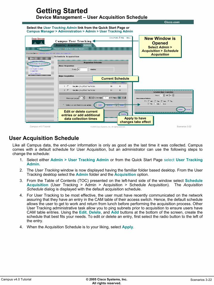
© 2005 Cisco Systems, Inc. All rights reserved.
Scenarios 3-22Campus v4.0 Tutorial
Scenarios 3-22© 2005 Cisco Systems, Inc. All rights reserved.Campus v4.0 Tutorial
Getting StartedDevice Management – User Acquisition Schedule
Select the User Tracking Admin link from the Quick Start Page orCampus Manager > Administration > Admin > User Tracking Admin
New Window is Opened
Select Admin > Acquisition > Schedule
Acquisition
New Window is Opened
Select Admin > Acquisition > Schedule
Acquisition
Current ScheduleCurrent Schedule
Edit or delete current entries or add additional
data collection times
Edit or delete current entries or add additional
data collection times Apply to have changes take effect
Apply to have changes take effect
User Acquisition ScheduleLike all Campus data, the end-user information is only as good as the last time it was collected. Campus comes with a default schedule for User Acquisition, but an administrator can use the following steps to change the schedule:
1. Select either Admin > User Tracking Admin or from the Quick Start Page select User Tracking Admin.
2. The User Tracking window is now displayed having the familiar folder based desktop. From the User Tracking desktop select the Admin folder and the Acquisition option.
3. From the Table of Contents (TOC) presented on the left-hand side of the window select Schedule Acquisition (User Tracking > Admin > Acquisition > Schedule Acquisition). The Acquisition Schedule dialog is displayed with the default acquisition schedule.
4. For User Tracking to be most effective, the user must have recently communicated on the network assuring that they have an entry in the CAM table of their access switch. Hence, the default schedule allows the user to get to work and return from lunch before performing the acquisition process. Other User Tracking administrative task allow you to ping subnets prior to acquisition to ensure users have CAM table entries. Using the Edit, Delete, and Add buttons at the bottom of the screen, create the schedule that best fits your needs. To edit or delete an entry, first select the radio button to the left of the entry.
4. When the Acquisition Schedule is to your liking, select Apply.

© 2005 Cisco Systems, Inc. All rights reserved.
Scenarios 3-23Campus v4.0 Tutorial
Scenarios 3-23© 2005 Cisco Systems, Inc. All rights reserved.Campus v4.0 Tutorial
Getting StartedDevice Management –Additional Acquisition Settings
User Tracking > Admin > Acquisition > Acquisition SettingsAdditional settings for User Tracking
acquisition
Additional settings for User Tracking
acquisition
Option for fetching End Hosts connected in a Voice VLAN setup
Option for fetching End Hosts connected in a Voice VLAN setup
Additional Acquisition SettingsUser Acquisition has additional settings to ensure retrieval of information in modern networks including DHCP environments and End Hosts and IP Phones sharing the same switch access port. Additionally, User Tracking can be configured to retrieve the login name of the user from UNIX hosts and NT or DNS domains. This option requires a login script (UTLite) to be installed on the login server. See the Campus User Guide for additional information.

© 2005 Cisco Systems, Inc. All rights reserved.
Scenarios 3-24Campus v4.0 Tutorial
Scenarios 3-24© 2005 Cisco Systems, Inc. All rights reserved.Campus v4.0 Tutorial
Getting StartedDevice Management – User Acquisition Ping Sweep
Subnets excluded from Ping Sweep
Subnets excluded from Ping Sweep
User Tracking > Admin > Acquisition > Ping Sweep
The Ping Sweep option (enabled by default) pings all the known IP Address in the subnet before starting
User Acquisition
The Ping Sweep option (enabled by default) pings all the known IP Address in the subnet before starting
User Acquisition
Subnets discovered during data collection process
Subnets discovered during data collection process
User Acquisition Ping SweepAgain, it is important for users to have an entry in the access switch CAM table in order to be discovered by the User Acquisition process. Therefore, by default prior to User Acquisition, the User Acquisition process pings all known subnets discovered during the data collection process. This is referred to as a Ping Sweep.Since this process adds traffic to the network and prolongs the time it takes to do a User Acquisition, it can be disabled or certain subnets can be excluded from the ping sweep.

© 2005 Cisco Systems, Inc. All rights reserved.
Scenarios 3-25Campus v4.0 Tutorial
Scenarios 3-25© 2005 Cisco Systems, Inc. All rights reserved.Campus v4.0 Tutorial
Getting StartedDevice Management – User Acquisition Results
User Tracking > Acquisition
• Display details of the most current User Tracking acquisition.
• Acquisition time can be used to help determine frequency of acquisition collection.
• Display details of the most current User Tracking acquisition.
• Acquisition time can be used to help determine frequency of acquisition collection.
User Acquisition ResultsTo assist in the setting of the User Acquisition schedule it is helpful to know the time it took for the User Acquisition process to run. To view the results of the latest User Acquisition process, select the Acquisitiontab from the User Tracking desktop.

© 2005 Cisco Systems, Inc. All rights reserved.
Scenarios 3-26Campus v4.0 Tutorial
Scenarios 3-26© 2005 Cisco Systems, Inc. All rights reserved.Campus v4.0 Tutorial
Getting StartedDevice Management – Managing Device Credentials
Configuration tasks in Campus require the correct SNMP credentials to write to the device
Configuration tasks in Campus require the correct SNMP credentials to write to the device
All device credential
administration is done from Common Services
All device credential
administration is done from Common Services
Select device or devices to associate SNMP
credentials with
Select device or devices to associate SNMP
credentials with
See next page
Managing Device CredentialsCampus is now configured to collect all necessary data on a periodic basis and is ready for read-only use. Because Campus contains many tasks that are used to configure a device (i.e. creating VLANs), the devices in the DCR that are managed by Campus may also require the appropriate SNMP credential to write to the device in order to perform the configuration tasks. In fact, other CiscoWorks applications will also require the devices to have the write-access SNMP credential, as well as, other credentials such as access passwords. Use the following steps to add the appropriate SNMP credentials to devices in the DCR so that Campus can perform configuration tasks:
1. Since the DCR is part of Common Services, all credential administration is done from the Common Services desktop. Launch the Common Services desktop by selecting the Common Servicesheader from the CiscoWorks Homepage.
2. From the Common Services desktop select Device and Credentials > Device Management. The Device Summary dialog is displayed showing the applications installed and if expanded all the groups defined for the installed applications.
3. In this scenario, we will assume all devices managed by Campus have the same write community string so we can simply select the Campus entry to effectively select all devices to be associated with the same string at one time. If this were not the case, the entries would have to be expanded and the appropriate groups or devices would need be selected one at a time, repeating these steps until all unique stings were entered for the appropriate devices.
4. Select the Edit button to add the appropriate SNMP credential for all selected devices.

© 2005 Cisco Systems, Inc. All rights reserved.
Scenarios 3-27Campus v4.0 Tutorial
Scenarios 3-27© 2005 Cisco Systems, Inc. All rights reserved.Campus v4.0 Tutorial
Getting StartedDevice Management - Manage Device Credentials (Continue …)
Skip to second step of the wizard
Skip to second step of the wizard
Edit appropriate fields and select
Finish when done
Edit appropriate fields and select
Finish when done
Each device in Campus now is
associated with the appropriate SNMP
credential
Each device in Campus now is
associated with the appropriate SNMP
credential
SNMP v2 or v3
Managing Device Credentials (Continue …)5. The Credentials Template wizard step 1 is displayed. Step 1 is used for basic device properties which
makes little sense when many objects are selected. Skip this step by selecting the second step of the wizard from the TOC.
6. The second step of the wizard is used for adding credentials. Enter the SNMP credentials and enter it a second time for verification since what is entered is not echoed to the screen.
7. Select Finish to associate the entered community string with all selected devices (remember we selected all Campus devices in step 3) in the DCR.
At this point Campus is be fully operational! The next scenario will look at additional administrative functions to enhance the use of Campus.

© 2005 Cisco Systems, Inc. All rights reserved.
Scenarios 3-28Campus v4.0 Tutorial
Preparing Campus for Preparing Campus for UseUse
• Getting Started
Preparing Campus for Use
• Topology Services
• User Tracking
• Path Analysis

© 2005 Cisco Systems, Inc. All rights reserved.
Scenarios 3-29Campus v4.0 Tutorial
Scenarios 3-29© 2005 Cisco Systems, Inc. All rights reserved.Campus v4.0 Tutorial
Preparing Campus for Use
• Discrepancy Reporting–Reported Discrepancies
–Syslog Discrepancy Messages
• Create Groups
Preparing Campus for UseEven though Campus was ready for use after the previous scenario was completed, this scenario looks at additional administration type functions to perform to make Campus more effective to use.The first portion of the scenario will look at configuring which discovered discrepancies to report on and which discrepancies to send as Syslog messages. The second portion of this scenario will look at how to create groups which facilitate the viewing of the network as logical sub-groupings of devices.

© 2005 Cisco Systems, Inc. All rights reserved.
Scenarios 3-30Campus v4.0 Tutorial
Scenarios 3-30© 2005 Cisco Systems, Inc. All rights reserved.Campus v4.0 Tutorial
Preparing Campus for Use Discrepancy Reporting
Campus Manager
DatabaseDatabase
As part of Data Collection efforts, Campus collects information
about difficult to find Physical and Logical discrepancies
As part of Data Collection efforts, Campus collects information
about difficult to find Physical and Logical discrepancies
Physical DiscrepanciesPhysical Discrepancies
Logical DiscrepanciesLogical Discrepancies
Examples of physical discrepancies reported:
• Mismatch in link speeds on Trunk Ports• CDP Enabled on Access Ports• Uplink Fast Not Enabled on Switches• Spanning Tree Enabled on Access Ports
Examples of logical discrepancies reported:
• Incorrect settings in VTP or ATM domains• Trunk VLANs mismatches
Discrepancy ReportingDuring the Campus Data Collection process, configuration of each physical and logical construct is analyzed. Therefore, Campus is able to report on both physical and logical misconfigurations to allow for their correction to help the network operate more efficiently. However, many of the reported discrepancies may not be considered a problem to some network administrators; therefore, Campus allows for the ability to select which detected discrepancies should be reported. Further, Campus also allows for the discovery of some (or all) discrepancies to be forwarded as a Syslog message to a Syslog server.Campus can automatically identify various types of discrepancies on network devices:
• Physical discrepancies: These include mismatches in line speed, trunk configuration, or duplex mode on two ends of a link. For example, full duplex configured on one side of a link and half duplex configured on the other side.
• Logical discrepancies: These include inconsistent or incorrect settings in VTP domains, VLANs, and ATM LANE components. For example, an ATM VLAN that has no entry in the LECS or if there is a VTP client and no VTP server. You do not need a VTP server, if the network uses only transparent nodes in the domain.
The next few pages look at the wizard used to configure discrepancy reporting in Campus.

© 2005 Cisco Systems, Inc. All rights reserved.
Scenarios 3-31Campus v4.0 Tutorial
Scenarios 3-31© 2005 Cisco Systems, Inc. All rights reserved.Campus v4.0 Tutorial
Preparing Campus for Use Discrepancy Reporting - Configuring Reported Discrepancies
Campus Manager > Administration > Admin > Network Discrepancies
Configure the discrepancies reported
and also configure if discrepancies are to also
be reported via syslog messages
Configure the discrepancies reported
and also configure if discrepancies are to also
be reported via syslog messages
Select discrepancies to be reported
Select discrepancies to be reported
Enable Syslog reportingEnable Syslog reporting
Configuring Reported DiscrepanciesUse the following steps to configure Campus discrepancy reporting:
1. From the Campus Manager Administration desktop (if not already open launch by selecting the Administration task in the Campus Manager dialog on the CiscoWorks Homepage) select Admin > Network Discrepancies.
2. The Network Discrepancies dialog is displayed with links to view the current discrepancies being reported on and the discrepancies being forwarded to the listed Syslog server. Select the Configurebutton to change the current set-up.
3. The Configure Network Discrepancies wizard is displayed showing a tree structure of all discrepancies detected by Campus. By default, these are all selected. Expand desired sections and un-select the discrepancies you do not want Campus to report on.
4. Select the Configure Syslog check box in the upper right-hand corner to configure Syslog reporting during the next step of the wizard.
5. Click Next> at the bottom of the wizard to move on to the next step of the wizard.

© 2005 Cisco Systems, Inc. All rights reserved.
Scenarios 3-32Campus v4.0 Tutorial
Scenarios 3-32© 2005 Cisco Systems, Inc. All rights reserved.Campus v4.0 Tutorial
Preparing Campus for Use Discrepancy Reporting - Syslog Discrepancy Messages
Syslog configuration screen is presented
as part of wizard when Configure Syslog is selected on previous
screen, else just a summary of selected
discrepancies is displayed
Syslog configuration screen is presented
as part of wizard when Configure Syslog is selected on previous
screen, else just a summary of selected
discrepancies is displayed
In this case only physical
discrepancies are forwarded as syslog
messages
In this case only physical
discrepancies are forwarded as syslog
messages
Enter syslog serverEnter syslog server
Last step displays summary of configuration,
select Finish to have changes take effect
Last step displays summary of configuration,
select Finish to have changes take effect
Syslog Discrepancy Messages, continue …6. If the Configure Syslog check box was not selected, this step shows a summary of what
discrepancies will be reported on, select Finish to have the configuration take effect.If the Configure Syslog check box was selected, this step again displays the discrepancy tree. This time, select the discrepancies you want to also be forwarded to a Syslog server as a Syslog message. Also, add the name or address of the Syslog server in the upper right-hand corner.
6. When the appropriate discrepancies have been selected and the Syslog server configured, click Next> to go to the final step of the wizard.
7. A summary of the new configuration is displayed, select Finish to have the configuration take effect.

© 2005 Cisco Systems, Inc. All rights reserved.
Scenarios 3-33Campus v4.0 Tutorial
Scenarios 3-33© 2005 Cisco Systems, Inc. All rights reserved.Campus v4.0 Tutorial
Preparing Campus for Use Create Groups
I want the engineers to see maps of the different regions of our NMTG network
Let’s start by creating
appropriate groups
Campus Manager > Administration > Admin > Groups
While in Campus Group
Administration, groups can only be
created under Campus on the local
server
While in Campus Group
Administration, groups can only be
created under Campus on the local
server
Create GroupsFor the remainder of this chapter, we introduce Ted, the IT manager for east coast operations of a large firm and one of his brightest engineers, Sally. The company was always in a reactive mode when it came to management of the network and Sally convinced Ted to purchase and install CiscoWorks to help them work more efficiently. Ted was impressed with the features of Campus and now that it is installed and operational, he wants Sally to begin using it.The first order of business is to make some groupings of devices that will assist the engineers and help-desk folks to better visualize the network. Sally uses the following steps to create a group consisting of the NMTG portion of the network:
1. From the Campus Manager Administration desktop, select Admin > Groups. The Group Administration and Configuration dialog is displayed.
2. The dialog contains a Group Selector which displays an entry for all CiscoWorks applications currently installed. Expanding these entries shows additional groups defined for those applications. Sally expands the Campus entry to reveal the group categories for Campus. When using Campus to create groups, the groups must be created under the User Defined Groups category, so Sally selects it. If groups were already defined under this category, Sally could have selected one of them. In other words, you can create a hierarchy of groups. The right side of the dialog displays information about the selected group.
3. Click Create to perform the next step.

© 2005 Cisco Systems, Inc. All rights reserved.
Scenarios 3-34Campus v4.0 Tutorial
Scenarios 3-34© 2005 Cisco Systems, Inc. All rights reserved.Campus v4.0 Tutorial
Preparing Campus for Use Create Groups - Properties
Dynamic or static membershipDynamic or static membership
Enter meaningful nameEnter meaningful name
Inherit rulesInherit rules
Usable only by current user or by all
CiscoWorks users
Usable only by current user or by all
CiscoWorks users
Group Properties4. The 4-step Create Group wizard is launched. The first step is to set the group properties: Enter a
meaningful name for the group, in this case nmtg.5. If attributes are to be selected from an existing Campus system or user defined group use the
Select Group button6. Use the Change Parent button to change the group parent. The parent must be in the User Defined
Groups hierarchy.7. Membership updates can be Automatic, meaning that if a device meets the rules of membership at
any time, then it becomes a member, or loses membership if it no longer matches the membership rules. This is known as a dynamic group. Conversely, selecting Only Upon User Request effectively makes a static group whose membership is only changed by the group creator regardless if a device meets or no longer meets the membership rules after the group was created.
8. The Visibility Scope attribute defines who will see and can use this group. If Sally were to select Private, then only her account would be able to use this group. Ted would not be able to use this group when he logged into CiscoWorks unless he also created a similar group.
9. Click Next> to go to the next step in the Create Group wizard.

© 2005 Cisco Systems, Inc. All rights reserved.
Scenarios 3-35Campus v4.0 Tutorial
Scenarios 3-35© 2005 Cisco Systems, Inc. All rights reserved.Campus v4.0 Tutorial
Preparing Campus for Use Create Groups - Rules
Create one or more rules to define
membership, using multiple possible
variables and operators
Create one or more rules to define
membership, using multiple possible
variables and operators
Rules can be combined with Boolean operatorsRules can be combined with Boolean operators
Set of variables to create rules
Set of variables to create rules
Group Membership RulesThe next step of the Create Group wizard is used to define the rules that determine membership in the group. Rules can be created using just about every variable collected by Campus using multiple operators including equals, contains, etc. Rules can also be combined with Boolean operators to create very detailed membership rules.
10. From the variable pull down list, Sally selects HostName.11. From the Operator Pull down list, she select contains.12. In the value field, enter nmtg (since all nmtg devices in the network are suppose to include the
letters “nmtg” in their host name).13. Click Add Rule Expression to add membership rule. The just created rule is listed in the Rule Text
box. Notice that in the Rule Expression portion of the dialog a new field is available containing Boolean variables for adding expressions together. After adding multiple expressions, the user may need to edit the rule set in the Text box by adding parenthesis to ensure proper interpretation.
14. Click Next> to go to the next step in the Create Group wizard.

© 2005 Cisco Systems, Inc. All rights reserved.
Scenarios 3-36Campus v4.0 Tutorial
Scenarios 3-36© 2005 Cisco Systems, Inc. All rights reserved.Campus v4.0 Tutorial
Preparing Campus for Use Create Groups – Verify/Fine Tune Membership
List of devices in groupList of devices in groupAdd or delete to fine tune list (appropriate rules will be added)
Add or delete to fine tune list (appropriate rules will be added)
Fine Tune Group MembershipThe third step of the Create Group wizard displays the membership of the group on the right side of the dialog box based on the membership rules just created. The left side of the dialog box is a list of the remaining available objects in the parent group. This step can be used to fine tune membership in the group by adding and/or removing devices. Devices added or removed will cause the appropriate membership rules to be generated. Sally needs to remove one device that was misnamed to perfect her list. The new membership rules will be seen in the final wizard step.
15. Click Next> to go to the next step in the Create Group wizard.

© 2005 Cisco Systems, Inc. All rights reserved.
Scenarios 3-37Campus v4.0 Tutorial
Scenarios 3-37© 2005 Cisco Systems, Inc. All rights reserved.Campus v4.0 Tutorial
Preparing Campus for Use Create Groups - Summary
Final Rule SetFinal Rule Set
New group addedNew group added
A hierarchy of user-defined groups can be
created
A hierarchy of user-defined groups can be
created
Create Group SummaryThe last Wizard step shows a summary of the group just created. Notice in the Rules that there was a rule added to exclude the device that Sally wanted removed.
16. Click Finish to create the group. The device selector now displays the nmtg group as a child group to the User Defined Groups entry.
Sally could now use the nmtg group as the parent group and create a subset to this group. (Refer back to Chapter 2 - Hierarchical Maps for a visual representation of this feature.)
Now, let’s look at using the major tools within Campus: Topology Services, User Tracking, and Path Analysis.

© 2005 Cisco Systems, Inc. All rights reserved.
Scenarios 3-38Campus v4.0 Tutorial
Topology ServicesTopology Services
• Getting Started
• Preparing Campus for Use
Topology Services
Creating a New VLAN
• Creating a Private VLAN
• User Tracking
• Path Analysis

© 2005 Cisco Systems, Inc. All rights reserved.
Scenarios 3-39Campus v4.0 Tutorial
Scenarios 3-39© 2005 Cisco Systems, Inc. All rights reserved.Campus v4.0 Tutorial
Topology ServicesCreate a New VLAN
We need to create a new VLAN in Bldg
B for the new Planning
Department and reserve 5 ports on
each switch, except the 2950.
Building B NetworkBuilding B Network
No Planning Ports
Inter-VLAN router
Topology Services – Create a New VLANRecently the company has added two new buildings – A and B. Both have identical network topologies. The newly created Planning Department is the first group of users slated to go into building B. The devices in building B have already been put into a VTP domain logically named “B”. Ted wanting to be proactive has decided to create a new VLAN for the Planning Department and reserve the last 5 ports on each switch (20-24) for their use.Ted has tasked Sally with this configuration request. Note:
• To perform the following configurations, the DCR must contain the appropriate write-access SNMP credential for the devices to be configured. (Refer to the earlier Getting Started scenario for more details on this task.)

© 2005 Cisco Systems, Inc. All rights reserved.
Scenarios 3-40Campus v4.0 Tutorial
Scenarios 3-40© 2005 Cisco Systems, Inc. All rights reserved.Campus v4.0 Tutorial
Topology ServicesLaunch Topology Services
Wait to connect to server in order to
ensure proper Java applets are available
Wait to connect to server in order to
ensure proper Java applets are available
Launch Topology Services from the
CiscoWorks Homepage
Launch Topology Services from the
CiscoWorks Homepage
Launch Topology ServicesSally knows that Topology Services in Campus can be used to view information about VTP domains, as well as, create and populate VLANs. Sally accesses the CiscoWorks Homepage and is ready to get started.
1. From the CiscoWorks Homepage, select Campus Manger > Topology Services.A new window containing no information (gray background) is displayed labeled Topology Services and a sub-window is also launched that displays the progress toward connecting to the ANI Server. The ANI Server is the process that handles most of the Campus Manager processing. When the connection is complete, this window closes and the contents of the Topology Services window are displayed.Note(s):
• If the Java Plug-in version 1.4.2_xx is not installed on the client, the connection window may not open for up to 5 minutes at which time it will ask if you wish to download and install the plug-in from the server. This Plug-in is required for Topology Services and Path Analysis tasks within Campus Manager
• Refer to Chapter 4 for more on system requirements. If the plug-in is already installed, the connection screen will also take some time to complete as Java applets and classes on downloaded. Subsequent launches of Topology Services or Path Analysis should proceed quicker.

© 2005 Cisco Systems, Inc. All rights reserved.
Scenarios 3-41Campus v4.0 Tutorial
Scenarios 3-41© 2005 Cisco Systems, Inc. All rights reserved.Campus v4.0 Tutorial
Topology ServicesVerify VTP Parameters
Select VTP Domain BRight-Click to display
menu and select Display View to launch map
Select VTP Domain BRight-Click to display
menu and select Display View to launch map
VTP Domain VTP Domain -- BB
Verify VTP ParametersThe first task on Sally’s list is to verify that the switch devices are correctly configured for VTP processing. Sally uses the following steps to verify the VTP domain:
1. From the Topology Services main window, expand the Managed Domains folder icon. 2. Expand the VTP Domains folder icon, and highlight VTP Domain B. (Verifies that it exists).3. Right-click on the VTP B domain entry and select Device View from the pop-up menu. A map
window showing VTP Domain Topology – B is displayed.

© 2005 Cisco Systems, Inc. All rights reserved.
Scenarios 3-42Campus v4.0 Tutorial
Scenarios 3-42© 2005 Cisco Systems, Inc. All rights reserved.Campus v4.0 Tutorial
Topology ServicesVerify VTP Parameters (Continue …)
Use filters to highlight VTP servers
Use filters to highlight VTP servers
Use filters to highlight VTP clients
Use filters to highlight VTP clients
VTP Servers
VTP Clients
Verify VTP Parameters (Continue …)4. On the right-hand side of the map window is a hierarchy of topology filters. Expand the VTP entry
and then expand the VTP Devices entry.5. Select the VTP Servers filter. The VTP Servers are displayed on the map and all other devices are
grayed out.6. Select the VTP Clients filter. The VTP Client are displayed on the map and all other devices are
grayed out.Sally used these steps to quickly verify the VTP mode configuration of all devices in the VTP Domain; the alternative would have been to login to each switch and run the appropriate show commands. Obviously, using Campus represents a huge savings in the time required to perform this task. Next, Sally needs to verify that links between the switches are configured as trunks.

© 2005 Cisco Systems, Inc. All rights reserved.
Scenarios 3-43Campus v4.0 Tutorial
Scenarios 3-43© 2005 Cisco Systems, Inc. All rights reserved.Campus v4.0 Tutorial
Topology ServicesVerify VTP Parameters (Continue …)
Use filters to view trunk linksUse filters to
view trunk links
Link is not highlighted and therefore not a trunkLink is not highlighted
and therefore not a trunk
Mouse over link to get informationMouse over link to get information
Verify VTP Parameters (Continue …)7. Under the already expanded VTP filter category, select the Trunk Encapsulation category. 8. After some messages indicating that some types of trunks are not present, all trunk links are
displayed and everything else is grayed out.This verifies the trunk configuration in the VTP Domain, only the link to the external router is not a trunk which is OK since the 3750 will be used as the inter-VLAN router.

© 2005 Cisco Systems, Inc. All rights reserved.
Scenarios 3-44Campus v4.0 Tutorial
Scenarios 3-44© 2005 Cisco Systems, Inc. All rights reserved.Campus v4.0 Tutorial
Topology ServicesCreate VLAN
VLAN creation tool is launched from the main
Topology Services Window
VLAN creation tool is launched from the main
Topology Services Window
Highlight VTP domain to create VLAN in
Highlight VTP domain to create VLAN in Enter new VLAN
informationEnter new VLAN
information
New VLAN is created!
New VLAN is created!
Create VLANNow that Sally has verified proper VTP configuration, she is ready to create the new VLAN. Even though the filters indicated which switches are configured as VTP servers, Topology Service doesn’t require her to know which switches are VTP servers to create a VLAN since it is aware of where the VTP servers are. Sally uses the following steps to create the new Planning Department VLAN:
1. From the main Topology Services window, highlight the VTP domain in which to create the VLAN in, and select Tools > VLAN Management > Create > Ethernet from the window menu bar.
2. The Create Ethernet VLAN dialog is displayed. Sally enters the VLAN name as Planning(replacing the suggested default in this case VLAN2). She keeps the suggested VLAN ID as 2, and enters a purpose and description for the VLAN.
3. Optionally, if there were VTP Transparent mode switches in this domain she could also configure them with this VLAN by selecting the appropriate check box.
4. Additionally, she does want to make sure the configuration is copied to the start-up configuration on CatIOS switches and clicks the appropriate check box.
5. If the VLAN needed to be extended across an ATM fabric that could be configured as well by selecting the LANE Services button.
6. Sally clicks Apply and the VLAN is created! It couldn’t be any easier.

© 2005 Cisco Systems, Inc. All rights reserved.
Scenarios 3-45Campus v4.0 Tutorial
Scenarios 3-45© 2005 Cisco Systems, Inc. All rights reserved.Campus v4.0 Tutorial
Topology ServicesUpdate Campus Database
Selected devices Selected devices
Data Collection Status
Data Collection Status
Update Campus DatabaseTed’s directive stated that the 2950 would not contain any Planning department people; so Sally has decided to prune the Planning VLAN from the trunk leading to the 2950 to reduce STP processing. However, prior to doing that task, she wants to make sure that the Campus database has the latest VLAN configuration information for all devices in VTP domain B. Use the following steps to update the Campus database for devices in VTP domain B:
1. Return to the VTP Domain Topology – B map window. Select Edit > Select > All Devices from the menu bar. All devices in the map will be selected indicated by a blue (default color) box around them.
2. Right-click on one of the devices and select Perform Data Collection from the pop-up menu. The Data Collection Status in the lower right-hand corner will indicate “Running”.
3. Data Collection is completed when the status returns to “Idle”.
Note(s): • It is always a good idea to Perform a Data Collection in this manner on devices prior to their being
modified to ensure Campus is working with the current configuration since the scheduled Data Collection may have occurred prior to someone making a change from the command line using telnet.

© 2005 Cisco Systems, Inc. All rights reserved.
Scenarios 3-46Campus v4.0 Tutorial
Scenarios 3-46© 2005 Cisco Systems, Inc. All rights reserved.Campus v4.0 Tutorial
Topology ServicesPruning VLANs on Trunk Ports
Right-click on trunk to configure and select
Trunk Attributes
Right-click on trunk to configure and select
Trunk Attributes
Currently defined VLANsCurrently defined VLANs
Prune VLAN id 2Prune VLAN id 2
Pruning VLANs on Trunk PortsSally uses the following steps to prune the Planning VLAN from the trunk leading to the 2950:
1. From the VTP Domain Topology – B map window, highlight the link between the 2950 and the 3550 and right-click on it. Select Trunk Attributes from the pop-up menu.
2. The Trunk Attributes dialog is displayed showing the current configuration of the trunk. Notice that only the default VLANs and the Planning VLAN are currently active on this trunk. In the entry box labeled “Disallow VLAN(s)”, enter the VLAN ID of the Planning VLAN – 2.
3. Make sure to copy this new configuration to the Start Up configuration on CatIOS devices by selecting the appropriate check box.
4. Select Apply to make the configuration change and prune the Planning VLAN from this trunk.

© 2005 Cisco Systems, Inc. All rights reserved.
Scenarios 3-47Campus v4.0 Tutorial
Scenarios 3-47© 2005 Cisco Systems, Inc. All rights reserved.Campus v4.0 Tutorial
Topology ServicesConfigure Inter-VLAN Routing
To configure Inter-VLAN routing, the device must be managed by RME and
have proper credentials in the DCR
To configure Inter-VLAN routing, the device must be managed by RME and
have proper credentials in the DCR
Select device to configure from the main Topology
Services window
Select device to configure from the main Topology
Services window
Link is not highlighted therefore not a trunk
Link is not highlighted therefore not a trunk
11
22
33
44
Configure Inter-VLAN RoutingSally’s next task is to create a route interface for the new VLAN. Use the following steps to configure a router:
1. From the main Topology Services window. Expand the Network Views folder then expand the VTP Views folder.
2. Select and highlight VTP domain B. In the Summary portion of the window, the devices in VTP domain B are listed.
3. Highlight the device to be configured with the route interface (3750 in this case), and right-click the device. Select Configure Inter-VLAN Routing from the pop-up menu.
4. At this point a pop-up window may ask for the location and account information for the RME server. Use the RME server name as opposed to “localhost”, enter the user account information and select Apply.
5. The Configure Inter-VLAN Routing dialog is displayed listing current VLAN interfaces configured.Select the New button. This activates the middle portion of the dialog that allows you to add the VLAN interface information. Enter VLAN ID and IP address information.
6. After the information is entered, click the Move to Interface Set button which moves the information into the Interface Set portion of the dialog. At this point additional VLAN interfacescould be added.
7. Click Apply to configure the interface.
Note: • The layer 3 device must be managed by RME and the DCR must have all appropriate credentials
in order to perform this task.

© 2005 Cisco Systems, Inc. All rights reserved.
Scenarios 3-48Campus v4.0 Tutorial
Scenarios 3-48© 2005 Cisco Systems, Inc. All rights reserved.Campus v4.0 Tutorial
Topology ServicesPopulate VLAN
Launch from CiscoWorks Homepage or Tools menu from the main Topology
Services window
Launch from CiscoWorks Homepage or Tools menu from the main Topology
Services window
Select VTP domainSelect VTP domain
Narrow the port selection down
Narrow the port selection down
Highlight ports to move into VLAN
Highlight ports to move into VLAN
Select VLAN and move selected ports to it
Select VLAN and move selected ports to it
11
22
33
44
55
Populate VLANThe final part of Ted’s directive was to reserve ports 20-24 on all switches for the Planning Department. Sally uses the following steps to perform this configuration from a single screen without having to login to each switch.
1. Return to the main Topology Window and ensure that VTP domain B is highlighted. Select Tools > VLAN Port Assignment from the window menu bar. (This task can also be launched from the CiscoWorks Homepage.)
2. The VLAN Port Assignment dialog is displayed. Ensure that VTP domain B is selected. Use the Find Port section of the dialog to limit the ports to be displayed. In this case, Sally selects Interface Name to contains “/2” to retrieve ports 2 and 20-29 (if existing) and Device Name to contains “3”which should include all switches except the 2950. Click Get Ports button.
3. Ports matching the query are listed in the bottom portion of the dialog. Using the “Ctrl” key, Sally highlights the subset of ports to be assigned to the Planning VLAN.
4. Select the Planning VLAN from the “Move selected ports to” drop down options list, and click Move to make the VLAN port assignments.

© 2005 Cisco Systems, Inc. All rights reserved.
Scenarios 3-49Campus v4.0 Tutorial
Scenarios 3-49© 2005 Cisco Systems, Inc. All rights reserved.Campus v4.0 Tutorial
Topology ServicesReport – VLAN Membership
Expand Managed Domains > VTP
Domains > B to see new VLAN created
Expand Managed Domains > VTP
Domains > B to see new VLAN created Select new VLAN to
see port membershipSelect new VLAN to
see port membership
VLAN Membership ReportSally uses the following steps to verify that the VLAN was created and populated as planned:
1. From the Topology Services main window, expand Managed Domains >VTP Domains > VTP Domain B.
2. Under this category all VLANs defined in VTP domain B are listed. Sally confirms that the Planning VLAN exists.
3. Highlight the Planning VLAN and the Summary section of the window displays all ports assigned to the Planning VLAN. Sally verifies that this is as expected.

© 2005 Cisco Systems, Inc. All rights reserved.
Scenarios 3-50Campus v4.0 Tutorial
Scenarios 3-50© 2005 Cisco Systems, Inc. All rights reserved.Campus v4.0 Tutorial
Topology ServicesPlanning VLAN STP Report
Select Spanning Tree VLAN filter and
Planning VLAN from selection window
Select Spanning Tree VLAN filter and
Planning VLAN from selection window
Notice Spanning Tree and that VLAN 2 does not use pruned trunk
Notice Spanning Tree and that VLAN 2 does not use pruned trunk
11
22
33
44
55
Planning VLAN STP ReportTo ensure that the VLAN was properly pruned from the 2950 trunk, Sally decides to look at the Spanning Tree for the Planning VLAN using the following steps:.
1. From the VTP Domain Topology – B map window (opened earlier in scenario), expand the Spanning Tree filter category, and click the VLAN entry.
2. A pop-up window will be displayed asking for the VLAN to be displayed. Select the Planning VLAN and click Select.
3. The map will now highlight the root bridge (all other devices grayed out) and will show the state of each port (forwarding or blocking). Sally notices that the link to the 2950 is not included in the STP, just as desired.
Sally reports back to Ted that the directive was completed. Sally also notes that this took just a couple of minutes using Campus, but would probably have taken close to an hour or more using the CLI interfaces of each device not to mention the possibility of making typing mistakes and not achieving the desired configuration.

© 2005 Cisco Systems, Inc. All rights reserved.
Scenarios 3-51Campus v4.0 Tutorial
Topology ServicesTopology Services
• Getting Started
• Preparing Campus for Use
Topology Services
• Creating a New VLAN
Creating Private VLANs
• User Tracking
• Path Analysis

© 2005 Cisco Systems, Inc. All rights reserved.
Scenarios 3-52Campus v4.0 Tutorial
Scenarios 3-52© 2005 Cisco Systems, Inc. All rights reserved.Campus v4.0 Tutorial
Topology ServicesPrivate VLANs
We need to enforce better security in the network by following this
trusted model:
DMZ servers are supposed to be accessible from Internet clients as well as from the internal trusted LAN.
DMZ servers will need access to some internal resources
DMZ servers are not supposed to talk to each other.
No traffic should be initiated from the DMZ to the Internet.
DMZ servers should only reply with traffic corresponding to incoming connections.
DMZ ServersDMZ Servers
Web ServersWeb Servers DNS ServersDNS Servers
FirewallFirewall
InternetInternet
Trusted LANTrusted LAN
Topology Services –Private VLANsRecently, there was a well-known vulnerability in a script that allowed an intruder to begin an X-term session by just sending an HTTP stream. Thus, the company has adopted the following trust model to help enforce and improve security in the network.
• The DNS and Web servers are supposed to be accessible from Internet clients as well as from the internal trusted LAN
• The servers in the DMZ (demilitarized zone) will need access to some internal resources • The DMZ servers are not supposed to talk to each other, unless they require “front-end” replications• No traffic should be initiated from the DMZ to the Internet• DMZ servers should only reply with traffic corresponding to incoming connections.

© 2005 Cisco Systems, Inc. All rights reserved.
Scenarios 3-53Campus v4.0 Tutorial
Scenarios 3-53© 2005 Cisco Systems, Inc. All rights reserved.Campus v4.0 Tutorial
Topology ServicesPrivate VLANs - Steps
DMZ ServersDMZ Servers
Web ServersWeb Servers DNS ServersDNS Servers
FirewallFirewall
InternetInternet
Trusted LANTrusted LAN
1. Create a primary VLAN 100 in the DMZ VTP domain
2. Create secondary VLANs:
o Community VLAN (50) – for the Web Servers to talk to each other for replication
o Isolated VLAN (60)– for the DNS servers
3. Associate the secondary VLANs with the primary VLAN
4. Assign ports to the secondary VLANs
5. Configure promiscuous ports
Sally will perform the following steps to deploy this trusted model:
Sally will perform the following steps to deploy this trusted model:
Community VLAN 50
IsolatedVLAN 60
Promiscuous Port
Private VLANs - StepsSally is task to implement the trusted model by following the above steps. With Topology Services in Campus Manager v4.x, Private VLANs (PVLANs) can be configured. In this network, communication is required between the Web Servers for the purpose of ‘Front-end’ content replication. In this cases, the community feature of the Private VLANs becomes very useful. Within the community, endpoints may communicate with one another and to any defined promiscuous port. Note that endpoints belonging to one community may not communicate with endpoints within a different community.Isolated ports are typically used for those endpoints that only require access to a limited number of outgoing interfaces on the router or multi-layer switch. An endpoint connected to an isolated port will only possess the ability to communicate with those endpoints connected to promiscuous ports. Endpoints connected to adjacent isolated ports cannot communicate. Isolated ports are typically reserved for hosts only requiring access to default gateways.And finally, the endpoint connected to a promiscuous port has the ability to communicate with any endpoint within the Private VLAN, in this case the port connected to the default gateway.

© 2005 Cisco Systems, Inc. All rights reserved.
Scenarios 3-54Campus v4.0 Tutorial
Scenarios 3-54© 2005 Cisco Systems, Inc. All rights reserved.Campus v4.0 Tutorial
Topology ServicesPrivate VLANs – Create Primary VLAN
1. Create a primary VLAN : Select the DMZ VTP Domain and launch the PVLAN configuration window
1. Create a primary VLAN : Select the DMZ VTP Domain and launch the PVLAN configuration window
Private VLANs – Create Primary VLANUse the following steps to create the Private VLANs, starting with the creation of the Primary VLAN:1. From the Topology Services window, select the DMZ VTP domain.2. From the main menu, select Tools> PVLAN Management> Create.3. In the Create Private VLAN dialog, select Primary from the pull-down menu.4. Enter the Private VLAN name and index of 100.5. Click Apply.

© 2005 Cisco Systems, Inc. All rights reserved.
Scenarios 3-55Campus v4.0 Tutorial
Scenarios 3-55© 2005 Cisco Systems, Inc. All rights reserved.Campus v4.0 Tutorial
Topology ServicesPrivate VLANs – Create Secondary VLANs
2. Create the secondary VLANs
• From the Create Private VLAN dialog, create the Community VLAN (50) and associated it with the primary VLAN (100); click Apply.
• From the same dialog, create the Isolated VLAN (60) and associate it with the primary VLAN (100); click Apply.
2. Create the secondary VLANs
• From the Create Private VLAN dialog, create the Community VLAN (50) and associated it with the primary VLAN (100); click Apply.
• From the same dialog, create the Isolated VLAN (60) and associate it with the primary VLAN (100); click Apply.
Web ServersWeb Servers
DNS ServersDNS Servers
Private VLANs – Create Secondary VLANUse the following steps to create the secondary VLAN for the Web servers: 1. In the Create Private VLAN dialog, select Community from the pull-down menu.2. Enter the Private VLAN name and index of 50.3. Click Apply.
Use the following steps to create the secondary VLAN for the DNS servers: 1. In the Create Private VLAN dialog, select Isolated from the pull-down menu.2. Enter the Private VLAN name and index of 60.3. Click Apply.

© 2005 Cisco Systems, Inc. All rights reserved.
Scenarios 3-56Campus v4.0 Tutorial
Scenarios 3-56© 2005 Cisco Systems, Inc. All rights reserved.Campus v4.0 Tutorial
Topology ServicesPrivate VLANs – Assign Ports
4. Assign Ports to the Secondary VLANs4. Assign Ports to the Secondary VLANs
Select ports connected to the Web ServersSelect ports connected to the Web Servers
Move selected ports to the Community VLAN (50)Move selected ports to the Community VLAN (50)
Private VLANs – Assign PortsUse the following steps to assign the switch ports to the newly created secondary VLAN for the Web servers:
1. From the Topology Services window, select the DMZ VTP domain.2. From the main menu, select Tools> VLAN Port Assignment. The VLAN Port Assignment window
can also be launched from the CiscoWorks desktop in the Campus Manager pane.3. Select the port(s) connected to the Web Servers from the table. The table can be populated by
showing all ports or by using the matching filter.4. In the “Move selected port to” field, select the newly created secondary VLAN 50. 5. Click Move to assign the community PVLAN to the Web Server ports.

© 2005 Cisco Systems, Inc. All rights reserved.
Scenarios 3-57Campus v4.0 Tutorial
Scenarios 3-57© 2005 Cisco Systems, Inc. All rights reserved.Campus v4.0 Tutorial
Topology ServicesPrivate VLANs – Assign Ports
4. Assign Ports to the Secondary VLANs4. Assign Ports to the Secondary VLANs
Select ports connected to the DNS Servers
Select ports connected to the DNS Servers
Move selected ports to the Isolated VLAN (60)Move selected ports to the Isolated VLAN (60)
Private VLANs – Assign PortsUse the following steps to assign the switch ports to the newly created secondary VLAN for the DNS servers:
1. From the VLAN Port Assignment window, select the port(s) connected to the DNS Servers from the table. The table can be populated by showing all ports or by using the matching filter.
2. In the “Move selected port to” field, select the newly created secondary VLAN 60. 3. Click Move to assign the isolated PVLAN to the DNS Server ports.

© 2005 Cisco Systems, Inc. All rights reserved.
Scenarios 3-58Campus v4.0 Tutorial
Scenarios 3-58© 2005 Cisco Systems, Inc. All rights reserved.Campus v4.0 Tutorial
Topology ServicesPrivate VLANs - Verify Port Assignment
Verify Port AssignmentVerify Port
Assignment
Port Mode: PVLANPort Mode: PVLAN
Private VLANs – Verify Port AssignmentVerify the VLAN port assignment from the VLAN Port Assignment window. Notice the Port Mode and the Association Type. The Port Mode displays the mode of the port. For example, PVLAN-Host, Promiscuous, or a non-PVLAN. The Association Type will be either Native (normal VLAN or Primary PVLAN) or Auxiliary (secondary VLANs).

© 2005 Cisco Systems, Inc. All rights reserved.
Scenarios 3-59Campus v4.0 Tutorial
Scenarios 3-59© 2005 Cisco Systems, Inc. All rights reserved.Campus v4.0 Tutorial
Topology ServicesPrivate VLANs – Configure Promiscuous Port
5. Configure Promiscuous Port connected to the gateway
5. Configure Promiscuous Port connected to the gateway
Select port connected to the gateway
Select port connected to the gateway
Private VLANs – Configure Promiscuous PortUse these steps to configure the port connected to the gateway as “Promiscuous”: 1. From the VLAN Port Assignment window, select the port connected to the gateway from the table.
The table can be populated by showing all ports or by using the matching filter.2. Click Configure Promiscuous Port. The Configure Promiscuous Port window will be displayed.

© 2005 Cisco Systems, Inc. All rights reserved.
Scenarios 3-60Campus v4.0 Tutorial
Scenarios 3-60© 2005 Cisco Systems, Inc. All rights reserved.Campus v4.0 Tutorial
Topology ServicesPrivate VLANs – Configure Promiscuous Port
• The secondary VLANs created are listed under the Available PVLANs table.
• Select the secondary VLANs (50, 60) associated to the Primary VLAN 100.
• Add them to the “Map VLAN(s)” table by clicking Add>,
• Click Apply.
• The secondary VLANs created are listed under the Available PVLANs table.
• Select the secondary VLANs (50, 60) associated to the Primary VLAN 100.
• Add them to the “Map VLAN(s)” table by clicking Add>,
• Click Apply.
<After clicking apply, the PVLANswill move here>
Private VLANs – Configure Promiscuous Port1. From the Configure Promiscuous Port window, select the secondary VLANs created from the
Available PVLANs table.2. Click Add>>. The VLAN indexes are added to the Map VLAN(s) table.3. Click Apply. 4. On successful configuration, you will now find the secondary VLANs under the “Mapped VLANs”
table. This shows that you have successfully configured the port connecting to the firewall as a promiscuous port.

© 2005 Cisco Systems, Inc. All rights reserved.
Scenarios 3-61Campus v4.0 Tutorial
Scenarios 3-61© 2005 Cisco Systems, Inc. All rights reserved.Campus v4.0 Tutorial
Topology ServicesVerify Private VLANs
• Return to the Topology Services window to verify that the newly created PVLANs are listed under the DMZ domain
• Notice that the Primary VLAN is a subfolder under the domain and the secondary VLANs are in the Primary VLAN folder
• Notice the difference in the VLAN icons:
• Normal VLAN• Community PVLAN• Isolated PVLAN
Verify Private VLANs1. Return to the Topology Services window to verify that the newly created PVLANs are listed under
the DMZ domain.2. Notice that the Primary VLAN is a subfolder under the domain and the secondary VLANs are in the
Primary VLAN folder.3. Notice the difference in the VLAN icons:
• Normal VLAN• Community PVLAN• Isolated PVLAN

© 2005 Cisco Systems, Inc. All rights reserved.
Scenarios 3-62Campus v4.0 Tutorial
Scenarios 3-62© 2005 Cisco Systems, Inc. All rights reserved.Campus v4.0 Tutorial
Topology ServicesVerify Private VLANs – VLAN Report
Launch the VLAN report for the DMZ domain verify if newly created Primary VLAN and secondary VLANs. For the secondary VLANs, you should be seeing the associated Primary VLAN in the appropriate columns.
Launch the VLAN report for the DMZ domain verify if newly created Primary VLAN and secondary VLANs. For the secondary VLANs, you should be seeing the associated Primary VLAN in the appropriate columns.
Verify Private VLANs – VLAN ReportUse these final steps to verify the creation of the PVLANs.
1. From the Topology Services window, select the DMZ VTP domain.2. From the main menu, select Reports > VLAN Report.3. Review the VLAN Report and verify the VLAN Types and Associated Primary VLANs.4. Optionally, run Path Trace analysis and verify the following:
• A trace between the Web servers is successful.• A trace between any the the Web servers and the DNS servers should fail• A trace between the DNS servers should fail.

© 2005 Cisco Systems, Inc. All rights reserved.
Scenarios 3-63Campus v4.0 Tutorial
User TrackingUser Tracking
• Getting Started
• Preparing Campus for Use
• Topology Services
User Tracking
• Path Analysis

© 2005 Cisco Systems, Inc. All rights reserved.
Scenarios 3-64Campus v4.0 Tutorial
Scenarios 3-64© 2005 Cisco Systems, Inc. All rights reserved.Campus v4.0 Tutorial
User TrackingTrack User Move
The Planning department is moving from the
192.168.159.112/28 & 192.168.137.128/28
subnets to the 192.168.177.192/28
subnet. I want to see what ports people are moving
from and to.
Let me create some custom User Tracking
reports
Launch User Tracking from the CiscoWorks Homepage
Launch User Tracking from the CiscoWorks Homepage
User Tracking – Track User MoveTed is ecstatic at the efficiency of Campus. Next, he tasks Sally with devising a way to track the Planning department user movements from their old location to the new building. Ted informs Sally that the personnel to staff the Planning department are currently in the 192.168.159.112/28 and 192.168.137.128/28 subnets and that he wishes to track the move progress everyday.Sally decides to create a couple of User Tracking custom reports that will show the users in each of the affected subnets and schedule the reports to run on a daily basis. First things first, Sally needs to launch the User Tracking application.
1. From the CiscoWorks Homepage, select Campus Manager > User Tracking. The User Tracking desktop is displayed.

© 2005 Cisco Systems, Inc. All rights reserved.
Scenarios 3-65Campus v4.0 Tutorial
Scenarios 3-65© 2005 Cisco Systems, Inc. All rights reserved.Campus v4.0 Tutorial
User TrackingCreating a Custom Layout
User Tracking > Reports > Custom Layouts
Create a new layout minimizing the data
displayed
Create a new layout minimizing the data
displayed
Currently defined layoutsCurrently defined layouts
Creating a Custom LayoutBefore creating the custom reports, Sally decides to create a new format that limits the displayed data to the basics that Ted needs to track the move progress. Use the following steps to create a new layout:
1. From the User Tracking desktop, select the Reports tab followed by the Custom Layouts option listed below the selected Reports tab (Reports > Custom Layout).
2. The Available Custom Layouts dialog is displayed listing the available layouts. Initially, only two exist – a standard one for data and a standard one for IP phones. Select the Create button to make a new one. The Add Layout dialog is displayed.
3. Select End Host at the top of the dialog as the type of layout. The left-hand side of the dialog contains a list of all the variable fields collected by User Tracking for end hosts.
4. Select the desired field to include in the report from this list. Click Add to move them to the right-hand side of the dialog which are the fields to be included in the report. Once all the fields for the report are added to the right side, highlight a field and determine its order in the report using the Up and Down arrows.
5. Enter a brief description and a name for the new report layout. Click Save to create the new layout.

© 2005 Cisco Systems, Inc. All rights reserved.
Scenarios 3-66Campus v4.0 Tutorial
Scenarios 3-66© 2005 Cisco Systems, Inc. All rights reserved.Campus v4.0 Tutorial
User TrackingCreate a Custom Report
User Tracking > Reports > Custom Reports
Create a Report showing just the hosts from the subnets the
Planning Department is moving from
Create a Report showing just the hosts from the subnets the
Planning Department is moving from
Type of user devices to generate report onType of user devices to generate report on
Devices to search fromDevices to
search from
Create a Custom ReportSally now needs to create two custom reports – one for the hosts on the original two subnets, and one for the new Planning subnet. Viewing the first report will show who still hasn’t moved and viewing the later report will indicate those who have moved and to what port in the Planning VLAN. (These reports assume that they attach to the correct Planning VLAN ports. A third report could be created that shows all users in VTP domain B to catch those who messed-up.) Sally uses the following steps to create the report for the users on the original or “moved from” subnets:
1. Select Reports > Custom Reports. The Available Custom Reports dialog is displayed listing any defined custom reports.
2. Select Create to make a new report. This launches the 4 step Create Custom Report wizard. The first step is the type of report this is; select End Host and click Next>.
3. The next step is used to select which devices are to be considered for this report. Select all Campus devices by clicking the checkbox next to the Campus entry and click Next>.

© 2005 Cisco Systems, Inc. All rights reserved.
Scenarios 3-67Campus v4.0 Tutorial
Scenarios 3-67© 2005 Cisco Systems, Inc. All rights reserved.Campus v4.0 Tutorial
User TrackingCustom Reports (Continue …)
Create the query criteria
Create the query criteria
View a report to ensure correct query
View a report to ensure correct query
Create Custom Report (Continue …)4. The third step of the wizard is to enter the search criteria for querying the User Tracking database.
Sally uses two rules, one for each subnet, and selects the Match any of the following option. (For more complex queries, select the Advanced radio button.)
5. To ensure that the query displays the desired data, Sally selects the View button to see the data reported by the query. Satisfied, she clicks Next> to move to the final step of the wizard.

© 2005 Cisco Systems, Inc. All rights reserved.
Scenarios 3-68Campus v4.0 Tutorial
Scenarios 3-68© 2005 Cisco Systems, Inc. All rights reserved.Campus v4.0 Tutorial
User TrackingCustom Reports (Continue …)
Final step of wizard shows a summary of the custom report
Final step of wizard shows a summary of the custom report
Now create another similar custom report using the subnet
the Planning Department is moving to as the search criteria
Now create another similar custom report using the subnet
the Planning Department is moving to as the search criteria
Final ResultTwo new custom reports
available
Final ResultTwo new custom reports
available
Create Custom Report (Continue … )6. The final step of the wizard shows a summary of the report configuration. Select Finish to actually
create the report format. Sally repeats these steps to create the “Moved to” report using the new subnet as the search criteria. The figure above illustrate the two new reports as available custom reports.
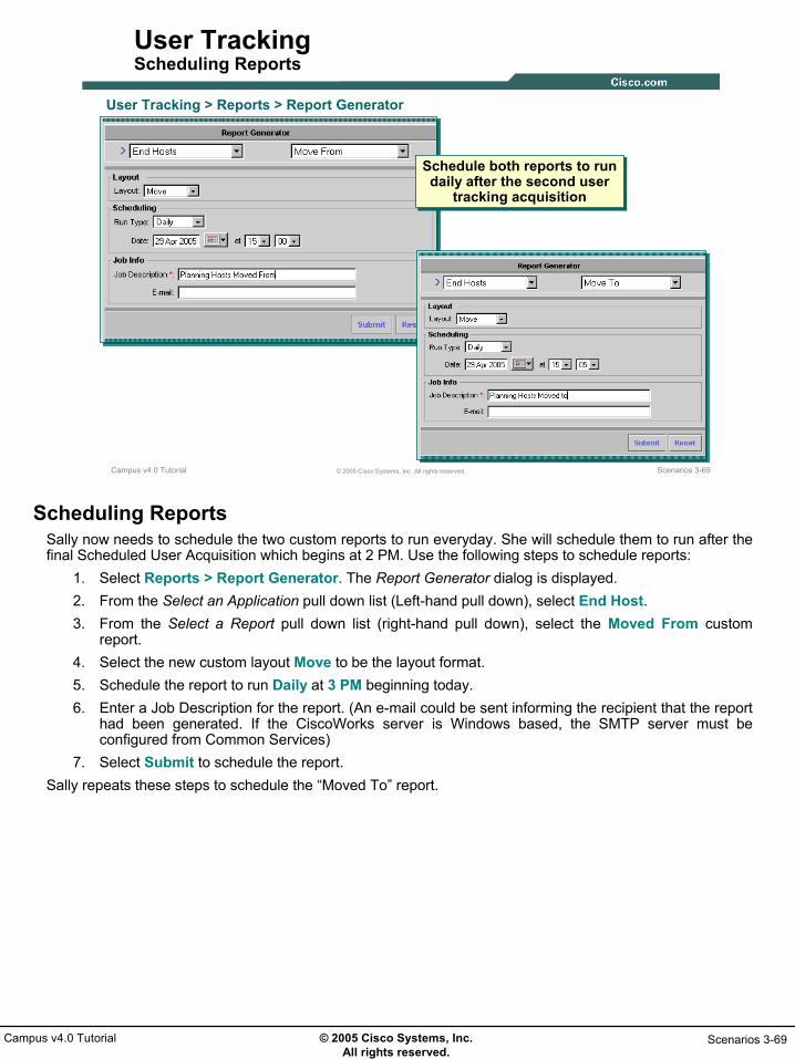
© 2005 Cisco Systems, Inc. All rights reserved.
Scenarios 3-69Campus v4.0 Tutorial
Scenarios 3-69© 2005 Cisco Systems, Inc. All rights reserved.Campus v4.0 Tutorial
User TrackingScheduling Reports
User Tracking > Reports > Report Generator
Schedule both reports to run daily after the second user
tracking acquisition
Schedule both reports to run daily after the second user
tracking acquisition
Scheduling ReportsSally now needs to schedule the two custom reports to run everyday. She will schedule them to run after the final Scheduled User Acquisition which begins at 2 PM. Use the following steps to schedule reports:
1. Select Reports > Report Generator. The Report Generator dialog is displayed. 2. From the Select an Application pull down list (Left-hand pull down), select End Host. 3. From the Select a Report pull down list (right-hand pull down), select the Moved From custom
report.4. Select the new custom layout Move to be the layout format. 5. Schedule the report to run Daily at 3 PM beginning today. 6. Enter a Job Description for the report. (An e-mail could be sent informing the recipient that the report
had been generated. If the CiscoWorks server is Windows based, the SMTP server must be configured from Common Services)
7. Select Submit to schedule the report.Sally repeats these steps to schedule the “Moved To” report.

© 2005 Cisco Systems, Inc. All rights reserved.
Scenarios 3-70Campus v4.0 Tutorial
Scenarios 3-70© 2005 Cisco Systems, Inc. All rights reserved.Campus v4.0 Tutorial
User TrackingStatus of Report Jobs
User Tracking > Reports > Report Jobs
Verify the jobs are scheduled
Verify the jobs are scheduled
Status of Report JobsTo view the currently scheduled reports, use the Reports > Report Jobs task. This will list both the reports scheduled to run and the status of any report that has already been executed.

© 2005 Cisco Systems, Inc. All rights reserved.
Scenarios 3-71Campus v4.0 Tutorial
Scenarios 3-71© 2005 Cisco Systems, Inc. All rights reserved.Campus v4.0 Tutorial
User TrackingViewing Reports
User Tracking > Reports > Archives
Archived ReportsArchived Reports
Viewing ReportsTed can now view the progress of the Planning Department’s move by viewing the reports everyday using the following steps:
1. Select Reports > Archives. The Archives dialog is displayed listing all archived reports.2. Ted views a report by selecting the check box next to the report to be viewed and clicking View.
The report opens in a new window. Notice that the report uses the custom layout created providing just enough information for Ted.
Since this is the first day, the “Moved To” report is empty since they have not yet been given the go ahead, but Ted is satisfied with the information and confident that it will provide him with the necessary information to track the move.

© 2005 Cisco Systems, Inc. All rights reserved.
Scenarios 3-72Campus v4.0 Tutorial
Path AnalysisPath Analysis
• Getting Started
• Preparing Campus for Use
• Topology Services
• User Tracking
Path Analysis

© 2005 Cisco Systems, Inc. All rights reserved.
Scenarios 3-73Campus v4.0 Tutorial
Scenarios 3-73© 2005 Cisco Systems, Inc. All rights reserved.Campus v4.0 Tutorial
Path AnalysisVerify Path Exists
I want to make sure the new Planning Department
can still reach the CCM after the move
Let’s use Campus and
run a path analysis
Campus Manager > Path Analysis
Path Analysis – Verify Path ExistsTed is eager to have the move commence, but first wants to make sure that there will still be connectivity to the Cisco Call Manager (CCM) until a new one can be configured and installed in Building B. He asks Sally to use the Path Analysis tool to check connectivity from Building B to the CCM.
1. From the CiscoWorks Homepage, select Campus Manager > Path Analysis. A new window containing no information (gray background) is displayed labeled Path Analysis and a sub-window is also launched that displays the progress toward connecting to the ANI Server. The ANI Server is the process that handles most of the Campus Manager processing. When the connection is complete, this window closes and the contents of the Path Analysis window are displayed.Note:
• If the Java Plug-in version 1.4.2_xx is not installed on the client, the connection window may not open for up to 5 minutes at which time it will ask if you wish to download and install the plug-in from the server. This Plug-in is required for Topology Services and Path Analysis tasks within Campus Manager. (Refer to Chapter 4 for more on system requirements.) If the plug-in is already installed, the connection screen will also take some time to complete as Java applets and classes on downloaded. Subsequent launches of Topology Services or Path Analysis should proceed quicker.
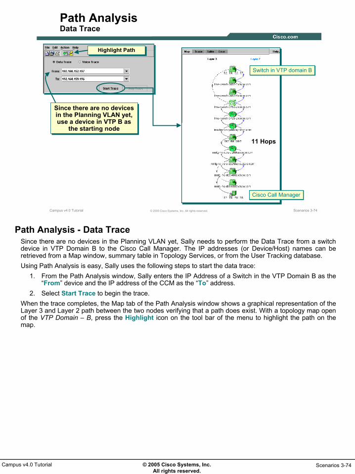
© 2005 Cisco Systems, Inc. All rights reserved.
Scenarios 3-74Campus v4.0 Tutorial
Scenarios 3-74© 2005 Cisco Systems, Inc. All rights reserved.Campus v4.0 Tutorial
Path AnalysisData Trace
Since there are no devices in the Planning VLAN yet, use a device in VTP B as
the starting node
Since there are no devices in the Planning VLAN yet, use a device in VTP B as
the starting node
Highlight PathHighlight Path
Cisco Call ManagerCisco Call Manager
Switch in VTP domain BSwitch in VTP domain B
11 Hops
Path Analysis - Data TraceSince there are no devices in the Planning VLAN yet, Sally needs to perform the Data Trace from a switch device in VTP Domain B to the Cisco Call Manager. The IP addresses (or Device/Host) names can be retrieved from a Map window, summary table in Topology Services, or from the User Tracking database. Using Path Analysis is easy, Sally uses the following steps to start the data trace:
1. From the Path Analysis window, Sally enters the IP Address of a Switch in the VTP Domain B as the “From” device and the IP address of the CCM as the “To” address.
2. Select Start Trace to begin the trace.When the trace completes, the Map tab of the Path Analysis window shows a graphical representation of the Layer 3 and Layer 2 path between the two nodes verifying that a path does exist. With a topology map open of the VTP Domain – B, press the Highlight icon on the tool bar of the menu to highlight the path on the map.

© 2005 Cisco Systems, Inc. All rights reserved.
Scenarios 3-75Campus v4.0 Tutorial
Scenarios 3-75© 2005 Cisco Systems, Inc. All rights reserved.Campus v4.0 Tutorial
Path AnalysisHighlight Path / STP
The VTP B domain window shows the packet path,
with an “extra” hop due to STP root bridge
configuration
The VTP B domain window shows the packet path,
with an “extra” hop due to STP root bridge
configuration
Use STP filter to see current STP configuration
Use STP filter to see current STP configuration
Start TraceStart TraceExtraHop
To Gateway &CCMTo Gateway &CCM
Path Analysis - Highlight Path/STPWhen selecting to highlight the path on a Map, the Layer 2 view, if not already open, is also launched. The path in the VTP Domain shows an extra hop. Sally decides to turn on the STP filter to explain this behavior. Since this trace took place across the default VLAN, Sally selects the default VLAN to display the STP. Sure enough, the root bridge selection explains why this path was chosen.

© 2005 Cisco Systems, Inc. All rights reserved.
Scenarios 3-76Campus v4.0 Tutorial
Scenarios 3-76© 2005 Cisco Systems, Inc. All rights reserved.Campus v4.0 Tutorial
Path AnalysisSTP Recommendation Report
RecommendedRoots
RecommendedRoots
RecommendedRoot – Least CostRecommended
Root – Least Cost
STP Recommendation ReportAs highlighted in Chapter 2, Campus includes a number of reports to help determine the optimal configuration for STP. Campus supports all three popular forms of spanning tree – per VLAN (PSTP), Cisco’s multiple instance STP (MISTP), and the IEEE standard for multiple instances of spanning tree (IEEE 802.1s). STP Recommendation Reports include:
• The Optimal Root Recommendation Report allows you to compute the optimal root in a switch cloud running Per VLAN STP, Cisco MISTP, or IEEE 802.1s.
• The Instances Reduction Recommendation Report allows you to compute the number of instances in a Switch Cloud running Cisco MISTP or IEEE 802.1s.
• The Number of Instances Recommendation Report allows you to compute the number of instances in a switch cloud running Cisco MISTP or IEEE 802.1s.
• The VLAN to Instance Mapping Recommendation Report allows you to compute the optimum number of VLANs to instances in a switch cloud running Cisco MISTP or IEEE 802.1s.
Running the STP Recommendation Report allows the user to computer the optimal root based on Least Depth, Cost, or Traffic. Least Depth computes depth from each node in the switch cloud. Chooses the root in a manner such that the spanning tree so formed has minimum depth. Least Cost computes depth from each node in the switch cloud. It computes maximum edge node cost for all the nodes by assuming current node as root node. The node with minimum value for maximum edge node is considered the optimal root. Traffic Data computes a spanning tree which provides optimal path for given percentage of traffic or selected nodes given a NAM or Netflow Collector.As illustrated, the Optimal Root Recommendation Report show the preferred root bridges based on least depth and least cost.

© 2005 Cisco Systems, Inc. All rights reserved.
Scenarios 3-77Campus v4.0 Tutorial
Scenarios 3-77© 2005 Cisco Systems, Inc. All rights reserved.Campus v4.0 Tutorial
Path AnalysisSTP Configuration Report – Change Root Bridge
Select the SwitchCloud that is the same as VTP
domain B(SwitchCloud renamed)
Select the SwitchCloud that is the same as VTP
domain B(SwitchCloud renamed)
Spanning Tree Configuration launched in respect to
SwitchCloud view
Spanning Tree Configuration launched in respect to
SwitchCloud view
Path Analysis - Change Root BridgeSally decides to use the STP configuration utility to now change the root bridge for the default VLAN. If this proves to be successful then she can make the change for the Planning VLAN to result in a more efficient path. To change the STP configuration for the default VLAN in VTP Domain B use the following steps:
1. Launch Topology Services from the CiscoWorks Homepage if not already open.2. The STP configuration task is launched against a Switch Cloud view. Expand the Network Views
category and then expand the LAN Edge View category. All interconnected devices at layer 2 will be displayed and labeled as a Switch Cloud. Find the Switch Cloud that corresponds to VTP domain B, right-click the icon and select Rename from the pop-up menu. Enter a new descriptive name for the view (i.e. Bldg B).
3. With the proper Switch Cloud view highlighted, select Reports > Spanning Tree Configuration from the window menu.

© 2005 Cisco Systems, Inc. All rights reserved.
Scenarios 3-78Campus v4.0 Tutorial
Scenarios 3-78© 2005 Cisco Systems, Inc. All rights reserved.Campus v4.0 Tutorial
Path AnalysisSTP Configuration Report – Change Root Bridge(Continue …)
Select the default VLAN(One STP instance per VLAN)
Select the default VLAN(One STP instance per VLAN)
Lower the priority of the 3750 to force it to be the
new root bridge
Lower the priority of the 3750 to force it to be the
new root bridge
Turn off Read-Only to allow for STP
configuration change
Turn off Read-Only to allow for STP
configuration change
Current root bridge selection resulted in extra hopCurrent root bridge selection resulted in extra hop
Change Root Bridge (Continue …)4. The Spanning Tree Configuration dialog is displayed in a new window. Make sure the Spanning
Tree Type is set to PVST and click the Select button on the right-hand side of the dialog.5. The Select Instance pop-up window is displayed. Select the default VLAN and click Select. The
window now lists the STP configuration for all devices in VTP Domain B for the default VLAN.6. Select the Device tab. Un-select the Read-Only check box to allow for STP configuration. Highlight
the 3750 that is to become the root bridge.7. The editable field are displayed in the Edit Here portion of the dialog. Lower the Priority value to
force this device to become the root bridge. Note that the priority value is a combination of priority and the VLAN index. The priority portion of the variable is the upper 4 bits and the VLAN index is the lower 12 bits. Therefore, acceptable values are multiples of 4096 plus the VLAN index. In the case, choose the priority to be 16384 plus VLAN ID 1 equals 16385.
8. Select Configure to make the STP parameter change.

© 2005 Cisco Systems, Inc. All rights reserved.
Scenarios 3-79Campus v4.0 Tutorial
Scenarios 3-79© 2005 Cisco Systems, Inc. All rights reserved.Campus v4.0 Tutorial
Path AnalysisData Trace 2
Re-do the Path Analysis to see if the changes provide
a more favorable path
Re-do the Path Analysis to see if the changes provide
a more favorable path
Cisco Call ManagerCisco Call Manager
Switch in VTP domain BSwitch in VTP domain B
10 Hops
Path Analysis - Data Trace 2Before running a repeat of the original trace, Sally again selects all devices in the VTP Domain – B view, and performs a data collection on them to retrieve the new STP configuration information. From the Path Analysis window, Sally simple uses the pull-down lists for the From and To list to select the IP addresses used for the original trace and then selects Start Trace.Sally notes there is one less hop, and now selects the Highlight Path button to verify that the Spanning Tree change has resulted in a shorter path.

© 2005 Cisco Systems, Inc. All rights reserved.
Scenarios 3-80Campus v4.0 Tutorial
Scenarios 3-80© 2005 Cisco Systems, Inc. All rights reserved.Campus v4.0 Tutorial
Path AnalysisHighlight Path/STP
Changing the root bridge makes for a more
favorable path
Changing the root bridge makes for a more
favorable path
Path Analysis - Highlight Path/STPThe highlighted path in the VTP Domain – B map window confirms that the new spanning tree resulted in a more favorable path. Sally also uses the Spanning Tree filter to see the STP states in the new spanning tree.Now that Sally realizes that changing the root bridge to the 3750 will always result in a better path between VLANs in VTP Domain B and also to destinations outside the VTP Domain (the path between devices in the same VLAN within the VTP domain, however, may require an additional hop), she goes ahead and repeats the STP configuration steps except for selecting the Planning VLAN instead of the default VLAN.

© 2005 Cisco Systems, Inc. All rights reserved.
Scenarios 3-81Campus v4.0 Tutorial
Thank You!
Continue on to Chapter 4 to learn about some of the system administration tasks not yet discussed.

© 2005 Cisco Systems, Inc. All rights reserved.
Scenarios 3-82Campus v4.0 Tutorial
• <Intentionally Blank>

© 2005 Cisco Systems, Inc. All rights reserved.
System Admin 4-1Campus v4.0 Tutorial
Chapter 4Chapter 4
Campus Manager v4.0Campus Manager v4.0System AdministrationSystem Administration

© 2005 Cisco Systems, Inc. All rights reserved.
System Admin 4-2Campus v4.0 Tutorial
System Admin 4-2© 2005 Cisco Systems, Inc. All rights reserved.Campus v4.0 Tutorial
Chapter 4 Outline
• System Requirements- Server
- Client
• Installation Guidelines
• Campus Manager Administration
• Troubleshooting
Chapter 4 OutlineThis chapter starts out by covering some basic requirements for both the CiscoWorks server, hosting the Common Services v3.0 and Campus Manager v4.0 software, and the client workstation used to access the CiscoWorks applications. The next section in this chapter highlights key information for installing CiscoWorks Common Services and Campus Manager. For detailed installation procedures or information on upgrading from previous versions of Campus Manager, refer to the Installation and Setup Guide or the LMS Getting Started Guide. A link to these guides can be found in Chapter 5.The next section briefly covers some remaining administrative maintenance tasks that are optionally, but allow the system administrator to customize or fine-tune the overall configuration of Campus Manager and optionally configure Common Services to integrate with Cisco Secure ACS for authorization and authentication of tasks.And finally, some common troubleshooting tips are summarized at the end of this chapter for common issues that may arise while using Campus Manager.

© 2005 Cisco Systems, Inc. All rights reserved.
System Admin 4-3Campus v4.0 Tutorial
System RequirementsSystem Requirements
System Requirements
• Installation Guidelines
• Campus Administration
• Troubleshooting

© 2005 Cisco Systems, Inc. All rights reserved.
System Admin 4-4Campus v4.0 Tutorial
System Admin 4-4© 2005 Cisco Systems, Inc. All rights reserved.Campus v4.0 Tutorial
Server RequirementsWindows Platform
* Campus Manager v4.0 requires Common Services v3.0 to be installed first. Installing additional CiscoWorks applications on the same server may require additional resources.
Network Size /Clients
Less than500 network devices
And 1 client connected at a time
Platform / CPUMemory (RAM) & Virtual Memory Disk Space
1G Hz or better Pentium processor
• 2 GB RAM
• 4 GB Virtual Memory
80 GB hard disk (NTFS format)
16 MB in Windows temporary directory
Common Services v3.0 and Campus Manager v4.0*
1G Hz or betterMulti-processor
• 4 GB RAM
• 8 GB Virtual Memory
Greater than500 network devices
Or more than 1 client connected at a time
80 GB hard disk (NTFS format)
16 MB in Windows temporary directory
Windows Server RequirementsTwo different types of software licenses are available for LMS, restricted and unrestricted. The restricted license will allow CiscoWorks to manage up to 300 devices. The unrestricted license allows for CiscoWorks to manage an unlimited number of devices, theoretically.The server resources required for Campus Manager depends on how many devices the server will be managing and how many clients will be accessing the server for information. The above chart provides minimum system requirements for a Windows server for several usage scenarios based on the number of managed devices and connected clients. Note(s):
• It should be noted that the system configurations above are for a CiscoWorks server with Common Services and Campus Manager only. Installing additional CiscoWorks applications may require additional resources.
• Common Services v3.0 must be installed prior to all CiscoWorks LMS v2.5 applications.• As far as the physical disk drive, the Common Services and Campus Manager software requires only
4 GB of disk space. Additional disk space is required for collected device data and paging space. For security and space reasons, the hard disk must be formatted as NTFS.
• Always check the latest CiscoWorks release notes for up-to-date information regarding system requirements.

© 2005 Cisco Systems, Inc. All rights reserved.
System Admin 4-5Campus v4.0 Tutorial
System Admin 4-5© 2005 Cisco Systems, Inc. All rights reserved.Campus v4.0 Tutorial
Server Requirements, Continue …Windows Platform
- Windows Operating System (only US-English and Japanese versions)• Windows 2000 Professional or Server with Service Pack 3 or later; Terminal
Services can be enabled in Remote Admin mode only or• Windows 2003 Server and Enterprise Edition; Terminal Services can be
enabled in Remote Admin mode only or• Windows Advanced Server (without enabling Terminal Service)• ODBC Driver Manager 3.5.10 or later• Do no install CiscoWorks on a system configured as a primary or backup
domain controller; Do not install CiscoWorks in an encrypted directory.
- Browser (optional; required to access CiscoWorks from server platform)• Microsoft Internet Explorer 6.0.26 and Microsoft Internet Explorer 6.0.28. • Java Virtual Machine (JVM) 5.0.0.3802 and later, and Java Plug-in version
1.4.2_04 or 1.4.2_06 (see notes).
Windows Server RequirementsCampus Manager is tested and supported for a finite number of system configurations. The previous page detailed minimum hardware requirements and this page lists the software and configuration requirements.Campus Manager is supported on Windows 2000 Professional and Server with Service Pack 3 or later. Additionally, Windows 2003 Server and Enterprise Editions are supported. Using only these operating systems, you can install Common Services on a system with Terminal Services enabled in Remote Administration mode only; Terminal Services enabled in Application mode is not supported. If you have a enabled Terminal Server in Application mode, disable the Terminal Server, reboot the system, and start the installation again. Windows Advanced Server is also supported; however, Terminal Services must be disabled. If you have a enabled Terminal Server, disable the Terminal Server, reboot the system, and start the installation again. The only other system software required is ODBC Driver Manager 3.5.10.When configuring the CiscoWorks server, do not configure the server as a primary or backup domain controller and do not install CiscoWorks in an encrypted directory.Browser Requirements On the CiscoWorks server, a web browser is not required. It can be installed, if a user wishes to access CiscoWorks directly from the server platform. Note(s):
• A vulnerability in the Java Plug-in 1.4.2_04 may allow an untrusted applet to escalate privileges, through JavaScript calling into Java code, including reading and writing files with the privileges of the user running the applet. For more details, refer Sun Alert ID: 57591. This is fixed in Java Plug-in 1.4.2_06.
• CiscoWorks neither exploits nor is impacted by this vulnerability. If you choose to use Sun Java Plug-in 1.4.2_06 instead of the one provided in Campus Manager (1.4.2_04), you can choose the plug-in manually.
• To modify your CiscoWorks installation to use Sun Java Plug-in 1.4.2_06, refer to Campus Manager Install Guide.

© 2005 Cisco Systems, Inc. All rights reserved.
System Admin 4-6Campus v4.0 Tutorial
System Admin 4-6© 2005 Cisco Systems, Inc. All rights reserved.Campus v4.0 Tutorial
Server RequirementsSolaris Platform
* Campus Manager v4.0 requires Common Services v3.0 to be installed first. Installing additional CiscoWorks applications on the same server may require additional resources.
Network Size /Clients
Less than500 network devices
And 1 client connected at a time
Platform / CPUMemory (RAM) & Swap Space Disk Space
Sun Ultra SPARC IIIi(see notes)
• 2 GB RAM
• 4 GB swap
80 GB hard disk
/tmp must be on swap partition
Common Services v3.0 and Campus Manager v4.0*
• 4 GB RAM
• 8 GB swap
Greater than500 network devices
Or more than 1 client connected at a time
80 GB hard disk
/tmp must be on swap partition
Sun Ultra SPARC10(see notes)
Solaris Server RequirementsThe server resources required for Campus Manager depends on how many devices the server will be managing and how many clients will be connected to the server simultaneously. The above chart provides minimum system requirements for a Solaris server for several usage scenarios based on the number of managed devices and number of concurrent CiscoWorks users or clients. Note(s):
• It should be noted that the system configurations above are for a CiscoWorks server with Common Services v3.0 and Campus Manager v4.0 only. Installing additional CiscoWorks applications may require additional resources.
• As far as the physical disk drive, the Common Services and Campus Manager software requires only 4 GB of disk space. Additional disk space is required for the data collected; thus, an 80 GB hard drive should be sufficient.
• Common Services v3.0 must be installed prior to all CiscoWorks LMS v2.5 applications.• CiscoWorks Common Services also supports Ultra SPARC II, IIi, and IIe and Ultra SPARC III and III
Cu machines. • Always check the latest CiscoWorks release notes and install guides for up-to-date information
regarding system requirements.

© 2005 Cisco Systems, Inc. All rights reserved.
System Admin 4-7Campus v4.0 Tutorial
System Admin 4-7© 2005 Cisco Systems, Inc. All rights reserved.Campus v4.0 Tutorial
Server Requirements, Continue …Solaris Platform
- Solaris Operating System (only US-English and Japanese versions)
• Solaris 2.8, 2.9• Use the showrev -p command to verify that these patches have
been applied.–Recommended and required patches listed in Install Guide–Patch 106292-05 must not be installed
- Browser (optional)• Netscape 7; Use Netscape downloaded only from the Sun site.• Java plug-in version 1.4.2_04 or 1.4.2_06 (see notes)
Solaris Server RequirementsIn the Solaris environment, Campus Manager has currently only been tested and certified to run on US-English and Japanese versions of Solaris 2.8 or 2.9. The installation and setup guide lists the required and recommended Sun patches. A link to this guide can be found in Chapter 5.
Web Browser / Java Notes• Obtain Netscape 7 only from the Sun web site. • Both Java Plug-in 1.4.2_04 and 1.4.2_06 are supported. However, a vulnerability in the Java Plug-in
1.4.2_04 may allow an untrusted applet to escalate privileges, through JavaScript calling into Java code, including reading and writing files with the privileges of the user running the applet. For more details, refer Sun Alert ID: 57591. This is fixed in Java Plug-in 1.4.2_06.
• CiscoWorks neither exploits nor is impacted by this vulnerability. If you choose to use Sun Java Plug-in 1.4.2_06 instead of the one provided in Campus Manager (1.4.2_04), you can choose the plug-in manually.
• To modify your CiscoWorks installation to use Sun Java Plug-in 1.4.2_06, refer to the Campus Manager Install Guide.

© 2005 Cisco Systems, Inc. All rights reserved.
System Admin 4-8Campus v4.0 Tutorial
System Admin 4-8© 2005 Cisco Systems, Inc. All rights reserved.Campus v4.0 Tutorial
Client RequirementsSystem Hardware
(One of the listed)• IBM PC Compatible, 300 MHz Pentium or better• Sun UltraSparc IIIi or better
Color Monitor with video card set to 24-bits color depth
Memory • 512 MB or more - Set virtual memory / swap space to twice the size of RAM
System Software(one of the listed)
• Windows 2000 SP3 • Windows 2000 Professional or Server SP4• Windows XP SP1 or 2• Windows 2003 Server and Enterprise edition without terminal
services• Solaris 2.8 or 2.9
Browser(One of the listed)
• Windows • 2000/XP – Microsoft IE 6.0.26 or 6.0.28• 2003 – Microsoft IE 6.0.3790.0• Netscape Navigator 7.1• Mozilla 1.7
• Solaris • Netscape Navigator 7.0 • Mozilla 1.7
Java plug-in version 1.4.2_04 or 1.4.2_06 (see notes)Java
Client RequirementsAccess to the installed CiscoWorks applications is achieved using a standard web browser. On Windows based platforms, CiscoWorks has been tested and certified using Microsoft Internet Explorer (6.0.26 and 6.0.28 for Windows 2000/XP and 6.0.3790.0 for Windows 2003), Netscape Navigator 7.1, and Mozilla 1.7. Solaris based platforms running US-English or Japanese versions of Solaris 2.8 or 2.9 can use Netscape Navigator 7.0 or Mozilla 1.7. Client systems should have at least 512 MB of memory or more; and configure the virtual memory / swap space twice that of the installed RAM.Web Browser / Java Notes:
• Obtain Netscape 7 only from the Sun web site. • Both Java Plug-in 1.4.2_04 and 1.4.2_06 are supported. However, a vulnerability in the Java Plug-in
1.4.2_04 may allow an untrusted applet to escalate privileges, through JavaScript calling into Java code, including reading and writing files with the privileges of the user running the applet. For more details, refer Sun Alert ID: 57591. This is fixed in Java Plug-in 1.4.2_06.
• CiscoWorks neither exploits nor is impacted by this vulnerability. If you choose to use Sun Java Plug-in 1.4.2_06 instead of the one provided in Campus Manager (1.4.2_04), you can choose the plug-in manually.
• To modify your CiscoWorks installation to use Sun Java Plug-in 1.4.2_06, refer to the Campus Manager Install Guide.
Additional Note(s):• It is always a good idea to check the latest CiscoWorks release notes for up-to-date information
regarding client requirements.• Client platforms not conforming to the above requirements may also work, but have not been tested
and certified by Cisco and therefore will not be supported should problems arise.

© 2005 Cisco Systems, Inc. All rights reserved.
System Admin 4-9Campus v4.0 Tutorial
Installation GuidelinesInstallation Guidelines
• System Requirements
Installation Guidelines
• Campus Administration
• Troubleshooting
© 2005 Cisco Systems, Inc. All rights reserved.
System Admin 4-10Campus v4.0 Tutorial
System Admin 4-10© 2005 Cisco Systems, Inc. All rights reserved.Campus v4.0 Tutorial
Installation Guidelines
• Use Administrator (Windows) or Root (Solaris) accounts
• If installing CiscoWorks applications on multiple servers, synchronize clocks on servers
• Install Common Services (CS) v3.0 first- Reboot Machine
• Campus installed in same directory as CS
• Refer to LMS v2.5 Quick Start Guide for installation procedure
- License file required
Installation RequirementsInstallation of Campus Manager should be performed according to the steps detailed in the Installation and Setup Guide. (A link to this guide can be found in Chapter 5.) It should be noted, however, that Campus Manager is not a stand-alone application. Like all CiscoWorks applications, Campus Manager depends on services supplied by the Common Services software. Therefore, prior to installing Campus Manager, Common Services should first be installed and the machine rebooted. Campus Manager will be installed in the same directory selected for Common Services. All CiscoWorks applications should be installed using the root user account on Solaris platforms or the Administrator (not a cloned account) user account on Windows platforms.Additionally, if the applications within CiscoWorks LMS is split between multiple servers, synchronize the clock on the servers so that the sharing of information using security certificates works properly.And finally, starting with LMS v2.5, CiscoWorks applications require a license file to be installed to work efficiently. The licensing mechanism is discussed next.
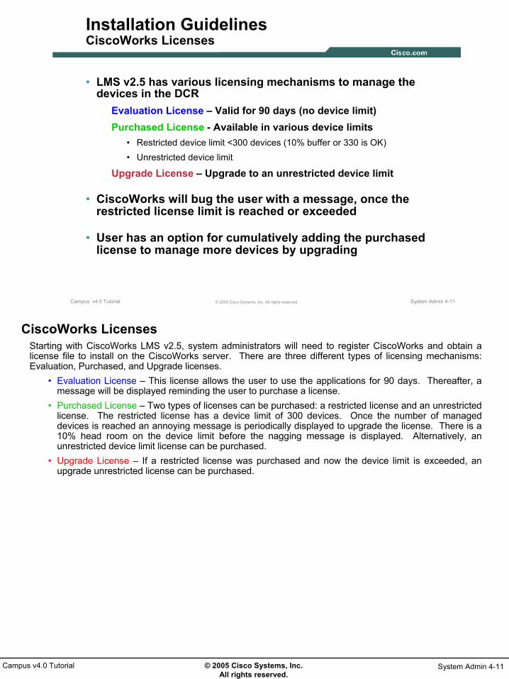
© 2005 Cisco Systems, Inc. All rights reserved.
System Admin 4-11Campus v4.0 Tutorial
System Admin 4-11© 2005 Cisco Systems, Inc. All rights reserved.Campus v4.0 Tutorial
Installation GuidelinesCiscoWorks Licenses
• LMS v2.5 has various licensing mechanisms to manage the devices in the DCR
Evaluation License – Valid for 90 days (no device limit)Purchased License - Available in various device limits
• Restricted device limit <300 devices (10% buffer or 330 is OK)• Unrestricted device limit
Upgrade License – Upgrade to an unrestricted device limit
• CiscoWorks will bug the user with a message, once the restricted license limit is reached or exceeded
• User has an option for cumulatively adding the purchased license to manage more devices by upgrading
CiscoWorks LicensesStarting with CiscoWorks LMS v2.5, system administrators will need to register CiscoWorks and obtain a license file to install on the CiscoWorks server. There are three different types of licensing mechanisms: Evaluation, Purchased, and Upgrade licenses.
• Evaluation License – This license allows the user to use the applications for 90 days. Thereafter, a message will be displayed reminding the user to purchase a license.
• Purchased License – Two types of licenses can be purchased: a restricted license and an unrestricted license. The restricted license has a device limit of 300 devices. Once the number of managed devices is reached an annoying message is periodically displayed to upgrade the license. There is a 10% head room on the device limit before the nagging message is displayed. Alternatively, an unrestricted device limit license can be purchased.
• Upgrade License – If a restricted license was purchased and now the device limit is exceeded, an upgrade unrestricted license can be purchased.

© 2005 Cisco Systems, Inc. All rights reserved.
System Admin 4-12Campus v4.0 Tutorial
System Admin 4-12© 2005 Cisco Systems, Inc. All rights reserved.Campus v4.0 Tutorial
Installation Guidelines Upgrading to Campus Manager v4.0
• Upgrade is supported from Campus Manager v3.2 and v3.3• Remote Upgrade is replaced with Backup / Restore• Refer to LMS v2.5 Data Migration Guidelines document• ANI Discovery is now called Device Discovery; file formats
and filenames have also changed– All properties related to Device Discovery will be moved to
DeviceDiscovery.properties from ANIServer.properties– SNMP credentials ( RO, retries, timeouts) will be moved to
discoverysnmp.conf from anisnmp.conf– Campus uses write community from DCR. User must update DCR
with correct Write Community string for configuration tasks– SNMP retries & timeouts alone will be moved to
datacollectionsnmp.conf from anisnmp.conf
Upgrading to Campus Manager v4.0System administrators can upgrade to Campus Manager 4.0 both from Campus Manager v3.3 and Campus Manager v3.2. Campus Manager v4.0 requires CiscoWorks Common Services v3.0, which is the foundation for the CiscoWorks family of products. You must upgrade to CiscoWorks Common Services v3.0 before installing or upgrading to Campus Manager v4.0. When CiscoWorks Common Services v3.0 is installed, the previous version of Campus Manager database is preserved. When Campus Manager v4.0 is then installed, certain data from the previous database is converted to Campus Manager v4.0 format. This data includes:
• Seed devices• SNMP community strings• Discovery schedule• User Tracking manually entered data fields• User Tracking queries and layouts• Path preferences• Job schedule• Topology groups
Additionally, many file formats and file names have changed in this release. For example, ANI Discovery has been renamed to Device Discovery; thus, several filenames have changed as well (illustrated above).
Note(s):• Refer to LMS v2.5 Data Migration Guidelines document on exact procedures for remote and local
migration of earlier LMS releases to LMS v2.5.• Cross platform backup/restore is NOT supported. That is, you cannot backup or restore from a Solaris
installation of LMS to a Windows installation and vice-versa.

© 2005 Cisco Systems, Inc. All rights reserved.
System Admin 4-13Campus v4.0 Tutorial
Campus AdministrationCampus Administration
• System Requirements
• Installation Guidelines
Campus Administration
• Troubleshooting

© 2005 Cisco Systems, Inc. All rights reserved.
System Admin 4-14Campus v4.0 Tutorial
System Admin 4-14© 2005 Cisco Systems, Inc. All rights reserved.Campus v4.0 Tutorial
Campus AdministrationPost Installation Steps
• Check for updates to Common Services and Campus Manager• Common Services
– Register applications (required in a multi-server environment)
– Add devices and credentials to DCR (One method is using Campus Manager)
– Create users and assign user roles – Optionally, integrate with Cisco Secure ACS
• Campus Manager– Configure the device discovery setting– Add/Edit/Verify Device Credentials – Schedule updates to discover devices, collect device information, and
User Tracking data
Post Installation StepsThe first step after installing the products is to check for any updates that are on-line at Cisco.com. CiscoWorks Product Updates panel, on the CiscoWorks desktop, is located at the lower right corner of the page. It displays informative messages about CiscoWorks product announcements, and help related topics. If you click the More Updates link, a popup window appears with all the Cisco Product Update details. (Refer to next page for more details.) Common Services, the backbone to all CiscoWorks applications, should be fine-tuned first. If the applications on the LMS bundle have been split up onto multiple servers, register the remote applications with Common Services. Secondly, add the devices to the CiscoWorks Device and Credentials Repository. This can be done in a number of ways as noted earlier in the tutorial. One of these ways is to have Campus discovery them. Additionally, create user accounts and assign user roles. Authentication and authorization of tasks can be customized by optionally using Cisco Secure ACS. (Refer to more information on this topic later in this section of the tutorial.)

© 2005 Cisco Systems, Inc. All rights reserved.
System Admin 4-15Campus v4.0 Tutorial
System Admin 4-15© 2005 Cisco Systems, Inc. All rights reserved.Campus v4.0 Tutorial
Campus AdministrationCheck for Software Updates
Additional ways to retrieve software
updates
Additional ways to retrieve software
updatesCampus Manager
Check for Software UpdatesFrom time to time, updates to all CiscoWorks applications are made available on Cisco.com. Typically, Incremental Device Updates (IDUs) are made available every 3 months. The CiscoWorks Home Page provides numerous ways to retrieve these updates:
• The lower right hand corner of the home page presents CiscoWorks Product Update notes with a link to all available updates.
• The Resource section of the home page (upper right-hand corner) contains a link to all CiscoWorks Software including updates.
• The Common Services Software Center contains a Software Update task. Selecting this task will display the currently installed CiscoWorks applications and a mechanism to retrieve updates.
Note(s):• Incremental Device Updates (IDUs)can be downloaded from Cisco.com at:
http://www.cisco.com/cgi-bin/tablebuild.pl/cw2000-campus• If the Common Services server is behind a firewall, the proxy settings are used to download messages
from Cisco.com. CiscoWorks Homepage provides an Admin user interface to accept the proxy settings. CiscoWorks Homepage alerts you if any urgent messages are found. By default, the polling interval is one minute. You can change the polling interval.

© 2005 Cisco Systems, Inc. All rights reserved.
System Admin 4-16Campus v4.0 Tutorial
System Admin 4-16© 2005 Cisco Systems, Inc. All rights reserved.Campus v4.0 Tutorial
Campus AdministrationDiscovery Status and Settings
Status of all three data discovery
processes
Configure the data discovery processes
1. Device Discovery
2. Data Collection
3. User Tracking Acquisition
Campus Manager > Administration
Campus Manager – Discovery Status and SettingsBy selecting Campus Manager->Administration, from the CiscoWorks desktop, system administrators can either check the status or the results of the data collection processes or configure the Campus discovery settings and schedules. The three discovery processes are: Device Discovery, Data Collection, and User Tracking Acquisition. Device Discovery Device Discovery lets you discover all the devices in your network. The details of these devices are stored in the Device Credentials Repository (DCR). Using the Device Discovery option you can enter:
• SNMP settings, which allow you to use SNMP v2 or v3, define the SNMP community strings, timeouts, and retry counts per device or device IP ranges using wildcards
• Seed device, which is used to start the discovery of the network by viewing the CDP tables of neighboring devices; also, limit the discovery to specific IP ranges, if desired.
• Periodicity at which Device Discovery is to be run
Data Collection Campus Data Collection collects the device data for the devices discovered. The device list is obtained from the DCR. You need to run data collection, for Campus applications to manage your network. Prior to running data collection make sure that the DCR has all the devices in your network. Using the Campus Data Collection option you can enter:
• SNMP settings, which allow you define SNMP timeouts, and retry counts per device or device IP ranges using wildcards for the collection of device data
• Data collection filters to limit collection to a subset of devices• Periodicity for running data collection
User Tracking AcquisitionUser Tracking Acquisition collects data about end hosts and IP phones. Configure the settings from the User Tracking Admin page. Let’s review the User Tracking Admin page now.

© 2005 Cisco Systems, Inc. All rights reserved.
System Admin 4-17Campus v4.0 Tutorial
System Admin 4-17© 2005 Cisco Systems, Inc. All rights reserved.Campus v4.0 Tutorial
Campus AdministrationDevice Based Logging – Device Discovery
• To assist with troubleshooting, restrict the logging per device for device discovery
• Only (management) IP addresses are accepted with comma separated
Admin> Device Discovery> Debugging Options
Device Based Logging – Device DiscoveryThe last menu option under Device Discovery is to configure or change the Debugging Options for Device Discovery. These settings are helpful when troubleshooting Campus Manager. The parameters allow you to restrict the logging on a per device level for various modules.Note that the log file name is called discovery.log.
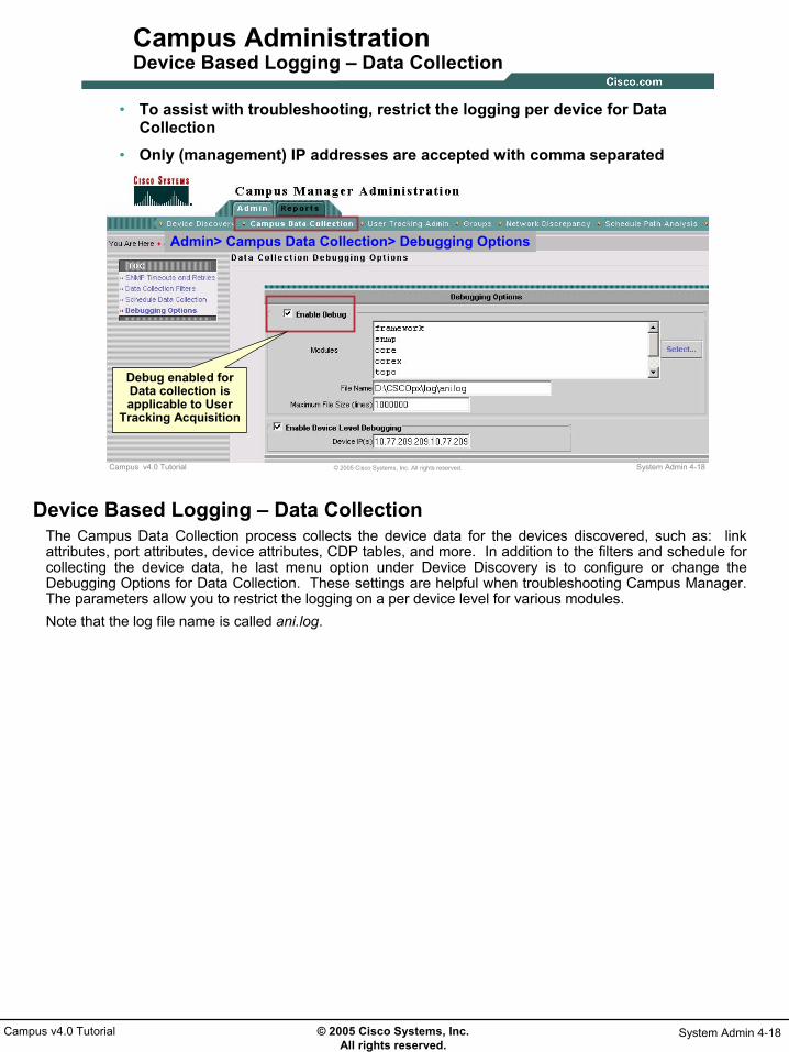
© 2005 Cisco Systems, Inc. All rights reserved.
System Admin 4-18Campus v4.0 Tutorial
System Admin 4-18© 2005 Cisco Systems, Inc. All rights reserved.Campus v4.0 Tutorial
Campus AdministrationDevice Based Logging – Data Collection
• To assist with troubleshooting, restrict the logging per device for Data Collection
• Only (management) IP addresses are accepted with comma separated
Admin> Campus Data Collection> Debugging Options
Debug enabled for Data collection is applicable to User
Tracking Acquisition
Device Based Logging – Data CollectionThe Campus Data Collection process collects the device data for the devices discovered, such as: link attributes, port attributes, device attributes, CDP tables, and more. In addition to the filters and schedule for collecting the device data, he last menu option under Device Discovery is to configure or change the Debugging Options for Data Collection. These settings are helpful when troubleshooting Campus Manager. The parameters allow you to restrict the logging on a per device level for various modules.Note that the log file name is called ani.log.

© 2005 Cisco Systems, Inc. All rights reserved.
System Admin 4-19Campus v4.0 Tutorial
System Admin 4-19© 2005 Cisco Systems, Inc. All rights reserved.Campus v4.0 Tutorial
Campus AdministrationUser Tracking Administration
Campus Manager > Administration
Configure User Tracking:
1. Acquisition settings, schedule, and ping sweeps
2. Report options: Purging policy and display of domain name
3. Import user names & notes for hosts already discovered
Campus Manager – User Tracking AdministrationBy selecting Campus Manager->Administration, from the CiscoWorks desktop, system administrators can either check the status or the results of the data collection processes or configure the Campus discovery settings and schedules. The three discovery processes are: Device Discovery, Data Collection, and User Tracking Acquisition. Device Discovery Device Discovery lets you discover all the devices in your network. The details of these devices are stored in the Device Credentials Repository (DCR). Using the Device Discovery option you can enter:
• SNMP settings, which allow you to use SNMP v2 or v3, define the SNMP community strings, timeouts, and retry counts per device or device IP ranges using wildcards
• Seed device, which is used to start the discovery of the network by viewing the CDP tables of neighboring devices; also, limit the discovery to specific IP ranges, if desired.
• Periodicity at which Device Discovery is to be run
Data Collection Campus Data Collection collects the device data for the devices discovered. The device list is obtained from the DCR. You need to run data collection, for Campus applications to manage your network. Prior to running data collection make sure that the DCR has all the devices in your network. Using the Campus Data Collection option you can enter:
• SNMP settings, which allow you define SNMP timeouts, and retry counts per device or device IP ranges using wildcards for the collection of device data
• Data collection filters to limit collection to a subset of devices• Periodicity for running data collection
User Tracking AcquisitionUser Tracking Acquisition collects data about end hosts and IP phones. Configure the settings from the User Tracking Admin page. Let’s review the User Tracking Admin page now.

© 2005 Cisco Systems, Inc. All rights reserved.
System Admin 4-20Campus v4.0 Tutorial
System Admin 4-20© 2005 Cisco Systems, Inc. All rights reserved.Campus v4.0 Tutorial
Campus AdministrationAuthentication and Authorization
• CiscoWorks has User Roles that restricts Campus users to specific tasks – refer to Permission Report below
• Campus Manager could also use Cisco Secure ACS for Authentication and Authorization, if configured in Common Services
– CM has two type of tasks that are authorized from Cisco Secure ACS• Device specific: Tasks that have device based authorization• Non-Device specific: Tasks that do not need device context for authorization
Common Services -> Server-> Reports-Permission Report
Authentication and Authorization By default, CiscoWorks Common Services uses CiscoWorks Server authentication (CiscoWorks Local) to authenticate users, and authorize them to access CiscoWorks Common Services applications. After authentication, authorization is based on the user role(s) that have been assigned to the user. A privilege is a task or an operation defined within the application. The user role(s) assigned defines the set of privileges, and dictates the extent and type of system access the user has. The privileges can be viewed in the Permission Report.System administrators can use the Cisco Secure Access Control Server (ACS) services to add new users, using a source of authentication other than the native CiscoWorks Server mechanism (that is, the CiscoWorks Local login module). Cisco Secure ACS provides authentication, authorization, and accounting services to network devices that function as AAA clients. Cisco Secure ACS uses the TACACS+ and RADIUS protocols to provide AAA services that ensure a secure environment. In ACS mode, custom roles can be created so that privileges can be fine-tuned based on your business’workflow and needs. That is, create a user, and assign the user with a set of privileges, that would suit his/her needs.

© 2005 Cisco Systems, Inc. All rights reserved.
System Admin 4-21Campus v4.0 Tutorial
System Admin 4-21© 2005 Cisco Systems, Inc. All rights reserved.Campus v4.0 Tutorial
Campus AdministrationIntegration with ACS
• ACS is an alternative security mode in CiscoWorks for authorization & authentication of users
• LMS v2.5 supports ACS v3.2
• New user roles can be created in ACS to fine-tune the CiscoWorks tasks allowed by a user
• Configure ACS after all CiscoWorks applications have been installed
• Refer to Common Services Tutorial or documentation for more information
Integration with ACS - ChecklistIf planning to use ACS, configure it after all CiscoWorks applications are installed. If you have installed an application after configuring the CiscoWorks Login Module to the TACACS+ mode, then the users of that application are not granted any permissions. However, the application is registered to Cisco Secure ACS. Multiple instances of same application using the same ACS server will share settings. Any changes will affect all instances of that application. If an application is configured with ACS and then the application is reinstalled, the application will inherit the old settings. You can create new roles using ACS. The role you create is not shared across all the LMS applications. The role is shared across the same application in different CiscoWorks Servers registered to that particular ACS. You have to create new roles for each of the LMS applications that are running on the CiscoWorks Server. For example: Assume you have configured 10 CiscoWorks Servers with an ACS server and you have created a role in RME (say, RMESU). This role is shared for the RME application that runs on all 10 CiscoWorks Servers.
System Identity User in ACS Mode: There can only be one System Identity User per machine. The System Identity User you configure has to be a Peer Server User. In ACS mode, the System Identity user needs to be configured in ACS, with all the privileges the user has in CiscoWorks.

© 2005 Cisco Systems, Inc. All rights reserved.
System Admin 4-22Campus v4.0 Tutorial
TroubleshootingTroubleshooting
• System Requirements
• Installation Guidelines
• Campus Administration
Troubleshooting

© 2005 Cisco Systems, Inc. All rights reserved.
System Admin 4-23Campus v4.0 Tutorial
System Admin 4-23© 2005 Cisco Systems, Inc. All rights reserved.Campus v4.0 Tutorial
TroubleshootingProcess Management
Common Services > Server > Admin > Processes
View status of all CiscoWorks processes
and start and stop them if necessary
View status of all CiscoWorks processes
and start and stop them if necessary
Process ManagementProcess Management isn’t a Campus Manager task, but a Common Services task used to manage all CiscoWorks processes. In the event something doesn’t quite seem right with Campus Manager, the system administrator should first check the processes to ensure that they are running. If not, they can be restarted, or stopped and restarted, in an attempt to fix the problem. The processes can be viewed by running the Common Services > Server > Admin > Processes task. The Admin task under the Server tab in Common Services also has tasks to run self-tests and collect information on the CiscoWorks server.

© 2005 Cisco Systems, Inc. All rights reserved.
System Admin 4-24Campus v4.0 Tutorial
System Admin 4-24© 2005 Cisco Systems, Inc. All rights reserved.Campus v4.0 Tutorial
Troubleshooting Device Discovery
Issue: Device Discovery not discovering devices or not adding devices to Device and Credentials Repository (DCR)
- Campus Manager Administration -> Reports -> Discovery Report shows if the device is “reachable” or “unreachable”
- Only “reachable” devices will be added to DCR; if unreachable, then check in the SNMP settings page if the community strings are correct for this device.
- SNMP Timeout and retry can be increased if the log file shows any SNMP timeout exceptions
- Check if there are any IP address filters that limit discovery to specific subnets. Only devices that pass through the IP filter are discovered and added to DCR.
- If the CiscoWorks server is integrated with Cisco Secure ACS, then check if same “Common Trust User” is configured in CiscoWorks Server as well as in ACS Server. This user must have System Administrator privileges on CiscoWorks Server.
- Enable debug for “devdiscovery” module and check the device discovery log file for any abnormalities; (refer to previous section: Campus Administration, Device Based Logging)
Troubleshooting – Device DiscoveryOne of the main features of Campus Manager is its ability to discovery the networked Cisco devices. This process of discovering the devices is called Device Discovery. If Device Discovery is not discovering the devices or not adding the devices to the Device and Credentials Repository (DCR), then review these troubleshooting tips.
• Check the Campus Manager Administration -> Reports -> Discovery Report. This report shows if the device is “reachable” or “unreachable”. Note the following:
- Only “reachable” devices will be added to DCR; if unreachable, then check in the SNMP settings page to see if the community strings are correct for this device.
- SNMP Timeout and retry counts can be increased if the log file shows any SNMP timeout exceptions. These settings can be view from the link Campus Manager Administration -> Device Discovery-> SNMP Settings.
• From the link Campus Manager Administration -> Device Discovery-> Discovery Settings, check if there are any IP address filters that limit discovery to specific subnets. Only devices that pass through the IP filter are discovered and added to DCR.
• If CiscoWorks server is integrated with Cisco Secure ACS, then check if same “Common Trust User” is configured in CiscoWorks server as well as in ACS Server. This user must have System Administrator privileges on CiscoWorks server.
• Enable debug for “devdiscovery” module and check the device discovery log file for any abnormalities; (Refer to previous section in tutorial on: Campus Administration, Device Based Logging)

© 2005 Cisco Systems, Inc. All rights reserved.
System Admin 4-25Campus v4.0 Tutorial
System Admin 4-25© 2005 Cisco Systems, Inc. All rights reserved.Campus v4.0 Tutorial
Troubleshooting Device Discovery
Issue: DeviceDiscovery not using devices from DCR for discovery- Check in Campus Manager Administration -> Device
Discovery -> Discovery Settings -> Seed Devices page, whether the seed device field is set to “Undefined_seed”. If so, clear this value and save the empty seed device list so that devices from DCR are considered for discovery.
- Enable debug for “devdiscovery” module and check the log file for any abnormalities (refer to previous section: Campus Administration, Device Based Logging)
Troubleshooting – Device DiscoveryIf the Campus Manager DeviceDiscovery is not using the devices from the DCR for discovery. Check thefollowing areas:
• Go to the Campus Manager Administration -> Device Discovery -> Discovery Settings -> Seed Devices page Check whether the seed device field is set to “Undefined_seed”. If so, clear this value and save the empty seed device list so that devices from DCR are considered for discovery.
• Enable debugging for the “devdiscovery” module and check the log file for any abnormalities. To enable this feature refer to previous section: Campus Administration, Device Based Logging.

© 2005 Cisco Systems, Inc. All rights reserved.
System Admin 4-26Campus v4.0 Tutorial
System Admin 4-26© 2005 Cisco Systems, Inc. All rights reserved.Campus v4.0 Tutorial
Troubleshooting Device Discovery
Issue: DeviceDiscovery not running- Check the process status ( pdshow DeviceDiscovery )
- “Never Started” means that it has not run after the start of daemon manager
- “Transient terminated” means that it has run successfully and completed
- “Program started - No mgt msgs received” means that DeviceDiscovery is currently running
- Check if it is scheduled (Campus Manager Administration -> Device Discovery -> Schedule Discovery)
- DeviceDiscovery process is spawned by ANIServer. So, check the state of ANIServer process. It should be “Running with busy flagset”
- Enable debug for “devdiscovery” module and check the log file for any abnormalities (refer to previous section: Campus Administration, Device Based Logging)
Troubleshooting – Device DiscoveryIf the Campus Manager DeviceDiscovery process does not appear to be running, review the following areas:
• Check the process status ( pdshow DeviceDiscovery ). One of the following status will appear.• “Never Started” means that it has not run after the start of daemon manager• “Transient terminated” means that it has run successfully and completed• “Program started - No mgt msgs received” means that DeviceDiscovery is currently running
• Check if Device Discovery is scheduled. Go to the task Campus Manager Administration -> Device Discovery -> Schedule Discovery and verify settings.
• Since the DeviceDiscovery process is spawned by ANIServer, check the state of the ANIServerprocess. It should be “Running with busy flag set”.
• Enable debug for “devdiscovery” module and check the log file for any abnormalities. To enable debugging, refer to previous section: Campus Administration, Device Based Logging.

© 2005 Cisco Systems, Inc. All rights reserved.
System Admin 4-27Campus v4.0 Tutorial
System Admin 4-27© 2005 Cisco Systems, Inc. All rights reserved.Campus v4.0 Tutorial
Troubleshooting Device Discovery
Issue: Device Discovery takes long time to complete- There are no known issues where Device Discovery hangs or takes
long time to complete
- Performance tests have shown that it takes approximately 15 minutes on a Solaris Sun Fire V210 machine to discover 5000 devices.
- DNS lookup could be one potential area where it can take more time. So, this option can be disabled from Campus Administration -> Device Discovery -> Discovery Settings page and then discovery can be restarted to see if that is the problem.
- Check if any other process is hogging the CPU
- Enable debug for “devdiscovery” module and check the device discovery log file for any abnormalities (refer to previous section: Campus Administration, Device Based Logging)
Troubleshooting – Device DiscoveryThere are no known issues where Device Discovery hangs or takes long time to complete. As a reference point, performance tests have shown that it takes approximately 15 minutes on a Solaris Sun Fire V210 machine to discover 5000 devices. So if it appears that the Campus Device Discovery process is taking a long time to complete, review the following areas:
• DNS lookup could be one potential area where it can take more time. So, this option can be disabled from Campus Administration -> Device Discovery -> Discovery Settings page and then discovery can be restarted to see if that is the problem. If DNS is not properly configured on the CiscoWorks server, then this is most likely the problem.
• Check if any other process is hogging the CPU.• Enable debug for “devdiscovery” module and check the device discovery log file for any abnormalities.
To enable debugging, refer to previous section: Campus Administration, Device Based Logging.

© 2005 Cisco Systems, Inc. All rights reserved.
System Admin 4-28Campus v4.0 Tutorial
System Admin 4-28© 2005 Cisco Systems, Inc. All rights reserved.Campus v4.0 Tutorial
Troubleshooting Data Collection Discovery
Issue: Campus Manager not managing devices- Check if Data Collection is running on schedule.
- Check if device is in DCR; if not, then it will not be managed by Campus.
- Check for IP address filters or VTP Domain filters that limit the devices to be managed in Campus Manager.
- If CiscoWorks Server is integrated with Cisco Secure ACS, then:- Check if the device is added as a client in the ACS server
- Check if this device is part of the Network Device Group and this group is associated with the “Common Trust User”
- Enable debug for core, corex modules and check the Data Collection log file for any abnormalities (refer to previous section: Campus Administration, Device Based Logging)
Troubleshooting – Data Collection DiscoveryOnce the CiscoWorks DCR is populated with Cisco devices, these devices have been added to Campus, and a Data Collection schedule has been defined, Campus can begin collecting data on the devices. If Campus Manager appears to not be managing the devices, check the following areas.
• Check if Data Collection is running on schedule.• Check if device is in DCR; if not, then it will not be managed by Campus.• Check for IP address filters or VTP Domain filters that limit the devices to be managed in Campus
Manager.• If CiscoWorks is integrated with Cisco Secure ACS, then:
• Check if the device is added as a client in the ACS server • Check if this device is part of the Network Device Group and this group is associated with the
“Common Trust User” • Enable debug for core, corex modules and check the Data Collection log file for any abnormalities. To
enable debugging, refer to previous section: Campus Administration, Device Based Logging.

© 2005 Cisco Systems, Inc. All rights reserved.
System Admin 4-29Campus v4.0 Tutorial
System Admin 4-29© 2005 Cisco Systems, Inc. All rights reserved.Campus v4.0 Tutorial
Troubleshooting User Tracking
Issue: User Tracking cannot discover any users or hosts- Check that devices have been discovered by Topology Services
Issue: User Tracking is not discovering the MAC Addresses/ IP phones
- This information is obtained by reading the CAM or switching table of discovered switches. If the switch has been discovered, there may be a problem with ANI reading the CAM table. (see notes for more information)
FIRST: Ensure that all the associated switch / router devices in the network are first properly discovered in the Topology Services map.
FIRST: Ensure that all the associated switch / router devices in the network are first properly discovered in the Topology Services map.
Troubleshooting – User TrackingIf having troubles with User Tracking, the first thing you should look at is the Topology Map. If the missing device in the map is an Ethernet device, check if it is advertising its existence to its neighboring devices through CDP and verify if the neighboring devices are receiving the advertisements. Below are some common issues that you may experience and possible solutions.
Issue: User Tracking cannot discover any users or hosts. In this case, there may be no information in the ANI database. You must have valid ANI seed device(s) and run an ANI discovery prior to running a User Tracking discovery.
Issue: User Tracking is not discovering the MAC addresses / IP phones. ANI only collects the CAM tables from the switches. If ANI is unable to read the device type, or if the device type is not known by ANI, the discovery has no way of knowing if the device is a router or a switch, and does not attempt to read the CAM table. Check if all the switches in your network are discovered and reachable by ANI and also ensure that ANI was able to determine the device type of your switches. Secondly, select a missing MAC address at random and use the following example to determine where the discovery went wrong: Switch1# show cam dynamic 2/2Thirdly, the SNMPagent on the switch may not be returning the correct information when ANI queries the CAM table through SNMP. Verify if the missing MAC address is present in the BRIDGE-MIB on the device, using the snmpwalk command. Remember to use the VLAN as the community string index to access the BRIDGE-MIB (public@555). If the community string index is not used, the device will only return the CAM table for VLAN1. If the device is not returning the MAC address, you are probably running into a bug in the BRIDGE-MIB code. Try upgrading the switch to the latest software version. Finally, ANI may think that the port that connects the host to the switch is part of the backbone and not an edge port. ANI ignores ports that are connected to other switches. ANI only reads the forwarding tables from ports that are directly connected to a host. If a port has a CDP neighbor, the forwarding information for that port will be ignored. What has happened is that there is a hub between the switch and the host and another CDP enable device is also connected to that hub. To resolve this problem, connect the CDP neighbor to another port.
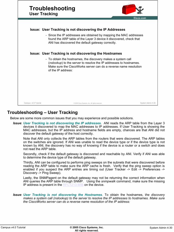
© 2005 Cisco Systems, Inc. All rights reserved.
System Admin 4-30Campus v4.0 Tutorial
System Admin 4-30© 2005 Cisco Systems, Inc. All rights reserved.Campus v4.0 Tutorial
Troubleshooting User Tracking
Issue: User Tracking is not discovering the IP Addresses- Since the IP addresses are obtained by mapping the MAC addresses
found the ARP table of the Layer 3 device it discovered, check that ANI has discovered the default gateway correctly.
Issue: User Tracking is not discovering the Hostnames - To obtain the hostnames, the discovery makes a system call
(nslookup) to the server to resolve the IP addresses to hostnames. Make sure the CiscoWorks server can do a reverse name resolutionof the IP address:
Troubleshooting – User TrackingBelow are some more common issues that you may experience and possible solutions.
Issue: User Tracking is not discovering the IP addresses. ANI reads the ARP table from the Layer 3 devices it discovered to map the MAC addresses to IP addresses. If User Tracking is showing the MAC addresses, but the IP address and hostname fields are empty, chances are that ANI did not discover the default gateway of the host correctly. Note that ANI only collects the ARP tables from the routers that were discovered. The ARP tables on the switches are ignored. If ANI was unable to read the device type or if the device type is not known by ANI, the discovery has no way of knowing if the device is a router or a switch and does not read the ARP table. Secondly, check if the default gateway is discovered and reachable by ANI. Verify if ANI was able to determine the device type of the default gateway. Thirdly, ANI can be configured to performs ping sweeps on the subnets that were discovered before reading the ARP table to make sure the ARP cache is fresh. Verify that the ping sweep option is enabled if you suspect the ARP entries are timing out (User Tracker -> Edit -> Preferences -> Discovery -> Ping Sweep). Lastly, the SNMPagent on the default gateway may not be returning the correct information when ANI queries the ARP table through SNMP. Using the snmpwalk command, make sure the missing IP address is present in the RFC1213-MIB on the device.
Issue: User Tracking is not discovering the Hostnames. To obtain the hostnames, the discovery makes a system call (nslookup) to the server to resolve the IP addresses to hostnames. Make sure the CiscoWorks server can do a reverse name resolution of the IP address:

© 2005 Cisco Systems, Inc. All rights reserved.
System Admin 4-31Campus v4.0 Tutorial
System Admin 4-31© 2005 Cisco Systems, Inc. All rights reserved.Campus v4.0 Tutorial
Troubleshooting User Tracking
Issue: User Tracking is not discovering the Phone Extension
- ANI collects the phone extensions by sending an SNMP request to the Cisco CallManagers that have been discovered. The ANI discovery does not contact the IP phones directly. Therefore, check to see if the CallManager has been discovered and has determined its type.
Issue: User Tracking is not discovering the Usernames on Windows Clients
- Before ANI can discover the user account that is logged into the Windows client, configure and run the UTLiteNT.bat on the client machine.
- Open Task Manager and verify that the UTLite.exe process is still running
- Verify that the Windows clients can send UTLite packets to the CiscoWorks server. By default, UTLite sends the user information to port 16236. Make sure this port is not blocked by an access list or firewall between the Windows client and the CiscoWorks server.
Troubleshooting – User TrackingBelow are some more common issues that you may experience and possible solutions.
Issue: User Tracking is not discovering the IP Phone Extensions. ANI collects the phone extensions by sending an SNMP request to the Cisco CallManagers that have been discovered. The ANI discovery does not contact the IP phones directly. The same troubleshooting tips apply to IP phones as for hosts. Refer to “User Tracking is not discovering the MAC addresses” for more info. And if unable to resolve the IP address of the IP phones, the same troubleshooting tips apply to IP phones as for hosts. Refer to “User Tracking is not discovering the IP addresses” for more info. Additionally, maybe ANI was unable to discover the CallManagers in the network. ANI discovers Cisco CallManager in the same way as other Cisco devices are discovered. Make sure that theCallManagers are sending CDP packets, and verify that the neighboring devices can see theCallManager. Check if all the CallManagers in your network are discovered and reachable by ANI. Verify if ANI was able to determine that the device is a CallManager. And finally, maybe the SNMPagent on the CallManager is not returning the correct information when ANI queries the CCM-MIB. Using snmpwalk, test if you can manually poll the extension table: If the device is not returning the extensions, try upgrading the CallManager to the latest software version.
Issue: User Tracking is not discovering the Usernames on Windows Clients. Before ANI can discover the user account that is logged into the Windows client, you need to configure and run theUTLiteNT.bat on the client machine. Secondly, make sure that the UTLite.exe is still running on the Windows clients using Task Manager. If it is not running, check the login script on your domain controller (User Manager for Domains -> Select the user -> Profile -> Logon Script Name). The logon script should contain a line that executes the UTLiteNT.bat script. Finally, Windows clients are sending the UTLite packets and the CiscoWorks server may not be receiving them. By default, UTLite sends the user information to port 16236 on the CiscoWorks server. Examine the traffic from UTLite to see if it is reaching the server with the help of a Packet Capture software. Make sure this port is not blocked by an access list or firewall between the Windows client and the CiscoWorks server.

© 2005 Cisco Systems, Inc. All rights reserved.
System Admin 4-32Campus v4.0 Tutorial
System Admin 4-32© 2005 Cisco Systems, Inc. All rights reserved.Campus v4.0 Tutorial
Troubleshooting User Tracking
Issue: User Tracking is not discovering the Usernames on UNIX Clients
- ANI uses the rusers command to discover the users on Unix hosts. If the UserName fields are empty for the Unix hosts, try running therusers command manually from the server.
Issue: User Tracking is discovering Duplicate MAC addresses- The host has moved in the network. Therefore, manually delete the oldest
entry by comparing the LastSeen field.
- ANI could have also mistakenly discovered trunk or backbone links as an edge port. In other words, ANI thinks the MAC addresses inthe CAM table of the backbone interface are directly connected to the interface through a hub. To resolve this, note the Device and Port that are listed in User Tracking for each duplicate MAC address and verify the CDP neighbors on that device to see if the port should be configured as a trunk port.
Troubleshooting – User TrackingBelow are some more common issues that you may experience and possible solutions.
Issue: User Tracking is not discovering the Usernames on UNIX Clients. ANI uses the ruserscommand to discover the users on Unix hosts. If the UserName fields are empty for the Unix hosts, try running the rusers command manually:
# rusers host1host1 root
Issue: User Tracking is discovering Duplicate MAC addresses. User Tracking lists duplicate MAC addresses because hosts have moved in the network. User Tracking keeps historical data about the hosts that have been discovered. By default, a discovered host remains in the database forever. If a host moves from one port to another, the host has two entries in User Tracking. You can find out what which entry is the old one and which is the new one by looking at the LastSeenfield.
User Tracking may also list duplicate MAC addresses because the topology was not discovered correctly. ANI discovers hosts by reading the CAM tables from the discovered switches. Because packets get forwarded and flooded over the Layer 2 network, multiple switches learn the MAC address of a host. To avoid duplicate MAC address entries, ANI ignores ports that are connected to other switches. ANI only reads the forwarding tables from ports that are directly connected to a host. ANI finds these end-user ports by looking for CDP neighbors on the ports. If a port has a CDP neighbor, the forwarding information for that port is ignored. If there are no CDP neighbors, the CAM table for that port goes into the User Tracking database. If you are seeing a lot of duplicate MAC addresses in User Tracking, chances are that ANI has mistakenly discovered one of your trunk or backbone links as an edge port. In other words, ANI thinks the MAC addresses in the CAM table of the backbone interface are directly connected to the interface through a hub. To resolve this, note the Device and Port that are listed in User Tracking for each duplicate MAC address and verify the CDP neighbors on that device.

© 2005 Cisco Systems, Inc. All rights reserved.
System Admin 4-33Campus v4.0 Tutorial
System Admin 4-33© 2005 Cisco Systems, Inc. All rights reserved.Campus v4.0 Tutorial
TroubleshootingLog Files and Location
• Log File Location:– Default location for all the logs will be under:
• /var/adm/CSCOpx/log in Solaris and
• $NMSROOT/log in Windows
• Log File Names:– Default discovery log is discovery.log
– Default data collection log is ani.log
– Default User Tracking acquisition log is ut.log
– All User Tracking user interface related logs will be in Cmapps.log
– OGS logs - CampusOGSClient.log, CampusOGSServer.log
– Spanning Tree Protocol (STP) advanced reports log is stpeng.log
Log Files and Locations For troubleshooting purposes, the log files provide a wealth of information that can provide answers to issues that may arise.
The default location for all the logs will be under the following directories.• /var/adm/CSCOpx/log in Solaris• $NMSROOT/log in Windows
There are several log files. The following is a list of processes and their associated log file names.• Default discovery log is discovery.log• Default data collection log is ani.log• Default User Tracking acquisition log is ut.log• All User Tracking user interface related logs will be in Cmapps.log• OGS logs - CampusOGSClient.log, CampusOGSServer.log• Spanning Tree Protocol (STP) advanced reports log is stpeng.log

© 2005 Cisco Systems, Inc. All rights reserved.
System Admin 4-34Campus v4.0 Tutorial
Thank You!
We hope that you have enjoyed using Campus Manager and have found its features to be an important part of your network-management toolkit.
Cisco Systems

CChhaapptteerr 55
CCaammppuuss MMaannaaggeerr vv44..00 RReeffeerreenncceess


Campus v4.0 © 2005 Cisco Systems, Inc References 5-1
Reference Materials Many Cisco reference documents have been created to help users understand the use of the CiscoWorks application, Campus Manager. However, finding help and documentation can often be a challenge. This reference chapter has been created to assist you in your pursuit of additional product information. Below are links to documents and Web pages that provide further details on the Campus Manager product.
• Campus Manager v4.0 Product Information ♦ Data Sheet (URL)
http://www.cisco.com/en/US/partner/products/sw/cscowork/ps563/products_data_sheets_list.html
♦ Quick Start Guide (LMS 2.5) (URL)
http://www.cisco.com/en/US/partner/products/sw/cscowork/ps2425/products_quick_start09186a008036dfa9.html
♦ Installation and Setup Guides (URL)
http://www.cisco.com/en/US/partner/products/sw/cscowork/ps563/prod_installation_guides_list.html
♦ Release Notes (URL)
http://www.cisco.com/en/US/partner/products/sw/cscowork/ps563/prod_release_notes_list.html
♦ User Guide (URL)
http://www.cisco.com/en/US/partner/products/sw/cscowork/ps563/products_user_guide_list.html
♦ Supported Devices (URL)
http://www.cisco.com/en/US/partner/products/sw/cscowork/ps563/products_device_support_tables_list.html
♦ Campus Manager Incremental Device Updates (IDUs) (URL)
http://www.cisco.com/cgi-bin/tablebuild.pl/cw2000-campus
♦ TCP and UDP Ports Used by Campus Manager (URL)
http://www.cisco.com/en/US/partner/products/sw/cscowork/ps563/prod_tech_notes_list.html

Campus v4.0 © 2005 Cisco Systems, Inc Reference 5-2
• Related Material ♦ CiscoWorks User Tracking Utility (Download)
http://www.cisco.com/cgi-bin/tablebuild.pl/cw2000-campus
♦ Data Migration Guidelines (LMS 2.5) (URL)
http://www.cisco.com/en/US/partner/products/sw/cscowork/ps2425/products_quick_start09186a00803ed826.html
♦ CiscoWorks LAN Management Solution (LMS) (URL)
Learn more about CiscoWorks solutions bundled in LMS: www.cisco.com/go/lms/
♦ CiscoWorks Common Service (CCS) v3.0 (URL)
Required for all CiscoWorks applications: http://www.cisco.com/en/US/products/sw/cscowork/ps3996/ps5672/index.html
♦ Cisco’s SNMP Object Navigator (URL)
http://tools.cisco.com/Support/SNMP/do/BrowseOID.do?local=en
♦ Solaris Patches (URL)
To obtain the patches, contact your Sun Microsystems representative or download them from the Sun web site: sunsolve.sun.com/
♦ LMS Documentation (URL) www.cisco.com/en/US/products/sw/cscowork/ps2425/prod_technical_documentation.html
♦ Quick Start Guide
♦ Release Notes
• Online Bug Tracker Search for known problems on the Cisco bug tracking system tool, called Bug Toolkit. To access Bug Toolkit, perform the following steps:
o Click on the link above (www.cisco.com/cgi-bin/Support/Bugtool/launch_bugtool.pl) o Login to Cisco.com o Click Launch Bug Toolkit. o Locate CiscoWorks Device Fault Manager from the list of Cisco Software
Products o Then click Next.

Campus v4.0 © 2005 Cisco Systems, Inc Reference 5-3
• Technical Notes / White Papers ♦ Network Management Systems: Best Practices White Paper (URL)
http://www.cisco.com/en/US/tech/tk869/tk769/technologies_white_paper09186a00800aea9c.shtml
The objective of this paper is to provide some deployment guidelines for all areas of network management: Fault, Configuration, Accounting, Performance, and Security (FCAPS).
♦ CiscoWorks LAN Management Solution White Papers (URL) www.cisco.com/en/US/products/sw/cscowork/ps2425/prod_white_papers_list.html
♦ LMS Deployment Guide
The objective of this paper is to review the steps to properly deploying the LMS suite of applications.
♦ Cost Analysis Using CiscoWorks LAN Management Solution
The CiscoWorks product family can provide a quantifiable financial and IT benefit to an organization, through the automation of routine labor, as well as helping to mitigate network degradation due to device failures. While it is difficult to derive an exact figure of the true and potential cost savings for every customer situation, the Cost Analysis Tool can provide an understanding of the scale of savings involved. At this point, the question that needs to be asked is not "What is the cost of the product?" but "What is the cost of NOT using CiscoWorks?"

Campus v4.0 © 2005 Cisco Systems, Inc Reference 5-4

a.
Chapter Questions
AAsssseessssmmeenntt QQuueessttiioonnss
CCaammppuuss MMaannaaggeerr vv44..00 TTuuttoorriiaall

Campus Manager v4.0 Tutorial
Assessment - 2 © 2005 Cisco System Inc. Campus v4.0 Tutorial

Campus Manager v4.0 Tutorial
Campus v4.0 Tutorial © 2005 Cisco Systems, Inc Assessment - 3
Based on the information in the Campus Manager v4.0 product tutorial, please answer the following questions.
Q1) Cisco has bundled the Campus Manager v4.0 application into CiscoWorks management solutions. Which of the following bundles contain Campus Manager? Choose all that apply.
A) The LAN Management Solution (LMS)
B) The Enterprise Management Solution (EMS)
C) The Small Network Management Solution (SNMS)
D) The CiscoWorks Management Solution (CMS)
E) The WAN Management Solution (WMS)
Q2) Which of the following features does Campus Manager provide? Choose all that apply.
A) Discovers Cisco devices in the network
B) Automates the download of device configuration files to the CiscoWorks archive
C) Displays a graphical topology of Cisco devices in the network
D) Collects information about the end hosts connected to the devices managed by Campus Manager
E) Analyzes the layer 2/ layer 3 paths between the devices managed by Campus Manager
F) Polls, analyzes, and detects faults and performance issues on device interfaces

Campus Manager v4.0 Tutorial
Assessment - 4 © 2005 Cisco System Inc. Campus v4.0 Tutorial
Q3) Which of the following are the three primary applications within Campus Manager? Choose three.
A) Topology Services
B) Device Discovery
C) ANI Server
D) Path Analysis
E) User Tracking
F) Host Acquisition
Q4) Which of the following does Campus Manager require in order for the Device Discovery process to discover the network and populate the DCR? Choose three.
A) Read only and read write community strings configured on the devices
B) Read community string only configured on the devices
C) CDP configured on the network devices or ILMI (for ATM devices)
D) A network baseline to initiate the discovery
E) A VTP or IP address range filter
F) One or more seed devices
Q5) Which Topology Services network view should be used to view all managed Layer 3 Cisco devices with routing capabilities on the network? Choose one.
A) The main window
B) The LAN Edge View
C) The Layer 2 View
D) The Layer 3 View
E) The LAN Switch View
F) The VTP Views

Campus Manager v4.0 Tutorial
Campus v4.0 Tutorial © 2005 Cisco Systems, Inc Assessment - 5
Q6) Campus Manager obtains an end user’s MAC address to switch port mapping using information from which of the following? Choose one.
A) ARP table of a router
B) CAM table of a router
C) CAM table of a switch
D) ARP table of a switch
E) User must manually define this mapping
Q7) Which Campus Manager Topology Services feature allows the user to see a "bird's eye” view or a small window showing the entire network map? Choose one.
A) Zoom in view
B) Zoom out view
C) Panner view
D) Full view
E) Normal view
Q8) When saving network layouts (location of devices and links on the topology map), the layout is saved per CiscoWorks user. Choose one.
A) True
B) False
Q9) If the Campus Device Discovery process is used to populate the CiscoWorks DCR, then the devices discovered will always be managed by Campus as well. Choose one.
A) True
B) False

Campus Manager v4.0 Tutorial
Assessment - 6 © 2005 Cisco System Inc. Campus v4.0 Tutorial
Q10) If a device fails to respond to an SNMP poll by Campus Manager, what happens in Campus Manager? Choose one.
A) The device is removed from all network views
B) The device is removed from the Campus database, but remains in the DCR
C) An email is sent to the network administrator
D) The device is displayed in red in the network views
Q11) The STP Optimal Root Recommendation report can provide the optimal path based on a given percentage of traffic, if which of the following is available in the STP domain? Choose all that apply.
A) Cisco routers configured with IP SLA
B) Network Analysis Module (NAM)
C) NetFlow Collector
D) Distributed sniffers
E) Cisco switches with mini-RMON enabled
Q12) Which of the following reports can help isolate problems with cables in the network having kinks, sharp bends, open or short circuits? Choose one.
A) Device Attributes report
B) Service Module report
C) Link Attributes report
D) Physical Discrepancies report
E) Time Domain Reflectometry report

Campus Manager v4.0 Tutorial
Campus v4.0 Tutorial © 2005 Cisco Systems, Inc Assessment - 7
Q13) Which statements best describe the User Tracking application? Choose all that apply.
A) Obtains information on end-nodes, servers, workstations, or VoIP telephone handsets connected to Cisco hubs that connect to Cisco routers
B) Obtains information on end-nodes, servers, workstations, or VoIP telephone handsets connected to Cisco layer 2 switches
C) Obtains information on end-nodes, servers, workstations, or VoIP telephone handsets connected to Cisco routers
D) All of the above
Q14) Which of the following items are prerequisites for managing the connectivity of end stations using User Tracking? Choose all that apply.
A) The end station must be on-line
B) The end station must be connected to a Cisco layer 2 switch discovered by CiscoWorks
C) The end station must support SNMP
D) The end station must support CDP
E) All of the above
Q15) What type of information can be viewed in the User Tracking display? Choose all that apply.
A) End user’s DNS host name, IP address, and MAC address
B) End user’s subnet / netmask
C) End user’s VTP domain and VLAN membership
D) End user’s device type
E) End user’s operating system or firmware version
F) Name and IP address of the switch that the end node is connected to
G) Port number on the switch that the end node is connected to

Campus Manager v4.0 Tutorial
Assessment - 8 © 2005 Cisco System Inc. Campus v4.0 Tutorial
Q16) The Last Seen field in the User Tracking table describes which of the following? Choose all that apply.
A) The last time an entry for the end node was found in a switching table during the acquisition process
B) The last time the end node transmitted data on the network
C) The last time the end node was polled by User Tracking
D) The time when the end node went offline
Q17) The information in the User Tracking table can be sorted by clicking on a column header. Choose one.
A) True
B) False
Q18) Which User Tracking Violation reports are available to identify duplicate or naming problems in the network? Choose four.
A) Duplicate MAC addresses
B) Duplicate IP addresses
C) Duplicate VTP domain names
D) Duplicate MAC addresses and VLAN names
E) End stations with no hostname
F) Ports with multiple MAC addresses

Campus Manager v4.0 Tutorial
Campus v4.0 Tutorial © 2005 Cisco Systems, Inc Assessment - 9
Q19) Match the User Tracking terminology to its appropriate definition.
_____ 1. Quick Report
_____ 2. Custom Report
_____ 3. Ping Sweep
_____ 4. Catalyst Switch CAM
_____ 5. Cisco router ARP table
_____ 6. DNS
_____ 7. UTLite
_____ 8. Report Generator
_____ 9. User Tracking Utility
_____ 10. DEE
A. Installed on Domain Controller, Novell Server, or Active
Directory to obtain user names
B. Allows for the execution of Duplicates, Custom, All Entry, and Switch Port Usage reports
C. Updates the router ARP and switch CAM tables on known subnets
D. Windows toolbar to quickly query the User Tracking database outside the CiscoWorks user interface
E. Used to map IP addresses to host names
F. Contains MAC addresses of end nodes using the network
G. Used to map MAC addresses to IP addresses
H. Command Line Interface to pull data from the Campus database in XML format
I. Query the database using a field in the database
J. Allows for more granular queries using multiple fields and can be saved for generating reports later

Campus Manager v4.0 Tutorial
Assessment - 10 © 2005 Cisco System Inc. Campus v4.0 Tutorial
Q20) The Report Generator feature in User Tracking allows the user to generator reports in which of the following ways? Choose all that apply.
A) Immediately
B) At a scheduled date and time
C) Periodically
D) All of the above
Q21) Which statements best describe the Path Analysis application? Choose all that apply.
A) Path Analysis illustrates the physical and logical paths that packets take between Cisco-only devices
B) Only Layer 2 switching paths are calculated
C) Layer 2 and 3 switching paths are calculated
D) Specific details on ports speeds can be seen
E) Specific details on link utilization between the hops can be seen
F) Specific details on interface numbers can be seen
G) Path Analysis can be used in IP Telephony networks for tracing VoIP calls and messages to the Cisco Call Manager
Q22) Path Analysis determines the network path of the VoIP in real-time by using what information? Choose all that apply.
A) Information gathered from performing a trace route command
B) SNMP requests to the routing tables in the IP Phones
C) Queries to the User Tracking database
D) Information collected from the Call Records stored in the Cisco Call Manager
E) Information collected from the Voice Health Monitor application

Campus Manager v4.0 Tutorial
Campus v4.0 Tutorial © 2005 Cisco Systems, Inc Assessment - 11
Q23) Path Analysis provides various output formats to display the results of the path trace. Which output format is similar to the trace route command, illustrating response times between hops? Choose one.
A) Map Output
B) Trace Output
C) Table Output
D) None of the above provide response times
Q24) Path Analysis provides various output formats to display the results of the path trace. Which output format displays how Path Analysis got the data? Choose one.
A) Map Output
B) Trace Output
C) Table Output
D) None of the above provide data sources

Campus Manager v4.0 Tutorial
Assessment - 12 © 2005 Cisco System Inc. Campus v4.0 Tutorial

a.
Chapter Questions
AAsssseessssmmeenntt QQuueessttiioonnss && AAnnsswweerrss
CCaammppuuss MMaannaaggeerr vv44..00 TTuuttoorriiaall

Campus Manager v4.0 Tutorial
Answers - 2 © 2005 Cisco System Inc. Campus v4.0 Tutorial
Campus Manager v4.0 Tutorial
Campus v4.0 Tutorial © 2005 Cisco Systems, Inc Answers - 3
Based on the information in the Campus Manager v4.0 product tutorial, please answer the following questions.
Q1) Cisco has bundled the Campus Manager v4.0 application into CiscoWorks management solutions. Which of the following bundles contain Campus Manager? Choose all that apply.
A) The LAN Management Solution (LMS)
B) The Enterprise Management Solution (EMS)
C) The Small Network Management Solution (SNMS)
D) The CiscoWorks Management Solution (CMS)
E) The WAN Management Solution (WMS)
Q2) Which of the following features does Campus Manager provide? Choose all that apply.
A) Discovers Cisco devices in the network
B) Automates the download of device configuration files to the CiscoWorks archive
C) Displays a graphical topology of Cisco devices in the network
D) Collects information about the end hosts connected to the devices managed by Campus Manager
E) Analyzes the layer 2/ layer 3 paths between the devices managed by Campus Manager
F) Polls, analyzes, and detects faults and performance issues on device interfaces

Campus Manager v4.0 Tutorial
Answers - 4 © 2005 Cisco System Inc. Campus v4.0 Tutorial
Q3) Which of the following are the three primary applications within Campus Manager? Choose three.
A) Topology Services
B) Device Discovery
C) ANI Server
D) Path Analysis
E) User Tracking
F) Host Acquisition
Q4) Which of the following does Campus Manager require in order for the Device Discovery process to discover the network and populate the DCR? Choose three.
A) Read only and read write community strings configured on the devices
B) Read community string only configured on the devices
C) CDP configured on the network devices or ILMI (for ATM devices)
D) A network baseline to initiate the discovery
E) A VTP or IP address range filter
F) One or more seed devices
Q5) Which Topology Services network view should be used to view all managed Layer 3 Cisco devices with routing capabilities on the network? Choose one.
A) The main window
B) The LAN Edge View
C) The Layer 2 View
D) The Layer 3 View
E) The LAN Switch View
F) The VTP Views

Campus Manager v4.0 Tutorial
Campus v4.0 Tutorial © 2005 Cisco Systems, Inc Answers - 5
Q6) Campus Manager obtains an end user’s MAC address to switch port mapping using information from which of the following? Choose one.
A) ARP table of a router
B) CAM table of a router
C) CAM table of a switch
D) ARP table of a switch
E) User must manually define this mapping
Q7) Which Campus Manager Topology Services feature allows the user to see a "bird's eye” view or a small window showing the entire network map? Choose one.
A) Zoom in view
B) Zoom out view
C) Panner view
D) Full view
E) Normal view
Q8) When saving network layouts (location of devices and links on the topology map), the layout is saved per CiscoWorks user. Choose one.
A) True
B) False
Q9) If the Campus Device Discovery process is used to populate the CiscoWorks DCR, then the devices discovered will always be managed by Campus as well. Choose one.
A) True
B) False (The devices must be populated from the DCR into Campus in order to be managed by Campus.)

Campus Manager v4.0 Tutorial
Answers - 6 © 2005 Cisco System Inc. Campus v4.0 Tutorial
Q10) If a device fails to respond to an SNMP poll by Campus Manager, what happens in Campus Manager? Choose one.
A) The device is removed from all network views
B) The device is removed from the Campus database, but remains in the DCR
C) An email is sent to the network administrator
D) The device is displayed in red in the network views
Q11) The STP Optimal Root Recommendation report can provide the optimal path based on a given percentage of traffic, if which of the following is available in the STP domain? Choose all that apply.
A) Cisco routers configured with IP SLA
B) Network Analysis Module (NAM)
C) NetFlow Collector
D) Distributed sniffers
E) Cisco switches with mini-RMON enabled
Q12) Which of the following reports can help isolate problems with cables in the network having kinks, sharp bends, open or short circuits? Choose one.
A) Device Attributes report
B) Service Module report
C) Link Attributes report
D) Physical Discrepancies report
E) Time Domain Reflectometry report

Campus Manager v4.0 Tutorial
Campus v4.0 Tutorial © 2005 Cisco Systems, Inc Answers - 7
Q13) Which statements best describe the User Tracking application? Choose all that apply.
A) Obtains information on end-nodes, servers, workstations, or VoIP telephone handsets connected to Cisco hubs that connect to Cisco routers
B) Obtains information on end-nodes, servers, workstations, or VoIP telephone handsets connected to Cisco layer 2 switches
C) Obtains information on end-nodes, servers, workstations, or VoIP telephone handsets connected to Cisco routers
D) All of the above
Q14) Which of the following items are prerequisites for managing the connectivity of end stations using User Tracking? Choose all that apply.
A) The end station must be on-line
B) The end station must be connected to a Cisco layer 2 switch discovered by CiscoWorks
C) The end station must support SNMP
D) The end station must support CDP
E) All of the above
Q15) What type of information can be viewed in the User Tracking display? Choose all that apply.
A) End user’s DNS host name, IP address, and MAC address
B) End user’s subnet / netmask
C) End user’s VTP domain and VLAN membership
D) End user’s device type
E) End user’s operating system or firmware version
F) Name and IP address of the switch that the end node is connected to
G) Port number on the switch that the end node is connected to

Campus Manager v4.0 Tutorial
Answers - 8 © 2005 Cisco System Inc. Campus v4.0 Tutorial
Q16) The Last Seen field in the User Tracking table describes which of the following? Choose all that apply.
A) The last time an entry for the end node was found in a switching table during the acquisition process
B) The last time the end node transmitted data on the network
C) The last time the end node was polled by User Tracking
D) The time when the end node went offline
Q17) The information in the User Tracking table can be sorted by clicking on a column header. Choose one.
A) True
B) False
Q18) Which User Tracking Violation reports are available to identify duplicate or naming problems in the network? Choose four.
A) Duplicate MAC addresses
B) Duplicate IP addresses
C) Duplicate VTP domain names
D) Duplicate MAC addresses and VLAN names
E) End stations with no hostname
F) Ports with multiple MAC addresses

Campus Manager v4.0 Tutorial
Campus v4.0 Tutorial © 2005 Cisco Systems, Inc Answers - 9
Q19) Match the User Tracking terminology to its appropriate definition.
__ I ___ 1. Quick Report
___J __ 2. Custom Report
__ C ___ 3. Ping Sweep
___F __ 4. Catalyst Switch CAM
___G__ 5. Cisco router ARP table
___ E__ 6. DNS
___A__ 7. UTLite
___ B__ 8. Report Generator
___D __ 9. User Tracking Utility
___H __ 10. DEE
A. Installed on Domain Controller, Novell Server, or Active
Directory to obtain user names
B. Allows for the execution of Duplicates, Custom, All Entry, and Switch Port Usage reports
C. Updates the router ARP and switch CAM tables on known subnets
D. Windows toolbar to quickly query the User Tracking database outside the CiscoWorks user interface
E. Used to map IP addresses to host names
F. Contains MAC addresses of end nodes using the network
G. Used to map MAC addresses to IP addresses
H. Command Line Interface to pull data from the Campus database in XML format
I. Query the database using a field in the database
J. Allows for more granular queries using multiple fields and can be saved for generating reports later

Campus Manager v4.0 Tutorial
Answers - 10 © 2005 Cisco System Inc. Campus v4.0 Tutorial
Q20) The Report Generator feature in User Tracking allows the user to generator reports in which of the following ways? Choose all that apply.
A) Immediately
B) At a scheduled date and time
C) Periodically
D) All of the above
Q21) Which statements best describe the Path Analysis application? Choose all that apply.
A) Path Analysis illustrates the physical and logical paths that packets take between Cisco-only devices
B) Only Layer 2 switching paths are calculated
C) Layer 2 and 3 switching paths are calculated
D) Specific details on ports speeds can be seen
E) Specific details on link utilization between the hops can be seen
F) Specific details on interface numbers can be seen
G) Path Analysis can be used in IP Telephony networks for tracing VoIP calls and messages to the Cisco Call Manager
Q22) Path Analysis determines the network path of the VoIP in real-time by using what information? Choose all that apply.
A) Information gathered from performing a trace route command
B) SNMP requests to the routing tables in the IP Phones
C) Queries to the User Tracking database
D) Information collected from the Call Records stored in the Cisco Call Manager
E) Information collected from the Voice Health Monitor application

Campus Manager v4.0 Tutorial
Campus v4.0 Tutorial © 2005 Cisco Systems, Inc Answers - 11
Q23) Path Analysis provides various output formats to display the results of the path trace. Which output format is similar to the trace route command, illustrating response times between hops? Choose one.
A) Map Output
B) Trace Output
C) Table Output
D) None of the above provide response times
Q24) Path Analysis provides various output formats to display the results of the path trace. Which output format displays how Path Analysis got the data? Choose one.
A) Map Output
B) Trace Output
C) Table Output
D) None of the above provide data sources

Campus Manager v4.0 Tutorial
Answers - 12 © 2005 Cisco System Inc. Campus v4.0 Tutorial