citroen c5 estate excl. 2.2 hdi/3.0 hdi - carpratikcitroen c-5 estate (excl. 2.2 hdi/ 3.0 hdi)...
TRANSCRIPT
Cat. No.
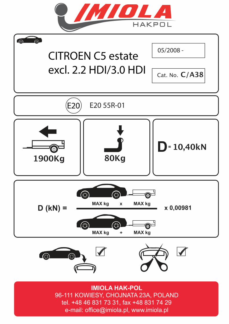
1900Kg 80Kg
05/2008 -
C/A38
10,40kN
e20
D (kN) = MAX kg MAX kg
MAX kg MAX kg
x
+
x 0,00981
D =
E20
CITROEN C5 estate
excl. 2.2 HDI/3.0 HDI
E20 55R-01
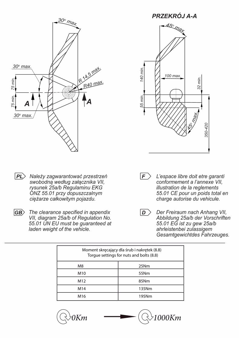
0Km 1000Km
Moment skręcający dla śrub i nakrętek (8.8)
Torgue settings for nuts and bolts (8.8)
M8
M10
M12
M14
M16
25Nm
55Nm
85Nm
135Nm
195Nm
R 14,5
max.
30o max.
30o max.
R40 max.
75 m
in.
75 m
in.
AA
100 max.
140 m
in.
PRZEKRÓJ A-A
55 m
in.
32 m
in.
350
-420
PL Należy zagwarantować przestrzeńswobodną według załącznika VII,rysunek 25a/b Regulaminu EKGONZ 55.01 przy dopuszczalnym ciężarze całkowitym pojazdu.
L’espace libre doit etre garanticonformement a l’annexe VII,illustration de la reglements 55.01 CE pour un poids total en charge autorise du vehicule.
The clearance specified in appendix VII, diagram 25a/b of Regulation No.55.01 UN EU must be guaranteed atladen weight of the vehicle.
Der Freiraum nach Anhang VII, Abbildung 25a/b der Vorschriften 55.01 EG ist zu gew 25a/b ahrleistenbei zulassigem Gesamtgewichtdes Fahrzeuges.
GB
F
D

Śruba M12x45-8.8 ; Bolt
Śruba M12x22-8.8 ; Bolt
A
B
C
D
E
F
Śruba M8x35 8.8 ; BoltPodkł. spręż.8,2 ; Spring WasherPodkł. okr. Ø23x Ø8,5x 2 ; Plain Washer
Śruba M10x30-8.8 ; BoltPodkł. okr. Ø30x Ø10,5x 3 Plain Washer
Śruba M8x35 8.8 ; BoltPodkł. spręż.12,2 ; Spring WasherPodkł. okr. Ø23x Ø8,5x 2 ; Plain Washer
Śruba M12x45-8.8 ; BoltPodkł. spręż.12,2 ; Spring WasherPodkł. okr. Ø36x Ø13x 3 ; Plain Washer
Nakrętka M12 ; NutPodkł. spręż.12,2 ; Spring WasherPodkł. okr. 13 ; Plain Washer
Śruba M10x35-8.8 ; BoltPodkł. okr. Ø30x Ø10,5x 3 ; Plain Washer
Śruba M12x45-8.8 ; Bolt
Śruba M12x45-8.8 ; BoltPodkł. spręż.12,2 ; Spring WasherPodkł. okr. Ø36x Ø13x 3 ; Plain Washer
H
I
G
G
Nakrętka M12 ; NutPodkł. spręż.12,2 ; Spring WasherPodkł. okr. 13 ; Plain Washer
Śruba M12x22-8.8 ; Bolt
Śruba M12x22-8.8 ; BoltPodkł. spręż.12,2 ; Spring Washer
Śruba M12x22-8.8 ; BoltPodkł. spręż.12,2 ; Spring Washer
A x1
B x1
C x1
D x1
E x1
F x1
G x2
H x1
I x1
M12x45 6M12x22 6M10x35 2M8x35 8
M12 4
Ø36xØ13x3 2Ø30xØ10,5x3 2Ø23xØ8,5x2 8
13 4
13 810,5 28,5 8

Śrub
a M12
x45-
8.8 ;
Bolt
Śrub
a M12
x22-
8.8 ;
BoltA
B
C
D
E
FPk
t. 2
Pkt. 2
Śrub
a M8x
35 8.
8 ; B
oltPo
dkł. o
kr. Ø
23x Ø
8,5x 2
; Plai
n Was
her
Śrub
a M10
x30-
8.8 ;
Bolt
Podk
ł. okr.
Ø30
x Ø10
,5x 3
; Plai
n Was
her
Śrub
a M10
x35-
8.8 ;
Bolt
Podk
ł. okr.
Ø30
x Ø10
,5x 3
; Plai
n Was
her
Śrub
a M8x
35 8.
8 ; B
oltPo
dkł. o
kr. Ø
23x Ø
8,5x 2
; Plai
n Was
her
Pkt. 3
Pkt. 3
Śrub
a M12
x45-
8.8 ;
Bolt
Pkt. 1
Pkt. 1
Śrub
a M12
x45-
8.8 ;
Bolt
Podk
ł. spr
ęż.12
,2 ; S
pring
Was
her
Podk
ł. okr.
Ø36
x Ø13
x 3 ; P
lain W
ashe
r
Śrub
a M12
x45-
8.8 ;
Bolt
Podk
ł. spr
ęż.12
,2 ; S
pring
Was
her
Podk
ł. okr.
Ø36
x Ø13
x 3 ; P
lain W
ashe
r
Nakrę
tka M
12 ; N
utPo
dkł. s
pręż
.12,2
; Spr
ing W
ashe
rPo
dkł. o
kr. 13
; Plai
n Was
her
Nakrę
tka M
12 ; N
utPo
dkł. s
pręż
.12,2
; Spr
ing W
ashe
rPo
dkł. o
kr. 13
; Plai
n Was
her
Śrub
a M12
x22-
8.8 ;
Bolt
G
G
I
HŚr
uba M
12x2
2-8.8
; Bo
ltPo
dkł. s
pręż
.12,2
; Sp
ring W
ashe
r
Śrub
a M12
x22-
8.8 ;
Bolt
Podk
ł. spr
ęż.12
,2 ; S
pring
Was
her
Nr ka
talog
owy
C/A3
8Ma
rkaod
05/08
- >
Citro
en C
-5 es
tate (
excl.
2.2 H
DI/ 3
.0 HD
I)96
-111
Kow
iesy
, Cho
jnat
a 23
Ate
l. +4
8 46
831
73
31

• Zdemontować tylne lampy.
• Odkręcić zderzak i jego plastikowe wzmocnienie.
• Przykręcić do tylnego pasa elementy haka E i F śrubami M8x35 8.8.
• Odszukać na zewnętrznej stronie podłużnic i udrożnić technologiczne otwory.
• Elementy C i D przykręcić do boków podłużnic śrubami M10x35 8.8 (pkt 2).• Przykręcić belkę haka A do elementów E i F oraz C i D śrubamiM12x45 8.8 (pkt 3).
• Dokręcić wszystkie śruby z momentem według tabeli.
• Podłączyć instalację elektryczną.
• Przykręcić zderzak.
• Przykręcić kulę i blachę gniazdka elektrycznego.
• Disassemble the rear lamps.
• Unscrew the bumper and its plastic reinforcement.
• Screw the elements E and F to the rear belt with bolts M8x35 8.8.
• Find the technological holes on the external side of the metal clamps and make them permeable.
• Screw the elements C and D to the sides of the metal clamps with bolts M10x35 8.8 (point 2).• Screw the main bar A to the elements E, F and C, D with bolts M12x45 8.8 (point 3).
• Tighten all the bolts according to the torque setting- see the table.
• Connect the electric wires.
• Screw the bumper.
• Fix the ball and electric plate.
• Dévisser les lampes et le pare-chocs.
• Dévisser la poutre de chocs (elle ne sera plus utilisée).
• Dévisser le carter du fond de la voiture du gauche.
• Visser les éléments E et F à la poutre du crochet A avec les boulons M12x45 8.8 (point 3).
technologiques restés après le démontage de la poutre de pare-chocs avec les boulons M8x35 8.8 (point 1).
• Serrer les éléments C et D à travers les trous dans le longeron en utilisant les boulons M10x35 8.8. (point 2) et ensuite les serrer au crochet d'attelage (A).
• Serrer le carter du côté gauche.
• Monter le pare-chocs et les lampes.
• Visser la boule et la tôle de la prise electrique à l'aide des boulons M12x70 8.8.
• Serrer tous les boulons avec un couple de serrage selon tableau.
• Raccorder le circuit électrique.
• Die hinteren Lichter abschrauben.
• Die Stoßstange und ihre Plastikverstärkung abschrauben.
• An den hinteren Karosseriestreifen die Tragteile E und F mit den Schrauben M8x35 8.8 anschrauben.
• Die Tragteile C und D an die Längsträgerseiten mit den Schrauben M10x35 8.8 (Punkt 2) anschrauben.• Den Querbalken A an die Tragteile E und F, C und D mit den Schrauben M12x45 8.8 (Punkt 3)
anschrauben.
• Alle Schrauben mit dem in der Tabelle angegebenem Drehmoment festziehen.
• Die Elektroinstallation anschließen.
• Die Stoßstange einbauen.
• Die Kugel und die Steckdosenhalterung anschrauben.
• Desmontar las luces traseras.
• Desatornille el parachoques y su refuerzo de plástico.
• Fijar los elementos de gancho E y F a la correa trasera con tornillos M8x35 8.8.
• Localizar los agujeros tecnológicos en el exterior de los largueros y ábrelos.
• Elementos C y D atornillar a los lados de los elementos laterales con pernos M10x35 8,8 (punto 2).• Fijar el gancho A a los elementos E y F con tornillos M12x45 8.8 (punto 3).
• Apretar todos los tornillos con el par según la tabla anterior.
• Conectar la instalación eléctrica.
• Apretar el parachoques.
• Apretar la bola y la placa de la toma eléctrica.
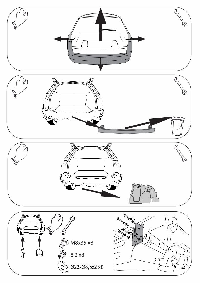
M8x35 x8
8,2 x8
Ø23xØ8,5x2 x8

M10x35 x2 10,2
x2
Ø30xØ10,5x3 x2
M12x45 x6
12,2 x6
Ø36xØ13x3 x2
13 x4

M12x22 x6
G x2