city & guilds 2330/2357 - feedbackfeedback-instruments.com/pdf/brochures/cg_powerlabs_rb... ·...
TRANSCRIPT

Electrotechnical Technology Principles
Covering therelevant partsof City & Guilds2330/2357, levelstwo and three -Certificate inElectrotechnicalTechnology
City & Guilds2330/2357
System Benefits
Low cost start-up
Flexible, modular systemcan be easily extended
High level of electricaland mechanical safetybuilt-in
Low cost installation -suitable for bench-top use
Easily portable machinesand system components
Modular concept providesflexibility for individualrequirements
Choice of conventional orvirtual instruments
All products providedwith in-depth teachingmanuals
In the UK today there is a large number of existing electrical installations andalso a rapidly increasing number of new property developments that requirethe skills of well-trained and knowledgeable electricians.
To maintain and install new electrical systems and appliances requires anunderstanding of not only the relevant electrical standards involved but alsothe concepts and underlying principles that create the system or appliance inthe first instance. Armed with this knowledge the qualified electrician is able tocope with the many technical issues that can arise in the working environment.
The City & Guilds scheme 2330 levels two and three certificate inElectrotechnical Technology requires that the appropriate relevant underpinningtheoretical knowledge is understood and that the learning of these principlesis carried out through ‘hands-on experience’.
To meet these requirements Feedback Instruments through its many yearsexperience in providing training solutions offers a product that fulfils many ofthe requirements to assist in delivering the C&G 2330/2357 course by way of amodular training system that provides a low cost start up covering the leveltwo requirements and the ability to expand the system to cover level three ata later date.
This brochure describes the modular ‘hands-on’ training system that alignswith the many tasks and assignments required to be performed that will gotowards obtaining accreditation to the appropriate related NVQ.
The 60-070 C&G 2330/2357 trainer has been conceived to reduce the numberof equipment choices simplifying the route to selecting the appropriate productfor your needs. The main choices are in instrumentation, either Virtual orConventional and in Electrical machines being Industrial or Dissectible.There are additions to the system to consider, however these have been keptto a minimum.
Powerframes
C&G 2330 curriculum mapping for 60-070
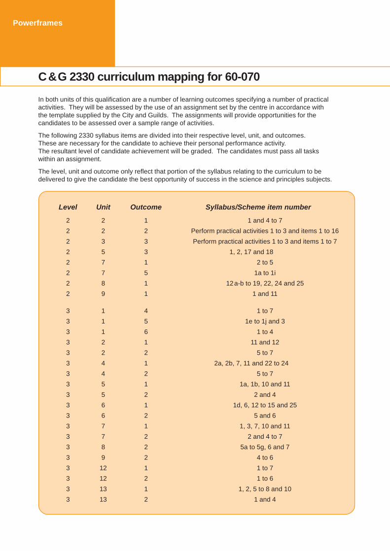
In both units of this qualification are a number of learning outcomes specifying a number of practicalactivities. They will be assessed by the use of an assignment set by the centre in accordance withthe template supplied by the City and Guilds. The assignments will provide opportunities for thecandidates to be assessed over a sample range of activities.
The following 2330 syllabus items are divided into their respective level, unit, and outcomes.These are necessary for the candidate to achieve their personal performance activity.The resultant level of candidate achievement will be graded. The candidates must pass all taskswithin an assignment.
The level, unit and outcome only reflect that portion of the syllabus relating to the curriculum to bedelivered to give the candidate the best opportunity of success in the science and principles subjects.
Level Unit Outcome Syllabus/Scheme item number
2 2 1 1 and 4 to 7
2 2 2 Perform practical activities 1 to 3 and items 1 to 16
2 3 3 Perform practical activities 1 to 3 and items 1 to 7
2 5 3 1, 2, 17 and 18
2 7 1 2 to 5
2 7 5 1a to 1i
2 8 1 12a-b to 19, 22, 24 and 25
2 9 1 1 and 11
3 1 4 1 to 7
3 1 5 1e to 1j and 3
3 1 6 1 to 4
3 2 1 11 and 12
3 2 2 5 to 7
3 4 1 2a, 2b, 7, 11 and 22 to 24
3 4 2 5 to 7
3 5 1 1a, 1b, 10 and 11
3 5 2 2 and 4
3 6 1 1d, 6, 12 to 15 and 25
3 6 2 5 and 6
3 7 1 1, 3, 7, 10 and 11
3 7 2 2 and 4 to 7
3 8 2 5a to 5g, 6 and 7
3 9 2 4 to 6
3 12 1 1 to 7
3 12 2 1 to 6
3 13 1 1, 2, 5 to 8 and 10
3 13 2 1 and 4

Electrotechnical Technology Principles
Powerframes
City & Guilds 2330/2357 for Levels 2 and 3
Start
VirtualInstrumentation
60-070-VIP
OR
Additions
Storage System90-100
OR
Option
Stand-alone option
ConventionalInstruments
60-070-CI1 & CI2
STEP THREE -Choose to addto 60-070-EP
Electrical Machines
ElectricalPrinciples60-070-EP
covers Electrotechnology
Transformers60-070-TFM
ElectromagneticMotor Control60-070-EMC
coversIndustrial Applications
ElectricalMachines60-070-EM
Dissectible Machines60-070-DM
Conventional Instruments only
Magnetic &ElectromagneticPrinciples 61-400
covers Electrical Science
AdditionsAdditions
ac MotorSpeed
Control60-070-
ASC
dc MotorSpeed
Control60-070-
DSC
STEP FIVE -Add to ElectricalMachines
STEP FOUR -Choose to addto 60-070-EP
STEP TWO - Obligatory Product
STEP ONE -ChooseInstrumentation
STEP SIX - Choose option(s)
see optional instrumentssee optional instruments
ElectromagneticMotor Control
65-020-1covers
Industrial Applications

Powerframes
Virtual Instrumentation 60-070-VIP
The Virtual Instrumentation 60-070-VIP comprises the 68-500 MultichannelI/O Module which is connected to a PC via a USB Interface and a softwarepackage which is supplied with a suite of virtual instruments.
The 68-500 has inputs for up to three ac or dc voltages and up to three ac ordc currents. These inputs are isolated from each other and each includes asingle ended monitoring point so that waveforms can be studied using aconventional low cost oscilloscope. In addition a 25-pin socket is used toconnect the 68-500 to the Torque/Speed Controller (68-441), which is partof 60-070-EM. This connector is used to read and control Torque & Speedrequirements and allows Torque & Speed measurement via the PC.
The standard virtual instrument screen provides nine analogue or digitalmeters (three voltmeters, three ammeters and three user defined meters)plus a display of Torque and Speed and a slider to allow loading of a machinevia the PC. Instrument settings can be saved for later use.
In addition to the meters the software provides very powerful plotting features.Any measured or calculated parameters (eg.Torque and Speed or PowerFactor and Current) can be plotted against each other. Multiple plots can beincluded on one set of axes to obtain a family of curves at perhaps differentvoltages and up to four graphs can be displayed simultaneously.Data can be saved or exported.
A Phasor Diagram (shown above) graphically shows the real-time relationshipbetween the various three phase voltages and currents.
A Transient Recorder allows plotting of in-rush current and startingcharacteristics.
Hardware Features
Purpose built, multi-channelI/O unit
Six isolated channels
Three voltage andthree current inputs
ac and dc measurements
50V - 500V ranges
0.2A - 10A ranges
Six isolated oscilloscopemonitoring points
PC USB interface included
Software Features
Computer based machinestesting system
Displays up to nineselectable meter windows
Choice of meter functions
Analogue or digitalvirtual meter
User definable meters
Real-time plotting
Four separate graph plotssimultaneously
Graph plotting with multiplefunctions
Data export facility
Transient recorder
Browser based software
Virtual Instrumentation option
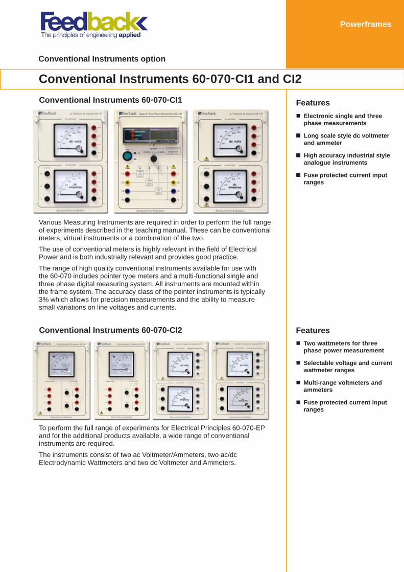
Conventional Instruments 60-070-CI1 and CI2
Powerframes
Features
Electronic single and threephase measurements
Long scale style dc voltmeterand ammeter
High accuracy industrial styleanalogue instruments
Fuse protected current inputranges
Features
Two wattmeters for threephase power measurement
Selectable voltage and currentwattmeter ranges
Multi-range voltmeters andammeters
Fuse protected current inputranges
Various Measuring Instruments are required in order to perform the full rangeof experiments described in the teaching manual. These can be conventionalmeters, virtual instruments or a combination of the two.
The use of conventional meters is highly relevant in the field of ElectricalPower and is both industrially relevant and provides good practice.
The range of high quality conventional instruments available for use withthe 60-070 includes pointer type meters and a multi-functional single andthree phase digital measuring system. All instruments are mounted withinthe frame system. The accuracy class of the pointer instruments is typically3% which allows for precision measurements and the ability to measuresmall variations on line voltages and currents.
To perform the full range of experiments for Electrical Principles 60-070-EPand for the additional products available, a wide range of conventionalinstruments are required.
The instruments consist of two ac Voltmeter/Ammeters, two ac/dcElectrodynamic Wattmeters and two dc Voltmeter and Ammeters.
Conventional Instruments option
Powerframes
Conventional Instruments 60-070-CI2
Conventional Instruments 60-070-CI1
Powerframes
Electrotechnology
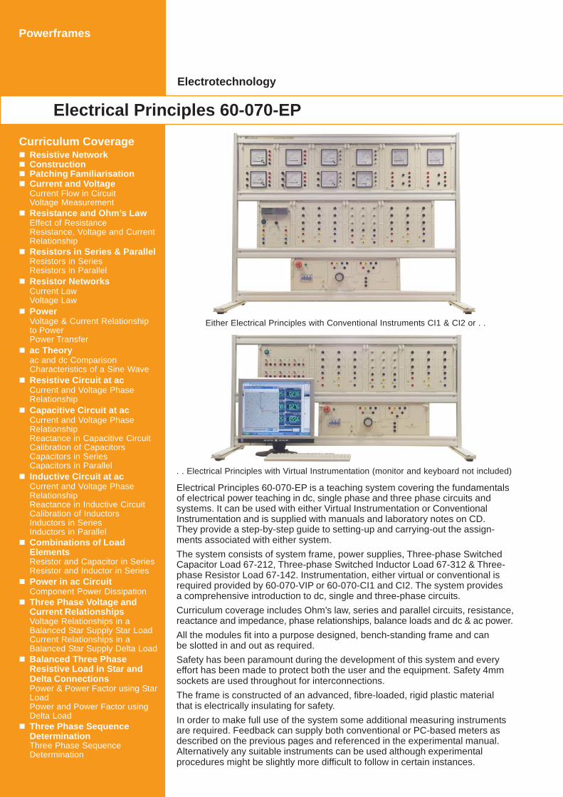
Electrical Principles 60-070-EP
Curriculum CoverageResistive NetworkConstructionPatching FamiliarisationCurrent and VoltageCurrent Flow in CircuitVoltage MeasurementResistance and Ohm’s LawEffect of ResistanceResistance, Voltage and CurrentRelationshipResistors in Series & ParallelResistors in SeriesResistors in ParallelResistor NetworksCurrent LawVoltage LawPowerVoltage & Current Relationshipto PowerPower Transferac Theoryac and dc ComparisonCharacteristics of a Sine WaveResistive Circuit at acCurrent and Voltage PhaseRelationshipCapacitive Circuit at acCurrent and Voltage PhaseRelationshipReactance in Capacitive CircuitCalibration of CapacitorsCapacitors in SeriesCapacitors in ParallelInductive Circuit at acCurrent and Voltage PhaseRelationshipReactance in Inductive CircuitCalibration of InductorsInductors in SeriesInductors in ParallelCombinations of LoadElementsResistor and Capacitor in SeriesResistor and Inductor in SeriesPower in ac CircuitComponent Power DissipationThree Phase Voltage andCurrent RelationshipsVoltage Relationships in aBalanced Star Supply Star LoadCurrent Relationships in aBalanced Star Supply Delta LoadBalanced Three PhaseResistive Load in Star andDelta ConnectionsPower & Power Factor using StarLoadPower and Power Factor usingDelta LoadThree Phase SequenceDeterminationThree Phase SequenceDetermination
Electrical Principles 60-070-EP is a teaching system covering the fundamentalsof electrical power teaching in dc, single phase and three phase circuits andsystems. It can be used with either Virtual Instrumentation or ConventionalInstrumentation and is supplied with manuals and laboratory notes on CD.They provide a step-by-step guide to setting-up and carrying-out the assign-ments associated with either system.
The system consists of system frame, power supplies, Three-phase SwitchedCapacitor Load 67-212, Three-phase Switched Inductor Load 67-312 & Three-phase Resistor Load 67-142. Instrumentation, either virtual or conventional isrequired provided by 60-070-VIP or 60-070-CI1 and CI2. The system providesa comprehensive introduction to dc, single and three-phase circuits.
Curriculum coverage includes Ohm’s law, series and parallel circuits, resistance,reactance and impedance, phase relationships, balance loads and dc & ac power.
All the modules fit into a purpose designed, bench-standing frame and canbe slotted in and out as required.
Safety has been paramount during the development of this system and everyeffort has been made to protect both the user and the equipment. Safety 4mmsockets are used throughout for interconnections.
The frame is constructed of an advanced, fibre-loaded, rigid plastic materialthat is electrically insulating for safety.
In order to make full use of the system some additional measuring instrumentsare required. Feedback can supply both conventional or PC-based meters asdescribed on the previous pages and referenced in the experimental manual.Alternatively any suitable instruments can be used although experimentalprocedures might be slightly more difficult to follow in certain instances.
Either Electrical Principles with Conventional Instruments CI1 & CI2 or . .
. . Electrical Principles with Virtual Instrumentation (monitor and keyboard not included)

Powerfames
Curriculum Coverage
Magnetic fields of permanentmagnets
Flux paths of cores
Magnetic materials, coefficients,BH curves
Electromagnetics, fields arounda wire and coil
Motor and generator principles
Mutual coupling
Transformer principles
Electrical Science - Stand-alone system
Magnetic & Electromagnetic Principles 61-400
The frame or bench-mounted panel comprises a series of magnetic andelectromagnetic components, which allow the investigation of a wide rangeof magnetic and electromagnetic principles. The magnetic componentssupplied are:
Bar magnets Four compasses Wound coilsdc solenoid Iron & ferrite cores Laminated coreFixed & moving conductors
The TFM Transformer option provides two additional modules; the 61-106Single Phase Transformer and the 61-107 Three Phase Transformer.Each is fully enclosed for safety and electrically protected.Front panel mimic diagrams simplify experimental connections.
Curriculum is provided for a comprehensive Transformer course coveringVoltage and Current ratios, turns ratios and step-up and step-down operation,no-load and on-load performance, auto-transformers, star, delta, open-deltaand zig-zag windings primary-secondary phase relationships and efficiency.
In addition to the instrumentation options CI1 and CI2 or Virtual, a digitalmultimeter with thermocouple type K input is required for use with 61-106.
Single & Three Phase Transformers 60-070-TFM
Curriculum CoverageSingle Phase Transformers
Voltage and current ratios,turns ratio, step-up, step-down
Voltage and current waveforms
Winding polarity, series andparallel connection
On-load characteristics, voltageregulation
Auto-transformer, transformersin parallel, current transformer
Three Phase TransformersWinding polarity, connectingStar, Delta, Open Delta andZig-Zag secondary windings
Voltage & current relationships,establishing the root 3 factor
On load characteristics
Voltage and current phasorrelationships for no-load andon-load transformer
Phase shift between primaryand secondary

FeaturesIndustrial style dc, single andthree phase machines
Supplied with comprehensiveTorque/Speed measurementsystem
High level of electrical andmechanical safety
Quick and easy machinecoupling
Multi-output dc, single andthree phase protected powersupply
Powerframes
Electrical Machines 60-070-EM
The Electrical Machines 60-070-EM provides an introduction to the study ofElectrical Machines which will be sufficient for the many requirements of City andGuilds 2330 and can be extended at any time by adding the ElectromagneticMotor Control 60-070-EMC Industrial Applications.A detailed manual providing both theory and experimental procedure is providedin hard copy and electronic formats to help the student gain a working under-standing of the subjects listed.
Curriculum Coverage
dc Motors and Generatorsdc Shunt Motor
dc Series Motor
dc Compound Motor
dc Separately Excited Motor
dc Shunt Generator
dc Compound Generator
Separately Excited dc Generator
ac Motors and GeneratorsSeries Universal Motor
Single Phase Induction Motor -Capacitor Start / Induction run
Three-phase Induction Motor
Three-phase Synchronous Motor
Three-phase SynchronousGenerator
Motor & Generator TestsInput power
Output power
Peak torque output
Torque/speed and efficiencycharacteristics
Synchronous speed
Power factor
Electrical Machines
The Universal Motor is a simple, versatileand very widely used motor which canoperate using a dc supply or a singlephase ac supply. Comparison is madebetween the operation using the ac anddc supplies and the need for a com-pensation winding is shown.Torque speed and efficiency curves aswell as shaft reversal are some of theinvestigations made.A mimic on the terminal box shows themotor configuration.
Universal Motor 63-100
dc Compound Wound Machine63-120
The dc compound machine is essentiallythree machines in one, consisting of anarmature and two individual fieldwindings, series and shunt that can beinterconnected to provide a thirdconnection namely compound. It is alsopossible to connect the windings toconfigure a separately excited fieldmachine. Not only are several motorconfigurations possible but also dcgenerators in their various forms mayalso be configured and tested.Connections are provided on a mimicpanel mounted above the motor for thetwo separate fields, series and shunt andthe armature. This arrangement allowsease of connection for the various motoror generator configurations possible.
The Single Phase Induction Motor is oneof the most commonly applied motorsfound in numerous industrial and domesticappliances. They consist of a main andstart winding that requires the addition of acapacitor to start the motor. These windingsand capacitor connections are shown on amimic panel mounted on top of the motor.Exercises to investigate the torque/speedcharacteristic, starting requirement and theeffect of the start capacitor on torqueoutput are some of the tests carried out.
Three-phase Induction Motor -Squirrel Cage, Dual Voltage 64-501
The Three-Phase Squirrel cage InductionMotor finds numerous industrial applica-tions due to its high reliability and lowmanufacturing cost. Ratings from 100Wto tens of kilowatts are available for heavyindustrial applications.It is considered to be the ac equivalentto the dc shunt motor due to it’s nearconstant torque/speed characteristic.A mimic panel mounted on top of themotor depicts the three separate windings,one for each phase. They can be con-figured as Star or Delta connections.The study of this particular motor coversStar or Delta power connections andforward and reverse operation, star/deltastarting, torque/speed and efficiency test.
SafetyAll electrical machines in the60-070 series are fitted withfully shrouded electricalconnectors, shaft guards,alignment pins and quick-fasten and release mechanicalcatches to retain coupledmachines.
Single phase Induction Motor-Capacitor Start/Induction Run 64-110

Electrical Machines 60-070-EM
Powerframes
Curriculum CoverageOpen circuit testShort circuit testEffect of speed variation onoutput voltage and frequencySynchronisation procedureOperation of a synchronousmachineVoltage regulation of asynchronous machineVariable reactor V curves
Electrical Machines
Features for 64-510Mimic diagram of motorwindingsRealistic industrial frame sizeElectrical and mechanicalprotection
The Synchronising Module shows how theThree Phase generator can be synchroni-sed to the existing power supply. The ver-satility of the 60-070 allows sophisticatedexperiments to be performed, such as,running the machine up to synchronousspeed, synchronising as a generator,changing to synchronous mode to a motorand studying the characteristics and pull-out torque.
Three Phase SynchronousMachine 64-510
Synchronising Lamps 68-120
The Three Phase Synchronous machineis mainly used for power generation andcan be found in power generation plantsall over the country to supply both domes-tic and industrial users with electricity.One of it’s characteristics that is extremelyuseful in power distribution systems is theability to control power factor throughvariation of the rotor current. The machinewindings are bought to a mimic panel thatdepicts the rotor and stator connectionsthat are three separate windings to allowfor star or Delta connections.As well as it’s operation as a three phasegenerator it can be run as a synchronousmotor providing constant speed outputand the ability to control power factor.The study of this machine covers its useas a motor and generator, startingrequirements, synchronisation, on loadand no load characteristics and itscharacteristics as a synchronous capacitoror inductor are some of the topics covered.
Torque/Speed Control Panel68-441
Used in conjunction with the SwingingField Dynamometer 67-502 the panelprovides all the necessary controls andmetering for manual measurement oftorque and speed values. Two variablecontrols in the torque mode are used toload the motor under test with eitherconstant toque or torque proportional withspeed type loads. When operating in thespeed mode only one variable control isused to set the desired speed value.A digital display can be switched todisplay either torque or speed values.Protection is provided by a ‘power inter-lock’ system that prevents operation if the67-502 is not fully connected. Controlover the dynamometer system can beexercised by computer through a multi-way connector that requires interconnec-tion to the 68-500 Multi-channel I/O panel.
Couples 63 & 64 series motorsto motor/generator for multi-machine experiments.12mm shaft to 12mm shaft.
Shaft Coupling and Key68-703
Used in conjunction with the 68-441Torque/Speed panel.A strain gauge beam is used for torquemeasurement that provides torque valuesin both torque and speed modes. Alsoprovided is the facility to carry out lockedrotor tests by means of a mechanism thatprevents the shaft from rotating, beingheld and allowed to move in sympathywith the swinging field of the dynamometermachine.An integral tachogenerator is used forspeed measurement, both torque andspeed signals connect to the 68-441along with the machine field andarmature connections.
Manual Swinging FieldDynamometer 67-502

The Dissectible Machine components allow overfifty machine assemblies to be built, covering awide range of ac and dc single and 3-phase motorsand generators.
The individual parts of the Machine assembly canbe identified prior to completion of the full assembly.
The assembled machines use low voltages, haveprotected rotating parts, and operate at relativelylow power and voltage levels. Nominal operatingvoltages are 50V dc and 125V ac.
The Instruction manual details the procedure for themachine assemblies with wiring diagrams used tointerconnect the units. Each assignment containsan aim and objective and is supported by theory.
The components are used to study subjects thatrange from the principles of magnetic circuits andelectrical machine theory through to three-phasesynchronous machines.
Students are able to see clearly the component partsof the machine and how they are interconnected,both electrically and mechanically.
With the addition of power supplies, metering,electrical and mechanical loads, the assembledmachine can be operated and tested.
Electrical Machines
Dissectible Machines 60-070-DM
Powerframes
System componentsBaseplateFrame ringShaft and couplingFixed and removable bearinghousingsWound statorSquirrel cage rotorHand crankCentrifugal switchBrushes and brush holdersInterpolesCommutator /slip ringsArmature poles and hubField polesCompound field coilsTools and hardwareRC load unitArmature, field & interpole coilsControl switchesComponent traySystem framePatch leads
Curriculum CoverageElementary ac and dc generators
dc series motor and generator
dc shunt motor and generator
dc compound motor andgenerator
Single phase ac seriesuniversal motor
Single phase ac repulsion motor
Single phase ac synchronousmotor/generator
Single phase ac generator
Three phase ac induction motor,squirrel cage, 2 pole and 4 pole
Three phase ac synchronousmotor and generator
ac brushless generator
Stepper motor
Shaded pole induction motor
Split field series motor
Dynamic braking of a dc motor
Power factor correction of acmotors
Synchronous motor V curvecharacteristics
Pole-changing induction motor
dc shunt motor faults
Four pole induction motor faults
Optional Dissectible Machines Storage System 90-100
Hand held Tacho-meter 68-470
dc Milliamme-ter, Centrezero 68-113
ResistorCapacitor Unit67-190
ControlSwitches65-130
ac Volt andFrequencyMeter 68-121
VariableResistance67-113
Prony Brake 67-470
dc Variable Speed Drive65-501
SynchronisingLamps 68-120
Variable ac/dcSupply 60-121
Unpopulated Populated

Electromagnetic Motor Control 60-070-EMC & 65-020-1
The use of power relays to provide a switched sequence of events for starting,stopping, foward and reversing of electrical machines has been traditionallycarried out by Electromagnetic control gear. The application of these devicesis widely used today and therefore the principles need to be understood.The Electromagnetic Motor Control 60-070-EMC and 65-020-1 provides studymethods and terminology associated with the implementation of control devicesin some of the most commonly used circuits for control of ac & dc machines, toa level that can be understood by both maintenance engineers and technicians.The equipment consists of a wide range of control gear that is provided onthree panels. The main panel has electromagnetic contactors, and the othertwo have pushbutton and rotary switch gear and indicator lights.A Magnetic pick-up is provided that fits onto the motor being controlled formeasurement of shaft speed.
Powerframes
Curriculum CoverageDOL starter, electromagnetic,locally controlledDOL starter, starting/inching/joggingStar/Delta starterPrimary impedance starterDOL starter: Foward/ReverseoperationDOL starter with dc injectionbrakingDOL starter with plug-brakingdc motor starterDynamic braking of a dcMotorIntroduction to switchgearMotor configurations
Industrial Applications
ac & dc Motor Speed Control 60-070-ASC & 60-070-DSC
The ASC ac Motor Speed Control and DSC dc Motor Speed Control optionsextend the curriculum to include a comprehensive introduction to PowerElectronics and ac & dc Motor Drives. They each comprise one additionalmodule, the 66-110 Variable Frequency Drive or 66-120 dc Motor SpeedController. Experiments are performed using the 64-501 Three Phase SquirrelCage Motor for ac, and 63-120 dc Compound Wound Machine for dc control.The 66-120 panel has separate Field and Armature connections that areprotected by high speed fuses. Motor protection is by an internal currentlimiting circuit.For both panels the front panel controls allow the variation of: Set Speed,Minimum Speed, IR Compensation and Acceleration/deceleration Time.Voltage boost is available for the 66-110 panel only.NB - these panels require the use of the optional instruments shown on theback page.
ac Curriculum CoverageBasic TheoryControl FunctionsInverter Voltage WaveformsCarrier FrequencyInverter Current WaveformsFrequency, Speed, Currentand Motor VoltageTorque/Speed test at variousfrequency settingsVoltage BoostVoltage/Frequency (V/F)characteristics
dc Curriculum CoverageThyristor dc motor controlprinciplesMotor voltage and currentwaveformsSpeed regulation with andwithout phase angle controlPhase angle versus motorspeedEffect of feedback voltage onspeed regulationCurrent limit controlTorque/speed performance

Feedback Instruments LimitedPark Road, Crowborough, E. Sussex,TN6 2QR, England.Telephone: +44 (0) 1892 653322Fax: +44 (0) 1892 663719E mail: [email protected]: www.feedback-group.com
Feedback Incorporated437 Dimmocks Mill Road, Suite 27,Hillsborough, NC 27278, USATelephone: (919) 644 6466Fax: (919) 644 6470E-mail: [email protected]: www.feedback-group.com
Registered in England number 990620.A subsidiary of Feedback plc.
Feedback reserves the right to changethese specifications without notice.
Ordering InformationVirtual Instrumentation 60-070-VIPConventional Instruments 60-070-CI1Conventional Instruments 60-070-CI2
ElectrotechnologyElectrical Principles 60-070-EP
Electrical Science (stand-alone)Magnetic and Electromagnetic Principles 61-400
TransformersTransformers 60-070-TFM
Electrical MachinesElectrical Machines 60-070-EMDissectible Machines 60-070-DMDissectible Machines Storage System (optional) 90-100
Industrial Applications AdditionsElectromagnetic Motor Control 60-070-EMCElectromagnetic Motor Control 60-0270-1ac Motor Speed Control 60-070-ASCdc Motor Speed Control 60-070-DSCVoltage & Current Monitor 68-150ac Voltmeter & Ammeter 68-111
Powerframes
Three Phase Earth Leakage Breaker 60-140-1
Ordering InformationThree Phase Earth Leakage Breaker 60-140-1
This unit is for use in systems where earth leakage breakers are not provided aspart of the laboratory electrical installation but overcurrent protection is installed.
Provides protection against the hazard of electric shockSuitable for connection to three-phase, 5 wire systemsFour pole, 30mA trip, earth leakage breakerThree phase power ‘on’ indicatorsSingle phase outlets on front and rearSafety earth terminalsThree-phase output on rear panel for use with 60-105
Optional InstrumentsIn order to perform all the experimentsfor ac and dc Motor Speed Controlthe following instruments are required.
For use where isolated voltage andcurrent waveform measurements arerequiredPrecision 4 terminal shunt current monitorShunt output isolated via voltage probeProbes output connects directly to ascope for safe monitoring
Voltage and Current Monitor 68-150(2 sets required)
ac Voltmeter and Ammeter 68-111A rectifier voltmeter and moving ironammeterSuited to the measurement of variablefrequency drives and ac suppliesRectifier voltmeter range 0 -250V and0 -500V acMoving ironammeter range0 -3A, fuseprotected
The following instruments are alsorequired for ac Motor Control when usingthe 66-110 if not available in the laboratory: