city of brampton street corridor master plan · city of brampton street corridor master plan ......
TRANSCRIPT
C I T Y O F B R A M P T O NS T R E E T C O R R I D O R M A S T E R P L A N
N A K D e s i g n G r o u p • U r b a n D e s i g n T A B L E O F C O N T E N T S
1.0 INTRODUCTION..................................................................... 1
1.1 Purpose of Document............................................................ 11.2 Master Plan Goal.....................................................................11.3 Design Objectives.................................................................... 21.4 Design Approach..................................................................... 2
2.0 PROJECT SCOPE...................................................................22.1 City Context 22.2 Regional Context 2
3.0 DESIGN VOCABULARY........................................................... 3-6
4.0 ARTERIAL ROAD HIERARCHY.................................................74.1 Primary Arterial / Main Streets...................................................84.1.1 Design Objectives.................................................................... 84.1.2 Conceptual Design Solutions.....................................................8
4.2 Primary Arterial Roads..............................................................94.2.1 Design Objectives.................................................................... 94.2.2 AcceleRide Program.................................................................94.2.3 Conceptual Design Solutions.....................................................9-10
4.3 Secondary Arterial Roads......................................................... 114.3.1 Design Objectives.................................................................... 114.3.2 Conceptual Design Solutions.................................................... 11-12
4.4 Perimeter Arterial Roads...........................................................134.4.1 Design Objectives.................................................................... 134.4.2 Conceptual Design Solutions.................................................... 13-14
4.5 Tertiary Arterial Roads.............................................................. 154.5.1 Design Objectives.................................................................... 154.5.2 Conceptual Design Solutions.................................................... 15-16
5.0 GATEWAYS............................................................................ 17-185.1 Design Objectives.................................................................... 185.2 Conceptual Design Solutions.................................................... 19-21
7.0 IMPLEMENTATION & FUNDING STRATEGIES......................... 22
C I T Y O F B R A M P T O NS T R E E T C O R R I D O R M A S T E R P L A N
N A K D e s i g n G r o u p • U r b a n D e s i g n I M P L E M E N T A T I O N
2 2
7.0 IMPLEMENTATION & FUNDING STRATEGIES
Implementation of the Street Corridor Master Plan isexpected to occur gradually over time, as funding orother circumstances allow. Sources forimplementation and funding strategies are thefollowing:
1. Capital road works such as road widening orreconstruction by the Region or the City.
2. Special capital initiatives by the City and/or theRegion.
3. Development amenities associated with newprivate development and funded by thedeveloper.
C I T Y O F B R A M P T O NS T R E E T C O R R I D O R M A S T E R P L A N
N A K D e s i g n G r o u p • U r b a n D e s i g n G A T E W A Y S
2 1
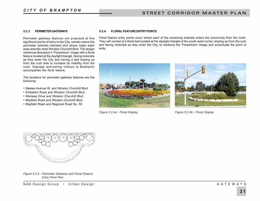
5.2.3 PERIMETER GATEWAYS
Perimeter gateway features are proposed at fivesignificant points of entry to the City, namely where theperimeter arterials intersect and where major east/west arterials meet Winston Churchill Blvd. The designreinforces Brampton’s ‘Flowertown’ image with a floralfeature located at the daylight triangle, facing motoristsas they enter the City and having a bed sloping upfrom the curb side to increase its visibility from theroad. Signage welcoming visitors to Bramptonaccompanies the floral feature.
The locations for perimeter gateway features are thefollowing:
• Steeles Avenue W. and Winston Churchill Blvd.• Embleton Road and Winston Churchill Blvd.• Wanless Drive and Winston Churchill Blvd.• Mayfield Road and Winston Churchill Blvd.• Mayfield Road and Regional Road No. 50
5.2.4 FLORAL FEATURE ENTRY POINTS
Floral feature entry points occur where each of the remaining arterials enters the community from the north.They will consist of a floral bed located at the daylight triangle of the south-west corner, sloping up from the curband facing motorists as they enter the City, to reinforce the ‘Flowertown’ image and accentuate the point ofentry.
Figure 5.2.3 - Perimeter Gateway and Floral FeatureEntry Point Plan
Figure 5.2.4a - Floral Display Figure 5.2.4b - Floral Display
C I T Y O F B R A M P T O NS T R E E T C O R R I D O R M A S T E R P L A N
N A K D e s i g n G r o u p • U r b a n D e s i g n G A T E W A Y S
2 0
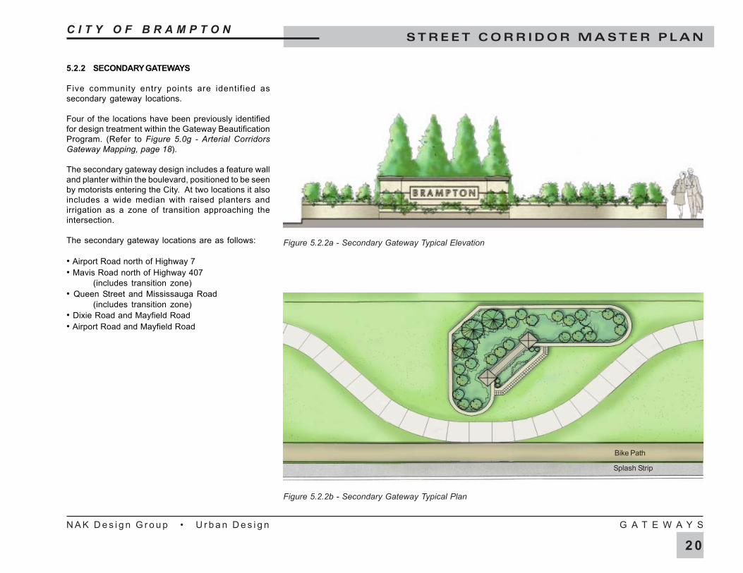
5.2.2 SECONDARY GATEWAYS
Five community entry points are identified assecondary gateway locations.
Four of the locations have been previously identifiedfor design treatment within the Gateway BeautificationProgram. (Refer to Figure 5.0g - Arterial CorridorsGateway Mapping, page 18).
The secondary gateway design includes a feature walland planter within the boulevard, positioned to be seenby motorists entering the City. At two locations it alsoincludes a wide median with raised planters andirrigation as a zone of transition approaching theintersection.
The secondary gateway locations are as follows:
• Airport Road north of Highway 7• Mavis Road north of Highway 407
(includes transition zone)• Queen Street and Mississauga Road
(includes transition zone)• Dixie Road and Mayfield Road• Airport Road and Mayfield Road
Figure 5.2.2b - Secondary Gateway Typical Plan
Figure 5.2.2a - Secondary Gateway Typical Elevation
Splash Strip
Bike Path
C I T Y O F B R A M P T O NS T R E E T C O R R I D O R M A S T E R P L A N
N A K D e s i g n G r o u p • U r b a n D e s i g n G A T E W A Y S
1 9
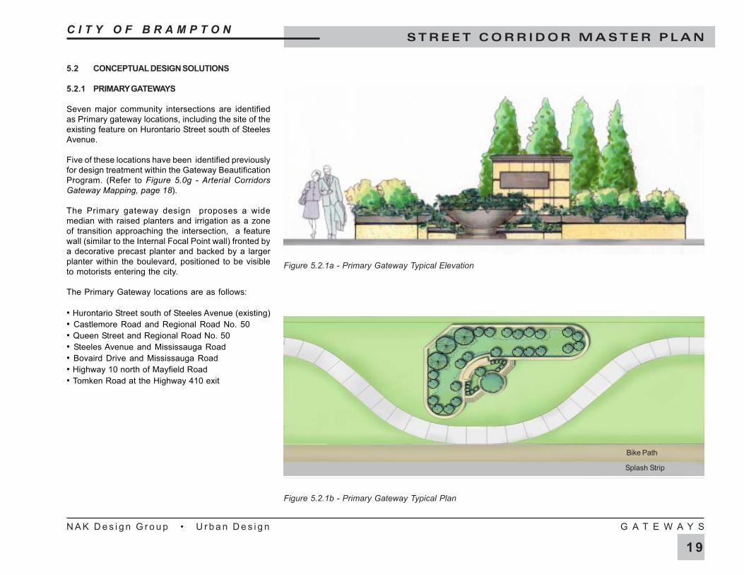
5.2 CONCEPTUAL DESIGN SOLUTIONS
5.2.1 PRIMARY GATEWAYS
Seven major community intersections are identifiedas Primary gateway locations, including the site of theexisting feature on Hurontario Street south of SteelesAvenue.
Five of these locations have been identified previouslyfor design treatment within the Gateway BeautificationProgram. (Refer to Figure 5.0g - Arterial CorridorsGateway Mapping, page 18).
The Primary gateway design proposes a widemedian with raised planters and irrigation as a zoneof transition approaching the intersection, a featurewall (similar to the Internal Focal Point wall) fronted bya decorative precast planter and backed by a largerplanter within the boulevard, positioned to be visibleto motorists entering the city.
The Primary Gateway locations are as follows:
• Hurontario Street south of Steeles Avenue (existing)• Castlemore Road and Regional Road No. 50• Queen Street and Regional Road No. 50• Steeles Avenue and Mississauga Road• Bovaird Drive and Mississauga Road• Highway 10 north of Mayfield Road• Tomken Road at the Highway 410 exit
Figure 5.2.1b - Primary Gateway Typical Plan
Figure 5.2.1a - Primary Gateway Typical Elevation
Splash Strip
Bike Path
C I T Y O F B R A M P T O NS T R E E T C O R R I D O R M A S T E R P L A N
N A K D e s i g n G r o u p • U r b a n D e s i g n G A T E W A Y S
1 8
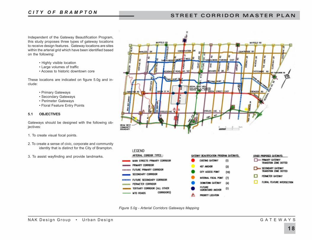
Figure 5.0g - Arterial Corridors Gateways Mapping
Independent of the Gateway Beautification Program,this study proposes three types of gateway locationsto receive design features. Gateway locations are siteswithin the arterial grid which have been identified basedon the following:
• Highly visible location• Large volumes of traffic• Access to historic downtown core
These locations are indicated on figure 5.0g and in-clude:
• Primary Gateways• Secondary Gateways• Perimeter Gateways• Floral Feature Entry Points
5.1 OBJECTIVES
Gateways should be designed with the following ob-jectives:
1. To create visual focal points.
2. To create a sense of civic, corporate and communityidentity that is distinct for the City of Brampton.
3. To assist wayfinding and provide landmarks.
C I T Y O F B R A M P T O NS T R E E T C O R R I D O R M A S T E R P L A N
N A K D e s i g n G r o u p • U r b a n D e s i g n G A T E W A Y S
1 7
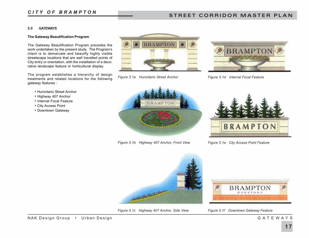
5.0 GATEWAYS
The Gateway Beautification Program
The Gateway Beautification Program precedes thework undertaken by the present study. The Program’sintent is to demarcate and beautify highly visiblestreetscape locations that are well travelled points ofCity entry or orientation, with the installation of a deco-rative landscape feature or horticultural display.
The program establishes a hierarchy of designtreatments and related locations for the followinggateway features :
• Hurontario Street Anchor• Highway 407 Anchor• Internal Focal Feature• City Access Point• Downtown Gateway
Figure 5.1a Hurontario Street Anchor
Figure 5.1b Highway 407 Anchor, Front View
Figure 5.1c Highway 407 Anchor, Side View
Figure 5.1d Internal Focal Feature
Figure 5.1e City Access Point Feature
Figure 5.1f Downtown Gateway Feature
C I T Y O F B R A M P T O NS T R E E T C O R R I D O R M A S T E R P L A N
N A K D e s i g n G r o u p • U r b a n D e s i g n S E C O N D A R Y C O R R I D O R S
1 6
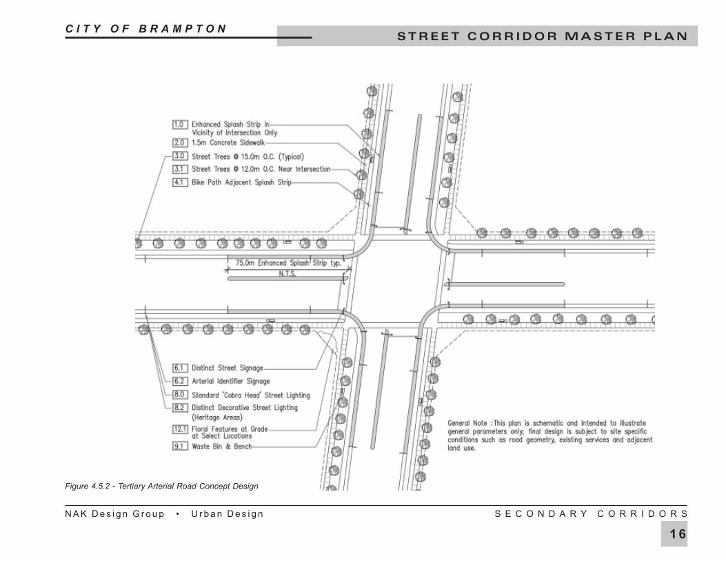
Figure 4.5.2 - Tertiary Arterial Road Concept Design
C I T Y O F B R A M P T O NS T R E E T C O R R I D O R M A S T E R P L A N
N A K D e s i g n G r o u p • U r b a n D e s i g n S E C O N D A R Y C O R R I D O R S
1 5
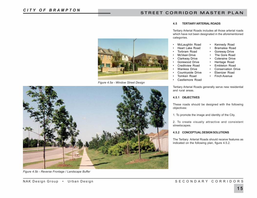
4.5 TERTIARY ARTERIAL ROADS
Tertiary Arterial Roads includes all those arterial roadswhich have not been designated in the aforementionedcategories.
• McLaughlin Road • Kennedy Road• Heart Lake Road • Bramalea Road• Torbram Road • Goreway Drive• McVean Drive • The Gore Road• Clarkway Drive • Coleraine Drive• Gorewood Drive • Heritage Road• Creditview Road • Embleton Road• Wanless Drive • Conservation Drive• Countryside Drive • Ebenizer Road• Tomken Road • Finch Avenue• Castlemore Road
Tertiary Arterial Roads generally serve new residentialand rural areas.
4.5.1 OBJECTIVES
These roads should be designed with the followingobjectives:
1. To promote the image and identity of the City.
2. To create visually attractive and consistentstreetscapes.
4.5.2 CONCEPTUAL DESIGN SOLUTIONS
The Tertiary Arterial Roads should receive features asindicated on the following plan, figure 4.5.2.
Figure 4.5b - Reverse Frontage / Landscape Buffer
Figure 4.5a - Window Street Design
C I T Y O F B R A M P T O NS T R E E T C O R R I D O R M A S T E R P L A N
N A K D e s i g n G r o u p • U r b a n D e s i g n S E C O N D A R Y C O R R I D O R S
1 4
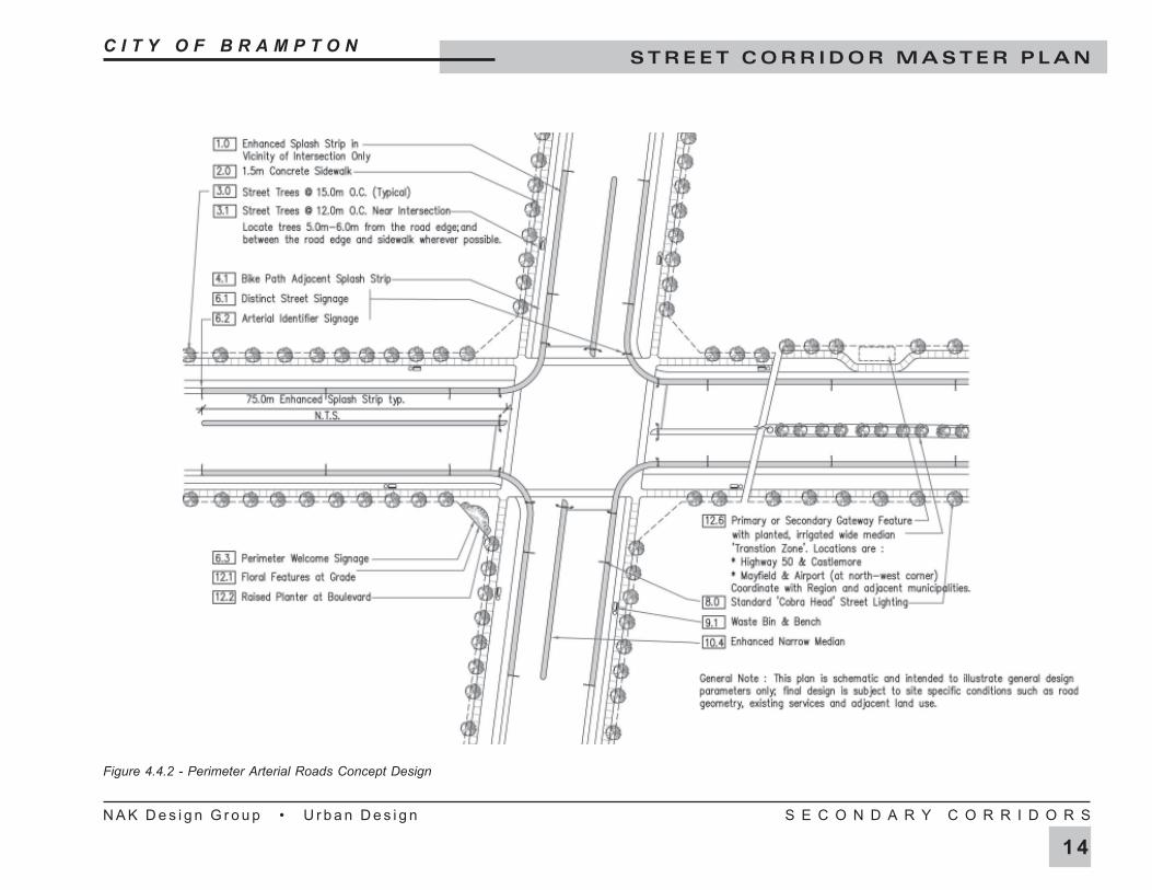
Figure 4.4.2 - Perimeter Arterial Roads Concept Design
C I T Y O F B R A M P T O NS T R E E T C O R R I D O R M A S T E R P L A N
N A K D e s i g n G r o u p • U r b a n D e s i g n S E C O N D A R Y C O R R I D O R S
1 3
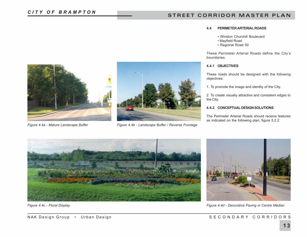
4.4 PERIMETER ARTERIAL ROADS
• Winston Churchill Boulevard• Mayfield Road• Regional Road 50
These Perimeter Arterial Roads define the City’sboundaries.
4.4.1 OBJECTIVES
These roads should be designed with the followingobjectives:
1. To promote the image and identity of the City.
2. To create visually attractive and consistent edges tothe City.
4.4.2 CONCEPTUAL DESIGN SOLUTIONS
The Perimeter Arterial Roads should receive featuresas indicated on the following plan, figure 5.2.2.
Figure 4.4a - Mature Landscape Buffer Figure 4.4b - Landscape Buffer / Reverse Frontage
Figure 4.4c - Floral Display Figure 4.4d - Decorative Paving in Centre Median
C I T Y O F B R A M P T O NS T R E E T C O R R I D O R M A S T E R P L A N
N A K D e s i g n G r o u p • U r b a n D e s i g n S E C O N D A R Y C O R R I D O R S
1 2
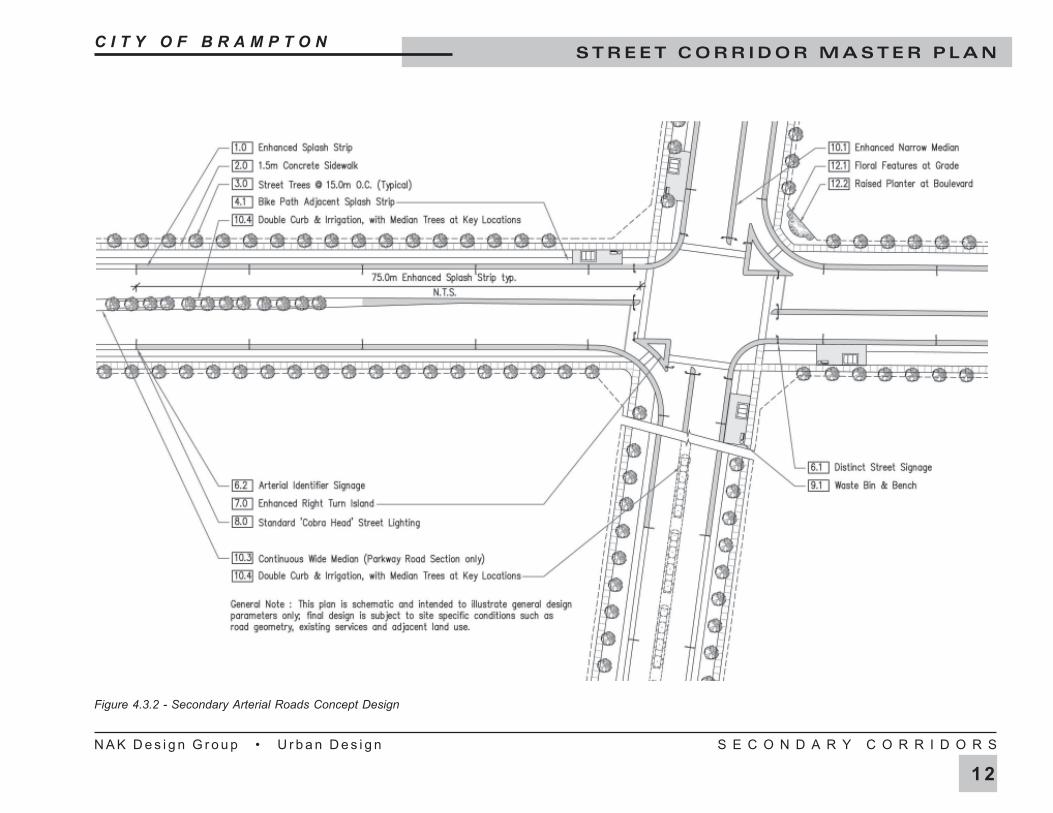
Figure 4.3.2 - Secondary Arterial Roads Concept Design
C I T Y O F B R A M P T O NS T R E E T C O R R I D O R M A S T E R P L A N
N A K D e s i g n G r o u p • U r b a n D e s i g n S E C O N D A R Y C O R R I D O R S
1 1
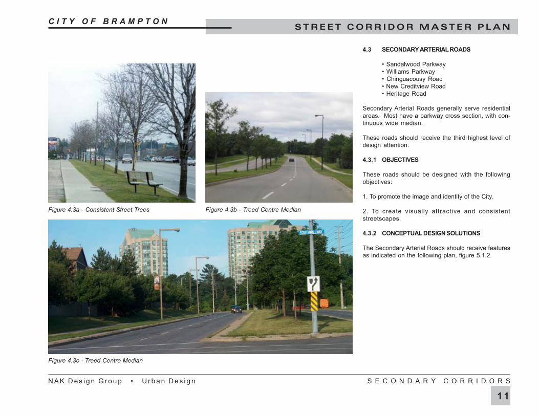
4.3 SECONDARY ARTERIAL ROADS
• Sandalwood Parkway• Williams Parkway• Chinguacousy Road• New Creditview Road• Heritage Road
Secondary Arterial Roads generally serve residentialareas. Most have a parkway cross section, with con-tinuous wide median.
These roads should receive the third highest level ofdesign attention.
4.3.1 OBJECTIVES
These roads should be designed with the followingobjectives:
1. To promote the image and identity of the City.
2. To create visually attractive and consistentstreetscapes.
4.3.2 CONCEPTUAL DESIGN SOLUTIONS
The Secondary Arterial Roads should receive featuresas indicated on the following plan, figure 5.1.2.
Figure 4.3c - Treed Centre Median
Figure 4.3a - Consistent Street Trees Figure 4.3b - Treed Centre Median
C I T Y O F B R A M P T O NS T R E E T C O R R I D O R M A S T E R P L A N
N A K D e s i g n G r o u p • U r b a n D e s i g n P R I M A R Y C O R R I D O R S
1 0
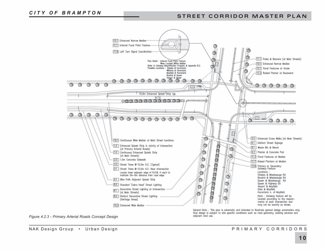
Figure 4.2.3 - Primary Arterial Roads Concept Design
C I T Y O F B R A M P T O NS T R E E T C O R R I D O R M A S T E R P L A N
N A K D e s i g n G r o u p • U r b a n D e s i g n P R I M A R Y C O R R I D O R S
9
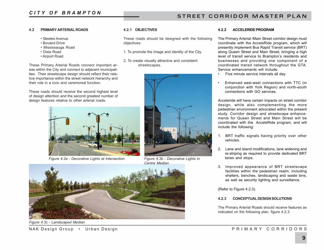
4.2.2 ACCELERIDE PROGRAM
The Primary Arterial /Main Street corridor design mustcoordinate with the AcceleRide program, which willpresently implement Bus Rapid Transit service (BRT)along Queen Street and Main Street, bringing a highlevel of transit service to Brampton’s residents andbusinesses and providing one component of acoordinated transit network throughout the GTA.Service enhancements will include:• Five minute service intervals all day.
• Enhanced east-west connections with TTC (inconjunction with York Region) and north-southconnections with GO services.
Acceleride will have certain impacts on street corridordesign, while also complementing the morepedestrian environment advocated within the presentstudy. Corridor design and streetscape enhance-ments for Queen Street and Main Street will becoordinated with the AcceleRide program, and willinclude the following:
1. BRT traffic signals having priority over othervehicles.
2. Lane and island modifications, lane widening andre-striping as required to provide dedicated BRTlanes and stops.
3. Improved appearance of BRT streetscapefacilities within the pedestrian realm, includingshelters, benches, landscaping and waste bins,as well as security lighting and surveillance.
(Refer to Figure 4.2.3).
4.2.3 CONCEPTUAL DESIGN SOLUTIONS
The Primary Arterial Roads should receive features asindicated on the following plan, figure 4.2.3.
4.2.1 OBJECTIVES
These roads should be designed with the followingobjectives:
1. To promote the image and identity of the City.
2. To create visually attractive and consistentstreetscapes.
4.2 PRIMARY ARTERIAL ROADS
• Steeles Avenue• Bovaird Drive• Mississauga Road• Dixie Road• Airport Road
These Primary Arterial Roads connect important ar-eas within the City and connect to adjacent municipali-ties. Their streetscape design should reflect their rela-tive importance within the street network hierarchy andtheir role in a civic and ceremonial function.
These roads should receive the second highest levelof design attention and the second greatest number ofdesign features relative to other arterial roads.
Figure 4.2a - Decorative Lights at Intersection
Figure 4.3c - Landscaped Median
Figure 4.3b - Decorative Lights inCentre Median

C I T Y O F B R A M P T O NS T R E E T C O R R I D O R M A S T E R P L A N
N A K D e s i g n G r o u p • U r b a n D e s i g n P R I M A R Y C O R R I D O R S
8
4.1 PRIMARY ARTERIAL / MAIN STREETS
• Hurontario / Main Street• Queen Street (East and West)
The City’s two principal north/south and east/weststreets, Hurontario and Queen Street respectively, con-nect focal parts of the City, including the downtown coreas well as the City to adjacent municipalities. Theirstreetscape design should reflect their primacy withinthe street network hierarchy and their role in a civic andceremonial function.
These roads should receive the highest level of de-sign attention and the greatest number of design fea-tures relative to other arterial roads.
4.1.1 OBJECTIVES
These roads, should be designed with the followingobjectives:
1. To promote the image and identity of the City.
2. To incorporate heritage elements.
3. To facilitate wayfinding and orientation.
4.1.2 CONCEPTUAL DESIGN SOLUTIONS
The Primary Arterial / Main Streets should receive thesame streetscape enhancements as for the PrimaryArterial Roads, indicated on figure 4.2.2. In addition,the Primary Arterial / Main Streets should also receivethe following features:
• Decorative light fixtures at arterial intersections.• Continuous coloured impressed concrete splash strips and medians.• Decorative cross walks at intersections.• Planted medians at key locations.
Figure 4.3c - Boulevard Design Figure 4.3d - Centre Median Planter
Figure 4.3a - Decorative Paving Figure 4.3b - Main Street, Brampton
C I T Y O F B R A M P T O NS T R E E T C O R R I D O R M A S T E R P L A N
N A K D e s i g n G r o u p • U r b a n D e s i g n P R I M A R Y C O R R I D O R S
7
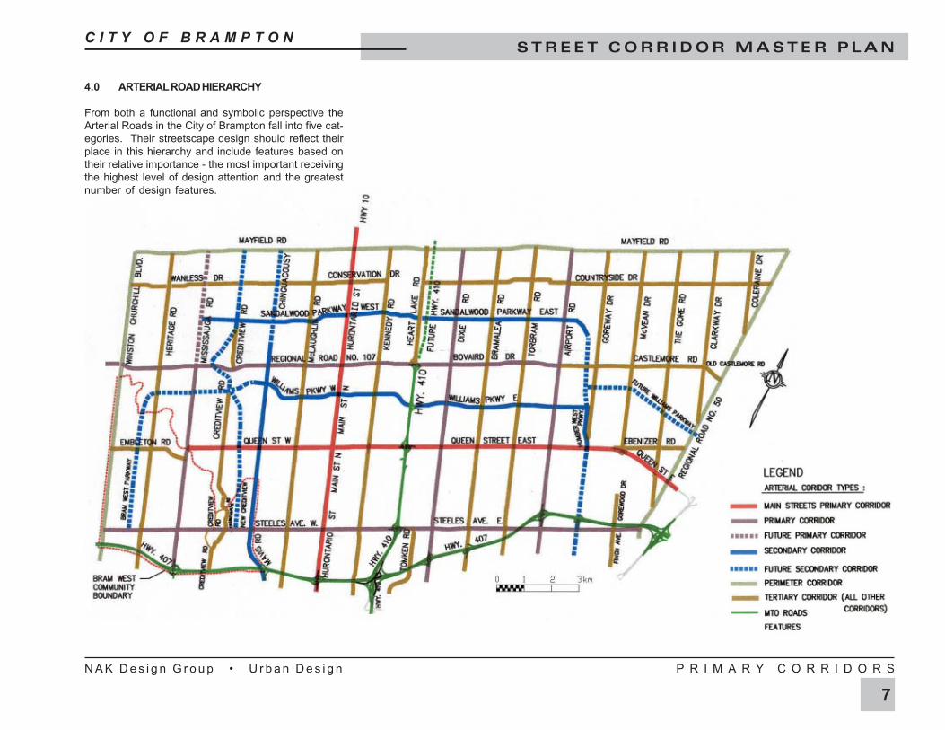
4.0 ARTERIAL ROAD HIERARCHY
From both a functional and symbolic perspective theArterial Roads in the City of Brampton fall into five cat-egories. Their streetscape design should reflect theirplace in this hierarchy and include features based ontheir relative importance - the most important receivingthe highest level of design attention and the greatestnumber of design features.
C I T Y O F B R A M P T O NS T R E E T C O R R I D O R M A S T E R P L A N
N A K D e s i g n G r o u p • U r b a n D e s i g n D E S I G N V O C A B U L A R Y
6
14.0 Enhanced Bridge DetailsBrampton Standard profile for precastpier caps(and copings where appli-cable). Cast in place piers and wallswith false joints. End piers should allowfor inset of future Brampton rose logopanel. Metal railing and mounts paintedsubdued blue.
16.0 Services
16.1 Below grade services locationcoordinated with sidewalk, bike pathand tree locations to minimizedisruption during servicing.
16.2 Above ground service boxes and pads:coordinate to minimize visual impact(especially at intersections) & physicalintrusion upon pedestrian movement;where several must occur, they shouldbe grouped and located for minimalvisual impact.
16.3 Traffic signal boxes : locate inconcealed locations where possible,beyond the daylight triangle.
17.0 Bus Bays or Lay-bys
17.1 Preferred location for Brampton Transitis at the near side of the intersection,but is ultimately determined by localtraffic flow.
17.2 Midblock bus bays should be providedaccording to traffic flow; eg. within 6lane heavy volume arterials and busier4 lane arterials.
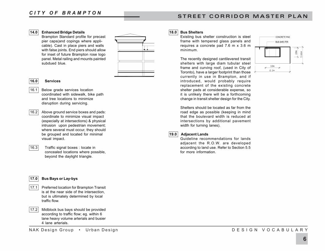
18.0 Bus SheltersExisting bus shelter construction is steelframe with tempered glass panels andrequires a concrete pad 7.6 m x 3.6 mminimum.
The recently designed cantilevered transitshelters with large diam tubular steelframe and curving roof, (used in City ofToronto), have a larger footprint than thosecurrently in use in Brampton, and ifintroduced, would probably requirereplacement of the existing concreteshelter pads at considerable expense, soit is unlikely there will be a forthcomingchange in transit shelter design for the City.
Shelters should be located as far from theroad edge as possible (keeping in mindthat the boulevard width is reduced atintersections by additional pavementwidth for turning lanes).
19.0 Adjacent LandsGuideline recommendations for landsadjacent the R.O.W. are developedaccording to land use. Refer to Section 5.5for more information.
12.2m
3.66m
C I T Y O F B R A M P T O NS T R E E T C O R R I D O R M A S T E R P L A N
N A K D e s i g n G r o u p • U r b a n D e s i g n D E S I G N V O C A B U L A R Y
5
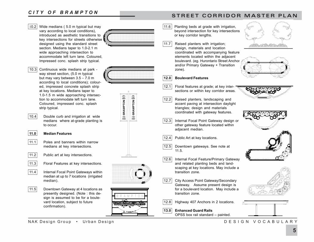
10.2 Wide medians ( 5.0 m typical but mayvary according to local conditions),introduced as aesthetic transitions tokey intersections for streets otherwisedesigned using the standard streetsection. Medians taper to 1.0-2.1 mwide approaching intersection toaccommodate left turn lane. Coloured,Impressed conc. splash strip typical.
10.3 Continuous wide medians at park -way street section, (5.0 m typicalbut may vary between 3.5 – 7.0 maccording to local conditions); colour-ed, impressed concrete splash stripat key locations. Medians taper to1.0-1.5 m wide approaching intersec-tion to accommodate left turn lane.Coloured, impressed conc. splashstrip typical.
10.4 Double curb and irrigation at widemedians where at-grade planting isto occur.
11.0 Median Features
11.1 Poles and banners within narrowmedians at key intersections.
11.2 Public art at key intersections.
11.3 Floral Features at key intersections.
11.4 Internal Focal Point Gateways withinmedian at up to 7 locations (irrigatedmedian).
11.5 Downtown Gateway at 4 locations aspresently designed. (Note : this de-sign is assumed to be for a boule-vard location, subject to futureconfirmation).
11.6 Planting beds at grade with irrigation,beyond intersection for key intersectionsor key corridor lengths.
11.7 Raised planters with irrigation;design, materials and locationcoordinated with accompanying featureelements located within the adjacentboulevard. (eg. Hurontario Street Anchorand/or Primary Gateway + Transitionzone).
12.0 Boulevard Features
12.1 Floral features at grade; at key inter-sections or within key corridor areas.
12.2 Raised planters, landscaping andaccent paving at intersection daylighttriangles; design and materialscoordinated with gateway features.
12.3 Internal Focal Point Gateway design orother gateway feature located withinadjacent median.
12.4 Public Art at key locations.
12.5 Downtown gateways. See note at11.5.
12.6 Internal Focal Feature/Primary Gatewayand related planting beds and land-scaping at key locations. May include atransition zone.
12.7 City Access Point Gateway/SecondaryGateway. Assume present design isfor a boulevard location. May include atransition zone.
12.8 Highway 407 Anchors in 2 locations.
13.0 Enhanced Guard RailsOPSS box rail standard – painted.
BR
AM
PTO
N
BR
AM
PTO
N
C I T Y O F B R A M P T O NS T R E E T C O R R I D O R M A S T E R P L A N
N A K D e s i g n G r o u p • U r b a n D e s i g n D E S I G N V O C A B U L A R Y
4
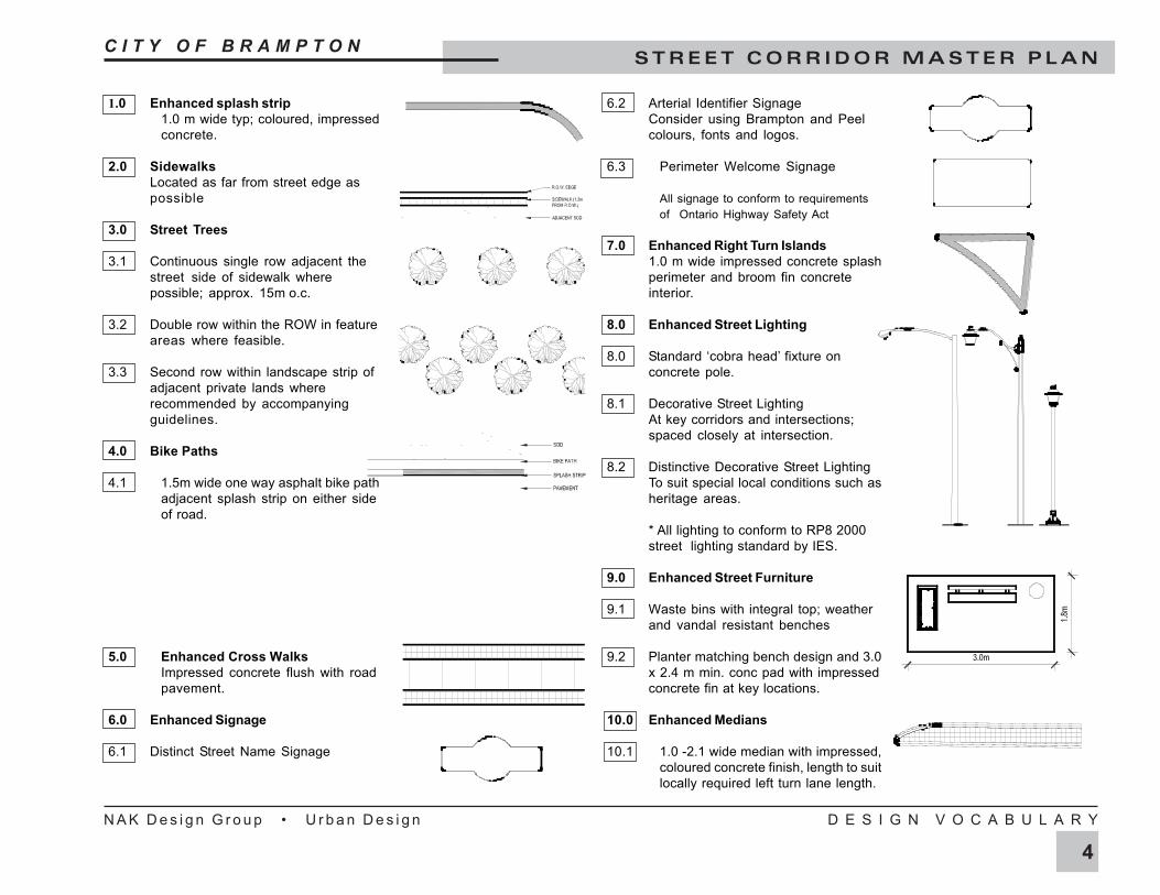
1.0 Enhanced splash strip1.0 m wide typ; coloured, impressedconcrete.
2.0 SidewalksLocated as far from street edge aspossible
3.0 Street Trees
3.1 Continuous single row adjacent thestreet side of sidewalk wherepossible; approx. 15m o.c.
3.2 Double row within the ROW in featureareas where feasible.
3.3 Second row within landscape strip ofadjacent private lands whererecommended by accompanyingguidelines.
4.0 Bike Paths
4.1 1.5m wide one way asphalt bike pathadjacent splash strip on either sideof road.
5.0 Enhanced Cross WalksImpressed concrete flush with roadpavement.
6.0 Enhanced Signage
6.1 Distinct Street Name Signage
6.2 Arterial Identifier SignageConsider using Brampton and Peelcolours, fonts and logos.
6.3 Perimeter Welcome Signage
All signage to conform to requirementsof Ontario Highway Safety Act
7.0 Enhanced Right Turn Islands1.0 m wide impressed concrete splashperimeter and broom fin concreteinterior.
8.0 Enhanced Street Lighting
8.0 Standard ‘cobra head’ fixture onconcrete pole.
8.1 Decorative Street LightingAt key corridors and intersections;spaced closely at intersection.
8.2 Distinctive Decorative Street LightingTo suit special local conditions such asheritage areas.
* All lighting to conform to RP8 2000street lighting standard by IES.
9.0 Enhanced Street Furniture
9.1 Waste bins with integral top; weatherand vandal resistant benches
9.2 Planter matching bench design and 3.0x 2.4 m min. conc pad with impressedconcrete fin at key locations.
10.0 Enhanced Medians
10.1 1.0 -2.1 wide median with impressed,coloured concrete finish, length to suitlocally required left turn lane length.
C I T Y O F B R A M P T O NS T R E E T C O R R I D O R M A S T E R P L A N
N A K D e s i g n G r o u p • U r b a n D e s i g n D E S I G N V O C A B U L A R Y
3
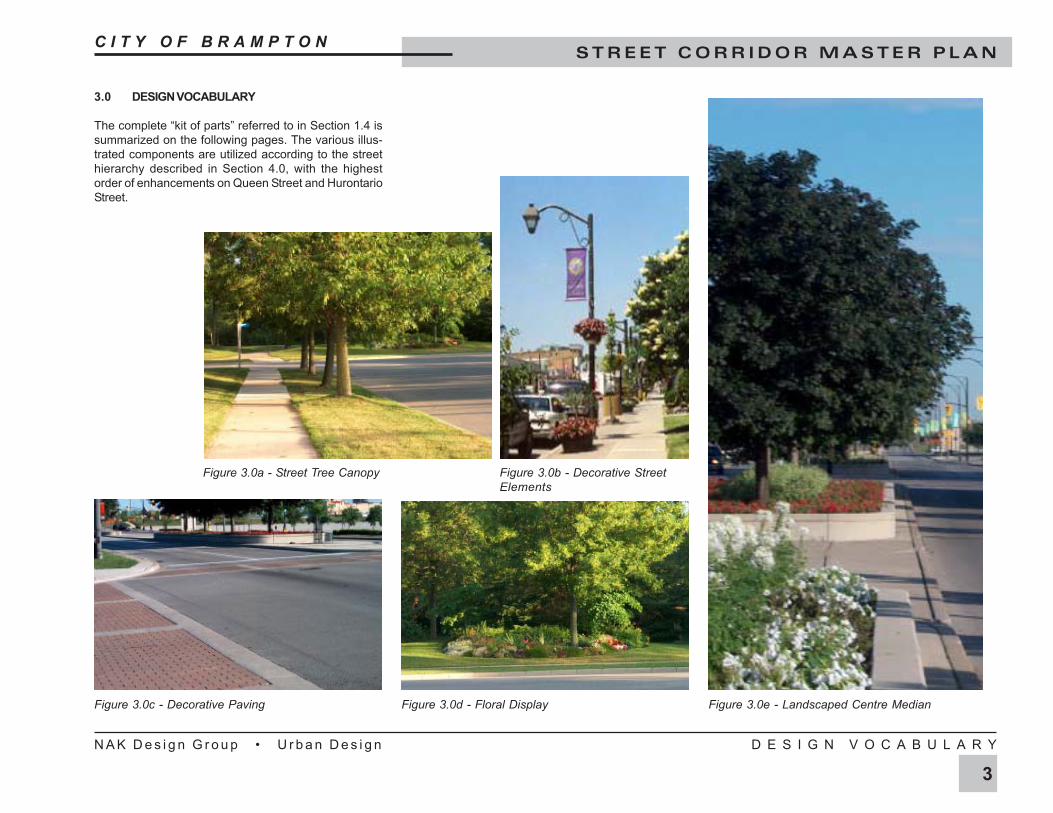
3.0 DESIGN VOCABULARY
The complete “kit of parts” referred to in Section 1.4 issummarized on the following pages. The various illus-trated components are utilized according to the streethierarchy described in Section 4.0, with the highestorder of enhancements on Queen Street and HurontarioStreet.
Figure 3.0c - Decorative Paving Figure 3.0d - Floral Display Figure 3.0e - Landscaped Centre Median
Figure 3.0a - Street Tree Canopy Figure 3.0b - Decorative StreetElements
C I T Y O F B R A M P T O NS T R E E T C O R R I D O R M A S T E R P L A N
N A K D e s i g n G r o u p • U r b a n D e s i g n P R O J E C T S C O P E
2
form an overall visual and functional composition. Thechallenge in preparing this Master Plan was to identifya number of key components that together would cre-ate a positive composition that would address theaforementioned objectives for the different types of cor-ridors. These components form the design vocabularyof the Master Plan and are essentially a “kit of parts” forthe City’s street corridors.
2.0 PROJECT SCOPE
The Street Corridor Master Plan provides a blueprintthat will guide the development of the City of Brampton’sarterial road network over the next several decades.The Master Plan supports the City’s vision and designobjective.
2.1 CITY CONTEXT
In the City-wide context, the Master Plan is an impor-tant step in achieving the City of Brampton’s designvision. It is also critical in providing detailed designguidelines for a component of urban design which hasa major impact on the image and identity of the Cityand plays a critical role in establishing a design bench-mark for the long-term development of the arterial roadnetwork.
2.2 REGIONAL CONTEXT
From a regional perspective, the Master Plan recog-nizes the relative importance of regional roads andgateways, provides the framework for the developmentof the City of Brampton as a distinct urban centre andco-ordinates the City and Region’s efforts in achieveingdesign excellence in its development.
1.3 DESIGN OBJECTIVES
The design objectives for the Arterial Road NetworkMaster Plan are:
1. To design streetscapes which reinforce the func-tional hierarchy of arterial road corridors and gateways.
2. To design streetscapes which enhance efficiencyand safety for motorists, pedestrians and cyclists.
3. To design visually attractive streetscapes.
4. To co-ordinate the elements which comprise thestreet zone including:
• Sidewalks, bikeways and walkwayconnections
• Transit stops and shelters,• Site furnishing• Street trees• Light standards• Decorative paving• Signage
5. To ensure appropriate and attractive interfaces withadjacent land uses.
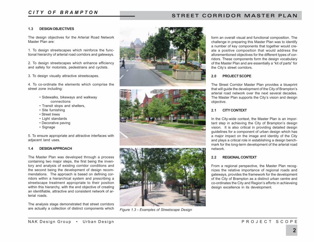
1.4 DESIGN APPROACH
The Master Plan was developed through a processcontaining two major steps, the first being the inven-tory and analysis of existing corridor conditions andthe second being the development of design recom-mendations. The approach is based on defining cor-ridors within a hierarchical system and prescribing astreetscape treatment appropriate to their positionwithin this hierarchy, with the end objective of creatingan identifiable, attractive and consistent network of ar-terial roads.
The analysis stage demonstrated that street corridorsare actually a collection of distinct components which Figure 1.3 - Examples of Streetscape Design
C I T Y O F B R A M P T O NS T R E E T C O R R I D O R M A S T E R P L A N
N A K D e s i g n G r o u p • U r b a n D e s i g n I N T R O D U C T I O N
1
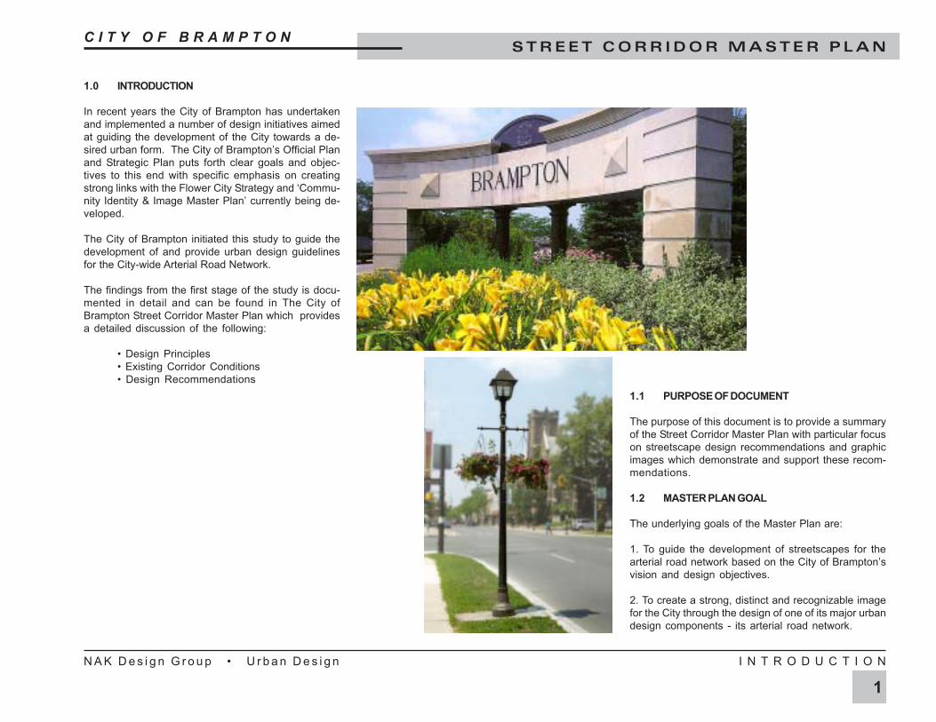
1.0 INTRODUCTION
In recent years the City of Brampton has undertakenand implemented a number of design initiatives aimedat guiding the development of the City towards a de-sired urban form. The City of Brampton’s Official Planand Strategic Plan puts forth clear goals and objec-tives to this end with specific emphasis on creatingstrong links with the Flower City Strategy and ‘Commu-nity Identity & Image Master Plan’ currently being de-veloped.
The City of Brampton initiated this study to guide thedevelopment of and provide urban design guidelinesfor the City-wide Arterial Road Network.
The findings from the first stage of the study is docu-mented in detail and can be found in The City ofBrampton Street Corridor Master Plan which providesa detailed discussion of the following:
• Design Principles• Existing Corridor Conditions• Design Recommendations
1.1 PURPOSE OF DOCUMENT
The purpose of this document is to provide a summaryof the Street Corridor Master Plan with particular focuson streetscape design recommendations and graphicimages which demonstrate and support these recom-mendations.
1.2 MASTER PLAN GOAL
The underlying goals of the Master Plan are:
1. To guide the development of streetscapes for thearterial road network based on the City of Brampton’svision and design objectives.
2. To create a strong, distinct and recognizable imagefor the City through the design of one of its major urbandesign components - its arterial road network.