city of christchurch bicycle network - sign design manual ... · map sign msp 2.1.6 used at prime...
TRANSCRIPT
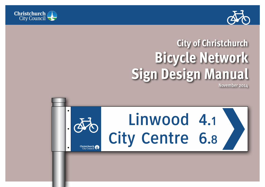
City of Christchurch
Bicycle Network Sign Design Manual
November 2014

Christchurch City Council • Bicycle Network Sign Design Manual • September 2014 2
This report was prepared for
Christchurch City CouncilPO Box 7 CHRISTCHURCH 1302New Zealand.Tel: +64 3 941 8999Fax: +64 3 941 8984Web: www.ccc.govt.nz
by
Warren SalomonSustainable Transport Consultants Pty LtdPO Box 1601 BONDI JUNCTION NSW 1355www.sustainabletransport.com.au
© Christchurch City Council November 2014
Amendment recordVersion Number
Date Description Page No.
0.1 5/11/2014 Draft preliminary report for internal comment -

Christchurch City Council • Bicycle Network Sign Design Manual • September 2014 3
Contents1 Introduction .............................................................................................................................................................................. 41.1 About this manual ......................................................................................................................................................................... 41.2 Methodology for signing bicycle routes ........................................................................................................................................ 41.3 Major sign types and their use ..................................................................................................................................................... 51.4 Sign families .............................................................................................................................................................................. 51.5 Application of different sign families ............................................................................................................................................ 91.6 Graphical standards for all sign families .................................................................................................................................... 101.6.1 Typefaces used on signs .............................................................................................................................................................. 101.6.2 Colours used on signs .................................................................................................................................................................. 111.6.3 Pictograms and logos used on signs ............................................................................................................................................ 121.6.4 Arrow types used on signs ........................................................................................................................................................... 131.7 Sign content conventions ........................................................................................................................................................... 142 Directional signs for bicycle routes .......................................................................................................................................... 162.1 Primary route signs .................................................................................................................................................................... 172.1.1 FBP Fingerboard signs ................................................................................................................................................................. 172.1.2 DIP Direction indication signs ....................................................................................................................................................... 202.1.3 ADP Advance direction signs ........................................................................................................................................................ 232.1.4 LPP Location plate signs .............................................................................................................................................................. 302.1.5 RDP Reassurance direction signs ................................................................................................................................................. 322.1.6 MSP Bicycle network map sign .................................................................................................................................................... 362.2 Local route signs ........................................................................................................................................................................ 422.2.1 FBL Local route fingerboards ....................................................................................................................................................... 422.2.2 LM Local route markers ............................................................................................................................................................... 452.3 Tourist/recreational signs ........................................................................................................................................................... 482.3.1 FBT Tourist/recreational route fingerboards .................................................................................................................................. 482.3.2 FIT Tourist/recreational facility indicators ..................................................................................................................................... 502.3.3 TMV & TMVB Tourist/Recreational Route Markers ......................................................................................................................... 522.4 Path-use signage ........................................................................................................................................................................ 542.4.1 PBS Path behaviour sign .............................................................................................................................................................. 543 Route numbering, naming and branding .................................................................................................................................. 564 Construction, materials and installation................................................................................................................................... 574.1 Construction standards ............................................................................................................................................................... 574.2 Graphic standards ....................................................................................................................................................................... 574.3 Installation standards ................................................................................................................................................................. 575 Sign maintenance ...................................................................................................................................................................... 61

Christchurch City Council • Bicycle Network Sign Design Manual • September 2014 4
1 Introduction1.1 About this manualThis sign design manual is divided into five parts:Part 1 – Introduction, methodology and sign content conventions. This section provides an overview of the signage system, guidance and a methodology for the planning and implementation of network signage usually on a route by route basis. This section also contains advice on standard abbreviations to be used on all signage where sign length needs to be minimised;Part 2 – Directional signs for bicycle routes. This consists of bicycle network signage to be used for primary, local and tourist/recreational bicycle routes in all locations, on-and off-road. This section provides dimensioned details of all types of signs used to sign the different elements of the network;Part 3 – Route numbering, naming and branding. This section provides guidelines on the use of route numbering systems, the naming of routes and the application route branding.;Part 4 – Construction, materials and installation. This section includes technical recommendations for the manufacture and placement of signs; and,Part 5 – Sign maintenance. This section covers issues associated with the on-going maintenance of the signage system.
1.2 Methodology for signing bicycle routes
The following process is undertaken when signing a bicycle route (refer to the Christchurch City Council report, Christchurch Bicycle Network Signage Plan for further information on detail issues):1. Determine the location and context of each route within the
overall bicycle network. The current edition of the Christchurch Bicycle Network Focal Point Map should be consulted to identify destinations to be listed for the route being signed and the destinations for other routes indicated at junctions. A key part of this process is to determine the Level of Signing for each bicycle route. This is done according to its position in the bicycle network route hierarchy – see Table 1 and the Christchurch Bicycle Network Signage Plan for details. Level of Signing determines the number and type of signs used for each route at a network junction;
2. Undertake a detailed sign site assessment to identify suitable locations for signs and to determine the physical condition of the route via a pre-signage and risk assessment survey;
3. Develop a signage schedule setting out the sign types and sign content to be used at route junctions;
4. Verify the sign schedule via site inspections and determine the precise locations for all signs. Update schedule with collected/corrected data;
5. Check all sign layouts for accuracy prior to manufacture. Manufacture signs;
6. Install signs; and,7. Conduct a final site check and verification of the complete sign
installation. This will be carried out by the sign designer who will issue instructions to correct any errors or omissions.
Table 1: Level of signing for bicycle routes*
Level of signing C1 C2 C3 C4Type of route High-speed, limited-access, routes All other primary bicycle routes Local routes Tourist/recreational routesAdvance direction signs
Yes, before route junctions with other C1 or C2 routes
Yes, at junctions where the route changes direction
No Route markers may be used on single routes
Fingerboards at intersection
Yes, at route junctions with other C1 or C2 routes
Yes Yes, mounted with street signage Yes
Reassurance signs with distances
Yes, after route junctions with other C1 or C2 routes
Only if advance direction signs are not used
No Route markers may be used in between intersections
Route markers No No Yes YesRoute numbering Optional No No NoBranding logos Optional Optional No Optional
*Refer to the CCC Report, City of Christchurch Bicycle Network Signage Plan for a detailed information on “level of signing” and signing methodology.
Christchurch City Council is developing a high-quality network of bicycle routes to enable residents and visitors to use their bicycles for transport, fitness and recreation on a daily basis. In order to ensure maximum use and access to this network Christchurch City Council is installing a system of directional and wayfinding signage across the bicycle network. The implementation of consistent way-finding and directional signage on the Christchurch bicycle network will help bicycle riders to more easily use the network. Comprehensive directional signage assists users to easily navigate to their trip destinations, builds user confidence in the system, increases personal safety and improves information and access to community facilities.
This manual details the design and manufacture of a comprehensive sign system covering primary, local and tourist/recreational bicycle routes located in on-road or off-road environments. A separate document, the City of Christchurch Bicycle Network Signage Plan details the methodology and process for the implementation of the signage system across the Christchurch bicycle network. This manual should be read in conjunction with the Signage Plan.
The implementation of bicycle route signage on the existing network will be undertaken as a progressive rollout at priority locations. All new cycle routes will include a signage component in accordance with this manual.

Christchurch City Council • Bicycle Network Sign Design Manual • September 2014 5
1.3 Major sign types and their useTable 2: CCC Bicycle Network and Local Facility Signage – Sign types and their usage
Sign Class Sign type Sign code
Manual section
Primary use Use with other sign families
Primary route
Fingerboard FBP 2.1.1 Used to indicate route direction only at intersections with other routes (primary or local). When used FBP signs always display distances.
Used also at branching junctions with local routes
Primary route
Direction Indication
DIP 2.1.2 Used in place of fingerboards at route junctions and at other intersections where the route changes direction. This sign can also be used for reassurance in-between intersections. Distances are only used when used in place of fingerboards at route junctions.
Used also at branching junctions with local routes
Primary route
Advance Direction
ADP 2.1.3 Used to indicate upcoming route options only at intersections of primary and secondary routes. ADP signs never display distances and only shown focal points (not sub destinations)
Only used on primary routes
Primary route
Location Plate LPP 2.1.4 Used to denote streets or roads which cross over the top of bicycle routes. Usually fixed to the face of bridges or overpasses. Can also be used to denote important adjacent streets.
Can be used for primary and local routes
Primary route
Reassurance Direction
RDP 2.1.5 Used to denote distances to upcoming directions after a major primary route junction.
Used mainly on high-speed, limited-access cycleways but can be used if reassurance is required on primary routes
Primary route
Map sign MSP 2.1.6 Used at prime network ‘gateway’ locations to advise cyclists of multiple network choices available from the map location.
See additional diagrams in this manual for on-road and off-road siting locations
Local route Fingerboard FBL 2.2.1 Used at intersections or path junctions where a local route branches from a primary route. Also used at the route destination indicating the route back to the start of the route (primary junction).
Where a local route branches from a primary route FBP fingerboards are also fitted to this intersection to show destinations and distances for the primary route
Local route Marker LMV LMH
2.2.2 Used at intersections, path junctions and route turnings to indicate the path of a local route
Only used on local routes in between FBL signs
Tourist/ recreational route
Fingerboard FBT 2.3.1 Used at the start and finish of tourist/recreational routes. Used at intersections or path junctions where the tourist/recreational route branches from a primary route.
Where a tourist/recreational route branches from a primary route FBP fingerboards are also fitted to this intersection to show destinations and distances for the primary route
Tourist/ recreational route
Facility indicator sign (fingerboard)
FIT 2.3.2 Used at points along a tourist/recreational route to indicate the road or path or route to facilities and attractions associated with the route. Also used at the facility to indicate the path back to the main route.
Only used on tourist/recreational routes
Tourist/ recreational route
Marker TMV TMVB
2.3.3 Used at intersections, path junctions and route turnings to indicate the path of a local route
Only used on tourist/recreational routes in between FBT signs
Path behaviour
Path behaviour sign
PBS 2.4.1 Used on paths to indicate preferred user behaviour See advice in Section 2.4.1 of this manual
1.4 Sign familiesThere are three sign groups or families – one for each route type within the bicycle network hierarchy of routes. These sign families are shown pages 6, 7 and 8 of this manual.
Primary route signsPrimary routes are the spine of the network from which local bicycle routes radiate. They provide connections between areas of high population density and major activity centres, such as public transport nodes, universities, schools, shopping or commercial centres, industrial areas and regional recreational facilities. Primary routes are usually high-quality, high-priority routes providing quick unhindered travel between the major centres offering the most direct access with minimal delays. The primary route sign family is shown on page 6 of this manual.
Local route signsLocal routes provide high quality connectivity usually feeding from primary routes to residential streets and local trip-generating facilities such as schools, bus and train interchanges, pools, libraries and shops. Local routes provide for necessary circulation within the city and suburbs. The local route sign family is shown on page 7 of this manual.
Tourist/recreational route signsTourist or recreational routes are designated routes which provide recreational and tourist bicycle access within the city or across regions. Examples of this type of route are rail trails (built along disused rail corridors), riverside pathways and historical trails. The tourist/recreational route sign family is shown on page 8 of this manual.
Path behaviour signsPath behaviour guidance signage is available for installation to communicate key behavioural messages to path users. A multi message sign has been developed for use on shared paths. Additional single message signs are also available for use in shared path environments. The path behaviour guidance sign family is shown on page 8 of this manual.

Primary route sign family
FBP Fingerboard SignMounted at junctions with other routes (primary,secondary or local)
ADP Advance Direction SignIndicates route direction information in advance of a junction with another primary route
DIP Direction Indication Sign To indicate travel direction only
RDP Reassurance Direction Sign Indicates destinations following a route junction
MSP Map SignIndcates bicycle routes available at a location
LPP Location Plate Sign For indicating important cross streets and roads. Sign is mounted above the entrances to path underpasses, subways or over-bridge structures
Christchurch City Council • Bicycle Network Sign Design Manual • September 2014 6
Primary route signs FBP - Fingerboards The sign type is used only at primary route junctions with other primary routes and with local routes. Refer to Drawings FBP-1 and FBP-2
DIP - Direction Indication Sign This plate-type sign is used to indicate continuing direction or change of direction for a primary or secondary route. It can be used at or near intersections or at points along a route. Refer to Drawings DIP and DIP-1-3
ADP - Advance Direction Sign This type of sign is used only on primary or secondary routes in advance of a junction with another primary or secondary route. Refer to Drawings ADP, ADP-2-4, ADP-5-6, ADPNR and ADPG
RDP - Reassurance Direction Sign This type of sign is used following a junction of primary routes to reassure riders and inform them of the distances to listed destinations. This type of sign is only used on routes with C1 level of signing such as high-speed, limited access cycleways. Refer to Drawings RDP, RDP-1-6 and RDPNR
LPP - Location Plate Sign This type of sign is used to mark cross streets/roads on the faces of bridges over bikeways or at underpasses. Refer to Drawings LPP
MSP Bicycle Network Map Sign This type of sign is only used at selected gateway locations where a number of route possibilities are available. A map can easily show multiple route possibilities within an area. Refer to Drawings MSP-A to MSP-D

Local route sign family
FBL-1 Fingerboard SignOne-line �ngerboard with pictograms. Shown mounted with local street sign �ngerboard
FBL-2 Fingerboard SignTwo-line �ngerboard indicating a primary route and its destinations. Shown mounted with local street sign �ngerboard
LMH Route Marker Horizontal Fingerboard type mounting. Shown mounted with local street sign.
PBS Path Behaviour SignFor use on shared paths to improve user behaviour
LMV Route Marker Vertical Used to indicate direction between �ngerboards
Christchurch City Council • Bicycle Network Sign Design Manual • September 2014 7
Local route signs FBL - Local route fingerboard This type of sign is used at the junction of a local route where it branches from a primary or secondary route and as a final sign towards the end of a local route pointing to the final destination. Refer to Drawings FBL-1 and FBL-2
LM - Local route marker This type of sign is used to indicate continuing direction and turnings for local routes in between local route fingerboards. Refer to Drawing LMH/LMV
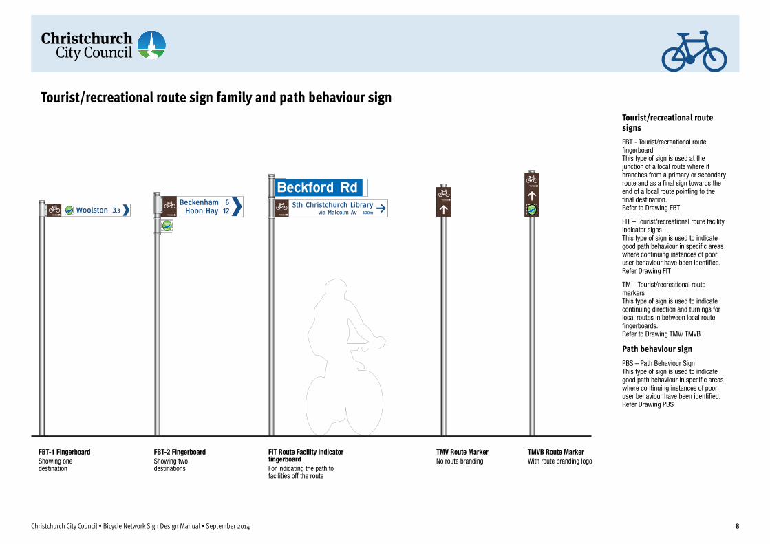
Tourist/recreational route sign family and path behaviour sign
FBT-1 Fingerboard Showing one destination
FBT-2 FingerboardShowing two destinations
TMV Route MarkerNo route branding
FIT Route Facility Indicator �ngerboardFor indicating the path to facilities off the route
TMVB Route MarkerWith route branding logo
Christchurch City Council • Bicycle Network Sign Design Manual • September 2014 8
Tourist/recreational route signs FBT - Tourist/recreational route fingerboard This type of sign is used at the junction of a local route where it branches from a primary or secondary route and as a final sign towards the end of a local route pointing to the final destination. Refer to Drawing FBT
FIT – Tourist/recreational route facility indicator signs This type of sign is used to indicate good path behaviour in specific areas where continuing instances of poor user behaviour have been identified. Refer Drawing FIT
TM – Tourist/recreational route markers This type of sign is used to indicate continuing direction and turnings for local routes in between local route fingerboards. Refer to Drawing TMV/ TMVB
Path behaviour sign PBS – Path Behaviour Sign This type of sign is used to indicate good path behaviour in specific areas where continuing instances of poor user behaviour have been identified. Refer Drawing PBS

Signing primary route intersectionsAt primary or secondary route junctions with another primary or secondary route (as in the junctions marked “a”) use two �ngerboards for each route at the junction and one advance direction sign 30-50m before the junction in each direction for each route.Direction indication signs are used on primary and secondary routes for reassurance between major intersections and at turnings where other routes are not present. See examples on the map marked “b”. Pavement markings can also be used to indicate dif�cult turnings and on- to off-road transitions.Map Boards are ideally located in an area with enough space to view the map in a safe off road environment such as adjacent parkland (see map example “c”).
a
b
f
d
c i
c i
c
gSigning local route intersections and destinationsWhere local routes branch from, or intersect with, primary or secondary routes (see map examples “d”) use one Local Destination �ngerboard for the local route and two �ngerboards for the primary route, one for each direction. Advance direction signs are not used on the primary/secondary route to indicate local route junctions.Local routes use �ngerboards only at each end of the route. The �rst points to the local destination as it branches from the primary/secondary, or local route. The second is located at the last turn before the destination (see example “e”). At all intermediate turns and for reassurance, route marker signs are used (see examples “f”). Road pavement markers can also be used on local routes.
Signing tourist/recreational routesThe Local Facility signage series (blue background with white lettering) is primarily intended as an aid to way�nding for pedestrian path users and to connect paths (often located in remote locations) to the local street system.Local Facility �ngerboards are used to indicate path services and facilities and to indicate the way to local centres remote from the path (see examples “g”). Linked street pavement indicators are the primary method of indicating all streets connected to the main path via access paths (see map example “h”). Information Maps are ideally located at key path junctions and at high pedestrian activity areas (see map example “i”).
Using different sign families at junctions where routes connectThe example, left, is an enlargement of the circled path intersection. This intersection is a junction between primary and local bicycle routes. The path between “h” and “g” (shown on the map right) also links the main path to the local street system for pedestrians.At this location the path junction should be signed for all users:• Bicycle Network �ngerboards (j) and ADP signs (k);• Local Destination �ngerboard indicating the route to the train station (l);• Linked street pavement markers (m) at each end of the linking path and
�ngerboards (n) at each end as the link path is lengthy.
b
a
b
b
b
b
dd
d
e
gg
a
h h
h
hh
j j
k
nl
m k
f
f f
f
ff
f
Legend
Schools, colleges and universities
Retail, cafes and entertainment
Government buildings
Parks and open public space
Commercial and industrial
Primary routeon-road
Primary routeoff-road within road corridor
Primary routeoff-road in parklands
Local routeoff-road
Local routeon-road
Linking path to local street system
Christchurch City Council • Bicycle Network Sign Design Manual • September 2014 9
Application of sign types
Bicycle network routes on- and off-roadThis group of signs is used to provide directional and wayfinding information for all CCC Bicycle Network Primary Routes. Refer to Section 2.1 for details
Local bicycle routes on- and off-roadThis group of sign types is used to provide directional and wayfinding information for all CCC Bicycle Network Local Routes. Refer to Section 2.2 for details
Tourist/recreational bicycle routes on- and off-roadThis group of sign types is used to provide directional and wayfinding information for tourist/recreational routes such as coastal trails, riverside trails and rail trails. Refer to Section 2.3 for details
Path behaviour signage for shared paths in parkland locationsThis group of signs and pavement markings is used to provide directional and wayfinding information primarily for pedestrians on all CCC shared paths. Refer to Section 2.4 for details
1.5 Application of different sign families

ABCDEFGHIJKLMNOPQRSTUVWXYZabcdefghijklmnopqrstuvwxyzClearview 3B - for blue letters on white base
ABCDEFGHIJKLMNOPQRSTUVWXYZabcdefghijklmnopqrstuvwxyzClearview 3W - for white letters on blue base
All measurements for lettering heights on signs are for the ‘X-height’
Notes for destination names and distances layout for �ngerboards and reassurance direction signsShowing distance numeral layout for destinations of less than a kilometre1. Destinations are listed �ush left. Lettering Cap X-height on FBP, RDP, FBL, FBT and FIT type signs is 60mm.2. Distance numerals one kilometre and above are the same point size as destination names.
Numerals for distances less than one kilometre are shown in metres and have a Cap X-height of 45mm. 3. Distance numerals are aligned on the decimal point and to the right side of the sign. 4. Distances less than 10km are shown to the nearest 100 metres in standard decimal form. 5. Distances less than one kilometre are shown in metres (rounded up to the nearest 100 metres eg: 500m - see above
example). The numerals and the ‘m’ abbreviation (no space in between) are aligned right with other destination numerals.6. If the destination can be seen from the sign location (ie less than 100m etc, then a distance should not be shown.
Distance numerals �ush right and aligned on the decimal point
Numerals for distances less than one kilometre and the sub-kilometre part of distances under 10km have a 45mm X-height
For signs showing only distances without decimal points, these distance numerals are aligned �ush right with the edge of the type zone
X-HEIGHT
Christchurch City Council • Bicycle Network Sign Design Manual • September 2014 10
Fonts
Clearview 3-BThe Clearview 3-B typeface is to be used on primary, local and tourist/recreational route signage for all destination names, text and numerals where blue or brown lettering on a white base is specified as detailed on individual sign type layout diagrams. All lettering shall be true to its letter form in face weight and construction.
Clearview 3-WThe Clearview 3-W typeface is to be used on primary, local and tourist/recreational route signage where white lettering on a black base is specified. All lettering shall be true to its letter form in face weight and construction.
Note: It is the responsibility of the signmaker to purchase the correct font. No other versions, similar or otherwise will be accepted.
1.6 Graphical standards for all sign families
1.6.1 Typefaces used on signs

AS2700 B23 Bright BlueRGB 23, 79, 137Pantone 7686C
PRIMARY SIGN COLOURS
PICTOGRAM/SYMBOL COLOURS
AS2700 G37Dark BrownRGB 79, 54, 45Pantone 476C
White symbol on blueAS2700 B23 Blue
Yellow symbol AS2700 Y26 Yellow on AS2700 B23 Blue
White symbol on AS2700 G13 Emerald Green
White symbol on AS2700 R13 Red
White symbol on AS2700 B23 Blue
Christchurch City Council • Bicycle Network Sign Design Manual • September 2014 11
ColoursColours as specified to be used for all parts and faces as noted on the sign type drawings.
AS2700 B23 Bright BlueUsed on all bicycle network signs for distance names and numerals, sign mastheads and pictograms as indicated on individual sign layouts.
AS2700 X65 Dark BrownUsed on all tourist/recreational signs as indicated on individual sign layouts.
AS2700 G13 Emerald GreenUsed as the background colour on the hospital/medical centre pictogram.
AS2700 BR13 Signal RedUsed as the background colour on the Fire Station pictogram.
1.6.2 Colours used on signs

PTI - Tourist Information Centre
PPS - Police Station
PHM - Hospital or Medical Centre
PFS - Fire Station PRE - Restaurant
PHS - Historic Site
PCA - CafePPT - Public Telephone
PMF - Public Toilets
PDW - Drinking Water
PSP - Swimming pool or beach
PWS - Walking path entrance
PTR - Train Station PLO - LookoutPAP - Airport
PBP - Bicycle Parking
PBS - Bicycle Shop (Repairs)
PSC - Shops or Shopping Centre
PPO - Post Of�ce
PAT - Auto Teller Machine
Christchurch City Council • Bicycle Network Sign Design Manual • September 2014 12
PictogramsPictograms to be selected relative to each section of the local destination route.
Pictograms will be provided digitally and must be scaled proportionally.
Note: pictograms may be obtained by the principal in charge upon request.
When nominating pictograms, use the codes provided eg. (PTR) = Train Station
1.6.3 Pictograms and logos used on signs
40mm78mm
130m
m
FBDA-1 DETAILSmall direction arrow for one-line �ngerboard
40mm
56mm120mm
220m
m56mm
FBDA-2 DETAILSmall direction arrow for two-line �ngerboard
Arrow sizing for all on-road cycle network directional signage is the width of the arrow head as indicated in the sample left.Ar
row
siz
esgi
ven
in m
m
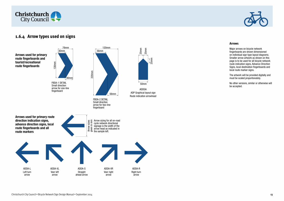
Arrows used for primary route �ngerboards and tourist/recreational route �ngerboards
Arrows used for primary route direction indication signs, advance direction signs, local route �ngerboards and all route markers
ADDA-LLeft turn
arrow
ADDA-VLVeer left arrow
ADDA-SStraight
ahead arrow
ADDA-VRVeer right
arrow
ADDA-RRight turn
arrow
50mm
25m
m
25m
m
25m
m
ADDGAADP Graphical layout sign
Route indication arrowhead
Christchurch City Council • Bicycle Network Sign Design Manual • September 2014 13
ArrowsMajor arrows on bicycle network fingerboards are shown dimensioned on individual sign type layout diagrams. Smaller arrow artwork as shown on this page is to be used for all bicycle network route indication signs, Advance Direction Signs, local destination fingerboards and local route marker signs.
The artwork will be provided digitally and must be scaled proportionately.
No other versions, similar or otherwise will be accepted.
1.6.4 Arrow types used on signs

Christchurch City Council • Bicycle Network Sign Design Manual • September 2014 14
1.7 Sign content conventionsPrimary route fingerboards• Fingerboards are usually double-sided signs which show
destinations and their distances. See sign layouts and details in Section 2.1.1.
• Primary route fingerboards are used at route junctions with other primary, local or tourist/recreational bicycle routes.
• When fingerboards are used along a route to indicate a change of route direction only, distance numerals are not used.
• Destination names are shown in mixed capitals and lower case. The Cap X-height of destination lettering is 60mm.
• The destination closest to the sign site is listed at the top of the sign with other destinations below in increasing distance order.
• Destination names are always aligned (justified) to the distance numerals and/or direction arrow (for a straght ahead arrow – always on the left side of the sign – the destination name(s) are left justified, for a right turn arrow the destination names are right justified).
• Distance numerals are located between the direction arrow and the destination name.
• The direction arrow always points outwards from the sign mounting towards the direction of travel.
• Distances above 10km are rounded to the nearest kilometre.• Distances less than 10km are shown to the nearest 100
metres in standard decimal form. • Distances less than one kilometre are shown in metres
(rounded to the nearest 100 metres eg: 300m). When listed on signs the numerals and the ‘m’ abbreviation (no space in between) are aligned right with other destination numerals.
• Distance numerals are aligned on the decimal point. • Distance numerals one kilometre and above are the same
point size as destination names. Numerals for distances less than one kilometre are shown in metres and have a Cap X-height of 45mm.
• Maximum length of fingerboard is 1200mm subject to lettering content.
• The white bicycle symbol in blue background is always located at the mounting end of each sign face. The bicycle always faces in the direction of travel.
Direction indication signs• Direction indication signs are generally used to indicate the
change of direction along a route where fingerboard signs cannot be used due to siting/mounting or legibility issues. In situations where fingerboards cannot be used at route junctions, direction indication signs may be used instead. When used at route junctions, direction indication signs show distances to destinations. When used along a route to indicate a change of route direction only, distance numerals are not used. See sign layouts and details in Section 2.1.2.
• Direction indication signs are only used to indicate a single route.
• Destination names are shown in mixed capitals and lower case. The Cap X-height of destination lettering is 60mm.
• The destination closest to the sign site is listed at the top of the sign with other destinations below in increasing distance order.
• Destination names are always aligned (justified) to the distance numerals and/or direction arrow (for a straght ahead arrow – always on the left side of the sign – the destination name(s) are left justified, for a right turn arrow the destination names are right justified).
• Distance numerals, when used, are located between the direction arrow and the destination name.
• The direction arrow always points outwards from the sign mounting towards the direction of travel.
• Distances above 10km, when used, are rounded to the nearest kilometre.
• Distances less than 10km, when used, are shown to the nearest 100 metres in standard decimal form.
• Distances less than one kilometre, when used, are shown in metres (rounded to the nearest 100 metres eg: 300m). When listed on signs the numerals and the ‘m’ abbreviation (no space in between) are aligned right with other destination numerals.
• Distance numerals, when used, are aligned on the decimal point.
• Distance numerals one kilometre and above, when used, are the same point size as destination names. Numerals for distances less than one kilometre are shown in metres and have a Cap X-height of 45mm.
• The white bicycle symbol is always located centred in the dark blue sign header. The bicycle always faces in the direction of travel if a turn is indicated. Where the sign indicates a straight ahead travel direction, the bicycle faces to the right side of the sign.
Advance direction signs• Advance direction signs are used to indicate the destination
choices for multiple routes in advance of a primary route junction. Advance direction signs are not usually used at local route junctions except in situations where the local route leads to a particularly strong trip attractor. Advance direction signs may be used at primary route junctions with tourist/recreational routes. See sign layouts and details in Section 2.1.3.
• Advance direction signs only show focal point destinations and never sub destinations.
• Advance direction signs never show distances.• Destination names are shown in mixed capitals and lower
case. The Cap X-height of destination lettering is 60mm.• Destination names are always aligned (justified) to the
direction arrow (for a straght ahead arrow – always on the left side of the sign – the destination name(s) are left justified, for a right turn arrow the destination names are right justified).
• The destination name and direction of travel arrow for the route being followed is always shown at the top of the sign. The destinations for other routes crossing or branching at the junction are listed below in order of network importance (routes to more popular destinations are listed ahead of more remote destinations).
• Destinations for branching or crossed routes are grouped with each direction indication arrow located between the destination lettering and the edge of the sign and facing outwards in the direction of travel for that route.
• Separate routes are indicated by a horizontal line between each route destination (where a route branches at the junction), or destinations (where a route is crossed at the junction).
• The white bicycle symbol is always located centred in the dark blue sign header. The bicycle always faces in the direction of travel if a turn is indicated for the route being followed. Where the sign indicates a straight ahead travel direction for the route
Christchurch City Council • Bicycle Network Sign Design Manual • September 2014 15
being followed, the bicycle faces to the right side of the sign.
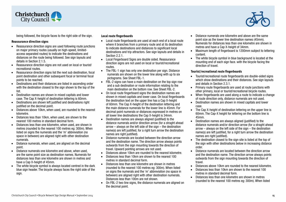
Reassurance direction signs• Reassurance direction signs are used following route junctions
on major primary routes (usually on high-speed, limited-access separated routes) to indicate the destinations and distances on the route being followed. See sign layouts and details in Section 2.1.5.
• Reassurance direction signs are not used on local or tourist/recreational routes.
• Reassurance direction signs list the next sub destination, focal point destination and other subsequent focal or terminal focal points to be reached.
• Destinations and their distances are listed in ascending order with the destination closest to the sign shown to the top of the list.
• Destination names are shown in mixed capitals and lower case. The Cap X-height of destination lettering is 60mm.
• Destinations are shown left justified and destinations right justified on the decimal point.
• Distances above 10km, when used, are rounded to the nearest kilometre.
• Distances less than 10km, when used, are shown to the nearest 100 metres in standard decimal form.
• Distances less than one kilometre, when used, are shown in metres (rounded to the nearest 100 metres eg: 300m). When listed on signs the numerals and the ‘m’ abbreviation (no space in between) are aligned right with other destination numerals.
• Distance numerals, when used, are aligned on the decimal point.
• Distance numerals one kilometre and above, when used, are the same point size as destination names. Numerals for distances less than one kilometre are shown in metres and have a Cap X-height of 45mm.
• The white bicycle symbol is always located centred in the dark blue sign header. The bicycle always faces the right side of the sign.
Local route fingerboards• Local route fingerboards are used at each end of a local route
where it branches from a primary route and at its destination to indicate destinations and distances to significant local destinations and trip attractors. See sign layouts and details in Section 2.2.1.
• Local Fingerboard Signs are double sided. Reassurance direction signs are not used on local or tourist/recreational routes.
• The FBL-1 sign has only one destination per sign. Distance numerals are shown on the lower line along with up to six pictograms. See Sheet FBL-1.
• FBL-2 signs can have a main destination on the top sign row and a sub destination or route information relating to the main destination on the bottom row. See Sheet FBL-2.
• On local route fingerboard signs the destination names are shown in mixed capitals and lower case. On local fingerboards the destination text on the upper line has a Cap X-height of 60mm. The Cap X-height of the destination lettering and the main distance numerals for the lower line is 45mm. For decimal point numerals or distances expressed in metres on all lower line destinations the Cap X-height is 34mm.
• Destination names are always aligned (justified) to the distance numerals and/or direction arrow (for a straght ahead arrow – always on the left side of the sign – the destination name(s) are left justified, for a right turn arrow the destination names are right justified).
• Distance numerals are located between the direction arrow and the destination name. The direction arrow always points outwards from the sign mounting towards the direction of travel. Upward pointing arrows are not used.
• Distances above 10km are rounded to the nearest kilometre.• Distances less than 10km are shown to the nearest 100
metres in standard decimal form. • Distances less than one kilometre are shown in metres
(rounded to the nearest 100 metres eg: 300m). When listed on signs the numerals and the ‘m’ abbreviation (no space in between) are aligned right with other destination numerals. Distances less than 100m are not shown.
• On FBL-2 two line signs, the distance numerals are aligned on the decimal point.
• Distance numerals one kilometre and above are the same point size as the lower line destination names (45mm). Numerals for distances less than one kilometre are shown in metres and have a Cap X-height of 34mm.
• Maximum length of fingerboard is 1200mm subject to lettering content.
• The white bicycle symbol in blue background is located at the mounting end of each sign face. with the bicycle facing the direction of travel.
Tourist/recreational route fingerboards• Tourist/recreational route fingerboards are double-sided signs
which show destinations and their distances. See sign layouts and details in Section 2.3.1.
• Primary route fingerboards are used at route junctions with other primary, local or tourist/recreational bicycle routes.
• When fingerboards are used along a route to indicate a change of route direction only, distance numerals are not used.
• Destination names are shown in mixed capitals and lower case.
• The Cap X-height of destination lettering on the upper line is 60mm. The Cap-X height for lettering on the bottom line is 45mm.
• Destination names are always aligned (justified) to the distance numerals and/or direction arrow (for a straght ahead arrow – always on the left side of the sign – the destination name(s) are left justified, for a right turn arrow the destination names are right justified).
• The destination closest to the sign site is listed at the top of the sign with other destinations below in increasing distance order.
• Distance numerals are located between the direction arrow and the destination name. The direction arrow always points outwards from the sign mounting towards the direction of travel.
• Distances above 10km are rounded to the nearest kilometre.• Distances less than 10km are shown to the nearest 100
metres in standard decimal form. • Distances less than one kilometre are shown in metres
(rounded to the nearest 100 metres eg: 300m). When listed

Christchurch City Council • Bicycle Network Sign Design Manual • September 2014 16
on signs the numerals and the ‘m’ abbreviation (no space in between) are aligned right with other destination numerals.
• Distance numerals are aligned on the decimal point. • Distance numerals one kilometre and above are the same
point size as destination names. • Numerals for distances less than one kilometre are shown in
metres and have a Cap X-height of 45mm for distance on the top line of the sign and 34mm for the lower line.
• Maximum length of fingerboard is 1200mm subject to lettering content.
• The white bicycle symbol in blue background is always located at the mounting end of each sign face. The bicycle always faces in the direction of travel.
Abbreviations Where a destination name is lengthy and greatly increases the potential size of a sign, an abbreviation may be used to reduce the overall size and cost of the sign.
Table 3 lists abbreviations which may be used on CCC bicycle network signage. Contact the CCC Bicycle Network Team for advice on other words not listed below.
Table 3 – Sign abbreviations
Name AbbreviationAvenue AvBrook BkCourt CtCreek CkCrescent CrEast EastHighway HwyIsland IsJunction JctKilometre, also Kilometres KmKilometres per hour Km/hMetre mMotorway MwyMountain MtNew Zealand NZNorth NthParade PdePark PkRailway RlyReserve ResRoad RdSouth SthSquare SqStation StnStreet StTerrace TceUniversity UniWest West

Christchurch City Council • Bicycle Network Sign Design Manual • September 2014 17
2 Directional signs for bicycle routes
Christchurch City Council • Bicycle Network Sign Design Manual • September 2014 18
2.1 Primary route signs
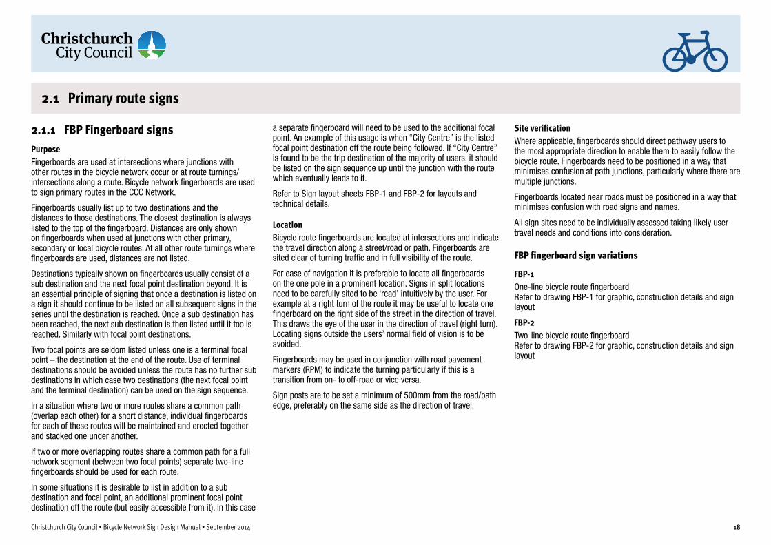
a separate fingerboard will need to be used to the additional focal point. An example of this usage is when “City Centre” is the listed focal point destination off the route being followed. If “City Centre” is found to be the trip destination of the majority of users, it should be listed on the sign sequence up until the junction with the route which eventually leads to it.
Refer to Sign layout sheets FBP-1 and FBP-2 for layouts and technical details.
LocationBicycle route fingerboards are located at intersections and indicate the travel direction along a street/road or path. Fingerboards are sited clear of turning traffic and in full visibility of the route.
For ease of navigation it is preferable to locate all fingerboards on the one pole in a prominent location. Signs in split locations need to be carefully sited to be ‘read’ intuitively by the user. For example at a right turn of the route it may be useful to locate one fingerboard on the right side of the street in the direction of travel. This draws the eye of the user in the direction of travel (right turn). Locating signs outside the users’ normal field of vision is to be avoided.
Fingerboards may be used in conjunction with road pavement markers (RPM) to indicate the turning particularly if this is a transition from on- to off-road or vice versa.
Sign posts are to be set a minimum of 500mm from the road/path edge, preferably on the same side as the direction of travel.
Site verificationWhere applicable, fingerboards should direct pathway users to the most appropriate direction to enable them to easily follow the bicycle route. Fingerboards need to be positioned in a way that minimises confusion at path junctions, particularly where there are multiple junctions.
Fingerboards located near roads must be positioned in a way that minimises confusion with road signs and names.
All sign sites need to be individually assessed taking likely user travel needs and conditions into consideration.
FBP fingerboard sign variations
FBP-1One-line bicycle route fingerboardRefer to drawing FBP-1 for graphic, construction details and sign layout
FBP-2Two-line bicycle route fingerboardRefer to drawing FBP-2 for graphic, construction details and sign layout
2.1.1 FBP Fingerboard signsPurposeFingerboards are used at intersections where junctions with other routes in the bicycle network occur or at route turnings/intersections along a route. Bicycle network fingerboards are used to sign primary routes in the CCC Network.
Fingerboards usually list up to two destinations and the distances to those destinations. The closest destination is always listed to the top of the fingerboard. Distances are only shown on fingerboards when used at junctions with other primary, secondary or local bicycle routes. At all other route turnings where fingerboards are used, distances are not listed.
Destinations typically shown on fingerboards usually consist of a sub destination and the next focal point destination beyond. It is an essential principle of signing that once a destination is listed on a sign it should continue to be listed on all subsequent signs in the series until the destination is reached. Once a sub destination has been reached, the next sub destination is then listed until it too is reached. Similarly with focal point destinations.
Two focal points are seldom listed unless one is a terminal focal point – the destination at the end of the route. Use of terminal destinations should be avoided unless the route has no further sub destinations in which case two destinations (the next focal point and the terminal destination) can be used on the sign sequence.
In a situation where two or more routes share a common path (overlap each other) for a short distance, individual fingerboards for each of these routes will be maintained and erected together and stacked one under another.
If two or more overlapping routes share a common path for a full network segment (between two focal points) separate two-line fingerboards should be used for each route.
In some situations it is desirable to list in addition to a sub destination and focal point, an additional prominent focal point destination off the route (but easily accessible from it). In this case

FBP-1 One-line primary route �ngerboard mounting arrangement.Length of �ngerboard to suit sign content.
45m
m45
mm
60m
m
150m
m
30mm 15mm40mm10mm
10mm
Section under clamp required for mounting in blue colour
40mm min
Bicycle symbol (130mm x 82.5mm) centred in blue area
160mm
FBP-1 One-line primary route �ngerboard artwork template
Sign content notes1. Distance numerals are located between the direction arrow and the destination name.
The direction arrow always points outwards from the sign mounting towards the direction of travel.
2. The white cyclist symbol in blue background is always located at the mounting end of each sign face. The cyclist always faces in the direction of travel.
3. Distances above 10km are rounded to the nearest kilometre.4. Distances less than 10km are shown to the nearest 100 metres in standard decimal
form. 5. Distances less than one kilometre are shown in metres (rounded to the nearest 100
metres eg: 300m). When listed on signs the numerals and the ‘m’ abbreviation (no space in between) are aligned right with other destination numerals.
6. Distance numerals are aligned on the decimal point. 7. Distance numerals one kilometre and above are the same point size as destination
names. Numerals for distances less than one kilometre are shown in metres and have a Cap X-height of 45mm.
8. Maximum length of �ngerboard is 1200mm subject to lettering content. FBP-1 One-line primary route �ngerboard reverse faceShowing layout arrangement for reverse face of �ngerboard
5mm radius on all protruding corners
FBP-1 One-line fingerboard
10mm
10mm White CCC logo (100mm x 25mm)
100m
m
Christchurch City Council • Bicycle Network Sign Design Manual • September 2014 19
FBP-1 Technical Details
Construction Details1. 150mm high (length to suit lettering)
6mm aluminium Standard Grade H5005 H34 with 5mm radius corners. Maximum length 1200mm subject to content.
2. Mounting and construction to CCC Construction Standard Specification.
3. Mount using standard galv/steel 150mm sign clamp. See Section 4 of this manual for details when mounting with other fingerboards.
Graphic DetailsDigital printed graphics in AS2700 B23 Bright Blue using full solvent inks onto white Class 2 retroreflective material sheeted with anti-graffiti overlay film NI-EF 40801-12-45 or equivalent.
SizesDESTINATIONS/DISTANCES 60mm cap X-height (Clearview 3-B) Numerals: ≥1km 60mm cap X-height, <1km 45mm cap x-height
BICYCLE SYMBOL White bicycle symbol 130mm x 82.5mm
ARROWS FBDA-1 fingerboard arrow
Drawing Number:
FBP-1

5mm radius on all protruding corners
FBP-2 Two-line primary route �ngerboard mounting arrangement.Length of �ngerboard to suit sign content. Layout arrangement for reverse face of this �ngerboard is similar to the FBP-1 �ngerboard reverse face layout.
140m
m
160mm
40m
m40
mm
60m
m40
mm
60m
m
240m
m
30mm 15mm40mm min
Section under clamp or required for mounting in blue colour
10mm
10mm
FBP-2 Two-line primary route �ngerboard artwork template
40mm
FBP-2 Two-line primary route �ngerboard layout Showing distance numeral layout for destinations of less than a kilometre
Sign content notes1. Distance numerals are located between the direction arrow and the destination name. The
direction arrow always points outwards from the sign mounting towards the direction of travel.
2. The white cyclist symbol in blue background is always located at the mounting end of each sign face. The cyclist always faces in the direction of travel.
3. Distances above 10km are rounded to the nearest kilometre.4. Distances less than 10km are shown to the nearest 100 metres in standard decimal form. 5. Distances less than one kilometre are shown in metres (rounded to the nearest 100
metres eg: 300m). When listed on signs the numerals and the ‘m’ abbreviation (no space in between) are aligned right with other destination numerals.
6. Distance numerals are aligned on the decimal point. 7. Distance numerals one kilometre and above are the same point size as destination names.
Numerals for distances less than one kilometre are shown in metres and have a Cap X-height of 45mm.
8. Maximum length of �ngerboard is 1200mm subject to lettering content.
FBP-2 Two-line fingerboard
Bicycle symbol (130mm x 82.5mm) centred in blue area
White CCC logo (100mm x 25mm)
10mm10mm
Christchurch City Council • Bicycle Network Sign Design Manual • September 2014 20
FBP-2 Technical Details
Construction Details1. 240mm high (length to suit lettering)
6mm aluminium Standard Grade H5005 H34 with 5mm radius corners. Maximum length 1200mm subject to content.
2. Mounting and construction to CCC Construction Standard Specification.
3. Mount using standard galv/steel 200mm sign clamp. See Section 4 of this manual for details when mounting with other fingerboards.
Graphic DetailsDigital printed graphics in AS2700 B23 Bright Blue using using full solvent inks onto white Class 2 retroreflective material sheeted with anti-graffiti overlay film NI-EF 40801-12-45 or equivalent.
SizesDESTINATIONS/DISTANCES 60mm cap X-height (Clearview 3-B) Numerals: ≥1km 60mm cap X-height, <1km 45mm cap x-height
BICYCLE SYMBOL White bicycle symbol 130mm x 82.5mm
ARROWS FBDA-2 fingerboard arrow
Drawing Number:
FBP-2

Christchurch City Council • Bicycle Network Sign Design Manual • September 2014 21
2.1.2 DIP Direction indication signsPurposeDirection indication signs are used to mark primary and secondary routes in the CCC bicycle network where fingerboards are not easily seen or followed.
Direction indication signs can also be used in place of fingerboards at intersections where other routes join or cross. At these locations distance numerals are shown on DIP signs. Numerals are not shown on DIP signs at intersections or route turnings in between route junctions.
Direction indication signs list only a focal point destination and a sub destination for the route being followed. The travel/turn direction for the focal point is indicated by an arrow located to the side of the first destination listed.
Direction arrows are located to the side of the sign and pointing in the direction of the upcoming turn. Turn arrows should always point out of the sign body. Straight ahead, left turn and veer left arrows should always be located to the left of destination names and right turn and veer right arrows located to the right of their destination names.
When two destination names are grouped with a single direction arrow, the destinations are justified to the side closest to the arrow.
If two overlapping routes share a common path for a full network segment (between two focal points) it is possible to combine signs for both routes for the route segment and only use one DIP sign for both routes as these will share the same sub destination while showing the focal point for each route.
In some situations it is desirable to list in addition to a sub destination and focal point, an additional prominent focal point destination off the route (but easily accessible from it). In this case a three-line direction indication sign will need to be used to list a sub destination and two focal points. An example of this usage is when “City Centre” is the listed focal point destination off the route being followed. If “City Centre” is found to be the trip destination
of the majority of users, it should be listed on the sign sequence up until the junction with the route which eventually leads to it.
This type of sign should not be used to indicate a named route. Refer to Sign layout sheets DIP-2 and DIP-1-3 for layouts and technical details.
LocationDirection indication signs are located at intersections or route turnings either before or after the intersection whichever offers the most visible and legible siting for the sign. The actual siting of these signs depends on the road/path situation. On a downhill approach, signs may need to be located on the approach side of the intersection to provide adequate warning of a turning. The optimal siting for a direction indication sign may be on the far side of large or complicated intersections to draw the eye of the user through the intersection along the street or road to be followed.
Direction indication signs should ideally be located on the left side of the road/path with good approach visibility.
Sign posts are to be set a minimum of 500mm from the road/path edge on the same side as the direction of travel.
Site verificationAll sign sites need to be individually assessed taking likely user travel needs and conditions into consideration.
DIP sign variations
DIP-1One-line direction indication signRefer to drawing DIP for graphic and construction details and drawing DIP-1-3 for sign layout
DIP-2Two-line direction indication signRefer to drawing DIP for graphic and construction details and drawing DIP-1-3 for sign layout
DIP-3Three-line direction indication signRefer to drawing DIP for graphic and construction details and drawing DIP-1-3 for sign layout
60mm
60mm
40mm
40mm
60mm
Width to suit
140m
m60
mm
40mm
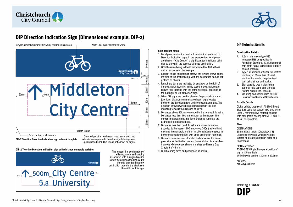
Sign content notes1. Focal point destinations and sub destinations are used on
Direction Indication signs. In the example two focal points are shown - “City Centre”, a signi�cant terminal focal point can be shown in the absence of a sub destination.
2. Only the route being followed is indicated by destinations and an arrow as on the example.
3. Straight ahead and left turn arrows are always shown on the left side of the destination(s) with the destination names left justi�ed as shown.
4. Right hand turns are indicated by an arrow to the right of the destination lettering. In this case the destinations are shown right justi�ed with the same horizontal spacings as for a straight or left turn arrow sign.
5. When DIP signs are used in place of �ngerboards at route junctions, distance numerals are shown signs located between the direction arrow and the destination name. The direction arrow always points outwards from the sign mounting towards the direction of travel.
6. Distances above 10km are rounded to the nearest kilometre. Distances less than 10km are shown to the nearest 100 metres in standard decimal form. Distance numerals are aligned on the decimal point.
7. Distances less than one kilometre are shown in metres (rounded to the nearest 100 metres eg: 300m). When listed on signs the numerals and the ‘m’ abbreviation (no space in between) are aligned right with other destination numerals.
8. Distance numerals one kilometre and above are the same point size as destination names. Numerals for distances less than one kilometre are shown in metres and have a Cap X-height of 45mm.
9. CCC branding sized and positioned as shown.
60mm
The longest line combination of lettering, arrow and spacing
associated with a single direction arrow determines the sign width.
For this sign the top arrow destination group in the stack sets
the width for this sign.
DIP-2 Two-line Direction Indication sign artwork template
60mm 40mm 40mm
60mm
DIP-2 Two-line Direction Indication sign with distance numerals variation
Outer edges of arrow heads, type descenders and extenders may protrude from the sign lettering zone
(pink dashed line). This line is not shown on signs.
5mm radius on all corners
DIP Direction Indication Sign (Dimensioned example: DIP-2)
10mm10mm
White CCC logo (100mm x 25mm)Bicycle symbol (130mm x 82.5mm) centred in blue area
Christchurch City Council • Bicycle Network Sign Design Manual • September 2014 22
DIP Technical Details
Construction Details1. 1.6mm aluminium type 5251,
tempered H38 as specified in Australian Standards 1734, sign panel with 5mm radius corners and digitally printed graphics.
2. Type 1 aluminium stiffener rail centred widthways 100mm less of sheet width with mounted to galvanised post using straps and buckle.
3. Sign panel to type 1 aluminium stiffener rails using self-piercing riveting system (eg. Henrob).
4. Mounting and construction to CCC Construction Standard Specification.
Graphic DetailsDigital printed graphics in AS2700 Bright Blue B23 using full solvent inks onto white Class 2 retroreflective material sheeted with anti-graffiti overlay film NI-EF 40801-12-45 or equivalent.
SizesDESTINATIONS 60mm cap X-height (Clearview 3-B) Distances only used when DIP sign is located at a route junction in place of a fingerboard.
SIGN MASTHEAD AS2700 B23 Bright Blue panel, width of sign x 140mm high White bicycle symbol 130mm x 82.5mm
ARROWS ADDA type 80mm
Drawing Number:
DIP

60mm 40mm
60mm
40mm
60mm
60mm
140m
m
60mm
40mm
40mm
60mm
60mm
140m
m
60mm
Width to suit length of lettering
Width to suit length of lettering
DIP-2 Two-line direction indication sign artwork template - single route with sub destinationThis version of the DIP sign is used instead of a �ngerboard to indicate a route turning at an intersection. Distance numerals are not shown where the intersection/turning is not a junction with another route.
60mm40mm
Notes relating to signs on this page1. Refer to general notes for all DIP
signs on Page 20 of this manual. 2. Refer to application and usage
notes for DIP signs on Drawing Number DIP-2 of this manual.
DIP-1 One-line direction indication sign artwork templateThis version of the DIP sign can be used in two ways: (a) in advance of an intersection to clearly indicate the continuing route direction; and, (b) in place of a �ngerboard at a minor route turning (where distances (in km) are not shown on signage).
DIP-3 Three-line direction indication sign artwork template - parallel routes with shared sub destinationThis version of the DIP sign is used instead of a �ngerboard to indicate a route turning at an intersection. Distance numerals are not shown where the intersection/turning is not a junction with another route.
60mm 40mm
60mm
40mm
60mm
40mm
60mm
40mm
60mm
60mm
140m
m
Width to suit length of lettering
DIP-2 Two-line direction indication sign with distance numerals - artwork template - single route with sub destinationThis version of the DIP sign is used instead of a �ngerboard at a route junction to indicate a route travel direction. Distances (in km) are shown on this sign variation.
DIP-1, DIP-2 & DIP-3 Direction Indication Signs – One- two- and three-line versions
Christchurch City Council • Bicycle Network Sign Design Manual • September 2014 23
DIP Technical Details
DIP-1One-line Direction Indication Sign Refer to drawing DIP for graphic and construction details
DIP-2 without distancesTwo-line Direction Indication Sign Refer to drawing DIP for graphic and construction details
DIP-2 with distancesTwo-line Direction Indication Sign with distance numerals shown Refer to drawing DIP for graphic and construction details
DIP-3Three-line Direction Indication Sign Refer to drawing DIP for graphic and construction details
Drawing Number:
DIP-1-3

Christchurch City Council • Bicycle Network Sign Design Manual • September 2014 24
2.1.3 ADP Advance direction signsPurposeAdvance direction signs are used to provide advance warning of route junctions between primary or secondary bicycle routes in the CCC Bicycle network. Advance direction signs are not used in advance of junctions with local routes. Fingerboards only are used at these junctions.
Advance direction signs list the focal point destinations for the route being followed and any other primary or secondary route passing through the junction. Sub destinations are not used on advance direction signs.
Distances to destinations are not listed on advance direction signs. Distances are provided on fingerboards at the actual junction.
The route being followed is always shown to the top of the sign.
Destinations are grouped according to their common travel direction. The travel/turn direction for each focal point, or group of focal points sharing a common direction, is indicated by an arrow pointing in the travel direction to be taken through the junction.
Travel/turn arrows should always point out of the sign body away from their associated destination names. Straight ahead, left turn and veer left arrows should be located to the left of their destination names and right turn and veer right arrows located to the right of their destination names. Where two or more destination names are grouped with a single direction arrow, the destinations are justified to the side closest to the arrow.
Where different routes are crossed, a horizontal line is used to separate the main travel direction arrow and destination names from those of other routes.
Destinations listed on advance direction signs should be consistent with fingerboards and other signs used on all routes feeding into the junction.
Advance direction signs for named routesADP-NR signs can be used to indicate the name of the route being followed (eg Bicentennial Bikeway etc). The layout of this type of sign is similar to standard advance direction signs with the addition of a facility name box at the top of the sign. Bikeway names are never shown for other routes only for the route being followed.
Advance direction signs with graphical layoutAt large, complex, multi-legged intersections, often with traffic islands, signalised crossings and divided roadways, it may be advisable to graphically indicate a recommended path through the intersection to the user as an aid to their navigation. In these situations (which often may also involve on-road to off-road transitions) an ADPG graphical layout sign can be used in advance of the intersection. As these signs have to be individually designed for each intersection they should be used sparingly when normal advance direction signs will not provide adequate indication of the correct path to take.
Refer to Sign layout sheets ADP, ADP-2-4, ADP-5-6, ADPNR, ADPG for layouts and technical details.
LocationAdvance direction signs are located between 30 and 50 metres in advance of the intersection. Mounting distance and actual sign siting depend on the road/path situation. On a downhill approach, signs may need to be located at the extent of the range or further back up the hill to account for a high approach speed.
Advance direction signs should always be located on the left side of the road/path with good approach visibility.
Sign posts are to be set a minimum of 500mm from the road/path edge on the same side as the direction of travel.
Site verificationAll sign sites need to be individually assessed taking likely user travel needs and conditions into consideration.
ADP Sign Variations
ADP-2Two-line advance direction signRefer to drawing ADP for graphic and construction detailsRefer to drawing ADP-2-4 for sign layout
ADP-3Three-line advance direction signRefer to drawing ADP for graphic and construction detailsRefer to drawing ADP-2-4 for sign layout
ADP-4Four-line advance direction signRefer to drawing ADP for graphic and construction detailsRefer to drawing ADP-2-4 for sign layout
ADP-5Five-line advance direction signRefer to drawing ADP for graphic and construction detailsRefer to drawing ADP-5-6 for sign layout
ADP-6Six-line advance direction signRefer to drawing ADP for graphic and construction detailsRefer to drawing ADP-5-6 for sign layout
ADP-NRAdvance direction sign for named routeRefer to drawing ADPNR for graphic, construction details and sign layout
ADP-GAdvance direction sign with special graphical layoutRefer to drawing ADPG for graphic, construction details and layout

60mm 60mm
40mm
40mm
40mm
60mm
60mm
60mm
Width to suit
40mm
40mm
60mm
60mm
40mm
40mm
40mm
Sign content notes1. Only focal point destinations are used on Advance
Direction signs. Sub destinations are not used. 2. The route being followed is always listed at the
top of the destination stack regardless of the direction of the arrow.
3. Focal points for parallel overlapping routes (which share a common direction), are listed with a single direction arrow. Within grouped items the closest destination is listed to the top.
4. Multiple destinations grouped with a single destination arrow are to be left justi�ed for straight ahead and left pointing arrows and right justi�ed for right pointing arrows.
5. Straight ahead and left turn arrows are always shown on the left side of the destination(s). Right turn arrows are always shown to the right of destinations.
6. Focal point destinations for other routes crossing or branching from the route being followed are shown below the followed route destinations and separated by a 4mm line.
In the example shown, the route being followed is to University. At the indicated junction this route is crossed by two other routes which both lead in one direction to Tower Junction and in the other to separate focal points of Belfasr and Airport.
7. CCC branding sized and positioned as shown.
60mm
The longest line combination of lettering, arrow and spacing associated with a single direction arrow determines the sign width. For this sign the top arrow destination group in the stack sets the width for this sign.
ADP-4 Four-line Advance Direction Sign artwork template
Outer edges of arrow heads, type descenders and extenders may protrude from the sign lettering zone (pink dashed line). This line is not shown on signs.
5mm radius on all corners
ADP Advance Direction Sign (Dimensioned example: ADP-4)White CCC logo (100mm x 25mm)Bicycle symbol (130mm x 82.5mm) centred in blue area
10mm10mm
140m
m
Christchurch City Council • Bicycle Network Sign Design Manual • September 2014 25
ADP Technical Details
Construction Details1. 1.6mm aluminium type 5251,
tempered H38 as specified in Australian Standards 1734, sign panel with 5mm radius corners and digitally printed graphics.
2. Type 1 aluminium stiffener rail centred widthways 100mm less of sheet width with mounted to galvanised post using straps and buckle.
3. Sign panel to type 1 aluminium stiffener rails using self-piercing riveting system (eg. Henrob).
4. Mounting and construction to CCC Construction Standard Specification.
Graphic DetailsDigital printed graphics in AS2700 B23 Bright Blue using full solvent inks onto white Class 2 retroreflective material sheeted with anti-graffiti overlay film NI-EF 40801-12-45 or equivalent.
SizesDESTINATIONS 60mm cap X-height (Clearview 3-B) Distances not used.
SIGN MASTHEAD AS2700 B23 Bright Blue panel, width of sign x 140mm high White bicycle symbol 130mm x 82.5mm
ARROWS ADDA type 80mm
Drawing Number:
ADP

60mm
40mm
40mm
140m
m40
mm60
mm60
mm
60mm
40mm
40mm
40mm
60mm
40mm
60mm
60mm
140m
m
60mm
60mm
40mm
40mm
60mm 40mm
60mm
60mm
40mm
60mm40mm
40mm60mm
40mm
Width to suit length of lettering
Width to suit length of lettering
Width to suit length of lettering
ADP-2 Two-line advance direction sign artwork templateThis version of the AD sign indicates direction for the primary route being followed and a right branching primary route.
ADP-3 Three-line advance direction sign artwork templateThis version of the AD sign indicates direction for the primary route being followed and a primary route crossing this route.
ADP-4 Four-line advance direction sign artwork templateThis version of the AD sign indicates direction for two primary routes sharing the same path (for the next route segment) and a primary route crossing these routes.
Notes relating to signs on this page1. Refer to general notes for all ADP signs on page 23
of this manual. 2. Refer to application and usage notes for ADP signs
on page 24 of this manual.
60mm
60mm
ADP-2, ADP-3 and ADP-4 Advance Direction Signs – Two- three- and four-line versions
60mm
40mm
40mm
40mm
60mm
60mm
40mm
40mm
60mm
60mm
140m
m
Christchurch City Council • Bicycle Network Sign Design Manual • September 2014 26
ADP Technical Details
ADP-2One- and two-line Advance Direction Sign Refer to drawing ADP for graphic and construction details
ADP-3Three-line Advance Direction Sign Refer to drawing ADP for graphic and construction details
ADP-4Four-line Advance Direction Sign Refer to drawing ADP for graphic and construction details
Drawing Number:
ADP-2-4

60mm
40mm
40mm
40mm
60mm
60mm
40mm
60mm
60mm
60mm
40mm
40mm
60mm
40mm
140m
m
60mm
40mm
40mm
40mm
60mm
60mm
40mm
40mm
60mm
60mm
60mm
40mm
140m
m40
mm
60mm 40mm
40mm
60mm
60mm40mm
60mm
40mm
40mm
60mm
ADP-5 Five-line advance direction sign artwork templateThis version of the AD sign indicates direction for one primary route crossing two overlapping primary routes (two focal points are indicated for each route). The horizontal lines are used to separate the different routes.
ADP-6 Six-line advance direction sign artwork templateThis version of the AD sign indicates direction for multiple overlapping primary routes (for the following route segment). Focal point destinations are indicated for each route and the City Centre focal point is also indicated as it is an important terminal focal point accessible via the Tower Junction route.
Width to suit length of lettering
Width to suit length of lettering
Notes relating to signs on this page1. Refer to general notes for all ADP signs on page 23 of this manual. 2. Refer to application and usage notes for ADP signs on page 24 of
this manual.
ADP-5 and ADP-6 Advance Direction Signs – Five- and six-line versions
60mm
60mm
Christchurch City Council • Bicycle Network Sign Design Manual • September 2014 27
ADP Technical Details
ADP-5Five-line Advance Direction Sign Refer to drawing ADP for graphic and construction details
ADP-6Six-line Advance Direction Sign Refer to drawing ADP for graphic and construction details
Drawing Number:
ADP-5-6

5mm radius on all corners
60mm
Width to suit
60m
m40
mm
40m
m40
mm
60m
m60
mm
140m
m40
mm
40m
m60
mm
60m
m
40mm
40mm
40mm
60mm
The longest line combination of lettering, arrow and spacing associated with a single direction arrow determines the sign width. For this sign the middle arrow destination in the list sets the width for this sign.
30mm
Sign content notes1. Named routes are prominent CCC cycleway facilities
with a signi�cant pre-investment in route naming both in existing signage and inclusion on existing public mapping. Named routes are only signed with the approval of the manager responsible for the CCC Bicycle Network.
2. The ADPNR is a variation of the standard ADP sign and is used only on named bicycle facilities. Refer to the notes for Advance Direction signs (see pages 23 and 24 for details of typical ADP sign layout etc).
3. The named route box on the ADPNR sign is only to be used to denote the route being followed. It is not to be used to indicate crossing or branching primary routes, whether named or not.
4. The named route box is always positioned at the top of the destination list.
5. The route name is white and centred within a 60mm high black route name box. This line of type is in Clearview 3-W 30mm Cap X-height.
6. ADPNR type signs are not to be used in place of DIP signs where such signs are used instead of �ngerboards at minor route turnings, or along dif�cult to follow routes as an aid to way�nding. See page 20 for details of this use.
7. In the example shown, the facility being followed is the Northern Line Cycleway to Papanui. At the signed intersection this route is crossed by another route which leads in one direction to the City Centre and in the other to the University.
ADPNR-3 Three-line Advance Direction Sign artwork template
Outer edges of arrow heads, type descenders and extenders may protrude from the sign lettering zone (pink dashed line). This line is not shown on signs.
ADPNR Advance Direction Sign for a named route (Dimensioned example: ADPNR-3)
10mm10mm
White CCC logo (100mm x 25mm)Bicycle symbol (130mm x 82.5mm) centred in blue area
Route name box, Black, 60mm high. White lettering 30mm high.
Christchurch City Council • Bicycle Network Sign Design Manual • September 2014 28
ADP-NR Technical Details
Construction Details1. 1.6mm aluminium type 5251,
tempered H38 as specified in Australian Standards 1734, sign panel with 5mm radius corners and digitally printed graphics.
2. Type 1 aluminium stiffener rail centred widthways 100mm less of sheet width with mounted to galvanised post using straps and buckle.
3. Sign panel to type 1 aluminium stiffener rails using self-piercing riveting system (eg. Henrob).
4. Mounting and construction to CCC Construction Standard Specification.
Graphic DetailsDigital printed graphics in AS2700 B23 Bright Blue using full solvent inks onto white Class 2 retroreflective material sheeted with anti-graffiti overlay film NI-EF 40801-12-45 or equivalent.
SizesROUTE NAME 30mm cap X-height (Clearview 3-W) white lettering on black background
DESTINATIONS 60mm cap X-height (Clearview 3-B) Distances not used.
SIGN MASTHEAD AS2700 B23 Bright Blue panel, width of sign x 140mm high White bicycle symbol 130mm x 82.5mm
ARROWS ADDA type 80mm
Drawing Number:
ADPNR

5mm radius on all corners
Airport
60mm
Width of sign to accommodate lettering and layout sizes
140m
m
60mm
60mm
Arrow heads for indicated routes protrude from type zone
ADPG Advance Direction Graphical Layout Sign artwork template For sign contents notes see next sheet
60mm
See Sheet ADPG-B for sign content notes
ADPG Advance Direction Sign with graphical layout
10mm10mm
White CCC logo (100mm x 25mm)Cyclist symbol (130mm x 82.5mm) centred in blue area
Christchurch City Council • Bicycle Network Sign Design Manual • September 2014 29
ADP-G Technical Details
Construction Details1. 1.6mm aluminium type 5251,
tempered H38 as specified in Australian Standards 1734, sign panel with 5mm radius corners and digitally printed graphics.
2. Type 1 aluminium stiffener rail centred widthways 100mm less of sheet width with mounted to galvanised post using straps and buckle.
3. Sign panel to type 1 aluminium stiffener rails using self-piercing riveting system (eg. Henrob).
4. Mounting and construction to CCC Construction Standard Specification.
Drawing Number:
ADPG-A

Sign content notes1. ADPG graphical layout signs are used only in advance of complex intersections where it is
necessary to indicate to the user a recommended path through the intersection. This may involve off-road to on-road transitions through multi-legged intersections often with traf�c islands, signalised crossings and divided roadways.
2. The ADPG is an individually designed variation of the standard ADP sign and is used only as an advance direction sign in place of a standard ADP sign. Refer to the notes for Advance Direction signs (pages 23 and 24 for details of typical ADP sign layout etc).
3. The suggested travel paths for all indicated routes is shown by a 50mm wide line in Blue. See page 13 for ADPGA arrow head details.
4. Streets crossed or followed by indicated routes are shown in 40% tone 80mm width for major roads and 65mm width for minor roads. The name of the cross street is shown in 30mm high black lettering aligned to the street.
5. The graphical layout should aim to clearly represent the approximate shape of the intersection and the angles of the street junctions to further assist with navigation.
6. Sign width is determined using standard ADP sign spacings. Graphical elements should be carefully spaced to ensure good legibility.
7. ADPNR type signs can be used in place of DIP signs where such signs are used at route turnings, or along dif�cult to follow routes as an aid to way�nding.
8. If destination names consist of two words these can be stacked (with a 25mm vertical spacing) for more compact layout. Where two separate destinations are listed the normal vertical spacing of 40mm should be used.
9. In the example shown, the facility being followed is an off-road route crossing Harewood Road and the parallel raiway line. After a short section on-road on a minor street the route rejoins the railway corridor as an off-road path to Northwood, the next focal point destination.
ADPG Advance Direction Graphical Layout Sign
ADPG Advance Direction Sign Graphical Layout – Layout details
Christchurch City Council • Bicycle Network Sign Design Manual • September 2014 30
ADP-G Technical Details
Graphic DetailsDigital printed graphics in AS2700 B23 Bright Blue using full solvent inks onto white Class 2 retroreflective material sheeted with anti-graffiti overlay film NI-EF 40801-12-45 or equivalent.
SizesDESTINATIONS 60mm cap X-height (Clearview 3-B) Distances not used.
SIGN MASTHEAD AS2700 B23 Bright Blue panel, width of sign x 140mm high White bicycle symbol 130mm x 82.5mm
ROAD SHAPES 40% black tone
ROAD NAMES 30mm cap X-height (Clearview 3-B) black lettering
ARROWS ADDGA arrow heads 50mm route direction lines.
Drawing Number:
ADPG-B

Christchurch City Council • Bicycle Network Sign Design Manual • September 2014 31
2.1.4 LPP Location plate signsPurposeLocation plate signs are located where a route passes under a significant road or cross street. Location plate signs are not used to mark junctions with other routes – fingerboards are used at these junctions.
The location plate sign lists only the name of the road or cross street. This sign does not show distances or direction arrows though in rare cases a direction arrow may be used as a further aid to route navigation where the associated underpass has a bend in the path direction or change of grade. This type of sign should not be used to indicate a named route.
There are two types of LPP sign. The LPP-A sign is used to mark a cross street or road which carries a bicycle route which is part of the CCC Bicycle Network. The LPP-B sign is used to indicate cross street names where these do not part of the bicycle network.
Refer to Sign layout sheet LPP for layout and technical details.
LocationLocation plate signs are located above the bikeway on both approaches to underpasses and bridges to clearly identify the street or road being crossed at different grade/level to the bikeway. The optimal siting for a location plate sign is on the face of a bridge/overpass structure, easily seen from, and directly above the bikeway/path. Signs are permanently affixed to the bridge/overpass structure. The method of fixing should take into account the type, age and materials used in the structure.
Location plate signs are used for primary, secondary and local routes. They may be used on local routes where the cross street or road is a primary or secondary bicycle route.
Site verificationAll sign sites need to be individually assessed taking likely user travel needs and conditions into consideration.
LPP Sign Variations
LPP-AOne-line location plate sign for use on a bicycle route to indicate a cross street which carries another bicycle route.Refer to drawing LPP for graphic, construction details and sign layouts
LPP-BOne-line location plate sign for use on a bicycle route to indicate a cross street which is not part of the bicycle network.Refer to drawing LPP for graphic, construction details and sign layouts

LPP-1 One-line Location Plate mounting arrangementMounting method to be determined depending on the structure to which it is to be �xed
50m
m50
mm
60m
m
160m
m
40mm 60mm min
100m
m
Sign content notes1. Maximum length of the location plate is 1200mm subject to lettering content.2. Destinations or distance numerals are not used on this type of sign. 3. LPP location plate signs may also be used on local routes where appropriate. 4. LPP-A type sign is used to mark overpasses of cross streets which carry a bicycle
route. LPP-B type sign is used to mark overpasses of cross streets which do not carry bicycle routes.
5. See Section 4 of this manual for guidance on destination name abbreviations
50m
m50
mm
60m
m
160m
m
40mm
LPP-A One-line Location Plate (bicycle route on cross street) Artwork TemplateLength of sign to suit sign content.
60mm min
75mm high CCC logo centred in blue area
75m
m
LPP-B One-line Location Plate (no bicycle route on cross street) Artwork TemplateLength of sign to suit sign content.
Mounting holesonly if required
5mm radius on all corners
5mm radius on all corners
LPP Location plate sign
10mm
10mm
Bicycle symbol (130mm x 82.5mm) centred in blue areaWhite CCC logo (100mm x 25mm)
Christchurch City Council • Bicycle Network Sign Design Manual • September 2014 32
LPP Technical Details
Construction Details1. 1.6mm aluminium type 5251,
tempered H38 as specified in Australian Standards 1734, sign panel with 5mm radius corners and digitally printed graphics.
2. Sign glued, screwed (or other) and permanently fixed to the face of overhead structures where the bikeway travels under or over a cross street/road.
3. Mounting and construction to CCC Construction Standard Specification.
Graphic DetailsDigital printed graphics in AS2700 B23 Bright Blue using full solvent inks onto white Class 2 retroreflective material sheeted with anti-graffiti overlay film NI-EF 40801-12-45 or equivalent.
SizesDESTINATIONS 60mm cap X-height (Clearview 3-B) Distances not used.
SIGN MASTHEAD AS2700 B23 Bright Blue panel, width of sign x 140mm high White bicycle symbol 130mm x 82.5mm
ARROWS Not used
Drawing Number:
LPP

Christchurch City Council • Bicycle Network Sign Design Manual • September 2014 33
2.1.5 RDP Reassurance direction signsPurposeReassurance direction signs are used mainly on high-speed or limited access routes such as veloways to indicate travel distance information (km) to upcoming destinations along the route. This type of sign also provides confirmation to users that they have joined the veloway or are continuing on it.
These signs, though most applicable for use on routes with a level of signing C1(see Table 2), may in specific instances be used on primary or secondary bicycle routes following remote intersections or after complex intersections to reassure riders that they have made a correct turn and are following the right route.
A maximum of six destinations per sign can be listed in descending distance order with the closest destination at the top of the list. Focal point destinations, terminal destinations and the next sub destination can be listed on reassurance destination signs.
Refer to Sign layout sheets RDP, RDP-2-6 and RDPNR for layouts and technical details.
Reassurance direction signs for named routesRDP-NR signs can be used to indicate the name of the route being followed (eg Northern Line Cycleway etc). The layout of this type of sign is similar to standard reassurance direction signs with the addition of a facility name box at the top of the sign. Bikeway names are never shown for other routes only for the route being followed.
LocationReassurance direction signs are installed 50 – 100m following veloway junctions with other primary or secondary routes. They are not appropriate for use near junctions with local routes as these are signed with both bicycle network and local destination fingerboards.
Sign posts are to be set a minimum of 500mm from the road/path edge on the same side as the direction of travel.
Site verificationAll sign sites need to be individually assessed taking likely user travel needs and conditions into consideration.
RDP Sign Variations (max 6 destinations)
RDP-2Two-line Reassurance Direction SignRefer to drawing RDP for graphic and construction detailsRefer to drawing RDP-2-6 for sign layout
RDP-3Three-line Reassurance Direction SignRefer to drawing RDP for graphic and construction detailsRefer to drawing RDP-2-6 for sign layout
RDP-4Four-line Reassurance Direction SignRefer to drawing RDP for graphic and construction detailsRefer to drawing RDP-2-6 for sign layout
RDP-5Five-line Reassurance Direction SignRefer to drawing RDP for graphic and construction detailsRefer to drawing RDP-2-6 for sign layout
RDP-6Six-line Reassurance Direction SignRefer to drawing RDP for graphic and construction detailsRefer to drawing RDP-2-6 for sign layout
RDP-NRReassurance Direction Sign showing named route (maximum six destinations as above)Refer to drawing RDPNR for graphic, construction details and sign layout

5mm radius on all corners
40m
m60
mm
Numerals aligned on decimal point
60m
m
60mm
60m
m60
mm
40m
m60
mm
40m
m40
mm
140m
m
60mmmin
60mm
Width to suitThe longest line combination of lettering, distance numerals and spacing determines the sign width.
Sign content notes1. Destinations are listed in distance sort order
with the nearest destination at the top of the list and the furtherest at the bottom.
2. Focal point destinations, terminal destinations and the next sub destination can be listed.
3. Destinations are listed �ush left. 4. Distances above 10km are rounded to the
nearest kilometre.5. Distances less than 10km are shown to the
nearest 100 metres in standard decimal form. 6. Distances less than one kilometre are shown
in metres (rounded to the nearest 100 metres eg: 300m). When listed on signs the numerals and the ‘m’ abbreviation (no space in between) are aligned right with other destination numerals.
7. Distance numerals are aligned on the decimal point.
8. Distance numerals one kilometre and above are the same point size as destination names. Numerals for distances less than one kilometre are shown in metres and have a Cap X-height of 45mm.
9. BCC branding sized and positioned as shown.
RDP-3 Four-line Reassurance Direction Sign artwork template
Outer edges of type descenders and extenders may protrude from the
sign lettering zone (pink dashed line). This line is not shown on signs.
RDP Reassurance Direction Sign (Dimensioned example: RDP-4)
10mm10mm
White CCC logo (100mm x 25mm)Bicycle symbol (130mm x 82.5mm) centred in blue area
Christchurch City Council • Bicycle Network Sign Design Manual • September 2014 34
RDP Technical Details
Construction Details1. 1.6mm aluminium type 5251,
tempered H38 as specified in Australian Standards 1734, sign panel with 5mm radius corners and digitally printed graphics.
2. Type 1 aluminium stiffener rail centred widthways 100mm less of sheet width with mounted to galvanised post using straps and buckle.
3. Sign panel to type 1 aluminium stiffener rails using self-piercing riveting system (eg. Henrob).
4. Mounting and construction to CCC Construction Standard Specification.
Graphic DetailsDigital printed graphics in AS2700 B23 Bright Blue using full solvent inks onto white Class 2 retroreflective material sheeted with anti-graffiti overlay film NI-EF 40801-12-45 or equivalent.
SizesDESTINATIONS/DISTANCES 60mm cap X-height (Clearview 3-B) Numerals: ≥1km 60mm cap X-height, <1km 45mm cap x-height
SIGN MASTHEAD AS2700 B23 Bright Blue panel, width of sign x 140mm high White bicycle symbol 130mm x 82.5mm
ARROWS Not used
Drawing Number:
RDP

RDP-2 Two-line Reassurance Direction Sign artwork template
RDP-3 Three-line Reassurance Direction Sign artwork template
RDP-4 Four-line Reassurance Direction Sign artwork template
RDP-5 Five-line Reassurance Direction Sign artwork template
RDP-6 Six-line Reassurance Direction Sign artwork template
Notes relating to signs on this page1. Refer to general layout and construction notes for
all RDP signs on page 33 of this manual. 2. Refer to application and usage notes for RDP
signs on page 32 of this manual.
RDP-2 to RDP-6 Reassurance Direction Sign – Two- to six-line variations
Christchurch City Council • Bicycle Network Sign Design Manual • September 2014 35
RDP Technical Details
RDP-2Two-line Reassurance Direction Sign Refer to drawing RDP for graphic and construction details
RDP-3Three-line Reassurance Direction Sign Refer to drawing RDP for graphic and construction details
RDP-4Four-line Reassurance Direction Sign Refer to drawing RDP for graphic and construction details
RDP-5Five-line Reassurance Direction Sign Refer to drawing RDP for graphic and construction details
RDP-6Six-line Reassurance Direction Sign Refer to drawing RDP for graphic and construction details
Drawing Number:
RDP-2-6
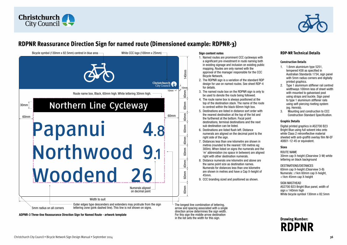
5mm radius on all corners
40m
m60
mm
60m
m60
mm
40m
m40
mm
60m
m60
mm
40m
m14
0mm
Numerals aligned on decimal point
Sign content notes1. Named routes are prominent CCC cycleways with
a signi�cant pre-investment in route naming both in existing signage and inclusion on existing public mapping. Routes are only named with the approval of the manager responsible for the CCC Bicycle Network.
2. The RDPNR sign is a variation of the standard RDP design for use on named routes. See sheet RDP-4 for details.
3. The named route box on the RDPNR sign is only to be used to denote the route being followed.
4. The route name box is always positioned at the top of the destination stack. The name of the route is centred within the black 60mm high box.
5. Destinations are listed in distance sort order with the nearest destination at the top of the list and the furtherest at the bottom. Focal point destinations, terminal destinations and the next sub destination can be listed.
6. Destinations are listed �ush left. Distance numerals are aligned on the decimal point to the right side of the sign.
7. Distances less than one kilometre are shown in metres (rounded to the nearest 100 metres eg: 300m). When listed on signs the numerals and the ‘m’ abbreviation (no space in between) are aligned right with other destination numerals.
8. Distance numerals one kilometre and above are the same point size as destination names. Numerals for distances less than one kilometre are shown in metres and have a Cap X-height of 45mm.
9. CCC branding sized and positioned as shown.
Route name box, Black, 60mm high. White lettering 30mm high.
RDPNR Reassurance Direction Sign for named route (Dimensioned example: RDPNR-3)
60mm
Width to suit
60mm
The longest line combination of lettering, arrow and spacing associated with a single direction arrow determines the sign width. For this sign the middle arrow destination in the list sets the width for this sign.
30mm
ADPNR-3 Three-line Reassurance Direction Sign for Named Route - artwork template
Outer edges type descenders and extenders may protrude from the sign lettering zone (pink dashed line). This line is not shown on signs.
10mm10mm
White CCC logo (100mm x 25mm)Bicycle symbol (130mm x 82.5mm) centred in blue area
Christchurch City Council • Bicycle Network Sign Design Manual • September 2014 36
RDP-NR Technical Details
Construction Details1. 1.6mm aluminium type 5251,
tempered H38 as specified in Australian Standards 1734, sign panel with 5mm radius corners and digitally printed graphics.
2. Type 1 aluminium stiffener rail centred widthways 100mm less of sheet width with mounted to galvanised post using straps and buckle. Sign panel to type 1 aluminium stiffener rails using self-piercing riveting system (eg. Henrob).
3. Mounting and construction to CCC Construction Standard Specification.
Graphic DetailsDigital printed graphics in AS2700 B23 Bright Blue using full solvent inks onto white Class 2 retroreflective material sheeted with anti-graffiti overlay film NI-EF 40801-12-45 or equivalent.
SizesROUTE NAME 30mm cap X-height (Clearview 3-W) white lettering on black background
DESTINATIONS/DISTANCES 60mm cap X-height (Clearview 3-B) Numerals: ≥1km 60mm cap X-height, <1km 45mm cap X-height
SIGN MASTHEAD AS2700 B23 Bright Blue panel, width of sign x 140mm high White bicycle symbol 130mm x 82.5mm
Drawing Number:
RDPNR

Christchurch City Council • Bicycle Network Sign Design Manual • September 2014 37
2.1.6 MSP Bicycle network map signPurposeBicycle network maps can show people the many possibilities a cycle network can offer them to navigate around their locality and further afield throughout the region. They can also show local routes centred on universities, schools, technical colleges, large work places, shopping centres, train or bus stations ferry wharves and other trip attractors. Cycle network maps show not only bicycle network routes but also the local street system, local/regional facilities and points of interest.
The MSP map sign shows the location of the user at the centre of the map which shows the surrounding street network with a coverage of approximately 6km x 6km. High quality Christchurch street maps are used and include the following features:• road network• existing Christchurch Bicycle Network routes (current route
highlighted)• parks, sporting or recreation grounds• local centres• major destinations such as shopping centres and employment
nodes• educational facilities• police stations• hospitals• public libraries• places of worship• scout/ community halls• public toilets• bicycle parking• waterways, water reservoirs, and• significant natural landmarks
Maps should be orientated north in line with conventional street directory mapping. Maps are produced at an appropriate scale to ensure the bikeway and surrounding features are easily identifiable with a “you are here” indicator approximately in the centre of the map. Significant trip attractors that exist outside the map area are marked with text and an arrow indicating the direction of the facility or destination (e.g. CBD 4km).
Refer to sign layout sheets MSP-A to MSP-E for layouts and technical details.
LocationMap signs are placed at network junctions and particularly at ‘gateway’ locations (bridges, CBD periphery etc) which provide access to a large section of the cycle network. This may be adjacent to a major road or at key junctions along the route.
Map signs for on-road routes should be sited in an off-road map viewing bay (see Sheet MSP-C) or in parklands adjacent to the street or road being followed (see Sheet MSP-E). Map signs ideally should be located to allow path users to view the map when facing in a northerly direction to facilitate easy map orientation.
Map viewing bays are not recommended on roads with a speed limit greater than 60km/h.
When siting maps near paths and off-road bikeways where no viewing bay is provided, map boards are located at least one metre from the path edge to ensure there is sufficient space to move off the path to read the sign and not create a hazard for other path users.
To indicate desired/safe rest stops along bikeways, the location of map boards, where appropriate, can be co-located with other bikeway infrastructure such as seats, lights, racks, shelters etc.
The location of signs in lit areas is recommended to extend the functional hours the signs are usable.
Site verificationMap signs are positioned where cyclists can easily translate the information from the map to the surrounding environment. All maps are positioned with maximum visibility for pathway users travelling in all directions. If a map board is positioned near a major road, the map should be located in an off-road map viewing bay visible to cyclists entering, exiting or passing the map bay.
Careful siting of the map board for maximum visibility also provides casual surveillance from passers-by which may discourage vandalism to the sign.
An MSP-AD sign is erected 50-100m in advance of a map viewing bay associated with a street or road (See Sheets MSP-C and MSP-AD for sign layout and siting details).
All sign sites need to be individually assessed taking likely user travel needs and conditions into consideration.

600mm
Network Map - Front View Network MapSide View
1000
mm
800m
m
1770
mm
Bicycle network area map sign - general and mounting
Route Interpretive Map - Front View
Pitasped untum nem liquae lam asit, sam sinctis et aut alibus pelitatqui ium doles aut etur
Pitasped untum nem liquae lam asit, sam sinctis et aut alibus pelitatempor sit aut diatibus, seque pore, quia vitiumqui ium doles aut etur? Quia con recte magnat aribus quias sequo tecae im a sum re pa voluptatius et odi sed qui aute nimusda estissunt adit repelendae. Nam ut aspellabo.
Pitasped untum nem liquae lam asit, sam sinctis et aut alibus pelitatempor sit aut diatibus, seque pore, quia vitiumqui ium doles aut etur? Quia con recte magnat aribus quias sequo tecae im a sum re pa voluptatius et odi sed qui aute nimusda estissunt adit repelendae. Nam ut aspellabo.
For more information call: 941 8999 or 0800 800 169www.ccc.govt.nz
Pitasped untum nem liquae lam asit, sam sinctis et aut alibus pelitatqui ium doles aut etur
Pitasped untum nem liquae lam asit, sam sinctis et aut alibus pelitatempor sit aut diatibus, seque pore, quia vitiumqui ium doles aut etur
Quia con recte magnat aribus quias sequo tecae im a sum re pa voluptatius et odi sed qui aute nimusda estissunt adit repelendae. Nam ut aspellabo.
Northern Line CyclewayPuari ki Pū-harakeke-nui
Major Cycle Route
Christchurch City Council • Bicycle Network Sign Design Manual • September 2014 38
MSP Technical Details
Construction Details 1. 1.6mm aluminium type 5251,
tempered H38 as specified in Australian Standards 1734, sign panel with 5mm radius corners and digitally printed graphics.
2. Type 1 aluminium stiffener rail centred widthways 100mm less of sheet width with mounted to galvanised post using straps and buckle.
3. Sign panel to type 1 aluminium stiffener rails using self-piercing riveting system (eg. Henrob).
4. Mounting and construction to CCC Construction Standard Specification.
Graphic DetailsDigital printed graphics in AS2700 B23 Bright Blue using full solvent inks onto 600 x 1000mm White Cast Vinyl sheeted with anti-graffiti overlay film NI-EF 40801-12-45 or equivalent.
Drawing Number:
MSP-A

Bicycle Network Area Map
For information call: 03 000 0000 (24hrs)www.ccc.govt.nz
Lettering in Regulatory Black
58
600
114
57
Bicycle network area map sign - layout details
Council information
5mm radius on all corners
Christchurch City Council • Bicycle Network Sign Design Manual • September 2014 39
MSP Technical Details
Graphic Details
SizesMAP SIGN TITLE 26mm cap X-height (Clearview 3-B) AS2700 G37 Black as shown
COUNCIL INFORMATION TEXT 12mm cap X-height (Clearview 3-W) white as shown
YOU ARE HERE POINTER AND TEXT 6mm cap X-height (Clearview 3-B) AS2700 R13 Red as shown
YOU ARE HERE MAP 600mm H x 585mm W
Map DetailsMaps should be consistent with any bicycle network maps in use. Existing bicycle routes are to be shown. Bus routes are not shown. All maps to include a legend box and “You are here” marker.
Layout NotesUse the template on this page as base guide when producing new artwork.
Drawing Number:
MSP-B

MSP Bicycle Network Map Sign mounted on path at edge of road corridor boundary or in adjacent parkland. Ensure map does not obstruct footpath.
15.0m min
Ramping details as per Austroads Guide to Road Design - Part 3, Figure 4.25
Roadway ≤60km/h
Figure A: Information Map Sign Viewing Bay for on-road bicycle routeThe diagram below shows recommended layout for a bicycle network map board viewing bay.
Sign MSP-AD sign mounted 100m in advance of map board
Notes1. For on-road routes MBP signs are always mounted off-road in a map viewing bay (layout as
shown above) or in an adjacent parklands. 2. When maps are used adjacent to off-road paths, the map board is sited with suf�cient
surrounding space to permit comfortable viewing of the map without obstructing the normal �ow of pedestrians or cyclists using the path. See sheet MSP-E in this manual for details.
3. The viewing area surrounding the map board should be paved to minimise erosion.4. For streets/roads with greater than 3,000vpd, mount one MBP-AD sign 100metres (or other
distance to suit site conditions) in advance of map viewing bay on the same side of the street as the bay.
5. For streets/roads with traf�c less than 3,000vpd, MBP-AD signs may be mounted to indicate the viewing bay from both approach directions.
6. Parking restriction signage should be erected to prevent overparking of the entrance and exit of the map viewing bay.
MSP Bicycle Network Map Sign – Siting details for on-road use
Christchurch City Council • Bicycle Network Sign Design Manual • September 2014 40
MSP Viewing Bay Technical Details
Layout for MSP viewing bay for on-road bicycle routes The map should be sited for optimal viewing from the viewing bay as detailed in the diagram on this sheet.
Drawing Number:
MSP-C

60mm
Width to suit
60mm
40mm
40mm
60mm
140m
m60
mm
40mm
60mm
All lettering and arrow head points to be within the sign lettering zone
Outer edges of arrow heads, type descenders and extenders may protrude from the sign lettering zone
MBP-AD Advance Direction Sign for use with Map Bay artwork template
Sign content notes1. The distance to map
viewing bay is nominally 100m. This may be varied to suit site requirements and the sign(s) sited accordingly.
2. This sign is intended for use for on-road travel in a one-way direction (same side as viewing bay) for roads ≥ 3000 vpd. For roads below 3000 vpd, signs may be placed to indicate the map viewing bay for travellers in a two-way direction.
3. CCC branding sized and positioned as shown.
MSP-AD Bicycle Network Map Bay Advance Direction Sign – Layout details
10mm10mm
White CCC logo (100mm x 25mm)Bicycle symbol (130mm x 82.5mm) centred in blue area
5mm radius on all corners
Christchurch City Council • Bicycle Network Sign Design Manual • September 2014 41
MSP-AD Technical Details
Primary Route Map Bay Advance Direction Sign
Construction Details1. 1.6mm aluminium type 5251,
tempered H38 as specified in Australian Standards 1734, sign panel with 5mm radius corners and digitally printed graphics.
2. Type 1 aluminium stiffener rail centred widthways 100mm less of sheet width with mounted to galvanised post using straps and buckle.
3. Sign panel to type 1 aluminium stiffener rails using self-piercing riveting system (eg. Henrob).
4. Mounting and construction to CCC Construction Standard Specification.
Graphic DetailsDigital printed graphics in AS2700 B23 Bright Blue using full solvent inks onto white Class 2 retroreflective material sheeted with anti-graffiti overlay film NI-EF 40801-12-45 or equivalent.
SizesSIGN LETTERING 60mm cap X-height (Clearview 3-B)
SIGN MASTHEAD AS2700 B23 Bright Blue panel, width of sign x 140mm high CCC Cyclist white, 100mm high
ARROWS ADDA type 80mm
PICTOGRAM PTI-Blue background. White “i”
Drawing Number:
MSP-AD

Figure A: Information Map Sign Viewing Bay for off-road pathThe diagram below shows recommended layout for high-use path map sign viewing bay.
MSP Bicycle Network Map Sign
3.0m
min
100m
5.0m min
45º
100m
MSP-AD sign
MSP-ADsign
Figure B: Information Map Sign Viewing Bay exampleThis photograph shows a map sign viewing bay constructed adjacent to a high-use shared path with kerbed path and additional landscaping. Roma Street Parklands/Normanby Pedestrian Cycle Link. Brisbane, Queensland.
Parklands
Parklands
MSP-AD Bicycle Network Map Sign Bay Advance Direction Sign – Siting details for off-road use
Christchurch City Council • Bicycle Network Sign Design Manual • September 2014 42
MSP Viewing Bay Technical Details
Layout for MSP viewing bay for off-road bicycle routes The map should be sited for optimal viewing from the viewing bay as detailed in the diagramon this sheet.
Drawing Number:
MSP-D

Christchurch City Council • Bicycle Network Sign Design Manual • September 2014 43
2.2 Local route signs
2.2.1 FBL Local route fingerboardsPurposeLocal destination fingerboards are used on primary and secondary routes to mark the start of a route to a significant local destination (see Table 1 for types of destinations suitable for local signing).
When signing local routes, local destination fingerboards are usually used as the first and last sign of the route with all intermediate intersections/turnings indicated by local destination markers.
At the junction of a local and primary or secondary route, it is usual practice to erect bicycle network fingerboards (for the primary or secondary route) as well as the local destination fingerboard.
Local destination fingerboards are also used to mark short local routes and indicate local destinations in areas where there are no primary and secondary bicycle routes.
There are three versions of the local destination fingerboard. The FBL-1 one-line sign lists destination, distance and direction arrow. This design allows for the addition of pictograms to indicate facilities available at the destination.
The FBL-1 sign is used for routes to a single local destination. Pictograms can be used on the sign to indicate services and facilities available at the destination.
The FBL-2 fingerboard is used on a route linking a local destination to a primary or secondary bicycle route which in turn links to more important trip destinations. The top row of the FBL-2 sign lists the name of the route, the lower line lists the focal points at either end of the primary or secondary route. Another variation of the FBL-2 sign is used where there is an important sub destination (or a destination accessible from a branching path) along this route.
Local destination fingerboards are designed to mount with standard street name signs. Where possible it is preferable to
mount these fingerboards on the same pole and below street name signs.
Refer to Sign layout sheets FBL-1 and FBL-2 for layouts and technical details for local destination fingerboards.
LocationLocal destination fingerboards are usually only located at intersections and point to the route travel direction along a street or path. Fingerboards are sited clear of turning traffic and in full visibility of cyclists using the route.
For ease of navigation it is preferable to locate all fingerboards on the one pole in a prominent location. Signs in split locations are to be carefully sited to be easily ‘read’ by the user. For example at a right turn of the route it may be useful to locate one fingerboard on the right side of the street in the direction of travel. This draws the eye of the user in the correct direction of travel. Locating signs outside the user’s normal field of vision is to be avoided.
Sign posts are to be set a minimum of 500mm from the road/path edge, preferably on the same side as the direction of travel.
Site verificationFingerboards need to be positioned in a way that minimises confusion at path junctions, particularly where there are multiple junctions.
Where applicable, fingerboards should direct pathway users to the most appropriate direction to enable them to easily follow the bicycle route.
Fingerboards located near roads must be positioned in a way that minimises confusion with road signs and names.
FBL Sign Variations
FBL-1One-line Local Bicycle Route Fingerboard with Services PictogramsRefer to drawing FBL-1 for sign layout, graphic and construction details
FBL-2Two-line Local Bicycle Route Fingerboard with Primary/Secondary Route indication or with Sub Destination indicationRefer to drawing FBL-2 for sign layout, graphic and construction details

Sign content notes1. Local Fingerboard Signs are double sided. See left for reverse side layout details. 2. The FBL-1 sign has only one listed destination per sign. The bottom row may
contain pictograms and the distance to the listed destination. 3. The white bicycle symbol in a blue background is located at the mounting end of
each sign face. with the cyclist facing the direction of travel.4. Distance numerals are located on the bottom row aligned with the destination
name and adjacent to the direction arrow. The direction arrow always points outwards from the sign mounting towards the direction of travel. Upward pointing arrows are not used.
5. Distances above 10km are rounded to the nearest kilometre.6. Distances less than 10km are shown to the nearest 100 metres in standard
decimal form. 7. Distances less than one kilometre are shown in metres (rounded to the nearest
100 metres eg: 300m). When listed on signs the numerals and the ‘m’ abbrevia-tion (no space in between) are aligned right with other destination numerals. Distances less than 100m are not shown.
8. Distance numerals for whole kilometres have a Cap X-height of 45mm (same as the pictograms). Numerals for distances less than one kilometre have a Cap X-height of 34mm.
9. Maximum length of �ngerboard is 1200mm subject to lettering content.
FBL-1 Local route �ngerboard artwork template
FBL-1 Local route/destination fingerboard - one destination only
60m
m45
mm
40mm160mm 40mm
30mm
20mm
200m
m
100m
m
30mm
FBL-1 Local route �ngerboard reverse side of above sign
White CCC logo (100mm x 25mm)
Bicycle symbol (130mm x 82.5mm) centred in blue area
10mm
10mm
120m
m
FBL-1 Local cycle route �ngerboard with optional pictograms (max 6)Mounted on same pole beneath street name sign.
Standard street name sign (200mm high)
45mm square pictograms to suit.8mm spacing between pictograms
Christchurch City Council • Bicycle Network Sign Design Manual • September 2014 44
FBL Technical Details
Construction Details1. Standard CCC street sign aluminium
extrusion 200mm high (length to suit lettering). Standard Grade H5005 H34. Maximum length 1200mm subject to content.
2. Mounting and construction to CCC Construction Standard Specification.
Graphic DetailsDigital printed graphics in AS2700 B23 Bright Blue using full solvent inks onto white Class 2 retroreflective material sheeted with anti-graffiti overlay film NI-EF 40801-12-45 or equivalent.
SizesDESTINATIONS Top line: 60mm cap X-height (Clearview 3-B) Bottom line: 45mm cap X-height (Clearview 3-B)
DISTANCES (Bottom line only) Clearview 3-B, ≥1km 45mm cap X-height, <1km 34mm cap X-height
BICYCLE SYMBOL White bicycle symbol 130mm x 82.5mm
ARROWS ADDA type 100mm
Drawing Number:
FBL-1

Sign content notes1. Local Fingerboard Signs are double sided. See previous page for
details of a typical reverse side layout. 2. The FBL-2 sign has up to two listed destinations per sign. The
bottom row may also contain the destinations for the indicated cycleway. Only the distance to the cycleway is listed (there will be other signage at the cycleway junction to provide this information).
3. A white bicycle symbol in a blue background is located at the mounting end of each sign face. with the cyclist facing the direction of travel.
4. Distance numerals are located on the bottom row aligned with the destination name and adjacent to the direction arrow. The direction arrow always points outwards from the sign mounting towards the direction of travel. Upward pointing arrows are not used.
5. Distances above 10km are rounded to the nearest kilometre.6. Distances less than 10km are shown to the nearest 100 metres in
standard decimal form. 7. Distances less than one kilometre are shown in metres (rounded to
the nearest 100 metres eg: 300m). When listed on signs the numerals and the ‘m’ abbreviation (no space in between) are aligned right with other destination numerals. Distances less than 100m are not shown.
8. Distance numerals for whole kilometres have a Cap X-height of 45mm (same as the pictograms. Numerals for distances less than one kilometre have a Cap X-height of 34mm.
9. Maximum length of �ngerboard is 1200mm subject to lettering content.
FBL-2 Local route �ngerboard with main destination - artwork template
FBL-2 Local route/destination fingerboard - two destination lines
60m
m45
mm
40mm160mm 40mm
30mm
20mm
200m
m
100m
m
30mm
FBL-2 Local route �ngerboard with two destinations. Sub destination on lower row.
FBL-2 Local cycle route �ngerboard indicating a primary route and that route’s destinationsMounted on same pole beneath street name sign.
White CCC logo (100mm x 25mm)
Bicycle symbol (130mm x 82.5mm) centred in blue area
10mm
10mm
120m
m
Standard street name sign (200mm high)
Christchurch City Council • Bicycle Network Sign Design Manual • September 2014 45
FBL Technical Details
Construction DetailsAs for FBL-1. See previous page.
Graphic DetailsAs for FBL-1. See previous page.
SizesAs for FBL-1. See previous page.
Drawing Number:
FBL-2

Christchurch City Council • Bicycle Network Sign Design Manual • September 2014 46
2.2.2 LM Local route markersPurposeLocal destination markers are used to mark local routes which typically branch off primary or secondary routes to reach important local destinations. Markers are used between the FBL fingerboards located at either end of the local route to mark route turnings and reassure riders that they are on the correct path of travel.
There are two versions of local destination markers. The horizontal layout type is double-sided and designed for side mounting with bracketing usually on the same poles and below standard street name signs.
Vertical type markers are single-sided markers designed to face the cyclist along a street or at a turning. These markers can be mounted on new or existing poles.
Refer to sign layout sheets LMH and LMV for layouts and technical details for local destination markers.
LocationLocal destination markers are usually located at intersections and point to the route travel direction along a street or path. Markers are sited in full visibility of cyclists using the route.
All marker posts are to be set a minimum of 500mm from the road/path edge, preferably on the same side as the direction of travel.
Site verificationRoute markers need to be positioned in a way that minimises confusion at path junctions, particularly where there are multiple junctions.
Where applicable, markers should direct users to the most appropriate direction to enable them to easily follow the bicycle route.
Markers located near roads must be positioned in a way that minimises confusion with road signs and names.
Local Route Markers Sign Variations
LMHLocal Bicycle Route Marker Horizontal FormatRefer to drawing LMH for graphic and construction details
LMV-SALocal Bicycle Route Marker Vertical Format, arrow indicating straight aheadRefer to drawing LMV for graphic and construction details
LMV-LTLocal Bicycle Route Marker Vertical Format, arrow indicating left turnRefer to drawing LMV for graphic and construction details
LMV-RTLocal Bicycle Route Marker Vertical Format, arrow indicating right turnRefer to drawing LMV for graphic and construction details
LMV-VLLocal Bicycle Route Marker Vertical Format, arrow indicating veer leftRefer to drawing LMV for graphic and construction details
LMV-VRLocal Bicycle Route Marker Vertical Format, arrow indicating veer rightRefer to drawing LMV for graphic and construction details

100m
m
300mm
150m
m
LMH Local route marker horizontal format artwork template
150mm 150mm
Sign content notes1. Route markers are used on local routes in between �ngerboards to mark
route turnings and as a general aid to route navigation.2. Route markers are preferably mounted below or on the same pole as street
name signs. 3. Horizontal markers are double sided and are designed to mount singly or
with street name signs to indicate route turnings.4. The marker is bracket mounted with the arrow pointing in the direction of
travel. The arrow should always point outwards from the mounting on each side of the marker.
5. The bicycle symbol always faces in the same direction as the arrow on both sides of the marker plate.
FrontBack Mounting
LMH Local route marker double sided layout arrangement
LMH Local Route Marker Horizontal Type – Layout details
10mm
10mm
100m
m
White CCC logo (100mm x 25mm)
Bicycle symbol (130mm x 82.5mm) centred in blue area
Local cycle routes are signed between local cycle route �ngerboard signs using route markers
LMH Local cycle route marker (horizontal layout)Shown mounted on same pole beneath street name sign
Double-sided marker mounted below street name sign
Standard street name sign (200mm high)
Christchurch City Council • Bicycle Network Sign Design Manual • September 2014 47
LMH Technical Details
Construction Details1. Standard CCC street sign aluminium
extrusion 150mm high x 300mm long. Standard Grade H5005 H34.
2. Mounting and construction to CCC Construction Standard Specification.
Graphic DetailsDigital printed graphics in AS2700 B23 Bright Blue using full solvent inks onto white Class 2 retroreflective material sheeted with anti-graffiti overlay film NI-EF 40801-12-45 or equivalent.
SizesBICYCLE SYMBOL White bicycle symbol 130mm x 82.5mm
ARROWS ADDA type 100mm
Drawing Number:
LMH

LMV Local cycle route marker vertical layoutLMV-SA shown mounted on separate pole (new or existing power pole)
Sign content notes1. Route markers are used on local routes in between �ngerboards to mark route turnings
and as a general aid to route navigation.2. Route markers are preferably mounted below or on the same pole as street name signs. 3. Vertical markers are single-sided and are designed to mount on new or existing street
poles to indicate route turnings.4. The marker is mounted with the arrow pointing in the direction of travel. The arrow
should always point cyclists in the recommended direction of travel.5. The bicycle symbol faces in the same direction as the arrow. For ‘Up arrow’ markers the
bicycle symbol faces to the right.
100mm
170mm
340m
m17
0mm
170m
m
LMV Local route marker vertical format artwork template
LMV-SAStraight ahead
LMV-LTLeft turn
LMV-RTRight turn
LMV-VLVeer left
LMV-VRVeer right
RMV Local route marker vertical format layout variations
LMV Local Route Marker Vertical Type – Layout details
10mm10mm
110m
m
5mm radius on all corners
Christchurch City Council • Bicycle Network Sign Design Manual • September 2014 48
LMV Technical Details
Construction Details1. 340mm high x 170mm wide. 6mm
aluminium Standard Grade H5005 H34 with 5mm radius corners.
2. Mounting and construction to CCC Construction Standard Specification.
Graphic DetailsDigital printed graphics in AS2700 B23 Bright Blue using full solvent inks onto white Class 2 retroreflective material sheeted with anti-graffiti overlay film NI-EF 40801-12-45 or equivalent.
SizesBICYCLE SYMBOL White bicycle symbol 130mm x 82.5mm
ARROWS ADDA type 100mm
Drawing Number:
LMV

Christchurch City Council • Bicycle Network Sign Design Manual • September 2014 49
2.3 Tourist/recreational signs
2.3.1 FBT Tourist/recreational route fingerboards
PurposeTourist/recreational route fingerboards are the major means of indicating bicycle route direction at decision points or intersections. Focal point destinations for the route, plus any sub destinations, are shown on intersection fingerboards along with distances.
If advance or reassurance direction signage is required near an intersection on tourist or recreational bicycle routes to ensure adequate route wayfinding (due to complicated intersection alignments etc), tourist/recreational route markers should be used.
Refer to sign layout sheets FBT for layouts and technical details for local destination fingerboards.
LocationTourist/recreational fingerboards are usually only located at intersections and point to the route travel direction along a street or path. Fingerboards are sited clear of turning traffic and in full visibility of cyclists using the route.
For ease of navigation it is preferable to locate all fingerboards on the one pole in a prominent location. Signs in split locations are to be carefully sited to be easily ‘read’ by the user. For example at a right turn of the route it may be useful to locate one fingerboard on the right side of the street in the direction of travel. This draws the eye of the user in the correct direction of travel. Locating signs outside the user’s normal field of vision is to be avoided.
Sign posts are to be set a minimum of 500mm from the road/path edge, preferably on the same side as the direction of travel.
Site verificationFingerboards need to be positioned in a way that minimises confusion at path junctions, particularly where there are multiple junctions.
Where applicable, fingerboards should direct pathway users to the most appropriate direction to enable them to easily follow the bicycle route.
Fingerboards located near roads must be positioned in a way that minimises confusion with road signs and names.
FBT Sign Variations
FBT-1One-line Local Bicycle Route Fingerboard with Services PictogramsRefer to drawing FBT for sign layout, graphic and construction details
FBT-2Two-line Local Bicycle Route Fingerboard with Primary/Secondary Route indicationRefer to drawing FBT for sign layout, graphic and construction details

5mm radius on all protruding corners
140m
m
160mm
40m
m40
mm
60m
m40
mm
60m
m
240m
m
30mm 15mm40mm minSection under clamp or required for mounting in brown colour
10mm
10mm
FBP-2 Two-line primary route �ngerboard artwork template
40mm
Sign content notes1. Distance numerals are located between the direction
arrow and the destination name. The direction arrow always points outwards from the sign mounting towards the direction of travel.
2. The white cyclist symbol in blue background is always located at the mounting end of each sign face. The cyclist always faces in the direction of travel.
3. Distances above 10km are rounded to the nearest kilometre.
4. Distances less than 10km are shown to the nearest 100 metres in standard decimal form.
5. Distances less than one kilometre are shown in metres (rounded to the nearest 100 metres eg: 300m). When listed on signs the numerals and the ‘m’ abbreviation (no space in between) are aligned right with other destination numerals.
6. Distance numerals are aligned on the decimal point. 7. Distance numerals one kilometre and above are the
same point size as destination names. Numerals for distances less than one kilometre are shown in metres and have a Cap X-height of 45mm.
8. Maximum length of �ngerboard is 1200mm subject to lettering content.
FBT Tourist/Recreational Route Fingerboards
Bicycle symbol (130mm x 82.5mm) centred in blue area
White CCC logo (100mm x 25mm)10mm
10mm
FBT-2 Intersection �ngerboard (two-lines, two destinations)With external route branding logo plate.
FBT-1 Intersection �ngerboard (one-line, one destination)With integrated route branding logo
Maximum size of logo 120mm square
150
mm
150 mm
Maximum size of logo 100mm square
Route branding logo for use on signs - artwork template
Route branding logo for use external to signs - artwork template
Christchurch City Council • Bicycle Network Sign Design Manual • September 2014 50
FBT Technical Details
Construction Details1. Standard CCC street sign aluminium
extrusion 200mm high (length to suit lettering). Standard Grade H5005 H34. Maximum length 1200mm subject to content.
2. Mounting and construction to CCC Construction Standard Specification.
3. External route branding tag made of 150mm aluminium extrusion fixed to pole beneath sign with standard Signfix fittings.
Graphic DetailsDigital printed graphics in AS2700 X65 Dark Brown using full solvent inks onto white Class 2 retroreflective material sheeted with anti-graffiti overlay film NI-EF 40801-12-45 or equivalent.
SizesDESTINATIONS 60mm cap X-height (Clearview 3-B)
DISTANCES Clearview 3-B, ≥1km 60mm cap X-height, <1km 45mm cap x-height
BICYCLE SYMBOL White bicycle symbol 130mm x 82.5mm
ARROWS FBDA-1 and FBDA-2 types
Drawing Number:
FBT

Christchurch City Council • Bicycle Network Sign Design Manual • September 2014 51
2.3.2 FIT Tourist/recreational facility indicators
PurposeThese fingerboard type signs are used on tourist/recreational routes to direct riders to facilities and attractions relevant to the route. They are usually used at intersections or access roads adjoining the route.
The name of the facility/attraction is shown on the fingerboard along with distances to these destinations. Where distances are less than 1 kilometre these shall be shown in metres. These signs are subject to approval by the route management authority. Facilities signs may include one or more facilities logos to indicate the availability of facilities/services such as toilets, water, rest stops, accommodation and attractions such as points of local interest and historic sites.
Refer to Sign layout sheet FIT for layouts and technical details for local destination fingerboards.
LocationTourist/recreational facility indicators are usually only located at intersections and point along the route travel direction towards the facility being indicated. Facility indicator signs are sited clear of turning traffic and in full visibility of cyclists using the route.
Sign posts are to be set a minimum of 500mm from the road/path edge, preferably on the same side as the direction of travel.
Site verificationFingerboards need to be positioned in a way that minimises confusion at path junctions, particularly where there are multiple junctions.
Where applicable, fingerboards should direct pathway users to the most appropriate direction to enable them to easily follow the bicycle route.
Fingerboards located near roads must be positioned in a way that minimises confusion with road signs and names.
FIT Sign Variations
FIT-1One-line Local Bicycle Route Fingerboard with services pictogramsRefer to drawing FIT for sign layout, graphic and construction details
FIT-2Two-line Local Bicycle Route Fingerboard without services pictograms and extra text on lower line to assist wayfindingRefer to drawing FIT for sign layout, graphic and construction details

Sign content notes1. The FIT-1 sign has only one listed destination per sign. The bottom
row may contain pictograms and the distance to the listed destination or additional text to assist way�nding.
2. The white bicycle symbol in a brown background is located at the mounting end of each sign face. with the bicycle facing the direction of travel.
3. Distance numerals are located on the bottom row aligned with the destination name and adjacent to the direction arrow. The direction arrow always points outwards from the sign mounting towards the direction of travel. Upward pointing arrows are not used.
4. Distances above 10km are rounded to the nearest kilometre.5. Distances less than 10km are shown to the nearest 100 metres in
standard decimal form. 6. Distances less than one kilometre are shown in metres (rounded
to the nearest 100 metres eg: 300m). When listed on signs the numerals and the ‘m’ abbreviation (no space in between) are aligned right with other destination numerals. Distances less than 100m are not shown.
7. Distance numerals for whole kilometres have a Cap X-height of 45mm (same as the pictograms or text). Numerals for distances less than one kilometre have a Cap X-height of 34mm.
8. Maximum length of �ngerboard is 1200mm subject to lettering content.
FIT-1 Tourist/Recreational Route Facility Indication �ngerboard artwork template
FIT Tourist/Recreational Route Facility Indication fingerboards
60m
m45
mm
40mm160mm 40mm
30mm
20mm
200m
m
100m
m
30mm
White CCC logo (100mm x 25mm)
Bicycle symbol (130mm x 82.5mm) centred in blue area
10mm
10mm
120m
m
All sign dimensions same as �ngerboard below
FIT-1 Facility Indication �ngerboard (one destination) with optional pictograms (max 6)Signs pointing to destinations off the route do not use route branding logos. See Sheets FBP, FBL-1 for similar details of reverse side layout.
FIT-2 Facility indication �ngerboard (one destination) without pictogramsDistance numerals are always positioned on the bottom row to reduce sign length
Standard street name sign (200mm high)
45mm square pictograms to suit.8mm spacing between pictograms
Christchurch City Council • Bicycle Network Sign Design Manual • September 2014 52
FIT Technical Details
Construction Details1. Standard CCC street sign aluminium
extrusion 200mm high (length to suit lettering). Standard Grade H5005 H34. Maximum length 1200mm subject to content.
2. Mounting and construction to CCC Construction Standard Specification.
Graphic DetailsDigital printed graphics in AS2700 X65 Dark Brown using full solvent inks onto white Class 2 retroreflective material sheeted with anti-graffiti overlay film NI-EF 40801-12-45 or equivalent.
SizesDESTINATIONS 60mm cap X-height (Clearview 3-B)
DISTANCES Clearview 3-B, ≥1km 60mm cap X-height, <1km 45mm cap x-height
BICYCLE SYMBOL White bicycle symbol 130mm x 82.5mm
ARROWS ADDA type 100mm
Drawing Number:
FIT

Christchurch City Council • Bicycle Network Sign Design Manual • September 2014 53
2.3.3 TMV & TMVB Tourist/Recreational Route Markers
PurposeTourist/recreational route markers are an additional aid to navigation and are used to supplement direction signing on routes that are significant through-routes (lengthy off-road trails). Markers, when used away from intersections, are placed at 5km intervals. Markers can also be used on trails as advance direction and reassurance signs to supplement intersection fingerboards.
Tourist/recreational route markers are single-sided signs designed to face the cyclist along a street or at a turning. These markers can be mounted on new or existing poles. The TMVB marker is similar to the TMV marker with the exception of an inset route branding logo.
Refer to sign layout sheet TMV for layouts and technical details for tourist/recreational route markers.
LocationTourist/recreational route markers are usually located at intersections and point to the route travel direction along a street or path. Markers are sited in full visibility of cyclists using the route.
All marker posts are to be set a minimum of 500mm from the road/path edge, preferably on the same side as the direction of travel.
Site verificationRoute markers need to be positioned in a way that minimises confusion at path junctions, particularly where there are multiple junctions.
Where applicable, markers should direct users to the most appropriate direction to enable them to easily follow the bicycle route.
Markers located near roads must be positioned in a way that minimises confusion with road signs and names.
Tourist/Recreational Route Markers Sign Variations
TMV-SATourist/recreational Bicycle Route Marker Vertical Format, arrow indicating straight aheadRefer to drawing TMV for graphic and construction details
TMV-LTTourist/recreational Bicycle Route Marker Vertical Format, arrow indicating left turnRefer to drawing TMV for graphic and construction details
TMV-RTTourist/recreational Bicycle Route Marker Vertical Format, arrow indicating right turnRefer to drawing TMV for graphic and construction details
TMV-VLTourist/recreational Bicycle Route Marker Vertical Format, arrow indicating veer leftRefer to drawing TMV for graphic and construction details
TMV-VRTourist/recreational Bicycle Route Marker Vertical Format, arrow indicating veer rightRefer to drawing TMV for graphic and construction details
TMVB-SATourist/Recreational Bicycle Route Marker with route branding logo and arrow indicating straight aheadRefer to drawing TMV for graphic and construction details
TMVB-LTTourist/Recreational Bicycle Route Marker with route branding logo and arrow indicating left turnRefer to drawing TMV for graphic and construction details
TMVB-RTTourist/Recreational Bicycle Route Marker with route branding logo and arrow indicating right turnRefer to drawing TMV for graphic and construction details
TMVB-VLTourist/Recreational Bicycle Route Marker with route branding logo and arrow indicating veer leftRefer to drawing TMV for graphic and construction details
TMVB-VRTourist/Recreational Bicycle Route Marker with route branding logo and arrow indicating veer rightRefer to drawing TMV for graphic and construction details

LMV Local cycle route marker vertical layoutLMV-SA shown mounted on separate pole (new or existing power pole)
Sign content notes1. Route markers are used on tourist/recreational routes in between �ngerboards to mark
route turnings and as a general aid to route navigation.2. In urban areas markers are preferably mounted below or on the same pole as street
name signs. 3. Markers are single-sided and are designed to mount on new or existing street poles to
indicate route turnings.4. The marker is mounted with the arrow pointing in the direction of travel. The arrow
should always point cyclists in the recommended direction of travel.5. The bicycle symbol faces in the same direction as the arrow. For ‘Up arrow’ markers the
bicycle symbol faces to the right.
100mm
170mm
340m
m
170m
m17
0mm
TMV Local route marker artwork template
TMV-SAStraight ahead
TMV-LTLeft turn
TMV-RTRight turn
TMV-VLVeer left
TMV-VRVeer right
TMV Tourist/Recreational Route Marker layout variationsTMVB markers use the same arrow con�guration with the addition of a branding logo as above right
TMV and TMVB Tourist/Recreational Route Markers – Layout details
10mm
10mm
110m
m
Arrow and bicycle logo centered in each vertical half of marker
170m
m
510m
m
170m
m17
0mm
10mm
10mm
Arrow, bicycle logo and route brand logo centered in each vertical third of marker
Maximum size of route branding logo 150mm square
TMVB Route markerWith route branding logo integrated into marker design.
TMVB Local route marker artwork template
150mm
170mm
5mm radius on all corners
5mm radius on all corners
Christchurch City Council • Bicycle Network Sign Design Manual • September 2014 54
TMV & TMVB Technical Details
Construction Details1. TMV 340mm high x 170mm wide.
6mm aluminium Standard Grade H5005 H34 with 5mm radius corners.
2. TMVB 510mm high x 170mm wide. 6mm aluminium Standard Grade H5005 H34 with 5mm radius corners.
3. Mounting and construction to CCC Construction Standard Specification.
Graphic DetailsDigital printed graphics in AS2700 X65 Dark Brown using full solvent inks onto white Class 2 retroreflective material sheeted with anti-graffiti overlay film NI-EF 40801-12-45 or equivalent.
SizesBICYCLE SYMBOL White bicycle symbol 130mm x 82.5mm
ARROWS ADDA type 100mm
Drawing Number:
TMV

All sign sizes: 250mm W x 330mm H
(d) Control Your Dog sign reminds dog owners of their
responsibilities. G9-259-4
(b) Warn When Approaching sign encourages path users to call out or
use their bells. G9-259-2
(a) Keep Left sign encourages all path users to travel on the
left. G9-259-1
(c) Stop Off Path sign encourages path users to keep the path clear.
G9-259-3
Level of usage Recommended installation
Level
Basic requirement for all shared paths. Low use and few reported con�icts.
Moderate path use and number of reported con�icts.
High path use and number of reported con�icts.
Path centreline and pavement symbols. See Austroads for path linemarking recommendations.
As for Level 1 plus group signs (Figure 1 (e) or (g)) at key locations and sign columns (Figure 1 (f)) at min 500m spacings.
As for Level 2 plus additional single or grouped behavioural signs according to the type and level of reported and observed con�icts.
Level 1
Level 2
Level 3
Christchurch City Council • Bicycle Network Sign Design Manual • September 2014 55
2.4 Path-use signage
Guidance signage to provide information on path features and to communicate key behavioural messages to path users has been developed for use on shared paths.
To improve management of shared paths through the promotion of key behavioural messages, a tiered implementation framework is recommended and is detailed in VicRoads Cycle Notes 10 – Shared Path Behavioural Signs and in the NSW Bicycle Guidelines Section 6.6 (see Table 4 and Figure 1 below). Choosing the appropriate level of path marking requires a site-specific analysis of the types of path user and the operational conditions relating to each location.
In addition to the multi-message PBS sign detailed below and on Drawing PBS, a set of four advisory signs has been developed for use on shared paths (Figure 1). These signs are to be used in conjunction with standard path linemarking and pavement symbols.
To improve management of shared paths through the use of the individual key message signs, a three level implementation framework is recommended. This framework (Table 4) provides recommendations from a basic Level 1 management up to high Level 3, where specific problem issues are addressed by targeted signage erected at path ‘hot spots’.
Table 4: Shared Path Behavioural Sign Installation Framework
users to get used to these Level 1 messages and, if necessary, make some observations or obtain feedback from path users. If further education of path users is required, consider introducing a Level 2 approach and then, if appropriate, site specific Level 3 messages.
2.4.1 PBS Path behaviour signPurposeWhere continuing instances of a range of poor path user behaviour and conflict between different types of users are recorded, the multi-message path-use sign may be selectively applied to improve path operation and to increase enjoyment and mutual respect among path users.
LocationThis sign is designed for use on high-volume pathways or where shared path conflict has been often reported by the community.
The sign features four key messages: SHARE THE PATH legends are placed on the main path near access points.
KEEP LEFT and RING YOUR BELL legends are placed intermittently on a path, at distances no closer than 400m apart.
SLOW DOWN legends should only be placed at known ‘hot spots’ of speeding cyclists, or at blind/ narrow curves in the path.
DOGS ON LEASH legends are placed near path access points and in areas where uncontrolled dogs have been regularly reported.
Site verificationLocations are selected where there is no existing signage, to avoid over-use of this medium.
Choosing the appropriate level of path signage requires an understanding of the types of path user and some information on the predominant types of conflicts and their locations.
It is recommended that an incremental ‘bottom up’ approach be used when installing the signs. Begin with Level 1 behavioural messages. These may be sufficient to significantly improve user behaviour and reduce conflicts to an acceptable level. Allow path
Figure 1: Shared path behavioural signs - individual messages
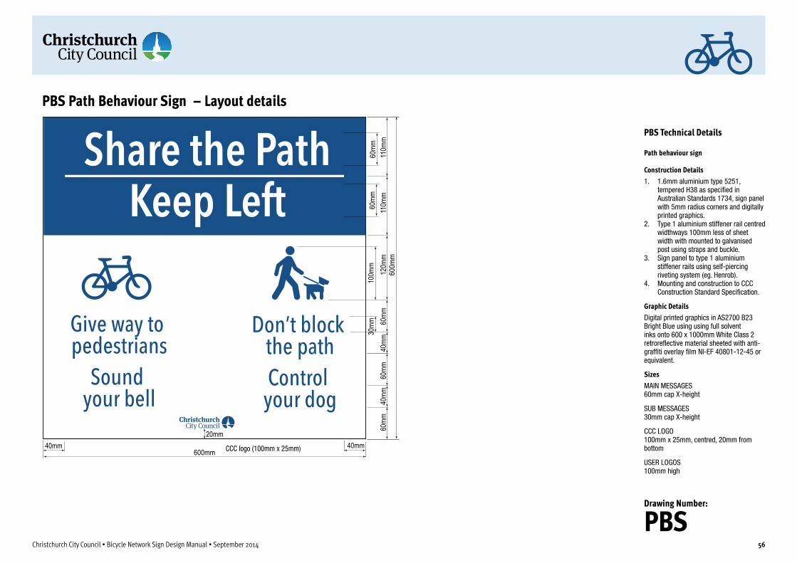
60m
m11
0mm
60mm
40mm
20mm
120m
m40
mm60
mm60
mm
600mm40mm
110m
m60
mm
100m
m30
mm
40mm
600m
m
PBS Path Behaviour Sign – Layout details
CCC logo (100mm x 25mm)
Christchurch City Council • Bicycle Network Sign Design Manual • September 2014 56
PBS Technical Details
Path behaviour sign
Construction Details1. 1.6mm aluminium type 5251,
tempered H38 as specified in Australian Standards 1734, sign panel with 5mm radius corners and digitally printed graphics.
2. Type 1 aluminium stiffener rail centred widthways 100mm less of sheet width with mounted to galvanised post using straps and buckle.
3. Sign panel to type 1 aluminium stiffener rails using self-piercing riveting system (eg. Henrob).
4. Mounting and construction to CCC Construction Standard Specification.
Graphic DetailsDigital printed graphics in AS2700 B23 Bright Blue using using full solvent inks onto 600 x 1000mm White Class 2 retroreflective material sheeted with anti-graffiti overlay film NI-EF 40801-12-45 or equivalent.
SizesMAIN MESSAGES 60mm cap X-height
SUB MESSAGES 30mm cap X-height
CCC LOGO 100mm x 25mm, centred, 20mm from bottom
USER LOGOS 100mm high
Drawing Number:
PBS

35mm 60mm
Numbered route indicator for TMR veloway
12mm 12mm
Sample branded route logoMaximum size of logo
60mm60mm
60mm
20mm
20mm
ADP sign layout with branded route
RDP sign layout on a veloway with branded route
Christchurch City Council • Bicycle Network Sign Design Manual • September 2014 57
3 Route numbering, naming and brandingThe primary cycle route signage system makes provision for the naming of cycle routes where these already exist (ADPNR and RDPNR sign variations). Naming routes is, however, cumbersome. Naming routes does not necessarily improve wayfinding and can place heavy demands on available sign space and can consequently increase the size of signs.
Lengthy route names are to be avoided. Where the length of a route name exceeds the available sign length (usually determined by the length of the longest listed destination) an abbreviated form or a smaller letter size may need to be used. When used, named route indication is limited to signs at the start and finish of the named route and to important junctions where other major routes enter.
Longer recreational and tourist routes are being developed throughout New Zealand for a variety of purposes ranging from local recreational paths to long distance trails such as the New Zealand Cycle Trail. These routes often pass through a number of local government areas. To give the route its own identity, local governments can cooperate to give the route a distinctive branding and a promotional identity which encompasses design elements such as path logo, specialist wayfinding and facilities signage designs.
The preferred way to identify tourism and recreational routes, along with more easily identifiable urban routes, is by branding – using an easily recognisable logo or symbol to mark the route. Humans respond quicker to symbols and graphical shapes and can read them from far greater distances than lettering or words. Logos are very compact and so require very little precious sign space.
Where a cycle route uses part or all of a route with a branded identity, the logo for this route may be integrated into the sign design (for new tourism and recreational cycle route signage installations) or affixed to existing signage as shown in the example on this page. Primary cycle route signage branding is integrated into the sign design as shown in the detail diagram. Local routes do not use branding logos.
Route branding logos can be used to indicate different routes by locating them on the same line as the relevant destination (see example). Where route identity branding logos are used for individual destinations, they are located on the same line as the related destination name and placed at the opposite end of the text line to the distance indication numerals. Where branding logos are primarily associated with the route (ie all listed destinations), they are located at the top of the sign adjacent to the bicycle symbol as for numbered routes (see the branding examples illustrated on this page). Logos, when used in conjunction with individual destinations should always match the height of the associated destination lettering.
Above: Integrated route branding on German national bicycle network signage. This example shows an advance direction sign in Munich, Bavaria. The lower sign indicates a link at the next junction to a lower riverside path. This path carries three overlapping branded routes - the Inner Ring Route (top line) and the River Isar Bike Route which is also part of German National Route Number 11 (lower line).
Above: Route branding examples from the Brisbane City Council Bicycle Signage Manual. The red symbol is used to denote a City Circle Route. The V1 tag indicates a high-speed, limited-access veloway, the V1.

Christchurch City Council • Bicycle Network Sign Design Manual • September 2014 58
4 Construction, materials and installationAll work and materials shall comply with Christchurch City Council Construction Standard Specification
4.1 Construction standardsConstruction standards is to be of the highest of industry standards. Spaces, drilled holes and fixings shall be consistent from one sign to another.
Screws, adhesives and silicones shall be concealed and or made flush with the surface.
Fit components with care. Graphic standards are to be carefully adhered to.
4.2 Graphic standardsThe following rules of graphic quality apply:• All lettering shall be true to its letter form in face weight and
construction.• All graphics are to be electronically, photographically or
mechanically reproduced.• All colours are as specified in AS2900 colour reference system
or other specified colour.
GraphicsSign messages are to be created from electronic artwork to faithfully reproduce the shapes and typefaces specified. The graphic layouts shall follow the guidelines outlined in the individual sign layout drawings. Graphics shown on these drawings will be provided on CDROM as Illustrator .ai or .eps files in Macintosh or Windows format.
It is the responsibility of the sign maker to ensure that all electronic files are accurately converted and match the individual sign layout drawings provided in form, size & colour.
The drawings shown in this manual are to be used as the primary reference.
Vinyl graphicsCut from self-adhesive vinyl by computer operated flatbed knife cutter or other accurate technique.
TypefaceThe fonts shown on the sign type drawings are to be used for all messages, text and numerals except where specifically stated otherwise. No other versions of typefaces will be accepted. It is the responsibility of the sign maker to purchase the fonts as specified.
Pictograms and arrowsOnly the symbols as shown on the sign type drawings are to be used. No other versions will be accepted.
ColoursColours for all parts and faces are as noted on the drawings.
4.3 Installation standardsSite conditionsSite inspections are to be carried out prior to installation to verify locations and confirm all mounting conditions.
GeneralAll installations to be plumb and level, at the heights indicated, securely mounted with theft-resistant fixings.
Work shall be complete with all bolts, rivets and other fittings to adequately transmit the loads and stresses imposed.
Where bolting of metal work to concrete is specified, fixings to be of approved masonry anchors of the required size.
Proper edge clearances are observed so there is no risk of possible damage to concrete or structural framing.
Packing of fixings is permitted to approved tolerances to level and square installations.

2.5
m M
inim
um s
ign
mou
ntin
g he
ight
1.4
m C
yclis
t eye
hei
ght
0.6m minimumclearance tosign supports
Allow suf�cient lateral mounting distance to allow clearance to sign from heavy vehicles considering the effect of road crossfall on the lean of the vehicle
0.6m minimumclearance to
sign. Supportsare �ush with
sign edges
Alternative offset mounting arrangement to provide additional lateral sign clearance
Clearances for cycle network signage
Clearances for map display boards
Bicycle Network Signage – Sign mounting clearances
Christchurch City Council • Bicycle Network Sign Design Manual • September 2014 59

Notes1. See separate diagram for individual
sign layout, typical intersection sign layout and mounting methodology.
2. Signs shown on the sample sign post are FBP-2 bicycle network �ngerboard signs used for marking primary or secondary routes. Local and recreational type signs can be mounted on the same sign pole where these routes branch. Local destination signs and local facility signs are always mounted below (lower level in the sign stack) to bicycle network signage.
3. Direction sign poles are galvanised plated to CCC Standard Speci�ca-tion for outdoor use.
4. Fingerboard signs are mounted on poles using standard �ngerboard mounting brackets. See individual sign design drawings in this manual for bracket details. Brackets should be pinned to prevent accidental movement due to wind or vandalism.
Additional sign(s) for same route mounted at same level
2.5
m M
inim
um s
ign
mou
ntin
g he
ight
for l
owes
t sig
n
1.4
m C
yclis
t eye
hei
ght
0.6m minimum clearance to sign supports
Allow suf�cient lateral mounting distance to allow
clearance to sign from heavy vehicles considering the effect of road crossfall on the lean of the vehicle
Bicycle Network Signage – Sign mounting details
Christchurch City Council • Bicycle Network Sign Design Manual • September 2014 60

Notes1. All signs for the route being followed should be mounted at the same level in the stack.2. Signs shown on the sample sign post (above) illustrate the preferred mounting hierarchy: Primary route being followed (top level of sign stack) FBP-2 �ngerboard signs used
for marking all primary routes. Primary route signs for other routes (middle level of sign stack) FBP-1 primary route
�ngerboard indicating branch route to destination shown on sign. Local route and local facility signage (lower level of sign stack) FBL-1 or FBL-2
signs are mounted as shown to indicate nearby facilities and local destinations which can be accessed from the route. Local facility signage is always mounted on the lower level of the sign stack below primary route signage.
3. Fingerboard signs are mounted to poles using standard �ngerboard mounting brackets. See individual design detail diagrams in this manual for details.
4. See separate diagrams for individual sign layouts and mounting methodology.
Sign stack mounting hierarchyUpper level - primary bicycle route signs for same route
Middle level - primary route signs for other branching or crossed routes
Lower level - Local route signage and local destination signage
Bicycle Network Signage – Fingerboard mounting hierarchy for network route junctions
Christchurch City Council • Bicycle Network Sign Design Manual • September 2014 61

Christchurch City Council • Bicycle Network Sign Design Manual • September 2014 62
5 Sign maintenanceGeneral cleaningStep 1Wipe clean with mild detergent and soft lint-free cloth.
Step 2When panels have dried, apply Mr Sheen or similar.
Note - DO NOT use abrasive cleaners, solvents or chemicals.
Touch up paintUse only 2 pack polyurethane paint (in the specified colours) when repairing minor chips, cracks, etc.
For major damage, panels will need to be removed and sprayed professionally.
Graffiti removalProcedure as outlined below:
Step 1Use general purpose thinners such as Acetic Acid Alcohol, Toluene or IPA (Isopropyl Alcohol) to clean graffiti from the surface.
Step 2Wipe off with clean white rag (Do not re-use dirty rags). If more than 2 applications are needed to remove stubborn stains, rinse the area with clean water and wipe dry before additional application.
Step 3Rinse all cleaned surfaces with water.
Step 4Allow surface to dry. Disregard used rags in closed container.

