city of dunn · city of dunn engineering design ... subgrade - that portion of the roadbed prepared...
TRANSCRIPT


CITY OF DUNN
ENGINEERING DESIGN AND CONSTRUCTION STANDARDS
Public Works Department P.O. Box 1065
Dunn, NC 28335
These Engineering Design and Construction Standards shall be reviewed on a periodic basis by the Director of Public Works.
This document shall be available for purchase per the latest fee schedule, or on the City’s
Website at http://www.dunn-nc.org/. Updates will be posted periodically on the City’s website. It shall be the responsibility of the holder of this document to maintain an up-to-date copy of the
Engineering Design and Construction Standards by obtaining and inserting all revisions.

TABLE OF CONTENTS SECTION 0.00 DESIGN CERTIFICATION REQUIREMENTS AND GENERAL
INFORMATION FOR DESIGN PROFESSIONALS SECTION 1.00 DEFINITIONS AND ABBREVIATIONS 1.01 Definitions 1.02 Abbreviations SECTION 2.00 GENERAL PROVISIONS 2.01 General 2.02 Quality of Materials 2.03 Inspections 2.04 Clearing and Grubbing 2.05 Earthwork 2.06 Maintenance of Traffic
2.07 Concrete 2.08 Permits 2.09 Acceptance Procedures 2.10 Planting, Fences, or Structures within City Utility
Easements 2.11 License Requirements 2.12 Retaining Walls 2.13 OSHA Standards 2.14 Safety and Health Hazards 2.15 Geodetic Monuments 2.16 Failure to Respond
SECTION 3.00 STREETS, DRIVEWAYS, AND PARKING LOTS
3.01 General 3.02 Design 3.03 Sight Distance 3.04 Materials 3.05 Construction and Inspection 3.06 Fire Lanes 3.07 Traffic Control and Street Name Signs 3.08 Traffic Calming Devices 3.09 Pedestrian Crossings 3.10 Street Trees 3.11 Throughfare / Median Plantings 3.12 Greenway Specifications
SECTION 4.00 SEDIMENTATION AND EROSION CONTROL 4.01 General 4.02 Applicability 4.03 Temporary Measures 4.04 Permanent Measures 4.05 Stabilization Measures 4.06 Slopes 4.07 Calculations 4.08 Construction Sequence 4.09 Minimum Standards for Residential Lots SECTION 5.00 PIPE TRENCHES 5.01 Excavation and Preparation of Pipe Trenches
5.02 Pipe Laying and Backfilling 5.03 Boring and Jacking5.04 Horizontal Directional Drilling
SECTION 6.00 WATER DISTRIBUTION
6.01 Water Distribution Pipe 6.02 Fire Hydrants 6.03 Valves and Appurtenances 6.04 Water Service Taps 6.05 Clearance Between Water Mains, Sanitary and Storm
Sewers 6.06 Backflow Prevention and Cross Connection 6.07 Automatic Fire Sprinkler System Standard 6.08 Testing and Inspection 6.09 Fire Protection during Construction 6.10 Irrigation Systems 6.11 Repair of Water Lines
SECTION 7.00 SANITARY SEWER 7.01 Gravity Sewer Mains
7.02 Force Sewer Mains 7.03 Manholes 7.04 Service Connections 7.05 Testing and Inspection 7.06 Repair of Sanitary Sewer Lines 7.07 Wastewater Pump Stations

SECTION 8.00 STORM DRAINAGE
8.01 Storm Drainage Materials8.02 Storm Sewers 8.03 Stormwater Impoundments
SECTION 9.00 AS-BUILT DRAWING REQUIREMENTS
9.01 As-Built Check List SECTION 10.00 ENVIRONMENTAL 10.01 General 10.02 Tree Protection and Preservation 10.03 Individual Lot Requirements 10.04 Utility Installation Associated with Environmentally Sensitive Areas STANDARD DETAILS

SECTION 0.00 Design Certification Requirements and General Information for Design Professionals
The City of Dunn Engineering Design and Construction Standards contained herein are to be utilized as a minimum standard for construction within the jurisdiction of the City of Dunn. The purpose of these specifications is to present typical standards for typical conditions encountered. This manual may also be subject to periodic change by the City. Where the specifications or standard drawings differ from the City Ordinance, the City Ordinance shall prevail. When changes are required, revisions will be posted on the City’s website. Extensive reference is made to state and federal publications. Unless otherwise indicated, the designer is to use the most current version. It is not the intent of these standard specifications and details to relieve the engineer of record for projects of any responsibility for the correct adaptation of these standards to the actual site conditions encountered on any project. The engineer preparing detailed drawings for a specific project must review the applicable portions of these specifications and details and satisfy himself or herself that these minimum standards will function correctly in his or her particular project. There may be circumstances in which the project engineer will wish to increase the material strengths, stone bedding requirements, reinforcing, etc. In situations where these modifications occur, the City of Dunn recommends that they be consulted regarding these proposed changes prior to plan submittal to the City. This will help insure that plan review takes a minimum amount of time. In order to ensure good engineering design, the City may occasionally require more stringent standards than those presented here. Where the designer determines that conformance with this manual would create an unreasonable hardship or where an alternative design may be more appropriate, those items must be submitted to the City for written authorization of the Director of Public Works prior to inclusion on construction documents presented for review by the City. In addition, any proposed deviations from these specifications must be clearly shown on the construction drawings, on the cover sheet, with the heading “Exceptions requested to the adopted City of Dunn Engineering Design and Construction Standards.” All of these deviations will be subject to approval by the Director of Public Works, or designee. Additionally, on every set of plans submitted to the City for review, the cover sheet or first sheet in the plan set shall have the following certification affixed: “This project shall be constructed in accordance with the following plans, and the adopted Engineering Design and Construction Standards of the City of Dunn. These plans were prepared in conformance with the approved preliminary plan approved by the City. Furthermore, the engineer whose seal and signature appear below this certifies that the City of Dunn Engineering Design and Construction and Standards have been thoroughly reviewed for applicability to this particular project. Any proposed exceptions or deviations from either the standards and/or form the approved preliminary plan are listed below:”
The professional engineer shall then list such deviations 1. 2. 3.
____________________________________________________ Signature & Seal of Professional Engineer

1-1
SECTION 1.00 DEFINITIONS AND ABBREVIATIONS
SUB-INDEX
1.01 DEFINITIONS 1.02 ABBREVIATIONS

1-2
SECTION 1.00
DEFINITIONS AND ABBREVIATIONS 1.01 DEFINITIONS
CERTIFICATE OF OCCUPANCY - Approval granted by the City for a new or renovated structure to be occupied.
CODE - The City of Dunn Code of Ordinances.
CONSTRUCTION INSPECTOR - The Construction Inspector, an assistant, or other representative duly authorized by the Director of Public Works.
CONTRACTOR – Person or persons performing construction activity, either as a primary or sub-contractor within the City, either for the City, for owners/developers, for utility companies, or any other entity. DETAILS – The drawings found within the City of Dunn Engineering Design and Construction Standards Manual DEVELOPMENT PLAN - Specific plans for residential, commercial/mixed use or industrial development of property filed in connection with an Architectural and Site Design Review or development incentives review under the terms of this UDO. A development plan may include, but not limited to: a site plan; landscape plan; Master Sign Plan; lighting plans; building elevations; and pedestrian and vehicular circulation plans, which are reasonably necessary to depict or describe certain information and data as required by this UDO. DEVELOPMENT PROCEDURES MANUAL – The City of Dunn procedural manual companion document to the Code of Ordinances. DIRECTOR OF PUBLIC WORKS – The Public Works Department Director, an assistant, or other representative duly authorized by the Director of Public Works.
EASEMENT - A property right to use or control real property of another.
ENGINEER – A person licensed to practice engineering in the State of North Carolina.
INVERT - The lowest point in the internal cross section of a pipe or other culvert.

1-3
MASTER PLAN - A drawing, map, plan or other graphic representation of an overall project, drawn to an appropriate scale by hand or other drawing method, but containing sufficient detail to depict the patterns proposed for an overall project and to determine compliance with the use and development standards provisions of the Code of Ordinances. OWNER/DEVELOPER - Person or persons who are responsible financially for the construction activity. PLANS – City-approved plans, profiles, standard details, supplemental plans, and working drawings, which show the location, dimensions, and details of the work to be performed. PROJECT - Any design, repair or construction activity occurring within the jurisdiction of the City of Dunn. RIGHT OF WAY - The land area between the back of curb or edge of pavement and the property boundary, including the area containing the street. STANDARDS - The general term comprising all the directions, provisions, and requirements contained or referred to in this book entitled “City of Dunn Engineering Design and Construction Standards” and in any subsequent revisions or additions to this document. SUBGRADE - That portion of the roadbed prepared as a foundation for the pavement structure. CITY – The City of Dunn, North Carolina

1-4
1.02 ABBREVIATIONS
AASHTO American Association of State Highway and Transportation Officials ABS Acrylonitrile Butadiene Styrene AFF Above Finish Floor ANSI American National Standards Institute ASTM American Society of Testing and Materials
AWWA American Water Works Association BHP Brake Horsepower °C Degrees Centigrade CO Certificate of Occupancy Cy/CuYd Cubic Yard
DEM Division of Environmental Management
DHS Division of Health Services DIP Ductile Iron Pipe DIPRA Ductile Iron Pipe Research Association
DWQ Division of Water Quality ETJ Extraterritorial Jurisdiction
°F Degrees Fahrenheit FEMA Federal Emergency Management Agency Ft foot GPD gallons per day GPM gallons per minute
1-5
HDPE High Density Polyethylene
HP Horsepower HGL hydraulic grade line
ID Internal Diameter In inches lbs pounds MSL Mean Sea Level MUTCD Manual on Uniform Traffic Control Devices NCDENR North Carolina Department of Environment and Natural Resources NCDOT North Carolina Department of Transportation NEC National Electric Code NFiPA National Fire Protection Association NRCS National Resource Conservation Service NYDOT New York Department of Transportation OC On Center oz ounce OD Outside Diameter OSHA Occupational Safety & Health Administration PC Point of Curvature PE Professional Engineer, Registered in the State of North
Carolina PLS Professional Land Surveyor, Registered in the State of
North Carolina

1-6
PPM parts per million PSI pounds per square inch PT Point of Tangency PVC Polyvinyl Chloride PVC Point of Curvature on Vertical Curve PVT Point of Tangency on Vertical Curve Qmax maximum discharge Qmin minimum discharge RH Relative Humidity SCS Soil Conservation Service sec second Sq Ft square feet SU Single Unit Truck (with 20 foot wheelbase and 30 foot overall length) Sq Yd square yard TDH Total Dynamic Head TRC Technical Review Committee UL Underwriters’ Laboratories, Inc. V Volts VAC Voltage - Alternating Current VDC Voltage (Direct Current) WB-50 Semitrailer Truck (with 30 foot wheelbase and 55 foot
overall length)
END OF SECTION 1.00

2-1
SECTION 2.00 GENERAL PROVISIONS
SUB-INDEX
2.01 GENERAL
2.02 QUALITY OF MATERIALS 2.03 INSPECTIONS 2.04 CLEARING AND GRUBBING 2.05 EARTHWORK 2.06 MAINTENANCE OF TRAFFIC A. General B. Materials C. Installation and Maintenance 2.07 CONCRETE 2.08 PERMITS A. City Permits B. State and Federal Permits 2.09 ACCEPTANCE PROCEDURES 2.10 PLANTINGS, FENCES, OR STRUCTURES WITHIN CITY UTILITY
EASEMENTS 2.11 LICENSE REQUIREMENTS 2.12 RETAINING WALLS 2.13 OSHA STANDARDS 2.14 SAFETY AND HEALTH HAZARDS 2.15 GEODETIC MONUMENTS 2.16 FAILURE TO RESPOND

2-2
SECTION 2.00
GENERAL PROVISIONS 2.01 GENERAL
All construction, both Development and City projects, shall conform to the requirements and dimensions on City approved construction plans, the City of Dunn Engineering Design and Construction Standards, and the Code of Ordinances of the City of Dunn. The design of streets, water systems, sanitary sewer systems, storm drainage systems, dam design, and grading plans shall be signed and sealed by a licensed North Carolina Professional Engineer in accordance with N.C. General Statute 89. In addition, refer to Section 9 of these standards “As-Built Drawing Requirements.”
2.02 QUALITY OF MATERIALS
It is the intent of this specification to provide materials of the highest standard known to the trade and to provide materials free from defects in workmanship and product. Equal materials not specified may be used if provided necessary documentation and samples necessary for the City to determine their acceptability and ISSUE A WRITTEN APPROVAL are provided to him or her a MINIMUM of 30 DAYS before being brought onto the construction site. Current standards and/or the latest revisions shall apply in all cases where materials are described by these standards.
2.03 INSPECTIONS
The Contractor shall provide the necessary manpower and equipment required as a part of the inspection process. The presence of the City’s Engineer or Public Works Staff at the work site shall in no way lessen the Contractor’s responsibility for conformity with the plans and specifications. Should the City’s Engineer or Public Works Staff accept materials, or work that does not conform with plans and specifications, whether from lack of discovery or for any other reason, it shall in no way prevent later rejection or corrections to the unsatisfactory materials or work when discovered. The Contractor shall have no claim for losses suffered due to any necessary removals or repairs resulting from the unsatisfactory work. Any work which has been covered without the City’s Engineer or Public Works Staff’s approval, shall, at the City’s Engineer or Public Works Staff’s request, be uncovered and be made available for inspection at the Contractor’s expense. Work performed before or after City staff’s normal work hours or during the weekend or City holidays shall comply with the City Code and shall include only such tasks that do not require observation by the City’s Engineer, unless previous arrangements have been made for overtime with the City Inspection Services.

2-3
2.04 CLEARING AND GRUBBING
The work of clearing and grubbing shall consist of the cutting, removal, and satisfactory disposal of all vegetation and all surface debris. Clearing and grubbing shall be conducted in a manner to prevent damage to vegetation that is intended to remain growing and also to prevent damage to adjacent property. Tree protection fencing shall be installed to protect all areas that are to remain undisturbed or protected.
2.05 EARTHWORK
Earthwork shall be defined as removal of earth or rock from its natural location or as the depositing of such material into fills areas as designated on the plans. Fill material shall be free from construction material, debris, frozen material, organic matter or unstable material. For the top 2 feet below finished sub grade, no fill material shall be used weighing less than 100 pounds per cubic foot. The top 2 feet of backfill material shall be free from stones greater than 4 inches. For all areas under a proposed roadway, the sub base, and the entire base course shall be compacted to a density of 100% maximum Standard Proctor dry density as determined by AASHTO method T99. For that portion of fill beyond the back of curb, to the right-of-way compact to a density of NO LESS THAN 98% of the maximum Standard Proctor dry density as determined by AASHTO method T99. Fill material shall be placed in lifts of 8 inches or less of uncompacted soil. Other fill material shall be compacted to a density of NO LESS THAN 90% of the maximum Standard Proctor dry density as determined by AASHTO method T99. Backfill material shall be placed in lifts of 12 inches or less of uncompacted soil. In areas where landscaping and vegetation is proposed within the median or behind the back of curb, the top 12” of material shall be prepared to support installation and growth of landscaping and vegetation.

2-4
2.06 MAINTENANCE OF TRAFFIC
A. General
When construction occurs in a traffic zone, traffic control devices must be erected, maintained, relocated, and removed in accordance with the plans, specifications, NCDOT Supplement to the MUTCD, and the MUTCD. This requirement shall apply for all construction occurring on public streets, including construction or repairs by utility companies. The MUTCD referred to in this provision shall be the current edition of the Manual on Uniform Traffic Control Devices for Streets and Highways, as prepared by the National Advisory Committee on Uniform Traffic Control Devices, including all standard documents referred to in Section 1A-7 of the MUTCD. Traffic control devices shall include but not be limited to signs, drums, barricades, cones, delineators, flashing arrow panels, temporary guardrail, temporary concrete median barrier, vehicle-mounted temporary impact attenuators, pavement marking, raised reflective pavement markers, flaggers, and pilot vehicles.
B. Materials
Unless otherwise required, materials used in the fabrication and installation of construction traffic control devices shall be in accordance with the applicable provisions of the MUTCD. All enclosed lens (Engineers Grade) sheeting required for use on traffic control devices shall have an identification mark on the surface. This mark signifies that the sheeting meets the requirements of Federal Specification L-S-300C for Minimum Reflectivity 1 Sheeting and Tape. The identification mark shall not interfere with the function of the device, but shall be visible both day and under illumination at night without the use of special devices.
C. Installation and Maintenance
Existing public streets or highways shall be kept open to traffic at all times by the Contractor unless permission to close the street, or portions thereof, is granted by the Director of Public Works and NCDOT. The City of Dunn Police Department must be contacted BY THE CONTRACTOR A MINIMUM OF 24 HOURS before any streets are closed or partially

2-5
closed. The Contractor must also contact NCDOT as required prior to closing any street or portions thereof. Work on any project shall not start until all traffic control devices required for the particular work activity are properly installed. Traffic control devices shall be properly maintained, relocated as necessary, cleaned and operated during the time they are in use. During periods when use of the devices is not warranted, they shall be removed from the work area, covered, or otherwise positioned so that they do not convey their message to the traveling public. The location, legends, sheeting, dimension, number of supports, and horizontal and vertical placement of warning signs, barricades, and other traffic control devices shall be as required by the plans or the MUTCD. Weeds, brush, trees, construction materials, equipment, etc., shall not be allowed to obscure any traffic control device in use. Competent and properly trained, attired, and equipped flaggers, using “stop” and “slow” paddles shall be provided when two-way traffic cannot be maintained. The Contractor shall assume full responsibility for the continuous and expeditious maintenance or replacement of all construction warning signs, barricades, and other traffic control devices. The Contractor shall continuously review and maintain all traffic control measures to assure that adequate provisions have been made for the safety of the public and workers. Failure to maintain all traffic control devices in a satisfactory condition shall be cause for suspension of construction operations until proper traffic control is re-established.
2.07 CONCRETE
Concrete shall be only plant-mixed or transit-mixed concrete conforming to ASTM C33 for aggregates and to ASTM C94 for ready-mixed concrete. Any concrete poured that has a slump over 4 inches as per ASTM C143, or has a batched time of more than 90 minutes, will be considered unacceptable. Concrete shall not be deposited on frozen sub grade. Concrete shall not be poured when the air temperature is falling below 40°F and the predicted low temperature for the succeeding 24-hour period is less than 32°F. All concrete when placed in the forms shall have a temperature of between 50° and 90°F and shall be maintained at a temperature of not less than 50°F for at least 72 hours for normal concrete and
2-6
24 hours for high early strength concrete, or for as much time as is necessary to secure proper rate of curing and designed compressive strength. Concrete shall be air entrained with 5-7% air. Retarders and accelerators shall be used only as directed by the Engineer.
2.08 PERMITS
Prior to construction of any project, it is the responsibility of the Owner/Developer to insure that any applicable permits from the City, County, and State and Federal Governments are obtained. Following is a list of the most common permits and/or approvals required:
A. City Permits
1. Construction Drawing Approval: Every construction site within the
City of Dunn shall require the approval of a construction drawing by the Public Works Department. A preconstruction conference shall also be required prior to the beginning of construction.
2. Work Permit: The creation of excessive noise associated with
construction that is regulated under this document, including but not limited to, erection, alteration, repair or demolition of any earthmoving activities, land clearing activities, street paving, or utility construction in a residential or business district, shall be limited to the guide lines as set forth in the Code of Ordinances and shall require approval by the Department of Public Works. Work on Sundays and on holidays shall also require approval by the Department of Public Works. The applicant shall designate an individual person or persons in control of the construction who shall be responsible for seeing that the activity complies with the terms of the approval.
3. Driveway Permit: A Driveway Permit is required for all new residential and non-residential driveways on existing City-maintained streets. The location of the driveway shall be shown on a plot plan. This permit may be obtained from the City of Dunn.
4. Burning Permit: A Burning Permit shall be obtained prior to any
burning. This permit may be obtained from the Dunn Emergency Services, Inc. (DES) for a fee.
5. Blasting Permit: A Blasting Permit is required any time there is to be
transportation, use or storage of explosive materials. This permit is required a minimum of 24 hours in advance of any explosive materials or blasting agents being transported into the corporate limits of the City. This

2-7
permit may be obtained from the Dunn Emergency Services, Inc. (DES) for a fee.
6. City of Dunn Encroachment Agreement: An Encroachment
Agreement shall be obtained from the Director of Public Works for any work within the right of way of City maintained streets. This includes (but is not limited to) utility installations, cuts and bores, irrigation systems, driveway modifications (such as paving or constructing a new driveway), and sidewalk modification. All repairs proposed for construction shall be in conformance with the City of Dunn Engineering Design and Construction Standards. A fee may be charged for this permit if the work requires an inspection. Any encroachment within the right-of-way without approval from the Director of Public Works will be considered a trespass and will be prosecuted criminally.
7. Certificate of Erosion Control Plan Approval and Land Disturbance Permit: An Erosion Control Plan and a Land Disturbance Permit are required whenever the denuded area on a project exceeds the area of disturbance as specified in the City Sedimentation and Erosion Control Ordinance. A Land Disturbance Permit may be issued by Dunn after both Construction Drawings and Erosion Control Plan approval are granted by the City, prior to any grading or site work. No building permits will be issued by the City until Certificate of Compliance (indicating that all sedimentation and erosion control measures are installed) is issued by the City. A Certificate of Completion (also issued by the City) will be required before City acceptance of project infrastructure.
8. Timbering Plan: A separate timbering plan is required for timbering or forestry activities and shall be in compliance with the rules of the State of North Carolina and any applicable Erosion Control laws and regulations. Encroachment into buffer or tree save areas must be permitted by the Department of Public Works or the Department of Planning & Zoning as specified in the Code of Ordinances, and be in compliance with the North Carolina Administrative Code 15A NCAC 02B.0311 Middle Cape Fear River Basin: Nutrient Sensitive Waters Management Strategy: Protection and Maintenance of Existing Riparian Buffers.
Additional permits may be required by other departments of the City of Dunn.
B. State and Federal Permits Applications for State Permits are to be submitted for City approval before submission to the applicable State agency, or as indicated below. It is the

2-8
responsibility of the Owner/Developer to ensure all permit applications, fees, and final plans are submitted and approvals obtained by the appropriate agency, after City Board, Technical Review Committee and/or City staff approval. All applicable permits MUST BE OBTAINED PRIOR TO ANY CONSTRUCTION. 1. Sanitary Sewer System Extension: For any proposed extension of the
public sanitary sewer system or for the construction of a privately maintained sanitary sewer collection system, a Non-Discharge Permit from the North Carolina Department of Environment, and Natural Resources, Division of Water Quality must be obtained. The application for the permit should be submitted for City approval sometime after City approval of construction drawings for the project. Four copies (2 originals and 2 copies) of the application, a set of plans, and any pump station or gravity sanitary sewer calculations are required for approval by the City. Fee schedules and application forms may be obtained from the NCDENR-DWQ. As-builts and a P.E. certification for the system must be provided to the Construction Inspector prior to the sanitary sewer system being placed in service. Sewer capacities shall not be provided by the City for any project until respective sewer permits for the project are issued from the state. Sewer extension permits shall expire within one year of issuance if construction has not begun. The City may limit the number of units which are permitted in any development, or development phase at any one time.
2. Water System Extension: For all public water line extensions 2” and
greater, a Water Main Extension Permit from the North Carolina Department of Environment, and Natural Resources, Division of Environmental Health must be obtained. The application for a permit should be submitted for City approval sometime after approval of construction drawings for the project. Four copies of the application, 3 sets of plans, 3 Engineer Reports, signed, sealed and dated and any flow calculations are required for approval by the City. Application forms may be obtained from the NCDENR-DEH. Fees are based upon length of line proposed and can be found in the Permit Application. As-builts and a P.E. certification must be provided to the Construction Inspector prior to the water system being placed in service. Water capacities shall not be provided by the City for any project until respective water permits for the project are issued from the state. Water extension permits shall expire within one year of issuance if construction has not begun. The City may limit the number of units which are permitted in any development, or development phase at any one time.
3. North Carolina Department of Transportation Encroachment Forms
2-9
and Driveway Permit: When any part of the project will encroach on NCDOT right of way, an encroachment form must be submitted and approved by NCDOT prior to construction. All encroachment applications and driveway permits require 5 sets of plans and 5 copies of the encroachment form. Fee schedules and encroachment forms are available from the NCDOT.
a) For installation of utilities a 3-party agreement between the
Developer, the City of Dunn and the NCDOT is required. The fee is determined by NCDOT. The City of Dunn will be the party of the second part.
b) For roadway widening, sidewalk installation, addition of curb and gutter, storm drainage, etc., a 2-party agreement between the Developer and the NCDOT is required. Before submitted to NC DOT, the City must first approve proposed improvement plans. The fee is determined by the NCDOT.
c) Driveway Permits must be obtained prior to the installation of any driveway cuts to be made on a State maintained road. These permits must be approved by the City before submittal to NC DOT. The fee is determined by the NCDOT.
4. North Carolina Division of Water Quality and United States Corps of
Engineers Permits: Appropriate permits for impacts to jurisdictional streams, wetlands and riparian buffers are required for all projects. Permits shall be for all impacts associated with the entire project as defined by a master type plan, unless approved by the Department of Public Works. Copies of approval letters and corresponding maps must be provided prior to construction drawing approval unless approved by the Director of Public Works. USGS stream information and Harnett County Soil Survey information for all projects are required at initial construction drawing submittal. A Land Disturbance Permit will not be issued for any plan that reflects a discrepancy in the location of any Cape Fear River Basin Buffer rules unless the buffer shown on the plan is more conservative, or NC Division of Water Quality has approved the new location of the buffer.
5. Federal Emergency Management Agency (FEMA): Encroachment into
floodplains which appear on a map of a community issued by the Federal Emergency Management Agency must comply with the City of Dunn Flood Damage Prevention Ordinance, the North Carolina Department of Crime Control and Public Safety, Division of Emergency Management, Floodplain Management Branch and the Federal Emergency Management Agency Regulation. Final versions of approved studies, map, digital files and as-built information shall be submitted to the Department of Public Works for historical reference.

2-10
2.09 ACCEPTANCE PROCEDURES
All improvements intended for public maintenance are eligible for acceptance by the City of Dunn following the procedures outlined below: 1. After the installation of improvements in accordance with the City Engineering Design and Construction Standards, and with plans approved by the Council and Director of Public Works, the Owner/Developer or designee shall contact the Construction Inspector to schedule a warranty inspection. Note that this inspection must be performed prior to recordation of a final plat for the project.
2. The Public Works Department will respond with a punch list within 10 working days from the punchlist inspection date. 3. The Owner/Developer or designee must complete all items indicated on
the punch list, and any additional items noted, within 60 days of the date of the warranty inspection, for the City to accept the infrastructure and begin one-year warranty. The Owner/Developer or designee must then request another warranty inspection if more than 60 days passes before the punchlist work is complete.
4. In accordance with the Code of Ordinances, building permits will be
withheld on any project that does not receive a Beginning of One Year Warranty Acceptance Letter by the time 25% of the building permits are issued for a platted phase of a project.
5. Upon the acceptable completion of all punch list items and payment of any
outstanding fees, the Owner/Developer or designee will receive a Beginning of One Year Warranty letter from the City of Dunn. This acceptance begins a warranty for materials and workmanship of not less than 1 year in duration from the date of acceptance. The warranty will be to the City from the Owner/Developer or designee. The City will perform routine maintenance during the warranty period.
6. A warranty bond is required to guarantee the workmanship and materials during the warranty period. Refer to the City Code of Ordinances for more information.
7. Sixty days before the end of the warranty period, the Owner/Developer or Designee shall request a final (end of one year warranty) inspection from the Construction Inspector.

2-11
8. The Public Works Department will respond with a punch list on workmanship or materials within 30 days of the request.
9. The Owner/Developer or designee must complete all items indicated on
the punch list, and any additional items noted, within 60 days of the final inspection. The Owner/Developer or designee must request another final inspection if more than 60 days passes before the punchlist work is complete.
10. Upon the acceptable completion of all final punchlist items, the Owner/Developer or designee will receive a final evaluation of One Year Warranty Acceptance Letter from the Public Works Department. The City will begin total maintenance of the project as of the date of the letter.
11. In accordance with the City of Dunn Code of Ordinances, building permits
may be withheld on any project that does not have an End of One Year Warranty Acceptance Letter by the time 75% of the building permits are issued for the project.
Until an End of One Year Warranty Acceptance Letter has been issued, all materials and workmanship are the responsibility of the Owner/Developer.
2.10 PLANTINGS, FENCES, OR STRUCTURES WITHIN CITY UTILITY EASEMENTS
An “easement” shall mean any area to which the City has unlimited access for servicing utility lines. Any plantings installed within an easement may be damaged or destroyed during the course of servicing. The City will not be liable for any damage to plantings, fences, accessory structures located either within an easement or in any manner restricting access to the easement. Further, the City shall not be liable for any incidental or consequential damage caused by the City’s removal of any structure impairing the easement. Any contractor or landowner who has impaired the easement by allowing an obstruction to be placed on the easement shall indemnify and hold harmless the City for any resulting incidental or consequential damages. The City will reseed as necessary any bare or disturbed soil for erosion control purposes. Small and medium shrubs, groundcovers, or grasses may be planted by the property owner within an easement (subject to the preceding paragraph) and as long as those planting do not inhibit access of the easement with required equipment by the City and/or its agents. Small trees (under 30 feet in height at maturity) may be planted a minimum of 10 feet from the centerline of the closest utility pipeline within the easement or 10

2-12
feet from the center of the easement, whichever is greater, and subject to the preceding paragraphs. Small trees as defined above shall include redbuds, fringe tree, serviceberry, crape myrtle, golden raintree, hawthorn, hornbeam, saucer or star magnolia, sassafras, smoke tree, sourwood, and sumac. Large trees, fences, gates, or any type of structures (e.g. retaining walls or utility sheds) shall not be placed within any City utility easement.
2.11 LICENSE REQUIREMENTS
All Contractors performing any construction activity involving the City of Dunn utility system or street system shall be licensed to practice general contracting in the State of North Carolina. The Contractor shall be classified in the appropriate area of license for the type of construction to be performed and shall not perform construction activity which exceeds the limitations of the designated Contractor’s license.
2.12 RETAINING WALLS
All retaining walls with a height of 5 feet or greater must be designed by a Professional Engineer and shall be signed and sealed. Design and construction drawings shall be submitted to the Director of Public Works for approval prior to construction. All necessary permits (e.g., building permit) must be obtained prior to any construction associated with retaining walls. Safety rails or fencing may also be required.
2.13 OSHA STANDARDS
All Contractors and their employees must comply with all OSHA standards while working on City projects, while on City of Dunn property or rights of way, and for all development projects within the City of Dunn.
2.14 SAFETY AND HEALTH HAZARDS
The operations of any Contractor shall not expose City of Dunn employees or residents to any hazardous chemicals or other occupational safety and health hazards. All Contractors working on City projects or on City of Dunn property or rights of way shall inform every individual who enters the project concerning hazardous chemicals which the Contractor might be using and to which the individual might become exposed by working in that area.

2-13
2.15 GEODETIC MONUMENTS NAD83 Geodetic monuments must be tied to the project when the project is within 2000 feet of a monument. .
2.16 FAILURE TO RESPOND
Where the Project Owner does not respond to directives by the City to complete certain repairs and/or work that, in the City’s opinion, causes a safety hazard or the potential for damages, the City may have such work performed and charge the project owner all associated expenses plus a 25% mobilization fee (examples: trench repairs, street washing, etc.). This section shall not create an obligation of the City to undertake such work or to be liable in any way for failure to undertake such work. The time frame for responding to the City’s directives shall be as directed by the Public Works Director.
END OF SECTION 2.00
3-1
SECTION 3.0 STREETS, DRIVEWAYS, AND PARKING LOTS
SUB-INDEX
3.01 GENERAL 3.02 DESIGN A. Street Classifications for City Specifications B. Horizontal Street Design C. Vertical Design D. Geometric-Radii E. Cul-de-sacs F. Driveways/Access G. Curb and Gutter H. Parking Lots/Off Street Parking I. Sidewalks J. Pavement Design K. Pavement Markings and Signage L. Bridge Design M. Shoulder Sections N. Roadway Connectivity O. Phased Construction 3.03 SIGHT DISTANCE A. Intersection Sight Distance B. Stopping Sight Distance 3.04 MATERIALS 3.05 CONSTRUCTION AND INSPECTION A. Streets B. Curb and Gutter, Driveways, and Sidewalks 3.06 FIRE LANES 3.07 TRAFFIC CONTROL AND STREET NAME SIGNS 3.08 TRAFFIC CALMING DEVICES 3.09 PEDESTRIAN CROSSINGS

3-2
SECTION 3.00
STREETS, DRIVEWAYS, AND PARKING LOTS 3.10 STREET TREES 3.11 THOROUGHFARE MEDIAN PLANTINGS
3.12 GREENWAY SPECIFICATIONS

3-3
3.01 GENERAL
The latest revision of the Standard Specifications for Roads and Structures of the North Carolina Department of Transportation shall apply unless otherwise specified herein. Whenever the following terms are used in above said specifications the intended meaning of such terms shall be as follows: “State” or “Commission” shall be replaced by “City of Dunn.” “Resident Engineer” shall be replaced by the words “Director of Public Works.” “Sampling and testing by Commission” shall be replaced by the words “sampling and testing by the City or its authorized testing agent.” “Inspection by Commission” shall be replaced by “Inspection by City or its duly authorized representative.”
3.02 DESIGN All streets (private and public) shall be designed and fully constructed to the City of Dunn Engineering Design and Construction Standards in accordance with all ordinances and policies of the City. Refer to the City of Dunn Code of Ordinances for requirements for improving existing thoroughfares and streets. NCDOT standards shall be used on all existing State roads, extensions of existing State roads, or roads to be maintained by NCDOT. Street design is based primarily on criteria dictated by the street classification, design speed, surrounding terrain, and traffic volumes. The following factors shall also be considered in determining street and right-of-way widths: urban-type development, on-street parking, alley-loaded units, zoning, depth of lots (length of driveways), garages, street trees, street network, setbacks, street classification, speed limit, and sidewalks. The Technical Review Committee shall make the final approval for necessary street and right of way widths for the City of Dunn. The following is intended to be recommended street and right of way widths minimum. Specific information and documentation on development and/or product types to be serviced by roadways should be provided for consideration of street widths, and such information may be incorporated into development and/or plan approval conditions. Note that a Transportation Impact Analysis may be required to accompany plans submitted to the City for consideration of traffic impacts due to development according to the City of Dunn Code of Ordinances.

3-4
In special circumstances, the City may elect to require payment of a fee-in-lieu of installation of roadway improvements.
A. Street Classifications for City Specifications *See above paragraph regarding factors that determine street cross-section and right-of-way section. Early communication (in preliminary design) with the City of Dunn to determine the appropriate street and right-of-way width for the particular development is encouraged. The following street cross sections comprise the most typically utilized sections for the City. The details at the end of these design and construction standards include additional cross sections that are utilized when other factors are considered. Note that reduced roadway cross sections maybe permitted for streets serving areas for which a master land use plan is approved, with approval of the Technical Review Committee. In areas where an entrance median is desired, the width of the median shall be in addition to required cross sections as specified.
1. Minor street (and/or Alley) Typical width: 25 feet of pavement on 50-foot public right-of-way
All alleys are primarily for service access to the back or side of properties.. They are encouraged in neo-traditional and mixed use developments, and adjacent to limited-access facilities. The purpose of an alley is to provide utility and vehicular access along the rear or side of new residential and non-residential structures. All alleys are to be maintained with measures to ensure the travel way is not obstructed in any manner, including by parking or loading. Proof roll inspection shall be required for an alley. A drainage system shall be provided and shall conform to all public street design drainage standards as outlined in this Manual. The City shall not be responsible for damage occurring to the pavement structure due to use of the private alley for access in providing public services. When alleys are used for the provision of these services, the Homeowner Association covenants for the development shall clearly state this. Alleys shall be constructed on a 50-foot public or private right-of-way with a paved travel lane of 25 feet, and clear shoulders of a minimum width 4.5 feet along each side. Under unique, site-specific circumstances, including such factors as the absence of utility lines in the alley and/or lack of real property, consideration of a reduction of rights of way and travel lane width may be made.

3-5
2. Residential Cul-de-sac (800 feet maximum)
Typical width: Typical width of street determined by residential street. Minimum
pavement radius of cul-de-sac 40’ from center of cul-de-sac minimum radius of r/w shall be 50’.
A street which serves abutting residential land use and which terminates in a turnaround and originates at the intersection with another street. With the exception of cul-de-sacs, other street types shall not intersect onto this street classification segment. Cul-de-sacs shall only be permitted on a case-by-case basis where extreme topographical or environmental concerns exist, or where future connection to other streets is impossible due to pre-existing development.
3. Residential Street Typical width: 30 feet face to face on 50-foot right of way A street where the primary function is to serve the immediately abutting residential land use, i.e., only local traffic generated by the residents in proximity of the street. In this classification, traffic volumes flowing from other intersecting residential streets shall not exceed the traffic volumes generated by the land use abutting the street, and this street classification shall not serve more than 150 dwelling units. Where the design will accommodate double sided on-street parking the Director of Public Works shall be consulted for the minimum width. Additional pavement marking and signage may be required where on-street parking is prohibited.
4. Commercial Cul-de-sac Typical width: Minimum pavement radius is 50’ with minimum r/w of 65’. A street which serves abutting non-residential land uses and which terminates in a turnaround and originates at the intersection with another street. With the exception of cul-de-sacs, other street types shall not intersect onto this street classification segment. This street may require additional turn lanes on either of the intersecting streets at the street intersection.
3-6
5. Residential Loop Street
Typical width: 30 feet face to face on 50-foot right of way
A street which serves abutting residential land use and which terminates on the same street from which it originates. Short residential cul-de-sac streets may be considered to intersect onto this street classification segment. Where the design will accommodate on-street parking the Director of Public Works shall be consulted for the minimum width of street and right-of-way. Additional pavement marking and signage may be required where on-street parking is prohibited.
6. Sub Collector Street Typical width: 34 feet face to face on 55-foot right of way
no on-street parking permitted A street, which serves traffic, generated by proximity land, which may include, uses other than residential. Design shall accommodate the vehicle type expected to use the facility which is typically larger than a passenger car. Where the design will accommodate on-street parking the Director of Public Works shall be consulted for the minimum width of street and right-of-way.
7. Collector Street Typical width: 40 feet face to face on 60 feet of right of way – no on-street parking
A street which serves various land use classifications, and whose primary function is traffic service, collecting traffic from streets intersecting it and funneling it to major streets. A collector street shall be provided when the roadway is the sole traffic route for more than 100 dwelling units, collects traffic from a commercial area of 20 acres or more, or contains other land uses which would account for similar traffic volumes. Where the design will accommodate double sided on-street parking the Director of Public Works shall be consulted for the minimum widthof street and right-of-way. Additional pavement marking and signage may be required where on-street parking is prohibited. If project frontage is within 500 feet of a major intersection, additional turn lanes and right of way widths may be required as determined by the Director of Public Works, NCDOT, and a Transportation Impact Analysis.

3-7
8. Major Street Typical width: 48 feet face to face on 80 feet of right of way. On street parking is prohibited. A Transportation Impact Analysis is required. A street which serves as a primary traffic artery of the urban area, serving the major centers of activity and carrying traffic between such centers at moderate speeds. Access to abutting property may be permitted by the Director of Public Works only on a very limited, controlled basis and in cases of a divided roadway will be limited to right in/right out unless a median and turn lanes are approved. However, the primary function of this street is to carry traffic having origin and destination removed from the street proper. The thoroughfare classifications carry the majority of trips entering and leaving the urban area as well as the through trips. Access is primarily provided by at-grade intersections which may be signal controlled. A slope easement of 20 feet in width shall be required adjoining each side of the right of way for this type of facility unless the complete facility is being constructed as part of the adjoining property development. The Director of Public Works may reduce or increase the slope easement width if necessary due to terrain. If property owner submits to the Director of Public Works (prior to construction drawing or preliminary plan approval) sufficient information to show that improvements to be located in the slope easement do not interfere with the right of the public to construct within adjoining right of way, then the Director of Public Works may permit the proposed improvement to occur. If project frontage is within 1000 feet of a major intersection, additional turn lanes and right of way widths may be required as determined by the Director of Public Works, NCDOT, and Transportation Impact Analysis. .
9. Highway Typical width: 48 feet face to face on 80 feet right of way. A Transportation Impact Analysis is required. An urban major roadway where sole function is to carry large volumes of traffic safely and expediently through the urban area. Access onto the facility is controlled to occur only at intersections with major streets or in some cases limited to right-in/right-out access subject to approval by the Director of Public Works and NCDOT. Such intersections are spaced at intervals which promote traffic progression with the absolute minimal delays incurred. The highest practical level of design shall be incorporated into facilities of this classification.

3-8
A slope easement of 20 feet in width shall be required adjoining each side of a street right of way unless the complete facility is being constructed as part of the adjoining property development. The Director of Public Works may reduce or increase the slope easement width if necessary due to terrain. If property owner submits to the Director of Public Works (prior to construction drawing or preliminary plan approval) sufficient information to show that improvements to be located in the slope easement do not interfere with the right of the public to construct within adjoining right of way then the Director of Public Works may permit the proposed improvement to occur. If project frontage is within 1000 feet of a major intersection, as determined by NCDOT, then additional turn lanes and right of way widths may be required by NCDOT in accordance with the approved Transportation Analysis.
B. Horizontal Street Design
All streets shall conform to the NCDOT Standards and shall be designed and located in proper relation to existing streets and environment. Collector streets, thoroughfares, and boulevards shall be as directional as possible but consistent with topography and preserving developed properties and community values. Residential streets shall be designed to minimize cuts and fills, and emphasis shall be placed on encouraging slower speeds in order to protect pedestrians using the facility and minimize persistent cut through traffic. The design of streets shall conform to the horizontal curve controls in Figure 1 at the end of this chapter. A minimum tangent of 150 feet is required between reverse curves for major streets, highways, boulevards, and collector streets. The tangent shall be extended as necessary to provide the minimum runoff lengths for the superelevated curves per AASHTO guidelines. The minimum tangent length approaching an intersection is 30 feet for residential streets. All intersections of streets classified as collector or greater shall have a tangent section not less than 100 feet approaching the intersection. Compound horizontal curves with the same direction of curvature shall have the radius of the flatter circular arc no more than 1½ times the radius of the sharper circular arc. Streets shall intersect each other at right angles whenever possible. The minimum desirable intersection angle is 80°. At no time shall a street intersect any other street at less than 75°. Intersections with thoroughfares, boulevards, or highways shall be at least 800 feet apart. There shall be a minimum of 200 feet between centerlines of street

3-9
jogs on collectors, boulevards, and major streets. Residential and marginal access streets shall not be offset less than 125 from their centerlines. Thoroughfares, boulevards, and collectors shall be superelevated. Superelevation shall conform to Figure 1 at the end of this chapter and shall conform to NCDOT and AASHTO standards. Tapers shall be used as necessary in street design. Approach tapers shall be used to shift lanes laterally. The following equations shall be used as applicable: Design Speed = Post speed plus 5 mph minimum Design Speed is 30 mph
L = WS for design speeds of greater than 40 mph L = WS2 /65 for design speeds of 40 mph or less L = Length in feet S = Speed in miles per hour W = Lateral offsets in feet
Turn bay tapers shall be at least 100 feet for posted speeds of 45 miles per hour and more. The minimum turn bay taper allowed is 8:1. Symmetrical reverse curve tapers are recommended for streets classified as collector or less. Storage lengths for the turn bays shall be calculated using an acceptable method. Streets with medians shall be designated to allow for proper turning movements for a SU (single unit truck) design vehicle. AASHTO guidelines shall be utilized for the actual median design and median opening dimension.
C. Vertical Design
Street grades shall be established with respect to existing topography to avoid excessive grading and the removal of existing trees and vegetation whenever practical. The minimum grade allowed on any street shall be ½%. The maximum grade allowed when approaching an intersection is 5% for the last 100 feet of pavement before the intersection unless otherwise approved by the Director of Public Works. The vertical curve controls found in Figure 1 at the end of this chapter shall also be utilized in street design.

3-10
D. Geometrics-Radii A minimum radius of 25 feet to the face of curb shall be required where residential streets intersect. A minimum radius of 30 feet measured to the face of curb shall be required where a residential street intersects with a non-residential street. It is recommended that the designer consider larger radii or 3-centered compound curves where needed to provide for turning movements of larger vehicles. A minimum radius of 40 feet shall be required where collectors intersect thoroughfare or boulevard streets.
E. Cul-de-sacs The minimum allowable cul-de-sac radius is 40 feet residential and 50 feet for commercial. The maximum allowable length of a cul-de-sac is 800 feet, measured from the last point of alternate access. The variance must be approved by the City Board upon recommendation by the Director of Public Works and public safety officials. Additional emergency secondary access may be required in these circumstances. No median shall be allowed in a 40-foot radius cul-de-sac. A median may be permitted where the cul-de-sac radius is increased and it can be demonstrated that all emergency and service vehicles can be readily accommodated.
F. Driveways/Access
1. General
In the interest of public safety and convenience, the City of Dunn may restrict the placement of a driveway to a particular location along the property owner’s frontage. Driveways will not generally be allowed along acceleration or deceleration lanes and associated tapers. No driveway will be allowed within the intersection of radii of intersecting roadways. 2. Non-residential Standard concrete driveway aprons as shown in the Standard Detail Section of these Standards shall be used when the development has less than 200 parking spaces. Street type turnouts shall be used when the development has 200 or more parking spaces or when access by larger trucks must be accommodated, as approved by the Technical Review Committee. The minimum radius for street type turnouts shall be determined by the type of vehicles which utilize the driveway on a daily
3-11
basis. The maximum vertical grade allowable for a distance of 25 feet into the site from the right of way line shall be 8%. In addition, the designer shall insure that adequate sight distance for all driveways is provided in accordance with AASHTO Standards. Non-residential driveways that are unpaved shall have a minimum 30-foot paved surface strip measured from the back of the driveway apron. Driveways without islands shall be a minimum of 22 feet wide, excluding curb and gutter. Driveways with islands shall have a 16-foot entrance lane, excluding curb and gutter. A 14-foot wide exit lane shall be required when only one lane is specified, and a 22-foot wide exit lane shall be used when two exit lanes are specified (all minimum measurements stated exclude curb and gutter). A minimum distance of 80 feet shall be required at all egress and ingress points from major streets and highways. The number of street and driveway connections permitted serving a single property frontage or commercial development shall be the minimum deemed necessary by the City of Dunn for reasonable service to the property without undue impairment of safety, convenience, and utility of the roadway. Normally, one driveway shall be permitted for any single property frontage. The use of shared driveways and joint access easements may be required for new accesses to “managed access” roadways. The arrangement of driveways should be related to adjacent driveways and nearby street intersections. Driveways close to street intersections shall be at least 25 feet from the point of tangency of the radius of curvature of the intersecting street. All driveways serving shopping center and other high volume generators shall be located a minimum of 200 feet from the intersection of public roads unless otherwise approved by the Director of Public Works. Where two driveways are proposed and approved along a single property frontage to facilitate operations, the minimum distance between the centerlines of the drives shall be 100 feet. The minimum distance between the centerlines of driveways into shopping centers and other high volume generators shall be 400 feet. For all median divided roadways, all driveways shall be limited to right in/right out unless located at approved planned median breaks. 3. Residential Residential driveways shall measure 12 feet wide from the curb cut to the right of way for a single car garage/driveway, shall measure 16 feet wide from the curb cut to the right of way for a double or greater car garage/driveway, and shall conform to the applicable Standard Detail for concrete driveway aprons. A minimum driveway length of 20 feet shall be provided between any building and the right of

3-12
way line for single-width parking areas and 25 feet shall be required for double-width parking areas. Triple-width parking areas shall require a site plan review and approval and may require additional length. All lots shall be served off the more minor classification of roadway, and there shall be only one driveway per residential lot. Residential driveways shall be located a minimum of 10 feet from the point of tangency of curb radii at street intersections. Additional distance will be required for roadways classified as collectors and higher.
G. Curb and Gutter
Curb and gutter shall be required on all streets and parking lots, unless otherwise approved by the Director of Public Works. Exceptions may be granted by the Director of Public Works in instances where: 1. The curb and gutter will only be temporary in nature; 2. There are environmental restrictions; 3. Drainage problems will be created; 4. Long term goal of the City’s Street Network; 5. There are conflicts with installation Streets without curb and gutter may also be approved in very low density, wide-frontage lots, and must meet all of the following requirements and be approved by the City of Dunn: 1. Minimum 60-foot rights of way; 2. 5% maximum vertical grade and 0.5% minimum grade; 3. Adequate swale system to carry the 10 year storm in a non-erosive manner –
this must be demonstrated by performance during the one-year warranty period or a change in the material of swales will be required;
4. Driveways across swales shall be constructed to provide for the passage of the 10 year storm;
5. All driveway pipes shall have flared end sections or headwalls on inlet and outlet ends of the pipe.
Variances for curb and gutter may not be issued for streets classified as collector or greater. All streets located in multi family developments shall have standard 2’6” curb and gutter. For other streets, 2’6” standard or 2’6” valley curb and gutter may be used. Median curb shall be a minimum width of 2’0” standard mountable curb or 2’0” to 2’6” standard curb and gutter. In parking lots, curb and gutter may be 2’0” or 2’6” standard curb and gutter or granite curb to match existing conditions.

3-13
Where 2’ 6” standard curb and gutter is used, driveway and utility service locations shall be shown in detail on construction drawings. A minimum 5-foot section of curb and gutter shall remain when removing any section of curb for the installation of a driveway, street turnout or repair of curb and gutter. When less than 5 feet of the curb remains, the full section of curb shall be removed to the next joint. Full removal of both the curb and gutter is required when installing a driveway. For parking lots, cut and fill slopes shall not begin immediately at the back of curb, instead a minimum 4 foot shoulder for fill slopes or 2 foot shoulder for cutslopes is required behind the back of curb. For roadways, cut and fill slopes shall begin outside a minimum 10’ or 12’ shoulder as shown on the details. On streets a minimum depth of 4 inches of I19.0B shall be placed under the curb and gutter and the sub-base shall have a minimum compaction of 100% Standard Proctor.
H. Parking Lots/Off Street Parking Parking lots shall be designed to provide safe maneuverability of vehicles. A minimum parking stall dimension of 9’ x 20’ shall be provided. An aisle width of 24 feet (two-way) is required on all sites. Handicap parking spaces shall reserve a minimum dimension of 8’ wide with a 5’ wide access aisle adjacent to the space (and must include one (1) 8’ wide access aisle for Van Accessibility), properly marked with signage in accordance with the N.C. Building Code. All parking facilities shall have dimensions per Figure 2. All minimum stall depths and module widths shall be measured to the face of curb when curb and gutter is used. Wheel stops, when used, shall be placed 2 feet from the center of the wheel stop to the face of the curb or edge of pavement. At locations where sidewalk and/or walkway abuts a 20-foot deep parking bay, the sidewalk shall be a minimum of 6 feet wide. A minimum pavement structure consisting of 8 inches of ABC and 2 inches of I19.0B and 2 inches of S9.5B shall be used along the travel aisle on parking facilities for multi-family (excluding duplex and triplex development) and non-residential developments. Access drives for these facilities shall also meet this minimum pavement standard. All paved parking facilities shall be striped in accordance with the MUTCD with 4-inch white lines, other than fire lanes, which shall be yellow. On all parking facilities, cut and fill slopes shall not begin immediately at the back of curb, instead, a minimum 4 foot shoulder for fill slopes and 2 foot shoulder for cut slopes is required behind the back of curb.

3-14
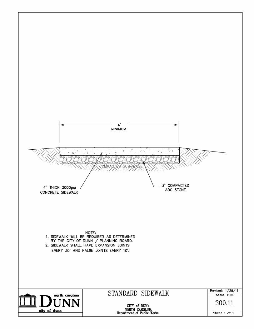
I. Sidewalks Sidewalks shall be constructed within the street right of way or public easement in accordance with these standards at locations as specified in the City of Dunn Pedestrian Plan. Sidewalks shall be installed at the time of roadway construction or widening unless otherwise approved by the City of Dunn. The minimum thickness of a sidewalk shall be 4 inches. At locations where a driveway crosses a sidewalk, a 6-inch depth is required. (Sidewalks shall have a uniform slope toward the roadway of ¼ inch per foot.) The utility strip between the sidewalk and the back of curb shall not be less than ¼ inch per foot nor greater than ½ inch per foot toward the roadway. Sidewalks are to be located a minimum distance of 5 feet off the back of curb. In some cases, where street trees are to located between the curb and the sidewalk, this distance is preferred to be increased to be a minimum of 7 feet. Refer to approved construction drawings for each project to determine this setback. This minimum requirement may not be varied without the approval of the City of Dunn. Where sidewalks and/or greenways intersect any section of curb and gutter, a handicap ramp shall be installed in accordance with current ADA Code.
J. Pavement Design
A pavement design shall be required for all thoroughfares, boulevards, and collector streets. The pavement design and traffic analysis shall be signed and sealed by a North Carolina Professional Engineer. Pavement design shall be based on subgrade conditions, a 20-year design life and projected traffic loading. Subgrade conditions shall be based upon corrected soaked CBR values at 0.1 inch penetration as per ASTM D1883. Soil samples used for these CBR tests shall be obtained at intervals not greater than 500 feet. Should a Professional Engineer with expertise in geotechnical engineering certify that the soil in question is of the same type with similar engineering properties this spacing may be increased to a 700-foot maximum spacing. Boring logs and scaled drawings designating boring locations with CBR tests and other pertinent data shall accompany the pavement design. The pavement thickness of any street shall, at a minimum, equal the design shown in the Standard Details section of these standards for the various street widths. Approved pavement design methods include those as proposed by NCDOT, the 1986 AASHTO Guidelines and the 1981 Asphalt Institute MS 1 document. The AASHTO method will require use of a terminal serviceability index of 2.0 for collectors and 2.5 for major streets and highways, So = 0.49 for flexible pavement and So = 0.39 for rigid pavements, a reliability of 98% for major streets and highways and a reliability of 95% for collectors.

3-15
All streets maintained by the NCDOT must receive approval of the pavement design from NCDOT prior to the beginning of construction. Normal crown for the pavement section shall be ¼”/foot, except as approved for superelevated cross-sections.
K. Pavement Markings
All roadways shall be marked and signed in accordance with the latest revisions of the MUTCD unless otherwise approved by the Director of Public Works. Pavement markings and signage shall be shown on roadway and subdivision plans and shall be installed prior to the issuance of Certificates of Occupancy for the development or final acceptance of the roadway. The pavement markings for all collector streets, thoroughfares, and boulevards, shall be thermoplastic. The pavement markings along thoroughfares or boulevards shall be installed such that the outside lanes are 13 feet in width to accommodate bicycle traffic unless otherwise approved by the Director of Public Works. At any time prior to 1 year warranty additional pavement markings and/or signage may be required by the Director of Public Works, at the developer’s expense.
L. Bridge Design
All public or private bridges shall be designed to withstand HS-20 highway loading unless otherwise approved by the City of Dunn and shall be properly signed and sealed by a North Carolina Professional Engineer.
M. Shoulder Sections
Shoulders shall be sufficient to permit the adequate installation and maintenance of sidewalks and utilities, as well as provide sufficient clear zone distance as defined by NCDOT. Shoulder sections without sidewalk shall be 12 feet wide on all streets with a cross section of 35 feet and greater. Shoulder sections without curb and gutter must be a minimum of 6 feet wide.
N. Roadway Connectivity A Connectivity Index shall be calculated for each subdivision, and shall be required to exceed 1.2 unless otherwise approved by the Director of Public Works due to unusual topographical restraints. This index shall be calculated by dividing the total number of street lengths (street sections between intersections including cul-de-sacs) by the number of street nodes (intersections plus cul-de-sacs).

3-16
Calculations should not include adjacent streets. In addition, intersections shall be spaced no more than 1200 feet to 1500 feet in each direction. Developments shall provide at least one vehicular access to each abutting property. This shall be accomplished via a public street and/or by joining adjacent parking lots and sharing driveways, at the discretion of the Director of Public Works. Development plans accomplishing this with parking lots and/or sharing driveways should provide a cross-access easement and complete the connection if an immediate benefit can be derived by completing the link. If no immediate benefit can be derived, development plans should provide cross access and construction easements and arrange the site design so when the adjoining property owner extends the connection to the property line, the link will be completed. If the link is to be completed in the future, the grade of the connection, parking, landscaping and/or other improvements must be designed and installed to allow for extension onto or into the adjacent properties in the supporting engineering design and calculations being provided. For roadways that stub-out to adjacent properties, sufficient information shall be provided to demonstrate the feasibility of extending the roadway to the adjacent properties. This shall include both plan and profile information for the extensions. In the event that the roadway, when extended, will cross a stream or creek, the vertical and horizontal alignment design for a minimum distance of 100 feet, plus City culvert report shall be completed. Design shall be per City geometric standards. Information on State and Federal regulatory permit ability shall also be provided to further demonstrate feasibility of the extension. In some instances, these permits may be required. Whenever possible, internal access drives should be located to join together at existing public streets and/or connect to adjacent private drives so that the internal circulation functions as an integral part of the surrounding transportation network. Where street networks have been approved with master plans of nearby developments, streets shall be designed for interconnection with those plans.
O. Phased Construction Any development with more than 200 dwelling units must have a secondary means of access during all phases of construction. Roadway construction may not be phased in such a manner to create a dead-end roadway or roadway network exceeding 2000 feet in length, or serving more than 200 dwelling units. Where a development plan or master plan has been approved and a development schedule can be provided that documents completion of future phases to eliminate the dead-end exceeding 2000 feet within a reasonable time frame, the Director of Public Works may approve an exception to this requirement if an alternate emergency access is approved and provided in the interim period. The Director of Public Works reserves the right to mandate more restrictive requirements after

3-17
consultation with the other Department Directors or for other extenuating circumstances.
3.03 SIGHT DISTANCE A. General
Sight distance shall mean the length of roadway visible to the driver traveling along the roadway or waiting to enter or cross the roadway. The sight triangle shall include both the horizontal and vertical plane and shall exist at all street intersections, multi-family, site, and non-residential driveway intersections. It shall be the responsibility of the designer for all proposed developments, including site, subdivision, landscape, infrastructure, and sign plans to meet these requirements as a part of the plan project design and approval process. Between the latest version of AASHTO and the Standard’s stated herein, the more restrictive standard shall apply. Some objects located within sight distance areas may not significantly obstruct the required visibility of the driver. The driver may be able to see over, under, or around some objects within sight distance areas. Objects that may be required within sight distance areas include fire hydrants, utility poles and traffic control devices, which should be located to minimize visual obstruction. Other objects 12 inches in diameter and smaller, such as tree trunks and sign posts, may be allowed within sight distance areas if located individually or in combination so as to not substantially restrict the driver’s view. The determination of what objects, if any, may be located within sight distance areas shall be made by the Director of Public Works. Trees greater than 12 inches in diameter and located in the street right of way shall be evaluated in accordance with other applicable City policies and requirements. It is recognized that in some cases conditions may exist that prevent the attainment of desirable sight distance due to social, economic or environmental consideration. In such cases, the maximum practical sight distance, up to the desirable values, shall be obtained. In addition, where desirable sight distance is not attained, additional measures, such as warning signs, reduced speed zones, and other traffic controls may be imposed. In all cases, unless otherwise provided by Ordinance or granted an exemption, the minimum provision of adequate stopping sight distance shall be required. The information and tabular data herein are provided as a guideline. The registered engineer shall ultimately be responsible to determine the design criteria and design.

3-18
B. Intersection Sight Distance
In order for vehicles to safely maneuver into or through an intersection, sufficient sight distance must be provided so as to avoid collisions. The horizontal line of sight is a visual line connecting the driver’s eye and the approaching vehicle, both of which are in the center of the travelway in this section. If this line of sight is impeded by any obstructions, either the obstruction should be moved or the alignment adjusted. The vertical stopping sight distance is measured along the centerline of the major street between the drivers of the two opposing vehicles. The vertical line of sight is a visual line connecting the driver’s eye, which is located 3.5 feet above the roadway surface, with the approaching vehicle, which is located 4.25 feet above the roadway surface. If this line of sight is impeded by any obstructions, either the obstruction should be moved or the alignment adjusted. The amount of sight distance required at an intersection depends on the type of traffic control at the intersection and the speeds of the vehicles. 1. Yield Sign Control
This type of design requires that the side street be posted with yield signs. The sight distance for the driver on the side street must be sufficient for the driver to observe a vehicle on the through street approaching from either the left or the right and bring his/her vehicle to a stop prior to reaching the intersection. The assumed operating speed approaching the yield sign is 10 mph resulting in a stopping sight distance of 45 feet. Where proper sight distance cannot be achieved for the driver on the side street at the design speed of the roadway, it may be necessary to have a posted speed reduction on the approach to the intersection or to replace the yield sign with a stop sign. Due to the possibility that a vehicle must stop at the yield sign, adequate sight distance at the intersection shall be provided for safe departure from a stopped condition as required by the section on stop sign controlled intersections.
2. Stop Sign Control At approaches to intersections that are controlled by stop signs or at driveways and alleys where the driver is required to stop before entering the street the driver must have an unobstructed view of the entire intersection and adequate sight distance for any of the various vehicular movements allowed upon departure of the intersection. These movements may include crossing the street, turning left or turning right onto the street. Where the through street is either undivided or divided with a median narrower than 20 feet, the crossing or left turn movements are treated as a single operation. Where the median can provide storage for the design vehicle (20 feet wide for a passenger car), the crossing or left turn movement may be considered in two phases of operation. The

3-19
measurement method for determining the sight line for left, right, and through movements from the side street is based on values listed in Table 3.1 on the following page. An obstruction to the driver’s view shall not be located within the sight triangles as defined herein to permit adequate view of the intersection. In addition, there shall be no sight obstruction located in the triangular areas to allow for safe departure through the intersection. The measurement of intersection sight distance is along the centerline of the appropriate lane of the roadway and is measured from an eye height of 3.5 feet above the surface of the roadway to an object 4.25 feet above the surface of the roadway. The location of the driver’s eye (d1) is dependent on the classification of the intersecting streets. For all intersections where the through street is a thoroughfare, the driver’s eye location shall be 18 feet back from the face of curb extended through the intersection or the edge of pavement if there is no curb. At all intersections where the through street is a local or collector street, and for ramp type driveways, the driver’s eye shall be located 15 feet behind the face of curb extended, or the edge of pavement if there is no curb. The sight distance for left or right turns onto the through street are dependent on the design speed of the roadway and are presented in Table 3.1 or the most current version of AASHTO guidelines.

3-20
3. Traffic Signal Control
At intersections controlled by traffic signals, the minimum sight distance will be stopping sight distance (Tables 3.1) for all side street movements except for the right turn movement. The right turn movement shall have intersection sight distance to allow right turn on red, except where it is economically impractical due to existing major features such as permanent buildings and existing, large, mature trees. The minimum sight distance for the right turn movement limited by existing major features shall be stopping sight distance. Where intersection sight distance cannot be achieved, right turn on red will be restricted.
TABLE 3.1 Vehicle Crossing the Roadway
Sight Distance (ft) per 10 mph of Design Speed for Appropriate Width of Crossing
2-Lanes 4-Lanes 6-Lanes 8-Lanes Passenger 100 120 130 140 Single Unit Truck 130 150 170 190 Large TTST 170 200 210 220
A. Stopping Sight Distance
At minimum, stopping sight distance must be available to the driver at all locations along roadways. Stopping sight distance applies to horizontal as well as vertical alignments. Stopping sight distance on horizontal curves is measured along the centerline of the inside lane around the curve and the line of sight is a straight line between two points on the centerline of the lane. On vertical curves, stopping sight distance is measured on a straight line between the driver’s eye and an object on the roadway surface. The height of the driver’s eye shall be measured at 3.5 feet above the roadway surface and the object shall be 2.0 feet above the roadway surface. A more detailed explanation of the measurement of stopping sight distance is included in A Policy on Geometric Design of Highways and Streets, 2001, by AASHTO (AASHTO Green Book). The minimum stopping sight distance required is based on wet pavements and depends on the design speed and the grade of the roadway. Table 3.2 presents the minimum stopping sight distances for various design speeds on level terrain. Table 3.3 presents adjustment factors for stopping sight distance on grades. Variable situations may require a greater length of stopping sight distance. Lengths in Table 3.2 and 3.3 are a guide and the registered engineer shall ultimately be responsible for the design criteria.

3-21
TABLE 3.2
MINIMUM STOPPING SIGHT DISTANCE FOR LEVEL AND WET CONDITIONS
Design speed (MPH)
Stopping sight distance (feet)
10 45 15 80 20 115 25 155 30 200 35 250 40 305 45 360 50 425 55 495 60 570
Source: AASHTO Green Book, 2001.
TABLE 3.3
ADJUSTMENT FACTORS FOR STOPPING SIGHT DISTANCE ON GRADES
Design speed (MPH)
Increase for downgrades correction in stopping sight distance (feet)
Decrease for upgrades* correction in stopping sight distance (feet)
3% 6% 9% 3% 6% 9%
20 1 5 11 -6 -8 -11 25 3 10 18 -8 -12 -15 30 5 15 27 0 -16 -21 35 7 21 37 -13 -21 -28 40 10 28 49 -16 -27 -36 45 18 40 67 -16 -29 -40 50 21 49 82 -20 -37 -50 55 25 58 98 -26 -45 -62 60 28 68 116 -32 -55 -75 *Assumed speed is lower than the design speed since vehicles normally travel at a slower speed on an upgrade.
Source: AASHTO Green Book, 2001.

3-22
3.04 MATERIALS
1. Portland Cement Concrete for curb and gutter, driveways, and sidewalks shall have a minimum 28-day compressive strength of 3000 psi, a non-vibrated slump between 2.5 and 4 inches, a minimum cement content of 564 pounds per cubic yard, an air entrainment of 5 to 7%, and a maximum water-cement ratio of 0.532.
2. Joint Filler shall be a non-extruding joint material conforming to ASTM
C1751.
3. Concrete Curing Agents shall be free from any impurities which may be detrimental to the concrete and shall meet Section 926 of NCDOT Standard Specifications for Roads and Structures.
4. Aggregate for portland cement concrete shall meet the requirements for fine
and course aggregate of Section 1014 of the NCDOT Standard Specifications for Roads and Structures.
5. Portland Cement and Admixtures shall meet the requirements of Section
1000 of the NCDOT Standard Specifications for Roads and Structures.
6. Water for mixing or curing the concrete shall be free from injurious amounts of oil, salt acid, or other products injurious to the finished product.
7. Aggregate Base Course shall consist of an approved coarse aggregate
produced in accordance with the requirements indicated for either Type A, B, or C aggregate as described in Section 910 of the NCDOT Standard Specifications for Roads and Structures.
8. Bituminous Surface Course, Type SF9.5 (A,B,C) and I19.0 (B, C) shall
consist of a mixture of coarse and fine aggregates, and asphalt cement, and shall meet the requirements of Section 645 of the NCDOT Standard Specifications for Roads and Structures. For NCDOT project the requirements of NCDOT for other types of asphalt (Superpave) shall apply
9. Bituminous Concrete Base Course, Type B25.0B, shall conform to the
general, material, and construction specifications as specified in Section 610 and Section 640 of the NCDOT Standard Specifications for Roads and Structures. For NCDOT project the requirements of NCDOT for other types of asphalt (Superpave) shall apply.
10. Tack Coat shall be asphalt or asphalt cement and shall meet the general,
material, and construction specifications as specified in Section 605 of the NCDOT Standard Specifications for Roads and Structures.

3-23
11. Concrete Pavement shall meet Section 700 of the NCDOT Standard Specifications for Roads and Structures.
12. Concrete Pavers may be used on privately maintained streets or as approved
by the Director of Public Works for pedestrian crossings in urban areas, in accordance with the applicable Standard Detail. The City of Dunn will not maintain decorative type paved street surfaces such as pavers or imprinted designs within public right of way, unless approved by the Director of Public Works.
13. Geotextile Fabric may be used to stabilize a roadway, subgrades, slopes, and
for other uses as necessary. At least one week prior to using this fabric, a sample and its associated engineering data shall be submitted to the Director of Public Works for approval. Areas stabilized with fabric shall be indicated on “as-built” drawings with the manufacturer name and type fabric specified.
3.05 CONSTRUCTION AND INSPECTION
No construction shall commence until the following applicable items have been obtained: • All required permits and approvals • City of Dunn development plan approval • City of Dunn Construction Drawing approval • Land Disturbance Permit
A. Streets
No base material shall be placed on a roadway until the storm sewer, subgrade, utilities, and all appurtenances have been inspected and meet City of Dunn Engineering Design and Construction Standards. The Construction Inspector may require field density testing of subgrade soils from a certified soils laboratory. The soils laboratory shall perform sufficient Proctors to evaluate the compaction characteristics of various soils used in the roadbed. The Construction Inspector may also require field density testing of the ABC used and an asphalt mix formula before either is inspected or approved. The final course of surface asphalt shall not be placed until the end of the warranty period. The subgrade shall be compacted as described in Section 2.05 Earthwork. Inspection of the subgrade prior to the placement of base course, and inspection of the base course prior to placement of asphalt, shall be performed by proofrolling and/or field density testing at the direction of the Construction Inspector.

3-24
When thoroughfare widening takes place, the existing edge line of the travel lane shall be sawcut. Achieve an overlap of the final inch of new asphalt by at least 6” onto the existing roadway cross-section. The objective to have the joint between new and old asphalt to be offset from the joint between subgrades (this overlap shall exclude the overlay). In addition, whenever an overlay is required, milling of 1 ½ inch shall occur at both tie-in stations to insure a smooth connection.
B. Curb and Gutter, Driveways, and Sidewalks
No concrete shall be placed until all forms and subgrades have been approved by the Construction Inspector. The surface of sidewalks shall be finished to grade and cross section with a float, troweled smooth, and finished with a broom. Subgrade shall be excavated to the required depth, and shaped to the proper cross-section. Where tree roots are encountered, they shall be removed to a depth of 1 foot for the full width of the excavation. The subgrade shall be stable and thoroughly compacted. Forms shall be set and maintained true to the required lines, grades, and dimensions. Forms shall be constructed with material of such strength and rigidity to prevent any appreciable deflection between supports. Straight forms shall be within a tolerance of ½ inch in 10 feet from a true line horizontally or vertically. Forms shall be thoroughly cleaned of all dirt, mortar and foreign material before being used. All inside form surfaces shall be thoroughly coated with commercial quality form oil. Grooved construction joints shall be cut to a depth equal to at least 1/3 of the total slab thickness. The joint shall be no less than 1/8 inch in width and cut at intervals equal to the width of the sidewalk. A 1/2-inch expansion joint filled with joint filler shall be placed between all rigid objects and placed no farther than 50 feet apart for sidewalks and curb and gutter, extending the full depth of the concrete with top of the filler 1/2 inch below the finished surface.
3.06 FIRE LANES
Fire lanes shall be installed in accordance with Dunn Emergency Services and inspected in accordance with the public street requirements of Section 3.05 A and 3.05 B of these standards. The general requirement designates that any building located more than 150 feet from a public road, or which exceeds 30 feet in height and is set back more than 50 feet from a public road, shall have a fire lane. Fire lanes shall be a minimum width of 20 feet and shall be properly marked and signed to designate the access as a “fire lane” as specified by the Fire Marshal. The surface of the fire lane shall be paved with a minimum of 8 inches of ABC stone and 2 inches of S9.5B asphalt.

3-25
All fire lanes shall be marked in accordance with one of the following requirements: 1. Continuously painted yellow striping along the fire lane with “No Parking -
Fire Lane” printed with minimum 8-inch high letters at 40-foot intervals or as directed by the Fire Marshal;
2. Continuously painted yellow curb with “No Parking - Fire Lane” along the fire lane, and with “No Parking - Fire Lane” printed with minimum 8-inch high letters at 40-foot intervals or as directed by the Fire Marshal;
3. The installation of the MUTCD standard sign showing “No Parking - Fire Lane” placed at each end of the fire lane and at 50-foot intervals with arrows on the signs or a continuously painted yellow strip along the designated fire lane.
3.07 TRAFFIC CONTROL AND STREET NAME SIGNS
Traffic control and street name signs within subdivisions which will be maintained by the City of Dunn shall be consistent with the MUTCD. All specialty traffic control and street name signs and posts must be in compliance and approved by the City of Dunn.
3.08 TRAFFIC CALMING DEVICES The City shall not allow the obstruction of any public street, private street or fire lane unless otherwise stipulated by the City Council. This requirement is in accordance with the current edition of the North Carolina State Fire Prevention Code. The reference to an “obstruction” shall include parking, speed bumps or any other device which may obstruct the free passage of emergency vehicles.
All traffic control devices must be shown and approved as a part of a site plan prior to installation and must be in conformance with the City Standard Specifications. The traffic control devices and all related signs and pavement markings shall be maintained by the Owner as a part of the approval of the plan. Traffic control devices shall include rumble strips, raised pavement markers, pavement undulations (speed humps) or speed bumps. The following traffic calming devices shall not be installed on public streets except with the approval of the City Council. 1. Rumble Strip An irregular surface established to draw the attention of motorists and alert them of potential hazards or conflicts. The material used as a part of a rumble strip may be cobblestone, stamped concrete, brick or rough surface asphalt.

3-26
A rumble strip may not vary more than 1 inch in height from the pavement elevation of the adjacent travelway. All rumble strips must be located outside any public right of way, unless otherwise approved by the Director of Public Works and the Public Safety Director. 2. Raised Pavement Markers Raised pavement markers may be used to create an irregular surface to draw the attention of motorists and to alert them of potential hazards or conflicts. The markers must be made of a flexible and durable solid material designed to support vehicular traffic. The placement of markers may be staggered in a manner as approved by the Public Works Department. All raised pavement markers shall have a maximum height of 1 inch above the pavement surface. The minimum size of the marker shall be 4” x 4”. The markers must be located outside any public right of way. All raised pavement markers shall have cube-corner microprism reflectors visible from either direction of travel. 3. Pavement Undulation (Speed Hump) A pavement undulation is a gradual raised pavement surface which extends transversely across the travelway. The surface material for a pavement undulation shall be the same as the adjacent travelway, typically asphalt. A pavement undulation shall be parabolic with a maximum height of 3 inches. The pavement shall be tapered to the edge of the pavement or gutter line for the last 12 inches along each side. The minimum length of the pavement undulation shall be 12 feet. All pavement undulations shall be clearly marked with pavement markings or warning signs for each direction of travel. Markings and signage shall be consistent with the MUTCD. . All pavement undulations must be located outside any public right of way and may not be used on any public or private street, access, travelway, etc., designated as a fire lane except as permitted by City Policy. Pavement undulations must be located a minimum distance of 500 feet from a signalized intersection. The City of Dunn and/or the N.C. Department of Transportation may require the removal of any speed undulation which causes traffic to back up onto a public street.
3.09 PEDESTRIAN CROSSINGS All locations which are designated for pedestrian traffic crossings shall be designated as a crosswalk with pavement marking and signage in accordance with MUTCD.

3-27
3.10 STREET TREES
Street trees, landscape, and landscape medians on streets within residential and non-residential developments and other areas shall be maintained by the Homeowners Association or by individual property owners fronting on the street. This shall include but is not limited to maintenance of the trees, landscape, ground cover and removal and replacement of plant materials. The City of Dunn accepts no responsibility for maintenance or replacement of street trees, landscape areas, or landscape medians.
Street tree shields shall be installed wherever street trees are required. A one-year warranty period following installation shall be provided on all street trees. After the one year warranty period, the Homeowner’s Association and/or the property owner shall be responsible for the care, removal, replacement and maintenance of street trees.
3.11 THOROUGHFARE/MEDIAN PLANTINGS
With the construction of streets in the Thoroughfare/Boulevard/Parking classification and above, landscaping of medians and shoulders shall be per the City of Dunn Thoroughfare Planting Guidelines. Thoroughfare median plantings shall be maintained by the City of Dunn, unless otherwise specified.
3.12 GREENWAY SPECIFICATIONS Greenway locations and alignments shall be as directed and approved by the
Director of Parks and Recreation and shall be in accordance with the City of Dunn Pedestrian Plan. Greenways alignment shall be finalized with the Director of Parks and Recreation prior to preliminary plan approval, with full construction plans and all permits provided prior to construction drawings approval for any project on which greenways are required.
Where greenway trails are required the following guidelines shall be followed.
• Maximum cross slope grade shall be 2 %.
• Maximum grade shall be 8%, unless approved by the Director of Parks and Recreation.
• Positive drainage shall be established.

3-28
• At all drainage crossings a Professional Engineer shall provide properly sized drainage pipe with supporting calculations.
• Bridge crossings may be required in some locations. If a bridge is required, it
must carry a 10,000 lb load and shall be designed by a registered engineer and approved by the City of Dunn and appropriate agencies.
• Greenways shall be 8 feet wide. However, in the following cases, greenways
shall be 10 feet in width when located on a sewer easement, when approaching an underpass, and at other times if determined necessary by Director Parks and Recreation.
• When the greenway intersects with a roadway, a 10’ wide, 6” thick concrete
pad will be required extending from the back of curb to the right of way line, or 18’, whichever is less. There shall be a handicap curb cut as shown in City of Dunn details. At the end of the pad, removable steel bollards will be required per City of Dunn detail.
• Where the greenway trail intersects roadway in which sidewalk is on opposite
side of road a handicap ramp will be required on sidewalk side of street to allow travel onto sidewalk from greenway.
• Greenways shall be located and constructed so as to minimize damage from
floodwaters. • The minimum material must be 3” of approved asphalt base material and 2”
SF9.5B. • Documentation of required permits, approvals, etc. shall be provided for
greenways prior to construction drawing approval of the project on which the greenway is required.
• Greenways shall be subject to the same construction inspections, performance,
and warranty requirements as roadway infrastructures.

3-29
Figure 1 CURVE CONTROLS
Horizontal Curve Controls Vertical Curve Controls Minimum
Design speed (mph)1
Maximum Super- elevation (ft./ft.)2
Minimum Radii (ft.)
Maximum Grade3 (percent)
Length Crest
Length Sag
Minimum Length (ft.)
Limited Access Thoroughfare
Design standards to be determined for each case individually by the Director of Public Works
Thoroughfare, Boulevard, Parkway
Design standards to be determined for each case individually by the Director of Public Works
Non-Residential Collector
40 0.04 565 9% 44A 64A 120
Residential Collector Streets & No Load Residential Collector
25 0.04 345 (300)
9% 29A 49A 120
Residential streets
30 Normal crown
205 230
10% 12A 26A 75
Cul-de-sacs 1000’ or less
30 Normal crown
150 10% 12A 26A 75
Loop road 1500’ or less
30 Normal crown
150 10% 12A 26A 75
1 Design speed shall be at least 5 mph greater than posted speed. 2 The superelevation tables found in A Policy on Design of Urban Highways and Arterial Streets - 2001 published by the American Association of State Highway Officials will be used for determining the actual “e” for various radii. 3 Design criteria can vary on a case-by-case basis if approved by the Director of Public Works. 4 Note: At the discretion of the Department of Public Works, the Kvalues in sags may be adjusted with additional street lighting A - Algebraic difference in grades.
END OF SECTION 3.00
4-1
SECTION 4.00 SOIL EROSION AND SEDIMENTATION CONTROL
SUB-INDEX
4.01 GENERAL 4.02 APPLICABILITY 4.03 TEMPORARY MEASURES
A. Standard Temporary Silt Fence B. Silt Fence Outlet C. Gravel & Rip Rap Filter Basin (Sediment Trap) D. Skimmer Sediment Basin E. Gravel & Rip Rap Horseshoe Inlet Basin F. Standard Riser-Barrel Sediment Basin (Sediment Pond) G. Catch Basin Riser/Filter H. Check Dam I. Construction Entrance J. Diversion Ditch K. Temporary Stream Crossing L. Storm Drain Inlet Protection M. Temporary Silt Ditch N. Slope Drains
4.04 PERMANENT MEASURES
A. Lined Stormwater Channels B. Storm Drain Outlet Protection
4.05 STABILIZATION MEASURES
A. Temporary Stabilization B. Permanent Stabilization C. Use of Drought Tolerant Plants
4.06 SLOPES 4.07 CALCULATIONS 4.08 CONSTRUCTION SEQUENCE
4.09 MINIMUM STANDARDS FOR RESIDENTIAL LOTS

4-2
4.01 GENERAL
This chapter contains standards and specifications for various techniques and devices used in temporary and permanent erosion control, for the purpose of insuring compliance with the City’s Sedimentation & Erosion Control Ordinance (i.e. to prevent soil erosion and sedimentation to offsite property or protected areas). These techniques and devices are the minimal acceptable for use in the City of Dunn. The use of other techniques and devices is acceptable if adequate control is provided by the alternative and prior approval is given based on a review of specifications for the measure.
The techniques and devices in this chapter should generally be used in the locations and under the conditions specified in the standards for the particular measure. No temporary or permanent erosion control devices are allowed to be placed in riparian buffers, unless approved by the Director of Public Works (or designee).
4.02 APPLICABILITY
Temporary and permanent erosion control measures shall be provided for all land disturbing work in accordance with the City’s Sedimentation and Erosion Control Ordinance. While all land disturbing work, regardless of the amount of disturbed area, shall require the installation of temporary and permanent measures to prevent erosion and sedimentation to offsite properties or protected areas, certain categories of land-disturbing work shall be required by the City to meet additional requirements:
1. Land disturbance exceeding 20,000 sq. ft. - requires erosion control plan
approval, a Land Disturbance Permit, payment of related fees, and a preconstruction meeting before clearing & grubbing and construction may begin.
2. Land disturbance exceeding one acre for a publicly funded project (i.e. a
public agency as financially responsible party) – requires plan approval by the North Carolina Department of Environment and Natural Resources, Division of Land Resources, Land Quality Section, Fayetteville Regional Office. Office copies of approved plans & permits should also be submitted to the City for record.
3. Land disturbance for the construction of individual residential buildings –
requires installation of certain site-specific erosion control measures prior to specific building inspections.
4-3
For most development-related land disturbance activities, the following shall apply. An erosion control plan must be submitted to and approved by the City or NCDENR Land Quality Section. A land disturbance (grading) permit shall be obtained from the City with erosion control plan approval, a preconstruction meeting, and all applicable fees paid prior to issuance of a Land Disturbance permit. Temporary measures shall be installed and inspected by the NCDENR Land Quality Section or the City for compliance and issuance of a Certificate of Compliance prior to initiation of any land disturbing activity (Certificate of Compliance). All permanent erosion control measures shall be incorporated into the work at the earliest practical time. All temporary measures shall be maintained until the permanent measures have taken effect or approval to remove such measures has been granted by the Director of Public Works or NCDENR Land Quality Section. Temporary and permanent measures shall be coordinated to provide effective and continuous erosion control throughout the construction and post-construction period to minimize siltation of streams, lakes, reservoirs, and other impoundments, ground surfaces and other property. These measures shall remain in effect until the City gives final approval in the form of a Certificate of Completion.
4.03 TEMPORARY MEASURES
A. Standard Temporary Silt Fence
Silt fence is a temporary sediment filter of geotextile fabric stretched between and attached to supporting posts (at maximum 8 feet spacing) and a wire fence, with the bottom of the fabric and wire buried in the ground. Silt fence shall be used below small disturbed areas less than ¼ acre per 100 feet of fence, where runoff can be stored behind the silt fence without damaging the fence or submerged area behind the fence. Silt fence is not intended for installation across areas of concentrated flow (i.e. streams, ditches, or waterways).
Silt fence shall consist of metal fence posts, wire fence, filter fabric, staples and wire. The wire fence shall be “hog wire”, minimum 14 gauge, with maximum mesh of 6 inches. The wire is used to attach the wire fence to the posts. The filter fabric shall be a synthetic geotextile stapled to the top of the wire fence.
Use/Design: Silt fence must be stable for the 10-year peak storm runoff. Silt fence shall be used where the drainage area is no greater than ¼ acre per 100 ft of fence. The depth of impounded water adjacent to silt fence in the design storm shall not exceed 1.5 ft at any point along the fence. The design life of a synthetic silt fence should be 6 months.

4-4
Installation: Refer to the approved erosion control plan for location, extent, and specifications. If silt fence is not installed correctly the first time, it will have to be re-installed. 1. Determine the location on the ground taking into consideration:
a) Sufficient spacing between the silt fence and the construction site for maintenance, grading, filling, and other construction activity.
b) Installation of the silt fence on the contour so that runoff
goes through the silt fence and does not flow along the silt fence to pond at the lowest point. Where ponding does occur, silt fence outlets may be necessary so that the fence does not collapse.
2. Clear the location of the silt fence, clearing only what is needed to
provide access by personnel and equipment for installation. 3. Excavate an 8-inch down and 4-inch forward along the location of
the fence. Using a “ditch witch” is helpful. 4. Along the lower side of the trench, place steel fence posts no more
than 8 feet apart and drive them 24 inches into the ground.
5. Attach wire fence (“hog wire” or min. 14 gauge with max. mesh of 6 inches) to the uphill side of the posts, placing 12 inches of the bottom of the fence into the trench. Use wire to fasten fence to the posts. Completed fence must be at least 1.5 feet high and not more than 2 feet high.
6. Attach synthetic filter fabric to the uphill side of the wire fence
with staples a maximum of 12 inches apart, placing 12 inches of the fabric into the trench with the wire fence. Use rolls of fabric and cut to necessary length in order to minimize the number of joints.
7. Backfill the trench and tamp the fill to firmly anchor the bottom of
the filter fabric and wire fence.
8. Where it is impossible to install the silt fence on the contour, runoff will flow along the fence and pond at the lowest point. Where the total drainage area to the point is greater than 5,000 ft2 a silt fence outlet is required. Where the drainage area is greater than 10,000 ft2, a sediment trap shall be used in lieu of a silt fence outlet. The location of silt fence outlets should be shown on the

4-5
plan, with installation checked in the field to determine if additional outlets are needed.
9. Silt fence shall be installed in accordance with the standard detail,
this specification, and the approved erosion control plan.
10. Access to silt fence must be provided in all phases of construction for maintenance and removal purposes. Following are some guidelines for minimum clearance required for silt fence:
a. Allow 15 to 25 feet of space between the fence and any
structure for equipment to maneuver for site construction and silt fence maintenance.
b. Allow 15 feet at the bottom of fill slopes over 5 feet high
for sediment storage and silt fence maintenance.
B. Silt Fence Outlet
A silt fence outlet is a low point placed (where necessary) along the length of a silt fence to allow water trapped behind the silt fence to drain out, thus minimizing failure of the silt fence. A silt fence outlet consists of a segment of hardware cloth and washed stone placed in the low point of a length of silt fence. The outlet may not be used in place of a sediment trap or basin. Provisions shall be made to provide such outlets where necessary to prevent damage and to ensure the maximum filtering efficiency of silt fence. Use/Design: Obvious points of ponding shall be identified on the erosion control plan and silt fence outlets designated where the drainage area to the point of ponding exceeds 5,000 ft2. Because it is difficult to predict these locations using a topographic map, contractor shall adjust outlet locations as necessary to the ponding location during silt fence installation. Silt fence outlets should NOT be located where the outflow will erode the soil below. A location should be selected that is protected with adequate vegetation, or protection should be provided via stone or layers of filter fabric. Silt fence outlets have the same requirements for access as silt fence, outlined above.
Installation: Refer to the approved erosion control plan for location, extent, and specifications. If silt fence is not installed correctly the first time, it will have to be reconstructed. Determine the exact location of the outlet before completing installation of the silt fence, taking into consideration:

4-6
1. Installation at the lowest point(s) in the fence where water will pond.
2. Maximum allowable drainage area restriction for silt fence.
3. Installation where the outlet is accessible for installation,
maintenance and removal.
4. Placement of the outlet so that water flowing through it will not create an erosion hazard below – avoid steep slopes below the outlet and areas without protective vegetation. Use slope drains if necessary.
The silt fence outlet shall be installed in accordance with the standard detail, and the approved erosion control plan.
C. Gravel & Rip Rap Filter Basin (Sediment Trap)
A sediment trap is a small, temporary ponding area formed by an embankment or excavation to detain sediment-laden runoff and trap the sediment. The erosion control plan should show the sediment trap drawn to scale with adequate room around it for machinery to construct and maintain it during all phases of construction. Use/Design: Use the following criteria to evaluate the location and to design all types of sediment traps. Sediment traps may be used for maximum drainage areas that are 5 acres or less and where access can be maintained for sediment removal and proper disposal. Investigate and evaluate the specific conditions on the site, determine if the location is suitable, and design the trap to fit the conditions. 1. Storage Capacity – The minimum volume of the sediment trap
shall be 3600 ft3/acre based on area draining into the basin. Measure volume below the crest elevation of the outlet.
2. Surface Area – To solve for the surface area use 435 sf/cfs of
Q10. Then, convert the answer into a minimum 2:1 ratio.
3. Weir Length and Depth – The spillway weir must be designed at least 10 feet long and sized to pass the peak discharge of the 10-yr storm or may be selected from Table 4.1. A maximum flow depth of 1 foot, a minimum freeboard of 1.0 feet, and maximum side slopes of 2:1 are recommended. Weir length is to be designed based on the following criteria by using the weir equation Q=CLH3/2 ; H, not to exceed .5’ and C=3

4-7
4. Total Depth – The minimum depth below the crest of the outlet is 3.5 feet. The maximum depth is 6 feet. Depth may vary in different parts of a trap due to topography.
Installation:
1. Embankment – Ensure that embankments for temporary sediment
traps do not exceed 5 feet in height measured at the center line from the original ground surface to the top of the embankment. Additional freeboard may be added to the embankment height to allow flow through a designated bypass location. Construct embankments with a minimum top width of 5 feet and side slopes of 2:1 or flatter. Machine compact embankments.
2. Outlet – The outlet area of a sediment trap consists of an earthen
embankment with filter fabric separating the rip rap and wash stone weir. Baffles to lengthen the distance water travels through the sediment trap should be incorporated in the sediment basin. Installation of baffles shall be as described in the silt fence specifications outlined in Section 4.03C.9. Construct the sediment trap outlet with a minimum of 10 feet in length of the embankment made of stone (located at the low point). The stone section serves two purposes: 1) the top section serves as a non-erosive spillway outlet for flood flows, and 2) the bottom section provides a means of dewatering the basin between runoff events.
3. Stone Size – Construct the outlet using well-graded stones with a
d50 size of 9 inches (class B erosion control stone is recommended) and a maximum stone size of 14 inches. A 1-ft thick layer of ½ - ¾ inch aggregate (NCDOT #57 washed stone is recommended) should be placed on the inside face to reduce drainage flow rate.
4. Side Slopes – Keep the side slopes of the spillway section at 2:1 or
flatter. To protect the embankment, keep the sides of the spillway at least 21 inches thick.
5. Depth of Spillway – Keep the crest of the spillway outlet a
minimum of 1.5 feet below the settled top of the embankment.
6. Protection from Piping – Place filter cloth on the foundation below the riprap to prevent piping. An alternative would be to excavate a keyway trench across the riprap foundation and up the sides to the height of the dam.

4-8
7. Weir Length and Depth – Keep the spillway weir at least 10 feet long and sized to pass the peak discharge of the 10-yr storm. A maximum flow depth of 6 inches, a minimum freeboard of 1 foot, and maximum side slopes of 2:1 are recommended. Weir length may be selected from Table 4.1 for most site locations in North Carolina.
8. Stabilization – Within 10 working days after completion, all areas
disturbed for the trap construction must be provided with ground cover sufficient to restrain erosion. Vegetation (either temporary or permanent) should be used on the top, slopes, and perimeter when the season allows it. When the season is not suitable for establishing vegetation, use a heavy layer of mulch.
9. Baffles - Shall be required in all sediment traps. Baffles normally
split the sediment traps into four cells (please refer to the approved plan for the amount and spacing of the baffles). Normally you will need to install three rows of silt fence with hog wire as per Section 4.03A and make sure that the end of each section is keyed into the side wall of the trap to prevent water from washing out the silt fence. The silt fence should be installed where the inlet cone (area furtherest from weir) is approximately 35% of the basin area. The first and second cell is approximately 25% of the basin area with the outlet zone consisting of the remaining 15%. The spacing between the metal posts shall be a maximum of 4’ apart. Slits are to be provided in the silt fence fabric in alternating spaces.
10. Trap Cleanout – Remove sediment from the trap and restore the
capacity to original trap dimensions when sediment has accumulated to one-half the design depth.
Sediment traps shall be installed according to the preceding criteria, the standard details and the approved erosion control plan.
D. Skimmer Sediment Basin
A Skimmer Sediment Basin is a small sediment basin that can be used in place of sediment traps. The erosion control plan must show the skimmer sediment basin drawn to scale with adequate room around it for machinery to construct and maintain it during all phases of construction. The Skimmer Sediment Basin outlet consists of an earthen embankment and stone weir spillway. The principal dewatering of the skimmer sediment basin comes through a skimmer adequately sized for the drainage area. The skimmer shall be attached to a minimum 8” Sch 40 PVC pipe on a smooth firm foundation of impervious soil. Do not use material such as sand, gravel or any other pervious material as backfill over the pipe.

4-9
Baffles should be included in the basin to lengthen the traveling distance of the water through the Basin. Baffles shall be used in all sediment traps and be designed in accordance with the Baffle specifications outlined in Section 4.03C.9. Use/Design: Use the following criteria to evaluate the location and to design all types of Skimmer Basins. Skimmer Basins shall be used in areas with a maximum drainage area of 10 acres, and located where access can be maintained for sediment removal and proper disposal. Skimmer Sediment Basins shall be placed in a suitable location which is the result of investigating and evaluating the specific conditions on the site and designing the basin to fit the conditions. 1. Storage Capacity – The minimum volume of the sediment trap
shall be 1800 ft3/acre based on the area draining into the basin. The volume shall be measured below the crest elevation of the outlet. The City of Dunn has a minimum depth of 2.5 feet.
2. Surface Area – To solve for the surface area use 325 SF/Cts.
Then, convert the answer into a minimum 2:1 ratio.
3. Weir Length and Depth – The spillway weir must be designed at least 10 feet long and sized to pass the peak discharge of the 10-yr storm or may be selected from Table 4.1. A maximum flow depth of 6 inches, a minimum freeboard of 1 foot, and maximum side slopes of 2:1 are recommended. Weir length is to be designed based on the following criteria by using the weir equation Q=CLH3/2 ; H, not to exceed .5’ and C=3
Table 4.1 Minimum Weir Length for Skimmer Sediment Basins
Drainage (Acres) Minimum Length of Weir (Feet) 1-4 10 5 12 6 14 7 16 8 18 9 20 10 22
4. Total Depth – The minimum depth below the crest of the outlet is 2 feet. The maximum depth is 6 feet. Depth may vary in different parts of a trap due to topography.

4-10
Installation:
1. Embankment – Ensure that embankments for temporary Skimmer Sediment Basins do not exceed 5 feet in height measured at the center line from the original ground surface to the top of the embankment. Additional freeboard may be added to the embankment height to allow flow through a designated bypass location. Construct embankments with a minimum top width of 5 feet and side slopes of 2:1 or flatter. Machine compact embankments.
2. Outlet Section – The primary outlet shall consist of a skimmer
with a minimum 8” Sch 40 PVC through the embankment on a smooth firm foundation of impervious soil. Do not use material such as sand, gravel or any other pervious material as backfill over the pipe. The emergency overflow shall consist of an earthen embankment with filter fabric separating the rip rap and wash stone weir. Baffles to lengthen the distance water travels through the sediment trap should be incorporated in the sediment basin. Installation of baffles shall be as described in the silt fence specifications outlined in Section 4.03C.9. Construct the sediment trap outlet with a minimum of 10 feet in length of the embankment made of stone (located at the low point).
3. Protection From Piping – The embankment around the skimmer
drain pipe shall not be constructed with material such as gravel, sand or any other pervious backfill
4. Side Slopes – Keep the side slopes of the spillway section at 2:1 or
flatter. To protect the embankment, keep top of the spill way at least 5 feet thick.
5. Depth of Spillway – Keep the crest of the spillway outlet a
minimum of 1’ 6” below the settled top of the embankment.
6. Stabilization – Within 10 working days after completion, all areas disturbed for the skimmer sediment basin construction must be provided with ground cover sufficient to restrain erosion. Vegetation (either temporary or permanent) should be used on the top, slopes, and perimeter when the season allows it. When the season is not suitable for establishing vegetation, use a heavy layer of mulch.
7. Baffles – Baffles shall be used in all sediment basins and be
designed in accordance with the baffle specifications outlined in Section 4.03C.9.

4-11
8. Trap Cleanout – Remove sediment from the trap and restore the
capacity to original trap dimensions when sediment has accumulated to one-half the design depth.
Skimmer Sediment Basins shall be installed according to the preceding criteria, the standard details and the approved erosion control plan.
E. Gravel and Rip Rap Horseshoe Inlet Basin
A Gravel and Rip Rap Horseshoe Inlet Protection Basin is one variation of a sediment trap. It is a “horse-shoe shaped” temporary impoundment used on an existing pipe invert. It may be used for drainage areas that are 5 acres or less. Design criteria shall be consistent with the sediment trap design specified in section 4.03 C of this design manual. These devices shall be installed according to standard detail and the approved erosion control plan.
F. Standard Riser-Barrel Sediment Basin (Sediment Pond)
A sediment basin is a temporary impoundment for use below larger areas of land disturbance with a stormwater release structure, formed by constructing an earthen embankment to create a natural or excavated basin across a drainage way. Materials: Sediment ponds shall be used for drainage areas less than or equal to 100 acres. In addition, the basin life should be limited to 3 years unless it is designed as a permanent structure. Use/Design: Special limitation – This specification applies only to the design and installation of sediment basins where failure of the structure would not result in loss of life, damage to homes or buildings, or interruption of use of public roads or utilities. Regardless of classification, structures 11 -15 feet or higher, and having a maximum storage capacity of 10 acre-ft or more are subject to the NC Dam Safety Act. Planning Considerations – Basin sites should be selected to capture sediment from all areas that are not treated adequately by other sediment traps, considering access for cleanout and disposal of trapped sediment. Locations where a pond can be formed by constructing a low dam across a natural swale are generally preferred to sites that require excavation (unless the structure will be permanent). If practical, divert sediment-free runoff away from the basin.

4-12
Design Criteria – The design and construction of a sediment pond involves much more thought and planning than most other sediment-trapping devices. A more precise design is required because of the volume of the sediment to be trapped, the large flow of runoff through the pond, and the hazard created. Adequate precautions should be taken to design the sediment basin properly and to prevent its failure.
1. Drainage Area – Limit drainage areas to 100 acres.
2. Design Basin Life – Ensure a design basin life of 3 years or less.
3. Dam Height – Limit dam height to 15 feet (see Special Limitation
statement above). Height of a dam is measured from the top of the dam to the lowest point at the downstream toe.
4. Storage Capacity – Ensure that the sediment storage volume of
the basin, as measured to the elevation of the crest of the principal spillway, is at least 1800 ft3/acre volume for the disturbed area draining into the basin (1800 ft3/acre volume is equivalent to ½ inch of sediment per acre of basin drainage area). Where possible, the entire drainage area is used for this computation, rather than the disturbed area alone, to help ensure adequate trapping efficiency. For purposes of measuring volume to determine whether or not the special limitation statement above applies, measure volume to the top of the dam.
5. Minimum Surface Area – 435 S.F. per CFS of Q10 peak inflow.
6. Design Runoff Rate – When calculating the runoff rate to
determine the minimum surface area of the trap, do not use the peak rate of runoff used to size the outlets; doing so will result in an oversized basin. Use an average runoff rate (which is not related to time of concentration) that anticipates the most common storms that will occur. Determine the average runoff rate using the Rational formula (Q = CIA): use a value of “C” for the most severe runoff conditions expected during development of the site; use 0.65 inches/hour as the value of intensity, “I” (0.65 in/hr is the intensity for a 10-year, 6-hour storm in Raleigh-Durham); and for “A” use the drainage area of the total watershed to the sediment trap.
7. Basin Shape – Ensure that the flow length to basin width ratio is
greater than 2:1 to improve trapping efficiency – attempt to maximize the length-to-width ratio of the basin as much as possible. This basin shape may be attained by site selection,

4-13
excavation, or installing baffles. Length is measured at the elevation of the principal spillway.
8. Spillway Capacity – The spillway system must carry the peak
runoff from the 10-yr storm with a minimum of 1 foot freeboard in the emergency spillway. Runoff computations should be based on the disturbed soil cover conditions expected during the effective life of the structure.
9. Principal Spillway – Construct the principal spillway with a
vertical riser connected to a horizontal barrel that extends through the embankment and outlets beyond the downstream toe of the dam, or an equivalent design. • Capacity – Ensure a minimum capacity of 0.2 cfs/acre of
drainage area, with the water surface at the emergency spillway crest elevation.
• Sediment cleanout elevation – Show the distance from the top of the riser to the pool level when the basin is 50% full. This elevation should also be marked in the field with a permanent stake set at this ground elevation or some other acceptable means of marking.
• Crest elevation – Keep the crest elevation of the riser a minimum of 1 foot below the crest elevation of the emergency spillway.
• Riser and barrel – Keep the minimum barrel size at 15 inches for corrugated metal pipe or 12 inches for smooth wall pipe to facilitate installation and reduce potential for failure from blockage. Ensure that the pipe is capable of withstanding the maximum external loading without yielding, buckling, or cracking. To improve the efficiency of the principal spillway system, make the cross-sectional area of the riser at least 1.5 times that of the barrel. The riser and barrel must be assembled with watertight connections.
• Anchoring the Riser – The base of the riser must be firmly anchored to prevent floating or dislocation, which could result in breaking of the watertight connections and failure of the structure when the water level rises. Secure the riser by an anchor with a buoyant weight greater than 1.1 times the water displaced by the riser.
• Draining the Basin – The riser shall have a skimmer attached to the drain plug at the riser so that it will fill the pond (to create conditions for sedimentation) and then slowly drain between rainfalls (so accumulated sediment will dry out for removal and standing water cannot breed mosquitoes). There are many techniques to accomplish this with either a single hole or multiple small holes.

4-14
• Anti-seep Collars – These are used to prevent water from seeping between the outside of the barrel and the fill material. Install at least one watertight anti-seep collar with a minimum projection of 1.5 feet around the barrel of the principal spillway conduits, 12 inches or larger in diameter. Locate the anti-seep collar slightly downstream from the dam centerline.
• Anti-vortex Device & Trash Guard – An anti-vortex device and trash guard must be provided for the inlet of the principal spillway. The anti-vortex device prevents the formation of a whirlpool within the riser inlet, which would restrict flow into the riser and reduce its capacity. The trash guard traps floating debris, preventing it from entering the riser and possible blocking the pipe. Trash guards are required on all risers. Anti-vortex devices are required on risers with diameters of 10 inches or more.
• Outlet Protection – Protect the outlet of the barrel against erosion.
10. Emergency Spillway – Construct the entire flow area of the
emergency spillway in undisturbed soil (not fill). Make the cross section trapezoidal with side slopes of 3:1 or flatter. Make the control section of the spillway straight and at least 20 feet long. The inlet portion of the spillway may be curved to improve alignment, but ensure that the outlet section is straight due to supercritical flow in this portion. • Capacity – The minimum design capacity of the emergency
spillway must be the peak rate of runoff from the 10-yr storm, less any reduction due to flow in the principal spillway. In no case should freeboard of the emergency spillway be less than 1 foot above the design depth of flow.
• Velocity – Ensure that the velocity of flow discharged from the basin is non-erosive for the existing conditions. When velocities exceed that allowable for the receiving areas, provide outlet protection.
11. Embankment –
• Cut-off Trench – Excavate a trench at the centerline of the embankment. Ensure that the trench is in undisturbed soil and extends the length of the embankment to the elevation of the riser crest at each end. A minimum of 2 feet depth is recommended.
• Top Width – The minimum top width of the dam shall be 8 feet for dams less than 10 feet in height and 10 feet wide for dams between 10 and 15 feet in height.

4-15
• Freeboard – Ensure that the minimum difference between the design water elevation in the emergency spillway and the top of the settled embankment is 1 foot.
• Side Slopes – Make the side slopes of the impoundment structure 3:1 or flatter.
• Allowance for Settlement – Increase the constructed height of the fill at least 10% above the design height to allow for settlement.
12. Basin Efficiency – Locate the sediment inlets to the basin the
greatest distance from the principal spillway. Allow the maximum reasonable detention period before the basin is completely dewatered – at least 10 hours. Reduce the inflow velocity and divert sediment-free runoff.
13. Stabilization – Within 10 working days after completion, all areas
disturbed for the basin construction must be provided with ground cover sufficient to restrain erosion. Vegetation (either temporary or permanent) should be used on the top, slopes, and perimeter when the season allows it – when the season is not suitable for establishing vegetation, use a heavy layer of mulch.
Sediment basins shall be installed according to the preceding criteria, the standard detail and the approved erosion control plan.
G. Check Dam Check dams are small, temporary stone dams constructed across a drainage way to reduce erosion by restricting the velocity of flow in the channel. Limit drainage areas to 2 acres or less. Do not use check dams in live streams.
Use/Design: Keep the maximum height to 2 feet at the center of the dam. Keep the center of the check dam at least 9 inches lower than the outer edges at natural ground elevation. Keep the side slopes at 2:1 or flatter. Ensure that the maximum spacing between dams places the toe of the upstream dam at the same elevation as the top of the downstream dam. Stabilize overflow areas along the channel to resist erosion caused by check dams.
Stone Size – Construct the check dam using well-graded stones with a d50 size of 9 inches (class B erosion control stone is recommended) and a maximum stone size of 14 inches. A 1-ft thick layer of ½ - ¾ inch aggregate (NCDOT #57 washed stone is recommended) should be placed on the upstream face to reduce drainage flow rate.

4-16
Installation: Check dams shall be installed according to the standard detail and the approved erosion control plan.
I. Construction Entrance
Construction entrances shall be installed at all points of access to construction sites (both residential and nonresidential) in accordance with the standard details and the approved erosion control plan. Any access point that does not have a construction entrance shall be barricaded to prevent its use.
Nonresidential Construction Entrance – Place fabric from the roadway into the site a minimum of 50 feet and allow for a minimum of 25 foot width along the roadway. Once the fabric is down place 2 inch to 3 inch railroad ballast or surge stone on the fabric. The first 35 feet of the stone shall be at a minimum depth of 6 inches and the remaining 15 feet of the entrance shall be a minimum depth of 12 inches.
Residential Construction Entrance – Install stone from the roadway into the site a minimum of 20 feet and allow for a minimum of 12 foot width along the roadway. Stone shall be clean #57 washed stone and be at a minimum of 6 inches in depth. It is recommended to use fabric under the stone to add to the total life of the construction entrance.
Washing – If conditions at the site are such that most of the mud and sediment are not removed by vehicles traveling over the gravel, tires of vehicles exiting the site should be washed. Washing should be done on an area stabilized with crushed stone that drains into a sediment trap or other suitable disposal area. A wash rack may also be used to make washing more convenient and effective.
Street Cleaning – The City may require the Financially Responsible Party of any project regardless of the size to clean any sediment (mud) that has been tracked or has left the site and is left on a roadway, sidewalk, or right-of-way. Failure to respond to directives by the City to complete the street or sidewalk cleaning and/or any other measures to remove sediment from the street, the City may have such work performed and charged to the Financially Responsible Party in an amount to cover all manual and administrative costs of such work. This shall not create an obligation of the City to undertake such work or to be liable in any way for failure to undertake such work.
J. Diversion Ditch
A diversion ditch is a temporary ridge or excavated channel or combination ridge and channel constructed across sloping land on a

4-17
predetermined grade. The purpose is to protect work areas from up-slope runoff and to divert sediment-laden water to appropriate traps or stable outlets. Diversion ditches shall be used for drainage areas less than or equal to 5 acres.
Diversion ditches shall be sized to handle the peak runoff from the 10-year storm. Where design velocities exceed 2 ft/second, a channel liner is usually necessary to prevent erosion. Diversions that are to serve longer than 30 working days should be seeded and mulched as soon as they are constructed to preserve dike height and reduce maintenance. Wherever feasible, build and stabilize diversions and outlets before initiating other land-disturbing activities.
Diversion ditches shall be installed in accordance with the standard detail and the approved erosion control plan.
K. Temporary Stream Crossing
A temporary stream crossing is a bridge, ford, or temporary structure installed across a stream or watercourse for short-term use by construction vehicles or heavy equipment. Stream crossings are of three general types: bridges, culverts and fords. Temporary stream crossings shall be installed in accordance with the standard detail, and Practice 6.70 in the North Carolina Erosion and Sedimentation Control Planning
L. Storm Drain Inlet Protection
Storm drain inlet protection is a sediment filter or trap around or across the inlet to a storm drain. The different types of storm drain inlet protection consist of 1) block and gravel filter, 2) hardware cloth and gravel filter, 3) excavated pit, and 4) plywood and stone, pipe inlet protection, 5) gravel and rip rap horseshoe inlet. The purpose of inlet protection is to detain and filter sediment-laden runoff before it enters a storm drain.
Erosion control plans that propose to use inlet protection must include detailed instructions and illustrations of how inlet protection will be implemented around each inlet. The plan must also include details of how diversions will be used to capture and direct runoff to the inlet and how berms will be built below the inlet to force runoff through the filter and into the inlet.
1. Block and Gravel Filters are particularly useful at storm drain
inlets. By varying the number of courses of block, the height of the filter can be varied to fit the particular location. The drainage area to the inlet must be 1 acre or less. Where the drainage area is greater, an excavated pit or other device must be used at the inlet. The filter is built of washed stone, hardware cloth, concrete blocks,
4-18
and 2x4’s. For yard inlets and junction boxes, the concrete blocks are placed around the perimeter of the inlet with the holes parallel to the ground to allow water to flow through them. The 2x4’s are placed behind the blocks as reinforcement. Hardware cloth is placed on the ground around the outside of the blocks and up over the holes in the block to prevent the stone from washing through. The washed stone is then placed on top of the hardware cloth up to the top of the blocks to form the filter. For curb inlets, the block and gravel filter is ½ of the filter for yard inlets and junction boxes. The end of the line of blocks is placed up against the curb to form a C-shaped filter around the opening. Block and gravel filter inlet protection shall be installed according to the standard detail and the approved erosion control plan.
2. Hardware Cloth and Gravel Filters are useful at yard inlets and inlets to junction boxes. The height of the filter can be varied to fit the particular location. The short height of the filter and open top allows runoff to overflow into the inlet instead of bypassing it when runoff ponds at the filter. The drainage area to the inlet must be 1 acre or less. Where the drainage area is greater, an excavated pit or other device must be used at the inlet. The filter is built of steel fence posts, hardware cloth, wire, and washed stone. Hardware cloth and gravel filter inlet protection shall be installed according to the standard detail and the approved erosion control plan.
3. An Excavated Pit around a storm drain inlet is essentially a sediment trap with the inlet structure serving as the outlet for the sediment trap. For small drainage areas (less than 1 acre), other types of inlet protection are recommended. Where the drainage area exceeds that for inlet protection devices and an excavated pit is desirable, use the sediment trap design criteria. An excavated pit inlet protection shall be installed according to the standard detail and the approved erosion control plan.
4. Plywood and Stone Pipe Inlet Protection Storm drain inlets must
be protected during all phases of construction, even while the pipe is being laid and before the junction boxes and inlet structures are in place. These devices shall be installed across the upstream pipe opening at the end of each work session and removed at the beginning of the next. If the pipe will not be extended for a prolonged time period gravel and rip rap horseshoe inlet protection with appropriate storage shall be installed to replace the plywood and stone structure. These devices are to be used on the pipe in small storm drain systems that are not located in live streams with large watersheds or watercourses where their use could cause

4-19
upstream flooding. These devices are made of plywood or steel fence posts, hardware cloth, and washed stone. Protection for the open end of storm drains shall be installed according to the standard detail and the approved erosion control plan.
M. Slope Drains
Slope drains consist of flexible tubing or conduit extending temporarily from the top to the bottom of a cut or fill slope. The slope drains convey concentrated runoff down the face of the slope without causing erosion. Slope drains are needed where grading or placement of a sediment-trapping device will result in concentrated runoff flowing over an erodible slope. Slope drains are usually used in conjunction with diversions at the top of the slope and some type of sediment-trapping device at the outlet. However, in some instances they may be used below a sediment-trapping device to carry outflow over a steep undisturbed slope. Slope drains must be designed to carry the peak runoff from a 10-year storm. The drainage area to any single slope drain must not exceed one acre. Larger drainage areas should be divided into several smaller ones to limit the damage if the slope drain should fail. Size the slope drain according to Table 4.2 to size the slope drains.
Table 4.2 Size of Slope Drain
Maximum Drainage Area per Pipe (acres)
Pipe Diameter (Inches)
Less than 0.5 12 0.75 15 1.0 18
Where the drainage area exceeds those in the table, use multiple pipes or, preferably, divide the area into two or more parts. In no instance can the watershed exceed one acre to any point where one or more slope drain is located. Slope drains shall be installed in accordance with the details (HS23EC) and the approved erosion control plan.
Maintenance: Slope drains must be inspected and maintained so that they continue to perform properly and contribute to erosion control rather than becoming a liability. Failure usually results from improper installation or maintenance of the inlet; runoff flowing between the pipe and the fill creates a weak point, and runoff flows on the slope instead of

4-20
in the pipe. Other failures result from faulty pipe connections or an improperly constructed diversion directing runoff to the inlet.
4.04 PERMANENT MEASURES
A. Lined Stormwater Channels Lined Stormwater channels are open constructed or improved drainage ways to convey runoff through and away from developed areas. The stormwater channel must carry the expected volume and velocity of runoff without damage to the channel lining or erosion of the soil beneath. Stormwater channels may be grass-lined channels, riprap channels or paved channels. Riprap and paved linings are used where velocities are too high for grass-lined channels. Permanent erosion control matting can be used in conjunction with grass-lined swales to increase the velocity of water in the channel. In addition, there are several acceptable shapes for stormwater channels: V-shaped channels, parabolic channels, and trapezoidal channels. V-shaped channels generally apply where the quantity of water is small such as in short reaches along roadsides. The V-shaped channel is least desirable because it is difficult to stabilize the bottom where velocities may be high. Parabolic channels are often used where larger flows are expected and space is available. The swale-like shape is pleasing and may best fit site conditions. Trapezoidal channels are used where runoff volumes are large.
Use/Design: Channels must be designed to carry peak runoff from at least a 10-year storm without eroding. Where flood hazard exists, increase the capacity according to the potential damage. Channel dimensions may be determined by using design table with appropriate retardance factors or by Manning’s formula using an appropriate “n” value. The design velocity in the channels determines what type of lining will be required. Stormwater channels shall be designed in accordance with this section, the standard detail, Practices 6.30 and 6.31 in the North Carolina Erosion and Sedimentation Control Planning and Design Manual. In addition, Appendix 8.05 in the North Carolina Erosion and Sedimentation Control Planning and Design Manual, Design of Stable Channels and Diversions, shall be used to design stormwater channels.
B. Storm Drain Outlet Protection
All stormwater release points shall be protected by riprap dissipation pads designed to reduce discharge velocities to non-erosive levels. Alternate measures will be evaluated on a case by case basis by the Director of

4-21
Public Works. Dissipation pads shall be designed and constructed with either an engineering fabric or washed stone barrier between the pad and the natural ground. Calculations shall be provided to indicate the sufficiency of the dissipation pads specified. Riprap pad design shall be in accordance with NYDOT or NRCS methods. Storm drain outlet protection shall be installed in accordance with the standard detail and the approved erosion control plan.
4.05 STABILIZATION MEASURES
A. Temporary Stabilization
Temporary seeding is the use of rapid growing annual grasses, small grains or legumes to provide initial, temporary cover for erosion control on disturbed areas for less than 12 months. Mulch is used to provide an immediate ground cover to protect disturbed soil from erosion during the completion of construction until the disturbance is permanently stabilized. Seeding and mulching shall be done immediately following construction. All disturbed areas shall be dressed to a depth of 8 inches (soil loosened using a ripper, harrow, or chisel plow). The top 3 inches shall be pulverized to provide a uniform seedbed.
Agricultural Lime – Shall be applied at the rate of 95-lbs/1000 ft2 or 2-tons/ ac. immediately before plowing (soils with a pH of 7 or higher need not be limed).
Grass Seed – Shall be applied at the rates outlined in Table 4.3. Fertilizer application rates are based upon soil tests. When soil testing is not possible, apply a 10-10-10 grade fertilizer at 700-1000 lbs/acre.
Surface Roughening – If recent tillage operations have resulted in a loose surface, additional roughening may not be required except to break up large clods. If rainfall causes the surface to be come sealed or crusted, loosen it just prior to seeding by disking, raking, harrowing, or other suitable methods. Groove or furrow slopes steeper than 3:1 on the contour before seeding.
Mulching – The use of appropriate mulch will help ensure establishment under normal conditions and is essential to the success under harsh site conditions. Mulching shall consist of small grain straw applied at a rate of 95-lbs/1000ft2 or 2-tons/acre. Mulched areas shall be tacked with asphalt at a rate of 200 to 400 gallons per acre, or other approved method sufficient to hold the straw in place.
If active construction ceases, meaning no substantial or significant progress is made in any area for more than 30 days, all disturbed areas

4-22
must be seeded, mulched, and tacked unless written approval is granted by the Environmental Engineer. Incidental grading shall not constitute substantial or significant progress in construction activity.
Table 4.3 – Temporary Seeding Recommendations
Date Type Planting Rate Jan. 1 – May 1 Rye and 120 lb/acre
Annual lespedeza (Kobe)1 50 lb/acre May 1 – Aug. 15 German millet 40 lb/acre Aug. 15 – Dec. 31 Rye (grain) 120 lb/acre
1 Omit annual lespedeza when duration of temporary cover is not to extend beyond June. Note on maintenance: refertilize if growth is not fully adequate. Reseed, refertilize and mulch immediately following erosion or other damage.
B. Permanent Stabilization
Permanent stabilization consists of a permanent ground cover to protect the disturbed soil and prevent erosion after completion of the disturbance. The different types of permanent stabilization are: 1) vegetation, 2) mulch, 3) stone, and 4) sod. The City of Dunn Erosion Control Ordinance requires that a permanent ground cover sufficient to restrain erosion be provided within 15 working days or 90 calendar days, whichever period is shorter, after completion of construction or development. Provision must be made in the erosion control plan to stabilize all disturbed areas. Vegetation – Seedbed preparation is very important in establishing good vegetative cover. All disturbed areas shall be dressed to a depth of 8 inches (soil loosened using a ripper, harrow, or chisel plow). The top 3 inches shall be pulverized to provide a uniform seedbed. Agricultural Lime – Shall be applied at the rate of 95-lbs/1000 ft2 or 2-tons/ ac. immediately before plowing (soils with a pH of 7 or higher need not be limed). Grass Seed – Shall be applied at the rates outlined in Tables 4.4 and 4.5. Fertilizer application rates are based upon soil testing. When soil testing is not possible, apply a 10-10-10 grade fertilizer at 700-1000 160/acre.
Surface Roughening – If recent tillage operations have resulted in a loose surface, additional roughening may not be required except to break up large clods. If rainfall causes the surface to be come sealed or crusted, loosen it just prior to seeding by disking, raking, harrowing, or other

4-23
suitable methods. Groove or furrow slopes steeper than 3:1 on the contour before seeding.
Table 4.4 – Permanent Seeding Recommendations
Shoulders, Side Ditches, Slopes (Maximum slope 3:1)
Date2 Type Planting Rate Aug. 15 – Nov. 1 Tall Fescue or Hard Fescue 300 lb/acre Nov. 1 – Mar. 1 Tall Fescue & Abruzzi Rye or Annual Rye 300 lb/acre Mar. 1 – Apr. 15 Tall Fescue or Hard Fescue 300 lb/acre Mar. 1 – Jul. 15 Hulled Common Bermuda grass
OR Hybrid Bermuda grass OR Centipede grass OR Zoysia grass OR St. Augustine grass
200 lb/acre
Apr. 15 – Jun. 30 Weeping Love Grass OR Bahia grass
25 lb/acre
Jul. 15 – Aug. 15 Tall Fescue and Browntop Millet or Sorghum-Sudan Hybrid1
35 lb/acre
1 Temporary – Reseed according to optimum season for desired vegetation. Do not allow temporary cover to grow over 12 inches in height before mowing to keep fescue from being shaded out. 2 Seeding dates will vary depending on weather conditions (e.g. temperature, rainfall, etc.) Note on maintenance: refertilize if growth is not fully adequate. Reseed, refertilize and mulch immediately following erosion or other damage.

4-24
Table 4.5 – Permanent Seeding Recommendations
Shoulders, Side Ditches, Slopes (Slopes 3:1 and 2:1 – not mowed)
Date Type Planting Rate Mar. 1 – Jun. 1 Sericea Lespedeza (scarified), AND 50 lb/acre
Mar. 1 – Apr. 15 Add Tall Fescue, OR 120 lb/acre Mar. 1 – Jun. 30 Add Weeping Love grass, OR 10 lb/acre Mar. 1 – Jun. 30 Add Hulled Common Bermuda Grass 25 lb/acre Jun. 1 – Sep. 1 Tall Fescue, AND 120 lb/acre
Add Browntop Millet1, OR 35 lb/acre Add Sorghum-Sudan Hybrids1 30 lb/acre
Sep. 1 – Mar. 1 Sericea Lespedeza (unhulled/unscarified), 70 lb/acre AND Add Tall Fescue, 120 lb/acre AND Add Abruzzi Rye and Annual Rye 25 lb/acre
1 For temporary seeding purposes. Note on maintenance: refertilize if growth is not fully adequate. Reseed, refertilize and mulch immediately following erosion or other damage. When seeding is finished, apply a layer of mulch, usually small grain straw, to encourage seed germination and to protect bare soil until the vegetation is established. It is advisable to anchor the mulch with either asphalt or netting to prevent the mulch being blown away. Where possible, irrigate the seeded areas to promote germination and growth. As a part of permanent vegetation, maintenance may be required to maintain vegetation for 12 months. This maintenance shall be considered a part of establishing permanent ground cover. Permanent vegetation shall be installed according to this section and the approved erosion control plan. Mulch – Mulching is defined as the application of a protective blanket of straw or other plant residue, or synthetic material to the soil surface. Mulching is an acceptable alternative to vegetation, except in locations where slopes are too great for the mulch to remain in place for long periods of time or and where concentrations of runoff require a more durable type of stabilization. Table 4.6 is a list of recommended mulches – this list is not exhaustive and other types of mulch are acceptable when used in the appropriate location, at a rate that will restrain erosion, and in a manner that will keep the material in place.

4-25
Table 4.6 – Mulching Materials and Application Rates
Material
Rate per 1000 ft2
Notes
Wood Chips 250 lbs. Require the addition of nitrogen while decaying
Bark Chips 2 cubic yards Apply w/ chip handler by hand. Do not use asphalt tack.
Shredded Bark 2 cubic yards Apply w/ mulch blower
Pine Straw 90 lbs. Avoid weeds
Compost or Manure 400 lbs. May contain objectionable weeds
C. Use of Drought Tolerant Plants
All sedimentation and erosion control plans shall be designed to incorporate water conservation materials and techniques through application of landscaping principals, including but not limited to: (1.) use of low water demanding plants and turf; (2.) use of re-use water supplies for irrigation; (3.) minimizing the use of high irrigation turf; (4.) use of mulches to reduce the evaporation rates.
4.06 SLOPES
Cuts, fills and graded areas shall not exceed 2:1 in slope. Slopes which are designed to be stabilized with vegetation which requires mowing shall not exceed 3:1. Slope breaks shall be implemented on long and steep slopes to prevent erosion and gullying consistent with Practice 6.02 in the North Carolina Erosion and Sedimentation Control Planning and Design Manual. The Director of Public Works may require more restrictive measures for site specific slope and stabilization. Cut and fill slopes adjacent to buffers or tree save areas shall be in accordance with Section 10 of this manual.
4.07 CALCULATIONS
The City shall review all calculations and assumptions used to formulate an erosion control plan. Erosion and sedimentation control measures, structures, and devices shall be planned, designed, and constructed to control the calculated peak runoff from a 10-year frequency storm. Runoff rates shall be calculated using the Rational Method, the Natural Resources Conservation Service (formerly Soil Conservation Service) Method, or other acceptable calculation procedures.

4-26
Runoff computations shall be based on rainfall data published by the National Weather Service for this area.
4.08 CONSTRUCTION SEQUENCE
The basic construction sequence on projects shall be as follows: 1. Attend pre-construction conference. 2. Obtain Land Disturbance (grading) Permit. 3. Install tree protection on site. 4. Install all erosion control measures as shown on the approved plan. 5. Call for on-site inspection by Public Works Department personnel (919-
557-3938) to obtain Certificate of Compliance. 6. Proceed with grading. 7. Clean sediment traps and basins when one-half full. 8. Seed and mulch denuded area within 15 working days or 90 calendar days,
whichever period is shorter, after finished grades are established and denuded slopes within 15 working days or 30 calendar days, whichever period is shorter, after finished grades are established.
9. Maintain soil erosion and sedimentation control measures until permanent
ground cover is established.
10. Call for on-site meeting to obtain approval for removal temporary erosion control measures, stabilize these areas and install applicable permanent measures and stormwater BMP’s.
11. Request final approval by Public Works Department – Certificate of
Completion
On complex projects, this basic construction sequence shall be expanded to show the order of devices installed, necessary phasing, special circumstances, etc.

4-27
4.09 MINIMUM STANDARDS FOR RESIDENTIAL LOTS
Erosion and Sedimentation Control measures shall be installed on all lots under construction regardless of the amount of disturbed area and must meet the following minimum criteria for erosion and sedimentation control measures: residential construction entrance and silt fence on the low side of the lot. Additional erosion control may be required for site specific areas of concern which will be identified by the Director of Public Works prior to issuance of a building permit or throughout the construction process.
END OF SECTION 4.00
5-1
SECTION 5.00 PIPE TRENCHES
SUB-INDEX
5.01 EXCAVATION AND PREPARATION OF PIPE TRENCHES 5.02 PIPE LAYING AND BACKFILLING 5.03 BORING AND JACKING 5.04 HORIZONTAL DIRECTIONAL DRILLING

5-2
SECTION 5.00
PIPE TRENCHES
5.01 EXCAVATION AND PREPARATION OF PIPE TRENCHES
Trenches for water distribution lines, sanitary sewer lines, force mains, and storm sewer lines shall be excavated to the required depth to permit installation of the pipe along the lines and grades shown on the construction drawings. The minimum trench width at the top of the pipe shall be at least 18 inches greater than the outside diameter of the pipe. Where excavation is in rock, the rock shall be removed to a depth of at least 6 inches below grade and shall be backfilled with materials in accordance with these specifications. Wet trenches shall be stabilized with #78 M stone or with a base layer of #57 stone.
5.02 PIPE LAYING AND BACKFILLING
All pipe shall be laid in accordance with the manufacturer’s recommendations. The subgrade at the bottom of the trench shall be shaped to secure uniform support throughout the length of the pipe. A space shall be excavated under the bell of each pipe to provide space to relieve bearing pressure on the bell and to provide room to adequately make the joint. Open ends of pipe shall be plugged with a standard plug or cap at all times when pipe laying is not in progress. Trench water shall not be allowed to enter the pipe. Backfill material shall be free from construction material, debris, frozen material, organic material, or unstable material. The top 2 feet of backfill material shall be free from stones greater than 4 inches in diameter. Under roadways and extending at a slope of 1 to 1 beyond the back of curb, measured perpendicular from centerline, backfill shall be compacted to a density of no less than 100% standard Proctor maximum dry density as measured by AASHTO method T99. Backfill shall be placed in lifts of 8 inches or less of the uncompacted soil. Other fill material shall be compacted to a density of no less than 95% of the maximum dry density as measured by AASHTO method T99. Suitable backfill material shall be utilized and compacted. Pavement repair shall be in accordance with the Standard Detail section of these standards. All trenches shall be properly backfilled at the end of each working day. All pavement cuts shall be repaired within a maximum of 3 days from the date the cut is made. Trench repairs in roadways shall be backfilled with stone and binder or flowable fill as directed by the Inspector. If conditions do not permit a permanent repair within the given time limit, permission to make a temporary repair must be obtained from the Director of Public Works. If roadway repairs are not

5-3
accomplished in accordance with these specifications, City forces may make such repairs and back charge the project owner in an amount equal to triple for all associated costs (See Section 2.16 of these specifications). In locations where backfill material is temporarily stockpiled on the roadway surface, a layer of 1½ inches of screenings shall be used between the pavement surface and the backfill material.
5.03 BORING AND JACKING
All crossings of City streets shall be by dry bore and jack method in order to minimize pavement cuts and maintenance problems. Variations with extenuating circumstances may be granted by the Director of Public Works. The City shall recommend that all crossings of State maintained streets within the City corporate limits be by the dry bore and jack method. In cases where circumstances such as utility conflicts will not allow crossing by bore and jack method, the City may consider approving other methods of crossing with additional requirements to minimize pavement failure and maintenance problems. Any crossing requiring an open cut must be approved by the City and NCDOT. In locations where open pipe trenches are not allowed, dry bore and jack operations may be allowed. Smooth wall or spiral welded steel pipe may be jacked through dry bores slightly larger than the pipe bored progressively ahead of the leading edge of the advancing pipe. The spoil material shall be mucked by the auger back through the pipe during the boring operation. As dry boring progresses, each new section of the encasement pipe shall be butt-welded to the section previously jacked into place. In the event that an obstruction is encountered during the boring and jacking operation, and the operation is relocating the auger is to be withdrawn and the excess pipe is to be cut off, capped, and filled with 1:3 portland cement grout at a sufficient pressure to fill all voids before moving to another boring site. If voids are encountered while installing encasement pipe 30 inches and larger, grout holes shall be installed at 10 foot centers and filled with 1:3 Portland cement grout at sufficient pressure to prevent settlement of the roadway, unless NCDOT approval stipulates otherwise. Other grout mixtures may be submitted for approval. Steel pipe shall be manufactured of grade ‘B’ steel with a minimum yield strength of 35,000 psi in accordance with ASTM A139 and A283. When used along or

5-4
under a roadway maintained by NCDOT, the encasement pipe shall be coated to meet NCDOT requirements. Size and wall thickness of smooth wall or spiral welded encasement pipe shall be as follows:
Pipe Size (O.D.) (inches)
Wall Thickness (inches)
12¾ 0.188 16 0.250 18 0.250 20 0.250 24 0.250 30 0.312 36 0.375
Casing pipe shall be installed with a minimum cover of 3 feet under pavement. All carrier pipe shall be ductile iron pipe resting on metal spiders as shown in the Standard Details section of these standards so as to prevent damage to the pipe bell. Pipe bells shall not contact the interior of the casing pipe. No blocks or spacers shall be wedged between the pipe and the top of the casing. Casing pipe shall have the following minimum sizes:
Carrier Pipe Size (inches)
Casing Pipe Size (inches)
4 12¾ 6 12¾ 8 18 10 20 12 24 14 26 16 28
5-5
5.04 HORIZONTAL DIRECTIONAL DRILLING
Water and sewer forcemain may be installed by horizontal directional drilling in areas where disturbance must be minimized. This does not include installation under city streets unless approved by the Director of Public Works. Piping shall be polyethylene pipe (See Section 6.01 of these specifications). Guided Boring Contractors will have actively engaged in the installation of pipe using guided boring for a minimum of three years. Field supervisory personnel employed by the Guided Boring Contractor will have at least three years experience in the performance of the work and tasks as stated in the contract document. Submit the following drawings and documents:
1. Working drawings and written procedure describing in detail the proposed method of installation. This will include, but not be limited to: size, capacity and setup requirements of equipment; location and siting of drilling and receiving pits, dewatering if applicable, method of fusion and type of equipment for joining pipe, type of cutting tool head, and method of monitoring and controlling line and depth.
2. If the Contractor determines that modifications to the method and equipment as stated in the submittal is necessary during construction, the Contractor will submit a plan describing such modifications, including the reasons for the modification.
3. Bentonite drilling mud products information (MSDS); special precautions necessary; method of mixing and application; and method of removing spoils.
Drilling operations must not interfere with, interrupt or endanger surface and activity upon the surface. The Contractor shall conduct pre-bid and pre-drill investigations of each individual site and make a determination as to the existing conditions. When rock stratum, boulders, underground obstructions, or other soil conditions that impede the progress of drilling operations are encountered, the Contractor shall change from a conventional drilling bit to one suitable for drilling in rock formations. This change in equipment shall be at no additional cost to the City of Dunn. Drilling fluid will be a mixture of water and bentonite clay. The Contractor will be responsible for making provisions for a clean water supply for the mixing of drilling fluid. The fluid will be inert. The fluid should remain in the tunnel to ensure the stability of the tunnel, reduce drag on the pulled pipe, and provide backfill with the annulus of the pipe and tunnel. Excess drilling fluid must be disposed of at an approved site. The contractor shall describe in writing the disposal location to the engineer. Disposal of drilling fluids must meet all federal and state standards. Contractor is responsible for transporting all excess fluids to

5-6
the disposal site and paying any disposal costs. Contractor shall immediately clean up all locations where drilling fluid inadvertently surfaces. The contractor shall verify the location of all adjacent underground utilities before beginning work. The Engineer shall be notified immediately if any obstruction is encountered that stops the forward progress of drilling operations. Dewatering of pits and excavations must meet the general provisions and specifications for new forcemain construction. The type of dewatering method will be at the option of the Contractor. When water is encountered, the Contractor must provide a dewatering system of sufficient capacity to remove water, keeping any excavations free of water until the backfill operation is in progress. Dewatering shall be performed in a manner that soil particle removal is held to a minimum. The Contractor and any of his subcontractors performing work in the state right-of-way in connection with boring operations shall furnish to the City necessary bonds and/or insurance certificates as noted in the permit(s). Excavate required pits in accordance with the working drawings. The drilling procedures and equipment shall provide protection of workers, particularly against electrical shock. As a minimum, grounding mats, grounded equipment, hot boots, hot gloves, safety glasses, and hard hats shall be used by crewmembers. The drilling equipment shall have an audible alarm system capable of detecting electrical current. The entry angle of the pilot hole and the boring process will maintain a curvature that does not exceed the allowable bending radii of the product pipe. The Contractor shall follow the pipeline alignment as shown on the Drawings, within the specifications stated. If adjustments are required, the Contractor shall notify the Engineer for approval prior to making the adjustments. After the pilot hole is completed, the Contractor shall install a swivel to the reamer and commence pullback operations. Pre-reaming of the tunnel may be necessary and is at the option of the Contractor. Reaming diameter will not exceed 1.5 times the diameter of the product pipe being installed. The product pipe being pulled into the tunnel will be protected and supported so that it moves freely and is not damaged by stones and debris on the ground during installation. Pullback forces will not exceed the allowable pulling forces for the product pipe. The Contractor shall allow sufficient lengths of product pipe to extend past the termination point to allow connections to the diffuser assembly. Pulled pipe will be allowed 24 hours of stabilization prior to making tie-ins. The length of extra product pipe will be at the Contractor's discretion. Drilling fluid returns (caused by fracturing of formations) at locations other than the entry and exit points will be minimized. The Contractor will immediately clean up any drilling fluids that surface through fracturing.

5-7
END OF SECTION 5.00

6-1
SECTION 6.00 WATER DISTRIBUTION
SUB-INDEX
6.01 WATER DISTRIBUTION PIPE A. Design B. Material C. Installation 6.02 FIRE HYDRANTS A. Location B. Specifications C. Installation 6.03 VALVES AND APPURTENANCES A. Location B. Specifications C. Installation 6.04 WATER SERVICE TAPS A. Materials B. Individual Water Services 6.05 CLEARANCE BETWEEN WATER MAINS, SANITARY AND ST ORM SEWERS 6.06 BACKFLOW PREVENTION AND CROSS CONNECTION A. General 6.07 AUTOMATIC FIRE SPRINKLER SYSTEMS A. General B. Design C. Post Indicator Valve
D. Backflow Prevention E. Fire Department Connection F. Dedicated Riser Room G. Access
6-2
H. Identification I. Installation
6.08 TESTING AND INSPECTION A. Hydrostatic Testing B. Chlorination C. Bacteriological Sampling 6.09 FIRE PROTECTION DURING CONSTRUCTION 6.10 IRRIGATION SYSTEMS 6.11 REPAIR OF WATER LINES

6-3
SECTION 6.00
WATER DISTRIBUTION 6.01 WATER DISTRIBUTION PIPE A. Design
Location: Water lines shall be extended along the entire roadway frontage length of any proposed project. All public water mains shall be located within dedicated right of way or dedicated easements with a minimum width of 20 feet. Landscape plantings, fences, or structures shall not be allowed within water line easements. Sizing: Water lines shall be sized as directed by the Director of Public Works. In residential areas, mains shall be 6-inch and 8-inch diameters. Six-inch mains shall be used only when a good grid exists. The total maximum length of 6-inch and 8-inch line, without connection to a larger main, is 1200 feet and 2000 feet, respectively. Where a sufficient grid network does not exist, lines shall be upsized additionally to provide adequate fire flow as directed by the Director of Public Works. If there is adjacent developable property, an adequate size line to properly serve future development shall be provided sufficient for any future project to meet City standards.
B. Material
All water mains shall be either ductile iron or PVC. The Public Works Department will maintain a list of approved manufacturers of other water distribution products. New manufacturers must submit requests for approval to the Public Works Department. Additional information such as catalogs, list of installations in the area, or material samples may be required. A written response will be mailed to the applicant accepting or rejecting the product within 90 days of the receipt of all necessary information. Ductile Iron Pipe shall be designed and manufactured in accordance with AWWA C150 and C151 for a laying condition Type 2 and a working pressure as follows:
3-12 inches 350 psi 14-20 inches 250 psi
24 inches 200 psi Pipe Joints shall be of the push-on type as per AWWA C111. Pipe lining shall be cement mortar with a seal coat of bituminous material in accordance with

6-4
AWWA C104. Galvanized steel pipe will not be allowed as a material for water mains or water services lines. Polyethylene Pipe shall be designed and manufactured in accordance with the following standards, unless otherwise specified:
1. ASTM D-3350 Polyethylene Plastics (PE) Pipe and Fittings Materials 2. ASTM D-2321-74 Underground Installation of Flexible Thermoplastic
Sewer Pipe 3. ASTM F-714 Polyethylene Plastic Pipe (SDR-PR) Based on Outside
Diameter 4. AWWA C 906 Polyethylene (PE) Pressure Pipe and Fittings 4” through
63” for Water Distribution
All pipe shall be DIP (Ductile Iron Pipe Size) unless otherwise noted on the plans.
C. Installation
All cross country waterline mains shall be a minimum of 4 feet deep from existing grade. All water mains shall be installed with a minimum cover of 3 feet measured from the top of the pipe to the finished subgrade of the roadway. When water lines are installed along a roadway which does not have curb and gutter or which are planned to be widened in the future, the water line shall be installed at 4.5’ minimum depth below edge of existing pavement. In addition, all waterline installation shall be placed to prevent conflict with future road improvements or foreseeable vertical alignment changes. Where air release valves are located on water mains the lines should be a minimum of 6 feet below the existing edge of pavement in this area. Locater devices as manufactured by 3M Corporation shall be placed directly on top of distribution water mains along major thoroughfares and cross-country installations (and as otherwise directed by the Director of Public Works) at 100’ intervals and turns/bends. Locater tape shall also be required to be installed at 2’ above the pipe. All construction relating to the utility improvements which will be maintained by the City of Dunn must be performed by a contractor licensed in North Carolina. Proof of licensure will be required at the Project Preconstruction Meeting. Operation of existing valves and fire hydrants shall be by City staff only.

6-5
6.02 FIRE HYDRANTS A. Location
All fire hydrants shall be installed on a minimum 6-inch waterline. Only 1 fire hydrant may be installed on a dead end 6-inch line. There shall be at least 1 fire hydrant at each street intersection located in accordance with the Standard Detail section of these Standards. Each fire hydrant shall have a valve on the hydrant service leg, located within 15 feet of the fire hydrant. In residential areas, the maximum distance between fire hydrants, measured along street centerlines, shall be 500 feet. When residential intersections are not more than 700 feet apart, no hydrant is required between the intersections. In residential areas, the minimum fire flow shall be 1000 gpm with a minimum system pressure of 25 psi. In business, office and institutional, and industrial districts, the maximum distance between hydrants, measured along street centerline, shall be 300 feet. When business, office and institutional, and industrial intersections are not more than 450 feet apart, no hydrant is required between intersections. The minimum fire flow in these areas shall be 1500 gpm with a minimum system pressure of 25 psi. On major thoroughfares with access points only at street intersections, hydrants shall be located at each street intersection and staggered at 1000 foot intervals along the street. Where these intersections are less than 1200 feet apart, no hydrant is required between the intersections. When new buildings are constructed, or existing buildings expanded, and they contain 10,000 total square feet of floor space (all floors of all buildings, new and existing, added together) hydrants shall be installed at 300-foot intervals along all sides of the building that are accessible to fire pumpers. These hydrants shall be at least 40 feet from the building. The total number of hydrants required shall not exceed 1 hydrant per separation of buildings, plus 1 hydrant per 10,000 square feet of floor space. See Section 6.07E for fire hydrants required for automatic fire sprinkler systems. Where sprinkler systems are used, the fire department connections shall be located within 50 feet of a fire hydrant and at fall zone line or as specified by the Fire Department, and shall be located so that nothing obstructs direct access. Where a sprinkler system or a riser room are required, outside access in accordance with the N.C. Building Code shall be provided. Backflow prevention for sprinkler systems shall be as specified in Section 6.06 of these Standards. Flow data for system design shall be field-verified by the designer. The City will provide assistance with opening valves and hydrants for the collection of data.

6-6
B. Specifications
Hydrants shall be furnished by Mueller, model shall be Centurian 250. Hydrants shall be equipped as follows: 4½-inch steamer and double 2½-inch hose connections with caps and chains, National Standard Threads, mechanical joint, 1½-inch pentagon operating nut, open left, painted fire hydrant red, bronze to bronze seating, a minimum 3½-foot bury depth with break away ground line flange and break away rod coupling. The hydrant bonnet will be designed with a sealed oil or grease reservoir with O-ring seals and a Teflon thrust bearing, furnished by Mueller “Centurion” (A-421). Fire hydrant caps shall be attached to the body of the hydrant with a minimum 2/0 twist link, heavy duty, non-kinking, machine chain.
C. Installation
Hydrants shall be set plumb, properly located with the pumper nozzle facing the closest curb. The back of the hydrant opposite the pipe connection shall be firmly blocked against the vertical face of the trench with 1/3 cubic yard of concrete. Double bridle rods and collars shall not be less than 5/8 inch diameter stock and coated with bituminous paint. All fire hydrants shall be newly painted in accordance with NFPA standards. A minimum of 8 cubic feet of stone shall be placed around the drains. The backfill around the hydrants shall be thoroughly compacted. Hydrant installation shall be in accordance with the Standard Details section of these Standards. Fire hydrant shall be installed with a minimum of 18”-24” from center of 6” cap to grade and shall be installed with positive drainage.
6.03 VALVES AND APPURTENANCES A. Location
Valves shall be installed on all branches from feeder mains and hydrants according to the following schedule: 3 valves at crosses; 2 valves at tees; and 1 valve on each hydrant branch. When a loop section of waterline is connected back into the feeder main within a distance of 200 feet or less, only 1 valve will be required in the feeder main. Where no waterline intersections are existing, a main line valve shall be installed at every 100 feet per 1-inch diameter main up to a distance of 2000 feet between valves. Blowoff assemblies shall be a minimum of 2 inches and installed at the end of all dead-end waterlines. Where there is not sufficient pressure or fire hydrants located to thoroughly flush the system, a larger blowoff may be required. On

6-7
large diameter mains or other circumstances, larger blowoffs may be required by the Director of Public Works. Combination air valves shall be installed at high points of waterlines 12 inches in diameter or larger, as directed by the Director of Public Works. Water lines shall be installed at a grade which will allow the air to migrate to a high point where the air can be released through an air valve. A minimum pipe slope of 1 foot in 500 feet should be maintained. The size of air valve shall be designed by a Professional Engineer registered in North Carolina. Combination air valves or other types of air release valves may be required at other locations as directed by the Director of Public Works.
B. Specifications
Gate Valves greater than 2 inches shall meet all requirements of AWWA C500 for a working pressure of 150 psi. All shall be mechanical joint with iron body, resilient wedge seat type in accordance with AWWA C509 with a non-rising stem and open left with a double O-ring seal. Gate valves shall be installed in a vertical position. Acceptable brands CLOW, Kennedy, Mueller or equal. Valve Boxes shall be cast iron of the screw or telescopic type with a 5-inch opening with “water” stamped on the cover. Valve box ring adjustments will not be allowed. Locking valve boxes may be required as determined by the Director of Public Works. All castings shall be made in the United States.
Butterfly Valves shall be installed in waterlines 16 inches or greater. All shall meet the requirements of AWWA C504 with mechanical joints, 2-inch operating nut and open left. Acceptable brands, Pratt, CLOW, K-Flo, Milliken or equal. Blowoff Assemblies shall be constructed as shown in the Standard Details Section of these Standards. The valves shall be an AWWA iron body gate valve with a non-rising stem and a 2-inch operating nut. Pipe Fittings shall be compact fittings in accordance with AWWA C153. Joints for fittings shall be mechanical joint and lined with cement mortar with a seal coat of bituminous material, all in accordance with AWWA C104. Reaction Blocking for all fittings or components subject to hydrostatic thrust shall be securely anchored by the use of concrete thrust blocks poured in place. The required reaction areas are shown in the Standard Details Section of these Standards. Concrete shall be installed so that it does not interfere with the removal of fittings. Material for reaction blocking shall be 3000 psi concrete. Alternative restraining methods may be considered only in unusual circumstances and must be designed by a Professional Engineer registered in North Carolina and approved by the Director of Public Works.

6-8
Tapping Sleeves shall be stainless steel sleeves with stainless steel flanges. The sleeves shall be mechanical joint to the main line and flanged to the tapping valve. Acceptable material Mueller, Rockwell, CLOW or equal. Tapping Saddles shall be used on mains 16 inches and larger. Saddles shall be made of ductile iron providing a factor of safety of 2.5 with a working pressure of 250 psi. Saddles shall be equipped with an AWWA C110 flange connection on the branch. Sealing gaskets shall be O-ring type, high quality molded rubber having an approximate 70 durometer hardness, placed into a groove on the curved surface of the saddles. Straps shall be alloy steel. The maximum size saddle outlet for each size of pipe to be tapped shall be as follows:
Size pipe to be tapped
Maximum size saddle outlet
16” 20” 24” and larger
12” 16” 20”
Acceptable brands Mueller, Rockwell, Ford. Combination Air Valves shall be of the single housing style that combines the operation of both an air/vacuum and air release valve. The valve shall be manufactured for a 150 PSIG working pressure and be sized by the Design Engineer of Record. The valve must meet the requirements of AWWA C512 and be installed in accordance with the Standard Details Section of these Standards. Acceptable Brands Cla-Val 36 series, ARI, Golden Anderson, Crispin or equal.
C. Installation
Valves shall be properly located, operable and at the correct elevation. All valves and reducers shall be rodded to a nearby tee or cross if possible. As shown in the Standard Details Section of these Standards. If reducers cannot be rodded, concrete blocking or other restraining methods will be required. The valve box shall be centered over the wrench nut and seated on compacted backfill without touching the valve assembly. The maximum depth of the valve nut shall be 5 feet, unless approved by the Director of Public Works. When valve extension kits are used, they must be manufactured by the same company which manufactured the valve. All valve boxes in roadways shall be encased in a trowel-finished 24” diameter circle by 8” thick circular pad of 3000 psi concrete beneath the asphalt course with the cover flush with the top of the pavement.
6-9
Valve boxes outside roadways shall be flush with finished grade with a 2’x2’x6” concrete encasement or precast concrete donut. Precast concrete valve box encasements may be used for valve box encasement outside of paved areas only.
6.04 WATER SERVICE TAPS A. Materials
Corporation Stops shall be brass, complete with a flared coupling and AWWA Standard threads as per AWWA C800. Taps shall be located at 10 or 2 o’clock on the circumference of the pipe. Service taps shall be staggered alternating from one side of the water main to the other, and at least 12 inches apart. The taps must be a minimum of 24 inches apart if they are on the same side of the pipe. All taps shall include service saddles.
Service Saddles shall be bronze body (85-5-5 waterworks brass) and double strap for taps with silicon bronze nuts conforming to ASTM A98 and factory-installed grade 60 rubber gaskets. Copper Service Tubing shall be type K soft copper tubing per ASTM B88. The longest available length of service line should be used with no unions. As an example, for a ¾-inch service connection, no union shall be used in the installation of 100 feet or less. Unions shall be made with flare type couplings. Meter Boxes for ¾-inch and 1-inch Services shall be 12 ½ inch depth cast iron MBX-1 and a complete unit (less meter) for setting a 5/8 by 3/4-inch water meter. Meter box grade adjuster rings are not acceptable. Meter Boxes for 1½ and 2-inch Services shall be 18 1/8 inch depth cast iron MBX-5. Piping for 1½ and 2-inch water meters shall be constructed from brass and copper tubing and shall be equipped with angled check valve outlets and by-pass flanged valve or by-pass flanged ball valve inlets. Meter boxes shall not be allowed in travel lanes or traffic areas. Meter box grade adjuster rings are not acceptable. Meters for ¾” services shall be supplied and installed by the City of Dunn. Meters for services 1 inch and greater shall be paid for by the Developer and installed by the City of Dunn Public Works Department after approval by the

6-10
Director of Public Works. A strainer shall be provided upstream of the meter on lines greater than 2 inches. Meter Boxes shall not be located in sidewalk or travel lanes, except as noted below. Meter Vaults within paved areas shall meet HS-20 loading requirements and shall be located outside travel areas. The access door shall be aluminum with a flush drop lift handle, stainless steel hinges and bolts, a stainless steel slam lock, an automatic hold open arm, and compression springs to allow for easy opening. Positive drainage shall be provided for all meter vaults. Positive drainage shall be construed to mean a “daylight” drain not less than 4” schedule 40 PVC pipe with flap valve on the end.
B. Individual Water Services
Individual water services shall be provided from the main to each water meter for single family residences in accordance with the Standard Details section of these Standards. A private side cut-off valve shall be required per City of Dunn Ordinance Book, Chap. 21 – Utilities; Art. II –Connections; Sect. 21-40 - Private Side Water Cut-off Valves. Multi-family units may be in accordance with the Standard Detail for multi-family units in the Standard Details section of these Standards. All connections shall be made by wet taps. Service connections shall be made perpendicular from the main line and shall run straight horizontally toward the meter and then vertically to the meter which shall be located at the edge of the right of way or easement of the served property. Refer to the standard detail on water service installations for more information. No water meter box or vault shall be located in streets, sidewalks, or parking areas in residential areas. In non-residential areas, meter locations shall be approved on a case-by-case basis. Provisions for backflow prevention shall be as specified in Section 6.06 of these Standards. Service taps to existing water lines shall be made by the City of Dunn Utilities Department, unless otherwise approved by the Director of Public Works. Service taps to new water lines shall be made by the Contractor in accordance with these Standards. Water meters shall be sized based on water demand. Water meter size shall be determined from the following table; or as otherwise specified by the Director of Public Works. All non-residential projects shall submit sealed calculations prepared in conformance with the AWWA Manual of Practice for approval of type of meter and meter size by the City.

6-11
WATER METER SIZING Load Range
(number of fixture units) Meter Size (inches)
Flow Range (GPM)
Supply Systems Predominately for Flush Tanks
Supply Systems Predominately for Flush Valves
5/8” PD 0 - 20 1 – 22 1 - 8 1” PD 20 - 50 22 – 140 9 - 50 1½” PD 50 - 100 140 – 450 50 - 275 2” C 100 - 200 450 – 1000 275 - 1000 3” C 200 - 400 1000 – 2500 1000 - 2500 4” C 400 - 600 2500 – 5000 2500 - 5000 PD = Positive Displacement T = Turbine (may be required on a case-by-case basis) C = Compound (must be sized on a case-by-case basis)
6.05 CLEARANCE BETWEEN WATER MAINS, SANITARY AND ST ORM
SEWERS
Water mains shall be laid at least 10 feet laterally (measured edge to edge) from existing or proposed sanitary or storm sewers unless NCDENR determines that local conditions or barriers prevent a 10-foot lateral separation--in which case: (1) The water main is laid in a separate trench, with the elevation of the bottom of the water main at least 18 inches above the top of the sewer; or (2) The water main is laid in the same trench as the sewer with the water main located at one side on a bench of undisturbed earth, and with the elevation of the bottom of the water main at least 18 inches above the top of the sewer. Whenever it is necessary for a water main to cross over a sewer, the water main shall be laid at such an elevation that the bottom of the water main is at least 18 inches above the top of the sewer, unless local conditions or barriers prevent an 18 inch vertical separation--in which case both the water main and sewer shall be constructed of ferrous materials and with joints that are equivalent to water main standards for a distance of 10 feet on each side of the point of crossing.

6-12
Whenever it is necessary for a water main to cross under a sewer, both the water main and the sewer shall be constructed of ferrous materials and with joints equivalent to water main standards for a distance of 10 feet on each side of the point of crossing. A section of water main pipe shall be centered at the point of crossing. Water mains and storm sewer mains shall have a minimum vertical separation of 12 inches when horizontal separation is less than 5 feet. Water lines that cross and run beneath storm drainage pipes that are greater than or equal to 42” diameter (single pipe) or 36” diameter (multiple pipes) shall be installed as restrained joint pipe and enclosed in casing pipe. Installation may be by bore and jack or excavation at discretion of Director of Public Works. Water lines that cross streams and/or creeks shall be installed without disturbance inside the top of bank on either side of the stream/creek. Installation may be by bore and jack or horizontal directional drilling (HDD). Other means of crossing must be approved by the Director of Public Works. Where distribution systems are installed in areas of groundwater contaminated by organic compounds, pipe and joint materials which do not allow permeation of the organic compounds shall be used. Non-permeable materials shall be used for all portions of the system in contact with contamination, including: pipe, joint materials, hydrant leads, and service connections.
6.06 BACKFLOW PREVENTION AND CROSS CONNECTION A. General
Cross-Connection shall mean any unprotected actual or potential connection or structural arrangement between a public or a consumer’s water system and any other source or system through which it is possible to introduce any contamination or pollution, other than the intended potable water with which the system is supplied. All residential water services for domestic purposes shall be provided with a dual check backflow prevention device on the meter setter within the meter box. All irrigation services and non-residential services shall be provided with reduced pressure principle backflow prevention installed in accordance with the State of North Carolina and the Foundation for Cross Connection Control and Hydraulic Research. Reduced pressure zone (RPZ) backflow preventers shall be installed immediately behind the meter (on the private side) with the preferred installation to be above ground. Alternate installations require approval of the Director of
6-13
Public Works. Above-ground installations that service any use other than single family residential users will require an insulated box mounted on a 4” concrete slab, wired for a heater and provided with a heater. A 4” concrete slab shall be provided for underground RPZ’s and for insulated boxes. Cross-connection control protection devices are required based on degree of health hazard involved as listed in Appendix-B of the Rules Governing Public Water Systems in North Carolina. These guidelines are the minimum requirements. The devices shall meet American Society of Sanitary Engineering (ASSE) standards or be on the University of Southern California approval list. The devices shall be installed and tested (both initial and periodic testing thereafter) in accordance with the manufacturer’s recommendations or the local cross-connection control program, whichever is more stringent.
6.07 AUTOMATIC FIRE SPRINKLER SYSTEMS A. General
Working drawings and calculations for all fire sprinkler systems and standpipe systems, prepared by a Professional Engineer registered in North Carolina, shall be submitted to the City of Dunn Inspection Department for approval before installation begins.
B. Design
Design shall include backflow prevention measures, details on any proposed fire pumps and/or tanks, calculations to insure that the allowable pressures in the City system are maintained. Flow data for system design shall be field-verified by the designer. The City will provide assistance with opening valves and hydrants for the collection of data. Fire lanes are required in front of all FDC, Riser Rooms, Fire Hydrants, PIV, and other entrances and exits as determined by the City.
C. Post Indicator Valve
A post indicator valve shall be provided on the owner’s side at the right of way or edge of easement. The valve shall be locked in open position monitored by an electronic tamper switch. When backflow prevention devices are contained within a building, an outside access (above the finish floor elevation) shall be provided. The top of the post indicator valve shall be installed at 36 inches from the finished grade and must be protected from vehicular obstruction with means of steel bollards when not located behind curb. The City shall maintain up to, but not including, the post indicator valve.

6-14
D. Backflow Prevention
When a fire protection system is proposed and no anti-freeze chemicals are to be used, a University of Southern California-approved double check valve assembly shall be included on the sprinkler fire protection line. If any chemicals are proposed to be added to a sprinkler fire protection system, a reduced pressure principle backflow preventer approved by Underwriters Laboratories and/or the State of North Carolina and the Foundation for Cross Connection Control and Hydraulic Research, University of Southern California shall be used.
E. Fire Department Connection
Where automatic fire sprinkler systems are used, a Fire Department Connection (FDC) shall be provided. The Fire Department Connection shall be located 36 inches above proposed grade and within 50 feet of a fire hydrant and at fall zone line or as specified by the Fire Department, and shall be located so that nothing obstructs direct access. A 5 foot clearance shall be provided around the FDC connection and labeled with 4 inch contrasting colored letters. When a sprinkler system serves only part of a large structure, the fire department connection shall be labeled as to which section of the structure that sprinkler riser serves. This labeling shall be a minimum of 2 inch lettering on a permanent sign. FDC shall have national standard threads and have brass caps with chains.
F. Dedicated Riser Room
A dedicated sprinkler riser room providing an entry door to the room from the exterior of the building in accordance with NC Building Code shall be provided. The exterior riser room door plus all other required or City designated fire exits shall have a protected clearance of 5 feet from any obstruction by vehicular movement by means of curbing, bollards, or concrete bumpers.
G. Access
All non-residential or other buildings which have a fire sprinkler protection system shall provide a “Knox Box” key entry system. This Knox Box shall be mounted on the exterior entrance to the dedicated riser room. Mount Knox Box on wall at 5 feet A.F.F. on door handle side of dedicated riser room door. This Knox Box shall be ordered through the City of Dunn Fire Department and shall be in place before a Certificate of Occupancy is issued. Forms are available from the City Fire Department. Average delivery time is 5 to 6 weeks. Keys to access the facility shall be provided to the City Fire Department by the owner/manager.

6-15
H. Identification
The exterior door leading to the dedicated sprinkler riser room shall be labeled with minimum 4 inch lettering designating “SPRINKLER RISER ROOM” in a contrasting color. Durable vinyl lettering is suggested.
I. Installation
All gas or electrical panels must be protected with steel bollards from vehicular traffic.
6.08 TESTING AND INSPECTION
Under no circumstance shall any waterline system valve be operated without prior approval by the Construction Inspector. Damage to City infrastructure resulting from illegal operation of valves shall be the responsibility of the Contractor. In addition, the Contractor shall be subject to a fine for operating a valve without prior approval. All materials shall be inspected by the Construction Inspector before they shall be allowed to be installed. Materials rejected by the Construction Inspector shall be immediately removed from the job site. The Contractor shall furnish all materials, labor, equipment, and shall pay for the water used to perform all testing and inspections to the satisfaction of the Construction Inspector. The Contractor shall obtain a Water Blowoff Permit from the Town Public Works Department for use when blowing off water mains. Water service taps shall not be made until after all water main testing is completed, and bacteriological testing is satisfactory.
A. Hydrostatic Testing
No valve in the existing City of Dunn water system shall be operated without authorization from the Construction Inspector via a Water Blowoff Permit. Each section of line which is to be hydrostatically tested shall be slowly filled with water at a rate which will allow complete evacuation of air from the line. Once the line is full, it shall be blown off at a minimum of 2.5 FPS to flush and remove any debris. The line must be pretested at 200 psi for 2 hours prior to contacting inspector for testing. Hand pumps shall not be used for the pressure testing of water mains. Taps used for testing purposes shall be removed after testing in accordance with Section 6.11 of these Standards.
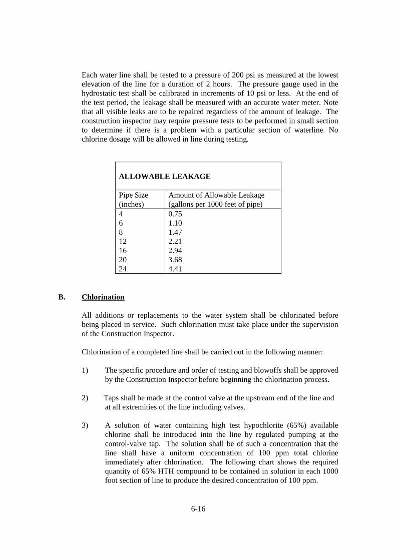
6-16
Each water line shall be tested to a pressure of 200 psi as measured at the lowest elevation of the line for a duration of 2 hours. The pressure gauge used in the hydrostatic test shall be calibrated in increments of 10 psi or less. At the end of the test period, the leakage shall be measured with an accurate water meter. Note that all visible leaks are to be repaired regardless of the amount of leakage. The construction inspector may require pressure tests to be performed in small section to determine if there is a problem with a particular section of waterline. No chlorine dosage will be allowed in line during testing.
ALLOWABLE LEAKAGE Pipe Size (inches)
Amount of Allowable Leakage (gallons per 1000 feet of pipe)
4 6 8 12 16 20 24
0.75 1.10 1.47 2.21 2.94 3.68 4.41
B. Chlorination
All additions or replacements to the water system shall be chlorinated before being placed in service. Such chlorination must take place under the supervision of the Construction Inspector. Chlorination of a completed line shall be carried out in the following manner: 1) The specific procedure and order of testing and blowoffs shall be approved
by the Construction Inspector before beginning the chlorination process. 2) Taps shall be made at the control valve at the upstream end of the line and at all extremities of the line including valves. 3) A solution of water containing high test hypochlorite (65%) available
chlorine shall be introduced into the line by regulated pumping at the control-valve tap. The solution shall be of such a concentration that the line shall have a uniform concentration of 100 ppm total chlorine immediately after chlorination. The following chart shows the required quantity of 65% HTH compound to be contained in solution in each 1000 foot section of line to produce the desired concentration of 100 ppm.

6-17
HYPOCHLORITE SOLUTION Pipe Size (inches)
High Test Hypochlorite (65%) (pounds per 1000 feet of line)
6” 8” 10” 12” 14” 16” 20” 24”
1.88 3.35 5.70 7.53 10.26 13.43 20.92 30.14
4) The HTH solution shall be circulated in the main by opening the control
valve and systematically manipulating hydrants and taps at the line extremities. The HTH solution must be pumped in at a constant rate for each discharge rate in order that a uniform concentration will be produced in mains. Note that for projects that are surrounded by populated development areas, the Construction Inspector can require that the circulation of HTH solution be accompanied with mechanical pumping.
5) HTH solution shall remain in lines for no less than 24 hours or as directed
by the Director of Public Works.
6) Extreme care shall be exercised at all times to prevent the HTH solution from entering existing mains.
C. Bacteriological Sampling All new water systems shall be valved off from the existing water system until a satisfactory bacteriological sample is obtained and the Construction Inspector has authorized the use of the new water system. 1. Free residual chlorine after 24 hours shall be at least 10 ppm or the Construction Inspector shall require that the lines be rechlorinated. 2. Flushing of lines may proceed after 24 hours, provided the free residual chlorine analysis is satisfactory. Flushing shall be continued until a chlorine test kit shows that the lines contain only the normal chlorine residual.

6-18
3. Samples for bacteriological analysis shall be collected by the Construction
Inspector 24 hours after flushing is completed. The Contractor shall furnish such help as may be required to secure the required samples. Samples shall be collected and delivered as specified by the Construction Inspector.
4. If bacteriological test results are unsatisfactory, the Contractor shall immediately obtain another Water Blowoff Permit, rechlorinate and retest the lines, proceeding with such measures as are necessary to secure properly disinfected lines.
6.09 FIRE PROTECTION DURING CONSTRUCTION
The fire protection water supply system, including fire hydrants, shall be installed and tested prior to placing combustible materials on the project site.
6.10 IRRIGATION SYSTEMS
All irrigation systems within public street right of way shall obtain a utility Encroachment Agreement from the Director of Public Works prior to installation of the system. Plans designating the location, size, material, depth, etc., shall be submitted with the application for an Encroachment Agreement. Pipe material for all lines within the public right of way shall be Schedule 40 PVC or greater. A distance of 2 feet from the back of curb and a minimum depth of 2 feet shall be provided. Irrigation systems shall have a backflow preventer installed in accordance with Section 6.06 of these Standards. All irrigation systems are required to secure a plumbing permit from the Development of Inspector’s prior to installation and shall be inspected after installation. A separate meter is preferred (not required) for irrigation systems. All irrigation line street crossings shall be contained within an encasement conduit. ductile iron or steel casing pipes shall be used. The City may, in some instances, permit irrigation systems installed in the medians of City-maintained roadways. These systems must also have french drains installed behind the curb and gutter and piped to a storm drainage collection system. These systems shall be allowed only when some permanent mechanism is established for the private perpetual maintenance of the system(s).
6-19
6.11 REPAIR OF WATER LINES
Joint Leaks of cast iron pipe, ductile iron pipe, and PVC pipe shall use a bell joint leak repair clamp as manufactured by Rockwell, or other approved equal. Line Breaks or Punctures shall be repaired by a full circle repair clamp as manufactured by Rockwell, Mueller, or other approved equal. Line Splits or Blow Outs shall be repaired by replacing the damaged section with ductile iron pipe with a cast iron coupling at each end. The following cast pipe couplings shall be used for each pipe material indicated: A.C. Pipe - Rockwell 441 cast coupling or other approved equal Ductile Iron Pipe - Rockwell 431 cast coupling or other approved equal PVC Pipe - Rockwell 411 cast coupling or other approved equal For A.C. Pipe to PVC or Ductile Iron Pipe connections, use a cast pipe coupling with different end diameters sized specifically for the pipe materials, and pipe outside diameter at each end. Water Service Line Repairs - A water service line severed between the water main and the water meter shall be repaired using new type K copper tubing and bronze or brass 3-piece flare unions. - A corporation stop pulled out of a PVC pipe water main shall have a new service saddle and a new corporation stop installed on the water main. - A corporation stop pulled out of a ductile iron pipe water main shall have a full circle repair clamp placed over the old tap hole. A new tap shall be made and a new corporation stop installed on the water main.
END OF SECTION 6.00

7-1
SECTION 7.00 SANITARY SEWER
SUB-INDEX
7.01 GRAVITY SEWER MAINS A. Design B. Materials C. Additional Requirements for Flexible and Semi-Rigid Sanitary Sewer Pipe 7.02 FORCE SEWER MAINS A. Materials B. Installation 7.03 MANHOLES A. Materials 7.04 SERVICE CONNECTIONS A. Materials B. Installation 7.05 TESTING AND INSPECTION 7.06 REPAIR OF SANITARY SEWER LINES 7.07 WASTEWATER PUMP STATIONS A. General Requirements B. Site Work C. Odor Control D. Piping and Valves E. Wet Well F. Electrical G. Alarm Dialer H. Generator Sets I. Transfer Switch J. SCADA K. Pump Motor Controls L. Force Main M. Water Service N. Landscaping and Appearance O. Warranties and Documentation P. Testing and Inspection

7-2
SECTION 7.00
SANITARY SEWER 7.01 GRAVITY SEWER MAINS A. Design Location
1. All public sanitary sewer mains shall be installed in dedicated street right of way or in dedicated utility easements. Sanitary sewer mains installed in City of Dunn maintained streets shall be located in the center of travel lanes. Mains located within N.C. Department of Transportation right of way shall be placed outside of pavement limits, in accordance with NCDOT standards. See Section 2.10 for landscape plantings within Utility easements.
2. Minimum widths of public sanitary sewer easements shall be:
Pipe Size Pipe Depth Easement Width 12” and smaller Less than 20’ 20’ 12” and smaller Greater than 20’ 30’
Greater than 12”, up to 24” Less than 20’ 30’ Greater than 12”, up to 24” Greater than 20’ 40’
Greater than 24” All depths Director of Public Works Specified
3. Sewer mains shall be centered within their easements. 4. Proposed sanitary sewers paralleling a creek shall be designed to a proper
depth to allow lateral connections such that all creek crossings will be below stream bed elevation unless otherwise approved by the Director of Public Works. The top of the sewer main shall have at least one foot of cover between it and the stream bed. Concrete encasement and ductile iron pipe, in accordance with the Standard Details Section of these Standards, shall be required when the cover between the top of the pipe and the stream bed is less than 3 feet.

7-3
Sewer lines crossing under stream and/or storm drainage pipe containing a single pipe greater than 42 inches or multiple pipes greater than 36 inches may be required to be installed with restrained joint pipe inside a steel casing pipe. Installation may be by bore and jack or excavation which will be at the discretion of the Director of Public Works. All encasements to be extended a minimum of 10 feet beyond the stream bank and/or storm drainage pipe.
5. Sanitary sewer mains shall not be installed under any portion of water impoundments unless approved by the Director of Public Works.
6. The following minimum separations must be maintained:
a) any private or public water supply source, including WS-1 waters or Class I or Class II impounded reservoirs used as a source of drinking water – 100 feet;
b) any waters classified WS-II, WS-III, B, SA, ORW, HQW or SB (from normal high water [or tide elevation] – 50 feet;
c) any other stream, lake, or impoundment – 25 feet or as required by State law.
Where the required minimum separations cannot be maintained, ferrous sanitary sewer pipe with joints equivalent to water main standards shall be used. However, in no instance may sanitary sewer lines be installed less than 25 feet from a private well or less than 100 feet from a public water supply source (or as required by State law).
7. Sanitary sewer lines shall be extended to adjacent upstream property lines,
in order to serve all upstream properties. These lines shall be sized to serve all upstream tributary areas.
Size 1. The minimum size of public gravity sanitary sewer mains shall be 8”.
2. Major interceptors shall be sized in accordance with the “Master Wastewater Plan of the City of Dunn.” In areas not included in the master plan, new sewer interceptors shall be designed based on the proposed land use (in accordance with the City’s Master Land Use Plan) of the contributory area. The following flow factors shall be used:

7-4
Land Use
Flow Factor
Residential 120 gpd/bedroom Office & Institutional 0.09 gpd/square feet of building space Commercial 0.12 gpd/square feet of building space Industrial 0.10 gpd/square feet of building space
Flow factors not listed herein shall be in accordance with the factors recommended by the NCDENR. These figures cover normal infiltration; however an additional allowance shall be required where conditions are unfavorable.
3. For existing sewer systems, an additional allowance shall be made to the
above flow factors where the existing flow exceeds these values and immediate remedial measures are not proposed.
4. The ratio of peak to average daily flow shall be 2.5.
5. Sanitary sewers shall be designed to carry the projected peak flow at no more than ½ full. The recommended minimum velocity for sanitary sewer lines is 2 fps. The minimum grades for public sanitary sewers shall be as follows:
Main Size (inches)
Minimum Slope (feet/100 feet)
8 0.40 12 0.22 15 0.15 16 0.14 18 0.12 21 0.10 24 0.08 30 0.06
6. The maximum grade for sanitary sewers is 10%. The maximum velocity in sanitary sewers is 15 feet per second. These limits may be exceeded with the approval of the Director of Public Works and with the incorporation of the following provisions:
a) All sewers of greater than 10% slope shall be ductile iron pipe;

7-5
b) High velocity manholes, in accordance with the Standard Details
Section of these Standards shall be used on all sewers with a slope greater than 10%;
c) Concrete anchors shall be installed on all sewers of greater than 10% slope at the following spacings: i) Not over 36’ center to center on grades from 10% to 25%; ii) Not over 24’ center to center on grades from 25% to 40%; iii) Not over 16’ center to center on grades exceeding 40%.
7. Sewer extensions should be designed for projected flows even when the diameter of the receiving sewer is less than the diameter of the proposed extension.
8. Pipe diameter changes shall occur in a manhole with the invert of the
larger pipe lowered sufficiently to maintain the same energy gradient. An approximate method of securing these results is to place the 0.8 depth point of both sewers at the same elevation.
9. All residential subdivision lots shall be served by public gravity sanitary
sewer unless otherwise approved by the Director of Public Works. If a pump is approved, it shall be privately maintained, must pump into a gravity service connection placed on the lot, and must have a note on the construction plans and recorded plat indicating a private pump may be required to serve the lot with sanitary sewer service.
10. Downstream receiving sewer infrastructure shall be evaluated to confirm
adequate capacity by the design engineer for each project. Developer shall be required to upgrade insufficient infrastructure.
Installation
1. Sanitary sewer mains shall be deep enough to serve adjoining and upstream properties and allow for sufficient slope in lateral lines. All sanitary sewer mains shall have the following minimum covers:

7-6
a) 4.5 feet from the top of pipe to finished subgrade when under a roadway or adjacent to a roadway which may be widened in the future;
b) 3 feet from top of pipe to finished grade in all other areas.
The above requirements may be waived at the direction of the Director of Public Works, in which case ductile iron pipe shall be installed.
2. The construction of all sanitary sewer lines which will be maintained by
the City must be performed by a contractor licensed in North Carolina.
3. Sewer mains from 14 to 20 feet deep shall require special bedding in accordance with the Standard Details Section of these Standards.
4. Sewers over 20 feet deep shall require ductile iron for the entire run
between manholes. 5. Pipe trench excavation and backfilling shall be performed in accordance
with Section 5.00 of these Standards. 6. Transitions of pipe material shall occur only at manholes. 7. Sanitary sewers shall be laid at least 10 feet laterally edge to edge from
existing or proposed water mains unless the top of the sewer main is at least 24 inches below the bottom of the water main and there is a horizontal separation of at least 3 feet from the closest edges of the pipes.
8. Where sanitary sewers cross beneath water mains with a vertical
separation of 24 inches or less or where water mains cross under sewer mains, the entire leg of sewer line shall be ductile iron pipe. The water line pipe shall be centered at the point of crossing and shall cross sanitary sewer lines at an approximate 90 degree angle.
9. Where sanitary and storm sewers cross with a vertical separation of less
than 12 inches the entire leg of sanitary sewer shall be of ductile iron pipe. Sanitary sewers shall have the top of pipe at least 12 inches below the bottom of storm sewer pipe when the horizontal separation between the closest edges of the two pipes is 3 feet or less.
10. There shall be a minimum 5-foot horizontal separation between parallel
gravity and/or force mains.
7-7
11. Sewer line easements shall be completely cleared of all vegetation, graded smooth, free from rocks, boulders, roots, stumps, and other debris, free from ponded water, and seeded and mulched upon the completion of construction.
12. The first new downstream manhole(s) of any sanitary sewer line extension
under construction shall be plugged on the outlet side and secured with stainless steel cable to prevent the passage of groundwater, runoff and sediment into the existing sanitary sewer system. All water upstream of the plug shall be pumped out of the sanitary sewer line and all sediment and solids shall be removed and properly disposed of by the Contractor. The plug shall have an identification plaque of stainless or aluminum directly mounted to show contractors name. Inspection of installation of plug shall be required by the Construction Inspector. The plug shall not be removed until the line has been inspected by the Construction Inspector to insure that all possible points of inflow or infiltration have been secured. Failure to meet this requirement will result in a $1,000 per day fine. If the plug blows out and causes equipment or material damage or spills downstream, the Contractor shall be responsible for resulting fines and costs of repairs. Authorization to remove the plug shall be required by Construction Inspector. If the Contractor fails to obtain necessary approvals and removes the plug before the system is activated, the Contractor shall be responsible for resulting State and City fines and damages resulting.
Manholes 1. All manhole cone sections shall be the eccentric type.
2. Manholes shall be spaced at a maximum distance of 425 feet apart. 3. Manholes for sewers under 18 inches in diameter shall be a minimum of 4
feet in diameter. Manholes for sewers 18 inches in diameter or greater shall be 5 feet in diameter.
4. All manholes that are over 20 feet deep shall be 5 feet in diameter.
5. Manholes shall be installed at each deflection of line and/or grade. The
flow channel through manholes should be smooth and shall conform to the shape of the entering/exiting sewer line. A standard 0.20-foot drop shall be provided at each manhole. Inverts “in” and “out” shall be as designated on the approved plans. Sewers shall be designed to minimize free drops in manholes.

7-8
Either precast or brick and mortar inverts may be used conforming to these Standards. The invert shall be smooth and uniform in shape along the entire length.
6. Outside drops shall be used when free drops exceed 24 inches. For drop manholes, the entire upstream leg of sewer must be ductile iron. For drop manholes, see the Standard Details Section of these Standards. Where the difference between the incoming pipe and manhole invert is less than 24” inches but greater than 12 inches, the invert shall be filleted to prevent solids deposition.
7. Manholes not located in roadways shall have a top elevation a minimum of 12 inches above finished grade. Manholes located along outfalls shall have a top elevation a minimum of 24 inches above finished grade or 100 year flood plain, or 12 inches above 500 year flood plain, whichever is higher.
8. Watertight manhole rings and covers shall only be allowed upon approval
by the Director of Public Works. Manholes with watertight tops shall be vented in accordance with the Standard Details Section of these Standards.
9. Manholes located within flood plain areas, on outfalls, and within any
areas of high groundwater shall be waterproofed by wrapping all joints with a minimum 8-inch width band of butyl joint wrap. Waterproofing shall be installed by mopping asphalt over the joint area, then wrapping butyl joint wrap around the joints, and finally mopping the wrap with another coat of asphalt. The total asphalt coat thickness shall be a minimum of 16 mils.
10. All manholes shall be vacuumed tested in accordance with ASTMC-1244.
B. Materials
The Director of Public Works will maintain a list of approved manufacturers for all sanitary sewer collection system products. New manufacturers must submit requests for approval to the Director of Public Works. Additional information such as catalogs, lists of installations in the area or material samples may be required. A written response will be mailed to the applicant accepting or rejecting the product within 90 days of the receipt of all necessary information. Each length of sanitary sewer pipe installed shall have plainly and permanently marked thereon the following information: 1. Pipe class or strength designation; 2. Manufacturer’s name or trademark;

7-9
3. Nominal pipe size. Ductile Iron Pipe Ductile iron pipe for gravity sewer use shall be designed and manufactured in accordance with AWWA C150 and C151 for a laying condition Type 2 and a working pressure as follows:
3” - 12” 350 psi 14” - 20” 250 psi
24” 200 psi 30” & up 150 psi
Pipe joints shall be of the push-on type as per AWWA C1211. Pipe lining shall be coal-tar epoxy lined.
Polyvinyl Chloride (PVC) Pipe PVC pipe shall be made of PVC plastic having a cell classification of 12454-B, 12454-C or 13364-B (with minimum tensile modulus of 500,000 psi) as defined in Specification D1784. PVC pipe shall have integral wall bell and spigot joints for the conveyance of domestic sewage. Fittings shall be made of PVC plastic having a cell classification of 12454-B, 12454-C or 13343-C as defined in Specification D1784. Fittings must be manufactured by pipe supplier or approved equal, and have bell and/or spigot configurations compatible with that of the pipe. Compounds with superior properties are also acceptable. All pipe less than 16 inches in diameter shall have a maximum Standard Dimension Ratio (SDR) of 35. Where laying conditions so warrant, and in accordance with manufacturer’s recommendations, lower SDR values (stronger pipe) may be required. PVC pipe 16 inches in diameter and larger SDR-26. Installation shall consist of Class I bedding material (as defined in Section 7.01 C) placed 4 inches below the pipe barrel and continuing to 4 inches above the pipe barrel, as per ASTM D2321. In addition, the installation of PVC pipe shall satisfy the requirements of Section 7.01-C below. See the Standard Details Section of these Standards for bedding requirements.
C. Additional Requirements for Flexible and Semi-Rigid Sanitary Sewer Pipe Installation of flexible and semi-rigid sanitary sewer pipe shall satisfy the requirements of the manufacturer and/or the following, whichever is more stringent:

7-10
1. Installation shall follow the recommendations of ASTM D-2321
“Underground Installation of Flexible Thermoplastic Sewer Pipe.” For flexible and semi-rigid pipes, bedding and embedment material shall be Class I. In any area where the pipe will be installed below existing or future ground water levels or where the trench could be subject to inundation, additional Class I material shall be used for bedding. Refer to the Standard Details Section of these Standards for embedment requirements.
2. The manufacturer’s specifications or otherwise approved method shall be
used in determining the stiffness class of the pipe to be installed so as to attain the required deflection control. The class of the pipe must be approved by the Director of Public Works prior to installation.
3. The maximum allowable deflection after installation shall be less than 5%
for flexible pipe and 3% for semi-rigid pipe. The mandrel (go/no-go) deflection test must be performed on each line prior to acceptance, and no less than 30 days after installation. The Contractor shall supply the mandrel used for this performance test. The mandrel device shall be cylindrical in shape having 9 possible contact points with the pipe. The mandrel’s length and diameter (ID of proving ring) shall equal the dimensions in the following table, and shall be subject to the Construction Inspector’s approval.

7-11
For flexible pipes the following shall apply:
Nominal Diameter (inches)
Mandrel Length (inches)
Mandrel Diameter (inches)
6 6 5.65 8 8 7.40 10 10 9.31 12 10 11.22 15 12 14.09
4. For PVC pipe, the pipe shall be produced with bell and spigot end
construction. Joining will be accomplished by rubber gasket in accordance with manufacturer’s recommendation, unless otherwise directed or approved by the Director of Public Works. Flexible watertight elastomeric seals in accordance with ASTM D3212-81, may also be used. Each pipe length shall be clearly marked with information including pipe size, profile number, and class number.
5. Minimum trench width shall be one pipe diameter plus 9 inches on each
side of the pipe. 6. Bedding (6-inch minimum) and embedment materials shall be per ASTM
D2321. Embedment materials shall be installed from trench wall to trench wall and from the invert to a minimum of 6 inches above the crown of the pipe.
7. The bedding and embedment material shall be compacted to a minimum of
90% Standard Proctor density for Class I materials. 8. If hydraulic jack shoring is utilized for trench walls where shoring is used,
it shall be kept to the area just above the top of the pipe. This will ensure the embedment materials and pipe will not be disturbed when removal is made.
9. Bedding and embedment material classifications shall be defined as
follows: Class I - Angular, (¼ to 1½ inch) graded stone, including a number of fill
materials that have regional significance such as coral, slag, cinders, crushed stone, crushed gravel, and crushed shells.
Class II - Coarse sands and gravels with maximum particle size of 1½ inch,
including variously graded sands and gravels containing small percentages

7-12
of fines, generally granular and non-cohesive, either wet or dry. Soil types GW, GP, SW and SP are included in this class.
Class III - Fine sand and clayey gravels, including fine sands, sand-clay mixtures,
and gravel-clay mixtures. Soil types GM, GC, SM, and SC are included in this class.
Class IV - Silt, silty clays, and clays, including inorganic clays and silts of
medium to high plasticity and liquid limits. Soil types MH, ML, CH and CL are included in this class. These materials are not recommended for embedment.
7.02 FORCE SEWER MAINS
A. Materials
Ductile Iron Pipe shall be required for force sewer mains at shallow depths (less than 3 feet) or when crossing water and storm piping. Ductile iron pipe shall be designed and manufactured in accordance with AWWA C150 and C151 for a laying condition Type 2 and a minimum working pressure as follows:
3” - 12” 350 psi 14” - 20” 250 psi
24” 200 psi 30” - 54” 150 psi
Pipe joints shall be of the push-on type as per AWWA C111. Pipe lining shall be cement mortar with a seal coat of bituminous material, all in accordance with AWWA C104. The Director of Public Works reserves the right to require other pipe lining materials in certain applications. PVC Pipe PVC pipe shall meet the requirements of AWWA C900. Pipe shall be Class 150, SDR 18, integral bell with strength equal to the pipe wall, cast iron O.D., 18-foot length, with a solid elastomeric ring.
PVC pipe for force mains with a diameter of 3 inches or less shall be SDR-21 or Schedule 40 in accordance with ASTM D1785.
PVC pipe shall require the installation of a 3-inch wide detector tape placed a maximum of 2 feet below the covering surface.
Pipe fittings shall be compact designed and manufactured per AWWA C153. Joints for fittings shall be mechanical joint and lined with cement mortar with a seal coat of bituminous material, all in accordance with AWWA C104.

7-13
Combination air valves shall be Cla-Val, 421, Golden Anderson, Crispin or an approved equal.
B. Installation Reaction blocking for all fittings or components subject to hydrostatic thrust shall be securely anchored by the use of concrete thrust blocks poured in place. The reaction areas are shown in the Standard Details Section of these Standards. No concrete shall interfere with the future removal of fittings. Material for reaction blocking shall be 3000 psi concrete.
Force mains shall be installed with a minimum cover of 4.5 feet measured from the top of the pipe to existing edge of pavement. Force mains shall be appropriately identified upon installation so that they will not be confused with potable waterlines. The pipe material shall be designated continuously on each joint of pipe as “sewer.” Force mains shall be designed and installed to minimize high points. Sewage combination air valves shall be installed at all the high points of all force mains in accordance with the Standard Details Section of these Standards. Manholes containing valves shall receive a bituminous or coal tar epoxy coating on the interior. Force sewer mains shall be installed in dedicated public rights of way or in dedicated utility easements. See Section 2.10 for landscape planting requirements within easements. Easements shall have the following dimensions:
Line Size Easement Width
12” and under 20 feet
greater than 12” 30 feet
All force mains shall have an in-line valve located 25 feet from the pump station. In addition, force main valves shall be spaced at appropriate intervals as determined by the Director of Public Works, and shall have locking valve box caps marked “Sewer.” Force main valves shall be resilient wedge gate type for force mains less than 12”; valves greater than 12”, shall be Dezurik eccentric plug valves, or approved equal. Force mains at air release manholes shall be a minimum of 6’ deep.
The receiving manhole plus the first downstream manhole below the receiving manhole for a force main shall receive an interior coating of Koppers “Super Service Black” with a total dry film thickness of 10 mils. All nicks and scratches

7-14
shall be touched up prior to acceptance of the manhole. The force main shall discharge at the invert of the receiving manhole and shall be as close as possible to 180° from the outlet pipe. No drop is allowed in the receiving manhole for a force main.
Locator devices as manufactured by 3M Corporation shall be placed directly on top of the sewer force mains, along major thoroughfares and cross-country installations (and as otherwise directed by the Director of Public Works) at 100 feet intervals and turns/bends.
7.03 MANHOLES
Materials
Manholes shall be precast concrete. All manholes shall have eccentric cone sections. Precast concrete manholes shall meet ASTM C478 as to design and manufacturer. The standard joint shall be sealed with a plastic cement putty meeting Federal Specification SS-S-00210, such as Ram-Nek or a butyl rubber sealant. All lift holes must be plugged with non shrinking grout after installation. For precast concrete manholes, see the Standard Details Section of these Standards. Manhole frames and covers shall be cast in ductile iron, conforming to ASTM A-48 Class 30, with “Sanitary Sewer” stamped on the cover and two 1-inch perforated holes. Castings shall be machined to give even and continuous bearing on the full length of the frame. Castings shall be free of porosity and blow holes, and shall receive one coat of Koppers Super Service Bitumastic black paint. Paint shall be kept off of bolt threads and surfaces shall be thoroughly wire-brushed before painting. Manhole frames shall be bolted to the manhole as per the Standard Details Section of these Standards. All manhole rings in roadways shall be encased in a concrete collar, 18 inches by 12 inches, of 3,000 psi concrete beneath the asphalt, with the cover flush with the top of pavement and rated for an AASHTO loading Class HS-20, as shown in the Standard Details Section of these Standards.
Watertight manhole frames and covers shall have neoprene gasket, machine bearing surfaces. Bolts shall be standard hexagonal-head, countersunk such that when fully tightened bolt head is flush with the top of the cover. Castings shall be free of porosity and blow holes, and shall receive one coat of Koppers Super Service Bitumastic black paint. Paint shall be kept off of bolt threads and surfaces shall be thoroughly wire-brushed before painting. Watertight manhole frames and covers shall only be permitted in lieu of elevating the manhole tops above the 100

7-15
and/or 500 year flood plain with specific approval by the Director of Public Works.
Manhole steps shall be furnished with the precast sections. Steps shall be of polypropylene material reinforced with a half-inch diameter grade 60 reinforcing steel rod. Manhole steps shall be designed for a vertical load of 400 pounds and a horizontal pull out load of 1,000 pounds. Steps shall be set 16” on center. Holes for the installation of manhole steps shall not project through the manhole wall. There shall be a minimum of 1-inch wall thickness from the deepest penetration of the step installation hole and the outside wall. Steps shall be at least 10” clear width and shall project at least 4” from the wall into which it is embedded. Steps shall not be located over the influent or effluent pipes and shall be installed along a vertical manhole wall from the shelf to the top of cone.
All manholes shall have 6-inch, 3,000 psi concrete bottoms resting on a minimum of 6 inches of #57 stone. Sewer mains shall enter and exit radially through the manhole. Inverts shall be constructed with a width and height equal to half that of the effluent pipe and shall be so brushed and troweled that a minimum energy loss occurs in the manhole. At each inlet and outlet of line 8 inches or greater, wastewater lines are to be connected to the manholes by means of compression connectors (flexible sleeves) cast into the manhole section. Flexible connectors are to be manufactured of high quality rubber or synthetic rubber and all strap clamps or draw bolts are to be manufactured from stainless steel.
7.04 SERVICE CONNECTIONS
A. Materials
Cast iron soil pipe shall be service weight hub and spigot meeting Federal Specifications WW-401. The joints shall be rubber type elastomeric as per ASTM C425.
PVC pipe shall be schedule 40 or greater supplied in 18 foot lengths. The pipe may be joined by elastomeric gaskets.
Ductile iron pipe shall be used for sanitary sewer services with less than 3 feet of cover or in excess of 16 feet of cover.
Services for new lines shall use in-line wyes of like material unless otherwise approved by the Director of Public Works.

7-16
Service saddles for existing PVC or ABS lines shall be of the same material as the main, solvent welded and fastened with double stainless steel bands as shown on the Standard Details Section of these Standards.
Service saddles for existing cast iron soil pipe services may be “ROMAC C” sewer saddles consisting of a virgin SBR gasket compounded for sewer service, a ductile iron saddle casting, a 304 stainless steel adjustable strap for fastening the gasket and the saddle casting to the sewer main and a 304 stainless steel adjustable circle clamp for securing the service line into the SBR gasket.
B. Installation
Individually owned structures shall require individual sewer taps to public sewer. All service connections to existing sanitary sewer mains shall be made by the City of Dunn Public Works Department.
Service taps into mains shall be made on the top quarter of the main with the wye angled with the direction of flow in the main. All services installed on new lines shall be inline wyes unless otherwise approved by the Director of Public Works.
Service lines between 3 and 14 feet in depth do not require special bedding. All service lines between 14 and 20 feet in depth shall require Class I bedding from 4 inches below service line to 4 inches above the service line. Service lines greater than 16 feet or less than 3 feet in depth must be ductile iron. Service connections to the main lines shall be perpendicular to the main line to the edge of the right of way or easement line. Service lines 4-inch in diameter shall have a minimum slope of 2.0 feet per 100 feet. Service lines 6-inch in diameter shall have a minimum slope of 1.0 feet per 100 feet. Cleanouts shall be required on all sewer services at a maximum spacing of 50 feet on 4-inch services and 100 feet on 6-inch services. A cleanout shall be placed on all service lines at the right of way line or at the edge of the easement. All cleanouts shall extend a minimum of 6 inches above finished grade or meet the optional installation requirements in accordance with the Standard Details Section of these Standards. Sewer cleanouts located in paved areas must have traffic load bearing mini-manhole.
All 6-inch service lines shall tie directly into a manhole.
All service lines which are connected into manholes shall be installed less than 24 inches above the invert or shall be installed with a standard drop as shown on the Standard Details Section of these Standards. Service lines shall not be installed through manhole cone sections or manhole joints. The use of service saddles will only be permitted for connection to existing sewer lines.

7-17
Service connections made using a “ROMAC C” sewer saddle shall be made only when the service line is cast iron soil pipe and only when the sewer main is 8”, 10”, or 12” diameter concrete, ductile iron, or PVC sewer pipe. This service connection shall not be used when the sewer main material is truss sewer pipe. The opening in the sewer main for the “ROMAC C” sewer saddle shall be cut with a hydraulically driven or a pneumatically driven circular tapping saw of the same nominal diameter as the sewer service line.
7.05 TESTING AND INSPECTION All materials used must be inspected by the Construction Inspector before they shall be allowed to be installed. Materials rejected by the Construction Inspector shall be immediately removed from the job site.
The Contractor shall furnish all materials, labor, and equipment, and shall pay for the water used to perform all testing and inspection to the satisfaction of the Construction Inspector. The Contractor shall obtain a meter from the City of Dunn for use.
Sanitary sewer lines shall be free and clean from obstructions and shall be visually inspected from every manhole to ensure all lines exhibit a fully circular pattern. Lines which do not exhibit a true line and grade or have structural defects shall be corrected. Any sewer mains over 14 feet deep shall require internal visual inspection by TV Camera at the expense of the developer at beginning of one year warranty and at end of one year if deemed necessary. Sanitary sewer service connections shall be visually inspected prior to backfilling.
See Section 7.01 C for additional testing requirements for flexible and semi-rigid pipe.
Low-pressure air testing shall be performed before all laterals or stubs are installed on the line and after the main has been backfilled to finished grade. Plugs shall be installed at each manhole to seal off the section of line to be tested. The line will be pressurized with a single hose and monitored by a separate hose connection from the plug. Air shall be slowly introduced into the sealed line until the internal air pressure reaches 4.0 psig. The air pressure shall then be allowed to stabilize for a minimum of 2 minutes to no less than 3.5 psig (plus groundwater pressure, if any). When the pressure reaches 3.5 psig, the time required for the pressure to drop 1.0 psi shall be observed and recorded. The line shall be termed “acceptable” if the pressure does not drop more than 1.0 psi in the time prescribed for the test in the following table:

7-18
STANDARD AIR TEST TABLE
Specification time (min:sec) required for pressure drop from 3½ to 2½ psig when testing one pipe diameter only
Length of Time (feet)
Pipe Diameter (inches)
4 6 8 10 12 15 18 21 24 25 0:04 0:10 0:18 0:28 0:40 1:02 1:29 2:01 2:38 50 0:09 0:20 0:35 0:55 1:19 2:04 2:58 4:03 5:17 75 0:13 0:30 0:53 1:23 1:59 3:06 4:27 6:04 7:55 100 0:18 0:40 1:10 1:50 2:38 4:08 5:56 8:05 10:34 125 0:22 0:50 1:28 2:18 3:18 5:09 7:26 9:55 11:20 150 0:26 0:59 1:46 2:45 3:58 6:11 8:30 175 0:31 1:09 2:03 3:13 4:37 7:05 200 0:35 1:19 2:21 3:40 5:17 12:06 225 0:40 1:29 2:38 4:08 5:40 10:25 13:36 250 0:44 1:39 2:56 4:35 8:31 11:35 15:07 275 0:48 1:49 3:14 4:43 9:21 12:44 16:38 300 0:53 1:59 3:31 10:12 13:53 18:09 350 1:02 2:19 3:47 8:16 11:54 16:12 21:10 400 1:10 2:38 6:03 9:27 13:36 18:31 24:12 450 1:19 2:50 6:48 10:38 15:19 20:50 27:13 500 1:28 5:14 7:34 11:49 17:01 23:09 30:14
If the section of line tested fails to meet these requirements, the source of leakage shall be determined and repaired. The section of line shall then be retested.
The Construction Inspector may require that an infiltration test be performed. Infiltration shall not exceed 100 GPD per inch per mile. At the discretion of the Director of Public Works, sanitary sewer manholes in areas of special concern may be required to be vacuum tested in accordance with ASTMC-1244.

7-19
7.06 REPAIR OF SANITARY SEWER LINES
The repair of damaged sanitary sewer lines shall be as follows:
1. V.C. Pipe - Replace damaged section with D.I.P. Install a Fernco
coupling at each end (encased in concrete).
2. PVC Pipe - Replace damaged section with PVC pipe. Install a Fernco coupling at each end (encased in concrete).
3. ABS/PVC Truss Pipe - Replace damaged section with D.I.P. Install a
Fernco coupling at each end (encased in concrete).
4. A.C. Pipe - Use a full circle repair clamp for the damaged section.
All repairs to damaged sanitary sewer lines shall be backfilled with ABC stone (crusher run) to a density of 95% Standard Proctor.
7.07 WASTEWATER PUMP STATIONS
A. General Requirements
In situations where gravity sewer is not feasible, the City of Dunn will consider allowing the installation of a wastewater pump station and force main. Note that the following factors shall be utilized in determining where wastewater pump stations may be installed: 1. Determination of, and design to, handle the wastewater flow that would be
generated by the total natural drainage basin based upon a combination of the proposed land use plan and/or approved developments, whichever flow is greater, or as directed by the Director of Public Works, with a design life as specified by the City. The City may require pump station to be constructed downstream to serve a larger basin.
2. Evaluation (and upgrades, if necessary) of the capacity and suitability
(with respect to potential for odor problems) of the receiving sewer main at the point of discharge and points downstream to determine if the downstream infrastructure can handle the transferred sewer flow. In addition, new pump stations may not discharge upstream of other existing pump stations. The Director of Public Works has the ability to approve deviations to this requirement due to extenuating circumstances.

7-20
3. A cost analysis of the pumping versus a gravity alternative (if one is
available). The estimated installed cost of the gravity alternative divided by the estimated installed cost of the pump station alternative must be equal to or greater than 3.5 for the City to consider allowing a pumping station. The City reserves the right to require special features and/or special components on certain pump stations per the Director of Public Works.
4. The City reserves the right on any pump station to perform the design and/or construction administration, with the developer reimbursing the City in full.
5. The City reserves the right to disallow pump stations where, in the City’s
opinion, it is not efficient or desirable to have another pump station. 6. New developments may be required to take downstream or upstream pump
stations off line, or upgrade them as directed by the Director of Public Works.
7. For any new or upgraded pump station, one spare pump of identified size
and manufacturer shall be provided to the City prior to pump station startup. The spare pump will be stored at the Public Utilities Department.
Wastewater pump stations shall meet all requirements of these standards. The developer and the developer’s engineer shall meet with the City Director of Public Works in a “pre-design meeting” prior to preliminary plan-level submittal of a site or subdivision requiring a pump station. The meeting shall be to discuss the site layout and other details and requirements for any proposed pump station before design begins. All pump stations shall be Gorman Rupp suction lift and all construction materials shall be suitable for exposure to wastewater. Pump stations shall meet the N.C. Building Code and shall be designed to comply with all OSHA regulations in addition to these Standards.
All stations shall have a minimum of 2 pumps of equal capacity. The pumps shall be capable of handling flows in excess of the expected peak flow. The peak flow for design shall be equal to 2.5 times the average daily flow. Where 3 or more pumps are required, they should be of such capacity that with any one unit out of service, the remaining units will have capacity to handle peak sewage flows. Pumps and the sewage force main shall be sized to provide a minimum velocity in the force main of 2.0 fps and a maximum velocity of 10 fps maximum allowable velocity is dependent upon force main material. The City reserves the right to require a larger force main size at no cost to the City based upon operating (power) costs.

7-21
Wastewater pump stations, all related structures and controls, shall be protected from physical damage by the 100 year and 500 year local and FEMA flood plains and shall be elevated to 2 feet above the most restrictive elevation. Flood elevations shall be supported by a flood study based on future land uses. Stations shall be designed to remain fully operational and accessible during the 100 year flood. Both flood elevations shall be shown on all site plans. All sewage pump stations shall be equipped with an alternate power source. Alternate power sources include on-site standby power. Small package type pump stations or grinder pumps may be approved by the Director of Public Works for private pump stations which serve only one site. These pump stations will be allowed only if the flow rate is less than 100 GPM and the force main is less than or equal to 4 inches in diameter. Private pump stations shall meet City and NCDENR-DWQ minimum design criteria. Documentation of future maintenance of both the station and the force main by owner of record shall be required.
B. Site Work
Pump station sites shall be conveyed to the City via deed and/or recordation, as specified by the City. A pump station site layout plan for all pump stations shall be laid out with the City in a separate pre-design meeting at preliminary plan review stage of any development project requesting installation of a pump station. The site layout plan shall require Board approval simultaneous with the preliminary site plan for the development project site. The site shall be graded generally to drain away from the pump station and to remove stormwater runoff from site in a non-erosive manner. The site shall be designed to accommodate both a WB50 and an SU design vehicle in a traffic pattern as directed by the Director of Public Utilities. In certain instances, remote fill ports may be required. All components of the pump station shall be surrounded by a concrete slab with minimum HS-20 loading flush with surrounding grade. Concrete slab and hatches shall be HS-20 loading. Signage shall be provided on the gate which provides the name of the station, its address, and emergency number of 910-892-2948 8am to 5pm Monday-Friday 910-892-2399 5pm-8AM (green lettering on a utility sign).

7-22
The site shall consist of a fenced-in hard surfaced area, a gravel vehicular area, plus required landscape buffers. The site shall be stabilized by crushed stone, low maintenance vegetative ground cover or other suitable materials.
The site area shall be secured by a 6-foot high chain link fence topped with 3 strands of barbed wire, or of a material as approved by the Director of Public Works. Fence products shall be only new materials using hot dipped galvanized iron or steel components and aluminum coated fence. Gates shall permit 180° opening and shall be located so as to provide vehicle accessibility for lifting the pumping units and any other operational tasks as required. There shall be a minimum gate opening of 12 feet to facilitate truck access. Larger gates may be required to accommodate other design vehicles’ turning radii. A 12-foot (minimum) wide access road to the site with vertical grades not to exceed 10% shall be provided. Access road shall consist of an all-weather surface (minimum of 8” ABC) with minimum 40’ long paved strip from roadway. No driveways may be located off of access road. Access road shall be fully contained within a minimum 20 foot wide combined access and utility easement, platted by the Developer. Reduction of width of access road to 10’ may be approved at the discretion of the Director of Public Works.
The site shall feature locks and security features as dictated by the Public Utilities Department along with all necessary OSHA signage. The site shall feature a minimum high pressure sodium vapor light of 600 watt (minimum) capacity to illuminate the pump station area. The light shall be mounted on a Class V utility pole at a height of 30 feet and controlled by means of a photo cell and an HOA switch located on the light pole, unless otherwise approved by the Director of Public Works.
C. Odor Control
Pump stations which shall be maintained by the City of Dunn may be required to incorporate a chemical feed and storage facility for both downstream and proximity odor control purposes. A hydrogen sulfide generation calculation may be required.
Chemical feed facilities should consist of the following at a minimum:
• Double walled liquid chemical storage tanks with a minimum capacity of
2,500 gallons; • Two Wallace & Tierman Model 44 chemical feed pumps, calibration
chambers and valves or a packaged-type chemical feed system with duplex pumps, calibration chamber, in a heated stainless steel chamber;
• A modular building to house tanks and pumps with lights, heater and sump pump may be required;
7-23
• A containment system in case of tank or piping failure may be required in addition to a double-walled tank.
The City reserves the right to require mechanical ventilation and treatment of exhaust from the wet well to address anticipated or existing proximity odors.
D. Piping and Valves Suction and discharge piping shall be minimum Class 50 ductile iron flanged pipe and as manufactured under AWWA Specification C 141. A check valve and a gate valve shall be provided for the discharge pipe of each pump. Check valve shall be iron bodied, fully bronze mounted with bronze clapper disc and bronze seat ring, and shall have a weight loaded lever arm capable of being mounted on either side of the valve and rated for 175 psi working pressure. The gate valve shall be hand-wheel operated. Entrance velocity into the pump shall not exceed 5ft/s to prevent to prevent vortices from forming and leading to the potential for air entrapment. The invert elevations for incoming sewer lines shall be set to minimize turbulence and prevent a cascading effect.
E. Wet Well
The wet well shall be precast concrete manhole sections conforming to ASTM C-478, latest revision. Extended bases or another foundation shall be used to provide adequate bearing surface if needed. All concrete shall have a minimum 28 day compressive strength of 3,000 psi. The wet well shall be designed to prevent the formation of vortices and the floor shall have a minimum side slope of 1:1 directed to a hopper bottom. Also, buoyancy calculations will be required for the wet well, free of pumps and water, to ensure that the anti-flotation design is adequate.
The manhole sections shall have joints of a durable mastic sealing material and the joints shall be further waterproofed on the outside of the wet well by the application of asphalt, overlapped by a 12 inch wide band of butyl joint wrap, and a finish mopping of asphalt. The interior side of the joints shall be plastered smooth with portland cement grout. The interior of the wet well shall then receive two successive coats of Koppers “Super Service Black,” “Duramer”, or a suitable coal tar epoxy, with a total dry film thickness of 10 mils. All nicks and scratches shall be touched up in the field before backfilling occurs.
The wet well shall feature a 316 stainless steel or 6063 alloy aluminum screening basket in front of the influent pipe. The basket shall be rectangular in shape and formed from ¼” x 3” bars on 2½ inch centers on a channel or angle frame. Grating, wire mesh, or perforated plates are not acceptable substitutes. Baskets shall be fabricated with cross members and bracing to provide structural stability under full loading. All bolted connections in the wet well shall be made using

7-24
stainless steel nuts, bolts and washers. Baskets shall be raised and lowered by means of a stainless steel chain or wire rope with rings. A specially designed hatch shall be provided that will permit the raised basket screen to be maneuvered into or out of the wet well. This access hatch shall be a square hatch of ¼” aluminum, 6063 alloy, and diamond pattern plate with steel hinges on an aluminum frame cast in place in the cover slab.
The wet well shall have a vent made from ductile iron, with flanged joint pipe fittings. An insect screen shall be included at the exposed end of the vent pipe. The insect screen shall be bronze or aluminum.
F. Electrical
Electrical service to all pump stations shall be 3 phase, 240 VAC or 480 VAC. No 208 volt stations are allowed. No open delta services are allowed. If pump motors are over 10 hp, 480 service will be required. The electrical power entrance shall be through a meter base, followed by a NEMA 3R heavy duty, single throw, fusible safety switch with a solid neutral; followed by a NEMA 3R automatic transfer switch as specified herein. All of these electrical components shall be suitably sized to be capable of service with both sewage pumps running.
Provide a minimum of 1 110 volt receptacle to be located at the pump station. All electrical components, including panel, shall be sealed off in accordance with the N.C. Electrical Code requirements for electrical service to gas pumps. NEMA 3R Enclosure: All outdoor equipment shall be enclosed in be a NEMA Type 3R enclosure of suitable size to house all components. A locking hasp shall be provided in addition to screw clamp type latches. Enclosure shall be fabricated from 14 gauge steel. The top of the enclosure shall serve as a drip shield and the seam-free sides shall prevent rain and sleet from entering. Inner panel shall be made of 12 gauge steel and shall be painted white. The enclosure and interior panel shall be painted with heat fused modified polyester powder, electrostatically applied over a phosphatized base. Enclosure shall be ANSI/ASA 61 grey.
G. Alarm Dialer
Required on all pump stations. See Director of Public Works for these specifications.
H. Generator Sets
Required on all pump stations. See Director of Public Works for these specifications. Sound proofing shall be required for every generator. Generator shall operate all components of pump station including pole light.

7-25
I. Transfer Switch Required on all pump stations. See Director of Public Works for these specifications.
J. SCADA
Required on all pump stations. See Director of Public Works for these specifications.
K. Pump Motor Controls General: Pump motor control equipment shall be enclosed in a prefabricated modular building as manufactured by Bally, Inc. or approval equal. Minimum size shall be 10’x10’. 1. Line Terminal Block: A terminal block shall be furnished with properly
sized line lugs to accept the main power source entering the control panel. Load lugs shall be adequate to accept all required load side wiring requirements. All live parts shall be fully shielded.
2. Motor Circuit Breakers (200-240 VAC): A properly sized, molded case, thermal magnetic circuit breaker shall be provided for each pump motor. Line and load sides shall be equipped with lugs properly sized for the horsepower and current rating of the motor(s). They shall be attached to mounting brackets which are specifically manufactured for use with the particular circuit breaker. The interrupting rating shall be 10,000 RMS symmetrical amps.
3. Motor Circuit Breakers (440-480 VAC): A properly sized, molded case,
hydraulic-magnetic circuit breaker shall be provided for each pump motor. Line and load sides shall be provided with lugs properly sized for the horsepower and current rating of the motor(s). The interrupting rating shall be 5,000 RMS symmetrical amps.
4. Transformer Primary Circuit Breaker (when transform er is required): A properly sized, 2 pole, molded case circuit breaker shall be furnished ahead of the control power 120 VAC power transformer for short circuit protection and disconnecting power to the transformer. The circuit breaker shall conform to the standards for the motor circuit breaker(s).
5. Control Power Transformer (when neutral is not available at job site - standard on 460 VAC): An industrial quality control transformer shall be furnished to provide control voltage. The transformer shall be sized
7-26
with an adequate KVA rating to provide 120 VAC power for all items required in the control and alarm circuits. Transformer shall be protected in its secondary by properly sized fuses and/or circuit breaker(s).
6. Magnetic Contactors and Overload Relays: A NEMA-rated across-the-
line magnetic contactor shall be furnished for each motor. A separate, panel mounted, 3 overload relay shall be supplied for each motor. Each leg of the overload relay shall be equipped with a properly sized overload heater. Contactor and overload relay shall be properly sized for the required horsepower, voltage and phase. Reduced voltage auto transformer starters will be required for motor sizes over 50 hp or when the power company requires reduced voltage auto transformer starters. Solid state starters will not be allowed.
7. Elapsed Time Meters: Six digit, non-resetable elapsed time meters shall be mounted in the control panel enclosure to record the running time of
each pump.
8. Condensation Strip Heater with Thermostat: A strip heater shall be furnished to prevent condensation within the control panel enclosure. The heater shall be controlled by a panel mounted, adjustable thermostat.
9. Phase and Voltage Monitor: A phase failure, reversal and under voltage
monitor shall be supplied to prevent the motors from running under low voltage, phase loss, or phase reversal conditions. The monitor will lock out the control circuit until the problem is corrected and the monitor automatically resets.
10. Lightning Arrestor: Lightning arrestors shall be provided to protect motors and control equipment from lightning-induced line surges. Lightning arrestors shall be Transient Voltage Surge Suppressors Series 57,000 as manufactured by Leviton or approved equal. Lightning arrestors shall be distribution panel-mount style in a weather tight case with hinged cover. Protection shall be via individual line replaceable modules with hybrid circuitry.
11. Thru-Door Overload Reset Push Buttons: Overload reset push buttons shall be provided for each overload relay. Push buttons shall be mounted so that with inner door closed, overload relays may be reset without entering high voltage compartment.
12. Switches: Heavy duty industrial grade oil tight switches shall be provided for each pump for “Hands-Off-Automatic” operation selection. All switch components shall be made of corrosion resistant metals and polyesters. Contact blocks shall be made of see-through polycarbonate for simplified

7-27
inspection of contacts. Cams and strokes shall be Teflon impregnated for abrasion free service without lubrication. The switches required shall be as follows:
Switch Function (Name Plate)
Voltage
Manual-Off-Automatic 120 VAC
13. Pilot Lights: Full voltage heavy duty industrial grade oil tight pilot lights shall be provided. All pilot light components shall be made of corrosion resistant metals and polyesters. An insulated socket shall be furnished to eliminate the possibility of shock during bulb change. Lens shall be made of lexan. The pilot lights required shall be as follows:
Pilot Light Function (Name Plate)
Voltage Lens Color
Pump 1 120 VAC green Pump 2 120 VAC green
14. Seal Failure Circuit Test Push Button (illuminated): Heavy duty industrial grade oil tight push buttons shall be provided for each submersible pump motor. All push button components shall be made of corrosion resistant metals and polyesters. Contact blocks shall be made of see-through polycarbonate for simplified inspection of contacts. An insulated socket shall be furnished to eliminate the possibility of shock during bulb change. Lens shall be made of lexan. The push buttons required shall be as follows:
Pilot Light Function (Name Plate)
Voltage Lens Color
P1 Seal Fail 120 VAC amber P2 Seal Fail 120 VAC amber
15. Pump Alternator Circuit (for duplex pump operation) : The electro-
mechanical alternator relay shall be of industrial design specifically for use in pump applications. It shall have single pole double throw heavy duty 10 amp silver cadmium oxide contacts enclosed in a transparent cover. The snap action contacts shall transfer when the unit is de-energized. The circuit shall never be closed or opened while current is being conducted. The alternator circuit shall alternate the lead pump position between the pumps and shall allow the lag pump to start in response to a rising water level in the wet well.

7-28
16. Control Relay(s): Plug-in control relays with 120 VAC coils shall be
provided as required. Contact rating shall be 5 amps (minimum). Sockets shall be of the same manufacture as the relays.
17. High Wet Well Level Alarm: The control panel shall be provided with a suitable alarm circuit, activated by a separate level control. This alarm shall signal a high water condition in the sump. Terminals shall be furnished in the control panel for connection of an externally mounted alarm device. A red flashing light and audible alarm shall be provided as a visual alarm of the high water condition in the wet well. The alarm light must be visible from a public road.
18. Liquid Level Controls: Mercury level control switches shall be provided
for pumps on, lead pump on, lag pump on, and high level alarm functions. The mercury switch shall be encapsulated in polyurethane foam for corrosion and shock resistance. Level switches shall be weighted to hold desired position in the sump. The cord connection for the control shall be numbered 16-2, rated for 13 amps, and shall be type SJTO. To ensure optimum longevity, contacts shall be rated for 20 amps at 115 VAC and shall be sealed in a heavy duty glass enclosure. No junction boxes or cable splices of any kind will be allowed in the wet well.
19. High Temperature Shutdown Circuit(s): The high pump motor temperature circuit shall provide terminals for connection of the leads from the temperature sensor provided in the pump motor windings. Upon a high temperature condition in the pump windings, the control power to the pump motor contactor shall be disconnected, thus stopping the pump motor. The pump shall automatically restart when the pump motor temperature returns to an acceptable level.
20. Ground Lug(s): Equipment ground lug(s) shall be provided for grounding the enclosure. The ground lug(s) shall be suitable for the service provided to the enclosure and shall be sized per table 250-95 of the N.E.C. In all cases the enclosure must be adequately grounded per article 250 of the N.E.C.
21. Terminals: Terminals shall be provided for connecting mercury float
switch leads, temperature sensor and seal fail sensor leads. Terminal blocks shall be rated for 600 volt use and accept a wire range of #22-8. All live parts shall be fully shielded. Block shall be constructed of nylon and have insulating walls on all sides of the lug. Blocks must be UL recognized.
22. Construction Standards: Subpanel shall be drilled and tapped to accept

7-29
machine thread bolts (self tapping screws are not acceptable). All control wiring shall be 16 AWG machine tool wire, Carol type 76512 or equal. All control wire shall be color coded or numbered in accordance with JIC standards. Power (motor) wiring shall be in accordance with the most recent National Electrical Code. Major groups of wires shall be contained in a plastic wiring trough such as Panduit type E or other approved equal.
23. Guarantee: The manufacturer of the control panel shall furnish a
warranty for one year from the date of installation stipulating that all equipment shall be free from defects in design, materials, and workmanship. The control panel manufacturer shall furnish replacement parts for any component proven defective, whether of his or other manufacture during the guarantee period, excepting only those items which are normally consumed in service, such as light bulbs.
L. Force Main
Force main shall be as specified as Section 7.02. All PVC force mains shall have
detector tape installed a maximum of 2 feet below the ground and over the force main. The detector tape shall be a 3-inch wide tape marked “Sewage Force Main” as manufactured by Allen or approved equal. The pipe shall have “sewer” designated on each joint. Locator devices as manufactured by 3M Corporation shall be placed directly on top of sewer force mains, along major thoroughfares and cross country installations (and as otherwise directed by Director of Public Works) at 100 feet intervals and turn/bends.
M. Water Service A minimum 1” public water service or well shall be provided to supply water at a minimum flow rate of 5 gpm with a residual pressure of 30 psi to a yard hydrant located on the pump station site. A City water meter and an above-ground RPZ in a heated hot box shall be required.
N. Landscaping and Appearance
Buffers shall be provided along both sides of the access road and surrounding the gravel vehicular area of the pump station site. Buffers shall extend 50 feet in all four directions from the required gravel vehicular area, plus a 10 foot buffer along both sides of the 20 foot access easement, and shall be included within the site dedicated to the City for the station. Buffers shall either be supplemented to be equivalent to or planted with an opaque buffer. Color of crane shall be determined by the City. The City shall reserve the right to establish other appearance requirements.

7-30
Buffers shall be maintained by the developer for two years from date of final (end of year) acceptance of pump station.
O. Warranties and Documentation
Warranties: In addition to the City’s required standard one year workmanship and materials warranty, the following shall apply. The developer shall warrant all pump station equipment for one year from the date of beginning of one year warranty of the pump station, as identified in the Letter of Acceptance for the pump station. The City reserves the right to make necessary emergency repairs and/or perform work necessary in emergency situations within this warranty period. The developer shall be responsible for reimbursement costs associated with any such work. If a non-emergency repair or other work becomes necessary within the warranty period, the City shall provide written notice to the Owner of need for such work. If the work is not completed within the time frame specified in the written notice, the City shall undertake the work and the developer shall be responsible for reimbursing those costs. Pre-Construction Documentation: The following information shall be provided to the City (for both Development projects and City – funded projects) for review and approval by the City prior to construction of the pump station. This review and approval shall not relieve the design engineer from the responsibility of insuring that the project meets all City standards:
• Shop Drawings for: • pumps • jib crane • generator • control panel • modular building • odor control • check valves • Other components as directed by the Director of Public Works
Pre-Start Up Documentation: The following documentation shall be supplied to the Director of Public Works prior to the Operational or “start-up” test for the pump station, and must be submitted in a complete package labeled Operation and Maintenance Manuals that is signed and sealed by the design engineer.
1. Cover Sheet listing the following: Pump manufacturer; source of repair
parts, complete with address and phone number; operating conditions - rated capacity and TDH of each pump; model number, serial number, impeller diameter of each pump; all data plate information from each pump motor; data on all other equipment included as components in the pump station;

7-31
2. Pump Performance Design Curve with operating conditions indicated on
it; also manufacturer’s (factory) Certified Pump Curve for each pump. 3. Detailed dimensional drawings of the pump and pump base elbow;
4. Detailed dimensional drawings of the pump motor;
5. A control panel wiring diagram;
6. Pump and Motor Installation and Service Manual and specific pump parts
list with part numbers.
7. Detailed information related to other components of the pump station, including but not limited to: control panel, alarm dialer, generator;
8. Mylar as-built; 9. P.E. certification; 10. Warranty letter; 11. Recorded access easement and/or right of way documentation. 12. Documentation of recorded site and access easement dedication to City.
P. Testing and Inspection
Hydrostatic Testing of Force Main: The force main shall be completely filled with water, all air shall be expelled from the pipe, and the discharge end of the pipeline shall be plugged and adequately blocked before the hydrostatic test begins.
The force main shall be tested to a pressure of 200 psi or 3 times the rated Total Dynamic Head of the pumps in psi, whichever is larger, as measured at the lowest elevation of the pipeline, for a duration of 2 hours. The pressure gauge used in the hydrostatic test shall be calibrated in increments of 10 psi or less. At the end of the test period, the leakage shall be measured with an accurate water meter.

7-32
PIPE SIZE ALLOWABLE LEAKAGE Pipe size (inches)
Leakage per 1000 feet of pipe (gallons)
4 0.85 6 1.28 8 1.70 12 2.56
All visible leaks are to be repaired regardless of the amount of leakage. Operational Test: A full operational test is required in conjunction with the punch list inspection before the pump station can be accepted by the City of Dunn for routine maintenance. The City of Dunn Field Inspection Test and Report (at end of Section 7.00) shall be completed during the test. The wet well shall be thoroughly cleaned to remove dirt, mud, gravel, and other foreign debris. The force main must be full and the wet well must be full to the high water alarm mark. The operational test shall check the proper functioning of the pumps, pump controls, and other pump station equipment. The pump and motor serial numbers shall be verified. All components of the pump station shall be checked to ensure that they are capable of performing the service intended. Contractor shall pull and reset both pumps in the presence of City staff before approval of the guide rail system. The operational test shall be performed by the City of Dunn. The Contractor or Developer shall ensure that a representative from the various pump station equipment manufacturers are present at the operational test to review proper operation of the equipment with the City of Dunn personnel.
Contractor’s Responsibility: The Contractor shall furnish all materials, labor, and equipment to perform all testing. The Contractor shall coordinate with the City of Dunn for the use of water for testing.
(CHECKLIST FOLLOWING)

8-1
SECTION 8.00 STORM DRAINAGE
SUB-INDEX
8.01 STORM DRAINAGE MATERIALS A. Pipe Materials B. Structure Materials 8.02 STORM SEWERS A. Location B. Sizing and Design C. Installation D. Pipe Inlets and Outlets E. Street Drainage 8.03 STORMWATER IMPOUNDMENTS

8-2
SECTION 8.00
STORM DRAINAGE
8.01 STORM DRAINAGE MATERIALS A. Pipe Materials 1. Reinforced Concrete Pipe shall conform to ASTM C76, Table III or
Table IV with a minimum 12-inch inside diameter. Joints shall be sealed with a plastic cement putty meeting Federal Specification SS-S-00210, such as Ram-Nek or a butyl rubber sealant.
2. Corrugated Steel Pipe or Pipe-Arch shall have a minimum 12-inch nominal diameter and conform to AASHTO M36 with pipe ends having no less than 2 round corrugations on each end. Bands for connecting pipes shall be corrugated with a minimum of 2 corrugations for each pipe. Pipe shall be fully bituminous coated with an asphalt paved invert in accordance with the requirements of AASHTO M190 for Type C pipe.
3. ADS N-12 High Density Polyethylene Corrugated Storm Sewer Pipe
(for use on private property only) shall have a minimum 12-inch nominal diameter and shall be used only in areas outside of public right of way. ADS pipe shall not be installed under any pavement or curb and gutter, and shall be installed with Class I or Class II bedding to the spring line of the pipe. Pipe material shall meet the product specifications of ASTM F667 and shall have a smooth interior.
B. Structure Materials
All storm drainage structures such as manholes, inlets, junction boxes and catch basins shall be constructed of either solid brick, solid block, or precast concrete. 1. Clay Brick shall be solid, rough, sound clay brick conforming to ASTM
C32, Grade MS. The brick shall be laid with full shove joints, filling up the joints with mortar. The thickness of the joints shall not exceed 3/8 of an inch.
2. Concrete Block or brick shall be solid and conform to ASTM C139 as to
design and manufacture. The block or brick shall be embedded in a mortar bed to form a ½-inch mortar joint.
3. Precast Concrete Manholes shall conform to ASTM C478 as to design and manufacture. All manhole cones shall be the eccentric type. Manhole

8-3
joints shall be sealed with a plastic cement putty meeting Federal Specification SS-S-00210, such as Ram-Nek or a butyl rubber sealant.
4. Manhole Frames and Covers shall be cast iron or ductile iron with
“Storm Sewer” stamped on the cover and two 1-inch holes. Castings shall be machined to give even and continuous bearing on the full length of the frame. Castings shall be free of porosity and blow holes, and shall receive one coat of Koppers Super Service Bitumastic black paint. Paint shall be kept off of bolt threads, and surfaces shall be thoroughly wire brushed before painting. All manhole rings in roadways shall be installed in accordance with the applicable Standard Detail in the Standard Details Section of these Standards.
5. Manhole Steps shall be of polypropylene material reinforced with a ½-
inch diameter reinforcing rod. They shall be designed for a vertical load of 400 pounds and a horizontal pullout load of 1,000 pounds, and shall be set 16 inches on center. Holes for the installation of manhole steps shall not project through the manhole wall, but shall stop a minimum of 1 inch from the outside wall. Steps shall be at least 10 inches clear width and shall project at least 4 inches from the wall into which they are embedded. Steps in precast concrete structures shall be installed by the manufacturer.
6. Catch Basins (curb inlets) for street drainage shall be in accordance with NCDOT Standard Details. Precast concrete boxes are allowed, but precast manholes are not acceptable for use as catch basins.
7. Headwalls and Endwalls may be cast in place per NCDOT Standard
Details, or precast with wing walls and apron by an approved manufacturer. Precast headwalls and endwalls shall require approval by the City Engineer and shall be installed in accordance with the manufacturer’s recommended installation procedures and specifications.
8.02 STORM SEWERS
A. Location 1. All storm sewers that convey public water from street runoff or conveys
runoff around a site, shall be installed in a dedicated street right of way or, when outside the right-of-way, in private drainage dedicated easements. Minimum widths of storm sewer easements shall be 20 feet for pipes up to and including 48 inches in diameter, and 30 feet for pipes greater than 48 inches in diameter.

8-4
2. See Sections 6.00 and 7.00 of these Standards for horizontal and vertical separation requirements between storm drainage pipe, water lines, and sanitary sewer lines.
3. The City of Dunn shall maintain only the storm sewer systems within City-maintained rights of way and on City-owned property. Storm drainage systems located on private property shall be maintained by the property owner(s). In the event that privately-owned storm drainage systems are not maintained by the property owner, and are causing an emergency situation, the City of Dunn shall take corrective action and back-charge the property owner for all costs associated with the corrective action.
4. Unless prevented by topographic constraints, storm sewer shall not
discharge into front yards of lots, but shall extend to within 20 feet of the rear property line in lots up to ½ acre in size and shall extend a minimum of 150 feet from right of way in lots larger than ½ acre.
B. Sizing and Design
1. Storm sewer systems shall be designed on the basis of the 2-year storm for inlet spacing, the 10-year storm for street drainage pipe sizing, the 25-year storm for cross-street drainage, and the 100-year storm for flood plain areas. The City’s Engineer may require that the 500 year storm event be used in certain instances. Pipes shall be designed to flow 7/8 full.
2. Runoff rates shall be calculated by the Rational Method, the SCS Method,
or other acceptable procedure. Runoff computations shall be based on rainfall data published by the National Weather Service for this area.
3. For drainage areas less than 2 square miles, the Rational Method is
recommended to calculate runoff. For drainage areas greater than 2 square miles, the SCS Method or other recognized method is recommended.
4. Time of concentration (tc) shall be appropriate for the drainage area in
question using Kirpich Equation (Bureau of Reclamation, 1974, p. 71). 5. Storm duration shall equal the time of concentration. 6. Storm sewer pipe shall be sized in accordance with the Manning Equation. 7. Storm sewers shall be designed to provide a velocity of at least 2 feet per
second at design flow.

8-5
8. The minimum pipe diameter shall be 12 inches where the inlet is grated and 15 inches where the inlet is not grated.
C. Installation
1. All storm sewers shall be installed to provide a true line and grade
between structures. 2. Structures shall be installed at each deflection of line and/or grade. 3. The maximum length between access points shall be 400 feet for all pipe
sizes. 4. No inaccessible storm drainage structures shall be allowed. 5. Pipe may enter through the corner of all structure material types except for
precast concrete “waffle” boxes. 6. A reinforced concrete slab, designed by a Professional Engineer, may be
used at oversized structures to adjust an inlet to standard horizontal dimensions.
7. The minimum cover for storm sewer pipe shall be 2 feet to finished
subgrade under roadways and 1 foot to finished grade in nonload-bearing areas. Trench excavation and backfilling shall be in accordance with Section 5.00 of these standards.
8. Pipe shall not project into a drainage structure but shall be finished flush
with the inside of the structure. 9. Catch basins between 5 and 20 feet in depth shall have minimum interior
dimensions of 4 feet by 4 feet, and those over 20 feet in depth shall have minimum interior dimensions of 5 feet by 5 feet.
10. Each drainage structure shall have a shaped invert constructed from
concrete, and a bench with a maximum 5:1 slope. The bench shall begin at a height of one-half the pipe diameter for 15 to 24-inch pipe, one-third the pipe diameter for 30 to 48-inch pipe, and one-fourth the diameter for pipe greater than 48 inches in diameter.
11. Precast concrete structures may be installed only to depths certified as
acceptable by the manufacturer.

8-6
D. Pipe Inlets and Outlets
1. Headwalls, endwalls, or flared end sections shall be installed at all inlets and discharge points.
2. Flared end sections shall be installed on single pipe culverts up to and
including 60 inches in diameter, and on multiple pipe culverts up to and including 36 inches in diameter.
3. Headwalls and endwalls shall be installed on single or multiple pipe
culverts greater than 36 inches in diameter. 4. Precast headwalls shall only be installed at single pipe culverts. 5. Energy dissipaters shall be installed at all discharge points and shall be
properly sized to ensure that stormwater is released at a nonerosive velocity. Dissipaters shall be designed to include scour protection.
6. A fabric or washed stone barrier shall be installed between the dissipation
pad and the natural ground. 7. Storm drainage channels and ditches shall be designed to carry design
flow at nonerosive velocities. Calculations indicating design velocities shall be provided along with typical channel cross-sections. The maximum allowable design velocity in grass channels is 4 feet per second.
8. The City Engineer may require additional information on the impact of
stormwater discharge on adjacent properties.
E. Street Drainage
1. Stormwater shall not be allowed to flow across streets at intersections. Drainage structures shall be provided to intercept flow prior to the radius of intersections or the street design shall provide for a continuous grade around the radius to channel flow down the intersecting street.
2. No stormwater inlets shall be placed within travel areas of a roadway. 3. Curb inlets shall be designed to intercept stormwater before the gutter
spread exceeds 8 feet for the 2-year storm. In areas of heavy pedestrian traffic, the maximum allowable spread may be decreased by the City Engineer.
8-7
8.03 STORMWATER IMPOUNDMENTS
Where there are existing or potential drainage and/or flooding problems downstream as determined by the City Engineer, retention or detention facilities may be required. The minimum drainage area for retention (wet facilities) is 10 acres. Detention (dry) facilities shall be utilized where the upstream drainage area is less than 10 acres. In addition, the following guidelines shall be followed when designing wet ponds: 1. Side slopes shall be no steeper than 3:1 and no flatter than 10:1. 2. Both barrel and riser shall be concrete, and the riser shall be located in or
near the embankment. 3. The riser inlet shall be covered with a trash rack to prevent clogging. 4. A maintenance access shall be provided via a minimum 10-foot wide
gravel road in a minimum 20-foot wide maintenance access easement or public right of way. The road shall be adequate to withstand heavy equipment. The access road shall not cross the emergency spillway, and shall have a maximum slope of 5:1.
5. The design shall include a minimum 20-foot maintenance easement
around the perimeter of the basin and dam structure. 6. On-site disposal areas capable of receiving sediment from at least 2 clean-
out cycles should be reserved in adjacent open space, if available. 7. The outlet channel shall be protected by an appropriately designed velocity
dissipater. 8. The embankment shall allow for a minimum 1-foot freeboard. 9. Anti-seep collars shall be installed around the barrel and a core trench
shall be installed under the embankment to key it to the substrate. 10. Retention facilities shall not be used as erosion control devices during
construction except as approved by the City Engineer. For all stormwater impoundments, the City shall receive design calculations including, but not limited to, hydrographs, routing and outlet sizing. The designer and developer shall consider liability in the design and selection of the type of

8-8
structure. Plans for all stormwater impoundments must be reviewed and approved by the City’s Engineer.
END OF SECTION 8.00

9-1
SECTION 9.00 “AS-BUILT” DRAWING REQUIREMENTS
All entities who develop or construct within the City of Dunn shall submit to the City of Dunn Construction Inspector an as-built set of construction drawings as a part of the City’s inspections and/or acceptance process. Initial “review” set shall include 3 sets of 24” x 36” blueprints. Final submittal shall be on 24” x 36” mylar and accompanied by a digital copy of the as built drawings, as specified later in this section. Lettering shall be bold, clear, and a minimum of 1/8” in height. The following items and the signed and sealed Professional Engineers Certification shall be affixed directly to the first sheet of the mylar as-builts:
• As-Built Certification per Item 3 below • State required water permit PE Certification (if applicable)
• State required sewer permit PE Certification (if applicable)
Attached is the City of Dunn “As-Built Checklist” which lists all information required on as-built, or record drawings. In addition, other specific certifications may be required on some projects.

9-2
City of Dunn Public Works Department
All entities who construct the following: public waterlines or sewer lines or related facilities, public or private storm drainage or stormwater systems, streets to be publicly or privately maintained, and/or other utilities or structures within public rights-of-way or easements, shall submit to the City of Dunn Department of Public Works, an as-built set of post-construction drawings as a part of the City’s inspections acceptance process. As-builts must be submitted prior to acceptance of the improvements or issuance of a Certificate of Occupancy. The following checklist must be attached to each set of as-builts submitted for approval. Each blank must be initialed by the applicant as being included on the as-builts or marked N/A if not applicable to the project. All plan sheets must be 24” X 36” mylar. Lettering shall be bold, clear and a minimum of 1/8” height. In addition, all applicable information listed below must be included on all as-built drawings.
As-Built Checklist 1. AS-BUILT INFORMATION:
Project: Phase: Submitted by: Phone #: (Please check) Blue Line for Review only � Mylar or Vellum (Final) � Transmittal Date:
2. INFORMATION REQUIRED TO BE ON COVER SHEET: Page #
______ A. Acreage in total tract ______ B. Average lot size ______ C. Total number of lots ______ D. Total linear footage of infrastructure chart, Page # Streets (List individually in lengths) ______ Sidewalk (List individual in lengths) Water mains (Identify lengths by size and material types) Sewer mains (Identify lengths by size and material types) _______ Storm drainage (Identify by size) Number of valves (For each size) Number of fire hydrants Number of manholes _______ Number of Catch basins Other (Any additional appurtenances) ______ E. Benchmark Reference information for City’s GPS Monumentation grid and/or
USGS monuments
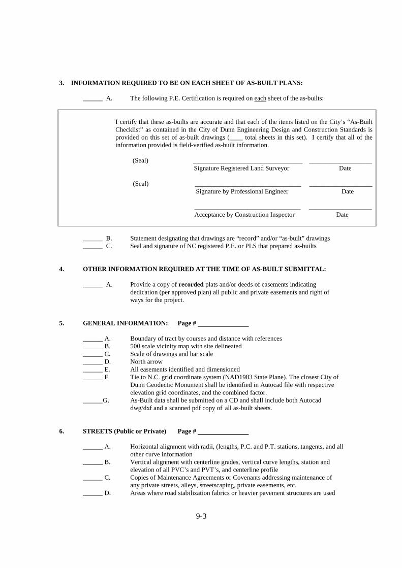
9-3
3. INFORMATION REQUIRED TO BE ON EACH SHEET OF AS-BUIL T PLANS:
______ A. The following P.E. Certification is required on each sheet of the as-builts:
I certify that these as-builts are accurate and that each of the items listed on the City’s “As-Built Checklist” as contained in the City of Dunn Engineering Design and Construction Standards is provided on this set of as-built drawings (____ total sheets in this set). I certify that all of the information provided is field-verified as-built information.
(Seal) _________________________________ ___________________ Signature Registered Land Surveyor Date
(Seal) ________________________________ ___________________ Signature by Professional Engineer Date
________________________________ ___________________ Acceptance by Construction Inspector Date
______ B. Statement designating that drawings are “record” and/or “as-built” drawings ______ C. Seal and signature of NC registered P.E. or PLS that prepared as-builts
4. OTHER INFORMATION REQUIRED AT THE TIME OF AS-BUILT SUBMITTAL:
______ A. Provide a copy of recorded plats and/or deeds of easements indicating dedication (per approved plan) all public and private easements and right of ways for the project.
5. GENERAL INFORMATION: Page #
______ A. Boundary of tract by courses and distance with references ______ B. 500 scale vicinity map with site delineated ______ C. Scale of drawings and bar scale ______ D. North arrow ______ E. All easements identified and dimensioned
______ F. Tie to N.C. grid coordinate system (NAD1983 State Plane). The closest City of Dunn Geodectic Monument shall be identified in Autocad file with respective elevation grid coordinates, and the combined factor.
______G. As-Built data shall be submitted on a CD and shall include both Autocad dwg/dxf and a scanned pdf copy of all as-built sheets. 6. STREETS (Public or Private) Page #
______ A. Horizontal alignment with radii, (lengths, P.C. and P.T. stations, tangents, and all other curve information
______ B. Vertical alignment with centerline grades, vertical curve lengths, station and elevation of all PVC’s and PVT’s, and centerline profile
______ C. Copies of Maintenance Agreements or Covenants addressing maintenance of any private streets, alleys, streetscaping, private easements, etc.
______ D. Areas where road stabilization fabrics or heavier pavement structures are used

9-4
7. STORM DRAINAGE AND ENVIRONMENTAL Page #
______ A. Outline of FEMA 500 year flood plain and elevation ______ B. Outline of FEMA 100 year flood plain and elevation
______ C. Outline of local 100 year flood areas and elevation per City flood plain ordinance
______ D. Outline of backwater easements ______ E. Elevation of all flood areas and finished floor elevations for adjacent structures
on which minimum finished floor elevations were required ______ F. Outline of Wetlands Cape Fear Buffers
______ G. Pipe materials ______ H. Structure invert and top elevations ______ I. Pipe size
______ J. Pipe slope and distance ______ K. Size of riprap dissipation pad ______ L. Statement of stormwater velocity at all outlets ______ M. Maintenance agreement responsibility statement
______ N. Permanent stormwater BMP’s with location and associated drainage easements required
______ O. Berm elevations and invert/top elevations for associated storm drainage inlets where required on construction drawings
8. WATER SYSTEM Page # ______ A. Pipe material labeled ______ B. Pipe size and length labeled ______ C. Separation from sanitary and storm sewer shown on plans ______ D. Locations with distance references (2 each per appurtenance) Valves Fire Hydrants Blow-offs
Meters Air release valves _____ E. Certification by N.C.P.E. of construction in accordance with sanitary water
extension permit _____ Certification required on the coversheet of the plans, and _____ As a separately submitted certification sheet _____ F. Location and length of bore and jacks
9. SANITARY SEWER SYSTEM Page # ______ A. Pipe material labeled ______ B. Pipe size and length labeled ______ C. Manhole top elevations ______ D. Invert in and out elevations ______ E. Pipe slope ______ F. Locations with distance references (2 each appurtenance) Clean-outs Air release valves Manholes Force main valves ______ G. Horizontal control (angles at manholes) ______ H. 100 year and 500 year flood plain elevations
______ I. Certification by N.C.P.E. of construction in accordance with sanitary sewer extension permit
______Certification required on the cover sheet of the plans, and ______ As a separately submitted certification sheet ______ J. Location and length of bore and jacks ______ K. Location and elevation of any vents

9-5
______ L. Areas of special bedding 10. For items shown above in bold italics, a survey point file of both horizontal (x, y) and vertical
(tops and inverts, or Z) information shall be required. X, Y, Z coordinates shall be provided on a CD, tied to NC grid or City monumentation grid, and accompanied by a certification sealed by a registered land surveyor. This information should accompany final submittal of mylar as-builts.
I certify that the information listed above is provided herein in these as-builts or record drawings.
__________________________________________ ____________________ (Seal) Registered Land Surveyor Date City of Dunn USE ONLY:
As-Builts Received By: _______________________ Date: _______________ As-Builts Reviewed By: _______________________ Date: _______________ (Attached) Comments Generated By: _____________ Date: _______________ Mylars Received By: __________________________ Date: _______________
END OF SECTION 9.00

10-1
SECTION 10.00 ENVIRONMENTAL
SUB-INDEX
10.01 GENERAL 10.02 TREE PROTECTION AND PRESERVATION
A. Tree Protection Fencing B. Combination Silt/Tree Protection Fencing C. Construction Operations
10.03 INDIVIDUAL LOT REQUIREMENTS
A. Erosion and Sedimentation Control B. Tree Preservation
10.04 UTILITY INSTALLATION ASSOCIATED WITH
ENVIRONMENTALLY SENSITIVE AREAS
A. Stream Crossing
10-2
10.01 GENERAL
This chapter contains standards, specifications, techniques and devices required to preserve the natural function of the environment. These techniques and devices are the minimal acceptable for use in the City of Dunn. The use of other techniques and devices is acceptable if adequate measures are provided by the alternative and prior approval is given by the Director of Engineering based on a review of specifications and details for the measure. The designer should also refer to Section 4.00 of these specifications for more Sedimentation & Erosion Control Standards.
10.02 TREE PROTECTION AND PRESERVATION
Tree protection and preservation is required whenever preservation or protection of existing vegetation is required per the City of Dunn Planning Department UDO and other ordinances, policies, etc. Fencing locations shall be shown on preliminary and construction drawings and may be modified in the field with approval of the Inspector. Trees shall be protected by fencing installed the distance from the trunk of the tree that equals the diameter of the trunk of the tree divided by two and converted into feet or at the drip line of the tree branches; whichever is more stringent. Tree protection fencing shall be installed before any work is done on the site and inspected during the Certificate of Compliance Inspection. Encroachment into buffer areas must be permitted by the Engineering Department per Section 7.06, D., 4., e Environmental Buffer Areas of the City of Dunn, Unified Development Ordinance and 2003 N.C. Sess. Law ch. 73, § 5.1. A. Tree Protection Fencing
Standard tree protection fencing shall be used to protect any tree save area including riparian buffers, thoroughfare buffers, open space or areas designated by the Town’s Engineering, Planning, or Parks and Recreation Departments. Fencing shall consist of high-visibility orange, UV-resistant high tensile strength poly barricade fabric with 5’ steel posts located at a maximum 8’ spacing, with minimum 10 gauge line wires. Signage shall be required which states “TREE PROTECTION AREA DO NOT ENTER” along the fencing at 50 foot intervals (maximum), and shall be made out of a durable waterproof material with a minimum of 3” lettering spaced clearly legible in accordance with the standard detail and the approved erosion control plan.
B. Combination Silt/Tree Protection Fencing

10-3
Combination temporary silt/tree protection fencing may be used wherever denuded area abuts any tree save area. This measure shall comply with those material and installation criteria specified for silt fence in section 4.03, A. Signage as described above in Section 10.02, A shall also be required in accordance with the standard detail and the approved erosion control plan.
C. Construction Operations in (or adjacent to) Tree Save Areas
When construction operations (including but not limited to cut and fill) cannot be avoided in or near either tree save areas or the drip line of the tree, the following criteria shall be met:
1. No more than 2” of fill may be placed on the roots or around the trunk
of a tree.
2. Cut slopes shall be no closer than 3 times the diameter of the tree, and shall not cause removal of more than 25% of the root zone surrounding the tree.
3. No heavy machinery shall be used within the drip line of the tree.
Construction equipment shall be limited to small rubber-tired equipment and hand work.
4. Root pruning with instruction by an arborist is required prior to the
installation of any permanent structures or excavation that encroaches into the root zone of a tree.
5. All denuded area around the tree must be covered by at least 3” of
mulch within 10 days of completion of work around the tree.
6. A 2 (two) year warranty period may be required for all work done in (or adjacent to) a tree save area.
10.03 INDIVIDUAL LOT REQUIREMENTS
A. Erosion and Sedimentation Control
Erosion and Sedimentation Control measures are required on lots that have an active construction in compliance with Section 4.09.
B. Tree Preservation

10-4
Tree preservation must take place on all lots with active construction in compliance with 10.02 of this section.
10.04 UTILITY INSTALLATION IN ENVIRONMENTALLY SENSITIVE
AREAS
A. Stream Crossing In areas where utility line installation is proposed to go through an area determined to be environmentally sensitive (such as stream, wetlands and/or floodplain) the following items shall be incorporated into design and construction in order to minimize adverse impacts to the area. Permits from regulatory agencies with jurisdiction, site specific erosion control devices (diversions, pumping, removal of fill, stabilization, etc.), a detailed construction sequence for the specific utility crossing, special techniques as required, and a special preconstruction meeting prior to starting the work. At the end of each work day, until completion, the site shall have appropriate erosion control measures installed to prevent damage from sedimentation and all channels must be restored to have positive flow. Once work has started, it must be completed in the shortest timeframe possible.
END OF SECTION 10.00