city of columbia engineering regulations part 5 ... · city of columbia engineering regulations -...
TRANSCRIPT

Table 5-1. Design Capacities for Arterial Streets and Urban Highways 5-19Table 5-2. Suggested Corner Sight Distance at Intersections 5-20Table 5-3. Length of Grade-Feet by Percent Upgrade 5-21Table 5-4. Minimum Length for Superelevation Runoff for 2-Lane Pavements 5-21Table 5-5. Normal Pavement or Surfancing Cross Slopes 5-22
List of tabLesTable Description Page No.
Figure 5-1. Data Sheet No. 1 - Traffic Data for Pavement Loading 5-10Figure 5-2. Data Sheet No. 1 - Example #1 5-11Figure 5-3. Data Sheet No. 1 - Example #2 5-12Figure 5-4. Data Sheet No. 2 - 20-Year Traffic Analysis Design Chart 5-13Figure 5-5. Data Sheet No. 2 - Example #1 5-14Figure 5-6. Data Sheet No. 2 - Example #2 5-15Figure 5-7. Data Sheet No. 3 - Coefficients of Relative Strength for Flexible Pavement
Components 5-16Figure 5-8. Data Sheet No. 3 - Example #1 5-17Figure 5-9. Data Sheet No. 3 - Example #2 5-18Figure 5-10. Standard Road Sections - Residential Street, Collectors and Industrial Streets,and
Arterial Streets 5-30
List of figuresFigure Description Page No.
City of Columbia Engineering Regulations - 5-i
5.1 General 5-15.2 Road System Design Criteria 5-15.3 Road Designation 5-25.4 Traffic Data 5-25.5 Subgrade Soil Support Value 5-45.6 Traffic Growth Rate 5-45.7 Coefficients of Relative Strenght of Pavement Component Layers 5-45.8 Structural Number (SN) 5-55.9 Stage Construction 5-55.10 Pavement Thickness Design Methods 5-55.11 Parking 5-195.12 Drainage 5-195.13 Geometrics 5-195.14 Complete Streets 5-29
CiTy oF Columbia ENgiNEEriNg rEgulaTioNsParT 5: sPECiFiCaTioN For roaDWay DEsigN
TablE oF CoNTENTsParagraph Description Page No.
Form 5-1. Complete Streets Agreement Form 5-34
List of formsForm Description Page No.
Table 5-6. Effective Road Width Due to Restricted Lateral Clearances Under Uninterrupted Flow Conditions 5-24
Table 5-7. Minimum Width of Usable Shoulders 5-26Table 5-8. Shoulder Cross Slopes 5-27Table 5-9. Suggested Earth Slopes for Design 5-27Table 5-10. Recommended Illumination Levels 5-28
City of Columbia Engineering Regulations - 5-ii

City of Columbia Engineering Regulations - 5-1
CiTy oF Columbia ENgiNEEriNg rEgulaTioNsParT 5: sPECiFiCaTioN For roaDWay DEsigN
5.1 general
5.1.1 Roadways and sidewalks must be designed in accordance with current City, SCDOT, International Fire Code: Appendix D and ADA regulations. Roadways should be designed for the anticipated traffic density 20 years from the proposed date of construction. Special conditions such as long range planning studies, proposed zoning, industrial parks, proposed and future interstate facilities, etc., should be considered in the design. This section also includes design for existing streets and sidewalks that require repair or to be replaced.
5.1.2 Roadway Signing and Pavement Markings
5.1.2.1 Signing on public streets shall be provided by the developer, and shall include, but not be limited to, the following: Street Markers, Stop Signs, Yield Signs, and Warning Signs. The signing shall conform to the current Manual on Uniform Traffic Control Devices (MUTCD) published by the Federal Highway Administration.
5.1.2.2 Pavement markings shall be provided by the developer, and shall include, but not be limited to, the following: Stop Bars, Centerlines, Lane Lines, and Parking Spaces. The signing shall conform to the current MUTCD.
5.1.2.3 The developer shall submit a roadway signing and marking plan to the Public Works Department for review and approval.
5.2 road system Design Criteria
5.2.1 In determining the required number of lanes, as well as pavement strength, the following factors shall be considered:
5.2.1.1 Road Designation
5.2.1.2 Traffic Data: DHV, ADT, Per cent of Trucks (T)
5.2.1.3 Soil Characteristics and Strength
5.2.1.4 Traffic Growth Rate
5.2.1.5 Pavement Strengths
5.2.1.6 Structural Number
5.2.1.7 Stage Development
5.2.1.8 Parking
City of Columbia Engineering Regulations - 5-2
5.2.1.9 Drainage
5.2.1.10 Geometrics
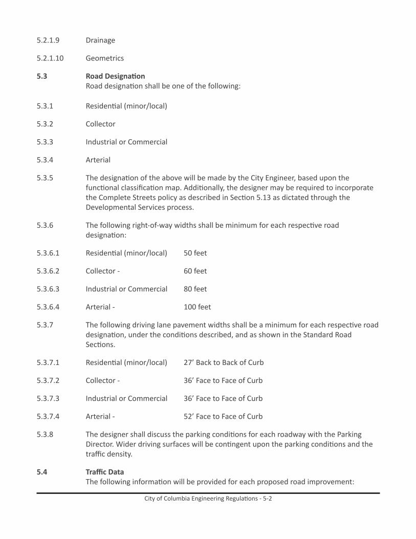
5.3 road DesignationRoad designation shall be one of the following:
5.3.1 Residential (minor/local)
5.3.2 Collector
5.3.3 Industrial or Commercial
5.3.4 Arterial
5.3.5 The designation of the above will be made by the City Engineer, based upon the functional classification map. Additionally, the designer may be required to incorporate the Complete Streets policy as described in Section 5.13 as dictated through the Developmental Services process.
5.3.6 The following right-of-way widths shall be minimum for each respective road designation:
5.3.6.1 Residential (minor/local) 50 feet
5.3.6.2 Collector - 60 feet
5.3.6.3 Industrial or Commercial 80 feet
5.3.6.4 Arterial - 100 feet
5.3.7 The following driving lane pavement widths shall be a minimum for each respective road designation, under the conditions described, and as shown in the Standard Road Sections.
5.3.7.1 Residential (minor/local) 27’ Back to Back of Curb
5.3.7.2 Collector - 36’ Face to Face of Curb
5.3.7.3 Industrial or Commercial 36’ Face to Face of Curb
5.3.7.4 Arterial - 52’ Face to Face of Curb
5.3.8 The designer shall discuss the parking conditions for each roadway with the Parking Director. Wider driving surfaces will be contingent upon the parking conditions and the traffic density.
5.4 Traffic DataThe following information will be provided for each proposed road improvement:

City of Columbia Engineering Regulations - 5-3
5.4.1 ADT, Average Daily Traffic, the daily traffic flow in both directions of travel, for a 24 hour period.
5.4.2 DHV, Design Hour Volume, the 30th highest hourly volume of the year is designated the DHV. If this information is not readily available DHV may be calculated at 12% of the ADT.
5.4.3 T, Percentage of Trucks, the quantity of trucks during the ADT or DHV, expressed as a percent of that total traffic. For the purpose here, light delivery trucks, such as panels and pick ups, are considered as passenger cars. In light of actual field data, T can be considered 10% on arterials, 5% on collector and residential. Special conditions must be discussed with the City Engineer for the industrial road designation.
5.4.3.1 Trucks shall be further identified as follows, during the actual traffic counting:
5.4.3.1.1 2DT – Unit truck, two axles
5.4.3.1.2 3SU – Unit truck, three axles
5.4.3.1.3 2S1 – Semi truck, two axles on cab, one axle on trailer
5.4.3.1.4 2S2 – Semi truck, two axles on cab, two axles on trailer
5.4.3.1.5 5AX – Truck with 5 axles or more
5.4.3.2 In lieu of the actual traffic count to determine T, and utilizing the percentage provided in Section 5.3.3 the following road designations shall contain the respective road groups as follows:
5.4.3.2.1 Residential (minor or local) – Road Group B
5.4.3.2.2 Collector – Road Group D
5.4.3.2.3 Arterial – Road Group G
5.4.3.2.4 Industrial or Commercial – Road Group J
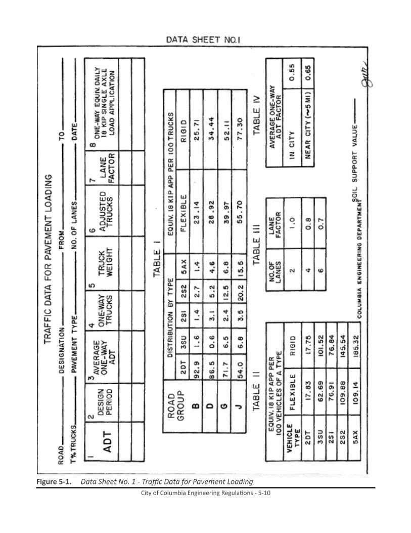
5.4.4 Road group loads and their effect on pavement design as related to these road groups is as shown on Data Sheet 1 of the design sheets.
5.4.5 Average one-way ADT, or when the 20 year ADT is calculated based upon section 5.9.4, shall be as follows: In City – 55%, In near city suburbs (5. mile radius) – 65%.
5.4.6 Lane Factor – In two lane roads the total one way traffic factor is 1.0. In four lane roads the most heavily traveled lane will be the right most lane and a factor of 0.8 will be applied to the total one-way traffic. In six lane roads the most heavily traveled lane will be the right lane also, and a factor of 0.7 will be applied to the total one-way traffic.

City of Columbia Engineering Regulations - 5-4
5.5 subgrade soil support ValueIn the case of proposed new construction, the soil support value of the subgrade soil will be provided by the triaxial shear test; modulus of deformation will be developed by laboratory testing and correlated with the accompanying oil support scale to provide these data. This value is requested also for staged road work (overlays) and road widening work. In lieu of an actual soils evaluation, a value of 1.50 may be used for the value of S.
5.6 Traffic growth rateA figure of 4% per year has been identified as the growth rate characterizing traffic within the United States. This figure should be used for forecasting anticipated ADT with the pavement design life. Other figures from local expertise are acceptable, when qualified as acceptable by the City Engineer.
5.7 Coefficients of relative strenght of Pavement Component layersThe required thickness of a given layer or layers varies with their respective tensile strength. This strength is expressed in terms of a relative coefficient. The estimated values of coefficients of the pavement components used in AASHO Interim Guide for the Design of Flexible Pavement Structures and AASHO Road Test Equations Applied to the Design of Bituminous Pavements in Illinois are utilized in this standard. It is to be understood that these coefficients may change if and when future studies are made to more accurately evaluate their respective tensile strength. At that time the City Engineer will provide updated coefficients for incorporation with these standards.
5.7.1 The designer is to be aware that the minimum pavement thickness for the particular road designation is as follows and as shown in the standard road sections on Drawing #RD-1:
5.7.1.1 Residential (minor/local) - 1 ½” Asphaltic concrete surface course 6” Macadam base course 6” Compacted subgrade
5.7.1.2 Collector - 2 ½” Asphaltic concrete surface course 6” Macadam base course 6” Compacted subgrade
5.7.1.3 Industrial or Commercial - 4” Asphaltic concrete surface course 6” Macadam base course 6” Compacted subgrade
5.7.1.4 Arterial - 5 ½” Asphaltic concrete surface course 8” Macadam base course 6” Compacted subgrade
City of Columbia Engineering Regulations - 5-5
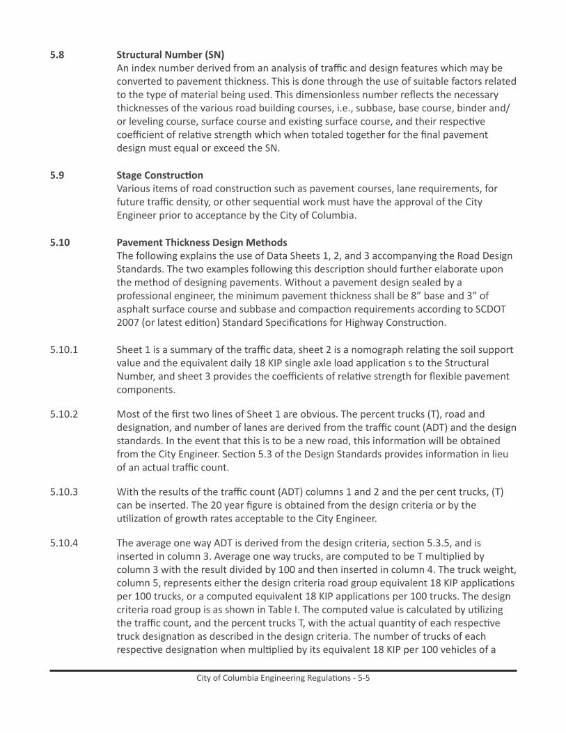
5.8 structural Number (sN)An index number derived from an analysis of traffic and design features which may be converted to pavement thickness. This is done through the use of suitable factors related to the type of material being used. This dimensionless number reflects the necessary thicknesses of the various road building courses, i.e., subbase, base course, binder and/or leveling course, surface course and existing surface course, and their respective coefficient of relative strength which when totaled together for the final pavement design must equal or exceed the SN.
5.9 stage ConstructionVarious items of road construction such as pavement courses, lane requirements, for future traffic density, or other sequential work must have the approval of the City Engineer prior to acceptance by the City of Columbia.
5.10 Pavement Thickness Design methodsThe following explains the use of Data Sheets 1, 2, and 3 accompanying the Road Design Standards. The two examples following this description should further elaborate upon the method of designing pavements. Without a pavement design sealed by a professional engineer, the minimum pavement thickness shall be 8” base and 3” of asphalt surface course and subbase and compaction requirements according to SCDOT 2007 (or latest edition) Standard Specifications for Highway Construction.
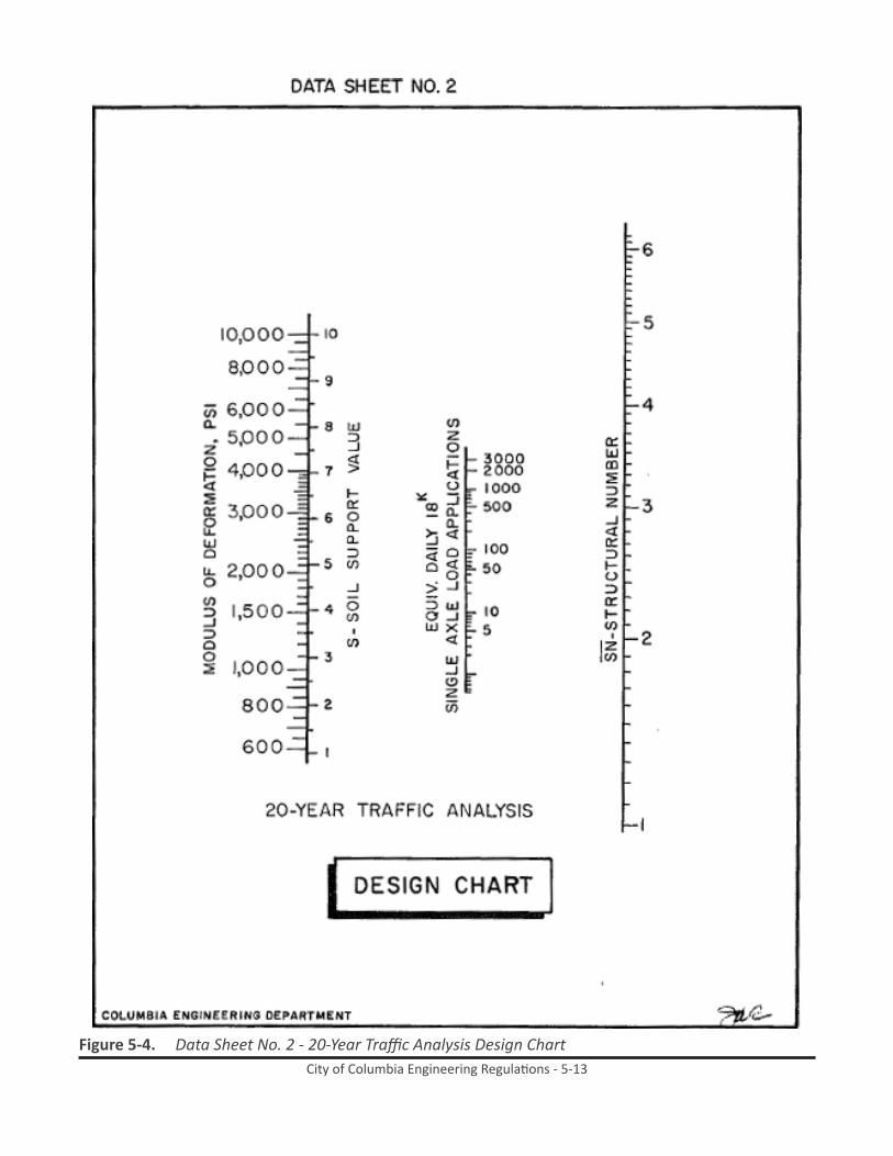
5.10.1 Sheet 1 is a summary of the traffic data, sheet 2 is a nomograph relating the soil support value and the equivalent daily 18 KIP single axle load application s to the Structural Number, and sheet 3 provides the coefficients of relative strength for flexible pavement components.
5.10.2 Most of the first two lines of Sheet 1 are obvious. The percent trucks (T), road and designation, and number of lanes are derived from the traffic count (ADT) and the design standards. In the event that this is to be a new road, this information will be obtained from the City Engineer. Section 5.3 of the Design Standards provides information in lieu of an actual traffic count.
5.10.3 With the results of the traffic count (ADT) columns 1 and 2 and the per cent trucks, (T) can be inserted. The 20 year figure is obtained from the design criteria or by the utilization of growth rates acceptable to the City Engineer.
5.10.4 The average one way ADT is derived from the design criteria, section 5.3.5, and is inserted in column 3. Average one way trucks, are computed to be T multiplied by column 3 with the result divided by 100 and then inserted in column 4. The truck weight, column 5, represents either the design criteria road group equivalent 18 KIP applications per 100 trucks, or a computed equivalent 18 KIP applications per 100 trucks. The design criteria road group is as shown in Table I. The computed value is calculated by utilizing the traffic count, and the percent trucks T, with the actual quantity of each respective truck designation as described in the design criteria. The number of trucks of each respective designation when multiplied by its equivalent 18 KIP per 100 vehicles of a

City of Columbia Engineering Regulations - 5-6
type (Table II), and then divided by 100 will be the equivalent truck weight figure based on the traffic count (ADT).
5.10.5 Column 6 is obtained by multiplying Column 5 by Column 4. Column 7 is obtained by going to Table III and selecting the appropriate lane factor, based upon the number of lanes in the project. Column 8 is obtained by multiplying Column 7 by Column 6. Column 8 becomes one point on the nomograph on Data Sheet 2, and is plotted as the equivalent daily 18 KIP single axle load applications.
5.10.6 The Soil Support Value, or the modulus of deformation is obtained through a soils test and is a measure of the bearing strength of the supporting subgrade under the pavement components. In lieu of a field test the value in the design criteria may be employed for S. The triaxial shear test is utilized for the field determination of the value of S, or the modulus of deformation, and becomes the second point on the nomograph shown on data sheet 2, under its appropriate scale shown.
5.10.7 The two points described in the preceding paragraphs describe a straight line, which is extended to intersect with the line segment designated SN on Data Sheet 2. The value of SN is obtained and used as a total pavement strength measure, which is to be equaled or exceeded by the total of the respective pavement section strengths. This formula employed is SN = T1a1 +T2a2+T3a3+T4a4
5.10.7.1 T1 = thickness of surface bituminous courses, in inches
5.10.7.2 T2 = thickness of surface course, in inches
5.10.7.3 T3 = thickness of base course, in inches
5.10.7.4 T4 = thickness of subbase course, in inches
5.10.7.5 A1, a2, a3, a4 = Coefficients of Relative Strengths which are obtained from Data Sheet 3 accompanying this example.
5.10.8 When the aforementioned equation computes to equal or exceed the SN obtained from the nomograph, the design pavement is valid and may be proposed. The designer should verify that the minimum asphaltic thickness, 1 ½”, has been used in the surface courses and that the minimum pavement thickness for each component or its equivalent is in accord with that established for its respective road designation.
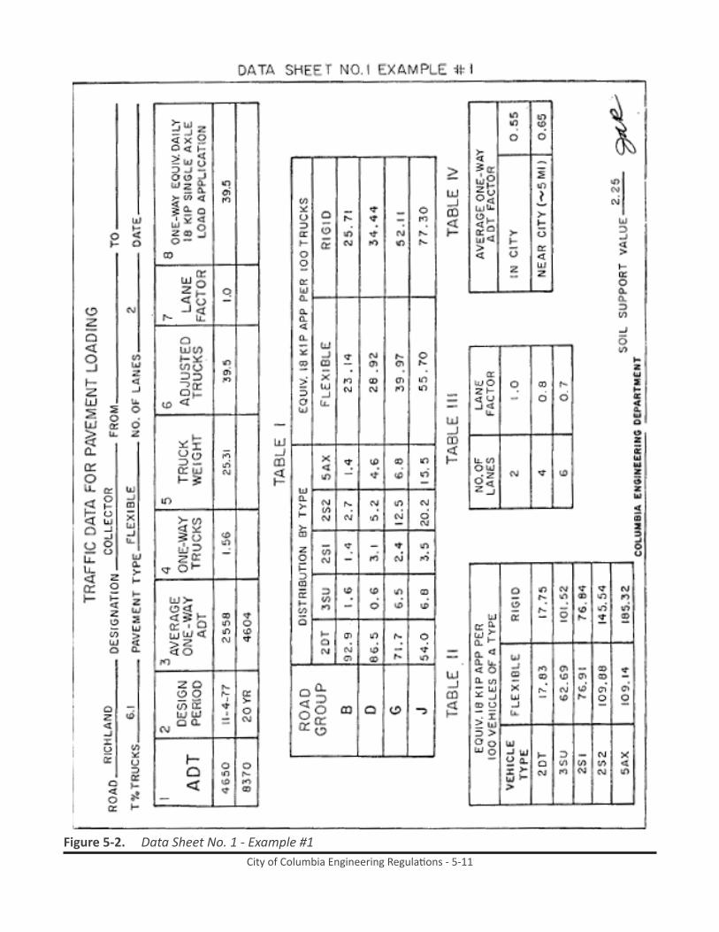
5.10.9 Example 1. Twenty-four hour traffic count (ADT) from the field reflects the following: 4,650 vehicles, of which there were 284 trucks, in the classification as follows: 2DT-243, 3SU-28, 2S1-10, 2S2-3, 5AX-0. A soils test indicates a Soil Support Value of 2.25.
5.10.10 Prior to starting calculations, note that the ADT indicates the road will carry a designation of either a collector or arterial road. Minimum Collector standards are paving width 36’ F to F of curb, 2 ½” asphaltic concrete surface course, 6” macadam base course, 6” compacted subbase course. Minimum arterial standards are paving width 52’ F to F of curb, 5 1/2” asphaltic concrete surface course, 8” macadam base course and 6”

City of Columbia Engineering Regulations - 5-7
compacted subbase course. Discussion should be held with the City Engineer to determine the appropriate road designation.
5.10.11 The % trucks T is 284 / 4650 = 0.061 or 6.1%. The ADT for the next 20 years, based upon 4% annual growth, is approximate 1.8 times 4650 = 8370, 8370 x .061 = 511 trucks. This example will assume the road has been designated as an in-City Collector, and will be two lanes. The average one way ADT factor is obtained from Table IV with this information the traffic on one lane will be 0.55 x 4650 or 2558 presently, 0.55 x 8370 or 4604 in 20 years. This data is inserted in Column 3.
5.10.12 The truck percentages for each respective designation are changed by the same amount, 0.55 x 243 – 133.6 2DT, 0.55 x 28 – 15.4 3SU, 0.55 x 10 – 5.5 2S2, 0.55 x 3 – 1.65 2S2, and 0.55 x 0 – 05AX. Note the total trucks 133.6 + 15.4 + 5.5 + 1.65 = 156.15 approximately equal to 0.55 x 284. These figures are inserted in column 4. At this point the example continues with present day figures for the calculations. To calculate the truck weight we compute the following, utilizing Table II of data sheet 1 and the approximate quantity of each respective truck designation.
5.10.12.1 133.5 x 17.83 = 15.26156.15
5.10.12.2 15.4 x 62.69 = 6.18156.15
5.10.12.3 5.5 x 76.91 = 2.71156.15
5.10.12.4 1.65 x 109.88 = 1.16156.15
5.10.12.5 0 x 109.14 = 0156.15
5.10.13 Totals 25.31 equivalent 18 KEP applications per 100 trucks. This value becomes the truck weight, Column 5.
5.10.14 Column 6, adjusted trucks, reflects the product of truck weight, Column 5, times the average one way trucks, Column 4, divided by 100 since the truck weight is predicated upon 18 KIP load applications per 100 trucks. This calculates to 25.31 x 156 / 100 or 39.5 and is inserted in Column 6.
5.10.15 Since this is tow lane the total one way factor is unity, from Table III and shown in Column 7. Critical lane traffic Column 6 times Column 7, 39.5 x 1.0 = 39.5.
5.10.16 Use 39.5 as one point to plot the equivalent daily 18 KIP single axle load applications, and plot the soil support value of 2.25 as a second point. The resulting straight line intersects a Structural Number (SN) of 3.49, as shown on data sheet 2.

City of Columbia Engineering Regulations - 5-8
5.10.17 Depending upon the engineering criteria involved in the road design, i.e., earth work, haul, etc., and utilizing the Coefficients of data sheet 3, the first attempt at a pavement design may be to employ an asphaltic concrete surface course of 4” times its Coefficient, resulting in SN of 3.49 = 4” x 0.44 + a2 t2 = a3T3 or a2T2 + a3T3 = 1.73, (3.49 – 1.76); the 6” compacted subbase can be brought in from the quarry and calculates to 0.12 x 6” or 0.72 thus SN = 1.76 + 0.72 + a2T2 or a2T2 = 1.01 to be made up in the base course. An average hot laid sand asphalt base course with a Coefficient 0.225 will result in 1.01 / 0.225 or 4.49 of base, say 4 ½”. The final equation reads a1 T1 + a2 T2 +a2 T3 = SN, or 1.76 + 0.72 +1.02 = 3.50, approximately equal to the 3.r9 required. Obviously various multiples of pavement structures could be utilized to compute the required Structural Number (SN) and the appropriate pavement design.
5.10.18 The SN for the collector’s minimum standards is 2.51. The designer is encouraged to compute the required pavement design based upon the 20 year ADT, and the minimum design standard SN of 2.51. Sheet 1 and 2 of example 1 reflects the SN, extended for 20 years, and the designer should observe the change in Structural Number (SN) is only 0.24 or less than 1” of asphaltic concrete, for this particular example (3.73 – 3.49 = 0.24), and 1” of asphaltic concrete has a coefficient of 0.44.
5.10.19 Example 2. This example illustrates a road serving a small subdivision, to be constructed in the future. No traffic counts are available. However, a soils study indicates a Soils Support Value of 1.75. The City Engineer, in conjunction with the Traffic Department, indicates an anticipated ADT of 437 vehicles for this type of in-city subdivision road at its proposed location, and designates the road as residential.
5.10.20 The following is an analysis for present day values only, with the 20 year figure left as an exercise for the designer:
5.10.20.1 From the design criteria section 5.3.3 the % trucks (T) is fixed to be 5% and the truck weight is determined to be Road Group B, section 5.3.3.2. Column 2 is thus 437 vehicles; Column 3 is 437 x .55 or 240 vehicles. The .55 reflects the maximum single lane per cent of the ADT. Column 4 is 240 x .05 or 12.00 trucks. Truck weight is determined as 23.14 equivalent 18 KIP applications per 100 trucks, from Table I, and is Column 5. Column 6 is based upon 100 trucks; since we have 12 trucks it is computed to be 9.12 x 23.14 = 2.78. Since there are only two lanes the lane factor, column 7 is unity and Column 8 become 1 x 2.78 = 2.78. This value, along with the Soil Support Value (S) of 1.75 from the soils test, establish the two points on the nomograph data sheet 2, which establishes a Structural Number (SN) of 2.42.
5.10.21 Utilizing data sheet 3, with the tabulated coefficients it appears as though an extra inch of hot laid asphalt concrete over the minimum is required. These computations are a1 T1 + a2 T2 + a3 T3 = SN or .44 x 2 ½” + .16 x 6” + .075 x 6” or 1.10 + 0.96 + 0.45 = 2.51. 2.51 being greater than 2.42 makes the design valid.
5.10.22 The reason for the initial estimate of an additional inch of hot laid asphalt concrete is that the minimum standards for a residential road designation result in Structural Number (SN) of 2.07. Also note that average values of the Coefficient a 2 and a3 have
City of Columbia Engineering Regulations - 5-9
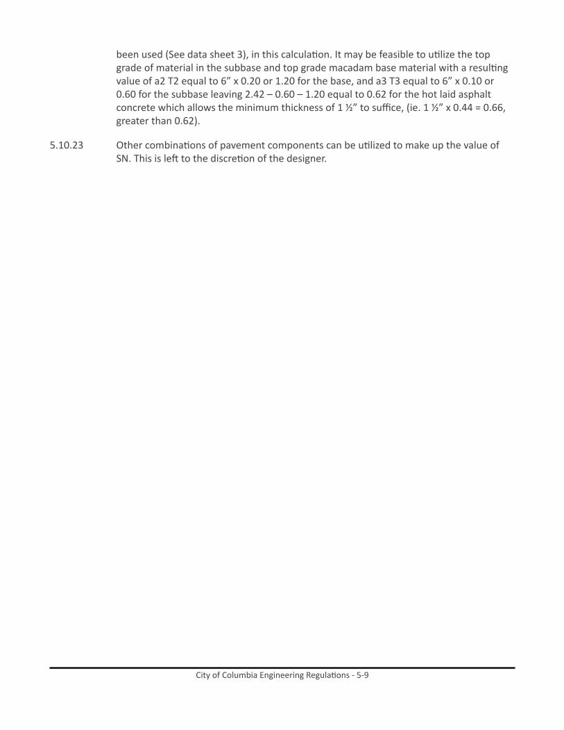
been used (See data sheet 3), in this calculation. It may be feasible to utilize the top grade of material in the subbase and top grade macadam base material with a resulting value of a2 T2 equal to 6” x 0.20 or 1.20 for the base, and a3 T3 equal to 6” x 0.10 or 0.60 for the subbase leaving 2.42 – 0.60 – 1.20 equal to 0.62 for the hot laid asphalt concrete which allows the minimum thickness of 1 ½” to suffice, (ie. 1 ½” x 0.44 = 0.66, greater than 0.62).
5.10.23 Other combinations of pavement components can be utilized to make up the value of SN. This is left to the discretion of the designer.
City of Columbia Engineering Regulations - 5-10
Figure 5-1. Data Sheet No. 1 - Traffic Data for Pavement Loading
City of Columbia Engineering Regulations - 5-11
Figure 5-2. Data Sheet No. 1 - Example #1

City of Columbia Engineering Regulations - 5-12
Figure 5-3. Data Sheet No. 1 - Example #2
City of Columbia Engineering Regulations - 5-13
Figure 5-4. Data Sheet No. 2 - 20-Year Traffic Analysis Design Chart

City of Columbia Engineering Regulations - 5-14
Figure 5-5. Data Sheet No. 2 - Example #1

City of Columbia Engineering Regulations - 5-15
Figure 5-6. Data Sheet No. 2 - Example #2

City of Columbia Engineering Regulations - 5-16
DATA SHEET 3
COEFFICIENTS OF RELATIVE STRENGTH FORFLEXIBLE PAVEMENT COMPONENTS
Pavement Components Coefficients a1 a2 a3
Surface CourseHot Laid Asphaltic Concrete Surface 0.44Hot Laid Asphaltic Concrete Binder 0.44Bituminous Surfacing 0.35
Old SurfaceOld asphalt concrete surface course 0.26Old asphalt concrete binder course 0.26Old sand asphalt 0.21Bituminous Surfacing 0.21
BaseEarth Type Base Course (Grd. Surf. Material) 0.08 - 0.12*Earth Type Base Course (Pit Material) 0.12 - 0.20*Macadam Base Course 0.12 – 0.20*Cement Stablized Earth Base Course 0.20Hot Laid Asphalt Base Course 0.20 – 0.25*Stabilized Aggregate Base Course 0.12 – 0.20*Hot Laid Asphalt Aggregate Base Course 0.34Cement Stabilized Aggregate Base Course 0.34Old PCC Pavement 0.40
SubbaseEarth Type Subbase Course (Grd. Surf. Material) 0.05 – 0.10*Earth Type Subbase Course (Pit Material) 0.08 – 0.12*Soil Aggregate Subbase Course 0.08 – 0.12*Cement Stabilized Earth Subbase 0.15
(*) Coefficient dependent on quality of material available.
Note: In general, in computing SN for resurfaced flexible pavements, the coefficient for the former surface be no greater than 0.6 of its original value, that for the former base be no greater than 0.7 of its original value, and that for the former subbase be no greater than 0.8 of its original value.
Figure 5-7. Data Sheet No. 3 - Coefficients of Relative Strength for Flexible Pavement Components

City of Columbia Engineering Regulations - 5-17
DATA SHEET 3 - EXAMPLE 1
COEFFICIENTS OF RELATIVE STRENGTH FORFLEXIBLE PAVEMENT COMPONENTS
Pavement Components Coefficients a1 a2 a3
Surface CourseHot Laid Asphaltic Concrete Surface 0.44Hot Laid Asphaltic Concrete Binder 0.44Bituminous Surfacing 0.35
Old SurfaceOld asphalt concrete surface course 0.26Old asphalt concrete binder course 0.26Old sand asphalt 0.21Bituminous Surfacing 0.21
BaseEarth Type Base Course (Grd. Surf. Material) 0.08 - 0.12*Earth Type Base Course (Pit Material) 0.12 - 0.20*Macadam Base Course 0.12 – 0.20*Cement Stablized Earth Base Course 0.20Hot Laid Asphalt Base Course 0.20 – 0.25*Stabilized Aggregate Base Course 0.12 – 0.20*Hot Laid Asphalt Aggregate Base Course 0.34Cement Stabilized Aggregate Base Course 0.34Old PCC Pavement 0.40
SubbaseEarth Type Subbase Course (Grd. Surf. Material) 0.05 – 0.10*Earth Type Subbase Course (Pit Material) 0.08 – 0.12*Soil Aggregate Subbase Course 0.08 – 0.12*Cement Stabilized Earth Subbase 0.15
(*) Coefficient dependent on quality of material available.
Note: In general, in computing SN for resurfaced flexible pavements, the coefficient for the former surface be no greater than 0.6 of its original value, that for the former base be no greater than 0.7 of its original value, and that for the former subbase be no greater than 0.8 of its original value.
Figure 5-8. Data Sheet No. 3 - Example #1

City of Columbia Engineering Regulations - 5-18
DATA SHEET 3 - EXAMPLE 2
COEFFICIENTS OF RELATIVE STRENGTH FORFLEXIBLE PAVEMENT COMPONENTS
Pavement Components Coefficients a1 a2 a3
Surface CourseHot Laid Asphaltic Concrete Surface 0.44Hot Laid Asphaltic Concrete Binder 0.44Bituminous Surfacing 0.35
Old SurfaceOld asphalt concrete surface course 0.26Old asphalt concrete binder course 0.26Old sand asphalt 0.21Bituminous Surfacing 0.21
BaseEarth Type Base Course (Grd. Surf. Material) 0.08 - 0.12*Earth Type Base Course (Pit Material) 0.12 - 0.20*Macadam Base Course 0.12 – 0.20*Cement Stablized Earth Base Course 0.20Hot Laid Asphalt Base Course 0.20 – 0.25*Stabilized Aggregate Base Course 0.12 – 0.20*Hot Laid Asphalt Aggregate Base Course 0.34Cement Stabilized Aggregate Base Course 0.34Old PCC Pavement 0.40
SubbaseEarth Type Subbase Course (Grd. Surf. Material) 0.05 – 0.10*Earth Type Subbase Course (Pit Material) 0.08 – 0.12*Soil Aggregate Subbase Course 0.08 – 0.12*Cement Stabilized Earth Subbase 0.15
(*) Coefficient dependent on quality of material available.
Note: In general, in computing SN for resurfaced flexible pavements, the coefficient for the former surface be no greater than 0.6 of its original value, that for the former base be no greater than 0.7 of its original value, and that for the former subbase be no greater than 0.8 of its original value.
Figure 5-9. Data Sheet No. 3 - Example #2

City of Columbia Engineering Regulations - 5-19
5.11 ParkingParking geometry will be parallel to the flow of traffic, unless otherwise approved by the City Engineer.
5.12 DrainageSurface storm water facilities are covered under a different design section. Whenever preliminary borings for a proposed roadway, or construction of proposed underground utilities such as water, sanitary sewer, gas, telephone, electric lines, etc., indicated that water bearing soils will be encountered at, or below, grade where pavement components are to be installed, the minimum requirements will be for the installation of sub-surface section drains with appropriate filter material i.e., open graded drain rock blended with coarse concrete sand. The minimum size of section drain pipe will be 4”, where short lengths of roadway, or gradual slopes (less than 10%) are to be constructed. Larger drains shall be installed as required.
5.12.1 Some standards of typical surface storm water facilities are included with these standards for road paving.
5.13 geometricsThis section addresses itself to the road features which provide safety and esthetics to the motoring public.
5.13.1 Design Hour Volume. As derived by actual traffic counts, or as calculated by the method in Section 5.3.2 the DHV may be utilized to determine the necessary number of traffic lanes, in accordance with the following Table 5-1:
Table 5-1. Design Capacities for Arterial Streets and Urban Highways
Type of Highway
Design Capacity, Passenger Cars Per Hours
Per 12-Foot LaneMajor Suburban Highway with Moderate Interference from Cross Traffic and Roadsides: Level of Service “C” 700-900
Major Suburban Highway, Considerable Interference from Cross Traffic and Roadsides: Level of Service “C” 500-700
Arterial Street, Traffic Signals Average One Mile Or More Apart, Parking Prohibited and Refuge Provided for Stalled Vehicles; Level of Service “C”
400-600
Arterial Street, Traffic Signals Less than One Mile Apart, Parking Prohibited
As Governed by Capacity of Intersections
5.13.2 Level of Service “C” for Urban and Suburban Arterials is defined as: service volumes about 0.80 of capacity with average overall travel speeds of 20 mph. Operating conditions at most intersections approximate load factor of 0.3. Peak hour factor is approximately 0.85. Traffic flow still stable with acceptable delays.

City of Columbia Engineering Regulations - 5-20
5.13.3 Sight Distance. The minimum safe stopping sight distances shall be as follows:Residential 200 feet Collector 275 feet Industrial 275 feet Arterial 300 feet
5.13.4 Stopping sight distance is measured from the driver’s eye, 3.75 feet above the pavement center line to the top of an object 6” high on the pavement center line.
5.13.5 Intersection safe sight distances will correspond to the requirements in Table 5-2 below, predicated upon the design speed.
Table 5-2. Suggested Corner Sight Distance at Intersections
Design Speed MPH
Minimum Corner Intersection Sight Distance, In Feet *
40 40030 30020 200
5.13.6 *Note: Corner Sight Distance is measured from a point on the minor road at least 15 feet from the edge of the major road pavement and measured from a height of eye of 3.75 feet on the minor road to a height of object of 4.5 feet on the major road. See figure VIII-5, page 398, “A Policy on Geometric Design of Rural Highways”.
5.13.7 Intersection design shall allow no structures or growth that interferes with the driver’s eye position when measured from a stopped vehicle on the minor roadway seeking to enter the major roadway.
5.13.8 Road Grades. Grades for streets in residential areas should be as flat as the consistent with the surrounding terrain. The gradient of residential streets should be less than 12% except in unusual terrain situations and desirably it should be less than 8%. On collector streets the gradient should be less than 10%, desirably it should be less than 7%. Where grades 4% or steeper are necessary, the drainage design may be critical. On such grades special care must be taken to prevent erosion on slopes and open drainage facilities as well as subsurface drainage.
5.13.9 For streets in industrial areas, gradient design should be less than 8%, desirably it should be less than 5% with emphasis on still flatter gradients.
5.13.10 In order to provide for proper drainage, the minimum grade that should be used for streets with outer curbing is 0.5%. A grade of 0.35% may be used where there is a high type pavement accurately crowned and supported on firm subgrade.
5.13.11 Although the grades indicated are permitted in extenuating circumstances, the maximum length of the grades that exceed the desirable will correspond to Table 5-3 below, for a speed reduction of 15 mph, and will apply to all road designations, except residential. See Section 5.12.18 regarding number of lanes.

City of Columbia Engineering Regulations - 5-21
Table 5-3. Length of Grade-Feet by Percent Upgrade
5.13.12 Alignment – Where deflection angle or more than ten (10) degrees occurs in the alignment of a marginal access or minor street or road, a curve of reasonable radius shall be introduced. A curve shall be introduced at any change in direction of a collector, industrial or arterial roadway. On arterials, the center line radius or curvature shall be determined by the City Engineer. On Collector and Industrial roads the center line radius or curvature shall not be less than four hundred (400) feet. On residential roads the center line radius of curvature shall not be less than one hundred fifty (150) feet.
5.13.13 Where curves are super elevated, lower values of the radius of curvature may apply. In no case will the residential radius of curvature be less than 115 feet, and the collector, or industrial radius of curvatures be less than 275 feet.
5.13.14 Elevation – Super elevation is advantageous for street operation. Super elevation should be provided on collector streets wherever operating speeds will not be low.
5.13.15 Where super elevation is used, street curbs should be designed for a maximum super elevation rate of 0.04 to 0.06 feet per foot. Minimum length or super elevation runoff is shown in Table 5-4.
Table 5-4. Minimum Length for Superelevation Runoff for 2-Lane Pavements
Superelevation Rate Feet Per Foot
L-Length of runoff in feet for Design Speed, MPH, of:20 30 40 50 60
.02 50 100 125 150 175
.04 50 100 125 150 175
.06 50 110 125 150 175For roadways greater than two lanes, the design will proceed as required by the City Engineer.
City of Columbia Engineering Regulations - 5-22
5.13.16 Pavement Crown – Pavement cross slope should be adequate to provide proper drainage. Cross slope normally should be as shown in Table 5 where there are flush shoulders adjacent to the travelway. Where there are outer curbs, cross slopes steeper by about a 1/16 to 1/8 inch per foot are desirable on the lane adjacent to the curb.
Table 5-5. Normal Pavement or Surfancing Cross Slopes
Surface TypeRange in rate of cross slope
Inch Per Foot Foot Per FootHigh 1/8 – ¼ .01 -.02
Intermediate 3/16 – 3/8 .015 - .03Low ¼ - ½ .02 - .04
5.13.17 Number of Lanes. Two moving traffic lanes plus additional width for curb and gutter, shoulders or parking are usually sufficient for most residential streets. On collector streets there should be provisions for four or more moving lanes except where the street is to be one-way in which case two moving lanes maybe the ultimate number that need be provided.
5.13.18 In industrial areas where there will be several mid-block left turns, it is recommended that an additional continuous two-way left turn lane in the center be provided.
5.13.19 The number of lanes to be provided on streets with a current ADT or 2,000 or more should be determined by highway capacity analysis of the design traffic volumes. Desirably such analysis should be made for future design traffic. Stage development may be considered for those streets on which four or more lanes for moving traffic is indicated.
5.13.20 On collector, arterial, and indiustrial road designations, where the design exceeds both the maximum slope and length and the actual traffic count indicates a T of more than 5% in the case of a collector, or more than 10% on arterials/industrial, a 12’ climbing clane is required for the maximum length of the pavement in the positive direction.
5.13.21 Median – Roadways designed for four or more lanes should include widths for appropriate median treatment whenever practical. There are substantial advantages for each increment in median width and it should be made as wide as practicable for the specific conditions. General types of street median treatment will need the following widths: (1) paint of stripe separations, 2 to 4 feet in width (2) narrow raised or curbed sections, 4 to 6 feet in width (3) paint striped or curbed sections providing space for separate left turn lanes, 14 to 18 feet in width.
5.13.22 On residential roads, median openings will be provided as necessary to serve abutting property and the traffic demand. They will be kept at a minimum. On collector streets, median openings will be provided at major street and minor street intersections and at reasonably spaced driveways serving motor traffic generators such as shopping centers. Median openings should be designed to include left turn lanes. Care should be taken to locate openings only where there is adequate sight distance.
City of Columbia Engineering Regulations - 5-23
5.13.23 Curbing – Roadways normally are designed with curbs for high utilization of available widths for control of drainage, protection of pedestrians, for delineation for a more finished appearance, for safety, and to assist in the orderly development of the roadside. The curb on the right of traffic should b 6” high.
5.13.24 On divided streets, the type of median curb should be determined in conjunction with the median width and the type of turning movement control to be affected. Where mid-block left turn movements are permitted and the median width is usually under 10 feet, a well delineated flush or rounded raised median separator 2” to 4” high is effective in channelizing traffic. This serves to avoid excessive travel distances and concentrations of turns at intersections. Where traver-sable wider medians are appropriate, they may be either flush or bordered with flat sloping lip curbs only a few inches high. On narrow and intermediate width medians and on some wide medians where cross median movements are undesirable or hazardous, a barrier curb should be used usually 6 to 8” high with a steep face. A high barrier curb or a central metal or high concrete barrier should be used with positive separation of opposing traffic is essential and there is no need for pedestrian crossings.
5.13.25 Steep faced curbs 6” or higher adjacent to moving traffic lanes should be offset from lane paving at least one foot. Where there is integral curb and gutter, construction, the gutter pan width, normally 12 to 18 inches, should be used as the offset distance.
5.13.26 Barrier or roll type curbing is acceptable upon approval of the City Engineer.
5.13.27 Manually poured in place (hand formed), extruded or precast curbing is acceptable. Curbing style is to be a harmonious match to the curbing already in existence in the surrounding environs. Where curbing does not exist in the surrounding environs the City Engineer will be the final authority on the requirement for the installation of curbing and the particular type.
5.13.28 Gutter will accompany all new curbing installations, with the following exception: Where existing curbing is curb only and no gutter, the designer is to verify the requirement for curbing with the City Engineer.
5.13.29 The accompanying standard illustrates acceptable types of curb and gutter. Other styles must be approved by the City Enginner.
5.13.30 Sidewalks – Sidewalks will be provided along both sides of roadways used for pedestrian access to schools, parks, shopping areas, transit stops and along all roadway with a commercial designation. In residential areas sidewalks will be provided on both sides of the roadway. The sidewalks should be located as far as practical from the traffic lanes; the outer edge of the sidewalk should be placed one foot from the property line, in the dedicated right-of-way. All new construction, addition or modification of sidewalks, driveways with through sidewalks and wheel chair ramps, must meet current ADA standards and SCDOT Standard Drawings No. 720-4 and 720-6; Located in the SCDOT Standard Drawings for Road Construction book.

City of Columbia Engineering Regulations - 5-24
5.13.31 The minimum width of sidewalk is to be five feet or current ADA requirements in Residentially zoned areas. Commercially zoned areas shall have a minimum width of sidewalk of six feet.
5.13.32 Border areas between the roadway and the sidewalk should be a minimum of four feet in width, ideally the border area should be eight to twelve feet in width. Any landscape areas located in the right of way must be approved by the Forestry and Beautification Superintendent prior to installation. Irrigation may be required depending on species and location.
5.13.33 Driveways – Driveways will be regulated as to the width of entrance, placement with respect to property lines and street intersections, vertical alignment, number of entrances to a single property, sight distance, drainage, parking, setback, lighting and signing and must be in accordance with SCDOT standards. The angle of entry shall be 90 degrees.
5.13.33.1 Driveways crossing sidewalks shall meet current ADA requirements.
5.13.34 Clearance to Obstructions – All roadways shall have a horizontal clearance of at least two feet between the face of curb, or edge of shoulder, and vertical obstructions, such as utility poles, fire hydrants, lighting poles, etc. Table 6 below reflects the effect of lateral clearance on lane capacity.Table 5-6. Effective Road Width Due to Restricted Lateral Clearances Under
Uninterrupted Flow Conditions
Clearance From Pavement Edge To
Obstruction. Both Sides (Ft.)
Effective Width of Two 12-Ft Lanes
(Ft)
Capacity of Two 12-Ft Lanes
(% of Ideal)6 24 1004 22 922 20 830 17 72
5.13.35 Guardrail is not be used, except where there is hazard to motorists and pedestrians; such points as fixed objects along the pavement edge, fills on steep grades, long through fills, or fills on sharp curvatures; other pints especially hazardous are along water courses, escarpments, along deep ditches in cuts, particularly with rock exposed, and similar locations. The more dangerous points along a highway are obvious from the plans, but the overall need for guardrail is best determined by field inspection as the grading nears completion. The need for guardrails on fills is related to the slope. Generally they may be omitted where it is practicable to provide slopes of 4:1 or flatter. In some cases, it is economical to flatten embankment slopes to 4:1 or less instead of constructing guardrail, provided right-of-way is available. Where guardrail cost per linear foot is four times the cost of fill per cubic yard, it’ generally more economical to flatten slopes from 2:1 to 4:1 on fills up to 15 feet in height. Saving in maintenance cost increases the fill depth at which it is economical to flatten slopes rather than use
City of Columbia Engineering Regulations - 5-25
guardrail. However, where there is an accident prone situation, even with flat slopes, guardrails are usually warranted. The basic principle for the use of guardrail to protect traffic from hazards is that guardrail will be used when the severity of an accident involving the hazard would be greater than the severity of an accident involving the protective guardrail.
5.13.36 Vertical clearance between the proposed center line of the road pavement and any elevated facility such as a bridge, walkway, tree limb, etc., shall be 15.0’ minimum.
5.13.37 Intersection Design- Intersections, including median openings, should be designed with adequate corner sight distance (See Table 5-2) and the area kept free of obstacles. The corner sight distance for collector roadways will be a minimum of 300 feet and desirably should be 400 feet or more. For residential roadways the minimum corner sight distance will be 200 feet and desirably should be 300 feet or more. In order to maintain the minimum sight distance, restrictions on height of embankment, locations of buildings and screening fences may be necessary. Any landscaping in the sight distance triangle should be low growing with a maximum height that will not interfere with a passenger vehicle operator’s line of sight.
5.13.38 It is desirable that intersecting streets meet at approximately a 90 degree angle. The alignment design should be adjusted so as to avoid an angle of intersection of less than 60 degrees. Closely spaced offset intersections are to be a minimum of 200 feet.
5.13.39 The intersection area and area where vehicles store while waiting to enter the intersection should be designed with a flat grad; the maximum grade on the approach leg should be no more than 5 percent.
5.13.40 Radii of 25 feet are adequate for passenger vehicles. These will be provided at residential streets where there is little occasion for trucks to turn, or at major intersections where there are parking lanes. Where the street has sufficient capacity to retain the curb lane as a parking lane for the foreseeable future, parking should be restricted for appropriate distances from the crossing.
5.13.41 Radii of 30 feet or more at collector streets should be provided where feasible so that a truck can turn without excessive lane encroachment.
5.13.42 Radii of 40 feet or more, and preferably three-centered compound curves or simple curves with tapers to fit the paths of appropriate design vehicles, should be provided where large truck combinations and buses turn frequently. Larger radii are also desirable where speed reductions would cause problems. This applies to the arterial and industrial road designations.
5.13.43 Radii dimensions should be coordinated with cross-walk distances or special designs to make crosswalks safer for pedestrians.
5.13.44 Corner curb radii on two-way streets have little effect on left turning movements. Where the width of an arterial street is equivalent to four or more lanes, generally there is no problem of encroachment by left turning vehicles.

City of Columbia Engineering Regulations - 5-26
5.13.45 Road Side Development – The tree categories of planting are: (a) Tree Planting – The primary purpose is aesthetic improvement in undeveloped areas where a higher type of planting is not justified and to preserve the naturalistic appearance by replacement of trees removed by construction; (b) Functional Planting – The primary purpose is erosion control, traffic safety, reduction of fire hazard or screening traffic from adjacent property, the aesthetic effect derived being of secondary benefit. (c) Landscaping – The primary purpose is aesthetic improvement of the right-of-way and the preservation of property values of adjacent development, the functional benefits thereby obtained being secondary. The City is not responsible for the maintenance of landscaped areas adjacent to individual properties or within a median/island unless specifically approved by the Superintendent of Forestry and Beautification. Such approval will not occur within residential areas.
5.13.46 As sight distance and safety are of primary importance, these considerations must not be subordinated to aesthetics. Applicable horizontal and vertical sight distance standards are set forth in 5.12.3 and 5.12.35. All planting shall be such that sight distances is equal to or greater than that required by the design standards for all intersections.
5.13.47 Proposed planting shall provide the initial or ultimate horizontal and vertical sight distance required by the design speed of the project. Particular attention should be paid to planting on the inside of curbs, in median areas and on cut slopes so that designed sight distances in the adjacent traffic lanes may be retained.
5.13.48 Shoulders – The shoulder portion of roadways serves a bifold purpose, namely: a) to accommodate stopped vehicles in emergencies; b) for lateral support of base and surface courses. Shoulder widths vary from about 2 feet on minor roads to about 12 feet or more on major roads, where the entire shoulder may be stabilized or have an all weather treatment.
5.13.49 As a general guide for developing design shoulder widths, Table 7 will be useful.
Table 5-7. Minimum Width of Usable Shoulders
Current ADTDesign Volume Usable Shoulder Width, Feet
DHV Minimum Desirable50-250 4 6
250-400 4 8400-750 100-200 6 10
200-400 8 10over 400 8 12
City of Columbia Engineering Regulations - 5-27
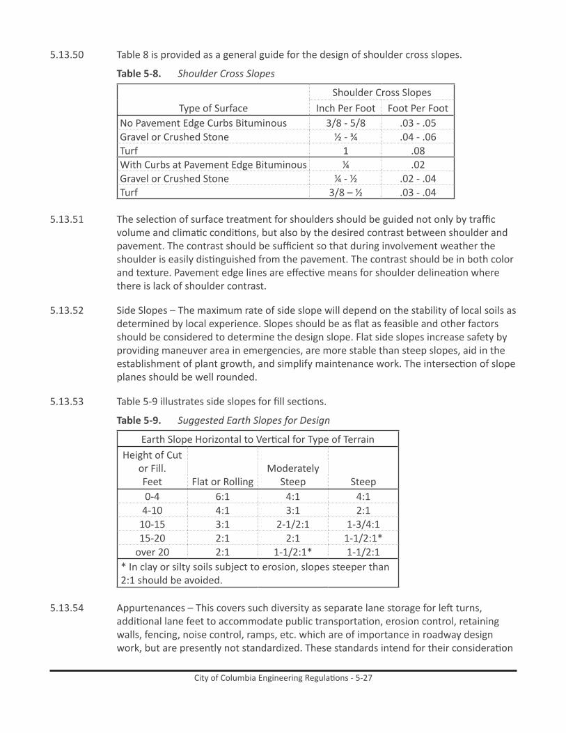
5.13.50 Table 8 is provided as a general guide for the design of shoulder cross slopes.
Table 5-8. Shoulder Cross Slopes
Type of SurfaceShoulder Cross Slopes
Inch Per Foot Foot Per FootNo Pavement Edge Curbs Bituminous 3/8 - 5/8 .03 - .05Gravel or Crushed Stone ½ - ¾ .04 - .06Turf 1 .08With Curbs at Pavement Edge Bituminous ¼ .02Gravel or Crushed Stone ¼ - ½ .02 - .04Turf 3/8 – ½ .03 - .04
5.13.51 The selection of surface treatment for shoulders should be guided not only by traffic volume and climatic conditions, but also by the desired contrast between shoulder and pavement. The contrast should be sufficient so that during involvement weather the shoulder is easily distinguished from the pavement. The contrast should be in both color and texture. Pavement edge lines are effective means for shoulder delineation where there is lack of shoulder contrast.
5.13.52 Side Slopes – The maximum rate of side slope will depend on the stability of local soils as determined by local experience. Slopes should be as flat as feasible and other factors should be considered to determine the design slope. Flat side slopes increase safety by providing maneuver area in emergencies, are more stable than steep slopes, aid in the establishment of plant growth, and simplify maintenance work. The intersection of slope planes should be well rounded.
5.13.53 Table 5-9 illustrates side slopes for fill sections.
Table 5-9. Suggested Earth Slopes for Design
Earth Slope Horizontal to Vertical for Type of TerrainHeight of Cut
or Fill. Feet Flat or Rolling
Moderately Steep Steep
0-4 6:1 4:1 4:14-10 4:1 3:1 2:1
10-15 3:1 2-1/2:1 1-3/4:115-20 2:1 2:1 1-1/2:1*
over 20 2:1 1-1/2:1* 1-1/2:1* In clay or silty soils subject to erosion, slopes steeper than 2:1 should be avoided.
5.13.54 Appurtenances – This covers such diversity as separate lane storage for left turns, additional lane feet to accommodate public transportation, erosion control, retaining walls, fencing, noise control, ramps, etc. which are of importance in roadway design work, but are presently not standardized. These standards intend for their consideration

City of Columbia Engineering Regulations - 5-28
and treatment by the designer as merited by traffic, zoning and the actual conditions as they exist, or are anticipated to exist, in the field.
5.13.55 Street Lighting
5.13.55.1 The City of Columbia provides standard, overhead-feed wood-pole lighting, leased from SCE&G, for publicly-owned streets within City limits at no additional charge to residents.
5.13.55.2 In the event the developer wishes to provide decorative (underground-feed) lighting, the developer shall sign the standard acknowledgement document waiving the City-provided lighting, and submit plans to the Public Works Department detailing the proposed lighting layout, wiring, and meter points, and a corresponding photometric diagram. General illumination standards are shown in the following table:
Table 5-10. Recommended Illumination Levels
Road Classification
Area Classification
Average Light Level (Footcandles) *
Uniformity Ratio (Average to Minimum)
CollectorCommercial 1.2
4 to 1Intermediate 0.9Residential 0.6
LocalCommercial 0.9
6 to 1Intermediate 0.7Residential 0.4
Sidewalks Intermediate 0.6 6 to 1Residential 0.2Intersections 0.8
* - Based upon asphalt road surface with diffuse or slightly specular reflectance.Decorative lighting poles and fixtures shall be selected from City-approved vendors, and shall conform to City standard designs. A listing of approved vendors may be obtained from the Public Works Department.
5.13.56 Roadway Signing and Pavement Markings
5.13.56.1 Signing on public streets shall be provided by the developer, and shall include, but not be limited to, the following: Street Markers, Stop Signs, Yield Signs, and Warning Signs. The signing shall conform to the current Manual on Uniform Traffic Control Devices (MUTCD) published by the Federal Highway Administration.
5.13.56.2 Pavement markings shall be provided by the developer, and shall include, but not be limited to, the following: Stop Bars, Centerlines, Lane Lines, and Parking Spaces. The signing shall conform to the current MUTCD.
5.13.56.3 The developer shall submit a roadway signing and marking plan to the Public Works Department for review and approval.
5.13.56.4 All traffic control devices shall be approved by the Traffic Engineer in advance of installation.
City of Columbia Engineering Regulations - 5-29
5.14 Complete streets
City of Columbia (DRAFTED FROM SCDOT EDM-22 – Feb. 23, 2003) May 2009
Subject: Policy for Complete Streets Considerations for Bicycle Facilities
Primary Departments: Preconstruction, Traffic Engineering, Engineering, Construction Management, Maintenance
Upon adoption of Resolution R2008-053, by Columbia City Council, where it is affirmed that bicycling accommodations should be a routine part of the City’s planning, design, construction, and operating activities, and will be included in the everyday operations of our transportation system, and
In order to provide guidance to City of Columbia Department personnel, the attached typical sections have been developed to supplement the following guidelines for the selection and design of bicycle facilities on all new projects. In addition, typical sections have been included to give guidance on how to restripe existing five-lane sections to accommodate bicycle facilities.

City of Columbia Engineering Regulations - 5-30
Figure 5-10. Standard Road Sections - Residential Street, Collectors and Industrial Streets,and Arterial
Streets

City of Columbia Engineering Regulations - 5-31City of Columbia Engineering Regulations - 5-31
10/07/02
The following describes shared roadways and bike lanes/paved shoulders and gives guidance on their design requirements for new projects. Other design considerations for bicycle accommodations are also addressed.
For guidance of any bicycle facility not specifically addressed below, the City of Columbia Departments will refer to AASHTO, Guide for the Development of Bicycle Facilities, Manual of Uniform Traffic Control Devices and/or South Carolina Department of Transportation’s Standard Specifications for Highway Construction.
a. shared roadways
Description
Shared roadways are the way most bicycle travel in the United States occurs. This type of facility can be used to accommodate bicyclists without signing and striping the roadway for bicycle travel. This type of facility works well to accommodate bicycles through urban areas that are not considered high bicycle-demand corridors or where other constraints do not allow the development of a bike lane/paved shoulder.
Design Considerations
On urban sections (curb and gutter), an outside travel lane width of fourteen (14) feet is the minimum recommended width for a shared-use lane. The gutter pan is not to be included in the width of the shared roadway. On stretches of roadways with grades greater than five percent, consideration should be given to providing a 15-foot travel lane width. Shared roadway widths greater than fourteen (14) feet that extend continuously along a stretch of roadway may encourage the undesirable operation of two motor vehicles, especially in urban areas, and are therefore not recommended as shared use roadways and consideration should be given to striping the additional width. The Department’s Pedestrian and Bicycle Coordinator and Traffic Engineering can provide assistance in determining the need for a shared roadway as opposed to bike lanes/paved shoulders. On rural sections (shoulder), criteria should be used as described in the bike lanes/paved shoulders section of this document.
b. bike lanes/Paved shoulders
Description
This type of facility incorporates bicyclists into a roadway by utilizing a bike lane/paved shoulder adjacent to the motor vehicle traffic. A bike lane should be a lane specifically signed and marked as indicated in the Manual on Uniform Traffic Control Devices (Part 9). A paved shoulder may be used to accommodate bicycle travel without specific markings and signs present. A bike lane provides for more predictable movements by the motorist and bicyclist. Bike lanes should be one-way facilities and carry bike traffic in the same direction as adjacent motor vehicle traffic. This type of facility should be used where the Department desires to provide continuity to other bicycle facilities or designate preferred routes through high demand corridors, such as any of our designated South Carolina bicycle touring routes or a municipality’s bikeway. The Department’s Pedestrian and Bicycle Coordinator and Traffic Engineering can provide assistance in determining the need for bike lanes as opposed to a shared roadway.
City of Columbia Engineering Regulations - 5-32City of Columbia Engineering Regulations - 5-32
10/07/02
Design Considerations
On rural sections (shoulder) with ADT greater than 500, bike lanes/paved shoulders should be a minimum of four (4) feet wide in each direction to accommodate bicycle travel. The bike lanes/paved shoulders will have a cross slope of 24H:1V (4.17%). Where motor vehicle speeds exceed 50 mph or the percentage of trucks, buses, and recreational vehicles are greater than five percent of the ADT, consideration should be given to providing a minimum six (6) feet of width to accommodate bicycle travel adjacent to the higher speeds (50 mph or greater) and to lessen the effect of windblast from the larger vehicles. On rural sections (shoulder) with ADT less than 500, paving two (2) feet of the earthen shoulder will be adequate to better accommodate bicyclists.
On urban sections (curb and gutter), bike lanes/paved shoulders should be a minimum of four (4) feet wide to accommodate bicycle travel. The bike lanes/paved shoulders will have a cross slope of 24H:1V (4.17%). The gutter pan is not to be included in the width of the bike lane/paved shoulder. Where the percentage of trucks, buses, and recreational vehicles are greater than five percent of the ADT, consideration should be given to providing a minimum six (6) feet of width. Where motor vehicle speeds are 50 mph or greater, Department guidelines for shoulder widths should be utilized as defined in the SCDOT Highway Design Manual, thus giving the bicyclist either eight (8) or ten (10) feet of paved shoulder width to utilize.
C. other Design Considerations for bicycle Facilities
Paving Existing Shoulders
In order for a shoulder to be usable to a bicyclist, it must be paved. Adding or improving paved shoulders often can be the best way to accommodate bicyclists in rural areas and benefit motor vehicle traffic. Paved shoulders have the added benefits of not only accommodating bicyclists, but also they can extend the service life of the road surface since edge deterioration will be significantly reduced. It is currently Department policy to provide two (2) feet of paved shoulder width on all new projects utilizing earthen shoulders. Where practical and attainable, a minimum width of four (4) feet should be paved on the shoulder to provide for bicycle facilities where the ADT of the road is greater than 500.
Where constraints do not allow obtaining the indicated widths, any additional width can be beneficial to a bicyclist.
Resurfacing/Restriping Existing Roadways
When the Department desires to accommodate bicycle facilities by resurfacing/restriping existing roadways, lane or median widths may be narrowed to obtain the desired bicycle facility. Roadways designated as being on the National or South Carolina Truck Network or roadways where the percentage of trucks, buses, and recreational vehicles are greater than five percent of the ADT should have lane widths of twelve (12) feet. Where conditions allow utilizing lane widths narrower than twelve (12) feet to accommodate bicycle facilities, the impacts of the narrower lane widths to motor vehicle traffic should be determined. Guidance on selecting the proper lane width for a roadway can be found in Chapters 19 through 22 of the SCDOT Highway Design Manual.
City of Columbia Engineering Regulations - 5-33City of Columbia Engineering Regulations - 5-33
10/07/02
A flush /painted median width of fifteen (15) feet is indicated by the South Carolina Highway Design Manual, but the width can be reduced to twelve (12) feet to accommodate bicycle facilities on an existing roadway or existing project. Median widths less than twelve (12) feet are not recommended where posted speeds are greater than 35 mph and the percentage of trucks, buses, and recreational vehicles is greater than five percent of the ADT.
Drainage Inlet Grates
Where practical, drainage inlets should be placed outside of the bicycle facility. Where this is not practical, hydraulically efficient, bicycle-safe grates should be utilized and should be placed or adjusted to be flush with the adjacent pavement surface. On bridges, a minimum of four (4) feet from the edge of the travel lane should be clear of drainage inlets.
Longitudinal Rumble Strips
Longitudinal rumble strips shall not be used where bicycle traffic is expected to occur.
Bridges
In general, bridge widths should match the approach roadway widths (travelway plus bike lanes/paved shoulders). However, in determining the width for major water crossings, consider the cost of the structure, traffic volume, and potential for future width requirements.
Valley Gutter Sections
The guidelines for shared roadways and bike lanes/paved shoulders will be utilized to accommodate bicycle facilities on roadways with valley gutter. Due to the fact that valley gutter sections are typically used on low volume, two-lane secondary roadways, the cross slope of the paved shoulder/bike lane should be 48H:1V (2.08%).

City of Columbia Engineering Regulations - 5-34City of Columbia Engineering Regulations - 5-34
10/07/02
STATE OF SOUTH CAROLINA )
) ACKNOWLEDGEMENT
COUNTY OF RICHLAND )
Whereas, is in the process of developing a subdivision to be known as XXXXX;
Whereas, desires to provide streetlights within XXXXX with such streetlights to be located in the public right-of-way;
Whereas, the City of Columbia is willing to provide standard streetlights within XXXXX with such standard streetlights to be located in the public right-of-way;
Whereas, instead of the standard streetlights offered to be provided by the City of Columbia, desires and has requested decorative streetlighting within XXXXX with such decorative streetlighting to be located in the public right-of-way;
NOW THEREFORE, acknowledges the City of Columbia’s ability and willingness to provide standard streetlighting within XXXXX with such standard streetlighting to be located in the public right-of-way;
further acknowledges and agrees that it waives and/or refuses the offer by the City of Columbia to provide standard streetlighting;
further acknowledges that will contract directly with SCE&G to provide the desired decorative streetlighting and that the City of Columbia shall have no obligation to provide streetlighting in XXXXX in the public right-of-way.
WITNESS:
By:
(Print Name):
Title:
Date: