city of guelph transit terminal renovation
TRANSCRIPT

PROJECT MANUAL - VOLUME 1
Issued for Bid
City of Guelph Transit Terminal Renovation 79 Carden Street
Guelph, Ontario N1H 3A4
Thomas Brown Architects Inc. 394 King Street East
Toronto, Ontario M5A 1K9
Tel: 416-364-5710 Fax: 416-364-4662
Project No. 1008
October 4, 2013

City of Guelph Transit Terminal Renovation Thomas Brown Architects Inc. Project No. 1008
Document Responsibility and Project Delivery
Section 00002 P a g e | 2
October 4, 2013
1.1 Document Responsibility
.1 Refer to Project Manual, Section 00010 -Table of Contents, for indication of document responsibility (DR). Abbreviations for entity responsible for document preparation are as follows:
.1 A -Denotes documents prepared by Architect.
.2 E1 -Denotes documents prepared by Electrical Engineer.
.3 E2 – Denotes documents prepared by Electrical Engineer for the Hydronic Heating System.
.4 H -Denotes documents prepared by Architectural Hardware Consultant.
.5 M1 -Denotes documents prepared by Mechanical Engineer.
.6 M2 – Denotes documents prepared By Mechanical Engineer for Hydronic Heating System.
.7 O -Denotes documents prepared by Owner.
.8 S – Denotes documents prepared by Structural Engineer.
1.2 Project Directory
.1 Owner: (O)
The Corporation of the City of Guelph 1 Carden Street Guelph, Ontario N1H 3A1
Tel: 519-822-1260 x2669
Contact: Rob Broughton
END OF SECTION

City of Guelph Transit Terminal Renovation Thomas Brown Architects Inc. Project No. 1008
Section 00010 P a g e | 1
October 4, 2013 Table of Contents
DR -indicates entity responsible for preparation of listed documents (see Section 00002)
Document Identification DR Pgs Issued PROJECT MANUAL -VOLUME 1
INTRODUCTORY INFORMATION
00001 Project Manual Title Page............................................... A 1 4/10/13 00002 Document Responsibility and Project Directory................ A 1 4/10/13 00010 Table of Contents ............................................................ A 4 4/10/13 00015 List of Drawings............................................................... A 2 4/10/13 00300 Information Available for Review...................................... A 1 5/2/13
DIVISION 01 - GENERAL REQUIREMENTS
01120 Work Sequence .............................................................. A 2 5/2/13 01210 Allowances ...................................................................... A 2 4/10/13 01250 Product Substitution Procedures................................. A 3 5/2/13 01260 Requests for Interpretation Procedures........................... A 2 5/2/13 01310 Coordination and Responsibility....................................... A 4 5/2/13 01312 Project Meetings............................................................. A 5 5/2/13 01323 Photographic Documentation........................................... A 1 5/2/13 01330 Submittals....................................................................... A 8 5/2/13 01351 Special Procedures for Work in Occupied Buildings........ A 6 5/2/13 01352 Qualifications of Restoration Professionals and Subcontractors................................................................ A 2 5/2/13 01353 Special Procedures for Historic Treatment....................... A 6 5/2/13 01354 Identification of Historic Finishes and Colours (Cash Allowance) ........... ...... A 4 4/10/13 01450 Quality Control................................................................. A 5 5/2/13 01500 TemporaryWork.............................................................. A 4 5/2/13 01600 Products and Workmanship............................................. A 6 5/2/13 01732 Cutting and Patching........................................................ A 2 5/2/13 01770 Project Closeout .............................................................. A 5 5/2/13
DIVISION 02 - SITEWORK
02222 Demolition........................................................................ A 3 5/2/13 02223 Selective Historic Demolition............................................ A 4 5/2/13 02775 Concrete Sitework .......................................................... A 4 5/2/13
DIVISION 04 - MASONRY
04931 Masonry Cleaning............................................................ A 9 5/2/13

City of Guelph Transit Terminal Renovation Thomas Brown Architects Inc. Project No. 1008
Section 00010 P a g e | 2
October 4, 2013 Table of Contents
DIVISION 05 - METALS
05500 Metal Fabrications ...........................................................
A
7
4/10/13
DIVISION 06 - WOOD,PLASTICS, AND COMPOSITES
06100 Rough Carpentry ............................................................ A 3 5/2/13 06400 Architectural Woodwork .................................................. A 10 5/2/13 06401 Interior Woodwork Restoration and Replacement............ A 7 5/2/13
DIVISION 07 - THERMAL AND MOISTURE PROTECTION
07464 WoodSoffits.................................................................... A 4 5/2/13 07620 Eavestroughs and Downspouts ..................................... A 3 5/2/13 07840 Firestopping and Smoke Seals ....................................... A 6 5/2/13 07900 Joint Sealants ................................................................. A 8 5/2/13
DIVISION 08 - OPENINGS
08051 Wood Window Restoration............................................... A 6 5/2/13 08110 Steel Doors and Frames.................................................. A 10 5/2/13 08143 Stile and Rail Wood Doors .............................................. A 3 5/2/13 08710 Finish Hardware .............................................................. A 4 5/2/13
Hardware Schedule (Cash Allowance)..................................H 9 12/2/13 08711 Automatic Door Operators ............................................... A 5 5/2/13 08800 Glass and Glazing .......................................................... A 5 5/2/13 08892 Glazing Repairs.............................................................. A 4 5/2/13
DIVISION 09 - FINISHES
09100 Metal Supports for Gypsum Board................................... A 6 5/2/13 09230 Historic Plaster Repair .................................................... A 10 5/2/13 09290 Gypsum Board................................................................. A 11 5/2/13 09310 Tiling ............................................................................... A 9 5/2/13 09512 Acoustical Tile Ceiling Systems ...................................... A 5 5/2/13 09900 Painting............................................................................ A 11 5/2/13
DIVISION 10 - SPECIALTIES
10110 Visual Display Surfaces .................................................. A 4 5/2/13 10211 Stainless Steel Toilet Partitions ....................................... A 4 5/2/13 10280 Washroom Accessories .................................................. A 3 5/2/13
DIVISION 11 - EQUIPMENT
11523 Television Mounts ........................................................... A 2 5/2/13
DIVISION 12 - FURNISHINGS
12241 Roller Window Shades.....................................................
A
4
5/2/13 12632 Public Waiting Area Seating (Partial Cash Allowance).........A 2 5/2/13

City of Guelph Transit Terminal Renovation Thomas Brown Architects Inc. Project No. 1008
Section 00010 P a g e | 3
October 4, 2013 Table of Contents
Document Identification DR Pgs Issued PROJECT MANUAL -VOLUME 2
DIVISION 15 - MECHANICAL
15010 Mechanical General Requirements................................. M1 23 4/11/13 15250 Insulation ........................................................................ M1 7 4/11/13 15400 Plumbing & Drainage...................................................... M1 14 4/11/13 15750 Liquid Heat Transfer M1 23 4/11/13 15850 Air Distribution ................................................................ M1 15 4/11/13
DIVISION 16 - ELECTRICAL
16010 Electrical General Requirements...................................... E1 12 4/11/13 16050 Basic Materials and Methods........................................... E1 22 4/11/13 16140 Wiring Devices................................................................. E1 4 4/11/13 16400 Service............................................................................. E1 4 4/11/13 16410 Grounding........................................................................ E1 3 4/11/13 16440 Panelboards .................................................................... E1 3 4/11/13 16470 Disconnect Switches........................................................ E1 3 4/11/13 16500 Lighting Equipment.......................................................... E1 6 4/11/13 16530 Emergency Lighting System ............................................ E1 4 4/11/13 16730 Telecommunication Raceway System.............................. E1 2 4/11/13 16760 CCTV System (Cash Allowance) E1 4 4/11/13 16780 Communications Cabling (Cash Allowance) E1 18 4/11/13 16950 Occupancy & Daylighting Sensors................................... E1 5 4/11/13
DIVISION 15 – MECHANICAL for work related to the Hydronic Heating System
13280 Hazardous Materials ................................. M2 1 9/13 15010 Mechanical General Requirements.......................... M2 5 9/13 15047 Identification...................................................... M2 2 9/13 15059 Cleaning and Protection .......................................... M2 1 9/13 15080 Cutting and Patching M2 1 9/13 15081 Thermal Insulation for Piping M2 2 9/13 15094 Hangers and Supports M2 3 9/13 15101 Installation of Pipework M2 5 9/13 15131 Pumps – Hydronic Systems M2 2 9/13 15179 Pipe System Filters M2 1 9/13 15181 Hydronic Specialties M2 2 9/13 15188 HVAC Water Treatment Systems M2 3 9/13 15190 Natural Gas Piping M2 3 9/13 15510 Hot Water Boilers M2 5 9/13 15551 Breeching, Flues, and Chimney Liners M2 2 9/13 15762 Finned Tube Radiation Heaters M2 2 9/13
City of Guelph Transit Terminal Renovation Thomas Brown Architects Inc. Project No. 1008
Section 00010 P a g e | 4
October 4, 2013 Table of Contents
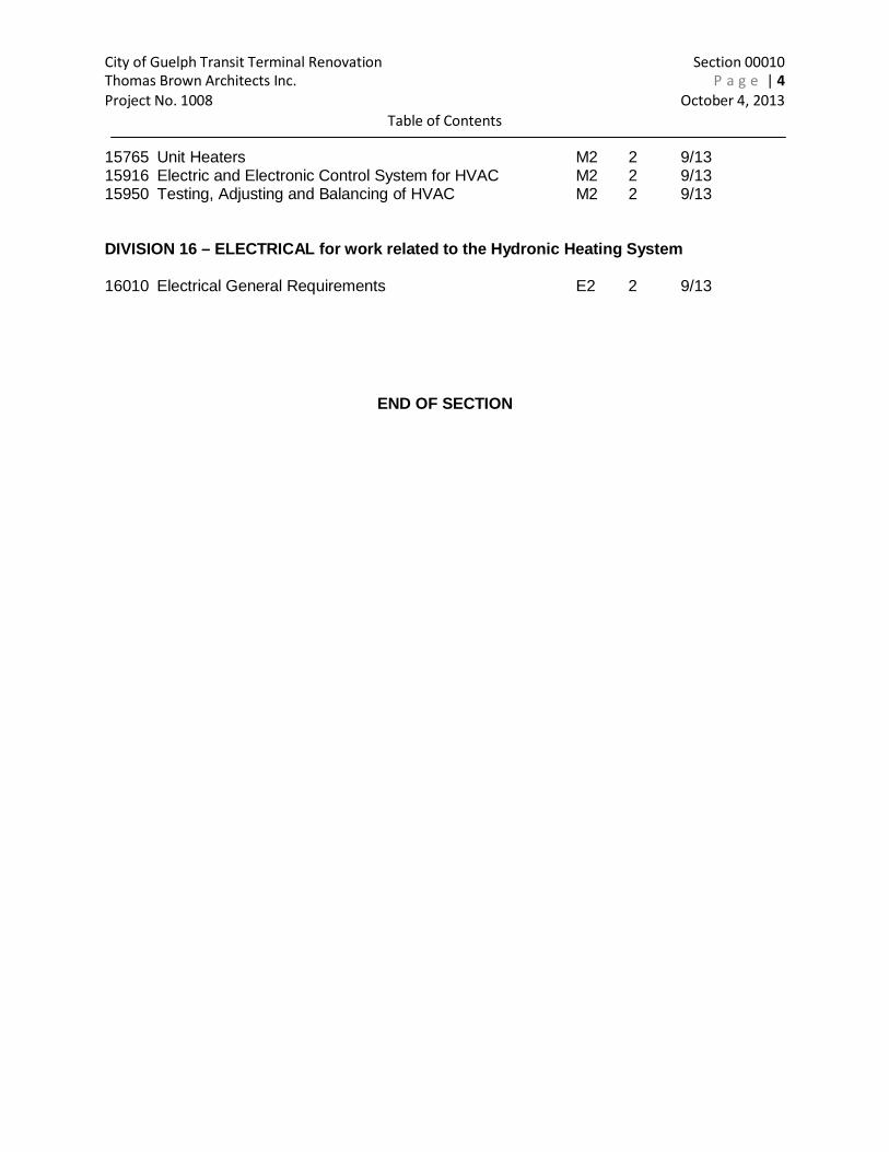
15765 Unit Heaters M2 2 9/13 15916 Electric and Electronic Control System for HVAC M2 2 9/13 15950 Testing, Adjusting and Balancing of HVAC M2 2 9/13
DIVISION 16 – ELECTRICAL for work related to the Hydronic Heating System
16010 Electrical General Requirements E2 2 9/13
END OF SECTION
City of Guelph Transit Terminal Renovation Thomas Brown Architects Inc. Project No. 1008
Section 00015 P a g e | 1
October 4, 2013 List of Drawings
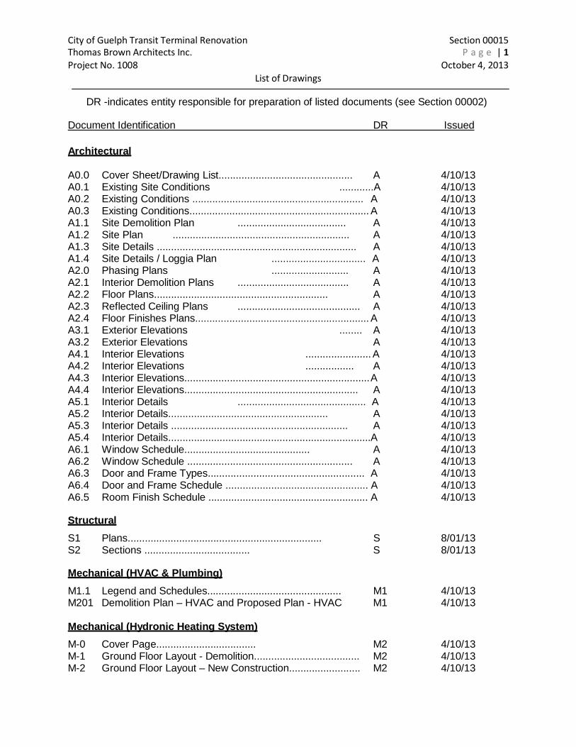
DR -indicates entity responsible for preparation of listed documents (see Section 00002)
Document Identification DR Issued
Architectural
A0.0 Cover Sheet/Drawing List............................................... A 4/10/13 A0.1 Existing Site Conditions ............A 4/10/13 A0.2 Existing Conditions ............................................................ A 4/10/13 A0.3 Existing Conditions............................................................... A 4/10/13 A1.1 Site Demolition Plan ...................................... A 4/10/13 A1.2 Site Plan .............................................................. A 4/10/13 A1.3 Site Details ...................................................................... A 4/10/13 A1.4 Site Details / Loggia Plan ................................. A 4/10/13 A2.0 Phasing Plans ........................... A 4/10/13 A2.1 Interior Demolition Plans ....................................... A 4/10/13 A2.2 Floor Plans............................................................. A 4/10/13 A2.3 Reflected Ceiling Plans ........................................... A 4/10/13 A2.4 Floor Finishes Plans............................................................. A 4/10/13 A3.1 Exterior Elevations ........ A 4/10/13 A3.2 Exterior Elevations A 4/10/13 A4.1 Interior Elevations ....................... A 4/10/13 A4.2 Interior Elevations ................. A 4/10/13 A4.3 Interior Elevations.................................................................A 4/10/13 A4.4 Interior Elevations............................................................. A 4/10/13 A5.1 Interior Details ............................................. A 4/10/13 A5.2 Interior Details........................................................ A 4/10/13 A5.3 Interior Details .............................................................. A 4/10/13 A5.4 Interior Details.......................................................................A 4/10/13 A6.1 Window Schedule............................................ A 4/10/13 A6.2 Window Schedule .......................................................... A 4/10/13 A6.3 Door and Frame Types....................................................... A 4/10/13 A6.4 Door and Frame Schedule .................................................. A 4/10/13 A6.5 Room Finish Schedule ........................................................ A 4/10/13
Structural
S1 Plans.................................................................... S 8/01/13 S2 Sections ..................................... S 8/01/13
Mechanical (HVAC & Plumbing)
M1.1 Legend and Schedules............................................... M1 4/10/13 M201 Demolition Plan – HVAC and Proposed Plan - HVAC M1 4/10/13
Mechanical (Hydronic Heating System)
M-0 Cover Page................................... M2 4/10/13 M-1 Ground Floor Layout - Demolition..................................... M2 4/10/13 M-2 Ground Floor Layout – New Construction......................... M2 4/10/13

City of Guelph Transit Terminal Renovation Thomas Brown Architects Inc. Project No. 1008
Section 00015 P a g e | 2
October 4, 2013 List of Drawings
M-3 Mech Room Layout: Demo and New Construction . M2 4/10/13 M-4 Mech Room Layout: HW Piping New Construction ........... M2 4/10/13 M-5 Schematic New Construction............................................. M2 4/10/13 M-6 Equipment Schedules M2 4/10/13 M-7 Installation Details M2 4/10/13
Electrical
E1.0 Legend and Schedules .................................................. E1 4/10/13 E1.1 Demolition Layout - Electrical ....................................... E1 4/10/13 E2.0 Lighting Layout .................................................. E1 4/10/13 E2.1 Power & Systems Layout E1 4/10/13
Electrical (Hydronic Heating System) E-1 Electrical Layout and SLD E2 4/10/13
END OF SECTION
City of Guelph Transit Terminal Renovation Thomas Brown Architects Inc. Project No. 1008
Section 00300 Page 1
February 5, 2013
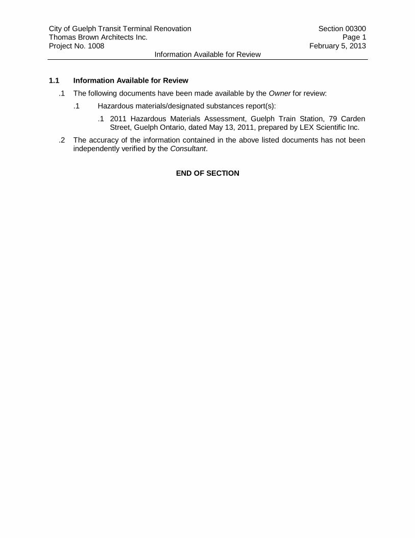
Information Available for Review 1.1 Information Available for Review
.1 The following documents have been made available by the Owner for review:
.1 Hazardous materials/designated substances report(s):
.1 2011 Hazardous Materials Assessment, Guelph Train Station, 79 Carden Street, Guelph Ontario, dated May 13, 2011, prepared by LEX Scientific Inc.
.2 The accuracy of the information contained in the above listed documents has not been independently verified by the Consultant.
END OF SECTION

City of Guelph Transit Terminal Renovation Thomas Brown Architects Inc. Project No. 1008
Work Sequence
Section 01120 Page 1
February 5, 2013
PART 1 - GENERAL
1.1 General Requirements
.1 Read and be governed by conditions of the Contract and sections of Division 1.
1.2 Sequencing Guidelines
.1 Work of this Contract is divided into distinct but interrelated Phases as indicated on the Phasing drawings A2.0.
.2 In general, the Phasing of the Work shall be based on maintaining Owner's operation uninterrupted; and maintaining continuous operation of the Owner's facilities and Owner's egress from, and access to, the buildings during construction. This refers to both internal building egress and access and external site and building egress and access.
.3 The intent of the Phasing is to maintain operation and access to all areas of the existing building by the Owner necessary to provide uninterrupted support services. The Owner's plant and facilities will remain in full operation throughout the Work. The Phasing described herein shall be used for the purpose of establishing a construction schedule and shall set a minimum level of performance for any other proposal. The Phasing indicated on the Phasing diagram shall be the governing sequence unless agreed to in writing by Owner, Consultant and Contractor.
.4 The Phasing described herein does not describe the construction process in its entirety nor does it describe all construction consequences of the Phasing. It remains the Contractor's sole responsibility to schedule all aspects of the construction within the general requirements described herein.
.5 Any suggested changes to the Phasing, Phasing procedures, and construction schedule are subject to agreement by the Owner and Consultant.
.6 Instructions issued under various sections throughout the Contract Documents with regard to conditions related to the Phasing of this Project shall be carried out in conjunction with work specified herein.
.7 The Work for each phase may include mechanical and electrical work outside the boundaries shown on the phasing drawing to complete construction and ensure proper functioning of all building systems for that area.
.8 Submit interference drawings for existing building conditions as required by the Phasing work and in accordance with Section 01330.
.9 Include for certain work to be done outside of regular working hours such as system changeovers, reconnecting existing services and other such work which would disrupt continuity of building services, building occupancy or Owner's operation. The times for performing such work shall be subject to the Owner's approval.
.10 Maintain and/or provide services and facilities (both temporary and permanent) when required during construction, to allow existing and/or occupied portions of the Owner's plant and facilities to function and operate during the Work. Refer also to Section 01351 in this regard.
City of Guelph Transit Terminal Renovation Thomas Brown Architects Inc. Project No. 1008
Work Sequence
Section 01120 Page 2
February 5, 2013
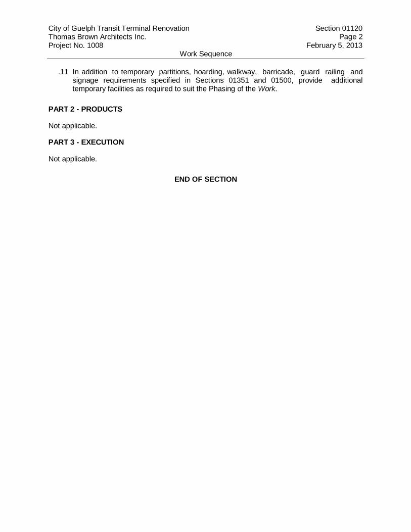
.11 In addition to temporary partitions, hoarding, walkway, barricade, guard railing and signage requirements specified in Sections 01351 and 01500, provide additional temporary facilities as required to suit the Phasing of the Work.
PART 2 - PRODUCTS
Not applicable.
PART 3 - EXECUTION
Not applicable.
END OF SECTION

City of Guelph Transit Terminal Renovation Thomas Brown Architects Inc. Project No. 1008
Section 01210 P a g e | 1
October 4, 2013 Cash Allowances
PART 1 -GENERAL 1.1 General Instructions
.1 Read and be governed by conditions of the Contract and sections of Division 1. 1.2 Section Includes
.1 Cash Allowances. 1.3 Cash Allowances
.1 The Contract Price includes the cash allowances stated below, which allowances shall be expended as the Owner directs through the Consultant.
.2 Cash allowances cover the net cost to the Contractor of services, products, construction machinery and equipment, freight, unloading, handling, storage, installation, and other authorized expenses incurred in performing the work stipulated under the cash allowances.
.3 Cash allowances do not include the Value Added Taxes payable by the Owner to the Contractor.
.4 Where cash allowances are noted for purchase only, the cost for storage at the Place of the Work and installation shall be part of the responsibility of the Contractor and is not included in the cash allowance. Storage at the Place of the Work and installation shall be in accordance with the manufacturer’s instructions.
.5 The Contract Price, and not the cash allowances, includes the Contractor’s overhead and profit in connection with such cash allowances.
.6 Where costs under a cash allowance exceed the amount of the cash allowance, the Contractor shall be compensated for any excess incurred and substantiated, plus and amount for overhead and for profit calculated in accordance with Section 01260.
.7 The Contract Price shall be adjusted by Change Order to provide for any difference between the actual cost and the cash allowance in accordance with Section 01260.
.8 The value of work performed under a cash allowance is eligible to be included in progress payments. Copies of invoices pertaining to expenditures against the cash allowance shall be appended to applications for progress payments.
.9 The Contractor is to prepare a schedule for the ordering of items called for under the cash allowances to avoid delaying the progress of the Work. Schedule to be in accordance with Section 01330.
.10 The Contractor is required to notify the Consultant in writing at such time as when 75% of the cash allowance has been expended.
.11 The total amount of the cash allowance shall be $297,000.00 and will cover the following:
.1 The cost of Independent Inspection and Testing Services.

City of Guelph Transit Terminal Renovation Thomas Brown Architects Inc. Project No. 1008
Section 01210 P a g e | 2
October 4, 2013 Cash Allowances
.2 The purchase of Door Finishing Hardware as specified under Section 08710 Door Hardware. Door Finishing Hardware to be supplied by Commercial Doors & Hardware, contact Pat Vitelli, Tel (416) 749-7231. Note that the purchasing of finishing hardware does not include Barrier-Free Door operators as specified in Section 08711, or electric strikes for hollow metal frames, or any hardware as required for Millwork items as noted on the drawings.
.3 The purchase and installation of Access Control and CCTV system. Note electrical rough-in for the Access Control and CCTV system is not included in this cash allowance.
.4 The purchase and installation of Structured Cabling. Note electrical rough-in for the Structured Cabling is not included in this cash allowance. Structured cabling to be provided by ACP Communications Technologies Inc., contact: Dave Linton, tel: 905-876-4026, [email protected]
.5 The purchase of a 4-sided illuminated clock for the Waiting Room. Note the installation and electrical rough-in for the clock is not included in this cash allowance. The clock is to be provided by Abernethy & Son Clockmakers, contact Phil Abernethy, Tel: 905-887-5327.
.6 The purchase and installation of Paging System and Speakers. Note electrical rough-in for the Paging System and Speakers is not included in this cash allowance. Paging System and Speakers to be provided by Minelec Limited, Mississauga. Contact: Andrew Young, Tel: 905-828-1520.
.7 The purchase and installation of Public Waiting Area Seating and integral charging stations, to be provided by Arconas, contact: Cordel Cover, Tel: 905- 272-0727 ext. 300.
.8 Historical interior and exterior colour analysis of existing heritage plaster and
woodwork to be undertaken by Artful Restorations, Guelph ON. Contact: Lloy Osburn, [email protected]
.9 The cost of balancing of the Hydronic Heating System. PART 2 -PRODUCTS
Not applicable.
PART 3 -EXECUTION
Not applicable.
END OF SECTION

City of Guelph Transit Terminal Renovation Thomas Brown Architects Inc. Project No. 1008
Section 01250 Page 1
February 5, 2013 Product Substitution Procedures
PART 1 - GENERAL
1.1 General Instructions
.1 Read and be governed by conditions of the Contract and sections of Division 1.
1.2 Product Substitution Procedures
.1 Base the Work of this Contract and the Contract Price upon using the new materials and Products specified.
.2 Where materials and Products are specified only by reference to standards, provide any material or Product that meets the standard.
.3 Materials and Products specified by their proprietary names or catalogue number shall form the basis for the Work. No substitutes for these may be used without the Consultant’s prior written authorization.
.4 Where a material or Product is specified by naming two or more acceptable materials or proprietary Products, Provide any one of the specified materials or Products. If compliance with a referenced standard is also specified, the material or Product selected shall meet the standard.
.5 Substitutions will be considered only when submitted in sufficient time to permit proper investigation by the Consultant, and under the conditions specified herein.
.6 Requests for substitution may only be considered if submitted within 30 days after Contract award. Requests for substitutions submitted after 30 days after Contract award may not be considered.
.7 There is no obligation on the part of the Consultant or the Owner to review or accept any proposed substitutions.
.8 Substitutions proposed may be considered only under the following conditions:
.1 If the proposed substitute materials and Products, having been brought to the attention of, and considered by, the Consultant as equivalent to those specified, will decrease the Contract Price.
.2 If the proposed substitute materials and Products, having been brought to the attention of, and considered by, the Consultant as equivalent to those specified, will not increase the Contract Price but will decrease the ContractContract Time.
.3 If a material or Product is specified together with a requirement for performance and it can be shown by the Contractor that the specified material or Product will not achieve the specified performance.
.4 When a substitution is otherwise advantageous to the Owner or to the execution of the Work as determined by the Consultant.
.9 When proposing substitutions, the Contractor shall submit with each application, the material and Product names and complete specifications substantiating compliance of the proposed substitution with the requirements of the Contract Documents, including:
.1 Product Identification.
.2 Detailed, item by item comparison between the properties and characteristics of the specified material or Product, and the proposed substitution.

City of Guelph Transit Terminal Renovation Thomas Brown Architects Inc. Project No. 1008
Section 01250 Page 2
February 5, 2013 Product Substitution Procedures
.3 Manufacturer’s name, address and telephone number.
.4 Manufacturer’s material or Product literature.
.5 Performance, technical and test data.
.6 Reference standards.
.7 Product limitations.
.8 Samples.
.9 List of existing installations.
.10 Changes to Contract Time, if any.
.11 Changes to Contract Price, if any.
.10 In making a request for substitution, the Contractor represents that:
.1 the Contractor has personally investigated the proposed Product or method, and has determined that it is equal or superior in all respects to that specified;
.2 the Contractor will provide the same guarantee for the substituted Product or method as for the Product or method specified or indicated;
.3 the Contractor will coordinate the installation of an accepted substitution into the Work, making such changes as may be required for the Work to be complete in all respects;
.4 the Contractor waives all claims for additional costs related to the substitution; and,
.5 the cost data provided by the Contractor as part of the Contractor’s substitution proposal is complete and includes all related costs including, but not limited to;
.1 coordination and supervision;
.2 installation and independent inspection and testing;
.3 any change in the cost of other affected areas; and,
.4 costs for any detailed design or related engineering work.
.11 Should the proposed substitution be accepted, either in part or in whole, the Contractor assumes full responsibility when the substitution affects any other part of the Work.
.12 Contractor to ensure that substitutions are accommodated by space allotted for the specified materials, Products, methods or processes.
.13 The cost of changes in the work of all trades necessitated by the use of proposed substitutions will not be considered or approved as a change in the Work and no increase in Contract Time will be considered or approved.
.14 Substitutions that have not been accepted through the process described in this section and are shown on shop drawings, will be rejected, whether or not the shop drawings have been reviewed.
.15 Credits arising from accepted substitutions will be credited to the Contract Price by way of a Change Order in accordance with the General Conditions, as amended.
.16 No substitutions will be permitted without prior written recommendation by the Consultant and prior written approval by the Owner.
City of Guelph Transit Terminal Renovation Thomas Brown Architects Inc. Project No. 1008
Section 01250 Page 3
February 5, 2013 Product Substitution Procedures
PART 2- PRODUCTS
Not applicable.
PART 3 - EXECUTION
Not applicable.
END OF SECTION

City of Guelph Transit Terminal Renovation Thomas Brown Architects Inc. Project No. 1008
Section 01260 Page 1
February 5, 2013 Requests for Interpretation Procedures
PART 1 - GENERAL
1.1 General Instructions
.1 Read and be governed by conditions of the Contract and sections of Division 1.
1.2 Section Includes
.1 Requests for Interpretation (RFI)
1.3 Request for Interpretation – RFI
.1 A request for interpretation (RFI) is a formal process used during the Work to obtain an interpretation of the Contract Documents pursuant to GC 2.2.7 through 2.2.10 (inclusive), as amended.
.1 An RFI shall not constitute notice of claim for a delay.
.2 Submittal procedures:
.1 RFI form:
.1 Submit RFI on form acceptable to the Consultant.
.2 Submit with RFI form necessary supporting documentation.
.2 RFI log:
.1 Maintain log of RFIs sent to and responses received from the Consultant, complete with corresponding dates.
.2 Submit updated log of RFIs with each progress draw submittal.
.3 Submit RFIs sufficiently in advance of affected parts of the Work so as not to cause delay in the performance of the Work. Costs resulting from failure to do this will not be paid by the Owner.
.4 RFIs shall be submitted only to the Consultant.
.5 RFIs shall be submitted only by Contractor. RFIs submitted by Subcontractors or Suppliers shall not be accepted.
.6 Number RFIs consecutively in one sequence in order submitted.
.7 Submit one distinct RFI per RFI form.
.8 Consultant shall review RFIs from the Contractor submitted in accordance with this section, with the following understandings:
.1 Consultant’s response shall not be considered as a Change Order or Change Directive, nor does it authorize changes in the Contract Price or Contract Time or changes in the Work.
.2 Only the Consultant shall respond to RFIs. Responses to RFIs received from entities other than the Consultant shall not be considered.
.9 Allow 10 Working Days for review of each RFI by the Consultant.
.1 Consultant’s review of RFI commences on date of receipt by the Consultant of RFI submittal and extends to date RFI returned by Consultant.
City of Guelph Transit Terminal Renovation Thomas Brown Architects Inc. Project No. 1008
Section 01260 Page 2
February 5, 2013 Requests for Interpretation Procedures
.2 When the RFI submittal is received by Consultant before noon, review period commences that day; when RFI submittal is received by Consultant after noon, review period begins on the next Working Day.
.3 If, at any time, the Contractor submits a large enough number of RFIs such that the Consultant cannot process these RFIs within 10 Working Days, the Consultant, will confer with the Contractor within 1 Working Day of receipt of such RFIs, and the Consultant and the Contractor will jointly prepare an estimate of the time necessary for processing same as well as an order of priority between the RFIs submitted. The Contractor shall accommodate such necessary time at no increase in the Contract Time and at no additional cost to the Owner.
.10 Contractor shall satisfy itself that an RFI is warranted by undertaking a thorough review of the Contract Documents to determine that the claim, dispute, or other matters in question relating to the performance of the Work or the interpretation of the Contract Documents can not be resolved by direct reference to the Contract Documents. Contractor shall describe in detail this review on the RFI form as part of the RFI submission. RFI submittals that lack such detailed review description, or where the detail provided is, in the opinion of the Consultant, insufficient, shall not be reviewed by the Consultant and shall be rejected.
PART 2 - PRODUCTS
Not applicable.
PART 3 - EXECUTION
Not applicable.
END OF SECTION

City of Guelph Transit Terminal Renovation Thomas Brown Architects Inc. Project No. 1008
Section 01310 Page 1
February 5, 2013 Coordination and Responsibility
PART 1 - GENERAL
1.1 General Instructions
.1 Read and be governed by conditions of the Contract and sections of Division 1.
1.2 Section Includes
.1 Laws, Notices, References, Standards and Regulations.
.2 Permits, Deposits and Responsibilities.
.3 Project Coordination and Responsibility.
.4 Setting Out the Work and Field Engineering.
.5 Protection and Damages of Property and Work.
.6 Fires and Smoking.
1.3 Laws, Notices, References, Standards and Regulations
.1 The building code: Ontario Regulation 350/06, including amendments, shall govern the Work.
.2 Comply with codes, by-laws, and regulations of authorities having jurisdiction over the Place of the Work. Codes and regulations form an integral part of the Contract Documents.
.3 It shall be the responsibility of the Contractor to give the required notices and comply with the laws, by-laws, ordinances, rules, regulations, codes, and orders of all authorities having jurisdiction, which are or become in force during the performance of the Work, and which relate to:
.1 the Work;
.2 the preservation of the public health;
.3 environmental protection; and/or,
.4 construction safety.
.4 It is the responsibility of the Contractor to schedule notifications and inspections required by authorities having jurisdiction such that notifications can be properly received and that inspections can be properly undertaken without causing a delay in the Work. The Contractor, at no additional cost to the Owner, shall be solely responsible for any delay in the Work caused by failure to properly schedule required notifications and inspections.
.5 The Contractor shall provide to the chief building official or the registered code agency, where a registered code agency is appointed under the Ontario Building Code Act in respect of the construction to which the notice relates, the required notices set out in Division C – Part 1 Sentence 1.3.5.1(2) and Sentence 1.3.5.2 of the Ontario Building Code, O.Reg. 350/06 as amended. The Contractor shall be present at each site inspection by an inspector or registered code agency as applicable under Division C – Part 1 Sentence 1.3.5.2 of the building code.

City of Guelph Transit Terminal Renovation Thomas Brown Architects Inc. Project No. 1008
Section 01310 Page 2
February 5, 2013 Coordination and Responsibility
.1 It is the responsibility of the Contractor to schedule notifications to the chief building official or the registered code agency such that the inspection pertaining to the notifications can be made within the time frame as required under Division C – Part 1 Sentence 1.3.5.3 of the Ontario Building Code, O.Reg. 350/06 as amended, without causing a delay in the Work. The Contractor, at no additional cost to the Owner, shall be solely responsible for any delay in the Work caused by failure to properly schedule required notifications and inspections.
.6 Without limiting the foregoing, wherever by-laws, codes, or standards are quoted in the Contract Documents, they shall be taken to mean the latest edition, including all revisions, amendments, or supplements, at the time of the Contract, unless an earlier edition is specifically quoted. If more than one by-law, code, or standard is quoted for a given Product, material or method, the latest edition of the most stringent shall govern.
.7 Wherever reference is made to “manufacturer’s instructions” or “manufacturer’s recommendations”, it shall mean printed instructions or recommendations, received directly from the referenced manufacturer. It shall also be taken to mean the latest edition of such instructions or recommendations.
.8 The Contractor shall be responsible for any delay in the progress of the Work due to a violation of any legislated requirements, and shall take the necessary steps to avoid delay in the final completion of the work, and such steps will not be considered or approved as changes in the Work.
1.4 Permits, Deposits and Responsibilities
.1 The Owner will apply for, pay for, and provide the building permit.
.2 All permits, licenses, certificates, and the like, other than the Building Permit, where required for the Work, shall be applied for, paid for, and obtained by the Contractor.
.3 The Contractor shall pay for any deposit for clean-up of mud-tracking onto roadways, and for the repair of any damage to roadways adjacent to the Place of the Work as may be required by the authorities having jurisdiction.
1.5 Project Coordination and Responsibility
.1 The Contractor shall coordinate the progress of the Work, mobilization areas of the Place of the Work, progress schedules, submittals, access to and use of the Place of the Work and facilities subject to any restrictions and conditions in accordance with the Contract Documents, reports and records, and any other processes, events, work, approvals, inspections and testing as may be required for the complete, proper and seamless execution of the Work.
.2 The Contractor shall be solely responsible for ensuring that the complete Contract Documents are distributed to, or otherwise made available for review by, all Subcontractors and Suppliers as required for the complete and proper and informed coordination and execution of the Work. Failure in this regard will be the sole responsibility of the Contractor and will not be accepted as a justification for a change in the Work and no change in the Work will be approved therefore.
City of Guelph Transit Terminal Renovation Thomas Brown Architects Inc. Project No. 1008
Section 01310 Page 3
February 5, 2013
Coordination and Responsibility
.3 The Contractor is required to employ a competent supervisor and necessary assistants who shall be in attendance at the Place of the Work at all times throughout the progress of the Work when work is being performed. The Contractor, through the supervisor, shall maintain good order and discipline among the Contractor’s employees engaged on the Work, and among any Subcontractors engaged on the Work.
.4 The responsibility as to which Subcontractor or trade provides the required materials or articles, and/or builds-in articles, rests solely with the Contractor unless otherwise explicitly stated in the Contract Documents, or directed by the Consultant.
.5 Subcontractors shall give the Contractor, in writing, instructions and information regarding their requirements as related to other parts of the Work.
.6 There shall be cooperation at all times between Subcontractors as required for the proper execution of the Work. Subcontractors shall supply others with the necessary accessories for building-in where required.
.7 There shall be cooperation at all times with any representatives of any Inspection and Testing Companies (as may be retained by the Owner) during the performance of their duties.
.8 Each Subcontractor shall report to the Consultant and the Contractor, in writing, any defects of surface or work, prepared by other Subcontractors, that adversely affects the work of their trade. Commencement of work shall imply acceptance of the prepared work otherwise.
.9 Each Subcontractor, upon completion of their work, shall remove any equipment, surplus materials, and debris resulting from their work. Each Subcontractor shall also, and at their own expense, make good any damage to the work of another Subcontractor as a result of their own work. The definition of what constitutes “damage” shall be at the sole discretion of the Consultant.
1.6 Setting Out the Work and Field Engineering
.1 The setting out of the Work shall rest solely with the Contractor, who will be responsible for same.
.2 As the work progresses, the Contractor shall be responsible for laying-out the exact locations of walls as a guide to the Subcontractors.
.3 Contractor to ensure that all pipes, service lines and ducts are concealed. Any exceptions to this should be noted on the drawings. Advise the Consultant in advance of the installation or fabrication of items where conditions are such that the installation or fabrication will be exposed.
1.7 Protection and Damages of Property and Work
.1 Contractor to ensure provision of adequate protection of materials, property, and work from damage and staining and to ensure protection of adjacent materials and work of Subcontractors to prevent damage. Any party responsible for damage to the work of another, shall make good such damage to the satisfaction of the Consultant. The cost for such making good will not be considered or approved as a change in the Work.
.2 Maintain access and surrounding areas to the Place of the Work free from soiling and debris resulting from the Work. Make good any soiling and remove any and all debris caused as a result of the Work to the satisfaction of the Owner and the Consultant.

City of Guelph Transit Terminal Renovation Thomas Brown Architects Inc. Project No. 1008
Section 01310 Page 4
February 5, 2013
Coordination and Responsibility
.3 All damage to existing sidewalks, fences, structures, curbs, services, roadways, parking and asphalt areas, grounds, sodding, trees, or other items on, or adjacent to, the Place of the Work, including mud tracks, deemed by the Consultant as being damaged due to the performance of the Work, shall be made good by the Contractor to the satisfaction of the Consultant, and such making good will not be considered or approved as a change in the Work.
.4 Abide by municipal requirements for maintaining sidewalks and roads in proper condition throughout the course of the Work. Provide a flag-person as required for the safe ingress and egress of vehicles to and from the Place of the Work.
.5 Floors and roofs shall not be over-loaded by accumulated materials. Place proper supports and braces as required to safely disseminate any temporary loading.
1.8 Fires and Smoking
.1 Fires are not permitted at the Place of the Work.
.2 Explosives shall not be used in the execution of the Work and are not permitted at the Place of the Work.
.3 Smoking shall be prohibited at the interior of the building at all times. Smoking shall also be prohibited in areas where volatile fumes or liquids are being used. Post “No Smoking” signs accordingly.
.4 Precautions shall be taken to avoid fire by spontaneous combustion. Remove combustible and non-combustible waste at regular intervals and/or when directed.
PART 2 - PRODUCTS
Not applicable.
PART 3 - EXECUTION
Not applicable.
END OF SECTION

City of Guelph Transit Terminal Renovation Thomas Brown Architects Inc. Project No. 1008
Section 01312 Page 1
February 5, 2013 Project Meetings
PART 1 - GENERAL
1.1 Administrative
.1 The Contractor shall schedule meetings as specified herein.
.1 Such scheduling shall be in consultation both with the Owner and with the Consultant.
.2 Written notice of each site meeting shall, in general, appear at the conclusion of the minutes of the preceding meeting or, else, shall be issued by the Consultant, via memorandum, no less than 24 hours prior to said meeting.
.2 The Contractor is to provide the physical space for the meetings at the Place of the Work, generally to be the site office (refer to Section 01500 Temporary Work for the complete requirements of the site office).
.3 The Consultant shall prepare agendas for meetings specified herein.
.1 Agendas shall include, as a minimum, the agenda items specified in the Contract Documents.
.4 The Consultant shall distribute written notice of each meeting specified herein, complete with meeting agenda, 4 days in advance of meeting date to the following, each of who shall be responsible for distributing such notices to other affected parties associated with them (such as, for example, Subcontractors in the case of the Contractor):
.1 The Contractor.
.2 The Owner.
.5 The Consultant shall chair and record the minutes of meetings specified herein.
.1 The Consultant shall distribute copies of minutes to the Owner, the Contractor, and all others in attendance within 3 Working Days after date of meeting.
.2 Any exceptions taken to, or clarification/correction required of, the various items recorded in the minutes, shall be furnished in writing and copied to all parties listed on the distribution list of the captioned minutes.
.6 Representatives of parties attending meetings shall be authorized to act on behalf of the parties they represent.
.7 Subcontractors and Suppliers shall not attend meetings unless authorized by the Consultant and the Owner.
.8 The Contractor shall prepare, and distribute to the Consultant and the Owner at each progress meeting date, the following:
.1 Monthly progress reports containing updated schedules, shop drawing logs, submittals and budget.
1.2 Contract Start-Up Meeting
.1 Within 10 days after award of Contract, request a meeting of parties in Contract to discuss and resolve administrative procedures and responsibilities prior to the commencement of the Work.
.2 The Owner, the Consultant, the Contractor, site superintendent(s), and inspection and testing company will be in attendance.

City of Guelph Transit Terminal Renovation Thomas Brown Architects Inc. Project No. 1008
Section 01312 Page 2
February 5, 2013 Project Meetings
.3 Agenda to include the following:
.1 Appointment of official representative of participants in the Project.
.2 Status of permits, fees and requirement of authorities having jurisdiction. Action required.
.3 Establishing a schedule for progress meetings.
.4 Requirements for Contract modification and interpretation procedures, including, but not limited to: requests for interpretation, Notices of Change, Change Orders, Supplemental Instructions, procedures, approvals required, mark-up percentages permitted, and administrative requirements.
.5 Schedule of submission of samples, colour chips, and items for Owners and/or Consultant’s consideration, Section 01330.
.6 Construction schedule and progress scheduling Section 01330.
.7 Delivery schedule of specified equipment, Section 01330.
.8 Appointment of inspection and testing agencies or firms, Section 01450.
.9 Requirements for notification for reviews. Allow a minimum of 48 hours notice to Consultant for review of the Work.
.10 Requirements for temporary facilities, signs, offices, storage sheds, utilities, fences, Section 01500.
.11 Security requirements at and for the Place of the Work, Section 01500.
.12 Record drawings, Section 01770.
.13 Maintenance manuals, Section 01770.
.14 Take-over procedures, acceptance, warranties, Section 01770.
.15 Progress claims, administrative procedures, holdbacks.
.16 Insurances, transcripts of policies.
.17 Contractor’s safety procedures.
.18 Workplace Safety and Insurance Board Certificate.
1.3 Pre-Installation Meetings
.1 During the course of the Work prior to Substantial Performance of the Work, schedule pre-installation meetings as required by the Contract Documents or as directed by the Consultant.
.2 As far as possible, pre-installation meetings shall be scheduled to take place on the same day as regularly scheduled progress meetings.
.3 Agenda to include the following:
.1 Appointment of official representatives of participants in the Project.
.2 Review of existing conditions and affected work, and testing thereof as required.
.3 Review of installation procedures and requirements.
.4 Review of environmental and site condition requirements.
.5 Schedule of the applicable portions of the Work.

City of Guelph Transit Terminal Renovation Thomas Brown Architects Inc. Project No. 1008
Section 01312 Page 3
February 5, 2013 Project Meetings
.6 Schedule of submission of samples, colour chips, and items for Consultant’s consideration.
.7 Requirements for temporary facilities, site sign, offices, storage sheds, utilities, fences, Section 01500.
.8 Requirements for notification for reviews. Allow a minimum of 48 hours notice to Consultant for review of the Work.
.9 Requirements for inspections and tests, as applicable. Schedule and undertake inspections and tests in accordance with Section 01450.
.10 Delivery schedule of specified equipment.
.11 Special safety requirements and procedures.
.4 The following shall be in attendance:
.1 Contractor.
.2 Subcontractors affected by the work for which the pre-installation meeting is being conducted.
.3 Consultant.
.4 Manufacturer’s representatives, as applicable.
.5 Inspection and testing company, as applicable.
1.4 Progress Meetings
.1 During the course of the Work prior to Substantial Performance of the Work, schedule progress meetings as directed by the Consultant.
.2 Attendees at progress meetings shall include the following:
.1 Contractor.
.2 Contractor’s site superintendent(s).
.3 Consultant.
.4 Owner.
.3 Agenda to include the following:
.1 Review, approval of proceedings of previous meeting.
.2 Review of items arising from proceedings.
.3 Review of progress of the Work since previous meeting and Contractor’s monthly progress report.
.4 Field observations, problems, conflicts.
.5 Problems that impede compliance with construction schedule.
.6 Review of off-site fabrication delivery schedules.
.7 Review material delivery dates/schedule.
.8 Corrective measures and procedures to regain construction schedule.
.9 Revisions to construction schedule.
.10 Progress, schedule, during subsequent period of the Work.

City of Guelph Transit Terminal Renovation Thomas Brown Architects Inc. Project No. 1008
Section 01312 Page 4
February 5, 2013 Project Meetings
.11 Review submittal schedules: expedite as required.
.12 Review status of submittals.
.13 Maintenance of quality standards.
.14 Pending changes and substitutions.
.15 Review of Contract modifications and interpretations, including, but not limited to: requests for interpretation and log, Notices of Change, Change Orders, Supplemental Instructions, for effect on construction schedule and on Contract Time.
.16 Review of status of as-built documents.
.17 Other business.
1.5 Pre-Takeover Meeting
.1 Prior to application for Substantial Performance of the Work, schedule a pre-takeover meeting.
.2 Agenda to include the following:
.1 Review, approval of proceedings of previous meeting.
.2 Review of items arising from proceedings.
.3 Review of procedures for Substantial Performance of the Work, completion of the Contract, and handover of the Work.
.4 Field observations, problems, conflicts.
.5 Review of outstanding Contract modifications and interpretations, including, but not limited to: requests for interpretation and log, Notices of Change, Change Orders, Supplemental Instructions, for effect on construction schedule and on Contract Time.
.6 Problems which impede Substantial Performance of the Work.
.7 Review of procedures for deficiency review. Corrective measures required.
.8 Review of arrangements for hydro, heating, and other services.
.9 Progress, schedule, during succeeding period of the Work.
.10 Review submittal requirements for warranties, manuals, and all demonstrations and documentation required for Substantial Performance of the Work.
.11 Review of keying and hardware requirements.
.12 Review of status of as-built documents and record drawings.
.13 Status of commissioning and training.
.14 Other business.
1.6 Post-Construction Meeting
.1 Prior to application for completion of Contract, schedule a post-construction meeting. Four days prior to date for meeting, Consultant shall confirm a date for meeting based on evaluation of completion requirements.
City of Guelph Transit Terminal Renovation Thomas Brown Architects Inc. Project No. 1008
Section 01312 Page 5
February 5, 2013 Project Meetings
.2 Agenda to include the following:
.1 Review, approval of proceedings of previous meeting.
.2 Confirmation that no business is arising from proceedings.
.3 Confirmation of completion of the Contract, and handover of reviewed documentation from the Consultant to the Owner.
.4 Confirmation of completion of Notices of Change, Change Orders, and Supplemental Instructions.
.5 Problems that impede Contract completion.
.6 Identify unresolved issues or potential warranty problems.
.7 Confirmation of completion of deficiencies.
.8 Corrective measures required.
.9 Confirmation of arrangements for hydro, heating and other services.
.10 Confirm submittal requirements for warranties, manuals, and demonstrations and documentation for Contract completion are in order.
.11 Review of procedures for communication during post-construction period.
.12 Handover of reviewed record documents by the Consultant to the Owner.
.13 Handover of Contract completion insurance policy transcripts by Contractor.
.14 Submission of final application for payment.
.15 Review and finalize outstanding claims, pricing, and allowance amounts.
.16 Status of commissioning and training.
.17 Demobilization and the Place of the Work restoration.
.18 Other business.
1.7 Special Meetings
.1 Owner and/or Consultant reserve the right to require special meetings which may be held on short notice and at which attendance by Contractor and representatives of affected Subcontractors and Suppliers is mandatory. Consultant shall keep detailed and accurate meeting notes and distribute copies promptly to all in attendance and those affected by agreements made at such meetings.
PART 2 - PRODUCTS
Not applicable.
PART 3 - EXECUTION
Not applicable.
END OF SECTION

City of Guelph Transit Terminal Renovation Thomas Brown Architects Inc. Project No. 1008
Section 01323 Page 1
February 5, 2013 Photographic Documentation
PART 1 - GENERAL
1.1 General
.1 Provide photographic documentation in digital format and in accordance with procedures and submission requirements specified in this section.
1.2 Digital Photographs
.1 Equipment: Provide photographs using minimum 4 megapixel digital camera.
.2 Submit the required photographs to the Consultant and to the Owner.
.3 Output: Supply date stamped maximum resolution colour photos to Consultant in JPEG format, on CD-ROM format.
.4 Number of photos required:
.1 Prior to construction: Provide necessary number of photographs, as required to document existing conditions and verify damage to adjacent streets and property which may or may not have occurred during construction: Minimum 50 photos.
.2 Each Progress draw: Provide 24 construction photographs each month to accompany each application for progress draw to document the stage of the Work from points selected by the Consultant showing as much as possible of the Work installed during the previous month.
.3 Provide minimum of 8 photographs on each meeting report and for each progress meeting.
.4 Completion: When the Work is completed, arrange to take final photographs of the Work from a minimum of 8 points of view.
PART 2 - PRODUCTS
Not applicable.
PART 3 - EXECUTION
Not applicable.
END OF SECTION

City of Guelph Transit Terminal Renovation Thomas Brown Architects Inc. Project No. 1008
Section 01330 Page 1
February 5, 2013 Submittals
PART 1 - GENERAL
1.1 General Instructions
.1 Read and be governed by conditions of the Contract and sections of Division 1.
1.2 Section Includes
.1 Certificates and Schedules.
.2 Shop Drawings and Product Data.
.3 Samples.
.4 Construction Progress Schedule.
1.3 Administrative
.1 Submit to the Consultant only all submittals listed for review. Submit with reasonable promptness and in an orderly sequence so as not to cause any delay in the Work. Failure to submit in ample time will not be considered sufficient reason for an extension of the Contract Time, and no claim for extension by reason of such default will be allowed.
.2 Submit only those submittals specifically required by the Contract Documents, or those specifically requested by the Consultant. Any submittals submitted that are not specifically required by the Contract Documents, or requested by the Consultant, will be returned to the Contractor at the Contractor’s expense without being reviewed.
.3 Work affected by a submittal shall not proceed until the review of that submittal is complete.
.4 Submittals that contain substitutions will be rejected. Substitutions are permitted only on substitution submittals as specified in Section 01250.
.5 Contractor’s review of submittals:
.1 The Contractor is to review submittals prior to submission to the Consultant. This review represents that the necessary requirements have been determined and verified, or will be, and that each submittal has been checked and coordinated with the requirements of the Work and all of the Contract Documents.
.2 Submittals shall bear stamp of Contractor and signature of a responsible official in Contractor’s organization indicating in writing that such submittals have been checked and coordinated by Contractor. Contractor’s review shall be performed by qualified personnel who have detailed understanding of those elements being reviewed and of the conditions at the Place of the Work proposed for installation.
.3 Check and sign each submittal and make notations considered necessary before submitting to Consultant for review. Where submittal is substantially and obviously in conflict with requirements of Contract Documents, reject submittal without submitting to Consultant and request resubmission. Note limited number of reviews of each submittal covered under Consultant’s services as specified below.
City of Guelph Transit Terminal Renovation Thomas Brown Architects Inc. Project No. 1008
Section 01330 Page 2
February 5, 2013 Submittals
.4 Contractor shall assume sole responsibility for any conflicts occurring in the Work that result from lack of comparison and coordination of submittals required for the Work.
.5 Notify Consultant in writing of changes made on submittals from Contract Documents. Consultant’s review of submittals shall not relieve Contractor of responsibility for changes made from Contract Documents not covered by written notification to Consultant.
.6 Submittals that clearly have not been reviewed by the Contractor, or are not stamped, signed, dated, and identified as to the specific project, will be returned without being reviewed.
.6 Consultant’s review of submittals:
.1 Review of submittals by Consultant is for the sole purpose of ascertaining conformance with the general design concepts and the general intent of the Contract Documents. This review shall not mean that Consultant approves the detail design inherent in the submittals, responsibility for which shall remain with the Contractor. Such review shall not relieve the Contractor of responsibility for errors or omissions in the submittals, or responsibility for meeting requirements of Contract Documents.
.2 Contractor shall be responsible for dimensions to be confirmed and correlated at the Place of the Work for information that pertains solely to fabrication processes or to techniques of construction and installation, and for coordination of the Work.
.3 Consultant’s review and markings on submittals do not authorize changes in the Work or the Contract Time, and will be accommodated at no additional cost to the Owner. If, in the opinion of the Contractor, the Consultant’s markings on submittals constitute a change in the Work or will effect a change in the Contract Time, then the Contractor shall so notify the Consultant in writing and request an interpretation following the procedures for requests for interpretation in accordance with Section 01260. If the Consultant finds that the Consultant’s markings on submittals do constitute a change in the Work or will effect a change in the Contract Time, then a Change Order will be prepared therefore. The time taken to process such a request for interpretation shall not, in and of itself, constitute a change in the Work nor increase the Contract Time.
.4 Submittals received but not required by the Contract Documents or requested by the Consultant will not be reviewed by the Consultant and will be marked 'NOT REVIEWED' by the Consultant and returned to the Contractor.
.7 Prepare submittals using SI (metric) units.
.8 Verify that field measurements and affected adjacent work are coordinated.
.9 The Contractor’s responsibility for errors and omissions in the submissions is not relieved by the Consultant’s review of submittals.
.10 The Contractor’s responsibility for deviations in the submission from the requirements of the Contract Documents is not relieved by the Consultant’s review of submittals.
.11 Keep one reviewed copy of each submittal in the site office.
.12 Engineered submittals:

City of Guelph Transit Terminal Renovation Thomas Brown Architects Inc. Project No. 1008
Section 01330 Page 3
February 5, 2013
Submittals
.1 Submittals for items required to be engineered shall be prepared under the direct control and supervision of a qualified professional engineer registered in the Place of the Work, and having minimum of $250,000 professional liability insurance, who shall also apply his/her professional seal and signature to submittals prepared under their direct control and supervision.
.2 A certificate of insurance indicating that the professional engineer under whose direct control and supervision the submittal has been prepared has the required professional liability insurance is to be submitted with submittals required to be sealed by professional engineer (or as otherwise indicated as engineered).
.3 Design includes life safety, sizing of supports, anchors, framing, connections, spans, and as additionally required to meet or exceed requirements of applicable codes, standards, regulations, and authorities having jurisdiction.
.4 Engineered submittals shall include design calculations, complete with references to codes and standards used in such calculations, supporting the proposed design represented by the submittal. Prepare calculations in a clear and comprehensive manner so that they can be easily reviewed. Incomplete or haphazard calculations will be rejected.
.5 The professional engineer responsible for the preparation of engineered submittals shall undertake periodic field review, including review of associated mock-ups, at locations wherever the work as described by the engineered submittal is in progress, during fabrication and installation of such work, and shall submit a field review report after each visit. Field review reports shall be submitted to the Consultant, to authorities having jurisdiction as required, and in accordance with the building code.
.6 Field reviews shall be at intervals as necessary and appropriate to the progress of the work described by the submittal to allow the engineer to be familiar with the progress and quality of such work and to determine if the work is proceeding in general conformity with the Contract Documents, including reviewed shop drawings and design calculations.
.7 Upon completion of the parts of the Work covered by the engineered submittal, the professional engineer responsible for the preparation of the engineered submittal and for undertaking the periodic field reviews described above, shall prepare and submit to the Consultant and authorities having jurisdiction, as required, a letter of general conformity for those parts of the Work, certifying that they have been Provided in accordance with the requirements both of the Contract Documents and of the authorities having jurisdiction over the Place of the Work.
.8 Costs for such field reviews and field review reports and letters of general conformity are included in the Contract Price.
1.4 Certificates and Schedules
.1 Prior to commencement of the Work, the Contractor is required to provide to the Owner a copy of the Contractor’s current Certificate of Clearance from the Workplace Safety and Insurance Board.
.2 No later than ten (10) Working Days prior to, and as a condition of, the first application for progress payment, the Contractor is required to submit the following to the Consultant::

City of Guelph Transit Terminal Renovation Thomas Brown Architects Inc. Project No. 1008
Section 01330 Page 4
February 5, 2013
Submittals
.1 A copy of the Contractor’s Certificate of Clearance from the Workplace Safety and Insurance Board provided to the Owner in accordance with paragraph 1.4.1 (above).
.2 A schedule of values for the parts of the Work in accordance with Section Payment Procedures.
.3 A construction progress schedule in accordance with paragraph 1.8 of this section (below).
1.5 Schedule of Submittals
.1 Before commencement of the Work, submit to the Consultant a detailed schedule of submittals required by the Contract Documents correlated to the construction progress schedule specified under paragraph 1.8 of this section (below).
.1 Schedule shall be accompanied by a checklist, correlated to both the schedule of submittals and the schedule of inspections and tests (specified under Section 01450), listing the following:
.1 Shop drawings.
.2 Samples.
.3 Mock-ups.
.4 Reviews, tests and inspections by:
.1 Manufacturers.
.2 Authorities having jurisdiction.
.3 Inspection and testing companies.
.5 Demonstration and training.
.2 Indicate dates for submitting, review time, resubmission time, float time, and last date for meeting construction schedule.
.3 Consultant will review submittal schedule and advise Contractor if volume and timing of submittals will permit timely review and response. Consultant may require modifications to submittals schedule in order to allow adequate time for review of submittals. Adjust submittals schedule and construction schedule as required to comply with Consultant’s needs.
.4 Make provisions in schedule for at least 10 Working Days for Consultant’s review of submittals. When submittals have to be reviewed by one or more of Consultant’s subconsultants, add 5 more Working Days for a total15 Working Day review period.
.5 If the Consultant requires resubmission of submittals, allow for an additional 10 Working Days review for each resubmission.
.6 If, at any time, the Contractor submits a large enough number of submittals such that the Consultant cannot process these submittals within 10 Working Days, the Consultant, in consultation with the Contractor within 3 Working Days of receipt of such submittal, will provide the Contractor with an estimate of the time necessary for processing same. The Contractor shall accommodate such necessary time at no increase in the Contract Time and at no additional cost to the Owner.

City of Guelph Transit Terminal Renovation Thomas Brown Architects Inc. Project No. 1008
Section 01330 Page 5
February 5, 2013
Submittals
.7 The Contractor shall periodically resubmit the submittal schedule to correspond to changes in the construction schedule. Such resubmissions shall maintain the minimum 10 Working Day period for the Consultant’s review.
1.6 Shop Drawings and Product Data
.1 The term “shop drawings” means drawings, diagrams, illustrations, schedules, performance charts, brochures, and other data which are to be provided by the Contractor to illustrate details of a portion of the Work.
.2 The Contractor shall provide all shop drawings called for in the Contract Documents or as the Consultant may reasonably request.
.3 The Contractor shall submit at least eight (8) copies of each shop drawing for review by the Consultant, for final distribution as follows (the Contractor is to ensure that additional copies are submitted in sufficient quantity for distribution to the Subcontractors affected by the work indicated therein):
.1 one (1) copy of each shop drawing for the Consultant’s records;
.2 one (1) copy of each for the records of the reviewer;
.3 one (1) copy of each for the records of the Contractor (to be kept at the site office throughout the duration of the Work); and,
.4 five (5) copies of each to return to the Contractor three (3) of which are for inclusion in the Operating and Maintenance Manuals in accordance with Section 01770.
.4 All submitted copies, other than the two (2) for the records of the Consultant and the reviewer, shall be returned to the Contractor once the review is complete.
.5 The Contractor shall submit copies of reviewed shop drawings to authorities having jurisdiction as required.
.6 Indicate materials, methods of construction and attachment or anchorage, erection diagrams, connections, explanatory notes, and all other information necessary for completion of the work.
.7 Where articles or equipment attach or connect to other articles or equipment, clearly indicate that such items have been coordinated, regardless of where in the Contract Documents the adjacent items are specified or indicated. Indicate cross references to the Contract Documents.
.8 Shop drawings shall clearly define the division of responsibility. No Products, items or equipment, or description of work, shall be indicated to be supplied, or work to be done, “By Others” or “By Purchaser.” It shall also be understood that any items, equipment, or description of the work shown on the shop drawings shall form a part of the Contract Documents unless specifically noted to the contrary. Shop drawings that do not clearly define the division of responsibility will be returned to the Contractor for same before being accepted for review by the Consultant.
.9 Shop drawings shall include:
.1 Fabrication and erection dimensions.
.2 Plans, sections, elevations, arrangements and sufficient full size details which indicate complete construction, components, methods of assembly as well as interconnections with other parts of the Work.

City of Guelph Transit Terminal Renovation Thomas Brown Architects Inc. Project No. 1008
Section 01330 Page 6
February 5, 2013
Submittals
.3 Design calculations prepared by professional engineer, as required, substantiating sizes for members and connections based on design loads.
.4 Clear definition of the division of responsibility for the work described thereon. No Products, items or equipment, or description of work, shall be indicated to be supplied, or work to be done, “By Others” or “By Purchaser”. Shop drawings marked with either of these phrases will be rejected without having been reviewed by the Consultant.
.5 Location and type of exposed anchors, attachments and locations and types of fasteners, including concealed reinforcements to accept mounted fasteners.
.6 Adhesives, joinery methods and bonding agents.
.7 Kinds and grades of materials, their characteristics relative to their purpose, detailed description of finishes and other fabrication information.
.8 Configurations, types and sizes required; identify each unit type on drawing and on Product.
.9 Descriptive names of equipment and mechanical and electrical characteristics when applicable.
.10 Data verifying that superimposed loads will not affect function, appearance and safety or work shown on shop drawings, as well as other interconnected work.
.11 Assumed design loadings, dimensions of elements and material specifications for load-bearing members.
.12 Proposed chases, sleeves, cuts and holes in structural members.
.13 Wall thicknesses of metals.
.14 Location and types of welds. For structural welds use AWS symbols and clearly show net weld lengths and sizes.
.15 Materials, gauges, and sizes being supplied including connections, attachments, reinforcement, anchorage and locations of exposed fastenings.
.16 Installation instructions and details for Products to be installed by separate Subcontractors, including function of each part.
.17 A list of Products covered by, or included on, the shop drawing. List of Products shall be complete and show manufacturer's name, Product name, generic description, standard certification where specified, manufacturer's complete installation data and precautions against wrong installation, operation and maintenance.
.18 Refer to individual sections of the specifications for more particular requirements for shop drawings.
.10 Compatibility statement: Include with each shop drawing a statement that each Product and material indicated on the shop drawing is compatible with each other Product and material with which it comes into contact.
.11 The Consultant will require a maximum of ten (10) Working Days from receipt of shop drawings for processing of same. The Contractor shall make allowances in the scheduling of the Work for this period of time for each submission and shall, also, make allowances in the schedule for the following potentialities:

City of Guelph Transit Terminal Renovation Thomas Brown Architects Inc. Project No. 1008
Section 01330 Page 7
February 5, 2013
Submittals
.1 If, upon review, adjustments are made on the shop drawings by the Consultant and they are returned to the Contractor marked “Revise and Resubmit,” the shop drawing shall be revised as required and clean copies resubmitted to the Consultant for an additional review. The Consultant shall, for each resubmission, require a maximum of ten (10) Working Days from receipt for processing of shop drawings.
.2 No claim for an increase in the ContractContract Time or claim for a change in the Work shall be considered or approved as a result of any of the following:
.1 The time taken for processing of shop drawings by the Consultant unless longer than ten (10) Working Days after receipt of same.
.2 The time taken by the Contractor for revision and resubmission of shop drawings.
.3 Any adjustments made on the shop drawings by the Consultant that are consistent with the intent of the Contract Documents.
.12 Make the changes in the shop drawings as the Consultant may require, consistent with the Contract Documents. When resubmitting, notify the Consultant in writing of any revisions made other than those requested.
.13 If, upon review by the Consultant, no errors or omissions are discovered or if only minor corrections are made, all submitted copies of the shop drawing (except the two retained by the Consultant) will be returned to the Contractor marked as “Reviewed” or “Reviewed as Noted”, and fabrication or installation of the work may proceed.
.14 Submit at least eight (8) copies of product data sheets or brochures for requirements requested in the Contract Documents and as the Consultant may reasonably request where shop drawings will not be prepared due to a standardized manufacture of a Product.
1.7 Samples
.1 Submit for review samples as requested in the Contract Documents. Label samples as to origin and intended use in the Work.
.2 Unless otherwise directed by the Consultant, deliver samples prepaid to the site office and notify Consultant in writing of the availability of sample for review.
.3 Notify the Consultant in writing at the time of submission of any deviations in the samples from the requirements of the Contract Documents.
1.8 Construction Progress Schedule
.1 Submit a construction progress schedule on which the following shall be indicated in addition to the schedule for the various items of work:
.1 Dates for the submittal of each shop drawing and product data sheet required by the Contract Documents;
.2 Dates for the submittal of samples required by the Contract Documents;
.3 Dates for the performance of inspections and tests required by the Contract Documents;

City of Guelph Transit Terminal Renovation Thomas Brown Architects Inc. Project No. 1008
Section 01330 Page 8
February 5, 2013
Submittals
.4 Dates for the construction and review of mock-ups required by the Contract Documents; and,
.5 Dates for expenditures against the cash allowances identified in Section 01210.
.2 Prepare schedule in the form of an horizontal bar chart.
.3 Provide a separate bar for each trade or operation.
.4 Provide an horizontal time scale identifying the first work day of each week.
.5 The format for the listings shall be the chronological order of the start of each item of work.
.6 The identification of the listings shall be by a brief systems description.
.7 Submission:
.1 Submit initial schedules within ten (10) Working Days after award of Contract, but before commencing the Work.
.2 Submit two (2) copies to the Consultant, who shall retain one (1) copy.
.3 The Consultant will review the submitted schedules and return a reviewed copy to the Contractor within ten (10) Working Days after receipt.
.4 The Contractor shall resubmit a finalized copy of the required schedules within five (5) Working Days after return of reviewed copy.
.5 The Contractor shall submit a revised construction progress schedule with each application for progress payment.
.8 Distribute copies of the revised schedule to:
.1 The site office.
.2 Subcontractors.
.3 All concerned parties.
.9 Instruct Subcontractors, Suppliers, and manufacturers, to report to the Contractor in writing within ten (10) days, any problems anticipated by the timetable shown in the schedule. The Contractor shall convey this information to the Consultant if necessary.
PART 2 - PRODUCTS
Not applicable.
PART 3 - EXECUTION
Not applicable.
END OF SECTION

City of Guelph Transit Terminal Renovation Thomas Brown Architects Inc. Project No. 1008
Special Procedures for Work in Occupied Buildings
Section 01351 Page 1
February 5, 2013
PART 1 - GENERAL
1.1 General Procedures
.1 For the purposes of this section:
.1 The words “worker” or “workers” shall mean the Contractor, Contractor's staff or employees, Subcontractors, Subcontractor's staff or employees, Suppliers, Supplier's staff or employees, or anyone engaged for the Work, directly or indirectly, by the Contractor, unless otherwise indicated.
.2 The words “make good” or “making good” shall mean that, when a finish or material has been altered, the material or finish shall be repaired or replaced, and refinished to match existing quality and appearance to acceptance of Consultant, and that repaired or replaced and refinished Work shall not be discernible from existing materials or finishes when judged by the Consultant from a viewing distance of 1830 mm (6'), and that such work is included in the Contract Price.
.2 Operational limitations:
.1 The existing building will remain in full use and occupancy throughout the Work, except for such parts of the building that have been vacated for the Work.
.2 Contractor's use of the Place of the Work is limited to permit regular use of existing Owner's facilities to continue with the least amount of interference and disruptions possible.
.3 In consultation with, and to acceptance of, the Consultant in the presence of the Owner, designate an entrance and a circulation route that workers shall use and that shall not be used by Owner's staff, building occupants, or the public.
.4 No storage of equipment or material is permitted on the rail platforms.
.5 If work is deemed necessary near the track, the Contractor must undertake a safety review with VIA Rail.
.6 Wearing of red or green helmets or clothing is not permitted near the rail tracks.
.3 Dust tight enclosure and partition doors and entrance doors to the Place of the Work shall remain closed.
.4 Areas of the existing building adjacent to the Place of the Work or areas affected by the Work, including circulation and access routes, shall be maintained in a clean state equivalent to the level of cleanliness maintained in the existing building, and as follows:
.1 Clean and vacuum the Place of the Work and areas surrounding the Place of the Work daily or more frequently as required.
.2 Wet mop floor areas in vicinity of access doors to the Place of the Work daily, or more frequently as required.
.3 Final cleaning shall be in accordance with Section 01770.
.5 Waste protection and removal:
.1 Waste management and disposal shall be in accordance with Section 01500 as supplemented herein.

City of Guelph Transit Terminal Renovation Thomas Brown Architects Inc. Project No. 1008
Special Procedures for Work in Occupied Buildings
Section 01351 Page 2
February 5, 2013
.2 Transport waste in containers with tightly fitting lids or cover waste with a wet sheet.
.3 Remove waste as it is created. Debris shall be contained and covered if it can not be removed immediately.
.4 Do not transport waste through occupied areas of existing building.
.5 Remove waste at the end of each Working Day through construction access routes.
.6 Document condition of the existing building in areas immediately adjacent to the Place of the Work by means of construction photographs in accordance with Section 01323.
1.2 Security
.1 Provide security for the Place of the Work by methods compatible with the security system for the existing building as directed by the Owner.
.2 Contractor shall coordinate the Work carefully with the Consultant in the presence of the Owner in order to ensure no disruption to the existing building’s security system.
.3 Where existing building’s security system is breached due to Contractor's negligence, be responsible for any damage or theft of property, regardless if area where damage or theft occurred is under Contractor's control or not.
1.3 Use of Existing Facilities
.1 Restrict access, parking, material deliveries, execution of work, operations and procedures to designated locations and times and do not deviate from designated procedures without prior acceptance by the Consultant in the presence of the Owner.
.2 Periodically review proposed construction operations with the Consultant in the presence of the Owner and cooperate as required to ensure that Owner's interests and requirements are not unduly compromised with regard to the normal operation and function of occupied areas on the existing building.
.3 Traffic through occupied areas of the existing building shall be kept to a minimum. Travel within occupied areas of the existing building shall be via the most direct route.
.4 Noise, dust and debris, and odours shall be minimized to ensure building occupants in adjacent areas are disturbed as little as possible. Corrective action to cease or limit disagreeable annoyances to building occupants shall be implemented immediately upon notification by the Consultant or the Owner.
.5 Use of existing containers and garbage bins shall not be permitted.
.6 Use of existing sanitary facilities shall not be permitted. Provide temporary sanitary facilities in accordance with Section 01500.
1.4 Parking
.1 Parking for workers shall not be made available by the Owner.
.2 Limited free public street parking and permits for public lot parking are available.

City of Guelph Transit Terminal Renovation Thomas Brown Architects Inc. Project No. 1008
Special Procedures for Work in Occupied Buildings
Section 01351 Page 3
February 5, 2013
.3 Throughout the Work, ensure that there is no interference with the operation of the existing premises, and that the existing parking areas and road system remain free and clear of obstructions.
.4 Illegally parked vehicles will be ticketed and/or towed at vehicle owner’s expense, and at no additional cost to the Owner.
1.5 Existing Services
.1 Service interruptions:
.1 Connection or disconnection of services that will interfere with the operation of the Owner's facilities shall not be done without the prior written acceptance of the Consultant in the presence of the Owner and during the times designated by the Owner. Premium charges associated with such work shall be included in the Contract Price.
.2 Provide at least 10 Working Days prior written notice to the Consultant and the Owner of requirement or intention to interrupt services, and obtain written permission of the Consultant in the presence of the Owner prior to commencing such interruption.
.3 In no instance shall interruptions affect the entire existing building.
.4 As far as possible, coordinate interruptions with the Owner's regular maintenance of building services and systems.
.5 Areas adversely affected by changes in air flows outside the construction areas as a result of a required shut-down of portions of the existing HVAC system within the construction areas are to be re-balanced to comfortable levels as advised by the Consultant.
.2 Should existing services be interrupted in breach of the above, Make Good immediately and provide protection against further such disruptions. Costs resulting from such interruptions and for making good shall be the responsibility of the Contractor at no additional cost to the Owner.
1.6 Protection of the Existing Building
.1 Protection requirements shall be in accordance with Section 01500, as supplemented herein.
.2 Keep Place of the Work safe and secure, denying access to unauthorized personnel.
.3 Protect existing work from damage. Make Good any damage caused. The onus is on the Contractor to substantiate that damage existed prior to commencement of the Work.
.4 Do not overload the existing structure due to the Work.
.5 Take special measures to protect existing work from damage when moving heavy loads or equipment. Protect areas used as passageways or through which materials are moved. Use resilient tired conveyances only when moving materials and equipment inside building. Provide coverings as required to protect existing work from damage.
.6 Separate exterior access, work and storage areas from Owner occupied existing areas, with fencing and hoarding as specified in Section 01570. Rearrange fencing/hoarding as Work progresses to suit extent and configuration of the Work.

City of Guelph Transit Terminal Renovation Thomas Brown Architects Inc. Project No. 1008
Special Procedures for Work in Occupied Buildings
Section 01351 Page 4
February 5, 2013
.7 Provide guards, barricades and other temporary protection to prevent injury to persons.
.8 Protect existing building components and contents from damage by weather, when executing Work affecting integrity of the building envelope. Provide temporary insulated and air tight weatherproof closures to protect openings made in existing building envelope. Make Good existing building components and contents damaged by weather resulting from inadequate temporary protection measures.
.9 Provide temporary fire resistant closures at existing areas openings exposed to construction areas for the Work to maintain fire and life safety of existing building.
.10 Protection of existing occupied areas:
.1 Existing exterior walls with windows of plain glazing, when exposed to the Work, shall be protected with 16 mm (5/8”) gypsum board for interior surfaces and 9.5 mm (3/8”) exterior grade plywood for exterior surfaces, mounted on suitable framing. Direct attachment to exterior masonry walls is prohibited.
.1 Plywood: in accordance with Section 06100.
.2 Metal framing: in accordance with Section 09100.
.3 Gypsum board: in accordance with Section 09290.
.2 Maintain such protection throughout the Work.
.3 Other openings in the existing exterior walls, such as doors and louvres, shall be similarly protected or replaced with doors of solid core wood or hollow steel construction.
1.7 Emergency and Fire Protection
.1 Provide and maintain ready access to fire protection equipment, in accordance with Section 01500.
.2 Provide temporary fire resistant closures at existing building openings exposed to construction areas.
.3 Contractor shall coordinate the work carefully with the Owner in order to ensure no disruption to the existing fire detection and annunciation systems. Failure to provide such coordination shall result in the Contractor incurring the responsibilities and expenses associated with disruption to the existing fire detection and annunciation systems at no additional cost to the Owner.
.1 Provide fire watch when existing fire detection and annunciation systems are not operational or on bypass.
.2 Whenever a changeover time occurs, which is an outage time of at least a portion of the fire alarm system, the municipal fire department shall be notified of the temporary shutdown and alternative measures shall be devised.
.4 Contractor shall coordinate the work carefully with the Consultant in the presence of the Owner in order to prevent unapproved disruptions to the existing sprinkler system, standpipe system, or other fire protection systems.
.1 Where temporary shut-down is necessitated, such shut down shall be in accordance with the requirements of authorities having jurisdiction and the building code.

City of Guelph Transit Terminal Renovation Thomas Brown Architects Inc. Project No. 1008
Special Procedures for Work in Occupied Buildings
Section 01351 Page 5
February 5, 2013
.5 Obtain ‘Hot Work Permit’ from Owner prior to hot work operation, which may cause the building's fire alarm system to be activated or create an unwarranted fire risk condition. The prevention of fires and false fire alarms caused by hot work operations is the primary goal of this procedure. Gas hoses, backflow preventers, fire resistive tarpaulins, curtains and other cutting and welding equipment must be in good repair before the permit is issued.
.1 ‘Hot Work’ is defined as work using open flames or sources of heat that could ignite materials in the work area.
.6 Fire separations:
.1 Maintain the integrity of fire separations, fire protection systems , and fire rated assemblies.
.2 Make Good fire separations, fire protection, and fire rated assemblies compromised as a result of the Work.
.7 Temporary fire separations:
.1 Provide temporary fire separations between existing occupied floor areas and new areas under construction.
.2 Construct temporary fire separations out of steel studs and gypsum board to provide a construction equivalent to a minimum of 1 hour fire resistance rating, unless otherwise indicated.
.1 Firestopping and smoke sealant: in accordance with Section 07840.
.2 Gypsum board: in accordance with Section 09290.
.3 Steel studs: in accordance with Section 09100.
.3 Where access is required, the doorway shall be protected by a door of solid core wood or hollow steel construction.
.4 Finish hardware equivalent to a minimum of 1 hour fire resistance rating, unless otherwise indicated.
.8 Maintaining existing building exit facilities:
.1 Maintain exit facilities serving the existing building.
.2 Where an exit is blocked-off or deleted as a result of the Work, an alternative exit shall be Provided that is acceptable to the Consultant, the Owner, and authorities having jurisdiction.
.3 Where it is necessary for access to be gained to an exit through the Place of the Work, the access shall be clearly defined and protected so that it is separated from construction areas by a smoke tight fire separation equivalent to a minimum of 1 hour fire resistance rating, unless otherwise indicated.
.9 Fire department access:
.1 Do not obstruct access route designated for fire department equipment.
.2 If it is necessary that existing access routes be obstructed or deleted, alternative access routes acceptable to the fire department and in accordance with the requirements of the Contract Documents and authorities having jurisdiction shall be Provided prior to commencement of work that will obstruct or delete existing access.

City of Guelph Transit Terminal Renovation Thomas Brown Architects Inc. Project No. 1008
Special Procedures for Work in Occupied Buildings
Section 01351 Page 6
February 5, 2013
.10 Combustible materials:
.1 Stockpiling of combustible materials adjacent to or inside the existing building shall not be acceptable.
.11 Temporary protection of openings in fire separations:
.1 Openings in existing floor assemblies and vertical fire rated assemblies required by the Work, shall be temporarily protected with materials as required to maintain continuity of the required fire resistance rating for existing fire rated assembly.
PART 2 - PRODUCTS
Not applicable.
PART 3 - EXECUTION
Not applicable.
END OF SECTION

City of Guelph Transit Terminal Renovation Thomas Brown Architects Inc. Project No. 1008
Section 01352 Page 1
February 5, 2013 Qualifications of Restoration Professionals and Subcontractors
PART 1 - GENERAL
1.1 General Instructions
.1 Read and be governed by conditions of the Contract and sections of Division 1.
1.2 Summary
.1 The Guelph VIA Rail Station, constructed in 1911, is a contributing building to the City’s Historic District and is a designated heritage railway station under the federal Heritage Railway Stations Protection Act (HRSPA). The City intends to have the building designated in accordance with the Ontario Heritage Act and establish a Heritage Conservation Easement with the Ontario Heritage Trust. The interior and exterior features and materials are significant character defining elements and are to be protected in place during construction and not disturbed until restored by qualified restoration professionals. It shall be the sole responsibility of the General Contractor to protect the historic building at all times.
.2 The Subcontractors who will be responsible for the execution of the restoration of the historic materials and surfaces on the interior and exterior of the Guelph VIA Rail Station, including but not limited to the following:
.1 Historic plaster repair – plaster coves and ceiling in waiting room
.2 Historic stone cleaning – exterior stone
.3 Historic clay masonry cleaning – exterior brick
.4 Historic mosaic tile restoration and re-creation – entry porch/waiting room.
.5 Historic wood window and door restoration and re-construction.
.6 Historic interior wood trim and exterior wood soffit restoration
.7 Historic paint colour analysis – waiting room woodwork and exterior woodwork.
.8 Must demonstrate a proven capability to execute the Work.
.3 Acceptable evidence of such qualifications will include, at a minimum, all of the following:
.1 A proven understanding of local, Provincial and Federal Heritage Restoration Guidelines with a minimum of five (5) years experience with projects of similar size and scope as that of the Guelph VIA Rail Station renovation, provide in writing.
.2 Presentation of three (3) similar projects that have been certified by the Ontario Heritage Trust as having met the Standards, provide in writing.
.3 Names and resumes of the project foreman and crewmembers to be assigned to the project listing projects successfully completed and contact names and phone numbers for the Owners of the projects. The foreman and crewmembers proposed for the project shall not be changed without written acceptance and agreement of the Owner to the change.
.4 Upon direction of the Consultant and prior to the approval of the proposed subcontractor, the proposed subcontractor will execute a mock-up of finished work with their proposed crew for the Consultant’s approval.

City of Guelph Transit Terminal Renovation Thomas Brown Architects Inc. Project No. 1008
Section 01352 Page 2
February 5, 2013 Qualifications of Restoration Professionals and Subcontractors
.5 With each bid the Subcontractor shall provide a written description of his onsite procedures and methods demonstration an understanding of both the requirements of the Project Specifications and the sensitivities involved in working around and with delicate historic material to be conserved and restored.
PART 2- PRODUCTS
Not applicable.
PART 3 - EXECUTION
Not applicable.
END OF SECTION
City of Guelph Transit Terminal Renovation Thomas Brown Architects Inc. Project No. 1008
Section 01353 Page 1
February 5, 2013 Special Procedures for Historic Treatment
PART 1 - GENERAL
1.1 General Instructions
.1 Read and be governed by conditions of the Contract and sections of Division 1.
1.2 Summary
.1 Furnish all labor, materials, tools, equipment and services necessary for and reasonably incidental to complete the special procedures for historic treatment work as shown on the drawings or specified, including, but not limited to the following:
.1 Protection of existing windows and frames.
.2 Removal of existing wood window sashes where required for restoration.
.3 Installation of temporary plywood and miscellaneous temporary protection at exterior openings in order to maintain a weather proof opening until restored window and door replacement.
.4 Determination of original finish and colour of interior window, door and ceiling beams, trims, sashes, muntins and casings.
.5 Stripping existing sashes of lead-base paint or other finishes and restore to original or scheduled finish. Removal and re-installation or replacement of glazing. Repairs to sashes and frames, replacement of missing and broken parts and hardware, and restoration to sound and operable condition.
.6 Reconstruction of one (1) new accessible entry door and sidelights to match details of existing.
.7 Renovation of two (2) entrance door assemblies to provide accessible doors.
.8 Construction of one (1) double entrance door to match historic detailing.
.9 Restoration of one (1) entrance door.
.10 Restoration of existing door and window transoms.
.11 Removal of all plywood and miscellaneous protection at exterior window openings prior to reinstallation of restored windows and doors.
.12 Restoration of existing interior wall, door, window and ceiling wood trims and reconstruction of new trims to match existing where missing.
.13 Caulking and weatherstripping of all restored installations for air and watertight condition.
.14 Furnishing and installation of hardware to restored doors.
.15 Restoration of existing mosaic floor tile in extent of Waiting Room.
.16 Protection of existing mosaic floor tile at entry porch with vapour barrier and non- crushable insulation, and encapsulation below a new concrete slab. Re-creation of existing mosaic tile pattern using new materials to match existing.
.17 Removal of perimeter board soffit and replacement with new tongue and groove wood soffit to match original tongue and groove wood soffit.
.18 Cleaning of all exterior masonry and stone to remove all vegetation, graffiti and efflorescence.

City of Guelph Transit Terminal Renovation Thomas Brown Architects Inc. Project No. 1008
Section 01353 Page 2
February 5, 2013 Special Procedures for Historic Treatment
1.3 Submittals
.1 Historic Treatment Program: Submit a written plan for each phase or process including protection of surrounding materials during operations. Describe in detail materials, methods, and equipment to be used in each phase of work.
.2 If alternative methods and materials to those indicated are proposed for any phase of work, provide a written description including evidence of successful use on other, com- parable projects, and program of testing to demonstrate effectiveness for use on this Project.
.3 For historic treatment specialists and supervisory personnel. Include list of completed projects with the scope of work and budget for each.
.4 As-Built Documents shall include modifications to the manufacturer’s written instructions and procedures, as documents as the Work progresses.
1.4 Quality Assurance
.1 Historic Treatment Specialist Qualifications: Refer to Section 01352.
.2 Historic Treatment Pre-Construction Conference: Conduct conference at Project site to record procedures established as a result of the review and distribute to affected parties.
1.5 Storage and Protection of Historic Materials
.1 Removed and Salvaged Historic Materials:
.1 Contractor to provide secure storage as require for the Work.
.2 Protect items from damage during transport and storage.
.3 Do not dispose of items removed from existing construction without prior written consent of Owner and the Ontario Heritage Trust.
.2 Removed and Reinstalled Historic materials:
.1 Clean and repair historic items to functional condition adequate for intended re- use.
.2 Pack or crate items after cleaning and repairing. Identify contents of containers.
.3 Protect items from damage during transport and storage.
.4 Reinstall items in locations indicated. Comply with installation requirements for new materials and equipment. Provide connections, supports, and miscellane- ous materials necessary to make item functional for use indicated.
.3 Protect construction indicated to remain against damage and soiling during historic treatment. When permitted by the Consultant, items may be removed to a suitable protected storage location during historic treatment and cleaned and reinstalled in their original locations after historic treatment operations are complete.
.4 When removed from their existing location, store historic materials within a weather-tight enclosure where they are protected from wetting by rain, snow, or ground water, and temperature variations. Secure stored materials to protect from theft.
.5 Identify removed items with an inconspicuous mark indicating their original location.

City of Guelph Transit Terminal Renovation Thomas Brown Architects Inc. Project No. 1008
Section 01353 Page 3
February 5, 2013 Special Procedures for Historic Treatment
1.6 Project Site Conditions
.1 Exterior cleaning and repairing:
.1 Proceed with the work only when forecasted weather conditions are favorable.
.1 Do not attempt repairs during rainy or foggy weather. Do not apply primer, paint, putty, or epoxy when the relative humidity is above 80%. Do not remove exterior elements of structures when rain is forecast or in progress.
.2 Do not perform exterior wet work when the air temperature is below 5 o C.
.3 Do not begin cleaning, patching, or repairing when there is any likelihood of frost or freezing.
.4 Do not begin cleaning when either the air or the surface temperature is below 7 o F unless approved means are provided for maintaining a 7 o C temperature of the air and materials during, and for 48 hours subsequent to cleaning.
.2 Perform cleaning and rinsing of the exterior only during daylight hours.
.2 Properties immediately adjacent to historic treatment area may be occupied during the Work. Conduct historic treatment so that operations will not be disrupted. Provide not less than 72 hours’ notice to adjacent property owner of act ivies that will affect their operations.
PART 2- PRODUCTS
Not applicable.
PART 3 – EXECUTION
3.1 Protection
.1 General:
.1 Comply with manufacturer’s written instructions for precautions and effects of products and procedures on adjacent building materials, components, and vegetation.
.2 Ensure that supervisory personnel are present when work begins and during its pro-gress.
.3 Temporary Protection of Historic Materials during Construction.
.1 Protect existing materials during installation of temporary protections and con-struction. Do not deface or remove existing materials.
.2 Attachment of temporary protection to existing construction shall be approved by the Architect prior to installation.
.4 Prior to the start of work or any cleaning operations, test existing drains and other wa-ter removal systems to ensure that drains and systems are functioning properly. Notify Architect immediately of drains or systems that are stopped or blocked. Do not begin Work of this Section until the drains are in working order.

City of Guelph Transit Terminal Renovation Thomas Brown Architects Inc. Project No. 1008
Section 01353 Page 4
February 5, 2013 Special Procedures for Historic Treatment
.1 Provide a method to prevent solids including stone or mortar residue from entering the drains or drain lines. Cleanout drains and drain lines that become blocked or filled by sand or any other solids because of work performed under this Contract.
.2 Protect storm drains from pollutants. Block drains or filter out sediments, allowing only clean water to pass.
3.2 Protection During Application of Chemicals – General
.1 Protect persons, motor vehicles, surrounding surfaces of building being restored, building site, plants, and surrounding buildings from harm or damage resulting from applications of chemical cleaners and paint removers.
.2 Cover adjacent surfaces with materials that are proven to resist chemical cleaners se- lected for Project unless chemicals being used will not damage adjacent surfaces. Use covering materials that contain only waterproof, UV-resistant adhesives. Apply masking agents to comply with manufacturer’s written instructions. Do not apply liquid masking agent to painted or porous surfaces. When no longer needed, promptly re-move masking to prevent adhesive staining.
.3 Do not clean surfaces during winds of sufficient force to spread cleaning solutions to unprotected surfaces.
.4 Neutralize and collect alkaline and acid wastes and dispose of off Owner’s property.
.5 Dispose of runoff from chemical operations by legal means and in a manner that pre- vents soil erosion, undermining of paving and foundations, damage to landscaping,and water penetration into building interiors.
3.3 Protection During Use of Heat-Generating Equipment
.1 Comply with the following procedures while performing work with heat-generating equipment, including welding, cutting, soldering, brazing, paint removal with heat, and other operations where open flames or implements utilizing heat are used:
.1 Obtain Owner’s approval for operations involving use of open-flame or welding equipment.
.1 Notification shall be given for each occurrence and location of work with heat- generating equipment.
.2 As far as practical, use heat-generating equipment in shop areas or outside the building
.3 Before work with heat-generating equipment commences, furnish personnel to serve as a fire watch (or watches) for location (s) where work is to be performed.
.4 Do not perform work with heat-generating equipment in or near rooms or in areas where flammable liquids or explosive vapors are present to thought to be present. Use a combustible gas indicator test to ensure that the area is safe.
.5 Remove and keep the area free of combustibles, including, rubbish, paper, waste, etc., within area of operations.
.1 If combustible materials cannot be removed, provide fireproof blankets to cover such materials.

City of Guelph Transit Terminal Renovation Thomas Brown Architects Inc. Project No. 1008
Section 01353 Page 5
February 5, 2013
Special Procedures for Historic Treatment
.6 Where possible, furnish and use baffles of metal or gypsum board to prevent the spraying of sparks or hot slag into surrounding combustible material.
.7 Prevent the extension of sparks and particles of hot metal through open windows, doors, holes, and cracks in floors, walls, ceilings roofs, and other openings.
.8 Inspect each location of the day’s work not sooner than 30 minutes after completion of operations to detect hidden or smoldering fires and to ensure that proper housekeeping is maintained.
3.4 Historic Treatment Procedures
.1 The principal aim of preservation work is to halt the process of deterioration and stabilize the item’s condition, unless otherwise indicated. Repair is required where specifically indicated. The following procedures shall be followed
.1 Retain as much existing material as possible; repair and consolidate rather than replace.
.2 Use additional material or structure to reinforce, strengthen, prop, tie, and sup- port existing materials or structure.
.3 Use reversible processes wherever possible.
.4 Use traditional replacement materials and techniques. New work shall be distinguishable to the trained eye, on close inspection, from old work.
.5 Record the work before the procedure with pre-construction photos and during the work with periodic construction photos.
.2 Prohibit smoking by personnel performing work on or near historic structures.
.3 Obtain the Consultant’s review and written approval in the form of a Change Order or Supplemental Instruction before making changes or additions to construction or removing historic materials.
.4 Notify the Consultant of visible changes in the integrity of material or components whether due to environmental causes including biological attack, UV degradation, freezing, or thawing; or due to structural defects including cracks, movement, or distortion.
.5 Do not proceed with the work in question until directed by the Consultant.
.6 Where missing features are indicated to be repaired or replaced, provide featureswhose designs are based on accurate duplications rather than on conjectural designs, subject to the approval of the Consultant.
.7 Where Work requires existing features to be removed, cleaned, and reused, perform these operations without damage to the materials itself, to adjacent materials, or to the substrate.
.8 Identify new or replacement materials and features with inconspicuous, permanent marks to distinguish them from original materials. Record the legend of identification marks and the locations of these marks on As-built Drawings.

City of Guelph Transit Terminal Renovation Thomas Brown Architects Inc. Project No. 1008
Section 01353 Page 6
February 5, 2013
Special Procedures for Historic Treatment
.9 When cleaning, match samples of existing materials that have been cleaned and identified for acceptable cleaning levels. Avoid over-cleaning to prevent damage to existing materials during cleaning.
END OF SECTION

City of Guelph Transit Terminal Renovation Thomas Brown Architects Inc. Project No. 1008
Identification of Historic Finishes and Colours
Section 01354 P a g e | 1
October 4, 2013
PART 1 –GENERAL 1.1 General Instructions
.1 Read and be governed by conditions of the Contract and sections of Division 1. 1.2 Section Includes
.1 Requirements for Conservator performing the work.
.2 Methodology for analysis.
.3 Reporting procedure. 1.3 Submittals
.1 Substantially complete (95%) and completed paint analysis reports will be submitted to the Architect for review and comment prior to completion of the contract. Two (2) copies of the completed reports to be provided in hardcopy and digital format to the Owner.
1.4 Quality Assurance
.1 Qualifications -Sampling: The conservator taking the samples must have a knowledge of paint sampling techniques sufficient to identify locations where complete stratigraphies are likely to exist, and where original paint colors are least likely to have degraded.
.2 Laboratory analysis/interpretation of Samples: This must be done by a conservator trained in the laboratory analysis of architectural paints on buildings of similar complexity.
PART 2-PRODUCTS
2.1 Equipment
.1 The Conservator must supply all required color books, lights, analytical materials, and color chips, as well as provide the necessary scaffolding, swing stages, electrical modifications, or removal of materials adjacent to the fabric to complete the inspection.
PART 3 – EXECUTION
.1 Field Samples
.1 In spaces designated for sampling, all original paint/stain colors and clear finishes must be identified. Take samples from areas that have been subjected to the least possible exposure. Indicate sample locations on floor plans and/or elevations of the space sampled.
.1 Take a sufficient number of samples to ensure:
.1 An accurate accounting of all of the finish layers on each sampled surface.
.2 That "like" elements in the same area or type of space in the building have the same number and sequence of layers.
.2 Sampling Technique: For each surface to be sampled:
City of Guelph Transit Terminal Renovation Thomas Brown Architects Inc. Project No. 1008
Identification of Historic Finishes and Colours
Section 01354 P a g e | 2
October 4, 2013
.1 Reveal each paint layer using a surgical scalpel or craft knife with a curved blade. Expose 1/4"-1/2" square inch of each layer.
.2 Matching: Using a daylight equivalent 3200 or 3400 Kelvin light source, match the first significant paint layers and original stain colors to the Munsell or Plochere System of Color Notation.
.3 Original Clear Finishes: Solvent test to identify the type of finish (shellac, varnish, lacquer).
Note the finish type in seriation charts and report narrative. .4 Sampling locations:
.1 Wood ceiling beams in Waiting Room.
.2 Wood trim below coved plaster.
.3 Interior window casings, frames and sashes.
.4 Exterior window sashes.
.5 Ceiling plaster in Waiting Room.
.6 Coved plaster at ceiling junctions in Waiting Room.
.8 Exterior t&g soffit and rafter tails. .5 Documentation for Paint Analysis: The conservator must perform all services and provide
all materials and equipment necessary to complete the study and prepare the report. Provide paint sampling, analysis, and a written report of findings and repainting recommendations for each location required. The following report format is recommended:
.1 Introduction: State the purpose of the paint analysis, recognize the sample locations, and explain the "period of significance" for paint restoration.
.2 Building name, number, and location.
.3 Areas subject to analysis..
.4 Examination dates and analysis names.
.5 Research methods.
.6 Paint Seriation Charts:
.7 Present paint seriation charts (color-finish history) graphically in columnar charts. Head each column with the name of the substrate, primer, first finish later, second finish layer, and so on, with the present paint layer shown last,at the bottom of the column.
.8 Align paint chronologies of different elements so that the paint scheme for any period can be read across a single horizontal line.
.9 Observation/findings: Describe paint evidence in clear, physical terms, e.g., "first layer primer", "first finish layer", rather than "first significant layer", or other terms ambiguous as to the position of the layer in the seriation.

City of Guelph Transit Terminal Renovation Thomas Brown Architects Inc. Project No. 1008
Identification of Historic Finishes and Colours
Section 01354 P a g e | 3
October 4, 2013
.10 Conclusion: Explain in general terms how the paint analysis findings relate to the overall design of the space. State clearly what is known and what is not known from the paint analysis. Do not abbreviate or restate the analysis findings.
.11 Recommendations: Provide recommended restoration colors. .12 Provide a narrative and a list of recommended finishes, by location, including common color names for paints and stains, Munsell or Plochere color codes, gloss levels, and clear finish types.
.13 Narrative: Explain the paint recommendations within the larger restoration context.
.14 Recommended colors for features lacking original paint: The recommendations for repainting must address gaps in the physical paint evidence. Provide recommended colors for all of the painted surfaces in the space. Draw analogies, if possible, between elements with known original paint colors (or clear finishes) and non- original or stripped elements for which physical paint evidence is unavailable.
.15 When paint evidence is unavailable, or an element is not original, prescribe restoration colors/finishes using the following types of evidence, in order of priority:
.1 Physical paint evidence from the same area of the building.
.2 Physical paint evidence from another, similar area of the building.
.3 Historical documentation on the building.
.4 Physical paint evidence from studies of other buildings of the same period, style,
and type, preferably in the same region.
.5 Scholarly research (primary or secondary, cite sources) on architectural paint
styles and practices of the period.
.6 Documentation for paint analysis: The conservator shall provide:
.1 A detailed listing of the number of samples required to identify all colors at these
locations and the cost to provide sampling and analysis.
.2 A narrative that documents the following:
.1 The actual methods used, including all tools and equipment.
.2 Paint analysis findings, describing original color schemes for each location.
.3 Any special comments on paint techniques or materials.
.4 Recommendations for repainting.
.5 Do not sample elements which visual inspection indicates are not original.
.7 Documentation for paint analysis: The conservator shall provide: .1 Paint chronology charts for all paint layers on the sampled surface. Match the

City of Guelph Transit Terminal Renovation Thomas Brown Architects Inc. Project No. 1008
Identification of Historic Finishes and Colours
Section 01354 P a g e | 4
October 4, 2013
first finish paint layer to the Munsell or Plochere standard color notation system; identify other colors by common color names.
.2 Record all paint layers on standardized paint seriation charts, using common color names. Show common color names and color codes for first significant layers.
.3 Record each layer of each different portion of the building fabric in corresponding layering sequence, so that the overall color scheme of each period of the building's history can be readily seen.
.8 Provide 3"x5" color chips (1 set) for the earliest or most significant (if predetermined not to be the original finish layer) color scheme, as a matching guide for repainting. If there are two periods of significance, provide color chips for both periods.
.9 Identify original finish systems for clear finished wood elements. Match original stain colors
to the Munsell or Plochere systems. Solvent test to identify the type of finish (shellac, varnish, lacquer).
END OF SECTION

City of Guelph Transit Terminal Renovation Thomas Brown Architects Inc. Project No. 1008
Section 01450 Page 1
February 5, 2013 Quality Control
PART 1 - GENERAL
1.1 General Instructions
.1 Read and be governed by conditions of the Contract and sections of Division 1.
1.2 Section Includes
.1 Inspection and testing: administrative requirements.
.2 Tests and mix designs.
.3 Mock-ups.
.4 Equipment and system adjustments and balance.
.5 Manufacturer’s field review.
1.3 Inspection
.1 The Owner and the Consultant shall have access to the Work at all times. If part of the Work is in preparation at locations other than the Place of the Work, access shall be given to such work whenever it is in progress.
.2 Give timely notice requesting inspection if Work is designated for special tests, inspections or approvals by the Contract Documents or by the Consultant’s instructions, or authorities having jurisdiction.
.3 If the Contractor covers, or permits to be covered, work that has been designated for special tests, inspections or approvals before such tests, inspections or approvals have been made, the Contractor shall, if so directed by the Consultant uncover the work, have the inspections or tests satisfactorily completed, and make good the work. Such uncovering and making good will not be considered or approved as a change in the Work.
.4 The Consultant may order any part of the Work to be examined if the Work is suspected not to be in accordance with the Contract Documents. If, upon examination, such work is found not to be in accordance with the Contract Documents, the Contractor shall correct such work and pay the cost of the examination and correction neither of which will be considered or approved as a change in the Work. If such work is found to be in accordance with the Contract Documents, the Owner shall pay for the cost of examination and replacement as a change in the Work in accordance with the General Conditions, as amended.
.5 Additional testing required because of changes in materials, proportions of mixes requested by Contractor or Subcontractors as well as any extra testing of materials occasioned by lack of identification or by failure of such materials being replaced to meet requirements of the Contract Documents or testing of structure or elements including load testing, shall be carried out at no additional cost to the Owner.
.6 Inspection and tests required by codes or ordinances, or by an authority having jurisdiction, and made by a legally constituted authority, shall be the responsibility of and shall be paid for by the Contractor and not be paid by Owner, unless otherwise specified in the Contract Documents.

City of Guelph Transit Terminal Renovation Thomas Brown Architects Inc. Project No. 1008
Section 01450 Page 2
February 5, 2013 Quality Control
.7 Inspection or testing performed exclusively for Contractor’s convenience shall be sole responsibility of Contractor, and will not be paid by Owner.
.8 Inspection and testing schedule:
.1 Prepare schedule for inspection and testing by advance discussion with the selected inspection and testing company to determine the time required for the inspection and testing company to perform its tests and to issue each of its findings, and allow for required time in the construction schedule.
.2 Correlate the inspection and testing schedule with the construction progress schedule specified under Section 01330 and accommodate and allow for time required for inspection and testing, including laboratory testing, in the construction progress schedule.
.9 The inspection and testing service does not relieve the Contractor of responsibility for normal shop and site inspection, and quality control of production.
1.4 Independent Inspection and Testing Agencies
.1 Independent Inspection and Testing Agencies may be engaged by the Owner for the purpose of inspecting and/or testing portions of the Work. Costs shall be covered by the cash allowance set out for this purpose in accordance with Section 01210 Allowances.
.2 The Contractor is to provide equipment as required for executing inspection and testing by the appointed agencies.
.3 The employment of Independent Inspection and Testing Agencies does not relieve the Contractor of the responsibility to perform the Work in accordance with the Contract Documents.
.4 If defects are revealed during inspection and/or testing, the appointed agency will request additional inspection and/or testing to ascertain the full degree of the defect. The Contractor will correct the defect or irregularity with no increase in the Contract Time and such correction will not be considered or approved as a change in the Work.
.5 The Contractor will be responsible for paying the costs for re-testing and re-inspection of work corrected in accordance with paragraph 1.4.4 (above) which costs will not be considered or approved as a change in the Work and will not be charged against the cash allowance for independent inspection and testing.
1.5 Access to the Work and Cooperation
.1 The Contractor is to allow the Independent Inspection and Testing Agencies access to the Work, wherever the Work is in progress, or wherever Products, materials, or equipment are stored prior to shipping, including to off-site manufacturing and fabrication plants.
.2 Cooperate to provide reasonable facilities for such access.
.3 Provide inspection company with materials and installation information as required and /or requested.
.4 Cooperate with inspection and testing companies and give adequate notification of any changes in source of supply, additional work shifts and any other proposed changes.

City of Guelph Transit Terminal Renovation Thomas Brown Architects Inc. Project No. 1008
Section 01450 Page 3
February 5, 2013 Quality Control
.5 No Product nor part of the Work shall be installed before it is tested when a test is specified or required, nor shall work be executed where a test or inspection is required and the inspector cannot attend.
.6 Supply labour required to assist inspection and testing company in sampling and making tests.
.7 Repair work damaged as a result of inspection and testing work.
.8 Cost of above labour and material shall be borne by applicable Subcontractors.
1.6 Procedures
.1 The Contractor shall notify the appropriate agency and the Consultant sufficiently in advance of the requirement for tests in order that attendance arrangements can be made reasonably.
.2 Submit samples and/or materials required for testing, as specifically requested in the Contract Documents. Submit with reasonable promptness and in an orderly sequence so as not to cause delay in the progress of the Work.
.3 The Contractor is to provide labour and facilities to obtain and handle samples and materials at the Place of the Work. Provide sufficient space to store and cure test samples.
1.7 Defective Work
.1 The Contractor shall remove defective work, whether the result of poor workmanship, use of defective Products, or damage, and whether the defective work has been incorporated into the Work or not, which has been rejected by the Consultant as failing to conform to the Contract Documents and replace or re-execute in accordance with the Contract Documents.
.2 The Contractor shall make good other contractors’ work damaged by such removals or re-executions at the Contractor’s expense and promptly.
.3 Removal, replacement or re-execution, and making good of defective work in accordance with paragraphs 1.7.1 and 1.7.2 (above) will not be considered or approved as a change in the Work.
.4 If, in the opinion of the Consultant, it is not expedient to correct the defective work or the work not performed in accordance with the Contract Documents, the Owner may deduct from the monies otherwise due to the Contractor, the difference in value between the work performed and that called for in the Contract Documents, the amount of which shall be determined by the Consultant.
1.8 Reports
.1 Submit four (4) copies of inspection and test reports promptly to the Consultant.
.2 Provide copies to the Subcontractor whose work is being inspected and/or tested, or to the manufacturer/fabricator of the material being inspected and/or tested.
.3 Copies of all inspection and test reports to be submitted as part of the Project Records Documents in accordance with Section 01770.

City of Guelph Transit Terminal Renovation Thomas Brown Architects Inc. Project No. 1008
Section 01450 Page 4
February 5, 2013 Quality Control
1.9 Test and Mix Designs
.1 Furnish test results and mix designs as required by the Contract Documents or as may reasonably be requested by the Consultant.
.2 The procedures for submittal of test results and mix designs shall be the same as those required for shop drawings in accordance with Section 01330 Submittals.
.3 Test results and mix designs are to be considered as forming part of the Project Record Documents in the same manner as shop drawings in accordance with Section 01770 Project Closeout.
.4 The costs of tests and mix designs beyond those called for in the Contract Documents, or beyond those required by the authorities having jurisdiction, shall be appraised by the Consultant and may be authorized as a change in the Work.
1.10 Mill Tests
.1 Submit mill test certificates required by the Contract Documents.
.2 The procedures for submittal of mill test certificates shall be the same as those required for shop drawings in accordance with Section 01330 Submittals.
.3 Mill test certificates are to be considered as forming part of the Project Record Documents in the same manner as shop drawings in accordance with Section 01770.
1.11 Mockups
.1 Prepare mockups for work specifically requested in the Contract Documents. Include for work of all Subcontractors and Suppliers required to provide mockups.
.2 Construct in locations acceptable to the Consultant unless otherwise indicated in the Contract Documents.
.3 Prepare the mockups for review by the Consultant with reasonable promptness and in an orderly sequence, so as not to delay the progress of the Work.
.4 Failure to prepare mockups in ample time will not be considered sufficient reason for an extension of the ContractContract Time, and no claim for extension by reason of such default will be allowed.
.5 Refer to the respective sections of the specifications to determine whether the mockup may remain as part of the Work, or must be removed.
.6 Work for which a mockup is required in accordance with the Contract Documents shall not proceed until the required mockup has been reviewed by the Consultant.
1.12 Equipment and Systems
.1 Submit testing, adjustment and balancing reports for mechanical and electrical systems as required by the Contract Documents, and in accordance with Division 15 and Division 16, as applicable.
.2 The procedures for submittal of adjustment and balancing reports for mechanical and electrical systems shall be the same as those required for shop drawings in accordance with Section 01330 Submittals.

City of Guelph Transit Terminal Renovation Thomas Brown Architects Inc. Project No. 1008
Section 01450 Page 5
February 5, 2013 Quality Control
.3 Adjustment and balancing reports for mechanical and electrical systems are to be considered as forming part of the Project Record Documents in the same manner as shop drawings in accordance with Section 01770 Project Closeout.
1.13 Manufacturer’s Field Review
.1 Where manufacturer’s field review is specified, manufacturer’s representative shall review the relevant parts of the work at the Place of the Work, or wherever such affected work is in progress, to ensure that work is being executed in accordance with manufacturer's written recommendations.
.2 Manufacturer’s field review is to ensure that the Products specified are being used in the Work and are being applied on surfaces prepared in accordance with their recommendations and the requirements of the Contract Documents.
.3 Unless otherwise indicated, manufacturer’s representative shall undertake a minimum of 1 field review, with additional reviews as deemed necessary by the manufacturer, to determine that the work of such sections is in accordance with the manufacturer’s written recommendations.
.4 Manufacturer’s representative shall submit a type-written report on manufacturer’s letterhead within 2 Working Days after each field review. Report shall document manufacturer’s representative’s field observations and recommendations.
PART 2 - PRODUCTS
Not applicable.
PART 3 - EXECUTION
Not applicable.
END OF SECTION

City of Guelph Transit Terminal Renovation Thomas Brown Architects Inc. Project No. 1008
Section 01500 Page 1
February 5, 2013 Temporary Work
PART 1 - GENERAL
1.1 General Instructions
.1 Read and be governed by conditions of the Contract and sections of Division 1.
1.2 Section Includes
.1 Temporary utilities.
.2 Temporary facilities.
.3 Temporary controls.
.4 Supplement the requirements of this section with the requirements specified in Section 01351.
1.3 Installation and Removal
.1 Provide temporary utilities, facilities and controls in order to execute the Work expeditiously.
.2 Arrange, obtain and pay cost for permits required for temporary facilities and controls.
.3 Remove from the Place of the Work all such work after use.
1.4 Sanitary Facilities
.1 Provide sufficient sanitary facilities for workers in accordance with local health authorities.
.2 Maintain in clean condition and properly screened from public view.
1.5 Water Supply
.1 Provide and maintain a temporary supply of water for use in the Work.
.2 Use existing water supply. Owner will pay water bills.
1.6 Temporary Heating and Ventilation
.1 Provide and pay for temporary heating, cooling and ventilating required for the Work during the construction period, including attendance, maintenance and fuel.
.2 Provide temporary heat and ventilation as required to:
.1 Facilitate continuous uninterrupted progress of the Work.
.2 Protect the Work and Products against damage and defacement caused by weather, harmful levels of temperature, humidity, and moisture.
.3 Provide ambient temperatures and humidity levels for proper storage, installation and curing of materials, in accordance with specified standards and manufacturer's requirements.
.4 Provide adequate ventilation to meet health regulations for safe working environment.

City of Guelph Transit Terminal Renovation Thomas Brown Architects Inc. Project No. 1008
Section 01500 Page 2
February 5, 2013 Temporary Work
.3 Construction heaters used inside buildings must be vented to the outside or be flameless type. Solid fuel salamanders are not permitted.
.4 Maintain temperatures of minimum 10 C in areas where the Work is in progress, unless indicated otherwise in the specification sections.
.5 Ventilate heated areas and keep building free of exhaust or combustion gases.
.6 Heat shall be uniformly distributed to avoid hot or cold areas or excessive drying.
.7 Make good any damage caused by inadequate or excessive heat. Such making good will not be considered or approved as a change in the Work.
1.7 Temporary Power and Light
.1 Provide and maintain an adequate temporary electrical service for performance of the Work including, but not limited to, operation of electric pumps, motors, vibrators and other power tools, hoisting and related construction and general illumination during the Work.
.1 Use existing electrical service into building. Owner will pay electrical bills.
.2 Abide by the rules of the Canadian Electrical Code.
.3 Maintain in good working order throughout the course of the Work.
1.8 Temporary Telephone
.1 Provide and pay for a temporary telephone, to be located in the site office, and available for use by the Owner, Consultant, and Subcontractors.
.2 The Contractor shall pay all service and local use charges for the telephone, including installation and removal on completion of the Work. Long distance charges shall be paid to the Contractor by the person or company making the call.
1.9 Hoisting
.1 Provide, operate and maintain any hoists/cranes required for moving of workers, materials and equipment.
.2 Hoists/cranes are to be operated by a qualified operator only. Proof of operator’s qualification shall be provided upon request.
1.10 Site Storage and Over Loading
.1 Confine the Work and the operations of workers to limits indicated by the Contract Documents. Do not unreasonably encumber the premises with Products or construction machinery and equipment.
.2 Do not load or permit to be loaded any part of the Work with a weight or force that will endanger the Work.
1.11 Site Office
.1 Provide a weathertight, lockable office for the use of the Contractor, Subcontractors, the Consultant, engineers, and the Owner when at the Place of the Work, and for the purposes of site meetings.

City of Guelph Transit Terminal Renovation Thomas Brown Architects Inc. Project No. 1008
Section 01500 Page 3
February 5, 2013 Temporary Work
.2 The site office shall have heat, light, and ventilation from sources as outlined above.
.3 Provide a meeting table, shelving, file cabinets, and the like, suitable for the storage and review of the Contract Documents, shop drawings, Change Orders, Supplemental Instructions, and all other record documents as required by the Contract Documents and by the authorities having jurisdiction.
.4 The site office shall not be used for the storage of Products, or construction machinery or equipment.
1.12 Equipment, Tool, and Material Storage
.1 Provide and maintain, in clean and orderly condition, lockable weatherproof sheds for storage of tools, equipment and materials.
.2 Locate materials not required to be stored in weatherproof sheds at the Place of the Work in a manner to cause the least interference with the Work.
1.13 Hoarding
.1 Provide hoarding and barricades as and where required by authorities having jurisdiction or required to protect the public, workers, and public and private property from injury or damage.
.2 Include for the provision of overhead protection and temporary exits and exit signs as may be required during the course of the Work.
.3 Include for the provision of temporary gates and/or doors to provide restricted access to the Place of the Work as required.
1.14 Weather Enclosures
.1 Provide weathertight closures to unfinished door and window openings, tops of shafts, and other openings in floors and roofs.
.2 Close-off floor areas where walls are not finished, seal-off other openings, and enclose building interior work area for temporary heat.
1.15 Dust Tight Screens
.1 Provide dust tight screens or partitions to localize dust generating activities, and for protection or workers, finished areas of work, and the public.
.2 Maintain and relocate protection until such work is complete.
1.16 Protection of Building Finishes and Equipment
.1 Provide protection for finished and partially finished building finishes and equipment during performance of the Work.
.2 Contractor will be held responsible for damage due to lack of, or improper, protection, and will be required to make good any such damage. Such making good will not be considered or approved as a change in the Work.

City of Guelph Transit Terminal Renovation Thomas Brown Architects Inc. Project No. 1008
Section 01500 Page 4
February 5, 2013 Temporary Work
1.17 Traffic Control and Road Maintenance
.1 Do not block roads or impede traffic. Keep construction traffic to designated roads only. Provide flagperson to direct traffic as required.
.2 Provide a hard surface area at the Place of the Work for cleaning down trucks prior to entry onto municipal roads or private roads outside of the Place of the Work.
.3 Keep public and private roads free of dust, mud and debris resulting from truck, machinery and vehicular traffic related specifically to this Project, for the duration of Work.
.4 Clean roads regularly, public or private. Wash down and scrape flush roads at least daily when earth moving operations take place. Maintain public property in accordance with requirements of authorities having jurisdiction.
1.18 Security
.1 The Contractor shall be solely responsible for securing the Place of the Work and the Work, and for securing areas used for the storage of Products or construction machinery and equipment. The Owner shall have no responsibility in this regard.
.2 Provide and maintain security lighting.
.3 Provide and maintain temporary locks. Premises to be locked after working hours.
1.19 Design and Safety Requirements for Temporary Facilities
.1 Be responsible for design, erection, operation, maintenance and removal of temporary structural and other temporary facilities. Engage and pay for registered professional engineering personnel skilled in the appropriate disciplines to perform these functions where required by law or by the Contract Documents; and in cases where such temporary facilities and their method of construction are of such a nature that professional engineering skill is required to produce safe and satisfactory results.
.2 Engage and pay for professional engineer(s) registered in Place of the Work to design and supervise construction and maintenance of hoardings, covered ways, protective canopies and project sign(s). Designs provided by Consultant or Owner for such work cover general appearance only.
PART 2 - PRODUCTS
Not applicable.
PART 3 - EXECUTION
Not applicable.
END OF SECTION

City of Guelph Transit Terminal Renovation Thomas Brown Architects Inc. Project No. 1008
Section 01600 Page 1
February 5, 2013 Products and Workmanship
PART 1 - GENERAL
1.1 General Instructions
.1 Read and be governed by conditions of the Contract and sections of Division 1.
1.2 Section Includes
.1 Product quality, availability, and delivery, storage, and handling.
.2 Existing facilities.
.3 Workmanship, coordination, and fastenings.
.4 Manufacturer’s instructions.
1.3 Delivery, Storage and Handling
.1 The Contractor is to be responsible for the costs of transportation of the Products required in the performance of the Work.
.2 Transportation costs of Products supplied by the Owner will be paid for by the Owner.
.3 The Contractor shall be responsible for unloading, handling, and storing all Products in accordance with the manufacturers’ requirements and recommendations, and in a manner to prevent damage, adulteration, deterioration and soiling.
.4 Store packaged or bundled Products in original and undamaged condition, with manufacturer’s seal and labels intact. Do not remove from packaging or bundling until required in the Work.
.5 Store Products subject to damage from weather in weathertight enclosures.
.6 Store any cementitious products clear of earth or concrete floors, and away from walls.
.7 Keep sand, when used for grout or mortar materials, clean and dry. Store sand on wooden platforms and cover with waterproof tarpaulins during inclement weather.
.8 Store sheet materials and lumber on flat, solid supports and keep clear of ground. Slope to shed moisture.
.9 Removal and replacement of Products damaged due to improper delivery, storage, or handling will not be considered or approved as a change in the Work.
1.4 Concealment
.1 In finished areas, conceal pipes, ducts and wiring in floors, walls, and ceilings, except where indicated otherwise.
.2 Before installation, inform the Consultant if there is a contradictory situation. Install as directed by the Consultant.
1.5 Remedial Work
.1 Perform remedial work required to repair or replace the parts or portions of the Work identified as defective or unacceptable. Coordinate adjacent affected work as required.

City of Guelph Transit Terminal Renovation Thomas Brown Architects Inc. Project No. 1008
Section 01600 Page 2
February 5, 2013 Products and Workmanship
.2 Perform remedial work using specialists familiar with the materials affected. Perform the work in such a manner as to neither damage nor endanger any other portion of the Work.
.3 Any remedial work required will not be considered or approved as a change in the Work.
1.6 Location of Fixtures
.1 Consider the location of fixtures, outlets, and mechanical and electrical items indicated as approximate.
.2 Inform the Consultant of a conflicting installation and proceed as directed.
1.7 Fastenings
.1 Provide metal fastenings and accessories in same texture, colour, and finish as adjacent materials, unless specifically indicated otherwise.
.2 Prevent electrolytic action between dissimilar metals and materials.
.3 Use non-corrosive hot dip galvanized steel fasteners and anchors for securing exterior work, unless stainless steel or other material is specifically requested in the Contract Documents.
.4 Space anchors within their load limit or shear capacity and ensure that they provide positive permanent anchorage. Wood, or any other organic material plugs are not acceptable.
.5 Keep exposed fastenings to a minimum, space evenly and install neatly.
.6 Fastenings which cause spalling or cracking of material to which anchorage is made are not acceptable.
1.8 Protection of Work in Progress
.1 Adequately protect Work completed or in progress. Work damaged or defaced due to failure in providing such protection is to be removed and replaced, or repaired, as directed by the Consultant. Such removal and replacement, or repair, will not be considered or approved as a change in the Work.
.2 Prevent overloading of any part of the Work. Do not cut, drill or sleeve any load bearing structural member, unless specifically indicated without the written approval of the Consultant.
PART 2 - PRODUCTS
2.1 Quality
.1 Products, construction materials and equipment, and articles (any of which may be referred to as “Products” throughout the Contract Documents) incorporated in the Work shall be new, not damaged or defective, and of the best quality (compatible with the Contract Documents) for the purpose intended. If requested, the Contractor shall furnish evidence as to the type, source, and quality of the Products Provided.

City of Guelph Transit Terminal Renovation Thomas Brown Architects Inc. Project No. 1008
Section 01600 Page 3
February 5, 2013 Products and Workmanship
.2 Defective Products, whenever identified prior to the completion of the Work, will be rejected, regardless of previous inspections or reviews. Inspection or review of the Work in progress by the Consultant, the Owner, or Independent Inspection and Testing Agencies does not relieve the Contractor of responsibility for the quality of the Products or Work, but, rather, is a precaution against oversight or error. The Contractor shall remove and replace defective Products at the Contractor’s own expense and be responsible for any delays and expenses caused by rejection, which delays and expenses will not be considered or approved as changes in the Work.
.3 Should any dispute arise as to the quality or fitness of the Products, the decision rests solely with the Consultant and shall be based upon the requirements and intent of the Contract Documents.
.4 Unless otherwise indicated in the Contract Documents, maintain uniformity of manufacture and manufacturer for any particular or similar item or items throughout the Work.
.5 Permanent labels, trademarks, and nameplates on Products are not acceptable in prominent locations, except where required for operating instructions, or when located in the mechanical/electrical room, or as may be provided otherwise in the Contract Documents.
2.2 Availability
.1 While it was the intent of the Bid Documents and procedures, and the goal of the competitive Bid process that led to the formation of this Contract, to provide unlimited competition to Provide Products, certain Products specified or indicated are accompanied by reference to brand names, proprietary names, trade marks, catalogue numbers, or catalogue designations or symbols, indicated as “acceptable products,” “acceptable materials,” or “acceptable manufacturers”. In such cases, the name of a distributor, supplier, or a dealer is sometimes given to assist the Contractor in finding a source of supply.
.2 The naming of a source of supply does not relieve the Contractor of the responsibility of finding his or her own source of supply. If unable to obtain the specified Product, the Contractor shall supply a substitute Product equal to, or superior to, the Product specified and in accordance with the procedures and requirements of Section 01250, which substitution will not be considered or approved as a change in the Work. Should the Contractor be unable to obtain a substitute Product equal to, or superior to, the specified Product, and the Owner accepts an inferior Product, the Contract Price shall be adjusted accordingly in an amount determined by the Consultant, in consultation with the Contractor, and in accordance with Section 01250 Contract Modification Procedures.
.3 The use of Product brand names, proprietary names, trade marks, catalogue numbers, or catalogue designations or symbols does not preclude the Contractor from proposing substitutions for the named Products, provided such proposals are in strict accordance with Section 01250.
City of Guelph Transit Terminal Renovation Thomas Brown Architects Inc. Project No. 1008
Section 01600 Page 4
February 5, 2013 Products and Workmanship
PART 3 - EXECUTION
3.1 Manufacturer's Instructions
.1 Unless otherwise indicated in the Contract Documents, install or erect Products in accordance with manufacturer's printed instructions. Do not rely on labels or enclosures supplied with Products. Obtain printed instructions directly from manufacturers.
.2 Notify Consultant in writing, of conflicts between the Contract Documents and manufacturer's instructions.
.3 Improper installation or erection of Products, due to failure in complying with these requirements, authorizes Consultant to require removal and re-installation at no additional cost to the Owner.
.4 Manufacturers’ representatives shall have access to the Work at all times. Contractor shall render assistance and facilities for such access in order that the manufacturers’ representatives may properly perform their function.
3.2 Galvanic/Dissimilar Metal Corrosion
.1 Insulate dissimilar metals from each other by suitable plastic strips, washers or sleeves to prevent galvanic corrosion where conductive liquid or electrolyte (rainwater or condensation) exists.
3.3 Workmanship
.1 General:
.1 Execute the Work using workers experienced and skilled in the respective duties for which they are employed.
.2 Do not employ an unfit person or anyone unskilled in their required duties.
.3 Decisions as to the quality or fitness of workmanship in cases of dispute rest solely with Consultant, whose decision is final.
.4 Upon request by the Consultant, submit proof, in the form of CCDC 11 - Contractor's Qualification Statement, of qualifications of Subcontractors to verify Subcontractor’s qualifications and experience meet or exceed the requirements of the Contract Documents.
.1 If, upon review of the Contractor’s Qualification Statement, it is found that the Subcontractor does not meet the qualification requirements specified in the Contract Documents pertaining to the parts of the Work for which the Subcontractor has been retained, the Contractor shall replace the unqualified Subcontractor with a qualified Subcontractor, satisfactory to the Contractor and the Owner, at no additional cost to the Owner and at no increase in the Contract Time.
.2 Coordination:
.1 Ensure cooperation of workers in layout of the Work. Maintain efficient and continuous supervision.
.2 Be responsible for coordination and placement of openings, sleeves and accessories.

City of Guelph Transit Terminal Renovation Thomas Brown Architects Inc. Project No. 1008
Section 01600 Page 5
February 5, 2013 Products and Workmanship
.3 Concealment:
.1 In finished areas, conceal pipes, ducts and wiring in floors, walls and ceilings, except where indicated otherwise.
.2 Before installation, inform Consultant of any contradictory situation. Install as directed by Consultant.
.4 Cutting and remedial work:
.1 Perform cutting and remedial work required to make parts of the Work come together. Coordinate the Work to ensure this requirement is maintained. Obtain permission from Consultant before commencing any cutting. Refer also to requirements of Section 01732.
.5 Location of fixtures:
.1 Consider location of fixtures, access panels, outlets and mechanical and electrical items indicated as approximate only. Locate fixtures, and the like approximately; Architectural drawings will relate these items to known dimensions, such as ceiling tile grid or wall locations and the like.
.2 Obtain Consultant’s acceptance for precise locations of fixtures, access panels, outlets, mechanical, and electrical items.
.3 Consultant reserves the right to relocate electrical outlets and mechanical fixtures at a later date, but prior to installation, without cost, provided that the relocation per outlet does not exceed 3050 mm (10') from the original location.
.4 Inform Consultant of conflicting installations. Install only as directed by Consultant.
.6 Fastenings:
.1 Provide metal fastenings and accessories in same texture, colour and finish as adjacent materials, unless indicated otherwise.
.2 Prevent electrolytic action and corrosion between dissimilar metals and materials.
.7 Protection of work in progress:
.1 Take reasonable and necessary measures, including those required by authorities having jurisdiction, to Provide protection.
.2 Adequately protect parts of the Work completed or in progress. Parts of the Work damaged or defaced due to failure in providing such protection is to be removed and replaced, or repaired, as directed by the Consultant, at no additional cost to the Owner.
.3 Prevent overloading of any part of the building. Do not cut, drill or sleeve any load bearing structural member without written permission of Consultant, unless specifically indicated. Refer also to Section 01732.
.4 Adequately protect finished flooring from damage. Take special measures when moving heavy loads or equipment on them.
.5 Keep floors free of oils, grease or other materials likely to discolour them or affect bond of applied surfaces.

City of Guelph Transit Terminal Renovation Thomas Brown Architects Inc. Project No. 1008
Section 01600 Page 6
February 5, 2013 Products and Workmanship
.6 Protect work of other Subcontractors from damage while doing subsequent work. Damaged work shall be made good by appropriate Subcontractors but at expense of those causing damage.
.7 Protect existing buildings, curbs, roads and lanes. If, during the Work, any buildings, curbs, roads or lanes are damaged, bear costs for repairs.
.8 Existing utilities:
.1 When breaking into or connecting to existing services or utilities, execute the Work at times approved by Owner, with a minimum of disturbance to Owner’s ongoing operations, the Work, and traffic.
.2 Protect, relocate or maintain existing active services. When inactive services are encountered, cap off in a manner approved by authority having jurisdiction and stake or otherwise record location of capped service.
.9 Protection of mechanical and electrical Products or materials:
.1 Wrap in protective plastic and seal mechanical and electrical items of mechanical and electrical equipment prior to and during for shipment, storage at the Place of the Work and after installation.
.2 Remove protective coverings only to the extent required for installation of the items. Re-install protection immediately following installation.
.3 Remove protective coverings in stages, as work areas are completed, or when directed by Consultant.
.10 Operational requirements: Operable Products shall be Provided fully operational and ready for intended use.
END OF SECTION
City of Guelph Transit Terminal Renovation Thomas Brown Architects Inc. Project No. 1008
Section 01732 Page 1
February 5, 2013 Cutting and Patching
PART 1 - GENERAL
1.1 General Instructions
.1 Read and be governed by conditions of the Contract and sections of Division 1.
1.2 Section Includes
.1 Requirements and limitations for cutting and patching the Work.
1.3 Submittals
.1 Submit a written request in advance of cutting or alteration which affects:
.1 The structural integrity of any element of the Work;
.2 The integrity of weather-exposed or moisture-resistant elements;
.3 The efficiency, maintenance, or safety of any operational element; and,
.4 The visual qualities of sight-exposed elements.
.2 Include in the request:
.1 Identification of the Work;
.2 The location and description of the affected work;
.3 A statement on the necessity for cutting or alteration;
.4 A description of the proposed work and products to be used;
.5 Any alternatives to cutting and patching; and,
.6 The date and time the work will be executed.
1.4 Preparation
.1 Inspect existing conditions, including elements subject to damage or movement during cutting and patching.
.2 After uncovering, inspect conditions affecting the performance of the Work.
.3 Beginning of cutting and patching shall be taken to mean acceptance of the existing conditions.
.4 Provide supports to assure the structural integrity of the surrounding elements as well as devices and methods to protect other portions of the Work from damage.
.5 Provide protection from weather for areas that may be exposed by uncovering work.
1.5 Performance Requirements
.1 Perform cutting, fitting, and patching to complete the Work.
.2 Fit the several parts together to integrate with other work.
.3 Remove and replace defective and non-conforming work.

City of Guelph Transit Terminal Renovation Thomas Brown Architects Inc. Project No. 1008
Section 01732 Page 2
February 5, 2013 Cutting and Patching
.4 Provide openings in non-structural elements of the Work for penetrations of mechanical and electrical work.
.5 Execute work by methods to avoid damage to other work, and which will provide proper surfaces to receive patching and finishing.
.6 Employ original installer to perform cutting and patching for weather-exposed and moisture-resistant elements and sight-exposed surfaces.
.7 Cut rigid materials using power saw or core drill. Pneumatic or impact tools shall not be allowed.
.8 Restore work with new Products in accordance with the requirements of the Contract Documents.
.9 Fit work airtight to pipes, sleeves, ducts, conduits, and other penetrations through surfaces.
.10 At penetration of fire-rated wall, ceiling, or floor construction, completely seal voids with fire-rated material, full thickness of construction element.
.11 Refinish surfaces to match adjacent finishes. For continuous surfaces, refinish to nearest intersection. For an assembly, refinish entire unit.
.12 If any field cutting is performed not in accordance with the above, the Contractor shall be held responsible for any failure or distress from such cutting.
PART 2 - PRODUCTS
Not applicable.
PART 3 - EXECUTION
Not applicable.
END OF SECTION

City of Guelph Transit Terminal Renovation Thomas Brown Architects Inc. Project No. 1008
Section 01770 Page 1
February 5, 2013 Project Closeout
PART 1 - GENERAL
1.1 General Instructions
.1 Read and be governed by conditions of the Contract and sections of Division 1.
.2 No less than two percent (2%) of the Contract Price is to be assigned as the cost for the preparation and delivery to the Consultant of the Project Record Documents. This value is to be indicated on the schedule of values in accordance with the General Conditions, as amended.
.3 The review to determine Substantial Performance of the Work will not take place until the documents and products described in this section have been received by the Consultant.
1.2 Section Includes
.1 Cleaning.
.2 Project record documents.
.3 Spare parts and maintenance materials.
.4 Systems demonstration.
.5 Substantial Performance of the Work and takeover procedures.
1.3 Progressive Cleaning
.1 Maintain the Work in a tidy condition, free from the accumulation of waste products and debris.
.2 Remove waste materials and debris from the Place of the Work at the end of each day.
.3 Clean interior areas prior to start of finish work and maintain these areas free of dust and other contaminants during finishing operations.
1.4 Final Cleaning
.1 Remove waste products and debris and leave the Work clean and suitable for occupancy by the Owner.
.2 Remove surplus Products, tools, construction machinery, and equipment.
.3 Leave work broom clean before review to determine Substantial Performance of the Work begins.
.4 Clean and polish all interior and exterior glass, mirrors, hardware, tile, stainless steel, aluminum, chrome, porcelain enamel, baked enamel, plastic laminate, and mechanical and electrical fixtures.
.5 Replace broken, scratched, or disfigured glass and/or mirrors in accordance with the Contract Documents. Such replacement will not be considered or approved as a change in the Work.
.6 Remove stains, spots, marks, and dirt from decorative work, electrical and mechanical fixtures, furniture fitments, and walls.

City of Guelph Transit Terminal Renovation Thomas Brown Architects Inc. Project No. 1008
Section 01770 Page 2
February 5, 2013 Project Closeout
.7 Vacuum clean and dust building interiors, behind grilles, louvres, and screens.
.8 Wax, seal, shampoo, or prepare floor finishes as recommended by the relevant flooring manufacturer.
.9 Broom clean and wash exterior walks, steps, and surfaces.
.10 Remove dirt and other disfigurations from exterior surfaces.
.11 Remove surplus mortar, caulking compound, and the like, from all interior and exterior surfaces of the building.
1.5 Project Record Documents
.1 Operation and Maintenance Manuals:
.1 Fifteen (15) days prior to applying for the review to determine Substantial Performance of the Work, the Contractor shall submit to the Consultant three (3) copies of the Operation and Maintenance Manuals.
.2 If revisions to the Operation and Maintenance Manuals are required, two (2) copies will be returned to the Contractor by the Consultant, with comments attached, for re-submission prior to undertaking the review to determine Substantial Performance of the Work.
.3 Manuals are to be re-submitted to the Consultant for review once any required revisions have been made.
.4 Manuals shall contain operational information on equipment, cleaning and lubrication schedules, filters, overhaul and adjustment schedules, and all other operation and maintenance information as required by the Contract Documents, including all warranties.
.5 Organize the data in the form of an instructional manual in binders of commercial quality, with hard covers, 8-1/2” x 11” in size, with a maximum ring size of 2”.
.6 On the cover, identify each binder with the typed or printed title “Operation and Maintenance Manuals,” listing also the title of the project, and identifying the subject matter of the contents.
.7 Arrange the contents into applicable categories of work, parallel to the sections of the specifications.
.8 When multiple binders are used, correlate data into consistent related groupings.
.9 Provide tabbed fly-leaf for each separate product and system, with typed description of product and major component parts of equipment.
.10 If drawings are included, provide with reinforced punched binder tab, bind in with text, folding drawings of a larger size to size of text pages.
.11 For each Product or system, list names, addresses, and telephone numbers of Subcontractors and Suppliers, including a local source of supplies and replacement parts.
.12 Product Data: mark each sheet to clearly identify specific products and component parts, as well as data applicable to the installation, and delete inapplicable information.

City of Guelph Transit Terminal Renovation Thomas Brown Architects Inc. Project No. 1008
Section 01770 Page 3
February 5, 2013
Project Closeout
.2 As-Built Documents:
.1 Prior to the commencement of the Work, the Consultant will provide the Contractor with a set of Contract Documents for the purpose of recording changes in the Work, as well as the actual locations of concealed services.
.2 Accurately and neatly record deviations from the Contract Documents caused by conditions at the Place of the Work and changes in the Work as the Work progresses.
.3 Record information by means of red felt-tip marker.
.4 Identify each document as “As-Built Copy.” Maintain in good condition in the site office and make available for review by the Consultant and the Owner upon request.
.5 In the specifications, legibly mark each item to record actual construction, including manufacturers, trade names, and catalogue number for each product actually installed, particularly optional items and substitute items.
.6 Mechanical and electrical records shall be kept by the respective Subcontractors (who shall receive an extra copy each of the mechanical and electrical drawings and specifications for this purpose from the Contractor), and shall be delivered to the Contractor who shall transfer the information to the As-Built Drawings.
.7 On completion of the construction work, and fifteen (15) days prior to applying for the review to determine Substantial Performance of the Work, the Contractor shall submit to the Consultant the complete As-Built Documents.
.3 Shop Drawings and Inspection Reports:
.1 Fifteen (15) days prior to applying for the review to determine Substantial Performance of the Work, the Contractor shall submit to the Consultant copies of all reviewed shop drawings including an inventory of the shop drawings submitted.
.2 Fifteen (15) days prior to applying for review to determine Substantial Performance of the Work, the Contractor shall submit to the Consultant copies of all inspection and testing reports bound together in one (1) volume and arranged in chronological sequence.
.4 Prepare and provide a Fire Safety Plan 1.6 Spare Parts and Maintenance Materials
.1 At the time of submission of the Project Record Documents, or earlier if acceptable to the Consultant and the Owner, the Contractor shall submit to the Owner maintenance equipment for the various items, pieces of equipment, systems, or accessories required by the Contract Documents.
.2 At the time of submission of the Project Record Documents, or earlier if acceptable to the Consultant and the Owner, the Contractor shall submit to the Owner extra materials for the various items, pieces of equipment, systems, or accessories required by the Contract Documents.
.3 Spare parts, maintenance materials, and extra materials provided shall be new, not damaged or defective, and of same quality, manufacture, and manufacturer as of the Products provided in the Work. If requested, the Contractor is to furnish evidence as to the type, source, and quality of the Products provided.

City of Guelph Transit Terminal Renovation Thomas Brown Architects Inc. Project No. 1008
Section 01770 Page 4
February 5, 2013
Project Closeout
.4 Defective Products will be rejected, regardless of previous inspections. The Contractor is to replace such Products and such replacement will not be considered or approved as a change in the Work.
.5 Store spare parts and maintenance materials in a manner to prevent damage or deterioration.
1.7 Systems Demonstration
.1 Systems demonstrations to occur prior to the application for the review to determine Substantial Performance of the Work.
.2 Preparation:
.1 Submit to both the Owner and the Consultant, a schedule of time and date for demonstration of each item of equipment and each system at least fifteen (15) days prior to designated dates.
.2 Ensure that the services, apparati, and equipment are installed and complete, have been inspected, tested and adjusted, and are all in perfect operating condition.
.3 Verify the conditions for demonstration and instructions comply with requirements and that designated personnel are present.
.3 Demonstration and Instructions:
.1 Demonstrate start-up, operation, control, adjustment, trouble-shooting, servicing, and maintenance of each item of equipment.
.2 Instruct personnel in all phases of operation and maintenance using the Operation and Maintenance Manuals as the basis of instruction.
.3 Review the contents of the Operation and Maintenance Manuals in detail to explain all aspects of operation and maintenance.
.4 Prepare and insert additional data in Operation and Maintenance Manuals when the need for additional data becomes apparent during instructions.
.4 Instruction Reports:
.1 Submit reports within five (5) Working Days after completion of demonstration, recording that demonstration and instructions have been satisfactorily completed. Give time and date of each demonstration, with a list of persons present.
1.8 Substantial Performance and Takeover Procedures
.1 The Contractor shall conduct an inspection of the Work to identify deficiencies and defects, which shall be repaired as required. When the Contractor considers that the Work is substantially performed, the Contractor shall prepare and submit to the Consultant a comprehensive list of items to be completed or corrected and apply for a review by the Consultant to establish Substantial Performance of the Work. Failure to include an item on the list does not alter the responsibility of the Contractor to complete the Contract.

City of Guelph Transit Terminal Renovation Thomas Brown Architects Inc. Project No. 1008
Section 01770 Page 5
February 5, 2013
Project Closeout
.2 No later than ten (10) Working Days after the receipt of the Contractor’s application, the Consultant and the Contractor will review the Work to identify any defect or deficiencies. If necessary, the Consultant will tabulate a list of deficiencies to be issued to the Contractor for correction of same.
.3 When the Consultant considers that the deficiencies and defects have been completed and that it appears that the requirements of the Contract Documents (as may have been amended during the Work) have been substantially performed, the Consultant shall issue a certificate of Substantial Performance of the Work to the Contractor, stating the date of Substantial Performance of the Work.
.4 Immediately following the issuance of the certificate of Substantial Performance of the Work, the Contractor, in conjunction with the Consultant, will establish a reasonable date for finishing the Work.
.5 The Warranty Period shall commence from the date of Substantial Performance of the Work.
PART 2 - PRODUCTS
Not applicable.
PART 3 - EXECUTION
Not applicable.
END OF SECTION

City of Guelph Transit Terminal Renovation Thomas Brown Architects Inc. Project No. 1008
Section 02222 Page 1
February 5, 2013 Demolition
PART 1- GENERAL
1.1 General Instructions
.1 Read and be governed by conditions of the Contract and sections of Division 1.
1.2 Section Includes
.1 Demolition and removal of selected non-structural portions of building.
.2 Removal of surplus materials from the Place of the Work.
.3 Related mechanical and electrical work and demolition requirements are covered under Division 15 and Division 16 respectively.
.4 Refer to Section 04931 for procedures and requirements for masonry cleaning.
.5 Refer to Section 08015 for procedures and requirements for wood window restoration.
1.3 Quality Assurance
.1 The work of this section shall be executed by a Subcontractor having a minimum of 5 years specialized demolition experience and able to deploy adequate equipment and skilled personnel to complete work expediently in an efficient and orderly manner.
.2 Pre-demolition meeting:
.1 Schedule a pre-demolition meeting following the procedures specified for pre- installation meetings in accordance with Section 01312.
.2 Review existing conditions at the Place of the Work thoroughly to establish full extent of items to be removed. Commencement of demolition work will be considered to be acceptance of existing conditions at the Place of the Work and removal of such items.
.3 Examine adjacent properties to determine extent of protection required.
1.4 Submittals
.1 Submit required submittals in accordance with Section 01330.
.2 Existing conditions documentation:
.1 Document existing conditions of adjoining construction including finish surfaces, that might be misconstrued as damage caused by demolition operations.
.2 Comply with Section 01323.
.3 Submit existing conditions documentation before demolition work begins.
1.5 Safety Requirements
.1 Comply with CSA S350-M1980.
.2 Undertake the Work and effect arrangements required by authorities having jurisdiction for protection of public and workers.
.3 Post danger signs conspicuously around property. Close doorways and thoroughfares giving access to area of demolition with barricades and hoarding as indicated or required.

City of Guelph Transit Terminal Renovation Thomas Brown Architects Inc. Project No. 1008
Section 02222 Page 2
February 5, 2013 Demolition
.4 Provide a competent, experienced supervisor in charge of the work and present at the Place of the Work whenever work is in progress.
.5 Demolition of asbestos containing materials can be hazardous to health. Stop the Work and notify the Owner and Consultant immediately should material resembling spray or trowel-applied asbestos, which has not already been identified, be encountered in the course of demolition work. Do not proceed until written instructions have been received from the Owner and Consultant.
.6 Should any suspect PCBs or other hazardous materials be encountered which have not already been identified, stop the Work in the immediate area which may disturb suspect materials. Immediately report any suspect asbestos, PCBs or other hazardous materials, not previously identified, to the Owner and Consultant.
1.6 Protection
.1 Prevent movement, settlement or damage of parts of existing building to remain. Make good damage caused by demolition.
.2 Take precautions to support affected structures and, if safety of building being demolished or adjacent structures or services appears to be endangered, cease operations and notify demolition engineer, Contractor and Consultant.
.3 Provide temporary weather enclosures in accordance with Section 01500.
.4 Protect work to remain against damage. Repair or replace damaged work at no additional cost to the Owner.
PART 2 - PRODUCTS
Not applicable.
PART 3 - EXECUTION
3.1 Examination
.1 Verify that utilities have been disconnected and capped.
.2 Observe existing conditions and correlate with requirements indicated to determine extent of selective demolition required.
.3 When unanticipated mechanical, electrical, or structural elements that conflict with intended function or design are encountered, investigate and measure the nature and extent of conflict. Promptly submit a written report to Consultant.
.4 Survey of existing conditions: Record existing conditions by use of photographs in accordance with Section 01323.
3.2 Utility Services and Mechanical / Electrical Systems
.1 Refer to Division 15 and Division 16 respectively.
3.3 Selective Demolition, General
.1 General: Demolish and remove existing construction only to the extent required by new construction and as indicated. Use methods required to complete the work within limitations of governing regulations and as follows:

City of Guelph Transit Terminal Renovation Thomas Brown Architects Inc. Project No. 1008
Section 02222 Page 3
February 5, 2013
Demolition
.1 Proceed with selective demolition systematically, from higher to lower level. Complete selective demolition operations above each floor or tier before disturbing supporting members on the next lower level.
.2 Neatly cut openings and holes plumb, square, and true to dimensions required. Use cutting methods least likely to damage construction to remain or adjoining construction. Use hand tools or small power tools designed for sawing or grinding, not hammering and chopping, to minimize disturbance of adjacent surfaces. Temporarily cover openings to remain.
.3 Cut or drill from the exposed or finished side into concealed surfaces to avoid marring existing finished surfaces.
.4 Do not use cutting torches until work area is cleared of flammable materials. At concealed spaces, such as duct and pipe interiors, verify condition and contents of hidden space before starting flame-cutting operations. Maintain fire watch and portable fire-suppression devices during flame-cutting operations.
.5 Maintain adequate ventilation when using cutting torches.
.6 Remove decayed, infested, or otherwise dangerous or unsuitable materials and promptly dispose of off-site.
.7 Locate selective demolition equipment and remove debris and materials so as not to impose excessive loads on supporting walls, floors, or framing.
.8 Dispose of demolished items and materials promptly.
.2 Dispose of demolished materials from Project site except where noted otherwise and in accordance with authorities having jurisdiction. Remove and transport debris in a manner that will prevent spillage on adjacent surfaces and areas.
.3 Do not sell demolished material at the Place of the Work.
.4 Clean existing surfaces specified to receive new applied finishes to assure proper adherence.
END OF SECTION

City of Guelph Transit Terminal Renovation Thomas Brown Architects Inc. Project No. 1008
Section 02223 Page 1
February 5, 2013 Selective Historic Demolition
PART 1- GENERAL
1.1 General Instructions
.1 Read and be governed by conditions of the Contract and sections of Division 1.
1.2 Section Includes
.1 Description of the level of care required in protecting existing finishes and components of the building.
.2 Administrative and procedural requirements for the following:
.1 Existing condition photographs.
.2 Periodic construction photographs.
.3 Protection will include, but is not limited to:
.1 Temporary protection of all elements from damage due to construction activities.
.2 Protection of all historic finishes.
.3 Protection of all utilities and systems in place as the Facility will be occupied throughout construction.
1.3 Definitions
.1 Remove: Where word “remove” or a remove indication occurs on the drawings, or is referred to, it shall mean to remove from the site, unless it is specified that material or equipment shall be re-used in the Project or delivered to the Owner.
1.4 Submittals
.1 Schedule:
.1 Describe demolition, removal procedures, sequence and schedule.
.2 Include schedule for shutting off and capping utilities and re-establishing utility services, if determined to be required to accomplish work outlined in the Contract Documents.
.2 Key Plan: Submit key plan of Project site and building with notation of vantage points marked for location and direction of each photograph. Indicate elevation of construction. Include same label information as corresponding set of photographs.
.3 Construction photographs: submit photographs in electronic format within seven (7) days of taking photographs.
.1 Identification: provide the following information:
.1 Title of Project
.2 Name and contact info of photographer.
.3 Name of contractor.
.4 Date photograph was taken if not date stamped.
.5 Description of vantage point, indicating location, direction and elevation.
.6 Unique sequential identifier.

City of Guelph Transit Terminal Renovation Thomas Brown Architects Inc. Project No. 1008
Section 02223 Page 2
February 5, 2013 Selective Historic Demolition
.2 Digital Images: submit a complete set of digital image electronic files as a Project Record Document on CD.
1.5 Quality Assurance
.1 Regulatory Requirements: Comply with safety requirements for demolition ANSI A10.6- 90.
.2 Contractor shall be responsible for repair/replacement of undocumented damage.
.3 Two week (10 business days) notice by the contractor to the Owner’s Representative is required for all excavation or other ground disturbing activities.
.4 All work shall be performed by skilled contractors having not less than 3 years satisfactory experience in comparable work.
1.6 Project Site Conditions
.1 Keep dust and dirt pollution to a minimum.
.2 Safety:
.1 Ensure safety of persons in demolition area.
.2 Provide temporary barriers as required.
.3 Provide adequate fire protection.
.4 Keep clear of hazardous substances and debris.
.5 Maintain access to exits at all times.
1.7 Scheduling
.1 Adhere to predetermined Construction Phasing.
.2 Complete demolition that might damage new construction before starting new work.
PART 2- PRODUCTS
2.1 Photographic Media
.1 Digital Images: Provide images in uncompressed .JPEG format produced by a digital camera at an image resolution of not less than 1600 x 1200 pixels.
PART 3 – EXECUTION
3.1 Preparation
.1 Provide temporary supports and protection for parts of structure as needed.
.2 Provide temporary closures for openings made in exterior walls, or where security fencing and/or gates are removed to accomplish work per the Contract Documents.
.3 Protect nearby interior surfaces and site vegetation as necessary.
.4 Provide bypass connections as necessary to maintain utility service to building.
.5 Do not attach protection materials directly to historic elements.

City of Guelph Transit Terminal Renovation Thomas Brown Architects Inc. Project No. 1008
Section 02223 Page 3
February 5, 2013 Selective Historic Demolition
3.2 Removals
.1 Remove items or materials in inverse order of that used in placing.
.2 Take every precaution to prevent damage to existing adjacent interior surfaces and surrounding areas.
.3 No flame cutting, vibrating equipment, or explosives will be permitted.
.4 Should accidental damage occur, promptly repair damaged area to satisfaction of Consultant or Owner’s Representative at no additional expense to the Owner.
.5 It may be necessary to halt work temporarily for architectural investigation as previously inaccessible areas are exposed. Contractor shall work elsewhere on project while investigation is conducted, when possible.
.6 Contractor shall stop work immediately and alert the Owner’s Representative if any hazardous substances are encountered during the work and await further instructions prior to proceeding with work in that area.
3.3 Identification and Documentation
.1 If any section of historic fabric is removed, Contractor shall record the date, location, dimensions, origin, and original use.
.2 Construction photographs: Take photographs using the maximum range of depth of field, and that are in focus, to clearly show the Work. Photographs that are out-of-focus will not be accepted. Maintain key plan with each set of construction photographs that identifies each photographic location. Include date and time in filename for each image.
.3 Field office images: Maintain one set of images on CD in the field office at Project site, available at all times for reference. Identify images same as for those submitted to the Consultant.
.4 Existing condition photographs: Before starting construction, take colour, digital photographs of Project site and surroundings, including existing items to remain during construction, from different vantage points. Flag construction limits before taking photographs. Take eight (8) photographs to show existing conditions adjacent to area of work before starting the Work.
.5 Periodic construction photographs: Take twelve (12) colour, digital photographs monthly, coinciding with the cut-off date associated with each Application for Payment. Select vantage points to show status of construction and progress since last photographs were taken.
.6 Additional photographs: Owner’s Representatives may issue requests for additional photographs, in addition to periodic photographs specified. Circumstances that could require additional photographs include, but are not limited to, follow-up when on site events result in construction damages or losses, Substantial completion of a major phase or component of the Work, extra record photographs at time of final acceptance.
3.4 Restoration
.1 Repair adjacent surfaces damaged or soiled by demolition work at no additional cost to the Owner.
.2 Restore utility services to normal operation.
.3 Remove equipment, temporary protection barriers, and debris and rubbish.

City of Guelph Transit Terminal Renovation Thomas Brown Architects Inc. Project No. 1008
Section 02223 Page 4
February 5, 2013 Selective Historic Demolition
.4 Dispose of unsalvageable materials.
3.5 Cleaning
.1 Remove demolished materials from site as work progresses.
.2 Leave areas of work in clean condition each day.
.3 Repair existing or new work which is not to be removed and which is damaged due to Contractor’s operations, by and at expense of the Contractor.
END OF SECTION

City of Guelph Transit Terminal Renovation Thomas Brown Architects Inc. Project No. 1008
Section 02775 Page 1
February 5, 2013 Concrete Sitework
PART 1 - GENERAL
1.1 General Instructions
.1 Read and be governed by conditions of the Contract and sections of Division 1.
1.2 Section Includes
.1 Concrete site work at exterior locations where indicated.
1.3 Quality Assurance
.1 Subcontractor qualifications:
.1 Execute the work of this section only by a Subcontractor, with minimum 5 years experience, who has adequate equipment and skilled workers to perform it expeditiously, and is known to have been responsible for satisfactory installations similar to that specified.
.2 Conduct quality control in accordance with Section 01450.
.3 Construct municipal sidewalks to requirements of jurisdictional authorities.
1.4 Submittals
.1 Submit required submittals in accordance with Section 01330.
.2 Mix designs:
.1 Well in advance of the first supply of concrete to the project submit, using the standard RMCAO form for “Concrete Mix Design Submission Form”, project concrete mix designs for review. Include following information:
.1 Concrete strength.
.2 Exposure class.
.3 Water-cement ratio.
.4 Maximum aggregate size.
.5 Slump range.
.6 Plastic air range.
.2 Describe in detail on the mix design summary and locations where each mix is to be placed in concrete site work.
.3 Samples:
.1 Submit 305 mm (12") x 305 mm (12") sample of specified finish.
PART 2 - PRODUCTS
2.1 Materials
.1 Cement: to CSA A3000-03, type 10, normal.
.2 Water and aggregates: to CAN/CSA A23.1/A23.2-04.
.3 Admixtures: to ASTM C494/C494M-05a for air entraining admixtures.

City of Guelph Transit Terminal Renovation Thomas Brown Architects Inc. Project No. 1008
Section 02775 Page 2
February 5, 2013 Concrete Sitework
.4 Free Draining Granular Fill: OPSS 1010 - April 2004, Granular ‘A’ with less than 5% passing the 75 um sieve.
.5 Granular Fill: OPSS 1010 - April 2004, Granular ‘B’.
.6 Joint filler: 12.7 mm (1/2") thick polyethylene foam, 32 kg/m2 (2 lbs/ft3) density, grey colour, pre-scored with removable strip to provide uniform sealing reservoir with sealant joint; W.R. Meadows ‘Deck-O-Foam’..
.7 Preformed contraction joint: 2 piece construction, pre-assembled preformed plastic control joint form; sized to 1/4 of concrete slab depth; W.R. Meadows ‘Speed-E-Joint’.
.8 Construction joint dowel system:
.1 Diamond shaped load plate: 1/4" and 3/8" saw cut from hot rolled steel plate meeting ASTM A 36. 3/4" saw cut from cold rolled steel plate for acceptable tolerances meeting ASTM 108-03 grade 1018.
.2 Pocket former: High density plastic with internal collapsible fins and spacer that hold diamond shaped load plate in correct position and creates a void to its vertical faces. This void, in addition to its tapered shape, shall allow for differential movement and shall prevent horizontal stress accumulation at joint, thus reducing likelihood of random cracking.
.3 Dimensions of plate: ** 1/4" by 4-1/2" by 4-1/2". ** 3/8" by 4-1/2" by 4 1/2". ** 3/4" by 4-1/2" by 4-1/2".
.4 Acceptable product: PNA Construction Technologies ‘PNA Diamond Dowel System’.
.9 Lumber: plywood and wood formwork to CAN/CSA A23.1/A23.2-04, free of defects where exposed.
.10 Form stripping agent: colourless, mineral oil, free of kerosene, with viscosity minimum 70, maximum 110 second Saybolt Universal at 38 °C, flashpoint minimum 150 °C open cup.
.11 Curing compound: chlorinated rubber type compound to ASTM C309-07, Type 2 (White), Class A.
.12 Welded wire fabric: to ASTM A185 / A185M-07.
.13 Billeted steel bars: to CSA G30.18-M92.
2.2 Concrete Mixes
.1 Comply with CAN/CSA A23.1/A23.2-04 and as follows; concrete exposed to chlorides shall be defined as concrete subject to pedestrian and vehicular traffic:
.1 Structurally reinforced concrete exposed to chlorides with or without freezing and thawing conditions:
.1 Class of exposure (see Table 1): C-1.
.2 Minimum compressive strength (see Table 2): 35 MPa at 28 days.
.3 Maximum water-to-cementing materials ratio (see Table 2): 0.40.
.4 Air content category (see Table 4): Category 1.
.2 Non-structurally reinforced (i.e., plain) concrete exposed to chlorides and freezing and thawing:

City of Guelph Transit Terminal Renovation Thomas Brown Architects Inc. Project No. 1008
Section 02775 Page 3
February 5, 2013 Concrete Sitework
.1 Class of exposure (see Table 1): C-2.
.2 Minimum compressive strength (see Table 2): 32 MPa at 28 days.
.3 Maximum water-to-cementing materials ratio (see Table 2): 0.45.
.4 Air content category (see Table 4): Category 1.
.3 Concrete in an unsaturated condition exposed to freezing and thawing but not to chlorides:
.1 Class of exposure (see Table 1): F-2.
.2 Minimum compressive strength (see Table 2): 25 MPa at 28 days.
.3 Maximum water-to-cementing materials ratio (see Table 2): 0.55.
.4 Air content category (see Table 4): Category 1.
.2 Accelerating admixtures may be used subject to approval in cold weather. If approved by Consultant, use of admixture shall not relax cold weather placement requirements of CAN/CSA A23.1/A23.2-04. Use of calcium chloride is not permitted.
2.3 Installations
.1 Cast-in-Place Concrete Curbs: Construct to dimensions and in locations as shown on the drawings.
.2 Cast-in-Place Concrete Sidewalks: provide to extents indicated, 150 mm (6") thick, unless otherwise indicated.
PART 3 - EXECUTION
3.1 Examination
.1 Ensure that sub-grade of compacted fill conforms to elevations and sections before placing granular base material.
3.2 Granular Base
.1 Place and compact fill materials in continuous horizontal layers not exceeding 200 mm (8") loose depth. Use methods to prevent disturbing or damaging buried services, foundation drainage system, waterproofing or dampproofing. Make good any damage.
.2 Backfilling: Use granular material, either Granular 'B' or selected excavated material from the Place of the Work approved by geotechnical engineer, to subgrade level. Compact to at least 98% of its SPMDD. Use free draining Granular ‘B; against foundation walls.
.3 Place Granular ‘A’ base to minimum 150 mm (6") compacted thickness, unless otherwise indicated.
.4 Compaction shall be to applicable Standard Proctor Maximum Dry Density (SPMDD).
.5 Compact granular bases to 98% SPMDD to ASTM D698-07e1.

City of Guelph Transit Terminal Renovation Thomas Brown Architects Inc. Project No. 1008
Section 02775 Page 4
February 5, 2013 Concrete Sitework
3.3 Forms
.1 Construct wood forms for unsupported concrete edges, to provide straight lines and smooth flowing curved lines as indicated. Provide architectural grade formwork and concrete ties in pattern and design as indicated or as approved by Consultant, for exposed concrete work. Apply form stripping agent to surfaces in contact with concrete. Remove forms when concrete fully cured.
3.4 Concrete
.1 Maintain accurate records of poured concrete items to indicate date, location of pour, quality, air temperature and test samples taken.
.2 Screed concrete to required levels, to tolerance of 12.7 mm (1/2") in 3050 mm (10').
.3 Finish concrete with consistent directional screeded broom finish.
.4 Tooled crack control joints to walks at 1525 mm (5'0") centre/centre.
.5 Apply curing compound to exposed concrete surfaces in accordance with manufacturer's installation instructions.
3.5 Expansion and Contraction Joints
.1 Install tooled transverse contraction joints after floating, when concrete is stiff, but still plastic, at intervals as indicated on the site plan and in accordance with Section 03300.
.2 Install expansion joints, 12.7 mm thick, at a maximum of 5000 mm on centre for sidewalks, 3600 mm on centre maximum for cast-in-place curbs, and 3000 mm on centre in both directions on the exterior concrete slab on grade.
.3 Install expansion joints around manholes and catch basins and along length adjacent to concrete curbs, catch basins, buildings, or permanent structure.
.4 When sidewalk is adjacent to curb, make joints of curb, gutters and sidewalk coincide.
.5 Place impregnated asphaltic expansion strips in expansion joints.
3.6 Clean-up
.1 Clear away excess and waste materials and debris resulting from the work of this section.
END OF SECTION

City of Guelph Transit Terminal Renovation Thomas Brown Architects Inc. Project No. 1008
Section 04931 Page 1
February 5, 2013 Masonry Cleaning
PART 1 - GENERAL
1.1 General Instructions
.1 Read and be governed by conditions of the Contract and sections of Division 1.
1.2 Section Includes
.1 Masonry cleaning.
.1 Cleaning exposed masonry surfaces (stone and clay) that are located between grade and soffit of the main roof.
1.3 Definitions
.1 Low-Pressure Spray: 100 to 400 psi ; 4 to 6 gpm.
.2 Medium-Pressure Spray: 400 to 800 psi; 4 to 6 gpm.
1.4 Quality Assurance
.1 Restoration Specialist: Work must be performed by a firm having not less than 5 years successful experience in comparable masonry restoration projects and employing personnel skilled in the cleaning processes and operations indicated.
.2 Refer to Section 01350.
.3 Cleaning: Prepare sample approximately 25 sq. ft. in area for each type of clay masonry and surface condition.
.1 Test cleaners and methods on samples of adjacent materials for possible adverse reactions, unless cleaners and methods are known to have a deleterious effect.
.2 Allow a waiting period of not less than 7 days after completion of sample cleaning to permit a study of sample panels for negative reactions.
.3 Testing shall begin with the gentlest and least invasive method proceeding gradually, if necessary, to more complicated methods, or a combination of methods. Testing shall begin with low-pressure water (100 psi or below) and can be aided by non-ionic detergents. Gradually increase pressure if needed and generally no higher than 300-400 psi.
1.5 Submittals
.1 Product Data: Submit manufacturer's technical data for each product indicated including recommendations for their application and use. Include test reports and certifications substantiating that products comply with requirements.
.2 Each type of chemical cleaning material data.
1.6 Delivery, Storage and Handling
.1 Deliver materials to site in manufacturer's original and unopened containers and packaging, bearing labels as to type and names of products and manufacturers.
.2 Protect masonry restoration materials during storage and construction from wetting by rain, snow or ground water, and from staining or intermixture with earth or other types of materials.

City of Guelph Transit Terminal Renovation Thomas Brown Architects Inc. Project No. 1008
Section 04931 Page 2
February 5, 2013 Masonry Cleaning
.3 Keep containers tightly closed and away from open flames. Protect liquid components from freezing. Comply with manufacturer's recommendations for minimum and maximum temperature requirements for storage.
PART 2 - PRODUCTS
2.1 Cleaning Materials and Equipment
.1 Nonacidic gel cleaner:
.1 Sure Klean 942 Masonry Cleaner; ProSoCo, Inc.
.2 Nonacidic liquid cleaner:
.1 Bio-Cleanse; Dominion Restoration, Inc.
.3 Alkaline prewash cleaner:
.1 Sure Klean 766 Prewash; ProSoCo, Inc.
.4 Mild acidic cleaner:
.1 DR-60 Stone and Masonry Cleaner; Dominion Restoration, Inc.
.2 Sure Klean Light-Duty Restoration Cleaner; ProSoCo, Inc.
.5 Acidic cleaner:
.1 Diedrich 101G Granite, Terra Cotta, and Brick Cleaner; DiedrichTechnologies, Inc.
.2 Hydroclean Brick, Granite, Sandstone and Terra Cotta Cleaner (HT- 626);Hydrochemical Techniques, Inc.
.3 Sure Klean Heavy-Duty Restoration Cleaner; ProSoCo, Inc.
.4 Sure Klean 1028 Restoration Cleaner; ProSoCo, Inc.
.5 Sure Klean Restoration Cleaner; ProSoCo, Inc.
.6 Alkaline paint remover:
.1 Diedrich 404/606/606X Paint Remover; Diedrich Technologies, Inc
.2 Hydroclean Heavy Duty Paint Remover (HT-716); Hydrochemical Techniques, Inc.
.3 Enviro Strip #1; ProSoCo, Inc.
.4 Enviro Strip #2; ProSoCo, Inc.
.5 1217 Poultice/Paint Stripper; ProSoCo, Inc.
.6 Sure Klean Heavy-Duty Paint Stripper; ProSoCo, Inc
.7 Adhesive residue remover:
.1 Commercially available emulsified, non-corrosive, non-caustic liquid solvent cleaner specifically formulated for removal of asphalt, grease, oil and similar stains from brick, stone and other masonry surfaces, such as"Sure Klean Asphalt and Tar Remover" (ProSoCo, Inc.).
.8 Ferrous-based stain remover:

City of Guelph Transit Terminal Renovation Thomas Brown Architects Inc. Project No. 1008
Section 04931 Page 3
February 5, 2013
Masonry Cleaning
.1 Commercially available liquid stain removing compound made up of blended organic acids in combination with special chelating and wetting agents specifically formulated for treatment and removal of metallic oxides from masonry, such as "Sure Klean Ferrous Stain Remover" (ProSoCo,Inc.).
.9 Non-ionic detergent:
.1 "Zyfo" or "Tergitol" (Union Carbide, or Ashland Chemical)
.2 "Triton" (Rohm & Haas) .3 "Igepal" (GAF Corporation).
.10 Trisodium phosphate:
.1 Strong base-type powdered cleaning material sold under brand names.
.2 Other chemical or common names include Sodium Orthophosphate;Tribasic sodium phosphate; Trisodium orthophosphate; TSP*; Phosphate of soda.
.11 Solvent-type paint remover:
.1 Diedrich 505 Special Coatings Stripper; Diedrich Technologies, Inc.
.2 Diedrich 505X Dry Strip; Diedrich Technologies, Inc.
.3 Dominion Multi-Layer Paint & Graffiti Remover; Dominion Restoration, Inc.
.4 Hydroclean Solvent Paint Remover (HT-300); Hydrochemical Techniques,Inc.
.5 Non-Methylene Chloride Paint Stripper; ProSoCo, Inc.
.6 Sure Klean 509 Paint Stripper; ProSoCo, Inc.
.7 Sure Klean 859 Paint Stripper; ProSoCo, Inc.
.8 Sure Klean 940 Paint Stripper; ProSoCo, Inc.
.12 Solvents such as acetone, lacquer thinner, N-methy-2-pyrrolidone acetone(C3H6O):
.1 A volatile fragrant flammable liquid ketone used chiefly as a solvent and inorganic synthesis.
.2 Other chemical or common names include Dimethyl ketone; Propanone
.13 Low-odor, solvent-type paint remover:
.1 Enviro Strip #3; ProSoCo, Inc.
.2 Enviro Strip #4; ProSoCo, Inc.
.14 Liquid strippable masking agent:
.1 Diedrich Acid Guard; Diedrich Technologies, Inc
.2 Sure Klean Acid Stop; ProSoCo, Inc.
.15 Water for Cleaning: Clean, potable, free of oils, acids, alkalis, salts, and organic matter:
.1 Warm Water: Heat water to temperature of 60 C 82C.
.16 Brushes: Fiber bristle only.
.17 Spray equipment: Provide equipment for controlled spray application of water and chemical cleaners, if any, at rates indicated for pressure, measured at spray tip, and for volume.

City of Guelph Transit Terminal Renovation Thomas Brown Architects Inc. Project No. 1008
Section 04931 Page 4
February 5, 2013
Masonry Cleaning
.1 For spray application of chemical cleaners provide low pressure tank or chemical pump suitable for chemical cleaner indicated, equipped with cone shaped spray tip.
.2 For spray application of water provide fan shaped spray tip which disperses water at angle of not less than 15 degrees.
PART 3– EXECUTION
3.1 Masonry Cleaning
.1 Preparation:
.1 General: Comply with recommendations of manufacturers of chemical cleaners for protecting building surfaces against damage from exposure to their products.
.2 Protect persons, motor vehicles, surrounding surfaces of building whose masonry surfaces are being restored, building site, mask windows and window frames.
.3 Prevent chemical cleaning solutions from coming into contact with pedestrians, motor vehicles, landscaping, buildings and other surfaces, which could be injured by such contact.
.4 Do not clean masonry during winds of sufficient force to spread cleaning solutions to unprotected surfaces.
.5 Dispose of run off from cleaning operations by legal means and in manner which prevents soil erosion, undermining of paving and foundations, damage to landscaping, and water penetration into building interiors.
.6 Erect temporary protection covers over pedestrian walkways and at points of entrance and exit for persons and vehicles, which must remain in operation during course of masonry restoration work.
.7 Protect glass and unpainted metal trim from contact with chemical cleaners by covering them with liquid strippable masking agent or polyethylene film and waterproof masking tape. Apply masking agent to comply with manufacturer's recommendations. Do not apply liquid masking agent to surfaces.
.8 Clean masonry surfaces only when air temperature is 40 deg F and above and will remain so for at least 7 days after completion of cleaning.
3.2 Cleaning Masonry General
.1 Proceed with cleaning in an orderly manner; work from top to bottom of each scaffold width and from one end of each elevation to the other. Work from bottom to top of the building for each scaffold drop.
.2 Use only those cleaning methods indicated for each masonry material and location.
.1 Use natural-fiber brushes only.
.2 Use spray equipment that provides controlled application at volume and pressure indicated, measured at spray tip. Adjust pressure and volume to ensure that cleaning methods do not damage masonry.
.1 Equip units with pressure gauges.

City of Guelph Transit Terminal Renovation Thomas Brown Architects Inc. Project No. 1008
Section 04931 Page 5
February 5, 2013 Masonry Cleaning
.3 For chemical cleaner spray application, use a low-pressure tank or chemical pump suitable for chemical cleaner indicated, equipped with a cone-shaped spray tip.
.4 For water spray application, use a fan-shaped spray tip that disperses water at an angle of 25 to 50 degrees.
.5 For heated water spray application, use equipment capable of maintaining temperature between 140 and 160 deg F at flow rates indicated.
.6 For steam application, use a steam generator capable of delivering live steam at nozzle.
.3 Perform each cleaning method indicated in a manner that results in uniform coverage of all surfaces, including corners, moldings, and interstices, and that produces an even effect without streaking or damaging masonry surfaces.
.4 Removing plant growth: Completely remove plant, moss, and shrub growth from masonry surfaces. Carefully remove plants, creepers, and vegetation by cutting at roots and allowing to dry as long as possible before removal. Remove loose soil and debris from open masonry joints to whatever depth they occur.
.1 Apply ammonium sulfamate or another acceptable root-killing material to plant roots according to manufacturer's written instructions. Do not apply materials to plants that are to remain.
.5 Water application methods: Where water application methods are indicated, comply with the following:
.1 Spray applications: Spray apply water to masonry surfaces to comply with requirements indicated for location, purpose, water temperature, pressure, volume, and equipment. Unless otherwise indicated, hold spray nozzle at least 6inches from surface of masonry and apply water from side to side in overlapping bands to produce uniform coverage and an even effect.
.2 Steam wash: Apply steam to masonry surfaces at pressures not exceeding 80psi. Hold nozzle at least 150mm from surface of masonry and apply steam from side to side or in direction of tooling in overlapping bands to produce uniform coverage and an even effect.
.6 Chemical cleaner application methods: Apply chemical cleaners to masonry surfaces to comply with chemical cleaner manufacturer's written instructions; use brush or spray application methods, at Contractor's option, unless otherwise indicated. Do not allow chemicals to remain on surface for periods longer than those indicated or recommended by manufacturer.
.1 Spray application: Apply chemical cleaners at pressures not exceeding 50 psi, unless otherwise indicated.
.2 Reapplying chemical cleaners: Do not apply chemical cleaners to same masonry surfaces more than twice. If additional cleaning is required, use a steam wash.
.7 Rinse off chemical residue and soil by working upward from bottom to top of each treated area at each stage or scaffold setting.
3.3 Cleaning Brickwork
.1 Cold-water wash: Clean brick masonry with cold water applied as follows:
.1 Low-pressure spray.
City of Guelph Transit Terminal Renovation Thomas Brown Architects Inc. Project No. 1008
Section 04931 Page 6
February 5, 2013 Masonry Cleaning
.2 Warm-water wash: Clean brick masonry with warm water applied as follows:
.1 Low-pressure spray.
.3 Detergent cleaning: Clean brick masonry with a detergent solution applied as follows:
.1 Wet masonry with cold water applied by low-pressure spray.
.2 Wet masonry with warm water applied by low-pressure spray.
.3 Scrub masonry with detergent solution using medium-soft brushes until soil is thoroughly dislodged and can be removed by rinsing. Use small brushes to remove soil from mortar joints and crevices. Dip brush in solution often to ensure that adequate fresh detergent is used and that masonry surface remains wet.
.4 Rinse with cold water to remove detergent solution and soil.
.5 Rinse with warm water to remove detergent solution and soil.
.1 Apply rinse by low-pressure spray.
.6 Repeat cleaning procedure above where required to produce the cleaning effect established by mockup.
.4 Non-acidic liquid chemical cleaning: Clean brick masonry with a non-acidic liquid cleaner applied as follows:
.1 Wet masonry with water of a temperature recommended by the manufacturer applied by low-pressure spray.
.2 Apply cleaner to masonry. Let cleaner remain on surface for period indicated below:
.1 As determined by testing during the mockup.
.3 Rinse with cold water to remove chemicals and soil.
.1 Apply rinse by low-pressure spray.
.4 Repeat cleaning procedure above where required to produce the cleaning effect established by mockup. Do not apply more than twice.
.5 Mild acidic chemical cleaning: Clean brick masonry with a mild acidic cleaner applied as follows:
.1 Wet masonry with water of a temperature recommended by the manufacturer applied by low-pressure spray.
.2 Apply cleaner to masonry. Let cleaner remain on surface for period indicated below:
.1 As determined by testing during the mockup.
.3 Rinse with cold water to remove chemicals and soil.
.1 Apply rinse by low-pressure spray.
.4 Repeat cleaning procedure above where required to produce the cleaning effect established by mockup. Do not apply more than twice.
.6 Acidic chemical cleaning: Clean brick masonry with an acidic cleaner applied as follows:
.1 Wet masonry with water of a temperature recommended by the manufacturer applied by low-pressure spray.

City of Guelph Transit Terminal Renovation Thomas Brown Architects Inc. Project No. 1008
Section 04931 Page 7
February 5, 2013 Masonry Cleaning
.2 Apply cleaner to masonry. Let cleaner remain on surface for period indicated below:
.1 As determined by testing during the mockup.
.3 Rinse with cold water to remove chemicals and soil.
.1 Apply rinse by low-pressure spray.
.4 Repeat cleaning procedure above where required to produce the cleaning effect established by mockup. Do not apply more than twice.
.7 Non-acidic gel chemical cleaning: Clean brick masonry with a non-acidic gel cleaner applied as follows:
.1 Wet masonry with water of a temperature recommended by manufacturer applied by low-pressure spray.
.2 Apply non-acidic gel cleaner in a 3mm thickness by brush, working into joints and crevices. Apply quickly and do not brush out excessively so area will be uniformly covered with fresh cleaner and dwell time will be uniform throughout area being cleaned.
.3 Let cleaner remain on surface for period indicated below:
.1 As determined by testing during the mockup.
.4 Remove bulk of non-acidic gel cleaner by squeegeeing into containers fordisposal.
.5 Rinse with warm water to remove chemicals and soil. Apply rinse by low- pressure spray.
.6 Repeat cleaning procedure above where required to produce the cleaning effect established by mockup. Do not apply more than twice.
.8 Paint removal with alkaline paint remover: Remove paint from masonry surfaces as follows:
.1 Apply paint remover to dry, painted masonry with brushes.
.2 Allow paint remover to remain on surface for period recommended by manufacturer.
.3 Rinse with cold water to remove chemicals and paint residue.
.4 Rinse with warm water to remove chemicals and paint residue.
.1 Apply rinse by low-pressure spray.
.5 Apply an acidic cleaner to masonry, while surface is still wet, using low-pressure spray equipment or a soft-fiber brush. Let cleaner remain on surface for period recommended by chemical cleaner manufacturer, unless otherwise indicated.
.6 Rinse with cold water to remove chemicals and soil.
.1 Apply rinse by low-pressure spray.
.9 Adhesive removal:
.1 Remove large accumulations by mechanical scraping with a wood spatula taking care to avoid damage to masonry.
.2 Brush apply solvent-based water rinse-able cleaner with a fine bristle brush to area damaged by tape residue.

City of Guelph Transit Terminal Renovation Thomas Brown Architects Inc. Project No. 1008
Section 04931 Page 8
February 5, 2013
Masonry Cleaning
.3 Allow to dwell for three to five minutes. Agitate with a stiff fiber bristle brush as necessary.
.4 Thoroughly rinse with low pressure water (400 psi).
.5 Repeat application to remove persistent stains and deeply embedded residues.
.10 Paint removal with solvent-type paint remover: Remove paint from masonry surfaces as follows:
.1 Apply thick coating of paint remover to painted masonry with natural-fiber cleaning brush, deep-nap roller, or large paint brush.
.2 Allow paint remover to remain on surface for period recommended by manufacturer. Agitate periodically with a stiff-fiber brush.
.3 Rinse with cold water to remove chemicals and paint residue.
.1 Apply rinse by low-pressure spray.
3.4 Graffiti Removal
.1 Identify the substance used to create the graffiti.
.2 Examine the surrounding area for signs of what may have been used to create the graffiti (i.e. spray cans or other debris).
.3 Begin with the least harsh method of removing paint.
.1 Wash the area with a solution of trisodium phosphate (TSP) and water. Apply with a non-metallic brush.
.2 When the paint has softened, scrape off as much as possible with a wooden scraper.
.3 Wash the area again using a non-ionic detergent and water.
.4 Thoroughly rinse the surface with clean, clear water.
.4 If a stronger method is necessary:
.1 Brush on a commercial paint remover (either a solvent such as lacquer thinner or acetone, or a methylene chloride-based remover may be used) with a non- metallic brush. Follow manufacturers instructions for application and dwell time.
.2 When the paint has softened, scrape off as much as possible with a wooden scraper.
.3 Wash the area again using a detergent and soapy water and rinse thoroughly with clean water.
.5 For felt tip marks, use a poultice:
.1 Pre-wet surface using denatured alcohol. Saturate a soft cloth with a mixture of acetone, lacquer thinner and N-methy-2-pyrrolidone. Test proportions to find the most effective mixture.
.2 Gently rub the stain with the saturated cloth.
.3 To remove remaining stain, prepare a poultice using the same solvent mixture as used in C.2. above mixed with a filler material such as attapulgite clay, kalin or fuller's earth (all clays), talc, chalk or whiting, shredded acid-free paper, or cotton pads. Mix to form a thick paste.

City of Guelph Transit Terminal Renovation Thomas Brown Architects Inc. Project No. 1008
Section 04931 Page 9
February 5, 2013
Masonry Cleaning
.4 Thoroughly wet the masonry surface to be treated with clean, clear water.
.5 Apply the mixture to the stained area in a 6mm to 20mm thick layer using a wood or plastic spatula and allow to dry. Be sure to spread the poultice well beyond the stained area. The liquid portion of the paste will migrate into the concrete where it will dissolve some of the staining material. Then the liquid will gradually move back beyond the concrete surface and into the poultice, where it will evaporate, leaving the dissolved staining material in the poultice.
.6 Keep poultice moist until stain has lifted. Exact length of time will vary and will re- quire periodic inspection of the substrate.
.7 Once it appears that the stain has lifted, allow the poultice to dry out. As the poultice dries, the solvent is re-absorbed by the poultice material bringing with it the stain.
.8 When the poultice has dried, brush or scrape it off with a wooden scraper.
.9 Using a stiff bristle brush, scrub the surface with scouring powder and clean water to remove any residual staining.
.10 Wash all residue using a non-ionic detergent.
.11 Thoroughly rinse the area with clean, clear water and allow to dry.
.12 Repeat the process as necessary to sufficiently remove the stain.
3.5 Ferrous Stain Removal
.1 Surface preparation:
.1 Commence ferrous stain removal immediately after general cleaning of masonry.
.2 Proceed from the top of the wall downward. Work shall not be considered complete until the Contracting Officer's representative has so notified the Contractor in writing.
.3 Filter the water with a 5 micron particulate filter placed in line with the water supply. Replace the filter as needed during the work.
.2 Application:
.1 Prewet wall with clean, clear water immediately before applying ferrous-based stain remover.
.2 Apply ferrous-based stain remover with natural fiber bristle brush. Allow to dwell on the surface for three to five minutes.
.3 Rinse all traces of chemical and residue with pressurized cold water. Repeat procedure if necessary. Rinse water pressure shall not exceed 300 psi, and shall be sprayed through nozzles fitted with 15 to 20 wide nozzle tips. Nozzles shall be held perpendicular to the surface at a working distance of 450 to750mm. All pressure pumps shall be equipped with working pressure gauges.
.4 Repeat procedure if necessary to remove all traces of ferrous stain.
END OF SECTION

City of Guelph Transit Terminal Renovation Thomas Brown Architects Inc. Project No. 1008
Section 05500 P a g e | 1
October 4, 2013 Metal Fabrications
PART 1 -GENERAL
1.1 General Instructions
.1 Read and be governed by conditions of the Contract and sections of Division 1.
1.2 Section Includes
.1 Work of this section includes metal fabrications and related metals as
indicated and including, but not limited to, the following:
.1 Steel handrails.
.2 Galvanized exterior condenser guard rails.
.3 Sidewalk grates for crawlspace ventilation.
1.3 Quality Assurance
.1 General: the work of this section shall be executed only by a Subcontractor who has adequate plant, equipment, and skilled tradespersons to perform work expeditiously, and is known to have been responsible for satisfactory installations similar to that required in the Work during a period of at least the immediate past 5 years.
.2 Welding:
.1 Weld structural components in steel to conform to requirements of
CSA W59-03, and by a fabricator fully certified by the Canadian Welding Bureau to conditions of CSA W47.1-03 and CSA W55.3- 1965 as applicable.
.3 Requirements of regulatory agencies: the work of this section that
functions to resist forces imposed by dead and live loads shall conform to requirements of jurisdictional authorities.
1.4 Submittals
.1 Submit required submittals in accordance with Section 01330.
.2 Submit list of fabrications to be Provided as part of the work of this section.
.3 Product data sheets:
.1 Submit manufacturer’s Product data sheets for Products
proposed for use in the work of this section.

City of Guelph Transit Terminal Renovation Thomas Brown Architects Inc. Project No. 1008
Section 05500 P a g e | 2
October 4, 2013 Metal Fabrications
.4 Shop drawings:
.1 Submit engineered shop drawings.
.2 Include plans, sections and large scale details, and shall indicate components and methods of assembly, materials and their characteristics, fastenings, metal finishes, welds, and their structural characteristics relative to their purpose, and other fabrication information required.
.3 Indicate proposed site connections and methods.
1.5 Design Requirements
.1 Design, fabricate, and install in accordance with the building code and requirements of all other governing authorities.
.2 Stair stringers are to be designed to limit vibration as specified in
CAN/CSA S16-01 (Including Supplement CSA S16S1-05), Appendix G, Guide for Floor Vibrations.
2 .3 Grating is to safely sustain a uniformly distributed load of 488 kg/m
(100
lb/sq.ft.) on a 915 mm (36”) span, and deflect less than 6 mm (0.250”).
.4 Design assemblies and connections to withstand own dead load, super- imposed dead loads, and fabrication forces, without permanent distortions or deformation, to maximum allowable deflection of L/360, within the following construction tolerances:
.1 Maximum variation from plumb in vertical lines:
.1 3.2 mm (1/8") in 3 m (10 ft)
.2 Maximum variation from level:
.1 3.2 mm (1/8") in 9 m (30 ft).
.3 Maximum variation from straight:
.1 3.2 mm (1/8") in 3 m (10 ft) under a 3 m (10 ft) straight
edge. .4 Maximum variation from angle indicated:
.1 10 seconds.
.5 Tolerances shall be non-cumulative.

City of Guelph Transit Terminal Renovation Thomas Brown Architects Inc. Project No. 1008
Section 05500 P a g e | 3
October 4, 2013 Metal Fabrications
.5 Design of metal fabrications to be by a professional engineer registered in the Place of the Work, except work designed on structural drawings. Professional engineer to be experienced in this type of engineering and in accordance with Section 01330.
1.6 Delivery, Storage and Handling
.1 Label, tag or otherwise mark metal fabrications supplied for installation by
other sections to indicate its function, location in building and shop drawing designation.
.2 Protect work from damage during delivery, storage and handling.
.3 Deliver work to location at the Place of the Work designated by
Contractor and to meet requirements of construction schedule. PART 2 -PRODUCTS
2.1 Materials
.1 General:
.1 Unless detailed or specified otherwise, standard Products will be
acceptable if construction details and installation meet intent of the Contract Documents.
.2 Include materials, Products, accessories, and supplementary
parts necessary to complete assembly and installation of work of this section.
.3 Incorporate only metals that are free from defects that are visible,
or that impair strength or durability. Install only new metals of best quality, and free from rust or waves and buckles, and that are clean, straight, and with sharply defined profiles.
.4 The engineer responsible for the production of the shop drawings
is responsible for structural design, member sizes, arrangement, connections and anchoring of work of this section. Coordinate and maintain materials, dimensions, layout and appearance to meet intent of the Contract Documents.
.2 Metals:
.1 Steel, structural shapes, plate, bars: hot-rolled, to meet specified
requirements of CAN/CSA G40.21-04, Grade 300W.
.2 Steel, hollow structural sections: hot-formed, seamless, to meet

City of Guelph Transit Terminal Renovation Thomas Brown Architects Inc. Project No. 1008
Section 05500 P a g e | 4
October 4, 2013 Metal Fabrications
specified requirements of CAN/CSA G40.21-04, Grade 350W, Class H.
.3 Steel, sheet: cold rolled, stretcher levelled, fully pickled, to meet
specified requirements of ASTM A1008/A1008M-04 or SAE Specification 1010.
.4 Steel pipe: ASTM A53 / A53M -07, Type E or S, Grade A or B,
standard weight, Schedule 40 seamless black or AISI MT 1010/1015, or acceptable alternative.
.5 Stainless steel sheet: AISI Type 316, 1.6 mm thick, unless
otherwise indicated or scheduled.
.6 Steel guard mesh: Welded wire grid, 3 mm diameter wire, minimum, mild steel, 50 mm x 50 mm openings, site painted in colour to match railings.
.3 Finishes:
.1 Shopprimer;steel:toCISC/CPMA2-75.
.2 Zinc rich paint; steel: to meet specified requirements of
CAN/CGSB 1.181-99, Galvafroid by W.R. Meadows.
.3 Hot dip galvanizing: for irregular sections, conforming to CAN/CSA G164-M92, minimum zinc coating of 600 g/m². Use air cooling method (no water or chromate dipping treatment permitted).
.4 Exterior fencing: Medallion Series 8300 Armour Shield triple-
coated cold form steel tubing.
.5 Finish painting: in accordance with Section 09900.
.4 Fastenings: steel, cadmium plated screws and bolts, and to ASTM A307- 04, Type 304 stainless steel where exposed to exterior (includes washers).
.5 Welding materials:
.1 Steel: to CSA W59-03.
.6 Grout:
.1 Epoxy grout: non-shrink, non-expanding, 'Sikadur Injection Gel
Fast-Set' as manufactured by Sika Canada Inc., HY-150 as manufactured by Hilti, REZIWELD 3/2 EPOXY GROUT/PATCH by W.R. Meadows, or approved alternative.

City of Guelph Transit Terminal Renovation Thomas Brown Architects Inc. Project No. 1008
Section 05500 P a g e | 5
October 4, 2013 Metal Fabrications
.2 Cementitious grout: non-shrink, non-expanding, 'Sika Grout 212' as manufactured by Sika, 'Sealtight CG-86 Construction Grout' as manufactured by W.R. Meadows, or approved alternative.
.7 Anchors: where exposed, countersunk 410 stainless steel Tapcon
fasteners to suit. Where exposed to view to match metal anchored.
.8 Dielectric separator (bituminous paint): Best grade, quick drying non- staining alkali resistant bituminous paint to CAN/CGSB 1.108-M89, or membrane type to acceptance of Consultant.
2.2 Fabrication
.1 General:
.1 Fabricate metal fabrications with machinery and tools specifically
designed for the intended manufacturing processes and by skilled tradesmen.
.2 Fit and assemble metal fabrications in shop. When this is not
possible, make a trial shop assembly.
.3 Incorporate anchors at 600 mm on centre or as otherwise required for secure attachment for metal fabrications located in cast-in- place concrete and concrete masonry units.
.4 Incorporate means for fastenings of other work secured to work of
this section.
.5 Do welding work in accordance with CSA W59-03, as applicable, unless specified otherwise.
.2 Construction:
.1 Fabricate with materials, component sizes, metal gauges,
reinforcing, anchors, and fasteners of adequate strength to withstand intended use, and within allowable design factors imposed by jurisdictional authorities. Fabricate items from steel unless otherwise noted.
.2 Ensure that metal fabrications will remain free of warping,
buckling, opening of joints and seams, distortion, and permanent deformation.
.3 Construct items that are part of floor construction, such as gratings and trench covers, to support the same live loads for

City of Guelph Transit Terminal Renovation Thomas Brown Architects Inc. Project No. 1008
Section 05500 P a g e | 6
October 4, 2013 Metal Fabrications
which surrounding floors are designed unless indicated otherwise.
.4 Drill drainage holes at exterior exposed tubular fabrications to permit drainage of trapped moisture.
.3 Assembly:
.1 Accurately cut, machine and fit joints, corners, copes and mitres
so that junctions between components fit together tightly and in true planes.
.2 Fasten work with concealed methods unless otherwise indicated.
.3 Weld connections where possible, bolt where not possible, and
cut off bolts flush with nuts. Countersink bolt heads, and incorporate method to prevent loosening of nuts. Ream holes drilled for fastenings.
.4 Grind welds smooth where exposed to view. Grind welds flat and
fill flush with filler compatible with finish coating system, where exposed to view.
.5 Allow for differential movements within assemblies and at
junctions of assemblies with surrounding Work.
.6 Field welding of hot dipped galvanized members only when other fastening methods are not possible. Locations of field welds to be clearly identified on reviewed shop drawings.
.4 Finish work:
.1 Incorporate holes and connections for work installed under other
sections.
.2 Cleanly and smoothly finish exposed edges of materials including holes.
.3 Cap open ends of sections exposed to view, such as pipes,
channels, angles, and other similar work.
.4 Machine or grind floor assemblies or their bearings to obtain level support.
.5 Shop prime painting:
.1 Clean loose mill scale, rust, dirt, weld flux and spatter from
the work after fabrication.

City of Guelph Transit Terminal Renovation Thomas Brown Architects Inc. Project No. 1008
Section 05500 P a g e | 7
October 4, 2013 Metal Fabrications
.2 Grind welds and projections smooth.
.3 Prepare and prime paint by methods specified in CISC/CPMA 2-75.
.6 Galvanizing:
.1 Galvanize metal fabrications following fabrication except
where impossible. Paint galvanized surfaces that are cut, welded or threaded with zinc rich paint to ensure a minimum coating of 0.102 mm, immediately following damage to galvanized protection.
PART 3 -EXECUTION
3.1 Examination
.1 Take measurements at the Place of the Work to ensure that metal
fabrications are fabricated to fit surrounding construction, around obstructions and projections in place, or as indicated, and to suit service locations.
3.2 Installation
.1 Install metal fabrications plumb, true, square, straight, level, and accurately and tightly fitted together and to surrounding work.
.2 Include in work of this section anchor bolts, high tensile bolts, washers
and nuts, expansion bolts, toggles, straps, sleeves, brackets, clips, and other items necessary for secure installation as required by loading and jurisdictional authorities. Weld to CAN/CSA S16-01 (Including Supplement CSA S16S1-05).
.3 Attach metal fabrications to interior concrete and masonry with corrosion
resistant expansion bolts to support load with a safety factor of 3.
.4 Attach metal fabrications to exterior concrete and masonry with non- shrink epoxy cement to support load with a safety factor of 3.
.5 Insulate between dissimilar metals or between metal, and masonry or
concrete with bituminous paint to prevent electrolytic action.
.6 Where indicated, grout metal posts, pickets, balusters, and the like, in metal sleeves cast into concrete, with non-shrink quick setting epoxy anchor cement, unless detailed otherwise. Fabricate sleeves of 75 mm (3") minimum in depth.

City of Guelph Transit Terminal Renovation Thomas Brown Architects Inc. Project No. 1008
Section 05500 P a g e | 8
October 4, 2013 Metal Fabrications
.7 Hand items over for casting into concrete or building into masonry to appropriate trades together with setting templates.
.8 Install roof ladders to suit locations indicated. Galvanized finish. Reinforce
walls as required to receive roof ladders.
.9 Through bolt or cast-in ladder anchorage assemblies unless otherwise approved by authorities having jurisdiction.
3.3 Adjustment and Cleaning
.1 After erection, touch up primed surfaces that are burned, scratched or
otherwise damaged with prime paint to match shop paint.
.2 Clean and repair areas of bare metal and welds on galvanized surfaces with 2 coats zinc rich paint. Welded area of members to be masked to minimize overpainting of adjacent undamaged surfaces.
.3 Remove damaged, dented, defaced, defectively finished, or tool marked
components and replace with new.
3.4 Protection
.1 Maintain protection of work of this section from time of installation until final finishes are applied or to final cleanup.
.2 Protect finished surfaces from damage.
3.5 Finishes
.1 Interior steel to be prime painted, unless otherwise indicated.
.2 Exterior steel shall be hot dip galvanized after fabrication.
END OF SECTION

City of Guelph Transit Terminal Renovation Thomas Brown Architects Inc. Project No. 1008
Section 06100 Page 1
February 5, 2013 Rough Carpentry
PART 1 - GENERAL
1.1 General Instructions
.1 Read and be governed by conditions of the Contract and sections of Division 1.
1.2 Section Includes
.1 The work of this section includes, but is not necessarily limited to, the following:
.1 Plywood backing panels.
.2 Wood studs and miscellaneous wood framing.
1.3 Submittals
.1 Submit required submittals in accordance with Section 01330.
.2 Shop drawings:
.1 Clearly indicate details of construction, profiles, jointing, fastening and other related details.
1.4 Source Quality Control
.1 Identify lumber by grade stamp of an agency certified by Canadian Lumber Standards Accreditation Board.
1.5 Storage
.1 When it is required that wood maintain dimensional stability and tolerances to ensure accurate installation of later work, store and install it only in dry areas, and where no further installation of moist materials is contemplated.
PART 2 - PRODUCTS
2.1 Wood Materials
.1 General requirements:
.1 Except as indicated or specified otherwise lumber shall be softwood, S4S, moisture content not greater than 19% at time of installation, in accordance with following standards:
.1 CSA O141-05.
.2 NLGA-2007 Standard Grading Rules for Canadian Lumber.
.2 Furring, blocking, nailing strips, grounds:
.1 Use S2S material.
.2 Board sizes: Spruce species, NLGA construction grade, S-DRY.
.3 Studs and framing: S-P-F Species Group, S-Dry or kiln dried, Stud Grade or No. 2 Grade unless otherwise indicated.

City of Guelph Transit Terminal Renovation Thomas Brown Architects Inc. Project No. 1008
Section 06100 Page 2
February 5, 2013 Rough Carpentry
2.2 Panel Materials
.1 Softwood plywood (CSP): to CSA O151-04.
.2 Douglas Fir plywood (DFP): to CSA O121-M1978.
2.3 Fastenings and Hardware
.1 Metal fasteners and connectors:
.1 Fastener and connector materials; exterior exposed and where exposed in wet service conditions:
.1 Hot-dipped galvanized fasteners to CAN/CSA G164-M92 (R2003) with minimum zinc coating of 600 g/m2 or hot-dipped galvanized fasteners complying with ASTM A153/A153M-05, Class A or B1, and connectors complying with ASTM A653/A653M-06a, Class G185.
.2 Use surface fastenings of following types, except where specific type is indicated.
.1 To hollow masonry, plaster and panel surfaces use 9 mm (11/32") expansion bolts or other acceptable anchor.
.2 To solid masonry and concrete use expansion bolts.
.3 To structural steel use bolts through drilled hole, or welded stud-bolts or power driven self-drilling screws, or welded stud-bolts.
PART 3 - EXECUTION
3.1 General
.1 Layout work carefully and to accommodate work of others. Cut and fit accurately. Erect in position indicated. Align, level, square, plumb, and secure work permanently in place.
.2 Bore holes true to line and to same size as bolts. Drive bolts into place for snug fit, and use plates or washers for bolt head and nut bearings. Turn up bolts and lag screws tightly when installed, and again just before concealed by other work or at completion of work.
.3 Cooperate with work of other sections to ensure that unity of actions will ensure orderly progress to meet construction schedule.
.4 Include in work of this section rough hardware such as nails, bolts, nuts, washers, screws, clips, and connectors required for complete and proper installations; and operating hardware required on work of this section for temporary use.
.5 Do not attach work by wood plugs or blocking in concrete or masonry.
.6 Do not regard nailers, blocking, and such other fastening provision indicated as exact or complete. Install required provisions for fastening, located and secured to suit Place of the Work conditions, and adequate for intended support.
.7 Cut work into lengths as long as practical and with square ends. Erect work plumb, in true planes, and fastened rigidly in place.
.8 Verify that grounds required for fastening of components and equipment are located correctly, and sized for adequate support.
.9 Double studs around openings and triple studs in corners in bearing partitions.

City of Guelph Transit Terminal Renovation Thomas Brown Architects Inc. Project No. 1008
Section 06100 Page 3
February 5, 2013 Rough Carpentry
3.2 Equipment Backboard
.1 Provide backboards for mounting equipment as required. Use 19 mm (3/4") Softwood Plywood.
.2 Refer to Division 15 and Division 16 for requirements for electrical backboards.
END OF SECTION

City of Guelph Transit Terminal Renovation Thomas Brown Architects Inc. Project No. 1008
Section 06400 Page 1
February 5, 2013 Architectural Woodwork
PART 1 - GENERAL
1.1 General Instructions
.1 Read and be governed by conditions of the Contract and sections of Division 1.
1.2 Section Includes
.1 Work of this section includes supply and installation of architectural woodwork as indicated on the drawings including, but not limited to, the following:
.1 Standing and running trim.
.2 Cabinetry and hardware.
.3 Solid surfacing countertops and fabrications.
.4 Factory and site finishing of architectural woodwork.
.5 Millwork finishing (casework/cabinet) hardware.
.6 Stile and rail doors and wall paneling:
.1 Stile and rail wood paneling.
.2 Wood furring, blocking, shims, and hanging strips for installing stile and rail wood paneling unless concealed within other construction before paneling installation.
.3 Shop finishing of stile and rail wood paneling.
1.3 Quality Assurance
.1 Special experience requirements:
.1 Manufacturer/Fabricator: architectural woodwork shall be manufactured by a firm having a minimum of 5 years experience on work of similar size and quality to that indicated and specified.
.2 Installer qualifications: engage an installer who has successfully completed 2 architectural woodwork projects similar in scope, materials and design to this Project within the last 5 years.
.2 Single-source manufacturing and Installation responsibility: Engage a qualified Manufacturer to assume undivided responsibility for woodwork specified in this section, including fabrication, finishing, and installation.
.3 Quality Standard: Comply with AWI/AWMAC Architectural Woodwork Quality Standards Manual (“AWI/AWMAC Manual”).
1.4 Submittals
.1 Submit required submittals in accordance with Section 01330.
.2 Product data sheets:
.1 Submit manufacturer’s Product data for each type of Product and process proposed for use in the work of this section and incorporated into items of architectural woodwork.
.3 Shop drawings:

City of Guelph Transit Terminal Renovation Thomas Brown Architects Inc. Project No. 1008
Section 06400 Page 2
February 5, 2013 Architectural Woodwork
.1 Submit shop drawings for the work of this section.
.2 Include full scale drawings of all exposed-to-view edge conditions.
.3 Include plans, sections and large scale details, and indicate components and methods of assembly, materials and their characteristics, fastenings, finishes, and other fabrication information required for the work of this section. Indicate assembly joint lines.
.4 Submit coordination drawings indicating locations of concealed grounds, cutouts, plates, and other required fabrications.
.5 Show relation to adjoining construction, details of outside and inside corners and door openings.
.4 Verification samples:
.1 Submit samples for purpose of verification of compliance with specified requirements.
.2 Submit 3 sets of 200 mm x 200 mm (8” x 8”) samples, or 200 mm (8”) long as applicable, of each specified Product, material and finish, including but not limited to the following:
.1 Shop finished materials, showing each type of finish and colour.
.2 Samples of each specified Product, in each specified colour and finish.
.3 Solid surfacing, in each specified colour and finish.
.5 Provide manual, detailing maintenance procedure for finishes requiring specific care, noting particularly those procedures or materials which will cause damage to finished surfaces.
1.5 Coordination
.1 Coordinate with other work to ensure satisfactory and expeditious completion of the work of this section.
.2 Take dimensions at the Place of the Work relative to the work of this section. Perform work of this section to suit dimensions and conditions at the Place of the Work.
.3 Provide forms, templates, anchors, sleeves, inserts and accessories required to be fixed to or inserted in the work of this section and set in place. Instruct applicable Subcontractors as to their locations.
.4 Coordinate with partition accessories, electrical, communications, and finish components to ensure that proper provisions are made for the installation of the work of this section and for work by others.
.5 Provide cut-outs for raceways, sleeves, grommets and other manufactured accessories which are required for the work of this section and for work by others.
1.6 Delivery, Storage and Handling
.1 Protect woodwork during transit, delivery, storage and handling to prevent damage, spoilage, and deterioration.

City of Guelph Transit Terminal Renovation Thomas Brown Architects Inc. Project No. 1008
Section 06400 Page 3
February 5, 2013 Architectural Woodwork
.2 Do not deliver woodwork until painting, wet work, grinding, and similar operations that could damage, soil, or deteriorate woodwork have been completed in installation areas. If woodwork must be stored in other than installation areas, store only in areas whose environmental conditions meet requirements specified under paragraph 1.7 "Project Conditions" (below).
.3 The woodwork manufacturer and the Contractor shall be jointly responsible to make certain that woodwork is not delivered until the building and storage areas are sufficiently dry so that the architectural woodwork will not be damaged by excessive changes in moisture content.
1.7 Project Conditions
.1 Environmental conditions; during installation: Obtain and comply with woodwork manufacturer's advice for optimum temperature and humidity conditions for woodwork during its storage and installation. Do not install woodwork until these conditions have been attained.
.2 Environmental conditions; during service life of woodwork: Obtain and comply with woodwork manufacturer's advice for optimum temperature and humidity conditions for woodwork during its storage and installation. Do not install woodwork until these conditions have been attained. Note that building humidity control is not in operation 24 hours per day or 365 days per year and system is intermittent during winter and summer months. As a result, fabrication of wood components should anticipate changes in humidity levels.
.3 Field Measurements: Where woodwork is indicated to be fitted to other construction, check actual dimension of other construction by accurate field measurements before manufacturing woodwork; show recorded measurements on final shop drawings. Coordinate manufacturing schedule with construction progress to avoid delays in the Work.
1.8 Warranty
.1 Warrant work of this section for a period of 2 years, in accordance with Section 01780.
PART 2 - PRODUCTS
2.1 Wood Materials
.1 Restriction of Source of Supply: 50% of wood products used in work of this section must be Forestry Stewardship Council (FSC) Certified, with chain of custody verification.
.2 Provide materials that comply with requirements of the AWI/AWMAC Manual for each type of woodwork and quality grade indicated and, where Products are part of woodwork, with requirements of the referenced Product standards that apply to Product characteristics indicated.
.3 Lumber: to AWI/AWMAC Manual with the following requirements:
.1 Hardwood for concealed blocking and framing: Economy grade, any species that, when painted, will not show any defects.
.2 Moisture Content: Provide kiln-dried (KD) lumber with an average moisture content range of 6% to 11% for interior work. Maintain temperature and relative humidity during fabrication, storage and finishing operations so that moisture content values for woodwork at time of installation do not exceed 5% to 10%.

City of Guelph Transit Terminal Renovation Thomas Brown Architects Inc. Project No. 1008
Section 06400 Page 4
February 5, 2013 Architectural Woodwork
.3 Solid hardwood; for transparent finish:
.1 Grade: to Architectural Woodwork Standards, Edition 1, 2009, Grade I.
.2 Species: Clear White Maple.
.3 Cut: Plain sawed/sliced.
.4 Panel materials: except where specified otherwise:
.1 Thickness: 19 mm (3/4"), minimum.
.2 Cores:
.1 At veneered work (typical): MDF, except at shelving use veneer core plywood.
.2 At melamine and plastic laminate work: particle board.
.3 Plywood backing; countertops: exterior grade DFP, sanded good one side plywood, with no added urea-formaldehyde used in composition.
.3 Maximum moisture content at time of installation: 10% to 12%.
.5 Wood Veneers:
.1 Veneer face grade: to Architectural Woodwork Standards, Edition 1, 2009, Grade AA; unless otherwise indicated, and as follows:
.1 Veneer species: Clear White Maple.
.2 Veneer cut: Plain sawed/sliced.
.3 Veneer leaf matching: Random
.6 Edgeband exposed panel edges with 6 mm (1/4") thick solid hardwood trim.
.7 Plywood backing; countertops:
.1 Softwood plywood: Douglas Fir plywood to CSA O121-M1978, exterior grade DFP, sanded good one side, with no added urea-formaldehyde used in composition.
.8 Medium density fibreboard; MDF:
.1 Premium grade, medium density fibreboard to ANSI/NPA A208.2-2009, 750 kg/m3 density, MDF Classification MD, interior MDF, FSC certified, no added urea-formaldehyde used in composition and for 100% recovered and recycled fibre.
.1 Acceptable Products:
.1 SierraPine Ltd. ‘Medite II’.
.2 SierraPine Ltd. ‘Arreis’.
.3 Uniboard ‘NuGreen’.
.4 PanelSource ‘PureKor’.
.5 Substitutions: in accordance with Section 01250.
.9 Particleboard; medium density:
.1 Industrial grade, medium density particleboard, 641-801 kg/m3 (40-50 lb/ft3) density, conforming to ANSI A208.1-1999 Grade M2.

City of Guelph Transit Terminal Renovation Thomas Brown Architects Inc. Project No. 1008
Section 06400 Page 5
February 5, 2013 Architectural Woodwork
.1 SCS certified 100% pre-consumer wood fibre containing no added urea- formaldehyde resins.
.2 Acceptable Product: Skyblend Particleboard as manufactured by Roseburg Forest Products and distributed by Goodfellow or McKillican Canadian Inc. or approved alternative.
.10 Particle board at veneer wall panelling; fire retardant:
.1 To ANSI A208.1-1999, Grade 1-M-1 (19 mm (3/4") or less) or Grade 1-M-1 1b (20.6 mm to 31.8 mm (13/16” to 1-1/4”)), and as follows:
.1 Surface burning characteristics: Flame spread < 20 and smoke developed < 25 in accordance with ASTM E84-09c, CAN/ULC-S102-03.
.2 Acceptable Product: Duraflake FR, by Flakeboard.
2.2 Stile and Rail Doors and Wall Paneling
.1 Stile and rail wood paneling for clear finish:
.1 Grade: Premium
.2 Provide materials that comply with requirements of referenced quality standard for each quality grade specified.
.3 Wood species: Select white clear maple solid stock and veneer, plain sawed/sliced.
.4 Stiles and rails: at fabricator’s option, stiles and rails may be either lumber or veneered construction with edges banded or with lumber mouldings, as indicated, to conceal core and veneer joints.
.5 Panels: panels with veneered faces and solid lumber rims.
.6 Insert panels: blueprint matched in a horizontal sequence for adjacent panels, with continuous vertical matching between adjacent panels. Book and balance match face-veneer leaves within each panel.
.2 Composite wood and agrifibre products:
.1 12.5mm Class A fire rated.
.2 Do not use adhesives that contain urea formaldehyde.
.3 Installation materials:
.1 Furring, blocking, shims, and hanging strips: softwood or hardwood lumber, kiln dried to less than 15% moisture content.
.2 Anchors: select material type, size and finish required for each substrate for secure anchorage. Provide metal expansion sleeves or expansion bolts for post- installed anchors.Use nonferrous-metal or hot-dip galvanized anchors and inserts at inside face of exterior walls.
.3 VOC limits for installation adhesives:
.1 Wood glues: 30 g/L
.2 Multi-purpose Construction Adhesives: 70 g/L.
.3 Contact adhesive: 80 g/L.

City of Guelph Transit Terminal Renovation Thomas Brown Architects Inc. Project No. 1008
Section 06400 Page 6
February 5, 2013 Architectural Woodwork
2.3 Plastic and Composite Materials
.1 Melamine:
.1 Conforming to ANSI A208.1-1999, grade M3, 19 mm (3/4") minimum thick, complete with matching non-yellowing edge trim, unless otherwise noted.
.2 Colour: White.
.2 Solid surface material; quartz-based fabricated stone surfacing:
.1 Composition: 93% crushed quartz aggregate combined with resins and pigments and fabricated into slabs using a vacuum vibro-compaction process, and as follows:
.1 Thickness: as indicated.
.2 Slab size: as indicated or required, sized to minimize number of joints in installation.
.3 Colours:
.1 SS-1: Caesarstone 6140’
.2 SS-2: Caesarstone 2020.
.4 Exposed edges and corners:
.1 Countertop: Square.
.2 Countertop outside corners: Square.
.3 Backsplash edges: Square.
.4 Backsplash outside corners: Square.
.5 Acceptable Product: CaesarStone Canada Quartz Surfacing.
.2 Accessories:
.1 Joint and mounting adhesives: Manufacturer's recommended adhesives to create inconspicuous, nonporous joints, with a chemical bond.
.2 Sealant: Mildew resistant sealant in accordance with Section 07900.
.3 Adhesives and sealants that will be visible in finished work shall be tinted to match the colour of the quartz panel.
.3 Substitutions: in accordance with Section 01250.
2.4 Fasteners and Adhesives
.1 Fasteners:
.1 Wood Screws: FF-S-111D Amendment 1 (1989), type, size, material and finish as required for the condition of use.
.2 Nails: FED FF-N-105, type, size material and finish as required for the condition of use.
.3 Anchors: Type, size material and finish as required for the condition of use.

City of Guelph Transit Terminal Renovation Thomas Brown Architects Inc. Project No. 1008
Section 06400 Page 7
February 5, 2013 Architectural Woodwork
.4 Fastening devices shall be set or countersunk flush with surface of framing member. No exposed fasteners permitted. Where accepted by Consultant, exposed fasteners shall be flat head hex socket cap screws and matching joint connector sex bolts by Murakoshi, distributed by Richelieu, Spaenaur Joint Connector bolt with decorative head, hex drive series; finish as selected by Consultant, bronze finish unless otherwise indicated.
.2 Adhesives: Moisture resistant complying with ASTM B4689-90, Type II, or FED MMM-A- 188, Type I, II or III; type best suited for the purpose.
2.5 Hardware
.1 Casework/cabinet hardware; to be furnished and installed by the architectural woodwork manufacturer:
.1 As far as practical, use one manufacturer’s products for all Products specified, indicated, or scheduled.
.2 The Products of this section are not covered by the cash allowance for door finishing hardware specified in Section 01210.
.3 Cabinet hardware: to CAN/CGSB 69.25, and as indicated.
.4 Auxiliary hardware: to CAN/CGSB 69.32, and as indicated.
.5 Stainless steel hat and coat hook: Specified under Section 10280 for installation as part of the work of this section.
2.6 Fabrication
.1 Fabrication shall be in accordance with the Architectural Woodwork Standards, Edition 1, 2009, Custom Grade, unless otherwise indicated or scheduled.
.2 Fabricate woodwork to dimensions, profiles, and details indicated with openings and mortises pre-cut, where possible, to receive hardware and other items of work.
.3 Complete fabrication, assembly, finishing, hardware application, and other work before shipment to maximum extent possible. Trial fit in shop and disassemble components only as necessary for shipment and installation. Where necessary, provide ample allowance for scribing, trimming, and fitting. Reassemble with concealed fasteners.
.4 Pre-cut openings: Provide woodwork, solid tops and other indicated materials with pre- cut openings, where possible, for hardware, appliances, plumbing fixtures, electrical work, telephone cut-outs and similar items. Locate openings accurately and Provide proper size and shape. Smooth edges of cut-outs and, where located in countertops, seal edges of cut-outs with a water-resistant coating.
.5 Measurements: Before fabrication of woodwork to be fitted to other construction, obtain field measurements and verify dimensions and shop drawing details as required for accurate fit.
.6 Provide lumber framing for architectural woodwork, complete with all bracing and fastening devices as required for a rigid installation, and as required to sustain the imposed loads.
.7 Do fabrication from field measurement with provision for scribing and transportation as required to meet built-in conditions.

City of Guelph Transit Terminal Renovation Thomas Brown Architects Inc. Project No. 1008
Section 06400 Page 8
February 5, 2013
Architectural Woodwork
.8 Maintain relative humidity and temperature during fabrication, storage and finishing operations matching that of the areas of installation.
.9 Reinforcing shown is minimum. Provide additional reinforcing as required to ensure a rigid assembly. Exposed surfaces shall be free from dents, tool marks, warpage, buckle, glue and open joints, or other defects. Accurately fit all joints, corners and mitres.
.10 Provide balancing sheets as required, and specified, complying with the Architectural Woodwork Standards, Edition 1, 2009.
.11 Provide necessary cut-outs on or through the furniture to accommodate architectural woodwork and work of other sections.
.12 Provide surface mount blocking & strapping necessary to support the work of this section. Such blocking shall not be exposed upon completion of work.
.13 Prefinish work at the factory, except where specified or indicated otherwise.
.14 Take responsibility for the stability of furniture and fitments.
.15 Provide 1.5 mm (1/16") space typical between door units, side panels and drawers unless otherwise indicated.
.16 Panel construction: 13 mm (1/2") hardwood edge, run veneer over 9 mm reveal between adjoining panels with solid wood spline.
.17 No end grain shall be visible: mitre external corners; house internal corners.
2.7 Fabrications - Stile and Rail Doors and Wall Paneling
.1 Complete fabrication, including assembly and finishing, to maximum extent possible, before shipment to project site. Disassemble components only as necessary for shipment and installation. Where necessary for fitting at site, provide ample allowance for scribing, trimming and fitting.
.2 Shop cut openings, to maximum extent possible, to receive hardware, appliances, plumbing fixtures, electrical work, and similar items. Locate opnings accurately and use templates or rough-in diagrams to produce accurately sized and shaped openings. Sand edges of cutouts to remove splinters and burrs.
.3 Finish paneling at fabrication shop as specified in this Section. Defer only tinal touch-up, cleaning and polishing until after installation.
.4 Preparation for finishing: Comply with referenced quality standard for sanding, filling countersunk fasteners, sealing concealed surfaces, and similar preparations for finish paneling, as applicable to each unit of work.
.5 Transparent finish: Premium, clear, satin sheen.
2.8 Fabrication - Solid Surfacing
.1 Fabrication to be performed by a solid surface manufacturer's certified fabricator/installer.
.2 Wherever possible, fabricate in single piece accurately made to fit space.
.3 Fabricate components in shop to greatest extent practical to size and shape indicated, in accordance with reviewed shop drawings and manufacturer's written requirements.

City of Guelph Transit Terminal Renovation Thomas Brown Architects Inc. Project No. 1008
Section 06400 Page 9
February 5, 2013
Architectural Woodwork
.4 Form joints between components using manufacturer's standard joint adhesive. Joints shall be inconspicuous in appearance and without voids. Attach 100 mm (4") wide solid surfacing material reinforcing strip under joints.
.5 Provide holes and cut-outs as indicated or as required.
.6 Rout and finish component edges to a smooth, uniform finish. Rout cut-outs then sand edges smooth. Repair or reject defective or inaccurate work.
.7 Surfaces shall have a uniform finish.
2.9 Finishing of Interior Architectural Woodwork
.1 Paint and stain finish, as indicated or scheduled: in accordance with Section 09900.
PART 3 - EXECUTION
3.1 Preparation
.1 Condition woodwork to average prevailing humidity conditions in installation areas before installing.
.2 Before installing architectural woodwork, examine shop-fabricated work for completion and complete work as required, including back priming and removal of packing.
.3 Provide all grounds, nailers and other required fabrications which are to be built into other work when required.
3.2 Installation
.1 Quality Standard: Install woodwork to comply with Section 1700 of the Architectural Woodwork Standards, Edition 1, 2009 for same grade specified in Part 2 of this section for type of woodwork involved.
.2 Install woodwork plumb, level, true, and straight with no distortions. Shim as required with concealed shims. Install to a tolerance of 3 mm in 2400 mm (1/8" in 8') for plumb and level (including tops) and with no variations in flushness of adjoining surfaces.
.3 Scribe and cut woodwork to fit adjoining work and refinish cut surfaces or repair damaged finish at cuts.
.4 Anchor woodwork to anchors or blocking built in or directly attached to substrates. Secure to grounds, stripping and blocking with countersunk, concealed fasteners and blind nailing as required for a complete installation. Except where prefinished matching fastener heads are required, use fine finishing nails for exposed nailing, countersunk and filled flush with woodwork and matching final finish where transparent finish is indicated.
.5 Complete the finishing work specified in this section to whatever extent not completed at shop or before installation of woodwork.
3.3 Installation - Stile and Rail Doors and Wall Paneling
.1 Grade: install paneling to comply with same grade as paneling to be installed.
.2 Install paneling level, plumb, true, and straight with no distortions. Shim as required with concealed shims. Install level and plumb to a tolerance of 1/8 inch in 96 inches. Install with no more than 1/16 inch in 96” vertical cup or bow and 1/8 inch in 96 inch horizontal variation from a true plane.

City of Guelph Transit Terminal Renovation Thomas Brown Architects Inc. Project No. 1008
Section 06400 Page 10
February 5, 2013
Architectural Woodwork
.3 Scribe and cut paneling to fit adjoining work, refinish cut surfaces, and repair damaged finished at cuts.
.4 Anchor paneling to supporting substrate with concealed panel-hanger clips. Do not use face fastening.
3.4 Adjustment and Cleaning
.1 Repair damaged and defective woodwork where possible to eliminate defects functionally and visually; where not possible to repair, replace woodwork. Adjust joinery for uniform appearance.
.2 Clean, lubricate, and adjust hardware.
.3 Clean woodwork on exposed and semi-exposed surfaces. Touch up factory-applied finishes to restore damaged or soiled areas.
.4 Protect architectural woodwork during remainder of construction period to ensure that work will be without damage or deterioration at time of acceptance.
3.5 Protection
.1 Provide final protection and maintain conditions, in a manner acceptable to manufacturer and installer, that ensure that woodwork is without damage or deterioration at time of Substantial Performance of the Work.
END OF SECTION

City of Guelph Transit Terminal Renovation Thomas Brown Architects Inc. Project No. 1008
Section 06401 Page 1
February 5, 2013 Interior Woodwork Restoration and Replacement
PART 1 - GENERAL
1.1 General Instructions
.1 Read and be governed by conditions of the Contract and sections of Division 1.
1.2 Section Includes
.1 Specifications for the replacement of woodwork shall include all work, materials and equipment required to:
.1 Re-instate missing window and door casings, sills and trims to match original profiles.
.2 Repair existing and re-instate missing sections of ceiling beams to match original profiles.
1.3 Sequencing and Scheduling
.1 Coordinate the work in this specification with appropriate work of other specifications to ensure proper scheduling for fabrication and installation of the work specified herein.
.2 Verify all dimensions in the field before fabrication of all architectural woodwork to assure proper fit.
1.4 Submittals
.1 1. Product Data: For each product indicated. Include recommendations for application and use. Include test reports and certifications substantiating that products comply with requirements.
.2 Samples for verification, before erecting the mockup, of the following:
.3 Each type of refinished and repaired woodwork in the form of samples 2 linear feet long.
.4 As referenced in Section 01350.
.5 Restoration program for each phase of the restoration process, including protection of surrounding materials on the building and Project site during operations. Describe in detail the materials, methods, equipment, and sequence of operations to be used for each phase of the restoration work.
.6 If alternative materials and methods to those indicated are proposed for any phase of restoration work, provide a written description, including evidence of successful use on other comparable projects, and a testing program to demonstrate their effectiveness for this Project.
.7 If materials and methods other than those indicated are proposed for refinishing and repair work, provide a written description, including evidence of successful use on other comparable projects, and a testing program to demonstrate their effectiveness for this Project.
1.5 Quality Assurance
.1 Restoration Specialist: Engage an experienced woodwork repair firm that has completed work similar in material, design, and extent to that indicated for this Project and with a record of successful in-service performance.

City of Guelph Transit Terminal Renovation Thomas Brown Architects Inc. Project No. 1008
Section 06401 Page 2
February 5, 2013 Interior Woodwork Restoration and Replacement
.2 At Contractor's option, the work may be divided between 2 specialist firms: 1 for new work and 1 for repair work.
.3 Field Supervision: Require restoration specialist firms to maintain an experienced full- time supervisor on the Project site during times that woodwork refinishing and repair are in progress.
.4 Mockups: Prepare field samples for restoration methods to demonstrate aesthetic effects and qualities of materials and execution. Use materials and methods proposed for completed Work and prepare samples under same weather conditions to be expected during remainder of Work.
.5 Locate mockups on the building where directed by Architect.
.6 Obtain Architect's approval of mockups before starting the remainder of woodwork refinishing and repair.
.7 Maintain mockups during construction in an undisturbed condition as a standard for judging the completed Work
.8 Source of Materials: Obtain materials for woodwork refinishing and repair from a single source for each type of material.
1.6 Delivery, Storage and Handling
.1 Deliver other materials to Project site in manufacturer's original and unopened containers, labeled with type and name of products and manufacturers.
.2 Comply with manufacturer's written instructions for minimum and maximum temperature requirements for storage.
PART 2 – PRODUCTS
2.1 Repair of Damaged or Missing Woodwork
.1 Materials:
.1 Wood Moisture Content: Provide kiln-dried lumber with an average moisture content range of 6% to 11% for interior work. Maintain temperature and relative humidity during fabrication, storage and finishing operations so that moisture content values for woodwork at time of installation do not exceed the above range.
.2 Replacement Wood: Match species, grade, grain pattern, and other special characteristics of woodwork.
.3 Provide wood blocking, anchorages and fasteners for above:
.1 Screws:
.1 Select material, type, size and finish recommended for each use.
.2 For metal framing supports, provide screws as recommended by metal framing manufacturer.
.2 Nails: material, type, size and finish required for each use.

City of Guelph Transit Terminal Renovation Thomas Brown Architects Inc. Project No. 1008
Section 06401 Page 3
February 5, 2013
Interior Woodwork Restoration and Replacement
.3 Anchors: Select material, type, size and finish required by each substrate for secure anchorage. Provide nonferrous metal or hot-dip galvanized anchors and inserts on inside face of exterior walls and elsewhere as required for corrosion resistance. Provide toothed steel or lead expansion bolt devices for drilled-in-place anchors. Furnish inserts and anchors, as required, to be set into concrete or masonry work for subsequent woodwork anchorage.
.2 Fabrication
.1 Wood Moisture Content: Comply with requirements of referenced quality standard for moisture content of lumber in relation to relative humidity conditions existing during time of fabrication and in installation areas.
.2 Fabricate woodwork to dimensions, profiles, and details identical to existing historic examples in place.
.3 Complete fabrication, including assembly, finishing and hardware application, before shipment to project site to maximum extent possible. Disassemble compo- nents only as necessary for shipment and installation. Where necessary for fit- ting at site, provide ample allowance for scribing, trimming, and fitting.
.4 Wood Surrounds and Trim: Fabricate to profiles required in single lengths for jamb and head conditions. Provisions for securing through face of trim shall include plugs to match surface.
.5 Measurements: Before proceeding with fabrication of woodwork required to be fitted to other construction, obtain field measurements and verify dimensions and shop drawing details as required for accurate fit.
.1 Where the sequence of measuring substrates before fabrication would delay the project, continue with fabrication (without field measurements) and pro- vide ample borders and edges to allow for subsequent scribing and trimming of woodwork for accurate fit.
2.2 Products Replacing Deteriorated Woodwork
.1 Materials:
.1 New or Replacement Materials:
.1 Wood Moisture Content: Provide kiln-dried lumber with an average moisture content range of 6% to 11% for interior work. Maintain temperature and relative humidity during fabrication, storage and finishing operations so that moisture content values for woodwork at time of installation do not exceed the above range.
.2 Replacement Wood: Match species, grade, grain pattern, and other special characteristics of existing woodwork.
.2 Clean, soft cloths
PART 3- EXECUTION
3.1 Repair of Damaged Woodwork
.1 Examination:

City of Guelph Transit Terminal Renovation Thomas Brown Architects Inc. Project No. 1008
Section 06401 Page 4
February 5, 2013
Interior Woodwork Restoration and Replacement
.1 Conserve as much of the original material as possible, repairing and restoring damaged existing woodwork rather than replacing it wherever practicable. Use salvaged material where practical in spaces with some existing woodwork to re- main
.2 Do a thorough examination of the existing wood condition. Do any necessary tests on an inconspicuous surface to learn the current condition and appropriate steps and materials necessary for restoration of the existing wood surfaces.
.2 Preparation:
.1 Protection:
.1 Protect adjacent surfaces with polyethylene covers during wood removal operations.
.2 Protect persons and surrounding surfaces of building interiors whose wood surfaces are being restored from damage resulting from wood restoration work.
.2 Surface preparation:
.1 Condition woodwork according to average prevailing humidity conditions in installation areas before installing.
.2 Before installing architectural woodwork, examine shop-fabricated work for completion and complete work as required, including back priming and removal of packing.
.3 Pre-installation meeting: Meet at project site before delivery of architectural woodwork and review coordination and environmental controls required for proper installation and ambient conditioning in areas to receive work. Include in meeting the contractor; consultant, and other owner representatives (if any); installers of architectural woodwork, wet work such as plastering, other finishes, painting, mechanical work and electrical work; and firms or persons responsible for continued operation (whether temporary or permanent) of HVAC system as required to maintain temperature and humidity conditions. Proceed with woodwork installation only when everyone concerned agrees that required ambient conditions can be maintained.
.3 Erection, installation, application
.1 General:
.1 Quality Standard: Install woodwork to comply with AWI Section 1700 for type of woodwork involved.
.2 Carefully remove at locations indicated any damaged or deteriorated woodwork. Unless indicated otherwise, replace the entire length of the existing damaged piece to the next butt joint.
.3 For partial replacement of existing pieces, use a neat, well-fitted level cut with grain aligned in transparent finish wood.
.2 Replacing deteriorated material: Install new pieces as follows:
.1 Install the work plumb, level, true and straight with no distortions. Shim as required using concealed shims. Install to a tolerance of 1/8" in 8'-0" for plumb and level; and with 1/16" maximum offset in flush adjoining surface,1/8" maximum offsets in revealed adjoining surfaces.

City of Guelph Transit Terminal Renovation Thomas Brown Architects Inc. Project No. 1008
Section 06401 Page 5
February 5, 2013 Interior Woodwork Restoration and Replacement
.2 Cut to fit unless specified to be shop-fabricated or shop-cut to exact size. Where woodwork abuts other finished work, scribe and cut for accurate fit. Before making cutouts, drill pilot holes at corners.
.3 Standing and Running Trim: Install with minimum number of joints possible, using full-length pieces (from maximum length of lumber available) to the greatest extent possible. Stagger joints in adjacent and related members. Cope at returns, miter at corners, and comply with Quality Standards for joinery.
.1 Reuse salvage material as required. Use only trim that can be reinstalled and refinished to an acceptable condition consistent with the existing trim to remain.
.2 Where salvage material will not match existing, remove and replace with new to replicate existing.
.4 Anchor woodwork to anchors or blocking built-in or directly attached to substrates. Secure to grounds, stripping and blocking with countersunk, concealed fasteners and blind nailing as required for a complete installation. Except where prefinished matching fasteners heads are required, use fine finishing nails for exposed nailing, countersunk and filled flush with woodwork, and matching final finish where transparent finish is suggested.
.5 Finish replacement woodwork to match adjacent woodwork surfaces.
.4 Adjusting and cleaning:
.1 Upon completion of this work, all floors, walls and other adjacent surfaces stained, marred, otherwise damaged by work under this section shall be cleaned and repaired and all work and the adjacent areas shall be left in a clean and perfect condition.
.2 All completed work shall be adequately protected from damage by subsequent building operations and effects of weather.
.3 Protection shall be by methods recommended by the manufacturer of installed materials and as approved by the Consultant.
.4 Repair damaged and defective woodwork wherever possible to eliminate defects functionally and visually; where not possible to repair properly, replace wood- work. Adjust joinery for uniform appearance.
.5 Clean woodwork on exposed and semi-exposed surfaces. Touch up factory- applied finishes to restore damaged or soiled areas.
.5 Protection:
.1 Protect work of other trades, whether to be restored or not, against damage by restoration work. Correct any damage by cleaning, repairing or replacing, as acceptable to the Consultant. At completion of work of other trades, restore all damaged or defaced surfaces.
.2 Provide final protection and maintain conditions in a manner acceptable to manufacturer and installer, that ensures that woodwork is without damage or deterioration at time of finishing.

City of Guelph Transit Terminal Renovation Thomas Brown Architects Inc. Project No. 1008
Section 06401 Page 6
February 5, 2013 Interior Woodwork Restoration and Replacement
3.2 Replacing Deteriorated Woodwork
.1 Preparation:
.1 Surface preparation:
.1 Condition woodwork to average prevailing humidity conditions in installation areas prior to installing.
.2 Back prime woodwork on all surfaces which will be concealed with one coat of wood primer. Schedule delivery to allow time for application and drying of back prime coat before installation of woodwork.
.3 Remove miscellaneous hardware, nails, etc., from all existing woodwork as required to provide a first class installation of new or replacement woodwork.
.2 Prior to installation of new architectural woodwork, examine shop fabricated work for completion, and complete work as required, including back priming and removal of packing.
.2 Erection, Installation, Application
.1 Carefully remove at locations indicated any damaged or deteriorated woodwork. Unless indicated otherwise, replace the entire length of the existing damaged piece.
.2 For partial replacement of existing pieces, use a neat, well-fitted level cut with grain aligned in transparent finished wood.
.3 Install new pieces as described below:
.1 Install the work plumb, level, true and straight with no distortions. Shim as required using
.2 Concealed shims.
.3 Cut to fit unless specified to be shop-fabricated or shop-cut to exact size. Where woodwork abuts other finished work, scribe and cut for accurate fit. Before making cutouts, drill pilot holes at corners.
.4 Standing and Running Trim: Install with minimum number of joints possible, using full-length pieces (from maximum length of lumber available) to the greatest extent possible. Stagger joints in adjacent and related members. Cope at returns, miter at corners, and comply with Quality Standards for joinery.
.5 Anchor woodwork to anchors or blocking built-in or directly attached to substrates. Secure to grounds, stripping and blocking with countersunk, con- cealed fasteners and blind nailing as required for a complete installation. Except where prefinished matching fasteners heads are required, use fine finishing nails for exposed nailing, countersunk and filled flush with woodwork, and matching final finish where transparent finish is indicated.
.1 Finish replacement woodwork to match adjacent woodwork surfaces
.3 Adjusting and Cleaning
.1 Upon completion of this work, all floors, walls, and other adjacent surfaces that are stained, marred, or otherwise damaged by work under this section shall be cleaned and repaired and all work and the adjacent areas shall be left in a clean and perfect condition.

City of Guelph Transit Terminal Renovation Thomas Brown Architects Inc. Project No. 1008
Section 06401 Page 7
February 5, 2013 Interior Woodwork Restoration and Replacement
.2 All completed work shall be adequately protected from damage by subsequent building operations and effects of weather.
END OF SECTION

City of Guelph Transit Terminal Renovation Thomas Brown Architects Inc. Project No. 1008
Section 07464 Page 1
February 5, 2013 Wood Soffits
PART 1 - GENERAL
1.1 General Instructions
.1 Read and be governed by conditions of the Contract and sections of Division 1.
1.2 Section Includes
.1 Replacement of existing wood panel soffit with wood tongue and groove soffit to match existing exterior profile.
1.3 References
.1 The standards referenced in this section are to the following editions:
.1 ASTM A153/A153M-95 – Standard Specification fro Zinc Coating (Hot-Dip) on Iron and Steel Hardware.
.2 NLGA-1994 – Standard Grading Rules for Canadian Lumber.
.3 WCLIB - West Coast Lumber Inspection Bureau "Grading Standards".
1.4 Quality Assurance
.1 Execute the work of this section only by a Subcontractor meeting the following qualifications:
.1 Has adequate plant, equipment, and skilled workers to perform it expeditiously.
.2 Is known to have been responsible for satisfactory installations similar to that specified during a period of at least the immediate past 5 years.
.2 Conduct quality control in accordance with Section 01450.
1.5 Submittals
.1 Submit required submittals in accordance with Section 01330.
.2 Product data sheets:
.1 Submit manufacturer’s Product data sheets for Products proposed for use in the work of this section.
.2 Provide data sheets on each product to be used, including:
.1 Preparation instructions and recommendations.
.2 Storage and handling requirements and recommendations.
.3 Installation methods.
.3 Samples:
.1 Submit duplicate full size samples of siding and trim material, complete with specified finish and profile specified.
.2 Selection Samples: For each finished product specified, 2 complete sets of colour chips representing manufacturer's full range of available materials and finished appearance.

City of Guelph Transit Terminal Renovation Thomas Brown Architects Inc. Project No. 1008
Section 07464 Page 2
February 5, 2013 Wood Soffits
.3 Verification Samples: For each finish product specified, 3 samples, nominal size 140 mm (5 1/2 inches) square representing actual product with finished colour and texture.
.4 Submit samples of accessories if requested by Consultant.
.4 Mock-ups:
.1 Construct 10 m² (100 ft²) area of typical installation for acceptance, in location as directed by Consultant. Locate at the Place of the Work as part of final installation.
.2 Mock-up shall incorporate siding, finishing accessories and adjacent materials including flashing and trim.
.5 Closeout submittals:
.1 Submit required closeout submittals in accordance with Section 01770.
.2 Submit manufacturer’s Product data sheets covering care and recommended maintenance procedures for the Products of this section for incorporation into the operation and maintenance manuals.
1.6 Environmental Requirements
.1 Do not install cladding during weather that might adversely affect the performance and appearance of the system.
.2 Do not install materials over surfaces that are wet, icy, dirty or otherwise unacceptable to the system being installed.
.3 Secure the work in a safe and watertight fashion before the onset of inclement weather and at the end of each day's work.
.4 Provide protection to building surfaces during hoisting, or application of materials. Protect adjacent surfaces in an acceptable manner from damage, marking and soiling during installation of this work.
1.7 Delivery, Storage and Handling
.1 Package materials and identify on attached labels the manufacturer, grade, contents, weight as applicable, and product and specification numbers.
.2 Acclimatize materials at the Place of the Work, to achieve and maintain optimum moisture content of wood products to siding manufacturer's written instructions.
.3 Provide well ventilated storage for materials under opaque, breathable and waterproof tarpaulins or sheds. Provide moisture barrier under wood products and elevate siding minimum 150 mm (6") above floor or ground to allow air to circulate freely around and throughout the stack of lumber.
.4 Handle materials carefully to preclude damage.
.5 Keep materials free from dirt, oil, debris, ice, snow and contaminants.
.6 Protect wood products during, transportation, site storage and erection.
1.8 Warranty
.1 Warrant work of this section for a period of 5 years, in accordance with Section 01780.

City of Guelph Transit Terminal Renovation Thomas Brown Architects Inc. Project No. 1008
Section 07464 Page 3
February 5, 2013 Wood Soffits
PART 2 - PRODUCTS
2.1 Materials
.1 Clear tongue-and-groove:
.1 Species: to match existing.
.2 Grade: A Clear and better.
.3 Pattern: to match existing profile.
.4 Texture: to match existing texture.
.5 Material: Solid.
.6 Moisture Content: Kiln-dried.
.7 Finish:
.1 Factory primed.
.2 Trim: Provide aluminum 70 mm (2-3/4”) continuous metal vent strip as manufactured by Canada Specialty Products.
.3 Fasteners:
.1 Material: No. 304 stainless steel.
.2 Type: Splitless Siding Nails.
.3 Length: Must be sufficient to penetrate solid wood a minimum of 32 mm (1 1/4").
PART 3- EXECUTION
3.1 Coordination
.1 Coordinate with installation of air barrier membrane, under Section 07270, and insulation, under Section 07200, to ensure complete continuity of air barrier and thermal barrier system for building.
3.2 Examination
.1 Examine substrate surfaces to receive the work of this section and ensure that work of other sections is complete and that there are not conditions which will adversely affect the performance of this work. Notify the Consultant of unsatisfactory conditions. Do not proceed with this work until unsatisfactory conditions have been corrected. Commencement of work implies acceptance of surfaces and conditions.
.2 Verify that temperature and environmental conditions required by the siding manufacturer is suitable for installation of materials.
.3 Do not commence installation until work of other sections that may damage the siding is complete.
3.3 Preparation
.1 Install strapping at spacing in accordance with manufacturer's installation instructions.
.2 Install metal flashings continuous at siding bottom ledges, sills, and over window and other openings. Lap ends and seal with sealant. Secure in position tight to wall sheathing.

City of Guelph Transit Terminal Renovation Thomas Brown Architects Inc. Project No. 1008
Section 07464 Page 4
February 5, 2013 Wood Soffits
.3 Install siding starter strips.
.4 Apply sealant around window, door, and other opening frames.
.5 Coordinate work with related trades; scribe and cope siding boards for accurate fit. Allow installation of related work to avoid cutting and patching.
.6 Select siding boards of longest possible lengths. Discard boards that are warped, twisted, bowed, crooked or otherwise defective.
3.4 Installation
.1 Install boards and accessories in accordance with siding manufacturer’s written instructions.
.2 Boards must not be install over wet strapping. Use kiln dried strapping only. Allow rain soaked materials to dry prior to installation.
.3 Install boards in straight aligned lengths, set level with plumb ends and corners. Spread the boards out on the surface in order to limit joints and cutting operations. Use long boards on large surfaces. Use short segments for small surfaces.
.4 Cut butt joints at 45 degrees. Position cut ends over bearing surfaces. Apply sealant to cut ends to minimize weather entry and humidity.
.5 Achieve joints less than 800 mm (32") apart in adjoining boards and distribute evenly over surface.
.6 Install trim over external and internal corners.
.7 Install corner strips, closures, fascia boards, frieze boards, skirt boards, and trim and as detailed on drawings.
.8 Fasten strapping securely to metal framing at 400 mm on centre spacing to manufacturer's written instructions.
.9 Fasten siding securely to wood substrate; ensure minimum 32 mm (1-1/4") nail penetration into solid substrate.
.10 Conceal fasteners.
.11 Caulk nail head prior to site finishing.
.12 Seal windows, doors and any protrusions through siding and trim neatly with sealant.
.13 Seal end cuts and other pressure-treated wood exposed during installation with pressure-treatment sealer as recommended by finish manufacturer.
3.5 Cleaning
.1 After installation is completed, clean to remove dirt, dust and foreign materials in accordance with manufacturer's instructions.
.2 Remove damaged, dented, defaced, defectively finished, or tool marked components and replace with new.
END OF SECTION

City of Guelph Transit Terminal Renovation Thomas Brown Architects Inc. Project No. 1008
Section 07620 Page 1
February 5, 2013 Eavestroughs and Downspouts
PART 1 - GENERAL
1.1 General Instructions
.1 Read and be governed by conditions of the Contract and sections of Division 1.
1.2 Section Includes
.1 Supply and installation of eaves trough and downpouts.
1.3 Quality Assurance
.1 Qualifications: Provide work of this section, executed by competent installers with minimum 5 years experience in application of Products, systems and assemblies specified and with approval of Product manufacturers.
.1 Work of this section shall be installed by a Subcontractor that is a member in good standing of the Canadian Roofing Contractors Association (CRCA) and Ontario Industrial Roofing Contractors Association (OIRCA), who has been a member for at least 5 years.
.2 Sealant shall be applied by a Subcontractor of recognized standing, having preferably not less than 5 years of proven experience in this type of work, and who has the necessary equipment and skilled mechanics to carry out the work of this section satisfactorily and can substantiate this to satisfaction of Consultant.
.3 Conduct a pre-installation meeting in accordance with Section 01312.
.4 Conduct quality control in accordance with Section 01450, supplemented as follows:
.1 The work of this section will be inspected and tested in conjunction with inspection and testing of roofing work.
1.4 Submittals
.1 Submit required submittals in accordance with Section 01330.
.2 Shop drawings:
.1 Submit layout drawings indicating locations of all joints in metal flashings at perimeter of roofs. Submit drawing of metal flashings for vents and similar components which penetrate roofing.
.2 Shop drawings showing layout, profiles, methods of joining, and anchorage details, including major counterflashing, trim/fascia units, and other flashing and sheet metal fabrications specified in this section.
.3 Samples:
.1 Submit full-size samples of each specified flashing material formed to detailed profile including corner, curb, cap, and parapet flashing, and coping including lock-joints and hold-down clips.
.2 Submit 2 - 50 mm x 50 mm (2" x 2") samples of each type of sheet metal material, colour and finish.

City of Guelph Transit Terminal Renovation Thomas Brown Architects Inc. Project No. 1008
Section 07620 Page 2
February 5, 2013 Eavestroughs and Downspouts
1.5 Product Handling
.1 Keep materials and equipment free from debris, ice, snow and contaminants. Allow air to circulate around metal components, sheets and break shapes.
.2 Protect holes, and reglets from water and ice during freezing weather.
1.6 Warranty
.1 Warrant work of this section for a period of 2 years, in accordance with Section 01780.
PART 2 - PRODUCTS
2.1 Gutters and Downspouts
.1 Form gutters and downspouts.
.2 Hanging gutters:
.1 Form using continuous forming method. Piece work not acceptable.
.2 Provide size and profile to match existing.
.3 Downspouts:
.1 Provide size and profile to match existing.
.4 Finish: galvanized and finished to match existing.
.5 Provide matching goosenecks, outlets, straps connectors, and fastenings.
2.2 Accessories
.1 Sealants: in accordance with Section 07900, colour as selected by Consultant from manufacturer's full range.
.2 Fasteners:
.1 Roofing nails; for cleats: 32 mm (1-1/4") long minimum hot dip galvanized steel roofing nails at 150 mm (6") maximum.
.2 Screws:
.1 Hot dip galvanized steel screws: 38 mm (1-1/2") long minimum at 450 mm (18") on centre maximum, hot dip galvanized steel to ASTM A153/A153M-05 and ASTM A653/A653M-06a Class G185, Construction Fasteners Inc. Woodgrip #14 screw complete with Sentri coating on threads, Chromagard colour match head and EPDM washer.
.3 Fasteners and plates to meet the requirements of Factory Mutual 4470 Standard for wind uplift and corrosion resistance.
2.3 Fabrication
.1 Form pieces in 3048 mm (10 ft) maximum lengths. Make allowance for expansion at joints.
.2 Sealed joints: Form non-expansion but movable joints in metal to accommodate sealant.
City of Guelph Transit Terminal Renovation Thomas Brown Architects Inc. Project No. 1008
Section 07620 Page 3
February 5, 2013 Eavestroughs and Downspouts
.3 Fabricate cleats and attachment devices of sizes as recommended by SMACNA's "Architectural Sheet Metal Manual" and by FMG Loss Prevention Data Sheet 1-49 for application, but not less than thickness of metal being secured.
.4 Hem exposed edges on underside 12.7 mm (1/2"). Mitre and seal corners with sealant.
.5 Form sections square, true and accurate to size, free from distortion and other defects detrimental to appearance or performance.
.6 Apply isolation coating to metal surfaces to be embedded in concrete or mortar.
PART 3- EXECUTION
3.1 Roof Drainage System Installation
.1 General: Install sheet metal roof drainage items to produce complete roof drainage system according to SMACNA recommendations and as indicated. Coordinate installation of roof perimeter flashing with installation of roof drainage system.
.2 Hanging gutters:
.1 Secure to building structure at 450 mm (18") on centre with concealed screw attached strap connectors.
.2 Slope gutters to downpipes. Ponding or collection of water not permitted. Seal connections watertight.
.3 Downspouts:
.1 Join sections with 38 mm (1-1/2") telescoping joints.
.2 Provide hangers with fasteners designed to hold downspouts securely to walls. Locate hangers at top and bottom and at 1525 mm (60") c.c. in between.
.3 Install rainwater leaders and provide goosenecks back to wall.
.4 Minimum rainwater leader gooseneck slope to be 45°. Maintain consistent rainwater leader sizing, free of constrictions.
3.2 Cleaning and Protection
.1 Remove deposits, stains or protections and wash metals left unpainted and exposed to view as recommended by manufacturer of metal or paint finish.
.2 Protection: Advise Contractor of required procedures for surveillance and protection of flashings and sheet metal work during construction to ensure that work will be without damage or deterioration other than natural weathering.
END OF SECTION
City of Guelph Transit Terminal Renovation Thomas Brown Architects Inc. Project No. 1008
Section 07840 Page 1
February 5, 2013 Firestopping and Smoke Seals
PART 1 - GENERAL
1.1 General Instructions
.1 Read and be governed by conditions of the Contract and sections of Division 1.
1.2 Section Includes
.1 Firestopping and smoke seal systems installed throughout the Work, except as otherwise indicated.
1.3 Quality Assurance
.1 Applicator Qualifications:
.1 Qualifications: Provide work of this section, executed by competent installers with minimum 5 years experience in application of Products, systems and assemblies specified and with approval, training and certification of Product manufacturers.
.1 Submit proof of manufacturer’s installer certification for each installer of firestopping and smoke sealant systems.
.2 A manufacturer's willingness to sell its firestopping Products to the Contractor or to a Subcontractor or installer engaged by the Contractor does not in itself confer qualification on the buyer.
.2 Applicator shall designate a single individual as Project foreperson who shall be present at the Place of the Work at all times throughout the work of this section when the work of this section is being performed.
.2 Single source responsibility for firestopping and smoke seal materials:
.1 Obtain firestopping and smoke seal materials from single manufacturer for each different Product required.
.2 Manufacturer shall instruct applicator in procedures for each material.
.3 Regulatory Requirements:
.1 Firestop system installation must meet requirements of CAN/ULC-S115-05 and ASTM E1966-07 tested assemblies that achieve a fire rating equal to that of construction being penetrated.
.2 Proposed firestopping and smoke seal materials and methods shall conform to applicable governing codes having local jurisdiction.
.4 Quality control to be in accordance with Section 01450.
1.4 Submittals
.1 Submit required submittals in accordance with Section 01330.
.2 Firestopping manual:
.1 Manufacturer of the Products proposed for use in the work of this section shall prepare a firestopping manual scheduling the products to be used for each assembly and installation required in the Work.
.2 Manual shall include manufacturer’s Product data sheets as specified under paragraph 1.4.4 (below).

City of Guelph Transit Terminal Renovation Thomas Brown Architects Inc. Project No. 1008
Section 07840 Page 2
February 5, 2013 Firestopping and Smoke Seals
.3 Firestopping manual shall be submitted within 4 weeks of Contract award.
.3 Shop drawings:
.1 Submit drawings indicating fire resistance rated assembly number, required temperature, hose stream, and flame rating, material thicknesses, installation methods and materials of firestopping and smoke seals, primers, supports, damming materials as applicable, reinforcements, anchorages, fastenings and methods of installation for each condition to be encountered.
.2 Designate on shop drawings static through penetrations and dynamic joint systems, relative positions, expansion and control joints in rated slabs and walls, firestopping details at receptacles and similar poke-through devices and surrounding permanent materials. Identify re-entry locations.
.4 Manufacturer's Product Data: Submit data and installation instructions for Products and prefabricated devices, providing descriptions sufficient for identification at the Place of the Work.
.1 Materials list of Products proposed for use in the work of this section;
.2 Manufacturer’s specifications and other data needed to prove compliance with the specified requirements;
.3 Certificates: Submit manufacturer's certification that installed firestopping and smoke seal Products are suitable for the use indicated and comply with specified requirements.
.4 Submit fire resistance rating test listings for firestopping and smoke seal systems.
.5 Manufacturer's engineering judgment identification number and shop drawing details when no ULC or cUL or Warnock Hersey system is available for an application. Engineered judgment must include both Project name and Subcontractor’s name who will install firestop system as described in shop drawing.
1.5 System Description
.1 Provide firestop and smoke seal systems consisting of a material, or combination of materials installed to retain the integrity of fire-rated construction by effectively impeding the spread of flame, smoke, and/or hot gasses through penetrations, blank openings or gaps, membrane penetrations, construction joints, or at perimeter fire containment in or adjacent to fire-rated barriers.
.2 Provide also smoke sealants applied over firestopping materials or combination smoke seal/firestop seal material to form air tight barriers to retard the passage of gas and smoke.
.3 Provide fire-resistance rating equivalent to the rating of the adjacent floor, wall or other fire separation assembly.
.4 Firestopping and smoke seals within mechanical and electrical assemblies shall be Provided as part of the work of Division 15 and Division 16 respectively.
.5 Provide firestopping and smoke sealant system assemblies as practical and as required to coordinate with the schedule and sequencing of the Work.
City of Guelph Transit Terminal Renovation Thomas Brown Architects Inc. Project No. 1008
Section 07840 Page 3
February 5, 2013 Firestopping and Smoke Seals
.6 Confirm locations of exposed/non-exposed firestopping/smoke seal surfaces with Consultant prior to application.
.7 Provide movement capability at movement joints in accordance with design requirements for movement joint.
1.6 Delivery Storage and Handling
.1 Deliver the materials to the Place of the Work in the manufacturer's unopened containers, containing the classification label, with labels intact and legible at time of use.
.2 Store materials in accordance with manufacturer's recommendations with proper precautions to ensure fitness of material when installed.
.3 Do not use damaged or adulterated materials and materials exceeding their expiry date.
PART 2 - PRODUCTS
2.1 Acceptable Manufacturers/Installation Specialists
.1 General: Manufacturers of firestopping and smoke seal system Products and installation specialists for the work of this section are limited to applicable assemblies as required for the Work and having ULC or cUL or Warnock Hersey labelled packaging.
.2 Acceptable manufacturers for work of this section:
.1 3M Canada Inc.
.2 A/D Fire Protection Systems Inc.
.3 Hilti Canada Corp.
.4 Nuco – Self-Seal Firestopping Products.
.5 Tremco Canada Ltd.
2.2 Materials
.1 Firestopping and smoke seal systems shall conform to the following:
.1 VOC content not to exceed 250 grams per litre minus water.
.2 Asbestos-free materials and systems capable of maintaining an effective barrier against flame, smoke and gasses in compliance with requirements of CAN/ULC- S115-05 and ASTM E1966-07 and not to exceed opening sizes for which they are intended.
.3 Provide firestopping materials and systems with fire-resistance rating not less than the fire-resistance rating of applicable adjacent assembly.
.4 Listed in accordance with CAN/ULC-S115-05.
.5 For services that penetrate a fire separation or a membrane forming part of an assembly required to have a fire-resistance rating, provide firestop system with "F" rating as required by building code.
.6 For combustible pipe penetrations through a fire separation required to have a fire-resistance rating, provide firestop system with “F” rating as required by building code.

City of Guelph Transit Terminal Renovation Thomas Brown Architects Inc. Project No. 1008
Section 07840 Page 4
February 5, 2013
Firestopping and Smoke Seals
.7 For services that penetrate a fire wall or a horizontal fire separation that is required to have a fire-resistance rating, provide firestop system with “FT” rating as required by building code.
.8 For joints in fire-separations, provide firestop system as required by building code.
.9 Products shall be compatible with abutting dissimilar membranes, architectural coatings, finishes at floors, walls and ceilings. Check with requirements of Contract Documents and manufacturer of selected materials being installed.
.2 Smoke sealants for overhead and vertical joints shall be non-sagging; sealants for floors shall be self-levelling.
.3 Smoke sealants at vertical through penetrations in areas with floor drains shall be waterproof type.
.4 Firestop collar or wrap devices attached to assembly around combustible plastic pipe (closed and open piping systems).
PART 3 - EXECUTION
3.1 Manufacturer's Instructions
.1 Compliance: Comply with manufacturer's written Product data including Product technical bulletins, Product installation instructions and Product packaging instructions.
3.2 Preparation
.1 Examine sizes, anticipated movement and conditions to establish correct thickness and installation of back-up materials.
.2 Comply with manufacturer’s instructions relative to temperature and humidity conditions, before, during and after installation.
.3 Clean bonding surfaces to remove deleterious substances including dust, paint, rust, oil, grease, moisture, frost and other foreign matter which may otherwise impair effective bonding.
.4 Remove insulation from insulated pipe and duct where such pipes or ducts penetrate a fire separation unless listed assembly permits such insulation to remain within assembly, or where mechanical trades have installed special fire rated insulated sleeves.
.5 Secure pipe, conduit, cable, and other items that penetrate firestopping and smoke seal systems.
.6 Prepare surfaces, prime, mask adjacent surfaces and clean in accordance with manufacturer's written specifications and to requirements of tested assembly.
3.3 Installation
.1 Coordinate with other sections to assure that pipes, conduit, cable, and other items that penetrate fire rated construction, have been permanently installed prior to installation of firestop assemblies.
.2 Schedule the Work to assure that penetrations and other construction that conceals penetrations are not erected prior to the installation of firestop and smoke seals.

City of Guelph Transit Terminal Renovation Thomas Brown Architects Inc. Project No. 1008
Section 07840 Page 5
February 5, 2013 Firestopping and Smoke Seals
.3 Mix and apply firestopping, gas and smoke seals in strict accordance with manufacturer's written instructions and tested designs to achieve required flame rated seal, to prevent the passage of gas and smoke and, where specifically designated, the passage of fluids.
.4 Provide temporary forming and packing as required. Apply materials with sufficient pressure to properly fill and consolidate the mass to seal openings.
.5 Tool or trowel exposed surfaces. Mask areas adjacent to sprayed firestopping to limit firestopping overspray to area not greater than 25 mm (1") of minimum required.
.6 Provide forming/damming materials and other accessories in accordance with manufacturers’ written instructions.
.7 Provide fill materials for through-penetration firestop systems by techniques to achieve the following results:
.1 Completely fill voids and cavities formed by openings, forming materials, accessories, and penetrating items.
.2 Install materials so that they contact and adhere to substrates formed by openings and penetrating items.
.3 For fill materials that will remain exposed after completing the Work, finish to Provide smooth, uniform surfaces.
.8 Seal joints to ensure an air and water resistant seal, capable of withstanding compressions and extensions due to thermal, wind or seismic joint movement.
.9 Provide joint fillers to provide support of firestop materials during application and at the position required to produce the cross-sectional shapes and depths of installed firestop material relative to joint widths that allow optimum sealant movement capability and develop fire-resistance required.
.10 Notify Consultant when random completed installations are ready for review, as directed by Consultant , prior to concealing or enclosing firestopping and as applicable, smoke seals.
.11 Remove temporary forming and dams only after materials have gained sufficient strength.
3.4 Identification
.1 Identify through-penetration firestopping and smoke seal systems with pressure- sensitive, self-adhesive, printed vinyl labels. Attach labels permanently to surfaces of penetrated construction on both sides of each firestopping system installation where labels will be visible to anyone seeking to remove penetrating items or firestopping and smoke seal systems. Include the following information on labels:
.1 The words: “Warning: Through-Penetration Firestopping system – Do Not Disturb”;
.2 Applicator’s name, address and phone number;
.3 Designation of applicable testing and inspection agency;

City of Guelph Transit Terminal Renovation Thomas Brown Architects Inc. Project No. 1008
Section 07840 Page 6
February 5, 2013 Firestopping and Smoke Seals
.4 Date of installation;
.5 Manufacturer’s name for firestopping and smoke seal system materials;
END OF SECTION

City of Guelph Transit Terminal Renovation Thomas Brown Architects Inc. Project No. 1008
Section 07900 Page 1
February 5, 2013 Joint Sealants
PART 1- GENERAL
1.1 General Instructions
.1 Read and be governed by conditions of the Contract and sections of Division 1.
1.2 Section Includes
.1 Exterior building sealants.
.2 Interior building sealants.
1.3 Quality Assurance
.1 Qualifications: Provide work of this section, executed by competent installers with minimum 5 years experience in application of Products, systems and assemblies specified and with approval and training of Product manufacturers. Installer to comply with quality assurance articles referenced in ASTM C1193-09 for installation of joint sealants.
.2 Conduct quality control in accordance with Section 01450.
1.4 Submittals
.1 Submit required submittals in accordance with Section 01330.
.2 Submit manufacturer's and Product name for each sealant which will be used in the Work prior to commencing the Work.
.3 Product data sheets:
.1 Submit manufacturer’s Product data sheets for Products proposed for use in the work of this section.
.4 Test sealant in contact with samples of materials to be sealed to verify adhesion will be achieved and no staining of the material will result. Prepare sample joints at the Place of the Work of each type of sealant for each joint condition.
.1 Submit test results to Consultant prior to application of sealants.
.5 Test sealant in contact with samples of porous materials to be sealed to ensure that no staining of the material will result in accordance with ASTM C1248-08.
.1 Submit test results to Consultant prior to application of sealants.
.6 Submit 2440 mm (96") long sealant joint mock-up.
.7 Submit "wet sample" sealant colour samples for each sealant Product and colour.
1.5 Environmental Requirements
.1 Verify substrates and ambient air temperature at the Place of the Work before, during and after application to ensure compliance with manufacturer’s recommendations. Surfaces shall be frost-free, dust-free, clean and completely dry at time of installation.
.2 Weather Conditions: In accordance with manufacturer’s instructions, do not apply silicone joint sealants in snow, rain, fog or mist, or when such conditions are expected. Allow joint surfaces to attain dry conditions as recommended by manufacturer before sealant application.

City of Guelph Transit Terminal Renovation Thomas Brown Architects Inc. Project No. 1008
Section 07900 Page 2
February 5, 2013 Joint Sealants
.3 Sealant and substrate materials: Conform to sealant manufacturer's specifications and recommendations. Keep organic sealant materials heated to at least 16 °C when working at temperatures below 10 °C.
1.6 Warranty
.1 Warrant work of this section for a period of 2 years, in accordance with Section 01780.
.2 Repair or replace joint sealants which fail to perform as air tight and water-tight joints; or fail in joint adhesion, cohesion, abrasion resistance, weather resistance, or general durability; or appear to deteriorate or become unserviceable or causing an objectionable appearance resulting from either defective or non-conforming materials and workmanship or in any other manner not clearly specified by submitted manufacturer's data as an inherent quality of the material for the exposure indicated.
.1 Defects shall include, but are not limited to:
.1 Staining from abutting materials or filler.
.2 Migrating, bleeding into, or staining abutting materials.
.3 Unsightly surface deformation by causes other than movement.
.4 Excessive colour change, chalking, or dust pick-up.
.5 Failing adhesively or cohesively where maximum elongation is less than 25% of designed width of exposed joints.
.6 Hardening to more than 25% over specified hardness.
PART 2 - PRODUCTS
2.1 Sealants
.1 General:
.1 Colours: Sealant colours shall match colours of adjacent materials, as selected and approved by Consultant:
.1 Colours shall be selected from manufacture’s full range of colours, generally to match adjacent finished colours
.2 Comply with ASTM C920-08 and other requirements indicated for each liquid- applied chemically curing sealant, including those referencing ASTM C920-08 classifications for type, grade, class, and uses.
.3 Provide joint sealants, primer(s) and backings that are compatible with one another and with joint substrates under conditions of service and application as demonstrated by joint sealant manufacturer based on proven test results and field experience.
.4 For sealants to be applied to porous substrates: Provide products that have undergone testing according to ASTM D1248-05 and have not stained porous joint substrates indicated for Work.
.5 Sealant supplied shall not exude any material(s) which travels into adjacent materials, or travels onto surfaces of adjacent materials; causing damage, or attracting soiling, which becomes apparent during the service life of the building.
.2 Interior sealants shall have VOC limit of less than 250 g/L.
City of Guelph Transit Terminal Renovation Thomas Brown Architects Inc. Project No. 1008
Section 07900 Page 3
February 5, 2013 Joint Sealants
.3 Sealant designations:
.1 Type 1 – Urethanes Two Part.
.1 Non-sag, multi-component, epoxidized polyurethane sealant to CAN/CGSB- 19.24, Type 2, Class B.
.2 Location: use at all locations except where noted otherwise.
.3 Acceptable Product: Dymeric, as manufactured by Tremco Ltd.
.2 Type 2 – Silicones One Part.
.1 One-part, acetoxy silicone sealant, mildew resistant, to CAN/CGSB-19.22.
.2 Location: for washroom fixtures and vanity tops.
.3 Acceptable Product: Tremsil 200, as manufactured by Tremco Ltd.
.3 Type 3 – Acrylics One Part.
.1 Acrylic terpolymer sealant, solvent release, to CGSB 19-GP-5M.
.2 Location: at interior joints between windows, door frames, and screen frames.
.3 Acceptable Product: Mono 555, as manufactured by Tremco Ltd.
.4 Type 4 – Acoustical Sealant.
.1 Siliconized acrylic latex sealant, to CAN/CGSB-19.21.
.2 Location: at all perimeter joints and openings in gypsum board systems.
.3 Acceptable Product: Tremflex 834, as manufactured by Tremco Ltd.
.5 Type 5 – Urethanes Two Part.
.1 Non-sag, multi-component, chemically cured, polyurethane sealant to CAN/CGSB 19.24, Type 2, Class B.
.2 Location: at control joints in masonry assemblies.
.3 Acceptable Product: Dymeric511, as manufactured by Tremco Ltd.
.6 Type 6 – Urethanes Two Part.
.1 Non-sag, multi-component, chemically cured, polyurethane sealant to CAN/CGSB 19.24.
.2 Location: at all locations calling for EPDM membrane.
.3 Acceptable Product: Lexcan pourable sealer.
.7 Type 7 – Urethanes One Part.
.1 Non-sag, single component, polyurethane sealant to CAN/CGSB 19.13.
.2 Location: at metal flashing and trim.
.3 Acceptable Product: RC-1 Sealant as manufactured by Lexsuco.
.8 Type 8 – Polyurethane One Part
.1 Non-sag, single component, moisture curing, modified polyurethane sealant to CAN/CGSB-19.12, class MC-2-25-B-N.

City of Guelph Transit Terminal Renovation Thomas Brown Architects Inc. Project No. 1008
Section 07900 Page 4
February 5, 2013 Joint Sealants
.2 Location: as toe bead filling void beneath glazing strip in aluminum framed glazing system in accordance with Section 08410.
.3 Acceptable Product: DyMonic, as manufactured by Tremco Ltd.
.9 Type 9 – Structural Silicone.
.1 Non-sag, single component, elastomeric, chemical curing, neutral core, medium modulus silicone sealant to CAN/CGSB 19.13, MCG-2-25-A-L.
.2 Location: as structural silicone sealant in aluminum framed glazing system in accordance with Section 08410.
.3 Acceptable Product: Spectrum 2, as manufactured by Tremco Ltd.
.10 Type 10 – Acrylics One Part.
.1 Single component, elastomeric, water based, acrylic firestop sealant to CAN 4-S115.
.2 Location: fire rated joints and penetrations in fire rated systems.
.3 Acceptable Product: TREMstop Acrylic, as manufactured by Tremco Ltd.
.11 Interior sealant, mildew resistant one part silicone sealant in accordance with the following:
.1 Comply with:
.1 ASTM C920-08, Type S, Grade NT, Class 25
.2 CAN/CGSB 19.22-M89.
.2 Acceptable Products:
.1 GE Silicones "Sanitary SCS1700 Sealant"
.2 BASF Building Systems "OmniPlus";
.3 Dow Corning "786"
.4 Tremco, Inc. "Tremsil 200";
2.2 Accessories
.1 General: Provide component joint sealant primers, backings and fillers that are compatible with joint substrates and other sealants or joint fillers specified and approved for applications indicated under joint sealant schedule.
.2 Cylindrical sealant backings: Provide joint backings that meet ASTM C1330-02(2007), Type O (open-cell polyurethane), or Type B (non-absorbent bi-cellular backing materials with surface skin), sized 25 percent or greater than joint opening with proper density to control sealant depth and profile. Follow joint sealant manufacturer’s recommendations with backing selections for optimum joint sealant performance, in accordance with the following schedule:
.1 Use open cell foam with non-absorbing closed cell skin (Sof-Rod) for vertical joints; round shape for open joints and triangular shape for angular joints.
.2 Use closed cell foam for horizontal joints.

City of Guelph Transit Terminal Renovation Thomas Brown Architects Inc. Project No. 1008
Section 07900 Page 5
February 5, 2013
Joint Sealants
.3 Bond-breaker tape: Polyethylene tape or other approved plastic tape as recommended by joint sealant manufacturer to prevent 3-sided joint adhesion to rigid, inflexible joint fillers or joint surfaces at back of joint where such adhesion would restrict proper sealant movement or result in sealant failure.
.4 Masking Tape: Non-staining, non-absorbent and compatible with joint sealants and adjacent surfaces.
.5 Sealant primers: Use primers only as recommended by sealant manufacturer where required to enhance adhesion of sealant to specific joint substrates indicated and as determined for use from pre-construction mock-up testing. Select primers in consultation with sealant manufacturer and manufacturer of substrate material which do not have a detrimental effect on sealant adhesion or in-service performance.
.6 Cleaners for nonporous surfaces: Provide non-staining, chemical cleaners of type which are acceptable to manufacturer of sealant and sealant backing material, which are not harmful to substrates and adjacent nonporous materials, and which do not leave oily residues or otherwise have a detrimental effect on sealant adhesion or in-service performance.
.1 Provide cleaner conditioner required for glass and glazed surfaces as recommended by sealant manufacturer.
PART 3 - EXECUTION
3.1 Manufacturer’s Recommendations
.1 Unless specified otherwise herein, comply with the recommendations and directions of the manufacturer whose materials are being used in the work of this section.
3.2 Preparation
.1 Prior to installation, clean substrates of substances that could impair the bond of joint sealants. Clean and prepare joint surfaces immediately before installing joint sealants. Protect adjacent work areas and finished surfaces from damage during joint sealant installation.
.2 Clean porous joint surfaces by using heavy-duty brushing, light abrasive, mechanical abrading or combination of these methods to produce a clean, sound surface for optimum bond with joint sealants per manufacturer’s recommendations. Provide a dry, dust-free and cleaned substrate for optimum results.
.3 Non-porous surfaces should be cleaned using the two-cloth solvent wipe method as referenced in ASTM C1193-09 and outlined by joint sealant manufacturer’s instruction. IPA (isopropyl alcohol) is not a degreasing solvent yet may be used in new construction for non-porous joint cleaning and preparation. Use xylene, toluene or MEK for degreasing solvent and general cleaning of non-porous surfaces.
.4 Rusting or scaling surfaces must be prepared using abrasive cleaning methods as recommended by joint sealant manufacturer prior to joint sealant installation. Efflorescence, mould, mildew and algae must be removed and neutralized prior to joint sealant installation.
.5 Coordinate cleaning, priming and installation to avoid contamination of wet, freshly coated or adjacent finished surfaces. Prepare finish-coated surfaces per joint sealant manufacturer’s specific recommendations.

City of Guelph Transit Terminal Renovation Thomas Brown Architects Inc. Project No. 1008
Section 07900 Page 6
February 5, 2013
Joint Sealants
.6 Test materials for indications of staining or poor adhesion before any sealing is commenced. Submit reports in writing to Consultant of results.
3.3 Masking
.1 Where necessary to prevent contamination or marring surfaces of adjacent materials, mask areas adjacent to joints with masking tape prior to priming or sealing application. Remove tape immediately after joint has been completed and an initial set achieved.
3.4 Installation
.1 Review the complete Contract Documents for extent of sealant work required.
.2 Comply with joint sealant manufacturer’s installation instructions for products, primers and applications indicated unless more stringent project-specific instructions or requirements apply.
.3 Apply joint sealants for continuous waterproof sealant joint protection. Vertical joints should be lapped over horizontal joints as recommended by sealant manufacturer. Comply with installation recommendations in ASTM C1193-09 for use of joint sealants as applicable to each specific sealant installation.
.4 Install sealant primers only when recommended by sealant manufacturer and demonstrated at pre-construction tests after joint surface preparation has been completed and when surfaces are verified as clean and dry. Allow any primer installation to completely dry or cure prior to installation of backing or joint sealants.
.5 Install joint sealants in accordance with joint sealant manufacturer’s instructions using proven techniques that comply with the following and in proper sequence with installation of primers and backings.
.1 Using proper joint sealant dispensing equipment, place sealants by pushing sealant beads into opening to fully wet-out joint sealant substrates. Fill sealant joint opening to full and proper configuration.
.2 Install, providing uniform cross-sectional shapes and depths in relation to joint width for optimum sealant movement capability per joint sealant manufacturer’s instructions.
.6 Joint sealant tooling is required for non-sag joint sealant installations. Immediately after placing fresh sealants and before skinning or curing begins, tool sealants using metal spatulas designed for this purpose in accordance with manufacturer’s recommendations. Provide a smooth, uniform sealant finish, eliminating air pockets and ensuring good contact for optimum sealant adhesion within each side of the joint opening.
.1 Provide concave joint configuration as indicated per figure 5-A in ASTM C1193- 09 unless otherwise indicated. Dry tooling is required for joint sealants, and wet tooling agents are not allowed.
.2 Remove excess sealant from surfaces adjacent to joint openings using metal spatula, promptly cleaning any sealant residue from adjacent finished surfaces. Remove masking after joint sealant is installed.
.7 Allow single-component sealants to fully cure before adhesion testing is performed as recommended by joint sealant manufacturer.
.8 Match approved sealant mock-up for colour, finish and overall aesthetics. Remove, refinish or re-install work not in compliance with the Contract Documents.

City of Guelph Transit Terminal Renovation Thomas Brown Architects Inc. Project No. 1008
Section 07900 Page 7
February 5, 2013 Joint Sealants
.9 When surfaces of adjacent materials are to be painted, perform sealant work before these surfaces are painted.
.10 Check to make sure shop paint is compatible with primer and sealant. When incompatible, inform Consultant and change primer and sealant to compatible type acceptable to Consultant.
.11 Check form release agent used on concrete for compatibility with primer and sealant. If they are incompatible inform Consultant and change primer and sealant to compatible type, or clean concrete to sealant manufacturer's acceptance.
.12 Install joint backing material, filler strips, gaskets, bond breakers and similar type material of comparable performance characteristics. Install bond breaker tape or packing over asphalt impregnated fibre board as recommended by sealant manufacturer.
.13 Where joints are 12.7 mm (1/2") or deeper, insert backing material in continuous uniform compression with setback from finished face of adjoining materials equal to required depth of sealant (width/depth ratio) as specified herein.
.14 On horizontal traffic surfaces, support joint filler against vertical movement which might result from traffic loads, including foot traffic.
.15 Pack joints tightly with sealant backing set at depth specified for sealant. Fill other voids with filler.
.16 Install bond breaker tape in bottom of joints in lieu of sealant backing where proper depth cannot be obtained when backing is installed.
.17 Maintain correct sealant depth. Sealant depth shall be 1/2 the width of the joint, maximum depth shall be 12.7 mm (1/2"), minimum depth shall be 6 mm (1/4"). Comply with manufacturer's written recommendations.
.18 Fillet bead sealant joints to be sized to provide proper contact area with substrates, in accordance with manufacturer's written recommendations.
.19 Apply sealants using pressure-operated guns fitted with suitable nozzles in accordance with manufacturer's directions. Apply sealants in such manner as to ensure good adhesion to sides of joints and to completely fill voids in joints.
.20 Apply sealants so that surfaces of joints are smooth, full bead, free from ridges, wrinkles, sags, air pockets and embedded impurities. Tool sealant surfaces to produce a smooth surface.
.21 Remove droppings and excess sealant as work progresses, before material achieves initial set. Do not use soap and water in tooling.
.22 Install sealant materials and primers when surfaces are prepared, and ambient temperature and weather conditions are prevalent, consistent with manufacturer's recommendations. Primer is mandatory for gun applied sealants.
.23 Install sealant with exterior face of sealant set back 10 mm (3/8") from face of adjacent materials at building movement joints, unless otherwise indicated.
.24 Do not apply sealants to areas where installation of paints, coatings or flooring is in progress. Apply sealants after such work is complete and fully cured.

City of Guelph Transit Terminal Renovation Thomas Brown Architects Inc. Project No. 1008
Section 07900 Page 8
February 5, 2013 Joint Sealants
3.5 Cleaning
.1 Clean off excess sealant or sealant residue adjacent to sealant joint installations as the work progresses by methods approved by joint sealant manufacturer. Do not damage adjacent surfaces with harmful removal techniques and protect finished surfaces beyond those that have been masked. Protect installed sealants during and after final curing from damage resulting during construction. Remove and replace damaged joint sealants.
.2 Remove temporary coverings and masking protection from adjacent work areas upon completion. Remove construction debris from the project site on a planned and regular basis.
END OF SECTION

City of Guelph Transit Terminal Renovation Thomas Brown Architects Inc. Project No. 1008
Section 08051 Page 1
February 5, 2013 Wood Window Restoration
PART 1 - GENERAL
1.1 General Requirements
.1 Read and be governed by conditions of the Contract and sections of Division 1.
1.2 Section Includes
.1 Section includes restoration of existing, in-place, window frames, sashes, operating hardware and accessories to return them to proper operation and sound condition.
1.3 References
.1 Architectural Woodwork Manufacturers Association of Canada (AWMAC)
.1 Architectural Woodwork Quality Standards Illustrated – [latest edition]
.2 Canadian Standards Association (CSA International)
.3 National Lumber Grading authority (NLGA)
.1 NLGA Standard Grading Rules for Canadian Lumber [2007].
1.4 Quality Assurance
.1 Provide qualified workers trained and experienced in repairing, restoring, replicating and replacing windows in historic buildings; submit documentation of their qualifications during 5 consecutive years of work of this type; and a list of installations made identifying when, where and for whom the installations were made.
.2 Submit Shop Drawings indicating elevations of units, fastenings, methods of installation and anchorage, method of glazing, locations of operating hardware, method and material for weatherstripping, insect screen details, connections with other work and window schedules showing location of each window unit.
.3 Wood Window Repair: Prepare one entire window unit to serve as mockup to demonstrate sample repairs and paint stripping of wood window members including frame, sash, glazing, and hardware.
.4 Conduct a pre-installation meeting in accordance with Section 01312.
.5 Conduct quality control in accordance with Section 01450.
1.5 Submittals
.1 Submit required submittals in accordance with Section 01330.
.2 Product data sheets:
.1 Submit manufacturer’s Product data sheets for Products proposed for use in the work of this section.
.3 Submit a work plan describing capture, storage, and disposal as required and/or governed by any and all local, state, and/or federal laws, codes, and regulations.
.4 Samples:
.1 Submit samples of cleaning materials for approval of Consultant.
.2 Show all equipment, tools, and plant to be used on site for cleaning operations for approval of Consultant at commencement of operations.

City of Guelph Transit Terminal Renovation Thomas Brown Architects Inc. Project No. 1008
Section 08051 Page 2
February 5, 2013 Wood Window Restoration
.3 Use only approved materials and equipment on job.
.5 Restorer’s information, provide references and company resume for window restoration company to be engaged in the work.
.6 Product Data: For each type of product.
.7 Shop Drawings: For repair and replacement of historic wood windows and components. Show location and extent of replacement work, with enlarged details of replacement parts indicating materials, profiles, joinery, reinforcing, method of splicing into or attaching to existing wood window, accessory items, and finishes.
.8 Qualification Data: For qualified historic treatment specialist.
.9 Preconstruction Evaluation: For historic treatment of wood windows.
1.6 Delivery, Storage and Handling
.1 Materials shall be stored out of contact with the ground and under weathertight covering.
1.7 Warranty
.1 Warrant work of this section for a period of 2 years, in accordance with Section 01780.
PART 2 – PRODUCTS
2.1 Replacement Wood Materials
.1 Wood: Clear fine-grained lumber; kiln dried to a moisture content of 6 to 12 percent at time of fabrication; free of visible finger joints, blue stain, knots, pitch pockets, and surface checks larger than 1/32 inch deep by 2 inches wide.
.1 Species: Match species of each existing type of wood product .
2.2 Wood Repair Materials
.1 Wood Consolidant: Ready-to-use product designed to penetrate, consolidate, and strengthen soft fibers of wood materials that have deteriorated due to weathering and decay and designed specifically to enhance the bond of wood-patching compound to existing wood.
.1 Products: Subject to compliance with requirements, available products that may be incorporated into the Work include, but are not limited to, the following:
.1 Abatron, Inc.; LiquidWood.
.2 ConServ Epoxy LLC; Flexible Epoxy Consolidant 100.
.3 Wood Care Systems; ROTFIX.
.2 Wood-Patching Compound: Two-part epoxy-resin wood-patching compound; knife-grade formulation as recommended by manufacturer for type of wood repair indicated, tooling time required for the detail of work, and site conditions. Compound shall be designed for filling voids in damaged wood materials that have deteriorated due to weathering and decay. Compound shall be capable of filling deep holes and spreading to feather edge.
.1 Products: Subject to compliance with requirements, available products that may be incorporated into the Work include, but are not limited to, the following:
.1 Abatron, Inc.; LiquidWood with WoodEpox.

City of Guelph Transit Terminal Renovation Thomas Brown Architects Inc. Project No. 1008
Section 08051 Page 3
February 5, 2013 Wood Window Restoration
.2 Advanced Repair Technology, Inc.; Primatrate with Flex-Tec HV.
.3 ConServ Epoxy LLC; Flexible Epoxy Consolidant 100 with Flexible EpoxyPatch 200.
.4 Polymeric Systems, Inc.; QuickWood.
.5 West System Inc.; West System.
.6 Wood Care Systems; ROTFIX with SCULPWOOD.
2.3 Glazing Materials
.1 Re-use existing intact original glass. Broken glazing to be replaced with new to match original.
.2 Refer to Section 08892.
2.4 Window Hardware
.1 General: Provide complete sets of window hardware consisting of sash balances, hinges, pulls, latches, and accessories indicated for each window or required for proper operation. Window hardware shall smoothly operate, tightly close, and securely lock wood windows and be sized to accommodate sash or ventilator weight and dimensions.
.2 Re-use existing original hardware, when it is salvageable.
.3 Replace existing damaged or missing window hardware with new hardware to match.
PART 3 – EXECUTION
3.1 Evaluation
.1 Perform a complete evaluation survey of the existing conditions of each wood window to determine the extent of repairs necessary. The evaluation survey may be in the form of a schedule and shall note at a minimum:
.1 Window location.
.2 Condition of the paint.
.3 Condition of the frame and sill.
.4 Condition of the interior and exterior trim.
.5 Condition of the sash, including rails, stiles and muntins.
.6 Glazing problems.
.7 Window hardware and operating system.
.8 Overall condition, i.e. excellent, good, fair, poor.
.2 For each window type, the survey should include colour photographs which show design details for comparison to new work and existing conditions.
.1 Full frame views, both interior and exterior.
.2 Close-up views of typical details, both interior and exterior.
3.2 Preparation
.1 Protect adjacent materials from damage by historic treatment of wood windows.

City of Guelph Transit Terminal Renovation Thomas Brown Architects Inc. Project No. 1008
Section 08051 Page 4
February 5, 2013 Wood Window Restoration
.2 Repair items in place where possible and retain as much original material as possible.
.3 Provide insulated hoarding around window openings during period of restoration. Brace back to interior – mechanical fastening to exterior masonry will not be accepted.
.4 Clean existing wood windows of mildew, algae, moss, plant material, loose paint, grease, dirt, and other debris by scrubbing with bristle brush or sponge and detergent solution. Scrub mildewed areas with mildewcide. After cleaning, rinse thoroughly with fresh water. Allow to dry before repairing or painting.
.5 Condition replacement wood members and replacement windows to prevailing conditions at installation areas before installing.
.6 Mechanical Abrasion: Where mechanical abrasion is needed for the work, use only the gentlest mechanical methods, such as scraping and natural-fiber bristle brushing, that will not abrade wood substrate, reducing clarity of detail. Do not use abrasive methods such as sanding, wire brushing, or power tools except as indicated as part of the historic treatment program and as approved by Consultant.
3.3 Repairs
.1 Example window:
.1 Prepare an existing window of each type to serve as an example of the quality of repairs to be provided for inspection and approval.
.2 Sash removal:
.1 Remove the interior stops first, in a method so as to not scar the wood.
.2 Detach connecting hardware and operating mechanisms and remove sash from frame.
.3 Identify removed sashes as to location to assure reinstallation in their original positions.
3.4 Paint Removal
.1 Prior to removal of paint, analysis is to be performed to determine the original colour of interior and exterior sashes and interior trim in accordance with Section 9 – Painting
.2 Lead-base paint to be removed in accordance with the requirements outlined in Hazardous Materials Assessment by Lex Scientific # 01110050.
.3 Areas on frame, sill, sash and muntins where paint as peeled, alligatored, blistered or crazed shall have paint removed to bare wood or first sound paint layer, using non- destructive means such as a chemical stripper or heat gun.
.1 If chemical strippers are used, neutralize wood after stripping to a litmus pH of 5 to 8.5. Allow wood to dry to a moisture content of 8 to 12 percent before repainting.
.2 If heat methods are used for paint removal, protect glass from sudden temperature change to avoid breakage.
3.5 Wood Repair
.1 Removed badly decayed areas (with more than 30 percent wood decayed) from wood sash, sill, frame and trim assemblies.

City of Guelph Transit Terminal Renovation Thomas Brown Architects Inc. Project No. 1008
Section 08051 Page 5
February 5, 2013
Wood Window Restoration
.2 Moderately decayed wood (less than 30% decayed), weathered, or gouged wood shall be patched with approved patching compounds, and shall be sanded smooth.
.3 Intact sash rails and stiles that are loose shall be repaired with new dowels to make joints tight.
3.6 Epoxy Wood Repair
.1 Apply epoxy wood repair materials in accordance with manufacturer\s written instructions. Health and safety precautions shall be followed in accordance with manufacturer’s instructions.
.2 The source or cause of wood decay shall be identified and corrected prior to application of patching materials.
.3 Wet wood shall be completely dried to a moisture content of 8 to 12 percent to its full depth before patching.
.4 Wood that is to be patched shall be clean of dust, grease and loose paint. Use clean mixing equipment to avoid contamination. Mix and proportions shall be as directed by the manufacturer. Batches shall be only large enough to complete the specific job intended.
.5 Patching materials shall be completely cured before painting or reinstallation of patched pieces.
3.7 Epoxy Liquid Wood Consulidant
.1 Epoxy liquid wood consolidant shall be used to penetrate and impregnate deteriorated wood sections to reinforce wood fibres that have become softened or absorbent.
3.8 Epoxy Paste
.1 Use epoxy paste to fill areas where portions of wood are missing such as holes, cracks, gaps, gouges, and other voids.
.2 Areas to receive epoxy paste patching material shall be primed with compatible epoxy liquid wood consolidant or a primer recommended by the manufacturer.
3.9 Wood Replacement
.1 Replace pieces decayed beyond repair with new pieces that match originals in all respects.
.2 Joinery shall match that of existing. Muntins shall have coped mortise and tenon joints. Molded members shall have mitred or coped joints.
3.10 Hardware
.1 Re-use existing hardware which is in good condition. Re-used hardware shall be stripped of paint down to bare metal.
.2 Install new hardware where original is missing, damaged, or unsuitable for new operation.
3.11 Glazing
.1 Reinstall lights to be reused in their original frames and positions.

City of Guelph Transit Terminal Renovation Thomas Brown Architects Inc. Project No. 1008
Section 08051 Page 6
February 5, 2013
Wood Window Restoration
.2 Rabbeted integral glazing recesses shall be brushed with boiled linseed oil prior to the application of bed glazing compound.
.3 Replace broken glass as specified in Division 8 Section 08892 – Glazing Repair.
3.12 Operating System
.1 Repair windows with counter-weight systems to original function.
.2 Re-use original sash weights (and sash chains, if applicable) wherever possible.
.3 Missing weights and sash cords or chains shall be replaced.
.4 When new weights are required, they shall match the originals in weight. Replacement weights shall be cast iron or square milled steel bar stock.
3.13 Weatherstripping
.1 Install weatherstripping on all operable windows.
.2 Weatherstripping shall consist of brass, compression or interlocking weather strips designed for permanent sealing under bumper or wiper action.
.3 Weatherstripping shall be provided at the perimeter of each sash including meeting rails and shall be installed in accordance with manufacturer’s instructions. Weatherstripping shall be completely concealed when sash is closed.
.4 Submit a 300mm sample of each type of weatherstripping with fasteners. Replacement weights shall be cast iron or square milled steel bar stock.
3.14 Painting - Preparation
.1 Areas where paint was removed or where existing paint shows crazing, wrinkling, and intercoat peeling shall be scraped, sanded and shall have edges feathered.
END OF SECTION

City of Guelph Transit Terminal Renovation Thomas Brown Architects Inc. Project No. 1008
Section 08110 Page 1
February 5, 2013 Steel Doors and Frames
PART 1 - GENERAL
1.1 General Instructions
.1 Read and be governed by conditions of the Contract and sections of Division 1.
1.2 Section Includes
.1 Hollow metal doors and panels (steel doors).
.2 Metal frames (steel frames, transom frames).
1.3 Quality Assurance
.1 Provide doors and frames manufactured by a firm specializing in the design and production of hollow metal steel doors and frames.
.2 Quality Standards: Perform work of this section in accordance with requirements of Canadian Steel Door Manufacturer's Association (CSDMA), latest edition, except as otherwise indicated.
.3 Coordination: cooperate fully with finish hardware distributor's representative during preparation of shop drawings and execution of shop fabrication.
1.4 Submittals
.1 Submit required submittals in accordance with Section 01330.
.2 Product data sheets:
.1 Submit manufacturer’s Product data sheets for Products proposed for use in the work of this section.
.3 Submit copy of NAAMM-HMMA 840-07 standard.
.4 Shop drawings:
.1 Include details of each door and frame type, finish hardware types and locations, frame profiles, door and frame elevations, mitre details, glazing preparation details and anchor details and locations.
.2 Include schedule identifying each unit, with door marks and numbers relating to numbering on drawings and in door schedule.
.3 Electrified hardware requirements and preparations shall be clearly indicated on shop drawings.
1.5 Fire Rating Requirements
.1 Fire rated labelled doors and frames: tested to ULC CAN4-S104-M80 and listed by a nationally recognized agency having a factory inspection service and shall be constructed as detailed in Follow-Up Service Procedures/Factory Inspection Manuals issued by listing agency to individual manufacturers.
.2 Install fire labelled steel door and frame products in accordance with NFPA 80-2007, current edition, except where indicated otherwise.

City of Guelph Transit Terminal Renovation Thomas Brown Architects Inc. Project No. 1008
Section 08110 Page 2
February 5, 2013 Steel Doors and Frames
1.6 Delivery, Storage, and Handling
.1 Inspect materials thoroughly upon receipt and report immediately discrepancies, deficiencies and damages, in writing, to Supplier.
.2 Note damages incurred during shipment on carriers' bill of lading and report immediately, in writing, to Supplier.
.3 Store materials properly on planks, out of water and covered to protect from damage from adverse weather conditions. Remove wet packaging immediately.
.4 Remove wrappings or coverings from doors upon receipt at the Place of the Work, and store in a vertical position, spaced with blocking to permit air circulation between them.
1.7 Warranty
.1 Warrant work of this section for a period of 2 years, in accordance with Section 01780.
PART 2 - PRODUCTS
2.1 Materials
.1 Steel:
.1 Fabricated from tensioned levelled steel to ASTM A924/A924M-10, galvanized to ASTM A653/A653M-06a, Commercial Steel CS, Type B.
.2 Steel shall be free of scale, pitting, coil breaks, surface blemishes, buckles, waves, and other defects.
.3 Equivalent minimum base steel thicknesses for gauges shall be in accordance with Appendix 1 of CSDMA “Recommended Specifications for Commercial Steel Door and Frame Products”.
.4 Finish: Galvanneal coating designation ZF120 (A40).
.2 Door core materials:
.1 Honeycomb; non-fire rated interior doors: Structural small cell 25 mm (1") maximum Kraft paper 'honeycomb'. Weight: 36.3 kg (80 lb) per ream (minimum). Density: 16.5 kg/m3 (1.03 pcf) minimum, sanded to required thickness.
.3 Adhesives:
.1 Heat resistant, single component, polyurethane reactive (water) hot melt, thermoset adhesive.
.2 Rigid insulation cores: Heat resistant, epoxy resin based, low viscosity, contact cement.
.3 Lock seam doors: fire resistant, resin reinforced polychloroprene, high viscosity sealant-adhesive.
.4 Primer: rust inhibitive for touch-up.
.5 Finishing hardware: in accordance with Section 08710.
.6 Miscellaneous:
.1 Door silencers: single stud rubber or neoprene type.

City of Guelph Transit Terminal Renovation Thomas Brown Architects Inc. Project No. 1008
Section 08110 Page 3
February 5, 2013 Steel Doors and Frames
.2 Glazing stops: formed channel of minimum 0.85 mm (20 gauge) steel, 15.9 mm (5/8") high.
2.2 Fabrication - General
.1 Fabricate steel doors, frames, transoms, sidelights and borrowed lights as applicable, to the design and dimensions indicated. Take field measurements where coordination with adjoining work is necessary.
.2 Fabricate steel doors and frames to be rigid, neat in appearance and free from defects, warp, wave or buckle with all corners square unless otherwise indicated.
.3 Operating clearances:
.1 Provide clearance at floor with allowance made for indicated finish flooring materials.
.2 Clearances for Fire-Rated Doors: As required by NFPA 80-2007.
.3 Clearances for Non-Fire-Rated Doors: Not more than 3 mm (1/8”) at jambs and heads, except not more than 6 mm (1/4”) between pairs of doors. Not more than 19 mm (3/4”) at bottom.
.4 Drill and tap or reinforce doors and frames for mortised or surface mounted hardware in accordance with accepted hardware schedule, ANSI A115, NFPA 80-2007, or manufacturers recommendations.
.5 Countersink exposed fasteners unless otherwise shown. Use flat or oval head screws.
.6 Reinforce components to resist stresses imposed by hardware in use.
.7 Allow for anticipated expansion and contraction of frames and supports.
.8 Fit elements at intersections and joints accurately together, in true planes, and plumb and level.
.9 Perform welding to CSA W59-03(R2008).
.10 Mortise, reinforce, drill and tap doors and frames and reinforcements to receive hardware and security devices using templates provided by respective Supplier.
.11 Touch up finish damaged during fabrication.
.12 Prepare doors or frames to receive seals where seals are indicated.
.13 Attach labels to doors and frames to suit required fire-protection and temperature rise ratings.
2.3 Fabrication – Steel Doors and Panels
.1 Fabricate doors and panels to a thickness of 45 mm (1-3/4"), unless indicated otherwise.
.2 Interior doors:
.1 Face sheets fabricated from 18 gauge steel.
.2 Insulation core: as specified under paragraph 2.1.5 (above).
.3 Longitudinal edges mechanically interlocked.
.1 Adhesive assisted with edge seams visible.

City of Guelph Transit Terminal Renovation Thomas Brown Architects Inc. Project No. 1008
Section 08110 Page 4
February 5, 2013
Steel Doors and Frames
.3 Fabricate of composite metal face construction with each face formed from flush sheet steel without visible seams, free of scale, pitting, coil brakes, buckles and waves.
.4 Formed edges shall be true and straight with minimum radius for the thickness of steel used.
.5 Lock and hinge edges shall be bevelled 3 mm in 50 mm (1/8" in 2") unless hardware or door swing dictates otherwise.
.6 Top and bottom of doors shall be provided with inverted, recessed, 16 gauge steel end channels, welded to each face sheet at 50 mm (2") on centre maximum.
.7 Prior to shipment, mark each door with an identification number as shown on the approved submittal drawings.
.8 Blank, reinforce, drill and tap doors for mortised, templated hardware. Locate hardware to manufacturer's standard unless indicated otherwise.
.9 Holes 12.7 mm (1/2") and larger shall be factory prepared.
.10 Glazing:
.1 For glazing materials up to and including 8 mm (5/16") thick, doors shall be provided with 20 gauge steel glazing trim and snap-in glazing stops.
.2 For glazing materials greater than 8 mm (5/16") thick, doors shall receive 20 gauge steel trim and screw fixed glazing stops. Screws shall be #6 x 32 mm (1¼") oval head TekTM (self-drilling) type at 305 mm (12") on centre maximum.
.3 Glazing trim and stops shall be accurately fitted (within 0.39 mm (0.015”) tolerance), butted at corners, with removable glazing stops located on the 'push' side of the door.
.11 Fabricate closing stiles of paired doors as indicated or scheduled.
2.4 Fabrication – Steel Frames
.1 General: Applicable to frames, transom frames, sidelight, and widow assemblies.
.2 Interior frames:
.1 Fabricated from:
.1 16 gauge steel.
.2 14 gauge steel for frames noted as heavy duty.
.2 Supplied set-up and welded (SUW).
.3 Factory assembled frame product shall be square, free of defects, warps or buckles.
.4 Set-up and welded corner joints (SUW):
.1 Profile welded–punch mitred, continuously welded on inside of the profile faces, rabbets, returns and soffit intersections, with exposed faces filled and ground to a smooth, uniform seamless surface, as defined in the CSDMA - “Recommended Specifications for Commercial Steel Door and Frame Products”.
.5 Set-up and welded joints at mullions, sills and center rails:
.1 Coped accurately, butted and tightly fitted.

City of Guelph Transit Terminal Renovation Thomas Brown Architects Inc. Project No. 1008
Section 08110 Page 5
February 5, 2013
Steel Doors and Frames
.2 At intersecting flush profile faces, securely weld, fill and grind to flush, smooth, uniform, seamless surface.
.3 At intersecting recessed profile faces, securely weld to concealed reinforcements, with exposed hairline face seams.
.4 At other intersecting profile elements make exposed face seams to hairline tolerance.
.6 Glazing stops shall be formed 20 gauge steel, 16 mm (0.625") height channel, accurately fitted, butted at corners and fastened to frame sections with #6 x 32 mm (1¼") oval head Tek (self-drilling) type screws at 305 mm (12") on centre maximum.
.7 Where required due to site access, when required for co-ordination or installation, or shipping limitations, frame product shall be fabricated in sections for splicing in the field.
.1 Field spliced jambs, heads and sills shall be provided with 16 gauge steel splice plates securely welded into one section, extending 100 mm (4") minimum each side of splice joint.
.2 Field splices at closed sections (mullions or center rails) shall be 16 gauge steel splice angles securely welded to the abutting member. Face of splice angle shall extend 100 mm (4") minimum into closed sections when assembled.
.3 Field splice joints shall be welded, filled and ground to present a smooth uniform surface by the installation company responsible for installation after assembly.
.8 On factory assembled frame product, provide 2 temporary steel jamb spreaders welded to the base of the jambs or mullions to maintain alignment during shipping and handling. Remove spreaders prior to anchoring of frames to floor.
.9 Each door opening shall be prepared for single stud door silencers. Silencers shall be shipped loose for installation by installer, after finish painting.
.1 Single interior doors: 3 at strike jamb.
.2 Pair of interior doors: 2 at header.
.3 Dutch doors: 4 at strike jamb.
.4 Sound, light, or smoke sealed doors: None required.
.5 Transom Panels: 2 at each jamb.
.10 Prior to shipment, mark each frame with an identification number as shown on the approved submittal drawings.
.11 Provide mullions and transom bars of closed construction type. For fixed condition, attach members to frame with butt-welded joints. For removable condition, attach members with removable mullion anchors.
.12 Conceal fastenings unless otherwise indicated.
.13 Fasten removable stops by counter-sunk Phillips head screws at approximately 225 mm (9") on centre symmetrically spaced on stop length.
.14 Anchor frames to floor by 1.6 mm (0.063") thick angle clips, welded to frame and Provide with 2 holes for floor anchorage.
.15 Grind welded corners to a flat plane, fill with metallic paste filler and sand to uniform smooth finish.

City of Guelph Transit Terminal Renovation Thomas Brown Architects Inc. Project No. 1008
Section 08110 Page 6
February 5, 2013 Steel Doors and Frames
.16 Protect strike and hinge reinforcements using guard boxes welded to frames at masonry construction.
.17 Weld in two channel spreaders per frame, to ensure proper frame alignment during shipment only.
.18 Reinforce head of frames wider than 1220 mm (48").
.19 Brace frame units to prevent distortion in shipment and protect finish.
.20 Where removable mullions provided under this section are indicated, head or transom mullion shall be reinforced. Provide loose mounting bracket/shoe mechanical fasteners and installation instructions.
2.5 Hardware Reinforcements and Preparations
.1 Door and frame product shall be blanked, reinforced, drilled and tapped at the factory for fully templated mortise hardware only, in accordance with the approved hardware schedule and templates provided by the hardware supplier.
.2 Door and frame products shall be factory blanked and reinforced only for mortised hardware that is not fully templated.
.3 Where surface mounted hardware, anchor hinges, thrust pivots, pivot reinforced hinges, or non-templated hardware are required frame product shall be reinforced only, with drilling and tapping done by field installation.
.4 Templated holes 12.7 mm (1/2") diameter and larger shall be factory prepared, except mounting and through bolt holes, which shall be by installation on site. Templated holes less than 12.7 mm (1/2") diameter shall be factory prepared only when required for the function of the device (for knobs, levers, cylinders, thumb or turn pieces) or when these holes over-lap function holes.
.5 Hinge reinforcements shall be 10 gauge steel minimum, high frequency type shall be provided.
.6 Reinforcements for continuous hinges shall be 12 gauge minimum.
.7 Frames shall be prepared for 114 mm (4.5”) standard weight hinges minimum unless otherwise indicated.
.8 Doors and frames in excess of 2450 mm (96") rabbet height shall be prepared for 114 mm (4.5”) heavy weight 4.6 mm (0.180”) hinges minimum.
.9 Lock, strike and flush bolt reinforcements shall be 16 gauge steel minimum, with extruded tapped holes that provide equivalent number of threads as 12 gauge.
.10 Strike reinforcements shall be 16 gauge steel minimum.
.11 Reinforcements for surface mounted hardware, concealed closers and holders and flush bolts shall be 12 gauge steel minimum.
.12 Reinforcements are not required for surface applied hardware supplied with thru-bolts and spacers or sex-bolts.
.13 Provide hardware mortises on perimeter frame members to be grouted in masonry or concrete partitions with 22 gauge steel grout guards.

City of Guelph Transit Terminal Renovation Thomas Brown Architects Inc. Project No. 1008
Section 08110 Page 7
February 5, 2013 Steel Doors and Frames
2.6 Frame Anchorage
.1 Frame products shall be provided with anchorage appropriate to floor, wall and frame construction.
.2 Each wall anchor shall be located immediately above or below each hinge reinforcement on the hinge jamb and directly opposite on the strike jamb.
.3 Frame products for installation in new masonry walls shall be provided with steel adjustable wall anchors of the T-strap, stirrup or wire, 16 gauge minimum or 3.96 mm (0.156”) diameter wire. Straps shall be not less than 50 mm (2") x 254 mm (10”) in size, corrugated and/or perforated.
.4 Frame products installed in steel stud and drywall partitions shall be provided with 20 gauge steel snap-in or "Z" stud type anchors.
.5 Jambs of frames in previously placed concrete, masonry or structural steel shall be punched and dimpled to accept machine bolt anchors, 6.4 mm (1/4") diameter, located not more than 150 mm (6") from the top and bottom of each jamb. Anchor preparations and guides shall also be located immediately above or below the intermediate hinge reinforcing and directly opposite on the strike jamb. Each preparation shall be provided with 16 gauge anchor bolt guides.
.6 Anchor bolts and expansion shell anchors for the above preparations shall be provided by the installation company.
.7 Where frame product is installed prior to construction of the adjacent wall, each jamb shall be provided with 16 gauge steel floor anchors. Each anchor shall be provided with 2 holes for mounting to the floor and shall be securely welded to the inside of the jamb profile.
.8 On sidelights or windows exceeding 3 m (9’-10”) in width, installed in stud partitions, channel extensions shall be provided from the top of the frame assembly to the underside of the structure above. Extensions shall be fabricated from 12 gauge steel formed channels, mounting angles and adjusting brackets, with mounting angles welded to the inside of frame head. Formed channels, adjusting brackets and fasteners shall be shipped loose. Channels shall be mechanically connected to mounting angles and adjusting brackets with supplied fasteners, on site, by contractor responsible for installation.
2.7 Sizes and Tolerances
.1 Widths of door openings shall be measured from inside of frame jamb rabbet with a tolerance of +1.6 mm (+0.063"), -0.8 mm (- 0.031").
.2 Heights of door openings shall be measured from the finished floor (exclusive of floor coverings) to the head rabbet of the frame with a tolerance of ± 1.2 mm (± 0.047").
.3 Unless finishing hardware dictates otherwise, doors shall be sized so as to fit the above openings and allow a 3 mm (1/8") clearance at jambs and head. A clearance of 19 mm (3/4") between the bottom of the door and the finished floor (exclusive of floor coverings) shall be provided. Tolerances on door sizes shall be ± 1.2 mm (± 0.047").
.4 Manufacturing tolerances on formed frame profiles shall be ± 0.8 mm (± 0.031") for faces, door stop heights and jamb depths. Tolerances for throat openings and door rabbets shall be ± 1.6 mm (± 0.063") and ± 0.4 mm (± 0.016") respectively. Hardware cut-out dimensions shall be as per template dimensions, +0.4 mm (+0.015"), - 0 mm (- 0”).

City of Guelph Transit Terminal Renovation Thomas Brown Architects Inc. Project No. 1008
Section 08110 Page 8
February 5, 2013 Steel Doors and Frames
2.8 Hardware Locations
.1 Hardware preparations in frame product shall be as noted below and locations on doors shall be adjusted for clearances specified in paragraph 2.7 of this section.
.2 Top of upper hinge preparation for 114.3 mm (4.5”) hinges shall be located 180 mm (7.5”) down from head, transom mullion or panel as appropriate. The top of the bottom hinge preparation for 114.3 mm (4.5”) hinges shall be located 310 mm (12.625”) from finished floor as defined in paragraph 2.7 of this section. Intermediate hinge preparations shall be spaced equally between top and bottom cutouts.
.3 Strike preparations for unit, integral, cylindrical and mortise locks and roller latches shall be centered 1033 mm (40-5/16") from finished floor. Strikes for deadlocks shall be centered at 1220 mm (48") from finished floor. Strikes for panic or fire exit hardware shall be located as per device manufacturer's templates.
.4 Push and/or pulls on doors shall be centered 1070 mm (42") from finished floor.
.5 Preparations not noted above shall be as per hardware manufacturer's templates.
.6 Hardware preparation tolerances shall comply with the ANSI A115 standards.
PART 3 - EXECUTION
3.1 Examination
.1 Provide necessary grounds, bracing and strapping for fitting and adequate for securing of the work.
.2 Cooperate with work of other sections to ensure fastenings set by others are provided and located, their work is installed to their specifications and that those responsible for back priming are notified in sufficient time for them to schedule work.
3.2 Installation – Steel Doors and Frames
.1 Set frame product plumb, square, aligned, without twist at correct elevation in accordance with NAAMM-HMMA 840-07.
.2 Frame Product Installation Tolerances:
.1 Plumbness tolerance, measured through a line from the intersecting corner of vertical members and the head to the floor, shall be ±1.6 mm (±1/16").
.2 Squareness tolerance, measured through a line 90 from one jamb at the upper corner of the product, to the opposite jamb, shall be ±1.6 mm (±1/16").
.3 Alignment tolerance, measured on jambs, through a horizontal line parallel to the plane of the wall, shall be ±1.6 mm (±1/16").
.4 Twist tolerance, measured at face corners of jambs, on parallel lines perpendicular to the plane of the wall, shall be ±1.6 mm (±1/16").
.3 Fire labelled product shall be installed in accordance with NFPA 80-2007.
.4 Brace frame product rigidly in position while building-in. Remove temporary steel shipping jamb spreaders. Install wood spreaders at mid-point of frame rabbet height to maintain frame widths.
.5 Provide vertical support at center of head for openings exceeding 1250 mm (48") in width.

City of Guelph Transit Terminal Renovation Thomas Brown Architects Inc. Project No. 1008
Section 08110 Page 9
February 5, 2013 Steel Doors and Frames
.6 Remove wood spreaders after product has been built-in.
.7 Secure anchorages and connections to adjacent construction.
.8 Frame product in unit masonry shall be fully grouted in place.
.9 Execute installation and assembly using skilled forces under supervision of a competent joinery foreperson.
.10 Install doors in accordance with NAAMM-HMMA 840-07, maintaining clearances outlined in paragraph 2.7 of this section.
.11 Install finishing hardware in accordance with ANSI A115.1G-1994, manufacturers' templates and instructions, and Section 08710.
.12 Adjust operable parts for correct clearances and function.
.13 Steel surfaces shall be kept free of grout, tar or other bonding materials or sealers.
.14 Remove grout or other bonding material from products immediately following installation.
.15 Provide appropriate anchorage for floor and wall construction. Each wall anchor shall be located immediately above or below each hinge reinforcement on the hinge jamb and directly opposite the strike jamb. On each jamb, install 2 anchors for openings up to and including 1525 mm (60") high and install 1 anchor for each additional height of 760 mm (30") of height or fraction thereof, except as indicated below. Frames placed in previously placed concrete, masonry or structural steel shall be Provided with anchors located not more than 150 mm (6") from top and bottom of each jamb, and intermediate anchors at 660 mm (26") on centre maximum.
.16 Secure frames set in previously constructed concrete or masonry openings by countersunk expansion bolts at same centres as for adjustable Tee wall anchors. Reinforce frame at fastening location to prevent indentation of frame by fastening device.
.17 Prior to site touch-up, exposed surfaces of Galvanneal steel to be finished with latex paints shall be cleaned with soap and water to remove foreign matter. When alkyd paints are specified, turpentine or paint thinners shall be used. Refer to paint manufacturers recommendations for additional information and requirements of Section 09900.
.18 Touch-up exposed field welds shall be finished to present a smooth uniform surface and with a rust inhibitive primer.
.19 Touch-up exposed surfaces that have been scratched or otherwise marred during shipment, installation, and handling shall be with a rust inhibitive primer.
.20 Finish paint in accordance with Section 09900.
.21 Install door silencers.
.22 Adequately fasten units and secure in place with concealed fixings wherever possible. Include grounds and furring where required.
.23 Coordinate installation of doors and frames with installation of hardware specified in Section 08710.
.24 Make allowance for deflection to ensure structural loads are not transmitted to frames.
.25 Adjust operable parts for correct clearances and function.
City of Guelph Transit Terminal Renovation Thomas Brown Architects Inc. Project No. 1008
Section 08110 Page 10
February 5, 2013 Steel Doors and Frames
3.3 Installation - Finishing Hardware
.1 Install finishing hardware in accordance with Section 08710.
3.4 Adjustment and Cleaning
.1 Adjust doors to swing freely, smoothly and easily, to remain stationary at any point, to close evenly and tightly against stops without binding, and to latch positively when doors are closed with moderate force.
.2 Adjust hardware so that latches and locks operate smoothly and without binding, and closers act positively with the least possible resistance in use. Lubricate hardware if required by Supplier’s instructions.
.3 Ensure that doors equipped with closers operate to close doors firmly against anticipated wind and building air pressure, and to enable doors to be readily opened as suitable for function, location and traffic.
.4 Clean hardware after installation in accordance with Supplier’s instructions.
END OF SECTION
City of Guelph Transit Terminal Renovation Thomas Brown Architects Inc. Project No. 1008
Section 08143 Page 1
February 5, 2013 Stile and Rail Wood Doors
PART 1 - GENERAL
1.1 General Instructions
.1 Read and be governed by conditions of the Contract and sections of Division 1.
1.2 Section Includes
.1 Stile and rail wood doors.
1.3 Quality Assurance
.1 In accordance with Section 01350, submit qualifications for review.
.2 Arrange for Consultant to inspect period wood door fabrication shop prior to starting and during the work.
.3 Mock-up:
.1 Prepare one full-size mock-up ready for coatings but not treated with coatings for inspection by Consultant before proceeding with further work.
.2 Notify Consultant 48 hours in advance of required inspection.
.3 Approved mock-up becomes standard of acceptance for finished Work.
.4 Approved mock-up will be incorporated in finished work.
PART 2- PRODUCTS
2.1 Materials
.1 Softwood lumber to CAN/CSA-0141 and NLGA requirements with maximum moisture content of 10% at time of fabrication.
.2 Hardwood lumber to NHLA requirements, moisture content of maximum 10% at time of fabrication.
.3 Wood species to match species of Doors D2 and D3 (original doors), for paint finish.
.4 Fasteners, nails, wood screws, wood pegs, wood pins, wood glues.
.5 Glazing in accordance with Section 08800.
.6 Provide hardware, including weather stripping and thresholds, that complies with Division 8 Section "Door Hardware."
2.2 Fabrication
.1 Stiles, rails, muntins, panels to be one piece solid stock.
.2 Mouldings on frame members to be run in solid stock and not simulated with applied mouldings.
.3 Prepare doors for glass. Provide glazing stops.
.4 Construction:
.1 Construct stile and rail doors with raised panels, fixed transoms, sashes, side lights to match existing doors D2 and D3 in species, detail and construction method to dimensions indicated on Drawing A6.3.

City of Guelph Transit Terminal Renovation Thomas Brown Architects Inc. Project No. 1008
Section 08143 Page 2
February 5, 2013 Stile and Rail Wood Doors
PART 3- EXECUTION
3.1 Examination
.1 Provide necessary grounds, bracing and strapping for fitting and adequate for securing of the work.
.2 Cooperate with work of other sections to ensure fastenings set by others are provided and located, their work is installed to their specifications and that those responsible for back priming are notified in sufficient time for them to schedule work.
3.2 Installation - General
.1 Execute installation and assembly at the Place of the Work using skilled forces under supervision of a competent joinery foreperson.
.2 Install work plumb, level and straight, and fasten it securely to backing to support itself and anticipated superimposed loads.
.3 Build into construction as indicated, or specified in other sections of this specification, or both.
.4 Adequately fasten units and secure in place with concealed fixings wherever possible. Include grounds and furring where required.
.5 Provide smooth surfaces with concealed fastenings.
3.3 Installation - Doors
.1 Install wood doors and frames after finishing of walls.
.2 Fit wood doors with 2 mm (0.079") clearance at jambs and heads, and 9.5 mm (3/8") over finished flooring and thresholds, and as required to suit automatic door bottoms.
.3 Ensure that top and bottom edges of wood doors are sealed if they are cut to fit, in accordance with door manufacturer’s instructions and warranty requirements.
.4 Install doors in accordance with manufacturer's instructions.
.5 Pilot drill screw and bolt holes.
.6 Machine cut for hardware. Core for handsets and cylinders.
.7 Coordinate installation of doors with installation of hardware specified in Section 08710.
.8 Conform to AWI/AWMAC Manual for fit, clearance, and joint tolerances.
3.4 Installation - Finishing Hardware
.1 Install finishing hardware in accordance with Section 08710.
3.5 Adjustment and Cleaning
.1 Adjust doors to swing freely, smoothly and easily, to remain stationary at any point, to close evenly and tightly against stops without binding, and to latch positively when doors are closed with moderate force.
.2 Adjust hardware so that latches and locks operate smoothly and without binding, and closers act positively with the least possible resistance in use. Lubricate hardware if required by Supplier's instructions.

City of Guelph Transit Terminal Renovation Thomas Brown Architects Inc. Project No. 1008
Section 08143 Page 3
February 5, 2013 Stile and Rail Wood Doors
.3 Ensure that doors equipped with closers operate to close doors firmly against anticipated wind and building air pressure, and to enable doors to be readily opened as suitable for function, location and traffic.
.4 Clean hardware after installation in accordance with Supplier's instructions.
.5 Sand and clean woodwork to leave free from finish defects in any exposed part.
END OF SECTION

City of Guelph Transit Terminal Renovation Thomas Brown Architects Inc. Project No. 1008
Section 08710 Page 1
February 5, 2013 Finish Hardware
PART 1 - GENERAL
1.1 General Instructions
.1 Read and be governed by conditions of the Contract and sections of Division 1.
1.2 Section Includes
.1 Supply and off-load to place in a clean, dry, and secure room at the Place of the Work, which has been designated for storage of all finish hardware specified including necessary fastening devices.
.2 Supply all finish hardware required and not supplied under other Sections.
.3 Check and verify hardware information on door and frame shop drawings, prior to fabrication.
.4 Packaging, labelling, provision of installation instructions, templates, fixings and similar items, and delivery to the Work site.
.5 Give assistance at the Place of the Work to organize hardware storeroom and supply qualified staff to correctly categorize, mark, and arrange each item in groups to enable efficient dispensing in specified hardware groups for each door to installation trades.
.6 Provide qualified staff at the Place of the Work promptly to assist installation trades subsequent to being requested and to ensure that hardware is being correctly installed.
.7 Upon completion of installation of hardware, hardware Supplier shall arrange and conduct, in company of Consultant and Contractor, inspections to verify that all hardware is installed and functioning satisfactorily, and where necessary shall recommend adjustments of such items as closer arms, valves, door holders and latch and locksets. Report comments in writing to Consultant and Contractor.
1.3 Quality Assurance
.1 Qualifications: Provide work of this section, executed by competent Supplier with minimum 5 years experience in Products, systems and assemblies specified and with approval of Product manufacturers.
1.4 Submittals
.1 Submit required submittals in accordance with Section 01330.
.2 Product data sheets:
.1 Submit manufacturer’s Product data sheets for Products proposed for use in the work of this section.
.3 Schedules:
.1 Prepare and submit for review, a finish hardware schedule with technical product data sheets for use in the Work. List type, selected manufacturer's name and number, location, mounting heights and finish of hardware and complete cross reference to door schedule and drawings.
.2 The indication or omission of a hardware component on the hardware schedule does not remove the responsibility of this section to ensure that all hardware can be installed and will function as intended.

City of Guelph Transit Terminal Renovation Thomas Brown Architects Inc. Project No. 1008
Section 08710 Page 2
February 5, 2013 Finish Hardware
.3 Prepare and submit for review, a keying schedule recognizing Owner requirements which shall be determined after award of Contract.
.4 Jigs:
.1 Submit template jigs for each component to be recessed to enable installation trades to prepare doors to preclude misalignment and improper fit.
.5 Maintenance Instructions:
.1 Instruct the Owner’s designated representative in proper care and preventative maintenance of hardware to assure longevity of operation.
.2 Submit maintenance instructions in accordance with Section 01770.
1.5 Regulatory Requirements
.1 Comply with codes and requirements of governing authorities, and as specified.
.2 Provide hardware items with characteristics to meet specified fire ratings, and conform to exit requirements of governing authorities.
1.6 Product Handling
.1 Submit template information drawings, promptly when requested, and submit 3 copies of installation instructions for each item supplied.
.2 Package each item of hardware individually, complete with trim and necessary fastenings, and accessories, including wrenches, keys, and other appurtenances required to ensure correct installation. Mark each item as to contents and appropriate use in specified groups.
.3 All items of hardware subject to handling when installed shall be submitted with an easily removable covering to protect against scratches, abrasions, coating with dissimilar finish materials on adjacent surfaces, and tarnishing.
1.7 Templates
.1 Submit for distribution, 3 copies of templates, template information, installation instructions and details necessary to enable preparation for, and installation of finish hardware in accordance with Door Hardware Institute recommended procedures. Submit templates arranged and marked coincident with specified hardware designations.
.2 Submit promptly when requested, the foregoing information in 3-ring plastic hard- covered binders suitably identified.
.3 In lieu of 1.7.1 and 1.7.2, arrange for the issue by each hardware manufacturer, the manufacturer's standard book of template drawings, at the option of door and frame manufacturers.
1.8 Inspection
.1 Inspect the installation of finish hardware on an agreed frequency.
.2 Advise in writing of work being performed that will prejudice the installation or correct operation of items of hardware.
.3 Ensure items have been installed complete with required trim and accessories, and fastenings are adequately secured and approved. Ensure closer arms, valves, holder devices, locksets and latchsets are correctly adjusted.
City of Guelph Transit Terminal Renovation Thomas Brown Architects Inc. Project No. 1008
Section 08710 Page 3
February 5, 2013 Finish Hardware
1.9 Coordination
.1 Coordinate work of this section to ensure information and material is promptly provided, to ensure orderly and expeditious progress of the Work, and to comply with schedule for completion.
.2 Within 3 weeks of Contract Award, submit confirmed orders to manufacturers/Suppliers to Consultant.
.3 Assist Contractor to organize hardware storeroom and supply qualified staff to correctly categorize, mark, and arrange each item in groups to enable efficient dispensing in specified hardware groups for each door to installation trades.
.4 Coordinate the work of this section to ensure supplied hardware can function as required and can be installed within the particular details of the door and frame assemblies. Hardware that cannot be installed or will not function as intended will be replaced at no cost to the Owner.
1.10 Warranty
.1 Warrant work of this section in accordance with Section 01780, except as follows:
.1 The warranty period with regard to the work of this section with regard to the closers is 5 years.
.2 Provide manufacturer's standard extended warranties.
PART 2 - PRODUCTS
2.1 Materials
.1 Finish hardware: in accordance with Finish Hardware Schedule.
PART 3 - EXECUTION
3.1 Examination
.1 Before furnishing any hardware, carefully check Contract Documents, verify door swings, door and frame materials and operating conditions, and assure that hardware will fit work to be attached.
.2 Check shop drawings and frame and door lists affecting hardware type and installation, and verify to correctness thereof, or advise of required revisions. Check that doors, frames and panels requiring additional support are reinforced.
.3 Point out special requirements to installer. Make final adjustment of hardware, in particular closer arms, valves and locksets, to work properly.
3.2 Installation
.1 Perform Installation in accordance with manufacturer’s written installation instructions. Refer also to installation requirements indicated, including that indicated in other sections of specifications.
.2 Accurately locate and adjust hardware to meet manufacturer's instructions. Use special tools and jigs as recommended.
.3 Locate door stops to contact doors 75 mm (3") from latch edge.
City of Guelph Transit Terminal Renovation Thomas Brown Architects Inc. Project No. 1008
Section 08710 Page 4
February 5, 2013 Finish Hardware
.4 Take delivery of finishing hardware and install, except hardware specified as part of work of another section. Check each item as received.
.5 Set, fit and adjust hardware according to manufacturer's directions, at heights later directed by Consultant. Hardware shall operate freely. Protect installed hardware from damage and paint spotting.
.6 Follow manufacturer's directions and installation instructions for installation of finish hardware.
.7 Sound seals:
.1 Install seals to continuously seal entire perimeter of doors. Secure in place with non-ferrous screws, in accurate alignment.
.2 Maintain integrity of seal at head of doors fitted with closers. Adapt seals as required to achieve specified performance.
.8 Pre-drill kickplates and doors prior to installation of kickplates. Apply with water-resistant adhesive and countersunk stainless steel screws.
.9 Set thresholds on two continuous beads of polyurethane caulking fastened with a minimum of 4 countersunk screws.
3.3 Adjustment and Cleaning
.1 Adjust doors to swing freely, smoothly and easily, to remain stationary at any point, to close evenly and tightly against stops without binding, and to latch positively when doors are closed with moderate force.
.2 Adjust hardware so that latches and locks operate smoothly and without binding, and closers act positively with the least possible resistance in use. Lubricate hardware if required by Supplier’s instructions.
.3 Ensure that doors equipped with closers operate to close doors firmly against anticipated wind and building air pressure, and to enable doors to be readily opened as suitable for function, location and traffic.
.4 Clean hardware after installation in accordance with Supplier’s instructions.
END OF SECTION

GUELPH TRANSIT STATION 79 CARDEN STREET GUELPH ,ONTARIO
Architect THOMAS BROWN ARCHITECTS
984 King Street East Toronto, Ontario
M5A 1K9 Tel: 416-364-5710
Submittal Date: FEBRUARY 12, 2013 Prepared By: Pat Vitelli, AHC
Commercial Doors & Hardware Ltd GUELPH TRANSIT STATION 43 Millwick Drive 79 CARDEN STREET GUELPH ,ONTARIO Weston , Ontario, TEL 416-749-7231, FAX 416-749-0683
Submittal Date: FEBRUARY 12, 2013 Prepared By: Pat Vitelli, AHC
Page 1 of 9

Manufacturers & Finishes
Manufacturers
Corbin-Russwin Crowder Gallery Specialty Hardware Ltd. Hager Architectural Hardware HES Innovations Norton Door Control Products Sargent
Finishes
626 - Satin chromium plated over nickel
630 - Satin stainless steel 689 - Aluminum painted
US26D - Satin chromium plated over nickel
US32D - Satin stainless steel USP - Primed for painting
Commercial Doors & Hardware Ltd GUELPH TRANSIT STATION 43 Millwick Drive 79 CARDEN STREET GUELPH ,ONTARIO Weston , Ontario, TEL 416-749-7231, FAX 416-749-0683
Submittal Date: FEBRUARY 12, 2013 Prepared By: Pat Vitelli, AHC
Page 2 of 9

Index of Abbreviations
Hand
LH - Left Hand LHR - Left Hand Reverse
RH - Right Hand RHR - Right Hand Reverse
RHRA - Right Hand Reverse Active
Commercial Doors & Hardware Ltd GUELPH TRANSIT STATION 43 Millwick Drive 79 CARDEN STREET GUELPH ,ONTARIO Weston , Ontario, TEL 416-749-7231, FAX 416-749-0683
Submittal Date: FEBRUARY 12, 2013 Prepared By: Pat Vitelli, AHC
Page 3 of 9

01
EXTERIOR
To
WAITING AREA 100
1
965
2150
RH
50
90°
1
02 EXTERIOR From WAITING AREA 100 1 965 2150 RHR 45 90° 2
03 EXTERIOR From WAITING AREA 100 1 965 2150 LHR 45 90° 2
04 WAITING AREA 100 From VIA RAIL TICKET SALES 106 1 965 2150 LHR 45 90° 3
05 WAITING AREA 100 To OFFICE 104 1 965 2150 LH 45 90° 4
06 WAITING AREA 100 To DRIVERS LOUNGE 101 1 965 2150 LH 45 90° 4
07 DRIVERS LOUNGE 101 From FAMILY WASHROOM 103 1 965 2150 LHR 45 90° 5
08 DRIVERS LOUNGE 101 To WASHROOM 102 1 915 2150 RH 45 90° 6
09 CORRIDOR 107 To GREYHOUND TICKET SALES 116
1 965 2150 LH 45 90° 4
10 CORRIDOR 107 To FAMILY WASHROOM 108 1 965 2150 LH 45 90° 5
11 CORRIDOR 107 To WOMENS WASHROOM 108 1 965 2150 LH 45 90° 7
12 CORRIDOR 107 To MENS WASHROOM 110 1 965 2150 RH 45 90° 8
13 CORRIDOR 107 To JANITOR 114 1 965 2150 LH 45 MIN 45 90° 9
14 GREYHOUND TICKET SALES 116
To OFFICE 115 1 965 2150 RHR 45 90° 10
15 VESTIBULE 112 To ELECTRICAL ROOM / IT ROOM111
1 965 2150 RH 45 90° 4
16 STAIR From VESTIBULE 112 1 915 2150 RHR 45 MIN 45 90° 11
17 EXTERIOR From VESTIBULE 112 1 875, 875 2150 RHRA 45 90° 12
18 ROLL UP SECTIONAL DOOR
1 13
19 EXTERIOR From VIA RAIL TICKET SALES 106 1 13
Openings Schedule
Opening To/ Nominal Nominal Door Degree of Number(s) Location 1 From Location 2 Qty Width Height Hand Label Thickness Opening Heading Num.
Commercial Doors & Hardware Ltd GUELPH TRANSIT STATION 43 Millwick Drive 79 CARDEN STREET GUELPH ,ONTARIO Weston , Ontario, TEL 416-749-7231, FAX 416-749-0683
Submittal Date: FEBRUARY 12, 2013 Prepared By: Pat Vitelli, AHC
Page 4 of 9
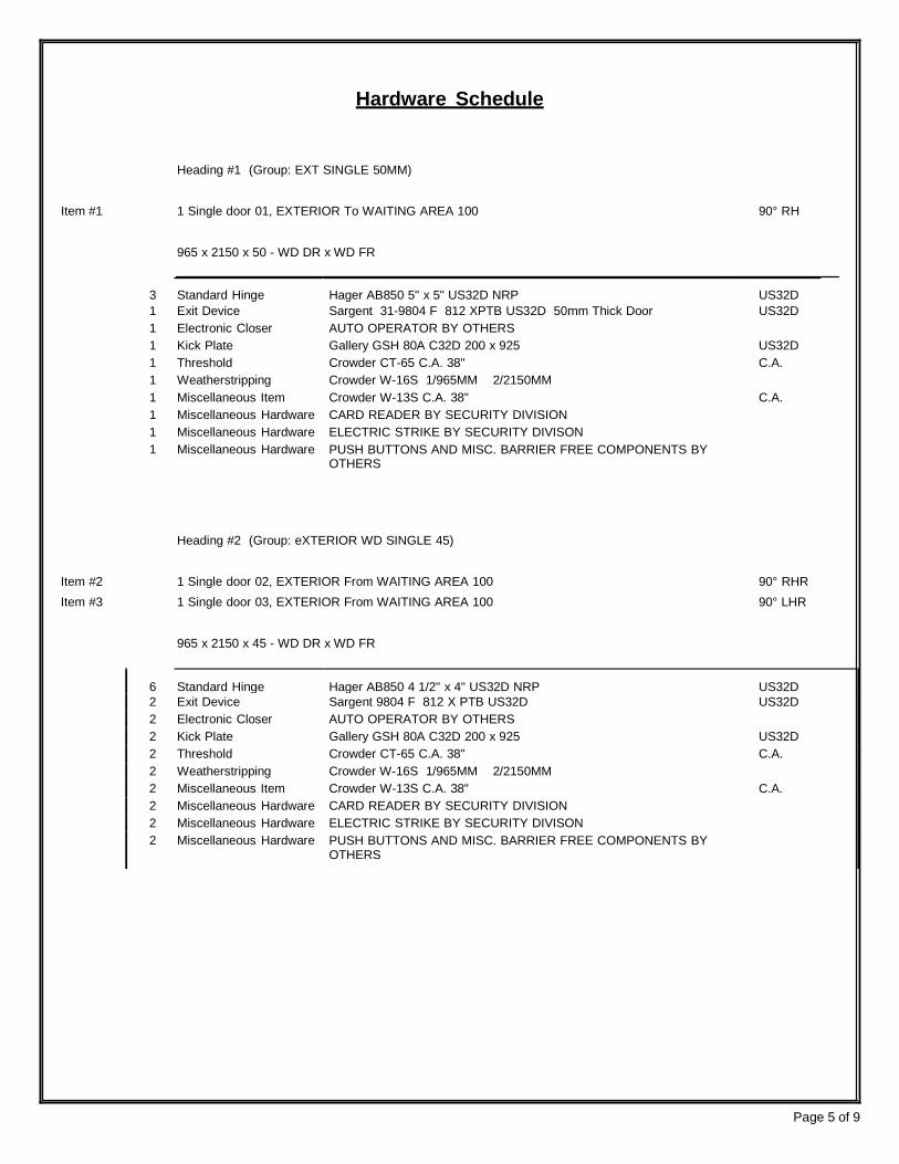
3
Standard Hinge
Hager AB850 5" x 5" US32D NRP
US32D 1 Exit Device Sargent 31-9804 F 812 XPTB US32D 50mm Thick Door US32D 1 Electronic Closer AUTO OPERATOR BY OTHERS 1 Kick Plate Gallery GSH 80A C32D 200 x 925 US32D 1 Threshold Crowder CT-65 C.A. 38" C.A. 1 Weatherstripping Crowder W-16S 1/965MM 2/2150MM 1 Miscellaneous Item Crowder W-13S C.A. 38" C.A. 1 Miscellaneous Hardware CARD READER BY SECURITY DIVISION 1 Miscellaneous Hardware ELECTRIC STRIKE BY SECURITY DIVISON 1 Miscellaneous Hardware PUSH BUTTONS AND MISC. BARRIER FREE COMPONENTS BY
OTHERS
Hardware Schedule
Heading #1 (Group: EXT SINGLE 50MM)
Item #1 1 Single door 01, EXTERIOR To WAITING AREA 100 90° RH
965 x 2150 x 50 - WD DR x WD FR
Heading #2 (Group: eXTERIOR WD SINGLE 45)
Item #2 Item #3
1 Single door 02, EXTERIOR From WAITING AREA 100 1 Single door 03, EXTERIOR From WAITING AREA 100
90° RHR 90° LHR
965 x 2150 x 45 - WD DR x WD FR
6
Standard Hinge
Hager AB850 4 1/2" x 4" US32D NRP
US32D
2 Exit Device Sargent 9804 F 812 X PTB US32D US32D 2 Electronic Closer AUTO OPERATOR BY OTHERS 2 Kick Plate Gallery GSH 80A C32D 200 x 925 US32D 2 Threshold Crowder CT-65 C.A. 38" C.A. 2 Weatherstripping Crowder W-16S 1/965MM 2/2150MM 2 Miscellaneous Item Crowder W-13S C.A. 38" C.A. 2 Miscellaneous Hardware CARD READER BY SECURITY DIVISION 2 Miscellaneous Hardware ELECTRIC STRIKE BY SECURITY DIVISON 2 Miscellaneous Hardware PUSH BUTTONS AND MISC. BARRIER FREE COMPONENTS BY
OTHERS
Page 5 of 9

3
Standard Hinge
Hager AB750 4 1/2" x 4" US26D NRP
US26D 1 Lockset Corbin-Russwin ML2057 NSA 626 626 1 Surface Closer Norton CLP-8501 689 689 1 Kick Plate Gallery GSH 80A C32D 200 x 925 US32D 1 Miscellaneous Item DOOR VIEWER 1755 US26D 1 Miscellaneous Hardware CARD READER BY SECURITY DIVISION 1 Miscellaneous Hardware ELECTRIC STRIKE BY SECURITY DIVISON
Heading #3 (Group: ELECT STOR CLP)
Item #4 1 Single door 04, WAITING AREA 100 From VIA RAIL TICKET SALES 106 90° LHR
965 x 2150 x 45 - HM DR x HM FR
Heading #4 (Group: ELECT STOR FS)
Item #5 Item #6 Item #7 Item #8
1 Single door 05, WAITING AREA 100 To OFFICE 104 1 Single door 06, WAITING AREA 100 To DRIVERS LOUNGE 101 1 Single door 09, CORRIDOR 107 To GREYHOUND TICKET SALES 116 1 Single door 15, VESTIBULE 112 To ELECTRICAL ROOM / IT ROOM111
90° LH 90° LH 90° LH 90° RH
965 x 2150 x 45 - HM DR x HM FR
12
Standard Hinge
Hager AB750 4 1/2" x 4" US26D NRP
US26D
4 Lockset Corbin-Russwin ML2057 NSA 626 626 4 Surface Closer Norton 8501-REG 689 689 4 Kick Plate Gallery GSH 80A C32D 200 x 925 US32D 4 Floor Door Stop Gallery GSH 218 C26D US26D 4 Miscellaneous Hardware CARD READER BY SECURITY DIVISION 4 Miscellaneous Hardware ELECTRIC STRIKE BY SECURITY DIVISON
Page 6 of 9

3
Standard Hinge
Hager AB750 4 1/2" x 4" US26D NRP
US26D 1 Latchset Corbin-Russwin ML2030 NSA 626 626 1 Surface Closer Norton 8501-REG 689 689 1 Kick Plate Gallery GSH 80A C32D (8" x 34 1/2") US32D 1 Floor Door Stop Gallery GSH 218 C26D US26D 1 Room Name Plate SIGN "WASHROOM" SIL/BLK
3
Standard Hinge
Hager AB750 4 1/2" x 4" US26D NRP
US26D 1 Dead Lock Corbin-Russwin DL4012 626 626 1 Door Pull Gallery 4012-2 C32D US32D 1 Push Plate Gallery (CAD) 5" x 20 " 630 1 Electronic Closer AUTO OPERATOR BY OTHERS 1 Kick Plate Gallery GSH 80A C32D 200 x 925 US32D 1 Floor Door Stop Gallery GSH 218 C26D US26D 1 Room Name Plate PICTOSIGN BARRIER FREE WOMEN SIL/BLK 1 Miscellaneous Hardware PUSH BUTTONS AND MISC. BARRIER FREE COMPONENTS BY
OTHERS
Heading #5 (Group: WR BF ELECT)
Item #9 Item #10
1 Single door 07, DRIVERS LOUNGE 101 From FAMILY WASHROOM 103 1 Single door 10, CORRIDOR 107 To FAMILY WASHROOM 108
90° LHR 90° LH
965 x 2150 x 45 - HM DR x HM FR
6
Standard Hinge
Hager AB750 4 1/2" x 4" US26D NRP
US26D
2 Lockset Corbin-Russwin ML2057 NSA 626 626 2 Electric Strike HES 1006F-24VDC-630 KM-630 ( FAIL SAFE) 630 2 Electronic Closer AUTO OPERATOR BY OTHERS 2 Kick Plate Gallery GSH 80A C32D 200 x 925 US32D 2 Floor Door Stop Gallery GSH 218 C26D US26D 2 Room Name Plate SIGN PICTO BARRIER FREE "FAMILY WASHROOM" SIL/BLK 2 Miscellaneous Hardware PUSH BUTTONS AND MISC. BARRIER FREE COMPONENTS BY
OTHERS
Heading #6 (Group: WASHROOM)
Item #11 1 Single door 08, DRIVERS LOUNGE 101 To WASHROOM 102 90° RH
915 x 2150 x 45 - HM DR x HM FR
Heading #7 (Group: WR PUSHPULL DL womens)
Item #12 1 Single door 11, CORRIDOR 107 To WOMENS WASHROOM 108 90° LH
965 x 2150 x 45 - HM DR x HM FR
Page 7 of 9
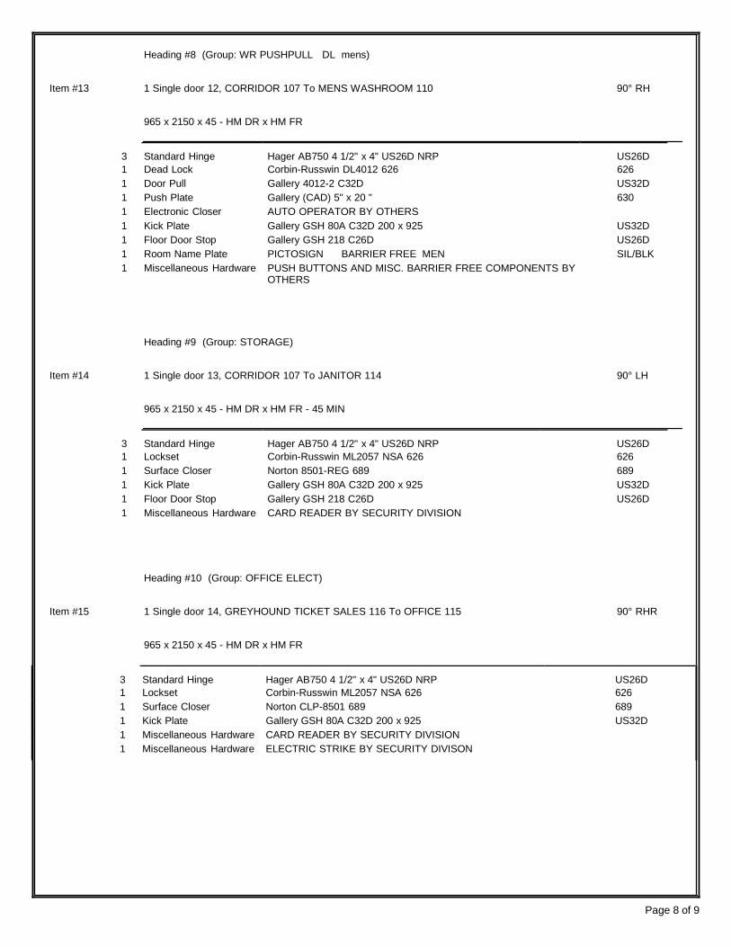
3
Standard Hinge
Hager AB750 4 1/2" x 4" US26D NRP
US26D 1 Dead Lock Corbin-Russwin DL4012 626 626 1 Door Pull Gallery 4012-2 C32D US32D 1 Push Plate Gallery (CAD) 5" x 20 " 630 1 Electronic Closer AUTO OPERATOR BY OTHERS 1 Kick Plate Gallery GSH 80A C32D 200 x 925 US32D 1 Floor Door Stop Gallery GSH 218 C26D US26D 1 Room Name Plate PICTOSIGN BARRIER FREE MEN SIL/BLK 1 Miscellaneous Hardware PUSH BUTTONS AND MISC. BARRIER FREE COMPONENTS BY
OTHERS
3
Standard Hinge
Hager AB750 4 1/2" x 4" US26D NRP
US26D 1 Lockset Corbin-Russwin ML2057 NSA 626 626 1 Surface Closer Norton 8501-REG 689 689 1 Kick Plate Gallery GSH 80A C32D 200 x 925 US32D 1 Floor Door Stop Gallery GSH 218 C26D US26D 1 Miscellaneous Hardware CARD READER BY SECURITY DIVISION
3
Standard Hinge
Hager AB750 4 1/2" x 4" US26D NRP
US26D 1 Lockset Corbin-Russwin ML2057 NSA 626 626 1 Surface Closer Norton CLP-8501 689 689 1 Kick Plate Gallery GSH 80A C32D 200 x 925 US32D 1 Miscellaneous Hardware CARD READER BY SECURITY DIVISION 1 Miscellaneous Hardware ELECTRIC STRIKE BY SECURITY DIVISON
Heading #8 (Group: WR PUSHPULL DL mens)
Item #13 1 Single door 12, CORRIDOR 107 To MENS WASHROOM 110 90° RH
965 x 2150 x 45 - HM DR x HM FR
Heading #9 (Group: STORAGE)
Item #14 1 Single door 13, CORRIDOR 107 To JANITOR 114 90° LH
965 x 2150 x 45 - HM DR x HM FR - 45 MIN
Heading #10 (Group: OFFICE ELECT)
Item #15 1 Single door 14, GREYHOUND TICKET SALES 116 To OFFICE 115 90° RHR
965 x 2150 x 45 - HM DR x HM FR
Page 8 of 9
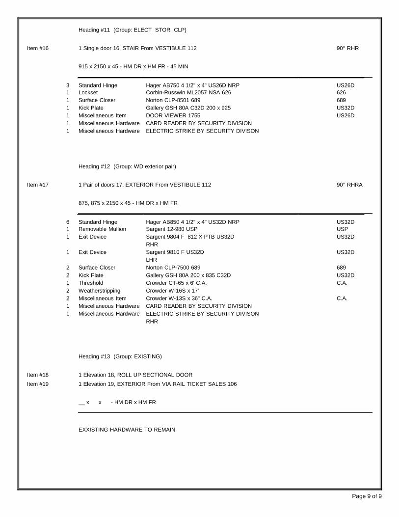
3
Standard Hinge
Hager AB750 4 1/2" x 4" US26D NRP
US26D 1 Lockset Corbin-Russwin ML2057 NSA 626 626 1 Surface Closer Norton CLP-8501 689 689 1 Kick Plate Gallery GSH 80A C32D 200 x 925 US32D 1 Miscellaneous Item DOOR VIEWER 1755 US26D 1 Miscellaneous Hardware CARD READER BY SECURITY DIVISION 1 Miscellaneous Hardware ELECTRIC STRIKE BY SECURITY DIVISON
Heading #11 (Group: ELECT STOR CLP)
Item #16 1 Single door 16, STAIR From VESTIBULE 112 90° RHR
915 x 2150 x 45 - HM DR x HM FR - 45 MIN
Heading #12 (Group: WD exterior pair)
Item #17 1 Pair of doors 17, EXTERIOR From VESTIBULE 112 90° RHRA
875, 875 x 2150 x 45 - HM DR x HM FR
6
Standard Hinge
Hager AB850 4 1/2" x 4" US32D NRP
US32D 1 Removable Mullion Sargent 12-980 USP USP 1 Exit Device Sargent 9804 F 812 X PTB US32D US32D 1
Exit Device
RHR Sargent 9810 F US32D
US32D
LHR 2 Surface Closer Norton CLP-7500 689 689 2 Kick Plate Gallery GSH 80A 200 x 835 C32D US32D 1 Threshold Crowder CT-65 x 6' C.A. C.A. 2 Weatherstripping Crowder W-16S x 17' 2 Miscellaneous Item Crowder W-13S x 36" C.A. C.A. 1 Miscellaneous Hardware CARD READER BY SECURITY DIVISION 1 Miscellaneous Hardware ELECTRIC STRIKE BY SECURITY DIVISON
RHR
Heading #13 (Group: EXISTING)
Item #18 1 Elevation 18, ROLL UP SECTIONAL DOOR Item #19 1 Elevation 19, EXTERIOR From VIA RAIL TICKET SALES 106
x x - HM DR x HM FR
EXXISTING HARDWARE TO REMAIN
Page 9 of 9

City of Guelph Transit Terminal Renovation Thomas Brown Architects Inc. Project No. 1008
Automatic Door Operators
Section 08711 Page 1
February 5, 2013
PART 1 - GENERAL
1.1 General Instructions
.1 Read and be governed by conditions of the Contract and sections of Division 1.
1.2 Section Includes
.1 Automatic door operators.
1.3 Quality Assurance
.1 Qualifications:
.1 Execute the work of this section only by a certified Subcontractor who has adequate plant, equipment, and skilled workers to perform it expeditiously, and is known to have been responsible for satisfactory installations similar to that specified during a period of at least the immediate past 5 years, and with 10 years satisfactory experience.
.2 Installer shall be approved in writing by the manufacturer of the operators for installation of their Product.
.2 Regulatory requirements:
.1 Use ULC or ULI listed and labelled hardware in fire separations and exit doors.
.2 Be responsible for, and abide by, all requirements and regulations of the building code. Conduct tests and inspections required, and pay all charges incidental thereto.
.3 Barrier free door operators shall be certified by the manufacturer to performance design criteria in accordance with CAN/CSA C22.2 NO. 247-92 (R2008), and ANSI/BHMA A156.19-2007.
1.4 Submittals
.1 Submit required submittals in accordance with Section 01330.
.2 Product data sheets:
.1 Submit manufacturer’s Product data sheets for Products proposed for use in the work of this section.
.3 Shop drawings:
.1 Shop drawings to be prepared specifically for this Contract and to indicate location of components, anchorage details, adjacent construction interface, and dimensions as well as all necessary wiring and electrical requirements.
.4 Samples:
.1 Submit samples of each finish material proposed for use in the Work.
.5 Quality assurance certification:
.1 Submit certificate of conformance to specified standards following procedures for submittal of Product data.

City of Guelph Transit Terminal Renovation Thomas Brown Architects Inc. Project No. 1008
Automatic Door Operators
Section 08711 Page 2
February 5, 2013
.6 Templates:
.1 Submit templates to Contractor for use by installers and fabricators as required for proper location and installation of hardware.
.7 Operation and maintenance data and training:
.1 Demonstrate, and provide instruction in, the proper operation and maintenance of the Products Provided as part of the work of this section to the Owner in accordance with Section 01770.
.2 Submit operation data and maintenance data for cleaning and maintenance of hardware for incorporation into the operation and maintenance manual specified in Section 01770.
1.5 Delivery, Storage and Handling
.1 Store finishing hardware in locked, clean dry area.
.2 Package each item of hardware, including fastenings, separately or in like groups of hardware, and label each package as to item definition and location.
1.6 Dimensions
.1 Check dimensions at the Place of the Work before fabrication commences, and report to Consultant in writing all discrepancies.
.2 Where dimensions are not available before fabrication commences, the dimension required shall be agreed upon between the various sections concerned.
1.7 Warranty
.1 Warrant work of this section for a period of 2 years, in accordance with Section 01780.
PART 2 - PRODUCTS
2.1 Automatic Door Operators - General
.1 Operation:
.1 Activation type: Push-button.
.2 Door to safely stop and reverse if an object is encountered in the opening or closing cycle.
.3 Manual opening force: 62 N.
.4 Closing force: 26.6 N.
.5 Factory-set door hold open voltage.
.6 Fail safe: In the event of power failure, door shall operate manually, without damage to operator components.
.2 Activators; wall-mounted:
.1 Push-button:
.1 Wall-mounted push-button switch, 2 required per opening.
City of Guelph Transit Terminal Renovation Thomas Brown Architects Inc. Project No. 1008
Automatic Door Operators
Section 08711 Page 3
February 5, 2013
.2 Provide 1 “Push To Lock” button for interior of two (2) barrier-free individual- use washrooms.
.3 Acceptable Product: Camden 40 Square push buttons.
.3 Electrical supply: 120 Volt.
2.2 Automatic Door Operators - Door Frame/Wall Mounted
.1 Provide adjustment by microprocessor for the following:
.1 Opening speed.
.2 Back-check.
.3 Hold-open, from 5 seconds to 30 seconds.
.4 Closing speed.
.5 Opening force.
.6 Acceleration during opening and recycling, for soft start.
.2 Controller:
.1 Completely electromechanical capable of the following functions:
.1 Obstruction detection.
.2 Initialization and power on.
.3 Door motion learn cycle.
.4 Manual mode, without spring closer.
.5 Power open/power close logic.
.2 Control box and motor/gear box to be contained in aluminum housing finished to match aluminum entrances, precision-machined gears and bearing seats and all- weather lubricant, mounted on vibration isolators.
.1 Design for surface-mounted application on surface of door frame/wall, maximum 3 mm (1/8") above top of door.
.2 Design for interior application.
.3 Gears: manufactured by operator manufacturer specifically for operators being provided.
.4 Motor: DC permanent magnet motor with shielded ball bearings. Stop motor when door stops or is fully open and when breakaway is operated.
.5 Door operating arm: forged steel, attached at natural pivot point of door. Do not use side block in top of door. Exposed arms to be factory polished and finished to match operator enclosure.
.6 Control circuits for actuators and safeties: low-voltage, NEC Class II.
.7 Service conditions: satisfactory operation between -34°C and 71°C.
.3 Acceptable Product:
.1 Typical: Horton ‘7100 Series’, or equivalent by Gyrotech.
City of Guelph Transit Terminal Renovation Thomas Brown Architects Inc. Project No. 1008
Automatic Door Operators
Section 08711 Page 4
February 5, 2013
.2 Barrier free washroom: Horton EMS-1 Washroom relay Package with HES 1006 Fail Safe Electric Strike.
2.3 Finishes
.1 Exposed aluminum components; anodized:
.1 Clear anodized, to AAMA 611-98, designation AA-M10C22A41.
2.4 Fabrication
.1 Fit intersecting members to flush hairline weathertight joints and mechanically fasten together, except where indicated otherwise.
.2 Conceal fastenings from view, except where indicated otherwise.
.3 Form cut-outs, recesses, mortising or milling for finishing hardware to templates supplied. Reinforce with aluminum or galvanized steel plates.
.4 Field apply isolation coating to aluminum in contact with dissimilar metals or cementitious materials.
PART 3 - EXECUTION
3.1 Examination
.1 Verify that door openings are properly installed and ready to receive the work of this section.
.2 Verify that electrical service is available, properly located, and of proper type.
3.2 Installation
.1 Install in accordance with manufacturer’s instructions and in accordance with CAN/CSA C22.2 NO. 247-92 (R2008).
.2 Adjust door operators for proper operation, without binding or scraping, and without excessive noise.
.3 Provide operator system complete in all its parts and connected to electrical service Provided as part of the work of Division 16. Secure all wiring such that it is concealed from view.
3.3 Adjustment
.1 Verify that installed hardware and operators function properly, and instruct installers accordingly of requirements and procedures for adjustments to ensure satisfactory operation.

City of Guelph Transit Terminal Renovation Thomas Brown Architects Inc. Project No. 1008
Automatic Door Operators
Section 08711 Page 5
February 5, 2013
3.4 Protection
.1 Apply temporary protective coating to finished surfaces. Remove coating after erection. Do not use coatings, such as masking tape or lacquer that will become hard to remove or leave residue.
END OF SECTION
City of Guelph Transit Terminal Renovation Thomas Brown Architects Inc. Project No. 1008
Section 08800 Page 1
February 5, 2013 Glass and Glazing
PART 1 - GENERAL
1.1 General Instructions
.1 Read and be governed by conditions of the Contract and sections of Division 1.
1.2 Quality Assurance
.1 Qualifications of installers: Provide the work of this section executed by specialist Subcontractor who shall be thoroughly trained and experienced in skills required, be completely familiar with referenced standards and requirements of the work of this section, and personally direct installation performed under this section.
.1 Foreperson experience: Minimum 10 years experience as glazing mechanic.
.2 Typical glazing mechanic experience: Minimum 3 years experience as glazers.
.2 Conduct quality control in accordance with Section 01450.
.3 Single source responsibility: Provide materials from a single manufacturer or fabricator for each kind and condition of glass indicated and composed of primary glass obtained from a single source for each type and class required.
1.3 Submittals
.1 Submit required submittals in accordance with Section 01330.
.2 Product data sheets:
.1 Submit manufacturer’s Product data sheets for Products proposed for use in the work of this section.
.3 Shop drawings:
.1 Submit full-size details indicating each type of glazing condition; show dimensions and materials with complete notations.
.2 For glass scheduled or indicated as engineered and glass to serve as guards in accordance with building code, shop drawings to be engineered shop drawings.
.4 Samples:
.1 Samples of each type of sealed glazing units, a fully assembled 305 mm (12") corner indicative in respects of required characteristics for each type of glazing system to be used in the Work.
.5 Closeout submittals:
.1 Submit closeout submittals in accordance with Section 01770.
.2 Submit maintenance and cleaning instructions for glass and glazing for incorporation into the operating and maintenance manuals.
1.4 Design Requirements
.1 Design glass to CAN/CGSB 12.20-M89.
.2 Design glass and glazing located less than 1070 mm (42") above finished floor, to requirements of the building code. Glass at guards, balustrades, and where glass is likely to be subjected to human impact shall comply with safety glass requirements of accordance with CAN/CGSB 12.20-M89 and CAN/CGSB 12.1-M90.

City of Guelph Transit Terminal Renovation Thomas Brown Architects Inc. Project No. 1008
Section 08800 Page 2
February 5, 2013 Glass and Glazing
.3 Provide annealed, heat strengthened, and tempered lights where required by the building code.
.4 Glass thicknesses and glass types specified, indicated, or scheduled in the Contract Documents are minimums required. Glass designer/engineer to modify as required to satisfy design and building code requirements, and requirements of authorities having jurisdiction, and any such modifications shall be clearly indicated on shop drawings.
1.5 Environmental Requirements
.1 Proceed with glazing only when glazing surfaces are accumulating no moisture from rain, mist or condensation.
.2 When temperature of glazing surfaces is below 4 °C, obtain approval of glazing methods and protective measures which will be used during glazing operations.
1.6 Warranty
.1 Warrant work of this section in accordance with Section 01780 and as follows:
.1 The glazing systems shall perform properly to the extent that the design and Contract Documents permit such performance for the duration of the warranty period.
.2 Sealed insulating glass unit manufacturer warranty including the following:
.1 Labour and materials.
.2 No dollar limit.
.3 Non-prorated.
.4 10 year warranty duration.
PART 2- PRODUCTS
2.1 Glass Materials
.1 Annealed (float) glass:
.1 Clear, annealed glass, 6 mm (1/4") thick minimum, CAN/CGSB 12.3-M91, Glazing Quality.
.2 Tempered and heat strengthened glass:
.1 To CAN/CGSB 12.1-M90, 6 mm (1/4") thick minimum.
.2 Tempering shall be performed using convection type furnace.
.3 Tempered and heat strengthened glass shall be treated prior to applying reflective or paint coatings.
.4 Tempering shall be performed using the horizontal tong-free method.
.5 Orient tempered glass in manner to produce consistent appearance.
2.2 Glazing Materials (Non-Fire Rated)
.1 Glazing gaskets: Preformed, EPDM, silicone compatible, to ASTM C864-05 and ASTM C1115-06.

City of Guelph Transit Terminal Renovation Thomas Brown Architects Inc. Project No. 1008
Section 08800 Page 3
February 5, 2013
Glass and Glazing
.2 Setting blocks: neoprene, durometer hardness to IGMAC recommendations, to ASTM C864-05.
.3 Spacer shims: neoprene, durometer hardness to IGMAC recommendations.
.4 Cleaners, Primers and Sealers: Type recommended by sealant or gasket manufacturer.
.5 Sealants: Types 1 and 3 in accordance with Section 07900.
2.3 Fabrication
.1 Grind, chamfer, and polish exposed glass edges, unless otherwise indicated.
2.4 Ticket Booth Framing System
.1 Aluminum framed glazing system:
.1 Acceptable Product: to later selection by Consultant.
PART 3- EXECUTION
3.1 Inspection
.1 Verify that openings to receive glazing are square and plumb, correctly sized, and within acceptable tolerances to maintain uniform face and edge clearances.
.2 Inspect butt and mitre joints in framing. Seal joints found to be open with a compatible sealant prior to glazing.
.3 Ensure glazing pockets and surfaces to be sealed are free of dust, construction debris, and contaminants, and ready to receive glazing.
.4 Report to the Consultant in writing any defects in existing work or unsatisfactory conditions at the Place of the Work. Do not begin to install glass until all conditions are satisfactory. Starting of the installation of the work of this section shall imply acceptance of existing conditions and surfaces.
3.2 Preparation
.1 Ensure fabricated glass will fit openings and that all required clearances to framing will be maintained.
.2 Clean contact surfaces with solvent and apply primers to surfaces to receive tapes and sealants in accordance with the manufacturer's instructions. Ensure surfaces are free of moisture and frost.
3.3 Workmanship
.1 Comply with IGMAC requirements and recommendations.
.2 Install materials in accordance with manufacturer's specifications, and ensure that each material in a glazing system is compatible with the others.
.3 Ensure that projections are removed from rebates and that sufficient depths and widths are provided.
.4 Place setting blocks as per manufacturer's design.

City of Guelph Transit Terminal Renovation Thomas Brown Architects Inc. Project No. 1008
Section 08800 Page 4
February 5, 2013
Glass and Glazing
.5 Install glass, rest on setting blocks, ensure full contact and adhesion at perimeter. Locate setting blocks at 1/4 points to span typically, and 1/8 points to span at long span locations, in accordance with design requirements of Section 08410, and IGMAC recommendations.
.6 Install removable stops, without displacing tape or sealant.
.7 Provide edge clearance of 3 mm (1/8") minimum.
.8 Insert spacer shims to center glass in space.
.9 Do not cut or abrade tempered or heat treated glass.
3.4 Glazing
.1 Cut glass to fit openings and to allow clearance which will ensure that glass is held firmly in place and is not subjected to stresses.
.2 Ensure that glass edges are clean cut.
.3 Do not cut or nip tempered glass to fit. Replace oversize or flared lights with entirely new units of proper dimensions.
.4 Set units of glass in each series with uniformity of pattern draw, bow and similar characteristics.
.5 Where sealants are used at butt joints, apply sealant in thin continuous clear bead.
.6 Glazing Preparation and Methods:
.1 Clean glazing rebate surfaces of traces of dirt, dust, or other contaminants.
.2 Use glazing sealants without addition of thinners and from only containers with seals unbroken until opened for use.
.3 Prime glass rebates except for aluminum or stainless steel, unless otherwise recommended by glazing material manufacturer. Primer shall be suitable for materials affected.
.4 Ensure that glazing sealants and tapes are in full contact with glazing surfaces.
.7 Position glazing tape for proper seal and bedding at fixed stops.
.8 Hollow Metal Doors and Frames: Specified under work of Section 08110. Install glass as indicated on the Door Schedule. Fixed stop bedding, glazing tape, removable stops, glazing tape.
.9 Install fire rated glazing in strict accordance with fire rated glazing material manufacturer's specifications. Field cutting or tampering is not permissible.
3.5 Protection
.1 Provide safety markings to installed glass by attaching streamers or tape to face of sash. Do not apply tape directly to the glass. Do not mark the glass with paint or any other substance that is hard to remove or could leave permanent stains.
.2 Take all precautions necessary to protect stored glass and installed glass from lime mortar, water run-off from concrete or copper, weld spatter, acids, roofing tar, solvents, abrasive cleaners, careless handling of construction machinery and equipment, and any other activities that could permanently damage the glass.

City of Guelph Transit Terminal Renovation Thomas Brown Architects Inc. Project No. 1008
Section 08800 Page 5
February 5, 2013
Glass and Glazing
.3 Install protective cover to glass where there is a high risk of damage. Use plywood, heavy kraft paper, or non-staining transparent plastic sheet. Do not let protective materials contact surface of glass.
.4 Do not rely on use of adhesive plastic films to protect installed glass. When plastic sheeting is used, it must be transparent, suspended away from the surface of the glass, and be provided with adequate ventilation holes to prevent heat build-up.
3.6 Finishing
.1 Immediately remove sealant and compound droppings from finished surfaces. Remove labels after work is completed.
.2 Final cleaning of glass in accordance with Section 01770.
.3 Remove and replace glass that is broken, chipped, cracked, abraded or damaged in other ways during construction period, including natural causes, accidents, and vandalism.
END OF SECTION

City of Guelph Transit Terminal Renovation Thomas Brown Architects Inc. Project No. 1008
Section 08892 Page 1
February 5, 2013 Glazing Repairs
PART 1 - GENERAL
1.1 General Instructions
.1 Read and be governed by conditions of the Contract and sections of Division 1.
1.2 Section Includes
.1 Guidance on replacing cracked, broken or missing panes of glass ,replacing cracked or missing window putty and cleaning glazing.
1.3 Definitions
.1 A window glass is in proper condition when it is set securely and tightly into the window frame, is properly caulked, and is not scratched, cracked, or broken.
1.4 Submittals
.1 Product Data: For each product indicated. Include recommendations for application and use. Include test reports and certifications substantiating that products comply with requirements.
1.5 Qualification Data
.1 For firms and persons specified in “Quality Assurance” Article to demonstrate their capabilities and experience. Include lists of completed projects with project names and addresses, names and addresses of Architects and Owners, and other information specified.
1.6 Sequencing and Scheduling
.1 Coordination of Work: The coordination of glass repairing/replacing with other proposed work on the windows must be coordinated.
PART 2- PRODUCTS
2.1 Materials
.1 Linseed oil putty (for wood windows)
.2 Materials for removing glazing compound:
.1 Paint remover
.2 -OR-
.3 Mineral spirits (for lacquer thinner):
.1 A petroleum distillate that is used especially as a paint or varnish thinner.
.2 Other chemical or common names include Benzine* (not Benzene); Naphtha*;Petroleum spirits*; Solvent naphtha*.
.3 Potential hazards: TOXIC AND FLAMMABLE.
.4 Safety precautions:
.1 AVOID REPEATED OR PROLONGED SKIN CONTACT.
.2 ALWAYS wear rubber gloves when handling mineral spirits.

City of Guelph Transit Terminal Renovation Thomas Brown Architects Inc. Project No. 1008
Section 08892 Page 2
February 5, 2013 Glazing Repairs
.3 If any chemical is splashed onto the skin, wash immediately with soap and water.
.5 Available from construction specialties distributor, hardware store, paint store, or printer's supply distributor.
.4 -OR-
.5 Muriatic acid (generally available in 18 degree and 20 degree Baume solutions):
.1 A strong corrosive irritating acid.
.2 Other chemical or common names include Chlorhydric acid; Hydrochloric acid; Hydrogen chloride; Marine acid*; Spirit of salt*; Spirit of sea salt*.
.3 Potential Hazards: TOXIC, CORROSIVE TO FLESH; CORROSIVE TO CONCRETE, STEEL, WOOD OR GLASS, FLAMMABLE.
.4 Available from chemical supply house, drugstore or pharmaceutical supply distributor, or hardware store.
.6 -OR-
.7 Linseed oil or thinned prime
.3 Glass to match existing.
.4 Glazier's points (if old ones are not usable)
.5 Neoprene setting blocks and shims
.6 Clean, potable water
.7 Ammonia
.8 Paper towels or rags
2.2 Equipment
.1 Goggles and gloves for protection when removing broken glass
.2 Hammer and chisel
.3 Soldering iron wrapped in foil, or a heat plate to remove old glazing compound
.4 Pliers and chisels for maneuvering glazier's points
.5 Sandpaper
.6 Very fine 0000 steel wool
.7 Paint brush to apply primer
.8 Glass cutter and straight edge
.9 Putty knife or glazier's tool for smoothing glazing compound
PART 3- EXECUTION
3.1 Examination
.1 Check for cracked, broken, chipped, or otherwise damaged glass.
.2 Inspect glazing putty on both sides of pane for cracked, loose, or missing sections which allow water to attack the metal components, especially at the joints.

City of Guelph Transit Terminal Renovation Thomas Brown Architects Inc. Project No. 1008
Section 08892 Page 3
February 5, 2013
Glazing Repairs
.3 Examine the condition of the metal window components for corrosion, loose connections, etc.
.1 Verify glass rattle or movement in the glazing system.
.2 Verify that glass stops intact.
.4 Inspect all surfaces which are to receive glass and/or glazing sealant for any defects or condition which will interfere with, or prevent a satisfactory installation.
.5 Correct all defects prior to installation of new glass.
.6 Verify the glass type in each window type prior to the installation of new glass.
3.2 Preparation
.1 Surface Preparation:
.1 Prior to reglazing, remove all oil, dirt, rust and other materials from the glass and the framing members.
.2 Prime and clean all glazing rabbets prior to glazing.
.3 Maintain glass in a reasonably clean condition during construction so that it will not be damaged by corrosive action.
3.3 Erection, Installation, Application
.1 Remove existing glazing compound using one of the following four methods:
.1 A hammer and chisel (at the risk of adjacent glazing).
.2 A soldering iron wrapped in foil or heat plate (can soften the compound to ease removal).
.3 Chemicals such as a paint remover, mineral spirits or muriatic acid. CAUTION: THESE ARE POTENTIALLY HARMFUL AND SHOULD BE USED IN WELLVENTILATED AREAS ONLY.
.4 Linseed oil (if the putty is linseed oil based - which most are).
.2 Remove glazier's points with pliers and reserve for reinstallation.
.3 Special procedures for wood windows:
.1 Thoroughly clean the sash of any remaining compound and sand grooves smooth.
.2 Apply linseed oil or thinned oil based primer to grooves to prevent wood from absorbing oil from new putty. If primer is used it should be applied in two coats, 24hours apart.
.4 Cut new glass 1/8" smaller in length and width, than the opening.
.1 Practice cutting on an unusable piece of glass first.
.2 Make sure the working surface is perfectly clean and do not press too hard with the glass cutter.
.1 Old window glass is often quite thin, and also contains impurities and irregular internal tensions.

City of Guelph Transit Terminal Renovation Thomas Brown Architects Inc. Project No. 1008
Section 08892 Page 4
February 5, 2013
Glazing Repairs
.2 Pressure from the wheel cutter on even a tiny piece of dirt can cause the pane tosplit or "run" in all the directions.
.3 Cut straight pieces, use a straight edge as a guide.
.1 Score the piece with one firm, even stroke of a sharp glass cutter dipped in oil.
.2 Tap along the line to break it off. Plastic glass-cutter's pliers can also be used to break the glass with a quick, downward snap.
.5 Apply a small bead of glazing compound around the groove to cushion the new glass and then install glass spaced evenly on all sides
.6 Replace glazier's points 4" to 6" apart around perimeter, tap them halfway in.
.7 Form glazing compound into a 3/8" diameter rope and press around perimeter of new glass. Using a putty knife, triangulate the surface of the compound. Hold the knife at a 45 degree angle and align compound with the muntin on the interior.
.8 Allow the compound to dry for a week, then paint accordingly with a 1/16" moisture seal extending onto the surface of the glass.
3.4 Adjusting and Cleaning
.1 After the installation of each light, remove all markings and labels from the glass
.2 Wash the glass on both sides with a mild solution of soapy water. NOTE: IN NO CASE SHALL ALKALINE OR ABRASIVE AGENTS BE USED TO CLEAN GLASS.CARE SHALL BE TAKEN DURING CLEANING TO AVOID SCRATCHING OF GLASS SURFACESBY USING GRITTY MATERIALS OR DRY CLOTHS.
.3 Rinse thoroughly with clean, clear water or as recommended by the glass manufacturer.
.4 Dry both sides of glass with a soft cotton dry cloth.
.5 Clean and trim excess glazing compound from glass, frames and sash promptly after installation.
.6 Clean adjacent surfaces if spills have occurred.
END OF SECTION

City of Guelph Transit Terminal Renovation Thomas Brown Architects Inc. Project No. 1008
Section 09100 Page 1
February 5, 2013 Metal Supports for Gypsum Board
PART 1 - GENERAL
1.1 General Instructions
.1 Read and be governed by conditions of the Contract and sections of Division 1.
1.2 Section Includes
.1 Metal support systems for gypsum board partitions, ceilings, and as indicated.
1.3 Quality Assurance
.1 Qualifications: Provide work of this section, executed by a Subcontractor with minimum 5 years experience in application of Products, systems and assemblies specified and with approval and training of Product manufacturers.
.2 Fire resistance rating: Where gypsum board systems with fire resistance ratings are indicated or required, provide materials and installations that are identical with those of applicable assemblies tested by fire testing laboratories acceptable to authorities having jurisdiction.
.3 Reference Standards:
.1 Applicable requirements of ASTM C754-09a for installation of steel framing.
1.4 Submittals
.1 Submit required submittals in accordance with Section 01330.
.2 Product data sheets:
.1 Submit manufacturer’s Product data sheets for Products proposed for use in the work of this section, including additional data as may be required to demonstrate compliance with the Contract Documents.
.3 Test Results:
.1 Submit certified test results for each required fire resistance rated assembly for work of this section.
1.5 Fire Resistance Rated Assemblies
.1 Materials for fire resistance rated construction shall conform to requirements of indicated fire resistance rated assembly.
PART 2 - PRODUCTS
2.1 Partition Support Materials
.1 Interior non-loadbearing channel stud framing: to ASTM C645-09a; roll formed from 0.91 mm (0.036”) minimum thickness unless otherwise indicated, electro-galvanized steel sheet. Provide service holes starting at 450 mm (18") from bottom, then 914 mm (36") on centre to top of studs.
.1 Steel studs; at backer plate locations: 0.91 mm (0.036”) minimum thickness.
.2 Steel studs at tile backer board locations: 0.91 mm (0.036”) minimum thickness.
.2 Interior floor and ceiling tracks (runners): to ASTM C645-09a; in widths to suit stud sizes.
City of Guelph Transit Terminal Renovation Thomas Brown Architects Inc. Project No. 1008
Section 09100 Page 2
February 5, 2013 Metal Supports for Gypsum Board
.1 Metal thickness: to match studs.
.2 For openings wider than 914 mm (36"), provide 0.91 mm (0.036”) minimum thickness for header.
.3 Runner fasteners:
.1 To concrete and masonry: Use stub nails or power-driven fasteners.
.2 To metal concrete inserts: Use 10 mm (3/8") Type S-12 Pan Head screws.
.3 To suspended ceilings: Use prefinished clips to match ceiling grid, as manufactured by CGC.
.4 Bracing channels: 19 mm x 10 mm x 1.22 mm (3/4" x 3/8" x 0.048") cold rolled galvanized steel.
2.2 Ceiling Support Materials and Systems
.1 General: Size ceiling support components to comply with ASTM C754-09a unless otherwise indicated.
.2 Main Runners: Steel channels, hot or cold rolled; G60 galvanized where used in shower rooms, other wet areas, and outdoors.
.3 Hanger Wire: ASTM A641/A641M-09a, soft, Class 1 galvanized, minimum 3.26 mm (8 AWG).
.4 Hanger Rods and Flats: Mild steel with zinc coating, galvanized for exterior applications.
.1 General: Size devices for 5 times load imposed by completed system as determined in accordance with ASTM E488-96(2003).
.1 Power actuated fastening systems are not permitted.
.2 Screws, clips, bolts, concrete inserts or other devices for ceiling hangers whose suitability for use intended has been proven through standard construction practices or by certified test data.
.3 Hangers: Comply with ASTM C754-09a for maximum ceiling area and loads to be supported.
.4 Interior concrete ceiling anchors; acceptable products:
.1 Dynabolt Sleeve Anchor 'TW-1614' or Readi-Tie-Drive 'TD4-112' tie wire anchor by ITW Ramset/Red Head.
.2 Redi-Drive by ITW Ramset/Red Head, complete with galvanized angle clip.
.3 Trubolt, or Dynabolt anchors by ITW Ramset/Red Head, complete with galvanized angle clip.
.4 Kwik-Bolt 3 - HHDCA 1/4 Ceiling Hangers by Hilti.
.5 Fasteners exposed to weather, condensation, and corrosion: Zinc-plated or stainless steel fasteners in applicable product lines specified in preceding paragraphs.
.5 Tie wire: 1.02 mm (18 AWG) minimum zinc coated, annealed wire.
.6 Furring anchorages: 1.62 mm (16 AWG) galvanized wire ties, manufacturer's standard wire type clips, bolts, nails or screws as recommended by furring manufacturer and complying with ASTM C754-09a.
City of Guelph Transit Terminal Renovation Thomas Brown Architects Inc. Project No. 1008
Section 09100 Page 3
February 5, 2013 Metal Supports for Gypsum Board
.7 Runner (carry) channels: 1.50 mm (0.059”) (16 gauge) thick cold rolled steel, primer painted or zinc coated for interior locations, Z275 galvanized for exterior locations:
.1 38 mm x 12.7 mm (1-1/2" x 1/2") where supported at centers of 914 mm (36") maximum.
.2 38 mm x 19 mm (1-1/2" x 3/4") where supported at centers of 1220 mm (48") maximum.
2.3 Furring
.1 Furring channels: 0.53 mm (0.021”) (25 gauge) 0.91 mm (0.036”) (20 gauge) minimum typical thickness, minimum 0.91 mm (0.036”) (20 gauge) at exterior soffits, cold rolled steel, wiped coated, nominal size of 22 mm (7/8") depth x 35 mm (1-3/8") face, hat type with knurled face.
.2 Resilient furring channels: ‘RC-1 Resilient Channel’ as manufactured by Canadian Gypsum Company or ‘Resilient Channel’ as manufactured by Nicholson Rollforming or Bailey Metal.
.3 Z-furring members: Manufacturer's standard screw type galvanized steel, z-shaped furring members; ASTM A653/A653M-06a, G60, 0.914 mm (0.036”) (20 gauge) minimum thickness of base metal, of depth indicated, designed for mechanical attachment of insulation boards or blankets.
.4 Fasteners for furring members: Type and size recommended by furring manufacturer for substrate and application indicated.
2.4 Accessories
.1 Backer plates:
.1 Metal backer plates: Steel, galvanized; minimum 150 mm (6") wide x 0.91 mm (0.036”) minimum x lengths to suit size of items to be attached; fastened to studs for attachment of surface mounted fittings and accessories.
.2 Plywood backer plates: Softwood plywood; 19 mm (3/4") minimum x lengths to suit size of items to be attached; fastened to studs for attachment of surface mounted fittings and accessories.
.3 Elimination of backer plates or direct attachment of accessories or equipment to studs will not be permitted.
PART 3 - EXECUTION
3.1 Installation General
.1 Comply with ASTM C754-09a and manufacturer's instructions, except as modified herein. Do not bridge building expansion joints with support system. Frame both sides of joints with furring and other supports as indicated.
.2 Provide and install studs, framing, shimming, and furring to provide proper support for gypsum board to achieve the following gypsum board tolerances:
.1 Do not exceed 3 mm (1/8") in 3 m (10’) variation from plumb, level, and plane.
.2 Do not exceed 10 mm (3/8”) from drawings locations.

City of Guelph Transit Terminal Renovation Thomas Brown Architects Inc. Project No. 1008
Section 09100 Page 4
February 5, 2013
Metal Supports for Gypsum Board
.3 Do not exceed 1.5 mm (1/16”) variation between planes of abutting edges or ends.
.3 Give complete cooperation and direction to trades erecting framing and furring over which this work is applied. Coordinate finished joint location with framing.
.4 Coordinate installation and cooperate with mechanical and electrical work to accommodate mechanical electrical items and any other work required to be incorporated into or coordinated with the partitions, ceiling and soffit systems.
.1 Where the presence of suspended ductwork or other mechanical or electrical services or devices above ceiling framing conflicts with ceiling framing suspension points from structure above, provide bridging framing below conflicting work as required to support ceiling framing on specified intervals.
.2 Do not suspend ceiling framing from mechanical or electrical suspension systems unless agreement is obtained in writing from engineer for Subcontractor installing such framing that additional imposed loads are acceptable; obtain Consultant’s acceptance before proceeding.
.5 Provide clearances between work of this section and structural elements to prevent transference of structural loads.
.6 Do not bridge building expansion joints with steel framing or furring members. Independently frame both sides of joints with framing of furring members or as indicated.
.7 Size framing systems according to manufacturer’s engineered load tables, to meet allowable deflection without permanent deformation.
.1 Maximum allowable deflection: L/240.
.2 Maximum allowable deflection for tiled partitions: L/360.
3.2 Blocking
.1 Attach to framing adequate backer plates to support the load of, and to withstand the withdrawal and shear forces imposed by, items installed upon the work of this section.
3.3 Furring - General
.1 Furring indicated in Contract Documents is schematic. Do not regard as exact or complete. Provide all necessary framing and furring to support gypsum board in accordance with manufacturers' specifications.
.2 Shim furring as required to achieve required installation tolerances.
.3 Leave finished work rigid, secure, square, level, plumb, curved to detailed radius and erected to maintain finish gypsum board line dimensions and contours. Make allowance for thermal movement.
.4 Thermally separate metal studs from exterior concrete or masonry.
3.4 Wall Furring
.1 Install steel furring for braced walls, free standing walls, walls that are furred out as indicated.
.2 Frame openings and around built-in equipment, cabinets, access panels, on 4 sides, with channels. Extend furring into reveals. Check clearances with equipment suppliers.

City of Guelph Transit Terminal Renovation Thomas Brown Architects Inc. Project No. 1008
Section 09100 Page 5
February 5, 2013
Metal Supports for Gypsum Board
.3 Provide bulkheads and boxed-in duct shafts, for beams, columns, pipes and around exposed services where indicated. Install 19 mm (3/4") channels at corners and at 305 mm (12") on centre.
3.5 Resilient Furring
.1 Erect gypsum board resilient furring maximum 610 mm (24") on centre and not more than 150 mm (6") from ceiling/wall juncture. Secure to each support with 25 mm (1") gypsum wallboard screw.
.2 Install 150 mm (6") continuous strip of 12.7 mm (1/2") gypsum board along base of partitions where resilient furring installed.
.3 Provide resilient furring channel transverse to framing members, or as indicated.
3.6 Metal Stud Partition Framing
.1 Provide partition tracks (runners) at floor and underside of structural assembly and as follows:
.1 Align accurately and lay out according to partition layout.
.2 Secure runners to concrete access flooring and to concrete slabs, as applicable, with screwed or shot fasteners located 50 mm (2") from each end and spaced at maximum 610 mm (24") on centre.
.3 At partition corners, extend one runner to end of corner and butt other runner to it, allowing necessary clearance for gypsum board thickness. Runners should not be mitred.
.2 Unless otherwise indicated, place interior studs vertically at centres as follows:
.1 Provide studs at 400 mm (16") on centre, and as specially spaced in accordance with details indicated.
.2 Provide studs not more than 50 mm (2") from abutting walls, openings and each side of corners.
.3 Provide freedom for 19 mm (3/4") deflection under beams, structural slabs and the like to avoid transmission of structural loads to studs, or install 50 mm (2") leg ceiling tracks.
.3 Install studs in tracks at floor and ceiling.
.4 Where horizontal runs of service lines are scheduled to be installed, arrange with applicable trades and install studs simultaneously with services.
.5 At openings in stud walls, erect track at head and sills to accommodate intermediate studs. At each end of track, cut out flanges, turn up web, and fasten to studs. Install intermediate studs above and below openings in same manner and spacing as wall studs. Install double studs at each jamb, and double tracks at head of door openings.
.6 At partitions requiring fire rating, erect in accordance with requirements of listing.
.7 Size studs, connections, and runners to carry loads according to stud manufacturer’s load tables, at 24 kg/m2 (5 lb/ft2) live load to meet maximum allowable deflection limits. Where depth of stud is indicated, size metal thickness to meet allowable deflection limits.
.8 Provide three studs at corner and intermediate intersections of partitions.
City of Guelph Transit Terminal Renovation Thomas Brown Architects Inc. Project No. 1008
Section 09100 Page 6
February 5, 2013
Metal Supports for Gypsum Board
.9 Coordinate work with others installing horizontal runs of service lines so that work is done simultaneously. Where standard holes are too small for installed services, notch studs, and splice notched flanges with splice pieces 305 mm (12") longer than notches, each fastened with 2 screws.
.10 Provide metal studding to maximum tolerance of 3 mm in 3 m (1/8” in 10 ft).
.11 Coordinate simultaneous erection of studs with installation of service lines. When erecting studs ensure web openings are aligned.
.12 Coordinate erection of studs with installation of door/window frames and special supports or anchorage for work specified in other sections.
.13 Unless otherwise indicated, partitions, together with gypsum board facings, shall extend above ceilings to underside of structure above.
.14 Maintain clearance to avoid transference of structural loads to studs.
.15 Chase Walls:
.1 Provide chase walls where indicated, consisting of two parallel steel stud partitions.
.2 Provide cross bracing consisting of metal furring, located at quarter points on each pair of studs. Attach cross bracing to studs with metal screws. Coordinate construction of partitions to suit installation of services.
3.7 Control Joints
.1 Control joints: in accordance with Section 09290.
3.8 Concrete Anchors
.1 Provide anchorage points in reinforced concrete floor slab underside in accordance with gypsum board manufacturer’s suspension requirements. Drill holes with carbide-tipped drill bits conforming to ANSI B212.15-1994.
.2 Provide anchors; minimum installation depth, and method of expansion as recommended by the anchor manufacturer.
END OF SECTION

City of Guelph Transit Terminal Renovation Thomas Brown Architects Inc. Project No. 1008
Historic Plaster Repair
Section 09230 Page 1
February 5, 2013
PART 1 - GENERAL
1.1 General Instructions
.1 Read and be governed by conditions of the Contract and sections of Division 1.
1.2 Section Includes
.1 Historic plaster repair including the following:
.1 Patching hairline cracks in plaster with reinforcing tape and joint compound.
.2 Patching holes in plaster. The extent of work described includes:
.1 Removing deteriorated plaster, and
.2 Applying three coats of plaster to the damaged area.
.3 Patching small chips, cracks or depressions in plaster surfaces.
.4 Concealing water stains on plaster walls or ceilings using a shellac-based primer sealer. A product, such as white-pigmented shellac can be used to seal, prime and block out existing stains, prohibiting them from bleeding through finish layers of paint.
1.3 References
.1 American Society for Testing and Materials International (ASTM)
.1 ASTM C5-03 Standard Specification for Quicklime for Structural Purposes.
.2 ASTM C35, Standard Specification for Inorganic Aggregates for Use in gypsum Plaster.
.3 ASTM C206, Standard Specification for Finishing Hydrated Lime.
.4 ASTM C841, Standard Specification for Installation of Interior Lathing and Furring.
.5 ASTM C-842, Standard Specification for Application of Interior Gypsum Plaster.
.6 ASTM C1489, Standard Specification for Lime Putty for Structural Purposes
.2 Canadian Standards Association (CSA International)
.1 CAN/CSA-a3000, Cementitious Materials Compendium (Consists of A3001, A3002, A3003, A3004 AND A3005.)
1.4 Submittals
.1 Product data: For each product indicated. Include recommendations for application and use. Include test reports and certifications substantiating that products comply with requirements.
.2 Samples for each product.
.3 Submit details of restoration program for each phase of the cleaning and repair process, including protection of surrounding materials on the building and Project site during operations. Describe in detail the materials, methods, equipment, and sequence of operations to be used for each phase of the cleaning and repair work.

City of Guelph Transit Terminal Renovation Thomas Brown Architects Inc. Project No. 1008
Historic Plaster Repair
Section 09230 Page 2
February 5, 2013
.1 If alternative materials and methods to those indicated are proposed for any phase of restoration and cleaning work, provide a written description, including evidence of successful use on other comparable projects, and a testing program to demonstrate their effectiveness for this Project.
1.5 Quality Assurance
.1 Refer to Section 01350.
.2 Chemical manufacturer qualifications: A company regularly engaged in producing plaster cleaners and consolidants that have been used for similar applications with successful results, and with factory-trained representatives who are available for consultation and Project site inspection and assistance at no additional cost.
.3 Mockups: Prepare field samples for restoration methods and cleaning procedures to demonstrate aesthetic effects and qualities of materials and execution. Use materials and methods proposed for completed Work and prepare samples under same weather conditions to be expected during remainder of Work.
.1 Plaster repair: Prepare sample panels of 9 square feet for each type of restoration proposed. Maintain the sample panel throughout the restoration to demonstrate the quality of materials and workmanship expected.
.4 Source of Materials: Obtain materials for plaster cleaning and repair from a single source for each type of material required to ensure a match of quality, color, pattern, and texture.
1.6 Delivery, Storage and Handling
.1 Deliver other materials to Project site in manufacturer's original and unopened containers, labeled with type and name of products and manufacturers.
.2 Store gypsum materials off the ground, under cover, and in a dry location.
.3 Comply with manufacturer's written instructions for minimum and maximum temperature requirements for storage.
1.7 Project Site Conditions
.1 Environmental requirements:
.1 Keep the room temperature above 55 o F until the plaster/joint compound has set.
.2 Provide ample ventilation as the plaster dries.
PART 2 – PRODUCTS
2.1 Products
.1 For patching hairline cracks:
.1 Joint compound such as "Durabond Wallboard Compound" (U.S. Gypsum Co.),"Krack-Kote" (Tuff-Kote Co.).
.2 Reinforcing tape (cloth or paper)
.3 Acrylic latex caulk
.2 For patching holes in 3 coat plaster:

City of Guelph Transit Terminal Renovation Thomas Brown Architects Inc. Project No. 1008
Historic Plaster Repair
Section 09230 Page 3
February 5, 2013
.1 Expanded metal diamond mesh latha. 3.4 lbs./sq. yard min.cut from copper bearing steel plates. Coated with rust inhibitive paint
.2 2. 18 Gauge Tie Wire and Drywall Nails
.3 Scratch and brown coats: aggregated gypsum plaster ASTM C 28
.1 Use of perlite as an aggregate is not allowed without compensating for shrinkage rate of finish coat.
.4 Finish Coat Gauging Plaster, Finish Lime
.5 Drywall screws
.6 Cloth mesh tape
.7 Joint compound such as "Durabond Wallboard Compound” (U.S. Gypsum Co.),"Krack-Kote" (Tuff-Kote Co.).
.8 Fibera. Fiberglassb. 2” maximum length, ½” minimum length
.9 Reinforcing Wirea. 1/8” dia. stainless steel, type 302b. threadedc. preformed to patch shape
.10 Epoxy Adhesive
.1 Two component
.2 Solvent free
.3 Moisture insensitive
.4 Sikadur 32, Hi-Mod.
.3 For patching small chips:
.1 Gypsum Plaster Materials:
.1 General: gypsum plastering materials shall conform to ANSI A42.1. Provide neat or ready-mixed materials at installer's option unless indicated otherwise.
.2 Base coat plaster: gypsum plaster ASTM C 28
.3 Base coat aggregate: Sand, ASTM C 35
.4 Finish Coat Gauging Plaster, Finish Lime
.2 Bonding Materials: Bonding agent shall conform to ASTM C631.
.3 Fiber
.1 Fiberglass
.2 2” maximum length, ½” minimum length
.4 For concealing water stains in plaster:
.1 White-pigmented shellac such as "Kilz" (Masterchem Industries, Inc.), "Bin"(William Zinsser & Co., Inc.).
.5 For re-adhering existing plaster:
.1 Pre-wetting agent
.2 Thickener gel:

City of Guelph Transit Terminal Renovation Thomas Brown Architects Inc. Project No. 1008
Historic Plaster Repair
Section 09230 Page 4
February 5, 2013
.1 5% Rohm and Haas Acrysol ASE-60 diluted with 81.9 parts water and 1.3 parts concentrated ammonia by weight.
.2 Gel pH: 8
.3 Unfilled adhesive:
.1 Rohm and Haas acrylic resin
.2 Rhoplex MC-76
.3 Rhoplex LC-67.
.4 Flled adhesive
.1 Glass microballoons
.2 Lime
.3 Coked. Rohm and Haas acrylic resine. Rhoplex MC-76f. Rhoplex LC-67g. gel thickener
2.2 Equipment
.1 For patching hairline cracks:
.1 Wide joint knife (approximately 5-6 inches wide)
.2 Sponge or heavy-nap cloth
.3 Caulking gun
.4 Crack widener or triangular can opener
.5 Stiff bristle brushes or vacuum
.2 For patching holes in 3 coat plaster:
.1 Hawk
.2 Slicker (flexible straight-edge)
.3 Plasterer's trowel
.4 Margin trowel
.5 Mortarboard and mudpan
.6 Pointing trowel
.7 Plywood scrap
.8 6 inch taping knife
.9 12 inch taping knife
.10 Joint tape (cloth mesh preferred)
.11 Stiff putty knife
.12 Goggles, work gloves, and dust mask
.13 Hammer and cold chisel
.14 Needlenose pliers and wire cutter
.15 Screwgun and drill

City of Guelph Transit Terminal Renovation Thomas Brown Architects Inc. Project No. 1008
Historic Plaster Repair
Section 09230 Page 5
February 5, 2013
.16 Spray bottle and dropcloths
.17 Tin snips
.18 Shop-vac
.19 Paint brush
.3 For patching small chips:
.1 Joint knife
.2 Sponge or heavy-nap cloth
.3 Crack widener or triangular can opener
.4 Stiff bristle brushes
.5 Hawk
.6 Slicker (flexible straight-edge)
.7 Plasterer's trowel
.8 Margin trowel
.9 Mortarboard and mudpan
.10 Pointing trowel
.4 For concealing water stains:
.1 Clean sponge
.2 Stiff, fiber bristle brush
.3 Paint brush, roller or airless sprayer
PART 3 – EXECUTION
3.1 Patching Hairline Cracks
.1 1. Examination:
.1 Types of plaster cracking include, map cracking, alligatoring, settlement cracks, hairline cracks, stress related cracks and cracks due to moisture. If a wall has an enormous number of cracks to be taped, replaster the surface.
.2 Application:
.1 Slightly widen the crack with a sharp, pointed tool like a crack widener or a triangular can opener.
.2 Brush or vacuum surface to remove dust and debris.
.3 Apply joint compound with a wide joint knife; Butter the compound into the crack, spreading it about 3 inches on either side of the crack.
.4 Center mesh reinforcing tape over the crack, and force the tape down into the bed of the joint compound with the knife; Remove any excess compound by wiping with the joint knife.
.5 When the tape is bedded, cover surface with a thin layer of compound and smooth as much as possible by working with the joint knife.

City of Guelph Transit Terminal Renovation Thomas Brown Architects Inc. Project No. 1008
Historic Plaster Repair
Section 09230 Page 6
February 5, 2013
.6 When the first coat has dried (at least 24 hours), smooth out any ridges by "wetsanding" with a damp sponge or a heavy-nap cloth folded flat or wrapped around a suitable block.
.7 Apply a second thin coat of joint compound and feather the edge at least 1 inch beyond the first coat.
.8 After the second coat has dried, wet-sand lightly and apply a thin finishing coat.
.9 Lightly sand the surface again, and clean off the area with damp sponge.
.10 After the surface has dried, brush off any plaster residue or dust.
.11 For gaps between plaster surfaces and surrounding woodwork, apply acrylic latex caulk using a caulking gun.
3.2 Patching Holes in 3 Coat Plaster
.1 Examination:
.1 Determine the extent of unsound plaster and evaluate work requirements and causes before proceeding. Signs of damaged plaster in need of replacing include:
.1 Holes
.2 Water Stains: Brownish rings on the plaster, especially the ceilings, indicate that the plaster has been wet. If the water was stopped quickly, the surface may only need to be sealed with pigmented shellac to prevent the stain from bleeding through the new paint or wallpaper. However, if the leak continued for a long period, the plaster may need to be replaced, and will often have a powdery appearance.
.3 Chipping, flaking and delamination of plaster due to water infiltration.
.2 Application:
.1 Removing deteriorated plaster:
.1 Use plaster washers to re-secure weakly-keyed areas of otherwise sound plaster to the wall or ceiling.
.2 Wear a dust mask, goggles and gloves and pull loose plaster from the walls with your hands or a flat prybar.
.3 To remove sound plaster, drill holes in the line of cut with a carbide drill bit; holding the chisel at a shallow angle, carefully cut directly from hole to hole with a cold chisel; cut the resulting plaster free from the lath by chipping the keys from the side.
.4 Cut the plaster back to the studs, if necessary, and re-secure the lath with drywall nails.
.5 Knock any plaster stuck between the lath back into the wall cavity.
.6 Vacuum all dust, loose plaster, and other debris from the hole with a shop- vac,or brush it out with a stiff bristle brush.
.2 Lathing the hole:
City of Guelph Transit Terminal Renovation Thomas Brown Architects Inc. Project No. 1008
Historic Plaster Repair
Section 09230 Page 7
February 5, 2013
.1 Install metal lath over the wood lath (metal lath lessens the likelihood of cracking caused by the old wood lath drawing too much moisture out of the plaster).
.2 If 2 hands are necessary to secure new metal lath, drive a finishing nail into an exposed stud; take a piece of lath slightly larger than the hole and hang it on the nail; with both hands now free, cut the lath to shape with tin snips.
.3 Use tie wire to secure the metal lath over the wood lath.
.4 To make a tie wire, bend a 6 inch long piece of wire into an elongated "U" and pull it around the old wood lath; space the tie wires every 6 inches.
.5 To secure the lath at studs, drive 1 inch drywall screws between the lath into the stud
.6 Provide reinforcing rod at areas unsuited for expanded metal lath.
.3 Applying the scratch and brown coats:
.1 Thoroughly moisten the old wood lath with a spray bottle, so it will not draw moisture out of the wet plaster used for patching.
.2 Apply the base coat (scratch coat) of plaster to the wall in an arching motion; keep the hawk close to the wall under the trowel to catch falling plaster; Use a margin trowel to work the plaster into edges and corners. The thickness of the new scratch coat should not exceed that of the old scratch coat (about 1/8 to1/4 inch).
.3 As it starts to set, score shallow, random scratches in it diagonally about every inch or so to provide keys for the next layer; Let the scratch coat set for 48hours.
.4 Apply the second coat (brown coat) using the same plaster that was used for the scratch coat.
.5 Run a slicker (a long flexible straight edge) over the entire patch; Keep the brown coat below the level of the surrounding finish coat by about 1/8 inch.
.6 As the brown coat starts to set, knock off any high spots; Let the brown coat set for 48 hours before applying the finish coat.
.4 Mixing the finish coat:
.1 Place approximately 2 quarts of cold, potable water into a 5 gallon plastic bucket
.2 Scoop in autoclave finish lime until it starts to float. NOTE: WEAR GOGGLES,A DUST MASK OR RESPIRATOR, AND LATEX GLOVES WHEN MIXINGLIME.
.3 If using single-hydrated lime, sift it into the water the day before and leave to slake overnight.
.4 Mix thoroughly with a mixer attachment on an electric drill, or by hand with a pointing trowel.
.5 Add small amounts of water or lime as necessary until all the lime is wet and there are no lumps or standing water.
.6 Use a scrap of plywood for a mortarboard and toss some lime putty onto it.
City of Guelph Transit Terminal Renovation Thomas Brown Architects Inc. Project No. 1008
Historic Plaster Repair
Section 09230 Page 8
February 5, 2013
.7 Form the putty into a ring using the margin trowel; Fill the center of the ring about 2/3 full with cold, clear water.
.8 Slowly sprinkle in gauging plaster until all the water is absorbed; The mixshould consist of 1 part gauging plaster to 3 parts lime putty.
.9 Mix the water and the plaster in the middle of the ring; It should be slightly stiffer than the lime putty.
.10 Fold in the lime putty and mix until all of the ingredients are stirred up.
.5 Applying the finish coat:
.1 If applying the finish coat over an old brown coat, the existing brown coat must be moistened well before applying the finish coat (unnecessary on a newly-applied brown coat). NOTE: Finishing plaster over an old brown coat occasionally fails because the new plaster does not bond to the dry, old substrate, even if it is wet down. Furthermore, the old plaster will absorb water faster, causing cracks in the finish coat as it starts to dry
.2 Following the same motions used when applying the first two coats, trowel the finish coat onto the patch.
.3 Fill in any hollows by dabbing with plaster and smooth out ridges.
.4 Spray a fine mist of water onto the plaster and trowel over the patch again to get a slick finish; Straighten edges and corners with margin trowel.
.5 Let the finish coat cure for about 1 week; Check it for shrinkage.
.6 Tape any small cracks with cloth mesh tape and joint compound.
.7 Wash down new plaster with a zinc sulphate solution (2 lbs./gallon of water)and allow to dry.
3.3 Patching Small Chips and Cracks
.1 Application:
.1 Scrape loose or damaged finish plaster and peeling paint from surface with chisel or joint knife. Remove material where required to enlarge cracks, chips, holes, etc.to at least 1/2 inch across and undercut to improve bonding of new material.
.2 Brush or vacuum surface to remove dust and debris.
.3 Moisten the surface by lightly spraying a fine mist of clean water from a spraybottle.
.4 Apply skim finish coat over low areas to bring entire finished surface out flush with the projecting firm and sound layers of adjacent plaster or paint. Form plaster as required to match original configuration and design or ornamental plaster.
.5 Once dry, sand by hand to produce a surface without bumps, cracks or depressions, ready to receive finish treatment.
.6 Bring it down, threading it between the lath and the nailer in a void near a plaster key, and wrap it back around the nailer; Twist it tightly around itself.

City of Guelph Transit Terminal Renovation Thomas Brown Architects Inc. Project No. 1008
Historic Plaster Repair
Section 09230 Page 9
February 5, 2013
3.4 Concealing Water Stains in Plaster
.1 Examination:
.1 Before proceeding with steps to conceal water stains, examine the plaster and substrate material for potential sources of moisture and make repairs as required.
.1 Look for signs of water infiltration: Examination may show where the water is entering.
.2 If possible, examine the condition of the back-up material:
.1 Examine the wall for open gaps or cracks in joints and around openings that could allow water to enter the building.
.2 Repair cracks in masonry and/or repoint as necessary before proceeding with the cleaning operations.
.3 Examine wall sections and details of construction: Carefully examine roof and wall junctures and flashing details for possible sources of moisture entry.
.2 Application:
.1 After source of moisture has been eliminated, allow the surface to thoroughly dry out.
.2 Carefully remove any surface deposits and loose paint using a stiff fiber bristle brush only. Fill cracks and holes as required.
.3 Wipe the surface with a clean, damp cloth.
.4 Apply white-pigmented shellac over the stained area using a brush, roller or airless sprayer. Follow manufacturer's instructions.
.1 Depending on the severity of the stain, multiple coats may be required. If so, allow the first coat to thoroughly dry (typically 45 minutes) before proceeding with additional coats.
.2 If using a brush or roller, apply additional coats in the same direction as the first coat.
.3 If the surface is to be repainted with a high-hiding paint, spot-priming only the stained areas is acceptable. However, if a high-hiding paint is NOT used to finish the surface, spot-priming is NOT RECOMMENDED, as primed areas may appear shiny through the paint finish. (Note: Many ceiling paints have little hiding strength). In such cases, the entire wall or ceiling surface should be primed with the white-pigmented shellac before repainting to produce a more uniform final appearance.
.5 Prime and repaint the entire surface with oil or latex paint as required.
3.5 Adjusting and Cleaning
.1 Upon completion of this work, all floors, walls and other adjacent surfaces that are stained, marred, or otherwise damaged by work in this procedure shall be cleaned and repaired and all work and the adjacent areas shall be left in a clean and perfect condition.

City of Guelph Transit Terminal Renovation Thomas Brown Architects Inc. Project No. 1008
Historic Plaster Repair
Section 09230 Page 10
February 5, 2013
.2 All completed work shall be adequately protected from damage by subsequent building operations and effects of weather. Protection shall be by methods recommended by the manufacturer of installed materials.
.3 Clean all affected surfaces of room and furnishings to their prior condition.
.4 Remove temporary protection and enclosure of other work. Promptly remove plaster from door frames, windows, and other surfaces that are not to be plastered. Repair floors, walls, and other surfaces that have been stained, marred, or otherwise damaged during the plastering work. When plastering work is completed, remove unused materials, containers, and equipment and clean floors of plaster debris.
END OF SECTION

City of Guelph Transit Terminal Renovation Thomas Brown Architects Inc. Project No. 1008
Section 09290 Page 1
February 5, 2013 Gypsum Board
PART 1 - GENERAL
1.1 General Instructions
.1 Read and be governed by conditions of the Contract and sections of Division 1.
1.2 Section Includes
.1 Gypsum board.
.2 Gypsum board; fire-rated.
.3 Water resistant gypsum board.
.4 Gypsum board accessories and miscellaneous related materials.
1.3 Quality Assurance
.1 Subcontractor executing the work of this section shall have a minimum of 10 years continuous experience in successful installation of work of type and quality indicated and specified.
.2 Single source responsibility: Obtain gypsum board products from a single manufacturer, or from manufacturers recommended by the prime manufacturer of gypsum boards.
.3 Fire resistance rating: Where gypsum board systems with fire resistance ratings are indicated or required, provide materials and installations that are identical with those of applicable assemblies tested by fire testing laboratories acceptable to authorities having jurisdiction.
1.4 Submittals
.1 Submit required submittals in accordance with Section 01330.
.2 Product data sheets:
.1 Submit manufacturer’s Product data sheets for Products proposed for use in the work of this section.
.3 Fire-rated assembly listings:
.1 Submit fire-rated assembly listings for each required fire resistance rated assembly for work of this section.
1.5 Environmental Requirements
.1 Environmental requirements, general: Comply with requirements of referenced gypsum board application standards and recommendations of gypsum board manufacturer, for environmental conditions before, during and after application of gypsum boards.
.2 Cold Weather Protection: When ambient outdoor temperatures are below 12°C maintain continuous, uniform comfortable building working temperatures of not less than 12°C for a minimum period of 48 hours before, during and following application of gypsum board and joint treatment materials or bonding of adhesives.
.3 Ventilation: Ventilate building spaces as required to remove water in excess of that required for drying of joint treatment material immediately after its application. Avoid drafts during dry, hot weather to prevent too rapid drying.

City of Guelph Transit Terminal Renovation Thomas Brown Architects Inc. Project No. 1008
Section 09290 Page 2
February 5, 2013 Gypsum Board
.4 Protection: Provide adequate protection of materials and work of this section from damage by weather and other causes. Protect work of other trades from damage resulting from work of this section. Make good such damage at no additional cost to the Owner.
1.6 Delivery, Storage and Handling
.1 Store materials in protected dry areas. Store gypsum board flat in piles with edges protected.
.2 Ensure that finish metal members are not bent, dented, or otherwise deformed.
.3 Deliver Products supplied under the work of this section only to those who are responsible for installation, to the place they direct, and to meet installation schedules.
.4 Package fire rated materials with labels attached.
PART 2 - PRODUCTS
2.1 Gypsum Board Panels
.1 Regular gypsum board: Gypsum core panel solid set core enclosed in paper, 12.7 mm (1/2") or 16 mm (5/8") thick unless otherwise indicated, 1220 mm (48") wide x maximum practical length, ends square cut, tapered edges, to ASTM C1396/C1396M-06a.
.1 Acceptable Products:
.1 CertainTeed ‘ProRoc Regular Gypsum Board’.
.2 CGC ‘SHEETROCK Gypsum Panel, Regular’.
.3 Georgia-Pacific ‘ToughRock Gypsum Board’.
.4 Lafarge ‘Gypboard’.
.2 Fire-rated gypsum board: Gypsum core panel with a specially formulated core for use in fire-resistive Type X or Type C designs, to ASTM C1396/C1396M-06a.
.1 Acceptable Products:
.1 CertainTeed ‘ProRoc X and C’.
.2 CGC ‘SHEETROCK Firecode and Firecode C’.
.3 Georgia-Pacific ‘ToughRock Fireguard and Fireguard Gypsum Board’.
.4 Lafarge ‘Firecheck C and X’.
.3 Water resistant gypsum wall board (greenboard): Gypsum core panel with enhanced water and water resistant paper facers to ASTM C1396/C1396M-06a, fire rated where indicated.
.1 Acceptable Products:
.1 CertainTeed ‘ProRoc Moisture Resistant’.
.2 CGC ‘SHEETROCK Water Resistant’.
.3 Georgia-Pacific ‘ToughRock Moisture-Guard’.
.4 Lafarge ‘Watercheck and Fire Watercheck’.

City of Guelph Transit Terminal Renovation Thomas Brown Architects Inc. Project No. 1008
Section 09290 Page 3
February 5, 2013 Gypsum Board
2.2 Fasteners
.1 Screws; for gypsum board: bugle head, fine thread, self-tapping, Type W or S or S-12 point to suit framing type and metal gauge, with corrosion resistant finish to ASTM C1002-04/ASTM C954-10. Screw sizing:
.1 #6 x 25 mm (1") for single thickness board fastening.
.2 #6 x 32 mm (1-1/4") for single thickness 15.9 mm (5/8") board fastening.
.3 #7 x 41 mm (1 5/8") for double thickness board fastening.
.2 Tie wire: 1.6 mm (0.063") diameter galvanized soft annealed steel wire.
2.3 Furring
.1 Furring channels: 0.53 mm (0.021”) (25 gauge) gauge minimum typical thickness, minimum 0.91 mm (0.036”) (20 gauge) at exterior soffits, cold rolled steel, wiped coated, nominal size of 22 mm (7/8") depth x 35 mm (1-3/8") face, hat type with knurled face.
.2 Z-furring members: Manufacturer's standard screw type galvanized steel, z-shaped furring members; ASTM A653/A653M-06a, G60, 0.914 mm (0.036”) (20 gauge) minimum thickness of base metal, of depth indicated, designed for mechanical attachment of insulation boards or blankets.
.3 Fasteners for furring members: Type and size recommended by furring manufacturer for substrate and application indicated.
2.4 Accessories
.1 Accessories: to ASTM C1047-10a unless otherwise indicated, maximum length pieces per location. Flanges shall be free from dirt, grease, or other material that adversely affects the bond of joint treatment or decoration.
.2 Trim reveal:
.1 Standard metal trim reveal for suspended gypsum board walls or ceilings abutting concrete block walls, suitable for paint finish in all locations except where indicated otherwise.
.3 Control joints: No. 093 Zinc Control Joint by CGC Inc. or approved alternate, certified by manufacturer for use at fire resistance rated assemblies.
.4 Casing beads, corner beads: 0.5 mm base thickness commercial grade sheet steel with Z275 zinc finish to ASTM A525, perforated flanges, one piece length per location.
2.5 Related Support Assemblies and Backer Plates
.1 Metal support systems and backer plates at interior assemblies: in accordance with Section 09100.
2.6 Joint and Adhesive Materials
.1 Joint compound:
.1 Gypsum board work: asbestos-free. Latex resin base, possessing good adhesion, mixed with fresh, unadulterated water having no detrimental effect on compounds, to ASTM C475/C475M-02(2007); type recommended by manufacturer for application indicated.

City of Guelph Transit Terminal Renovation Thomas Brown Architects Inc. Project No. 1008
Section 09290 Page 4
February 5, 2013 Gypsum Board
.1 Dust control joint compound:
.1 Acceptable Products:
.1 CGC Sheetrock Brand Dust Control Joint Compound.
.2 Gypsum board to receive tile finish: setting-type powder based joint finishing compound. ‘Durabond’ by CGC or approved alternate.
.2 Joint reinforcing tape:
.1 Gypsum board: 50 mm x 0.3 mm (2" x 0.01") thick, perforated paper, with chamfered edges.
.3 Laminating adhesive; for gypsum panels only: in accordance with gypsum board manufacturer's printed installation instructions, to suit application.
.1 Use adhesives that have a VOC content of 50 g/L or less when calculated according to 40 CFR 59, Subpart D (EPA Method 24).
.4 Sealant: Type 4 in accordance with Section 07900 or as recommended by gypsum board manufacturer.
2.7 Acoustic Wall Assembly Materials
.1 Acoustic sealant; where concealed: non-skinning acoustic sealant, non-hardening type to CGSB 19.21-M87, as manufactured by Tremco, or CGC .
.2 Acoustic sealant; where exposed: Interior paintable sealant in accordance with Section 07900.
.3 Acoustic compound: premixed perlite plaster.
.4 Acoustic (sound attenuation) insulation:
.1 Mineral-fibre sound attenuation batts: to CAN/ULC S702-97, Type 1, and to CAN/ULC-S114-05.
.1 Acceptable Products: Roxul 'AFB'.
.2 Thickness: Minimum of 90% of wall assembly cavity depth unless otherwise indicated.
.3 Fasteners: use mechanical fasteners to secure batts into position as recommended by manufacturer.
2.8 Access Doors
.1 Access doors: in accordance with Division 15 and Division 16.
PART 3 - EXECUTION
3.1 Installation
.1 General: Comply with ASTM C840-08, GA 216-07, GA 600-06, and manufacturer's instructions, except as otherwise indicated. Do not bridge building expansion joints with support system. Frame both sides of joints with furring and other supports as indicated.
.2 Install exposed gypsum board with face side out. Do not install imperfect, damaged or damp boards. Butt boards together for a light contact at edges and ends with not more than 1.6 mm (1/16") open space between boards. Do not force into place.

City of Guelph Transit Terminal Renovation Thomas Brown Architects Inc. Project No. 1008
Section 09290 Page 5
February 5, 2013 Gypsum Board
.3 Cover both faces of stud partition framing with gypsum board in concealed spaces (above ceiling, and the like) unless otherwise indicated, except in chase walls which are properly braced internally.
.4 Attach gypsum board to supplementary framing and blocking provided for additional support at openings and cut-outs.
.5 Securely attach trim, casings, framing, and accessories.
.6 Apply components of fire-rated assemblies in conformance with indicated designs.
.7 Erect materials to dimensions indicated, plumb, level, straight, and square to adjoining elements.
.8 Do not apply gypsum board in close proximity to hot pipes or heating ducts.
.9 Install materials with the minimum number of joints. Tightly butt joints, without force, and neatly align them.
.10 Frame openings on every side. Provide clearances with services.
.11 Work shall include bulkheads over doors, frames, screens, and changes in ceiling levels, pipe space and as indicated.
.12 Provide clearances between work of this section and structural elements to prevent transference of structural loads in accordance with Section 09100.
.13 Tolerances:
.1 Do not exceed 3 mm (1/8") in 3 m (10’) variation from plumb, level, and plane in exposed surfaces, except at joint between gypsum board panels.
.2 Do not exceed 10 mm (3/8”) from drawings locations.
.3 Do not exceed 1.5 mm (1/16”) variation between planes of abutting edges or ends.
3.2 Metal Furring
.1 Furring indicated in Contract Documents is schematic. Do not regard as exact or complete. Provide all necessary framing and furring to support gypsum board in accordance with manufacturers' specifications.
.2 Shim furring as required to achieve required installation tolerances.
.3 Leave finished work rigid, secure, square, level, plumb, curved to detailed radius and erected to maintain finish gypsum board line dimensions and contours. Make allowance for thermal movement.
.4 Thermally separate metal studs from exterior concrete or masonry.
.5 Install steel furring for braced walls, free standing walls, walls that are furred out as indicated.
.6 Frame openings and around built-in equipment, cabinets, access panels, on 4 sides, with channels. Extend furring into reveals. Check clearances with equipment suppliers.
.7 Provide bulkheads and boxed-in duct shafts, for beams, columns, pipes and around exposed services where indicated. Install 19 mm (3/4") channels at corners and at 305 mm (12") on centre.

City of Guelph Transit Terminal Renovation Thomas Brown Architects Inc. Project No. 1008
Section 09290 Page 6
February 5, 2013 Gypsum Board
3.3 Accessories
.1 At external corners install corner trim secured to framing at 230 mm (9-1/16") on centre on both flanges with screw fasteners or clinch tool.
.2 Secure casing trim at board edges where exposed to view, where board butts against other materials with no trim to conceal junction, at perimeter of ceiling surfaces at tops of partitions where they stop against continuous ceiling surfaces, and where indicated.
.3 Erect accessories straight, plumb or level, rigid and at proper plane.
.4 Use full length pieces.
.5 Make joints tight, accurately aligned and rigidly secured. Mitre and fit corners, free from rough edges. Secure in accordance with manufacturer's specifications unless otherwise required.
.6 Installation tolerances:
.1 Alignment with board panels shall not exceed tolerances specified above.
.2 End joints shall be flush aligned to maximum offset of 0.5 mm (0.020”).
3.4 Board Application - General
.1 Before application of gypsum board commences, ensure that internal services have been installed, tested, and approved; that conduits, pipes, cables, and outlets are plugged, capped, or covered; and that fastenings and supports installed by others are in place.
.2 Extend board into door, window, and other openings, reveals, behind fitments, and other applied items and on metal stud partitions to structure above unless indicated otherwise.
.3 Apply board with long dimension perpendicular to supports, typically.
.4 Locate joints on opposite sides of partitions on different studs, and at least 305 mm (12") from opening jambs.
.5 Install board to minimize joints, and align end joints to be the least objectionable (where they are unavoidable), according to the indicated lighting design. Locate joints in ceilings where least prominently discerned, and never line them up with opening edges.
.6 Form smooth joints at ends and at field cut edges of board panels.
.7 Fasten board to support members by gypsum board screws, 9.5 mm (0.374") minimum to, and 12.7 mm (1/2") maximum from, center of joints. Space screws:
.1 At fire rated board as per fire-rated assembly.
.2 At typical board walls at 400 mm (16") on centre at edges and field unless otherwise required.
.3 At typical board ceilings at 305 mm (12") on centre at edges and field unless otherwise required.
.8 At laminated plain gypsum board locations: Apply adhesive with notched spreader to leave ribbons 10 mm x 13 mm (3/8" x 1/2") at 38 mm (1-1/2") apart over entire back side of face layer. Erect board immediately after spreading adhesive. Temporarily secure face boards with screws or bracing to ensure adequate bond until adhesive sets. Temporary face screws may also be used. Substrate shall be fully cured and sufficiently dry to allow adhesive to fully cure and not re-emulsify.
City of Guelph Transit Terminal Renovation Thomas Brown Architects Inc. Project No. 1008
Section 09290 Page 7
February 5, 2013 Gypsum Board
.9 Use floating angle method of application to minimize the effects of truss uplift and the possibility of fastener popping in areas adjacent to wall and ceiling intersections in wood framed construction with trusses. This method is applicable where either single nailing, double nailing, or screw attachment to wood framing is used.
.10 Offset gypsum board joints 150 mm minimum from corners of openings.
.11 Gypsum panel product joints shall be located so that no joint will align with the edge of an opening unless control joints are to be installed at these locations.
3.5 Water Resistant Gypsum Board Application
.1 Apply water resistant gypsum board to washroom and shower walls and locations where adhered mirrors are indicated or scheduled. Apply water resistant sealant to edges, ends, cut-outs which expose gypsum core and to fastener heads. Do not apply joint treatment on areas to receive tile finish.
.2 Apply water resistant sealant to edges, ends, cut-outs which expose gypsum core at walls and ceilings.
.3 Apply water resistant board over adjacent fire separation partitions where applicable.
3.6 Acoustic Wall Assemblies
.1 Sound attenuation insulation:
.1 Install sound attenuation insulation wherever insulation in partitions is indicated.
.2 Install sound attenuation insulation in partitions so indicated by filling voids with batts of specified thickness.
.3 Maintain air space between backs of sound attenuation insulation and back of opposite face layer, as applicable.
.4 Pack sound attenuation insulation against ducts, conduits and services passing through acoustic wall assemblies.
.5 Extend acoustic wall assemblies to underside of structure. Incorporate approved provision to prevent transmittance of structural deflection to partition assembly.
.6 Staple sound attenuation insulation where required by manufacturer's data.
.7 Where studs are not faced with gypsum board on both sides, mechanically fasten wire mesh to non-faced side of stud to retain insulation.
.8 Mechanically attach sound attenuation insulation in wall assemblies where cavity of wall assembly is greater than 150 mm.
.9 Secure insulation in such a manner that it will not sag.
3.7 Finishing
.1 Provide levels of gypsum board finish for locations as follows, in accordance with GA- 214.
.1 Level 1: Ceiling plenum areas and concealed areas, except provide higher level of finish as required to comply with fire resistance ratings and acoustical ratings.
.2 Level 2: Gypsum board substrate at applied hard surfaces, except remove tool marks and ridges.

City of Guelph Transit Terminal Renovation Thomas Brown Architects Inc. Project No. 1008
Section 09290 Page 8
February 5, 2013
Gypsum Board
.3 Level 4: Exposed gypsum board surfaces, except where another finish level is indicated.
.2 Interior Gypsum Board:
.1 Prefill:
.1 Use setting-type joint compound. Mix joint compound according to manufacturer's directions.
.2 Fill joints between boards flush to top of eased or beveled edge.
.3 Fill joints of gypsum board above suspended ceilings in fire rated partitions.
.4 Wipe off excess compound and allow compound to harden.
.2 Taping (Level 1):
.1 Butter taping compound into inside corners and joints.
.2 Center tape over joints and press down into fresh compound.
.3 Remove excess compound.
.4 Tape joints of gypsum board above suspended ceilings.
.3 First coat (Level 2):
.1 Use taping or all-purpose drying-type compound.
.2 Immediately after bedding tape, apply skim coat of compound and allow to dry completely in accordance with manufacturer's instructions.
.3 Apply first coat of compound over flanges of trim and accessories, and over exposed fastener heads and finish level with board surface.
.4 Second coat (Level 3): After first coat treatment is dried, apply second coat of compound over tape and trim, feathering compound 50 mm (2") beyond edge of first coat.
.5 Third coat (Level 4):
.1 After second coat has dried, sand surface lightly and apply thin finish coat to joints, fasteners and trim, feathering compound 50 mm (2") beyond edge of second coat.
.2 Allow third coat to dry. Apply additional compound, and touch-up and sand, to provide surface free of visual defects, tool marks, and ridges, and ready for application of finish.
.3 Finished joints will be accepted with a camber not greater than 1 mm (1/32") and shall be seamless, plumb, true and flush and with square, neat corners.
.4 Where new partitions align with existing gypsum board, apply required amount of skim coats to make transition inconspicuous from a distance of 914 mm (36”).
.5 Completed installation at interface between new and existing construction shall provide an inconspicuous joint.
.6 At board fasteners: fill holes and depressions with a 2 coat application of joint filler.

City of Guelph Transit Terminal Renovation Thomas Brown Architects Inc. Project No. 1008
Section 09290 Page 9
February 5, 2013
Gypsum Board
.3 Water-resistant gypsum board: Treat fastener heads and joints with setting-type joint compound.
.1 For joints to be covered with tile, apply tape and joint compound bedding coat and skim coat only; do not apply finish coats.
.2 Do not crown joints or leave excess compound on panels.
.3 Remove tool marks and ridges.
.4 For fastener heads to be covered with tile, apply one coat of joint compound.
.4 Cementitious backer board: Prepare and finish joints in accordance with manufacturer's instructions.
.5 Joint Compound:
.1 Apply finish coat of compound feathering 75 to 100 mm (3” to 4”) beyond tape edges.
.2 Feather coats onto adjoining surfaces so that camber is maximum 0.79 mm (1/32”).
.6 Trim:
.1 Use same fasteners to anchor trim accessory flanges as required to fasten gypsum board to supports, unless otherwise recommended by trim manufacturer.
.2 Install metal corner beads at external corners.
.3 Install metal casing bead trim whenever edge of gypsum base would otherwise be exposed or semi exposed, and where gypsum base terminates against dissimilar material.
.4 Erect beads plumb or level, with minimum joints.
.7 Control Joints
.1 Provide control joints set in board facing. Support control joints with studs or furring channels on both sides of joint.
.2 Provide control joints in required locations.
.1 Review control joint locations with Consultant prior to installation.
.3 Full height door frames shall be considered equivalent to a control joint.
.4 Install control joints where a partition, wall, or ceiling traverses a construction joint (expansion, seismic or building control element) in the building structure.
.5 Install control joints where a wall or partition runs in an uninterrupted straight plane exceeding 9100 mm (30 linear feet).
.6 Install control joints in interior ceilings:
.1 With perimeter relief:
.1 Linear dimensions between control joints shall not exceed 15000 mm (50 ft) and total area between control joints shall not exceed 230 m² (2500 ft²).
.2 Without perimeter relief:

City of Guelph Transit Terminal Renovation Thomas Brown Architects Inc. Project No. 1008
Section 09290 Page 10
February 5, 2013 Gypsum Board
.1 Linear dimensions between control joints shall not exceed 9100 mm (30 ft) and total area between control joints shall not exceed 84 m² (900 ft²).
.7 Install control joints where ceiling framing members change direction.
.8 Where a control joint occurs in an acoustical or fire-rated system, blocking shall be provided behind the control joint by using a backing material such as 16 mm (5/8") type X gypsum panel products, mineral fibre, or other tested equivalent. Construct through-wall control joints at fire-rated assemblies in accordance with assembly listing requirements.
.9 Line up control joints with joints in other construction or with centre lines of mullions, columns, piers, or similar building elements, where accepted by Consultant.
.10 Install control joints straight and true.
.11 Ceiling height door frames may be used as control joints. Less than ceiling height frames shall have control joints extending to the ceiling from both corners. If control joints are not used, additional reinforcement is required at corners to distribute concentrated stresses.
.12 Board joints shall be located so that no joint will align with the edge of an opening unless control joints are to be installed at these locations.
3.8 Fire Separations
.1 Install fire-rated assemblies in accordance with assembly listing requirements in order to obtain fire ratings indicated and as required by authorities having jurisdiction.
.2 Vertical bulkheads in ceiling spaces over fire rated partitions, doors and the like shall have same fire rating as the partition over which they occur. Such bulkheads shall be of gypsum board construction unless otherwise indicated.
.3 Use fire rated gypsum wallboard as specified.
.4 Where lighting fixtures, diffusers, and the like are recessed into fire rated ceilings or bulkheads, provide enclosure to maintain required fire rating. Form removable panel to give access to fixture outlet box.
.5 Where fire hose cabinets or other fixtures or equipment are recessed in fire rated walls or partitions, provide gypsum board enclosure or backing to maintain required fire rating, unless otherwise detailed.
3.9 Access Doors
.1 Install access doors to mechanical and electrical fixtures specified in respective sections of Division 15 and Division 16.
.2 Access doors shall be as supplied by Division 15 and Division 16. Locations to be reviewed and confirmed by Consultant.
.3 Install access panels in locations to be determined by coordination with trades installing mechanical, electrical and other building services and consultation with Consultant.
.4 Rigidly secure frames to furring or framing systems.

City of Guelph Transit Terminal Renovation Thomas Brown Architects Inc. Project No. 1008
Section 09290 Page 11
February 5, 2013 Gypsum Board
3.10 Special Cleaning
.1 Clean up and remove surplus materials and rubbish resulting from the work of this section on completion and when directed and from cavities before enclosing.
.2 Clean off beads, casings, joint compound droppings and the like, leave the work of this section ready for painting trades.
END OF SECTION

City of Guelph Transit Terminal Renovation Thomas Brown Architects Inc. Project No. 1008
Section 09310 Page 1
February 5, 2013 Tiling
PART 1 - GENERAL
1.1 General Instructions
.1 Read and be governed by conditions of the Contract and sections of Division 1.
1.2 Section Includes
.1 Hard surface tiling.
1.3 Quality Assurance
.1 Execute work of this section only by a Subcontractor who has adequate plant, equipment, and skilled workers to perform it expeditiously, and is known to have been responsible for satisfactory installations similar to that specified during a period of at least the immediate past 5 years.
.2 Subcontractor shall be a member company in good standing of the Terrazzo, Tile and Marble Association of Canada and have been a member for at least the past 5 years.
.3 Comply with TTMAC Manual - 2002 Specification Guide 09300 Tile Installation Manual as produced by the Terrazzo, Tile and Marble Association of Canada.
1.4 Submittals
.1 Submit required submittals in accordance with Section 01330.
.2 Samples:
.1 Submit full size samples of each type of tile specified.
.3 Product data sheets:
.1 Submit manufacturer’s Product data sheets for Products proposed for use in the work of this section.
.4 Closeout submittals:
.1 Submit closeout submittals in accordance with Section 01770.
.2 Maintenance materials:
.1 Provide minimum 2% of each type and colour of tile required for the Work for maintenance use.
.2 Maintenance material to be of same production run as installed material.
.3 Maintenance data:
.1 Submit maintenance instructions for inclusion in the maintenance manuals.
1.5 Environmental Requirements
.1 Environmental Conditions: Execute work of this section while temperature is maintained within safe working temperatures in accordance with manufacturer's installation instructions for a period of 72 hours before, during and following installation. Avoid concentrated or irregular heating during curing period.

City of Guelph Transit Terminal Renovation Thomas Brown Architects Inc. Project No. 1008
Section 09310 Page 2
February 5, 2013 Tiling
.2 Protection: Protect work of this section against damage by work of other sections for a minimum of 72 hours after application of grouting by prohibiting passage of traffic over tile. Do not immerse in water and protect tilework from freezing for at least 28 days after installation.
1.6 Sequencing and Scheduling
.1 Coordinate installation of tile work with related work.
.2 Proceed with tile work only after curbs, vents, drains, piping, and other projections through substrate have been installed and when substrate construction and framing of openings have been completed.
PART 2 – PRODUCTS
2.1 Tile Materials
.1 PT: Porcelain tile.
.2 CT: Ceramic tile.
.3 MT: Mosaic floor tile to match existing at exterior front entrance porch.
.4 Acceptable Products:
.1 MT-1: White mosaic to match existing.
.2 MT-2: Yellow mosaic to match existing.
.3 MT-3: Light green mosaic to match existing.
.4 MT-4: Dark green mosaic to match existing.
.5 MT-5: Sand mosaic to match existing.
.6 MT-6: Red mosaic to match existing.
.7 MT-7: Octangular white mosaic to match existing.
.8 MT-8: Octangular dark green mosaic to match existing.
.9 PT-1: Stones-So Matte Balsaltina Grey as manufactured by Olympia Tile.
.1 Size: 305 mm x 610 mm (12”x24”)
.10 PT-2: Stones-So Matte, Pietra Dakar (Sand) as manufactured by Olympia Tile.
.1 Size: 305 mm x 610 mm (12”x24”)
.11 PT-3: Progetto Pavimenti Perla as manufactured by Stone Tile.
.1 Size: 305 mm x 610 mm (12”x24”)
.12 PT-4: Progetto Pavimenti Nero as manufactured by Stone Tile.
.1 Size: 100 mm x 610 mm (4”x24”)
.13 PT-5: Graniti Fiandre Active Beige Ground, semi-matte as manufactured by Savoia Canada.
.1 Size: 305 mm x 610 mm (12”x24”) SILVER
.14 PT-6: Graniti Fiandre Active White Ground, honed as manufactured by Savoia Canada.

City of Guelph Transit Terminal Renovation Thomas Brown Architects Inc. Project No. 1008
Section 09310 Page 3
February 5, 2013 Tiling
.1 Size: 305 mm x 610 mm (12”x24”)
.15 CT-1: Yukon Bevelled Gloss White as manufactured by Olympia Tile.
.1 Size: 75 mm x 150 mm (3”x6”)
.16 CT-2: Trend Wallpaper Collection Recycled Glass as manufactured by Stone Tile.
2.2 Grout and Adhesives
.1 Acceptable manufacturers:
.1 Flextile Ltd.
.2 LATICRETE International, Inc.
.3 MAPEI Corp.
.4 TEC Specialty Products, Inc.
.2 Setting adhesives; interior applications:
.1 Portland cement/sand/latex mixture, to ANSI A118.4-2009 and with minimum Shear Bond (Porcelain Tile, immersion and dry 28 day cure tests) of 2.3 MPa (340 psi) when tested to ANSI A118.4-2009.
.1 Acceptable products:
.1 Flextile ‘51’ mixed with Flextile ‘44’.
.2 Laticrete 'Laticrete 4237 Latex Thin Set Liquid' with 'Portland 211 Crete Filler Powder'.
.3 Mapei 'KERALASTIC' mixed with 'KERABOND'.
.4 TEC Specialty Products, Inc. 'Super Flex Latex-Modified Thin Set Mortar'.
.3 Grout:
.1 Epoxy, to ANSI A118-2009.
.1 Flextile '100 Flex-Epoxy 100% Solids Epoxy Grout'.
.2 Laticrete ‘SpectraLOCK PRO Grout’.
.3 Mapei ‘Kerapoxy’.
.4 TEC Specialty Products, Inc. ‘100% Solids Epoxy Mortar and Grout’.
.2 Grout schedule:
.1 G-1: floor use, silver grey, 2 mm wide joint.
.2 G-2: wall use, silvery grey, 2 mm wide joint.
.3 G-3: wall use, white, 2 mm wide joint.
.4 MT-1 to MT-8: to match existing mosaic grout.
.5 Colours: to later selection by Consultant from manufacturer’s full range.
.3 Water: clean and free of chemicals detrimental to mortar and grout mixes.
.4 Sand: to ASTM C144-04, passing 16 mesh.
.5 Cement: to CSA A3000-03/CSA A3000-03/CAN/CSA A362-1998, Type 10.

City of Guelph Transit Terminal Renovation Thomas Brown Architects Inc. Project No. 1008
Section 09310 Page 4
February 5, 2013 Tiling
.4 Scratch coat (by volume): 1 part Portland cement, 4 parts sand, and latex additive where required by TTMAC Detail. Premixed mortar may be used in accordance with manufacturer’s instructions. Adjust water volume depending on moisture content of sand to obtain consistency and workability.
.5 Slurry bond coat: mix Portland cement and water to a creamy paste consistency. Include latex additive where required by TTMAC Detail.
.6 Mortar bed for walls (by volume): 1 part Portland cement, 4 parts sand, and latex additive where required by TTMAC Detail. Premixed mortar may be used in accordance with manufacturer’s instructions. Adjust water volume depending on moisture content of sand to obtain consistency and workability.
.7 Leveling coat (by volume): 1 part Portland cement, 4 parts sand, and latex additive where required by TTMAC Detail. Premixed mortar may be used in accordance with manufacturer’s instructions.
.8 Mortar bed for floors; where applicable: 1 part cement, 4 parts sand, 1 part water. Water volume may be adjusted depending on water content of sand.
2.3 Accessories
.1 Cleavage membrane: 0.11 mm thick polyethylene film, to CAN/CGSB-51.34-M.
.2 Reinforcing wire fabric: galvanized welded wire fabric, 2” x 2”, WO.3 x WO.3 (16 ASW gauge or 0.0625” diameter), to ASTM A185/A185M-07 and ASTM A82/A82M-07, except for minimum wire size.
.3 Trim:
.1 Type 1; at outside corners: Schluter ‘Rondec’, anodized aluminum.
.2 Type 2; at vertical tile/wall junctions: Schluter ‘Jolly’, anodized aluminum.
.3 Type 3; at vertical transition between PT-1 and PT-2: Schluter ‘Design Line’, 25 mm stainless steel.
.4 Transition strips: purpose made metal extrusion, anodized aluminum.
.5 Reducer strips: purpose made extrusions, anodized aluminum, maximum slope of 1:2.
.6 Prefabricated movement joints: purpose made, having a Shore A Hardness of not less than 60 and elasticity of ±40% when used in accordance with TTMAC Detail 301EJ- 2002.
PART 3 - EXECUTION
3.1 Examination
.1 Ensure compatibility of Products supplied under this section, and which bear contact with substrate.
.2 Before work of this section commences, examine the areas to be covered and report any flaw or adverse conditions in writing to the Contractor and the Consultant. Do not proceed with the tilework until surfaces and conditions comply with the requirements indicated in the manufacturer's instructions and in ANSI A108.5-2009 specification.
.3 Miscalibrated tiles, tiles with chipped corners, tiles with holes, will not be accepted for installation.
City of Guelph Transit Terminal Renovation Thomas Brown Architects Inc. Project No. 1008
Section 09310 Page 5
February 5, 2013 Tiling
.4 Carefully inspect the tiles for colour variation. Tiles presenting noticeable variations shall be carefully selected, set aside and used in areas where they fit in the pattern homogeneously. Provide for appropriate lighting equipment in addition to existing lighting in the immediate area where the installation is being performed so that any shade differences which are normally very slight can be identified easily.
3.2 Preparation
.1 Wall Surfaces:
.1 Roughen previously painted surfaces having hard glossy finish by sandpaper or other abrasive medium, and completely remove finishes which are not compatible with compounds specified under this section, and that are to be in contact with such objectionable finishes.
.2 Remove all foreign matter such as loose mortar, plaster, visible laitance, cement, form release agents, dust and the like which would otherwise impede bonding of levelling coat or mortars.
.3 Prime very dry gypsum, wood or porous concrete with primer, brush or roller applied at full strength in accordance with adhesive manufacturer's recommendations.
.2 Floor Surfaces:
.1 Completely remove oil, grease, waste and all other contaminants from floor areas scheduled to receive new ceramic tile.
.2 Mechanically or chemically (using trisodium phosphate or similar material) remove all paints, adhesives or other previously applied compounds to expose clean surface of existing concrete substrate. Do not use any acids.
.3 Levelling Underlayment: Where substrate varies beyond limitations as set forth hereinafter, prime substrate, mix and apply underlayment in accordance with manufacturer's instructions.
.4 Concrete shall be minimum of 120 days old.
.5 Wire brush steel substrates to remove deleterious substances and rust, to promote full adhesion to steel.
.6 Provide levelling coat where required to bring surfaces to true even plane. Allow levelling coat to completely cure prior to installation of tile finish.
.3 Mixing:
.1 General: Mix mortars, additives and grouts in strict accordance with manufacturer's requirements.
.2 Rotating blade mechanical mixer: Pour latex additive, start mixer and add sand first, followed by Portland cement. Mix no mortar in same mixer as a dissimilar type of mortar unless the mixer is first thoroughly washed clean.
.3 Pail batch mixing with low revolution drill mixers as follows:
.1 Premix separately prior to adding to the latex additive.
.2 Pour latex additive into clean mixing vessel and add dry materials slowly while mixing into a homogeneous and smooth consistency.

City of Guelph Transit Terminal Renovation Thomas Brown Architects Inc. Project No. 1008
Section 09310 Page 6
February 5, 2013 Tiling
3.3 Installation Tolerances
.1 Maximum allowable lippage:
.1 Tile up to 152 mm x 152 mm (6" x 6") in size: 0.79 mm (1/32”).
.2 Tile greater than 152 mm x 152 mm (6" x 6") in size: 1.5 mm (1/16”).
.2 Finish planes shall be straight and plumb to within 6 mm in 3 m (1/4” in 10 feet).
3.4 Installation - General
.1 Install products in accordance with manufacturer's specifications and as indicated herein.
.2 Install in accordance with 2002 Specification Guide 09300 Tile Installation Manual as produced by TTMAC, except where specified otherwise.
.3 Install in accordance with ANSI A108.5-2009 and ANSI A108.10-2009.
.4 Lay out tile work as indicated on drawings, and where lay-out not indicated, lay-out tiles so tiles less than 1/2 the least dimension do not occur and with minimum amount of cutting.
.5 Make joints even, straight, plumb and of uniform width.
.6 Provide uniform positive slope to floor drains, to minimum allowable slope of 20 mm/m (1/4 inch/ft).
.7 Provide edge protection at tile edges and corners, unless otherwise indicated, using maximum length pieces.
.8 Provide edge protection and transition strips at tile transitions, unless otherwise indicated, using maximum length pieces.
.9 Lap tile at inside corners and seal around doors. Apply sealant in accordance with Section 07900 and manufacturer’s instructions. Sealant colour to later selection by Consultant.
.10 Install flooring to entire area indicated or scheduled, including coverplates occurring within finished floor areas. Maintain overall continuity of colour and pattern with pieces of flooring installed on cover plates. Tightly butt edges to perimeter of floor around cover plates and to cover plates. Do not install flooring to floor drains occurring within finished floor areas.
.11 Review locations of tile accessories with Consultant prior to setting tile and comply with directions of Consultant.
3.5 Setting
.1 Using a damp towel, wipe off the back side of floor tile to remove any dust or other residue that may be left over from the manufacturing process.
.2 Place as much tile as possible in one operation before setting bed reaches initial set. Clean back and remove bed when it has set before tile is laid.
.3 Prime materials and by methods specified by manufacturer of bond coat.
.4 Except where tiles have setting tabs, and except for expansion, control and isolation joints, maintain joint widths as selected by Consultant.

City of Guelph Transit Terminal Renovation Thomas Brown Architects Inc. Project No. 1008
Section 09310 Page 7
February 5, 2013 Tiling
.5 Back up tile coves, curbs and other shaped pieces solid with mortar. Rigidly set, reinforce or otherwise make firm and secure such pieces.
.6 Beat tiles in thoroughly and sufficiently to cause mortar ribs or notches to come together into a continuous void free bed and allow the mortar to flow up partially into the joint space to maximum of 1/3 the thickness of the tile. Sound floor tiles by tapping and reset all tiles with voids in setting bed.
.7 Tile shall contact setting materials for minimum of 95% coverage.
.8 Remove any excess setting material from the joint area so that 2/3 of the depth of the tile is available for grouting.
.9 Remove smudges or smears of setting material from the tile surface with a damp sponge or cloth immediately after final adjustment and beat-in while the mortar is fresh.
.10 Do necessary cutting and drilling of fixtures, fittings, and built-in or penetrating units without marring the tile. Replace all cracked or damaged tile.
.11 Form external angles with round edge tile extending over edge of square edge adjacent tile. Internal angles shall be formed square, carrying 1 flat tile past edge of other.
.12 Extend tile into recesses at windows, doors, or other openings.
.13 Extend tiles 100 mm (4") behind mirrors, and fully behind cabinets, cupboards and other fixed objects at walls.
.14 Cut tiles to conform to irregularities in wall lines and vertical planes along outer edges. Smooth cut edges with carborundum block or by other means to provide clean straight edge.
.15 At floor drains in mortar bed: Provide minimum setting bed of 10 mm, sloped to drain at 6 mm in 305 mm.
3.6 Crack Suppression Membrane (Crack Isolation Membrane) Installation
.1 Install membrane in accordance with manufacturer's instructions.
.2 Prepare substrate in accordance with manufacturer's instructions.
.3 Install crack suppression membrane to substrates for tile flooring installations located on suspended structural floor assemblies. Treat substrate with full coverage of crack isolation membrane and reinforcement in accordance with crack isolation membrane manufacturer’s installation instructions.
3.7 Mortar-Bed Tiling
.1 Verify 25 mm (1") nominal bed thickness has been allowed. Apply latex-Portland cement thin bed mortar with flat trowel as a slurry bond coat approximately 1.5 mm (1/16”) thick over clean concrete slab in compliance with current revision of ANSI A108.1-2009 (A-1 through A-3; A-4.1a.5.2).
.2 Place latex-Portland cement thick bed mortar over slurry bond coat while bond coat is wet and tacky. Omit reinforcing wire fabric and fully compact bed by tamping.
.3 Spread latex-Portland cement thin bed mortar with flat trowel over surface of "green"/fresh mortar bed as a slurry bond coat approximately 1.5 mm (1/16”) thick.

City of Guelph Transit Terminal Renovation Thomas Brown Architects Inc. Project No. 1008
Section 09310 Page 8
February 5, 2013
Tiling
.4 Apply latex-Portland cement thin bed mortar slurry bond coat to back of tile or threshold and place each piece/sheet while slurry bond coats are wet and tacky. Beat with a hardwood block or rubber mallet to level/imbed pieces before mortar bed takes initial set.
.5 Clean excess mortar/adhesive from finished surfaces.
.6 For installation of tile over cured (pre-floated) latex-Portland cement thick bed mortar, follow Thin Bed Method.
3.8 Thin-Set Method
.1 Install latex Portland cement mortar in compliance with current revisions of ANSI A108.1-2009 (A-1 through A-3) and ANSI A108.5-2009(A-4.3).
.2 Use the appropriate trowel notch size to ensure full bedding of the tile.
.3 Work the latex Portland cement mortar into good contact with the substrate and comb with notched side of trowel.
.4 Spread only as much latex Portland cement mortar as can be covered while the mortar surface is still wet and tacky.
.5 When installing large format (>200 mm x 200 mm (8” x 8”)) tile/stone, rib/button/lug back tiles, pavers or sheet mounted ceramics/mosaics, spread latex Portland cement mortar onto the back of (i.e. ‘back-butter’) each piece/sheet in addition to trowelling latex Portland cement mortar over the substrate.
.6 Beat each piece/sheet into the latex Portland cement mortar with a beating block or rubber mallet to insure full bedding and flatness.
.7 Allow installation to set until firm.
.8 Clean excess latex Portland cement mortar from tile face and joints between pieces.
.9 Do not cover, bridge or fill tile joints located over expansion joints with adhesive.
3.9 Control Joints
.1 Carry substrate control and movements joints through to tile work.
.2 Install control joints around the perimeter of tiled areas, around columns and where tile abuts other hard materials, also incorporate control joints over all building expansion joints.
.3 Cut tiles or stones on both sides along the edges of control or expansion joints.
.4 Provide control joints equal to width of interior tile joints in floors and walls at perimeters of floor and within 7300 mm to 11 m (24 ft to 36 ft) centre to centre by raking out joints to full depth of tile and cleaning joints for application of sealant in accordance with Section 07900. In areas subject to sunlight or exposed to exterior provide control joints within 2400 mm to 3500 mm (8 ft to 12 ft) centre to centre.
.1 Review locations with Consultant prior to setting tile and comply with instruction given by Consultant.
3.10 Grouting or Pointing
.1 Chemical Resistant, Water Cleanable Tile-Grouting Epoxy (ANSI A118.3-2009):

City of Guelph Transit Terminal Renovation Thomas Brown Architects Inc. Project No. 1008
Section 09310 Page 9
February 5, 2013
Tiling
.1 Follow manufacturer‘s recommendations for minimum cure time prior to grouting. Store liquid components of grout for 24 hours at 21-27 °C prior to use to facilitate mixing and application unless otherwise indicated in manufacturer’s installation instructions.
.2 Substrate temperature must be 4-35 °C unless otherwise indicated in manufacturer’s installation instructions.
.3 Verify joints are free of dirt, debris or grout spacers.
.4 Sponge or wipe dust/dirt off tile faces and remove water standing in joints.
.5 Apply grout release to face of absorptive, abrasive, non-slip or rough textured tile units that are not hot paraffin coated to facilitate cleaning.
.6 Spread using a sharp edged, hard rubber float and work grout into joints.
.7 Using strokes diagonal (at 45° angle) to the grout lines, pack joints full and free of voids/pits. Then hold float face at a 90° angle to grouted surface and use float edge to "squeegee" off excess grout, stroking diagonally to avoid pulling grout out of filled joints.
.8 Once excess grout is removed, begin cleaning grout haze approximately 20-30 minutes after grouting depending on temperature. Using a circular motion, lightly scrub grouted surfaces with the damp sponge to dissolve grout film/haze. Then drag sponge diagonally over the scrubbed surfaces to remove froth. Rinse sponge frequently and change cleaning solution at least every 4.7 m2 (50 ft2). Discard sponges as they become "gummy" with residue.
.9 Within 1 hour of finishing first cleaning, clean the same area again following the same procedure but utilizing a clean white scrub pad and fresh cleaning solution. Rinse scrub pad frequently. Drag a clean sponge diagonally over the scrubbed surfaces to remove froth. Use each side of sponge only once before rinsing and change cleaning solution at least every 4.7 m2 (50 ft2). Allow cleaned areas to dry and inspect tile surface. Rinse with clean water and allow surface to dry. Inspect grout joint for pinholes/voids and repair them with freshly mixed grout.
.2 Apply grout in strict accordance with manufacturer's printed instructions. Use sanded grout for joint size of 3 mm and greater.
.3 Grout joint width to be 2.0 mm unless otherwise indicated.
.4 Use caution when using sanded grouts to prevent scratching of tile or other material surfaces.
.5 Do not cover, bridge or fill any expansion joints in tile with grout.
3.11 Protection and Clean-Up
.1 Clean installed tile surfaces after installation and grouting cured.
.2 Re-point joints after cleaning to eliminate imperfections. Avoid scratching tile surfaces.
END OF SECTION
City of Guelph Transit Terminal Renovation Thomas Brown Architects Inc. Project No. 1008
Section 09512 Page 1
February 5, 2013 Acoustical Tile Ceiling Systems
PART 1 - GENERAL
1.1 General Instructions
.1 Read and be governed by conditions of the Contract and sections of Division 1.
1.2 Section Includes
.1 Acoustical tile ceiling systems.
1.3 Quality Assurance
.1 Qualifications: Provide work of this section, executed by competent installers with minimum 5 years experience in application of Products, systems and assemblies specified and with approval and training of Product manufacturers.
.2 Single source responsibility: Obtain each type of acoustical ceiling unit and suspension system from a single source with resources to provide products of consistent quality in appearance and physical properties without delaying progress of the Work.
.3 Coordination of work: coordinate layout and installation of acoustic ceiling units and suspension systems components with other work supported by or penetrating through ceilings, including light fixtures, HVAC equipment, partition system and fire suppression system components.
.4 Quality control to be in accordance with Section 01450.
1.4 Submittals
.1 Submit required submittals in accordance with Section 01330.
.2 Product data sheets:
.1 Submit manufacturer’s Product data sheets for Products proposed for use in the work of this section.
.3 Shop drawings:
.1 Submit manufacturer's standard details.
.2 Indicate lay-out, insert and hanger spacing and fastening details, splicing method for main and cross runners, location of access splines, and acoustical unit support at ceiling fixture.
.3 Submit reflected ceiling plans for special grid patterns as indicated.
.4 Samples:
.1 Submit sample of each component of ceiling system. Samples shall fully represent materials to be supplied in colour, texture, finish and construction.
.2 Submit samples, load test data and design tables for each type of insert to be used in the Work for hanger supports.
.5 Certificate of compliance:
.1 Submit certificate of compliance stating that the suspension system provided, including materials and installation, comply with the requirements of the Contract Documents.

City of Guelph Transit Terminal Renovation Thomas Brown Architects Inc. Project No. 1008
Section 09512 Page 2
February 5, 2013 Acoustical Tile Ceiling Systems
.6 Closeout submittals:
.1 Submit maintenance materials and manual in accordance with Section 01770.
.2 Maintenance data:
.1 Submit maintenance and cleaning instructions for acoustical ceiling systems for incorporation into the maintenance manuals.
.3 Maintenance materials:
.1 Deliver for maintenance use, 2% of each type and colour of suspension components and acoustical tiles used in the Work.
.2 Pack panels in suitable containers, clearly dated and identified as to type and location of installation in the Work, and store where directed by Owner.
1.5 Design Requirements
.1 Maximum deflection: L/360 in accordance with ASTM C635/C635M-07 deflection test.
.2 Design suspension system to support safely, and without distortion, the superimposed loads of:
.1 Air supply diffusers and return grilles.
.2 Lighting fixtures.
.3 Coordinate installation and cooperate with mechanical and electrical Subcontractors, to accommodate mechanical and electrical items, or any other work required to be incorporated in or coordinated with the ceiling system.
1.6 Environmental Requirements
.1 Commence installation after building is enclosed with windows and exterior doors in place and glazed, and roof watertight.
.2 Interior temperature of building to range from 15°C to 30°C and relative humidity of not more than 70% before and during installation.
1.7 Delivery, Storage, and Handling
.1 Ship exposed members and mouldings in rigid crates to avoid damage. Bent or deformed material shall be rejected. Baked enamelled members shall be suitably wrapped and protected against damage.
.2 Deliver acoustical ceiling units to the Place of the Work in original, unopened packages and store in a fully enclosed space where they will be protected against damage from moisture, direct sunlight, surface contamination, and other causes.
.3 Before installing acoustical ceiling units, permit them to reach room temperature and stabilized moisture content.
.4 Handle acoustical ceiling units carefully to avoid chipping edges or damaging units.

City of Guelph Transit Terminal Renovation Thomas Brown Architects Inc. Project No. 1008
Section 09512 Page 3
February 5, 2013 Acoustical Tile Ceiling Systems
PART 2 - PRODUCTS
2.1 Acoustical Tiles
.1 Lay-in acoustical tiles:
.1 Classification: Type III, Form 2, Pattern J Z in accordance with ASTM E1264.
.2 Size: 610 mm x 610 mm x 19 mm (24" x 24" x 3/4") nominal.
.3 Material: Wet-formed mineral fibre.
.4 Surface texture: Factory-applied latex paint.
.5 Edge: Flush Tegular.
.6 Colour: White.
.7 Flame Spread: Class A Flame Spread 25 or under, to CAN/ULC S102.
.8 Acceptable Products:
.1 Armstrong ‘Ledges 8013’.
2.2 Metal Suspension Systems
.1 Hanger anchorage devices: Screws, clips, bolts, concrete inserts or other devices applicable to the indicated method of structural anchorage for ceiling hangers and whose suitability for use intended has been proven through standard construction practices or by certified test data. Size devices for 3 x calculated load supported except size direct pull-out concrete inserts for 5 x calculated loads.
.2 Hangers: Galvanized wire, recommended by manufacturer of suspension system, minimum 2.66 mm (12 gauge).
.3 Tie Wire: 1.519 mm (0.06") diameter, galvanized steel wire.
.4 Suspension System Accessories:
.1 Splices, clips, and perimeter moulding, of manufacturer's standard type to suit the applicable conditions unless special conditions and access area are shown or specified.
.2 Angle wall mouldings; hemmed with prefinished exposed flanges:
.1 For 24 mm (15/16") grid applications; angle moulding with exposed bottom flange of 22 mm (7/8”).
.1 Armstrong ‘7803’
.2 CGC ‘M7’.
.5 Metal finish: Metal exposed in finished work shall have a pre-coated baked enamel finish in non-yellowing, flat white.
.6 Narrow suspension system, non fire-rated:
.1 Intermediate duty to ASTM C635, 14 mm (9/16") interlocking tee system, designed to support acoustical panels in patterns indicated with deflection of main tees less than L/360, consisting of main tees and cross tees. The system shall provide lock joint intersections of cross and main tees.
.2 Acceptable products:

City of Guelph Transit Terminal Renovation Thomas Brown Architects Inc. Project No. 1008
Section 09512 Page 4
February 5, 2013 Acoustical Tile Ceiling Systems
2.3 Miscellaneous Materials
.1 Acoustical sealant: Non-drying, non-hardening, non-skinning, non-staining, non- bleeding, gunnable sealant complying with requirements specified in Section 07900.
PART 3 - EXECUTION
3.1 Installation - General
.1 Do not start installation until exterior glazing has been completed and exterior openings are closed in. Ensure wet work is completed and dried out to a degree acceptable to panel manufacturer before installation is commenced. Maintain uniform temperatures of at least 16 °C for 72 hours prior to commencement of the work of this section and maintain temperature until completion of the work of this section.
.2 Install ceiling panels and metal suspension system in accordance with manufacturer's directions. Where manufacturer's directions are at variance with Contract Documents, notify Consultant before proceeding with installation.
.3 Do not commence installation until all work above suspended ceiling has been completed, inspected and accepted.
3.2 Installation - Suspension System
.1 Install suspension system rigid, secure, square, level and plumb, framed and erected to maintain dimensions and contours indicated, and in accordance with ASTM C636 / C636M - 08, CISCA installation standards and any other applicable national or local code requirements. Make allowance for thermal and structural movement.
.2 Attach hangers to structure with inserts and hanger supports. Do not use powder activated fasteners.
.3 Support hangers for suspended ceiling grid independent of walls, columns, pipes and ducts.
.4 Space hangers for ceilings at maximum 1220 mm (48") on centre in both directions. Provide additional hangers as required.
.5 Locate hangers at not more than 150 mm (6") from ends of main tee members.
.6 Erect suspension systems at required heights and water tube, transit, or laser beam level to tolerance of 1:1200.
.7 Allowable tolerances: to ASTM C636 / C636M - 08.
.8 Design suspension systems for a maximum mid-span deflection not exceeding L/360.
.9 Install exposed tee members to pattern indicated. Securely attach hangers to main tee members.
.10 Exposed tees shall be as long as possible to minimize joints. Make joints square, tight, flush and reinforce with splines. Distribute joints to prevent clustering in one area.
.11 Space tee bars to suit ceiling panels and as detailed, and to accommodate lighting fixtures, diffusers and return grilles.
.12 Cooperate in the installation of ceiling systems, making adjustments where required to ensure that the lighting fixtures, supply diffusers, exhaust grilles and other built-in items properly fit into ceiling module and finish flush with rest of ceiling.
City of Guelph Transit Terminal Renovation Thomas Brown Architects Inc. Project No. 1008
Section 09512 Page 5
February 5, 2013 Acoustical Tile Ceiling Systems
.13 Restrict creep inside module panels so that in all cases strips are centred on module lines.
.14 Install edge moulding as detailed where ceiling abuts vertical surfaces. Lap corners, use maximum lengths to minimize joints. Make joints square, tight and flush.
.1 Apply continuous ribbon of acoustical sealant, concealed on back of vertical leg before installing mouldings.
.2 Screw attach mouldings to substrates at intervals not more than 400 mm (16") on centre and not more than 210 mm (8") from ends, levelling with suspension system to tolerance of 3 mm in 3660 mm (1/8" in 12'-0"). Lap corners accurately and connect securely.
3.3 Installation - Tiles
.1 Take precautions during installation to ensure tile edges are not chipped or otherwise damaged.
.2 Install acoustical tiles to form horizontal and level ceiling with all parts flush and joints butted tightly to hairline appearance.
.3 Distribute variations in colour and texture of panels to obtain a uniform appearance.
.4 Minimize field cutting. Where necessary, match factory cut edge and colour.
3.4 Cleaning and Completion
.1 Carefully examine suspended acoustical ceilings on completion and replace uneven or defective or damaged materials, eliminate all waves, remedy damaged exposed finished surfaces and remove soiled or stained areas.
.2 Clean dirty and discoloured surfaces of acoustical units and suspension system according to manufacturer's recommendations.
END OF SECTION

City of Guelph Transit Terminal Renovation Thomas Brown Architects Inc. Project No. 1008
Section 09900 Page 1
February 5, 2013 Painting
PART 1 - GENERAL
1.1 General Instructions
.1 Read and be governed by conditions of the Contract and sections of Division 1.
1.2 Section Includes
.1 Exterior painting.
.2 Interior painting.
.3 Extent of work:
.1 Paint and finish "paintable" surfaces for area of the Work indicated in the Contract Documents except those exempt by the Contract Documents.
.2 The following surfaces are considered "non-paintable" for purposes of this Contract. Omit painter's finishes from following items:
.1 Material and equipment furnished completely prime and finish painted by manufacturer;
.2 Internal surfaces of steel tanks and stacks;
.3 Sprayed fire-resistant materials;
.4 Stainless steel, weathering steel, copper, bronze, chromium plate, nickel, anodized or lacquered aluminum, monel metal;
.5 Exposed insulation, glass, plastic, brick, stone, resilient floors, treads and bases, tile and hardware;
.6 Prefinished metals, unless required to be colour coded.
.7 Metallic and mastic insulation finishes;
.8 Abrasive material finishes on floors, stair treads, stair nosings and landings;
.9 Insulated electric cables;
.10 Machined parts of machinery and equipment.
.11 Concealed surfaces.
1.3 References
.1 Canadian Painting Contractors Association Painting Specifications Manual, latest edition, available from the Ontario Painting Contractors Association (OPCA) and referenced herein as the OPCA Manual.
.2 CAN/CGSB 85.100-93 Painting.
1.4 Quality Assurance
.1 Comply with the requirements of the OPCA Manual and CAN/CGSB 85.100-93, except where more stringent requirements are specified.
.2 Qualifications of Applicators: applicators shall have minimum of 5 years proven satisfactory painting experience of projects of similar size and class subject to Consultant’s approval.
City of Guelph Transit Terminal Renovation Thomas Brown Architects Inc. Project No. 1008
Section 09900 Page 2
February 5, 2013 Painting
.3 Field quality control shall be in accordance with Section 01450.
1.5 Submittals
.1 Submit required submittals in accordance with Section 01330.
.2 Association manual: submit copy of OPCA Manual, and maintain one copy at site office for reference.
.3 Colours:
.1 Prior to beginning painting work, Contractor will be furnished with paint colour numbers and copies of colour schedule for surfaces to be painted. Colours will be selected by the Consultant.
.4 Samples:
.1 Samples for verification:
.1 Submit samples of various finishes for Consultant's approval, at least 30 days before materials are required.
.2 Sample surfaces:
.1 Use 3 mm thick plate steel for finishes over metal surfaces.
.2 Use 12.5 mm thick birch plywood for finishes over wood surfaces.
.3 Use 12.7 mm gypsum board for finishes over gypsum board and other smooth surfaces.
.3 Where possible identify each sample as to Project, finish, formula, colour name, number, sheen name and gloss values, date and name of Contractor and painting Subcontractor.
.4 Resubmit as required until colours and gloss value are approved.
.5 Product data and list of Products:
.1 At least 60 days before to work of this section commences, submit name of paint manufacturer whose Products are proposed for use in the Work along with a complete list of Products intended for use in Work, prepared by paint manufacturer. Indicate manufacturer's official certification that Products listed thereon are the top quality made by the company unless otherwise indicated herein.
.2 List shall indicate name of paint manufacturer, the catalogue number, grade, and quality of the Products proposed for use, and be correlated to the schedule furnished by the Consultant.
.3 List shall be accompanied by manufacturer’s Product data sheets for each Product listed.
.4 Products delivered to the Place of the Work shall conform to the reviewed list of Products.
.6 Mock-ups:

City of Guelph Transit Terminal Renovation Thomas Brown Architects Inc. Project No. 1008
Section 09900 Page 3
February 5, 2013 Painting
.1 Provide full finished mock-up installation of each paint colour, for indicated surfaces and mock-up size, showing colour and finish selected by Consultant, under lighting conditions matching final area lighting, for acceptance by Consultant. Locate at the Place of the Work as part of finished installation if accepted.
.1 Gypsum board: 100 ft2.
.2 Hollow metal doors and frames: 1 door and frame for each finish specified.
.3 Site painted steel.
.2 Upon completion and approval, sample finishes shall serve as a standard for the balance of the work of this section. Subsequent work carried out and not in the Consultant’s opinion equal to the standard shall be repainted without charge.
.7 Extra materials:
.1 Provide two sealed containers, each of four litres (one gallon) capacity of each paint product in each colour used in the work for Owner’s maintenance use. Containers shall be new, clearly labelled with manufacturer's name, type of paint, colour and colour number. Store at the Place of the Work where directed by Owner.
1.6 Environmental Requirements
.1 Conform to the OPCA Manual.
.2 Areas shall be clean and dust free before painting is commenced.
.3 In areas where interior painting and decorating work is proceeding, provide a minimum of 25 candle power/ft2 lighting on the surfaces to be painted.
.4 Make thorough examination of the complete Contract Documents to determine intent, extent, materials, types of surfaces, and locations requiring painting and be fully cognizant of requirements.
.5 Use sufficient clean drop cloths and protective coverings for full protection of floors, furnishings and work not being painted. Protect mechanical, electrical and special equipment and all other components of building which do not require painting from paint spotting and other soiling during painting process. Mask adjoining work adjacent to work being painted or carefully cut in without overlaps. Clean surfaces soiled by spillage of paint and paint spatters. If cleaning operations damage the surface, repair or replace damaged work without cost to the Owner.
.6 Do not paint over dust, rust, scale, grease, moisture, scuffed surfaces or conditions otherwise detrimental to the formation of a durable paint film.
.7 Be responsible for damage to the work of this section until the building is complete and accepted by the Consultant. In cases of damage, surfaces shall be cleaned and repainted to Consultant’s approval.
.8 Avoid applying paint to surfaces when exposed to direct sunlight. Do not paint interior surfaces at temperatures under 10 °C, nor on surfaces where condensation has or will form due to presence of high humidity and lack of proper ventilation.
.9 Provide ventilation to remove odours, evaporating solvents and moisture.

City of Guelph Transit Terminal Renovation Thomas Brown Architects Inc. Project No. 1008
Section 09900 Page 4
February 5, 2013 Painting
.10 Check moisture content of surfaces to be painted using electronic moisture meter approved by paint manufacturer, and Consultant, or other approved method. Maximum moisture contents shall be in accordance with manufacturer’s recommendations and as follows:
.1 Gypsum board and plaster: Maximum 12% to 14%.
.2 Wood: Maximum 15%.
1.7 Storage, Delivery, Handling and Protection
.1 Deliver materials to the Place of the Work in sealed original containers with labels intact and store in space directed by Consultant. Keep stored materials covered at all times. The presence of any unauthorized material or containers for such at the Place of the Work shall be sufficient cause for rejection of all paint materials at the Place of the Work at that time.
.2 Exercise extreme caution in the storage of materials to prevent fire or that may create fire hazards. Thinners and solvents shall be stored in CSA approved metal safety containers in accordance with governing fire and safety regulations.
.3 In areas of storage protect floor and wall surfaces from paint drips. Protect floors with sheets or clean plywood or metal pans where mixing is being carried out. Post "No Smoking" signs in areas of storage and mixing and strictly enforce this requirement. Provide and maintain fire extinguishers, accessible in storage and mixing areas.
.4 Leave storage areas clean and free from evidence of occupancy when these are required for intended use.
.5 Keep waste rags in metal drums containing water and remove from the Place of the Work at the end of each Working Day.
.6 Provide labels on each container, correlated to the reviewed list of Products, with the following information
.1 Name of title of Product.
.2 Manufacturer's stock number.
.3 Manufacturer's name.
.4 Contents by volume, for major pigment and vehicle constituents.
.5 Thinning instructions.
.6 Application instructions.
1.8 Warranty
.1 Warrant work of this section in accordance with Section 01780.
.2 Throughout the warranty period, painting systems shall remain free from failure due to causes including: material failure; surface preparation less than that specified; and paint film thickness less than that specified, or when not specified, less than that coverage recommended by manufacturer.
.3 Presence of any of following during the warranty period shall constitute failure: visible corrosion; film peeling, blistering, checking, scaling, embrittling or general film disintegration; and poor adhesion as determined by tape "peel-off" test procedures.

City of Guelph Transit Terminal Renovation Thomas Brown Architects Inc. Project No. 1008
Section 09900 Page 5
February 5, 2013 Painting
PART 2 - PRODUCTS
2.1 Materials
.1 Acceptable Products:
.1 Only Products by ICI Paints, Benjamin Moore Co. Ltd., Sherwin-Williams Co., or Pratt & Lambert Ltd. shall be used in the Work, unless explicitly specified otherwise.
.2 Paints and coatings materials used within the weatherproofing system shall not exceed the VOC content limits of the following criteria.
.1 Interior paints and coatings: Green Seal GS-11; to following Green Seal VOC limits:
.1 Flat coating type: 50 gm/L.
.2 Non-flat coating type: 100 gm/L.
.2 Anti-corrosive and anti-rust paints applied to interior ferrous metal substrates: Green Seal Standard GC-03, Anti-Corrosive Paints.
.3 Clear wood finishes, floor coatings, stains, and shellacs applied to interior elements: South Coast Air Quality Management District (SCAQMD) Rule 1113, Architectural Coatings
.3 Paint and finishing materials shall be highest grade, manufacturer’s first line quality (not Contractor’s first line).
.4 Paint and coating materials for each system shall be Products of a single manufacturer.
.5 Provide safe and adequate equipment, scaffolding, ladders, plant, tools, brushes, rollers, clean drop cloths and other items required for the completion of the work.
.6 Ensure the proper use of proprietary materials in strict accordance with manufacturer's directions.
.7 Undercoatings and primers shall be made for the purpose by the manufacturer of the finishing materials being used, or as approved by same.
.8 Brushes, rollers, and the like shall be the best of their respective kinds, clean and suitable for the work.
.9 Joint sealants: in accordance with Section 07900.
PART 3 - EXECUTION
3.1 Conditions of Surfaces
.1 Prior to commencement of work of this section, thoroughly examine surfaces scheduled to be painted.
.2 Check surfaces with electric moisture meter and do not proceed if reading is higher than 12-15% or as otherwise required by paint or coating manufacturer.
.3 Check surfaces to determine if pH of surfaces meet manufacturer’s requirements.
.4 Inspect surfaces to be coated for gouges, marks, nibs, and other defects and properly prepare patching, filling, smoothing or other surface preparation necessary to ensure satisfactory finish.

City of Guelph Transit Terminal Renovation Thomas Brown Architects Inc. Project No. 1008
Section 09900 Page 6
February 5, 2013 Painting
.5 Report in writing any condition adversely affecting this work.
.6 Proceed with work only when surfaces and conditions are satisfactory. Remove dust, grease, rust, scale and extraneous matter, tool and machine marks and insects from all surfaces which could be detrimental to a satisfactory and acceptable finish.
3.2 Preparation
.1 Prepare surfaces to receive paints and coating in accordance with Chapter 3 of the OPCA Manual.
.2 Prepare existing surfaces to be repainted in accordance with Article 6.2 of CAN/CGSB 85.100-93.
.1 Woodwork: examine and test original finish of existing interior woodwork. Apply new finish to match existing.
.3 Clean floors, adjacent surfaces and surfaces to be painted before work is commenced.
.4 Before commencement of work, remove electric plates, surface hardware, canopies of lighting fixtures, and other escutcheons and appurtenances. Mask adjacent items that are not removable. Replace items removed, when paint is dry and clean them. Use cleaning methods that will not damage finish.
.5 Use sufficient drop cloths and protective coverings for the full protection of work not to be painted or coated.
.6 Keep waste rags in covered metal drums containing water and remove from building at end of each day.
.7 Shut down motors, fans, and mechanical ventilation systems during spray painting. Shut down air intakes in affected areas and ventilate to exterior, when applying noxious smelling or VOC containing paints and coatings.
.8 Materials shall be thoroughly mixed before application and applied without cutting or admixture except as indicated in writing by the manufacturer.
.9 Metal:
.1 Clean unpainted and shop primed metal to provide satisfactory surfaces to receive overcoats and provide permanent adhesion of coatings. Remove rust and scale with emery paper and wire brushes. Prime bare metal, make good shop primed metal where abraded, feather out edges to make touch-up patches inconspicuous. Thoroughly clean metal surfaces including piping and ductwork of oil and grease with mineral spirits.
.2 Remove loose paint and scale from shop primed metal work.
.10 Gypsum Board:
.1 Ensure that gypsum board joints are smooth and board is clean and free of jointing compound spatter.
.2 Test surfaces for alkalinity with pink litmus paper or other recognized method.
.11 Metal Surfaces; Galvanized:
.1 Apply cold phosphate surface treatment to SSPC-PT2-82 to unpassivated zinc- coated metal.

City of Guelph Transit Terminal Renovation Thomas Brown Architects Inc. Project No. 1008
Section 09900 Page 7
February 5, 2013 Painting
.2 For passivated zinc-coated metal ("white rusted"), power wire brush or vigorously hand wire brush to scuff galvanize thoroughly, and solvent clean to SSPC-SP1- 82.
.3 Prepare galvanized steel at wet areas to SSPC-SP7 – Sweep Blast.
.12 Woodwork:
.1 Sand, wipe off dust and grit before prime coat application. Putty nail holes and minimal cracks after primer has dried; sand between primer and top coats with No. 300 sandpaper and remove dust.
3.3 Application - Primers
.1 Apply primer coats to steel and galvanized steel surfaces that have and have not received shop coat or primer.
.2 Finish and back prime wood components prior to their installation.
.3 When primer sealer is dry, touch up visible suction spots before the next coat is applied and do not proceed with the work until suction spots are sealed.
.4 Use high-build type primer/sealers at glass mat finished gypsum board substrate.
3.4 Application
.1 Apply to surfaces scheduled to be finished. Apply materials in accordance with manufacturer's printed directions.
.2 Paint and coating finishes shall be free of defects in materials and workmanship affecting appearance and performance. Defects shall include but not be limited to improper cleaning and preparation of surfaces, entrapped dust and dirt, alligators, blisters, peeling, drips, runs, uneven coverage, misses, poor cutting in, improper use or application of materials.
.3 Paint shall be applied by means of brushes, except for wall and ceiling surfaces that shall be applied by rollers or spray application. Apply varnish by brush. Apply stain by wiping.
.4 Consultant shall have the right to prohibit the use of spray painting for such reasons during application as carelessness, poor masking or protective measures, drifting paint fog, disturbance to other trades or failure to obtain a dense even opaque finish.
.5 Apply coats only when the previous coat is dry/cured, in accordance with manufacturer’s printed installation instructions.
.6 Apply materials evenly, in full coats free from brush and roller marks, sags, runs, crawls, ridges, and other defects. Completed paint or coating shall be uniform in finish, sheen, colour, and texture.
.7 Areas exhibiting incomplete or unsatisfactory coverage shall have the entire plane painted. Where cutting and patching work has been performed, shall have the entire plane painted. Patching will not be acceptable.
.8 Permit paint to dry before applying succeeding coats, touch up suction spots and prepare previous coats in accordance with manufacturer’s printed instructions. Remove dust of sanding.

City of Guelph Transit Terminal Renovation Thomas Brown Architects Inc. Project No. 1008
Section 09900 Page 8
February 5, 2013 Painting
.9 Arrange to have traffic barred from completed areas wherever possible or provide adequate protection to prevent contamination of paints or coatings with foreign substances.
.10 Tint filler to match wood to receive clear finishes, where filler is required. Work filler well into grain and before it has set wipe excess from surface.
.11 Prime woodwork designed for painting as soon as possible after woodwork is delivered to site. Prime surfaces of such woodwork, exposed and semi-exposed, before installation. Back-prime woodwork indicated to receive transparent finish with 1 coat of specified transparent finish reduced 25%.
.12 Sand semi-gloss, medium and high gloss finishes lightly between coats. Sand and dust between each coat to remove defects visible from distance of 1.5 m (5 ft).
.13 Reseal cut edges of wood doors and seal unfinished tops and bottoms of wood doors with 3 coats polyurethane sealer.
.14 Finishes and number of coats indicated are the minimum required. Apply further coats until complete uniform coverage is achieved to suit paint products and colours.
.15 Priming coat shall be colour toned lighter than second coat and the second coat shall be toned lighter than finish coat. Only the finish coat shall match the colour of the accepted samples.
.16 Paint inside surfaces of light coves white unless otherwise indicated.
.17 Grilles and perforated items shall be spray painted. Do not block perforations and apply evenly to present consistent appearance free from defects visible from distance of 1.5 m (5 ft)
.18 Do not apply paints and coating over fire rating labels.
.19 Do not apply paints and coatings over identification labels on mechanical and electrical equipment.
.20 Paint removable and operable items, such as access panels and doors, grilles, and similar items, while the item is removed or open, so as to not create a paint seal at the juncture of the opening or removable item and its fixed frame or substrate.
.21 Keep sprinkler heads, fire detection equipment, and smoke detection equipment free of paint.
.22 Repaint existing surfaces and finishes where scheduled, where alterations or renovations have been carried out, and where surfaces have been disturbed by the alterations or renovations. Repaint surfaces entirely between changes of plane.
.23 Paint both sides and edges of plywood backboards for equipment before installation.
3.5 Mechanical and Electrical Items
.1 Finish paint primed mechanical and electrical items with 2 coats of paint. Include for the following list unless otherwise indicated:
.1 Conduit
.2 Fire hose cabinets
.3 Fire extinguisher cabinets
.4 Radiators

City of Guelph Transit Terminal Renovation Thomas Brown Architects Inc. Project No. 1008
Section 09900 Page 9
February 5, 2013 Painting
.5 Stacks
.6 Vents
.2 Prime and paint exposed insulated and bare pipes. Prime and paint exposed conduits and electrical raceways, fittings, outlet boxes, junction boxes, pull boxes and similar items. Use heat resistant epoxy paint on pipes and surfaces where operating surface temperature exceeds 65°C (149°F).
.3 Coordinate the painting of pipes, and coverings with mechanical contractor applying colour banding, flow arrows and pipe identification after the painting of pipes and coverings.
.4 Paint work to match adjacent walls and ceilings unless directed otherwise.
.5 Paint interior surfaces of air ducts and pipe trenches including heating pipes and elements that are visible through grilles and louvres with one coat of flat metal paint to limit of sight-line. Paint to be black or white as directed by Consultant.
.6 Gas pipes, whether concealed or exposed, shall be painted in yellow-orange colour, in accordance with gas code.
3.6 Patching
.1 Do retouching to ensure that the work is handed over to the Owner in proper condition, free of runs, spatter, finger marks, rust, watermarks, scratches, blemishes or other disfiguration, with full, even coverage.
.2 After fully painting, retouching and finishing a room or area, notify Consultant. After review and acceptance by Consultant, post sign "Painting Complete - No Admittance Without Permission".
3.7 Cleaning
.1 Promptly as the work proceeds and on completion of the work, remove paint where spilled, splashed or spattered during the progress of the work keep the premises free from unnecessary accumulation of tools, equipment, surplus materials and debris; at the conclusion of the work leave the premises clean.
3.8 Schedules
.1 Finish Schedule:
.1 Assume full responsibility for painting and varnishing of all materials of the contract exposed in the finished work which do not already have finished surfaces and that normally require paint or varnish finish. Inspect surfaces over which the work of this section is dependent for unevenness, cracks, surface defects, moisture, cleanliness, roughness and other irregularities detrimental to the application and performance of the work. Confirm conditions satisfactory before proceeding. Failure in complying with above or failure to have unsatisfactory conditions corrected before proceeding, shall not relieve Contractor of responsibility for required results.
.2 Exposed means visible in complete work including interiors of cupboards and closets, tops of doors, trim, and the like, whether in sight line or not, including behind surface mounted fixtures and heating units.
City of Guelph Transit Terminal Renovation Thomas Brown Architects Inc. Project No. 1008
Section 09900 Page 10
February 5, 2013
Painting
.3 Consultant shall have the option of having wood painted or stained/transparent finished.
.4 In instances where materials specified are not suitable for particular application or are contrary to manufacturer's recommendations for use on particular surface, immediately bring to attention of Consultant for clarification and instructions.
.5 Where finishing formula for surfaces requiring paint is not specified, follow recommendations of OPCA Painting Specifications Manual as follows:
.1 Interior painting: Custom Grade, except where otherwise noted.
.6 Consultant shall have right to make changes in colour tone of finishes prior to final coat to obtain desired results without additional cost to Owner.
.7 Unless otherwise noted or scheduled, walls shall be painted the same colour within a given area.
.8 Access doors, prime coated butts and other prime painted hardware, registers, radiators and covers, exposed piping and electrical panels shall be painted to match adjacent surfaces in terms of colour, texture and sheen, unless otherwise indicated.
.9 Gloss terms have following values in accordance with ASTM D523-08:
Gloss Term
Gloss Units @ 60° Angle
Level 1 - Matte
>0 to 5 Level
Level 2 - High-Sheen; flat, velvet
0 to 10 Level
Level 3 - Traditional Eggshell
10 to 25 Level
Level 4 - Satin
20 to 35 Level
Level 5 - Traditional Semi-gloss
35 to 70 Level
Level 6 - Traditional Gloss
70 to 85 Level
3.9
Level 7 - High Gloss
Schedule - Interior Finishes
>85
.1 System references listed are based on Chapter 4B (Interior) of OPCA Manual and are Custom Grade, Low VOC (Green Seal GS-11), unless otherwise indicated:
.1 Formula 3: for gypsum board walls apply CPCA System INT-4-B:
.1 One coat latex primer sealer CPCA #50.
.2 Two coats latex semi-gloss CPCA #54 or #133.
.2 Formula 4: for gypsum board ceilings apply CPCA System INT-4-B:
.1 One coat latex primer sealer CPCA #50.
.2 Two coats latex semi-gloss CPCA #53 or #131.

City of Guelph Transit Terminal Renovation Thomas Brown Architects Inc. Project No. 1008
Section 09900 Page 11
February 5, 2013
Painting
.3 Formula 5: for wood to receive paint finish apply CPCA System INT-1-P as follows and to match existing:
.1 One coat stain blocking/adhesion promoting primer (waterborne) CPCA #17.
.2 Two coats latex semi-gloss CPCA #54 or #133.
.4 Formula 6: for primed ferrous metal surfaces apply CPCA System INT-12-F:
.1 One coat latex dryfall CPCA #118.
.2 High traffic surfaces – custom system:
.1 One coat high performance primer (waterborne) CPCA #3.
.2 Two coats latex S/G CPCA #54 or #133.
.5 Formula 7: for galvanized and zinc coated metal apply CPCA System INT-13-D:
.1 One coat galvanized primer (waterborne) CPCA #61.
.2 Two coats latex S/G CPCA #54 or #133 or Flat #53 or #131.
.6 Formula 9: for woodwork to receive natural finish apply the following and match existing:
.1 Three coats waterborne polyurethane clear.
.7 Formula 10: for insulation covering apply CPCA System INT-6-C:
.1 One coat latex primer sealer CPCA #50.
.2 Two coats latex S/G CPCA #54 or #133.
.8 For plaster, drywall (gypsum board); Latex finish, INT. 4-B:
.1 Gloss:
.1 Typical walls: Eggshell
.2 Typical ceilings: Flat
3.10 Schedule - Exterior Finishes
.1 System references listed are based on Chapter 4A (Exterior) of OPCA Manual and are Custom Grade, Low VOC (Green Seal GS-11), unless otherwise indicated:
.1 Wood; Alkyd finish, EXT. 1-A:
.1 Gloss: Semi-Gloss
3.11 Schedule – Colours
.1 Colours to be determined upon historical paint colour analysis.
END OF SECTION

City of Guelph Transit Terminal Renovation Thomas Brown Architects Inc. Project No. 1008
Section 10110 Page 1
February 5, 2013 Visual Display Surfaces
PART 1 - GENERAL
1.1 General Instructions
.1 Read and be governed by conditions of the Contract and sections of Division 1.
1.2 Section Includes
.1 Tackboards.
.2 Marker boards (whiteboards).
.3 Related trim, adhesives, and fastenings.
1.3 Quality Assurance
.1 Erection of materials to be carried out by competent workers supervised by a foreperson with at least 10 years experience in this specialized field and approved in writing by manufacturer for installation of their Product.
1.4 Submittals
.1 Submit required submittals in accordance with Section 01330.
.2 Product data sheets:
.1 Submit manufacturer’s Product data sheets for Products proposed for use in the work of this section.
.3 Samples:
.1 Submit 305 mm x 305 mm (12" x 12") samples of each Product specified, diagonally cut to show cross section through assembly, complete with accessories and trim, in accordance with Section 01330.
.4 Shop drawings:
.1 Show proposed system of anchorage and materials being supplied on shop drawings submitted for review.
.2 Show dimensional layouts, hardware items, anchorage devices, dimensions, description of materials and finishes, and all other pertinent information.
.5 Maintenance data:
.1 Submit maintenance data for maintenance of Products for incorporation into maintenance manual specified in Section 01770.
1.5 Trademarks and Labels
.1 No trademarks or labels will be accepted on exposed finished work.
1.6 Protection
.1 During installation utmost care to be taken by workers to ensure the protection of the Work from damage by other trades until the building is ready for occupation and handed over to the Owner.
.2 Protection of materials during the painting operation shall be carried out by the use of polyethylene covering which shall be the responsibility of the painting Subcontractor.

City of Guelph Transit Terminal Renovation Thomas Brown Architects Inc. Project No. 1008
Section 10110 Page 2
February 5, 2013 Visual Display Surfaces
1.7 Warranty
.1 The warranty period with regard to the Products of this section is 10 years, in accordance with section 01780.
PART 2 - PRODUCTS
2.1 Tackboards
.1 Krommenie cork tackboard: 12.7 mm (1/2") factory prelaminated consisting of 6 mm (1/4") thick a.s.p. krommenie cork laminated to 6 mm (1/4") particle board or masonite substrate under mechanical pressure in maximum panel sizes of 1219 mm x 1219 mm (4'-0" x 4'-0"). Bonding of materials by a waterproof adhesive that will not delaminate or rupture at the contact surfaces. Provide aluminum angle trim as indicated.
.1 A total of three (3) tackboards are required, in locations to be advised later by Consultant.
.2 Colour of tackboard to be selected by Consultant from manufacturer's standard colour range.
.2 Aluminum Trim: Extruded aluminum components, AA6063 T5 or approved alternative.
.1 Finish; Typical: etched and clear anodized 0.051 mm satin finish free from extruding draw marks and surface scratches.
.3 Acceptable manufacturers:
.1 Architectural School Products (a.s.p.).
.2 Delta Products Ltd.
2.2 Marker Boards (Whiteboards)
.1 Porcelain enamel board with porcelain enamel writing surface on 0.8 mm (22 gauge) high quality enameling steel base, 11.1 mm impregnated fibreboard core in maximum panel sizes of 1219 mm x 1219 mm (4'-0" x 4'-0"), and 0.4 mm (28 gauge) stretcher levelled zinc coated back sheet. Writing surface and back sheet laminated in one piece under mechanical or hydraulic pressure to core.
.1 White colour writing surface, designed for long lasting heavy duty marker writing surface, free of permanent marker staining.
.2 Joints shall be absolutely flush and level, plumb true with edges finished square and fitted as closely as possible. Use concealed joint fasteners.
.3 Particle board backing to CAN3-0188.1-M78, 6 mm thick, with sanded faces.
.4 Porcelain writing surface: 0.076 mm (0.003") thick porcelain enamel to Porcelain Enamel Institute Standards PEI /s104. Gloss factor: 6-8 as measured by 45° glossmeter.
.5 Concealed mechanical joining system: integral, slotted, PVC insert laminated into ends of panels and 25 mm wide, 2 mm thick, galvanized steel spline.
.6 A total of three (3) marker boards are required, in locations to be advised later by Consultant.
.7 Acceptable manufacturers:
.1 Architectural School Products (a.s.p.).

City of Guelph Transit Terminal Renovation Thomas Brown Architects Inc. Project No. 1008
Section 10110 Page 3
February 5, 2013 Visual Display Surfaces
.2 Delta Products Ltd.
2.3 Trim Components
.1 Extruded aluminum components, with end pieces, AA6063 T5.
.2 Tackboards:
.1 Acceptable Products:
.1 Perimeter: ASP No. 505.
.3 Marker boards:
.1 Acceptable Products:
.1 Perimeter: ASP No. 505.
.2 Chalktray: ASP No. 521.
2.4 Fastenings
.1 Use laminating adhesives as required to manufacturer's specifications.
.2 Reinforcing anchor plates to be galvanized steel plates conforming to CSA G4-00 (R2006).
.3 Use screws, bolts of galvanized steel or aluminum.
.4 Ferrous metal not specified must be plated or baked enamel and treated with primer conforming to CAN/CGSB 1.140-M91.
PART 3 - EXECUTION
3.1 Examination
.1 Prior to commencement of erection, check surfaces for irregularities, trueness and rigidity and projections and defects and immediately report in writing to Contractor.
.2 Commencing installation implies acceptance of surface conditions.
3.2 Installation - Tackboards
.1 Secured from behind and mounted in accordance with manufacturer's written instructions to satisfaction of Consultant.
.2 Install secure, plumb and square.
.3 Secure wall brackets to blocking in stud walls, or with zinc plated metal expansion type anchors at masonry back-up.
.4 Locate seams as directed by Consultant.
3.3 Installation –Marker Boards
.1 Install in accordance with manufacturer's written installation instructions.
.2 Secure wall brackets to blocking in stud walls, or with zinc plated metal expansion type anchors at masonry back-up.
.3 Join panels together by use of 14 gauge x 25.4 mm (1") wide steel spline and extruded polyvinyl slotted insert for flush butt joints, with a hairline appearance.

City of Guelph Transit Terminal Renovation Thomas Brown Architects Inc. Project No. 1008
Section 10110 Page 4
February 5, 2013 Visual Display Surfaces
.4 Erect units plumb, level and accurate.
.5 Locate seams as directed by Consultant.
3.4 Installation – Trim Components
.1 Install in accordance with manufacturer's written installation instructions.
.2 Attach aluminum trim, where applicable, in such a manner that fastenings shall be concealed. Fastening shall be accomplished by the use of #10 x 25.4 mm (1") steel wood screws with rawl plugs, attached to walls.
.3 Erect units plumb, level and accurate.
.4 Leave trim and surfaces clean and free of stains or marks and completely cover finished surfaces with "Pliofilm" immediately after installation and remove only at time of final inspection.
END OF SECTION

City of Guelph Transit Terminal Renovation Thomas Brown Architects Inc. Project No. 1008
Section 10211 Page 1
February 5, 2013 Stainless Steel Toilet Partitions
PART 1 - GENERAL
1.1 General Instructions
.1 Read and be governed by conditions of the Contract and sections of Division 1.
1.2 Section Includes
.1 Toilet partitions
1.3 Quality Assurance
.1 The work of this section shall be performed by a Subcontractor who is regularly engaged in the assembly and installation of toilet partition systems. Subcontractor shall demonstrate to the acceptance of the Consultant, that they have successfully performed on comparable projects over the previous 5 years.
1.4 Submittals
.1 Submit required submittals in accordance with Section 01330.
.2 Product data sheets:
.1 Submit manufacturer’s Product data sheets for Products proposed for use in the work of this section.
.3 Samples:
.1 Submit 3 samples of each colour of panel and samples of hardware items, and a typical base mounted sample of a pilaster and shoe.
.4 Shop drawings:
.1 Show the proposed system of anchorage and materials being supplied on shop drawings submitted for review.
.2 Show all hardware items, anchorage devices, dimensions, description of materials and finishes, and all other pertinent information.
.5 Closeout submittals:
.1 Submit closeout submittals in accordance with Section 01770.
.2 Maintenance data:
.1 Submit maintenance data for maintenance of work of this section for incorporation into maintenance manual.
1.5 Product Handling
.1 Cover exposed stainless steel surfaces with protective masking.
1.6 Warranty
.1 Warrant work of this section for a period of 2 years, in accordance with Section 01780.
City of Guelph Transit Terminal Renovation Thomas Brown Architects Inc. Project No. 1008
Section 10211 Page 2
February 5, 2013 Stainless Steel Toilet Partitions
PART 2 - PRODUCTS
2.1 Acceptable manufacturer/Product
.1 Hadrian Manufacturing Inc. ‘Elite Plus Series, no Sighline’, embossed stainless steel.
2.2 Products – General
.1 Toilet Partitions:
.1 Floor mounted partitions headrail braced.
2.3 Materials
.1 Sheet steel: stainless steel to ASTM A240 / A240M - 09a, type 304, in following base steel thicknesses:
.1 Doors and panels: 0.8 mm (0.03") (22 gauge).
.2 Pilasters: 1.2 mm (0.05") (18 gauge).
.2 Headrail; for floor mounted headrail braced partitions: 25 mm (1") x 41 mm (1.6") extruded anodized aluminum with anti-grip design. Wall thickness to be 1.5 mm (0.06") and shall be securely attached to wall and pilasters with manufacturer's fittings. Make joints at pilaster location.
.3 Pilasters: 32 mm (1-1/4") die formed stainless steel.
.4 Fastenings: stainless steel type.
.5 Core: Honeycomb type, minimum compressive strength 213 kPa (31 psi), maximum cell size 12.5 mm (1/2").
.6 Door and panel thickness: 25 mm (1").
.7 Hardware:
.1 General: Hardware shall be heavy duty, chrome plated, non-ferrous metal castings in a high gloss finish. Chrome finish shall be high gloss uniform finish without discolourations, pits, marks or any other visual defects.
.2 Hinges: concealed casting, adjustable 15° door-open angle, self-lubricating, non- rising return movement.
.3 Latch set: Emergency entry built in, combination latch, door stop, keeper and bumper. Provide lever type thumbturn at barrier free stalls.
.4 Wall and connecting brackets: Either continuous formed type or patch type metal to match finish of hinges.
.5 Coat hook: Combination coat hook and door keeper matching design of hinges with a neoprene rubber bumper.
.6 Provide style and material matching door pulls for out-swinging doors.
.7 Exposed fasteners: Chrome plated screws and bolts of same material as hardware item being secured. Threaded inserts and T-nuts are acceptable for composite core construction.
.8 Concealed fasteners: Corrosion resistant zinc plated screws or bolts.
.8 Steel finish: No. 4 brushed finish or satin finish.

City of Guelph Transit Terminal Renovation Thomas Brown Architects Inc. Project No. 1008
Section 10211 Page 3
February 5, 2013 Stainless Steel Toilet Partitions
2.4 Fabrication
.1 Fabricate toilet partitions doors and compartments to layout dimensions shown.
.1 At headrail braced floor mounted partitions, construct partitions to measure 1780 mm (70") to top of doors and side panels, and approximately 318 mm (12.5") between finished floor and bottoms of doors and side panels.
.2 Fabricate doors, panels and pilasters of sheet steel cemented under pressure to core material. Make pilasters 32 mm (1-1/4") thick; all other doors and panels,25 mm (1") thick. Use only plywood cores for pilasters and panels on which grab bars are mounted.
.3 Provide formed edges on doors, panels and pilasters. Weld edges together and seal with continuous oval crown locking strips with corners mitred, welded and ground smooth.
.4 Provide heavy duty adjustable anchoring device at floor of each pilaster to rigidly secure in place. Anchoring device shall permit vertical adjustment of pilaster. Use minimum 10 mm (0.375") x 178 mm (7") stud with expansion insert anchoring system.
.5 Conceal and protect floor fastening with die formed stainless steel pilaster shoe cap, complete with concealed hold-in-place clips. Exposed screws are not to be permitted.
.6 Reinforce doors, panels and pilasters to accept hardware, tissue holders and fittings.
.7 Reinforce pilasters and doors of barrier free cubicles to support the wider door without deformation.
PART 3- EXECUTION
3.1 Installation
.1 General: Comply with manufacturer's written installation instructions. Install units rigid, straight, level, and plumb. Secure units in position with manufacturer's recommended anchoring devices.
.1 Maximum Clearances:
.1 Pilasters and Panels: 12.7 mm (1/2").
.2 Panels and Walls: 25.4 mm (1").
.2 Stirrup brackets: Secure panels to walls and to pilasters with no fewer than two brackets attached near top and bottom of panel.
.1 Locate wall brackets so holes for wall anchors occur in masonry or tile joints.
.2 Align brackets at pilasters with brackets at walls.
.3 Overhead-braced units: Secure pilasters to floor and level, plumb, and tighten. Set pilasters with anchors penetrating not less than 45 mm (1-3/4") into structural floor unless otherwise indicated in manufacturer's written instructions. Secure continuous head rail to each pilaster with no fewer than two fasteners. Hang doors to align tops of doors with tops of panels, and adjust so tops of doors are parallel with overhead brace when doors are in closed position.
.4 Install hardware components and enclosures with fastenings and screws to manufacturer's standard. Attach panel and pilasters to brackets with through type sleeve bolt and nut.

City of Guelph Transit Terminal Renovation Thomas Brown Architects Inc. Project No. 1008
Section 10211 Page 4
February 5, 2013 Stainless Steel Toilet Partitions
.5 Erect enclosures accurately to dimensions shown, plumbing securely, and anchoring in position. Hang doors, adjust hinges to perform as specified. Re-check doors for emergency feature. Tighten pilaster shoes.
.6 Make good finished surfaces damaged during shipment or installation.
.7 Install system to be free of rattles and reverberations during normal usage.
3.2 Adjustment and Cleaning
.1 Hardware adjustment:
.1 Adjust hardware so that latches operate smoothly and without binding. Lubricate hardware if required by Supplier’s instructions.
.2 Set hinges on in-swinging doors to hold doors open approximately 30 degrees from closed position when unlatched. Set hinges on out-swinging doors to return doors to fully closed position.
.2 Clean exposed surfaces using materials and methods recommended by manufacturer. Provide protection during remainder of construction period.
END OF SECTION

City of Guelph Transit Terminal Renovation Thomas Brown Architects Inc. Project No. 1008
Section 10280 Page 1
February 5, 2013 Washroom Accessories
PART 1 - GENERAL
1.1 General Instructions
.1 Read and be governed by conditions of the Contract and sections of Division 1.
1.2 Submittals
.1 Product data sheets:
.1 Submit manufacturer’s Product data sheets for Products proposed for use in the work of this section.
.2 Shop drawings:
.1 Clearly indicate fabrication details, plans, elevations, hardware, and installation details.
.3 Maintenance data:
.1 Submit operation and maintenance data for incorporation into maintenance manual specified in Section 01770.
.4 Templates:
.1 Submit templates to Contractor for use by installers and fabricators as required for proper location and installation of hardware.
1.3 Delivery, Storage and Handling
.1 Package or crate, and brace products to prevent distortion in shipment and handling. Label packages and crates, and protect finish surfaces by sturdy wrappings.
.2 Deliver products to location at the Place of the Work designated by Contractor.
PART 2 - PRODUCTS
2.1 Products
.1 Incorporate reinforcing, fastenings and anchorage required for building-in of Products.
.2 Specified manufacturer's catalogue references are the minimum acceptable standards for work of this section. Where two manufacturers or Products are specified for a given accessory, select one or the other for installation in the Work, but not both.
.1 Acceptable product manufacturer:
.1 Bobrick Washroom Equipment, Inc.
.3 Lettering: for identification of accessories and operation instructions shall be silk screened using international symbols unless otherwise specified.
.4 Washroom accessory schedule; locations as indicated or scheduled. Exact locations determined by Consultant.
.1 Toilet paper dispenser: Bobrick ‘B-253’.
.2 Stainless steel hat and coat hook:
.1 Shall be Bobrick B-6827 Hat and Coat Hook.
.2 A total of ten (10) stainless steel hooks are required.

City of Guelph Transit Terminal Renovation Thomas Brown Architects Inc. Project No. 1008
Section 10280 Page 2
February 5, 2013 Washroom Accessories
.3 Grab bars:
.1 30 mm diameter stainless steel grab bars with concealed mounting and peened gripping surface, Model B-5806.99x24 as manufactured by Bobrick Washroom Equipment of Canada Ltd.
.2 90 degree grab bar, model B-816722.99 as manufactured by Bobrick Washroom Equipment of Canada Ltd.
.3 Swing up grab bar, Model B-4998.88.
.4 A total of four (4) of each type of grab bar is required to be installed in barrier free washrooms 103, 108, 109 and 110.
.4 Surface Mounted Sanitary Napkin Disposal:
.1 Model B-270 as manufactured by Bobrick.
.2 A total of three (3) sanitary napkin disposal is required.
.5 Hand dryers, electric:
.1 Acceptable products:
.1 World Dryer ‘SIMdri’.
.2 A total of six (6) hand dryer is required.
.6 Mop/broom holder: ‘Bobrick ‘B-224’.
five (5) hand dryers are required.
.7 Surface-mounted shelves: to later selection by Consultant.
.8 Tilt mirrors: Bobrick ‘B-293’., laminated safety glass. .1 750 mm x 1200 mm: A total of three (3) tilt mirrors are required.
five (5) .2 600 mm x 1200 mm: A total of two (2) tilt mirrors are required.
.9 Changing table:
.1 Acceptable products:
.1 Hausmann Industries ‘Model 4075’, with ComfortPlus vinyl upholstery, colour 709 Gray.
PART 3 - EXECUTION
3.1 Installation
.1 Submit manufacturer's information and templates required for installation of work of this section, and assist or supervise, or both, the setting of anchorage devices, and construction of other work incorporated with Products specified in this section in order that they function as intended.
.2 Install work to meet manufacturers' recommended specifications, true, tightly fitted, and level or flush to adjacent surfaces, as suitable for installation.
.3 Include reinforcing, anchorage and mounting devices required for the installation of each Product.
.4 Fit joints and junction between components tightly and in true planes, conceal and weld joints where possible.

City of Guelph Transit Terminal Renovation Thomas Brown Architects Inc. Project No. 1008
Section 10280 Page 3
February 5, 2013 Washroom Accessories
.5 Fabricate Products with materials and component sizes, metal gauges, hardware, reinforcing, anchors, and fastenings of adequate strength to ensure that washroom accessories will remain free of warping, buckling, opening of joints and seams, and distortion within limits of intended use.
.6 Supply handling instructions, anchorage information, roughing-in dimensions, templates and service requirements for installation of the work of this section, and assist or supervise, or both, the setting of anchorage devices and construction of other work incorporated with Products specified in this section.
3.2 Barrier Free Installation Heights
.1 Install accessories to permit operable parts and controls to be accessed at 1100 mm (43") maximum above finished floor, unless otherwise indicated.
3.3 Installation of Washroom Accessories
.1 Provide manufacturer's handling instructions, anchorage information, roughing-in dimensions, and templates for installation of the work of this section.
.2 Install and secure fixtures rigidly in place as follows:
.1 Use expansion shields in solid masonry or concrete, toggle bolts in hollow masonry or sheet metal screws at metal studs.
.3 Install grab bars in accordance with manufacturer's recommendations, on built-in plywood backing.
.4 Install only as specified by manufacturer.
.5 Verify locations and mounting heights with Consultant before roughing-in.
.6 Install plumb, level, straight, tight and secured, centred between joints on masonry and tile walls.
.7 Insulate surfaces to prevent electrolytic action due to contact with dissimilar metals, or concrete or masonry if required. Use bituminous paint or other approved means.
.8 Stainless steel hat and coat hook shall be installed as part of the work of Section 06400.
3.4 Adjustment and Cleaning
.1 Verify under work of this section that installed Products function properly, and adjust them accordingly to ensure satisfactory operation. Test mechanisms, hinges, locks, and latches and adjust and lubricate to ensure washroom accessories are in perfect working order.
.2 Do not remove protective coatings until final cleaning, or earlier if directed by Consultant.
.3 Refinish damaged or defective work so that no variation in surface appearance is discernible. Refinish work at Place of the Work only if approved.
END OF SECTION

City of Guelph Transit Terminal Renovation Thomas Brown Architects Inc. Project No. 1008
Section 11523 Page 1
February 5, 2013 Television Mounts
PART 1- GENERAL
1.1 General Instructions
.1 Read and be governed by conditions of the Contract and sections of Division 1.
1.2 Section Includes
.1 Television Mounts to locations indicated.
1.3 Quality Assurance
.1 Qualifications: Provide work of this section, executed by competent installers with minimum 5 years experience in application of Products, systems and assemblies specified, and with approval and training of Product manufacturers.
.2 Conduct quality control in accordance with Section 01450.
1.4 Submittals
.1 Submit required submittals in accordance with Section 01330.
.2 Product data sheets:
.1 Submit manufacturer’s Product data sheets for Products proposed for use in the work of this section.
.3 Shop drawings:
.1 Submit shop drawings for each type of installation and fabrication in accordance with Section 01330.
.2 Indicate location, size, arrangement, hardware, anchor or mounting details, and accessories.
.4 Samples:
.1 Submit 3 samples of each component of framing system for approval in accordance with Section 01330. Do not order materials until samples are approved. Samples shall fully represent materials to be supplied in colour, sheen, finish and construction.
.2 Submit 3 – 300 mm (12") square samples each type and colour of scrims and fabric from which Owner selects final colour. Submit samples of typical seaming method, hems and attachment to metalwork details for general workmanship and methods.
.5 Mock-ups:
.1 Provide when requested, at the Consultant's discretion, mock-ups of items as requested by Consultant.
.2 Reviewed mock-ups become the standard for the Work.
.6 Closeout submittals:
.1 Provide operation and maintenance data in accordance with Section 01770.
.2 Instructions shall include specific warning of maintenance and cleaning operations, practices or materials which may damage or disfigure the metal or fabric components.

City of Guelph Transit Terminal Renovation Thomas Brown Architects Inc. Project No. 1008
Section 11523 Page 2
February 5, 2013 Television Mounts
PART 2 - PRODUCTS
2.1 Materials
.1 Acceptable Product:
.1 Quadruple Ceiling Mount ‘ECM-3763Q’ with ‘AST-2446/2’ mounting pole as manufactured by Premier Mounts.
PART 3 - EXECUTION
3.1 Installation
.1 Install television mounts in locations indicated and in accordance with manufacturer’s instructions.
.2 Adjust television mounts for proper operation, and instruct Owner in proper operation thereof.
3.2 Cleaning
.1 Clean surfaces after installation using manufacturer’s recommended cleaning procedures.
END OF SECTION

City of Guelph Transit Terminal Renovation Thomas Brown Architects Inc. Project No. 1008
Section 12241 Page 1
February 5, 2013 Roller Window Shades
PART 1- GENERAL
1.1 General Instructions
.1 Read and be governed by conditions of the Contract and sections of Division 1.
1.2 Section Includes
.1 Roller window shades at interior locations, per drawing A6.5 Roof Finish Schedule.
1.3 Quality Assurance
.1 Manufacturer: Company specializing in manufacturing the Products specified in this section, with minimum 10 years experience.
.2 Installer qualifications: Roller window shade fabricator.
1.4 Submittals
.1 Submit required submittals in accordance with Section 01330.
.2 Product data sheets:
.1 Submit manufacturer’s Product data sheets for Products proposed for use in the work of this section.
.2 Submit manufacturers’ installation instructions.
.3 Shop drawings:
.1 Submit shop drawings or fully dimensioned catalogue cuts.
.2 Window treatment schedule: Use same designations indicated on Contract Documents.
.3 Clearly indicate general construction, configurations, jointing methods and locations, fastening methods, handing of controls, required blocking locations, banding (tandem shades), and installation details.
.4 Samples:
.1 Submit samples of each material and finish colour selected and each accessory.
.5 Mock-ups:
.1 Erect 1 full size mock-up each roller shade type at the Place of the Work for review. Completed and accepted mock-up shall act as the standard to which balance of the work of this section will be judged.
.6 Closeout submittals:
.1 Submit closeout submittals in accordance with Section 01770.
.2 Operation and maintenance instructions:
.1 Submit operation and maintenance instructions for incorporation into operation and maintenance manuals.
1.5 Protection
.1 Before delivery to the Place of the Work, check each shade for operation; remove finger marks and smudges.

City of Guelph Transit Terminal Renovation Thomas Brown Architects Inc. Project No. 1008
Section 12241 Page 2
February 5, 2013 Roller Window Shades
.2 Tightly wrap Products in polyethylene or other protective covering and leave in open position until directed.
1.6 Delivery, Storage and Handling
.1 Package Products to prevent distortion in shipment and handling. Label packages and crates, and protect finish surfaces by sturdy wrappings.
1.7 Warranty
.1 Provide Product warranty for work of this section for a period of 2 years against defects in labour, materials, and workmanship in accordance with Section 01780.
PART 2 - PRODUCTS
2.1 Acceptable Manufacturers
.1 Roller window shades shall be fabricated by one of the following:
.1 MechoShade Systems, Inc.
.2 Nysan Solar Control, A Hunter Douglas Contract Company.
.3 Solarfective Products Ltd.
.4 SunProject Toro Inc.
.5 Sun Glow Window Covering Products of Canada Ltd.
.2 Substitutions: in accordance with Section 01250.
2.2 Hardware – Manual Controlled Shades
.1 Chain operated, with infinite positioning. Left or right hand operation and banding as applicable to suit Place of the Work condition.
.1 Drive assembly:
.1 Must allow finger tip control and include a built in shock absorber system to prevent chain breakage under normal operating conditions;
.2 Factory set for the size and travel of the shades;
.3 Capable of being field adjusted from the exterior of the shade unit without having to disassemble the hardware.
.4 Drive Chain: No. 10 stainless steel bead chain formed in a continuous loop. The chain shall have passed a 40 kg (90 lb) load test. Chain may be positioned at either, or both, ends of the shade without disassembly of the shade unit.
.5 Provide counter balancing mechanism designed to offset the weight of the shade and give fingertip control.
2.3 Assembly
.1 Provide fully factory assembled shade unit consisting of 2 end shade brackets, shade tube, extruded aluminum fascia, hembar and fabric as specified.
.2 Factory modify housings where necessary to bypass columns.

City of Guelph Transit Terminal Renovation Thomas Brown Architects Inc. Project No. 1008
Section 12241 Page 3
February 5, 2013 Roller Window Shades
.3 End brackets: a two piece moulded ABS construction with a 6.35 mm (1/4") diameter nylon drive sprocket. Bracket colour shall coordinate with the fascia colour.
.4 Shade tube: Minimum 1.52 mm (0.060") thick extruded aluminum with three equally spaced continuous stiffening fins, non-sag design, maximum deflection under full load of fabric L/700.
.5 Fascia: 1.7 mm (0.067") thick extruded aluminum.
.6 Hembar: Extruded aluminum with matching plastic end finials.
.7 Mounting: Removal of shade system shall not require the disassembly of the shade unit.
2.4 Shade Mounting System
.1 Extruded aluminum bracket designed to accept preassembled shade system.
.1 Brackets to be used to facilitate the alignment with shade opening.
.2 Modular construction: Shades must be removable as a complete modular unit without any component disassembly required.
2.5 Aluminum Finish
.1 Exposed aluminum: Clear anodized AA-M12C22A31.
.2 Unexposed aluminum: mill finish.
2.6 Shade Fabric Types
.1 Sun control fabric:
.1 Acceptable Products; 3% open area:
.1 MechoShade ‘ThermoVeil Series 1000’.
.2 Solarfective ‘Solarblock 300 Series’.
.3 SunProject Toro ‘SC3500’, low VOC.
.2 Colour: as selected by Consultant from manufacturer’s full range.
.2 Performance: Fabric shall hang flat, without buckling or distortion. Edge, where trimmed, shall hang true and straight, without shifting sideways more than 3 mm (1/8") in either direction due to warp distortion or weave design.
.3 Flammability: Certified by an independent Laboratory to pass CAN/ULC S109-03 Large Flame Test.
2.7 Fabrication
.1 Finished assemblies shall be, square, true to size and free from distortion, twist, or other defects that could affect their strength, operation or appearance. Factory applied finish shall be uniform, smooth and without blemishes.
.2 The fabric shall be colour fast, retain its shape, not be affected by moisture or heat, and shall be non-flammable. Cut fabric to eliminate glare and reflection from shining surfaces while maintaining exterior view. The top of the fabric is retained in recessed spline of the shade roller and the bottom of the fabric is retained by the hem bar.

City of Guelph Transit Terminal Renovation Thomas Brown Architects Inc. Project No. 1008
Section 12241 Page 4
February 5, 2013 Roller Window Shades
PART 3 - EXECUTION
3.1 Installation
.1 Install work by manufacturer’s skilled tradesmen and installed in accordance with manufacturers recommendations.
.2 Install shade systems in a plumb, squared, rigidly coupled and adequately anchored, maintaining uniformed clearances, accurate alignment levels, and parallel with the window plane. Fabric shall not travel more than 3 mm (1/8") in either direction within channels after installation.
.3 Fabric shall be pre-measured and manufactured off-site.
.4 Shades shall be snapped into place without screws or visible fasteners.
.5 Incorporate reinforcing, fastening and anchorage required for installation of shades.
.6 Securely attach installation fittings to their mounting surfaces with stainless steel or hardened aluminum screws of proper length and type, and durable anchors.
.7 Install shade roller true and level, and with cloth to hang flat without buckling or distortion.
3.2 Demonstration
.1 Before acceptance of system, arrange for demonstration of equipment with authorized representatives of Owner, to be performed by representative of shade manufacturer to assure proper function, operation and explanation.
.2 Conduct comprehensive demonstration for Owner’s staff on operation and care of interior window treatments.
3.3 Adjustment and Cleaning
.1 Verify that installed shade system functions properly, and adjust it accordingly to ensure satisfactory operation.
.2 Refinish damaged or defective work so that no variation in surface appearance is discernible.
END OF SECTION

City of Guelph Transit Terminal Renovation Thomas Brown Architects Inc. Project No. 1008
Section 12632 Page 1
February 5, 2013 Public Waiting Area Seating
PART 1 – GENERAL
1.1 General Instructions
.1 Read and be governed by conditions of the Contract and sections of Division 1.
1.2 Section Includes
.1 Fixed seating systems, floor mounted, in public waiting area.
1.3 Quality Assurance
.1 Qualifications:
.1 Manufacturer: Manufacturer shall have been regularly engaged in the design and manufacturing of telescopic seating for not less than 10 years.
.2 Installer: Provide work of this section, executed by competent installers with minimum 5 years experience in application of Products, systems and assemblies specified and with approval and training of Product manufacturers.
.2 Conduct quality control in accordance with Section 01450.
1.4 Submittals
.1 Submit required submittals in accordance with Section 01330.
.2 Samples:
.1 Submit 1 compete seat assembly in specified colour.
.3 Product data sheets:
.1 Submit manufacturer’s Product data sheets, including installation instructions.
.4 Closeout submittals:
.1 Submit closeout submittals in accordance with Section 01770.
.2 Operating and maintenance instructions:
.1 Submit operating and maintenance instructions for incorporation into the maintenance manuals.
1.5 Warranty
.1 Warrant work of this section for a period of 2 years.
PART 2- PRODUCTS
2.1 Seating System
.1 Type 1; Seating system:
.1 Acceptable Product:
.1 Arconas Corporation ‘Bernu Maple Wood’, grade A, partially upholstered with Bernu Loop arms, integral side tables and charging stations. Quantity and locations as indicated on drawings.

City of Guelph Transit Terminal Renovation Thomas Brown Architects Inc. Project No. 1008
Section 12632 Page 2
February 5, 2013 Public Waiting Area Seating
.2 Type 2; Seating system:
.1 Acceptable Product:
.1 Victor Stanley Inc. ‘FBF-50’ 240 mm wide with 3 armrests.
.2 Colour: Silver.
PART 3- EXECUTION
3.1 Examination
.1 Take measurements at the Place of the Work to ensure that the seating system is fabricated to fit surrounding construction, and around obstructions and projections in place, or as indicated.
3.2 Installation
.1 Install seating in accordance with seating manufacturer’s written installation instructions.
.2 Care shall be taken to ensure that equipment is positioned, aligned, and tightened down to facilitate optimum performance of the arena seating system.
.3 Examine work in place on which seating work is dependent. Ensure correction of defects influencing required completion and performance of seating work in accordance with the requirements of the applicable section of work prior to commencement of work.
.4 Provide manufacturer's information and templates required for installation of work, and assist or supervise, or both, the setting of anchorage devices, and construction of other work incorporated with Products in the work of this section.
.5 Install work to meet manufacturer’s specifications and installation instructions, true, tightly fitted, and level or flush to adjacent surfaces, as suitable for installation.
.6 Include reinforcing, anchorage and mounting devices required for the installation of each product.
3.3 Adjustment and Cleaning
.1 Verify under work of this section that installed Products function properly, and adjust them accordingly to ensure quiet operation, free of objectionable noise
.2 Refinish damaged or defective work so that no variation in surface appearance is discernible.
.3 Replace chairs where automatic tip-up movement is not functioning.
.4 Remove and dispose of debris caused by the work of this section.
END OF SECTION