city of laredo standard technical specifications …
TRANSCRIPT
CITY OF LAREDO STANDARD TECHNICAL
SPECIFICATIONS MANUAL
APENDIX A
Rev. xx/xx/2013

DISCLAIMER
The Engineer shall be ultimately responsible for designing and selecting the appropriate material for each specific application. The selected materials shall be identified on the construction plans. Information from the referenced specifications has been included within this Manual for the convenience of the reader. However the engineer, contractor, or manufacturer must also assume the responsibility of familiarizing themselves with these requirements. The City will not assume responsibility for non compliance with the referenced specifications as a result of information not provided in this Manual.
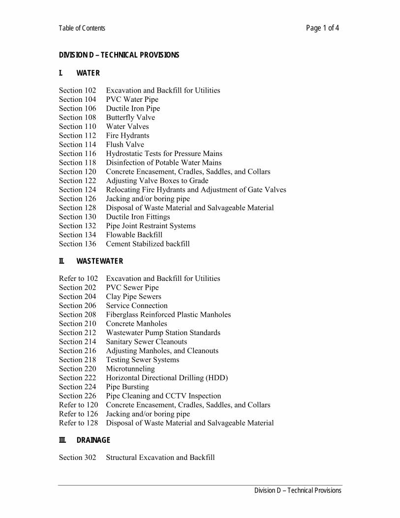
Table of Contents Page 1 of 4
Division D – Technical Provisions
DIVISION D – TECHNICAL PROVISIONS I. WATER
Section 102 Excavation and Backfill for Utilities Section 104 PVC Water Pipe Section 106 Ductile Iron Pipe Section 108 Butterfly Valve Section 110 Water Valves Section 112 Fire Hydrants Section 114 Flush Valve Section 116 Hydrostatic Tests for Pressure Mains Section 118 Disinfection of Potable Water Mains Section 120 Concrete Encasement, Cradles, Saddles, and Collars Section 122 Adjusting Valve Boxes to Grade Section 124 Relocating Fire Hydrants and Adjustment of Gate Valves Section 126 Jacking and/or boring pipe Section 128 Disposal of Waste Material and Salvageable Material Section 130 Ductile Iron Fittings Section 132 Pipe Joint Restraint Systems Section 134 Flowable Backfill Section 136 Cement Stabilized backfill
II. WASTEWATER Refer to 102 Excavation and Backfill for Utilities Section 202 PVC Sewer Pipe Section 204 Clay Pipe Sewers Section 206 Service Connection Section 208 Fiberglass Reinforced Plastic Manholes Section 210 Concrete Manholes Section 212 Wastewater Pump Station Standards Section 214 Sanitary Sewer Cleanouts Section 216 Adjusting Manholes, and Cleanouts Section 218 Testing Sewer Systems Section 220 Microtunneling Section 222 Horizontal Directional Drilling (HDD) Section 224 Pipe Bursting Section 226 Pipe Cleaning and CCTV Inspection Refer to 120 Concrete Encasement, Cradles, Saddles, and Collars Refer to 126 Jacking and/or boring pipe Refer to 128 Disposal of Waste Material and Salvageable Material
III. DRAINAGE Section 302 Structural Excavation and Backfill
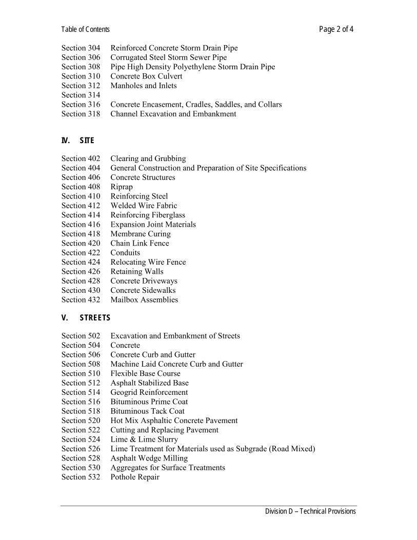
Table of Contents Page 2 of 4
Division D – Technical Provisions
Section 304 Reinforced Concrete Storm Drain Pipe Section 306 Corrugated Steel Storm Sewer Pipe Section 308 Pipe High Density Polyethylene Storm Drain Pipe Section 310 Concrete Box Culvert Section 312 Manholes and Inlets Section 314 Section 316 Concrete Encasement, Cradles, Saddles, and Collars Section 318 Channel Excavation and Embankment
IV. SITE Section 402 Clearing and Grubbing Section 404 General Construction and Preparation of Site Specifications Section 406 Concrete Structures Section 408 Riprap Section 410 Reinforcing Steel Section 412 Welded Wire Fabric Section 414 Reinforcing Fiberglass Section 416 Expansion Joint Materials Section 418 Membrane Curing Section 420 Chain Link Fence Section 422 Conduits Section 424 Relocating Wire Fence Section 426 Retaining Walls Section 428 Concrete Driveways Section 430 Concrete Sidewalks Section 432 Mailbox Assemblies
V. STREETS Section 502 Excavation and Embankment of Streets Section 504 Concrete Section 506 Concrete Curb and Gutter Section 508 Machine Laid Concrete Curb and Gutter Section 510 Flexible Base Course Section 512 Asphalt Stabilized Base Section 514 Geogrid Reinforcement Section 516 Bituminous Prime Coat Section 518 Bituminous Tack Coat Section 520 Hot Mix Asphaltic Concrete Pavement Section 522 Cutting and Replacing Pavement Section 524 Lime & Lime Slurry Section 526 Lime Treatment for Materials used as Subgrade (Road Mixed) Section 528 Asphalt Wedge Milling Section 530 Aggregates for Surface Treatments Section 532 Pothole Repair

Table of Contents Page 3 of 4
Division D – Technical Provisions
Section 534 Utility Cut Pavement Repair Section 536 Parking Lots Section 538 Pedestrian Railing
VI. ENVIRONMENTAL Section 602 Silt Fence Section 604 Erosion Control Blankets Section 606 NPDES Requirements Section 608 Hydro-Mulch Seeding Section 610 Seeding
VII. TRAFFIC MANAGEMENT Section 702 Permanent Traffic Barricades Section 704 Street Signs Section 706 Reflectorized Pavement Markings Section 708 Metal Beam Guard Fence Section 710 Relocation of Permanent Signs Section 712 Traffic Control and Regulation Section 714 Lighting and Traffic Signals
VIII. MISCELLANEOUS Section 802 Sheeting and Bracing Section 804 Work Performed on Non-Working Days Section 806 Automatic irrigation System Section 808 Steel Plate Bridging Utility Provisions Section 810 Definitions IX. STANDARD DRAWINGS No. TITLE OF DRAWING 102-1 Trench backfill condition “A” 102-2 Trench backfill condition “B” 102-3 Trench backfill condition “C” 102-4 Trench backfill condition “D” 126-1 Steel Casing 126-2 Casing Spacers 126-3 Casing End seals 304-1 Storm Sewer Pipe Connections 304-2 Storm Sewer Pipe Connections
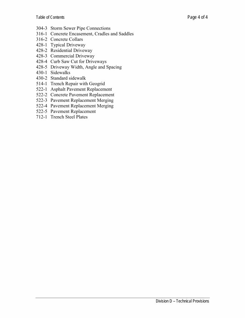
Table of Contents Page 4 of 4
Division D – Technical Provisions
304-3 Storm Sewer Pipe Connections 316-1 Concrete Encasement, Cradles and Saddles 316-2 Concrete Collars 428-1 Typical Driveway 428-2 Residential Driveway 428-3 Commercial Driveway 428-4 Curb Saw Cut for Driveways 428-5 Driveway Width, Angle and Spacing 430-1 Sidewalks 430-2 Standard sidewalk 514-1 Trench Repair with Geogrid 522-1 Asphalt Pavement Replacement 522-2 Concrete Pavement Replacement 522-3 Pavement Replacement Merging 522-4 Pavement Replacement Merging 522-5 Pavement Replacement 712-1 Trench Steel Plates

Excavation and Backfill for Utilities Page 1 of 9
Division D - Technical Provisions
SECTION 102
EXCAVATION AND BACKFILL FOR UTILITIES D-102.01 SCOPE: This section shall govern all excavation and backfill which will be encountered during the work, and supplements those paragraphs pertaining to excavation in Sections entitled "SPECIFICATIONS FOR SDR 26-GRAVITY SEWER PIPING", "WATER LINE CONSTRUCTION", AND "PVC PIPE WATER CONDUITS & INSTALLATION" of these specifications. D-102.02 CLASSIFICATION: All excavation for this Project shall be considered unclassified. The Contractor is expected to determine the nature of the work and to make his bid prices reflective of the actual conditions which will be encountered. No claim for extra compensation shall be made by the Contractor due to rock, or other unfavorable excavation conditions encountered during the course of the work. D-102.03 EXISTING UTILITIES: Before commencing excavation, the Contractor shall notify all utility companies with sufficient lead time, and confirm the location of existing underground lines and conduits in the work area by calling 811. D-102.04 CLEARING: The Contractor shall do all clearing, grubbing, etc. necessary to complete the work. D-102.05 DEWATERING: The Contractor shall provide and maintain adequate equipment to remove and dispose of all surface and ground-water entering excavations, trenches, or other parts of the work. D-102.06 EXCAVATION: Unless otherwise ordered by the Engineer in writing, trench shall be as indicated in the Drawings, and trenching for water lines shall be excavated to a depth of five feet. D-102.07 SHEETING AND SHORING: Where necessary to protect workmen, the work, or the existing structures, the Contractor shall sheet, brace, and shore the excavation to prevent caving or sliding. This item is further described in Division D, Section 802, entitled "SHEETING AND BRACING". D-102.08 DISPOSAL OF EXCESS SOIL: Unless otherwise specified, the Contractor shall dispose of all unsuitable or excess excavation spoil daily. Disposal shall be made at a location and in a manner which is acceptable to the Owner. D-102.09 PIPE ZONE: The "pipe zone" shall mean that portion of the trench which extends from 24 " above the top of the pipe joints to the bottom of the excavation. "Above the pipe zone" shall mean that portion of the trench which shall extend from 24" above the top of the pipe joints to the top of the finished surface. D-102.10 BLASTING: Where deemed necessary by the Contractor, and only when authorized in writing by the Engineer, the trench may be blasted. The Contractor shall take all necessary precautions as specified in the General Provisions of these Specifications. The Contractor shall be
Excavation and Backfill for Utilities Page 2 of 9
Division D - Technical Provisions
solely responsible for any damage incurred due to blasting. D-102.11 OVER-EXCAVATION: In the event of over-excavation, the over- excavated depth of the trench shall be filled with the appropriate bedding material. D-102.12 STABILIZATION: Subgrade for pipe work shall be firm, dense, and thoroughly consolidated. The subgrade shall be free of mud, muck, loose material and debris, and shall remain firm and intact under the workmen's feet. D-102.13 PIPE EMBEDMENT & PIPE ZONE BACKFILL: The first layer of backfill shall be sufficient to provide a compacted depth of one-half the outside diameter of the barrel. This layer shall be placed by hand and tamped with hand or pneumatic tampers. The rest of the pipe zone shall be placed in a similar manner in layers not to exceed 8" loose measure to the top of the pipe zone. Unless otherwise specified, the embedment and material in the pipe zone shall be granular siliceous material free of rocks over 2" in any dimension, which shall contain no more than 25 percent by weight of clay, silt, or organic such as pit run washed sand. Select excavation material may be acceptable; however, the contractor may be required to submit ample sieve analysis results from a reputable independent testing laboratory in order to use such materials for embedment. All backfill material shall be free of trash, debris, and boulders larger than 5" in any dimension. B ackfill material containing rock over 3" in any dimension shall not be used in trenches under paved areas. The pipe trench shall be backfilled in a manner so as to prevent future settlement for a period of one year after date of final payment. Before leaving the work at night or any other time, the upper ends of all pipes shall be securely closed with a tight fitting plug and provisions shall be made to keep the line from floating out of place should the trench fill with water. Any damage to the sewer lines from failure to follow these provisions shall be repaired at Contractor's expense. Provisions must be made at all times to keep the interior of the pipe that has been laid free from dirt, silt, gravel, and any other foreign matter and any such material that is deposited within the pipe from any cause whatsoever must be removed as the work progresses. D-102.14 BACKFILLING: All trenches and excavations shall be backfilled within 24 hours after pipes are installed therein unless other means of protecting the pipe is directed by the Engineer. At no times, however, shall any backfilling be done until the Engineer has inspected the pipe to be covered. Backfilling requirements: Materials:
1.1. Initial (primary) backfill to a point of 12 inches above the top of pipe shall be done as
follows:
1.1.1. Suitable excavated material placed in uniform lifts not more than 6 inches in depth and shall be compacted to the density specified herein. The maximum dry density and optimum moisture shall be determined as per TxDot Tex-114-E. Test for in place density shall be in accordance with TxDOT Tex-115-E within 24 hours after
Excavation and Backfill for Utilities Page 3 of 9
Division D - Technical Provisions
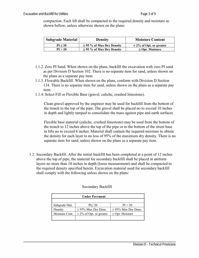
compaction. Each lift shall be compacted to the required density and moisture as shown bellow, unless otherwise shown on the plans:
Subgrade Material Density Moisture Content PI ≤ 20 ≥ 95 % of Max Dry Density ± 2% of Opt. or greater PI > 20 ≥ 95 % of Max Dry Density ≥ Opt. Moisture
1.1.2. Zero PI Sand. When shown on the plans, backfill the excavation with zero PI sand as per Division D Section 102. There is no separate item for sand, unless shown on the plans as a separate pay item.
1.1.3. Flowable Backfill. When shown on the plans, conform with Division D Section 134. There is no separate item for sand, unless shown on the plans as a separate pay item.
1.1.4. Select Fill or Flexible Base (gravel, caliche, crushed limestone).
Clean gravel approved by the engineer may be used for backfill from the bottom of the trench to the top of the pipe. The gravel shall be placed no to exceed 10 inches in depth and lightly tamped to consolidate the mass against pipe and earth surfaces.
Flexible base material (caliche, crushed limestone) may be used from the bottom of the trench to 12 inches above the top of the pipe or to the bottom of the street base in lifts no to exceed 8 inches. Material shall contain the required moisture to obtain the density for each layer to no less of 95% of the maximum dry density. There is no separate item for sand, unless shown on the plans as a separate pay item.
1.2. Secondary Backfill. After the initial backfill has been completed at a point of 12 inches
above the top of pipe, the material for secondary backfill shall be placed in uniform layers no more than 10 inches in depth (loose measurement) and shall be compacted to the required density specified herein. Excavation material used for secondary backfill shall comply with the following unless shown on the plans:
Secondary Backfill
Under Pavement Subgrade Mat. PI≤ 20 PI > 20 Density ≥ 95% Max Dry Dens. ≥ 95% Max Dry Dens. Moisture Cont. ± 2% of Opt. or greater ≥ Opt. Moisture
Excavation and Backfill for Utilities Page 4 of 9
Division D - Technical Provisions
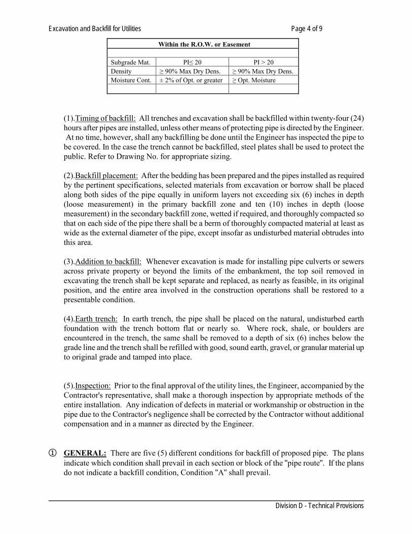
Within the R.O.W. or Easement Subgrade Mat. PI≤ 20 PI > 20 Density ≥ 90% Max Dry Dens. ≥ 90% Max Dry Dens. Moisture Cont. ± 2% of Opt. or greater ≥ Opt. Moisture
(1).Timing of backfill: All trenches and excavation shall be backfilled within twenty-four (24) hours after pipes are installed, unless other means of protecting pipe is directed by the Engineer. At no time, however, shall any backfilling be done until the Engineer has inspected the pipe to be covered. In the case the trench cannot be backfilled, steel plates shall be used to protect the public. Refer to Drawing No. for appropriate sizing. (2).Backfill placement: After the bedding has been prepared and the pipes installed as required by the pertinent specifications, selected materials from excavation or borrow shall be placed along both sides of the pipe equally in uniform layers not exceeding six (6) inches in depth (loose measurement) in the primary backfill zone and ten (10) inches in depth (loose measurement) in the secondary backfill zone, wetted if required, and thoroughly compacted so that on each side of the pipe there shall be a berm of thoroughly compacted material at least as wide as the external diameter of the pipe, except insofar as undisturbed material obtrudes into this area. (3).Addition to backfill: Whenever excavation is made for installing pipe culverts or sewers across private property or beyond the limits of the embankment, the top soil removed in excavating the trench shall be kept separate and replaced, as nearly as feasible, in its original position, and the entire area involved in the construction operations shall be restored to a presentable condition. (4).Earth trench: In earth trench, the pipe shall be placed on the natural, undisturbed earth foundation with the trench bottom flat or nearly so. Where rock, shale, or boulders are encountered in the trench, the same shall be removed to a depth of six (6) inches below the grade line and the trench shall be refilled with good, sound earth, gravel, or granular material up to original grade and tamped into place. (5).Inspection: Prior to the final approval of the utility lines, the Engineer, accompanied by the Contractor's representative, shall make a thorough inspection by appropriate methods of the entire installation. Any indication of defects in material or workmanship or obstruction in the pipe due to the Contractor's negligence shall be corrected by the Contractor without additional compensation and in a manner as directed by the Engineer.
① GENERAL: There are five (5) different conditions for backfill of proposed pipe. The plans
indicate which condition shall prevail in each section or block of the "pipe route". If the plans do not indicate a backfill condition, Condition "A" shall prevail.
Excavation and Backfill for Utilities Page 5 of 9
Division D - Technical Provisions
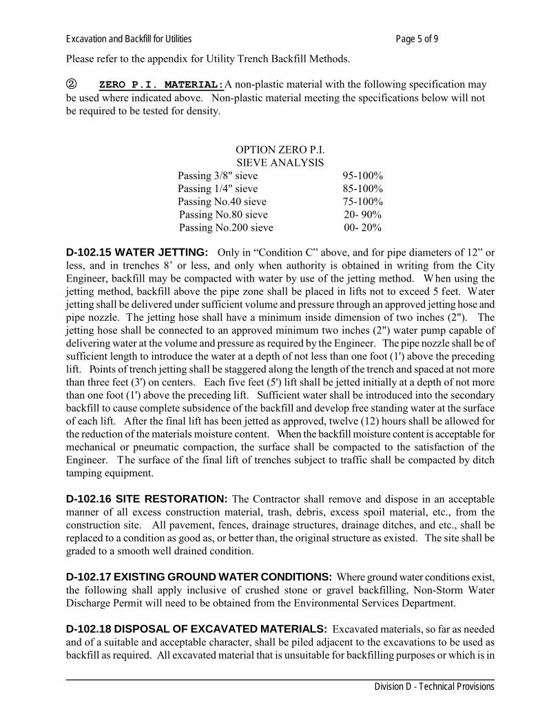
Please refer to the appendix for Utility Trench Backfill Methods. ② ZERO P.I. MATERIAL:A non-plastic material with the following specification may be used where indicated above. Non-plastic material meeting the specifications below will not be required to be tested for density.
OPTION ZERO P.I. SIEVE ANALYSIS
Passing 3/8" sieve 95-100% Passing 1/4" sieve 85-100% Passing No.40 sieve 75-100% Passing No.80 sieve 20- 90% Passing No.200 sieve 00- 20%
D-102.15 WATER JETTING: Only in “Condition C” above, and for pipe diameters of 12” or less, and in trenches 8’ or less, and only when authority is obtained in writing from the City Engineer, backfill may be compacted with water by use of the jetting method. W hen using the jetting method, backfill above the pipe zone shall be placed in lifts not to exceed 5 feet. Water jetting shall be delivered under sufficient volume and pressure through an approved jetting hose and pipe nozzle. The jetting hose shall have a minimum inside dimension of two inches (2"). The jetting hose shall be connected to an approved minimum two inches (2") water pump capable of delivering water at the volume and pressure as required by the Engineer. The pipe nozzle shall be of sufficient length to introduce the water at a depth of not less than one foot (1') above the preceding lift. Points of trench jetting shall be staggered along the length of the trench and spaced at not more than three feet (3') on centers. Each five feet (5') lift shall be jetted initially at a depth of not more than one foot (1') above the preceding lift. Sufficient water shall be introduced into the secondary backfill to cause complete subsidence of the backfill and develop free standing water at the surface of each lift. After the final lift has been jetted as approved, twelve (12) hours shall be allowed for the reduction of the materials moisture content. When the backfill moisture content is acceptable for mechanical or pneumatic compaction, the surface shall be compacted to the satisfaction of the Engineer. The surface of the final lift of trenches subject to traffic shall be compacted by ditch tamping equipment. D-102.16 SITE RESTORATION: The Contractor shall remove and dispose in an acceptable manner of all excess construction material, trash, debris, excess spoil material, etc., from the construction site. All pavement, fences, drainage structures, drainage ditches, and etc., shall be replaced to a condition as good as, or better than, the original structure as existed. The site shall be graded to a smooth well drained condition. D-102.17 EXISTING GROUND WATER CONDITIONS: Where ground water conditions exist, the following shall apply inclusive of crushed stone or gravel backfilling, Non-Storm Water Discharge Permit will need to be obtained from the Environmental Services Department. D-102.18 DISPOSAL OF EXCAVATED MATERIALS: Excavated materials, so far as needed and of a suitable and acceptable character, shall be piled adjacent to the excavations to be used as backfill as required. All excavated material that is unsuitable for backfilling purposes or which is in
Excavation and Backfill for Utilities Page 6 of 9
Division D - Technical Provisions
excess of the amount required or needed to satisfactorily complete the backfill, shall be disposed of daily. The character and suitability of all backfill material shall meet the approval of the Engineer. Desirable top soil, or sod, etc., shall be carefully piled separately from the other excavated material so that it can be placed in this original position when required. Excavated material shall be handled at all times in such manner as to cause a minimum of inconvenience to public travel and to permit safe and convenient access to private and public properties adjacent to or along the line of the work. In parkways and easements, where it is necessary to deposit excavated materials on lawns during the progress of the work, care shall be taken to prevent damage to such lawns. Where damage is done to such lawns all expense of replacing the lawn shall be borne by the Contractor. D-102.19 REMOVAL AND REPLACEMENT OF SOD, SHRUBBERY, PLANTS, ETC.: Where it is necessary to remove the sod, shrubbery, plants, etc., in order to make any excavation for this work, such areas as are backfilled shall have the same sod, shrubbery, plants, etc. replaced in good condition or if necessary to furnish new sod, shrubbery, or plants of the same kind and in good condition, same shall be furnished by the Contractor at his expense. The sod, where removal is deemed necessary, shall be removed in squares cut out with a sharp spade or other satisfactory tool; the square shall be of such sizes that they may be conveniently handles without breaking. Such sod shall be removed in layers of not less than four inches (4") depth and shall be stored and given proper attention to protect sod from drying out, pending the time of replacement. If trees and plants shall be removed, this work shall be done in the approved manner as to require protection of roots, branches, etc.; when backfilling is completed the trees and plants shall be replaced in their original position or as near such position as possible. If irrigation system has to be removed and replaced, refer to Section 806. D-102.20 PROTECTION OF TREES, PLANTS, SHRUBBERY, ETC.: In developed areas where trees, plants, shrubbery, etc., are adjacent to the line of work, the Contractor shall protect such trees, plants, or shrubbery by wooden boxes, frames, or guards of sufficient strength to prevent any injury from machinery, trucks, or workmen during the prosecution of the work. D-102.21 Payment. No pay item will be included in the proposal nor direct payment made for excavation and backfill. The cost for placing the material shall be included in the unit price bid for the specific work function.
PVC Water Pipe Page 1 of 6
Division D - Technical Provisions
SECTION 104
PVC WATER PIPE D-104.01 GENERAL 1. Description
This work shall consists of the construction, complete in place of PVC Water Pipe as specified herein, and in conformity with the lines, grades, dimensions, materials, and design shown on the plans.
D-104.02 PRODUCTS 1. Polyvinyl Chloride Water Pipe A. GENERAL
All polyvinyl chloride (PVC) water pipe shall of the rigid (UNPLASTICIZED) type and must bear the National Sanitation Foundation seal of approval for potable water pipe. Each joint of pipe shall consist of single continuous extrusion; bells or other components attached by solvent welding are not acceptable. Pipe shall be pressure rated at 200 psi (DR 14, C-900) as indicated. Pipe shall have push-on, rubber joints of the bell and spigot type with thickened general bells with rubber gasket joints. The wall thickness of each pipe bell and joint coupling must be greater than the standard pipe barrel thickness. Clearance must be provided in every gasket joint for both lateral pipe deflection and for linear expansion and contraction. Concrete thrust blocking shall be placed behind bends and tees. Concrete support cradles or blocking shall be required for support of all fire hydrants, valves and AWWA C110 fittings; such support shall be provided for AWWA C153 fittings when required by the Engineer.
B. APPLICABLE SPECIFICATIONS
Except as modified or supplemented herein, PVC pipe shall meet the following standards: -DR 14, C-900, Class 200 PVC Pipe to be used for installation of water mains 8” to 12” not deeper than 8 feet. All installation methods, testing procedures and backfilling requirements must be followed as per these specifications. -AWWA C-900, DR 14 f or PVC Pressure Pipe, in 2, 6, 8 and 12 i nches nominal size, having Cast Iron size outside diameters in trenches greater than or equal to a depth of 10 ft. -Fittings used with PVC Pressure pipe shall be AWWA C-110 or AWWA C-153 compact ductile iron fittings. For water mains 16 and 24 inches nominal size -AWWA C900 DR 14 Class 200 -AWWA C905 DR 18 Class 235 -Any pipe 24” or greater requires a separate specification submittal.
PVC Water Pipe Page 2 of 6
Division D - Technical Provisions
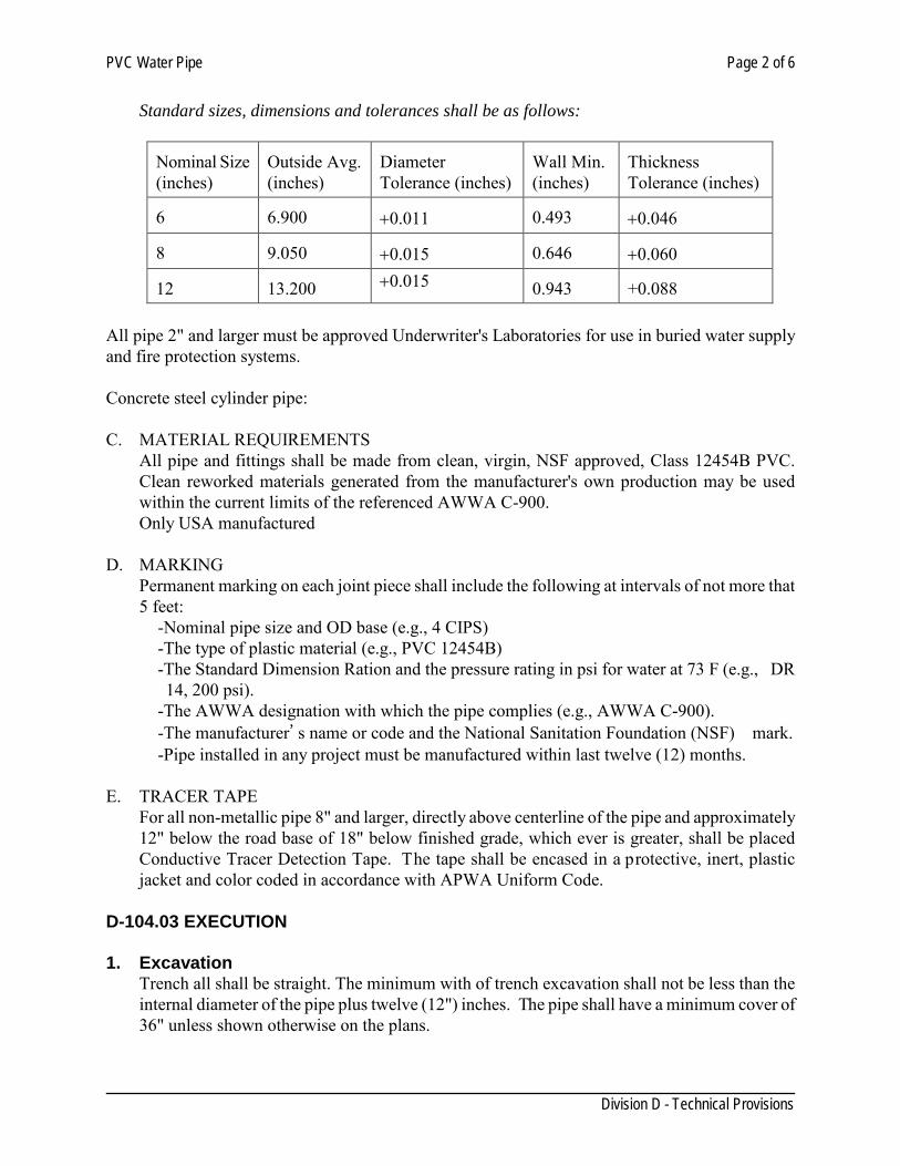
Standard sizes, dimensions and tolerances shall be as follows:
Nominal Size (inches)
Outside Avg. (inches)
Diameter Tolerance (inches)
Wall Min. (inches)
Thickness Tolerance (inches)
6
6.900
+0.011
0.493
+0.046
8
9.050
+0.015
0.646
+0.060
12
13.200 +0.015
0.943 +0.088
All pipe 2" and larger must be approved Underwriter's Laboratories for use in buried water supply and fire protection systems. Concrete steel cylinder pipe: C. MATERIAL REQUIREMENTS
All pipe and fittings shall be made from clean, virgin, NSF approved, Class 12454B PVC. Clean reworked materials generated from the manufacturer's own production may be used within the current limits of the referenced AWWA C-900. Only USA manufactured
D. MARKING
Permanent marking on each joint piece shall include the following at intervals of not more that 5 feet:
-Nominal pipe size and OD base (e.g., 4 CIPS) -The type of plastic material (e.g., PVC 12454B) -The Standard Dimension Ration and the pressure rating in psi for water at 73 F (e.g., DR 14, 200 psi).
-The AWWA designation with which the pipe complies (e.g., AWWA C-900). -The manufacturer's name or code and the National Sanitation Foundation (NSF) mark. -Pipe installed in any project must be manufactured within last twelve (12) months.
E. TRACER TAPE
For all non-metallic pipe 8" and larger, directly above centerline of the pipe and approximately 12" below the road base of 18" below finished grade, which ever is greater, shall be placed Conductive Tracer Detection Tape. The tape shall be encased in a protective, inert, plastic jacket and color coded in accordance with APWA Uniform Code.
D-104.03 EXECUTION 1. Excavation
Trench all shall be straight. The minimum with of trench excavation shall not be less than the internal diameter of the pipe plus twelve (12") inches. The pipe shall have a minimum cover of 36" unless shown otherwise on the plans.
PVC Water Pipe Page 3 of 6
Division D - Technical Provisions
2. Embedment Using Gravel or Granular Material Where rock shale or boulders are encountered in the trench, the same shall be removed to a depth of 6" below the grade line and the trench shall be refilled with sand, gravel, or up to the original grade and tamped into place.
3. Pipe Laying
Pipe shall not be laid where the sub-grade is in a condition unsatisfactory to the Engineer. If sub-grade is soft, spongy, of disintegrated, the material shall be removed until a firm, stable and uniform bearing is reached and the sub-grade brought back to grade with suitable materials thoroughly compacted in place. Embedment for the pipe or the pipe itself will NOT be laid in water.
Where pipe is installed beneath railroad tracks, construction clearance to cross under railroad trackage shall be obtained by Contractor or facility owner from proper railroad authorities. Any expense of bracing or support to tracks during excavation operation beneath trackage shall be considered part of the contractor.
Where pipe shall be installed beneath State Highways, construction clearance and other requirements to cross under State Highways shall be obtained from State Highway District Engineer by facility owner.
Proper traffic control devices as per TMUTCD shall be placed and maintained to assure maximum traffic and pedestrian safety, or as directed by Local, Railroad, State Highway authorities or other governing agencies.
Owner will obtain all permits for construction, and will make a formal application for the right to cross canals, railroads, highways, pipe lines etc., Contractor must cooperate fully with all agencies involved while construction in areas controlled by such agencies.
Before pipe is laid, all dirt shall be removed from inside; and all lumps, blisters, excess coal tar, dirt, oil, and grease removed from both inside and outside of pipe.
After pipe is laid, care shall be taken to avoid entrance of dirt, water or small animals by use of tight bulk heads in all openings.
4. Service Saddles
Service saddles shall be of the un-hinged type on PVC Class 900 pipe (size 6" to 12"). The saddle body and bottom is to be of 85-5-5-5 solid brass, material as per ASTM B-62, single width with a minimum of two (2) silicone bronze bolts and a cc-thread.
Bronze saddles with bronze bolts must meet the latest revision of AWWA specifications for saddles to be used on Class 900 PVC pipes.
-Saddles 6" to 12" are to be Jones J-996, or approved equal. -Saddles 14" to 16" are to be Jones J-979, or approved equal
PVC Water Pipe Page 4 of 6
Division D - Technical Provisions
Stainless Steel Saddle Type 316 As per ASTM A240M (to meet or exceed). These specifications are not intended to eliminate any material or equipment of equal quality and purpose of that specified, but instead designed to set standards. If the contractor wishes to use equal material or equipment, he shall submit a sample and/or written proof of quality that
substitute is of equal or better quality to Engineer and Water Utilities Engineer and shall function as these plans and specifications intend.
5. Pipe Joints
Manufacturer's recommendations shall be followed. Under no circumstances joints will be subject to full hydrostatic pressure until after the joint has cured for 8 hours.
6. Installation
No tapping or threading of plastic pipe shall be permitted on pipe with a wall thickness less than Schedule 80.
7. Pipe Restraints
• Mechanical joints • Concrete Thrust Blocks
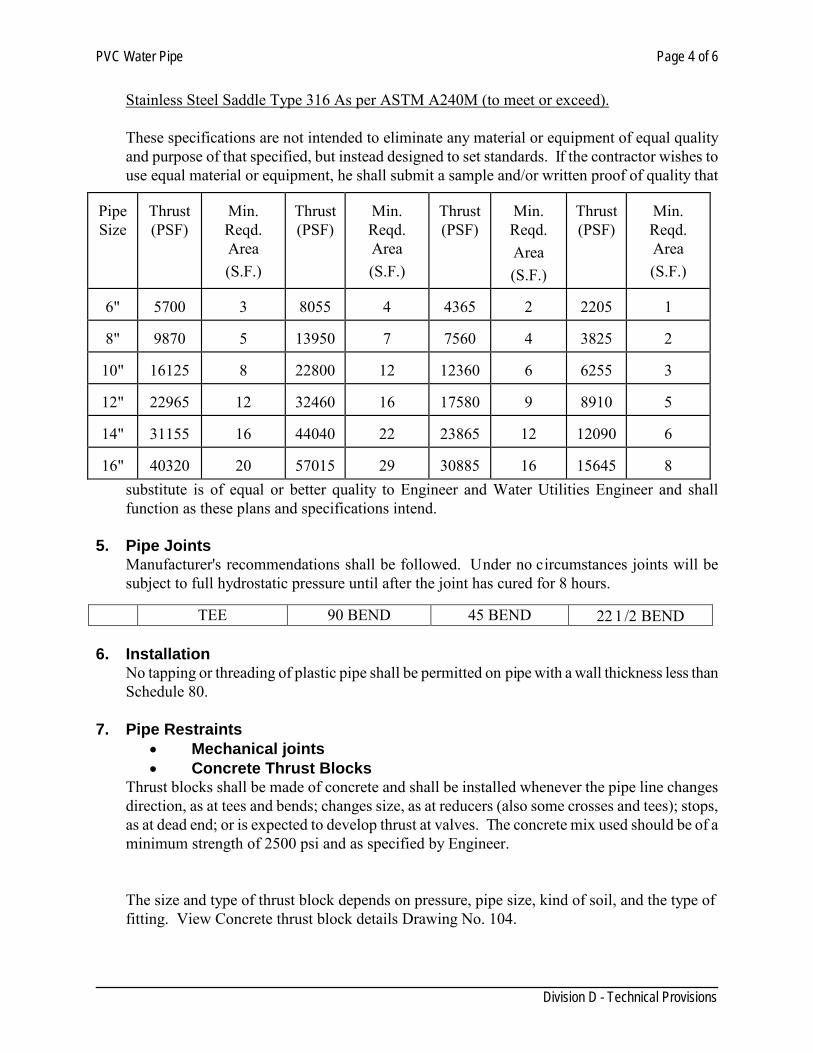
Thrust blocks shall be made of concrete and shall be installed whenever the pipe line changes direction, as at tees and bends; changes size, as at reducers (also some crosses and tees); stops, as at dead end; or is expected to develop thrust at valves. The concrete mix used should be of a minimum strength of 2500 psi and as specified by Engineer.
The size and type of thrust block depends on pressure, pipe size, kind of soil, and the type of fitting. View Concrete thrust block details Drawing No. 104.
TEE 90 BEND 45 BEND 22 1/2 BEND
Pipe Size
Thrust (PSF)
Min. Reqd. Area (S.F.)
Thrust (PSF)
Min. Reqd. Area (S.F.)
Thrust (PSF)
Min. Reqd. Area (S.F.)
Thrust (PSF)
Min. Reqd. Area (S.F.)
6"
5700
3
8055
4
4365
2
2205
1
8"
9870
5
13950
7
7560
4
3825
2
10"
16125
8
22800
12
12360
6
6255
3
12"
22965
12
32460
16
17580
9
8910
5
14"
31155
16
44040
22
23865
12
12090
6
16"
40320
20
57015
29
30885
16
15645
8
PVC Water Pipe Page 5 of 6
Division D - Technical Provisions
Thrust based on 150 psi water pressure. Area based on 2,000 psf soil bearing 8. Storage
Storage of PVC shall be in the shade or shall be covered with a suitable cover. PVC pipe shall not be exposed to the sun longer than 24 hours while being laid.
9. Hydrostatic Tests
All pipe lines constructed under this contract before being accepted shall be tested with a hydraulic test according to Section 116"Hydrostatic Tests for Pressure Mains".
The cost of testing and finding leaks and repairing the same and re-testing, if necessary, shall be at the expense of the Contractor. The water required to fill the lines shall be furnished by the Contractor.
10. Line Disinfection
The completed water line shall be disinfected according to Section 118"Disinfection of Potable Water Mains".
The chlorinated water shall then be discharged from the water line and replaced with fresh potable water.
The Contractor will furnish all labor materials and equipment necessary to complete the proper disinfection of the line and the cost of this operation shall be included in the bid price for installation of the distribution system.
11. Measurement
PVC pipe will be measured for payment in linear feet along the center line of the trench. No deduction will be made for valves and fittings.
12. Payment
PVC pipe will be paid for at the unit price per linear foot, complete in place, as provided in the proposal and contract. The contract price per linear foot shall be the total compensation for the furnishing of all labor, materials, tools, equipment, and incidentals necessary to complete work, including excavation, granular embedment material, backfill, and disposal of surplus materials, in accordance with the plans and these specifications.
Ductile Iron Pipe Page 1 of 3
Division D - Technical Provisions
SECTION 106 DUCTILE IRON PIPE
GENERAL
D-106.01 DESCRIPTION: 1. Scope: This section describes the manufacture, construction, and installation of ductile iron pipe and fittings. D-106.02 QUALITY ASSURANCE: Reference Standards: a. AWWA - C105, C110, C111, C115, C151, C153, C600, C651. b. ASTM - C33, C150 D-106.03 SUBMITTALS: 1. Submit manufacturer's data on pipe furnished, indicating compliance with the Specifications
regarding dimensions, thickness, weights, and materials. W here flanged pipe is called for, submit complete piping layout indicating the length of each flanged joint to be furnished.
PRODUCTS D-106.04 DUCTILE IRON PIPE AND FITTINGS: 1. GENERAL:
a. Ductile iron pressure pipe six inches (6") in diameter and larger shall conform to the current American National Standard Specifications for Ductile Iron Pipe, Centrifugally Cast in Metal Molds or Sand-Lined Molds, for Water or Other Liquids, AWWA C151 (A 21.51).
b. Ductile iron pipe less than six inches (6") in diameter shall be prohibited. 2. DESIGN REQUIREMENTS:
a. The ductile iron shall conform in all respects to the Current Specification for Ductile Iron Castings, ASTM Designation A536.
b. Thickness Class: Ductile iron pipe shall be Class 5.2 minimum unless otherwise shown on the plans.
3. JOINTS:
a. All ductile iron pressure pipes shall be furnished with one of the following types of joints. Buried pipe shall be furnished with push-on or mechanical joint ends unless otherwise noted. Exposed pipe shall be flanged. TYPE OF JOINT REFERENCE STANDARD
Ductile Iron Pipe Page 2 of 3
Division D - Technical Provisions
Push-on Joint AWWA C111 Mechanical Joint AWWA C111 Flanged Ends AWWA C110 & 115
b. All screwed flanges shall be ductile iron. c. Provide restrained joint inside encasement.
4. COATING AND LINING: All ductile iron pipe and all fittings shall be bituminous coated
outside in accordance with AWWA Standards, and polyethylene lined. Provide a nominal 40 mil interior lining of polyethylene. P rovide lining of a blend of high- density and low-density polyethylene powders complying with ASTM D1248 compounded with an inert filler and carbon black to resist ultraviolet rays. Preheat pipe in a furnace to insure uniform heat distribution and fusing of the polyethylene powders and proper bonding to the pipe.
5. UNDERWRITER'S APPROVAL: Ductile iron pipe shall be approved by the Underwriter's
Laboratory and shall be accepted by the State Fire Insurance Board for use in water distribution systems without penalty. All pipes shall be new.
6. BOLTS AND NUTS: Bolts and nuts for mechanical joints pipe shall be of 316 stainless steel.
Flange bolts and nuts for above ground installation shall be 304 stainless steel. Flange bolts and nuts for below ground or submerged installations shall be Type 316 stainless steel.
D-106.05 FLANGE GASKETS: Flange gaskets shall be full faced and conform to Appendix A of AWWA C115. EXECUTION D-106.06 EXECUTION: Lay all pipes in accordance with AWWA C600, except as modified herein. D-106.07 PIPE LAYING AND JOINTING:
1. After the subgrade and embedment materials have been placed and the length of pipe has been placed in the trench, center the spigot in the bell and apply the pipe joint lubricant recommended by the pipe manufacturer. Force the spigot "home" using cables or excavating machinery. Use timbers to protect the bell of the joint from damage during jointing operation, especially when excavating machinery is used to force the pipe home.
2. Lay the pipe in such a fashion that the full length of the barrel of the pipe is resting on the embedment. Excavate bell holes so the bell of the pipe does not touch the bottom of the ditch. Take precautions to prevent dirt and embedment materials from entering the joint space. No blocking up of the pipe or joints will be permitted.
D-106.08 CUTTING OF PIPE: Saw cut pipe for closure pieces in a neat, workmanlike manner without damage to the pipe. Make each cut square to the centerline of the pipe and bevel the outside edge of the pipe at the cut to the same configuration and dimensions as the factory applied spigot
Ductile Iron Pipe Page 3 of 3
Division D - Technical Provisions
level. D-106.9 PROTECTION OF PIPE: At all times when pipe laying is not in progress, cover the open ends with a pvc plug of the pipeline to prevent water, debris, and animals from entering the pipe. Remove all foreign matter or dirt from the pipe during laying operations. Do not lay pipe in water or when trench conditions are unsuitable for such work. D-106.10 POLYETHYLENE TUBE PROTECTION: All buried cast iron and ductile iron pipe and fitting shall be provided with polyethylene tube protection. Install polyethylene tube according to AWWA C105. Completely cover all fitting and connections with polyethylene film held securely in place with joint tape or strapping. D-106.11 COATING: Provide a 10 mil thick field coat of bituminous paint on exposed piping. D-106.12 PAYMENT:
Butterfly Valve Page 1 of 2
Division D - Technical Provisions
SECTION 108
BUTTERFLY VALVE
D-108.01 DESCRIPTION: This item shall govern the furnishing of all materials and doing all of the work required to install butterfly valves of the sizes called for in the plans and/or as directed by the Engineer. D-108.02 MATERIALS
1. Butterfly Valves shall be Mueller Linesralill or approved equivalent and shall be manufactured in accordance with the latest revision of AWWA C504 for Class 105B service. All butterfly valves shall be manufactured in accordance with the latest revision of AWWA C504 for Class 150B service and comply with the following details:
• Valve Bodies shall be constructed of cast iron ASTM A-126 Class Band conform to AININA C504 in terms of laying lengths and minimum body shell thickness.
• End Connections shall be as specified on the plans. • Valve Discs shall also be made from cast iron ASTM A-126 Class B (3"- 20").
Disc shall be furnished with 316 stainless steel seating edge to mate with the rubber seat on the body.
• Valve Seat shall be Buna N rubber located on the valve body. In sizes 20" and smaller, valves shall have bonded seats that meet test procedures outlined in ASTM 0-429 Method B.
• Valve Shafts shall conform to stainless steel ASTM A-276 Type 304. Shaft seals shall be standard self-adjusting, Chevron V-Type packing. Shaft seals shall be of a design allowing replacement without removing the valve shaft.
• Valve Bearings shall be sleeve type that are corrosion resistant and selflubricating.Bearing load shall not exceed 1/51h of the compressive load strength of the material.
• Valve Actuators shall be fully grease packed and have stops in the open/close position. The actuator shall have a mechanical stop which will withstand an input torque of 450 ft. Ibs. The traveling nut shall engage alignment grooves in the housing.
• The Valve Interior and Exterior Surfaces, except for seating, shall be coated in accordance with TT-C-494A and AININA C504.
• Bolts and Nuts shall be 316 stainless steel and shall be restraint as per spec 132.
2. CAST IRON VALVE BOXES: Valve boxes in traffic areas shall be two piece, cast iron, screw type, Tyler Series 6850, Mueller or equivalent. The drop cover shall be lettered "WATER". A 6" minimum concrete collar around the valve box where subject to traffic shall be provided. D-108.03 CONSTRUCTION METHODS SETTING VALVES: Valves shall be set in place as piping is being laid. Valves shall be set with stems vertical. Valve boxes shall be placed and adjusted so that the lids are
Butterfly Valve Page 2 of 2
Division D - Technical Provisions
slightly below finished grade and so that the base does not bear directly upon any part of the valve. Valve shall have a concrete support as per Engineer design. Valve extensions shall be installed on valves buried more than 8 feet. PLASTIC WRAP AND SAND: The valve and fitting beneath shall be wrapped with 8 mil. Polyethylene wrapping material and shall be encased with sand to a point 6" all around the valve. BACKFILLING: Backfill around valve and valve box shall be placed in accordance with the adjacent pipe backfill, as shown in the plans and specified separately herein. D-108.04 MEASUREMENT "Butterfly Valves" will not be measured separately, but shall be included in lump sum bid provided in the bid proposal for fittings, valves, and related appurtenances. D-108.05PAYMENT Payment for "Butterfly Valves" will be paid for at the unit price bid per each of various sizes as shown on plans, which price shall be full compensation for all labor, materials, equipment, including couplings, reaction blocking, joint restraint, valve box assembly, concrete collar, packing operator extensions, and other incidentals necessary to complete the installation and make the valve fully functional as intended.
Water Valves Page 1 of 4
Division D - Technical Provisions
SECTION 110 WATER VALVES
D 110.01 GENERAL 1. Description
This item to consist of valves furnished and installed as indicated. Unless otherwise indicated, all valves 4" and larger shall be AWWA type valves suitable design and fully equipped for service buried in earth, without need for further modification and shall be wrapped with 8 mil polyethylene film with all edges and laps securely taped to provide continuous wrap. Where not indicated, the contractor may use valves with any type end-joint allowed for fittings of the pipe class being used. Unless otherwise indicated, all valve stems shall be adjusted to situate the operating nut not less than 30" or more than 36" below the proposed ground or paving surface of the finished project.
D 110.02 PRODUCTS 1. Materials
Contractor shall, as requested by the Utilities Director, submit descriptive information and evidence that materials and equipment Contractor proposes for incorporation into work is of the kind and quality that satisfies the specified functions and quality. 1. Iron Body Gate Valves, 6" to 12", including Tapping Valves, shall conform to AWWA
C509 2. Iron Body Gate Valves larger than 12", including Tapping Valves, shall be single disc,
meeting the requirements of AWWA C500. 3. Stainless SteelTapping Sleeve
a. Flanged outlet conforming to type 316-L Stainless steel MSS SP-60, with bolt holes drilled per ANSI B16.1 Class 125. Seat rings and body casting shall be over-sized as required to accommodate full size cutters; the outlet end shall be constructed and drilled to allow the drilling machine adapter to be attached directly to the valve.
b. Integral MJ flange outlet conforming type 316 Stainless steel c. Test plug ¾” NPT shall be stainless steel
1. Samples, Inspection and Testing Requirements. All tests and inspections called for by the applicable standards shall be performed by the
manufacturer. Upon request, results of these tests shall be made available to the purchaser. 2. Other Requirements:
Each submittal shall be accompanied by: -Complete data covering the operator, including type and size, model number, etc., the manufacturer's name and address of his nearest service facility, the numbers of turns to fully open and close the valve, detailed instruction for calibrating the limit stops for open and closed positions and any other information which may be necessary to operate and maintain the operator. - Complete dimensional data and installation instructions for the valve assembly as it is to
Water Valves Page 1 of 4
Division D - Technical Provisions
be installed, including the operator. - Complete replacement parts lists and drawings, identifying every part from both the valve and operator.
2. Valves 1. a. Stem Seals: All valves shall be approved O-ring type stem seals. At least two O-rings shall
be in contact with the valve stem where it penetrates the valve body. Valves up to 16” must open counter clock and close clock wise.
b. Operation: All valves shall be approved O-ring type stem seals. At least two O-rings shall be in contact with the valve stem where it penetrates the valve body.
c. Gearing: Double disc gate valves in 16" and larger sizes shall gear and, when necessary for proper bury depth and cover, shall be horizontal bevel-geared type enclosed in a lubricated gear case.
d. Bypass: Unless otherwise indicated, 16" and larger gate valve shall be equipped with a by pass of the non-rising stem type which meets the same AWWA standard required for the main valve.
e. Valve Ends: Valve ends shall be push-on, flanged or mechanical joint, as indicted or approved.
f. Gear Case: All geared valves shall have enclosed gear cases of the extended type, attached to the valve bonnet in a manner that makes it possible to replace the stem seal without disassembly and without disturbing the gears, bearing or gear lubricant. Gear cases shall be designed and fabricated with an opening to atmosphere so that water leakage past the stem seal does not enter the gear case.
g. Valve Body: Double disc gate valves in 16" and larger sizes installed in the horizontal position shall have bronze rollers, tracks, scrapers, etc.
D 110.03 EXECUTION 1. Construction Methods 1. Setting Valves
Unless otherwise indicated, main valves, blow-off valves and piping shall be set and jointed in the manner described for cleaning, laying, and jointing pipe.
Unless otherwise indicated, valves shall be set at the locations shown on the drawings and such that their location does not conflict with other appurtenances such as curb ramps. Valves shall be installed so the tops of operating stems will be at the proper elevation required for the piping at the location indicated above but not exceeding 5ft. in depth. Valve boxes and valve stem casings shall be firmly supported and maintained, centered and aligned plum over the valve or operating stem, with the top of the box or casing installed flush with the finished ground or pavement in existing streets, and installed with the top of the box or casing approximately 6" below the standard street subgrade in streets which are excavated for paving construction or where such excavation is scheduled or elsewhere as directed by the Engineer.
2. Protective Covering
Unless otherwise indicated, all flanges, nuts, bolts, threaded outlets and all other steel component
WATER VALVES Page 4 of 5
Division D - Technical Provisions
shall be coal tar coated and shall be wrapped with standard 8 m il (minimum) low density polyethylene film or 4 mil (minimum) cross laminated high-density polyethylene meeting ANSI/AWWA Specification C-105 current, with all edges and laps taped securely to provide a continuous and watertight wrap. Repair all punctures of the polyethylene, including those caused in the placement of bedding aggregates, with duct tape to restore the continuous protective rap before backfilling.
3. Valve Box, Casing and Cover.
Stems of all buried valves shall be protected by valve box assemblies. Valve box castings shall conform to ASTM A48, Class 30B. Testing shall be verified by the manufacturer. Valve box extension shall be as per manufacturer recommendations. Only USA products will be approved.
2. Measurement
All types of valves will be measured per assembly as per BFV. 3. Payment Payment shall be full compensation in accordance with the pay item seen in the bid, for excavation, furnishing, hauling and placing valves and barrel extensions including anchorage and all incidental and subsidiary material and work; preparing, shaping, dewatering, shoring of trenches, bedding, placing, adjusting to grade, anchoring in place, and compacting backfill materials and for all other incidentals necessary to complete the installation, as indicated, complete in place.
Fire Hydrants Page 1 of 3
Division D - Technical Provisions
SECTION 112 FIRE HYDRANTS
D-112.01 TYPE OF HYDRANT All fire hydrants shall be Dry Barrel, Traffic Model (break away), Post Type having Compression Type Main Valves (5 1/4" opening), closing with line pressure. Hydrants shall be cast-iron, fully bronze mounted, working pressure of 250 psi, test pressure of 500 psi, and shall conform and be in accordance with the latest specifications and revisions of American Water Works Association (AWWA) Standard C-502 for Fire Hydrants for ordinary water works service, except for supplementary requirements contained herein. D-112.02 DESIGN OF HYDRANT Hydrants shall be Mueller Company A423 Super Centurion with safety crash flange or approved equal. D-112.03 FUNCTIONAL REQUIREMENTS Design Working Pressure shall be 250 psi (test pressure 500 psi). Inlet shall be side connection hub end for mechanical joint (ANSI A21.11 - current). Shoe shall be rigidly designed to prevent breakage, with harnessing lugs for joint restraint. Lower Barrel shall be rigid to assure above ground break at traffic feature. Bury length of hydrant shall be 3 1/2 feet hydrant lead pipe may be elbowed up from main using restrained joints; flanged joints in lead pipes are not allowed. Flange type connections between hydrant shoe, barrel sections and bonnet shall have minimum 6-316 Stainless Steel bolts and nuts for the underground fittings and 304 SS for the above ground connections. Hydrant Main Valve shall be 5 1/4 inch I.D. Valve stem design shall meet requirements of AWWA C502, with operating nut turning clockwise to close. Operating nut shall be pentagonal - 1 1/2 inch (point to flat) at base, and 1 7/16" at top - 1 inch minimum height. Seat ring shall be bronze (bronze to bronze threading), and shall be removable with light weight stem wrench. Valve mechanisms shall be flushed with each operation of valve; there shall be a minimum of two (2) drain ports. Traffic feature shall have replaceable break-away ferrous metal stem coupling-held to stem by readily removable type 304 stainless steel fastenings. Break-away flange or frangible lugs shall be designed to assure above ground break. Break-away or frangible bolts will not be acceptable. Outlet nozzles shall be located approximately 18" above ground. Each hydrant shall have two (2) 2 1/2 inch nozzles 180 degrees apart with National (American) Standard Fire Hose Coupling Screw Thread NFPA 1963 and one (1) 4 1/2 inch pumper nozzle with national standard thread. Nozzles shall be threaded or cam-locked, O-ring sealed, and shall have type 304 stainless steel locking devices. Nozzle caps (without chains) and cap gaskets shall be furnished on the hydrant. The cap nut shall have he same configuration as the operating nut. Hydrant shall have Dry-Top Construction, factory lubricated oil or grease with the lubricant plug readily accessible. Hydrant shall have double O-ring seals in a bronze stem sheath housing to assure separation of lubricant for water and shall have a weather seal, to provide complete weather protection.

Fire Hydrants Page 2 of 3
Division D - Technical Provisions
D-112.04 VALVE FACING The main valve of the hydrant shall be SBR Rubber with a 90 Durometer hardness. The hydrant shall be equipped with a travel stop device located in the top of the hydrant which terminates the downward travel of the main rod. Travel stop devices in the form of a stop in the elbow of the hydrant which could allow the main rod to be put into compression if the hydrant is "over opened" will not be permitted. D-112.05 LOWER BARREL SECTION The lower barrel section shall be made to conform with the section thickness requirements of AWWA Specification C-502-1973, or the latest revision thereof, and can be furnished in Gray Iron or Ductile Iron. Screwed on flanges are not acceptable. D-112.06 HYDRANT ADJUSTMENT The hydrant must be capable of accommodating an extension piece at the ground line without shutting down the hydrant or excavating. No more than two (2) fire hydrant extensions will be permitted. D-112.07 OPERATING NUT Hydrant operating nut and cap nuts shall be pentagonal shape 1 1/2" point to flat NST unless otherwise specified. The operating nut shall be a combination weather shield and functional operating device that will protect all operating parts from excessive moisture intrusion by means of an "O" ring seal. D-112.08 BREAK-AWAY STEMS Break-away stem coupling shall be of stainless steel; its retaining pins, bolts, nuts, etc., of type 316 stainless steel.
D-112.09 SETTING FIRE HYDRANTS.Fire hydrants shall be located in a manner to provide accessibility and in such a manner that the possibility of damage from vehicles or conflict with pedestrian travel will be minimized. Unless otherwise directed, the setting of any hydrant shall conform to the construction drawings. All hydrants shall stand plumb; those near curbs shall have the 4" nozzle facing the curb and perpendicular to it. The hydrant bury mark shall be located at ground or other finish grade; nozzles of all new hydrants shall be approximately 18" above grade. Lower barrel length shall not exceed 5 feet. Barrel extensions are not permitted unless approved by the Engineer. Each hydrant shall be connected to the main by 6" ductile iron or PVC pipe; a 6" gate valve shall be installed in the line for individual shutoff of each new hydrant. Fire hydrants on mains under construction shall be painted white. When the mains are accepted and placed in service this hydrants shall be repainted to original color. D-112.10 SUPPLEMENTAL DETAILS A. HYDRANT OUTLET: Each hydrant shall have two (2) 2 1/2" hosenozzles and one (1) 4 1/2" pumper with National Standard Threads. B. DIRECTION OF OPENING: Hydrant shall open by turning to the left (counterclockwise) and shall close by turning to the right (clockwise).
Fire Hydrants Page 3 of 3
Division D - Technical Provisions
C. DRAIN OPENING: Each hydrant shall have two (2) external drain ports. D rain valve mechanisms that include springs or rods are not acceptable.
D-112.11 MEASUREMENT Fire hydrants will be measured per assembly. D-112.12 PAYMENT Fire hydrants installation shall be paid for at the unit price bid, including fittings between the main line and the fire hydrant, setting, adjusting to grade, and other appurtenances necessary for proper operation anchor tee, gate valve, pipe, and ID tag.
Flush Valve Page 1 of 1
Division D - Technical Provisions
SECTION 114 BLOW-OFF HYDRANT
D-114.01 DESCRIPTION: Dead Ends shall be avoided at all times by looping the lines. If this is not possible provide a Blow-off Hydrant (not exceeding 300 ft.). Where stub-outs are placed and/or dead ends not exceeding 30 feet in length a standard plug shall be inserted into the bells of pipes, tees or crosses and spigot ends shall be capped.
D-114.02 DESIGN OF HYDRANT: The hydrant shall be # 78 M ainguard hydrant manufactured by John C. Kupferle Foundry Company or approved equal. Hydrant shall be lockable and with traffic breakaway. Detail No. D-114.03 FUNCTIONAL REQUIREMENTS Hydrant shall be post type with 2” FTP inlet and 2-1/2’ NST nozzle. All operating parts of the hydrant can be serviced or replaced without digging up or disturbing the supply line connection. Hydrant shall be manually operated by using a wrench on t he top screw or operating nut. Hydrant shall be opened by turning the top screw to the left or counterclockwise at least 6 turns but no m ore than 7 turns. Hydrant shall be closed by turning the top screw to the right or clockwise. Hydrant closes against the pressure. Handle should never be forced one way or the other. The hydrant shall be self-draining, non-freezing type. When the hydrant is turned off, the inlet valve is closed, and the drain ports are opened, allowing the water in the hydrant to drain out. D-114.04 MEASUREMENT: hydrant will be measured per assembly. D-114.05 PAYMENT: hydrant installation shall be paid for at the unit price bid, including fittings between the main line and the hydrant, setting, adjusting to grade, and other appurtenances necessary for proper operation; but shall not include pipe and valve between the main line and hydrant. Utility Department will provide all technical information along with drawings as soon as available. Detail will be revised to include concrete box to Undisturbed Earth or Thrust Block.
Hydrostatic Tests for Pressure Mains Page 1 of 3
Division D - Technical Provisions
SECTION 116 HYDROSTATIC TESTS FOR PRESSURE MAINS
D-116.01 GENERAL 1. Summary
A. Measurement and Payment 1. Separate payment will not be made for hydrostatic testing of water mains. Include
costs for testing, repair of defects, and retesting required in this section in appropriate unit prices bid for water line construction.
2. The costs associated with purchase of water to fill proposed lies for flushing,
disinfecting, chlorination, dechlorination, and hydrostatic testing shall be paid by the Contractor. Said costs shall be subsidiary to the unit price bid for construction of appropriate size of water line.
2. Quality Assurance
A. Contractor shall perform hydrostatic tests on water lines in accordance to AWWA C600-93 and these specifications. Hydrostatic test must be performed in the presence of the City of Laredo Utilities Inspector.
3. Submittals
A. Submit in accordance with the Standard General Conditions and Supplementary Conditions.
B. Copies of all testing results shall be submitted to the Engineer prior to acceptance of piping system.
D-116.02 PRODUCTS 1. Water
A. Water used to fill proposed lines, for flushing, for disinfection, and testing of lines shall be potable water from the City of Laredo. Contractor shall coordinate and contract with the City for a temporary construction meter to be located off an existing fire hydrant, if available; otherwise a temporary fire hydrant shall be furnished by the Contractor.
D-116.03 EXECUTION 1. General
A. Conduct pressure and leakage tests in accordance with Section 3 of AWWA C600 of these specifications. Contractor must notify City of Laredo Utilities Engineer 48 hours prior to pressure and leakage testing.
B. Commence test procedures when following conditions met. 1. Pipe section to be tested is clean and free of dirt, sand, or other foreign material. 2. Pipe outlets plugged with test plugs. Plugs, pipes, fittings, and valves secured to
prevent blowouts. 3. Value of applied test pressure checked at each point in test section to ensure it
does not exceed maximum allowable pressure of pipes, valves, fittings, and
Hydrostatic Tests for Pressure Mains Page 2 of 3
Division D - Technical Provisions
appurtenances. C. Safety: Perform pressure testing in accordance with OSHA requirements and in manner
protecting worker, bystanders, and adjacent property. D. Correct leaks defects, and retest until acceptable results obtained.
D-116.04 PRESSURE TESTS
A. Test pressures shall be as follows: 1. Water Main Test Pressure: 150 psi at highest elevation in test section.
B. Test Procedure:
1. Add water to expel air. 2. Pressurizing equipment shall include regulator set to avoid over pressurizing and
damaging otherwise acceptable line. 3. Make test connection, subject main to normal water pressure, and examine for
leaks. 4. Apply test pressure by means of force pump of design and capacity that required
pressure can be applied and maintained without interruption for duration of test. 5. Measure test pressure by means of tested and properly calibrated pressure gauge. 6. Maintain initial test pressure for sufficient length of time to permit inspecting
piping under test, but not less than 30 min. 7. In case repairs are required, repeat pressure test until pipe installation conforms to
specified requirements. 8. Perform final test at required test pressure for 4 hrs.
C. Water main considered to have failed pressure test if applied pressure drops 1 psi.
D-116.05 LEAKAGE TEST
A. Conduct pressure test and initial leakage test concurrently. Final leakage test may be waived by Engineer if found unnecessary to add water during duration of final pressure test.
B. Leakage defined as quantity of water to be supplied into newly laid pipe, or section
thereof, necessary to maintain specified leakage test pressure after main has been filled with water and entrapped air expelled.
1. Leakage shall not exceed number of gph as determined by following formula for
rubber-sealed joints.
L = ND(P)½ 7,400
Where: L= allowable leakage in gallons per hour N= number of joints under test D= nominal diameter of main in inches P= average pressure in lbs./sq. in. gauge during leakage test
Hydrostatic Tests for Pressure Mains Page 3 of 3
Division D - Technical Provisions
2. If section under test contains joints of various diameter allowable leakage will be
sum of computed leakage for each size of joint.
C. Test Procedure:
1. Submit test section to approximately 150 psi gauge pressure at highest elevation of water main under test.
2. Conduct final leakage test for 4 hours. 3. Repair defects and retest until acceptable results obtained.
D-116.06 PAYMENT No direct payment
Disinfection of Potable Water Mains Page 1 of 3
Division D - Technical Provisions
SECTION 118 DISINFECTION OF POTABLE WATER MAINS
D 118.01 GENERAL 1. Summary A. Section Includes:
1. Requirements for disinfection of new water mains and existing water mains which has been relocated or contaminated by construction operations.
B. Measurement and Payment:
1. Include cost of work specified in this section in this section in unit prices bid for construction of appropriate water line.
2. Costs associated with purchasing of water to fill proposed line, for flushing, disinfecting, chlorination, dechlorination, and hydrostatic testing shall be paid for by the Contractor. Said costs are subsidiary to the unit price bid for construction of appropriate size water line.
2. References A. American Water Works Association (AWWA):
1. AWWA C651-92- Standard for disinfecting water main. 3. Submittals A. Prior to starting disinfection work, furnish detailed outline of proposed sequence operation,
manner of filling and flushing units, source and quality of water to be used, and disposal of wasted water.
B. Submit in accordance with the Standard General Conditions and Supplementary Conditions. C. Copies of all test results shall be submitted to the Engineer prior to acceptance of piping system. 4. Quality Assurance A. Regulatory Requirements:
1. Disinfection work shall be acceptable to Engineer, and to the City of Laredo Regulations. All testing must be performed at the presence of the City of Laredo Utilities Inspector.
B. Source Quality Assurance: 1. Perform work in connection with disinfection under direction of experienced supervisor. 2. Use equipment in proper working condition and adequate for specified work.
D 118.02 PRODUCTS 1. Chlorine A. Chlorine gas-water solution or direct chlorine feed is preferred for disinfection. B. Use of high test calcium hypochlorite or tablet method of disinfection shall be approved by the
Engineer.
Disinfection of Potable Water Mains Page 2 of 3
Division D - Technical Provisions
C. Tablet form calcium hypochlorite may be used only for water mains up to 12" in dia. and less than 2,500 ft in length.
2. Water A. Water used to fill proposed lines, for flushing, and for disinfection and testing of lines shall be
potable water from the City of Laredo. Contractor shall coordinate and contract with the City for a temporary construction meter to be located off and existing fire hydrant, if available, otherwise a temporary fire hydrant shall be furnished by the Contractor.
D 118.03 EXECUTION 1. General A. Method of disinfection for water containment devices and piping systems shall conform to
AWWA C 651. Contractor must notify City of Laredo Utilities Engineer 48 hours prior to disinfecting a pipe.
2. Chlorine Preparation A. Liquid Chlorine:
1. Apply chlorine gas-water solution by means of solution feed chlorinating device of, if approved by Engineer, dry gas may be fed directly through proper devices for regulating rate of flow and providing effective diffusion of gas into water within unit being treated.
2. Provide chlorinating devices for feeding solutions of chlorine gas that prevent backflow of water into chlorine cylinder.
B. Calcium Hypochlorite: 1. Prepare granular calcium hypochlorite as water mixture before introduction into unit.
Make dry powder into paste and thin to approximately 1% chlorine solution. 2. To prepare chlorine solution, add 1 lb. of calcium hypochlorite (65% to 70% available
to 7 1/2 gal of water.
3. Pipeline Preparation A. After pressure and leakage tests complete, flush units thoroughly to remove foreign material. B. Release entrapped air at high points and fill units with disinfecting agent and water to allow
disinfecting agent to come in contact with interior surfaces. C. If complete venting cannot be accomplished through available outlets, provide necessary
corporation cocks and vent piping. 4. Application of Disinfectant A. Point of Application:
1. Apply chlorinating agent at supply end of unit being disinfected. 2. For pipes, apply disinfectant through corporation cock installed in top of pipe. 3. Place tablets in accordance with AWWA C651.
Disinfection of Potable Water Mains Page 3 of 3
Division D - Technical Provisions
B. Rate of Application: 1. Introduce water at controlled rate in order to regulate chlorine dosage. 2. Proportion rate of chlorine mixture flow to rate of water entering unit so chlorine dose
applied produces at least 25 mg/l chlorine residual after period of 24 hrs. 3. Method of determining rate of flow of water into unit being disinfected shall be approved
by Engineer. C. Isolating Systems:
1. Keep chlorine gas-water disinfecting solution and contaminated water from flowing into units previously chlorinated and flushed.
D. Quality:
1. Retain chlorinated water in unit long enough to destroy nonspore-forming bacteria. 2. Minimum retention period shall be 24 hrs with chlorine residual at end of this period of not
less than 25 mg/l (ppm)
E. Disinfecting Valves: 1. Operate valves and appurtenances while line or unit is being disinfected to ensure surfaces
of valves are disinfected. F. Swabbing:
1. Flush and swap pipe, fittings or valves that must be placed in service immediately with 5% solution of calcium hypochlorite immediately prior assembly.
2. Secure approval from Engineer before using this method of disinfection. G. Valve Operation:
Valves proposed for construction shall be operated by Contractor. Existing City valve shall be operated by City personnel only. Contractor shall coordinate opening or closing of City valves and the isolation of City water lines with the City of Laredo Water Utilities.
5. Final Flushing and Test A. Following chlorination, flush unit or system until replacement water in system is proven to be
comparable in quality to water which will enter unit or system. B. Laboratory tests shall be performed at the City of Laredo Testing Labs and samples will be
taken by the City of Laredo Water Utilities Inspector. C. Repetition of Flushing and Testing:
1. If initial treatment results in unsatisfactory bacterial test, repeat disinfection until satisfactory results obtained.
D. Prevent entry of contaminated water into previously disinfected units or systems. E. Contractor shall discharge water at acceptable chlorine level. Any cost associated with de-
chlorination shall be paid by Contractor.
Concrete Encasement, Cradles, Saddles, and Collars Page 1 of 1
Division D - Technical Provisions
SECTION 120 CONCRETE ENCASEMENT, CRADLES, SADDLES, AND COLLARS
D-120.01 DESCRIPTION: This Item shall govern for placing concrete encasement, cradles, saddles, and collars, when called for the Project plans or as directed by the Engineer. D-120.02 MATERIALS: Concrete: All concrete shall, at a minimum, conform to the provisions of TxDOT Specifications, (Item 421) 2004 edition or latest revision , "Concrete" (Class B) or shall be of the class noted on the plans. D-120.03 CONSTRUCTION METHODS: 1. Concrete Encasement: When concrete encasement is show on the plans or when directed
by the Engineer, the trench shall be excavated and fine graded to a depth conforming with details and sections shown on the plans. The pipe shall be supported by precast concrete blocks of the same strength as the concrete for encasement and securely tied down to prevent floatation. Encasement shall then be placed to a depth and width conforming with details and sections shown on the plans.
2. Concrete Cradles: When concrete cradles are shown on the plans or when called for by the
Engineer, the trench shall be prepared and the pipe supported in the same manner as described in this specification and shall be constructed in accordance with details and sections shown on the plans.
3. Concrete Saddles: When shown on the plans or when directed by the Engineer, pipe to
receive concrete saddle shall be backfilled in accordance with TxDOT (Item No. 402, )"Excavation, Trenching, and Backfill" to the spring line and concrete placed for a depth and width conforming with details and sections shown on the plans.
4. Concrete Collars: When shown on the plans or when directed by the Engineer, concrete
collars shall be constructed in accordance with details and sections shown on the plans. D-120.04 MEASUREMENT: "Concrete Encasement, Cradles, Saddles, and Collars", will be measured by the cubic yard of accepted work, complete in place. Reinforcing, if required, shall not be measured for payment. D-120.05 PAYMENT: "Concrete Encasement, Cradles, Saddles, and Collars", will be paid for at the unit price bid per cubic yard, which price shall be full compensation for furnishing and placing all materials, manipulation, labor, tools, equipment, and incidentals necessary to complete the work.
Adjusting Valve Boxes to Grade Page 1 of 1
Division D - Technical Provisions
SECTION 122 ADJUSTING VALVE BOXES TO GRADE
D-122.01 GENERAL: Section includes adjusting elevation of valve boxes to new grades. D-122.02 UNIT PRICES: Payment for adjusting valve boxes to grade is on a per valve box basis. D-122.03 REFERENCE: A. ASTM C270 - Specification for Mortar for Unit Masonry.
PRODUCTS D-122.04 CONCRETE MATERIALS: A. For cast in place concrete, conform to requirements to Section 504- Concrete and Section
406 - Concrete Structures. B. For mortar mix, conform to requirements of ASTM C270, Type S, using Portland
Cement.
EXECUTION
D-122.05 EXAMINATION: Examine existing valve box for damage or defects that would affect adjustment to grade and report such damage or defects to City Engineering. D-122.06 ESTABLISHING GRADE: Coordinate grade related items with existing grade and finished grade or paving. D-122.07 ADJUSTING VALVE BOXES: A. Salvage and reuse valve box and surrounding concrete block. B. Remove and replace 6-inch ductile iron riser pipe with suitable length for depth of cover
required to establish the adjusted elevation to accommodate actual finish grade. C. Reinstall valve box and riser piping plumbed in vertical position. Provide minimum 6
inches telescoping freeboard space between riser pipe top butt end and interior contact flange of valve box for vertical movement damping.
D-122.08 BACKFILL AND GRADING: A. Backfill the area of excavation surrounding each adjusted valve box and compact
according to requirement of Section 102 - Excavation and Backfill for Utilities. B. Grade to ground surface to drain away from each valve box. Place earth fill around the
valve box concrete slab.
Relocation of Fire Hydrants and Adjustment of Gate Valves Page 1 of 1
Division D - Technical Provisions
SECTION 124 RELOCATION OF FIRE HYDRANTS AND ADJUSTMENT OF GATE VALVES
D-124.01 GENERAL: Section includes relocation of fire hydrants and adjustment of gate valves. D-124.02 MEASUREMENT AND PAYMENT: Payment is on a lump sum basis for each fire hydrant relocated or each gate valve adjusted. Gate valve adjustment is not a pay item. D-124.03 SUBMITTALS: Submit new locations of fire hydrant to Utility Director for approval. EXECUTION D-124.04 INSTALLATION: A. Set fire hydrant plumb and brace at locations and grades as shown on plans. When barrel of
hydrant passes through concrete slab, place a 1-inch thick piece of standard sidewalk expansion joint material around section of barrel passing through concrete.
B. Locate nozzle center line minimum 18 inches above finish grade. C. Place 12 x 12 i nch yellow indicator (plastic, sheet metal, plywood, or other material
approved by Utility Director on pumper nozzles of new or relocated fire hydrants installed on new mains not in service. Remove indicator after new main is tested and approved by Utility Director.
D. Do not cover drain ports when placing concrete thrust block. E. Obtain Utility Director approval in writing prior to installation of hydrants which requires
changes in bury depth due to obstructions not shown on plans. Unit price adjustments will not be allowed for changes in water main flow line or fire hydrant barrel length caused by such obstructions.
F. Plug branch lines to valves and fire hydrants shown on plans to be removed, backfill with
flowable condition backfill material and deliver removed fire hydrant to the Utilities Department yard.
G. Remove and dispose of unsuitable materials and debris in accordance with requirement of
Section 128 - Waste Material Disposal. H. Fire hydrant shall be pressure, disinfect bacteriological, and flow tested and pass as per
Section 112 before acceptance.
Jacking and/or Boring Pipe Page 1 of 7
Division D - Technical Provisions
SECTION 126 JACKING AND/OR BORING PIPE AND CASING
D- 126.01 DESCRIPTION: This item shall govern for the furnishing and installation of pipe by the methods of jacking and/or boring as shown on the plans in conformity with this specification. D- 126.02 GENERAL: A geotechnical baseline report prepared by the engineer shall be made available prior to bidding for the project. If geotechnical report is not available or if the contractor needs additional information, the contractor is responsible for contracting a geotechnical laboratory to do a subsurface exploration. 1. PERMITS: Owner/Contractor shall obtain a right of way use permit for the work from City
of Laredo and any other agencies. 2. CONTRACTOR QUALIFICATIONS:
2.1. The contractor shall be trained by the respective manufacturer of the equipment in the use of the machinery. The contractor shall provide certification from the manufacturer that the contractor has been trained and is proficient in the use of equipment. Only the contractor’s employee trained and certified by the manufacturer shall be allowed to operate the equipment during the project.
2.2. The contractor shall submit job history and reference list of equal or greater size projects successfully completed including the owner, engineer, addresses, phone numbers, and dates that said projects were completed.
2.3. All personnel shall be fully trained in their respective duties as part of the directional drilling crew and in safety. The Supervisor must have at least two years directional drilling experience. A competent and experienced supervisor representing the Drilling Contractor shall be present at all times during the actual drilling operations. A responsible representative who is thoroughly familiar with the equipment and type work to be performed must be in direct charge and control of the operation at all times.
D - 126.03 MATERIALS: 1. Pipe: Pipe shall be of the types and sizes shown on the plans and shall conform to the
requirements of either “Storm Drainage”, “water” or “Sanitary Sewers” pipes. 2. Liner plate: As shown on project plans. 3. Grout: Grout shall be sand cement slurry containing a minimum of seven (7) sacks of
Portland Cement per cubic yard of slurry. All slurry shall be plant batched and transit mixed. 4. Steel pipe: casing shall be manufactured from steel conforming to ASTM Grade 2 as
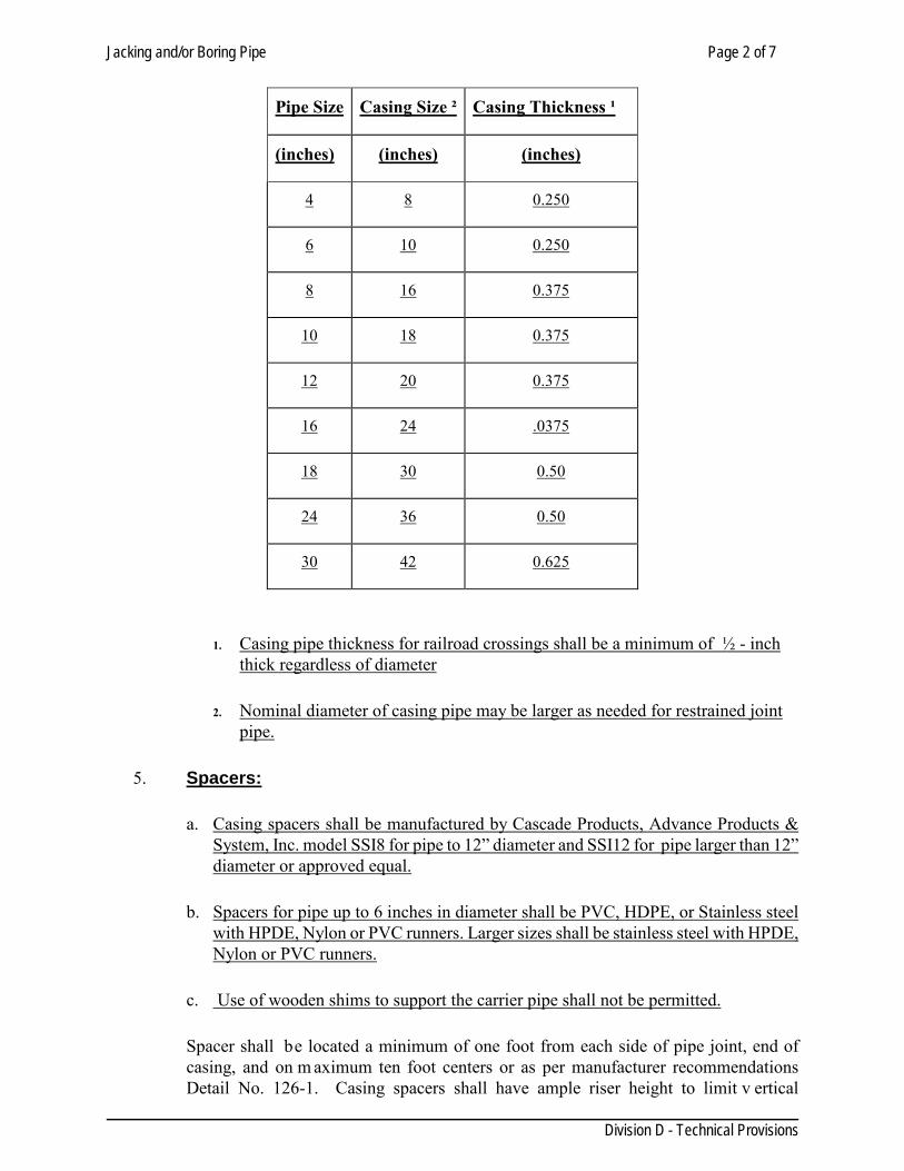
amended to date, with a minimum yield strength of 35,000 psi before cold forming. Pipe may be straight seam or spiral welded casing on an open trench. A protective coat will be required as specified on the plans. The diameter and wall thickness of the steel piping installed shall he as listed in the following:
Jacking and/or Boring Pipe Page 2 of 7
Division D - Technical Provisions
1. Casing pipe thickness for railroad crossings shall be a minimum of ½ - inch thick regardless of diameter
2. Nominal diameter of casing pipe may be larger as needed for restrained joint pipe.
5. Spacers:
a. Casing spacers shall be manufactured by Cascade Products, Advance Products & System, Inc. model SSI8 for pipe to 12” diameter and SSI12 for pipe larger than 12” diameter or approved equal.
b. Spacers for pipe up to 6 inches in diameter shall be PVC, HDPE, or Stainless steel with HPDE, Nylon or PVC runners. Larger sizes shall be stainless steel with HPDE, Nylon or PVC runners.
c. Use of wooden shims to support the carrier pipe shall not be permitted.
Spacer shall be located a minimum of one foot from each side of pipe joint, end of casing, and on m aximum ten foot centers or as per manufacturer recommendations Detail No. 126-1. Casing spacers shall have ample riser height to limit v ertical
Pipe Size Casing Size ² Casing Thickness ¹
(inches) (inches) (inches)
4 8 0.250
6 10 0.250
8 16 0.375
10 18 0.375
12 20 0.375
16 24 .0375
18 30 0.50
24 36 0.50
30 42 0.625
Jacking and/or Boring Pipe Page 3 of 7
Division D - Technical Provisions
movement of the carrier pipe within the casing pipe. A maximum of 1 inch clearance shall be provided between the top runner and the I.D. of the casing pipe for carrier sizes of 6 inch through 12 inch. A maximum of 2 inch clearance shall be provided between the top runner and the I.D. of casing pipe for carrier pipe sizes 18 inch through 64 inch.
6. Casing End Seals: Shall be used to completely close both openings on either side of the casing. These end seals shall be Pull on (seamless), Wrap around, Zipper or Molded with stainless steel straps for securing to the carrier pipe and casing. End seals shall be constructed of specially compounded synthetic rubber a minimum thickness of 1/8 inch.
D - 126.04 CONSTRUCTION METHODS: Conform to the requirements of the City, Texas Department of Transportation, Railroad Company, or County having jurisdiction over the right-of-way involved, as to details of construction methods and time of construction. All work necessary to meet the requirements of the City, Texas Department of Transportation, Railroad Company, or County will be considered incidental to the installation of the pipeline in the right-of-way. The Contractor shall abide by the more stringent of these specifications, or the specifications of the regulatory agencies. 1. Jacking: Is prohibited on TxDot row. Suitable pits or trenches shall be excavated for the
purpose of jacking operations for placing end joints of the pipe. When trenches are cut in the sides of embankment such work shall be securely sheeted and braced. Jacking operations shall in no way interfere with the operation of railroads, streets, highways or other facilities and shall not weaken or damage such facilities. Barricades and lights shall be furnished as directed by the Engineer to safeguard traffic and pedestrians. 1.1. Location - A minimum distance from the edge of the paved shoulder or curb, to the face of
any access pit, equipment, and supplies, shall be a minimum of 10 feet along arterials streets and a minimum of 5 feet along local streets. Any deviation from these distances shall require prior approval from the Engineer.
1.2. Equipment shall not be used as fencing to protect access pits. 1.3. The pipe to be jacked shall be set on guides to support the section of pipe being jacked and
to direct it in the proper line and grade. Embankment material shall be excavated just ahead of the pipe and material removed through the pipe, and the pipe forced through the opening thus provided.
1.4. The excavation for the underside of the pipe, for at least one-third of the circumference of the pipe, shall conform to the contour and grade of the pipe. A clearance of not more than two inches (2") may be provided for the upper half of the pipe.
1.5. Generally, pipe shall be jacked from downstream end. P ermissible lateral or vertical variation in the final position of the pipe from line and grade will be as show on the plans or as determined by the Engineer.
1.6. Any pipe damaged in jacking operations shall be removed and replaced at the Contractor’s expense.
1.7. Jacking pits shall be backfilled immediately upon completion of jacking operations. The backfill shall be compacted as per Section 102.
Jacking and/or Boring Pipe Page 4 of 7
Division D - Technical Provisions
2. Boring: Excavation for “Boring” pits and installation of shoring shall be as outlined under “Jacking”. Variation in line and grade shall apply as specified under “Jacking”. 2.1. Dry Boring (auger bore)
2.1.1. All bores will be accomplished by dry mechanical bore unless otherwise pre-approved by engineer
2.1.2. Only workmen experienced in boring operations shall perform the work. 2.1.3. The use of water or other fluids in connection with the boring operation will NOT be
permitted except for a minor required amount of bentonite solution for cutting head. 2.1.4. The casing pipe shall be placed in the bore hole simultaneously while boring is being
performed. Installing the encasement conduit inmediately by pulling it in place from opposite the boring machine or by jacking the conduit through the bore is not acceptable. Take proper care to secure the joints of the conduit as subsequent sections are installed by welding joints. Provide a steel rail or timber cradle in the pit to support and guide the conduit in its installation.
2.1.5. If after completion of the installation of the conduit, there is more than one inch (1”) clearance between the outside of the barrel of the conduit and the wall of the bore, grouting of these voids will be required. If during construction of the bore, a cave-in occurs within the bore, grouting of the voids between the conduit and the walls of the bore will be required throughout the length of the bore.
2.2. Wet Boring 2.2.1. All bores will be accomplished by dry mechanical bore unless otherwise pre-
approved by the Engineer.(see above) 2.2.2. Only workmen experienced in boring operations shall perform the work. 2.2.3. The use of water or other fluids in connection with the boring operation will be
permitted only to lubricate cuttings. Jetting will not be permitted. In consolidated soil formations, a gel-forming colloidal drilling fluid consisting of at least ten (10%) percent of high-grade bentonite may be used to consolidate cuttings of the bit, seal the walls of the hole, and lubricate removal of cuttings and installation of the pipe immediately thereafter.
2.2.4. While boring is being performed, install the encasement conduit immediately by pulling it in place from opposite the boring machine or by jacking the conduit through the bore. Encasement conduit may be placed after the boring operation is complete, if permission is obtained from the City. Take proper care to secure the joints of the conduit as subsequent sections are installed, by use of cables or welding joints. Provide a steel rail or timber cradle in the pit to support and guide the conduit in its installation.
2.2.5. If after completion of the installation of the conduit, there is more than one inch (1”) clearance between the outside of the barrel of the conduit and the wall of the bore, grouting of these voids will be required. If during construction of the bore, a cave-in occurs within the bore, grouting of the voids between the conduit and the walls of the bore will be required throughout the length of the bore.
2.2.6. Grouting material and equipment shall be on the jobsite before beginning installation of the conduit, in order that the grouting around the encasement conduit is to be started immediately after pipe is in place.
Jacking and/or Boring Pipe Page 5 of 7
Division D - Technical Provisions
3. Support of pipes across bore or tunnel pits: After completion of the bore or tunnel and installation of the carrier pipe with the bore or tunnel, remove all loose earth and debris from the pit down to undisturbed earth. Pour a continuous 2,000 psi concrete or cement stabilized sand support under the carrier pipe from the edge of the bore or tunnel to the first joint in the trench past the end of the pit. The concrete support shall be brought up to the horizontal centerline of the pipe.
4. Joints: Joints for pipe for “Jacking”, “Boring” shall be as specified welded with a full penetration weld for the full circumference. Water tight pipe joints are required to ensure the integrity of the roadbed. Casing pipe shall be constructed to prevent water leakage or earth infiltration throughout its entire length.
5. Lubrication Fluids:
5.1. Lubrication fluids are specifically required for this method regardless of the soil conditions. Any deviation from the use of lubrication shall require prior approval from the Engineer.
5.2. Lubrication fluids, consisting of a mixture of water and bentonite or bentonite/polymer, shall be used in the annular space between the casing being installed and the native soil. Lubrication may also be used inside the casing pipe to facilitate spoil removal.
5.3. Grease is not allowed for use as lubrication for this purpose. 6. Pipe Locating and tracking: One of the following tracking, locating, and guidance systems
shall be used, unless an alternate is approved by the Engineer. 6.1. Waterline system. 6.2. Mechanical control head. 6.3. Electronic (inertial) control head. 6.4. Walkover system. Laser guided tunnel attachment. 6.5. Laser guided pilot rod.
7. Settlement/Heaving Monitoring:
7.1. This method shall be performed in a manner that will minimize the movement of the ground in front of, above, and surrounding the HAB operation; and will minimize subsidence of the surface above and in the vicinity of the boring. The ground shall be supported in a manner to prevent loss of ground and keep the perimeter and face of the boring stable at all times, including during shutdown periods.
7.2. Potential heave or settlement shall be monitored at each shoulder point, edge of pavement, the edge of each lane (or centerline for two lane roads), and otherwise at 50 foot intervals along the pipe centerline.
7.3. A survey shall be performed one day prior to initiating this operation at each required monitoring location. A similar survey shall then be performed at each location, on a daily basis, until the permitted activity has been completed. All survey readings shall be recorded to the nearest one-hundredth (0.01) of a foot. D igital photographs of the pavement conditions shall also be taken prior and after the pipe installation.
7.4. All operations shall stop immediately whenever monitored points indicate a vertical change in elevation of 1/2 inch or more, or any surface disruption is observed. The Contractor shall then immediately report the amount of settlement to the Engineer/ Inspector.
7.5.
Jacking and/or Boring Pipe Page 6 of 7
Division D - Technical Provisions
8. Groundwater Control: 8.1. Dewatering shall be conducted whenever there is a high ground water table level to prevent
flooding and facilitate the operation. The water table elevation shall be maintained at least 2 feet below the bottom of the casing at all times. When needed, dewatering may be initiated prior to any excavation.
8.2. Minor water seepage or pockets of saturated soil may be effectively controlled through bailing or pumping. This control shall be accomplished without removing any adjacent soil that could weaken or undermine any access pit, its supports, or other nearby structure.
8.3. Larger volumes of ground water shall be controlled with one or more well points or with staged deep wells. Well points and staged deep well pumping systems shall be installed and operated without damage to property or structures, and without interference with the rights of the public, owners of private property, pedestrians, vehicular traffic, or the work of other contractors. Any pumping methods used for de-watering and control of ground water and seepage shall have properly designated filters to ensure that the adjacent soil is not pumped along with the water. Well diameter, well spacing and the pump’s pumping rate, shall provide adequate draw down of the water level. Wells shall be located to intercept ground water that otherwise would enter the access pit excavation and interfere with the work. Upon removal of a well, the hole shall be filled and grouted according to the specifications identified as flowable fill, and plug drill holes as directed by the Engineer.
8.4. Existing storm sewers shall only be used to discharge water from the dewatering operation in accordance with a permit obtained from the appropriate storm sewer owner. Filters or sediment control devices shall be required to ensure that the existing system is not adversely affected by construction debris or sediment.
8.5. If grouting is used to prevent ground water from entering the area of the access pit, the grouting shall be installed without damage to property or structures and without interference with the rights of the public, owners of private property, pedestrians, vehicular traffic, or the work of other contractors. The material properties of the grout shall conform to the specifications identified as flowable fill.
9. Failure:
9.1. Should anything prevent completion of this operation, the remainder of the pipe shall be constructed and/or abandoned by methods approved by the Engineer.
9.2. Abandonment of any component of the installation shall only be allowed as approved by the Engineer.
10. Grouting of Bores: Space between pipe and liner, pipe and limits of excavation, and liner and
limits of excavation shall be pressure grouted, unless otherwise specified on the plans. 11. Spoils: Spoil locations shall be pre-approved by the engineering inspector. When no suitable
location for spoil can be found on site, the contractor shall be required to haul and dispose of this material at no extra cost. Where spoils are to be placed on parking areas (asphalt or concrete), sidewalks, or other paved surfaces, the spoils shall be placed on a barrier to prevent the soil from embedding into the paved surface.
D - 126.05: CONTAMINATION: When an area of contaminated ground is encountered, all operations shall stop immediately, and shall not proceed until approved by the Engineer/Inspector. Any slurry shall be tested for contamination and disposed of in a manner, which meets Local, State and/or Federal requirements.
Jacking and/or Boring Pipe Page 7 of 7
Division D - Technical Provisions
D - 126.06: WORKSITE RESTORATION: 1. Access pits and excavations shall be backfilled with suitable material, and in a method
approved by the Engineer/Inspector as per section 102. Any embedded supports shall be removed to 10 feet below the original ground surface. The disturbed work site area shall be restored to existing grades and original material condition.
2. The disturbed grass-surface area shall be topsoiled, seeded, fertilized, mulched, and anchored.
3. Upon completion of the work, the contractor shall remove and properly dispose of all excess materials and equipment from the work site.
D - 126.07: MEASUREMENT: Jacking and boring shall be measured by the number of linear feet of pipe in place. Measurement will be made from end to end of the liner plate and shall include the liner plate and installed pipe as shown on the plans. D - 126.08: PAYMENT: The work performed and material furnished as specified by this item, measured as provided above shall be paid for at the contract bid price per lineal foot for pipe jacked, or bored, which price shall be full compensation for furnishing all pipe of the type shown on the project plans and all materials, labor, tools, equipment, and incidentals necessary to complete the work, including excavation, grouting, backfilling, restoration to original ground conditions, and disposal of surplus material. Specify: spacers, pipe, and end seals.
Disposal of Waste Material and Salvageable Material Page 1 of 1
Division D - Technical Provisions
SECTION 128 DISPOSAL OF WASTE MATERIAL AND SALVAGEABLE MATERIAL
D-128.01 GENERAL: Section includes disposal of waste material and salvageable material. D-128.02 UNIT PRICES: No separate payment will be made for waste material disposal under this section. Include payment in unit price for related sections. D-128.03 SUBMITTALS: A. Obtain and submit disposal permits for proposed disposal sites if required by local
ordinances, and/or TCEQ. B. Submit a copy of written permission from a property owner, along with description of
property prior to disposal of excess material adjacent to the Project. Submit a written and signed release from property owner upon completion of disposal work.
EXECUTION D-128.04 SALVAGEABLE MATERIAL:
Excavated Material: when indicated on plans, load haul, and deposit excavated material at a location or locations shown on plans outside the limits of project.
Base, Surface, and Bedding Material: Local shell, gravel, bituminous, or other base and surfacing material designated for salvage.
Pipe Culvert: Load culverts designated for salvage into designated trucks. Other Salvageable Materials: Conform to requirements of individual specification section.
Coordinate disposal of material with Environmental Services Director.
D-128.05 EXCESS MATERIAL: A. Vegetation, rubble, broken concrete, debris, asphaltic concrete pavement, excess soil, and
other materials not designated for salvage, shall become property of the Contractor and shall be removed from the job site and legally disposed of.
B. Excess soil may be deposited on pr ivate property adjacent to the project when written
permission is obtained from property owner. See Paragraph 126.03B above. C. Waste materials shall be removed from the site on a daily basis, such that the site is
maintained in a neat and orderly condition.
Ductile Iron Fittings Page 1 of 2
Division D - Technical Provisions
SECTION 130
DUCTILE IRON FITTINGS
D-130.01 DESCRIPTION: This item shall consist of grey-iron and ductile-iron fittings installation and adjustment installed in accordance with these specifications, manufactured in U.S. and as directed by the Engineer. D-130.02 MATERIALS AND CONSTRUCTION:
1. Fittings: All fittings shall conform to American Water Works Association (AWWA) Standards for Grey-Iron and Ductile-Iron Compact Fittings, and AWWA Standard C-153 for Ductile Iron Compact Fittings, Class D as manufactured. Fittings 6 inches through 12 inches in size shall be push-on joint compact body unless otherwise stated on the plans. Fittings shall be installed with the thrust blocking and/or joint restraint, as shown in the plans. Fittings 16 inches through 24 inches in size shall be mechanical joint type unless otherwise specified on the plans. Adapters shall be used where necessary to provide a transition between asbestos-cement pipe and the fittings. Thrust blocking shall be provided as specified on the plans or in the standard drawings. Anti-corrosion embedment and polyethylene wrapping is incidental to all installed ductile iron fittings shall be provided as specified in "Excavation, Trenching and Backfill" or when shown in the plans and no separate payment will be made for this embedment or wrapping.
2. Cleaning Ductile-Iron: All lumps, blisters, and excess coal-tar coating shall be
removed from the ends of cast-iron fittings. The outside of the spigot and the inside of the bell shall be wire-brushed and wiped clean, dry, and free from oil and grease before the pipe is laid. The interior of the pipe shall be blown clean with compressed air or swabbed out clean and dry as directed by the Engineer. Immediately prior to placing any pipe in the trench, the interior shall be cleaned by an approved brush or swab or with compressed air to remove all dirt and foreign materials. All pipe and fittings shall be suspended above ground to be inspected for defects by the Contractor.
D-130.04 MEASUREMENT: Ductile-Iron Fittings will not be measured separately, but shall be included in lump sum bid provided in the bid proposal for fittings, valves, and related appurtenances.
Ductile Iron Fittings Page 2 of 2
Division D - Technical Provisions
D-130.05 PAYMENT: Payment for Cast-Iron and Ductile Iron Compact Fittings will be by weight tonage types and sizes installed. Such payment shall also include excavation, selected embedment material, anticorrosion embedment when specified, hauling and disposition of surplus excavated materials, polyethylene sleeve, asphaltic material for ferrous surfaces, all glands, nuts, bolts, gaskets and concrete reaction and thrust blocking and joint restraint systems. If compact fittings are not manufactured and other fittings are installed, Contractor will provide quantities and unit weights with pay request. Weight tables are estimated quantities and can be verified by vender information. Payments will be made by the lesser of the two (weights versus supplier) at the inspectors discretion.
Pipe Joint Restraint Systems Page 1 of 6
Division D - Technical Provisions
SECTION 132 PIPE JOINT RESTRAINT SYSTEMS
D 132.01 GENERAL
1. Description This specification covers pipe joint restraint systems to be used on domestic water mains for PVC C-900 pipe sizes 4-inch through 12- inch diameter and PVC C-905 pipe sizes 16- inch through 24- inch diameter, and for Ductile Iron pipe sizes from 4-inch through 24-inch diameter. Joint restraint systems are classified as “compression, “mechanical joint” or non- metallic restrained joint “ for the specific type of pipe joint to be restrained.
D 132.02 PRODUCTS 1. General Requirements
A. Underwriter Laboratories (U.L) and Factory Mutual (FM) certifications are required on all restraint systems.
B. Unless otherwise noted, restraint systems to be used on PVC C-900 and C-905 pipe shall meet or exceed A.S.T.M. Standard F1674-96, “Standard Test Methods for Joint Restraint Products for Use with PVC Pipe,” or the latest revision thereof. Restraint systems used on ductile pipe shall meet or exceed U.L. Standard 194 and shall be made in USA only.
C. Non-metallic restrained joint pipe and couplings shall be utilized specifically for C-900 PVC pipe and fittings in sizes 4”-12”, and for C-905 PVC pipe and fittings in size 16”.
D. Each restraint system shall be packaged individually and include installation instructions.
E. Each restraint system shall be wrapped with 8 mil. of polyethylene film with all
edges and laps securely taped to provide continued wrap. 2. Specific Requirements: A. Restrainer for PVC C-900/C-905 & Ductile Iron Push-on Type Connections:
1. Pipe restraints shall be utilized to prevent movement for push-on D.I. or PVC
(C900&C905) (compression type) bell and spigot pipe connections or where a flexible coupling has been used to join two sections of plain-end pipe D.I. or PVC (C900&C905). The restrainer may be adapted to connect a plain end D.I. or PVC
Pipe Joint Restraint Systems Page 2 of 6
Division D - Technical Provisions
pipe to a ductile iron mechanical joint (MJ) bell fitting. The restrainer must not be directionally sensitive.
2. The pipe shall be restrained by a split retainer band. The band shall be cast ductile
iron, meeting or exceeding ASTM A536-80, Grade 65-45-12. The inside face or contact surface of the band shall be of sufficient width to incorporate cast or machined non-directionally sensitive serration to grip the outside circumference of the pipe. The serration shall provide full (360 degrees) contact and maintain pipe roundness and avoid any localized points of stress. The split band casting shall be designed to “bottom-out” before clamping bolt forces (110ft-lb minimum torque) can over-stress the pipe, but will provide full non-directionally sensitive restraint at the rated pressures.
3. Bolts and nuts used to attach the split retainer ring shall comply with ANSI B 18.2/18.2.2, SAE Grade 5. Tee-bolts, nuts and restraining rods shall be 316 Stainless Steel conforming to C111/a21.11 90 and c153/a21.53 88
4. The split ring type non-directionally sensitive restrainer system shall be capable of a test pressure twice the maximum sustained working pressure listed in section D and be for both D.I. and/or PVC C900.
5. Restraint systems sizes six through twelve inches shall be capable of use for both
ductile iron and/or PVC C900.
6. The restraint system may consist of two types: the two split retainer rings and for new construction use only the one split and one solid cast backup ring.
B. Compression Ring Fitting Restrainer for Ductile Iron Pipe & PVC C-900.
1. Compression ring with follower gland type of restrainer may be utilized in
conjunction with Mechanical Joint (MJ) bell end ductile iron pipe fittings for restraining PVC C-900 and ductile iron pipe.
2. The system shall utilize a standard MJ gasket with a color-coded compression ring
and replacement gland conforming to ASTM A 536-80, Grade 65-45-12.
3. Standard MJ fitting Tee-bolts and nuts shall be 316 Stainless Steel conforming to AWWA C111/A21.11-90 and AWWA C153/A21.53-88.
4. Standard MJ gasket shall be virgin SBR meeting ASTM D-2000 3 BA 715 or 3
BA 515. 5. T he restraint system shall be capable of a test pressure twice the maximum sustained working pressure listed in section D.
Pipe Joint Restraint Systems Page 3 of 6
Division D - Technical Provisions
C. Non-metallic restrained joint pipe and couplings for PVC C-900/C-905 Type Connections:
1. Gasketed restrained coupling connections shall join two sections of factory grooved PVC (C900/C-905) pipe. The restrainer coupling or must not be directionally sensitive.
2. The coupling shall incorporate twin elastomeric sealing gaskets meeting the
requirements of ASTM F-477 and shall be DR-14 Class 200 C-900 for 4” -12” pipe, meeting or exceeding the performance requirements of AWWA C-900, latest revision; and DR-18 C-905 for 16” pipe, meeting or exceeding the performance requirements of AWWA C-905, latest revision . The inside face or contact surface of the coupling connection shall be of sufficient width to incorporate a factory machined non-directionally sensitive groove in both pipe and coupling to grip the outside circumference of the pipe. The couplings shall provide full (360 degrees) contact and maintain pipe roundness and avoid and localized points of stress. The coupling shall be designed with an internal stop to align the precision-machined grooves in the coupling and pipe prior to installation of a non- metallic thermoplastic restraint spleen, and will provide full non-directionally sensitive restraint at the rated pressures.
3. High-strength flexible thermoplastic spleens shall be inserted into mating
precision –machined grooves in the pipe and coupling to provide full non-directional restraint with evenly distributed loading.
4. The non- metallic restrained joint pipe and couplings for PVC C-900/C-905 type
non-directionally sensitive restrainer system shall be capable of a t est pressure twice the maximum sustained working pressure listed in Section D and be for PVC: C-900 pipe sizes four (4) through twelve (12) inch, and C-905 pipe size sixteen (16) inch.
5. Non-metallic restrained joint pipe and couplings for PVC C-900 restrained
systems sizes four (4) through twelve (12) inches shall be capable of use for both (DR 18) and four (4) through eight (8) inches for (DR 14) PVC C900 pipe. Non-metallic restrained joint pipe and couplings for PVC C-905 restrained systems size sixteen (16) inches shall be capable of use for (DR 18) PVC C905 pipe.
6. The non- metallic restrained joint pipe and couplings for PVC C-900 restraint
system and for PVC C-905 restraint system shall consist of a pipe and couplings system produced by the same manufacturer meeting the performance qualifications of Factory Mutual (FM) and Underwriters Lab (UL).
D. Fitting Restraint for Ductile Iron Pipe (Only):
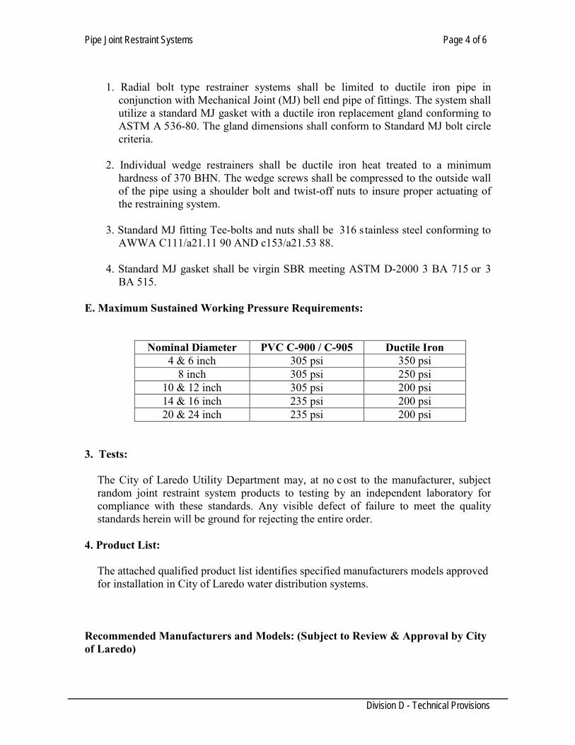
Pipe Joint Restraint Systems Page 4 of 6
Division D - Technical Provisions
1. Radial bolt type restrainer systems shall be limited to ductile iron pipe in
conjunction with Mechanical Joint (MJ) bell end pipe of fittings. The system shall utilize a standard MJ gasket with a ductile iron replacement gland conforming to ASTM A 536-80. The gland dimensions shall conform to Standard MJ bolt circle criteria.
2. Individual wedge restrainers shall be ductile iron heat treated to a minimum
hardness of 370 BHN. The wedge screws shall be compressed to the outside wall of the pipe using a shoulder bolt and twist-off nuts to insure proper actuating of the restraining system.
3. Standard MJ fitting Tee-bolts and nuts shall be 316 s tainless steel conforming to
AWWA C111/a21.11 90 AND c153/a21.53 88. 4. Standard MJ gasket shall be virgin SBR meeting ASTM D-2000 3 BA 715 or 3
BA 515. E. Maximum Sustained Working Pressure Requirements:
Nominal Diameter PVC C-900 / C-905 Ductile Iron 4 & 6 inch 305 psi 350 psi
8 inch 305 psi 250 psi 10 & 12 inch 305 psi 200 psi 14 & 16 inch 235 psi 200 psi 20 & 24 inch 235 psi 200 psi
3. Tests:
The City of Laredo Utility Department may, at no c ost to the manufacturer, subject random joint restraint system products to testing by an independent laboratory for compliance with these standards. Any visible defect of failure to meet the quality standards herein will be ground for rejecting the entire order.
4. Product List:
The attached qualified product list identifies specified manufacturers models approved for installation in City of Laredo water distribution systems.
Recommended Manufacturers and Models: (Subject to Review & Approval by City of Laredo)
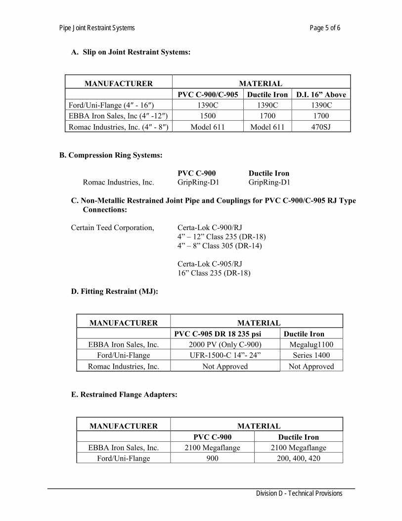
Pipe Joint Restraint Systems Page 5 of 6
Division D - Technical Provisions
A. Slip on Joint Restraint Systems:
MANUFACTURER MATERIAL PVC C-900/C-905 Ductile Iron D.I. 16” Above
Ford/Uni-Flange (4″ - 16″) 1390C 1390C 1390C EBBA Iron Sales, Inc (4″ -12″) 1500 1700 1700 Romac Industries, Inc. (4″ - 8″) Model 611 Model 611 470SJ
B. Compression Ring Systems: PVC C-900 Ductile Iron Romac Industries, Inc. GripRing-D1 GripRing-D1
C. Non-Metallic Restrained Joint Pipe and Couplings for PVC C-900/C-905 RJ Type
Connections:
Certain Teed Corporation, Certa-Lok C-900/RJ 4” – 12” Class 235 (DR-18) 4” – 8” Class 305 (DR-14) Certa-Lok C-905/RJ 16” Class 235 (DR-18)
D. Fitting Restraint (MJ):
MANUFACTURER MATERIAL PVC C-905 DR 18 235 psi Ductile Iron
EBBA Iron Sales, Inc. 2000 PV (Only C-900) Megalug1100 Ford/Uni-Flange UFR-1500-C 14”- 24” Series 1400
Romac Industries, Inc. Not Approved Not Approved
E. Restrained Flange Adapters:
MANUFACTURER MATERIAL PVC C-900 Ductile Iron
EBBA Iron Sales, Inc. 2100 Megaflange 2100 Megaflange Ford/Uni-Flange 900 200, 400, 420
Pipe Joint Restraint Systems Page 6 of 6
Division D - Technical Provisions
D 132.03 MEASUREMENT AND PAYMENT: There is no pay item for joint restraint systems. The cost of furnishing and installing joint restraints shall be included with and considered fully subsidiary to the unit bid price of the items that they restrain: pipe, valves, fittings, Etc.
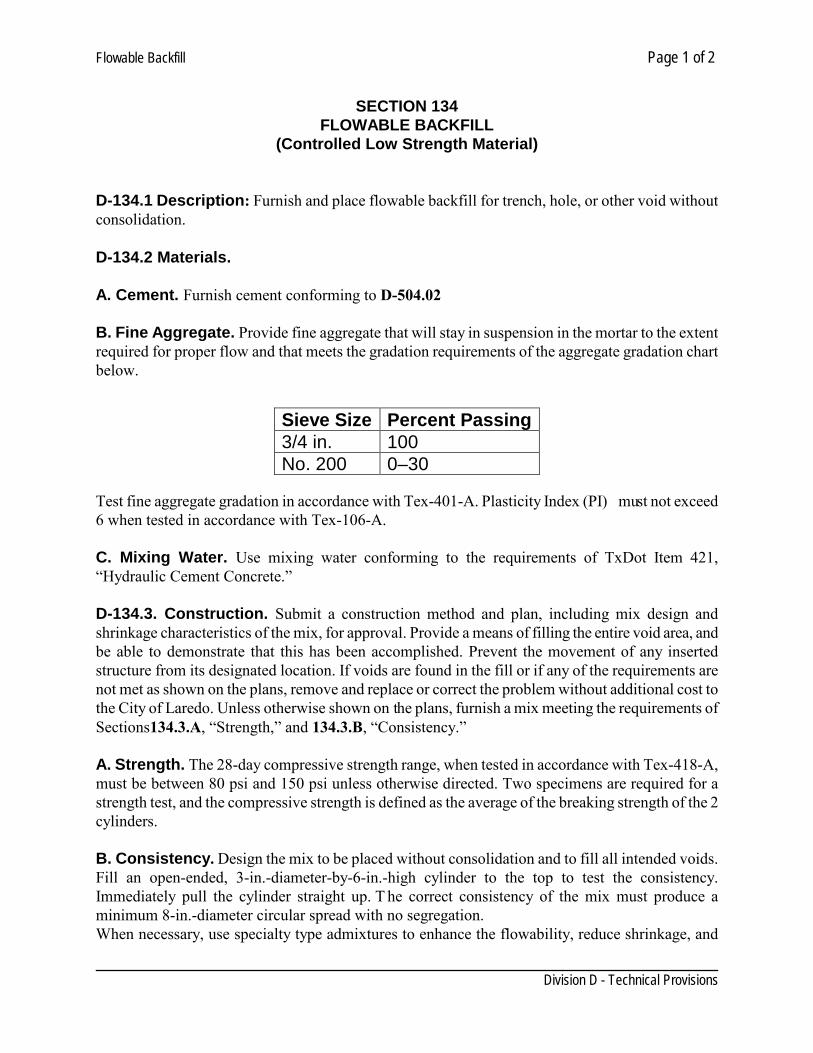
Flowable Backfill Page 1 of 2
Division D - Technical Provisions
SECTION 134
FLOWABLE BACKFILL (Controlled Low Strength Material)
D-134.1 Description: Furnish and place flowable backfill for trench, hole, or other void without consolidation. D-134.2 Materials. A. Cement. Furnish cement conforming to D-504.02 B. Fine Aggregate. Provide fine aggregate that will stay in suspension in the mortar to the extent required for proper flow and that meets the gradation requirements of the aggregate gradation chart below. Test fine aggregate gradation in accordance with Tex-401-A. Plasticity Index (PI) must not exceed 6 when tested in accordance with Tex-106-A. C. Mixing Water. Use mixing water conforming to the requirements of TxDot Item 421, “Hydraulic Cement Concrete.” D-134.3. Construction. Submit a construction method and plan, including mix design and shrinkage characteristics of the mix, for approval. Provide a means of filling the entire void area, and be able to demonstrate that this has been accomplished. Prevent the movement of any inserted structure from its designated location. If voids are found in the fill or if any of the requirements are not met as shown on the plans, remove and replace or correct the problem without additional cost to the City of Laredo. Unless otherwise shown on the plans, furnish a mix meeting the requirements of Sections134.3.A, “Strength,” and 134.3.B, “Consistency.” A. Strength. The 28-day compressive strength range, when tested in accordance with Tex-418-A, must be between 80 psi and 150 psi unless otherwise directed. Two specimens are required for a strength test, and the compressive strength is defined as the average of the breaking strength of the 2 cylinders. B. Consistency. Design the mix to be placed without consolidation and to fill all intended voids. Fill an open-ended, 3-in.-diameter-by-6-in.-high cylinder to the top to test the consistency. Immediately pull the cylinder straight up. T he correct consistency of the mix must produce a minimum 8-in.-diameter circular spread with no segregation. When necessary, use specialty type admixtures to enhance the flowability, reduce shrinkage, and
Sieve Size Percent Passing 3/4 in. 100 No. 200 0–30
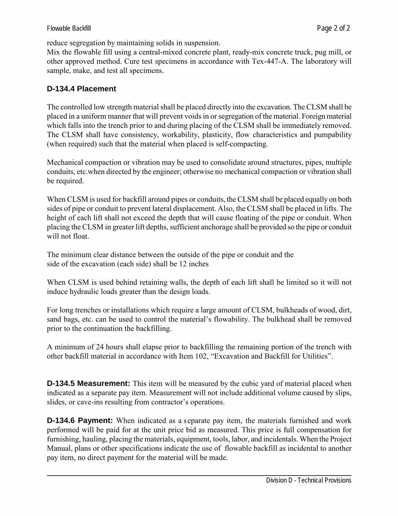
Flowable Backfill Page 2 of 2
Division D - Technical Provisions
reduce segregation by maintaining solids in suspension. Mix the flowable fill using a central-mixed concrete plant, ready-mix concrete truck, pug mill, or other approved method. Cure test specimens in accordance with Tex-447-A. The laboratory will sample, make, and test all specimens. D-134.4 Placement The controlled low strength material shall be placed directly into the excavation. The CLSM shall be placed in a uniform manner that will prevent voids in or segregation of the material. Foreign material which falls into the trench prior to and during placing of the CLSM shall be immediately removed. The CLSM shall have consistency, workability, plasticity, flow characteristics and pumpability (when required) such that the material when placed is self-compacting. Mechanical compaction or vibration may be used to consolidate around structures, pipes, multiple conduits, etc.when directed by the engineer; otherwise no mechanical compaction or vibration shall be required. When CLSM is used for backfill around pipes or conduits, the CLSM shall be placed equally on both sides of pipe or conduit to prevent lateral displacement. Also, the CLSM shall be placed in lifts. The height of each lift shall not exceed the depth that will cause floating of the pipe or conduit. When placing the CLSM in greater lift depths, sufficient anchorage shall be provided so the pipe or conduit will not float. The minimum clear distance between the outside of the pipe or conduit and the side of the excavation (each side) shall be 12 inches When CLSM is used behind retaining walls, the depth of each lift shall be limited so it will not induce hydraulic loads greater than the design loads. For long trenches or installations which require a large amount of CLSM, bulkheads of wood, dirt, sand bags, etc. can be used to control the material’s flowability. The bulkhead shall be removed prior to the continuation the backfilling. A minimum of 24 hours shall elapse prior to backfilling the remaining portion of the trench with other backfill material in accordance with Item 102, “Excavation and Backfill for Utilities”. D-134.5 Measurement: This item will be measured by the cubic yard of material placed when indicated as a separate pay item. Measurement will not include additional volume caused by slips, slides, or cave-ins resulting from contractor’s operations. D-134.6 Payment: When indicated as a separate pay item, the materials furnished and work performed will be paid for at the unit price bid as measured. This price is full compensation for furnishing, hauling, placing the materials, equipment, tools, labor, and incidentals. When the Project Manual, plans or other specifications indicate the use of flowable backfill as incidental to another pay item, no direct payment for the material will be made.
Cement-Stabilized Backfill Page 1 of 2
Division D - Technical Provisions
SECTION 136
CEMENT-STABILIZED BACKFILL D-136.1. Description: When shown on t he plans, backfill the excavation to the bottom of pavement base with cement-stabilized sand or caliche. D-136.2 Materials:
A. Cement: Cement shall consist of Type I Portland Cement conforming to ASTM C150 B. Sand: Zero P.I. sand as aggregate for cement-stabilized backfill. Use only approved aggregate
up to the bottom of existing pavement section base. C. Caliche D. Water: Water shall be clean and clear, free of oils, acids, alkalis, organic matter or other
deleterious substances and shall conform to the requirements of ASTM C94. D-136.3 Execution: Sand/caliche-cement Mixture Product. The mixture shall consist of a minimum of two (2 ) sacks of Portland cement per cubic yard based on the dry weight of the aggregate. The mixture shall contain sufficient water to hydrate the cement (not flowable). The cement, sand/caliche and water shall be mixed in a pugmill type mixer, which meets the approval of the Engineer. It shall be mixed for a minimum period of two minutes per batch. No mixing will be allowed on street surface. D-136.4 Placement: Place cement-stabilized backfill equally along the sides of structures to prevent strain on or displacement of the structure. Fill voids when placing cement-stabilized backfill. Use hand operated tampers if necessary to fill voids. The sand cement mixture shall be placed in maximum eight (8) inch thick lifts, loose measure, and thoroughly rodded and tamped around the pipe, boxes, structures, bridge approaches and paving sections. Placement and compaction shall be performed in a manner that will thoroughly fill all voids without placing undue strain on or displacement of the structure. Cement stabilized sand backfill below the top of sewers, manholes, inlets or other structures shall be placed equally along all sides of the structure. Cement stabilized sand backfill/bedding shall be placed in a manner that will completely fill all voids in the trench. Should compaction be required to fill all voids in the areas described, hand operated tampers may be used.
Cement-Stabilized Backfill Page 2 of 2
Division D - Technical Provisions
Materials not placed and not compacted within four (4) hours after mixing shall be rejected. Do not place or compact sand/caliche-cement mixtures in standing or free water. D-136.5 Performance: Random samples of the delivered product will be taken in the field at the direction of the Engineer and tested. A minimum of one (1) sample per week or job shall be taken at random to represent a production that is less than one hundred (100) tons per week. Two (2) samples per week shall be taken at random to represent a production greater than one hundred (100) tons per week. The Engineer shall have the option to obtain additional samples for testing. D-136.6 Measurement: When specified or shown on the plans as a pay item will be measured by the cubic yard. Measurement will not include additional volume caused by slips, slides, or cave-ins resulting from contractor’s operations D-136.6 Payment: When indicated as a separate pay item, the materials furnished and work performed will be paid for at the unit price bid as measured. This price is full compensation for furnishing, hauling, placing the materials, equipment, tools, labor, and incidentals. When the Project Manual, plans or other specifications indicate the use of cement stabilized sand as incidental to another pay item, no direct payment for the material will be made.
PVC Sewer Pipe Page 1 of 4
Division D - Technical Provisions
SECTION 202 PVC SEWER PIPE
D-202.01. GENERAL 1. Submittals: A. Test Results: Include results of tests with shipment of materials. Furnish 2 additional copies of
test results to Engineer. B. Submit in accordance with the Standard General Conditions and Supplementary Conditions. C. Contractor shall submit all final testing reports for deflection testing and for low pressure air
testing of sewer pipe in accordance with Section B- Testing Sewer Systems. D. Any deviations from the standards shall be approved by the Director of Utilities in writing. D-202.02. PRODUCTS 1. Polyvinyl Chloride (PVC) Sewer Pipe A. All PVC Sewer Pipe and Fittings used in this contract shall be made of plastic, meeting the
requirements of: ASTM D3034. All PVC sewer pipe, service saddles and fittings shall be SDR- 26.
B. Fittings:
1. Fittings such as saddles, elbows, tees, and wyes shall be of material and construction
corresponding to and have joint design compatible with adjacent pipe.
2. Provide submittals for approval of adapters for transitions to other types of pipe. C. Pipe Joints:
1. Rubber Gasket: Bell and spigot joint, sealed by a rubber gasket so assembly will remain
watertight under conditions of service including movements resulting from expansion, contraction, settlement, and deformation of pipe. Gaskets shall conform to ASTM C361.
D. Pipe Markings: Mark at intervals of 5 feet or less with following.
1. Manufacturer's name or trademark. 2. Nominal pipe size. 3. PVC cell classification, for example 12454-B. 4. Legend, "Type PSM SDR-26 PVC Sewer Pipe". 5. ASTM D3034 6. Extrusion date, period of manufactured or lot number.
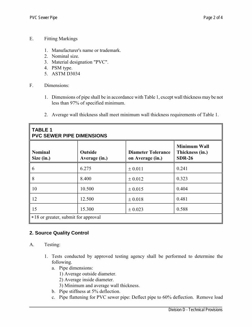
PVC Sewer Pipe Page 2 of 4
Division D - Technical Provisions
E. Fitting Markings
1. Manufacturer's name or trademark. 2. Nominal size. 3. Material designation "PVC". 4. PSM type. 5. ASTM D3034
F. Dimensions:
1. Dimensions of pipe shall be in accordance with Table 1, except wall thickness may be not
less than 97% of specified minimum.
2. Average wall thickness shall meet minimum wall thickness requirements of Table 1. TABLE 1 PVC SEWER PIPE DIMENSIONS Nominal Size (in.)
Outside Average (in.)
Diameter Tolerance on Average (in.)
Minimum Wall Thickness (in.) SDR-26
6
6.275
± 0.011
0.241
8
8.400
± 0.012
0.323
10
10.500
± 0.015
0.404
12
12.500
± 0.018
0.481
15
15.300
± 0.023
0.588
∗18 or greater, submit for approval 2. Source Quality Control A. Testing:
1. Tests conducted by approved testing agency shall be performed to determine the following. a. Pipe dimensions:
1) Average outside diameter. 2) Average inside diameter. 3) Minimum and average wall thickness.
b. Pipe stiffness at 5% deflection. c. Pipe flattening for PVC sewer pipe: Deflect pipe to 60% deflection. Remove load
PVC Sewer Pipe Page 3 of 4
Division D - Technical Provisions
and examine specimen for evidence of splitting, cracking or breaking.
2. Conduct tests on random sampling basis covering representative extrusion dates making up Project of each individual pipe size.
3. Engineer may waive testing on small projects with not more than 400 ft. of individual
pipe size and individual extrusion dates of less than 10 pipe, totaling no more than 400 ft. pipe acceptance subject to visual inspection by utility inspector for defects.
4. Tests reports shall show results of these tests and conformance to ASTM requirements.
D 202.03 EXECUTION 1. Installation A. Trench, backfill, and compaction shall be done in accordance with Section 102, "Excavation
and Backfilling for Utilities". B. Rubber Gasket Joint:
1. Immediately before making joint, lubricate outside of gasket and inside of bell of groove of last pipe with approved vegetable lubricant.
2. Assure gasket and ends of pipe are clean and free of sand and gravel. 3. Introduce spigot or tongue of pipe being laid, with gasket in place, into bell or groove end
of previously laid pipe. 4. Carefully set pipe to line and grade, and jack or push completely home. 5. Use jack or "come-along" to ensure joints are tights.
2. Field Quality Control A. Pipe shall be subject to rejection for failure to conform to requirements of Specifications or
following: 1. Fractures or cracks passing through pipe wall or socket, except single crack not exceeding
2 in. in length at either end of pipe of single fracture in socket not exceeding 3 in. in width nor 2 in. in length shall not be considered cause for rejection unless these defects exist in more that 5% of entire shipment or delivery.
2. Chips or fractures on interior of pipe exceeding 2" in length, 1" in width, and depth more than 1/4 barrel thickness.
3. Cracks sufficient to impair strength, durability, or serviceability of the pipe. 4. Defects indicating improper proportioning, mixing, and molding. 5. Variations of more than 1/8 in./lin.ft. in alignment of pipe intended to be straight. 6. Damage ends, where such damage prevents making satisfactory joint.
7. Complete discoloration of any side of pipe. 8. Manufactured date exceeding one year. B. Specially fabricated fittings, stubs, or pipe sections, shall be submitted for approval by
Engineer prior to manufacture.
PVC Sewer Pipe Page 4 of 4
Division D - Technical Provisions
3. Measurement PVC sewer pipe will be measured for payment in linear feet along the horizontal centerline of the pipe no deduction will be made for manholes or fittings.
4. Payment
Plastic sewer pipe will be paid for at the unit price per linear foot, complete in place, as provided in the proposal and contract. The contract price per linear foot shall be the total compensation for furnishing of all labor, materials, tools, equipment, and incidentals necessary to complete the work, including excavation, granular embedment material, backfill, and disposal of surplus materials, in accordance with plans and specifications.
Clay Pipe Sewers Page 1 of 4
Division D- Technical Provisions
SECTION 204 CLAY PIPE SEWERS
D-204.01 DESCRIPTION: This Specification shall govern for the furnishing, excavating, laying, or placing, and backfilling, shoring, and other operations necessary to the installing of all clay sewer pipes of 18” or greater may be used. D-204.02 MATERIALS: Clay sewer pipe shall be vitrified clay pipe and shall meet all of the requirements for "Extra Strength Clay Pipe" as prescribed by ASTM Specifications C-200. All joints shall comply with ASTM Specification No.C-425 for joints using materials having resilient properties. D-204.03 EXCAVATION: Pipe sewers shall be built in a trench, the width of which at the top of the pipe shall not exceed the external diameter of the bell of the pipe, plus eight (8") inches. A greater width may be permitted by the Engineer when necessary to sheet the trench. The ground shall be excavated in open trench to the width, depth, and in the direction necessary for the proper construction of the pipe sewer according tot he plan, except where tunneling is considered necessary or proper by the Engineer. The width of existing surface structures to be removed, such as pavement, sidewalks, driveways, curb, curb and gutter, etc., shall not be in excess of that specified for trench width at the top of the pipe, except as permitted or authorized by the Engineer to conform to adjacent markings or joints in the structure. The excavation of the trench shall not advance more than two hundred (200) feet ahead of the completed pipe work, except where, in the opinion of the Engineer, it is necessary. Where trench has been excavated below grade, selected fill material shall be used to bring the trench to the required grade and shall be thoroughly compacted by means of mechanical tamps. The Contractor shall do no tunneling except upon w ritten permission from the Engineer. I f permitted, the tunnel shall be of such height and width as the Engineer may direct, and shall be excavated in conformity with a cross section approved by him/her in writing. D-204.04 BRACING AND SHORING: Shall be as per OSHA (Occupational Safety & Health Association). D-204.05 FOUNDATIONS: If the foundation is good, firm earth, the earth shall be shaped or pared to give a fill support to the lower third of each pipe and, if necessary to secure a proper bearing for the pipe, a layer of gravel or other suitable material shall be placed. The same means of securing a firm foundation shall be adopted in case the excavation has been made deeper than necessary. If there is not a good natural foundation, the pipes shall be laid in a masonry cradle supported on a foundation carried to a soil of satisfactory bearing power or supported on a structure designed to carry the weight of pipe and its load to a firm bearing. If the foundation is rock, an equalizing bed of earth or sand well compacted shall be placed upon the rock. The thickness of these beds under the barrel of the pipe shall be not less than four (4) inches. Pipe shall be laid in these beds so that at least the lower third of each pipe is supported its entire
Clay Pipe Sewers Page 2 of 4
Division D- Technical Provisions
length. D-204.06 PIPE LAYING: Each pipe shall be laid to the line and grade given by the Engineer and in such manner as to form a close concentric joint with the adjoining pipe and prevent sudden offsets of the flow line. All pipes shall be laid with the bells uphill. Joints shall be made in the manner specified. The interior of the sewer shall, as the work progresses, be cleared of all dirt and superfluous materials of every description. On small pipe sewers, where cleaning after laying may be difficult, a swab or drag shall be kept in the pipe and pulled forward past each joint immediately after its completion. "T" or "Y" branches or junctions shall be installed at the places shown on plans or designated by the Engineer. D-204.07 BACKFILL: All trenches and excavations in this section shall be in accordance with, Section 102. D-204.08 ORDER OF CONSTRUCTION: The construction of all sewer pipe lines shall begin at the lower or outlet end, or at the low point in the line. When construction involves the building of the main sewer pipe lines having one or more laterals or tributary lines, the construction of the laterals or tributary lines shall not be started until the main sewer has been completed to the point where the lateral or tributary line connects with the main sewer line. Sewer appurtenances shall be constructed as soon as the sewer which they serve is constructed to their locations. The postponing of the construction of appurtenances until the sewer line has been completed, or the construction of appurtenances in advance of the construction of the sewer line, will not be permitted. All connections to existing sewers shall be done in a manner acceptable to the Engineer. D-204.09 DELIVERY: Sewer pipe and other materials delivered to the job site in advance of their use shall be stored in a manner satisfactory to the Engineer. All defective sewer pipe or material shall be removed from the site of the work. I f sewer pipe is placed along side of the line of construction, it shall be done in such manner as to prevent any unnecessary inconvenience to the public or interfere with the adjacent property, and after permission from the Engineer. Tight fitting stoppers or bulkheads shall be securely placed in or across the end of all sewer lines when construction is stopped temporarily, or at the end of a day's work. Such closures need not be water tight. D-204.10 REJECTION OF PIPE: Pipe shall be subject to rejection on account of any of the following:
a. Variations in any dimension exceeding the permissible variations given in Table II, ASTM Designation C-13.
b. Fractures or cracks passing through the barrel or socket, except that a single crack at the
spigot end of the pipe not exceeding 75% of the depth of the socket, or a single fracture in the socket not exceeding 3" around the circumference nor 2" lengthwise may be permitted.
Clay Pipe Sewers Page 3 of 4
Division D- Technical Provisions
c. Chips or fractures on the interior of the pipe exceeding 2" in length, 1 inch in width, and of
a depth more than one fourth (1/4) the thickness of the shell. d. Blisters that are broken or exceed the dimensions specified in Section 26, A STM
Designation C-13. e Fire cracks or hair cracks sufficient to impair the strength, durability, or serviceability of
the pipe. f. Variation of more than 1/8 inch per linear foot in alignment of a pipe intended to be
straight.
g. Glaze that does not conform to the requirements specified in Section 25, ASTM Designation C-13.
h. Insecure attachment of spurs on branches.
i. Failure to give a clear ringing sound when placed on end and dry-tapped with a light
hammer. All rejected pipes shall be replaced by the Contractor with pipes which meet the requirements of these specifications and those set out in ASTM Designation C-13 without additional cost to the Owner. D-204.11 BORINGS: Where any information pertaining to the character of the subsurface formations to be encountered in the excavation work is needed by the Contractor, contractor shall make such borings at Contractors own expense, and it is expressly understood that the Owner and/or Engineer does not assume any responsibility for any subsurface formations to be encountered along the trenching or other excavations. D-204.12 PUMPING, BAILING, AND DRAINAGE: The Contractor shall immediately remove any surface or seepage water or waters from the sewer pipe lines, drains, trenches, ditches, or other surfaces which may accumulate during the progress of the work, by providing the necessary ditches, temporary drain lines, or by pumping, bailing, or any other means necessary to attain the desired relief. The Contractor shall have available, at all times during the progress of the work, such pumps, and equipment must be maintained in good working condition during the process of completing the work so bid. D-204.13 CONCRETE CUSHION, CRADLE, OR PROTECTION: Concrete cradle, cushion, or protection where required, shall be constructed as shown on the plans. Where a condition arises which requires the installing of such concrete cushions or cradle or protection, not shown on the plans, such installation shall be made only on t he written instructions of the Engineer; such instruction shall designate the location, shape, type, and manner of construction. Where concrete cradle or cushion is constructed beneath the sewer pipe, the sub-grade shall be prepared to the dimensions and form as shown on the plans. Concrete cradle, cushion, or protection shall be placed in a dry trench unless, in the opinion of the Engineer, such a method is not
Clay Pipe Sewers Page 4 of 4
Division D- Technical Provisions
practicable. Where the concrete is placed in a wet trench the work shall be done strictly as directed or approved by the Engineer. D-204.14 MEASUREMENT: All pipe installed in accordance with the above specifications and accepted by the Engineer shall be measured by the linear foot of the size and at the depth installed. The depth shall be measured from the flow line of the pipe to the ground surface over the centerline of the pipe at the time of construction. Depth measurement shall be made at manholes, at intervals not to exceed fifty feet (50’) between manholes and at breaks in the profile of the ground, at the time of construction. T he length of sewer mains and laterals will be measured between centers of manholes where the installation involves the connecting of sewer into a manhole at each end of the line being measured. Where the installation involves a connection to an existing stub, the measurement shall be made from the end of the stub to the center of the manhole on the work being measured. Sewer stubs shall be measured from the end of the stub to the center of the manhole to which the stub is connected. Single joints of pipe constructed with a manhole are considered a part of that manhole and no additional payments will be allowed. Concrete cradle or concrete encasement protection will be measured by the linear foot along the center of the pipe where it has been installed in accordance with the details shown on the plans. D-204.15 PAYMENT: All sewer mains, laterals, and stubs measured as set out above, shall be paid for at the unit price bid per linear foot complete in place, of the size, type, and depth constructed, which price shall be full compensation for furnishing all labor, material, and equipment, for all hauling, excavation, shaping of trench bottom, bracing, sheeting, and lumber not ordered left in place, for all installation, backfilling, tamping of backfill, and for all clean-up and incidentals necessary to furnish sewer pipe complete in place. Concrete cradle and concrete encasement will be paid for at the unit price bid per linear foot complete in place.
Service connection Page 1 of 5
SECTION 206 SERVICE CONNECTION
D-206.01 DESCRIPTION: This Specification shall govern for the furnishing, excavating, laying, or placing, and backfilling, shoring, and other operations necessary to the installing of all sanitary sewer services. D-206.02 MATERIALS: Polyvinyl Chloride (PVC) PVC pipe and fittings 6 inch (6”) through 12 inch (12”) diameter shall meet requirements of ASTM D3034, wall thickness classification SDR-26, as modified herein. Pipe shall be furnished in lengths of not less than 12 feet. Pipe with blisters, bubbles, cuts, or scrapes on inside or outside surfaces or imperfections which will impair the performance or life of the pipe, will be rejected. Joints for PVC pipe and fittings shall be the integral bell gasketed joint design so, when assembled, the elastomeric gasket inside the bell is compressed radially on the pipe spigot and provides a watertight joint. Joints shall conform to ASTM D3212. The fittings shall be made from PVC components as defined and described in ASTM standard Dl 784. The gasket shall meet requirements of ASTM F477. PVC pipe and fittings shall be legibly marked in accordance with ASTM D3034 and ASTM F679, and in addition marked with the date and location of manufacture. Pipe not marked as indicated herein will be rejected and pipe manufactured more than twelve months before the date of the work site inspection will not be accepted. D-206.03 EXECUTION: Sewer connections shall be provided for each dwelling and lot to be served and shall be a minimum of 6 inch (6”) diameter. Only one (1) single lateral per lot will be permitted. The location of each sewer connection shall be clearly indicated in the construction drawings . All new sewer construction shall include pre-manufactured wyes for sewer connections. Details No.____. Saddles will only be allowed for connection to existing sewer lines. Saddles shall be installed by cutting the pipe with a tapping machine. Connection shall be either with a saddle tap or a slip-line tap Details No. Service connection branches shall be plugged with a pipe stopper manufactured for such service. The stopper shall be capable of sustaining without failure or leakage. The lowest floor elevation of any structure to be served by gravity shall be a minimum of four feet (4’) above the invert elevation of its sewer connection at the sewer main. For existing structures, connection to the public sewer with plumbing fixtures located on a floor of the structure that is not four (4) feet or more above the sewer main as specified above shall not be allowed unless a written waiver is obtained from the Utilities Department Director or a pumping operation is utilized. Sewer connections shall not be tied directly into an interceptor sewer (18” or greater) unless specifically approved by the Utilities Director.
Service connection Page 2 of 5 The minimum and maximum slope for a sewer lateral shall be 0.5% and 12.35% respectively. The following are not permitted:
1) Attaching sewer service connections to the vertical portion of the cleanout constructed at the property line or easement line.
2) Drop connections on the portion of the lateral in the right of way or in a sanitary sewer easement.
For projects involving the construction of new sewer mains, the sewer lateral to the property line or easement line shall be constructed and tested with the sewer mains. After acceptance by the City, the plumbing contractor shall construct the sewer lateral from the building to the tested sewer lateral, then construct a cleanout at the property or easement line and connect it to the tested portion of the lateral. When specifically approved by the Director, a portion of the cleanout at the property line or easement line to within three feet (3’) of the ground surface and a portion of the sewer lateral on the private property past any utility easements may be constructed and tested with the sewer mains, provided that a means of protecting the cleanout and/or extended sewer lateral is provided.
A sanitary sewer lateral table shall be included in the construction plans. The table will include stationing, the inverts of the lateral at the main and elbow, invert at the property or easement line, and depth at the property or easement line as well as Northing and Easting. D-206.04 CLEANOUTS: A six-inch (6”) cleanout shall be provided at one foot (1’) from the property line within the R.O.W or easement line for each service connection. Lateral backwater valves shall be installed on sewer laterals serving buildings with basements or floors located below the top of the wetwell elevation of the nearest wastewater pumping station. Connection of roof downspouts, exterior foundation drains, areaway drains, basement drains and other sources of surface runoff and groundwater directly or indirectly to a sanitary sewer is prohibited. D-206.05 BACKFILL: All trenches and excavations in this section shall be in accordance with, Section 102. D-206.06 CONCRETE CUSHION, CRADLE, OR PROTECTION: Concrete cradle, cushion, or protection where required, shall be constructed as shown on the plans. Where a condition arises which requires the installing of such concrete cushions or cradle or protection, not shown on the plans, such installation shall be made only on t he written instructions of the Engineer; such instruction shall designate the location, shape, type, and manner of construction. Where concrete cradle or cushion is constructed beneath the sewer pipe, the sub-grade shall be prepared to the dimensions and form as shown on the plans. Concrete cradle, cushion, or protection
Service connection Page 3 of 5 shall be placed in a d ry trench unless, in the opinion of the Engineer, such a method is not practicable. Where the concrete is placed in a wet trench the work shall be done strictly as directed or approved by the Engineer. D-206.07 PAYMENT: All sewer laterals, and stubs, shall be paid for at the unit price bid per piece complete in place, of the size, type, and depth constructed, which price shall be full compensation for furnishing all labor, material, and equipment, for all hauling, excavation, shaping of trench bottom, bracing, sheeting, for all installation, backfilling, tamping of backfill, and for all clean-up and incidentals necessary to furnish sewer services complete in place.
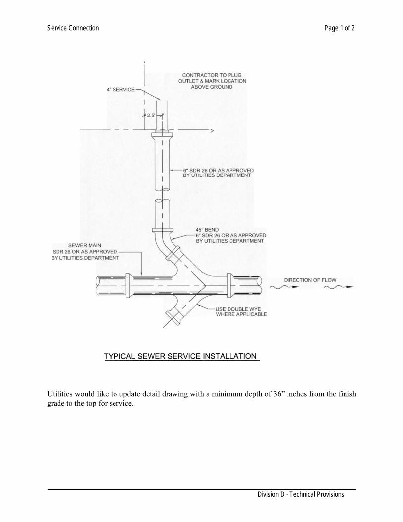
Service Connection Page 1 of 2
Division D - Technical Provisions
Utilities would like to update detail drawing with a minimum depth of 36” inches from the finish grade to the top for service.
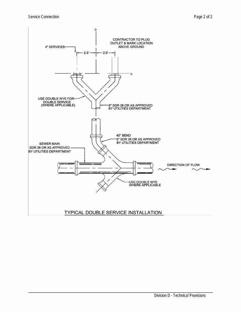
Service Connection Page 2 of 2
Division D - Technical Provisions
Fiberglass Reinforced Plastic Manholes Page 1 of 2
Division D - Technical Provisions
SECTION 208 FIBERGLASS REINFORCED PLASTIC MANHOLES
D-208.01 MATERIALS (prefab and open bottom) Fiberglass reinforced plastic manholes shall be in accordance with ASTM D3753 “Glass Fiber-Reinforced Polyester Manholes” and the requirements of this specification. The inside diameter of the manhole barrel shall be either 48” or as indicated in the plans. A concentric reducer over the barrel shall have an inside diameter of 30 inches. The minimum wall thickness for all manholes regardless of depth shall be ½” (.480”). D-208.02 GOVERNING STANDARDS ASTM D3553 - Standard specifications for glass fiber reinforced polyester manholes. ASTM D2412 - Test method for external loading properties plastic pipe by parallel-plate
loading. ASTM C581 - Practice for determining chemical resistance of thermosetting resins. ASTM D2584 - Test method for ignition loss of cured reinforced resins. ASTM D695 - Test method for compressive properties of rigid plastics. ASTM C790 - Test methods for flexural properties of unreinforced and reinforced plastics
and electrical insulating materials. ASTM D2583 - Test methods for indentation hardness of rigid plastics by means of barcol
impressor. The contractor shall furnish the manufacturer’s certificate that the material meets the standards set forth herein. All fiberglass manhole sections shall be identified with the manufacturer’s name, identification number, and manhole length. Glass Fiber – Reinforced Polyester Manholes shall be prohibited within street sections on Truck Routes & Industrial Parks. D-208.03 MANHOLE RINGS AND COVERS All manhole rings and covers for streets shall have a clear opening of no less than 30” and a height of 5” and a minimum weight for ring and cover of 298 pounds, and shall have the seating surface of ring machined to secure a snug fit. Manholes in street section shall be entered in a concrete slab 6’x6’x8” reinforced with #4 rebar at 8” centers. The castings for manhole rings and covers shall be as detailed on drawings. They shall be grey iron castings boldly filleted at angles and the rises shall be sharp and perfect. The casting shall be true to pattern, form, and dimensions, free from cracks, sponginess, blow holes, or other pouring faults affecting their strength and value for the service intended. Surfaces of the castings shall bee free from burnt on sand and shall be reasonable smooth. Runners, risers, fins, and other cast-on places shall be removed from the surface. Utilities Department will provide detailed drawings for manhole rings. D-208.04 EXCAVATION The contractor shall be all necessary excavation for the various manholes. Such excavation shall be of sufficient size as to permit the proper installation of the base and wall forms, and allow room for striping of such forms. All such excavation shall conform to the size and dimensions as shown on
Fiberglass Reinforced Plastic Manholes Page 2 of 2
Division D - Technical Provisions
the drawings, plus a maximum of four (4) feet to permit working room. Care shall be taken to insure that the excavation is not carried to a greater depth that required. If it becomes necessary to shore the walls and also permit the construction of the manhole itself without necessitating the removal of any shoring until such time as the entire manhole is completed. No shoring shall be left or back filled around, unless authorized by the Engineer. Shoring shall remain in place for at least twenty-four (24) hours after the masonry or concrete work has been completed. D-208.05 GENERAL CONSTRUCTION METHODS All manhole work shall be completed and finished in a careful and workmanlike manner, special care being given to sealing the joints around all pipe that extend through the wall of the manhole. Joints for sewer pipe for line and drop connections in sizes 8”-15” shall be made by means of InsertaTee watertight compression connection or approved equal as shown in the plans and details. Install in accordance with the manufacturer’s written instructions. Connections for pipe larger that 15” shall be made using a pre-approved connection. Install in accordance with the manufacturer’s written instructions after finishing of wall has additional concrete to shape or form on the drawing. Where old manholes are to be adjusted to meet new lines and grades, all old masonry or concrete shall be thoroughly cleaned and wetted before joining any new masonry or concrete to it. All work on manholes shall be done in a workmanlike manner and in conformity with the usual practice used for such work. All materials for adjusting old manholes shall conform to the requirements set out in these specifications for manhole work. D-208.06 BACKFILLING The backfilling around the outside of manholes shall commence as soon as the concrete or masonry has been allowed to cure the required time and the forms and shoring have been removed. Such backfill shall be placed in layers of not more than six inches and shall be thoroughly tamped before the next layer is installed. It is anticipated that the backfilling shall be either hand or mechanically tamped. Whichever method is used, care must be exercised to insure that the backfill is thoroughly compacted to the density shown on the drawings. When a density is not shown on the drawings, compaction shall be 90% standard proctor density (ASTM D-690). Unless shown otherwise on the drawings suitable material selected from the excavation shall be used for backfill. Material must be subject to approval by the Engineer. D-208.07 DROP MANHOLES Drop manholes shall consist of construction of a standard sanitary sewer manhole with one standard drop connection on one side only when 24 inches above the manhole invert, as shown in the detail drawings. A ll material used in the drop connection shall conform to the requirements of the pertinent specifications. D-208.08 MEASUREMENT This item will be measured by each individual structure completed. The depth will measure from the flow line to the top of the rim. The size (for Type “A” manholes) shall be the nominal inside diameter. This item includes but, is not limited to the following: Structural Excavation; Loading, hauling, and disposing of all excess material; Furnishing all labor and materials; Placing and compacting all backfill; Final Grading.
Fiberglass Reinforced Plastic Manholes Page 3 of 2
Division D - Technical Provisions
D-208.09 PAYMENT This item will be paid for at the Contract unit price bid per each structure for the various sizes, types and various depths of manholes complete and in place as shown in the drawings and specified herein.
Concrete Manholes Page 1 of 6
Division D - Technical Provisions
SECTION 210
CONCRETE MANHOLES 210.01 DESCRIPTION: This item shall govern construction of manholes complete in place and the materials used therein, including excavation, installation, backfilling and surface restoration. It shall also include furnishing and installing rings, covers, appurtenances and any pumping, and drainage necessary to complete work. Wastewater manholes shall be acceptance tested by the Contractor. The Contractor shall submit descriptive information and evidence that the materials and equipment the Contractor proposes for incorporation into the Work is of the kind and quality that satisfies the specified functions and quality.
MATERIALS
210.02 MATERIALS and COMPONENTS: (1) Cast in place concrete shall be Class A, and precast concrete shall be Class I. All interior surfaces
of wastewater manholes shall have a solvent-free 100% solids, ultra high build epoxy coating ( Raven 405) or be otherwise acceptably protected from the acidic effects of municipal wastewater. Backfill or overexcavated areas shall be as per Section 102.
(2) Mortar: Mortar shall be composed of one part Portland Cement, one part masonry cement (or ¼
part hydrated line), and sand equal to 2-1/2 to 3 times the sum of the volumes of the cement and lime used. The sand shall meat the requirements for “Fine Aggregate” as given in Section 406 “Concrete for Structures”.
(3) Reinforcement: Reinforcing steel shall conform to the requirements of Section 410, “Reinforcing
Steel”. Secondary, non-structural steel may be replaced by collated fibrillated polypropylene fibers acceptable to the Engineer in cast-in-place wastewater manholes.
(4) Brick: Brick for ring adjustment courses or for wastewater manholes shall be prohibited. (5) Ring and Covers: Rings and covers shall conform to the requirements as described on the Std.
Details.
Replacement Rings and Covers, 30”(clear opening) diameter Lids: This ring and cover shall be used for the replacement of broken rings and covers, Minor Manhole Adjustment, or as otherwise directed by the Engineer. Rings and Covers, 30” (clear opening) diameter Lids: This ring and cover should be used for all new manhole construction, except as otherwise directed by the Engineeer.
(6) Pipe-to-Manhole: Precast bases shall have flexible, resilient and non-corrosive boot
connector’s or ring waterstops acceptable to the Engineer confirming to the requirements of ASTM C 923 on all wastewater pipe connections.
Concrete Manholes Page 2 of 6
Division D - Technical Provisions
(7) Precast Grade Ring: Rings shall be reinforced Class A concrete
Precast Grade Rings, 30-1/2” Inside Diameter: This adjustment ring shall be used only for adjusting existing manholes with 30 inch lids and for Wastewater Access Device. Inside to outside diameter dimension of ring shall be 6” with a thickness of 3” to 6”. Precast Grade Rings 35” Inside Diameter: This adjustment ring shall be used for new manhole construction with 32” lids. Inside to outside dimensions of ring shall be 6” with a thickness of 4” to 6”.
(8) New manhole Construction and Minor Manhole Adjustment:
New manhole construction and minor manhole adjustments shall be performed as indicated on plans and shall consist of adding precast reinforced concrete rings to adjust the manhole to final grade.
For new manhole construction, the maximum vertical allowable ring adjustment shall be limited to 18 inches (the maximum includes the depth of the ring casting). For existing manhole adjustments that fall within the limits of overlay and street reconstruction projects, the maximum vertical allowable shall be limited to two feet (the maximum includes the depth of the ring casting). All other existing manholes shall have a maximum allowable ring adjustment of one foot (the maximum includes the depth of the ring casting). Any adjustment that will exceed these requirements shall be accomplished as indicated on Std. Detail, and as described below in (9) “Major Manhole Adjustment”. All manholes located in flooded areas shall have bolted down covers and vents in accordance with TCEQ requirements. Any development within the Flood zone will require a Floodplain Development permit.
(9) Major Manhole Adjustment:
Any adjustment that exceeds the requirements of (8) Minor Manhole adjustments, shall be accomplished as indicated on plans and shall consist of any combination of removing the concrete rings, and/or the manhole cone section, and/or the straight riser section of the manhole to bring the manhole to final grade. All manholes located in flooded areas shall have bolted down covers and vents in accordance with TCEQ requirements. Any development within the Flood zone will require a Floodplain Development permit.
(10) Waterproofing Joint Materials: O -ring and wedge seals for the joints of all wastewater manholes, when indicated, shall conform to the requirements of ASTM C443. Cold applied preformed plastic gaskets for wastewater manholes shall be as specified by Engineer. Connections between reinforced concrete wastewater manhole structures and pipe shall meet the requirements of ASTM C923.
210.03 CONSTRUCTION: All manholes shall have a minimum inside diameter of 48 inches for pipe up to 15” diameter and minimum 60 inches for pipes up to. Manhole base section shall be appropriately increased to accommodate all converging pipe. A minimum horizontal clearance of 12 inches shall be maintained between adjacent pipes. Pipe ends within the base section shall not be relied upon to support overlying manhole dead and live load weights. All wastewater branch connections to
Concrete Manholes Page 3 of 6
Division D - Technical Provisions
new or existing main shall be made at manholes with the influent pipe crown installed at the elevation of the effluent pipe crown or above. Where lines enter the manhole up to 24 inches above the flow line of the outlet, the invert shall be sloped upward to receive the flow, thus preventing splashing or solids deposition. Where the springline of an influent pipe is 24 inches or more above the springline of the effluent pipe, a drop manhole shall be used. Construction of extensions to existing system shall require placement of new manholes at locations indicated or directed by the Engineer. Unless otherwise indicated, wastewater manholes shall have concentric cones, except on manholes over large mains where an eccentric cone shall be situated to provide access to an invert ledge. Manholes shall be founded to the established elevations on uni formly stable subgrade. Unstable subgrade shall be overexcavated a minimum of 12 inches and replaced with a material acceptable to the Engineer. Precast base units shall be founded and leveled on a 6 inch coarse aggregate bedding. The cast-in-place concrete cradle shall be poured against undisturbed trench walls up the pipe’s springline. All adjustments shall be completed prior to the placement of the final surface. Manhole components to be reused shall be carefully removed and the contact areas shall be cleaned of all mortar, concrete, grease and sealing compounds. Any items broken in the process of removal and cleaning shall be replaced in kind by the Contractor of this expense. If the adjustment involves raising the elevation of the top of the manhole in accordance with these specifications, the top of the concrete ring shall be cleaned and built up vertically to the new elevation, using new or salvage concrete rings and the ring and cover installed with the top surface conforming to the proposed grade. Cast-in-place foundations shall have a minimum depth of 12 inches at the invert flowling. The widths of all manhole inverts shall be specifically sized for the connecting pipes. Inverts shall be “U” shaped with a minimum depth of a minimum fall of 0.10 of a foot between the inlet and outlet. The lowermost riser section may be set in the concrete while still green, after which the foundation shall be cured a minimum of 24 hours prior to proceeding with construction of the manhole up to 12 feet in depth. The foundation shall be cured an additional 24 hours prior to continuing construction above the 12 foot level. Manhole shall be measured from the invert flow line to the finish surface elevation. Wastewater manhole having cast in place foundations may be constructed over existing wastewater pipes, except polyvinyl chloride (PVC), and the top half of the pipe removed to facilitate invert construction. The manhole shall rise from the springline elevation of the pipe, approximately one inch of each 12 inches of run (8%). Wastewater manholes with lines larger than 15 inches shall require precast bases; manholes constructed over in-service mains however, may be built on cast-in-place foundations if the flow cannot be interrupted. Precast and cast-in-place wastewater junctions boxes shall be allowed only where indicated on the plans or-acceptable to the Engineer. The floors of the manholes also, shall rise outwardly from the springline on a slope at 1:12 (8%). Wastewater lines, except reinforced concrete pipe, set in cast-in-place foundations, shall require a waterstop seal or gasket acceptable to the Engineer around the outside perimeter of the pipe. It shall be approximately centered under the manhole section wall. Cast-in-place manholes, junction boxes and flat-slab transitions shall be reinforced Class A concrete.
Concrete Manholes Page 4 of 6
Division D - Technical Provisions
All structural concrete work shall conform to Section 406, “Concrete Structures”. Forms will be required for all cast-in-place walls above the foundation. Where the surrounding material can be trimmed to a smooth vertical face, outside forms may be omitted. Backfilling for manholes shall conform to the density requirements of Section 102. M anhole construction in roadways may be staged to facilitate base construction. Manholes constructed to interim elevations shall be covered with steel plates of sufficient thickness to support vehicular traffic. Steel plates on wastewater manholes shall be set in mortar to minimize inflow. Manholes shall be completed to finish elevation prior to placement of the roadway’s finish surface. The excavation for construction of manhole construction shall be backfilled with cement stabilized sand (2 sacks per cubic yard) up to the bottom of Portland Cement pavement slabs or to within two (2) inches of finish elevation of asphalted concrete pavements. The cement-stabilized sand shall be a minimum of 12 inches thick. When rings and covers are set to grade, the inside and outside of the concrete rings shall be wiped with mortar so placed as to win a durable water-tight joint smooth and even with the manhole cones section. No grouting shall be performed when the atmospheric temperature is at or below 40 degree F, and when necessary, because of a sudden drop in temperature, joints shall be protected against freezing for at least 24 hours. 210.04 ACCEPTANCE TESTING OF WASTEWATER MANHOLES: Manholes shall be tested separately and independently of the wastewater lines. (Move to section 218.04)??????? (1) Test by the Vacuum Methods: Shall not be acceptable unless recommended by Engineer and
authorized by the Utilities Director. (2) Test by the Exfiltration Method. All manhole testing shall be performed by Exfiltration Method of testing described below. This method may only be used when ground water is not present. If ground water is present a Vacuum Test may be used only if directed by the Engineer. All backfilling and compaction shall be completed prior to the commencement of testing. (a) Procedures:
1. Manhole section interiors shall be carefully inspected; units found to have through-wall lift holes, or any penetration of the interior surface by inserts provided to facilitate handling, will not be accepted. Coating shall be applied after the testing unless coating is applied before field assembly, or at the factory. All lift holes and exterior joins shall be plugged with an acceptable non-shrink grout. No grout shall be placed in horizontal joints.
2. After cleaning the interior surface of the manhole, the Contactor shall place and inflate
pneumatic plugs in all of the connecting pips to isolate the manhole; sealing pressure within the plugs shall be as recommended by the plug manufacturer.
3. Concrete manhole shall be filled with water or otherwise thoroughly water for a period of 24 hours prior to testing.
Concrete Manholes Page 5 of 6
Division D - Technical Provisions
4. At the start of the test, the manhole shall be filled to the top with wetted. The test time shall be 1 hour (60 minutes). The Construction Inspector must be present for observation during the entire time of the test. Permissible loss of water in the 1hour test time is 0.025 gallons per diameter foot, per foot of manhole depth. For a 4-foot diameter manhole, this quantity converts to a maximum permissible drop in the water lever (from the top of the manhole cone). Of 0.05 inches per foot of manhole depth (0.5 inches for a 10 foot deep manhole).
(3) Failure to Pass the Test (Records of Tests)
If the manhole fails to pass the initial test method as described in (2) Test by the Exfiltration Medhod and, if allowed, (1) Test by the Vacuum, or if visible groundwater leakage into the manhole is observed, the Contractor shall locate the leak, If necessary by disassembly of the manhole, checking gaskets and replacing if necessary, relubrication, and re-assembly, or Contractor may install an acceptable exterior joint sealing product (recommended by Engineer and approved by Utilities Director) on all joints and then retested. If any manhole fails the vacuum and/or exfiltration tested twice, the Contractor shall consider replacing that manhole. If the Constrictor chooses to attempt to repair that manhole, the manhole must be retested until it passes. In no case shall cold applied preformed plastic gasket be sued for repair. Records of all manhole testing shall be made available to the Engineer at the close of each working day, or as otherwise directed. Any damaged or visually defective products, or any products out or acceptable tolerance shall be removed from the site. At a minimum, test Records shall include the following and shall be part of the Project records turned in with the acceptance package: Name of the manhole manufacturer Date tested/date re-tested Passed/failed and state what was done to correct the problem Location/station of manhole Type of Coating Any repairs made to the joints.
(4) Inspection: The Engineer shall make visual inspection of each manhole after it has passed the testing requirements and is considered to be its final condition. The inspection shall determine the completeness of the manhole; any defects shall be corrected to the Engineer’s satisfaction. All testing shall be performed at the presence of a Utilities Inspector.
210.04 MEASURMENT: All manholes and the type indicated shall be measured as units complete in place. New manholes constructed to interim elevations to facilitate stage construction shall be measured as one
Concrete Manholes Page 6 of 6
Division D - Technical Provisions
unit regardless of the number of interim elevation constructed. All labor, materials and other expenses necessary for the stage construction shall be considered subsidiary to the completed unit.
210.05 PAYMENT: Payment for completed manholes of the type indicated shall be made at the unit price bid for each including all labor, equipment, materials, time and incidentals necessary to complete the work.
Adjusting Manholes, Cleanouts, and Inlets Page 1 of 2
Division D - Technical Provisions
SECTION 216 ADJUSTING MANHOLES, CLEANOUTS, AND INLETS
D-216.01 DESCRIPTION: This item shall govern for the furnishing of materials and for adjusting, abandoning, or capping existing sewer manholes, cleanouts, or inlets where required by the plans. Manholes, cleanouts, and inlets shall be adjusted to positions and/or elevations as shown on the plans or as ordered by the Engineer and in accordance with these specifications.
MATERIALS
D-216.02 MATERIALS: Manholes, cleanouts, or inlet rings, plates, grates, covers in good condition removed from the manholes, cleanouts, and inlets in the process of abandonment, capping, or adjustment may be re-used upon approval from the engineer. Infra-riser?????
CONSTRUCTION METHODS D-216.03 CONSTRUCTION: Manholes, cleanouts, or inlet rings, covers, plates, and grates shall be removed carefully and the contact areas shall be cleaned of all mortar and grease. Rings, covers, plates, or grates broken in the process of removal and cleaning shall be replaced in kind by the Contractor at his expense. If the adjustment involves lowering the top of a manhole, cleanout, or inlet, a sufficient depth of concrete shall be removed to permit reconstruction on a batter not exceeding one (1) inch horizontal to two (2) inches vertical. The manhole or inlet ring, cover, plate, or grate shall then be installed with top conforming to the proposed new surface of street or grading as the case may be. If the adjustment involves raising the elevation of the top of manhole, cleanout, or inlet, the top course shall be cleaned of mortar and built up vertically to the new elevation using new Class "A" Concrete as per section 504, and the ring, cover, plate, or grate installed with top conforming to the proposed new surface of street or grading as the case may be. If abandonment of an inlet, cleanout, and manhole is required, it shall be removed completely to a depth one foot below the bottom of the trench. In each instance, the bottom of the trench shall be restored to grade by backfilling and compacting by the methods provided herein for backfill. If capping of a manhole, cleanout, or inlet is required by the plans, capping shall be in accordance with the details shown on the plans.
MEASUREMENT
D-216.04 MEASUREMENT: Manholes, cleanouts, or inlets completely adjusted, abandoned, or capped as prescribed above, will be measured by the unit of each manhole, cleanout, or inlet adjusted. The excavation and backfill involved will not be measured for payment.
Adjusting Manholes, Cleanouts, and Inlets Page 2 of 2
Division D - Technical Provisions
PAYMENT
D-216.05 PAYMENT: Each manhole, cleanout, or inlet adjusted, measured as prescribed above, complete in accordance with these specifications, will be paid for at the unit price bid for "Adjusting Manholes", "Adjusting Cleanouts", and "Adjusting Inlets", which price shall be full compensation for furnishing all required materials, including backfill as required, excavation, tools, labor, equipment, and incidentals required to complete the work.
Proposed Wastewater Pump Station Standards Page 1 of 8
Division D - Technical Provisions
SECTION 212 PROPOSED WASTEWATER PUMP STATION STANDARDS
212.1 Description:
This item shall govern the design of wastewater pumping stations. The Engineer shall design Wastewater Pump Stations shall to comply with Texas Commission for Environmental Quality (TCEQ) - Design Criteria for Sewerage Systems, 30 TAC 317.3 or any revisions thereto as applicable. The Wastewater Pumping Station design shall also meet the criteria and standards listed within this item of the City of Laredo (COL) Specifications for Water and Sanitary Sewer Construction, if it is to be accepted as part of the COL infrastructure.
The installation of submersible, self-priming type pumping stations is preferred. The engineer shall make an earnest effort to incorporate the design of this pumping station type into projects submitted to the Utilities Department for review. If another type of pumping station (i.e. dry well – wet well, suction lift) is proposed to COL for review and approval, the Engineer shall justify that it is more appropriate for the project than the preferred submersible type.
212.2 Pumping Station General Information:
a. The pumping station shall be installed in a location, which is readily accessible by maintenance vehicles and is removed from the vehicular traffic lanes of streets and alleys. A minimum 12 foot caliche road shall be constructed along the access easement for operation and maintenance.
b. The lift station wet well and piping should be designed to avoid
operational problems with grit accumulation and provisions for grit removal.
d. The expected average and peak flow rates produced by all the phases or
units of a proposed development that will be served by the pumping station must be presented. Any expected expansions, modifications or replacements of lift stations related to the growth of the development must be presented with the initial submittal of the design report and engineering drawings.
e. A minimum of two independent pumps shall be provided. Both pumps at
stations with only two units shall be the same size. Pumping stations shall be designed so that one unit or the largest capacity unit can be out of service and the remaining unit(s) is (are) able to deliver the expected peak hourly flow rate to the designated point.
e. Public access will be prevented by installing an 8 foot high fence around
the pumping station compound with 3 strands of barbed wire above the
Proposed Wastewater Pump Station Standards Page 2 of 8
Division D - Technical Provisions
fence. Entrance gates will be at least 12 feet in width and shall be located near the wet well to facilitate cleaning with a vacuum truck.
212.3 Pumping Station Valves and Piping
a. Each pump shall have individual discharge lines. Individual shutoff and check valves will be installed on the discharge line of each pump and shall not be installed within the lift station wet well. A separate valve pit shall be constructed.
b. Check valves shall be swing arm type and not be installed on the vertical
portion of the discharge piping. Individual shut off valves will be gate valves (not plug valves) with a valve pit box. Valve pit box shall be of minimum 4 feet by 6 feet, equipped with a drain, a check valve in the drain pipe and proper ventilation. All valve pits deeper than 4 feet shall include an aluminum ladder.
c. 45 degree cast iron elbows will be provided for pump discharge piping
turns. d. Discharge plumbing shall include 4” quick connect with valve and cap.
212.4 Suction Lift Pumping Station Piping
a. Unless otherwise specified in this section, suction lift pumps shall meet all other applicable requirements in these standards and 30 TAC 317.3.
b. Suction lift pump stations using dynamic suction lifts exceeding the limits
outlined in the following sections may be approved upon submittal of factory certification of pump performance and detailed calculations indicating satisfactory performance under design conditions. Detailed calculations must include static suction lift as measured from the “lead pump off” elevation to the centerline of the pump suction, friction and other dynamic head losses, altitude correction, required net positive suction head and a safety factor of 6 feet.
c. The pump equipment compartment shall be above grade or offset and shall
be physically isolated from the wet well to prevent the humid and corrosive atmosphere from entering the equipment compartment. Wet well access shall be provided through another opening in the wet well cover.
d. Self-priming pumps shall be capable of priming and repriming at the “lead
pump on” elevation. Self-priming and repriming shall be automatically accomplished within 60 seconds under design operating conditions.
Proposed Wastewater Pump Station Standards Page 3 of 8
Division D - Technical Provisions
e. Suction piping shall not exceed the size of the pump suction and shall not exceed 25 feet in total length.
f. Priming lift at “lead pump on” elevation shall include a safety factor of at
least 4 feet from the maximum allowable priming lift for the specific equipment at design operating conditions.
g. The total of the dynamic suction lift at the “pump off elevation” and
required net positive suction head at design operating conditions shall not exceed 22 feet.
h. “T” fitting shall be installed on the individual suction lines in lieu of a 90
degree elbows at the last turn before the pumps to facilitate suction line cleaning.
i. Dresser couplings with rubber compression rings will be installed on the
suction lines to reduce vibrations and facilitate removal.
j. A ¾ inch bleeder valve and piping will be installed on the pump housing to prime and clean pumps.
k. Slide type fittings with boot gaskets with be installed on piping at the
pumps to facilitate pump removal.
l. Vacuum gages shall be installed on the suction lines at pump housings m. Pulley guards will be provided. 212.5 Pumps
a. A minimum 5 horsepower unit will be provided (no single phase pumps accepted).
b. 30 TAC 317.3.c.4 requires submittal of a design report which will include
system curves, pump curves and head calculations: Total Suction Lift or Total Suction Head, Net Positive Suction Head available and required Total Discharge Head and Total Dynamic Head including friction losses
c. The following information will be submitted in the design report for review and approval in addition to the information in the above Section 216.5.b that is required by the TCEQ.
1) Manufacturer(s) of the motor and pump 2) Pump and motor serial numbers 3) Suction pipe, discharge pipe and impeller sizes 4) Pump speed ratio 5) Motor rated horsepower
Proposed Wastewater Pump Station Standards Page 4 of 8
Division D - Technical Provisions
6) Motor rated speed 7) Motor characteristics: voltage, phase, frequency 8) Rated capacity for site conditions 9) Efficiency 10) Electrical Diagrams 11) Manufacturer’s Specifications
d. Pumps in Submersible Type Pumping Station shall be readily removed
and replaced without dewatering the wet well or disconnecting any piping in the wet well.
212.6 Wet Wells
a. The proposed elevation of all critical components must be presented
including: pump intake line inverts, control and alarm levels, top of the wet well, top of the dry well, control and alarm levels, influent line invert(s), invert overflow to emergency storage. Invert flow of pipe to wet well shall not be less then the diameter of inflow pipe.
b. A lockable aluminum hatch cover with minimum dimensions of 4 feet by
6 feet shall be installed in the wet well cover for access.
c. The wet well shall be located near the gated Lift Station compound entrance for easy access of maintenance equipment.
d. The wet well shall be lined with an epoxy coating over all interior surfaces
to prevent corrosion of the concrete structure as specified in Division D, Section 210, entitled “Concrete Manholes”. Fiber glass wet wells do not require epoxy coating. Fiberglass wall thickness shall be minimum 3/4” thick.
e. The bottom of the excavated pit for wet or dry well structure must be
leveled and native soils, if present, compressed with excavation equipment for the installation of a gravel bed to support the base of the structure.
f. A minimum of 12 inches of pea gravel shall be installed as bedding
material in the finished bottom of dry well and wet well excavations. The pea gravel will also be installed between the wet or dry well and the excavation to an elevation of 1/3 the total depth of the structure as measured from the well bottom. Utilities Inspectors will make a site- specific decision regarding the need or amount of pea gravel placement when the dry well and/or wet well is to be installed within rock.
212.7 Pump Station Controls
Proposed Wastewater Pump Station Standards Page 5 of 8
Division D - Technical Provisions
a. Control systems shall be an air bubble, ultrasonic or float type. The electrical equipment shall comply with the National Electrical Code requirements for Class 1, Group C and D, Division 1, locations.
b. High and low level floats shall also be installed with air bubble and
ultrasonic system to operate in case of control system malfunction.
c. The control system bubbler, transducer, or float controls shall be placed in an area of the wet well which is removed from of the effects of the influent flow(s) being received.
d. Provisions shall be made to automatically alternate the pumps at the
completion of each pumping cycle at all stations. An alternation stop switch shall be provided.
e. Pump “Lead – Lag” Operation:
One pump will be adequate to deliver all anticipated peak flows. The “lead” pump is turned on at the first on control elevation with the “lag” pump started with a rising liquid level at the second on control elevation. The “lead” and “lag” pumps will both continue to operate until the pump off control elevation is attained. The “lead” and “lag” shall be automatically alternated between the pumps at the completion of each pumping cycle. The “lag” pump shall start if the “lead” pump fails to start at the beginning of a cycle.
f. Additional support shall be provided for the rear of the communication
box cabinet to bear the weight and prevent leaning. 212.8 Pump Instrumentation and Monitoring
a. The telemetry alarm system shall be of equal brand or compatible to current system used by the City in the area and shall be installed at all lift stations with battery backup and an automatic dialing capacity.
The alarm level elevation shall also be annunciated locally at the lift station with an audible and visual alarm to comply with 30 TAC 317.3.e.5.
b. All lift stations shall be equipped with hour meters for each pump to
record pump motor running time, phase monitor, and lighting arrestor.
c. Pressure gauges shall be installed on the discharge line of each pump.
d. Flow measuring devices with instantaneous rate indicators, totalizers and recorders designed specifically for sewage force mains shall be provided at lift stations receiving peak flows of 1,200 gallons per minute or more.
Proposed Wastewater Pump Station Standards Page 6 of 8
Division D - Technical Provisions
212.9 Force Mains
a. The force main will be installed at least 3 feet below the finished ground surface, but not at the same elevation as the gravity inlet line(s).
b. Thrust blocking shall be provided on all buried force main piping in
accordance with the most current version of the COL Specifications for Water and Sanitary Sewer Construction.
c. A gate valve shall be installed on the force main outside pumping stations
in a pit box for the following scenarios: (1) if located over and along a creek or the Rio Grande river bed or (2) if the volume held within the force main is greater than the emergency wet well volume above the alarm level when located outside any creek or river bed. The valve will prevent sewage flow from draining back into the wet well during emergencies and equipment reparation.
d. No segment of the force main shall have zero slope to limit the
accumulation of gases. Low points should be avoided to prevent solids accumulation.
e. Force mains shall transition into a gravity line within a manhole in a
manner that minimizes agitation of sewage. The crowns of the force main and outlet gravity line will match with bench grouting installed to direct flow into the outlet with a minimal change in the gravity flow angle.
212.10 Ventilation
a. There shall be no connection between wet well and dry well ventilation systems.
b. Permanently Mechanical ventilation is required for dry wells located
below the ground surface and for wet wells having screens or mechanical equipment requiring regular maintenance or inspection.
Portable ventilation equipment shall be provided for use at submersible pump station and suction lift pump station wet wells when entrance to the wet well for equipment maintenance is required.
c. Multiple air inlets and outlets are desirable in dry wells over 15 feet deep.
Dampers should not be used on exhaust or fresh air ducts. Fine screens or other obstructions within air ducts should be avoided to prevent clogging.
d. Manual lighting/ventilation switches shall override automatic controls
installed for intermittently operated lighting/venting equipment.
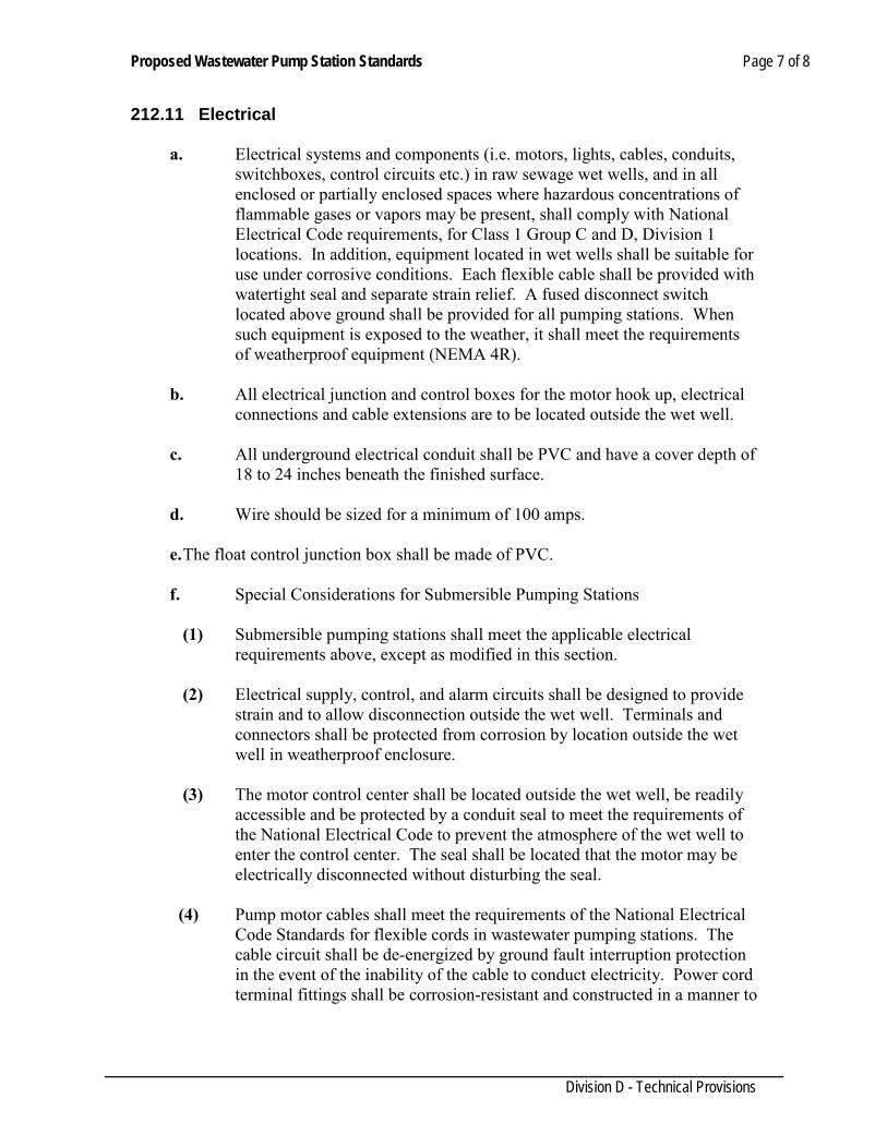
Proposed Wastewater Pump Station Standards Page 7 of 8
Division D - Technical Provisions
212.11 Electrical
a. Electrical systems and components (i.e. motors, lights, cables, conduits, switchboxes, control circuits etc.) in raw sewage wet wells, and in all enclosed or partially enclosed spaces where hazardous concentrations of flammable gases or vapors may be present, shall comply with National Electrical Code requirements, for Class 1 Group C and D, Division 1 locations. In addition, equipment located in wet wells shall be suitable for use under corrosive conditions. Each flexible cable shall be provided with watertight seal and separate strain relief. A fused disconnect switch located above ground shall be provided for all pumping stations. When such equipment is exposed to the weather, it shall meet the requirements of weatherproof equipment (NEMA 4R).
b. All electrical junction and control boxes for the motor hook up, electrical
connections and cable extensions are to be located outside the wet well.
c. All underground electrical conduit shall be PVC and have a cover depth of 18 to 24 inches beneath the finished surface.
d. Wire should be sized for a minimum of 100 amps.
e. The float control junction box shall be made of PVC.
f. Special Considerations for Submersible Pumping Stations
(1) Submersible pumping stations shall meet the applicable electrical
requirements above, except as modified in this section.
(2) Electrical supply, control, and alarm circuits shall be designed to provide strain and to allow disconnection outside the wet well. Terminals and connectors shall be protected from corrosion by location outside the wet well in weatherproof enclosure.
(3) The motor control center shall be located outside the wet well, be readily
accessible and be protected by a conduit seal to meet the requirements of the National Electrical Code to prevent the atmosphere of the wet well to enter the control center. The seal shall be located that the motor may be electrically disconnected without disturbing the seal.
(4) Pump motor cables shall meet the requirements of the National Electrical
Code Standards for flexible cords in wastewater pumping stations. The cable circuit shall be de-energized by ground fault interruption protection in the event of the inability of the cable to conduct electricity. Power cord terminal fittings shall be corrosion-resistant and constructed in a manner to
Proposed Wastewater Pump Station Standards Page 8 of 8
Division D - Technical Provisions
prevent entry of moisture into the cable, shall be provided with relief appurtenances, and shall be designed to facilitate field construction.
212.12 Emergency Operations
a. An evaluation of the power supply reliability at the lift station location shall be performed in accordance with 30 TAC 317.3.e.1. Wastewater retention capacity within the lift station and collection system shall be calculated at peak flow with volumes above the alarm level.
b. If the installation of a spill containment structure is required in accordance
with 30 TAC 317.3.e.4, it will be designed to completely drain stored wastewater into the lift station wet well as its level is lowered to normal operating levels.
c. There shall be an electrical connector installed on the above ground power
service panel with an approved transfer switch to connect a standby generator if a permanent on-site unit is not required. This electrical connector shall be sized to allow connection of the properly sized generator to operate the pumping station.
d. All permanently installed engine driven generators shall be protected from
operating conditions that would result in damage to the equipment. Protective equipment shall be capable of shutting down the engine and activating an on site alarm. Protective equipment shall monitor for conditions of low oil pressure and overheating.
e. The generating unit of a permanently installed or portable generator shall
be adequate to provide power for pump motor starting current, lighting, proper ventilation and other equipment necessary for safety and proper operation of the lift station.
f. The engine shall be located above grade with adequate ventilation of fuel
vapors and exhaust gases.
212.13 MEASUREMENT AND PAYMENT: Separate measurement or payment will be made for this item and the Contractor shall investigate/ the conditions as they exist in the field and include the unit price bid for the items concerned full reimbursement. Payment shall be made in lump sum.
Sanitary sewer cleanouts Page 1 of 2
Division D- Technical Provisions
SECTION 214 SANITARY SEWER CLEANOUTS
D-214.01 DESCRIPTION: This Specification shall govern for the furnishing, excavating, laying, or placing, and backfilling, shoring, and other operations necessary to the installing of all sanitary sewer cleanouts. Cleanout connections shall be provided at the end of the sanitary sewer main and shall be a minimum of 8 i nch (8”) diameter. The location s hall be clearly indicated on the construction drawings. D-214.02 MATERIALS: Cast iron boot and cover shall be Alamo Ironworks # 813-45 or approved equal. PVC pipe and fittings 6 inch (6”) through 12 inch (12”) diameter shall meet requirements of ASTM D3034, wall thickness classification SDR-26, as modified herein. PVC pipe and fittings 16 inch (18”) through 48 inch (48”) diameter shall meet the requirements of ASTM F679, wall thickness T- 1. as modified herein. Pipe shall be furnished in lengths of not less than 12 feet. Pipe with blisters, bubbles, cuts, or scrapes on inside or outside surfaces or imperfections which will impair the performance or life of the pipe, will be rejected. Joints for PVC pipe and fittings shall be the integral bell gasketed joint design so, when assembled, the elastomeric gasket inside the bell is compressed radially on the pipe spigot and provides a watertight joint. Joints shall conform to ASTM D3212. The fittings shall be made from PVC components as defined and described in ASTM standard Dl 784. The gasket shall meet requirements of ASTM F477. PVC pipe and fittings shall be legibly marked in accordance with ASTM D3034 and ASTM F679, and in addition marked with the date and location of manufacture. Pipe not marked as indicated herein will be rejected and pipe manufactured more than twelve months before the date of the work site inspection will not be accepted. D-214.03 EXECUTION: A eight-inch (8”) cleanout shall be provided at one foot (1’) from the property line within the R.O.W or easement line or as indicated on the plans. A cast iron cleanout cover shall be placed over every cleanout for the main line as per Detail No. D-214.04 BACKFILL: All trenches and excavations in this section shall be in accordance with, Section 102. D-214.05 CONCRETE CUSHION, CRADLE, OR COLLAR: Concrete cradle, cushion, or collar, shall be constructed as shown on the plans. Where concrete cradle or cushion is constructed beneath the sewer pipe, the sub-grade shall be prepared to the dimensions and form as shown on the plans. Concrete cradle, cushion, or collar shall be placed in a dry trench unless, in the opinion of the Engineer, such a method is not practicable. Where the concrete is placed in a wet trench, the work
Sanitary sewer cleanouts Page 2 of 2
Division D- Technical Provisions
shall be done strictly as directed or approved by the Engineer. Cleanout cover shall be at the same elevations of the pavement or finish grade providing the X, Y, Z coordinates D-214.06 PAYMENT: All sewer cleanouts, shall be paid for at the unit price bid per piece complete in place, of the size, type, and depth constructed, which price shall be full compensation for furnishing all labor, material, and equipment, for all hauling, excavation, shaping of trench bottom, bracing, sheeting, for all installation, backfilling, tamping of backfill, and for all clean-up and incidentals necessary to furnish sewer services complete in place.

Testing Sewer System Page 1 of 5
Division D - Technical Provisions
SECTION 218 TESTING SEWER SYSTEM
D-218.01 GENERAL 1. Summary A. Section Includes:
1. Deflection testing of sanitary sewer lines. 2. Leakage testing of sanitary sewer lines. 3. Leakage testing of sanitary sewer manholes.
B. Measurement and Payment:
1. Include costs for testing in appropriate unit prices bid for sewer line construction. 2. Submittals A. Submit in accordance with Standard General Conditions and Supplementary Conditions. B. Copies of all test results shall be submitted to the Engineer prior to acceptance of sewer
system. D-218.02 PRODUCTS (N/A) D-218.03 EXECUTION 1. GENERAL A. Commence test procedures when following condition are met.
1. Pipe section to be tested is clean and free of dirt, sand, water or other foreign material. Pipe system shall be isolated from the existing waste water system. 2. Pipe section to be tested has backfill placed and compacted
B. Repair visible leaks in manholes and sewers regardless of results of leakage tests. C. Notify Engineer and City of Laredo Utilities Department in writing 48 hours before
beginning tests. D. Contractor shall furnish and pay for all water required for testing. 2. Deflection Testing of Sanitary Sewer Lines A. Perform tests on sewer pipe in presence of Engineer and City of Laredo Utilities
Inspector. B. Provide necessary test mandrel, cable, reeling equipment, and other materials and
equipment required to perform tests. Provide cable at each end of test mandrel to allow withdrawal if mandrel becomes stuck.
C. Deflection Tests shall be performed on all flexible pipes. For pipelines with inside diameters less than 27 inches, a rigid mandrel shall be used to measure deflection.
Testing Sewer System Page 2 of 5
Division D - Technical Provisions
1. Mandrel sizing. The rigid mandrel shall have an outside diameter (OD) equal to 95%
of the inside diameter (ID) of the pipe. The inside diameter of the pipe, for the purposes of determining the outside diameter of the mandrel, shall be the average outside diameter minus two minimum wall thicknesses for OD controlled pipe and the average inside diameter for ID controlled pipe, all dimensions shall be per appropriate standard. Statistical or other "tolerance packages" shall not be considered in mandrel sizing.
2. Mandrel design. The rigid mandrel shall be constructed of a metal or a rigid plastic material that can withstand 200 psi without being deformed. The mandrel shall have nine or more "runners" or "legs" as long as the total number of legs is an odd number. The barrel section of the length of at last 75% of the inside diameter of the pipe. A proving ring shall be provided and used for each size mandrel in use.
3. Method options. Adjustable or flexible mandrels are prohibited. A television inspection is not a substitute of the deflection test. Mandrels with removable legs or runners may be accepted on a case-by-case basis.
D. The test shall be performed without mechanical pulling devices. Sewer is considered to have passed deflection test if mandrel can be drawn through sewer system being tested without aid of mechanical assistance.
E. If excessive force is required or mandrel fails to pass through, sewer shall have failed deflection test.
F. The test shall be conducted after the final backfill has been in place at least 30 days. No pipe shall exceed a deflection of 5.0%. If a pipe should fail to pass deflection test, the problem shall be corrected and a second test shall be conducted after the final backfill has been in place and additional 30 days. Correct failed sewers by excavating sewer a point of failure and for distance of 10 ft on either side, allowing sewer to return to its original round cross-section and backfill according to Specifications. Remove and replace sewers failing to return to original round cross-section or failing second deflection test at not cost to Owner. Do not use devices to generate internal pressures or vibrations to correct failed sewers.
3. Leakage Testing of Sanitary Sewer Lines A. Tests:
1. Pressure test sanitary sewer pipe 24 inches or smaller in diameter using low pressure air test.
B. General: 1. Conduct tests in presence of Engineer and City of Laredo Utilities Inspector. 2. Provide piping connections between section of line being tested and air supply, test
pressure equipment, weirs, meters, certified pressure gauge, and other equipment, materials, and facilities necessary to make specified test.
3. Provide bulkheads, blocking, bracing or other temporary sectionalizing devices that may be required.
4. Remove temporary sectionalizing devices after test complete. C. Low Pressure Air Test
1. General:
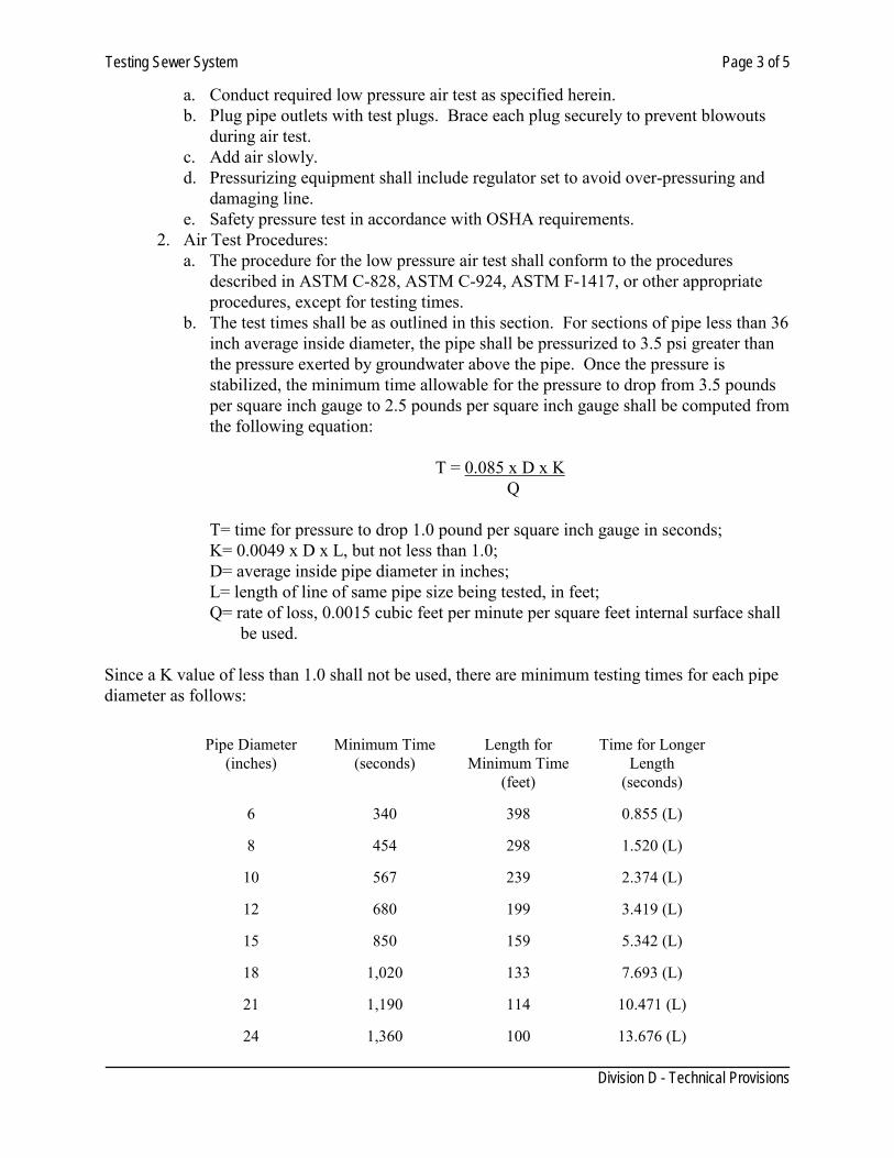
Testing Sewer System Page 3 of 5
Division D - Technical Provisions
a. Conduct required low pressure air test as specified herein. b. Plug pipe outlets with test plugs. Brace each plug securely to prevent blowouts
during air test. c. Add air slowly. d. Pressurizing equipment shall include regulator set to avoid over-pressuring and
damaging line. e. Safety pressure test in accordance with OSHA requirements.
2. Air Test Procedures: a. The procedure for the low pressure air test shall conform to the procedures
described in ASTM C-828, ASTM C-924, ASTM F-1417, or other appropriate procedures, except for testing times.
b. The test times shall be as outlined in this section. For sections of pipe less than 36 inch average inside diameter, the pipe shall be pressurized to 3.5 psi greater than the pressure exerted by groundwater above the pipe. Once the pressure is stabilized, the minimum time allowable for the pressure to drop from 3.5 pounds per square inch gauge to 2.5 pounds per square inch gauge shall be computed from the following equation:
T = 0.085 x D x K
Q
T= time for pressure to drop 1.0 pound per square inch gauge in seconds; K= 0.0049 x D x L, but not less than 1.0; D= average inside pipe diameter in inches; L= length of line of same pipe size being tested, in feet; Q= rate of loss, 0.0015 cubic feet per minute per square feet internal surface shall be used.
Since a K value of less than 1.0 shall not be used, there are minimum testing times for each pipe diameter as follows:
Pipe Diameter (inches)
Minimum Time
(seconds)
Length for
Minimum Time (feet)
Time for Longer
Length (seconds)
6
340
398
0.855 (L)
8
454
298
1.520 (L)
10
567
239
2.374 (L)
12
680
199
3.419 (L)
15
850
159
5.342 (L)
18
1,020
133
7.693 (L)
21
1,190
114
10.471 (L)
24
1,360
100
13.676 (L)
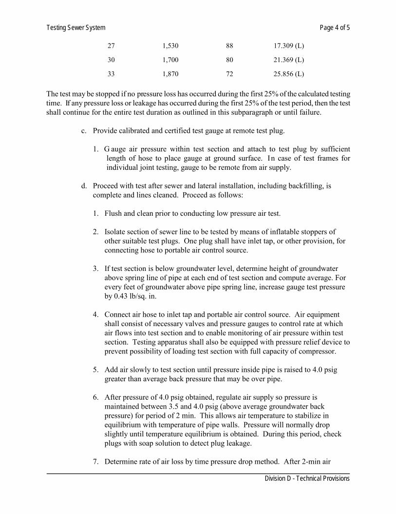
Testing Sewer System Page 4 of 5
Division D - Technical Provisions
27
1,530
88
17.309 (L)
30
1,700
80
21.369 (L)
33
1,870
72
25.856 (L)
The test may be stopped if no pressure loss has occurred during the first 25% of the calculated testing time. If any pressure loss or leakage has occurred during the first 25% of the test period, then the test shall continue for the entire test duration as outlined in this subparagraph or until failure.
c. Provide calibrated and certified test gauge at remote test plug.
1. G auge air pressure within test section and attach to test plug by sufficient length of hose to place gauge at ground surface. In case of test frames for individual joint testing, gauge to be remote from air supply.
d. Proceed with test after sewer and lateral installation, including backfilling, is
complete and lines cleaned. Proceed as follows:
1. Flush and clean prior to conducting low pressure air test.
2. Isolate section of sewer line to be tested by means of inflatable stoppers of other suitable test plugs. One plug shall have inlet tap, or other provision, for connecting hose to portable air control source.
3. If test section is below groundwater level, determine height of groundwater
above spring line of pipe at each end of test section and compute average. For every feet of groundwater above pipe spring line, increase gauge test pressure by 0.43 lb/sq. in.
4. Connect air hose to inlet tap and portable air control source. Air equipment
shall consist of necessary valves and pressure gauges to control rate at which air flows into test section and to enable monitoring of air pressure within test section. Testing apparatus shall also be equipped with pressure relief device to prevent possibility of loading test section with full capacity of compressor.
5. Add air slowly to test section until pressure inside pipe is raised to 4.0 psig
greater than average back pressure that may be over pipe.
6. After pressure of 4.0 psig obtained, regulate air supply so pressure is maintained between 3.5 and 4.0 psig (above average groundwater back pressure) for period of 2 min. This allows air temperature to stabilize in equilibrium with temperature of pipe walls. Pressure will normally drop slightly until temperature equilibrium is obtained. During this period, check plugs with soap solution to detect plug leakage.
7. Determine rate of air loss by time pressure drop method. After 2-min air
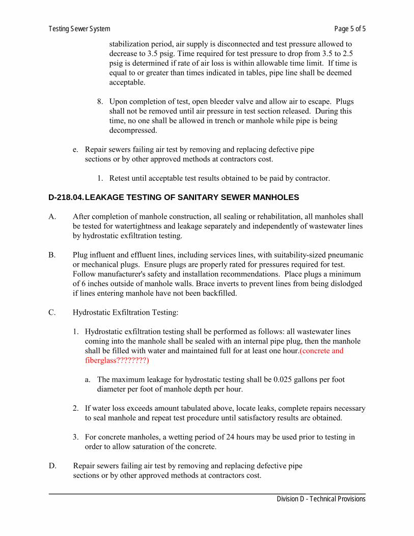
Testing Sewer System Page 5 of 5
Division D - Technical Provisions
stabilization period, air supply is disconnected and test pressure allowed to decrease to 3.5 psig. Time required for test pressure to drop from 3.5 to 2.5 psig is determined if rate of air loss is within allowable time limit. If time is equal to or greater than times indicated in tables, pipe line shall be deemed acceptable.
8. Upon completion of test, open bleeder valve and allow air to escape. Plugs
shall not be removed until air pressure in test section released. During this time, no one shall be allowed in trench or manhole while pipe is being decompressed.
e. Repair sewers failing air test by removing and replacing defective pipe
sections or by other approved methods at contractors cost.
1. Retest until acceptable test results obtained to be paid by contractor. D-218.04. LEAKAGE TESTING OF SANITARY SEWER MANHOLES A. After completion of manhole construction, all sealing or rehabilitation, all manholes shall
be tested for watertightness and leakage separately and independently of wastewater lines by hydrostatic exfiltration testing.
B. Plug influent and effluent lines, including services lines, with suitability-sized pneumanic
or mechanical plugs. Ensure plugs are properly rated for pressures required for test. Follow manufacturer's safety and installation recommendations. Place plugs a minimum of 6 inches outside of manhole walls. Brace inverts to prevent lines from being dislodged if lines entering manhole have not been backfilled.
C. Hydrostatic Exfiltration Testing:
1. Hydrostatic exfiltration testing shall be performed as follows: all wastewater lines coming into the manhole shall be sealed with an internal pipe plug, then the manhole shall be filled with water and maintained full for at least one hour.(concrete and fiberglass????????)
a. The maximum leakage for hydrostatic testing shall be 0.025 gallons per foot
diameter per foot of manhole depth per hour.
2. If water loss exceeds amount tabulated above, locate leaks, complete repairs necessary to seal manhole and repeat test procedure until satisfactory results are obtained.
3. For concrete manholes, a wetting period of 24 hours may be used prior to testing in
order to allow saturation of the concrete.
D. Repair sewers failing air test by removing and replacing defective pipe sections or by other approved methods at contractors cost.

Microtunneling Page 1 of 7
Division D - Technical Provisions
SECTION 220 MICROTUNNELING
D-220.01 DESCRIPTION: The trenchless installation of pipes below ground, by jacking the pipe behind a remotely-controlled, steerable, guided, articulated microtunnel boring machine (MTBM) which is connected to and shoved forward by the pipe being installed, generally precluding man entry. A geotechnical baseline report prepared by the engineer shall be made available prior to bidding for the project. If geotechnical report is not available, the contractor is responsible for contracting a geotechnical laboratory to do a subsurface exploration. 1. PERMITS: Contractor shall obtain a right of way use permit for the work from City of Laredo
and any other agency. 2. CONTRACTOR QUALIFICATIONS:
2.1. The contractor shall be trained by the respective manufacturer of the microtunneling equipment in the use of the machinery. The contractor shall provide certification from the manufacturer that the contractor has been trained and is proficient in the use of equipment. Only the contractor’s employee trained and certified by the manufacturer shall be allowed to operate the equipment during the project.
2.2. The contractor shall submit job history and reference list of equal or greater size projects successfully completed including the owner, engineer, addresses, phone numbers, and dates that said projects were completed.
2.3. All personnel shall be fully trained in their respective duties as part of the microtunneling crew and in safety. The Supervisor must have at least two years of microtunneling experience. A competent and experienced supervisor representing the Drilling Contractor shall be present at all times during the actual drilling operations. A responsible representative who is thoroughly familiar with the equipment and type work to be performed must be in direct charge and control of the operation at all times.
D-220.02 MATERIALS: Pipe:
(a) Pipe shall be specifically designed and certified for microtunneling by the pipe manufacturer and shall comply with ASTM and ASCE (ASCE Standard Construction Guidelines for Microtunneling) Specifications for use in Microtunneling. (b) All joints shall consist of an elastomeric sealing element, sleeve, and a compression cushion ring as required by applicable ASTM and ASCE standards.
Allowable forces: The allowable jacking strength capacity of pipe shall be capable of withstanding the maximum jacking forces imposed by the operation.
Microtunneling Page 2 of 7
Division D - Technical Provisions
Pipe Characteristics
(a) Steel pipe shall have a minimum wall thickness of 1/4 inch or as specified in section 126,
whichever is larger. Likewise, concrete pipe shall have a minimum wall thickness as specified in section 304. (b) Pipe shall be round. Steel pipe shall have a roundness tolerance, so that the difference between the major and minor outside diameters shall not exceed 1% of the specified nominal outside diameter, or 0.25 inch, whichever is less. Likewise, concrete and other types of pipes shall have similar roundness tolerances. (c) Pipe shall have square and machine beveled ends. The pipe end maximum out-of-square tolerance shall be 0.04 inch, (measured across the diameter). (d) Pipe shall be straight. The maximum allowable straightness deviation over any 10 foot length of steel pipe is 1/8 inch. (e) Pipe shall be without any significant dimensional or surface deformities. All pipes shall be free of visible cracks, holes, foreign material, foreign inclusions, blisters, or other deleterious or injurious faults or defects. Any section of the pipe with a gash, blister, abrasion, nick, scar, or other deleterious fault greater in depth than ten percent (10%) of the wall thickness, shall not be used.
Protective Coatings (Steel Pipe)
A coating to provide a corrosion barrier as well as an abrasion barrier is required. The coating shall be bonded well to the pipe and have a hard smooth surface to resist soil stresses and reduce friction. A mill-applied fusion bonded epoxy coating is required for steel pipes.
SUBMITTALS:
1. Prior to beginning work, the Contractor shall submit to the Engineer a work plan detailing the procedure and schedule to be used to execute the project. The work plan shall include a description of all equipment to be used, down-hole tools, a list of personnel and their qualifications and experience (including back-up personnel in the event that an individual is unavailable), list of subcontractors, a schedule of work activity, a safety plan (including MSDS of any potentially hazardous substances to be used), traffic control plan (if applicable), an environmental protection plan and contingency plans for possible problems. Work plan shall be comprehensive, realistic and based on actual working conditions for the particular project. Plan shall document the thoughtful planning required to successfully complete the project.
2. Specifications on material to be used shall be submitted to Engineer and material shall include the pipe, fittings, drilling mud, drilling additives and any other item, which is to be an installed component of the project or used during construction.
D-220.03 CONSTRUCTION: For street crossings, the crossing shall be as close to 90 degrees as practical. 1. Minimum Allowable Depths: Minimum allowable depth of cover shall be as specified in the
Microtunneling Page 3 of 7
Division D - Technical Provisions
approved plans 2. Method
(a) At completion of the MT operation, the installed pipe shall be inspected by means of a Closed Circuit Television (CCTV) camera and/or a pressure test. Damaged pipe shall be jacked through to the receiving shaft and be removed. Other methods of repairing the damaged conduit may be used, as recommended by the manufacturer and approved by the Engineer/ Inspector. (b) Perform shaft and tunnel excavation in a manner that will minimize the movement of the ground in front of and surrounding the excavation and minimize subsidence of the surface, structures, and utilities above and in the vicinity of the excavation. Support the ground in a manner to prevent loss of ground and keep shafts stable. Support pit excavation by positive means and as necessary during all shutdown periods. (c) The contractor shall continuously monitor and compare the actual volume of spoil recovered to the theoretical volume. (d) If any damage is observed to any property, the work shall cease immediately until a plan of action to minimize further damage and restore the damaged property is submitted and approved by the Engineer/ Inspector. (e) Pipe ends shall be temporarily sealed until the drive and receiving shafts are made permanent, or other manholes are installed, to prevent water or earth infiltration. (f) The control equipment shall integrate the method of excavation, removal of soil, and simultaneous placement of pipe. Line and grade shall be controlled by a guidance system that relates the actual position of the MTBM to a design reference (e.g. by a laser beam transmitted from the drive shaft along the center line of the pipe to a target mounted in the shield). As each pipe section is jacked forward, the control system shall synchronize spoils removal, excavation, and jacking speeds. The MTBM display equipment shall continuously show and automatically record the position of the shield with respect to the project design line and grade.
3. Equipment
(a) The Microtunneling Boring Machine (MTBM) shall be mechanically articulated to enable steering of the shield and shall be capable of incremental adjustments to maintain face stability for the soil conditions encountered. A remotely controlled steering mechanism shall be provided that allows for the operation of the system without the need for personnel to enter the tunnel. (b) The measuring and balancing of earth and groundwater pressure shall be achieved by use of a slurry system. The MTBM cutter face shall at all times be capable of supporting the full excavated area without the use of ground stabilization and have the capability of measuring the earth pressure at the face and setting a calculated earth balancing pressure. (c) The MTBM shall be advanced by jacks mounted in a jacking frame and located in the drive shaft. The MTBM shall be moved forward by the jacks advancing a successive string of connected pipes toward a receiving shaft. (d) The MTBM shall meet the following minimum performance requirements:
• Capable of providing positive face support regardless of the MTBM type. • Articulated to enable controlled steering in both the vertical and horizontal direction to a
tolerance of plus or minus 1 inch from design alignment. • All functions are controlled remotely from a surface control unit.
Microtunneling Page 4 of 7
Division D - Technical Provisions
• Capable of controlling rotation, using a bi-directional drive on the cutter head or by using anti-roll fins or grippers.
• Capable of injecting lubricant around the exterior of the pipe being jacked. • Indication of steering direction. • For slurry type MTBM, the following is also required: • Measurement of the volume of slurry flow in both the supply and return side of the slurry
loop. • Indications of slurry bypass valve position. • Indication of pressure of the slurry in the slurry chamber.
4. Drive and Receiving Shafts
(a) Location - A minimum distance, from the edge of the paved shoulder or curb, to the face of any access pit, equipment, and supplies, shall be a minimum of 10 feet along arterials and a minimum of 5 feet along local streets. Any deviation from these distances shall require prior approval from the Engineer/Inspector. (b) Sheeting and Bracing -Sheeting and bracing shall be required whenever any part of the access pit excavation is located within the roadbed influence area. Steel sheet piling shall be furnished and installed as indicated. An additional earth retention structure shall be required above and below the bore hole on the drilling face of all access pits to prevent loss of material during construction. (c) Protection - Fencing barriers shall be installed adjacent to access pits, open excavations, equipment and supplies with suitable fencing and plastic drums to prohibit pedestrian access to the work site. Equipment shall not be used as fencing to protect access pits. (d) Miscellaneous Items
• Thrust blocks should be designed to distribute loads into the ground in a uniform manner such that any deflection of the thrust block is uniform and does not impart excessive loads on the shaft itself or cause the jacking frame to become misaligned.
• Entry and exit seals should be provided at shaft walls if needed to prevent inflows of groundwater and slurry.
5. Over Cut Allowance- Overcut is the annular space between the excavated bore and the outside
diameter of the pipe. When using this method, the allowable overcut shall not exceed the outside pipe radius by more than one inch.
6. Water Tight joints-Water tight pipe joints are required to ensure the integrity of the roadbed.
Pipe shall be constructed to prevent water leakage or earth infiltration throughout its entire length.
7. Lubrication and Slurry Fluids
(a) Lubrication shall be used to reduce necessary jacking forces in cohesive soil. The most common lubrication is bentonite. (b) The pumping rate, pressures, viscosity and density of the slurry shall be monitored to ensure adequate removal of spoil. The excess slurry at entry and exit points in pits shall be contained until they are recycled or removed from the site. All slurry fluids shall be disposed of or recycled
Microtunneling Page 5 of 7
Division D - Technical Provisions
in a manner acceptable to the appropriate local, state or federal regulatory agencies. 8. Settlement/Heaving Monitoring
(a) This method shall be performed in a manner that will minimize the movement of the ground in front of, above, and surrounding the boring operation; and will minimize subsidence of the surface above and in the vicinity of the boring. (b) Potential heave or settlement shall be monitored at each shoulder point, edge of pavement, the edge of each lane (or centerline for two lane roads), and otherwise at 50 foot intervals along the pipe centerline. (c) A survey shall be performed prior to initiating this operation at each required monitoring location. A similar survey shall then be performed at each location, on a daily basis, until the permitted activity has been completed. All survey readings shall be recorded to the nearest one-hundredth (0.01) of a foot. Digital photographs of the pavement conditions shall also be taken prior and after the pipe installation. (d) All operations shall stop immediately whenever monitored points indicate a vertical change in elevation of 1/2 inch or more, or any surface disruption is observed. The Contractor shall then immediately report the amount of settlement to the Engineer/ Inspector.
9. Ground Water Control
(a) Dewatering shall be conducted whenever there is a high ground water table level to prevent flooding and facilitate the operation. The water table elevation shall be maintained at least 2 feet below the bottom of the casing at all times. When needed, dewatering may be initiated prior to any excavation. (b) Minor water seepage or pockets of saturated soil may be effectively controlled through bailing or pumping. This control shall be accomplished without removing any adjacent soil that could weaken or undermine any access pit, its supports, or other nearby structure. (c) Larger volumes of ground water shall be controlled with one or more well points or with staged deep wells. Well points and staged deep well pumping systems shall be installed and operated without damage to property or structures, and without interference with the rights of the public, owners of private property, pedestrians, vehicular traffic, or the work of other contractors. Any pumping methods used for de-watering and control of ground water and seepage shall have properly designated filters to ensure that the adjacent soil is not pumped along with the water. Well diameter, well spacing and the pump’s pumping rate, shall provide adequate draw down of the water level. Wells shall be located to intercept ground water that otherwise would enter the access pit excavation and interfere with the work. Upon removal of a well, the hole shall be filled and grouted according to the specifications identified in as flowable fill, and Plugging Drill Holes as directed by the Engineer. (d) Existing storm sewers shall only be used to discharge water from the dewatering operation in accordance with a permit obtained from the appropriate storm sewer owner. Filters or sediment control devices shall be required to ensure that the existing system is not adversely affected by construction debris or sediment. (e) If grouting is used to prevent ground water from entering the area of the access pit, the grouting shall be installed without damage to property or structures and without interference with the rights of the public, owners of private property, pedestrians, vehicular traffic, or the work of
Microtunneling Page 6 of 7
Division D - Technical Provisions
other contractors. The material properties of the grout shall conform to the specifications identified in as flowable fill.
10. Failure
(a) Should anything prevent completion of this operation, the remainder of the pipe shall be constructed and/or abandoned by methods approved by the Engineer/Inspector and accepted by the city. (b) Abandonment of any component of the installation shall only be allowed as approved by the Engineer/Inspector and accepted by the city.
D-220.04 CONTAMINATION: When an area of contaminated ground is encountered, all operations shall stop immediately, and shall not proceed until approved by the Engineer/Inspector. Any slurry shall be tested for contamination and disposed of in a manner, which meets Local, State and/or Federal requirements.
D-220.05 WORK SITE RESTORATION:
(a) Access pits and excavations shall be backfilled with suitable material, and in a method approved by the Engineer/Inspector. (b) The disturbed grass-surface area shall be top soiled, seeded, fertilized, mulched, and anchored. (c) Upon completion of the work, the contractor shall remove and properly dispose of all excess materials and equipment from the work site.
D-220.06 MEASUREMENT AND PAYMENT: This Item will be measured by the linear foot. Such measurements will be made between the ends of the barrel along its flow line. Payment for the work in this section will be as per linear foot or as stipulated in the contract documents. The price for installing the pipe lines shall be full compensation for all materials, labor, equipment, cost of insertions and retrieval, pavement removal and replacement, testing, and incidentals required to complete the replacement process. D-220.07 TELEVISING PIPE: The pipe system shall be televised and the video reports submitted to the City for review. Video reports can be submitted on CDROM or DVD compact disks. All lines must be flushed and cleaned prior to televising. The video report will be used to view the condition of the storm sewer pipe prior to acceptance. Workmanship and cleanliness of the installation will be checked. Video reports shall become the property of the City and contain the following:
1. Reference the start and end of each video segment as it begins, by clearly identifying the manhole/catch basin number where the video segment begins and the manhole/catch basin number where the video segment ends.
2. Footages along the storm sewer line must be shown on the video report and zeroed out at the beginning of each segment starting from the center of the manhole/catch basin.
Microtunneling Page 7 of 7
Division D - Technical Provisions
3. The video camera should be guided forward at a moderate to slow pace along the bottom of the pipe.
4. The camera should stop at any unusual instances that are viewed while in progress and provide a more detailed and longer view of the specific instance (i.e. — bad joint, dirt in lines, settlement in line, etc.).
Horizontal Directional Drilling Page 1 of 6
Division D - Technical Provisions
SECTION 222 HORIZONTAL DIRECTIONAL DRILLING
D-222.01 GENERAL: This Item shall govern the furnishing and installing pipe for constructing pipe culverts, storm sewer mains and water lines. The pipes shall be of the sizes, types, design and dimensions shown on the plans and shall include all connections and joints to new or existing pipes, sewer, manholes, inlets, headwalls and other appurtenances as may be required to complete the work. A geotechnical baseline report prepared by the engineer shall be made available prior to bidding for the project. If geotechnical report is not available, the contractor is responsible for contracting a geotechnical laboratory to do a subsurface exploration. 1. PERMITS: Contractor shall obtain a right of way use permit for the work from City of Laredo. 2. CONTRACTOR QUALIFICATIONS:
2.1. The contractor shall be trained by the respective manufacturer of the equipment in the use of the machinery. The contractor shall provide certification from the manufacturer that the contractor has been trained and is proficient in the use of equipment. Only the contractor’s employee trained and certified by the manufacturer shall be allowed to operate the equipment during the project.
2.2. The contractor shall submit job history and reference list of equal or greater size projects successfully completed including the owner, engineer, addresses, phone numbers, and dates that said projects were completed.
2.3. All personnel shall be fully trained in their respective duties as part of the directional drilling crew and in safety. The Supervisor must have at least two years directional drilling experience. A competent and experienced supervisor representing the Drilling Contractor shall be present at all times during the actual drilling operations. A responsible representative who is thoroughly familiar with the equipment and type work to be performed must be in direct charge and control of the operation at all times.
D-222.02 MATERIALS: Approved materials for HDD include: high-density polyethylene (HDPE), steel, fusible PVC, restrained joint PVC, and ductile iron pipe. Alternate materials will require prior approval: Pipe: HDPE pipes shall conform to the current ASTM D1248, ASTM D3350, and ASTM F714. Steel pipe shall conform to the current ASTM A 53-97 and ASTM 139-96. Ductile iron pipe shall conform to the current ASTM 716-95 and ASTM 746-95. PVC pipe shall conform to the current ASTM F1962-99 and ASTM D2321-00.
Allowable forces: The pulling force shall not exceed the pipe manufactures recommendation. When using HDPE pipe, an extra six foot section of the pipe shall be pulled out of the borehole to check for any sign of stress or damage.
Pipe Characteristics
(a) HDPE pipe shall have a minimum SDR value of 14?.
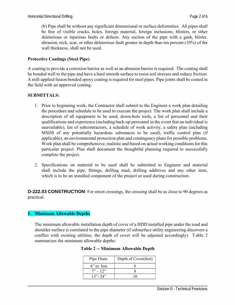
Horizontal Directional Drilling Page 2 of 6
Division D - Technical Provisions
(b) Pipe shall be without any significant dimensional or surface deformities. All pipes shall be free of visible cracks, holes, foreign material, foreign inclusions, blisters, or other deleterious or injurious faults or defects. Any section of the pipe with a gash, blister, abrasion, nick, scar, or other deleterious fault greater in depth than ten percent (10%) of the wall thickness, shall not be used.
Protective Coatings (Steel Pipe)
A coating to provide a corrosion barrier as well as an abrasion barrier is required. The coating shall be bonded well to the pipe and have a hard smooth surface to resist soil stresses and reduce friction. A mill-applied fusion bonded epoxy coating is required for steel pipes. Pipe joints shall be coated in the field with an approved coating.
SUBMITTALS:
1. Prior to beginning work, the Contractor shall submit to the Engineer a work plan detailing the procedure and schedule to be used to execute the project. The work plan shall include a description of all equipment to be used, down-hole tools, a list of personnel and their qualifications and experience (including back-up personnel in the event that an individual is unavailable), list of subcontractors, a schedule of work activity, a safety plan (including MSDS of any potentially hazardous substances to be used), traffic control plan (if applicable), an environmental protection plan and contingency plans for possible problems. Work plan shall be comprehensive, realistic and based on actual working conditions for this particular project. Plan shall document the thoughtful planning required to successfully complete the project.
2. Specifications on material to be used shall be submitted to Engineer and material shall include the pipe, fittings, drilling mud, drilling additives and any other item, which is to be an installed component of the project or used during construction.
D-222.03 CONSTRUCTION: For street crossings, the crossing shall be as close to 90 degrees as practical. 1. Minimum Allowable Depths
The minimum allowable installation depth of cover of a HDD installed pipe under the road and shoulder surface is correlated to the pipe diameter (if subsurface utility engineering discovers a conflict with existing utilities, the depth of cover will be adjusted accordingly). T able 2 summarizes the minimum allowable depths:
Table 2 -- Minimum Allowable Depth
Pipe Diam. Depth of Cover(feet)
6” or less 6 7” – 12” 8 13”- 24” 10
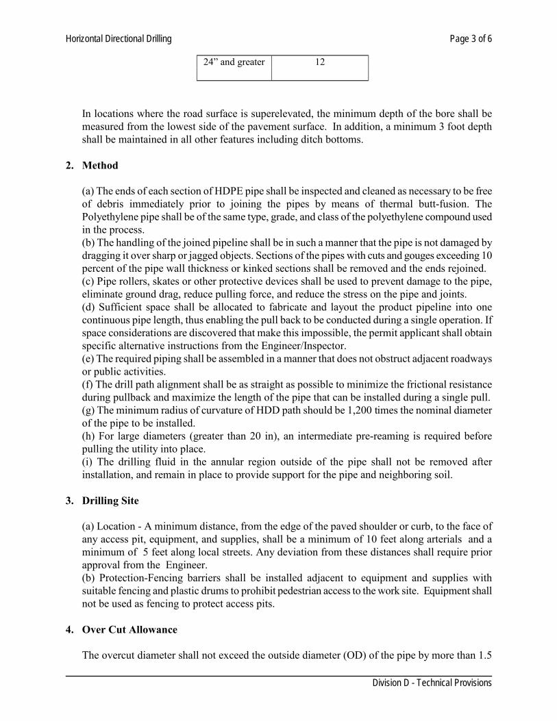
Horizontal Directional Drilling Page 3 of 6
Division D - Technical Provisions
24” and greater 12
In locations where the road surface is superelevated, the minimum depth of the bore shall be measured from the lowest side of the pavement surface. In addition, a minimum 3 foot depth shall be maintained in all other features including ditch bottoms.
2. Method
(a) The ends of each section of HDPE pipe shall be inspected and cleaned as necessary to be free of debris immediately prior to joining the pipes by means of thermal butt-fusion. The Polyethylene pipe shall be of the same type, grade, and class of the polyethylene compound used in the process. (b) The handling of the joined pipeline shall be in such a manner that the pipe is not damaged by dragging it over sharp or jagged objects. Sections of the pipes with cuts and gouges exceeding 10 percent of the pipe wall thickness or kinked sections shall be removed and the ends rejoined. (c) Pipe rollers, skates or other protective devices shall be used to prevent damage to the pipe, eliminate ground drag, reduce pulling force, and reduce the stress on the pipe and joints. (d) Sufficient space shall be allocated to fabricate and layout the product pipeline into one continuous pipe length, thus enabling the pull back to be conducted during a single operation. If space considerations are discovered that make this impossible, the permit applicant shall obtain specific alternative instructions from the Engineer/Inspector. (e) The required piping shall be assembled in a manner that does not obstruct adjacent roadways or public activities. (f) The drill path alignment shall be as straight as possible to minimize the frictional resistance during pullback and maximize the length of the pipe that can be installed during a single pull. (g) The minimum radius of curvature of HDD path should be 1,200 times the nominal diameter of the pipe to be installed. (h) For large diameters (greater than 20 in), an intermediate pre-reaming is required before pulling the utility into place. (i) The drilling fluid in the annular region outside of the pipe shall not be removed after installation, and remain in place to provide support for the pipe and neighboring soil.
3. Drilling Site
(a) Location - A minimum distance, from the edge of the paved shoulder or curb, to the face of any access pit, equipment, and supplies, shall be a minimum of 10 feet along arterials and a minimum of 5 feet along local streets. Any deviation from these distances shall require prior approval from the Engineer. (b) Protection-Fencing barriers shall be installed adjacent to equipment and supplies with suitable fencing and plastic drums to prohibit pedestrian access to the work site. Equipment shall not be used as fencing to protect access pits.
4. Over Cut Allowance
The overcut diameter shall not exceed the outside diameter (OD) of the pipe by more than 1.5
Horizontal Directional Drilling Page 4 of 6
Division D - Technical Provisions
times to ensure excessive voids are not created resulting in post installation settlement.
5. Water Tight joints
Water tight pipe joints are required to ensure the integrity of the roadbed. Pipe shall be constructed to prevent water leakage or earth infiltration throughout its entire length.
6. Drilling Fluids
(a) Drilling fluid shall be used during drilling and back reaming operations. (b) Excess drilling fluids shall be contained within a lined pit or containment pond, or trailer-mounted portable tank, until removed from the site. (c) All drilling fluids shall not enter the streets, manholes, sanitary and storm sewers, and other drainage systems, including streams and rivers.
7. Pipe Locating and Tracking
(a) During construction, continuous monitoring and plotting of pilot drill progress shall be undertaken to ensure compliance with the proposed installation alignment. The contractor shall plot the actual horizontal and vertical alignment of the pilot bore at each edge of pavement and at intervals not exceeding 20 feet. This “as built” plan and profile shall be updated as the pilot bore is advanced. (b) The contractor shall at all times provide and maintain instrumentation that will accurately locate the pilot hole and measure drilling fluid quantity. The contractor shall grant the Engineer/ Inspector access to all data and readout pertaining to the position of the bore head, the fluid pressures, and flows. (c) Trace wire is required for all non metallic pipe installation for post construction location purposes.
8. Settlement/Heaving Monitoring
(a) This method shall be performed in a manner that will minimize the movement of the ground in front of, above, and surrounding the boring operation; and will minimize subsidence of the surface above and in the vicinity of the boring. The ground shall be supported in a manner to prevent loss of ground and keep the perimeter and face of the boring stable at all times, including during shutdown periods. (b) Potential heave or settlement shall be monitored at each shoulder point, each edge of pavement, the edge of each lane (or centerline for two lane roads), and otherwise at 50 foot intervals along the pipe centerline. (c) For pipe sizes larger than 3 inches a survey shall be performed one day prior to initiating this operation at each required monitoring location. A similar survey shall then be performed at each location, on a daily basis, until the permitted activity has been completed. All survey readings shall be recorded to the nearest one-hundredth (0.01) of a foot. Digital photographs of the pavement conditions shall also be taken prior and after the pipe installation. (d) All operations shall stop immediately whenever monitored points indicate a vertical change
Horizontal Directional Drilling Page 5 of 6
Division D - Technical Provisions
in elevation of 1/2 inch or more, or any surface disruption is observed. The Contractor shall then immediately report the amount of settlement to the Engineer/ Inspector.
9. Failure
(a) Should anything prevent completion of this operation, the remainder of the pipe shall be constructed and/or abandoned by methods approved by the Engineer/Inspector. (b) Abandonment of any component of the installation shall only be allowed as approved by the Engineer/Inspector.
D-222.04 CONTAMINATION: When an area of contaminated ground is encountered, all operations shall stop immediately, and shall not proceed until approved by the Engineer/Inspector. A ny slurry shall be tested for contamination and disposed of in a manner, which meets Local, State and/or Federal requirements.
D-222.05 BULKHEAD: Pipe ends shall be temporarily sealed with a cap until the connection is made permanent, to prevent water or earth infiltration.
D-222.06 WORK SITE RESTORATION:
(a) Access pits and excavations shall be backfilled with suitable material, and in a method approved by the Engineer/Inspector. (b) The disturbed grass-surface area shall be top soiled, seeded, fertilized, mulched, and anchored. (c) Upon completion of the work, the contractor shall remove and properly dispose of all excess materials and equipment from the work site.
D-222.07 MEASUREMENT AND PAYMENT: This Item will be measured by the linear foot. Such measurements will be made between the ends of the barrel along its flow line. Payment for the work in this section will be as per linear foot or as stipulated in the contract documents. The price for installing the pipe lines by HDD shall be full compensation for all materials, labor, equipment, cost of insertions and retrieval, pavement removal and replacement, testing, and incidentals required to complete the replacement process. D-222.08 TELEVISING PIPE: The pipe system shall be televised and the video reports submitted to the City for review. Video reports can be submitted on CDROM or DVD compact disks. All lines must be flushed and cleaned prior to televising. The video report will be used to view the condition of the storm sewer pipe prior to acceptance. Workmanship and cleanliness of the installation will be checked. Video reports shall become the property of the City and contain the following:
Horizontal Directional Drilling Page 6 of 6
Division D - Technical Provisions
1. Reference the start and end of each video segment as it begins, by clearly identifying the manhole/catch basin number where the video segment begins and the manhole/catch basin number where the video segment ends.
2. Footages along the storm sewer line must be shown on the video report and zeroed out at the beginning of each segment starting from the center of the manhole/catch basin.
3. The video camera should be guided forward at a moderate to slow pace along the bottom of the pipe.
4. The camera should stop at any unusual instances that are viewed while in progress and provide a more detailed and longer view of the specific instance (i.e. — bad joint, dirt in lines, settlement in line, etc.).
Pipe Bursting Page 1 of 6
Division D - Technical Provisions
SECTION 224 PIPE BURSTING
D-224.01 DESCRIPTION: This section addresses the procedures to be employed for pipe bursting water/sewer pipelines, as identified on the drawings, and replacing with new pipe as specified. At no time shall this method be used when another unprotected underground utility or facility is located within 2.5 feet from the bursting head. D-224.02 GENERAL: This section includes minimum requirements for design, materials and equipment used in the pipe bursting process for trenchless construction of pipelines. A geotechnical baseline report prepared by the engineer shall be made available prior to bidding for the project. If geotechnical report is not available, the contractor is responsible for contracting a geotechnical laboratory to do a subsurface exploration. 1. PERMITS: Contractor shall obtain a right of way use permit for the work from City of Laredo
and any other agency. 2. CONTRACTOR QUALIFICATIONS:
2.1. The contractor shall be trained by the respective manufacturer of the pipe bursting equipment in the use of the machinery. The contractor shall provide certification from the manufacturer that the contractor has been trained and is proficient in the use of equipment. Only the contractor’s employee trained and certified by the manufacturer shall be allowed to operate the equipment during the project.
2.2. The contractor shall submit job history and reference list of equal or greater size projects successfully completed including the owner, engineer, addresses, phone numbers, and dates that said projects were completed.
2.3. All personnel shall be fully trained in their respective duties as part of the directional drilling crew and in safety. The Supervisor must have at least two years directional drilling experience. A competent and experienced supervisor representing the Drilling Contractor shall be present at all times during the actual drilling operations. A responsible representative who is thoroughly familiar with the equipment and type work to be performed must be in direct charge and control of the operation at all times.
D-224.03 MATERIALS:
Pipe - Pipe used in this method includes an existing Host pipe and a Replacement pipe.
Allowable forces- The pulling force shall not exceed the pipe manufactures recommendation. Replacement Pipe Characteristics
(a) HDPE pipe shall have a standard dimension ratio (SDR) of 14?or as specified. (b) Pipe shall be round. Steel pipe shall have a roundness tolerance, so that the difference between the major and minor outside diameters shall not exceed 1% of the specified nominal outside diameter, or 0.25 inch, whichever is less. Likewise, HDPE, ductile iron, and PVC
Pipe Bursting Page 2 of 6
Division D - Technical Provisions
pipe shall have similar roundness tolerances. (c) Pipe shall have square and machine beveled ends. The pipe end maximum out-of-square tolerance shall be 0.04 inch, (measured across the diameter). (d) The maximum allowable straightness deviation over any 10 foot length of steel pipe is 1/8 inch. Likewise, ductile iron, and PVC pipe shall have similar straightness tolerances. HDPE pipe does not to be straight. (e) Pipe shall be without any significant dimensional or surface deformities. All pipes shall be free of visible cracks, holes, foreign material, foreign inclusions, blisters, or other deleterious or injurious faults or defects. Any section of the pipe with a gash, blister, abrasion, nick, scar, or other deleterious fault greater in depth than ten percent (10%) of the wall thickness, shall not be used.
SUBMITTALS:
1. Prior to beginning work, the Contractor shall submit to the Engineer a work plan detailing the procedure and schedule to be used to execute the project. The work plan shall include a description of all equipment to be used, down-hole tools, a list of personnel and their qualifications and experience (including back-up personnel in the event that an individual is unavailable), list of subcontractors, a schedule of work activity, a safety plan (including MSDS of any potentially hazardous substances to be used), traffic control plan (if applicable), an environmental protection plan and contingency plans for possible problems. Work plan shall be comprehensive, realistic and based on actual working conditions for this particular project. Plan shall document the thoughtful planning required to successfully complete the project.
2. Specifications on material to be used shall be submitted to Engineer and material shall include the pipe, fittings, drilling mud, drilling additives and any other item, which is to be an installed component of the project or used during construction.
D-224.04 CONSTRUCTION: 1. Method:
(a) The ends of each section of HDPE pipe shall be inspected and cleaned as necessary to be free of debris immediately prior to joining the pipes by means of thermal butt-fusion. The Polyethylene pipe shall be of the same type, grade, and class of the polyethylene compound used in the process. (b) The handling of the joined pipeline shall be in such a manner that the pipe is not damaged by dragging it over sharp or jagged objects. Sections of the pipes with cuts and gouges exceeding 10 percent of the pipe wall thickness or kinked sections shall be removed and the ends rejoined. (c) Pipe rollers, skates or other protective devices shall be used to prevent damage to the pipe, eliminate ground drag, reduce pulling force, and reduce the stress on the pipe and joints. (d) Sufficient space shall be allocated to fabricate and layout the product pipeline into one continuous pipe length, thus enabling the pull back to be conducted during a single operation. If space considerations are discovered that make this impossible, the permit applicant shall obtain
Pipe Bursting Page 3 of 6
Division D - Technical Provisions
specific alternative instructions from the Engineer/Inspector. (e) The required piping shall be assembled in a manner that does not obstruct adjacent roadways or public activities. (f) Portions of the manhole shall be removed to ease the pipe installation. Upon completion, the manhole shall be restored appropriately
2. Access Pits:
(a) Location - A minimum distance, from the edge of the paved shoulder or curb, to the face of any access pit, equipment, and supplies, shall be a minimum of 10 feet along arterials and a minimum of 5 feet along local streets. Any deviation from these distances shall require prior approval from the Engineer/Inspector. However, for this method, the location and number of insertion or launching pits will typically be located near existing or proposed manholes. Therefore, access pits shall be placed and located to minimize the total number of pulls and maximize the length of pipe replaced per pull, and within the constraints of the maintaining service. Access pits shall be located at points near specific repair locations whenever possible.
(b) Sheeting and Bracing - Sheeting and bracing shall be required whenever any part of the access pit excavation is located within the roadbed influence area. Steel sheet piling shall be furnished and installed as indicated in the section 802. An additional earth retention structure shall be required above and below the bore hole on the drilling face of all access pits to prevent loss of material during construction.
(c) Protection - Fencing barriers shall be installed adjacent to access pits, open excavations, equipment and supplies with suitable fencing and plastic drums to prohibit pedestrian access to the work site. Equipment shall not be used as fencing to protect access pits. (d) Miscellaneous Items: 1. The pit or manhole wall must have a thrust block with proper structural capabilities to resist
the pull/push forces. 2. Manholes and pipes shall be protected by installing all pulleys, rollers, bumpers, alignment
control devices and other equipment required to protect existing manholes, and to protect the pipe from damage during installation. Under no circumstances shall the new pipe be stressed beyond its elastic limit.
3. Oversize Allowance - Oversize is the annular space between the enlarged host pipe and the
outside diameter of the replacement pipe. When using this method, the allowable oversize diameter is two inches greater than the replacement pipe diameter.
4. Water Tight joints-Water tight joints are required to ensure the integrity of the roadbed. Pipe shall be constructed to prevent water leakage or earth infiltration throughout its entire length.
5. Settlement/Heaving Monitoring
(a) This method shall be performed in a manner that will minimize the movement of the ground
Pipe Bursting Page 4 of 6
Division D - Technical Provisions
in front of, above, and surrounding the boring operation; and will minimize subsidence of the surface above and in the vicinity of the boring. (b) Potential heave or settlement shall be monitored at each edge of right of way, each shoulder point, each edge of pavement, the edge of each lane (or centerline for two lane roads), and otherwise at 50 foot intervals along the pipe centerline. (c) A survey shall be performed one day prior to initiating this operation at each required monitoring location. A similar survey shall then be performed at each location, on a daily basis, until the permitted activity has been completed. All survey readings shall be recorded to the nearest one-hundredth (0.01) of a foot. Digital photographs of the pavement conditions shall also be taken prior and after the pipe installation (d) All operations shall stop immediately whenever monitored points indicate a vertical change in elevation of 1/2 inch or more, or any surface disruption is observed. The Contractor shall then immediately report the amount of settlement to the Engineer/ Inspector.
6. Ground Water Control: Pipe bursting below the groundwater table increases the difficulty of
bursting operations. During the operation, insertion and receiving pits shall be kept dry.
(a) Dewatering shall be conducted whenever there is a high ground water table level to prevent flooding and facilitate the operation. The water table elevation shall be maintained at least 2 feet below the operation at all times. (b) Minor water seepage or pockets of saturated soil may be effectively controlled through bailing or pumping. This control shall be accomplished without removing any adjacent soil that could weaken or undermine any access pit, its supports, or other nearby structure. (c) Larger volumes of ground water shall be controlled with one or more well points or with staged deep wells. Well points and staged deep well pumping systems shall be installed and operated without damage to property or structures, and without interference with the rights of the public, owners of private property, pedestrians, vehicular traffic, or the work of other contractors. Any pumping methods used for de-watering and control of ground water and seepage shall have properly designated filters to ensure that the adjacent soil is not pumped along with the water. Well diameter, well spacing and the pump’s pumping rate, shall provide adequate draw down of the water level. Wells shall be located to intercept ground water that otherwise would enter the access pit excavation and interfere with the work. Upon removal of a well, the hole shall be filled and grouted according to the specifications identified in as flowable fill, and as directed by the Engineer. (d) Existing storm sewers shall only be used to discharge water from the dewatering operation in accordance with a permit obtained from the appropriate storm sewer owner. Filters or sediment control devices shall be required to ensure that the existing system is not adversely affected by construction debris or sediment. (e) If grouting is used to prevent ground water from entering the area of the access pit, the grouting shall be installed without damage to property or structures and without interference with the rights of the public, owners of private property, pedestrians, vehicular traffic, or the work of other contractors. The material properties of the grout shall conform to the specifications identified in as flowable fill.
7. Failure
Pipe Bursting Page 5 of 6
Division D - Technical Provisions
(a) Should anything prevent completion of this operation, the remainder of the pipe shall be constructed and/or abandoned by methods approved by the Engineer/Inspector. (b) Abandonment of any component of the installation shall only be allowed as approved by the Engineer/Inspector.
D-224.05 CONTAMINATION: When an area of contaminated ground is encountered, all operations shall stop immediately, and shall not proceed until approved by the Engineer/Inspector.
D-224.06 BULKHEAD: Pipe ends shall be temporarily sealed with a cap until the connection is made permanent, to prevent water or earth infiltration.
D-224.07 WORK SITE RESTORATION:
(a) Access pits and excavations shall be backfilled with suitable material, and in a method approved by the Engineer/Inspector. The shafts shall be backfilled and sealed upon completion. The shaft and supports shall be removed to 10 feet below the original ground surface. The disturbed work site area shall be restored to existing grades and original material condition. (b) The disturbed grass-surface area shall be topsoiled, seeded, fertilized, mulched, and anchored, etc. Slopes steeper than 1:3, shall be sodded. (c) Upon completion of the work, the contractor shall remove and properly dispose of all excess materials and equipment from the work site.
D-224.08 MEASUREMENT AND PAYMENT: Payment for the work in this section will be as per linear foot or as stipulated in the contract documents. The price for replacing the pipe lines by bursting shall be full compensation for all materials, labor, equipment, cost of insertions and retrieval pits, machine pits, pavement removal and replacement, testing, and incidentals required to complete the replacement process. D-224.09 TELEVISING PIPE: The pipe shall be televised and the video reports submitted to the City for review. Video reports can be submitted on CDROM or DVD compact disks. All lines must be flushed and cleaned prior to televising. The video report will be used to view the condition of the storm sewer pipe prior to acceptance. Workmanship and cleanliness of the installation will be checked. Video reports shall become the property of the City and contain the following:
1. Reference the start and end of each video segment as it begins, by clearly identifying the manhole/catch basin number where the video segment begins and the manhole/catch basin number where the video segment ends.
2. Footages along the storm sewer line must be shown on the video report and zeroed out at the beginning of each segment starting from the center of the manhole/catch basin.

Pipe Bursting Page 6 of 6
Division D - Technical Provisions
3. The video camera should be guided forward at a moderate to slow pace along the bottom of the pipe.
4. The camera should stop at any unusual instances that are viewed while in progress and provide a more detailed and longer view of the specific instance (i.e. — bad joint, dirt in lines, settlement in line, etc.
Pipe Cleaning and CCTV Inspection Page 1 of 6
Division D - Technical Provisions
SECTION 226 PIPE CLEANING AND CCTV INSPECTION
D-226.01 DESCRIPTION: This Item shall govern the cleaning and Closed Circuit Television (CCTV) inspection of sanitary and storm sewer mains before assessment, rehabilitation and final acceptance of a system. The Contractor shall do the televising. The City reserves the right to re-televise any new sanitary sewer/storm drain work after the placement of pavement or permanent trench resurfacing, but before acceptance by the Engineer, to determine the existence and extent of any foreign material or obstructions such as, but not necessarily limited to, cement grout, wood, rocks, sand, concrete, or pieces of pipe, and any structural deficiencies or sags precipitated by the permanent resurfacing operations or other Contract Work. The Contractor shall notify the Engineer five (5) working days in advance of the anticipated date of the televising. Five (5) working days shall be allowed for the Engineer to review each individual video recording of each and every storm drain documented on that particular recording. In the event that any deficiencies or sags are discovered by the Engineer, either by the Contractor’s televising or the City’s re-televising, Five (5) working days shall be allowed for the Engineer to determine whether the deficiencies or sags are repairable in place. If the Engineer determines that the deficiencies or sags are not repairable in place, the affected portion(s) shall be reconstructed in accordance with these Specifications. The Contractor shall not be entitled to any additional working days due to delays resulting from the correction of any deficiencies or sags, either repairable or non- repairable in place, as determined by televised inspections and the Engineer. D-226.02 GENERAL: The CCTV inspection work must be completed by a certified National Association of Sewer Service Companies (NASSCO) Pipeline Assessment and Certification Program (PACP) trained operator(s) using established PACP coding and observations. 1. General Requirements:
a. The video operator must have at least one (1 ) year of experience with a project of a similar nature. b. Video shall be submitted to the Municipality on DVDs with high quality color in a format reviewable by the Municipality. C. Video recordings that are out of focus shall be cause for rejection of the recordings and Contractor shall re-televise at no additional cost to the Owner. d. The Contractor shall notify the Engineer five (5) Municipal working days prior to televising. e. The Contractor shall turn over the original video recordings to the Engineer immediately after recording. f. Televising shall be done in one direction for the entire length between manholes; each section shall be isolated from the remainder of the pipe as required. Sufficient water shall be supplied to cause drainage within the isolated section prior to televising. g. Pipe must be clean and free of dirt, rock, gravel, debris, or any other material or obstruction that will hinder the CCTV inspection.
Pipe Cleaning and CCTV Inspection Page 2 of 6
Division D - Technical Provisions
h. For underground storm drain conduit installations, the maximum operation tolerance for a sag shall be one-hundredth foot (0.01’) per inch of pipe diameter. No sag shall be longer than sixty feet (60’). When CCTV inspection is used to check for sag, a calibrated readable device acceptable to the Engineer shall be used to measure the depth of sag. i. The Contractor shall not be entitled to any additional working days due to delays in securing the CCTV services of a private vendor.
D-226.03 EQUIPMENT:
1. CCTV inspection equipment shall consist of a monitoring unit and self-contained camera with pan, tilt and zoom capability. This equipment shall be specifically designed and constructed for such inspection purposes. The camera shall be mounted on a crawler or adjustable skids and have a height adjust to facilitate the inspection of different sizes of pipe and to allow for visual judgment of ovality by centering the camera within the pipe. The camera shall be self-operative in one hundred percent (100%) humidity conditions. Focal distance shall be adjustable through a range of from one inch (1”) to infinity. The camera shall be waterproof and shall have a remote controlled self-contained lighting system capable of producing effective illumination for all sizes of pipe. The lighting system shall be capable of lighting the entire periphery of the pipe. The remote reading footage counter shall be accurate to within one-half percent (0.5%) over measured distance of the particular section being inspected and shall be displayed on the television monitor. The equipment shall be capable of providing a clear digital recording of the interior of the pipes. An inclinometer which gives a profile of the pipeline must be used for all new pipe inspections or on existing pipe at the discretion of the Engineer. The camera, television monitor and other components of the video system shall be capable of producing a minimum three hundred and fifty (350) line resolution color video picture. The equipment shall be capable of televising the entire length in one direction. When televising storm drains the camera shall be capable of scanning the joints for three hundred and sixty degrees (360°).
2. High velocity pipe cleaning equipment shall be constructed for ease and safety of operation.
The equipment shall have a selection of nozzles capable of scouring the interior of the size range of pipe indicated on the plans.
3. Debris removal equipment shall consist of a vacuum tanker unit capable of removing typical
sewage debris accumulated by the pipe cleaner at the manholes.
4. Solid debris cutting equipment shall be hydraulically given by the sewer cleaner. The equipment must have circular saw-tooth blades in sizes consistent with the pipe being cleaned.
D-226.04 CCTV INSPECTION REPORTS:
1. Audio and written documentation shall accompany all DVD(s) submitted to the Engineer.
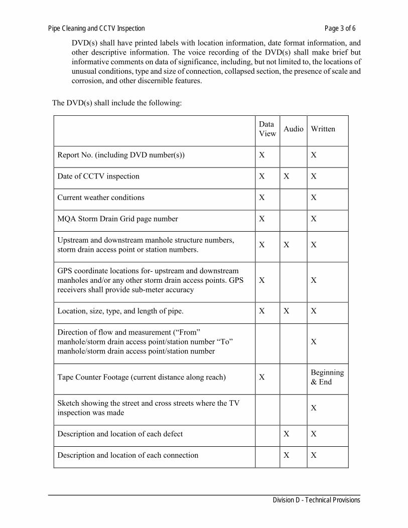
Pipe Cleaning and CCTV Inspection Page 3 of 6
Division D - Technical Provisions
DVD(s) shall have printed labels with location information, date format information, and other descriptive information. The voice recording of the DVD(s) shall make brief but informative comments on data of significance, including, but not limited to, the locations of unusual conditions, type and size of connection, collapsed section, the presence of scale and corrosion, and other discernible features.
The DVD(s) shall include the following:
Data View Audio Written
Report No. (including DVD number(s)) X X
Date of CCTV inspection X X X
Current weather conditions X X
MQA Storm Drain Grid page number X X
Upstream and downstream manhole structure numbers, storm drain access point or station numbers. X X X
GPS coordinate locations for- upstream and downstream manholes and/or any other storm drain access points. GPS receivers shall provide sub-meter accuracy
X X
Location, size, type, and length of pipe. X X X
Direction of flow and measurement (“From” manhole/storm drain access point/station number “To” manhole/storm drain access point/station number
X
Tape Counter Footage (current distance along reach) X Beginning & End
Sketch showing the street and cross streets where the TV inspection was made X
Description and location of each defect X X
Description and location of each connection X X
Pipe Cleaning and CCTV Inspection Page 4 of 6
Division D - Technical Provisions
2. A digital video shall be provided accompanied by an inspection report. This report shall be in accordance with the NASSCO defect codes. A sample inspection report and corresponding digital data file shall be submitted for review prior to starting the project. The report shall be a record of the exact location of each leak or- fault discovered by the inspection - e.g. open joints, broken, cracked, deformed or collapsed pipe, presence of grease, roots, debris, accumulation, obstruction, infiltration, water depth variations and other points of significance. The reference location for distance measurements shall be the centerline of the launch manhole (Station 0+000). If the inspection includes an intermediate manhole, station shall be reset to 0+000 in the center of the intermediate manhole.
3. All videos shall be in digital MPEG format that is compatible with the City of Laredo inspection software. Recorded picture quality and definition shall be to the satisfaction of the City.
4. The report shall include the location of all service connections together with a statement of opinion as to whether or not the service connections are subject to joint infiltration. Intrusions of service connections into the main line shall be noted with reference to the degree of intrusion.
5. Photographs of sewer defects and service connections shall be taken. The photographs shall be coordinated with the written report by reference numbers. A minimum of one photograph per line or manhole-to-manhole segment shall be taken to show a representative view of the workmanship.
5. Each manhole-to-manhole section of pipe shall be located on the report form in such a way as to be readily identifiable. Identify such items as name of subdivision, street names, manhole numbers, type of pipe, joint length, direction of flows, pipe diameter, manhole depth, inspection date, names of the inspection technician, persons viewing, and video identification numbers. Lot and block numbers for all services shall be provided.
6. Two copies of the final CCTV report with corresponding video shall be provided to the City within two weeks after the completion of the inspection. Media submitted shall become the property of the City.
7. All digital media shall be numbered and cross-indexed to the written report. Video footage shall indicate the size of the sewer, the manhole-to-manhole segment being inspected, plus the street address or location.
8. To insure photographic quality in reports, color printers shall be used. D-226.05 EXECUTION: 1. Pipe Cleaning
1.1. Acceptance of pipe and manhole cleaning shall be made upon review of the corresponding video inspection.
1.2. Block debris at downstream manhole to prevent contamination of the downstream mains. Sludge, dirt, sand and other debris resulting from the cleaning operations shall be removed from the downstream manhole of the section being cleaned. Passing material from the section being cleaned to the downstream pipe section shall not be permitted.
Pipe Cleaning and CCTV Inspection Page 5 of 6
Division D - Technical Provisions
1.3. The liquid portion of material removed at the manholes shall be decanted back into the pipe. The solid and semi-solid material removed at the manholes shall be disposed of at a designated site as approved by the City of Laredo.
2. Traffic Control
2.1. Interference to the normal flow of traffic shall be kept to a minimum. 2.2. Traffic control equipment shall conform to the TMUTCD Manual for Temporary Traffic
Control. 3. Closed Circuit Television Inspection Procedures
3.1. The CCTV inspection shall provide a fill record of the condition of the pipes, manholes and appurtenances along the designated section of sewer. This shall include all installation and material defects. The CCTV inspection shall use inclinometer testing that is compatible to the City’s software.
3.2. For new construction, completely wet the pipe with clean water to fill any sags prior to inspection
3.3. The Contractor shall not attempt a CCTV inspection if water levels in the pipe obstruct the cameras view unless instructed by the City.
3.4. Traveling speed of the camera in the pipeline to be as follows: 3.4.1. 0.33 ft/s for pipelines less than 8” diameter ? 3.4.2. 0.5 ft/s for 8” to 12” diameter ? 3.4.3. 0.66 ft/s for over 12” diameter ? or 3.4.4. Will not exceed a traverse rate of 30 ft/min. ?
3.5. Position camera lens centrally in the pipeline with a positioning tolerance of plus or minus
10% off the vertical centerline axis of the pipeline. 3.6. During the inspection, the camera operator shall pan the camera to focus on observable
deficiencies in the pipe that may be located off-center to the direction of camera travel. This shall include but not be limited to all services, joints to the top, left or right, cracks and fractures or surface deterioration of the pipe walls. Pan and tilt into each service connection.
3.7. Upon completion the Contractor shall provide inspection reports and digital media as detailed in Section 3.0 above.
3.8. Manual winches, power winches, TV cable and powered rewinds or other devices that do not obstruct the camera view or interface with proper documentation of the pipe conditions shall be used to move the camera through the pipe. If, during the televising operations, the television camera will not pass through an entire manhole section or access point section, the Contractor shall reset the equipment in a manner so that the inspection can continue opposite the obstruction. If the television camera encounters an obstruction within a section not accessible to a manhole or access point, the Contractor shall remove the obstruction by excavation or other appropriate means, replace whatever pipe is necessary, and retelevise the entire section.
3.9. Whenever non-remote powered and controlled winches are used to pull the television camera through the line, telephones, radios, or other suitable means of communication shall be set up between the two manholes or access points of the section being inspected to ensure that adequate communications exist between members of the crew.
3.10. The importance of accurate distance measurements is emphasized. Measurement for
Pipe Cleaning and CCTV Inspection Page 6 of 6
Division D - Technical Provisions
location of defects shall be above ground by means of a meter device Marking on the cable, or the like, which would require interpolation for depth of manhole or storm access points, is not acceptable. The accuracy of the measurement shall be checked daily by use of a walking meter, roll-a-tape, or other suitable device. Measurements shall be from center to center of each manhole or access point. Unless permission is given by the Engineer to do otherwise. Distance shall be shown on the video data view at all times.
3.11. The City, or a City approved contractor, can excavate a pipe in order to free lodged camera
equipment at the expense of the Contractor D-226.06 MEASUREMENT: Measurement for all sizes of pipe shall be based on the horizontal distances and shall be from center to center of manholes, from the center of manholes to center of catch basins, from center of manholes to center of cleanout “wye”, and from center of manhole to end of pipe including flared end sections. Televising pipe is considered incidental to the pay item and no separate payment shall be made.
Structural Excavation and Backfill Page 1 of 3
Division D - Technical Provisions
SECTION 302 STRUCTURAL EXCAVATION AND BACKFILL
D-302.01 DESCRIPTION: This item shall consist of doing the excavation for the placing of structures; for the disposal of all material obtained from such excavation; for the backfilling around completed structures to the finished grade as called for on the plans. Work to be done shall include all the necessary pumping or bailing, sheeting, drainage, and the construction and removal of any required cofferdams. Unless otherwise provided, the work included herein shall provide for the removal of old structures or portions thereof, trees, and other obstructions necessary to the proposed construction. D-302.02 DEFINITIONS: "Common Structural Excavation" shall include the removal of all materials regardless of its nature. D-302.03 USE OF EXPLOSIVES: When the use of explosives is necessary for the prosecution of the work, the Contractor shall use the utmost care not to endanger life or property. All explosives shall be stored in a secure manner, and all storage places shall be marked clearly "DANGEROUS EXPLOSIVES". The method of storing and handling explosives and highly flammable materials shall conform to Federal and State laws and regulations. Contractor shall provide permit from the appropriate agency. The Contractor shall not use explosives until he has taken the necessary legal precautions to save the Owner against any claims arising from such use of explosives.
CONSTRUCTION METHODS D-302.04 EQUIPMENT: All equipment necessary and required for the proper construction of structures and appurtenances shall be on project site in first class working condition and shall be approved by the Engineer before construction is permitted to start. The Contractor shall provide hand tamping devices and pneumatic tampers as may be necessary to obtain the proper compaction for the bed and backfill as specified. D-302.05 COMMON EXCAVATION: Common excavation shall be done in accordance with the lines and depths indicated on the plans or as established by the Engineer. Unless written permission to the contrary is given by the Engineer, no excavation shall be made outside a vertical plan three feet from the footing lines and parallel thereto. In order that the Engineer may judge the adequacy of a proposed foundation, the Contractor, if requested, shall make soundings to determine the character of the subgrade materials. The maximum depth of such soundings will not be required to exceed five (5) feet below the proposed footing grade; it is the intent of this provision that soundings shall be made at the time the excavation in each foundation is approximately complete. The final elevation to which a foundation is to be constructed shall be as shown on the plans or as raised or lowered by written order of the Engineer when such alterations are judged proper to satisfactorily comply with the design requirements for the structure. Should it be found necessary in the judgment of the plans, the necessary alterations in the details of the structure shall be accomplished in a manner as directed by the Engineer.
Structural Excavation and Backfill Page 2 of 3
Division D - Technical Provisions
When a structure is to rest on an excavated surface other than rock, special care shall be taken not to disturb the bottom of the excavation and the final removal of the foundation material to grade shall not be performed until just before the footing is placed. D-302.06 ROCK EXCAVATION: All material encountered, regardless of its nature, shall be included as common structural excavation. Unless written permission to the contrary is given by the Engineer, no excavation shall be made outside a vertical plane 3 (three) feet from the footing lines and parallel thereto. Rock foundation material shall be freed from all loose material, cleaned and cut to a firm surface either level, stepped, or serrated as directed by the Engineer. All seams shall be cleaned out and filled out with concrete at the time the footing is placed. D-302.07 EXCAVATED MATERIAL: Excavated material required to be used for backfill may be deposited by the Contractor in storage piles at points convenient for rehandling. The location of storage piles shall be subjected to the approval of the Engineer who may require that survey points or lines be kept free from any obstruction. Excavated material not required for backfill shall be disposed of by the Contractor as directed by the Engineer or as specified herein. If, in the opinion of the Engineer, the bottom of the ditch consists of unstable soil, this soil shall be removed from the full width of the trench and replaced with a pit-run gravel. Pit-run gravel shall vary in size from 3/4" to 3 1/2". The material shall be free from large amounts of organic material such as grass, roots, etc. The Engineer shall determine the depth of removal or unstable soil and the amount of backfill necessary. The cost of removing this unstable soil and replacing it with approved material shall be covered by a supplemental agreement. The sides of the trench shall be vertical unless otherwise approved by the Engineer. The Contractor shall install such trench bracing and sheeting as is necessary to protect the excavation also as required for the safety and to conform with governing laws. Unless otherwise provided, the bracing and sheeting shall be removed by the Contractor after the backfilling has been replaced to a point at lease 12 (twelve) inches above the top of the structure. In no case shall any sheeting or bracing be removed until the backfilling conditions have been met. The cost of bracing and sheeting shall be included in the unit price per linear foot for the structures. The Contractor shall take adequate precautions to prevent damage to all existing utilities. Any utility lines cut or damaged shall be repaired or restored to their former condition. D-302.08 DEWATERING TRENCH: Removal of water may be accomplished by bailing, pumping, or by a well-point installation as conditions warrant. Pumping or bailing from any excavation shall be done through or alongside any concrete being placed. No pumping or bailing will be permitted during the placing of concrete or for a period of at least 24 hours thereafter, unless it is done from a suitable sump separated from the concrete work by a watertight wall.
1. Minor water seepage or pockets of saturated soil may be effectively controlled through bailing or pumping. This control shall be accomplished without removing any adjacent
Structural Excavation and Backfill Page 3 of 3
Division D - Technical Provisions
soil that could weaken or undermine any access pit, its supports, or other nearby structure.
2. Larger volumes of ground water shall be controlled with one or more well points or with staged deep wells. Well points and staged deep well pumping systems shall be installed and operated without damage to property or structures, and without interference with the rights of the public, owners of private property, pedestrians, vehicular traffic, or the work of other contractors. Any pumping methods used for de-watering and control of ground water and seepage shall have properly designated filters to ensure that the adjacent soil is not pumped along with the water. Well diameter, well spacing and the pump’s pumping rate, shall provide adequate draw down of the water level. Wells shall be located to intercept ground water that otherwise would enter the access pit excavation and interfere with the work. Upon removal of a well, the hole shall be filled and grouted according to the specifications identified as flowable fill, and plug drill holes as directed by the Engineer.
3. Existing storm sewers shall only be used to discharge water from the dewatering operation in accordance with a permit obtained from the appropriate storm sewer owner. Filters or sediment control devices shall be required to ensure that the existing system is not adversely affected by construction debris or sediment.
4. If grouting is used to prevent ground water from entering the area of the access pit, the grouting shall be installed without damage to property or structures and without interference with the rights of the public, owners of private property, pedestrians, vehicular traffic, or the work of other contractors. The material properties of the grout shall conform to the specifications identified as flowable fill.
D-302.09 BEDDING: The structure shall be bedded as shown on plans on fine granular materials over an earth foundation accurately shaped to fit the lower part of the structure exterior for at least 15% of its overall height. Selected material from excavation or borrow shall then be placed along both sides of the structure equally in layers not more than six (6) inches thick and compacted by mechanical tamps or rammers for the remainder of the lower 30% of the overall height of the structure. D-302.10 BACKFILLING: As soon as practicable, all portions of excavation not occupied by the permanent structure shall be backfilled. Backfill material shall be free from large or frozen lumps, wood or other extraneous material, placed in successive layers of not more than 6" in depth (loose measurement) for the full width of the cross section. The material and the layers shall have the proper moisture content before tamping or rolling. W etting or drying of the material and manipulations to secure a uniform moisture content throughout the layer will be required. Should the material be too wet to permit proper compaction or rolling, all work on all positions of the fill thus affected shall be corrected. Unless otherwise provided by the plans or special provisions, hand tamping will not be accepted as an alternate for mechanical compaction. As a general rule, material used in filling or backfilling the portions described in this paragraph shall be an earth free of any appreciable amount of gravel or stone particles more than 4 (four) inches in greatest dimension and of a gradation that permits thorough compaction. When, in the opinion of the Engineer, such material is not readily available, the use of rock or gravel mixed with earth will be permitted provided no particles larger than 12 (twelve) inches in the greatest and 6 (six) inches in the
Structural Excavation and Backfill Page 4 of 3
Division D - Technical Provisions
least dimensions may be used. The percentage of fines shall be sufficient to fill all voids and insure a uniform and thoroughly compacted mass of proper density. No backfill shall be placed adjacent to or over single and multiple boxes until the top slab has attained 500 psi flexural strength. All backfill as specified above shall be compacted to not less than 95% of the maximum density at optimum moisture content as determined by procedures set out under Tex-113-E or Tex-114-E. The compaction shall extend to the entire depth of each layer as specified or shown on the plans and the backfill, when completed, shall be a homogenous and uniformly compacted mass. Water jetting in backfill operations will not be permitted. D-302.11 CLEANING AND RESTORATION OF SITE: After the backfill is completed, the Contractor shall notify the Environmental Services Department before the disposal of all surplus material, dirt, and rubbish from the site and shall restore all disturbed areas to their original condition. After all work is completed, the Contractor shall remove all tools and other equipment used by him, leaving the entire site free, clear, and in good condition. D-302.12 MEASUREMENT AND PAYMENT No separate measurement or payment will be made under this item, but all such work done shall be deemed a subsidiary obligation of the Contractor, and as having been taken into account and included in the price bid for the complete job.
Reinforced Concrete Storm Drain Pipe Page 1 of 6
Division D - Technical Provisions
SECTION 304 REINFORCED CONCRETE STORM DRAIN PIPE
D-304.01 DESCRIPTION: This item shall consist of reinforced concrete storm drain pipe of types, sizes, and classes shown on the plans furnished and existing in the field. This specification also deals with existing, conflicting pipelines discovered during construction requiring replacement.
MATERIALS D-304.02 REINFORCED CONCRETE STORM DRAIN PIPE: Reinforced concrete storm drain pipe shall be tongue and groove pipe and shall meet the requirements of ASTM Designation C76-59T, Class 3, with either Type A or Type B Wall, and 24” diameter minimum. Extra strength pipe shall meet the requirements of ASTM Designation C76-59T, Class 4, with either Type A or Type B Wall or latest ASTM Standards. Where pipe is installed with a cover of 12” or less, it shall be Class 4 with Type "A" Wall. Causes for Rejection: Pipe shall be subject to rejection for failure to conform to any of the specification requirements. Individual sections of pipe may be rejected because of any of the following:
(a) Fractures or cracks passing through the shell, except for a single end crack that does
not exceed the depth of the joint. (b) Defects that indicate imperfect proportioning, mixing and molding. (c) Surface defects indicating honeycombed or opened texture. (d) Damaged ends, where such damage would prevent making a satisfactory joint.
(e) Pipe sections not installed in accordance to the lines and grades shown on the plans.
Repairs: Pipe may be repaired if necessary, because of occasional imperfections in manufacture or accidental injury during handling and will be acceptable if, in the opinion of the Engineer, the repairs are sound and properly finished and cured and the repaired pipe conforms to the requirements of the specifications. Rejections: All rejected pipe shall be plainly marked by the Engineer/Inspector and shall be replaced by the Contractor with pipe which meets the requirements of these specifications. Such rejected pipe shall be removed immediately from the site of work. D-304.03 JOINTS MATERIAL: Reinforced concrete drain pipe joints shall be constructed to Ram-Nek, rubber O-rings, or approved equal. D-304.04 CONCRETE: Concrete used for pipe cradles shall meet the requirements of Class "C" concrete (3600 psi), as set out in the section titled "CONCRETE" of these specifications. This
Reinforced Concrete Storm Drain Pipe Page 2 of 6
Division D - Technical Provisions
concrete shall be furnished by an approved transit mix concrete company and/or mixed on jobsite to specifications herein established.
CONSTRUCTION METHODS D-304.05 EQUIPMENT: All equipment necessary and required for the proper construction of sewers and appurtenances shall be on project site in first class working condition and shall be approved by the Engineer before construction is permitted to start. The Contractor shall provide such hand tamping devices and pneumatic tampers as may be necessary to obtain the proper compaction for the pipe and backfill as specified. D-304.06 EXCAVATION: (a) Common: Common excavation shall consist of all excavation and shall be carried out to neat lines as specified and shown on the plans. If the excavation is carried out to a point below the required depth, this portion of the trench shall be filled at the Contractor's expense with selected material approved by the Engineer and thoroughly compacted to the specified elevation of the pipe bed. (b) Rock: Rock excavation shall consist of the removal of boulders and detached rock 1/2 cubic yards in volume or greater, and all rock in ledges or masses which can be removed only by the use of bars, sledges, mechanical hammers, or by blasting. The sides of the trenches shall be excavated to neat lines of the required width and no rock masses shall be allowed to extend into these lines. The bottom of the trench shall be excavated horizontally to a depth of at least one-half the diameter of the pipe, or a minimum of 6 (six) inches greater than the finished grade of the pipe bed. After removal of all broken material from the trench, this portion of the trench shall be filled with clean, dry sand, or an equivalent granular material to the elevation of the pipe bed. When the use of explosives is necessary for the prosecution of the work, the Contractor shall use the utmost care not to endanger life or property. All explosives shall be stored in a secure manner and all storage places shall be clearly marked "DANGEROUS EXPLOSIVES". The method of storing and handling explosives and highly flammable materials shall conform to Federal, State, and local laws and regulations. T he Contractor shall not store or use explosives until he has taken the necessary legal precautions to save the Owner against any claims arising from such possession or use of explosives, with permission secured from the Engineer. (c) General: Excavated material not required or acceptable for backfill shall be disposed of by the Contractor as directed by the Engineer, or as specified herein. If, in the opinion of the Engineer, the bottom of the ditch consists of unstable soil, this soil shall be removed from the full width of the trench and replaced with a pit run gravel or pipe cradles. P ipe cradles shall be constructed in accordance with Division D, Section 304, Paragraph D-304.11, "CRADLES", of these specifications. Pit run gravel shall vary in size from 3/4" to 3-1/2". The material shall be free from large amounts of organic material such as grass, roots, etc. The Engineer shall determine the depth of removal of unstable soil and the amount of backfill necessary. The cost of removing this unstable soil and
Reinforced Concrete Storm Drain Pipe Page 3 of 6
Division D - Technical Provisions
replacing it with approved material shall be covered by supplemental agreement. The sides of the trench shall be vertical unless otherwise approved by the Engineer. Spaces for the construction of pipe joints shall be excavated accurately to size so that the barrel supports the entire weight of the pipe and so that no less than 3/4 of the length of the barrel is in continuous contact with the bed. Joint holes shall be large enough to permit easy working under the bottom of the pipe. The bottom of the ditch shall be shaped as shown on the plans. The Contractor shall install such trench bracing and sheeting as is necessary to protect the excavation, and as required for safety and to conform with governing laws. Such installations shall be governed by the requirements set forth under Division D, Section 802, "SHEETING AND BRACING", and pursuant to the Trench Safety Law of the State of Texas. Unless otherwise provided, the bracing and sheeting shall be removed by the Contractor after the backfilling has been replaced to a point at least 12 (twelve) inches above the top of the pipe. In no case shall any sheeting or bracing be removed until the backfilling conditions have been met. The cost of bracing and sheeting shall be included in the lump sum price per foot of pipe in the Trench Safety bid item. The Contractor shall take adequate precautions to prevent damage to all existing utilities. Any utility lines cut or damaged shall be repaired and restored to their former condition as specified by the respective utility. D-304.07 TUNNELING: If approved by City Engineer, refer to Division D, Section 220 D-304.08 EXCAVATION IN STREETS: Excavation in streets, together with the implementation and maintenance of the traffic control plan where specified and the restoration of the pavement riding surface shall be in accordance with plan details or as required by other specifications included in the contract. Pavement shall be restored as per Division D, Section 522 and 534. D-304.09 REMOVING OLD STRUCTURES: When old inlets or manholes are encountered and no plan provision is made for adjustments or connection to the new sewers, such manholes and inlets shall be removed completely to a depth one (1) foot below the bottom of the trench. In each instance, the bottom of the trench shall be restored to grade by backfilling and compacting by the methods provided hereinafter for backfill. Where the trench cuts through storm or sanitary sewers which are known to be abandoned, these sewers shall be cut flush with the side of the trench and blocked with a concrete plug in a manner satisfactory to the Engineer. D-304.10 DEWATERING TRENCH: Sewers shall not be constructed or laid in a trench in the presence of water. All water shall be removed from the trench sufficiently prior to the sewer placing operation to insure a dry, firm bed on which to place the sewer, and the trench shall be maintained in such unwatered condition until all concrete and mortar is set. R emoval of water may be accomplished by bailing, pumping, or by a well-point installation as conditions warrant.

Reinforced Concrete Storm Drain Pipe Page 4 of 6
Division D - Technical Provisions
In the event that a trench cannot be dewatered to the point where the pipe subgrade is free from mud, or it is difficult to keep the reinforcing steel clean in cast-in-place monolithic sewers, a seal shall be used in the bottom of the trench. Such seal shall consist of a lean concrete mixture (not less than three (3) sacks of cement per cubic yard), with a minimum depth of three (3) inches. D-304.11 CRADLES: When, in the opinion of the Engineer, the natural fill material forming the bottom of the trench does not offer a suitable foundation for the pipe, he shall determine the location and dimensions of the necessary supporting cradles which must be added. These design details shall be shown on plans furnished to the Contractor, who will carry out the required work under the Engineer's direction. Payment for any additional work incurred in this operation shall be covered by Supplemental Agreement. D-304.12 CONNECTIONS: When a pipe to pipe connection is proposed, the connecting pipe outside diameter in no case shall exceed one half the inside diameter of the main storm drain. All connections shall provide a suitable concrete collar as per details 304-1 thru 304-3. Connections that lay on a pipe joint will not be allowed. D-304.13 INSTALLATION AND BACKFILL: 1. Bedding material shall consist on granular material such as gravel, pea gravel and any other
material approved by the engineer. Place bedding to the depths shown on the Standard details or project plans. The bedding shall be spread manually around the pipe to provide uniform bearing.
2. Pipe installation shall start at the outlet end unless otherwise authorized, with the spigot or
tongue end pointing downstream, and precede towards the inlet end with the abutting sections properly matched, true to the established lines and grades. Lower sections of pipe into the trench without damaging the pipe or disturbing the bedding and sides of trench. Prevent the bedding material from entering the pipe as is laid. Carefully clean the ends of the pipe before the joint material is applied. Once the pipe is in place, fill the lift holes with the precast concrete plugs. Lay multiple lines of reinforced concrete pipe with the center lines of individual barrels parallel. Unless otherwise shown on the plans, use the clear distances between outer surfaces of adjacent pipes shown on the table. Minimun Clearence Distance between Pipes
Equivalent Diameter Min. Clear Distance 24 in. 11 in. 30 in. 1 ft. 1 in. 36 in. 1ft. 3in. 42 in. 1ft. 5 in. 48 in. 1 ft. 7 in. 54 in. 1 ft. 11 in.
60 to 84 in. 2 ft.

Reinforced Concrete Storm Drain Pipe Page 5 of 6
Division D - Technical Provisions
3. Backfill: 3.1. Trench shall not be backfilled until the installed pipe conforms to the requirements
specified. Any trench improperly backfilled, or where settlements occurs, shall be reopened to the depth required for proper compaction, then refilled and compacted with the surface restored to the required grade and compaction. No trench more than 300 feet shall be kept open without backfill.
3.2. Initial (primary) backfill to a point of 12 inches above the top of pipe shall be done as
follows:
3.2.1. Suitable excavated material placed in uniform lifts not more than 6 inches in depth and shall be compacted to the density specified herein. The maximum dry density and optimum moisture shall be determined as per TxDot Tex-114-E. Test for in place density shall be in accordance with TxDOT Tex-115-E within 24 hours after compaction. Each lift shall be compacted to the required density and moisture as shown bellow, unless otherwise shown on the plans:
Subgrade Material Density Moisture Content PI ≤ 20 ≥ 95 % of Max Dry Density ± 2% of Opt. or greater PI > 20 ≥ 95 % of Max Dry Density ≥ Opt. Moisture
3.2.2. Cement stabilized Sand. When shown on the plans, backfilled the excavation with cement stabilized sand backfill as per Division D Section 134. Prevent the pipe from being displaced during the placement and prevent the backfill from entering the pipes. There is no separate item for cement stabilized sand, unless shown on the plans as a separate pay item.
3.2.3. Flowable Backfill. When shown on the plans, conform with Division D Section 136. There is no separate item for cement stabilized sand, unless shown on the plans as a separate pay item.
3.2.4. Select Fill or Flexible Base (gravel, caliche, crushed limestone).
Clean gravel approved by the engineer may be used for backfill from the bottom of the trench to the top of the pipe. The gravel shall be placed no to exceed 10 inches in depth and lightly tamped to consolidate the mass against pipe and earth surfaces.
Flexible base material (caliche, crushed limestone) may be used from the bottom of the trench to 12 inches above the top of the pipe or to the bottom of the street base in lifts no to exceed 8 inches. Material shall contain the required moisture to obtain the density for each layer to no less of 95% of the maximum dry density.
3.3. Secondary Backfill. After the initial backfill has been completed at a point of 12 inches
above the top of pipe, the material for secondary backfill shall be placed in uniform layers no more than 10 inches in depth (loose measurement) and shall be compacted to the required density specified herein. Excavation material used for secondary backfill
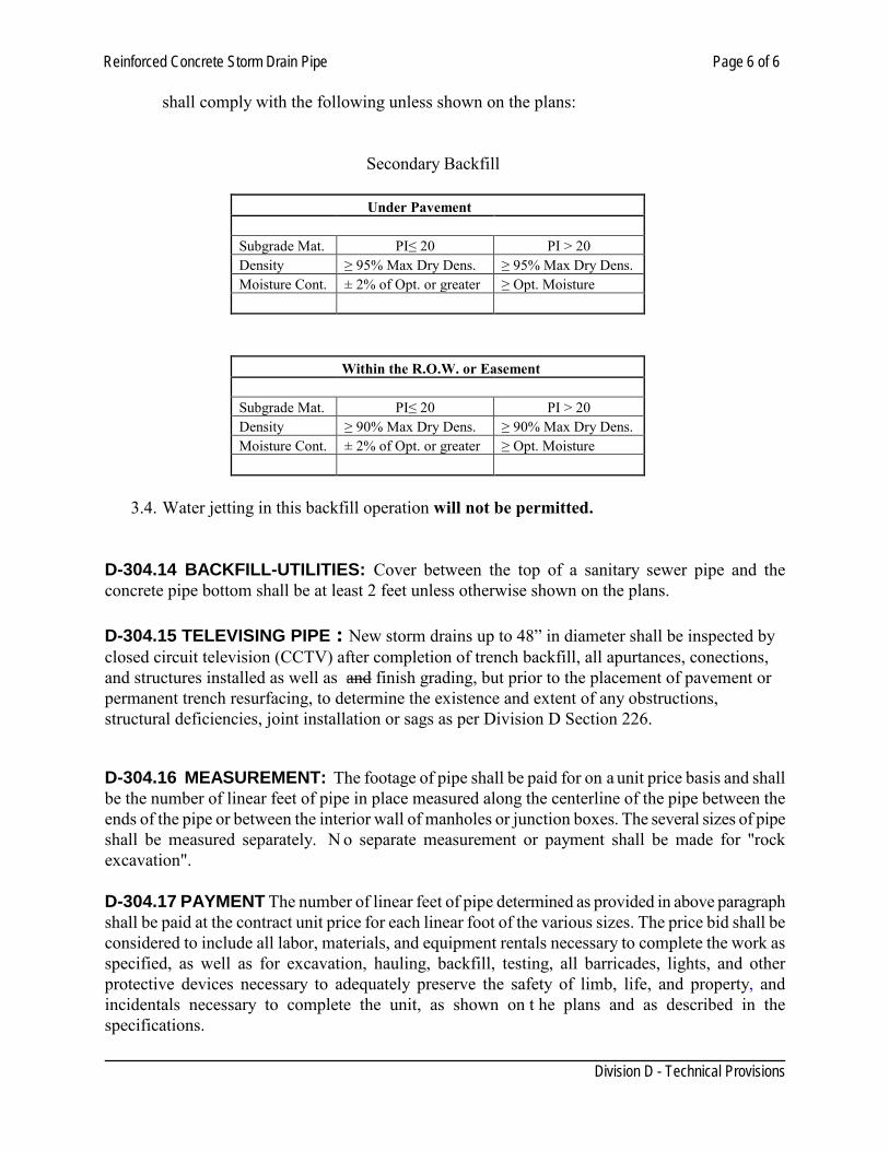
Reinforced Concrete Storm Drain Pipe Page 6 of 6
Division D - Technical Provisions
shall comply with the following unless shown on the plans:
Secondary Backfill
Under Pavement Subgrade Mat. PI≤ 20 PI > 20 Density ≥ 95% Max Dry Dens. ≥ 95% Max Dry Dens. Moisture Cont. ± 2% of Opt. or greater ≥ Opt. Moisture
Within the R.O.W. or Easement Subgrade Mat. PI≤ 20 PI > 20 Density ≥ 90% Max Dry Dens. ≥ 90% Max Dry Dens. Moisture Cont. ± 2% of Opt. or greater ≥ Opt. Moisture
3.4. Water jetting in this backfill operation will not be permitted.
D-304.14 BACKFILL-UTILITIES: Cover between the top of a sanitary sewer pipe and the concrete pipe bottom shall be at least 2 feet unless otherwise shown on the plans. D-304.15 TELEVISING PIPE : New storm drains up to 48” in diameter shall be inspected by closed circuit television (CCTV) after completion of trench backfill, all apurtances, conections, and structures installed as well as and finish grading, but prior to the placement of pavement or permanent trench resurfacing, to determine the existence and extent of any obstructions, structural deficiencies, joint installation or sags as per Division D Section 226.
D-304.16 MEASUREMENT: The footage of pipe shall be paid for on a unit price basis and shall be the number of linear feet of pipe in place measured along the centerline of the pipe between the ends of the pipe or between the interior wall of manholes or junction boxes. The several sizes of pipe shall be measured separately. N o separate measurement or payment shall be made for "rock excavation". D-304.17 PAYMENT The number of linear feet of pipe determined as provided in above paragraph shall be paid at the contract unit price for each linear foot of the various sizes. The price bid shall be considered to include all labor, materials, and equipment rentals necessary to complete the work as specified, as well as for excavation, hauling, backfill, testing, all barricades, lights, and other protective devices necessary to adequately preserve the safety of limb, life, and property, and incidentals necessary to complete the unit, as shown on t he plans and as described in the specifications.
Corrugated Steel Storm Sewer Pipe Page 1 of 2
Division D - Technical Provisions
SECTION 306 CORRUGATED STEEL STORM SEWER PIPE
D-306.01 GENERAL: This item shall govern the furnishing of corrugated steel pipe and pipe-arch for culverts and storm sewers for the types, sizes and designations as shown on the plans and further specified in these specifications. D-306.02 MATERIALS: The pipe shall be fabricated from sheet conforming to the current AASHTO M-274 (ASTM 929) specification for ALUMINIZED STEEL Type 2 material. Sampling, testing and inspection of metal sheets and coils used for corrugated steel pipe shall be in accordance with Test Method Tex-708-I. D-306.03 MANUFACTURE: The pipe shall meet the requirements of AASHTO M-36 (ASTM A760) for corrugated steel pipe and AASHTO M-274 D-306.04 CLASSIFICATION (TYPE): The pipe shall be manufactured to conform to the current AASHTO M-36 (ASTM A760) specification and shall have an external helical corrugation pattern of ¾” x ¾” x 7½” as described in AASHTO M-36 (ASTM A760). All round pipe shall conform to the Type IR pipe classification. All pipe arches shall conform to the Type II R classification. D-306.05 GAGE: Unless otherwise shown on the plans or specifications, gages shall be minimum as required by the Texas Department of Transportation, Height of Cover Tables, latest edition. D-306.06 COUPLING BANDS: Coupling bands shall be of the same base material and coating as the pipe. Coupling bands shall lap evenly on each of the pipes being connected and shall fit securely into at least one full circumferential corrugation to form a tightly closed joint. All pipe shall be field jointed with corrugated locking bands. Connecting bands shall be drawn together by means of not less than two bolts not less than ½ in. (13 mm) diameter through angles or bar and strap device suitably welded or riveted. Coupling bands shall be no more than three nominal sheet thicknesses lighter than the pipe to be connected and in no case thinner than 0.052 in. (1.32 mm). D-306.07 INSTALLATION: Corrugated steel pipe shall be installed as outlined in AASHTO Standard Specification for Highway Bridges and ASTM A798. D-306.08 BACKFILL: Trench shall not be backfilled until the installed pipe conforms to the requirements specified. Any trench improperly backfilled, or where settlements occurs, shall be reopened to the depth required for proper compaction, then refilled and compacted with the surface restored to the required grade and compaction. No trench more than 300 feet shall be kept open without backfill. 1. Primary backfill in any condition shall be cement stabilized sand as per Division D Section xxx
at least 12 inches on the sides and above of top of pipe. Prevent the pipe from being displaced during the placement and prevent the backfill from entering the pipes. There is no separate item
Corrugated Steel Storm Sewer Pipe Page 2 of 2
Division D - Technical Provisions
for cement stabilized sand, unless shown on the plans as a separate pay item. 2. Secondary backfill shall be in accordance with Division D Section 304.13.3.3 D-306.09 TELEVISING PIPE : New storm drains up to 48” in diameter shall be inspected by closed circuit television (CCTV) after completion of trench backfill, all apurtances, conections, and structures installed as well as finish grading, but prior to the placement of pavement or permanent trench resurfacing, to determine the existence and extent of any obstructions, structural deficiencies, or sags as per Division D Section 226. D-306.10 MEASUREMENT: Corrugated steel pipe will be measured by the linear foot. Such measurements shall be made between the ends of the barrel along its central axis. Where spurs or branches, or connections to existing pipe lines are involved, measurement of the spur or new connecting pipe will be made from the intersection of the central axis with the outside surface of the pipe into which it connects. Where inlets, headwalls, catch basins, manholes, junction chambers, or other structures are included in lines of pipe, that length of pipe tying into the other structure wall will be included for measurement but not other portion of the structure length or width will be included. For multiple pipes, the measure length will be the sum of the lengths of the barrels, measured as prescribed above. In event of a change in design which either increases or decreases the quantity of pipe, the variation in quantity will be measured as prescribed above and the quantity shown on the plans and in the proposal will be increase or decreased as the case may be. D-306.11 PAYMENT: Payment for corrugated steel pipe, measured as prescribed above will be made at the contract unit price bid per linear foot for various sizes, of corrugated steel pipe. The price bid shall be considered to include all labor, materials, and equipment rentals necessary to complete the work as specified, as well as for excavation, hauling, backfill, testing, all barricades, lights, and other protective devices necessary to adequately preserve the safety of limb, life, and property, and incidentals necessary to complete the unit, as shown on t he plans and as described in the specifications.
High Density Polyethylene Storm Drain Pipe Page 1 of 6
Division D - Technical Provisions
SECTION 308 HIGH DENSITY POLYETHYLENE STORM DRAIN PIPE
D-308.01 GENERAL: This Item shall govern for the furnishing and installing of all thermoplastic pipe for constructing thermoplastic pipe culverts or thermoplastic storm sewer mains, laterals, and stubs. The pipes shall be of the sizes, types, design and dimensions shown on the plans and shall include all connections and joints to new or existing pipes, sewer, manholes, inlets, headwalls and other appurtenances as may be required to complete the work. A private system using HDPE pipe up to the property line, may enter the public right of way to connect with a public storm sewer at a structure. However, HDPE pipe is not allowed to be installed underneath public streets. Do not utilized HDPE pipe in closed storm sewers. D-308.02 MATERIALS: Pipes within the R.O.W. shall be Type “S” with watertight joint and not to exceed 36” diam. Unless otherwise specified on the plans or herein, thermoplastic pipe and joint fittings shall conform to the following: (a) High density polyethylene pipe and fittings shall meet the requirements as in AASHTO M 294. (b) Raw Materials. The pipes and the fittings shall be manufactured from virgin PE compounds, which conform to the requirements of cell class 335400C as defined and described in ASTM D 3350, except that carbon black content shall not exceed 5%. PE compounds shall meet the Environmental Stress Crack Resistance according to the SP-NCTL test set forth in AASHTO M 294. (c) Designation of Type. The HDPE pipes used for gravity flow drainage applications shall be of Type S (outer corrugated wall with smooth inner liner) or Type D (inner and outer smooth walls braced circumferentially or spirally with projections or ribs). (d) Section Properties. Minimum wall thickness of the inner walls of Type S pipe and inner and outer walls of Type D pipe shall be as specified in Section 7.2.2 of AASHTO M 294. The pipe stiffness at 5% deflection, when determined in accordance with ASTM designation D 2412, shall be as specified in Section 7.4 of AASHTO M 294. D-308.04 JOINTS: Joints shall be installed such that the connection of pipe sections will form a continuous line free from irregularities in the flow line. Joints shall conform to one of the following: • Watertight Joints — Joints meeting the requirements of ASTM 3212. D-308.05 END SECTIONS: Provide non flammable end sections of the minimum length shown in the table I for each exposed pipe end. Minimum length shown in the table refers to the portion of pipe completely embedded into the embankment or natural ground. All exposed and mitered pipe sections shall consist of the same non-flammable material.
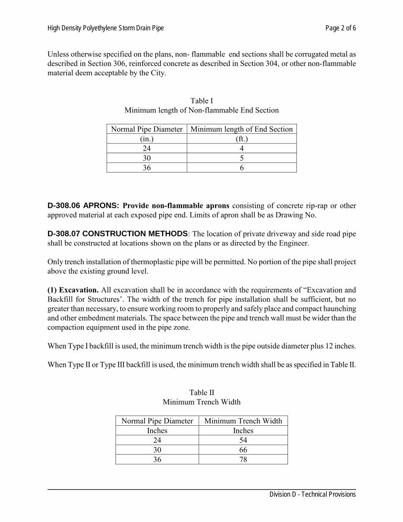
High Density Polyethylene Storm Drain Pipe Page 2 of 6
Division D - Technical Provisions
Unless otherwise specified on the plans, non- flammable end sections shall be corrugated metal as described in Section 306, reinforced concrete as described in Section 304, or other non-flammable material deem acceptable by the City.
Table I Minimum length of Non-flammable End Section
Normal Pipe Diameter Minimum length of End Section
(in.) (ft.) 24 4 30 5 36 6
D-308.06 APRONS: Provide non-flammable aprons consisting of concrete rip-rap or other approved material at each exposed pipe end. Limits of apron shall be as Drawing No. D-308.07 CONSTRUCTION METHODS: The location of private driveway and side road pipe shall be constructed at locations shown on the plans or as directed by the Engineer. Only trench installation of thermoplastic pipe will be permitted. No portion of the pipe shall project above the existing ground level. (1) Excavation. All excavation shall be in accordance with the requirements of “Excavation and Backfill for Structures’. The width of the trench for pipe installation shall be sufficient, but no greater than necessary, to ensure working room to properly and safely place and compact haunching and other embedment materials. The space between the pipe and trench wall must be wider than the compaction equipment used in the pipe zone. When Type I backfill is used, the minimum trench width is the pipe outside diameter plus 12 inches. When Type II or Type III backfill is used, the minimum trench width shall be as specified in Table II.
Table II Minimum Trench Width
Normal Pipe Diameter Minimum Trench Width
Inches Inches 24 54 30 66 36 78
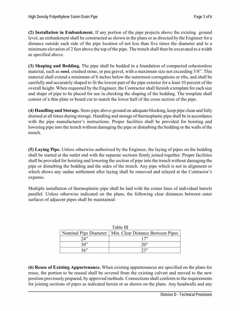
High Density Polyethylene Storm Drain Pipe Page 3 of 6
Division D - Technical Provisions
(2) Installation in Embankment. If any portion of the pipe projects above the existing ground level, an embankment shall be constructed as shown in the plans or as directed by the Engineer for a distance outside each side of the pipe location of not less than five times the diameter and to a minimum elevation of 2 feet above the top of the pipe. The trench shall then be excavated to a width as specified above. (3) Shaping and Bedding. The pipe shall be bedded in a foundation of compacted cohesionless material, such as sand, crushed stone, or pea gravel, with a maximum size not exceeding 3/8”. This material shall extend a minimum of 6 inches below the outermost corrugations or ribs, and shall be carefully and accurately shaped to fit the lowest part of the pipe exterior for a least 10 percent of the overall height. When requested by the Engineer, the Contractor shall furnish a template for each size and shape of pipe to be placed for use in checking the shaping of the bedding. The template shall consist of a thin plate or board cut to match the lower half of the cross section of the pipe. (4) Handling and Storage. Store pipe above ground on adequate blocking, keep pipe clean and fully drained at all times during storage. Handling and storage of thermoplastic pipe shall be in accordance with the pipe manufacturer’s instructions. Proper facilities shall be provided for hoisting and lowering pipe into the trench without damaging the pipe or disturbing the bedding or the walls of the trench. (5) Laying Pipe. Unless otherwise authorized by the Engineer, the laying of pipes on the bedding shall be started at the outlet end with the separate sections firmly joined together. Proper facilities shall be provided for hoisting and lowering the section of pipe into the trench without damaging the pipe or disturbing the bedding and the sides of the trench. Any pipe which is not in alignment or which shows any undue settlement after laying shall be removed and relayed at the Contractor’s expense. Multiple installation of thermoplastic pipe shall be laid with the center lines of individual barrels parallel. Unless otherwise indicated on the plans, the following clear distances between outer surfaces of adjacent pipes shall be maintained:
Table III Nominal Pipe Diameter Min. Clear Distance Between Pipes
24” 17” 30” 20” 36” 23”
(6) Reuse of Existing Appurtenance. When existing appurtenances are specified on the plans for reuse, the portion to be reused shall be severed from the existing culvert and moved to the new position previously prepared, by approved methods. Connections shall conform to the requirements for joining sections of pipes as indicated herein or as shown on the plans. Any headwalls and any
High Density Polyethylene Storm Drain Pipe Page 4 of 6
Division D - Technical Provisions
aprons or pipe attached to the headwall that are damaged during moving operations shall be restored to their original condition at the Contractor’s expense. The Contractor, if he so desires, may remove and dispose of the existing headwalls and aprons and construct new headwalls at his own expense, in accordance with the pertinent specifications and design indicated on the plans or as furnished by the Engineer. (7) Connections and Stub Ends. Connections of pipe sewer to existing sewers or sewer appurtenance shall be as shown on the plans or as directed by the Engineer. The bottom of the existing structure shall be mortared or concreted if necessary, to eliminate any drainage pockets created by the new connection. Where the sewer is connected into existing structures, which are to remain in service, any damage to the existing structure resulting from making the connection shall be restored by the Contractor to the satisfaction of the Engineer. Stub ends, for connections to future work not shown on the plans, shall be sealed by installing watertight plugs into the free end of the pipe. D-308.08 BACKFILLING: Backfill from the pipe bedding up to 1 foot above the top of the pipe is critical for the successful performance of the pipe. Pipe backfill provides necessary structural support to the pipe and controls pipe deflection. Special emphasis is to be placed upon the need for obtaining uniform backfill material and uniform compacted density throughout the length of the pipe, so that unequal pressure will be avoided. Care should be taken to insure proper backfill under the pipe in the haunch zone. 1. Primary backfill material shall meet the following specifications: • Type I - Backfill shall consist of flowable fill in accordance with Division D Section 134, “Flowable Backfill”. The flowable backfill shall be placed across the entire width of the trench and shall maintain a minimum depth of 12 inches above the pipe. A minimum of 24 hours shall elapse prior to backfilling the remaining portion of the trench with other backfill material. • Type II - Backfill shall consist of cement stabilized backfill in accordance with Division D Section 136. Cement stabilized backfill shall be placed and compacted to ensure that all voids are filled completely. • Type III - Backfill shall consist of hard, durable, clean granular material that is free of organic matter, clay lumps, and other deleterious matter. Such backfill shall meet the gradation requirements shown in Table II. The backfill material shall be placed along both sides of the completed structure(s) to a depth of 12 inches above the pipe. The backfill shall be placed in uniform layers not exceeding 6 inches in depth (loose measurement), wetted if required, and thoroughly compacted between adjacent structures and between the structure and the sides of the trench. Until a minimum cover of 12 inches is obtained, only hand operated tamping equipment will be allowed within vertical planes 2 feet beyond the horizontal projection of the outside surfaces of the structure.
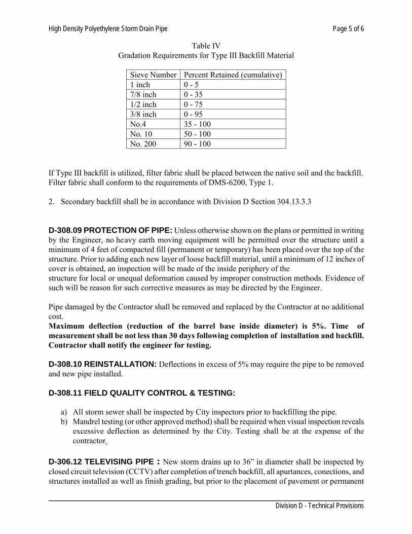
High Density Polyethylene Storm Drain Pipe Page 5 of 6
Division D - Technical Provisions
Table IV Gradation Requirements for Type III Backfill Material
Sieve Number Percent Retained (cumulative) 1 inch 0 - 5 7/8 inch 0 - 35 1/2 inch 0 - 75 3/8 inch 0 - 95 No.4 35 - 100 No. 10 50 - 100 No. 200 90 - 100
If Type III backfill is utilized, filter fabric shall be placed between the native soil and the backfill. Filter fabric shall conform to the requirements of DMS-6200, Type 1. 2. Secondary backfill shall be in accordance with Division D Section 304.13.3.3
D-308.09 PROTECTION OF PIPE: Unless otherwise shown on the plans or permitted in writing by the Engineer, no heavy earth moving equipment will be permitted over the structure until a minimum of 4 feet of compacted fill (permanent or temporary) has been placed over the top of the structure. Prior to adding each new layer of loose backfill material, until a minimum of 12 inches of cover is obtained, an inspection will be made of the inside periphery of the structure for local or unequal deformation caused by improper construction methods. Evidence of such will be reason for such corrective measures as may be directed by the Engineer. Pipe damaged by the Contractor shall be removed and replaced by the Contractor at no additional cost. Maximum deflection (reduction of the barrel base inside diameter) is 5%. Time of measurement shall be not less than 30 days following completion of installation and backfill. Contractor shall notify the engineer for testing. D-308.10 REINSTALLATION: Deflections in excess of 5% may require the pipe to be removed and new pipe installed. D-308.11 FIELD QUALITY CONTROL & TESTING:
a) All storm sewer shall be inspected by City inspectors prior to backfilling the pipe. b) Mandrel testing (or other approved method) shall be required when visual inspection reveals
excessive deflection as determined by the City. Testing shall be at the expense of the contractor.
D-306.12 TELEVISING PIPE : New storm drains up to 36” in diameter shall be inspected by closed circuit television (CCTV) after completion of trench backfill, all apurtances, conections, and structures installed as well as finish grading, but prior to the placement of pavement or permanent
High Density Polyethylene Storm Drain Pipe Page 6 of 6
Division D - Technical Provisions
trench resurfacing, to determine the existence and extent of any obstructions, structural deficiencies, or sags as per Division D Section 226. D-308.13 MEASUREMENT: This Item will be measured by the linear foot. Such measurements will be made between the ends of the barrel along its flow line, exclusive of safety end treatments. For multiple pipes, the measured length will be the sum of the lengths of the barrels, measured as prescribed above. D-308.14 PAYMENT: The work performed and materials furnished in accordance with this Item and measured as provided under “Measurement” will be paid for at the unit price bid for “Thermoplastic Pipe” of the size, joint type and backfill type specified. This price shall be full compensation for furnishing, hauling, placing and joining of pipes; for all connections to new or existing structures; for moving and reusing headwalls where required; for removing and disposing of portions of existing structures as required; for cuffing of pipe ends on skew; and for all labor, tools, equipment and incidentals necessary to complete the work.
Concrete Box Culverts Page 1 of 4
Division D - Technical Provisions
SECTION 310 CONCRETE BOX CULVERTS
D-310.01 DESCRIPTION This Item shall govern for the materials furnished, and for constructing, furnishing, and placing concrete box culverts, at the locations shown, and in accordance with the details on the plans of this Item. Unless otherwise shown on the plans, The Contractor shall have the option of furnishing cast-in-place, pre-cast (formed) or precast (machine made) box culverts. D-310.02 MATERIALS All materials shall conform to the pertinent requirement of the following items:
Section D-406, "Concrete Structures" Section D-504, "Concrete" Section D-410, "Reinforcing Steel" Section D-304, "Reinforced Concrete Storm Drain Pipe"
Concrete for precast (machine-made) concrete boxes shall conform to ASTM C1433 When precast (machine-made) boxes are furnished and portland cement is partially replaced, blended, or otherwise modified by pozzolan, the pozzolan shall be fly ash conforming to the Departmental Materials Specification D-9-8900, "Fly Ash". Copies of Departmental Materials Specifications are available form the Texas Department of Transportation, Division of Materials and Tests, 125 East 11th Street, Austin, Texas 78701-2483. For culverts with overlay or 1 to 2 course surface treatment or if the top slab is the final riding surface, use class “S” concrete for top slabs of “cast-in-place” concrete culverts unless otherwise shown on the plans. Use class ”C” for the rest of the culvert and for other cast-in-place boxes. D-310.03 TYPES Cast-in-place concrete boxes shall conform to the details shown on the plans and to the requirements of Section 504 "Concrete" and Section 406 "Concrete Structures". Precast (formed) concrete boxes shall conform to the details shown of the plans and the requirement of (TxDOT Standard Specification 2004 or latest Edition) Item 424, "Precast Concrete Structures (Fabrication)". Precast (machine-made) concrete boxes shall conform to the requirements of ASTM C1433. D-310.04 FABRICATION (1) General. All fabrication of concrete boxes including forming, casting, and curing shall conform to the following requirements.
(a) Cast-in-place concrete boxes shall be produced in accordance with Section 406, Concrete Structures". (b) Precast (formed) concrete boxes shall be produced in accordance with Item 424, "Precast
Concrete Structure (Fabrication)”. (TxDOT Standard Specification 2004 Edition) Contractor shall provide shop drawings signed and sealed by a Registered Professional Engineer in Texas.
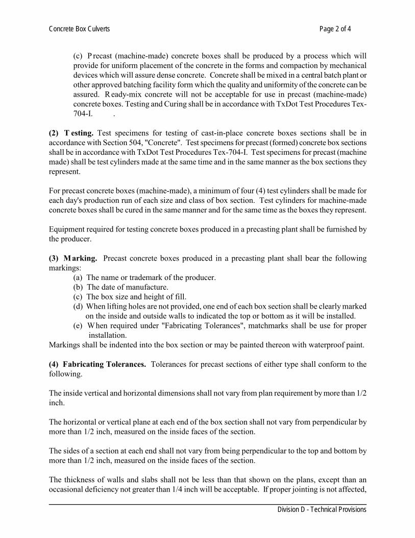
Concrete Box Culverts Page 2 of 4
Division D - Technical Provisions
(c) P recast (machine-made) concrete boxes shall be produced by a process which will provide for uniform placement of the concrete in the forms and compaction by mechanical devices which will assure dense concrete. Concrete shall be mixed in a central batch plant or other approved batching facility form which the quality and uniformity of the concrete can be assured. R eady-mix concrete will not be acceptable for use in precast (machine-made) concrete boxes. Testing and Curing shall be in accordance with TxDot Test Procedures Tex-704-I. .
(2) T esting. Test specimens for testing of cast-in-place concrete boxes sections shall be in accordance with Section 504, "Concrete". Test specimens for precast (formed) concrete box sections shall be in accordance with TxDot Test Procedures Tex-704-I. Test specimens for precast (machine made) shall be test cylinders made at the same time and in the same manner as the box sections they represent. For precast concrete boxes (machine-made), a minimum of four (4) test cylinders shall be made for each day's production run of each size and class of box section. Test cylinders for machine-made concrete boxes shall be cured in the same manner and for the same time as the boxes they represent. Equipment required for testing concrete boxes produced in a precasting plant shall be furnished by the producer. (3) Marking. Precast concrete boxes produced in a precasting plant shall bear the following markings:
(a) The name or trademark of the producer. (b) The date of manufacture. (c) The box size and height of fill. (d) When lifting holes are not provided, one end of each box section shall be clearly marked on the inside and outside walls to indicated the top or bottom as it will be installed. (e) When required under "Fabricating Tolerances", matchmarks shall be use for proper
installation. Markings shall be indented into the box section or may be painted thereon with waterproof paint. (4) Fabricating Tolerances. Tolerances for precast sections of either type shall conform to the following. The inside vertical and horizontal dimensions shall not vary from plan requirement by more than 1/2 inch. The horizontal or vertical plane at each end of the box section shall not vary from perpendicular by more than 1/2 inch, measured on the inside faces of the section. The sides of a section at each end shall not vary from being perpendicular to the top and bottom by more than 1/2 inch, measured on the inside faces of the section. The thickness of walls and slabs shall not be less than that shown on the plans, except than an occasional deficiency not greater than 1/4 inch will be acceptable. If proper jointing is not affected,
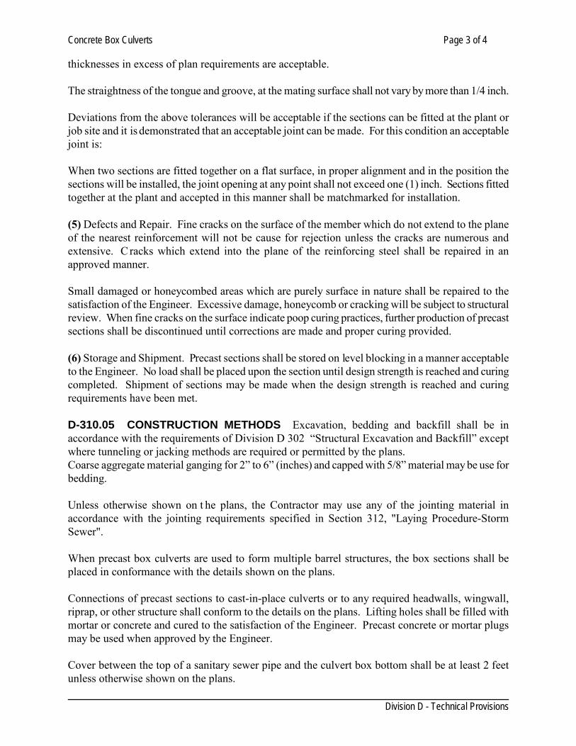
Concrete Box Culverts Page 3 of 4
Division D - Technical Provisions
thicknesses in excess of plan requirements are acceptable. The straightness of the tongue and groove, at the mating surface shall not vary by more than 1/4 inch. Deviations from the above tolerances will be acceptable if the sections can be fitted at the plant or job site and it is demonstrated that an acceptable joint can be made. For this condition an acceptable joint is: When two sections are fitted together on a flat surface, in proper alignment and in the position the sections will be installed, the joint opening at any point shall not exceed one (1) inch. Sections fitted together at the plant and accepted in this manner shall be matchmarked for installation. (5) Defects and Repair. Fine cracks on the surface of the member which do not extend to the plane of the nearest reinforcement will not be cause for rejection unless the cracks are numerous and extensive. C racks which extend into the plane of the reinforcing steel shall be repaired in an approved manner. Small damaged or honeycombed areas which are purely surface in nature shall be repaired to the satisfaction of the Engineer. Excessive damage, honeycomb or cracking will be subject to structural review. When fine cracks on the surface indicate poop curing practices, further production of precast sections shall be discontinued until corrections are made and proper curing provided. (6) Storage and Shipment. Precast sections shall be stored on level blocking in a manner acceptable to the Engineer. No load shall be placed upon the section until design strength is reached and curing completed. Shipment of sections may be made when the design strength is reached and curing requirements have been met. D-310.05 CONSTRUCTION METHODS Excavation, bedding and backfill shall be in accordance with the requirements of Division D 302 “Structural Excavation and Backfill” except where tunneling or jacking methods are required or permitted by the plans. Coarse aggregate material ganging for 2” to 6” (inches) and capped with 5/8” material may be use for bedding. Unless otherwise shown on t he plans, the Contractor may use any of the jointing material in accordance with the jointing requirements specified in Section 312, "Laying Procedure-Storm Sewer". When precast box culverts are used to form multiple barrel structures, the box sections shall be placed in conformance with the details shown on the plans. Connections of precast sections to cast-in-place culverts or to any required headwalls, wingwall, riprap, or other structure shall conform to the details on the plans. Lifting holes shall be filled with mortar or concrete and cured to the satisfaction of the Engineer. Precast concrete or mortar plugs may be used when approved by the Engineer. Cover between the top of a sanitary sewer pipe and the culvert box bottom shall be at least 2 feet unless otherwise shown on the plans.
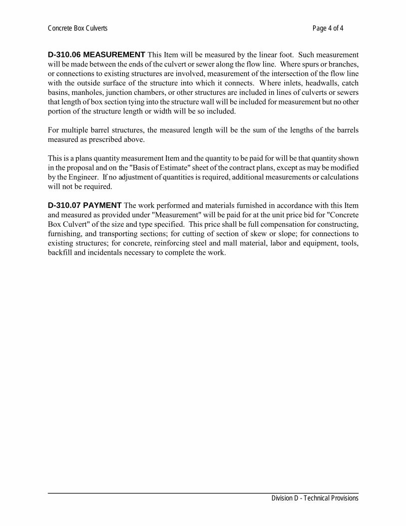
Concrete Box Culverts Page 4 of 4
Division D - Technical Provisions
D-310.06 MEASUREMENT This Item will be measured by the linear foot. Such measurement will be made between the ends of the culvert or sewer along the flow line. Where spurs or branches, or connections to existing structures are involved, measurement of the intersection of the flow line with the outside surface of the structure into which it connects. Where inlets, headwalls, catch basins, manholes, junction chambers, or other structures are included in lines of culverts or sewers that length of box section tying into the structure wall will be included for measurement but no other portion of the structure length or width will be so included. For multiple barrel structures, the measured length will be the sum of the lengths of the barrels measured as prescribed above. This is a plans quantity measurement Item and the quantity to be paid for will be that quantity shown in the proposal and on the "Basis of Estimate" sheet of the contract plans, except as may be modified by the Engineer. If no adjustment of quantities is required, additional measurements or calculations will not be required. D-310.07 PAYMENT The work performed and materials furnished in accordance with this Item and measured as provided under "Measurement" will be paid for at the unit price bid for "Concrete Box Culvert" of the size and type specified. This price shall be full compensation for constructing, furnishing, and transporting sections; for cutting of section of skew or slope; for connections to existing structures; for concrete, reinforcing steel and mall material, labor and equipment, tools, backfill and incidentals necessary to complete the work.
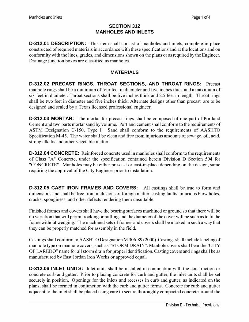
Manholes and Inlets Page 1 of 4
Division D - Technical Provisions
SECTION 312 MANHOLES AND INLETS
D-312.01 DESCRIPTION: This item shall consist of manholes and inlets, complete in place constructed of required materials in accordance with these specifications and at the locations and on conformity with the lines, grades, and dimensions shown on the plans or as required by the Engineer. Drainage junction boxes are classified as manholes.
MATERIALS D-312.02 PRECAST RINGS, THROAT SECTIONS, AND THROAT RINGS: Precast manhole rings shall be a minimum of four feet in diameter and five inches thick and a maximum of six feet in diameter. Throat sections shall be five inches thick and 2.5 feet in length. Throat rings shall be two feet in diameter and five inches thick. Alternate designs other than precast are to be designed and sealed by a Texas licensed professional engineer. D-312.03 MORTAR: The mortar for precast rings shall be composed of one part of Portland Cement and two parts mortar sand by volume. Portland cement shall conform to the requirements of ASTM Designation C-150, Type I. Sand shall conform to the requirements of AASHTO Specification M-45. The water shall be clean and free from injurious amounts of sewage, oil, acid, strong alkalis and other vegetable matter. D-312.04 CONCRETE: Reinforced concrete used in manholes shall conform to the requirements of Class "A" Concrete, under the specification contained herein Division D Section 504 for "CONCRETE". Manholes may be either pre-cast or cast-in-place depending on the design, same requiring the approval of the City Engineer prior to installation. D-312.05 CAST IRON FRAMES AND COVERS: All castings shall be true to form and dimensions and shall be free from inclusions of foreign matter, casting faults, injurious blow holes, cracks, sponginess, and other defects rendering them unsuitable. Finished frames and covers shall have the bearing surfaces machined or ground so that there will be no variation that will permit rocking or rattling and the diameter of the cover will be such as to fit the frame without wedging. The machined sets of frames and covers shall be marked in such a way that they can be properly matched for assembly in the field. Castings shall conform to AASHTO Designation M 306-89 (2000). Castings shall include labeling of manhole type on manhole covers, such as “STORM DRAIN”. Manhole covers shall bear the ‘CITY OF LAREDO” name for all storm drain for proper identification. Casting covers and rings shall be as manufactured by East Jordan Iron Works or approved equal. D-312.06 INLET UNITS: Inlet units shall be installed in conjunction with the construction or concrete curb and gutter. Prior to placing concrete for curb and gutter, the inlet units shall be set securely in position. Openings for the inlets and recesses in curb and gutter, as indicated on the plans, shall be formed in conjunction with the curb and gutter forms. Concrete for curb and gutter adjacent to the inlet shall be placed using care to secure thoroughly compacted concrete around the
Manholes and Inlets Page 2 of 4
Division D - Technical Provisions
inlet and formed openings and recesses without displacement of the inlet units in the forms.
CONSTRUCTION METHODS D-312.07 GENERAL: Construct manholes and inlets as soon as is practicable after pipe lines into or through the manhole or inlet locations are completed. All concrete work shall be performed in accordance with the requirements of the item, "Concrete Structures", unless otherwise specified. Forms will be required for all concrete walls except where the nature of the surrounding material may be trimmed to a smooth, vertical face (the outside form for concrete bases supporting brick walls may be omitted with the approval of the Engineer). Care shall be taken when connecting to the manhole several pipes with an angle less than 90 degrees between them. Minimum clear distance between two wall penetrations shall be 12 i n. or half diameter of the smaller penetration, whichever is greater. See Detail No. D-312.08 EXCAVATION: (a) Excavation shall conform to Division D Section 302.The Contractor shall do all excavation for structures to the lines, grades, and elevations shown on the plans or staked by the Engineer. The excavation shall be sufficient size to permit the placing of a full width and length of the structure shown, plus such additional sizes to allow for forms. (b) The Contractor shall do all bracing, sheeting, or shoring necessary to perform and protect the excavation in the structure or as required for safety to conform with governing laws. The cost of bracing, sheeting, and shoring shall be included in the unit price bid for this structure. (c) Unless otherwise provided, bracing, sheeting, or shoring involved in the construction of this item shall be removed by the Contractor after completion of the structure. T he removal shall be performed in such a manner as not to disturb or mar finish or masonry. The cost of removal shall be included in the unit price bid for the structure. (d) After each excavation is completed, the Contractor shall notify the Engineer to that effect, and concrete and reinforcing steel shall be placed after the Engineer has approved the depth of excavation and the character of the foundation material. D-312.9 CONCRETE STRUCTURES: Shall be in accordance with Division D Section 406 All invert channels shall be constructed and shaped accurately so as to be smooth, uniform, and cause minimum resistance to flow. The interior floor shall be sloped downward toward the outlet. D-312.10 INLET AND OUTLET PIPES: Inlet and outlet pipes shall extend through the walls of the structures for sufficient distance beyond the outside of the surface to allow for connections, but shall be cut off flush with the wall on the inside surfaces unless otherwise directed. A concrete collar shall be placed around the pipe so as to prevent leakage and to form a neat connection. Detail No.
Manholes and Inlets Page 3 of 4
Division D - Technical Provisions
Care shall be taken when connecting a pipe in skew to an inlet box to avoid braking the corners and top & bottom beams of the box. D-312.11 INVERTS: The inverts passing out or through the manhole or inlet shall be shaped and routed across the floor of the manhole or inlet as shown on the plans. This may be accomplished by adding and shaping mortar or concrete after the base is cast or by placing the required additional material with the base. D-312.12 THE PLACEMENT AND TREATMENT OF CASTING, FRAMES, AND FITTINGS: All castings, frames, and fittings shall be placed in positions indicated on plans, or as directed by the Engineer and shall be set in true to line and elevation. If frames or fittings are to be set in concrete or cement mortar, all anchors or anchor bolts shall be in place and position before the concrete or mortar is placed. The unit shall not be disturbed until all the mortar or concrete is set. When frames or fittings are to be placed upon previously constructed masonry, the bearing surfaces of the masonry shall be brought true to line and grade and present an even bearing surface in order that the entire face or back of the unit will come in contact with the masonry. The unit shall be set in mortar beds or anchored to the masonry as indicated on the plans or as directed and approved by the Engineer. All units shall be set firm and secure. When concrete structures are so located as to be within the paved areas of the street, the finish top of these structures shall match existing grades. D-312.13 BACKFILLING: (a) After a structure has been completed, the area around it shall be filled with approved material in accordance with the Division D Section 302, "STRUCTURAL EXCAVATION AND BACKFILL". Fill shall be made to the elevations shown on the plans or ad directed by the Engineer. (b) No backfill material shall be placed against any structure until permission is given by the Engineer. In the case of the concrete, such permission preferably shall not be given until the concrete has been in place for 14 days and tested in a laboratory conforming to the requirements of ASTM Designation C-42. All water must be removed from excavation before backfilling is done unless otherwise directed by the Engineer. (c) Fill in place shall be deposited on all sides of the structure at the same time and to approximately the same elevation. Special care shall be taken to prevent any wedging action against the structure and all slopes, bounding or within the area to be backfilled, will be stepped or serrated to prevent wedge action. (d) All backfill shall be compacted as per Division DSection 302. (e) Backfill shall not be measured for direct payment. Performance of this work is not payable directly but shall be considered a subsidiary obligation of the Contractor covered under the contract unit price for the structure involved.
Manholes and Inlets Page 4 of 4
Division D - Technical Provisions
D-312.14 CLEANING AND RESTORATION OF SITE: After the backfill is completed, the Contractor shall dispose of all surplus material, dirt, and rubbish from the site. Surplus dirt shall be disposed of as ordered by the Engineer. The Contractor shall restore all disturbed areas to their original condition. After all work is completed, the Contractor shall remove all tools and other equipment used by him, leaving the entire area free, clear, and in good condition. The performance of the work described in this section is not payable directly, but shall be considered as a subsidiary obligation of the Contractor, covered under the contract unit price for each manhole and inlet. D-312.15 MEASUREMENT: The number, types and nominal sizes of manholes and inlets shown on the plans shall be measured per each unit complete in place and accepted by the Engineer. D-312.16 PAYMENT :The number of units of manholes and inlets determined as provided in above paragraph shall be paid at the contract unit price for each of the various types and nominal sizes of manholes and inlets as called for on the Bid Schedule, which price and payment shall constitute full compensation for furnishing all materials, for placing and finishing, for all excavation and hauling, for all backfill, for setting and anchoring any frame, cover, for all labor, equipment, tools, and incidentals necessary to complete the unit, as shown on t he plans and as described in the specifications.

SECTION 314
Concrete Encasement, Cradles, Saddles, and Collars Page 1 of 1
Division D - Technical Provisions
SECTION 316 CONCRETE ENCASEMENT, CRADLES, SADDLES, AND COLLARS
D-316.01 DESCRIPTION: This Item shall govern for placing concrete encasement, cradles, saddles, and collars, when called for the Project plans or as directed by the Engineer. D-316.02 MATERIALS: Concrete: All concrete shall be class “A” and conform to the provisions of Division D Section 504 or shall be of the class noted on the plans. D-316.03 CONSTRUCTION METHODS: 1. Concrete Encasement: When concrete encasement is show on the plans or when directed
by the Engineer, the trench shall be excavated and fine graded to a depth conforming with details and sections shown on the plans. The pipe shall be supported by precast concrete blocks of the same strength as the concrete for encasement and securely tied down to prevent floatation. Encasement shall then be placed to a depth and width conforming with details and sections shown on the plans.
2. Concrete Cradles: When concrete cradles are shown on the plans or when called for by the
Engineer, the trench shall be prepared and the pipe supported in the same manner as described in this specification and shall be constructed in accordance with details and sections shown on the plans.
3. Concrete Saddles: When shown on the plans or when directed by the Engineer, pipe to
receive concrete saddle shall be backfilled in accordance with Division D Section 302, "Structural Excavation, and Backfill" to the spring line and concrete placed for a depth and width conforming with details and sections shown on the plans.
4. Concrete Collars: When shown on the plans or when directed by the Engineer, concrete
collars shall be constructed in accordance with details and sections shown on the plans. See details No.
D-316.04 MEASUREMENT: "Concrete Encasement, Cradles, Saddles, and Collars", will be measured by the cubic yard of accepted work calculated based on the lines and dimensions shown on the plans, complete in place. Reinforcing, if required, shall not be measured for payment. D-316.05 PAYMENT: "Concrete Encasement, Cradles, Saddles, and Collars", will be paid for at the unit price bid per cubic yard, which price shall be full compensation for furnishing and placing all materials, manipulation, labor, tools, equipment, and incidentals necessary to complete the work.
Channel Excavation and Embankment Page 1 of 1
Division D - Technical Provisions
SECTION 318 CHANNEL EXCAVATION AND EMBANKMENT
D-318.01 DESCRIPTION Shall consist of required excavation for all channels proposed in the plans; the removal and proper utilization or disposal of all excavated materials; and constructing, shaping and finishing all earthwork involved in conformity with the required lines, grades and typical cross sections and in accordance with specifications requirements herein outlined. D-318.02 METHODS All suitable materials removed from the excavation shall be used, insofar as practicable, in the formation of embankments as required by the Item, “Embankment”, or shall be otherwise utilized or satisfactorily disposed of as indicated on plans, or as directed, and completed work shall conform to the established alignment, grades and cross sections. During construction, the channel shall be kept and drained, insofar practicable, and the work shall be prosecuted in a neat workmanlike manner. Unsuitable channel excavation in excess of that needed for construction shall be as known as “WASTE” and shall become property of the Contractor to be disposed of by him outside the limits of the right of way. Payment will not be allowed for excavation of any material which is used for purposes other than those designated, except as provided in the governing specifications under the item “Scope of Work.” D-318.03 MEASUREMENT All channel excavation will be measured in its original or final, fully compacted position and the volume computed in cubic yards by the method of average in end areas. D-318.04 PAYMENT All work performed as required herein and in the Item, “Embankment” and measured as provided under “Measurement” will be paid for at the unit price bid under the following method:
Ordinary Compaction (for channel embankment) each layer shall not exceed one (1) foot of loose depth, and shall be compacted as per specifications. Each layer shall be brought to the moisture content ordered by the Engineer, and shall be kept leveled with suitable equipment to insure uniform compaction over the entire layer.
The prices bid for channel excavation or embankment shall each be full compensation for furnishing all labor, materials, tools, equipment and incidentals necessary to complete the work. Payment for unauthorized work will not be made. All work required for disposing of waste, including haul, will not be paid for directly, but shall be considered subsidiary work pertaining to the various contract items, and such cost shall be included in the unit prices for these items. When specified on the plans, and hauling of materials will not be paid directly, but shall be considered as subsidiary work pertaining to the various contract items, and such cost shall be included in the unit prices bid.
Concrete Structures Page 1 of 5
Division D - Technical Provisions
SECTION 406 CONCRETE STRUCTURES
D-406.01 GENERAL: This item shall consist of reinforced concrete structures built in accordance with the design requirements and details shown on the plans and in conformity with the requirements herein.
MATERIALS
D-406.02 CONCRETE: Concrete shall conform to the requirements of Section D-504. Unless otherwise specified on the plans or in the proposal. D-406.03 REINFORCING STEEL: Reinforcing steel shall conform to the requirements of Section D-410. Wire mesh reinforcement shall conform to the requirements of ASTM Designation A185. D-406.04 STRUCTURAL STEEL: Structural steel shall conform to the requirements of ASTM Designation A-36. D-406.05 EXPANSION JOINT MATERIAL: (a)Pre-molded expansion joint material shall conform to the requirements of Division D, Section 414, titled, EXPANSION JOINT MATERIALS. (b)Poured joint material shall conform to requirements of Federal Specifications SS-S-156, SS-S-159, or SS-S-164. D-406.06 FORM MATERIAL: (a)Form lumber for all exposed concrete surfaces shall be CM concrete form lumber, Southern Yellow Pine or approved equal, S4S, grade marked in accordance with the latest grading rules of the Southern Pine Association. Form lumber not otherwise specified shall be No. 2 Common Southern Yellow Pine, S4S. (b)Plywood form shall be of Douglas Fir Plywood, 5 ply, and at least 3/4" thick, conforming to the grading rules as required under State Department of Highways and Public Transportation Specifications.
CONSTRUCTION METHODS
D-406.07 REINFORCEMENT: (a) Reinforcing shall be detailed, fabricated, and erected in accordance with Manual of Standard Practice for Detailing Reinforced Concrete Structures (ACT 315-57). S hop drawings shall be submitted in triplicate for engineering approval prior to fabrication. All reinforcement shall be entirely free from rust, scale, grease, or other coating which might destroy or reduce its bond with concrete. (b) Spacing: Unless otherwise indicated, the clear distance between parallel bars shall be not less
Concrete Structures Page 2 of 5
Division D - Technical Provisions
than one and one- half times the diameter of round bars. In no case shall the distance between bars be smaller than the maximum size of the aggregates. (c) Protective Covering: Reinforcement shall be protected by the thickness of concrete indicated on the plans. Unless otherwise specified, the protective coverings over reinforcement shall not be less than the maximum size of aggregates. (d) Splicing and Lapping: As per section D-410 (e) Supports: All reinforcement shall be secured in place true to the lines and grades, indicated by the use of metal supports, spacers, or ties approved by the Engineer. Such supports shall be of sufficient number and strength to maintain the reinforcement in place throughout the concreting operations. The use of pebbles, pieces of broken stones or brick, metal pipe and wooden blocks shall not be permitted. D-406.08 FORMS: (a) General: Forms shall conform to the shape, lines, and dimensions of the members of structures, as called for on the plans and shall be substantial and sufficiently tight to prevent leakage of mortar. All details of form construction shall be subject to the approval of the Engineer and permission to place concrete will not be given until all such work is complete to his satisfaction. (b) Braces and Ties: Forms shall be properly braced and tied together so as to maintain position and shape. Metal form of an approved type shall be used to hold forms in place. Such ties shall be of a type especially designed for use in connection with concrete work and shall have provision to permit easy removal of the metal to a depth of at least one- half inch from the surface of the concrete. The use of wire from ties will not be permitted except for minor or special form areas where the use of rigid type metal ties would be impracticable. Where wire ties are used, all wires upon removal of the forms shall be cut back at least one-half inch from the face of the concrete. (c) Curved Surface: In the case of exterior exposed curved surfaces, the Contractor shall use such forming as may be necessary to provide smooth forms of uniform curvature. (d) Coating: Plywood forms and plywood form lining shall be mill-oiled according to standard practice recommended by the Douglas Fir Plywood Association. Form lumber for all other exposed surfaces shall be coated with approved non-staining mineral oil which shall be applied shortly before the concrete is deposited. In general, all forms shall be thoroughly wetted before the concrete is placed. (e) Cleanouts: At the time of placing concrete, the forms shall be clean and entirely free from all chips, dirt, sawdust, and other extraneous matter. For narrow walls and other locations where access to the bottom of the forms is not readily obtainable otherwise, adequate cleanout openings shall be provided. (f) Chamfers: Unless otherwise shown on the plans, fill forms at all sharp corners and edges with triangular chamfer strips measuring ¾ in. on the sides. Dress wood molding on all faces. Make
Concrete Structures Page 3 of 5
Division D - Technical Provisions
molding for chamfers strips of materials of a grade that will not split when nailed and that can be maintain to true line without warping. D-406.09 PLACING CONCRETE-GENERAL: (a) Supervision: The Contractor shall give the Engineer sufficient notice before starting to place concrete in any unit of the structure to permit the inspection of forms, reinforcing steel, and preparation for placing. Concrete shall not be placed in footings until the character of the foundation has been approved by the Engineer and permission has been given to proceed. When footings can be placed in dry foundation pits, forms may be omitted, if desired by the Contractor and approved by the Engineer, and the entire excavation filled with concrete to the top of the footing. Where this procedure is followed, no measurement for payment will be made for concrete placed outside of the footing dimensions shown on the plans. (b) Placing: Place concrete according to TxDOT item 420. All concrete shall be placed before its initial set has occurred. The operation of depositing and compacting the concrete shall be conducted so as to form a compact, dense, impervious mass of uniform texture which shall show smooth faces on all surfaces. Each part of the forms shall be filled by depositing the concrete directly as near its final position as possible. The coarse aggregate shall be worked back from the face and the concrete forced under and around the reinforcement bars without displacing them. Depositing large quantities at one point in the forms and running or working it along the forms will not be permitted. Concrete in columns shall be placed monolithically unless otherwise provided. An interval of not less than 4 hours shall elapse between the placing of concrete above the tops of the columns or walls to allow shrinkage. Concrete in walls, columns, and deep foundations shall be placed in a manner that will avoid separation of the aggregates or displacement of the reinforcement. Suitable chutes or vertical pipes shall be provided. (c) Vibrating: All concrete shall be placed with the aid of mechanical vibrating equipment unless otherwise directed. Vibration shall be transmitted directly to the concrete, and in no case shall it be transmitted through the forms of reinforcing steel. The duration of vibration shall at any location be held to the minimum necessary to produce thorough compaction. Vibration shall be supplemented by hand spading to insure the flushing of mortar to the surface of all forms. (d) Construction Joints: Construction joints shall be formed as shown on the plans. In all cases where they are not shown on the plans, they shall be formed as directed by the Engineer. Where indicated or required dowel rods shall be used. Before placing is resumed, all water and laitance shall be removed and the concrete shall be cut away, if necessary, to insure a strong dense concrete at the joint. In order to secure adequate bond, the surface of all concrete already in place shall be cleaned and roughened and shall then be spread with a 1/2 inch layer of mortar of the same sand-cement ratio as is used in the concrete immediately before the new concrete is deposited. D-406.10 FINISHING EXPOSED SURFACES: An ordinary surface finish shall be applied to all concrete surfaces either as a final finish or preparatory to a higher grade or class of finish. Higher grades and classes of finish shall be in accordance with TxDOT Item 427, "Surface Finishes for Concrete". Where neither a grade nor class of finish is specified, an ordinary surface finish shall be provided as follows:
Concrete Structures Page 4 of 5
Division D - Technical Provisions
After form removal, all porous or honeycombed areas and spalled areas shall be corrected by chipping away all loose or broken material to sound concrete. Holes and spalls caused by removal of metal ties, etc., as required by TxDOT Item 420, shall be cleaned and filled with adhesive grout or epoxy grout. Exposed parts of metal chairs on surfaces to be finished by rubbing shall be chipped out to depth of one-half inch and the surface repaired.
All fins, runs, drips, or mortar shall be removed from surfaces which remain exposed. Form marks and chamfer edges shall be smoothed by grinding and/or rubbing. Grease, oil, curing compound, etc., shall be removed from surfaces requiring a higher grade of finish. Discolorations resulting from spillage or splashing of asphalt, paint, or other similar material shall be removed. Repairs shall be dense, well bonded, and properly cured, and when made on surfaces which remain exposed and do not require a higher finish, shall be finished to blend with the surrounding concrete. Unless otherwise specified on the plans, ordinary surface finish shall be the final finish for the following exposed surfaces: Inlets, manholes, and sewer appurtenances. D-406.11 FINISHING VERTICAL SURFACES (General): After tie rods and bolts are removed, the holes shall be filled solid with cement mortar. Honeycomb and minor defects shall not be patched until approval has been given by the Engineer. D-406.12 REMOVAL OF FORMS: (a) Finished Concrete: Forms for surfaces required to be finished shall be removed when the concrete has aged not less than 1/2 nor more than 2 curing days after the concrete has been placed. (b) Unfinished Concrete: Forms and false work may be removed when the concrete has attained a compressive strength of not less than 65 percent of the design strength except that forms for walls, columns, and sides of beams may be removed after 48 hours. (c) Curing Day: The term "curing day" will be interpreted as any calendar day on which the temperature is above 50 F for at least 19 hours. In continued cold weather, the Engineer will determine when sufficient time has elapsed to permit the removal of forms and false work. D-406.13 DEFECTIVE WORK: Any defective work discovered after the forms have been removed shall be repaired immediately. If the surface of the concrete is bulging, uneven, or shows excess honeycombing or form marks, which, in the opinion of the Engineer, cannot be repaired satisfactorily, the entire section shall be removed before the repair work is started. N o extra compensation will be allowed for extra work or materials involved in repairing or replacing defective concrete. D-406.14 CURING: Concrete shall be maintained in a moist condition for at least five (5) days after placement. Curing shall be commenced as soon as possible after the concrete has been finished. This shall be either by means of approved curing compound, sprinkling, or by damp curing by means of wet mats, sand, etc. Adequate protection shall be provided to prevent damage from extreme weather conditions shall they be either hot or cold temperatures, wind, or other conditions which
Concrete Structures Page 5 of 5
Division D - Technical Provisions
would cause evaporation of moisture from the fresh concrete. The ACI recommendations for hot or cold weather shall be followed. D-406.15 ADDITIONAL CONCRETE FINISH FOR EXPOSED SURFACES: Concrete shall be finished pursuant to 2004 TxDOT Specification Item 427 or latest revision. D-406.16 CONCRETE STRUCTURE REPAIRS: For all repairs, provide materials suitable for the appropriate horizontal, vertical or overhead application. Approval from the engineer for any proposed repair is required unless a repair material type is indicated in the plans. Remove unsound concrete, repair spalled or delaminated concrete, and replace concrete with repair materials. All concrete repairs shall be as per TxDOT Item 429, 2004 edition or latest revision. D-406.17 MEASUREMENT AND PAYMENT: No separate measurement or payment will be made under this item, but all such work done shall be deemed a subsidiary obligation of the Contractor, having been taken into account and included in price bid for the complete job.
Clearing and Grubbing Page 1 of 1
Division D - Technical Provisions
SECTION 402 CLEARING AND GRUBBING
D-402.01 DESCRIPTION: "Clearing and Grubbing” shall consist of the removal and disposal of trees, stumps, brush roots, vegetation, logs, rubbish, and other objectionable matter. Full compliance with NPDES (National Pollution Discharge Elimination System) permitting & Drainage Standard shall be maintained. D-402.02 CONSTRUCTION METHODS: The right-of-way shall be cleared of stumps, brush, logs, rubbish, trees, and shrubs, except such trees and shrubs and certain areas designated by the Engineer for preservation. Those trees, shrubs, and other landscape features specifically designed by the Engineer for preservation shall be carefully protected from abuse, marring, or damage during construction operations. Continual parking and/or servicing of equipment under the branches of trees designated for preservation will not be permitted. Trees and shrubs designated for preservation that must be pruned shall be trimmed as directed and all exposed cuts over two (2) inches in diameter shall be treated with an approved material. Areas required for embankment construction, for roadway, channel and structural excavation, and for borrow sites and material sources shall be cleared and grubbed. On areas required for roadway, channel, or structural excavation, all stumps, roots, etc., (except for designated trees and brush) shall be removed to a depth of at least two (2) feet below the existing ground surface. All holes remaining after clearing and grubbing shall be backfilled and tamped as directed by the Engineer and the entire area bladed to prevent ponding of water and to provide drainage, except, in areas to be immediately excavated, the Engineer may direct that the holes not be backfilled. When permitted by the plans, trees and stumps may be cut off as close to natural ground as practicable on areas which are to be covered by at least three (3) feet of embankment. On areas required for borrow sites and material sources, stumps, roots, etc., (except for designated trees and brush) shall be removed to the complete extent necessary to prevent such objectionable matter becoming mixed with the material to be used in construction. All cleared and grubbed material shall be disposed of in a manner satisfactory to the Engineer. Unless otherwise provided, all merchantable timber removed as required above shall become the property of the Contractor. D-402.03 MEASUREMENT: Payment will be made for this item as clearing and grubbing and the Contractor shall investigate the conditions as they exist in the field. D-402.04 PAYMENT: Price shall be full compensation for placing removing, loading and disposing all materials, manipulation, labor, tools, equipment, dumping fees and details necessary to complete the work.
General Construction & Preparation of Site Page 1 of 2
Division D - Technical Provisions
SECTION 404 GENERAL CONSTRUCTION AND PREPARATION OF SITE
D-404.01 INTENT OF PLANS AND SPECIFICATIONS: The intent of the plans and specifications is to prescribe a complete work or improvement which the Contractor undertakes to do so, in full compliance with the plans, specifications, special provisions, proposal, and contract. The Contractor shall do all work as provided in the plans, specifications, special provisions, proposal, and contract, and shall do such additional work as may be considered necessary to complete the work in a satisfactory and acceptable manner. The Contractor shall furnish all labor, tools, materials, machinery, equipment, and incidentals necessary to the prosecution of the work. D-404.02 DESCRIPTION OF SITE: This item shall consist of the preparation of site for construction operations by the removal and disposal of all obstructions which are not otherwise provided for in the plans and specifications. Such obstructions shall be considered to include removal of sections of existing utility lines (water, sewer, & force main), existing fences/gates, and other such materials as shown on the plans including concrete slabs. This item shall include the removal of obstructions in accordance with the item "Clearing and Grubbing", Section 402. It is the intent of this item to provide for the disposal of all objectionable materials not specifically provided for elsewhere in the plans/specifications. All materials to be salvaged by the Owner shall be properly disposed of by the contractor as directed. D-404.03 FINAL CLEAN-UP: Upon the completion of the work and before acceptance and final payment will be made, the Contractor shall clean and remove from the site of the work, surplus and discarded materials, temporary structures, and debris of every kind. Contractor shall leave the site of the work in a neat and orderly condition. Surplus and waste materials removed from the site of the work shall be disposed of at locations satisfactory to the Engineer. Grounds around any structures shall be dressed to final grade as shown on plans. D-404.04 COORDINATION OF PROJECT: The plans, these specifications, the proposal, special provisions, and all supplementary documents are intended to describe a complete work and are essential parts of the contract. A requirement occurring in any of them is binding. In case of discrepancies, figured dimensions shall govern over specifications; and plans and quantities shown on the plans shall govern over those shown in the proposal. The Contractor shall not take advantage of any apparent error or omission in the plans and specifications, and the Engineer shall be permitted to make such corrections or interpretations as may be deemed necessary for the fulfillment of the intent of the plans and specifications. In the event the Contractor discovers an apparent error or discrepancy, Contractor shall immediately call this to the attention of the Engineer. D-404.05 COOPERATION OF CONTRACTOR: The Contractor shall give to the work the consistent attention necessary to facilitate the progress thereof, and he shall cooperate with the Engineer, his inspectors, and with other contractors in every way possible. D-404.06 MATERIALS-GENERAL: The materials shall be the best procurable, as required by the plans, specifications, and special provisions. The Contractor shall not start delivery of materials until
General Construction & Preparation of Site Page 2 of 2
Division D - Technical Provisions
the Engineer has approved the source of supply. Only materials conforming to these specifications shall be used in the work, and such materials shall be used only after approval has been given by the Engineer and only so long as the quality of said materials remains equal to the requirements of the specifications. The Contractor shall furnish approved materials from other sources, if for any reason the product from any source at any time before commencement or during the prosecution of the work proves unacceptable. After approval, any material which has become mixed with or coated with dirt or any other foreign substances during its delivery and handling will not be permitted to be used in the work. D-404.07 MATERIALS-STORAGE: Any and all materials, such as cement, lime, mill work, or other materials or equipment subject to deterioration by exposure to weather or other factors, shall be stored in such a manner to protect them from deterioration or damage preceding the time they become a permanent part of final structure. D-404.08 MEASUREMENT AND PAYMENT: All work performed will NOT be paid directly but shall be included in the unit price bid for other items of construction. Price shall be full compensation for furnishing and placing all materials, manipulation, labor, tools, equipment, and incidentials necessary to complete the work.
Rip Rap Page 1 of 2
Division D - Technical Provisions
SECTION 408 RIPRAP
D-408.01 GENERAL: This item shall govern the furnishing and placing of riprap. D-408.02 MATERIALS:
1. Concrete: Unless otherwise shown in the plans, concrete shall be Class “A”. The riprap will consist of a minimum of 4 inch slab with a 6 x 6- W2.9 x W2.9 welded wire fabric or No. 3 or No. 4 r einforcing steel bars spaced at maximum 18-inch centers each way , and per requirements of specifications entitled, "CONCRETE", Division D, Section 504. Grout shall be in accordance with TxDot item 421
2.Stone shall be as large as can be conveniently placed in a layer of the required depth. The
stones, excepting small stones and spalls used to chink interstices shall weigh not less than 10 pounds and at least 50 percent of the stone shall weigh not less than 100 pounds.
3.Sacks shall be made of burlap not lighter than 10 ounce and shall be approximately 19 1/2
inches by 36 inches measured inside the seams when the sack is laid flat. Sound reclaimed sacks may be used.
D-408.03 CONSTRUCTION METHODS: If the slopes and bottom of the trench for toe walls are dry and not consolidated properly, the Engineer may require the entire area to be sprinkled, or sprinkled and consolidated before the concrete is placed. All surfaces shall be moist when concrete is placed. 1. The concrete riprap shall have a toe ditch as specified on plans. Concrete slab shall be placed,
finished, and cured in accordance with the item, "CONCRETE STRUCTURES" Division D, Section 406 of these specifications.
2. Stone: for plain and grouted riprap shall be sound and durable, free from seams and coatings, and of such characteristics that it will not disintegrate when subjected to the action of water. Stone shall be of shapes which will form a stable protection structure of the required depth. Rounded boulders or cobbles shall not be used on slopes steeper than 2 to 1 unless grouted. Angular shapes may be used on any slope. Flat or needle shapes will not be acceptable unless the thickness of the piece is more than 1/3 the length. Do not place grout when air temperature is below 35° F. Protect work for rapid drying for at least 3 days after placement. For non grouted rock riprap and when the voids are going to be filled only with spalls or small stones, use filter fabric with the length running up and down the slope with a minimum of 2 feet overlap. Non grouted rock riprap shall be constructed as per design and engineer’s recommendations. Waste concrete may be used, if the pieces are sound free from coatings, steel and meet the size requirements specified for a stone.
3. Sacks: the capacity of each sack shall be 1.25 cubic feet. Each sack shall contain 1 cubic foot of
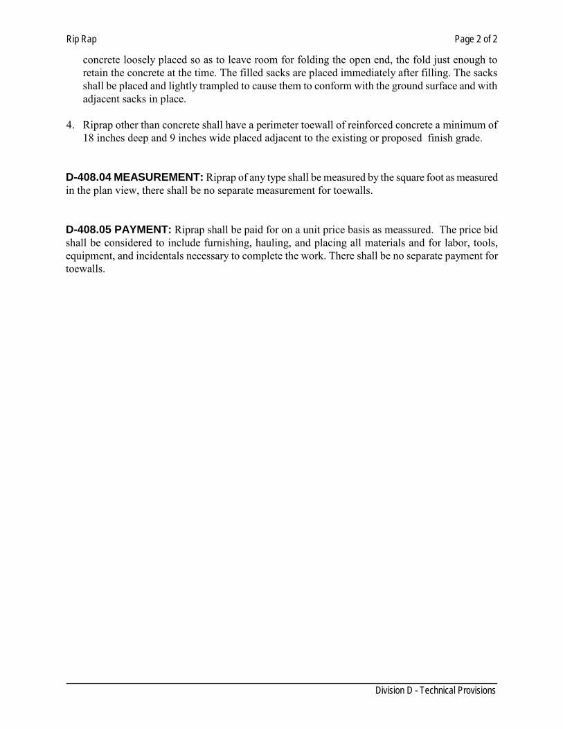
Rip Rap Page 2 of 2
Division D - Technical Provisions
concrete loosely placed so as to leave room for folding the open end, the fold just enough to retain the concrete at the time. The filled sacks are placed immediately after filling. The sacks shall be placed and lightly trampled to cause them to conform with the ground surface and with adjacent sacks in place.
4. Riprap other than concrete shall have a perimeter toewall of reinforced concrete a minimum of
18 inches deep and 9 inches wide placed adjacent to the existing or proposed finish grade. D-408.04 MEASUREMENT: Riprap of any type shall be measured by the square foot as measured in the plan view, there shall be no separate measurement for toewalls. D-408.05 PAYMENT: Riprap shall be paid for on a unit price basis as meassured. The price bid shall be considered to include furnishing, hauling, and placing all materials and for labor, tools, equipment, and incidentals necessary to complete the work. There shall be no separate payment for toewalls.
Reinforcing Steel Page 1 of 2
Division D - Technical Provisions
SECTION 410 REINFORCING STEEL
D-410.01 DESCRIPTION: This item shall provide for the furnishing and placing of bar reinforcing steel of the size and quantity designated for use in structures and other concrete items that require reinforcing steel as shown on the plans and in accordance with these specifications. D-410.02 MATERIALS: Reinforcing steel shall conform to the requirement of Item 440, "Reinforcing Steel" of the TxDOT latest Provisions. Reinforcing steel bars produced outside of the United States are acceptable if such bar reinforcement conforms to the requirements of the ASTM Designations. D-410.03 PLACING REINFORCEMENT: All steel reinforcing shall be accurately placed in the position shown on t he plans and firmly held during the placing and setting of concrete. A ll reinforcement shall be inspected and approved before placement to be free from dust, rust, mill scale, paint, oil, or foreign material. When stored, it shall not be in direct contact with the ground. Bars shall be tied at all intersections. Distances from forms shall be maintained by means of stays, precast blocks, ties, hangers, metal chairs, or other approved supports. Blocks for holding reinforcement from contact with the form shall be precast concrete blocks of approved shape and dimensions or other equally suitable devices. The use of pebbles, pieces of broken stones or brick, metal pipe and wooden blocks shall not be permitted. Reinforcement in any sections shall be placed and then inspected and approved by the Inspector before the placing of concrete begins. D-410.04 SPLACING AND LAPPING: Unless otherwise indicated, all spliced bars shall be staggered. Laps shall be in accordance with Table No. 1.
Table 1 Minimum Lap Requirements for Bar Sizes through No. 11
Bar size No.
(in) Bar size No.
(mm) Uncoated Lap
Length Coated Lap
Length 3 10 1 ft 4 in 2 ft 0 in 4 13 1 ft 9 in 2 ft 8 in 5 16 2 ft 2 in 3 ft 3 in 6 19 2 ft 7 in 3 ft 11 in 7 22 3 ft 5 in 5 ft 2 in 8 25 4 ft 6 in 6 ft 9 in 9 29 5 ft 8 in 8 ft 6 in 10 32 7 ft 3 in 10 ft 11 in 11 36 8 ft 11in 13 ft 5 in
Note: bar size numbers (in.) are based on the number of eighths of an inch included in the nominal diameter of the bar. Bar size numbers (mm) approximate the number of millimeters included in the nominal diameter of the bar.
Reinforcing Steel Page 2 of 2
Division D - Technical Provisions
D-410.05 MEASUREMENT AND PAYMENT: No separate measurement or payment will be made under this item, but all such work done shall be deemed a subsidiary obligation of the Contractor, having been taken into account and included by him in price bid for the complete job.
Welded Wire Fabric Page 1 of 1
Division D - Technical Provisions
SECTION 412 WELDED WIRE FABRIC
D-412.01 DESCRIPTION: This item shall govern the furnishing and placing of the various sizes of welded wire fabric as indicated on the plans or as directed by the Engineer. D-412.02 MATERIAL: All welded wire fabric used in construction shall conform to the requirements of ASTM Designation A-185. It shall be 6 x 6- W2.9 x W2.9 welded wire fabric, plain electric welded reinforcing fabric or as indicated on the plans. D-412.03 CONSTRUCTION METHODS: All splices in the wire fabric shall overlap sufficiently to allow two (2) pairs or transverse wires to be tied together and no splices of less than six (6) inches will be permitted. At the edge of the construction, the wire fabric shall not be less than one (1) inch nor more than three (3) inches from the edge of the concrete and shall have no wires projecting beyond the last member parallel to the edge of the concrete. The wire fabric shall be straightened to lie flat in place without bulges or excessive vertical displacement and shall be supported properly throughout to insure its proper position in the finished construction. D-412.04 MEASUREMENT: No measurement of welded wire fabric will be made. D-412.05 PAYMENT: No direct payment for furnishing and placing welded wire fabric will be made. All materials and labor required will be considered subsidiary to the item in which it is used and shall be included in the unit price bid for said item.
Reinforcing Fiberglass Page 1 of 1
Division D - Technical Provisions
SECTION 414 REINFORCING FIBERGLASS
D-414.01 DESCRIPTION: This item shall govern for the furnishing and placing of concrete reinforced with fibrous mesh in accordance with these specifications and with details as shown on the plans. D-414.02 MATERIALS: (1) Concrete All concrete shall conform to the requirements of Section D-406, “Concrete for Structures”. Unless otherwise shown on the plans or in the bid item, the concrete shall be class A concrete. (2) Reinforced Reinforcement shall be 100% virgin polypropylene fibrillated fibers specially manufactured for use as concrete reinforcement and meeting the requirements of ASTM C1116. The fibrous material shall not contain reprocessed olefin. Each container of fibrous material shall bear the manufacturer’s name and/or trademark and the net weight of fibrous material in the package. The specific gravity of the fibrous material shall be 0.91 plus or minus .05. The tensile strength shall be 80 to 110 ksi. The lengths of the fibrous material shall be 1/2, 3/4, 1- 1/2 and 2 inches in the length. Unless otherwise shown on the plans, each cubic yard of concrete shall contain no less than 1- 1/2 pounds of fibrous material. The fibrous material shall be added to the concrete mix at the time the mix is batched. The fiber-reinforced concrete shall be furnish either by batch mixing or continuous mixing, and shall be free of fiber balls when delivered to the point designated by the purchaser. D-414.03 Excavation, Placing of Concrete, Finishing, Curing and Backfill All excavation, placing of concrete, finishing, curing and backfilling shall be in accordance with the Section D-302, “Structural Excavation and Backfill”, and Section D-406, “concrete Structures”. D-414.04 MEASUREMENT: No measurement of fiberglass will be made. D-412.05 PAYMENT: No direct payment for furnishing and placing fiberglass will be made. All materials and labor required will be considered subsidiary to the item in which it is used and shall be included in the unit price bid for said item.
Expansion Joint Materials Page 1 of 1
Division D- Technical Provisions
SECTION 416 EXPANSION JOINT MATERIALS
D-416.01 DESCRIPTION: This item shall govern for furnishing and placing of all expansion joint material as herein specified in the various items of these specifications or as shown on the plans or as directed by the Engineer. D-416.02 MATERIAL: The material used for expansion joints shall conform to either of the following: (1) Preformed Bituminous Fiber Material shall be formed from cane or other suitable fibers of a cellular nature securely bound together and uniformly impregnated with a suitable asphaltic binder and shall meet the requirements of the Standard Specifications for Preformed Expansion Joint Filler for Concrete Paving and Structural Construction, ASTM Designation D-1751. (2) Boards for expansion joints shall be obtained from Redwood or Cypress timber and shall be sound heartwood, free from sapwood, knots, clustered birds-eye, checks, and splits. Occasional sound or hollow birds-eye when not in clusters will be permitted provided the board is free from any other defects that will impair its usefulness as a joint filler. D-416.03 CONSTRUCTION METHODS: All materials used shall extend the full depth of the concrete and shall be perpendicular to the exposed face. All joints shall be shaped to conform to the contour of the finished section in which they are installed. All material shall be a minimum of one-half (1/2") inch thick. D-416.04 MEASUREMENT: Expansion Joint Materials will not be measured for payment. D-416.05 PAYMENT: No direct payment will be made for Expansion Joint Materials. All material supplied and installed as specified herein shall be considered subsidiary work to the various items of these specifications calling for Expansion Joint Materials.
Membrane Curing Page 1 of 1
Division D - Technical Provisions
SECTION 418 MEMBRANE CURING
D-418.01 DESCRIPTION: This item shall consist of curing by the impervious membrane method of all curbs, sidewalks, drive approaches, concrete riprap, concrete structures, and other concrete as specified in the various items of these specifications or as indicated on the plans. D-418.02 MATERIALS: The membrane curing compound shall comply with the requirements as set forth under "Membrane Curing, Type 2, White Pigmented" of the TxDOT latest provisions. Type 1-D (Resin Base Only) is required for bridge slabs and top slabs of direct traffic culverts and all other surfaces that required a higher grade of surface finish. D-418.03 CONSTRUCTION METHODS: The membrane curing compound shall be applied after the surface finishing has been completed, and immediately after the free surface moisture has disappeared. The surface shall be completely sealed with a uniform coating of the curing compound applied at the rate of coverage recommended by the manufacturer or as directed by the Inspector. Do not apply membrane curing compound on projections of reinforcing steel or concrete that will later form a construction joint. Do not apply membrane curing to dry surfaces. Dampen formed surfaces and surfaces that have been given a first rub so that they are moist at the time of application of membrane. The liquid-membrane forming compound must not disintegrate, check, peel, or crack during the required curing period. It must not peel or pick up under traffic and must disappear from the surface of the cured concrete by gradual disintegration. D-418.04 MEASUREMENT: "Membrane Curing" will not be measured for payment. D-418.05 PAYMENT: The work and materials prescribed herein will not be paid for directly, but shall be included in the unit price bid for the items of construction in which these materials are used.
Chain Link Fence Page 1 of 5
SECTION 420 CHAIN LINK FENCE
D-420.01 DESCRIPTION: Work includes: providing chain link fence system where shown on the drawings, as specified herein, and as needed for a complete and proper installation. D-420.02 PRODUCT: Dimensional Data: General: Pipe size indicated are commercial pipe sizes. Galvanizing: On steel framework and appurtenances, provide galvanized finish with not less than the following weight of zinc per square foot. 1. Pipe: 1.8 oz., complying with ASTM A120. 2. Hardware and Accessories: Comply with Table 1 of ASTM A153. 3. Fabric: 1.2 oz, complying with Class I of ASTM A392. Fabric: A. Provide number 9 gauge or 0.148" wires in two (2) mesh with top and bottom knuckled finish. B. Place fabric in one piece width. Posts, Rails, and Associated Items: A. End, corner, slope, and pull posts: provide at least the following minimum sizes and weights:
Material and dimensions: lbs./ft. Pipe: 2.875" outside dimension 5.79
B. Line posts: provide minimum sizes and weights.
Material and dimensions: lbs./ft. Pipe: 1.900" outside dimension 2.75
C. Gate posts: provide gate posts for supporting single gate leaf, or one leaf of a double gate
installation, for nominal gate widths as follows:
Material and dimensions: lbs./ft. Pipe: 2.875" outside dimension 5.79
D. Top rails:
Material and dimensions: lbs./ft. Pipe: 1.660" outside dimension 1.80 1. Provide in manufacturer's longest lengths, with expansion type couplings approximately
6" long for each joint.
Chain Link Fence Page 2 of 5
2. Provide means for attaching top rail securely to each gate, corner, pull, slope, and end posts.
E. Post brace assemblies: Provide at end and gate posts, at both sides of corner, slope and pull
posts, with the horizontal brace located at mid-height of the fabric.
Material and dimensions: lbs./ft. Pipe: 1.660" outside dimension 1.80
Use 3/8" diameter rod with turnbuckle for diagonal truss.
F. Tension wire: Provide number 9 gauge galvanized coiled spring wire at bottom of fabric. G. Post tops:
1. Provide steel, wrought iron or malleable iron, designed as weathertight closure cap. 2. Provide one cap for each post. 3. Provide caps with openings to permit through passage of top rail.
H. Stretcher Bars:
1. Provide one-piece lengths equal to full height of fabric with a minimum cross section of 3/19" x 3/4".
2. Provide one stretcher bar for each gate and end post, and tow of each corner, slope and pull post, except where fabric is woven integrally into the post.
I. Stretcher Bar Bands:
1. Provide steel, wrought iron or malleable iron, spaced not over 15" on centers, to secure stretcher bars to end, corner, pull, slope, and gate posts.
2. Bands may be used also with special fittings for securing rails to end, corner, pull, slope, and gate posts.
D-420.03 GATES: A. General:
1. Provide additional horizontal and vertical member to assure proper operation of the gate, and for attachment of fabric hardware and accessories.
2. Space frame members not more than 8 feet apart.
Material and dimensions: lbs./ft. Pipe: 1.660" outside dimension 2.27
B. Gate Hardware: Provide the following for each gate:
1. Hinges: a. Pressed or forged steel or malleable iron, to suit the gate size; non-lift-off type, offset
to permit 180Ε opening. b. Provide 1-11/2 pr. of hinges for each leaf over 6 feet in nominal height.
Chain Link Fence Page 3 of 5
2. Latches: a. Provide forked type or plunger-bar type to permit operation from either side of the
gate. b. Provide padlock eye as integral part of latch.
3. Keeper: Provide keeper for vehicle gates, which automatically engages the gate leak and holds it in the open position until manually released.
4. Double gates: a. Provide gate stops for double gates consisting of mushroom or flush plat with anchors. b. Set in concrete to engage the center drop rod or plunger bar. c. Provide locking device and padlock eyes as an integral part of the latch, requiring both
gate leaves.
D-420.04 MISCELLANEOUS MATERIALS AND ACCESSORIES:
A. Wire ties:
1. For tying fabric topline posts, use number 9 gauge wire ties spaced 12" on centers. 2. For tying fabric to rails and braces, use number 9 gauge wire ties spaced 24" on
centers. 3. For tying fabric to tension wire, use number 11 gauge hog rings spaced 24" on centers. 4. Manufacturer's standard wire ties will be acceptable if of equal strength and durability.
B. Concrete: Comply with provisions for 2500 psi concrete.
D-420.05 EXECUTION:
Surface Conditions: Examine the areas and conditions under which work of this Section will be performed. Correct conditions detrimental to timely and proper completion of the work. Do not proceed until unsatisfactory conditions are corrected.
Installation: A. General:
1. Install posts at a maximum spacing of 10 feet on centers. 2. Install corner or slope posts where changes in line or grade exceed a 30° deflection.
B. Excavating:
1. Drill holes for post footings in firm, undisturbed or compacted soil, strictly adhering to the dimensions and spacing shown.
2. Post hole dimensions. a. Provide 30" deep by 8" diameter foundations for line post for 5 foot fabric height
and less. b. Provide 36" deep by 8" diameter foundations for line posts for fabric heights
exceeding 5 feet. c. Provide 35" deep by 12" diameter foundations for all other posts.
3. Spread soil from excavations uniformly adjacent to the fence line, or on adjacent areas
of the site if so directed.
C. Setting Posts:
Chain Link Fence Page 4 of 5
1. Remove loose and foreign materials from sides and bottoms of holes, and moisten soil prior to placing concrete.
2. Center and align post in holes. 3. Place concrete around posts in a continuous pour, and vibrate and tamp for
consolidation. 4. Check each post for vertical and top alignment and hold in position during placement
and finishing operations. 5. Trowel tops of footings, and slope or dome to direct water away from posts. 6. Extend footing for gate posts to the underside of bottom hinge. 7. Set keeps, stops, sleeves, and other accessories into concrete as required. 8. Keep exposed concrete surfaces cured with membrane curing material.
D. Concrete Strength:
1. Allow concrete to attain at least 75% of its minimum 28-day strength before rails, tension wires, and/or fabric is installed.
E. Rails and Bracing:
1. Install fence with top rail and bottom tension wire. 2. Install tip rails continuously through post caps or extension arms bending to radius for
curved runs. 3. Provide expansion couplings as recommended by the fencing manufacturer. 4. Provide bracing to the midpoint of the nearest line post or posts at all end corners,
slope, pull, and gate posts.
5. Install tension wires parallel to the line of fabric by weaving through the fabric and tying to each post with not less than number 6 gauge galvanized wire, or by securing the wire to the fabric.
F. Installing Fabric:
1. Leave approximately 2" between finish grade and bottom salvage. 2. Excavate high points in the ground to clear the bottom of the fence. 3. Place and compact fill to within 1" of the bottom of the fabric in depressions. 4. Pull fabric taut and tie to post, rails, and tension wires. 5. Install fabric on outward side fencing side of fence and anchor to framework so that
the fabric remains in tension after pulling force is removed. 6. Install stretcher bars by threading through or clamping to fabric on 4" centers and
secure to posts with metal bands spaced 15" on centers.
G. Installing Gates:
1. Install gates plumb, level, and secure for full opening without interference. 2. Install ground-set items in concrete for anchorage in accordance with the fence
manufacturer's recommendations. 3. Lubricate and adjust the hardware for smooth operation.
H. Miscellaneous:
1. Use U-shaped tie wires, conforming to diameter of pipe to which attached, clasping pipe and fabric firmly with ends twisted at least two full turns.
Chain Link Fence Page 5 of 5
2. Bend ends of wire to minimize hazards to persons and clothing. 3. Fasteners.
a. Install nuts for tension bank and hardware bolts on side of fence opposite fabric side.
b. Peen the ends of bolts to prevent the removal of nuts. 4. Repair coatings damaged in the shop or field erection, using a hot-applied repair
compound applied in accordance with its manufacturer's recommendations. D-420.06 Measurement and Payment:
1. Measurement: Chain link fence of each height specified will be measured by the linear foot measured including gates. Gates will be measured as linear footage of fence complete in place.
2. Payment: T he work performed and material furnished as prescribed by this Item,
measured as provided under "Measurement" will be paid for at the unit price bid for "Chain Link Fence".
Conduits Page 1 of 2
Division D - Technical Provisions
SECTION 422 CONDUITS
D-422.01 DESCRIPTION This item shall govern for the furnishing and placing of conduit of the types and sizes indicated on the plans, including junction boxes, fittings, expansion joints, attachments, and incidentals. D-422.02 MATERIALS All conduit and fittings shall meet the requirements of the National Electrical Code and shall be listed by Underwriters Laboratories, and shall be marked in accordance with the applicable requirements of the NEC. Junction boxes, expansion joints, and conduit fittings shall be fabricated from a material similar to the connection conduit unless indicated otherwise on the Plans and shall be listed by Underwriters Laboratories. Rigid metal conduit shall be steel, hot dipped galvanized inside and outside. When tested in accordance with ASTM Designation: A 90, zinc coating shall be minimum of 1.5 ounces per square foot. Electronic metallic tubing and intermediate metal conduit shall be steel, hot dipped galvanized on the outside and protected on the inside with a suitable corrosion-resistant materials. Fittings shall be rain-tight. Set screw and pressure cast fittings will not be permitted. Polyvinyl chloride and high-density polyethylene conduit shall meet the requirements of NEMA Standard TC-2 and UL 651, and the requirements of NEC for Rigid Nonmetallic Conduit. Unless otherwise noted on the Plans, PVC and HDP conduit shall be heavy wall (Schedule 40). Flexible conduit shall liquid-tight metal meeting requirement of NEC and be UL-listed. Where conduit system metallic, all lengths of flexible metal conduit shall be fitted with bonding jumpers. D-422.03 CONSTRUCTION METHODS Conduit systems for new street crossings shall be installed prior to the subgrade compaction and the Curb & Gutter construction. All conduit systems for street crossings shall be installed at least two (2’) feet away from the existing or future sidewalk or extended to the Right of Way line. The conduit, junction boxes, fitting, and incidentals shall be placed in accordance with the lines, grades, details, and dimensions shown on the Plans, or as directed by the Engineer. Installation of conduit shall be in accordance with the requirements of NEC. Conduit placed for concrete encasement shall be secured and supported in such a manner that the alignment will not be disturbed during placement of the concrete. No concrete shall be placed until all of the conduit ends have been capped and all box openings closed. For electrical conduits a 12” of clearance in all directions shall be used when close to any water carrier pipe. Where conduit is treated in the field, a standard conduit cutting die with a 3/4 inch taper per foot
Conduits Page 2 of 2
Division D - Technical Provisions
shall be used. Conduit placed on structures shall be firmly fastened with three (3) feet of each outlet box, junction box or fitting and at other locations as required by the NEC. When required by the Engineer, immediately prior to installation of conductors or final acceptance, a spherical template having a diameter of not less than 75 percent of the inside diameter of the conduit shall be drawn through the conduit to insure that the conduit is free from obstruction. Than all conduit ends shall be closed using permanent type caps. D-422.04 SAMPLING AND TESTING When tests are required, sampling and testing will be in accordance with the Department's Manual of Testing Procedures. D-422.05 CURB MARKINGS The location, size, and purpose of all conduits shall be clearly marked on street curbs. D-422.6 MEASUREMENT Conduit of the types and sizes specified on the plans will be measured by the linear foot along the main line of the conduit except that flexible metal conduit will not be paid for directly but will subsidiary to the various pay items. No measurement will be allowed under this item for conduit used in circuit protector assemblies, service poles, transformer stations, or roadway illumination assembly foundations. D-422.07 PAYMENT Conduit, measured as provided under "Measurement", will be paid for at the unit price bid in linear feet for "Conduit", of the types and sizes specified, which prices shall each be full compensation for furnishing and installing all conduit, jacking, boring, excavation, backfilling, replacing pavement , or surface treatment and marking location of conduit; for furnishing and installing all fittings, outlet boxes, bends, expansion devices, junction boxes, attachment devices and incidentals, and for all labor tools, equipment and incidentals as necessary to complete the work.
Relocating Wire Fence Page 1 of 1
Division D - Technical Provisions
SECTION 424 RELOCATING WIRE FENCE
D-424.01 DESCRIPTION: This item shall consist of removing and relocating the wire fence(s) at the location(s) designated on the plans, and for furnishing and installing any additional materials required as specified by this item or as indicated on the plans. D-424.02 MATERIALS: All materials furnished shall be equal to or better than the materials of the existing fence unless specifically designated otherwise on the plans. D-424.03 CONSTRUCTION METHODS: Construction methods shall be equal to or better than existing type of wire fencing or conform to the Division D, Technical Provisions of Section 420 , "Chain Link Fence", for the relocating of existing chain link wire fence. D-424.04 MEASUREMENT: Accepted work as performed and prescribed by this item will be measured by the linear foot of fence relocated. D-424.05 PAYMENT: The work performed and the materials furnished as prescribed by this Item will be paid for at the contract unit bid price per linear foot for "Relocating Wire Fence", which price shall be full compensation for removing and reinstalling the existing fence, and for furnishing all additional materials, for all labor, tools, equipment, and incidentals necessary to complete the work.
Retaining Walls Page 1 of 2
Division D - Technical Provisions
SECTION 426 RETAINING WALLS
D-426.01 GENERAL: Section includes furnishing the materials and constructing retaining walls as shown on the plans and required by this section. Spread footing retaining walls shall consist of reinforced concrete footings and reinforced concrete stems as shown on the plans.
D- 426.02 MATERIALS A. All materials shall conform to the pertinent requirements of the following Sections:
1. Section 406 Concrete Structures 2. Section 410 Reinforcing Steel 3. Section 416 Expansion Joint Materials
B. Unless otherwise shown on t he plans, concrete for retaining wall shall conform to the following:
1. Cast-in-Place, Reinforced Class “C” 2. Cast-in-Place, Nonreinforced Class “A”
C. All steel elements in contact with soil shall be galvanized or epoxy coated. Epoxy coating shall be in accordance with Section 410 - Reinforcing Steel, except that the coating thickness shall be a minimum of 18 mm.
D. Joint fillers, pads, waterstops, and other incidental materials shall be as shown on the plans, or approved by the Engineer.
D-426.03 BACKFILL MATERIAL: Backfill for spread footing retaining walls shall consist of suitable earth material such as rock, loam, clay, or other such materials as approved by the Engineer that will form a stable embankment.
D-426.04 CONSTRUCTION METHODS: A. Construction of retaining walls shall conform to the design and details shown on the
plans and to the pertinent requirements of the following Sections:
1. Section 406 Concrete Structures 2. Section 410 Reinforcing Steel 3. Section 416 Expansion Joint Materials
B. Any required piling or drilled shafts shall be in accordance with the pertinent Specification.
C. Contractor shall prevent surface water or rainwater from damaging the retaining wall during construction. Shape the backfill to prevent water from ponding or flowing on the backfill or against the retaining wall face. Remove and replace all portions of the
Retaining Walls Page 2 of 2
Division D - Technical Provisions
retaining wall damaged or out of tolerance by erosion, sloughing, or saturation of the retaining wall or embankment backfill.
D-426.05 MEASUREMENT: Retaining walls will be measured by the square foot of the front surface area of the wall. Unless otherwise shown on the plans, the area will be measured from one (1) foot below finished grade to the top of wall including any coping required. D-426.06 PAYMENT: The work performed and materials furnished in accordance with this Section and measured as provided under “Measurement” will be paid for at the unit price bid for “Retaining Walls”, of the type and/or special surface finish specified. This price shall be full compensation for excavation in back of retaining walls and for footings; furnishing and placing footings, leveling pads, copings and traffic railing foundations, when required; furnishing placing and compacting backfill to finished grade, including cement for stabilization; furnishing and placing concrete, reinforcing steel, waterproofing material, filter material, drain pipe, drainage aggregate, joint material, water stop, and filter fabric when required; fabricating, curing and finishing all panels; furnishing and placing temporary and/or permanent earth reinforcement, anchorage systems and fasteners; for wall erection; and for all labor, tools, equipment and incidentals necessary for a complete retaining wall. No payment will be made for piling or drilled shafts, except when used as foundations for spread footing or MSE walls. When piling or drilled shafts are installed beyond limits shown on t he drawings at the direction of the Engineer, the additional quantity will be paid for in accordance with the appropriate bid item.
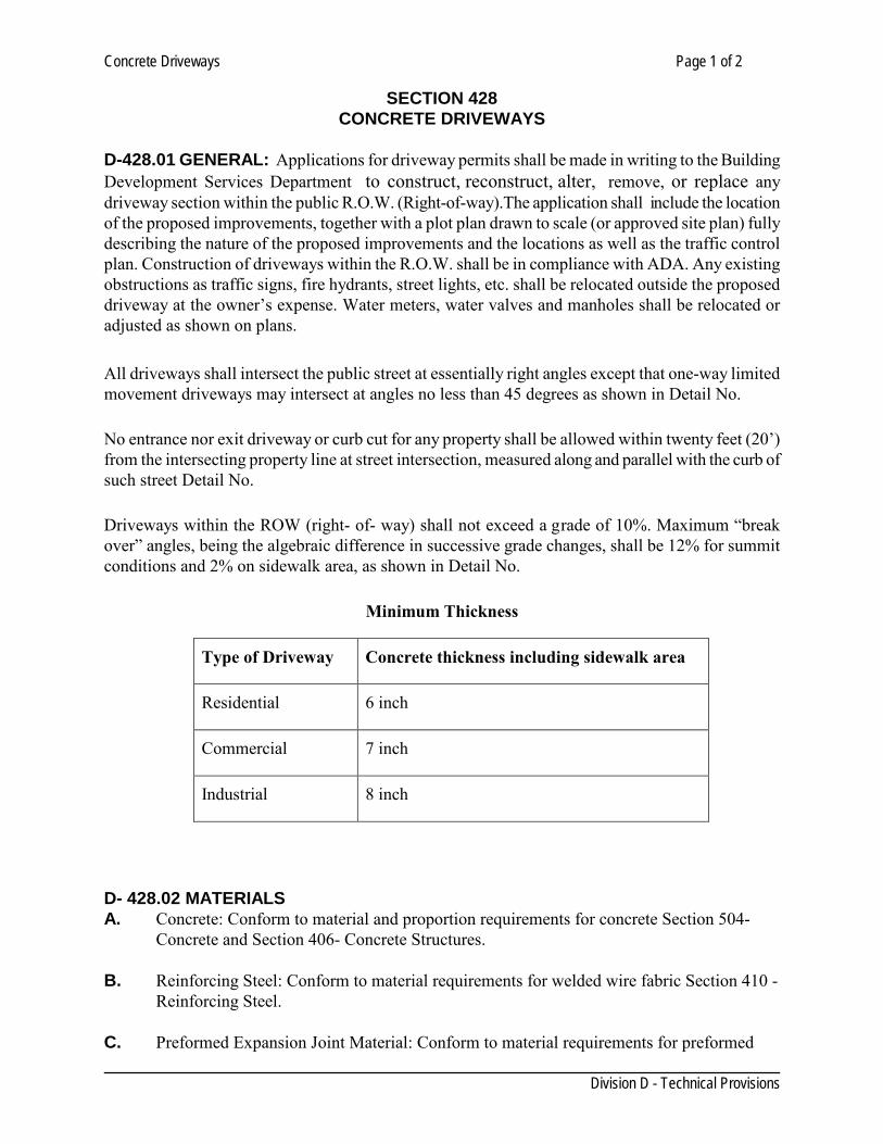
Concrete Driveways Page 1 of 2
Division D - Technical Provisions
SECTION 428 CONCRETE DRIVEWAYS
D-428.01 GENERAL: Applications for driveway permits shall be made in writing to the Building Development Services Department to construct, reconstruct, alter, remove, or replace any driveway section within the public R.O.W. (Right-of-way).The application shall include the location of the proposed improvements, together with a plot plan drawn to scale (or approved site plan) fully describing the nature of the proposed improvements and the locations as well as the traffic control plan. Construction of driveways within the R.O.W. shall be in compliance with ADA. Any existing obstructions as traffic signs, fire hydrants, street lights, etc. shall be relocated outside the proposed driveway at the owner’s expense. Water meters, water valves and manholes shall be relocated or adjusted as shown on plans. All driveways shall intersect the public street at essentially right angles except that one-way limited movement driveways may intersect at angles no less than 45 degrees as shown in Detail No.
No entrance nor exit driveway or curb cut for any property shall be allowed within twenty feet (20’) from the intersecting property line at street intersection, measured along and parallel with the curb of such street Detail No.
Driveways within the ROW (right- of- way) shall not exceed a grade of 10%. Maximum “break over” angles, being the algebraic difference in successive grade changes, shall be 12% for summit conditions and 2% on sidewalk area, as shown in Detail No.
Minimum Thickness
Type of Driveway Concrete thickness including sidewalk area
Residential 6 inch
Commercial 7 inch
Industrial 8 inch
D- 428.02 MATERIALS A. Concrete: Conform to material and proportion requirements for concrete Section 504-
Concrete and Section 406- Concrete Structures. B. Reinforcing Steel: Conform to material requirements for welded wire fabric Section 410 -
Reinforcing Steel. C. Preformed Expansion Joint Material: Conform to material requirements for preformed
Concrete Driveways Page 2 of 2
Division D - Technical Provisions
expansion joint material of Section 416- Expansion Joint Material. D. Expansion Joint Filler: Conform to material requirements for expansion joint material of
Section 406- Concrete Structures.
D-428.03 PREPARATION: A. Identify and protect utilities which are to remain. B. Protect living trees, other plant growth, and features designated to remain. C. Conduct clearing and grubbing operation in accordance with Section 402 - Clearing and
Grubbing. D. Excavate subgrade to the line, grade and cross-section shown on plans. Remove soft
spots and pumping soils and replace with fill material having a Plasticity Index between 7 and 20.
E. If there is an existing curb and gutter, saw cut the curb leaving the gutter radius or reconstruct as the existing.
D-428.04PLACEMENT: Place and finish concrete in accordance with applicable portions of Section 406 - Concrete Structures. No exposed materials shall be allowed as finish surface within the R.O.W. D-428.05 JOINTS: Install joints in concrete driveway in accordance with Section 406- Concrete Structures. D-428.06 CONCRETE CURING: Cure concrete in accordance with Section 406- Concrete Structures. D-428.07 PROTECTION: Conform to applicable requirements of Section 406- Concrete Structures. D-428.08 MEASUREMENT AND PAYMENT: Payment for concrete driveways is on square foot basis. Refer to Division C, General Provisions, Section 9 Measurement and Payment for unit price procedures
Concrete Sidewalks Page 1 of 4
Division D -Technical Provisions
SECTION 430 CONCRETE SIDEWALKS
D-430.01 GENERAL: Section includes reinforced concrete sidewalks and accessible ramps. Applications for sidewalk permits shall be made in writing to the Building Development Services Department to construct, reconstruct, alter, remove, or replace any sidewalk section within the R.O.W. (Right-of-Way). The application shall include the location of the proposed improvements, together with a plot plan drawn to scale (or approved site plan) fully describing the nature of the proposed improvements and the locations as well as the traffic control plan. Construction of sidewalks and accessible ramps shall be in compliance with ADA. Any existing obstructions as water meters, traffic signs, fire hydrants, water valves, street lights, etc. shall be relocated outside the proposed driveway at the owner’s expense. D- 430.02 REFERENCES: A. ASTM C 31-Standard Practice for Making and Curing Concrete Test Specimens in the field. B. ASTM C 39-Standard Test Method for Compressive Strength of Cylindrical Concrete
Specimens. C. ASTM C 42- Test Method for Obtaining and Testing Drilled Cores and Sawed Beams of
Concrete. D. ASTM C 138 -Standard Test Method for Unit Weight, Yield, and Air Content (Gravimetric)
of Concrete. E. ASTM C 143 - Standard Method for Slump of Hydraulic Cement Concrete. F. ASTM C 172 - Practice for Sampling Freshly Mixed Concrete. G. ASTM C 698 - Standard Test Methods for Moisture - Density Relations of Soils and Soil
Aggregate Mixtures Using 5.5 - Pound Rammer and 12-inch Drop. D- 430.03 SUBMITTALS: Submit certified testing results and certificates of compliance. D- 430.04 MATERIALS A. Concrete: Conform to material and proportion requirements for concrete Section 406. B. Reinforcing Steel: Conform to material requirements in section 410 & 412. C. Reinforcing Fiberglass: Conform to material and proportion requirements as per Section 414.
Approval from the City engineer is required. D. Preformed Expansion Joint Material: Conform to material requirements for preformed
expansion joint material of Section 416 - Expansion Joint Material. E. Expansion Joint Filler: Conform to material requirements for expansion joint material of
Section 406- Concrete Structures. F. Forms: Use straight, unwrapped wood or metal forms with nominal depth equal to or greater
Concrete Sidewalks Page 2 of 4
Division D -Technical Provisions
than the proposed sidewalk thickness. The use of 2” by 4” lumber as forms will be allowed. EXECUTION D-430.05 REPLACEMENT: Replace sidewalks and accessible ramps that are removed or damaged during construction as per this specification to the next joint. Provide replaced and new sidewalks with accessible ramps if sidewalk intersects curb at street or driveway as per the latest ADA standards. D-430.06 PREPARATION: A. Identify and protect utilities which are to remain. B. Protect living trees, other plant growth, and features designated to remain. C. Conduct clearing and grubbing operation in accordance with Section 402 - Clearing and
Grubbing. D. Excavate subgrade to the line, grade and cross-section shown on plans. Remove soft spots
and pumping soils and replace with fill material having a Plasticity Index between 7 and 20. D-430.07 PLACEMENT: A. Setting Forms: Securely stake forms to line and grade. Maintain position during concrete
placement. B. Reinforcement: Install 6 x 6, W2.9 x W2.9 welded wire fabric or No. 3 reinforcing steel
bars on 18 -inch centers longitudinally and transversely. Lay longitudinal bars in walk continuously, except through expansion joints. Support reinforcement in manner to maintain reinforcement in center of slab vertically during placement.
C. Expansion Joints: Install expansion joints at 40’ to 80’ in accordance with Section 416 -
Expansion Joint Material. D. Place concrete in forms to specified depth and tamp thoroughly with “jitterbug” tamp, or
other acceptable method. Bring mortar to surface. Where a sidewalk crosses a driveway, ensure that the sidewalk depth and reinforcement are not less than the driveway cross-sectional details shown on the plans.
E. Strike off to smooth finish with wood strike board. Finish smoothly with wood hand float.
Brush across sidewalk with fine-haired brush. Exposed material shall not be allowed as finish surface.
F. Unless otherwise indicated on plans, mark off joints ¼ inch deep, at spacing equal to 5 feet
and matching C&G joints. Use joint tool equal in width to edging tool. G. Finish edges with tool having ¼ inch radius. H. After concrete has set sufficiently, refill space along side of sidewalk to top of walk with
Concrete Sidewalks Page 3 of 4
Division D - Technical Provisions
suitable material. Tamp until firm and solid. Dispose of excess material in accordance with Section 128 - Waste Material Disposal. Repair driveways and parking lots damaged by sidewalk excavation in accordance with Section 430.
D-430.08 CURING: Conform to requirements of Section 406 - Concrete Curing. D-430.09 FIELD QUALITY CONTROL: A. Testing will be performed under provision of Division C, General Provisions, Section 6
Control of Work and Materials. B. Compressive Strength Test Specimens: Four test specimens for compressive strength test
will be made in accordance with ASTM C 31 for each 30 cubic yards or less of sidewalk that is place in one day. Two specimens will be tested at 7 days. The remaining two specimens will be tested at 28 days. S pecimens will be tested in accordance with ASTM C 39. Minimum compressive strength shall be 3000 pounds per square inch at 28 days.
C. Yield test for cement content per cubic yard of concrete will be made in accordance with
ASTM C 138. If such cement content is found to be less than that specified per cubic yard, reduce batch weights until amount of cement per cubic yard of concrete conforms to requirements.
D. If the Contractor places concrete without notifying the laboratory, the City will have the
concrete tested by means of a core test as specified in ASTM C 42. If the concrete does not meet the specification, the cost of the test will be deducted from payment due the Contractor.
E. Sampling of fresh concrete shall be in accordance with ASTM C 172. F. Take slump tests when cylinders are made. G. Concrete shall be acceptable if the average of the two 28 day compression tests is equal to or
greater than the minimum 28-day strength specified. H. If either of the two tests is less than the average of the two tests by more than 10 percent, that
entire test shall be considered erratic and not indicative of the concrete strength. Core samples will be required of this concrete.
I. If any 28-day laboratory test indicates that concrete of low strength has been placed, the
concrete in question shall be tested by taking cores as directed by the City Engineer may direct. At least three representative cores shall be taken and tested as specified in ASTM C 42. Cost for any additional testing required due to a failed test will be paid by the contractor.
D-430.10 NONCONFORMING: Remove and replace areas of sidewalk that fail compressive strength tests, with concrete of thickness shown on plans. Nonconforming sidewalk sections shall be replaced at no additional cost to the City.
Concrete Sidewalks Page 4 of 4
Division D - Technical Provisions
D-430.11 PROTECTION: Maintain sidewalks in good condition until completion of work. Replace damaged sidewalks in accordance with Paragraph D-430.06 - Replacement. D-430.12 MEASUREMENT: Sidewalks will be measured by the square foot or by the foot of different widths. Accessible ramps will be measured by each unit. The unit will consist of the curb ramp, landing, adjacent flares or side curb, and detectable warning surface as show on the plans. D-430.13 PAYMENT: Will be paid by the unit price bid for concrete sidewalks for the depth specified and accessible ramps. This price is full compensation for surface preparation of base; materials; removal and disposal of excavated material; drilling and doweling into the existing concrete curb, sidewalk and pavement; repair of the adjacent street or pavement structure damaged by the operations; and equipment, labor, materials, tools and incidentals.
Mailbox Assemblies Page 1 of 1
Division D - Technical Provisions
SECTION 432 MAILBOX ASSEMBLIES
D-432.01 GENERAL: This item shall govern for the installation, removal, temporarily relocation, or replacement of mailbox assemblies at locations established by the Engineer.
D-432.02 MATERIALS: Materials for mailbox assemblies shall conform to the details shown on the drawings and U.S. Postal Service design criteria. D-432.03 CONSTRUCTION METHODS: A. No mailboxes shall be placed or constructed within the sidewalk unless special provisions are made to ensure complete compliance with A.D.A. & T.D.L.R. B. The Contractor shall remove and relocate all mailbox assemblies along the existing roadway to a point outside the limits of the proposed construction. The temporary relocation of mailboxes may be accomplished by mounting mailboxes on portable stands furnished by the Contractor and approved by the Engineer. C. All mailboxes and mailbox assemblies shall be maintained by the Contractor in an upright position and serviceable condition during the construction period. A ny existing mailboxes or mailbox assemblies damaged or destroyed as a result of the Contractor’s operations shall be replaced by the Contractor at his expense. D. In the event additional mailbox installations are required after construction has begun, an approved mailbox will be furnished by the Contractor and the Contractor shall install either a temporary and/or a permanent supporting assembly. E. After all construction work in the area has been completed; mailboxes shall be removed from their temporary position and positioned in permanent locations as shown on the drawings or as directed by the Engineer.
D-432.04 MEASUREMENT: AND PAYMENT: This item will be measured as each permanent installation of mailbox assemblies complete in place. A dditional permanent mailbox assemblies installed during construction will be measured as each installation complete in place. D-432.05 PAYMENT: The work performed and materials furnished in accordance with this item and measured as provided under “Measurement” will be paid for at the unit price bid for Mailbox Assemblies.” This price shall be full compensation for temporarily relocating mailbox assemblies, providing portable mailbox stands, installing mailboxes in permanent locations; for furnishing all materials and for all manipulations, labor, tools, equipment and incidentals necessary to complete the work. No compensation will be made for temporarily relocating mailboxes more than once.
Excavation & Embankment of Streets Page 1 of 4
Division D - Technical Provisions
SECTION 502 EXCAVATION AND EMBANKMENT OF STREETS
D-502.01 DESCRIPTION: This item shall consist of doing all required excavation within the limits of the roadway (except for excavation otherwise classified such as excavation for drainage structures, etc.): the removal and proper utilization or disposal of all excavated materials; the erection of all embankments; and the constructing, shaping, compacting, and finishing of all earthwork on the entire roadway and approaches thereto in conformity with the lines, grades, and typical sections as shown on the plans and established by the Engineer. D-502.02 GENERAL: Soil material for street subgrade or embankment with a PI > 20 shall be stabilized as shown on the plans. The method shall be approved by the City Engineer. All material encountered of whatever nature within the limits indicated shall be removed and disposed of as directed. T he Contractor shall inform and satisfy himself as to the character, quantity, and distribution of all material to be excavated. No payment will be made for any excavated material which is used for purposes other than required in the plans or proposal or as directed by the Engineer. The rough excavation shall be carried to such depth that sufficient material will be left above the designated grade to allow for compaction. Likewise on embankments, sufficient material shall be placed above the designated grade to allow for compaction and settlement. Should the Contractor excavate below the designated lines, Contractor shall replace such material excavated with approved material in an approved manner and condition at own expense. The Engineer shall have complete control over the excavation, moving, placing, and disposition of all material, and he shall determine the suitability of material to be placed in embankments. Stakes set by the Engineer as provided in the "General Provisions" shall include only one set of offset alignment and grade stakes. All slope stakes, bluetops, and additional alignment stakes shall be furnished and set by the Contractor.
EQUIPMENT D-502.03 GRADING EQUIPMENT: The Contractor may use any type of earth-moving equipment the contractor wishes to use or has available, provided such equipment is in satisfactory condition and of such capacity that the grading schedule as planned by the Contractor and approved by the Engineer can be maintained. D-502.04 COMPACTING EQUIPMENT: (a) Tamping rollers shall consist of two metal rollers, drums, or shells or 40 " minimum diameter, each not less than 42 " in length and unit-mounted in a rigid frame in such manner that each roller may oscillate independently of the other; and each roller, drum, or shell shall be surmounted by metal studs with tamping feet projecting not less than seven (7) inches from the surface of the drum and spaced not less than six (6) inches nor more than ten (10) inches measured diagonally from center to center. The area of each tampering foot shall be not less than five (5) feet square inches nor more than eight (8) square inches. Each unit shall be provided with a suitable tamper foot cleaning device.
Excavation & Embankment of Streets Page 2 of 4
Division D - Technical Provisions
Where more than one rolling unit is used, the rolling units shall be pivoted on the main frame in a manner which will permit the rolling units to adapt themselves to uneven ground and to rotate individually. When empty, the weight of the roller shall be such that the unit pressure applied by the tamping foot in contact with the ground is not less than 120 pounds per square inch. (b) Pneumatic rollers shall consist of not less than nine pneumatic tired wheels running on two axles in such manner that the rear group of tires will not follow in the tracks of the forward group and shall be mounted on a rigid frame provided with platform or body suitable for ballast loading. The front axle shall rotate around the kingpin so located that the roller may be turned within a minimum circle. The pneumatic tire roller under working conditions shall have an effective rolling width of approximately sixty (60) inches and shall give a minimum compression of three hundred and twenty-five (325) pounds per inch of width of tire trend (c) Smooth self-propelled rollers shall weigh at least ten tons and may be tandem or three-wheel type. The wheels of the roller shall be equipped with adjustable scrapers.
CONSTRUCTION METHODS D-502.05 EXCAVATION: The excavation material shall be handled in such a manner as to allow the selected material to be properly placed in embankment and in the capping of the pavement subgrades as determined by the Engineer. Any suitable surplus material shall be stock-piled in approved areas for later use as directed by the Engineer. The contractor shall make the distribution as indicated on the plans, and the widening or narrowing of the section or raising or lowering of the grade to avoid haul will not be permitted. During the process of excavation, the grade shall be maintained in such condition that it will be well drained at all times. When directed, temporary drains and drainage ditches shall be installed to intercept and divert surface water. In cut areas, the top of the subgrade shall be scarified and compacted to a minimum depth of six (6) inches to not less than 95% compaction as per TEX. 113-E or 114 -E, or ASTM 1557 or ASTM 698, as appropriate to the extent of at least 12” inches behind the back of the curb or edge of pavement. When the required density cannot be obtained, the material shall be undercut and replaced with suitable material as directed. The material placed to refill and undercut portion shall be handled and compacted as specified for embankments. During compacting operations, water shall be added to the subgrade material. Such watering shall be done by approved methods and using approved equipment. This moisture shall not be more than 2% above or below the optimum. Approved subgrade shall be primed, cured and after primed will be covered with base within maximum seven (7) days. D-502.06 BORROW: Borrow excavation shall consist of excavation made outside the normal grading limits to obtain material for the completion of embankments and for other purposes. It shall be the Contractor's responsibility to locate and obtain the supply, and the Contractor shall notify the Engineer sufficiently in advance to permit tests and measurements to be made.
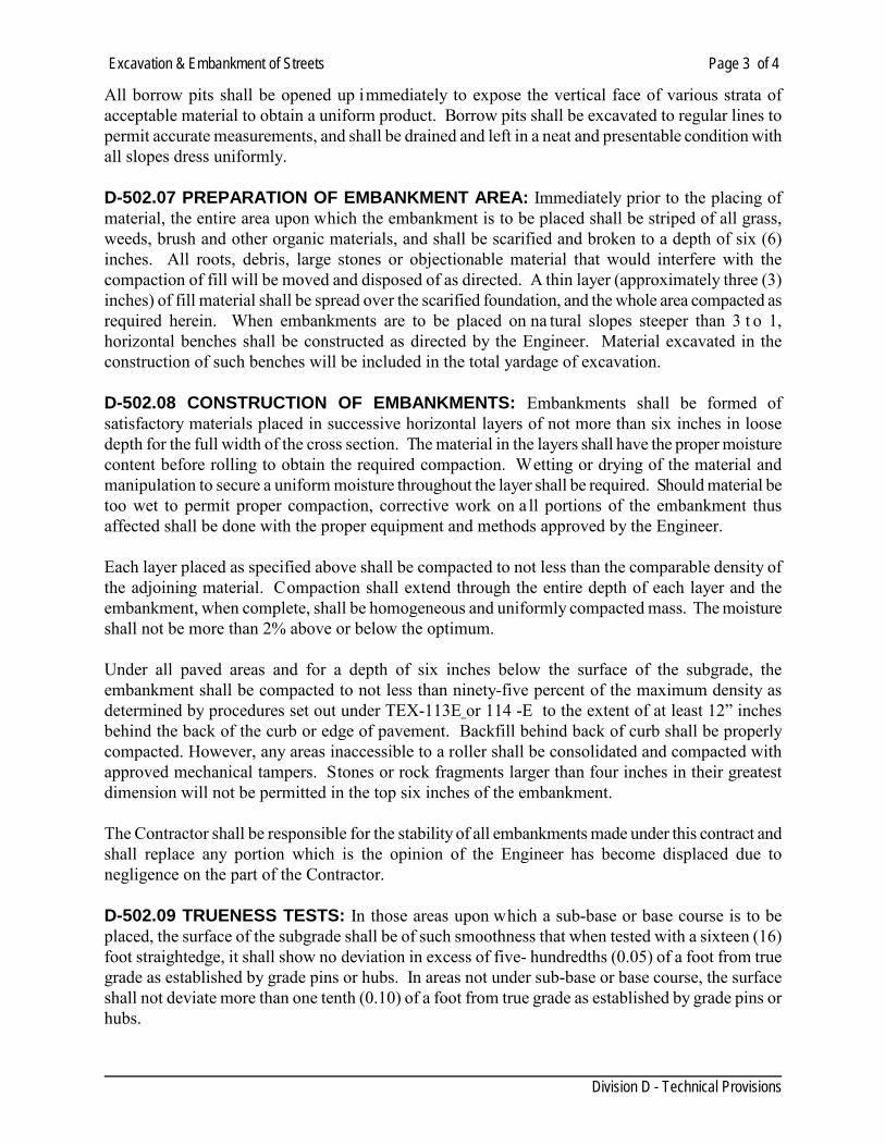
Excavation & Embankment of Streets Page 3 of 4
Division D - Technical Provisions
All borrow pits shall be opened up immediately to expose the vertical face of various strata of acceptable material to obtain a uniform product. Borrow pits shall be excavated to regular lines to permit accurate measurements, and shall be drained and left in a neat and presentable condition with all slopes dress uniformly. D-502.07 PREPARATION OF EMBANKMENT AREA: Immediately prior to the placing of material, the entire area upon which the embankment is to be placed shall be striped of all grass, weeds, brush and other organic materials, and shall be scarified and broken to a depth of six (6) inches. All roots, debris, large stones or objectionable material that would interfere with the compaction of fill will be moved and disposed of as directed. A thin layer (approximately three (3) inches) of fill material shall be spread over the scarified foundation, and the whole area compacted as required herein. When embankments are to be placed on na tural slopes steeper than 3 t o 1, horizontal benches shall be constructed as directed by the Engineer. Material excavated in the construction of such benches will be included in the total yardage of excavation. D-502.08 CONSTRUCTION OF EMBANKMENTS: Embankments shall be formed of satisfactory materials placed in successive horizontal layers of not more than six inches in loose depth for the full width of the cross section. The material in the layers shall have the proper moisture content before rolling to obtain the required compaction. Wetting or drying of the material and manipulation to secure a uniform moisture throughout the layer shall be required. Should material be too wet to permit proper compaction, corrective work on a ll portions of the embankment thus affected shall be done with the proper equipment and methods approved by the Engineer. Each layer placed as specified above shall be compacted to not less than the comparable density of the adjoining material. Compaction shall extend through the entire depth of each layer and the embankment, when complete, shall be homogeneous and uniformly compacted mass. The moisture shall not be more than 2% above or below the optimum. Under all paved areas and for a depth of six inches below the surface of the subgrade, the embankment shall be compacted to not less than ninety-five percent of the maximum density as determined by procedures set out under TEX-113E or 114 -E to the extent of at least 12” inches behind the back of the curb or edge of pavement. Backfill behind back of curb shall be properly compacted. However, any areas inaccessible to a roller shall be consolidated and compacted with approved mechanical tampers. Stones or rock fragments larger than four inches in their greatest dimension will not be permitted in the top six inches of the embankment. The Contractor shall be responsible for the stability of all embankments made under this contract and shall replace any portion which is the opinion of the Engineer has become displaced due to negligence on the part of the Contractor. D-502.09 TRUENESS TESTS: In those areas upon which a sub-base or base course is to be placed, the surface of the subgrade shall be of such smoothness that when tested with a sixteen (16) foot straightedge, it shall show no deviation in excess of five- hundredths (0.05) of a foot from true grade as established by grade pins or hubs. In areas not under sub-base or base course, the surface shall not deviate more than one tenth (0.10) of a foot from true grade as established by grade pins or hubs.
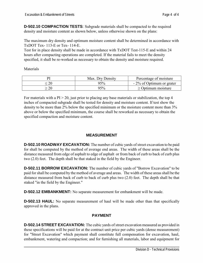
Excavation & Embankment of Streets Page 4 of 4
Division D - Technical Provisions
D-502.10 COMPACTION TESTS: Subgrade materials shall be compacted to the required density and moisture content as shown below, unless otherwise shown on the plans: The maximum dry density and optimum moisture content shall be determined in accordance with TxDOT Tex- 113-E or Tex- 114-E. Test for in place density shall be made in accordance with TxDOT Test-115-E and within 24 hours after compacting operations are completed. If the material fails to meet the density specified, it shall be re-worked as necessary to obtain the density and moisture required. Materials
PI Max. Dry Density Percentage of moisture ≤ 20 95% - 2% of Optimum or grater ≥ 20 95% ≥ Optimum moisture
For materials with a PI > 20, just prior to placing any base materials or stabilization, the top 4 inches of compacted subgrade shall be tested for density and moisture content. If test show the density to be more than 2% below the specified minimum or the moisture content more than 3% above or below the specified minimum, the course shall be reworked as necessary to obtain the specified compaction and moisture content.
MEASUREMENT
D-502.10 ROADWAY EXCAVATION: The number of cubic yards of street excavation to be paid for shall be computed by the method of average end areas. The width of these areas shall be the distance measured from edge of asphalt to edge of asphalt or from back of curb to back of curb plus two (2.0) feet. The depth shall be that staked in the field by the Engineer. D-502.11 BORROW EXCAVATION: The number of cubic yards of "Borrow Excavation" to be paid for shall be computed by the method of average and areas. The width of these areas shall be the distance measured from back of curb to back of curb plus two (2.0) feet. The depth shall be that staked "in the field by the Engineer." D-502.12 EMBANKMENT: No separate measurement for embankment will be made. D-502.13 HAUL: No separate measurement of haul will be made other than that specifically approved in the plans.
PAYMENT D-502.14 STREET EXCAVATION: The cubic yards of street excavation measured as provided in these specifications will be paid for at the contract unit price per cubic yards (dense measurement) for "Street Excavation" which payment shall constitute full compensation for excavation, haul, embankment, watering and compaction; and for furnishing all materials, labor and equipment for
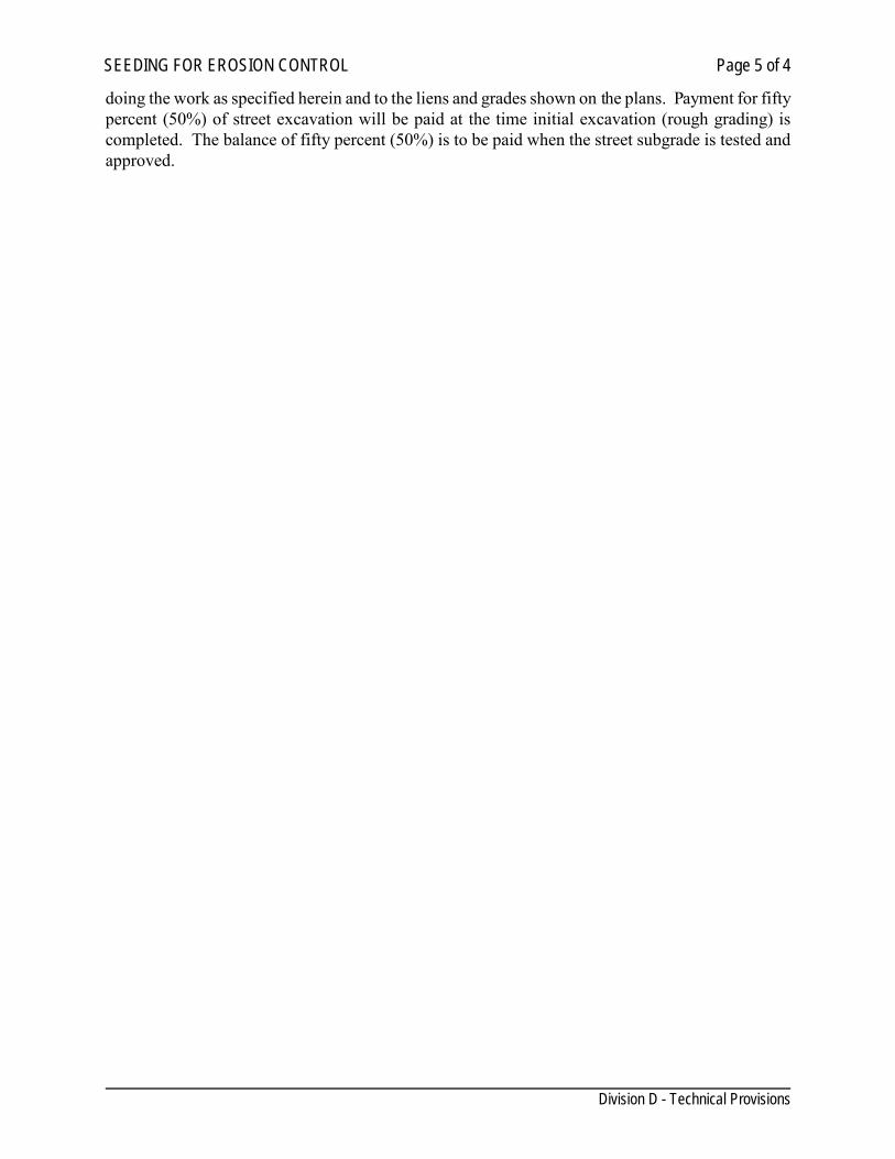
SEEDING FOR EROSION CONTROL Page 5 of 4
Division D - Technical Provisions
doing the work as specified herein and to the liens and grades shown on the plans. Payment for fifty percent (50%) of street excavation will be paid at the time initial excavation (rough grading) is completed. The balance of fifty percent (50%) is to be paid when the street subgrade is tested and approved.
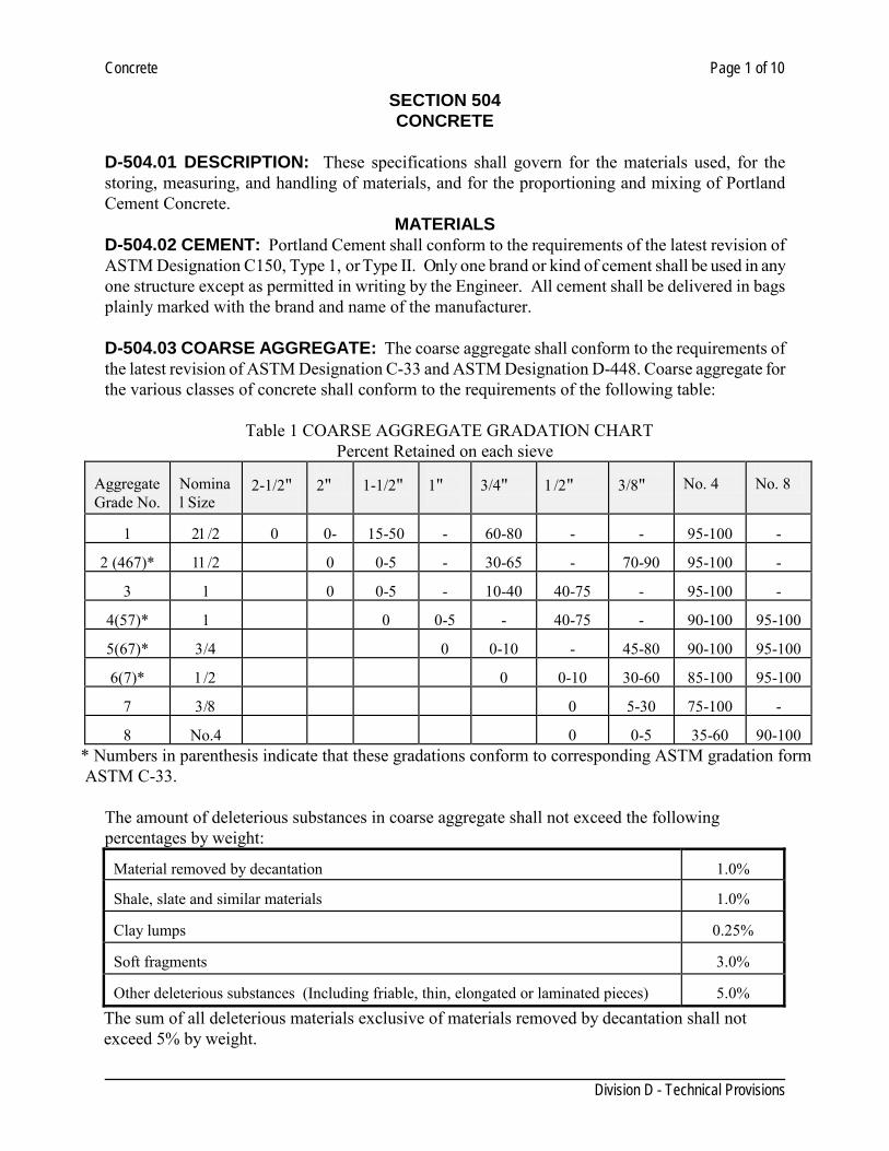
Concrete Page 1 of 10
Division D - Technical Provisions
SECTION 504 CONCRETE
D-504.01 DESCRIPTION: These specifications shall govern for the materials used, for the storing, measuring, and handling of materials, and for the proportioning and mixing of Portland Cement Concrete.
MATERIALS D-504.02 CEMENT: Portland Cement shall conform to the requirements of the latest revision of ASTM Designation C150, Type 1, or Type II. Only one brand or kind of cement shall be used in any one structure except as permitted in writing by the Engineer. All cement shall be delivered in bags plainly marked with the brand and name of the manufacturer. D-504.03 COARSE AGGREGATE: The coarse aggregate shall conform to the requirements of the latest revision of ASTM Designation C-33 and ASTM Designation D-448. Coarse aggregate for the various classes of concrete shall conform to the requirements of the following table:
Table 1 COARSE AGGREGATE GRADATION CHART Percent Retained on each sieve
Aggregate Grade No.
Nominal Size
2-1/2"
2"
1-1/2"
1"
3/4"
1/2"
3/8"
No. 4
No. 8
1
21/2
0
0-
15-50
-
60-80
-
-
95-100
-
2 (467)*
11/2
0
0-5
-
30-65
-
70-90
95-100
-
3
1
0
0-5
-
10-40
40-75
-
95-100
-
4(57)*
1
0
0-5
-
40-75
-
90-100
95-100
5(67)*
3/4
0
0-10
-
45-80
90-100
95-100
6(7)*
1/2
0
0-10
30-60
85-100
95-100
7
3/8
0
5-30
75-100
-
8
No.4
0
0-5
35-60
90-100
* Numbers in parenthesis indicate that these gradations conform to corresponding ASTM gradation form ASTM C-33.
The amount of deleterious substances in coarse aggregate shall not exceed the following percentages by weight:
Material removed by decantation
1.0%
Shale, slate and similar materials
1.0%
Clay lumps
0.25%
Soft fragments
3.0%
Other deleterious substances (Including friable, thin, elongated or laminated pieces)
5.0%
The sum of all deleterious materials exclusive of materials removed by decantation shall not exceed 5% by weight.
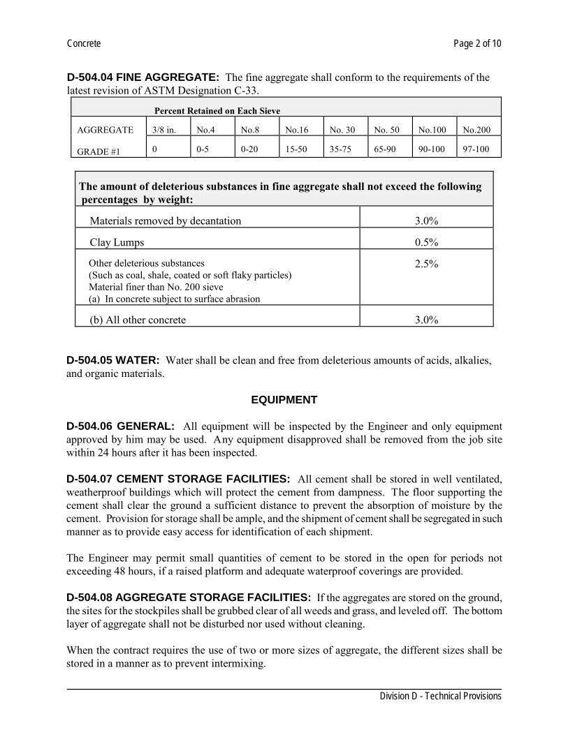
Concrete Page 2 of 10
Division D - Technical Provisions
D-504.04 FINE AGGREGATE: The fine aggregate shall conform to the requirements of the latest revision of ASTM Designation C-33.
Percent Retained on Each Sieve AGGREGATE GRADE #1
3/8 in.
No.4
No.8
No.16
No. 30
No. 50
No.100
No.200
0
0-5
0-20
15-50
35-75
65-90
90-100
97-100
The amount of deleterious substances in fine aggregate shall not exceed the following percentages by weight: Materials removed by decantation
3.0%
Clay Lumps
0.5%
Other deleterious substances (Such as coal, shale, coated or soft flaky particles) Material finer than No. 200 sieve (a) In concrete subject to surface abrasion
2.5%
(b) All other concrete
3.0%
D-504.05 WATER: Water shall be clean and free from deleterious amounts of acids, alkalies, and organic materials.
EQUIPMENT
D-504.06 GENERAL: All equipment will be inspected by the Engineer and only equipment approved by him may be used. Any equipment disapproved shall be removed from the job site within 24 hours after it has been inspected. D-504.07 CEMENT STORAGE FACILITIES: All cement shall be stored in well ventilated, weatherproof buildings which will protect the cement from dampness. The floor supporting the cement shall clear the ground a sufficient distance to prevent the absorption of moisture by the cement. Provision for storage shall be ample, and the shipment of cement shall be segregated in such manner as to provide easy access for identification of each shipment. The Engineer may permit small quantities of cement to be stored in the open for periods not exceeding 48 hours, if a raised platform and adequate waterproof coverings are provided. D-504.08 AGGREGATE STORAGE FACILITIES: If the aggregates are stored on the ground, the sites for the stockpiles shall be grubbed clear of all weeds and grass, and leveled off. The bottom layer of aggregate shall not be disturbed nor used without cleaning. When the contract requires the use of two or more sizes of aggregate, the different sizes shall be stored in a manner as to prevent intermixing.
Concrete Page 3 of 10
Division D - Technical Provisions
Materials in all stockpiles shall be handled and placed in such manner that segregation of materials within the stockpile will be avoided. D-504.09 MEASURING EQUIPMENT: Equipment for measuring concrete materials shall be such that the proportions can be accurately controlled and easily checked at any time during the work, preferably measurement by weight rather than by volume. D-504.10 MIXING EQUIPMENT: The mixing shall be done in a batch mixer of approved type and size which will insure the uniform distribution of the material throughout the mass so that the mixture will be uniform in color and smooth in appearance. Whenever a concrete mixer is not suitable or adequate for the work, it shall be removed from the site upon written order from the Engineer. Pick-up and throw-over blades in the mixer drum which are worn down more than ten percent (10%) in depth shall be repaired or replaced. D-504.11 CLASSIFICATION AND MIX DESIGN: It shall be the responsibility of the Contractor to furnish the mix design, using a Coarse Aggregate Factor acceptable to the Engineer, for the class(es) of concrete specified to conform with the requirements contained herein and in accordance with TxDOT Standards. The contractor shall perform, at his own expense, the work required to substantiate the design, except the testing of strength specimens, which will be done by the Department. Complete concrete design data shall be submitted to the Engineer for approval and shall be less than 1 year old signed and sealed by a licensed professional engineer in the State of Texas. It shall also be the responsibility of the Contractor to determine and measure the batch quantity of each ingredient including all water, not only for batch designs, but for all concrete produced for the project, so that the mix conforms to these specifications and other requirements shown on the plans. In lieu of the above mix design responsibility, the Contractor may accept a design furnished by the Engineer, however, this will not relieve him of the responsibility of providing concrete meeting the requirements of these specifications. Trial batches will be made and tested using all the proposed ingredients prior to placing of concrete, and when the aggregate, and/or type, brand or source of cement, or admixture is changed. When the brand and/or source of cement only is changed, the Engineer may waive trial batches only if a prior record of satisfactory performance of the cement has been established. Trial batches shall be made in the mixer to be used on the job. When Transit Mix concrete is to be used, the trial designs will be made in a transit mixer representative of the mixers to be used. Batch size shall not be less than fifty percent (50%) of its rated mixing capacity. Mix designs from previous or concurrent jobs may be used without trial batches if it is shown that no substantial change in any of the proposed ingredients has been made. Mix design shall be current or less than one (1) year old. The coarse aggregate factor shall not be more than 0.82, but when the voids in the coarse aggregate exceed 48 percent of the total dry loose volume, the coarse aggregate factor shall not exceed 0.85.
Concrete Page 4 of 10
Division D - Technical Provisions
The coarse aggregate factor shall not be less than 0.68 unless authorized by the Engineer in writing. Water reducing or retarding agents may be used will with all classes of concrete at the option of the Contractor, and will be required for hot weather concreting for cased drilled shafts and for continuous slab placement. When a retarding admixture is required for hot weather concreting, must meet the requirements of ASTM C 94 When used in continuous slab placement, the amount to be used will be established by several trial batches with varying retarder content and simulating the placing conditions to be encountered. When water reducing or retarding agents are used at the option of the Contractor, reduced dosage of the admixture will be permitted. Entrained air materials shall comply with ASTM C 260 and will be required in accordance with Table 7 TxDOT item 421. Specimens will be tested in accordance with Tex-414-A or Tex-416-A D-504.12 QUALITY OF CONCRETE: The concrete shall be uniform, workable, and of a consistency acceptable to the Engineer. The cement content, maximum allowable water/cement ratio, the desired and maximum slump, the proper amount of entrained air and the strength requirements for all classes of concrete shall conform to the requirements of these specifications. It shall be the responsibility of the Contractor to provide concrete meeting these specifications. During the progress of the work, the Engineer will cast test cylinders or beams, perform slump and entrained air tests, and will make temperature checks, as required, to insure compliance with the specifications. A strength test shall be defined as the average of the breaking strength of two cylinders or two beams as the case may be. Specimens will be tested in accordance with Test Methods TEX-418- A or Tex-448- A. If the required strength or consistency of the class of concrete being produced cannot be secured with the minimum cement specified or without exceeding the maximum water/cement ratio, the Contractor will be required to furnish different aggregates, use a w ater-reducing agent, an air-entraining agent, or increase the cement content in order to provide concrete meeting these specifications. All test specimens, beams or cylinders, representing tests for removal of forms and/or false work shall be cured using the same methods, and under the same conditions as concrete represented. "Design Strength" beams and cylinders shall be cured in accordance with TxDOT Bulletin C-11 and Supplement thereto. The Contractor shall provide and maintain curing facilities as described in TxDOT Bulletin C-11 and Supplement thereto, for the purpose of curing test specimens. Provision shall be made to maintain the water in the curing tank at temperatures between 70°F and 90°F.
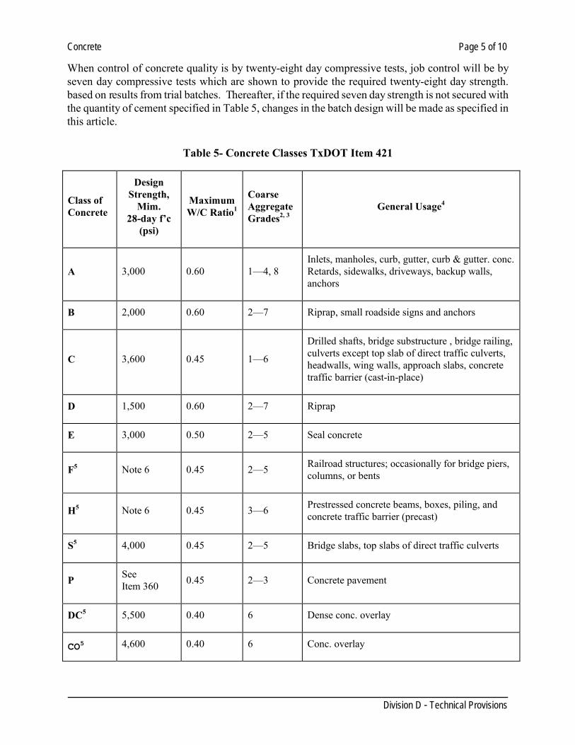
Concrete Page 5 of 10
Division D - Technical Provisions
When control of concrete quality is by twenty-eight day compressive tests, job control will be by seven day compressive tests which are shown to provide the required twenty-eight day strength. based on results from trial batches. Thereafter, if the required seven day strength is not secured with the quantity of cement specified in Table 5, changes in the batch design will be made as specified in this article.
Table 5- Concrete Classes TxDOT Item 421
Class of Concrete
Design Strength,
Mim. 28-day f’c
(psi)
Maximum W/C Ratio1
Coarse Aggregate Grades2, 3
General Usage4
A 3,000 0.60 1—4, 8 Inlets, manholes, curb, gutter, curb & gutter. conc. Retards, sidewalks, driveways, backup walls, anchors
B 2,000 0.60 2—7 Riprap, small roadside signs and anchors
C 3,600 0.45 1—6
Drilled shafts, bridge substructure , bridge railing, culverts except top slab of direct traffic culverts, headwalls, wing walls, approach slabs, concrete traffic barrier (cast-in-place)
D 1,500 0.60 2—7 Riprap
E 3,000 0.50 2—5 Seal concrete
F5 Note 6 0.45 2—5 Railroad structures; occasionally for bridge piers, columns, or bents
H5 Note 6 0.45 3—6 Prestressed concrete beams, boxes, piling, and concrete traffic barrier (precast)
S5 4,000 0.45 2—5 Bridge slabs, top slabs of direct traffic culverts
P See Item 360 0.45 2—3 Concrete pavement
DC5 5,500 0.40 6 Dense conc. overlay
CO5 4,600 0.40 6 Conc. overlay
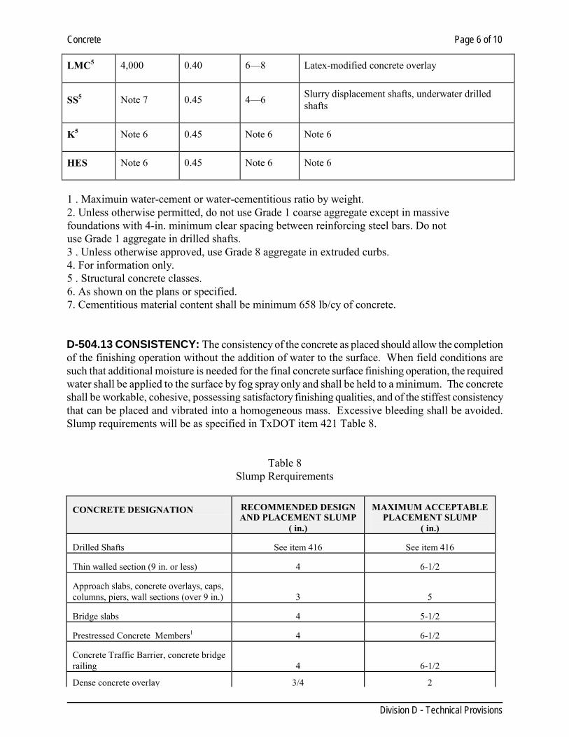
Concrete Page 6 of 10
Division D - Technical Provisions
LMC5 4,000 0.40 6—8 Latex-modified concrete overlay
SS5 Note 7 0.45 4—6 Slurry displacement shafts, underwater drilled shafts
K5 Note 6 0.45 Note 6 Note 6
HES Note 6 0.45 Note 6 Note 6
1 . Maximuin water-cement or water-cementitious ratio by weight. 2. Unless otherwise permitted, do not use Grade 1 coarse aggregate except in massive foundations with 4-in. minimum clear spacing between reinforcing steel bars. Do not use Grade 1 aggregate in drilled shafts. 3 . Unless otherwise approved, use Grade 8 aggregate in extruded curbs. 4. For information only. 5 . Structural concrete classes. 6. As shown on the plans or specified. 7. Cementitious material content shall be minimum 658 lb/cy of concrete. D-504.13 CONSISTENCY: The consistency of the concrete as placed should allow the completion of the finishing operation without the addition of water to the surface. When field conditions are such that additional moisture is needed for the final concrete surface finishing operation, the required water shall be applied to the surface by fog spray only and shall be held to a minimum. The concrete shall be workable, cohesive, possessing satisfactory finishing qualities, and of the stiffest consistency that can be placed and vibrated into a homogeneous mass. Excessive bleeding shall be avoided. Slump requirements will be as specified in TxDOT item 421 Table 8.
Table 8 Slump Rerquirements
CONCRETE DESIGNATION
RECOMMENDED DESIGN AND PLACEMENT SLUMP
( in.)
MAXIMUM ACCEPTABLE
PLACEMENT SLUMP ( in.)
Drilled Shafts
See item 416
See item 416
Thin walled section (9 in. or less)
4
6-1/2
Approach slabs, concrete overlays, caps, columns, piers, wall sections (over 9 in.)
3
5 Bridge slabs
4
5-1/2
Prestressed Concrete Members1
4
6-1/2
Concrete Traffic Barrier, concrete bridge railing
4
6-1/2 Dense concrete overlay
3/4
2
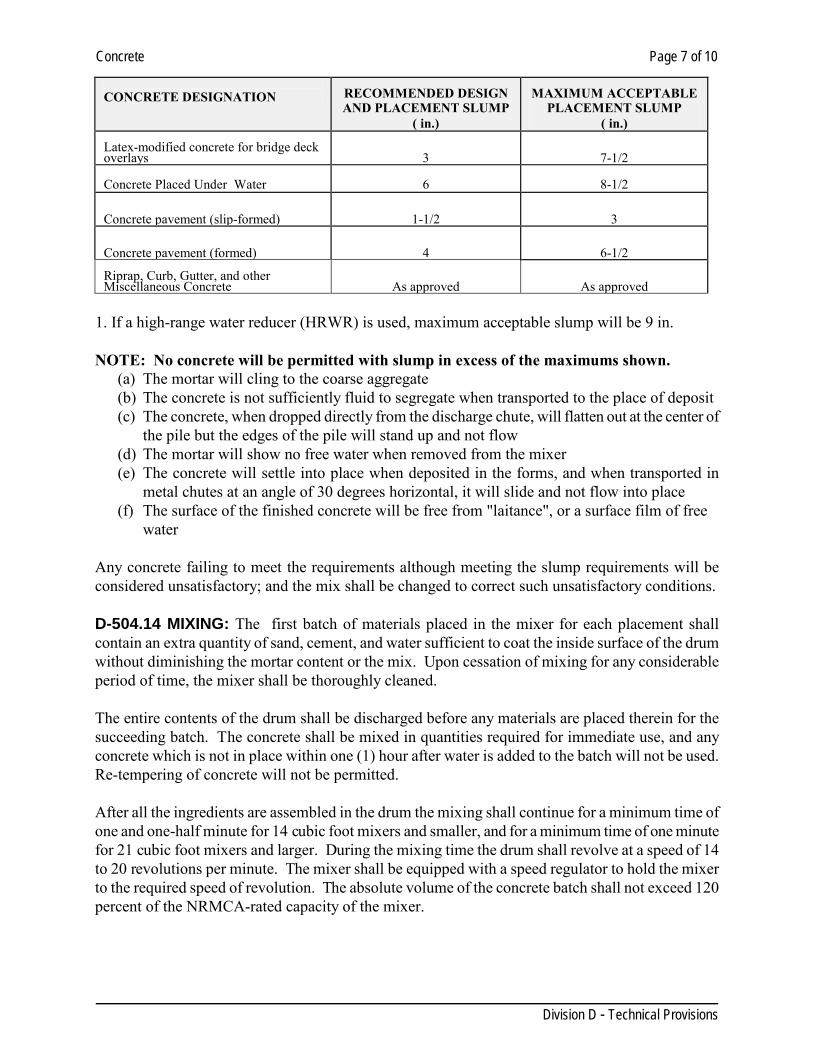
Concrete Page 7 of 10
Division D - Technical Provisions
CONCRETE DESIGNATION
RECOMMENDED DESIGN AND PLACEMENT SLUMP
( in.)
MAXIMUM ACCEPTABLE
PLACEMENT SLUMP ( in.)
Latex-modified concrete for bridge deck overlays
3
7-1/2 Concrete Placed Under Water
6
8-1/2
Concrete pavement (slip-formed)
1-1/2
3 Concrete pavement (formed)
4
6-1/2 Riprap, Curb, Gutter, and other Miscellaneous Concrete
As approved
As approved 1. If a high-range water reducer (HRWR) is used, maximum acceptable slump will be 9 in. NOTE: No concrete will be permitted with slump in excess of the maximums shown.
(a) The mortar will cling to the coarse aggregate (b) The concrete is not sufficiently fluid to segregate when transported to the place of deposit (c) The concrete, when dropped directly from the discharge chute, will flatten out at the center of
the pile but the edges of the pile will stand up and not flow (d) The mortar will show no free water when removed from the mixer (e) The concrete will settle into place when deposited in the forms, and when transported in
metal chutes at an angle of 30 degrees horizontal, it will slide and not flow into place (f) The surface of the finished concrete will be free from "laitance", or a surface film of free
water Any concrete failing to meet the requirements although meeting the slump requirements will be considered unsatisfactory; and the mix shall be changed to correct such unsatisfactory conditions. D-504.14 MIXING: The first batch of materials placed in the mixer for each placement shall contain an extra quantity of sand, cement, and water sufficient to coat the inside surface of the drum without diminishing the mortar content or the mix. Upon cessation of mixing for any considerable period of time, the mixer shall be thoroughly cleaned. The entire contents of the drum shall be discharged before any materials are placed therein for the succeeding batch. The concrete shall be mixed in quantities required for immediate use, and any concrete which is not in place within one (1) hour after water is added to the batch will not be used. Re-tempering of concrete will not be permitted. After all the ingredients are assembled in the drum the mixing shall continue for a minimum time of one and one-half minute for 14 cubic foot mixers and smaller, and for a minimum time of one minute for 21 cubic foot mixers and larger. During the mixing time the drum shall revolve at a speed of 14 to 20 revolutions per minute. The mixer shall be equipped with a speed regulator to hold the mixer to the required speed of revolution. The absolute volume of the concrete batch shall not exceed 120 percent of the NRMCA-rated capacity of the mixer.
Concrete Page 8 of 10
Division D - Technical Provisions
D-504.15 READY MIX CONCRETE: Concrete forms from a central plant of mixed-in-transit mixer trucks may be used if it complies with these specifications. The Engineer shall have free access at all times to the batching and mixing plant for sampling of all materials and inspection of work performed at this project. Concrete shall be delivered in water-tight containers which will not permit segregation of the materials. When delivered, the concrete shall be uniform throughout the mass. The delivery ticket shall include the date, time, strength, slump, and amount of batch delivered. If an extra charge of water is required at the job site because of too low a slump, the drum shall be turned a minimum of 30 revolutions after addition of such water. Mixer shall be completely emptied before recharging. Trucks shall not be loaded greater than NRMCA-rated capacity. The maximum time interval between the addition of the cement to the batch and the placing of the concrete in the forms shall conform to the requirements set up under TxDOT specifications, Item 421. Overwet mixers shall be rejected and shall not be corrected by the addition of either aggregate or cement to the particular batch in question. D-504.16 ADVERSE WEATHER: In threatening weather which, in the opinion of the Engineer, may result in conditions which will adversely affect the quality of the concrete to be placed, the Engineer may order postponement of the work. Where work has been started and changes in weather conditions require protective measures to be used, the Contractor shall furnish adequate shelter to protect the concrete against damage from rainfall, wind, or damage due to freezing temperature. In case it is necessary to continue mixing operation during rainfall, the Contractor shall provide protective coverings for the material stockpiles as well as the concrete being placed. The covering for aggregate stockpiles will be required only to the extent as may be necessary to control the moisture conditions in the aggregate so that adequate control of the consistency of the concrete mix may be maintained. No concrete shall be mixed without the approval of the Engineer when the air temperature is at or below 40 degrees Fahrenheit taken in the shade away from artificial heat and falling. If authorized by the Engineer, concrete may be mixed when the air temperature is 35 degrees Fahrenheit and rising. When permission is given for mixing when the temperature is below 40 degrees Fahrenheit, the Engineer will specify the special precautions which shall be taken. In case the air temperature is at or above 85 degrees Fahrenheit, concrete may be mixed in accordance with the requirements set up in TxDOT, Specifications. Hand mixing of concrete will be permitted only for small placements or in the case of an emergency and then only when authorized by the Engineer. The Engineer will also specify the proportioning and methods of mixing to be used. D-504.17 TESTING AND INSPECTION OF MATERIALS: (a) Concrete testing of mix designs shall be made by a commercial testing laboratory approved by the
Engineer. One copy of the test reports shall go to the Engineer and one copy of same shall go to the Contractor.
(b) Selection of the testing laboratory by the Engineer shall be understood as in no way relieving the
Concrete Page 9 of 10
Division D - Technical Provisions
Contractor's responsibility for the satisfactory performance of the work in full conformance with the requirements of the contract. Excluding written protest by the Contractor, in advance of processing or use of materials, services of the testing laboratory shall be understood as constituting full acceptance by an approval of the Contractor.
(c) Tests of concrete and materials shall be made under the direction of the Engineer who shall have
access to all places where materials are stored, proportioned, or mixed. (d) The Contractor shall submit to the Engineer the mixes he/she intends to use which have been
proven by preliminary compression test prior to commencement of work. Proving tests shall consist of at least six 6" x 12" cylinders for each mix specified. Three cylinders shall be tested at 7 days and three at 28 days.
(e) During the progress of the work one set of 3 (4) each 6" x 12" cylinders for compression tests
shall be cast for each 50 c.y. or day's pour. Cylinders shall be tested for compression at seven 7 days, 14 days, and at 28 days, and one cylinder will be reserved as "stand-by" or as per engineer’s recommendation.
Samples used for testing must be representative of the batch tested and should be taken from the middle third portion of the batch. Samples shall be mixed with a shovel to insure uniformity throughout the sample and immediately molded into test specimens. If test cylinders fail to meet specified strength at 28 days by more than 5%, core tests of the structure may be ordered by the Engineer at the Contractor's expense. These tests shall be made by an approved laboratory. (f) Slump tests: Slump tests shall be made on each sample taken for compression tests and shall
comply with Table 8 “Slump Requirements”. Additional slump tests shall be as required by the Engineer.
D-504.18 TEST METHODS: (a) ASTM Designation C-17 "Standard Method of Sampling Fresh Concrete." (b) ASTM Designation C-143 "Standard Method of Slump Test for Consistency of Portland Cement
Concrete". (c ) ASTM Designation C-31 "Standard Method of Making and Curing Compression and Flexure
Test Specimens in the Field". (d) ASTM Designation C-39 "Standard Method of Test for Compressive Strength of Molded
Concrete Cylinders". (e) ASTM Designation C-42 "Standard Methods of Securing, Preparing, and Testing Specimens
from Hardened Concrete for Compressive and Flexural Strengths".
Concrete Page 10 of 10
Division D - Technical Provisions
All tests shall conform to the requirements of the latest revisions of the applicable ASTM Designations. D-504.19 PLACING, CURING, AND FINISHING: The placing of concrete including construction of forms and falsework, curing and finishing, shall be in accordance with Division D, Section 406, CONCRETE STRUCTURES. D-504.20 MEASUREMENT AND PAYMENT: No separate measurement or payment will be made under this item, but all such work done shall be deemed a subsidiary obligation of the Contractor, having been taken into account and included in price bid for the complete job.
Concrete Curb and Gutter Page 1 of 2
Division D - Technical Provisions
SECTION 506 CONCRETE CURB AND GUTTER
D-506.01 DESCRIPTION: This item shall consist of curb and gutter composed of Portland Cement concrete, constructed as herein specified on an approved subgrade or base course, in conformity with the lines and grades established by the Engineer and the details and sections shown on the plans.
MATERIALS
D-506.02 CONCRETE: Concrete shall be Class "A" and shall conform to the requirements of Division D, Section 504, titled "CONCRETE" in the specifications. D-506.03 EXPANSION JOINT MATERIAL: Filler for expansion joints shall be preformed bituminous fiber type and shall conform to the requirements of Division D, Section 416, titled "EXPANSION JOINT Materials". D-506.04 FORMS: Forms shall be of metal and of a section satisfactory to the Engineer, straight, free from warp and of a depth equal to the depth of the finished work. Forms shall be securely staked to line and grade and maintained in true position during the placing of concrete. D-506.05 REINFORCING STEEL: Reinforcing steel shall conform to the requirements of Division D, Section 410, titled REINFORCING STEEL.
CONSTRUCTION METHODS D-506.06 SUBGRADE OR BASE COURSE: The subgrade and base course shall be excavated and shaped to line, grade and cross-section, compacted as specified. The subgrade and base course shall be moist at the time concrete is placed. The specified subgrade and base materials and specifications for the roadway shall extend 1 foot beyond the back of curb. D-506.07 PLACING CONCRETE: Placement of concrete shall comply with TxDOT Item 420.Where reinforcing is required, it shall be placed and supported upon suitable chairs or concrete spacer blocks before concrete is poured. D-506.08 FINISHING AND JOINTING: The surface of the concrete shall be struck off to the required line and grade with an appropriately shaped screed and shall be floated smooth while the concrete is still soft. The surface shall be floated with a wood float until a slight excess of sand appears. The outer edges and joints shall be rounded with approved tools to the radii shown on the plans. When the concrete has taken sufficient set, the inside form shall be carefully removed, and the surface thus exposed shall be pointed up where necessary, then wetted and rubbed with a wooden block to remove all form marks and other irregularities, producing a finish similar in appearance to the finished upper surfaces. Mortar finishing will not be permitted. Where the location of expansion joints is not indicated, joints shall be placed at spacing of not more than forty (40) feet. Expansion joint material shall be of the thickness shown on the plans and shall conform to the required section of the curb. Expansion joint material shall be placed between the curb and any abutting structures, and around all obstructions protruding through the curb and gutter as shown on the plans.
Concrete Curb and Gutter Page 2 of 2
Division D - Technical Provisions
Dummy groove contraction joints shall be placed at intervals of approximately ten (10) feet. Joints shall be made so that the joint is perpendicular to the line of the curb. D-506.09 CURING: As per Division D, Section 418. Other methods of curing if approved by the Engineer may be used at the Contractor's option. D-506.10 BACKFILLING: The curb shall be backfilled to the full height of the concrete, tamped, and sloped as directed. D-506.11 MEASUREMENT: The footage of concrete curb and gutter to be paid for shall be the number of linear feet, measured along the back of the curb in place, completed, and accepted. The various types and classes of curb and gutter shall be measured separately. D-506.12 PAYMENT: The footage of concrete curb and gutter, measured as provided in Division D, Section 506, Paragraph D-506.11 will be paid for at the contract unit price per linear foot for concrete curb and gutter of the various types and classes.
Machine Laid Concrete Curb and Gutter Page 1 of 1
Division D - Technical Provisions
SECTION 508 MACHINE LAID CONCRETE CURB AND GUTTER
D-508.01 DESCRIPTION: This item shall consist of curb and gutter composed of Portland Cement concrete, constructed as herein specified on prepared subgrade, compacted as specified or shown, with reinforcing steel and in conformity with the lines and grades established by the Engineer and the details and sections shown on the plans. D-508.02 MATERIALS: Shall conform to TxDOT Specifications 2004, Item 529 or latest revision, as stated for extruding curb. D-508.03 CONSTRUCTION METHODS: Shall conform to TxDOT Specifications 2004 or latest revision, Item 529, as stated for extruding curb. D-508.04 MEASUREMENT: The footage of concrete curb and gutter to be paid for shall be the number of linear feet, measured along the back of the curb in place, completed, and accepted. The various types and classes of curb and gutter shall be measured separately. D-508.05 PAYMENT: The footage of concrete curb and gutter, the curing, the preparation of subgrade, and the placing of flexible base where shown under the curb to dimensions shown on the plans, measured as provided in Division D, Section 508, Paragraph D-508.04 shall be paid for at the contract unit price per linear foot for concrete curb and gutter.
Flexible Base Course Page 1 of 2
Division D - Technical Provisions
SECTION 510 FLEXIBLE BASE COURSE
D-510.01 GENERAL: Flexible Base shall consist of a foundation course for surfacing, pavement, or other base courses; shall be composed of uncontaminated materials of uniform quality that meet the requirements of TxDOT Item 247, and shall be constructed as herein specified in conformity with the sections shown on the plans and to the lines and grades established by the Engineer.
MATERIALS
D-510.02 MATERIALS: The materials shall consist of argillaceous limestone, calcareous clay particles with or without stone, conglomerate, gravel, sand, or other granular materials. The materials shall be at least Type “B” Grade II, conforming to Item No. 247 of the Texas Department of Transportation Specifications 2004 or latest edition. The source of the material shall be approved by the Engineer prior to use. The plasticity index of caliche shall have a maximum of 12 a nd a minimum of 5. The Contractor shall stockpile the material to be used for this particular project. Sampling and testing shall conform to TxDOT or ASTM specifications. Triaxial test will be required only when specified by the engineer. Stones greater than 3" in any direction shall be removed from street during construction.
CONSTRUCTION METHODS D-510.03 CONSTRUCTION METHODS: The flexible base materials shall be placed on the approved subgrade in courses not to exceed eight (8) inches compacted depth. I t shall be the responsibility of the Contractor that the required amount of materials be delivered and uniformly spread and shaped. All materials shall be moved from the place where it is dumped by cutting in windrow. After the material has been cut into windrows, it shall be sprinkled, spread, shaped, and rolled in proper sequence to prevent segregation and as necessary for required compaction. The surface upon completion shall be smooth and in conformity with typical sections and to the established lines and grades. Any deviation in excess of 1/4 inch in cross section and in length of 16 feet measured longitudinally shall be corrected. All irregularities, depressions, or weak spots which develop shall be corrected. Flexible base shall be compacted to an apparent dry density of not less than 98 percent (98%) of the maximum dry density as determined in accordance with TxDOT Specifications Test Method TEX 113-E. Tests for density will be made within 24 hours after compaction operations are completed. If the material fails to meet the density specified, it shall be reworked as necessary to meet the density required. Just prior to the placing of any succeeding course of flexible base or surfacing on a previously completed course, the density and moisture of the top four (4) inches of the flexible base shall be checked and if tests show the density to be more than 2 percent (2%) below the specified minimum or the moisture content to be more than 3 percent (3%) above or below the optimum, the course shall be reworked as necessary to obtain the specified compaction and moisture content. Should the base course due to any reason or cause lose the required stability, density, or finish before the surface is completed, it shall be recompacted, refinished, and retested at the sole expense of the Contractor.
Flexible Base Course Page 2 of 2
Division D - Technical Provisions
The limits of placement for F.B.C. will extend 1 foot beyond the back of curb (whenever curb is specified) in order to provide proper support for concrete curb.
D-510.04 MEASUREMENT: Flexible Base: The number of square yards of flexible base course to be paid for shall be measured as the square yards in place after compaction. Thickness shall be checked by means of depth tests or cores, but no extra yardage for thickness in excess of that shown on the plans will be paid.
D-510.05 PAYMENT: The yardage of flexible base measured as provided for in Paragraph above will be paid for at the contract unit price for "Flexible Base". All payment made under this section shall constitute full compensation for excavation for furnishing, loading, hauling, and placing materials; for mixing, blending, sprinkling, shaping and compacting; for reconditioning the underlying course and shoulders, and for furnishing all labor, tools, and equipment as specified herein.
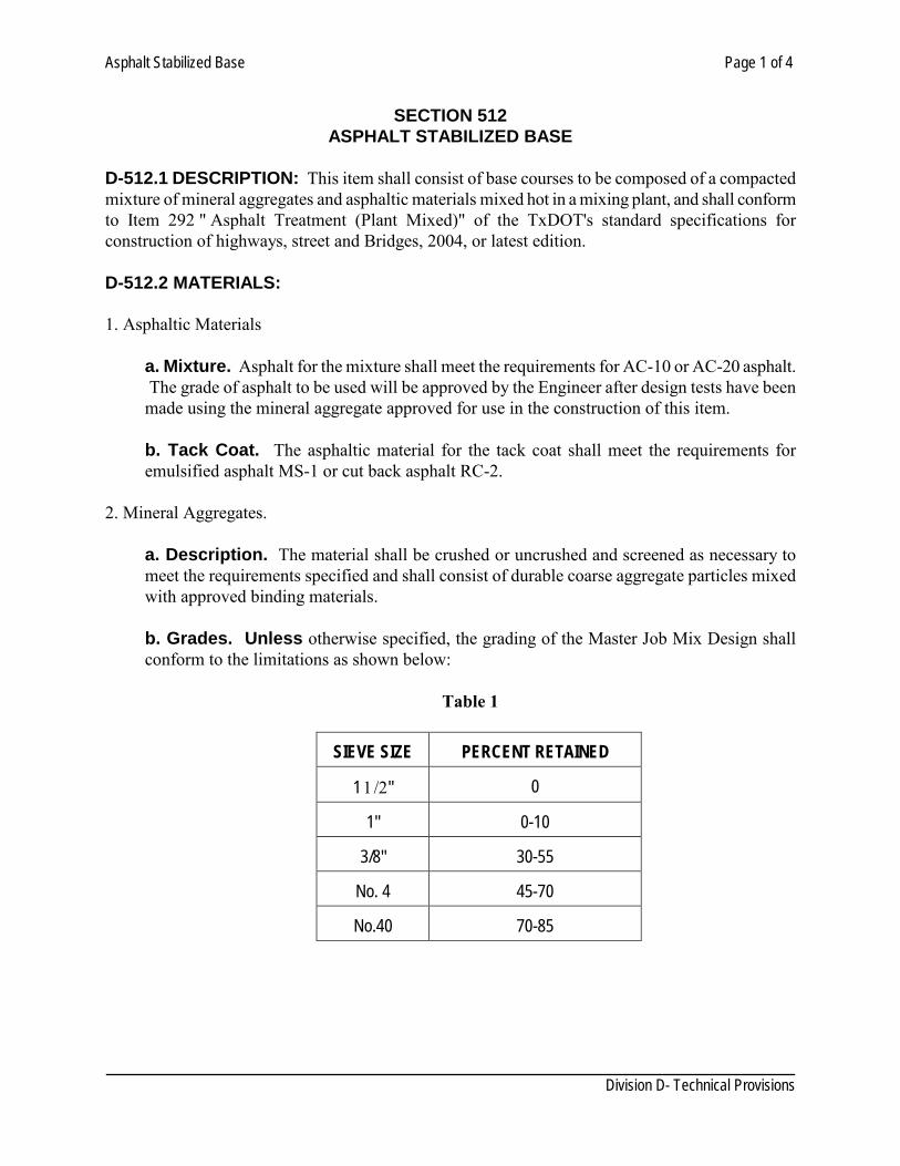
Asphalt Stabilized Base Page 1 of 4
Division D- Technical Provisions
SECTION 512
ASPHALT STABILIZED BASE D-512.1 DESCRIPTION: This item shall consist of base courses to be composed of a compacted mixture of mineral aggregates and asphaltic materials mixed hot in a mixing plant, and shall conform to Item 292 " Asphalt Treatment (Plant Mixed)" of the TxDOT's standard specifications for construction of highways, street and Bridges, 2004, or latest edition. D-512.2 MATERIALS: 1. Asphaltic Materials
a. Mixture. Asphalt for the mixture shall meet the requirements for AC-10 or AC-20 asphalt. The grade of asphalt to be used will be approved by the Engineer after design tests have been made using the mineral aggregate approved for use in the construction of this item.
b. Tack Coat. The asphaltic material for the tack coat shall meet the requirements for emulsified asphalt MS-1 or cut back asphalt RC-2.
2. Mineral Aggregates.
a. Description. The material shall be crushed or uncrushed and screened as necessary to meet the requirements specified and shall consist of durable coarse aggregate particles mixed with approved binding materials.
b. Grades. Unless otherwise specified, the grading of the Master Job Mix Design shall conform to the limitations as shown below:
Table 1
SIEVE SIZE
PERCENT RETAINED
1 1/2"
0
1"
0-10
3/8"
30-55
No. 4
45-70
No.40
70-85
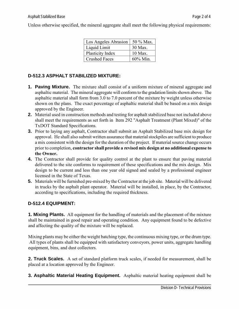
Asphalt Stabilized Base Page 2 of 4
Division D- Technical Provisions
Unless otherwise specified, the mineral aggregate shall meet the following physical requirements:
Los Angeles Abrasion 50 % Max. Liquid Limit 30 Max. Plasticity Index 10 Max. Crushed Faces 60% Min.
D-512.3 ASPHALT STABILIZED MIXTURE: 1. Paving Mixture. The mixture shall consist of a uniform mixture of mineral aggregate and
asphaltic material. The mineral aggregate will conform to the gradation limits shown above. The asphaltic material shall form from 3.0 to 7.0 percent of the mixture by weight unless otherwise shown on the plans. The exact percentage of asphaltic material shall be based on a mix design approved by the Engineer.
2. Material used in construction methods and testing for asphalt stabilized base not included above shall meet the requirements as set forth in Item 292 "Asphalt Treatment (Plant Mixed)" of the TxDOT Standard Specifications.
3. Prior to laying any asphalt, Contractor shall submit an Asphalt Stabilized base mix design for approval. He shall also submit written assurance that material stockpiles are sufficient to produce a mix consistent with the design for the duration of the project. If material source change occurs prior to completion, contractor shall provide a revised mix design at no additional expense to the Owner.
4. The Contractor shall provide for quality control at the plant to ensure that paving material delivered to the site conforms to requirement of these specifications and the mix design. Mix design to be current and less than one year old signed and sealed by a professional engineer licensed in the State of Texas.
5. Materials will be furnished pre-mixed by the Contractor at the job site. Material will be delivered in trucks by the asphalt plant operator. Material will be installed, in place, by the Contractor, according to specifications, including the required thickness.
D-512.4 EQUIPMENT: 1. Mixing Plants. All equipment for the handling of materials and the placement of the mixture shall be maintained in good repair and operating condition. Any equipment found to be defective and affecting the quality of the mixture will be replaced. Mixing plants may be either the weight batching type, the continuous mixing type, or the drum type. All types of plants shall be equipped with satisfactory conveyors, power units, aggregate handling equipment, bins, and dust collectors. 2. Truck Scales. A set of standard platform truck scales, if needed for measurement, shall be placed at a location approved by the Engineer. 3. Asphaltic Material Heating Equipment. Asphaltic material heating equipment shall be
Asphalt Stabilized Base Page 3 of 4
Division D- Technical Provisions
adequate to heat the asphaltic material to the required temperature in the quantities needed. 4. Surge Storage System. A surge storage system may be used providing the mixture from the surge storage unit is of equal quality to that coming from the mixer. 5. Spreading and Finishing Machine. The spreading and finishing machine shall be of a type approved by the Engineer, shall be capable of producing a surface that will meet the requirements of the typical cross-section, and shall have adequate power to propel the delivery vehicles in a satisfactory manner. 6. Motor Grader. The motor grader, if used, shall be a self- propelled motor grader and shall be in good operating condition. 7. Rollers. Rollers shall be power driven and of any type capable of obtaining the required compaction. D-512.5 STORAGE, PROPORTIONING, AND MIXING: 1. Storage and Heating of Asphaltic Materials. The asphaltic material shall be ample to meet the requirements of the plant. A sphalt shall not be heated to a temperature in excess of that recommended by the producer. All equipment used in the handling and storage of asphaltic material shall be kept in a clean condition and be operated in such a manner that there will be no contamination with foreign matter. 2. Feeding and Drying of Aggregate. The feeding of various sizes of aggregate to the dryer shall be done in such a manner that a uniform and constant flow of materials in the required proportions will be maintained. In no case shall the aggregate be introduced into the mixing unit at a temperature of more than 400 F. 3. Proportioning. The proportioning of the various materials entering the asphaltic mixer shall be in accordance with these specifications. 4. Mixing. a. Batch Type Mixer. In the charging of the weigh box and in the charging of the mixer from the weigh box, such methods or devices shall be used as are necessary to assure a uniform asphaltic mixture. In introducing the batch to the mixer, all mineral aggregate shall be introduced first, the asphaltic material added, and the materials thoroughly mixed for at least 30 seconds. The mixing time may be increased, if, in the opinion of the Engineer, the mixture is not uniform. b. Continuous Type Mixer. The amount of aggregate and asphaltic material entering the mixer and the rate of travel through the mixer shall be coordinated so that a uniform mixture of the specified grading and asphaltic content will be produced.
Asphalt Stabilized Base Page 4 of 4
Division D- Technical Provisions
c. Dryer-Drum Mixer. The amount of aggregate and asphaltic material entering the mixer and the rate of travel through the mixer shall be coordinated so that a uniform mixture of the specified grading and asphaltic content will be produced. d. Tolerances. When tested as determined by the Engineer, the asphalt content in the samples of the mixture shall not vary by more than 0.5 percentage points from the Job Mix Design. The gradation of the aggregates must be within the master grading limits except that a tolerance of 2 percentage points is allowed on the sieve size that shows 0% retained in table 1. D-512.6 CONSTRUCTION METHODS: 1. Prime Coat. Before the asphalt stabilized base material is laid, the surface upon which the material will be placed shall be thoroughly cleaned and given a uniform prime coat using MC-30 cutback asphalt. The prime coat should be just sufficient to lightly coat the soil and should not exceed 0.1 gallons per square yard. 2. Transporting Asphalt Stabilized Base. The asphaltic mixture shall be hauled to the project site in vehicles which have been cleaned of all foreign material. 3. Placing. The asphalt stabilized base material shall be dumped and spread on the prepared surface with the specified spreading and finishing machine in such a manner that when properly compacted, the finished surface will be smooth, of uniform density, and will meet the requirements of the typical cross-sections. The limits of placement for A.S.B. will extend 1 foot beyond the back of curb (whenever curb is specified) in order to provide proper support for concrete curb. 4. Compacting. It is the intent of these specifications to require in-place density and that the materials be placed and compacted from 95 to 98 percent of the “Theoretical Specific Gravity” of the job sample with 96% being the optimum. 6. Surface Tests. The surface of the pavement, after compaction, shall be smooth and true to the
established line, grade, and cross-section. In- place density testing of the compacted base and mix extraction and gradation tests shall be required by the Engineer.
7. The assigned Laboratory shall test a job site sample to compare with the approved Hot-Mix
design. Reports of Core test, made by the assigned laboratory, to assure the required compacted lift thickness shall be provided prior to acceptance.
D-512.7 MEASUREMENT: Work and materials prescribed by the item shall be measured by the square yard of surface area, complete in place. PAYMENT: The work performed and materials furnished with this item, will be paid for at the unit price bid per compacted squared yard for the various thickness, grade and binder type specified. This price is full compensation for furnishing and disposing of materials, loading, hauling, placing, compacting, replacing defective work, equipment, labor, tools, and incidentals.
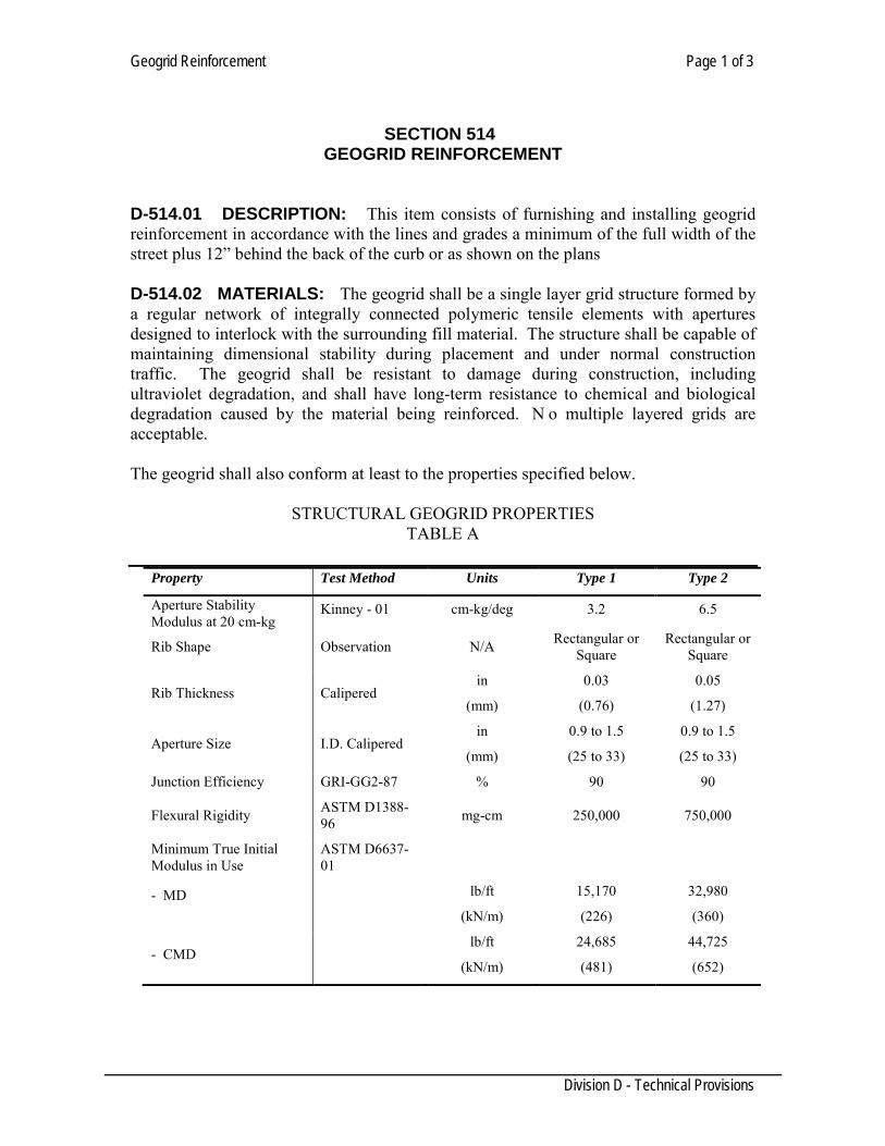
Geogrid Reinforcement Page 1 of 3
Division D - Technical Provisions
SECTION 514
GEOGRID REINFORCEMENT
D-514.01 DESCRIPTION: This item consists of furnishing and installing geogrid reinforcement in accordance with the lines and grades a minimum of the full width of the street plus 12” behind the back of the curb or as shown on the plans D-514.02 MATERIALS: The geogrid shall be a single layer grid structure formed by a regular network of integrally connected polymeric tensile elements with apertures designed to interlock with the surrounding fill material. The structure shall be capable of maintaining dimensional stability during placement and under normal construction traffic. The geogrid shall be resistant to damage during construction, including ultraviolet degradation, and shall have long-term resistance to chemical and biological degradation caused by the material being reinforced. N o multiple layered grids are acceptable. The geogrid shall also conform at least to the properties specified below.
STRUCTURAL GEOGRID PROPERTIES
TABLE A
Property Test Method Units Type 1 Type 2
Aperture Stability Modulus at 20 cm-kg
Kinney - 01 cm-kg/deg 3.2 6.5
Rib Shape Observation N/A Rectangular or Square
Rectangular or Square
Rib Thickness Calipered in
(mm)
0.03
(0.76)
0.05
(1.27)
Aperture Size I.D. Calipered in
(mm)
0.9 to 1.5
(25 to 33)
0.9 to 1.5
(25 to 33)
Junction Efficiency GRI-GG2-87 % 90 90
Flexural Rigidity ASTM D1388-96 mg-cm 250,000 750,000
Minimum True Initial Modulus in Use
ASTM D6637-01
- MD
lb/ft
(kN/m)
15,170
(226)
32,980
(360)
- CMD lb/ft
(kN/m)
24,685
(481)
44,725
(652)
Geogrid Reinforcement Page 2 of 3
Division D - Technical Provisions
Approved products are TENSAR TriAx TX5-475 and TENSAR TriAx TX7-450 or approved equal. Alternate geogrid material will be considered. Such materials must be pre-approved in writing by the Engineer prior to bid date. Alternate material packages must be submitted to the Engineer a minimum of 15 days prior to bid date. Submittal packages must include, as a minimum, the following:
1. Full-scale laboratory testing and in-ground testing of pavement structures reinforced with the specific geogrid which quantifies the structural contribution of the geogrid to the pavement structure. T he increase in structural layer coefficient of the base course must meet of exceed that of the design geogrid.
2. Independent certified tests results stating that the alternate geogrid has a
secant aperture stability modulus at 20 cm-kg, when tested in accordance with the “Grid Aperture Stability by In-Plane-Rotation” test of 3.2 or greater.
3. A list of 5 comparable projects, it terms of size and applications, in the United
States, where the results of the specific alternate geogrids use can be verified after a minimum of 1 year of service.
4. A sample of the geogrid and certified specification sheets.
D-514.03 CONSTRUCTION METHODS: Subgrade shall be prepared as indicated on the plans or as directed by the Engineer. The geogrid shall be installed in accordance with the lines and grades shown on the plans. The geogrid shall be oriented such that the roll lengths run parallel to the road. Geogrid sections shall be overlapped a minimum of three foot for CBR (California Bearing Ratio) less or equal to 1.0 and one foot for CBR greater or equal to 4.0 as per manufacturer, unless otherwise indicated on the plans or as directed by the Engineer. C are shall be taken to ensure the geogrid sections do not separate during construction; adjacent rolls shall be tied together every 30 feet using suitable plastic ties. P lacement of geogrid around corners may require cutting and diagonal lapping. The geogrid shall be pinned, or held in place by other suitable means, at the beginning of the backfill section but will be left free elsewhere to relieve wrinkles or folds in material during fill placement. Fill material shall be place in lift thicknesses and compacted as shown on t he plans. Tracked construction equipment shall operate on the grid only with a minimum fill cover of four inches. R ubber-tired equipment may operate directly on the grid at speed less than five miles per hour if the underlying material is capable of supporting loads. Sections of geogrid which are damaged by construction activity shall be repaired or replaced at the Contractor’s expense.
Geogrid Reinforcement Page 3 of 3
Division D - Technical Provisions
If an existing street constructed with geogrid needs to be cut and excavated, contractor shall make the repairs replacing the geogrid on the bottom of the trench and bottom of flexible base or as was originally installed overlapping with the existing geogrid at least three foot around the trench (Detail 514-1). D-514.04 MEASUREMENT: This item will be measured by the square yard of surface area as shown on the plans. No measurement will be made for lapping material. D-514.05 PAYMENT: The work performed and materials furnished, as prescribed by this item, measured as provided under “MEASUREMENT”, will be paid for the unit price bid for “Geogrid Reinforcement”, which price shall be full compensation for furnishing all labor, material, freight, tools, equipment and incidentals, and for doing all the work involved in placement of the geogrid, complete in place.
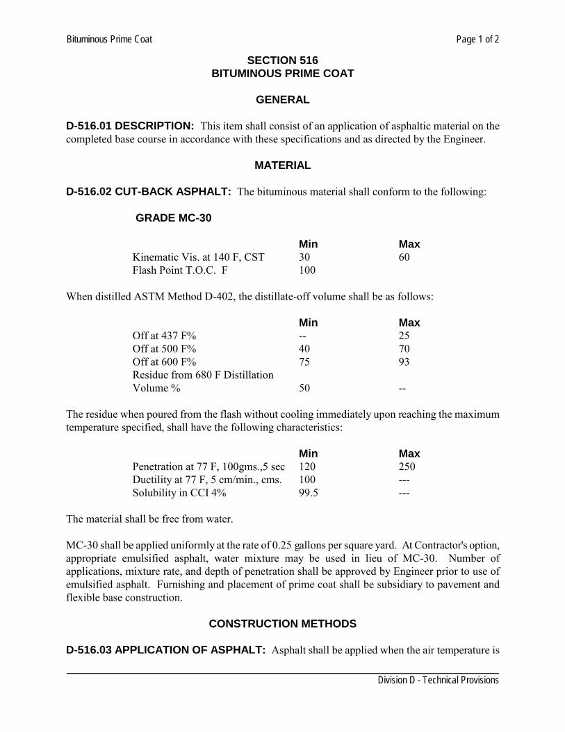
Bituminous Prime Coat Page 1 of 2
Division D - Technical Provisions
SECTION 516 BITUMINOUS PRIME COAT
GENERAL
D-516.01 DESCRIPTION: This item shall consist of an application of asphaltic material on the completed base course in accordance with these specifications and as directed by the Engineer.
MATERIAL D-516.02 CUT-BACK ASPHALT: The bituminous material shall conform to the following:
GRADE MC-30 Min Max Kinematic Vis. at 140 F, CST 30 60 Flash Point T.O.C. F 100 When distilled ASTM Method D-402, the distillate-off volume shall be as follows: Min Max Off at 437 F% -- 25 Off at 500 F% 40 70 Off at 600 F% 75 93 Residue from 680 F Distillation Volume % 50 -- The residue when poured from the flash without cooling immediately upon reaching the maximum temperature specified, shall have the following characteristics: Min Max Penetration at 77 F, 100gms.,5 sec 120 250 Ductility at 77 F, 5 cm/min., cms. 100 --- Solubility in CCI 4% 99.5 --- The material shall be free from water. MC-30 shall be applied uniformly at the rate of 0.25 gallons per square yard. At Contractor's option, appropriate emulsified asphalt, water mixture may be used in lieu of MC-30. Number of applications, mixture rate, and depth of penetration shall be approved by Engineer prior to use of emulsified asphalt. Furnishing and placement of prime coat shall be subsidiary to pavement and flexible base construction.
CONSTRUCTION METHODS D-516.03 APPLICATION OF ASPHALT: Asphalt shall be applied when the air temperature is
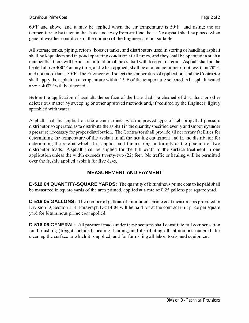
Bituminous Prime Coat Page 2 of 2
Division D - Technical Provisions
60°F and above, and it may be applied when the air temperature is 50°F and rising; the air temperature to be taken in the shade and away from artificial heat. No asphalt shall be placed when general weather conditions in the opinion of the Engineer are not suitable. All storage tanks, piping, retorts, booster tanks, and distributors used in storing or handling asphalt shall be kept clean and in good operating condition at all times, and they shall be operated in such a manner that there will be no contamination of the asphalt with foreign material. Asphalt shall not be heated above 400°F at any time, and when applied, shall be at a temperature of not less than 70°F, and not more than 150°F. The Engineer will select the temperature of application, and the Contractor shall apply the asphalt at a temperature within 15°F of the temperature selected. All asphalt heated above 400°F will be rejected. Before the application of asphalt, the surface of the base shall be cleaned of dirt, dust, or other deleterious matter by sweeping or other approved methods and, if required by the Engineer, lightly sprinkled with water. Asphalt shall be applied on t he clean surface by an approved type of self-propelled pressure distributor so operated as to distribute the asphalt in the quantity specified evenly and smoothly under a pressure necessary for proper distribution. The Contractor shall provide all necessary facilities for determining the temperature of the asphalt in all the heating equipment and in the distributor for determining the rate at which it is applied and for insuring uniformity at the junction of two distributor loads. A sphalt shall be applied for the full width of the surface treatment in one application unless the width exceeds twenty-two (22) feet. No traffic or hauling will be permitted over the freshly applied asphalt for five days.
MEASUREMENT AND PAYMENT D-516.04 QUANTITY-SQUARE YARDS: The quantity of bituminous prime coat to be paid shall be measured in square yards of the area primed, applied at a rate of 0.25 gallons per square yard. D-516.05 GALLONS: The number of gallons of bituminous prime coat measured as provided in Division D, Section 514, Paragraph D-514.04 will be paid for at the contract unit price per square yard for bituminous prime coat applied. D-516.06 GENERAL: All payment made under these sections shall constitute full compensation for furnishing (freight included) heating, hauling, and distributing all bituminous material; for cleaning the surface to which it is applied; and for furnishing all labor, tools, and equipment.
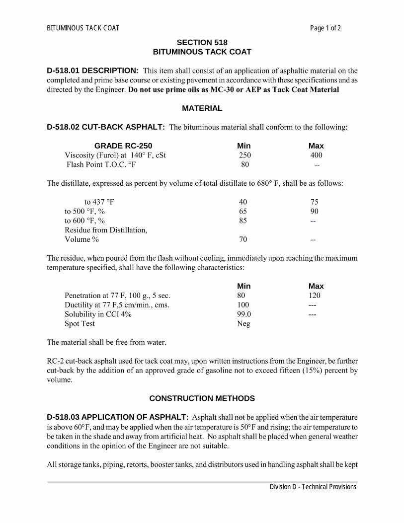
BITUMINOUS TACK COAT Page 1 of 2
Division D - Technical Provisions
SECTION 518 BITUMINOUS TACK COAT
D-518.01 DESCRIPTION: This item shall consist of an application of asphaltic material on the completed and prime base course or existing pavement in accordance with these specifications and as directed by the Engineer. Do not use prime oils as MC-30 or AEP as Tack Coat Material
MATERIAL D-518.02 CUT-BACK ASPHALT: The bituminous material shall conform to the following:
GRADE RC-250 Min Max
Viscosity (Furol) at 140° F, cSt 250 400 Flash Point T.O.C. °F 80 --
The distillate, expressed as percent by volume of total distillate to 680° F, shall be as follows: to 437 °F 40 75 to 500 °F, % 65 90 to 600 °F, % 85 -- Residue from Distillation, Volume % 70 -- The residue, when poured from the flash without cooling, immediately upon reaching the maximum temperature specified, shall have the following characteristics: Min Max Penetration at 77 F, 100 g., 5 sec. 80 120 Ductility at 77 F,5 cm/min., cms. 100 --- Solubility in CCI 4% 99.0 --- Spot Test Neg The material shall be free from water. RC-2 cut-back asphalt used for tack coat may, upon written instructions from the Engineer, be further cut-back by the addition of an approved grade of gasoline not to exceed fifteen (15%) percent by volume.
CONSTRUCTION METHODS D-518.03 APPLICATION OF ASPHALT: Asphalt shall not be applied when the air temperature is above 60°F, and may be applied when the air temperature is 50°F and rising; the air temperature to be taken in the shade and away from artificial heat. No asphalt shall be placed when general weather conditions in the opinion of the Engineer are not suitable. All storage tanks, piping, retorts, booster tanks, and distributors used in handling asphalt shall be kept
BITUMINOUS TACK COAT Page 2 of 2
Division D - Technical Provisions
clean and in good operating condition at all times, and they shall be operated in such a manner that there will be no contamination of the asphalt with foreign material. Asphalt shall not be heated above 400°F and at the time of application, it shall be at a temperature not less than 100°F, and not more than 175°F. The Engineer will select the temperature of application and the Contractor shall apply the asphalt at a temperature within 15 degrees of the temperature selected. All asphalt heated above 400°F will be rejected. Before application of asphalt, the surface to receive the coat shall be cleaned of dirt, or other deleterious matter by sweeping or other approved methods. Asphalt shall be applied on the clean surface by an approved type of self-propelled pressure distributor so operated as to distribute the asphalt in the quantity specified evenly and smoothly under the pressure necessary for proper distribution. The Contractor shall provide all necessary facilities for determining the temperature of the asphalt in all the heating equipment and in the distributor for determining the rate at which it is applied, and for insuring uniformity at the junction of two distributor loads. Asphalt shall be applied for the full width of the surface treatment in one application unless the width exceeds twenty-two (22) feet. No traffic or hauling will be permitted on the freshly applied asphalt.
MEASUREMENT
D-518.04 QUANTITY-SQUARE YARDS: The quantity of bituminous tack coat to be paid for shall be measured in square yards of the area tacked, applied at a rate of 0.10 gallons per square yard.
PAYMENT
D-518.05 GALLONS: The number of gallons of bituminous tack coat measured as provided in Division D, Section 516, Paragraph D-516.04 will be paid for at the contract unit price per square yard for bituminous prime coat, applied. D-518.06 GENERAL: All payment made under these sections shall constitute full compensation for furnishing (freight included), heating, hauling, and distributing all bituminous material; for cleaning the surface to which it is to be applied; and for furnishing all labor, tools, and equipment.
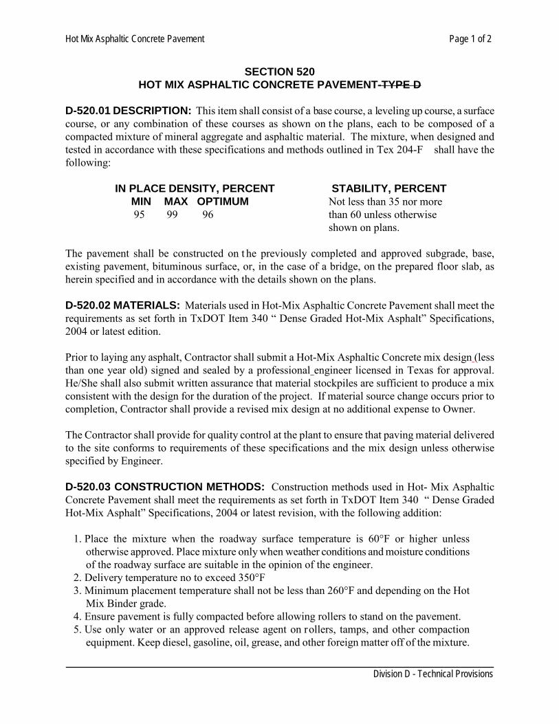
Hot Mix Asphaltic Concrete Pavement Page 1 of 2
Division D - Technical Provisions
SECTION 520
HOT MIX ASPHALTIC CONCRETE PAVEMENT-TYPE D D-520.01 DESCRIPTION: This item shall consist of a base course, a leveling up course, a surface course, or any combination of these courses as shown on the plans, each to be composed of a compacted mixture of mineral aggregate and asphaltic material. The mixture, when designed and tested in accordance with these specifications and methods outlined in Tex 204-F shall have the following: IN PLACE DENSITY, PERCENT STABILITY, PERCENT
MIN MAX OPTIMUM Not less than 35 nor more 95 99 96 than 60 unless otherwise
shown on plans. The pavement shall be constructed on t he previously completed and approved subgrade, base, existing pavement, bituminous surface, or, in the case of a bridge, on the prepared floor slab, as herein specified and in accordance with the details shown on the plans. D-520.02 MATERIALS: Materials used in Hot-Mix Asphaltic Concrete Pavement shall meet the requirements as set forth in TxDOT Item 340 “ Dense Graded Hot-Mix Asphalt” Specifications, 2004 or latest edition. Prior to laying any asphalt, Contractor shall submit a Hot-Mix Asphaltic Concrete mix design (less than one year old) signed and sealed by a professional engineer licensed in Texas for approval. He/She shall also submit written assurance that material stockpiles are sufficient to produce a mix consistent with the design for the duration of the project. If material source change occurs prior to completion, Contractor shall provide a revised mix design at no additional expense to Owner. The Contractor shall provide for quality control at the plant to ensure that paving material delivered to the site conforms to requirements of these specifications and the mix design unless otherwise specified by Engineer. D-520.03 CONSTRUCTION METHODS: Construction methods used in Hot- Mix Asphaltic Concrete Pavement shall meet the requirements as set forth in TxDOT Item 340 “ Dense Graded Hot-Mix Asphalt” Specifications, 2004 or latest revision, with the following addition:
1. Place the mixture when the roadway surface temperature is 60°F or higher unless otherwise approved. Place mixture only when weather conditions and moisture conditions of the roadway surface are suitable in the opinion of the engineer.
2. Delivery temperature no to exceed 350°F 3. Minimum placement temperature shall not be less than 260°F and depending on the Hot
Mix Binder grade. 4. Ensure pavement is fully compacted before allowing rollers to stand on the pavement. 5. Use only water or an approved release agent on rollers, tamps, and other compaction
equipment. Keep diesel, gasoline, oil, grease, and other foreign matter off of the mixture.
Hot Mix Asphaltic Concrete Pavement Page 2 of 2
Division D - Technical Provisions
6. Allow the compacted pavement to cool to 160°F or lower before opening to traffic. D-520.04 EQUIPMENT: Mixing plants that will not continuously produce a mixture meeting all of requirements of TxDOT Item 340.4 Specifications, 2004, shall not be allowed. D-520.05 TESTING: The assigned Laboratory shall test a job site sample to compare with the approved Hot-Mix design and also test for in-place air void determination as per TxDot Item 340. Reports of Core test, made by the assigned laboratory, to assure the required compacted lift thickness shall be provided prior to acceptance. D-520.06 MEASUREMENT: The asphaltic mixture shall be measured by square yards of various types and thickness as actually used in the completed and accepted work in accordance with the plans and specifications for the project. No separate measurement will be made for fluxing oil. D-520.07 PAYMENT: The number of square yards of asphaltic mixture placed will be paid for at the contract unit price per square yard of various types and thickness. The unit price will be full compensation for surface preparation, hot mix material, placement, equipment, labor, tools and incidentals.
Cutting and Replacing Pavement Page 1 of 2 SECTION 522 CUTTING AND REPLACING PAVEMENT D-522.01 DESCRIPTION: This item shall govern for the cutting of pavements, the removal and bases and the replacement of bases and pavements, as herein specified and in conformity with the typical sections shown on the plans and to the lines established by the Engineer. D-522.02 MATERIALS: 1. Prime Coat: All prime coat shall conform to the provisions of Division D, Section 516,
"Bituminous Prime Coat". 2. Tack Coat: All tack coat shall conform to the provisions of Division D, Section
518,"Bituminous Tack Coat: 3. Flexible Base Course: All flexible base shall conform to the provisions of Division D,
Section 510, "Flexible Base Course ". 4. Hot-Mix Asphaltic Concrete Pavement: All hot-mix asphaltic concrete pavement
shall conform to the provision of Division D, Section 520, "Hot Mix Asphaltic Concrete Pavement - Type D".
5. Excavation and Backfilling: All excavation and backfilling shall conform to the
provision of Division D, Section 102, "Excavation and Backfill for Utilities" Backfill under existing pavement.
D-522.03 CONSTRUCTION METHODS: 1. Cutting of Pavements:
a. Concrete and asphaltic concrete pavements: All concrete and asphaltic concrete pavements shall be cut with a concrete saw. The depth of the cut shall be such that upon removal of concrete and/or asphaltic concrete the sides of the cut shall be straight and square. Care shall be taken when cutting concrete pavement, not to cut transverse reinforcing steel.
b. Base Material: Base material shall be removed by normal trenching operations.
2. Replacement of Bases:
a. Base Material: Base replacement shall be of the type shown on the plans and in the bid proposals.
3. Replacement of Pavements: Pavements shall be replaced with hot-mix asphaltic
concrete pavement or reinforced concrete pavement. Replacement will be of the type shown on the plans and in the bid proposals. a. Hot-mix asphalt pavement: Shall be furnished and placed in accordance with
Division D, Section 520, "Hot-Mix Asphaltic Concrete Pavement. Flexible base shall be
Cutting and Replacing Pavement Page 2 of 2
primed in accordance with the provisions of Division D, Section 516, "Bituminous Prime Coat", prior to the placement of hot-mix asphaltic concrete.
b. All concrete bases shall be tack coated with RC- 250 in accordance with the provisions of Division D, Section 518, "Bituminous Tack Coat", prior to the placement of hot-mix asphaltic concrete.
c. Replacement of pavement, shall be with straight lines parallel and perpendicular to the flow of traffic. Do not replace pavement areas with angled sides or irregular shapes. All
replacements shall be full lane width see details 534-1 to 534-5 for special conditions.
D-522.04 MEASUREMENT: This item will be measured by the square yard of finished pavement surface area repaired. No measurement will be made for areas outside the limits shown in the plans or other damaged because of Contractor negligence without written authorization by the engineer. D-52205 PAYMENT: The work performed and the materials furnished in accordance with this specification shall be paid for the unit price bid per square yard of the various pavement types and depths when specified. The price shall be considered full compensation for saw cutting, removal, stockpiling, and/or disposal of existing pavement, base, and waste material and for all equipment, materials, labor, tools, and incidentals to reconstruct the pavement base, prime, tack and surface course shown in the plans. Curb replacement, where incidentally repaired will not be paid for directly but will be considered subsidiary to this item.
Lime & Lime Slurry Page 1 of 2
Division D - Technical Provisions
SECTION 524 LIME & LIME SLURRY
D-524.01. DESCRIPTION This item establishes the requirments for hydrated lime, and commercial lime slurry. CAUTION: Use of quicklime can be dangerous. Users should become informed of the
recommended precautions in handling, storage and use of quicklime. D-524.02. TYPES The various types and grades are defined and identified as follows: Type A, Hydrated Lime - A dry powered material consisting of essentially of calcium hydroxide. Type B, Commercial Lime Slurry: A liquid mixture of essentially hydrated lime and water in slurry form. Type C, Quicklime: A dry material consisting essentially of calcium oxide. It shall be furnished inn either of two grades which differ in sizing.
Grade DS - “pebble” quicklime of a gradation suitable for wither “Dry Placing” or for use in the preparation of a slurry for “Wet Placing”. Grade S - finely-graded quicklime for use in the preparation of a slurry for wet placing. (Note: Due to the possibility of appreciable amount of finely divided, powdered quicklime being present in this product, the use of Type C, Grade S Quicklime is restricted to “Slurry Placing” only. It is considered to be unsuitable for “Dry Placing”). D-524.03. GENERAL Lime shall be applied as provided for in the governing specifications, as a dry material or as a mixture of lime solids and water n the form of lime slurry. For dry application, Type A, Hydrated Lime or Type C, Quicklime of Grade DS only may be used where specifications permit. For wet application, lime slurry may be delivered to the job site as Type B, Commercial Lime Slurry or a lime slurry may be prepared at the job site or other location approved by the Engineer, by using Type A Hydrated Lime or Type C Quicklime as specified. The lime and lime slurry being furnished under the terms of this specification shall, in addition to other requirements, also meet the following chemical and physical requirements.
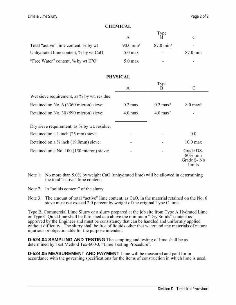
Lime & Lime Slurry Page 2 of 2
Division D - Technical Provisions
CHEMICAL
Type
A B C Total “active” lime content, % by wt
90.0 min¹
87.0 min²
-
Unhydrated lime content, % by wt CaO:
5.0 max
-
87.0 min “Free Water” content, % by wt H²O:
5.0 max
-
-
PHYSICAL
Type
A B C Wet sieve requirement, as % by wt. residue:
Retained on No. 6 (3360 micron) sieve:
0.2 max
0.2 max²
8.0 max³
Retained on No. 30 (590 micron) sieve:
4.0 max
4.0 max²
-
Dry sieve requirement, as % by wt. residue:
Retained on a 1-inch (25 mm) sieve:
-
-
0.0
Retained on a ¾ inch (19.0mm) sieve:
-
-
10.0 max
Retained on a No. 100 (150 micron) sieve:
-
-
Grade DS-80% min
Grade S- No limits
Note 1: No more than 5.0% by weight CaO (unhydrated lime) will be allowed in determining
the total “active” lime content. Note 2: In “solids content” of the slurry. Note 3: The amount of total “active” lime content, as CaO, in the material retained on the No. 6
sieve must not exceed 2.0 percent by weight of the original Type C lime. Type B, Commercial Lime Slurry or a slurry prepared at the job site from Type A Hydrated Lime or Type C Quicklime shall be furnished at a above the minimum “Dry Solids” content as approved by the Engineer and must be consistency that can be handled and uniformly applied without difficulty. The slurry shall be free of liquids other that water and any materials of nature injurious or objectionable for the purpose intended. D-524.04 SAMPLING AND TESTING The sampling and testing of lime shall be as determined by Test Method Tex-600-J, “Lime Testing Procedure”. D-524.05 MEASUREMENT AND PAYMENT Lime will be measured and paid for in accordance with the governing specifications for the items of construction in which lime is used.
Lime Treatment for Materials Used as Subgrarde (Road Mixed) Page 1 of 7
Division D - Technical Provisions
SECTION 526 LIME TREATMENT FOR MATERIALS USED AS SUBGRADE
(ROAD MIXED)
D-526.01. DESCRIPTION This section shall govern for treating the new or existing subgrade, the existing pavement structure or a combination thereof to be used as subgrade by pulverizing, adding lime, mixing, and compacting the mixed material as specified in this section. D-526.02 MATERIALS (1) Lime. The lime shall meet the requirements of Section 522 “Lime and Lime Slurry”, for the type of lime specified. The Contractor shall have the option of selecting from the types shown on the plans, the type of lime to be used. The Engineer shall be notified in writing before changing the source or type. All lime slurries used in “Slurry Placing” shall be furnished at or above the minimum “Dry Solids” content as approved by the Engineer. (2) Water. Water shall meet the material requirements of Item 204 “Sprinkling”. (3) Asphalt. Asphalt shall conform to the requirements of Item 300 “ Asphalts, Oils and Emulsions”. D-526.03 EQUIPMENT (1) General. The machinery, tools and equipment necessary for proper prosecution of the work on this section shall be on the project and approved by the Engineer prior to beginning this item. All machinery, tools and equipment used shall be maintained in a satisfactory working condition. (2) Lime Storage. Both quicklime and hydrated lime in dry form shall be suitably stored in closed, weatherproof containers until immediately before use. Storage bins, when used, shall be completely enclosed. Hydrated lime in bags shall be store in weatherproof buildings with adequate protection from ground dampness. Type C Quicklime, when permitted by the Engineer, shall be shipped only in bulk; bagged material will not be acceptable. (3) Lime Weight Verification. When lime is furnished in trucks, the weight of lime shall be determined on certified scales or the contractor shall provide a set of standard platform truck scales at a location approved by the Engineer. Scales shall conform to the requirements of Item 520, “Weighing and Measuring Equipment”. When Type A Hydrated Lime is furnished in bags, each bag shall bear the manufacturer’s certified weight. Bags varying more than five (5) percent from that weight may be rejected and the average weight of bags in any shipment, as shown by weighing 10 bags taken at random, shall not be less than the manufacturer’s certified weight. (4) Slurry Equipment. Type C Quicklime of Grade “DS” or “S”, when used to manufacture slurry on the project, or other location approved by the Engineer shall be slurried in agitated slurry tanks.
Lime Treatment for Materials Used as Subgrarde (Road Mixed) Page 2 of 7
Division D - Technical Provisions
The slurrying of Type C Quicklime must be handled in such a way as not to generate any dust hazardous to job personnel or to the public or be potentially damaging to any adjacent property. The distributor truck used for slurry placing need not necessarily be equipped with an agitator; however, the slurry at the time of distribution must meet the consistency requirements specified. The Contractor shall, if necessary, use appropriate equipment to achieve the consistency requirements under Section 44.4.(4)(b). For Type B Commercial Lime Slurry, the distributor truck shall be equipped with a sampling device in accordance with Test Method Tex-600-J, Part I. D- 526.04 CONSTRUCTION METHODS (1) General. The completed course shall be uniformly treated, free from loose or segregated areas, of uniform density and moisture content, well bound for its full depth and shall have a smooth surface. (2) Preparation of Subgrade or Existing Base. Prior to treating existing material, it shall be sharped to conform to the typical sections, as shown on the plans or as established by the Engineer. This work shall be done in accordance with the provisions of applicable bid items. When shown on the plans, any existing asphaltic concrete pavement shall be removed and will be paid for in accordance with applicable bid items. Before pulverizing or scarifying an existing material, when shown on the plans and when directed by the Engineer, the Contractor shall proof roll the roadbed in accordance with Item 216, “Rolling (Proof)”. Soft spots shall be corrected as directed by the Engineer. When the Contractor elects to use a cutting and pulverizing machine that will process the material to the plan depth, the Contractor will not be required to excavate to the secondary grade or windrow the material. This method will be permitted only if a machine is provided which will insure that the material is cut uniformly to the proper depth and which has cutter that will plane the secondary grade to a uniform surface over the entire width of the cut. The machine shall provide a visible indication of the depth of cut at all times. In lieu of using the cutting and pulverizing machine, the Contractor shall excavate and windrow the material to expose the secondary grade to the typical sections, lines and grades as shown on the plans or as established by the Engineer. (3) Pulverization. The existing pavements or base material shall be pulverized or scarified so that 100 percent shall pass the two (2) inch sieve. (4) Application. The percentage by weight or pounds per square yard of lime to be added will be as shown on the plans and may be varied by the Engineer if conditions warrant. Lime shall be spread only on that area where the mixing operations can be completed during the same working day, except as required for quicklime in subarticle 44.4.(5).
Lime Treatment for Materials Used as Subgrarde (Road Mixed) Page 3 of 7
Division D - Technical Provisions
Unless otherwise approved by the Engineer, the lime operation shall not be stated when the air temperature is above 35 F and rising. The temperature will be taken in the shade and away from artificial heat. Lime shall not be placed when weather conditions in the opinion of the Engineer are unsuitable.
CAUTION: Use of quicklime can be dangerous. U sers should be informed of the recommended precautions in handling, storage and use of quicklime.
The application and mixing of lime with the material shall be accomplished by the methods herein described as “Dry Placing” or “Slurry Placing”. Type A Hydrated Lime shall be applied by “Slurry Placing” unless otherwise shown on the plans or approved by the Engineer. Type B Commercial Lime Slurry shall be applied by “Slurry Placing”. Type C Quicklime shall be applied by “Slurry Placing” or “Dry Placing” as shown on the plans. The method of applying Type C Quicklime may be changed if approved in writing by the Engineer. W hen Type C Quicklime is used for dry placement, it shall be Grade “DS”. When Type C Quicklime is used for slurry placement, it shall be either Grade “DS” or Grade “S”. Grade “S” shall be used in slurry placement only.
(a) Dry Placing. The lime shall be distributed by a spreader approved by the Engineer or by bag distribution for Type A Hydrated Lime at the rate shown on the plans or as directed by the Engineer.
The lime shall be distributed at a uniform rate and in such a manner as to reduce the scattering of lime by wind. Lime shall not be applied when wind conditions, in the opinion of the Engineer, are such that blowing lime becomes objectionable to adjacent property owners or dangerous to traffic. A motor grader shall not be used to spread Type A Hydrated Lime but may be used to spread Type C Quicklime, Grade “DS”.
The material shall be sprinkled as approved by the Engineer.
(b) Slurry Placing. When Type A Hydrated Lime is specified and slurry placement is to be used, Type A Hydrated Lime shall be mixed with water to form a slurry with a solids content approved by the Engineer.
Type B Commercial Lime Slurry shall be delivered to the project in slurry form at or above minimum dry solids content approved by the Engineer. The distribution of lime at the rate(s) shown on the plans or approved by the Engineer shall be attained by successive passes over a measured section of roadway until proper lime content has been secured.
When Type C Quicklime is applied as a slurry, the amount of dry quicklime shall be 80 percent of the amount shown on the plans. The slurry shall contain at least the minimum dry solids content approved by the Engineer. The residue from the slurrying procedure shall be spread uniformly over the length of the roadway currently being processed unless otherwise approved by the Engineer. This residue is primarily inert material with little stabilizing value, but may contain a small amount of quicklime particles that slake slowly. A concentration of these particles could cause the compacted stabilized material to swell during
Lime Treatment for Materials Used as Subgrarde (Road Mixed) Page 4 of 7
Division D - Technical Provisions
slaking.
Slurry Consistency Requirements: Slurry shall be of such consistency that it can be applied uniformly without difficulty.
When the distributor truck is not equipped with an agitator, the contractor shall have a standby pump available on the project for agitating the lime and water as required by the Engineer in case of undue delays in dispersing the slurry.
(5) Mixing. The mixing procedure shall be the same for “Dry Placing” or “Slurry Placing” as herein described. During the interval between application and mixing, hydrated lime that has been exposed to the open air for a period of six (6) hours or more or to excessive loss due to washing or blowing will not be accepted for payment. The material and lime shall be thoroughly mixed by equipment approved by the Engineer. The material and lime shall be brought to the proper moisture content and may be left to cure one (1) to four (4) days as approved by the Engineer or the mixing continued until a homogeneous friable mixture of material and lime is obtained. In addition to the above, when Type C Quicklime, Grade “DS”, is used under “Dry Placing”, the material and lime shall be mixed as thoroughly as possible at the time of lime application. Sufficient moisture shall be added during the mixing to hydrate the quicklime. A fter mixing, and prior compaction, the mixture of material, quicklime and water shall be moist cured for two (2) to seven (7) days, as approved by the Engineer. After curing, mixing shall continue until the pulverization requirements are met. When shown on the plans or approved by the Engineer, the pulverization requirement may be waived when the material contains a substantial quantity of aggregate. Following mixing, a sample of the material at roadway moisture will be obtained for pulverization testing. All nonslaking aggregates retained on the ¾-inch sieve will be removed from the sample. The remainder of the material shall meet the following pulverization requirement when tested by Test Method Tex-101-E, Part III:
Percent Minimum passing 1¾″ sieve 100 Minimum passing ¾″ sieve 85
(6) Compaction Methods. Prior to compaction, the material shall be aerated or sprinkled as necessary to provide the optimum moisture. Compaction of the mixture shall immediately after the pulverization requirement is met. Compaction shall continue until the entire depth of the mixture is uniformly compacted by “Ordinary Compaction” or “Density Control” as shown on the plans. Throughout this entire operation the shape of the course shall be maintained by blading, and the surface upon completion shall be smooth
Lime Treatment for Materials Used as Subgrarde (Road Mixed) Page 5 of 7
Division D - Technical Provisions
and in conformity with the typical sections, lines and grades as shown on the plans or as established by the Engineer. When shown on the plans or approved by the Engineer, multiple lifts will be permitted.
(a) Ordinary Compaction. W hen “Ordinary Compaction” is shown on t he plans the following provisions shall apply:
The material shall be sprinkled and rolled as directed by the Engineer. All irregularities, depressions or weak spots which develop shall be corrected immediately by scarifying the areas affected, adding or removing material as required, reshaping and recompacting by sprinkling and rolling.
Should the material lose the required stability, compaction or finish before the next course is place or the project is accepted, it shall be reworked in accordance with Subarticle 44.4.(7). However, compaction shall be in accordance with “Ordinary Compaction”.
(b) Density Control. When “Density Control” is shown on the plans the following provisions shall apply:
Unless otherwise shown on t he plans, each course shall be sprinkled as required and compacted to the extent necessary to provide not less that 95 percent of the optimum density as determined by Test Method Tex-121-E, Part II. Roadway density testing will be as outlined in Test Method Tex-115-E.
When the material fails to meet the density requirements, or should the material lose the required stability, density or finish before the next course is place, or the project is accepted, it shall be reworked in accordance with Subarticle 36.4.(7).
(7) Reworking a S ection. When a section is reworked within 72 hour s after completion of compaction, the Contractor shall rework the section to provide the required compaction. When a section is reworked more than 72 hours after completion of compaction, the Contractor shall add 25 percent of the specified rate of lime. Reworking shall include loosening, road mixing as approved by Engineer, compacting, and finishing. When a section is reworked, a new optimum density will be determined from the reworked material in accordance with Test Method Tex-121-E, Part II. (8) Finishing and Curing. After the final layer or course of the lime treated material has been compacted, it shall be brought to the required lines and grades in accordance with the typical sections. The completed section shall then be finished by enrolling with a pneumatic tire or other suitable roller as approved by the Engineer. The completed section shall be moist cured and prevented from drying by addition of an asphalt material at the rate of 0.05 to 0.20 gallons per square yard as determined by the Engineer. This material shall be the type shown on the plans. Curing shall continue for seven (7) days before further courses are added or traffic is permitted, unless otherwise approved by the Engineer.
Lime Treatment for Materials Used as Subgrarde (Road Mixed) Page 6 of 7
Division D - Technical Provisions
However, the lime treated material may be covered by other courses, the day following finishing, when approved by the Engineer. When the plans provide for the treated material to be covered by other courses of material, the next course shall be applied within 14 c alendar days after final compaction is completed, unless otherwise approved by the Engineer. D-526.05. TOLERANCES Tolerances shall conform to the following: (1) Density Tolerances. The Engineer may accept the work providing not more than one (1) out of the most recent five (5) density tests performed is below the specified density, provided the failing test is no more than three (3.0) pounds per cubic foot below the specified density. (2) Grade Tolerances. Finished grade tolerances shall be in accordance with Subarticle 132.3.(2). D-526.06. MEASUREMENT This item will be measured as follows: (1) Lime. (a) Type A. i. Hydrated Lime (Dry). When Type A Hydrated Lime is used under “Dry Placing”, the
quantity of lime will be measured by the ton of 2000 pounds, dry weight. ii. Hydrated Lime (Slurry). When Type A Hydrated Lime is used under “Slurry Placing”, the
quantity of lime will be measured by the ton of 2000 pounds, dry weight of the hydrate lime used to prepare the lime slurry at the job site.
(b) Type B. Commercial Lime Slurry. When Type B Commercial Lime Slurry is used, the quantity of lime will be calculated from the minimum percent “Dry Solids Content” of the slurry previously agreed upon for the project by the Contractor and the Engineer. This figure will be multiplied by the weight of the slurry in tons delivered, which must be at or above the required minimum “Dry Solids Content”. (c) Type C. i. Quicklime (Dry). When Type C Quicklime is used under “Dry Placing”, the quantity of lime
will be measured by the ton of 2000 pounds, dry weight of the quicklime actually delivered on the road.
ii. Quicklime (Slurry). When Type C Quicklime is used under “Slurry Placing”, the quantity
will be measured by the ton of 2000 pounds, dry weight of quicklime used to prepare the hydrated lime slurry. The measured tonnage of Type C Quicklime will be multiplied by a conversion factor of 1.28 to give the quantity of equivalent hydrated lime which will be the basis of payment.
(2) Lime Treatment. Lime treatment will be measured by the square yard of the depth specified to
Lime Treatment for Materials Used as Subgrarde (Road Mixed) Page 7 of 7
Division D - Technical Provisions
the lines and grades shown on the typical sections. D-526.07 PAYMENT The work performed and materials furnished in accordance with this Item and measured as provided under “Measurement” will be paid for as follows: (1) Lime. Lime will be paid for at the unit price bid for “Lime” of one of the following specified types, which price will be full compensation for furnishing all lime.
(a) Type A (Dry) (b) Type A (Slurry) (c) Type B (d) Type C (Dry) (e) Type C (Slurry)
Lime for reworking a section in accordance with subarticle 44.4.(7) will not be paid for directly but will be subsidiary to this Item. (2) Lime Treatment. “Lime Treated Subgrade (Ordinary Compaction)” or “Lime Treated Subgrade (Density Control)” of the depth specified will be paid for at the unit price bid per square yard. This price shall be full compensation for shaping existing material, loosening, mixing, pulverizing, spreading, drying, applying lime, water content of the slurry, compacting, curing including curing materials, shaping and maintaining, processing, hauling, reworking if required, preparing secondary subgrade, and for all mixing water, tools, equipment, labor, and incidentals necessary to complete the work. When proof rolling is shown on t he plans and directed by the Engineer, it will be paid for in accordance with Item 216 “Rolling (Proof)”. When “Ordinary Compaction” is shown on the plans, all sprinkling and rolling, except proof rolling, will not be paid for directly but will be considered subsidiary to this Item, unless otherwise shown on the plans. When “Density Control” is shown on the plans, all sprinkling and rolling, except proof rolling, will not be paid for directly but will be considered subsidiary to this Item. When subgrade is constructed under this project, correction of soft spots will be at the Contractor’s expense. When subgrade is not constructed under this project, correction of soft spot will be in accordance with Article 9.3.
Asphalt Wedge Milling Page 1 of 2
Division D - Technical Provisions
SECTION 528 ASPHALT WEDGE MILLING
D- 528.01 DESCRIPTION: The item shall consist of milling the existing pavement from the lip of gutter to the depth of 1” and transition it to match the existing pavement at a width of 3’ to 5’ as instructed by the Engineer or as shown in the plans. The existing pavement to be milled will either be asphalt, concrete or brick pavement. The removal and disposal of the milled materials shall be as directed by the Engineer. The milled surface shall provide a smooth surface free from gouges, ridges, oil film, and other imperfections of workmanship, and shall have uniform textured appearance. In all situations where the existing HMAC surface contacts the curb face the wedge milling shall include the removal of the existing asphalt covering the gutter up to and along the face of curb. The wedge milling operations shall be performed in a continuous manner along both sides of the street. Contractor is required to begin the overlay, within five (5) working days from the date of the wedge milling completion of any one street, on that street. Should the contractor fail to meet this condition, the wedge milling will be shut down and each day that exceed five (5) days that the overlay has not started will be considered a separate working day and charged as such irrespective of any other work that the contractor is performing on the project. The overlay, once begun, on a street, shall continue uninterrupted until complete. Penalties will cease when these operations are no more than five (5) working days apart, the engineer will enforce these conditions. D- 528.02 PRODUCTS: Equipment: The equipment for removing the pavement surface shall be a power operated milling machine or other equal or better mechanical means capable of removing in either one pass or two passes, the necessary pavement thickness in a five-foot minimum width. The equipment shall be self-propelled with sufficient power, traction and stability to maintain accurate depth of cut and slope. The machine shall be equipped with an integral lading and reclaiming means to immediately remove material being cut from the surface of the roadway and discharge the cuttings into a truck, all in one operation. Adequate back up equipment (mechanical street sweepers, loaders, water truck, etc.) and personnel will also be provided to keep flying dust to a minimum and to insure that all cuttings are removed from street surface daily. The machine shall be equipped with means to control dust created by the cutting action and shall have a manual system providing for uniformly varying the depth of cut while the machine is in motion thereby making it possible to cut flush to all inlets, manholes, or other obstruction within the paved area. The speed of the machine shall be variable in order to leave the desired grid pattern specified under Surface Texture. D- 528.03 CONSTRUCTION: The existing pavement to be milled will either be asphalt, or concrete pavement. The removal and disposal of the milled materials shall be as directed by the Engineer. The milled surface shall provide a smooth surface free from gouges, ridges, oil film, and other imperfections of workmanship, and shall have uniform textured appearance. In all situations where the existing HMAC surface contacts the curb face the wedge milling shall include the removal of the existing asphalt covering the gutter up to and along the face of curb. The wedge milling operations for this project will be performed in a continuous manner along both sides of the street. Stockpiling of salvaged material will not be permitted on the project site unless designated by the Engineer. Contractor is required to begin the overlay, within five (5) working days from the date of
Asphalt Wedge Milling Page 2 of 2
Division D - Technical Provisions
the wedge milling completion of any one street, on that street. Should the contractor fail to meet this condition, the wedge milling will be shut down and each day that exceed five (5) days that the overlay has not started will be considered a separate working day and charged as such irrespective of any other work that the contractor is performing on the project. The overlay, once begun, on a street, shall continue uninterrupted until complete. Penalties will cease when these operations are no more than five (5) working days apart, the engineer will enforce these conditions. D- 528.04 MEASUREMENT: This item will be measured by the square yard. D- 528.05 PAVEMENT: This item will be paid by the unit price bid per square yard of the various depths shown. The price will be full payment for furnishing all milling equipment, materials, labor and disposal of all surplus materials to the site indicated by the engineer.
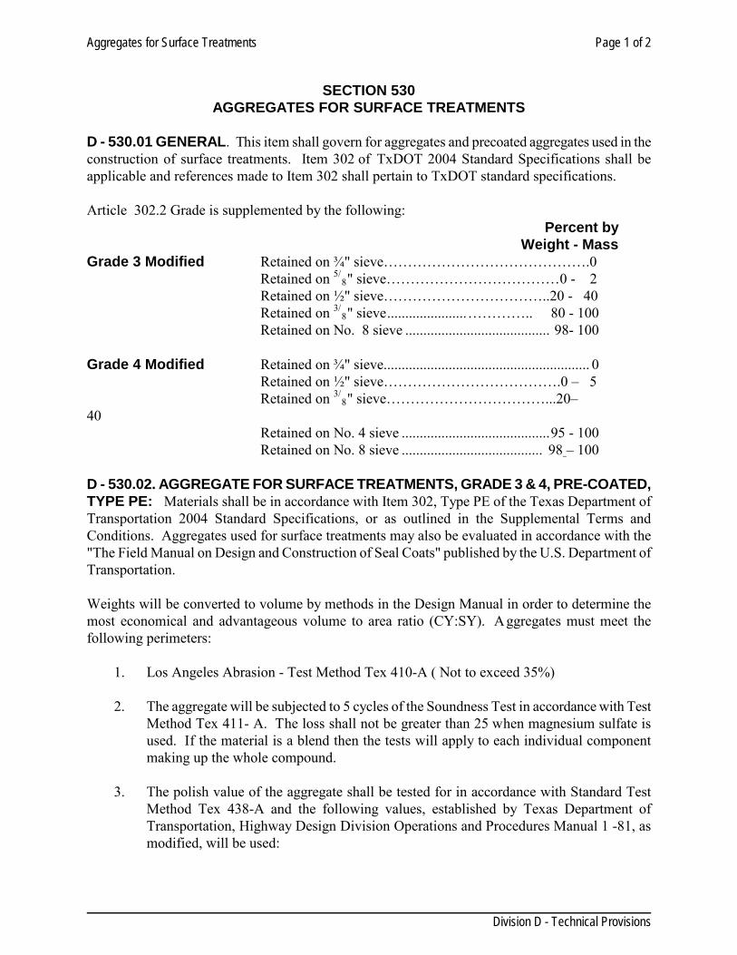
Aggregates for Surface Treatments Page 1 of 2
Division D - Technical Provisions
SECTION 530
AGGREGATES FOR SURFACE TREATMENTS D - 530.01 GENERAL. This item shall govern for aggregates and precoated aggregates used in the construction of surface treatments. Item 302 of TxDOT 2004 Standard Specifications shall be applicable and references made to Item 302 shall pertain to TxDOT standard specifications. Article 302.2 Grade is supplemented by the following:
Percent by Weight - Mass
Grade 3 Modified Retained on ¾" sieve…………………………………….0 Retained on 5/
8" sieve………………………………0 - 2 Retained on ½" sieve……………………………..20 - 40 Retained on 3/
8" sieve ...................... ………….. 80 - 100 Retained on No. 8 sieve ........................................ 98- 100
Grade 4 Modified Retained on ¾" sieve......................................................... 0
Retained on ½" sieve……………………………….0 – 5 Retained on 3/
8" sieve……………………………...20– 40
Retained on No. 4 sieve ......................................... 95 - 100 Retained on No. 8 sieve ....................................... 98 – 100
D - 530.02. AGGREGATE FOR SURFACE TREATMENTS, GRADE 3 & 4, PRE-COATED, TYPE PE: Materials shall be in accordance with Item 302, Type PE of the Texas Department of Transportation 2004 Standard Specifications, or as outlined in the Supplemental Terms and Conditions. Aggregates used for surface treatments may also be evaluated in accordance with the "The Field Manual on Design and Construction of Seal Coats" published by the U.S. Department of Transportation. Weights will be converted to volume by methods in the Design Manual in order to determine the most economical and advantageous volume to area ratio (CY:SY). Aggregates must meet the following perimeters:
1. Los Angeles Abrasion - Test Method Tex 410-A ( Not to exceed 35%) 2. The aggregate will be subjected to 5 cycles of the Soundness Test in accordance with Test
Method Tex 411- A. The loss shall not be greater than 25 when magnesium sulfate is used. If the material is a blend then the tests will apply to each individual component making up the whole compound.
3. The polish value of the aggregate shall be tested for in accordance with Standard Test
Method Tex 438-A and the following values, established by Texas Department of Transportation, Highway Design Division Operations and Procedures Manual 1 -81, as modified, will be used:
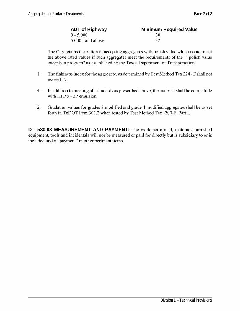
Aggregates for Surface Treatments Page 2 of 2
Division D - Technical Provisions
ADT of Highway Minimum Required Value 0 - 5,000 30 5,000 - and above 32
The City retains the option of accepting aggregates with polish value which do not meet the above rated values if such aggregates meet the requirements of the " polish value exception program" as established by the Texas Department of Transportation.
1. The flakiness index for the aggregate, as determined by Test Method Tex 224 - F shall not
exceed 17.
4. In addition to meeting all standards as prescribed above, the material shall be compatible with HFRS - 2P emulsion.
2. Gradation values for grades 3 modified and grade 4 modified aggregates shall be as set
forth in TxDOT Item 302.2 when tested by Test Method Tex -200-F, Part I.
D - 530.03 MEASUREMENT AND PAYMENT: The work performed, materials furnished equipment, tools and incidentals will nor be measured or paid for directly but is subsidiary to or is included under “payment” in other pertinent items.
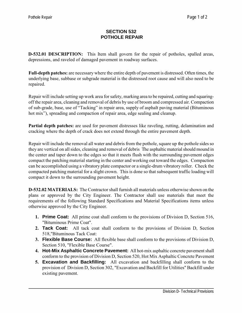
Pothole Repair Page 1 of 2
Division D- Technical Provisions
SECTION 532 POTHOLE REPAIR D-532.01 DESCRIPTION: This Item shall govern for the repair of potholes, spalled areas, depressions, and raveled of damaged pavement in roadway surfaces. Full-depth patches: are necessary where the entire depth of pavement is distressed. Often times, the underlying base, subbase or subgrade material is the distressed root cause and will also need to be repaired.
Repair will include setting up work area for safety, marking area to be repaired, cutting and squaring-off the repair area, cleaning and removal of debris by use of broom and compressed air. Compaction of sub-grade, base, use of “Tacking” in repair area, supply of asphalt paving material (Bituminous hot mix”), spreading and compaction of repair area, edge sealing and cleanup.
Partial depth patches: are used for pavement distresses like raveling, rutting, delamination and cracking where the depth of crack does not extend through the entire pavement depth.
Repair will include the removal all water and debris from the pothole, square up the pothole sides so they are vertical on all sides, cleaning and removal of debris The asphaltic material should mound in the center and taper down to the edges so that it meets flush with the surrounding pavement edges compact the patching material starting in the center and working out toward the edges. Compaction can be accomplished using a vibratory plate compactor or a single-drum vibratory roller. Check the compacted patching material for a slight crown. This is done so that subsequent traffic loading will compact it down to the surrounding pavement height.
D-532.02 MATERIALS: The Contractor shall furnish all materials unless otherwise shown on the plans or approved by the City Engineer. The Contractor shall use materials that meet the requirements of the following Standard Specifications and Material Specifications items unless otherwise approved by the City Engineer.
1. Prime Coat: All prime coat shall conform to the provisions of Division D, Section 516, "Bituminous Prime Coat".
2. Tack Coat: All tack coat shall conform to the provisions of Division D, Section 518,"Bituminous Tack Coat:
3. Flexible Base Course: All flexible base shall conform to the provisions of Division D, Section 510, "Flexible Base Course".
4. Hot-Mix Asphaltic Concrete Pavement: All hot-mix asphaltic concrete pavement shall conform to the provision of Division D, Section 520, Hot Mix Asphaltic Concrete Pavement
5. Excavation and Backfilling: All excavation and backfilling shall conform to the provision of Division D, Section 302, "Excavation and Backfill for Utilities" Backfill under existing pavement.
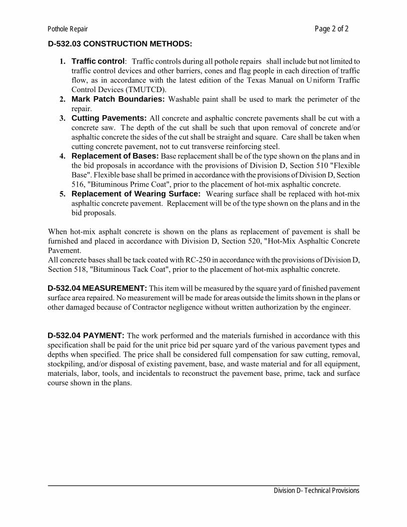
Pothole Repair Page 2 of 2
Division D- Technical Provisions
D-532.03 CONSTRUCTION METHODS:
1. Traffic control: Traffic controls during all pothole repairs shall include but not limited to traffic control devices and other barriers, cones and flag people in each direction of traffic flow, as in accordance with the latest edition of the Texas Manual on U niform Traffic Control Devices (TMUTCD).
2. Mark Patch Boundaries: Washable paint shall be used to mark the perimeter of the repair.
3. Cutting Pavements: All concrete and asphaltic concrete pavements shall be cut with a concrete saw. The depth of the cut shall be such that upon removal of concrete and/or asphaltic concrete the sides of the cut shall be straight and square. Care shall be taken when cutting concrete pavement, not to cut transverse reinforcing steel.
4. Replacement of Bases: Base replacement shall be of the type shown on the plans and in the bid proposals in accordance with the provisions of Division D, Section 510 "Flexible Base". Flexible base shall be primed in accordance with the provisions of Division D, Section 516, "Bituminous Prime Coat", prior to the placement of hot-mix asphaltic concrete.
5. Replacement of Wearing Surface: Wearing surface shall be replaced with hot-mix asphaltic concrete pavement. Replacement will be of the type shown on the plans and in the bid proposals.
When hot-mix asphalt concrete is shown on the plans as replacement of pavement is shall be furnished and placed in accordance with Division D, Section 520, "Hot-Mix Asphaltic Concrete Pavement. All concrete bases shall be tack coated with RC-250 in accordance with the provisions of Division D, Section 518, "Bituminous Tack Coat", prior to the placement of hot-mix asphaltic concrete. D-532.04 MEASUREMENT: This item will be measured by the square yard of finished pavement surface area repaired. No measurement will be made for areas outside the limits shown in the plans or other damaged because of Contractor negligence without written authorization by the engineer. D-532.04 PAYMENT: The work performed and the materials furnished in accordance with this specification shall be paid for the unit price bid per square yard of the various pavement types and depths when specified. The price shall be considered full compensation for saw cutting, removal, stockpiling, and/or disposal of existing pavement, base, and waste material and for all equipment, materials, labor, tools, and incidentals to reconstruct the pavement base, prime, tack and surface course shown in the plans.
Utility Cut Pavement Repair Page 1 of 3 SECTION 534
UTILITY CUT PAVEMENT REPAIR D-534.01 DESCRIPTION: This section covers pavement removal and replacement for all incursions into the pavement caused by utility main, connections and service repairs. Pavement maintenance activities that cause incursions, such as pothole repair, joint repair, or delamination repair, are not covered by this section. D-534.02 GENERAL:
1. PERMITS: Contractor shall obtain a right of way use permit for the work from City of Laredo.
2. SALVAGE AND DISPOSAL: Excavated material shall be lawfully disposed of off site. Contractor shall make all arrangements necessary for disposal of materials.
3. DAMAGES: All damage caused directly or indirectly to the street or subsurface outside the pavement cut area shall be regarded as a part of the street cut. This includes any holes drilled into the pavement and not properly plugged, or gouges caused by equipment. These areas, as established by the City representative, shall be included in the total area repaired. All damaged survey markers, benchmarks, or traffic devices within the excavation shall be replaced.
D-534.03 RELATED WORK: Refer to the following sections for the indicated related work. Section 520 Hot mix Asphaltic concrete Section 504 Concrete Section 506 Curb and Gutter Section 510 Flexible base Section 410 Reinforcing Steel Section 528 Asphalt Wedge Milling Section 102 Excavation and Backfill for Utilities Section 712 Traffic Control and Regulation D-534.04 CONSTRUCTION METHODS PATCH LAYOUT: Size and orientation of patch is dependent on size of the excavation, the age and type of pavement, and the classification of the road. Refer to detail drawings for limitation on patch layout. Areas with widths of 24 inches or less between the edge of the curb and gutter and the repair surface will also be removed. PATCH EXTENSION AND MERGING: Patches near the edge of pavement or near a joint in the pavement will be extended. Patches in recently placed or overlaid asphalt shall include an extended surface course mill and overlay. Adjacent patches shall be merged when sufficiently close. Refer to detail drawings for additional extension and merging requirements.
Utility Cut Pavement Repair Page 2 of 3
PAVEMENT REMOVAL: Pavement shall be cut wider than the excavation to provide a shoulder of undisturbed earth under the edges of the patch. Refer to detail drawings for overcut requirements. Pavement cut shall produce a full depth vertical face in sound pavement. If pavement is asphalt over concrete or brick, the asphalt cut shall be stepped back from the cut in the rigid base prior to patching. Where a portion of a pavement, curb, walk, or wall is to be left in place, the portion removed shall stop at an existing joint or a sawn joint. Joints shall be sawn or sliced full depth along a straight line and with a perpendicular face. No method of cutting, breaking or excavation that would vibrate or dislocate remaining pavement shall be used. If patch edges are damaged, they shall be re-cut into sound pavement.
PATCHES IN ASPHALT PAVEMENT: The asphalt patch area for street excavations that fall within the wheel path of the vehicular travel lane shall be increased in size to the center of the lane or adjacent lane. In no circumstance will the edge of a patch area be allowed to fall within the wheel path. The depth of asphalt patches in asphalt streets shall typically be the depth of the existing asphalt surface plus one inch or as specified by the Engineer. Flexible Base shall extend to bottom of existing pavement or a minimum of 12 inches whichever is thicker. On asphalt surface pavement with concrete base, a 2 inches of asphalt surface course shall be placed over the cured concrete. PATCHES IN CONCRETE PAVEMENT: Patches shall be tied or dowelled into existing concrete on all sides. When repairing concrete, removal perimeter shall be saw cut and replacement concrete shall be doweled into the old concrete as directed by the City of Laredo. See section D-534.03 for material specs for concrete requirements ties and dowels. The concrete pavement shall be replaced with 4,000 psi concrete to match the finish and thickness of the existing pavement, but not less than 8 inches thick. All concrete construction shall be protected from vehicular traffic, including contractor vehicles, until the concrete has achieved eighty (80) percent of its ultimate strength. Concrete shall be coated and sealed with a uniform application of membrane curing compound applied in accordance with manufacturer's recommendations. The use of quick curing concrete (3000 psi strength within 48 hours) shall be used on all arterial and collector streets when repair areas are less than 500 square feet or when temperatures are below 40° F. Quick curing concrete repairs may be opened to traffic within two (2) days or when the concrete has achieved eighty (80) percent of its ultimate strength. Where existing cracks or damage is adjacent to the area being repaired, the repair area shall include the cracked or damaged concrete. Patch shall be covered with a plate as per Section 808 until concrete reaches 3/4 of its design strength or seven days, whichever is shorter. Concrete base shall be placed flush with existing pavement surface and finished to match existing surface.
Utility Cut Pavement Repair Page 3 of 3 D-534.05 MEASUREMENT AND PAYMENT: Measurement an payment shall be as per Division D Section 522. D-534.06 STANDARD DETAILS RELATED TO THE WORK OF THIS SECTION: 534 - 1 ASPHALT PAVEMENT PATCH 534 - 2 CONCRETE PAVEMENT PATCH 534 - 3 UTILITY CUT REPAIR - MERGING 534 - 4 UTILITY CUT REPAIR - MERGING 534 - 5 UTILITY CUT REPAIR - MERGING
Parking Lots Page 1 of 6
Division D - Technical Provisions
SECTION 536
PARKING LOTS D - 536.01 DESCRIPTION: This item shall govern for the different type of materials and wearing surfaces used in the construction of parking lots for commercial, office, business, industrial, institutional, multi- family and other uses. D - 536.02 GENERAL: (a) These standards differentiate the construction requirements between materials systems allowed in
parking space areas and interior drives and loading areas. While all the following methods are permitted within the defined parking space area, some are restricted from use in the interior drive and loading areas. This is due to the higher load frequencies and vehicle turns within the interior drive areas.
(b) The American Disabilities Act (ADA) must be considered when utilizing these standards. Certain surface materials (particularly aggregate, concrete grid and geotextile) can not be used in designated handicapped parking spaces or along accessible routes as defined by the ADA.
(c) Aggregate, concrete grid and geotextile can not be use in designated fire lanes or emergency vehicle rout.
D - 536.03 MATERIALS: Materials shall be in accordance with:
Asphalt Section 520 Flexible Base Section 510 Concrete Section 504 Concrete Pavers ASTM C936 and the Interlocking Concrete Paver Institute (ICPI) Geotextile or Geogrid Aggregate Chip Seal
D - 536.04 CONSTRUCTION:
1. Hot Mix Asphalt:
a. Sub-grade: In-situ material or fill material approved by the Engineering Department as necessary. Fine graded and compacted to a density not less than 95% of maximum dry density per Tex-113E or Tex-114E
b. Base Course: Minimum 8” graded aggregate base per Standard Technical Specification Manual Division D Section 510 or as per plans.
Parking Lots Page 2 of 6
Division D - Technical Provisions
c. Surface: Hot Mix Asphalt Pavement per Standard Technical Specification Manual Division D Section 520. Consisting of a minimum of two inches (2”) of either type “C” or “D”.
d. On Industrial parking lots a reinforced concrete running board three feet (3’) wide and twelve inches (12”) of thickness will be required to rest the landing legs of the trailers.
e. Maintenance: The property owner is responsible for properly maintaining the pavement surface. The surface must be kept free of weeds and other vegetation. The surface grade shall be maintained as installed, ruts and potholes must be repaired immediately.
2. Portland Cement Concrete:
a. Sub-grade: In-situ material or fill material. Fine graded and compacted to a density not less than 95% of maximum dry density per Tex 113E or Tex-114E
b. Base Course: Not required, however a 4” graded aggregate base is recommended.
c. Surface: 3600 psi Portland cement concrete pavement. Minimum between four (4”) and eight inches (8”) thick reinforced with minimum # 3 or # 4 rebar @ 24 o.c. as per Land Development Chapter 24.78 and Standard Technical Specification Manual Division D Section 504. Colored and/or imprinted concrete is acceptable.
d. Maintenance: The property owner is responsible for properly maintaining the pavement surface. The surface must be kept free of weeds and other vegetation. The surface grade shall be maintained as installed. Ruts and potholes must be repaired immediately.
3. Concrete Unit Pavers – Standard:
a. Sub-grade: In-situ material or fill material approved by the Engineering Department. Fine graded and compacted to a density not less than 95% of maximum dry density per Tex 113E. or Tex-114E
b. Base Course: Minimum eight inch (8”) graded aggregate base as per Standard Technical Specification Manual Division D Section 510.
c. Surface: Interlocking Concrete Unit Payers (ASTM C936). Minimum thickness 2-3/8” over a 1” thick sand bed. Install per Interlocking Concrete Paver Institute (ICPI) standards. Edge entire perimeter with edge restraint system approved by ICPI.
d. Maintenance: The property owner is responsible for properly maintaining the pavement surface and edge restraints per the paver’s manufacturer’s recommendations. The surface must be kept free of weeds and other vegetation. The surface grade shall be maintained as installed. Ruts and potholes must be repaired immediately.
Parking Lots Page 3 of 6
Division D - Technical Provisions
4. Concrete Unit Pavers – Permeable:
a. Sub-grade: In-situ material or fill material approved by the Engineering Department. Sub-grade soil must have a minimum infiltration rate of one half inch (1/2”) per hour as determined by a standard percolation test with a plasticity index of zero. Fine graded and moderately compacted such that the permeability of the soil is not negatively impacted but soil is able to support the expected vehicular load surcharge. Lack of well draining soil may prevent the use of this method.
b. Base Course:
i. Option 1: With piped under drain system: 4” thick graded aggregate base course per Standard Technical Specification Manual Division D Section 510.
ii. Option 2: Open graded base: 6” thick (8” preferred) # 57 stone per Standard Technical Specification Manual Division D Section 504. Install a layer of filter fabric between the base course and the bedding material.
iii. Where permeable pavers adjoin an asphalt surface, the pavers shall be bordered by a flush concrete curb. It is recommended that the base course beneath the asphalt surface within 4’ of the curb be graded stabilized aggregate base to a depth of not less than 6” in order to avoid future settlement of the asphalt pavement adjacent to the border Curb.
c. Surface: Interlocking Concrete Unit Paver system (ASTM C936) with void area per square foot of between twelve and twenty percent (12%-20%). Minimum paver thickness of 2-3/8” over a minimum 1” # 8 a ggregate bedding layer per Standard Technical Specification Manual Division D Section 504. Fill void material with poorly graded aggregate as recommended by the paver’s manufacturer. Install per Interlocking Concrete Paver Institute (ICPI) standards. Edge entire perimeter with edge restraint system approved by ICPI.
d. Maintenance: The property owner is responsible for properly maintaining the pavement surface and edge restraints per the paver’s manufacturer’s recommendations. The surface must be kept free of weeds and other vegetation. The surface grade shall be maintained as installed. Ruts and potholes must be repaired immediately. All stone must be contained within the parking/driveway area.
5. Concrete Grid Pavers – Parking Areas Only:
a. Subgrade: In-situ material or fill material approved by the engineer. Sub-grade soil must have a minimum infiltration rate of one half inch (1/2”) per hour as determined by a standard percolation test with a plasticity index of zero. Fine graded and moderately compacted such that the permeability of the soil is not negatively impacted but soil is able to support the expected vehicular load surcharge.
Parking Lots Page 4 of 6
Division D - Technical Provisions
b. Base Course:
i. Option 1: With piped under drain system: 4” thick graded aggregate base course per Standard Technical Specification Manual Division D Section 510.
ii. Option 2: Open graded base: 6” thick (8” preferred) # 57 stone per Standard Technical Specification Manual Division D Section 504. Install a layer of filter fabric between the base course and the bedding material.
iii. Where permeable pavers adjoin an asphalt surface, the pavers shall be bordered by a flush concrete curb. It is recommended that the base course beneath the asphalt surface within 4’ of the curb be graded stabilized aggregate base to a depth of not less than 6” in order to avoid future settlement of the asphalt pavement adjacent to the border curb.
c. Surface Course: Concrete Grid Pavers per National Concrete Masonry Association (NCMA) A-I 5-82. Void area per square foot between twenty and fifty percent (20%-50%). One inch (1”) thick #8 aggregate bed per Standard Technical Specification Manual Division D Section 504 (voids filled with stone) or a 1” sand bed (voids filled with topsoil and vegetation). Install per grid manufacturer’s recommendations.
d. Maintenance: The property owner is responsible for properly maintaining the pavement surface and edge restraints per the paver’s manufacturer’s recommendations. The surface grade shall be maintained as installed. Ruts and potholes must be repaired immediately. All stone must be contained within the parking/driveway area and immediately removed from the sidewalk or public street areas. All vegetation must be properly maintained and cut to a height not exceeding nine inches.
6. Geotextile Grid System –Parking Areas Only:
a. Subgrade: In-situ material or fill material approved by the Engineering Department. Sub-grade soil must have a minimum infiltration rate of one half inch (1/2”) per hour as determined by a standard percolation test with a plasticity index of zero. Fine graded and moderately compacted such that the permeability of the soil is not negatively impacted but soil is able to support the expected vehicular load surcharge.
b. Base Course: 4” thick graded aggregate base course as per Standard Technical Specification Manual Division D Section 510.
c. Surface Course: Geotextile or plastic grid type system with voids filled with either stone or vegetation. Minimum load rating of 40.000 pounds gross vehicle weight. Submit system specifications, manufacturer literature and sample to City Engineer for approval. Install per manufacturers recommendations.
d. Maintenance: The property owner is responsible for properly maintaining the pavement surface per the geotextile manufacturer recommendations. All stone must be contained
Parking Lots Page 5 of 6
Division D - Technical Provisions
within the parking driveway area and immediately removed from the sidewalk or public Street areas. The surface grade shall be maintained as installed. Ruts and potholes must be repaired immediately. All vegetation must be properly maintained and cut to a height not exceeding six inches.
7. Aggregate Surface – On Temporary spill-over Parking Areas Only:
a. Subgrade: In-situ material or fill material. Sub-grade soil must have a minimum infiltration rate of one half inch (1/2”) per hour as determined by a standard percolation test with a plasticity index of zero. Fine graded and moderately compacted such that the permeability of the soil is not negatively impacted but soil is able to support the expected vehicular load surcharge.
b. Base Course: 4” graded aggregate base as per Standard Technical Specification Manual Division D Section 510.
c. Surface: Minimum 4” thickness aggregate material with 0% fines (no material passing a # 200 sieve). All material to be contained with perimeter edging consisting of either concrete curbing, treated landscape timbers, or masonry. Submit aggregate sample and sieve analysis to City Engineer for approval.
d. Maintenance: The property owner is responsible for properly maintaining the stone surface and edge restraint. All stone must be contained within the parking area and immediately removed from the sidewalk, public street, or travel/back-up areas. The surface must be kept free of weeds and other vegetation. The surface grade shall be maintained as installed. Ruts and potholes must be repaired immediately. Add stone as necessary to maintain grading and drainage. The surface shall be kept moist as necessary to prevent dust and debris from becoming airborne.
8. Chip Seal Pavement – On Temporary Parking Areas Only:
a. Sub-grade: In-situ material or fill material (approved by the engineer as necessary. Fine graded and compacted to a density not less than 95 % of maximum dry density per Tex- 113E or Tex-114E.
b. Base Course: Not required, however a 4” graded aggregate base is recommended.
c. Surface: Chip seal surface treatment per TxDot Item 316. Consisting of a single prime
coat and two seal coats.
d. Maintenance: The property owner is responsible for properly maintaining the pavement
surface. The surface must be kept free of weeds and other vegetation. The surface grade shall be maintained as installed Ruts and potholes must be repaired immediately.
Parking Lots Page 6 of 6
Division D - Technical Provisions
9. Pavement Overlays:
a. Existing impermeable pavements may be overlaid from time to time for maintenance purposes. Pavement overlays shall not increase the authorized impervious area of any parking lot.
i. Existing pavements constructed per above standard section 2.02, 2.03 or 2.04:
Minimum of 1” thickness of Type “D” or minimum of 1-1/2” thickness of Type “C”. Construct overlays in accordance with Standard Technical Specification Manual Division D Section 520.
ii. Existing impermeable pavements constructed with a minimum of 2” hot-mix
asphalt or 4” concrete: Minimum of 1” thickness of Type “D” or minimum of 1-1/2” thickness of Type “C” Construct overlays in accordance with Standard Technical Specification Manual Division D Section 520.
iii. Existing pavements not constructed per these standards nor with a minimum 2”
hot-mix asphalt or 4” concrete pavement thickness and not required to be permeable for stormwater management purposes: Minimum of 1-1/2” thickness of Type “D” .Construct overlays in accordance with Standard Technical Specification Manual Division D Section 520.
b. Permeable pavement areas shall not be overlaid. Repairs and maintenance to pervious
pavement materials shall be per the pavement manufacturer’s recommendations and shall not decrease the design porosity or functionality of the pavement system.
10. Drainage: All parking lots shall be design with the appropriate drainage system. Evidence of
poor drainage, which includes ponding (bird baths) or standing water that does not drain from surface of parking lot, is an unacceptable consequence of poor parking construction. The City will require that the contractor rectify any ponding susceptible areas at their cost and at the schedule and method acceptable to the city engineer.
D - 536.05 MEASUREMENT AND PAYMENT: Regardless of the type of materials used for the construction of the parking lot, this item will be measure and pay by the square yard. The unit bid price shall include all work and materials for subgrade, base, base protection, wearing surface course as shown in the plans and bid, labor, equipment and incidentals.
Pedestrian Railing Page 1 of 2
Division D - Technical Provisions
SECTION 538
PEDESTRIAN RAILING D - 538.01 DESCRIPTION: This Item shall govern for the construction of steel pipe pedestrian railing, on bridges, culverts, walls, or incidental structures as shown on the plans. D - 538.02 GENERAL: In general, railing shall include that portion of the structure erected on and above the roadway or along the edges of walks, walls, curbs and/or slabs for the protection of pedestrians and shall include any tie-in anchorage to approach railing or guard fence. Railing, including the necessary anchorage, shall be in accordance with these specifications and the details shown on drawings 543-1 to 543-6 as well as with ADA. D - 538.03 MATERIALS: All materials shall conform to the requirements of the TxDot items “Concrete Structures”, “Reinforcing Steel”, “Metal for Structures”, “Steel Structures” and “Concrete”. D – 538.04 QUALITY ASSURANCE: Bridge railings shall meet the requirements of the Texas Department of Transportation’s, “Standard Specifications for Construction of Highways Streets and Bridges” 2004 edition and as hereinafter amended. D - 538.05 SUBMITTALS: Contractor shall submit fabrication drawings for metal railing, showing construction and materials. D - 538.06 FABRICATION: Fabrication and erection of railing shall conform to the pertinent provisions of the Item “Steel Structures” and to the requirements of these specifications. Splicing of members will be permitted only as provided by the plans. All splice locations and details shall be shown on the shop or erection drawings. For metal railings, shop or erection drawings shall be prepared and forwarded for approval in accordance with the requirements of the Item “Steel Structures”. Shop welding shall be in accordance with the Item “Steel Structures” while field welding, when required, shall be in accordance with the Item “Structural Welding”. Pipe rail and posts, shop fabricated into panels shall be mounted in a jig clamped in their true relative position, accurately spaced with respect to each other and while assembled shall be completely welded or bolted, as the case may be. When required by the plans, as each rail section is completely assembled and connection, the adjacent section shall be set in its proper relative position with the ends engaged and remain in this position until completely connected. Each pair of sections shall be matchmarked so they may be erected in the same order in which they were fabricated. The fabricated elements for deep beam railing shall conform to the dimensions and cross- section shown on the plans. The rail shall be straight and free from warp. The maximum deviation for straightness of either edge of a full length section shall be one-half of an inch. Rail elements shall be jointed and connected to the rail posts as shown on the plans. Lapped elements shall have the
Pedestrian Railing Page 2 of 2
Division D - Technical Provisions
lap in the direction of traffic in the adjacent lane. D - 538.07 PROTECTIVE COATING: Unless otherwise noted on the plans, all portions of steel railing shall be galvanized. Galvanized railing shall be hot dipped galvanized after fabrication, in accordance with ASTM Designation A123 and A153. After erection, any damaged galvanizing on steel posts and rail elements shall be thoroughly cleaned and painted with two coats of zinc dust-zinc oxide paint conforming to the requirements of Federal Specification TTP- 641b or repaired by the application of repair compounds meeting Federal Specification O-G-93. When fabrication is done after galvanizing and when specifically required by the plans, the cut edges and bolt holes shall be cleaned by brushing and the cleaned area shall be treated as specified above. D - 538.08 MEASUREMENT: Measurement Railing, of the type designated, shall be measured by the linear foot, in accordance with the dimensions and details shown on the plans. Measurement will be made upon the face of the rail in place. D - 538.09 PAYMENT: Payment will be made at the contract unit price bid per linear foot for railing of the type indicated on the plans, complete in place, measured as provided herein, which price shall be full compensation for furnishing, preparing and placing of all concrete, expansion joint material, reinforcing steel, structural steel, pipe, anchor bolts, anchorage devices and all other materials required in the finished railing and for all labor, tools, hardware, equipment, galvanizing and all other incidentals necessary to complete the work in the manner and in accordance with the plans and these specifications.
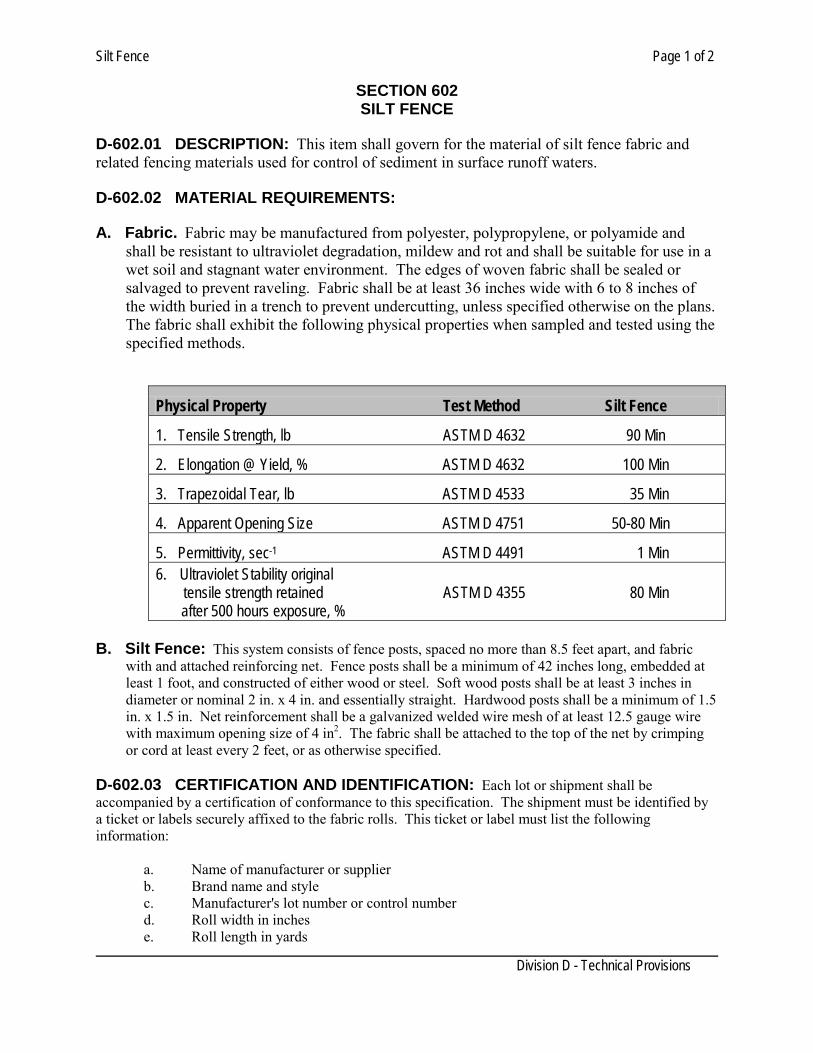
Silt Fence Page 1 of 2
Division D - Technical Provisions
SECTION 602 SILT FENCE
D-602.01 DESCRIPTION: This item shall govern for the material of silt fence fabric and related fencing materials used for control of sediment in surface runoff waters. D-602.02 MATERIAL REQUIREMENTS: A. Fabric. Fabric may be manufactured from polyester, polypropylene, or polyamide and
shall be resistant to ultraviolet degradation, mildew and rot and shall be suitable for use in a wet soil and stagnant water environment. The edges of woven fabric shall be sealed or salvaged to prevent raveling. Fabric shall be at least 36 inches wide with 6 to 8 inches of the width buried in a trench to prevent undercutting, unless specified otherwise on the plans. The fabric shall exhibit the following physical properties when sampled and tested using the specified methods.
Physical Property Test Method Silt Fence
1. Tensile Strength, lb ASTM D 4632 90 Min
2. Elongation @ Yield, % ASTM D 4632 100 Min
3. Trapezoidal Tear, lb ASTM D 4533 35 Min
4. Apparent Opening Size ASTM D 4751 50-80 Min
5. Permittivity, sec-1 ASTM D 4491 1 Min 6. Ultraviolet Stability original
tensile strength retained ASTM D 4355 80 Min after 500 hours exposure, %
B. Silt Fence: This system consists of fence posts, spaced no more than 8.5 feet apart, and fabric
with and attached reinforcing net. Fence posts shall be a minimum of 42 inches long, embedded at least 1 foot, and constructed of either wood or steel. Soft wood posts shall be at least 3 inches in diameter or nominal 2 in. x 4 in. and essentially straight. Hardwood posts shall be a minimum of 1.5 in. x 1.5 in. Net reinforcement shall be a galvanized welded wire mesh of at least 12.5 gauge wire with maximum opening size of 4 in2. The fabric shall be attached to the top of the net by crimping or cord at least every 2 feet, or as otherwise specified.
D-602.03 CERTIFICATION AND IDENTIFICATION: Each lot or shipment shall be accompanied by a certification of conformance to this specification. The shipment must be identified by a ticket or labels securely affixed to the fabric rolls. This ticket or label must list the following information: a. Name of manufacturer or supplier b. Brand name and style c. Manufacturer's lot number or control number d. Roll width in inches e. Roll length in yards
Silt Fence Page 2 of 2
Division D - Technical Provisions
D-602.04 MEASUREMENT AND PAYMENT: A. Unless indicated in the PROPOSAL FORMS as a pay item, no separate payment for work
performed under this Item. Include cost of work performed under this Item in Contract prices bid for items of which this work is a component. When indicated in PROPOSAL FORMS as pay item measure and pay for the filter fabric fence by the linear feet of completed and accepted filter fabric fence between the limits of the beginning and ending of wooden stakes. Filter fabric fence, measured as stated will be paid for at the unit price bid for "FILTER FABRIC FENCE, COMPLETE IN PLACE".
B. Payment for filter fabric fence will include and be full compensation for all labor, equipment,
materials, supervision, and all incidental expenses for construction of these items, complete in place, including, but not limited to, protection of trees, maintenance requirements, repair and replacement of damaged sections, removal of sediment deposits, and removal of erosion and sedimentation control systems at the end of construction.
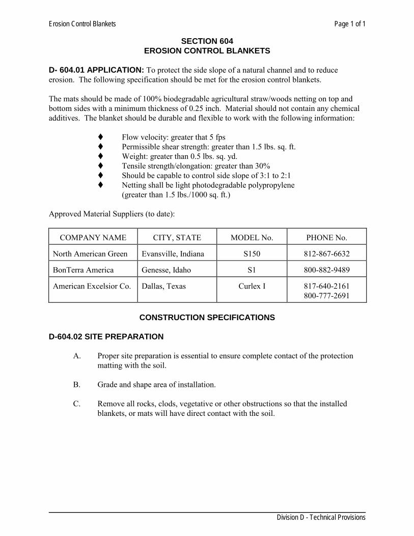
Erosion Control Blankets Page 1 of 1
Division D - Technical Provisions
SECTION 604 EROSION CONTROL BLANKETS
D- 604.01 APPLICATION: To protect the side slope of a natural channel and to reduce erosion. The following specification should be met for the erosion control blankets. The mats should be made of 100% biodegradable agricultural straw/woods netting on top and bottom sides with a minimum thickness of 0.25 inch. Material should not contain any chemical additives. The blanket should be durable and flexible to work with the following information:
Flow velocity: greater that 5 fps Permissible shear strength: greater than 1.5 lbs. sq. ft. Weight: greater than 0.5 lbs. sq. yd. Tensile strength/elongation: greater than 30% Should be capable to control side slope of 3:1 to 2:1 Netting shall be light photodegradable polypropylene
(greater than 1.5 lbs./1000 sq. ft.) Approved Material Suppliers (to date):
COMPANY NAME
CITY, STATE
MODEL No.
PHONE No. North American Green
Evansville, Indiana
S150
812-867-6632
BonTerra America
Genesse, Idaho
S1
800-882-9489
American Excelsior Co.
Dallas, Texas
Curlex I
817-640-2161 800-777-2691
CONSTRUCTION SPECIFICATIONS
D-604.02 SITE PREPARATION
A. Proper site preparation is essential to ensure complete contact of the protection matting with the soil.
B. Grade and shape area of installation.
C. Remove all rocks, clods, vegetative or other obstructions so that the installed
blankets, or mats will have direct contact with the soil.
NPDES Requirements Page 1 of 2
Division D - Technical Provisions
SECTION 606 NPDES REQUIREMENTS
D-606.01 GENERAL: This section describes the required documentation to be prepared and signed by the Contractor before conducting construction operations, in accordance with the terms and conditions of the National Pollutant Discharge Elimination System (NPDES) Permit, as stated in the Federal Register Vol. 57 No. 175, issued by the Environmental Protection Agency on September 2, 1992. The Contractor shall be responsible for implementation, maintenance, and inspection of storm water pollution prevention control measures including, but not limited to, erosion and sediment controls, stormwater management plans, waste collection and disposal, off-site vehicle tracking, and other practices shown on the drawings or specified elsewhere in this or other specifications. The Contractor shall review implementation of the Storm Water Pollution Prevention Plan (SWPPP) in a meeting with the City Engineer prior to start construction. D-606.02 UNIT PRICES: Unless indicated in the Unit Price schedule as a pay item, no separate payment will be made for work performed under this section. Include cost of work performed under this section in pay items of which this work is a component. D-606.03 REFERENCES:
ASTM D3786- Standard Test Method for Hydraulic Bursting Strength for Knitted Goods and Non-woven Fabrics
ASTM D4632- Standard Test Method for Grab Breaking Load and Elongation of Geotextiles
EXECUTION
D-606.04 NOTICE OF INTENT: The Contractor shall fill out, sign, and date the Contractor’s Notice of Intent (NOI). The signed copy of the Contractor’s NOI shall be returned to the City. The City will complete the Owner’s Notice of Intent and will submit both notices to the EPA. Submission of the NOI is required by both the City and the Contractor before construction operations start. D-606.05 CERTIFICATION REQUIREMENTS: Submit name, address, and telephone number of persons or firms responsible for maintenance and inspection of erosion and sediment control measures and all Subcontractors. D-606.06 RETENTION OF RECORDS: (a) The Contractor shall keep a copy of the Storm Water Pollution Prevention plan at the construction site or at the Contractor’s office from the date it became effective to the date of project completion. (b) At the project closeout, the Contractor shall submit to the City all NPDES forms and
NPDES Requirements Page 2 of 2
Division D - Technical Provisions
certifications, as well as a copy of the SWPPP. Stormwater pollution prevention records and data will be retained by City for a period of three (3) years from the date of project completion. D-606.07 REQUIRED NOTICES: (a) The following notices shall be posted from the date that this SWPPP goes into effect until the date of final site stabilization:
1. Copies of the Notices of Intent submitted by the City and Contractor and a brief project description shall be posted at the construction site or at Contractor’s office in a prominent place for the public viewing.
2. Notice to drivers of equipment and vehicles, instruction them to stop, check, and
clean tires of debris and mud before driving onto traffic lanes. Post such notices at every stabilized construction exit area.
3. In an easily visible location on site, post a notice of waste disposal procedures.
4. Notice of hazardous material handling and emergency procedures shall be posted
with the NOI on site. Keep copes of Material Safety Data Sheets at a location on site that is know to all personnel.
5. Keep a copy of each signed certification at the construction site or at Contractor’s
office.
Hydro-Mulch Seeding Page 1 of 4
Division D - Technical Provisions
SECTION 608 HYDRO-MULCH SEEDING
D-608.01 GENERAL
1.01 SUMMARY This Section includes the preparation, application and protection of operations consisting of hydro-mulch seeding within the lines and limits as shown on PLANS and as further directed by the ENGINEER.
1.02 RELATED REQUIREMENTS (NOT USED)
1.03 REFERENCES The publications listed below form a part of this Specification to the extent referenced. The publications are referred to in the text by basic designation only.
TEXAS DEPARTMENT OF AGRICULTURE (TDA)
TDA Chapter 61 1994 Texas Seed Law-Rules and Regulations (March Issue)
TEXAS DEPARTMENT OF TRANSPORTATION STANDARD SPECIFICATIONS FOR CONSTRUCTION OF HIGHWAYS, STREETS
AND BRIDGES (TxDOT)
TxDOT Item 164 1995 2004 Seeding for Erosion Control
TxDOT Item 166 1995 2004 Fertilizer
TxDOT Item 168 1995 2004 Vegetative Watering
1.04 - 1.06 (NOT USED)
1.07 QUALITY ASSURANCE A sample of each variety of seed to be furnished for analysis and testing when directed by the ENGINEER.
1.08 DELIVERY, STORAGE, AND HANDLING Each variety of seed to be furnished and delivered in separate bags or containers and protected from moisture until placed.
1.09 - 1.11 (NOT USED)
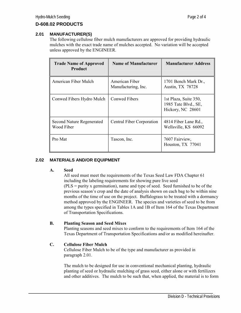
Hydro-Mulch Seeding Page 2 of 4
Division D - Technical Provisions
D-608.02 PRODUCTS
2.01 MANUFACTURER(S) The following cellulose fiber mulch manufacturers are approved for providing hydraulic mulches with the exact trade name of mulches accepted. No variation will be accepted unless approved by the ENGINEER.
Trade Name of Approved Product
Name of Manufacturer Manufacturer Address
American Fiber Mulch American Fiber Manufacturing, Inc.
1701 Bench Mark Dr., Austin, TX 78728
Conwed Fibers Hydro Mulch Conwed Fibers 1st Plaza, Suite 350, 1985 Tate Blvd., SE, Hickory, NC 28601
Second Nature Regenerated Wood Fiber
Central Fiber Corporation 4814 Fiber Lane Rd., Wellsville, KS 66092
Pro Mat Tascon, Inc. 7607 Fairview, Houston, TX 77041
2.02 MATERIALS AND/OR EQUIPMENT
A. Seed All seed must meet the requirements of the Texas Seed Law FDA Chapter 61 including the labeling requirements for showing pure live seed (PLS = purity x germination), name and type of seed. Seed furnished to be of the previous season’s crop and the date of analysis shown on each bag to be within nine months of the time of use on the project. Buffalograss to be treated with a dormancy method approved by the ENGINEER. The species and varieties of seed to be from among the types specified in Tables 1A and 1B of Item 164 of the Texas Department of Transportation Specifications.
B. Planting Season and Seed Mixes Planting seasons and seed mixes to conform to the requirements of Item 164 of the
Texas Department of Transportation Specifications and/or as modified hereinafter. C. Cellulose Fiber Mulch
Cellulose Fiber Mulch to be of the type and manufacturer as provided in paragraph 2.01. The mulch to be designed for use in conventional mechanical planting, hydraulic planting of seed or hydraulic mulching of grass seed, either alone or with fertilizers and other additives. The mulch to be such that, when applied, the material is to form
Hydro-Mulch Seeding Page 3 of 4
Division D - Technical Provisions
a strong, moisture-retaining mat without the need of an asphalt binder. It shall be kept in a dry condition until applied and shall not be molded or rotted.
D. Fertilizer Fertilizer to be in accordance with Texas Department of Transportation Specification Item 166.
E. Water Water to be in accordance with Texas Department of Transportation Specification Section 168.
2.03 - 2.04 (NOT USED)
D-608.03 EXECUTION
3.01 - 3.02 (NOT USED)
3.03 ERECTION/INSTALLATION/APPLICATION AND/OR CONSTRUCTION
A. Construction Methods After the designated areas have been completed to the lines, grades and cross sections shown on the PLANS, seeding to be performed in accordance with the requirements hereinafter described. Unless otherwise approved by the ENGINEER, all areas to be seeded to be cultivated to a depth of at least four (4) inches, except where seeding is to be done using a seed drill suitable for seeding into untilled soil. The seedbeds to be cultivated sufficiently to reduce the soil to a state of good tilth when the soil particles on the surface are small enough and lie closely enough together to prevent the seed from being covered too deeply for optimum germination. Cultivation of the seedbed will not be required in loose sand where depth of sand is four (4) inches or more.
B. Planting Season and Seed Mixes Planting season and the required seed mixes to be in accordance with the required table for location of operation as specified in Texas Department of Transportation Specification Item 164 as modified hereinafter.
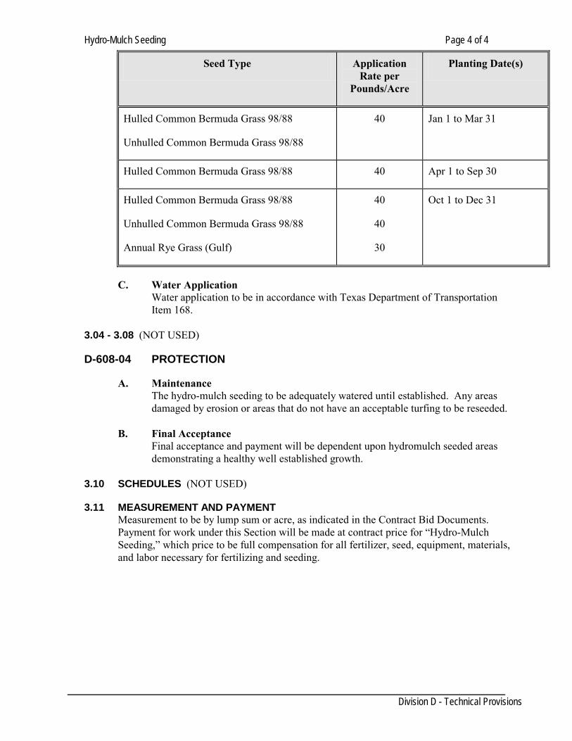
Hydro-Mulch Seeding Page 4 of 4
Division D - Technical Provisions
Seed Type Application Rate per
Pounds/Acre
Planting Date(s)
Hulled Common Bermuda Grass 98/88
Unhulled Common Bermuda Grass 98/88
40 Jan 1 to Mar 31
Hulled Common Bermuda Grass 98/88 40 Apr 1 to Sep 30
Hulled Common Bermuda Grass 98/88
Unhulled Common Bermuda Grass 98/88
Annual Rye Grass (Gulf)
40
40
30
Oct 1 to Dec 31
C. Water Application Water application to be in accordance with Texas Department of Transportation Item 168.
3.04 - 3.08 (NOT USED)
D-608-04 PROTECTION
A. Maintenance The hydro-mulch seeding to be adequately watered until established. Any areas damaged by erosion or areas that do not have an acceptable turfing to be reseeded.
B. Final Acceptance Final acceptance and payment will be dependent upon hydromulch seeded areas demonstrating a healthy well established growth.
3.10 SCHEDULES (NOT USED)
3.11 MEASUREMENT AND PAYMENT Measurement to be by lump sum or acre, as indicated in the Contract Bid Documents. Payment for work under this Section will be made at contract price for “Hydro-Mulch Seeding,” which price to be full compensation for all fertilizer, seed, equipment, materials, and labor necessary for fertilizing and seeding.
Seeding Page 1 of 3
Division D - Technical Provisions
SECTION 610 SEEDING
D-610.01 GENERAL 1.01 SUMMARY Scope: Seeding and fertilizing of areas not covered by structures, sidewalks, or roads within the project area. Project area is indicated on PLANS or by Special Provision. When shown on PLANS, provide soil retention protection. 1.02 – 1.11 (NOT USED) D-610.02 PRODUCTS 2.01 MANUFACTURER(S) (NOT USED) 2.02 MATERIALS AND/OR EQUIPMENT
A. Seeds: Conform to requirements of U.S. Department of Agriculture Rules and Regulations as set forth in Federal Seed Act and Texas Seed Law. Use seed which has been treated with an approved fungicide. Container labels to show purity and germination and name and type of seed. Planting date, type, and rate of application as follows:
Rate of Application Type in Pounds per Acre Planting Date 1. Unhulled Bermuda Grass 20 January 1 - April 1 2. Hulled Bermuda Grass 12 April 1 - October 1 3. Mix Bermuda and October 1 - January 1 Rye in Following Proportions Unhulled Bermuda Grass 12 Rye Grass (Gulf) 200
B. Fertilizer: Use pellet or granular fertilizer with analysis of 16 percent nitrogen, 20 percent phosphoric acid, and zero percent potash (or 10-10-5), unless otherwise required. Determine percent by methods of Association of Official Agricultural Chemists. Container labels to show analysis. Powdered or caked fertilizer not permitted.
C. Straw Mulch: Use straw of oat or rice stems, prairie grass, bermuda grass, or other approved straw. Do not use straw containing Johnson grass or other noxious weeds and foreign materials. D. Fiber Mat: Fiber mat to consist of machine-produced mat of wood fibers, with consistent thickness throughout blanket. Use blanket with top side of netted twisted kraft paper having high wet strength or biodegradable extruded plastic mesh. Use blanket of weight from 0.7 Pound per square yard to 1.0 Pound per square yard.
Seeding Page 2 of 3
Division D - Technical Provisions
E. Paper Mesh: Use paper mesh consisting of knitted construction of yarn with uniform openings interwoven with strips of biodegradable paper, furnished in rolls with suitable protection for outdoor storage. Use paper mesh of weight from 0.2 pound per square yard to approximately 0.5 pound per square yard.
F. Wire staples: As recommended by fiber mat or paper mesh manufacturer.
2.03 – 2.04 (NOT USED) D-610.03 EXECUTION 3.01 – 3.02 (NOT USED) 3.03 ERECTION/INSTALLATION/APPLICATION AND/OR CONSTRUCTION
A. General Fertilizing and Seeding: After area(s) to receive fertilizing and seeding has been completed to lines, grades, and sections shown on PLANS, apply fertilizer at uniform average rate of 500 pounds per acre. Thoroughly mix upper 3 inches of topsoil with fertilizer until a uniform mixture of fertilizer and topsoil is obtained. Sprinkle areas to be seeded with water, using fine spray to avoid washing or erosion of soil. Broadcast seed with sowing equipment at rate specified above, using care to obtain uniform distribution. After broadcasting, lightly rake seeds into soil to a depth not to exceed 1/2 inch. Complete seeding by rolling with roller developing 15 to 25 pounds per inch of tread. Keep seeded areas moist for a period of 10 days immediately following placement. When watering seeded areas, use fine spray to prevent erosion of seeds or soil. Reseed any areas damaged by erosion. Do not apply seeds when weather is too windy or other adverse conditions exist.
B. Straw Mulch Soil Retention Blanket 1. Fertilizing and Seeding: After ditch or slope has been completed to lines, grades, and cross-sections shown on PLANS, apply fertilizer and seed as per A. above. When seed and fertilizer are to be distributed as water slurry, mixture to be applied within 30 minutes after all components are placed in equipment.
2. Mulch Application: Immediately upon completion of planting of seed and fertilizing, spray straw mulch uniformly over the area at the rate of 1.5 to 2 tons of hay or 2.5 tons of straw per acre. Equip mulching machine to inject asphaltic material into straw uniformly as it leaves the equipment at the rate of 0.05 To 0.10 Gallon of asphalt per square yard of mulched area. When watering seeded areas, use fine spray to prevent erosion of seeds or soil. Reseed any areas damaged by erosion for any reason. Mulching operation to follow seeding and fertilizing immediately in continuous operation.
C. Fiber Mat or Paper Mesh Soil Retention Blanket
1. Fertilizing and Seeding: See B.1. above.
Seeding Page 3 of 3
Division D - Technical Provisions
2. Fiber Mat or Paper Mesh Installation: Place fiber mat or paper mesh within 24 hours after seeding operations have been completed. Prior to placing, clear area to be covered of all rocks or clods over 1.5-inch diameter and all sticks or other foreign material which will prevent close contact of the blanket with the soil. Area to be smooth and free of ruts or other depressions. If, as a result of a rain, prepared seed bed becomes crusted or eroded, or if eroded places, ruts, or depression exist for any reason, rework soil until smooth and reseed such areas. After area has been properly prepared, lay fiber mat or paper mesh flat, smooth, and loosely, without stretching or crimping material. Apply materials with lengths running parallel to the flow of water. Where more than one width is required, butt or overlap edges as required by manufacturer. Hold material in place by means of wire staple driven into soil at 90 degree angle to surface. Staple material along each edge and in grid pattern with minimum 3-foot centers each way as recommended by manufacturer. In ditches and on slopes, provide additional stapling as recommended by manufacturer.
3.04 – 3.10 (NOT USED) 3.11 MEASUREMENT AND PAYMENT
A. Fertilizing and Seeding: Measure by the acre or lump sum as indicated in PROPOSAL. Payment for work under this Item will be made at Contract price for “Seeding,” which price to be full compensation for all fertilizer, seed, equipment, materials and labor necessary for fertilizing and seeding. B. Straw Mulch Seeding: Measure by the square yard as indicated in the PROPOSAL. Payment for work under this Item to be made at the Contract price for “Straw Mulch Seeding,” which price to be full compensation for all fertilizer, seed, straw mulch, equipment, materials and labor necessary for fertilizing and seeding. C. Fiber Mat Seeding: Measure by the square yard as indicated in the PROPOSAL. Payment for work under this Item to be made at the Contract price for “Fiber Mat Seeding,” which price to be full compensation for all fertilizer, seed, fiber mat, equipment, materials, and labor necessary for fertilizing and seeding. D. Paper Mesh Seeding: Measure by the square yard as indicated in the PROPOSAL. Payment for work under this Item to be made at the Contract price for “Paper Mesh Seeding,” which price to be full compensation for all fertilizer, seed, paper mesh, equipment, materials, and labor necessary for fertilizing and seeding.
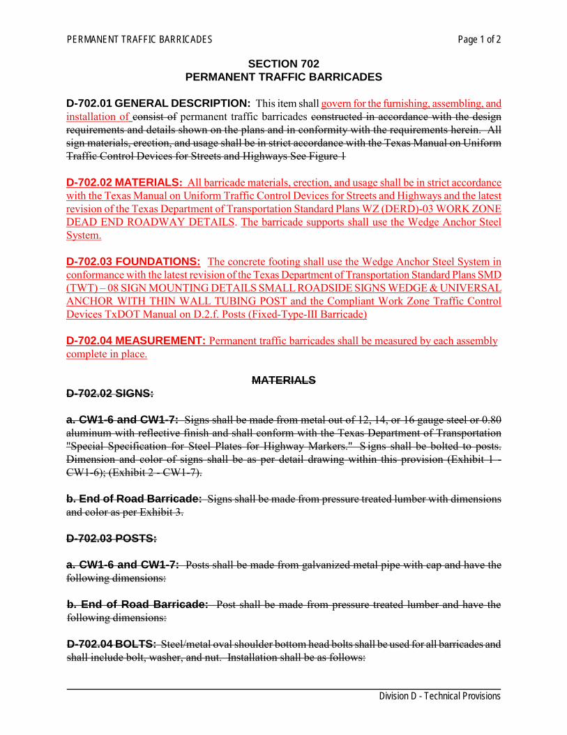
PERMANENT TRAFFIC BARRICADES Page 1 of 2
Division D - Technical Provisions
SECTION 702 PERMANENT TRAFFIC BARRICADES
D-702.01 GENERAL DESCRIPTION: This item shall govern for the furnishing, assembling, and installation of consist of permanent traffic barricades constructed in accordance with the design requirements and details shown on the plans and in conformity with the requirements herein. All sign materials, erection, and usage shall be in strict accordance with the Texas Manual on Uniform Traffic Control Devices for Streets and Highways See Figure 1 D-702.02 MATERIALS: All barricade materials, erection, and usage shall be in strict accordance with the Texas Manual on Uniform Traffic Control Devices for Streets and Highways and the latest revision of the Texas Department of Transportation Standard Plans WZ (DERD)-03 WORK ZONE DEAD END ROADWAY DETAILS. The barricade supports shall use the Wedge Anchor Steel System. D-702.03 FOUNDATIONS: The concrete footing shall use the Wedge Anchor Steel System in conformance with the latest revision of the Texas Department of Transportation Standard Plans SMD (TWT) – 08 SIGN MOUNTING DETAILS SMALL ROADSIDE SIGNS WEDGE & UNIVERSAL ANCHOR WITH THIN WALL TUBING POST and the Compliant Work Zone Traffic Control Devices TxDOT Manual on D.2.f. Posts (Fixed-Type-III Barricade) D-702.04 MEASUREMENT: Permanent traffic barricades shall be measured by each assembly complete in place.
MATERIALS D-702.02 SIGNS: a. CW1-6 and CW1-7: Signs shall be made from metal out of 12, 14, or 16 gauge steel or 0.80 aluminum with reflective finish and shall conform with the Texas Department of Transportation "Special Specification for Steel Plates for Highway Markers." S igns shall be bolted to posts. Dimension and color of signs shall be as per detail drawing within this provision (Exhibit 1 - CW1-6); (Exhibit 2 - CW1-7). b. End of Road Barricade: Signs shall be made from pressure treated lumber with dimensions and color as per Exhibit 3. D-702.03 POSTS: a. CW1-6 and CW1-7: Posts shall be made from galvanized metal pipe with cap and have the following dimensions: b. End of Road Barricade: Post shall be made from pressure treated lumber and have the following dimensions: D-702.04 BOLTS: Steel/metal oval shoulder bottom head bolts shall be used for all barricades and shall include bolt, washer, and nut. Installation shall be as follows:
PERMANENT TRAFFIC BARRICADES Page 2 of 2
Division D - Technical Provisions
CW1-6 & CW1-7: END OF ROAD BARRICADE:
PAYMENT D-702.05 PAYMENT: Permanent barricades signs shall be paid by each assembly complete in place. for on a unit price basis. The price bid shall be considered to include materials, labor, equipment and incidentals necessary to complete the work. Payment will be made when installed barricade is approved and accepted by the Owner .
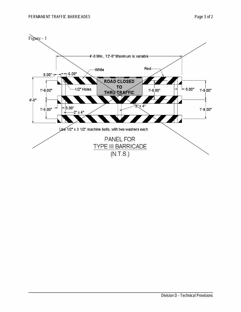
PERMANENT TRAFFIC BARRICADES Page 3 of 2
Division D - Technical Provisions
Figure - 1
STREET SIGNS Page 1 of 4
Division D - Technical Provisions
SECTION 704 STREET SIGNS
D-704.01 GENERAL DESCRIPTION This item shall govern for the furnishing, assembling, and installation of street signs. Street Name Signs see Figure 704 - 1 thru Figure – 3 704 - 4. D-704.02 MATERIALS The sign supports shall use the Wedge Anchor Steel System and shall be tall enough to provide a minimum of 7 feet ground clearance (7.5 feet maximum) from bottom edge of the sign assembly. Length of the support will vary depending on the type and size of the signs installed on the pole as an assembly. be made from new galvanized round steel pipe, 2-3/8 O.D., 0.065 gauge. Pipe must be long enough to provide a 7 feet ground clearance from bottom edge of sign assembly. Length of the pipe will vary depending on the type, size, or signs installed on the pole as an assembly. The type of support, size and specifications for the pipe and sign shall be as shown on the plans. All traffic signs must comply with the latest edition of the Texas Manual of Uniform Traffic Control Devices. Unless otherwise specified by the Engineer, all signs shall be fabricated from 0.080 gauge aluminum. Engineering Grade reflective sheeting shall be used for all traffic signs except stop signs and school advance crossing signs. All stop signs shall be fabricated with High Intensity reflective sheeting. All school advance crossing signs shall be fabricated from lime green Diamond Grade reflective sheeting. Sign face materials shall conform to ASTM D 4956-04, reflective beaded sheeting, TYPE II or better except for stop signs and school zone signs. All stop signs shall conform to ASTM D 4956-04, reflective prismatic sheeting, TYPE III or better. All school zone signs shall conform to ASTM D 4956-04, reflective prismatic sheeting, TYPE VII or better. Street name signs shall be fabricated with engineering grade reflective sheeting. Street name signs shall have white lettering with a green background. Aluminum sign blades for street signs shall be 9 inch in height with a minimum length of 30 inches and maximum length of 48 inches. Lettering on post-mounted Street Name signs shall use a six (6) inch upper and lower case Clearview Highway font character set (6CV-2W). Street name lettering used for abbreviations, designations and block numbers shall use a three (3) inch upper and lower case Clearview Highway font character set (3CV-2W). Street name lettering shall be 5 inch white reflective highway gothic font uppercase and lowercase letters. It shall include street abbreviations and designators and block numbers with 3 inch reflective highway gothic font, uppercase and lowercase letters. Street name sign specifications are shown on Street Name Standard Detail included herein. Follow Figure – 704-4 for Mast Arm Street Name Sign Specification. D-704.03 PROVISIONS: Sidewalk clearance and sign standards shall comply with the lattest revisionof the TEXAS ACCESSIBILITY STANDARDS D-704.04 FOUNDATIONS: The concrete footing shall use the Wedge Anchor Steel System in conformance with the latest revision of the Texas Department of Transportation Standard Plans SMD (TWT) – 08 SIGN MOUNTING DETAILS SMALL ROADSIDE SIGNS WEDGE & UNIVERSAL ANCHOR WITH THIN WALL TUBING POST. Foundations for all pipe supports shall conform to the Street Sign Foundation Detail included herein. Signs shall be installed no less than 2 feet from the back of curve curb and the edge of sign. It shall not be installed more than five feet from the back of curve with a maximum of 6 feet. Maximum sidewalk clearance shall be
STREET SIGNS Page 2 of 4
Division D - Technical Provisions
maintained in identifying location of sign, but it shall not be installed more than 5 feet from back of curb to the edge of the sign. The location of the sign may be modified in special situations where the ROW is limited or obstructions are present based on engineering judgement. See Examples 1 thru 4 When the above requirement cannot be met due to location or width of sidewalk, a minimum of 30 inches sidewalk clearance shall be provided. No sign shall be attached to the posts until the concrete has aged at least two (2) curing days or until otherwise permitted by the Engineer. Street Sign Foundation Details are included in the Detail Section. D-704.05 MEASUREMENT: AND PAYMENT Small roadside Traffic Street signs shall be measured by each assembly complete in place. The work performed and material furnished as prescribed by this item, measured as provided for, will be paid for at the unit price bid for Street Signs of the support type as specified, which payment shall be full compensation for furnishing, fabricating, galvanizing and erecting the supports; furnishing concrete foundations, where required; furnishing complete signs; furnishing the sign connections and all hardware; assembling the signs supports; washing and cleaning the signs as specified; and all other details and incidentals necessary to provide the signs complete and installed in place. D-704.06 PAYMENT: Street signs shall be paid by each assembly complete in place. The price bid shall be considered to include materials, labor, equipment and incidentals necessary to complete the work.

STREET SIGNS Page 3 of 4
Division D - Technical Provisions
Figure – 1:
Figure – 2:
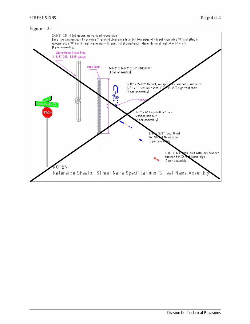
STREET SIGNS Page 4 of 4
Division D - Technical Provisions
Figure – 3:
REFLECTORIZED PAVEMENT MARKINGS Page 1 of 6
Division D - Technical Provisions
SECTION 706 REFLECTORIZED PAVEMENT MARKINGS
D-706.1. GENERAL DESCRIPTION: This item shall govern for furnishing and placing reflectorized pavement markings and raised reflectorized pavement markers of the types, colors, shapes, sizes, widths, and thickness shown on the plans. Unless otherwise approved by the Engineer, Type I or II pavement markings shall be used on all roadways within the City of Laredo that are under the City’s jurisdiction. Reflectorized pavement markings supplemented by raised reflectorized pavement markings (traffic buttons) shall be required on all streets with a road classification of major collector or greater. The installation of these must abide by to the latest edition of the Texas Manual of Uniform Control Devices and must comply with the latest TxDOT Traffic Engineer Standard Detail Sheets. D-706.2. MATERIALS: The pavement marking installation must abide to the latest edition of the Texas Manual of Uniform Control Devices and must comply with the latest TxDOT Traffic Engineer Standard Detail Sheets. When Type I or Type II white pavement markings are to be applied on concrete, black pavement marking paint shall be applied under the white paint and shall exceed a minimum of 2 inches and a maximum of 4 inches in all directions from the edge of the white pavement marking to make it more visible. When using preformed pavement markings, it shall have the black edge as part of the preformed pavement marking. Type I: Marking Materials. Type I markings are thermoplastic type materials that require heating to elevated temperatures for application. Type I marking materials shall conform to TxDOT Departmental Materials Specifications DMS-8220. Each container of Type I marking material shall be clearly marked to indicate the color, weight, type of material, manufacturer’s name and the lot/batch number. Type I pavement markings shall be used for all crosswalks, stop bars and lane designation when required. Type II: Marking Materials. Type II markings are paint-type materials that are applied at ambient or slightly elevated temperatures. Type II marking materials shall conform to TxDOT Departmental Materials Specifications DMS-8200, YPT-12 and/or WPT-12, and DMS-8200. Blue Reflectors for Fire Hydrants. Blue raised reflective markers shall be used on all streets to identify location for all fire hydrants. One marker (Type II-B-B) shall be installed in the center of roadway immediately in front of the location of fire hydrant. The pavement marker shall have two (2) reflectorized faces 180° of each other. The body, other than the reflective faces, shall be blue. Reflectorized raised pavement markers shall abide by latest TxDOT Traffic Engineer Standard Plan Sheets. D- 706.3. EQUIPMENT REQUIREMENTS The equipment used to place pavement markings shall be capable of accomplishing the required pavement markings. For projects that exceed 2000 linear feet the equipment used to place pavement markings shall: 1. Be maintained in satisfactory operating condition.
REFLECTORIZED PAVEMENT MARKINGS Page 2 of 6
Division D - Technical Provisions
2. Be considered in satisfactory operating condition if it has an average placement rate of
5,000 linear feet per hour of acceptable four-inch solid or broken lines over any five (5) consecutive working days. Must comply with the latest edition of the Texas Manual of Uniform Traffic Control Revisions.
3. Meet or exceed the material handling at elevated temperatures requirements of the National
Fire Underwriters and the Texas Railroad Commission. 4. Be capable of placing a minimum of 40,000 linear feet of four-inch solid or broken
markings per working day. 5. Have production capabilities similar to four-inch marking equipment and shall be capable
of placing linear markings up to eight (8) inches in width in a single pass when used for placing markings in widths other than four (4) inches.
6. Have production capabilities considered satisfactory by the Engineer when used to place
markings other than solid or broken lines. 7. Be capable of placing a centerline and no-passing barrier-line configuration consisting of
one (1) broken line with two (2) solid lines at the same time to the alignment and spacing shown on the plans.
8. Be capable of placing broken and/or continuos white line from both sides. 9. Be capable of placing lines with clean edges and of uniform cross-section. All lines shall
have a tolerance of plus or minus 1/8 inch per four (4) inch width. 10. Have an automatic cut-off device with manual operating capabilities to provide clean,
reasonably square marking ends to the satisfaction of the Engineer, and to provide a method of applying broken line in an approximate stripe-to-gap ration of 10 to 30. The length of any stripe-gap cycle shall not be less than 39.5 feet or more than 40.5 feet.
11. Provide continuous mixing and agitation of the pavement marking material. The use of
pans, aprons or similar appliances which the die overruns will not be permitted for longitudinal striping applications.
12. Apply glass beads by an automatic bead dispenser attached to the pavement marking
equipment in such a manner that the beads are dispensed uniformly and almost instantly upon the marking as the marking is being applied to the road surface. The bead dispenser shall have an automatic cut-off control, synchronized with the cut-off of the pavement marking equipment.
When Type I markings are to be placed, the contractor shall have a hand-held thermometer on the project. The thermometer shall be capable of measuring the temperature of the pavement marking material to be placed.
REFLECTORIZED PAVEMENT MARKINGS Page 3 of 6
Division D - Technical Provisions
D- 706.4 CONSTRUCTION METHODS General: When required by the Engineer, the Contractor and the Engineer shall review the sequence of work to be followed and the estimated progress schedule. Markings may be placed on roadways either free of traffic or open to traffic. On roadways already open to traffic, the markings shall be placed under traffic conditions that exist with a minimum of interference to the operation of the facility. Traffic control shall be as shown on the plans or as approved by the Engineer in writing. All markings placed under open-traffic conditions shall be protected from traffic damage and disfigurement. On roadways open to traffic, with three (3) lanes of travel in one direction, all markings shall be placed from the outside lanes only, unless otherwise approved in writing by the Engineer. Guides to mark the lateral location of pavement markings shall be established as shown on the plans or as directed by the Engineer. The Contractor shall establish the pavement marking guides and the Engineer will verify the location of the guides. Markings shall be placed in proper alignment with the guides. The deviation rate in alignment shall not exceed one (1) inch per 200 feet of roadway. The maximum deviation shall not exceed two (2) inches nor shall any deviation be abrupt. Markings shall essentially have a uniform cross-section. The density and quality of markings shall be uniform throughout their thickness. The applied markings shall have no more than five (5) percent, by area, of holes or voids and shall be free of blisters. Markings, in place on the roadway, shall be reflectorized both internally and externally. Glass beads shall be applied to the materials at a uniform rate sufficient to achieve uniform and distinctive retroreflective characteristics when observed in accordance with Test Method Tex-828-B Determining Functional Characteristics of Pavement Markings. The Contractor’s personnel shall be sufficiently skilled in the work of installing pavement markings. Markings placed that are not in alignment or sequence, as shown on the plans or as stated in this specification, shall be removed by the Contractor at the Contractor’s expense. Removal shall be in accordance with Item 667, “Eliminating Existing Pavement Markings and Markers,” except for measurement and payment. Guides placed on the roadway for alignment purposes shall not establish a permanent marking on the roadway. Unless otherwise shown on the plans, pavement markings may be applied by any method that will yield markings meeting the requirements of these specifications. Surface Preparation: New portland-cement-concrete surfaces shall be cleaned in accordance with Item 678, “Pavement Surface Preparation for Markings” to remove curing membrane, dirt, grease, loose and/or flaking existing construction markings and other forms of contamination. Older portland-cement-concrete surfaces and asphaltic surfaces that exhibit loose and/or flaking
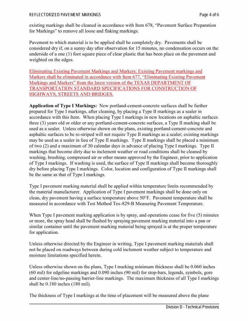
REFLECTORIZED PAVEMENT MARKINGS Page 4 of 6
Division D - Technical Provisions
existing markings shall be cleaned in accordance with Item 678, “Pavement Surface Preparation for Markings” to remove all loose and flaking markings. Pavement to which material is to be applied shall be completely dry. Pavements shall be considered dry if, on a sunny day after observation for 15 minutes, no condensation occurs on the underside of a one (1) foot square piece of clear plastic that has been place on the pavement and weighted on the edges. Eliminating Existing Pavement Markings and Markers: Existing Pavement markings and Markers shall be eliminated in accordance with Item 677, “Eliminating Existing Pavement Markings and Markers” from the latest version of the TEXAS DEPARTMENT OF TRANSPORTATION STANDARD SPECIFICATIONS FOR CONSTRUCTION OF HIGHWAYS, STREETS AND BRIDGES. Application of Type I Markings: New portland-cement-concrete surfaces shall be further prepared for Type I markings, after cleaning, by placing a Type II markings as a sealer in accordance with this Item. When placing Type I markings in new locations on asphaltic surfaces three (3) years old or older or any portland-cement-concrete surfaces, a Type II marking shall be used as a sealer. Unless otherwise shown on the plans, existing portland-cement-concrete and asphaltic surfaces to be re-striped will not require Type II markings as a sealer; existing markings may be used as a sealer in lieu of Type II markings. Type II markings shall be placed a minimum of two (2) and a maximum of 30 calendar days in advance of placing Type I markings. Type II markings that become dirty due to inclement weather or road conditions shall be cleaned by washing, brushing, compressed air or other means approved by the Engineer, prior to application of Type I markings. If washing is used, the surface of Type II markings shall become thoroughly dry before placing Type I markings. Color, location and configuration of Type II markings shall be the same as that of Type I markings. Type I pavement marking material shall be applied within temperature limits recommended by the material manufacturer. Application of Type I pavement markings shall be done only on clean, dry pavement having a surface temperature above 50°F. Pavement temperature shall be measured in accordance with Test Method Tex-829-B Measuring Pavement Temperature. When Type I pavement marking application is by spray, and operations cease for five (5) minutes or more, the spray head shall be flushed by spraying pavement marking material into a pan or similar container until the pavement marking material being sprayed is at the proper temperature for application. Unless otherwise directed by the Engineer in writing, Type I pavement marking materials shall not be placed on roadways between during cold inclement weather subject to temperature and moisture limitations specified herein. Unless otherwise shown on the plans, Type I marking minimum thickness shall be 0.060 inches (60 mil) for edgeline markings and 0.090 inches (90 mil) for stop-bars, legends, symbols, gore and center-line/no-passing barrier-line markings. The maximum thickness of all Type I markings shall be 0.180 inches (180 mil). The thickness of Type I markings at the time of placement will be measured above the plane
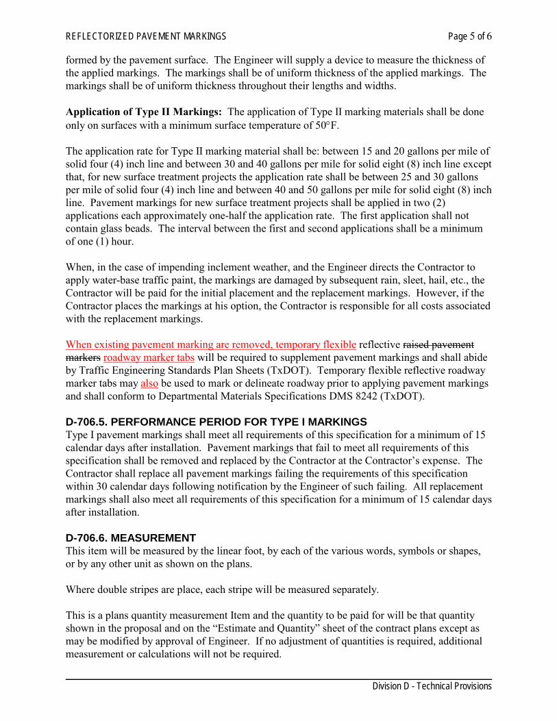
REFLECTORIZED PAVEMENT MARKINGS Page 5 of 6
Division D - Technical Provisions
formed by the pavement surface. The Engineer will supply a device to measure the thickness of the applied markings. The markings shall be of uniform thickness of the applied markings. The markings shall be of uniform thickness throughout their lengths and widths. Application of Type II Markings: The application of Type II marking materials shall be done only on surfaces with a minimum surface temperature of 50°F. The application rate for Type II marking material shall be: between 15 and 20 gallons per mile of solid four (4) inch line and between 30 and 40 gallons per mile for solid eight (8) inch line except that, for new surface treatment projects the application rate shall be between 25 and 30 gallons per mile of solid four (4) inch line and between 40 and 50 gallons per mile for solid eight (8) inch line. Pavement markings for new surface treatment projects shall be applied in two (2) applications each approximately one-half the application rate. The first application shall not contain glass beads. The interval between the first and second applications shall be a minimum of one (1) hour. When, in the case of impending inclement weather, and the Engineer directs the Contractor to apply water-base traffic paint, the markings are damaged by subsequent rain, sleet, hail, etc., the Contractor will be paid for the initial placement and the replacement markings. However, if the Contractor places the markings at his option, the Contractor is responsible for all costs associated with the replacement markings. When existing pavement marking are removed, temporary flexible reflective raised pavement markers roadway marker tabs will be required to supplement pavement markings and shall abide by Traffic Engineering Standards Plan Sheets (TxDOT). Temporary flexible reflective roadway marker tabs may also be used to mark or delineate roadway prior to applying pavement markings and shall conform to Departmental Materials Specifications DMS 8242 (TxDOT). D-706.5. PERFORMANCE PERIOD FOR TYPE I MARKINGS Type I pavement markings shall meet all requirements of this specification for a minimum of 15 calendar days after installation. Pavement markings that fail to meet all requirements of this specification shall be removed and replaced by the Contractor at the Contractor’s expense. The Contractor shall replace all pavement markings failing the requirements of this specification within 30 calendar days following notification by the Engineer of such failing. All replacement markings shall also meet all requirements of this specification for a minimum of 15 calendar days after installation. D-706.6. MEASUREMENT This item will be measured by the linear foot, by each of the various words, symbols or shapes, or by any other unit as shown on the plans. Where double stripes are place, each stripe will be measured separately. This is a plans quantity measurement Item and the quantity to be paid for will be that quantity shown in the proposal and on the “Estimate and Quantity” sheet of the contract plans except as may be modified by approval of Engineer. If no adjustment of quantities is required, additional measurement or calculations will not be required.
REFLECTORIZED PAVEMENT MARKINGS Page 6 of 6
Division D - Technical Provisions
Type II pavement markings requiring two (2) applications on new surface treatments will be measured as one (1) marking. Type II pavement marking materials, when used as a sealer for Type I markings will be measured as Type II markings. D-706.7. PAYMENT The work performed and materials furnished in accordance with this Item and measured as provided under “Measurement” will be paid for at the unit price bid for “Reflectorized Pavement Markings” of the various types, colors, shapes, sizes, widths, and thickness (Type I markings only) specified. This price shall be full compensation for furnishing all materials; for application of pavement and raised pavement markings and for all other labor, tools, equipment and incidentals necessary to complete the work, except as shown below. Surface Preparation, when shown on the plans, will be paid for under Item 678 “Pavement Surface Preparation for Markings.” Final work zone pavement markings (paint and beads), which will be, used as a sealer for Type I pavement markings will be paid for under this Item. When replacement Type II markings are required due to damage to the original markings from rain, sleet, hail, etc., and the original markings were placed at the direction of the Engineer, the plan quantity requirements under “Measurement” do not apply to the original and replacement markings. The Contractor will be paid for the actual quantity of original and replacement markings at the unit price bid for that item.
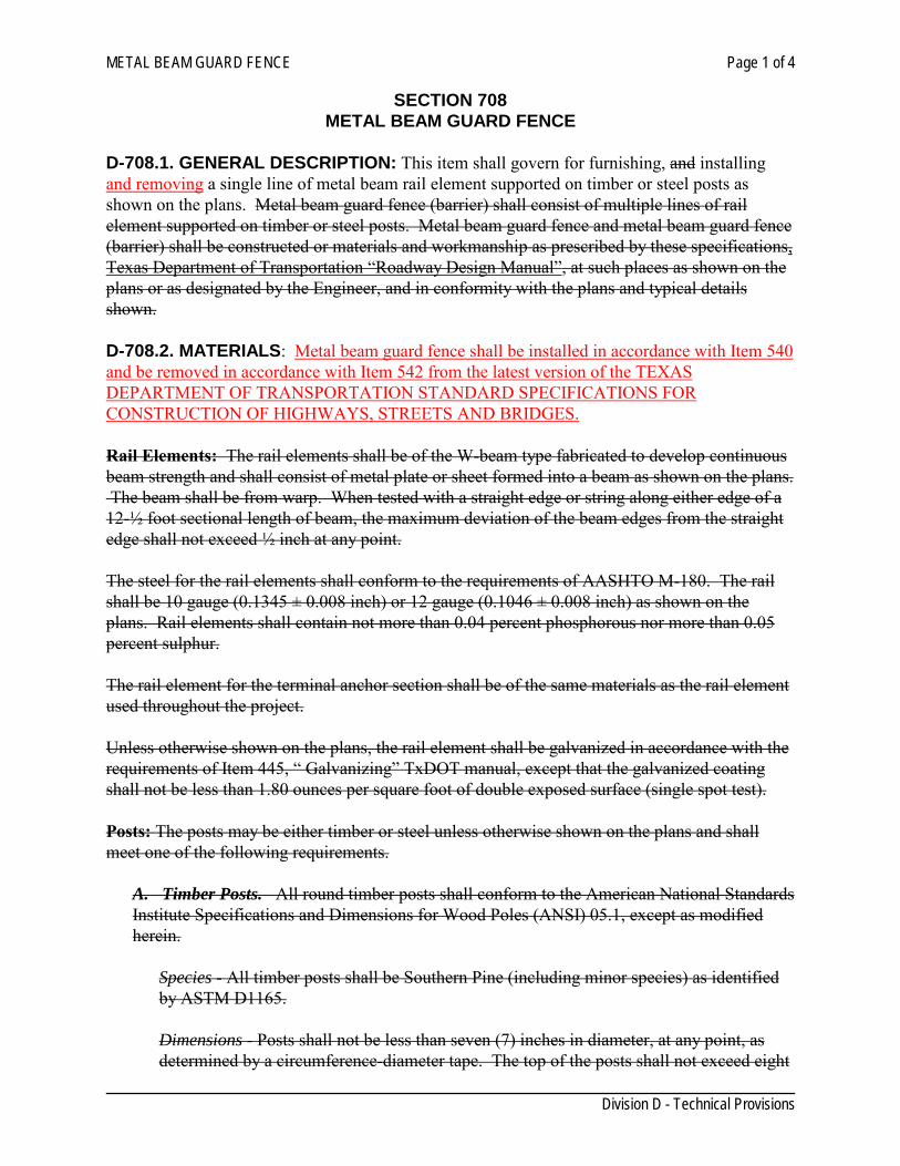
METAL BEAM GUARD FENCE Page 1 of 4
Division D - Technical Provisions
SECTION 708 METAL BEAM GUARD FENCE
D-708.1. GENERAL DESCRIPTION: This item shall govern for furnishing, and installing and removing a single line of metal beam rail element supported on timber or steel posts as shown on the plans. Metal beam guard fence (barrier) shall consist of multiple lines of rail element supported on timber or steel posts. Metal beam guard fence and metal beam guard fence (barrier) shall be constructed or materials and workmanship as prescribed by these specifications, Texas Department of Transportation “Roadway Design Manual”, at such places as shown on the plans or as designated by the Engineer, and in conformity with the plans and typical details shown. D-708.2. MATERIALS: Metal beam guard fence shall be installed in accordance with Item 540 and be removed in accordance with Item 542 from the latest version of the TEXAS DEPARTMENT OF TRANSPORTATION STANDARD SPECIFICATIONS FOR CONSTRUCTION OF HIGHWAYS, STREETS AND BRIDGES. Rail Elements: The rail elements shall be of the W-beam type fabricated to develop continuous beam strength and shall consist of metal plate or sheet formed into a beam as shown on the plans. The beam shall be from warp. When tested with a straight edge or string along either edge of a 12-½ foot sectional length of beam, the maximum deviation of the beam edges from the straight edge shall not exceed ½ inch at any point. The steel for the rail elements shall conform to the requirements of AASHTO M-180. The rail shall be 10 gauge (0.1345 ± 0.008 inch) or 12 gauge (0.1046 ± 0.008 inch) as shown on the plans. Rail elements shall contain not more than 0.04 percent phosphorous nor more than 0.05 percent sulphur. The rail element for the terminal anchor section shall be of the same materials as the rail element used throughout the project. Unless otherwise shown on the plans, the rail element shall be galvanized in accordance with the requirements of Item 445, “ Galvanizing” TxDOT manual, except that the galvanized coating shall not be less than 1.80 ounces per square foot of double exposed surface (single spot test). Posts: The posts may be either timber or steel unless otherwise shown on the plans and shall meet one of the following requirements.
A. Timber Posts. All round timber posts shall conform to the American National Standards Institute Specifications and Dimensions for Wood Poles (ANSI) 05.1, except as modified herein.
Species - All timber posts shall be Southern Pine (including minor species) as identified by ASTM D1165.
Dimensions - Posts shall not be less than seven (7) inches in diameter, at any point, as determined by a circumference-diameter tape. The top of the posts shall not exceed eight
METAL BEAM GUARD FENCE Page 2 of 4
Division D - Technical Provisions
(8) inches in diameter below the dome or bevel. The diameter at the butt of a post shall not exceed the diameter of the top of that post by more than two (2) inches. The length of the posts shall be as shown on the plans; the length shall not vary more than one (1) inch from the specified length. Manufacture - Posts may be domed or beveled, as specified. When posts are domed, the dome shall be approximately hemispherical in shape and the radius of the dome of each posts shall be one-half the diameter of the posts at the base of the domed portion. The dome shall be smooth, and the distance from the top of the dome to the base of the dome shall not vary more than one (1) inch at any location. When posts are beveled, the bevel will be a minimum of 10 degrees and a maximum of 15 degrees for acceptance.
All posts shall be smooth shaved by machine. No “ringing” of the posts as caused by improperly adjusted peeling machine is permitted. All outer and inner bark shall be removed during the shaving process. All knots and knobs shall be trimmed smooth and flush with the surface of the posts.
The groundline, for the purpose of applying those restrictions of ANSI 05.1 that reference the groundline, shall be defined as being located three feet from the butt end of each post.
Holes shall be drilled as shown on the plans for the type of posts being manufactured, with a location tolerance of ¼ of an inch in any direction. All manufacturing shall be completed prior to preservative treatment.
Knots - The maximum diameter of any single knot shall not exceed three (3) inches. The sum of diameter of all knots grater that 0.5 inch in any one (1) foot section shall not exceed eight (8) inches.
Scars - Scars are permitted as defined in ANSI 05.1 provided that the depth of the trimmed scar is not more than one (1) inch.
Shape and Straightness - All timber posts shall be nominally round in cross section. A straight line drawn from the center of the top to the center of the butt of any post shall not deviate from the centerline of the posts more than 1¼ inches at any point. Post shall be free from reverse bends.
Splits and Shakes - Splits or ring shakes are not permitted in the top. Splits are not permitted in the butt, a single shake is permitted in the butt, provided it is not wider that one-half the butt diameter.
Timber Spacers - When timber spacers are required, the timber species shall be the same as those furnished for the timber posts. The size and hole location shall be shown on the plans, with a tolerance of ¼ inch.
Spacers shall be of medium grain, at least four (4) rings per inch on one end, and free from splits, shakes, compression wood or decay in any form. Individual knots, knot clusters or knots in the same cross section of a face are permitted, provided they are
METAL BEAM GUARD FENCE Page 3 of 4
Division D - Technical Provisions
sound or firm, and are limited in cumulative width (when measured between lines parallel to the edges) to no more than one-half of the width of the face. Wane or the absence of wood is limited to one-third of the face on no more than 10 percent of the lot. Grain deviation is limited to one (1) inch in six (6) inches. The material may be rough swan or surfaced, full sized, hit or miss, with a tolerance of ¼ inch for all dimensions.
All manufacturing shall be completed prior to preservative treatment. Treatment - Timber posts and spacers shall be preservative treated in accordance with Item 492 “Timber Preservative and Treatment, TxDOT manual.” In addition to the referenced following provisions shall apply:
Each post treated shall have a minimum sapwood depth of one (1) inch, as determined by examination of the tops and butts of each post. The use of peeler cores is prohibited. Material that has been air dried or kiln dried shall be inspected for moisture content in accordance with AWPA Standard M2 prior to treatment. Test of representative pieces shall be conducted. The lot shall be considered acceptable when the average moisture content does not exceed 25 percent. Pieces exceeding 29 percent moisture content shall be rejected and removed from the lot.
B. Steel Posts. Steel posts and spacers shall be rolled sections as shown on the plans and conform to the requirements of ASTM A 36. The top of all posts shall be beveled or square as shown on the plans. The posts and spacers shall be drilled or punched for rail attachment as shown on the plans.
Steel posts and spacers shall be galvanized in accordance with the requirements of Item 445 “Galvanizing”.
Fittings: Fittings shall consist of bolts, nuts and washers conforming to the details shown on the plans and to the requirements of Item 442 “Metal for Structures.” Fittings shall be galvanized in accordance with Item 445 “Galvanizing.” Terminal Connectors: Terminal connectors, where required, shall conform to the details shown on the plans and to the materials and galvanizing requirements specified for rail elements. Concrete: Unless otherwise shown on the plans, the concrete for terminal anchor posts or for embedment of other posts in concrete, where embedment is required, shall meet the requirements for Class “A” concrete as specified in Item 421, “Portland Cement Concrete.” D-708.3 SAMPLING AND TESTING When directed by the Engineer, a sample of the rail and terminal section shall be taken for each project or for each shipment to a project. Samples of bolts and nuts may also be required. All samples shall be furnished to the Department free of charge. The uniformity of the zinc coating shall be determined by visual inspection. If, in the opinion of the Engineer, visual examination is not conclusive, the uniformity of the coating may be determined by magnetic thickness gauge measurement, in accordance with ASTM E376.
METAL BEAM GUARD FENCE Page 4 of 4
Division D - Technical Provisions
D-708.6. CONSTRUCTION METHODS The posts shall be set plumb and firm to the line and grade shown on the plans. Unless the plans call for setting in concrete, the posts shall be backfilled by throughly tamping the materia in four (4) inch layers. Where shown on details the rail element shall be blocked out from the posts with spacers. The rail elements shall be erected to produce a smooth, continuos rail paralleling the line and grade of the roadway surface or as shown on the plans. The rail elements shall be joined end to end by bolts and lapped in the direction of traffic in the lane adjacent to the guard fence. When shown on the plans, the rail elements shall be curved. Curving of rail elements shall be done during fabrication of the rail elements. Holes for special details may be field-drilled or punched, when approved by the Engineer. Driving will be an acceptable method of attaining the established line and grade for posts. A structural steel driving head suitable for the type and size of post being driven shall be used. Wood cushion blocks shall be used as necessary to prevent damage to the post. Rope mat, belting or other similar cushioning material may be used in addition to wood cushion blocks. When posts are driven, the driving may be performed with power hammers (steam, compressed air or diesel) or gravity hammers approved by the Engineer. Pilot holes may be required or permitted. The size and depth shall be determined by the Contractor with the approval of the Engineer based on results of trial operations of the first few post driven. Loosened soil around the post shall be thoroughly tamped and any void between the soil and the post resulting from the driving shall be filled with suitable material and thoroughly compacted as directed by the Engineer. After erection, all parts of galvanized steel posts, spacers, washers, bolts and rail elements on which the galvanizing has become scratched, chipped or otherwise damaged shall be repaired in accordance with Item 445 “Galvanizing.” D-708.5. MEASUREMENT: Metal Beam Guard Fence will be measured by the linear foot of fence, complete in place, measurement being made upon the face of the rail in place, from center to center of end posts, from terminal anchor section or in the case of structure to railing connection, from the points shown on the plans, except as follows: Where bids are requested for “Terminal Anchor Sections,” measurement will be as each section, complete in place, each section consisting of a terminal anchor post and one 25 foot rail element, as shown on the plans. D-708.6 PAYMENT: The work performed and material furnished in accordance with this item and measured as provided under “Measurement,” will be paid for at the unit price bid for “Metal Beam Guard Fence,” “Metal Beam Guard Fence (Barrier),” Metal Guard Fence (Barrier) (Blockout)” or “Metal Beam Guard Fence (Blockout),” of the gauge specified. This price shall be full compensation for furnishing all materials, except timber posts furnished by the Department, including necessary boring for preparation, for hauling and erection; for setting posts in concrete when required; for spacers where required and for all labor, tools, equipment and incidentals necessary to complete the work, including driving posts, excavating, backfilling and disposing of surplus material. When bids are requested for “Terminal Anchor Section” measured as provided under “Measurement,” payment will be made at the unit price bid for “Terminal Anchor Section” of the
METAL BEAM GUARD FENCE Page 5 of 4
Division D - Technical Provisions
gauge specified. This price shall be full compensation for furnishing the turn-down rail element, anchor assembly, terminal anchor post and foundations; and for all labor, tools, equipment and incidentals necessary to complete the work including excavation, backfilling and disposal of surplus materials.
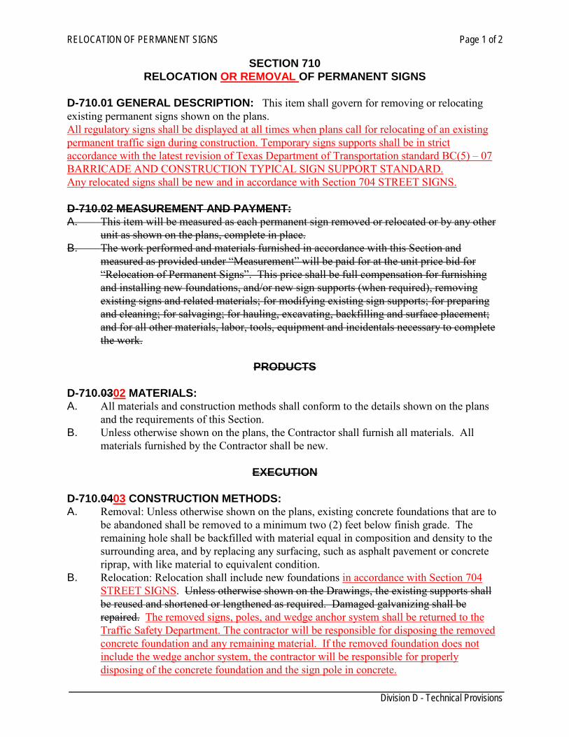
RELOCATION OF PERMANENT SIGNS Page 1 of 2
Division D - Technical Provisions
SECTION 710 RELOCATION OR REMOVAL OF PERMANENT SIGNS
D-710.01 GENERAL DESCRIPTION: This item shall govern for removing or relocating existing permanent signs shown on the plans. All regulatory signs shall be displayed at all times when plans call for relocating of an existing permanent traffic sign during construction. Temporary signs supports shall be in strict accordance with the latest revision of Texas Department of Transportation standard BC(5) – 07 BARRICADE AND CONSTRUCTION TYPICAL SIGN SUPPORT STANDARD. Any relocated signs shall be new and in accordance with Section 704 STREET SIGNS. D-710.02 MEASUREMENT AND PAYMENT: A. This item will be measured as each permanent sign removed or relocated or by any other
unit as shown on the plans, complete in place. B. The work performed and materials furnished in accordance with this Section and
measured as provided under “Measurement” will be paid for at the unit price bid for “Relocation of Permanent Signs”. This price shall be full compensation for furnishing and installing new foundations, and/or new sign supports (when required), removing existing signs and related materials; for modifying existing sign supports; for preparing and cleaning; for salvaging; for hauling, excavating, backfilling and surface placement; and for all other materials, labor, tools, equipment and incidentals necessary to complete the work.
PRODUCTS
D-710.0302 MATERIALS: A. All materials and construction methods shall conform to the details shown on the plans
and the requirements of this Section. B. Unless otherwise shown on the plans, the Contractor shall furnish all materials. All
materials furnished by the Contractor shall be new.
EXECUTION
D-710.0403 CONSTRUCTION METHODS: A. Removal: Unless otherwise shown on the plans, existing concrete foundations that are to
be abandoned shall be removed to a minimum two (2) feet below finish grade. The remaining hole shall be backfilled with material equal in composition and density to the surrounding area, and by replacing any surfacing, such as asphalt pavement or concrete riprap, with like material to equivalent condition.
B. Relocation: Relocation shall include new foundations in accordance with Section 704 STREET SIGNS. Unless otherwise shown on the Drawings, the existing supports shall be reused and shortened or lengthened as required. Damaged galvanizing shall be repaired. The removed signs, poles, and wedge anchor system shall be returned to the Traffic Safety Department. The contractor will be responsible for disposing the removed concrete foundation and any remaining material. If the removed foundation does not include the wedge anchor system, the contractor will be responsible for properly disposing of the concrete foundation and the sign pole in concrete.
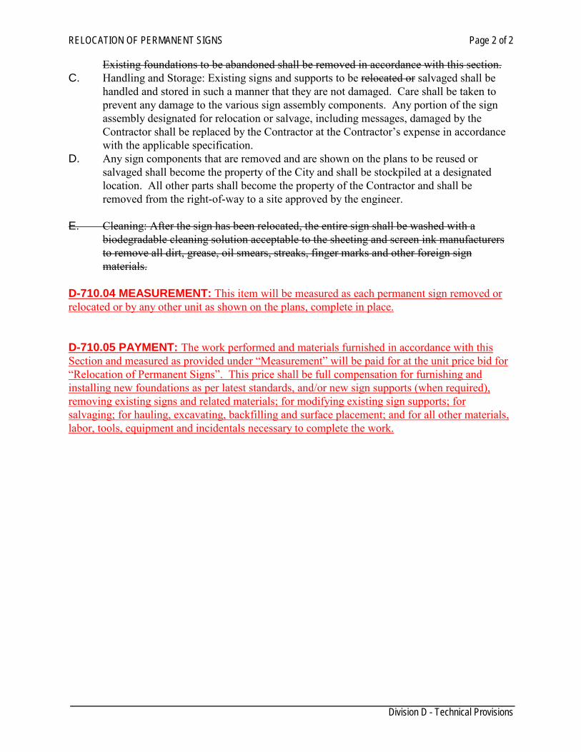
RELOCATION OF PERMANENT SIGNS Page 2 of 2
Division D - Technical Provisions
Existing foundations to be abandoned shall be removed in accordance with this section. C. Handling and Storage: Existing signs and supports to be relocated or salvaged shall be
handled and stored in such a manner that they are not damaged. Care shall be taken to prevent any damage to the various sign assembly components. Any portion of the sign assembly designated for relocation or salvage, including messages, damaged by the Contractor shall be replaced by the Contractor at the Contractor’s expense in accordance with the applicable specification.
D. Any sign components that are removed and are shown on the plans to be reused or salvaged shall become the property of the City and shall be stockpiled at a designated location. All other parts shall become the property of the Contractor and shall be removed from the right-of-way to a site approved by the engineer.
E. Cleaning: After the sign has been relocated, the entire sign shall be washed with a
biodegradable cleaning solution acceptable to the sheeting and screen ink manufacturers to remove all dirt, grease, oil smears, streaks, finger marks and other foreign sign materials.
D-710.04 MEASUREMENT: This item will be measured as each permanent sign removed or relocated or by any other unit as shown on the plans, complete in place. D-710.05 PAYMENT: The work performed and materials furnished in accordance with this Section and measured as provided under “Measurement” will be paid for at the unit price bid for “Relocation of Permanent Signs”. This price shall be full compensation for furnishing and installing new foundations as per latest standards, and/or new sign supports (when required), removing existing signs and related materials; for modifying existing sign supports; for salvaging; for hauling, excavating, backfilling and surface placement; and for all other materials, labor, tools, equipment and incidentals necessary to complete the work.
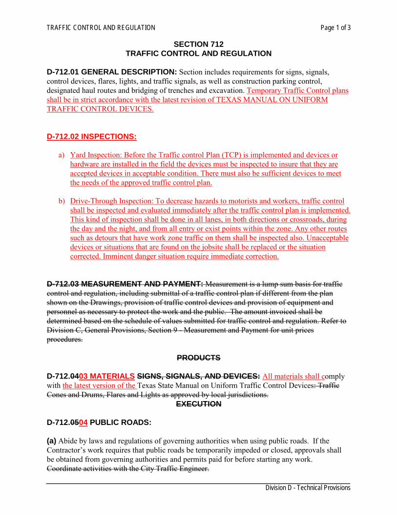
TRAFFIC CONTROL AND REGULATION Page 1 of 3
Division D - Technical Provisions
SECTION 712 TRAFFIC CONTROL AND REGULATION
D-712.01 GENERAL DESCRIPTION: Section includes requirements for signs, signals, control devices, flares, lights, and traffic signals, as well as construction parking control, designated haul routes and bridging of trenches and excavation. Temporary Traffic Control plans shall be in strict accordance with the latest revision of TEXAS MANUAL ON UNIFORM TRAFFIC CONTROL DEVICES. D-712.02 INSPECTIONS:
a) Yard Inspection: Before the Traffic control Plan (TCP) is implemented and devices or hardware are installed in the field the devices must be inspected to insure that they are accepted devices in acceptable condition. There must also be sufficient devices to meet the needs of the approved traffic control plan.
b) Drive-Through Inspection: To decrease hazards to motorists and workers, traffic control
shall be inspected and evaluated immediately after the traffic control plan is implemented. This kind of inspection shall be done in all lanes, in both directions or crossroads, during the day and the night, and from all entry or exist points within the zone. Any other routes such as detours that have work zone traffic on them shall be inspected also. Unacceptable devices or situations that are found on the jobsite shall be replaced or the situation corrected. Imminent danger situation require immediate correction.
D-712.03 MEASUREMENT AND PAYMENT: Measurement is a lump sum basis for traffic control and regulation, including submittal of a traffic control plan if different from the plan shown on the Drawings, provision of traffic control devices and provision of equipment and personnel as necessary to protect the work and the public. The amount invoiced shall be determined based on the schedule of values submitted for traffic control and regulation. Refer to Division C, General Provisions, Section 9 - Measurement and Payment for unit prices procedures.
PRODUCTS D-712.0403 MATERIALS SIGNS, SIGNALS, AND DEVICES: All materials shall comply with the latest version of the Texas State Manual on Uniform Traffic Control Devices: Traffic Cones and Drums, Flares and Lights as approved by local jurisdictions.
EXECUTION D-712.0504 PUBLIC ROADS: (a) Abide by laws and regulations of governing authorities when using public roads. If the Contractor’s work requires that public roads be temporarily impeded or closed, approvals shall be obtained from governing authorities and permits paid for before starting any work. Coordinate activities with the City Traffic Engineer.
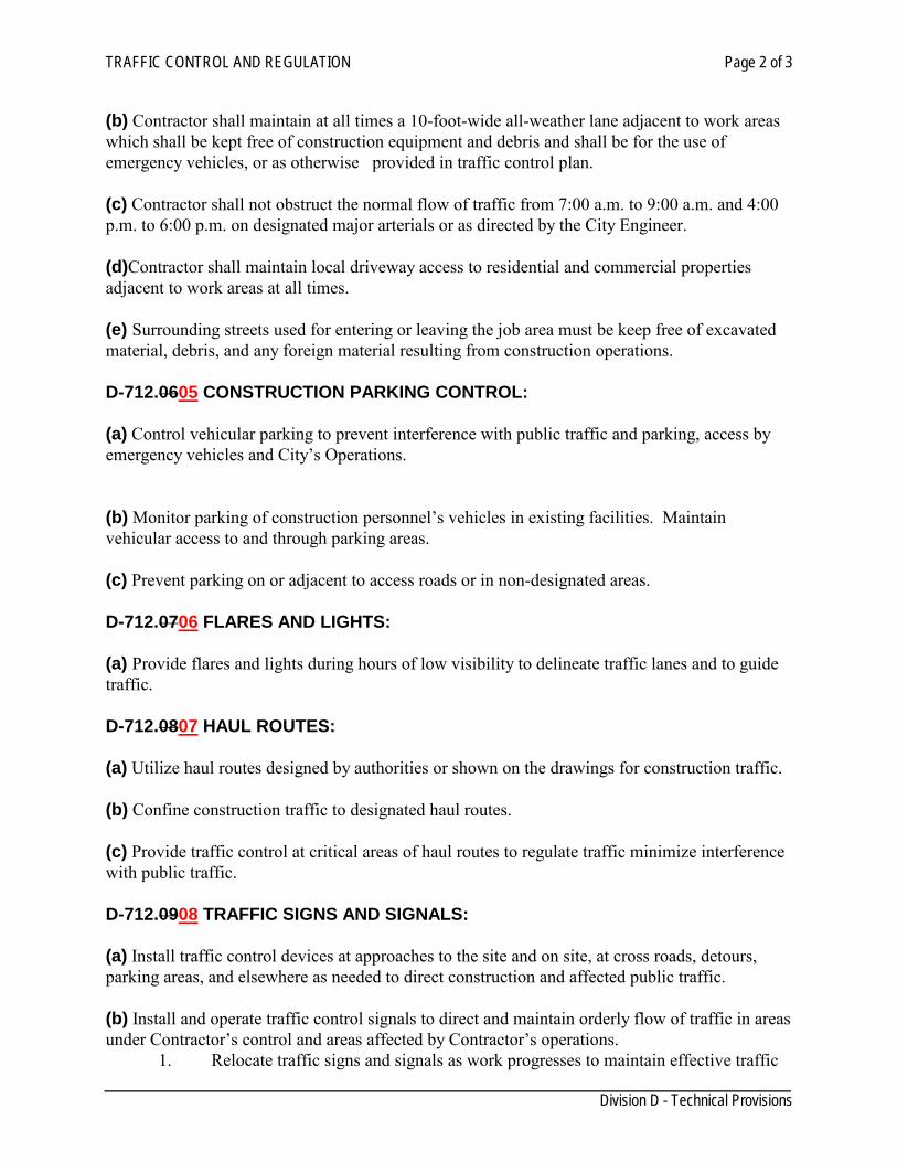
TRAFFIC CONTROL AND REGULATION Page 2 of 3
Division D - Technical Provisions
(b) Contractor shall maintain at all times a 10-foot-wide all-weather lane adjacent to work areas which shall be kept free of construction equipment and debris and shall be for the use of emergency vehicles, or as otherwise provided in traffic control plan. (c) Contractor shall not obstruct the normal flow of traffic from 7:00 a.m. to 9:00 a.m. and 4:00 p.m. to 6:00 p.m. on designated major arterials or as directed by the City Engineer. (d)Contractor shall maintain local driveway access to residential and commercial properties adjacent to work areas at all times. (e) Surrounding streets used for entering or leaving the job area must be keep free of excavated material, debris, and any foreign material resulting from construction operations. D-712.0605 CONSTRUCTION PARKING CONTROL: (a) Control vehicular parking to prevent interference with public traffic and parking, access by emergency vehicles and City’s Operations. (b) Monitor parking of construction personnel’s vehicles in existing facilities. Maintain vehicular access to and through parking areas. (c) Prevent parking on or adjacent to access roads or in non-designated areas. D-712.0706 FLARES AND LIGHTS: (a) Provide flares and lights during hours of low visibility to delineate traffic lanes and to guide traffic. D-712.0807 HAUL ROUTES: (a) Utilize haul routes designed by authorities or shown on the drawings for construction traffic. (b) Confine construction traffic to designated haul routes. (c) Provide traffic control at critical areas of haul routes to regulate traffic minimize interference with public traffic. D-712.0908 TRAFFIC SIGNS AND SIGNALS: (a) Install traffic control devices at approaches to the site and on site, at cross roads, detours, parking areas, and elsewhere as needed to direct construction and affected public traffic. (b) Install and operate traffic control signals to direct and maintain orderly flow of traffic in areas under Contractor’s control and areas affected by Contractor’s operations.
1. Relocate traffic signs and signals as work progresses to maintain effective traffic
TRAFFIC CONTROL AND REGULATION Page 3 of 3
Division D - Technical Provisions
control. D-712.1009 BRIDGING TRENCHES AND EXCAVATIONS (a) Whenever necessary, bridge trenches and excavation to permit an unobstructed flow of traffic. (b) Secure bridging against displacement by using adjustable cleats, angles, bolts or other devices whenever bridge is installed: 1. On a existing bus route; 2. When more than five percent of daily traffic is comprised of commercial or truck traffic; 3. When more than two separate plates are used for the bridge; or 4. When bridge is to be used for more than five consecutive days. (c) Install bridging to operate with minimum noise. (d) Adequately shore the trench or excavation to support bridge and traffic. (e) Extend steel plates used for bridging a minimum one foot beyond edges of trench or excavation. Use temporary paving materials (premix) to featheredges of plates to minimize wheel impact on secured bridging. (f) Use steel plates (refer to SECTION 808) of sufficient thickness to support H-20 loading, truck or lane that produces maximum stress. D-712.1110 REMOVAL (a) Remove equipment and devices when no longer required. (b) Repair damage caused by installation (c) Remove post settings to a depth of 2 feet. D-712.11 MEASUREMENT: Measurement is a lump sum basis for traffic control and regulation, including submittal of a traffic control plan if different from the plan shown on the Drawings, provision of traffic control devices and provision of equipment and personnel as necessary to protect the work and the public. D-712.12 PAYMENT: The amount invoiced shall be paid by percent completed or as approved by the Engineer based on the schedule of values submitted for traffic control and regulation. Refer to Division C, General Provisions, Section 9 - Measurement and Payment for unit prices procedures.
LIGHTING AND SIGNING Page 1 of 1
Division D - Technical Provisions
SECTION 714 LIGHTING AND TRAFFIC SIGNALS
D-715.01 GENERAL DESCRIPTION: This item shall govern for the furnishing, assembling, and installation of street lighting, electrical services, traffic signals, and flashers and shall be in strict accordance with DIVISION VI, Lighting and Signing from the Texas Department of Transportation STANDARDS SPECIFICATIONS FOR CONSTRUCTION OF HIGHWAYS, STREETS AND BRIDGES. D-702.02 MATERIALS: All materials, erection, and usage shall be in strict accordance with DIVISION VI, Lighting and Signing from the Texas Department of Transportation STANDARDS SPECIFICATIONS FOR CONSTRUCTION OF HIGHWAYS, STREETS AND BRIDGES. D-704.04 MEASUREMENT: Measurement will depend on t he item and shall be in strict accordance with DIVISION VI, Lighting and Signing from the Texas Department of Transportation STANDARDS SPECIFICATIONS FOR CONSTRUCTION OF HIGHWAYS, STREETS AND BRIDGES. D-702.05 PAYMENT: The amount invoiced shall be paid as approved by the Engineer based on the schedule of values submitted. The price bid shall be considered to include materials, labor, equipment and incidentals necessary to complete the work.
Sheeting and Bracing Page 1 of 2
Division D - Technical Provisions
SECTION 802 SHEETING AND BRACING
GENERAL
D-802.01 DESCRIPTION: Unstable soil encountered in trench or foundation excavation which tends to cave in or otherwise, shall be properly sheeted and braced as per OSHA requirements. Sufficient bracing material shall be left in place to guarantee safety to workmen and material where removal of such sheeting and bracing after it has served its purpose would be dangerous to workmen during backfilling or harmful to materials in place.
MATERIALS D-802.02 MATERIALS: The sheeting material to be placed in contact with the dirt shall be either rough lumber with a minimum thickness of 2" appropriately designed steel sheet piling. Braces shall consist of lumber with a minimum thickness of 4" or metal screw jacks or other mechanical devices approved by the Engineer. All lumber shall be No. 3 common or better. D-802.03 WHEN TO INSTALL SHEETING AND BRACING: Whenever, in the opinion of the Engineer or the Contractor, the soil at the edge of any excavation is sufficiently unstable as to endanger the safety of life, limb, or property, sheeting and bracing material shall be installed. Such material shall also be installed in all trenches whose sides are steeper than the natural angle of repose of the soil material if it were in loose uncompacted condition and the trenches are in excess of 8 feet deep, but only such portions of the total height of the trench shall be sheeted as appears necessary. Should a layer or pocket of material be encountered anywhere in the trench or other excavation which is of such type as to make possible the failure of adjacent soils, such layer or pocket shall be sheeted and braced in such a manner as to insure its permanency. Whenever a doubt exists as to the necessity of the installation of sheeting and bracing, it shall be installed.
CONSTRUCTION METHODS D-802.04 GENERAL: Upon discovery of unstable material in any excavation, such sheeting and bracing as may be deemed adequate by the Engineer shall be installed. Stay bracing, piling boards, and box or vertical sheeting methods shall be used depending on the nature of the unstable material encountered. Metal sheeting and steel sheet piling may be used at the option of the Engineer. D-802.05 MEASUREMENT: This item will be measured by the foot along the long axis of the trench. D-802.06PAYMENT: Contractor shall investigate the conditions as they exist in the field and include in the unit price bid per linear foot. This price is full compensation for the excavation and backfill required for excavation protection; furnishing, placing and removing shoring, sheeting, or bracing; dewatering or diversion of water; jacking and jack removal; and equipment, labor, materials, tools and incidentals.
Sheeting and Bracing Page 2 of 2
Division D - Technical Provisions
Work Performed on Non-Working Days Page 1 of 1
Division D - Technical Provisions
SECTION 804
WORK PERFORMED ON NON-WORKING DAYS D-804.01 WORKING DAY: A working day is Monday thru Friday, 8:00 a.m. to 5:00 p.m. excluding holidays. D-804.02 WORK PERFORMED ON A NON-WORKING DAY: Any work which is to be performed on a non-working day must be inspected. The Engineer will decide which work will be requiring the presence of an inspector. D-804.03 COST OF INSPECTION: The cost for having an inspector present shall be incurred by the Contractor performing the work. Such arrangements will be made in writing and submitted to the Engineer for his approval. Any testing requested by the contractor out of service hours or any overtime charged by the testing laboratory for delaying, shall be paid by the contractor. D-804.04 STOP WORK: Any work stoppage by the contractor must be reported in writing to the engineer and owner 24 hours prior to work stoppage.
Automatic Irrigation System Page 1 of 8
Division D - Technical Provisions
SECTION 806
AUTOMATIC LANDSCAPE IRRIGATION SYSTEM D-806.01 DESCRIPTION: The work consists of the installation of a complete underground landscape irrigation system as shown on the drawings and as specified hereafter. The Contractor performing this work shall furnish all labor, equipment, materials, and perform tests necessary for the completion of the system. Contractor is responsible to obtain an irrigation permit before start construction. D-806.02 GENERAL: All irrigation installations and repairs are to be made under the direct supervision of a licensed irrigator or irrigation technician (TCEQ 344). Contractor shall not begin construction of the irrigation system without having the meter tap installed. Contractor shall be aware of the following: 1. Protection of existing utilities.
The Contractor shall be responsible for locating all cables, conduits, piping, irrigation system, and any other utilities or structures that may be encountered either above or below ground. This includes, but is not limited to trees, ornamentals, and turf grass. All necessary precautions must be taken by the Contractor to prevent any damage to these existing improvements. In the event that such damage should occur from the Contractor’s operations, the Contractor shall repair or replace or bring to original condition the damaged utilities or improvements at the Contractors expense.
2. Rock If the Contractor encounters rock or other unfavorable trenching conditions, no additional compensation will be paid. When material from the excavation or trenching is unsuitable for use as backfill, additional backfill material suitable for this purpose shall be brought in at the expense of the Contractor. It shall also be the Contractors responsibility to remove and legally dispose of all unsuitable materials removed from the trench that cannot be used in the backfill operation.
3. Safety Contractor shall provide all required safety signage, barricades, and flashers/strobes. All employees shall have proper safety devices and equipment, including safety vests, and hearing and eye protection. All equipment and personal protective equipment shall meet OSHA and TXDOT safety standards. Warning signs and barricading shall be in accordance with all local, state and/or federal laws. If a contractor is discovered working without necessary safety devices or equipment in place, they will be required to stop all work in progress. Contractor will not be allowed to return to work until adequate safety equipment and/or devices are in place. In addition, all open trenches or pits that are unattended should be flagged in their entirety. Installed valve boxes shall remain securely closed unless Contractor is rendering work to the box. And if traffic, vehicular or otherwise, is affected, Contractor shall submit a complete traffic control plan.
D-MATERIALS: unless otherwise shown on the plans, use materials that meet the following:
Automatic Irrigation System Page 2 of 8
Division D - Technical Provisions
1. General: The irrigation system was designed around equipment manufactured by specific
companies as a standard. There are “no approved equals” for any of the materials specified. Contractor will be required to submit a complete list of all materials to be used in the installation.
2. Pipe: Use polyvinyl chloride (PVC) pipe meeting ASTM D2241, SDR 13.5, SDR 17, SDR 21; or ASTM D1785, Schedule 40.
a. Irrigation pipe downstream of master valve shall be class 200 PVC for sizes ¾”and up. All PVC pipe shall be continuously and permanently marked with the manufacturers name or trade mark, size, schedule, type, working pressure at 73 degrees F., SDR number, products standard number and National Sanitation Foundation (NSF) approval.
b. All lateral line pipes shall be solvent welded. “Ring-and-gasket” pipe may be used with engineer’s approval for main lines 4” and above only if AWA mechanical joint fittings and proper blocking are used on a ll directional changes, see Detail 806-1 “thrust blocks”.
c. Copper pipe or tubing shall be type K” for pipe installed downstream of irrigation meter to the master valve. Use straight lengths of domestic manufacturer only.
3. Fittings: Furnish fittings as shown on the plans. PVC fittings must meet ASTM D2466. Solvent welded pipe fittings shall be molded fittings, Schedule 40, manufactured of the same material as the pipe, and shall be suitable for solvent weld slip joint ring, tight seal or threaded connection. All copper pipe fittings shall be sweat-type fittings of domestic manufacturer.
4. Cements: Cleaners/primers, and joint compounds.
a. Cement shall be clear plastic pipe cement for use on all sizes and schedules of PVC pipe and fittings. Cement must be NSF approved and meet ASTM D 2564 specifications. Note: Colored glue is to be used for any reason to ensure primer is visible during inspection.
b. PVC pipe and fittings shall be primed with a colored primer prior to applying the PVC cement in accordance with the Uniform Plumbing Code (Section 316) or the International Plumbing Code (Section 605).
c. All threaded connections between PVC and metal pipe shall be made using teflon tape only.
d. All metal to metal connections and all PVC to PVC threaded connections shall use teflon tape.
5. Wiring:
a. Low voltage wire: Use minimum 14 gauge UL-approved wire for direct burial. b. All wire splices shall be made watertight using either Wade WC-014, 3M
DBY/DBR, or Tom King “black” LVS500, splice connectors. All wiring installed under sidewalks, roadways, parking lots, etc, shall be installed in a Class 200 PVC sleeve). The sleeve shall be sized to allow for easy installation or removal of the wire Detail 806-2, 806-3, and 806-4. Note: Wire should not be run in the same sleeve as a main or lateral line ,Detail 806-5
6. Backflow Prevention Assembly: All assemblies are to be approved by the American Water
Automatic Irrigation System Page 3 of 8
Division D - Technical Provisions
Works Association. All backflow prevention assemblies shall be provided in accordance with the following:
a. Irrigation system with chemical additives shall use a RPBA ( Reduced-Pressure principle Backflow Prevention Assembly) Detail 806-10.
b. Irrigation system without chemical additives can use the following: i. DCVA (Double Check Valve Backflow Prevention Assembly) Detail 806-9,
ii. AVB (Atmospheric Vacuum Breaker), or iii. PVB (Pressure Vacuum Breaker)
Consult with the Utilities department for the list of approved Manufacturers.
7. Accessories: Use valves, sprinkler heads, and controllers that meet the requirements shown on the plans.
D-806.04 SUBMITTALS: 1. Record Drawings:
a. The Contractor shall provide and keep up-to-date a complete set of record drawings which shall be corrected to show all approved changes in the location of irrigation heads, controllers, backflow preventers, valves, drains, meters, points of connection, wire splice points, pipe and wire routing and other changes that may have been made from the original drawings and specifications. All gate valves, manual drains, wire splices, automatic and manual valve locations, controllers, power supply, and mainline piping shall be shown with actual triangulated measurements to reference points so they may be easily located in the field.
b. At the time of final acceptance, the Contractor shall furnish a reproducible record drawing (mylar) prepared showing the entire completed system as actually installed. The Contractor shall provide a legible reduction of the drawings, laminated in plastic as well as a high resolution digital scanned copy.
D-806.05 CONSTRUCTION: This work shall be performed by either a licensed irrigator/ licensed irrigation technician by the TCEQ and shall be on-site at all times while the landscape irrigation system is being installed. Documentation of the license shall be provided. When an irrigator is not on-site, the irrigator shall be responsible for ensuring that a licensed irrigation technician is on-site to supervise me installation of the irrigation system. The Owner may demand that work stop until the Contractor provides for a Licensed Irrigator, Licensed Irrigation technician to be present at the project site and supervising all irrigation work. Contractor shall perform the following activities as required: 1. A pre-construction site observation will be conducted prior to construction to observe conditions
and note features which maybe considered inoperable or have prior damage. Note: A site visit affidavit may be required.
2. In any situation that the plans show a conflict in the actual site conditions, it shall be the
Contractor’s responsibility to notify the Owner/Engineer of the conflict to receive direction.
Automatic Irrigation System Page 4 of 8
Division D - Technical Provisions
Irrigation work shown on the drawings within tree dripline areas is not diagrammatic, and must be constructed exactly as shown on the drawings.
3. Excavation and trenching ,Detail 806-5:
a. Prior to trenching, the Contractor shall contact line location services to spot all utility lines.
b. Excavation and trenching for pipelines shall be true to line with vertical trench banks. The width of the trenches shall not be greater than necessary to permit proper jointing, tamping, backfilling, bedding or any other installation procedures may be necessary.
c. Excavate the trench a minimum of 12 inches of soil cover for main lines and a minimum of 6 inches of soil cover for laterals or as shown on plans. Use common trenches for irrigation lines and wire runs where feasible. Protect trenches and boring pits 5 ft deep or deeper in accordance with Section “Shoring and Bracing”
d. In rocky areas, the trenching depth shall be six (6) inches below normal trench depth to allow for pipe bedding as described in other portions of these specifications.
4. Pipe and fittings:
a. Before installation, the inside of the pipe shall be cleaned of all direct and foreign matter and shall be kept in a cleaned condition during and after laying of the pipe. When work is not in progress, open ends of pipe and fittings shall be securely dosed so that no trench water, earth, or other foreign substances enter the pipe or fittings. Where pipe ends are left for future expansion or connections, they shall be valved and capped, as directed on the drawings.
b. Before installing the pipe, all rubbish and rocks shall be removed from the trenches. If the soil is extremely rocky, the trenches shall be padded with dirt or sand. Material used for pipe padding shall be approved by the engineer. The full length of each section of the pipe shall rest solidly upon the pipe bed.
c. PVC pipe will expand or contract at the rate of one (1) inch per 100 feet per 10 degrees F change in temperature. Therefore, the pipe shall be installed in a manner so as to provide for expansion and contraction as recommended by the manufacturer.
d. When more than one pipe is installed in the same trench, a four (4)-inch separation shall be maintained at all times.
e. After all irrigation piping, risers, valves, thrust blocks, etc. have been installed and partially backfilled as specified, the control valve shall be opened and a full head of water used to flush out the system. After the system is thoroughly flushed, risers shall be capped off and the system pressure tested in accordance with the testing section of these specifications. At the conclusion of the pressure test, the heads shall be installed and the backfill operation completed.
5. Backfilling:
a. Upon completion of a particular section of the irrigation system, and after sufficient time has elapsed for the curing of solvent weld joints, partial backfilling can begin if inspection has occurred and owner’s representative has approved. Only the sections approved can be backfilled. If a hydrostatic test is required, all joints, risers and connections shall remain exposed for visual observation during the hydrostatic test. After completion and acceptance of the hydrostatic test for a particular section of the irrigation
Automatic Irrigation System Page 5 of 8
Division D - Technical Provisions
system, the backfill operation can be completed if owner’s representative has approved. b. In the event that the material from the excavation or trenching is found to be unsuitable
for use in backfill. It shall be removed from the site and properly disposed of by the Contractor and at the Contractor’s expense. The Contractor shall then, at no additional cost to the Owner, arrange for, purchase, and furnish suitable backfill material consisting of earth, loam, sandy clay, sand, or other approved materials free of large clods of earth or sharp stones.
6. Sleeved crossing Detail 806-6: Unless otherwise noted on drawings, all piping installed under
sidewalks, roadways, parking lots, etc., shall be sleeved in a SCH 40 PVC pipe two sizes larger than the pipe to be sleeved. Wring shall be placed in a separate sleeve from that of the pipe crossing and shall be two(2) inches or larger SCH 40 PVC. Every effort shall be made by the Contractor to install sleeving prior to the pouring or construction of the sidewalks, roadways, parking lots, etc. If prior sleeving is not possible, all crossings must be bored unless written authorization for an open cut is obtained from the engineer. All pipe and wire sleeves shall extend 1-2’ beyond paving, concrete, median opening, and payers.
7. Irrigation heads Detail 806-7 Irrigation heads shall be the type and make specified on the plans
and shall be installed to finished grade unless otherwise specified. Irrigation heads shall be installed a maximum of six (6) inches and a minimum of four (4) inches from curbs, walls, driveways, building walls, etc. Heads shall be installed in the vertical positions, hand backfilled, and compacted to near original density.
8. Controller (weather based sensor ) Detail 806-8:
a. A licensed electrician shall perform power installation for AC controllers. b. The controller shall be mounted and wired according to the manufacturers recommended
procedures and as specified in these specifications and on the drawings. c. Electric control valves shall be connected to controller in the numerical sequences as
shown on the drawings. The owner reserves the right to change the numerical sequencing of the valves during the installation process if it is deemed necessary or appropriate.
d. Controller shall be installed in a locking controller enclosure as specified on the drawings.
e. Contractor shall provide two blue wires for the pulse signal on the flow meter in addition to two green wires to be used as spares.
f. All controller wire installation must be done in accordance with manufacturer’s specification.
9. Electrical control valves, Details 806-2, 806-3: All electric control valves shall have flow
control and be of the type and size as indicated on the drawings and shall be installed where shown on the drawings, following the published recommendations of the manufacturer and in accordance with these specifications and drawings.
a. Any DC-powered system must provide DC latching solenoids at no additional cost the Owner.
b. All DC-powered systems must be installed per manufacturers specification c. The valve boxes shall be as specified in City standard detail
Automatic Irrigation System Page 6 of 8
Division D - Technical Provisions
d. Valve wire splices shall be waterproofed using either Wade WC-014, 3M DBY/DBR, or Tom King “black” LV9500 splice connectors, part # LV9500. The Contractor shall leave 24 inches of wire coiled to facilitate raising the wire out of the valve box for repairs.
e. Type K copper shall installed from the inlet side of the ball valve/master valve assembly back to the double check; and from the inlet side of double check back to the meter.
f. The contractor shall install 2 yellow wires for master valve and 2 black wires to be used as spare. Both pairs of wires shall run from the master valve to the controller.
10. Volt control valve wiring: All wire installation procedures as described herein shall be checked
to conform to local electrical codes. a. For AC controllers, all wire used for the 24 volt wiring from the controller to the electric
control valves shall be type ‘UF”. 600 volt, solid copper, single conductor, PVC insulated and bear UL approval for direct burial underground feeder cable. Unless otherwise specified on the drawings, the 24 volt common wires shall be white wire No. 12 AWG and the remaining 24 volt control wires shall be red No. 12 AWG. These colors shall be noted on the “as-built” record drawings.
b. The Contractor shall install the 24-volt control valve wiring in the same trench as me irrigation system mainline. In no situation shall the wire be installed above (i.e. on top of) the mainline. The wires shall be laid loose in the trench to allow for contraction. Control wires shall be taped together in 20’ increments
c. No wire splices will be allowed in DC Systems. other than at valve box locations. Wire splices in AC systems are allowed, but must receive prior approval from owners representative and must be noted on the ‘as built” plans. If needed, they shall be made only at common splice points and placed in a standard double check valve box. Reference Detail 806-4. The location of these wire splice boxes shall be shown on the “as-built” record drawings. No bulled wire splices shall be permitted. All wire splices shall be made waterproof using material specified in section 2.04
d. In no case shall wires of different colors be spliced together. e. All wiring shall be subsidiary to control valve installation.
Note: DC latching solenoids shall not exceed a distance of more than 800 feet from the controller.
11. 120 Volt controller power wiring (AC Systems only): AC Controllers requiring 120 volt wiring shall be installed in accordance with State and local electrical codes and regulations. The 120-volt service shall consist of one black and one white wire. The neutral wire must be bonded. All wiring is subsidiary to project. If required, contractor shall provide and install 120-volt power to the controller location. A Licensed Electrician shall perform all high voltage electrical work.
12. Mainline manual drain valves: M anual drain valves of the size and type indicated on t he
drawings may be installed as necessary at low points of mainline piping, at any other points that may be indicated on the irrigation system drawings.
13. Backflow Assembly: Assemblies will be installed in an accessible location to facilitate
maintenance, testing and repair and shall never be located more than five feet above the floor or grade level. Backflow preventers shall be installed between the meter and the owner’s first tap or tee.
Automatic Irrigation System Page 7 of 8
Division D - Technical Provisions
a. Before installing an assembly, pipelines shall be thoroughly flushed to remove foreign
material. b. Test cocks must never be used as supply connections and must be plugged except
when being tested. c. Type K copper pipe shall be used for all RP and PVB installations. d. Schedule 80 PVC pipe and fittings shall be used for AVB installations in residential
settings. e. At least one union shall be installed within at least 12 inches of the backflow
prevention assembly. f. A manual shut-off valve shall be installed between the potable water supply and the
backflow prevention unit.
14. Testing:
a. Upon completion of the irrigation system’s main line, the entire mainline shall be tested for a six (6) hour period at existing static pressure. Prior to testing, the mainline shall be partially backfilled, leaving all joints and connections exposed for visual observation. All dirt shall be flushed from the system and the line filled with water to remove air. The mainline shall be brought to static pressure. The existing static pressure must be retained for a six (6) hour period. Any leaks resulting in the six (6) hour pressure test shall be repaired and the system retested until the system passes the test.
b. The irrigator shall ensure the backflow prevention device is tested by a l icenced Backflow Prevention Assembly Tester prior to being placed in service and the test results provided to the local water purveyor and the irrigation system's owner or owner's representative within ten business days of testing of the backflow prevention device.
D-806.06 INSPECTIONS: Backflow prevention device shall be inspected and tested at least once a year by a licensed Backflow Prevention Assembly Tester. D-806.07 MEASUREMENT AND PAYMENT: This item may be paid by a lump sum or as indicated in the contract documents.
Automatic Irrigation System Page 8 of 8
Division D - Technical Provisions
Steel Plate, Trench Plate: Bridging Utility Provisions Page 1 of 3
Division D - Technical Provisions
SECTION 808 STEEL PLATE, TRENCH PLATE: BRIDGING UTILITY PROVISIONS
GENERAL
D-808.01 DESCRIPTION: Temporary Steel Plate Bridging: When approved by the Engineer or Contracting Agency the Contractor may use steel plates to bridge excavated trenches in areas where the roadway surface is to be opened to traffic. D-808.02 MATERIALS: The plates shall be of steel construction capable of suporting HS-20 loading. Plates shall be fabricated from ASTM-36 Steel (Min). (see drawing 808-1 for plate tickness) Plate Locks Trench Securing System D-808.03 WHEN TO INSTALL STEEL PLATES: When backfilling operations of an excavation in the traveled way either transverse or longitudinal cannot be properly completed within a work day, steel plate bridging may be required to preserve unobstructed traffic flow. In such cases, the fo1lowing conditions shall apply:
1. The plates must extend beyond the edge of the trench wall to adequately support the traffic loads on it. All steel trench plates shall extend beyond the edges of the trench wall a minimum of twelve (1 2”) inches. Drawing No. 808-1
2. Trenches and excavations shall be adequately shored and braced to withstand highway traffic loads.
3. Each plate must be fully supported around the perimeter to prevent wobbling or rocking with non asphaltic shims and installed to operate with minimum noise.
4. Plates shall be secured and ramped on all sides with a trench plate securing device, to ensure a smooth transition from the road surface to the top of the plate surface and back to the road surface.
5. If the trench steel plates are going to be in place more than 48 hrs, a “STEEL PLATE” sign with black lettering on an orange background will be used in advance of steel plate bridging. This sign is used along with any other required construction signing.
6. The contractor is responsible for maintenance of the steel plates, shoring, and trench plate securing systems, and ensuring that they meet minimum specifications. If city forces must correct emergency condition due to excavation and plate placement and or movement, Contractor will be charged for the cost of corrective measures required.
Steel Plate, Trench Plate: Bridging Utility Provisions Page 2 of 3
Division D - Technical Provisions
CONSTRUCTION METHODS
D-808.04 GENERAL: For trenches and excavations with spans greater than four feet (4’), a structural design shall be prepared by a civil engineer registered in the state of Texas and approved by the City. Steel plate bridging and shoring shall be installed using either Method (1) or (2):
Method 1: Roadways with posted speeds equal to or less than 30 mph
One pre-approved method of securing steel trench plates involves a perimeter restraint consisting of polypropylene (PP). This method involves placing a 6” wide strip of PP along the edges of the trench plate which are exposed to traffic. The adjacent edges of multiple trench plates do not require additional edge restraint along those edges.
The PP strips shall be tapered from a nominal 1” thickness to approximately 1/4’ to provide a ramped surface for vehicles to enter and exit the trench plate. The PP perimeter restraint shall be safety orange in color to provide high visibility and help alert drivers to the presence of trench plates.
The perimeter restraint shall be secured to the pavement with 4” long Simpson -Titan H.D 3/8” concrete anchors (or equal) with washers. Anchors shall be spaced at intervals of 36” or less. The ends of the perimeter restraint shall be anchored a minimum 4” and a maximum of 8” from each end.
The horizontal gaps between the sides of the perimeter restraint and the trench plate shall not exceed ½”. Vertical differences in elevation between the top of the perimeter restraint and the top of the trench plate shall not exceed ½”. Plates shall be shimmed with PP shims to prevent vertical movement of the trench plate of more than ¼” at any location. Shims, as required, shall be secured below the perimeter restraint at the anchor locations used to secure the frame. Shim thicknesses shall be limited to a total of 3/4”. Gaps that require greater than 3/4” thick shims shall be corrected by reorienting trench plates to reduce the size of vertical gaps between the bottom of the trench plate and the street surface.
Holes in the PP perimeter restraint and shims shall be pre-drilled and oversized to allow for PP expansion and contraction. Holes in the perimeter restraints shall be counter sunk to minimize exposure of bolt heads to traffic.
Trench plates may be removed and replaced as necessary to complete utility work in the street without removal of the PP perimeter restraint. Upon completion of construction and permanent removal of trench plates and frames, the anchor screw holes shall be filled with liquid asphalt during the trench patching operation or with high strength grout or other material approved or directed by the engineer. Patch material shall be struck smooth with the street surface.
The PP securing system shall be substantially similar, or equal to, the Plate Lock Trench Plate Securing System which is pre-approved for use. The trench plate securing system shall be installed
Steel Plate, Trench Plate: Bridging Utility Provisions Page 3 of 3
Division D - Technical Provisions
per manufacture’s direction and continuously maintained around all outside edges of the trench plates until removal of the plates.
Method 2: Roadways with posted speeds greater than 30 mph
The pavement shall be cold-planed to a depth equal to the thickness of the plate and to a width and length equal to the dimensions of the plate(s) The approach and ending plates shall be attached to the roadway by a minimum of 2 dowels pre-drilled into the corners of the plate and drilled 3 inches into the pavement: subsequent plates shall be butted to each other.
D-808.05 MEASUREMENT AND PAYMENT: No Separate measurement or payment will be made for this item
Definitions Page 1 of 5
Division D - Technical Provisions
SECTION 810
DEFINITIONS
Whenever used in these GENERAL CONDITIONS or in the other Contract Documents, the following terms have the meanings indicated which are applicable to both the singular and plural thereof:
Addenda-Written or graphic instruments issued by ENGINEER prior to the receipt of bids which clarify, correct, or change the Bidding Requirements or the Contract Documents.
Agreement-The written contract between OWNER and CONTRACTOR covering the Work to be performed; other Contract Documents are attached to the Agreement and made a part thereof as provided therein.
Application for Payment-A request from CONTRACTOR for a progress or final payment on the form accepted by ENGINEER and which is accompanied by such supporting documentation as is required by the Contract Documents.
Asbestos-Any material that contains more than one percent (1%) asbestos and is friable or is releasing asbestos fibers into the air above current action levels established by the United States Occupational Safety and Health Administration.
BID-The offer or proposal of the BIDDER submitted on t he prescribed form setting forth the required information, including prices for the Work to be performed.
Bidder- An individual, partnership, l imited liability company, corporation, or joint venture submitting a bid for a proposed Contract.
Bidding Documents-The advertisement or Invitation to Bid, Instructions to Bidders, the Bid form, and the proposed Contract Documents (including all Addenda issued prior to receipt of Bids).
Bidding Requirements-The information requested by and conditions for bidding set forth in the advertisement or Invitation to Bid, Instructions to Bidders, and the Bid form.
Bonds-Performance and Payment bonds and other instruments of security.
Change Order-A document prepared by ENGINEER, which is signed by CONTRACTOR and OWNER and authorizes an addition, deletion, or revision in the Work, or an adjustment in the Contract Price or the Contract Times, issued on or after the Effective Date of the Agreement.
Contract Documents-The Agreement, Addenda (which pertain to the Contract Documents), Contractor’s Bid (including documentation accompanying the BID and any post-bid documentation accompanying the BID and any post-bid documentation submitted prior to the Notice of Award) when attached as an exhibit to the Agreement, the Notice to Proceed, the Bonds, these GENERAL CONDITIONS, the Supplementary Conditions, the Specifications, and the PLANS, as the same are more specifically identified in the Agreement, together with all Written Amendments, Change Orders, Work Change Directives, Field Orders, and
Definitions Page 2 of 5
Division D - Technical Provisions
ENGINEERS’s written interpretations and clarifications, issued pursuant to Paragraph 3.3, on or after the Effective Date of the Agreement. S hop Drawing submittals approved pursuant to Paragraphs 6.17.4 and 6.17.5 and the reports and drawings referred to in Paragraphs 4.2.1 and 4.2.2 are not Contract Documents.
Contract Price-The amount agreed to by OWNER and CONTRACTOR for completion of the Work, in accordance with the Contract Documents, as stated in Article 4 of the Agreement (subject to the provisions of Paragraph 11.3.1 in the case of Unit Price Work), and as adjusted by any Change Orders.
Contract Times-The numbers of days or the dates stated in the Agreement: (i) to achieve Substantial Completion, and (ii) to complete the Work so that it is ready for final payment as evidenced by ENGINEER’s written recommendation of final payment in accordance with Paragraph 14.9.1.
CONTRACTOR-The person, firm, or corporation with whom OWNER has entered into the Agreement.
Defective-An adjective which, when modifying the word Work, refers to Work that is unsatisfactory, faulty, or deficient, in that it does not conform to, or has not been performed in accordance with, the Contract Documents, or does not meet the requirements of any inspection, reference standard, test, or approval referred to in the Contract Documents, or has been damaged prior to ENGINEER’s recommendation of final payment (unless responsibility for the protection thereof has been assumed by OWNER at Substantial Completion in accordance with Paragraph 14.5.1 or 14.6).
Effective Date of the Agreement-The date indicated in the Agreement on which it becomes effective; but if no such date is indicated, it means the date on which the Agreement is signed and delivered by the last of the two parties to sign and deliver.
ENGINEER-The licensed person, firm, or corporation authorized by the City or the owner to act on their behalf.
ENGINEER’s Subconsultant-A licensed person, firm, or corporation having a contract with ENGINEER to furnish services as ENGINEER’s independent professional associate or consultant with respect to the Project and who is identified as such in the Supplementary Conditions.
Field Order-A written order issued by ENGINEER which orders minor changes in the Work in accordance with Paragraph 9.5 but which does not involve a change in the Contract Price or the Contract Times.
General Requirements-Sections of Division A, B, and C of the Specifications.
Hazardous Waste-The term Hazardous Waste shall mean (i) any hazardous materials, hazardous wastes, hazardous substances, and toxic substances as those or similar terms are defined under any Environmental Laws; (ii) any Asbestos or any material which contains any hydrated mineral silicate, including chrysolite, amosite, crociodolite, tremolite, anthophylite, and/or actinolite, whether friable or non-friable;(iii) any PCBs or PCB-containing materials, or fluids; (iv) radon;
Definitions Page 3 of 5
Division D - Technical Provisions
(v) any other hazardous, radioactive, toxic, or noxious substance, material, pollutant, or solid, liquid, or gaseous waste; (vi) any pollutant or contaminant (including petroleum, petroleum hydrocarbon, petroleum products, crude oil, and any factions thereof; any oil or gas exploration or production waste, and natural gas, synthetic gas, and any mixtures thereof) that in its condition, concentration, or area of release could have a significant effect on human health, the environment, or natural resources; (vii) any substance that, whether by its nature or its use, is subject to regulation under any Environmental Law or, with respect to which any Environmental Law or Governmental Authority, requires environmental investigation, monitoring, or remediation; (viii) any Radioactive Material; and (ix) any underground storage tanks, as defined in 42 U .S.C. Section 699(1)(A)(I) (including those defined by Section 9001[1] of the 1984 Hazardous and Solid Waste Amendments to the Resource Conservation Act, 42 U.S.C. Section 6901 et seq.; the Texas Water Code Annotated Section 26.344; and Title 30 of the Texas Administrative Code Sections 334.3 and 334.4), whether empty, filled, or partially filled with any substance.
Laws and Regulations; Laws or Regulations-Any and all applicable laws, rules, regulations, ordinances, codes, and orders of any and all governmental bodies, agencies, authorities, and courts having jurisdiction over the Work, the Project, and/or the CONTRACTOR’s performance of the Work.
Liens-Liens, charges, security interests, or encumbrances upon real property or personal property.
Milestone-A principal event specified in the Contract Documents relating to an intermediate completion date or time prior to Substantial Completion of all the Work.
Notice of Award-The written notice by OWNER to the apparent Successful Bidder stating that, upon compliance by the apparent Successful Bidder with the conditions precedent enumerated therein, within the time specified, OWNER will sign and deliver the Agreement.
Notice to Proceed-A written notice given by OWNER to CONTRACTOR (with a copy to ENGINEER) fixing the date on w hich the Contract Times will commence to run and on which CONTRACTOR shall start to perform CONTRACTOR’s obligation under the Contract Documents.
OR EQUAL CLAUSE- Whenever a m aterial or article required is specified or shown on t he plans by using the name of the proprietary product, or of a particular manufacturer or vendor, any material or article which will perform adequately the duties imposed by the general design will be considered equal and satisfactory, provided the material or article so proposed is of equal substance and function, and only after written approval by the City Engineer. OWNER-The public body or authority, corporation, association, firm, or person which is a party to the Agreement and for whom the Work is to be provided.
Partial Utilization-Use by OWNER of a substantially completed part of the Work for the purpose for which it is intended (or a related purpose) prior to Substantial Completion of all the Work in accordance with Paragraph 14.6.
PCBs-Polychlorinated biphenyls.
Definitions Page 4 of 5
Division D - Technical Provisions
Petroleum-Petroleum, including crude oil or any fraction thereof, which is liquid at standard conditions of temperature and pressure (60 degrees Fahrenheit and 14.7 pounds per square inch absolute), such as oil, petroleum, fuel oil, oil sludge, oil refuse, gasoline, kerosene, and oil mixed with other non-Hazardous Wastes and crude oils.
PLANS-The PLANS which show the scope, extent, and character of the Work to be furnished and performed by CONTRACTOR and which have been prepared or approved by ENGINEER and are referred to in the Contract Documents. Shop drawings are not Drawings as so defined.
Project-The total construction of which the Work to be provided under the Contract Documents may be the whole, or a part as indicated elsewhere in the Contract Documents.
Radioactive Material-Source, special nuclear, or byproduct material as defined by the Atomic Energy Act of 1954 (42 USC Section 2011 et seq.) as amended from time to time.
Resident Project Representative-The authorized representative of the OWNER who may be assigned to the site or any part thereof.
Right of Way- A general term denoting land or property devoted to transportation purposes.
Samples-Physical examples of materials, equipment, or workmanship that are representative of some portion of the Work and which establish the standards by which such portion of the Work will be judged.
Shop Drawings-All drawings, diagrams, illustrations, schedules, and other data or information which are specifically prepared or assembled by or for CONTRACTOR and submitted by CONTRACTOR to illustrate some portion of the Work.
Specifications-Those portions of the Contract Documents consisting of written technical descriptions of materials, equipment, construction systems, standards, and workmanship as applied to the Work and certain administrative details applicable thereto.
Subcontractor-An individual, firm, or corporation having a direct contract with CONTRACTOR or with any other Subcontractor for the performance of a part of the Work at the site. Excluding a material supplier, truck owner-operator, wholly owned subsidiary, specialty-type businesses such as security companies and rental companies.
Subsidiary- Materials, labor, or other elements that because of their nature or quantity have not been identified as a separate item and are included within the items on which they necessarily depend.
Substantial Completion-The Work (or a specified part thereof) has progressed to the point where, in the opinion of ENGINEER as evidenced by ENGINEER’s definitive certificate of Substantial Completion, it is sufficiently complete, in accordance with the Contract Documents, so that the Work (or specified part) can be utilized for the purposes for which it is intended or, if no such certificate is issued, when the Work is complete and ready for final payment as evidenced by ENGINEER’s written recommendation of final payment in accordance with Paragraph 14.9. The terms “substantially complete” and “substantially completed” as applied to
Definitions Page 5 of 5
Division D - Technical Provisions
all or part of the Work refer to Substantial Completion thereof.
Supplementary Conditions-The part of the Contract Documents which amends or supplements these GENERAL CONDITIONS.
Supplier-A manufacturer, fabricator, supplier, distributor, materialman, or vendor having a direct contract with CONTRACTOR or with any Subcontractor to furnish materials or equipment to be incorporated into the Work by CONTRACTOR or any Subcontractor.
Traffic Lane- The strip of roadway intended to accommodate the forward movement of a single line of vehicles.
Underground Facilities-All pipelines, conduits, ducts, cables, wires, manholes, vaults, tanks, tunnels, or other such facilities or attachments, and any encasements containing such facilities which have been installed underground.
Unit Price Work-Work to be paid for on the basis of unit prices.
Work-The entire completed construction or the various separately identifiable parts thereof required to be furnished by the CONTRACTOR under the Contract Documents. Work includes and is the result of the CONTRACTOR performing or furnishing all labor, furnishing and incorporating all materials and equipment into the construction, performing or furnishing all services, and furnishing all documents, all as required by the Contract Documents.
Work Change Directive-A written directive to CONTRACTOR, issued on or after the Effective date of the Agreement and signed by OWNER and prepared by ENGINEER, ordering an addition, deletion or revision in the Work, or responding to differing or unforeseen physical conditions under which the Work is to be performed, as provided in Paragraph 4.2 or 4.3, or to emergencies under Paragraph 6.15. A Work Change Directive will not change the Contract Price or the Contract Times but is evidence that the parties expect that the change directed or documented by a Work Change Directive will be incorporated in a subsequently issued Change Order following negotiations by the parties as to its effect, if any, on t he Contract Price or Contract Times as provided in Paragraph 10.1.2.
Written Amendment-A written amendment of the Contract Documents, signed by OWNER and CONTRACTOR on or after the Effective Date of the Agreement and normally dealing with the nonengineering or nontechnical, rather than strictly construction-related aspects of the Contract Documents.