city of pismo beach - ebidboard€¦ · city of pismo beach proposal forms, agreement, bonds,...
TRANSCRIPT

CITY OF PISMO BEACH
PROPOSAL FORMS, AGREEMENT, BONDS, CONTRACT ADMINISTRATIONS FORMS AND SPECIAL PROVISIONS FOR THE
PISMO HEIGHTS GENERATOR ENCLOSURE PROJECT
PRE‐BID JOB WALK:
Thursday, September 14, 2017 at 2:00 pm, PDT
BIDS DUE: Thursday, September 28, 2017 at 2:00 pm, PDT
CITY OF PISMO BEACH
760 MATTIE ROAD PISMO BEACH, CA 93449 CITY OF PISMO BEACH

THIS PAGE INTENTIONALLY LEFT BLANK FOR DUPLEX PRINTING


THIS PAGE INTENTIONALLY LEFT BLANK FOR DUPLEX PRINTING
TABLE OF CONTENTS DESCRIPTION PAGE
CITY OF PISMO BEACH NOTICE TO BIDDERS ................................................................................................. 9
PROPOSAL FORM ........................................................................................................................................ 11
BID SHEET .................................................................................................................................................... 14
BID SCHEDULE ............................................................................................................................................. 16
BID BOND .................................................................................................................................................... 18
CERTIFICATION OF AFFIRMATIVE ACTION PROGRAM ................................................................................ 20
CONTRACTOR'S LICENSING STATEMENT .................................................................................................... 21
LIST OF SUBCONTRACTORS ......................................................................................................................... 23
CITY OF PISMO BEACH BIDDERS INFORMATION LIST ................................................................................. 24
NON‐COLLUSION AFFIDAVIT ....................................................................................................................... 26
CONTRACTOR’S PERFORMANCE CERTIFICATION ....................................................................................... 27
AGREEMENT ................................................................................................................................................ 28
FAITHFUL PERFORMANCE BOND ................................................................................................................ 32
LABOR AND MATERIAL BOND ..................................................................................................................... 34
MAINTENANCE BOND ................................................................................................................................. 36
WORKER'S COMPENSATION INSURANCE CERTIFICATE .............................................................................. 38
NOTICE OF AWARD ..................................................................................................................................... 39
NOTICE TO PROCEED .................................................................................................................................. 41
CHANGE ORDER .......................................................................................................................................... 42
CHANGE ORDER INSTRUCTIONS ................................................................................................................. 43
WORK DIRECTIVE CHANGE ......................................................................................................................... 44
WORK DIRECTIVE CHANGE INSTRUCTIONS ................................................................................................ 45
SPECIAL PROVISIONS ................................................................................................................................... 46
SECTION 1 DEFINITIONS AND TERMS ......................................................................................................... 46 1‐1 DEFINITIONS AND TERMS ............................................................................................ 46
SECTION 2 SCOPE AND CONTROL OF WORK .............................................................................................. 49 2‐1 AWARD AND EXECUTION OF CONTRACT ..................................................................... 49
2‐1.01 PROPOSAL FORM .......................................................................................................... 49 2‐1.02 REQUIRED DOCUMENTS ............................................................................................... 49 2‐1.03 EXAMINATION OF PLANS, SPECIAL PROVISIONS, CONTRACT FORMS AND SITE OF
WORK ........................................................................................................................... 50 2‐1.04 CHECK OF EXISTING CONDITIONS ................................................................................ 50 2‐1.05 BID SECURITY ................................................................................................................ 50 2‐1.06 PUBLIC OPENING OF PROPOSALS ................................................................................. 50 2‐1.07 REJECTION OF PROPOSALS ........................................................................................... 50

2‐1.08 WITHDRAWAL OF PROPOSALS ..................................................................................... 50 2‐1.09 DISQUALIFICATION OF BIDDERS ................................................................................... 51 2‐1.10 LICENSING OF BIDDERS ................................................................................................ 51 2‐1.11 EXPERIENCE OF BIDDERS .............................................................................................. 51 2‐1.12 MATERIAL GUARANTY .................................................................................................. 51 2‐1.13 AWARD OF CONTRACT ................................................................................................. 51 2‐1.14 RETURN OF BID SECURITY ............................................................................................ 51 2‐1.15 EXECUTION OF CONTRACT ........................................................................................... 51 2‐1.16 FAILURE TO EXECUTE CONTRACT ................................................................................. 52 2‐1.17 REGISTRATION WITH DEPARTMENT OF INDUSTRIAL RELATIONS (DIR) ....................... 52
2‐2 SUBCONTRACTING ....................................................................................................... 52 2‐2.01 GENERAL ....................................................................................................................... 52 2‐2.02 CONTROL OF WORK AND ASSIGNMENT ...................................................................... 53
2‐3 CONTRACT BONDS ....................................................................................................... 53 2‐3.01 PERFORMANCE ............................................................................................................. 54 2‐3.02 LABOR AND MATERIALS ............................................................................................... 54 2‐3.03 MAINTENANCE AND WARRANTY ................................................................................. 54
2‐4 PLANS AND SPECIFICATIONS ........................................................................................ 54 2‐4.01 GENERAL ....................................................................................................................... 54 2‐4.02 INTENT OF PLANS AND SPECIAL PROVISIONS .............................................................. 54 2‐4.03 PLANS ............................................................................................................................ 54 2‐4.04 CONFORMITY WITH PLANS AND ALLOWABLE DEVIATIONS ......................................... 55 2‐4.05 COORDINATION AND INTERPRETATION OF PLANS, SPECIFICATIONS AND SPECIAL
PROVISIONS ................................................................................................................. 55 2‐4.06 RECORD DOCUMENTS .................................................................................................. 55
2‐5 SCOPE OF WORK .......................................................................................................... 55 2‐5.01 DESCRIPTION ................................................................................................................ 55 2‐5.02 PROJECT DETAILS AND LOCATION ................................................................................ 55
2‐6 RIGHTS‐OF‐WAY ........................................................................................................... 56 2‐7 CONSTRUCTION STAKING ............................................................................................ 56 2‐8 COMPACTION CONTROL AND TESTING ....................................................................... 56
2‐8.01 PAYMENT ...................................................................................................................... 56 2‐9 AUTHORITY OF THE CITY ENGINEER ............................................................................ 56 2‐10 INSPECTION .................................................................................................................. 57
2‐10.01 AUTHORITY OF INSPECTORS ......................................................................................... 57 SECTION 3 CHANGES IN WORK ................................................................................................................... 58
3‐1 ALTERATIONS AND CHANGES ...................................................................................... 58 3‐2 EXTRA WORK ................................................................................................................ 58
3‐2.01 BASIS FOR ESTABLISHING COSTS .................................................................................. 59 3‐3 PROCEDURE AND PROTEST .......................................................................................... 60 3‐4 NOTICE OF POTENTIAL CLAIM ..................................................................................... 60
SECTION 4 CONTROL OF MATERIALS .......................................................................................................... 62 4‐1 MATERIALS AND WORKMANSHIP ................................................................................ 62
4‐1.01 GENERAL ....................................................................................................................... 62 4‐1.02 PROTECTION OF WORK AND MATERIALS ..................................................................... 62 4‐1.03 STORAGE OF MATERIALS .............................................................................................. 62 4‐1.04 DEFECTIVE MATERIALS ................................................................................................. 63 4‐1.05 DISPOSAL OF MATERIALS ............................................................................................. 63

4‐1.06 CERTIFICATES OF COMPLIANCE .................................................................................... 63 4‐1.07 CERTIFICATES ................................................................................................................ 63 4‐1.08 TRADE NAMES AND ALTERNATIVES ............................................................................. 63 4‐1.09 TESTING ........................................................................................................................ 64 4‐1.10 UNAUTHORIZED OR DEFECTIVE WORK ........................................................................ 64
4‐2 CITY‐FURNISHED MATERIALS ....................................................................................... 65 SECTION 5 UTILITIES .................................................................................................................................... 66
5‐1 LOCATION ..................................................................................................................... 66 5‐2 PROTECTION ................................................................................................................ 66 5‐3 RELOCATION ................................................................................................................ 67 5‐4 COMPENSATION .......................................................................................................... 67 5‐5 TEMPORARY UTILITIES ................................................................................................. 67
SECTION 6 PROSECUTION, PROGRESS, AND ACCEPTANCE OF THE WORK ................................................ 68 6‐1 GENERAL ...................................................................................................................... 68 6‐2 COMMENCEMENT OF WORK ....................................................................................... 68 6‐3 PROGRESS SCHEDULE .................................................................................................. 68 6‐4 CONFERENCES .............................................................................................................. 68 6‐5 ORDER OF WORK ......................................................................................................... 68 6‐6 PROSECUTION OF WORK ............................................................................................. 68 6‐7 SUSPENSION OF WORK ................................................................................................ 69 6‐8 TERMINATION OF CONTRACT ...................................................................................... 69 6‐9 DELAYS BY THE CITY ..................................................................................................... 70 6‐10 TIME OF COMPLETION ................................................................................................. 70 6‐11 FINAL INSPECTION ....................................................................................................... 71 6‐12 GUARANTEE ................................................................................................................. 71 6‐13 LIQUIDATED DAMAGES ................................................................................................ 71 6‐14 USE OF IMPROVEMENT DURING CONSTRUCTION ...................................................... 72
SECTION 7 RESPONSIBILITIES OF THE CONTRACTOR .................................................................................. 73 7‐1 EQUIPMENT ................................................................................................................. 73 7‐2 WATER .......................................................................................................................... 73 7‐3 LABOR .......................................................................................................................... 73
7‐3.01 CHARACTER OF WORKMEN .......................................................................................... 73 7‐3.02 EMPLOYMENT .............................................................................................................. 73 7‐3.03 HOURS OF LABOR ......................................................................................................... 74 7‐3.04 PREVAILING WAGES ..................................................................................................... 74 7‐3.05 TRAVEL AND SUBSISTENCE PAYMENTS ........................................................................ 75
7‐4 INSURANCE REQUIREMENT AND INDEMNIFICATION GENERAL .................................. 75 7‐4.01 MINIMUM SCOPE OF INSURANCE ................................................................................ 75
7‐5 MINIMUM LIMITS OF INSURANCE ............................................................................... 75 7‐6 OTHER INSURANCE PROVISIONS ................................................................................. 76 7‐7 ACCEPTABILITY OF INSURERS ....................................................................................... 77 7‐8 VERIFICATION OF COVERAGE ...................................................................................... 77 7‐9 SUBCONTRACTORS ...................................................................................................... 77 7‐10 INDEMNIFICATION ....................................................................................................... 77 7‐11 PERMITS ....................................................................................................................... 78
7‐11.01 GENERAL ....................................................................................................................... 78 7‐11.02 ENCROACHMENT PERMIT AND BUSINESS LICENSE ..................................................... 78 7‐11.03 BUILDING PERMIT ......................................................................................................... 78

7‐11.04 SALES AND USE TAXES .................................................................................................. 78 7‐12 THE CONTRACTOR’S REPRESENTATIVE ........................................................................ 78
7‐12.01 PROJECT SUPERINTENDENT ......................................................................................... 79 7‐13 PROJECT SITE MAINTENANCE ...................................................................................... 79
7‐13.01 DUST CONTROL ............................................................................................................. 79 7‐13.02 CLEANUP ....................................................................................................................... 80 7‐13.03 SANITATION .................................................................................................................. 80 7‐13.04 ENVIRONMENTAL QUALITY PROTECTION .................................................................... 80
7‐14 PROTECTION AND RESTORATION OF EXISTING IMPROVEMENTS ............................... 81 7‐14.01 PRESERVATION OF PROPERTY ...................................................................................... 81 7‐14.02 SURVEY MARKERS ........................................................................................................ 81
7‐15 PUBLIC CONVENIENCE AND SAFETY ............................................................................ 81 7‐15.01 TRAFFIC AND ACCESS ................................................................................................... 81 7‐15.02 NOTIFICATION OF PUBLIC AGENCIES ........................................................................... 81 7‐15.03 STORAGE OF EQUIPMENT AND MATERIALS IN PUBLIC STREETS ................................. 82 7‐15.04 SAFETY .......................................................................................................................... 82
7‐16 ADDITIONAL AND EMERGENCY PROTECTION ............................................................. 83 7‐17 LAWS TO BE OBSERVED ............................................................................................... 84
7‐17.01 WORK IN PUBLIC STREETS ............................................................................................ 84 7‐17.02 CITY ORDINANCES ........................................................................................................ 84
SECTION 8 (LEFT INTENTIONALLY BLANK) .................................................................................................. 85 SECTION 9 MEASUREMENT AND PAYMENT ............................................................................................... 86
9‐1 METHOD OF PAYMENT ................................................................................................ 86 9‐2 MEASUREMENT OF QUANTITIES ................................................................................. 86 9‐3 FINAL PAYMENT ........................................................................................................... 86 9‐4 SCOPE OF PAYMENT .................................................................................................... 87 9‐5 STOP NOTICES .............................................................................................................. 87 9‐6 PROGRESS PAYMENTS ................................................................................................. 87 9‐7 SUBSTITUTION OF SECURITIES ..................................................................................... 87 9‐8 BID ITEMS ..................................................................................................................... 88
9‐8.01 CONSTRUCTION COORDINATION (BID ITEM NO. 1) ..................................................... 88 9‐8.02 GENERATOR ENCLOSURE (BID ITEM NO. 2) ................................................................. 90 9‐8.03 ELECTRICAL IMPROVEMENTS (BID ITEM NO. 3) ........................................................... 90 9‐8.04 MECHANICAL IMPROVEMENTS (BID ITEM NO. 4) ........................................................ 91
APPENDIX A ................................................................................................................................................. 93

Pismo Heights Generator Enclosure Project PAGE ‐ 9
CITY OF PISMO BEACH NOTICE TO BIDDERS
SEALED BIDS will be received at the office of the City Clerk located at 760 Mattie Road, Pismo Beach,
California, 93449, before Thursday, September 28, 2017 at 2:00 pm, PDT pacific daylight time (PDT) as determined by www.time.gov. Bids received by fax will not be accepted. Bids will be opened immediately thereafter in the City Council Chambers for the following work:
PISMO HEIGHTS GENERATOR ENCLOSURE PROJECT Project Plans and Specifications are available at the Engineering Division office located at 760 Mattie Road, Pismo Beach, CA, 93449. A non‐refundable fee of $50.00 per set will be charged. Electronic Plans and Specifications are available via email at no charge. Questions will be accepted in writing up to 72 hours before bid closing by emailing Chad Stoehr at [email protected]. Questions regarding bid procedure or other non‐technical questions can be asked by emailing Erin Olsen at [email protected] or by calling (805) 773‐4656. A mandatory Pre‐Bid Meeting will be held on Thursday, September 14, 2017 at 2:00 pm. Please meet promptly at the project site. Bidders that do not attend this mandatory pre‐bid meeting shall be disqualified from bidding on this project. Before submitting Bids, Contractors shall be licensed in accordance with the Laws of the State of California. Accordingly, the successful Bidder shall possess a Class A, General Engineering, Contractor’s license or a Class B, General Building Contractor’s License at the time this contract is awarded. Individual subcontractors working under a General Building Contractor or General Engineering Contractor shall possess a Class C, Specialty Contractor’s License for their respective type of construction at the time this contract is awarded. A certified check, cashier's check, or Bidder's Bond executed by an admitted surety insurer in the amount of ten percent (10%) of the bid, and properly made payable to the City of Pismo Beach, will be required to accompany each proposal. The successful contractor will be required to furnish [three (3)] acceptable surety bonds: one for faithful performance, one for labor and materials and the other for maintenance following construction. Each bond is to be executed in a sum equal to one hundred percent (100%) of the contract price, except that the maintenance bond shall be for ten percent (10%) of the contract price and shall remain in effect for one year following acceptance of the project for final payment. The successful contractor will be required to obtain a business license from the City and pay related fees. Provision is made for security substitution on payment withholds as provided in Public Contract Code Sections 22200 and 22300. It shall be mandatory upon all contractors and subcontractors listed on all bid proposals be registered with the Department of Industrial Relations (DIR) pursuant to Labor Code section 1725.5, unless exempt per Labor Code section 1771.1(a).

Pismo Heights Generator Enclosure Project PAGE ‐ 10
It shall be mandatory upon the contractor to whom the contract is awarded, and upon any subcontractor under the contractor, to be registered with the DIR pursuant to Labor Code section 1725.5, and to determine the rate and to pay not less than the State Prevailing Wage and per diem rate to all laborers, workers and mechanics employed by them in the execution of the contract. The contractor will be required to maintain and distribute certified payroll records in compliance with Section 1776 of the California Labor Code. Prevailing Wage Rates are on file in the office of the City Clerk of the City of Pismo Beach. This project is subject to compliance monitoring and enforcement by the Department of Industrial Relations. In submitting a bid to a public purchasing body, the bidder offers and agrees that if the bid is accepted, it will assign to the purchasing body all rights, title, and interest in and to all causes of action it may have under Section 4 of the Clayton Act (15 U.S.C. Sec. 15) or under the Cartwright Act (Chapter 2 (commencing with Section 16700) of Part 2 of Division 7 of the Business and Professions Code), arising from purchases of goods, materials, or services by the bidder for sale to the purchasing body pursuant to the bid. Such assignment shall be made and become effective at the time the purchasing body tenders final payment to the bidder. Bidders shall contact the Department of Public Works Engineering Division office at (805) 773‐4656 the day prior to bid opening to obtain any addenda information. Submittal of a signed bid shall be evidence that the bidder has obtained this information and that the bid is based on any changes contained therein. On the outside of the bid envelope the bidder shall indicate the following:
1. Name and address of bidder
2. Name of project on which bid is submitted
3. Date and time of bid opening Contract award will be based on the base bid. The right is reserved by the City of Pismo Beach to reject any or all bids, to evaluate the bids submitted, and award the contract to the lowest responsive bidder. The City further reserves the right to waive any informalities or minor irregularities in the bid. No bidder may withdraw his bid for a period of sixty (60) working days after the date set for the opening thereof. Dated this _____ day of __________________, 2016, at Pismo Beach, California. BY: __________________________________ Erica Inderlied, City Clerk

Pismo Heights Generator Enclosure Project PAGE ‐ 11
PROPOSAL FORM City Clerk City of Pismo Beach 760 Mattie Road Pismo Beach, CA 93449 City Council: The undersigned hereby proposes to perform all work for which a contract may be awarded to the undersigned and to furnish any and all plant, labor, services, material, tools, equipment, supplies, transportation, utilities, and all other items and facilities necessary therefore as provided in the Contract Documents, and to do everything required therein for the project construction as specifically set forth in documents entitled: PROPOSAL FORMS, AGREEMENT, BONDS, CONTRACT ADMINISTRATION FORMS AND SPECIAL PROVISIONS FOR THE
PISMO HEIGHTS GENERATOR ENCLOSURE PROJECT
together with all appurtenances thereto, all as set forth in the Contract Documents; and further proposes and agrees that, if the undersigned's proposal is accepted, the undersigned will contract in the form and manner stipulated to perform all the work called for in the Contract Documents, and to complete all such work in strict conformity therewith within the time limits set forth therein, and that the undersigned will accept as full payment therefore the price or prices set forth in the Bid Sheet(s) forming a part hereof. A cashier's check, a certified check or a Bid Bond, executed by an admitted surety insurer, properly made payable to the City of Pismo Beach, hereinafter designated as the City, for the sum of _______________________ dollars, ($________________) which amount is not less than 10 percent of the total amount of the Bid, is attached hereto and is given as a guarantee that the undersigned will execute the agreement and furnish the required bonds and insurance if awarded the Contract and, in case of failure to do so within the time provided, the proceeds of said check shall be forfeited to the City if applicable, or, the Sureties' liability to the City for forfeiture of the face amount of the Bid Bond shall be considered as established.

Pismo Heights Generator Enclosure Project PAGE ‐ 12
It is understood and agreed that:
1. The undersigned has carefully examined all the Contract Documents, which shall comprise those documents specifically referred to in Article 4 of the Agreement Form.
2. The undersigned has, by investigation at the site of the Work and otherwise,
satisfied itself as to the nature and location of the Work and has fully informed itself as to all conditions and matters which can in any way affect the Work or the cost thereof.
3. The undersigned fully understands the scope of the Work and has checked carefully
all words and figures inserted in its Proposal and further understands that the City will in no way be responsible for any errors or omissions in the preparations of this Proposal.
4. The undersigned understands that no more than 50% of the work, as defined by the
contract price, may be done by subcontractors. True copies of subcontracts will be provided to the City Engineer upon his request.
5. The undersigned will execute the Agreement and furnish the required performance
and payment bonds and proof of the specified insurance coverage within ten (10) working days, not including holidays, after notice of acceptance of its Proposal by the City; and further, that this Proposal may not be withdrawn for a period of sixty (60) working days after the date set for the opening of Bids, unless otherwise required by law. If any Bidder shall withdraw its Bid within said period, the Bidder shall be liable under the provisions of the Bid Security, or the Bidder and its Surety shall be liable under the Bid Bond, as the case may be. Also, the undersigned will furnish a Maintenance Bond in the form of ten percent (10%) of the total Bid Price prior to final acceptance of the Work. The Maintenance Bond shall remain in effect for a period of one year following the acceptance of the Work.
6. The undersigned hereby certifies that this Proposal is genuine and not sham or
collusive or made in the interest or in behalf of any person not herein named, and the undersigned has not directly or indirectly induced or solicited any other Bidder to put in a sham bid, or any other person or corporation to refrain from bidding; the undersigned has not in any manner sought by collusion to secure for itself an advantage over any other Bidder.

Pismo Heights Generator Enclosure Project PAGE ‐ 13
7. The undersigned agrees that, in conformance with Section 4552 of the California Government Code, the undersigned shall conform to the following requirements: In submitting a bid to the City of Pismo Beach, the undersigned offers and agrees that if the bid is accepted, it will assign to the City all rights, title, and interest in and to all causes of action it may have under Section 4 of the Clayton Act 15 U.S.C. 15, or under the Cartwright Act, Chapter 2.
8. In conformance with the current statutory requirements of Section 1860 et. seq. of
the Labor Code of the State of California, the undersigned confirms the following as his or her certification:
I am aware of the provisions of Section 3700 of the Labor Code which requires every employer to be insured against liability for worker’s compensation or to undertake self‐insurance in accordance with the provisions before commencing the performance of the work of this Contract. Now: In compliance with the Notice to Bidders and all the provisions hereinbefore stipulated; the undersigned with full cognizance thereof, hereby proposes to perform the entire Work for the prices set forth in the attached Bid Sheet(s) upon which award of contract is based. Dated ________________________________ Bidder ________________________________ (Corporate Seal) By _____________________ Title __________________________________ Bidder's Post Office Address ______________________________________ ______________________________________ Corporation organized under the laws of the State of: _____________________________________

Pismo Heights Generator Enclosure Project PAGE ‐ 14
BID SHEET
PROJECT: Pismo Heights Generator Enclosure Project BID OPENING: Thursday, September 28, 2017 at 2:00 pm, PDT in the office of the City
Clerk of the City of Pismo Beach. NAME OF BIDDER: BUSINESS ADDRESS:
BUSINESS PHONE: FAX: RESIDENCE ADDRESS:
RESIDENCE PHONE:

Pismo Heights Generator Enclosure Project PAGE ‐ 15
TO: CITY COUNCIL CITY OF PISMO BEACH
The undersigned declares that he has carefully examined the location of the proposed work, that he has examined the Plans and Specifications and read the accompanying instructions to bidders, and hereby proposes to furnish all materials, machinery, tools, labor and services, and do all the work necessary to complete the project in accordance with said Plans, Specifications, and Special Provisions for the unit prices shown. The undersigned declares that he has read and acknowledges the following: Bids are required for the entire work. Incidental items of work shall be incorporated into the most appropriate unit price bid item and no additional compensation shall be made therefore. The amount of the Bid for comparison purposes will be the total of all items. The total of unit basis items will be determined by multiplying the unit price bid by the estimated quantity set forth for the item. The Bidder shall set forth for each item of work, in clearly legible figures, a unit price and a total for the item in the respective spaces provided for this purpose. In the case of the unit basis items, the amount set forth under the "Total" column shall be the multiplication of the unit price bid by the estimated quantity of the item. In case of discrepancy between the unit price and the total set forth for the item, the unit price shall prevail; provided, however, if the amount set forth as a unit price is ambiguous, unintelligible, or uncertain for any reason, or is omitted, or in the case of unit basis items, is the same amount as the entry in the "Total" column, then the amount set forth in the "Total" column for the item shall prevail in accordance with the following:
1. As to lump sum items, the amount set forth in the "Total" column shall be the unit price.
2. As to unit basis items, the amount set forth in the "Total" column shall be divided by
the estimated quantity for the item and the price thus obtained shall be the unit price.
The City reserves the right to reject any and all bids. The Base Bid includes compliance with the plans, contract documents, and one (1) year maintenance at the project Site. The basis of award for the contract will be the total price of the base bid.

Pismo Heights Generator Enclosure Project PAGE ‐ 16
BID SCHEDULE
PISMO HEIGHTS GENERATOR ENCLOSURE PROJECT
BASE BID
TOTAL PRICE BASE BID $____________ Total Bid Amount in Words: ____________________________________________________ Signature of Bidder: ____________________________________ Date: _______________
LS=lump sum, EA=each, LF=linear feet
ITEM DESCRIPTION QUANTITY UNIT UNIT COST
TOTAL COST
1. Construction Coordination
1 LS $______ $____________
2. Generator Enclosure
1 LS $______ $____________
3. Electrical Improvements
1 LS $______ $____________
4. Mechanical Improvements 1 LS $______ $____________
5.
Extra Work at the Direction of the City Engineer (billed time and material)
1
LS
$10,000

Pismo Heights Generator Enclosure Project PAGE ‐ 17
The Contractor shall comply with the requirements the State Labor Code. The undersigned further agrees that in case of default in executing and submitting the
Contract with required bonds and insurance within ten (10) working days after having received notice that the Contract is ready for signature, the proceeds of the check or bond accompanying this Bid shall become the property of the City. The Contractor to whom the contract is awarded shall submit a statement each month certifying that it is in conformance with the City's Affirmative Action Program.
The following Certification of Affirmative Action Program, Contractor's Licensing Statement, List of Subcontractors, Bidders Information List, Bid Security Form and Non‐Collusion Affidavit shall be filled out, signed, and submitted by each Bidder and shall be part of the Contract Documents.

Pismo Heights Generator Enclosure Project PAGE ‐ 18
BID BOND
THE CONTRACTOR MAY SUBSTITUTE A FORM FROM AN APPROVED SURETY HOWEVER THE SUBSTITUTED FORM MUST CONTAIN THE SAME PROVISIONS AS THE CITY FORM. Bond #___________________ Premium __________________ Know All Men By These Presents: That we, ___________________________________________________ as principal and ______________________________________________ as surety, are held and firmly bound unto the City of Pismo Beach, California, a Municipal Corporation, hereinafter referred to as "City," in the sum of_________________________________________________ dollars ($____________________), to be paid to the said Owner, its successors, and assigns; for which payment, well and truly to be made, we bind ourselves, our heirs, executors, administrators, successors, and assigns, jointly and severally, firmly by these presents. The Condition of this obligation is such that if the certain proposal of the above bounden _________________________________________________ to construct improvements in connection with a project entitled
PISMO HEIGHTS GENERATOR ENCLOSURE PROJECT
in the City of Pismo Beach, County of San Luis Obispo, as specifically set forth in documents entitled the same, all in accordance with the Specifications and Plans on file at the offices of the City of Pismo Beach, Department of Public Works, 760 Mattie Road, Pismo Beach, California 93449, is not withdrawn within the period of sixty (60) working days after the date set for the opening of Bids, unless otherwise required by law, and notwithstanding the award of the Contract to another Bidder and that if said proposal is accepted by the City through action of its legally constituted contracting authorities and if the above bounden _____________________________________________ his heirs, executors, administrators, successors and assigns, shall duly enter into and execute a contract for such construction and shall execute and deliver the required Performance and Payment Bonds and proof of Insurance Coverage within ten (10) working days (not including holidays) after the date of notification by and from the said City that the said Contract is ready for execution, then this obligation shall become null and void; otherwise it shall be and remain in full force and virtue. In Witness Whereof, we hereunto set our hands and seal this ________ day of _________________, 20___. Address of Contractor:

Pismo Heights Generator Enclosure Project PAGE ‐ 19
________________________ (seal) ________________________ (seal) Address of Surety: ________________________ (seal) ________________________ (seal)

Pismo Heights Generator Enclosure Project PAGE ‐ 20
CERTIFICATION OF AFFIRMATIVE ACTION PROGRAM
The Bidder hereby certifies that it is in compliance with the Civil Rights Act of 1964, Executive Order No. 11246, the California Fair Employment Practices Act, and any other applicable federal and state laws and regulations relating to equal opportunity employment. NAME OF BIDDER: ______________________________________________ ADDRESS: ______________________________________________________
___________________________________________________ SIGNATURE OF BIDDER: ___________________________________ (or authorized agent) TITLE: ________________________________________________ DATE: _______________________________________________

Pismo Heights Generator Enclosure Project PAGE ‐ 21
CONTRACTOR'S LICENSING STATEMENT The undersigned is licensed in accordance with the laws of the State of California providing for the registration of Contractors. The undersigned hereby certifies that they possess at the time of bid a State of California Class A, General Engineering, Contractor’s license or a Class B, General Building Contractor’s License at the time this contract is awarded. Individual subcontractors working under a General Building Contractor or General Engineering Contractor shall possess a Class C, Specialty Contractor’s License for their respective type of construction at the time this contract is awarded. The undersigned further agrees that they will maintain current throughout the term of this contract. Contractor's License Classification and Number: _________________________ Name of Firm or Individual: ______________________________________ Business Address: __________________________________________ Business Tel: _________________Business Fax: __________________
(or) Signature, Title, and Address of members signing on behalf of partnership: Name _________________________________ Title ___________________________________ Address _______________________________________________________ Name _________________________________ Title ___________________________________ Address ________________________________________________________ Name _________________________________ Title ___________________________________ Address ________________________________________________________
(or)

Pismo Heights Generator Enclosure Project PAGE ‐ 22
Name of Corporation: _____________________________________________ Business Address: __________________________________________________ Corporation organized under the laws of the State of ____________________ _____________________________________ Signature of President of Corporation _____________________________________ Signature of Secretary of Corporation

Pismo Heights Generator Enclosure Project PAGE ‐ 23
LIST OF SUBCONTRACTORS In accordance with the provisions of Section 4100 et. seq. of the California Public Contract Code, the Bidder shall, in its Bid, list the name and place of business of each subcontractor who will perform work or labor or render service to the prime contractor in an amount in excess of one‐half of 1 percent of the prime contractor's total bid or, in the case of bids or offers for the construction of streets or highways, including bridges, in excess of one‐half of 1 percent of the prime contractor's total bid or ten thousand dollars ($10,000), whichever is greater Name under which Subcontractor is
listed
License No. and Classification
Address of Place of Business
Specific Description of Subcontract
Do not list alternative subcontractors for the same work.

Pismo Heights Generator Enclosure Project PAGE ‐ 24
CITY OF PISMO BEACH BIDDERS INFORMATION LIST
All bidders are required to provide the following information for all DBE and non‐DBE contractors, who provided a proposal, bid, quote, or were contacted by the proposed prime. This information is also required from the proposed prime contractor, and must be submitted with their bid/ proposal. The City of Pismo Beach will use this information to maintain and update a “Bidder’s” List to assist in the overall annual DBE goal setting process. To the extent permitted by law, all information submitted will be held in strict confidence and will not be shared without your consent.
Prime Contractor: Firm Name: Phone: ___________________ Business Address: Fax: ______________________
License No. and Classification Years in Business: _________ Contact Person: __________________________________________________________________________ Is the firm currently certified as a DBE by Caltrans? ☐ No ☐ Yes Cert. Number: __________________________________ Gross Annual Receipts for last year: ☐ < $1 million ☐ < $5 million ☐ < $10 million ☐ < $15 million ☐ > $15 million Type of work/ services/ materials provided for this job:☐ Contractor ☐ Supplier ☐ Manufacturer ☐ Trucking ☐ Broker☐ Other (describe): _______________________________________________________________________ Contractor Specialty for this job: ☐ Roadway Construction (including signing, paving, and concrete)☐ Roadway Painting/Striping ☐ Roadway Lighting & Electrical Signals ☐ Bridge & Tunnel Construction ☐ Water, Sewer, & Pipeline Construction ☐ Power & Communication Transmission Line (including conduit construction)☐ Landscaping/Irrigation ☐ Other Heavy Construction (including parks, reclamation, reservoir, water & sewer treatment facilities)☐ Masonry (including retaining walls and foundations)☐ Concrete Retaining Walls ☐ Building Construction ☐ Other (describe):
Pismo Heights Generator Enclosure Project PAGE ‐ 25
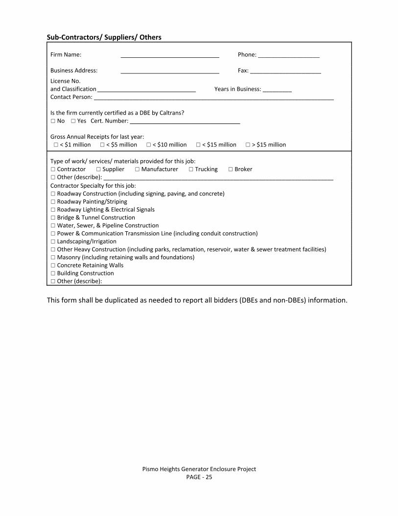
Sub‐Contractors/ Suppliers/ Others Firm Name: Phone: ___________________ Business Address: Fax: ______________________
License No. and Classification Years in Business: _________ Contact Person: __________________________________________________________________________ Is the firm currently certified as a DBE by Caltrans? ☐ No ☐ Yes Cert. Number: __________________________________ Gross Annual Receipts for last year: ☐ < $1 million ☐ < $5 million ☐ < $10 million ☐ < $15 million ☐ > $15 million Type of work/ services/ materials provided for this job:☐ Contractor ☐ Supplier ☐ Manufacturer ☐ Trucking ☐ Broker☐ Other (describe): _______________________________________________________________________ Contractor Specialty for this job: ☐ Roadway Construction (including signing, paving, and concrete)☐ Roadway Painting/Striping ☐ Roadway Lighting & Electrical Signals ☐ Bridge & Tunnel Construction ☐ Water, Sewer, & Pipeline Construction ☐ Power & Communication Transmission Line (including conduit construction)☐ Landscaping/Irrigation ☐ Other Heavy Construction (including parks, reclamation, reservoir, water & sewer treatment facilities)☐ Masonry (including retaining walls and foundations)☐ Concrete Retaining Walls ☐ Building Construction ☐ Other (describe):
This form shall be duplicated as needed to report all bidders (DBEs and non‐DBEs) information.
Pismo Heights Generator Enclosure Project PAGE ‐ 26
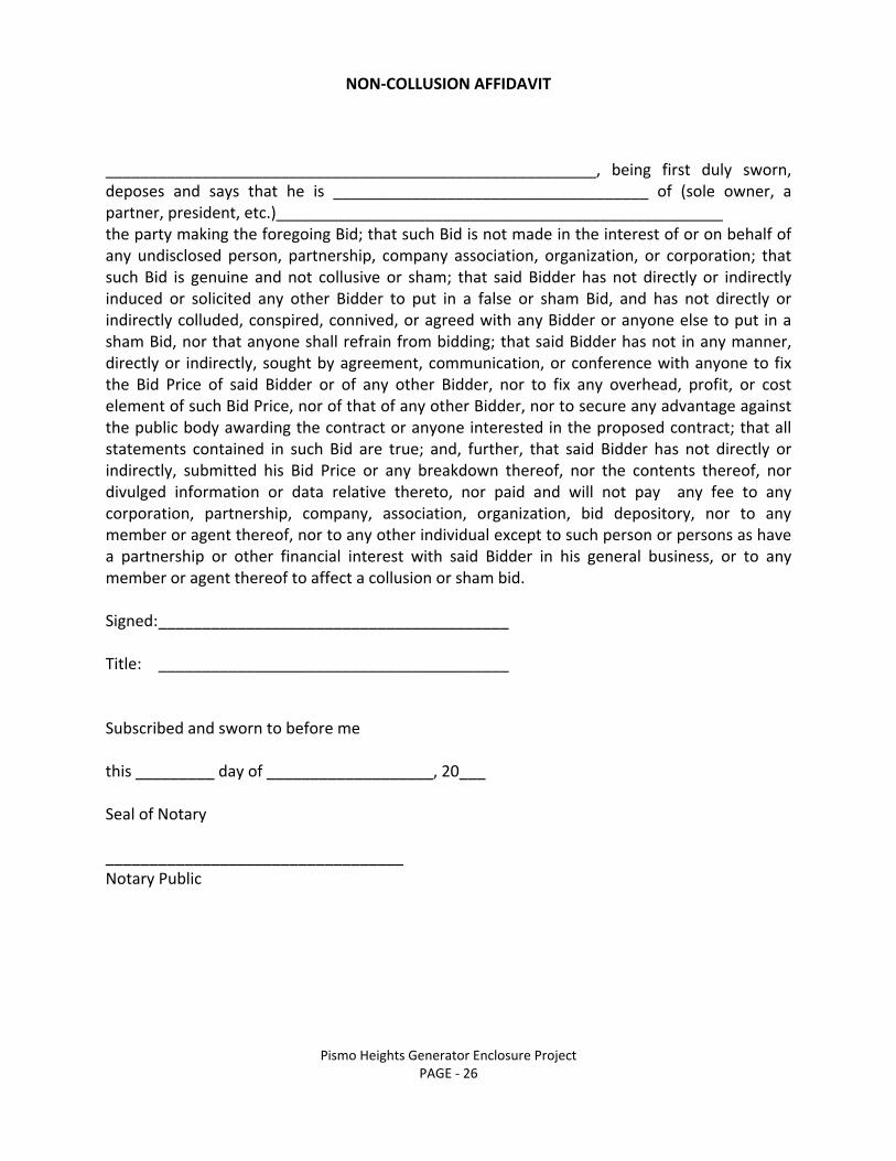
NON‐COLLUSION AFFIDAVIT
________________________________________________________, being first duly sworn, deposes and says that he is ____________________________________ of (sole owner, a partner, president, etc.)___________________________________________________ the party making the foregoing Bid; that such Bid is not made in the interest of or on behalf of any undisclosed person, partnership, company association, organization, or corporation; that such Bid is genuine and not collusive or sham; that said Bidder has not directly or indirectly induced or solicited any other Bidder to put in a false or sham Bid, and has not directly or indirectly colluded, conspired, connived, or agreed with any Bidder or anyone else to put in a sham Bid, nor that anyone shall refrain from bidding; that said Bidder has not in any manner, directly or indirectly, sought by agreement, communication, or conference with anyone to fix the Bid Price of said Bidder or of any other Bidder, nor to fix any overhead, profit, or cost element of such Bid Price, nor of that of any other Bidder, nor to secure any advantage against the public body awarding the contract or anyone interested in the proposed contract; that all statements contained in such Bid are true; and, further, that said Bidder has not directly or indirectly, submitted his Bid Price or any breakdown thereof, nor the contents thereof, nor divulged information or data relative thereto, nor paid and will not pay any fee to any corporation, partnership, company, association, organization, bid depository, nor to any member or agent thereof, nor to any other individual except to such person or persons as have a partnership or other financial interest with said Bidder in his general business, or to any member or agent thereof to affect a collusion or sham bid. Signed: ________________________________________ Title: ________________________________________ Subscribed and sworn to before me this _________ day of ___________________, 20___ Seal of Notary __________________________________ Notary Public

Pismo Heights Generator Enclosure Project PAGE ‐ 27
CONTRACTOR’S PERFORMANCE CERTIFICATION The Bidder has been engaged in the contracting business, under the present business name, for _______ years. Experience in work of a nature similar to that covered in the proposal extends for a period of ________ years. The bidder, as a contractor, has completed the following contracts satisfactorily within the last three (3) years for the persons, firm, or authority indicated, and to whom reference is made:
YEAR TYPE OF WORK CONTRACT AMOUNT
LOCATION AND FOR WHOM PERFORMED
Attach a list of equipment owned by the bidder that will be made available for use on the proposed work. Signed: _________________________________
Title: ____________________________________

Pismo Heights Generator Enclosure Project PAGE ‐ 28
AGREEMENT For The Construction of the
PISMO HEIGHTS GENERATOR ENCLOSURE PROJECT This agreement is made and entered into this ______ day of _______________ 20___, at Pismo Beach, California, by and between the City of Pismo Beach, hereinafter referred to as "City", and
(name of individual or firm) Hereinafter referred to as "Contractor." Whereas, the Contractor, as will appear by reference to the records of the Proceedings of the City, was duly awarded the contract for the Work hereinafter mentioned. Now, Therefore, it is hereby agreed that: Article 1 ‐ Witnesseth, that for and in consideration of the payment and agreements hereinafter mentioned, to be made and performed by said City, and under the conditions expressed in the two bonds, bearing even date with these present, and hereunto annexed, said Contractor agrees with said City, at its own cost and expense, to do all the work and furnish all materials, except such as are mentioned in the Contract Documents to be furnished by the City, necessary to construct and complete in good, workmanlike and substantial manner the above‐described work in accordance with the Contract Documents as listed herein and are by such reference made a part hereof. Article 2 ‐ The said City hereby promises and agrees with the said Contractor to employ, and does hereby employ, the said Contractor to provide the materials and to do the Work according to the terms and conditions herein contained and referred to, for the price of $___________________ (_____________dollars and ______________cents), and hereby contracts to pay the same at the time, in the manner, and upon the conditions above set forth; and the said parties for themselves, their heirs, executors, and administrators. Article 3 ‐ The said Contractor agrees to receive and accept the price stated in the Bid Schedule as full compensation for furnishing all materials and for doing all the work contemplated and embraced in this Agreement; also for all loss or damage arising out of the nature of the work aforesaid, or from the action of the elements, or from any unforeseen difficulties or obstructions which may arise or be encountered in the prosecution of the Work until its acceptance by the said City and for all expenses incurred by or in consequence of the suspension or discontinuance of the Work; and for well and faithfully completing the Work, and the whole thereof in the manner and according to the requirements of the Contract Documents therefore, and the requirements of the Engineer under their terms, to wit:

Pismo Heights Generator Enclosure Project PAGE ‐ 29
Article 4 ‐ It is expressly agreed by and between the parties hereto that the Contract Documents shall consist of the Notice to Bidders, Proposal, Bid Sheet(s), Certification of Affirmative Action Program, Contractor's Licensing Statement, List of Subcontractors, Bid Security, Non‐Collusion Affidavit, Agreement, Faithful Performance Bond, Labor and Materials Bond, Maintenance Bond, Worker's Compensation Certificate, Notice of Award, Notice to Proceed, Special Provisions, Technical Provisions and the Project Plans. In addition, all Change Orders and Work Directive Changes authorizing additions, deletions, or modifications, and all appendices, bulletins and addenda as prepared prior to the date of opening Bids setting forth any modifications or corrections or interpretations of any of said documents. In the event of any conflict between the provisions thereof, the terms of said documents shall control over each other in the following order:
1. Agreement 2. Change Orders and Work Directive Changes 3. Addenda 4. Notice To Bidders 5. Contract Proposal 6. Special Provisions 7. Technical Provisions 8. Contract Plans 9. City of Pismo Beach Standard Specifications and Drawings 10. Standard Specifications for Public Works Construction, “Greenbook”, 2015 edition,
or the latest edition thereof. 11. Standard Plans for Public Works Construction, “Greenbook”, 2015 edition, or the
latest edition thereof. 12. California State Department of Transportation Standard Specifications, latest
edition, when specifically referenced in the plans. Article 5 ‐ The Contractor agrees to commence work pursuant to this Contract within ten (10) working days from the date specified in the Notice to Proceed, and to diligently prosecute the same to completion within one hundred and twenty (120) Working Days from the date of commencement as specified in the Notice To Proceed. Article 6 ‐ For any withhold of amounts earned by the Contractor (under Paragraph 2), the Contractor may substitute securities as provided in Section 22300 of the Public Contract Code, as amended, which states in part as follows:

Pismo Heights Generator Enclosure Project PAGE ‐ 30
Provisions shall be included in any invitation for bid and in any contract documents to permit the substitution of securities for any moneys withheld by a public agency to ensure performance under a contract, provided that substitution of securities provisions shall not be required in contracts in which there will be financing provided by the Farmers Home Administration of the United States Department of Agriculture pursuant to the Consolidated Farm and Rural Development Act (7 U.S.C. Sec. 1921 et seq.), and where federal regulations or policies, or both, do not allows the substitution of securities. At the request and expense of the contractor, securities equivalent to the amount withheld shall be deposited with the public agency, or with a state or federally chartered bank in California as the escrow agent, who shall then pay such moneys to the contractor. Upon satisfactory completion of the contract, the securities shall be returned to the contractor. Alternatively, the contractor may request and the owner shall make payment of retention earned directly to the escrow agent at the expense of the contractor. At the expense of the contractor, the contractor may direct the investment of the payments into securities and the contractor shall receive the interest earned on the investments upon the same terms provided for in this section for securities deposited by the contractor. Upon satisfactory completion of the contract, the contractor shall receive from the escrow agent all securities, interest, and payments received by the escrow agent from the owner, pursuant to the terms of this section. The contractor shall pay to each subcontractor, not later than 20 days of receipt of the payment, the respective amount of interest earned, net of costs attributed to retention withheld from each subcontractor, on the amount of retention withheld to ensure the performance of the contractor. Securities eligible for investment under this section shall include those listed in Section 16430 or bank or savings and loan certificates of deposit, interest bearing demand deposit accounts, standby letters of credit, or any other security mutually agreed to by the contractor and the public agency. The contractor shall be the beneficial owner of any securities substituted for moneys withheld and shall receive any interest thereon. The escrow agreement entered into must be substantially similar to the form included in Public Contract Code Section 22300(e). The contractor shall obtain the written consent of the surety to such agreement. If any provision of this Section shall be declared by a court of law to be illegal or unenforceable, then, notwithstanding, this Section shall remain in full force and effect (exclusive of the illegal or unenforceable provision).

Pismo Heights Generator Enclosure Project PAGE ‐ 31
In Witness whereof, the parties to these present hereunto set their hands on the date first above written. CITY OF PISMO BEACH By: __________________________________ James R. Lewis, City Manager Attest: __________________________________ Erica Inderlied, City Clerk Approved as to form: __________________________________ David Fleishman, City Attorney Approved as to content: __________________________________ Benjamin A. Fine, P.E. Director of Public Works/City Engineer CONTRACTOR By: __________________________________ (name of firm or individual) __________________________________ (signature) __________________________________ (printed name) __________________________________ (title)

Pismo Heights Generator Enclosure Project PAGE ‐ 32
FAITHFUL PERFORMANCE BOND THE CONTRACTOR MAY SUBSTITUTE A FORM FROM AN APPROVED SURETY HOWEVER THE SUBSTITUTED FORM
MUST CONTAIN THE SAME PROVISIONS AS THE CITY FORM. Bond #___________________ Premium __________________ KNOW ALL MEN BY THESE PRESENTS, that WHEREAS, the City Council of the City of Pismo Beach, State of California, by Resolution adopted on ________________, has awarded to ______________ ______________________________________________________________ hereinafter designated as the "Principal", a contract for construction of
PISMO HEIGHTS GENERATOR ENCLOSURE PROJECT
in strict conformity with the Plans and Special Provisions titled Pismo Heights Generator Enclosure Project now on file in the office of the Director of Public Works of the City of Pismo Beach; and WHEREAS, said Principal is required under the terms of said Contract to furnish a bond for the faithful performance of said Contract; NOW, THEREFORE, WE _______________________________________ as Principal, hereinafter designated as the "Contractor" and __________________________________ as Surety, are held and firmly bound unto the City of Pismo Beach, in the sum of _______________________________________________________________________ Dollars ($ ___________________ ), said sum being one hundred percent of the estimated amount payable by the said City of Pismo Beach under the terms of the Contract, for which payment well and truly to be made, we bind ourselves, our heirs, executors and administrators, successors or assigns, jointly and severally, firmly by these presents. THE CONDITION OF THIS OBLIGATION IS SUCH, that if the above bounded Contractor, his or its heirs, executors, administrators, successors or assigns, shall in all things stand to and abide by, and well and truly keep and perform the covenants, conditions and agreements in the said Contract and any alteration thereof made as therein provided on his or their part, to be kept and performed at the time and in the manner therein meaning and shall indemnify and save harmless the City of Pismo Beach, its elected and appointed officers and agents, as therein stipulated, then this obligation shall become null and void; otherwise it shall remain in full force and effect.

Pismo Heights Generator Enclosure Project PAGE ‐ 33
And the said Surety, for value received, hereby stipulates and agrees that no change, extension of time, alteration or addition to the terms of the Contract or to the work to be performed hereunder or the Specifications and Special Provisions accompanying the same shall in any way affect its obligations on this bond, and it does hereby waive notice of any change, extension of time, alteration or addition to the terms of the Contract or to the work or to the said Specification and Special Provisions. IN WITNESS WHEREOF, this instrument has been duly executed by the Contractor and Surety above named, on the ______ day of __________________, 20___. Address of Contractor: ________________________ (seal) ________________________ (seal) Address of Surety: ________________________ (seal) ________________________ (seal)

Pismo Heights Generator Enclosure Project PAGE ‐ 34
LABOR AND MATERIAL BOND THE CONTRACTOR MAY SUBSTITUTE A FORM FROM AN APPROVED SURETY HOWEVER THE SUBSTITUTED FORM MUST CONTAIN THE SAME PROVISIONS AS THE CITY FORM.
Bond #___________________ Premium __________________ KNOW ALL MEN BY THESE PRESENTS, that WHEREAS, the City Council of the City of Pismo Beach State of California, by Resolution adopted on the ________ day of ______________________, 20 , has awarded to _______________________________________________ hereinafter designated as the "Principal", a contract for construction of
PISMO HEIGHTS GENERATOR ENCLOSURE PROJECT
in strict conformity with the Plans and Special Provisions titled Pismo Heights Generator Enclosure Project, now on file in the office of the Director of Public Works of the City of Pismo Beach; and WHEREAS, said Principal is required to furnish a bond in connection with said contract, providing that if said Principal, or any of his or its sub‐contractors shall fail to pay for any materials, provisions, provender or any other supplies or teams used in, upon, for or about the performance of the work contracted to be done, or for any work or labor done thereon of any kind, the Surety on this bond will pay the same to the extent hereinafter set forth; NOW, THEREFORE, WE _________________________________________ as Principal, hereinafter designated as the "Contractor" and _____________________________________ as Surety, are held and firmly bound unto the City of Pismo Beach, in the sum of ________________________________________________________ Dollars ($ _______________________), said sum being one hundred percent of the estimated amount payable by the said City of Pismo Beach under the terms of the Contract, for which payment well and truly to be made, we bind ourselves, our heirs, executors and administrators, successors or assigns, jointly and severally, firmly by these presents. THE CONDITION OF THIS OBLIGATION IS SUCH, that if the above bounded Contractor, his or its heirs, executors, administrators, successors or assigns, shall fail to pay for any materials, provisions, provender or other supplies or teams used in, upon, for or about the performance of the work contracted to be done, or for any work or labor thereon of any kind, as required by the provisions of an act of the Legislature of the State of California, entitled; "An act to secure the payment of claims of persons employed by Contractors upon Public Works, and the claims of persons who furnish materials, supplies, teams, implements or machinery used or consumed

Pismo Heights Generator Enclosure Project PAGE ‐ 35
by such contractors in the performance of such works, and prescribing the duties of certain public officers with respect thereto" approved May 10, 1919, as amended, and provided that the person, companies or corporations so furnishing said materials, provisions, provender or other supplies, teams, appliances or power used, in upon, for or about the performance of the work contracted to be executed or performed by any person, company or corporation renting or hiring teams or implements or machinery or power for or contributing to said work to be done, or any person who performs work or labor upon the same, or any person who supplies both work and materials therefore, shall have complied with the provisions of said Act, then Surety will pay the same in or to an amount not exceeding the amount hereinabove set forth, and also will pay, in case suit is brought upon this Bond, such reasonable Attorney's fees as shall be fixed by the Court, awarded and taxed as in the above mentioned Statute provided. This Bond shall insure to the benefit of any and all persons, companies and corporations entitled to file claims under said act, so as to give a right of action to them or their assigns in any suit brought upon this Bond. And the said Surety, for value received, hereby stipulates and agrees that no change, extension of time, alterations or additions to the terms of the Contract or to the work to be performed hereunder or the Specifications and Special Provisions accompanying the same shall in any way affect its obligations on this Bond, and it does hereby waive notice of any such change, extension of time, alteration or addition to the term of the contract or to the Work or to the Specifications or Special Provisions. IN WITNESS WHEREOF, this instrument has been duly executed by the Contractor and Surety above‐named, on the ______ day of __________________ 20___. Address of Contractor: ________________________ (seal) ________________________ (seal) Address of Surety: ________________________ (seal) ________________________ (seal)

Pismo Heights Generator Enclosure Project PAGE ‐ 36
MAINTENANCE BOND
THE CONTRACTOR MAY SUBSTITUTE A FORM FROM AN APPROVED SURETY HOWEVER THE SUBSTITUTED FORM MUST CONTAIN THE SAME PROVISIONS AS THE CITY FORM.
Bond #___________________ Premium __________________ KNOW ALL MEN BY THESE PRESENTS, that WHEREAS, the City Council of the City of Pismo Beach State of California, by Resolution adopted on the ________ day of ______________________, 20 , has awarded to _______________________________________________ hereinafter designated as the "Principal", a contract for construction of
PISMO HEIGHTS GENERATOR ENCLOSURE PROJECT
in strict conformity with the Plans and Special Provisions titled Pismo Heights Generator Enclosure Project, now on file in the office of the Director of Public Works of the City of Pismo Beach; and WHEREAS, said Principal is required to furnish a maintenance bond in connection with said contract, providing that if said Principal, or any of his or its sub‐contractors shall fail to maintain and remedy said Work free from defects in materials and workmanship thereon of any kind, the Surety on this bond will pay the same to the extent hereinafter set forth; NOW, THEREFORE, WE _________________________________________ as Principal, hereinafter designated as the "Contractor" and _____________________________________ as Surety, are held and firmly bound unto the City of Pismo Beach, in the sum of ________________________________________________________ Dollars ($ _______________________), said sum being ten percent (10%) of the estimated amount payable by the said City of Pismo Beach under the terms of the Contract, for which payment well and truly to be made, we bind ourselves, our heirs, executors and administrators, successors or assigns, jointly and severally, firmly by these presents. NOW, THE CONDITION OF THIS OBLIGATION IS SUCH, that if the above bounded Contractor, his or its heirs, executors, administrators, successors or assigns, shall maintain and remedy said Work free from defects in materials and workmanship for a period ____ years (s) commencing on ___________________________. (the “Maintenance Period”), then this obligation shall be void; otherwise it shall remain in full force and effect. And the said Surety, for value received, hereby stipulates and agrees that no change, extension

Pismo Heights Generator Enclosure Project PAGE ‐ 37
of time, alterations or additions to the terms of the Contract or to the Work to be performed hereunder or the Specifications and Special Provisions accompanying the same shall in any way affect its obligations on this Bond, and it does hereby waive notice of any such change, extension of time, alteration or addition to the term of the contract or to the Work or to the Specifications or Special Provisions. IN WITNESS WHEREOF, this instrument has been duly executed by the Contractor and Surety above‐named, on the ______ day of __________________ 20___. Address of Contractor: ________________________ (seal) ________________________ (seal) Address of Surety: ________________________ (seal) ________________________ (seal)

Pismo Heights Generator Enclosure Project PAGE ‐ 38
WORKER'S COMPENSATION INSURANCE CERTIFICATE Prior to execution of the Contract Agreement, the Contractor shall execute the following form as required by Sections 1860 and 1861 of the California Labor Code: I am aware of the provisions of Section 3700 of the Labor Code, which requires every employer to be insured against liability for Worker's Compensation or to undertake self‐insurance in accordance with the provisions of said Code, and I will comply with such provisions before commencing the performance of the work of this Contract. ___________________________________________________ (name of firm) _____________________________________ ______________ (signature) (date) ___________________________________________________ (title) Attest:________________________________ _______________
(signature) (date) __________________________________________________ (title)

Pismo Heights Generator Enclosure Project PAGE ‐ 39
NOTICE OF AWARD DATE: TO:
(bidder’s name) (street address) (city, state, zip code) Project Title: Pismo Heights Generator Enclosure Project You are hereby notified that your Bid dated , for the above Contract has been considered. You are the apparent successful Bidder and have been awarded a contract for the project entitled Pismo Heights Generator Enclosure Project. The Contract Price of your contract is: $ . Three copies of each of the proposed Contract Documents (except Plans) accompany this Notice of Award. Three sets of the Plans will be delivered separately or otherwise made available to you immediately. You must comply with the following conditions precedent within ten (10) working days of the date of this Notice of Award; that is, by __________________, 20___.
1. You must deliver to the City of Pismo Beach three fully executed counterparts of the Agreement including all the Contract Documents. This includes the triplicate sets of the Plans. Each of the Contract Documents must bear your signature on the cover.
2. You must deliver with the executed Agreement the Contract Security Bonds as
specified in the Instructions to Bidders, Special Provisions and Supplementary Conditions.
3. You must supply proof of a current City of Pismo Beach business license.
4. You must supply proof of a City of Pismo Beach encroachment permit covering work
to be performed in the right‐of‐way on this project. Failure to comply with these conditions within the time specified will entitle the City to consider your Bid abandoned, to annul this Notice of Award and to declare your Bid Security forfeited.

Pismo Heights Generator Enclosure Project PAGE ‐ 40
Within ten (10) working days after you comply with those conditions, the City will return to you one fully signed counterpart of the Agreement with the Contract Documents attached. CITY OF PISMO BEACH By: _______________________________ Benjamin A. Fine, P.E. Director of Public Works/City Engineer
Pismo Heights Generator Enclosure Project PAGE ‐ 41
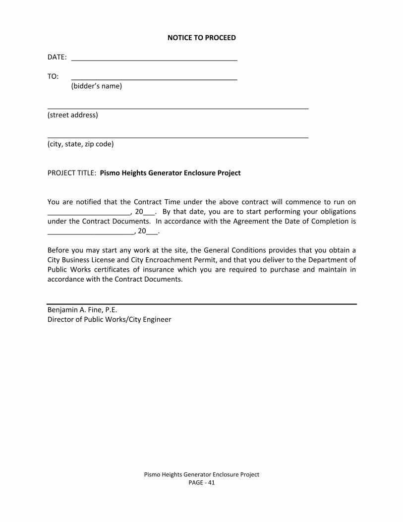
NOTICE TO PROCEED DATE: TO:
(bidder’s name) (street address) (city, state, zip code) PROJECT TITLE: Pismo Heights Generator Enclosure Project You are notified that the Contract Time under the above contract will commence to run on _____________________, 20___. By that date, you are to start performing your obligations under the Contract Documents. In accordance with the Agreement the Date of Completion is ______________________, 20___. Before you may start any work at the site, the General Conditions provides that you obtain a City Business License and City Encroachment Permit, and that you deliver to the Department of Public Works certificates of insurance which you are required to purchase and maintain in accordance with the Contract Documents.
Benjamin A. Fine, P.E. Director of Public Works/City Engineer

Pismo Heights Generator Enclosure Project PAGE ‐ 42
CHANGE ORDER (Instructions follow)
No._____________
Project: Pismo Heights Generator Enclosure Project Date of Issuance: Contractor: You are directed to make the following changes in the Contract Documents. Description: Purpose of Change Order: Attachments: (List documents supporting change) Change in Contract Price: Change in Contract Time: Original Contract Price: $ __________________________
_______ days
Previous Change Orders: No. ___________ to No. ____________
Net change from previous Change Orders: _______ days
$___________________________ Contract Price Prior to this Change Order Contract Time Prior to this
Change Order $___________________________ ____________________________ Net Increase (decrease) of this Change Order Net Increase (decrease) of this Change Order $___________________________ ________ days Contract Price with all approved Change Orders Contract Time with all approved Change Orders $____________________________ ________ days
The amount and time provided in this contract change order are a full and final accord and satisfaction of all costs and time directly and indirectly related and all other claims related hereto are herby waived. The Contractor has reviewed the plans and specifications related to this change order and all changes thereto are accounted for in the attachment labeled “Attachment A”. Recommended: Recommended: by ____________________ by ____________________ Approved: Approved: Approved: ___________________ ___________________ ____________________ Benjamin A. Fine, P.E. James R. Lewis Contractor Director of Public Works/ City Manager City Engineer

Pismo Heights Generator Enclosure Project PAGE ‐ 43
CHANGE ORDER INSTRUCTIONS
A. GENERAL INFORMATION This document was developed to provide a uniform format for handling contract changes that affect Contract Price or Contract Time. Changes that have been initiated by a Work Directive Change must be incorporated into a subsequent Change Order if they affect price or time. Changes that affect Contract Price or Contract Time should be promptly covered by a Change Order. The practice of accumulating change order items to reduce the administrative burden may lead to unnecessary disputes. For supplemental instructions and minor changes not involving a change in the Contract Price or Contract Time, a Field Order may be used. B. COMPLETING THE CHANGE ORDER FORM The City Engineer initiates the form, including a description of the changes involved and attachments based upon documents and proposals submitted by Contractor, or requests from City of Pismo Beach or both. Once the City Engineer has completed and signed the form, all copies should be sent to Contractor for approval. After approval by Contractor, all copies should be sent returned to the City Engineer. The City Engineer will make distribution of executed copies after approval by the City. If a change applies only to price or to time, cross out the part of the tabulation that does not apply.

Pismo Heights Generator Enclosure Project PAGE ‐ 44
WORK DIRECTIVE CHANGE (Instructions follow)
No._____________ Project: Pismo Heights Generator Enclosure Project Date of Issuance: Contractor: You are directed to make the following changes(s): Description: Purpose of Work Directive Change: Attachments: (List documents supporting change) If a claim is made that the above change(s) have affected Contract Price or Contract Time, any claim for a Change Order based thereon will involve one of the following methods of determining the effect of the change(s). Method of determining Method of determining change in Contract Price: change in Contract Time: [ ] Time and Materials [ ] Contractor's Records [ ] Unit Prices [ ] Engineer's Records [ ] Cost plus fixed fee [ ] Other ________________________ [ ]Other____________________ Estimated increase (decrease) Estimated increase (decrease) in Contract Price: $ ____________ in Contract Time: ______ days. If the change involves an If the change involves an increase, the estimated amount increase, the estimated time is not to be exceeded without is not to be exceeded without further authorization. further authorization. ________________________________ ___________________________ RECOMMENDED: AUTHORIZED: by _____________________________ by ______________________ Authorized City Representative Benjamin A. Fine, P.E. Title: _______________________ City Engineer/Director of Public Works

Pismo Heights Generator Enclosure Project PAGE ‐ 45
WORK DIRECTIVE CHANGE INSTRUCTIONS A. GENERAL INFORMATION This document was developed for use in situations involving changes in the Work which, if not processed expeditiously, might delay the Project. These changes are often initiated in the field and may affect the Contract Price or the Contract Time. This is not a Change Order, but only a directive to proceed with work that may be included in a subsequent Change Order. For supplemental instructions and minor changes not involving a change in the Contract Price or the Contract Time, a Field Order may be used. B. COMPLETING THE WORK DIRECTIVE CHANGE FORM The City Engineer initiates the form, including a description of the items involved and attachments. Based on conversations between the City Engineer and Contractor, the City Engineer completes the following: METHOD OF DETERMINING CHANGE, IF ANY, IN CONTRACT PRICE: Mark the method to be used in determining the final cost of Work involved and the net effect on the Contract Price. If the change involves an increase in the Contract Time and the estimated amount is approached before the additional or changed work is completed, another Work Directive change must be issued to change the time or Contractor may stop the changed work when the estimated time is reached. If the Work Directive Change is not likely to change the Contract Time, the space for estimated increase (decrease) should be marked "Not Applicable." METHOD OF DETERMINING CHANGE, IF ANY, IN CONTRACT TIME: mark the method to be used in determining the change in Contract Time and the estimated increase or decrease in Contract Time. If the change involves an increase in the Contract Time and the estimated time is approached before the additional or change Work is completed, another Work Directive Change must be issued to change the time or Contractor may stop the changed work when the estimated time is reached. If the Work Directive Change is not likely to change the Contract Time, the space for estimated increase (decrease) should be marked "Not Applicable." The City Engineer will complete and sign the form. Once authorized by the City, the City Engineer should send a copy to Contractor. Once the work covered by this directive is completed or final cost and time determined, Contractor should submit documentation for inclusion in a Change Order. THIS IS A DIRECTIVE TO PROCEED WITH A CHANGE THAT MAY AFFECT THE CONTRACT PRICE OR THE CONTRACT TIME. A CHANGE ORDER, IF ANY, SHOULD BE CONSIDERED PROMPTLY.

Pismo Heights Generator Enclosure Project PAGE ‐ 46
SPECIAL PROVISIONS for the
PISMO HEIGHTS GENERATOR ENCLOSURE PROJECT The Contractor shall furnish all materials, labor, tools, equipment and incidentals required to completely construct the improvements shown on the plans entitled;
PISMO HEIGHTS GENERATOR ENCLOSURE PROJECT The Contractor shall perform all of the work in conformance with the Agreement, the project Plans, the City of Pismo Beach Specifications and Drawings, the Standard Specifications and Plans, these Special Provisions and as directed by the City Engineer. Full compensation for work shown on the plans or work which is required by these Special Provisions which is not specifically identified on the Bid Schedule shall be considered as included in the contract price paid for the various items of work identified on the Bid Schedule and no additional compensation shall be allowed therefore.
SECTION 1 DEFINITIONS AND TERMS 1‐1 Definitions and Terms Whenever, in these Special Provisions, the Project Plans, or in any documents or instruments where these Special Provisions and Plans govern, the following terms are used or pronouns in place of them are used, the intent and meaning shall be interpreted as follows:
A. Agency. The City of Pismo Beach
B. Bid. An offer to furnish the necessary services and materials to perform the work called for by the Contract Documents.
C. Bidder. Any individual, firm or corporation submitting a proposal for the work contemplated, acting directly or through a duly authorized representative.
D. Board. The City Council of the City of Pismo Beach
E. Proposal. The offer of the Bidder for the Work when made out and submitted on the prescribed Proposal Form, properly signed and guaranteed.
F. Proposal Guaranty. The cash, check or Bidder's Bond accompanying the Proposal submitted by the Bidder as a guarantee that the Bidder will enter into a Contract with the City for the construction of the Work if awarded to him.

Pismo Heights Generator Enclosure Project PAGE ‐ 47
G. Work. All work specified, indicated, shown or contemplated in the Contract to construct the improvements, including all alterations, amendments or extensions thereto made by Change Orders or other written orders by the City Engineer.
H. City. The City of Pismo Beach, California, as created by law, and including any official of the City authorized to act for the City.
I. Contract. The written agreement covering the performance of the Work, and the furnishing of labor, material, tools and equipment in the construction of the Work. The Contract includes all of the Contract Documents.
J. Contract Documents. The Notice to Bidders, Proposal, Bid Schedule, Certification of Affirmative Action Program, Contractor's Licensing Statement, List of Subcontractors, Bid Security, Non‐Collusion Affidavit, Contractor’s Performance Certification, Agreement, Faithful Performance Bond, Labor and Materials Bond, Maintenance Bond, Worker's Compensation Certificate, Notice of Award, Notice to Proceed, Special Provisions, Plans, any addenda and bulletins issued during the bidding period, and all Change Orders amending or extending the work contemplated and which may be required to complete the work in a substantial and acceptable manner.
K. Plans. The official plans, typical cross‐sections, general cross‐sections, working drawings and supplemental drawings, or reproductions thereof, approved by the City Engineer, which show the location, character, dimensions and details of the work to be done, and which are to be considered as a part of the Contract supplementary to these Special Provisions.
L. Special Provisions. The Special Provisions are specific clauses setting forth conditions or requirements peculiar to the particular work called for by the Plans.
M. City Standard Specifications and Drawings. Where reference is made to the City Standard Specifications and Drawings, the reference shall be to the City of Pismo Beach Engineering Department Standard Specifications and Drawings.
N. Standard Specifications. Where reference is made to the Standard Specifications, the reference shall be to the Standard Specifications for Public Works Construction “Greenbook”, 2015 Edition, or the latest edition thereof. Where paving operations are a part of the Contract, for paving operations only, the Standard Specifications shall refer to the State of California Department of Transportation Standard Specifications, 2010 Edition, or the latest edition thereof.
O. Standard Plans. Where reference is made to the Standard Plans, the reference shall be to the Standard Plans for Public Works Construction, 2015 Edition, or the latest edition thereof.

Pismo Heights Generator Enclosure Project PAGE ‐ 48
P. Days. Unless otherwise designated, days as used in the Contract Documents will be understood to mean working days.
Q. Liquidated Damages. The amount prescribed in the Special Provisions to be paid to the City, or to be deducted from any payments due or to become due the Contractor, for each day's delay in completing the Work beyond the time allowed in the Special Provisions.
R. City Engineer. The City Engineer of the City of Pismo Beach, acting either directly or through properly authorized agents, such agents acting within the scope of the particular duties delegated to them.
S. Inspector. An authorized representative of the City of Pismo Beach assigned by the City to make inspection of work performed or material supplied by the Contractor.
T. Superintendent. The executive representative of the Contractor present on the work at all times during progress, authorized to receive and fulfill instructions from the City Engineer.
U. Design Engineer. That individual or firm responsible for the design of the project, when the design is not by the City Engineer.
Where State Agencies, State Departments or State Officers are referred to in the above‐mentioned Standard Specifications and Standard Plans, the comparable City Agency, City Department or City Officer shall be meant thereby for the purposes of these Contract Documents. In particular, intent and meaning shall be interpreted as follows: STATE, OR COUNTY OR STATE OF CALIFORNIA ........................................................... CITY OF PISMO BEACH DEPARTMENT OR DEPARTMENT OF TRANSPORTATION .......................................................... CITY COUNCIL CITY OF PISMO BEACH DIRECTOR OR DIRECTOR OF TRANSPORTATION .............................................. DIRECTOR OF PUBLIC WORKS EITHER DIRECTLY OR THROUGH PROPERLY AUTHORIZED AGENT AND CONSULTANTS ATTORNEY GENERAL ................................................................................................................. CITY COUNCIL CITY OF PISMO BEACH

Pismo Heights Generator Enclosure Project PAGE ‐ 49
SECTION 2 SCOPE AND CONTROL OF WORK 2‐1 Award and Execution of Contract 2‐1.01 Proposal Form All proposals must be made upon blank forms contained herein. All proposals must give the prices proposed in figures, and must be signed by the Bidder, with his address. If an individual makes the proposal, his name and post office address must be shown. If made by a firm or partnership, the name and post office address of each member of the firm or partnership must be shown. If made by a corporation, the proposal must show the name of the state under the laws of which the corporation was chartered and the names, titles, and business addresses of the president, secretary and treasurer. All proposals shall be submitted as directed in the Notice to Bidders under sealed cover, plainly marked as a Proposal, and identifying the project to which the Proposal relates and the date of the Bid opening therefore. Proposals which are not properly marked may be disregarded. 2‐1.02 Required Documents The following documents shall be completed and submitted b the Contractor at the times specified by an “X” opposite each title. If no column is marked, the document is not required.
(a) With Bid Submittal Package (b) With Agreement by Awardee (c) Prior to Start of Construction (a) (b) (c) X Contract Proposal X Bid Sheet X Bid Bond X Certification of Affirmative Action Program X Contractor’s Licensing Statement X Bidder’s Information List X List of Subcontractors X Non‐Collusion Affidavit X Contractor’s Performance Certification X Agreement X Faithful Performance Bond X Labor and Material Bond X Maintenance Bond X Worker’s Compensation Insurance Certificate X Certificates of Insurance (Refer to Special Provisions) X Materials List and Manufacturer’s Brochures X Construction Schedule X Shop Drawings, Shoring Plans, Falsework Plans, Etc X Traffic Control Plan – Not Applicable X Public Agency Notification Report per Section 7.14.02

Pismo Heights Generator Enclosure Project PAGE ‐ 50
2‐1.03 Examination of Plans, Special Provisions, Contract Forms and Site of Work The bidder shall examine carefully the site of the work contemplated, the Plans, Special Provisions, and Contract Forms thereof. The submission of a Bid shall be conclusive evidence that the Bidder has investigated and is satisfied as to the conditions to be encountered, as to the character, quality and quantities of work to be performed and materials to be furnished, and as to the requirements of the Proposal, Plans, Special Provisions, and Contract. 2‐1.04 Check of Existing Conditions Upon request and prior to the receipt of proposals, the City Engineer will make available to prospective bidders all information the City may have as to sub‐surface conditions and surface topography at the project site. The City does not assume any responsibility with respect to the accuracy of the information, or unforeseen developments which may occur. 2‐1.05 Bid Security All Bids shall be presented under sealed cover and shall be accompanied by cash, cashier's check, certified check, or Bidder's Bond, made payable to the City of Pismo Beach for an amount equal to at least ten percent (10%) of the amount of said bid, and no Bid shall be considered unless such cash, cashier's check, certified check or Bidder's Bond is enclosed therewith. 2‐1.06 Public Opening of Proposals Proposals will be opened and read publicly at the time and place indicated in the Notice to Bidders. Bidders or their authorized agents are invited to be present. 2‐1.07 Rejection of Proposals Proposals may be rejected if they show any alterations of form, additions not called for, conditional or alternative bids, incomplete bids, erasures, or irregularities of any kind. The right is reserved to reject any or all proposals. When a Proposal is signed by an agent, other than the officer or officers of a corporation authorized to sign contracts on its behalf, or a member of a partnership, a Power of Attorney must be on file with the City prior to opening bids or shall be submitted with the Proposal; otherwise, the Proposal will be rejected as irregular and unauthorized. 2‐1.08 Withdrawal of Proposals Any Bid may be withdrawn at any time prior to and not after the hour fixed in the public notice for the opening of the Bids, provided that a request in writing, executed by the Bidder or his duly authorized representative, for the withdrawal of such Bid is filed with the City Engineer. The withdrawal of a Bid shall not prejudice the right of a Bidder to file a new bid.

Pismo Heights Generator Enclosure Project PAGE ‐ 51
2‐1.09 Disqualification of Bidders More than one (1) proposal from an individual, firm, partnership, corporation, or combination thereof, under the same or different names will not be considered, and reasonable grounds for believing that any individual, firm, partnership, corporation, or combination thereof, is interested in more than one (1) proposal from the work contemplated will cause the rejection of all proposals in which such individual, firm, partnership, corporation, or combination thereof, is interested. If there is reason for believing that collusion exists among the bidders, none of the participants in such collusion will be considered in future proposals. Proposals in which the prices are obviously unbalanced may be rejected. 2‐1.10 Licensing of Bidders Before submitting bids, Bidders shall be licensed in accordance with the provisions of Sections 7000 through 7145, inclusive, of the Business and Professions Code of the State of California, and any Bidder or Contractor not so licensed is subject to the penalties imposed by such laws. 2‐1.11 Experience of Bidders All Bidders may be required to furnish a sworn statement of their financial responsibility, technical ability, and experience before award is made to any particular Bidder. 2‐1.12 Material Guaranty Before any contract is awarded the Bidder may be required to furnish a complete statement of the origin, composition, and manufacture of any or all materials to be used in the construction of the Work, together with samples, which samples may be subjected to the tests provided for in the Specifications or in these Special Provisions to determine their quality. 2‐1.13 Award of Contract The right is reserved to reject any and all proposals. The award of the contract, if it is awarded, will be to the lowest responsible Bidder, whose proposal complies with all the requirements prescribed. The award, if made, will be made within sixty (60) working days after the opening of the Proposals. The basis of award for the contract will be the total price of the base bid. All Bids will be compared on the basis of the City Engineer's estimate of the quantities of work to be done. 2‐1.14 Return of Bid Security The Proposals of the three (3) lowest Bidders will be considered in awarding the Contract. The City Engineer will return all other Proposal securities promptly after the tabulation of Bids has been made. The Proposal securities retained will be returned after the successful Bidder has executed the Contract and the bonds accompanying the same are approved and filed. 2‐1.15 Execution of Contract The contract shall be signed by the successful Bidder and returned, together with the contract bonds and insurance certificates within ten (10) working days after the Bidder has received notice that the Contract has been awarded. No Proposal shall be considered binding upon the

Pismo Heights Generator Enclosure Project PAGE ‐ 52
City until the execution and return to the City of the Contract and the filing of the contract bonds and insurance certificates with the City. With execution of the contract, the Contractor offers and agrees to assign to the City all rights, title, and interest in and to all causes of action it may have under Section 4 of the Clayton Act (15 U.S.C. Sec. 15) or under the Cartwright Act (Chapter 2 of Part 2 of Division 7 of the Business and Professions Code. This assignment shall be made and become effective at the time the City tenders final payment to the Contractor, without further acknowledgment by the parties. 2‐1.16 Failure to Execute Contract Failure to execute and return a Contract and file acceptable bonds and insurance as provided herein within ten (10) working days after the Bidder has received notice that the Contract has been awarded, shall be just cause for the annulment of the award and the forfeiture of the Bidder's guaranty to the City. Upon the failure or refusal of the successful Bidder to execute and return the contract and file acceptable bonds and insurance, the award may be made to the second lowest responsible Bidder, and should he fail or refuse to execute and return the Contract and file acceptable bonds and insurance, the award may be made to the third lowest responsible Bidder. On failure or refusal of the second or third lowest responsible Bidder to whom the Contract is awarded to execute and return the Contract and file acceptable bonds and insurance, their Bidder's guaranty shall be likewise forfeited to the City. 2‐1.17 Registration with Department of Industrial Relations (DIR) It shall be mandatory upon all contractors and subcontractors listed on all bid proposals and those whom the contract is awarded be registered with the DIR pursuant to Labor Code section 1725.5, unless exempt per Labor Code section 1771.1(a). 2‐2 Subcontracting 2‐2.01 General In accordance with the provisions of Chapter 2, Division 5, Title 1 of the Government Code of the State of California, each Bidder for the work specified shall set forth in his Bid:
A. The name and the location of the place of business of each subcontractor who will perform work or labor or render service to the prime contractor in or about the construction of the work or improvement, or a subcontractor licensed by the State of California who, under subcontract to the prime contractor, specially fabricates and installs a portion of the Work or improvement according to detailed drawings contained in the Plans and Special Provisions, in an amount in excess of one‐half (1/2) of one percent (0.5%) of the prime contractor's total Bid or Ten Thousand Dollars, whichever is greater.

Pismo Heights Generator Enclosure Project PAGE ‐ 53
B. The portion of the Work which will be done by each such subcontractor. The prime contractor shall list only one (1) subcontractor for each such portion as is defined by the prime contractor in his Bid.
If a prime contractor fails to specify a subcontractor, or if a prime contractor specifies more than one (1) subcontractor for the same portion of work to be performed under the contract in excess of one‐half (1/2) of one percent (0.5%) of the prime contractor's total bid or Ten Thousand Dollars, whichever is greater, he agrees that he is fully qualified to perform that portion himself and that he shall perform that portion himself. If his bid is accepted, he shall not be permitted to subcontract any portion of the work which he is required to perform himself, to substitute any person as subcontractor in place of the subcontractor listed in the original Bid, or to permit any such subcontract to be voluntarily assigned or transferred or allow it to be performed by anyone other than the original subcontractor listed in the original Bid, except under the conditions set forth in Chapter 2, Division 5, Title 1 of the Government Code of the State of California. Should the prime contractor violate any of these provisions, his so doing will be deemed a violation of his Contract, and the City may exercise the option, in its own discretion, of (1) canceling his Contract, or (2) assessing the prime contractor a penalty in an amount of not more than ten percent (10%) of the amount of the subcontract involved. The funds recovered through the application of this penalty shall be deposited in the fund out of which the prime contract is awarded. The prime contractor agrees that he is as fully responsible to the City for the acts and omissions of his subcontractors and of persons either directly or indirectly employed by them, as he is for the acts and omissions of persons directly employed by him. Nothing contained in the Contract Documents shall create any contractual relation between any subcontractor and the City. 2‐2.02 Control of Work and Assignment The Contractor shall give his personal attention to the fulfillment of the Contract and shall keep the work under his control, including the work of all subcontractors. Where a portion of the work sublet by the Contractor is not being prosecuted in a manner satisfactory to the City Engineer, the subcontractor shall be removed immediately on the request of the City Engineer and shall not again be employed on the Work. Subcontracts may be assigned only upon written consent of the City Engineer. 2‐3 Contract Bonds The Contractor shall furnish three (3) good and sufficient bonds. These bonds shall be in the amount and for the purposes specified below. They shall be surety bonds issued by corporations duly and legally licensed to transact business in the State of California. They shall be issued at the expense of the Contractor, and shall be maintained by him at his expense

Pismo Heights Generator Enclosure Project PAGE ‐ 54
during the entire life of the Contract. The City shall determine the acceptability of all proposed surety companies. 2‐3.01 Performance One (1) bond shall be in the amount of one hundred percent (100%) of the Contract Price and shall guarantee faithful performance of the Contract and insure the City during the life of the Contract. 2‐3.02 Labor and Materials One (1) bond shall be in the amount of one hundred percent (100%) of the Contract Price and shall secure the obligations set forth in Section 3248 of the Civil Code of the State of California. 2‐3.03 Maintenance and Warranty One (1) bond shall be in the amount of ten percent (10%) of the contract price to secure maintenance following construction and shall remain in effect for one (1) year following the date a Notice of Completion for the project is filed with the County Recorder. 2‐4 Plans and Specifications 2‐4.01 General The work embraced herein shall be done in accordance with the California Building Code, Standard Specifications for Public Works Construction, 2015 Edition, and the Standard Plans for Public Works Construction, 2015 Edition, and the California State Department of Transportation Standard Specifications, 2010 Edition, for paving operations, insofar as the same may apply and in accordance with these Special Provisions. 2‐4.02 Intent of Plans and Special Provisions The intent of the plans and these Special Provisions is to prescribe the details for the performance and completion of the work which the Contractor undertakes to perform in accordance with the terms of the Contract. Where the plans or these Special Provisions describe portions of the work in general terms, but not in complete detail, it is understood that only the best general practice is to prevail and that only materials and workmanship of the first quality are to be used. Unless otherwise specified, the Contractor shall furnish all labor, materials, tools, equipment, and incidentals, and do all the work involved in executing the Contract in a satisfactory and workmanlike manner. 2‐4.03 Plans All work shall conform to the approved Plans. It is mutually agreed, however, that approval by the City Engineer of the Contractor's working plans does not relieve the Contractor of any responsibility for accuracy of dimensions and details, and that the Contractor shall be responsible for agreement and conformity of his working plans with the approved Plans and Special Provisions.

Pismo Heights Generator Enclosure Project PAGE ‐ 55
2‐4.04 Conformity with Plans and Allowable Deviations Finished surfaces in all cases shall conform to the dimensions shown on the approved Plans. Deviations from the approved Plans as may be required by the exigencies of construction will be determined in all cases by the City Engineer and authorized in writing. 2‐4.05 Coordination and Interpretation of Plans, Specifications and Special Provisions The Standard Specifications and Standard Plans, the Project Plans and Special Provisions, and all supplementary documents are essential parts of the Contract, and a requirement occurring in one is as binding as though occurring in all. They are intended to be cooperative, to describe, and to provide for a complete work. Project Plans shall govern over Standard Plans; Standard Plans and Project Plans shall govern over Standard Specifications; and the Special Provisions shall govern over both the Standard Specifications and the Project Plans. Should it appear that the work to be done, or any matter relative thereto is not sufficiently detailed or explained in the Project Plans and Special Provisions, or is otherwise unclear, the Contractor shall apply to the City Engineer for such further explanation as may be necessary and shall conform to such explanation or interpretation as part of the Contract. In the event of doubt or question relative to the true meaning of the Special Provisions, reference shall be made to the City Council, whose decision thereon shall be final. In the event of any discrepancy between any drawing and the figures written thereon, the figures shall be taken as correct. 2‐4.06 Record Documents The Contractor shall maintain in a safe place at the site one record copy of all Drawings, Specifications, Addenda, Written Amendments, Change Orders, Work Change Directives, Field Orders, and written interpretations or clarifications in good order and annotated to show all changes made during construction. These record documents together with all approved Samples and a counterpart of all approved Shop Drawings will be available to the Engineer for reference. Upon completion of the Work, these record documents, Samples and Shop Drawings will be delivered to the Inspector for review and then to the City Engineer for approval. 2‐5 Scope of Work 2‐5.01 Description The work encompassed by the Bid Schedule generally consists of furnishing all labor, equipment and materials necessary for construction of the improvements as shown on the project plans and in these specifications. 2‐5.02 Project Details and Location Details peculiar to the work to be performed are found in Appendix A.

Pismo Heights Generator Enclosure Project PAGE ‐ 56
2‐6 Rights‐of‐Way The City will provide rights‐of‐way or easements for work to be constructed. The Contractor shall make his own arrangements and pay all expenses for additional area required by him outside of the limits of rights‐of‐way or easements unless otherwise specifically provided. In the event of delay on the part of the City, its officers, agents, or employees, in obtaining any such rights‐of‐way or easements for the work to be constructed, then the Contractor shall have time for the completion of his Contract for the period or periods caused by such delay or delays, but shall have no damages against the City, its officers, agents, or employees. 2‐7 Construction Staking The Contractor shall lay out the work and stake the necessary control points for the Contractor's operations. The Contractor shall furnish such facilities and labor necessary to preserve all stakes and points set for lines, grades, or measurements of the work in their proper places until authorized to remove them by the City Engineer. The Contractor shall pay all expenses incurred in replacing stakes that have been removed without proper authority. 2‐8 Compaction Control and Testing The City will perform all soils testing work under the supervision of the City Engineer and employ the services of a soil testing laboratory to control and report upon the compaction in compacted embankments, structure backfill and excavation backfill. Should the compaction methods used fail to achieve the required degree of compaction, the Contractor shall revise his methods to achieve the required compaction unless otherwise directed by the City Engineer. The Contractor shall make all necessary excavations for test pits as directed by the City Engineer. The Contractor shall refill and re‐compact test pits to the densities specified in the plans and these Special Provisions. The Contractor shall provide shoring or other safety measures as required for testing. 2‐8.01 Payment The City will pay the costs for the initial compaction tests. If any tests fail to meet the requirements of these Special Provisions, the Contractor shall pay the costs of the retests until the specified compaction is obtained. Full compensation for conforming to the requirements of this section, including excavation, shoring and backfilling of test pits shall be considered as included in the contract price paid for the item of work to which it is appurtenant and no additional compensation shall be allowed therefore. 2‐9 Authority of the City Engineer The City Engineer shall decide any and all questions which may arise as to the quality or acceptability of materials furnished and work performed, and as to the manner of performance and rate of progress of the Work; all questions which arise as to the interpretation of the Plans and Special Provisions; all questions as to acceptable fulfillment of the Contract on the part of

Pismo Heights Generator Enclosure Project PAGE ‐ 57
the Contractor; and all questions as to claims and compensation. His decision shall be final and he shall have executive authority to enforce and make effective such decisions and orders which the Contractor fails to carry out promptly. 2‐10 Inspection The City Engineer shall at all times have access to the Work during construction and shall be furnished with every reasonable facility for ascertaining that the materials used and employed and the workmanship are in accordance with the requirements and intentions of these Special Provisions. All work done and all materials furnished shall be subject to inspection and approval. Whenever the Contractor varies the period during which work is carried on each day, he shall give due notice to the City Engineer so that proper inspection may be provided. Any work done in the absence of the City Engineer will be subject to rejection. The inspection of the work shall not relieve the Contractor of any of his obligations to fulfill the Contract as prescribed. Inspections may be conducted by the state and county, and the state and county inspectors shall at all times have access to the work during its construction, and shall be furnished with every reasonable facility for ascertaining that the materials and the workmanship are in accordance with the requirements and intentions of these Special Provisions and the Plans. The inspection of the work by state or county inspectors shall not relieve the Contractor of any of his obligations to fulfill the Contract as prescribed. Projects financed in whole or in part with federal or state funds shall be subject to inspection at all times by the federal and state agency involved. 2‐10.01 Authority of Inspectors Properly authorized inspectors shall be considered to be the representatives of the City limited to the duties and powers entrusted to them. It will be their duty to inspect materials and workmanship of those portions of the work to which they are assigned, either individually or collectively, under instructions of the City Engineer, and to report any and all deviations from the Plans, Special Provisions, and other contract provisions which may come to their notice.

Pismo Heights Generator Enclosure Project PAGE ‐ 58
SECTION 3 Changes in Work 3‐1 Alterations and Changes The City reserves the right to make such alterations, deviations, additions to, or omissions from the Plans and Special Provisions, including the right to increase or decrease the quantity of any item or portion of the Work, or to omit any item or portion of the Work, as may be deemed by the City Engineer to be necessary or advisable, and to require such extra work as may be determined by the City Engineer to be required for the proper completion or performance of the whole work contemplated. Any such alterations or changes will be set forth in a change order, which will specify, in addition to the work to be done or omitted in connection with the change made, adjustment of Contract Time, if any, and the basis of compensation for such work or credit to the City, as the case may be. A Change Order will not become effective until approved by the City. Upon receipt of an approved Change Order, the Contractor shall proceed with the ordered work. If ordered in writing by the City Engineer, the Contractor shall proceed with the Change Order forthwith. 3‐2 Extra Work New unforeseen work will be classed as Extra Work when determined by the City Engineer that such work is not covered by the Contract Unit Prices. Extra Work also includes work specifically designated as Extra Work in the Plans and Special Provisions. The Contractor shall do such Extra Work and furnish materials and equipment therefore upon receipt of an approved Change Order or other written order of the City Engineer, and in the absence of such approved Change Order or other written order of the City Engineer, he shall not be entitled to payment for such Extra Work. Where such Extra Work is ordered by a written order other than an approved Change Order, the City Engineer will, as soon as practicable, issue an approved Change Order therefore. The applicable provisions of Section 3 of these Special Provisions and Section 3 of the Standard Specifications regarding Change Orders shall be fully applicable to such subsequently issued Change Order. Payment for Extra Work will be made on the basis of the prices established in the approved Change Order when such Change Order has been executed by the Contractor. Payment for Extra Work required to be performed pursuant to the provisions of this section, in the absence of an executed Change Order, will be made by force account as provided in the following section of these Special Provisions, unless otherwise agreed to by the Contractor and the City Engineer. All Extra Work shall be adjusted daily upon report sheets furnished to the City Engineer by the Contractor and signed by both parties. Such daily reports shall thereafter be considered the true record of Extra Work performed.

Pismo Heights Generator Enclosure Project PAGE ‐ 59
All proposals for Extra Work performed shall be submitted in triplicate to the City Engineer. 3‐2.01 Basis for Establishing Costs Extra Work as heretofore defined, when ordered and accepted, shall be paid for under a written Change Order in accordance with the terms therein provided. Payment for Extra Work will be made at the unit price or lump sum price previously agreed upon by the Contractor and the City Engineer or by force account. If the work is done on force account, the Contractor shall receive the actual cost of the materials furnished by him as shown by his paid vouchers, plus fifteen percent (15%). However, the City reserves the right to furnish such materials required as it deems expedient, and the Contractor shall have no claim for profit on the cost of such materials. For all labor, the Contractor shall receive the wage rate for the various trades used in the extra work as set forth the California Department of Transportation District 5 Publication “General Prevailing Wage Determinations and Apprentice Schedules”, latest edition plus a 15% mark‐up. For all equipment rented, the Contractor shall receive the rental rate actually paid, plus a 15% mark‐up. The contractor shall provide the City with dated rental receipts to verify rental charges. The cost of labor, whether the employer is the Contractor, subcontractor, or other forces, will be the sum of the following:
A. Actual Wages. The actual wages paid shall include any employer payments to or on behalf of the workers for health and welfare, pension, vacation, and similar purposes. B. Labor Surcharge. To the actual wages will be added a labor surcharge, which shall constitute full compensation for all payments imposed by state and federal laws and for all other payments made to or on behalf of the workers, other than actual wages and subsistence and travel allowance. The labor surcharge will be as set forth in the California Department of Transportation publication entitled, "Labor Surcharge & Equipment Rental Rates." C. Subsistence and Travel Allowance. The actual subsistence and travel allowance paid to such workers.
All extra work done on force account shall be recorded daily on report sheets prepared by the City Engineer and signed by the Contractor, which daily reports shall thereafter be considered the true record of the Extra Work done. In the event of a dispute or failure of the Contractor to sign the City Engineer's daily report, the Contractor shall have seven (7) calendar days to make a claim to the City Engineer in writing, or the City Engineer's daily report shall be the basis for payment.

Pismo Heights Generator Enclosure Project PAGE ‐ 60
When Extra Work is performed by subcontractors, the Contractor shall reach agreement with them as to the distribution of the payments made by the City, including the above percentages. No additional payment therefore will be made by the City by reason of the performance of the Work by a subcontractor or other forces. 3‐3 Procedure and Protest A Change Order approved by the City may be issued to the Contractor at any time. Should the Contractor disagree with any terms or conditions set forth in an approved Change Order which he has not executed, he shall submit a written protest to the City Engineer within fifteen (15) working days after the receipt of such approved Change Order. The protest shall state the points of disagreement, contract specification references, and, if possible, the quantities and costs involved. If a written protest is not submitted, payment will be made as set forth in the approved Change Order, and such payment shall constitute full compensation for all work included therein or required thereby. Such un‐protested approved Change Order will be considered an executed Change Order as that term is used in these Special Provisions. Where the protest concerning an approved Change Order relates to compensation, the compensation payable for the work specified or required by said Change Order to which such protest relates will be determined as provided in Section 3‐2 of these Special Provisions. The Contractor shall keep full and complete records of the costs of such work and shall permit the City Engineer to have such access thereto as may be necessary to assist in the determination of the compensation payable for such work. Where the protest concerning an approved Change Order relates to the adjustment of the Contract Time for the completion of the work, the time to be allowed therefore will be determined as provided in Section 6‐6 of the Standard Specifications. Proposed Change Orders may be presented to the Contractor for his consideration prior to approval by the City. If the Contractor signifies his acceptance of the terms and conditions of such proposed Change Order by executing such document, and if such Change Order is approved by the City and issued to the Contractor, payment in accordance with the provisions as to compensation therein set forth shall constitute full compensation for all work included therein or required thereby. A Change Order executed by the Contractor and approved by the City Engineer is an executed Change Order as that term is used in these Special Provisions. An approved Change Order shall supersede a proposed, but unapproved, Change Order covering the same work. 3‐4 Notice of Potential Claim It is hereby mutually agreed that the Contractor shall not be entitled to the payment of any additional compensation for any cause, including any act or failure to act by the City Engineer, or the happening of any event, thing, or occurrence, unless he shall have given the City Engineer due written notice of potential claim as hereinafter specified; provided, however, that compliance with this section shall not be a prerequisite as to matters within the scope of the

Pismo Heights Generator Enclosure Project PAGE ‐ 61
protest provisions in Section 3‐3, nor to any claim which is based on differences in measurements or errors of computation as to contract quantities. The written notice of potential claim shall set forth the reasons for which the Contractor believes additional compensation will or may be due, the nature of the costs involved, and, insofar as possible, the amount of the potential claim for additional compensation if based on an act or failure to act by the City Engineer; or, in all other cases, within fifteen (15) days after the happening of the event, thing, or occurrence giving rise to the potential claim. It is the intention of this section that differences between the parties arising under and by virtue of the contract be brought to the attention of the City Engineer at the earliest possible time in order that such matters may be settled, if possible, or other appropriate action promptly taken. The Contractor hereby agrees that he shall have no right to additional compensation for any claim that may be based on any such act, failure to act, event, thing, or occurrence for which no written notice of potential claim as herein required was filed.

Pismo Heights Generator Enclosure Project PAGE ‐ 62
SECTION 4 Control of Materials 4‐1 Materials and Workmanship 4‐1.01 General The Contractor shall furnish all materials required to complete the Work, except materials that are designated in the Special Provisions to be furnished by the City. Notwithstanding any prior inspection or approval, only materials conforming to the requirements of the Special Provisions shall be incorporated in the work. The materials furnished and used shall be new, except as may specifically be provided elsewhere in the Plans and these Special Provisions. The materials shall be manufactured, handled, and used in a workmanlike manner to insure completed work in accordance with the Plans and Special Provisions. When requested, the Contractor shall furnish the City Engineer a list of his sources of materials. The list shall be furnished to the City Engineer in sufficient time to permit proper inspecting and testing of materials to be furnished from such listed sources in advance of their use. The Contractor shall furnish without charge such samples as may be required. Inspection and tests will be made and reports rendered, as required by the City Engineer, but it is understood that such inspections and tests in no way shall be considered as a guaranty of acceptance of any material which may be delivered later for incorporation in the work. 4‐1.02 Protection of Work and Materials Until the formal acceptance of the Work by the City Council, the Contractor shall be responsible for and have care, custody, and control of the Work and the materials to be used therein, including materials delivered to the work, materials for which partial payment has been received, and materials which have been furnished by the City; and the Contractor shall bear full risk of loss, injury, or damage to any part of the work and materials by action of the elements, or from any other cause, whether arising from the execution or non‐execution of the work. The Contractor shall rebuild, repair, restore, and make whole all losses or damages to any portion of the work or materials before final acceptance, and shall bear the expense thereof, except such losses or damages occasioned by acts of the federal government or the public enemy, or by acts of God as defined in Section 7105 of the Government Code of the State of California. Suspension of the work for any cause whatever shall not relieve the Contractor of his responsibility for the work and materials as herein specified. 4‐1.03 Storage of Materials Materials shall be stored in such a manner as to insure the preservation of their quality and fitness for the Work. When considered necessary by the City Engineer, materials shall be

Pismo Heights Generator Enclosure Project PAGE ‐ 63
placed on platforms or other hard, clean surfaces and covered when directed. Materials shall be stored so as to facilitate prompt inspection. 4‐1.04 Defective Materials All materials not conforming to the requirements of the Plans and Special Provisions shall be rejected, whether in place or not. They shall be removed immediately from the site of the Work, unless otherwise permitted by the City Engineer. No rejected material, the defects of which have been subsequently corrected, shall be used in the Work, unless approval in writing has been given by the City Engineer. Upon failure of the Contractor to comply promptly with any order of the City Engineer made under the provisions of this section, the City Engineer shall have authority to cause the removal and replacement of rejected materials and to deduct the cost thereof from any moneys due or to become due the Contractor. 4‐1.05 Disposal of Materials Unless otherwise specified in the Special Provisions, the Contractor shall make his own arrangements for disposing of materials off of the City's property, and he shall pay all costs involved therewith. 4‐1.06 Certificates of Compliance The City Engineer may permit the use of certain materials, prior to sampling and testing, if accompanied by a Certificate of Compliance stating the material complies in all respects with the requirements of the Special Provisions. The Certificate shall be signed by the manufacturer of the material. All materials used on the basis of a Certificate of Compliance may be sampled and tested at any time. The fact that the material is used on the basis of a certificate shall not relieve the Contractor of the responsibility for incorporating the material in the work in conformance with the Plans and Special Provisions. 4‐1.07 Certificates The Contractor shall submit to the City Engineer three (3) certified copies of reports from the company supplying a product or material, stating that the product or material delivered to the work complies with the Special Provisions. The certificate shall be presented to the City Engineer for review prior to use of the product or material in the Work. No additional payment will be made for furnishing such certificates, and costs incurred shall be included in the prices paid for the various items of work. 4‐1.08 Trade Names and Alternatives For convenience in designation on the Plans or in the Special Provisions, certain articles or materials to be incorporated in the Work may be designated under a trade name of a manufacturer and its catalog information. The use of an alternative article or material which is of equal quality and of the required characteristics for the purpose intended will be permitted, subject to the following requirements:

Pismo Heights Generator Enclosure Project PAGE ‐ 64
A. The burden of proof as to the quality and suitability of alternatives shall be upon the Contractor, and he shall furnish all information necessary as required by the City Engineer. The City Engineer shall be the sole judge as to the quality and suitability of alternative articles or materials, and his decision shall be final. B. Whenever the Special Provisions permit the substitution of a similar or equivalent material or article, no tests or action relating to the approval of such substitute material will be made until the request for substitution is made in writing by the Contractor, accompanied by complete data as to the equality of the material or article proposed. Such request shall be made within 35 days from the date of the Notice to Proceed and shall be made in ample time to permit approval without delaying the work.
4‐1.09 Testing Testing of materials or work shall be done in accordance with standard methods in use by nationally recognized laboratories. The City Engineer and the laboratory, or its authorized representative, shall make and approve all testing. Whenever a reference is made in the Standard Specifications or these Special Provisions to a test method by California Number, it shall mean the test method in effect on the day the Notice to Bidders for the work is dated. Whenever a reference is made in the Standard Specifications or these Special Provisions to a specification or test designation either of the American Society for Testing and Materials, or any other recognized national organization, the number accompanying the test designation representing the year of adoption of the test is omitted, and it shall mean the test method in effect on the day of the Notice to Bidders for the work is dated. When requested by the City Engineer, the Contractor shall furnish, without charge, samples of all materials entering into the Work, and no materials shall be used prior to approval by the City Engineer. 4‐1.10 Unauthorized or Defective Work All work which is defective in its construction, or deficient in any of the requirements of these Special Provisions, shall be remedied or removed and replaced by the Contractor in an acceptable manner, and no compensation will be allowed for such correction. Any work done beyond the lines and grades shown on the Plans, or established by the City Engineer, or any Extra Work done without written authority, will be considered as unauthorized, and no compensation will be allowed for such work. Upon failure on the part of the Contractor to comply forthwith with any order of the City Engineer made under the provisions of this section, the City Engineer shall have the authority to cause defective work to be remedied or removed and replaced, and unauthorized work to be removed, and to deduct the costs thereof from any moneys due or to become due the Contractor.

Pismo Heights Generator Enclosure Project PAGE ‐ 65
4‐2 City‐Furnished Materials There are no City‐furnished materials on this project.

Pismo Heights Generator Enclosure Project PAGE ‐ 66
SECTION 5 Utilities 5‐1 Location The City does not guarantee the accuracy or completeness of any data shown on the Plans relative to the locations, sizes, dimensions, depths, and character of pipes, conduits, poles, or any other structures or utilities located above ground or underground. Before starting excavation and during construction, the Contractor shall notify at least 48 hours in advance (or the time required by respective agency or utility), all agencies and utilities which may be affected by the excavation or construction. At least two working days prior to excavating, the Contractor shall contact the following for locating underground facilities:
Underground Service Alert – 800‐642‐2444
The Contractor's attention is brought to the fact that he shall hand expose existing underground facilities prior to the start of actual excavation per the California Occupational, Safety and Health Act and the Division of Industrial Safety Construction Orders. Care shall be exercised by the Contractor to avoid personal injuries and damage to existing facilities. The Contractor shall hand expose utilities at least one hundred feet (100') ahead of construction operations in order to verify location and depth. Contractor agrees that he shall assume sole and complete responsibility for locating all underground utilities and other facilities and for protecting the same during the course of construction. 5‐2 Protection The Contractor, at his expense, shall protect all power and/or telephone or other poles by supporting, shoring, temporary or permanent relocation, or other means acceptable to the respective utility owner(s). The Contractor shall properly support, and protect from freezing and other injury, existing water pipes paralleling, crossing over or under any proposed work; also, all water services, sewers and sewer service, gas mains and gas service, telephone conduits, or any other underground services in a manner satisfactory to the owner of the utility which may be exposed during the progress of the Work. The Contractor shall assume full responsibility for any damage to pipes, conduits, poles, or any other structures or utilities, and he shall not make any claim for inconvenience, delay, idle equipment, idle labor or added cost of performing the Work which may be attributed in any degree to inaccuracy of information furnished by the City or the design engineer relative to the locations, sizes, dimensions, depths, and character of any pipes, conduits, poles, or other structures and utilities, or for failure of the City or design engineer to furnish any information relative thereto.

Pismo Heights Generator Enclosure Project PAGE ‐ 67
Should any damage occur, the Contractor shall notify the owner of the utility at once and render every assistance possible to repair the damage and restore the service. No extra compensation will be made for the repair of any service or utility damaged by the Contractor nor for any damage incurred through neglect or failure to provide adequate protection to existing utilities. The utility companies may bill the Contractor for damages to their facilities caused by the Contractor's operations. The Contractor shall maintain in continuous service all sewers, irrigation or drain ditches, flumes, pipes, and other water courses which he may encounter during the prosecution of the Work, and in no case interfere with, divert, or obstruct the flow of water in any such courses without first securing permission from the owner of same item. The Contractor shall maintain continuous service of utilities to all residents and businesses. Allowed exceptions to this requirement will be service interruptions of no longer than one‐half hour, but in all cases the Contractor must notify the affected residents, businesses, and utility owners at least 24 hours in advance. If not at home, the Contractor shall leave a notice of attempt to notify on their door. 5‐3 Relocation The Contractor, at his expense, shall lower, raise or relocate all water mains, gas mains, telephone conduits, sewers and services or other utilities interfering with the construction of the project, with the consent and to the satisfaction of the owner of the utility. 5‐4 Compensation Full compensation for conforming to the requirements of this section and for conforming to all provisions of the Standard Specifications shall be considered as included in the prices paid for the various contract items of work involved and no additional compensation will be allowed therefore. 5‐5 Temporary Utilities The Contractor shall make all necessary arrangements for electric power and shall be responsible for payment thereof, including all necessary transmission lines and appurtenances or power plants.

Pismo Heights Generator Enclosure Project PAGE ‐ 68
SECTION 6 Prosecution, Progress, and Acceptance of the Work 6‐1 General Attention is directed to the provisions in Section 6, “Prosecution, Progress, and Acceptance of the Work,” of the Standard Specifications and to those sections of these Special Provisions entitled “Beginning of Work”, “Time of Completion”, and “Liquidated Damages”. 6‐2 Commencement of Work No work shall commence before contract bonds and insurance certificates have been filed with the City and an authorized City representative has signed the Contract and a Notice to Proceed has been issued to the Contractor. The Contractor shall begin work within TEN (10) CALENDAR DAYS after receiving a Notice to Proceed from the City of Pismo Beach. 6‐3 Progress Schedule The Contractor shall submit to the City Engineer a practicable progress schedule within five (5) working days of receiving the Notice to Proceed, and within ten (10) working days of the City Engineers written request at any other time. No progress payments will be made for any work until a satisfactory progress schedule has been submitted to the City Engineer. 6‐4 Conferences A preconstruction conference will be held prior to commencing work. Prior to commencing work and at any time during the progress of the Work, the City Engineer shall have authority to require the Contractor to attend conferences of any or all of the subcontractors engaged in the work, and any notice of such conference shall be duly observed and complied with by the Contractor. 6‐5 Order of Work When required by the Special Provisions or Plans, the Contractor shall follow the sequence of operations as set forth therein. Full compensation for conforming to such requirements will be considered as included in the prices paid for the various contract items of work, and no additional compensation will be allowed therefore. 6‐6 Prosecution of Work The Contractor shall begin work as soon as possible after receiving the Notice to Proceed from the City and shall diligently prosecute the same to completion as heretofore specified. No work shall commence before contract bonds and insurance certificates have been filed with the City and the Contract has been signed. Construction and equipment maintenance operations shall commence no earlier than 7:00 a.m. and end no later than 4:00 p.m. on designated working days, Monday through Friday. No work is allowed on Saturday, Sunday, and legal holidays. Legal holidays are defined as: New Years Day, Martin Luther King’s Birthday, Washington’s Birthday, Memorial Day, Independence Day, Labor Day, Veteran’s Day, Thanksgiving Day, Day

Pismo Heights Generator Enclosure Project PAGE ‐ 69
after Thanksgiving, Christmas Eve and Christmas Day. When a legal holiday falls on a Sunday, the following Monday shall be a designated legal holiday. In addition to legal holidays, there are certain authorized City special events that may require the contractor to modify his operations or shorten certain working days. The Contractor is responsible for determining which events may affect his schedule and for determining if any changes in schedule or working days are required. No compensation will be given for delays caused by authorized specials events or by the Contractor’s failure to comply with this provision. A calendar of special events is on file with the City Clerk. 6‐7 Suspension of Work The City Engineer shall have the authority to suspend the work wholly or in part for such period as he may deem necessary due to unsuitable weather, or to such other conditions as are considered unfavorable for the suitable prosecution of the Work, or for such time as he may deem necessary due to the failure on part of the Contractor to carry out orders given or to perform any provisions of the Work. The Contractor shall immediately comply with the written order of the City Engineer to suspend the work wholly or in part. The suspended work shall be resumed when conditions are favorable and methods are corrected, as ordered or approved in writing by the City Engineer. In the event that a suspension of work is ordered by the City Engineer, the Contractor, at his expense, shall do all the work necessary to provide a safe, smooth, and unobstructed passageway through the construction for use by public traffic as provided in Section 7‐10 “Public Convenience and Safety”, of the Standard Specifications and as specified in these Special Provisions. In the event the Contractor fails to perform the work above specified, the City will perform such work and the cost thereof will be deducted from moneys due or which may become due the Contractor. The Contractor shall not be entitled to additional contract time or additional compensation for idle equipment, idle labor, mobilization, storage, rent or any other cost or expense which may be incurred by the Contractor as a result of a suspension of work ordered by the City Engineer. A suspension of work shall not relieve the Contractor of his responsibilities as set forth in the section in these Special Provisions entitled “Legal Relations and Responsibilities”. 6‐8 Termination of Contract If at any time, in the opinion of the City Engineer, the Contractor has failed to supply an adequate working force or materials of proper quality, or has failed in any other respect to prosecute the Work with the diligence and force specified in and intended by the terms of the Contract, notice thereof in writing shall be served upon him, and should he neglect or refuse to provide means for satisfactory compliance with the Contract, as directed by the City Engineer, within the time specified in such notice, the City Engineer in any such case shall have the power to suspend the operation of the Contract. Upon receiving notice of such suspension, the Contractor shall discontinue said work, or such parts of it as the City Engineer may designate.
Pismo Heights Generator Enclosure Project PAGE ‐ 70
Upon such suspension, the Contractor's control shall terminate and thereupon the City Engineer, or his duly authorized agent, may take possession of all or any part of the Contractor's materials, tools, equipment, and appliances upon the premises, and use the same for the purpose of completing said Contract, and hire such force and buy or rent such additional machinery, tools, appliances, equipment, and supplies, at the Contractor's expense, as may be necessary for the proper conduct of the Work and for the completion thereof, or may employ other parties to carry the Contract to completion, employ the necessary workmen, substitute other machinery or materials, and purchase the materials contracted for, in such manner as the City Engineer shall deem proper; or the City Engineer may annul and cancel the Contract and relent the work or any part thereof. Any excess of costs arising therefrom over and above the Contract Price will be charged against the Contractor and his sureties, who shall be liable therefore. In the event of such suspension, all moneys due the Contractor or retained under the terms of the Contract shall be forfeited to the City, but such a forfeiture will not release the Contractor or his sureties from liability or failure to fulfill the Contract. The Contractor and his sureties will be credited with the amount of money so forfeited toward any excess costs over and above the Contract Price arising from the suspension of the operations of the Contract and the completion of the Work by the City as above provided, and the Contractor will be so credited with any surplus remaining after all just claims for such completion have been paid. On the completion of the Contract, the original Contractor is entitled to the return of all his unused materials, and his equipment, tools, and appliances, except that he shall have no claim on account of usual or ordinary depreciation, loss, and wear and tear. In the determination of the question whether there has been any such noncompliance with the Contract as to warrant the suspension or annulment thereof, the decision of the City Engineer shall be binding on all parties to the Contract. 6‐9 Delays by the City Any act or omission of anything required to be done by the City, its officers, agents, employees, the design engineer, and all authorized agents which shall cause the Contractor delay in the completion of the Work shall be grounds for extension of time on the part of the Contractor to complete the Work, but shall give the Contractor no damages for such delay. 6‐10 Time of Completion The Contractor shall diligently prosecute the work to completion before the expiration of one hundred and twenty (120) working days after the date of the Notice to Proceed. A working day is defined as any day, except Saturdays, Sundays, and legal holidays, and days on which the Contractor is specifically required by the Special Provisions to suspend construction operations, and except days on which the Contractor is prevented by inclement weather or conditions resulting in immediately there from adverse to the current controlling operation or
Pismo Heights Generator Enclosure Project PAGE ‐ 71
operations, as determined by the City Engineer, from proceeding with at least seventy‐five percent (75%) of the normal labor and equipment force engaged in such operation or operations for at least sixty percent (60%) of the total daily time being currently spent on the controlling operation or operations. 6‐11 Final Inspection Whenever the work provided and contemplated by the Contract shall have been satisfactorily completed and final cleaning up performed, the Contractor will provide written assertion that the work is complete and will request final inspection. The City Engineer will make the final inspection following receipt of written notice. A federal or state inspector may accompany the City Engineer on final inspection for projects financed with federal or state funds. If, in the City Engineer’s judgment, work is determined to be in compliance with these Special Provisions, the City Engineer will recommend to the City Council acceptance of the completed work. The work is not complete until such acceptance by the City Council. 6‐12 Guarantee For a period of one (1) year after the date of acceptance and filing of the Notice of Completion of the work, the Contractor shall be responsible for the repair of all defects or failures, except such defects or failures which are due to negligence in operation by the City or its agents, acts of third parties, acts of God, or acts of the public enemy. The obligation of the Contractor shall be enforceable against his surety or sureties for the Faithful Performance Bond under this Contract, during the life of the Contract and for a period of one (1) year after final acceptance of all work under the contract. Prior to final payment under the contract, the Contractor shall extend the Performance Bond or furnish an additional bond in the amount of ten percent (10%) of the total original contract price to assure performance of the Contractor's obligations after the expiration of the obligation under the Faithful Performance Bond. The form of bond and the surety shall be subject to approval of the City. The Contractor, upon notice of the City, shall promptly commence and diligently prosecute the repair of any defects or failures that develop during the one‐year maintenance period. The work of repairing any defects or failures includes the necessary excavation, backfill, and replacement of any improvements destroyed or disturbed by reason of such work. 6‐13 Liquidated Damages It is agreed by the parties to the Contract that in case all the work called for under the Contract is not completed before or upon the expiration of the time limit as set forth in these Special Provisions, damage will be sustained by the City, and that it is and will be impracticable to determine the actual damage which the City will sustain, in the event of any, by reason of such delay; and it is therefore agreed that the Contractor will pay to the City the sum of ONE THOUSAND DOLLARS ($1,000.00) PER DAY for each and every calendar day delay beyond the

Pismo Heights Generator Enclosure Project PAGE ‐ 72
time prescribed to complete the work; and, the Contractor agrees to pay such Liquidated Damages as herein provided, and in case the same are not paid, agrees that the City may deduct the amount thereof from any moneys due or that may become due the Contractor under the contract. It is further agreed that in case the work called for under the Contract is not finished and completed in all parts and requirements within the time specified, the City Engineer shall have the right to extend the time for completion or not, as may seem best to serve the interest of the City; and if he decides to extend the time limit for the completion of the Contract, he shall further have the right to charge the Contractor, his heirs, assignees, or sureties, and to deduct from final payment for the work, all or any part, as he may deem proper, of the actual costs of engineering, inspection, superintendence, and other overhead expenses which are directly chargeable to the Contract, and which accrue during the period of such extension, except that the cost of final surveys and preparation of the final estimate shall not be included in such charges. The Contractor shall not be assessed with Liquidated Damages, nor the costs of engineering and inspection during any delay in the completion of the work caused by acts of the federal government or the public enemy, or acts of God, fire, floods, epidemics, severe weather, or delays of subcontractors due to such causes; provided that the Contractor shall, within ten (10) days from the beginning of such delay, notify the City Engineer in writing of the cause of delay, who shall ascertain the facts and extent of the delay, and his finding of the facts thereon shall be final and conclusive. 6‐14 Use of Improvement During Construction If desired by the City, and consented to by the Contractor in writing, portions of the work, as completed, may be placed in service. The Contractor shall provide proper access to the work for this purpose, but such use and operation shall not constitute an acceptance of the work, and the Contractor shall be liable for defects due to faulty construction until the entire work under this contract is finally accepted. The City shall perform normal maintenance on approved portions of work placed in service.

Pismo Heights Generator Enclosure Project PAGE ‐ 73
SECTION 7 Responsibilities of the Contractor 7‐1 Equipment Only equipment suitable to produce the quality of work required will be permitted to operate on the project. The Contractor shall provide adequate and suitable equipment to meet the above requirements, and when ordered by the City Engineer, shall remove unsuitable equipment from the work. 7‐2 Water Currently the City of Pismo Beach is under a normal water supply condition. It is the Contractor’s responsibility to know the requirements under the current water supply condition which can be found at www.pismobeach.org. The Contractor is responsible for procuring his own source of construction water including any associated fees or expenses. There may be City fire hydrants located within the limits of the project. If City water is authorized to be used for this project, the Contractor shall acquire a construction water meter from the City and pay all fees and costs, and abide by all water use restrictions associated with the use of such water. 7‐3 Labor 7‐3.01 Character of Workmen If any subcontractor or person employed by the Contractor shall fail or refuse to carry out the directions of the City Engineer, or shall appear to the City Engineer to be incompetent or to act in a disorderly or improper manner, he shall be discharged immediately on the requisition of the City Engineer, and such person shall not again be employed on the work. 7‐3.02 Employment In connection with the performance of work under this contract, the Contractor agrees that neither he nor any subcontractor who performs any work or labor or renders any service pursuant hereto shall discriminate against any employee or applicant for employment because of race, sex, creed, color, or national origin. Each Bidder shall submit with his Bid, certification that he is in compliance with the Civil Rights Act of 1964, Executive Order No. 11246, the California Fair Employment Practices Act, and any other applicable federal and state laws and regulations relating to equal opportunity employment. The Contractor shall submit a statement each month while the project is in progress certifying that he is in compliance with the above laws and regulations. The project is considered as being in progress upon issuance of the Notice to Proceed and until the project is accepted by the City Council. The certification shall be on a form approved by the City. If, on or before the 25th of any month, the Contractor has not submitted the required certificate for the current month, the City will retain an amount equal to two percent (2%) of the estimated value of the work performed during the month from the monthly estimate,

Pismo Heights Generator Enclosure Project PAGE ‐ 74
except that such retention shall not exceed Two Thousand Dollars ($2,000.00) nor be less than Five Hundred Dollars ($500.00). Retention for failure to submit a certificate shall be in addition to all other retention provided for in these Special Provisions. After the required certificate is received, the retention for that certificate will then be released with the next monthly partial payment which is made. The Contractor and all subcontractors shall comply with the provisions of Section 1777.5 and Section 1777.6, et seq. of the Labor Code of the State of California. The responsibility for compliance with these provisions is fixed with the prime contractor for all apprentice occupations. If the prime contract involves less than Thirty Thousand Dollars ($30,000.00) or twenty (20) days, Labor Code Section 1777.5 shall not apply. 7‐3.03 Hours of Labor A legal day’s work shall be eight (8) hours. 7‐3.04 Prevailing Wages Bidders are hereby notified that, pursuant to Section 1770, et. seq. of the Labor Code of the State of California, the Director of Industrial Relations of the State of California has ascertained the general prevailing rate of hourly wages and rates for legal holidays and overtime work in the locality where this work is to be performed for each craft or type of worker or mechanic needed to execute the Contract which will be awarded to the successful Bidder. Prevailing Wage Rates are on file in the office of the City Clerk. An up‐to‐date rate schedule can be obtained by contacting the Department of Industrial Relations, Division of Labor Statistics and Research, 455 Golden Gate Avenue, 5th Floor, Room 5184, San Francisco, CA 94102. The Contractor shall post a copy of the prevailing wage rates at each job site. The Contractor shall comply with the provisions of Labor Code Section 1775. In accordance with said Section 1775, the Contractor shall forfeit, as a penalty to the City, Twenty‐Five Dollars ($25.00) for each calendar day, or portion thereof, for each worker paid less than the stipulated prevailing rate for such work or craft in which such worker is employed for any public work done under the contract by him or by any subcontractor under him. In addition to said penalty, the Contractor shall pay to each worker the difference between the stipulated prevailing wage rate and the amount paid to each worker for each calendar day, or portion thereof, for which each worker was paid less than the stipulated prevailing wage rate. The Contractor may pay compensation to workers in excess of the prevailing wage rate as determined above; however, such payments shall not be the basis for any claim for additional compensation to the Contractor by the City. The possibility of wage increases is one of the elements to be considered by the Contractor in determining his bid, and will not under any circumstances be considered as the basis for any claim for additional compensation to the Contractor by the City.

Pismo Heights Generator Enclosure Project PAGE ‐ 75
The City Engineer will require submittal of certified payrolls from the Contractor when, in his opinion, they are needed to verify that the Contractor is in compliance with the State Labor Code or when needed to confirm the cost of work being done or the cost of proposed changes on the project. The payrolls shall be on a form and at a frequency as required by the City Engineer. 7‐3.05 Travel and Subsistence Payments The Contractor and all subcontractors shall make appropriate travel and subsistence payments to all workers needed to execute the contract. 7‐4 Insurance Requirement and Indemnification General The Contractor shall procure and maintain for the duration of the Contract insurance against claims for injuries to persons or damages to property which may arise from or in connection with the performance of the work hereunder, by the Contractor, his agents, representatives, employees or Subcontractors. The cost of such insurance shall be included in the Contractor’s bid. 7‐4.01 Minimum Scope of Insurance Coverage shall be at least as broad as:
1. Insurance Services Office Commercial General Liability coverage (“Occurrence,” Form CG‐0001).
2. Insurance Services Office Form Number CA‐0001 0692, covering Automobile Liability, Code 1, “Any Auto,” and endorsement CA‐0025.
3. Workers’ Compensation Insurance with statutory limits as required by the State of California and Employer’s Liability Insurance;
4. Course of Construction insurance covering for all risks of loss.
7‐5 Minimum Limits of Insurance The Contractor shall maintain limits no less than:
1. General Liability: One Million Dollars ($1,000,000.00) combined single‐limit per occurrence for bodily injury, personal injury and property damage. If commercial General Liability Insurance or other form with a general aggregate limit is used, either the general aggregate limit shall apply separately to this project/location or the general aggregate limit shall be twice the required occurrence limit;
2. Automobile Liability: One Million Dollars ($1,000,000.00) combined single‐limit per accident for bodily injury and property damage;
3. Worker’s compensation: As required by the State of California; 4. Employers’ Liability: One million Dollars ($1,000,000.00) per accident for bodily injury or
disease; 5. Course of Construction: Completed value of the Project.

Pismo Heights Generator Enclosure Project PAGE ‐ 76
7‐5 Deductibles and self‐insured Retention Any deductibles or self‐insured retention must be declared to and approved by the City. At the option of the City, either the insurer shall reduce or eliminate such deductibles or self‐insured retention as respects the City, its elected and appointed officials, employees and volunteers, or the Contractor shall procure a bond guaranteeing payment of losses and related investigations, claim administration and defense expenses. 7‐6 Other Insurance Provisions The policies are to contain, or to be endorsed to contain, the following provisions:
1. General Liability and Automobile Liability Coverage: (a) The City, its officials, employees, agents and volunteers; are to be
covered as insured as respected liability arising out of activities performed by or on behalf of the Contractor, including but not limited to blanket contractual liability, broad form property damage, explosion, collapse and underground hazard coverage (XCU), products and completed operation of the Contractor, or premises owned, leased or used by the contractor or automobiles owned, leased, hired or borrowed the Contractor. The coverage shall contain no special limitation on the scope of protection afforded to the City, its elected and appointed officials and employees or volunteers; and shall protect them from claims for personal injury, death or property damage suffered by third persons or by officers, agents and employees of Contractor and arising out of or in connection with the work which is the subject of this contract.
(b) The Contractor’s insurance coverage shall be primary insurance as respects the City, its officials, employees, agents, and volunteers. Any insurance or self‐insurance maintained by the City, its elected and appointed officials and employees, agents or volunteers; shall be in excess of the Contractor’s insurance, shall be contribute with it.
(c) Any failure to comply with reporting provisions of the policies shall not affect coverage provided to the City, its elected and appointed officials and employees agents or volunteers;
(d) Coverage shall state that the Contractor’s insurance shall apply separately to each insured against whom claim is made or suit is brought, except with respect to the limits of the insurer’s liability.
2. Course of construction policies:
(a) The City of Pismo Beach shall be named as loss payee; (b) The insurer shall waive all rights of subrogation against the City.
3. Workers’ Compensation and Employers’ Liability Coverage: (a) The insurer shall agree to waive all rights of subrogation against the City,
its officials, employees, agents, and volunteers; for losses arising from

Pismo Heights Generator Enclosure Project PAGE ‐ 77
work performed by the Contractor for the City.
4. All Coverage: (a) Each insurance policy required by this Section shall be in effect on the
date the work is commenced and shall expire no sooner than one (1) year after the date on which the work is accepted by the City. Each insurance policy required by this Section shall be endorsed to state that coverage shall not be suspended, voided, canceled, reduced in coverage or in limits, except after thirty (30) days prior written notice by Certified Mail, Return Receipt Requested has been given to the City Director of Public Works and Risk Management Office.
7‐7 Acceptability of Insurers Insurance is to be placed with insurers with a Best Rating of no less than A: VII, and who are admitted to write policies in the State of California and contribute to the state guaranty fund. 7‐8 Verification of Coverage Contractors shall furnish the City with certificates of insurance and with original endorsements affecting coverage required by this Section (actual policy). The certificates and endorsements for each insurance policy are to be signed by a person authorized by that insurer to bind coverage on its behalf. The certificates and endorsements are to be on forms required by the City and are to be received and approved in writing by the City before work commences. The City reserves the right to require complete, certified copies of all insurance policies, including endorsements affecting the coverage required by these Special Provisions at any time. 7‐9 Subcontractors The contractors shall include all Subcontractors as named insured under policies, or shall furnish separate certificates and endorsements for each Subcontractor. All coverage for Subcontractors shall be subject to all of the requirements stated herein. 7‐10 Indemnification The contractor shall indemnify, defend, and hold harmless the City, and its elected and appointed officials, employees and agents or volunteers, from and against any and all claims asserted, liability, loss, damage, expense, costs (including without limitation costs and fee of litigation) of every nature arising of, directly or indirectly, or in connection with this Contract or the acts or omissions of Contractor, Contractor’s subcontractors, employees, representative, agents and invitees including, but not limited to, performance of the work hereunder of failure to comply with any of the obligations contained herein, except such loss or damage which was caused by the established active negligence of City or the established sole negligence or willful misconduct of City, its elected and appointed officials, employees and agents or volunteers. Said indemnification and hold harmless provisions shall be in full force and effect regardless of whether or not there shall be insurance policies covering and applicable to such liability, loss, damage, expense or cost.
Pismo Heights Generator Enclosure Project PAGE ‐ 78
The Contractor agrees that the use of any and all public streets and improvements, which are part of or subject to this Contract shall be at all, times, prior to the final acceptance by the City, the sole and exclusive rise of the Contractor. The Contractor further specifically agrees that he shall indemnify and hold City free of any liability for any accident, loss or damage to the work, which is the subject of this Contract prior to its completion and acceptance by the City. 7‐11 Permits 7‐11.01 General The Contractor shall be responsible for obtaining any miscellaneous permits, which may be required, including any required permit from the Division of Industrial Safety prior to the commencement of any trench or excavation work. 7‐11.02 Encroachment Permit and Business License The Contractor shall obtain both a business license (Contact the City Finance Department at 805‐773‐7014 for required fees) and an encroachment permit (no‐fee) from the City of Pismo Beach prior to commencement of construction operation on the project. If work is proposed in the State right‐of‐way, the contractor shall obtain and comply with the conditions of a State Highways (Caltrans) encroachment permit. 7‐11.03 Building Permit The Contractor is responsible for applying for and obtaining a building permit through the City of Pismo Beach Building Department prior to construction of the project. The Contractor is responsible for fulfilling all requirements and providing all required documentation requested during the building permit application process. 7‐11.04 Sales and Use Taxes The Contractor shall pay sales and use taxes assessed by Federal, State, or local authorities on all materials and equipment furnished by the Contractor in performance of the Work. 7‐12 The Contractor’s Representative The Contractor shall designate in writing before starting work an authorized representative who shall have the authority to represent and act for the Contractor. Said authorized representative shall be present at the site of the work at all times while work is actually in progress. When work is not in progress and during periods when work is suspended, arrangements acceptable to the City Engineer shall be made for any emergency work, which may be required. Whenever the Contractor or his authorized representative is not present on any particular part of the work where it may be desired to give direction, orders will be given by the City Engineer, which shall be received and obeyed by the superintendent or foreman who may have charge of the particular work in reference to which the orders are given.

Pismo Heights Generator Enclosure Project PAGE ‐ 79
Any order given by the City Engineer, not otherwise required by the Special Provisions to be in writing, will on request of the Contractor, be given or confirmed by the City Engineer in writing. 7‐12.01 Project Superintendent The contractor shall designate in writing before starting work a project superintendent who will be present at the job site full time. Although the superintendent may or may not have the authority to represent and act for the contractor, the project superintendent shall be present at the site of the work at all times while work is actually in progress. Once work has commenced, the contractor may not change the project superintendent without first meeting the following conditions, all of which must be met prior to the changing of the project superintendent:
Contractor must request the change of the project superintendent in writing to the City Engineer no less than15 working days prior to the date of the anticipated change.
The City Engineer must approve in writing the request for a change in superintendent. o If the City Engineer does not approve the change (s)he will provide in writing a
reason for this decision.
No less than 5 working days before the change of the project superintendent there will be a “job progress meeting” this meeting must be attended by the current project superintendent, the proposed superintendent, the Contractor (or Contractor’s representative as outlined in section 7‐12 and the City Engineer or authorized representative.
7‐13 Project Site Maintenance 7‐13.01 Dust Control
A. Description This work consists of the Contractor providing all the labor, materials, tools, equipment and incidentals required for dust control in conformance with the provisions of Section 7‐8.1 “Cleanup and Dust Control”, of the Standard Specifications. Dust control operations shall be performed by the Contractor at the time, location and in the amount required as often as necessary to prevent his operations from producing dust in amounts harmful to persons or causing a nuisance to persons living nearby or occupying buildings in the vicinity of the Work. The application of either water or dust preventative shall be used to control dust. If, in the opinion of the City Engineer, the Contractor has failed to adequately suppress dust conditions, the City Engineer shall have the power to engage the services, manpower and equipment of others to control dust at the Contractor's expense.
B. Payment Full compensation for dust control and for conforming to all provisions of the Standard Specifications, these Special Provisions, and the requirements of the City Engineer shall be

Pismo Heights Generator Enclosure Project PAGE ‐ 80
considered as included in the prices paid for the various contract items of work involved and no additional compensation will be allowed therefore. 7‐13.02 Cleanup All surplus materials and/or debris of any type or quality resulting from the Contractor's work shall be removed off the work site and disposed of at a location previously approved by the City Engineer. The work site shall be left neat and clean. 7‐13.03 Sanitation The Contractor shall install and maintain throughout the construction work chemical toilet facilities for the use of all workmen on the job. Toilet facilities shall be maintained in a sanitary condition, comply with local health department regulations, and shall be removed from the premises upon completion of the work. The City Engineer may establish sanitary and policy rules and regulations for all forces employed under this contract, and if the Contractor fails to enforce these rules, the City Engineer may enforce them at the expense of the Contractor. 7‐13.04 Environmental Quality Protection The Contractor shall take measures as necessary to affect water pollution control. Construction operations shall be so conducted as to prevent discharge of wastes and pollutants into surface waters and underground water sources. Such water pollution control measures shall be directed toward eliminating discharge, or averting accidental spillage, of such industrial and domestic wastes as oils, gasses, fuels, sewage, toxic materials, and other substances which may be hazardous to public health and welfare, or harmful to fish and wildlife. The Contractor shall be responsible for compliance with the applicable state and local regulations for prevention and abatement of pollution of surface and underground water. The Contractor's pollution control methods shall be subject to approval by the City. The City shall have the right to require the Contractor, at his expense, to initiate and maintain such pollution control measures as deemed necessary to eliminate pollution of water caused by or resulting from the Contractor's operations. The cost of all work required by this paragraph shall be included in the prices paid for the various items of work, and no additional compensation will be made therefore. The Contractor shall exercise care to preserve the natural landscape and shall conduct his construction operations so as to prevent any unnecessary destruction, scarring, or defacing of the natural surroundings in the vicinity of the work. Except where clearing is required for permanent works, for approved construction roads, and for excavation operations, all trees, native shrubbery, and vegetation shall be preserved and shall be protected from damage, which may be caused, by the Contractor's construction operations and equipment. No special re‐seeding or replanting will be required under these Special Provisions; however, on completion of the Work, and in addition to the requirements of the section of the Special Provisions regarding cleanup, all work areas shall be smoothed and graded in a manner to conform to the natural appearance of the landscape. Where unnecessary destruction, scarring,

Pismo Heights Generator Enclosure Project PAGE ‐ 81
damage, or defacing may occur as a result of the Contractor's operations, the same shall be repaired, replanted, re‐seeding, or otherwise corrected at the Contractor's expense. 7‐14 Protection and Restoration of Existing Improvements 7‐14.01 Preservation of Property The Contractor shall conduct his operations in such a manner as to avoid injury or damage to property and improvements or facilities on or adjacent to the site of the Work. If such objects are injured or damaged by reason of the Contractor's operations, they shall be replaced or restored at the Contractor's expense. 7‐14.02 Survey Markers Existing land subdivision monuments and stakes shall be fully protected from damage or displacement, and they shall not be disturbed unless directed by the City Engineer. Damaged or displaced monuments and stakes shall be replaced by a licensed land surveyor at the Contractor’s expense. Full compensation for conforming to the requirements of this section shall be considered as included in the prices paid for the various items of work, and no additional compensation will be made therefore. 7‐15 Public Convenience and Safety 7‐15.01 Traffic and Access The Contractor shall so conduct his operations as to cause the least possible inconvenience to the general public, residents of the vicinity, City operations. The Contractor shall furnish, erect, and maintain such fences, barriers, lights, and signs as are necessary to give adequate warning to the public at all times that work is in progress and of any dangerous conditions to be encountered as a result thereof, and he shall also erect and maintain such warning signs as may be required by the City Engineer. 7‐15.02 Notification of Public Agencies The contractor shall prepare a report documenting his contacts with, and efforts to coordinate with, the following public agencies:
1. City/County Bus Service 2. City Solid Waste and Recycling Services 3. Public Schools and School District 4. Police Department 5. Fire Department 6. Ambulance Service/s 7. State Highways (Caltrans) 8. U.S. Postal Service 9. Air Pollution Control District The report shall identify any major conflicts identified by each agency or n/a if none exist.

Pismo Heights Generator Enclosure Project PAGE ‐ 82
For each contact the report shall document the person contacted, their title, phone number, date and time of the contact. This report shall be submitted to the City Engineer and project inspector prior to start of construction.
7‐15.03 Storage of Equipment and Materials in Public Streets The Contractor's operations shall be confined to the area established by the Plans unless the Contractor obtains additional areas as described elsewhere in the Special Provisions. Available space on the job site may be used for the storage of materials and equipment. The location and extent of areas so used shall be as designated and approved by the City Engineer. It shall be clearly understood that the responsibility for the protection and safekeeping of equipment and materials on or near the site will be entirely that of the Contractor and that no claim shall be made against the City by reason of any act of any employee or trespasser. It shall be further understood that should any occasion arise necessitating access to the sites occupied by the stored materials and equipment, the Contractor shall promptly move same. Upon approval of the City Engineer, the Contractor may obtain and use privately owned secure areas for material and equipment storage. Such additional storage areas shall be approved by the City Engineer prior to use and shall be available to the City Engineer at all times during the progress of the Work. Contractor shall be responsible for the protection and safekeeping of equipment and materials at such storage sites. 7‐15.04 Safety
A. Compliance with State and Federal Health and Safety Requirements The completed work shall include all necessary permanent safety devices, such as machinery guards and similar ordinary safety items required by the State and Federal (OSHA) Industrial Safety Authorities, and applicable local and national codes. Further, any features of the Work subject to such safety regulations shall be fabricated, furnished, and installed in compliance with these requirements. The Contractor shall have in force a Hazard Communication Program and a Safety Program, which meet all Local, State and Federal requirements for such programs. All construction equipment used to prosecute the Work and all equipment furnished and installed under this Contract shall meet all requirements of the State of California Division of Industrial Safety.
B. Excavation Safety Plans As required by Section 6705 of the California Labor Code and in addition thereto, whenever work under the Contract involves excavation 5 feet or more in depth, the Contractor shall submit a detailed plan for acceptance by the City. The plan shall detail the design of shoring, bracing, sloping, or other provisions to be made for worker protection from the hazard of caving ground during the excavation. If such plan varies from the shoring system standards established by the Construction Safety Orders of the Division of Industrial Safety, the plan shall

Pismo Heights Generator Enclosure Project PAGE ‐ 83
be prepared by a registered civil or structural engineer. Nothing in this section shall be deemed to allow the use of a shoring, sloping or other protective system less effective than that required by the Construction Safety Orders. Nothing in this section shall be construed to impose tort liability on the City, the Design Engineer, or any of their officers, agents or employees. The contract unit price for each bid item will include any and all work required to comply with safety requirements and no additional compensation will be made therefore.
C. Notice of Unusual Conditions When performing trenching or excavation deeper than 4 feet, the Contractor shall promptly, and before disturbing the unusual condition, notify the City in writing of:
A. Material that the Contractor believes may be hazardous waste, as defined in Section 25117 of the Health and Safety Code and required to be removed to a Class I, Class II, or Class III disposal site in accordance with existing law. B. Subsurface or latent physical conditions at the site differing from those indicated. C. Unknown physical conditions of any unusual nature, different materially from those ordinarily encountered and generally recognized as inherent in work of the character provided for in the contract.
The City shall promptly investigate when notified of such conditions, and if it finds that the conditions involve hazardous waste, or do materially so differ, and cause a decrease or increase in the Contractor's cost of, or the time required for, performance of any part of the work shall issue a change order under the procedures described in the contract. Should a dispute arise between the City and the Contractor whether hazardous material is involved, or whether conditions do materially differ, or do cause a decrease or increase in the Contractor's costs or time required for performance of any part of the work, the Contractor shall not be excused from any scheduled completion date provided for by the contract, but shall proceed with all work to be performed under the contract. The Contractor shall retain any and all rights provided either by contract or by law, which pertain to the resolution of disputes and protests between the City and Contractor. 7‐16 Additional and Emergency Protection Whenever, in the opinion of the City Engineer, the Contractor has not taken sufficient precautions for the safety of the public or for the protection of the works to be constructed under this contract, or for the protection of adjacent structures which may be injured by processes of construction on account of such neglect, and whenever, in the opinion of the City Engineer, an emergency shall arise and immediate action shall be considered necessary in order to protect public or private, personal or property interests, then and in that event, the City Engineer, with or without notice to the Contractor, may provide suitable protection to the said

Pismo Heights Generator Enclosure Project PAGE ‐ 84
interests by causing such work to be done and such materials to be furnished as shall provide such protection as the City Engineer may consider necessary and adequate. The cost and expense of such work and materials so furnished shall be borne by the Contractor, and if the same shall not be paid on presentation of the bills therefore, then such costs shall be deducted from any amounts due or to become due the Contractor. The performance of such emergency work under the direction of the City Engineer shall in no way relieve the Contractor from any damages which may occur during or after such precaution has been taken by the City Engineer. 7‐17 Laws to Be Observed The Contractor shall comply with all existing national, state, and local laws, and all ordinances and regulations of the City which in any manner affect those engaged or employed in the work or the materials used in the work, or which in any way affect the conduct of the work, and all such orders and decrees of bodies or tribunals having any jurisdiction or authority over the same. 7‐17.01 Work in Public Streets All of the work shown on the Plans and included in these Special Provisions that is located in public streets shall be done in accordance with local and City ordinances regulating the use of public streets within the City, except as otherwise provided herein. The Contractor shall inform himself as to all regulations and requirements of the City and shall conduct his operations in compliance therewith. 7‐17.02 City Ordinances The Contractor shall observe all ordinances relating to the obstruction of streets or fire hydrants, the transportation of materials, the maintenance of signals and passageways, and all laws relating to City improvements. The Contractor shall notify the Police Dispatcher designating any avenue, street, or alley that is closed to travel due to the construction work. The Contractor shall again notify the Police Dispatcher when said avenue, street, or alley is restored and safe for travel.

Pismo Heights Generator Enclosure Project PAGE ‐ 85
SECTION 8 (Left Intentionally Blank)

Pismo Heights Generator Enclosure Project PAGE ‐ 86
SECTION 9 Measurement and Payment 9‐1 Method of Payment Payment will be made on the basis of the unit prices bid for the various items as called for on the Bid Sheet(s) and included in the Contract as awarded. The quantities given in the Proposal and Contract forms are approximate only and are given as a basis for the comparison of bids, and the City does not expressly or by implication agree that the actual amount of work will correspond therewith, but reserves the right to increase or decrease the amount of or any class or portion of the Work or to omit portions of the Work as may be deemed necessary or advisable by the City Engineer. 9‐2 Measurement of Quantities Materials paid for by the ton shall be weighed on public scales or other scales for which the State Bureau of Weights and Measures has issued a certificate of inspection which is available to the City Engineer. Full compensation for all expenses involved in conforming to the above requirements for weighing materials shall be included in the prices for the materials being weighed, and no additional allowance will be made therefore. The quantity of materials paid for by the lineal foot, square foot or square yard shall be determined by horizontal measurement. 9‐3 Final Payment The City Engineer shall, after completion of the Contract, make a final estimate of the amount of work done thereunder and the value of such work. The City shall pay ninety‐five percent (95%) of such value, after deducting therefrom all previous payments and all amounts to be retained under the Contract. The payment of the retained amount shall be due and payable thirty‐five (35) days after a notice of completion is filed with the County Recorder. The final estimate shall be conclusive and binding against both parties to the Contract on all questions relating to the performance of the Contract and the amount of work done thereunder and compensation therefore, except in the case of gross error. The Contractor agrees that the payment of the final amount due under the Contract is contingent upon the Contractor furnishing a release of all claims against the City arising by virtue of this contract. Disputed contract claims in stated amounts may be specifically excluded by the Contractor from the operation of the release.

Pismo Heights Generator Enclosure Project PAGE ‐ 87
9‐4 Scope of Payment The Contractor shall accept the compensation as herein provided as full payment for furnishing all materials, labor, tools, and equipment necessary to complete the Work, and for performing all work contemplated and embraced under the Contract; also, for loss or damage arising from the nature of the Work, or from the action of the elements, except as heretofore provided, or from any unforeseen difficulties which may be encountered during the prosecution of the Work, until the final acceptance by the City Council, and for all risks of every description connected with the prosecution of the Work; also, for all expenses incurred in consequence of the suspension or discontinuance of the Work as herein specified; and for completing the Work according to the Plans and Special Provisions. Neither the payment of any estimate nor of any retained percentage shall relieve the Contractor of any obligation to make good any defective work or materials. 9‐5 Stop Notices The City Council, or other appropriate City officials, may, at their option and at any time, retain out of any amounts due the Contractor sums sufficient to cover claims filed pursuant to Section 1181, et seq. of the Code of Civil Procedures of the State of California. 9‐6 Progress Payments Between the 20th and 25th day of each month, the City Engineer shall make an approximate estimate of the value of the work done during the month under the Special Provisions. Whenever the said estimate or estimates of work done since the last previous estimate exceeds Three Hundred Dollars ($300.00) in amount, ninety‐five percent (95%) of such estimated sum will be paid the Contractor on or before the 10th day of the following month. The estimated value of work done may include seventy‐five percent (75%) of the net invoice value of acceptable nonperishable materials delivered to the Work. The Contractor shall furnish to the City Engineer such detailed information as he may request to aid him as a guide in the preparation of the estimate. It is understood that the estimates from month to month will be approximate only and all monthly estimates and payments will be subject to correction in subsequent estimates, and the making of progress payments shall not in any respect be taken as an admission of the City of the amount of work done or of its quality or sufficiency, nor as an acceptance of the work or release of the Contractor of any of his responsibility under the Contract. No such estimate or payment shall be required to be made when, in the judgment of the City Engineer, the work is not proceeding in accordance with the provisions of the Contract, or when, in his judgment, the total value of the work done since the last estimate amounts to less than Three Hundred Dollars ($300.00). 9‐7 Substitution of Securities Bidders are hereby notified that in accordance with the provisions of Public Contract Code Section 22300, securities may be substituted for any monies which the City may withhold
Pismo Heights Generator Enclosure Project PAGE ‐ 88
pursuant to the terms of this Contract to ensure performance. (See Article 6 of the Agreement General Conditions). 9‐8 Bid Items 9‐8.01 Construction Coordination (Bid Item No. 1)
A. Description This work includes the furnishing of all tools, equipment, labor and materials required to accomplish all of the following Work within the limits designated on the plans or as directed by the City Engineer in accordance with the plans and specifications. The Work includes but is not limited to the following:
1. Mobilization/Demobilization – Contractor shall move in and set up all equipment, materials, etc. as necessary to complete all aspects of this project. This item also includes the cost of all bonds, insurance, and Permits. City permits are “no fee.” At the completion of project, Contractor shall remove all equipment, materials, etc. from the site to the satisfaction of the City Engineer.
2. Public Safety – The Contractor shall concern himself with public safety at all times during the life of this contract. Work area shall be clearly identified. Public access through the project shall be by means of well‐established and delineated corridors. Traffic control measures shall be implemented as necessary to maintain the safe, efficient flow of traffic in both directions on Longview Avenue at all times during construction. Materials shall be stockpiled in such a manner as to assure no hazard to the public or environment. Tools and equipment shall be likewise kept locked and out of reach. Work area shall be kept free of garbage and other waste.
3. City Personnel and Infrastructure ‐ The existing reservoir, generator and all associated facilities in the site vicinity are maintained and regularly operated by City utility personnel. All existing equipment and infrastructure, including the generator shall remain in operation during construction, and the Contractor is responsible for maintaining safe access for city personnel allowing them to complete their normal daily tasks through project completion.
4. Construction Schedule – The Contractor is responsible for preparing, amending, implementing, and complying with a construction schedule for all Work on this project. The initial schedule shall be submitted to the City Engineer at the time of the award of the contract. The schedule shall be amended, and submitted to the City Engineer, as necessary if progress varies significantly from the schedule and at a minimum, every week.
5. Dust Control – The Contractor shall comply with all City and County requirements for dust control. Contractor shall provide adequate personnel and equipment as necessary to abate all dust, which results from either his operation or created by a portion of the Work of this project. Dust control measures shall be in effect during the entire length of this contract including weekends and holidays. Contractor shall designate a contact

Pismo Heights Generator Enclosure Project PAGE ‐ 89
person responsible for responding to any calls regarding dust issues and implementing dust control measures.
6. Construction Water – The Contractor is responsible for securing a suitable source of water and all associated fees and expenses. The Contractor is responsible for abiding by the City’s current declared water supply condition. Current restrictions can be found at www.pismobeach.org.
7. Construction Clean‐Up – The Contractor is responsible for leaving the project areas in suitable condition for public use. It is imperative that all contractor Work, pavement, walkways, stockpile, storage, and equipment areas be completely clean and free of foreign material, gravel, aggregate base, broken asphalt, pipe, hardware, packing material, and concrete when the Work is complete. All said material shall be picked up and removed from the site and not scattered. All removals from the site shall be done so in a legal manner. Contractor is responsible for all costs associated with loading, hauling, and dumping including any required permits, fees, etc.
8. Utility Coordination – The Contractor is responsible for all coordination efforts with regards to utilities on the project including temporary service interruptions, tie‐ins, etc. and scheduling the inspection of all Contractor Work. The Contractor shall be responsible for any financial claims associated with missed inspections, repeat inspections, or any costs associated with re‐working portions of the project due to failed inspections or lack of inspections based on the Contractors failure to schedule and follow through with same.
9. Training and Start‐Up ‐ The Contractor is responsible for performing start‐up testing of the complete installation for compliance with the plans and specifications following completion of all work. The start‐up testing shall be done in the presence of the City Engineer and/or Architect. The Contractor is also responsible for training of City personnel for operation and maintenance of all building systems.
10. Miscellaneous – All items which are shown on the plans or identified in the specification or implied thereby, or incidental to any of the described items, even though not specifically called out in a particular item shall be included as part of this bid item.
B. Measurement Measurement for Bid Item No. 1 Work will be based upon completion of this work as a lump sum. The measurement shall be made by the contractor and verified by the City Engineer.
C. Payment Payment for Bid Item No. 1 shall be made on a percent complete basis based on the lump sum amount for this item. The lump sum cost shall constitute full compensation for furnishing all labor, materials, tools, and equipment associated with performing all Work involved in providing Bid Item No. 1 in place, operational, and in conformance with the plans & specifications.

Pismo Heights Generator Enclosure Project PAGE ‐ 90
9‐8.02 Generator Enclosure (Bid Item No. 2)
A. Description This work includes the furnishing of all tools, equipment, labor and materials required to accomplish all of the following Work within the limits designated on the plans or as directed by the City Engineer in accordance with the plans and specifications.
The Work includes but is not limited to the following:
1. Any demolition required prior to construction of the new generator enclosure.
2. Construction of the new enclosure including foundations, slabs, masonry walls, framing, doors, louvers, drywall, penetrations, drainage tie‐ins, etc.
3. Construction of all exterior finishes including paint, stucco, quoins, roofing, gutters and downspouts, etc.
4. All other incidental work necessary to complete Generator Enclosure in accordance with the Contract Documents.
B. Measurement Measurement for Bid Item No. 2 will be based upon completion of this work as a lump sum. The measurement shall be made by the contractor and verified by the City Engineer.
C. Payment Payment for Bid Item No. 2 shall be made on a percent complete basis based on the lump sum amount for this item. The lump sum cost shall constitute full compensation for furnishing all labor, materials, tools, and equipment associated with performing all Work involved in providing Bid Item No. 2 in place, operational, and in conformance with the plans & specifications.
9‐8.03 Electrical Improvements (Bid Item No. 3)
A. Description This work includes the furnishing of all tools, equipment, labor and materials required to accomplish all of the following Work within the limits designated on the plans or as directed by the City Engineer in accordance with the plans and specifications.
The Work includes but is not limited to the following:
1. Construction of all wiring, conduit runs, relocations, tie‐ins, switches, smoke detectors, thermostats, sirens, variable frequency drives (VFD’s), etc.
2. Construction of all exterior and interior lighting.

Pismo Heights Generator Enclosure Project PAGE ‐ 91
3. All other work necessary to complete Electrical Improvements in accordance with the Contract Documents.
B. Measurement Measurement for Bid Item No. 3 will be based upon completion of this work as a lump sum. The measurement shall be made by the contractor and verified by the City Engineer.
C. Payment Payment for Bid Item No. 3 shall be made on a percent complete basis based on the lump sum amount for this item. The lump sum cost shall constitute full compensation for furnishing all labor, materials, tools, and equipment associated with performing all Work involved in providing Bid Item No. 3 in place, operational, and in conformance with the plans & specifications.
9‐8.04 Mechanical Improvements (Bid Item No. 4)
A. Description This work includes the furnishing of all tools, equipment, labor and materials required to accomplish all of the following Work within the limits designated on the plans or as directed by the City Engineer in accordance with the plans and specifications.
The Work includes but is not limited to the following:
1. Construction of all exhaust fans, make‐up air units, ducting, venting, silencers, etc.
2. All other work necessary to complete Mechanical Improvements in accordance with the Contract Documents.
B. Measurement Measurement for Bid Item No. 4 will be based upon completion of this work as a lump sum. The measurement shall be made by the contractor and verified by the City Engineer.
C. Payment Payment for Bid Item No. 4 shall be made on a percent complete basis based on the lump sum amount for this item. The lump sum cost shall constitute full compensation for furnishing all labor, materials, tools, and equipment associated with performing all Work involved in providing Bid Item No. 4 in place, operational, and in conformance with the plans & specifications.

Pismo Heights Generator Enclosure Project PAGE ‐ 92

Pismo Heights Generator Enclosure Project PAGE ‐ 93
APPENDIX A
Construction Plans and Specifications


TABLEOFCONTENTS
DESCRIPTION-SECTION PAGEPROJECTSUMMARY–011000 1SUBSTITUTIONS–012500 2INTERPRETATIONOFCONSTRUCTIONDOCUMENTS–012613 4CONSTRUCTIONPROGRESS–01326 5SUBMITTALS–013300 8QUALITYCONTROL–014000 11CONSTRUCTIONFACILITIES&TEMPORARYCONTROLS-015000 14TEMPORARYEROSION&SEDIMENTCONTROL–015713 20FIELDENGINEERING–017123 26CONSTRUCTIONWASTEMANAGEMENT&DISPOSAL–017419 27CLEANING–017420 31CONTRACTCLOSEOUT–017700 34VAPORBARRIER–030505 37CONCRETEFORMING–031000 39CONCRETEREIFORCING–032000 44CONCRETE–033000 49CONCRETEFLOORFINISHES–033511 62CONCRETEUNITMASONRY–042731 64WATERPROOFING–071300 86CLAYROOFTILE–073213 88HOLLOWMETALINSULATEDDOORS&FRAMES–081113 95INSULATEDROLLINGFIREDOOR–083300 99

TABLEOFCONTENTS–CONT.
LOUVERSANDVENTS–089000 104METALLATH–092236.23 110PORTLANDCEMENTPLASTERING–092400 113GENERALELECTRICALREQUIREMENTS–101000 117

1
Section 01 1000 Summary PART 1 GENERAL 1.01 PROJECT A. Project Name: City of Pismo Beach Emergency Generator Enclosure B. The project consists of the construction of a new enclosure for the use and containment of an emergency generator for use with the city water system. Existing buildings are to remain, and are not included in scope. 1.02 CONTRACT DESCRIPTION A. Contract Type: A single prime contract based on a Stipulated Price as described in the City’s contract conditions. - Agreement Form. 1.03 DESCRIPTION OF ALTERATIONS WORK A. Prepare the site and perform the general conditions as shown on the drawings and stated in this specification. 1.04 OWNER OCCUPANCY A. Owner intends to occupy/use the Project upon Substantial Completion. B. Cooperate with Owner to minimize conflict and to facilitate Owner's operations. C. Schedule the Work to accommodate Owner occupancy/use. 1.05 CONTRACTOR USE OF SITE AND PREMISES A. Provide access to and from site as required by law and by Owner: 1. Emergency Building Exits During Construction: Keep all exits required by code open
during construction period; provide temporary exit signs if exit routes are temporarily altered. 2. Do not obstruct roadways, sidewalks, or other public ways without permit.
B. Existing building spaces may not be used for storage or staging. C. Utility Outages and Shutdown:
1. Limit disruption of utility services to hours the enclosure is unoccupied. 2. Do not disrupt or shut down life safety systems, power or water, without 7 days notice to Owner and authorities having jurisdiction. 3. Prevent accidental disruption of utility services to other facilities.
End of Section

2
01 2500 Substitutions PART 1 – GENERAL 1.01 "Or Equal" Substitutions A. One Product Specified: Unless the Specifications state that no substitution is permitted, whenever in the Contract Documents any specific article, device, equipment, product, material, fixture, patented process, form, method, or type of construction is indicated or specified by name, make, trade name, or catalog number, with or without the words “or equal”, such specification shall be deemed to be used for the purpose of facilitating description of material, process, or article desired and shall be deemed to be followed by the words “or equal”. Contractor may, unless otherwise stated, offer any material, process, or article, which shall be substantially equal or better in every respect to that so indicated or specified and will completely accomplish the purpose of the Contract Documents. B. Two or More Products Specified: When two or more acceptable products are specified for an item of the Work, the choice will be up to the Contractor. Contractor shall utilize the same product throughout the Project. If a timely substitution request as set forth in Section 1.02.A. is not provided and an “or equal” substitution is requested, the Owner may consider the substitution only if the product specified is no longer commercially available.
1. The burden of proof as to the equality of any material, process or article shall rest with the Contractor, and the Contractor shall submit all data substantiating a request for an “or equal” substitution item as provided in Section 3400 of the Public Contract Code, Specification Section 01 3300 and other specific sections of the specifications prior to Award of Contract.
1.02 Request for Substitutions A. Substitute Request Process: Requests for substitutions of products, materials, or processes other than those specified must be made per Section 1.02, paragraph “C”; Substitution Submittal Procedure. Non-compliance to this process may not be accepted or approved. Requests must be submitted fourteen (14) calendar days prior to the date of the Bid Opening to be considered. An addendum will be issued seven (7) calendar days prior to Bid Opening, identifying all equipment and materials deemed equivalent to those specified and approved by the Architect. B. Substitution Request Content: A substitution request must constitute a representation that the subcontractor/general contractor:
1. Has investigated proposed product and determined that it is equal in quality and serviceability of the specified item. 2. Will provide the same warranty for the substitution as for the specified product. 3. Will coordinate installation and make changes to other work, which may be required for the work to be complete with no additional cost to General Contractor / Owner. 4. Will be acceptable in consideration of the required design and artistic effect. 5. Will require no excessive or more expensive maintenance including adequacy and availability of replacement parts. 6. Waives claims for additional costs or time extension, which may subsequently become apparent. 7. Will reimburse Owner for review or redesign services by the Architect and re-approval fees by authorities, agencies, or the Owner.

3
C. Substitution Submittal Procedure: 1. Contractor shall furnish four (4) copies of the requested information sufficient to determine whether the proposed substitution is equivalent including, but not limited to, all drawings, specifications, samples, performance data, calculations, and other information as may be required to assist the Architect and the Owner in determining whether the proposed substitution is acceptable. 2. The final decision shall be the Owner’s. Owner may condition its approval of the substitution upon delivery to Owner of an extended warranty or other assurances of adequate performance of the substitution. 3. If the Substitution is Permitted: The Contractor shall be solely and directly responsible for fitting approved substituted material and equipment into the available space in a manner acceptable to the Owner and for the proper operation of the substituted equipment with all other equipment with which it may be associated. The Contractor shall bear all costs of meeting the above requirements for presenting a proposed substitution, and if the substitution is accepted, the Contractor must bear all costs involved including costs of Construction Manager’s, Architect’s, and Engineer’s services required in adapting the substituted material or equipment to the installation to the complete satisfaction of the Owner.

4
Section 01 2613 Interpretation of Contract Documents (Prior to Bid) PART 1 – GENERAL 1.01 Interpretation of Contract Documents A. If any firm contemplating submitting a bid for the proposed contract is in doubt as the true meaning of any part of the drawings, specifications, or other Contract Documents, or finds discrepancies in, or omissions from the drawings or specifications, he or she shall submit to the Architect a written request (use attached "Request for Interpretation" form) for an interpretation or correction thereof. The person submitting the request will be responsible for its prompt delivery. Any interpretation or correction of the Contract Documents will be made only by Addendum and will be faxed or e-mailed and/or mailed to each person receiving set of such documents. Owner will not be responsible for any other explanation or interpretation of the Contract Documents. 1.02 Requests for Interpretation A. Refer to Section 1.02, Paragraph “C” for the required information and data to "Request for Interpretation" of plans and specifications. Bidders are to address all required and requested information for all requests of interpretation. Any deviation, or incomplete request may constitute a non-response. Bidders are to submit written requests for interpretations or corrections by fax or e-mail to the Owner's Architect: CRSA Architecture Attn. : Dana Hunter, Project Manager (805) 544-3380 x 206 ([email protected]) Craig Smith, Project Architect (805) 544-3380 x 202 ([email protected]) 890 Monterey Street, San Luis Obispo, CA. 93401, Fax: (805) 544-8625 To expedite the interpretation process, interpretations may be faxed or e-mailed to bidders as addenda, follow-up hard copies may be delivered by mail. B. All information must be filled out on the form as pertains to the Contractor's information: Company name, address, phone number, fax number, e-mail, contact person, date, and time of request. Questions or Requests for Clarification are to be printed or typed on these forms. If bidders have several questions, which will not fit on one form, the bidder is to photo copy the form, number each page, and submit multiple forms. C. Deadline for Requests for Interpretation: All requests for interpretation must be received by noon on the tenth (10th) calendar day proceeding the bid date. End of Section REQUEST FOR INTERPRETATION OF CONTRACT DOCUMENTS Date: Time: Company: Contact Person: Address: Telephone: Fax: E-mail: Plan Sheet: Specification Section: Interpretation Requested:

5
Section 01 3216 Construction Progress Schedule PART 1 GENERAL 1.01 SECTION INCLUDES A. Work under this section shall consist of furnishing computerized Critical Path Method (CPM) contract schedule showing in detail how the Contractor plans to execute and coordinate the work. 1.02 SUBMITTALS A. CPM Contract Schedule:
1. Within seven (7) calendar days after receiving Notice to Proceed, Contractor shall furnish the Owner's Representative, Architect and Construction Manager each, two (2) prints of a CPM contract schedule (six copies total). 2. Construction Manager will review the CPM contract schedule for conformance with the requirements of the contract. Within seven (7) calendar days after receipt, Owner's Representative will accept the CPM contract schedule or will return it with comments. If the proposed CPM contract schedule is not accepted, Contractor shall revise the schedule to incorporate comments and resubmit the schedule for acceptance within seven (7) calendar days after receiving it.
B. Construction Progress Schedule: 1. Contractor shall submit to the Construction manager, Architect and Owner's Representative each month an up-to-date status report of the work.
1.03 GENERAL REQUIREMENTS A. The contract schedule shall be the basis for evaluating job progress, payment requests, and time extension requests. The responsibility for developing the contract schedule and monitoring actual progress as compared to the schedule rests with the Contractor. B. Failure of the contract schedule to include any element of the work, or any inaccuracy in the contract schedule, will not relieve the Contractor from responsibility for accomplishing all the work in accordance with the contract. C. No constraint on any activity is allowed in the schedule unless it is required by the contract. The schedule should reflect a logical flow of the project activities. D. Acceptance of the official contract schedule will not relieve the Contractor of the responsibility for accomplishing the work in accordance with the contract. 1.04 CONSTRUCTION PROGRESS SCHEDULE A. The Contractor's monthly Construction Progress Schedule report shall include:
1. Contractor's estimated percentage complete for each activity not yet completed. 2. Actual start/finish dates for activities as appropriate. 3. Identification of processing errors, if any, on the previous update reports. 4. Revisions, if any, to the assumed activity durations, including revisions for weather impact, for any activities due to the effect of the previous update on the schedule. 5. Identification of activities which are affected by Cost Request Bulletin issued during the update period.

6
6. Resolution of conflict between actual work progress and schedule logic. When out-of-sequence activities develop in the contract schedule because of actual construction progress, the Contractor shall submit a revision to schedule logic to conform to current status and direction.
B. Progress payments pursuant to the contract will require an update of the construction progress schedule. 1.05 SHORT INTERVAL SCHEDULE: A. Short Interval Scheduling (SIS) may be used throughout the on-site construction activity. B. The interval shall be a three (3) week projection and shall include the week submitted and two (2) weeks thereafter. C. It shall contain sufficient detail to evaluate daily milestones and manpower/equipment loading, and shall identify/tie into the monthly updated contract schedule. D. Short interval schedule shall be approved by the Construction Manager and Owner's Representative. E. Short interval schedule shall be submitted weekly. F. During the weekly construction meeting, the Construction Manager and the Contractor will review and discuss short interval schedules. 1.06 SCHEDULE REVISIONS A. Should the Contractor, after acceptance of the contract schedule, intend to change his plan of construction, the Contractor shall submit his requested revisions to the Construction Manager and Owner's Representative along with a written statement of the revision; including a description of the logic for rescheduling the work, methods of maintaining adherence to intermediate milestones, and other specific dates and the reasons for the revisions. If the requested changes are acceptable to the Owner's Representative, they will be incorporated into the contract schedule in the next reporting period. B. Schedule revisions shall be submitted at least seven (7) calendar days prior to the date of submission of update information. The Owner will have seven (7) calendar days to review the revisions. C. If the sequence of construction differs significantly from the contract schedule, as determined by the Owner's Representative or the Construction Manager, the Contractor shall submit within fifteen (15) calendar days a revised schedule to the Owner's Representative for acceptance. 1.07 SCHEDULE CHANGES A. When a Cost Request Bulletin is issued which has the potential to impact specified completion dates, a network window shall be prepared by the Contractor to reflect the impact of such changes, said network window shall be submitted to the Owner's Representative and Construction Manager. After the network window has been accepted, by the Owner's Representative and Construction Manager, and the Contractor ordered to proceed with the Cost Request Bulletin, it shall be incorporated into the contract schedule. Time extensions will be considered only to the extent there is insufficient remaining float to accommodate these changes, and pursuant to Part 1 of these specifications. No additional cost beyond that provided in the General Conditions will be allowed for the incorporation of approved Cost Request Bulletin into the contract schedule.

7
B. The Contractor shall submit to the Construction Manager, Architect and Owner's Representative, a net work window for all claimed time extension requests showing the impact of claimed delay on the contract schedule. Time extensions shall be negotiated per the requirements of the General Conditions. C. Float or Slack Time is the amount of time between the earliest start date and the late start date or between the earliest finish date and the latest finish date of activities of the contract schedule. No time extensions or delay costs will be allowed for delays caused by the Owner, on paths or activities containing float time, providing such delay does not exceed the float time per the latest updated version of the contract schedule. D. The Owner's Representative and Construction Manager shall have no obligation to consider any time extension request unless the requirements of the contract documents are complied with; the Owner shall not be responsible or liable to the Contractor for any construction acceleration due to failure of the Owner to grant time extensions under the contract documents should the Contractor fail to substantially comply with the submission requirements and the justification requirements of this contract for time extension requests. The Contractor's failure to perform in accordance with the contract schedule shall not be excused because the Contractor has submitted time extension requests; until, and unless, such requests are approved by the Owner. 1.08 RECOVERY SCHDEULE: A. If the contract schedule falls fourteen (14) calendar days behind schedule on milestone dates or completion dates, the Contractor shall be required to prepare and submit a Recovery Schedule to the Construction Manager and Owner's Representative, with form and detail appropriate to the need to explain, and display, how they intend to reschedule activities to regain compliance with the contract schedule during the immediate subsequent pay period. B. Upon acceptance by the Construction Manager and Owner's Representative, the recovery schedule shall be incorporated into the contract schedule by the Contractor. 1.09 PAYMENTS WITHHELD: A. Progress payments may be withheld in whole or in part should the Contractor fail to comply with the requirements of this section.

8
Section 01 3300 Submittals PART 1 – GENERAL 1.01 Description A. To ensure that specified products are furnished and installed in accordance with plans and specifications, transmittal procedures have been established for submittals for review by the Construction Manager, the Architect, and the Owner. B. Make all following submittals in strict accord with provisions of this Section and with requirements of the General Conditions:
1. Progress Schedule. 2. Schedule of Values 3. Certification. 4. Shop Drawings. 5. Descriptive Data/Material Lists. 6. Samples. 7. Alternatives (Substitutions).
PART 2 – PRODUCTS 2.01 Progress Schedule -- Prepare and submit progress schedule of procurement and fabrication activities, and component deliveries as required by Section 01 3216 and within the time of completion identified in Notice to Bidders. 2.02 Shop Drawings A. Submittals shall include eight complete copies of each original, name and location of project, name of Contractor, and contract numbers and cross references to contract documents. Number shop drawings consecutively. Make drawings legible and complete in every respect. Refer to General Conditions. B. If shop drawings show variations from Contract requirements because of standard shop practice or other reason, make specific mention of such variations in letter of transmittal, as well as on drawings, in order that (if acceptable) suitable action may be taken for proper adjustment of Contract. Unless specific changes have been noted and accepted, no deviations from Contract Documents will be permitted. 2.03 Product Data/Material Lists A. Manufacturer's Standard Schematic Drawings:
1. Modify drawings to delete information, which is not applicable to Project. 2. Supplement standard information to provide additional information applicable to Project.
B. Manufacturer's catalog sheets, brochures, diagrams, schedules, performance charts, illustrations, and other standard descriptive data:
1. Clearly mark each copy to identify pertinent materials, products, or models. 2. Show dimensions and clearances required. 3. Show performance characteristics and capacities. 4. Show wiring diagrams and controls. 5. Include calculations when applicable.

9
2.04 Samples Where required by the specifications and by change orders, the Contractor shall provide at no additional cost: A. Physical examples to illustrate materials, equipment or workmanship, and to establish standards by which completed work is judged. B. Where size of samples is not specified, office samples should be of sufficient size and quantity to clearly illustrate:
1. Functional characteristics of product or material, with integrally related parts and attachment devices.
a. After review, samples may be used in construction of project.
PART 3 – EXECUTION 3.01 Submission Requirements A. Schedule submissions at least eight weeks before dates reviewed submittals will be needed. Some submissions may be required to be submitted even earlier. B. Identification: Identify all submittals with names and location of project, name of Contractor and contract numbers.
1. Submittals shall be accompanied by letter of transmittal addressed to Construction Manager following format and procedures established at the Preconstruction Conference. 2. Each submittal shall be consecutively numbered and shall contain list of items submitted properly identified as to drawing numbers, Specifications Section or other identification. 3. Submittals not adequately identified will be returned to Contractor for correction and resubmittal.
C. Architect will review submittals for conformance with Contract Documents and acceptance by Architect covers only such conformance. Responsibility for accuracy and correction and resubmittal shall be the Contractor's. D. Acceptance of submittals will be general and shall not relieve Contractor from responsibility for proper fitting and construction of work, nor from furnishing materials and work required by Contract, which may not be indicated on submittals. E. No portion of work requiring submittals that affect the construction shall be commenced until submittal has been reviewed and accepted by Architect. All such portions of work shall be in accordance with accepted submittals. F. Number of copies required by Architect: Provide copies as follows; or greater quantity where so specified in individual Specification Section. Add number of copies required by Contractor for distribution to the following numbers:
1. Schedule of Values: Two (2) copies AIA form G107 with back up sheets. 2. Certification: Three (3) copies 3. Samples: As specifically indicated in pertinent Specification Section. 4. Samples for Color/Pattern Selection. Three (3) sets of manufacturer's complete range for initial selection: and additional samples as requested of selected color/pattern for inclusion in final color schedule. 5. Alternatives: Six (6) copies of all required related data and information.

10
3.02 Submittals shall include (where applicable): A. Date and revision dates.
1. Project title and work order number. 2. Names of Contractor, subcontractor and supplier or manufacturer. 3. Identification of product or material. 4. Relation to adjacent structure or material. 5. Field dimensions, clearly identified as such. 6. Specification Section number. 7. Consecutive submittal number. 8. Blank space for Architect's stamp and approving agency as required. 9. Contractor's stamp, initialed or signed, certifying review of submittal, verification of field measurements and compliance with Contract Documents.

11
Section 01 4000 Quality Control PART 1 – GENERAL 1.01 Definitions A. Soils Engineer and Testing Laboratory: The Owner will retain a qualified soils engineer and testing laboratory to perform tests and report on work as specified in the contract documents, and as otherwise required. B. Testing Agency: An organization other than the testing laboratory, retained and paid by the Owner to perform tests and report on whether or not designated items of work comply with the requirements of the contract documents. 1.02 Tests A. The Owner will select an independent testing laboratory to conduct the tests. Selection of the material required to be tested shall be by the laboratory or the Owner's representative and not by the Contractor. B. The Contractor shall notify the Owner's representative a sufficient time in advance of the manufacture of material to be supplied by him under the contract documents, which must by terms of the Contract be tested, in order that the Owner may arrange for the testing of same at the source of supply. C. Any material shipped by the Contractor from the source of supply prior to having satisfactorily passed such testing and inspection or prior to the receipt of notice from said representative that such testing and inspection will not be required shall not be incorporated in the job. D. The Owner will select and pay testing laboratory costs for all tests and inspections, but may be reimbursed by the Contractor for such costs under the contract documents. 1.03 Testing Laboratory A. General: Services of a testing laboratory are required for work specified in various individual specification Sections. B. Contractor Responsibilities:
1. Contractor shall cooperate with testing laboratory personnel. 2. Furnish copies of product test reports as specified. 3. Furnish incidental labor and facilities:
a. To provide access to work to be tested b. To obtain and handle samples at the project site or at the source of the product to be tested as requested by the testing lab c. To facilitate inspections and tests d. To facilitate storage and curing of test samples e. To fabricate testing samples as indicated
1.04 Test Reports A. The testing laboratory will distribute reports as follows:
1. Construction Manager (1 copy) 2. Architect (1 copy) 3. Applicable Consultants (1 copy each) 4. State Agencies as appropriate 5. Owner's Project Inspector
B. The Owner shall distribute reports in the same manner and number as for the testing laboratory.

12
1.05 Retesting A. The Owner Representative shall have the right to order additional tests as instructed if he has reasonable doubt that materials comply with Specification requirements.
1. If additional tests establish that materials comply with Specification requirements, costs for such tests will be paid by the Owner.
2. If additional tests establish that materials do not comply with Specification requirements, costs for such retests shall be paid by the Contractor.
1.06 Inspection by the Owner A. The Owner, Construction Manager and Architect shall, at all times, have access for the purpose of inspection to all parts of the work and to the shops wherein the work is in preparation, and the Contractor shall at all times maintain proper facilities and provide safe access for such inspection. B. The Owner, Architect and Construction Manager shall have the right to reject materials and quality of work, which are defective, or to require their correction. Rejected work quality shall be satisfactorily corrected and rejected materials shall be removed from the premises without charge to the Owner. If the Contractor does not correct such rejected work within a reasonable time, fixed by written notice, the Owner may correct same and charge the expense to the Contractor. C. Should it be considered necessary or advisable by the Owner, Architect or Construction Manager, at any time before final acceptance of the entire work to make an examination of the work already completed by removing or tearing out the same, the Contractor shall on request promptly furnish all necessary facilities, labor and materials. If such work is found to be defective in any respect due to the fault of the Contractor or his subcontractor, he shall defray all expenses of such examinations and of satisfactory reconstruction. If, however, such work is found to meet the requirements of the Contract, the additional cost of labor and material necessarily involved in the examination and replacement shall be allowed to the Contractor. PART 3 – EXECUTION 3.01 CONTROL OF INSTALLATION A. Monitor quality control over suppliers, manufacturers, products, services, site conditions, and workmanship, to produce Work of specified quality. B. Comply with manufacturers' instructions, including each step in sequence. C. Should manufacturers' instructions conflict with Contract Documents, request clarification from Architect before proceeding. D. Comply with specified standards as minimum quality for the Work except where more stringent tolerances, codes, or specified requirements indicate higher standards or more precise workmanship. E. Have Work performed by persons qualified to produce required and specified quality. F. Verify that field measurements are as indicated on shop drawings or as instructed by the manufacturer. G. Secure products in place with positive anchorage devices designed and sized to withstand stresses, vibration, physical distortion, and disfigurement.
13
3.02 MOCK-UPS A. Tests will be performed under provisions identified in this section and identified in the respective product specification sections. B. Assemble and erect specified items with specified attachment and anchorage devices, flashings, seals, and finishes. C. Accepted mock-ups shall be a comparison standard for the remaining Work. D. Where mock-up has been accepted by Architect and is specified in product specification sections to be removed, remove mock-up and clear area when directed to do so. 3.03 TOLERANCES A. Monitor fabrication and installation tolerance control of products to produce acceptable Work. Do not permit tolerances to accumulate. B. Comply with manufacturers' tolerances. Should manufacturers' tolerances conflict with Contract Documents, request clarification from Architect before proceeding. C. Adjust products to appropriate dimensions; position before securing products in place. 3.04 MANUFACTURERS' FIELD SERVICES A. When specified in individual specification sections, require material or product suppliers or manufacturers to provide qualified staff personnel to observe site conditions, conditions of surfaces and installation, quality of workmanship, as applicable, and to initiate instructions when necessary.
1. Submit qualifications of observer to Architect 30 days in advance of required observations.
2. Observer subject to approval of Architect. B. Report observations and site decisions or instructions given to applicators or installers that are supplemental or contrary to manufacturers' written instructions. 3.05 DEFECT ASSESSMENT A. Replace Work or portions of the Work not conforming to specified requirements. B. If, in the opinion of Architect, it is not practical to remove and replace the Work, Architect will direct an appropriate remedy or adjust payment. End of Section

14
Section 01 5000 Construction Facilities & Temporary Controls PART 1 GENERAL 1.01 Work Included A. This Section includes requirements for construction facilities and temporary controls, including temporary utilities, support facilities, and security and protection. B. Temporary utilities include, but are not limited to, the following:
1. Water service and distribution. 2. Temporary electric power and light. 3. Temporary heat. 4. Ventilation. 5. Sanitary facilities, including drinking water and washing facilities. 6. Storm and sanitary sewer.
C. Support facilities include, but are not limited to, the following: 1. Field offices and storage sheds.
2. Temporary roads and paving. 3. Dewatering facilities and drains. 4. Temporary enclosures. 5. Temporary project identification signs and bulletin boards. 6. Waste disposal services. 7. Construction aids and miscellaneous services and facilities.
D. Security and protection facilities include, but are not limited to, the following: 1. Temporary fire protection. 2. Barricades, warning signs, and lights. 3. Enclosure fence for the site. 4. Environmental protection.
1.02 Quality Assurance A. Regulations: Comply with industry standards and applicable laws and regulations of authorities having jurisdiction including, but not limited to, the following:
1. Building code requirements. 2. Health and safety regulations. 3. Utility company regulations. 4. Police, fire department, and rescue squad rules. 5. Environmental protection regulations.
B. Inspections: Arrange for authorities having jurisdiction to inspect and test each temporary utility before use. Obtain required certifications and permits. 1.03 Standards - Comply with the following listed standards A. NFPA 241 "Standard for Safeguarding Construction, Alterations, and Demolition Operations B. ANSI A10 Series standards for "Safety Requirements for Construction and Demolition C. NECA Electrical Design Library "Temporary Electrical Facilities D. Electrical Service: Comply with NEMA, NECA, and UL standards and regulations for temporary electric service. Install service in compliance with NFPA 70 "National Electric Code." E. NFPA 10 "Standard for Portable Fire Extinguishers"

15
F. NFPA 241 "Standard for Safeguarding Construction, Alterations, and Demolition Operations." 1.04 Submittals A. Temporary Utilities: Submit reports of tests, inspections, meter readings, and similar procedures performed on temporary utilities. B. Implementation and Termination Schedule: Within 15 days of the date established for commencement of the Work, submit a schedule indicating implementation and termination of each temporary utility. 1.05 Project Conditions A. Temporary Utilities: Prepare a schedule indicating dates for implementation and termination of each temporary utility. At the earliest feasible time, when acceptable to the Owner, change over from use of temporary service to use of permanent service. B. Conditions of Use: Keep temporary services and facilities clean and neat in appearance. Operate in a safe and efficient manner. Relocate temporary services and facilities as the Work progresses. Do not overload facilities or permit them to interfere with progress. Take necessary fire-prevention measures. Do not allow hazardous, dangerous, or unsanitary conditions, or public nuisances to develop or persist on-site. PART 2 PRODUCTS 2.01 Materials A. General: Provide new materials. If acceptable to the Architect, the Contractor may use undamaged, previously used materials in serviceable condition. Provide materials suitable for use intended. B. Tarpaulins: Provide waterproof, fire-resistant, UL-labeled tarpaulins with flame-spread rating of 15 or less. For temporary enclosures, provide translucent, nylon-reinforced, laminated polyethylene or polyvinyl chloride, fire-retardant tarpaulins. C. Water: Provide potable water approved by local health authorities. D. Open-Mesh Fencing: Provide 0.120-inch- (3-mm-) thick, galvanized 2-inch (50-mm) chain link fabric fencing 6 feet (2 m) high with galvanized barbed-wire top strand and galvanized steel pipe posts, 1-1/2 inches (38 mm) I.D. for line posts and 2-1/2 inches (64 mm) I.D. for corner posts. 2.02 Equipment A. General: Provide new equipment. If acceptable to the Architect, the Contractor may use undamaged, previously used equipment in serviceable condition. Provide equipment suitable for use intended. B. Water Hoses: Provide 3/4-inch (19-mm), heavy-duty, abrasion-resistant, flexible rubber hoses 100 feet (30 m) long, with pressure rating greater than the maximum pressure of the water distribution system. Provide adjustable shutoff nozzles at hose discharge. C. Electrical Outlets: Provide properly configured, NEMA-polarized outlets to prevent insertion of 110- to 120-Volt plugs into higher voltage outlets. Provide receptacle outlets equipped with ground-fault circuit interrupters, reset button, and pilot light for connection of power tools and equipment.

16
D. Electrical Power Cords: Provide grounded extension cords. Use hard-service cords where exposed to abrasion and traffic. Provide waterproof connectors to connect separate lengths of electric cords if single lengths will not reach areas where construction activities are in progress. Do not exceed safe length-voltage ratio. E. Lamps and Light Fixtures: Provide general service lamps of wattage required for adequate illumination. Provide guard cages or tempered-glass enclosures where exposed to breakage. Provide exterior fixtures where exposed to moisture. F. Heating Units: Provide temporary heating units that have been tested and labeled by UL, FM, or another recognized trade association related to the type of fuel being consumed. G. Temporary Offices: Provide prefabricated or mobile units or similar job-built construction with lockable entrances, operable windows, and serviceable finishes. Provide heated and air-conditioned units on foundations adequate for normal loading. H. Temporary Toilet Units: Provide self-contained, single-occupant toilet units of the chemical type. Provide units properly vented and fully enclosed with a glass-fiber-reinforced polyester shell or similar nonabsorbent material. Provide self contained washing facilities, stocked with soap, disposable towels, and drinking cups; Use only potable water in Health Dept. approved containers. I. Fire Extinguishers: Provide hand-carried, portable, UL-rated, Class A fire extinguishers for UL-rated, Class ABC, dry-chemical extinguishers or a combination of extinguishers of NFPA-recommended classes for the exposures.
1. Comply with NFPA 10 and NFPA 241 for classification, extinguishing agent, and size required by location and class of fire exposure.
PART 3 EXECUTION 3.01 Installation A. Use qualified personnel for installation of temporary facilities. Locate facilities where they will serve the Project adequately and result in minimum interference with performance of the Work. Relocate and modify facilities as required. B. Provide each facility ready for use when needed to avoid delay. Maintain and modify as required. Do not remove until facilities are no longer needed or are replaced by authorized use of completed permanent facilities. 3.02 Temporary Utility Installation A. General: Engage the appropriate local utility company to install temporary service or connect to existing service. Where company provides only part of the service, provide the remainder with matching, compatible materials and equipment. Comply with company recommendations.
1. Arrange with company and existing users for a time when service can be interrupted, if necessary, to make connections for temporary services. 2. Provide adequate capacity at each stage of construction. Prior to temporary utility availability, provide trucked-in services. 3. Obtain easements to bring temporary utilities to the site where the Owner's easements cannot be used for that purpose. 4. Use Charges: Cost or use charges for temporary facilities are not chargeable to the Owner or Architect. Neither the Owner nor Architect will accept cost or use charges as a basis of claims for Change Orders.
B. Water Service: Install water service and distribution piping of sizes and pressures adequate for

17
construction until permanent water service is in use. 1. Sterilization: Sterilize temporary water piping prior to use.
C. Electric Power Service: Provide weatherproof, grounded electric power service and distribution system of sufficient size, capacity, and power characteristics during construction period. Include meters, transformers, overload-protected disconnects, automatic ground-fault interrupters, and main distribution switchgear.
1. Install electric power service underground, except where overhead service must be used. 2. Power Distribution System: Install wiring overhead and rise vertically where least exposed to damage. Where permitted, wiring circuits not exceeding 125 Volts, ac 20Ampere rating, and lighting circuits may be nonmetallic sheathed cable where overhead and exposed for surveillance.
D. Lighting: When overhead floor or roof deck has been installed, provide temporary lighting with local switching.
1. Install and operate temporary lighting that will fulfill security and protection requirements without operating the entire system. Provide temporary lighting that will provide adequate illumination for construction operations and traffic conditions. 2. If temporary outdoor lighting is installed is shall be shielded such that no light spills from the project site.
E. Temporary Heat: Provide temporary heat required by construction activities for curing or drying of completed installations or for protection of installed construction from adverse effects of low temperatures or high humidity. Select safe equipment that will not have a harmful effect on completed installations or elements being installed. Coordinate ventilation requirements to produce the ambient condition required and minimize consumption of energy. F. Heating Facilities: Except where the Owner authorizes use of the permanent system, provide vented, self-contained, LP-gas or fuel-oil heaters with individual space thermostatic control.
1. Use of gasoline-burning space heaters, open flame, or salamander heating units is prohibited.
G. Sanitary facilities include temporary toilets, wash facilities, and drinking-water fixtures. Comply with regulations and health codes for the type, number, location, operation, and maintenance of fixtures and facilities. Install where facilities will best serve the Project's needs. Maintain service until District allows use of permanent facilities.
1. Provide toilet tissue, paper towels, paper cups, and similar disposable materials for each facility. Provide covered waste containers for used material.
H. Wash Facilities: Install wash facilities supplied with potable water at convenient locations for personnel involved in handling materials that require wash-up for a healthy and sanitary condition. Dispose of drainage properly. Supply cleaning compounds appropriate for each condition.
1. Provide safety showers, eyewash fountains, and similar facilities for convenience, safety, and sanitation of personnel.
3.03 Support Facilities Installation A. Temporary Paving: Construct and maintain temporary all weather and/or paved roads to support the indicated loading adequately and to withstand exposure to traffic during the construction period. Locate temporary paving for roads, storage areas, and parking where the same permanent facilities will be located. Review proposed modifications to permanent paving with the Architect.
1. Coordinate temporary paving development with subgrade grading, compaction, installation and stabilization of sub-base, and installation of base and finish courses of

18
permanent paving. 2. Install temporary paving to minimize the need to rework the installations and to result in permanent roads and paved areas without damage or deterioration when occupied by the Owner.
3. Delay installation of the final course of permanent asphalt concrete paving until immediately before Substantial Completion. Coordinate with weather conditions to avoid unsatisfactory results. 4. Extend temporary paving in and around the construction area as necessary to accommodate delivery and storage of materials, equipment usage, administration, and supervision.
B. Dewatering Facilities and Drains: For temporary drainage and dewatering facilities and operations not directly associated with construction activities included under individual Sections, comply with dewatering requirements of applicable Division 2 Sections. Where feasible, utilize the same facilities. Maintain the site, excavations, and construction free of water. C. Temporary Enclosures: Provide temporary enclosures for protection of construction, in progress and completed, from exposure, foul weather, other construction operations, and similar activities. D. Collection and Disposal of Waste: Collect waste from construction areas and elsewhere daily. Comply with requirements of NFPA 241 for removal of combustible waste material and debris. Enforce requirements strictly. Do not hold materials more than 7 days during normal weather or 3 days when the temperature is expected to rise above 80 deg. F. (27 deg. C.). Handle hazardous, dangerous, or unsanitary waste materials separately from other waste by containerizing properly. Dispose of material lawfully. 3.04 Security and Protection Facilities Installation A. Except for use of permanent fire protection as soon as available, do not change over from use of temporary security and protection facilities to permanent facilities until Substantial Completion, or longer, as requested by the Architect. B. Temporary Fire Protection: Until fire-protection needs are supplied by permanent facilities, install and maintain temporary fire-protection facilities of the types needed to protect against reasonably predictable and controllable fire losses. Comply with NFPA 10 "Standard for Portable Fire Extinguishers" and NFPA 241 "Standard for Safeguarding Construction, Alterations, and Demolition Operations."
1. Locate fire extinguishers where convenient and effective for their intended purpose, but not less than one extinguisher on each floor at or near each usable stairwell. 2. Store combustible materials in containers in fire-safe locations. 3. Maintain unobstructed access to fire extinguishers, fire hydrants, temporary fire-protection facilities, stairways, and other access routes for fighting fires. Prohibit smoking in hazardous fire-exposure areas. 4. Provide supervision of welding operations, combustion-type temporary heating units, and similar sources of fire ignition.
C. Permanent Fire Protection: At the earliest feasible date in each area of the Project, complete installation of the permanent fire-protection facility, including connected services, and place into operation and use. Instruct key personnel on use of facilities. D. Barricades, Warning Signs, and Lights: Comply with standards and code requirements for erection of structurally adequate barricades. Paint with appropriate colors, graphics, and warning signs to inform personnel and the public of the hazard being protected against. Where appropriate and needed, provide lighting, including flashing red or amber lights.

19
E. Enclosure Fence: Before excavation begins, install an enclosure fence with lockable entrance gates. Locate where indicated, or enclose the entire site or the portion determined sufficient to accommodate construction operations. Install in a manner that will prevent people, dogs, and other animals from easily entering the site, except by the entrance gates. F. Provide open-mesh, chain-link fencing with posts set in a compacted mixture of gravel and earth or portable fencing, if appropriate, with sufficient hold down weight to prevent overturning.. G. Security Enclosure and Lockup: Install substantial temporary enclosure of partially completed areas of construction. Provide locking entrances to prevent unauthorized entrance, vandalism, theft, and similar violations of security. H. Storage: Where materials and equipment must be stored, and are of value or attractive for theft, provide a secure lockup. Enforce discipline in connection with the installation and release of material to minimize the opportunity for theft and vandalism. I. Environmental Protection: Provide protection, operate temporary facilities, and conduct construction in ways and by methods that comply with environmental regulations, and minimize the possibility that air, waterways, and subsoil might be contaminated or polluted or that other undesirable effects might result. Avoid use of tools and equipment that produce harmful noise. Restrict use of noise-making tools and equipment to hours that will minimize complaints from persons or firms near the site. 3.05 Operation, Termination, and Removal A. Supervision: Enforce strict discipline in use of temporary facilities. Limit availability of temporary facilities to essential and intended uses to minimize waste and abuse. B. Maintenance: Maintain facilities in good operating condition until removal. Protect from damage by freezing temperatures and similar elements.
1. Maintain operation of temporary enclosures, heating, cooling, humidity control, ventilation, and similar facilities on a 24-hour basis where required to achieve indicated results and to avoid possibility of damage.
C. Termination and Removal: Unless the Architect requests that it be maintained longer, remove each temporary facility when the need has ended, when replaced by authorized use of a permanent facility, or no later than Substantial Completion. Complete or, if necessary, restore permanent construction that may have been delayed because of interference with the temporary facility. Repair damaged Work, clean exposed surfaces, and replace construction that cannot be satisfactorily repaired.
1. Materials and facilities that constitute temporary facilities are the Contractor's property. The Owner reserves the right to take possession of project identification signs. 2. Remove temporary paving not intended for or acceptable for integration into permanent paving. Where the area is intended for landscape development, remove soil and aggregate fill that do not comply with requirements for fill or subsoil in the area. Remove materials contaminated with road oil, asphalt and other petrochemical compounds, and other substances that might impair growth of plant materials or lawns. Repair or replace street paving, curbs, and sidewalks at the temporary entrances, as required by the governing authority. 3. At Substantial Completion, clean and renovate permanent facilities used during the construction period including, but not limited to, the following:

20
Section 01 5713 Temporary Erosion and Sediment Control PART 1 GENERAL 1.01 SECTION INCLUDES A. Prevention of erosion due to construction activities. B. Prevention of sedimentation of waterways, open drainage ways, and storm and sanitary sewers due to construction activities. C. Restoration of areas eroded due to insufficient preventive measures. D. Performance bond. E. Compensation of Owner for fines levied by authorities having jurisdiction due to non-compliance by Contractor. 1.04 PERFORMANCE REQUIREMENTS A. Comply with requirements of EPA (NPDES) for erosion and sedimentation control, as specified by the NPDES and in compliance with requirements of Construction Permit requirements whether the project is required by law to comply or not. B. Develop and follow an Erosion and Sedimentation Prevention Plan. C. Do not begin clearing, grading, or other work involving disturbance of ground surface cover until applicable permits have been obtained; furnish all documentation required to obtain applicable permits.
1. Owner will withhold payment to Contractor equivalent to all fines resulting from non-compliance with applicable regulations.
D. Omitted. E. Timing: Put preventive measures in place as soon as possible after disturbance of surface cover and before precipitation occurs. F. Storm Water Runoff: Control increased storm water runoff due to disturbance of surface cover due to construction activities for this project.
1. Prevent runoff into storm and sanitary sewer systems, including open drainage channels, in excess of actual capacity or amount allowed by authorities having jurisdiction, whichever is less. 2. Anticipate runoff volume due to the most extreme short term and 24-hour rainfall events that might occur in 25 years.
G. Erosion On Site: Minimize wind, water, and vehicular erosion of soil on project site due to construction activities for this project.
1. Control movement of sediment and soil from temporary stockpiles of soil. 2. Prevent development of ruts due to equipment and vehicular traffic. 3. If erosion occurs due to non-compliance with these requirements, restore eroded areas at no cost to Owner.
H. Erosion Off Site: Prevent erosion of soil and deposition of sediment on other properties caused by water leaving the project site due to construction activities for this project. 1. Prevent windblown soil from leaving the project site.
2. Prevent tracking of mud onto public roads outside site.

21
3. Prevent mud and sediment from flowing onto sidewalks and pavements. 4. If erosion occurs due to non-compliance with these requirements, restore eroded areas at no cost to Owner.
I. Sedimentation of Waterways On Site: Prevent sedimentation of waterways on the project site, including rivers, streams, lakes, ponds, open drainage ways, storm sewers, and sanitary sewers.
1. If sedimentation occurs, install or correct preventive measures immediately at no cost to Owner; remove deposited sediments; comply with requirements of authorities having jurisdiction. 2. If sediment basins are used as temporary preventive measures, pump dry and remove deposited sediment after each storm.
J. Sedimentation of Waterways Off Site: Prevent sedimentation of waterways off the project site, including rivers, streams, lakes, ponds, open drainage ways, storm sewers, and sanitary sewers.
1. If sedimentation occurs, install or correct preventive measures immediately at no cost to Owner; remove deposited sediments; comply with requirements of authorities having jurisdiction.
K. Open Water: Prevent standing water that could become stagnant. L. Maintenance: Maintain temporary preventive measures until permanent measures have been established. 1.05 SUBMITTALS A. See Section 01 3300 - Submittals, for submittal procedures. B. Erosion and Sedimentation Control Plan:
1. Submittal: a. Site plan identifying soils and vegetation, existing erosion problems, and areas vulnerable to erosion due to topography, soils, vegetation, or drainage. b. Site plan showing grading; new improvements; temporary roads, traffic accesses, and other temporary construction; and proposed preventive measures. c. Where extensive areas of soil will be disturbed, include storm water flow and volume calculations, soil loss predictions, and proposed preventive measures. d. Schedule of temporary preventive measures, in relation to ground disturbing activities. e. Other information required by law. f. Format required by law is acceptable, provided any additional information specified is also included.
2. Obtain the approval of the Plan by authorities having jurisdiction. 3. Obtain the approval of the Plan by Owner.
C. Certificate: Mill certificate for silt fence fabric attesting that fabric and factory seams comply with specified requirements, signed by legally authorized official of manufacturer; indicate actual minimum average roll values; identify fabric by roll identification numbers. D. Inspection Reports: Submit report of each inspection; identify each preventive measure, indicate condition, and specify maintenance or repair required and accomplished.

22
PART 2 PRODUCTS 2.01 MATERIALS A. Mulch: Use one of the following:
1. Straw or hay. 2. Erosion control matting or netting. 3. Polyethylene film, where specifically indicated only.
B. Bales: Air dry, rectangular straw bales. 1. Cross Section: 14 by 18 inches, minimum. 2. Bindings: Wire or string, around long dimension.
C. Bale Stakes: One of the following, minimum 3 feet long: 1. Steel U- or T-section, with minimum mass of 1.33 lb per linear foot.
2. Wood, 2 by 2 inches in cross section.
D. Silt Fence Fabric: Polypropylene geotextile resistant to common soil chemicals, mildew, and insects; non-biodegradable; in longest lengths possible; fabric including seams with the following minimum average roll lengths:
1. Average Opening Size: 30 U.S. Std. Sieve, maximum, when tested in accordance with ASTM D4751. 2. Permittivity: 0.05 sec^-1, minimum, when tested in accordance with ASTM D4491. 3. Ultraviolet Resistance: Retaining at least 70 percent of tensile strength, when tested in accordance with ASTM D4355/D4355M after 500 hours exposure. 4. Tensile Strength: 100 lb-f, minimum, in cross-machine direction; 124 lb-f, minimum,
in machine direction; when tested in accordance with ASTM D4632/D4632M. 5. Elongation: 15 to 30 percent, when tested in accordance with ASTM D4632/D4632M. 6. Tear Strength: 55 lb-f, minimum, when tested in accordance with ASTM D4533. 7. Color: Manufacturer's standard, with embedment and fastener lines preprinted.
E. Silt Fence Posts: One of the following, minimum 5 feet long: 1. Steel U- or T-section, with minimum mass of 1.33 lb per linear foot.
F. Gravel: See Section 32 1123 for aggregate. PART 3 EXECUTION 3.01 EXAMINATION A. Examine site and identify existing features that contribute to erosion resistance; maintain such existing features to greatest extent possible. 3.02 PREPARATION A. Schedule work so that soil surfaces are left exposed for the minimum amount of time. 3.03 SCOPE OF PREVENTIVE MEASURES A. In all cases, if permanent erosion resistant measures have been installed temporary preventive measures are not required. B. Construction Entrances: Traffic-bearing aggregate surface.
1. Width: As required; 20 feet, minimum. 2. Length: 50 feet, minimum. 3. Provide at each construction entrance from public right-of-way.

23
4. Where necessary to prevent tracking of mud onto right-of-way, provide wheel washing area out of direct traffic lane, with drain into sediment trap or basin.
C. Linear Sediment Barriers: Made of silt fences. 1. Provide linear sediment barriers:
a. Along downhill perimeter edge of disturbed areas, including soil stockpiles. 2. Space sediment barriers with the following maximum slope length upslope from
barrier: a. Slope of Less Than 2 Percent: 100 feet.. b. Slope Between 2 and 5 Percent: 75 feet. c. Slope Between 5 and 10 Percent: 50 feet. d. Slope Between 10 and 20 Percent: 25 feet. e. Slope Over 20 Percent: 15 feet.
D. Storm Drain Curb Inlet Sediment Trap: Protect each curb inlet using one of the following measures:
1. Filter fabric wrapped around hollow concrete blocks blocking entire inlet face area; use one piece of fabric wrapped at least 1-1/2 times around concrete blocks and secured to prevent dislodging; orient cores of blocks so runoff passes into inlet. 2. Straw bale row blocking entire inlet face area; anchor into pavement.
E. Storm Drain Drop Inlet Sediment Traps: As detailed on drawings. F. Temporary Splash Pads: Stone aggregate over filter fabric; size to suit application; provide at downspout outlets and storm water outlets. G. Soil Stockpiles: Protect using one of the following measures:
1. Cover with polyethylene film, secured by placing soil on outer edges. 2. Cover with mulch at least 4 inches thickness of pine needles, sawdust, bark, wood chips, or shredded leaves, or 6 inches of straw or hay.
H. Mulching: Use only for areas that may be subjected to erosion for less than 6 months. I. Temporary Seeding: Use where temporary vegetated cover is required. 3.04 INSTALLATION A. Traffic-Bearing Aggregate Surface:
1. Excavate minimum of 6 inches. 2. Place geotextile fabric full width and length, with minimum 12 inch overlap at joints. 3. Place and compact at least 6 inches of 1.5 to 3.5 inch diameter stone.
B. Silt Fences: 1. Store and handle fabric in accordance with ASTM D4873. 2. Where slope gradient is less than 3:1 or barriers will be in place less than 6 months, use nominal 16 inch high barriers with minimum 36 inch long posts spaced at 6 feet maximum, with fabric embedded at least 4 inches in ground. 3. Where slope gradient is steeper than 3:1 or barriers will be in place over 6 months, use nominal 28 inch high barriers, minimum 48 inch long posts spaced at 6 feet maximum, with fabric embedded at least 6 inches in ground. 4. Where slope gradient is steeper than 3:1 and vertical height of slope between barriers is more than 20 feet, use nominal 32 inch high barriers with woven wire reinforcement and steel posts spaced at 4 feet maximum, with fabric embedded at least 6 inches in ground. 5. Install with top of fabric at nominal height and embedment as specified. 6. Do not splice fabric width; minimize splices in fabric length; splice at post only, overlapping at least 18 inches, with extra post.

24
7. Fasten fabric to steel posts using wire, nylon cord, or integral pockets. 8. Wherever runoff will flow around end of barrier or over the top, provide temporary splash pad or other outlet protection; at such outlets in the run of the barrier, make barrier not more than 12 inches high with post spacing not more than 4 feet.
C. Straw Bale Rows: 1. Install bales in continuous rows with ends butting tightly, with one bale at each end of
row turned uphill. 2. Install bales so that bindings are not in contact with the ground. 3. Embed bales at least 4 inches in the ground. 4. Anchor bales with at least two stakes per bale, driven at least 18 inches into the ground; drive first stake in each bale toward the previously placed bale to force bales together. 5. Fill gaps between ends of bales with loose straw wedged tightly. 6. Place soil excavated for trench against bales on the upslope side of the row, compacted.
D. Mulching Over Large Areas: 1. Dry Straw and Hay: Apply 2-1/2 tons per acre; anchor using dull disc harrow or
emulsified asphalt applied using same spraying machine at 100 gallons of water per ton of mulch. 2. Erosion Control Matting: Comply with manufacturer's instructions.
E. Mulching Over Small and Medium Areas: 1. Dry Straw and Hay: Apply 4 to 6 inches depth. 2. Erosion Control Matting: Comply with manufacturer's instructions.
3.05 MAINTENANCE A. Inspect preventive measures weekly, within 24 hours after the end of any storm that produces 0.5 inches or more rainfall at the project site, and daily during prolonged rainfall. B. Repair deficiencies immediately. C. Silt Fences:
1. Promptly replace fabric that deteriorates unless need for fence has passed. 2. Remove silt deposits that exceed one-third of the height of the fence. 3. Repair fences that are undercut by runoff or otherwise damaged, whether by runoff or other causes.
D. Straw Bale Rows: 1. Promptly replace bales that fall apart or otherwise deteriorate unless need has passed. 2. Remove silt deposits that exceed one-half of the height of the bales. 3. Repair bale rows that are undercut by runoff or otherwise damaged, whether by runoff or other causes.
E. Clean out temporary sediment control structures weekly and relocate soil on site. F. Place sediment in appropriate locations on site; do not remove from site. 3.06 CLEAN UP A. Remove temporary measures after permanent measures have been installed, unless permitted to remain by Architect. B. Clean out temporary sediment control structures that are to remain as permanent measures.

25
C. Where removal of temporary measures would leave exposed soil, shape surface to an acceptable grade and finish to match adjacent ground surfaces. End of Section

26
Section 01 7123 Field Engineering PART 1 – GENERAL 1.01 Description A. Lay out and install the work to the lines and grades indicated and specified. B. Retain and pay expenses of a qualified civil engineer or land surveyor to establish on the site the required reference points and bench marks. Establish building lines and elevations, check structural framework for plumbness, and establish the required basic grid lines from which work of other SECTIONS shall be laid out. 1.02 Qualifications of Engineer or Surveyor - The engineer or land surveyor shall be licensed in the State of California and shall be acceptable to the Owner. 1.03 Survey Reference Points A. Existing basic horizontal and vertical control points for the Project are indicated on the Horizontal Control Plan and Grading and Drainage Plan . B. Locate and protect control points prior to starting site work, and preserve permanent reference points during construction.
1. Make no changes or relocations without prior written notice from the Owner's Representative and Architect. 2. Report to the Owner's Representative and Architect if a reference point is lost or destroyed, or requires relocation because of necessary changes in grades or locations. 3. Require the civil engineer or land surveyor to replace control points which become lost or destroyed; base replacements on original survey control.
1.04 Project Survey Requirements A. Establish and maintain lines and levels, locate and lay out:
1. Site Improvements a. Stakes for grading, fill, and topsoil placement b. Utility slopes and invert elevations
2. Batter boards for structures 3. Building foundations, column locations, floor level, and retaining walls. 4. Controlling lines and levels required for mechanical and electrical work.
B. From time to time verify layouts 1.05 Records A. Maintain a complete, accurate log of control and survey work as it progresses. 1.06 Submittals A. Submit name and address of civil engineer or land surveyor. B. Upon request, submit documentation to verify accuracy of field engineering work. End of Section

27
Section 01 7419 Construction Waste Management and Disposal PART 1 GENERAL 1.01 WASTE MANAGEMENT REQUIREMENTS A. Employ processes that ensure the generation of as little waste as possible due to error, poor planning, breakage, mishandling, contamination, or other factors. B. Minimize trash/waste disposal in landfills; reuse, salvage, or recycle as much waste as economically feasible. C. Required Recycling, Salvage, and Reuse: The following may not be disposed of in landfills or by incineration:
1. Aluminum and plastic beverage containers. 2. Corrugated cardboard. 3. Wood pallets. 4. Clean dimensional wood. 5. Land clearing debris, including brush, branches, logs, and stumps; see Section 31 1000 Site Clearing for use options. 6. Concrete. 7. Concrete masonry units. 8. Asphalt paving. 9. Metals, including packaging banding, metal studs, sheet metal, structural steel, piping, reinforcing bars, door frames, and other items made of steel, iron, galvanized steel, stainless steel, aluminum, copper, zinc, lead, brass, and bronze. 10. Fluorescent lamps (light bulbs).
D. Contractor shall submit periodic Waste Disposal Reports; all landfill disposal, recycling, salvage, and reuse must be reported regardless of to whom the cost or savings accrues; use the same units of measure on all reports. D. Contractor shall develop and follow a Waste Management Plan designed to implement these requirements. F. Methods of trash/waste disposal that are not acceptable are:
1. Burning on the project site. 2. Burying on the project site. 3. Dumping or burying on other property, public or private. 4. Other illegal dumping or burying.
G. Regulatory Requirements: Contractor is responsible for knowing and complying with regulatory requirements, including but not limited to Federal, state and local requirements, pertaining to legal disposal of all construction and demolition waste materials. 1.02 RELATED REQUIREMENTS A. Section 01 3300 - Submittals: Additional requirements for project meetings, reports, submittal procedures, and project documentation. B. Section 01 5000 - Temporary Facilities and Controls: Additional requirements related to trash/waste collection and removal facilities and services. C. Section 01 6000 - Product Requirements: Waste prevention requirements related to delivery,

28
storage, and handling. F. Section 01 7000 - Execution and Closeout Requirements: Trash/waste prevention procedures related to demolition, cutting and patching, installation, protection, and cleaning. G. Section 31 1000 - Site Clearing: Handling and disposal of land clearing debris. 1.03 DEFINITIONS A. Clean: Untreated and unpainted; not contaminated with oils, solvents, caulk, or the like. B. Construction and Demolition Waste: Solid wastes typically including building materials, packaging, trash, debris, and rubble resulting from construction, remodeling, repair and demolition operations. C. Hazardous: Exhibiting the characteristics of hazardous substances, i.e., ignitibility, corrosivity, toxicity or reactivity. D. Nonhazardous: Exhibiting none of the characteristics of hazardous substances, i.e., ignitibility, corrosivity, toxicity, or reactivity. E. Nontoxic: Neither immediately poisonous to humans nor poisonous after a long period of exposure. F. Recyclable: The ability of a product or material to be recovered at the end of its life cycle and remanufactured into a new product for reuse by others. G. Recycle: To remove a waste material from the project site to another site for remanufacture into a new product for reuse by others. H. Recycling: The process of sorting, cleansing, treating and reconstituting solid waste and other discarded materials for the purpose of using the altered form. Recycling does not include burning, incinerating, or thermally destroying waste. I. Return: To give back reusable items or unused products to vendors for credit. J. Reuse: To reuse a construction waste material in some manner on the project site. K. Salvage: To remove a waste material from the project site to another site for resale or reuse by others. L. Sediment: Soil and other debris that has been eroded and transported by storm or well production run-off water. M. Source Separation: The act of keeping different types of waste materials separate beginning from the first time they become waste. N. Toxic: Poisonous to humans either immediately or after a long period of exposure. O. Trash: Any product or material unable to be reused, returned, recycled, or salvaged. P. Waste: Extra material or material that has reached the end of its useful life in its intended use. Waste includes salvageable, returnable, recyclable, and reusable material.

29
1.04 SUBMITTALS A. See Section 01 3300 - Submittals, for submittal procedures. B. Sustainable Design Documentation: Submit Waste Management Plan and Waste Disposal Reports C. Submit Waste Management Plan within 10 calendar days after receipt of Notice of Award of Bid, or prior to any trash or waste removal, whichever occurs sooner; submit projection of all trash and waste that will require disposal and alternatives to landfilling. D. Waste Management Plan: Include the following information:
1. Analysis of the trash and waste projected to be generated during the entire project construction cycle, including types and quantities. 2. Landfill Options: The name, address, and telephone number of the landfill(s) where trash/waste will be disposed of, the applicable landfill tipping fee(s), and the projected cost of disposing of all project trash/waste in the landfill(s). 3. Landfill Alternatives: List all waste materials that will be diverted from landfills by reuse, salvage, or recycling. 4. Meetings: Describe regular meetings to be held to address waste prevention, reduction, recycling, salvage, reuse, and disposal. 5. Materials Handling Procedures: Describe the means by which materials to be diverted from landfills will be protected from contamination and prepared for acceptance by designated facilities; include separation procedures for recyclables, storage, and packaging. 6. Transportation: Identify the destination and means of transportation of materials to be recycled; i.e. whether materials will be site-separated and self-hauled to designated centers, or whether mixed materials will be collected by a waste hauler.
E. Waste Disposal Reports: Submit at specified intervals, with details of quantities of trash and waste, means of disposal or reuse, and costs; show both totals to date and since last report.
1. Submit updated Report with each Application for Progress Payment; failure to submit Report will delay payment. 2. Submit Report on a form acceptable to Owner. 3. Landfill Disposal: Include the following information:
a. Identification of material. b. Amount, in tons or cubic yards, of trash/waste material from the project disposed of in landfills. c. State the identity of landfills, total amount of tipping fees paid to landfill, and total disposal cost. d. Include manifests, weight tickets, receipts, and invoices as evidence of quantity and cost.
4. Recycled and Salvaged Materials: Include the following information for each: a. Identification of material, including those retrieved by installer for use on other projects. b. Amount, in tons or cubic yards, date removed from the project site, and receiving party. c. Transportation cost, amount paid or received for the material, and the net total cost or savings of salvage or recycling each material. d. Include manifests, weight tickets, receipts, and invoices as evidence of quantity and cost. e. Certification by receiving party that materials will not be disposed of in landfills or by incineration.
5. Material Reused on Project: Include the following information for each: a. Identification of material and how it was used in the project. b. Amount, in tons or cubic yards.

30
c. Include weight tickets as evidence of quantity. 6. Other Disposal Methods: Include information similar to that described above, as appropriate to disposal method. PART 3 EXECUTION 3.01 WASTE MANAGEMENT PROCEDURES A. Waste management and diversion goals may be achieved by the following methods:
1. Roll Off Waste Container: Contractor may hire a company which provides a roll off waste container which is then sorted off site. 2. On Site Sorting: Contractor to sort waste on site.
3.02 WASTE MANAGEMENT PLAN IMPLEMENTATION A. Manager: Designate an on-site person or persons responsible for instructing workers and overseeing and documenting results of the Waste Management Plan. B. Communication: Distribute copies of the Waste Management Plan to job site foreman, each subcontractor, Owner, and Architect. C. Instruction: Provide on-site instruction of appropriate separation, handling, and recycling, salvage, reuse, and return methods to be used by all parties at the appropriate stages of the project. D. Meetings: Discuss trash/waste management goals and issues at project meetings. 1. Pre-bid meeting.
2. Pre-construction meeting. 3. Regular job-site meetings.
E. Facilities: Provide specific facilities for separation and storage of materials for recycling, salvage, reuse, return, and trash disposal, for use by all contractors and installers.
1. Provide containers as required. 2. Provide adequate space for pick-up and delivery and convenience to subcontractors. 3. Keep recycling and trash/waste bin areas neat and clean and clearly marked in order to avoid contamination of materials.
F. Hazardous Wastes: Separate, store, and dispose of hazardous wastes according to applicable regulations. G. Recycling: Separate, store, protect, and handle at the site identified recyclable waste products in order to prevent contamination of materials and to maximize recyclability of identified materials. Arrange for timely pickups from the site or deliveries to recycling facility in order to prevent contamination of recyclable materials. H. Reuse of Materials On-Site: Set aside, sort, and protect separated products in preparation for reuse. I. Salvage: Set aside, sort, and protect products to be salvaged for reuse off-site. End of Section

31
Section 01 7420 Cleaning PART 1 GENERAL 1.01 Section Includes A. Cleaning throughout the construction period, and final project cleaning prior to the acceptance tour. 1.02 Related Sections A. Section 01 5000 - Construction Facilities and Temporary Controls 1.03 Quality Assurance A. Inspection: Conduct daily inspection, and more often if necessary, to verify that requirements of cleanliness are being met. B. Codes and Standards: In addition to the requirements specified herein, comply with pertinent requirements of authorities having jurisdiction. PART 2 PRODUCTS 2.01 Cleaning Materials and Equipment A. Provide required personnel, equipment, and materials needed to maintain the specified standard of cleanliness. 2.02 Compatibility A. Use cleaning materials and equipment that are compatible with the surfaces being cleaned, as recommended by the manufacturer of the material to be cleaned. PART 3 EXECUTION 3.01 Progress Cleaning A. General:
1. Retain stored items in an orderly arrangement allowing maximum access, not impeding drainage or traffic, and providing the required protection of materials. 2. Do not allow the accumulation of scrap, debris, waste material, and other items not required for construction of this work. Debris shall be removed from the site and disposed of in a lawful manner. Disposal receipts or dump tickets shall be furnished to Architect upon request. 3. At least twice each month, and more often if necessary, remove scrap debris, and waste material from the job site. 4. Provide adequate storage for items awaiting removal from the job site, observing requirements for fire protection and protection of the ecology.
B. Site:
1. Daily, and more often if necessary, inspect the site and pick up all scrap, debris, and waste material. Remove items to the place designated for their storage. Flammable waste shall be kept in sealed metal containers until removed from the site. 2. Weekly, and more often if necessary, inspect, arrangements of materials stored on the site; restack, tidy, or otherwise service arrangements to meet the requirements specified above. 3. Maintain the site in a neat and orderly condition.

32
C. Structures:
1. Weekly, and more often if necessary, inspect the structures and pick up scrap, debris, and waste material. Remove items to the place designated for their storage. 2. Weekly, and more often if necessary, sweep interior spaces clean.
a. “Clean”, for the purpose of this subparagraph, shall be interpreted as meaning free from dust and other material capable of being removed by use of reasonable effort and a handheld broom, i.e., “broom-clean”.
3. As required preparatory to installation of succeeding materials, clean the structures of pertinent portions thereof to the degree of cleanliness recommended by the manufacturer of the succeeding material, using equipment and materials required to achieve the required cleanliness. 4. Following the installation of finish floor materials, clean the finish floor daily, and more often if necessary, and while work is being performed in the space in which finish materials have been installed.
a. “Clean”, for the purpose of this subparagraph, shall be interpreted as meaning free from foreign material that, in the opinion of the Architect, may be injurious to the finish floor material, i.e., “vacuum-clean”.
D. General: The General Conditions require general cleaning during construction. Prior to completion of the work, remove from the job site all tools, surplus materials, equipment, scrap, debris, and waste, conduct final progress cleaning as described below. E. Cleaning: Employ experienced workers or professional cleaners for final cleaning. Clean each surface or unit to the condition expected in a normal, commercial building cleaning and maintenance program. Comply with manufacturer's instructions. Unless otherwise specifically directed by the Architect, water and broom clean paved areas on the site and public paved areas directly adjacent to the site. Remove resultant debris F. Complete the following cleaning operations before requesting inspection for certification of Substantial Completion.
1. Remove labels that are not permanent labels. 2. Clean transparent materials, including mirrors and glass in doors and windows. Remove glazing compounds and other substances that are noticeable vision-obscuring materials. Replace chipped or broken glass and other damaged transparent materials.
G. Clean exposed exterior and interior hard-surfaced finishes to a dust-free condition, free of stains, films, and similar foreign substances. Restore reflective surfaces to their original condition. Leave concrete floors broom clean. Vacuum carpeted surfaces. Sweep and mop vinyl and rubber surfaces. H. Structures:
1. Exterior: In areas affected by the work under this contract, visually inspect exterior surfaces and remove traces of soil, waste material, smudges, and other foreign matter. Remove traces of splashed material from adjacent surfaces. If necessary to achieve a uniform degree of exterior cleanliness, hose down the exterior of the structure. 2. In the event of stubborn stains not removable with water, the Architect may require light sandblasting or other cleaning at no additional cost to the Owner.
I. Interior: In areas affected by the work under this contract, visually inspect interior surfaces and remove traces of soil waste material, smudges, and other foreign matter. Remove traces of splashed materials from adjacent surfaces. Remove paint drippings, spots, stains, and dirt from finished surfaces. Use only the cleaning materials and equipment instructed by the manufacturer of the surface material. J. Glass: Clean glass inside and outside.

33
K. Polished surfaces: On surfaces requiring the routine application of buffed polish, apply the polish recommended by the manufacturer of the material being polished. Glossy surfaces shall be cleaned and shined as intended by the manufacturer
1. Wipe surfaces of mechanical and electrical equipment. Remove excess lubrication and other substances. Clean plumbing fixtures to a sanitary condition. Clean light fixtures and lamps. 2. Clean the site, including landscape development areas, of rubbish, litter, and other foreign substances. Sweep paved areas broom clean; remove stains, spills, and other foreign deposits. Rake grounds that are neither paved nor planted to a smooth, even-textured surface.
L. Pest Control: Engage an experienced, licensed exterminator to make a final inspection and rid the Project of rodents, insects, and other pests. M. Removal of Protection: Remove temporary protection and facilities installed for protection of the Work during construction. N. Compliance: Comply with regulations of authorities having jurisdiction and safety standards for cleaning. Do not burn waste materials. Do not bury debris or excess materials on the Owner's property. Do not discharge volatile, harmful, or dangerous materials into drainage systems. Remove waste materials from the site and dispose of lawfully. O. Extra Materials: Where extra materials of value remain after completion of associated Work, they become the Owner's property. Dispose of these materials as directed by the Owner. P. Timing: Schedule final cleaning as accepted by the Architect to enable the Owner to accept a completely clean project. Q. Cleaning During Owner's Occupancy
1. Should the Owner occupy the work or any portion thereof prior to its completion by the Contractor and acceptance by the Owner, responsibilities for interim and final cleaning of the occupied spaces shall be determined by the Architect in accordance with the General Conditions of the Contract.
End of Section

34
Section 01 7700 Contract Closeout PART 1 – GENERAL 1.01 Requirements Included A. Closeout Procedures. B. Project Record Documents. C. Operation and Maintenance Data. D. Guaranties, Warranties, Bonds and Waivers. E. Spare Parts and Maintenance Materials. 1.02 Related Requirements A. General Conditions: Fiscal provisions, legal submittals and other administrative requirements. B. Section 01 1100 - Summary of Work C. Section 01 3300 – Submittals D. Section 01 7135 - Restoration of Improvements E. Section 01 7420 – Cleaning 1.03 Closeout Procedures A. Comply with procedures stated in General Conditions of the Contract. B. When Contractor considers work has reached substantial completion, submit written certification that work is ready for inspection. 1.04 Removal of Utilities, Facilities, and Controls A. Each trade/subcontractor responsible for installation shall be responsible for and not limited to the following:
1. Remove temporary above grade or buried utilities, equipment, facilities, materials, prior to final application for payment inspection. 2. Remove unused or temporary underground utilities or installations completely. 3. Clean and repair damage caused by installation or use of temporary work. 4. Restore existing facilities used during construction to original condition. Restore permanent facilities used during construction to specified condition.
1.05 Project Record Drawings and Specifications A. General
1. Maintain, on daily basis, Record Drawings showing "as-built” condition of project; subject to monthly review by Architect, Construction Manager, or Owner. 2. Store documents separate from those used for construction. 3. At time of installation, installed locations of all work relating to above and underground utilities, architectural, structural, heating, ventilation, air conditioning,

35
plumbing, electrical, and other scopes of work as may be required, shall be recorded on prints by Contractor, and reviewed with the Owner. Do not conceal work until required information is recorded. 4. The Contractor will transfer installed locations to reproducible prints and submit prints for review by Architect through the Construction Manager.
a. All information entered on reproducible prints shall be neat, legible, and emphasized by drawing "balloons" around changed items. b. Locate and dimension all work, including stubs for future connections, with reference to permanent landmarks or buildings and indicate approximate depth below finish grade. c. Symbols and designations used in preparing Record Drawings shall match those used in Contract Drawings.
5. Prior to final inspection, submit project record documents with transmittal letter containing date, project title, Contractor's name and address, list of documents and signature of Contractor.
a. Failure of the Contractor to comply with this section in total or in part may constitute reason for the withholding of all or part of the monthly progress payment due the Contractor for that month.
6. Prior to processing the Contractor's monthly payment request, Construction Manager, Architect, or Owner's Representative will meet with the Contractor to review and verify that the Record Documents have been updated. 7. Label and date each Record Drawing “RECORD DOCUMENT” in legibly printed letters.
B. Record Drawing Information: 1. Record the following information:
a. Locations of work buried under or outside each building, such as plumbing and electrical lines and conduits. b. Actual numbering of each electrical circuit. c. Locations of significant work concealed inside each building whose general
locations are changed from those shown on the Contract. d. Locations of all items, not necessarily concealed, which vary from the Contract Documents. e. Installed location of all cathodic protection anodes. f. Deviations from the sizes, locations and other features of installation shown in the Contract Documents. g. Locations of underground work, points of connection with existing utilities, changes in direction, valves, manholes, catch basins, capped stubouts, invert elevations, etc. h. Sufficient information to locate work concealed in each building with reasonable ease and accuracy; in some instances, this may be by dimension. In others, it may be in relation to the spaces in the building near which it was installed.
2. Provide additional drawings as necessary for clarification.
C. Record Specifications 1. Owner's Representative will provide Contractor with one (1) set of Contract Specifications, which shall be labeled “Record Document” in legible letters. 2. Mark each section legibly to record manufacturer, trade name, catalog number and supplier of each product and item of equipment actually installed.
1.06 Operation and Maintenance Data A. Provide data for other Sections as required by the Contract Documents. B. Submit two sets prior to final inspection, bound in 8-1/2 x 11 inch three ring side binders with

36
durable plastic covers; with identification on, or readable through, front cover stating general nature of manual. C. Provide a separate volume for each system, with a table of contents and index tabs for each volume; all material neatly typewritten; each volume containing:
1. Part 1: Directory, listing names, addresses and telephone numbers of Owner's Representative. Contractor, and relevant Sub-Contractors; and index furnishing complete information as to location in manual of all emergency data regarding installation. 2. Part 2: Operation and maintenance instructions, arranged by system. For each system, give names, addresses and telephone numbers of subcontractors and suppliers; and Include the following:
a. List of equipment. b. Parts list; including complete nomenclature and names and address of nearest vendor of parts. c. Detailed operating instructions. d. Maintenance instructions, equipment, including routine maintenance cards with time frequency of routine maintenance noted. e. Maintenance instructions, finishes. f. Shop drawings and product data, including changes made during construction. g. Copies of Guaranties/Warranties.
D. Extraneous Data: Where contents of manuals include manufacturers' catalog pages, clearly indicate precise items included in this installation and delete, or otherwise clearly indicate, all manufacturer's data with which this installation is not concerned. E. Final inspection will not be scheduled until all maintenance/operating manuals are delivered to the District Representative. F. Contractor will be responsible for training of Owner's personnel for operation of all building systems. 1.07 Guaranties, Warranties, and Bonds A. Standard Guarantee: Guarantee all work executed under this Contract to be free of all defects of work quality and materials for a period of one (1) year after completion and acceptance by the Owner. Refer to General Conditions and to other specific product and installation warranties listed in individual sections. 1.08 Spare Parts and Maintenance Materials Extra Stock A. Provide products, spare parts, and maintenance materials in guaranties specified in each section, in addition to that used for construction of work. Coordinate with the Construction Manager and deliver to project site. Provide with a detailed transmittal and obtain receipt prior to final payment. End of Section

37
Section 03 0505 Underslab Vapor Barrier PART 1 GENERAL 1.01 SECTION INCLUDES A. Sheet vapor barrier under concrete slabs on grade. 1.02 RELATED REQUIREMENTS A. Section 03 1000 - Concrete Forming and Accessories: Forms and accessories for formwork. B. Section 03 2000 - Concrete Reinforcing. C. Section 03 3000 - Cast-in-Place Concrete: Preparation of subgrade, granular fill, placement of concrete. 1.03 REFERENCE STANDARDS A. ASTM E1643 - Standard Practice for Selection, Design, Installation and Inspection of Water Vapor Retarders Used in Contact with Earth or Granular Fill Under Concrete Slabs; 2011. B. ASTM E1745 - Standard Specification for Plastic Water Vapor Retarders Used in Contact with Soil or Granular Fill under Concrete Slabs; 2011. 1.04 SUBMITTALS A. See Section 01 3000 - Administrative Requirements, for submittal procedures. B. Product Data: Submit manufacturers' data on manufactured products. C. Samples: Submit samples of under-slab vapor barrier to be used. D. Manufacturer's Installation Instructions: Indicate installation procedures and interface required with adjacent construction. PART 2 PRODUCTS 2.01 MATERIALS A. Under-slab Vapor Barrier:
1. Water Vapor Permeance: Not more than 0.010 perms (0.6 ng/(s m2 Pa)), maximum. 2. Complying with ASTM E1745 Class A. 3. Thickness: 15 mils (0.4 mm). 4. Basis of Design:
a. Stego Industries LLC; Stego Wrap Vapor Barrier (15-mil): www.stegoindustries.com.
B. Accessory Products: Vapor barrier manufacturer's recommended tape, adhesive, mastic, etc., for sealing seams and penetrations in vapor barrier. PART 3 EXECUTION 3.01 EXAMINATION A. Verify that surface over which vapor barrier is to be installed is complete and ready before proceeding with installation of vapor barrier. 3.02 INSTALLATION A. Install vapor barrier in accordance with manufacturer's instructions and ASTM E1643.

38
B. Install vapor barrier under interior slabs on grade; lap sheet over footings and seal to foundation walls. C. Lap joints minimum 6 inches (150 mm). D. Seal joints, seams and penetrations watertight with manufacturer's recommended products and follow manufacturer's written instructions. E. No penetration of vapor barrier is allowed except for reinforcing steel and permanent utilities. F. Repair damaged vapor retarder before covering with other materials. End of Section

39
Section 03 1000 Concrete Forming and Accessories PART 1 GENERAL 1.01 SECTION INCLUDES A. Formwork for cast-in place concrete, with shoring, bracing and anchorage. B. Installation of items to be embedded in concrete, such as anchor bolts, inserts, embeds, and sleeves. C. Openings for other work. D. Form accessories. E. Form stripping. 1.02 RELATED REQUIREMENTS A. Drawings and general provisions of the Contract, Including General and Supplementary Conditions Division 01 Specification Sections, apply to this Section B. Section 03 2000 - Concrete Reinforcing. C. Section 03 3000 - Cast-in-Place Concrete. D. Section 05 1200 - Structural Steel Framing: Placement of embedded steel anchors and plates in cast-in-place concrete. 1.03 REFERENCE STANDARDS A. ACI 117 - Standard Specifications for Tolerances for Concrete Construction and Materials; 2010. B. ACI 301 - Specifications for Structural Concrete; 2010 (Errata 2012). C. ACI 318 - Building Code Requirements for Structural Concrete and Commentary; 2011. D. ACI 347R - Guide to Formwork for Concrete; 2014. E. PS 1 - Structural Plywood; 2009. 1.04 SUBMITTALS A. See Section 01 33 23 - Submittal Procedures, for submittal procedures B. Product Data: Provide data on void form materials and installation requirements. C. Shop Drawings: Indicate pertinent dimensions, materials, bracing, and arrangement of joints and ties. Review and approval will not include form strength and adequacy. D. Keep an accurate record of the dates of removal of forms, form shores and reshores, and furnish copies to the SEOR.

40
1.05 QUALITY ASSURANCE A. Comply with the pertinent provisions of 01 4000 "Quality Requirements." B. Construct forms according to ACI 347, "Guide to Formwork for Concrete," and conforming to tolerances of ACI 117, "Standard Specifications for Tolerances for Concrete Construction and Materials" 1.06 DELIVERY, STORAGE, AND HANDLING A. Comply with pertinent provisions of Division 01 Section 01 67 00 "Product Requirements," delivering materials in a timely manner to ensure uninterrupted progress. B. Deliver prefabricated forms and installation instructions in manufacturer's packaging. C. Store prefabricated forms off ground in ventilated and protected manner to prevent deterioration from moisture. PART 2 PRODUCTS 2.01 FORMWORK – GENERAL A. Provide concrete forms, accessories, shoring, and bracing as required to accomplish cast-in-place concrete work. B. Design and construct to provide resultant concrete that conforms to design with respect to shape, lines, and dimensions. C. Comply with applicable state and local codes with respect to design, fabrication, erection, and removal of formwork. D. Comply with relevant portions of ACI 347R, ACI 301, and ACI 318. 2.02 WOOD FORM MATERIALS A. Softwood Plywood: PS 1, B-B Medium or High Density Concrete Form Overlay, Class I, grade marked, not mill oiled. B. Lumber: DF species; WCLIB Construction grade or better, WWPA No. 1 grade or better; with grade stamp clearly visible. 2.03 REMOVABLE PREFABRICATED FORMS A. Void Forms: Moisture resistant treated paper faces, biodegradable, structurally sufficient to support weight of wet concrete mix until initial set; 2 inches (50 mm) thick. B. Void Forms: Fabricated of corrugated pater with moisture resistant treated paper faces, biodegradable, structurally sufficient to support weight of wet concrete mix unitl initial set (1,500 psf minimum working load).
1. For temporary support of concrete walls and grade beams spanning between supports forms shall be "WallVoid" manufacturered by SureVoid Products, Inc. 2. For creating gaps between concrete slabs or steps in underlying soils, forms shall be "SlabVoid" by SureVoid Products, Inc.

41
2.04 FORMWORK ACCESSORIES A. Form ties: Prefabricated rod, flat band, wire, internally threaded disconnecting type, or equal, not leaving metal within 1-1/2" of concrete surface. B. Form Release Agent: Capable of releasing forms from hardened concrete without staining or discoloring concrete or forming bugholes and other surface defects, compatible with concrete and form materials, and not requiring removal for satisfactory bonding of coatings to be applied.
1. Composition: Colorless reactive, mineral oil-based, soy-based, or vegetable-oil based compound. 2. Do not use materials containing diesel oil or petroleum-based compounds. 3. VOC Content: In compliance with applicable local, State, and federal regulations. C. Embedded Anchor Shapes, Plates, Angles and Bars: As specified in Section 05 1200.
PART 3 EXECUTION 3.01 EXAMINATION A. Verify lines, levels and centers before proceeding with formwork. Ensure that dimensions agree with drawings. 3.02 EARTH FORMS A. Hand trim sides and bottom of earth forms. Remove loose soil prior to placing concrete. Sides of all footings and grade beams shall be formed, unless the member detail provides at least 3" clear cover to reinforcement and indicates the member is cast against earth. Remove formwork prior to backfilling operations. 3.03 ERECTION – FORMWORK A. Erect formwork, shoring and bracing to achieve design requirements, in accordance with requirements of ACI 301. B. Rigidly construct forms to prevent mortar leakage, sagging, displacement or bulging between studs. Use clean, sound, approved form material, coated with specified materials only, not oil. Provide backing on all plywood joints. C. Coat forms with the specified resin coating, not form oil. Construct forms to exact shapes, sizes, lines and dimensions required to obtain level, plumb, and straight surfaces. Provide openings, offsets, keys, reglets, anchorages, recesses, moldings, chamfers, blocking, screeds, drips, bulkheads, and all other required features. Make forms easily removable without hammering or prying against concrete. Space forms apart with metal spreaders. Construct forms to accurate alignment, locations and grades, and provide against sagging, leakage of concrete mortar, or displacement occurring during and after placing of concrete. Coordinate installation of inserts and anchors in forms according to shop drawings and requirements for work of other sections. D. Provide bracing to ensure stability of formwork. Shore or strengthen formwork subject to overstressing by construction loads. E. Corners and angles: Provide 3/4" x 3/4" beveled chamfer strips for all exposed concrete corners and angles square unless indicated otherwise. F. Reglets and Rebates: Form required reglets and rebates to receive frames, flashing and other equipment. Obtain required dimensions, details, and precise positions for work to be installed

42
under other sections and form concrete accordingly. G. Form Joints: Align joints and make watertight. Keep form joints to a minimum. Fill joints to produce smooth surfaces, intersections, and arises. Use polymer foam or equivalent fillers at joints and where forms abut or overlap existing concrete to prevent leakage of mortar. H. Recesses, Drips, and Profiles: Provide smooth milled wood or pre-formed rubber or plastic shapes of types shown and required. I. Cleanouts and Cleaning: Provide Temporary openings in all wall forms and other vertical forms for cleaning and inspection. Clean forms and surfaces to receive concrete prior to placing. J. Re-Use: Clean and Recondition form material before re-use. 3.04 APPLICATION - FORM RELEASE AGENT A. Apply form release agent on formwork in accordance with manufacturer's recommendations. B. Apply prior to placement of reinforcing steel, anchoring devices, and embedded items. C. Do not apply form release agent where concrete surfaces will receive special finishes or applied coverings that are affected by agent. Soak inside surfaces of untreated forms with clean water. Keep surfaces coated prior to placement of concrete. 3.05 INSERTS, EMBEDDED PARTS, AND OPENINGS A. All necessary pipe sleeves, anchors, or other required inserts shall be accurately installed as part of the work of other sections, according to Specification Section 03 30 00, Section 1.3.B for submittal requirements related to this scope. B. Obtain approval before framing openings in structural members that are not indicated on drawings. C. Provide formed openings where required for items to be embedded in passing through concrete work. D. Locate and set in place items that will be cast directly into concrete. E. Conduits or pipes:
1. Locate so as not to reduce strength of the concrete 2. Do not place pipes, other than conduits, in a slab 4-1/2" thick or less in any case. Conduit buried in a concrete slab shall not have an outside dimension greater than 1/3 the slab thickness nor be placed below the bottom reinforcing or over the top reinforcement. 3. Sleeves: Pipe sleeves may pass through the slab or walls if not exposed to rusting or other deterioration and are of uncoated or galvanized iron or steel. Provide sleeves of diameter large enough to pass any hub or coupling on pipe, including any insulation. 4. Conduits may be embedded in walls only if the outside diameter does not exceed 1/3 the wall thickness, are spaced no closer than 3 diameters on centers and not impair the strength of the structure.
F. Coordinate with work of other sections in forming and placing openings, slots, reglets, recesses, sleeves, bolts, anchors, other inserts, and components of other work. G. Install accessories in accordance with manufacturer's instructions, so they are straight, level, and plumb. Ensure items are not disturbed during concrete placement.

43
H. Install water stops in accordance with manufacturer's instructions, so they are continuous without displacing reinforcement. Heat seal joints so they are watertight. I. Provide temporary ports or openings in formwork where required to facilitate cleaning and inspection. Locate openings at bottom of forms to allow flushing water to drain. J. Close temporary openings with tight fitting panels, flush with inside face of forms, and neatly fitted so joints will not be apparent in exposed concrete surfaces. 3.06 FORM CLEANING A. Clean forms as erection proceeds, to remove foreign matter within forms. B. Clean formed cavities of debris prior to placing concrete. 3.07 FORMWORK TOLERANCES A. Construct formwork to maintain tolerances required by ACI 117, unless otherwise indicated. B. Deflection: Limit Deflection of forming surfaces from concrete pressure to L/240. C. Finish Lines: Position formwork to maintain hardened concrete finish lines within following permissible deviations.
1. Variation from Plumb: In 10'-0" 1/4 inch In any story or 20'-0" 3/8 inch In 40'-0" or more 3/4 inch
2. Variation from Level or Grades Indicated In 10'-0" 1/4 inch In any story or 20'-0" 3/8 inch In 40'-0" or more 3/4 inch
3. Cross-Sectional Dimensions a. Minus 1/4 inch b. Plus 1/2 inch
3.08 FIELD QUALITY CONTROL
A. An independent testing agency will perform field quality control tests, as specified in Section 01 4000 - Quality Requirements. B. Inspect erected formwork, shoring, and bracing to ensure that work is in accordance with formwork design, and to verify that supports, fastenings, wedges, ties, and items are secure. 3.09 FORM REMOVAL A. Do not remove forms or bracing until concrete has gained sufficient strength to carry its own weight and all superimposed loads as determined by testing field cured cylinders, but not sooner than specified in ACI 347 Section 3.6.2.3. Load supporting forms may be removed when concrete has attained 75 percent of required 28 day compressive strength, but no sooner than 3 days, provided construction is reshored. Vertical formwork for cast in place concrete walls may be removed no sooner than 1 day following concrete placement, provided that the contractor can demonstrate that no sloughing or sagging of concrete will occur.
1. Reshore structural members as specified per ACI 347. 2. Remove formwork progressively so unbalanced loads are not imposed on the structure. 3. Avoid damage to concrete surfaces during removal. 4. Remove formwork in same sequence as concrete placement to achieve similar concrete surface coloration.
End of Section

44
Section 03 2000 Concrete Reinforcing PART 1 GENERAL 1.01 SECTION INCLUDES A. Reinforcing Steel for Concrete Foundations B. Reinforcing Steel for Concrete Slabs on Grade C. Supports and accessories for steel reinforcement. 1.02 RELATED REQUIREMENTS A. Drawings and general provisions of the Contract, Including General and Supplementary Conditions Division 01 Specification Sections, apply to this Section. B. Section 03 1000 - Concrete Forming and Accessories. C. Section 03 3000 - Cast-in-Place Concrete. 1.03 REFERENCE STANDARDS A. ACI 301 - Specifications for Structural Concrete; 2010 (Errata 2012). B. ACI 315 - Manual of Standard practice for Detailing Reinforced Concrete Structures; 2011. C. ACI 318 - Building Code Requirements for Structural Concrete and Commentary; 2011. D. ACI SP-66 - ACI Detailing Manual; 2004. E. ASTM A615/A615M - Standard Specification for Deformed and Plain Carbon Steel Bars for Concrete Reinforcement; 2015. F. ASTM A706/A706M - Standard Specification for Low-Alloy Steel Deformed and Plain Bars for Concrete Reinforcement; 2014. G. AWS D1.4/D1.4M - Structural Welding Code - Reinforcing Steel; 2011. H. CRSI (DA4) - Manual of Standard Practice; 2009. I. CRSI (P1) - Placing Reinforcing Bars; 2011. 1.04 SUBMITTALS A. See Section 01 3000 - Administrative Requirements, for submittal procedures. B. Shop Drawings: Comply with requirements of ACI SP-66. Include the following:
1. complete bar layout 2. representative sections 3. details for congested conditions 4. proposed layout where vertical and horizontal bars intersect 5. bar schedules

45
6. typical bending diagrams and offsets 7. shapes of bent bars 8. spacing of bars 9. splice lengths and locations
C. Where welding is proposed: 1. Detail welding to conform to AWS D1.4 2. Submit Copies of welding operator's certificate 3. Where reinforcement complying with ASTM A615 is to be welded, chemical tests shall be performed to determine the weldability in accordance with Section 3.5.2 of ACI 318-11. 4. Weld Procedure Specifications:
a. All WPS's shall be submitted to the Structural Engineer of Record (SEOR) for review and approval prior to use. b. For WPS's that have been qualified by test, the supporting Procedure Qualification Record (PQR) shall be submitted to the SEOR for review and approval. c. Included shall be WPS for repair welds
D. Reports: Submit certified copies of mill test report of reinforcement materials analysis. 1.05 QUALITY ASSURANCE A. Comply with the pertinent provisions of 01 40 00 "Quality Requirements." B. Perform work of this section in accordance with ACI 301. C. Welders' Certificates: Submit certifications for welders employed on the project, verifying AWS qualification within the previous 12 months. 1.06 DELIVERY STORAGE AND HANDLING A. Comply with pertinent provisions of Division 01 Section 01 6000 "Product Requirements," delivering materials in a timely manner to ensure uninterrupted progress. B. Bundle bars, tag with identification, and transport and store so as not to damage any material. Use metal tags indicating size, length and other marking shown on placement drawings. Maintain tags after bundles are broken. C. Avoid exposure to dirt, moisture or conditions harmful to reinforcement. 1.07 EXTRA MATERIAL A. Provide an allowance of an additional 10% of the total reinforcing steel tonnage in addition to the quantities shown on the drawings. This additional steel shall be installed in sizes and locations as directed by the structural engineer. PART 2 PRODUCTS 2.01 REINFORCEMENT A. Reinforcing Steel: ASTM A615/A615M, Grade 60 (60,000 psi) (420 MPa).
1. Deformed billet-steel bars. 2. Unfinished. 3. Only to be used for conditions where bars will not be welded. 4. Sustainability:

46
a. Reinforcing Steel shall meet the following two conditions in order to receive credits per the U.S. Green Building Council (USGBC) LEED for new Construction certification: 1) MR4 (Recycled Content): The reinforcing steel shall have a recycled material content of 80 percent or greater. 2) MR5 (Regional Materials): Both the harvest (steel billet producer) and manufacturing (fabricator) sites must be within 500 miles of the project site.
B. Reinforcing Steel: ASTM A706/A706M, Grade 60 (60,000 psi) deformed low-alloy steel bars. 1. Unfinished.
2. Used in all cases where welding of bars is required 3. Sustainability: Refer to sustainability requirements for A615 steel.
C. Reinforcement Accessories:
1. Tie Wire: ASTM A82, Annealed copper bearing steel, minimum 16 gage, 0.0508 inch (1.29 mm). 2. Chairs, Bolsters, Bar Supports, Spacers: Sized and shaped for adequate support of reinforcement during concrete placement. Standard manufactured products shall conform to the Concrete Reinforcing Institute, "Manual of Stand Practice," latest edition. 3. Use dense precast concrete supports with embedded wire ties for reinforcement placed
on grade. Elsewhere, use wire bar supports.
D. Welding electrodes: AWS D1.4, Table 5.1 and 5.3, low hydrogen electrodes, E8018 for Grade 60 Steel. 2.02 Re-bar Splicing: A. Coupler Systems: Mechanical devices for splicing reinforcing bars conforming to the requirements of ACI 318-11 Section 12.14.3; capable of developing 1.25fy of the steel reinforcing yield strength in tension and compression. All mechanical splices in Special Structural Walls, Special Moment Frames and Concrete Diaphragms shall be Type 2 conforming to the requirements of ACI 318-11 Section 21.1.6 & 21.11.7.4, capable of developing 1.25fy of the steel reinforcing yield strength in tension and compression and develop the specified tensile strength of the spliced bar. 1. Products:
a. Dayton Superior Corporation; Bar Lock Coupler System: www.daytonsuperior.com (ICC-ESR 2481. b. Lenton Lock Couplers (IAPMO-ES 129).
B. Dowel Bar Splicer with Dowel-Ins: Mechanical devices for connecting dowels; capable of developing full steel reinforcing design strength in tension and compression.
1. Products: a. Dayton Superior Corporation; Dowel Bar Splicer D101A with Straight Dowel-In: www.daytonsuperior.com. b. Lenton Form Savers (IAPMO-ES 129).
2.03 FABRICATION A. Fabricate concrete reinforcing in accordance with CRSI (DA4) - Manual of Standard Practice. B. Bending and Forming
1. Fabricate bars of the indicated sizes and bend and form to required shapes and lengths by methods not injurious to materials 2. Do not heat reinforcement for bending 3. Bend bars No. 6 size and larger in the shop only. 4. Bars with unscheduled kinks or bends are subject to rejection.

47
5. Use only tested and approved bar materials
C. Welding: 1. Use only ASTM A706 steel where welding is proposed.
a. Perform welding where shown or approved, by the direct electric arc process in accordance with AWS D1.4 using specified low hydrogen electrodes. b. Preheat 6" each side of joint. c. Protect joints from drafts during the cooling process; accelerated cooling is prohibited. d. Do not tack weld bars. e. Welding shall not be done on or within two bar diameters of any bent portion of a bar that has been bent cold. f. Welding of crossing bars shall not be permitted for assembly reinforcement unless authorized by the SEOR. g. Clean metal surfaces to be welded of all loose scale and foreign material. h. Clean welds each time electrode is changed and chip burned edges before placing welds. i. When wire brushed, the completed welds must exhibit uniform section, smooth welded metal, feather edges without undercuts or overlays, freedom from porosity and clinkers, and good fusion and penetration to the base metal. j. Cut out welds or parts of welds found defective with chisel and replace with proper welding. k. Fillet welds may be considered prequalified per AWS D1.4, section 6.1.2.
2. Other welds are to be qualified per AWS D1.4 Section 6.1.2. 3. Where ASTM A615 steel is to be used or occurs in existing elements and is to be welded.
a. Complete chemical analyses shall be performed to determine chemical composition and, for a new bar, provided in the mill certifications to determine weldability in accordance with ACI 318 Section 3.5.2 with modifications per AWS D1.4. b. The carbon equivalency (CE) shall be clearly defined and bars with a CE above 0.75 shall not be welded. c. Welding Procedure Specifications and supporting Procedure Qualification Records with required testing per AWS D1.4, shall be provided for review and approval prior to welding. d. These WPS's and PQR's shall be specific to the CE as determined above, and shall, in addition to the other AWS requirement, include minimum and maximum preheat and interpass temperatures that are specified to the CE. This preheat and interpass temperature shall be strictly enforced in the field. e. If separate shipments of bars vary the weldability, the process listed in the above requirements shall be repeated for these new bars.
D. Locate reinforcing splices not indicated on drawings at point of minimum stress. Review locations of splices with SEOR. PART 3 EXECUTION 3.01 PLACEMENT A. Before placing bars, and again before concrete is placed, clean bars of loose rust and/or mill scale, dirt, oil, or any other coating that may be deleterious or could reduce bond with the concrete. B. Securing in place:
1. Accurately place bars and wire tie in precise position where bars cross.

48
2. Bend ends of wire ties away from the forms. 3. Wire tie bars to the corners of ties and stirrups. 4. Support bars according to the Concrete Reinforcing Steel Institute (CRSI) "Placing Reinforcing Bars," using approved accessories and chairs. 5. Place precast concrete cubes with embedded wire ties to supporting reinforcing steel bars in concrete placed on grade and in footings. 6. Take adequate precautions to ensure that reinforcing bar position and spacing is maintained during concrete placement.
C. Do not displace or damage vapor barrier. D. Maintain concrete cover around reinforcing as follows:
1. Refer to Drawings for cover requirements
E. Splices: 1. Do not splice reinforcing bars at the points of maximum stress except where indicated.
2. Lap splices as shown or required to develop the full strength or stress of the bars. 3. Stagger splices in horizontal wall bars at least 48" longitudinally in alternate bars and opposite faces.
F. Field Welding: As specified for fabrication. 3.02 FIELD QUALITY CONTROL A. Comply with all pertinent provisions of Division 01 Section 01 40 00 "Quality Requirements". B. Supervision: Perform Work to this Section under supervision of a capable superintendent. C. An independent testing agency, as specified in Section 01 40 00, shall inspect installed reinforcement for conformance to contract documents before concrete placement. D. Where welding is done in the shop or at the site, perform welding of reinforcing bars under inspection of the Testing Laboratory Welding Inspector in accordance with Chapter 17 of the CBC. The welding inspector shall make a systematic record of all welds:
1. Identification marks of welders; 2. List of defective welds; 3. Manner of correction of defects. The welding inspector shall check the material, equipment details of construction and procedures as well as the welds. The inspector shall check the ability of the welder. The welding inspector shall furnish the structural engineer and the enforcement agency with a verified report that the welding which is required to be inspected is proper and has been done in conformity with the approved plans and specifications. The welding inspector shall use all means necessary to determine the quality of the weld. The inspector may use gamma ray, magnaflux, trepanning, sonics or any other aid to visual inspection, which the inspector may deem necessary to assure the adequacy of the welding.
End of Section.

49
Section 03 3000 CONCRETE PART 1 – GENERAL 1.01 SECTION INCLUDES A. Section Includes cast-in-place concrete, concrete materials, mixture design, placement procedures and finishes for the following: B. Floors and slabs on grade C. Joint devices associated with concrete work. D. Miscellaneous concrete elements, including equipment pads, light pole bases, flagpole bases, thrust blocks, and manholes. E. Concrete curing. F. Concrete Foundations 1.02 RELATED REQUIREMENTS A. Drawings and general provisions of the Contract, Including General and Supplementary Conditions Division 01 Specification Sections, apply to this Section B. Section 03 1000 - Concrete Forming and Accessories: Forms and accessories for formwork. C. Section 03 2000 - Concrete Reinforcing. D. Section 03 3511 - Concrete Floor Finishes: Densifiers, hardeners, applied coatings, and polishing. 1.03 REFERENCE STANDARDS A. ACI 117 - Standard Specifications for Tolerances for Concrete Construction and Materials; 2010. B. ACI 211.1 - Standard Practice for Selecting Proportions for Normal, Heavyweight, and Mass Concrete; 1991 (Reapproved 2009). C. ACI 301 - Specifications for Structural Concrete; 2010 (Errata 2012). D. ACI 302.1R - Guide for Concrete Floor and Slab Construction; 2004 (Errata 2007). E. ACI 304R - Guide for Measuring, Mixing, Transporting, and Placing Concrete; 2000. F. ACI 305R - Hot Weather Concreting; 2010. G. ACI 306R - Cold Weather Concreting; 2010. H. ACI 308R - Guide to Curing Concrete; 2001 (Reapproved 2008). I. ACI 309R - Guide for Consolidation of Concrete

50
J. ACI 318 - Building Code Requirements for Structural Concrete and Commentary; 2011. K. ASTM A615/A615M - Standard Specification for Deformed and Plain Carbon Steel Bars for Concrete Reinforcement; 2015. L. ASTM A706/A706M - Standard Specification for Deformed and Plain Low-Alloy Steel Bars for Concrete Reinforcement; 2015. M. ASTM C33/C33M - Standard Specification for Concrete Aggregates; 2013. N. ASTM C39/C39M - Standard Test Method for Compressive Strength of Cylindrical Concrete Specimens; 2015a. O. ASTM C94/C94M - Standard Specification for Ready-Mixed Concrete; 2015. P. ASTM C109/C109M - Standard Test Method for Compressive Strength of Hydraulic Cement Mortars (Using 2-in. or (50-mm) Cube Specimens); 2013. Q. ASTM C143/C143M - Standard Test Method for Slump of Hydraulic-Cement Concrete; 2012. R. ASTM C260/C260M - Standard Specification for Air-Entraining Admixtures for Concrete; 2010a. S. ASTM C494/C494M - Standard Specification for Chemical Admixtures for Concrete; 2013. T. ASTM C618 - Standard Specification for Coal Fly Ash and Raw or Calcined Natural Pozzolan for Use in Concrete; 2015. U. ASTM C685/C685M - Standard Specification for Concrete Made by Volumetric Batching and Continuous Mixing; 2014. V. ASTM C1602/C1602M - Standard Specification for Mixing Water Used in the Production of Hydraulic Cement Concrete; 2012 W. ASTM E1155 - Standard Test Method for Determining F(F) Floor Flatness and F(L) Floor Levelness Numbers; 1996 (Reapproved 2008). 1.04 SUBMITTALS A. See Section 01 3300 - Submittals, for submittal procedures. B. Product Data: Comply with the pertinent provisions of Section 01 6000 " Product Requirements." Submit manufacturers' data on manufactured products showing compliance with specified requirements and installation instructions.
1. Material Certificates: For Each of the following, signed by the manufacturer(s) a. Cementitious materials b. Admixtures c. Curing compounds d. Non-shrink grout
2. Material Test Reports: For the following, from a qualified testing agency, indicating compliance with the requirements:
a. Aggregates
C. Mix Design: Submit proposed concrete mix design(s). For each concrete mixture: 1. Indicate Intended Locations for use 2. Indicate proposed mix design complies with requirements of ACI 301, Section 4 - Concrete Mixtures.

51
3. Indicate proposed mix design complies with requirements of ACI 318, Chapter 5 - Concrete Quality, Mixing and Placing.
a. Mixes shall be based on existing approved compressive strength test data for concrete mixes in accordance with ACI 318 Section 5.3.1.1 and requirements below: 1) Strength Requirements: Design mixes for structural concrete for minimum 28-daycompressive strengths required by Drawings and Specifications. The trial batch strength for each mix shall exceed indicated or specified strength by 750 psi or a lesser amount based on the standard deviations of strength test records according to ACI 318. 2) Normal Weight Concrete Mix Design: Design all mixes for workability and durability of concrete. Control the mixes in accordance with the CBC, ACI 318 Section 5.2, ACI 211.1, Standard Practice for Selecting Proportions for Normal, Heavyweight, and Mass Concrete, and Chapter 4, ACI 318, Building Code Requirements for Reinforced Concrete. Make adjustments in cement content required for concrete strengths at Contractor's expense and do not exceed 0.50 (or as indicated on concrete general notes of approved plans) absolute water-cement or cement plus fly ash ratio by weight. Do not use calcium chloride or any admix containing such material. Admixtures containing a material releasing nitrates in solution are limited to 0.06 percent by weight for the chloride ion. 3) Maximum Aggregate Sizes: Not exceeding 3/4 of minimum clear space between bars and between bars and forms, nor larger than 1/5 of least dimensions between the forms. Design the mixes with 1" maximum size, except maximum 1-1/2" size for foundations as submitted by the contractor and approved by the Architect and Structural Engineer of Record. 4) Pumped Concrete: Design Concrete mixes specifically for pump placing with dry loose volume of fine aggregates not more than 47 percent of total aggregates. 5) ACI 318 Section 5.3.1.1 with test records. Where a testing laboratory acceptable to the enforcement agency has records of compressive strength tests, a standard deviation shall be established. Test records from which a standard deviation is calculated shall: (a) Represent materials, quality control procedures and conditions similar to those expected, and changes in materials and proportions within the test records shall not have been more restricted than those for proposed work. (b) Represent concrete produced to meet a specified strength or strengths f’ c within 1,000 psi of that specified for proposed work. (c) Must consist of at least 30 consecutive tests or two groups of consecutive tests totaling at least 30 tests as defined in ACI 318 Section 5.3.1.1, except as provided in ACI 318 Section 5.3.1.2.
4. Include alternate mix designs when characteristics of materials, project conditions, weather, test results, or other circumstances warrant adjustments.
D. Manufacturer's Installation Instructions: For concrete accessories, indicate installation procedures and interface required with adjacent construction. E. Delivery Tickets: With each transit truck provide delivery ticket, signed by an authorized representative from the batch plan, containing all information required by ASTM C94, as well as time batched, type of brand of cement, cement content, maximum size of aggregate and total water content.
1. Installer Qualifications: And experienced installer who has completed concrete work similar in material, design, and extent to that indicated for this project and whose work has resulted in construction with a record of successful in-service performance. Adequate numbers of trained and experienced personnel shall be used. 2. Manufacturer Qualifications: The production facility supplying hydraulic cement

52
concrete shall have a current Certification of Ready Mixed Concrete Production Facilities from the National Ready Mixed Concrete Association, or equivalent. 3. Concrete Testing and Inspection Services: The owner shall engage a qualified Independent Testing Agency to perform evaluation test and special inspections per Structural Notes on Drawings and as required per the code. Personnel conducting test shall be qualified as ACI Concrete Field Testing Technician, Grade 1 according to ACI
CP-1 or an equivalent program. C. Perform work of this section in accordance with ACI 301 and ACI 318.
1. Maintain one copy of each document on site. D. Source Quality Control: Refer to the following paragraphs for specific procedures. Concrete materials which, by previous tests or actual service, have shown conformance may be used without testing when so approved by SEOR. Testing laboratory shall perform the following conformance testing
1. Cementitious Material Test: The concrete supplier shall furnish to the enforcement agency certification from the cement manufacturer that the cement proposed for use on the project has been manufactured and tested in compliance with the requirements of ACI 318-11 Section 3.2.1 and the ASTM standards listed in the materials section of this Specification. 2. Aggregates for Normal Weight Concrete: Test the aggregate before and after concrete mix is designed and whenever character of aggregate varies or source of material is changed in accordance with ASTM C33 and CBC. Include a sieve analysis. Obtain samples of aggregates at the dry batching or ready-mix concrete plant in accordance with ASTM D75.
E. Compliance with Regulations: All materials shall comply with the current rules and regulations of the local air quality management district, with the rules regarding volatile organic compounds, and with FDA rules and regulations for dangerous substances in construction products. F. Allowable Tolerances: Construct concrete conforming to the tolerances specified in ACI 117 "Recommended Tolerances for Concrete Construction and Materials", as applicable, unless exceeded by the requirements of regulatory agencies or otherwise indicated or specified.
1. Refer to Section 03 3511 Concrete Floor Finishes for required levels of floor flatness and floor levelness at exposed concrete floors. Tolerances to comply with listed requirements of ASTM E 1155
1.06 DELIVERY, STORAGE, AND HANDLING A. Comply with pertinent provisions of Section 01 67 00, "Product Requirements." B. Ready-mix concrete shall be mixed and delivered in accordance with ASTM C 94. Each batch of concrete delivered to the Project site shall be accompanied by a time slip bearing departure time and signature of batch plant supervisor. Concrete shall be placed within 90 minutes after start of mixing. Concrete which has developed initial set shall not be used. Concrete which has partially hardened shall not be used. Deliver all materials in timely manner to ensure uninterrupted progress of the work. C. Deliver, store and handle all cement and aggregate materials so as to prevent their deterioration or intrusion by foreign matter. Deteriorated or contaminated materials shall not be furnished. 1.07 JOB CONDITIONS A. Cold Weather Requirements:

53
1. Follow recommendations of ACI 306R when concreting during cold weather. 2. Adequate equipment shall be provided for heating concrete materials and protecting concrete during freezing or near-freezing weather. Surfaces, in which concrete is to come in contact with, shall be free from frost or ice. No frozen materials or materials containing ice shall be furnished. 3. When placing concrete during freezing or near-freezing weather the mix shall have a temperature of at least 50 degrees F., but not more than 90 degrees F. when cement is added. Concrete shall be maintained at a temperature of at least 50 degrees F. for at least 72 hours after placing or until it has thoroughly hydrated. When necessary, concrete materials shall be heated before mixing. Special precautions shall be provided for protection of transit-mixed concrete.
B. Hot Weather Requirements: 1. Follow recommendations of ACI 305R when concreting during hot weather. 2. During hot weather, proper attention shall be provided for ingredients, production methods, handling, placing, protection and curing, to prevent excessive concrete temperatures or water evaporation which could impair required strength or durability.
PART 2 PRODUCTS 2.01 FORMWORK A. Comply with requirements of Section 03 1000. 2.02 REINFORCEMENT A. Comply with requirements of Section 03 2000. 2.03 CONCRETE MATERIALS A. Cement: ASTM C150/C150M, Type II - Moderate Portland type, low alkali. Provide Type V where concrete is in contact with soil corrosive to concrete. Use Type III from one batch by a single source for all architecturally exposed concrete. B. Fine and Coarse Aggregates: ASTM C 33, C330, and C 227, from approved pits, free from vegetable matter and of opaline, feldspar, or siliceous magnesium substances; all washed, clean, hard, fine-grained sound crushed rock or gravel; not over 5 percent by weight of flat, thin, elongated, friable, or laminated pieces (pieces having major dimension over 5 times average dimension) or more than 2 percent by weight of shale or cherty material. Any suitable individual grading of coarse aggregate may be furnished, provided Grading of Combined Aggregate indicated in following table is obtained. C. Water: Water shall be potable and free from deleterious matter or shall otherwise satisfy the requirements of ASTM C1602. D. Pozzolan: ASTM C618, Class F or N Fly Ash (Class C Not permitted) subject to the conditions of the CBC, containing two percent or less carbon.
1. Where fly ash replacement is 25% or higher, maximum water-cement ratio shall be 0.45. 2. Fly ash need not be included in lightweight concrete mix designs.
E. Water: Clean, potable and not detrimental to concrete, complying with ASTM C94 and ASTM C1602 2.04 ADMIXTURES

54
A. Admixtures to be used in concrete shall be subject to prior approval by the Structural Engineer. Where more than one admixture is used, they shall be compatible. Use of admixtures shall be consistent throughout Work. B. Do not use chemicals that will result in soluble chloride ions in excess of 0.1 percent by weight of cement. C. Air Entrainment Admixture: ASTM C260/C260M. D. High Range Water Reducing Admixture: ASTM C494/C494M Type F.
1. Super-Plasticizers (High Range Water Reducers): ASTM C494, Type F. Capable of producing concrete which can be placed at 8 11 inch slump without segregation, capable of maintaining slump within 2" of that initially mixed for 2 hours, and of maintaining concrete temperature within 2 degrees F. from time of batching for 2 hours minimum.
E. Water Reducing and Retarding Admixture: ASTM C494/C494M Type D. 1. Only one brand. When used, are subject to approval of Structural Engineer of Record, and must reduce the mixing water at least 10 percent without entraining air in excess of 2 percent by volume. If the water reducing agent entrains more than 2 percent air, the water reduction shall be at least 12 percent, but in no case shall the water reducing agent entrain air in excess of 4 percent.
F. Water Reducing Admixture: ASTM C494/C494M Type A. 1. Only one brand. When used, are subject to approval of Structural Engineer of Record, and must reduce the mixing water at least 10 percent without entraining air in excess of 2 percent by volume. If the water reducing agent entrains more than 2 percent air, the water reduction shall be at least 12 percent, but in no case shall the water reducing agent entrain air in excess of 4 percent.
2.05 ACCESSORY MATERIALS A. Non-Shrink Cementitious Grout: Premixed compound consisting of non-metallic aggregate, cement, water reducing and plasticizing agents. 1. Minimum Compressive Strength at 48 Hours: 2,000 pounds per square inch.
2. Minimum Compressive Strength at 28 Days, ASTM C109/C109M: 7,000 pounds per square inch. 3. non-gas-forming and free of oxidizing catalysts and inorganic accelerators, used as dry or damp pack, or mixed to a 20-second flow (CRC-C 611), without segregation or bleeding at any temperature between 45 degrees F and 100 degrees F. 4. Low-Slump, Dry Pack Products:
a. Drypack: Field mixture of I part Portland cement to 2 parts fine aggregate mixed to a damp consistency such that a ball molded in the hands will stick together and hold its shape. In lieu of field mixing, Contractor may use factory mixed drypack material, such as Master Builders "Set Grout." f'c shall be equal to 5,000 psi.
B. Non-Shrink Epoxy Grout: Moisture-insensitive, two-part; consisting of epoxy resin, non-metallic aggregate, and activator. 2.06 BONDING AND JOINTING PRODUCTS A. Bonding Agent: "Weld-Crete," manufactured by Larsen Products Co., P.O. Box 2127, Rockville, MD 20852, Master Builders "Concresive," or equal. B. Construction Joint Materials: "Key-Kold" or "Kwik-Joint," of profiles indicated.

55
C. Expansion Joint Fillers: Preformed strips, non-extruding and resilient bituminous type, of thickness indicated, conforming to ASTM D 1751 and ASTM D1752. 2.07 CURING MATERIALS A. Curing Compound, Naturally Dissipating: Clear, water-based, liquid membrane-forming compound; complying with ASTM C309. B. Moisture-Retaining Sheet: ASTM C171.
1. Curing paper, regular. 2. White-burlap-polyethylene sheet, weighing not less than 10 ounces per linear yard, 40 inches wide.
2.08 CONCRETE MIXING A. Furnish ready-mixed concrete from an approved commercial off-site plant. Conform to ASTM C 94, except materials, testing, and mix designs as specified herein. Use transit mixer trucks equipped with automatic devices for recording number of revolutions of drum. Comply with CBC Section, 1905. B. Admixtures: All approved admixtures shall be introduced into the concrete at the batch plant. Field additions are not acceptable. C. Slump: Adjust quantity of water so concrete at point and time of placing does not exceed the slumps per plans when tested according to ASTM C143. Use the minimum water necessary for workability required by part of structure being cast. D. For compressive strength, density, fly ash content, slump, and water-cement ratio, refer to the general notes in the plans. PART 3 EXECUTION 3.01 EXAMINATION A. Verify lines, levels, and dimensions before proceeding with work of this section. 3.02 GENERAL A. Time of Placing: Do not place concrete until reinforcement, conduits, outlet boxes, anchors, hangers, sleeves, bolts, and other embedded materials are securely fastened in place. Contact the inspector at least 24 hours before placing concrete; do not place concrete until inspected by the inspector. B. Pouring Record: A record shall be kept on the Project site of time and date of placing concrete in each portion of structure. Such record shall be maintained on the Project site until Substantial Completion and shall be available for examination by the SEOR. 3.03 PREPARATION A. Earth Subgrade: Dampen 24 hours before placing concrete, but do not muddy. Re-roll where necessary for smoothness and remove loose material. B. Verify forms are clean and free of rust before applying release agent. C. Reglets and Rebates:

56
1. Form reglets and rebates in concrete to receive flashing, frames and other equipment as detailed and required. Coordinate dimensions and locations required with other related Work. 2. If concrete slabs on grade adjoin a wall or other perpendicular concrete surface, form a reglet in wall to receive and carry horizontal concrete Work. Reglet shall be full thickness of the slab and shall be 3/4 inch wide, unless otherwise indicated. Requirement does not apply to exterior walks, unless specifically indicated.
D. Screeds: Install screeds accurately and maintain at required grade or slab elevations after steel reinforcement has been installed , but before starting to place concrete. Install screeds adjacent to walls and in parallel rows not to exceed 8 feet on centers. E. Screeds Over Vapor Barrier: Use weighted pad or cradle type screeds and do not drive stakes through the vapor barrier. Check with an instrument level, transit, or laser. F. Coordinate placement of embedded items with erection of concrete formwork and placement of form accessories. G. Remove all free water from forms before concrete is deposited. Remove hardened concrete, debris, and foreign materials from interior surfaces of forms, exposed reinforcing, and from surfaces of mixing and conveying equipment. H. Wetting: Wet wood forms sufficiently to tighten up cracks. Wet other materials sufficiently to reduce absorption and to help maintain concrete workability. I. Gravel Fill: Recompact disturbed gravel and bring to correct elevation. J. Sand Beds or Sub-slab Drainage Fill: Recompact disturbed material and bring to correct elevation. K. All concrete shall be thoroughly consolidated by suitable means during placement and shall be thoroughly worked around reinforcement and embedded fixtures and into corners of forms. L. Interior Slabs on Grade: Install vapor retarder under interior slabs on grade. Lap joints minimum 6 inches. Seal joints, seams and penetrations watertight with manufacturer's recommended products and follow manufacturer's written instructions. Repair damaged vapor retarder before covering. 3.04 PLACING CONCRETE A. Sheet Vapor Retarders:
1. Place, protect, and repair sheet vapor retarder according to ASTM E 1643 and manufacturer’s written instructions. 2. Lap joints 6 inches or as required by the manufacturer and seal with manufacturer’s recommended adhesive or tape.
B. Conveying and Placing: 1. Place concrete in accordance with ACI 304R. 2. Do not place concrete until reinforcing steel and forms or decks have been approved by the Inspector and other authorities having jurisdiction. Concrete shall be placed only under direct observation of the inspector. Do not place concrete outside of regular working hours, unless the inspector has been notified at least 48 hours in advance. 3. Comply with CBC Sections 1905.9 and 1905.10. 4. Concrete shall be conveyed from mixer to location of final placement by methods,

57
which will prevent separation or loss of materials. Place concrete in horizontal layers not more than 18" thick within 90 minutes after water is first added to the batch. 5. In placing concrete in columns, walls or thin sections, provide openings in forms, elephant trunks, tremies or other recognized devices, to prevent segregation and accumulation of partially hydrated concrete on forms or metal reinforcement above level of concrete being placed. Such devices shall be installed so that concrete will be dropped vertically. Unconfined vertical drop of concrete from end of such devices to final placement surface shall not exceed 5-feet for concealed concrete or over 3-feet for exposed concrete. 6. Concrete shall be placed as a continuous operation until placing of panel or section is completed. Top surfaces of vertically formed lifts shall be level. 7. Concrete shall be thoroughly consolidated during placement, and shall be worked around reinforcement and embedded fixtures with mechanical vibrators. 8. Where new concrete is placed against or on old or existing concrete, apply bonding agent to surface of old concrete prior to placement of new concrete.
C. Compaction and Screeding: 1. Compacting: Compact each layer of the concrete as placed with mechanical vibrators or equivalent equipment. Transmit vibration directly to concrete and in no case through the forms unless approved. Accomplish thorough compaction. Supplement by rodding or spading by hand adjacent to forms. Compact concrete into corners and angles of forms and around reinforcement and embedded fixtures. Recompact deep sections with congestion due to reinforcing steel as required. 2. Operation of Vibrators: Do not horizontally transport concrete in forms with vibrators nor allow vibrators to contact forms or reinforcing. Push vibrators vertically into the preceding layers that are still plastic and slowly withdraw, producing maximum obtainable density in concrete without creating voids or segregation. In no case disturb concrete that has partially set. Vibrate at intervals not exceeding two-thirds the effective visible vibration diameter of the submerged vibrator. Avoid excessive vibration that causes segregation. 3. Tamp freshly placed concrete with a heavy tamper until at least 3/8 inch of mortar is brought to surface. Concrete shall then be tamped with a light tamper and screeded with a heavy straightedge until depressions and irregularities are eliminated, and surface is true to finish grades or elevations. Remove excess water and debris. 4. Where slabs are to receive separate cement finish or mortar setting bed, continued tamping to raise mortar to surface is not performed. Laitance shall be removed by brushing with a stiff brush or by light sandblasting to expose clean top surface of coarse aggregate.
D. Floating and Troweling: 1. When concrete has hydrated sufficiently, it shall be floated to a compact and smooth surface. After floating, wait until concrete has reached proper consistency before troweling. Top surfaces shall receive at least 2 troweling operations with steel hand trowel. Prior to and during final troweling, apply a fine mist of water frequently with an atomizing type fog sprayer. Omit troweling for slabs to receive a separate cement finish.
E. Joints: Comply with CBC Section 1906.4. Locate joints in concrete only where shown or approved and obtain prior approval for points of stoppage of any pour. Clean and roughen surface of construction joints by removing entire surface and exposing 1/4" of clean coarse aggregate solidly embedded in mortar matrix by chipping, use of an approved retarder agent, or equal. Water and keep hardened concrete wet for not less than 24 hours before placing the next lift or abutting concrete. Cover the horizontal surfaces of existing or previously placed and hardened concrete with a 2" thick layer of fresh concrete of required mix less 50 percent of coarse aggregate just before balance of concrete is placed. F. Vertical Elements: Stop placement of concrete in walls and columns 1 1/2" below bottom of

58
beams or supported slabs. Stop placement at sills and heads of wall openings in the same manner. Allow concrete in vertical elements to be in place at least 2 hours and until vertical settlement has ceased before placing concrete for floor framing. G. Correction of Segregation: Before placing next layer of concrete, and at the top of each placement for vertical elements, remove all concrete containing excess water or fine aggregate, or showing deficiency of coarse aggregate, and fill the space with compacted concrete of correct proportions. Comply with CBC Section, 1906.4. H. Filling, Leveling and Patching:
1. Concrete slabs exhibiting high or low spots and indicated to receive resilient floor covering or soft floor covering, shall have surfaces repaired. High spots shall be honed, or ground with power-driven machines to required tolerances. Low spots shall be filled with latex underlayment, installed in strict accordance with manufacturer's written recommendations. 2. Holes resulting from form ties or sleeve nuts shall be solidly packed, through exterior walls, by pressure grouting with cement grout, as specified. Grouted holes on exposed surfaces shall be screeded flush and finished to match adjoining surfaces.
I. Cement Base: Cement base shall be of the height, thickness, and shape detailed. Base shall be reinforced with one inch mesh, 18 gage, zinc-coated wire fabric. Base finish mixture shall be one part Portland cement, 2 parts of fine aggregate and one part pea gravel. Colored cement base shall include a chemically inert mineral oxide pigment in the mix. J. Place concrete for floor slabs in accordance with ACI 302.1R. K. Finish floors level and flat, unless otherwise indicated, within the tolerances specified below. 3.05 EXPANSION AND CONSTRUCTION JOINTS A. EXPANSION AND CONSTRUCTION JOINTS
1. Construction Joints: Details and proposed location of construction joints shall be as indicated on the Drawings, located to least impair strength of structure, in accordance with the following:
a. Thoroughly clean contact surface by sand blasting entire surface not earlier than 5 days after initial placement. b. A mix containing same proportion of sand and cement provided in concrete plus a maximum of 50 percent of coarse aggregate shall be placed to a depth of at least one inch on horizontal joints. Vertical joints shall be wetted and coated with a neat cement grout immediately before placing of new concrete. c. Should contact surface become coated with earth, sawdust, or deleterious material of any kind after being cleaned, entire surface shall be re-cleaned before applying mix.
2. Expansion Joints: Provide expansion joints where indicated in walks and exterior slabs. Space approximately 20 feet apart, unless otherwise indicated. Joints shall extend entirely through slab with joint filler in one piece for width of walk or slab. 3. Tooled Joints: Slabs, walks and paving shall be marked into areas as indicated with markings made with a V-grooving tool. Marks shall be round-edged, free from burrs or obstructions, with clean cut angles and shall be straight and true. Walks, if not indicated, shall be marked off into rectangles of not more than 12 square feet and shall have a center marking where more than 5 feet wide.
3.06 FLOOR FLATNESS AND LEVELNESS TOLERANCES A. Correct defects by grinding or by removal and replacement of the defective work. Areas requiring corrective work will be identified. Re-measure corrected areas by the same process.

59
3.07 CONCRETE FINISHING A. Soda and Acid Wash: Concrete surfaces to receive plaster, paint or other finish, and which have been formed by oil coated forms, shall be scrubbed with a solution of 1-1/2 pounds of caustic soda to one gallon of water. Surfaces where smooth wood or waste molds have been furnished shall be scrubbed with a solution of 20 percent muriatic acid. Wash with clean water after scrubbing. B. Sacking: Exposed concrete curbs, and other similar surfaces shall be sacked by an application of Portland cement grout, floated, and rubbed. Sacking shall not be performed until patching and filling of holes has been completed. Entire sacking operation for any continuous area shall be started and completed within the same day.
1. Mix one part portland cement and 1-1/2 parts fine sand with sufficient water to produce a grout having consistency of thick paint. Wet surface of concrete sufficiently to prevent absorption of water from grout. Apply grout uniformly with a brush or spray gun, then immediately float surface with a cork or other suitable float, scouring wall vigorously. 2. While grout is still plastic, finish surface with a sponge-rubber float, removing excess grout. Allow surface to dry thoroughly, then rub vigorously with dry burlap to completely remove dried grout. No visible film or grout shall remain after rubbing with burlap.
C. Sandblasting: Exterior concrete surfaces to receive stucco dash coat finish, where plywood or other smooth forms have been furnished, shall be uniformly sand-blasted with sharp quartz sand under sufficient air pressure to remove dirt, form oil and other foreign materials, and roughen surface to provide a proper bond. Such surfaces shall be thoroughly washed with clean water after sandblasting. D. Abrasive: Concrete stair treads, landings, ramps and steps on exterior of buildings. Abrasive grains in amount of 30 pounds per 100 square feet shall be evenly installed by dust-on method and embedded into surface during first troweling operation. Additional abrasive grains, in amount of 30 pounds per 100 square feet, shall then be evenly installed and embedded into surface during final troweling operation. E. Cement Grout and Dry-Pack Concrete: Cement grout shall be mixed at the Project site and shall be composed of one volume of portland cement and 2-1/2 volumes of fine aggregate. Materials shall be mixed dry with sufficient water added to make mixture flow under its own weight. When grout is used as a dry pack concrete, add sufficient water to provide a stiff mixture, which can be molded into a sphere. F. Concrete Slabs: Finish to requirements of ACI 302.1R, and as follows:
1. Other Surfaces to Be Left Exposed: Trowel as described in ACI 302.1R, minimizing burnish marks and other appearance defects.
3.08 CURING AND PROTECTION A. Comply with requirements of ACI 308R. Immediately after placement, protect concrete from premature drying, excessively hot or cold temperatures, and mechanical injury. B. Maintain concrete with minimal moisture loss at relatively constant temperature for period necessary for hydration of cement and hardening of concrete. C. All curing shall be per CBC Section 1905.11. Keep forms containing concrete in a wet condition until removed. Keep concrete continuously moist for not less than 7 days after placement. Keep concrete above 50ºF and moist with a fine fog water spray until protected by curing media.

60
D. Forms containing concrete, top of concrete between forms, and exposed concrete surfaces after removal of forms shall be maintained in a thoroughly wet condition for at least 7 consecutive days after placing. Use the water curing method, curing sheet material, or a clear liquid membrane-forming curing compound except as otherwise specified. E. During times of dry or excessive winds, high ambient temperature, low humidity, or other ambient conditions causing rapid drying, use specified evaporation retardant and finishing aid material according to the manufacturers instructions and cure concrete with a fine fog spray of water, or equal, applied both during and after finishing and continued until final curing operations are started. F. Within 24 hours after finishing, exterior slabs and paving, and interior slabs to receive cement topping or mortar setting beds, shall be covered with sand to a depth of 2 inches and kept thoroughly wet for 7 days.
1. Instead of sand covering, exterior walks and paving where no other surface treatment is specified, may be cured with clear liquid curing compound immediately installed in accordance with manufacturer's directions.
G. Where fly ash replacement is 20% or higher, floor slabs shall receive a 3 day moist cure and then 1 coat of approved curing compound. All other surfaces, with the exception of foundations, shall receive a coat of approved curing compound immediately after removal of formwork. H. Surfaces Not in Contact with Forms:
1. Initial Curing: Start as soon as free water has disappeared and before surface is dry. Keep continuously moist for not less than three days by water ponding, water-saturated sand, water-fog spray, or saturated burlap. 2. Final Curing: Begin after initial curing but before surface is dry.
3.09 GROUTING AND DRYPACKING A. Install as indicated or required. Where grouting and drypacking is part of the work of other sections, it shall conform to the following requirements, as applicable. B. Drypacking: Mix materials thoroughly with minimum amount of water. Install drypack by forcing and rodding to fill voids and provide complete bearing under plates. Finish exposed surfaces smooth and cure with damp burlap or liquid curing compound. C. Non-Shrink Grouting:
1. Mixing: Mix the approved non-shrink grout material with sufficient water per manufacturers recommendations. 2. Application: Surfaces to receive the non-shrink grout shall be clean, and shall be moistened thoroughly immediately before placing the mortar. Before grouting, surfaces to be in contact shall be roughened and cleaned thoroughly, all loose particles shall be removed and the surface flushed thoroughly with neat cement grout immediately before the grouting mortar is placed. Place fluid grout from one side only and puddle, chain, or pump for complete filling of voids; do not remove the dams or forms until grout attains initial set. Finish exposed surfaces smooth, and cure as recommended by grout manufacturer.
3.10 FIELD QUALITY CONTROL A. Comply with pertinent provisions of Section 014000: Quality Requirements. B. Provide free access to concrete operations at project site and cooperate with appointed firm.

61
C. Testing/Evaluation of Concrete: Conform to CBC and ACI. Testing Laboratory shall perform following tests. Samples for testing shall be obtained in accordance with ASTM C 172, and shall be taken from as close to point of placement as possible.
1. Compressive Strength Tests: Cast one set of three or more cylinders from each days placing and each 50 cubic yards, or fraction thereof, or not less than once for each 2,000 square feet of surface area for slabs and walls, of each strength of structural concrete. Date cylinders, assign record number, and tag showing the location from which sample was taken. Also record slump test result of sample. Do not make more than two series of tests from any one location or batch of concrete. 2. Test Cylinders: Samples will be made in accordance with ASTM C172. Cast cylinders in according to ASTM C31; 24 hours later, store cylinders under moist curing conditions at about 70 F. Test according to ASTM C39 at 7 and 28 day ages. The remaining cylinder shall be kept in reserve in case tests are unsatisfactory.
D. Core Tests: Comply with CBC and ACI. If tests show that compressive strength of any concrete falls below required minimum at 28 day age, additional curing and testing of concrete which unsatisfactory test reports represent may be directed. Testing Laboratory shall take and test drilled cores as directed in accordance with ASTM C42. Contractor shall refill core holes with drypack concrete of the same compressive strength required for cored concrete. If core tests results are unsatisfactory, Contractor shall furnish required labor, equipment, and weights, and the Testing Laboratory shall conduct load testing on involved parts of building or structure as directed. Contractor shall bear additional curing and test costs, including Testing Laboratory costs, for concrete not meeting required compressive strength at 28 day age even if testing demonstrates that concrete has eventually attained required minimum compressive strength, and all costs for required corrections or removals and replacements as directed and required for approved construction. E. Take one additional test cylinder during cold weather concreting, cured on job site under same conditions as concrete it represents. F. Perform one slump test for each set of test cylinders taken, following procedures of ASTM C143/C143M. G. Slab Testing: Cooperate with manufacturer of specified moisture vapor reduction admixture (MVRA) to allow access for sampling and testing concrete for compliance with warranty requirements. 3.11 CLEAN UP A. Remove rubbish, debris and waste materials and legally dispose of off the Project site. 3.12 PROTECTION A. Do not permit traffic over unprotected concrete floor surface until fully cured. End of Section

62
Section 03 3511 Concrete Floor Finishes PART 1 GENERAL 1.01 SECTION INCLUDES A. Surface treatments for concrete floors and slabs. 1.02 RELATED REQUIREMENTS A. Section 03 3000 - Cast-in-Place Concrete: Finishing of concrete surface to tolerance; floating, troweling, and similar operations; curing. 1.03 ADMINISTRATIVE REQUIREMENTS A. Coordinate the work with concrete floor placement and concrete floor curing. 1.04 SUBMITTALS A. Product Data: Manufacturer's published data on each finishing product, including information on compatibility of different products and limitations. B. Maintenance Data: Provide data on maintenance and renewal of applied finishes. 1.05 QUALITY ASSURANCE A. Perform work in accordance with ACI 302.1 B. Installer Qualifications:
1. Use an experienced installer and adequate number of skilled workmen who are thoroughly trained and experienced in the necessary craft. 2. The special concrete finish manufacturer shall certify applicator. 3. Applicator shall be familiar with the specified requirements and the methods needed for proper performance of work of this section.
1.07 DELIVERY, STORAGE, AND HANDLING A. Deliver materials in manufacturer's sealed packaging, including application instructions. 1.08 PROTECTION A. No satisfactory chemical or cleaning procedure is available to remove petroleum stains from the concrete surface. Prevention is therefore essential.
1. All hydraulic powered equipment must be diapered to avoid staining of the concrete. 2. No trade will park vehicles on the inside slab. If necessary to complete their scope of work, drop cloths will be placed under vehicles at all times. 3. No pipe cutting machine will be used on the inside floor slab. 4. Steel will not be placed on interior slab to avoid rust staining. 5. Acids and acidic detergents will not come into contact with slab. 6. All trades are to be informed that the slab must be protected at all times.

63
1.09 FIELD CONDITIONS A. Comply with manufacturers written instructions for cure time, substrate temperature and moisture content, ambient temperature and humidity, ventilation and other conditions affecting topping performance. B. Maintain light level equivalent to a minimum 200 W light source at 8 feet above the floor surface over each 20 foot square area of floor being finished. PART 2 PRODUCTS 2.01 CONCRETE FLOOR FINISH APPLICATIONS A. Liquid Densifier/Hardener:
1. Use at following locations: All locations shown on plans to have exposed concrete.. 2.02 DENSIFIERS AND HARDENERS AND SEALERS A. Liquid Densifier/Hardener: Penetrating chemical compound that reacts with concrete, filling the pores and dustproofing; for application to concrete after set.
1. Products: a. Ashford Formula; Curecrete Distribution, Inc.: www.ashfordformula.com b. W.R. Meadows, Inc; Liqui-Hard: www.wrmeadows.com/sle. c. Substitutions: See Section 01 6000 - Product Requirements.

64
Section 04 2731 Concrete Unit Masonry PART 1 GENERAL 1.01 SECTION INCLUDES A. Concrete Block. B. Mortar and Grout. C. Installation of Reinforcement D. Placement of anchor bolts, assemblies and embeds E. Grouting of plates and embeds F. Accessories. 1.02 RELATED REQUIREMENTS A. Section 03 2000 - Concrete Reinforcing: Reinforcing steel for grouted masonry. B. Section 05 5000 - Metal Fabrications: Loose steel lintels. C. Section 07 9200 - Joint Sealants: Sealing control and expansion joints. 1.03 REFERENCE STANDARDS A. ACI 530/530.1/ERTA - Building Code Requirements and Specification for Masonry Structures and Related Commentaries; 2011. B. ASTM C90 - Standard Specification for Loadbearing Concrete Masonry Units; 2014. C. ASTM C140/C140M - Standard Test Methods of Sampling and Testing Concrete Masonry Units and Related Units; 2014. D. ASTM C144 - Standard Specification for Aggregate for Masonry Mortar; 2011. E. ASTM C150/C150M - Standard Specification for Portland Cement; 2015. F. ASTM C207 - Standard Specification for Hydrated Lime for Masonry Purposes; 2006 (Reapproved 2011). G. ASTM C270 - Standard Specification for Mortar for Unit Masonry; 2014a. H. ASTM C404 - Standard Specification for Aggregates for Masonry Grout; 2011. I. ASTM C476 - Standard Specification for Grout for Masonry; 2010. J. ASTM C979/C979M - Standard Specification for Pigments for Integrally Colored Concrete; 2010. K. ASTN C1019 - Standard Test Method for Sampling and Testing Grout, 2016

65
L. ASTM C1314 - Standard Test Method for Compressive Strength of Masonry Prisms; 2014. 1.04 SUBMITTALS A. See Section 01 3300 - Submittals, for submittal procedures. B. Mix Designs and test results:
1. One of the following for each mortar mix a. Mix designs indicating type and proportions of ingredients in compliance with the proportion specification of ASTM C270, or b. Mix designs and mortar tests performed in accordance with the property specification of ASTM C270
2. One of the following for each grout mix a. Mix designs indicating type and proportions of ingredients in compliance with the proportion specification of ASTM C476, or b. Mix designs and grout strength tests performed in accordance with the property specification of ASTM C476, or c. Compressive strength tests performed in accordance with ASTM C1019, and slump flow and Visual Stability Index (VSI) as determined by ASTM C1611/C1611M.
C. Material Certificates- Material certificates for the following, certifying that each material is in compliance.
1. Reinforcement a. Refer to Section 03 2000 Concrete Reinforcement
2. Anchors, ties, fasteners, and metal accessories 3. Masonry Units 4. Mortar and grout materials 5. Self-Consolidating grout
D. Construction Procedures 1. Cold weather construction procedures 2. Hot weather construction procedures
E. Samples: Submit two samples of decorative block units to illustrate color, texture, and extremes of color range. F. Samples of cured dry mortar showing finish color. G. Cured sealant colors for control joints. H. Control Joint Filler, 12" pieces of each size and type. 1.05 QUALITY ASSURANCE A. Comply with the pertinent provisions of 01 4000 "Quality Requirements." B. Comply with provisions of the following codes and standards except where exceeded by requirements of the contract documents.
1. California Building Code (CBC), 2016 2. ACI 530/530.1/ERTA, Building Code Requirements for Masonry Structures, 2013
C. Inspections:
1. General: Structural verifications inspections and test shall be performed in accordance with the following codes and standards:
a. California Building Code (CBC), 2016 b. ACI 530/530.1/ERTA, 2013Bldg. Code Requirements for Masonry Structures.

66
2. Owner Requirements: a. The owner or owner's agent shall employ one or more approved agencies to perform inspections during construction as required by code and shown in the contract documents and specifications.
3. Special Inspection a. Qualifications: The special inspector(s) shall provide written documentation to the building official demonstrating his or her competence and relevant experience or training. The experience or training shall be considered relevant when the documented experience or training is related in complexity to the same type of special inspection activities for projects of similar complexity and material quantities. b. Special Inspection Report Requirements 1) The special inspector shall keep record of inspections 2) The special inspector shall furnish inspection reports to the building official and to the Architect and Engineer of Record. 3) Reports shall indicate that work inspected was or was not completed in conformance to approved construction documents. 4) Discrepancies shall be brought to the immediate attention of the contractor for correction 5) If not corrected discrepancies shall be brought to the attention of the building official, and the Architect and Engineer of Record prior to completion of that phase of work. 6) A final report documenting the special inspections and correction of any discrepancies noted shall be submitted to the building official.
4. Contractor Requirements a. Special inspection is in addition to the contractor's quality control inspections and testing. The contractor's quality control inspections and testing shall occur prior to special inspection and reports shall be available to the special inspector. b. The contractor will notify, in writing, the owner or owner's agent at least 48 hours in advance of special inspection required. c. The contractor shall ensure that the work for which special inspection is required remains accessible and exposed for special inspection purposes until completion of the required special inspection. d. Any contractor responsible for the construction of the main wind and/or seismic force resisting system shall submit a written statement of responsibility to the building official and owner prior to commencement of work on the system or component. The statement of responsibility shall contain acknowledgement and awareness of the special inspection requirements.
5. Inspections Required per TMS 602-13/ACI 530.1/ASCE 6-13: Level C Quality Assurance.
1.06 MINIMUM TESTS:
1. Verification of f', and f'AAC in accordance with Article 1.4B prior to construction (see Section a below). 2. Verification of proportions of materials in premixed or preblended mortar and grout other than self-consolidating grout as delivered to the project site. 3.. Verification of slump flow and visual stability Index (VSI) as delivered to the project site in accordance with Article 1.5 B.1.b.3 for self-consolidating grout
1.07 MINIMUM SPECIAL INSPECTION: A. Inspection Task Frequency Reference for Criteria Cont. Periodic TMS402/ACI 530/ASCE 5 TMS402/ACI 530.1/ASCE 6
1. Verify Compliance with the approved submittals X Art. 1.5 2. Verify that the following are in compliance:

67
a. Proportions of site-mixed mortar, grout X Art. 2.1, 2.6A, 2.6B, 2.6C, 2.4G.1.b b. Grade, type and size of reinforcement and anchor bolts X Sec. 6.1 Art. 2.4, 3.4 c. Placement of masonry units and construction of mortar joints X Art. 3.3B d. Placement of reinforcement, connectors X Sec. 6.1, 6.2.1, 6.2.6, 6.2.7 Art. 3.2E, 3.4,3.6A e. Grout space prior to grouting X Art. 3.2D,3.2F f. Placement of grout X Art. 3.5, 3.6C g. Size and location of structural elements X Art. 3.3F h. Type, size, and location of anchors including other details of anchorage of masonry to structural members, frames and other construction X Sec. 1.2.1(e), 6.1.4.3, 6.2.1 i. Welding of reinforcement X Sec. 8.1.6.7.2, 9.3.3.4(c), 11.3.3.4(b) j. Preparation, construction, and protection of masonry during cold weather (temperature below 40 degrees F) or hot weather (temperature above 90 degrees F.) X Art. 1.8C, 1.8D
3. Observe Preparation of grout specimens, and/or prismsX Art. 1.4, B.2.a.3, 1.4,B.2.b.3, 1.4 B.2.c.3, 1.4 B.3, 1.4 B.4
a. Masonry compressive strength shall be determined for each wythe by the unit strength method or by the prism method (Reference the Specification for Masonry Structures (TMS 602-13/ACI 530.1-13/ASCE 6-13 Art. 1.4) 1) Unit Strength Method (Reference the Specification for Masonry Structures (TMS 602-13/ACI 530.1-13/ASCE 6-13 Art. 1.4B.2)
(a) Units are to be sampled and tested to very conformance with ASTM C90. (b) Thickness of the bed joint shall not exceed 5/8".
(c) For grouted masonry the grout shall conform to TMS 602-13/ACI 530.1-13/ASCE 6-13 Art. 2.2.
2) Prism Test Method: Determine the compressive strength of concrete masonry by the prism test method in accordance with ASTM C1314.
1.08 DELIVERY, STORAGE, AND HANDLING A. Deliver, handle, and store masonry units by means that will prevent mechanical damage and contamination by other materials. B. Do not use damaged masonry units, damaged components of structure, damaged packaged materials, C. Protect cementitious materials for mortar and grout from precipitation and groundwater D. Do not use masonry materials that are contaminated E. Store different aggregates separately F. Protect reinforcement, ties and metal accessories from permanent distortions and store them off the ground. 1.09 PROJECT CONDITIONS A. Construction Loads - Do not apply construction loads that exceed the safe superimposed load capacity of the masonry and shores, if used. B. Masonry Protection - Cover top of unfinished masonry work to protect it from moisture Intrusion C. Hot Weather Construction - Implement approved hot weather procedures and comply with the

68
following: 1. Preparation When the ambient air temperature exceeds 100 degrees F, or exceeds 90
degrees F with a wind velocity greater than 8 mph: a. Preparation When the ambient air temperature exceeds 100 degrees F, or exceeds 90 degrees F with a wind velocity greater than 8 mph:
1) Maintain sand piles in a damp, loose condition 2) Provide necessary conditions and equipment to produce mortar having a temperature below 120°F
2. Construction — While masonry work is in progress a. When the ambient air temperature exceeds 100°F, or exceeds 90°F with a wind velocity greater than 8 mph:
1) Maintain temperature of mortar and grout below 120°F. 2) Flush mixer, mortar transport container, and mortar boards with cool water before they come into contact with mortar ingredients or mortar. 3) Maintain mortar consistency by retempering with cool water. 4) Use mortar within 2 hr of initial mixing.
3. Protection — When the mean daily temperature exceeds 100°F or exceeds 90°F with a wind velocity greater than 8 mph, fog spray all newly constructed masonry until damp, at least three times a day until the masonry is three days old.
PART 2 PRODUCTS 2.01 CONCRETE MASONRY UNITS A. Concrete Block: Comply with referenced standards and as follows:
1. Load-Bearing Units: ASTM C90, medium weight. a. Hollow block.
2.02 MORTAR AND GROUT MATERIALS A. Mortar
1. Provide mortar conforming to the following parameters a. Conform to ASTM C270 b. Comply with Section 2103.2 of the 2016 CBC c. Type S Mortar d. 1,800 psi minimum 28 day compressive strength
B. Grout 1. Provide grout conforming to the following parameters
a. Conform to ASTM C476 b. Comply with Section 2103.3 of the 2016 CBC c. 2,000 psi minimum 28 day compressive strength. Determine compressive strength of grout in accordance with ASTM C1019. d. Do not use admixtures unless accepted by the Engineer of Record. Field addition of admixtures is not permitted in self-consolidating grout.
C. Portland Cement: ASTM C150/C150M, Type I; color as required to produce approved color sample.
1. Hydrated Lime: ASTM C207, Type S. 2. Grout Aggregate: ASTM C404.
D. Pigments for Colored Mortar: Pure, concentrated mineral pigments specifically intended for mixing into mortar and complying with ASTM C979/C979M.

69
2.03 REINFORCEMENT AND ANCHORAGE A. Reinforcing Steel: Type specified in Section 03 2000; size as indicated on drawings; uncoated finish. 2.04 ACCESSORIES A. Preformed Control Joints: Rubber material. Provide with corner and tee accessories, fused joints. B. Joint Filler: Closed cell polyvinyl chloride; oversized 50 percent to joint width; self expanding; 1/2 inch wide by maximum lengths available. C. Cleaning Solution: Non-acidic, not harmful to masonry work or adjacent materials. 2.05 MORTAR AND GROUT MIXES A. Mortar
1. Mix cementitious materials and aggregates between 3 and 5 minutes in a mechanical batch mixer with a sufficient amount of water to produce a workable consistency. Do not hand mix mortar. Maintain workability of mortar by remixing or retempering. Discard mortar which has begun to stiffen or is not used within 2-1/2 hours after initial mixing. 2. Limit the weight of mineral oxide or carbon black pigments added to project-site prepared mortar to the following maximum percentages by weight of cement:
a. Pigmented portland cement-lime mortar 1) Mineral oxide pigment = 10 percent 2) Carbon black pigment = 2 percent
b. Pigmented mortar cement mortar 1) Mineral oxide pigment = 5 percent 2) Carbon black pigment = 1 percent
c. Pigmented masonry cement mortar 1) Mineral oxide pigment = 5 percent 2) Carbon black pigment = 1 percent Do not add mineral oxide or carbon black pigment to preblended colored mortar or colored cement.
3. Do not use admixtures containing more than 0.2 percent chloride ions
B. Grout 1. Except for self-consolidating grout, mix grout in accordance with the requirements of
ASTM C476. 2. Unless otherwise required, mix grout other than self-consolidating grout to a consistency that has a slump between 8 and 11 inches. 3. Proportioning of self-consolidating grout at the project site is not permitted. Do not add water at the project site except in accordance with the self-consolidating grout manufacturer's recommendations.
C. Grout: ASTM C476; consistency required to fill completely volumes indicated for grouting; fine grout for spaces with smallest horizontal dimension of 2 inches or less; coarse grout for spaces with smallest horizontal dimension greater than 2 inches. PART 3 EXECUTION 3.01 EXAMINATION A. Verify that field conditions are acceptable and are ready to receive masonry. 1. Include verification that foundations are constructed within a level alignment tolerance of +/- 1/2 inch.

70
B. Verify that related items provided under other sections are properly sized and located. 1. Include verification that reinforcing dowels are positioned in accordance with the project drawings. C. If stated conditions are not met notify the Architect and Engineer of Record. 3.02 PREPARATION A. Clean reinforcement and shanks of anchor bolts by removing mud, oil, or other materials that will adversely affect or reduce bond at the time mortar or grout is placed. Reinforcement with rust, mill scale, or both are acceptable without cleaning or brushing provided that the dimensions, of a cleaned sample are not less than required by the ASTM specification governing the reinforcement. B. Prior to placing masonry, remove laitance, loose aggregate, and anything else that would prevent mortar from bonding to the foundation. C. Wetting Masonry units
1. Concrete Masonry - Unless otherwise required, do not wet concrete masonry before laying. Wet cutting is permitted.
D. Debris - Construct grout spaces free of mortar dropping, debris, loose aggregates, and any material deleterious to masonry grout. E. Reinforcement - Place reinforcement and ties in grout spaces prior to grouting F. Cleanouts - Provide cleanouts in the bottom course of masonry for each grout pour when grout pour exceeds 5 ft 4 in.
1. Construct cleanouts so that the space to be grouted can be cleaned and inspected. In solid grouted masonry, space cleanout horizontally a maximum of 32 inches on center. 2. Construct cleanouts with an opening of sufficient size to permit removal of debris. The minimum opening dimension shall be 3 in. 3. After cleaning, close cleanouts with closures braced to resist grout pressure.
3.03 COURSING A. Establish lines, levels, and coursing indicated. Protect from displacement. B. Maintain masonry courses to uniform dimension. Form vertical and horizontal joints of uniform thickness. C. Concrete Masonry Units:
1. Bond: Running. Unless Otherwise required on the drawings 2. Coursing: One unit and one mortar joint to equal 8 inches.
3.04 PLACING AND BONDING A. Placing mortar units
1. Mortar joints at foundations - In the starting course on the foundations and other supporting members, construct bed joints so that the bed joint thickness is a least /1/4 inch and not more than:
a. 1-1/4" when the first course of masonry is solid grouted and supported by a concrete foundation.
2. Bed and head joints - Unless otherwise required construct 3/8 in thick bed and head joints except at foundation. Construct joints that also conform to the following
71
a. Fill holes not specified in exposed and below grade masonry with mortar. b. Unless otherwise required, tool joint with a round jointer when the mortar is thumbprint hard. c. Remove masonry protrusions extending 1/2 inch or more into cells or cavities to be groutted.
3. Hollow units - Place hollow units so: a. Face shells of bed joints are fully mortared b. Webs are fully mortared in:
1) all courses of piers, columns and pilasters; 2) when necessary to confine grout or insulation.
c. Head joints are mortared, a minimum distance from each face equal to the face shell thickness of the unit. d. Vertical cells to be grouted are aligned and unobstructed openings for grout are provided in accordance with the project drawings.
4. Open units with beveled ends - Fully grout open-end units with beveled ends. Head joints of open-end units with beveled ends need not be mortared. At the beveled ends, form a grout key that permits grout within 5/8 inch of the face of the unit to prevent leakage of grout. 5. All Units
a. Place clean units while the mortar is soft and plastic. Remove and re-lay in fresh mortar any unit disturbed to the extent that the initial bond is broken after initial positioning. b. Cut exposed edges or faces of masonry units smooth, or position so that exposed faces or edges are unaltered manufactured surfaces. c. When the bearing of a masonry wythe on its support is less than two-thirds of the wythe thickness, notify the Architect and Engineer of Record.
B. Embedded items an accessories - Install embedded items and accessories as follows: 1. Construct chases as masonry units are laid 2. Install pipes and conduits passing horizontally through masonry partitions. 3. Place pipes and conduits passing horizontally through piers, pilasters, or columns 4. Place horizontal pipes and conduits in and parallel to plane of walls 5. Install secure connectors, flashing, weep holes, weep vents, nailing blocks, and other accessories. 6. Install movement joints. 7. Aluminum - Do not embed aluminum conduits pipes and accessories in masonry, grout or mortar unless they are effectively coated or isolated to prevent chemical reaction between aluminum and cement or electrolytic action between aluminum and steel.
C. Bracing of masonry - Design, provide and install bracing that will assure stability of masonry during construction. D. Site tolerances - Erect masonry within the following tolerances from the specified dimensions.
1. Dimension of elements a. In cross section or elevation (-1/4 in., +1/2 in.) b. Mortar joint thickness bed joints between masonry courses (+ 1/8 in) bed joint between flashing and masonry (-1/2 in., +1/8 in.) head (-1/4 in., +3/8 in.) c. Grout space or cavity width, except for masonry walls passing framed construction (-1/4 in., +3/8 in.)
2. Elements a. Variation from level bed joints (+/- 1/4 in. in 10 ft, +/- 1/2 in. maximum) top surface of load bearing walls (+/- 1/4 in. in 10 ft, +/- 1/2 in. maximum) b. Variation from plumb (+/- 1/4 in. in 10 ft, +/- 3/8 in. in 20 ft,+/- 1/2 in. maximum) c. True to a line (+/- 1/4 in. in 10 ft, +/- 3/8 in. in 20 ft,+/- 1/2 in. maximum) d. Alignment of columns and walls (bottom versus top) (+/- 1/2 in. for load

72
bearing walls and columns., +/- 3/4 in. for non-load bearing walls) 3. Location of elements
a. Indicated in plan (+/- 1/2 in. in 20 ft, +/- 3/4 in. maximum) b. Indicated in elevation (+/- 1/4 in. in story height +/- 3/4 in. maximum) c. If the above conditions cannot be met due to previous construction, notify the Architect and Engineer of Record. d. Reinforcement, tie, and anchor installation
3.05 REINFORCEMENT, TIE AND ANCHOR INSTALLATION A. Basic requirements - Place reinforcement, wall ties and anchors in accordance with the sizes, types, and locations indicated on the Project Drawings and as specified. Do not place dissimilar metals in contact with each other. B. Reinforcement
1. Support reinforcement to prevent displacement caused by construction loads or by placement of grout or mortar, beyond the allowable tolerances. 2. Completely embed reinforcing bars in grout in accordance with the Section entititled grout placement. 3. Maintain clear distance between reinforcing bards and the interior of masonry unity or formed surface of at least 1/4 inch for fine grout and 1/2 inch for coarse grout, except where cross webs of hollow units are used as supports for horizontal reinforcement. 4. Place reinforcing bars maintining the following minimum cover:
a. Masonry face exposed to earth or weather 2 in for bars larger than No. 5, 1-12/ in. for No. 5 bars or smaller. b. Masonry not exposed to earth or weather 1-1/2 in.
5. Maintain minimum clear distance between parallel bars of the nominal bar size or 1 in., whichever is greater.
6. In columns and pilasters, maintain minimum clear distance between vertical bars of one and one-half times the nominal bar size or 1-1/2 in., whichever is greater. 7. Splice only where indicated on the Project Drawings, unless otherwise acceptable. When splicing by welding, provide welds in conformance with the provisions of AWS D1.4. 8. Do not bend reinforcement after it is embedded in grout or mortar without approval from the Engineer of Record. 9. Noncontact lap splices - Postion bars spliced by noncontact lap splices no farther apart transversely than one-fift the specified length of lap nor more than 8 in. 10. Joint reinforcement
a. Place joint reinforcement so that longitudinal wires are embedded in mortar with a minimum cover of 1/2 in. when not exposed to weather or earth; or 5/8 in. when exposed to weather or earth. b. Provide minimum 6 in. lap splice for joint reinforcement. c. Ensure that all ends of longitudinal wires of joint reinforcement at laps are embedded in mortar or grout.
11. Placement tolerances a. Place reinforcing bars in walls and flexural elements within a tolerance of +/- 1/2 in. when the distance from the centerline of reinforcing bars to the opposite face of masonry, d, is equal to 8 in. or less, +/- 1in. for d equal to 24 in. or less but greater than 8 in., and 1-1/4 in. for d greater than 24 in. b. Place vertical bars within:
1) 2 in. of the required location along the length of the wall when the wall segment length exceeds 24 in.
2) 1 in. of the required location along the length of the wall when the wall segment length does not exceed 24 in 3) If it is necessary to move bars more than one bar diameter or a

73
distance exceeding the tolerance stated above to avoid interference with other reinforcing steel, conduits, or embedded items notify the Engineer of Record. 4) Foundation dowels that interfere with unit webs are permitted to be bent to a maximum of 1 in. horizontally for every 6 in. of vertical height.
C. Anchor bolts
1. Embed headed and bent-bar anchor bolts larger than 1/4 in. diameter in grout that is placed in accordance with Section 3.06A and Section 3.06B. Anchor bolts of 1/4 in. diameter or less are permitted to be placed in grout or mortar bed joints that have a specified thickness of at least 1/2 in. thickness. 2. For anchor bolts placed in the top of grouted cells and bond beams, maintain a clear distance between the bolt and the face of masonry unit of at least 1/4 in. when using fine grout and 1/2 in. when using coarse grout. 3. For anchor bolts placed throught the face shell of a hollow masonry unit, drill a hole that is tight-fitting to the bolt or provide minimum clear distance that conforms to Section 3.05D.2 around the bolt and through the face of the shell. For the portion of the bolt that is within the grouted cell, maintain a clear distance between the bolt and the face of masonry unit and between the head or bent leg of the bolt and the formed surface of grout of at least 1/4 in. when using fine grout and at least 1/2 in when using coarse grout. 4. Place anchor bolt with a clear distance between parallel anchor bolts not less than the nominal diameter of the anchor bolt, nor less than 1 in.
3.06 GROUT PLACEMENT A. Placing time - Place grout wihin 1-1/2 hr from introducing water in the mixture and prior to initial set. 1. Discard site-mixed grout that does not meet the specified slump without adding water
after initial mixing. 2. For ready-mixed grout:
a. Addition of water is permitted at the time of discharge to adjust slump. b. Discard ready mixed grout that does not meet the specified slump without adding water, other than the water that was added at the time of discharge. The time limit is waived as long as the ready mixed grout meets the specified slump.
B. Confinement - Confine grout to the areas indicated on the project drawings. Use material to confine grout that permits bond between masonry units and mortar. C. Grout pour height - Do not exceed the maximum grout pour height per CBC requirements.
1. Fine and course grouts are defined by ASTM C476. 2. For grouting between masonry wythes. 3. Minimum clear width of grout space and minimum clear grout space dimension are the net dimension of the space determined by subtracting masonry protrusions and the diameters of horizontal bars from the as-built cross section of the grout space. Select grout type and maximum grout pour height based on minimum clear space. 4. Area of vertical reinforcement shall not exceed 6 percent of the area of the grout space.
D. Grout lift height 1. For grout conforming to Section 2.02B
a. Where the following conditions are met, place grout in lifts not exceeding 12 ft 8 in.
1) The masonry has cured at least 4 hours 2) The grout slump is maintained between 10 and 11 in. 3) No intermediate reinforced bond beams are placed between the top and the bottom of the pour height

74
b. When conditions 1 and 2 are met but there are intermediate bond beams within the grout pour, limit the grout lift height to the bottom of the lowest bond beam that is more than 5 ft. 4 in. above the bottom of the lift, but do not exceed a grout lift height of 12 ft. 8 in. c. When the conditions of 1 or 2 are not met, place grout in lifts not excedding 5
ft. 4in. 2. For self-consolidating grout conforming to Section 2.02B:
a. When placed in masonry that has cured for at least 4 hours, place in lifts not exceeding the grout pour height. b. When placed in masonry that has not cured for at least 4 hours, place in lifts not exceeding 5 ft. 4 in. or the grout pour height, whichever is less.
E. Consolidation 1. Consolidate grout at the time of placement.
a. Consolidate grout pours 12 in. or less in height by mechanical vibration. b. Consolidate pours exceeding 12 in in height by mechanical vibration, and reconsolidate by mechanical vibration after initial water loss and settlement has occurred.
2. Consolidation or reconsolidation is note required for self-consolidating grout. F. Grout key - When grouting, form grout keys between grout pours. Form grout keys between grout lifts when the first lift is permitted to set prior to placement of the subsequent lift.
1. Form a grout key by terminating the grout a minimum of 1-1/2 in. below a mortar joint. 2. Do not form grout keys within beams. 3. At beams or lintels laid with closed bottom units, terminate the grout pour at the bottom of the beam or lintel without forming a grout key. 4. Alternate grout placement - Place masonry units and grout using construction procedures employed in the accepted grout demonstration panel.
G. Lap splices minimum 24 bar diameters. H. Support and secure reinforcing bars from displacement. Maintain position within 1/2 inch of dimensioned position. I. Place and consolidate grout fill without displacing reinforcing. 3.07 CONTROL AND EXPANSION JOINTS A. Do not continue horizontal joint reinforcement through control or expansion joints. B. Install preformed control joint device in continuous lengths. Seal butt and corner joints in accordance with manufacturer's instructions. 3.08 FIELD QUALITY CONTROL A. An independent testing agency will perform field quality control tests, as specified in Section 01 4000 - Quality Requirements. B. Verify f'm and f'AAC in accordance with Section 1.05 C. Sample and test grout as required in Section 1.04 and 1.05

75
3.09 CLEANING A. Remove excess mortar and mortar droppings. B. Replace defective mortar. Match adjacent work. C. Clean soiled surfaces with cleaning solution. D. Use non-metallic tools in cleaning operations. E. Remove debris F. Do not damage the masonry 3.10 PROTECTION A. Protect adjacent construction and in place masonry against damage. B. Without damaging completed work, provide protective boards at exposed external corners that are subject to damage by construction activities. End of Section

76
SECTION 06 10000
ROUGH CARPENTRY
PART 1 - GENERAL
1.1 DESCRIPTION:
A. This section specifies wood blocking, framing, sheathing, furring, nailers, sub-flooring, rough hardware, and light wood construction.
1.2 RELATED WORK:
A. Milled woodwork: Section 06 20 00, FINISH CARPENTRY. B. Gypsum sheathing: Section 09 29 00, GYPSUM BOARD. C. Cement board sheathing: Section 06 16 63, CEMENTITIOUS SHEATHING.
1.3 SUBMITTALS:
A. Submit in accordance with Section 01 33 23, SHOP DRAWINGS, PRODUCT DATA, AND SAMPLES.
B. Shop Drawings showing framing connection details, fasteners, connections and dimensions.
C. Manufacturer’s Literature and Data: 1. Submit data for lumber, panels, hardware and adhesives. 2. Submit data for wood-preservative treatment from chemical treatment manufacturer
and certification from treating plants that treated materials comply with requirements. Indicate type of preservative used and net amount of preservative retained.
3. Submit data for fire retardant treatment from chemical treatment manufacturer and certification by treating plant that treated materials comply with requirements. Include physical properties of treated materials based on testing by a qualified independent testing agency.
4. For products receiving a waterborne treatment, submit statement that moisture content of treated materials was reduced to levels specified before shipment to project site.
D. Manufacturer’s certificate for unmarked lumber.
1.4 PRODUCT DELIVERY, STORAGE AND HANDLING:
A. Protect lumber and other products from dampness both during and after delivery at site. B. Pile lumber in stacks in such manner as to provide air circulation around surfaces of each
piece. C. Stack plywood and other board products so as to prevent warping. D. Locate stacks on well drained areas, supported at least 6 inches above grade and cover
with well-ventilated sheds having firmly constructed over hanging roof with sufficient end wall to protect lumber from driving rain.
1.5 QUALITY ASSURANCE:
A. Installation/Installer: By a sub-trade with a minimum of five (5) years’ experience in the type of work required by this section and specification.
1.6 GRADING AND MARKINGS:
A. Any unmarked lumber or plywood panel for its grade and species will not be allowed on VA Construction sites for lumber and material not normally grade marked, provide manufacturer’s certificates (approved by an American Lumber Standards approved agency) attesting that lumber and material meet the specified the specified requirements.

77
1.7 APPLICABLE PUBLICATIONS:
A. Publications listed below form a part of this specification to extent referenced. Publications are referenced in the text by basic designation only.
B. American Forest and Paper Association (AFPA): NDS-15 ...................................... National Design Specification for Wood Construction WCD1-01 ................................... Details for Conventional Wood Frame Construction
C. American Institute of Timber Construction (AITC): A190.1-07 .................................. Structural Glued Laminated Timber
D. American Society of Mechanical Engineers (ASME): B18.2.1-12(R2013) .................... Square and Hex Bolts and Screws B18.2.2-10 ................................. Square and Hex Nuts B18.6.1-81(R2008) .................... Wood Screws
E. American Plywood Association (APA): E30-11 ........................................ Engineered Wood Construction Guide
F. ASTM International (ASTM): A653/A653M-13 ........................ Steel Sheet Zinc-Coated (Galvanized) or Zinc-Iron Alloy
Coated (Galvannealed) by the Hot Dip Process C954-11 ..................................... Steel Drill Screws for the Application of Gypsum Board
or Metal Plaster Bases to Steel Studs from 0.033 inch (2.24 mm) to 0.112-inch (2.84 mm) in thickness
C1002-14 ................................... Steel Self-Piercing Tapping Screws for the Application of Gypsum Panel Products or Metal Plaster Bases to Wood Studs or Metal Studs
D198-14 ..................................... Test Methods of Static Tests of Lumber in Structural Sizes
D2344/D2344M-13 .................... Test Method for Short-Beam Strength of Polymer Matrix Composite Materials and Their Laminates
D2559-12a ................................. Adhesives for Structural Laminated Wood Products for Use Under Exterior (Wet Use) Exposure Conditions
D3498-03(R2011) ...................... Adhesives for Field-Gluing Plywood to Lumber Framing for Floor Systems
D6108-13 ................................... Test Method for Compressive Properties of Plastic Lumber and Shapes
D6109-13 ................................... Test Methods for Flexural Properties of Unreinforced and Reinforced Plastic Lumber and Related Products
D6111-13a ................................. Test Method for Bulk Density and Specific Gravity of Plastic Lumber and Shapes by Displacement
D6112-13 ................................... Test Methods for Compressive and Flexural Creep and Creep-Rupture of Plastic Lumber and Shapes
F844-07a(R2013) ....................... Washers, Steel, Plan (Flat) Unhardened for General Use F1667-13 .................................... Nails, Spikes, and Staples
G. American Wood Protection Association (AWPA): AWPA Book of Standards
H. Commercial Item Description (CID): A-A-55615 ................................. Shield, Expansion (Wood Screw and Lag Bolt Self
Threading Anchors) I. Forest Stewardship Council (FSC):
FSC-STD-01-001(Ver. 4-0)FSC Principles and Criteria for Forest Stewardship J. Military Specification (Mil. Spec.):
MIL-L-19140E ........................... Lumber and Plywood, Fire-Retardant Treated K. Environmental Protection Agency (EPA):
40 CFR 59(2014) ....................... National Volatile Organic Compound Emission Standards for Consumer and Commercial Products
L. Truss Plate Institute (TPI): TPI-85 ........................................ Metal Plate Connected Wood Trusses

78
M. U.S. Department of Commerce Product Standard (PS) PS 1-95 ....................................... Construction and Industrial Plywood PS 20-10 ..................................... American Softwood Lumber Standard
N. ICC Evaluation Service (ICC ES): AC09 .......................................... Quality Control of Wood Shakes and Shingles AC174 ........................................ Deck Board Span Ratings and Guardrail Systems
(Guards and Handrails) PART 2 - PRODUCTS
2.1 LUMBER:
A. Unless otherwise specified, each piece of lumber must bear grade mark, stamp, or other identifying marks indicating grades of material, and rules or standards under which produced. 1. Identifying marks are to be in accordance with rule or standard under which material
is produced, including requirements for qualifications and authority of the inspection organization, usage of authorized identification, and information included in the identification.
2. Inspection agency for lumber approved by the Board of Review, American Lumber Standards Committee, to grade species used.
a. Lumber grades specified are for general use. b. Design members and fastenings to conform to AITC Timber Construction Manual.
B. Structural Members: Species and grade as listed in the AFPA NDS having design stresses
as shown, and as specified in the approved and developed structural calculations. C. Lumber Other Than Structural:
1. Unless otherwise specified, species graded under the grading rules of an inspection agency approved by Board of Review, American Lumber Standards Committee.
2. Framing lumber: Minimum extreme fiber stress in bending of 7584 kPa (1100 PSI). 3. Furring, blocking, nailers and similar items 101 mm (4 inches) and narrower
Standard Grade; and, members 152 mm (6 inches) and wider, Number 2 Grade.
D. Sizes: 1. Conforming to PS 20. 2. Size references are nominal sizes, unless otherwise specified, actual sizes within
manufacturing tolerances allowed by standard under which produced.
E. Moisture Content: 1. Maximum moisture content of wood products is to be as follows at the time of
delivery to site. a. Boards and lumber 50 mm (2 inches) and less in thickness: 19 percent or less. b. Lumber over 50 mm (2 inches) thick: 25 percent or less.
F. Fire Retardant Treatment: 1. Comply with Mil Spec. MIL-L-19140. 2. Treatment and performance inspection, by an independent and qualified testing
agency that establishes performance ratings.
G. Preservative Treatment: 1. Do not treat Heart Redwood and Western Red Cedar. 2. Treat wood members and plywood exposed to weather or in contact with plaster,
masonry or concrete, including framing of open roofed structures; sills, sole plates, furring, and sleepers that are less than 610 mm (24 inches) from ground; nailers, edge strips, blocking, crickets, curbs, cant, vent strips and other members provided in connection with roofing and flashing materials.
3. Treat other members specified as preservative treated (PT).

79
4. Preservative treat by the pressure method complying with AWPA Book use category system standards U1 and T1, except any process involving the use of Chromated Copper Arsenate (CCA) or other agents classified as carcinogenic for pressure treating wood is not permitted.
2.3 PLYWOOD:
A. Comply with PS 1. B. Bear the mark of a recognized association or independent inspection agency that
maintains continuing control over quality of plywood which identifies compliance by veneer grade, group number, span rating where applicable, and glue type.
C. Sheathing:
1. Verify with Structural for anuy additional dead load requirements. 2. APA rated Exposure 1 or Exterior; panel grade CDX or better. 3. Wall sheathing:
a. Minimum 9 mm (11/32 inch) thick with supports 406 mm (16 inches) on center and 12 mm (15/32 inch) thick with supports 610 mm (24 inches) on center unless specified otherwise.
b. Minimum 1200 mm (48 inches) wide at corners without corner bracing of framing.
4. Roof sheathing: a. Minimum 9 mm (11/32 inch) thick with span rating 24/0 or 12 mm (15/32 inch)
thick with span rating for supports 406 mm (16 inches) on center unless specified otherwise.
b. Minimum 15 mm (19/32 inch) thick or span rating of 40/20 or 18 mm (23/32 inch) thick or span rating of 48/24 for supports 610 mm (24 inches) on center.
D. Underlayment:
1. APA rated Exposure 1 or Exterior, panel grade CDX Plugged. 2. Minimum 6 mm (1/4 inch) thick or greater over plywood subflooring // and 9 mm
(3/8 inch) thick or greater over board subflooring, // unless otherwise shown.
2.4 STRUCTURAL-USE PANELS:
A. Comply with APA E30. B. Bearing the mark of a recognized association or independent agency that maintains
continuing control over quality of panel which identifies compliance by end use, Span Rating, and exposure durability classification.
C. Wall and Roof Sheathing:
1. APA rated sheathing panels, durability classification of Exposure 1 or Exterior Span Rating of 16/0, or greater, for supports 406 mm (16 inches) on center and 24/0 or greater for supports 610 mm (24 inches) on center, panel grade CDX.
D. Underlayment:
1. APA rated Exposure l, panel grade CDX. 2. Minimum 6 mm (1/4 inch) thick or greater over subfloor.
D. Wood "I" Beam Members: 1. Size and Shape as indicated in contract documents. 2. Cambered and marked "TOP UP". 3. Plywood webs: PS-1, minimum 9 mm (3/8 inch) thick, unless shown otherwise. 4. Flanges: Kiln dried stress rated dense lumber minimum 38 mm (1-1/2 inch) thick,
width as indicated on contract documents.

80
5. Plywood web fitted into flanges and joined with ASTM D2559 adhesive to form "I" beam section unless shown otherwise.
2.5 ROUGH HARDWARE AND ADHESIVES:
A. Anchor Bolts: 1. ASME B18.2.1 and ASME B18.2.2 galvanized, 13 mm (1/2 inch) unless shown
otherwise. 2. Extend at least 203 mm (8 inches) into masonry or concrete with ends bent 50 mm (2
inches), unless shown/detailed otherwise.
B. Miscellaneous Bolts: Expansion Bolts: C1D A-A-55615; lag bolt, long enough to extend at least 65 mm (2-1/2 inches) into masonry or concrete. Provide 13 mm (1/2 inch) bolt unless shown otherwise, unless shown/destailed otherwise.
C. Washers
1. ASTM F844. 2. Provide zinc or cadmium coated steel or cast iron for washers exposed to weather.
D. Screws: 1. Wood to Wood: ASME B18.6.1 or ASTM C1002. 2. Wood to Steel: ASTM C954, or ASTM C1002. 3. Stainless steel for Steel to Wood.
E. Nails: 1. Size and type best suited for purpose unless noted otherwise. Provide aluminum-alloy
nails, plated nails, or zinc-coated nails, for nailing wood work exposed to weather and on roof blocking.
2. ASTM F1667: a. Common: Type I, Style 10. b. Concrete: Type I, Style 11. c. Barbed: Type I, Style 26. d. Underlayment: Type I, Style 25. e. Masonry: Type I, Style 27. f. Provide special nails designed for use with ties, strap anchors, framing
connectors, joists hangers, and similar items. Nails not less than 32 mm (1-1/4 inches) long, 8d and deformed or annular ring shank.
F. Framing and Timber Connectors:
1. Fabricate of ASTM A653/A653M, Grade A; steel sheet not less than 1.3 mm (0.052 inch) thick unless specified otherwise. Apply standard plating to steel timber connectors after punching, forming and assembly of parts.
2. Framing Angles: Angle designed with bendable legs to provide three (3) way anchors.
3. Straps: a. Designed to provide wind and seismic ties with sizes as shown or specified. b. Strap ties not less than 32 mm (1-1/4 inches) wide. c. Punched for fastener.
5. Joist Hangers: a. Fabricated of 1.6 mm (0.063 inch) minimum thick sheet, U design unless shown
otherwise. b. Heavy duty hangers fabricated of minimum 2.7 mm (0.108 inch) thick sheet, U
design with bent top flange to lap over beam. 6. Timber Connectors: Fabricated of steel to shapes indicated on contract drawings.

81
7. Joist Ties: Mild steel flats, 5 mm by 32 mm (3/16 inch by 1-1/4 inch) size with ends bent about 30 degrees from horizontal, and extending at least 406 mm (16 inches) onto framing. Punch each end for three (3) spikes.
8. Wall Anchors for Joists and Rafters: a. Mild steel strap, 5 mm by 32 mm (3/16 inch by 1-1/4 inch) with wall ends bent
50 mm (2 inches), or provide 9 mm by 130 mm (3/8 inch by 5 inch) pin through strap end built into masonry.
b. Strap long enough to extend onto three joists or rafters, and punched for spiking at each bearing.
c. Strap not less than 101 mm (4 inches) embedded end. 9. Joint Plates:
a. Steel plate punched for nails. b. Steel plates formed with teeth or prongs for mechanically clamping plates to
wood. c. Size for axial eccentricity, and fastener loads.
G. Adhesives: 1. For field-gluing plywood to lumber framing floor or roof systems: ASTM D3498. 2. For structural laminated Wood: ASTM D2559.
PART 3 – EXECUTION
3.1 INSTALLATION OF FRAMING AND MISCELLANEOUS WOOD MEMBERS:
A. Conform to applicable requirements of the following: 1. AFPA NDS for timber connectors. 2. AITC A190.1 Timber Construction Manual for heavy timber construction. 3. AFPA WCD1 for nailing and framing unless specified otherwise. 4. APA for installation of plywood or structural use panels. 5. TPI for metal plate connected wood trusses.
B. Fasteners: 1. Nails.
a. Nail in accordance with the Recommended Nailing Schedule as specified in the CBC, AFPA WCD1 where detailed nailing requirements are not specified in nailing schedule. Select nail size and nail spacing sufficient to develop adequate strength for the connection without splitting the members.
b. Use special nails with framing connectors. c. For sheathing and subflooring, select length of nails sufficient to extend 25 mm
(1 inch) into supports. d. Use 8d or larger nails for nailing through 25 mm (1 inch) thick lumber and for
toe nailing 50 mm (2 inch) thick lumber. e. Use 16d or larger nails for nailing through 50 mm (2 inch) thick lumber. f. Select the size and number of nails in accordance with the Nailing Schedule
except for special nails with framing anchors. g. Nailing Schedule; Using Common Nails:
1) Joist bearing on sill or girder, toe nail three (3) 8d nails or framing anchor. 2) Bridging to joist, toe nail each end two (2) 8d nails. 3) Ledger strip to beam or girder three (3) 16d nails under each joint. 4) Subflooring or Sheathing:
a) 152 mm (6 inch) wide or less to each joist face nail two (2) 8d nails. b) Subflooring, more than 152 mm (6 inches) wide, to each stud or joint,
face nail three (3) 8d nails. c) Plywood or structural use panel to each stud or joist face nail 8d, at
supported edges 152 mm (6 inches) on center and at intermediate supports 254 mm (10 inches) on center. When gluing plywood to joint

82
framing increase nail spacing to 305 mm (12 inches) at supported edges and 508 mm (20 inches) o.c. at intermediate supports.
5) Sole plate to joist or blocking, through sub floor face nail 20d nails, 406 mm (16 inches) on center.
6) Top plate to stud, end nail two (2) 16d nails. 7) Stud to sole plate, toe nail or framing anchor. Four (4) 8d nails. 8) Doubled studs, face nail 16d at 610 mm (24 inches) on center. 9) Built-up corner studs 16d at 610 mm (24 inches) (24 inches) on center.
10) Doubled top plates, face nails 16d at 406 mm (16 inches) on center. 11) Top plates, laps, and intersections, face nail two (2) 16d. 12) Continuous header, two pieces 16d at 406 mm (16 inches) on center along
each edge. 13) Ceiling joists to plate, toenail three (3) 8d or framing anchor. 14) Continuous header to stud, four (4) 16d. 15) Ceiling joists, laps over partitions, face nail three (3) 16d or framing anchor.
SECTION 06 10000
16) Ceiling joists, to parallel rafters, face nail three (3) 16d. 17) Rafter to plate, toe nail three (3) 8d or framing anchor. Brace 25 mm (1 inch)
thick board to each stud and plate, face nail three (3) 8d. 18) Built-up girders and beams 20d at 812 mm (32 inches) on center along each
edge. 2. Bolts:
a. Fit bolt heads and nuts bearing on wood with washers. b. Countersink bolt heads flush with the surface of nailers. c. Embed in concrete and solid masonry or provide expansion bolts. Special bolts or
screws designed for anchor to solid masonry or concrete in drilled holes may be used.
d. Provide toggle bolts to hollow masonry or sheet metal. e. Provide bolts to steel over 2.84 mm (0.112 inch, 11 gage) in thickness. Secure
wood nailers to vertical structural steel members with bolts, placed one at ends of nailer and 610 mm (24 inch) intervals between end bolts. Provide clips to beam flanges.
3. Drill Screws to steel less than 2.84 mm (0.112 inch) thick. a. ASTM C1002 for steel less than 0.84 mm (0.033 inch) thick. b. ASTM C954 for steel over 0.84 mm (0.033 inch) thick.
4. Power actuated drive pins may be provided where practical to anchor to solid masonry, concrete, or steel.
5. Do not anchor to wood plugs or nailing blocks in masonry or concrete. Provide metal plugs, inserts or similar fastening.
6. Screws to Join Wood: a. Where shown or option to nails. b. ASTM C1002, sized to provide not less than 25 mm (1 inch) penetration into
anchorage member. c. Spaced same as nails.
7. Installation of Timber Connectors: a. Conform to applicable requirements of the AFPA NDS. b. Fit wood to connectors and drill holes for fasteners so wood is not split.
C. Set sills or plates level in full bed of mortar on masonry or concrete walls. 1. Space anchor bolts 1219 mm (4 feet) on centers between ends and within 152 mm (6
inches) of end. Stagger bolts from side to side on plates over 178 mm (7 inches) in width.
2. Provide shims of slate, tile or similar approved material to level wood members resting on concrete or masonry. Do not use wood shims or wedges.
3. Closely fit, and set to required lines.

83
D. Cut notch, or bore in accordance with AFPA WCD1 passage of ducts wires, bolts, pipes,
conduits and to accommodate other work. Repair or replace miscut, misfit or damaged work.
E. Blocking Nailers, and Furring:
1. Install furring, blocking, nailers, and grounds where shown. 2. Provide longest lengths practicable. 3. Provide fire retardant treated wood blocking where shown at openings and where
shown or specified. 4. Layers of Blocking or Plates:
a. Stagger end joints between upper and lower pieces. b. Nail at ends and not over 610 mm (24 inches) between ends. c. Stagger nails from side to side of wood member over 127 mm (5 inches) in
width.
5. Fabricate roof edge vent strips with 6 mm by 6 mm (1/4 inch by 1/4 inch) notches, 101 mm (4 inches) on center, aligned to allow for venting of // insulating concrete // // and venting base sheet //. // Option: Texture 1-11 plywood with parallel grooves 101 mm (4 inches) o.c. may be used. //
6. Unless otherwise shown, provide wall furring 25 mm by 75 mm (1 inch by 3 inch) continuous wood strips installed plumb on walls, using wood shims where necessary so face of furring forms a true, even plane. Space furring not over 406 mm (16 inches) on centers, butt joints over bearings and rigidly secure in place. Anchor furring on 406 mm (16 inches) centers. //
F. Floor and Ceiling Framing:
1. Set with crown edge up. 2. Bear on not less than 101 mm (4 inches) on concrete and masonry, and 38 mm (1-1/2
inches) on wood and metal unless shown otherwise. 3. Support joist, trimmer joists, headers, and beams framing into carrying members at
same relative levels on joist hangers unless shown otherwise. 4. Lap and spike wood joists together at bearing, or butt end-to-end with scab ties at
joint and spike to plates. Scab tie lengths not less than 203 mm (8 inches) lap on joist ends. Install wood I beam joists as indicated in contract documents.
5. Frame openings with headers and trimmer joist. Double headers carrying more than two tail joists and trimmer joists supporting headers carrying more than one tail joist unless otherwise indicated in contract documents.
6. Drive nails through headers into joists using two (2) nails for 50 mm by 152 mm (2 inch by 6 inch); three (3) nails for 50 mm by 203 mm (2 inch by 8 inch) and four (4) nails for 50 mm by 254 mm (2 inch by 10 inch) and over in size.
7. Install nearest joist to double headers and spike joist to both header members before trimmer joist is installed and secured together.
8. Doubled joists under partitions parallel with floor joists. // Fire cut joists built into masonry or concrete. //
9. Where joists run perpendicular to masonry or concrete, anchor every third joist to masonry or concrete with one (1) metal wall anchor. Securely spike anchors with three (3) nails to side of joist near its bottom.
10. Anchor joists running parallel with masonry or concrete walls to walls with steel flats spaced not over 1828 mm (6 feet) apart. Extend steel flats over at least three (3) joists and into masonry 101 mm (4 inches) with ends turned 50 mm (2 inches); bolt to concrete. Set top of flats flush with top of joists, and securely nail steel flats to each joist.
G. Bridging (if applicable):

84
1. Provide 25 mm by 75 mm (1 inch by 3 inch) lumber with ends beveled for slope. // Option: Metal bridging may be provided in lieu of wood bridging. //
2. Install one (1) row of bridging for joist spans over 2438 mm (8 feet), but less than 4877 mm (16 feet) long; install two (2) rows for spans over 4877 mm (16 feet) long.
3. Install an extra row of bridging between trimmer and next two (2) joists if header is more than 610 mm (2 feet) from end of trimmer or from regular row of bridging.
4. Secure with two (2) nails at ends. 5. Leave bottom ends loose until after subflooring or roof sheathing is installed.
6. Install single row of bridging at centerline of span and two (2) rows at the third points of span unless otherwise shown.
H. Roof Framing:
1. Set rafters with crown edge up. 2. Form a true plane at tops of rafters. 3. Valley, Ridge, and Hip Members:
a. Size for depth of cut on rafters. b. Straight and true intersections of roof planes. c. Secure hip and valley rafters to wall plates by using framing connectors. d. Double valley rafters longer than the available lumber, with pieces lapped not
less than 1219 mm (4 feet) and spiked together. e. Butt joint and scab hip rafters longer than the available lumber.
4. Spike to wall plate and to ceiling joists except when secured with framing connectors.
5. Frame openings in roof with headers and trimmer rafters. Double headers carrying more than one (1) rafter unless shown otherwise.
6. Install 50 mm by 101 mm (2 inch by 4 inch) strut between roof rafters and ceiling joists at 1219 mm (4 feet) on center unless shown otherwise.
I. Partition and Wall Framing: 1. Provide 50 mm by 101 mm (2 inch by 4 inch) studs spaced 406 mm (16 inches) on
centers; unless otherwise indicated on contract documents. 2. Install double studs at openings and triple studs at corners. 3. Installation of sole plate:
a. Anchor plates of walls or partitions resting on concrete floors in place with expansion bolts, one (1) near ends of piece and at intermediate intervals of not more than 1219 mm (4 feet) or with power actuated drive pins with threaded ends of suitable type and size, spaced 610 mm (2 feet) on center unless shown otherwise.
b. Nail plates to wood framing through subfloor as specified in nailing schedule. 4. Headers or Lintels:
a. Make headers for openings of two (2) pieces of 50 mm (2 inch) thick lumber of size shown with plywood filler to finish flush with face of studs or solid lumber of equivalent size.
b. Support ends of headers on top of stud cut for height of opening. Spike cut stud to adjacent stud. Spike adjacent stud to header.
5. Provide double top plates, with members lapped at least 610 mm (2-feet) spiked together.
6. Install intermediate cut studs over headers and under sills to maintain uniformity of stud spacing.
7. Provide single sill plates at bottom of opening unless otherwise indicated in contract documents. Toe nail to end stud, face nail to intermediate studs.
8. Install 50 mm (2 inch) blocking for firestopping so that maximum dimension of any concealed space is not over 2438 mm (8 feet) in accordance with AFPA WCD1.
9. Install corner bracing when plywood or structured use panel sheathing is not used. a. Let corner bracing into exterior surfaces of studs at an angle of approximately 45
degrees, extended completely over walls plates, and secured at bearing with two (2) nails.

85
b. Provide 25 mm by 101 mm (1 inch by 4 inch) corner bracing. J. Rough Bucks:
1. Install rough wood bucks at opening in masonry or concrete where wood frames or trim occur.
2. Brace and maintain bucks plumb and true until masonry has been built around them or concrete cast in place.
3. Cut rough bucks from 50 mm (2 inch) thick stock, of same width as partitions in which they occur and of width shown in exterior walls.
4. Extend bucks full height of openings and across head of openings; fasten securely with anchors specified.
M. Underlayment:
1. Where finish flooring of different thickness is used in adjoining areas, provide underlayment of thickness required to bring finish-flooring surfaces into same plane.
2. Apply to dry, level, securely nailed, clean, wood subfloor without any projections. 3. Plywood and particle underlayment are to be glue-nailed to subfloor. 4. Butt underlayment panels to a light contact with a 1 mm (1/32 inch) space between
plywood or hardboard underlayment panels and walls, and approximately 9 mm (3/8 inch) between particleboard underlayment panels and walls.
5. Stagger underlayment panel end joints with respect to each other and offset joints with respect to joints in the subfloor at least 50 mm (2 inches).
6. After installation, avoid traffic on underlayment and damage to the finish surface.
N. Sheathing: 1. Provide plywood or structural-use panels for sheathing. 2. Lay panels with joints staggered, with edge and ends 3 mm (1/8 inch) apart and
nailed over bearings as specified. 3. Set nails not less than 9 mm (3/8 inch) from edges. 4. Install 50 mm by 101 mm (2 inch by 4 inch) blocking spiked between joists, rafters
and studs to support edge or end joints of panels.
End of Section

86
Section 07 1300 Sheet Waterproofing PART 1 GENERAL 1.01 SECTION INCLUDES A. Sheet membrane waterproofing. 1.02 RELATED REQUIREMENTS A. Section 03 3000 - Cast-in-Place Concrete: Concrete substrate. 1.03 REFERENCE STANDARDS A. ASTM D412 - Standard Test Methods for Vulcanized Rubber and Thermoplastic Elastomers--Tension; 2006a (Reapproved 2013). B. ASTM D570 - Standard Test Method for Water Absorption of Plastics; 1998 (Reapproved 2010). C. ASTM D624 - Standard Test Method for Tear Strength of Conventional Vulcanized Rubber and Thermoplastic Elastomers; 2000 (Reapproved 2012). D. ASTM D746 - Standard Test Method for Brittleness Temperature of Plastics and Elastomers by Impact; 2014. E. ASTM E96/E96M - Standard Test Methods for Water Vapor Transmission of Materials; 2014. F. NRCA ML104 - The NRCA Roofing and Waterproofing Manual; Fifth Edition, with interim updates. 1.04 SUBMITTALS A. Product Data: Provide data for membrane. PART 2 PRODUCTS 2.01 WATERPROOFING APPLICATIONS A. Self-Adhered Modified Bituminous Sheet Waterproofing: Use at inside face of raised planters. 2.02 MEMBRANE MATERIALS A. Self-Adhered Modified Bituminous Membrane:
1. Thickness: 60 mil (0.060 inch). 2. Tensile Strength:
a. Carrier Film: 8,000 psi, measured in accordance with ASTM D 412. b. Polymeric membrane: 600 psi, measured in accordance with ASTM D 412.
3. Elongation at Break: 300 percent, minimum, measured according to ASTM D412. 4. Peel Adhesion - Wet and Dry - 7 lb./in. 5. Lap Adhesion - Dry - 7 lb./in. 6. Water Absorbtion: .2%, 72 hrs. maz. per ASTM D 1970 7. Puncture Resistance: 170 lb. per ASTM E154

87
8. Adhesives, Sealants, Tapes, and Accessories: As recommended by membrane manufacturer.
9. Manufacturers: a. Soprema; Colphene 3000 - Basis of Design b. Carlisle Coatings & Waterproofing Incorporated; MiraDRI 860/861: www.carlisleccw.com/sle. c. Dow Chemical Company; Weathermate Flexible Flashing; www.dow.com d. E.I. du Pont de Nemours and Co.; Dupont Flexwrap NF; www.dupont.com e. W.R. Meadows, Inc; MEL-ROL: www.wrmeadows.com/sle.
PART 3 EXECUTION 3.01 EXAMINATION A. Verify existing conditions before starting work. B. Verify substrate surfaces are durable; free of matter detrimental to adhesion or application of waterproofing system. C. Verify that items that penetrate surfaces to receive waterproofing are securely installed. 3.02 PREPARATION A. Protect adjacent surfaces not designated to receive waterproofing. B. Clean and prepare surfaces to receive waterproofing in accordance with manufacturer's instructions. Vacuum substrate clean. C. Do not apply waterproofing to surfaces unacceptable to membrane manufacturer. 3.03 INSTALLATION – MEMBRANE A. Install membrane waterproofing in accordance with manufacturer's instructions. B. Roll out membrane. Minimize wrinkles and bubbles. C. Self-Adhering Membrane: Remove release paper layer. Roll out on substrate with a mechanical roller to encourage full contact bond. D. Overlap edges and ends and seal by method recommended by manufacturer, minimum 3 inches. Seal permanently waterproof. Apply uniform bead of sealant to joint edge. E. Reinforce membrane with multiple thickness of membrane material over joints, whether joints are static or dynamic. F. Weather lap joints on sloped substrate in direction of drainage. Seal joints and seams. End of Section

88
SECTION 07 32 13 CLAY ROOF TILES
PART 1 GENERAL
1. SUMMARY
a. Section Includes:
1) Clay roof tiles over underlayment nailed to roof sheathing.
2. RELATED REQUIREMENTS
a. Counter-flashing and Flashing of Roof Projections: Section 07 60 00, FLASHING
AND SHEET METAL.
b. Miscellaneous Wood Carpentry: Section 06 10 00, ROUGH CARPENTRY.
c. Roof Hatches (Scuttles) and Roof Vents: Section 07 71 00, ROOF
SPECIALTIES.
d. Clay Tile shape, Size, and Color: Section 09 06 00, SCHEDULE FOR
FINISHES.
e. Sealants: Section 07 92 00, JOINT SEALANTS.
3. APPLICABLE PUBLICATIONS
a. Comply with references to extent specified in this section.
b. ASTM International (ASTM):
1) B3-13 - Soft or Annealed Copper Wire.
2) C270-14a - Mortar for Unit Masonry.
3) C920-14a - Elastomeric Joint Sealants.
4) C1167-11 - Clay Roof Tiles.
5) D226/D226M-09 - Asphalt-Saturated Organic Felt Used in Roofing and
Waterproofing.
6) D1970/D1970M-15a - Self-Adhering Polymer Modified Bituminous Sheet
Materials Used as Steep Roofing Underlayment for Ice Dam Protection.
7) D4586/D4586M-07(2012)e1 - Asphalt Roof Cement, Asbestos-Free.
8) F1667-15 - Driven Fasteners: Nails, Spikes, and Staples.
4. PREINSTALLATION MEETINGS
a. Conduct pre-installation meeting minimum 30 days before beginning Work of this
section.
1) Required Participants:

89
a) Owner.
b) Architect.
c) Contractor.
d) Installer.
e) Supplier (if indicated on construction documents).
f) Other installers responsible for adjacent and intersecting work, including
flashing and sheet metal.
2) Meeting Agenda: Distribute agenda to participants minimum 3 days before
meeting.
a) Installation schedule.
b) Installation sequence.
c) Preparatory work.
d) Protection before, during, and after installation.
e) Installation.
f) Terminations.
g) Transitions and connections to other work.
h) Other items affecting successful completion.
3) Document and distribute meeting minutes to participants to record decisions
affecting installation.
5. SUBMITTALS
a. Submittal Procedures: Section 01 33 23, SHOP DRAWINGS, PRODUCT DATA,
AND SAMPLES.
b. Submittal Drawings:
1) Show size, configuration, and details of all roof shapes.
c. Manufacturer's Literature and Data:
1) Description of each product.
2) Installation instructions.
d. Samples:
1) Clay Roof Tiles: Full sized, each type and color.
a) Submit quantity required to show full color range.
e. Operation and Maintenance Data:
1) Care instructions for clay roof tiles.
6. DELIVERY
a. Deliver products in manufacturer's original sealed packaging.

90
b. Mark packaging, legibly. Indicate manufacturer's name or brand, type, // color, //
production run number, and manufacture date.
c. Before installation, return or dispose of products within distorted, damaged, or
opened packaging.
7. STORAGE AND HANDLING
a. Store tiles according to manufacturer's instructions. Store roll goods on end in
upright position.
b. Protect products from damage during handling and construction operations.
c. Keep materials dry, covered completely and protected from weather.
8. FIELD CONDITIONS
a. Environment:
1) Mortaring Ambient Temperature: Minimum 4 degrees C (40 degrees F) and
rising.
9. WARRANTY
a. Construction Warranty: FAR (Contractor’s one year installation and material
warranty) clause 52.246-21, "Warranty of Construction."
PART 2 PRODUCTS
1. PRODUCTS - GENERAL
a. Provide two (2) – piece, mission, clay tile, as manufactured by REDLANDS
ROOF TILE
2. CLAY ROOF TILES
a. Clay Roof Tiles: ASTM C1167, Grade 1, providing resistance to severe frost
action.
b. Special Shapes: Eave closure tiles, hip covers, ridge cover starters and other
shapes indicated on drawings.
c. Tiles for Repairs: Match existing tile color, size, and shape. Minimum (3) square
feet.
d. Refer to architectural detail enclosure sheet in plan set for manufactures specific
details.
3. ROOFING NAILS
a. Nails for Clay Roof Tiles: ASTM F1667, Type I, Style 23, copper slating nails.
1) Length: Penetrate roof deck minimum 19 mm (3/4 inch).

91
4. ROOFING UNDERLAYMENT
a. Organic Felt: ASTM D226/D226M, Type II, No. 30, non-perforated.
b. Self-Adhering Modified Bituminous Underlayment: ASTM D1970/D1970M.
5. METAL FLASHING
a. Provide metal roof flashings, including apron flashings, step flashings, valley
flashings, drip edges, and vent pipe flashings specified in Section 07 60 00,
FLASHING AND SHEET METAL.
1) Metal: Copper.
a) Valleys: 1 mm (20 oz., 0.039 inches) minimum.
b) Other Locations: 0.55 mm (16 oz., 0.022 inches) minimum.
6. ACCESSORIES
a. Asphalt Roof Cement: ASTM D4586/D4586M, Type II.
b. Mortar: ASTM C270, Type N or O. Match tile color.
c. Joint Sealant: ASTM C920, nonstaining silicone, Type S, Grade NS,
Class 100/50.
d. Nailers: Preservative-treated wood complying with Section 06 10 00, ROUGH
CARPENTRY.
e. Nose Clips: Manufacturer's standard copper nose clip.
f. Copper Wire: ASTM B3, 2.11 mm (0.083 inch) diameter, minimum.
2.7 DECKING
A. Minimum decking shall be ¾” Struct I, CDX, Plywood decking with galvanized,
10d at 6-6-12.
PART 3 EXECUTION
1. CONDITIONS
A. All clay roof tiles are to be secured to the plywood roof sheathing in accordance
with the manufacturers specifications and requirements.
2. PREPARATION
a. Examine and verify substrate suitability for roofing installation.
1) Verify roof substrates are sound, within manufacturer's tolerances, and free
from defects which would interfere with roofing installation.

92
2) Verify roof accessories, vent pipes and other projections through roof are in
place and roof flashing is installed, or ready for installation, before installing
clay roof tiles.
3) Ensure other construction operations requiring roof deck traffic are complete.
b. Protect existing construction and completed work from damage.
c. Verify roof slope to be a minimum of 3:12 prior to installation.
3. INSTALLATION - GENERAL
a. Install products according to manufacturer's instructions and attached drawings.
1) When manufacturer's instructions deviate from specifications, submit
proposed resolution for Contracting Officer's Representative consideration.
4. METAL DRIP EDGE INSTALLATION
a. At eaves and rakes, install copper drip edges specified in Section 07 60 00,
FLASHING AND SHEET METAL.
1) Eaves: Install metal drip edge before underlayment.
2) Rakes: Install metal drip edge after underlayment.
b. Secure metal drip edges with compatible nails spaced maximum 250 mm
(10 inches) on center along inner edges.
5. FLASHING INSTALLATION
a. Install metal flashings at valleys and projections through deck such as chimneys
and vent stacks. Install metal flashings to comply with requirements in Section
07 60 00, FLASHING AND SHEET METAL.
b. Install channel flashing at intersections with side slope vertical surfaces.
1) Vertical Leg Height: 125 mm (5 inches) minimum.
2) Horizontal Leg Width: 75 mm (3 inches) minimum.
3) Lap each length of channel flashing 200 mm (8 inches) minimum.
4) Fasten vertical leg of channel flashing, 300 mm (12 inches) on center.
c. Install apron flashing to cover roof tiles at downslope sides of projections.
d. Overlap vertical leg of channel flashing and apron flashing with counter-flashing
50 mm (2 inches) minimum.
6. UNDERLAYMENT INSTALLATION
a. Install self-adhering sheet underlayment, working from low point to high point.
Lap sides 90 mm (3-1/2 inches) minimum, and lap ends 150 mm (6 inches)
minimum. Install at the following locations:

93
1) Eaves and Rakes: From edge of eave and rake to 600 mm (24 inches)
minimum beyond inside face of exterior wall.
a) Lap underlayment over eave metal drip edge.
2) Valleys, Hips and Roof Slope Transitions: Centered over change in slope,
and extended 450 mm (18 inches) minimum on both sides.
3) Ridges: Centered on ridge, and extended 900 mm (36 inches) minimum on
both sides. // Do not cover ridge vent opening. //
4) Sidewalls and Projections through Roof: Extended 450 mm (18 inches) from
projection, and extended up projection 150 mm (6 inches) minimum.
5) Roll underlayment to ensure adhesion to roof deck and metal flashings.
b. Install two layers organic felt underlayment on roof deck not covered by
self-adhering sheet underlayment, with 150 mm (6 inches) minimum end laps,
75 mm (3 inches) minimum head laps, and 300 mm (12 inches) minimum ridge
laps.
1) Lap in direction of flow.
2) Stagger vertical joints.
3) Nail felt 125 mm (5 inches) on centers along laps.
7. ROOF ACCESSORY INSTALLATION
a. Install roof vents per manufacturers specifications and requirements, before
installing clay roof tiles.
b. Lap underlayment over base flanges of roof accessory flashings.
c. Install channel flashing and counter-flashing at base of roof accessories.
8. NAILER INSTALLATION
a. Fasten wood nailers to roof deck at ridges and rakes.
9. CLAY ROOF TILE INSTALLATION
a. Lay courses parallel with eaves.
b. Do not stretch courses.
c. Space courses to finish even and parallel upper level terminations.
d. Use special shapes to start and finish // hips, // ridges, and rakes.
e. Fit tiles closely at ridges, around vent pipes, flashing and other projections
through roof.
f. Secure each tile with two nails, where possible.
1) Use copper wire fastening where nails are not possible.

94
g. Install nose clips according to manufacturer's instructions.
h. Cover nails and wire fastenings in finished work.
i. Lay tile with minimum 75 mm (3 inches) end lap unless otherwise required by
manufacturer.
j. Recess eave closure tile minimum 38 mm (1-1/2 inches) from lower end of tile.
k. Fill laps at the following locations with roof cement:
1) End bands.
2) Ridge cover tiles.
3) Gable rakes at end bands.
4) Gable rakes at field tiles.
l. Use maximum 6 mm (1/4 inch) thick roof cement to level tile.
1) Use mortar to level and bed tile where off-level dimension exceeds 6 mm
(1/4 inch).
m. Use sealant to point around eave closures, ridge cover joints, and top fixtures.
1) Apply sealant cap bead over exposed fasteners.
2) Comply with Section 07 92 00, JOINT SEALANTS.
n. Coordinate with Section 07 60 00, FLASHING AND SHEET METAL for
installation of flashing with tile work. Keep flashing concealed except where
exposed on vertical surfaces.
10. REPAIR
a. Replace damaged and stained tiles.
11. CLEANING
a. Upon completion remove cement splatter and excess roof cement from clay roof
tile and adjacent surfaces.
12. PROTECTION
a. Protect clay roof tiles from construction operations.
b. Do not allow traffic on roof after completion.
End of Section

95
Section 08 1113 Hollow Metal Insulated Doors and Frames PART 1 GENERAL 1.01 SECTION INCLUDES A. Fire-rated hollow metal insulated doors and frames. 1.02 RELATED REQUIREMENTS A. Door Hardware. Provide submittal for review and approval, per specified door. 1.05 SUBMITTALS A. See Section 01 3300 - Submittals, for submittal procedures. B. Product Data: Materials and details of design and construction, hardware locations, reinforcement type and locations, anchorage and fastening methods, and finishes; and one copy of referenced standards/guidelines. C. Shop Drawings: Details of each opening, showing elevations, glazing, frame profiles, and any indicated finish requirements. 1.06 QUALITY ASSURANCE A. Manufacturer Qualifications: Company specializing in manufacturing the products specified in this section with minimum three years documented experience. 1.07 DELIVERY, STORAGE, AND HANDLING A. Comply with NAAMM HMMA 840 or ANSI/SDI A250.8 (SDI-100) in accordance with specified requirements. B. Protect with resilient packaging; avoid humidity build-up under coverings; prevent corrosion and adverse effects on factory applied painted finish. PART 2 PRODUCTS 2.01 MANUFACTURERS A. Hollow, Insulated, Metal Doors and Frames:
1. Overly Door; series SC; Model number 5592175; UL fire rated; STC 55; Flush Sound Control Door and Frame assembly; Dual Compression Seals, as manufactured by:
Overly Door Company 574 West Otterman Street Greensburg, PA 15601-0070 Telephone: 724-834-7300 Fax: 724-830-2871 2.02 DESIGN CRITERIA A. Requirements for Hollow, Insulated Metal Doors and Frames:
1. Steel used for fabrication of doors and frames shall comply with one or more of the following requirements; Galvannealed steel conforming to ASTM A653/A653M,

96
cold-rolled steel conforming to ASTM A1008/A1008M, or hot-rolled pickled and oiled (HRPO) steel conforming to ASTM A1011/A1011M, Commercial Steel (CS) Type B for each. 2. Accessibility: Comply with ICC A117.1 and ADA Standards. 3. Exterior Door Top Closures: Flush end closure channel, with top and door faces aligned. 4. Door Edge Profile: Manufacturers standard for application indicated. 5. Typical Door Face Sheets: Flush. 6. Glazed Lights: Non-removable stops on non-secure side; sizes and configurations as indicated on drawings. Style: Manufacturers standard. 7. Hardware Preparations, Selections and Locations: Comply with NAAMM HMMA 830 and NAAMM HMMA 831 or BHMA A156.115 and ANSI/SDI A250.8 (SDI-100) in accordance with specified requirements.
B. Frame Anchors: ASTM A 591, Commercial Steel (CS), 40Z coating designation; mill phosphatized.
1. For anchors built into exterior walls, steel sheet complying with ASTM A 1008 or ASTM A 1011, hot-dip galvanized according to ASTM A 153, Class B.
C. Inserts, Bolts, and Fasteners: Hot-dip galvanized according to ASTM A 153. D. Powder-Actuated Fasteners in Concrete: Fastener system of type suitable for application indicated, fabricated from corrosion-resistant materials, with clips or other accessory devices for attaching hollow metal frames of type indicated. 2.03 HOLLOW, INSULATED METAL DOORS A. Fire-Rated Doors:
1. Based on SDI Standards: ANSI/SDI A250.8 (SDI-100). a. Level 2 - Heavy-duty. b. Physical Performance Level B, 500,000 cycles; in accordance with ANSI/SDI A250.4. c. Model 5592175 - Full Flush. d. Door Face Metal Thickness: 18 gage, 0.042 inch, minimum.
2. Fire Rating: As indicated on Door Schedule, tested in accordance with UL 10C and NFPA 252 ("positive pressure fire tests").
a. Provide units listed and labeled by UL (DIR) or ITS (DIR). b. Attach fire rating label to each fire rated unit.
3. Core Material: Manufacturers standard core material/construction in compliance with requirements. 4. Door Thickness: 1-3/4 inch, nominal. 5. Door Finish: Factory primed and field finished.
2.04 HOLLOW METAL FRAMES A. Comply with standards and/or custom guidelines as indicated for corresponding door in accordance with applicable door frame requirements. B. Frame Finish: Factory primed and field finished.
1. Frame Metal Thickness: 16 gage, 0.053 inch, minimum.
C. Door Frames, Fire-Rated: Full profile/continuously welded type. 1. Fire Rating: Same as door, labeled.
2. Frame Metal Thickness: 18 gage, 0.042 inch, minimum.

97
D. Frames for Wood Doors: Comply with frame requirements in accordance with corresponding door. E. Mullions for Pairs of Doors: Removable type, with profile similar to jambs. F. Borrowed Lites Glazing Frames: Construction and face dimensions to match door frames, and as indicated on drawings. G. Transom Bars: Fixed, of profile same as jamb and head. H. Frames Wider than 48 Inch: Reinforce with steel channel fitted tightly into frame head, flush with top. 2.05 ACCESSORIES (as applicable) A. Removable Stops: Formed sheet steel, mitered or butted corners; prepared for countersink style tamper proof screws. B. Mechanical Fasteners for Concealed Metal-to-Metal Connections: Self-drilling, self-tapping, steel with electroplated zinc finish. C. Silencers: Resilient rubber, fitted into drilled hole; 3 on strike side of single door, 3 on center mullion of pairs, and 2 on head of pairs without center mullions. D. Temporary Frame Spreaders: Provide for factory- or shop-assembled frames. 2.06 FINISHES A. Primer: Rust-inhibiting, complying with ANSI/SDI A250.10, door manufacturer's standard. PART 3 EXECUTION 3.01 EXAMINATION A. Verify existing conditions before starting work. B. Verify that opening sizes and tolerances are acceptable. C. Verify that finished walls are in plane to ensure proper door alignment. 3.02 INSTALLATION A. Install doors and frames in accordance with manufacturer's instructions and related requirements of specified door and frame standards or custom guidelines indicated. B. Install fire rated units in accordance with NFPA 80. C. Coordinate frame anchor placement with wall construction. D. Coordinate installation of hardware. E. Frames with masonry anchors much be grouted full in field. D. Bolt-in frames are to have all voices between wall and frame continuously caulked.

98
3.03 TOLERANCES A. Clearances Between Door and Frame: Comply with related requirements of specified door and frame standards or custom guidelines indicated. B. Maximum Diagonal Distortion: 1/16 in measured with straight edge, corner to corner. 3.04 ADJUSTING A. Adjust for smooth and balanced door movement. End of Section

99
SECTION 08 33 00 Insulated AlarmGard®, FireGard™
INSULATED ROLLING FIRE DOORS / SMOKESHIELD® INSULATED FIRE DOORS PART 1 GENERAL 1.1 SUMMARY
A. Section Includes: Manual automatic closing, overhead rolling fire doors with SmokeShield®UL leakage rated assembly label.
B. Products That May Be Supplied, But Are Not Installed Under This Section: 1. Control Station 2. Annunciator
1.2 SYSTEM DESCRIPTION
A. Performance Requirements: 1. Provide doors with Underwriters' Laboratories, Inc. label for the fire
rating classification, 3 hr. and Factory Mutual 3 hour fire rating label]
2. Provide doors with Underwriters' Laboratories, Inc. label for “Leakage Rated Assembly” or “S” label a. Comply with NFPA 105 air leakage requirements b. Pass UL test procedure 1784
B. Design Requirements: 1. Wind Loading:
a. Supply doors to withstand up to 24.0 psf design wind load. 1.3 SUBMITTALS
A. Reference Section 01 33 00–Submittal Procedures; submit the following items: 1. Product Data 2. Shop Drawings: Include special conditions not detailed in Product Data.
Show interface with adjacent work. 3. Quality Assurance/Control Submittals:
a. Provide manufacturer ISO 9001:2008 registration. b. Provide manufacturer and installer qualifications - see 1.4 below. c. Provide manufacturer's installation instructions.
4. Closeout Submittals: a. Operation and Maintenance Manual. b. Certificate stating that installed materials comply with this specification.
1.4 QUALITY ASSURANCE
A. Qualifications: 1. Manufacturer Qualifications: ISO 9001:2008 registered and a minimum
of five years experience in producing fire and smoke control units of the type specified.
2. Installer Qualifications: Manufacturer's approval.

100
1.5 DELIVERY STORAGE AND HANDLING
A. Reference Section 01 66 00–Product Storage and Handling Requirements. B. Follow manufacturer's instructions.
1.6 WARRANTY
A. Standard Warranty: Two years from date of shipment against defects in material and workmanship.
B. Maintenance: Submit for owner’s consideration and acceptance of a maintenance service agreement for installed products.
PART 2 PRODUCTS 2.1 MANUFACTURER
A. Manufacturer: 1. Cookson: 1901 South Litchfield Road, Goodyear, AZ 85338. Telephone: (800) 294-4358.
Substitutions: Not permitted.
2.2 PRODUCT INFO
A. Model: ERD21 2.3 MATERIALS
A. Curtain: 1. Slats: No. 6M
a. Galvanized Steel with Finish as Described Below: No. 6M, face slat with Galvanized Steel back cover; minimum 22 gauge, Grade 40 steel, ASTM A 653 galvanized steel zinc coating
a. Stainless Steel: No. 6M, face slat with Stainless Steel back cover: minimum 22 gauge AISI type 304 stainless steel
2. Mineral Wool Insulated Door Material: a. Mineral Wool Insulated Door Material: 7/8 inch (22 mm) thick
fire retardant mineral wool, ASTM C665-95 or ASTM C612-93 b. Flame Spread Index of 0 and a Smoke Developed Index of 0 as
tested per ASTM E84.
c. Sound Transmission Class (STC) rating: Up to 32, as tested per
ASTM E90 and based on testing a complete, operable assembly d. R-value: Minimum R-Value 5.3 (U-value of 0.189) as calculated
using the ASHRAE Handbook of Fundamentals 3. Slat Finish (Interior/Exterior):
a. GalvaNex™ Coating System (Stock Color): 1) ASTM A 653 galvanized base coating treated with dual
process rinsing agents in preparation for chemical bonding baked-on base coat and tan baked-on polyester enamel finish coat.
B. Endlocks: Assemble interlocking slat sections with high strength cast iron combination endlock/windlocks on alternate slats each secured with a minimum of two ¼” (6.35 mm) rivets per UL requirements.

101
C. Bottom Bar:
1. Configuration: a. Structural Steel Angles: 2 structural steel angles minimum
2”x2”x1/8” (50x50x3.2 mm) 2. Finish:
a. Powder Coat (Stock Colors): Zirconium treatment followed by a tan baked-on polyester powder coat; minimum 2.5 mils (0.065 mm) cured film thickness
D. Guides:
1. Fabrication: a. Minimum 1/4 inch (6.35 mm) structural steel angles. Top of
inner and outer guide angles to be flared outwards to form bell-mouth for smooth entry of curtain into guides. Provide removable guide stoppers to prevent over travel of curtain and bottom bar. Top 16 ½” (419.10 mm) of coil side guide angles to be removable for ease of curtain installation and as needed for future curtain service.
2. Finish: a. Powder Coat (Stock Colors): Zirconium treatment followed by a
tan baked-on polyester powder coat; minimum 2.5 mils (0.065 mm) cured film thickness
E. Counterbalance Shaft Assembly:
1. Barrel: Steel pipe capable of supporting curtain load with maximum deflection of 0.03 inches per foot (2.5 mm per meter) of width
2. Spring Balance: Oil-tempered, heat-treated steel helical torsion spring assembly designed for proper balance of door to ensure that maximum effort to operate will not exceed 25 lbs (110 N). Provide wheel for applying and adjusting spring torque.
F. Brackets: Fabricate from minimum 1/4 inch (6.35 mm) steel plate with permanently lubricated ball or roller bearings at rotating support points to support counterbalance shaft assembly and form end closures 1. Finish:
a. Powder Coat (Stock Colors): Zirconium treatment followed by a tan baked-on polyester powder coat; minimum 2.5 mils (0.065 mm) cured film thickness.
G. Hood: Minimum 24 gauge galvanized steel with reinforced top and bottom edges. Provide minimum 1/4 inch (6.35 mm) steel intermediate support brackets 1. Finish:
a. GalvaNex™ Coating System (Stock Colors): 1) ASTM A 653 galvanized base coating treated with dual
process rinsing agents in preparation for chemical bonding baked-on base coat and tan baked-on polyester enamel finish coat
H. Combination Weather/Smoke Seals: 1. Bottom Bar:
a. Manually Operated Doors: Two, replaceable, UL listed, nylon brush smoke seals
2. Guides and Head: Replaceable, UL listed, nylon brush smoke seals sealing against fascia side of curtain
102
2.4 OPERATION
A. Manual Operation:
1. FireGard™ Series Manual Chain Operation: Thermally activated, manually operated system with planetary gear reduction and internal release mechanism. a. Provide an internal brake mechanism to hold the door at any
position during normal door operation. b. Thermally activate automatic closure by melting of a fusible link. c. Control automatic closure speed with an internal, totally
enclosed, variable rate centrifugal governor without the use of electrical pulsation, non-variable rate viscosity, oscillation type or other governing devices.
d. Maintain automatic closure speed at an average of 12” (304mm) per second. e. Reset door system by reconnecting fusible links or by re-
engaging a failsafe release device from floor level. f. Provide minimum #50 roller chain from operator output shaft to
the door drive shaft. g. Install system only with manufacturer supplied or specified fasteners. h. Ensure that manual resetting of spring tension or mechanical
components will not be required. i. Drop test and reset door system twice by all means of activation
and comply fully with NFPA 80 Section 5. 2.5 ACCESSORIES
A. Locking: 1. Padlockable chain keeper on guide. (Manual Chain operated.)
B. Floor Level Test Device: For FireGard™ Motor, Chain or Crank operator. 1. Provide assembly that allows activation and reset from floor level.
C. Trim Package:
1. Minimum 16 gauge powder coated steel to match guides. (ALTERNATIVE BID ITEM).
PART 3 EXECUTION 3.1 EXAMINATION
A. Examine substrates upon which work will be installed and verify conditions are in accordance with approved shop drawings.
B. Coordinate with responsible entity to perform corrective work on unsatisfactory substrates. C. Commencement of work by installer is acceptance of substrate.

103
3.2 INSTALLATION
A. General: Install door and operating equipment with necessary hardware, anchors, inserts, hangers and supports.
B. Comply with NFPA 105 and follow manufacturer's installation instructions. 3.3 ADJUSTING
A. Following completion of installation, including related work by others, lubricate, test, and adjust doors for ease of operation, free from warp, twist, or distortion.
3.4 FIELD QUALITY CONTROL
A. Site Test: Test doors for normal operation and automatic closing. Coordinate with authorities having jurisdiction to witness test and sign Drop Test Form.
3.5 CLEANING
A. Clean surfaces soiled by work as recommended by manufacturer. B. Remove surplus materials and debris from the site.
3.6 DEMONSTRATION
A. Demonstrate proper operation, testing and reset procedures to Owner's Representative. B. Instruct Owner's Representative in maintenance procedures.
END OF SECTION

104
SECTION 08 90 00
LOUVERS AND VENTS
PART 1 - GENERAL
1.1 DESCRIPTION:
A. This section specifies fixed and operable wall louvers, door louvers and wall vents.
1.2 RELATED WORK:
A. Louvers in Steel Doors: Section 08 11 13, HOLLOW METAL DOORS AND FRAMES.
B. Color of finish: Section 09 06 00, SCHEDULE FOR FINISHES.
1.3 SUBMITTALS:
A. Submit in accordance with Section 01 33 23, SHOP DRAWINGS, PRODUCT DATA,
AND SAMPLES.
B. Shop Drawings:
1. Each type, showing material, finish, size of members, // operating devices, // method
of assembly, and installation and anchorage details.
C. Manufacturer's Literature and Data:
1. Each type of louver and vent.
D. Color samples.
1.4 APPLICABLE PUBLICATIONS:
A. The publications listed below form a part of this specification to the extent referenced.
The publications are referenced in the text by the basic designation only.
B. The Master Painters Institute (MPI):
Approved Product List – Updated Monthly
C. ASTM International (ASTM):
A240/A240M-14 ........................ Chromium and Chromium-Nickel Stainless Steel Plate,
Sheet, and Strip for Pressure Vessels and for General
Applications
A653/A653M-13 ........................ Steel Sheet Zinc-Coated (Galvanized) or Zinc-Iron Alloy
Coated (Galvannealed) by the Hot Dip Process
A1008/A1008M-13 .................... Steel, Sheet, Carbon, Cold Rolled, Structural, and High
Strength Low-Alloy with Improved Formability
B209-14 ..................................... Aluminum and Aluminum Alloy, Sheet and Plate
B209M-14 .................................. Aluminum and Aluminum Alloy, Sheet and Plate
(Metric)

105
B221-14 ..................................... Aluminum and Aluminum Alloy Extruded Bars, Rods,
Wire, Shapes, and Tubes
B221M-13 .................................. Aluminum and Aluminum Alloy Extruded Bars, Rods,
Wire, Shapes, and Tubes (Metric)
D1187/D1187M-97(R2011) ...... Asphalt-Base Emulsions for Use as Protective Coatings
for Metal
D. National Association of Architectural Metal Manufacturers (NAAMM):
AMP 500-06 .............................. Metal Finishes Manual
E. National Fire Protection Association (NFPA):
90A-15 ....................................... Installation of Air Conditioning and Ventilating Systems
G. American Architectural Manufacturers Association (AAMA):
2605-13 ...................................... High Performance Organic Coatings on Architectural
Extrusions and Panels
H. Air Movement and Control Association, Inc. (AMCA):
500-L-07 .................................... Testing Louvers
PART 2 - PRODUCTS
2.1 MATERIALS:
A. Aluminum, Extruded: ASTM B221M (B221).
B. Stainless Steel: ASTM A240/A240M, Type 302B.
C. Galvanized Steel Sheet: ASTM A653/A653M; G90 min.
D. Carbon Steel and Sheet: ASTM A1008/A1008M (interior use louvers only).
E. Aluminum, Plate and Sheet: ASTM B209M (B209); alloy 3003 or 5005 with temper as
required for forming.
F. Fasteners: Fasteners for securing louvers and wall vents to adjoining construction, except
as otherwise specified or indicated in construction documents, to be toggle or expansion
bolts of size and type as required for each specific type of installation and service
condition.
1. Where type, size, or spacing of fasteners is not shown or specified, submit shop
drawings showing proposed fasteners, and method of installation.
2. Fasteners for louvers, louver frames, and wire guards to be of stainless steel or
aluminum with same finish as louvers.
3. Fasteners for louvers, louver frames and wire guards within mental health areas to be
non-removable/tamper-proof type.
G. Inorganic Zinc Primer: MPI No. 19.
H. Bituminous Coating: ASTM D1187/D1187M; cold applied asphalt mastic emulsion.

106
2.2 EXTERIOR WALL LOUVERS:
A. General:
1. Provide the fixed type louvers of size and design shown.
2. Heads, sills and jamb sections are to have formed caulking slots or be designed to
retain caulking. Head sections are to have exterior drip lip, and sill sections an
integral water stop.
3. Furnish louvers with sill extension or separate sill as shown.
4. Frame is to be mechanically fastened or welded construction with welds dressed
smooth and flush.
B. Performance Characteristics:
1. Weather louvers are to be compliant to the allowable free area velocity are to be
compliant to all testing requirements per AMCA Standard 500-L.
2. Louvers are to bear AMCA certified rating seals for air performance and water
penetration ratings.
C. Aluminum Louvers:
1. General: Frames, blades, sills and mullions (sliding interlocking type); 2 mm (0.078-
inch) thick extruded 6063-T5 or –T52 aluminum. Blades to be standard and drainable
type and have reinforcing bosses.
2. Louvers, fixed: Make frame sizes 13 mm (1/2-inch) smaller than openings. Single
louvers frames are not to exceed 1676 mm (66 inches) wide. When openings exceed
1676 mm (66 inches), provide twin louvers separated by mullion members.
3. Louvers are to withstand the effects or gravity loads and the following wind loads and
stresses within limits and under conditions indicated without permanent deformation
of louver components, noise or metal fatigue caused by louver-blade rattle or flutter,
or permanent damage to fasteners and anchors.
a. Wind load acting inward or outward of not less than 1436 Pa (30 lb. per sq. ft.).
2.3 CLOSURE ANGLES AND CLOSURE PLATES:
A. Fabricate from 2 mm (0.078-inch) thick stainless steel or aluminum.
B. Provide continuous closure angles and closure plates on inside head, jambs and sill of
exterior wall louvers.
C. Secure angles and plates to louver frames with screws, and to masonry or concrete with
fasteners as indicated in construction documents.
2.4 WIRE GUARDS:
A. Provide wire guards on outside of all exterior louvers, except on exhaust air louvers.
B. Fabricate frames from 2 mm (0.078-inch) thick extruded or sheet aluminum designed to
retain wire mesh.

107
C. Wire mesh to be woven from not less than 1.6 mm (0.063-inch) diameter aluminum wire
in 13 mm (1/2-inch) square mesh.
D. Miter corners and join by concealed corner clips or locks extending not less than 57 mm
(2-1/4 inches) into rails and stiles. Equip wire guards over 1219 mm (4 feet) in height
with a mid-rail constructed as specified for frame components.
E. Fasten frames to outside of louvers with aluminum or stainless steel devices of same
finish as louvers designed to allow removal and replacement without damage to the wire
guard or the louver.
2.5 BLANK-OFF PANELS:
A. Uninsulated panels attached with clips or screws as follows: Panel finish is to be same
finish applied to louvers.
1. Aluminum sheet for aluminum louvers, 1.27 mm (0.050 inch) minimum thickness.
B. Insulated laminated panels consisting of an insulating core surfaced on back and front
with metal sheets and attached to back of louver with clips on screws and gasketed or
sealant sealed perimeter. Panel finish is to be same finish applied to louvers.
1. Thickness: // 25 mm (1 inch) // // 50 mm (2 inches) // .
2. Aluminum sheet for aluminum louver 0.81 mm (0.032 inch) minimum.
3. Insulating Core: Rigid, glass-fiber-board .
2.6 EXTERIOR DOOR LOUVERS:
A. Fabricate of 1.6 mm (0.063-inch) thick extruded aluminum. Miter frames at corners and
join by concealed corner brackets. Louvers are to be weather resistant type.
B. Equip louvers on outside with wire guards, except omit wire guards for louvers in doors
located completely below enclosed areaways.
SECTION 08 90 00
2.7 WALL VENTS:
A. Fabricate exterior wall vents from either 4.7 mm (0.185-inch) thick aluminum plate or 6
mm (1/4-inch) thick cast iron, perforated in diamond lattice pattern, with not over 19 mm
(3/4-inch) openings.
B. Vents are to have aluminum screen frame with aluminum alloy insect screening mounted
on back of vent by means of 19 mm x 5 mm (3/4-inch by 3/16-inch) top and bottom bars
screwed to grille.
C. Vent Frames in Masonry: Fabricate of 45 mm x 30 mm x 5 mm (1-3/4 inch by 1-1/4 inch
by 3/16-inch) steel angles bolted with 6 mm (1/4-inch) diameter expansion bolts at jambs.

108
2.9 AIR INTAKE VENTS:
A. Fabricate exterior louvered wall ventilators for fresh air intake for air conditioning units
from extruded aluminum, ASTM B221M (B221). Form with integral horizontal louvers
and frame, with drip extending beyond face of wall and integral water stops.
B. Provide 0.8 mm (0.032-inch) thick aluminum sleeves in cavity walls.
2.11 FINISH:
A. In accordance with NAAMM Metal Finishes Manual: AMP 500-505
B. Aluminum Louvers - Air Intake Vents and Wire Guards
1. Finish painting of exposed surfaces of shop primed louvers with (2) finish coats to
match exterior paint color: enamel base.
2. Surfaces are to be cleaned free from scale, rust, oil and grease, and then given a light
colored prime paint after fabrication. Paint all contact surfaces of assembled work
with an additional shop coat of similar paint.
2.12 PROTECTION:
A. Provide protection for aluminum against galvanic action wherever dissimilar materials
are in contact, by painting the contact surfaces of the dissimilar material with a heavy
coat of bituminous coating (complete coverage), or by separating the contact surfaces
with a performed synthetic rubber tape having pressure sensitive adhesive coating on one
side.
B. Isolate the aluminum from plaster, concrete and masonry by coating aluminum with
zinc-chromate primer.
C. Protect finished surfaces from damage during fabrication, erection, and after completion
of the work. Strippable plastic coating on finish is not approved.
PART 3 - EXECUTION
3.1 INSTALLATION:
A. Set work accurately, in alignment and where indicated in construction documents. Install
plumb, level, free of rack and twist, and set parallel or perpendicular as required to line
and plane of surface.
B. Furnish setting drawings and instructions for installation of anchors and for the
positioning of items having anchors to be built into masonry construction. Provide
temporary bracing for such items until masonry is set.
C. Provide anchoring devices and fasteners as shown and as necessary for securing louver
vents to building construction as specified. Power actuated drive pins may be used,
except for removal items and where members would be deformed or substrate damaged
by their use.

109
D. If necessary set wall louvers vents in masonry walls during progress of the work. If wall
louvers vents are not delivered to job in time for installation in prepared openings, make
provision for later installation.
3.2 CLEANING AND ADJUSTING:
A. After installation, all exposed prefinished and plated items and all items fabricated from
stainless steel and aluminum are to be cleaned as recommended by the manufacturer and
protected from damage until completion of the project.
B. Restore louvers and vents damaged during installation and construction so no evidence
remains of corrective work. If results of restoration are unsuccessful, as determined by
Contracting Officer Representative (COR) damaged units and replace with new units.
End of Section

110
Section 09 2236.23 Metal Lath PART 1 GENERAL 1.01 SECTION INCLUDES A. Metal lath for cement and gypsum plaster. 1.02 RELATED REQUIREMENTS A. Section 07 2500 - Weather Barriers: Weather barrier under exterior plaster and stucco. B. Section 09 2400 - Cement Plastering. 1.03 REFERENCE STANDARDS A. ASTM A641 - Standard Specification for Zinc–Coated (Galvanized) Carbon Steel Wire B. ASTM C847 - Standard Specification for Metal Lath; 2014a. C. ASTM C1002 - Standard Specification for Steel Self-Piercing Tapping Screws for Application of Gypsum Panel Products or Metal Plaster Bases to Wood Studs or Steel Studs; 2014. D. ASTM C1063 - Standard Specification for Installation of Lathing and Furring to Receive Interior and Exterior Portland Cement-Based Plaster; 2015a. 1.04 SUBMITTALS A. Product Data: Provide data on furring and lathing components, structural characteristics, material limitations, and finish. PART 2 PRODUCTS 2.01 MANUFACTURERS A. Subject to compliance with specifications, provide products as manufactured by one of the following
1. Wire Lath: a. Structawire Corp.; www.structawire.com b. Tree Island Steel (K-lath); www.treeisland.com c. Davis Wire; www.daviswire.com
2.02 LATH A. All lath must be recognized by a current evaluation report issued by ICC ES. B. Diamond Mesh Metal Lath: ASTM C847, galvanized; self-furring.
1. Weight: 3.4 lb/sq yd.
C. Flat Rib Metal Lath: ASTM C847, galvanized; 1/8 inch thick minimum. 1. Weight: 3.4 lb/sq yd.
D. Ribbed Metal Lath: ASTM C847, galvanized; 3/8 inch thick.
1. Weight: 3.4 lb/sq yd. E. Welded Wire Lath: 17. ga galvanized steel wire; with 1 1/2 inch by 1 1/2 inch openings
1. Galvanized to ASTM A641 2. Self furring to 1/4 inch.
F. Woven Wire Lath: 17 ga. galvanized ; with 1 1/2 inch hexagonal opening

111
1. Galvanized to ASTM A641 2. Self furring to 1/4 inch
G. Strip Mesh: Expanded metal lath, same weight as diamond mesh lath, 4 inch wide by 24 inch long; galvanized. H. Beads, Screeds, Joint Accessories, and Other Trim: Depth governed by plaster thickness, and maximum possible lengths.
1. Casing Beads: Square edges. 2. Corner Beads: Bullnosed corners.
a. 7/8" radius b. Galvanized wire
3. Base Screeds: Bevelled edges. a. 7/8 inch ground b. 26 ga. c. Galvanized d. 3 1/2 inch minimum vertical attachment flange
2.03 ACCESSORIES A. Anchorage: Tie wire, nails, and other metal supports, of type and size to suit application; to rigidly secure materials in place, galvanized and conforming with ASTM C-1063 B. Fasteners: Self-piercing tapping screws; ASTM C1002 or ASTM C954. C. Line Wire: 18 gauge steel. PART 3 EXECUTION 3.01 EXAMINATION A. Verify that the substrate to apply the metal lath framing is free of gaps, protrusions or other foreign objects that would impair the integrity of the stucco membrane. If stucco system will be applied over wood sheathing, verify the sheathing has a 1/8” gap on all edges of every sheet. Do not begin work unless this condition exists. B. For exterior plaster and stucco on stud walls, verify that weather barrier has been installed over sheathing substrate completely and correctly. C. Do not begin until unacceptable conditions have been corrected. D. If substrate preparation is the responsibility of another installer, notify Architect of unsatisfactory preparation before proceeding. 3.02 INSTALLATION – GENERAL A. Install lath and furring for Portland cement plaster in accordance with the ESR for submitted product and according to manufacturer's recommendations. 3.03 CONTROL AND EXPANSION JOINT INSTALLATION A. Control Joint Spacing: 8 feet on center vertically, horizontally and otherwise as indicated on the exterior elevation drawings, sections, or noted on all referenced plans.

112
3.04 LATH INSTALLATION A. Apply metal lath as per ICC report and as indicated below. B. Apply metal lath taut, with long dimension perpendicular to supports. C. Lap ends minimum 2 inch. Secure end laps with tie wire where they occur between supports. D. Continuously reinforce internal angles with corner mesh, except where the metal lath returns 3 inches from corner to form the angle reinforcement; fasten at perimeter edges only. E. Place corner bead at external wall corners; fasten at outer edges of lath only. F. Place base screeds at termination of plaster areas; secure rigidly in place. G. Place 4 inch wide strips of metal lath centered over junctions of dissimilar backing materials, and secure rigidly in place. H. Place lath vertically above each top corner and each side of door frames to 6 inches above ceiling line. I. Place casing beads at terminations of plaster finish. Butt and align ends. Secure rigidly in place. J. Place additional strip mesh diagonally at corners of lathed openings. Secure rigidly in place. K. Weep Screeds: The #7 FHA flange shall be installed over the first layer on substrate and under the second layer of Grade D paper, running the paper down the 3.5" flange. L. Horizontal lath: Horizontal lath shall be either flat ribbed metal lath or alternate product complying with ASTM C 847
1. Structa Wire VTruss Walls & Ceiling, ESR 2017 is an approved alternate
End of Section

113
Section 09 2400 Portland Cement Plastering PART 1 GENERAL 1.01 SECTION INCLUDES A. Three coat Portland cement plaster for installation over metal lath and solid surfaces. B. Single layer weather resistive barrier over barrier specified in section 07 2500 1.02 RELATED REQUIREMENTS A. Section 07 4646 - Fiber Cement Siding: Trim B. Section 09 2236.23 - Metal Lath: Metal furring and lathing for plaster. C. Section 09 9113 - Exterior Painting. 1.03 REFERENCE STANDARDS A. ASTM C897 - Standard Specification for Aggregate for Job-Mixed Portland Cement-Based Plasters; 2015. B. ASTM C150/C150M - Standard Specification for Portland Cement; 2015. C. ASTM C207 - Standard Specification for Hydrated Lime for Masonry Purposes; 2006 (Reapproved 2011). D. ASTM C926 - Standard Specification for Application of Portland Cement-Based Plaster; 2015b. 1.04 SUBMITTALS A. Product Data: Provide data on plaster materials, characteristics and limitations of products specified. B. Submit documentation on manufacturer's standard system warranties. 1.05 QUALITY ASSURANCE A. Installer Qualifications: Company specializing in performing the work of this section with minimum three years documented experience. 1.07 FIELD CONDITIONS A. Follow manufacturer's recommendations for temperatures before, during, and after application of plaster system. B. Protect plaster from uneven and excessive evaporation, especially during hot, dry, and/or windy weather. 1.08 WARRANTY A. System Warranty: At completion of work, provide written system warranty documentation. B. Warranty Length: 5 years minimum

114
PART 2 PRODUCTS 2.01 WEATHER-RESISTANT BARRIER A. FS UU-B-790, Type I Grade D, Style 2 vapor-permeable paper with following:
1. Asphalt saturated paper weighing 56 lbs. per 1,000 square feet, having tensile strength of 89 lbs. and 60-minute water resistance rating.
2.02 PORTLAND CEMENT PLASTER ASSEMBLIES A. Exterior Stucco: Portland cement plaster system, made of finish, brown, and scratch coat and reinforcing mesh. 2.03 PLASTER MATERIALS A. Portland Cement, Aggregates, and Other Materials: In accordance with ASTM C926. B. Premixed One-Coat Stucco: Mixture of Type I Portland cement, complying with ASTM C150/C150M, hydrated lime complying with ASTM C207, fibers and other approved ingredients, install in accordance with ASTM C926.
1. Manufacturers: a. Omega Products International, Inc.; Diamond Wall (concentrate or sanded): omega.omega-products.com b. La Habra Stucco; FASTWALL Fiber Reinforced Basecoat : www.lahabrastucco.com c. Or other approved equal
C. Premixed Textured Coating: Polymer modified acrylic coating, integrally colored, hand or spray applied to substrates prepared in accordance with manufacturer's recommendations.
1. Manufacturers: a. Omega Products International, Inc.; Omega Flex: omega.omega-products.com b. La Habra Stucco; Perma-Flex Stucco Grade Acrylic Finish : www.lahabrastucco.com c. Or other approved equal
2. Color: As selected by Architect from manufacturer's custom colors. 3. Finish: Fine sand to match adjacent plaster at soffits
D. Portland Cement: ASTM C150/C150M, Type I. E. Lime: ASTM C206 or ASTM C207, Type S. F. Sand Aggregate: ASTM C897 G. Water: Clean, fresh, potable and free of mineral or organic matter that could adversely affect plaster. H. Acoustic Sealant: Acrylic emulsion latex or water-based elastomeric sealant; do not use solvent-based non-curing butyl sealant. 2.04 METAL LATH A. Metal Lath and Accessories: As specified in Section 09 2236.23. B. Beads, Screeds, and Joint Accessories: As specified in Section 09 2236.23.

115
2.05 PLASTER MIXES A. Over Metal Lath: Three-coat application, mixed and proportioned in accordance with manufacturer's instructions. B. Premixed Plaster Materials: Mix in accordance with manufacturer's instructions. C. Mix only as much plaster as can be used prior to initial set. D. Mix materials dry, to uniform color and consistency, before adding water. E. Protect mixtures from freezing, frost, contamination, and excessive evaporation. F. Do not retemper mixes after initial set has occurred. PART 3 EXECUTION 3.01 EXAMINATION A. Verify the suitability of existing conditions before starting work. B. Metal Lath and Accessories: Verify lath is flat, secured to substrate, and joint and surface perimeter accessories are in place. 3.02 PREPARATION A. Protect all surrounding areas and surfaces from damage and staining during application of finish system. B. Remove projections, protruding fasteners, and loose or foreign matter that might interfere with proper installation. 3.03 WEATHER RESISTIVE BARRIER A. Water-Resistive Barriers: Install continuous barrier over surfaces indicated, with sheets lapped to shed water but with seams not sealed. B. Take care to lap new barrier under any existing barrier or flashing to remain. C. Install sheets shingle-fashion to shed water, with seams generally horizontal. D. Overlap seams as recommended by manufacturer but at least 6 inches. E. Attach to framed construction with fasteners extending through sheathing into framing. F. Space fasteners at 12 to 18 inches on center along each framing member supporting sheathing. G. Coordinate installation of weather barrier with the work of Section 07 4646 - Fiber Cement Siding such that weather barrier is continuous from opening to opening with the minimum number of seams. H. Install one layer over weather barrier specified in 07 2500 at all areas to receive lath and plaster.

116
3.04 PLASTERING A. Apply premixed plaster in accordance with manufacturer's instructions. B. Apply plaster in accordance with ASTM C926. C. Three-Coat Application Over Metal Lath:
1. Apply first coat to a nominal thickness of 3/8 inch. 2. Apply second coat to a nominal thickness of 3/8 inch. 3. Apply finish coat to a nominal thickness of 1/8 inch.
D. Moist cure base coat for 24 hours as per manufacturer's recommendations. E. After curing, dampen previous coat prior to applying finish coat. F. Finish Texture: Float to a consistent and smooth finish. G. Avoid excessive working of surface. Delay troweling as long as possible to avoid drawing excess fines to surface. H. Moist cure finish coat for minimum period of 48 hours. I. At acoustical assemblies, provide resilient seal to penetrations, such as conduit, piping, outlet boxes, using acoustic sealant, rather than plastering tight to penetrations, except where firestopping is provided. End of Section

117
10-1000 General Electrical Requirements PART 1 General 1.1 The Requirement A. General:
1. The CONTRACTOR shall provide all tools, supplies, materials, equipment, and all labor necessary for the furnishing, construction, installation, testing, and operation of all electrical work and appurtenant work necessary to provide a complete and operable system, all in accordance with the requirements of the Contract Documents. 2. The provisions of this Section shall apply to all electrical items specified in the various Sections 16 and all other Sections specifying electrical items of these Specifications, except where otherwise specified or shown in the Contract Documents.
B. Responsibility: 1. The CONTRACTOR shall be responsible for:
a. Complete systems in accordance with the intent of these Contract Documents. b. Coordinating the incoming electrical service with the electric utility company providing service. c. Coordinating the details of facility equipment and construction for all Specification Divisions which affect the work covered under Division 16, Electrical. d. Furnishing and installing all incidental items not actually shown or specified, but which are required by good practice to provide complete functional systems.
C. Existing Conditions: 1. The electrical drawings were developed from past record drawings and information supplied by the City of Pismo Beach. 2. Carry out any work involving the shutdown of existing services to any piece of equipment now functioning or the tie-in of equipment to the existing system at such time as to provide the least amount of inconvenience to the City of Pismo Beach. Coordinate all shutdowns with the City of Pismo Beach. Operational shutdown shall not exceed more than five (5) consecutive days unless directed otherwise by the City. Do such work when directed by the ENGINEER or the City INSPECTOR. 3. After award of Contract, confer with ENGINEER/INSPECTOR to verify at each area of construction activity the location of existing underground utilities. Protect all existing underground utilities during construction. 4. NO work shall be started that involves the existing electrical system without first obtaining and completing all coordination forms required by the facility. All such coordination forms shall be submitted with drawings and procedures showing information about what, where, why and how the work will be done in accordance with the GENERAL REQUIREMENTS. 5. Prior to starting any underground work the CONTRACTOR shall obtain all the information of the underground utilities or obstructions from the ENGINEER and take proper precautions to locate the utilities by potholing or other approved means in accordance with PROTECTION OF PERSONS AND PROPERTY AND RESTORATION OF EXISTING IMPROVEMENTS of the GENERAL CONDITIONS, and POTHOLING of the GENERAL REQUIREMENTS.
D. Intent of Drawings:
1. Electrical plan drawings show only general locations of equipment, devices, and raceway, unless specifically dimensioned. The CONTRACTOR shall be responsible for the proper routing of raceway, subject to the approval of the ARCHITECT

118
E. Work Included in Division 16, Electrical: 1. Electrical - general provisions. 2. Basic materials and methods. 3. Raceways. 4. Conductors. 5. Grounding. 6. Lighting. 7. Electrical Tests
1.2 Reference Specifications, Codes and Standards A. Without limiting the generality of other requirements of these specifications, all work specified herein shall conform to or exceed the applicable requirements of the National Electric Code (NEC); provided, that where a local code or ordinance is in conflict with the NEC, the provisions of said local code ordinance shall take precedence. B. All work specified herein shall conform to or exceed the applicable requirements of the referenced portions of the following publications to the extent that the provisions thereof are not in conflict with other provisions of these specifications.
1. Codes and Standards: a. CEC California Electrical Code, latest adopted edition. b. Title 8, Industrial Relations, Subchapter 5, Electrical Safety Orders, California Code of Regulations.
2. Commercial Standards: a. All material, equipment, and construction, installation, and testing procedures shall conform to applicable standards of NEMA, ANSI, and IEEE except where modified or supplemented by these Specifications. All equipment and materials shall be in accordance with the applicable requirements of the California Code of Regulations (CCR), Title 8.
C. All equipment furnished by the CONTRACTOR shall be listed by and shall bear the label of Underwriters' Laboratories, Incorporated (UL) or of an independent testing laboratory acceptable to City of Pismo Beach. D. The construction and installation of all electrical equipment and materials shall comply with all applicable provisions of the CalOSHA Safety orders (Title 8, CCR), State Building Standards, and applicable local codes and regulations. 1.4 Contractor Submittals A. Submittals shall be made in accordance with the GENERAL REQUIREMENTS. B. The CONTRACTOR shall submit complete material lists for the work of this Section. Such lists shall state manufacturer and brand name of each item or class of material. The CONTRACTOR shall also submit shop drawings for all grounding work. C. Shop drawings are required for materials and equipment listed in this and other sections. Shop drawings shall provide sufficient information to evaluate the suitability of the proposed material or equipment for the intended use, and for compliance with these Specifications. The following shall be included:
1. Front, side, and rear elevations, footprints and top views, with dimensions. 2. Location and size of conduit entrances and access plates. 3. Component data.

119
4. Connection diagrams, terminal diagrams, l schematic wiring diagrams, conductor size, and type, etc. 5. Method of anchoring and embedded structural members; weight. 6. Finish. 7. Nameplates. 8. Temperature limitations, as applicable. 9. Rating of equipment as per specifications and drawings. 10. NEMA rating of enclosures. 11. Approved listing.
D. Catalog data shall be submitted to supplement all shop drawings. Catalog cuts, bulletins, brochures, or the like or photocopies of applicable pages thereof shall be submitted for mass produced, non-custom manufactured material. These catalog data sheets shall be stamped to indicate the project name, applicable Specification section and paragraph, model number, and options. This information shall be marked in spaces designated for such data in the stamp. E. Materials and Equipment Schedules: The CONTRACTOR shall deliver to the ENGINEER a complete list of all materials, equipment, apparatus, and fixtures which it proposes to use. The list shall include sizes, names of manufacturers, catalog numbers, and such other information required to identify the items. F. Manuals: The CONTRACTOR shall furnish manuals as specified under TECHNICAL MANUALS of the GENERAL REQUIREMENTS. G. Record Drawings: In addition to the Record Drawings as a part of the record drawing requirements specified in the GENERAL REQUIREMENTS, the CONTRACTOR shall show depths and routing of all concealed below-grade electrical installations. Said set of record drawings shall be available to the ARCHITECT and the INSPECTOR during construction. After final inspection, the CONTRACTOR shall transfer all record drawing information to a set of reproducible vellums which shall then be delivered to the ENGINEER. In addition, the Record Drawings shall show all variations between the work as actually constructed and as originally shown on the Drawings, based upon information supplied by the CONTRACTOR. H. Manufacturer's Drawings: One set of equipment manufacturer's drawings shall be submitted to the ARCHITECT for its records. I. The CONTRACTOR shall obtain and submit from the manufacturer a list of suggested spare parts for each piece of equipment according to the provisions of SPARE PARTS of the GENERAL REQUIREMENTS. After approval, CONTRACTOR shall furnish such spare parts suitably packaged, identified with the equipment number, and labeled. CONTRACTOR shall also furnish the name, address, and telephone number of the nearest distributor for each piece of equipment. All spare parts are intended for use by the CITY, only. Any spare parts which the ENGINEER permits the CONTRACTOR to use for startup activities shall be replaced by the CONTRACTOR prior to the CITY's acceptance of beneficial use of the equipment.
1. During the term of this Contract the CONTRACTOR shall notify the ENGINEER in writing about any manufacturer's modification of the approved spare parts, such as part number, interchangeability, model change or others. If the ENGINEER determines that the modified parts are no longer applicable to the supplied equipment, the CONTRACTOR at its expense shall provide applicable spare parts.
J. The CONTRACTOR shall coordinate all necessary material and equipment inspection and testing with the City of Pismo Beach as specified under SAMPLING, TESTING AND FABRICATION INSPECTION of the GENERAL REQUIREMENTS. K. The CONTRACTOR shall clearly state deviations from the specifications and/or drawings on

120
the first page of the submittal. Deviations and substitutions not noted on submittals may be requested by the CITY to be replaced after installation at the cost of the CONTRACTOR. 1.5 Quality Assurance A. General:
1. Field Control of Location and Arrangement: The Drawings diagrammatically indicate the desired location and arrangement of outlets, conduit runs, equipment, and other items only. Exact locations shall be determined by the CONTRACTOR in the field based on the physical size and arrangement of equipment, finished elevations, required clearances and other obstructions. Locations shown on the Drawings, however, shall be adhered to as closely as possible. 2. All conduit and equipment shall be installed in such a manner as to avoid all obstructions and to preserve head room and keep openings and passageways clear. Lighting fixtures, switches, convenience outlets, and similar items shall be located within finished rooms, as shown. Where the Drawings do not indicate exact locations, the CONTRACTOR shall submit proposed locations to the ENGINEER for review. Where equipment is installed without instruction and must be moved, it shall be moved without additional cost to the City of Pismo Beach. 3. Workmanship: All materials and equipment shall be installed in accordance with printed recommendations of the manufacturer which have been reviewed by the ENGINEER and INSPECTOR. The installation shall be accomplished by workmen skilled in this type of work and installation shall be coordinated in the field with other trades so that interferences are avoided. 4. All work, including installation, connection, calibration, testing, and adjustment, shall be accomplished by qualified, experienced personnel working under continuous, competent supervision. The completed installation shall display competent work, reflecting adherence to prevailing industrial standards and methods. 5. Protection of Equipment and Materials: The CONTRACTOR shall provide adequate means for and shall fully protect all finished parts of the materials and equipment against damage from any cause during the progress of the work and until acceptable by the ENGINEER and the INSPECTOR. 6. All materials and equipment, both in storage and during construction, shall be covered in such a manner that no finished surfaces will be damaged, marred, or splattered with water, foam, plaster, or paint. All moving parts shall be kept clean and dry. 7. The CONTRACTOR shall replace or have refinished by the manufacturer, all damaged materials or equipment, including face plates of panels and switchboard sections, at no expense to the City of Pismo Beach. 8. Tests: The CONTRACTOR shall make all tests required by the ENGINEER or the INSPECTOR or other authorities having jurisdictions as per applicable standards. All such tests shall be performed in the presence of the ENGINEER or the INSPECTOR. The CONTRACTOR shall furnish all necessary testing equipment and pay all costs of tests, including all replacement parts and labor necessary due to damage resulting from damaged equipment or from test and correction of faulty installation. Operational testing shall be performed on all equipment furnished and/or connected in other Sections. Electrical and all other divisions specifying electrical items including furnishing of support labor for testing. 9. Standard test reports for mass-produced equipment shall be submitted along with the shop drawing for such equipment. Test reports on testing specifically required for individual pieces of equipment shall be submitted to the ENGINEER and the INSPECTOR for review prior to final acceptance of the project. 10. Any test failure shall be corrected in a manner satisfactory to the ENGINEER and INSPECTOR.

121
B. Area Designations: 1. General: For purposes of delineating electrical enclosure and electrical installation requirements of this project, certain areas have been classified in the Contract Documents as defined below. Electrical installations within these areas shall conform to the referenced code requirements for the area involved.
a. General Purpose Locations: Electrical work installed in areas which are not otherwise specifically classified shall be "General Purpose." Workmanship and enclosures shall comply with the general requirements of these Specifications. Enclosures shall be NEMA Type 12. b. Outdoor Locations: In outdoor locations, raceway shall be rigid galvanized steel conduit; entrances shall be threaded; and fittings shall have gasketed covers. Provisions shall be made to drain the fitting or conduit system. Threaded fastening hardware shall be stainless steel. Mounting brackets shall be galvanized. Attachments or welded assemblies shall be galvanized after fabrication. Instruments and control cabinets, panels, switchboards and motor control centers shall be "Weatherproof
NEMA Type 4 Enclosures shall be mounted 1/4-inch from walls to provide an air space, unless specifically shown otherwise. c. Damp Location: Indoors of the generator building are classified as damp locations and shall have electrical installations which conform to the requirements for outdoor locations; except, that the air space from walls may be 1/4-inch and enclosures shall be NEMA Type 4. " d. Splash Locations: Indoors of the generator building are classified as splash-proof shall have electrical installations as described for "outdoor locations".
C. Cleanup: 1. In addition to the requirements of ENVIRONMENTAL CONTROL of the GENERAL REQUIREMENTS, in all parts of the materials and equipment shall be thoroughly cleaned. Exposed parts shall be thoroughly clean of cement, plaster, and other materials. All oil and grease spots shall be removed with a non-flammable cleaning solvent. Such surfaces shall be carefully wiped and all cracks and corners scraped out. 2. During the progress of the work, the CONTRACTOR shall clean the premises and shall leave the premises and all portions of the site free of debris.
D. Shop Inspection:
1. All electrical materials and equipment shall be subject to shop inspection by the INSPECTOR or representative of a Testing Agency.
PART 2 Products 2.1 General Requirements A. Unless otherwise indicated, provide all first-quality, new materials and equipment, free from any defects, in first-class condition, and suitable for the space provided. Provide materials and equipment listed by UL wherever standards have been established by that agency. B. Where two or more units of the same class of material or equipment are required, provide products of a single manufacturer. Component parts of materials or equipment of the same manufacturer are preferred. C. All electrical equipment shall be U.L. listed or approved by a testing laboratory recognized by the City of Pismo Beach

122
2.2 Standard Products A. Unless otherwise indicated, provide materials and equipment which are the standard products of manufacturers regularly engaged in the production of such materials and equipment. Provide the manufacturers' latest standard design that conforms to these Specifications. 2.3 Equipment Finish A. Provide materials and equipment with manufacturers' standard finish system, in accordance with Division 9 Finishes. Provide manufacturers' standard finish color, except where specific color is indicated. If manufacturer has no standard color, finish equipment in accordance with Division 9 Finishes with ANSI No. 61, light gray color. 2.5 Special Tools A. The CONTRACTOR shall provide all special tools required for operation and maintenance of the equipment. The tools shall be considered as part of the product and become the property of the City of Pismo Beach. PART 3 Execution 3.1 General A. Install materials and equipment in a workmanlike manner utilizing craftsmen skilled in the particular trade. Provide work which has a neat and finished appearance. Carry out work in accordance with NECA Standard of Installation unless otherwise specified. B. Coordinate electrical work with ENGINEER and the INSPECTOR and work of all other trades to avoid conflicts, errors, delays, and unnecessary interference with operation of the plant during construction. 3.2 Protection During Construction A. Throughout this Contract, provide protection for materials and equipment against loss or damage in accordance with provisions elsewhere in these Contract Documents. Throughout this Contract, follow manufacturers' recommendations for storage. Protect everything from the effects of weather. Prior to installation, store items in clean, dry, indoor locations. Store in clean, dry, indoor, heated locations items subject to corrosion under damp conditions, and items containing electrical insulation, such as transformers, conductors, motors, and controls. Provide temporary heating, sufficient to prevent condensation, in transformers, switchgear, switchboards, motors, and motor control centers which do not have space heaters. B. Following installation, protect materials and equipment from corrosion, physical damage, and the effects of moisture on insulation. When equipment intended for indoor installation is installed at the CONTRACTOR's convenience in areas where it is subject to dampness, moisture, dirt, or other adverse atmosphere until completion of construction, ensure that adequate protection from these atmospheres is provided that is acceptable to the ENGINEER and the INSPECTOR. Cap conduit runs during construction with manufactured seals. Keep openings in boxes or equipment closed during construction. Energize all space heaters furnished with equipment. 3.3 Material and Equipment Installation A. Follow manufacturers' installation instructions explicitly, unless otherwise indicated. Wherever any conflict arises between the manufacturers' instructions, codes and regulations, and these Contract Documents, follow ENGINEER's decision. Keep copy of manufacturers' installation instructions on the jobsite available for review at all times.

123
B. Use appropriate conduit and conductor entry fittings with enclosures which maintain the specified enclosure environmental capability after proper installation. 3.4 Removal or Relocation of Materials and Equipment A. Where existing materials and equipment are removed or relocated, remove all materials no longer used such as studs, straps, conduits, and wires. Remove or cut off concealed or embedded conduit, boxes, or other materials and equipment to a point at least 3/4-inch below the final finished surface. B. Repair affected surfaces to conform to the type, quality, and finish of the surrounding surface in a neat and workmanlike manner. Follow any specific instructions given under Division 9, Finishes. Utilize skilled craftsmen of the trades involved. 3.5 Cutting & Patching A. Lay out work carefully in advance. Do not cut or notch any structural member or building surface without specific approval of ENGINEER or the INSPECTOR. Carefully carry out any cutting, channeling, chasing, or drilling of floors, walls, partitions, ceilings, paving, or other surfaces required for the installation, support, or anchorage of conduit, raceways, or other electrical materials and equipment. Following such work, restore surfaces neatly to original condition. Utilize skilled craftsmen of the trades involved. 3.6 Load Balance A. The Drawings and Specifications indicate circuiting to electrical loads and distribution equipment. Balance electrical load between phases as nearly as possible on switchboards, panelboards, motor control centers, etc. 3.7 Phasing Sequence A. Coordinate motor phasing checks with the ENGINEER/INSPECTOR and the CONTRACTOR responsible for the driven equipment. Submit a written report to the ENGINEER for each motor verifying that phasing has been checked and corrected. 3.8 Cleaning and Touchup Painting A. Keep the premises free from accumulation of waste material or rubbish. Upon completion of work, remove all materials, scraps, and debris from premises and from interior and exterior of all devices and equipment. Touch up scratches, scrapes, or chips in interior and exterior surfaces of devices and equipment with finishes matching as nearly as possible the type, color, consistency, and type of surface of the original finish. If extensive damage is done to equipment paint surfaces, refinish the entire equipment in a manner that provides a finish equal to or better than the factory finish, that meets the requirements of the Specifications, and that is acceptable to the ENGINEER and the INSPECTOR. 3.9 Inspection A. Allow materials, equipment, and workmanship to be inspected at any time by the ENGINEER or the INSPECTOR. Correct work, materials, or equipment not in accordance with these Contract Documents or found to be deficient or defective in a manner satisfactory to the ENGINEER and the INSPECTOR. 3.10 Service Continuity A. Maintain continuity of electric service to all functioning portions of the process or buildings during hours they are normally in use. Temporary outages will be permitted during cutover work at such times and places as can be prearranged with ENGINEER and the electric utility company providing service to the facility. Such outages shall be kept to a minimum number and minimum length of time. Make no outages without prior written authorization of the ENGINEER and notification of the INSPECTOR. Include all costs for temporary wiring and overtime work required in the Contract price. Remove all temporary wiring at the completion of the work.
124
3.11 Checkout and Startup A. During checkout and startup of the various plant systems, provide a crew of skilled craftsmen to be available for checkout and troubleshooting activities as required by the ENGINEER. Since coordination with other crafts and CONTRACTORS will often be required, the craftsmen assigned to checkout must be available outside normal working hours when necessary. 3.12 Tests A. General: Carry out tests specified hereinafter and as indicated under individual items of materials and equipment specified in other sections. B. Operations: After the electrical system installation is completed, at such time the ENGINEER or the INSPECTOR may indicate or conduct an operating test for approval. Demonstrate that the equipment operates in accordance with the requirements of these Specifications and Drawings. Demonstrate that protective functions are operating properly and are properly incorporated in control system, circuit breaker, and motor control center circuitry. Perform the test in the presence of the ENGINEER and the INSPECTOR. Furnish all instruments and personnel required for the tests. PART 1 General 1.1 The Requirement A. The CONTRACTOR shall furnish all tools, equipment, materials, and supplies and shall perform all labor required to complete the work as indicated on the Drawings and specified herein. B. This section covers the work necessary to furnish and install, complete, the materials specified hereinafter. 1.2 Related Work Specified Elsewhere A. The WORK of the following Sections and Divisions applies to the WORK of this Section. Other Sections and Divisions, not referenced below, shall apply to the extent required for proper performance of this WORK.
1. Section 10-11 General Electrical Requirements 2. Work Specified Under Other Divisions:
a. All concrete work required for encasement, installation, or construction of the work specified in the various Sections is included as a part of the work hereunder, and shall be 2500-psi concrete conforming to the applicable requirements of Section 10-7, "Cast-in-Place Concrete"; provided, that the following exceptions and supplementary requirements shall apply:
i. Consolidation of encasement concrete around duct banks shall be by hand puddling, and/or no mechanical vibration. ii. A workability admixture shall be used in encasement concrete, which shall be a hydroxylated carboxylic acid type in liquid form. Admixtures containing calcium chloride shall not be used. iii. Concrete for encasement of conduit or duct banks shall contain an integral red-oxide coloring pigment in the proportion of 8 pounds per cubic yard of concrete.
b. Components for ventilating systems, including conductors for control wiring, unless specifically shown on Electrical Drawings.
B. Materials and equipment furnished and installed under other Divisions with raceway and electrical conductors furnished, installed and connected under Division 16, Electrical. 1.3 Reference Specifications, Codes and Standards A. All work specified herein shall conform to or exceed the applicable requirements of the

125
referenced portions of the following publications to the extent that the provisions thereof are not in conflict with other provisions of these specifications.
1. Codes and Standards: a. CEC California Electrical Code, latest adopted edition. b. Title 8, Industrial Relations, Subchapter 5, Electrical Safety Orders, California Code of Regulations.
2. Government Standards: a. FS W-C-596E/GEN(1) Connector, Plug, Receptacle and Cable Outlet, Electrical Power. b. FS W-S-896E/GEN(1) Switches, Toggle (Toggle and Lode), Flush Mounted (ac). c. FS WW-C-581E Conduit, Metal, Rigid, And Intermediate; And Coupling, Elbow, and Nipple, Electrical Conduit: Steel, Zinc Coated.
3. Commercial Standards: a. ANSI B16.5 Pipe Flanges and Flanged Fittings, Steel, Nickel Alloy, and Other Special Alloys. b. ANSI C80.1 Rigid Steel Conduit, Zinc Coated, specification for. c. ANSI Z55.1 Gray Finishes for Industrial Apparatus and Equipment. d. ANSI/UL 467 Grounding and Bonding Equipment, Safety Standard. e. NEMA WD-1-1.10 General Requirements for Wiring Devices. f. NEMA AB-1 Molded Case Circuit Breakers. g. EMA KS-1 Enclosed Switches. h. ICEA S-61-402 Thermoplastic - Insulated Wire and Cable for the Transmission and Distribution of Electrical Energy. i. ICEA S-19 Rubber - Insulated Wire and Cable for the Transmission and Distribution of Electrical Energy. j. UL 943 Ground Fault Circuit Interrupters.
B. All equipment furnished by the CONTRACTOR shall be listed by and shall bear the label of Underwriters' Laboratories, Incorporated, (UL) or of an independent testing laboratory acceptable to the CITY. C. The construction and installation of all electrical equipment and materials shall comply with all applicable provisions of the Cal/ OSHA Safety Orders (Title 8, CCR), State Building Standards, and applicable local codes and regulations. 1.4 Contractor Submittals A. Submittals shall be made in accordance with the requirements of Section 10-11 General Requirements. 1.5 Quality Assurance A. Quality assurance shall be in accordance with all applicable requirements of Section 10-11 General Requirements. 2.1 Service Entrance A. Provide labor and furnish equipment as required by the electric utility which will provide service to the facility. All such materials and work shall meet the requirements of the utility company. B. Provide temporary service for construction tools and testing apparatus during construction. 2.2 Outlet and Device Boxes A. General: Provide boxes not less than 2-inches deep, unless shallower boxes are required by structural conditions and are specifically accepted by the ENGINEER. Do not use box extensions to provide wiring space required by the NEC. For hollow masonry construction, provide boxes of

126
sufficient depth so that conduit knockouts or hubs are in the masonry void space. B. Sheet Steel (SS) Boxes: Provide zinc- or cadmium-plated boxes of the one-piece drawn type. Install 4-inch minimum octagonal boxes for ceiling outlets, except where smaller boxes are required for the particular fixture being installed. Use concrete type boxes in poured concrete slabs. Provide 2-inch by 4-inch minimum boxes for switches and receptacles. Provide plaster rings where required. C. Cast Steel (CS) Boxes: Provide boxes of cast ferrous metal with gasketed, watertight, cast ferrous metal covers and stainless steel screws. Provide boxes with threaded conduit hubs and cast mounting lugs where lugs are required. Use Crouse-Hinds or Appleton Type FS or FD boxes, no equal. D. Provide a box suitable for the conditions encountered at each outlet in the wiring or raceway system and sized in accordance with the CEC. Use the listed types unless otherwise indicated or accepted.
1. Types to be provided, Steel Raceway System:
Locations Box Type All Cast steel Exterior and Interior Locations, with: Exposed Raceways Cast steel Concealed Raceways Cast steel Concrete Encased Raceways Cast steel Class I, II, or III Hazardous Areas Cast steel
2.3 Junction and Pull Boxes A. Utilize NEMA 4X 316 stainless steel watertight enclosures for outdoor or wet and corrosive locations and where subscript WP is indicated at the box location on the Drawings. B. Where outlet boxes are used as junction or pull boxes, use materials as specified under article 2.2, OUTLET AND DEVICE BOXES. C. Where larger sheet steel boxes are required, utilize boxes of code-gauge, galvanized steel with full-access screw covers mounted with corrosion-resistant machine screws. D. Where larger cast metal boxes are required, use neoprene gasketed, watertight boxes with hinged, cast metal full-access covers, stainless steel cover hardware, and drilled and tapped conduit entrances. Use Crouse-Hinds Series W, O.Z./Gedney Series Y boxes, or equal. For below grade conduit, use Crouse-Hinds Type WJBF, O.Z./Gedney Series YR, or equal, minimum size 8-inches by 8-inches by 6-inches. For hazardous areas, use boxes applicable for the location and hazardous atmosphere present. E. Where larger nonmetallic boxes are required, they shall be gasketed, watertight, corrosive resistant, and have a hinged, full-access screw cover. The hinge and machine screws shall be stainless steel. The box and cover shall be of high impact strength fiberglass-reinforced polyester material with stability to high heat. The boxes shall have conduit hubs and any required mounting lugs. The minimum size shall be 7-inches by 10-inches by 6-1/2-inches deep. Use Crouse-Hinds, or equal, Type NJB boxes. F. Use concrete boxes of reinforced, cast concrete, 10-inches by 17-inches minimum inside dimensions, Brooks Products, Inc., No. 3-1/2T, Quikset W.17 Associated, or equal. Mark cast iron cover as per CITY standards. Boxes shall be inspected and approved by the CITY prior to site delivery.

127
G. Use special boxes where indicated on the Drawings. 2.4 Terminal Junction Boxes (TJB) A. Provide hinged-cover terminal junction boxes of the required type and size where indicated. Utilize NEMA 12 enclosures for indoor dry locations. Utilize NEMA 4X watertight enclosures, as described under article 2.4, JUNCTION AND PULL BOXES, for outdoor or wet locations and where subscript WP is indicated at the box location on the Drawings. Provide terminal blocks with a separate connection point for each conductor entering or leaving the box. Provide 25 percent spare terminal points for CITY use following completion of installation. Paint interior surfaces with white enamel or lacquer. 2.5 Wiring Devices A. Switches:
1. General Use Switches: Provide heavy duty industrial grade, totally-enclosed, ac type, quiet tumbler switches meeting NEMA WD 1 performance standards and Federal Specification W-S-896E, and capable of control of 100 percent tungsten filament and fluorescent lamp loads. Use switches rated at 20 amps, 120/277 volts. Provide operating handles colored brown. Switches shall have screw terminals. 2. Weatherproof Switches: Use switches mounted in a cast metal box with gasketed, weatherproof device plate.
a. Acceptable Manufacturers: i. Hubbell HBL Series; ii. Pass & Seymour 12xx Series; iii. Leviton 112x Series; iv. No equal.
B. Receptacles: 1. Single and Duplex: Provide specification grade receptacles meeting NEMA WD 1 performance standards and Federal Specification W-C-596, and having a contact arrangement such that contact is made on two sides of each inserted blade without detent. Use two-pole, three-wire grounding type receptacles rated 20 amps, 125 volts, NEMA Configuration 5-20R, and with screw type wire terminals suitable for No. 10 AWG. Provide high strength thermoplastic bases colored brown.
a. Acceptable Manufacturers: i. Hubbell HBL Series; ii. Pass & Seymour TR5362 Series; iii. Leviton 5362 Series; iv. No equal.
2. Weatherproof Receptacles: Receptacles shall be specified above mounted in a cast metal box with gasketed, weatherproof device plate as specified below. 3. Ground Fault Interrupter (GFI) Receptacles: Provide duplex specification grade GFI receptacles tripping at 5 milliamps; rated 20 amps, 120 volts, NEMA Configuration 5-20R; and capable of interrupting 1,000 amps without damage. Use units meeting NEMA WD 1, fitting standard sized outlet boxes, having No. 12 AWG copper TW insulated pigtails, having provision for testing, and brown in color.
a. Use standard model where ground fault protection is needed at an individual location. Use feed-thru model where ground fault protection is specified for "downstream" conventional receptacles. Provide receptacles accepting standard device plates. b. Acceptable Manufacturers:
i. Hubbell HBL Series; ii. Pass & Seymour TR5362 Series; iii. Leviton 5362 Series; iv. No equal.

128
C. Device Plates: 1. General:
a. Provide plates fitting closely and tightly to the box on which they are to be installed. On surface mounted boxes, provide plates which do not extend beyond the sides of the box unless the plates do not have sharp corners or edges. b. Use plate material compatible with the box material such that galvanic corrosion of the plate and/or box does not occur.
2. Plastic (P) Plates: Provide specification grade device plates manufactured of 0.10-inch minimum thickness, noncombustible, thermosetting material. Provide brown one-piece with smooth exterior faces and with oval-head metal mounting screws of a color matching that of the plate. 3. Metal (M) Plates: Provide specification grade, one-piece, 0.040-inch nominal minimal thickness, No. 430 satin finish stainless steel device plates with oval-head, matching mounting screws. 4. Engraved Plates: Where device titles are indicated, provide device plates engraved with the designated titles. Provide engraved letters, numbers, or characters 1/8-inch high with filler of white color. 5. Cast Metal (CM) Plates: Provide cast metal device plates of copper-free aluminum with gaskets and stainless steel screws with oval heads. 6. Weatherproof (WP) Plates:
a. Where weatherproof receptacles are designated, the receptacle shall be installed in the specified box with a gasketed, weatherproof, cast metal or stainless steel cover plate with individual cap over each receptacle opening and stainless steel mounting screws. Utilize plates with caps held tightly closed with stainless steel springs when receptacle is not in use.
i. Acceptable Manufacturers: (i) Hubbell (ii) Gaylor (iii) Tymac (iv) Or equal.
b. Where weatherproof switches are designated, the switch shall be installed in the specified box with a gasketed, weatherproof, cast metal cover plate incorporating an external operator for the internal switch and with stainless steel mounting screws.
i. Acceptable Manufacturers: (i) Hubbell (ii) Gaylor (iii) Tymac (iv) Or equal.
7. Raised Sheet Metal (SM) Plates: Provide 1/2-inch high zinc or cadmium-plated steel device plates designed for one-piece drawn type sheet steel boxes.
Circuit Breakers: A. Furnish indicating type molded circuit breakers providing ON/OFF and TRIPPED positions of the operating handle. Furnish thermal magnetic, quick-make, quick-break circuit breakers which are non interchangeable in accordance with the CEC. Do not use tandem or dual circuit breakers in normal single-pole spaces. Do not use single-pole circuit breakers with handle ties where multiple circuit breakers are indicated. Utilize multi-pole circuit breakers designed so that an overload on one pole automatically causes all poles to open. Provide circuit breakers meeting requirements of NEMA AB 1. Install bolt-on circuit breakers in all panelboards. Provide circuit breaker handle padlocking provisions where indicated or required. B. Where ground fault interrupter (GFI) circuit breakers are indicated or required by the CEC, provide a unit containing a conventional thermal magnetic trip and a ground fault sensor rated to trip the circuit breaker in approximately 0.025 second for a 5-milliampere ground fault (UL Class

129
A sensitivity). Utilize a ground fault sensor having the same rating as the circuit breaker and having a push-to-test button.
1. Acceptable Manufacturers: a. Square D; b. Cutler-Hammer; c. No equal.
2.7 Fused Switches, Individual, 600 Volts and Less A. Mount individual fused switches in NEMA 12, industrial use enclosures unless otherwise indicated. Provide NEMA 4X, 316 stainless steel rain tight enclosure for fused switches mounted outdoors and wherever the subscript WP is indicated on the Drawings. Provide fused switches that can be locked in the OFF position. Interlock enclosure and switch to prevent opening the cover with the switch in the ON position. Provide fused switches which are quick-make, quick-break, motor rated, load-break, heavy-duty (HD) type having external marking clearly indicating ON and OFF positions. Provide fuses of the current ratings indicated and types specified herein. Utilize fuse mountings that reject Class H fuses and will accept only the current¬-limiting fuses specified. Provide fused switches meeting the requirements of NEMA KS 1 and UL listed for application to a system having an available short circuit current as indicated or 42,000 amps rms symmetrical if not indicated on the drawings. Provide switches with terminals suitable for use with 75 degrees C wire at full CEC 75 degrees C ampacity. 2.8 Fuses, 600 Volts and Less A. Provide a complete set of current-limiting fuses wherever fuses are indicated. Supply a set of six spare fuses of each type and each current rating installed. Utilize fuses that fit mountings specified with switches and which provide features rejecting Class H fuses. Provide the following types:
1. equipment, panels, or boxes. Provide screw clamp compression, dead front barrier type terminal blocks with current bar providing direct contact with wire between the compression screw and yoke. Provide yoke, current bar, and clamping screw constructed of high strength and high conductivity metal. Utilize yoke that guides all strands of wire into the terminal. Utilize current bar providing dependable vibration-proof connection. Supply terminals constructed to allow connection of wire without any special preparation other than stripping. Rail mount individual terminals to create a complete assembly and provide terminals constructed such that jumpers can be installed with no loss of space on terminal or rail.
B. Size all terminal block components to allow insertion of all necessary wire sizes and types. Supply terminal blocks with marking system allowing the use of preprinted or field-marked tags. Supply CSA certified and UL approved terminal blocks manufactured by Weidmuller, Ideal, Electrovert, or equal. Provide terminal blocks with 25 percent spare termination points for OWNER’S use following completion of installation. 2.11 Control Relays A. Provide magnetic control relays, NEMA Class A300 (300 volts, 10 amps continuous, 7,200VA make, 720VA break), industrial control type with field convertible contacts, and meeting the requirements of NEMA ICS 2. Provide Square D 8501 Type KP, Allen-Bradley Bulletin 700-HA, Eaton Type D3PF, General Electric CR240, no equal. A600 (600 volts, 10 amps continuous, 7,200VA make, 720VA break), industrial control type with field convertible contacts, and meeting the requirements of NEMA ICS 2. Provide Square D 8501 Type X, Allen-Bradley Bulletin 700-N, General Electric CR120, no equal. B. Where time delay relays are specified or required, unless otherwise noted, provide magnetic control relays with a timer attachment adjustable over the range specified on the Drawings. C. Where latching (mechanically held) relays or motor thermal detector relays are 10-1000

130
General Electrical Requirements specified, provide magnetic control relays with mechanical latch attachment with unlatching coil and coil clearing contacts. Utilize an attachment allowing easy manual latching and unlatching. 2.12 Magnetic Contactors A. Provide contactors of the NEMA sizes indicated. Mount contactors in NEMA 12, dust-tight, drip-tight, industrial use enclosures unless otherwise indicated. Utilize contactors manufactured and rated in accordance with NEMA ICS 2. 2.13 Enclosure Paint and Finish A. All metallic enclosures shall be finished with a prime coat of rust inhibitor and painted as follows:
1. For motor and transformer circuits, 600 volts and less, 0 to 600 amps, UL Class RK-1 with time delay, Bussmann Type LPS-RK, Shawmut Type A6D-R, or equal. 2. For motor and transformer circuits, 250 volts and less, 0 to 600 amps, UL Class RK-1 with time delay, Bussmann Type LPN-RK, Shawmut Type A2D-R, or equal. 3. For feeder and service circuits, 600 volts and less, 0 to 600 amps, UL Class RK-1, Bussmann Type KTS-R, Shawmut Type A6K-R, or equal. 4. For feeder and service circuits, 250 volts and less, 0 to 600 amps, UL Class RK-1, Bussmann Type KTN-R, Shawmut Type A2K-R, or equal. 5. For feeder and service circuits, 600 volts and less, 601 to 6,000 amps, UL Class L, Bussmann Type KRP-C, Shawmut Type A4BY, or equal.
2.9 Pushbuttons, Indicating Lights, and Selector Switches A. For non-hazardous, indoor, dry locations, including motor control centers, control panels, and individual stations, provide heavy-duty, oil tight type pushbuttons, indicating lights, selector switches, and stations for these devices.
1. Acceptable Manufacturers: a. Square D; b. Allen-Bradley; c. No equal.
B. For non-hazardous, outdoor, or normally wet locations, or where otherwise indicated, provide heavy-duty corrosion¬-resistant, watertight type pushbuttons, indicating lights, or selector switches mounted in NEMA 4X 316 stainless steel watertight enclosures. Provide special gasketing required to make complete station watertight.
1. Acceptable Manufacturers: a. Square D; b. Allen-Bradley; c. No equal.
C. Provide devices meeting the requirements of NEMA ICS 2, and having individual, extra large nameplates indicating their specific function. Provide pushbutton stations with laminated plastic nameplates indicating the drive they control. Provide contacts with NEMA designation rating A600. Install provisions for locking pushbuttons and selector switches in the OFF position wherever lockout provisions are indicated. D. Utilize selector switches having standard operating levers. Make all indicating lights transformer push-to-test type. Provide ON or START pushbuttons colored black. Provide OFF or STOP pushbuttons colored red. 2.10 Terminal Blocks 600 Volts and Less A. Provide 600-volts terminal blocks for termination of all control circuits entering or leaving per ANSI No. 61 or as per the ENGINEER’s instructions.

131
3.1 Outlet and Device Boxes A. Installation:
1. Mount boxes at the following heights unless otherwise required by the Americans with Disabilities Act (heights are to the centerline of the box):
Wall switches 48-inches above floor Thermostats 54-inches above floor Receptacles: 36-inches above floor unless otherwise indicated.
a. Where above heights do not suit the building construction or finish, locate boxes where directed by the ENGINEER. b. Locations indicated are approximate. Study the Drawings in relation to spaces and equipment surrounding each outlet. When necessary, with the approval of the ENGINEER, relocate outlets to avoid interference with mechanical equipment or structural features. Locate all light switches on lock side of doors. Locate all light fixture outlets in a symmetrical pattern according to the room layout unless otherwise indicated. c. Mount all boxes plumb and level. Use flush mounted boxes with concealed conduits. Make edges of boxes flush with finished surface. Provide proper type extension rings or plaster covers for this purpose. For flush mounted boxes, make holes in the surrounding surface no larger than required to receive the box. d. Install boxes in a secure, substantial manner supported independently of conduit by attachment to the building structure or a structural member. Fasten boxes with bolts and expansion shields on concrete or brick, toggle bolts on hollow masonry units, and machine screws or welded, threaded studs on steelwork. Threaded studs driven in by a powder charge and provided with lock washers and nuts are acceptable in lieu of expansion shields. Boxes embedded in concrete or masonry need not be additionally supported. Utilize galvanized mounting hardware in industrial areas. e. Provide flush or recessed lighting fixtures with separate junction boxes when required by the fixture terminal temperature. Where boxes support fixtures, provide proper means of attachment with adequate strength. f. Open no more knockouts in sheet steel boxes than are actually required. Seal any used openings in any type box.
3.2 Junction and Pull Boxes A. Where indicated on the Drawings, and where necessary to terminate, tap-off, or redirect multiple conduit runs, provide and install appropriately designed junction boxes. Furnish and install pull boxes where necessary in the raceway system to facilitate conductor installation. Provide pull boxes to limit conduit runs to less than 150-feet and to contain no more than the equivalent of three right-angle bends unless accepted by the ENGINEER.
1. Types to be Provided: a. Use boxes of the types listed for specific locations under article2.3, OUTLET AND DEVICE BOXES. b. Use outlet boxes as junction boxes and pull boxes wherever possible and allowed by applicable codes. c. Provide cast concrete boxes as indicated for below grade conduit. Provide watertight, cast metal for above grade locations.
2. Installation: a. Make all boxes accessible. Do not install boxes in finished areas unless accepted by the ENGINEER. Mount all boxes plumb and level. Use flush mounted boxes with concealed conduits. Make edges of boxes flush with the final surface.

132
b. Mount boxes in a secure, substantial manner, supported independently of conduit by attachment to the building structure or a structural member. Fasten boxes with bolts and expansion shields on concrete or brick, toggle bolts on hollow masonry units, and machine screws or welded threaded studs on steelwork. Threaded studs driven in by a powder charge and provided with lock washers and nuts are acceptable in lieu of expansion shields. Boxes embedded in concrete or masonry need not be additionally supported. Utilize galvanized mounting hardware in industrial areas. c. Install boxes for conduits under grade flush with finished grade in locations outside of paved areas, roadways, or walkways. d. If adjacent structure is available, the box may be mounted on the structure surface just above finished grade in accessible but unobtrusive location. If it is found desirable to locate boxes in paved areas, roadways, or walkways, obtain ENGINEER's written approval and utilize boxes and covers suitable for the weights to which they may be subjected.
3.3 Terminal Junction Boxes (TJB) A. Install in accordance with all the requirements detailed under article 3.2, JUNCTION AND PULL BOXES above. Label each block and terminal with a permanently attached, non-destructible tag. 3.4 Wiring Devices A. Switches: Mount switches at the heights indicated under article 3.1, OUTLET AND DEVICE BOXES. Mount switches for switch operation in the vertical position. B. Receptacles: Mount receptacles at heights indicated under article 3.1, OUTLET AND DEVICE BOXES. Mount receptacles with grounding slot down except where horizontal mounting is indicated, in which case mount with neutral slot down. Ground receptacles to boxes with grounding wire, not by yoke or screw contact. Mount weatherproof receptacles with the hinge for the protective cover above (not at side, or below) the receptacle opening.
1. Special Purpose Receptacles: Locate special purpose receptacles where shown. Install and mount the receptacles in accordance with the manufacturer's instructions and the applicable codes.
C. Device Plates: 1. 1. Installation: Securely fasten device plates to switch or receptacle boxes or the wiring device contained therein. Install device plates used with flush mounted boxes with all four edges in continuous contact with the finished wall surfaces without the use of mats or similar materials. Plaster fillings will not be acceptable. Install device plates vertically or horizontally with an alignment tolerance of 1/16-inch. Do not use sectional type device plates. End of Section End of Specification