city of portland | bureau of environmental …
TRANSCRIPT
2020C I T Y O F P O R T L A N D | B U R E A U O F E N V I R O N M E N TA L S E R V I C E S
Sewer and Drainage Facilities Design Manual

Acknowledgements Abernathy, Helena Aiona, Adrienne Altman, Rachele Ashney, Dan Belston, Randy Blanco, Joe Boatman, Daniel Brawley-Chesworth, Alice Brophy, Ana Burger, Steven Callahan, Megan Chang, Cathy Clayton, Amber Coker, Alice Cole, John Collins, Dave Criblez, Matt Dunlap, Ivy Durshpek, Erik Dvorak, Joe Fitch, Ben Frogner, Rachel Gardner, Issac Gould, Sam Gualotunia, Melanie Hawkins, Stephen
Hess, Jeremiah Hess, Randy Hickey, Matt Himes, Stephen Hjorten, Susan Houle, John Huard, Brad Irwin, Gary Jones, Doug Kohlsmith, Emma Krauter, Rodney Lai, Viola Lastomirsky, Chris Lehman, Rosa Leis, Patrick Lions, Ray Lopez, Ashley Mandilag, Arnel Martinek, Karen Martinez, Jenny Meyer, Taryn Nabhan, Bethany Naval, Nick Nikolayev, Andrey Overby, Christa
Parulekar, Nishant Perde-Zundel, Dan Perez, Francisco Perez, Shawn Pfeiffer, Tom Poletski, Don Russell, Margaret Ryan, Bill Savage, Gregory Shaffner, Eric Sheets, Julia Simpson, Amy Stevens, Henry Szwaya, Michael Trujillo, Stephanie Wells, James Wilson, Brandon Winkler, Bret Wolsborn, Don Wood, Jim Wu, Binhong
This manual is dedicated to the hard work and commitment to service of all BES employees with special thanks to those in Engineering Services, Construction, Development Services, and the Materials Testing Lab.

Sewer and Drainage Facilities Design Manual
March 2020
WITH APPLIED ERRATA #1 November 2008
#2 July 2011
Prepared by the City of Portland Bureau of Environmental Services
For more information
Colleen Harold 503-823-5564

Table of Contents General Information ........................................................................................... 1-1
1.1 Introduction ............................................................................................................... 1-1
1.2 City's Authority to Manage and Operate the Public Sewer System .......................... 1-2
1.3 Urban Services Boundary .......................................................................................... 1-4
1.4 Relationship between this Manual and the Stormwater Management Manual ..... 1-5
1.5 Organization of this Manual ...................................................................................... 1-5
1.6 Applicability ............................................................................................................... 1-6
1.7 The Need for Standards ............................................................................................. 1-7
1.8 Manual Revision — The Process for Suggesting Changes ......................................... 1-7
1.9 Coordination with other City Bureaus ....................................................................... 1-7
1.10 Useful Contacts within the City ............................................................................... 1-7
1.11 Companion Documents and Internet Links ............................................................. 1-8
Project Delivery, Permitting, and General Procedures .................................... 2-1
Introduction ............................................................................................................... 2-2
Types of Projects ....................................................................................................... 2-2 Local Improvement ..................................................................................................... 2-2 Public Improvement ................................................................................................... 2-2
General Design Responsibilities ................................................................................ 2-3 2.3.1 BES Employees ............................................................................................................ 2-3 2.3.2 Consultant under Contract with the City .................................................................... 2-3 2.3.3 Consultant under Contract with a Permittee ............................................................. 2-4
Plan, Specification, Computation, and Other Requirements .................................... 2-5 2.4.1 Plan Requirements...................................................................................................... 2-5 2.4.2 Specification Requirements ........................................................................................ 2-5 2.4.3 Use of Standard Details and Drawings........................................................................ 2-6 2.4.4 Computation and Other Supporting Document Requirements ................................ 2-10 2.4.5 Ownership of Documents ......................................................................................... 2-10 2.4.6 Consistency ............................................................................................................... 2-11 2.4.7 BES Lacks Permitting Jurisdiction for Other City Bureaus or Outside Agencies ....... 2-11
Public Works Permits............................................................................................... 2-11 2.5.1 Sewer Connection Permits ....................................................................................... 2-11 2.5.2 Simplified Permit in Public ROW/Easements ............................................................ 2-11 2.5.3 Public Works Permit Application Requirements ....................................................... 2-12 2.5.4 Public Works Permit Process .................................................................................... 2-12
Design Variance Request ......................................................................................... 2-15 The Design Variance Process - Requesting a Change from These Standards ........... 2-15
General Design Requirements .......................................................................... 3-1
Project Service Life .................................................................................................... 3-2
Service Requirements ................................................................................................ 3-3 Service to Existing and Future Development .............................................................. 3-3 Gravity Systems versus Pumped Systems ................................................................... 3-3 Sewer Separation ........................................................................................................ 3-4 Sanitary Sewers .......................................................................................................... 3-4 Storm Drainage Facilities ............................................................................................ 3-4 Combined Sewers ....................................................................................................... 3-5
Drainage for Seeps, Springs, and Artesian Conditions .............................................. 3-6
Standard Sewer Locations ......................................................................................... 3-7 Within a Right of Way (ROW) ..................................................................................... 3-7 Within Public Easement .............................................................................................. 3-8
Obtaining Easements — Preparation, Form, and Recording .................................. 3-10 Separate Document .................................................................................................. 3-11 Eminent Domain and Condemnation ....................................................................... 3-11 Permit Project Easement .......................................................................................... 3-11 Private Easements .................................................................................................... 3-12
Drainage Reserve and Tracts ................................................................................... 3-12
Survey Requirements .............................................................................................. 3-14 Survey Standard ........................................................................................................ 3-14 City of Portland Datum ............................................................................................. 3-14 Vertical Control ......................................................................................................... 3-15 Horizontal Control .................................................................................................... 3-15
Geotechnical Investigations Requirements ............................................................. 3-15 Utility Investigation Requirements ........................................................................... 3-16 Underground Utility Location ................................................................................... 3-17 Addressing and Resolving Utility Relocation Conflicts .............................................. 3-17
Environmental Investigation Requirements ............................................................ 3-18 City Staff and Consultant Designers for City Projects ............................................... 3-18 Public Works Permit Projects ................................................................................... 3-19
Resiliency and Seismic Considerations .................................................................. 3-19
ODEQ Review of City Projects ............................................................................... 3-21
Flow Conversion Factors ....................................................................................... 3-22
General Pipeline Design Criteria and Procedures ............................................ 4-1
Introduction ............................................................................................................... 4-3
Pipe Materials ............................................................................................................ 4-3 Pipeline Materials ....................................................................................................... 4-4 Joints ........................................................................................................................... 4-5 Fusion Welding ........................................................................................................... 4-8 Selection of Pipe Class and Wall Thickness ................................................................. 4-9

General Horizontal Alignment ................................................................................... 4-9
General Vertical Alignment ..................................................................................... 4-11 Minimum Depth Determination ............................................................................... 4-12 Minimum Vertical Separation ................................................................................... 4-13 Crossing between Sanitary Sewers and Water Lines ................................................ 4-13 Vertical Alignment - Profile Requirement ................................................................. 4-15 Determining Sewer Slope between Maintenance Holes/Structures ........................ 4-16
Pipeline Strength Design ......................................................................................... 4-16 Dead (Soil) Loads ...................................................................................................... 4-17 Live Loads.................................................................................................................. 4-17 Rigid Pipe Design ...................................................................................................... 4-22 Flexible Pipe Design .................................................................................................. 4-25
Maintenance Hole Location and Design .................................................................. 4-30 Types of Maintenance Holes .................................................................................... 4-31 Flow Diversion Maintenance Hole Design ................................................................ 4-31 Horizontal and Vertical Maintenance Hole Locations .............................................. 4-31 Maximum and Minimum Spacing between Maintenance holes .............................. 4-32 Maintenance Hole Design ......................................................................................... 4-33 Pipe to Maintenance Hole Geometry ....................................................................... 4-33 Inside Drop Maintenance Hole Connection .............................................................. 4-35 Pipe Stubouts from Maintenance holes ................................................................... 4-36 Maintenance Hole Channel Design ........................................................................... 4-36
Maintenance Hole Depth Design ............................................................................ 4-38 Diameter of Frames and Covers ............................................................................. 4-38 Setting Elevation of Maintenance Hole Frame and Cover ...................................... 4-39 Alternate Maintenance Hole Features ................................................................... 4-40
Cleanouts - When and Where They Can be Used ................................................... 4-40 Lateral Cleanout ........................................................................................................ 4-40 Terminal Cleanout .................................................................................................... 4-41
Abandonment of Sewers, Maintenance Holes, Sumps and Structures .................. 4-41 4.8.1 Sewers less than 12 Inches in Diameter ................................................................... 4-42 4.8.2 Sewers 12 inches or greater in Diameter ................................................................. 4-42
Maintenance Holes and Sumps ................................................................................ 4-42
Buoyancy of Sewers ................................................................................................. 4-42
Constructing Sewers on Steep Slopes ................................................................... 4-48 Anchors for Pipe 24-inch Diameter and Smaller and Shallow Burial (less than 4’ deep
from crown of pipe) ........................................................................................................... 4-49 4.10.2 Anchors for Pipe Greater Than 24-inch Diameter and Shallow Burial (less than 4’ deep from crown of pipe) .................................................................................................. 4-49
Minimum Shoring and Tie-back Clearances to BES Assets in the Right of Way .... 4-50
Corrosion and Odor Control Design Considerations ............................................. 4-51 4.12.1 Design Approach ..................................................................................................... 4-51
Sewer System Repairs ........................................................................................... 4-52

The Use of Trenchless Technologies in Construction ............................................ 4-52
Sanitary Sewer Design ....................................................................................... 5-1
Introduction ............................................................................................................... 5-2
Estimating Design Flow ............................................................................................. 5-2
Flow Estimates for Existing Service Area ................................................................... 5-3
Flow Estimates for Unserved or Redeveloped Areas ................................................ 5-3 Subbasin...................................................................................................................... 5-4 Population................................................................................................................... 5-5 Net Developable Area ................................................................................................. 5-5 Zoning Designations .................................................................................................... 5-5 Contingency Factor for Unanticipated Land Use Changes .......................................... 5-6 Calculating Sanitary Flow ............................................................................................ 5-6 Calculating Industrial Flow .......................................................................................... 5-9 Calculating Infiltration and Inflow .............................................................................. 5-9 Calculating Design Flows........................................................................................... 5-10
Design Criteria for Mainline Sewers ........................................................................ 5-13 Capacity .................................................................................................................... 5-13 Minimum Pipe Size ................................................................................................... 5-13 Manning’s Roughness Coefficient ............................................................................ 5-13 Minimum and Maximum Velocity ............................................................................ 5-13 Minimum Slope ......................................................................................................... 5-13
Design Criteria for Laterals ...................................................................................... 5-14 Pipe Size and Material .............................................................................................. 5-14 Horizontal Alignment ................................................................................................ 5-14 Slope ......................................................................................................................... 5-16 Vertical Alignment .................................................................................................... 5-16 Calculating Lateral and Mainline Inverts .................................................................. 5-17 Limits of City Maintenance Responsibility ................................................................ 5-19 Pressure Lateral Systems Located in the Public Right of Way ............................................ 5-20 Connection to the Public Sewer System ................................................................... 5-22 Use of Wye or Wye Head Fittings ............................................................................. 5-24
Deep Connection Riser (DCR) .................................................................................. 5-25
Hydrologic Analysis for Drainage ....................................................................... 6-1
Introduction ............................................................................................................... 6-3
Overview .................................................................................................................... 6-4
Applicability ............................................................................................................... 6-4 Variance from These Standards .................................................................................. 6-4 Facility Sizing to Serve Future Development .............................................................. 6-5
Facility Classification .................................................................................................. 6-5 Return Period .............................................................................................................. 6-5
Hydrologic Analysis – Converting Rainfall to Runoff ................................................. 6-7 6.5.1 Select a Storm Return Period ...................................................................................... 6-7

Select a Method to Convert Precipitation into Runoff ............................................... 6-7 HEC-HMS and EPA-SWMM Applications .................................................................. 6-26 Precipitation Data and Antecedent Conditions ........................................................ 6-27 Total Rainfall Depth .................................................................................................. 6-28 Intensity-Duration-Frequency (IDF) Information ...................................................... 6-28 Hyetographs - Rainfall Intensity Distributions .......................................................... 6-32 Antecedent Conditions ............................................................................................. 6-33
Physical Characterization of Site ............................................................................. 6-34 Area........................................................................................................................... 6-34 Land Use and Surface Type ....................................................................................... 6-34 Soils ........................................................................................................................... 6-35 Hydrologic Length and Slope .................................................................................... 6-37 Lakes, Wetlands or Storage Facilities ....................................................................... 6-37
Time of Concentration ............................................................................................. 6-38 Flow Regimes ............................................................................................................ 6-38 Sheet Flow ................................................................................................................ 6-39 Shallow Concentrated Flow ...................................................................................... 6-40 Open Channel Flow ................................................................................................... 6-42
Design Criteria ......................................................................................................... 6-42 Capacity .................................................................................................................... 6-42 Manning’s Roughness Coefficient (n) ....................................................................... 6-43 Minimum Conduit Sizes ............................................................................................ 6-43 Minimum and Maximum Velocity ............................................................................ 6-44 Minimum Slope ......................................................................................................... 6-44 Energy Losses ............................................................................................................ 6-45
Data Collection, Monitoring, and Instrumentation Installation Requirements ...... 6-45
Combined Sewer Design .................................................................................... 7-1
Introduction ............................................................................................................... 7-2
Combined Sewer History in Portland ........................................................................ 7-2
Applicability ............................................................................................................... 7-3
Sizing Facilities to Serve Future Development .......................................................... 7-3 7.4.1 Sanitary Wastewater .................................................................................................. 7-4
Stormwater Runoff ..................................................................................................... 7-4
Analysis Methods ...................................................................................................... 7-4 Design Criteria ............................................................................................................ 7-4 Capacity ...................................................................................................................... 7-5 Manning’s Roughness Coefficient (n) ......................................................................... 7-5 Minimum Conduit Sizes .............................................................................................. 7-6 Minimum and Maximum Velocity .............................................................................. 7-6 Minimum Slope ........................................................................................................... 7-6 Energy Losses .............................................................................................................. 7-6 Other Considerations .................................................................................................. 7-7
Surcharged Combined Sewers ................................................................................... 7-7

Background ................................................................................................................. 7-7 Allowable Surcharge Criteria ...................................................................................... 7-8 Exceptions Requiring BES Approval ............................................................................ 7-9 Serving and Protecting Future Development from Basement Flooding ................... 7-10 Rehabilitation Considerations................................................................................... 7-10
Hydraulic Design................................................................................................. 8-1
Introduction ............................................................................................................... 8-3
Manning’s Equation ................................................................................................... 8-3 Methods of Application and Calculations ................................................................... 8-3
Hydraulic Grade Lines ................................................................................................ 8-6
Critical Flow Calculations ........................................................................................... 8-7
Closed Conduits ......................................................................................................... 8-8 Closed Conduits - Design Criteria................................................................................ 8-8 Manning’s nch Values for Closed Conduits .................................................................. 8-8
Open Channels (for the Sole Purpose of Conveyance) ............................................. 8-9 Design Criteria ............................................................................................................ 8-9 Channel Classification ............................................................................................... 8-10 Velocity Limitations .................................................................................................. 8-11 Manning’s nch Values for Channels ........................................................................... 8-11 Stable Channel Design .............................................................................................. 8-15 Vegetative Design ..................................................................................................... 8-17 Design Procedures .................................................................................................... 8-18 Flexible Channel Lining (Riprap) Design .................................................................... 8-20
Outlet Structures ..................................................................................................... 8-23 General ..................................................................................................................... 8-23 Outlet Structure Types .............................................................................................. 8-23 Orifices ...................................................................................................................... 8-24 Perforated Risers ...................................................................................................... 8-25 Pipe and Culverts ...................................................................................................... 8-26 Sharp-Crested Weir .................................................................................................. 8-26 Broad-Crested Weirs ................................................................................................. 8-27 V-Notched Weir ........................................................................................................ 8-28 Proportional Weirs ................................................................................................... 8-29
Combination Outlets ............................................................................................... 8-30
Secondary Outlets ................................................................................................... 8-31
Trash Racks and Safety Grates ................................................................................ 8-31 Trash Rack Design ..................................................................................................... 8-31
Energy Dissipation ................................................................................................. 8-32
Definitions ........................................................................................................... 9-1 Reference Materials List .................................................................................................... 9-13

Sewer and Drainage Facilities Design Manual — March 2020 1-1 Chapter 1. General Information
General Information This chapter outlines the City of Portland’s stormwater management requirements and the related regulations and policies. It includes the following sections.
Introduction ...................................................................................................... 1-1
City's Authority to Manage and Operate the Public Sewer System ...................... 1-2
Urban Services Boundary ................................................................................... 1-4
Relationship between this Manual and the Stormwater Management Manual ... 1-5
Organization of this Manual ............................................................................... 1-5
Applicability ...................................................................................................... 1-6
The Need for Standards ..................................................................................... 1-7
Manual Revision — The Process for Suggesting Changes ..................................... 1-7
Coordination with other City Bureaus ................................................................ 1-7
Useful Contacts within the City ........................................................................ 1-7
Companion Documents and Internet Links ....................................................... 1-8
Introduction This Sewer and Drainage Facilities Design Manual (“Sewer Design Manual” or “Manual”) provides information to assist City staff, Consultants, designers and others who are responsible for planning, designing, constructing, reviewing and approving sewer and drainage facilities within the City of Portland. The 2006 version of the Manual replaced the 1991 Sewer Design Manual. This 2020 edition of the Manual replaces all previous versions.
The Manual provides information on City design standards and criteria. Using and following these standards can expedite a project's preparation, review, and approval. These adopted standards help to ensure uniformity throughout the City's sewer and drainage system. Facilities designed in accordance with this Manual will meet the City's performance objectives and improve system operation and maintenance efficiency.
Compliance with these standards does not relieve a designer from the responsibility to apply conservative and sound professional judgment when

Sewer and Drainage Facilities Design Manual — March 2020 1-2 Chapter 1. General Information
designing City-owned facilities. All Manual users are responsible to review and verify the applicability of the methods and materials presented herein as they pertain to the specific project under design.
The standards set forth in this document are minimum standards and are intended to assist but not substitute for competent work by design professionals. Designers preparing a project and following these standards shall also take into account such matters as environmental impact, maintenance of pedestrian and vehicular traffic patterns, maintenance of existing and proposed utility services, constructability, system maintenance and sustainability principles. Only when applying these standards and considering other such factors, can public facilities be designed that are both cost effective and that provide long-term economy of operation and maintenance.
City's Authority to Manage and Operate the Public Sewer System The City of Portland, through the authority derived from the City Charter and Code Sections:
“…may construct, reconstruct, enlarge, alter, modify, equip, operate and maintain, a sewage disposal or sewage purification system within…the corporate limits…” including all methods of collection, transport, treatment and disposal of sewage” (Charter of the City of Portland, Chapter 11 Special Services).”
The Bureau of Environmental Services (BES) Chief Engineer has Code authority (Code Chapter 17.04.037 Responsible Engineer) to approve the design of all sewers constructed for ownership and maintenance by the City.
Title 3 of the City Code, Section 3.13.020, states: “The Bureau of Environmental Services is responsible for design, construction, operation and maintenance of the sanitary and stormwater collection and transport systems, and watershed management.” Figure 1-1 below clarifies graphically sewer terminology used by BES.
This Manual, “Sewer and Drainage Facilities Design Manual”, has been adopted by the City Council as an administrative rule in accordance with City Code 17.32.50.

Sewer and Drainage Facilities Design Manual — March 2020 1-3 Chapter 1. General Information
Figure 1-1 Graphics for Sewer Terminology

Sewer and Drainage Facilities Design Manual — March 2020 1-4 Chapter 1. General Information
Urban Services Boundary Figure 1-2 shows the City’s Urban Services Boundary (USB). Properties within this boundary are within the City’s sewer service area and may receive sewer service from the City of Portland. Connections to serve properties outside the City Boundary, but inside the City’s USB are subject to the City’s Urban Services policies and to review and approval by the BES Chief Engineer. The BES Chief Engineer has the authority to review and approve with conditions or deny any such request (City Code Title 17.32.090 Connection from Properties Outside the City).
See the City’s Urban Services policies at www.portlandoregon.gov/citycode/26904 with attention to ENB-1.03 – Expedited Process for Minor Boundary Changes.
Figure 1-2 Urban Services Boundary (USB)
Source: Bureau of Planning September 2003 – Planning Commission’s Report and Recommendation – Creation of an Expedited Review Process for Uncontested Annexations and Service Extensions

Sewer and Drainage Facilities Design Manual — March 2020 1-5 Chapter 1. General Information
Relationship between this Manual and the Stormwater Management Manual (SWMM)
Both the SDFDM and SWMM are under the authority of the Bureau of Environmental Services (BES) and have been adopted by City Council as administrative rules. This Manual and the SWMM are complementary documents that share features related to hydrology and hydraulic design of drainage facilities; each document addresses overlapping though different aspects of system design.
Designers will need to reference each manual when working in the City to determine the appropriate standards that could influence a project.
This Manual is the primary reference for designing public sewers. Use it to design pipelines, drainage channels and other public facilities for conveying and disposing of sanitary sewage and combined sewage flows.
The SWMM is the primary reference for designing public and private stormwater management facilities and designing water quality facilities and storage structures for managing stormwater flow. Private development, redevelopment, stormwater retrofits, public works projects, and capital improvement projects that trigger stormwater management requirements must use the SWMM to design stormwater management facilities and stormwater conveyance facilities. The SWMM should not be used to design any public sewer conveyance facility presented in this Manual.
The authors have done their best to resolve conflicts between the SDFDM and SWMM manuals; however, there may be duplicate information shared between them. This information was unable to be resolved because of the overlap of subject matter shared between these documents. Before completing any design, a designer must contact the City to resolve any identified conflicts between these documents.
Organization of this Manual This Design Manual is divided into nine chapters; each of which addresses a particular technical topic related to sewer design. Each chapter is further divided to include related material about a specific aspect of the design process.
CHAPTER 1. GENERAL INFORMATION – Offers an overview of the Manual organization, describes the need for standards, revision processes and includes reference materials.

Sewer and Drainage Facilities Design Manual — March 2020 1-6 Chapter 1. General Information
CHAPTER 2. PROJECT DELIVERY, PERMITTING AND GENERAL PROCEDURES –Identifies city project types, general design responsibilities, plan and specification requirements, Public Works Permit Application and Review processes and Manual Revision and Variance procedures.
CHAPTER 3. GENERAL DESIGN REQUIREMENTS – Outlines the current City design standards that designers should understand before beginning a project.
CHAPTER 4. GENERAL PIPELINE DESIGN CRITERIA AND PROCEDURES – Presents information relevant to all types of sewer and pipeline projects.
CHAPTER 5. SANITARY SEWER DESIGN – Presents specific criteria related to the design of separate sanitary sewers including planning criteria and methods to estimate wastewater flows.
CHAPTER 6. HYDROLOGIC ANALYSIS FOR DRAINAGE – Defines specific hydrologic analysis criteria for designing separated storm sewers and related facilities.
CHAPTER 7. COMBINED SEWER DESIGN – Presents criteria related to design of combined sewers including planning criteria, diversion maintenance holes and storage facilities.
CHAPTER 8. HYDRAULIC DESIGN – Describes methodologies and criteria for analyzing water flow in pipes, open channels, maintenance holes and outlet conveyance facilities and outfalls.
CHAPTER 9. DEFINITIONS AND REFERENCE MATERIALS LIST
Applicability The Standards set forth in this Manual are the minimum criteria accepted by the City for planning, designing and constructing public sewer system facilities. These design procedures and standards apply to all public sanitary, stormwater/drainage and combined sewer facilities owned by the City. It also applies to all privately-owned facilities located in public rights-of-way.
The Bureau of Development Services (BDS) reviews and approves all private facilities located on private property within the City to ensure compliance with State plumbing code. Private facilities located on county or State-owned rights-of-way (ROW) within the City limits must receive approval from those jurisdictions in addition to meeting the City’s requirements.

Sewer and Drainage Facilities Design Manual — March 2020 1-7 Chapter 1. General Information
The Need for Standards The City of Portland is responsible for the operation and maintenance of thousands of miles and numerous major and minor facilities within the sewer system. BES requires installation of “standard” facilities if they are owned and maintained by the City. Standard facilities are those the City has historically used or has selected because of their outstanding performance characteristics, reliability and availability and found them compatible with current design, operation and maintenance practices.
For a City the size of Portland, it is essential to have uniformity throughout the City’s system to avoid maintenance of large and varied inventories of materials and to reduce the variety of maintenance equipment required. It is also important to use materials and methods that have proven to be reliable and that offer predictable performance throughout a facility’s Project Service Life.
Manual Revision — The Process for Suggesting Changes This Manual will be revised and updated periodically to reflect changes in City policy, the introduction of new materials and development of improved design techniques. As a Manual user, you can become a part of this revision process in one of two ways.
• Advise BES of any errors or corrections found in the Manual; and, • Submit technical or content changes in effort to improve the Manual's
quality and usefulness.
BES will issue updates to this Manual on a periodic basis. All Manual users shall insert these revisions into their Manual copy upon receipt.
Coordination with other City Bureaus Sewer projects can affect large areas of public or private property because of the depth and the size of these facilities. Other bureaus have authority to issue permits or impose conditions that can influence a project's execution. Issues that require inter-bureau coordination include street restoration, traffic management, utility relocation or protection of adjacent utilities, vegetation restoration and mitigation. Timely coordination with these bureaus will help to assure receipt of any necessary approvals and conditions before project award.
Useful Contacts within the City The following is a list of City contacts that may be useful in providing information to designers preparing a project for review.

Sewer and Drainage Facilities Design Manual — March 2020 1-8 Chapter 1. General Information
Bureau of Environmental Services 1120 SW 5th Avenue Portland, OR 97204-1972 General Information: 503-823-7740 Development Services Hot Line: 503-823-7761 Design Manual - Questions and Answers: Call General Information (above) Portland Bureau of Transportation 1120 SW 5th Avenue Portland, OR 97204-1979 General Information: 503-823-7004 Survey: 503-823-7150 Right-of-Way Acquisition: 503-823-7166 Street Systems Management: 503-823-7608
Bureau of Development Services 1900 SW 4th Avenue Portland, OR 97201-5350 General Information: 503-823-7300 Plumbing Inspection Section: 503-823-7302 Site Development Section: 503-823-6892 Development Services Center: 503-823-7310 Portland Water Bureau 1900 SW 4th Avenue Portland, OR 97201 General Information: 503-823-7770 Development Review Services: 503-823-7368
Companion Documents and Internet Links This Manual is not a stand-alone document. Other City service Bureau requirements and state regulations cover additional aspects of project design and permitting. Information about these other resources is available through the contacts and links listed below.
Use this Manual with the current version of these companion documents to obtain up-to date information on design practices and procedures. Reference these documents to derive the greatest benefit from the information in this Manual. These documents may contain necessary supplemental information when completing a project. Users are encouraged to visit the City web page www.portlandoregon.gov to identify current links and contact numbers to other City Bureaus. Many documents are available electronically and directly

Sewer and Drainage Facilities Design Manual — March 2020 1-9 Chapter 1. General Information
downloadable from the individual web sites. A partial list of relevant documents follows.
STANDARD CONSTRUCTION SPECIFICATIONS City of Portland
This document contains the Standards Construction Specifications for all projects owned and/or maintained by the City of Portland. Direct purchase ($30) or by mail ($35) from:
Bureau of Development Services – Resource & Records 1900 SW 4th Avenue Portland, OR 97201-5350 503-823-7300
OREGON UTILITY COORDINATING COUNCIL (OUCC) STANDARDS MANUAL “Dig Safely” Manual
Copies available from:
OUCC 305 NE 102nd Avenue, Suite 300 Portland, OR 97220 503-232-1987 or 1-800-332-2344 Online manual available at: oucc.net.
CADD STANDARDS GUIDELINES City of Portland, Bureau of Environmental Services
The guidelines are necessary when preparing sewer, wastewater treatment and pump station projects. It is of special interest to CADD professionals and drafters; these documents contain AutoCAD layering information and templates with useful menus to aid in preparing project plans.
Information is available from:
BES – Engineering Services 1120 SW 5th Avenue, Suite 613 Portland, OR 97204-1972 503-823-7740 Online guidelines available at: https://www.portlandoregon.gov/bes/77336
MANUFACTURERS STANDARDS FOR PRECAST CONCRETE PRODUCTS (MSPCP) City of Portland, Bureau of Environmental Services

Sewer and Drainage Facilities Design Manual — March 2020 1-10 Chapter 1. General Information
This Manual is primarily for manufacturers of precast maintenance holes, pipe and related facilities. It outlines BES’s manufacturing and testing procedures and practices to construct precast facilities.
Copies are available online:
1120 SW 5th Avenue, Suite 613 Portland, OR 97204-1972 503-823-7740 Online Manual located here: https://www.portlandoregon.gov/bes/article/342585
Oregon Department of Environmental Quality (ODEQ) Copies are available from:
ODEQ 700 NE Multnomah Street, Suite 600 Portland, OR 97232-4100 503-229-5696 Online version available at: https://secure.sos.state.or.us/oard/displayDivisionRules.action;JSESSIONID_OARD=oNdOVOOrFrkgvSwYvi1POcLh9jvwkzktf0M02Ik9vFdpmW1-1QF_!-1397433681?selectedDivision=1469 Oregon Administrative Rules (OAR), CHAPTER 333, DIVISION 61, PUBLIC WATER SYSTEMS, 333-61-0050 (9), Crossings - Sanitary sewers and water lines
Oregon Health Authority, Public Health Division Copies are available from:
Oregon Health Authority – Public Health Division 800 NE Oregon St. Portland, OR 97232 971-673-1222 Online version available at: https://secure.sos.state.or.us/oard/viewSingleRule.action?ruleVrsnRsn=240632
EROSION CONTROL (EC) MANUAL City of Portland
This manual provides information that will assist designers when developing a project specific EC plan.
Direct purchase, $5.50 from:

Sewer and Drainage Facilities Design Manual — March 2020 1-11 Chapter 1. General Information
Bureau of Development Services – Resource & Records
1900 SW 4th Avenue Portland, OR 97201-5350 503-823-7660
Online manual available at: portlandonline.com/bds
STORMWATER MANAGEMENT MANUAL (SWMM) City of Portland
This essential document defines the City’s current stormwater management methods, procedures and practices within the City. Direct purchase, $35 or a free CD containing the SWMM from:
Bureau of Environmental Services 1120 SW 5th Avenue, Suite 613 Portland, OR 97204-1972 503-823-7740 Online manual available at: portlandonline.com/bes.
WATER QUALITY FACILITIES – A DESIGN GUIDANCE HANDBOOK City of Portland
This Handbook is a reference to the SWMM that elaborates on the standards found within this later document. It contains useful design information that is applicable to a variety of stormwater facilities. Copies available from:
BES Engineering Services – Specifications, Standards and Materials Section 1120 SW 5th Avenue, Suite 613 Portland, OR 97204-1972 503-823-7740
BES CAPITAL PROJECT IMPLEMENTATION PROCEDURES MANUAL City of Portland
This manual is for BES staff and consultants who are responsible for completing a BES Capital Improvement Project (CIP). It summarizes and outlines the internal BES project delivery procedures that guide a project from its inception to project closeout.
Copies are available on-line:
BES Project Management Office 1120 SW 5th Avenue, Room 6013 Portland, OR 97204-1972 503-823-7740

Sewer and Drainage Facilities Design Manual — March 2020 1-12 Chapter 1. General Information
Intranet copy available: www.portlandoregon.gov/BES/66500
ENGINEERING SERVICES QUALITY MANUAL (MANUAL NO. 2) City of Portland
This manual defines BES’s internal QA/QC procedures associated with project delivery. Copies are available from:
BES Project Management Office 1120 SW 5th Avenue, Suite 613 Portland, OR 97204-1972 503-823-7740 Online copy available: https://www.portlandoregon.gov/Bes/57013
CONTRACTING FOR PROFESSIONAL, TECHNICAL AND EXPERT SERVICES (PTE) MANUAL
City of Portland
This manual defines the City’s processes and procedures to develop and manage PTE procurement opportunities while maintaining fair and open competition.
Copies are available from:
Procurement Services 1001 SW 5th Avenue, Room 500 Portland, Oregon 97204-1972 503-823-5047 or visit the Procurement web site for online copy available at: portlandoregon.gov/omf CITY OF PORTLAND WEB PAGE
This web site is currently under update 2020. It provides a wealth of information about the City government, its services, programs and regulations that can affect sewer design. The site contains information about the City Charter and Code, links to City Bureaus, zoning code and other information that designers may find helpful. http://www.portlandonline.com
ODEQ UNDERGROUND INJECTION CONTROL (UIC) PROGRAM
This web site provides information about the ODEQ UIC program. Designers should reference this information if stormwater will be disposed of using underground injection methods.

Sewer and Drainage Facilities Design Manual — March 2020 1-13 Chapter 1. General Information
The use of sumps and drywells for public and private stormwater disposal is regulated by the ODEQ under OAR 340-044 Construction and Use of Waste Disposal Wells or Other Underground Injection Activities (Underground Injection Control). These rules define the permitted practices as well as the requirements to construct and operate a sump or drywell anywhere in the State. These regulations are found at the ODEQ website (Refer to 1.11, Companion Documents and Internet Links). All City owned UICs are permitted by the City under the City’s Water Pollution Control Facility (WPCF) permit issued by the state. All questions related to registration of a City owned UIC and WPCF requirements should be directed to the City’s UIC program.
ADDITIONAL REFERENCES AND RESOURCES
Refer to the Chapter 9 for additional reference materials list that may be useful when completing City projects.

Sewer and Drainage Facilities Design Manual — March 2020 1-14 Chapter 1. General Information
CHAPTER 1 NOTEWORTHY ITEMS
• Use this Manual to design all publicly owned and maintained sewer and drainage facilities.
• Designers will need to reference both this Manual and the SWMM when completing development requiring sewer and drainage improvements and stormwater management and water quality facilities.
• This Manual is organized into 9 chapters covering all of the topics a designer will need to complete a development requiring construction of sewer and/or drainage facilities.
• Manual users are encouraged to suggest modifications and improvements to this Manual. Updating this Manual will occur on a regular, periodic basis.
• Key Contacts are provided to assist designers with contact information needed to navigate the City permits process.
• The Definitions in Chapter 9 include the key terms and their definitions within the context of their use in this Manual and match those used in the Stormwater Management Manual (SWMM).

Sewer and Drainage Facilities Design Manual — March 2020 2-1 Chapter 2. Project Delivery, Permitting, and General Procedures
Project Delivery, Permitting, and General Procedures
This chapter introduces the City's delivery process for public sewer projects and includes a list of the requirements when preparing project submittals. There is also a description of the general process for obtaining a Public Works Permit as well as guidelines describing how to prepare and submit a Form to suggest a revision to the Manual and the process to obtain a variance from these Standards. The chapter is organized into the following sections:
Introduction ...................................................................................................... 2-2
Types of Projects ............................................................................................... 2-2 Local Improvement ..................................................................................................... 2-2 Public Improvement ................................................................................................... 2-2
General Design Responsibilities ......................................................................... 2-3 2.3.1 BES Employees ............................................................................................................ 2-3 2.3.2 Consultant under Contract with the City .................................................................... 2-3 2.3.3 Consultant under Contract with a Permittee ............................................................. 2-4
Plan, Specification, Computation, and Other Requirements ................................ 2-5 2.4.1 Plan Requirements...................................................................................................... 2-5 2.4.2 Specification Requirements ........................................................................................ 2-5 2.4.3 Use of Standard Details and Drawings........................................................................ 2-6
Table 2-1 Revisions to the Existing Standard Details and Drawings ............................... 2-6 2.4.4 Computation and Other Supporting Document Requirements ................................ 2-10 2.4.5 Ownership of Documents ......................................................................................... 2-10 2.4.6 Consistency ............................................................................................................... 2-11 2.4.7 BES Lacks Permitting Jurisdiction for Other City Bureaus or Outside Agencies ....... 2-11
Public Works Permits ....................................................................................... 2-11 2.5.1 Sewer Connection Permits ....................................................................................... 2-11 2.5.2 Simplified Permit in Public ROW/Easements ............................................................ 2-11 2.5.3 Public Works Permit Application Requirements ....................................................... 2-12 2.5.4 Public Works Permit Process .................................................................................... 2-12
Design Variance Request ................................................................................. 2-15 The Design Variance Process - Requesting a Change from These Standards ........... 2-15
Manual Revision Request – Form 2-1 ............................................................................. 2-1

Sewer and Drainage Facilities Design Manual — March 2020 2-2 Chapter 2. Project Delivery, Permitting, and General Procedures
Introduction This chapter introduces a designer to the general procedures to be followed when designing and constructing a public sewer project.
A sewer project is classified as either a Local Improvement or a Public Improvement depending on the method of finance. Managing a project can be the responsibility of City staff, a consultant hired by the City or a consultant hired by a developer. Each project manager, regardless of the project type, must complete certain fundamental project responsibilities such as schedule, design, permits and final project documents. BES has drafting standards (refer to Chapter 1, Companion Documents and Internet Links) that all sewer design projects must follow. Public sewer projects must reference the City of Portland Standard Construction Specifications and Plans, as well as the City and BES Supplemental Specifications and Special Provisions. Designers are responsible for writing project Special Provisions.
Before accepting ownership of a public sewer, the City must receive and be able to review any documents and materials used in the course of preparing a design.
Types of Projects Projects for constructing Public sewer facilities are classified as a Local Improvement or as a Public Improvement. Classification depends upon the selected method of project financing (Code of the City of Portland (Code) Title 17, Chapter 17.04 Definitions).
Local Improvement A Local Improvement project is financed through assessment of the benefited properties after the formation of a Local Improvement District (LID).
Public Improvement A Public Improvement employs other means to finance improvements than through the assessment process. A Public Improvement may be constructed either as a Capital Improvement financed with public funds, or as a Permit Project constructed under a Public Works permit issued by the Chief Engineer, BES, and financed by a Permit Applicant (“permittee”).
Generally, BES staff assumes responsibility for the design of Capital Projects. BES also employs Consultants for specific Capital Projects requiring special staff needs or technical expertise. A Consulting Engineer under contract to a permittee generally prepares projects requiring a Public Works permit.

Sewer and Drainage Facilities Design Manual — March 2020 2-3 Chapter 2. Project Delivery, Permitting, and General Procedures
Regardless who is assigned to manage a project, each project has specific tasks that must be completed during the project duration. The following paragraphs list the common tasks and activities a manager needs to consider as part of any City project. Those noted items represent a partial list of all activities that could occur during a project. Additional information about project delivery procedures is found in the following three BES documents: 1) Implementation Procedures for Capital Projects, 2) Engineering Services Quality Manual, and 3) Construction Services Procedures Manual.
General Design Responsibilities BES defines three project types and classifies them by whoever is assigned responsibility for project management and completion. Project and reporting responsibilities do vary depending on the individual and whether they are a City employee or a hired consultant. The three project types are those that are managed by: 1) BES staff, 2) a Consultant under contract to the City, or, 3) a Consultant under contract to a permittee.
2.3.1 BES Employees The Design and PM's responsibilities begin at project initiation and extends throughout the life of the project.
A BES Construction Manager (CM) manages day-to-day administrative project duties during the bidding and award phase, the construction phase, and the project completion (startup/closeout) phase. (See the Construction Services Procedures Manual for additional information.) During construction, the design PM provides design oversight through submittal reviews and by sharing design insight and assumptions.
Other BES and City employees are responsible for inspection during construction, materials testing, branch location and survey. Inspection personnel prepare the project as-built drawings. BES mapping personnel transfer the reviewed as-built construction information into the City Records System.
2.3.2 Consultant under Contract with the City Selection of a Consultant follows the procedures outlined in the City’s current Manual for Contracting for Professional, Technical and Expert Services (PTE). All of the tasks listed in the previous section is required, however, the division of responsibilities between BES staff and the Consulting Engineer will depend upon the terms of the particular project contract.

Sewer and Drainage Facilities Design Manual — March 2020 2-4 Chapter 2. Project Delivery, Permitting, and General Procedures
2.3.3 Consultant under Contract with a Permittee A permittee selects an eligible Professional Engineer licensed by the State of Oregon. The BES Development Engineering Section assigns a staff PM to serve as a City contact during the project. The permittee is expected to perform survey work. Before starting any survey work, the City requires a deposit for the estimated cost.
The Consulting Engineer assumes responsibility for the following listed items:
• Surveying • CAD work • Accumulating background information • Design • Assist City with the acquisition of any required easements • Writing project notes in addition to the BES Standard Permit Notes on the
Plans • Writing additional Special Provisions • Estimating material quantities and costs to assist BES in determining
permit fee and bond values. • Obtaining City approval • Project revisions • Notify utilities • Permit Applications (e.g. City, County and State and other special • permits)
The BES Development Engineering PM assumes responsibility for the following items:
• Advise Consulting Engineer on City Standards, methods and procedures • Permit application processing • Coordinate internal reviews • Provide submittal review • Prepare Project Book from template • Act as liaison with other City bureaus • Calculate permit fees and confirm bond requirements
A BES Permit Program Construction Manager (CM) manages a project during construction. During construction, the CM works with the City PM to resolve problems that arise. The CM will involve the permittee’s Consulting Engineer as necessary to resolve problems.
BES and City staff are responsible for inspection, materials testing, and branch (lateral/wye) location. BES staff prepares as-built drawing. The drawings are
Sewer and Drainage Facilities Design Manual — March 2020 2-5 Chapter 2. Project Delivery, Permitting, and General Procedures
routed back to the designer for review, and to BES mapping for archival into the City's Records System.
All project documents including but not limited to drawings, Special Provisions, survey notes, calculations, and other documents required by BES become the property of the City.
Plan, Specification, Computation, and Other Requirements
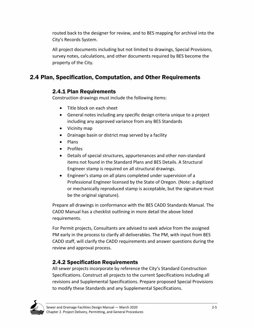
2.4.1 Plan Requirements Construction drawings must include the following items:
• Title block on each sheet • General notes including any specific design criteria unique to a project
including any approved variance from any BES Standards • Vicinity map • Drainage basin or district map served by a facility • Plans • Profiles • Details of special structures, appurtenances and other non-standard
items not found in the Standard Plans and BES Details. A Structural Engineer stamp is required on all structural drawings.
• Engineer's stamp on all plans completed under supervision of a Professional Engineer licensed by the State of Oregon. (Note: a digitized or mechanically reproduced stamp is acceptable, but the signature must be the original signature).
Prepare all drawings in conformance with the BES CADD Standards Manual. The CADD Manual has a checklist outlining in more detail the above listed requirements.
For Permit projects, Consultants are advised to seek advice from the assigned PM early in the process to clarify all deliverables. The PM, with input from BES CADD staff, will clarify the CADD requirements and answer questions during the review and approval process.
2.4.2 Specification Requirements All sewer projects incorporate by reference the City’s Standard Construction Specifications. Construct all projects to the current Specifications including all revisions and Supplemental Specifications. Prepare proposed Special Provisions to modify these Standards and any Supplemental Specifications.

Sewer and Drainage Facilities Design Manual — March 2020 2-6 Chapter 2. Project Delivery, Permitting, and General Procedures
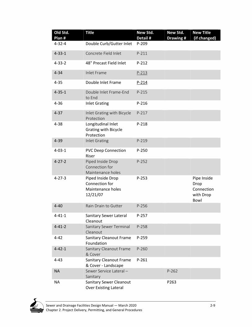
2.4.3 Use of Standard Details and Drawings The City of Portland, uses Standard Details and Drawings depicting many facilities and appurtenances for sewer construction. Include relevant Standard Details, Drawings, and special non-standard Details on separate plan sheet(s) in the Construction documents; doing so will provide a complete archive set of project-specific plans and related details in effect at the time the project was designed. When referencing either special, or Standard Details in a project plan set, reference the assigned Detail number.
The following table summarizes revisions made to the existing Standard Details and Drawings. Please note this additional information when encountering old references.
Table 2-1 Revisions to the Existing Standard Details and Drawings Old Std. Plan #
Title New Std. Detail #
New Std. Drawing #
New Title (if changed)
4-01 Typical Trench Sections – Backfill & Surfacing
P-100 Discontinued
4-02 Pipe Bedding and Pipe Zone
P-101
4-04 Anchor Walls for Sewer Pipe
P-102
4-05 Sewer Pipe Concrete Encasement
P-103
N/A Metal Slope Anchors for Pipe
P-104
Fig 1 (4-14) Top Slab “A” for Precast Maintenance hole
P-140 MSPCP Top Slab "A"
Fig 2 (4-08-5) Top Slab “B” for Precast Maintenance hole
P-141 MSPCP Top Slab "B"
Fig 3 (4-08-5) Top Slab “C” for Precast Maintenance hole
P-142 MSPCP Top Slab "C"
Fig 4 (4-08-5) Top Slab “D” for Precast Maintenance hole
P-143 MSPCP Top Slab "D"
Fig 5 (4-08-5) Top Slab “E” for Precast Maintenance hole (60”Dia.)
P-144 MSPCP Top Slab "E" (Reducing Slab for 60" dia.)
Fig 6 (4-08-5) P-145 MSPCP Top Slab "E" (Reducing Slab for 72"- 144")

Sewer and Drainage Facilities Design Manual — March 2020 2-7 Chapter 2. Project Delivery, Permitting, and General Procedures
Old Std. Plan #
Title New Std. Detail #
New Std. Drawing #
New Title (if changed)
Fig 7 (4-08-4) Large Precast Concrete Maintenance hole - Long Base Section Reinf.
P-146 MSPCP Longitudinal Section (60" dia. - 96" dia.)
Fig 8 (4-08-4) Large Precast Concrete Maintenance hole - Long Base Section Reinf.
P-147 MSPCP Longitudinal Section (108" dia. - 144" dia.)
Fig 9 Precast Concrete Maintenance hole – Top Slabs “A” through “D”
P-148 MSPCP Top Slabs "A" through "D"
Fig 10 Precast Concrete Maintenance hole – Top Slab “E” and Base Slabs.
P-149 MSPCP Top Slabs "E" and Base Slab
4-06-1 4-06-3 4-08-1 4-08-2
Precast Concrete MH, Precast Conc. MH w/ Precast Base, Large Precast Concrete MH, Large Precast Concrete MH – Types
P-150 MSPCP Precast Concrete Maintenance hole
4-08-3 Large Precast Concrete MH - Bases
P-151 Maintenance hole Cast-in-Place Base & Precast Base Slab
4-14 Top Slab for Precast Concrete Maintenance hole
P-152 Top Slabs for Precast Concrete Maintenance holes
4-10 Precast Sump P-160
4-11 Sedimentation Maintenance hole with Hood (Rev 6/30/08)
P-161
4-11-1 Sedimentation Maintenance hole with Baffle
P-162
4-11-2 Sedimentation Maintenance hole with Elbow
P-163 Discontinued
4-12 Sampling Maintenance hole
P-164

Sewer and Drainage Facilities Design Manual — March 2020 2-8 Chapter 2. Project Delivery, Permitting, and General Procedures
Old Std. Plan #
Title New Std. Detail #
New Std. Drawing #
New Title (if changed)
4-16 Step for Precast Maintenance hole
P-168
4-20-1 Maintenance hole Frame - 6" Depth
P-171
4-20-2 Maintenance hole Frame - 10" Depth
P-172
4-20-3 36 Inch Maintenance hole Frame
P-173
4-21 Maintenance hole Riser Ring
P-174
4-21-1 36 Inch Maintenance hole Riser Ring
P-175
4-22 Maintenance hole Cover P-176
4-22-1 36 Inch Maintenance hole Cover
P-177
4-22-2 36 Inch Maintenance hole Double Cover
P-178
4-23 Tamperproof Maintenance hole Frame/Cover 6" Depth
P-179
4-24 Tamperproof Maintenance hole Frame/Cover 10" Depth
P-180
4-25 Watertight Maintenance hole Frame/Cover 6" Depth
P-181
4-26 Watertight Maintenance hole Frame/Cover 10" Depth
P-182
Manhole with Beaver Slide
P-183
4-30 Concrete Inlet P-200 Discontinued
4-30-1 Adjust Concrete Inlet P-201
4-30-2 Inlet Location at Curb Return
P-202
4-31-1 Concrete Double Inlet - End to End
P-203
4-31-2 Concrete Double Inlet P-204 Discontinued
4-32-1 Curb Inlet P-206 Discontinued
4-32-2 Combination Curb Inlet P-207
4-32-3 Curb/Gutter Inlet P-208
Sewer and Drainage Facilities Design Manual — March 2020 2-9 Chapter 2. Project Delivery, Permitting, and General Procedures
Old Std. Plan #
Title New Std. Detail #
New Std. Drawing #
New Title (if changed)
4-32-4 Double Curb/Gutter Inlet P-209
4-33-1 Concrete Field Inlet P-211
4-33-2 48" Precast Field Inlet P-212
4-34 Inlet Frame P-213
4-35 Double Inlet Frame P-214
4-35-1 Double Inlet Frame-End to End
P-215
4-36 Inlet Grating P-216
4-37 Inlet Grating with Bicycle Protection
P-217
4-38 Longitudinal Inlet Grating with Bicycle Protection
P-218
4-39 Inlet Grating P-219
4-03-1 PVC Deep Connection Riser
P-250
4-27-2 Piped Inside Drop Connection for Maintenance holes
P-252
4-27-3 Piped Inside Drop Connection for Maintenance holes 12/21/07
P-253 Pipe Inside Drop Connection with Drop Bowl
4-40 Rain Drain to Gutter P-256
4-41-1 Sanitary Sewer Lateral Cleanout
P-257
4-41-2 Sanitary Sewer Terminal Cleanout
P-258
4-42 Sanitary Cleanout Frame Foundation
P-259
4-42-1 Sanitary Cleanout Frame & Cover
P-260
4-43 Sanitary Cleanout Frame & Cover - Landscape
P-261
NA Sewer Service Lateral – Sanitary
P-262
NA Sanitary Sewer Cleanout Over Existing Lateral
P263

Sewer and Drainage Facilities Design Manual — March 2020 2-10 Chapter 2. Project Delivery, Permitting, and General Procedures
2.4.4 Computation and Other Supporting Document Requirements To facilitate project review, a designer should provide with the Plans all necessary data requested that supports a design. Supporting information, as applicable to a project, should include but is not limited to the following items:
• Current zoning, pending zone change, current comprehensive plan designation, comprehensive plan amendment request, non-conforming uses and other planning actions
• Applicable Permits • Area to be served including all features such as utilities, wells, wetlands,
etc. including all survey notes and maps • Completed checklists • Delineated Tributary or drainage area • Flow calculations for sanitary and/or storm sewer design • Test borings and geotechnical report • Level 1 or 2 Environmental Reports, if required • Pipe strength calculations • Structural calculations • Cost comparisons for alternate designs based on Project Service Life • Material quantity estimates • Clear statement of assumptions and methods • Erosion control plan, conforming to City Code Title 10 Erosion and
Sediment Control Regulations • Operations and maintenance instructions; per Code chapter 17.38.040
Stormwater Quality and Quantity Control Facilities Required • Flow management facility design • Traffic requirements, traffic counts • Planting details (e.g. seed mixes, species) • Construction cost estimates
2.4.5 Ownership of Documents Section 17.24.085 of City Code establishes the City as the recipient and Owner of all documents used in the preparation of a sewer design project. The Code requires all plans; specifications, survey notes, geotechnical studies and other original documents prepared or produced during the design or construction of a sewer become City property. On permit projects, before the City accepts an improvement, the assigned PM must receive and acknowledge all relevant design and construction documents.

Sewer and Drainage Facilities Design Manual — March 2020 2-11 Chapter 2. Project Delivery, Permitting, and General Procedures
2.4.6 Consistency Before submitting Plans for review, the responsible Consultant is responsible for checking all drawings, specifications, notes and computations for consistency, clarity and accuracy.
2.4.7 BES Lacks Permitting Jurisdiction for Other City Bureaus or Outside Agencies BES has no authority to issue permits for work under the jurisdiction of other Bureaus or agencies. Such work shall not be shown on the BES construction drawings, except in enough detail as to clarify the relationship to and effect upon BES facilities and as required by the assigned PM. Permits should be referenced and included in the contract documents.
Public Works Permits
2.5.1 Sewer Connection Permits This type of work is allowed under a Sewer Connection Permit typically involves connection of a private sewer lateral to either a public sewer or an existing public sewer lateral. The conditions and criteria can be found in ENB-4.17 Sanitary System Connection Administrative Rules.
Any preexisting non-conforming sewer connections that require repair must seek independent connections to a City sewer following the Nonconforming Sewer Conversion Program Administrative Rules.
2.5.2 Simplified Permit in Public ROW/Easements Formerly known as Short Sewer Extensions, Simplified Permits are issued to address the modifications and extension of an existing City mainline sewer to serve new development (<100 feet) and to resolve nonconforming sewer situations (<200 feet).
Projects that fail to meet criteria of the Simplified Permit will be required to follow the Public Works Permit process or to request a Design Variance from the Standards of the City’s Sewer and Drainage Facilities Design Manual.
Before receiving a Simplified Permit, the Permittee/Consultant must submit all the applicable items requested by the assigned BES Project Manager. Items include:
• A complete site plan indicating pre- and post- construction conditions • Sewer pipe profiles and elevations • Pipe inverts elevations at maintenance holes
Sewer and Drainage Facilities Design Manual — March 2020 2-12 Chapter 2. Project Delivery, Permitting, and General Procedures
• Up-to-date utility information for the area of work must be shown on the plan and profile
• Pipe sizes, lengths and fitting types • Pipe material, bedding and slope • Street grades • All existing and proposed sewer connections • Label streets and the location of all easements • Erosions control methods
After receipt, review and acknowledgment by the Project Manager (PM), a Simple Permit is issued, and the applicant can schedule a meeting with the Inspection staff.
2.5.3 Public Works Permit Application Requirements Title 17 of the Portland City Code PCC 17.32.030 requires all persons wishing to construct or alter any public sewer to make an application to BES and obtain a Public Works Permit (City Code Chapter 17.32 Sewer Regulations.
BES manages and oversees the Public Works Permit Program. Employees review proposals to modify or connect to a public sewer or implement drainage improvements and issue permits with conditions for completing this work.
BES has updated rules regarding sewer connection provides expedited review and approval processes for completing simple sewer extensions (generally shorter than 100 feet),) and connection work, and modification of nonconforming sewers to meet regulation current standards. The Short Sewer Extension Simplified Permit process addresses the increased scope of work required to address nonconforming sewers. This Permit process is referenced as the Simplified Permit process.
The City has possible permit paths for anyone wishing to connect to a public sewer or modify a sewer to serve development. The City will review connection applications and determine which of the three Permit processes apply to the proposed or corrective work.
A building permit, Public Works Inquiry or Early Assistance response is required to gain approval for a Permit under these rules.
2.5.4 Public Works Permit Process This Permit process is generally initiated by the permittee/consultant; and the City provides guidance and oversight to assure the project conforms to the current standards. The process is complete when approval is received. Generally, the process follows the eight steps described below.

Sewer and Drainage Facilities Design Manual — March 2020 2-13 Chapter 2. Project Delivery, Permitting, and General Procedures
Step 1: Early Assistance or Public Works Inquiry –Applicant to use these processes to submit a proposed plan to seek clarification of city requirements of public facility improvements. Permittee/Consultant initiates an Early assistance or public Works Inquiry through the Bureau of Development website public works permitting and the corresponding instructions. Through this response BES will deliver information outlining the requirements for completing the Permit process.
Step 2: Prepare and Submit Application – Permittee/Consultant submits application to Public Works Permitting for review. Include plans, calculations, Operation and Maintenance (O&M) information and any requested supporting documents.
Step 3: BES Review – BES Systems Development staff will review the plans and incorporate their review comments as well as, from other BES groups. The BES PM will return comments to the applicant.
Step 4: Plan Revision – Permittee/Consultant reviews the comments and revises and resubmits the plans to address the review comments. Permittee/Consultant must respond in written response to each review comment. These review steps follow the Public Works Review process for concept, design and final plan review. After receiving approval, the Permittee/Consultant prepares and submits a set of stamped and signed drawings/mylars as well as an electronic copy of the project plans.
Step 5: Permit Approval – The BES PM, after receiving the signed mylars, prepares an internal signature routing package and circulates the documents for approval from the BES Chief Engineer. BES will determine the project permit fee and confirm any bond requirements.
Step 6: Required Submittals – Before receiving a Public Works Permit, the Permittee/Consultant must submit all the applicable items requested by the PM. A partial list of these items is found in the following section following this paragraph. After receipt and acknowledgment by the PM, a Public Works Permit is issued, and the permittee/consultant can schedule a pre-construction meeting with the BES Construction staff.
Before receiving a BES Public Works Permit, the applicant must submit or provide proof to BES of the following listed items.
• Provide a final, complete plan set of drawings/mylars stamped and signed by the Consultant
• Pay-in-full all estimated plan review and construction inspection fees

Sewer and Drainage Facilities Design Manual — March 2020 2-14 Chapter 2. Project Delivery, Permitting, and General Procedures
• Submit proof of a Performance Guarantee equal to 100 percent of the estimated construction cost
• Provide proof of Insurance • Obtain and provide evidence for any required permanent or
temporary easements, for both on-site and off-site easements • Secure all required agency and regulatory permits and approvals (e.g.
BDS, Division of State Lands (DSL), and Army Corps of Engineers) • Submit electronic copy of the final plan set
Step 7: Pre-construction Meeting and Submittals – Applicant contacts BES Construction to schedule a pre-construction meeting with project staff. Before this meeting, assigned construction manager (CM) may request project submittal information. Construction may commence following the successful completion of this meeting and satisfactory review of all the submitted.
Step 8: Project Completion – When project construction is complete (i.e., the CM has completed the Final Inspection), the BES will perform a final project accounting to determine whether there is money owed by the applicant or whether there will be a refund. Costs will be determined on actual time charged, per City Code.
The bulleted list in this section summarizes the applicable criteria for Permitting that an applicant wishing to connect to or work on a sewer must meet to obtain one of three permit types issued by the City. Each corresponding Permit requires a more involved application and design process to receive approval to perform the desired work.
Applicable Criteria for Permitting Construction Work on Public Sewer Located in the ROW
Sewer Connection Permit —Applicable Permit Criteria • Sewer service lateral repairs in the public right of way • All connections to a public sewer main and sewer service laterals • Relocations of existing sewer service laterals (from curb to the main) • Construction and/or extension of sewer service laterals to private
property for future use • Repair of private lines in the public right-of-way • Repair of a non-conforming sewer in the public right-of-way. • Maintenance holes are less than 48” diameter
Simplified Permit—Applicable Permit Criteria • No sewer main more than 18 feet • No maintenance hole more than 12 feet deep • Does not require a City approved traffic control plan • Does not require any maintenance hole greater than 48 inches diameter

Sewer and Drainage Facilities Design Manual — March 2020 2-15 Chapter 2. Project Delivery, Permitting, and General Procedures
• Work does not cross any major utility • Does not involve work on a brick maintenance hole • No engineering required to design an extension from any City sewer • Does not require extension of a brick sewer or a clay sewer constructed
before 2010 • No relocation of any utility • No conflict with the standard proximity rules pertaining to utilities • No excavation near a structure or retaining wall that requires
geotechnical design • No excavation adjacent to a water body, drainageway or involving
groundwater • No work outside of the public right-of-way • No extension longer than 100 feet to serve a development project • No extension longer than 200 feet to serve a non-conforming sewer • No extension longer than 200 feet to resolve a failing on-site system • No sewers greater than 12 inches diameter
Public Works Permit—Applicable Permit Criteria • Any Simplified Permit Criteria not satisfied. • Construct/modify public sewer and appurtenances • Construct any maintenance hole greater than 48” diameter • Construct/modify any public storm facility
Design Variance Request
The Design Variance Process - Requesting a Change from These Standards This Manual establishes the design standards for the Bureau; however, it is not always possible or desirable to strictly adhere to these standards. BES has a process to review any proposed design standards variance.
Designers wishing to prepare a design that does not follow these Standards need to complete a Design Variance Request - Form-2-2, found at the end of this chapter.
STEP 1: PREPARE A VARIANCE REQUEST Use the Design Variance Request - Form 2-2 to prepare a request. The request describes the nature of the variance and the need for a departure from these Standards. The information on the form must clearly indicate what the variance is, why it is needed and how the variance differs from the established BES standard.

Sewer and Drainage Facilities Design Manual — March 2020 2-16 Chapter 2. Project Delivery, Permitting, and General Procedures
The project type and who is responsible for the design will dictate which of the following procedures to follow when requesting a variance. Generally, the BES assigned employee and Section supervisor will receive the Variance Request and coordinate the review.
• If the project involves a Local Improvement District (LID), then, the assigned BES employee submits a written request to their supervisor.
If the project involves a Public Works Permit, then, a Permittee/Consultant submits a written request to the BES Development Services employee.
If the project involves a Capital Improvement Project managed by a Consultant hired by the City, then, the Consultant prepares the variance request to the BES PM, who forwards it to their supervisor.;
• If the project involves a Capital Improvement Project managed by City employees, then the BES PM (either the design PM or the construction PM, as appropriate for the phase of the project) prepares the variance request to their supervisor.
STEP 2: BES REVIEWS THE REQUEST Design Review Criteria - BES will receive and review any variance request from the design standards in this Manual. Acceptance or rejection of a proposal is based on conformance to the BES Mission Statement (January 2017) and to the City’s obligations and authority in Code and Charter to develop and manage sewage facilities that protect public health, water quality and the environment. In addition, any proposed variance must also ensure worker safety and health, maintain operational and performance efficiency throughout the sewer system and provide services at a fair and economical cost to residents.
After receiving a request, the recipient as described in step 1 above, will circulate the variance request form and the reviewer’s recommendations for action for review to their Division or Section Manager as well as other divisions or sections within the Bureau and including any other interested City Bureaus.
STEP 3: PROVIDE SUPPORTING INFORMATION If additional information is needed, the requester will be asked to provide the information. If a proposed product requires laboratory testing before approval, the requester will be responsible for all testing and any associated costs.
STEP 4: BES ANSWERS THE REQUEST Following its formal review, BES replies to the request in writing using the Reply section of the Design Variance Request - Form 2-2, found at the end of this chapter. There are four possible replies to a request: Approved, Rejected,

Sewer and Drainage Facilities Design Manual — March 2020 2-17 Chapter 2. Project Delivery, Permitting, and General Procedures
Approved with Modifications, and Revise and Re-submit. Generally, the Division Manager or supervisor and the Chief Engineer will sign and reply on the Design Variance Form and return the form to the requestor within 1 to 4 weeks of a request, depending on the complexity. All decisions are final.
A process flow chart figure describing this submittal and review process is below.

Sewer and Drainage Facilities Design Manual — March 2020 Manual Revision Request Form
Manual Revision Request – Form 2-1
Date ______________________
Manual Chapter _____________ Section # ____________ Page # _________________
Manual Users Name _______________________________ Phone (____)___________
Company____________________________________________________________________
Address_____________________________________________________________________
In the space provided below, please present a description of your suggested change or revision. All comments or recommendations for revision are welcome and encouraged to point out discrepancies, suggested modifications, or recommendations for additional information and clarification including examples to be added, etc.
Please include a detailed descriptive reason for the suggested change including supporting documentation. If necessary, attach additional pages to this form.
____________________________________________________________________________
____________________________________________________________________________
____________________________________________________________________________
____________________________________________________________________________
____________________________________________________________________________
____________________________________________________________________________
____________________________________________________________________________

Sewer and Drainage Facilities Design Manual —March 2020 Manual Revision Request Form
____________________________________________________________________________
____________________________________________________________________________
____________________________________________________________________________
____________________________________________________________________________
Mail to: Bureau of Environmental Services – Project Management Office 1120 SW 5th Avenue, Room 1100 Portland, OR 97204 -1972 Attn: BES Sewer and Drainage Facilities Design Manual – Proposed Revision

Sewer and Drainage Facilities Design Manual —March 2020 Design Variance Request Form
Design Variance Request – Form 2-2
Project Name: _______________________________________ Project Number___________
Submitter ___________________________________________ Date: _________________
Project Type (check one): Permit CIP Other _______________
Submittal Status (check one): Initial Submittal Revised Submittal
BES Project Manager Name _____________________________________________________
Variance Description: Be thorough. Describe the variance request, why it is needed, and how it differs from the established design standards (cite current standard). Describe how the variance will offer comparable or superior performance over the current standard. Use additional sheets if necessary.
______________________________________________________________________________
______________________________________________________________________________
______________________________________________________________________________
______________________________________________________________________________
______________________________________________________________________________
Send to: BES Section Supervisor (see Manual subsection 2.6.2, Step 1) Or, mail to: Bureau of Environmental Services – Chief Engineer
1120 SW 5th Avenue, Room 1100 Portland, OR 97204 -1972 Attn: BES Sewer and Drainage Facilities - Design Variance Request

Sewer and Drainage Facilities Design Manual — March 2020 Design Variance Request Form
Reply Section: (For BES Reviewers’ use only)
Reviewer’s names and initials: ____________________________________________ _____________________________________________________________________
Approved as submitted
Approved – Make Corrections Noted
Variance Rejected Revise and Re-submit
Remarks: _____________________________________________________________________ _____________________________________________________________________ _____________________________________________________________________ _____________________________________________________________________ _____________________________________________________________________ Signed: ___________________________________________ Date: ______________ Engineering Services Design Division Manager (Required for all approvals) Signed: ___________________________________________ Date: ______________ Bureau of Environmental Services Chief Engineer (Required for all approvals)

Sewer and Drainage Facilities Design Manual — March 2020 2-20 Chapter 2. Project Delivery, Permitting, and General Procedures
CHAPTER 2 NOTEWORTHY ITEMS
• Financing a public sewer improvement determines whether a project is defined as a Local Improvement or a Capital Project.
• BES staff or a consultant hired by BES or a permit applicant can be responsible for project management. Regardless who manages a project there are identified responsibilities and activities that guide project execution.
• BES has set standards when preparing Plans and Specifications for public sewer projects.
• Standard Details and Drawings need only be referenced for inclusion in a Project Plan set.
• BES has prepared a general checklist of some of the important supporting information that a designer may need to submit to BES as part of the supporting the final design submittal.
• The City is the ultimate owner of all materials and documents used when completing a public sewer design.
• BES has an established process to follow when obtaining a Public Works permit.
• BES encourages Manual users to suggest improvements and modifications to the Manual.
• Follow the Design Variance Process when it is necessary to depart from these standards.

Sewer and Drainage Facilities Design Manual — March 2020 3-1 Chapter 3. General Design Requirements
General Design Requirements This chapter summarizes the general requirements designers need to understand and comply with when completing a sewer project within the City. Topics include an overview of the City sewerage system, service requirements, location and easement standards, survey standards, investigating and coordinating with other underground utilities, geotechnical investigation, and ODEQ review of City projects. This chapter is organized into the following primary sections:
Project Service Life ............................................................................................ 3-2 Table 3-1 Project Service Life for Select BES Facilities .................................................... 3-2
Service Requirements ........................................................................................ 3-3 Service to Existing and Future Development .............................................................. 3-3 Gravity Systems versus Pumped Systems ................................................................... 3-3 Sewer Separation ........................................................................................................ 3-4 Sanitary Sewers .......................................................................................................... 3-4 Storm Drainage Facilities ............................................................................................ 3-4 Combined Sewers ....................................................................................................... 3-5
Drainage for Seeps, Springs, and Artesian Conditions ......................................... 3-6
Standard Sewer Locations .................................................................................. 3-7 Within a Right of Way (ROW) ..................................................................................... 3-7 Within Public Easement .............................................................................................. 3-8
Table 3-2 Permanent and Temporary Construction Easement Width Requirements for Sewers ............................................................................................................................. 3-9
Obtaining Easements — Preparation, Form, and Recording .............................. 3-10 Separate Document .................................................................................................. 3-11 Eminent Domain and Condemnation ....................................................................... 3-11 Permit Project Easement .......................................................................................... 3-11 Private Easements .................................................................................................... 3-12
Drainage Reserve and Tracts ............................................................................ 3-12
Survey Requirements ...................................................................................... 3-14 Survey Standard ........................................................................................................ 3-14 City of Portland Datum ............................................................................................. 3-14
Equation 3-1 City Datum Conversion Factor ................................................................. 3-14 Vertical Control ......................................................................................................... 3-15 Horizontal Control .................................................................................................... 3-15

Sewer and Drainage Facilities Design Manual — March 2020 3-2 Chapter 3. General Design Requirements
Geotechnical Investigations Requirements ....................................................... 3-15 Utility Investigation Requirements ........................................................................... 3-16 Underground Utility Location ................................................................................... 3-17 Addressing and Resolving Utility Relocation Conflicts .............................................. 3-17
Environmental Investigation Requirements ...................................................... 3-18 City Staff and Consultant Designers for City Projects ............................................... 3-18 Public Works Permit Projects ................................................................................... 3-19
Resiliency and Seismic Considerations ............................................................ 3-19
ODEQ Review of City Projects ........................................................................ 3-21
Flow Conversion Factors ................................................................................ 3-22 Table 3-3 Useful Conversion Factors ............................................................................ 3-22
Project Service Life BES assumes that all designed facilities operate optimally and continuously during their Project Service Life. Different facilities have differing service lives based upon service characteristics, level of risk, reliability, cost of replacement and other factors. Facilities reaching this age of service could be eligible for replacement although it is not uncommon for a facility to have a physical life longer than its established service life. The Service Life is useful for performing economic analyses when evaluating alternatives. Table 3-1 presents the Project Service Life for select BES facilities.
Table 3-1 Project Service Life for Select BES Facilities Sewer System Facility Type Project Service Life, years
Conveyance Pipes 100 Culvert Pipe 50 Force Main (i.e. pressure sewer) 50 Maintenance hole 50 Sump 30 Mechanical Equipment (e.g. pumps, process equipment) 25 Structure (e.g. pump station, treatment work, etc.) 50 Roadside Ditches 15 Stormwater Surface Retention Facility 30 Pump Station Components Superstructure (above-ground) 75 Wetwell 75 Pumps 25 Electrical & Instrumentation 20

Sewer and Drainage Facilities Design Manual — March 2020 3-3 Chapter 3. General Design Requirements
Service Requirements The City Sewer System is designed to collect sewage from lowest floors of all habitable buildings through gravity service where practicable.
Service to Existing and Future Development Design all sewers and stormwater drainage facilities to carry the flow from all existing and future development occurring within a drainage basin. Use the current Comprehensive Plan zoning designations for future development conditions.
Some areas of the City contain a mixture of combined sewers and separated storm and sanitary sewers. Design each system following the appropriate calculation methods described in this Manual.
Gravity Systems versus Pumped Systems The City prefers that sewer facilities operate under gravity flow conditions, where practical. (Reference: ENB-4-07 – Sewer Development Service Administrative Rules) Where factors make provision for gravity flow impractical, BES will consider a variance for a pump station or individual building pump system or other alternative, refer to Section 5.6.7 Pressure Lateral Systems. If conditions prevent meeting the minimum requirements for gravity service, an applicant shall submit a Design Variance Request Form (Form 2-2) requesting an exception from these Standards. A request should offer justification why pumping to a public sewer is the preferred alternative. Instructions for completing a Variance Request Form are in Chapter 2.
The following is a partial list of the minimum items that must be considered in a Design Variance Request:
• City Maintenance access • Public Health and Safety • Potential Environmental Zone impact
Providing service from an existing sewer main to a developed property is subject to more constraints than when building a new sewer to serve vacant land. For example, the elevation difference between the site/building and an existing sewer facility could limit the service depth and prevent gravity service to a basement. Service to existing development has potentially more conflicting off-site and utility issues that influence sewer construction. At a minimum, the City will attempt to serve a property’s first floor elevation with gravity service; if this is not possible, a private pump system may be the only option to access a sewer.

Sewer and Drainage Facilities Design Manual — March 2020 3-4 Chapter 3. General Design Requirements
Sewer Separation Design all new sanitary and storm sewers as separate facilities designed to convey only wastewater or stormwater. There may be circumstances in areas served with combined sewers when this standard cannot be met. In such cases, the designer is directed to follow the Design Variance procedures provided in Chapter 2 to request a variance from this standard. The City Code (City Code Title 17.32.080) requires the separation of private storm and sanitary plumbing lines on private property. In combined sewer areas, provide a single public service line to its point of connection with the private portion of the system. Projects to separate an existing combined facility must include provision for service lines to each of the separate private systems.
In all cases, the sewer depth must be sufficient to meet the criteria established for the service lateral size and material, grade, depth, and clearances. Designers must thoroughly analyze site conditions on individual private property that can affect the design of the main line sewer and the service lateral.
The City is committed to provide all lots, whether improved or unimproved, with sanitary sewer service. Providing gravity service is the City’s desire but this is not always feasible given the established minimum design criteria as well as other physical sewer system and site constraints. For example, the depth of an existing mainline sewer controls the lateral elevation at its connection to a building sewer. Other physical factors such as site slope and the relationship of the building (i.e. up-slope of down-slope) to the street as well as the elevation of an existing building sewer influence service to a site.
The location of the last service line on a sewer run may determine the termination point (i.e. maintenance hole or cleanout) of the sewer system (Refer to Chapter 4, Cleanouts - When and Where They Can Be Used).
Sanitary Sewers Design sanitary sewers to collect domestic sewage, industrial wastes and other contaminated water from the lowest floors of all plumbed buildings and from each lot or building site in the City's sewer service area. BES assumes that development of vacant land will include a basement.
Storm Drainage Facilities Design stormwater drainage facilities to collect runoff from an entire drainage area and convey it to an approved point of disposal. Design public drainage facilities to provide direct connection for gravity stormwater disposal from private property where no other approved method of disposal is available. On-site disposal is subject to approval by the Site Development Section of BDS.

Sewer and Drainage Facilities Design Manual — March 2020 3-5 Chapter 3. General Design Requirements
(Refer to Chapter 1, Useful Contacts within the City). The disposal of stormwater into the ground using any device classified as an underground injection facility is regulated by the ODEQ. (Refer to Chapter 1. Companion Documents and Internet Links).
It is the responsibility of the designer to determine the need for a storm sewer service line for stormwater and groundwater disposal from each lot, building site or existing building, and to design the facilities to meet the service needs. Any proposal for on-site disposal of private stormwater must receive written approval of the BDS, Plumbing Inspection Section, before BES's approval of public improvements.
The use of sumps and dry wells for public and private stormwater disposal is regulated by the ODEQ under OAR Division 44 Construction and Use of Waste Disposal Wells or other Underground Injection Activities (Underground Injection Control) filed September 2001. These rules define the permitted practices as well as the requirements to construct and operate a sump or drywell anywhere in the State. These regulations are found at the ODEQ website (Refer to Chapter 1, Companion Documents and Internet Links). Public UICs are also subject to the City’s Water Pollution Control Facility (WPCF) permit from ODEQ.
Discharge to Curbed Streets Foundation drains and/or crawl space drains are required for the majority of buildings constructed in the City. Such groundwater drains are not permitted to discharge to the street surface.
Roof drains from most single-family residences and other buildings of similar size are permitted to discharge to the surface of curbed streets after Stormwater Management Manual (SWMM) requirements are met. Streets with sufficient crown and curb height (i.e. 6-inches minimum) for the discharge pipe may receive this runoff. BES prohibits most commercial and industrial property roof and parking lot drains from discharging to the street surface.
Combined Sewers Design combined sewers to collect and transport a mixture of sanitary and storm drainage flows. This requires construction of a combined sewer at or below the depth required to provide gravity sanitary and drainage service to buildings throughout the City. Consider all factors influencing the design of separate sewer and storm drainage systems when designing a combined sewer.

Sewer and Drainage Facilities Design Manual — March 2020 3-6 Chapter 3. General Design Requirements
Drainage for Seeps, Springs, and Artesian Conditions Occasions may arise when construction activity intercepts a subsurface or artesian water source that threatens to bring groundwater up to the ground surface where it can impact streets, vehicle operations and other improvements. Designers need to anticipate conditions and consider adding a drain field or similar system to collect this water and manage conditions to minimize any resulting affects. Refer to Figure 3-1 Interception of Groundwater During Construction and Its Management. Construction management of groundwater will need to comply with a DEQ 1200-C Erosion Control Permit, the City’s Source Control Manual as well as, all of the projects’ regulatory permits. Depending on the final design solution selected, a facility could fall under the ODEQ UIC rules. A designer must first review these rules and determine if these regulations affect the siting or use of a selected solution for this purpose. Private drainage is prohibited to a City owned UICs. For City owned properties where construction dewatering is necessary all proposed UICs would need to be approved under the City’s WPCF UIC permit and registered with the UIC program. These regulations are found at the ODEQ website (refer to 1.11, Companion Documents and Internet Links).
Figure 3-1 Interception of Groundwater During Construction and Its Management

Sewer and Drainage Facilities Design Manual — March 2020 3-7 Chapter 3. General Design Requirements
Standard Sewer Locations
Within a Right of Way (ROW) All City sewers shall be constructed in public rights-of-way, wherever feasible or in public sewer easements, when conditions dictate. The following are the standard locations of sewers within public right of ways:
Sanitary sewer and combination sewer: Locate 4 feet north or west of ROW centerline.
Storm sewer: Locate 4 feet south or east of ROW centerline.
Determine sewer locations primarily by the requirements of accessibility for construction and maintenance and of service needs. Sewer construction and street restoration in public rights-of–way are permitted activities and require a Street Opening Permit obtained through the Portland Bureau of Transportation (Refer to Chapter 1, Useful Contacts within the City). This permit process is separate from obtaining a BES Sewer Permit.
Sewers should normally be located: • To conform to the applicable City of Portland, Standard Details (e.g.
Detail P-504), • To conform with the Oregon Health Division, Oregon Administrative
Rules (OAR), Chapter 333, Division 61, Public Water Systems, 333-61-0050 (10), Crossings - Sanitary sewers and water lines for separating sanitary sewer and water lines
• When feasible, at sufficient distance outside of the “Zone of Influence” from a wall or building footing, other underground utilities and other obstructions to reduce construction and maintenance hazards or provide a designed shoring system.
• To avoid logical locations of other planned improvements (e.g. buildings) • To avoid placement under existing or future paralleling curbs, fences,
retaining walls or other impediments to maintenance • To avoid environmental zones or other identified sensitive areas.
The preliminary design effort should be with the goal of placing all sewers in their standard locations within streets unless those locations are not feasible. These standards apply to a straight street. For curved streets, BES must approve any departure from these standards (see Chapter 4). All sewers shall be located parallel to one another.
If a roadway is asymmetric within the ROW, then reference the curb-to-curb centerline to locate sewers.

Sewer and Drainage Facilities Design Manual — March 2020 3-8 Chapter 3. General Design Requirements
The existing locations and sizes of other underground utilities or other factors may require a non-standard sewer location. The remainder of the street must be reserved for locating other underground utilities.
Within Public Easement Some factors to consider when evaluating whether to place sewer on private property within a permanent public sewer easement include site availability, accessibility for future maintenance, proximity of existing structures, proximity of trees and other natural features, the public relations aspect of negotiating an easement acquisition, and the impact of an easement on the current and future use of the property.
If conditions dictate that placing sewers on private property is the preferred option, doing so will require the City to acquire a permanent easement and possibly other property rights (e.g. temporary construction easement) from the property owner. This section contains design standards of permanent and temporary public easements; Section 3.5 describes different methods the City can use to acquire public easements. If public sewer exists in an easement, a Permit of Entry is required for any reason, such as maintenance, rehab or repair. The property owner must sign the Permit of Entry and the City must accept it before issuing the Certificate of Completion.
3.4.2.1 Location Locating easements is project-specific and should be decided with cost effectiveness and impacts to private property owners in mind. The City should discuss possible easement locations with the affected property owners and consider the owners’ concerns during design. Permanent public sewer easements need to be placed in locations that allow unobstructed vehicle access for maintenance and sewer repair activities. Examples include driveways, parking lots, required building setback areas or similar. Provide for adequate access along an easement from the right of way. Within an easement, center a single asset within the easement centerline to provide room for access and future maintenance or construction activities.
Avoid angling easements across properties (bisection). Consider the probability of future property improvement such as retaining walls, fencing or plantings that could create barriers and limit sewer access and maintenance. For example, avoid spanning an easement across a property line shared by two adjoining lots; doing so would necessitate easement acquisition from two property owners versus one, and placement of a future privacy fence along the shared property line could impede access and damage asset.

Sewer and Drainage Facilities Design Manual — March 2020 3-9 Chapter 3. General Design Requirements
Easements should be as far from existing buildings as practicable. If an element of an existing building such as a footing or roof overhang is within a proposed easement area the easement should be adjusted accordingly to remove the access conflict. The easement document should acknowledge the presence of any non-restrictive building features in the easement area and include any necessary clauses as applicable (e.g. indemnification clauses). The horizontal distance between the sewer and the excavation zone must be such that excavating for the sewer construction or repair does not endanger the building.
The maximum slope of the easement should be less than 10% in both longitudinal or cross slope. Easement locations must be shown on the plans by distance to known property lines or public rights-of-way lines and, where necessary, by angles.
3.4.2.2 Width Show the limits of the permanent easement, as well as any temporary construction easements, on the final plans. Define an easement width based on the sewer’s depth and size, soils, slope and stability, equipment access, the storage and stockpiling of materials during construction, and future access, maintenance or construction needs. Local conditions may require additional widths.
Table 3-2 Permanent and Temporary Construction Easement Width Requirements for Sewers
Sewer Pipe Size Minimum Permanent Easement Width (ft)1
Temporary Construction Easement (ft)2
Less than or equal to 24 inches 15 10
Greater than 24 inches 20 Width to be determined by BES
1 The listed easement widths assume level ground having less than 10% longitudinal or cross-slope. Easements on sloped ground will require additional width for maintenance vehicle access. Increase the minimum easement width 5 feet for each 5 % increase in slope above 10% longitudinal or cross slope.
2 The temporary construction easement is a separate easement, in addition to the permanent easement width.
The minimum width for a permanent sewer easement is 15 feet. An additional width of 5 feet is necessary if a sewer is constructed at a depth greater than 10 feet. Additional width is required for the following conditions: ground slopes over 10% longitudinally or in cross slope; more than one pipeline located in an easement; pipe is 20 feet or deeper; or if other factors are present through site-specific review by BES. This additional width is needed to safely perform construction and/or maintenance of the sewer asset. These widths are

Sewer and Drainage Facilities Design Manual — March 2020 3-10 Chapter 3. General Design Requirements
cumulative, IE this additional width should be added to the minimum widths stated above and indicated in Table 3-2.
3.4.2.3 Uses and Encroachments If it is determined during design that multiple pipes - or other private or public non-sewer features - will occupy an easement area, increased width may be necessary beyond that prescribed Section 3.4.2.2, and/or the easement may need to include clauses related to the other allowed features, i.e. encroachments.
If an owner wants to construct a feature or conduct activities in an existing public easement, and the feature or activity is not expressly allowed by the easement language, they will not be permitted unless the BES Chief Engineer or designee consents in writing to the encroaching feature or activity. PCC 17.32.040 authorizes BES to review for encroachments in public sewer easements, and these encroachments are typically documented by an Encroachment Agreement between the owner and the City that is recorded against the property and maintained in the BES asset database associated with the relevant asset and easement records.
When working in easements, avoid any unnecessary damage or destruction of natural features, vegetation or manmade improvements.
For more information regarding private easements, please refer to section 3.5.4.
3.4.2.4 Existing Public Sewers For construction projects or maintenance activities related to an existing public sewer located in a permanent public sewer easement, permission to access the sewer may already exist in the rights granted by the permanent easement; when unsure, the BES designer or permit reviewer should consult with the City Attorney’s Office. If the permanent easement does not grant sufficient rights to access the sewer for the proposed work, additional property rights must be obtained, such as a Temporary Construction Easement. For early access to the site for specific purposes such as testing or survey, a Permit of Entry may also be necessary. See Section 3.5 for information about acquiring property rights.
Obtaining Easements — Preparation, Form, and Recording There are several methods by which the City can receive an easement, including:
1. By separate recorded document; 2. By use of eminent domain; 3. By recording a plat with the county; or 4. By street vacation.

Sewer and Drainage Facilities Design Manual — March 2020 3-11 Chapter 3. General Design Requirements
Methods one and two (separate recorded document and eminent domain) are the most commonly used for BES Capital Improvement projects, and both can require financial payment to the property owner to obtain the property right. Easements reserved on plats are typically associated with a permit project and therefore do not require payment because they are associated with sewer projects the developer must complete to serve their project (occasionally public easements located off of the development site are needed in order to provide approvable service, which would be recorded via separate document and the developer would provide any payment to the affected property owner). Easements reserved through street vacations are more common for maintaining the right of City access to existing sewers located within the street to be vacated.
Separate Document As soon as BES identifies, selects and approves an easement location for a capital project, the BES PM will refer the easement negotiation to the Bureau of Transportation’s Right-of-Way Acquisition section. The Right-of-Way Acquisition section may request additional information from the designer to process the negotiation and complete the easement acquisition.
Easements should be prepared on the City's standard form with the proper wording of easement conditions. Easements must be in the name of the City and recorded with the County. All legal property owners must sign an easement. Signature(s) must agree with the name(s) used on the property deed. Under PCC 17.16.140, the BES Director can accept an easement on behalf of the City if the compensation paid to the property owner is $50,000 or less. All other easements must be accepted by City Council via ordinance; the City will record the easement with the County.
Eminent Domain and Condemnation The City has the right of eminent domain and may exercise that right through condemnation of land for public sewer construction purposes. When a demonstrated need and public benefit exists, the City could exercise their right of condemnation. It is not the practice of the City to proceed with condemnation for the sole purpose of promoting or facilitating development when no expanded public need exists. The City Council must approve all condemnation proceedings. Refer condemnation proceedings to the Bureau of Transportation’s Right-of Way Acquisition section.
Permit Project Easement Generally, staff from the BES Development Engineering and Development Planning sections review easements associated with permit projects that are

Sewer and Drainage Facilities Design Manual — March 2020 3-12 Chapter 3. General Design Requirements
intended to provide services to partitions or subdivisions reviewed through the BDS land division and final plat processes. The assigned BES PM should discuss the location of easements with the consulting engineer as early as possible in the project design process. BES staff will review proposed easements against the standards in this manual and require changes to the permit plans and plat document, as applicable.
When easements are within the land division site, no additional negotiation is needed, and the easement is established when the final plat is recorded.
When off-site easements outside of the land division site are needed to construct the permit project, those must be acquired via separate document. In these cases, permittees can negotiate directly with off-site property owners. Permittees are responsible for paying all costs related to the acquisition of the off-site easement, including reimbursement of City costs and any negotiated payments to affected property owners. Refer questions related to off-site easement acquisition to the Bureau of Transportation’s Right-of-Way Acquisition section.
All permanent and temporary public easements (both within and outside of the development site) must be shown on the final permit or project plans, and all permanent and temporary public easements that are within the development site must be shown on the final plat.
Private Easements Easements for private sewer lines granted to one property owner from another property owner are private easements. BES has authority to determine approvable route of sewer service, point of connection to the City system, and elements for conforming legal connections; but private easements are reviewed and approved by the Bureau of Development Services, BDS. Contact BDS for allowed encroachments into existing or proposed private easements.
Drainage Reserve and Tracts The project designer should be aware that work in or near drainageways, streams, wetlands, and environmental, river or greenway overlay zones may trigger additional City, State, and/or Federal regulations and review.
PCC 17.38 and Title 33 authorizes the Director of BES to require a drainage reserve or tracts over seeps, springs, wetlands and drainageways to preserve their function. Establishment of a reserve or tract is intended to protect the integrity of these features to safely convey water and to limit flooding impacts to development. A drainage reserve acts as a no-build area delineated on both

Sewer and Drainage Facilities Design Manual — March 2020 3-13 Chapter 3. General Design Requirements
sides of a drainageway and its adjacent riparian area. BES must review and approve any proposed encroachments into the drainage reserve area unless allowed per the Stormwater Management Manual. Drainageway definitions, reserve widths, exemptions and encroachment review submittal requirements are described in detail in the Stormwater Management Manual.
Tracts are typically created through the BDS land division process; criteria that BDS uses to require protective tracts are found in City Code Chapter 33.640 Streams, Seeps, and Wetlands. Consult with BDS or the BES Development Planning section with questions about tract requirements.
Regardless of whether a seep, spring, wetland or drainageway is protected in a reserve or a tract, separate permanent and/or temporary permission to access and construct in that area may need to be acquired; see Section 3.5 for more information. In addition, construct no private structure, culvert, excavation or fill within the reserve or tract area unless applicable authorization is granted, e.g. in writing by the BES Chief Engineer, and/or permission from BDS if the work is within an environmental overlay zone (Environmental Conservation or Protection zones).
Title 33 is implemented by the Bureau of Development Services (BDS) and includes regulations related to Environmental Zones (c and p overlay zones), Willamette Greenway Zones (n, r, g, i and q overlay zones) and River Zones (g* or e overlay zones). Typical activities that trigger environmental, river or greenway review include but are not limited to: development; removing, cutting, moving, or clearing vegetation; changing topography, grading, excavating or filling; resource enhancement; dedication or expansion of public right-of-way; pipe and utility work outside of developed right-of-way; and constructing new outfalls or upsizing existing outfalls. Refer to Title 33.430, Title 33.440 and Title 33.475 for a complete description of activities that trigger BDS review or contact BDS at 503-823-PLAN.
The Bureau of Development Services also implements Title 24, which regulates work in flood hazard areas and unidentified watercourse floodways and includes balanced cut and fill requirements. Refer to Title 24.50 or contact the BDS, Site Development section for additional information.
Work in State jurisdictional waters (including rivers, wetlands, ponds, intermittent streams and perennial streams) may trigger a permit or review by the Department of State Lands (DSL). Regulated activities in a jurisdictional water of the United States may require review by the Army Corps of Engineers. Depending on the activities proposed, the project designer should also be aware of requirements under the Endangered Species Act, the Clean Water Act, ODFW’s Fish Passage

Sewer and Drainage Facilities Design Manual — March 2020 3-14 Chapter 3. General Design Requirements
Law, the Migratory Bird Treaty Act and any other applicable local, State or Federal regulation.
Survey Requirements Complete all surveys for sewer design and construction on the ground at the site of the proposed sewer construction. It is not acceptable to establish elevations and locations for sewers from aerial survey topographic maps and other indirect sources. Only a close grid topographic map drawn from ground elevations taken at the site is acceptable. The contour interval should be sufficient to show topographic information at the appropriate level of detail – usually 1’ or 2’ interval. When the close grid method is used, it may be necessary to conduct supplemental surveys on the actual sewer alignment. Typical survey interval at the sewer centerline is 50 feet, with 25 feet or less needed if topography variations dictate. When submitting plans for review, flag and provide access for viewing all maintenance holes, ends-of-line, and proposed sewer alignment and any other related facilities.
Permit project applicants shall submit the design survey before the City reviews the plans; submit the construction survey before beginning construction. The City will verify these surveys before construction.
Survey Standard All surveys must be third order or better.
City of Portland Datum All survey and design work prepared for BES must reference the City of Portland datum. The City adopted the current datum in 1896. The Oregon Department of Transportation (ODOT), Federal and local agencies reference either the National Geodetic Vertical Datum (NGVD) or their own adopted datum for vertical survey control. River elevation and flood stage reports for the Columbia and Willamette Rivers reference either the NGVD or another local datum that differs from the City datum.
Designers are responsible to confirm the reference datum of any survey data used for sewer projects and convert this information to the City datum.
The City datum is 1.375 feet above NGVD. Therefore, to convert an elevation from the NGVD to the City datum use the following relationship:
(NGVD Elevation)+1.375=(COP datum Elevation)
Equation 3-1 City Datum Conversion Factor

Sewer and Drainage Facilities Design Manual — March 2020 3-15 Chapter 3. General Design Requirements
To convert an elevation from the City datum to NGVD, subtract 1.375 feet to the elevation. Information for converting between the City datum and other local datums is found by accessing the Survey section website address at: www.portlandoregon.gov/transportation/article/70676
Vertical Control All design projects shall reference the City of Portland datum; tie the design survey to existing City benchmarks. Show the locations and elevations of all City benchmarks used to establish elevations. City benchmark locations and elevations are available from the Portland Bureau of Transportation Engineering and Development, Survey section or at their City website.
Horizontal Control All alignment surveys must result in a closed traverse with the ends tied into known points defined with established monuments. Leave no survey loose ended or tied into indefinite points. Tie all recorded property corners identified in the construction area to provide intermediate control points (Oregon Revised Statues ORS 209.150 and 209.155). Also, tie buildings, trees over 8” in diameter, retaining walls and waterways.
Geotechnical Investigations Requirements Geotechnical investigations are necessary for the proper design of any sewer project. It is necessary to determine the existing soil conditions and groundwater elevations to facilitate pipeline design, and specify the appropriate bedding and backfill, to determine suitable construction procedures, and to design shoring, including specifying parameters for Contractor shoring design.
A Geotechnical Investigation is the responsibility of the Engineer of Record to determine if site warrants it on Permit projects. The City has the discretion, in some instances, to request an investigation if in disagreement and will be assessed by the assigned BES PM with the plans for review.
Geotechnical investigations should include at a minimum, a description, the following:
• Prepare a description of the project area topography, landform and geological formation.
• Prepare a plan showing the proposed construction and locations of soil borings or test pits. All location(s) of test pits or soil borings shall be assigned coordinates and elevations and reference the City of Portland datum. Survey these locations or extrapolate their placement from

Sewer and Drainage Facilities Design Manual — March 2020 3-16 Chapter 3. General Design Requirements
topography established from the project survey monuments. Do not use an aerial topographic map or other indirect source.
• Develop soil profiles encountered at discrete locations in the project area from a sufficient number of test pits or soil borings to adequately define subsurface conditions. The profiles shall extend a minimum of 5-feet deeper than the planned depth of construction and show the elevation of the water table, if encountered. Prepare soil descriptions in accordance with the following ASTM Standards:
o ASTM D2487-00 Standard Classification of Soils for Engineering Purposes (Unified Soil Classification System)
o ASTM D2488-00, Standard Practice for Description and Identification of Soils (Visual - Manual Procedure)
• Describe any anticipated seasonal water table range of fluctuations, whether or not the water table was encountered in the soil borings.
• Discuss the effect the soil conditions and water table elevations may have on the proposed construction including recommendations for shoring, dewatering and trench bottom stabilization.
• Address trench backfill interaction with site geology. • Comment on the suitability of native soil for trench backfill as defined by
Division 2 of the City of Portland's Standard Construction Specifications.
Utility Investigation Requirements Underground utility investigation and coordination is vital to proper sewer design. Failure to adequately investigate the depth and location of other utilities, reserve the sewer location, or provide for future utilities can be very costly. It is the responsibility of the designer to investigate the location of existing and proposed underground utilities during the design process. The Designer should document in writing the contacts with Utilities and confirmation of conflict resolution.
The Oregon Utilities Coordinating Council (refer to Chapter 1, Companion Documents and Internet Links for information) is a state agency clearinghouse responsible for notifying utility owners of planned excavation within proximity of a utility. Designers should contact the One-Call Center directly during a pre-design and request a "presurvey" information transfer to determine potential utility conflicts before beginning design. A designer making such a request will only receive utility maps for an area of interest; no utility marking will result from this request. During the design phase, City survey staff will coordinate with the One-Call Center and request that utilities be visibly field marked prior to surveying.

Sewer and Drainage Facilities Design Manual — March 2020 3-17 Chapter 3. General Design Requirements
Underground Utility Location It may be necessary to establish the elevations and locations of existing underground utilities in the field. If so, consider having their locations marked and potholed before starting the survey. Tie all surface indications of any underground utility locations to the survey.
Underground utility investigation should include, at a minimum, the following:
• A field reconnaissance of the proposed sewer route to look for surface indications of existing utilities that may need to be marked or potholed for establishment of the utility location by the surveyor.
• Location of utilities from evidence obtained in the field rather than by measurements taken from the records. Request the survey crew to contact the One-Call Center and have utility locations marked. Coordinate survey work to tie in all marked utilities in the proposed work area.
• Instructions to the surveyors to document the locations and/or elevations of all utilities found, marked or potholed. Document all poles, overhead or underground wires, hydrants and other utilities, which are in the potential work area.
• Research all available records of existing underground utilities in the work area.
• Submit for review the preliminary construction drawings to the Development Review Service of the Portland Water Bureau and to all utility owners that may have or plan to construct facilities in the project area. The preliminary drawings should show the designer's best information regarding the existing utility elevations and locations.
• Upon approval and signing of the construction drawings, submit copies of the plans to all utility owners that may have or plan to locate facilities in the project area.
Addressing and Resolving Utility Relocation Conflicts The City Engineer has authority through City Code Title 17.16.100 to require utilities to be moved. Resolving any utility conflicts by the Designer should include, at a minimum, the following:
• Notify Utilities in writing of conflicts • Meet with Utilities to resolve conflicts • Confirm resolution agreement with Utilities in writing

Sewer and Drainage Facilities Design Manual — March 2020 3-18 Chapter 3. General Design Requirements
Environmental Investigation Requirements It is necessary to determine if contaminants of concern exist in soil, groundwater, and other media encountered during sewer work for worker health and safety and for contaminated media management and disposal.
An environmental assessment of a project site is required for sewer projects designed by the City, consultants designing on behalf of the City, and public works permit projects, to understand the risk of encountering contaminated media during construction.
City Staff and Consultant Designers for City Projects All sewer projects require an environmental assessment to determine if environmental features of concern are impacting the project site. The project manager will coordinate with the City of Portland Coordinated Site Analysis (CSA) Program, and an environmental consultant if assigned to the project. A CSA staff member shall be assigned to all sewer projects, even if an environmental consultant is assigned. The CSA staff shall provide environmental work for the project or provide oversight and review for environmental consultant work.
An environmental assessment shall include, at a minimum, research into the history of land uses at the project site in the form of a Phase I Environmental Site Assessment (ESA) or Level 1, and may also include sampling and analysis of soil, sediment, groundwater, surface water, or other environmental media in the form of a Phase II ESA or Level 2, as directed by findings of the Phase I ESA or Level 1.
Environmental Phase II ESAs or Level 2 investigations shall include, at a minimum, the following:
• A description of the project area. • A plan or map showing the proposed construction area and locations of
soil borings or test pits. All location(s) of test pits or soil borings shall be assigned coordinates and reference the City of Portland datum. Survey or GPS these locations or extrapolate their placement from known features or landmarks.
• Soil profiles encountered at discrete locations in the project area from a sufficient number of test pits or soil borings to adequately define subsurface contamination. The profiles shall extend to the planned depth of construction and show the elevation of the water table, if encountered.
• Soil descriptions prepared in accordance with the following ASTM Standards, if not provided by the geotechnical engineer.

Sewer and Drainage Facilities Design Manual — March 2020 3-19 Chapter 3. General Design Requirements
• ASTM D2487-00 Standard Classification of Soils for Engineering Purposes (Unified Soil Classification System)
• ASTM D2488-00, Standard Practice for Description and Identification of Soils (Visual - Manual Procedure)
• A description of any water, moisture, and any visual or olfactory signs of contamination encountered in the soil borings or test pits.
• An evaluation of all laboratory analytical data with appropriate screening criteria, including those for disposal characterization and for risk-based decision making for construction and excavation worker exposure.
• A recommendation for management of contaminated media (soil, groundwater, asbestos piping, etc.) if it is expected to be encountered during construction.
• A clear indication in the report of any laboratory analytical data exceedances of risk-based screening values for construction and excavation workers.
Public Works Permit Projects All Permit projects shall follow the Public Works Permit Application Requirements outlined in section 2.5.1 of this manual. As part of the Public Works Permit Process, the permittee may be required to complete an environmental questionnaire about the history of site uses and environmental condition of the project site. If answers on the questionnaire indicate that contaminated media may be present at the project site, BES may require the permittee to complete a Phase II ESA or Level 2 investigation to locate, characterize, and quantify contaminated media that may be encountered during construction. If a Phase II ESA or Level 2 is deemed necessary for the project to proceed, the permittee shall provide a Phase II ESA or Level 2 report that includes the items listed in 3.9.1 above.
Resiliency and Seismic Considerations Background Recent studies of the Cascadia Subduction Zone (CSZ) estimate there is a 24% change of a Magnitude 9.0 earthquake impacting the Portland metro region in the next 50 years and the Geologic Society of America stating there’s a greater than 41% chance of a large earthquake in the next 50 years. The CSZ is located about 70 to 100 miles off the Pacifica coast shoreline. The earthquake is anticipated to cause ground responses that include wave propagation (ground shaking) and permanent ground deformation such as liquefaction, lateral spreading, ground settlement, and landslides. These soil movements can impact pipes and associated infrastructure such as laterals and maintenance holes in

Sewer and Drainage Facilities Design Manual — March 2020 3-20 Chapter 3. General Design Requirements
various ways including cracking, collapse, shearing, compression, flotation, and joint separation.
The Resiliency Master Plan The BES Resiliency Master Plan (RMP) was developed to integrate the ORP resiliency goals specifically into BES infrastructure and practices and supports the 2018-2027 BES Strategic Plan’s multiple initiatives to help make our built and natural systems more resilient. The RMP identified critical assets within our system, referred to as the “backbone” of the system, and included data on potential ground motions impacting those assets; these are the assets that should be the focus for resiliency improvements. The RMP notes that assets have varying levels of importance, depending on the service they provide, and therefore have differing level of service recovery time goals. The main priority for BES after any seismic event is to route sewage away from the public in order to avoid a public health disaster.
Applying Resiliency to Projects BES is in the process of developing methods of making the pipe more seismically resilient, i.e., “hardening” a pipe to the desired level of service. Hardening a pipe to resilient design, however, may not always be feasible due to site conditions, pipe option limitations, cost, etc. There may be opportunities to cost-effectively “enhance” a pipes resiliency where, in design, incremental improvements for resiliency can be incorporated to give the pipe a better chance of survival while acknowledging the possibility of failure—this may be the case where a pipe’s material can be upgraded but the pipe can remain susceptible to flotation and ground improvements are not feasible or are cost prohibitive. In cases where a critical asset cannot be mitigated to achieve resiliency, a response plan should be identified to manage its failure and restore its services.
BES has prioritized the areas of the backbone system where permanent ground deformation is expected to damage BES assets. Designers can review seismic soil hazard data against seismic vulnerability of the backbone and non-backbone pipes to understand which pipes should be pro-actively made resilient (upgrade before natural asset management cycle) and which pipes may be a better candidate for opportunistic, cost-effective resilient or enhanced design upgrades (upgrade during asset management cycle, i.e., “we’re going to be working on that asset anyways, we may as well upgrade it if it’s cost-effective”.
In these soil hazard areas, the standard design process may not apply and resilient best practices in design1 should be evaluated along with a
1 See the Resiliency Master Plan’s “Seismic Resiliency Technical Memorandum #7 – Identifying and Prioritizing BES Pipelines for Seismic Resiliency Improvements – Attachment B.”

Sewer and Drainage Facilities Design Manual — March 2020 3-21 Chapter 3. General Design Requirements
documentation on the decision process for what the final design approach was, why, and if a response document is needed. Additionally, designers need to consider interdependencies with other lifeline infrastructure (emergency transportation routes, key water transmission lines, or key electricity and gas utility infrastructure) or critical facilities (hospitals, fire stations, government buildings, etc.). If a failure of a BES asset may impact another critical lifeline or facility, there is more reason for BES to require design for resiliency.
Identification of critical assets and services, along with resilient design and construction approaches, will continue to evolve as BES learns more about its system, lifeline interdependencies, and the community’s needs.
ODEQ Review of City Projects The Oregon State Department of Environmental Quality (ODEQ) has issued the OREGON ADMINISTRATIVE RULES, REVIEW OF PLANS AND SPECIFICATIONS, CHAPTER 340, DIVISION 52. These rules include information for Sewer Pipelines as well as Raw Sewage Lift Stations. This document describes the minimum requirements for gravity sewer and pump station design and construction.
The purpose of these rules is to "prescribe requirements and procedures to obtain approval of plans and specifications as required by ORS 468B.055 for the construction, installation or modification of disposal systems, treatment works and sewerage systems." The rules require that "except where exempted … all plans and specifications along with other data submitted for the proposed construction, installation or modification project involving disposal systems, treatment works, sewerage systems or common sewers" shall first be submitted to ODEQ for review.
In 1981, ODEQ granted the City of Portland an exemption from this requirement for the submittal of gravity sewer projects to ODEQ for review. The City must still submit pressure systems and treatment works for review. Under this agreement, the City is responsible for reviewing, approving and constructing gravity sewer projects in conformance with the rules of ODEQ, the City's published standards, and the terms of the City's National Pollutant Discharge Elimination System (NPDES) Waste Discharge Permit.
Copies are also available from ODEQ (Refer to Chapter 1, Companion Documents and Internet Links).
A copy of the NPDES Permit is available from BES. Designers shall become familiar with these documents in order that their designs fulfill the agreement for exemption from the submittal requirements.

Sewer and Drainage Facilities Design Manual — March 2020 3-22 Chapter 3. General Design Requirements
Flow Conversion Factors Sewer design requires the determination of flow rates for sizing pipes and establishing slope. Report flow rates using different systems of units depending on the preference of a designer, a reviewer, or a group or section in BES that is responsible for a facility design. Some commonly used systems of units for defining flow rate include gallons per minute (gpm); gallons per day (gpd); million gallons per day (mgd) and cubic feet per second (cfs).
BES has adopted the following factors to convert flow information between these commonly used systems of units.
Table 3-3 Useful Conversion Factors To convert Multiply by To obtain
Cubic feet per second 448.8 Gallons per minute
Gallons per minute 0.002228 Cubic feet per second
Cubic feet per second 646,300 Gallons per day
Gallons per day 1.547 x 10⁻⁶ Cubic feet per second
Gallons per day 1 x 10⁻⁶ Million gallons per day
Million gallons per day 1.547 Cubic feet per second

Sewer and Drainage Facilities Design Manual — March 2020 3-23 Chapter 3. General Design Requirements
CHAPTER 3 NOTEWORTHY ITEMS
• The City has established Project Service Life criteria for all sewer facilities. These are the minimum service criteria needed when performing Life Cycle cost comparison for alternate designs.
• Gravity sewer service is the preferred method for collecting and transporting sanitary, stormwater and combined sewage for disposal.
• All new sewers shall be designed as separate facilities. Private sanitary and stormwater drainage facilities shall be separated up to the property line.
• Drainage reserves are intended to protect and maintain natural drainage features throughout the City. The Director and Chief Engineer of BES have authority to enforce protection of these features impacted by development.
• A minimum easement width is 15 feet. Additional width is often required because of ground slope, soil conditions, and sewer depth and maintenance requirements. Temporary construction easements are generally necessary to provide additional width during construction activities.
• All survey work shall meet third order accuracy. All design work must reference the City datum. Relating City datum surface elevation to NGVD and other datums requires the use of a published conversion factor.
• Utility investigations are encouraged before beginning a design project. State law requires excavators to contact the One-Call Clearinghouse service before beginning any underground excavation.
• ODEQ authorized the City of Portland to review and approve the design of gravity sewers within its jurisdiction. However, ODEQ retains authority and requires the City to submit for review and approval all pump station and wastewater facility improvements designs occurring within the City.

Sewer and Drainage Facilities Design Manual — March 2020 4-1 Chapter 4. General Pipeline Design Criteria and Procedures
General Pipeline Design Criteria and Procedures
This chapter presents general pipeline, structural and hydraulic design criteria and procedures. Designers will need to reference these data and apply these procedures when designing City sewers. The chapter presents information on available pipeline materials, horizontal and vertical alignment including clearance distances, pipe strength design, procedures for abandoning, and anchoring pipes on steep slopes, and maintenance holes design and location criteria. The chapter is organized into the following sections:
Introduction ...................................................................................................... 4-3
Pipe Materials ................................................................................................... 4-3 Pipeline Materials ....................................................................................................... 4-4 Joints ........................................................................................................................... 4-5
Table 4-1A Gravity Sewers - Standard Pipeline and Joint Materials ............................... 4-6 Table 4-1B General Pipeline Service Conditions and Material Suitability (Pipe Matrix) . 4-7
Fusion Welding ........................................................................................................... 4-8 Selection of Pipe Class and Wall Thickness ................................................................. 4-9
General Horizontal Alignment ............................................................................ 4-9 Table 4-2 Maximum Horizontal Blind Bend Deflection Angle for Select Pipe Sizes ...... 4-11
General Vertical Alignment .............................................................................. 4-11 Minimum Depth Determination ............................................................................... 4-12
Table 4-3 Minimum Cover Requirements Over the Top of a Public Sewer .................. 4-12 Minimum Vertical Separation ................................................................................... 4-13 Crossing between Sanitary Sewers and Water Lines ................................................ 4-13 Vertical Alignment - Profile Requirement ................................................................. 4-15 Determining Sewer Slope between Maintenance Holes/Structures ........................ 4-16
Pipeline Strength Design .................................................................................. 4-16 Dead (Soil) Loads ...................................................................................................... 4-17
Equation 4-1 In-Place Weight of Soil for Pipeline Design ............................................. 4-17 Live Loads.................................................................................................................. 4-17
Equation 4-2 Boussinesq Equation for load on pipes ................................................... 4-18 Equation 4-3 Calculating distributed live loads............................................................. 4-18 Table 4-4 Values of Coefficients (Cs’) ............................................................................ 4-18 Table 4-5 Values for Load Coefficient (Cs) .................................................................... 4-19

Sewer and Drainage Facilities Design Manual — March 2020 4-2 Chapter 4. General Pipeline Design Criteria and Procedures
Table 4-6 Values for impact factor (F’, IF) ..................................................................... 4-19 Equation 4-4 Calculating Live Load on a Pipe ............................................................... 4-19 Table 4-7 Live-Load Coefficients for Single-Wheel Loads ............................................ 4-20 Table 4-8 Live-Load Coefficients for two passing trucks ............................................... 4-20 Equation 4-5 Calculate Distribution Area of the Live Load ........................................... 4-21 Equation 4-6 Wheel Load Distribution Area ................................................................. 4-21
Rigid Pipe Design ...................................................................................................... 4-22 Equation 4-7 Marston’s Load on a Rigid Pipe ............................................................... 4-22 Table 4-9 Maximum Allowable Depth to Invert for Circular Concrete Pipe, Class B Bedding ......................................................................................................................... 4-23 Table 4-10 Maximum Allowable Depth to Invert for Circular Concrete Pipe, Class C Bedding ......................................................................................................................... 4-24
Flexible Pipe Design .................................................................................................. 4-25 Equation 4-8 Flexible Pipe Trench Prism Load .............................................................. 4-25 Equation 4-9 Transposed Modified Iowa Equation....................................................... 4-26 Table 4-11 Flexible Pipe Design Parameters ................................................................. 4-26 Equation 4-10a Critical Wall Buckling Pressure(PΔcr) .................................................... 4-27 Equation 4-10b Wall Buckling Pressure (Pb) ................................................................. 4-27 Equation 4-11 Soil Prism Load Pressure (PΔs) ................................................................ 4-27 Equation 4-12 Leonhardt’s Modulus for Soil Reaction ................................................. 4-28 Equation 4-13 Leonhardt’s Zeta Factor (z) .................................................................... 4-28 Table 4-12 Average Values of Modulus of Soil Reaction E’ (for Initial Flexible Pipe Deflection) .................................................................................................................... 4-30
Maintenance Hole Location and Design ............................................................ 4-30 Types of Maintenance Holes .................................................................................... 4-31 Flow Diversion Maintenance Hole Design ................................................................ 4-31 Horizontal and Vertical Maintenance Hole Locations .............................................. 4-31
Table 4-13 Circumstances Requiring Maintenance Holes and Exceptions ................... 4-32 Maximum and Minimum Spacing between Maintenance holes .............................. 4-32 Maintenance Hole Design ......................................................................................... 4-33 Pipe to Maintenance Hole Geometry ....................................................................... 4-33 Inside Drop Maintenance Hole Connection .............................................................. 4-35 Pipe Stubouts from Maintenance holes ................................................................... 4-36 Maintenance Hole Channel Design ........................................................................... 4-36
Maintenance Hole Depth Design ............................................................................ 4-38 Diameter of Frames and Covers ............................................................................. 4-38 Setting Elevation of Maintenance Hole Frame and Cover ...................................... 4-39
Table 4-14 Diameter Requirements for Maintenance holes Frames and Covers ......... 4-39 Alternate Maintenance Hole Features ................................................................... 4-40
Cleanouts - When and Where They Can be Used .............................................. 4-40 Lateral Cleanout ........................................................................................................ 4-40 Terminal Cleanout .................................................................................................... 4-41
Abandonment of Sewers, Maintenance Holes, Sumps and Structures ............... 4-41 4.8.1 Sewers less than 12 Inches in Diameter ................................................................... 4-42 4.8.2 Sewers 12 inches or greater in Diameter ................................................................. 4-42
Maintenance Holes and Sumps ................................................................................ 4-42
Buoyancy of Sewers......................................................................................... 4-42

Sewer and Drainage Facilities Design Manual — March 2020 4-3 Chapter 4. General Pipeline Design Criteria and Procedures
Equation 4-14 Buoyancy Force of Displaced Water ...................................................... 4-43 Equation 4-15 Summation of Forces ............................................................................. 4-44 Equation 4-16 Weight of Dry Backfill above Pipe ......................................................... 4-45 Equation 4-17 Unit Weight of Submerged Backfill ....................................................... 4-45 Equation 4-18 Weight of Submerged Backfill above Pipe............................................. 4-46 Equation 4-19 Total Weight of Dry and Submerged Backfill ......................................... 4-46 Equation 4-20 Total Weight of Dry and Submerged Backfill with a Factor of Safety ... 4-46 Equation 4-21 Minimum Depth of Cover ...................................................................... 4-47
Constructing Sewers on Steep Slopes ............................................................. 4-48 Anchors for Pipe 24-inch Diameter and Smaller and Shallow Burial
(less than 4’ deep from crown of pipe).............................................................................. 4-49 Table 4-15 Anchor Spacing for Sewers 24-inches in Diameter and less and Shallow Burial (<4’ deep) ....................................................................................... 4-49
4.10.2 Anchors for Pipe Greater Than 24-inch Diameter and Shallow Burial (less than 4’ deep from crown of pipe).............................................................................. 4-49
Minimum Shoring and Tie-back Clearances to BES Assets in the Right of Way . 4-50
Corrosion and Odor Control Design Considerations ........................................ 4-51 4.12.1 Design Approach ..................................................................................................... 4-51
Sewer System Repairs .................................................................................... 4-52
The Use of Trenchless Technologies in Construction ....................................... 4-52
Introduction This Chapter presents the minimum standard design criteria common to the design of sewer pipelines and appurtenances within the City of Portland. Use the material in this Chapter in conjunction with material found in other chapters to design sanitary, combined and storm sewers. When designing City sewers, it remains the designer’s responsibility to review and verify the applicability of all materials and procedures as they relate to the specific project under design.
Pipe Materials The City of Portland Standard Construction Specifications describe a variety of pipeline materials acceptable for use on public projects within the City. BES does not approve, for use in the construction of public sewers, of all the pipe material types presented in the Standard Construction Specifications. Designers shall ensure all designs allow for the use of accepted materials that conform to this Manual and all applicable sections of the Standard Specifications and Standard Details.
At times, the selection and use of an alternate pipeline material may be necessary to address a specific design or construction issue. BES shall receive and

Sewer and Drainage Facilities Design Manual — March 2020 4-4 Chapter 4. General Pipeline Design Criteria and Procedures
review submittal information for these alternate materials before incorporation into a project. Should BES make special consideration to use an alternate product, it will be for the specific project and circumstances in question and will not be interpreted as a general approval for use elsewhere. A designer proposing an alternate material shall follow the variance process (Refer to Chapter 2, The Variance Process – Requesting a Change from these Standards.) Designers shall provide documentation on the plans citing any alternate material approved for use. If the material specification is lengthy or complex, provide supplemental data to the Special Specifications.
Pipeline Materials Historically, most public sanitary, combination and storm sewers (including culverts) were of rigid pipe materials. The primary material used has been concrete pipe conforming to either ASTM C-14 (non-reinforced) or C-76 (reinforced). Non-reinforced concrete is no longer accepted. The development and improvement of thermoplastic pipe materials has increased the use of flexible pipe throughout the City. BES has identified a number of rigid and flexible pipeline materials as being acceptable for public sewer projects. BES must review alternate materials before their use on any project.
Materials for pipe 15-inches in diameter and smaller include reinforced concrete pipe (RCP), vitrified clay pipe (VCP ES ASTM C700), polyvinylchloride (PVC), high-density polyethylene (HDPE) or Coated Interior Ductile Iron Pipe (DI). Sanitary sewer laterals must be PVC. For pipes larger than 15- but less than 36-inches in diameter, RCP, VCP ES ASTM C700, PVC and HDPE are suitable materials. Pipe 36-inches in diameter and larger reinforced concrete (C76), fiber reinforced pipe (FRP), and PVC per tables 4-1(A) and (B). Inlet lead pipe can be HDPE or PVC. The design life and dead load conditions as well as, depth of burial and constructability factors limit the choice of material available to a designer.
Tables 4-1A and 4-1B present the pipe and joint materials that BES accepts for gravity and pressure sanitary, storm, and combined sewer systems. The designer must note the pipe material, specification and strength class on the construction plans along with the bedding class or method. Do not change pipeline materials between maintenance holes.
Use of Alternate Pipe Materials A designer may select pipe manufactured to industry standards for special projects or conditions. For example, when a sewer is to be designed to flow under highly surcharged conditions, or where groundwater levels are excessive,

Sewer and Drainage Facilities Design Manual — March 2020 4-5 Chapter 4. General Pipeline Design Criteria and Procedures
reinforced concrete low-head pressure pipe might be considered. In areas where hydrogen sulfide may create corrosion problems, such as downstream from pumping station or pressure sewer discharge, a designer may want to specify PVC, HDPE or Fiberglass pipe be used if available in the required diameter. Other situations involving pipe rehabilitation might require investigation of HDPE stud liner, PVC T-Lock or RCP with extra “sacrificial” concrete or other special protective lining to address project conditions. BES will review any proposal to use pipe material not listed in Tables 4-1A and 4-1B.
Joints Each joint or opening provides a potential point of failure, path for extraneous water, and tree root intrusion. To improve the operational efficiency of a sewer, designers should always attempt to design a system that minimizes the number of joints.
Design all public gravity sewers with standard bell and spigot joints with rubber gaskets. The advent of new pipe materials, increased pipe segment length, and improved mechanical joint/gasket and coupling design help to reduce the number of pathways for infiltration, root intrusion, and minimize points of failure.

Sewer and Drainage Facilities Design Manual — March 2020 4-6 Chapter 4. General Pipeline Design Criteria and Procedures
Table 4-1A Gravity Sewers - Standard Pipeline and Joint Materials
SEWERS 4 THROUGH 15 INCHES IN DIAMETER INCLUDING SEWER LATERALS: • 6-inch-diameter laterals to new sewers • 4-inch-diameter laterals when tapping or connecting to existing sewers
Pipe Type and Material ASTM Standard Reference Pipe Joint
Polyvinylchloride (PVC) ASTM D3034, SDR 35 and DR 26 AWWA C 900, PC165 or PC235
ASTM D3212 ASTM D3139
Coated Interior Ductile Iron Pipe (DI)
ASTM Class 52 DIP ASTM A674
High Density Polyethylene (HDPE) PE 3408 & 4710
ASTM D3350, ASTM F714 SDR 26, 21, 17 and 11
Standard Mechanical HDPE couplings or fusion welds ASTM D3261
Reinforced Concrete ASTM C-76, Classes III, IV & V ASTM C443
Clay VCP ES ASTM C700 ASTM C425
SEWERS GREATER THAN 15 INCHES THROUGH 36 INCHES IN DIAMETER
Pipe Type and Material ASTM Standard Reference Pipe Joint
High Density Polyethylene (HDPE) PE 3408 & 4710
ASTM D3350, ASTM F714 DR 26, 21, 17 and 11
ASTM D3261
Polyvinylchloride (PVC) AWWA C 900, PC165 or PC235 & ASTM F679
ASTM D3212 ASTM D3139
Reinforced Concrete ASTM C-76, Classes III, IV & V ASTM C443
Clay VCP ES ASTM C700 ASTM C425
SEWERS GREATER THAN 36 INCHES IN DIAMETER Pipe Type and Material ASTM Standard Reference
Pipe Joint Fiber Reinforced Pipe (FRP) ASTM D3262, D3754 ASTM D4161
High Density Polyethylene (HDPE) PE 3408
ASTM D3350, ASTM F714 SDR 26, 21, 17 and 11
ASTM D3261
Reinforced Concrete ASTM C-76, Classes III, IV, & V ASTM C-655 for Class III larger than 108”, Class IV larger than 84” and Class V larger than 72”
ASTM C443
One minor difference between DR and SDR is that SDR refers only to a particular series of numbers i.e 51, 41, 32.5, 26, 21, 17 etc. this has been shown in both tables 4.1A & B. The two terms are interchangeable. SDR=DR=OD/t.

Sewer and Drainage Facilities Design Manual — March 2020 4-7 Chapter 4. General Pipeline Design Criteria and Procedures
Table 4-1B General Pipeline Service Conditions and Material Suitability (Pipe Matrix)
Approved Pipe Materials PVC
F679
PVC
ASTM
(D30
34)
PVC
AWW
A (C
900)
RCP
(C76
)
HDPE
VCP
(C70
0)
FRP
DI, E
poxy
Coa
ted
(C52
)
Public Gravity Sewer, 4-inch to 15-inch diameter NO YES YES YES YES YES NO YES
Public Gravity Sewer, 16-inch to 36-inch diameter (F679≥18-in)
YES4 NO YES YES YES YES YES NO
Public Gravity Sewer, greater than 36-inch diameter NO1,4 NO YES4 YES NO NO YES NO
Public Service Laterals PVC ASTM 3034, DR 35 per SDFDM Table
4-1 or approved alternate
Primary Material Selection: Structural Invert depth greather than 18 feet NO1 NO NO1 YES YES YES2 YES YES
Shallow depth (under 2 feet), live loading, impact loading NO NO NO1 YES NO1 NO YES YES
Loose, running soil, trench width concerns YES2 NO1 NO1 YES NO1 YES2 NO1 YES
Lack of bearing strength, soft soil, organic material at pipe depth
YES YES3 YES3 YES YES3 NO NO YES
Slopes (define steepness of slope)/installtion method and structural forces on pipe
YES YES2 YES2 YES2 YES2 YES2 YES2 YES2
Fluid Stream — H2S Potential YES YES YES NO1 YES YES YES2 YES2
Fluid Stream — Hydrocarbon Risk, expect joint compound issues
NO NO NO YES NO YES NO1 YES
Flow Velocity ≥ 15 ft/sec YES YES YES NO1 YES YES YES YES
Surcharging and transient loads YES YES YES YES3 YES NO1 YES YES
Trench water, high GW, flotation forces, seasonal GW fluctuations
NO NO1 NO1 YES NO1 YES NO1 YES
Resiliency—Slope instability, liquifaction and ground acceleration
YES YES YES NO1 YES NO1 YES NO1
Secondary Material Selection: Availability, safety, sustainability, and cost-benefit
Special handling, construction safety YES YES
Pipe availability, manufacturing schedule YES YES YES YES YES YES NO1 YES
Trees, limited access, permanent structures YES YES YES NO1 YES NO1 YES YES
Sustainability, toxic by-products, high-energy inputs, transportation NO NO1 NO1 YES YES YES YES NO1

Sewer and Drainage Facilities Design Manual — March 2020 4-8 Chapter 4. General Pipeline Design Criteria and Procedures
Table 4-1B continued NOTES:
YES = Pipe can be used NO = Pipe cannot be used, refer to numbered exceptions:
1. Requires exception 2. Requires calcs/engineering 3. Provide stabilization/geotechnical consultation 4. Special bedding submittal Gaskets in pipe with hydrocarbon MUST be approved. Approved Pipe Materials: CSP, ASTM 14, CI III, Class B Bedding (Discontinued) PVC Pipe ASTM F679, ASTM D3034, DR35, Flexible Pipe Bedding PVC Pipe, AWWA C900, PC165/235, Flexible Pipe Bedding RCP, ASTM C76, CI III/ IV/V, Class B Bedding HDPE ASTM D3035 SDR 17/ 21/ 26, Flexible Pipe Bedding VCP, Extra Strength, Class B Bedding Alternative Pipe Materials: Fiber Reinforced Pipe (to be used at >36" with no laterals), ASTM D3262, D3 754, ASTM D4161 Flexible Pipe Bedding Ductile Iron Pipe, Flexible Pipe Bedding
Fusion Welding HDPE pipe is the only pipe material that employs fusion welding to join segments. BES accepts as a standard practice the fusion welding of HDPE pipe. BES also allows joining HDPE pipe with standard push-on couplings and mechanical coupling devices as long as the fittings are made from HDPE or steel that are pressure rated compatible with the pipe. Situations when fusion welded HDPE pipe could be used are slip lining, pipe bursting, force main, where contaminated soil or groundwater exists, or on steep slopes.
Research has shown solvents with low molecular weight or organic solvents and their vapors can permeate some plastic pipe materials and some elastomeric gasket materials. Material selection must ensure no leaching of the contaminant through the pipe wall or joint to the pipe interior. HDPE and PVC gasketed fittings are also subject to this potential leaching. Contact the BES Coordinated Site Analysis Program and refer to the environmental investigation reports described in section 3.9 of this Manual to determine the types of contaminants that could be encountered during project construction.
Only pressure applications and other critical installations require that a data logger record and document the joint quality and integrity of the fusion welded system.

Sewer and Drainage Facilities Design Manual — March 2020 4-9 Chapter 4. General Pipeline Design Criteria and Procedures
Selection of Pipe Class and Wall Thickness Polyvinyl Chloride Pipe (PVC) ASTM D3034, AWWA C900 and High-Density Polyethylene Pipe (HDPE) ASTM F 714 When bedded and backfilled in accordance with the Standard Detail for Flexible Pipe Bedding (Standard Detail P-101 Pipe Bedding and Pipe Zones) both PVC and HDPE pipe are suitable for installation up to 18 feet of cover measured from the pipe invert.
For depth greater than 18 feet, either the contract documents must be modified to provide better bedding/backfill, or specify a stronger pipe material, such as Ductile Iron pipe or a thick-walled plastic pipe.
Reinforced Concrete Pipe ASTM C 76 Pipe class selection for a new installation for various depths of cover is determined using the information in this chapter as well as the referenced ASTM standards. A designer should note that construction conditions including the bedding, backfill, trench width and all other criteria are assumed to be in accordance with BES specifications and Standard Details and Drawings. For conditions that differ from these criteria, special analysis is required to support a design.
Regardless of the pipe type, the design calculations should generally follow the procedures presented in this Manual as well as any additional information available from manufacturer’s literature.
General Horizontal Alignment Construct sewers with a straight alignment between structures unless BES approves of an alternate alignment. Straight sewers are easier and less costly to inspect, operate and maintain. Sewer alignments must also be parallel to curbs, street centerlines, property lines and/or easement lines.
Before selecting a sewer alignment, a designer is responsible for identifying all existing and proposed facilities and considering the existing underground conditions and underground utilities. The proposed alignment must result in the best overall design considering operation, maintenance, and economics.
Locate a sewer to minimize disruption to any environmental resource area such as an environmental protection zone, wetland, riparian corridor, and areas designated as geologically unstable. By necessity gravity sewers are typically located along drainage courses where streams, wetlands, tree protection zones, etc. are likely to restrict a pipe location. Pipe located in wetlands require anti-seep

Sewer and Drainage Facilities Design Manual — March 2020 4-10 Chapter 4. General Pipeline Design Criteria and Procedures
collars or equivalent technology. Consider all existing environmental resource features and information to avoid disturbance in these areas, when possible.
No Curved Sewers Requiring Pulled Joints and the Use of Blind Bends BES does not allow the design or construction of horizontal curved sewer pipe of any size that utilize “pulled” joints or longitudinal pipe bending to achieve a curved alignment. The City will only accept the construction of a deflected pipe alignment that uses a blind bend to locate an angle point between two maintenance holes, or inlets and maintenance holes. Maintenance considerations, avoidance of other substructures and the need to reserve space in the ROW for other utilities are primary factors that determine when deflected sewer alignments are preferred. Construct any sewer adjacent to a deflected sewer on a parallel alignment.
If an alignment between two maintenance holes creates a minor deviation (plus or minus (+/-) 1 1/2 feet) from the “standard sewer location” (Refer to Chapter 3, Standard Sewer Locations), place the sewer on a straight horizontal alignment. Only install a blind bend when this alignment results in a significant impediment to sewer construction activities, maintenance, or other utilities in the street area.
Locate no more than one blind bend between maintenance holes. The horizontal sewer alignment may deviate from the “standard sewer location” referenced to the street centerline. A departure of +/- 3 feet from the standard location is acceptable. Construct a maintenance hole when the alignment falls outside of these limits. All blind bends shall be factory-fabricated.
The design and as-built records must accurately show the distance from maintenance holes to the blind bend; the distance from the sewer centerline at the angle point to the defined street centerline or to the property line; and all horizontal curve information along the defined street centerline.
The maximum allowed deflection angle for a blind bend is a function of the pipe size and maintenance considerations. Table 4-2 defines the maximum allowed horizontal deflection angle for typical sewer pipe sizes including laterals.

Sewer and Drainage Facilities Design Manual — March 2020 4-11 Chapter 4. General Pipeline Design Criteria and Procedures
Table 4-2 Maximum Horizontal Blind Bend Deflection Angle for Select Pipe Sizes
Nominal Pipe Diameter, inches
Maximum Deflection Angle
Sewer Service Lateral 22½ degrees to change direction1
Main Line Sewers
Less than 8 None allowed
8 11¼ degrees
10 and 12 22½ degrees
Greater than 12 45 degrees (Use two sixteenth bends (22½ degrees in series) unless otherwise authorized)
1 Refer to Standard Plan P-262 Sewer Service Lateral to determine the number of bends allowed within right-of-way.
General Vertical Alignment Design all sewers on a straight vertical alignment between structures. The current and future service needs, and slope determines the depth of a gravity sewer. A pressure sewer (i.e. force main) is not as dependent on either of these factors. Force mains transport flow under pressure and are generally located at a depth less than what is required for a gravity sewer. Regardless of the type of sewer, other factors also influence sewer depth. These include local regulations, underground utilities and existing structures, general topography, and the need to protect the sewer from surface influences (e.g. traffic loads, etc.). Economy, pipe strength limitations, and maintenance needs are also determining factors.
GRAVITY SEWERS Gravity sewers must be deep enough to provide service to all buildings and sites served. They must also be deep enough to pass, with adequate clearance, under other existing and future utilities. Occasionally, BES allows a sewer to pass over unusually deep or large utilities, especially other sewers. They should not be any deeper than necessary to provide “unrestricted service” protection from surface influences and conform to alignment requirements. The determination of the depth to provide “unrestricted service” must include reasonable allowances for unknown and unexpected conditions, such as the location and depth of future utilities.
At locations where gravity service to a building site is infeasible, BES may permit design of an individual pumped service. BES must review a proposed private pumped service before construction. The BDS Plumbing Inspection Section

Sewer and Drainage Facilities Design Manual — March 2020 4-12 Chapter 4. General Pipeline Design Criteria and Procedures
(Refer to Chapter 1, Useful Contacts within the City) issues the permit for constructing a private sewage pumping system.
FORCE MAINS Force mains operate under pressure, are not dependent upon pipe slope and can transport sewage over topographic barriers and over distances where the lack of slope prohibits gravity service. Because of these characteristics, a force main is installed at shallow depth below the ground surface. A primary factor dictating burial depth is the soil cover needed to protect the force main from surface loads, freeze protection as well as conflicts with other utilities and structures. A force mains’ inherent characteristic provides greater flexibility for changing its vertical location and avoiding conflicts. Do not directly connect sanitary service laterals to a pressurized pipe.
Design and construct all force mains to the requirements of the Pump Station Design Manual (Refer to Chapter 1, Companion Documents and Internet Links).
Minimum Depth Determination BES has established minimum sewer depths and cover requirements for gravity and pressure sewers (See table.). Cover over the top of pipe is determined by the difference between the top of pipe and finished ground elevation. Factors that influence the facility depth include whether it is public or private, its location in a street or in an off-street location, and the City’s preference to serve all buildings and sites with gravity service.
Inlet lead pipes connect inlets in series or directly to a sewer main. Because of their location within a ROW, the minimum depth of cover for an inlet lead is less than that required for sewer mains and service laterals. BES developed criteria specifying the minimum cover depth required for inlet lead pipe and alternate pipe materials when this criterion cannot be met
Table 4-3 Minimum Cover Requirements Over the Top of a Public Sewer
Public Sewer Type Locations a) Public Row or Street b) Public Sewer Easement
Sewer mains 6 feet 3 feet
Inlet lead pipe 2 feet 2 feet
Force main 3 feet 3 feet
Service lateral 3 feet at curb 3 feet The 2-foot minimum cover depth for an Inlet pipe applies only at the face of the structure where the pipe connects to the inlet. Refer to Standard Inlet details for additional information.

Sewer and Drainage Facilities Design Manual — March 2020 4-13 Chapter 4. General Pipeline Design Criteria and Procedures
Minimum Vertical Separation The following requirements establish minimum vertical sewer separations.
The following criteria assume a sewer lateral being 100 feet long, placed at a 2 percent (1/4-inch per foot) slope.
• Provide 4 feet plus one-half the diameter of the receiving sewer separation between the lowest habitable building floor served, and the invert of the sanitary lateral at the point of connection to the sewer. An allowance of 2 feet is included in the 4 feet separation for elevation losses in the sanitary plumbing systems. Those are common conditions; actual conditions may require greater depths. BES may allow lesser depths if properly documented and justified.
• Provide 2 feet plus one-half the diameter of the receiving sewer between a stormwater or groundwater source (e.g. roof drain, footing drain etc.) and the invert of the storm sewer lateral at the point of connection to a sewer.
• Provide 1-foot separation between the outside walls (skin to skin) of a sewer (e.g. main, lateral, etc.) and any intersecting sewer or utility (excluding water lines).
• BES does not consider a request for an exception from these standards based solely on economic factors as being adequate justification to grant an exception. BES will investigate each potential connection for factors that may require greater or lesser vertical distances. (Refer to Chapter 5, Sewer Service Laterals for additional information about sewer lateral design).
BES will consider numerous factors to establish sewer depths that deviate from the standards set forth above. If conditions require deviation from these standards, a designer must provide a complete analysis of the need for such a design and submit a Variance Request Form.
Crossing between Sanitary Sewers and Water Lines The vertical and horizontal separation between sewers including sewer laterals and water lines shall follow the requirements of the Oregon Health Division, Oregon Administrative Rules (OAR), Chapter 333, Division 61, Public Water Systems, 333-610050 (10), Crossings, Sanitary Sewers and Water lines.
The regulations mandate a minimum separation between water and sewer pipes to assure protection of a water supply. Conformance with the regulation allows water and sewer pipes to cross and parallel one another without following any special requirements.

Sewer and Drainage Facilities Design Manual — March 2020 4-14 Chapter 4. General Pipeline Design Criteria and Procedures
When construction prevents adherence to the specified separation distances, use special pipe construction techniques casings and pipe materials that meet pressure class and rating required by water main crossings.
COMMON TRENCHES AND SEWERS PARALLEL TO THE WATER LINE Instructions for a designer:
• Do not install a sewer directly above or below a water pipe; • Do not construct a sewer within 5 feet from the outside wall and below
the invert of the water pipe; • Locate the sewer a minimum of 1 foot away from the outside wall of a
water pipe; • Locate the top of the sewer below the invert of the water pipe. Place the
water pipe on an undisturbed earthen bench adjacent to the sewer trench.
When a sewer is constructed more than 5 feet from the outside wall of a water pipe and below its invert, there are no special requirements.
When a sewer is constructed less than 10 feet from the outside wall of a water pipe, but the sewer invert is less than one foot below the invert of the water pipe, the designer should design for constructing a sewer using pressure pipe materials.
SEWERS CROSSING WATER LINES The minimum vertical separation between a water pipe and a crossing sewer main is 1 1/2 feet. Increase this separation distance to 2 1/2 feet when the crossing pipe is a sewer lateral.
Figure 4-1 depicts the general spatial relationships between a sewer and water pipe. Departure from these specified separation distances require special construction procedures and Portland Water Bureau approval through a variance.

Sewer and Drainage Facilities Design Manual — March 2020 4-15 Chapter 4. General Pipeline Design Criteria and Procedures
Figure 4-1 Common Trenches and Sewers Parallel to the Water Line
Vertical Alignment - Profile Requirement A sewer profile (i.e. grade line) depicts the approximate elevation of the ground along the centerline of the pipe route. They are useful for identifying features that could influence design and construction decisions and to estimate excavation and backfill quantities.
For pipelines constructed within or adjacent to an existing roadway, the profile shall reference the existing roadway centerline only if the pipeline centerline is near the standard sewer location, and the difference between the ground elevations is less than 1/2 foot. If a roadway is an unimproved street, or does not have an established roadway grade, the designer shall contact the Portland Bureau of Transportation to receive information regarding the elevation of the future roadway. The designer will be required to show the approved centerline profile and label it as being the Future Roadway Centerline.
Pipelines constructed off street shall reference the existing ground elevation over the pipeline centerline as determined from field surveys.

Sewer and Drainage Facilities Design Manual — March 2020 4-16 Chapter 4. General Pipeline Design Criteria and Procedures
Determining Sewer Slope between Maintenance Holes/Structures BES calculates a sewer slope by referencing the centerline invert elevation at the center of each maintenance hole/structure and the total distance measured between the centers of each maintenance hole/structure. All calculated inverts entering or leaving a maintenance hole/structure reference the maintenance hole/structure center. Include this information on the Plans (refer to Chapter 4, Maintenance Hole Channel Design).
There are other techniques to calculate sewer slope. However, this method allows surveyors to efficiently field-stake a maintenance hole location and depth to the invert. During construction, BES inspectors use the field stake information and profile data to confirm that invert elevations into and out of maintenance holes/structures are as shown on the Plans.
Show the calculated sewer slope on the profile to four significant figures. Present the information as a percentage. Show this pipe slope on the profile.
To determine the pipe slope, subtract the downstream maintenance hole invert elevation (IE In) from the upstream invert elevation (IE Out), and divide the difference by the total distance between the maintenance hole centers. Multiply this number by 100 to obtain the pipe slope as a percent.
Pipeline Strength Design Design all sewers to resist the combined dead and live loads expected upon them for the pipe design life, and to avoid differential pipe loading conditions. Pipe designed for the City must have enough strength to resist any stress caused by external loads and internal pressure. It must also possess adequate stiffness to resist deflection and be durable to resist the effects of changing environmental conditions during its design life.
BES has approved for use both rigid and flexible pipe materials in the City. A flexible pipe is one that will deflect a limited amount vertically and horizontally without structural failure distress. Rigid pipe does not meet this deflection criterion.
Example 4-1 Calculating Pipe Slope Between Structures
The total distance between two maintenance holes (centerline to centerline) is 304 feet. If the upstream maintenance hole invert elevation is 101.00, and the downstream maintenance hole elevation is 99.00, then the drop between the two maintenance holes is 2.0 feet. Take the invert difference (2.0 feet) and divide it by the pipe distance (304 feet) between maintenance holes. The calculated pipe slope is 0.0066 feet per foot or 0.66 percent.

Sewer and Drainage Facilities Design Manual — March 2020 4-17 Chapter 4. General Pipeline Design Criteria and Procedures
Dead (Soil) Loads Design pipe to support dead loads based on the maximum in-place weight of the backfill/embedment soil material. BES has selected the following in-place weight of soil for calculating earth loads for pipeline design.
In-place weight of soil (γ)=135 pounds per cubic foot �lbsft3
�
Equation 4-1 In-Place Weight of Soil for Pipeline Design
This is the minimum value unless it can be shown that the actual compacted and saturated backfill density will be less. Dead loads shall include any fills that are planned or can be anticipated.
Live Loads All pipes in streets, highways, and other traveled areas must support AASHTO HS-20 live loads in addition to dead loads. For depths greater than 10 feet to crown of pipe, the anticipated HS-20 live loads are negligible. All pipes under railroad tracks must support Cooper E80 live loads in addition to dead loads.
Investigate off-street sewer locations to determine the potential live loads imposed upon the pipe. In such locations live loads may result from passage of heavy equipment; storage of heavy materials such as sand, gravel, earth, metal or machinery; fill placement, or other causes. Live loads may significantly influence the design of shallow pipes. Investigate all live loads and submit calculations with the construction drawings.
For design of live loads based on cover (depth to crown) use the DL Holl integration of the Boussinesq equation to determine the load on pipes caused by live loads.
Figure 4-2 AASHTO HS 20 Loading Distribution Examples

Sewer and Drainage Facilities Design Manual — March 2020 4-18 Chapter 4. General Pipeline Design Criteria and Procedures
𝑊𝑊𝑠𝑠𝑠𝑠 = 𝐶𝐶𝑠𝑠(𝑃𝑃𝐹𝐹′
𝐿𝐿)
Where: Wsc= Live Load on pipe (lb/ft)
P=Concentrated loads (lb) F’=Impact factor (Derived from table 4.6) L=Effective length of pipe (ft), typical 3 ft. Cs=Load coefficient which is a function of Bc/(2H) and L/(2H) where H=height to fill from top of pipe to ground surface.
Equation 4-2 Boussinesq Equation for load on pipes
Impact factor F’, varies based on type of loading experienced (i.e. Airport runway vs highway vs arterial etc.) see table below for impact factor.
For calculating distributed live loads (𝑾𝑾𝒔𝒔𝒔𝒔) the Hall and Newmark integration of the Boussinesq equation:
𝑊𝑊𝑠𝑠𝑠𝑠 = 𝐶𝐶𝑠𝑠𝑝𝑝𝐹𝐹′𝐵𝐵𝐶𝐶
Where 𝑝𝑝=Intensity of distributed load (lb/ft^2) 𝐵𝐵𝐶𝐶 =Diameter of pipe (in.)
Equation 4-3 Calculating distributed live loads
Table 4-4 Values of Coefficients (Cs’) Values of Coefficients, Cs’ for Concentrated and Distributed Superimposed Loads Vertically
Centered Over Conduit* D/2H
or Be/2H
M/2H or L/2h 0.1 0.2 0.3 0.4 0.5 0.6 0.7 0.8 0.9 1.0 1.2 1.5 2.0 5.0
0.1 0.019 0.037 0.053 0.067 0.079 0.089 0.097 0.103 0.108 0.112 0.117 0.121 0.124 0.128 0.2 0.037 0.072 0.103 0.131 0.155 0.174 0.189 0.202 .0211 0.219 0.229 0.238 0.244 0.248 0.3 0.053 0.103 0.149 0.190 0.224 0.252 0.274 0.292 0.306 0.318 0.333 0.345 0.355 0.360 0.4 0.067 0.131 0.190 0.241 0.284 0.320 0.349 0.373 0.391 0.405 0.425 0.440 0.454 0.460 0.5 0.079 0.155 0.224 0.284 0.336 0.379 0.414 0.441 0.463 0.481 0.505 0.525 0.540 0.548 0.6 0.089 0.174 0.252 0.320 0.379 0.428 0.467 0.499 0.524 0.544 0.572 0.596 0.613 0.624 0.7 0.097 0.189 0.274 0.349 0.414 0.467 0.511 0.546 0.584 0.597 0.628 0.650 0.674 0.688 0.8 .0103 0.202 0.292 0.373 0.441 0.499 0.546 0.584 0.615 0.639 0.674 0.703 0.725 0.740 0.9 0.108 0.211 0.306 0.391 0.463 0.524 0.574 0.615 0.647 0.673 0.711 0.742 0.766 0.784 1.0 0.112 0.219 0.318 0.405 0.481 0.544 0.597 0.639 0.673 0.701 0.740 0.774 0.800 0.816 1.2 0.117 0.229 0.333 0.425 0.505 0.572 0.628 0.674 0.711 0.740 0.783 0.820 0.849 0.868 1.5 0.121 0.238 0.345 0.440 0.525 0.596 0.650 0.703 0.742 0.774 0.820 0.861 0.894 0.916 2.0 0.124 0.244 0.355 0.454 0.540 0.613 0.674 0.725 0.766 0.800 0.849 0.894 0.930 0.956
*Influence coefficients for solution of Holl’s and Newmark’s integration of the Boussinesq equation for vertical stress. Source: “Design and Construction of Sanitary and Storm Sewers” Manuals and Reports on Engineering Practice NO. 37, American Society of Civil Engineers and Manual of Practice No. 9, Water Pollution Control Federation, 1969, p. 206.

Sewer and Drainage Facilities Design Manual — March 2020 4-19 Chapter 4. General Pipeline Design Criteria and Procedures
Table 4-5 Values for Load Coefficient (Cs) D/2H
or Be/2H
(1)
M/2H or L/2h
0.1 (2)
0.2 (3)
0.3 (4)
0.4 (5)
0.5 (6)
0.6 (7)
0.7 (8)
0.8 (9)
0.9 (10)
1.0 (11)
1.2 (12)
1.5 (13)
2.0 (14)
5.0 (15)
0.1 0.019 0.037 0.053 0.067 0.079 0.089 0.097 0.103 0.108 0.112 0.117 0.121 0.124 0.128
0.2 0.037 0.072 0.103 0.131 0.155 0.174 0.189 0.202 0.211 0.219 0.229 0.238 0.244 0.248
0.3 0.053 0.103 0.149 .0190 .0.224 0.252 0.274 0.292 0.306 0.318 0.333 0.345 0.355 0.360
0.4 0.067 0.131 0.190 0.241 0.284 0.320 0.349 0.373 0.391 0.405 0.425 0.440 0.454 0.460
0.5 0.079 0.155 0.224 0.284 0.336 0.379 0.414 0.441 0.463 0.481 0.505 0.525 0.540 0.548
0.6 0.089 0.174 0.252 0.320 0.379 0.428 0.467 0.499 0.524 0.544 0.572 0.596 0.613 0.624
0.7 0.097 0.189 0.274 0.349 0.414 0.467 0.511 0.546 0.584 0.597 0.628 0.650 0.674 0.688
0.8 0.103 0.202 0.292 0.373 0.441 0.499 0.546 0.584 0.615 0.639 0.674 0.703 0.725 0.740
0.9 0.108 0.211 0.306 0.391 0.463 0.524 0.574 0.615 0.647 0.673 0.711 0.742 0.766 0.784
1.0 0.112 0.219 0.318 0.405 0.481 0.544 0.597 0.639 0.673 0.701 0.740 0.774 0.800 0.816
1.2 0.117 0.229 0.333 0.425 0.505 0.572 0.628 0.674 0.711 0.740 0.783 0.820 0.849 0.868
1.5 0.121 0.238 0.345 0.440 0.525 0.596 0.650 0.703 0.742 0.774 0.820 0.861 0.894 0.916
2.0 0.124 0.244 0.355 0.454 0.540 0.613 0.674 0.725 0.766 0.800 0.849 0.894 0.930 0.956
Table 4-6 Values for impact factor (F’, IF)
Height (ft.) Impact Factor (F, IF) 1≤H≤2 1.35
2≤H≤3 1.15
H>3 1
An option for calculating live loads on PVC pipes is a modified Boussinesq equation for calculation of live point loads at the surface of a semi-infinite elastic soil.
𝑊𝑊𝐿𝐿 = 𝐶𝐶𝐿𝐿 𝑃𝑃(𝐼𝐼𝐹𝐹)/12
Where: WL=Live load on pipe (lbs/in) CL=Live-Load Coefficient P=Wheel load (lbs) If=Impact factor.
Equation 4-4 Calculating Live Load on a Pipe

Sewer and Drainage Facilities Design Manual — March 2020 4-20 Chapter 4. General Pipeline Design Criteria and Procedures
Table 4-7 Live-Load Coefficients for Single-Wheel Loads
(Note: An Effective Length of 3 ft is assumed)
Height of Cover Over Pipe - ft
Pipe Diameter in.
2 4 6 8 10 12 14 16 18 Live-Load Coefficient CL
8 0.055 0.018 0.008 0.005 0.003 0.002 0.002 0.001 0.001
10 0.068 0.022 0.010 0.006 0.004 0.003 0.002 0.002 0.001
12 0.080 0.026 0.013 0.007 0.005 0.003 0.002 0.002 0.001
14 0.092 0.031 0.015 0.008 0.005 0.004 0.003 0.002 0.002
16 0.104 0.035 0.017 0.010 0.006 0.004 0.003 0.002 0.002
18 0.114 0.039 0.019 0.011 0.007 0.005 0.004 0.003 0.002
20 0.125 0.043 0.021 0.012 0.008 0.005 0.004 0.003 0.002
24 0.143 0.051 0.025 0.014 0.009 0.007 0.005 0.004 0.003
30 0.165 0.062 0.030 0.018 0.012 0.008 0.006 0.005 0.004
36 0.183 0.072 0.036 0.021 0.014 0.010 0.007 0.006 0.004
42 0.196 0.082 0.041 0.024 0.016 0.011 0.008 0.006 0.005
48 0.206 0.090 0.046 0.028 0.018 0.013 0.009 0.007 0.006
54 0.214 0.097 0.051 0.031 0.020 0.014 0.011 0.008 0.007
60 0.219 0.104 0.055 0.034 0.022 0.016 0.012 0.009 0.007
Table 4-8 Live-Load Coefficients for two passing trucks (Note: An Effective Length of 3 ft is assumed, and coefficients are for 6-ft axle widths, 3.0 ft between passing wheels.)
Height of Cover Over Pipe - ft Pipe
Diameter in. 2 4 6 8 10 12 14 16 18
Live-Load Coefficient CL 8 0.0523 0.0296 0.0169 0.0112 0.0081 0.0062 0.0049 0.0039 0.0032
10 0.0654 0.0369 0.0211 0.0140 0.0101 0.0077 0.0061 0.0049 0.0041 12 0.0785 0.0443 0.0253 0.0168 0.0122 0.0093 0.0073 0.0059 0.0049 14 0.0916 0.0517 0.0295 0.0196 0.0142 0.0108 0.0085 0.0069 0.0057 16 0.1047 0.0591 0.0338 0.0224 0.0162 0.0124 0.0098 0.0079 0.0065 18 0.1177 0.0665 0.0380 0.0252 0.0182 0.0139 0.0110 0.0089 0.0073 20 0.1308 0.0739 0.0422 0.0279 0.0203 0.0155 0.0122 0.0099 0.0081 24 0.1570 0.0887 0.0506 0.0335 0.0243 0.0186 0.0147 0.0118 0.0097 30 0.1962 0.1108 0.0633 0.0419 0.0304 0.0232 0.0183 0.0148 0.0122 36 0.2355 0.1330 0.0760 0.0503 0.0365 0.0279 0.0220 0.0178 0.0146
42 0.2747 0.1552 0.0886 0.0587 0.0426 0.0325 0.0256 0.0207 0.0171 48 0.3140 0.1773 0.1013 0.0671 0.0486 0.0371 0.0293 0.0237 0.0195
54 0.3532 0.1995 0.1139 0.0755 0.0547 0.0418 0.0330 0.0266 0.0219 60 0.3925 0.2217 0.1266 0.0838 0.0608 0.0464 0.0366 0.0296 0.0244

Sewer and Drainage Facilities Design Manual — March 2020 4-21 Chapter 4. General Pipeline Design Criteria and Procedures
An alternative method for calculating the effects of live loads on a pipe involves using the AASHTO design method for determining loads over its distribution area:
Begin by calculating the distribution area of the live load using the equation below: Note: This equation is typically the one used for live loads.
𝐴𝐴 = (𝑊𝑊 + 𝛼𝛼𝛼𝛼)(𝐿𝐿 + 𝛼𝛼𝛼𝛼)
Where: A= area of load distribution under fill (ft^2) W = Width of dual-tire (ft) L = Length of dual-tire (ft) α = 1.15 for all soil types H = Height of cover (ft) (Note: Height of cover refers to height of cover from top of pipe.)
Equation 4-5 Calculate Distribution Area of the Live Load
Dividing the wheel load (P) by the load distribution area (A) gives you the impact of loading at a point on the pipe surface.
𝑊𝑊𝐿𝐿 = 𝑃𝑃/𝐴𝐴
Equation 4-6 Wheel Load Distribution Area
TYPES OF PIPES AND THEIR DESIGN STRENGTH STANDARDS Pipe material is classified as either rigid or flexible. This classification acknowledges that rigid and flexible pipe types differ structurally and dictate different testing and construction methods to achieve acceptable performance. Rigid pipe primarily differs from flexible pipe in the way it resists soil and live loading through the internal strength of the pipe material. Flexible pipe resists loading by transferring the load from the pipe to the surrounding soil. It does this by slightly deflecting downward vertically and outward horizontally. The downward deflection causes a deflection outward horizontally which transfers the load. The nature of a flexible pipe load resistance brings up one very important fact: the proper bedding material and compaction % density for flexible pipe is essential, since the load is resisted by the pipe bedding and surrounding soil.
Pipe made from concrete and clay is rigid pipe. The basis of strength design method is rigid pipe design principles. The ASTM Standard Three-Edge Bearing (TEB) laboratory test established the pipe strength for developing these principles. The supporting strength of clay and non-reinforced concrete pipe reference the TEB pipe strengths. Reinforced concrete pipe strengths use the “D-

Sewer and Drainage Facilities Design Manual — March 2020 4-22 Chapter 4. General Pipeline Design Criteria and Procedures
load” concept that specifies its strength classification independent of pipe diameter. Use the 0.01-inch crack strength criteria for evaluating reinforced concrete pipe for loading conditions, not the ultimate or crushing strength.
Pipe made from PVC, HDPE and ductile iron is flexible pipe. Therefore, the method of strength design uses flexible pipe principles. The required pipe wall thickness is determined by considering internal pressure and trench load separately. For gravity sewers, there is no internal pressure, only trench-load and live loads, if applicable.
Table 4-1A and 4-1B lists the flexible and rigid pipe materials including their strength class that are accepted by BES for constructing City sewers.
Rigid Pipe Design Soil loading for rigid pipe relies on the Marston load theory. The general form of the equation is:
𝑊𝑊 = 𝐶𝐶 𝛾𝛾 𝐵𝐵2 Where: W = Vertical load per unit length of soil prism acting on the pipe, lbs/ft2 C = Dimensionless coefficient accounting for trench conditions and pipe depth 𝛾𝛾 = Insitu weight of soil =135 lbs/ft^3 B = Trench width or outside pipe diameter determined as function of the installation conditions, feet
Equation 4-7 Marston’s Load on a Rigid Pipe
For rigid pipe, a key criterion to determine the soil load is the “transition width.” The “transition width” is the trench width at which the soil load is at a maximum. As the trench width increases up to the “transition width” the load on the pipe continues to increase. After reaching the ‘transition width” soil load on the pipe does not increase. Measure the trench width at the top of the pipe. A “transition width” varies with depth of cover and pipe diameter. The Concrete Pipe Design Manual has tabulated data and design aids to calculate the external pipe dead and live loads based on this design methodology and determining the required pipe strength to withstand those loads.
Tables 4.4 and 4.5 Maximum Allowable Depth to Invert for Circular Concrete Pipe for Class C and B Bedding Conditions present the maximum allowable depth of burial for concrete pipe under the most commonly occurring conditions

Sewer and Drainage Facilities Design Manual — March 2020 4-23 Chapter 4. General Pipeline Design Criteria and Procedures
encountered in the City. Only use the tables when the installation conforms to the conditions outlined in the footnotes.
Table 4-9 Maximum Allowable Depth to Invert for Circular Concrete Pipe, Class B Bedding
Size, Inches ASTM C-76 Reinforced Class lII Class IV Class V
6 8
10 12 15
-- -- --
9.0 9.5
-- -- --
13.5 14.0
-- -- --
20.0 21.0
18 21 24 27 30
10.0 10.5 11.0 11.5 11.5
14.5 15.0 15.5 16.0 16.5
21.5 22.5 23.5 23.5 24.0
36 42 48 54 60
12.5 13.0 14.0 14.5 15.5
17.5 18.0 18.5 19.5 20.0
24.0 25.5 26.5 27.0 28.0
66 72 78 84 90
16.5 17.5 18.0 19.0 19.5
21.0 21.5 22.0 23.0 24.1
28.0 28.5 29.0 29.5 30.5
96 102 108 114 120
20.5 21.0 22.0 22.5 23.0
24.5 25.7 26.5 27.2 28.0
31.0 31.5 32.5 33.0 34.0
NOTES: • Depths are for pipes placed with CLASS B bedding. Bedding factor (B f) = 1.7 (Refer to
Standard Detail P-101) • The weight of the compacted soil over the pipe does not exceed 135-lbs./cubic foot • Assume a trench width, measured at the top of the pipe, equal to or greater than the Transition
Width. • All depths are in feet measured to the inside invert of the pipe. • The H-20 live load is insignificant when the listed depth minus the wall thickness (OD-t), in
feet, is greater than 10 feet.
THIS TABLE MAY ONLY BE USED FOR INSTALLATIONS CONFORMING TO THE FOLLOWING: • The pipe is constructed of concrete manufactured to ASTM C-76 Standards. • The pipe will NOT be subject to any additional load except backfill & AASHTO HS-20 highway
loading. • The minimum cover over the top of the pipe is 3.0 feet. A special load analysis is required for
pipes with less than 3.0 feet of cover.

Sewer and Drainage Facilities Design Manual — March 2020 4-24 Chapter 4. General Pipeline Design Criteria and Procedures
Table 4-10 Maximum Allowable Depth to Invert for Circular Concrete Pipe, Class C Bedding
Size, Inches ASTM C-76 Reinforced
Class lII Class IV Class V 6 8
10 12 15
-- -- --
8.0 8.5
-- -- --
12.0 12.5
-- -- --
18.0 18.5
18 21 24 27 30
9.0 9.5 9.5
10.0 10.5
13.0 13.5 14.0 14.5 15.0
19.0 19.5 20.0 20.5 21.0
36 42 48 54 60
11.6 12.0 13.0 13.5 14.5
15.5 16.0 17.0 17.5 18.5
22.0 22.5 23.5 24.0 24.5
66 72 78 84 90
15.5 16.0 17.0 17.5 18.5
19.0 20.0 20.5 21.5 22.5
25.5 26.0 26.5 27.5 28.0
96 102 108 114 120
19.0 20.0 20.5 21.0 22.0
23.0 24.0 25.0 25.5 26.5
28.5 29.5 30.0 31.0 32.0
NOTES: • Depths are for pipes placed with CLASS C bedding. Bedding factor (B f) = 1.5 (Refer Stnd Plan
402) • The weight of the compacted backfill over the pipe does not exceed 135 lbs. / cubic foot • Assume a trench width, measured at the top of the pipe, equal to or greater than the
Transition Width. • All depths are in feet measured to the inside invert of the pipe. • The H-20 live load is insignificant when the listed depth minus the wall thickness (OD-t), in
feet, is greater than 10 feet. THIS TABLE MAY ONLY BE USED FOR INSTALLATIONS CONFORMING TO THE FOLLOWING:
• The pipe is constructed of concrete manufactured to ASTM C-76 Standards. • The pipe will NOT be subject to any additional load except backfill & AASHTO HS-20 highway
loading. • The minimum cover over the top of the pipe is 3.0 feet. A special load analysis is required for
pipes with less than 3.0 feet of cover.

Sewer and Drainage Facilities Design Manual — March 2020 4-25 Chapter 4. General Pipeline Design Criteria and Procedures
Flexible Pipe Design Soil loading for flexible pipe uses the concept of a prism load, that is, the weight of the column of soil directly over the pipe for the full height of the backfill (see Figure 4-3). The equation for the flexible pipe prism load is:
P = 𝛾𝛾H
144
Where: P = Prism load, pounds per square inch, (psi) γ= Unit weight of soil prism over pipe = 135 lbs/ft3 H = Height of soil column over the top of the pipe, feet Note: The value 144 in the denominator is a conversion factor.
Equation 4-8 Flexible Pipe Trench Prism Load
Figure 4-3 Trench Soil Prism Load
LONG-TERM DEFLECTION CALCULATION There are a number of issues affecting the design of flexible pipe. One of the most important design considerations is deflection. Since flexible pipe is supposed to deflect, controlling and limiting the amount of deflection to avoid buckling is the key concern.
Vertical deflection is determined using a transposed Modified Iowa Equation where the pipe dimension ration (SDR or DR) replaced the moment of inertia and the pipe radius resulting in the following form:
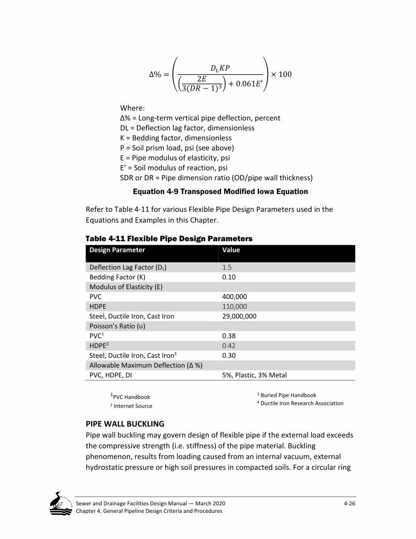
Sewer and Drainage Facilities Design Manual — March 2020 4-26 Chapter 4. General Pipeline Design Criteria and Procedures
∆% = �𝐷𝐷𝐿𝐿𝐾𝐾𝑃𝑃
� 2𝐸𝐸3(𝐷𝐷𝐷𝐷 − 1)3� + 0.061𝐸𝐸′
� × 100
Where: ∆% = Long-term vertical pipe deflection, percent DL = Deflection lag factor, dimensionless K = Bedding factor, dimensionless P = Soil prism load, psi (see above) E = Pipe modulus of elasticity, psi E’ = Soil modulus of reaction, psi SDR or DR = Pipe dimension ratio (OD/pipe wall thickness)
Equation 4-9 Transposed Modified Iowa Equation
Refer to Table 4-11 for various Flexible Pipe Design Parameters used in the Equations and Examples in this Chapter.
Table 4-11 Flexible Pipe Design Parameters Design Parameter Value
Deflection Lag Factor (DL) 1.5 Bedding Factor (K) 0.10 Modulus of Elasticity (E) PVC 400,000 HDPE 110,000 Steel, Ductile Iron, Cast Iron 29,000,000 Poisson’s Ratio (υ) PVC1 0.38 HDPE2 0.42 Steel, Ductile Iron, Cast Iron3 0.30 Allowable Maximum Deflection (∆ %) PVC, HDPE, DI 5%, Plastic, 3% Metal
1PVC Handbook 2 Internet Source
3 Buried Pipe Handbook 4 Ductile Iron Research Association
PIPE WALL BUCKLING Pipe wall buckling may govern design of flexible pipe if the external load exceeds the compressive strength (i.e. stiffness) of the pipe material. Buckling phenomenon, results from loading caused from an internal vacuum, external hydrostatic pressure or high soil pressures in compacted soils. For a circular ring

Sewer and Drainage Facilities Design Manual — March 2020 4-27 Chapter 4. General Pipeline Design Criteria and Procedures
the critical buckling pressure is expressed as Pcr and is calculated using the A.P. Moser Critical Buckling Pressure Equation below,
Pcr = 2𝐸𝐸/((1 − 𝜐𝜐2)(𝐷𝐷𝐷𝐷 − 1)3) Pb = Buckling pressure (psi) E = Pipe modulus of elasticity (psi) υ= Poisson’s Ratio (dimensionless - use 0.36 for PVC or 0.42 HDPE) t = Wall thickness (in) D = Pipe inside diameter (in) Pcr = Critical buckling pressure (psi) E’ = Composite soil modulus of reaction (psi)
Equation 4-10a Critical Wall Buckling Pressure(PΔcr)
For wall buckling pressure.
𝑃𝑃𝑏𝑏 =2𝐸𝐸
(1 − 𝜐𝜐2)�𝑡𝑡𝐷𝐷�3
Equation 4-10b Wall Buckling Pressure (Pb)
Once the critical buckling pressure is determined, that value can be compared to the soil prism load above the pipe to see if the pipe will buckle under that critical buckling pressure.
Note, that the soil prism load may need additional calculations if the pipe does not have the depth of cover as required by this manual. Assuming the depth of cover meets those requirements, the soil prism load is determined as shown in Equation 4-11 below:
𝑃𝑃𝑠𝑠 =γH
Equation 4-11 Soil Prism Load Pressure (PΔs)
SOIL MODULUS OF REACTION (E’) The soil modulus of reaction (E’) is a measure of the embedment material and surrounding soils’ ability to support the loads transferred by the deflection of flexible pipe. A composite E value is used. The composite E value includes several factors that consider the pipe and trench geometry, the E value of the native soil and the E value of the embedment material.
The composite E’ is determined using Leonhardt’s formula.

Sewer and Drainage Facilities Design Manual — March 2020 4-28 Chapter 4. General Pipeline Design Criteria and Procedures
𝐸𝐸′ = 𝑧𝑧 × 𝐸𝐸′𝑏𝑏 Where: E’ = Composite soil modulus of reaction, psi 𝐸𝐸′𝑏𝑏 = Soil modulus of reaction of embedment (i.e. bedding), psi z = Leonhardt’s zeta factor (see derivation of factor below Equation 4-13)
Equation 4-12 Leonhardt’s Modulus for Soil Reaction
𝑧𝑧 =1.662 + 0.639 �𝐵𝐵𝐷𝐷 − 1�
�𝐵𝐵𝐷𝐷 − 1� + �1.662 − 0.361 �𝐵𝐵𝐷𝐷 − 1�� �𝐸𝐸′𝑏𝑏𝐸𝐸′𝑛𝑛�
For Equation 4-12: E'b = Soil modulus reaction for pipe bedding (psi)
E'n= Soil modulus reaction for native soil (psi). This number value is provided by Geotech. B = Trench width D = Pipe outside diameter
Equation 4-13 Leonhardt’s Zeta Factor (z)
Example 4-2 Buckling Pressure (Pb) Given: 12-inch PVC ASTM D3034 SDR 35 sewer pipe with a pipe wall thickness of 0.25” and a 400,000 psi pipe modulus of elasticity
Required: What is the pipe buckling pressure?
𝑃𝑃𝑏𝑏 =2𝐸𝐸
(1 − 𝜐𝜐2)�𝑡𝑡𝐷𝐷�3
𝑃𝑃𝑏𝑏 =2(400,000)
(1 − (0.36)2)�
0.2512
�3
= 8.31 𝑝𝑝𝑝𝑝𝑝𝑝
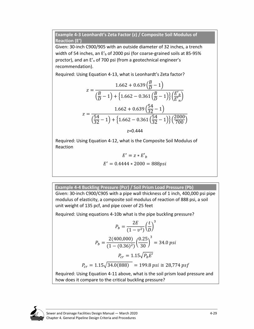
Sewer and Drainage Facilities Design Manual — March 2020 4-29 Chapter 4. General Pipeline Design Criteria and Procedures
Example 4-3 Leonhardt’s Zeta Factor (z) / Composite Soil Modulus of Reaction (E’) Given: 30-inch C900/905 with an outside diameter of 32 inches, a trench width of 54 inches, an E’b of 2000 psi (for coarse-grained soils at 85-95% proctor), and an E’n of 700 psi (from a geotechnical engineer’s recommendation). Required: Using Equation 4-13, what is Leonhardt’s Zeta factor?
𝑧𝑧 =1.662 + 0.639 �𝐵𝐵𝐷𝐷 − 1�
�𝐵𝐵𝐷𝐷 − 1� + �1.662 − 0.361 �𝐵𝐵𝐷𝐷 − 1�� �𝐸𝐸′𝑏𝑏𝐸𝐸′𝑛𝑛�
𝑧𝑧 =1.662 + 0.639 �54
32 − 1�
�5432 − 1� + �1.662 − 0.361 �54
32 − 1�� �2000700 �
z=0.444
Required: Using Equation 4-12, what is the Composite Soil Modulus of Reaction
𝐸𝐸′ = 𝑧𝑧 ∗ 𝐸𝐸′𝑏𝑏
𝐸𝐸′ = 0.4444 ∗ 2000 = 888𝑝𝑝𝑝𝑝𝑝𝑝
Example 4-4 Buckling Pressure (Pcr) / Soil Prism Load Pressure (Pb) Given: 30-inch C900/C905 with a pipe wall thickness of 1 inch, 400,000 psi pipe modulus of elasticity, a composite soil modulus of reaction of 888 psi, a soil unit weight of 135 pcf, and pipe cover of 25 feet
Required: Using equations 4-10b what is the pipe buckling pressure?
𝑃𝑃𝑏𝑏 =2𝐸𝐸
(1 − 𝜐𝜐2)�𝑡𝑡𝐷𝐷�3
𝑃𝑃𝑏𝑏 =2(400,000)
(1 − (0.36)2)�
0.2530
�3
= 34.0 𝑝𝑝𝑝𝑝𝑝𝑝
𝑃𝑃𝑠𝑠𝑟𝑟 = 1.15�𝑃𝑃𝑏𝑏𝐸𝐸′
𝑃𝑃𝑠𝑠𝑟𝑟 = 1.15�34.0(888) = 199.8 𝑝𝑝𝑝𝑝𝑝𝑝 ≅ 28,774 𝑝𝑝𝑝𝑝𝑝𝑝
Required: Using Equation 4-11 above, what is the soil prism load pressure and how does it compare to the critical buckling pressure?

Sewer and Drainage Facilities Design Manual — March 2020 4-30 Chapter 4. General Pipeline Design Criteria and Procedures
Table 4-12 Average Values of Modulus of Soil Reaction E’ (for Initial Flexible Pipe Deflection) Soil Type Bedding Material (Unified Classification System)
E’ for Degree of Compaction of Bedding, psi
Dumped
Slight < 85% Proctor 40% Relative Density
Slight < 85%- 95% Proctor 40% - 70% Relative Density
Slight > 95% Proctor > 70% Relative Density
Fine grained soils (LL>50)b
Soils with medium to high plasticity CH<MH, CH-MH
No data available, consult a competent soils engineer, otherwise use E’ = 0
Fine grained soils (LL<50) Soils with medium to no plasticity, CL, ML, ML-CL, with less than 25% coarse –grained particles
50 200 400 1000
Fine grained soils (LL<50) Soils with medium to no plasticity, CL, ML, ML-CL, with more than 25% coarse –grained particles Coarse grained particles with fines GM, GC, SM, SC contains more than 12% fines
100 400 1000 2000
Coarse-grained soils. Little of no fines GW, GP, SW, SP c contains less than 12% fines
200 1000 2000 3000
Crushed rock 1000 3000 3000 3000
Notes: Standard proctors in accordance with ASTM D698 are used with this table. Values applicable for fills less than 50 feet. Table does not include safety factor. For use in predicting initial
deflections only, appropriate Deflection Lag factor must be applied for long-term deflection a ASTM designations D2487, USBR Designation E-3. b LL = Liquid Limit. c Or any borderline soil beginning with one of these symbols ( i.e. GM-GC, GC-SC).
Maintenance Hole Location and Design Maintenance holes are located throughout the sewer systems primarily to provide safe and easy access for both maintenance personnel and equipment.

Sewer and Drainage Facilities Design Manual — March 2020 4-31 Chapter 4. General Pipeline Design Criteria and Procedures
Typically, BES does not approve cleanouts for this purpose but under specific circumstances, will accept them as an acceptable alternative to a maintenance hole. Refer to Section 4.7.
Permitted maintenance hole taps will require core hole drilling and/or saw cutting of the maintenance hole wall at the penetration point before coring of the maintenance hole wall.
The connection method must allow the sewer flow to merge with the existing sewer flow in the main line.
Types of Maintenance Holes A designer must design all maintenance holes as complete pre-cast units. During construction, the option is given to construct the base as either pre-cast or poured-in-place concrete. The minimum maintenance hole diameter is 48-inches and the maximum diameter is 120-inches.
Owing to the overall age of the City sewer system, designers regularly encounter brick and monolithic concrete maintenance holes. Construction involving brick and monolithic concrete maintenance holes requires an understanding and experience working with these structures. PBOT typically leads any effort requiring construction on these structures.
Flow Diversion Maintenance Hole Design Flow diversion maintenance holes must be designed to satisfy the following requirements:
• Meet the hydraulic flow design for the system; • Meet the long-term maintenance needs.
Flow diversion maintenance holes must be designed so that the underflow conduit/pipe can be easily plugged during periods when the connecting intercepting sewer requires maintenance. The hydraulic flow design is typically unique at each diversion maintenance hole. The Design Engineer must consult, with the BES, District Maintenance Engineer during the design to account for long-term maintenance needs. Design must incorporate a type of installation such as a metal plate, slide gate, or stop logs to easily plug the underflow conduit.
Horizontal and Vertical Maintenance Hole Locations Maintenance holes are required when specific conditions occur, but BES may grant an exception under certain circumstances. Table 4-13 lists these conditions and potential exceptions.

Sewer and Drainage Facilities Design Manual — March 2020 4-32 Chapter 4. General Pipeline Design Criteria and Procedures
Designers should locate maintenance holes to avoid conflict with other utilities and improvements. Designers must be aware of potential conflicts and try to avoid locating maintenance holes in sidewalks or parking areas unless approved by BES or in the travel lanes of public roads where automobile wheels are likely to regularly contact the maintenance hole. The designer should coordinate with PBOT when proposed maintenance holes are located in sidewalks and crosswalks.
When the maintenance hole frame and cover encroach into a sidewalk and curb, the designer must indicate on the drawings to rotate the top section (i.e. cone) and frame and cover to be clear of the sidewalk and curb.
Table 4-13 Circumstances Requiring Maintenance Holes and Exceptions Circumstances That Require a Maintenance hole
Circumstances When BES Could Approve an Exception
At every change in alignment Refer to Chapter 4, No Curved Sewers Requiring Pulled Joints and the Use of Blind Bends
At every change in pipe diameter
At every present or future junction with another sewer
Refer to Chapter 5, Sewer Laterals
At every grade break and every abrupt elevation change of the sewer
At the upper end of all sewers Refer to Chapter 4, Cleanouts – When and Where They Can be Used
At a storm inlet where it connects to a sewer that is less than 24-inches in diameter
At a storm inlet where it connects to a combined sewer and the escape of sewer gas and odor is possible,
At all private connections where the diameter of the private line exceeds one half the diameter of the public sewer
Refer to Chapter 5, Pipe, Size and Material
Maximum and Minimum Spacing between Maintenance holes The maximum spacing between maintenance holes must not exceed 500 feet without BES approval. The minimum distance between the outside walls of adjacent maintenance holes is 5 feet.

Sewer and Drainage Facilities Design Manual — March 2020 4-33 Chapter 4. General Pipeline Design Criteria and Procedures
Maintenance Hole Design Standard Details and Drawings for maintenance holes are found on the PBOT website and these Standard Details and Drawings are suitable for most conditions. Use a Standard Details and Drawings unless it is not appropriate for a project. If a special design is required for any reason, it will be necessary to show the detail on the construction drawings and to provide structural calculations, as needed.
Provide maintenance holes in accordance with the Standard Details, Drawings and the Manufacturer’s Standards for Precast Concrete Products (MSPCP, 2005). (Refer to Chapter 1, Companion Documents and Internet Links). The designer must review these Standard Details for the following requirements: depth of pipe, type of pipe material, and other factors discussed in the following paragraphs.
Design all maintenance holes with sufficient inside dimensions to perform inspection and cleaning operations and to allow for proper channel construction. During the preliminary design phase, the designer must determine the appropriate size and orientation of each maintenance hole.
Maintenance hole selection is a function of the size of the incoming and outgoing pipes, their geometry, as well as the depth of the sewer. The following paragraphs present the BES standards that guide maintenance hole selection.
Pipe to Maintenance Hole Geometry Minimum pre-cast maintenance hole diameters and the maximum sewer sizes can be found on the manufacturer’s website. These standards apply when constructing a maintenance hole and when connecting a new sewer to an existing maintenance hole but not when setting a maintenance hole over an existing sewer.
All pipes connecting to a maintenance hole must maintain a minimum separation of 1-foot core-hole to core-hole and all section breaks, in the maintenance hole wall. The designer shall assume the maximum sewer size and deflection angle between incoming and outgoing pipes for a given maintenance hole diameter with no other pipe connecting to the maintenance hole. When connecting a new sewer to an existing maintenance hole maintain 1 foot of clearance vertically and horizontally for all new construction.
When a designer cannot achieve the specified clearance between the outside walls of a new sewer and an existing sewer provide an offset design for the new sewer into the maintenance hole. Offset sewer connections will require details and dimensions shown on the plans (See Figure 4-6).

Sewer and Drainage Facilities Design Manual — March 2020 4-34 Chapter 4. General Pipeline Design Criteria and Procedures
Figure 4-4 Minimum Diameter Precast Maintenance Hole for Maximum Sewer Sizes
Figure 4-5 New Pipe Connection to an Existing Maintenance Hole

Sewer and Drainage Facilities Design Manual — March 2020 4-35 Chapter 4. General Pipeline Design Criteria and Procedures
Figure 4-6 Offset Pipe Connections to a Maintenance Hole
Inside Drop Maintenance Hole Connection BES review and approval for any maintenance hole designed with an inside drop connection is required. Designers must reference the Standard Drawings and Details, P-253 for specific information. A designer may reference the Standard Drawing for an Inside Drop only when connecting a 12-inch sewer or smaller pipe to a maintenance hole. Inside drop connections on sewers larger than 12 inches require special design.
A designer must apply the following requirements to determine if an inside drop connection can be used:
• The maintenance hole must be a minimum of 15-feet deep; • The minimum drop allowed is 3 feet; • Construct only one inside drop in a standard 48-inch maintenance hole; • Provide 1 foot of clearance in all directions from the outside wall of the
drop structure to all other connections and appurtenances in the maintenance hole;
• The drop structure must not be in a location that obstructs the flow of any other connection to the maintenance hole;
• The drop structure must not be in a location that obstructs maintenance hole access or steps.
Specify the diameter of the drop connection on the plans. The diameter of the drop connection must not be more than one pipe size smaller than the diameter of the incoming sewer

Sewer and Drainage Facilities Design Manual — March 2020 4-36 Chapter 4. General Pipeline Design Criteria and Procedures
Pipe Stubouts from Maintenance holes Provide a pipe stubout from a maintenance hole at any location where a possible future extension could occur or at the end of the sewer line unless otherwise directed by BES. A stubout must be a maximum of 4 feet long measured from the outside maintenance hole wall. The City requires that a flexible joint be located within 18-inches from the outside maintenance hole wall. Consult with the BES Systems Development division to determine if a need for an extension is anticipated for future development or to resolve a nonconforming sewer.
Maintenance Hole Channel Design Flow through a maintenance hole may cause detrimental energy losses. This is an especially important consideration where the sewer design capacity and velocity approach the minimum acceptable limits as well a controlling hydrogen sulfide (Refer to Chapters 5, 6 and 7, Minimum and Maximum Velocity). Energy losses can be especially significant at maintenance holes where alignment changes occur. Designers must submit calculations to support their design and show how they have compensated for energy losses at any critical location. A designer should give special attention to the channel flow depth of the incoming and outgoing sewers to avoid creating turbulence.
BES has established standards for designing the maintenance hole channel to compensate for normal energy losses. For purposes of slope calculation, these elevations reference the intersection of the incoming and exiting sewer pipe inverts (usually referenced at the center of the maintenance hole See Figure 4-7.)
VERTICAL ALIGNMENT The crown of all incoming sewers must be at least as high as the crown of the outgoing sewer.
• When the incoming and outgoing sewers are of equal size and are passing straight through the maintenance hole, no added elevation change is required;
• If sewers intersect or the alignment changes at the maintenance hole, the invert elevation differences must be 0.05 feet for every 15 degrees of horizontal deflection (round up);
• The maintenance hole channel slope must be equal to and continuous with the slope of the same sewer outside of the maintenance hole (Refer to Chapter 4, Determining Sewer Slope Between Maintenance Hole Structures);
• Sanitary sewers must enter the maintenance hole through a channel in the base. This includes drop connections, connections to existing maintenance holes, and laterals;

Sewer and Drainage Facilities Design Manual — March 2020 4-37 Chapter 4. General Pipeline Design Criteria and Procedures
• Storm sewers and inlet leads do not need to enter a maintenance hole at its base but need to be located to avoid the maintenance hole steps. The invert of a storm sewer pipe must not be greater than 4 feet above the maintenance hole invert. See Standard Drawings for the location of the invert entering a maintenance hole for a storm inlet lead of 12” pipe or smaller;
• The maximum drop between incoming and outgoing sewer mainline inverts must be 1 foot. When the drop across the inverts is greater than 1 foot then the designer should adjust the inverts to suit the maximum allowed or design the maintenance hole channel with a “beaver slide” (Std Detail P-183) or with a drop maintenance hole (Std. Detail P -253) connection if the distance is greater than 3 feet.
Figure 4-7 Maintenance Hole Channel Design
HORIZONTAL ALIGNMENT • When incoming and outgoing sewers have the same diameter, the
channel width must be the same as the sewer inside diameter; • When the diameters of the sewer pipelines are different, the designer
will uniformly taper the channel width from one pipe to the other to provide a smooth transition;
• For sewers less than 12 inches, the minimum radius of the channel centerline must be 1/2 the diameter of the maintenance hole;
• For sewers greater than or equal to 12 inches the minimum radius of the outer channel wall must be 1/2 the maintenance hole diameter;
• The channel must have a uniform curve, with no reverse curves within the maintenance hole;

Sewer and Drainage Facilities Design Manual — March 2020 4-38 Chapter 4. General Pipeline Design Criteria and Procedures
• The top of the bench must be to the spring line of the incoming and outgoing sewers when the pipes are the same diameter;
• When the incoming and outgoing sewers have different diameters, the top of the bench must be set at the spring line of the highest pipe within the maintenance hole, except when a “beaver slide” is designed;
• If the hydraulic grade line (HGL) in the maintenance hole is higher than the top of the largest sewer within the maintenance hole, then design the top of the channel 3 inches above the HGL;
• For sewers where the width of the bench is inadequate, or the channel width is unsafe for a worker to straddle the open channel, a platform may be required to bridge the channel for safety and for maintenance purposes. A designer should size the platform for easy of removal through the maintenance hole openings;
• To reference the pipe invert elevations on the profile, the designer must provide the inverts of all pipes entering and exiting the maintenance hole. The designer must design the pipe exiting the maintenance hole to have its invert at the lowest elevation;
• Where feasible, the designer should locate a maintenance hole frame and cover outside of the travel lanes of public roads where automobile wheels are likely to have regular contact with the maintenance hole.
Maintenance Hole Depth Design For design purposes, measure the maintenance hole depth from the top of the maintenance hole frame and cover to the invert at the maintenance hole centerline.
The maximum depth for all standard maintenance holes 48- through 120-inches is thirty feet. Maintenance holes deeper than 30 feet require design by an Oregon licensed Structural Engineer. BES must review all design submittals and calculations before incorporating these designs into a project.
The minimum maintenance hole depth must be 4 feet from the top of the maintenance hole frame and cover to the invert at the maintenance hole centerline. When this depth is less than 4 feet but not less than 3 feet provide a flat top shallow type maintenance hole. Twelve inches is the maximum pipe size for shallow type maintenance holes.
Diameter of Frames and Covers The size of the maintenance hole frame and cover is a function of the largest sized pipe that enters or exits a maintenance hole. Unless otherwise indicted on the Plans the required maintenance hole openings must be in accordance with BES Standard Drawings and Details and manufacturer’s recommendation.

Sewer and Drainage Facilities Design Manual — March 2020 4-39 Chapter 4. General Pipeline Design Criteria and Procedures
Setting Elevation of Maintenance Hole Frame and Cover Factors that influence setting the elevation of a maintenance hole frame and cover include its location either inside or outside of a public ROW and the anticipated future fill conditions over the maintenance hole.
A designer must show the design elevation of each maintenance hole center on the profile. When using the roadway profile to calculate the rim elevation, give the elevation to the 1/100 (0.01) of a foot. When using a roadway profile showing contour lines calculate the rim elevation to the nearest 1/10 (0.1) of a foot.
When the maintenance hole is located outside of an existing ROW or in a public sewer easement, design the rim to the existing ground elevation or as directed by BES.
In areas where 2 feet or more of grading is planned, design maintenance holes to match the existing grade. Design the sewer to handle any additional fill.
When planned future grading over the maintenance hole is less than 2 feet, set the rim elevation to match the future grade or as directed by BES.
When the future grading will decrease the cover over the sewer, set the rim elevation to the initial grade. The sewer must be designed to handle the increased live load resulting from reduced fill over the sewer.
Table 4-14 Diameter Requirements for Maintenance holes Frames and Covers Special design is required for non-circular, monolithic and vaulted maintenance holes
Maintenance hole Type
Maintenance hole Diameter, Inches
Nominal Diameter of Maintenance hole Frame and Cover, Inches
Standard Detail Reference
Precast 48 24 P-150 to P-183 Precast 60 24 Precast 72 36 Precast 84 36 Precast 96 36 Precast 108 and 120 36 Brick 48 24 COP no longer
constructs these Monolithic Varies 24 Special Design is
required for Casson type MH’s

Sewer and Drainage Facilities Design Manual — March 2020 4-40 Chapter 4. General Pipeline Design Criteria and Procedures
Alternate Maintenance Hole Features The Standard Drawings and Details show some alternate maintenance hole features. Where such features are required, a note on the construction drawings must specify their use. Examples include: a watertight maintenance hole frame and cover that is specified if floodwaters are expected to cover the maintenance hole top or if the maintenance hole must be located in the street gutter or subject to surcharge and tamper-proof maintenance hole frames and covers where maintenance holes may be subject to vandalism.
Cleanouts - When and Where They Can be Used A cleanout provides another entry point for City personnel to access a sewer for maintenance or inspection purposes; they also assist City employees when locating sewer utilities in a ROW. A cleanout may be used in lieu of a maintenance hole however BES must approve the use of any cleanout. Any cleanout located in a pedestrian way must have a cover with a non-slip surface.
There are two cleanout design standards: (1) Lateral Cleanout (Standard Detail P-257) and (2) Terminal Cleanout (Standard Detail P-258). Each has different application requirements.
Lateral Cleanout The City may require a cleanout on a sewer lateral when circumstances justify its use. Any of the following circumstances would be justification for the City to require a lateral cleanout within the ROW. Where the:
• Slope of the lateral is less than the minimum required; • City employees regularly clean a problematic lateral; • Lateral between the service connection and the sewer main is under a
major street/highway; • Sewer main is under a light/heavy rail, trolley track, streetcar rail etc.; • Lateral is adjacent to a major utility that limits using a conventional open-
cut excavation method; • Approved wye connection is located in the ROW, install a cleanout only
on the straight through wye branch; • Private lateral runs parallel to a curb and the distance to the building
sewer connection is less than 100 feet; otherwise install a maintenance hole.
• All lateral Cleanouts will comply with Cleanouts Over Laterals – Refer to Chapter 9, Reference Materials List for “Cleanouts for Facilitating Pipe Rehabilitation Memorandum”.

Sewer and Drainage Facilities Design Manual — March 2020 4-41 Chapter 4. General Pipeline Design Criteria and Procedures
A designer must place cleanouts behind the curb within the planting strip or furnishing zone or at the property line on the property side of the sidewalk. Where possible locate a cleanout to avoid conflict with tree roots, driveway aprons, water meters and hydrants, existing or proposed Green Street Facilities or other existing utilities.
A lateral cleanout must be located in the ROW downstream from the private sewer connection to the public sewer lateral. Typically, place the cleanout in front of or behind the curb in a paved or landscape area. Under certain circumstances the cleanout could be located behind the sidewalk at the property-line, or in downtown in the sidewalk provided an approved non-slip cap is used, with BES approval. Surface restoration requirements are project-specific.
Terminal Cleanout A terminal cleanout occurs at the end of a sewer mainline or a dead-end of a sewer where there is no plan for future extension or service connection. It is usually located in the ROW of an improved street although this is not a requirement.
An exception occurs on a multi-phased permit project. In this case, the terminal cleanout can serve as a temporary sewer access and termination point for beginning the next phase of development. When the next phase of development begins, remove the cleanout and begin the new sewer from its location. Never use cleanouts when a maintenance hole is specified or required.
Construction of a terminal cleanout is limited to an 8-inch sewer. The maximum distance from the cleanout to the nearest downstream maintenance hole is limited to 100 feet maximum for grades less than 5% and 150 feet for grades greater than 5%.
Abandonment of Sewers, Maintenance Holes, Sumps and Structures
As part of the ongoing process of sewer construction and reconstruction, BES regularly replaces and abandons numerous facilities throughout the sewer system. Factors that influence whether to abandon a facility include development, facility location or replacement of deteriorated facilities and new regulations, etc.
Pipe can be abandoned using a number of methods and must be abandoned per the City of Portland Standard Construction Specifications.

Sewer and Drainage Facilities Design Manual — March 2020 4-42 Chapter 4. General Pipeline Design Criteria and Procedures
The designer must clearly indicate the limits, describe the method(s), and show the locations of abandonment and/or removal of pipelines, structures and appurtenances on the drawings and clearly reference the current Standard Construction Specifications.
4.8.1 Sewers less than 12 Inches in Diameter Abandonment of sewers must comply with City of Portland Standard Construction Specifications. Before abandonment, BES must approve abandonment of all pipes.
4.8.2 Sewers 12 inches or greater in Diameter Abandonment of sewers must comply with City of Portland Standard Construction Specifications. Before abandonment, BES must approve abandonment of all pipes.
Maintenance Holes and Sumps Abandon maintenance holes and other structures in accordance with City of Portland Standard Construction Specifications. Sumps identified for abandonment must meet state requirement as specified in OAR 340-044-040. All City owned sumps (UICs) must be decommissioned as specified per the City’s UIC decommissioning plan (UICs). For City owned UICs all decommissioning activities must be reported and approved through the City’s UIC program.
If a designer determines that a structure contains items for removal such as pipe, fittings, valves, operators and other appurtenances, indicate which items to salvage on the drawings. BES must review and advise the designer which of these items to salvage. Coordinate delivery of the salvaged items to BES or PBOT for storage.
Buoyancy of Sewers Constructing a sewer in an area subject to inundation increases the possibility of pipe and maintenance hole flotation. Situations and locations where this condition can occur are found at stream crossings, Water Quality Pollution Reduction Facilities, in flood plains and in areas subject to high ground water. When such conditions exist, evaluate the possibility of pipe flotation and, if necessary, modify the pipe design to counteract this condition.
The buoyancy of a pipe depends upon several factors:
• The weight of the pipe; • The weight of the volume of water displaced by the pipe;

Sewer and Drainage Facilities Design Manual — March 2020 4-43 Chapter 4. General Pipeline Design Criteria and Procedures
• The weight of the liquid load carried in the pipe; and • The weight of the backfill.
As a conservative practice, BES recommends that a pipe be considered empty for two reasons 1) so the weight of the liquid load will be considered an additional safety factor and 2) the possibility of the pipe not being in use at all times.
The first step is to determine if a pipeline will float with no backfill material. The sum of the pipe weight and the weight of displaced water will determine if the conditions exist to cause flotation.
A designer should select the pipe material and determine the weight per lineal foot (Wpipe), including the bell joint and appurtenances. This information is obtained from published product data.
Unless otherwise specified by the City, the designer should calculate ASTM C76 pipe weight using Wall C. ASTM D3034 and D3035 define dimension ratios for various classes of thermoplastic pipe having different wall thickness. Refer to manufacturer’s published data for specific material and pipe weight.
The approximate weight of any pipe can be calculated using Equation 4-14.
To determine weight of pipe, locate manufacture pipe table.
When a pipe immersed in the fluid displaces water, a buoyant or upward force is created; if the buoyant force is greater than the weight of the pipe displaced water flotation will occur. The force of displaced fresh water per linear foot of circular pipe is calculated using Equation 4-14:
𝑊𝑊𝑤𝑤𝑤𝑤𝑤𝑤𝑤𝑤𝑟𝑟 =𝜋𝜋4𝐵𝐵𝑠𝑠2𝛾𝛾𝑤𝑤𝑤𝑤𝑤𝑤𝑤𝑤𝑟𝑟
Where: Wwater = Weight of displaced water, lbs/linft Bc = Outside pipe diameter, feet γwater = Unit weight of fresh water, 62.4 lbs/cu ft
Equation 4-14 Buoyancy Force of Displaced Water
If clean water is displaced use a unit weight equal to γwater = 62.4 pounds per cubic foot (lbs/cu ft). If other constituents mix with the water, its unit weight could change from this value. Local conditions should be investigated for specific projects.
Sum the weights of the pipe (Wpipe) and displaced water (Wwater) to determine if the weight of the pipe is adequate to prevent flotation.

Sewer and Drainage Facilities Design Manual — March 2020 4-44 Chapter 4. General Pipeline Design Criteria and Procedures
�𝑊𝑊𝑝𝑝+𝑤𝑤 = 𝑊𝑊𝑝𝑝𝑝𝑝𝑝𝑝𝑤𝑤 + 𝑊𝑊𝑤𝑤𝑤𝑤𝑤𝑤𝑤𝑤𝑟𝑟
Where: Wwater = Weight of displaced water, lbs/lin. ft. Wpipe = Weight of pipe, lbs/lin. ft. ΣWp+w = Resultant summation of forces
Equation 4-15 Summation of Forces
If the resultant force is positive, the pipe will not float. If the resultant force is negative, the designer must determine the weight of backfill directly over the pipe necessary to prevent flotation.
To complete evaluation on the affect that backfill plays on preventing pipe flotation it is first necessary to define the factors that will require evaluation. Figure 4-7 defines the general conditions for evaluating a pipe for buoyancy.
Figure 4-7 Definition Sketch for Evaluating Buried Pipe Buoyancy Conditions
Where: H = depth from top of pipe to finished surface, ft Hsub = Depth of backfill below groundwater and above pipe, ft B = Outside diameter of pipe, ft D = Nominal pipe diameter, ft
The weight of the backfill directly over the pipe assists resisting the buoyant force. The unit weight of compacted backfill material varies with material, grain size, degree of compaction and the depth of submergence. For computations,

Sewer and Drainage Facilities Design Manual — March 2020 4-45 Chapter 4. General Pipeline Design Criteria and Procedures
use the average values for specific gravity and unit weight of backfill material provide sufficient accuracy.
The weight of backfill above a pipe including the area below the top of pipe and above the exterior pipe walls above the springline can be calculated using the following general relationship (Equation 4-16)
𝑊𝑊𝑠𝑠𝑟𝑟𝑑𝑑 = 𝛾𝛾𝑠𝑠𝑟𝑟𝑑𝑑�(𝛼𝛼 − 𝛼𝛼𝑠𝑠𝑠𝑠𝑏𝑏)𝐵𝐵𝑠𝑠� Where: Wdry = Weight of backfill above the water level, pounds per linear foot γdry = Average in-place weight of well-compacted backfill, lbs/cuft Hsub = Depth of submerged backfill above top of pipe, feet H = Depth from top of pipe to surface, feet Bc = Nominal outside pipe diameter, feet
Equation 4-16 Weight of Dry Backfill above Pipe
The unit weight of submerged backfill is equal to the dry density of the backfill minus the weight of water displaced by the solid soil particles. It can be calculated using Equation 4-17:
𝛾𝛾𝑠𝑠𝑠𝑠𝑏𝑏 = �𝑆𝑆𝑆𝑆 − 1𝑆𝑆𝑆𝑆
� × 𝛾𝛾𝑠𝑠𝑟𝑟𝑑𝑑
Where: γsub = Average unit of weight of submerged backfill, lbs/cuft γdry = Average in-place weight of well-compacted backfill, lbs/cuft SG = Specific gravity of backfill, assume 2.65
Equation 4-17 Unit Weight of Submerged Backfill
Using the default value for SG will provide sufficient accuracy. Under these conditions the relationship simplifies to γsub = 5/8 γdry. Certain conditions may require soil investigation to determine the actual soil conditions; the designer will be responsible for determining actual soil conditions.
The weight of submerged backfill above the pipe, including the shaded area below the top of pipe and above the exterior pipe walls above the springline, can be calculated by Equation 4-18:

Sewer and Drainage Facilities Design Manual — March 2020 4-46 Chapter 4. General Pipeline Design Criteria and Procedures
𝑊𝑊𝑠𝑠𝑠𝑠𝑏𝑏𝑤𝑤 = 𝛾𝛾𝑠𝑠𝑠𝑠𝑏𝑏(0.1073𝐵𝐵𝑠𝑠2 + 𝛼𝛼𝑠𝑠𝑠𝑠𝑏𝑏𝐵𝐵𝑠𝑠) Where: Wsubt = Weight of saturated backfill directly above pipe, lbs γsub = Average unit weight of saturated backfill, lbs/cuft Bc = Nominal outside pipe diameter, feet Hsub = Depth of submerged backfill above top of pipe, feet
Equation 4-18 Weight of Submerged Backfill above Pipe
Therefore, the total weight of backfill acting downward on the pipe is determined from the sum of Wdry and Wsub
�𝑊𝑊𝑆𝑆+𝐷𝐷 = 𝑊𝑊𝑠𝑠𝑟𝑟𝑑𝑑 + 𝑊𝑊𝑠𝑠𝑠𝑠𝑏𝑏
Where: Wdry = Weight of dry backfill directly above pipe, lbs/cuft Wsub = Weight of submerged backfill above the pipe, lbs/cuft ΣWS+D = Resultant summation of forces, lbs
Equation 4-19 Total Weight of Dry and Submerged Backfill
Lacking detailed knowledge of the backfill material and local groundwater conditions the designer must apply a factor of safety to decrease the downward force of backfill acting downward on the pipe. Use a factor of safety of 1.5 unless detailed site knowledge dictates use of another value. The total weight of backfill above the pipe with a Factor of Safety is calculated using Equation 4-20.
𝑊𝑊𝐹𝐹𝑆𝑆 =∑𝑊𝑊𝑆𝑆+𝐷𝐷
𝐹𝐹𝑆𝑆
Where: WFS = Total weight acting downward on the pipe with a FS ΣWS+D = Resultant summation of forces FS = Factor of Safety, use 1.5
Equation 4-20 Total Weight of Dry and Submerged Backfill with a Factor of Safety
After determining both the upward force due to displacement of water and the downward force from the backfill material, determine the resultant force acting on the pipe. If the resultant force is positive, the pipe will not float. If the resultant force is negative, the designer will have to select and analyze procedures required to prevent flotation.
Procedures to prevent flotation when the weight of pipe and backfill is not adequate include the following:

Sewer and Drainage Facilities Design Manual — March 2020 4-47 Chapter 4. General Pipeline Design Criteria and Procedures
a) Increase or change the pipe to a heavier pipe material b) Design concrete collars on the pipe. When computing the needed volume
of concrete per linear foot of pipe anchorage, use the submerged weight of concrete of 87.6 pounds per foot to calculate the needed weight to overcome the buoyant force.
To determine the minimum height of inundated backfill necessary to prevent flotation during construction use the following relationships to calculate the force exerted by the inundated backfill on the pipe to overcome the buoyant force acting upward on the pipe.
𝑊𝑊𝑠𝑠𝑠𝑠𝑏𝑏 = 𝛾𝛾𝑠𝑠𝑠𝑠𝑏𝑏(0.1073𝐵𝐵𝑠𝑠2 +)𝛼𝛼𝑠𝑠𝑠𝑠𝑏𝑏𝐵𝐵𝑠𝑠
𝐹𝐹𝑆𝑆 & 𝛼𝛼𝑠𝑠𝑠𝑠𝑏𝑏 𝑚𝑚𝑝𝑝𝑛𝑛 =
𝐹𝐹𝑆𝑆∑𝑊𝑊𝑠𝑠𝑠𝑠𝑏𝑏
𝑊𝑊𝑠𝑠𝑠𝑠𝑏𝑏𝐵𝐵𝑠𝑠− 0.1073𝐵𝐵𝑠𝑠
Where: Wsub = Resultant summation of forces FS = Factor of Safety, use 1.5 γsub = Average submerged unit weight of backfill, lbs/cuft Hsub = Depth of submerged backfill above top of pipe, feet Hsub min = Minimum depth of submerged backfill above pipe, feet Bc = Nominal outside pipe diameter, feet
Equation 4-21 Minimum Depth of Cover
When pipes are buried in soil under water, the suggested height of soil cover above the pipe to prevent flotation of an empty pipe is about H – (D/2). Because a factor of safety is advisable, the minimum cover requirement is often H = D, where H is height, and D is diameter of pipe.

Sewer and Drainage Facilities Design Manual — March 2020 4-48 Chapter 4. General Pipeline Design Criteria and Procedures
Constructing Sewers on Steep Slopes The City defines a steep slope as any inclined surface with a longitudinal or cross slope grade of 20% or greater. Steeply sloped soil has a greater potential for downhill movement. A sewer located on a steep slope requires special design considerations and methods to prevent joint displacement and misalignment. Construction on steep slopes can increase surface erosion and the potential for trench washout. BES review of these special designs is required at the discretion of the BES Chief Engineer.
Example 4-5 Pipe Buoyancy Calculations Given: A 24-inch diameter sewer crosses a stream with only 2 feet of cover. Required: Will the empty pipe float in the fully backfilled condition? Select the pipe material and determine Wp, weight of the pipe. 30-inch RCP, Bc = 38.5 inches (3.21 feet), Wall C weight per linear foot = 477 pounds/linear foot Determine the weight of water displaced by the pipe.
𝑊𝑊𝑤𝑤 =𝜋𝜋4
(3.212) × 62.4 = 504 𝑙𝑙𝑙𝑙𝑝𝑝
Summation of Forces
�𝑊𝑊𝑃𝑃+𝑊𝑊 = 477 + (−504) = −27 𝑙𝑙𝑙𝑙𝑝𝑝
There is a net upward force on the pipe, therefore, the pipe could float without backfill directly over the pipe. Determine weight of inundated backfill
𝑊𝑊𝑠𝑠𝑠𝑠𝑏𝑏 = �58
× 135� �0.1073(3.212) + (2 × 3.21)� = 635 𝑙𝑙𝑙𝑙𝑝𝑝
Determine weight of backfill above ground water level 𝑊𝑊𝑠𝑠𝑟𝑟𝑑𝑑 = 135(2 − 2)3.21 = 0
Determine total weight of the backfill
�𝑊𝑊𝐷𝐷+𝑆𝑆 = 0 + 635 = 635 𝑙𝑙𝑙𝑙𝑝𝑝
Apply Factor of Safety to Total weight
𝑊𝑊𝐹𝐹𝑆𝑆 =6351.5
= 423
Sum all forces to determine resultant force
�𝑊𝑊 = −27 + 423 = 396 𝑙𝑙𝑙𝑙𝑝𝑝

Sewer and Drainage Facilities Design Manual — March 2020 4-49 Chapter 4. General Pipeline Design Criteria and Procedures
BES has developed construction techniques to counteract these effects when constructing sewers on steep slopes. Examples of these include the use of restrained joint fittings and sewer trench under-drains. Anchor walls may also be used when top of pipe is constructed shallower than 4’ or is within an identified soil creep zone.
BES limits the use of certain pipe materials on steep slopes due to their inherent nature to fail under the conditions that can occur on steep slopes. Concrete pipe should not be used in slope grades of 20% or greater. Other pipe materials such as high-density polyethylene (HDPE) pipe with butt-fused joints or welded ductile iron pipe (DIP) of long lengths, should be used instead with anchors installed as described in the following sections.
Anchors for Pipe 24-inch Diameter and Smaller and Shallow Burial (less than 4’ deep from crown of pipe) A designer should provide concrete or metal anchors, with submittals, according to Standard Detail No. P-102 (concrete) or P-104 (metal), Details and the anchor spacing criteria in Table 4-15. Lay pipe with bells facing upgrade and with anchors cast around the pipe directly behind the bell on the downgrade side.
Table 4-15 Anchor Spacing for Sewers 24-inches in Diameter and less and Shallow Burial (<4’ deep) GRADE, PERCENT Pipe Material ANCHOR SPACING (on slope) 20% to 35% All pipe materials,
except concrete 35 feet
35% to 50% All pipe materials, except concrete
25 feet
Greater than 50% All pipe materials, except concrete
Special design is required. Provide details on drawings and submit calculations.
4.10.2 Anchors for Pipe Greater Than 24-inch Diameter and Shallow Burial (less than 4’ deep from crown of pipe) For pipe greater than 24 inches, special design is required in the right of way and public easements according to the limits of BES maintenance responsibility. The designer must consult with BES for the design criteria and subsequently submit details and calculations to BES for approval.
If the slope is in a known landslide area and/or where creep is a problem, special design is required.
Sewer and Drainage Facilities Design Manual — March 2020 4-50 Chapter 4. General Pipeline Design Criteria and Procedures
Minimum Shoring and Tie-back Clearances to BES Assets in the Right of Way
Shoring and tie-backs placed in the right of way are required to receive permission from the City of Portland. An encroachment permit from PBOT may be required. These systems typically consist of drilled soldier piles, horizontal walls, wood lagging and tensioned tie-back anchors that extend under the roadway. The tiebacks are installed nearly horizontal, typically less than 20 degrees from horizontal. The locational tolerance (anchor deviation) of drilled tieback anchors in the construction industry are typically between 3 and 5 percent. Borehole deviation is cumulative, longer (deeper) holes exhibit more deviation.
When drilled piles or tie-back anchors are near BES assets (pipes, etc.), the following design requirements apply:
• Minimum separation distance from tie-back to BES assets is 3-ft plus a 5% angle deviation. Label the actual separation distance from the tie-back to the asset, edge to edge, on the plan set.
• Minimum separation distance from shoring wall to BES assets is 5-ft. Label the actual separation distance from the shoring wall to the asset on the plan set.
• Location and elevation of BES assets is required to be determined from surveyed information. Information from GIS mapping is not acceptable.
o Potholes to determine location and elevation of BES assets may be required in the design phase.
• If the required separation distance cannot be achieved, a Design Variance request (See Section 2.6.1 Design Variance Process) can be submitted for review.
• The engineer is required to show that the vibration forces during pile construction or the forces from the building’s piles will not cause damage to BES assets. BES may require the engineer to provide calculations and/or monitoring to determine the assets were not damaged.
• If the Contractor adjusts the angle of the tie-back by more than 5%, the stamping professional engineer is required to approve the revision to the plans.
The following are construction related requirements and submittals for reference:
• 7 days prior to construction, the permittee is required to provide BES a quality control plan that indicates construction methods limiting the construction angle error. The quality control plan shall also include the proposed volume of grout and method of recording grout used during construction. No grout can inadvertently enter any BES assets. The

Sewer and Drainage Facilities Design Manual — March 2020 4-51 Chapter 4. General Pipeline Design Criteria and Procedures
contact person for related BES submittals and notifications is BES Maintenance District Engineer.
• The permittee is required to conduct TV inspection of the existing public sewers before and after the completion of the drilling for the tie back shoring, soldier pile, soil nails and soil anchors. The permittee shall coordinate sewer system access with BES District Maintenance Engineer, two weeks in advance of pre and post TV inspection. The initial TV inspection shall be provided to BES no later than two weeks before the drilling operation and within 30 days after the support system is completed, use BES maintenance hole identification numbers to identify the sewer inspection videos. The permittee is to locate and cap all laterals that can be affected by the shoring. If any damage or other issues are determined by the City of Portland to require repair or attention, the permittee is responsible to provide any repairs and coordination which are required by the City of Portland.
• Excavation activities involving shoring, tie-backs, and grouting occurring within the public right-of-way could result in damage to BES sewers. The applicant/contractor is responsible for the expense to repair and/or reconstruction of damaged assets including damage to private property from resulting sewer backups. Grout around tie-back that flows into the sewer main or laterals is a common cause of damage that should be avoided.
Corrosion and Odor Control Design Considerations A major cause of odors in a sewer system is hydrogen sulfide (H2S), a gas detectable in very low concentrations. H2S is also notable for its toxicity and its ability to corrode various materials used in sewer and treatment plant construction.
Significant developments have evolved for the control of odors and corrosion in wastewater collection systems and treatment plants; in particular, use of chemicals for odor and corrosion control has increased substantially.
4.12.1 Design Approach The need exists for a comprehensive design approach that brings together available information in a form convenient for those designing new systems or applying odor and corrosion control procedures in existing systems.
While H2S control is now a well-developed technology, continuing advances in basic knowledge and in control procedures are to be expected. Application of the art in its present state can overcome sulfide-producing tendencies in existing systems and help minimize future problems.

Sewer and Drainage Facilities Design Manual — March 2020 4-52 Chapter 4. General Pipeline Design Criteria and Procedures
It is the City of Portland’s expectation that all new and rehabilitation sewer designs generated by employees and consultants include considerations for odors and corrosion.
Sewer System Repairs As the owner and operator of the City municipal sewer system BES has overall responsibility for approving the location, design, construction and repair of all public sewer assets in the ROW and public easements, including laterals. This authority requires that BES establish standards and methods to guide the repair of these assets to assure their operation and performance. This responsibility differs from maintenance responsibility for specific sewer assets in the sewer system (i.e. laterals). Refer to Section 5.6.6 for information about the limits and responsibility for maintaining sewer laterals.
The following criteria apply to any planned repair work to sewer laterals within the ROW.
• Spot repairs will not be approved on any portion of a lateral located in a ROW. Replace the entire portion of the lateral for which an entity has maintenance responsibility;
• Any repair or connection to a new system within the public ROW (property line to curb) will require that the repaired or replacement pipe be of the same material as the downstream pipe.
Spot Repairs are allowed on sewer mains subject to approval by BES. Spot repair pipe material should match the inside diameter of the existing pipe.
The Use of Trenchless Technologies in Construction BES uses multiple kinds of trenchless construction methods in addition to open cut excavation. These include cured-in-place pipe (CIPP; ambient, thermal and UV cure), micro-tunneling, directional drilling, pipe bursting, sliplining, and jack and bore, which are further described below. Of the technologies listed, only CIPP is truly “trench less”. Most products involve an insertion/receiving pit and digging up any lateral connections. The benefits of using a trenchless technology in construction versus traditional methods all relate to convenience, time, and money. Benefits can include:
• Fewer traffic control measures; • Simpler mobilization; • Considerably less time spent in construction; • Less intrusive noise, impact, and time spent in construction to residential
neighborhoods;

Sewer and Drainage Facilities Design Manual — March 2020 4-53 Chapter 4. General Pipeline Design Criteria and Procedures
• Less impact to surface (roads, green space, etc.) leading to less time to restore and less money;
• Environmentally friendly; • These repairs can have a design life of 50 years and conform to industry
standards.
CIPP: This rehabilitation method repairs existing pipelines. CIPP is a jointless, seamless, pipe within a pipe ranging in diameter from 4 to 110 inches. It is one of the most widely used rehabilitation methods used in not just sewer, but also gas, water, and chemical pipelines.
(Pilot-Tube) Micro-tunneling: This method of construction uses a remote-controlled micro-tunnel boring machine (MTBM) that provides continuous face support to directly install product pipelines underground in a single, or multiple passes, all with limited human access.
Pipe bursting: This is a trenchless method for buried pipelines and uses the existing pipe as the path of replacement. The existing, deteriorating pipe is fractured, and remaining pieces are driven into the surrounding ground by using internal mechanical force, while the replacement pipe is pulled into place. There is no need to remove existing pipe, drill a new bore, or take a separate step to install the new pipe. Note: The degree of upsizing when pipe bursting should be considered. Size-for-size or higher size replacement is feasible within 2 diameters, depending on the pipe type. However, 4 diameters is considered to be extremely difficult.
Sliplining: This method is completed by installing a smaller “carrier pipe” into a larger “host pipe,” grouting the annular space between the two pipes and sealing the ends.
Jack and bore: A trenchless method of underground pipe construction wherein a pipe or series of pipe sections is pushed into place while excavation happens at the head of a pipe string. Often, jack and boring involves a casing. A casing is a pipe or other conduit that is jacked into place, providing initial ground support for pipe insertion and acting as a carrier pipe with its own permanent ground support.
In most of these alternative methods, full and thorough geotechnical analysis is required and should be used as the basis of the construction method chosen. The condition of existing pipes should be investigated before determining what method is feasible.

Sewer and Drainage Facilities Design Manual — March 2020 4-54 Chapter 4. General Pipeline Design Criteria and Procedures
CHAPTER 4 NOTEWORTHY ITEMS
• BES lists a number of standard rigid and flexible pipe materials that can be used for gravity sewer applications. BES will review any request for use of an alternate pipe material when requested by a designer.
• All public sewers will be joined using push-on or mechanical joints and fittings. Only HDPE pipe allows both fusion welding and push-on or mechanical coupling systems to join pipe together. HDPE fittings must be made with HDPE or steel that is pressure rated and compatible with the pipe.
• All listed standard pipe materials are specified for use to a maximum depth of cover. For depths greater than those specified, designers will need to modify the installation methods or specify stronger pipe material to address specific design conditions.
• BES does not allow curved sewer pipe that rely on “pulled” joints or longitudinal pipe bending. Instead the use of a single blind bend is recommended between maintenance holes.
• Construct all sewers with straight, continuous horizontal and vertical alignment between maintenance holes or structures.
• BES has established minimum depth and vertical separation distances to achieve gravity service to platted properties and to avoid conflict with other utilities. Separation between a sewer and water pipeline follows DEQ and OHD standards.
• Use a Manning’s roughness factor of 0.013 when designing a combined sewer regardless of material type.
• Pipe slope is calculated as the difference in elevation between the center invert elevations of adjacent maintenance holes divided by the center-to-center distance between maintenance holes.
• When performing pipeline strength analysis use an insitu/in-place soil weight of 135 lbs/ft3.
• Maintenance holes are constructed to provide access to service and safely maintain sewers. BES lists specific criteria to follow when designing and locating maintenance holes throughout the sewer system. The distance between maintenance holes must not exceed 500 feet without BES approval

Sewer and Drainage Facilities Design Manual — March 2020 5-1 Chapter 5. Sanitary Sewer Design
Sanitary Sewer Design This chapter provides information when designing public sanitary sewers and assessing projected load on existing sanitary sewers. Private sanitary sewers need to be designed according to the State Specialty Plumbing Code. Topics include a description of a sanitary sewer’s primary functions, flow allocations, estimating design flow using population and zoning data, contingency and peak factors, pipe slope and size as well as the design of laterals and deep riser connections. This chapter is organized into the following sections:
Introduction ...................................................................................................... 5-2
Estimating Design Flow ...................................................................................... 5-2
Flow Estimates for Existing Service Area ............................................................. 5-3
Flow Estimates for Unserved or Redeveloped Areas ........................................... 5-3 Table 5-1 Sanitary Sewer Design Flow Assumptions ...................................................... 5-4
Subbasin...................................................................................................................... 5-4 Population................................................................................................................... 5-5 Net Developable Area ................................................................................................. 5-5 Zoning Designations .................................................................................................... 5-5 Contingency Factor for Unanticipated Land Use Changes .......................................... 5-6 Calculating Sanitary Flow ............................................................................................ 5-6
Equation 5-1 Average Sanitary unit Flow rate, cfs/acre ................................................. 5-6 Equation 5-2a Average Sanitary Flow for Zone Area I cfs ............................................... 5-7 Equation 5-2b Average Sanitary Flow for Zone Area I cfs ............................................... 5-7 Equation 5-3 Average Sanitary Flow Rate for Subbasin I cfs........................................... 5-7 Equation 5-4 Peak Sanitary Flow, cfs .............................................................................. 5-7 Table 5-2 Average Sanitary Unit Flow Rates by Zoning Map Code ................................. 5-8
Calculating Industrial Flow .......................................................................................... 5-9 Equation 5-5 Peak Industrial Flow Rate for Zone Area ................................................... 5-9 Equation 5-6 Total peak industrial flow, cfs .................................................................... 5-9
Calculating Infiltration and Inflow .............................................................................. 5-9 Equation 5-7 Peak I/I Flow Rate .................................................................................... 5-10
Calculating Design Flows........................................................................................... 5-10 Equation 5-8 Design Flow for Subbasin ........................................................................ 5-10
Design Criteria for Mainline Sewers ................................................................. 5-13 Capacity .................................................................................................................... 5-13

Sewer and Drainage Facilities Design Manual — March 2020 5-2 Chapter 5. Sanitary Sewer Design
Minimum Pipe Size ................................................................................................... 5-13 Manning’s Roughness Coefficient ............................................................................ 5-13 Minimum and Maximum Velocity ............................................................................ 5-13 Minimum Slope ......................................................................................................... 5-13
Design Criteria for Laterals ............................................................................... 5-14 Pipe Size and Material .............................................................................................. 5-14 Horizontal Alignment ................................................................................................ 5-14 Slope ......................................................................................................................... 5-16 Vertical Alignment .................................................................................................... 5-16 Calculating Lateral and Mainline Inverts .................................................................. 5-17
Equation 5-9 Sewer Main Invert Elevation ................................................................... 5-18 Equation 5-10 Lowest Building Elevation to Receive Gravity Service ........................... 5-18
Limits of City Maintenance Responsibility ................................................................ 5-19 Pressure Lateral Systems Located in the Public Right of Way ............................................ 5-20 Connection to the Public Sewer System ................................................................... 5-22 Use of Wye or Wye Head Fittings ............................................................................. 5-24
Deep Connection Riser (DCR) ........................................................................... 5-25
Introduction Public sanitary sewers perform two primary functions:
• Safely carry the design peak discharge, • Transport suspended materials to prevent deposition in the sewer.
It is essential that a sanitary sewer has adequate capacity for the peak flow and that it functions at minimum flows without causing operational problems.
A designer must design all sanitary sewer to convey all expected flow assuming its ultimate contributing area is developed to the maximum allowed under the current comprehensive plan.
Sanitary sewer design must follow these adopted standards. BES must approve any departure from these standards.
Estimating Design Flow Flow in sanitary sewers is calculated as the following three components:
• Sanitary Flow: Wastewater from non-industrial land uses (residential, commercial, and institutional). A peaking factor is applied to average sanitary flow to account for daily fluctuations.
• Industrial Flow: Wastewater in which industrial wastes predominate (industrial zones).

Sewer and Drainage Facilities Design Manual — March 2020 5-3 Chapter 5. Sanitary Sewer Design
• Infiltration and Inflow (I/I): Seasonally elevated groundwater and rainfall derived infiltration and inflow (RDII) that enters the sanitary sewer through defective pipes, leaking joints, maintenance holes, illegal connections and cross connections.
Flow in a sanitary sewer varies continuously throughout the day with the minimum flow typically in early morning hours and peak flow occurring during the daylight hours. Flow due to I/I can increase dramatically during and following periods of rainfall. It is often the case that the I/I component is greater than the peak dry weather flow. The total peak flow is used to establish a sanitary sewer’s size and slope.
Flow Estimates for Existing Service Area BES performed flow monitoring for separated sanitary sewer basins as part the 2012 Sanitary Sewer System Plan. Hydrologic and hydraulic basin models were created and calibrated to the flow monitor data. The system plan models (or updated versions of these models) should be consulted when evaluating existing system flows. Whenever possible, facilities planners and designers should employ flow monitoring and measurement to verify the latest modeled flows.
Detailed instructions for running the models in existing service areas is beyond the scope of this document. Whenever an existing system is to be evaluated for its ability to convey flow, or to assess capacity available for development projects, the system must be reviewed by BES staff.
Flow Estimates for Unserved or Redeveloped Areas BES has established unit flow rates for the three flow components described in section 5.2 that should be used when designing new sewers to serve previously unserved areas. The following steps summarize the process for estimating design flows:
1. Determine the subbasin boundaries: Identify the boundary of the area to be evaluated (the “study area”). Identify the connection point to the collection system. If multiple connection points to the collection system exist in the study area, define a single subbasin for each connection point. Flows are calculated for each subbasin.
2. Determine the zoning: Refer to section 5.4.4 for information about how to identify the Comprehensive Plan or Zoning designations within each subbasin. If the subbasin includes multiple zones identify the coverage within the subbasin for each zone. The result of this process will be a list of all zone-areas, aggregate areas by zone, within each subbasin. Each

Sewer and Drainage Facilities Design Manual — March 2020 5-4 Chapter 5. Sanitary Sewer Design
zone-area will have one Zoning Map or Comprehensive Plan Map code (Table 5-2).
3. Determine the net developable land area: Follow the process described in section 5.4.3 to identify the total area that could be developed for a future ultimate build-out condition. If necessary, adjust the subbasin boundary and zoning codes that were identified in Step 1 to account for zoning changes associated with potential development. The result of this process will be a table of zone-areas within each subbasin, classified by area and zoning code.
4. Follow the procedure outlined in section 5.4.6 to estimate the peak sanitary flow generated from each subbasin.
5. Follow the procedure outlined in section 5.4.7 to estimate the peak industrial flow generated from each subbasin.
6. Follow the procedure outlined in section 5.4.8 to estimate the peak I/I for each subbasin.
7. Follow the procedure outlined in section 5.4.9 to calculate a “design flow” (QDES) for each subbasin.
Flow in undeveloped and redeveloping areas are calculated based on the assumptions listed in Table 5-1.
Table 5-1 Sanitary Sewer Design Flow Assumptions Parameter Value Units
Per capita average sanitary flow rate 80 gallons per person per day
0.0001238 cfs per person Occupants per Dwelling Unit (Single-Family Residential) 2.6 occupants per dwelling unit
Occupants per Dwelling Unit (all other) 2.2 occupants per dwelling unit
Open Space average sanitary flow rate 750 gallons per net acre per day 0.001160 cfs per net acre per day
Industrial peak flow rate 5000 gallons per net acre per day 0.007735 cfs per net acre per day
Sanitary Flow Contingency Factor (C) 1.25 unitless
Infiltration and Inflow peak flow rate 2,000 gallons per acre per day 0.003094 cfs per acre per day
The Peaking Factor Applies to All Residential and Commercial Zones. The Infiltration and Contingency Factors apply to all Zones.
Subbasin A subbasin is the entire area projected to contribute flow to a single location in the sanitary sewer collection system. Flows are calculated for each subbasin.

Sewer and Drainage Facilities Design Manual — March 2020 5-5 Chapter 5. Sanitary Sewer Design
Review as-built records, plumbing records, sewer maps, contour maps to help define the subbasin boundary.
Population Population estimates are used to calculate the average wastewater flow for land use zone types other than “Open Space”, “Industrial” or “Commercial”. The total population is determined from the number of occupants living in each single and multi-family dwelling unit. A single-family residence is assumed to have 2.6 occupants and multi-family residence 2.2 occupants.
Net Developable Area Net developable acreage (i.e. net acres) includes all land within a subbasin that is currently developed, or could be developed, to a land use that generates sanitary flows. BES applies net acres to zones (see section 5.4.4) to calculate zone-areas.
1. To calculate the net acres for areas that contain existing development, subtract all non-developable land that is unlikely to be available for development at any time in the future. Some examples of non-developable land that qualify for subtraction include environmental protection zones, street rights-of way, parks or cemeteries.
2. For completely undeveloped land (e.g. greenfields), determine the net acres by multiplying the undeveloped area by a factor of 0.85 to compensate for future street dedications.
Zoning Designations Portland’s 2035 Comprehensive Plan sets a long-term vision of how and where the City will grow and change through the year 2035 to accommodate expected population and job growth. The Comprehensive Plan Map establishes land use designations for all land within Portland’s Urban Services Boundary, and these designations directly guide subsequent decisions about zoning.
The City’s Zoning Map helps implement the Comprehensive Plan by establishing zoning designations (“zones”) that define how land can be used and what can be built on any given property today. Zones include a set of rules in the City’s Planning and Zoning code (Title 33, or “zoning code”) that clarify what uses are allowed and how buildings may be developed or changed, which in turn impacts population density and the types of wastewater contributors that can locate in an area. All properties in Portland have both Comprehensive Plan and Zoning designations, and usually they match. Review the Comprehensive Plan (Chapter 10 correlates comprehensive plan and zoning designations), the City’s official zoning map, and the zoning code to confirm applicable designations in the study area.

Sewer and Drainage Facilities Design Manual — March 2020 5-6 Chapter 5. Sanitary Sewer Design
It is necessary to consider service to current development as well as to the ultimate planned development allowed by zoning. If the Comprehensive Plan Map and Zoning Map designations for a site are different, use the Comprehensive Plan designation unless strong evidence indicates a different flow-producing land use should be used.
Contingency Factor for Unanticipated Land Use Changes Changing land uses within a subbasin pose an unknown design factor affecting sewer design. Population and land use estimates for planning purposes have a shorter projection period than what is required for a sewer design. BES recognizes this inherent uncertainty resulting from changing land use and the effect it can have on sewer flow rates. Therefore, BES applies a contingency factor of 1.25 to sanitary and industrial flows to account for these unforeseen and unanticipated changes.
Calculating Sanitary Flow Average sanitary flow is estimated based on the total dwelling units, number of occupants per dwelling unit and an average flow rate per occupant as shown in Equation 5-1.
𝑞𝑞𝑆𝑆 = 𝑈𝑈 × 𝐷𝐷 × 𝑞𝑞𝑅𝑅 Where: qs=Average sanitary unit flow rate, cubic feet per second (cfs) per acre U=Dwelling units per net acre (see Table 5-2) R=Occupants per dwelling unit (see Table 5-1) qR=flow per occupant, cfs per person (see Table 5-1)
Equation 5-1 Average Sanitary unit Flow rate, cfs/acre
Table 5-2 lists zoning classifications identified in the City’s Comprehensive Plan with their designated Title 33 Map Zoning Symbol, assumed dwelling units per acre, and unit average sanitary flow rate calculated per Equation 5-1. Table 5-2 does not include values for industrial zone types; calculating industrial flow is discussed in the next section (5.4.8).
The average sanitary flow rate for each zone-area within the subbasin (excluding industrial zone-areas) is calculated using Equation 5-2a.

Sewer and Drainage Facilities Design Manual — March 2020 5-7 Chapter 5. Sanitary Sewer Design
𝑄𝑄𝐴𝐴𝑆𝑆𝐴𝐴𝐴𝐴𝑝𝑝 = 𝐴𝐴𝑝𝑝 × 𝑞𝑞𝑝𝑝 × 𝐶𝐶 Where: QASANi=Average sanitary flow for zone area i, cfs Ai=Net area for zone area i, acres qi=Average unit flow rate for the zoning in zone area i, cfs per acre C=Contingency Factor, unitless (see Table 5-1)
Equation 5-2a Average Sanitary Flow for Zone Area I cfs
If the total number of dwelling units is specified directly, such as for a proposed redevelopment project, then use Equation 5-2b to calculate a sanitary flow estimate based on this value.
𝑄𝑄𝐴𝐴𝑆𝑆𝐴𝐴𝐴𝐴𝑝𝑝 = 𝐷𝐷𝑈𝑈 × 𝐷𝐷 × 𝑞𝑞𝑅𝑅 × 𝐶𝐶 Where: QASANi=Average sanitary flow for zone area i, cfs DU=Total number of dwelling units R=Occupants per dwelling unit (see Table 5-1) qR=flow per occupant, cfs per person (see Table 5-1) C=Contingency Factor, unitless (see Table 5-1)
Equation 5-2b Average Sanitary Flow for Zone Area I cfs
Use the greater of the two sanitary flow estimates calculated using Equations 5-2a and 5-2b.
The total average sanitary flow rate for the subbasin is calculated using Equation 5-3.
𝑄𝑄𝐴𝐴𝑆𝑆𝐴𝐴𝐴𝐴 = �𝑄𝑄𝐴𝐴𝑆𝑆𝐴𝐴𝐴𝐴𝑝𝑝
𝑛𝑛
𝑝𝑝=1
Where: QASAN=Total average sanitary flow, cfs QASANi=Average sanitary flow for zone area i, cfs n=the number of zone areas contributing sanitary flow in the subbasin
Equation 5-3 Average Sanitary Flow Rate for Subbasin I cfs
The peak sanitary flow rate for the subbasin is calculated using Equation 5-4.
𝑄𝑄𝑆𝑆𝐴𝐴𝐴𝐴 = 1.8 × (𝑄𝑄𝐴𝐴𝑆𝑆𝐴𝐴𝐴𝐴)0.9018 QSAN=Peak sanitary flow, cfs QASAN=Total average sanitary flow, cfs
Equation 5-4 Peak Sanitary Flow, cfs

Sewer and Drainage Facilities Design Manual — March 2020 5-8 Chapter 5. Sanitary Sewer Design
Table 5-2 Average Sanitary Unit Flow Rates by Zoning Map Code CENTRAL
CITY OUTSIDE CENTRAL
CITY
Zoning Map Code
General Zone a Name
Dwelling Units per Net Acre
Unit Flow Rate (cfs /acre)
Dwelling Units per Net Acre
Unit Flow Rate (cfs /acre)
CE COM Commercial Employment 39.2 0.0289 27.2 0.0327 CI1 INS Campus Institutional 1 NA 0.0083 2.2 0.0067 CI2 INS Campus Institutional 2 NA 0.0497 13.1 0.0400 CM1 COM Commercial Mixed Use 1 23.5 0.0173 19.6 0.0195 CM2 COM Commercial Mixed Use 2 39.2 0.0289 81.7 0.0306 CM3 COM Commercial Mixed Use 3 74.1 0.0337 98.0 0.0368 CX COM Central Commercial 60.7 0.0456 95.8 0.0504 EG1 EMG General Employment 1 NA 0.0497 NA 0.0263 EG2 EMG General Employment 2 NA 0.0497 NA 0.0162 EX EMC Central Employment 84.7 0.0415 98.0 0.0368 IG1 IND General Industrial 1 NA NAb NA NAb IG2 IND General Industrial 2 NA NAb NA NAb IH IND Heavy Industrial NA NAb NA NAb IR INS Institutional Residential 72.0 0.0248 4.4 0.0268 OS POS Open Space NA 0.0012 NA 0.0012 R1 MFR Residential 1,000 65.0 0.0203 65.0 0.0177 R10 SFR Residential 10,000 4.4 0.0014 4.4 0.0014 R2 MFR Residential 2,000 32.0 0.0113 32.0 0.0087 R2.5 SFR Residential 2,500 17.4 0.0056 17.4 0.0056 R20 SFR Residential 20,000 2.2 0.0007 2.2 0.0007 R3 MFR Residential 3,000 21.0 0.0057 21.0 0.0057 R5 SFR Residential 5000 8.7 0.0028 8.7 0.0028 R7 SFR Residential 7,000 6.2 0.0020 6.2 0.0020 RF SFR Residential Farm/Forest 0.5 0.0002 0.5 0.0002 RH MFR High Density Residential 125.0 0.0392 125.0 0.0340 RX MFR Central Residential 144.0 0.0495 150.0 0.0408 RMP MFR Residential Manufactured
Dwelling Park 29.0 0.0079 29.0 0.0079
a) General Zones: COM=Commercial, EMG=General Employment, EMC=Central Employment, SFR=single family residential, MFR=multi-family residential, INS=institutional, IND=industrial, POS=open space
b) Sanitary flow is not calculated for industrial sites by zone; see section 5.4.7 to calculate industrial flow. Source: Bureau of Planning and Sustainability

Sewer and Drainage Facilities Design Manual — March 2020 5-9 Chapter 5. Sanitary Sewer Design
Calculating Industrial Flow Industrial flow can vary significantly depending on the industry type, size, operational phase and whether it has an on-site sanitary treatment facility. Peak flow can also vary greatly depending on the shifts of operation, but once a shift begins, flows can remain constant. The designer shall conduct a survey to determine if a significant number of industries are located within an area. BES’s Pollution Prevention Group maintains a list of industries within the City. Pollution Prevention Group staff can aid in determining industrial flow contributions.
Peak industrial flow is estimated by multiplying the net area of the zone-area by a peak unit flow rate and a contingency factor. Note that this is a peak flow rate, so no additional peaking factor is required.
The peak industrial flow rate for each zone-area within the subbasin is calculated using Equation 5-5.
𝑄𝑄𝐼𝐼𝐴𝐴𝐷𝐷𝑝𝑝 = 𝐴𝐴𝑝𝑝 × 𝑞𝑞𝑃𝑃𝐼𝐼 × 𝐶𝐶 Where: QINDi=Peak industrial flow for zone area i, cfs Ai=Net area for industrial zone area i, acres qPI=Industrial peak unit flow rate, cfs per acre (see Table 5-1) C=Contingency Factor, unitless (see Table 5-1)
Equation 5-5 Peak Industrial Flow Rate for Zone Area
The total peak industrial flow rate for the subbasin is calculated using Equation 5-6.
𝑄𝑄𝐼𝐼𝐴𝐴𝐷𝐷 = �𝑄𝑄𝐼𝐼𝐴𝐴𝐷𝐷𝑝𝑝
𝑛𝑛
𝑝𝑝=1
Where: QIND=Total peak industrial flow, cfs QINDi=Peak industrial flow for zone area i, cfs n=the number of zone areas contributing industrial flow in the subbasin
Equation 5-6 Total peak industrial flow, cfs
Calculating Infiltration and Inflow The sewer capacity shall include an allowance for infiltration and inflow (I/I). I/I may enter a sewer through defective pipes, leaking joints, maintenance holes, illegal connections or cross connections. Flow monitoring data and modeling has shown that I/I account for most of the peak flow in some of Portland’s

Sewer and Drainage Facilities Design Manual — March 2020 5-10 Chapter 5. Sanitary Sewer Design
sanitary sewer basins. Analysis of existing system flows is beyond the scope of this document.
For new system and redeveloped system flow, a peak I/I flow rate is calculated by multiplying the total area of the study area (excluding open spaces and undevelopable area, as defined in table 5-1 and above) by a peak unit I/I rate. Note that this is a peak flow rate, so no additional peaking factor is required.
The peak I/I flow rate is calculated using Equation 5-7:
𝑄𝑄𝐼𝐼𝐼𝐼 = (𝐴𝐴𝐵𝐵 − 𝐴𝐴𝑂𝑂𝑆𝑆 − 𝐴𝐴𝑈𝑈) × 𝑞𝑞𝐼𝐼𝐼𝐼 Where: Q_II=Peak I/I flow, cfs A_B=Total subbasin area, acres A_OS=Total subbasin open space area, acres A_U=Total subbasin undevelopable area, acres q_II=Peak unit I/I flow rate, cfs per acre (see Table 5-1)
Equation 5-7 Peak I/I Flow Rate
Calculating Design Flows The design flow for a subbasin is calculated using Equation 5-8:
𝑄𝑄𝐷𝐷𝐷𝐷𝑆𝑆 = (𝑄𝑄𝑆𝑆𝐴𝐴𝐴𝐴 + 𝑄𝑄𝐼𝐼𝐴𝐴𝐷𝐷 + 𝑄𝑄𝐼𝐼𝐼𝐼) Where: QDES=Design flow, cfs QSAN=Peak sanitary flow, cfs (eq.5.4) QIND=Peak industrial flow, cfs (eq.5.6) QII=Peak I/I flow, cfs (eq.5.7)
Equation 5-8 Design Flow for Subbasin

Sewer and Drainage Facilities Design Manual — March 2020 5-11 Chapter 5. Sanitary Sewer Design
The following examples highlight the process of applying all of these methods to determine the sanitary unit flows and design flows for theoretical developments.
Example 5-1. Calculating Average Sanitary Unit Flow Rates Given: Bureau of Planning and Sustainability is proposing new zones with dwelling densities not included in the existing zones listed in Table 5-2. A multi-family residential zone (MF90) with 90 dwelling units per net acre and single-family residential zone (SF10) with 10 dwelling units per net acre is proposed.
Required: Determine the unit average sanitary flow rate for the two zones.
From Table 5-1, Single and multi-family residential assumes 2.6 and 2.2 occupants per dwelling unit, respectively. The average sanitary flow rate per person is 0.0001238 cfs.
Equation 5-1 is used to calculate the unit average sanitary flow rates.
𝑞𝑞𝐴𝐴𝑆𝑆𝐴𝐴𝐴𝐴 𝑀𝑀𝐹𝐹90 = 2.2 × 90 × 0.0001238 = 0.02451 𝑐𝑐𝑝𝑝𝑝𝑝 𝑝𝑝𝑝𝑝𝑝𝑝 𝑎𝑎𝑐𝑐𝑝𝑝𝑝𝑝
𝑞𝑞𝐴𝐴𝑆𝑆𝐴𝐴𝐴𝐴 𝑆𝑆𝐹𝐹10 = 2.6 × 10 × 0.0001238 = 0.00322 𝑐𝑐𝑝𝑝𝑝𝑝 𝑝𝑝𝑝𝑝𝑝𝑝 𝑎𝑎𝑐𝑐𝑝𝑝𝑝𝑝

Sewer and Drainage Facilities Design Manual — March 2020 5-12 Chapter 5. Sanitary Sewer Design
Example 5-2. Applying the Methods to Calculate Design Flows Given: A 130-acre subbasin, not in the central city area, containing 60 redevelopable net acres (65 total acres) of existing residential development (R5), an undeveloped 40-acre parcel zoned single family residential (R7), an undeveloped 10-acre parcel of general industrial (IG1), and 15 acres of open space (OS).
Required: Determine the design flows for a sewer serving this area.
Calculate Peak Sanitary Flow
From Table 5-1, sanitary flow per net acre for each zone is; R5=0.0028, R7 =0.0020, OS=0.0012. The net area for the R7 zone-area is calculated by applying the 0.85 factor to the undeveloped R7 area. Equation 5-2a is used to calculate the average sanitary flow for each zone-area.
𝑄𝑄𝐴𝐴𝑆𝑆𝐴𝐴𝐴𝐴 𝑅𝑅5 = 60 × 0.0028 × 1.25 = 0.2100 𝑐𝑐𝑝𝑝𝑝𝑝
𝑄𝑄𝐴𝐴𝑆𝑆𝐴𝐴𝐴𝐴 𝑅𝑅7 = 0.85 × 40 × 0.0020 × 1.25 = 0.0850 𝑐𝑐𝑝𝑝𝑝𝑝
Q𝐴𝐴𝑆𝑆𝐴𝐴𝐴𝐴 𝑂𝑂𝑆𝑆 = 15 × 0.0012 × 1.25 = 0.0225 𝑐𝑐𝑝𝑝𝑝𝑝
Equation 5-3 is used to calculate the total average sanitary flow.
𝑄𝑄𝐴𝐴𝑆𝑆𝐴𝐴𝐴𝐴 = 0.21 + 0.085 + 0.0225 = 0.3175 𝑐𝑐𝑝𝑝𝑝𝑝
Equation 5-4 is used to calculate the peak sanitary flow from the average sanitary flow.
𝑄𝑄𝑆𝑆𝐴𝐴𝐴𝐴 = 1.8 × (0.3175)0.9018 = 0.6397 𝑐𝑐𝑝𝑝𝑝𝑝
Calculate Peak Industrial Flow
The net area for the IG1 zone-area is calculated by applying the 0.85 factor to the undeveloped IG1 area. A contingency factor is applied.
Equation 5-5 is used to calculate the peak industrial flow.
𝑄𝑄𝐼𝐼𝐴𝐴𝐷𝐷 = 0.85 × 10 × 0.007735 × 1.25 = 0.0822 𝑐𝑐𝑝𝑝𝑝𝑝
Calculate Peak I/I Flow
The unit peak I/I rate is listed in Table 5-1. Equation 5-7 is used to calculate the peak I/I flow. The total subbasin area minus open space and undevelopable area is assumed to contribute to I/I.
𝑄𝑄𝐼𝐼𝐼𝐼 = (130 − 15 − 5) × 0.003094 = 0.3403 𝑐𝑐𝑝𝑝𝑝𝑝
Compute the Peak Design Flow
Equation 5-8 is used to sum the three peak flow components.
𝑄𝑄𝐷𝐷𝐷𝐷𝑆𝑆 = 0.6397 + 0.0822 + 0.3403 = 1.0622 ≅ 1.06 𝑐𝑐𝑝𝑝𝑝𝑝
Sewer and Drainage Facilities Design Manual — March 2020 5-13 Chapter 5. Sanitary Sewer Design
Design Criteria for Mainline Sewers A designer should use Manning’s Equation to determine the pipe size and slope to carry the peak design flow. Refer to Chapter 8- Hydraulic Design for discussion about the application of this equation and other design aides for calculating pipe capacity and velocity.
Capacity Design must be for the full pipe flow at build-out conditions. The designer must design sanitary sewers to convey the peak design flow with open channel conditions. BES only allows the design of surcharged systems where a submerged or partially submerged outlet requires such a design. BES must approve all exceptions to the open channel requirement.
Minimum Pipe Size Eight-inch pipe is the minimum size for a sanitary sewer main.
Manning’s Roughness Coefficient A Manning’s roughness coefficient “n” = 0.013 must be used for sizing gravity sanitary sewers. Use this Manning’s roughness coefficient regardless of the pipe material specified.
BES has selected a constant value for the roughness coefficient although studies have shown it can vary as a function of flow depth, pipe size and material. Use of the constant value simplifies pipe design and provides an accepted standard for designing sewers without compromising the system integrity.
Minimum and Maximum Velocity Design gravity sewers to carry the calculated peak design flow at a minimum velocity of 2.5 feet per second (fps). The maximum allowable velocity must be 15 fps.
Minimum Slope A designer must design a sanitary sewer with a slope that achieves the specified minimum self-cleaning velocity for the expected design flow. For a pipe expected to flow at depths less than full use the peak design flow rate to establish a slope to achieve this velocity.
An exception to this requirement will occur when a sewer terminates at a maintenance hole or cleanout where there are few service connections draining

Sewer and Drainage Facilities Design Manual — March 2020 5-14 Chapter 5. Sanitary Sewer Design
into the sewer. In this case, design a sanitary sewer with a minimum slope of 1% (0.01 feet/foot (ft/ft)).
Design Criteria for Laterals Construct a public sewer lateral (SL) to provide sanitary service to each platted private property. The lateral must be located within the ROW or an easement as follows:
• For a lateral from a public sewer main in the ROW, extend the lateral to the property line;
• For a lateral from a public sewer main in an easement, provide a tee or wye only.
For a site with more than one building, plumbing regulations may allow a separate lateral to serve multiple buildings in the same platted tax lot. Individual services are required for each tax lot.
Pipe Size and Material The minimum lateral size for new sewer construction in the public right-of-way is 4inches. When tapping or connecting to an existing sewer, BES prefers a 6-inch lateral but under certain circumstances will approve a 4-inch lateral. Pipe material influences the minimum pipe size available for installation.
BES allows a 4-inch lateral pipe when connecting a 4-inch building sewer from a one- or two-family dwelling to an existing sewer main. Laterals must be sized appropriately for commercial, industrial or multi-family developments.
Materials approved for lateral use within the ROW include concrete, PVC, HDPE and Ductile Iron. The City does not accept Acrylonitrile-Butadiene-Styrene (ABS) pipe anywhere within the public ROW or within any public sewer easement.
Horizontal Alignment Lateral tees must be perpendicular to the sewer main to avoid excessive exposure of other utilities during excavation for construction or maintenance, per PCC 17.24.060.C. Refer to Figure 5-1. and PCC 17.32.070.b.1. Maintenance of Sewer and Drainage Systems. There are exceptions that allow angled pipe depending on various factors occurring in the ROW, such as connection to MH, utility conflicts, and replacement or reconstruction, etc.
Sewer Laterals within the ROW
Materials: Concrete, PVC, HDPE, and ductile iron
Minimum pipe sizes: 4 inches

Sewer and Drainage Facilities Design Manual — March 2020 5-15 Chapter 5. Sanitary Sewer Design
To avoid conflict with other utilities during either construction or when performing maintenance work the City requires three feet of horizontal separation between the outside wall of the sewer lateral and the corresponding utility line.
Lateral maintenance hole taps require 12-inches of separation between the outer diameter of any existing pipe core hole and that of the lateral tap. Refer to 4.6.6 Pipe to Maintenance Hole Geometry for further guidance when connecting to a maintenance hole.
Figure 5-1 Lateral Horizontal Alignment
Distances for typical branch location:
• At least 5 feet from property line; • At least 5 feet from water meter; • At least 3 feet from gas line; • Sufficiently located away from trees that are 6 inches in diameter or
greater; • Angled laterals as allowed per design variance.
Particularly for sloping lots where service depth is critical, laterals may be a minimum of 5 feet from the downslope served property corner. Each proposed building or dwelling must have an individual lateral, unless otherwise approved.

Sewer and Drainage Facilities Design Manual — March 2020 5-16 Chapter 5. Sanitary Sewer Design
When a sewer terminates at a maintenance hole BES will approve connection of a lateral if such placement will not interfere with other existing or future connections or threaten the structural integrity of the maintenance hole. In this case, a lateral must be oriented at 90 degrees from the axis of the downstream sewer. The lateral invert must be at the maintenance hole invert. BES may approve an exception to this requirement when the maintenance hole is greater than 15 feet deep. Refer to Chapter 4, Inside Drop Maintenance Hole Connection for design criteria.
Slope Two percent or 1/4-inch per foot is the minimum sewer lateral slope for determining a sewer main design elevation. There is no maximum slope defined for a lateral inside a ROW or easement. However, when the slope exceeds 100% (45 degrees or one foot per foot) the designer should consider using a Deep Connection Riser (DCR). Refer to Chapter 5.7, Deep Connection Riser (DCR).
Vertical Alignment A lateral’s vertical alignment is influenced by many factors that include the service elevation, the distance from the main sewer, minimum cover requirements, conflicting utilities and site conditions.
BES requires a designer to show on the plan and profile the elevation of the lowest habitable floor of the dwelling or building (e.g. basement or first floor) served. Provide gravity service to property line whenever possible.
If the designer has knowledge of any proposed building on a parcel being developed, show these elevations on the plan and profile.
BES has established minimum cover depths to the top of the lateral at the property line must be a minimum cover depth of 3 feet.
To assure the sewer lateral has positive slope from its point of connection to the sewer main the lateral invert at the property line must be at or above the crown of the sewer. (See Figure 5-2) Because there are extenuating circumstances when this is not feasible to achieve this criteria BES will review and may allow an exception to this standard.

Sewer and Drainage Facilities Design Manual — March 2020 5-17 Chapter 5. Sanitary Sewer Design
Figure 5-2 Sewer Lateral - Minimum Depth of Cover
To avoid surcharge under normal flow conditions a lateral invert at a sewer main must be at or above the pipe spring line. This requires the sewer main invert to be lower than that of the lateral invert. For a sewer reconstruction project or when pipes are upsized to control basement flooding, check that all existing lateral inverts meet this connection criteria. If necessary, design the new pipe at a greater depth to assure that any lateral invert will enter the pipe at or above the new pipeline spring line or reconstruct the lateral to avoid an operation problem.
Refer to Chapter 4.4, General Vertical Alignment for discussion of general standards. The designer must submit for BES approval any exception to the minimum cover and slope requirement.
Calculating Lateral and Mainline Inverts Use Equation 5-9 to determine the minimum lateral invert elevation (LSE) on the mainline sewer.

Sewer and Drainage Facilities Design Manual — March 2020 5-18 Chapter 5. Sanitary Sewer Design
𝐿𝐿𝑆𝑆𝐸𝐸 −𝑀𝑀𝑝𝑝𝑀𝑀.𝐶𝐶𝑙𝑙𝑝𝑝𝑎𝑎𝑝𝑝𝑎𝑎𝑀𝑀𝑐𝑐𝑝𝑝 − ∆ − 12� 𝑀𝑀𝑎𝑎𝑝𝑝𝑀𝑀 𝑂𝑂𝐷𝐷 = 𝑀𝑀𝑝𝑝𝑀𝑀𝑝𝑝𝑀𝑀𝑀𝑀𝑀𝑀 𝐿𝐿𝑎𝑎𝑡𝑡𝑝𝑝𝑝𝑝𝑎𝑎𝑙𝑙 𝐼𝐼𝑀𝑀𝐼𝐼𝑝𝑝𝑝𝑝𝑡𝑡 𝐸𝐸𝑙𝑙𝑝𝑝𝐼𝐼𝑎𝑎𝑡𝑡𝑝𝑝𝐸𝐸𝑀𝑀 𝐸𝐸𝑀𝑀 𝑆𝑆𝑝𝑝𝑤𝑤𝑝𝑝𝑝𝑝 𝑀𝑀𝑎𝑎𝑝𝑝𝑀𝑀
Where: LSE (Basement)Lowest service elevation determined at the site/building Min. Clearance = 2 feet. A standard dimension to provide the minimum clearance needed to construct a building sewer under a basement floor slab and building foundation and to account for other losses. ∆ = Elevation change calculated by multiplying 2 percent by either the distance to the point of connection on a building/dwelling or 100 feet, whichever is greater ½ Main OD = One half the sewer main diameter (in feet)
Equation 5-9 Sewer Main Invert Elevation
By rearranging Equation 5-9 it is possible to calculate the minimum building elevation served with gravity service from an existing sewer main. Any living space below this elevation will not realize gravity sewer service without employing a different design. Equation 5-10 is the recast equation.
𝐿𝐿𝑆𝑆𝐸𝐸 = 𝑆𝑆𝑝𝑝𝑤𝑤𝑝𝑝𝑝𝑝 𝑀𝑀𝑎𝑎𝑝𝑝𝑀𝑀 𝑝𝑝𝑀𝑀𝐼𝐼𝑝𝑝𝑝𝑝𝑡𝑡 +12𝑀𝑀𝑎𝑎𝑝𝑝𝑀𝑀 𝑂𝑂𝐷𝐷 + ∆ + 𝑀𝑀𝑝𝑝𝑀𝑀.𝐶𝐶𝑙𝑙𝑝𝑝𝑎𝑎𝑝𝑝𝑎𝑎𝑀𝑀𝑐𝑐𝑝𝑝
Equation 5-10 Lowest Building Elevation to Receive Gravity Service
See Figure 5-3 for an illustration of the defining reference locations and elevations.
Example 5-3. Calculate a Sewer Main Invert Elevation Given: The distance from building sewer at the house to the mainline sewer = 100 feet. The proposed sewer main is a concrete ASTM C76 pipe 8-inches in diameter.
Required: Calculate the maximum elevation at the mainline sewer to provide gravity sewer service to the lowest service elevation of 200.0’.
200.00 − 2 𝑝𝑝𝑡𝑡 − (100 × 0.02) − �8
(12 × 2)� = 195.6′.
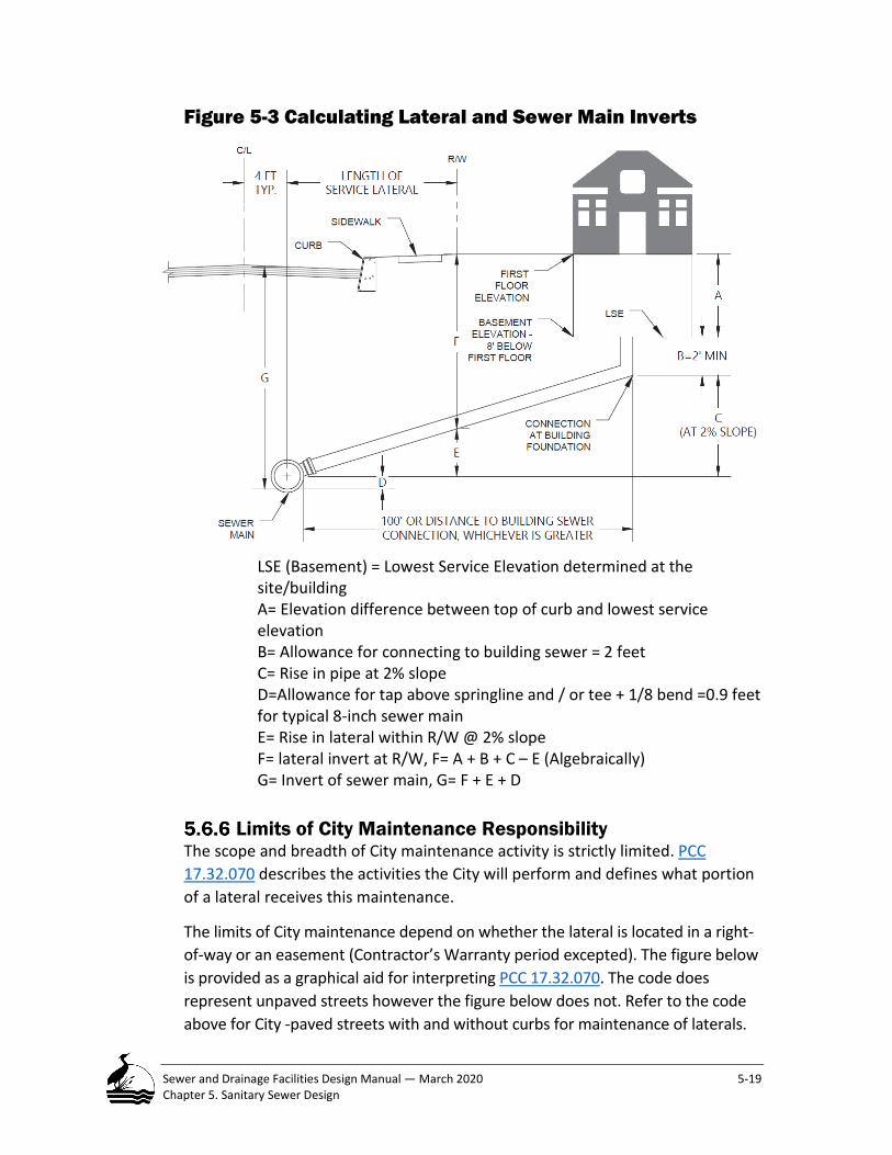
Sewer and Drainage Facilities Design Manual — March 2020 5-19 Chapter 5. Sanitary Sewer Design
Figure 5-3 Calculating Lateral and Sewer Main Inverts
LSE (Basement) = Lowest Service Elevation determined at the site/building A= Elevation difference between top of curb and lowest service elevation B= Allowance for connecting to building sewer = 2 feet C= Rise in pipe at 2% slope D=Allowance for tap above springline and / or tee + 1/8 bend =0.9 feet for typical 8-inch sewer main E= Rise in lateral within R/W @ 2% slope F= lateral invert at R/W, F= A + B + C – E (Algebraically) G= Invert of sewer main, G= F + E + D
Limits of City Maintenance Responsibility The scope and breadth of City maintenance activity is strictly limited. PCC 17.32.070 describes the activities the City will perform and defines what portion of a lateral receives this maintenance.
The limits of City maintenance depend on whether the lateral is located in a right-of-way or an easement (Contractor’s Warranty period excepted). The figure below is provided as a graphical aid for interpreting PCC 17.32.070. The code does represent unpaved streets however the figure below does not. Refer to the code above for City -paved streets with and without curbs for maintenance of laterals.

Sewer and Drainage Facilities Design Manual — March 2020 5-20 Chapter 5. Sanitary Sewer Design
Figure 5-4 Limits of City Maintenance Responsibility
Right-of-way: Refer to PCC 017.032.070.B.1 for The Limits of City Maintenance Responsibility.
An exception from the aforementioned maintenance limits occurs when a sewer lateral is located under a Green Street Facility built with either a specified soil mix or multiple curbs that define the facility perimeter. Refer to PCC 017.32.070 for The Limits of City Maintenance Responsibility.
Easement area: The City only maintains the portion of a lateral defined to the end of a tee fitting located on the main sewer or to the first pipe joint if out of a maintenance hole.
Alleys: The City only maintains the sewer connection and lateral between the sewer main and the Right-of-Way.
Pressure Lateral Systems Located in the Public Right of Way There are locations within the City of Portland, Bureau of Environmental Services (BES) service area where the cost of providing gravity sewer service to either existing developed lots or potentially developable lots significantly exceeds current cost recovery through system development charges, branch fees, and line fees.

Sewer and Drainage Facilities Design Manual — March 2020 5-21 Chapter 5. Sanitary Sewer Design
Those location constraints may justify a decision by BES to implement an alternative service delivery approach, such as using pressurized laterals to provide connectivity to the public sewer system. BES must review and approve engineered plans for any proposed pressurized lateral systems.
Minimum requirements for pressurized lateral systems are as follows:
3. Pressurized laterals shall only be used to provide service to a single parcel. If there is more than one parcel in an area that requires this type of service, the pressurized laterals will be installed in a common trench, where possible, and will discharge to a common collection box, vault, pipe, or maintenance hole that will be connected to a gravity sewer.
4. All pressurized lateral assemblies shall include a grinder pump1, with appropriate high pressure and temperature shut off systems and approved piping material. An isolation valve and flushing connection with check valve shall be located in a valve box at grade. Septic Tank Effluent Pump (STEP) systems will not be approved by BES.
5. Property owner shall install and maintain the pressurized lateral system up to the property side of the valve box adjacent to the property that is being served. If a curb exists, the vault should be located at the back of curb. If there is no curb, the vault should be located between the property line and the anticipated curb line.
6. Plan and profile drawings must be prepared, and final contract documents must be sealed by a professional engineer registered to practice in the State of Oregon.
7. Horizontal and vertical alignment shall be in accordance with City Code 17.32 and must comply with Oregon Administrative Rules (OAR) 333 and OAR 340 requirements regarding separation from other buried utilities, including but not limited to potable water transmission pipelines.
8. Grade changes resulting in high points along the pipes alignment should be avoided or minimized. Alignments should exclude high points. Air release and/or vacuum release valves will not be allowed.
9. Individual pressure service lines in a common trench must be separated by two inches skin-to-skin and must be at the same elevation in the trench. They may not be bundled or stacked vertically. The maximum number of individual pressure lines allowed in a common trench shall be five or as approved by BES.
10. The pressure service line construction contract shall require the installation of electronic locating materials in accordance Section 00446.10 of the City of Portland (COP) Standard Construction Specifications (SCS).
1 Exceptions must be approved by BES.

Sewer and Drainage Facilities Design Manual — March 2020 5-22 Chapter 5. Sanitary Sewer Design
11. Horizontal and vertical elevations and pipe types and appurtenances must be approved by BES.
12. Pressure line pipe material requirements: a. Individual pressure service lines less than 2-inch nominal diameter
will not be allowed.
b. 2-inch through 4-inch individual pressure service pipes may be constructed using schedule 80 polyvinyl-chloride (PVC) pipe and fittings or DR 9 high density polyethylene (HDPE) pipe and fittings, subject to a case-by-case review and approval by BES.
13. Discharge point requirements: a. All individual sewage pressure service pipelines installed in the
same ROW must discharge individually to a common discharge location, such as a pipe, collection box, vault, or maintenance hole that will be connected to the BES gravity sewer system. The invert elevation (IE) of the individual pressure service laterals where they penetrate the wall of the common discharge location must be 8-12-inches above the IE of the gravity sewer pipe where it exits the discharge location. Each wall penetration shall be provided with a saddle or link-seal type of fitting.
14. Construction inspection and hydrostatic testing requirements: a. The pressure service system construction contractor must
coordinate with BES construction inspection during the installation of the proposed individual pressure service laterals and appurtenances.
b. Prior to connection to the BES gravity sewer collection and conveyance system, the individual pressure service laterals and pumping assembly must be hydrostatically tested and approved in accordance with the requirements of Section 01140.51 of the COP, SCS.
c. Final connection to the BES gravity sewer system shall be in accordance with COP SCS Section 00490.42. BES Construction Inspection representative must approve the final connection to the BES gravity sewer system.
Connection to the Public Sewer System All lateral connections to public sewers must be done in a manner that assures the integrity and serviceability of the publicly maintained portion of the system. Acceptable methods include a manufactured fitting or a field fabricated fitting that require coring and tapping of the sewer main or maintenance hole to receive the lateral sewer.
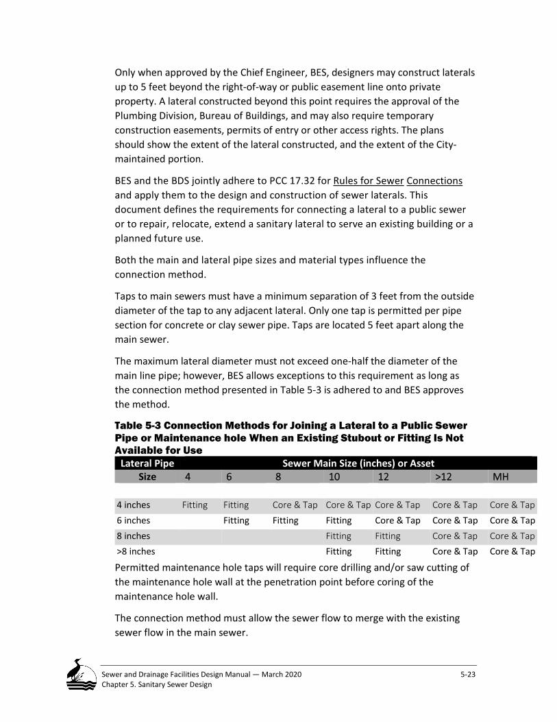
Sewer and Drainage Facilities Design Manual — March 2020 5-23 Chapter 5. Sanitary Sewer Design
Only when approved by the Chief Engineer, BES, designers may construct laterals up to 5 feet beyond the right-of-way or public easement line onto private property. A lateral constructed beyond this point requires the approval of the Plumbing Division, Bureau of Buildings, and may also require temporary construction easements, permits of entry or other access rights. The plans should show the extent of the lateral constructed, and the extent of the City-maintained portion.
BES and the BDS jointly adhere to PCC 17.32 for Rules for Sewer Connections and apply them to the design and construction of sewer laterals. This document defines the requirements for connecting a lateral to a public sewer or to repair, relocate, extend a sanitary lateral to serve an existing building or a planned future use.
Both the main and lateral pipe sizes and material types influence the connection method.
Taps to main sewers must have a minimum separation of 3 feet from the outside diameter of the tap to any adjacent lateral. Only one tap is permitted per pipe section for concrete or clay sewer pipe. Taps are located 5 feet apart along the main sewer.
The maximum lateral diameter must not exceed one-half the diameter of the main line pipe; however, BES allows exceptions to this requirement as long as the connection method presented in Table 5-3 is adhered to and BES approves the method.
Table 5-3 Connection Methods for Joining a Lateral to a Public Sewer Pipe or Maintenance hole When an Existing Stubout or Fitting Is Not Available for Use
Lateral Pipe Sewer Main Size (inches) or Asset Size 4 6 8 10 12 >12 MH
4 inches Fitting Fitting Core & Tap Core & Tap Core & Tap Core & Tap Core & Tap
6 inches Fitting Fitting Fitting Core & Tap Core & Tap Core & Tap 8 inches Fitting Fitting Core & Tap Core & Tap
>8 inches Fitting Fitting Core & Tap Core & Tap
Permitted maintenance hole taps will require core drilling and/or saw cutting of the maintenance hole wall at the penetration point before coring of the maintenance hole wall.
The connection method must allow the sewer flow to merge with the existing sewer flow in the main sewer.

Sewer and Drainage Facilities Design Manual — March 2020 5-24 Chapter 5. Sanitary Sewer Design
Use of Wye or Wye Head Fittings BES discourages the use of Wye or Wye-head fittings anywhere in the public portion of the sewer system. The City requires that lateral connections be oriented perpendicular to the sewer main to assist with locating the pipe in the future and to ensure that shoring conflicts with other underground utilities in the Right of Way are minimized during future repairs. Use of a wye fitting requires a second fitting to orient the lateral pipe perpendicular to the main. The City strives to reduce the number of fittings and joints used in the public sewer system to reduce opportunities where roots or other failures could occur.
The City allows an exception to this practice under the Nonconforming Sewer Program and if the use of a wye is an appropriate solution. If the location of Wye is different than as shown in figure 5-5, the Wye must be relocated to conform to the figure. Wyes installed at the curb to serve separate properties will only be approved by the City when the connecting pipes are pre-existing and the affected property owners are participating in the City’s Nonconforming Sewer Conversion program. A wye is a non-conforming sewer connection.
Figure 5-5 Shared Wye Connection Horizontal Alignment (City Wye)

Sewer and Drainage Facilities Design Manual — March 2020 5-25 Chapter 5. Sanitary Sewer Design
Deep Connection Riser (DCR) A deep connection riser is used where the depth of the sewer main or conflicts with existing utilities or other obstructions are located such to prevent the use of the typical lateral connection. Generally, four of the following five criteria must be satisfied to use a deep riser, as shown in Figure 5-6:
• The receiving sewer must have a minimum depth of 12 feet, • The length of the deep riser measurement from the crown or top of main
sewer invert to the top of the riser must be at least 3 feet. • The slope from the sewer main to the building sewer invert at the ROW is
greater than 100% (45 degrees). • The lateral must maintain a minimum slope of 2% up to the vertical
section of the riser. • More than one connection to a deep riser connection requires BES
review approval Field conditions may dictate deviations from these standards. BES must approve any deviation from these standards. Review and approval by BES is required. A designer must provide the stationing along the sewer main, the top elevation and the invert of the lateral at the property line. Refer to the City of Portland Standard Detail P-250, PVC Deep Connection Riser (see Chapter 1,11, Companion Documents and Internet Links.)

Sewer and Drainage Facilities Design Manual — March 2020 5-26 Chapter 5. Sanitary Sewer Design
Figure 5-6 Deep Riser Connection
Example 5-4. Siting a DCR Given: A private lot on a level site. The sewer main is 12 feet deep and the discharge point of the building sewer is 7 feet below the ground surface.
Required: Locate a Deep Riser Connection. Under these conditions a DCR would not be approved for use, however, if the discharge depth were 6 feet or less a riser could be used.

Sewer and Drainage Facilities Design Manual — March 2020 5-27 Chapter 5. Sanitary Sewer Design
CHAPTER 5 NOTEWORTHY ITEMS
• BES recognizes three components of wastewater in a sanitary sewer: 1) sanitary flow 2) industrial flow and 3) infiltration and inflow.
• The flow calculation methodology provided in this section is suitable for designing new sewers in unserved redeveloped areas. Whenever an existing system is to be evaluated for its ability to generate or convey flow, this analysis must be performed or reviewed by BES staff.
• The City’s current Comprehensive Plan and Title 33, Planning and Zoning code are to be referenced to establish population density estimates for designing a sewer.
• For new development, BES uses the net developable acreage to calculate sanitary flow. At a minimum, fifteen percent of the undeveloped area is dedicated to future right-of-way needs.
• BES requires that the calculated sanitary flow rate be increased by a contingency factor of 1.25 to account for unforeseen land use changes occurring in a subbasin.
• 8 inches is the minimum size accepted for a public sanitary sewer. • Use a Manning’s roughness factor of 0.013 when designing sanitary
sewer regardless of material type. • Minimum and maximum velocities in a sanitary sewer is 2.5 and 15 fps,
respectively. • Minimum pipe slope must be selected to maintain minimum self-cleaning
velocity for the expected design flow. • A 6-inch (4 inch if BES approved) public lateral must be provided to each
platted private property, within a public ROW. • Lateral tees must be installed perpendicular to a main sewer to avoid
utility conflicts. • The minimum slope of a sewer lateral within the right-of-way is 2
percent. • Four criteria must be satisfied to use a deep connection riser in the ROW.

Sewer and Drainage Facilities Design Manual —March 2020 6-1 Chapter 6. Hydrologic Analysis for Drainage
Hydrologic Analysis for Drainage This chapter provides technical information and procedures for completing hydrologic analysis when designing storm sewers and the performance aspects relative to water quality. Users of the Stormwater Management Manual (SWMM) may reference this information, Chapter 7, and these procedures to design the hydrologic aspects of water quality facilities.
This chapter introduces the Citywide drainage system, how it functions in the broad context of stormwater management and establishes the facility types that will use this chapter for design. The remainder of the chapter discusses sizing drainage facilities for future development, the expected hydrologic performance objective (i.e., storm return period) for each facility type depending on its function within the system, and comparison of several hydrologic analysis methods BES accepts for estimating and routing flows for facility design. The chapter closes with a discussion of hydraulic design criteria for closed conduits and open channels.
Introduction ...................................................................................................... 6-3
Overview .......................................................................................................... 6-4
Applicability ...................................................................................................... 6-4 Variance from These Standards .................................................................................. 6-4 Facility Sizing to Serve Future Development .............................................................. 6-5
Facility Classification ......................................................................................... 6-5 Return Period .............................................................................................................. 6-5
Table 6-1 Drainage Facilities with their Design Storm Return Periods ........................... 6-6
Hydrologic Analysis – Converting Rainfall to Runoff ............................................ 6-7 6.5.1 Select a Storm Return Period ...................................................................................... 6-7

Sewer and Drainage Facilities Design Manual —March 2020 6-2 Chapter 6. Hydrologic Analysis for Drainage
Select a Method to Convert Precipitation into Runoff ............................................... 6-7 Table 6-2 Design Applications of the Recommended Hydrologic Methods ................... 6-9 Equation 6-1 Rational Formula ..................................................................................... 6-11 Table 6-3 Rational Formula Method ............................................................................. 6-12 Table 6-4 Rational Formula Method ............................................................................. 6-13 Equation 6-2 NRCS Rainfall to Runoff ........................................................................... 6-15 Equation 6-3 Theoretical Relationship Between Ia and S .............................................. 6-15 Equation 6-4 Rainfall to Runoff ..................................................................................... 6-16 Equation 6-5 S related to CN ......................................................................................... 6-16 Table 6-5 Non-Composite Curve Numbers (CNs) .......................................................... 6-17 Table 6-6 Composited Curve Numbers (CNs)................................................................ 6-18 Equation 6-6 SBUH Rainfall to Runoff ........................................................................... 6-22 Equation 6-7 SBUH Reservoir Routing .......................................................................... 6-22 Table 6-7 HEC-HMS Analytic Methods .......................................................................... 6-24 Table 6-8 EPA-SWMM-RUNOFF and EXTRAN Blocks Analytic Methods ....................... 6-25
HEC-HMS and EPA-SWMM Applications .................................................................. 6-26 Table 6-9 Suggested Monthly Evaporation Data for EPA-SWMM Models ................... 6-26 Table 6-10 Parameters for Green-Ampt Analysis ......................................................... 6-27
Precipitation Data and Antecedent Conditions ........................................................ 6-27 Total Rainfall Depth .................................................................................................. 6-28
Table 6-11 Total Rainfall Depths for Various Storm Durations PIA ............................... 6-28 Intensity-Duration-Frequency (IDF) Information ...................................................... 6-28
Table 6-12 Tabulated Rainfall Intensity Duration Frequency Rainfall Data Compiled at Portland International Airport ...................................................................................... 6-29 Table 6-13 Tabulated Rainfall Intensity Duration Frequency Rainfall Data Compiled at Portland International Airport ...................................................................................... 6-30
Hyetographs - Rainfall Intensity Distributions .......................................................... 6-32 Table 6-14 NRCS Type 1A -24-hour Hyetograph – 10–Minute Intervals ....................... 6-32
Antecedent Conditions ............................................................................................. 6-33 Equation 6-8 Convert Average CN Values to Wet Antecedent Conditions .................. 6-33
Physical Characterization of Site ...................................................................... 6-34 Area........................................................................................................................... 6-34 Land Use and Surface Type ....................................................................................... 6-34
Equation 6-9 Mapped Pervious Area ............................................................................ 6-34 Soils ........................................................................................................................... 6-35
Table 6-15 NRCS Hydrologic Soil Groups (HSG) ............................................................ 6-36 Hydrologic Length and Slope .................................................................................... 6-37 Lakes, Wetlands or Storage Facilities ....................................................................... 6-37
Time of Concentration ..................................................................................... 6-38 Equation 6-10 Time of Concentration ........................................................................... 6-38
Flow Regimes ............................................................................................................ 6-38 Table 6-16 Flow Regime Types and General Characteristics ........................................ 6-39 Equation 6-11 Manning’s Kinematic Solution (Overton and Meadows 1976) ............. 6-39
Sheet Flow ................................................................................................................ 6-39 Table 6-17 Manning’s Surface Roughness “ns” Coefficient for Sheet Flow Calculation less than 300 feet................................................................................................................. 6-40
Shallow Concentrated Flow ...................................................................................... 6-40

Sewer and Drainage Facilities Design Manual —March 2020 6-3 Chapter 6. Hydrologic Analysis for Drainage
Equation 6-12 a and b – Average Velocities for Shallow Concentrated Flow, Paved and Unpaved Surfaces ......................................................................................................... 6-42
Open Channel Flow ................................................................................................... 6-42 Equation 6-13 Flow Segment Flow Times ..................................................................... 6-42
Design Criteria ................................................................................................. 6-42 Capacity .................................................................................................................... 6-42 Manning’s Roughness Coefficient (n) ....................................................................... 6-43 Minimum Conduit Sizes ............................................................................................ 6-43 Minimum and Maximum Velocity ............................................................................ 6-44 Minimum Slope ......................................................................................................... 6-44 Energy Losses ............................................................................................................ 6-45
Data Collection, Monitoring, and Instrumentation Installation Requirements ... 6-45
Introduction This chapter provides technical information and procedures for completing hydrologic analysis when designing storm sewers and stormwater management facilities for water quality and flow control the performance aspects relative to water quality. Users of the Stormwater Management Manual (SWMM) may reference this information and these procedures to design the hydrologic aspects of water quality facilities. This chapter applies to all public drainage conveyance facilities operating under gravity flow conditions.
Drainage facility design requires designers to understand and analyze the causes – (i.e., hydrology) of runoff and its effects (i.e., hydraulics.) Stormwater management involves the application of technical and non-technical strategies to minimize and avoid any adverse impacts. Use the information in this chapter to design drainage facilities to collect, transport, store or dispose of runoff.
The public drainage system comprises a variety of facility types including curb and gutters, inlets, catchbasins, storm sewer pipes, culverts, drainage channels and storage facilities. This chapter is the primary reference to calculate runoff volume and flow.
USE this chapter for designing storm-only separated drainage facilities; that is, those without connection to any sanitary sewer. DO NOT USE this chapter to design a combined sewer. Although stormwater is a major flow component in a combined sewer, a combined sewer has different hydrologic and hydraulic design criteria from those described in this chapter. Refer to Chapter 7 - Combined Sewer Design when designing a combined sewer.

Sewer and Drainage Facilities Design Manual —March 2020 6-4 Chapter 6. Hydrologic Analysis for Drainage
Overview Drainage facility design is one facet of the City’s overall stormwater management program. The City’s stormwater management program also includes planning, policy, design and education. In the broadest sense, the goals of stormwater management are to correct existing problems and to prevent new problems from occurring in the future. Stormwater management requires the use of information collected from different disciplines to effectively manage runoff and limit its impacts. Some of the most significant adverse impacts are flooding, property damage, erosion and pollutant transport. Designers utilize structural and non-structural techniques to mimic an area’s natural hydrologic character to lessen the adverse impacts resulting from development.
Applicability This chapter and the current SWMM complement one another and share several common elements related to hydrologic analysis and hydraulic design. However, users of these documents must understand each document has limited applicability to different facility types found in the sewer system.
This chapter provides technical information and analytic procedures to design public structural drainage facilities. The SWMM is for the design of public and private stormwater facilities for water quality, flow and volume control. SWMM also includes protections for drainageways on private property. The SWMM refers to the SDFDM for analytic procedures. Refer to 1.4, Relationship Between this Manual and the SWMM for discussion of how these documents relate to one another.
Variance from These Standards Departure from the City’s drainage standards to less restrictive requirements is uncommon. Designers wanting to propose a variance from these standards should read 2.6.2, The Design Variance Process. Typically, a departure from the standards involves the application of a more restrictive standard to address unanticipated factors or design conditions. Conditions that warrant the application of a more restrictive standard include the following:
• Where no overland flow route is available to safely carry runoff away from a facility subject to flooding;
• Where flooding an arterial street (Contact the Portland Bureau of Transportation for a copy of the 1999 PDOT Transportation Plan for Street Classification Definitions Refer to 1.10, Useful Contacts within the City or other major transportation route could delay emergency services or the delivery of critical goods and services;

Sewer and Drainage Facilities Design Manual —March 2020 6-5 Chapter 6. Hydrologic Analysis for Drainage
• Where flooding within a commercial district could damage expensive merchandise or equipment stored in buildings;
• Where flooding over a roadway embankment could result in a catastrophic road fill failure;
• Where over-topping of a storage facility or overloading the hydraulic capacity of a drainage facility would cause property damage or endanger life;
• Where flooding could endanger human health and safety, result in extensive property damage, or impact the environment significantly;
• Where intentional impoundment or increase in the volume or depth of water could occur upstream of a road embankment that is not specifically designed for this purpose;
• Where the transfer of runoff between area drainage systems is proposed. BES must approve the plan. As part of a variance request for such a transfer, a designer must submit a complete analysis justifying a need to divert runoff from one area to another and identify all mitigating impacts and benefits. Changing a discharge point or drainage system may trigger requirements of the SWMM.
Facility Sizing to Serve Future Development A designer must design all drainage facilities to manage runoff for the future build-out condition defined by the City’s Comprehensive Plan and Zoning Code and meet the requirements presented in this Chapter. All development must also comply with the requirements defined in the current SWMM.
The City encourages development to incorporate sustainable practices into a design to limit runoff. Until development occurs, it is impossible to predict when the improvements and the potential magnitude of runoff reduction will happen. Because of the inherent uncertainty regarding the timing and extent of development, BES does not allow sizing any drainage facility smaller than required to manage runoff for the future build-out condition defined by the City’s Comprehensive Plan and Zoning Code.
Facility Classification
Return Period BES assigns each drainage facility a design return period (RP) based on its expected level of operation and failure risk. The magnitude and severity of a storm relates directly to the RP. The longer the storm RP the larger the facility size needed to manage the resultant runoff and volume.
The RP is a measure of the chance that a storm will occur within a specified time. The RP reciprocal (1/RP) is the likelihood that a storm equal to or exceeding the

Sewer and Drainage Facilities Design Manual —March 2020 6-6 Chapter 6. Hydrologic Analysis for Drainage
specified storm will occur in any one year. For example, an event with an assigned five-year RP has a 20 percent (i.e., 1/5) chance of occurring in any one-year duration. BES has established the following design standards for drainage facilities:
A designer must design all storm drainage facilities to pass up to the 10-year 24-hour storm (Except Columbia South Shore Plan District requires use of a 25-year 24-hour storm) without surcharge and provide a means to pass a 25-year 24-hour storm without damage to property, endangering human life or public health, or significant environmental impact.
Runoff from a 25-year storm may surcharge a separated stormwater system but the hydraulic grade line (HGL) must remain a minimum of 6 inches below the lowest critical elevation identified within the system. The critical elevation may be the ground surface or a property where potential flooding could occur, whichever is lower.
Table 6-1 lists each facility type and its assigned design return period.
Table 6-1 Drainage Facilities with their Design Storm Return Periods Facility Type Design Storm
Return Period, years Street Gutter and Inlet (10/25) 1 Piped Flow - Separated Storm Sewer (Conduit) 10 2 Surface Flow - Open Channel including Roadside Swale, Channel or Ditch
25 3
Culvert 25 4 Sump System 105 Outfall Variable Flow Control Storage Volume Variable 6 Special Circumstances Variable7 Bridges ODOT Standards 8 River with FEMA Floodplain 100
1 The normal design storm is 10 year. The design of a street gutter and the placement of an inlet depend on the safe collection and conveyance of the design storm flow and the allowable spread of water on the pavement. The 25-year design storm is for special conditions.
2 Except 25 years in Columbia South Shore Plan District. 3 Design roadside facilities to convey the design storm within a channel defined within the top-of bank. 4 At a minimum design culverts to convey the specified design storm through a roadway fill without
surcharging the inlet (i.e. water depth must not exceed the inside height of the pipe crown). In some situations, the degree of failure risk is large enough to justify a design frequency greater than that specified. BES may consult with the Portland Bureau of Transportation (PBOT) to clarify the street classification established in the Transportation Element of the City Comprehensive Plan and determine if the return period for designing a particular culvert requires a different design RP.
5 Use 10-year 24-hour Design Storm with a safety factor of 2 applied. 6 This refers to the storage volume needed to achieve a specific flow control objective. A facility is sized to
manage flow volume whereas an outlet control structure is sized to release flow at a predetermined flow. The design volume is a function of the inflow and outflow hydrographs and the desired level of flow control.

Sewer and Drainage Facilities Design Manual —March 2020 6-7 Chapter 6. Hydrologic Analysis for Drainage
7 Special Circumstances refer to facilities that require compliance with additional standards beyond BES’s standards. For example, bridges receiving federal funding could require additional permitting and more stringent design constraints. Work in rivers with published floodplains would follow FEMA’s Federal Flood Insurance Program procedures. Water bodies with native or migratory fish would require consultation with NOAA Fisheries. All of these circumstances could significantly influence facility design.
8 Follow the Oregon Department of Transportation (ODOT) Bridge Section Standards.
Hydrologic Analysis – Converting Rainfall to Runoff Hydrologic analysis generally involves six steps to simulate rainfall and convert it to runoff:
• Select a Storm Return Period (RP) for a Facility; • Select a Method to Convert Precipitation into Runoff; • Physically Characterize the Drainage Basin; • Calculate Time of Concentration; • Select Representative Precipitation/Storm Data; • Perform Routing Calculations.
A fundamental assumption inherent in all of the selected analysis methods is that the return period of the rainfall and runoff are equal. In Portland, intense rainfall commonly occurs after an extended period of light rainfall, when typical light rainfall will have wetted the vegetation, saturated the soil and filled small depressions.
6.5.1 Select a Storm Return Period A designer should use Table 6-1 to select the design storm RP corresponding to the facility type of interest.
Select a Method to Convert Precipitation into Runoff The City accepts the following six hydrologic single-event analysis methods as being suitable to design drainage facilities.
• Rational Method; • National Resource and Conservation Service (formerly Soil Conservation
Service (SCS)) TR-55; • Santa Barbara Urban Hydrograph (SBUH) Method; • Army Corps of Engineers Hydrologic Engineering Center (HECH-HMS); • US Environmental Protection Agency Stormwater Management Model
(EPA - SWMM-Runoff); and • Regression Analysis.
The first three methods (Rational, TR-55 and the SBUH) employ hand calculation procedures. They can be automated using spreadsheet or commercial software applications. The next two methods, HEC-HMS and the EPA - SWMM-Runoff

Sewer and Drainage Facilities Design Manual —March 2020 6-8 Chapter 6. Hydrologic Analysis for Drainage
require computer software to run. The last method, Regression Analysis, requires field monitoring data of flows, and is commonly used in urban forested areas where runoff characteristics can be highly influenced by infiltration, interflow, and groundwater influences. Hand calculation and/or spreadsheets are then used to develop a regression formula that models runoff based on a given rainfall input.
All of these methods were selected for several reasons: 1) the City’s historic use of these methods, 2) their proven reliability for the range of conditions experienced locally and 3) the availability of equations, design aids, computer programs and documentation that support these methods.
Table 6-2 provides limitations on the use of design applications of the recommended hydrologic methods:
• Peak Flow Estimation Only: Single event rainfall-runoff models, and continuous rainfall-runoff modeling. The Rational Method and TR-55 with manual calculation are included in this category. The hydrologic tools included here are used for sizing conveyance system elements that receive runoff from small areas with relatively uniform drainage characteristics. The Rational Method can also be applied for rate-based water quality facility sizing.
• Single Event Rainfall-Runoff Modeling: The hydrologic tools in this category include SBUH, TR-55 Windows version, EPA - SWMM, and HEC-HMS. These methods can simulate a single storm and produce a runoff hydrograph in addition to peak flow. These methods are applicable for conveyance sizing, water quality, and flow control facility sizing.
• Continuous Rainfall-Runoff Modeling: HEC-HMS and EPA - SWMM, including the EPA SWMM, XP-SWMM, and PC-SWMM variants, are hydrologic tools that use precipitation and evaporation time series as inputs to generate a corresponding runoff time-series. In addition to conveyance and stormwater facility sizing, these models can provide annual and monthly water balance, flood frequency distributions, and flow duration analysis.
BES recognizes the limitations of these methods and understands that their results are only an approximation of natural phenomena and processes. The relationship between the precipitation falling on a surface and the amount of runoff produced is complex with too many factors to expect precise solutions.
A designer must use sound technical judgment when applying any of these methods. If necessary, make appropriate adjustments when specific site characteristics dictate departure from these standards, and document those assumptions as part of the approval process.

Sewer and Drainage Facilities Design Manual —March 2020 6-9 Chapter 6. Hydrologic Analysis for Drainage
Table 6-2 Design Applications of the Recommended Hydrologic Methods
Hydr
olog
ic
Anal
ysis
Typ
e
Appl
icab
le M
etho
ds
Lim
itatio
ns a
nd
Cons
trai
nts
Suitable Applications
Applicable Capabilities
Conv
eyan
ce
Sizin
g
Wat
er Q
ualit
y Fa
cilit
y Si
zing
Flow
Con
trol
Fa
cilit
y Si
zing
Incl
udes
Hy
drol
ogic
Flo
w
Rout
ing
Inclu
des E
xplic
it Hy
drau
lic
Rout
ing
Peak
Flo
w
Estim
atio
n O
nly3
Rational Method Area < 10 acres
for rate-
based facilities
NA No No
NRCS (SCS)1 TR-55
(manual calculation)
TOC >= 6 minutes NA NA No No
Sing
le E
vent
Ra
infa
ll-Ru
noff
Mod
elin
g SBUH Area < 50 acres No No
NRCS (SCS)1 WinTR-55
Area >= 1acre or TOC >= 6
minutes Yes No
EPA-, XP-, PC- SWMM Area > 1/8 acre Yes Yes
HEC-HMS Area > 1/8 acre Yes No
Cont
inuo
us
Rain
fall-
Runo
ff M
odel
ing
EPA-, XP-, PC-
SWMM2 Area > 1/8 acre Yes Yes
HEC-HMS2 Area > 1/8 acre Yes No
1 Requires composited CN values for larger basins with non-uniform land uses and vegetation coverage. 2 For continuous modeling, recommend using Horton or Green-Ampt infiltration methods instead of the
simplified method in hydrologic analysis. 3 For sizing of inlets that are prone to debris loading and clogging, it is recommended that either a factor
safety be applied to peak flow estimates using methods other than the Rational Method or that the clogging factor is increased to account for the increased percentage of clogging.
Sewer and Drainage Facilities Design Manual —March 2020 6-10 Chapter 6. Hydrologic Analysis for Drainage
6.5.2.1 Rational Method
A. GENERAL The Rational Method is typically used for designing conveyance systems that receive runoff from small, quickly responding drainage areas. This method is easy to apply and generally produces conservative results.
The inputs to the Rational Method include the drainage area in acres, average rainfall intensity in inches per hour for a given recurrence interval corresponding to the estimated time of concentration for the drainage site, and the assumed runoff coefficient for the site.
Several assumptions are inherent in this method:
• A single point-of-interest characterizes each contributing drainage area; • Constant rainfall intensity occurs uniformly over an entire drainage area
for a time duration equal to the time of concentration Tc; • The estimated peak discharge has the same RP as the rainfall intensity (I);
and • The runoff coefficient (C) remains constant during a storm event and for
all storms with different RPs.
The analysis of only the impervious area from a developed site (with its corresponding large C factor and shorter Tc) may yield a higher peak runoff value than when using the entire site. Designers should check the peak runoff from both the entire site and only the impervious area for this condition (particularly in areas where the overland portion is grassy, yielding a long Tc) to avoid underestimating peak runoff. When determining a C value, a designer should account for any future land use changes that could occur during the facility design period.
Since this method relies on a composite C value and a single Tc, the distribution and grouping of different land uses will affect the results of hydrologic analyses. Consistently divide the drainage area into homogeneous sub-drainage areas.
Use of the Rational Formula requires a Tc for each design location within a drainage basin. The duration of rainfall is set equal to each area Tc to estimate the design average rainfall intensity using the appropriate Intensity Duration Frequency (IDF) curve.
B. APPLICATION A designer may use the Rational Method to design conveyance facilities including street gutters, drainage inlets, storm sewer pipes, culverts and small roadside ditches and culverts. It is most applicable to small, impervious,

Sewer and Drainage Facilities Design Manual —March 2020 6-11 Chapter 6. Hydrologic Analysis for Drainage
developed areas. Its use is limited to drainage areas of 10 acres or less and for which the Tc does not exceed 30 minutes.
A designer must not use this Method for storage facility design or any application where a hydrograph is required or when calculating peak flow for a downstream facility such as a bridge, culvert or storage facility that restricts flow, stores water and reduces the peak discharge rate.
C. EQUATION The Rational Method estimates a peak runoff rate at any location in a drainage basin as a function of the runoff coefficient, average rainfall intensity for duration equal to the estimated Tc and the drainage basin area.
Equation 6-1 relating all of these variables is the basis of the Rational Method.
𝑄𝑄 = 𝐶𝐶𝐼𝐼𝐴𝐴 Where: Q = peak runoff, cfs C = runoff coefficient representing a ration between runoff to rainfall, dimensionless I = average rainfall intensity, inches/hour, for a design storm duration equal to Tc A = drainage area contributing to the point-of-interest, acres
Equation 6-1 Rational Formula
D. RUNOFF COEFFICIENT (C) A Rational Method runoff coefficient represents the ratio of the average rainfall intensity to the maximum runoff rate. The actual percentage of rainfall to runoff varies greatly depending upon many factors including preceding rainfall, storm return period, soil, slope, and vegetation. Several inherent assumptions of this Method limit the variability of these factors and help to assure a conservative design.
Table 6-3 and Table 6-4 present Runoff Coefficients for use with the Rational Method. Table 6-3 categorizes the runoff coefficients according to typical land use types corresponding to zoning for developed areas, percent average impervious area for typical land uses, ground slopes, and hydrologic soil groups. Table 6-4 groups the runoff coefficients for undeveloped area into different aggregate land uses classified for general surface characteristics, ground slopes, and hydrologic soil groups. The runoff coefficients from Table 6-4 were the basis for calculating the runoff coefficients in Table 6-3.
Since C is the variable least susceptible to precise determination and requires design judgment it is desirable to develop a composite runoff coefficient using

Sewer and Drainage Facilities Design Manual —March 2020 6-12 Chapter 6. Hydrologic Analysis for Drainage
the percentages of different surface types found in a drainage basin. A designer should calculate composite runoff coefficients for non-typical land uses not found in Table 6-3 using the values from Table 6-4. The runoff coefficients in Table 6-3 represent “typical” values and may require adjustment when an area deviates significantly from the range of conditions cited.
E. TIME OF CONCENTRATION (TC) The Rational Method requires estimating Tc for each point-of-interest to select a corresponding rainfall intensity from an IDF chart.
Tc is calculated from the most remote point of the drainage area tributary to a point-of-interest. Under no circumstances can the Tc be less than 1/2 the time step. The City typically uses a 10-minute time step; when a 10-minute time step is used, the Tc must be at least 5 minutes.
F. RAINFALL Rainfall intensity is the rainfall rate, in inches per hour, for a given design storm. A designer must use the published IDF curve data tabulated in Table 6-12 to select an intensity corresponding to the appropriate design storm RP and the estimated Tc.
Table 6-3 Rational Formula Method Runoff Coefficients for Developed Areas. Average Impervious Area Percent for Typical Land Uses, Ground Slopes and Hydrologic Soils Groups Percent Impervious
Hydrologic Soil Group
Drainage Area Slope Typical Area Zoning, Service Road and Land Use
Under <5%
5% to 10%
Over 10%
0-10 A B C D
0.19 0.24 0.29 0.33
0.24 0.30 0.36 0.43
0.29 0.36 0.44 0.52
Zones: OS, RF Street Type: Local Queuing Other: Parks, Cemeteries and Playgrounds
11-20 A B C D
0.26 0.30 0.35 0.39
0.31 0.37 0.42 0.48
0.36 0.43 0.50 0.57
Zones: R20 Street Types: Local Queuing
21-30 A B C D
0.34 0.37 0.41 0.45
0.39 0.44 0.49 0.54
0.44 0.50 0.56 0.62
Zones: R10 Street Types: Local Queuing
31-40 A B C D
0.41 0.44 0.47 0.51
0.46 0.50 0.55 0.59
0.51 0.56 0.61 0.67
Zones: R7, R5 Street Types: Local Queuing

Sewer and Drainage Facilities Design Manual —March 2020 6-13 Chapter 6. Hydrologic Analysis for Drainage
Percent Impervious
Hydrologic Soil Group
Drainage Area Slope Typical Area Zoning, Service Road and Land Use
41-50 A B C D
0.49 0.52 0.55 0.57
0.54 0.57 0.61 0.65
0.59 0.63 0.67 0.72
Zones: R2.5 Street Types: Local Traffic & Neighborhood Collector
51-60 A B C D
0.56 0.58 0.61 0.63
0.61 0.64 0.67 0.70
0.66 0.70 0.74 0.77
Zones: Street Types: Local Traffic & Neighborhood Collector
61-70 A B C D
0.64 0.66 0.67 0.69
0.69 0.72 0.74 0.76
0.74 0.77 0.80 0.82
Zones: R2, R3, RMP Street Types: Local Traffic & Neighborhood Collector
71-80 A B C D
0.71 0.72 0.73 0.75
0.76 0.78 0.80 0.81
0.81 0.83 0.85 0.87
Zones: IR, CI1 Street Types: Local Traffic & Neighborhood Collector
81-90 A B C D
0.79 0.80 0.81 0.81
0.84 0.85 0.86 0.87
0.89 0.90 0.91 0.92
Zones: RH, IG2, EG1, EG2, CR, CM1, CM2, CM3, CI2, CE, Street Types
91-100 A B C D
0.86 0.87 0.87 0.88
0.91 0.92 0.92 0.92
0.96 0.97 0.97 0.97
Zones: RX, CX, EX, IH, IG1 Street Types: Arterial, Commercial Other: Any portion of a paved street
Notes: Any of the runoff coefficients may be adjusted to the nearest 0.05 to reflect any departure from these typical values. Any adjustment must be applied uniformly throughout a drainage area.
All Zoning designations reference the current City Comprehensive Plan. Designated Street Classifications reference the current Transportation Element of the City’s Comprehensive Plan and any applicable standards.
Table 6-4 Rational Formula Method Runoff Coefficients for Undeveloped Areas. General Surface Characteristics, Ground Slope and Hydrologic Soil Groups Surface Characteristics Hydrologic
Soil Group Ground
Slope
Under 5% 5% to 10 % Over 10%
Woodland A B C D
0.10 0.15 0.25 0.30
0.15 0.20 0.30 0.35
0.20 0.25 0.35 0.40
Lawn, Pasture, and Meadow
A B C D
0.15 0.20 0.25 0.30
0.20 0.25 0.35 0.40
0.25 0.30 0.45 0.50

Sewer and Drainage Facilities Design Manual —March 2020 6-14 Chapter 6. Hydrologic Analysis for Drainage
Surface Characteristics Hydrologic Soil Group
Ground Slope
Under 5% 5% to 10 % Over 10%
Cultivated Land A B C D
0.25 0.30 0.40 0.50
0.35 0.45 0.55 0.65
0.50 0.60 0.70 0.80
Railroad Yard - 0.25 0.30 0.40 Gravel Areas and Walks Loose Packed
- 0.30 0.70
0.40 0.75
0.50 0.80
Pavement and Roof - 0.90 0.95 1.00
6.5.2.2 National Resource and Conservation Service Soil Conservation Service TR-55 Hydrograph Method The TR-55 hydrologic method requires basic data similar to what is required for the Rational Method. However, it is more comprehensive in that it also considers a rainfall time distribution (i.e., hyetograph), as well as rainfall losses to interception/depression storage and an infiltration rate that decreases during the storm duration.
TR-55 is a highly tabular method with peak flow calculations closely matching the SBUH method. This method is popular for areas with wetlands because it includes a factor that incorporates many different land use types, including one that accounts for the effect of wetlands on peak discharge rates.
TR-55 can be performed either through manual calculations or an automated computer program. For the manual approach, please refer to the steps contained in the “Urban Hydrology for Small Watersheds: TR-55” (Agriculture 1986) by NRCS of the U.S. Department of Agriculture (USDA). The Windows computer application version of the TR-55 model, or WinTR-55, can be freely downloaded from the USDA-NRCS website.
WinTR-55 has a straightforward user interface for easily calculating times of concentration (Tc) and composited curve numbers (CN). The computer program is regarded by the NRCS as a tool for modeling “small watershed hydrology.” WinTR-55 can handle up to 10 sub-basins with a total area of 25 mi² that are connected with up to 10 routing reaches. A singular sub-basin without any connections to any routing reaches can be modeled if one simply wants to generate runoff hydrographs for a subject basin.

Sewer and Drainage Facilities Design Manual —March 2020 6-15 Chapter 6. Hydrologic Analysis for Drainage
A. APPLICATION Use the TR-55 method to estimate a peak runoff rate and generate a hydrograph for routing flow. The method described is applicable for areas with time of concentration equal to 6 minutes or greater than, and with a drainage area larger than 1-acre. The TR-55 method can be used for most design applications, including storage and outlet structures, drainage facilities, culverts, small drainage ditches, and open channels and energy dissipation facilities. The TR-55 manual method is based upon charts and tables; custom storms may not be readily applied using this procedure.
B. EQUATIONS The TR-55 Method estimates an outflow hydrograph that represents the sum of all of the individual subarea hydrographs within a drainage area modified by the effects of travel time and channel storage. Because this method assumes the physical characteristics of a drainage area (e.g., area, slope, soils). are constant the approach assumes similarity in the hydrograph shape from storms of similar rainfall characteristics. The following discussion outlines the equations and basic concepts used in the TR-55 method.
The NRCS derived a relationship between accumulated rainfall and accumulated runoff from experimental plots for numerous soil and cover conditions. The method relies on Equation 6-2 to estimate direct runoff from a 24-hour storm.
𝑄𝑄 =(𝑃𝑃 − 𝐼𝐼𝑤𝑤)2
(𝑃𝑃 − 𝐼𝐼𝑤𝑤) + 𝑆𝑆
Where: Q = accumulated direct runoff, inches P = accumulated rainfall (potential maximum runoff, inches) Ia = Initial abstraction (including surface storage, interception, evaporation and infiltration before runoff, inches) S = Potential maximum soil retention (inches)
Equation 6-2 NRCS Rainfall to Runoff
Through studies on many small agricultural watersheds, the NRCS established an approximate empirical relationship between Ia and S expressed by the following relationship.
𝐼𝐼𝑤𝑤 = 0.2𝑆𝑆
Equation 6-3 Theoretical Relationship Between Ia and S
Substituting 0.2S for Ia in equation 6-2 becomes:

Sewer and Drainage Facilities Design Manual —March 2020 6-16 Chapter 6. Hydrologic Analysis for Drainage
𝑄𝑄 =(𝑃𝑃 − 0.2𝑆𝑆)2
(𝑃𝑃 + 0.8𝑆𝑆)
Equation 6-4 Rainfall to Runoff
To achieve further simplification, the NRCS defined the parameter S in terms of the estimated CN obtained from analysis of an area’s physical characteristics.
𝑊𝑊ℎ𝑝𝑝𝑝𝑝𝑝𝑝 𝑆𝑆 =1000𝐶𝐶𝐶𝐶
− 10 𝑎𝑎𝑀𝑀𝑎𝑎 𝐶𝐶𝐶𝐶 = 𝐶𝐶𝐷𝐷𝐶𝐶𝑆𝑆 𝐶𝐶𝑀𝑀𝑝𝑝𝐼𝐼𝑝𝑝 𝐶𝐶𝑀𝑀𝑀𝑀𝑙𝑙𝑝𝑝𝑝𝑝
Equation 6-5 S related to CN
C. CURVE NUMBER - RUNOFF FACTOR Like the Rational Method, the TR-55 method uses the physical characteristics of an area to determine and assign a runoff factor (equivalent in purpose to a CN) to indicate an area’s runoff potential. Higher CN factors correspond to higher runoff potential. The primary characteristics generally referenced when assigning CNs are the soil type and land use or ground cover conditions.
Tables 6-5 and 6-6 give average condition CNs for various non-composite and composited conditions, respectively. When analyzing a drainage area containing multiple land uses or surface and cover conditions that depart from the values given in Table 6-5, the City recommends using a composite CN for analysis purposes. Generalizing a complex area with a lumped CN does not take into consideration the distribution of specific land uses but characterizes a drainage basin as containing uniform land uses represented by the composite CN. If a designer needs to develop a composite CN, calculate them using the weighted method as presented in Example 6.1. A set of composited CNs for common types of combined conditions is given in Table 6-6. These can be further composited depending on the actual area composition.
Because of this simplifying step and the implication this has when designing a facility, the City does not accept lumped CN analysis for any drainage area larger than 25 acres.
The different land uses within a basin should reflect a uniform hydrologic group represented by a single curve number. Any number of land uses can be included, but their spatial distribution is important to the hydrologic analysis; for basins with multiple land uses sub-basins should be developed, and separate hydrographs developed and routed to the point of interest.

Sewer and Drainage Facilities Design Manual —March 2020 6-17 Chapter 6. Hydrologic Analysis for Drainage
D. RAINFALL The TR-55 method requires use of the standard NRCS Type 1A rainfall distribution (hyetograph) and total storm depth corresponding to the critical storm duration to calculate runoff quantities. The hyetograph distributes the total rainfall volume for select storm frequencies and durations. Select a total rainfall depth from Table 6-12 Total Rainfall Depths for Various Storm Durations Recorded at the Portland International Airport (PIA) and apply the appropriate NRCS Type 1A Hyetograph found in Table 6-13.
Table 6-5 Non-Composite Curve Numbers (CNs)
Cover Type Hydrologic Soil Group Notes REF A B C D
Woods/Forest 30 55 70 77 Woods are protected from grazing, and litter and brush adequately
cover the soil.
NRCS
Woods-grass combination
32 58 72 79 - NRCS
Brush, Mixture with predominantly brush
30 48 65 73 - NRCS
Herbaceous (grass, weeds, and low-growing brush mix, with brush the minor element)
- 63 75 85 - NRCS
Pasture, grassland, continuous forage for grazing
39 61 74 80 - NRCS
Meadow with continuous grass
30 58 71 78 - WSDOT
Grass Lawn 35 56 70 77 - NRCS Bare Soil 77 86 91 94 Affected by degree of surface
toughness and compactness NRCS
Dirt Roads 77 88 94 96 Affected by degree of surface toughness, compactness and
aggregate size
NRCS

Sewer and Drainage Facilities Design Manual —March 2020 6-18 Chapter 6. Hydrologic Analysis for Drainage
Table 6-6 Composited Curve Numbers (CNs) Cover Type Hydrologic Soil Group Hydrologic
Condition Notes REF
A B C D
Parks and Open Space (golf courses, cemeteries with lawns)
68 79 86 89 Poor grass cover < 50% NRCS 49 69 79 84 Fair grass cover 50%
to 75% NRCS
39 61 74 80 Good grass cover > 75% NRCS Paved Roadways 98 98 98 98 - Streets with
curbs and gutters connected to storm system
NRCS
83 89 92 93 - Streets with open ditches or vegetated
shoulders and no curbs
NRCS
Gravel Roads (including ROW)
76 85 89 91 - Affected by degree of surface
toughness, compactness and
aggregate size
NRCS
Cover Type Hydrologic Soil Group Notes REF A B C D Gravel Roads 82 91 96 98 Affected by degree of surface
toughness, compactness and aggregate size
NRCS
Paved streets, parking lots, roofs, driveways
98 98 98 98 - NRCS
Open water: lakes, ponds and wetlands with standing water
100 100 100 100 - WSDOT
Woody Wetlands periodically saturated
86 86 86 86 - USDA/ASCE
Emergent Herbaceous Wetlands periodically saturated
80 80 80 80 - USDA/ASCE

Sewer and Drainage Facilities Design Manual —March 2020 6-19 Chapter 6. Hydrologic Analysis for Drainage
Cover Type Hydrologic Soil Group Hydrologic Condition
Notes REF
A B C D
Dirt Roads (including ROW)
72 82 87 89 - Affected by degree of surface
toughness, compactness and
aggregate size
NRCS
Residential 77 85 90 92 - Area=1/8 ac, Avg PIA=65%
NRCS
61 75 83 87 - Area=1/4 ac, Avg PIA=3.8%
NRCS
57 72 81 86 - Area=1/3 ac, Avg PIA=3.0%
NRCS
54 70 80 85 - Area ½ ac, Avg PIA=2.5%
NRCS
51 68 79 84 - Area=1 ac, Avg PIA=2.0%
NRCS
46 65 77 82 - Area=2 ac., Avg PIA=1.5%
NRCS
Pasture, grassland, continuous forage for grazing
68 79 86 89 Poor < 50% ground cover or heavily grazed with no
mulch.
NRCS
49 69 79 84 Fair 50 to 75% ground cover and not heavily grazed.
NRCS
Meadow with continuous grass
30 58 71 78 Good > 75% ground cover and lightly
or only occasionally
grazed.
NRCS
Grass Lawn 35 56 70 77 - - -
Brush, Mixture with predominantly brush
48 67 77 83 Poor < 50% ground cover.
NRCS
35 56 70 77 Fair 50 to 75% ground cover.
NRCS
30 48 65 73 Good > 75% ground cover.
NRCS
Herbaceous (grass, weeds, and low-growing brush mix, with brush the minor element)
- 80 87 93 Poor <30% ground cover
WSDOT
- 71 81 89 Fair 30% to 70% ground cover
WSDOT
- 62 74 85 Good >70% ground cover
WSDOT

Sewer and Drainage Facilities Design Manual —March 2020 6-20 Chapter 6. Hydrologic Analysis for Drainage
Cover Type Hydrologic Soil Group Hydrologic Condition
Notes REF
A B C D
Woods-grass combination
57 73 82 86 Poor CNs shown were computed for areas with 50
percent woods and 50 percent grass (pasture)
cover. Other combinations of conditions may be computed
from the CNs for woods and
pasture.
NRCS
43 65 76 82 Fair NRCS 32 58 72 79 Good NRCS
Woods/Forest 45 66 77 83 Poor Forest litter, small trees, and
brush are destroyed by
grazing, burning or regular clearing.
NRCS
36 60 73 79 Fair Woods are grazed, but not
burned, and some forest litter
covers the soil.
NRCS
30 55 70 77 Good Woods are protected from
grazing, and litter and brush
adequately cover the soil.
NRCS
Pre-development 65 72 79 81 Good Composite of upland forests, riparian forests, meadow/prairie
and oak savannah
NRCS/Seattle
*Curve Number can vary based upon the degree of compaction of the base soil. A slightly higher number would imply a greater degree of compaction.

Sewer and Drainage Facilities Design Manual —March 2020 6-21 Chapter 6. Hydrologic Analysis for Drainage
Example 6-1 Calculating A Weighted Curve Number for a Mixed-Use Area
Given: A 100-acre drainage basin containing the following mix of land uses: 80 acres Residential R-5 with HSG soil type – B and 20 acres of Open field in good condition with HSG soil type – C.
Required: Calculate a weighted CN for the area.
Land Use % of Total Land Area CN from Table 6-5 & 6-6 Calculated Weighted CN
Residential Lot 80 85 (80/100) x 85 = 68
R-5 Zoning
Soil HSG - B
Meadow – Good 20 71 (20/100) x 71 = 14
Condition
Soil HSG - C
Total Weighted Composite CN = 82
6.5.2.3 Santa Barbara Urban Hydrograph (SBUH) Method The foundation of the Santa Barbara Urban Hydrograph (SBUH) method is the TR-55 Unit Hydrograph method. Like the TR-55 method, the SBUH method relies on the CN approach to convert rainfall to runoff, however the SBUH methodology uses a different scheme to derive a runoff hydrograph. The SBUH method, unlike the TR-55 method, uses incremental runoff rates transformed into a series of instantaneous hydrographs and routes them through an imaginary reservoir with a routing constant based on the time of concentration and the time interval.
A. APPLICATION Use the SBUH method to estimate a peak runoff rate and hydrograph for areas draining up to 50 acres and with homogenous characteristics and simple drainage networks. Use this method for sizing conveyance and design of flow control storage facilities and their associated inlet and outlet control structures.
B. EQUATIONS The SBUH method directly computes a runoff hydrograph without going through the intermediate step of developing a unit hydrograph and therefore is often simpler to use. It is ideally adapted for use in a spreadsheet format.
The first step is to compute the instantaneous hydrograph for each time step:

Sewer and Drainage Facilities Design Manual —March 2020 6-22 Chapter 6. Hydrologic Analysis for Drainage
𝐼𝐼(𝑡𝑡) =60.5 × 𝐷𝐷(𝑡𝑡) × 𝐴𝐴
𝑎𝑎𝑤𝑤
Where: I(t) = instantaneous hydrograph, cfs R (t) = total runoff depth from both impervious and pervious areas, at time increment dt, inches A = area, acres dt = time step, minutes. (The maximum time interval is 10-minutes for all design storms 24-hours or less).
Equation 6-6 SBUH Rainfall to Runoff
Following development of an incremental input hydrograph, the method routes each hydrograph through an imaginary reservoir, using Equation 6-7, to obtain the incremental output runoff hydrograph, Qt+1.
𝑄𝑄1+1 = 𝑄𝑄1 + 𝑤𝑤(𝐼𝐼𝑤𝑤 + 𝐼𝐼𝑤𝑤+1 − 2𝑄𝑄1)
𝑤𝑤 = 𝑠𝑠𝑡𝑡(2𝑇𝑇𝑐𝑐+𝑠𝑠𝑡𝑡)
Where: dt = time interval, minutes
Equation 6-7 SBUH Reservoir Routing
Summation all of the incremental output hydrograph produces the total storm runoff hydrograph volume.
The following discussion outlines the equations and basin concepts used in the SBUH method.
C. CURVE NUMBER RUNOFF FACTOR The SBUH method uses the same area characteristics and procedures as described previously for the TR-55 Hydrograph Method to determine and assign CN factor(s) to characterize an area’s hydrology.
D. TIME OF CONCENTRATION (TC) Each point-of-interest requires a Tc to determine the incremental hydrograph routing constant, w.
The travel time distance is determined from the point-of-interest to the most remote point of the area tributary to the location. If needed, the average hydrologic slope is determined for the same distance. Under no circumstances can the Tc be less than 5 minutes.

Sewer and Drainage Facilities Design Manual —March 2020 6-23 Chapter 6. Hydrologic Analysis for Drainage
E. RAINFALL The SBUH method uses a NRCS Type 1A rainfall distribution along with a total 24-hour rainfall depth to compute a final hydrograph volume and peak flow rate. Refer to Tables 6-12 and 6-13 to obtain this information.
6.5.2.4 Computer Models for Drainage System Design There are numerous proprietary and public domain computer programs for completing rainfall-runoff analysis. Because of this variety of available models, the City limits discussion to two models that historically received widespread use throughout the City. Both of these models are in the public domain. The City may accept other proprietary models.
Computer models provide the ability to describe the performance of an entire drainage system, incorporate various system components in detail, which is not possible using hand calculations. However, it is false to assume that answers obtained from the model are more accurate. A designer should not exclude from consideration other methods of calculation.
6.5.2.4.1 HEC-HMS (formerly HEC-1) This computer model was developed by the Hydrologic Engineering Center of the US Army Corp of Engineers. This program develops discharge hydrographs for one or more locations in a drainage basin. The drainage basin can be subdivided into one or more sub-basins. The model is designed to be applicable to a wide range of issues including large river flood hydrology and small urban or natural watershed runoff. The model allows a wide variety of options for specifying precipitation, losses, and runoff transformation and routing.
HEC-HMS is highly adaptable to a variety of projects because it has a large collection of simplified and empirically-based algorithms (methods) as well as more complex and deterministic ones. HEC-HMS is capable of complex hydrologic modeling based upon many time-varying meteorological and physical landscape parameters. Given its complexity, the modeling program is more typically used on larger scale projects. There are multiple options in HEC-HMS to choose from, including canopy interception, surface storage, infiltration losses, “transforms” (rainfall to runoff generation), and baseflow recession. The availability of certain input data often limits the complexity of the methods chosen. HEC-HMS is generally used for the modeling of larger watersheds, but it is possible to model runoff from areas as small as 500 square feet.
The key inputs are basin parameters, precipitation, and methods that account for losses and the transformation of rainfall to runoff.
A list of the analysis methods commonly used with HEC-HMS for City projects is listed in Table 6-7.

Sewer and Drainage Facilities Design Manual —March 2020 6-24 Chapter 6. Hydrologic Analysis for Drainage
Table 6-7 HEC-HMS Analytic Methods Hydrologic Process Analytic Method Precipitation Type 1A NRCS storm distribution or user
defined synthetic hyetograph. Losses Soil Conservation Service Curve Number
Transforming Rainfall Excess to Runoff Kinematic wave across multiple planes with intercepting channels
Routing through Stream Channels Muskingum-Cunge and normal depth
Reservoir Routing User defined Discharge Rating Curve
HEC-HMS is known to be a complicated model capable of modeling large watersheds, but it is found to adaptable to small ones too. The steeper than average learning curve of the program is greatly reduced by the collection of clear and informative pdf manuals that are installed along with the program. HEC-HMS can be downloaded from https://www.hec.usace.army.mil/software/hec-hms/
Once the program is installed, new users can use the “Quick Start Guide” which includes a tutorial. The program also provides a standard “User’s Manual”, a detailed “Technical Reference Manual”, and an “Application Guide.” These manuals can be found in the ‘docs” subdirectory where the program is installed but can be easily accessed directly from within the program under the “Help” pull-down menu.
6.5.2.4.2 EPA – Stormwater Management Model (EPA-SWMM) The EPA Storm Water Management Model is a sophisticated single-event or long-term dynamic rainfall-runoff simulation model used primarily to model runoff quantity from primarily urban areas. It incorporates hydrologic processes as well as a flexible set of hydraulic modeling capabilities to route runoff through the drainage system of pipes, channels, storage units and diversion structures. Using EPA-SWMM, one can simulate most urban storm runoff and routing processes. However, it requires experienced users to obtain the most benefit from all of its capabilities.
EPA-SWMM is capable of complex hydrologic modeling, including time-varying rainfall, snow accumulation and melting processes, rainfall interception from depression storage, infiltration of rainfall into unsaturated soil layers, percolation of infiltrated water into groundwater layers, interflow between groundwater and the drainage system, and non-linear reservoir routing of overland flow. It is nearly unlimited with respect to the size or number of basins

Sewer and Drainage Facilities Design Manual —March 2020 6-25 Chapter 6. Hydrologic Analysis for Drainage
it can represent and is equally capable of highly complex hydraulic interconnections between those basins.
Sub-catchments in EPA-SWMM are divided into pervious and impervious subareas. Surface runoff can infiltrate into the upper soil zone of the pervious area, but not through the impervious area. Infiltration of rainfall from the pervious area of a sub-catchment can be estimated using three different methods: Horton infiltration, Green-Ampt infiltration and NRCS Curve Number infiltration.
The EPA-SWMM program consists of six blocks. Three blocks are used for most drainage facility design. These blocks include runoff, extended transport and executive.
The Runoff Block generates stormwater runoff hydrographs from various tributary drainage areas. This information can be input to subsequent model blocks. Runoff calculations are based on the sheet flow kinematic wave principle for any excess runoff.
The Extran Block simulates the hydraulic response of a major drainage system. This block can also simulate storage facilities at any point in the system, and can account for backwater effects, although sewer surcharging can underestimate needed storage volumes.
Table 6-8 describes EPA-SWMM parameters commonly used for City facilities.
Table 6-8 EPA-SWMM-RUNOFF and EXTRAN Blocks Analytic Methods Hydrologic Process Analytic Method Precipitation Type 1A NRCS storm distribution or user
defined synthetic hyetograph. Losses Explicit estimate of infiltration and surface
retention factors Transforming Rainfall Excess to Runoff Kinematic wave across multiple planes with
intercepting channels Flow Input from Runoff Block or hydrographs
generated in another model. Routing through Stream Channels Provide geometry, roughness, and invert
elevation of each facility including ground elevation at each node. Model calculates explicit solution to St. Venant equations
Reservoir Routing User defined storage versus volume relationship at point of interest.

Sewer and Drainage Facilities Design Manual —March 2020 6-26 Chapter 6. Hydrologic Analysis for Drainage
HEC-HMS and EPA-SWMM Applications Both HEC-HMS and EPA-SWMM are versatile modeling tools that can handle many different methodologies of varying complexity and can be applied to basins with various sizes. Although the programs are typically used for modeling large watersheds and for continuous rainfall-runoff modeling, they perform well using simplified methods with assumed variables. The City uses EPA-SWMM extensively in stormwater runoff estimates and a summary of typical used numbers are summarized below. The user can use these numbers as a start point in model calibration when monitored flow data is available.
METEOROLOGICAL DATA The meteorological input data to EPA-SWMM includes precipitation data and evaporation data.
• For precipitation data, use the 24-hour NRCS Type IA distribution for the 2-, 5-, 10- and 25-year design storms. Total depth and 10-minute hyetograph for the design storms should be based on Table 6-12 and Table 6-14 of this Manual.
• The potential Monthly Evaporation Data provided is based on a 30-year average (1961-1991) monthly pan evaporation measurements collected at the National Weather Service Station in the Portland International Airport.
Table 6-9 Suggested Monthly Evaporation Data for EPA-SWMM Models Month Inch/Month January 0.908
February 1.349 March 2.285 April 3.402 May 5.126 June 5.953 July 7.586
August 6.825 September 4.762
October 2.46 November 1.106 December 0.762
CATCHMENT DATA The catchment input data are recommended to be generated based on physical measurements of a sub-catchment and values and references recommended in the EPA-SWMM User’s Manual and on-line help manual.

Sewer and Drainage Facilities Design Manual —March 2020 6-27 Chapter 6. Hydrologic Analysis for Drainage
• Area, impervious percentage, slope and width • Manning’s n for impervious area and for pervious area as a measure of
the resistance of a surface to flows conveyed by that surface. • Detention storage for impervious area and for pervious area as measure
of depression storage on a portion of a sub-catchment that has to be filled before generating runoff
• % Zero-Imperv defines percent of the impervious area with no depression storage
INFILTRATION DATA Green-Ampt is recommended infiltration method. The recommended soil infiltration parameters required for Green-Ampt method are based on City-wide hydrodynamic model calibration results and are presented in the table below:
Table 6-10 Parameters for Green-Ampt Analysis
Suction Head (inch)
Hydraulic Conductivity
(in/hr)
Initial Moisture
Deficit (%) Notes Southwest Portland, CSO Area
3.54 0.12 72% Low permeability. Used in CSO models.
Southwest Portland, Stephens Creek Area
10.75 0.06 27% Silty clay loam/silty clay. Based on Stephens Creek calibrated model.
East Side CSO Area
4.33 0.39 76% Urban soils. Used in CSO models with no flow from pervious area.
Columbia Slough Area
4.33 0.1 33% Sandy clay loam. Based on Multnomah County Drainage Districts Columbia Slough outfall model calibration.
Precipitation Data and Antecedent Conditions Hydrology information is required for all of the selected hydrologic analysis methods. The selection of a specific method determines the hydrology information needed to complete analysis. For example, the Rational Method requires rainfall intensity obtained from an Intensity Duration Curve (IDF). A majority of other methods such as TR-55 Unit Hydrograph method use total

Sewer and Drainage Facilities Design Manual —March 2020 6-28 Chapter 6. Hydrologic Analysis for Drainage
rainfall depth. All of the identified analytical methods ignore precipitation in the form of snow.
Total Rainfall Depth Several analytic methods use the total cumulative rainfall depth for different duration storms to calculate runoff. Table 6-11 lists the total rainfall depth for the 2- through 100- year storm events for durations of 1-, 6-, 12- and 24-hours at the PIA.
Table 6-11 Total Rainfall Depths for Various Storm Durations PIA Return Period, years
Duration, hours
1 6 12 24 2 0.46 1.2 1.8 2.4 5 0.59 1.5 2.2 2.9
10 0.68 1.7 2.5 3.4 25 0.79 1.9 2.8 3.8 50 0.90 2.1 3.1 4.3
100 0.99 2.3 3.4 4.7 If necessary, designers will have to interpolate other durations from the data in Table 6-11.
Intensity-Duration-Frequency (IDF) Information Rainfall intensity is the average rainfall rate, in inches per hour (in/hr) falling at a location. It is variable, not only from storm to storm, but also throughout the duration of a storm. Rainfall intensities do not follow predictable patterns; therefore, the City statistically analyzed historic rainfall data to develop a set of IDF curves for the PIA that could be applied Citywide with adjustment to account for local and regional factors that influence local precipitation patterns. Figure 6-1 is a graphical representation of the resulting statistical analysis of this historic rainfall data.

Sewer and Drainage Facilities Design Manual —March 2020 6-29 Chapter 6. Hydrologic Analysis for Drainage
Figure 6-1 Intensity Duration Frequency (IDF) Curves for Portland, Oregon
Table 6-12 contains the tabulated data used to develop these curves. There is no precipitation value given for less than a 5-minutes duration.
Table 6-12 Tabulated Rainfall Intensity Duration Frequency Rainfall Data Compiled at Portland International Airport
Rainfall Intensity, inches per hour
Time, minutes Return Period, years
2 5 10 25 50 100 5 1.92 2.47 2.86 3.32 3.75 4.14 6 1.75 2.25 2.60 3.02 3.43 3.78 7 1.62 2.08 2.40 2.80 3.18 3.50 8 1.52 1.95 2.24 2.61 2.96 3.28 9 1.43 1.84 2.11 2.46 2.79 3.08
10 1.35 1.74 2.00 2.32 2.65 2.91 11 1.28 1.66 1.90 2.22 2.52 2.77 12 1.22 1.59 1.82 2.12 2.41 2.66 13 1.17 1.53 1.75 2.04 2.32 2.55 14 1.13 1.48 1.69 1.96 2.24 2.46 15 1.09 1.43 1.63 1.90 2.16 2.37 16 1.06 1.38 1.57 1.83 2.08 2.29 17 1.02 1.33 1.52 1.77 2.01 2.21 18 0.99 1.28 1.47 1.72 1.94 2.14
0.10
1.00
10.00
1 10 100 1000 10000
Rain
fall
Inte
nsity
, inc
hes/
hour
Duration, minutes
2-year
5-year
10-year
25-year
50-year
100-year

Sewer and Drainage Facilities Design Manual —March 2020 6-30 Chapter 6. Hydrologic Analysis for Drainage
Rainfall Intensity, inches per hour
Time, minutes Return Period, years
2 5 10 25 50 100 19 0.96 1.24 1.42 1.66 1.88 2.07 20 0.93 1.20 1.38 1.60 1.82 2.01 21 0.90 1.16 1.34 1.56 1.77 1.95 22 0.87 1.13 1.30 1.52 1.72 1.89 23 0.85 1.10 1.27 1.48 1.67 1.84 24 0.83 1.07 1.23 1.44 1.62 1.79 25 0.81 1.04 1.19 1.40 1.58 1.74 26 0.79 1.01 1.16 1.36 1.54 1.69 27 0.77 0.98 1.13 1.32 1.50 1.64 28 0.75 0.96 1.10 1.29 1.46 1.60 29 0.73 0.94 1.07 1.26 1.42 1.56 30 0.71 0.92 1.05 1.22 1.39 1.53 35 0.64 0.82 0.95 1.11 1.26 1.38 40 0.59 0.76 0.87 1.02 1.16 1.27 45 0.55 0.70 0.81 0.95 1.08 1.18 50 0.51 0.66 0.76 0.89 1.01 1.10 60 0.46 0.59 0.68 0.79 0.90 0.99 90 0.37 0.47 0.54 0.62 0.70 0.77
120 0.32 0.40 0.46 0.53 0.59 0.65 180 0.27 0.33 0.38 0.43 0.49 0.53 240 0.23 0.29 0.34 0.38 0.41 0.46 300 0.21 0.27 0.31 0.34 0.38 0.42 360 0.20 0.25 0.28 0.32 0.35 0.39 420 0.19 0.23 0.26 0.30 0.33 0.36 480 0.18 0.22 0.25 0.28 0.31 0.34 540 0.17 0.21 0.24 0.27 0.30 0.33 600 0.16 0.20 0.23 0.26 0.29 0.31 720 0.15 0.18 0.21 0.24 0.26 0.29
1080 0.12 0.15 0.17 0.19 0.21 0.23 1440 0.10 0.12 0.14 0.16 0.18 0.20
Table 6-13 contains the tabulated data used to develop these curves. There is no precipitation value given for less than a 5-minutes duration.
Table 6-13 Tabulated Rainfall Intensity Duration Frequency Rainfall Data Compiled at Portland International Airport Rainfall Intensity, inches per hour Time, Minutes
Return Period, years 2 5 10 25 50 100
5 1.92 2.47 2.86 3.32 3.75 4.14 6 1.75 2.25 2.60 3.02 3.43 3.78 7 1.62 2.08 2.40 2.80 3.18 3.50 8 1.52 1.95 2.24 2.61 2.96 3.28
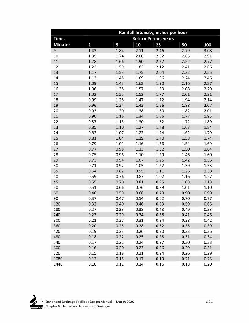
Sewer and Drainage Facilities Design Manual —March 2020 6-31 Chapter 6. Hydrologic Analysis for Drainage
Rainfall Intensity, inches per hour Time, Minutes
Return Period, years 2 5 10 25 50 100
9 1.43 1.84 2.11 2.46 2.79 3.08 10 1.35 1.74 2.00 2.32 2.65 2.91 11 1.28 1.66 1.90 2.22 2.52 2.77 12 1.22 1.59 1.82 2.12 2.41 2.66 13 1.17 1.53 1.75 2.04 2.32 2.55 14 1.13 1.48 1.69 1.96 2.24 2.46 15 1.09 1.43 1.63 1.90 2.16 2.37 16 1.06 1.38 1.57 1.83 2.08 2.29 17 1.02 1.33 1.52 1.77 2.01 2.21 18 0.99 1.28 1.47 1.72 1.94 2.14 19 0.96 1.24 1.42 1.66 1.88 2.07 20 0.93 1.20 1.38 1.60 1.82 2.01 21 0.90 1.16 1.34 1.56 1.77 1.95 22 0.87 1.13 1.30 1.52 1.72 1.89 23 0.85 1.10 1.27 1.48 1.67 1.84 24 0.83 1.07 1.23 1.44 1.62 1.79 25 0.81 1.04 1.19 1.40 1.58 1.74 26 0.79 1.01 1.16 1.36 1.54 1.69 27 0.77 0.98 1.13 1.32 1.50 1.64 28 0.75 0.96 1.10 1.29 1.46 1.60 29 0.73 0.94 1.07 1.26 1.42 1.56 30 0.71 0.92 1.05 1.22 1.39 1.53 35 0.64 0.82 0.95 1.11 1.26 1.38 40 0.59 0.76 0.87 1.02 1.16 1.27 45 0.55 0.70 0.81 0.95 1.08 1.18 50 0.51 0.66 0.76 0.89 1.01 1.10 60 0.46 0.59 0.68 0.79 0.90 0.99 90 0.37 0.47 0.54 0.62 0.70 0.77 120 0.32 0.40 0.46 0.53 0.59 0.65 180 0.27 0.33 0.38 0.43 0.49 0.53 240 0.23 0.29 0.34 0.38 0.41 0.46 300 0.21 0.27 0.31 0.34 0.38 0.42 360 0.20 0.25 0.28 0.32 0.35 0.39 420 0.19 0.23 0.26 0.30 0.33 0.36 480 0.18 0.22 0.25 0.28 0.31 0.34 540 0.17 0.21 0.24 0.27 0.30 0.33 600 0.16 0.20 0.23 0.26 0.29 0.31 720 0.15 0.18 0.21 0.24 0.26 0.29 1080 0.12 0.15 0.17 0.19 0.21 0.23 1440 0.10 0.12 0.14 0.16 0.18 0.20

Sewer and Drainage Facilities Design Manual —March 2020 6-32 Chapter 6. Hydrologic Analysis for Drainage
Hyetographs - Rainfall Intensity Distributions A hyetograph represents the incremental trace of rainfall depth over time. All of the selected hydrologic analysis methods, except the Rational Method, require input of a Portland Modified NRCS Type 1A rainfall distribution. The City must approve the use of any other non-standard hyetograph.
Table 6-14 shows the Type 1A 24-hour design storm hyetograph. To construct a design storm hyetograph, multiply each time step rainfall distribution fraction times the selected design storm total rainfall depth, in inches.
Table 6-14 NRCS Type 1A -24-hour Hyetograph – 10–Minute Intervals
Minutes
Fraction of Total Depth Minutes
Fraction of Total Depth Minutes
Fraction of Total Depth Minutes
Fraction of Total Depth
10 0.004 370 0.0095 730 0.0072 1090 0.004 20 0.004 380 0.0095 740 0.0072 1100 0.004 30 0.004 390 0.0095 750 0.0072 1110 0.004 40 0.004 400 0.0095 760 0.0072 1120 0.004 50 0.004 410 0.0134 770 0.0057 1130 0.004 60 0.004 420 0.0134 780 0.0057 1140 0.004 70 0.004 430 0.0134 790 0.0057 1150 0.004 80 0.004 440 0.018 800 0.0057 1160 0.004 90 0.004 450 0.018 810 0.0057 1170 0.004
100 0.004 460 0.034 820 0.0057 1180 0.004 110 0.005 470 0.054 830 0.0057 1190 0.004 120 0.005 480 0.027 840 0.0057 1200 0.004 130 0.005 490 0.018 850 0.0057 1210 0.004 140 0.005 500 0.0134 860 0.0057 1220 0.004 150 0.005 510 0.0134 870 0.0057 1230 0.004 160 0.005 520 0.0134 880 0.0057 1240 0.004 170 0.006 530 0.0088 890 0.005 1250 0.004 180 0.006 540 0.0088 900 0.005 1260 0.004 190 0.006 550 0.0088 910 0.005 1270 0.004 200 0.006 560 0.0088 920 0.005 1280 0.004 210 0.006 570 0.0088 930 0.005 1290 0.004 220 0.006 580 0.0088 940 0.005 1300 0.004 230 0.007 590 0.0088 950 0.005 1310 0.004 240 0.007 600 0.0088 960 0.005 1320 0.004 250 0.007 610 0.0088 970 0.005 1330 0.004 260 0.007 620 0.0088 980 0.005 1340 0.004 270 0.007 630 0.0088 990 0.005 1350 0.004 280 0.007 640 0.0088 1000 0.005 1360 0.004 290 0.0082 650 0.0072 1010 0.004 1370 0.004 300 0.0082 660 0.0072 1020 0.004 1380 0.004 310 0.0082 670 0.0072 1030 0.004 1390 0.004

Sewer and Drainage Facilities Design Manual —March 2020 6-33 Chapter 6. Hydrologic Analysis for Drainage
Minutes
Fraction of Total Depth Minutes
Fraction of Total Depth Minutes
Fraction of Total Depth Minutes
Fraction of Total Depth
320 0.0082 680 0.0072 1040 0.004 1400 0.004 330 0.0082 690 0.0072 1050 0.004 1410 0.004 340 0.0082 700 0.0072 1060 0.004 1420 0.004 350 0.0095 710 0.0072 1070 0.004 1430 0.004 360 0.0095 720 0.0072 1080 0.004 1440 0.004
Source: King County, 1990. Note: Rainfall values from Table 6-11 should be multiplied by each of the fractions in the above table to determine the amount of rainfall during each of the time-periods of the storm.
Antecedent Conditions Antecedent conditions describe the wetness of soil just before a design storm event.
Antecedent moisture is an important variable amongst several in determining the total runoff peak flow and volume from a particular storm event over a given catchment. Assumptions in the setup of hydrologic models need to consider this real-world condition to achieve greater accuracy. Antecedent rainfall is most useful in complex applications like EPA-SWMM or HEC-HMS that dynamically model infiltration losses or soil moisture content in addition to losses throughout the simulation time. For methodologies like SBUH and TR-55, a prescribed adjustment to CNs can be used to simulate the effects of antecedent moisture conditions. In the TR-55 method, Antecedent Runoff Condition (ARC) is an index of runoff potential for a storm event and is another way of accounting for antecedent moisture.
The NRCS defines three classes of Antecedent Moisture Conditions (AMC): dry (I); average (II) and wet (III). Runoff curve numbers vary with antecedent moisture conditions. The City recommends AMC II for most hydrologic analysis. Designers concerned with flooding or other conditions during winter can adjust these standard CN values using Equations 6.8 or 6.9 to convert the standard CN values to wet conditions.
𝐶𝐶𝐶𝐶(𝐼𝐼𝐼𝐼𝐼𝐼) =23𝐶𝐶𝐶𝐶(𝐼𝐼𝐼𝐼)
�10 + 0.13𝐶𝐶𝐶𝐶(𝐼𝐼𝐼𝐼)�
Equation 6-8 Convert Average CN Values to Wet Antecedent Conditions

Sewer and Drainage Facilities Design Manual —March 2020 6-34 Chapter 6. Hydrologic Analysis for Drainage
Physical Characterization of Site Runoff is the process whereby precipitation which has, accumulated on the surface, moves to a low point. All of the hydrologic analysis methods use several key physical variables to perform hydrologic analysis. BES’ HYDRA (Hydrological Data Retrieval and Alarm) rain gauge network monitors rainfall amounts in key locations around the City. Collected rainfall data is used to evaluate and calculate rainfall impact before and after area development.
Area Runoff is directly proportional to the drainage area size. Area includes all surfaces draining to a point-of-interest before and after development. Generally, the natural topography defines a drainage area boundary. Field investigation is often necessary to confirm conditions not shown on a topographic map. An actual drainage boundary can differ from a natural topographic drainage boundary because of development patterns and infrastructure improvements.
Land Use and Surface Type The distribution of impervious and pervious surfaces defines an area’s potential to generate runoff. Designers rely on maps or aerial photos to assess the distribution of impervious surfaces throughout an area. These easily quantified surfaces comprise the mapped impervious area (MIA). The MIA is that portion of a drainage basin covered with impermeable material. Mapped Pervious Area (MPA) is the area remaining after subtracting the MIA from the total area, See Equation 6-9. Most analytic methods define MIA and MPA as percentages of the total area.
𝑇𝑇𝐸𝐸𝑡𝑡𝑎𝑎𝑙𝑙 𝐵𝐵𝑎𝑎𝑝𝑝𝑝𝑝𝑀𝑀 𝐴𝐴𝑝𝑝𝑝𝑝𝑎𝑎 −𝑀𝑀𝐼𝐼𝐴𝐴 = 𝑀𝑀𝑃𝑃𝐴𝐴 Where: MIA = Mapped Impervious area, acres MPA = Mapped Pervious Area, acres
Equation 6-9 Mapped Pervious Area
All of the identified hydrologic methods assume direct connection between the impervious and pervious surfaces and a drainage system. That is, all accumulated runoff flows directly into a drainage facility. This assumption also applies where runoff flows from an impervious area and travels over a short pervious area segment (e.g. less than 25 feet) and then into a drainage facility. BES accepts this simplifying assumption because it is difficult to explicitly define what percentage of MIA is unconnected in anything but the simplest area. Unless a designer provides detailed evidence to refute this assumption, a designer should assume

Sewer and Drainage Facilities Design Manual —March 2020 6-35 Chapter 6. Hydrologic Analysis for Drainage
the MIA and MPA percentages are fully connected and use these area estimates to calculate runoff.
BES may allow adjustment of the runoff coefficients used to convert rainfall to runoff if documented evidence shows that a portion of the MIA does not flow directly into a drainage facility because of modifications. The City’s Downspout Disconnection program provides an example of one such program. This City sponsored program has successfully disconnected the roof downspouts for over 30,000 residences and eliminated the direct discharge of runoff into the sewer system from those properties.
Soils In the 1980s, the NRCS completed and published soil surveys for the entire City Service area that includes land within three counties - Multnomah, Clackamas and Washington. Soils were classified into four hydrologic soil groups (HSG), A, B, C or D, depending on the soils’ potential to infiltrate water and generate runoff. The NRCS began a process to update the original Soil Survey documentation using geographic information systems and databases. This process led to development of a Soil Survey Geographic (SSURGO) database which is available through the NRCS website. As a part of this modernization, NRCS refined many of the methods used previously to classify soils. This led to adjustment in the mapped distribution of HSG soils encountered throughout the City Service area.
Figure 6-2 Hydrologic Soil Groups presents this updated distribution of soils indicating the potential of a soil to generate runoff.
The soil map units most affected by these changes were Urban Land complex and Rock Outcrop. These map units, when reclassified according to the SSURGO criteria, in this case, Runoff Potential, resulted in much of the area to have greater runoff potential than what was shown in the original Soil Survey reports. For example, many of these targeted map units found in Multnomah County were reclassified from being originally HSG-B to become HSG-D.
Table 6-15 lists these soil group designations, their general characteristics and corresponding surface textures. Because the scale of the Figure 6-2 is so large, and development continues to occur, there will be discrepancies between the soil distribution shown in the figure and evidence found on the ground. Designers are encouraged to perform geotechnical investigation including testing and analysis to supplement this general information. BES requires submittal of a geotechnical report with findings and recommendations when proposing on-site stormwater management practices (Refer to 3.8, Geotechnical Investigation Requirements).

Sewer and Drainage Facilities Design Manual —March 2020 6-36 Chapter 6. Hydrologic Analysis for Drainage
Figure 6-2 Hydrologic Soil Groups
Table 6-15 NRCS Hydrologic Soil Groups (HSG) Hydrologic Soil Group
General Characteristics Soil Textures
A Low runoff potential and high infiltration rate Sand, gravel, loamy sand or sandy loam
B Moderately low runoff potential and predominant in eastern Portland, south of the Columbia Slough area. This soil type consists chiefly of moderately deep or deep, moderately well drained or well drained soils that have moderately fine texture to moderately coarse texture.
Silt loam or loam
C Moderately high runoff potential and predominant in western Portland, though some soils of Type C can be found in outer southeast Portland. These soils consist chiefly of moderately
Sandy clay loam

Sewer and Drainage Facilities Design Manual —March 2020 6-37 Chapter 6. Hydrologic Analysis for Drainage
Hydrologic Soil Group
General Characteristics Soil Textures
fine texture to very fine texture soils with low infiltration rates and often have a hard-pan clay layer (especially in the West Hills) that impedes the downward movement of water and creates perched groundwater conditions during the wet season.
D High runoff potential and found scattered throughout Portland, though it is in greatest abundance in the Columbia Slough area. These soils consist chiefly of clays that have a high shrink-swell potential, soils that have a high-water table, soils that have a clay layer at or near the surface, and soils that are shallow over nearly impervious material.
Clay loam, silty clay loam, sandy clay silty clay, or clay
Hydrologic Length and Slope Hydrologic length, LH, is the hypothetical continuous path runoff follows from the most remote contributing location to a point-of-interest. Its total length is the sum of different flow segment lengths that correspond to differing flow regimes (See 6.7, Time of Concentration). The average slope of this path, SH, is the difference in the ground elevation between its beginning and end. Along this path, the slope of individual flow segments will differ from this average slope. Use these individual segment slopes to calculate travel time and time of concentration for analysis.
For large or complex drainage areas containing a variety of different land uses or topography, select several homogenous areas and determine the slope for each and average the slope of them together to determine a representative area slope. The City accepts this simplifying assumption because it is impossible to explicitly define all of the potential slopes that could occur across anything but a very simple homogeneous area.
Lakes, Wetlands or Storage Facilities Ponds, wetlands, undersized culverts through an embankment and constructed storage facilities are all examples of facilities that store and slow runoff from reaching a point-of interest. Inventory each area to determine the number and character of each of these features. Hydrographic analysis may be necessary depending on the size and location of each facility.

Sewer and Drainage Facilities Design Manual —March 2020 6-38 Chapter 6. Hydrologic Analysis for Drainage
Time of Concentration The time of concentration (Tc) defines the time for runoff to travel from the most remote contributing part of an area along the hydrologic length to a point-of-interest. Tc is the sum of elapsed travel times (ΣTtn) as runoff moves along consecutive travel segments. The travel time (Tt) is the time it takes runoff to travel through a defined flow segment.
𝑇𝑇𝐶𝐶 = 𝑇𝑇𝑤𝑤1 + 𝑇𝑇𝑤𝑤2 …𝑇𝑇𝑤𝑤𝑛𝑛
Where Tc=Time of concentration, minutes Tt=Travel time of individual segments, minutes n = number of flow segments
Equation 6-10 Time of Concentration
There are common errors frequently overlooked when calculating Tc. In some cases, runoff from an impervious portion of a drainage area will produce greater peak flow than would occur from the entire area. Another common error is to overlook the change in the hydrologic length and slope before and after development. BES requires a minimum time of concentration of 5 minutes.
Flow Regimes As precipitation transforms into runoff, it passes through three flow regimes, each with differing characteristics. The three regimes are: sheet flow, shallow concentrated flow and open channel flow.
Sheet flow is the first segment where enough precipitation has accumulated on a surface to produce discernable runoff. For sheet flow, the travel time results directly from applying Equation 6-11.
Following sheet flow, runoff transitions into shallow concentrated flow or open channel flow that include flow in defined channels across surfaces as well in a gutter, a ditch or closed conduit. Calculating travel times for shallow concentrated and open-channel flow require a two-step process. The first step is to compute the average flow velocity of each regime segment using Manning’s equation. After determining the average velocity, use Equation 6-11 to convert flow velocity to travel time in minutes. Table 6-16 presents these different flow regimes, their general characteristics and their associated system components.
There are other flow types that result from excess precipitation (e.g. inter-flow, groundwater recharge) but these do not directly contribute directly to surface runoff and therefore are not considered when designing drainage facilities.

Sewer and Drainage Facilities Design Manual —March 2020 6-39 Chapter 6. Hydrologic Analysis for Drainage
Table 6-16 Flow Regime Types and General Characteristics Flow Regime General Characteristics Drainage System Component
Sheet Water in a thin layer (less than 0.1 foot deep) traveling over a flat sloping surface. Maximum distance = 300 feet.
Natural surfaces, landscaped surfaces, impervious and pervious surfaces.
Shallow Concentrated
Water with visible depth traveling in recognizable paths across a surface, can include gutter flow.
Natural surfaces, landscaped surfaces, impervious and pervious surfaces.
Open channel Water with measurable depth flowing in a confined channel, depression or conduit. Can include gutter flow.
Open drains, roadside ditches, natural channels and street drainage pipe flow.
𝑇𝑇𝑤𝑤 =0.95(𝑀𝑀𝐿𝐿)0.7
𝑆𝑆𝐻𝐻0.4 , where 𝑃𝑃2 = 2.4 inches
Where Tt = Travel time, minutes 𝑀𝑀 = Manning’s surface roughness coefficient for sheet flow from Table 6-16 𝐿𝐿 = flow length = hydrologic length, feet (ft) 𝑆𝑆𝐻𝐻 = hydrologic slope (land or watercourse slope), foot per foot, (ft/ft)
Equation 6-11 Manning’s Kinematic Solution (Overton and Meadows 1976)
Sheet Flow Sheet Flow usually occurs at the upper extent of a drainage area. Travel time for sheet flow is calculated using a simplified form of the Manning's Kinematic Solution (Equation 6-11) with the following assumptions: (1) shallow steady uniform flow, (2) constant intensity of rainfall excess available for runoff, (3) 24-hour rainfall duration, (4) minor effect of infiltration on travel time and (5) maximum flow segment length less than 300 feet.
With sheet flow, the friction value represented by the Manning’s Roughness coefficient “ns” accounts for the effect of raindrop impact, drag over a plane surface, obstacles such as litter and rocks, and erosion and sediment transport. Table 6-17 contains design values for calculating the Tt for various surface conditions where sheet flow occurs. BES limits the sheet flow length to a maximum distance of 300 feet.

Sewer and Drainage Facilities Design Manual —March 2020 6-40 Chapter 6. Hydrologic Analysis for Drainage
Table 6-17 Manning’s Surface Roughness “ns” Coefficient for Sheet Flow Calculation less than 300 feet Surface Description Manning’s Surface Roughness, ns
Concrete or asphalt 0.011 Bare sand 0.010 Graveled surface 0.020 Bare clay-loam (eroded) 0.020
Grass Short grass prairie Dense grass – lawn Bermuda grass
0.15 0.24 0.41
Woods Light underbrush Dense underbrush
0.40 0.80
Paved Streets and Gutters
Concrete gutter, trowel finished 0.012
Asphalt pavement Smooth texture Rough texture
0.013 0.018
Concrete gutter with asphalt pavement Smooth Rough
0.013 0.015
Concrete pavement Float finish Broom finish
0.014 0.016
For gutters with small slope where sediment may accumulate increase the ns value by:
0.002
Shallow Concentrated Flow Runoff, after traveling a maximum of 300 feet as sheet flow, becomes shallow concentrated flow. The estimated average velocity is a function of the flow slope and the surface condition or channel type.
MANNING’S EQUATION Equation 8-1 provides the general equation for average velocity for shallow concentrated flow. Use Figure 6-3, Average Velocities for Shallow Concentrated Flow, to calculate the average runoff flow velocity for shallow concentrate flow

Sewer and Drainage Facilities Design Manual —March 2020 6-41 Chapter 6. Hydrologic Analysis for Drainage
on slopes over 0.005 feet per foot (ft/ft). For slopes less than 0.005 ft/ft, use equation 6-12a for paved surfaces and 6-12b for unpaved areas.
Figure 6-3 Average Velocities for Shallow Concentrated Flow
These equations assume solution of Equation 8-1 with different assumed values of nch and RH. For unpaved areas, assume nch=0.05 and RH=0.4, for paved areas, assume nch=0.025 and RH=0.2. If conditions differ significantly from these assumptions, a designer may use the values found in Chapter 8, Hydraulic Design or other accepted references to better represent flow conditions.
0.001
0.01
0.1
1
1.00 10.00 100.00 Average Velocity, fps
Unpaved Paved

Sewer and Drainage Facilities Design Manual —March 2020 6-42 Chapter 6. Hydrologic Analysis for Drainage
(a)Paved Surfaces 𝑉𝑉 = 20.3282�𝑆𝑆𝐻𝐻 (a)
(b)Unpaved Surfaces 𝑉𝑉 = 16.1345�𝑆𝑆𝐻𝐻 (b) Where: V = Velocity, feet per second (fps)
SH = Hydrologic slope, ft/ft
Equation 6-12 a and b – Average Velocities for Shallow Concentrated Flow, Paved and Unpaved Surfaces
Open Channel Flow Open channel flow begins where flow converges, and normal depth increases. Usually it is where there is physical evidence of a defined flow channel such as a ditch, or drainageway or flow enters a closed conduit.
Equation 8-2 is the primary method for estimating average flow in open-channel conveyance elements. Equation 8-3 is useful for circular drainage lines.
Converting Average Flow Velocity into Travel Time Following determination of the average velocity for shallow concentrated and open channel regimes, Equation 6-13 rearranges the known variables for Manning’s Equation to calculate the travel time for water to move through each flow segment.
𝑇𝑇𝑤𝑤 =𝐿𝐿𝐻𝐻
60 × 𝑉𝑉
Where: Tt = Travel time for individual segment, min. LH = Hydrologic segment length, ft V = Flow velocity, fps 60 = Conversion factor
Equation 6-13 Flow Segment Flow Times
Tt represents the ratio between a segment’s flow-length to the average flow velocity.
Design Criteria
Capacity Use Manning’s Equation 8-1 to determine a facility’s size, shape and the corresponding slope to convey the peak design flow. Refer to Chapter 8, Hydraulic Design for a discussion about the application of this equation for calculating capacity and velocity for pipes and channels.

Sewer and Drainage Facilities Design Manual —March 2020 6-43 Chapter 6. Hydrologic Analysis for Drainage
CLOSED CONDUIT Design must be for full-pipe flow at build-out conditions. Design drainage facilities to convey the peak design flow with open channel (i.e. gravity) conditions. BES allows the design of surcharged systems following the criteria discussed previously.
OPEN CHANNEL Design open channels as either trapezoidal or parabolic cross-section. Avoid triangular or rectangular cross-sections because they are generally less efficient. General information on various channel cross-sections and their geometric relationships are found in Chapter 8, Hydraulic Design.
To meet the growing emphasis on water quality, designers will design and retrofit more open channel drainage facilities with characteristics that accommodate this emphasis. Many of these facilities incorporate vegetation or geotextiles and need to be designed using factors that account for increased channel roughness owing to the use of these materials. Refer to Chapter 8, Hydraulic Design. Refer to the ODOT Hydraulics Manual for additional roughness coefficients for major streams and floodplain areas.
Manning’s Roughness Coefficient (n) CLOSED CONDUIT A designer must design all gravity conduits using a roughness coefficient (n) equal to 0.013. Use this coefficient regardless of the specified pipe material. BES has selected a constant coefficient value although studies have shown it can vary as a function of pipe material, flow depth and pipe size. The use of a constant value simplifies design and provides an accepted standard for designing a drainage system without compromising system integrity. A designer must receive approval before using other pipe materials and proposed n values. Open Channels Designers must use appropriate values of Manning’s Roughness Coefficients found in Chapter 8, Hydraulic Design.
Minimum Conduit Sizes The minimum inside diameter (ID) for storm sewers is 12 inches.
Inlet leads also follow this standard except that BES allows a 10-inch ID pipe downstream from a single concrete inlet.
Materials approved for use within the ROW are in Tables 4-1a &b.
STORM SEWER & INLET LEADS Materials: Refer to Chapter 4–Table 4-1a & 4.1b Minimum ID Size: 12 inches

Sewer and Drainage Facilities Design Manual —March 2020 6-44 Chapter 6. Hydrologic Analysis for Drainage
Minimum and Maximum Velocity CLOSED CONDUIT The minimum velocity in a drainage sewer should not be less than 3 feet per second (fps) or greater than 15-fps to carry the calculated peak flow in a pipe flowing full or half full under gravity conditions. Setting a minimum velocity helps to prevent solids deposition and costly non-scheduled maintenance work. Generally, a velocity of 15-fps or greater can be tolerated within a public drainage system, however, when the velocity exceeds this upper value a designer needs to assure the City that they have given proper consideration to the selection of pipe material and joint design that address turbulence, abrasion, and forces at direction changes. If the flow rate exceeds 15-fps, consider enhanced materials, plunge pools or other methods to dissipate energy and slow flow.
OPEN CHANNELS For open channels, the maximum flow velocity is generally the governing design criteria. Minimum velocity is a factor that must be considered to assure that flow moves through a channel to maintain available capacity. Maximum velocities are selected to account for the type of channel lining material (e.g. soil, geotextile fabric, rock or riprap), as well as the type and condition of vegetation present. Studies (AASHTO Model Drainage Manual, 1991) indicate that the range of maximum allowable velocities in lined channels varies from 2 fps in a sand lined channel to 6 fps in channels lined with rock or hardpan. For vegetative lined channels, maximum velocities should be maintained below 4 fps. Refer to Chapter 8, Hydraulic Design.
Minimum Slope CLOSED CONDUIT A designer must design a storm sewer with a slope that achieves the specified minimum velocity for the expected design flow at build-out. An exception to this requirement occurs where a drainage sewer terminates at a maintenance hole or cleanout where the runoff from the tributary area is significantly less than the pipe capacity at the minimum slope. In these cases, design a storm sewer with a minimum slope of 0.01 feet/feet (ft/ft) or 1%.
Inlet leads are a special case and a minimum of 2% slope is required.
Open channels must be designed at a positive slope that allows the channel to drain freely following a storm event. The minimum slope must be 0.1%. If this
MINIMUM AND MAXIMUM VELOCITY
Conduit: Minimum – 2.5 fps sanitary sewer
3 fps combination sewer Maximum – 15 fps
Open Channels: Minimum – 2 fps Maximum - 6 fps

Sewer and Drainage Facilities Design Manual —March 2020 6-45 Chapter 6. Hydrologic Analysis for Drainage
slope cannot be achieved then design the channel with features that encourage infiltration, water use by vegetation and/or evaporation.
Energy Losses Pipe materials, junctions, transitions, flow expansions and contractions, bends, maintenance holes, and other structures cause turbulence and increase energy loss in sewers and open channels. When the design capacity and flow velocity approach the minimum acceptable requirements, a designer must compensate for these energy losses in the design. Methods for determining energy losses are in Chapter 8, Hydraulic Design.
Data Collection, Monitoring, and Instrumentation Installation Requirements
When designing new sewer pipe systems, extensions, or extensive existing system modifications, flow monitoring locations at key points to evaluate performance and operation may need to be considered. This will require evaluation regarding the sewer pipe system, connections to any existing systems, and/or the reasons for installation to determine whether monitoring placement is necessary. To collect accurate, timely and reliable long-term data, monitoring equipment needs to be installed in a manner to facilitate installation, maintenance and repair. There are several physical considerations that need to be evaluated when designing a monitoring location, including pipe material, the types of data needed, physical site location, availability of power, rights-of-way, radio frequency signal path, maintenance hole accessibility, and surveys of underground utility impact. A recommended option while considering monitoring locations is to enhance the design of certain maintenance holes to specifically address monitoring equipment requirements.
Regarding pipe material, installation of long-term monitoring equipment needs to be secured to the interior of the pipe to monitor water levels and velocity. To facilitate installation, as well as to increase reliability of the installation and stability of the data collection, pipe materials must be concrete. The monitoring point in the sewer pipe needs to be located 3 to 5 pipe diameters away from pipe transitions or other structures that impact laminar flow conditions.
Regarding site location, there should be consideration for availability of electrical power, proximity to ROW, signal path, maintenance hole accessibility, underground utility, equipment box placement and conduit runs.

Sewer and Drainage Facilities Design Manual —March 2020 6-46 Chapter 6. Hydrologic Analysis for Drainage
CHAPTER 6 NOTEWORTHY ITEMS
• This chapter applies to the design of storm-only separated drainage facilities for conveyance.
• Information overlap between this chapter and the SWMM is unavoidable. If a conflict is identified it is the designer’s responsibility to receive clarification from BES before proceeding.
• BES does not allow drainage facility downsizing to a size less than that required to manage runoff for the future build-out condition as defined in the Comprehensive Plan and Zoning Code.
• The City’s current Comprehensive Plan and Zoning Code are the references to establish criteria for designing a drainage facility.
• BES has assigned each drainage facility found in the City a design storm return period. This criterion establishes the minimum expected level of operation and associated failure risk for each facility.
• There are five hydrologic single-event analysis methods suitable to design drainage facilities: 1) Rational Method; 2) NRCS TR-55; 3) SBUH; 4) ACOE HEC-HMS and 5) EPA-SWMM Runoff. Each method has limits for application.
• BES has defined total rainfall depth values, IDF curve information and rainfall hyetographs for use with each of the identified hydrologic analysis methods.
• Antecedent Moisture Condition II representing average rainfall and runoff potential is recommended for performing hydrologic analysis.
• Use a Manning’s roughness factor of 0.013 when designing storm sewer regardless of material type.
• Mapped Impervious Area and surface soil information are the primary factors that define runoff potential. Soil information follows the NRCS Hydrologic Soil Groups: A, B, C and D.
• Time of concentration is comprised of three components: 1) Sheet flow < 300 feet, 2) Shallow concentrated flow and 3) Open channel flow.
• The minimum diameter of a storm sewer pipe is 12 inches. • Closed conduits and open channel have different minimum and
maximum velocities because of differing material types. • Closed conduits and open channel have different minimum and
maximum slopes.

Sewer and Drainage Facilities Design Manual — March 2020 7-1 Chapter 7. Combined Sewer Design
Combined Sewer Design This chapter provides technical information and procedures for designing a combined sewer facility. This chapter provides a brief historic overview of the role and function that combined sewers play within the City’s sewer system. Following this is a compilation of the facility types that will use this information for design, a discussion of the specific design criteria and the analysis methods when designing a combined sewer.
Combined sewers carry both sanitary wastewater as well as stormwater runoff. Many techniques and procedures discussed in Chapter 5, Sanitary Sewer Design and Chapter 6, Hydrologic Analysis for Drainage Facility Design can be applied directly to the design of combined sewer with refinements described in this chapter. This chapter presents specific revisions to tailor these techniques for the design of a combined sewer. A review of Chapter 6 is recommended when using Chapter 7.
Introduction ...................................................................................................... 7-2
Combined Sewer History in Portland .................................................................. 7-2
Applicability ...................................................................................................... 7-3
Sizing Facilities to Serve Future Development..................................................... 7-3 7.4.1 Sanitary Wastewater .................................................................................................. 7-4
Stormwater Runoff ..................................................................................................... 7-4
Analysis Methods .............................................................................................. 7-4 Design Criteria ............................................................................................................ 7-4
Table 7-1 Design Storm Return Periods for Drainage Facilities without Surcharge ........ 7-5 Capacity ...................................................................................................................... 7-5 Manning’s Roughness Coefficient (n) ......................................................................... 7-5 Minimum Conduit Sizes .............................................................................................. 7-6 Minimum and Maximum Velocity .............................................................................. 7-6

Sewer and Drainage Facilities Design Manual — March 2020 7-2 Chapter 7. Combined Sewer Design
Minimum Slope ........................................................................................................... 7-6 Energy Losses .............................................................................................................. 7-6 Other Considerations .................................................................................................. 7-7
Surcharged Combined Sewers ............................................................................ 7-7 Background ................................................................................................................. 7-7 Allowable Surcharge Criteria ...................................................................................... 7-8 Exceptions Requiring BES Approval ............................................................................ 7-9 Serving and Protecting Future Development from Basement Flooding ................... 7-10 Rehabilitation Considerations................................................................................... 7-10
Introduction This chapter describes methods and procedures for designing a combined sewer facility for gravity conditions. Gravity flow is the primary flow condition the City desires throughout the Citywide sewer system. However, because of the general age and locations of combined facilities, the City, under controlled circumstances, allows them to surcharge (pressurized flow) and plans for the improvement of sewer capacity in other circumstances. 7.6, Surcharged Combined Sewers describes when the City allows design of a surcharged combined sewer.
There are over 900 miles of combined sewers within the City. The area served with combined sewers includes the older one-third of the City on both sides of the Willamette River and south of the Columbia Slough.
This chapter focuses on the design of combined sewers to collect, route, store or dispose of combined wastewater and stormwater. A designer should use the procedures in this chapter to design the following facility types:
• Combined sewers for gravity and surcharged condition; • Flow control storage facilities, and • Diversion structures.
Combined Sewer History in Portland Combined sewers, first constructed in Portland in the 1860’s, were considered state-of-the-art when they were constructed unlike a separated sewer, a combined sewer collects and carries sanitary wastewater and stormwater in a single pipe. During dry weather, the majority of flow is sanitary wastewater; during a rainfall event, flow is a mixture of wastewater and stormwater, with most of the flow being stormwater runoff. Originally, the combined sewers discharged directly into any available and nearby water body. As the system

Sewer and Drainage Facilities Design Manual — March 2020 7-3 Chapter 7. Combined Sewer Design
expanded, pipes were constructed along the smaller streams to transport the polluted stream flow, sewage and stormwater runoff to the larger rivers.
As the public’s awareness about pollution caused by these discharges increased and citizens demanded improvement of the environment, the City built diversion maintenance holes along the combined sewers to direct dry weather flow into a new sewer interceptor system near the Willamette River and Columbia Slough that captured raw sewage and delivered the dry-weather flow to a treatment facility. Diversion MH’s partially solved the concentrated sewerage discharge problems to the river. Today, it is often overlooked when evaluating this system in the context of today’s technology and regulations that the hydraulic capacity of the original combined sewer diversions and intercepting pipes were designed to frequently overflow to prevent sewage from backing up into basements. The diversions and interceptors were typically sized for 3 times the daily dry weather flow based on expected development at the time. Over time, additional areas of development draining to these systems increased beyond the original estimates, further taxing the available system capacity.
Today, more than 150 years after the city’s first sewers came into service, combined sewers remain an important component of the City’s sewer infrastructure system. The City maintains ongoing programs to analyze and improve the existing system and update deficient sewers. These programs are coordinated with efforts to increase the interceptor system capacity by reducing inflow, to limit overflow volumes and frequencies to water bodies to meet regulations, and to limit basement flooding. Continuing improvements to pipe materials, design methods, and construction techniques will allow this system to continue to serve the City into the future.
Applicability This chapter applies to the design of combined sewers and their related facilities.
Sizing Facilities to Serve Future Development Combined sewers must be designed to safely collect and deliver wastewater and stormwater in the same pipe from a drainage basin for at least the current planning horizon, which is about 50 years into the future. The planning horizon takes into account buildout conditions as specified by the City’s Comprehensive Plan. These buildout condition specifications include ultimate buildable capacities determined by a socio-economic model developed by BPS. For more information, see the Buildable Lands Inventory.
Sewer and Drainage Facilities Design Manual — March 2020 7-4 Chapter 7. Combined Sewer Design
7.4.1 Sanitary Wastewater Apply the methods and procedures presented in Chapter 5, Sanitary Sewer Design to determine wastewater flow rates for a combined sewer with modification, noted in this chapter, when designing combined sewers.
Stormwater Runoff Apply the methods and procedures presented in Chapter 6, Hydrologic Analysis for Drainage, with modification, noted in this chapter, when designing combined sewers.
Analysis Methods For combined sewers, BES recommends the hydrologic methods specified in 6.5, Hydrologic Analysis – Converting Rainfall to Runoff. Due to the complex issues often involved with combined sewers, computer models are often used to characterize the problems and determine the best solutions.
Modeling is a fundamental part of the BES sewer design process in the combined area. Wherever possible and appropriate, the modeling approach uses the standards contained in this Manual. However, due to both the sophistication of, and required planning horizons for, many of these systems, there are cases where this manual does not provide appropriate or adequate guidance on all modeling assumptions and inputs. In these cases, BES employees will provide approval before final design. BES’ HYDRA network collects combined sewer flow data from key locations in the bureau’s wastewater collection system. The Sewer Level Remote Telemetry (SLRT) monitoring sites are useful for analysis and model calibration, and to gauge surcharge frequency. The collected flow data measures existing conditions and is an evaluative step to pipe sizing for future sewer development.
Design Criteria The capacity of a combined sewer requires a pipe size large enough to carry combined sanitary wastewater and stormwater flows. Generally, the peak stormwater flow defines a combined sewer’s minimum hydraulic capacity.
Since combined sewer functions primarily as a drainage facility, the City defines its hydraulic performance by referencing a specific storm event with a corresponding return period (RP) designation.
Design a combined sewer to pass a 25-year storm without surcharge. Designers will need to evaluate and identify a route to carry and safely pass flows that exceed the 25-year storm without damage to property or endangering human

Sewer and Drainage Facilities Design Manual — March 2020 7-5 Chapter 7. Combined Sewer Design
life or public health. Table 7-1 lists the primary system facility types and their assigned design return periods.
Table 7-1 Design Storm Return Periods for Drainage Facilities without Surcharge
Combined Sewer Facility Design Storm Return Period, years
Combined sewer 25
Diversion Maintenance hole (upstream of Combined Sewer Overflow (CSO) tunnel)
Variable – generally, maximize dry weather flow and average annual wet weather flows (at least 3 times average dry weather flow) to interceptor without causing systemwide issues
Diversion Maintenance hole (upstream of receiving water)
For Willamette River, 3-year summer design storm or 4-per-winter design storm (whichever is worse); for Columbia Slough, 10-year summer design storm or 5-year winter design storm (whichever is worse)
Flow Control Storage Facility
Volume Variable 1
Outlet Control Structure Variable
1 This refers to the storage volume needed to achieve a specific flow control objective. The design storm(s) to size a facility volume could differ from the design storm(s) needed to design the outlet control structure.
Capacity A designer should use the analysis methods recommended in Section 7.5 Analysis Methods, to determine a facility’s size and the corresponding slope to convey the peak design flow. Refer to Chapter 8, Hydraulic Design for discussion about the application of this equation for calculating capacity and velocity for combined sewer facilities.
Design must be for full-pipe flow for the current future planning horizon. Design facilities to convey the peak design flow with open channel (i.e. gravity) conditions. BES allows the design of surcharged systems following the criteria presented in 7.6, Surcharged Combined Sewers.
Manning’s Roughness Coefficient (n) All pipe must be designed using a coefficient of n=0.013. Use this coefficient regardless of the specified pipe material, even if tests indicate that certain materials (such as plastic) result in smoother roughnesses. BES has selected a constant coefficient value even though studies have shown it can vary as a

Sewer and Drainage Facilities Design Manual — March 2020 7-6 Chapter 7. Combined Sewer Design
function of material, water depth, and size. The use of a constant value simplifies design and provides an accepted standard for designing a combined sewer without compromising system integrity. Other materials and n values require City approval before use.
During analysis, use a coefficient of n=0.015 for existing non-circular pipes. Design of non-circular pipes require City approval regarding assumptions and design methodology.
Minimum Conduit Sizes Combined sewer pipe minimum inside diameter (ID) is 12 inches.
Materials approved for use within the ROW are in Tables 4-1A and 4-1B.
Minimum and Maximum Velocity The minimum velocity should not be less than 3.0 feet per second (fps), in order to convey wastewater, or greater than 15 fps to carry the calculated peak flow in a pipe flowing full or half-full under gravity conditions. When the velocity exceeds this upper value, a designer needs to consider the selection of pipe material and joint design that address turbulence, abrasion and forces at direction changes.
Minimum Slope A designer must design a combined sewer to achieve the specified minimum velocity for the expected design flow at build-out. An exception to this occurs where a sewer terminates at a maintenance hole or cleanout where the flow input from a tributary area is significantly less than the pipe capacity at the minimum slope. In these cases, design a combined sewer with a minimum slope of 0.01 ft/ft or 1%.
Energy Losses Pipe materials, junctions, transitions, flow expansions and contractions, bends, maintenance holes, and other structures cause turbulence and increase energy loss in sewers. Since most sewers exceed the design flow requirements, there is usually excess capacity and velocity to overcome a majority of these normal energy losses. However, when the design capacity and velocity approach the minimum acceptable requirements, a designer must compensate for these energy losses in the design. Methods for determining energy losses are in Chapter 8. Hydraulic Design.
COMBINED SEWER MINIMUM SIZE AND APPROVED MATERIALS Materials: Table 4-1A & 4-1B Minimum ID Size: 12 inches

Sewer and Drainage Facilities Design Manual — March 2020 7-7 Chapter 7. Combined Sewer Design
Other Considerations BES maintains a network of monitoring telemetry collectively called HYDRA. In certain cases, design of sewers may require consideration of monitoring requirements. BES’ HYDRA (Hydrological Data Retrieval and Alarm) rain gauge network monitors rainfall amounts in key locations around the City. Collected rainfall data is used to evaluate and calculate rainfall impact before and after area development.
BES maintains both permanent and temporary monitors. In some projects, monitoring of nearby collection systems related to the system under design can be affected for the following example reasons:
• Sanitary sewer overflow monitoring; • Regulatory fulfillment needs (e.g., fulfillment of requirements stipulated
in Mutual Agreement Orders and permits filed with the State of Oregon); • Operational and/or maintenance needs.
BES should be consulted if review of the collection system under design indicates changes necessary to existing monitoring sites.
Temporary monitors used during design of systems may end up being deployed for longer than 5 years. In such cases, these monitors should be reconsidered as permanent monitors, and equipment designed as directed by BES.
Surcharged Combined Sewers
Background The City of Portland prefers that all sewers operate under gravity-flow, open channel conditions but recognizes it may be impossible to meet this goal at all times because of planned and unplanned circumstances. Unplanned surcharge can cause undesirable conditions and unintended consequences.
The City uses reported sewer surcharge occurrences as a symptom to diagnose actual and potential problems. Surcharging could also indicate operational, structural and hydraulic failure.
Designing a sewer to surcharge is an acceptable engineering practice under certain circumstances. Intentionally surcharging a pipe utilizes all available potential storage volume that exists in most sewer pipes. Structurally, many pipe materials can withstand intermittent internal pressure when a pipe surcharges. Minor, infrequent surcharging allows flow exceeding a sewer’s hydraulic capacity to pass without triggering a replacement project, as long as property damage does not result. The negative aspect of allowing a sewer to surcharge is that it
Sewer and Drainage Facilities Design Manual — March 2020 7-8 Chapter 7. Combined Sewer Design
could result in basement backup, sanitary sewer overflow, and structural damage.
Asset management principles regarding risks of various kinds of failure when designing for surcharged conditions or with pipes in the vicinity that are at risk of surcharge should be employed. These principles include identifying the potential consequences of having a system with surcharge, determining the likelihood of failures resulting from various levels of surcharge under specific design storms and antecedent conditions, analyzing for surrounding and dependent facilities and timelines for improvement, and evaluating for the lowest risk exposure for the City.
When designed properly, a surcharged sewer can optimize a sewer system operation and performance. All designers must apply the following criteria whenever planning or designing a sewer or facility to surcharge. BES’ HYDRA network collects combined sewer flow data from key locations in the bureau’s wastewater collection system. The SLRT monitoring sites are useful for analysis and model calibration, and to gauge surcharge frequency. The collected flow data measures existing conditions and is an evaluative step to pipe sizing for future sewer development.
Allowable Surcharge Criteria Designers must verify all of the following criteria before BES will approve intentional surcharge of any existing gravity sewer.
1. Surcharge during a 25-year storm will not cause basement flooding under existing and expected build-out development conditions.
2. An existing pipe identified to surcharge is an approved rigid or flexible material (refer to Table 4-1A & B) with gasketed joints able to maintain a watertight seal during and after surcharge.
3. Pipe segments and joints are in satisfactory condition. 4. Surcharge depth must not exceed the lowest elevation determined when
applying all of the following criteria: a. 4 feet above the maximum inside crown elevation, and b. 16 feet above the lowest invert elevation, or, c. Any service where the likelihood of basement flooding exists.
5. The maximum duration for surcharge is 30 minutes during the 25-year design storm.
6. On the average, a surcharge event does not occur more frequently than once annually.
7. The sewer is not an un-lined or un-reinforced brick sewer.

Sewer and Drainage Facilities Design Manual — March 2020 7-9 Chapter 7. Combined Sewer Design
The depth of allowable surcharge varies as a function of pipe slope and depth of invert. Any existing service elevation below the lowest calculated surcharge height will limit the allowable surcharge height.
Exceptions Requiring BES Approval 1. New Sewers - A designer may design for the surcharge of a new sewer
only if the condition results from backwater occurring in an existing downstream sewer that has met all of the Allowable Surcharge Criteria. If any sewer service is at risk for basement flooding, limit the surcharge height below this limiting service elevation.
2. Maximum Surcharge Height– Exceed the allowed maximum height only when:
a. No identified service elevation is below the proposed maximum surcharge height.
b. The sewer system design (e.g. pipe, joints, and connection details) allows for the increased pressure resulting from a surcharge height greater than the allowed maximum. Document the analysis and system design modification(s) required for managing the increased pressure.
3. Willamette River Outfall Sewer – Sewer outfalls adjacent to the Willamette River surcharge because varying uncontrolled river levels often exceed the inside crown of the outfall pipe. The City references 18.0 MSL during a 25-year storm as the standard maximum river level to evaluate the performance of a basin sewer system including its outfall. Upstream sewers that surcharge during this event may be exempt from some of the Allowable Surcharge Criteria. Designers must identify sewers upstream of river outfalls that are subject to flooding during the standard maximum river level. Most combined sewers in the Willamette basin are now upstream of CSO storage facilities, which have flap gates preventing entry of water from the Willamette River during situations when the river level exceeds the tunnel facilities’ relief elevation of 18.0 ft.
4. Storage Facilities – Storage facilities are part of the Citywide CSO management control strategy. They operate by temporarily storing excess combined sewer flow for later controlled release and treatment. During normal operation, a facility could and often exceeds the maximum surcharge height and duration limits, but it must never cause or exacerbate basement flooding.

Sewer and Drainage Facilities Design Manual — March 2020 7-10 Chapter 7. Combined Sewer Design
Serving and Protecting Future Development from Basement Flooding The City will attempt to provide gravity service at the depth of the existing sewer, unless physical constraint(s) or unforeseen circumstances constrain the sewer location and depth.
The City will not consider deepening an existing sewer to provide gravity service to a future development when the existing sewer provides only first floor service.
A sewer designed to operate under temporary surcharged conditions must provide future development with the same protection from basement flooding that existing development receives.
A designer will identify each lot with a note that states, “No Basement Service provided” if it is determined not to receive basement service. This note must be displayed on the cover sheet of the Plans. A designer must include this information in the Final Design Report.
Rehabilitation Considerations Rehabilitation of pipes is a common method for extending the service lives of combined sewers in a cost-effective manner. However, rehabilitation often leads to decreased capacity (liners and sleeves have thickness and reduce the effective inside diameter for conveying combined sewage). The systems involved with pipe rehabilitation also need to be analyzed for capacity, including installation of green infrastructure to reduce inflow in certain higher infiltration areas, and a life cycle analysis can reveal that a lining installation may be more expensive than replacing the pipe and including green infrastructure. Linings are not usually expected to extend pipe remaining useful life as long as a new pipe’s remaining useful life. Costs continuously change, and so this type of analysis is required for each instance of rehabilitation.

Sewer and Drainage Facilities Design Manual — March 2020 7-11 Chapter 7. Combined Sewer Design
CHAPTER 7 NOTEWORTHY ITEMS
• This chapter applies ONLY to the design of combined sewer facilities that convey wastewater containing a mixture of sewage and stormwater.
• Design a combined sewer using the individual analysis methods for each component that makeup the combined wastewater (e.g. sanitary flow and drainage flow). Add these individual components to determine the design flow rates for sizing these facilities.
• Design combined sewer facilities to convey the peak flow rate for the future build-out condition as defined in the Comprehensive Plan and Zoning Code.
• The City’s current Comprehensive Plan and Zoning Code are to the references to establish criteria for designing a drainage facility.
• It is the City’s plan to design all combined sewer facilities to convey the 25-year peak flow without surcharge. However, BES recognizes that portions of the system can and do surcharge due in part to the age and complexity of the existing combined sewer system. If surcharging is unavoidable BES has defined specific criteria to follow to ensure impacts are minimized and public health and safety is maintained.
• Two analysis methods are recommended for completing design of a combined sewer. They are 1) the Rational Method and 2) SWMM. Each method has limitations that a user will need to recognize when applying either method.
• Use a Manning’s roughness factor of 0.013 when designing a combined sewer regardless of material type.
• The minimum size of a combined sewer pipe is 12 inches. • Maintain a minimum velocity of 3 fps and a maximum velocity of 15 fps. • Minimum slopes must be selected to achieve the minimum self-cleansing
velocity for the expected design flow at build-out.

Sewer and Drainage Facilities Design Manual — March 2020 8-1 Chapter 8. Hydraulic Design
Hydraulic Design This chapter presents criteria and design information to guide the design of hydraulic facilities to collect, treat, transport, store, manage and dispose of wastewater and stormwater runoff.
This chapter does not attempt to describe in detail all design situations and problems that may be encountered working throughout the City.
Introduction ...................................................................................................... 8-3
Manning’s Equation ........................................................................................... 8-3 Equation 8-1 Manning’s Equation ................................................................................... 8-3
Methods of Application and Calculations ................................................................... 8-3 Equation 8-2 Manning’s Equation – Hydraulic Capacity ................................................. 8-4 Equation 8-3 Manning’s Equation – Capacity Full - Pipe Flow ........................................ 8-4 Equation 8-4 Manning’s Equation – Full - Pipe Velocity ................................................. 8-4 Equation 8-5 Manning’s Equation – Headloss as a Function of Slope, Length and Average Velocity .......................................................................................... 8-4 Equation 8-6 Manning’s Equation – Headloss as a Function of Length, Flow Depth and Average Velocity ................................................................................... 8-5 Equation 8-7 Manning’s Equation – Full Pipe Slope ....................................................... 8-5 Equation 8-8 Manning’s Equation – Open Channel Slope of Energy Grade Line ........... 8-5
Hydraulic Grade Lines ........................................................................................ 8-6
Critical Flow Calculations ................................................................................... 8-7 Equation 8-9 Froude Number ......................................................................................... 8-7 Equation 8-10 Critical Depth ........................................................................................... 8-7
Closed Conduits ................................................................................................. 8-8 Closed Conduits - Design Criteria................................................................................ 8-8 Manning’s nch Values for Closed Conduits .................................................................. 8-8
Table 8-1 Manning’s Roughness Coefficient “nch” for Closed Conduits .......................... 8-8
Open Channels (for the Sole Purpose of Conveyance) ......................................... 8-9 Design Criteria ............................................................................................................ 8-9 Channel Classification ............................................................................................... 8-10 Velocity Limitations .................................................................................................. 8-11
Table 8-2 Maximum Velocities for Comparing Lining Materials ................................... 8-11 Table 8-3 Maximum Velocities for Vegetative Channel Linings .................................... 8-11
Manning’s nch Values for Channels ........................................................................... 8-11 Table 8-4 Manning’s Roughness Coefficient “nch” for Channels ................................... 8-12

Sewer and Drainage Facilities Design Manual — March 2020 8-2 Chapter 8. Hydraulic Design
Table 8-5 Manning’s Roughness Coefficient “nch” for Lined Channels ......................... 8-13 Equation 8-11 Manning’s nch Relationships for Vegetal Degree of Retardance .......... 8-14 Table 8-6 Classification of Vegetative Cover as related to the Degree of Retardance1 8-14 Table 8-7 Retardance Class Coefficients for Equation 8-11 .......................................... 8-15
Stable Channel Design .............................................................................................. 8-15 Equation 8-12 Average Channel Shear Stress ............................................................... 8-16 Equation 8-13 Maximum Channel Shear Stress ............................................................ 8-16 Equation 8-14 Riprap Permissible Shear Stress ............................................................ 8-17 Table 8-8 Permissible Unit Shear Stresses for Lining Materials .................................... 8-17
Vegetative Design ..................................................................................................... 8-17 Design Procedures .................................................................................................... 8-18
Equation 8-15 Stability Analysis – Step 4 ...................................................................... 8-18 Equation 8-16 Stability Analysis - Step 5 ....................................................................... 8-18 Equation 8-17 Stability Analysis - Step 8 ....................................................................... 8-19
Flexible Channel Lining (Riprap) Design .................................................................... 8-20 Equation 8-18 Manning’s nch for Riprap ....................................................................... 8-21 Equation 8-19 Natural Channel Velocity Correction Coefficient for Bends .................. 8-21 Equation 8-20 Prismatic Channel Velocity Correction Coefficient for Bends ............... 8-21 Equation 8-21 d30 Riprap Sizing ..................................................................................... 8-21 Equation 8-22 Riprap Stone Weight ............................................................................. 8-22 Equation 8-23 Water Surface Elevation Change in Bends ............................................ 8-22
Outlet Structures ............................................................................................. 8-23 General ..................................................................................................................... 8-23 Outlet Structure Types .............................................................................................. 8-23 Orifices ...................................................................................................................... 8-24
Equation 8-24 Orifice .................................................................................................... 8-24 Perforated Risers ...................................................................................................... 8-25
Equation 8-25 Perforated Riser Pipe ............................................................................. 8-25 Pipe and Culverts ...................................................................................................... 8-26 Sharp-Crested Weir .................................................................................................. 8-26
Equation 8-26 Sharp Crested Weir – Without End Contractions .................................. 8-26 Equation 8-27 Sharp Crested Weir - With End Contractions ........................................ 8-27 Equation 8-28 Submerged Sharp Crested Weir ............................................................ 8-27
Broad-Crested Weirs ................................................................................................. 8-27 Equation 8-29 Broad Crested Weir ............................................................................... 8-28
V-Notched Weir ........................................................................................................ 8-28 Equation 8-30 V-Notched Weir ..................................................................................... 8-29
Proportional Weirs ................................................................................................... 8-29 Equation 8-31 Proportional Weir .................................................................................. 8-30
Combination Outlets ............................................................................................... 8-30
Secondary Outlets ........................................................................................... 8-31
Trash Racks and Safety Grates ......................................................................... 8-31 Trash Rack Design ..................................................................................................... 8-31
Energy Dissipation ......................................................................................... 8-32

Sewer and Drainage Facilities Design Manual — March 2020 8-3 Chapter 8. Hydraulic Design
Introduction Designers utilize hydraulic calculations to design sewer facilities to collect, transport, store and dispose of wastewater and stormwater runoff. For the majority of hydraulic facilities encountered within the City, a designer will assume flow is one-dimensional, incompressible, steady and uniform. All of the design methods presented in this chapter assume the sewer system operates according to open channel, gravity-flow design principles. To maintain open channel flow, the water surface must remain open to atmospheric pressure. For pipes, this means the flow depth is less than the inside conduit diameter. Open channels, by definition, meet this criterion because their water surface is always opened to the atmosphere.
Manning’s Equation The Manning’s Equation, Equation 8-1, is a widely used empirical formula for evaluating open channels under steady uniform flow conditions. It is the recommended formula to be used for the design of new open channels and conduits.
𝑉𝑉 =1.49𝑀𝑀𝑠𝑠ℎ
𝐷𝐷𝐻𝐻23�𝑆𝑆𝐻𝐻
Where: V = Average velocity, fps nch = Manning’s Roughness Coefficient for open channel conditions RH = Hydraulic radius, ft SH = Invert or channel slope, ft/ft
Equation 8-1 Manning’s Equation
While Manning’s Equation is commonly used for design of pipes and open channels of all shapes and sizes either flowing full or partially full, modeling studies are often required to better understand overall system performance.
Methods of Application and Calculations The Manning’s Equation can be used to determine the hydraulic capacity, average velocity, required channel slope, friction losses, and water surface depth in prismatic conduits and channels under steady uniform flow conditions.
To determine the hydraulic capacity of a facility, Manning’s Equation is recast in terms of discharge and the equation becomes (Equation 8-2):

Sewer and Drainage Facilities Design Manual — March 2020 8-4 Chapter 8. Hydraulic Design
𝑄𝑄 =1.49𝑀𝑀𝑠𝑠ℎ
𝐴𝐴𝐷𝐷𝐻𝐻23�𝑆𝑆𝐻𝐻
Where: Q = Flow rate, cfs A = Cross-sectional flow area, ft2
Equation 8-2 Manning’s Equation – Hydraulic Capacity
To calculate the capacity for a circular pipe flowing full, Equation 8-2 can be reformulated to become Equation 8-3:
𝑄𝑄𝐹𝐹 =0.463𝑀𝑀𝑠𝑠ℎ
𝐷𝐷83�𝑆𝑆𝐻𝐻
Where: D = diameter of circular pipe, ft
Equation 8-3 Manning’s Equation – Capacity Full - Pipe Flow
To calculate the velocity for a circular pipe flowing full, Equation 8-2 can also be simplified to become Equation 8-4:
𝑉𝑉𝐹𝐹 =0.590𝑀𝑀𝑠𝑠ℎ
𝐷𝐷23�𝑆𝑆𝐻𝐻
Equation 8-4 Manning’s Equation – Full - Pipe Velocity
Manning’s Equation can be rewritten to determine friction losses for a conveyance facility as either a function of slope, length and flow velocity (Equation 8-5), or,
𝛼𝛼𝑓𝑓 =(2.87𝑀𝑀𝑠𝑠ℎ2 𝑉𝑉2𝐿𝐿)
𝑆𝑆𝐻𝐻43
Where: Hf = Total head loss due to friction, ft L = Length of conduit or channel, ft
Equation 8-5 Manning’s Equation – Headloss as a Function of Slope, Length and Average Velocity
as a function of flow depth, length and velocity (Equation 8-6).

Sewer and Drainage Facilities Design Manual — March 2020 8-5 Chapter 8. Hydraulic Design
𝛼𝛼𝑓𝑓 =(29𝑀𝑀𝑠𝑠ℎ2 𝑉𝑉2𝐿𝐿)
𝐷𝐷𝐻𝐻432𝑔𝑔
Equation 8-6 Manning’s Equation – Headloss as a Function of Length, Flow Depth and Average Velocity
For a pipe flowing full, Manning’s Equation can be recast to compute the corresponding slope required to maintain a minimum average to maintain self-cleaning conditions (Equation 8-7):
𝑆𝑆𝐻𝐻 = 2.88�𝑀𝑀𝑠𝑠ℎ𝑉𝑉
𝐷𝐷23�2
Equation 8-7 Manning’s Equation – Full Pipe Slope
The City specifies a different minimum self-cleaning velocity, in feet per second (fps) for sanitary versus the other two types of sewer systems in the City. In a sanitary only sewer, maintain velocities above 2.5 fps; drainage system sewers and combined sewers are designed to achieve a minimum velocity of 3.0 fps.
When evaluating uniform flow conditions in an open channel, use the following form of Manning’s Equation to evaluate channel slope to achieve channel flow capacity: All variables were previously defined.
𝑆𝑆𝐻𝐻 =
⎣⎢⎢⎢⎡
𝑄𝑄𝑀𝑀𝑠𝑠ℎ
�1.49𝐴𝐴𝐷𝐷𝐻𝐻23�⎦⎥⎥⎥⎤2
Equation 8-8 Manning’s Equation – Open Channel Slope of Energy Grade Line

Sewer and Drainage Facilities Design Manual — March 2020 8-6 Chapter 8. Hydraulic Design
Numerous references are available that have published tables and charts that provide geometric and hydraulic characteristics of standard open channel and closed conduits cross section shapes relative to depth of flow. Figure 8-1 is an example of a reference depicting this for a circular pipe, which along with the results of the equations 8-3 and 8-4 can be used to estimate flow and average velocity for various depths in a circular pipe.
Figure 8-1 Hydraulic Ratios of a Circular Section
A/Af HR/HRf
V/Vf Q/Qf
Hydraulic Grade Lines All head losses in a closed pipe system are considered in computing the hydraulic grade line to determine water surface elevation at critical locations. Hydraulic control is a water surface elevation from which hydraulic calculations begin. If the control occurs at an upstream location, (i.e. inlet control) the beginning hydraulic grade line is this established water surface elevation minus the summation of the entrance loss plus the difference in velocity head. If the control occurs at an outlet (i.e. outlet control), the beginning water surface is the hydraulic grade line in the outlet pipe.

Sewer and Drainage Facilities Design Manual — March 2020 8-7 Chapter 8. Hydraulic Design
Critical Flow Calculations When designing an open channel, calculating the critical depth of flow is important in order to determine if the flow will be subcritical or supercritical. If the flow is subcritical, flows are tranquil and wave action is minimal. In subcritical flow, a downstream control section influences the depth at any upstream point. In supercritical flow, an upstream control section influences the depth of flow at any downstream point. In addition, the flow has relatively shallow depth and high velocity.
If flow is subcritical, it is relatively easy to handle through careful design of channel transitions and junctions. If flow is supercritical, transitions in channel slope and shape can result in significant energy loss, creating areas of turbulence and rapidly changing flow depths.
The Froude number, Fr, is useful for evaluating the type of flow conditions in a pipe or open channel. It is calculated using the Equation 8-9.
𝐹𝐹𝑟𝑟 =𝑉𝑉
�𝑔𝑔𝐴𝐴𝑇𝑇
Where: Fr = Froude number V = Average velocity, fps g = Gravity constant, ft/sec2
A = Cross-sectional area, ft2
T = Top width of water surface, ft
Equation 8-9 Froude Number
If Fr is greater than 1.0, flow is supercritical, if it is under 1.0, flow is subcritical. If the Fr is 1.0, critical flow conditions exist.
Critical depth only depends upon the discharge rate and the channel geometry. The general equation for determining critical depth is given in Equation 8-10.
𝑄𝑄2
𝑔𝑔=𝐴𝐴3
𝑇𝑇
Where: Q = design discharge rate, cfs
Equation 8-10 Critical Depth
Solving this equation requires- an iterative solution method.

Sewer and Drainage Facilities Design Manual — March 2020 8-8 Chapter 8. Hydraulic Design
Closed Conduits Closed conduits serve as the primary means to transport wastewater and drainage flows collected from throughout the USB to disposal locations. The most widely used equation for determining the velocity of flow is the Manning’s Equation (Equation 8-1). In addition to the general form of this equation, it has been modified into other forms to calculate discharge capacity (Equation 8-2) and friction losses (Equation 8-5), as well as other variables that affect operation and performance.
Closed Conduits - Design Criteria The following criteria should be followed for closed pipe design:
• For ordinary conditions, most sewers should be sized on the assumption that they will flow full or practically full under the design discharge. Under specific conditions, separated storm sewers and combined sewers are exempted from this standard. Refer to Chapter 6.4, Facility Classification or Chapter 7, Design Criteria for Surcharged Combined Sewers;
• The maximum hydraulic gradient should not produce a velocity that exceeds 15 fps. Facilities with flow exceeding this value could require additional design considerations to address rapid energy transfer and dynamic forces;
• The minimum desirable slope should ensure development of self-cleaning velocities that are a function of the sewer type;
• Sewers must not be reduced in diameter when the slope in the downstream section is increased;
• If a sewer is allowed to surcharge, the maximum water surface depth must not exceed the lowest controlling elevation defined for the system.
Manning’s nch Values for Closed Conduits The City has selected one value for the Manning’s roughness coefficient that must be used when designing closed conduits for conveying wastewater or drainage flows. Table 8-1 lists the accepted value for a variety of material configurations.
Table 8-1 Manning’s Roughness Coefficient “nch” for Closed Conduits Channel Type Manning’s nch Values Conduits – Sewers and Culverts All sewer pipe materials including: concrete, polyvinylchloride (PVC), high density polyethylene (HDPE) and Cast Iron
0.013
All concrete culverts including circular and irregular shapes 0.013 Clay, hobas, fiberglass 0.013 *For all other materials (brick, corrugated metal pipe cmp) BES should be consulted for roughness coefficient.

Sewer and Drainage Facilities Design Manual — March 2020 8-9 Chapter 8. Hydraulic Design
Open Channels (for the Sole Purpose of Conveyance) Open channels are an integral part of the City’s infrastructure. Examples include development sites utilizing open channel facilities for surface runoff, roadside drainage ditches and natural soil bottom, grass and riprap channels. When the hydraulic radius, cross-sectional area and roughness coefficient and slope are known, discharge can be calculated directly from Equation 8-2. The channel slope can be calculated using Equation 8-8 when the discharge, roughness coefficient, area and hydraulic radius are known.
Design Criteria The following criteria should be followed for open channel design:
• Channel slopes are dictated by site design constraints. Channel gradients greater than 2% may require the use of flexible linings to maintain stability. Most flexible lining materials are suitable for protecting gradients up to 10% with the exception of some vegetation types. Linings, such as riprap and gabions are more suitable for protecting very steep channels with gradients greater than 10%;
• Channel side slopes must be stable throughout the entire length, and side slope must depend on the channel materials. A maximum of 2:1 should be used for the channel side slope, unless otherwise justified by calculations or local conditions. Roadside ditches should have a maximum side slope of 3:1. If safety is a concern, channel side slopes should be 4:1 or flatter;
• Trapezoidal and parabolic cross sections are preferred over triangular sections. For vegetative channels, design stability should be determined using low vegetative retardance conditions (e.g. Class D) and for design capacity higher vegetative retardance conditions (e.g. Class C). Refer to Table 8-6 for guidance designing vegetative channels;
• For vegetative channels, flow velocities within the channel should not exceed the maximum permissible velocities listed in Tables 8-2 and 8-3;
• If channel relocation is unavoidable, the cross-sectional shape, meander pattern, roughness, sediment transport, and slope should conform to the existing conditions as much as practicable. Some means of energy dissipation may be necessary when existing conditions cannot be duplicated;
• Streambank stabilization should be provided when appropriate. Any stream disturbance should include both upstream and downstream banks;
• Open channels systems should be sized to handle a 25-year design storm; • Include freeboard when designing open channel depths. Generally,
provide 6 to 12 inches of depth above the design flow elevation. Evaluate

Sewer and Drainage Facilities Design Manual — March 2020 8-10 Chapter 8. Hydraulic Design
the consequence of overtopping the channel when specifying channel freeboard. Consider the character flow (i.e. flow depth, waves, splashing etc.) to establish freeboard.
When applicable, route the 100-year design storm through a channel system to determine flood depths for siting building elevations contact BDS to ensure compliance with their associated regulations. Refer to 1.10, Useful Contacts within the City.
Channel Classification Open channels are classified according to the lining type used to line the channel bottom and sides. There are three main classifications: vegetated, flexible and rigid. Vegetated linings include grass with mulch, sod and wetland channels. Flexible linings include riprap and some forms of manufactured linings including gabions, while rigid linings generally involve concrete or rigid block
Vegetative linings, where practical, are the most preferred lining for an artificial channel. Vegetative linings stabilize the channel body, consolidate soil mass of the bed, check erosion on channel surface, and provide habitat and water quality benefits. Conditions when vegetation may not be acceptable include but are not limited to:
• High flow velocities; • Standing or continuously flowing water; • Lack of maintenance to prevent growth of tall or woody vegetation; • Lack of nutrients to sustain vegetation and inadequate soil substrate; • Excessive shade that prevents growth of vegetation.
Proper seeding, mulching and soil preparation are required during construction to ensure establishment of healthy vegetation.
Flexible linings such as rock riprap, including rubble, are the most common type of flexible lining for channels. It presents a rough surface that can dissipate energy and mitigate increases in erosive velocity. These linings are usually less expensive than rigid linings and have self-repairing qualities that reduce maintenance. However, they may require the use of filter fabric depending on the underlying soils, and the growth of grass and weeds may present maintenance problems.
Rigid linings are generally constructed of concrete and used where high flow velocity exists. Higher velocities, however, create potential for scour at channel lining transitions and channel headcutting.

Sewer and Drainage Facilities Design Manual — March 2020 8-11 Chapter 8. Hydraulic Design
Velocity Limitations The design of an open channel should be consistent with the velocity limitations of the selected channel lining. Rooted plants, seeding and mulch should only be used when the design value does not exceed the allowable value for bare soil. Grassy channels used for stormwater pollution reduction purposes must meet SWMM flow velocity limitations to prevent re-suspension of pollutants. Velocity limitations for various linings are listed in Tables 8-2 and 8-3. Vegetative lining calculation procedures are presented in Chapter 8, Vegetative Design and riprap procedures are found in Chapter 8.6.8, Flexible Channel Design.
Table 8-2 Maximum Velocities for Comparing Lining Materials Material Maximum Velocity (fps) Sand Silt Firm Loam Fine gravel Stiff Clay Graded Loam or Silt to Cobbles Coarse Gravel Hard Pan
2.0 3.5 3.5 5.0 5.0 5.0 6.0
Source: AASHTO Model Drainage Manual, 1991
Table 8-3 Maximum Velocities for Vegetative Channel Linings Vegetative Type Slope Range (%)1 Maximum Velocity2
(fps)
Bermuda grass Tall Fescue grass mixtures Kentucky bluegrass Grass mixture Annual3 Sod
0 to 10 0 to 10 0 to 5 0 to 5 0 to 5 ---
5 4 6 4 3 4
1Do not use on slopes steeper than 10% except for a side slope in a combination channel 2Use velocities exceeding 5 fps only where good stands can be maintained 3Annuals use on mild slopes or as a temporary protection until permanent covers are established.
Manning’s nch Values for Channels The Manning’s nch value is an important variable in channel flow computations. This variable can significantly affect discharge, depth and velocity estimates. The depth of flow in a channel of given geometry and longitudinal slope is primarily a function of the channel resistance to flow or roughness. This depth is called the normal depth and is computed from the Manning’s Equation (Equation 8-1). Since Manning’s nch values depend on many different physical characteristics, care and good engineering judgment must be exercised in the selection process.

Sewer and Drainage Facilities Design Manual — March 2020 8-12 Chapter 8. Hydraulic Design
Table 8-4 lists values for a variety of channel types and material configurations.
Table 8-4 Manning’s Roughness Coefficient “nch” for Channels Channel Type
Manning’s nch Values
Open Channels – Natural Minor stream on plain (top width at flood stage < 100 feet) Clean straight, full stage, no pools 0.030 Same as above but more stones and weeds 0.035 Clean, winding, some pools and shallows 0.040 Same as above but some weeds and stones 0.045 Same as above, lower stages, more ineffective slopes and sections 0.048
Same as above but more stones 0.050 Sluggish reaches, dense vegetation, weedy, deep pools 0.070
Very sluggish, weedy, deep pools or floodways with heavy stand of timber or underbrush
0.100
Upland channels, no vegetation in channel, banks usually steep, trees and brush along banks Gravel bottom 0.025 Same as above but more cobbles and boulders 0.040 Earth bottom, clean 0.020 Same as above but more debris and litter 0.030 Open Channels – Excavated or Dredged Earth, straight, uniform clean, recently completed Same as above but clean, recently completed 0.018 Same as above after weathering 0.020 Same as above but short grass, few weeds 0.027 Earth, winding and sluggish Same as above no vegetation 0.025 Same as above but grass and some weed 0.030 Same as above but dense weeds in deep channels 0.035 Same as above but earth bottom and rubble sides 0.030 Same as above but stony bottom and weedy banks 0.035 Same as above but cobble bottom and clean sides 0.040
Gravel, straight, uniform section, clean 0.025
Unmaintained, clean bottom, brush on side slopes 0.050 Same as above highest flow stage 0.070 Unmaintained, dense weeds as high as flow depth 0.080 Unmaintained, dense brush, high stages 0.100

Sewer and Drainage Facilities Design Manual — March 2020 8-13 Chapter 8. Hydraulic Design
LINED CHANNELS Table 8-5 provides a tabulation of Manning’s nch values for various lined channel configurations and depths of flow.
Table 8-5 Manning’s Roughness Coefficient “nch” for Lined Channels
Lining Category Type
Manning’s nch values for given flow depth ranges
0-0.5 ft 0.6 – 2.0 ft >2.1 ft
Rigid Concrete 0.015 0.013 0.013 Grouted rip rap 0.015 0.013 0.013 Stone masonry 0.040 0.030 0.028 Soil cement 0.042 0.032 0.030 Asphalt 0.025 0.022 0.020 Bare soil 0.018 0.016 0.016 Rock cut 0.023 0.020 0.020 Unlined Woven Paper net 0.045 0.035 0.025 Jute net 0.016 0.015 0.015 Fiberglass roving 0.028 0.022 0.019 Straw with net 0.028 0.021 0.019 Temporary Curled wood mat 0.065 0.033 0.025 Synthetic mat 0.066 0.035 0.020 1-inch D50 0.036 0.025 0.021 2-inch D50 0.044 0.033 0.030 6-inch D50 0.066 0.041 0.034 12-inch D50 0.104 0.069 0.035 Gravel/Riprap
Note: Values listed are representative values for the represented depth ranges. Manning’s roughness coefficients vary with flow depth. Reference: HEC-15, 1988
VEGETATIVE CHANNELS Manning’s roughness coefficients for vegetative and other linings vary significantly depending on the amount of submergence. The classification of vegetal covers by degree of retardance is provided in Table 8-6.
Equation 8-11 is a general relationship for calculating a Manning’s n value for lined channel using the vegetation type and amount of retardance each vegetation type provides. Table 8-7 lists a Coefficient of Retardance for each retardance class.

Sewer and Drainage Facilities Design Manual — March 2020 8-14 Chapter 8. Hydraulic Design
𝑀𝑀𝑠𝑠ℎ =1.22𝐷𝐷𝐻𝐻
16
[𝐶𝐶𝑅𝑅𝐶𝐶 + 19.97𝑙𝑙𝐸𝐸𝑔𝑔(𝐷𝐷𝐻𝐻1.4 × 𝑆𝑆𝐻𝐻0.4)]
Where: RH = Hydraulic radius, ft SH = Surface segment or conduit slope, ft/ft CRC = Retardance Class Coefficient, Table 8-7
Equation 8-11 Manning’s nch Relationships for Vegetal Degree of Retardance
Table 8-6 Classification of Vegetative Cover as related to the Degree of Retardance1
Retardance Cover Type2 Condition
A Weeping love grass Yellow blue stem Ischaemum
Excellent stand, tall, average 2.5 feet Excellent stand, tall, average 3 feet
B Kudzu Bermuda grass Native grass mixture (little bluestem, bluestem, blue gamma and other long and short Midwest grasses) Weeping love grass Lespedeza sericea Alfalfa Weeping love grass Blue gamma
Dense or very dense growth, uncut Good stand, tall, average 1 foot Good stand unmowed Good stand unmowed Good stand, tall, average, 2 feet Good stand, not woody, average, 1.6 feet Good stand, tall, average, 1 foot Good stand, unmowed, average 1-foot Good stand, uncut, average 1 foot
C Crab grass Bermuda grass Grass legume mixture-summer (orchard grass, redtop Italian ryegrass and Common lespedeza) Centipede grass Kentucky bluegrass
Fair stand, uncut, average 0.8 to 4 feet Good stand, mowed, average 0.5 feet Very dense cover, average 0.5 feet Good stand, headed, average 0.5 to 1 foot
D Bermuda grass Common lespedeza Buffalo grass Grass-legume mixture Fall, spring (orchard grass, redtop, Italian ryegrass, and common lespedeza) Lespedeza sericea
Good stand, cut to 0.6 feet Excellent stand, uncut, average 0.4 feet Good stand, uncut, average 0.3 to 0.5 feet Good stand, uncut, 0.3 to 0.4 feet Good stand Before cutting After cutting to 2”
E Bermuda grass Bermuda grass
Good stubble cut to 1 1/2 inches Burned stubble

Sewer and Drainage Facilities Design Manual — March 2020 8-15 Chapter 8. Hydraulic Design
1 Values listed are representative values for the represented depth ranges. Manning’s roughness coefficients vary with flow depth. Reference: HEC-15, 1988
2 The City of Portland does not approve all plants listed in this reference table. Refer to the Portland Plant List Adopted by the City Council, effective December 13, 1991 and Amended March 23, 2004, for all approved plantings.
Table 8-7 Retardance Class Coefficients for Equation 8-11 Flow Retardance Class
Retardance Class Coefficients (CRC)
A 30.2 B 37.4 C 44.6 D 49.0 E 52.1
Note: Equations are valid for flows less than 50 cfs.
Stable Channel Design HEC-15 provides a detailed presentation of stable channel design related to the design of open channels. This section provides a brief summary of the significant concepts.
The procedures for stable channel design provide a means of evaluating and defining channel configuration that will perform within acceptable limits of stability. For many drainage channels, bank instability and lateral migration cannot be tolerated. Stability is achieved when the material forming the channel boundary effectively resists the erosive forces of the flow. Principles of rigid boundary hydraulics can be applied to evaluate this type of system.
Both velocity and tractive force methods have been applied to the determination of channel stability. Permissible velocity procedures are empirical in nature and have been used to design numerous channels in the US and the world. However, the tractive force method considers the actual physical processes occurring at the channel boundary and represent a more realistic model of the detachment and erosion process.
The hydrodynamic force created by water flowing in a channel cause shear stress on the channel bottom. The bed material, in turn, resists the shear stress by developing a tractive force. Tractive force theory states that the flow-induced shear stress should not produce a force greater than the tractive resistive force of the bed material. This tractive resisting force of the bed material creates the permissible or critical shear stress of the bed material. In a uniform flow, the shear stress is equal to the effective component of the gravitational force acting on the body of water parallel to the channel bottom. The average shear is found using Equation 8-12.

Sewer and Drainage Facilities Design Manual — March 2020 8-16 Chapter 8. Hydraulic Design
𝜏𝜏 = 𝛾𝛾𝐷𝐷𝐻𝐻𝑆𝑆 Where: τ = Average shear stress, lb/ft2 γ = Unit weight of water, 62.4 lb/ft3
RH = Hydraulic radius, ft S = Average channel slope, ft/ft
Equation 8-12 Average Channel Shear Stress
The maximum shear stress for a straight channel occurs on the channel bed and is less than or equal to the shear stress at maximum depth. The maximum shear stress is computed using Equation 8-13.
𝜏𝜏𝑠𝑠 = 𝛾𝛾𝑎𝑎𝑆𝑆 Where: τd = Maximum shear stress, lb/ft2 γ = Unit weight of water, 62.4 lb/ft3 d = Maximum depth of flow, ft S = Average channel slope, ft/ft
Equation 8-13 Maximum Channel Shear Stress
Shear stress in channels is not uniformly distributed along the wetted perimeter of the channel. A typical distribution of shear stress in a trapezoidal channel tends toward zero at the corners with the maximum on the bed of the channel at its centerline, and the maximum for the side slopes occurs around the lower third of the side slope.
For trapezoidal channels lined with riprap or gravel and having side slopes steeper than 3: 1, slope stability must also be considered. This analysis, which is outside the scope of this Manual, requires comparison of the tractive force ratio between the side slopes and the channel bottom with the ration of shear stresses exerted on the channel side and bottom.
The permissible or critical shear stress in a channel defines the force required to initiate movement of the channel bed or lining material. Table 8-8 presents the permissible shear stress values for manufactured vegetative and riprap channel lining. The permissible shear stress values for non-cohesive soils are a function of the mean diameter of the channel material. For larger stone sizes including rock riprap, Equation 8-14 gives the permissible shear stress.

Sewer and Drainage Facilities Design Manual — March 2020 8-17 Chapter 8. Hydraulic Design
𝜏𝜏𝑝𝑝 = 𝐾𝐾𝑝𝑝𝐷𝐷50 Where: τp = Permissible shear stress, lb/ft2 D50 = mean riprap size, ft
Kp = Conversion constant = 4.0
Equation 8-14 Riprap Permissible Shear Stress
For cohesive material, the plasticity index provides a good guide for determining the permissible shear stress.
Table 8-8 Permissible Unit Shear Stresses for Lining Materials Lining Category Type Permissible Unit Shear Stress
(lbs/ft2) Temporary* Woven Paper net
Jute net Fiberglass roving Single Double Straw with net Curled wood mat Synthetic mat
0.15 0.45 0.60 0.85 1.45 1.55 2.00
Vegetative
Class A Class B Class C Class D Class E 1-inch D50 2-inch D50
3.70 2.10 1.00 0.60 0.35
Gravel Riprap
6-inch D50 12-inch D50
0.33 0.67
Rock Riprap
2.00 4.00
Note: Values listed are representative values for the represented depth ranges. Manning’s roughness coefficients vary with flow depth. Reference: HEC-15, 1988
Vegetative Design A two-part procedure is recommended for design of temporary and vegetative channel linings. Part 1, the design stability component, involves determining channel dimensions for low vegetative retardance conditions using Class D as defined in Table 8-6.
Part 2, the design capacity component, involves determining the flow depth increase necessary to maintain capacity for higher vegetative retardance

Sewer and Drainage Facilities Design Manual — March 2020 8-18 Chapter 8. Hydraulic Design
conditions, using Class C (Refer to Table 8-6). If temporary lining is to be used during construction, vegetative retardance Class E should be used for the design stability calculations.
A designer should not use this procedure if the slope exceeds 1% or a combination of lining materials will be used.
Design Procedures Stability – A designer will use the following steps for stability calculations.
1. Determine design variables, including discharge Q, bottom slope SH cross section parameters and vegetation type.
2. Using Table 8-3 assign a maximum velocity, vmax based on vegetation and slope.
3. Assume a value of n and determine the corresponding value of vRH from the n versus vRH curves in Figure 8-2. Use retardance Class D for permanent vegetation and E for temporary construction.
4. Calculate the hydraulic radius using Equation 8-15.
𝐷𝐷𝐻𝐻 =(v𝐷𝐷𝐻𝐻)𝑉𝑉𝑚𝑚𝑤𝑤𝑚𝑚
Where: RH = Hydraulic radius, ft vRH = Value obtained from Figure 8-2
Vmax = Maximum velocity from step 2, fps
Equation 8-15 Stability Analysis – Step 4
5. Use the Equation 8-16 to calculate the value of vRH
𝐼𝐼𝐷𝐷𝐻𝐻 =�1.49𝐷𝐷𝐻𝐻
53√𝑆𝑆�
𝑀𝑀𝑠𝑠ℎ
Where: S = Channel bottom slope, ft/ft nch = Manning’s nch value assumed in step 3
Equation 8-16 Stability Analysis - Step 5
6. Compare the vRH product value obtained in step 5 to the value obtained from Figure 8-2 for the assumed n value in step 3. If the values are not

Sewer and Drainage Facilities Design Manual — March 2020 8-19 Chapter 8. Hydraulic Design
reasonably close, return to step 3 and repeat the calculations using the new assumed n value.
7. Determine the depth of flow using a trial and error procedure. 8. If bends are considered, calculate the length of downstream protection,
Lp for the bend, using Equation 8-17. Provide additional protection, such as gravel, reinforced soil lifts, bioengineered treatments or riprap in the bend and extending downstream for a length Lp.
𝐿𝐿𝑃𝑃𝐷𝐷𝐻𝐻
= 0.604�𝐷𝐷𝐻𝐻16
𝑀𝑀𝑏𝑏�
Where: nb = Manning’s roughness coefficient in the bend RH = Hydraulic radius, feet
Lp = Protection length, feet S = Average channel slope, ft/ft
Equation 8-17 Stability Analysis - Step 8
Figure 8-2 Manning’s nch Value as a Function of Vegetative Flow Retardance
Capacity - Use the following steps for design capacity calculations.
1. Assume a depth of flow greater than the value from step 7 above and compute the waterway area and hydraulic radius.

Sewer and Drainage Facilities Design Manual — March 2020 8-20 Chapter 8. Hydraulic Design
2. Divide the design flow rate by the waterway area from step 1 to find the velocity.
3. Multiply the velocity from step 2 by the hydraulic radius from step 1 to find the value of vRH.
4. Use Figure 8-2 to find Manning’s n value for retardance Class C based on the vRH value from step 3.
5. Use Manning’s Equation to find the velocity using the hydraulic radius from step 1, Manning’s n value from step 4 and appropriate bottom slope.
6. Compare the velocity values from steps 2 and 5. If the values are not reasonably close, return to step 1 and repeat the calculations.
7. Add an appropriate freeboard to the final depth from step 6. Generally, 6 inches to 12 inches is adequate. Add freeboard consistent with the calculated depth of flow and level of failure risk. Add additional freeboard generally, 20% of ∆d to account for change in depth due to bends.
8. If bends are considered, calculate super elevation of the water surface profile at the bend using the Equation 8-23.
Flexible Channel Lining (Riprap) Design The following procedure is based on results and analysis of laboratory and field data (Maynord, 1987, Reese, 1984, Reese, 1988). This procedure applies to riprap placement in both natural and prismatic channels and has the following assumptions and limitations:
• Minimum riprap thickness equal to d100; • The value of D85/D15 less than 4.6; • Froude number less than 1.2; • Side slopes up to 2:1; • A safety factor of 1.2; • Maximum velocity less than 15 fps; • Specific weight of stone is 165 pounds per cubic foot.
This procedure is not applicable if significant turbulence is caused by boundary irregularities, such as obstructions or structures.
Design Procedure A designer will use the following steps:
Step 1 - Determine the average velocity in the main channel for the design condition. Manning’s nch values for riprap can be calculated from Equation 8-18:
𝑀𝑀𝑠𝑠ℎ = 0.0395(𝐷𝐷50)1 6�

Sewer and Drainage Facilities Design Manual — March 2020 8-21 Chapter 8. Hydraulic Design
Where: nch = Manning’s roughness coefficient for stone riprap D50 = diameter of stone for which 50%, by weight, of the gradation is finer (ft) S = Average channel slope, ft/ft
Equation 8-18 Manning’s nch for Riprap
Step 2 - If the rock is to be placed at the outside of a bend, multiply the velocity determined in Step 1 by the bend correction coefficient, Cb (Maynord, 1987) using Equation 8-19 or 8-20 for either a natural or a prismatic channel. This requires determining the top width, T, upstream from a bend and the centerline bend radius, Rb
𝐶𝐶𝑏𝑏 = 1.80 �𝐷𝐷𝑏𝑏𝑇𝑇�−0.161099
Equation 8-19 Natural Channel Velocity Correction Coefficient for Bends
𝐶𝐶𝑏𝑏 = 1.65 �𝐷𝐷𝑏𝑏𝑇𝑇�−0.251239
Equation 8-20 Prismatic Channel Velocity Correction Coefficient for Bends
Step 3 - Determine the required minimum d30 value from Equation 8-21.
𝑎𝑎30𝐷𝐷� = 0.193𝐹𝐹𝑟𝑟2.5
Where: d30 = Stone diameter for which 30%, by weight, of the gradation is finer (ft) D = Depth of flow above stone, feet Fr = Froude number, see Equation 8-9 V = Mean velocity above the storm, feet per second g = Gravity constant S = Average channel slope, ft/ft
Equation 8-21 d30 Riprap Sizing
Step 4 – Determine available riprap gradations. A well-graded riprap is preferable to uniform size. The diameter of the largest stone, d100, should not be more than 1.5 times the d50 size. Blanket thickness should be greater than or equal to d100 except as noted below. Sufficient fines (below d15) should be

Sewer and Drainage Facilities Design Manual — March 2020 8-22 Chapter 8. Hydraulic Design
available to fill the voids in the larger rock sizes. The stone weight for a selected stone size can be calculated by Equation 8-22.
𝑊𝑊 = 0.5236𝑆𝑆𝑊𝑊𝑠𝑠𝑎𝑎3 Where: W = Stone weight, pounds D = Selected stone diameter, feet
SWs = Specific weight of stone, pound per cubic foot S = Average channel slope, ft/ft
Equation 8-22 Riprap Stone Weight
FLOW IN BENDS Flow around a bend in an open channel induces centrifugal forces because of the change in flow direction. This creates superelevation of the water surface at the outside of bends and can cause water to splash over the side of the channel if adequate freeboard is not provided. This superelevation can be estimated by Equation 8-23.
∆𝑎𝑎 =𝑉𝑉2𝑇𝑇𝑔𝑔𝐷𝐷𝑠𝑠
Where: Δd= difference in water surface elevation between the inner and outer banks of the channel bend, ft V = Average channel velocity, fps
T = Surface width of channel, ft g = Gravitational acceleration, ft/s2
Rc = Radius of centerline of the channel, ft
Equation 8-23 Water Surface Elevation Change in Bends
Equation 8-23 is valid for subcritical flow conditions. The elevation of the water surface at the outer channel bank will be ∆d/2 higher than the centerline water surface elevation (the average water surface elevation immediately before the bend) and the elevation of the water surface at the inner channel bank will be ∆d/2 lower than the centerline water surface elevation. Flow around a bend imposes higher shear stress on the channel bottom and sides.

Sewer and Drainage Facilities Design Manual — March 2020 8-23 Chapter 8. Hydraulic Design
Outlet Structures
General Primary and secondary outlets provide a critical function of the regulation of flow for structural facilities. There are several different types of outlets. Some consist of a single stage outlet structure, where others combine several outlet structures to provide multistage outlet control.
For a single stage system, a facility can be designed as a simple pipe or culvert. For multi-stage control, the inlet is designed considering a range of design flows.
A stage-discharge curve is developed for the full range of flows that a structure would experience. The outlets are housed in a riser structure connected to a single outlet conduit. An alternate approach would be to provide several pipe or culvert outlets at different elevations in a facility that are either discharged separately or are combined to discharge to a single location.
Outlet Structure Types There are a wide variety of outlet structure types, the most common are covered in the section. Descriptions and equations are provided for the following outlet types for use in a variety of facility types used to control flow.
• Orifices • Broad-crested weirs • Perforated risers • V-notched weirs • Pipes/Culverts • Proportional weirs • Sharp crested weirs • Combination outlets
Each of these outlet types has a different design purpose and application:
• Water quality and channel protection flows are normally handled with smaller, more protected outlet structures such as reverse slope pipes, hooded orifices, orifices located with screened pipes or risers, perforated plates or risers and V-notched weirs.
• Larger flows, such as those related to extreme flood flows and those causing over bank flow conditions, are typically handled using one of the following three outlet types:
• A riser with different sized openings. • An overflow at the top of the riser (i.e. drop inlet structure). • A broad crested weir or spillway.
Overflow weirs of different heights and configurations can also be designed to handle the control of multiple design flows.

Sewer and Drainage Facilities Design Manual — March 2020 8-24 Chapter 8. Hydraulic Design
Orifices An orifice is a circular or rectangular opening of a prescribed shape and size. The flow rate depends on the height of water above the opening and the size and edge treatment of the orifice
For a single orifice, the orifice discharge can be determined using the standard orifice equation, Equation 8-24.
𝑄𝑄 = 𝐶𝐶𝐴𝐴�2𝑔𝑔𝛼𝛼 Where: Q = Orifice flow discharge, cfs C = discharge coefficient: sharp edge 0.60 – 0.80, rounded edge: 0.92 A = cross-sectional area of orifice or pipe, ft2
g = Gravitational constant d = Diameter of orifice or pipe, ft H = Effective head on the orifice, measured from the center of the orifice
Equation 8-24 Orifice
If the orifice discharges as a free outfall, then the effective head is measured form the center of the orifice to the upstream water surface elevation. If the orifice is submerged, then the effective head is the difference in the elevation of the headwater and tailwater surfaces.
CLOGGING POTENTIAL FOR SMALL DIAMETER ORIFICES Small diameter orifices can easily clog, preventing a facility from meeting its design purpose and potentially causing adverse impacts. Therefore, BES requires flow control orifices to be a minimum of 2 inches in diameter, unless otherwise allowed by the SWMM. Even these minimum-sized orifices are subject to clogging and need to be protected. There are a number of different anticlogging designs, including:
• The use of a reverse slope pipe attached to a riser for a stormwater pond or wetland with a permanent pool. The pipe inlet is submerged 1 foot below the elevation of the permanent pool to prevent floatables from clogging the pipe and avoid the discharge of warmer water at the surface of the pond;
• A hooded outlet installed on the outlet of a facility with a permanent pool;
• Internal orifice protection using an over-perforated vertical standpipe with ½ inch orifices or slots that are protected by wire cloth and a stone filled filtering jacket;
• Use an adjustable gate valve to achieve an equivalent orifice diameter.

Sewer and Drainage Facilities Design Manual — March 2020 8-25 Chapter 8. Hydraulic Design
Figure 8-3 Typical Orifice Configurations and Definitions Orifice Definitions Perforated Riser
Perforated Risers A special kind of orifice flow is a perforated riser as illustrated above. In a perforated riser, an orifice plate at the bottom of the riser, in the outlet pipe just downstream or in another location, controls the flow. It is important that the perforations on the riser convey more flow than the orifice plate so as not to become the control. Referring to Figure 8-3 a shortcut equation (Equation 8-25) has been developed to estimate the total flow capacity of the perforated section (McEnroe, 1988):
𝑄𝑄 = 𝐶𝐶𝑝𝑝2𝐴𝐴𝑝𝑝3𝛼𝛼𝑠𝑠
�2𝑔𝑔𝛼𝛼32
Where: Q = discharge, cfs Cp = discharge coefficient for perforations (Typically = 0.60) Ap = cross-sectional area of all the holes, ft2
Hs = distance from S/2 below the lowest row to S/2 above the top row, ft
Equation 8-25 Perforated Riser Pipe
D
H
H
D
D H1 H3 H2
s/2
S
Bottom Orifice Plate
Free Outfall
Submerged Outfall H s
s/2
H

Sewer and Drainage Facilities Design Manual — March 2020 8-26 Chapter 8. Hydraulic Design
Pipe and Culverts Discharge pipes are often used as an outlet structure for flow management facilities. The design of these pipes can be used for either single or multi-stage discharges. A reverse-slope underwater pipe is often used for water quality or channel protection outlets.
Pipes smaller than 12 inches in diameter may be analyzed as a submerged orifice as long as H/D is greater than 1.5. Note: for low flow conditions when the flow reaches and begins to overflow the pipe, weir flow controls. As the stage increases, the flow will transition to orifice flow.
Pipes greater than 12 inches in diameter should be analyzed as a discharge pipe with headwater and tailwater effects taken into account.
Sharp-Crested Weir If the overflow portion of a weir has a sharp, thin leading edge such that the water springs clear as it overflows, the overflow is termed a sharp-edged weir. If the sides of the weir also cause the through flow to contract, it is called an end-contracted sharp-crested weir. Sharp-crested weirs have stable stage-discharge relations and are often used as a measuring device. A sharp-crested weir with no end contractions is illustrated in Figure 8-4(a). The discharge equation for this configuration is given in Equation 8-26 (Chow, 1959).
𝑄𝑄 = �3.27 + 0.4 �𝛼𝛼𝛼𝛼𝑠𝑠ℎ
�� 𝐿𝐿𝛼𝛼32
Where: Q = discharge, cfs H = head above weir Hch = Height of weir above channel bottom, ft
L = Horizontal weir length, ft
Equation 8-26 Sharp Crested Weir – Without End Contractions
A sharp-crested weir with end contractions is illustrated in Figure 8-4(b). Equation 8-27 is the discharge equation for this configuration
Figure 8-4 Sharp Crested Weir Definitions
L L

Sewer and Drainage Facilities Design Manual — March 2020 8-27 Chapter 8. Hydraulic Design
(a) No end Contractions (b) With end Contractions
(c) Free Outfall (d) Submerged Outfall
𝑄𝑄 = �3.27 + 0.4 �𝛼𝛼𝛼𝛼𝑠𝑠ℎ
�� (𝐿𝐿 − 0.2𝛼𝛼)32
Equation 8-27 Sharp Crested Weir - With End Contractions
A sharp-crested weir will be affected by submergence when the tailwater rises above the weir crest elevation. The result will be that the discharge over the weir will be reduced. This condition is illustrated in Figure 8-4(d). The discharge equation for a sharp-crested submerged weir is shown in Equation 8-28 (Brater and King, 1976).
𝑄𝑄𝑠𝑠 = 𝑄𝑄𝑓𝑓 �1 − �𝛼𝛼2𝛼𝛼1�32�
0.385
Where: Qs = submergence flow, cfs Qf = free flow, cfs H1 – Upstream head above crest, ft
H2 – Downstream head above crest, ft
Equation 8-28 Submerged Sharp Crested Weir
Broad-Crested Weirs A weir in the form of a relatively long, raised channel control section is a broad crested weir. The flow control section can have different shapes such as triangular or circular.
True broad-crested weir flow occurs when the upstream head above the crest is between the limits of about 1/20 and 1/2 of the crest length, b, in the direction of flow. For example, a thick wall or a flat stop log can act like a sharp-crested weir when the approach head is large enough that the flow springs from the
Hch
H H
H 1 H 2
Flow Flow

Sewer and Drainage Facilities Design Manual — March 2020 8-28 Chapter 8. Hydraulic Design
upstream corner. If the upstream head is small enough relative to the top profile length, the stop log can act like a broad-crested weir (USBR, 1997)
Figure 8-5 Broad Crested Weir Definitions
The equation for the broad-crested weir is (Brater and King, 1976)
𝑄𝑄 = 𝐶𝐶𝐿𝐿𝛼𝛼32
Where: Q = discharge, cfs C = broad-crested weir coefficient (normally varies from 2.6 to 3.1) L = weir length perpendicular to flow, ft
H = head above weir crest, ft
Equation 8-29 Broad Crested Weir
The broad-crested crest shape and length parallel to the flow influence the value of the weir coefficient. A smooth rounded crest increases friction and head loss and corresponds to a maximum coefficient of 3.1. Sharp corners improve flow efficiency and correspond to a minimum coefficient of 2.6.
V-Notched Weir The discharge through a V-notched weir can be calculated from Equation 8-30 (Brater and King, 1976).
Figure 8-6 V-notched Weir Dimensions
L
H
B

Sewer and Drainage Facilities Design Manual — March 2020 8-29 Chapter 8. Hydraulic Design
𝑄𝑄 = 2.5𝑡𝑡𝑎𝑎𝑀𝑀 �𝜃𝜃2�𝛼𝛼
52
Where: Q = discharge, cfs θ = Theta, angle of V-notch, degrees H = head on apex of notch, ft
Equation 8-30 V-Notched Weir
Proportional Weirs Although it is more complex to design and construct, a proportional weir may significantly reduce the required storage volume for a given site. The proportional weir is distinguished from the other control devices by having a linear head-discharge relationship achieved by allowing the discharge area to vary non-linearly with head. A typical proportional weir is illustrated in Figure 8-7. Design equations for proportional weirs are in Equation 8-31 (Sandvik, 1985).
𝑄𝑄 = 4.97√𝑎𝑎𝑙𝑙 �𝛼𝛼 −𝑎𝑎3�
𝑥𝑥𝑙𝑙
= 1 − (.32)�𝑎𝑎𝑝𝑝𝑐𝑐𝑡𝑡𝑎𝑎𝑀𝑀�𝑦𝑦𝑎𝑎�
Theta/2
H
H

Sewer and Drainage Facilities Design Manual — March 2020 8-30 Chapter 8. Hydraulic Design
Where: Q = discharge, cfs Dimensions a, b, H, x and y are shown in Figure 8-7
Equation 8-31 Proportional Weir
Figure 8-7 Proportional Weir Dimensions
Combination Outlets Combinations of orifices, weirs and pipes can be used to provide a multi-stage outlet control for different storage volumes within a storage facility.
There are generally two types of combination outlets: shared outlet control structures and separate outlet controls. Selection depends on various factors including the character of flow, design objective (water quality, channel protection, basement flooding relief), location and operation and maintenance considerations. Shared outlet control is typically achieved by designing a number of individual outlet openings (i.e. orifices, weirs or drops) at different elevations on a riser pipe which all flow to a common larger conduit, pipe or receiving water body.
Separate outlet controls are less common and may consist of several pipe or conduit outlets at different levels in a storage facility that either discharge separately or are combined to discharge at a single location.
The use of a combination outlet requires the construction of a composite stage discharge curve suitable for control of multiple storm flows.
A designer may be creative to achieve the most economical and hydraulically efficient outlet design possible in designing a multi-stage outlet. Many iterations are usually required to arrive at a minimum structure size and storage volume that achieve proper control. The stage-discharge table or rating curve is a
y
a
b
H
x

Sewer and Drainage Facilities Design Manual — March 2020 8-31 Chapter 8. Hydraulic Design
composite of the different outlets used for different elevations within the multi-stage riser.
Secondary Outlets The purpose of a secondary outlet is to provide a controlled overflow path when flow exceeds the maximum design storm for a conveyance system or storage facility. In many cases, a facility does not warrant elaborate study to determine spillway capacity. Instead, it requires identifying the path water will follow when capacity is exceeded and assure safety and health impacts are effectively managed and minimized. Evaluating the risk of failure and determining the potential impact resulting from failure when homes, transportation facilities and health could be impacted are factors that would make analysis and design of secondary overflow channels a significant design issue.
Trash Racks and Safety Grates Trash racks and safety grates are a critical element of outlet design and serve several important functions:
• Keeping debris away from the entrance to an outlet to prevent clogging; • Capturing debris to provide a means for relatively easy removal; • Ensuring that people and large animals are kept out of confined
conveyance systems; • Providing a safety system that prevents anyone from being drawn into
the outlet and allows a safe exit.
When properly designed, trash racks serve these purposes without interfering significantly with the hydraulic capacity of the outlet or inlet in the case of conveyance structures (ASCE, 1985; Allred-Coonrod, 1991). The location and size of the trash rack depends on a number of factors, including head losses through the rack, structural convenience, safety and size of outlet.
The inclined vertical rack is most effective for lower stage outlets. Debris will ride up the trash rack as water levels rise; allowing for the removal of accumulated debris with a rake while standing on the top of the structure.
Trash Rack Design A trash rack must be large enough such that partial plugging will not adversely restrict flow reaching the outlet control or conveyance inlet. A commonly used “rule-of-thumb” is to have the trash rack area at least 10 times larger than the control outlet size or inlet.

Sewer and Drainage Facilities Design Manual — March 2020 8-32 Chapter 8. Hydraulic Design
The surface of all trash racks should be maximized and located a suitable distance from the entrance to avoid interference with the hydraulic capacity. Spacing of the trash rack bars must be proportional to the size of the smallest opening. However, where a small orifice is provided a separate trash rack for that outlet should be used.
Provide a trash rack with hinged connections to facilitate removal of accumulated debris and sediment from around the structure. Avoid bolting or setting the rack in concrete. Depressing the ground surface or entrance area upstream of the inlet are methods to provide sediment storage near the entrance of the trash rack. Trash racks at entrances to pipes should be sloped at 3H:1V to 5H:1V to allow trash to slide up the rack with rising water level – the slower the approach flow the flatter the angle.
The bar opening space for small pipes should be less than the pipe diameter. For larger diameter pipes, openings should be 6 inches or less. Alternate debris trapping methods can also be used upstream of trash racks using pipe or chain safety net.
The control for an outlet or pipe should not shift to the grate, nor should the grate cause the headwater to exceed the design elevations. Therefore, head loss through the grate should be calculated.
Energy Dissipation The outlets of pipes and lined channels are points of critical erosion potential. Stormwater that is transported through constructed conveyance systems at design capacity generally reaches a velocity that exceeds the capacity of the receiving channel or area to resist erosion. To prevent scour at a stormwater outlet, protect the outlet structure and minimize potential for downstream erosion, a flow transition structure is needed to absorb the initial impact of flow and reduce the speed of the flow to a nonerosive velocity.
Energy dissipaters are engineered devices such as rip-rap aprons or concrete baffles placed at the outlet of stormwater conveyance for the purpose of reducing the velocity, energy and turbulence of the discharged flow.
• Erosion problems at culverts, pipe and engineered channel outlets are common. Determinations of the flow conditions, scour potential and channel erosion resistance must be standards procedures all design.
• Energy dissipaters must be engineered whenever the velocity of flows leaving a stormwater management facility exceeds the erosion velocity of the downstream
• area channel system.

Sewer and Drainage Facilities Design Manual — March 2020 8-33 Chapter 8. Hydraulic Design
• Energy dissipation design will vary based on discharge specifics and tailwater conditions
• Outlet structures should provide uniform redistributions or spreading of the flow without excessive separation or turbulence.

Sewer and Drainage Facilities Design Manual — March 2020 8-34 Chapter 8. Hydraulic Design
CHAPTER 8 NOTEWORTHY ITEMS • This chapter summarizes a broad range of general hydraulic equations
and methods related to the design of sewer system facilities. • Manning’s Equation is the primary analysis method for designing facilities
that operate under open-channel conditions. • Use critical flow calculation methods to determine when and where
subcritical and supercritical flow regimes exist in a system. Areas where flow transitions from one regime to another are potential areas requiring additional design study and analysis.
• The HGL is established from a location where hydraulic control occurs. It may occur on the upstream or the downstream end of a sewer.
• Closed conduits and open channel have different design criteria owing to their difference in material type and function.
• Open channel types are classified as to the lining type. BES defines three types of open channel lining types: 1) vegetative 2) flexible and 3) rigid. Each type has different minimum and maximum velocity limitations.
• When designing all closed conduits types apply a Manning’s roughness factor of 0.013.
• Open channels use a variety of Manning’s roughness coefficients that depend on the lining material type.
• There are a variety of primary outlet structures used to regulate flow throughout the sewer system. BES has defined analysis methods to design orifices, perforated risers, pipes and culverts, a variety of weir types and combination outlets.
• BES limits the size of small diameter orifices to 2-inches to limit potential clogging and failure.
• Secondary outlets serve to provide a controlled overflow path when flows exceed the maximum design storm for a facility. BES requires that all facility types consider a secondary outlet to direct flows where they will cause the least harm to property, and the public.
• Trash racks and safety grates are important features to help ensure critical elements continue to operate over a range of flow conditions. Trash racks must be designed to operate without interfering with a sewer’s hydraulic capacity.

Sewer and Drainage Facilities Design Manual —March 2020 9-1 Chapter 9. Definitions
Definitions All terms in this glossary relate to planning and designing sewer and drainage facilities. Several of these same or similar terms are defined differently or used in a different context in other City documents.
Each term in this glossary has been reviewed, and in some cases, revised to avoid an obvious conflict between the current definition and those same terms when found in other documents; unfortunately, potential conflicts may still exist. When planning or designing a sewer facility, first refer to these definitions. If a conflict between the definitions in this Manual and another document is identified, ask BES employees to clarify the issue before proceeding.
Applicant – Any person, company, or agency that applies for a permit through the City of Portland. Includes all parties represented or hired by the applicant. Applicant is also known as the Permit Applicant.
Approved Receiving System (Discharge Point) – Any system or route of conveyance approved by BES to receive stormwater runoff or other discharges. Receiving systems include, but are not limited to, groundwater; onsite, offsite, or public stormwater, sanitary, or combined sewers; and waters of the state.
Average Rainfall Intensity – The average rate of rainfall upon a drainage basin, usually expressed in inches per hour.
Artesian – Describes water rising to the surface under hydrostatic pressure.
Backfill – The material placed in an excavation during the process of backfilling.
Backwater – The water upstream from an obstruction that is deeper than it would normally be without the obstruction.
Baffle – A structure built to absorb energy, to trap floating debris or to deflect, check, disturb, or regulate flow. Can be a device used in a culvert to facilitate fish passage.

Sewer and Drainage Facilities Design Manual —March 2020 9-2 Chapter 9. Definitions
Base Flood – 100-year flood frequency. This is a flood having a 1 percent chance of being equaled or exceeded in any given year.
Blind Connection – Two pipes that are connected without an access from the surface for maintenance.
Building Drain – Within a building the lowest elevation of horizontal piping that conducts sanitary sewage or stormwater to a building sewer.
Building Sewer – See PCC 17.32.020 Definitions.
Capacity – See PCC 17.32.020 Definitions.
Catch Basin – A structure located just below the ground surface that collects and guides stormwater runoff to a sewer system that has a sumped sediment storage or inverted pipes to capture pollutants; A structural facility located just below the ground surface, that guides flow via an inlet pipe to an underground sewer system.
Channel – A long, narrow depression that conveys water and is open to the air, such as a bed of a stream or river, or a conduit.
Cleanout – A pipe constructed vertically from a sanitary lateral or a terminus sewer using a wye fitting and extending to the ground surface to provide a point of entry for sewer cleaning or inspection equipment. Cleanouts can also be used in stormwater facilities and stormwater laterals.
Collector Sewer – A pipe designed to collect flow from two or more sewers.
Combined or Combination Sewer – See PCC 17.32.020 Definitions.
Combined Sewage – Wastewater containing both sanitary sewage and stormwater flows.
Common Private Sewer System (also called Party Sewer) – See PCC 17.32.020 Definitions.
Connection – See PCC 17.32.020 Definitions.
Conveyance – See PCC 17.32.020 Definitions
Consulting Engineer – A non-City employee or design professional registered by the State of Oregon who gives expert or professional engineering advice or service.
Critical Depth – A flow depth, occurring under open channel conditions, that produces the greatest discharge while minimizing the specific energy of the flow.

Sewer and Drainage Facilities Design Manual —March 2020 9-3 Chapter 9. Definitions
Critical Flow – The maximum flow quantity carried in an open channel that coincides with a critical depth and velocity.
Crown –The inside top of a pipe measured directly above the invert.
Curb – A raised margin formed along the edge of a street or other paved area forming part of a gutter to convey surface water to an inlet or an approved discharge point.
Culvert – A hydraulically short conduit, open on both ends, generally used to convey stormwater runoff through a roadway or an embankment and typically constructed without maintenance holes, inlets or catch basins. Water flowing in a culvert generally occurs as open channel flow.
Combined Sewer Overflow (CSO) – A discharge of a mixture of sanitary sewage and stormwater at a point in the combination sewer system designed to relieve surcharging flows.
Combination Sewer Outfall (CSO) Drop Shaft – A secondary form of diversion maintenance hole that is designed to send combined sewage overflow to a CSO tunnel. If the capacity of the CSO tunnel and the attendant downstream pump station is exceeded, this structure can provide relief by allowing excess flow to discharge to a combined sewer overflow.
CSO Main line – A pipe connecting the overflow from diversion maintenance holes before captured by a CSO Tunnel. The main line originally led directly to a combined sewer overflow outfall prior to operation of the CSO tunnels.
CSO Tunnel – A series of large diameter connected pipes that serves to store and detain combined sewer overflow during heavy rainfall.
Dam – A barrier constructed across a watercourse for the purposes of either diverting water into a conduit or channel or creating a reservoir.
Design Engineer – A licensed, Professional Engineer with responsibility to design and prepare project plans and specifications. May also be referred to as the “Engineer of Record.”
Design Storm – A combination of the design storm return period (which refers to the frequency) and the storm duration (which defines the rainfall depth or intensity). A prescribed hyetograph and total precipitation amount (for a specific duration recurrence frequency) are used to estimate runoff for a hypothetical storm for the purposes of analyzing existing drainage, designing new drainage facilities, or assessing other impacts of a proposed project on the flow of surface water.

Sewer and Drainage Facilities Design Manual —March 2020 9-4 Chapter 9. Definitions
Design Water Surface Elevation (Overflow Elevation) – The elevation at the upper limit of the maximum depth and the lower limit of the freeboard, which corresponds to the overflow elevation.
Development – Any human-induced change to improved or unimproved real estate, whether public or private, including but not limited to construction, installation, or expansion of a building or other structure; land division; street construction; drilling; and site alteration such as dredging, grading, paving, parking or storage facilities, excavation, filling, or clearing. Development encompasses both new development and redevelopment.
Discharge – See PCC 17.34.020 Definitions.
Discharge Point (Disposal) – See PCC 17.32.020 Definitions
Discharge Rate – The rate of flow expressed in cubic feet per second (cfs).
Disturbance – An action that causes an alteration to soil or vegetation. The action may create temporary or permanent disturbance. Examples include development, exterior alterations, exterior improvements, demolition and removal of structures and paved areas, cutting, clearing, damaging, or removing native vegetation.
Diversion Maintenance Hole – A sewer maintenance hole or structure constructed with a regulating device to divert flow to another pipe, a point of disposal, to a storage facility, or pollution reduction facility.
Diversion Structure – a flow control structure designed to send low flows to an interceptor system and high flows to an overflow system, especially in cases where the low flows have a sanitary component and the overflow system leads directly to a receiving water. They are designed to ensure the low flow system does not receive an excessive amount of flow and to provide relief during rainfall or other inflow events exceeding the low flow system’s design.
Drainage Basin or Drainage Area – A defined area that contributes sanitary, stormwater or combined sewage flows to a point-of-interest or a sewer facility. The topography, natural or man-made barriers, political or economic factors define the area’s boundaries.
Drainage – Waters generated at or conveyed through a particular site. Drainage is predominantly surface runoff generated from rainfall. Groundwater naturally occurring at the surface (such as seeps or springs) or pumped to the surface will be considered drainage.
Drainage Reserve – See PCC 17.38.020 Definitions. .

Sewer and Drainage Facilities Design Manual —March 2020 9-5 Chapter 9. Definitions
Drainageway – See PCC 17.38.020 Definitions.
Driveway – The area that provides vehicular access to a site. A driveway begins at the property line and extends into the site. In parking areas, the driveway does not include vehicular parking, maneuvering, or circulation areas.
Drop Connection or Drop Maintenance hole – A vertical connection constructed as part of or added to a maintenance hole to provide a controlled means of passing flow from a shallow sewer to a deeper sewer.
Drywell – A structural subsurface facility (e.g. cylinder or vault) with perforated sides or bottom used to dispose/infiltrate stormwater into the ground. The Oregon Department of Environmental Quality (ODEQ) regulates construction and operation of drywells following the Underground Injection Control (UIC) rules.
Energy Dissipation – Any method used to slow or reduce the total energy of flowing water.
Energy Grade Line – A calculated characteristic determined by adding the potential head and velocity head to describe the total energy of flow at any point in a sewer.
Expansion – Adding another level or penthouse on top of existing building roof or Expanding the footprint of a building over existing impervious surface such as an outdoor plaza, subterranean parking, or basement of building.
Factor of Safety – A sizing multiplier that evaluates the risks and values of specific conditions, including the failure mode of the construction material, unexpected construction deficiencies, and potential cost of system failure. The safety factor is applied to the maximum performance limit to calculate a risk-based design value used for sizing facilities. A safety factor must be used to provide reasonable assurance of acceptable long-term system performance.
Floodplain – The total land area inundated by the base flood. The area includes the flood fringe and floodway. The City and County define these areas within the flood hazard regulation. Refer to PCC 24.50 Flood Hazard Areas.
Floodway – The channel of the river or stream and those portions of the floodplain that convey the 100-year base flood flow. City and County flood hazard regulations define these areas. Refer to PCC 24.50 Flood Hazard Areas.
Flow – The rate or volume of water moving within a natural or man-made system. Flow is often measured as a ratio, such as cubic feet per second (cfs).
Flow Control – The practice of limiting the release of peak flow rates and volumes from a site. Flow control is intended to protect downstream properties,

Sewer and Drainage Facilities Design Manual —March 2020 9-6 Chapter 9. Definitions
infrastructure, and natural resources from the increased stormwater runoff peak flow rates and volumes resulting from development.
Flow Control Structure – A device used to delay or divert a calculated amount of stormwater to or from a stormwater management facility.
Force Main – A pipe used to transport sewage from a lift station or pumping station through means of internal system pressure.
Freeboard – The vertical distance between the design water surface elevation and the elevation at which overtopping of a structure or facility that contains the water would occur.
Gabion – An external wire structure filled with earth or stones typically used to stabilize slopes or to dissipate flow energy.
Geotextile – A woven or non-woven water-permeable material, generally made of synthetic products such as polypropylene, used in stormwater management and erosion and sediment control applications to trap sediment or to prevent fine soil particles from clogging the aggregates.
Grade – Either 1) the elevation assigned to the pipe invert; or 2) the slope of the pipe between maintenance holes or structures.
Gravity Sewer – A pipe or channel that carries and conveys flow using energy from gravity via a downward slope in the pipe or channel.
Green Street – See PCC 17.32.020 Definitions
Groundwater – See PCC 17.38.020 Definitions.
Gutter – That portion of a roadway section, adjacent to the curb face, used to collect and convey stormwater runoff.
Haunch, Pipe – An area of pipe embedment located under the pipe beginning at the pipe bottom up to the spring line.
Headwater (HW) – The depth of water impounded upstream of a culvert caused by a constriction, friction, or the configuration of the culvert entrance.
Hydraulic Gradient (HGL) – The calculated slope between the potential head difference measured at different points along a pipe or conduit.
Hydrograph – A graph showing the flow rate past a specific point over time.
Impervious Surface – See PCC 17.38.020 Definitions.
Infiltration – See PCC 17.38.020 Definitions.

Sewer and Drainage Facilities Design Manual —March 2020 9-7 Chapter 9. Definitions
Inlet – Either 1) A structural facility located just below the ground surface, that guides flow via an inlet pipe to an underground sewer system; or 2) The entry point, such as downspouts, piping, or curb cuts, into an onsite stormwater management system or discharge point.
Interceptor Sewer – Typically a large diameter sewer receiving flow from several collector and trunk sewers including a limited quantity of flow from combination sewers through diversion structures. All collected sewage is transported to a treatment plant or point-of-disposal.
Invert – The inside bottom of a pipe or conduit measured directly below the crown.
Maintenance Engineer – Each Maintenance Engineer is expected to have knowledge of the sewer system in their district and the City in general. They are part of the Wastewater Collection System Maintenance Engineering Team. The Maintenance Engineer needs to know how any change to one piece can affect the operation and maintenance requirements on other parts of the system or know how to determine the effect.
Maintenance hole – A structure commonly known as a manhole that provides access to underground utilities for maintenance and inspection purposes
Marker Ball – A passive (no batteries or moving parts), spherical device no greater than 4.5 inches in diameter used in conjunction with a standard electronic marker to locate underground utilities at a depth of up to 5-ft below the surface.
Nonconforming Sewer – See PCC 17.32.020 Definitions.
Open Channel – A means of conveyance for fluids that is partially or fully exposed to the atmosphere.
Operations and Maintenance (O&M) – The continuing activities required to keep assets and their components functioning in accordance with design objectives.
Orifice – An opening in a plate, wall, or partition through which water may flow for the purposes of flow control or measurement.
Outfall – A location where collected and concentrated water is discharged to a receiving water. An outfall can occur at the end of a piped system, from a structural facility, or from an open drainage channel.

Sewer and Drainage Facilities Design Manual —March 2020 9-8 Chapter 9. Definitions
Overflow – Excess volume of stormwater or wastewater that exceeds the storage or conveyance capacity of a facility or system component and causes a release of flow to another facility, system component or the environment.
Overflow Structure or Overflow Maintenance hole – A simple control structure that places an overflow pipe at a higher invert than that for the regular flow pipe. When flow exceeds the capacity of the regular flow pipe at this structure, flow will rise until it reaches the overflow pipe, and then the excess flow will flow out the overflow pipe to another part of the system or an outfall
Permeability – The ability of soil or another porous material to infiltrate water.
Permit – An official document issued by a regulatory body authorizing performance of a specified activity.
Pervious – Either 1) any surface determined to have a runoff coefficient less than 0.8; or 2) a surface modified in a way to encourage infiltration of water. –
Pervious Pavement (aka Porous Pavement or Permeable Pavement) – Alternative pavement systems that allow water to percolate into subsurface drainage systems or the ground. Examples include permeable pavers, pervious asphalt, and pervious concrete systems.
Point of Interest – Any location where flow information is desired.
Pollutant – See PCC 17.34.020 Definitions.
Pollution Reduction Facility (PRF) – A facility designed and constructed to treat stormwater runoff by removing pollutants. These facilities can include natural, passive systems involving vegetation and landscaping or manufactured devices that employ physical and mechanical treatment methods (Refer to the SWMM for additional information).
Practicable – See PCC 17.38.020 Definitions.
Private Sanitary Lateral – Privately owned sewer. Begins from the building drain and terminates at the public collector sewer or the public lateral sewer
Private Sewer Lateral – Means a sewer pipe that: 1) Has been designated as “private” by the BES Chief Engineer or has not been accepted as a public improvement by the BES Chief Engineer, and 2) Serves as a conveyance system for individual or common private sewer systems.
Project Manager (PM) – A person assigned the responsibility of coordinating and overseeing a Capital Improvement project from start-up to its completion. A PM

Sewer and Drainage Facilities Design Manual —March 2020 9-9 Chapter 9. Definitions
may be a City employee from Engineering Services, Development Engineering or other BES work group or a Consultant.
Project Service Life – The period a sewer or facility will remain in service after which time it could be a candidate for replacement due to obsolescence or deterioration.
Public Facility – A street, right-of-way, sewer, drainage, stormwater, or other asset that is owned by the City.
Public Improvement – See PCC 17.04.010 Definitions
Public Right of Way – See PCC 17.32.020 Definitions.
Public Sewer – See 17.04.010 Definitions.
Pumping Station or Lift Station – A facility constructed to lift wastewater by mechanical methods from a deep sewer to a shallow sewer in order that it may continue as gravity flow.
Public Sewer Easement – See PCC 17.32.020 Definitions
Public Sewer Lateral – Means a conduit extending from a public sewer to a private plumbing system of a building, buildings or property. “Public Sewer Lateral” is the portion of a conduit that: 1) Is located in a public right of way; 2) Extends from a public sewer or maintenance hole to the curb line, or projected future curb line, if no curb exists; 3) Receives the discharge from a building sewer or common private sewer system; and 4) Is not a common private sewer system, 5) Is City operated and maintained
Public Sewer System – Means the entire sewage collection and treatment system, including but not limited to, all City laterals, pipes, conduits, outfalls, pumps, treatment facilities, physical and biological processes, and any other components involved in the collection, detention, transportation, treatment, reuse, and disposal of stormwater, wastewater and sludge.
Public Works Project – See PCC 17.04.010 Definitions
Redevelopment – See PCC 17.38.020 Definitions
Relief Sewer – A sewer designed and constructed to carry flows that exceed the capacity of an existing sewer.
Repair – Work performed to patch, replace components, replace, or rehabilitate entire facilities that serve the City’s sewer and drainage system.

Sewer and Drainage Facilities Design Manual —March 2020 9-10 Chapter 9. Definitions
Reservoir – The temporarily stored volume of runoff prior to overflow. For vegetated surface facilities it is defined as the volume between the top of the growing medium, the design water surface elevation (overflow elevation), and the edges of the facility (whether sloped or vertical). In a sedimentation chamber, it is defined as the volume of runoff stored prior to discharge to the receiving system.
Retention Facility – A facility designed to receive and hold stormwater runoff so that some volume of stormwater that enters the facility is not released offsite. Retention facilities permanently retain a portion of the water onsite, where it infiltrates, evaporates, or is absorbed by surrounding vegetation.
Retrofit – Installation of a new facility or system components to manage existing stormwater or wastewater flows.
Roadway – Any paved surface used to carry vehicular traffic (cars/trucks, forklifts, farm machinery, or any other large machinery).
Runoff – Excess stormwater originating from rainfall that collects and flows across a surface and ultimately reaches a disposal location either directly, or indirectly.
Runoff Coefficient – A unitless number between zero and one that relates the average rate of rainfall over a homogenous area to the maximum rate of runoff.
Sanitary Lateral (Lateral or House Branch) – A public or private sewer that discharges into a sewer main which has no other common sewer tributary to it.
Sanitary Sewer – A sewer that carries liquid and waterborne wastes from residences, commercial buildings, industrial complexes, and institutions together with minor quantities of ground, storm and surface waters that are not admitted intentionally.
Sedimentation Maintenance Hole – A maintenance hole located upstream of a sump or PRF that functions as a small settling basin to trap settleable solids from stormwater before being discharged into the downstream facility.
Separated System – A sewer designed to receive either only wastewater or only stormwater.
Service Elevation – The lowest elevation determined at a dwelling/building/lot draining by gravity to a public sewer. Often referred to as the “lowest floor served” it can refer to a finished basement floor. Compute this elevation from the dwelling/building/lot to a new sewer or from an existing sewer to a dwelling/building/lot using the method found in the Chapter 5 – Sanitary Sewer Design.

Sewer and Drainage Facilities Design Manual —March 2020 9-11 Chapter 9. Definitions
Sewage – Waste matter carried away in sewers or drains
Sewer Lateral – City maintained sewer to serve private property extending from a main to the curb line of improved public streets or the proposed standard curb location in an unimproved public right-of-way.
Sewer System – All public sewer facilities within the City Service area designed to collect, convey, and dispose of sanitary, stormwater, and combined sewage and flow. Includes a broad range of facilities such as: sanitary pipe, storm drainage pipe, open channels, combined sewer pipes, and related facilities.
Sewer Main – A primary sewer used to collect flow from several sewer collectors or laterals.
Sheet Flow – Uniform flow over plane surfaces without concentration of water into defined channels.
Site – Any lot or parcel of land or contiguous combination where development occurs. For utility lines, trenches, or similar activities the site includes only the disturbance area directly related to the linear work activity.
Spring Line – A horizontal plane half the distance between the invert and the crown of a circular pipe.
Standard Location – The designated location in a street or public-right-of-way reserved for the construction of a public utility or utilities.
Steep Slope – An inclined surface whose vertical elevation change increases or decreases at a rate greater than 10 percent (1 foot vertical for every 10 feet horizontal). It also includes any surface of less than 10 percent known to be geologically unstable and prone to soil mass movement and mass wasting and instability.
Storage Facility – A structure designed with an outlet control device to temporarily store excess sewage or stormwater exceeding the available hydraulic or operational capacity of a downstream sewer. A sewer experiencing intermittent surcharging does not define a storage facility unless the sewer has a flow control device to limit the outflow rate and cause intentional filling and emptying.
Storm Sewer – A sewer designed to carry only stormwater and surface water, including street flow and other wash waters. Excludes domestic wastewater and industrial wastes.
Stormwater – See PCC 17.32.020 Definitions.
Sewer and Drainage Facilities Design Manual —March 2020 9-12 Chapter 9. Definitions
Stormwater Management – Techniques used to reduce pollutants from, detain, retain, or provide a discharge point for stormwater runoff that best preserves or mimics the natural hydrologic cycle.
Stormwater Management Facility – See PCC 17.38.020 Definitions.
Sump – 1) A public sump is typically 30 feet deep, with perforated sidewalls that function as an infiltration device for the disposal of stormwater runoff from public streets. Public sumps are generally configured with an upstream sedimentation maintenance hole. 2) Any volume of a facility below the point of outlet in which water or solids can accumulate.
Surcharge – Either 1) A flow condition when the downstream hydraulic capacity is less than the upstream inflow causing water to back up and rise above the inside crown of a pipe or facility; or 2) The greatest measured distance from the water surface to the pipe crown.
Surface Flow – Flow resulting from precipitation traveling overland as sheet flow or as concentrated flow in natural channels, streams or structural conveyance systems.
Terminal Cleanout – A sewer cleanout constructed at the upstream end of a collector sewer.
Top of Pipe - Outside top of pipe.
Transition Width - is the trench width at which the soil load is at a maximum.
Underflow Conduit – A pipe used to carry a defined amount of dry-weather flow from a combined sewer diversion maintenance hole to an interceptor sewer.
Underground Injection Control (UIC) – Defined by DEQ as any system, structure, or activity that is intended to discharge fluids below the ground surface such as sumps, drywells, and soakage trenches.
Unit Hydrograph – A hydrograph resulting from a unit depth of excess runoff produced by a storm of uniform intensity and specified duration.
Wastewater – Spent water that contains dissolved and suspended matter. See Sewage.
Wastewater Treatment Plant – A facility designed and operated to remove contaminates and pollutants from wastewater before discharging to a point of disposal.

Sewer and Drainage Facilities Design Manual —March 2020 9-13 Chapter 9. Definitions
Water Body – A naturally occurring water feature that includes rivers, sloughs, perennial and intermittent streams and seeps, ponds, lakes, aquifers and wetlands.
Watercourse – A channel in which water flow occurs, either continuously or intermittently with some degree of regularity. Watercourses may be either natural or manmade.
Water Quality Storm (Pollution Reduction Storm) – The Pollution Reduction storm event is representative of 90% of the average annual rainfall and is used to size facilities for the pollution reduction stormwater management requirement.
Water Table – The water table, also called the groundwater table, is the upper level of an underground surface in which the soil or rocks are saturated with water. The zone of saturation is where the pores and fractures of the soil or rock are saturated with water. Technically, the water table is the surface where the water pressure head is equal to the atmospheric pressure (where gauge pressure = 0). The water table is defined by the levels at which water stands in a well that penetrates the zone of saturation.
Wellhead Protection Area – A drinking water source area where additional groundwater protections are in place to secure the City’s drinking water supplies and protect public health. The City regulates the storage, use, and transportation of chemicals in these sensitive areas, and more stringent stormwater management standards may apply.
Wetland – See 17.04.010 Definitions.
Zone of Influence – A theoretical region located adjacent to and below a structure where unsupported excavation could cause soil settlement and structural failure. The upper limit of this region where unsupported excavation may be allowed is generally defined by a plane oriented at 45-degrees below a horizontal plane that extends from a point determined by intersecting the projections of the outermost and lowest points located on the structure in question.
Reference Materials List External Documents
Design Data 9 – Standard Installations and Bedding Factors for the Indirect Design Method – American Concrete Pipe Association
Book 2, Chapter 7, Buried Pipe Design, Chevron-Phillips Chemical Company LP. Performance Pipe Engineering Manual

Sewer and Drainage Facilities Design Manual —March 2020 9-14 Chapter 9. Definitions
Sewer Pipelines. State of Oregon, Department of Environmental Quality, Division 52
Deflection: Pipe/Soil Mechanism, Uni-Bell PVC Pipe Association Uni-TR-1-97
Utilities Installations/Pipeline Installation Procedures for Crossings Union Pacific Railroad
Engineering and Design – Conduits, Culverts, and Pipes – US Army Corp of Engineers, Manual 110-2-2902:
Chapter 5 Designing and Avoiding Odor and Corrosion in New Wastewater Collections Systems, US Environmental Protection Agency
City Code, Policy, and Procedure
33.640 Streams, Springs, Seeps, and Wetlands
BDS Private Sewer Easements Code Guide (OPSC/7/#2)
Chapter 17.32 Public Sewer and Drainage System Permits, Connections and Maintenance
Chapter 17.38 Drainage and Water Quality
Chapter 340 Division 52 OAR
Nonconforming Sewer Conversion Program Administrative Rules
North Arrow Memo
TRN-1.08 - Pavement Maintenance Policy & Practice

ES1903 FEB2020
The City of Portland ensures meaningful access to City programs, services, and activities to comply with Civil Rights Title VI and ADA Title II laws and reasonably provides: translation, interpretation, modifications, accommodations, alternative formats, auxiliary aids, and services. To request these services, call 503-823-7740, City TTY 503-823-6868, Relay Service: 711.Traducción e Interpretación | Biên Dịch và Thông Dịch | अनुवादन तथा व्याख्या | 口笔译服务 | Устный и письменный перевод | Turjumaad iyo Fasiraad | Письмовий і усний переклад | Traducere și interpretariat | Chiaku me Awewen Kapas 503-823-7740