city of ryde · a wsud strategy is a written report detailing potable water savings, stormwater...
TRANSCRIPT

City of Ryde
Water Sensitive Urban Design Guidelines
Adopted 26 May 2015
Effective 3 June 2015

2
Table of Contents
1 INTRODUCTION................................................................................................................. 3
2 PREPARATION OF A WSUD STRATEGY......................................................................... 4
3 SITE ASSESSMENT........................................................................................................... 7
4 INITIATIVES FOR POTABLE WATER CONSERVATION .................................................. 9
WATER EFFICIENT FITTINGS AND APPLIANCES .................................................... 9 4.1
WATER EFFICIENT LANDSCAPING ........................................................................... 9 4.2
RAINWATER TANKS ................................................................................................. 10 4.3
STORMWATER HARVESTING AND WASTEWATER RECYCLING ......................... 13 4.4
5 INITIATIVES FOR STORMWATER QUALITY MANAGEMENT ....................................... 19
GROSS POLLUTANT TRAPS .................................................................................... 21 5.1
VEGETATED SWALES AND BUFFER STRIPS ......................................................... 23 5.2
BIORETENTION SYSTEMS ...................................................................................... 29 5.3
WETLANDS ............................................................................................................... 34 5.4
6 VEGETATION GUIDE....................................................................................................... 39
SWALES AND BUFFER STRIPS ............................................................................. 39
TREES AND SHRUBS .............................................................................................. 41 6.2
WETLANDS ............................................................................................................... 41 6.3
BATTERS .................................................................................................................. 42 6.4
EPHEMERAL ZONE ................................................................................................. 44 6.5
SHALLOW MARSH ................................................................................................... 45 6.6
MARSH ...................................................................................................................... 45 6.7
DEEP MARSH........................................................................................................... 45 6.8
DEEP WATER - POOLS ........................................................................................... 45 6.9
BIORETENTION SYSTEMS ...................................................................................... 45 6.10
7 REFERENCES ................................................................................................................. 49
3
1 INTRODUCTION
Water Sensitive Urban Design (WSUD) aims to manage the effects of urban development on the urban water cycle by considering the management of potable water, wastewater and stormwater elements in an integrated manner.
The main elements of the urban water cycle are:
The natural water cycle of a catchment, including rainfall, runoff (stormwater), surface water and groundwater
Potable water treated to drinking water standard, usually imported from external catchments, before being piped to households, businesses and industry
Wastewater generated by households, businesses and industry and transported to regional treatment plants for basic treatment and disposal to waterways and water bodies
Urban water cycle management is based on these three elements of the urban water cycle, i.e. stormwater, potable water and wastewater. The management objectives of water sensitive urban design for the City of Ryde are:
Protection and enhancement of natural water systems (creeks and rivers etc.)
Treatment of urban stormwater to meet water quality objectives for reuse and/or discharge to receiving waters
Matching the natural water runoff regime as closely as possible (where appropriate)
Reducing potable water demand through water efficient fittings and appliances, rainwater harvesting and wastewater reuse
Minimising wastewater generation and maximising treatment to a standard suitable for effluent reuse opportunities and/or to release to receiving waters
Integrating stormwater management into the landscape, creating multiple use corridors that maximise the visual and recreational amenity of urban development
Management of the urban water cycle must still consider traditional management issues with stormwater, potable water and wastewater such as: stormwater systems providing flood protection and flow attenuation, and wastewater and potable water supplies ensuring an acceptable standard of public health.
The objectives of WSUD are integrated with the management of the urban water cycle. That is, the objectives aim to conserve potable water, ensure stormwater quality and minimise wastewater. Additional information outlining how the WSUD objectives can be met through urban water management is provided in the following sections.
The overall aim of this document is to provide the relevant parties with the necessary detail to design a WSUD solution that meets the objectives of the City of Ryde’s DCP 2014 - Part 8.2 Stormwater and Floodplain Management (herein referred to as, the “DCP”).

4
2 PREPARATION OF A WSUD STRATEGY
The WSUD provisions within the DCP require that a WSUD Strategy be submitted for development applications lodged within City of Ryde, for the following development types:
Development of land located in a mixed use business zone or industrial zone if the development is 1, 500sqm or greater. This will include residential flat buildings and mixed use developments.
Development on land for SP2 Infrastructure e.g. schools , hospitals and other institutions
Above ground parking areas accommodating more than 50 carspaces.
Land subdivisions that result in 5 or more allotments.
A WSUD Strategy is a written report detailing potable water savings, stormwater quality controls and waterway stability management measures that are to be implemented on the site to meet the WSUD targets. The main elements of a Strategy are shown in Table 1. Table 1 provides detail on the information required as well as links to supporting information and key resources and tools available to assist in the preparation of the WSUD Strategy. Preparation of a WSUD Strategy will involve tasks including:
Site assessment – both desktop and field assessment.
Evaluation of site constraints and opportunities.
Quantification of water conservation strategy.
Computer modelling and concept design of stormwater quality, hydrology and waterway stability measures.
Co-ordination with urban designers and landscape architects to integrate WSUD elements into the development master plan.
Table 1 identifies where further information is available in meeting the WSUD Targets identified in the DCP.

5
Table 1 – Contents of a WSUD Strategy (Tools and Resources)
Outline contents Details Key tools and
resources
Background information
.
Summarise any background information available, including previous studies, concurrent studies.
Constraints and opportunities
Identify the key constraints and opportunities for water management on the
site.
Identify receiving environments.
Map general drainage patterns, natural water courses and flow paths on site, as well as the location of all points/areas of discharge from the site.
Identify riparian corridors and EEC’s on site and liaise with the relevant government departments as required.
Section 3
(Site Assessment)
WSUD objectives
Identify which WSUD objectives apply to the proposed development.
This section should demonstrate that all the objectives have been considered in determining which apply:
The appropriate set of water conservation targets should be selected according to the development type.
Stormwater quality objectives apply consistently in all cases.
Waterway stability targets
DCP
Water conservation
Demonstrate how the water conservation targets are met.
Plan for integrated water cycle management through the site by conducting a water balance. The water balance for the development should determine baseline potable mains water consumption and stormwater flows and seek to optimise the three urban water streams.
Section 4.
(Potable Water Conservation)
6
Outline contents Details Key tools and
resources
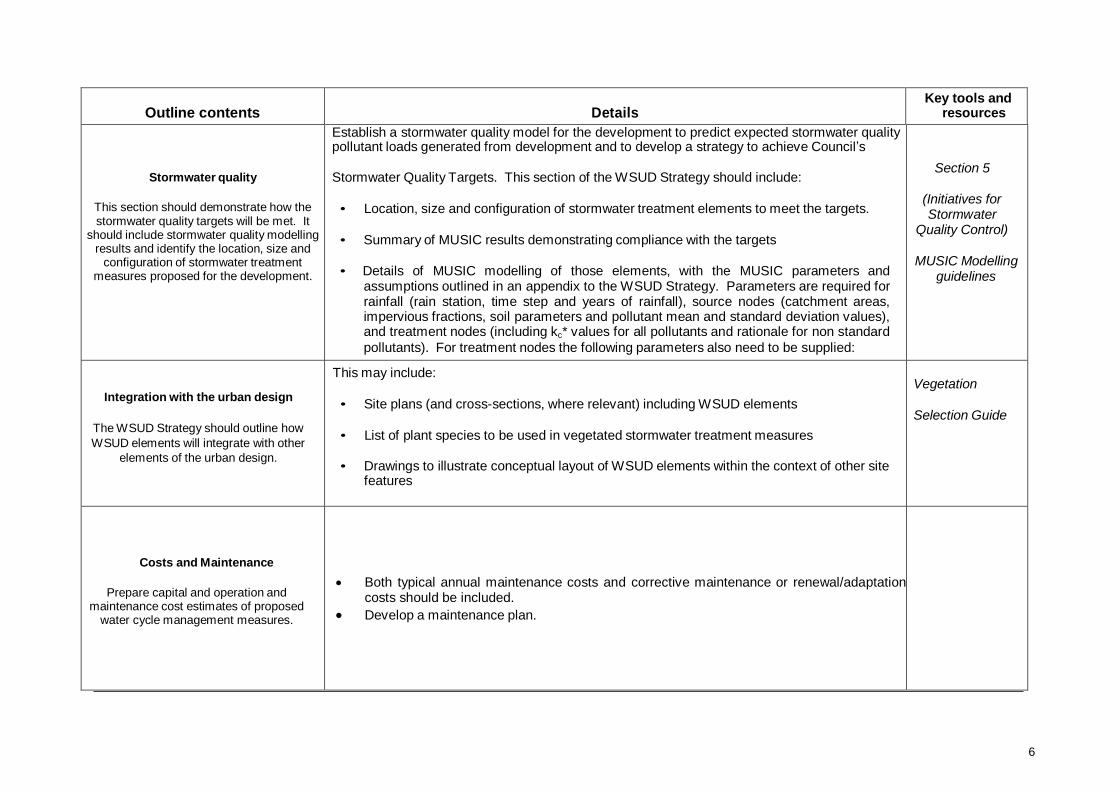
Stormwater quality
This section should demonstrate how the stormwater quality targets will be met. It
should include stormwater quality modelling results and identify the location, size and
configuration of stormwater treatment measures proposed for the development.
Establish a stormwater quality model for the development to predict expected stormwater quality pollutant loads generated from development and to develop a strategy to achieve Council’s
Stormwater Quality Targets. This section of the WSUD Strategy should include:
• Location, size and configuration of stormwater treatment elements to meet the targets.
• Summary of MUSIC results demonstrating compliance with the targets
• Details of MUSIC modelling of those elements, with the MUSIC parameters and assumptions outlined in an appendix to the WSUD Strategy. Parameters are required for rainfall (rain station, time step and years of rainfall), source nodes (catchment areas, impervious fractions, soil parameters and pollutant mean and standard deviation values), and treatment nodes (including kc* values for all pollutants and rationale for non standard
pollutants). For treatment nodes the following parameters also need to be supplied:
o bioretention systems - hydraulic conductivity, extended detention depth and filter depth
o ponds and wetlands - inlet pond size, permanent pool depth, extended detention depth and notional detention time
o Swales - slope and vegetation heights
Section 5
(Initiatives for Stormwater
Quality Control)
MUSIC Modelling guidelines
Integration with the urban design
The WSUD Strategy should outline how
WSUD elements will integrate with other
elements of the urban design.
This may include:
• Site plans (and cross-sections, where relevant) including WSUD elements
• List of plant species to be used in vegetated stormwater treatment measures
• Drawings to illustrate conceptual layout of WSUD elements within the context of other site features
Vegetation
Selection Guide
Costs and Maintenance
Prepare capital and operation and maintenance cost estimates of proposed
water cycle management measures.
Both typical annual maintenance costs and corrective maintenance or renewal/adaptation costs should be included.
Develop a maintenance plan.

7
3 SITE ASSESSMENT
In the development of a WSUD Strategy it is necessary to undertake a site assessment. The site assessment is required to:
Determine what site-specific objectives apply (e.g. the objectives for stream-forming flows depend on the presence and nature of streams downstream of the development)
Provide information on physical constraints that will guide the concept and detailed design of
WSUD measures such as stormwater treatment devices and storage systems.
Site assessment will involve some fieldwork and desktop investigation. Important considerations to be addressed in a site assessment are outlined in Table 2 below.
Main considerations
Specific issues Further information, potential
additional investigations
Receiving waterways
Streams requiring stream stability controls
Potential for stream rehabilitation Geomorphologist and ecologist input
Vegetation Endangered Ecological Communities
Weeds
State Government and Council information
Existing development
Previous development on the site to be retained or removed
Underground and overhead services
Evidence of impacts from existing development on receiving waterways
Services search
Landform
Catchments and drainage
Slope
Shallow bedrock
Proposed cut and fill
Detailed survey
Soils and groundwater
Soil permeability
Acid sulphate soils
Salinity
Shallow groundwater
Geotechnical assessment

8
Table 2: Site assessment checklist
All stormwater treatment devices can be subject to site-specific constraints. Stormwater treatment devices should be first selected based on matching the pollutant removal capability of a device with target pollutants in the stormwater. The physical constraints of the site (e.g. slope, soils, groundwater, etc) then need to be incorporated into the design of the selected device.
Table 3 has been reproduced from the WSUD Technical Design Guidelines for South East Queensland (Moreton Bay Waterways and Catchments Partnership, 2006), summarising key
physical constraints that may affect the use of specific WSUD measures. It provides a useful summary, however it needs to be supplemented by site-specific investigation and technical design information for a more complete feasibility assessment in each case.
Table 3: Summary of physical constraints affecting WSUD measures

9
4 INITIATIVES FOR POTABLE WATER CONSERVATION
Potable water conservation contributes to reducing demand on water resources and wastewater discharges to the environment. To reduce the demand on potable water it is important to identify current sources and uses of potable water, and the quantity and potential reuse of wastewater generated.
Potable water conservation applies to all types and scales of development and the DCP includes the performance targets listed in Section 3.3.2 of the DCP (Part 8.2).
Approaches to conserve potable water include:
Water efficient fittings and appliances
Water efficient landscaping
Rainwater tanks
Potable water substitution with treated stormwater or recycled wastewater
These are discussed further in the following sections.
WATER EFFICIENT FITTINGS AND APPLIANCES 4.1
Within buildings, the key water conservation opportunity is the use of water-efficient fittings and appliances. The Water Efficiency Labelling and Standards Scheme (WELS, http://www.waterrating.gov.au/) provides a good guide to the availability and water use of fittings and appliances. Water efficient fittings and appliances include:
Tap fittings Toilets and urinals Shower heads Washing machines and dishwashers
New fittings and appliances are labelled with their water star rating, making it easy to select fittings that meet the minimum star ratings set out in the DCP.
WATER EFFICIENT LANDSCAPING 4.2
Water efficient landscaping can assist in meeting BASIX water conservation targets in residential development, and is also applicable to commercial and industrial development and in public open space. Currently there are no accepted best practice guidelines for xeriscaping (landscaping for minimal water use) or urban irrigation; however it is known that irrigation water demands are affected by a large number of factors, and the following measures can be taken to reduce water demands:
Locate and design landscaping for interception and retention of flows from runoff (passive irrigation)
Use good quality, well-structured topsoils and increase depth of soil to increase water storage in soil
Initially use deep mulch in landscaped areas to reduce evaporation from the soil and increase soil organic matter over time as plantings fill out
Increase planting density (both single level and stacked plantings) to maximise soil shading in time
Choose native (or other) species suitable to the climate and situation and prioritise deep rooted perennials
Where turf is required, use warm season grasses and increase height at mowing

10
Where deemed necessary, use subsurface or drip irrigation for more efficient water application and soil moisture sensors (can be electronic or manual assessment) for irrigation scheduling
Landscape and water features should be located and designed at initiation so that they are integrated into the water cycle of a site and are not dependent on potable water for irrigation or top-up.
A plant selection guide has been developed for the City of Ryde which is comprised mostly of Australian natives or naturalised species that are typical of the Sydney 'Turpentine Ironbark' Forest and more the Ryde LGA. Incorporating these plants into urban areas will add considerable biodiversity and ecological habitat value to urban areas of Ryde LGA. Vegetation in urban areas also serves several important functions such as: soil stabilisation, modulation of microclimates, filtration of particulate air pollution, water pollution filtration as well as providing faunal habitat, natural borders, and visual amenity.
RAINWATER TANKS 4.3
Rainwater is runoff from roofs, which can be captured and used without treatment for toilet flushing, irrigation, washing machines and hot water systems. Rainwater may also be used in cooling towers.
Rainwater tanks can be incorporated into building design so they do not impact on the aesthetics of a development or the surrounding environment. Tanks can be selected to suit heritage areas, be located underground and some newer, slim line designs utilise tanks as sections of fencing or walls. An example of a rainwater tank installation suitable for domestic uses, in commercial or (smaller) industrial settings is given in Figure 2.
4.3.1 Design Considerations
Tanks should be sized for the associated roof area, water demand and climate. Rainwater tanks are most effective when they are sized efficiently, that is- tank size is matched to demand and available runoff from the roof area. A desired level of reliability can be achieved with the selection of an appropriate sized tank.
Roof area and construction
The roof area available for rainwater harvesting is determined by the roof configuration and the number of downpipes connected to the rainwater tank.
Roofs constructed of cement or terracotta tiles, Colorbond®, galvanised steel, Zincalume®, fibrous cement, polycarbonate, fibreglass or slate should be suitable for the collection of rainwater for drinking water. Steel claddings should be free of corrosion. Lead flashing should be restricted to parts of the roof not used for drinking water.
Figure 2 - Rainwater tank in residential property
Water Demand
Average water demand in the 2006/07 period was ~237 kL/yea for single dwellings, ~1275 kL/year for commercial properties,~1860 kL/yr for industrial properties, ~190 kL/yr for units/flats and ~1300 kL/yr for other property types (SoER 2007). Water metering and water bills from similar types of business can also provide an estimate of the water demand.
11
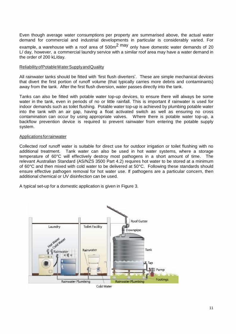
Even though average water consumptions per property are summarised above, the actual water demand for commercial and industrial developments in particular is considerably varied. For
example, a warehouse with a roof area of 500m2 may only have domestic water demands of 20 L/ day, however, a commercial laundry service with a similar roof area may have a water demand in the order of 200 kL/day.
Reliability of Potable Water Supply and Quality
All rainwater tanks should be fitted with ‘first flush diverters’. These are simple mechanical devices that divert the first portion of runoff volume (that typically carries more debris and contaminants) away from the tank. After the first flush diversion, water passes directly into the tank.
Tanks can also be fitted with potable water top-up devices, to ensure there will always be some water in the tank, even in periods of no or little rainfall. This is important if rainwater is used for indoor demands such as toilet flushing. Potable water top-up is achieved by plumbing potable water into the tank with an air gap, having a float activated switch as well as ensuring no cross contamination can occur by using appropriate valves. Where there is potable water top-up, a backflow prevention device is required to prevent rainwater from entering the potable supply system.
Applications for rainwater
Collected roof runoff water is suitable for direct use for outdoor irrigation or toilet flushing with no additional treatment. Tank water can also be used in hot water systems, where a storage temperature of 60°C will effectively destroy most pathogens in a short amount of time. The relevant Australian Standard (AS/NZS 3500 Part 4.2) requires hot water to be stored at a minimum of 60°C and then mixed with cold water to be delivered at 50°C. Following these standards should ensure effective pathogen removal for hot water use. If pathogens are a particular concern, then additional chemical or UV disinfection can be used.
A typical set-up for a domestic application is given in Figure 3.

12
Figure 3: T ypical configuration of a rainwater tank used to meet / supplement laundry and toilet water demands (ACT Government, 2006)
Installation
A licensed plumber is required to install the rainwater tank with all installations conforming to Australian standards (AS3500.1.2 Water Supply: Acceptable Solutions).
4.3.2 Sizing Curves
For residential development, the BASIX online tool allows a rainwater tank to be sized to meet the water conservation target. Sizing curves suitable for industrial and commercial developments within the Ryde LGA have been developed. The water demands modelled ranged from 25 L/day to 1500 L/day. The upper limit was selected based on a commercial building with a roof area of 3000 m2, a net lettable area (NLA) of 16 500m2 and a water demand of 1.01kL/ yr per NLA.
The rainwater tank sizing curve has been derived using Epping Chester Street daily rainfall in conjunction with daily evapotranspiration sourced from the Sydney Airport AMO weather station (refer to MUSIC Modelling Guidelines for more information). Stormwater quality parameters for storm flow conditions have been adjusted within MUSIC as per the NSW DECC recommendation (refer to MUSIC Modelling Guidelines for more information).
The sizing curves have been developed for a roof area of 100m2. For roof areas outside this range, the roof area should be scaled to give a roof area of 100m2 (for example, the scale factor for a 400m2 roof area is 4). If the roof area needs to be scaled, the water demand must also be scaled. An appropriate tank size (to achieve a given demand efficiency) can be read from the sizing curves. The tank size is then multiplied by the scale factor to give the real tank size required. It should be noted that the optimal rainwater tank size does not attempt to meet 100% of demand, but should aim for the point of diminishing returns.
Figure 4 shows that an appropriate rainwater tank size in Ryde is approximately 1-2 kL for every 100 m2 of roof that drains to the tank, regardless of the demand.
4.3.3 Maintenance
Rainwater tanks involve regular preventative maintenance in order to avoid the need for corrective action. Recommended maintenance includes:
6-monthly inspections of roof areas and gutters to ensure they are relatively free of leaves and debris.
Vegetation and trees that overhang the roof may need to be pruned.
First flush devices should be checked and cleaned out once every 3-6 months.
Bypass screens at inlet and overflow points should be inspected each 6 months to check for fouling and clean them.
Each 2-3 years, tanks should be checked for accumulation of sludge. Sludge may become a problem if it is deep enough to reach the level of the out take pipe and so produce discoloured or sediment-laden water, or when it affects storage capacity. When necessary, sludge can be removed by vacuum, by siphon, by suspending the sludge and washing it through, or by completely emptying the tank.
If a pump system is used, the pump manufacturer should be consulted for advice on necessary maintenance.

13
4.3.4 Further Information
Information on modelling rainwater tanks in MUSIC is included in the MUSIC Modelling Guidelines.
The enHealth document “Guidance on Use of Rainwater Tanks” (Australian Government, 2004) provides information on health-related issues associated with rainwater tanks.
Figure 4: Rainwater tank Sizing Curves for the Ryde LGA.
STORMWATER HARVESTING AND WASTEWATER RECYCLING 4.4
Stormwater harvesting and wastewater recycling can be undertaken at a range of scales and the design of harvesting and reuse systems varies greatly depending on the scale of the project, the water source and the intended reuse. The following sections of this document provide some high-level guidance to assist in planning for a stormwater harvesting and/or wastewater reuse scheme.
In designing a stormwater harvesting or wastewater reuse scheme, some of the key considerations are:
The source of water, including volumes, timing and proximity to reuse opportunities
Matching supply with demand, and deciding how to make up any shortfall in dry periods.
Stormwater can provide significant volumes of water for reuse, but supply is variable and a large storage is often required to meet demands in times of low rainfall.
The source, type and concentration of contaminants including physical characteristics such as temperature
Water quality requirements of the intended application.

14
Possibility to meet multiple objectives; e.g. stormwater harvesting can achieve reduced stormwater quantity and improved stormwater quality discharging from the catchment.
Space available for treatment and storage. Large above-ground storages may require special safety considerations, such as dam safety. Underground storage may be expensive and difficult to construct, depending on the soil conditions.
Pumping requirements.
Potential health risks from pathogens.
Costs of stormwater harvesting/wastewater recycling, relative to other options.
4.4.1 Water Sources
Stormwater can be harvested from a pipe, culvert or open channel. Normally stormwater should be harvested from urban drainage systems. Where stormwater is harvested from a creek, impacts on geomorphology and aquatic habitat should be minimised. If stormwater is harvested from a river, a water access licence would be required.
Wastewater can be reused on an individual allotment (e.g. within an industrial site) or can be harvested from a sewer for treatment, distribution and reuse. Different types of wastewater have different quality and quantity characteristics. In general most wastewater is poorer quality than urban stormwater, but wastewater flows are more consistent, which can make it equally attractive as an alternative water supply.
4.4.2 Treatment Requirements
Water quality criteria for typical reuse applications are shown in Table 5 which has been reproduced from DEC (2006). In order to meet these criteria, wastewater and stormwater both need to be treated. General treatment requirements for different water sources are given in Table 6.

15
Table 5: Water quality criteria for typical stormwater reuse applications
Water Type Source Quality Treatment Required
Potable Mains Water Reticulated (piped) water distribution
High Quality None
Rainwater From roof during rain, generally stored in rainwater tanks
Reasonable quality Low.
Sedimentation can occur inside rainwater tanks
Stormwater Catchment runoff, including roads and pavements.
Moderate quality Reasonable treatment needed to remove litter and reduce sediment and nutrient backlog.

16
“Light” Grey water Catchment runoff,
Including impervious areas like roads and pavements
Moderate quality Moderate treatment required to reduce pathogens and organic content.
Grey water “Light greywater”, plus laundry water, including basin and washing machine.
Low quality – high organic loading and highly variable depending on how it was used.
High level of treatment required to reduce pathogens and organic content
Black water Greywater, plus
kitchen, and toilet water. Can also be sourced from sewers
Lowest quality
wastewater – high levels of pathogens and organics
Advanced treatment and disinfection required
Table 6 – Summary of water quality in the urban water cycle.
Wastewater treatment is generally provided by specialist suppliers of wastewater treatment solutions. Landcom’s “Wastewater reuse in the Urban Environment: selection of technologies” report (February 2006) provides guidance as to appropriate treatment systems for projects of different scales.
Stormwater can be treated for reuse using the same kind of treatment measures as outlined in Section 5. Depending on the reuse application, disinfection may also be required. Stormwater treatment for storage and reuse should aim to remove gross pollutants and suspended solids as a minimum, so that these do not accumulate in the storage or interfere with the operation of pumps and the stormwater distribution system. Where stormwater is to be stored above-ground, nutrient removal would also be important to minimise the risk of eutrophication and algal growth. Depending on the application for treated stormwater, it may also be necessary to remove other pollutants such as salts, heavy metals and pesticides. Generally, where there is a possibility of public contact with treated stormwater (for example, in a sprinkler irrigation system at a sports field), disinfection is required. Disinfection may be undertaken by chlorination, ozone or UV.
The quality of water and pollutants generated from an industrial process vary between industries. For example, the wastewater generated from a warehouse will be similar to that of a commercial / office application, while wastewater collected from a mechanic could be contaminated with oils, greases and PAHs (polyaromatic hydrocarbons). Generally, most harvesting opportunities in an industrial setting will be from industrial processes, cooling systems and firewater.
4.4.3 Storage
Water balance modelling should be used to size an appropriate storage for reuse, based on supply and demand characteristics.
The sizing curves for rainwater tanks can be used to make an initial estimate of a suitable stormwater storage volume – the roof area should be substituted with the impervious catchment area. However this may give an optimistic estimate of the reliability, as usually only treated stormwater is directed to the stormwater storage. In general, untreated flows should bypass the storage system to achieve the best possible reuse water quality.

17
As for rainwater harvesting, stormwater harvesting is better able to meet demands that are spread evenly throughout the year, rather than irrigation demands which are seasonally dependent.
Storage facilities can take the form or underground tanks or natural ponds above ground (Figure 5).
Figure 5: Stormwater storage being installed at the South Australian Museum (left), and stormwater harvesting pond at Barra Brui oval, St Ives (right).
4.4.4 Reuse Options
A matrix of water sources and potential reuse opportunities is given in Table 7. The table has been adapted from the Australian guidelines on water reuse (2006) and the BASIX assessment tool.
Table 7 – Water reuse applications in commercial and residential development.
Table 7 does not include industrial reuse applications. Indicative reuse applications for industrial water reuse are not easily definable. Industrial uses generally include cooling water, process water, washdown water and supplementary emergency water supply. Industry-based water quality guidelines will need to be consulted.

18
4.4.5 Risk Management
Potable water substitution with stormwater or wastewater needs to consider public health as a key design requirement. A preventative risk management process is recommended (NRMMC 2006) to ensure that alternative water sources do not pose a health risk. The draft guidelines for water recycling advocate a risk management framework in assessing a reuse water scheme. The risk management framework is effective in:
Identifying the source of hazards (for example, sewer overflow)
Identifying the people at risk from the hazard and how they would be exposed
Identifying the health effects resulting from the hazard
Identifying measures that prevent the hazard from occurring (for example, first flush systems on rainwater tanks)
Identifying appropriate indicators of unsatisfactory water
Linking the hazards and preventative measures into a management procedure.
The preventative management procedure should outline an adequate:
Water quality monitoring program and
Maintenance procedure to ensure critical control points are operating effectively and the likelihood of them failing due to neglect is low.
4.4.6 Further Information
Information on modelling stormwater harvesting, storage and reuse systems is included in the MUSIC Modelling Guidance document.
The NSW Department of Environment and Climate Change has published Managing Urban Stormwater: Harvesting and Reuse (2006), which includes useful details on statutory considerations and health and environmental risks related to stormwater harvesting, as well as planning, design and operation considerations. The document also presents several case studies of successful stormwater harvesting projects in NSW.
NSW Department of Energy, Utilities and Sustainability (DEUS) 2007 NSW Guidelines for Greywater Reuse in Sewered, Single Household Residential Premises.
Landcom (2006) “Wastewater reuse in the Urban Environment: selection of technologies” prepared by Ecological Engineering, February 2006.
Sydney Water has published Best Practice Guidelines for cooling towers. These are available online: http://www.sydneywater.com.au/Publications/FactSheets/SavingWaterBestPracticeGuidelinesCoolingTowe rs.pdf

19
5 INITIATIVES FOR STORMWATER QUALITY MANAGEMENT
Stormwater is runoff from ground surfaces such as roads, carparks and pedestrian areas and can contain gross pollutants, sediments, nutrients, heavy metals, hydrocarbons and faecal contamination. Development of a WSUD strategy must meet the stormwater quality objectives set in the DCP. The stormwater quality objectives are given in terms of annual gross pollutants, TSS, TP and TN load reductions of 90%, 85%, 65% and 45%, respectively.
No single treatment measure can effectively treat this full range of pollutants. In practice, the application of WSUD for stormwater treatment rarely involves a single type of treatment device and generally a ‘treatment train’ is proposed. A treatment train is a series of treatment measures that collectively address a range of stormwater pollutants. This is intended to balance the need to meet relevant treatment objectives with the flexibility required for WSUD to be feasible across a wide variety of sites.
The particle size of stormwater pollutants varies from gross solids, litter, coarse to medium size particulates (fine litter, sediment and suspended solids) to fine colloidal and dissolved particulates (soluble nutrients, metals etc). The variation of type and particle size distribution of stormwater pollutants is shown in Figure 6. Coarser pollutants generally require removal early in the treatment train, so that the operation of treatment elements targeting finer pollutants is optimised.
Figure 6 – Size range of typical stormwater pollutants (after Ecological Engineering 2003)
Figure 7 shows which pollutants are targeted by different types of stormwater treatment measures. The treatment systems discussed in this guide are GPTs (Gross Pollutant Traps), grass swales and buffer strips, bioretention systems and wetlands. These systems have been selected as they are effective in removing the target pollutants (gross pollutants, TSS, TP and TN).
Planning and design of stormwater treatment elements needs to consider site conditions including:
The nature of the proposed development
Natural assets to be preserved on site
Physical infrastructure existing on the site
Landscape attributes of the site
Topography, geology, soils and groundwater
Ecology of the site and receiving environments
Catchment areas and impervious areas
The distribution of treatment systems throughout a catchment.

20
Figure 7: Treatment options for different size ranges (after Ecological Engineering 2003)
Design of WSUD elements needs to consider the full range of conditions under which WSUD elements must operate. The performance of an urban stormwater quality improvement strategy is measured through the impact of a continuous period of typical climatic conditions. Computer modelling with software packages such as MUSIC is used to predict system performance in terms of mean annual pollutant loads captured and to assess the most effective design specifications. The following sections provide information useful at the device selection and preliminary sizing stage, including:
The purpose of each element and how it works
Where it would be most appropriately located in the urban landscape
Important design considerations, including soil and vegetation selection for vegetated stormwater treatment measures. The design considerations point to the advantages and disadvantages, benefits and risks of each WSUD element
Basic sizing curves for stormwater quality treatment devices. Sizing curves can provide a useful first estimate of treatment measure performance before detailed modelling is undertaken. Detailed modelling will be necessary on all projects to predict treatment performance more reliably. The sizing curves can then also be used to check that model results are within the expected range.
Maintenance requirements
References to more detailed information are provided where relevant.
MUSIC modelling is required to demonstrate compliance with the load-based targets for TSS, TP and TN.

21
GROSS POLLUTANT TRAPS 5.1
Gross pollutants include litter, leaves and other vegetative matter. Many gross pollutant traps (GPTs) will also capture significant loads of coarse suspended solids.
5.1.1 Location
Gross pollutant traps (GPTs) are often the first treatment measure in a treatment train, for example they can be used upstream of wetlands and other water bodies to protect them from gross pollutants. Gross pollutant capture efficiency varies between different types of GPTs, as does coarse sediment removal. Most GPTs cannot remove fine sediments, nutrients or other pollutants to any significant degree. GPTs are available in a range of different types and sizes, suitable for a wide range of applications. Figure 8 shows a range of GPTs.
5.1.2 Design Considerations
Key design considerations include:
The size of the catchment to be treated, and the flow rate that must pass through the GPT. GPTs are normally sized to treat the 3-month to 1-year ARI flow.
The type of waterway on which the GPT is to be installed (pipe/culvert/open channel).
Pollutant types and loads in the catchment – for example, commercial areas are likely to generate higher loads of litter than residential areas.
Target pollutants. For example as pre-treatment to a wetland, it is important to remove coarse sediments. However at other locations, it may be undesirable to trap sediment, in case it reduces natural sediment deposition downstream.
The GPT’s efficiency in trapping pollutants will affect the frequency and magnitude of cleanouts, and the volume of waste material that must be disposed of.
Some GPTs store captured pollutants in a drained state, while others hold them in stagnant water.
Anaerobic conditions in wet sumps can lead to odours, and wet pollutants may be more difficult to clean out than dry pollutants.
Access and equipment requirements for cleanouts. Small pit insert GPTs may be cleaned out by hand, while larger GPTs may require a bobcat, excavator or crane to remove the pollutants and/or basket.
Upstream flooding. GPT designs should ensure that there is no risk of increased flooding upstream of the GPT.
Costs. It is important to consider the life cycle costs of GPTs, as operation and maintenance costs over the lifetime of a GPT can far outweigh the design and installation costs.
5.1.3 Maintenance
Regular maintenance is essential to ensure the performance of GPTs. Normally cleanouts are required around once every 3 months, however each trap should be monitored during the first few years of operation to determine the required cleanout frequency. Poorly maintained GPTs can:
Fail to trap pollutants.
Release contaminants by leaching from the collected pollutants. Reduce the capacity of the drainage system and potentially lead to upstream flooding.
Lead to unpleasant odours and reduced visual amenity.
The nature of maintenance activities depends to a large extent on the type of trap installed; this should be considered during the design stage. GPT suppliers can provide information on maintenance methods.

22
Development integrating such systems will warrant a Positive Covenant to registered on the title of the property, to ensure future owners/ occupants are aware of the system and maintenance requirements.
5.1.4 Further Information
Information on modelling GPTs in MUSIC is included in the MUSIC Modelling Guidance document. There are several different manufacturers of GPTs in Australia and each of them can provide detailed information on their products. Manufacturers include Baramy, Ecosol, Nettech, Rocla, and others.
Figure 8: Typical range of gross pollutant traps

23
VEGETATED SWALES AND BUFFER STRIPS 5.2
Vegetated swales are both a stormwater conveyance and treatment mechanism. They are effective for removal of suspended solids, particularly coarse sediments, and will also reduce some phosphorus and nitrogen loads. A typical swale configuration is shown in Figure 9.
Figure 9 – Typical swale arrangement.
5.2.1 Location
Vegetated swales can be used instead of pipes to convey stormwater and provide a ‘buffer’ between the receiving water and the impervious areas of a catchment. They can be integrated with landscape features in parks and gardens as well as incorporated in street designs, adding to the aesthetic character of an area.
Buffer strips are intended to slow and filter flow from impervious surfaces to the drainage system. The key to their operation, like swales, is an even shallow flow over a wide vegetated area. The vegetation facilitates an even distribution and slowing of flow thus encouraging pollutant settling as well as incorporating some of the nutrients. Buffers are commonly used as a pre-treatment for other stormwater measures. They may be located at the edge of a road, carpark or pedestrian area. Buffer strips are also often incorporated on the outer edges of a swale, as in Figure 10.
Figure 10: Typical swale and buffer strip configuration

24
5.2.2 Design considerations
Swales are normally sized to convey low flows, for example the 3 month ARI peak flow, however they can also be sized for conveyance of higher flows where required. Typical widths range from 0.1 to 2.0 m at the base and side slopes are normally 1 in 3 to 1 in 6. Swales operate best with slopes from 2% to 4%. Slopes milder than this can tend to become waterlogged and have stagnant ponding, although the use of underdrains can alleviate this problem. For slopes steeper than 4%, check banks along swales, dense vegetation and/or drop structures can help to distribute flows evenly across the swales as well as slow velocities. Driveway crossovers can provide an opportunity for check dams (to provide temporary ponding) or can be constructed at grade and act like a ford during high flows (see Figure 11).
Figure 11 - Examples of different types of swale crossings
Buffer strips should be set down from the paved surface to account for sediment accumulation and plant growth over time (see Figure 12). Generally between 40 and 50 mm set down from the paved surface will be adequate with a pavement surface that is tapered down towards the buffer strip (as illustrated in the diagram below).
Figure 12: Typical buffer strip arrangement
Vegetation should cover the whole width of the swale, be capable of withstanding design flows and be of sufficient density to provide good filtration. It should also be selected to be compatible with the landscape of the area and maintenance capabilities. For best performance, vegetation height should be above the water level for the design flow.

25
Edge treatment should prevent vehicular access to roadside swales, and allow flows into the swale. Some examples of different arrangements for delivering water to a swale while restricting vehicular access are shown in Figure 13.
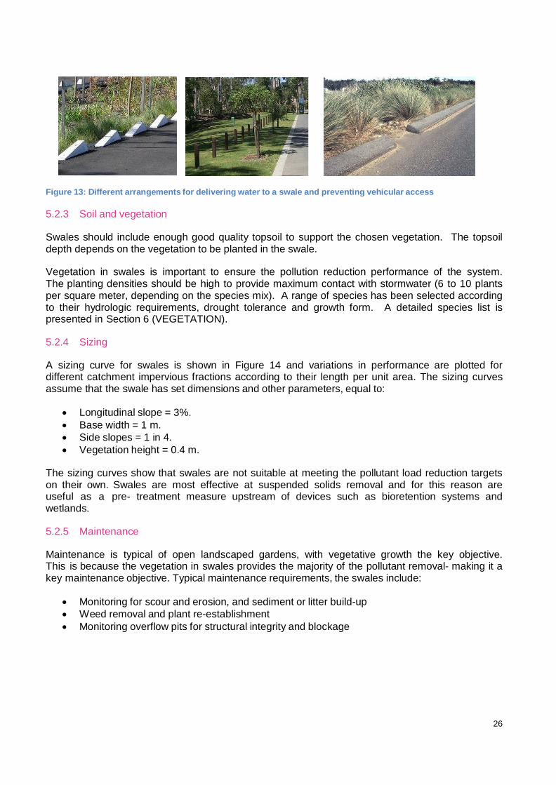
26
Figure 13: Different arrangements for delivering water to a swale and preventing vehicular access
5.2.3 Soil and vegetation
Swales should include enough good quality topsoil to support the chosen vegetation. The topsoil depth depends on the vegetation to be planted in the swale.
Vegetation in swales is important to ensure the pollution reduction performance of the system. The planting densities should be high to provide maximum contact with stormwater (6 to 10 plants per square meter, depending on the species mix). A range of species has been selected according to their hydrologic requirements, drought tolerance and growth form. A detailed species list is presented in Section 6 (VEGETATION).
5.2.4 Sizing
A sizing curve for swales is shown in Figure 14 and variations in performance are plotted for different catchment impervious fractions according to their length per unit area. The sizing curves assume that the swale has set dimensions and other parameters, equal to:
Longitudinal slope = 3%.
Base width = 1 m.
Side slopes = 1 in 4.
Vegetation height = 0.4 m.
The sizing curves show that swales are not suitable at meeting the pollutant load reduction targets on their own. Swales are most effective at suspended solids removal and for this reason are useful as a pre- treatment measure upstream of devices such as bioretention systems and wetlands.
5.2.5 Maintenance
Maintenance is typical of open landscaped gardens, with vegetative growth the key objective. This is because the vegetation in swales provides the majority of the pollutant removal- making it a key maintenance objective. Typical maintenance requirements, the swales include:
Monitoring for scour and erosion, and sediment or litter build-up
Weed removal and plant re-establishment
Monitoring overflow pits for structural integrity and blockage

27
5.2.6 Further Information
Section 6 (VEGETATION) details appropriate vegetation types both for swales as well as the local flora of the Ryde LGA.
For more information on swales and buffer strips refer to the Western Sydney Technical Guidelines (UPRCT 2004) or “Managing Urban Stormwater: Treatment Techniques” (DECC 2007).

28
Figure 14: Sizing curves for swales in Ryde LGA.

29
BIORETENTION SYSTEMS 5.3
Bioretention systems are vegetated soil media filters, which treat stormwater by allowing it to pond on the vegetated surface, then slowly infiltrate through the soil media. Treated water is captured at the base of the system and discharged via outlet pipes. A typical bioretention system is shown in Figure 15.
Figure 15: Bioretention system typical arrangement
5.3.1 Location
Bioretention systems can be implemented in several sizes/shapes in many different locations. For example, in planter boxes, parks or in streetscapes integrated with traffic calming measures. It is important to have sufficient depth (normally at least 0.8 m) between the inlet and outlet, therefore they may not be suitable at sites with shallow bedrock or other depth constraints, however they are otherwise a very flexible and effective treatment measure for dissolved nutrients.
5.3.2 Design considerations
In bioretention systems stormwater runoff is filtered through a vegetated soil media layer and is then collected via perforated pipes and routed to downstream waterways or storages for reuse. Temporary ponding above the soil media provides additional treatment. Bioretention systems are not intended for exfiltration and discharge to groundwater. Vegetation that grows in the filter media enhances its function by preventing erosion of the filter medium, continuously breaking up the soil through plant growth to prevent clogging of the system and providing biofilms on plant roots that pollutants can adsorb to.
Selection of an appropriate filtration media is a key issue that involves a trade-off between providing sufficiently high hydraulic conductivity to treat as much stormwater as possible, while retaining sufficient water to support vegetation growth. A sandy loam or fine sand is suitable, with a hydraulic conductivity of 50-180 mm/hr. Typically flood flows bypass the device thereby preventing high flow velocities that can dislodge collected pollutants or scour vegetation.

30
Figure 16 - Examples of bioretention systems in planter boxes, in the streetscape, and in parks
Bioretention systems must be protected from clogging by pretreating stormwater to remove course to medium sediments. Pre-treatment by sedimentation basin or swale is appropriate prior to directing stormwater to a bioretention system. A sediment forebay can also be included at the inlet to the bioretention system. If the filter media clogs, it will need to be replaced.
Street trees
Street tree bioretention systems are small systems that are incorporated at street tree locations. These systems can be integrated into high-density urban environments and can take on a variety of forms. The filter media should be at least 0.8 m deep to allow for root growth of the tree, therefore substantial depth is required between the inlet and outlet. Some examples of street tree bioretention systems are shown in Figure 17.
Figure 17 - Example street tree bioretention systems
Raingardens
Raingardens can be incorporated in a range of locations, as they can be any shape and size. They are essentially bioretention systems however tend to incorporate a greater number of plant species. Typical locations include pocket parks, traffic calming measures and between parking bays. Examples of raingardens are given in Figure 18.
Figure 18: Examples of bioretention raingardens

31
Bio retention Swales
Swale bioretention systems provide both stormwater treatment and conveyance functions. A bioretention system is installed in the base of a swale. The swale component provides stormwater pre-treatment to remove coarse to medium sediments while the bioretention system removes finer particulates and dissolved pollutants. A bioretention system can be installed in part of a swale, or along the full length of a swale, depending on treatment requirements. Typically, these systems should be installed with slopes of between 1 and 4 %. In steeper areas, check dams are required to reduce flow velocities. For milder slopes, it is important to ensure adequate drainage is provided to avoid nuisance ponding (a bioretention system along the full length of the swale will provide this drainage). Runoff can be directed into conveyance bioretention systems either through direct surface runoff (eg. with flush kerbs) or from an outlet of a pipe system. Figure 19 shows some examples of bioretention swales.
Figure 19: Example bioretention swales
5.3.3 Soil and vegetation
Soil for a bioretention system needs to be highly permeable and free-draining. Normally sandy loam is recommended with a saturated hydraulic conductivity in the range of 80-300 mm/hr. Some organic matter is beneficial; however labile organic carbon content should be kept to a low percentage to avoid leaching nutrients from the system. Amendments such as activated charcoal (biochar/agrichar etc) can be used as a substitute for organic matter in these soils as it is highly resistant to degradation whilst conferring growth benefits.
A detailed soil specification for bioretention systems is available from the Facility for Advancing Water Biofiltration (FAWB) at Monash University: http://www.monash.edu.au/fawb. Only soils that meet this specification should be used for these systems.
Plants used in bioretention should be suited to sandy, free-draining soils, and tolerant of drought. Bioretention systems should be planted densely to maximise the biological processing of nutrients. Planting can incorporate several growth forms – shrubs, tufted plants and groundcover species, to ensure that the plant roots occupy all parts of the media. Using several species reduces the risk that insect attack, disease or adverse weather will harm all of the plants at once creating a more robust treatment system. A detailed species list is presented in Section 6 (VEGETATION). The final compilation of species needs to be determined by Council so as to be consistent with the landscaping of the area.

32
5.3.4 Sizing
Sizing curves for bioretention systems are shown in Figure 19. Variations in performance are plotted for differing catchment imperviousness values and assume that the bioretention systems have a filter depth of
0.5 m, a sandy-loam filter material (saturated hydraulic conductivity of 100mm/hr), extended detention of 0.2 m and an average particle size of 0.45 mm.
5.3.5 Maintenance
Bio retention systems require regular maintenance, similar to swales.
Maintenance requirements of Bioretention systems include:
Monitoring for scour and erosion, and sediment or litter build-up
Weed removal and plant re-establishment
Monitoring overflow pits for structural integrity and blockage
5.3.6 Further Information
Section 6 (VEGETATION) details appropriate vegetation types both for bioretention systems as well as the local flora of the Ryde LGA.
For more detailed information on bioretention systems refer to the Western Sydney Technical Guidelines (UPRCT
2004) or “Managing Urban Stormwater: Treatment Techniques” (DECC 2007).

33
Figure 20 – Sizing curves for biorention elements in the City of Ryde LGA.

34
WETLANDS 5.4
Constructed surface flow wetland systems use enhanced sedimentation, fine filtration and biological uptake processes to remove pollutants from stormwater. They generally consist of:
An inlet zone (essentially a sediment basin)
A macrophyte zone (a shallow heavily vegetated area to remove fine particulates and take up soluble pollutants), and
A high-flow bypass channel (to protect the macrophyte zone).
Wetland systems can also incorporate open water areas. Wetland processes are engaged by slowly passing runoff through heavily vegetated areas where plants filter sediments and pollutants from the water. Biofilms that grow on the plants absorb nutrients and other associated contaminants. While wetlands can play an important role in stormwater treatment, they can also have significant community benefits. They provide habitat for wildlife and a focus for recreation, such as walking paths and resting areas. They can also improve the aesthetics of new developments and can be a central landscape feature.
5.4.1 Location
Wetland systems can be combined with flood protection measures when incorporated into retarding basins. An open water body or pond at the downstream end of a wetland can provide water storage for reuse purposes, such as irrigation. Wetlands can be constructed on many scales, from small devices to large regional systems. In highly urban areas they can have a hard-edged form and be part of a streetscape or building forecourt. In regional settings they can be over 10 hectares in size and provide significant habitat for wildlife.
Figure 21 - Small and large-scale wetlands (Docklands and Lynbrook in Melbourne)
5.4.2 Design considerations
Effective pollutant removal in wetlands depends largely on the macrophyte zone. Vegetation in the macrophyte zone plays a key role in pollutant removal, and it is therefore important to protect vegetation from high flows, debris and high sediment loads. Open water zones can provide a polishing step, as UV light provides a level of human pathogen removal dependant on

35
several factors. Some of these considerations are illustrated in Figure 22 and are expanded in the following sections on each element of the wetland.
A high flow bypass is essential to protect vegetation
Vegetation provides a key pollutant removal role
Open water zones allow sunlight to provide some disinfection and provide
habitat
Figure 22 - Key wetland design considerations
Pre-treatment of stormwater is necessary to protect wetland function. Gross pollutants and course to medium sediments should be removed before runoff reaches the wetland. A sediment basin is recommended upstream of a wetland.
Wetlands should be designed with a detention time of 72 hours to ensure sufficient contact time for biological processes. The macrophyte zone outlet orifice must be sized accordingly. Multiple level orifice riser outlets are considered to give the most uniform detention times for wetlands.
Wetlands can be designed to minimise mosquito habitat and to encourage mosquito predators. “Managing Urban Stormwater: Treatment Techniques” (DECC 2007) has more information on designing to minimise the risk of mosquito breeding.
Inlet zone and bypass structure
The inlet zone or sediment basin reduces flow velocities and encourages settling of sediments from the water column. The inlet zone can drain during periods without rainfall and then fill during runoff events. The inlet zone is sized according to the design storm discharge and the target particle size for trapping. Typically it is about 10% of the total wetland area and around 2 m deep.
Macrophyte zone
For macrophyte zones to function efficiently, flows that pass through the vegetation must be evenly distributed. Dense vegetation growth is required to dissipate flows and to support

36
efficient filtration. Flow and water level variations and maximum velocities are important considerations and can be controlled with an appropriate outlet structure.
Different zones in a macrophyte system perform different functions. Figure 23 shows a typical zonation including submerged marsh, deep and shallow emergent marsh and ephemeral marsh zones. Ephemeral areas are organic matter traps. These areas wet and dry regularly and thus enhance the breakdown process of organic vegetation. Marsh areas promote epiphyte (biofilms) growth on the plant surfaces. Epiphytes promote adhesion of fine colloidal particulates to wetland vegetation and uptake of nutrients. The marsh plants remove nutrients and promote microbial activity and pollution degradation.
Open water zone
Sometimes, there are areas of open water surrounding the outlet of wetlands. These can increase UV disinfection and provide habitat for fish and other aquatic species, as well as perform an aesthetic and passive recreation function.
Figure 23: Wetland indicative long section
5.4.3 Soil and vegetation
Wetlands need to be lined with an impermeable liner, which can either be a layer of compacted clay or a strong plastic liner. Wetlands should include at least 200-300 mm good quality topsoil to support the vegetation.
Vegetation for wetlands is important to ensure the pollution reduction performance of the system. A range of species has been selected according to their hydrologic requirements and growth form. A detailed species list is presented in Section 6 (VEGETATION).

37
5.4.4 Sizing
A sizing curve for constructed wetlands is shown in Figure 24. The sizing curve plots the total wetland area (including the macrophyte zone and the inlet pond) as a percentage of the catchment area. The sizing curves assume the following:
The surface area of the inlet pond is 10% that of the macrophyte zone
The inlet pond has a permanent pool depth of 2 m
The average water depth in the macrophyte zone is 0.4 m.
The outlet configuration provides 72 hr detention.
5.4.5 Maintenance
Wetlands require the following routine maintenance activities:
Checking the wetland after storms for scour and erosion
Removing debris, particularly around inlets and outlets
Regularly removing sediment from the sediment basin
Weeding and replanting
It can be useful to design wetlands to allow them to be completely drained. This can assist in occasional corrective maintenance actions such as extensive weeding and replanting. This would also assist in the control of pests such as Gambusia, which can be removed from a waterbody by drying it out extensively, then refilling.
5.4.6 Further Information
Section 6 (VEGETATION) details appropriate vegetation types both for wetlands as well as the local flora of the Ryde LGA. In addition, the WSUD MUSIC Modelling Guidance provides further
detail as to technical design and assessment of WSUD treatment elements for the City of Ryde.
For more detailed information on wetlands, refer to the Western Sydney Technical Guidelines (UPRCT 2004) or “Managing Urban Stormwater: Treatment Techniques” (DECC 2007). Information is also available in:
the DLWC Constructed Wetlands Manual, 1998.
The CRC for Catchment Hydrology Managing Urban Stormwater Using Constructed Wetlands 1999.
The Institute of Engineers Australian Runoff Quality 2006.

38
Figure 24 - Sizing curves for wetlands in the Ryde LG

39
6 VEGETATION GUIDE
This section provides an indicative plant species list for vegetated WSUD elements such as;
Swales and buffer strips
Wetlands
Bioretention systems
Most of the plants selected are Australian natives or naturalised ground covers that occur naturally in Ryde City LGA as documented by the National Herbarium of NSW.
The majority of the plant species listed are known to occur naturally in the Ryde City LGA. Incorporating these plants into urban areas will add considerable biodiversity and ecological habitat value to urban areas. Vegetation can perform many important functions in urban areas, such as visual amenity, soil stabilisation, microclimate control, fauna habitat, natural borders, and water pollution filtration and uptake. Advice from land managers and landscape architects should be sought to determine that the plants used in each specific situation meet the needs of all the other site users.
These lists were guided by:
Botanic Gardens Trust (July 2005). PlantNET - The Plant Information Network System of Botanic Gardens Trust, Sydney, Australia (version 2.0.). http://plantnet.rbgsyd.nsw.gov.au (Species for Ryde City LGA region)
Department of Land and Water Conservation (1998) – The Constructed Wetlands Manual. - Volume 1.
New South Wales National Parks and Wildlife Service (2002) Interpretation Guidelines for the Native Vegetation Maps of the Cumberland Plain, Western Sydney, Final Edition NSW NPWS, Hurstville.
SWALES AND BUFFER STRIPS
This is an indicative species list for planting in swales and buffer strips. During the detailed design of a swale or buffer strip the advice of a WSUD professional should be sought to guide the exact location, species mix and planting densities to ensure optimal treatment performance based on the detailed specifications of each treatment measure.
A key consideration in selecting vegetation for swales is the need for flow conveyance. Vegetation selection needs to be considered in the hydraulic modeling of the swale. If an open conveyance channel is required, then dense vegetation shou ld be avoided. Turf species and trees may be appropriate. The use of tufted species in swales creates better fauna habitat and a more natural appearance than turf. Tufted species also create a low maintenance landscape once established – requiring very little weeding or mowing. However, tufted species can present an erosion risk if they are not appropriately planted. Vegetation should be densely planted (at least 8 plants per m2) in an offset pattern because sparse planting or planting in rows can lead to the formation of preferential flow paths. Swale design that incorporates tufted species should give

40
consideration to the use of appropriate design flow velocities and appropriate roughness values for vegetated conditions as opposed to turf.
Dense shrubs and/or trees can be used effectively to limit vehicular or pedestrian access to the swale surface if desired. However, since the purpose of swales is the conveyance and filtration of water, vigorous plant growth along the water’s flow path is desired. For this reason care should be taken not to plant shrubs and trees too densely along the swale so as not to shade out the vegetation that interacts with the water.
Swales should be constructed with a layer of good quality topsoil to support vegetation. Swale plants should be those species suited to growth in the native soils of the area.
6.1.1 Turf
Species selected for turf need to be tolerant of mowing and some traffic. The turf grasses listed are naturalised ground covers that do not have weedy tendencies and have been used successfully as turf grasses in other areas. Where local specialists are available their advice should be sought regarding the performance of these species under local conditions.
Cynodon dactylon (Couch, Bermudagrass)
Microlaena stipoides (Weeping Grass)
Paspalum distichum (Water Couch)
Paspalum vaginatum (Salt Water Couch)
Sporobolus virginicus (Sand Couch, Nioaka)
Zoysia macrantha (Prickly Couch)
Digitaria didactyla (Blue Couch)
Stenotaphrum secundatum (Buffalo grass)
6.1.2 Tufted Species
Tufted grasses
Aristida ramosa (Purple Wiregrass)
Bothriochloa macra (Red Grass)
Danthonia pilosa (Smooth Flower Wallaby Grass)
Danthonia semiannularis (Wallaby Grass)
Danthonia tenuior (Wallaby Grass)
Deyeuxia quadriseta (Reed Bent Grass)
Dichelachne micrantha (Shorthair Plumegrass)
Dichelachne sieberiana (Plumegrass)
Elymus scaber (Common Wheat Grass)
Imperata cylindrica (Blady Grass)
Poa sieberiana (Grey Tussock Grass)
Stipa rudis (Speargrass)
Stipa scabra (Speargrass)
Themeda australis (Kangaroo Grass)

41
Tufted sedges or rushes
Baumea juncea (BareTtwig-rush)
Cyperus polystachyos (Umbrella Grass)
Cyperus sanguinolentus (Umbrella Grass)
Fimbristylis dichotoma (Common Fringe-sedge)
Ficinia nodosa (Knobbly Club-rush)
Gahnia aspera (Rough Saw-sedge)
Gahnia melanocarpa (Black Fruit Saw-sedge)
Lepidosperma elatius (Tall Sword-sedge)
Lepidosperma laterale (Sword-sedge)
Juncus bufonius (Toad Rush)
Juncus usitatus (Common Rush)
Lomandra filiformis (Wattle Mat-Rush)
Lomandra longifolia (Spiny Mat-Rush)
TREES AND SHRUBS 6.2
The selection of trees for swales and buffer strips is often based on criteria set by landscape architect designs, bush fire hazard concerns, habitat values or street tree plans. Where these criteria are important, specialist advice should be sought regarding the appropriate species selection. Some species grow best in certain light and soil moisture conditions and these attributes should be considered when choosing plants. This information is available in guides to the native plants of the Sydney region.
A list of indigenous, low-water use trees and shrubs appropriate for use in the Ryde City LGA is available from the BASIX website.
Most of these species will be appropriate for use as accent planting in swales, or to form the basis of vegetated buffer strips http://www.basix.nsw.gov.au/help/Water/Common_areas_and_Central_systems/Landscape/List_of_indigenous_species.htm)
WETLANDS 6.3
Plant species used in wetlands play specific roles depending on their location. The species included in this list have been specifically chosen for their suitability to specific water depths, their growth form, hardiness and proven performance in treatment wetlands. Many of the species recommended for wetlands would also be suitable for planting around the edges of ponds or sediment basins. Water depth should be used as a guide to suitable plants for these situations.
Those species used on the batters should be terrestrial vegetation adapted to growing in moist areas - often plants that might normally grow alongside waterways. Within the wetland itself, there are five different zones identified in Figure 25, all with specific vegetation requirements depending on the range of water depths:
The ephemeral marsh is periodically inundated and vegetation selected needs to be able to tolerate short-term flooding

42
The shallow marsh is normally inundated, however water depths would be shallow (less than 0.2 m) and during dry times, the shallow marsh may occasionally be dry
The marsh is permanently inundated with water depths of 0.2-0.35 m
The deep marsh is permanently inundated, with water depths up to 0.5 m
Open water pools are too deep to support emergent vegetation, however can be planted with submerged species
Figure 25 – Indicative wetland long section showing plant zones.
The following list of species is indicative only, the guidance of a WSUD professional should be sought to guide the exact location, species mixes and planting densities
(generally 6 to 8 plants per m2) to ensure o p t i m a l t r e a t m e n t performance based on the detailed specifications of each treatment measure.
The species selected for a wetland should reflect the landscape form designed by landscape architects working on the site, or the type of habitat desired.
BATTERS 6.4
Lower batter (species preferring moist soils)
Carex appressa (Tall Sedge)
Cyperus gracilis (Slender Flat-Sedge)

43
Cyperus polystachyos (Umbrella Grass)
Cyperus sanguinolentus (Umbrella Grass)
Eleocharis gracilis (Spike Rush)
Fimbristylis dichotoma (Common Fringe-sedge)
Gahnia clarkei (Tall Saw-Sedge)
Hypolepis muelleri (Harsh Ground Fern)
Isolepis cernua (Nodding Club-rush)
Isolepis inundata (Swamp Club-sedge)
Ficinia nodosa (Knobby Club-rush)
Juncus usitatus (Common Rush)
Upper batter (species preferring drier soils) Tussocky grasses and sedges
Aristida ramosa (Purple Wiregrass)
Bothriochloa macra (Red Grass)
Cyperus caudata (Sedge)
Danthonia pilosa (Velvet Wallaby Grass)
Danthonia semiannularis (Wallaby Grass)
Danthonia tenuior (Wallaby Grass)
Deyeuxia quadriseta (Reed Bent Grass)
Dichelachne micrantha (Shorthair Plumegrass)
Dichelachne sieberiana (Plumegrass)
Elymus scaber (Common Wheat Grass)
Imperata cylindrica (Blady Grass)
Lomandra filiformis (Wattle Mat Rush)
Lomandra longifolia (Spiny Mat Rush)
Poa sieberiana (Grey Tussock Grass)
Stipa rudis subsp. rudis (Speargrass)
Stipa scabra subsp. scabra (Speargrass)
Themeda australis (Kangaroo Grass)
Herbs
Adiantum aethiopicum (Common Maidenhair)
Adiantum hispidulum var. hispidulum (Rough Maidenhair fern)
Arthropodium minus (Small Vanilla Lily)
Asplenium flabellifolium (Necklace fern)
Cassinia aureonitens (Yellow Cassinia)
Doodia aspera (Prickly Rasp Fern)
Helichrysum scorpioides (Button Everlasting)
Ozothamnus diosmifolius (Rice Flower)
Pellaea falcata (Sickle Fern)
Viola banksii (Native Violet)
Viola betonicifolia (Native Violet)
Viola hederacea (Native Violet)
Xanthosia pilosa (Woolly Xanthosia)
Trees and shrubs may be planted amongst the vegetation of the batters, but should be planted in such a way so as not to shade the aquatic macrophytes. It is

44
recommended that trees and shrubs be planted in the upper batter only, and that consideration is given to the aspect of the site in relation to incident sunlight.
Shrubs
Boronia polygalifolia (Dwarf Boronia)
Callitris citrinus
Callitris linearifolius
Callitris linearis
Grevillea buxifolia subsp. buxifolia (Spider Flower Grevillea)
Grevillea linearifolia (Linear Leaf Grevillea)
Grevillea sericea subsp. sericea (Pink Spider Flower, Silky Grevillea)
Grevillea speciosa (Red Spider Flower Grevillea)
Grevillea sphacelata (Grey Spider Flower)
Hakea dactyloides (Finger Hakea, Broad-leaved Hakea)
Hakea salicifolia subsp. salicifolia (Willow-leaved Hakea)
Hakea sericea (Needlebush)
Isopogon anemonifolius (Broad-leaf Drumsticks)
Melaleuca decora (White Feather Honey Myrtle, Paperbark)
Melaleuca linariifolia (Flax-leaved Paperbark)
Persoonia lanceolata ( Lance Leaf Geebung)
Trees
A list of indigenous, low-water use trees appropriate for use in the Ryde City local government area is available from the BASIX website. Most of these species will be appropriate for planting on the upper batter. http://www.basix.nsw.gov.au/help/Water/Common_areas_and_Central_systems/Landscape/List_of_in digenous_species.htm.
EPHEMERAL ZONE 6.5
Carex apressa (Tall Sedge)
Cyperus gracilis (Slender Flat-Sedge)
Cyperus imbecillis (Sedge)
Cyperus polystachyos (Umbrella Grass)
Cyperus sanguinolentus (Umbrella Grass)
Cyperus tetraphyllus (Sedge)
Eleocharis gracilis (Spike Rush)
Ficinia nodosa (Knobbly Club-rush)
Fimbristylis dichotoma (Common Fringe-sedge)
Isolepis inundata (Swamp Club-sedge)
Juncus bufonius (Toad Rush)
Juncus striata
Juncus usitatus (Common Rush)
Lepidosperma laterale (Variable Sword Sedge)
Lepyrodia scariosa (Scale Rush)
Ptilothrix deusta
45
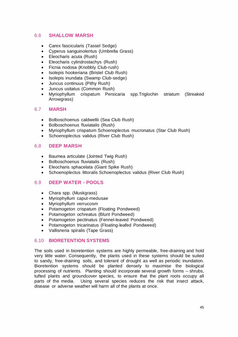
SHALLOW MARSH 6.6
Carex fascicularis (Tassel Sedge)
Cyperus sanguinolentus (Umbrella Grass)
Eleocharis acuta (Rush)
Eleocharis cylindrostachys (Rush)
Ficnia nodosa (Knobbly Club-rush)
Isolepis hookeriana (Bristel Club Rush)
Isolepis inundata (Swamp Club-sedge)
Juncus continuus (Pithy Rush)
Juncus usitatus (Common Rush)
Myriophyllum crispatum Persicaria spp.Triglochin striatum (Streaked Arrowgrass)
MARSH 6.7
Bolboschoenus caldwellii (Sea Club Rush)
Bolboschoenus fluviatalis (Rush)
Myriophyllum crispatum Schoenoplectus mucronatus (Star Club Rush)
Schoenoplectus validus (River Club Rush)
DEEP MARSH 6.8
Baumea articulate (Jointed Twig Rush)
Bolboschoenus fluviatalis (Rush)
Eleocharis sphacelata (Giant Spike Rush)
Schoenoplectus littoralis Schoenoplectus validus (River Club Rush)
DEEP WATER - POOLS 6.9
Chara spp. (Muskgrass)
Myriophyllum caput-medusae
Myriophyllum verrucosm
Potamogeton crispatum (Floating Pondweed)
Potamogeton ochreatus (Blunt Pondweed)
Potamogeton pectinatus (Fennel-leaved Pondweed)
Potamogeton tricarinatus (Floating-leafed Pondweed)
Vallisneria spiralis (Tape Grass)
BIORETENTION SYSTEMS 6.10
The soils used in bioretention systems are highly permeable, free-draining and hold very little water. Consequently, the plants used in these systems should be suited to sandy, free-draining soils, and tolerant of drought as well as periodic inundation. Bioretention systems should be planted densely to maximise the biological processing of nutrients. Planting should incorporate several growth forms – shrubs, tufted plants and groundcover species, to ensure that the plant roots occupy all parts of the media. Using several species reduces the risk that insect attack, disease or adverse weather will harm all of the plants at once.

46
This list of species is indicative only, the advice of a WSUD professional should be sought to guide the exact location, species mixes and planting densities (generally 8 plants per m2) to ensure optimal treatment performance based on the detailed specifications of each treatment measure. Bioretention systems will commonly comprise five to ten species, depending on the size and hydrologic conditions within individual systems.
6.10.1 Groundcover Plants
Actinotus helianthi (Flannel Flower)
Cassinia aureonitens (Yellow Cassinia)
Helichrysum scorpioides (Buttons Everlasting)
Ozothamnus diosmifolius (Rice Flower)
Prostanthera howelliae (Mint Bush)
Senecio lautus (Variable Groundsel)
6.10.2 Tufted Species
Grasses
Bothriochloa macra (Red grass)
Danthonia tenuior (Smooth Flower Wallaby Grass)
Eragrostis brownii (Brown’s Lovegrass)
Imperata cylindrica (Blady grass)
Poa sieberiana (Grey Tussock Grass)
Sporobolus virginicus (Sand Couch, Nioaka)
Stipa pubescens
Stipa scabra (Speargrass)
Themeda australis (Kangaroo Grass)
Zoysia macrantha (Prickly Couch) Sedges
Baumea juncea (Bare Twig-Rush)
Cyperus gracilis (Slender Flat-Sedge)
Juncus bufonius (Toad Rush)
Lepidosperma laterale (Sword-Sedge)
Lomadra longifolia (Spiny Mat-rush)
Lomandra filiformis subsp. filiformis (Wattle Mat-rush)
Lomandra gracilis
6.10.3 Shrubs
Amperea xiphoclada var. xiphoclada (Broom Spurge)
Astroloma pinifolium (Pine Heath)
Banksia ericifolia (Heath-leaved Banksia)
Banksia integrifolia (Coastal Banksia)
Banksia marginata (Silver Banksia)
Billardiera scandens (Appleberry)
Boronia rigens (Stiff Boronia)
Bossiaea heterophylla (Variable Bossiaea)
Bossiaea obcordata (Spiny Bossiaea)
Bossiaea scolopendria
Brachyloma daphnoides (Daphne Heath)

47
Bursaria spinosa (Blackthorn, Boxthorn, Sweet Bursaria)
Callistemon citrinus (Common Red Bottlebrush)
Callistemon linearifolius (Nettle Bottlebrush)
Callistemon linearis (Narrow leaved Bottlebrush)
Callistemon rigidus (Stiff Bottlebrush)
Calytrix tetragona (Fringe Myrtle)
Correa reflexa (Native Fuchsia)
Crowea saligna (Willow-leaved Crowea)
Daviesia acicularis
Dillwynia retorta (Eggs and Bacon)
Epacris microphylla (Coral Heath)
Eriostemon australasius (Wax Flower)
Gompholobium glabratum (Wedge Pea)
Gompholobium grandiflorum (Large Wedge Pea)
Gompholobium minus (Dwart Wedge Pea)
Gompholobium pinnatum (Pinnate Wedge Pea)
Hakea dactyloides (Finger Hakea, Broad-leaved Hakea)
Hakea sericea (Needlebush)
Hovea linearis (Narrow Leaf Hovea)
Isopogon anemonifolius (Broad-leaf Drumsticks)
Leptospermum trinervium (Slender Tea-Tree)
Leucopogon appressus (Heath)
Leucopogon ericoides (Pink Beard-heath)
Leucopogon juniperinus (Prickly Beard-heath)
Leucopogon lanceolatus (Lance Beard-heath)
Leucopogon microphyllus
Leucopogon setiger
Melaleuca erubescens (White Flowering Melaleuca)
Melaleuca linariifolia (Flax-leaved Paperbark)
Melaleuca nodosa
Melaleuca thymifolia (Thyme Honey-Myrtle)
Melichrus procumbens
Monotoca elliptica
Phyllota grandiflora
Phyllota phylicoides
Pimelea curviflora
Pimelea linifolia (Rice Flower)
Pultenaea linophylla (Small-leafed Bush Pea)
Styphelia longifolia (Five Corners)
Styphelia triflora (Pink Five Corners)
Woollsia pungens
Zieria pilosa
6.10.4 Trees
Allocasuarina distyla (Scrub She Oak)
Allocasuarina littoralis (She Oak)
Angophora bakeri (Narrow-leaved apple)
Angophora costata (Smooth Barked Apple)
Casuarina glauca (Swamp Oak)

48
Eucalyptus haemastoma (Scribbly Gum)
Eucalyptus piperita (Sydney Peppermint)
Eucalyptus punctata subsp. wianamattica (Grey Gum)
Eucalyptus sieberi (Silver top)

49
7 REFERENCES
CRC for Catchment Hydrology 1999 Managing Urban Stormwater Using Constructed Wetlands.
CRC for Freshwater Ecology 1998 Design Guidelines: Stormwater Pollution Control Ponds and Wetlands.
engineers Australia 2001 Australian Rainfall and Runoff.
enHealth 2004 Guidance on Use of Rainwater Tanks (Australian Government, Canberra).
Landcom 2006 Wastewater reuse in the Urban Environment: selection of technologies, available online: http://www.landcom.com.au/Wastewaterreuse.aspx.
Moreton Bay Waterways and Catchments Partnership 2006 WSUD Technical Design Guidelines for South East Queensland.
Natural Resource Ministerial Council and Environment Protection and Heritage Council 2006
Australian Guidelines for Water Recycling: Managing Health and Environmental Risks (Phase 1).
NSW Department of Energy, Utilities and Sustainability (DEUS) 2007 NSW Guidelines for Greywater Reuse in Sewered, Single Household Residential Premises.
NSW Department of Environment and Climate Change (DECC) 2003 Use of effluent by irrigation (consultation draft).
NSW Department of Environment and Climate Change (DECC) 2006 Managing Urban Stormwater: Harvesting and Reuse.
NSW Department of Environment and Climate Change (DECC) 2007 Managing Urban Stormwater: Harvesting and Reuse.
NSW Department of Health 2004 Greywater and Sewage Recycling in Multi-Unit Dwellings and Commercial Premises - Interim Guidance.
NSW Department of Land and Water Conservation (DLWC) 1998 Constructed Wetlands Manual. NSW Government 1993 NSW guidelines for urban and residential use of reclaimed water.
NSW Government 2004 Managing Urban Stormwater: Soils and Construction (the “Blue Book”) Fourth edition, reprinted 2006. Available from Landcom.
NSW National Parks and Wildlife Service (2002) Interpretation Guidelines for the Native Vegetation Maps of the Cumberland Plain, Western Sydney, Final Edition NSW NPWS, available online at http://www.basix.nsw.gov.au/help_detached/water/landscape/list_of_indigenous_species.htm
Rutherford, I.D., Jerie, K. and Marsh, N 2000 A Rehabilitation Manual for Australian Streams CRC for Catchment Hydrology and the Land and Water Resources Research and Development Corporation.
SoER (2007) Northern Sydney Regional Organisation of Councils- State of the Environment Report- City of Ryde Edition
Upper Parramatta River Catchment Trust 2004, Water Sensitive Urban Design Technical Guidelines for Western Sydney.
Wong, T.H.F. (Ed) 2006 Australian Runoff Quality Engineers Australia, Sydney.